Embed Size (px)
Citation preview

Operational Condition and Superfinishing Effect on
High-Speed Helical Gearing System Performance
NASA/TM—2007-214696
June 2007
R. Handschuh
U.S. Army Research Laboratory, Glenn Research Center, Cleveland, Ohio
C. Kilmain and R. Ehinger
Bell Helicopter Textron Inc., Fort Worth, Texas
ARL–TR–4099
U.S. ARMY
RESEARCH LABORATORY
https://ntrs.nasa.gov/search.jsp?R=20070022618 2018-05-23T03:50:48+00:00Z
NASA STI Program . . . in Profile
Since its founding, NASA has been dedicated to the
advancement of aeronautics and space science. The
NASA Scientific and Technical Information (STI)
program plays a key part in helping NASA maintain
this important role.
The NASA STI Program operates under the auspices
of the Agency Chief Information Officer. It collects,
organizes, provides for archiving, and disseminates
NASA’s STI. The NASA STI program provides access
to the NASA Aeronautics and Space Database and its
public interface, the NASA Technical Reports Server,
thus providing one of the largest collections of
aeronautical and space science STI in the world.
Results are published in both non-NASA channels and
by NASA in the NASA STI Report Series, which
includes the following report types:
• TECHNICAL PUBLICATION. Reports of
completed research or a major significant phase
of research that present the results of NASA
programs and include extensive data or theoretical
analysis. Includes compilations of significant
scientific and technical data and information
deemed to be of continuing reference value.
NASA counterpart of peer-reviewed formal
professional papers but has less stringent
limitations on manuscript length and extent of
graphic presentations.
• TECHNICAL MEMORANDUM. Scientific
and technical findings that are preliminary or
of specialized interest, e.g., quick release
reports, working papers, and bibliographies that
contain minimal annotation. Does not contain
extensive analysis.
• CONTRACTOR REPORT. Scientific and
technical findings by NASA-sponsored
contractors and grantees.
• CONFERENCE PUBLICATION. Collected
papers from scientific and technical
conferences, symposia, seminars, or other
meetings sponsored or cosponsored by NASA.
• SPECIAL PUBLICATION. Scientific,
technical, or historical information from
NASA programs, projects, and missions, often
concerned with subjects having substantial
public interest.
• TECHNICAL TRANSLATION. English-
language translations of foreign scientific and
technical material pertinent to NASA’s mission.
Specialized services also include creating custom
thesauri, building customized databases, organizing
and publishing research results.
For more information about the NASA STI
program, see the following:
• Access the NASA STI program home page at
http://www.sti.nasa.gov
• E-mail your question via the Internet to
• Fax your question to the NASA STI Help Desk
at 301–621–0134
• Telephone the NASA STI Help Desk at
301–621–0390
• Write to:
NASA Center for AeroSpace Information (CASI)
7115 Standard Drive
Hanover, MD 21076–1320

Operational Condition and Superfinishing Effect on
High-Speed Helical Gearing System Performance
NASA/TM—2007-214696
June 2007
National Aeronautics and
Space Administration
Glenn Research Center
Cleveland, Ohio 44135
R. Handschuh
U.S. Army Research Laboratory, Glenn Research Center, Cleveland, Ohio
C. Kilmain and R. Ehinger
Bell Helicopter Textron Inc., Fort Worth, Texas
ARL–TR–4099
U.S. ARMY
RESEARCH LABORATORY
Prepared for the
Forum 63
sponsored by the American Helicopter Society International
Virginia Beach, Virginia, May 1–3, 2007

Available from
NASA Center for Aerospace Information
7115 Standard Drive
Hanover, MD 21076–1320
National Technical Information Service
5285 Port Royal Road
Springfield, VA 22161
Available electronically at http://gltrs.grc.nasa.gov
Level of Review: This material has been technically reviewed by technical management.

NASA/TM—2007-214696 1
Operational Condition and Superfinishing Effect on High-Speed Helical Gearing System Performance
R. Handschuh
U.S. Army Research Laboratory Glenn Research Center
Cleveland, Ohio
C. Kilmain and R. Ehinger Bell Helicopter Textron Inc.
Fort Worth, Texas
Abstract An experimental effort has been conducted on an aerospace-
quality helical gear train to investigate the thermal behavior of the gear system. Oil inlet temperature was varied from 160 to 250 °F. Also, the test gears were run in both an as-ground condition and after isotropic superfinishing (ISF) condition. In-depth temperature measurements were made across the face width and at the axial end of the gear mesh. Supply power measurements were made at varying speeds and loads up to 5000 hp and 15000 rpm (pitch line velocity to 24000 feet per minute). Test results from the parametric studies and the superfinishing process are presented. The tests indicated that superfinishing offered no improvement in performance due to the high lubricant film thickness generated by the extremely high pitch line velocity that the majority of the tests were conducted. Increasing lubricant inlet temperature had the most dramatic effect on performance improvement.
Introduction High speed, heavily loaded and lightweight gearing
components are found in propulsion systems for rotorcraft. The high pitch line velocity that is part of these systems makes the thermal aspects of the gear system design very important. Also, transmission systems used in certain applications have gear trains that provide the proper spacing between the parallel engine and rotor shafts (ref. 1). These gear trains can cause additional thermal problems as the idler gears in this system receive two meshing cycles (on opposites sides of the gear teeth) per revolution. Therefore, weight optimized aerospace drive system components can have difficulty when operation includes primary lubrication system failure.
In prior studies using this gear train system, testing has focused on basic operational characteristics (refs. 2 and 3) and the comparison of analytical predictions to experimental results (ref. 4). The results from these studies have shown and quantified the effect of operational conditions on the power required to rotate the gear system at high speed and load. Also, gear windage was shown to be one of the primary gear mesh losses and is the least understood of the gearing loss mechanisms (refs. 5 and 6). At the present time gear windage reduction techniques have been trial and error. However there
is a performance benefit that can be realized if the design engineers can come up with an effective system to reduce these losses.
The objective of this study was to investigate the effect of lubricant input temperature and additional gear surface treatment beyond the baseline finish ground surface on performance parameters measured in the test facility. The baseline gears that had been used in prior test programs were removed from the test facility and had the superfinishing process applied. The inlet temperature of the lubricant was varied from 160 to 250 °F. Tests were conducted at these various operating conditions (including the inlet temperature) in the as-ground (including run-in) and with superfinishing applied. The superfinishing process has been shown to be very useful in contact fatigue life improvement (refs. 7 and 8). This process has also been shown in other studies to reduce power loss and scoring loads when applied to the gear flanks.
Test Facility, Test Instrumentation, and Test Hardware Test Facility
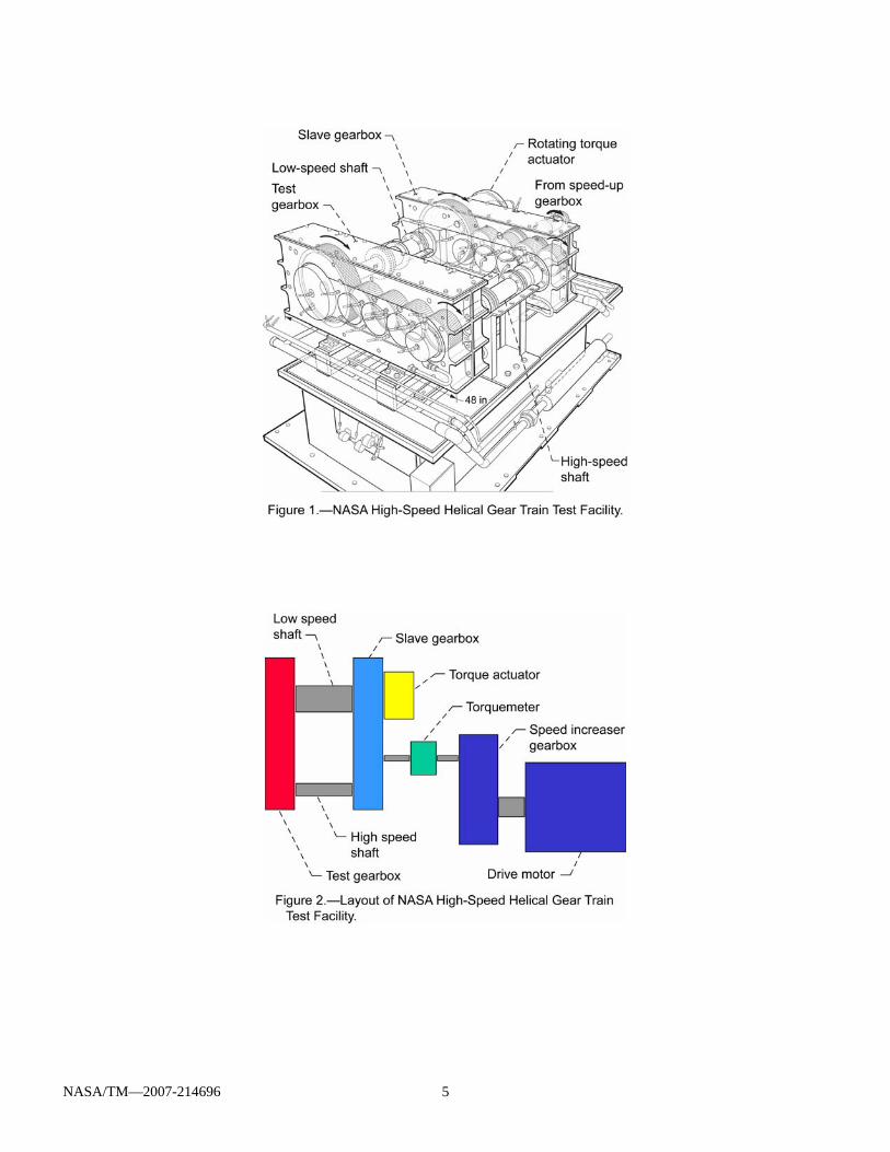
The test facility used for this study is shown in figure 1. The facility is a closed-loop, torque-regenerative testing system. There is a test gearbox and slave gearbox that are basically mirror images. Each gearbox has an input gear, three idlers, and one bull gear. The gearboxes are joined together through the input gears and bull gears via shafting.
The facility is powered by a 500 hp DC drive motor and its output speed is increased using a speed-increasing gearbox. The output of the speed-increasing gearbox then passes through a torque and speed sensor before connecting to the slave gearbox. The entire test stand configuration is shown in figure 2.
Each gearbox has separate oil supply and scavenge pumps and reservoirs. All flow rates have been calibrated at various temperatures and pressures prior to installation for accurate flow rate measurement. Lubrication system flow rate is controlled using the supply pressure. Temperature is controlled via immersion heaters in the reservoir and heat exchangers that cool the lubricant returned from the gearboxes. Each lubrication system has very fine 3-micron
NASA/TM—2007-214696 2
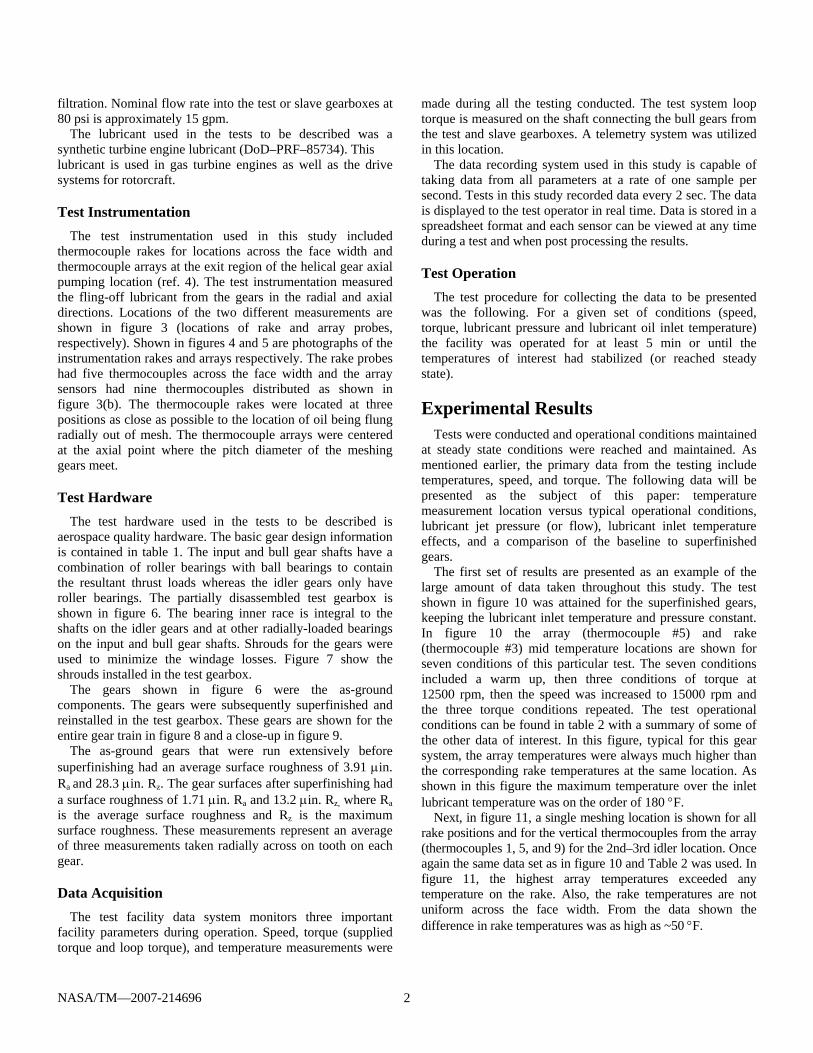
filtration. Nominal flow rate into the test or slave gearboxes at 80 psi is approximately 15 gpm.
The lubricant used in the tests to be described was a synthetic turbine engine lubricant (DoD–PRF–85734). This lubricant is used in gas turbine engines as well as the drive systems for rotorcraft.
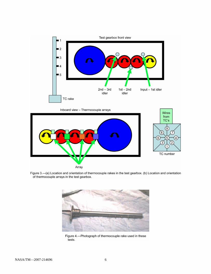
Test Instrumentation The test instrumentation used in this study included
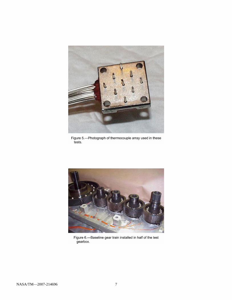
thermocouple rakes for locations across the face width and thermocouple arrays at the exit region of the helical gear axial pumping location (ref. 4). The test instrumentation measured the fling-off lubricant from the gears in the radial and axial directions. Locations of the two different measurements are shown in figure 3 (locations of rake and array probes, respectively). Shown in figures 4 and 5 are photographs of the instrumentation rakes and arrays respectively. The rake probes had five thermocouples across the face width and the array sensors had nine thermocouples distributed as shown in figure 3(b). The thermocouple rakes were located at three positions as close as possible to the location of oil being flung radially out of mesh. The thermocouple arrays were centered at the axial point where the pitch diameter of the meshing gears meet.
Test Hardware The test hardware used in the tests to be described is
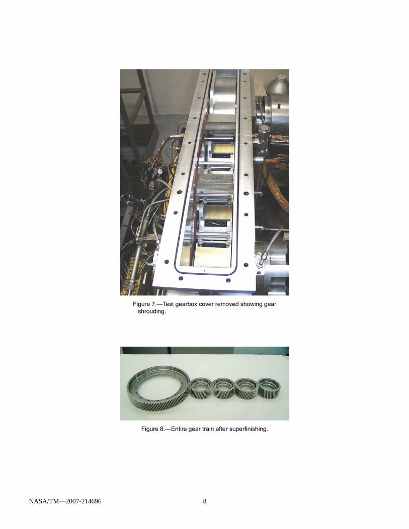
aerospace quality hardware. The basic gear design information is contained in table 1. The input and bull gear shafts have a combination of roller bearings with ball bearings to contain the resultant thrust loads whereas the idler gears only have roller bearings. The partially disassembled test gearbox is shown in figure 6. The bearing inner race is integral to the shafts on the idler gears and at other radially-loaded bearings on the input and bull gear shafts. Shrouds for the gears were used to minimize the windage losses. Figure 7 show the shrouds installed in the test gearbox.
The gears shown in figure 6 were the as-ground components. The gears were subsequently superfinished and reinstalled in the test gearbox. These gears are shown for the entire gear train in figure 8 and a close-up in figure 9.
The as-ground gears that were run extensively before superfinishing had an average surface roughness of 3.91 μin. Ra and 28.3 μin. Rz. The gear surfaces after superfinishing had a surface roughness of 1.71 μin. Ra and 13.2 μin. Rz, where Ra is the average surface roughness and Rz is the maximum surface roughness. These measurements represent an average of three measurements taken radially across on tooth on each gear.
Data Acquisition The test facility data system monitors three important
facility parameters during operation. Speed, torque (supplied torque and loop torque), and temperature measurements were
made during all the testing conducted. The test system loop torque is measured on the shaft connecting the bull gears from the test and slave gearboxes. A telemetry system was utilized in this location.
The data recording system used in this study is capable of taking data from all parameters at a rate of one sample per second. Tests in this study recorded data every 2 sec. The data is displayed to the test operator in real time. Data is stored in a spreadsheet format and each sensor can be viewed at any time during a test and when post processing the results.
Test Operation The test procedure for collecting the data to be presented
was the following. For a given set of conditions (speed, torque, lubricant pressure and lubricant oil inlet temperature) the facility was operated for at least 5 min or until the temperatures of interest had stabilized (or reached steady state).
Experimental Results Tests were conducted and operational conditions maintained
at steady state conditions were reached and maintained. As mentioned earlier, the primary data from the testing include temperatures, speed, and torque. The following data will be presented as the subject of this paper: temperature measurement location versus typical operational conditions, lubricant jet pressure (or flow), lubricant inlet temperature effects, and a comparison of the baseline to superfinished gears.
The first set of results are presented as an example of the large amount of data taken throughout this study. The test shown in figure 10 was attained for the superfinished gears, keeping the lubricant inlet temperature and pressure constant. In figure 10 the array (thermocouple #5) and rake (thermocouple #3) mid temperature locations are shown for seven conditions of this particular test. The seven conditions included a warm up, then three conditions of torque at 12500 rpm, then the speed was increased to 15000 rpm and the three torque conditions repeated. The test operational conditions can be found in table 2 with a summary of some of the other data of interest. In this figure, typical for this gear system, the array temperatures were always much higher than the corresponding rake temperatures at the same location. As shown in this figure the maximum temperature over the inlet lubricant temperature was on the order of 180 °F.
Next, in figure 11, a single meshing location is shown for all rake positions and for the vertical thermocouples from the array (thermocouples 1, 5, and 9) for the 2nd–3rd idler location. Once again the same data set as in figure 10 and Table 2 was used. In figure 11, the highest array temperatures exceeded any temperature on the rake. Also, the rake temperatures are not uniform across the face width. From the data shown the difference in rake temperatures was as high as ~50 °F.
NASA/TM—2007-214696 3
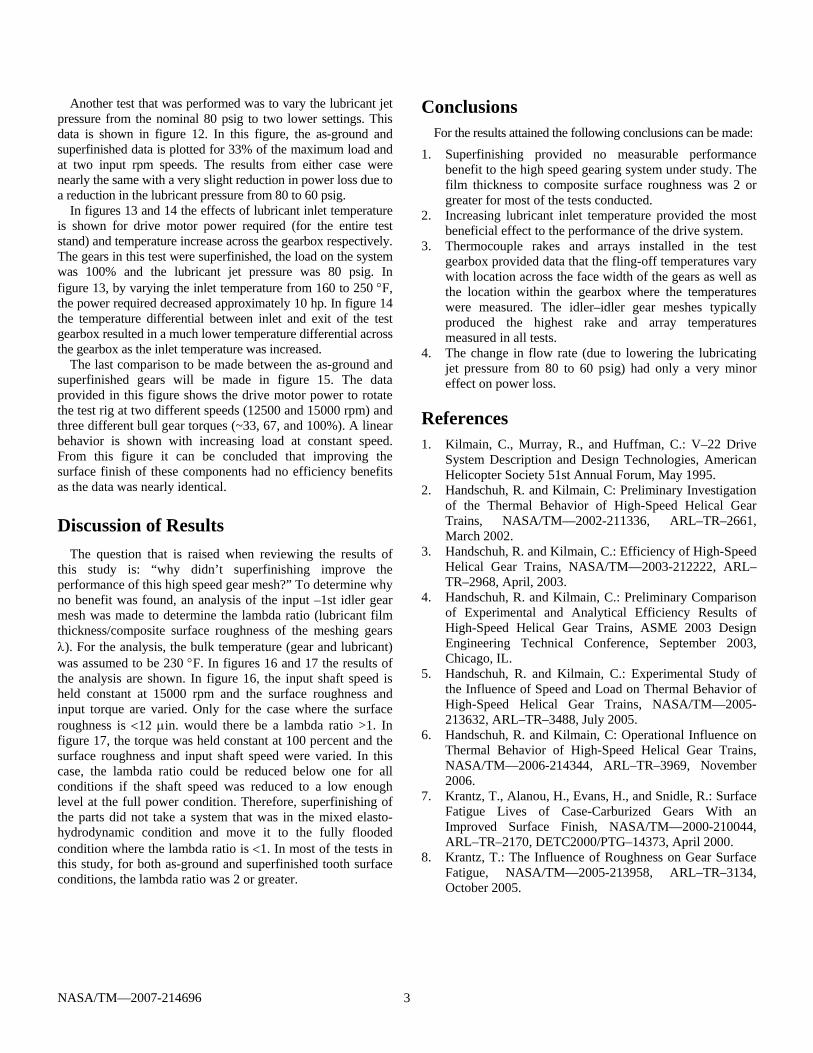
Another test that was performed was to vary the lubricant jet pressure from the nominal 80 psig to two lower settings. This data is shown in figure 12. In this figure, the as-ground and superfinished data is plotted for 33% of the maximum load and at two input rpm speeds. The results from either case were nearly the same with a very slight reduction in power loss due to a reduction in the lubricant pressure from 80 to 60 psig.
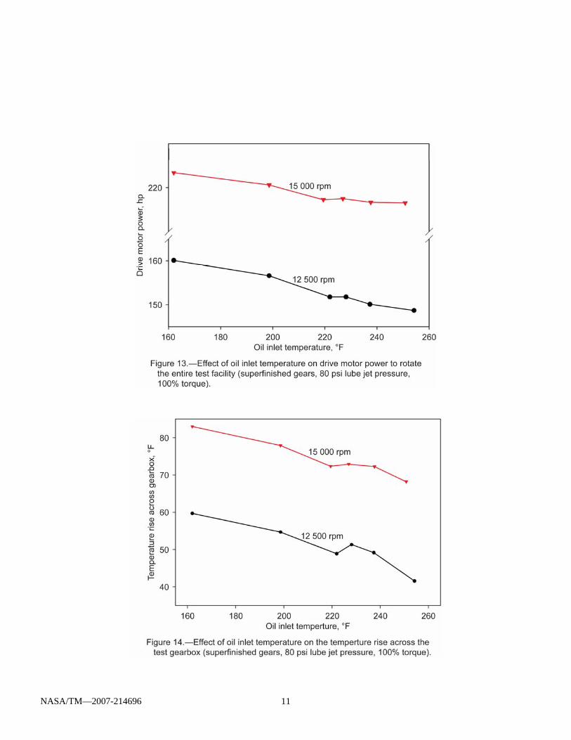
In figures 13 and 14 the effects of lubricant inlet temperature is shown for drive motor power required (for the entire test stand) and temperature increase across the gearbox respectively. The gears in this test were superfinished, the load on the system was 100% and the lubricant jet pressure was 80 psig. In figure 13, by varying the inlet temperature from 160 to 250 °F, the power required decreased approximately 10 hp. In figure 14 the temperature differential between inlet and exit of the test gearbox resulted in a much lower temperature differential across the gearbox as the inlet temperature was increased.
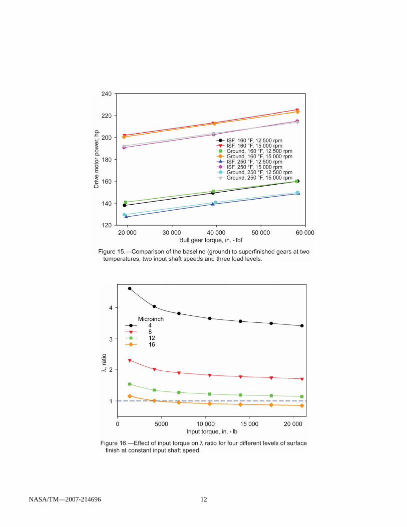
The last comparison to be made between the as-ground and superfinished gears will be made in figure 15. The data provided in this figure shows the drive motor power to rotate the test rig at two different speeds (12500 and 15000 rpm) and three different bull gear torques (~33, 67, and 100%). A linear behavior is shown with increasing load at constant speed. From this figure it can be concluded that improving the surface finish of these components had no efficiency benefits as the data was nearly identical.
Discussion of Results The question that is raised when reviewing the results of
this study is: “why didn’t superfinishing improve the performance of this high speed gear mesh?” To determine why no benefit was found, an analysis of the input –1st idler gear mesh was made to determine the lambda ratio (lubricant film thickness/composite surface roughness of the meshing gears λ). For the analysis, the bulk temperature (gear and lubricant) was assumed to be 230 °F. In figures 16 and 17 the results of the analysis are shown. In figure 16, the input shaft speed is held constant at 15000 rpm and the surface roughness and input torque are varied. Only for the case where the surface roughness is <12 μin. would there be a lambda ratio >1. In figure 17, the torque was held constant at 100 percent and the surface roughness and input shaft speed were varied. In this case, the lambda ratio could be reduced below one for all conditions if the shaft speed was reduced to a low enough level at the full power condition. Therefore, superfinishing of the parts did not take a system that was in the mixed elasto-hydrodynamic condition and move it to the fully flooded condition where the lambda ratio is <1. In most of the tests in this study, for both as-ground and superfinished tooth surface conditions, the lambda ratio was 2 or greater.
Conclusions For the results attained the following conclusions can be made:
1. Superfinishing provided no measurable performance benefit to the high speed gearing system under study. The film thickness to composite surface roughness was 2 or greater for most of the tests conducted.
2. Increasing lubricant inlet temperature provided the most beneficial effect to the performance of the drive system.
3. Thermocouple rakes and arrays installed in the test gearbox provided data that the fling-off temperatures vary with location across the face width of the gears as well as the location within the gearbox where the temperatures were measured. The idler–idler gear meshes typically produced the highest rake and array temperatures measured in all tests.
4. The change in flow rate (due to lowering the lubricating jet pressure from 80 to 60 psig) had only a very minor effect on power loss.
References 1. Kilmain, C., Murray, R., and Huffman, C.: V–22 Drive
System Description and Design Technologies, American Helicopter Society 51st Annual Forum, May 1995.
2. Handschuh, R. and Kilmain, C: Preliminary Investigation of the Thermal Behavior of High-Speed Helical Gear Trains, NASA/TM—2002-211336, ARL–TR–2661, March 2002.
3. Handschuh, R. and Kilmain, C.: Efficiency of High-Speed Helical Gear Trains, NASA/TM—2003-212222, ARL–TR–2968, April, 2003.
4. Handschuh, R. and Kilmain, C.: Preliminary Comparison of Experimental and Analytical Efficiency Results of High-Speed Helical Gear Trains, ASME 2003 Design Engineering Technical Conference, September 2003, Chicago, IL.
5. Handschuh, R. and Kilmain, C.: Experimental Study of the Influence of Speed and Load on Thermal Behavior of High-Speed Helical Gear Trains, NASA/TM—2005-213632, ARL–TR–3488, July 2005.
6. Handschuh, R. and Kilmain, C: Operational Influence on Thermal Behavior of High-Speed Helical Gear Trains, NASA/TM—2006-214344, ARL–TR–3969, November 2006.
7. Krantz, T., Alanou, H., Evans, H., and Snidle, R.: Surface Fatigue Lives of Case-Carburized Gears With an Improved Surface Finish, NASA/TM—2000-210044, ARL–TR–2170, DETC2000/PTG–14373, April 2000.
8. Krantz, T.: The Influence of Roughness on Gear Surface Fatigue, NASA/TM—2005-213958, ARL–TR–3134, October 2005.

NASA/TM—2007-214696 4
TABLE 1.—BASIC GEAR DESIGN DATA
Number of teeth input and 2nd idler Number of teeth 1st and 3rd idler Number of teeth Bull gear
50 51 139
Module, mm (diametral pitch (1/in.)) 3.033 (8.375) Face width, mm (in.) 67.2 (2.625) Helix angle, degree 12 Gear material Pyrowear 53
TABLE 2.—CONDITIONS FOR FIGURES 10 AND 11. TESTS WERE CONDUCTED AT 160 °F OIL INLET TEMPERATURE ON SUPERFINISHED GEARS
Condition Input shaft
speed Loop power
Temperature increase across
gearbox
Drive motor power
(krpm) (hp) (°F) (hp)
A Warm up
B 12.5 1379 50.6 138.0 C 12.5 2801 55.1 149.2 D 12.5 4170 59.7 160.1 E 15.0 1657 73.8 201.9 F 15.0 3366 79.1 213.2 G 15.0 4986 83.0 225.1
NASA/TM—2007-214696 5
NASA/TM—2007-214696 6
NASA/TM—2007-214696 7
NASA/TM—2007-214696 8

NASA/TM—2007-214696 9

NASA/TM—2007-214696 10
NASA/TM—2007-214696 11
NASA/TM—2007-214696 12

NASA/TM—2007-214696 13
REPORT DOCUMENTATION PAGE Form Approved OMB No. 0704-0188
The public reporting burden for this collection of information is estimated to average 1 hour per response, including the time for reviewing instructions, searching existing data sources, gathering and maintaining the data needed, and completing and reviewing the collection of information. Send comments regarding this burden estimate or any other aspect of this collection of information, including suggestions for reducing this burden, to Department of Defense, Washington Headquarters Services, Directorate for Information Operations and Reports (0704-0188), 1215 Jefferson Davis Highway, Suite 1204, Arlington, VA 22202-4302. Respondents should be aware that notwithstanding any other provision of law, no person shall be subject to any penalty for failing to comply with a collection of information if it does not display a currently valid OMB control number. PLEASE DO NOT RETURN YOUR FORM TO THE ABOVE ADDRESS. 1. REPORT DATE (DD-MM-YYYY) 01-06-2007
2. REPORT TYPE Technical Memorandum
3. DATES COVERED (From - To)
4. TITLE AND SUBTITLE Operational Condition and Superfinishing Effect on High-Speed Helical Gearing System Performance
5a. CONTRACT NUMBER
5b. GRANT NUMBER
5c. PROGRAM ELEMENT NUMBER
6. AUTHOR(S) Handschuh, R.; Kilmain, C.; Ehinger, R.
5d. PROJECT NUMBER
5e. TASK NUMBER
5f. WORK UNIT NUMBER WBS 877868.02.07.03.01.01
7. PERFORMING ORGANIZATION NAME(S) AND ADDRESS(ES) National Aeronautics and Space Administration John H. Glenn Research Center at Lewis Field Cleveland, Ohio 44135-3191
8. PERFORMING ORGANIZATION REPORT NUMBER E-15897
9. SPONSORING/MONITORING AGENCY NAME(S) AND ADDRESS(ES) National Aeronautics and Space Administration Washington, DC 20546-0001 and U.S. Army Research Laboratory Adelphi, Maryland 20783-1145
10. SPONSORING/MONITORS ACRONYM(S) NASA, ARL
11. SPONSORING/MONITORING REPORT NUMBER NASA/TM-2007-214696; ARL-TR-4099
12. DISTRIBUTION/AVAILABILITY STATEMENT Unclassified-Unlimited Subject Category: 37 Available electronically at http://gltrs.grc.nasa.gov This publication is available from the NASA Center for AeroSpace Information, 301-621-0390
13. SUPPLEMENTARY NOTES
14. ABSTRACT An experimental effort has been conducted on an aerospace-quality helical gear train to investigate the thermal behavior of the gear system. Oil inlet temperature was varied from 160 to 250 °F. Also, the test gears were run in both an as-ground condition and after isotropic superfinishing (ISF) condition. In-depth temperature measurements were made across the face width and at the axial end of the gear mesh. Supply power measurements were made at varying speeds and loads up to 5000 hp and 15000 rpm (pitch line velocity to 24000 feet per minute). Test results from the parametric studies and the superfinishing process are presented. The tests indicated that superfinishing offered no improvement in performance due to the high lubricant film thickness generated by the extremely high pitch line velocity that the majority of the tests were conducted. Increasing lubricant inlet temperature had the most dramatic effect on performance improvement.15. SUBJECT TERMS Gears; Transmissions
16. SECURITY CLASSIFICATION OF: 17. LIMITATION OF ABSTRACT
18. NUMBER OF PAGES
19
19a. NAME OF RESPONSIBLE PERSON R. Handschuh
a. REPORT U
b. ABSTRACT U
c. THIS PAGE U
19b. TELEPHONE NUMBER (include area code) 216-433-3969
Standard Form 298 (Rev. 8-98)Prescribed by ANSI Std. Z39-18