Embed Size (px)
Citation preview
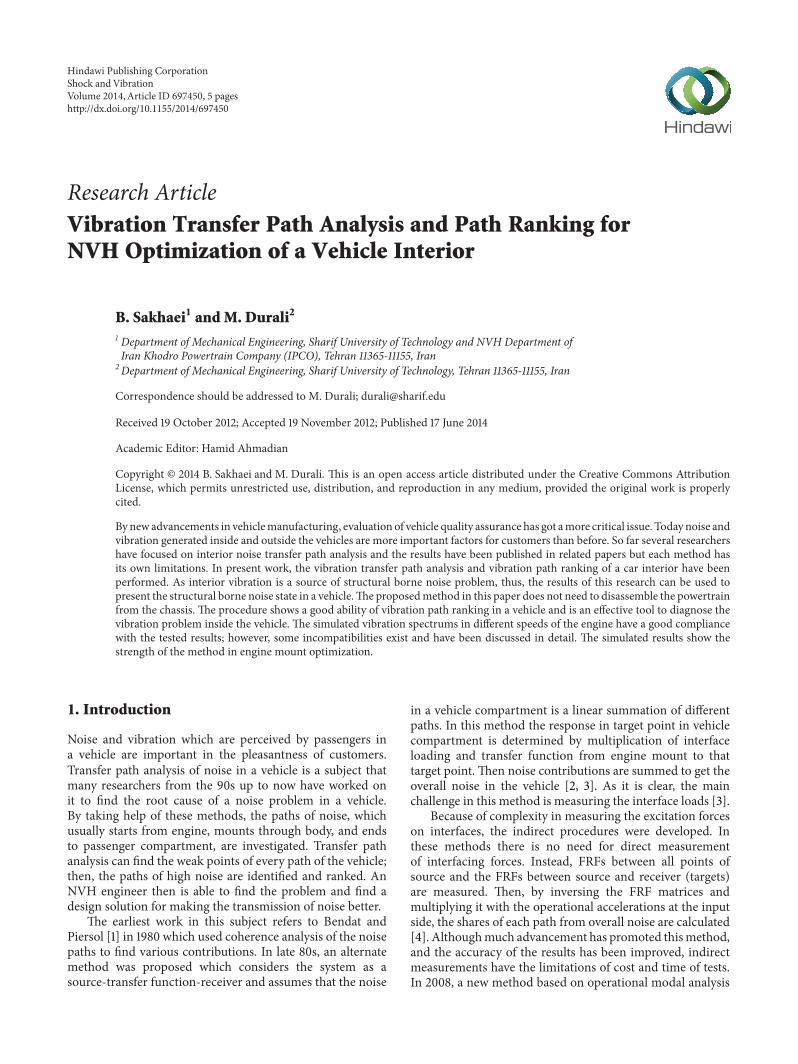
Research ArticleVibration Transfer Path Analysis and Path Ranking forNVH Optimization of a Vehicle Interior
B Sakhaei1 and M Durali2
1 Department of Mechanical Engineering Sharif University of Technology and NVH Department ofIran Khodro Powertrain Company (IPCO) Tehran 11365-11155 Iran
2Department of Mechanical Engineering Sharif University of Technology Tehran 11365-11155 Iran
Correspondence should be addressed to M Durali duralisharifedu
Received 19 October 2012 Accepted 19 November 2012 Published 17 June 2014
Academic Editor Hamid Ahmadian
Copyright copy 2014 B Sakhaei and M Durali This is an open access article distributed under the Creative Commons AttributionLicense which permits unrestricted use distribution and reproduction in any medium provided the original work is properlycited
By new advancements in vehiclemanufacturing evaluation of vehicle quality assurance has got amore critical issue Today noise andvibration generated inside and outside the vehicles are more important factors for customers than before So far several researchershave focused on interior noise transfer path analysis and the results have been published in related papers but each method hasits own limitations In present work the vibration transfer path analysis and vibration path ranking of a car interior have beenperformed As interior vibration is a source of structural borne noise problem thus the results of this research can be used topresent the structural borne noise state in a vehicleThe proposedmethod in this paper does not need to disassemble the powertrainfrom the chassis The procedure shows a good ability of vibration path ranking in a vehicle and is an effective tool to diagnose thevibration problem inside the vehicle The simulated vibration spectrums in different speeds of the engine have a good compliancewith the tested results however some incompatibilities exist and have been discussed in detail The simulated results show thestrength of the method in engine mount optimization
1 Introduction
Noise and vibration which are perceived by passengers ina vehicle are important in the pleasantness of customersTransfer path analysis of noise in a vehicle is a subject thatmany researchers from the 90s up to now have worked onit to find the root cause of a noise problem in a vehicleBy taking help of these methods the paths of noise whichusually starts from engine mounts through body and endsto passenger compartment are investigated Transfer pathanalysis can find the weak points of every path of the vehiclethen the paths of high noise are identified and ranked AnNVH engineer then is able to find the problem and find adesign solution for making the transmission of noise better
The earliest work in this subject refers to Bendat andPiersol [1] in 1980 which used coherence analysis of the noisepaths to find various contributions In late 80s an alternatemethod was proposed which considers the system as asource-transfer function-receiver and assumes that the noise
in a vehicle compartment is a linear summation of differentpaths In this method the response in target point in vehiclecompartment is determined by multiplication of interfaceloading and transfer function from engine mount to thattarget point Then noise contributions are summed to get theoverall noise in the vehicle [2 3] As it is clear the mainchallenge in this method is measuring the interface loads [3]
Because of complexity in measuring the excitation forceson interfaces the indirect procedures were developed Inthese methods there is no need for direct measurementof interfacing forces Instead FRFs between all points ofsource and the FRFs between source and receiver (targets)are measured Then by inversing the FRF matrices andmultiplying it with the operational accelerations at the inputside the shares of each path from overall noise are calculated[4] Althoughmuch advancement has promoted thismethodand the accuracy of the results has been improved indirectmeasurements have the limitations of cost and time of testsIn 2008 a new method based on operational modal analysis
Hindawi Publishing CorporationShock and VibrationVolume 2014 Article ID 697450 5 pageshttpdxdoiorg1011552014697450
2 Shock and Vibration
was proposed This method named operational path analysis(OPA) which shortened the test time but it had accuracyproblem because excitation in one direction often has sideeffect responses in other directions and putting this methodinto effect needs high experience [5]
Multilevel TPA has the strength of indirect measurementbut can be done in a shorter time relative to indirect methodIt was first introduced in 2002 by Eisele et al [6] whichanalyzed the interior structural noise in a vehicle Howeverthe method is effective in prediction of the critical paths butless attention has been paid to it
Although almost all publications in interior noise transferpath analysis have focused on interior noise simulation thereis no work on the interior vibration simulation In this paperan interior vibration simulation of the vehicle for the first timewas done The method was based on multilevel TPA and theresults show that this method has the ability of TPA analysiseffectively It is a fast method which rarely has the problemof measurement noise interfering The results show thatvehicle interior vibration simulation has good potential ofengine mount optimization behaviour By this method alsovibration fault diagnosis is more effective than conventionalnoise path ranking methods
2 General Formulation
Vibrations in a vehicle mostly transfer from engine mountlocations through vibration transfer paths into the body ofthe car and finally receives to the target locations in passengercompartment Elements in vibration generation and transferinto the vehicle are divided into two major parts active andpassive elements IC engine is an active vibration source andthe engine mounts and body transfer functions from mountlocations to target points in the vehicle compartment arepassive elements
In passive part of vibration transfer each enginemount ineach vehicle principal coordinate comprises one path Thusfor a vehicle with 3 engine mounts there are 9 transfer pathsThese engine mount paths beside relative body and chassistransfer functions send vibration energy to the passengercompartment
Basic equation in transfer path analysis assumes thatthe total noise and vibration felt at passenger position aresuperposing the contribution of each path Equation (1)implies the relation [4] as follows
119910 (119891) =
119899
sum
1
119910119894(119891) (1)
where 119910(119891) = vibration at passenger location and 119910119894(119891) =
contribution of vibration from each pathThe system approach to the transfer path analysis explains
that the partial contribution 119910119894(119891) of the vibration in the
target point is a product of input force of the active part andthe transfer function between the interface and the receiverlike
119910119894(119891) = FRF
119894119896(119891) lowast 119865
119894(119891) (2)
By combining (1) and (2) general basic equation oftransfer path analysis is given by
119910 (119891) =
119899
sum
119894=1
FRF119894119896(119891) lowast 119865
119894(119891) (3)
As it is clear from (3) it is assumed that vibration transferpaths have linear behaviour Also it is obvious that transferpath analysis is performed in frequency region In thismethod as soon as any problem arises in overall amplitude ofvibration the different path contribution will be investigatedand the responsible path for that problem will be identifiedAs each contribution is equal to the product of the input forceand the transfer function then it is easier to locate the exactlocation of problem
Multilevel TPA is classified in fast TPA groups ofmethodsin which the contribution to a target response is a chain oflinked subsystems In this method few FRF measurementsare being performed and then bymultiplying the input signalto this chain the output will be the vibration share of eachpath at target location (4) Consider
119910119894(119891) = [119867
1] [1198672] [1198673] sdot sdot sdot 119865
119894(119891) (4)
where 119865119894(119891) = input forces at engine mount interface
By noting (4) the basic equation of multilevel TPA can bewritten as follows
119886interior = 119865119894 (119891) times119886interior119886body (119891)
997888rarr119886interior119865body (119891)
= 119886engine (119891) times119886body (119891)
119886engine (119891)times119865body (119891)
119886body (119891)
times119886interior (119891)
119865body (119891)
(5)
According to (5) for evaluation of 119886interior from each pathit is needed to measure three transfer functions of mounttransmissibility apparentmass and chassis transfer functionrespectively
3 Interior Vibration Simulation ofa Sedan Car
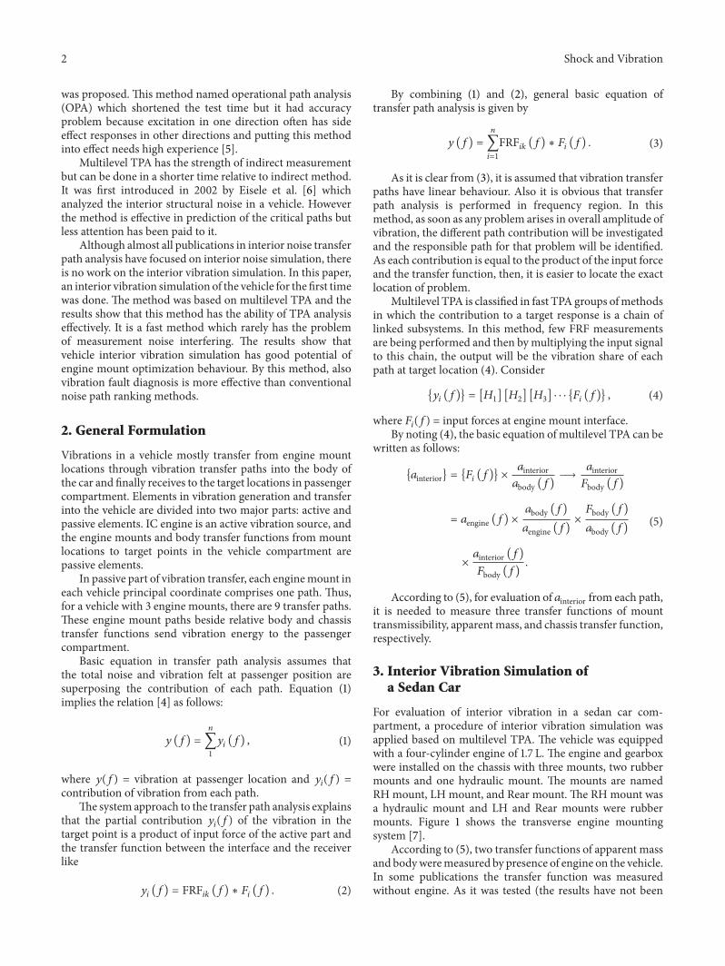
For evaluation of interior vibration in a sedan car com-partment a procedure of interior vibration simulation wasapplied based on multilevel TPA The vehicle was equippedwith a four-cylinder engine of 17 L The engine and gearboxwere installed on the chassis with three mounts two rubbermounts and one hydraulic mount The mounts are namedRH mount LH mount and Rear mount The RH mount wasa hydraulic mount and LH and Rear mounts were rubbermounts Figure 1 shows the transverse engine mountingsystem [7]
According to (5) two transfer functions of apparent massand bodyweremeasured by presence of engine on the vehicleIn some publications the transfer function was measuredwithout engine As it was tested (the results have not been
Shock and Vibration 3
LH mount
Roll axis
RH mount
Drive shafts axis
Rear mount
Figure 1 Transverse engine mounting system [7]
P1P2
P3
Figure 2 P1 hammer excitation P2 triaxial accelerometer for bodytransfer function and P3 triaxial accelerometer for chassis apparentmass [7]
reported) transfer functions without engine caused signifi-cant error in calculating the contributions
All of the measurements were performed with a BampK3570 data acquisition with 25Khz range FFT analyzer Thereare two 4524 BampK triaxial accelerometers and a piezoelectricimpact hammer of maximum 5KN force range The signalswere recorded with a 7Hz high pass filter to prevent doublehit error of impact hammer
First the body transfer function (119886interior(119891)119865body(119891))was measured by exciting the engine mount location with animpact hammer The impact was applied on the body side ofengine mount and the force was measured with piezoelectricelement of hammer Simultaneously a triaxial accelerometerwas installed on the vehicle compartment floor (point P2 inFigure 2) As it was mentioned the excitation was appliedat presence of engine and gearbox at original location Thefrequency span of the body transfer function was taken upto 800Hz because only the interior vibration of the vehiclewas importantThe frequency resolution of FFT analyzer was025Hz
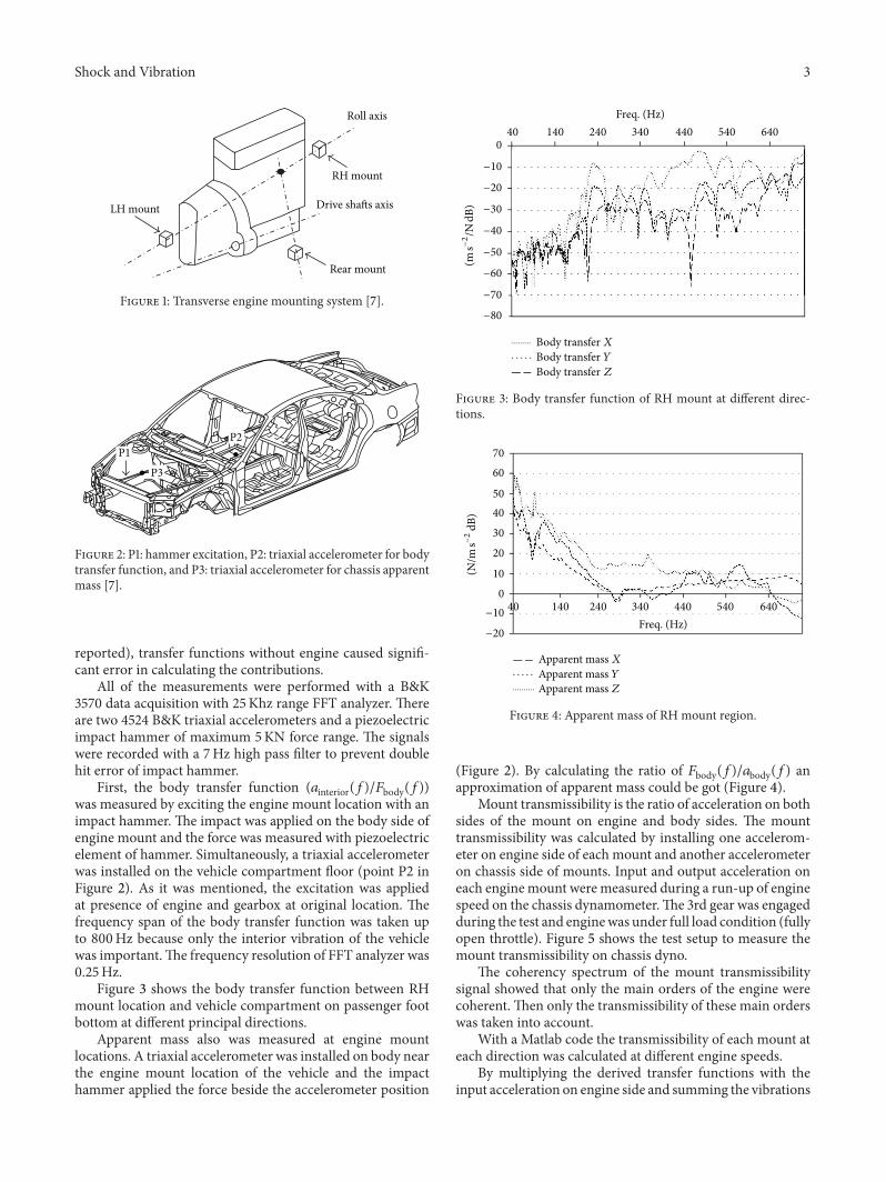
Figure 3 shows the body transfer function between RHmount location and vehicle compartment on passenger footbottom at different principal directions
Apparent mass also was measured at engine mountlocations A triaxial accelerometer was installed on body nearthe engine mount location of the vehicle and the impacthammer applied the force beside the accelerometer position
0
minus10
minus20
minus30
minus40
minus50
minus60
minus70
minus80
40 140 240 340 440 540 640
Body transfer XBody transfer YBody transfer Z
Freq (Hz)
(m sminus
2N
dB)
Figure 3 Body transfer function of RH mount at different direc-tions
70
60
50
40
30
20
10
0
minus10
minus20
Apparent mass XApparent mass YApparent mass Z
40 140 240 340 440 540 640
Freq (Hz)
(Nm
sminus2
dB)
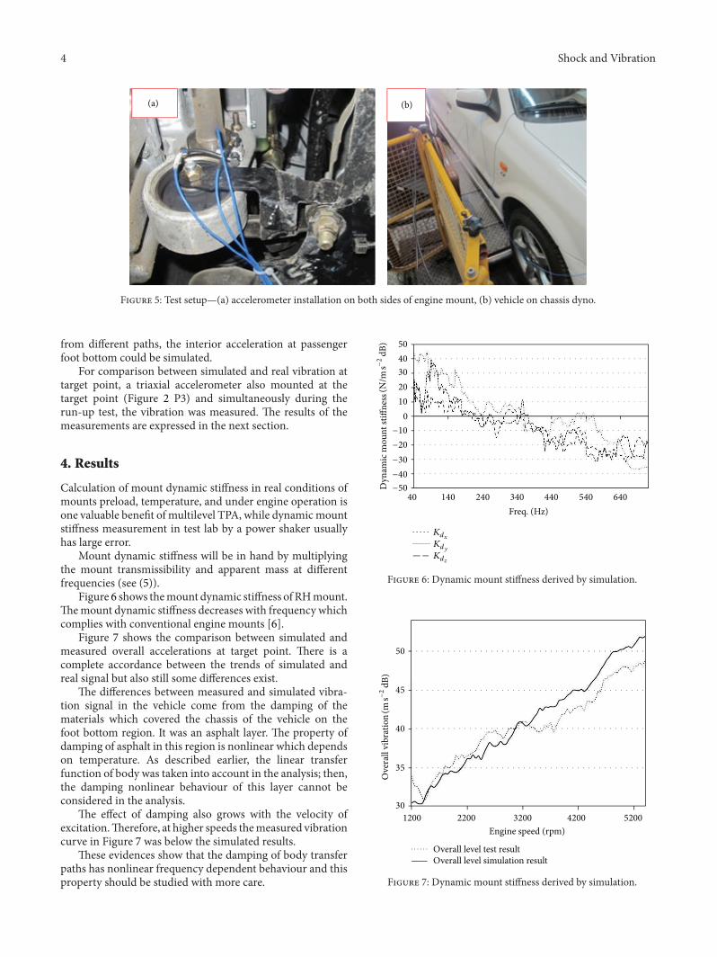
Figure 4 Apparent mass of RH mount region
(Figure 2) By calculating the ratio of 119865body(119891)119886body(119891) anapproximation of apparent mass could be got (Figure 4)
Mount transmissibility is the ratio of acceleration on bothsides of the mount on engine and body sides The mounttransmissibility was calculated by installing one accelerom-eter on engine side of each mount and another accelerometeron chassis side of mounts Input and output acceleration oneach enginemount were measured during a run-up of enginespeed on the chassis dynamometerThe 3rd gear was engagedduring the test and enginewas under full load condition (fullyopen throttle) Figure 5 shows the test setup to measure themount transmissibility on chassis dyno
The coherency spectrum of the mount transmissibilitysignal showed that only the main orders of the engine werecoherent Then only the transmissibility of these main orderswas taken into account
With a Matlab code the transmissibility of each mount ateach direction was calculated at different engine speeds
By multiplying the derived transfer functions with theinput acceleration on engine side and summing the vibrations
4 Shock and Vibration
(a) (b)
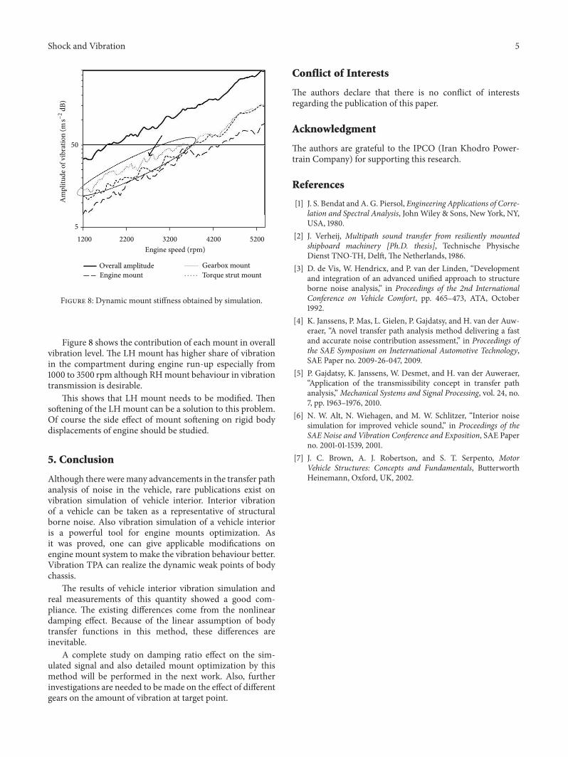
Figure 5 Test setupmdash(a) accelerometer installation on both sides of engine mount (b) vehicle on chassis dyno
from different paths the interior acceleration at passengerfoot bottom could be simulated
For comparison between simulated and real vibration attarget point a triaxial accelerometer also mounted at thetarget point (Figure 2 P3) and simultaneously during therun-up test the vibration was measured The results of themeasurements are expressed in the next section
4 Results
Calculation of mount dynamic stiffness in real conditions ofmounts preload temperature and under engine operation isone valuable benefit of multilevel TPA while dynamicmountstiffness measurement in test lab by a power shaker usuallyhas large error
Mount dynamic stiffness will be in hand by multiplyingthe mount transmissibility and apparent mass at differentfrequencies (see (5))
Figure 6 shows themount dynamic stiffness of RHmountThemount dynamic stiffness decreases with frequency whichcomplies with conventional engine mounts [6]
Figure 7 shows the comparison between simulated andmeasured overall accelerations at target point There is acomplete accordance between the trends of simulated andreal signal but also still some differences exist
The differences between measured and simulated vibra-tion signal in the vehicle come from the damping of thematerials which covered the chassis of the vehicle on thefoot bottom region It was an asphalt layer The property ofdamping of asphalt in this region is nonlinear which dependson temperature As described earlier the linear transferfunction of body was taken into account in the analysis thenthe damping nonlinear behaviour of this layer cannot beconsidered in the analysis
The effect of damping also grows with the velocity ofexcitationTherefore at higher speeds themeasured vibrationcurve in Figure 7 was below the simulated results
These evidences show that the damping of body transferpaths has nonlinear frequency dependent behaviour and thisproperty should be studied with more care
40 140 240 340 440 540 640
Freq (Hz)
50
40
30
20
10
0
minus10
minus20
minus30
minus40
minus50Dyn
amic
mou
nt st
iffne
ss(N
m sminus
2dB
)
Kd119909Kd119910Kd119911
Figure 6 Dynamic mount stiffness derived by simulation
50
45
40
35
30
1200 2200 3200 4200 5200
Overall level test resultOverall level simulation result
Engine speed (rpm)
Ove
rall
vibr
atio
n(m
sminus2
dB)
Figure 7 Dynamic mount stiffness derived by simulation
Shock and Vibration 5
1200 2200 3200 4200 5200
50
5
Overall amplitudeEngine mount
Gearbox mountTorque strut mount
Engine speed (rpm)
Am
plitu
de o
f vib
ratio
n(m
sminus2
dB)
Figure 8 Dynamic mount stiffness obtained by simulation
Figure 8 shows the contribution of each mount in overallvibration level The LH mount has higher share of vibrationin the compartment during engine run-up especially from1000 to 3500 rpm although RHmount behaviour in vibrationtransmission is desirable
This shows that LH mount needs to be modified Thensoftening of the LH mount can be a solution to this problemOf course the side effect of mount softening on rigid bodydisplacements of engine should be studied
5 Conclusion
Although there weremany advancements in the transfer pathanalysis of noise in the vehicle rare publications exist onvibration simulation of vehicle interior Interior vibrationof a vehicle can be taken as a representative of structuralborne noise Also vibration simulation of a vehicle interioris a powerful tool for engine mounts optimization Asit was proved one can give applicable modifications onengine mount system to make the vibration behaviour betterVibration TPA can realize the dynamic weak points of bodychassis
The results of vehicle interior vibration simulation andreal measurements of this quantity showed a good com-pliance The existing differences come from the nonlineardamping effect Because of the linear assumption of bodytransfer functions in this method these differences areinevitable
A complete study on damping ratio effect on the sim-ulated signal and also detailed mount optimization by thismethod will be performed in the next work Also furtherinvestigations are needed to be made on the effect of differentgears on the amount of vibration at target point
Conflict of Interests
The authors declare that there is no conflict of interestsregarding the publication of this paper
Acknowledgment
The authors are grateful to the IPCO (Iran Khodro Power-train Company) for supporting this research
References
[1] J S Bendat and A G Piersol Engineering Applications of Corre-lation and Spectral Analysis JohnWiley amp Sons New York NYUSA 1980
[2] J Verheij Multipath sound transfer from resiliently mountedshipboard machinery [PhD thesis] Technische PhysischeDienst TNO-TH Delft The Netherlands 1986
[3] D de Vis W Hendricx and P van der Linden ldquoDevelopmentand integration of an advanced unified approach to structureborne noise analysisrdquo in Proceedings of the 2nd InternationalConference on Vehicle Comfort pp 465ndash473 ATA October1992
[4] K Janssens P Mas L Gielen P Gajdatsy and H van der Auw-eraer ldquoA novel transfer path analysis method delivering a fastand accurate noise contribution assessmentrdquo in Proceedings ofthe SAE Symposium on Ineternational Automotive TechnologySAE Paper no 2009-26-047 2009
[5] P Gajdatsy K Janssens W Desmet and H van der AuweraerldquoApplication of the transmissibility concept in transfer pathanalysisrdquoMechanical Systems and Signal Processing vol 24 no7 pp 1963ndash1976 2010
[6] N W Alt N Wiehagen and M W Schlitzer ldquoInterior noisesimulation for improved vehicle soundrdquo in Proceedings of theSAE Noise and Vibration Conference and Exposition SAE Paperno 2001-01-1539 2001
[7] J C Brown A J Robertson and S T Serpento MotorVehicle Structures Concepts and Fundamentals ButterworthHeinemann Oxford UK 2002
International Journal of
AerospaceEngineeringHindawi Publishing Corporationhttpwwwhindawicom Volume 2014
RoboticsJournal of
Hindawi Publishing Corporationhttpwwwhindawicom Volume 2014
Hindawi Publishing Corporationhttpwwwhindawicom Volume 2014
Active and Passive Electronic Components
Control Scienceand Engineering
Journal of
Hindawi Publishing Corporationhttpwwwhindawicom Volume 2014
International Journal of
RotatingMachinery
Hindawi Publishing Corporationhttpwwwhindawicom Volume 2014
Hindawi Publishing Corporation httpwwwhindawicom
Journal ofEngineeringVolume 2014
Submit your manuscripts athttpwwwhindawicom
VLSI Design
Hindawi Publishing Corporationhttpwwwhindawicom Volume 2014
Hindawi Publishing Corporationhttpwwwhindawicom Volume 2014
Shock and Vibration
Hindawi Publishing Corporationhttpwwwhindawicom Volume 2014
Civil EngineeringAdvances in
Acoustics and VibrationAdvances in
Hindawi Publishing Corporationhttpwwwhindawicom Volume 2014
Hindawi Publishing Corporationhttpwwwhindawicom Volume 2014
Electrical and Computer Engineering
Journal of
Advances inOptoElectronics
Hindawi Publishing Corporation httpwwwhindawicom
Volume 2014
The Scientific World JournalHindawi Publishing Corporation httpwwwhindawicom Volume 2014
SensorsJournal of
Hindawi Publishing Corporationhttpwwwhindawicom Volume 2014
Modelling amp Simulation in EngineeringHindawi Publishing Corporation httpwwwhindawicom Volume 2014
Hindawi Publishing Corporationhttpwwwhindawicom Volume 2014
Chemical EngineeringInternational Journal of Antennas and
Propagation
International Journal of
Hindawi Publishing Corporationhttpwwwhindawicom Volume 2014
Hindawi Publishing Corporationhttpwwwhindawicom Volume 2014
Navigation and Observation
International Journal of
Hindawi Publishing Corporationhttpwwwhindawicom Volume 2014
DistributedSensor Networks
International Journal of
2 Shock and Vibration
was proposed This method named operational path analysis(OPA) which shortened the test time but it had accuracyproblem because excitation in one direction often has sideeffect responses in other directions and putting this methodinto effect needs high experience [5]
Multilevel TPA has the strength of indirect measurementbut can be done in a shorter time relative to indirect methodIt was first introduced in 2002 by Eisele et al [6] whichanalyzed the interior structural noise in a vehicle Howeverthe method is effective in prediction of the critical paths butless attention has been paid to it
Although almost all publications in interior noise transferpath analysis have focused on interior noise simulation thereis no work on the interior vibration simulation In this paperan interior vibration simulation of the vehicle for the first timewas done The method was based on multilevel TPA and theresults show that this method has the ability of TPA analysiseffectively It is a fast method which rarely has the problemof measurement noise interfering The results show thatvehicle interior vibration simulation has good potential ofengine mount optimization behaviour By this method alsovibration fault diagnosis is more effective than conventionalnoise path ranking methods
2 General Formulation
Vibrations in a vehicle mostly transfer from engine mountlocations through vibration transfer paths into the body ofthe car and finally receives to the target locations in passengercompartment Elements in vibration generation and transferinto the vehicle are divided into two major parts active andpassive elements IC engine is an active vibration source andthe engine mounts and body transfer functions from mountlocations to target points in the vehicle compartment arepassive elements
In passive part of vibration transfer each enginemount ineach vehicle principal coordinate comprises one path Thusfor a vehicle with 3 engine mounts there are 9 transfer pathsThese engine mount paths beside relative body and chassistransfer functions send vibration energy to the passengercompartment
Basic equation in transfer path analysis assumes thatthe total noise and vibration felt at passenger position aresuperposing the contribution of each path Equation (1)implies the relation [4] as follows
119910 (119891) =
119899
sum
1
119910119894(119891) (1)
where 119910(119891) = vibration at passenger location and 119910119894(119891) =
contribution of vibration from each pathThe system approach to the transfer path analysis explains
that the partial contribution 119910119894(119891) of the vibration in the
target point is a product of input force of the active part andthe transfer function between the interface and the receiverlike
119910119894(119891) = FRF
119894119896(119891) lowast 119865
119894(119891) (2)
By combining (1) and (2) general basic equation oftransfer path analysis is given by
119910 (119891) =
119899
sum
119894=1
FRF119894119896(119891) lowast 119865
119894(119891) (3)
As it is clear from (3) it is assumed that vibration transferpaths have linear behaviour Also it is obvious that transferpath analysis is performed in frequency region In thismethod as soon as any problem arises in overall amplitude ofvibration the different path contribution will be investigatedand the responsible path for that problem will be identifiedAs each contribution is equal to the product of the input forceand the transfer function then it is easier to locate the exactlocation of problem
Multilevel TPA is classified in fast TPA groups ofmethodsin which the contribution to a target response is a chain oflinked subsystems In this method few FRF measurementsare being performed and then bymultiplying the input signalto this chain the output will be the vibration share of eachpath at target location (4) Consider
119910119894(119891) = [119867
1] [1198672] [1198673] sdot sdot sdot 119865
119894(119891) (4)
where 119865119894(119891) = input forces at engine mount interface
By noting (4) the basic equation of multilevel TPA can bewritten as follows
119886interior = 119865119894 (119891) times119886interior119886body (119891)
997888rarr119886interior119865body (119891)
= 119886engine (119891) times119886body (119891)
119886engine (119891)times119865body (119891)
119886body (119891)
times119886interior (119891)
119865body (119891)
(5)
According to (5) for evaluation of 119886interior from each pathit is needed to measure three transfer functions of mounttransmissibility apparentmass and chassis transfer functionrespectively
3 Interior Vibration Simulation ofa Sedan Car
For evaluation of interior vibration in a sedan car com-partment a procedure of interior vibration simulation wasapplied based on multilevel TPA The vehicle was equippedwith a four-cylinder engine of 17 L The engine and gearboxwere installed on the chassis with three mounts two rubbermounts and one hydraulic mount The mounts are namedRH mount LH mount and Rear mount The RH mount wasa hydraulic mount and LH and Rear mounts were rubbermounts Figure 1 shows the transverse engine mountingsystem [7]
According to (5) two transfer functions of apparent massand bodyweremeasured by presence of engine on the vehicleIn some publications the transfer function was measuredwithout engine As it was tested (the results have not been
Shock and Vibration 3
LH mount
Roll axis
RH mount
Drive shafts axis
Rear mount
Figure 1 Transverse engine mounting system [7]
P1P2
P3
Figure 2 P1 hammer excitation P2 triaxial accelerometer for bodytransfer function and P3 triaxial accelerometer for chassis apparentmass [7]
reported) transfer functions without engine caused signifi-cant error in calculating the contributions
All of the measurements were performed with a BampK3570 data acquisition with 25Khz range FFT analyzer Thereare two 4524 BampK triaxial accelerometers and a piezoelectricimpact hammer of maximum 5KN force range The signalswere recorded with a 7Hz high pass filter to prevent doublehit error of impact hammer
First the body transfer function (119886interior(119891)119865body(119891))was measured by exciting the engine mount location with animpact hammer The impact was applied on the body side ofengine mount and the force was measured with piezoelectricelement of hammer Simultaneously a triaxial accelerometerwas installed on the vehicle compartment floor (point P2 inFigure 2) As it was mentioned the excitation was appliedat presence of engine and gearbox at original location Thefrequency span of the body transfer function was taken upto 800Hz because only the interior vibration of the vehiclewas importantThe frequency resolution of FFT analyzer was025Hz
Figure 3 shows the body transfer function between RHmount location and vehicle compartment on passenger footbottom at different principal directions
Apparent mass also was measured at engine mountlocations A triaxial accelerometer was installed on body nearthe engine mount location of the vehicle and the impacthammer applied the force beside the accelerometer position
0
minus10
minus20
minus30
minus40
minus50
minus60
minus70
minus80
40 140 240 340 440 540 640
Body transfer XBody transfer YBody transfer Z
Freq (Hz)
(m sminus
2N
dB)
Figure 3 Body transfer function of RH mount at different direc-tions
70
60
50
40
30
20
10
0
minus10
minus20
Apparent mass XApparent mass YApparent mass Z
40 140 240 340 440 540 640
Freq (Hz)
(Nm
sminus2
dB)
Figure 4 Apparent mass of RH mount region
(Figure 2) By calculating the ratio of 119865body(119891)119886body(119891) anapproximation of apparent mass could be got (Figure 4)
Mount transmissibility is the ratio of acceleration on bothsides of the mount on engine and body sides The mounttransmissibility was calculated by installing one accelerom-eter on engine side of each mount and another accelerometeron chassis side of mounts Input and output acceleration oneach enginemount were measured during a run-up of enginespeed on the chassis dynamometerThe 3rd gear was engagedduring the test and enginewas under full load condition (fullyopen throttle) Figure 5 shows the test setup to measure themount transmissibility on chassis dyno
The coherency spectrum of the mount transmissibilitysignal showed that only the main orders of the engine werecoherent Then only the transmissibility of these main orderswas taken into account
With a Matlab code the transmissibility of each mount ateach direction was calculated at different engine speeds
By multiplying the derived transfer functions with theinput acceleration on engine side and summing the vibrations
4 Shock and Vibration
(a) (b)
Figure 5 Test setupmdash(a) accelerometer installation on both sides of engine mount (b) vehicle on chassis dyno
from different paths the interior acceleration at passengerfoot bottom could be simulated
For comparison between simulated and real vibration attarget point a triaxial accelerometer also mounted at thetarget point (Figure 2 P3) and simultaneously during therun-up test the vibration was measured The results of themeasurements are expressed in the next section
4 Results
Calculation of mount dynamic stiffness in real conditions ofmounts preload temperature and under engine operation isone valuable benefit of multilevel TPA while dynamicmountstiffness measurement in test lab by a power shaker usuallyhas large error
Mount dynamic stiffness will be in hand by multiplyingthe mount transmissibility and apparent mass at differentfrequencies (see (5))
Figure 6 shows themount dynamic stiffness of RHmountThemount dynamic stiffness decreases with frequency whichcomplies with conventional engine mounts [6]
Figure 7 shows the comparison between simulated andmeasured overall accelerations at target point There is acomplete accordance between the trends of simulated andreal signal but also still some differences exist
The differences between measured and simulated vibra-tion signal in the vehicle come from the damping of thematerials which covered the chassis of the vehicle on thefoot bottom region It was an asphalt layer The property ofdamping of asphalt in this region is nonlinear which dependson temperature As described earlier the linear transferfunction of body was taken into account in the analysis thenthe damping nonlinear behaviour of this layer cannot beconsidered in the analysis
The effect of damping also grows with the velocity ofexcitationTherefore at higher speeds themeasured vibrationcurve in Figure 7 was below the simulated results
These evidences show that the damping of body transferpaths has nonlinear frequency dependent behaviour and thisproperty should be studied with more care
40 140 240 340 440 540 640
Freq (Hz)
50
40
30
20
10
0
minus10
minus20
minus30
minus40
minus50Dyn
amic
mou
nt st
iffne
ss(N
m sminus
2dB
)
Kd119909Kd119910Kd119911
Figure 6 Dynamic mount stiffness derived by simulation
50
45
40
35
30
1200 2200 3200 4200 5200
Overall level test resultOverall level simulation result
Engine speed (rpm)
Ove
rall
vibr
atio
n(m
sminus2
dB)
Figure 7 Dynamic mount stiffness derived by simulation
Shock and Vibration 5
1200 2200 3200 4200 5200
50
5
Overall amplitudeEngine mount
Gearbox mountTorque strut mount
Engine speed (rpm)
Am
plitu
de o
f vib
ratio
n(m
sminus2
dB)
Figure 8 Dynamic mount stiffness obtained by simulation
Figure 8 shows the contribution of each mount in overallvibration level The LH mount has higher share of vibrationin the compartment during engine run-up especially from1000 to 3500 rpm although RHmount behaviour in vibrationtransmission is desirable
This shows that LH mount needs to be modified Thensoftening of the LH mount can be a solution to this problemOf course the side effect of mount softening on rigid bodydisplacements of engine should be studied
5 Conclusion
Although there weremany advancements in the transfer pathanalysis of noise in the vehicle rare publications exist onvibration simulation of vehicle interior Interior vibrationof a vehicle can be taken as a representative of structuralborne noise Also vibration simulation of a vehicle interioris a powerful tool for engine mounts optimization Asit was proved one can give applicable modifications onengine mount system to make the vibration behaviour betterVibration TPA can realize the dynamic weak points of bodychassis
The results of vehicle interior vibration simulation andreal measurements of this quantity showed a good com-pliance The existing differences come from the nonlineardamping effect Because of the linear assumption of bodytransfer functions in this method these differences areinevitable
A complete study on damping ratio effect on the sim-ulated signal and also detailed mount optimization by thismethod will be performed in the next work Also furtherinvestigations are needed to be made on the effect of differentgears on the amount of vibration at target point
Conflict of Interests
The authors declare that there is no conflict of interestsregarding the publication of this paper
Acknowledgment
The authors are grateful to the IPCO (Iran Khodro Power-train Company) for supporting this research
References
[1] J S Bendat and A G Piersol Engineering Applications of Corre-lation and Spectral Analysis JohnWiley amp Sons New York NYUSA 1980
[2] J Verheij Multipath sound transfer from resiliently mountedshipboard machinery [PhD thesis] Technische PhysischeDienst TNO-TH Delft The Netherlands 1986
[3] D de Vis W Hendricx and P van der Linden ldquoDevelopmentand integration of an advanced unified approach to structureborne noise analysisrdquo in Proceedings of the 2nd InternationalConference on Vehicle Comfort pp 465ndash473 ATA October1992
[4] K Janssens P Mas L Gielen P Gajdatsy and H van der Auw-eraer ldquoA novel transfer path analysis method delivering a fastand accurate noise contribution assessmentrdquo in Proceedings ofthe SAE Symposium on Ineternational Automotive TechnologySAE Paper no 2009-26-047 2009
[5] P Gajdatsy K Janssens W Desmet and H van der AuweraerldquoApplication of the transmissibility concept in transfer pathanalysisrdquoMechanical Systems and Signal Processing vol 24 no7 pp 1963ndash1976 2010
[6] N W Alt N Wiehagen and M W Schlitzer ldquoInterior noisesimulation for improved vehicle soundrdquo in Proceedings of theSAE Noise and Vibration Conference and Exposition SAE Paperno 2001-01-1539 2001
[7] J C Brown A J Robertson and S T Serpento MotorVehicle Structures Concepts and Fundamentals ButterworthHeinemann Oxford UK 2002
International Journal of
AerospaceEngineeringHindawi Publishing Corporationhttpwwwhindawicom Volume 2014
RoboticsJournal of
Hindawi Publishing Corporationhttpwwwhindawicom Volume 2014
Hindawi Publishing Corporationhttpwwwhindawicom Volume 2014
Active and Passive Electronic Components
Control Scienceand Engineering
Journal of
Hindawi Publishing Corporationhttpwwwhindawicom Volume 2014
International Journal of
RotatingMachinery
Hindawi Publishing Corporationhttpwwwhindawicom Volume 2014
Hindawi Publishing Corporation httpwwwhindawicom
Journal ofEngineeringVolume 2014
Submit your manuscripts athttpwwwhindawicom
VLSI Design
Hindawi Publishing Corporationhttpwwwhindawicom Volume 2014
Hindawi Publishing Corporationhttpwwwhindawicom Volume 2014
Shock and Vibration
Hindawi Publishing Corporationhttpwwwhindawicom Volume 2014
Civil EngineeringAdvances in
Acoustics and VibrationAdvances in
Hindawi Publishing Corporationhttpwwwhindawicom Volume 2014
Hindawi Publishing Corporationhttpwwwhindawicom Volume 2014
Electrical and Computer Engineering
Journal of
Advances inOptoElectronics
Hindawi Publishing Corporation httpwwwhindawicom
Volume 2014
The Scientific World JournalHindawi Publishing Corporation httpwwwhindawicom Volume 2014
SensorsJournal of
Hindawi Publishing Corporationhttpwwwhindawicom Volume 2014
Modelling amp Simulation in EngineeringHindawi Publishing Corporation httpwwwhindawicom Volume 2014
Hindawi Publishing Corporationhttpwwwhindawicom Volume 2014
Chemical EngineeringInternational Journal of Antennas and
Propagation
International Journal of
Hindawi Publishing Corporationhttpwwwhindawicom Volume 2014
Hindawi Publishing Corporationhttpwwwhindawicom Volume 2014
Navigation and Observation
International Journal of
Hindawi Publishing Corporationhttpwwwhindawicom Volume 2014
DistributedSensor Networks
International Journal of

International Journal of
AerospaceEngineeringHindawi Publishing Corporationhttpwwwhindawicom Volume 2014
RoboticsJournal of
Hindawi Publishing Corporationhttpwwwhindawicom Volume 2014
Hindawi Publishing Corporationhttpwwwhindawicom Volume 2014
Active and Passive Electronic Components
Control Scienceand Engineering
Journal of
Hindawi Publishing Corporationhttpwwwhindawicom Volume 2014
International Journal of
RotatingMachinery
Hindawi Publishing Corporationhttpwwwhindawicom Volume 2014
Hindawi Publishing Corporation httpwwwhindawicom
Journal ofEngineeringVolume 2014
Submit your manuscripts athttpwwwhindawicom
VLSI Design
Hindawi Publishing Corporationhttpwwwhindawicom Volume 2014
Hindawi Publishing Corporationhttpwwwhindawicom Volume 2014
Shock and Vibration
Hindawi Publishing Corporationhttpwwwhindawicom Volume 2014
Civil EngineeringAdvances in
Acoustics and VibrationAdvances in
Hindawi Publishing Corporationhttpwwwhindawicom Volume 2014
Hindawi Publishing Corporationhttpwwwhindawicom Volume 2014
Electrical and Computer Engineering
Journal of
Advances inOptoElectronics
Hindawi Publishing Corporation httpwwwhindawicom
Volume 2014
The Scientific World JournalHindawi Publishing Corporation httpwwwhindawicom Volume 2014
SensorsJournal of
Hindawi Publishing Corporationhttpwwwhindawicom Volume 2014
Modelling amp Simulation in EngineeringHindawi Publishing Corporation httpwwwhindawicom Volume 2014
Hindawi Publishing Corporationhttpwwwhindawicom Volume 2014
Chemical EngineeringInternational Journal of Antennas and
Propagation
International Journal of
Hindawi Publishing Corporationhttpwwwhindawicom Volume 2014
Hindawi Publishing Corporationhttpwwwhindawicom Volume 2014
Navigation and Observation
International Journal of
Hindawi Publishing Corporationhttpwwwhindawicom Volume 2014
DistributedSensor Networks
International Journal of