Embed Size (px)
Citation preview
Chen et al. BMC Musculoskeletal Disorders 2013, 14:281http://www.biomedcentral.com/1471-2474/14/281
RESEARCH ARTICLE Open Access
Biomechanical comparison of three stand-alonelumbar cages — a three-dimensional finiteelement analysisShih-Hao Chen1, Ming-Chieh Chiang2, Jin-Fu Lin3, Shang-Chih Lin4 and Ching-Hua Hung2*
Abstract
Background: For anterior lumbar interbody fusion (ALIF), stand-alone cages can be supplemented with vertebralplate, locking screws, or threaded cylinder to avoid the use of posterior fixation. Intuitively, the plate, screw, andcylinder aim to be embedded into the vertebral bodies to effectively immobilize the cage itself. The kinematic andmechanical effects of these integrated components on the lumbar construct have not been extensively studied. Anonlinearly lumbar finite-element model was developed and validated to investigate the biomechanical differencesbetween three stand-alone (Latero, SynFix, and Stabilis) and SynCage-Open plus transpedicular fixation. All fourcages were instrumented at the L3-4 level.
Methods: The lumbar models were subjected to the follower load along the lumbar column and the moment atthe lumbar top to produce flexion (FL), extension (EX), left/right lateral bending (LLB, RLB), and left/right axialrotation (LAR, RAR). A 10 Nm moment was applied to obtain the six physiological motions in all models. Thecomparison indices included disc range of motion (ROM), facet contact force, and stresses of the annulus andimplants.
Results: At the surgical level, the SynCage-open model supplemented with transpedicular fixation decreased ROM(>76%) greatly; while the SynFix model decreased ROM 56-72%, the Latero model decreased ROM 36-91%, in allmotions as compared with the INT model. However, the Stabilis model decreased ROM slightly in extension (11%),lateral bending (21%), and axial rotation (34%). At the adjacent levels, there were no obvious differences in ROMand annulus stress among all instrumented models.
Conclusions: ALIF instrumentation with the Latero or SynFix cage provides an acceptable stability for clinical usewithout the requirement of additional posterior fixation. However, the Stabilis cage is not favored in extension andlateral bending because of insufficient stabilization.
Keywords: ALIF, Anterior lumbar interbody fusion, Stand-alone cage, Finite element analysis
BackgroundThe lumbar interbody cage is an improvement in spinalfusion which facilitates stabilization of the motion seg-ments and relieves discogenic back pain [1,2]. The com-mon design is either cylindrical or trapezoid in shapeand often uses serrated anchorages on the upper andlower surfaces to prevent loosening or subsidence of thecage [3-6]. Stand-alone cages have been used in ALIF
* Correspondence: [email protected] of Mechanical Engineering, National Chiao Tung University,1001 University Road, Hsinchu 30010, TaiwanFull list of author information is available at the end of the article
© 2013 Chen et al.; licensee BioMed Central LCommons Attribution License (http://creativecreproduction in any medium, provided the or
treatment and their ability to stabilize the intervertebralmotion has been reported to be superior in flexion andbending to extension and rotation [7,8]. In clinical use,the construct stability can be further enhanced by thesupplementation of posterior fixation such as pedicle orfacet screws [9,10]. However, the significant morbiditiesof the combined anterior and posterior approaches havebeen mentioned [11]. These drawbacks may be over-come through the use of newly designed ALIF cages thatcan be inserted via a single anterior or lateral approachwith minimal operative morbidity and without causingdamage to posterior bony elements and neural, vascular,
td. This is an open access article distributed under the terms of the Creativeommons.org/licenses/by/2.0), which permits unrestricted use, distribution, andiginal work is properly cited.
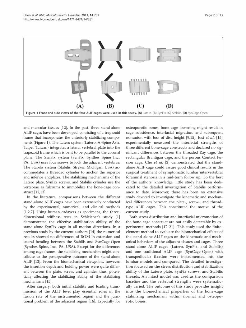
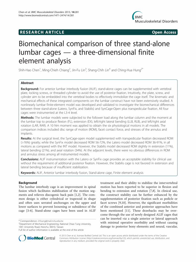
Figure 1 Front and side views of the four ALIF cages were used in this study. (A) Latero. (B) SynFix. (C) Stabilis. (D) SynCage-Open.
Chen et al. BMC Musculoskeletal Disorders 2013, 14:281 Page 2 of 13http://www.biomedcentral.com/1471-2474/14/281
and muscular tissues [12]. In the past, three stand-aloneALIF cages have been developed, consisting of a trapezoidframe that incorporates the anteriorly stabilizing compo-nents (Figure 1). The Latero system (Latero; A-Spine Asia,Taipei, Taiwan) integrates a lateral vertebral plate into thetrapezoid frame which is bent to be parallel to the coronalplane. The SynFix system (SynFix; Synthes Spine Inc.,PA, USA) uses four screws to lock the adjacent vertebrae.The Stabilis system (Stabilis; Stryker, Michigan, USA) ac-commodates a threaded cylinder to anchor the superiorand inferior endplates. The stabilizing mechanisms of theLatero plate, SynFix screws, and Stabilis cylinder use thevertebrae as fulcrums to immobilize the bone-cage con-struct [12,13].In the literature, comparisons between the different
stand-alone ALIF cages have been extensively conductedby the experimental, numerical, and clinical methods[1,2,7]. Using human cadavers as specimens, the three-dimensional stiffness tests in Schleicher’s study [1]demonstrated the effective stabilization ability of thestand-alone SynFix cage in all motion directions. In aprevious study by the current authors [14] the numericalresults showed no differences of ROM in extension andlateral bending between the Stabilis and SynCage-Open(Synthes Spine, Inc., PA, USA). Except for the differencesamong cage frames, the stabilizing mechanism might con-tribute to the postoperative outcome of the stand-aloneALIF [12]. From the biomechanical viewpoint, however,the insertion depth and holding power were quite differ-ent between the plate, screw, and cylinder, thus, poten-tially affecting the stabilizing ability of the stabilizingmechanisms [15].After surgery, both initial stability and loading trans-
mission of the ALIF level play essential roles in thefusion rate of the instrumented region and the junc-tional problem of the adjacent region [16]. Especially for
osteoporotic bones, bone-cage loosening might result incage subsidence, interfacial migration, and subsequentnonunion with loss of disc height [9,15]. Jost et al. [15]experimentally measured the interfacial strengths ofthree different bone-cage constructs and declared no sig-nificant differences between the threaded Ray cage, therectangular Brantigan cage, and the porous Contact Fu-sion cage. Cho et al. [2] demonstrated that the stand-alone ALIF cage could assure good clinical results in thesurgical treatment of symptomatic lumbar intervertebralforaminal stenosis in a mid-term follow up. To the bestof the authors’ knowledge, little study has been dedi-cated to the detailed investigation of Stabilis perform-ance to date. Moreover, there has been no extensivestudy devoted to investigate the kinematic and mechan-ical differences between the plate-, screw-, and thread-type ALIF cages. This constituted the motive of thecurrent study.Both stress distribution and interfacial micromotion of
the bone-cage construct are not easily detectable by ex-perimental methods [17-21]. This study used the finite-element method to evaluate the biomechanical effects ofthe stand-alone ALIF cages on the kinematic and mech-anical behaviors of the adjacent tissues and cages. Threestand-alone ALIF cages (Latero, SynFix, and Stabilis)and one traditional ALIF cage (SynCage-Open) withtranspedicular fixation were instrumented into thelumbar models and compared. The detailed investiga-tion focused on the stress distribution and stabilizationability of the Latero plate, SynFix screws, and Stabilisthreads. An intact model was used as the comparisonbaseline and the vertebral strengths were systematic-ally varied. The outcome of this study provides insightinto the biomechanical properties of the bone-cagestabilizing mechanism within normal and osteopo-rotic bones.
Chen et al. BMC Musculoskeletal Disorders 2013, 14:281 Page 3 of 13http://www.biomedcentral.com/1471-2474/14/281
MethodsOne intact and four instrumented models of the lumbarspine were constructed in this study. The first was theintact model (INT model) to serve as the comparisonbaseline. The other four models were instrumentedwith ALIF cages (Latero, SynFix, Stabilis, and SynCage-Open) and/or transpedicular fixation at the L3-4 level(Figures 1c-d).
Intact modelsA three-dimensional nonlinear model of the lumbarspine was constructed from L1 to L5 levels (Figure 2).The lumbar geometry was reconstructed from 1-mmcomputed tomography scans of a middle-aged male. TheCT-scanning images of only one vertebra were used tobuild the entire lumbar column. The other vertebraewere duplicated and spanned by the intervertebral discsthat were manually developed by the CAD software.This makes the vertebral bodies, posterior elements, andassociated processes quite similar in shape and size. Thepre-procedures of the lumbar FE model were establishedusing ANSYS, Ed.9.0 software (ANSYS Inc., Canonsburg,PA, USA). The INT model was an osseo-ligamentouslumbar spine which includes the vertebrae, intervertebraldiscs, endplates, posterior elements, and all seven liga-ments. The eight-node solid elements were used formodeling the cortical bone, cancellous bone, posteriorelement, and endplate. The material properties of all tis-sues were assumed to be homogeneous and transverselyisotropic [22]. The intervertebral disc consisted of annu-lus ground substance, nucleus pulpous, and collagen
Figure 2 The lumbar finite-element model used in this study. (A) Intac(C) Four ALIF cages instrumented at the L3-4 level.
fibers embedded in the ground substance. Thenonlinear annulus ground substance was simulated byusing the hyper-elastic Mooney-Rivlin formulation [23].In the radial direction, twelve double cross-linked fiberlayers were defined to decrease elastic strength propor-tionally from the outermost layer to the innermost. Thecollagen fibers in different annulus layers were strength-ened by the weight factor using the approach from aprevious study by the current authors [20]. The weightfactors of the elastic modulus were 1.0 at outermostlayers, 1–3, 0.9 at layers 4–6, 0.75 at layers 7–9, and0.65 at the innermost layers, 10–12. The nucleuspulpous was modeled as an incompressible fluid with abulk modulus of 1666.7 MPa by eight-node fluid ele-ments [22].No morphological change in vertebrae was simulated in
this study. Only decrease in vertebral strength was as-sumed to model the biomechanical property of the osteo-porotic bone. There were two vertebral strengthssimulated in this study: normal and osteoporotic models.Compared to the normal bone, “osteoporosis” was definedas a decrease of 66% in the elastic modulus for cancellousbone and a decrease of 33% for the cortical bone [24]. Allseven ligaments and collagen fibers were simulated bytwo-node bilinear link elements with uniaxial tensionresistance only, which were arranged in an anatomicallycorrect direction [25]. The cross-sectional areas of eachligament and material properties of the spine wereobtained from previous studies (Table 1) [20,22,23,25].The facet joint was modeled with sliding and non-penetrating behavior using an eight-node surface-to
t model from L1 to L5 levels. (B) Instrumented model at the L3-4 level.
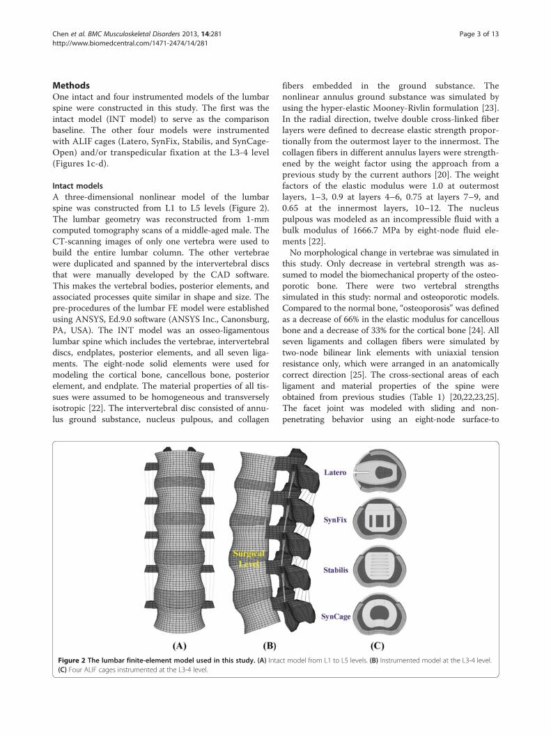
Table 1 Material properties used in the FE model
Material Element Type Young’s Modulus (MPa) Area(mm2)
Reference
Poisson’s Ratio
Bone Ex = 11300 vxy = 0.484 [22]
Cortical 8-node SOLID185 Ey = 11300 vxz = 0.203
Ez = 22000 vyz = 0.203
Gx = 3800
Gy = 5400
Gz = 5400
Cancellous 8-node SOLID185 Ex = 140 vxy = 0.45 [22]
Ey = 140 vxz = 0.315
Ez = 200 vyz = 0.315
Gx = 48.3
Gy = 48.3
Gz = 48.3
Posterior bone 8-node SOLID185 3500 0.25 - [22]
Disc [22]
Nucleus pulposus 8-node FLUID80 1666.7 - - [22]
Ground Substance 8-node SOLID185 C10 = 0.42 - -
C01 = 0.105
Annulus fibers 2-node LINK10 [23]
Outermost 550 - 0.76
Second 495 - 0.5923
Third 412.5 - 0.4712
Innermost 357.5 - 0.3572
Cartilaginous Endplates 8-node SOLID185 24 0.4 - [22]
Ligaments 2-node LINK10 [25]
ALL 7.8 - 24
PLL 10 - 14.4
TL 10 - 3.6
LF 15 - 40
ISL 10 - 26
SSL 8 - 23
CL 7.5 - 30
Latero (PEEK) 8-node SOLID185 6500 0.2
Latero-plate (Titanium alloy) 8-node SOLID185 110000 0.3
SynFix-LR (PEEK) 8-node SOLID185 6500 0.2
Locking screw (Titanium alloy) 8-node SOLID185 110000 0.3
Stabilis (Titanium alloy) 8-node SOLID185 110000 0.3
SynCage-Open (Titanium alloy) 8-node SOLID185 110000 0.3 -
Pedicle screw (Titanium alloy) 8-node SOLID185 110000 0.3
ALL anterior longitudinal ligament; PLL posterior longitudinal ligament; TL transverse ligament; LF ligamentum flavum; ISL interspinous ligament; SSL supraspinousligament; CL capsular ligament.
Chen et al. BMC Musculoskeletal Disorders 2013, 14:281 Page 4 of 13http://www.biomedcentral.com/1471-2474/14/281
-surface contact element which can slide between three-dimensional target surfaces. The initial gap between apaired facet was kept within 0.5 mm and the coefficient offriction was set at 0.1 [20,22].
ALIF modelsThe Latero cage can be interlocked with a bent lateralplate that is inserted parallel to the coronal plane andinto the vertebral bodies, thus preventing cage loosening.
Chen et al. BMC Musculoskeletal Disorders 2013, 14:281 Page 5 of 13http://www.biomedcentral.com/1471-2474/14/281
The SynFix cage consists of a trapezoid frame incorpo-rated with an anterior plate and screws to stabilize thecage body. The Stabilis cage is a trapezoid frame with athreaded cylinder at the middle region to increase thebone-purchasing ability. Without the serrated anchor-ages, the final ALIF model of the SynCage-Open cage isfurther instrumented with bilateral pedicle screws to en-hance the construct stability. The models of all cage sys-tems were established by SolidWorks, Ed. 2012 software(SolidWorks Corporation, Concord, MA, USA). Thespikes of the Latero cage and the screw threads of theSynFix cage were omitted to simplify numerical calcula-tion (Figure 1).For ALIF simulation, the L3-4 level of the INT model
underwent partial discectomy and total nuclectomy. Forthe SynFix, Stabilis and SynCage-Open models, the an-terior approach was used to remove the anterior longitu-dinal ligament, anterior and a half inner layer of theannulus, and the entire nucleus pulpous. For the Lateromodel, the lateral approach was adapted to remove thelateral and a half inner layer of the annulus and the en-tire nucleus pulpous. All the other ligaments of the threemodels were preserved.Accordingly, the Latero, SynFix, Stabilis, and SynCage-
Open peek cages were modeled and inserted into the L3-4level. The friction coefficient of the bone-cage interfaceswas 0.8 to mimic a serrated surface for the initial stabilityof the trapezoid frame [14]. The SynCage-Open modelwas supplemented with bilateral transpedicular fixation. Inthe SynCage-Open and SynFix models, the pedicle screw(6-mm diameter) and locking screw (4-mm diameter)were respectively modeled with three-dimensional beamelements. The bone-screw interfaces were assumed to befully bonded to simulate intimate bone-screw purchase.The numbers of elements and nodes were 98,988/135,786,112,087/253,492, 114,849/162,169, and 106,436/180,875 forthe Latero, SynFix, Stabilis, and SynCage-Open models, re-spectively. The material properties of the ALIF cages, sup-plementary components, and transpedicular fixator werelisted in Table 1.
Finite-element analysesOnly vertical compression onto the lumbar top can po-tentially lead to excessive movement of the lumbar col-umn [16]. In this study, the follower load was used toconstrain each motion segment of the lumbar modelwith the two-node truss elements that induce contrac-tions for a given temperature change [26]. In principle,the ideal follower load remains tangent to the spinecurve, and each spinal segment is loaded in nearly purecompression without artifact motions. Using the trial-and-error method, the attached points of truss elementswere modified to optimize the follower load path ap-proximated through the instantaneous center of rotation
at each motion segment [27]. This study cautiously de-creased the temperature of the truss elements to producea 400-N follower load for minimizing the ROM of eachmotion segment (<0.2°). Subsequently, a 10-Nm momentwas applied to the lumbar top to simulate flexion-extension, left/right lateral bending, and left/right axial ro-tation, respectively. During simulation, the bottom of theL5 vertebral body was fixed completely. The comparisonindices were intersegmental ROM, facet force, and stressesof annulus, implant, and endplate. The annulus stress isthe stress of the ground substance. From the biomechan-ical viewpoint, the annulus fibers are mainly responsiblefor the tension. However, the ground substance can bearthe various loads that always exist within the interverte-bral discs. Previous in vitro studies demonstrated that adisc may prolapse under certain load combinations offlexion, lateral bending, axial rotation, and axial compres-sion [28-30]. Only the stress of the annulus fibers cannotprovide the sufficient information about the disc loads.Consequently, this study uses the stress of the groundsubstance as the index of the disc prolapse and herniation.
ResultsThis study used four parameters as the comparison indi-ces, including intersegmental ROMs, annulus stress,endplate stress, and facet contact forces (Figures 3, 4,5, 6, 7 and 8). There were five models: one intact (INT),3 stand-alone ALIF cages (Latero, SynFix, and Stabilis),and one established fixation (A +P: SynCage with transpedi-cular fixation). The ROM comparison of the instrumentedmodelswith normal andosteoporotic bonewas normalized bythecorrespondingvalueoftheintactmodel.
Convergence and validation of the intact modelThe convergence test consisted of three mesh qualities:4,750 elements / 4,960 nodes for the coarse model,27,244 elements / 30,630 nodes for normal model, and84,594 elements / 94,162 nodes for the finest model. Forthe finest mesh quality, the changes in total ROM wererespectively within 1.03% in flexion (< 0.2°), 4.39% in ex-tension (< 0.5°), 0.01% in torsion (<0.2°), and 0.001% inlateral bending (< 0.1°). Consequently, this study usedthe finest model to evaluate the biomechanical behaviorsof the INT and ALIF models under four physiologicalmotions.For model validation, the ROM changes in five levels
of the INT model were compared with the experi-mental results of Rohlmann’s study [27]. Under 3.75-and 7.5-Nm moments with 150-N preload, a previousstudy [31] by the current authors showed data of thecurrent INT model within the extreme values ofRohlmann’s results. Under a 10-Nm moment with150 N preload, however, the predicted ROMs of thisstudy were 6° to 11° less than those of the in vitro tests
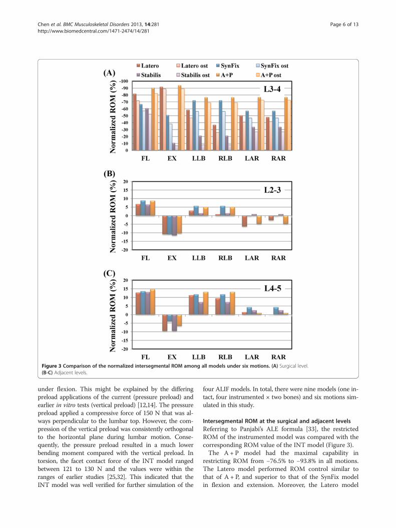
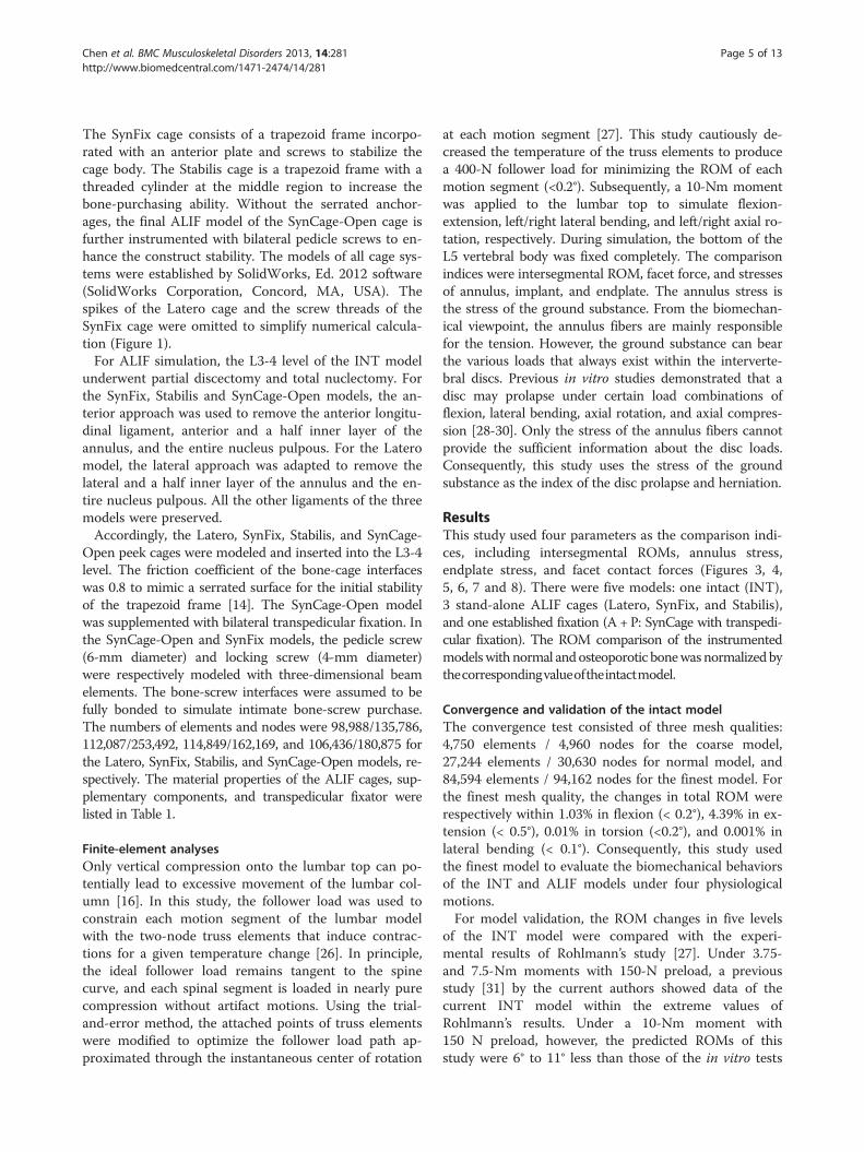
Figure 3 Comparison of the normalized intersegmental ROM among all models under six motions. (A) Surgical level.(B-C) Adjacent levels.
Chen et al. BMC Musculoskeletal Disorders 2013, 14:281 Page 6 of 13http://www.biomedcentral.com/1471-2474/14/281
under flexion. This might be explained by the differingpreload applications of the current (pressure preload) andearlier in vitro tests (vertical preload) [12,14]. The pressurepreload applied a compressive force of 150 N that was al-ways perpendicular to the lumbar top. However, the com-pression of the vertical preload was consistently orthogonalto the horizontal plane during lumbar motion. Conse-quently, the pressure preload resulted in a much lowerbending moment compared with the vertical preload. Intorsion, the facet contact force of the INT model rangedbetween 121 to 130 N and the values were within theranges of earlier studies [25,32]. This indicated that theINT model was well verified for further simulation of the
four ALIF models. In total, there were nine models (one in-tact, four instrumented × two bones) and six motions sim-ulated in this study.
Intersegmental ROM at the surgical and adjacent levelsReferring to Panjabi’s ALE formula [33], the restrictedROM of the instrumented model was compared with thecorresponding ROM value of the INT model (Figure 3).The A + P model had the maximal capability in
restricting ROM from −76.5% to −93.8% in all motions.The Latero model performed ROM control similar tothat of A + P, and superior to that of the SynFix modelin flexion and extension. Moreover, the Latero model
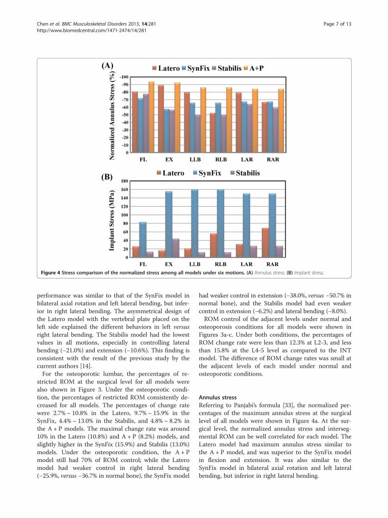
Figure 4 Stress comparison of the normalized stress among all models under six motions. (A) Annulus stress. (B) Implant stress.
Chen et al. BMC Musculoskeletal Disorders 2013, 14:281 Page 7 of 13http://www.biomedcentral.com/1471-2474/14/281
performance was similar to that of the SynFix model inbilateral axial rotation and left lateral bending, but infer-ior in right lateral bending. The asymmetrical design ofthe Latero model with the vertebral plate placed on theleft side explained the different behaviors in left versusright lateral bending. The Stabilis model had the lowestvalues in all motions, especially in controlling lateralbending (−21.0%) and extension (−10.6%). This finding isconsistent with the result of the previous study by thecurrent authors [14].For the osteoporotic lumbar, the percentages of re-
stricted ROM at the surgical level for all models werealso shown in Figure 3. Under the osteoporotic condi-tion, the percentages of restricted ROM consistently de-creased for all models. The percentages of change ratewere 2.7% ~ 10.8% in the Latero, 9.7% ~ 15.9% in theSynFix, 4.4% ~ 13.0% in the Stabilis, and 4.8% ~ 8.2% inthe A + P models. The maximal change rate was around10% in the Latero (10.8%) and A + P (8.2%) models, andslightly higher in the SynFix (15.9%) and Stabilis (13.0%)models. Under the osteoporotic condition, the A + Pmodel still had 70% of ROM control; while the Lateromodel had weaker control in right lateral bending(−25.9%, versus −36.7% in normal bone), the SynFix model
had weaker control in extension (−38.0%, versus −50.7% innormal bone), and the Stabilis model had even weakercontrol in extension (−6.2%) and lateral bending (−8.0%).ROM control of the adjacent levels under normal and
osteoporosis conditions for all models were shown inFigures 3a-c. Under both conditions, the percentages ofROM change rate were less than 12.3% at L2-3, and lessthan 15.8% at the L4-5 level as compared to the INTmodel. The difference of ROM change rates was small atthe adjacent levels of each model under normal andosteoporotic conditions.
Annulus stressReferring to Panjabi’s formula [33], the normalized per-centages of the maximum annulus stress at the surgicallevel of all models were shown in Figure 4a. At the sur-gical level, the normalized annulus stress and interseg-mental ROM can be well correlated for each model. TheLatero model had maximum annulus stress similar tothe A + P model, and was superior to the SynFix modelin flexion and extension. It was also similar to theSynFix model in bilateral axial rotation and left lateralbending, but inferior in right lateral bending.
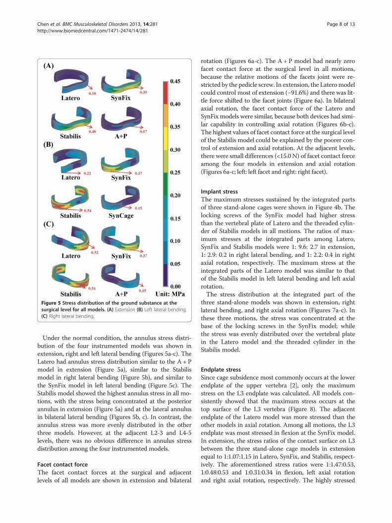
Figure 5 Stress distribution of the ground substance at thesurgical level for all models. (A) Extension (B) Left lateral bending.(C) Right lateral bending.
Chen et al. BMC Musculoskeletal Disorders 2013, 14:281 Page 8 of 13http://www.biomedcentral.com/1471-2474/14/281
Under the normal condition, the annulus stress distri-bution of the four instrumented models was shown inextension, right and left lateral bending (Figures 5a-c). TheLatero had annulus stress distribution similar to the A + Pmodel in extension (Figure 5a), similar to the Stabilismodel in right lateral bending (Figure 5b), and similar tothe SynFix model in left lateral bending (Figure 5c). TheStabilis model showed the highest annulus stress in all mo-tions, with the stress being concentrated at the posteriorannulus in extension (Figure 5a) and at the lateral annulusin bilateral lateral bending (Figures 5b, c). In contrast, theannulus stress was more evenly distributed in the otherthree models. However, at the adjacent L2-3 and L4-5levels, there was no obvious difference in annulus stressdistribution among the four instrumented models.
Facet contact forceThe facet contact forces at the surgical and adjacentlevels of all models are shown in extension and bilateral
rotation (Figures 6a-c). The A + P model had nearly zerofacet contact force at the surgical level in all motions,because the relative motions of the facets joint were re-stricted by the pedicle screw. In extension, the Lateromodelcould control most of extension (−91.6%) and there was lit-tle force shifted to the facet joints (Figure 6a). In bilateralaxial rotation, the facet contact force of the Latero andSynFix models were similar, because both devices had simi-lar capability in controlling axial rotation (Figures 6b-c).The highest values of facet contact force at the surgical levelof the Stabilis model could be explained by the poorer con-trol of extension and axial rotation. At the adjacent levels,there were small differences (<15.0 N) of facet contact forceamong the four models in extension and axial rotation(Figures 6a-c; left: left facet and right: right facet).
Implant stressThe maximum stresses sustained by the integrated partsof three stand-alone cages were shown in Figure 4b. Thelocking screws of the SynFix model had higher stressthan the vertebral plate of Latero and the threaded cylin-der of Stabilis models in all motions. The ratios of max-imum stresses at the integrated parts among Latero,SynFix and Stabilis models were 1: 9.6: 2.7 in extension,1: 2.9: 0.2 in right lateral bending, and 1: 2.2: 0.4 in rightaxial rotation, respectively. The maximum stress at theintegrated parts of the Latero model was similar to thatof the Stabilis model in left lateral bending and left axialrotation.The stress distribution at the integrated part of the
three stand-alone models was shown in extension, rightlateral bending, and right axial rotation (Figures 7a-c). Inthese three motions, the stress was concentrated at thebase of the locking screws in the SynFix model; whilethe stress was evenly distributed over the vertebral platein the Latero model and the threaded cylinder in theStabilis model.
Endplate stressSince cage subsidence most commonly occurs at the lowerendplate of the upper vertebra [2], only the maximumstress on the L3 endplate was calculated. All models con-sistently showed that the maximum stress occurs at thetop surface of the L3 vertebra (Figure 8). The adjacentendplate of the Latero model was more stressed than theother models in axial rotation. Among all motions, the L3endplate was most stressed in flexion at the SynFix model.In extension, the stress ratios of the contact surface on L3between the three stand-alone cage models in extensionequal to 1:1.07:1.15 in Latero, SynFix, and Stabilis, respect-ively. The aforementioned stress ratios were 1:1.47:0.53,1:0.48:0.53 and 1:0.31:0.34 in flexion, left axial rotationand right axial rotation, respectively. The highly stressed
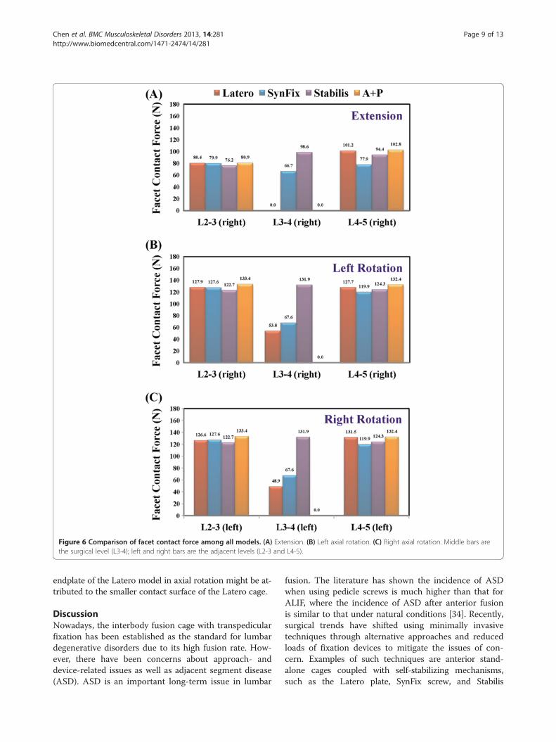
Figure 6 Comparison of facet contact force among all models. (A) Extension. (B) Left axial rotation. (C) Right axial rotation. Middle bars arethe surgical level (L3-4); left and right bars are the adjacent levels (L2-3 and L4-5).
Chen et al. BMC Musculoskeletal Disorders 2013, 14:281 Page 9 of 13http://www.biomedcentral.com/1471-2474/14/281
endplate of the Latero model in axial rotation might be at-tributed to the smaller contact surface of the Latero cage.
DiscussionNowadays, the interbody fusion cage with transpedicularfixation has been established as the standard for lumbardegenerative disorders due to its high fusion rate. How-ever, there have been concerns about approach- anddevice-related issues as well as adjacent segment disease(ASD). ASD is an important long-term issue in lumbar
fusion. The literature has shown the incidence of ASDwhen using pedicle screws is much higher than that forALIF, where the incidence of ASD after anterior fusionis similar to that under natural conditions [34]. Recently,surgical trends have shifted using minimally invasivetechniques through alternative approaches and reducedloads of fixation devices to mitigate the issues of con-cern. Examples of such techniques are anterior stand-alone cages coupled with self-stabilizing mechanisms,such as the Latero plate, SynFix screw, and Stabilis
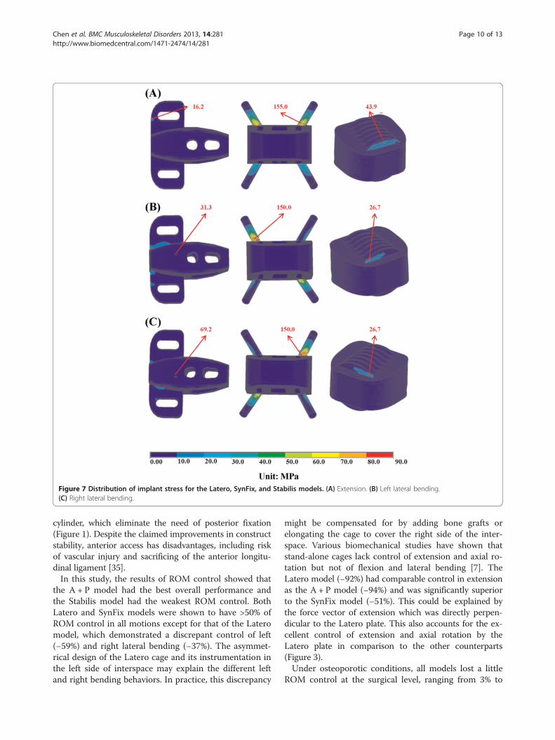
Figure 7 Distribution of implant stress for the Latero, SynFix, and Stabilis models. (A) Extension. (B) Left lateral bending.(C) Right lateral bending.
Chen et al. BMC Musculoskeletal Disorders 2013, 14:281 Page 10 of 13http://www.biomedcentral.com/1471-2474/14/281
cylinder, which eliminate the need of posterior fixation(Figure 1). Despite the claimed improvements in constructstability, anterior access has disadvantages, including riskof vascular injury and sacrificing of the anterior longitu-dinal ligament [35].In this study, the results of ROM control showed that
the A + P model had the best overall performance andthe Stabilis model had the weakest ROM control. BothLatero and SynFix models were shown to have >50% ofROM control in all motions except for that of the Lateromodel, which demonstrated a discrepant control of left(−59%) and right lateral bending (−37%). The asymmet-rical design of the Latero cage and its instrumentation inthe left side of interspace may explain the different leftand right bending behaviors. In practice, this discrepancy
might be compensated for by adding bone grafts orelongating the cage to cover the right side of the inter-space. Various biomechanical studies have shown thatstand-alone cages lack control of extension and axial ro-tation but not of flexion and lateral bending [7]. TheLatero model (−92%) had comparable control in extensionas the A + P model (−94%) and was significantly superiorto the SynFix model (−51%). This could be explained bythe force vector of extension which was directly perpen-dicular to the Latero plate. This also accounts for the ex-cellent control of extension and axial rotation by theLatero plate in comparison to the other counterparts(Figure 3).Under osteoporotic conditions, all models lost a little
ROM control at the surgical level, ranging from 3% to
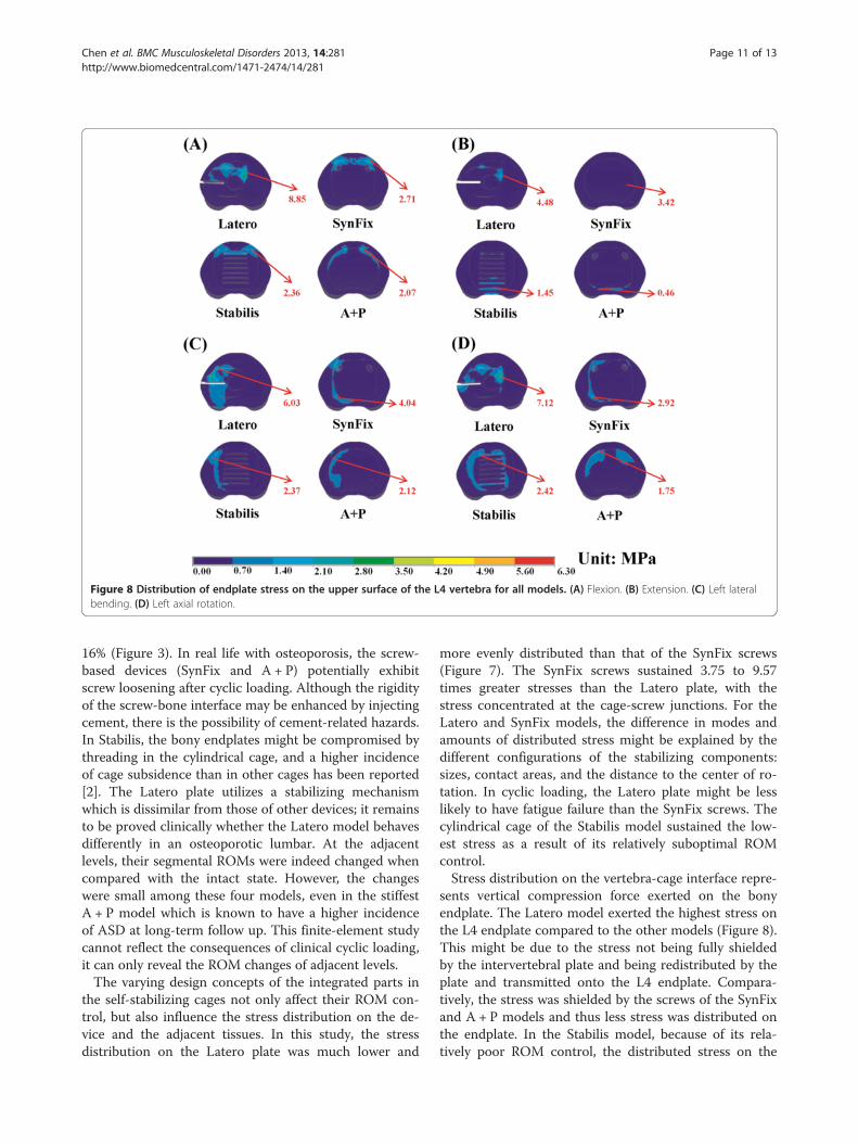
Figure 8 Distribution of endplate stress on the upper surface of the L4 vertebra for all models. (A) Flexion. (B) Extension. (C) Left lateralbending. (D) Left axial rotation.
Chen et al. BMC Musculoskeletal Disorders 2013, 14:281 Page 11 of 13http://www.biomedcentral.com/1471-2474/14/281
16% (Figure 3). In real life with osteoporosis, the screw-based devices (SynFix and A + P) potentially exhibitscrew loosening after cyclic loading. Although the rigidityof the screw-bone interface may be enhanced by injectingcement, there is the possibility of cement-related hazards.In Stabilis, the bony endplates might be compromised bythreading in the cylindrical cage, and a higher incidenceof cage subsidence than in other cages has been reported[2]. The Latero plate utilizes a stabilizing mechanismwhich is dissimilar from those of other devices; it remainsto be proved clinically whether the Latero model behavesdifferently in an osteoporotic lumbar. At the adjacentlevels, their segmental ROMs were indeed changed whencompared with the intact state. However, the changeswere small among these four models, even in the stiffestA + P model which is known to have a higher incidenceof ASD at long-term follow up. This finite-element studycannot reflect the consequences of clinical cyclic loading,it can only reveal the ROM changes of adjacent levels.The varying design concepts of the integrated parts in
the self-stabilizing cages not only affect their ROM con-trol, but also influence the stress distribution on the de-vice and the adjacent tissues. In this study, the stressdistribution on the Latero plate was much lower and
more evenly distributed than that of the SynFix screws(Figure 7). The SynFix screws sustained 3.75 to 9.57times greater stresses than the Latero plate, with thestress concentrated at the cage-screw junctions. For theLatero and SynFix models, the difference in modes andamounts of distributed stress might be explained by thedifferent configurations of the stabilizing components:sizes, contact areas, and the distance to the center of ro-tation. In cyclic loading, the Latero plate might be lesslikely to have fatigue failure than the SynFix screws. Thecylindrical cage of the Stabilis model sustained the low-est stress as a result of its relatively suboptimal ROMcontrol.Stress distribution on the vertebra-cage interface repre-
sents vertical compression force exerted on the bonyendplate. The Latero model exerted the highest stress onthe L4 endplate compared to the other models (Figure 8).This might be due to the stress not being fully shieldedby the intervertebral plate and being redistributed by theplate and transmitted onto the L4 endplate. Compara-tively, the stress was shielded by the screws of the SynFixand A + P models and thus less stress was distributed onthe endplate. In the Stabilis model, because of its rela-tively poor ROM control, the distributed stress on the
Chen et al. BMC Musculoskeletal Disorders 2013, 14:281 Page 12 of 13http://www.biomedcentral.com/1471-2474/14/281
endplate was less than in the other three models. Therewere two biomechanical implications in the Lateromodel, which had higher vertical load on the L4 endplatethan the other counterparts. The first implication indi-cates that higher vertebral stress may increase the inci-dence of cage subsidence particularly in suboptimal bonedensity. On the other hand, unshielded vertical load maybe beneficial for graft consolidation according to Wolff'slaw.After interbody fusion, abnormally high transmission of
loads to the facet joints may ultimately result in arthriticchanges. At the surgical level, when comparing the threestand-alone cage models, the Latero model was shown tohave the lowest values of facet contact force in bilateralrotation and was near absent in extension (Figure 6). Thefacet joints at the surgical level seemed to be relativelywell protected in the Latero model in comparison to theSynFix and Stabilis models. At the adjacent levels, therewere few differences of facet contact force among all fourinstrumented models. This indicates that the reasons forthe degenerative facet joints at the adjacent levels mightbe attributed to the other clinical factors.Distribution of annulus stress can provide the clinical
implication that higher stress may result in annulus dis-ruption and disc herniation [28-30]. At the surgical levelfor the four instrumented models, the distribution of an-nulus stress was well correlated inversely to their ROMcontrol (Figures 3, 4a). At right lateral bending, the highestannulus stress was found in the Latero model, where itwas concentrated at the right annulus. This correspondedto the relatively inferior control of the Latero due to itsasymmetrical design. The posterior and left sides of annu-lus in the Stabilis model sustained the highest stress at ex-tension and lateral bending, which manifested in itsinferior control of those moments.
ConclusionsThere were several limitations inherent in this study. Bonefusion was not included and only the effect of the initialstability was considered for the stand-alone cages. Degen-erative discs are common in most patients with ALIF sur-gery; however, it is challenging in modeling to assignmaterial properties to various grades of degenerative discs,such as delamination, dehydration, or reduced disc height.These variations of the lumbar tissues were not included inthis study. In addition, the geometry of implants was some-what simplified for mesh modeling. This study was notconcerned with the effect of bone ingrowth into the cageand ligament pretension after inserting the implants. Thestabilizing behaviors of trunk muscles were mimicked bythe follower load that has been extensively used in relatedin vitro tests [16,27]. However, the real situations of musclecontraction and complicated external load conditionsin vivo were not investigated. The fatigue failure of the
cages’ components was not studied in the static simulationand the current authors we recommend that they shouldbe evaluated by experimental or clinical observation.In conclusion, this study extensively compared the sta-
bilizing mechanisms of three stand-alone ALIF cages. Thevertebral plate of the Latero model provided sufficientability in stabilizing intersegmental motions: it was com-parable to the A + P model in flexion and extension, com-parable to the SynFix in bilateral axial rotation and leftlateral bending, and inferior but compensable in right lat-eral bending. In contrast, the Stabilis model was less favor-able due to its poorer control in extension and lateralbending. Further experimental and clinical studies shouldbe conducted to validate the numerical observations.
AbbreviationsALIF: Anterior lumbar interbody fusion; INT: Intact model; A + P: Model,SynCage with transpedicular fixation; ROM: Range of motion; FL: Flexion;EX: Extension; LLB: Left lateral bending; RLB: Right lateral bending; LAR: Leftaxial rotation; RAR: Right lateral bending.
Competing interestsThe authors declare that they have no competing interests.
Authors’ contributionsMCC participated in the study design, in collecting the data, the statisticallyanalyses and drafting of the manuscript. SHC, JFL and CHH participated inthe study design. SCL advised and assisted drafting of the manuscript. Allauthors read and approved the final manuscript.
AcknowledgementsThis study was supported by a grant from the National Science Council ofthe Republic of China. The computing facilities provided by the NationalCenter for High-Performance Computing are greatly appreciated.
Author details1Department of Orthopedics, Tzu-Chi General Hospital at Taichung and TzuChi University, Taichung, Taiwan. 2Department of Mechanical Engineering,National Chiao Tung University, 1001 University Road, Hsinchu 30010,Taiwan. 3BoneCare Orthopedic Centers, Han-Chiung Clinics, Taipei, Taiwan.4Graduate Institute of Biomedical Engineering, National Taiwan University ofScience and Technology, Taipei, Taiwan.
Received: 6 March 2013 Accepted: 24 September 2013Published: 2 October 2013
References1. Schleicher P, Gerlach R, Schár B, Cain CM, Achatz W, Pflugmacher R, Haas NP,
Kandziora F: Biomechanical comparison of two different concepts forstand alone anterior lumbar interbody fusion. Eur Spine J 2008,17:1757–1765.
2. Cho CB, Ryu KS, Park CK: Anterior lumbar interbody fusion with stand-alone interbody cage in treatment of lumbar intervertebral foraminalstenosis: comparative study of two different types of cages.J Korean Neurosurg Soc 2010, 47:352–357.
3. Brantigan JW, Steffee AD, Lewis ML, Quinn LM, Persenaire JM:Lumbar interbody fusion using the Brantigan I/F cage for posteriorlumbar interbody fusion and the variable pedicle screw placementsystem: two-year results from a Food and Drug Administrationinvestigational device exemption clinical trial. Spine 2000, 25:1437–1446.
4. Kuslich SD, Danielson G, Dowdle JD, Sherman J, Fredrickson B, Yuan H,Griffith SL: Four-year follow-up results of lumbar spine arthrodesis usingthe Bagby and Kuslich lumbar fusion cage. Spine 2000, 25:2656–2662.
5. Pavlov PW, Spruit M, Havinga M, Anderson PG, van Limbeek J, Jacobs WC:Anterior lumbar interbody fusion with threaded fusion cages andautologous bone grafts. Eur Spine J 2000, 9:224–229.
Chen et al. BMC Musculoskeletal Disorders 2013, 14:281 Page 13 of 13http://www.biomedcentral.com/1471-2474/14/281
6. Steffen T, Tsantrizos A, Aebi M: Effect of implant design and endplatepreparation on the compressive strength of interbody fusion constructs.Spine 2000, 25:1077–1084.
7. Oxland TR, Lund T: Biomechanics of stand-alone cages and cages incombination with posterior fixation: a literature review. Eur Spine J 2000,9:S95–S101.
8. Steffen T, Tsantrizos A, Fruth I, Aebi M: Cage: designs and concepts.Eur Spine J 2000, 9:S89–S94.
9. Costa F, Sassi M, Ortolina A, Cardia A, Assietti R, Zerbi A, Lorenzetti M,Galbusera F, Fornari M: Stand-alone cage for posterior lumbar interbodyfusion in the treatment of high-degree degenerative disc disease: designof a new device for an “old” technique. A prospective study on a seriesof 116 patients. Eur Spine J 2011, 20:S46–S56.
10. Tsuang YH, Chiang YF, Hung CY, Wei HW, Huang CH, Cheng CK:Comparison of cage application modality in posterior lumbar interbodyfusion with posterior instrumentation—A finite element study.Med Eng Phys 2009, 31:565–570.
11. Lin RM, Huang KY, Lai KA: Mini-open anterior spine surgery for anteriorlumbar diseases. Eur Spine J 2008, 17:691–697.
12. Cain CM, Schleicher P, Gerlach R, Pflugmacher R, Scholz M, Kandziora F:A new stand-alone anterior lumbar interbody fusion device:biomechanical comparison with established fixation techniques.Spine 2005, 30(23):2631–2636.
13. Kim Y: Finite element analysis of anterior lumbar interbody fusion:threaded cylindrical cage and pedicle screw fixation. Spine 2007,32:2558–2568.
14. Chen SH, Tai CL, Lin CY, Hsieh PH, Chen WP: Biomechanical comparison ofa new stand-alone anterior lumbar interbody fusion cage withestablished fixation techniques - a three-dimensional finite elementanalysis. BMC Musculoskelet Disord 2008, 9:88.
15. Jost B, Cripton PA, Lund T, Oxland TR, Lippuner K, Jaeger P, Nolte LP:Compressive strength of interbody cages in the lumbar spine: the effectof cage shape, posterior instrumentation and bone density.Eur Spine J 1998, 7:132–141.
16. Patwardhan AG, Havey RM, Meade KP, Lee B, Dunlap B: A follower loadincreases the load-carrying capacity of the lumbar spine in compression.Spine 1999, 24:1003–1009.
17. Kettler A, Wilke HJ, Dietl R, Krammer M, Lumenta C, Claes L: Stabilizingeffect of posterior lumbar interbody fusion cages before and after cyclicloading. J Neurosurg 2000, 92:87–92.
18. Kim Y: Prediction of mechanical behaviors at interfaces between boneand two interbody cages of lumbar spine segments. Spine 2001,26:1437–1442.
19. Oxland TR, Lund T, Jost B, Cripton P, Lippuner K, Jaeger P, Nolte LP:The relative importance of vertebral bone density and disc degenerationin spinal flexibility and interbody implant performance. Spine 1996,21:2558–2569.
20. Polikeit A, Ferguson SJ, Nolte LP, Orr TE: Factors influencing stresses in thelumbar spine after the insertion of intervertebral cages: finite elementanalysis. Eur Spine J 2003, 12:413–420.
21. Silva MJ, Keaveny TM, Hayes WC: Load sharing between the shell andcentrum in the lumbar vertebral body. Spine 1997, 22:140–150.
22. Lu YM, Hutton WC, Gharpuray VM: Do bending, twisting, and diurnal fluidchanges in the disc affect the propensity to prolapse? A viscoelasticfinite element model. Spine Nov 1996, 21(22):2570–2579.
23. Schmidt H, Heuer F, Simon U, Kettler A, Rohlmann A, Claes L, Wilke HJ:Application of a new calibration method for a three-dimensional finiteelement model of a human lumbar annulus fibrosus. Clin Biomech(Bristol, Avon) May 2006, 21(4):337–344.
24. Carter DR, Hayes WC: The compressive behavior of bone as a two-phaseporous structure. J Bone Joint Surg Am 1977, 59(7):954–62.
25. Goel VK, Monroe BT, Gilbertson LG, Brinckmann P: Interlaminar shearstresses and laminae separation in a disc. Finite element analysis of theL3-L4 motion segment subjected to axial compressive loads. Spine 1995,20:689–698.
26. Renner SM, Natarajan RN, Patwardhan AG, Havey RM, Voronov LI, Guo BY,Andersson GB, An HS: Novel model to analyze the effect of a largecompressive follower pre-load on range of motions in a lumbar spine.J Biomech 2007, 40:1326–1332.
27. Rohlmann A, Neller S, Claes L, Bergmann G, Wilke HJ: Influence of afollower load on intradiscal pressure and intersegmental rotation of thelumbar spine. Spine 2001, 26:E557–E561.
28. Edwards WT, Ordway NR, Zheng Y, McCullen G, Han Z, Yuan HA:Peak stresses observed in the posterior lateral anulus.Spine 2001, 26:1753–1759.
29. Adams MA, Hutton WC: The mechanics of prolapsed intervertebral disc.Int Orthopaed 1982, 6:249–253.
30. McNally DS, Adams MA, Goodship AE: Can intervertebral disc prolapse bepredicted by disc mechanics? Spine 1993, 18:1525–1530.
31. Chen SH, Zhong ZC, Chen CS, Chen WJ, Hung C: Biomechanicalcomparison between lumbar disc arthroplasty and fusion. Med Eng Phys2009, 31:244–253.
32. Goel VK, Kong W, Han JS, Weinstein JN, Gilbertson LG: A combined finiteelement and optimization investigation of lumbar spine mechanics withand without muscles. Spine 1993, 18:1531–1541.
33. Panjabi MM: Hybrid multidirectional test method to evaluate spinaladjacent-level effects. Clin Biomech 2007, 22:257–265.
34. Bae JS, Lee SH, Kim JS, Jung B, Choi G: Adjacent segment degenerationafter lumbar interbody fusion with percutaneous pedicle screw fixationfor adult low-grade isthmic spondylolisthesis: minimum 3 years offollow-up. Neurosurg. 2010, 67:1600–1607.
35. Ploumis A, Wu C, Fischer G, Mehbod AA, Wu W, Faundez A, Transfeldt EE:Biomechanical comparison of anterior lumbar interbody fusion andtransforaminal lumbar interbody fusion. J Spinal Disord Tech 2008,21:120–125.
doi:10.1186/1471-2474-14-281Cite this article as: Chen et al.: Biomechanical comparison of threestand-alone lumbar cages — a three-dimensional finite elementanalysis. BMC Musculoskeletal Disorders 2013 14:281.
Submit your next manuscript to BioMed Centraland take full advantage of:
• Convenient online submission
• Thorough peer review
• No space constraints or color figure charges
• Immediate publication on acceptance
• Inclusion in PubMed, CAS, Scopus and Google Scholar
• Research which is freely available for redistribution
Submit your manuscript at www.biomedcentral.com/submit