Embed Size (px)
Citation preview

Hindawi Publishing CorporationISRN Industrial EngineeringVolume 2013 Article ID 869736 10 pageshttpdxdoiorg1011552013869736
Research ArticleModeling and Analysis of Injection Moulding ProcessParameters for Plastic Gear Industry Application
Nik Mizamzul Mehat12 Shahrul Kamaruddin2 and Abdul Rahim Othman2
1 Department of Mould Technology Kolej Kemahiran Tinggi MARA Balik Pulau Genting 11000 Balik Pulau Penang Malaysia2 School of Mechanical Engineering Universiti Sains Malaysia Engineering Campus 14300 Nibong Tebal Penang Malaysia
Correspondence should be addressed to Shahrul Kamaruddin meshahengusmmy
Received 18 April 2013 Accepted 8 May 2013
Academic Editors A Gomez and J Wei
Copyright copy 2013 Nik Mizamzul Mehat et al This is an open access article distributed under the Creative Commons AttributionLicense which permits unrestricted use distribution and reproduction in any medium provided the original work is properlycited
The performance of plastic gears in wide variety of power and motion transmission applications is rather limited due to weakmechanical properties and divergentmechanism of failures Amethodical simulation is carried out to analyze the gear performancewith various gating system types gate locations and processing parameters via grey-based Taguchi optimization methodWith theobtained optimum results in simulation stage the flow patterns of polymer melt inside the mould during filling packing andcooling processes are studied and the plastic gear failures mechanism related to processing parameters are predicted The outputresults in the future can be used as guidance in selecting the appropriatematerials improving part andmould design and predictingthe performance of the plastic gear before the real process of the part manufacturing takes place
1 Introduction
Gears have been in use for more than three thousand yearsand commonly utilized in power and motion transmissionunder different loads and speeds Due to the fiscal andpractical advantages the demand of using plastics in gearingindustry is significantly increased and indubitably continuesin the future In comparing with metal gears plastic gearshave several advantages such as light weight noiseless run-ning resistance to corrosion lower coefficients of frictionand ability to run under none lubricated conditions [1 2]Plastic gears can be produced by hobbing or shaping likewiseto metal gears or alternatively by injection moulding Withthe continuous expansion of technology plastic injectionmoulding bears itself to considerably more economicalmeans of mass production to meet the rapidly rising marketdemand of plastic gearing in various applications Injectionmoulded plastic gears have been used with success in theautomotive industry officemachines and household utensilsin food and textile machinery as well as a host of otherapplicationsrsquo areas [3] Unlike metal gears the potential usesof plastic gear however are rather limited due to weakmechanical properties poor heat conductors and tendency
to undergo creep [4] Apart from that the plastic gear toothexperiences complex stresses during service and can fail bydivergent mechanism Investigations on plastic gear failureswere extensively conducted Senthilvelan andGnanamoorthy[5] observed different types of failures on the Nylon 66 spurgears such as gear tooth wear cracking at the tooth surfacetooth root cracking and severe shape deformation In thereview work of Breeds et al [6] and Hooke et al [7] a sharpincrease in wear loss over the addendum and dedendum ofacetal gears is also observed to be strikingly different resultingfrom the differences in friction forces and increasing torqueon each gear face during the running operation Despitewear failure plastic base gears in addition are sensitive totemperature due to heat generation during service whichresulted in surface fatigue and fatigue cracking at tooth rootacceleration [8] On the other report of Osman and Velex [9]plastic gears can also fail due to contact fatigue or surfacepitting as a result of dynamic tooth loads during the runningoperation
Referring to the modes of failures there are many factorscontributing to the occurrence of plastic gear deficienciesMaterial selection for the gears in instance is a criticaldecision in manufacturing the plastic gear by using injection
2 ISRN Industrial Engineering
moulding process as some plastic gear failures are causedby poor material selection There are several different typesof nylon (eg Nylon 6 Nylon 66 and Nylon 12) widelyused in gear production that offer great toughness andwear well against other plastics and metals Terashima etal [10] reported that nylon materials lose their tensilestrength within the range of 5ndash10 when exposed to atemperature increase of 10∘C each Furthermore Nylon 66has poor thermal properties with low heat conductivity andlarge thermal expansion Under high load and high speedthese characteristics can lead to local accumulations of heattooth wear and decreased performance In contrast acetalis strong has good resistance to creep and fatigue has alow coefficient of friction and is resistant to abrasion andchemicals [11] However acetal is so brittle that it has a lowlevel of resistance to shock load compared to nylon and alsoknown to be noisy under greaseless condition [12]
Apart from material selection a proper part or moulddesign also plays a major role in getting the most out ofplastic gears A high quality moulded plastic gear startswith the design and construction of a high quality plasticgear mould The mould shall always have proper cool-ing channels venting properly sized gates and runnersample coring and ejection capabilities quality mould surfacefinish precision fits and tolerances concentricity betweenmould components and proper mould material selectionAny misjudgment in the part and mould design can leadto disastrous consequences on the plastic gear producedand cause subsequent modifications in the production lineindirectly incurring high production cost [13] In the researchconducted by Luscher et al [14] the number of gates ifkept small was shown to have a strong influence on theperiodicity of both run-out and long-term transmission erroron moulded polyketone gears However the gating schemehad minimal influence on the total magnitude of the errorsfor the same gears
As plastic materials exhibit extremely convoluted proper-ties the complexity of the moulding process makes it verychallenging to attain the desired gear part properties Theintricacy of injection moulding process in producing a widerange of parts with complex shape including those with tighttolerances [15 16] has created a very intense effort to keep thequality characteristic of moulded plastic gear under controlEven if it is possible to select an optimal material for aspecific gear task based on the properties such as strengthwear stiffness damping and noise production due to thecomplexity of injection moulding process which involvingmany processing parameters such as pressure temperatureand time improper setting of processing parameters couldnegatively affect the final quality of the moulded plasticgear In fact the optimum properties of the plastic materialwith the most innovative part and mould design cannotbe achieved and become meaningless without optimumprocessing parameters during the gear manufacturing Inaddition poor processing practices relying on experienceintuition or trial and error in obtaining information regard-ing the processing parameters will also create the condi-tions for gear failure modes that could not be predicted oraccounted for by even the most prudent of designers
Table 1 Mesh statistic of gear model
Mesh statisticNumber of elements 537216Minimum aspect ratio 1156Maximum aspect ratio 19709Average aspect ratio 1547Match percentage 833Reciprocal percentage 681
Be acquainted with the importance of the factors men-tioned above on the final quality of moulded plastic gearstherefore by intriguing the evolution of injection mouldingflow analysis simulation packages available in the marketnowadays this research is conducted to study the effect of thetypes of gating system and gate locations on the quality of amoulded plastic gear as well as on the processing parametersAn attempt has also been made to identify the crucialprocessing parameters affecting the quality characteristics ofplastic gear with the optimized gating system and determinethe optimum level of injectionmoulding parameters for mul-tiresponse characteristics of plastic gear using grey relationalanalysis coupled with Taguchi optimization method Withthe obtained optimum results in simulation stage the flowpatterns of polymer melt inside the mould during fillingpacking and cooling processes can be studied and the plasticgear failuresmechanism related to processing parameters canbe predicted The output results in the future can be used asa guidance to facilitate the engineersdesigners in selectingthe appropriate materials improving part and mould designas well as predicting the performance of the plastic gear partbefore the real process of the part manufacturing takes place
2 Experimental Procedures
21 Simulation Model and Material Preliminary study ofinjection moulding flow analysis is undertaken by usingmoldflow plastic insight (MPI) version 61 software Forthe gear three dimension (3D) geometrical drawing it wasinitially done in SolidWorks (Figure 1) and further importedto MPI for injection moulding analysis simulation Thespur gear design which is compliant to American GearsManufacturers Association (AGMA) standardswas usedThedetails geometry and specification for the gear are shownin the Figure 2 In order to run the MPI analysis the gearmodel must have an appropriate finite element mesh createdIn this study the gear model is meshed using 3D meshtechnology [17] Table 1 shows the meshing information ofthe gear simulation model The crystalline thermoplasticpolypropylene (PP) is specified for the meshed gear modelThe PP manufacturer is Idemitsu Petrochemical Co Ltd thetrade name is Polypro J2000G
22 Preliminary Filling Analysis of GearModel After creatingthe initial 3D mesh for the gear model a preliminary fillinganalysis is conducted to forecast and visualize the fillingpattern or the transient progression of the polymer flow
ISRN Industrial Engineering 3
Figure 1 3D model of spur gear
R165
R135
12060112
10
12060110
Figure 2 Geometry and specification of spur gear module = 15pressure angle = 20∘ number of teeth = 20 face width = 10mm
front within the feed system and mould cavity before theoptimization of processing parameters takes place Fillingpattern plays an important role in determining and iden-tifying any potential aesthetic issues such as short shothesitation air traps and weld line due to wrongly gear typesand locations selected Selecting on location of gating systemnot only affects flow pattern but also significantly influenceson anisotropic or directional shrinkage result from flow-induced orientation and eventually contributes to warpageand residual stresses in moulded gear
Three different types and locations of gate for the modelgear as shown in Figure 3 are studied in order to optimizethe filling of plastic material into the cavity of the gearpart The best gate type and location for the polymer fillinside the cavity will be selected The selected gating systemshould produce a balanced flow front within the part with nounderflow or over packing effects as well as unidirectional
Referring to the Figure 4 inside gating system the mate-rial is injected in one spot and from there the melt materialflows to fill out the cavity This creates a weld line oppositeto the gate The area where the weld is located will be of
limited strength as the plasticmaterial is less fluid at that pointin time An unbalanced filling around a core which resultsin deflection in the core can be seen Due to the fact thatshrinkage of the material in the direction of the flow will bedifferent from that perpendicular to the flow a side gatedgear will be somewhat elliptical rather than round On theother hand in gear model with diaphragm gate (Figure 5)the injection of material is in all directions at the same timewhich is important for the concentricity of the gear Thereis no presence of a weld line Since the diaphragm is fedfrom a concentric sprue uniform flow to all parts of the gateis easy to maintain This will result in radial flow patterndeveloping from the gate Though this radial flow patternwill result in residual conflicting strains the symmetry ofthese strains the resulting stresses and the structural rigidityprovided by the gear shape will generally result in the mostacceptable moulding conditions For the gear with multiplepin gating (Figure 6) the plastic is injected at several placessymmetrically located By using this type of gating systemresults in a more uniform filling pattern with reasonableviscosity of plastic when the material welds as well as createsuniform shrinkage in all direction
From the results of filling pattern in preliminary fillinganalysis conducted it is clarified that diaphragm andmultiplepin gating gear strongly influence the uniformity of thetransient progression of the polymer flow front in the cavityHowever the multiple-pin gating system is not economicalto be used for single cavity mould due to the complexity ofthree plate mould machining processes which require highcost of tools production Therefore in this case the modelgear with diaphragm gate is selected as best location gateand will be further studied in the next processing parametersoptimization in CFW analysis
23 Cool + Flow + Warp (CFW) Analysis CFW analysis isconducted after the optimized gating system for the studiedmodel gear is completely determined in the preliminary fill-ing analysis A systematic approach based onTaguchimethodis adopted in designing the experimentThe Taguchi methodis an efficient tools and widely applied in designing high-quality manufacturing system [18] mechanical component[19] and process optimization [20 21] The popularity ofTaguchi method is due to its robustness in designing high-quality system based on orthogonal array experiments whichprovides much reduced variance for the experiment withoptimum setting of process control parameters
In this study volumetric shrinkage and deflection wereselected as response variables to characterize and evaluatethe gear simulation model related to injection mouldingprocess parameters These two quality characteristics arecarefully chosen as controlling features to be studied due toits impact on the quality of finalmoulded gear to be producedin future Shrinkage and deflection negatively influence thedimensional stability and accuracy of the involute profileconcentricity roundness tooth spacing uniformity and thesize of the gear hence impacting the quality of the endmoulded gear noise vibration and product life In thisstudy the-lower-the-better quality characteristic or in otherwords theminimumvolumetric shrinkage and deflection are
4 ISRN Industrial Engineering
(a) side gate (b) diaphragm gate (c) multiple-pin gate
Figure 3 Three different types and locations of gates for the model gear
Scale (30 mm) Y
ZX
5132
3849
2566
1283
0
(s)
Fill time= 5132 (s)
Figure 4 Filling pattern for side gating gear
preferable in studying the effects of processing parameters onthe moulded gear After careful examination of all possibleparameters that can affect the quality characteristics six pro-cessing parameters (melt temperature mould temperaturepacking pressure packing time injection time and coolingtime) were selected and were varied to obtain optimum levelsof parameters for acceptable quality The injection mouldingprocess parameters and their levels used in conducting theMPI simulation are shown in Table 2
After determining the number of processing parametersand their levels an appropriate orthogonal array (OA) hasto be established for laying out the design of the experimentthat needs to be conducted The Taguchirsquos OA is an attemptto uncover subtle interactions among process variables witha small fraction of all possible combinations Ilzarbe et al[22] reported that Taguchirsquos OA achieved the highest usagein engineering application with 31 outweighing other types
Scale (30 mm) Y
ZX
Fill time= 425 (s)
425
3187
2125
1062
0
(s)
Figure 5 Filling pattern for diaphragm gating gear
Table 2 Injection moulding parameters and their levels
Column Factors Level 1 Level 2 Level 3119860 Melt temperature (∘C) 200 230 260119861 Mold temperature (∘C) 20 30 50119862 Packing pressure () 60 80 120119863 Packing time (s) 5 10 30119864 Injection time (s) 1 2 3119865 Cooling time (s) 10 30 50
of experimental design due to its practicalityThe selection ofthe OA is concerned with the total degree of freedom (DOF)of the injection moulding process parameters The DOF isdefined as the number of comparisons among the processparameters required to optimize the parameters In this studythere are six injectionmoulding process parameters eachwith
ISRN Industrial Engineering 5
Scale (30 mm)
4562
3421
2281
114
0Y
ZX
Fill time= 4562 (s)
(s)
Figure 6 Filling pattern for multiple pin gating gear
Table 3 Design of experiment using L18 (21 37)
Factors notrials no 1 2 3 4 5 6 7 8119860 119861 119862 119863 119864 119865
1 1 1 1 1 1 1 1 12 1 1 2 2 2 2 2 23 1 1 3 3 3 3 3 34 1 2 1 1 2 2 3 35 1 2 2 2 3 3 1 16 1 2 3 3 1 1 2 27 1 3 1 2 1 3 2 38 1 3 2 3 2 1 3 19 1 3 3 1 3 2 1 210 2 1 1 3 3 2 2 111 2 1 2 1 1 3 3 212 2 1 3 2 2 1 1 313 2 2 1 2 3 1 3 214 2 2 2 3 1 2 1 315 2 2 3 1 2 3 2 116 2 3 1 3 2 3 1 217 2 3 2 1 3 1 2 318 2 3 3 2 1 2 3 1
three levels By neglecting the interaction among the injectionmoulding parameters the total DOF is twelve The DOF forthe OA should be greater than or at least equal to that of theprocess parametersThereby an L
18(21 37) OA is considered
The experimental layout as illustrated in Table 3 is used forconducting the simulation on gear model
In Table 3 the trial numbers indicate the number ofconducted simulations In this study 18 simulations areconducted and assigned as Trials 1ndash18 Factors119860ndash119865 represent
the processing parameters 119860 for melt temperature 119861 formold temperature 119862 for packing pressure 119863 for packingtime 119864 for injection time and 119865 for cooling time All thesefactors are assigned to Columns 2ndash7 The two remainingcolumns (ie Columns 1 and 8) are eliminated and will notbe used when running the experiment
3 Analysis Method
The Grey relational analysis (GRA) associated with theTaguchi method is applied to analyze the data obtained inCFW analysis as well as to determine the optimal processingparameters for the desired multiple quality characteristics ofthemoulded plastic gearThe grey theory is based on the ran-dom uncertainty of small samples which developed into anevaluation technique to solve certain problems of system thatare complex and have incomplete information The methodis a normalization evaluation technique which is extendedto solve the complicated multiperformance characteristicsoptimization effectively
31 Data Preprocessing A data preprocessing is required inview of the fact that the range and unit in one data may differfrom the others Moreover it is necessary when the sequencescatter range is too large or the target sequence directionsare different The data pre-processing involves the transferof the original sequence to a comparable sequence Let theoriginal reference sequence and comparability sequences berepresented as 119909(119874)
0
(119896) and 119909(119874)119894
(119896) 119894 = 1 2 119898 119896 =
1 2 119899 respectively There are four methodologies ofdata pre-processing available for the GRA based on thecharacteristics of the data sequence as follows
The-larger-the better characteristic is as follows
119909lowast
119894
(119896) =119909(119874)
119894
(119896) minusmin119909(119874)119894
(119896)
max 119909(119874)119894
(119896) minusmin119909(119874)119894
(119896)
(1)
The-smaller-the-better characteristic is as follows
119909lowast
119894
(119896) =max119909(119874)
119894
(119896) minus 119909(119874)
119894
(119896)
max 119909(119874)119894
(119896) minusmin119909(119874)119894
(119896)
(2)
The-nominal-the-better characteristic is as follows
119909lowast
119894
(119896) = 1 minus
10038161003816100381610038161003816119909(119874)
119894
(119896) minus 11987411986110038161003816100381610038161003816
max max 119909(119874)119894
(119896) minus 119874119861119874119861 minusmin119909(119874)119894
(119896)
(3)
Alternatively the original sequence can be normalizedusing the simplest methodology in which the values of theoriginal sequence can be divided by the first value of thesequence
119909lowast
119894
(119896) =119909(119874)
119894
(119896)
119909(119874)
119894
(1)
(4)
where 119909(119874)119894
(119896) = the original sequence 119909lowast119894
(119896) = the sequenceafter the data preprocessing max 119909(119874)
119894
(119896) = the largest valueof 119909(119874)119894
(119896) and min119909(119874)119894
(119896) = the smallest value of 119909(119874)119894
(119896)
6 ISRN Industrial Engineering
Table 4 Experimental results of multiple quality characteristic for gear model
Experimental run Factors Volumetric shrinkage () Deflection (mm)119860 119861 119862 119863 119864 119865
1 200 20 60 5 1 10 1837 043752 200 30 80 10 2 30 1906 037403 200 50 120 30 3 50 1947 035764 230 20 60 10 2 50 2025 039665 230 30 80 30 3 10 2013 035106 230 50 120 5 1 30 2102 053747 260 20 80 5 3 30 2226 058518 260 30 120 10 1 50 2327 042949 260 50 60 30 2 10 2241 0383510 200 20 120 30 2 30 1870 0344411 200 30 60 5 3 50 1927 0425412 200 50 80 10 1 10 1831 0392113 230 20 80 30 1 50 2103 0360614 230 30 120 5 2 10 2028 0512715 230 50 60 10 3 30 2004 0385716 260 20 120 10 3 10 2233 0408017 260 30 60 30 1 30 2327 0382818 260 50 80 5 2 50 2246 06049
32 Grey Relational Coefficient and Grey Relational GradeFollowing data preprocessing a grey relational coefficientcan be calculated with the preprocessed sequences The greyrelational coefficient is defined as follows
120574 [119909lowast
0
(119896) 119909lowast
119894
(119896)] =Δmin + 120577ΔmaxΔ0119894(119896) + 120577Δmax
0 lt 120574 [119909lowast
0
(119896) 119909lowast
119894
(119896)] le 1
(5)
where Δ0119894(119896) is the deviation sequence of the reference
sequence119909lowast0
(119896) is the comparability sequence119909lowast119894
(119896) namely
Δ0119894(119896) = |119909
lowast
0
(119896) minus 119909lowast
119894
(119896)|Δmax = min
forall119895 isin 119894
maxforall119896
|119909lowast
0
(119896) minus 119909lowast
119895
(119896)|
Δmin = minforall119895 isin 119894
minforall119896
|119909lowast
0
(119896) minus 119909lowast
119895
(119896)|
120577 = distinguishing coefficient 120577 isin |0 1|
On the other hand the grey relational grade is a weightingsumof the grey relational coefficient and is defined as follows
120574 (119909lowast
0
119909lowast
119894
) =
119899
sum
119896=1
120573119896120574 [119909lowast
0
(119896) 119909lowast
119894
(119896)]
119899
sum
119896=1
120573119896= 1
(6)
Here the grey relational grade 120574(119909lowast0
119909lowast
119894
) represents thelevel of correlation between the reference sequence and thecomparability sequence If the two sequences are identicallycoincidence then the value of grey relational grade is equalto one The grey relational grade also indicates the degree of
influence that the comparability sequence could exert on thereference sequence Therefore if a particular comparabilitysequence is more important to the reference sequence thanthe other comparability sequences the grey relational gradefor that comparability sequence and reference sequence willexceed that for other grey relational grades Grey relationalanalysis is actually a measurement of absolute value of datadifference between sequences and could be used to measureapproximation correlation between sequences
4 Analysis and Discussion ofExperimental Results
41 The Optimum Injection Moulding Process ParametersThe results of volumetric shrinkage and deflection of thegear model with the optimized diaphragm gating system fordifferent combination of injection moulding parameters ofeighteen experimental runs (Table 3) are listed in Table 4In order to find the optimum levels of melt temperature(factor 119860) mould temperature (factor 119861) packing pressure(factor 119862) packing time (factor119863) injection time (factor 119864)and cooling time (factor 119865) for the desired multiple qualitycharacteristics of the PP moulded gear the results in Table 4are needed to be normalized as the range and unit in one dataare different from the others By adopting the GRA typicallylower values of volumetric shrinkage and deflection in themoulded gear as the target values are desirable Thus thedata sequence have the-smaller-the-better characteristicThevalues of volumetric shrinkage and deflection are set to be thereference sequence 119909(119874)
0
(119896) 119896 = 1 2 Moreover the resultsof eighteen experiments were the comparability sequences119909(119874)
119894
(119896) 119894 = 1 2 3 18 119896 = 1 2 Table 5 lists all of the
ISRN Industrial Engineering 7
Table 5 The sequences of each quality characteristics after datapreprocessing
Volumetric Shrinkage () Deflection(mm)
Reference sequence 10000 10000Comparability sequences
Experiment no 1 09879 06426Experiment no 2 08488 08864Experiment no 3 07661 09493Experiment no 4 06089 07996Experiment no 5 06331 09747Experiment no 6 04536 02591Experiment no 7 02036 00760Experiment no 8 00000 06737Experiment no 9 01734 08499Experiment no 10 09214 10000Experiment no 11 08065 06891Experiment no 12 10000 08169Experiment no 13 04516 09378Experiment no 14 06028 03539Experiment no 15 06512 08415Experiment no 16 01895 07559Experiment no 17 00000 08526Experiment no 18 01633 00000
sequences following data preprocessing using (2) where thereference and comparability sequences are denoted as 119909lowast
0
(119896)
and 119909lowast119894
(119896) respectivelyAs for the deviation sequences Δ
01can be calculated as
follows
Δ01(1) =1003816100381610038161003816119909lowast
0
(1) minus 119909lowast
1
(1)1003816100381610038161003816 = |1 minus 09879| = 00121
Δ01(2) =1003816100381610038161003816119909lowast
0
(2) minus 119909lowast
1
(2)1003816100381610038161003816 = |1 minus 06426| = 03574
(7)
So Δ01= (00121 03574)
The same calculatingmethod was performed for 119894 = 1ndash18and the results of all Δ
0119894for 119894 = 1ndash18 are listed in Table 6
Investigating the data presented in Table 6 we can findthat Δmax(119896) and Δmin(119896) are as follows
Δmax = Δ 8 (1) = Δ 18 (2) = 10000
Δmin = Δ 12 (1) = Δ 10 (2) = 00000(8)
The distinguishing coefficient 120577 can be substituted for thegrey relational coefficient in (5) Given that all the processparameters have equal weighting the value of 120577 is defined as05 Table 7 lists the grey relational coefficient and grade forall eighteen comparability sequences
In order to calculate the average grey relational grade foreach injection moulding parameters level the main effectsrsquoanalysis of the Taguchi method was employed It was doneby sorting the grey relational grades corresponding to levelsof the injection moulding parameters in each column ofthe orthogonal array and taking an average on those with
Table 6 The deviation sequences
Deviation sequences Δ0119894
(1) Δ0119894
(2)Experiment no 1 00121 03574Experiment no 2 01512 01136Experiment no 3 02339 00507Experiment no 4 03911 02004Experiment no 5 03669 00253Experiment no 6 05464 07409Experiment no 7 07964 09240Experiment no 8 10000 03263Experiment no 9 08266 01501Experiment no 10 00786 00000Experiment no 11 01935 03109Experiment no 12 00000 01831Experiment no 13 05484 00622Experiment no 14 03972 06461Experiment no 15 03488 01585Experiment no 16 08105 02441Experiment no 17 10000 01474Experiment no 18 08367 10000
the same level For instance for the factor 119860 (as shown inTable 3) experiments Nos 1 2 3 10 11 and 12 were set atlevel 1Therefore the average grey relational grade for119860
1can
calculated as follows
1198601
=(07798 + 07913 + 07947 + 09321 + 06687 + 08660)
6
= 08054
(9)
Similarly the average grey relational grades for1198602and119860
3are
calculated as follows
1198602
=(06375 + 07643 + 04404 + 06832 + 04968 + 06742)
6
= 06160
1198603
=(03684 + 04692 + 05730 + 05267 + 05528 + 03537)
6
= 04740
(10)
Using the similar method calculations were performed foreach injectionmoulding parameter level and themain effectsrsquoanalysis was constructed as shown in Table 8 and plotted inFigure 7
In view of the fact that the grey relational grade rep-resents the level of correlation between the reference and
8 ISRN Industrial Engineering
Table 7 The grey relational coefficient and grey relational grade for eighteen comparability sequences
Experimental run (comparability sequences) Volumetric shrinkage () Deflection (mm) Grey relational gradeGrey relational coefficient
1 09764 05832 077982 07678 08148 079133 06813 09080 079474 05611 07139 063755 05767 09518 076436 04778 04029 044047 03857 03511 036848 03333 06051 046929 03769 07691 0573010 08641 10000 0932111 07209 06166 0668712 10000 07319 0866013 04769 08894 0683214 05573 04363 0496815 05891 07593 0674216 03815 06719 0526717 03333 07723 0552818 03741 03333 03537
Table 8 The main effect analysis for grey relational grade
Column Parameters Level 1 Level 2 Level 3119860 Melt temperature (∘C) 08054 06160 04740119861 Mould temperature (∘C) 06546 06239 06170119862 Packing pressure () 06477 06378 06100119863 Packing time (s) 05180 06608 07167119864 Injection time (s) 06319 06307 06328119865 Cooling time (s) 06678 06265 06012
08508
07507
06506
05505
04504
A1 A2 A3 B1 B2 B3 C1 C2 C3 D1 D2 D3 E1 E2 E3 F1 F2 F3
Gre
y re
latio
nal g
rade
Injection moulding parameter level
Melttemperature temperature
Mould Packing Packingpressure time time time
Injection Cooling
Figure 7 Main effects plot for grey relational grade
the comparability sequences the larger grey relational grademeans that the comparability sequence exhibits a strongercorrelation with the reference sequence Basically the largerthe grey relational grade the better the multiple qualitycharacteristics are From Figure 7 it is clearly shown that themultiple quality characteristics of the PP moulded gear with
optimized diaphragm gating system are greatly influencedby the adjustments of the processing parameters Consid-ering multiple quality characteristic in terms of volumetricshrinkage and deflection two opposite trends are observedwhere the increment of melt temperature mould temper-ature packing pressure and cooling time result in greatervolumetric shrinkage and deflection of the moulded gear Onthe contrary the increment of packing time and injectiontime reduces the volumetric shrinkage and deflection
As in this case the best combination of processingparameters and levels could easily be obtained from themain effect analysis by selecting the level of each parameterwith the highest grey relational grade Referring to Figure 41198601 1198611 1198621 1198633 1198643 and 119865
1show the largest value of grey
relational grade for factors 119860 119861 119862119863 119864 and 119865 respectivelyAs a result the optimal parameter setting which statisticallyresults in the minimum volumetric shrinkage as well asdeflection for the PP moulded gear is predicted to be119860111986111198621119863311986431198651 Restated the melt temperature is 200∘C
mould temperature is 20∘C packing pressure is 60 packingtime is 30 s injection time is 3 s and cooling time is 10 s
From the result of optimum combination of processingparameters and levels the increasing of melt temperature ofPP seems to not greatly improve the ability of the moltenmaterial to flow through a thin section of the diaphragm gateto the cavity of the mould However since the diaphragmis fed from a concentric sprue uniform flow to all parts ofthe gate is easy to maintain which has enhanced the fillingrate or the injection time of the molten material to be filledin the cavity Therefore greater time for the molten materialto be filled in the cavity is expected to result in minimumvolumetric shrinkage and deflection of themoulded gearTheway of the diaphragmgate has been attached to the gear cavity
ISRN Industrial Engineering 9
Table 9 ANOVA table for the grey relational grade for eighteen comparability sequences
Column Parameters DOF 119878 119881 119865 119860 Melt temperature (∘C) 2 03318 01659 81264 67579119861 Mold temperature (∘C) 2 00048 00024 1180 0981119862 Packing pressure () 2 00046 00023 1123 0934119863 Packing time (s) 2 01260 00630 30861 25664119864 Injection time (s) 2 00000 00000 0003 0003119865 Cooling time (s) 2 00136 00068 3320 2761All otherserror 5 00102 00020 2079Total 17 04910 100000
is greatly influencing the determination of optimum packingand cooling process in the mould The packing pressure of60 and packing time of 30 s as well as cooling time of 10 sare recognized to be the optimumpacking and cooling for theminimum volumetric shrinkage and deflection in the studiedmoulded gear
42 The Significance of Injection Moulding Parameters Inorder to examine the extent to which injection mould-ing parameters significantly influence the performance ofmoulded gear analysis of variance (ANOVA) of the Taguchimethod is performed on the grey relational grade for eighteencomparability sequences (Table 7)The computed quantity ofdegrees of freedom (DOF) sum of square (119878) variance (119881)119865-ratio (119865) and percentage contribution () are presented inTable 9
In ANOVA the 119865-ratio which is also known as varianceratio denoted as 119865 in the Table 9 is used to identify thesignificance of the processing parameters by performinga test of significance against the error term at a desiredconfidence level A large value of 119865 will result in highpercentage contribution indicating the relative importanceranking of the processing parameters in influencing thequality characteristics However the processing parameterswith highest percentage contribution need not necessarilybe significant because only the computed 119865-ratios of theprocessing parameters which are greater than the 119865-Tableof specific confidence level are statistically considered assignificant [23]
In the present study the degrees of freedom for thenumerator is 2 and that for the denominator is 5 from the119865-Table at 001 level of significance (99 confidence) theobtained result 119865001 (25) = 13274 Referring to Table 9 outof six processing parameters only two parameters includingmelt temperature and packing time are considered as signifi-cant as their119865-ratios and are greater than the threshold valuesobtained from the 119865-Table of 99 confidence level
As shown in Table 9 it can be observed that the melttemperature is the most influential processing parameterwhich demonstrates the strongest comparability sequenceamong the injection moulding processing parameters withthe percentage contribution of 67579The analysis revealedthat the melt temperature had the strongest correlation withthe volumetric shrinkage and deflection in the moulded gear
for the specific material selected Nevertheless injection timewas found to have the least importance on volumetric shrink-age and deflection concurrently with the lower percentagecontribution of only 0003
5 Conclusions
The findings of simulation experiment reveal that theadvancement of the simulation packages is capable of simu-lating the scenarios of the polymer melt without conductingthe real experiment As in this study MPI software is auseful tool to predict volumetric shrinkage and deflectionof the moulded gear under different process conditions Theintegration of the grey-based Taguchi optimization methodand numerical simulation provides designers and engineerswith a systematic and efficient approach to identify the mostsignificant processing parameters on the quality characteris-tics of the final moulded gear out of numerous processingvariables with minimal simulation trials required Througha series of analysis and optimization it was found out thatgate types and locations have a great influence on the fillingpattern or the transient progression of the polymer flow frontwithin the feed system andmould cavity Predicting and visu-alizing the filling pattern in mould cavity using simulationpackages before the real manufacturing process takes placereduces the incurring high production cost due to subsequentmould modification in production line as well as minimizingthe potential aesthetic issues in the moulded gear From themain effect analysis of the average grey relational grade itwas also found that the largest value of grey relational gradefor melt temperature mould temperature packing pressurepacking time injection time and cooling time were 220∘C20∘C 60 30 s 3 s and 10 s respectively Therefore theoptimal combination of processing parameters for producinga moulded gear with the minimum volumetric shrinkageand deflection was determined as 119860
1 1198611 1198621 1198633 1198643 and
1198651when multiple quality characteristics are simultaneously
considered Out of six important injection moulding processparameters investigated in this study only two parametersincludingmelt temperature and packing time are consideredas significant on the examined quality characteristics of themoulded gear The melt temperature showed the strongestcomparability sequence with the percentage contribution of67579 followed by packing time of 25664 Injection timewas found to have least importance on volumetric shrinkage
10 ISRN Industrial Engineering
and deflection concurrently with the lower percentage con-tribution of only 0003
Acknowledgment
The authors acknowledge the Research Grant provided byUniversity Sains Malaysia Pulau Pinang for funding thestudy that resulted in this paper
References
[1] H Imrek ldquoPerformance improvementmethod for Nylon 6 spurgearsrdquo Tribology International vol 42 no 3 pp 503ndash510 2009
[2] K Mao W Li C J Hooke and D Walton ldquoFriction and wearbehaviour of acetal and nylon gearsrdquoWear vol 267 no 1ndash4 pp639ndash645 2009
[3] K Mao ldquoA new approach for polymer composite gear designrdquoWear vol 262 no 3-4 pp 432ndash441 2007
[4] S Senthilvelan and R Gnanamoorthy ldquoEffect of gear toothfillet radius on the performance of injection molded Nylon 66gearsrdquoMaterials and Design vol 27 no 8 pp 632ndash639 2006
[5] S Senthilvelan and R Gnanamoorthy ldquoDamage mechanismsin injection molded unreinforced glass and carbon reinforcednylon 66 spur gearsrdquo Applied Composite Materials vol 11 no 6pp 377ndash397 2004
[6] A R Breeds S N Kukureka K Mao D Walton and C JHooke ldquoWear behaviour of acetal gear pairsrdquo Wear vol 166no 1 pp 85ndash91 1993
[7] C J Hooke K Mao D Walton A R Breeds and S N Kuku-reka ldquoMeasurement and prediction of the surface temperaturein polymer gears and its relationship to gear wearrdquo Journal ofTribology vol 115 no 1 pp 119ndash124 1993
[8] E Letzelter J-P de Vaujany L Chazeau and M GuingandldquoQuasi-static load sharing model in the case of Nylon 66cylindrical gearsrdquo Materials and Design vol 30 no 10 pp4360ndash4368 2009
[9] T Osman and Ph Velex ldquoA model for the simulation of theinteractions between dynamic tooth loads and contact fatiguein spur gearsrdquo Tribology International vol 46 pp 84ndash96 2012
[10] K Terashima N Tukamoto and N Nishida ldquoDevelopment ofplastic gears for power transmission design on load-carryingcapacity rdquo Bulletin of the Japan Society of Mechanical Engineers vol 29 no 250 pp 1326ndash1329 1986
[11] C Kim H Ahn and T Chong ldquoReciprocating sliding wear ofnylon and polyacetal against steelrdquo Transactions of the KoreanSociety of Mechanical Engineers A vol 24 no 3 pp 786ndash7932000
[12] M Kurokawa Y Uchiyama T Iwai and S Nagai ldquoPerformanceof plastic gear made of carbon fiber reinforced polyamide 12rdquoWear vol 254 no 5-6 pp 468ndash473 2003
[13] IMatinMHadzistevic J Hodolic D Vukelic andD Lukic ldquoACADCAE-integrated injection mold design system for plasticproductsrdquo International Journal of Advanced ManufacturingTechnology vol 63 no 5ndash8 pp 595ndash607 2012
[14] A Luscher D Houser and C Snow ldquoAn investigation of thegeometry and transmission error of injection molded gearsrdquoJournal of Injection Molding Technology vol 4 no 4 pp 177ndash190 2000
[15] M J Reig V J Segui and J D Zamanillo ldquoRheological behaviormodeling of recycled ABSPC blends applied to injectionmold-ing processrdquo Journal of Polymer Engineering vol 25 no 5 pp435ndash457 2005
[16] H Sadabadi and M Ghasemi ldquoEffects of some injection mold-ing process parameters on fiber orientation tensor of short glassfiber polystyrene composites (SGFPS)rdquo Journal of ReinforcedPlastics and Composites vol 26 no 17 pp 1729ndash1741 2007
[17] MoldFlow Corporation MoldFlow Plastic Insight Release 61MoldFlow Framingham Mass USA 2008
[18] A Mahfouz S A Hassan and A Arisha ldquoPractical simulationapplication evaluation of process control parameters in Twist-ed-Pair Cables manufacturing systemrdquo Simulation ModellingPractice andTheory vol 18 no 5 pp 471ndash482 2010
[19] H-J Shim and J-K Kim ldquoCause of failure and optimization of aV-belt pulley considering fatigue life uncertainty in automotiveapplicationsrdquo Engineering Failure Analysis vol 16 no 6 pp1955ndash1963 2009
[20] N S Mohan A Ramachandra and S M Kulkarni ldquoInfluenceof process parameters on cutting force and torque duringdrilling of glass-fiber polyester reinforced compositesrdquoCompos-ite Structures vol 71 no 3-4 pp 407ndash413 2005
[21] N M Mehat and S Kamaruddin ldquoOptimization of mechanicalproperties of recycled plastic products via optimal processingparameters using the Taguchi methodrdquo Journal of MaterialsProcessing Technology vol 211 no 12 pp 1989ndash1994 2011
[22] L Ilzarbe M J Alvarez E Viles and M Tanco ldquoPracticalapplications of design of experiments in the field of engineeringa bibliographical reviewrdquo Quality and Reliability EngineeringInternational vol 24 no 4 pp 417ndash428 2008
[23] P K Chaulia and R Das ldquoProcess parameter optimization forfly ash brick by Taguchi methodrdquoMaterials Research vol 11 no2 pp 159ndash164 2008
International Journal of
AerospaceEngineeringHindawi Publishing Corporationhttpwwwhindawicom Volume 2014
RoboticsJournal of
Hindawi Publishing Corporationhttpwwwhindawicom Volume 2014
Hindawi Publishing Corporationhttpwwwhindawicom Volume 2014
Active and Passive Electronic Components
Control Scienceand Engineering
Journal of
Hindawi Publishing Corporationhttpwwwhindawicom Volume 2014
International Journal of
RotatingMachinery
Hindawi Publishing Corporationhttpwwwhindawicom Volume 2014
Hindawi Publishing Corporation httpwwwhindawicom
Journal ofEngineeringVolume 2014
Submit your manuscripts athttpwwwhindawicom
VLSI Design
Hindawi Publishing Corporationhttpwwwhindawicom Volume 2014
Hindawi Publishing Corporationhttpwwwhindawicom Volume 2014
Shock and Vibration
Hindawi Publishing Corporationhttpwwwhindawicom Volume 2014
Civil EngineeringAdvances in
Acoustics and VibrationAdvances in
Hindawi Publishing Corporationhttpwwwhindawicom Volume 2014
Hindawi Publishing Corporationhttpwwwhindawicom Volume 2014
Electrical and Computer Engineering
Journal of
Advances inOptoElectronics
Hindawi Publishing Corporation httpwwwhindawicom
Volume 2014
The Scientific World JournalHindawi Publishing Corporation httpwwwhindawicom Volume 2014
SensorsJournal of
Hindawi Publishing Corporationhttpwwwhindawicom Volume 2014
Modelling amp Simulation in EngineeringHindawi Publishing Corporation httpwwwhindawicom Volume 2014
Hindawi Publishing Corporationhttpwwwhindawicom Volume 2014
Chemical EngineeringInternational Journal of Antennas and
Propagation
International Journal of
Hindawi Publishing Corporationhttpwwwhindawicom Volume 2014
Hindawi Publishing Corporationhttpwwwhindawicom Volume 2014
Navigation and Observation
International Journal of
Hindawi Publishing Corporationhttpwwwhindawicom Volume 2014
DistributedSensor Networks
International Journal of
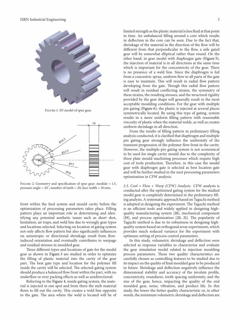
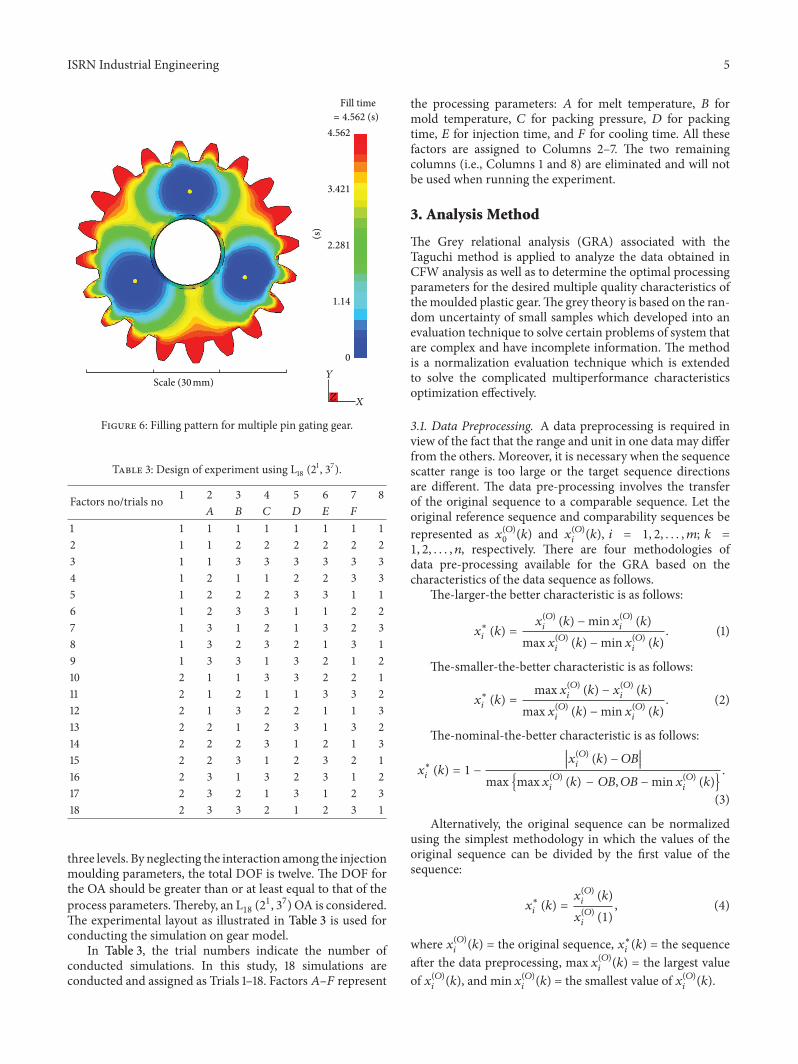
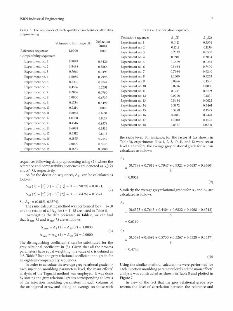

International Journal of
AerospaceEngineeringHindawi Publishing Corporationhttpwwwhindawicom Volume 2014
RoboticsJournal of
Hindawi Publishing Corporationhttpwwwhindawicom Volume 2014
Hindawi Publishing Corporationhttpwwwhindawicom Volume 2014
Active and Passive Electronic Components
Control Scienceand Engineering
Journal of
Hindawi Publishing Corporationhttpwwwhindawicom Volume 2014
International Journal of
RotatingMachinery
Hindawi Publishing Corporationhttpwwwhindawicom Volume 2014
Hindawi Publishing Corporation httpwwwhindawicom
Journal ofEngineeringVolume 2014
Submit your manuscripts athttpwwwhindawicom
VLSI Design
Hindawi Publishing Corporationhttpwwwhindawicom Volume 2014
Hindawi Publishing Corporationhttpwwwhindawicom Volume 2014
Shock and Vibration
Hindawi Publishing Corporationhttpwwwhindawicom Volume 2014
Civil EngineeringAdvances in
Acoustics and VibrationAdvances in
Hindawi Publishing Corporationhttpwwwhindawicom Volume 2014
Hindawi Publishing Corporationhttpwwwhindawicom Volume 2014
Electrical and Computer Engineering
Journal of
Advances inOptoElectronics
Hindawi Publishing Corporation httpwwwhindawicom
Volume 2014
The Scientific World JournalHindawi Publishing Corporation httpwwwhindawicom Volume 2014
SensorsJournal of
Hindawi Publishing Corporationhttpwwwhindawicom Volume 2014
Modelling amp Simulation in EngineeringHindawi Publishing Corporation httpwwwhindawicom Volume 2014
Hindawi Publishing Corporationhttpwwwhindawicom Volume 2014
Chemical EngineeringInternational Journal of Antennas and
Propagation
International Journal of
Hindawi Publishing Corporationhttpwwwhindawicom Volume 2014
Hindawi Publishing Corporationhttpwwwhindawicom Volume 2014
Navigation and Observation
International Journal of
Hindawi Publishing Corporationhttpwwwhindawicom Volume 2014
DistributedSensor Networks
International Journal of