Embed Size (px)
Citation preview

Research ArticleModel-Based Experimental Development of Passive CompliantRobot Legs from Fiberglass Composites
Shang-Chang Lin Chia-Jui Hu Wen-Pin Shih and Pei-Chun Lin
Department of Mechanical Engineering National Taiwan University Sec 4 No 1 Roosevelt Road Taipei 106 Taiwan
Correspondence should be addressed to Pei-Chun Lin peichunlinntuedutw
Received 14 January 2015 Accepted 18 May 2015
Academic Editor Luis Gracia
Copyright copy 2015 Shang-Chang Lin et al This is an open access article distributed under the Creative Commons AttributionLicense which permits unrestricted use distribution and reproduction in any medium provided the original work is properlycited
We report on the methodology of developing compliant half-circular and composite robot legs with designable stiffness Firstforce-displacement experiments on flat cantilever composites made by one or multifiberglass cloths are executed By mapping thecantilever mechanics to the virtual spring model the equivalent elastic moduli of the composites can be derived Next by using themodel that links the curved beam mechanics back to the virtual spring the resultant stiffness of the composite in a half-circularshape can be estimated without going through intensive experimental tryouts The overall methodology has been experimentallyvalidated and the fabricated composites were used on a hexapod robot to perform walking and leaping behaviors
1 Introduction
After millions of years of adaptation in the natural envi-ronment animal legs have evolved and diversified their legmorphology into various formsThough the appearance maybe different the main function of the legs still lies in enablinganimals to negotiate widely diversified natural terrainsThus how the individual leg moves and how the legs arecoordinated are both critical and fundamental biomechanicsquestions Previously the researchers found that no matterhow many legs the biological systems have their dynamicrunning locomotion in the sagittal plane can be approximatedby a simple mathematical model ldquoSLIPrdquo (Spring-LoadedInverted Pendulum) [1ndash3] The SLIP model is composed ofa point mass representing the body and a massless springleg The SLIP model is widely recognized as the intrinsic andqualitative ldquotemplaterdquowhich can describe the general runninglocomotion of legged animals with different geometricalshapes and evolutionary stages as the ldquoanchorrdquo [4]
The research described in the previous paragraph sug-gests that the legs of bioinspired legged robots should beoperated like a passive and linear spring by using stiffness orforce control For example on the arms [5] hands [6] legs [7]or exoskeleton [8] Though ideally the spring-like behaviorcan be achieved by controlling multi-degree-of-freedom
(DOF) legs to act like a spring empirically this approachis extremely challenging because artificial actuators such aselectric motors have limited power density in comparison tobiological actuators such asmusclesThus instead of using theanimal-like multi-DOF legs some legged robots use passivecompliant components as legs [9] The quadruped Scoutseries uses linear springs as the legs [10ndash12] The hexapodRHex series went through various generations of legs [13 14]and it uses the half-circular legs made of fiberglass compositein its latest version [15 16] The hexapod Sprawl series usespolyurethane to generate passive compliance of the legs [1718]
The material in a half-circular shape is one of the idealcomponents for compliant legs on a robot owing to its simplemorphology The RHex with the half-semicircular legs hasdemonstrated versatile behaviors such as running [19] stairascentdescent [20 21] high-step climbing [22] bounding[23] leaping [24] and other advanced dynamic maneuvers[16] The RHex uses a fiberglass composite as the leg materialbecause commercial deformable polymers are unlikely tomeet the necessary requirements such as stiffness robustnessand minimum plastic effect However making a fiberglasscomposite leg with adequate stiffness and in a circularshape still relies heavily on the engineering trial-and-errorprocess
Hindawi Publishing CorporationApplied Bionics and BiomechanicsVolume 2015 Article ID 754832 14 pageshttpdxdoiorg1011552015754832
2 Applied Bionics and Biomechanics
Here we propose a methodology to design and fabricatea compliant half-circular fiberglass composite with desiredstiffness The composite made in strips is utilized as thereference test to investigate the empirical elastic propertiesbecause a flat composite sheet is easier to fabricate and eachsheet can produce strips with different fiber orientations forevaluation The equivalent elastic modulus is adopted as theinterface to link the microscale mechanics to the macroscaleresilient behaviors because the detailed mechanics of thefiberglass composite as determined by the mechanics of thelaminates and bonding adhesives and their interactions arehard to analyze analytically In order to link the elastic behav-iors of the flat sheets and the half-circular beams twomodelsthat can be experimentally implemented are introduced tolink the resultant stiffness to the equivalent elastic modulusAs a result the mechanical properties derived based on thedeformation test on the flat strip composite can be directlydeployed to the half-circular composite
The remainder of the paper is organized as followsSection 21 introduces the elastic models utilized for exper-imental implementation while Section 22 describes theexperimental methods Section 3 report the experimen-tal results of the cantilever and half-circular compositesSection 4 concludes the work
2 Materials and Methods
21 Elastic Models In general the resultant stiffness of amaterial is determined by its elastic modulus as well as itsgeometric dimensions From the aspect of robotic engineer-ing where the system is usually integrated with existingmaterials the changing of material properties to fit therobotic requirements is usually a challengeThus the requiredmechanical characteristics of the robot are usually achievedby designing and tuning the dimensions of the componentsand choosing adequate and available raw materials Forexample in our application where compliant legs are desiredthe design strategy lies in investigating the fiberweave patternand the number of layers of fiberglass sheets required to formthe leg so the macroscale leg stiffness can be achieved
A compliant leg in a half-circular shape is desired fortwo reasons first a robot with half-circular legs has rollingcontact to the ground which is reported to have excellentlocomotion characteristics Second the component in half-circular shape is easy to fabricate and has compliant behaviorSince the majority of the reported analyses are on flatsheetsbars (ie beam model) this work starts with theanalysis on the flatmaterials first and then extends to the half-circular shaped materials
211 Cantilever Beam Model The elastic characteristicsof the cantilever rectangular beam model are shown inFigure 1(a) and are described as follows It has one elasticparameter the elastic modulus (119864) and three geometricparameters including length (119897) width (119908) and thickness(ℎ) When the force (119865) is applied to the beam the free endof the beam will deform a distance (119910) According to thesolid mechanics of materials the deformation of the beammainly results from the tension and compression of the beam
F
w
h
k
E I
yx
l
(b)(a)
Figure 1 The solid mechanic model (a) and the simplified model(b) of the cantilever beam
material in microscale The normal strain in any rectangularcross section of the beam can be represented as
120590 =119872 sdot 119888
119868 (1)
where 119888 119872 and 119868 represent the distance from the neutralsurface the bending moment and the moment of inertiarespectivelyThe last term is determined by the width (119908) andheight (ℎ) of the beam 119868 = 119908ℎ
312 The bending moment
(119872) caused by the external forced loading on an arbitraryposition of the beam can be expressed as
119872 = 119865 (119897 minus 119909) (2)
The strain energy of the whole beam (119880119887) due to the moment
can then be computed
119880119887= ∬120590119889120598 119889119881 = int
119871
0
1198722
2119864119868119889119909 = int
119871
0
[119865 (119897 minus 119909)]2
2119864119868119889119909
=11986521198973
6119864119868
(3)
The strain energy from shear force is ignored because itis relatively small in comparison to that from bending Inaddition the elastic property of the cantilever beam modelcan be approximated by a lumped linear spring with stiffness(119896) as shown in Figure 1(b) whose equilibrium positionresides at the position where the beam is not force loadedThe spring potential of the lumped model is
119880119896=12119896119910
2 (4)
Because the cantilever beam model and the lumped modelrepresent the same system the potential energies of bothsystems can be treated the same
119880119887=
11986521198973
6119864119868=
(119896119910)21198973
6119864119868=12119896119910
2= 119880119896 (5)
As a result the ldquoresultant stiffnessrdquo of the beammodel can bederived as
119896 =31198641198681198973
=119908ℎ3119864
41198973 (6)
Applied Bionics and Biomechanics 3
r
F
h
w
k
E I
y
R
(b)(a)
r1r2
120579
Figure 2 The solid mechanic model (a) and the simplified model(b) of the curved beam
212 Curved Beam Model The cantilever rectangular beammodel can be extended to the model with a half-circularshape as shown in Figure 2(a) the same shape as the robotleg The curved beam also has four parameters the elasticmodulus (119864) the radius of the curvature (119877) the beam width(119908) and the beam thickness (ℎ) While an external force isapplied to the beam at the bottom side the arbitrary crosssection at angle 120579 has a normal force (119865
120579) and a bending
moment (119872120579)
119865120579= 119865 sin 120579
119872120579= 119865119877 sin 120579
(7)
Thus the normal stress at this position can be computed
120590120579=
minus119865120579
119860+119872120579 (119903 minus 119877)
119868
=minus119865 sin 120579
119860+119865119877 sin 120579 (119903 minus 119877)
119868
(8)
where119860 represents the cross section area and 119903 is the distancefrom the circular center to the stress The strain energy of thewhole half-circular leg (ie from 120579 = 0
∘ to 120579 = 180∘) can beyielded
119880119888= ∭
120590120579
2119864119889119881 =
119908
2119864
sdot int120587
0int1199031
1199032
[minus119865 sin 120579
119860+119865119877 sin 120579 (119903 minus 119877)
119868]
2119903119889119903 119889120579
=1199081198652120587
41198641199031
2 minus 11990322
21198602 minus2119877119860119868
[13(1199031
3minus 1199032
3)
minus119877
2(1199031
2minus 1199032
2)] +
1198772
1198682[1199031
4 minus 11990324
4
minus2119877 (1199031
3 minus 11990323)
3+1198772 (1199031
2 minus 11990322)
2]
(9)
where the symbols 1199031
and 1199032
represent the outer andinner radii of the curved beam respectively As shown inFigure 2(a) these two radii can be related to the dimensionsof the beam by
1199031 minus 1199032 = ℎ
1199031 + 1199032 = 2119877(10)
By importing (10) into (9) the strain energy of the curvedbeam can be derived as
119880119888=
1199081198652120587
4119864119877ℎ
1198602 minus2119860119868
[119877ℎ
3(31198772
+ℎ2
4)minus119877
3ℎ]
+1198772
1198682[119877ℎ
2(21198772
+ℎ2
2)]minus
2119877ℎ3
(31198772+ℎ2
4)
+1198773ℎ =
1198652119877120587
4119908ℎ119864(121198772
ℎ2minus 1)
(11)
Similarly the elastic property of the curved beam model canbe approximated by a lumped linear spring with stiffness (119896)as shown in Figure 2(b) whose equilibrium position residesat the point where the curved beam is not force loaded Thespring is vertically posed with a natural length of 2119877 Sincethe curved beam model and the lumped model representthe same system the strain energies of both systems can betreated the same
119880119888=
1198652119877120587
4119908ℎ119864(121198772
ℎ2minus 1) =
(119896119910)2119877120587
4119908ℎ119864(121198772
ℎ2minus 1)
=12119896119910
2= 119880119896
(12)
As a result the ldquoresultant stiffnessrdquo of the curved beammodelcan be derived as
119896 =2119908ℎ119864
119877120587 (121198772ℎ2 minus 1) (13)
Because the ratio 119877ℎ of the curved beam in our robot legapplication is greater than an order the constant term 1 in theparenthesis can be ignored Therefore the resultant stiffnesscan be approximated as
119896 =119908ℎ
3119864
61198773120587 (14)
The approximation also indicates that the strain energycaused by normal force is much smaller in comparison tothat caused by bending moment similar to the results of thecantilever beam model as reported
213 Composite Model Equations (6) and (14) reveal therelation of the modelrsquos resultant stiffness to its geometricparameters and elastic modulus This modulus representsthe explicit behavior of the complex internal stress-strainbehavior The beam formed by composite materials is one ofthe representative examples As shown in Figure 3 assume
4 Applied Bionics and Biomechanics
MM
E1
E2
E3
Eeq
Figure 3 The composite material is stacked in layers of materialswith different elastic moduli and the composite can be regarded asa homogeneous material with an ldquoequivalentrdquo elastic modulus
the beam is formed by layered thin sheets and that thestacking is symmetric to the neutral surface of the beamOwing to the geometrical constraint the strain (120576
119894) within
each layer and between the layers is continuous but the stressat the interface of the layers can be varied Similar to thebehaviors observed in the cantilever beammodel and curvedbean model the bending moment is the main factor thatdetermines the resultant stiffness This is mainly caused bythe moment in the cross section Thus the bending momentof the composite beammodel can be computed as the sum ofall moments caused by the normal stress in all layers
119872 = ∬120590119910119889119860 = 2119908(int1198891
01205901119910119889119910+ sdot sdot sdot
+ int119889119899minus1
119889119899minus2
120590119899minus1119910119889119910+int
119889119899
119889119899minus1
120590119899119910119889119910)
= 2119908(int1198891
0
1198641119864119899
1199102
ℎ120590119899119889119910+ sdot sdot sdot + int
119889119899minus1
119889119899minus2
119864119899minus1119864119899
1199102
ℎ120590119899119889119910
+int119889119899
119889119899minus1
119864119899
119864119899
1199102
ℎ120590119899119889119910) =
2120590119899119908
119864119899ℎ
(1198641 int1198891
01199102119889119910+ sdot sdot sdot
+ 119864119899minus1 int119889119899minus1
119889119899minus2
1199102119889119910+119864
119899int119889119899
119889119899minus1
1199102119889119910) =
2120590119899119908
3119864119899ℎ
sdot
119899
sum119894=1
119864119894(119889119894
3minus119889119894minus1
3) =
2120576119899119908
3ℎ
119899
sum119894=1
119864119894(119889119894
3minus119889119894minus1
3)
(15)
Then the ldquoequivalentrdquo elastic modulus of this compositebeam can be computed
119872 =2120576119899119882
3ℎ
119899
sum119894=1
119864119894(119889119894
3minus119889119894minus1
3) =
2119864eq120576119899119882
3ℎsdot ℎ
3
119864eq =sum119899
119894=1 119864119894 (1198891198943minus 119889119894minus1
3)
ℎ3
(16)
The derivation shown above suggests a methodology todevelop a compliant robot leg from composite materials Inapplications of uniform and isotropic materials where thematerial dimensions and elastic modulus are known (6) and(14) reveal the effects of these parameters on the overallcompliant behavior the ldquoresultantrdquo stiffness In contrast inour application of compositematerials where the ldquoequivalentrdquoelastic modulus is not a given parameter (6) and (14) can be
Table 1 Specifications of the fiberglass clothes
(a)
E-glass (0∘)Layer orientation (∘) 0∘ 45∘ 90∘ minus45∘
Layer weight (gm2) 472 mdash 45 mdashWeight knitting yarn (gm2) 10
(b)
E-glass (minus45∘ 0∘ 45∘)Layer orientation (∘) 0∘ 45∘ 90∘ minus45∘
Layer weight (gm2) 295 148 45 148Weight knitting yarn (gm2) 12
reversely utilized to compute the equivalent elastic moduluswhere the detailed mechanics of the stress-strain behaviorare not necessary to the analysis In this case both thedimensions (ie (119897 119908 ℎ) or (119877 119908 ℎ)) and resultant stiffness(119896) of the beam should be known a priori The former isusually known when the material is fabricated The latter canbe obtained by empirical force-displacement measurementand the detailed method for this will be reported in the nextsection
22 Experimental Methods
221 Fiberglass Sample Preparation The fiberglass compos-ite is formed by layered fiberglass cloths with epoxy in-between The elastic modulus of each thin fiberglass layeris determined not only by the mechanical properties of theglass fiber itself but also by how the fibers are woven Theanisotropic properties of the fibers are actually favorablebecause different mechanical properties of the compositecan be achieved by the sample without altering its size Toinvestigate the isotropic effect two kinds of fiberglass clothswere adopted the E-glass (0∘) and the E-glass (minus45∘ 0∘ 45∘)and Table 1 shows their specifications
The fiberglass composites were fabricated in two differentshapes for experimental evaluation The first shape is a stripsome 10 cm long and 2 cm wide In addition the fiberglasscloths were cut in three different directions (0∘ 45∘ 90∘) asshown in Figure 4(a) to evaluate the anisotropic effect Thesecond shape is the half-circular shape shown in Figure 4(b)the same shape as the legs on the robot
The step-by-step fabrication procedure for the half-circular leg is described in the exemplary demonstration(i) Preparing a mold as shown in Figure 5(a) the fiberglasscloths were stacked from the inner to outer surfaces so amold supporting the shape of the inner surface is requiredAfter determining the dimensions of the leg an aluminumhollow cylinder was made as the mold (ii) Covering a releasefilm and a peel-ply on the mold is as shown in Figure 5(b)(iii) Preparing fiberglass cloths as shown in Figure 5(c) cutthe cloths to the right dimensions following the selecteddirections (iv) Preparing the epoxy resin is as shown inFigure 5(c) (v) Stacking the fiberglass cloths is as shownin Figure 5(d) brushing the cloths with epoxy and stacking
Applied Bionics and Biomechanics 5
0∘45∘
90∘2 cm
10 cm
(a)
2 cm14 cm
~4 cm
(b)
Figure 4The fiberglass composites (a) the definition of the cuttingdirections and the size of the strip samples (b)The size of the curvedbeam sample
them layer by layer on top of the peel-ply After each layer wasstacked using a roller to roll the surface in order to tightlycompress the layered composite and to force resin into thecloth The type and orientation of the anisotropic cloth ineach layer can be different determined by the experimentalsetting (vi) Covering a release film and a perforated film onthe stacked fiberglass layers (vii) Covering a breather plyso the vacuum pump can remove the air bubbles within thestacked fiberglass layers (viii) Covering a vacuum baggingfilm and sealing it with a sealant tape are as shown inFigure 5(e) (xi) Curing the composite in the oven with thevacuum pump on is as shown in Figures 5(f) and 5(g) Thetemperature and time for curing are determined by the epoxyproperties (x) After curing the raw composite was fabricatedand ready for cutting into the shape of the legs as shown inFigure 5(h)
Figure 6 shows various photos taken during the fabri-cation process (a) The release film and the peel-ply werecovered on the mold (b) The cloths were brushed with theepoxy (c) The release film perforated film and breather plywere covered on the stacked fiberglass layer (d) The edgesof all layers were trimmed (e) The vacuum bagged film wascovered and sealed thematerial assembly by using the sealanttape (f) A photo of the whole assembly which contains thefiberglass layers and other associated films (g) The assemblywas cured in the oven (h)A photo of thewhole assembly aftercuring
222 Sample Stiffness Measurement Customized testingsetups were built to take the force-displacement measure-ments of the cantilever beam and curved beam wherethe force and displacement were directly matched with theoperational directions of the virtual springs as shown inFigures 1(b) and 2(b) Though the conventional tensile testcan also derive the elastic modulus of the material the setupis hard to modify for our force-displacement measurementsIn addition the layered composite material has differentbehaviors in tension and compression so the customizationis required for experimental validation
The sample was clamped to the testing setup as shownin Figure 7 The setup was mounted under a drill press and
(a) (b)
Epoxy
(c) (d)
(e)
Oven
(f)
Oven
Pump
ON
ON
(g) (h)
Figure 5 The fabrication process for the fiberglass composites
the one-dimensional compression motion was generated bythe linear guide way of the drill press By using the lockingmechanism of the drill press the sample was set to becompressed with several displacements In themeantime theforce was measured using a commercial bidirectional forcetransducer
The experiment procedure has three steps (i) Calibrationfor the rectangular beam use the jig structure to hold thecantilever beam horizontally as shown in Figure 7(a) Thenvertically align the drill press and force sensor to the freeend of the sample so the force can be applied to the samplewith displacement in the correct direction For the curvedbeam mount the cylindrical tube inside the curved beam asshown in Figure 7(b) and place the assembly in between theforce sensor at the bottom and the drill press at the top Makesure the force can be applied to the sample with displacementin the correct direction After the alignment remove thecylindrical tube circular so the curved beam can be subjectto compression (ii) Measurement the force data is collectedwhen the displacements of the rectangular beam are 5mm7mm and 10mm and when those of the curved beam are
6 Applied Bionics and Biomechanics
(a) (b)
(c) (d)
(e) (f)
(g) (h)
Figure 6 Photos of the fabrication process for the fiberglass composites
3mm 5mm 7mm 10mm and 12mmThe experiments arerepeated several times using different samples with the sameparameters so the variation of the mechanical characteristicsof the samples has less effect on the final results (iii) Analysisuse the linear regressionmethod to find the slopes of the forceversus displacement data which represents the ldquoresultantrdquostiffness of the rectangular beam or the curved beam Thenby using (6) and (14) the ldquoequivalentrdquo elastic modulus of thebeam can be derived
3 Results and Discussion
31 Experiment Results of the Strip Fiberglass Composites inthe Cantilever Beam Test The equivalent elastic modulus of
the fiberglass composite is determined by several factors suchas the elastic modulus and weave of the fiberglass clothsthe elastic modulus of the epoxy and the stacking methodsTo simplify the development the microscale mechanics areignored but the macroscale mechanics of the composite arecaptured More specifically the equivalent elastic modulusserves as the key factor for evaluating the performance of thelayered composite
311 Experiments on 4-Layer Composites Made by One Kindof Fiberglass Cloth The fiberglass composite strips were fab-ricated by a single kind of fiberglass cloth and in four layersTogether with three different cutting directions (0∘ 45∘ 90∘)there are six kinds of samples in total Table 2 lists forces of
Applied Bionics and Biomechanics 7
Force gauge
Drill press
(a)
Force gauge
Drill press
Cylindrical tube(remove after calibration)
(b)
Figure 7 Measurement setup of the cantilever beam experiments (a) and the curved beam experiments (b)
Table 2 Forces versus displacements of the fiberglass composite strips made by the E-glass (0∘) and E-glass (minus45∘ 0∘ 45∘) with three differentcutting directions (0∘ 45∘ 90∘)
Disp(mm)
Test 1(N)
Test 2(N)
Test 3(N)
Test 4(N)
Test 5(N)
Test 6(N)
Test 7(N)
Average(N)
Std(N)
E-glass (minus45∘ 0∘ 45∘)-0∘5 639 647 567 642 637 643 620 628 0287 904 892 790 886 880 910 865 875 04110 1282 1288 1132 1278 1268 1291 1239 1254 056
E-glass (minus45∘ 0∘ 45∘)-45∘5 423 461 367 384 392 410 407 406 0307 601 639 519 542 563 573 578 574 03910 851 920 737 770 789 820 818 815 059
E-glass (minus45∘ 0∘ 45∘)-90∘5 307 320 238 269 257 271 274 276 0287 440 438 359 378 365 375 391 392 03410 618 636 488 538 516 540 551 555 054
E-glass (0∘)-0∘5 443 464 351 409 544 576 505 470 0787 625 647 489 578 780 812 713 664 11410 888 927 702 821 1096 1155 1013 943 158
E-glass (0∘)-45∘5 156 159 112 409 137 137 132 177 1037 223 226 160 578 195 199 191 253 14510 314 319 226 821 275 278 266 357 207
E-glass (0∘)-90∘5 125 121 102 129 108 108 121 116 0107 174 172 147 185 167 150 167 166 01310 250 244 207 260 223 215 241 234 020
the strips in three displacements Figure 8 shows the force-displacement plot of these samples The data is representedin a statistical manner with means and standard deviations(STD) which are obtained from seven experimental runsSeveral comments can be addressed
(i) The means of each kind of composite are alignedto nearly a straight line which passes zero indicat-ing that it is reasonable to approximate the force-displacement of the cantilever beam by a virtualspring system as shown in Figure 1
(ii) The stiffness of the virtual springs (ie slope of theforce-displacement plot) shown in Figure 8 can beextracted and replotted as the vertical axis as shown inFigure 9(a) The figure clearly shows that the stiffnessof the E-glass (minus45∘ 0∘ 45∘) is larger than that of theE-glass (0∘) no matter what the cutting direction isIt may be intuitive that the stiffness of the E-glass (0∘)with the cutting direction in 0∘ (ie hereafter referredto as E-glass (0∘)-0∘) should be larger than that ofthe E-glass (minus45∘ 0∘ 45∘) in any cutting directionbecause the fibers of the former are more aligned
8 Applied Bionics and Biomechanics
0 5 10
10
15
150
5
y (mm)
F (N
) 0∘
45∘
90∘
E-glass (minus45∘ 0∘ 45∘)
(a)
10
15
0 50
5
y (mm)
F (N
)
0∘
45∘
90∘
E-glass (0∘)
10 15
(b)
Figure 8 The force-displacement relation of the fiberglass composite strips made by the E-glass (minus45∘ 0∘ 45∘) in (a) and the E-glass (0∘) in(b)
125310 plusmn 5668
81577 plusmn 5845
55638 plusmn 5226
23481 plusmn 193528142 plusmn 3131
94395 plusmn 15878
1400
1200
1000
800
600
400
2000 45 90
k (N
m)
Cutting direction (∘)
E-glass (minus45∘ 0∘ 45∘)E-glass (0∘)
(a)
1921 plusmn 035
1356 plusmn 045
942 plusmn 045784 plusmn 065
2675 plusmn 129
674 plusmn 035
0 45 90
30
25
20
15
10
5
E(G
pa)
Cutting direction (∘)
E-glass (minus45∘ 0∘ 45∘)E-glass (0∘)
(b)
Figure 9The resultant stiffness (a) and equivalent elastic moduli (b) of the fiberglass composite strips made by the E-glass (minus45∘ 0∘ 45∘) andthe E-glass (0∘) with three different cutting directions
to resist the bending However because the E-glass(minus45∘ 0∘ 45∘) has 20 more knitted yarn per squaremeter than the E-glass (0∘) the composite of theformer is thicker than that of the latter though bothhave the same four layers According to (6) theresultant stiffness is affected not only by the elasticmodulus but also by the geometric properties of thecomposite In this set of experiments the thickness ofthe composite appears to have a larger effect than thefiber direction resulting in the phenomenon shownin Figure 8
(iii) The equivalent elastic moduli of the compositescan be computed by (6) with given dimensions Asshown in Figure 9(b) after eliminating the geometriceffects the elastic modulus of the E-glass (0∘)-0∘has the highest value as expected Furthermorethe elastic moduli of the E-glass (0∘)-45∘ and E-glass (0∘)-90∘ have very low values and this phe-nomenon is also expected because few fibers arealigned in these directions In contrast the elasticmodulus of the E-glass (minus45∘ 0∘ 45∘) has a gentlechange
Applied Bionics and Biomechanics 9
In short this set of experiments confirms that (i) themechanic behavior of the empirical composite samplesmatches that of the model and (ii) the idea of using thevirtual spring to model the elastic behavior is feasible in thiscomposite case In addition the elastic moduli of these twokinds of cloths each with three cutting directions are yieldedand will serve as the reference for the following developmentwhere the composite is composed of both fiberglass clothes
312 Experiments on 4-Layer Composites Made by Two Kindsof Fiberglass Cloths In this set of experiments two kindsof fiberglass cloths are mixed to form a 4-layer compositeFour different stacking combinations of the composite wereused and all were symmetric to the center plane The (S)stacking configuration used the E-glass (0∘) and the E-glass(minus45∘ 0∘ 45∘) with the same orientation as the inner layerand outer layer respectively The (D) stacking configurationused the E-glass (0∘) as the inner layer and the E-glass(minus45∘ 0∘ 45∘) as the outer layer but the latter rotated 90∘The(S1015840) and (D1015840) stacking configurations had reversed inner andouter fiberglass clothes without altering the cutting directionsaccordingly These four configurations were adopted in anattempt to evaluate two effects first the positions of the layersin thewhole composites (ie S versus S1015840 andDversusD1015840) andsecond the effect of the cutting direction on the stiffness
Figure 10 plots the equivalent elastic moduli of these fourconfigurations in statistical representations (ie mean andSTD) In addition the equivalent elastic modulus of the E-glass (0∘) and the E-glass (minus45∘ 0∘ 45∘)with the same cuttingdirections are also plotted for comparison The figure revealsthat as expected the elastic moduli of the mixed four-layercomposites are mostly located between those of the four-layer composite made either by the E-glass (0∘) or the E-glass(minus45∘ 0∘ 45∘)with the same cutting directionsMoreover the
elastic moduli of the four-layer composites are closer to thatof the outer layer than the inner layer because the bending-induced deformation is mainly determined by the momentgenerated by the outer layer
The equivalent elastic modulus of the mixed compositecan also be estimated by (16) where the dimensions of thecomposite were empirically measured and the elastic moduliof the individual layers were derived by the experimentdescribed in Section 311 Table 3 shows the elastic moduli offour configurations by prediction and three test experimentsThe table reveals that except for one test result the percentageerrors between the estimated and experiment results of 36tests were within 10 and 23 out of 36 tests had errors lessthan 5 The averaged error of eleven out of twelve typesof composites is less than 4 The matched result confirmsthat the composites made by different fiberglass clothes withdifferent cutting directions can be empirically made andits equivalent elastic modulus can also be predicted withreasonable accuracy
313 Experiments on 6-Layer Composites Made by Two Kindsof Fiberglass Cloths The estimation of the elastic modulusof the composite stacked by the E-glass (0∘) and the E-glass (minus45∘ 0∘ 45∘) is functional not only for the 4-layercomposite but also for other numbers of layers A 6-layer
Table 3The estimated andmeasured elastic modulus of the 4-layerstrip composites
(a)
Type S-0 S-45 S-90 D-0 D-45 D-90Estimated 119864 (GPa) 1990 1303 917 1101 1303 1806Test 1 1701 1404 890 1026 1293 1650Error () 1453 774 294 683 078 863Test 2 1867 1272 899 1099 1265 1837Error () 619 239 192 015 293 172Test 3 1987 1316 935 1140 1397 1940Error () 017 099 194 359 715 741Mean 1852 1331 908 1088 1318 1809STD (144) 067 024 058 070 147Average error () 695 212 098 115 118 017
(b)
Type S1015840-0 S1015840-45 S1015840-90 D1015840-0 D1015840-45 D1015840-90Estimated 119864 (GPa) 255 878 718 2388 878 88Test 1 258 85 732 2163 805 866Error () 116 328 190 943 840 156Test 2 2716 870 681 2553 839 906Error () 65 092 515 691 452 302Test 3 2562 887 698 2532 892 894Error () 049 093 281 604 158 162Mean 2619 869 704 2416 845 889STD 084 019 026 219 044 021Average error () 272 103 200 117 372 098
Table 4The estimated andmeasured elastic modulus of the 6-layercomposites
Type D222-0 D222-45 D222-90Estimated 119864 (GPa) 945 1342 1880Test 1 1034 1285 1906Error () 938 426 137Test 2 955 1368 2019Error () 103 192 737Test 3 1020 1392 1876Error () 792 377 021Mean 1003 1348 1934STD 042 056 075Average error () 614 047 285
(D222) stacking configuration used the E-glass (0∘)-0∘ asthe inner two layers and the E-glass (minus45∘ 0∘ 45∘)-90∘ asthe outer four layers was made to confirm this conclusionFigure 11 shows the equivalent elastic modulus of this mixedcomposite as well as that of the composites made by eachkind of fiberglass cloth As expected because the outerlayer dominates the elastic behavior the equivalent elasticmodulus of the mixed composite is close to that of the E-glass (minus45∘ 0∘ 45∘) In addition because four out of six layerswere E-glass (minus45∘ 0∘ 45∘) the equivalent elastic modulusis closer to that of the E-glass (minus45∘ 0∘ 45∘) than the com-posite of the 4-layer D stacking configuration Table 4 shows
10 Applied Bionics and Biomechanics
S
0 45 90
30
25
20
15
10
5
E(G
pa)
Cutting direction (∘)
E-glass (minus45∘ 0∘ 45∘)E-glass (0∘)
(a)
0 45 90
30
25
20
15
10
5
E(G
pa)
Cutting direction (∘)
E-glass (minus45∘ 0∘ 45∘)E-glass (0∘)S998400
(b)
D
0 45 90
30
25
20
15
10
5
E(G
pa)
Cutting direction (∘)
E-glass (minus45∘ 0∘ 45∘)E-glass (0∘)
(c)
0 45 90
30
25
20
15
10
5
E(G
pa)
Cutting direction (∘)
E-glass (minus45∘ 0∘ 45∘)E-glass (0∘)D998400
(d)
Figure 10 The equivalent elastic moduli of the 4-layer fiberglass composite strips made by the mixed E-glass (minus45∘ 0∘ 45∘) and the E-glass(0∘) in four different layer configurations (S S1015840 D D1015840)
the elasticmodulus of themixed composite by prediction andthree test experiments The table reveals that the percentageerrors between the estimated and experiment results of 9 testswere within 10 and 6 out of 9 tests had errors less than 5
The matched predicted and experimental results suggestthat the methodology can be adopted as a useful designtool if the equivalent elastic modulus of the individuallayer is known a priori the desired elastic modulus ofthe composite can be correctly designed in simulation firstwithout relying on an experimental trial-and-error method
This methodology will be extended to design compliant half-circular legs in the next section
32 Experiment Results of the Curved Beam Model Theultimate goal of this work is to develop a methodologyfor fabricating a fiberglass composite that has the desiredresultant stiffness so the composite can be implemented ona robot for developing dynamic behaviors In order to linkthe development of the half-circular composite to the stripcomposite described in the previous section the half-circular
Applied Bionics and Biomechanics 11
0 45 90
E(G
pa)
30
25
20
15
10
5
Cutting direction (∘)
E-glass (minus45∘ 0∘ 45∘)E-glass (0∘)D222
Figure 11 The equivalent elastic moduli of the 6-layer fiberglasscomposite strips made by the mixed E-glass (minus45∘ 0∘ 45∘) and theE-glass (0∘) in D222 layer configurations
composite for experimental validation used the same twokinds of the fiberglass cloths as well as the same layerconfiguration Unlike the composite strips where the samplesin all three cutting directions can be obtained by cutting asingle large composite plate the layers of the half-circularcomposite can only have one specific configuration at atime As a result instead of making composites in all twelvecombinations of (S S1015840 D D1015840) only the four of them closestto our interest were selected for evaluation including S-0∘ S-90∘ D-0∘ and D-90∘ In addition the composites made byone kind of fiberglass cloth were made for comparison aswell including E-glass (0∘)-0∘ E-glass (minus45∘ 0∘ 45∘)-0∘ andE-glass (minus45∘ 0∘ 45∘)-90∘
Figure 12 shows the force-displacement of the compos-ite strips and the half-circular composites Similar to thebehavior observed in the composite strip the means of themeasured experimental data of the half-circular compositeare aligned nearly to a straight line Thus it is reasonableto approximate the force-displacement of the half-circularcomposite by a virtual spring system as shown in Figure 2By using the stiffness (ie slope of this figure) and measureddimensions the equivalent elastic modulus of the half-circular composite can be computed using (14) Table 5 liststhe elastic moduli of these configurations by experimentalmeasurement and estimation where the latter was obtainedby the results of composite strips The close match betweenthese two data sets in most of the composite configurationsconfirms that the fabricated strip and half-circular compos-ites with the same layer configuration have similar valuesof elastic modulus and this further confirms two pointsfirst the fabrication process and product quality are reliableand second the test results and model development ofthe composite strips can provide useful design informationbefore making half-circular composites
Table 5 The estimated and measured elastic modulus of thesemicircular composites
Estimated 119864 Measured 119864 Error ()E-glass (minus45045)-0 1921 1918 015E-glass (minus45045)-90 942 922 205E-glass (0)-0 2675 2684 037S-0 1990 2042 260S-90 917 998 879D-0 1101 1089 108D-90 1806 2071 1464
Table 6 Specifications of the half-circular composite leg made bythe E-glass (0∘ 90∘)-0∘
Thickness(mm)
Width(mm)
Stiffness(km)
119864
(Gpa)1 360 2069 256310 19982 360 2086 261898 20163 361 2041 250990 19684 360 2090 267084 20585 362 2077 259405 1980
Averaged stiffness (km) 259137 plusmn 6025
The RHex-style robot in our lab has a mass of 65 kg andthe dimensions 045m in length 028m in width and 02min height (standing height)The current robot legs have radius70mm and width 20mm In order to evaluate the effect ofleg compliance on the robotrsquos behavior the new compositelegs should have the same dimensions as the old legs Thusaccording to (14) the possible parameters for variation are thethickness and equivalent elastic modulus of the compositeThus the resultant stiffness can be varied by changing eithercloth type or the number of layers
The desired stiffness of the robot can be estimated by thedynamics of the spring-mass model as reported in [25] Theliterature reported that animals with different masses havedifferent stride frequencies [26] A system weighing around65 kg should have a stride frequency within the range of2ndash4Hz Note that because the robot utilizes an alternatingtripod gait the leg stride frequency should be half of themodel stride frequency about 1-2Hz In addition becausetripod locomotion involves three legs contacting the groundsimultaneously the stiffness of each leg should be one-thirdof the model stiffness As a result the individual leg stiffnessis set to about 2000ndash2500Nm
In the first attempt the fiberglass legs were made by theE-glass (0∘ 90∘)-0∘ As shown in Table 6 the legs have anaveraged resultant stiffness of 2591Nm 36 error to thedesired 2500Nm However when the legs were installed onthe robot for the running test the low lateral stiffness resultedin lateral motion disturbance so the robot could hardlyperform straight forward locomotion Thus in addition toplanning the compliance in the sagittal plane of the robot thelateral stiffness should be considered This is the reason whywe need to stack the different fibers together
12 Applied Bionics and Biomechanics
0 50
5
15
15
10
10y (mm)
F (N
)
S-0
D-0D-90
S-90E-glass (minus45∘ 0∘ 45∘)-0E-glass (minus45∘ 0∘ 45∘)-90E-glass (0∘)-0
(a)
0 5 10 150
5
10
y (mm)
F (N
)S-0
D-0D-90
S-90E-glass (minus45∘ 0∘ 45∘)-0E-glass (minus45∘ 0∘ 45∘)-90E-glass (0∘)-0
(b)
Figure 12 The force-displacement relation of the fiberglass composite strips (a) and semicircular composites (b) made by the E-glass(minus45∘ 0∘ 45∘) and the E-glass (0∘) in seven different material and layer configurations
Robot
(a)
Robot
(b)
Figure 13 The robot installed with the fiberglass composite legs performs walking (a) and leaping (b) behaviors
In the second attempt the fiberglass legs were made bythree layers of E-glass (minus45∘ 0∘ 45∘)-90∘ on each outer sideand four layers of E-glass (0∘)-0∘ on the inner side effectivelythe ldquoD configurationrdquo but with more layers The designprocess followed that described in the previous two sectionsAs shown in Table 7 the legs have the averaged resultantstiffness of 2555Nm 2 error to the desired 2500Nm Inaddition because of the 90∘ rotated configuration of the E-glass (minus45∘ 0∘ 45∘) the lateral stiffness as well as the torsionalstiffness with respect to the vertical axis are stiffer to resistthe perturbation generation during locomotion test Therobot with this set of legs can perform walking and leapinglocomotion with the snapshots extracted from the recordedvideo being shown in Figure 13 as a demonstration
4 Conclusion
We report on the methodology for developing complianthalf-circular and composite robot legs with designable
Table 7 Specifications of the half-circular composite leg made bythe E-glass (minus45∘ 0∘ 45∘)-90∘ and the E-glass (0∘)-0∘
Thickness(mm)
Width(mm)
Stiffness(km)
119864
(Gpa)Estimated119864 (GPa)
1 437 2065 270881 1183
10192 434 2057 266414 11643 415 1995 224524 10484 428 2031 245586 11235 435 2083 270262 1105Averaged stiffness (km) 255533 plusmn 20195
stiffness The composite made in strips is utilized as thereference test to investigate the empirical elastic propertiesbecause the flat composite sheet is easier to fabricate and eachsheet can produce strips with different fiber orientations forevaluation By executing the force-displacement experiments
Applied Bionics and Biomechanics 13
on the flat cantilever composite composed of the samekind of fiberglass cloth together with the mapping modelfrom the cantilever mechanics to the reduced-order virtualspring the equivalent elastic modulus of the composite canbe revealed In this work two kinds of fiberglass clothseach with three cutting directions were tested so there aresix reference elastic moduli to serve as the ldquodatabaserdquo fordesigning composites with mixed fiberglass cloths The 4-layer composites with twelve configurations were experi-mentally evaluated where the equivalent elastic moduli ofthe estimated and experimental values were utilized as thecomparison basis The results reveal that among 36 tests 35of them have percentage errors less than 10 and 23 of themhave percentage errors less than 5 The 6-layer compositeswith three configurations were evaluated as well The resultsreveal that among 9 tests all have percentage errors less than10 and 6 out of 9 tests have percentage errors less than 5Qualitative observation reveals that the fiber directions of thelayered cloth have a critical effect on the equivalent elasticmodulus As expected the cloths at the outer layers had thelarger effect on the equivalent elastic modulus
After confirming that the elastic behavior of the flatcomposites made by mixed fiberglass layers can be correctlyestimated the strategy is extended to the composite in half-a-semicircular shape The mapping model from the curvedbeam mechanics to the reduced-order virtual spring wasdeveloped to map the equivalent elastic modulus back tothe resultant stiffness of the half-circular composite Theexperimental results confirm that the designed 8-layer half-circular composites have an averaged resultant stiffness of2555Nm which has only a 2 error to the desired stiffnessvalue 2500NmThe fabricated compositeswere utilized as therobot legs and the robot can reliably perform walking andleaping behaviors
We are currently in the process of revising the methodol-ogy to include the effect of damping into the design processThis would require model formation in a dynamic mannerand the experimental setup should be capable of capturingthe dynamics of the composites as well
Conflict of Interests
The authors declare that there is no conflict of interestsregarding the publication of this paper
Acknowledgments
This work is supported by Ministry of Science and Technol-ogy (MOST) Taiwan under Contract MOST 103-2221-E-002-091 -MY3 and National Taiwan University Taiwan underContract NTU-CDP-102R7817
References
[1] R M Alexander Elastic Mechanisms in Animal MovementCambridge University Press Cambridge UK 1988
[2] R Blickhan ldquoThe spring-massmodel for running and hoppingrdquoJournal of Biomechanics vol 22 no 11-12 pp 1217ndash1227 1989
[3] P Holmes R J Full D Koditschek and J GuckenheimerldquoThe dynamics of legged locomotion models analyses andchallengesrdquo SIAM Review vol 48 no 2 pp 207ndash304 2006
[4] R J Full and D E Koditschek ldquoTemplates and anchorsneuromechanical hypotheses of legged locomotion on landrdquoJournal of Experimental Biology vol 202 no 23 pp 3325ndash33321999
[5] M H Rahman T Kittel-Ouimet M Saad J-P Kenne and P SArchambault ldquoDevelopment and control of a robotic exoskele-ton for shoulder elbow and forearm movement assistancerdquoApplied Bionics and Biomechanics vol 9 no 3 pp 275ndash2922012
[6] M Controzzi M DrsquoAlonzo C Peccia C M Oddo M CCarrozza and C Cipriani ldquoBioinspired fingertip for anthropo-morphic robotic handsrdquo Applied Bionics and Biomechanics vol11 no 1-2 pp 25ndash38 2014
[7] C E Syrseloudis I Z Emiris T Lilas and A Maglara ldquoDesignof a simple and modular 2-DOF ankle physiotherapy devicerelying on a hybrid serial-parallel robotic architecturerdquo AppliedBionics and Biomechanics vol 8 no 1 pp 101ndash114 2011
[8] M Folgheraiter J de Gea B Bongardt J Albiez and FKirchner ldquoBio-inspired control of an arm exoskeleton jointwith active-compliant actuation systemrdquo Applied Bionics andBiomechanics vol 6 no 2 pp 193ndash204 2009
[9] X D Zhou and S S Bi ldquoA survey of bio-inspired compliantlegged robot designsrdquo Bioinspiration and Biomimetics vol 7 no4 Article ID 041001 2012
[10] I Poulakakis J A Smith and M Buehler ldquoModeling andexperiments of untethered quadrupedal running with a bound-ing gait the Scout II robotrdquo International Journal of RoboticsResearch vol 24 no 4 pp 239ndash256 2005
[11] I Poulakakis E Papadopoulos and M Buehler ldquoOn thestability of the passive dynamics of quadrupedal running witha bounding gaitrdquo International Journal of Robotics Research vol25 no 7 pp 669ndash687 2006
[12] J A Smith I Poulakakis M Trentini and I Sharf ldquoBoundingwith active wheels and liftoff angle velocity adjustmentrdquo TheInternational Journal of Robotics Research vol 29 no 4 pp 414ndash427 2010
[13] U Saranli M Buehler and D E Koditschek ldquoRHex a simpleand highly mobile hexapod robotrdquo International Journal ofRobotics Research vol 20 no 7 pp 616ndash631 2001
[14] P C Lin Proprioceptive sensing for a legged robot [PhD disser-tation] Department of Mechanical Engineering University ofMichigan 2005
[15] U Saranli A A Rizzi and D E Koditschek ldquoModel-baseddynamic self-righting maneuvers for a hexapedal robotrdquo Inter-national Journal of Robotics Research vol 23 no 9 pp 903ndash9182004
[16] A M Johnson and D E Koditschek ldquoToward a vocabularyof legged leapingrdquo in Proceedings of the IEEE InternationalConference on Robotics and Automation (ICRA rsquo13) pp 2568ndash2575 deu May 2013
[17] J G Cham S A Bailey J E Clark R J Full and MR Cutkosky ldquoFast and robust hexapedal robots via shapedeposition manufacturingrdquo International Journal of RoboticsResearch vol 21 no 10-11 pp 869ndash882 2002
[18] S Kim J E Clark and M R Cutkosky ldquoiSprawl designand tuning for high-speed autonomous open-loop runningrdquoInternational Journal of Robotics Research vol 25 no 9 pp 903ndash912 2006
14 Applied Bionics and Biomechanics
[19] K J Huang C K Huang and P C Lin ldquoA simple runningmodel with rolling contact and its role as a template for dynamiclocomotion on a hexapod robotrdquo Bioinspiration amp Biomimeticsvol 9 no 4 Article ID 046004 2014
[20] E Z Moore D Campbell F Grimminger and M BuehlerldquoReliable stair climbing in the simple hexapod lsquoRHexrsquordquo inProceedings of the IEEE International Conference onRobotics adnAutomation (ICRA rsquo02) pp 2222ndash2227 May 2002
[21] D Campbell and M Buehler ldquoStair descent in the simplehexapod RHexrdquo in Proceedings of the IEEE International Con-ference on Robotics and Automation (ICRA rsquo03) pp 1380ndash1385September 2003
[22] Y-C Chou W-S Yu K-J Huang and P-C Lin ldquoBio-inspired step-climbing in a hexapod robotrdquo Bioinspiration andBiomimetics vol 7 no 3 Article ID 036008 2012
[23] D Campbell and M Buehler ldquoPreliminary bounding experi-ments in a dynamic hexapodrdquo in Experimental Robotics VIII BSiciliano and P Dario Eds vol 5 pp 612ndash621 Springer BerlinGermany 2003
[24] Y C Chou K J Huang W S Yu and P C Lin ldquoModel-baseddevelopment of leaping in a hexapod robotrdquo IEEE Transactionson Robotics vol 31 no 1 pp 40ndash54 2015
[25] K J Huang S C Chen H Komsuoglu G A D Lopes JE Clark and P C Lin ldquoDesign and performance evaluationof a bio-inspired and single-motor-driven hexapod robot withdynamic gaitsrdquo ASME Journal of Mechanisms and Robotics vol7 Article ID 031017 12 pages 2015
[26] N CHeglund C R Taylor and T AMcMahon ldquoScaling stridefrequency and gait to animal size mice to horsesrdquo Science vol186 no 4169 pp 1112ndash1113 1974
International Journal of
AerospaceEngineeringHindawi Publishing Corporationhttpwwwhindawicom Volume 2014
RoboticsJournal of
Hindawi Publishing Corporationhttpwwwhindawicom Volume 2014
Hindawi Publishing Corporationhttpwwwhindawicom Volume 2014
Active and Passive Electronic Components
Control Scienceand Engineering
Journal of
Hindawi Publishing Corporationhttpwwwhindawicom Volume 2014
International Journal of
RotatingMachinery
Hindawi Publishing Corporationhttpwwwhindawicom Volume 2014
Hindawi Publishing Corporation httpwwwhindawicom
Journal ofEngineeringVolume 2014
Submit your manuscripts athttpwwwhindawicom
VLSI Design
Hindawi Publishing Corporationhttpwwwhindawicom Volume 2014
Hindawi Publishing Corporationhttpwwwhindawicom Volume 2014
Shock and Vibration
Hindawi Publishing Corporationhttpwwwhindawicom Volume 2014
Civil EngineeringAdvances in
Acoustics and VibrationAdvances in
Hindawi Publishing Corporationhttpwwwhindawicom Volume 2014
Hindawi Publishing Corporationhttpwwwhindawicom Volume 2014
Electrical and Computer Engineering
Journal of
Advances inOptoElectronics
Hindawi Publishing Corporation httpwwwhindawicom
Volume 2014
The Scientific World JournalHindawi Publishing Corporation httpwwwhindawicom Volume 2014
SensorsJournal of
Hindawi Publishing Corporationhttpwwwhindawicom Volume 2014
Modelling amp Simulation in EngineeringHindawi Publishing Corporation httpwwwhindawicom Volume 2014
Hindawi Publishing Corporationhttpwwwhindawicom Volume 2014
Chemical EngineeringInternational Journal of Antennas and
Propagation
International Journal of
Hindawi Publishing Corporationhttpwwwhindawicom Volume 2014
Hindawi Publishing Corporationhttpwwwhindawicom Volume 2014
Navigation and Observation
International Journal of
Hindawi Publishing Corporationhttpwwwhindawicom Volume 2014
DistributedSensor Networks
International Journal of
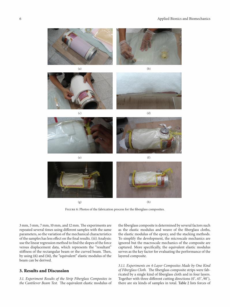
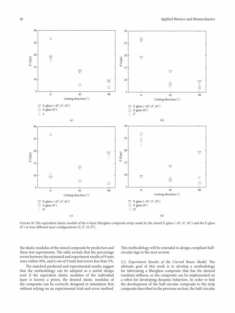
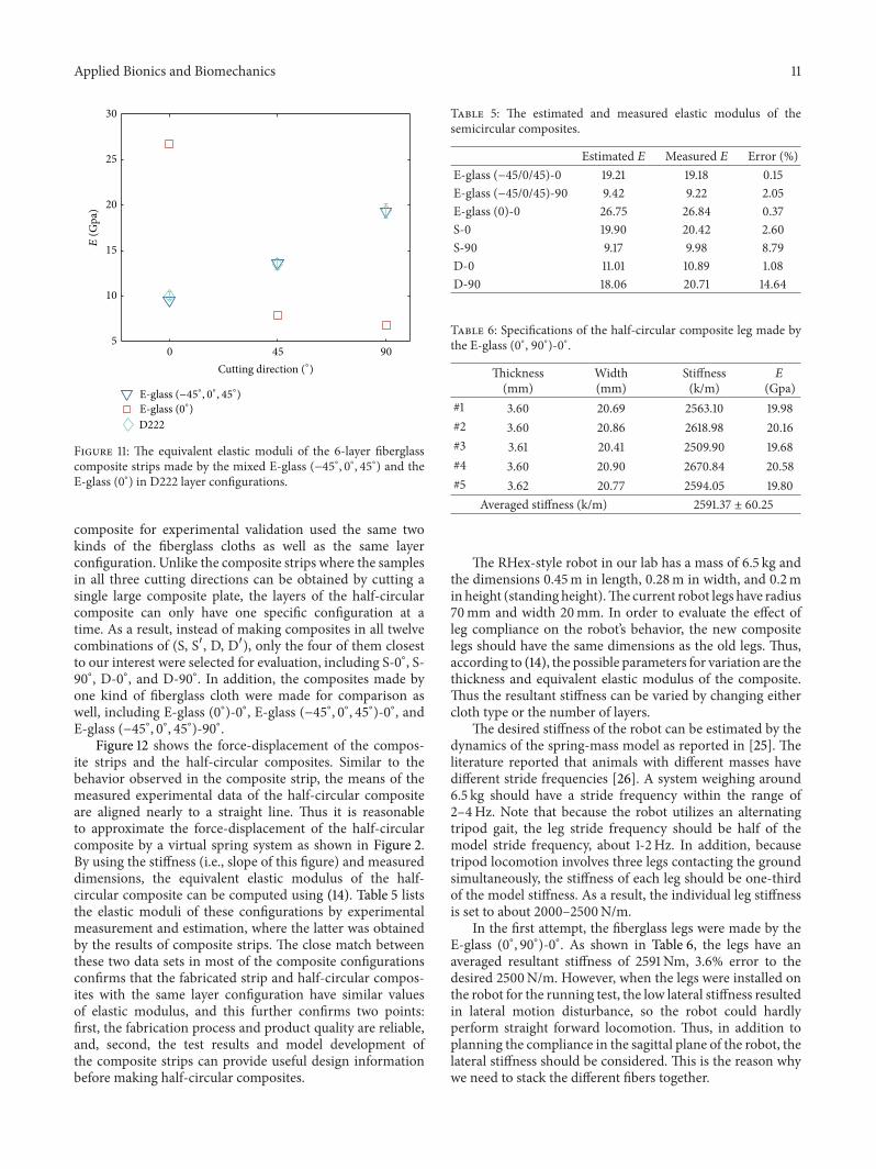

International Journal of
AerospaceEngineeringHindawi Publishing Corporationhttpwwwhindawicom Volume 2014
RoboticsJournal of
Hindawi Publishing Corporationhttpwwwhindawicom Volume 2014
Hindawi Publishing Corporationhttpwwwhindawicom Volume 2014
Active and Passive Electronic Components
Control Scienceand Engineering
Journal of
Hindawi Publishing Corporationhttpwwwhindawicom Volume 2014
International Journal of
RotatingMachinery
Hindawi Publishing Corporationhttpwwwhindawicom Volume 2014
Hindawi Publishing Corporation httpwwwhindawicom
Journal ofEngineeringVolume 2014
Submit your manuscripts athttpwwwhindawicom
VLSI Design
Hindawi Publishing Corporationhttpwwwhindawicom Volume 2014
Hindawi Publishing Corporationhttpwwwhindawicom Volume 2014
Shock and Vibration
Hindawi Publishing Corporationhttpwwwhindawicom Volume 2014
Civil EngineeringAdvances in
Acoustics and VibrationAdvances in
Hindawi Publishing Corporationhttpwwwhindawicom Volume 2014
Hindawi Publishing Corporationhttpwwwhindawicom Volume 2014
Electrical and Computer Engineering
Journal of
Advances inOptoElectronics
Hindawi Publishing Corporation httpwwwhindawicom
Volume 2014
The Scientific World JournalHindawi Publishing Corporation httpwwwhindawicom Volume 2014
SensorsJournal of
Hindawi Publishing Corporationhttpwwwhindawicom Volume 2014
Modelling amp Simulation in EngineeringHindawi Publishing Corporation httpwwwhindawicom Volume 2014
Hindawi Publishing Corporationhttpwwwhindawicom Volume 2014
Chemical EngineeringInternational Journal of Antennas and
Propagation
International Journal of
Hindawi Publishing Corporationhttpwwwhindawicom Volume 2014
Hindawi Publishing Corporationhttpwwwhindawicom Volume 2014
Navigation and Observation
International Journal of
Hindawi Publishing Corporationhttpwwwhindawicom Volume 2014
DistributedSensor Networks
International Journal of