Embed Size (px)
Citation preview
Research ArticleLateral Earth Pressure behind Walls Rotating about Baseconsidering Arching Effects
Dong Li, Wei Wang, and Qichang Zhang
Tianjin Key Laboratory of Nonlinear Dynamics and Chaos Control, School of Mechanical, Tianjin University, Tianjin 300072, China
Correspondence should be addressed to Qichang Zhang; [email protected]
Received 2 July 2014; Revised 20 August 2014; Accepted 8 September 2014; Published 11 November 2014
Academic Editor: Limin Sun
Copyright © 2014 Dong Li et al.This is an open access article distributed under the Creative Commons Attribution License, whichpermits unrestricted use, distribution, and reproduction in any medium, provided the original work is properly cited.
In field, the earth pressure on a retaining wall is the common effect of kinds of factors. To figure out how key factors act, it hastaken into account the arching effects together with the contribution from the mode of displacement of a wall to calculate earthpressure in the proposed method. Based on Mohr circle, a conversion factor is introduced to determine the shear stresses betweenartificial slices in soil mass. In the light of this basis, a modified differential slices solution is presented for calculation of active earthpressure on a retaining wall. Comparisons show that the result of proposed method is identical to observations from model testsin prediction of lateral pressures for walls rotating about the base.
1. Introduction
Prediction of earth pressure is an important subject ofresearch for design of retaining structures in prone rup-ture region. Rupture mechanism in the backfill behind aretaining structure should take into account the mode ofwall movement. It is common in practice that movementsof retaining wall are considered in terms of translation (T),rotation about base (RB), and rotation about top (RT). Con-ventional earth pressure theories are brought forward onlyfor retaining structures with rigid free translation, such asmethodsmodeled by Coulomb [1], Rankine [2], Khajehzadehet al. [3], Xu [4], and differential slice technique Wang [5].In contrast to the usual methods, the research needs morelight on prediction of lateral earth pressure on a rotatingwall. Terzaghi [6] conducted several large-scale model teststo recognize the importance of walls rotation. Despite the failin measuring the actual stresses against the wall, he arrivedat his conclusions by measuring the total thrust by load cells.Some researches applied pseudodynamic method to analyzethe pressure on the retaining wall, such as [7–10]. However,all of them failed to take into account the arching effectsin the soil. James and Bransby [11] investigated the passivefailure of an initially vertical plane which was rotated aboutits base into a mass of dry sand with an unloaded horizontal
surface. Although the results showed uniformity betweenthe predicted principal compressive stress directions and theobserved principal compressive strain increment direction,this theory only focuses on the failure mechanism of slippingplane and ignores other boundary conditions. Small-scalemodel of retaining walls (e.g., [12, 13]) and field observations[14] have enhanced the understanding of lateral earth pres-sure problems of rotation. Chang used a modified Coulomb’ssolution of active pressure to analyze the earth pressuredistribution due to different wall movements [15]. Recently,Song and Zhang [16] revealed the formation mechanism ofearth pressures against rigid retaining wall with RT and RBmode. Nevertheless, soil arching effects should be taken intoaccount to predict earth pressure distributions for applicationof advanced developments.
Granular matters exhibit some unique character, suchas arching effects, which inspire the interest of a lot ofscholars [17–20]. Soil arching behavior develops when theearth pressure transfers from the yielding part of soil to theadjacent part. Terzaghi [21] used trap door tests to explainhow pressure transferred from yielding parts of a soil mass toadjoined stationary; nonyielding parts led to the formation ofan arching zone. Following this pioneering study, numerousworks have been carried out to investigate the arching effectin various engineering problems. Handy [22] deduced the
Hindawi Publishing CorporationMathematical Problems in EngineeringVolume 2014, Article ID 715891, 7 pageshttp://dx.doi.org/10.1155/2014/715891
2 Mathematical Problems in Engineering
distribution of lateral earth pressure behind a retaining wallby assuming that the curve describing the minor principalstress is a catenary. Later, Harrop-Williams [23] theoreticallyderived that the shape of the arch can be approximated bya circular arc to cohere with the assumption of constantstresses along the arch. Paik and Salgado [24] proposed anew formulation for calculating the active earth pressure on arigid retaining wall undergoing horizontal translation, whichtook into account the arching effects that occurred in theretained soil mass. Jiang et al. [25] theoretically analyzed theshape of the minor principal stress arch. Using finite elementmethod, Potts and Zdravkovic [26] reviewed the nature ofthe soil arching that developed in the retained soil mass.Nadukuru and Michalowski [27] applied discrete elementmethod for calculation of active loads on retaining structureswith different movements. The results showed that archingandmodes of wall movements appear to be the primary causeaffecting the pressure distribution.
Motivated by the above literature review, this paperfocuses on an analytical method for the earth pressuredistribution on a rigid wall rotating about base (RB) withconsideration of the arching effects. First, it infers suitablelateral earth coefficients 𝐾 assuming that the arch formsa part of circular arc in the soil. Then using differentialslice technique as the framework of analysis, a reasonableformula is proposed for RB. It adopts a simple conceptof average friction angle of soil to relate the mobilizedshearing resistance towall displacement. At last, comparisonsare made between the prediction of proposed method andexisting experiments results.
2. Basic Theory
As Terzaghi alluded, archingmay play a role in distribution ofpressures on retaining structures. Whereas the term archinghas been accepted in the geotechnical literature, the conceptdoes not relate to the formation of a physical arch but rathera distribution of pressures for which stiffer components ofthe system attract more loads. According to Terzaghi’s theory,a column of soil is assumed to move downwards under theinfluence of its own weight and is restrained by friction alongthe boundary of this falling column and the surrounding soilmass. In a similar way to Handy’s method, it is to substitute acircular arc describing the path of the minor principal stressto mimic soil arching effects [24].
3. Lateral Earth Pressure of Coefficients
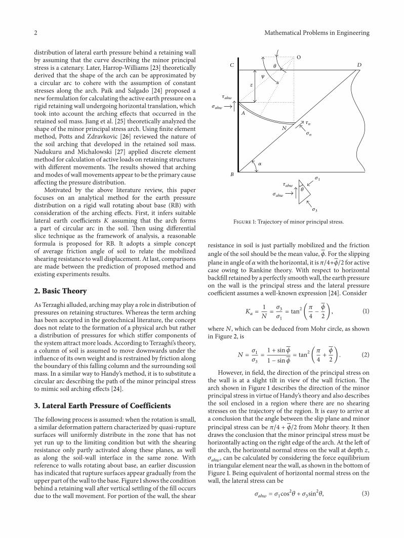
The following process is assumed: when the rotation is small,a similar deformation pattern characterized by quasi-rupturesurfaces will uniformly distribute in the zone that has notyet run up to the limiting condition but with the shearingresistance only partly activated along these planes, as wellas along the soil-wall interface in the same zone. Withreference to walls rotating about base, an earlier discussionhas indicated that rupture surfaces appear gradually from theupper part of thewall to the base. Figure 1 shows the conditionbehind a retaining wall after vertical settling of the fill occursdue to the wall movement. For portion of the wall, the shear
z
𝜏n
𝜎n
𝛼
𝜃
𝜃
𝜓
A
B
C D
N
𝜎1
O
𝜎3
𝜏ahw
𝜎ahw
𝜏ahw
𝜎ahw
Figure 1: Trajectory of minor principal stress.
resistance in soil is just partially mobilized and the frictionangle of the soil should be the mean value, 𝜙. For the slippingplane in angle of𝛼with the horizontal, it is𝜋/4+𝜙/2 for activecase owing to Rankine theory. With respect to horizontalbackfill retained by a perfectly smoothwall, the earth pressureon the wall is the principal stress and the lateral pressurecoefficient assumes a well-known expression [24]. Consider
𝐾𝑎=1
𝑁=𝜎3
𝜎1
= tan2 (𝜋4−𝜙
2) , (1)
where𝑁, which can be deduced from Mohr circle, as shownin Figure 2, is
𝑁 =𝜎1
𝜎3
=1 + sin𝜙1 − sin𝜙
= tan2 (𝜋4+𝜙
2) . (2)
However, in field, the direction of the principal stress onthe wall is at a slight tilt in view of the wall friction. Thearch shown in Figure 1 describes the direction of the minorprincipal stress in virtue of Handy’s theory and also describesthe soil enclosed in a region where there are no shearingstresses on the trajectory of the region. It is easy to arrive ata conclusion that the angle between the slip plane and minorprincipal stress can be 𝜋/4 + 𝜙/2 from Mohr theory. It thendraws the conclusion that the minor principal stress must behorizontally acting on the right edge of the arch. At the left ofthe arch, the horizontal normal stress on the wall at depth 𝑧,𝜎𝑎ℎ𝑤
, can be calculated by considering the force equilibriumin triangular element near the wall, as shown in the bottom ofFigure 1. Being equivalent of horizontal normal stress on thewall, the lateral stress can be
𝜎𝑎ℎ𝑤
= 𝜎1cos2𝜃 + 𝜎
3sin2𝜃, (3)
Mathematical Problems in Engineering 3
N(𝜎n𝜏n)
𝜑
𝜎𝜎3𝜎3
𝜎1
𝜎1
𝛿 𝜃
𝜏
O𝜏ahw
𝜎ahw
𝜏aw
𝜎aw
M(𝜎a𝜏a)
A(𝜎ahw𝜏ahw)
Figure 2: Mohr circle for earth stresses near the wall.
where 𝜃 describes the direction of the major principal stresswith respect to horizontal near the wall. The conjugatevertical normal stress is expressed by
𝜎𝑎V𝑤 = 𝜎1sin
2
𝜃 + 𝜎3cos2𝜃. (4)
Similarly, the horizontal normal stress at the random pointalong the archwith angle𝜓 to the horizontal can be expressedby
𝜎𝑎ℎ= 𝜎1cos2𝜓 + 𝜎
3sin2𝜓. (5)
The conjugate vertical normal stress is given by
𝜎𝑎V = 𝜎1sin
2
𝜓 + 𝜎3cos2𝜓. (6)
Dividing (5) and (6) by 𝜎1and substituting 𝜎
3/𝜎1= 1/𝑁 can
derive𝜎𝑎ℎ
𝜎1
= cos2𝜓 + 1
𝑁sin2𝜓,
𝜎𝑎V
𝜎1
= sin2𝜓 + 1
𝑁cos2𝜓.
(7)
Based on the theory of Mohr circle, as shown in Figure 2, theshear stress, 𝜏
𝑎ℎ𝑤, on the left edge of the arch is given by
𝜏𝑎ℎ𝑤
= 𝜎𝑎ℎ𝑤
tan 𝛿 = (𝜎𝑎ℎ𝑤
− 𝜎3) tan 𝜃. (8)
Thus,
tan 𝜃 =𝜎𝑎ℎ𝑤
tan 𝛿𝜎𝑎ℎ𝑤
− 𝜎3
. (9)
Substitution of (3) into (9) yields a quadratic equation
tan 𝜃 =(𝜎1cos2𝜃 + 𝜎
3sin2𝜃) tan 𝛿
𝜎1cos2𝜃 − 𝜎
3cos2𝜃
=
(𝑁 + tan2𝜃) tan 𝛿𝑁 − 1
.
(10)
Solving (10) for tan 𝜃 gives
tan 𝜃 =(𝑁 − 1) ± √(𝑁 − 1)
2
− 4𝑁tan2𝛿2 tan 𝛿
.(11)
For fear of the error propagation, it is an appropriatemethod-ology to replace tan 𝜃 by character 𝑘. Of the two values givenby (11), the larger one dovetails nicely with the experimentsby Guo and Zhou [28].
The lateral earth pressure coefficient can be defined by theratio of the horizontal stress to the vertical stress. As for a slicewith depth 𝑧 from the surface of the backfill, the lateral earthpressure coefficient is bound up with the horizontal normalstress and the average vertical normal stress. The verticalnormal stress acting on the unit arch, corresponding to thegiven slice, can be calculated as
d𝑉 = 𝜎1(sin2𝜓 + 1
𝑁cos2𝜓) (𝑅 sin𝜓d𝜓) , (12)
where𝑅 is the radius of the arch, representingminor principalstress trajectory, and it can be given by
𝑅 =𝐻 − 𝑧
1 − sin 𝜃 + cos 𝜃 tan𝛼. (13)
Thevertical component of average normal stress along thearch can be calculated by
𝜎𝑎V =
∫𝜋/2
𝜃
d𝑉𝑅 cos 𝜃
= ∫
𝜋/2
𝜃
𝜎1(sin2𝜓 + 1
𝑁cos2𝜓)
sin𝜓cos 𝜃
d𝜓
= 𝜎1(1 −
𝑁 − 1
3𝑁cos2𝜃) .
(14)
4 Mathematical Problems in Engineering
z
(𝜎 , 𝜏)
𝜏n
𝜎n
𝛼
(𝜎 + d𝜎 , 𝜏 + d𝜏)
𝜏ahw
𝜎ahw
Figure 3: Free body diagram of differential slice.
Dividing (1) by (14), it can be derived that
𝐾 =𝜎1cos2𝜃 + 𝜎
3sin2𝜃
𝜎1(1 − ((𝑁 − 1) /3𝑁) cos2𝜃)
=3𝑁cos2𝜃 + 3sin2𝜃3𝑁 − (𝑁 − 1) cos2𝜃
=3𝑁 + 3𝑘
2
1 + 2𝑁 + 3𝑁𝑘2.
(15)
From (15), it should lay great stress on the fact that thelateral earth pressure coefficient only has relation to the ratioof principal stresses (𝑁 = 𝜎
1/𝜎3) and the wall-soil friction
angle (𝛿).The shear stress, 𝜏
𝑎V, corresponding to 𝜎𝑎V can be
obtained in the following way. As shown in Mohr circle, itcan be deduced from triangular diagram that
𝜏𝑎V2
= (𝜎1− 𝜎𝑎V) (𝜎𝑎V − 𝜎3) . (16)
Substituting (14) in (16), it can be obtained that
𝜏𝑎V =
1
3𝜎1cos 𝜃 (1 − 1
𝑁)√3 − cos2𝜃. (17)
Rather, the coefficient ratios between 𝜏𝑎V and 𝜎𝑎V are kept
as the function of 𝜃 and can be exhibited as
𝐾𝑎V =
(𝑁 − 1) cos 𝜃√3 − cos2𝜃3𝑁 − (𝑁 − 1) cos2𝜃
. (18)
According to the trigonometric function, (18) can betransformed into
𝐾𝑎V =
(𝑁 − 1)√2 + 3𝑘2
1 + 2𝑁 + 3𝑁𝑘2. (19)
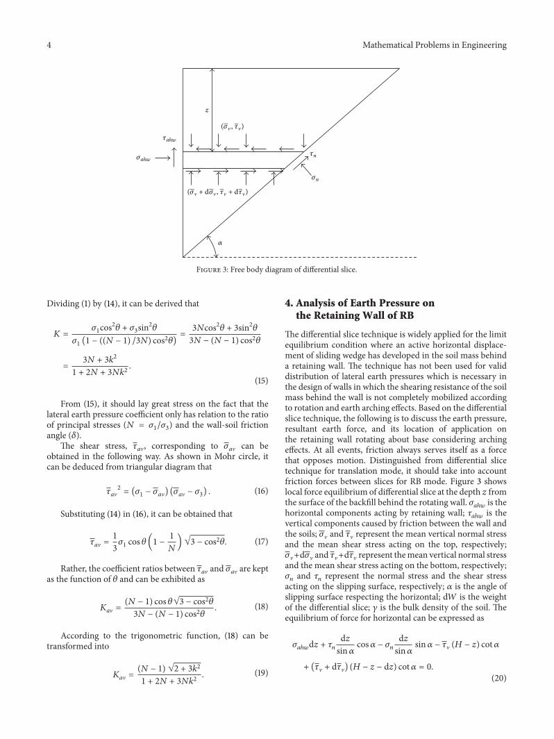
4. Analysis of Earth Pressure onthe Retaining Wall of RB
The differential slice technique is widely applied for the limitequilibrium condition where an active horizontal displace-ment of sliding wedge has developed in the soil mass behinda retaining wall. The technique has not been used for validdistribution of lateral earth pressures which is necessary inthe design of walls in which the shearing resistance of the soilmass behind the wall is not completely mobilized accordingto rotation and earth arching effects. Based on the differentialslice technique, the following is to discuss the earth pressure,resultant earth force, and its location of application onthe retaining wall rotating about base considering archingeffects. At all events, friction always serves itself as a forcethat opposes motion. Distinguished from differential slicetechnique for translation mode, it should take into accountfriction forces between slices for RB mode. Figure 3 showslocal force equilibrium of differential slice at the depth 𝑧 fromthe surface of the backfill behind the rotating wall. 𝜎
𝑎ℎ𝑤is the
horizontal components acting by retaining wall; 𝜏𝑎ℎ𝑤
is thevertical components caused by friction between the wall andthe soils; 𝜎V and 𝜏V represent the mean vertical normal stressand the mean shear stress acting on the top, respectively;𝜎V+d𝜎V and 𝜏V+d𝜏V represent themean vertical normal stressand the mean shear stress acting on the bottom, respectively;𝜎𝑛and 𝜏
𝑛represent the normal stress and the shear stress
acting on the slipping surface, respectively; 𝛼 is the angle ofslipping surface respecting the horizontal; d𝑊 is the weightof the differential slice; 𝛾 is the bulk density of the soil. Theequilibrium of force for horizontal can be expressed as
𝜎𝑎ℎ𝑤
d𝑧 + 𝜏𝑛
d𝑧sin𝛼
cos𝛼 − 𝜎𝑛
d𝑧sin𝛼
sin𝛼 − 𝜏V (𝐻 − 𝑧) cot𝛼
+ (𝜏V + d𝜏V) (𝐻 − 𝑧 − d𝑧) cot𝛼 = 0.(20)
Mathematical Problems in Engineering 5
After elided quadratic differential item, (20) is simplified:
𝜎𝑎ℎ𝑤
d𝑧 + 𝜏𝑛cot𝛼d𝑧 − 𝜎
𝑛d𝑧 + (𝐻 − 𝑧) cot𝛼d𝜏V − 𝜏V cot𝛼d𝑧
= 0.
(21)
Summation of all forces in vertical acting on the differentialslice yields
d𝜎V (𝐻 − 𝑧) cot𝛼 + 𝜏𝑎ℎ𝑤
d𝑧 + 𝜎𝑛d𝑧 cot𝛼 + 𝜏
𝑛d𝑧
− 𝜎Vd𝑧 cot𝛼 − d𝑊 = 0.
(22)
Because of the overt relationship between normal stresses andshear stresses along the wall and along the slipping surface, itis liable to reach the following expressions:
𝜎𝑎ℎ𝑤
= 𝐾𝜎V,
𝜏𝑛= 𝜎𝑛tan𝜙,
𝜏𝑎ℎ𝑤
= 𝜎𝑎ℎ𝑤
tan 𝛿,
𝜏V = 𝐾𝑎V𝜎V,
d𝑊 = 𝛾 (𝐻 − 𝑧) cot𝛼d𝑧.
(23)
Substituting (23) into (21) and (22), the yielded simultaneousequations could be reduced as
d𝜎Vd𝑧
= 𝐴𝛾 −(1 − 𝐵𝐾) 𝜎V
𝐻 − 𝑧, (24)
where
𝐴 =(1 − tan𝜙 cot𝛼)
𝐶,
𝐵 =(1 + tan𝛼 tan𝜙 + tan 𝛿 tan𝛼 − tan 𝛿 tan𝜙)
𝐶,
𝐶 = 1 + cot𝛼 (𝐾𝑎V − tan𝜙) + 𝐾
𝑎V tan𝜙.
(25)
Further, it should be emphasized that the stress integra-tion in (24) over the height must be in accordance with initialcondition of 𝜎V = 0 at 𝑧 = 0. Thus, 𝜎V can be expressed as
𝜎V =𝐴𝐻𝛾
𝐵𝐾 − 2((1 −
𝑧
𝐻) − (1 −
𝑧
𝐻)
𝐵𝐾−1
) . (26)
The horizontal lateral pressure can be got with a given lateralpressure coefficient
𝜎𝑎ℎ𝑤
= 𝐾𝜎V =𝐾𝐴𝛾𝐻((1 − (𝑧/𝐻)) − (1 − (𝑧/𝐻))
𝐵𝐾−1
)
𝐵𝐾 − 2
(27)
and then the horizontal component of the resultant force canbe the integration of (27):
𝐹ℎ= ∫
𝐻
0
𝐾𝐴𝛾𝐻((1 − (𝑧/𝐻)) − (1 − (𝑧/𝐻))𝐵𝐾−1
)
𝐵𝐾 − 2d𝑧
=𝐴𝛾𝐻2
2𝐵𝐾.
(28)
As shown in Figure 1, the total resultant thrust can becalculated as
𝐹𝑇=
𝐹ℎ
cos 𝛿=
𝐴𝛾𝐻2
(4 − 2𝐵𝐾) cos 𝛿. (29)
The application point of the total force is the focus inengineering practice. For the distribution of lateral earthpressure is nonlinear, the height of application of the earthforce on the wall can be obtained by dividing the momentof the lateral earth pressure about the base by the lateralhorizontal earth force. The moment,𝑀, can be the integralof moment of slices about the base
𝑀 = ∫
𝐻
0
𝐾𝐴𝛾𝐻((1 − (𝑧/𝐻))1−𝐵𝐾
− (1 − (𝑧/𝐻)))
𝐵𝐾(𝐻 − 𝑧) d𝑧
=𝐾𝐴𝛾𝐻
3
3 + 3𝐵𝐾
(30)
and the location of application of the total earth force isexpressed as
𝑙 =𝑀
𝐹ℎ
=2𝐵𝐾𝐻
3 + 3𝐵𝐾. (31)
5. Results and Discussion
Results of observation from Fang and Ishibashi [13] modelstudies furnish the basis for the present discussions. Thetests involved a 1m high wall rotating about the base in aloose to medium dense sand (𝜙 = 33.4
∘
→ 40.4∘ and
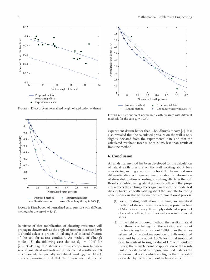
𝛾 = 15.4 kN/m3). The limiting value of wall friction 𝛿 isalways treated as a linear function of internal friction 𝜙 andexpressed as 𝛿 = 𝑎𝜙.With respect to two cases discussed here,it can conservatively replace 𝛿 by 𝛿 = 2𝜙/3. Figure 4 plotsthe calculated values of the point of application of the activethrust with respect to the soil shear strength. The resultsindicate that the arching effects bring about higher location ofactive resultant forces than thosewithout considering archingeffects behind walls rotating about the base. The comparisonalso reveals that only small differences exist between theresults with arching effects and the measured datum.
Figure 5 shows a comparison of calculated lateral pres-sures with Fang’s measurements [13] for the case of RBin sand (𝜙 = 33.4
∘). Such comparison is also done withRankine theory [2] and Choudhury theory [7] as shown inFigure 5. This case is viewed as quasi-active state for theshearing resistance at the base becoming fully mobilized[15]. The curve, plotted as the normalized mobilized lateralpressure in equilibrium state, 𝜎V/𝛾𝐻, versus the normalizeddepth, 𝑧/𝐻, clearly shows the nonlinear lateral earth pressuredistribution.The trajectory agrees with the experimental databy Fang and Ishibashi and the calculated resultant force isabout only 2.64% less than the active Rankine value but hassome difference with Choudhury theory [7].
Prior to rotation, the stress state in the soil will correspondto the initial at-rest condition as naturally deposited sand.
6 Mathematical Problems in Engineering
32 34 36 38 40 420.2
0.22
0.24
0.26
0.28
0.3
0.32
Friction angle of the soil
Loca
tion
of th
e res
ulta
nt fo
rce
Proposed methodNo arching effectsExperimental data
Figure 4: Effect of 𝜙 on normalized height of application of thrust.
Normalized earth pressure
Nor
mal
ized
eart
h de
pth
(l/H
)
Proposed methodRankine method
Experimental dataChoudhury theory in 2006 [7]
0
0.1
0.2
0.3
0.4
0.5
0.6
0.7
0.8
0.9
10 0.1 0.2 0.3 0.4 0.5 0.6 0.7
Figure 5: Distribution of normalized earth pressure with differentmethods for the case 𝜙 = 33.4∘.
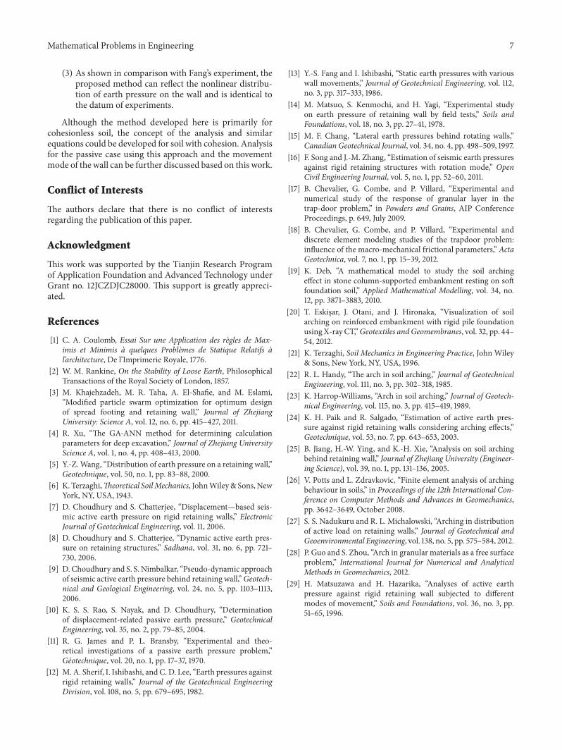
In virtue of that mobilization of shearing resistance willpropagate downwards as the angle of rotation increases [29];it should select a proper initial angle of internal frictionof the soil for at-rest condition. As method of Chang’smodel [15], the following case chooses 𝜙
0= 10.4
∘ for𝜙 = 33.4
∘. Figure 6 shows a similar comparison betweenseveral analytical methods and experimental results for RBin conformity to partially mobilized sand (𝜙
0= 10.4
∘).The comparisons exhibit that the present method fits the
Normalized earth pressure
Nor
mal
ized
eart
h de
pth
(l/H
)
Proposed methodRankine method
Experimental dataChoudhury theory in 2006 [7]
0
0.1
0.2
0.3
0.4
0.5
0.6
0.7
0.8
0.9
10 0.1 0.2 0.3 0.4 0.5 0.6 0.7
Figure 6: Distribution of normalized earth pressure with differentmethods for the case 𝜙
0= 10.4
∘.
experiment datum better than Choudhury’s theory [7]. It isalso revealed that the calculated pressure on the wall is onlyslightly deviated from the experimental data and that thecalculated resultant force is only 2.33% less than result ofRankine method.
6. Conclusion
An analytical method has been developed for the calculationof lateral earth pressure on the wall rotating about baseconsidering arching effects in the backfill. The method usesdifferential slice technique and incorporates the deformationof stress distribution according to arching effects in the soil.Results calculated using lateral pressure coefficient that prop-erly reflects the arching effects agree well with the model testdata for backfilledwalls rotating about the base.The followingconclusions can also be drawn from aforementioned process.
(1) For a rotating wall about the base, an analyticalmethod of shear stresses in slices is proposed in baseofMohr circle theory. It is simply exhibited as productof a scale coefficient with normal stress in horizontalslices.
(2) In the light of proposed method, the resultant lateralsoil thrust exerted against the rotating wall aboutthe base is less by only about 2.68% than the valuesestimated by the Rankine equation for fullymobilizedcase and by only about 2.35% for initial mobilizedcase. In contrast to single value of H/3 with Rankinetheory, the variable point of application of the resul-tant force calculated by proposedmethodmatches theexperimental results which are higher than the valuecalculated by method without arching effects.
Mathematical Problems in Engineering 7
(3) As shown in comparison with Fang’s experiment, theproposed method can reflect the nonlinear distribu-tion of earth pressure on the wall and is identical tothe datum of experiments.
Although the method developed here is primarily forcohesionless soil, the concept of the analysis and similarequations could be developed for soil with cohesion. Analysisfor the passive case using this approach and the movementmode of the wall can be further discussed based on this work.
Conflict of Interests
The authors declare that there is no conflict of interestsregarding the publication of this paper.
Acknowledgment
This work was supported by the Tianjin Research Programof Application Foundation and Advanced Technology underGrant no. 12JCZDJC28000. This support is greatly appreci-ated.
References
[1] C. A. Coulomb, Essai Sur une Application des regles de Max-imis et Minimis a quelques Problemes de Statique Relatifs al’architecture, De l’Imprimerie Royale, 1776.
[2] W. M. Rankine, On the Stability of Loose Earth, PhilosophicalTransactions of the Royal Society of London, 1857.
[3] M. Khajehzadeh, M. R. Taha, A. El-Shafie, and M. Eslami,“Modified particle swarm optimization for optimum designof spread footing and retaining wall,” Journal of ZhejiangUniversity: Science A, vol. 12, no. 6, pp. 415–427, 2011.
[4] R. Xu, “The GA-ANN method for determining calculationparameters for deep excavation,” Journal of Zhejiang UniversityScience A, vol. 1, no. 4, pp. 408–413, 2000.
[5] Y.-Z.Wang, “Distribution of earth pressure on a retaining wall,”Geotechnique, vol. 50, no. 1, pp. 83–88, 2000.
[6] K. Terzaghi,Theoretical SoilMechanics, JohnWiley& Sons,NewYork, NY, USA, 1943.
[7] D. Choudhury and S. Chatterjee, “Displacement—based seis-mic active earth pressure on rigid retaining walls,” ElectronicJournal of Geotechnical Engineering, vol. 11, 2006.
[8] D. Choudhury and S. Chatterjee, “Dynamic active earth pres-sure on retaining structures,” Sadhana, vol. 31, no. 6, pp. 721–730, 2006.
[9] D. Choudhury and S. S. Nimbalkar, “Pseudo-dynamic approachof seismic active earth pressure behind retaining wall,”Geotech-nical and Geological Engineering, vol. 24, no. 5, pp. 1103–1113,2006.
[10] K. S. S. Rao, S. Nayak, and D. Choudhury, “Determinationof displacement-related passive earth pressure,” GeotechnicalEngineering, vol. 35, no. 2, pp. 79–85, 2004.
[11] R. G. James and P. L. Bransby, “Experimental and theo-retical investigations of a passive earth pressure problem,”Geotechnique, vol. 20, no. 1, pp. 17–37, 1970.
[12] M. A. Sherif, I. Ishibashi, and C. D. Lee, “Earth pressures againstrigid retaining walls,” Journal of the Geotechnical EngineeringDivision, vol. 108, no. 5, pp. 679–695, 1982.
[13] Y.-S. Fang and I. Ishibashi, “Static earth pressures with variouswall movements,” Journal of Geotechnical Engineering, vol. 112,no. 3, pp. 317–333, 1986.
[14] M. Matsuo, S. Kenmochi, and H. Yagi, “Experimental studyon earth pressure of retaining wall by field tests,” Soils andFoundations, vol. 18, no. 3, pp. 27–41, 1978.
[15] M. F. Chang, “Lateral earth pressures behind rotating walls,”Canadian Geotechnical Journal, vol. 34, no. 4, pp. 498–509, 1997.
[16] F. Song and J.-M. Zhang, “Estimation of seismic earth pressuresagainst rigid retaining structures with rotation mode,” OpenCivil Engineering Journal, vol. 5, no. 1, pp. 52–60, 2011.
[17] B. Chevalier, G. Combe, and P. Villard, “Experimental andnumerical study of the response of granular layer in thetrap-door problem,” in Powders and Grains, AIP ConferenceProceedings, p. 649, July 2009.
[18] B. Chevalier, G. Combe, and P. Villard, “Experimental anddiscrete element modeling studies of the trapdoor problem:influence of the macro-mechanical frictional parameters,” ActaGeotechnica, vol. 7, no. 1, pp. 15–39, 2012.
[19] K. Deb, “A mathematical model to study the soil archingeffect in stone column-supported embankment resting on softfoundation soil,” Applied Mathematical Modelling, vol. 34, no.12, pp. 3871–3883, 2010.
[20] T. Eskisar, J. Otani, and J. Hironaka, “Visualization of soilarching on reinforced embankment with rigid pile foundationusing X-ray CT,”Geotextiles andGeomembranes, vol. 32, pp. 44–54, 2012.
[21] K. Terzaghi, Soil Mechanics in Engineering Practice, John Wiley& Sons, New York, NY, USA, 1996.
[22] R. L. Handy, “The arch in soil arching,” Journal of GeotechnicalEngineering, vol. 111, no. 3, pp. 302–318, 1985.
[23] K. Harrop-Williams, “Arch in soil arching,” Journal of Geotech-nical Engineering, vol. 115, no. 3, pp. 415–419, 1989.
[24] K. H. Paik and R. Salgado, “Estimation of active earth pres-sure against rigid retaining walls considering arching effects,”Geotechnique, vol. 53, no. 7, pp. 643–653, 2003.
[25] B. Jiang, H.-W. Ying, and K.-H. Xie, “Analysis on soil archingbehind retaining wall,” Journal of Zhejiang University (Engineer-ing Science), vol. 39, no. 1, pp. 131–136, 2005.
[26] V. Potts and L. Zdravkovic, “Finite element analysis of archingbehaviour in soils,” in Proceedings of the 12th International Con-ference on Computer Methods and Advances in Geomechanics,pp. 3642–3649, October 2008.
[27] S. S. Nadukuru and R. L. Michalowski, “Arching in distributionof active load on retaining walls,” Journal of Geotechnical andGeoenvironmental Engineering, vol. 138, no. 5, pp. 575–584, 2012.
[28] P. Guo and S. Zhou, “Arch in granular materials as a free surfaceproblem,” International Journal for Numerical and AnalyticalMethods in Geomechanics, 2012.
[29] H. Matsuzawa and H. Hazarika, “Analyses of active earthpressure against rigid retaining wall subjected to differentmodes of movement,” Soils and Foundations, vol. 36, no. 3, pp.51–65, 1996.

Submit your manuscripts athttp://www.hindawi.com
Hindawi Publishing Corporationhttp://www.hindawi.com Volume 2014
MathematicsJournal of
Hindawi Publishing Corporationhttp://www.hindawi.com Volume 2014
Mathematical Problems in Engineering
Hindawi Publishing Corporationhttp://www.hindawi.com
Differential EquationsInternational Journal of
Volume 2014
Applied MathematicsJournal of
Hindawi Publishing Corporationhttp://www.hindawi.com Volume 2014
Probability and StatisticsHindawi Publishing Corporationhttp://www.hindawi.com Volume 2014
Journal of
Hindawi Publishing Corporationhttp://www.hindawi.com Volume 2014
Mathematical PhysicsAdvances in
Complex AnalysisJournal of
Hindawi Publishing Corporationhttp://www.hindawi.com Volume 2014
OptimizationJournal of
Hindawi Publishing Corporationhttp://www.hindawi.com Volume 2014
CombinatoricsHindawi Publishing Corporationhttp://www.hindawi.com Volume 2014
International Journal of
Hindawi Publishing Corporationhttp://www.hindawi.com Volume 2014
Operations ResearchAdvances in
Journal of
Hindawi Publishing Corporationhttp://www.hindawi.com Volume 2014
Function Spaces
Abstract and Applied AnalysisHindawi Publishing Corporationhttp://www.hindawi.com Volume 2014
International Journal of Mathematics and Mathematical Sciences
Hindawi Publishing Corporationhttp://www.hindawi.com Volume 2014
The Scientific World JournalHindawi Publishing Corporation http://www.hindawi.com Volume 2014
Hindawi Publishing Corporationhttp://www.hindawi.com Volume 2014
Algebra
Discrete Dynamics in Nature and Society
Hindawi Publishing Corporationhttp://www.hindawi.com Volume 2014
Hindawi Publishing Corporationhttp://www.hindawi.com Volume 2014
Decision SciencesAdvances in
Discrete MathematicsJournal of
Hindawi Publishing Corporationhttp://www.hindawi.com
Volume 2014 Hindawi Publishing Corporationhttp://www.hindawi.com Volume 2014
Stochastic AnalysisInternational Journal of