Embed Size (px)
Citation preview
Research ArticleExperimental Investigation of Injection Strategies onLow Temperature Combustion Fuelled with Gasoline ina Compression Ignition Engine
Binbin Yang,1,2 Mingfa Yao,2 Zunqing Zheng,2 and Lang Yue2
1School of Transportation and Vehicle Engineering, Shandong University of Technology, Zibo 255049, China2State Key Laboratory of Engines, Tianjin University, Tianjin 300072, China
Correspondence should be addressed to Mingfa Yao; y [email protected]
Received 9 January 2015; Accepted 3 March 2015
Academic Editor: Ming Huo
Copyright © 2015 Binbin Yang et al. This is an open access article distributed under the Creative Commons Attribution License,which permits unrestricted use, distribution, and reproduction in any medium, provided the original work is properly cited.
The present study focuses on the experimental investigation on the effect of fuel injection strategies on LTC with gasoline on asingle-cylinder CI engine. Firstly, the engine performance and emissions have been explored by sweeping SOI1 and split percentagefor the load of 0.9MPa IMEP at an engine speed of 1500 rpm.Then, the double-injection strategy has been tested for load expansioncompared with single-injection. The results indicate that, with the fixed CA50, the peak HRR is reduced by advancing SOI1 andincreasing split percentage gradually. Higher indicated thermal efficiency, as well as lower MPRR and COV, can be achievedsimultaneously with later SOI1 and higher split percentage. As split percentage increases, NO
𝑋emission decreases but soot emission
increases. CO and THC emissions are increased by earlier SOI1, resulting in a slight decrease in combustion efficiency. Comparedwith single-injection, the double-injection strategy enables successful expansion of high-efficiency and clean combustion region,with increasing soot, CO, and THC emissions at high loads and slightly declining combustion efficiency and indicated thermalefficiency, however. MPRR and soot emission are considered to be the predominant constraints to the load expansion of gasolineLTC, and they are related to their trade-off relationship.
1. Introduction
With great concerns about engine emitted pollutant andglobal warming issues, alternative combustion conceptsare drawing increasing attention worldwide. The conceptsapplied to compression ignition (CI) engines mainly con-sist of homogeneous charge compression ignition (HCCI)[1], premixed charge compression ignition (PCCI) [2], lowtemperature combustion (LTC) [3], and so forth. They allshare the feature of achieving lower temperature combustiontogether with a lean mixture distribution by allowing extratime from end of the injection to start of the combustion(SOC), thereby yielding the simultaneous ultra-low nitrogenoxides (NO
𝑋) and particle matter (PM) emissions, which are
greatly challenged in conventional CI engines. Therefore, allthese combustion concepts can be labeled under the term ofLTC.
LTC concept is generally characterized by long ignitiondelay, high exhaust gas recirculation (EGR) rate, and
premixed charge. With the further research, except thedominating role of chemical kinetics in LTC already beenrecognized, the importance of fuel and air mixing processhas also been realized. However, as the conventional fuel inCI engines, diesel fuel has cetane number (CN) higher than40 and poor volatility, which makes its ideal mixing withair before the onset of combustion unachievable at highengine loads even by the combination of a variety of technicalmeans, for example, high pressure injection, cooled EGR, anddecreased compression ratio [4]. As a result, the operationrange of high-efficiency and clean LTC with diesel is stilllimited within low and medium loads.
Recently, the fuel properties of LTC have gained greatscientific concerns, mainly because fuel properties controlthe time scales of both chemical kinetics and fuel-air mixing.Thus, it is suggested that a less reactive fuel is preferredfor combustion control at high engine loads. In the formerstudies, mixture of gasoline and diesel termed as dieseline
Hindawi Publishing CorporationJournal of ChemistryVolume 2015, Article ID 207248, 10 pageshttp://dx.doi.org/10.1155/2015/207248
2 Journal of Chemistry
by Turner et al. [5] is demonstrated as a promising fuelfor simultaneous reduction of NO
𝑋and soot emissions at a
lower EGR level, owing to the improved premixture by thebetter volatility and lower CN. The relevant works have beenconducted extensively during the past decade [5, 6], but it ischallenging to further increase the engine load. Based on thedeep insight into fuel properties of LTC, Johansson et al. pro-posed to inject gasoline directly into cylinder by common-railsystem, which is referred to as partially premixed combustion(PPC) concept [7]. Under PPC conditions, autoignition canbe made to occur after the fuel and air are well mixed, andsoot emission can be reduced. The successful operation ofPPC concept with gasoline has been estimated to reach 49-50% brake efficiency between 1.5 and 2.6MPa gross indicatedmean effective pressure (IMEP) while keeping low emissions[8]. Meanwhile, mixture concentration distribution can bewell controlled by adjusting injection strategies, which isfavorable for combustion phasing and burning rate control.Furthermore, the high-octane fuel PPC has the ability ofreducing the heavy reliance on the EGR usage in diesel LTC,avoiding the consequent fuel economy penalty.
Nevertheless, a full separation between end of the injec-tion and SOC results in unacceptable pressure oscillationwhich enhances heat transfer and leads to increased specificfuel consumption. Thus, the high pressure rise rate is agreat concern for such premixed combustion. In an effort tosolve the maximum pressure rise rate (MPRR) issue whilemaintaining stable combustion, low-octane gasoline has beenused to avoid the overmixing of fuel and air [9]. The issuemight also be alleviated via applying advanced injectionstrategies, for example, the double-injection strategy pro-posed by Kalghatgi et al. [10]. The research identifies thatgasoline split injection early in the compression stroke helpsreduce MPRR for a given load and enables heat releaseto occur later with low cyclic variation as compared withsingle-injection strategy. Because of that, higher IMEP can bereached with lower smoke and NO
𝑋; for example, one of the
operating points hasmean IMEP of 1.595MPa, as well as AVLsmoke opacity of 0.33% andNO
𝑋of 0.58 g/kWh.The research
group from Wisconsin University has conducted some rel-evant works of comparing the single- and double-injectionstrategy at A50 (1300 rpm @ 1.3MPa IMEP) condition [11].Interestingly, the double-injection strategy produces higherMPRR and NO
𝑋emission as compared to single-injection
strategy, which demonstrates the engine performance andemissions are strongly influenced by injection parametersin multi-injection strategy. Ciatti and Subramanian fromArgonne National Laboratory have proposed three injectionstrategies to struggle for meeting the current emission leg-islation [12]. For the medium and high loads, the partiallypremixed charge is obtained through an earlier injection andthe rest of the fuel is injected around top dead center. Asload increases, the first injection has to be well advancedto prepare sufficient premixing charge. The significance ofmixture stratification resulting from the overlap of fuel sprayand followed combustion in controlling combustion rate hasbeen recognized by Yang et al. [13].
Based on the analysis of the existing problems, the authorsintend to explore the effect of fuelling strategies on LTC with
Table 1: Engine and injector specifications.
Bore (mm) 105Stroke (mm) 125Connecting rod length (mm) 210Squish height (mm) 0.85Displacement (L) 1.08Compression ratio 16 : 1Swirl ratio 1.5IVO (∘CA ATDC) −377IVC (∘CA ATDC) −133EVO (∘CA ATDC) 125EVC (∘CA ATDC) −342
93 research octane number (RON) gasoline. The study isdriven in two steps. Firstly, a sweeping of start of the firstinjection (SOI1) and split percentage is experimented in detailto investigate the effect of these two factors on combustionand emission characteristics, as well as to seek for the keylimiting factors of operation range expansion. Secondly, thedouble-injection strategy is tested at high load conditionfor load expansion, with a baseline experiment with single-injection. Therefore, the current research will be served as atheoretical evidence for the operation range expansion ofhigh-efficiency and clean combustion in CI engines.
2. Experimental Apparatus
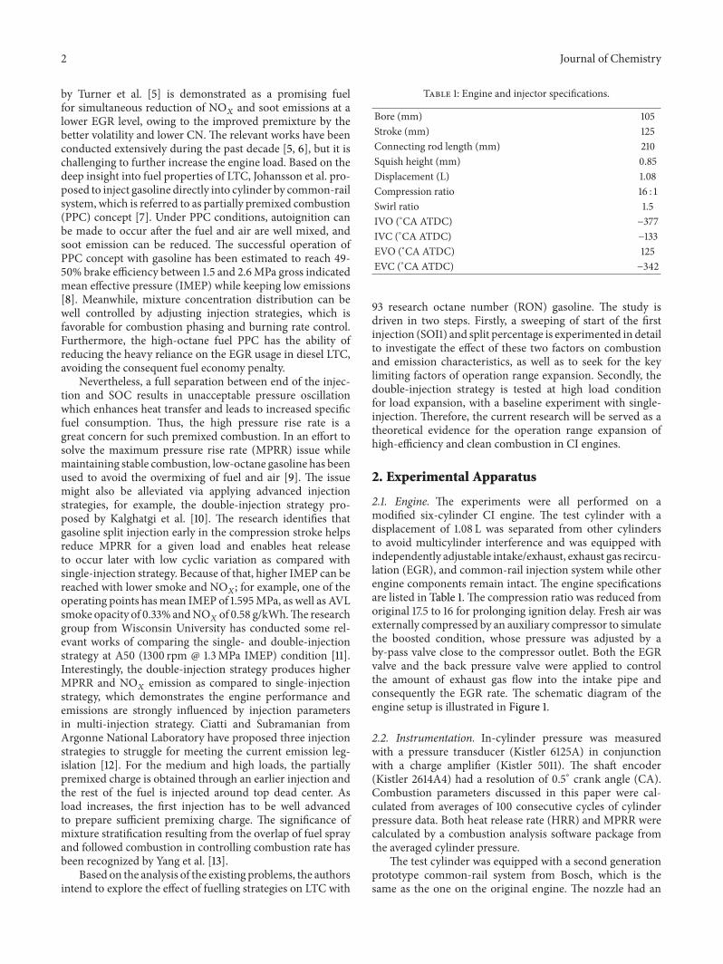
2.1. Engine. The experiments were all performed on amodified six-cylinder CI engine. The test cylinder with adisplacement of 1.08 L was separated from other cylindersto avoid multicylinder interference and was equipped withindependently adjustable intake/exhaust, exhaust gas recircu-lation (EGR), and common-rail injection system while otherengine components remain intact. The engine specificationsare listed in Table 1. The compression ratio was reduced fromoriginal 17.5 to 16 for prolonging ignition delay. Fresh air wasexternally compressed by an auxiliary compressor to simulatethe boosted condition, whose pressure was adjusted by aby-pass valve close to the compressor outlet. Both the EGRvalve and the back pressure valve were applied to controlthe amount of exhaust gas flow into the intake pipe andconsequently the EGR rate. The schematic diagram of theengine setup is illustrated in Figure 1.
2.2. Instrumentation. In-cylinder pressure was measuredwith a pressure transducer (Kistler 6125A) in conjunctionwith a charge amplifier (Kistler 5011). The shaft encoder(Kistler 2614A4) had a resolution of 0.5∘ crank angle (CA).Combustion parameters discussed in this paper were cal-culated from averages of 100 consecutive cycles of cylinderpressure data. Both heat release rate (HRR) and MPRR werecalculated by a combustion analysis software package fromthe averaged cylinder pressure.
The test cylinder was equipped with a second generationprototype common-rail system from Bosch, which is thesame as the one on the original engine. The nozzle had an
Journal of Chemistry 3
11
1514
4
16
M1
2
12
7 8
13 96
5
3
10
(1) Compressor(2) By-pass valve(3) Air flow meter(4) Surge tank(5) Inlet heater(6) Inlet cooler(7) EGR valve(8) Intercooler
(9) One-way valve(10) Pressure transducer(11) Charge amplifier(12) Direct injector(13) Back pressure valve(14) Exhaust analyzer(15) Smoke meter(16) Encoder
Figure 1: Schematic of experimental setup.
umbrella angle of 150∘ and 8 orifices, whose diameter was0.15mm.The ECU for controlling the direct injection systemwas coordinated by software on a PC. The arrangementenabled flexible settings of common-rail pressure, injectiontiming, injection quantity, andmulti-injection strategies.Thefuel flow rate was measured by a fuel consumption meter(AVL 733S) with a gravity scale, and each operating point wassampled for at least 3 minutes.
The concentrations of gaseous emissions, for example,NO𝑋, total hydrocarbon (THC), carbonmonoxide (CO), and
carbon dioxide (CO2), were measured using an exhaust ana-
lyzer (Horiba MEXA-7100DEGR), which measures NO𝑋by
the chemiluminescent method, THC by the flame ionizationmethod, and CO and CO
2by the nondispersive infrared
method. The EGR rate was determined via calculating theratio of intake CO
2to exhaust CO
2concentration, as shown
in (1). Consider
EGR =[CO2]intake
[CO2]exhaust⋅ 100%. (1)
A filter smoke meter (AVL 415S) was utilized to measuresoot levels in terms of filter smoke number (FSN) andchanged into mass by the empirical formula provided by theinstrument manual as follows:
soot = 5.320.405
× FSN × 𝑒0.3062×FSN × 0.001 ×(𝑚air + 𝑚fuel)
1.2929
,
(2)
where𝑚air and𝑚fuel are the intake air flow and fuel consump-tion rate, respectively, kg/h.
During the combustion process, not all the chemicalenergy of fuel has been released. The analysis of the energyutilization that is represented by the combustion efficiency,namely, the fraction that is burned compared to that which issupplied, is calculated using the following [14]:
𝜂comp = (1 −∑
𝑛
𝑖=1𝑥
𝑖𝑄LHV𝑖
𝑄LHVfuel) ⋅ 100%, (3)
where 𝑥𝑖and 𝑄LHV𝑖 represent the mass fractions and lower
heating values (LHV) of HC, CO, and hydrogen (H2),
respectively. For this study,𝑄LHVHC has been treated equal to𝑄LHVfuel.
Combustion stability was expressed by the coefficient ofvariability (COV) of IMEP, and a value of 5% was thoughtto be an acceptable limit for this type of engine. The COV ofIMEP was defined by the following:
COVIMEP =1
IMEPmean
√
∑
𝑁
𝑖=1(IMEP
𝑖− IMEPmean)
2
𝑁 − 1
.
(4)
2.3. Fuel. Commercially available 93 RON gasoline was usedfor all engine tests. Since the high pressure pump and injectorwere originally designed to operatewith diesel fuel, a lubricityagent (Afton H4140 [15]) of 1000 ppm was added to gasolinefuel to avoid failure of the common-rail injection system.Thephysical and chemical properties of H4140 lubricity agentwere listed in Table 2.
4 Journal of Chemistry
Table 2: Physical and chemical properties of H4140 lubricity agent.
Physical form LiquidColor Amber (shallow)Density (kg/m3) 0.91Solubility Insoluble in cold water onlyViscosity (cSt@40∘C) 17Flash point (∘C) 100 (closed cup)
20
35
50
65
80
Split
(%)
−70 −60 −50 −40 −30
−15
−14−13
−12
−11
−10
−9.0
−8.0
−6.0−4.0
SOI1 (∘CA ATDC)
SOI2 (∘CA ATDC)
Figure 2: SOI2 as a function of SOI1 and split percentage; CA50 setat 10∘CA ATDC.
3. Results
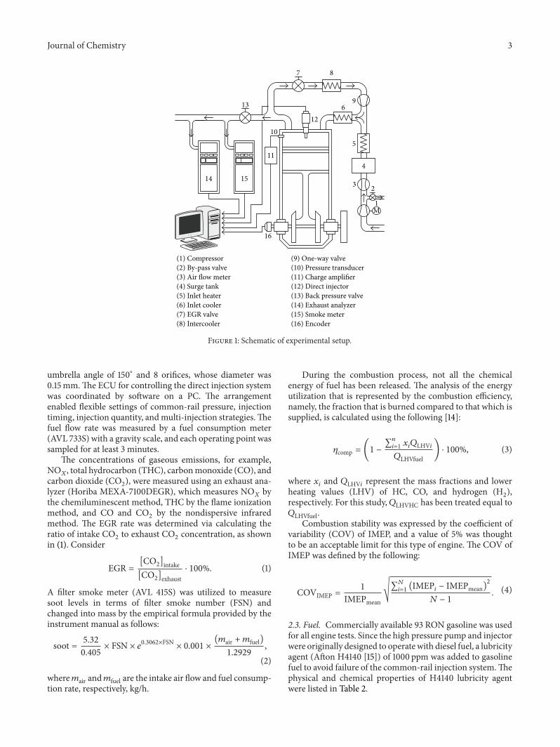
3.1. SOI1 and Split Percentage Sweeping. The major parame-ters affecting gasoline autoignition considered herein includeSOI1 and split percentage. Thus, a sweep in SOI1 and splitpercentage had firstly been conducted to seek for opti-mized engine performance and emissions. In this section,the experiments were carried out for the load of 0.9MPaIMEP (fuelling rate of 50mg/cycle) at an engine speed of1500 rpm. SOI1 was altered from −30 to −70∘CA after topdead center (ATDC) with an interval of 15∘CA and fuel splitpercentage from 20% to 80% in 10% intervals, where theremaining fuel was injected in the following injection event.Intake pressure and temperature were raised sufficiently to220 kPa abs. and 323K, respectively, for stable combustion.A baseline EGR level of 45% was used to avoid combustionreactions during the early stage of the compression stroke.Since the cone angle of the injector is as large as 150∘, anappropriately lower injection pressure of 40MPa was appliedto reduce spray penetration, avoiding fuel wall-impingementand entering into the crevice volume. During the SOI1 andsplit percentage sweeping, the combustion phase of 50%accumulative heat release (CA50) was maintained at 10∘CAATDC, for the efficient combustion coupled with acceptablepressure rise rate. Since EGR rate was kept constant duringthe experiments, CA50 was mainly controlled by start of thesecond injection (SOI2).
The contour plot in Figure 2 clearly shows the SOI2 asa function of SOI1 and split percentage to keep CA50 fixed.
0 10 20 30 40
0
100
200
300
400Split (%) = 50%
Crank angle (∘CA ATDC)−20 −10
Hea
t rele
ase r
ate (
J/∘CA
)
SOI1: −30∘CA ATDCSOI1: −40∘CA ATDCSOI1: −50∘CA ATDC
SOI1: −60∘CA ATDCSOI1: −70∘CA ATDC
Figure 3: Heat release profile as a function of SOI1; split percentageset at 50%.
When SOI1 is advanced, the split fuel and airmixture get evenleaner locally and its reactivity is weakened as a consequence,so SOI2 has to be put forward. With the increase of fuelamount in the first injection, the richer premixed chargewith enhanced reaction activity has shown the potential toadvance the combustion process, so SOI2 has to be delayedfor the fixed CA50. It can therefore be concluded that SOI2should be put forward along with the earlier SOI1 and lowersplit percentage and retarded closer to TDC otherwise.
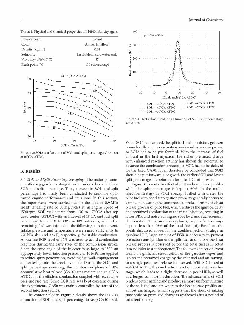
Figure 3 presents the effect of SOI1 on heat release profileswhile the split percentage is kept at 50%. In the multi-injection strategy in PCCI concept fuelled with diesel, thepilot fuel with good autoignition property generally occurs tocombustion during the compression stroke, forming the heatrelease process of pilot fuel, which reduces the ignition delayand premixed combustion of the main injection, resulting inlower PRR and noise but higher soot level and fuel economydeterioration.Thus, on an energy basis, the pilot fuel is alwayskept to less than 25% of the total fuel [16]. Based on thepoints discussed above, for the double-injection strategy ingasoline LTC, large amount of EGR is necessary to preventpremature autoignition of the split fuel, and no obvious heatrelease process is observed before the total fuel is injectedinto cylinder as a consequence.The following injection eventforms a significant stratification of the gasoline vapor andignites the premixed charge by the split fuel and air mixing,so a single-peak heat release is observed. With SOI1 fixed at−30∘CA ATDC, the combustion reaction occurs at an earlierstage, which leads to a slight decrease in peak HRR, as wellas a longer combustion duration. The advancement of SOI1renders better mixing and produces a more uniform mixtureof the split fuel and air, whereas the heat release profiles arealmost unchanged, which suggests that the effect of mixingtime scale on premixed charge is weakened after a period ofsufficient mixing.
Journal of Chemistry 5
0 10 20 30 40
0
100
200
300
400
−20 −10
Crank angle (∘CA ATDC)
Hea
t rele
ase r
ate (
J/∘CA
)
Split (%) = 20%Split (%) = 35%Split (%) = 50%
Split (%) = 65%Split (%) = 80%
SOI1 = −60∘CA ATDC
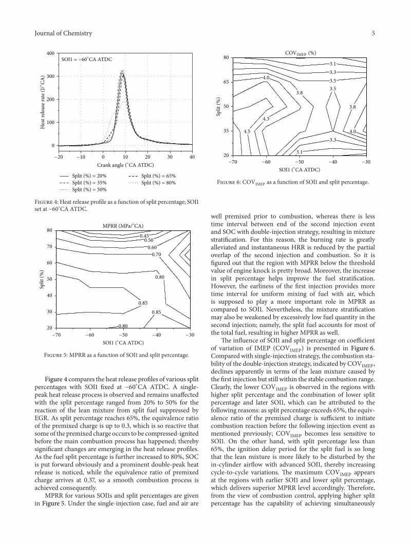
Figure 4: Heat release profile as a function of split percentage; SOI1set at −60∘CA ATDC.
0.80
0.70
0.85
0.600.50
0.45
0.85
0.8020
30
40
50
60
70
80
Split
(%)
−70 −60 −50 −40 −30
SOI1 (∘CA ATDC)
MPRR (MPa/∘CA)
Figure 5: MPRR as a function of SOI1 and split percentage.
Figure 4 compares the heat release profiles of various splitpercentages with SOI1 fixed at −60∘CA ATDC. A single-peak heat release process is observed and remains unaffectedwith the split percentage ranged from 20% to 50% for thereaction of the lean mixture from split fuel suppressed byEGR. As split percentage reaches 65%, the equivalence ratioof the premixed charge is up to 0.3, which is so reactive thatsomeof the premixed charge occurs to be compressed-ignitedbefore the main combustion process has happened; therebysignificant changes are emerging in the heat release profiles.As the fuel split percentage is further increased to 80%, SOCis put forward obviously and a prominent double-peak heatrelease is noticed, while the equivalence ratio of premixedcharge arrives at 0.37, so a smooth combustion process isachieved consequently.
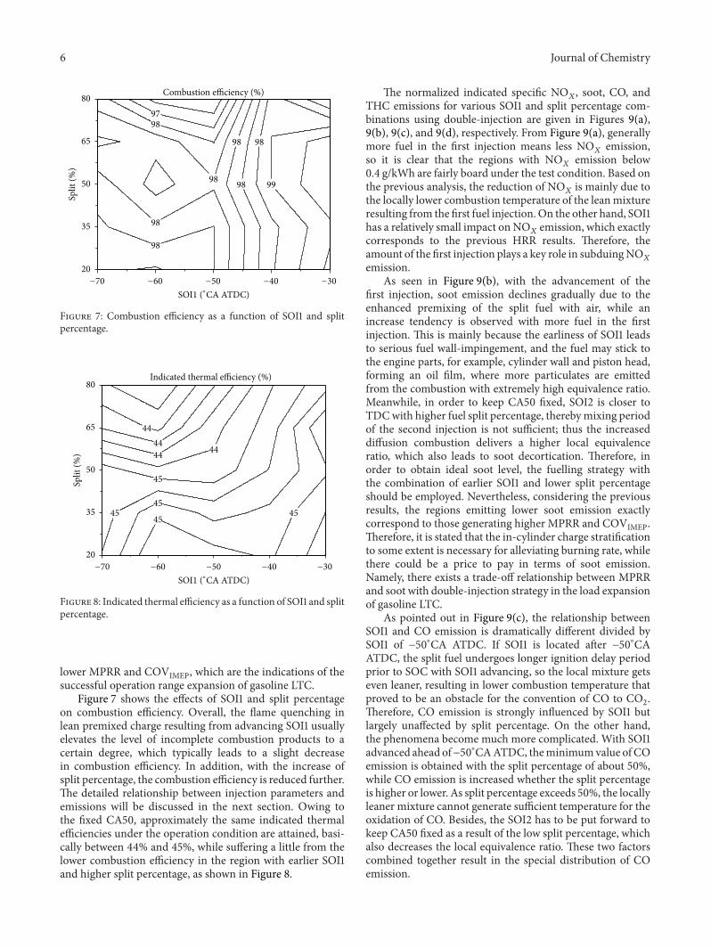
MPRR for various SOI1s and split percentages are givenin Figure 5. Under the single-injection case, fuel and air are
4.5
4.3
4.0
3.8
3.53.5
3.3
3.3
3.8
3.1
3.1
4.0
20
35
50
65
80
Split
(%)
−70 −60 −50 −40 −30
SOI1 (∘CA ATDC)
COVIMEP (%)
Figure 6: COVIMEP as a function of SOI1 and split percentage.
well premixed prior to combustion, whereas there is lesstime interval between end of the second injection eventand SOC with double-injection strategy, resulting in mixturestratification. For this reason, the burning rate is greatlyalleviated and instantaneous HRR is reduced by the partialoverlap of the second injection and combustion. So it isfigured out that the region with MPRR below the thresholdvalue of engine knock is pretty broad. Moreover, the increasein split percentage helps improve the fuel stratification.However, the earliness of the first injection provides moretime interval for uniform mixing of fuel with air, whichis supposed to play a more important role in MPRR ascompared to SOI1. Nevertheless, the mixture stratificationmay also be weakened by excessively low fuel quantity in thesecond injection; namely, the split fuel accounts for most ofthe total fuel, resulting in higher MPRR as well.
The influence of SOI1 and split percentage on coefficientof variation of IMEP (COVIMEP) is presented in Figure 6.Compared with single-injection strategy, the combustion sta-bility of the double-injection strategy, indicated by COVIMEP,declines apparently in terms of the lean mixture caused bythe first injection but still within the stable combustion range.Clearly, the lower COVIMEP is observed in the regions withhigher split percentage and the combination of lower splitpercentage and later SOI1, which can be attributed to thefollowing reasons: as split percentage exceeds 65%, the equiv-alence ratio of the premixed charge is sufficient to initiatecombustion reaction before the following injection event asmentioned previously; COVIMEP becomes less sensitive toSOI1. On the other hand, with split percentage less than65%, the ignition delay period for the split fuel is so longthat the lean mixture is more likely to be disturbed by thein-cylinder airflow with advanced SOI1, thereby increasingcycle-to-cycle variations. The maximum COVIMEP appearsat the regions with earlier SOI1 and lower split percentage,which delivers superior MPRR level accordingly. Therefore,from the view of combustion control, applying higher splitpercentage has the capability of achieving simultaneously
6 Journal of Chemistry
98
98
98
98
98
9998
9897
20
35
50
65
80
Split
(%)
Combustion efficiency (%)
SOI1 (∘CA ATDC)−70 −60 −50 −40 −30
Figure 7: Combustion efficiency as a function of SOI1 and splitpercentage.
45
45
45
444444
44
4545
20
35
50
65
80
Split
(%)
Indicated thermal efficiency (%)
−70 −60 −50 −40 −30
SOI1 (∘CA ATDC)
Figure 8: Indicated thermal efficiency as a function of SOI1 and splitpercentage.
lower MPRR and COVIMEP, which are the indications of thesuccessful operation range expansion of gasoline LTC.
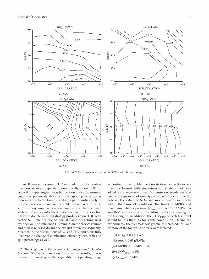
Figure 7 shows the effects of SOI1 and split percentageon combustion efficiency. Overall, the flame quenching inlean premixed charge resulting from advancing SOI1 usuallyelevates the level of incomplete combustion products to acertain degree, which typically leads to a slight decreasein combustion efficiency. In addition, with the increase ofsplit percentage, the combustion efficiency is reduced further.The detailed relationship between injection parameters andemissions will be discussed in the next section. Owing tothe fixed CA50, approximately the same indicated thermalefficiencies under the operation condition are attained, basi-cally between 44% and 45%, while suffering a little from thelower combustion efficiency in the region with earlier SOI1and higher split percentage, as shown in Figure 8.
The normalized indicated specific NO𝑋, soot, CO, and
THC emissions for various SOI1 and split percentage com-binations using double-injection are given in Figures 9(a),9(b), 9(c), and 9(d), respectively. From Figure 9(a), generallymore fuel in the first injection means less NO
𝑋emission,
so it is clear that the regions with NO𝑋
emission below0.4 g/kWh are fairly board under the test condition. Based onthe previous analysis, the reduction of NO
𝑋is mainly due to
the locally lower combustion temperature of the leanmixtureresulting from the first fuel injection. On the other hand, SOI1has a relatively small impact on NO
𝑋emission, which exactly
corresponds to the previous HRR results. Therefore, theamount of the first injection plays a key role in subduingNO
𝑋
emission.As seen in Figure 9(b), with the advancement of the
first injection, soot emission declines gradually due to theenhanced premixing of the split fuel with air, while anincrease tendency is observed with more fuel in the firstinjection. This is mainly because the earliness of SOI1 leadsto serious fuel wall-impingement, and the fuel may stick tothe engine parts, for example, cylinder wall and piston head,forming an oil film, where more particulates are emittedfrom the combustion with extremely high equivalence ratio.Meanwhile, in order to keep CA50 fixed, SOI2 is closer toTDCwith higher fuel split percentage, therebymixing periodof the second injection is not sufficient; thus the increaseddiffusion combustion delivers a higher local equivalenceratio, which also leads to soot decortication. Therefore, inorder to obtain ideal soot level, the fuelling strategy withthe combination of earlier SOI1 and lower split percentageshould be employed. Nevertheless, considering the previousresults, the regions emitting lower soot emission exactlycorrespond to those generating higher MPRR and COVIMEP.Therefore, it is stated that the in-cylinder charge stratificationto some extent is necessary for alleviating burning rate, whilethere could be a price to pay in terms of soot emission.Namely, there exists a trade-off relationship between MPRRand soot with double-injection strategy in the load expansionof gasoline LTC.
As pointed out in Figure 9(c), the relationship betweenSOI1 and CO emission is dramatically different divided bySOI1 of −50∘CA ATDC. If SOI1 is located after −50∘CAATDC, the split fuel undergoes longer ignition delay periodprior to SOC with SOI1 advancing, so the local mixture getseven leaner, resulting in lower combustion temperature thatproved to be an obstacle for the convention of CO to CO
2.
Therefore, CO emission is strongly influenced by SOI1 butlargely unaffected by split percentage. On the other hand,the phenomena become much more complicated. With SOI1advanced ahead of−50∘CAATDC, theminimumvalue ofCOemission is obtained with the split percentage of about 50%,while CO emission is increased whether the split percentageis higher or lower. As split percentage exceeds 50%, the locallyleaner mixture cannot generate sufficient temperature for theoxidation of CO. Besides, the SOI2 has to be put forward tokeep CA50 fixed as a result of the low split percentage, whichalso decreases the local equivalence ratio. These two factorscombined together result in the special distribution of COemission.
Journal of Chemistry 7
0.43
0.40
0.360.33
0.30
0.27
0.46
20
35
50
65
80Sp
lit (%
)
−70 −60 −50 −40 −30
SOI1 (∘CA ATDC)
NOX (g/kWh)
(a) NO𝑋
0.0026
0.0050
0.010
0.030
20
35
50
65
80
Split
(%)
soot (g/kWh)
−70 −60 −50 −40 −30
SOI1 (∘CA ATDC)
(b) soot
161514
13
12
11
10
1415
9.0
1617
20
35
50
65
80CO (g/kWh)
−70 −60 −50 −40 −30
SOI1 (∘CA ATDC)
Split
(%)
(c) CO
4.5 4.0 3.5 3.0 2.5 2.0 1.5 1.0 0.800.70
20
35
50
65
80
Split
(%)
THC (g/kWh)
−70 −65 −60 −55 −50 −40 −35−45 −30
SOI1 (∘CA ATDC)
(d) THC
Figure 9: Emissions as a function of SOI1 and split percentage.
As Figure 9(d) shows, THC emitted from the double-injection strategy depends monotonically upon SOI1 ingeneral. By applying earlier split injection under the runningcondition previously described, the spray penetration isincreased due to the lower in-cylinder gas densities early inthe compression stroke, so the split fuel is likely to causeserious spray impingement on combustion chamber wallsurface, or enters into the crevice volume. Thus, gasolineLTCwith double-injection strategy producesmore THCwithearlier SOI1 mainly due to partial flame quenching nearcylinder wall, or unburnedHC remains in the crevice volumeand then is released during the exhaust stroke consequently.Meanwhile, the distributions of CO and THC emissions fullyillustrate the change of combustion efficiency with SOI1 andsplit percentage as well.
3.2. The High Load Performance for Single- and Double-Injection Strategies. Based on the previous results, it wasdecided to investigate the capability of operating range
expansion of the double-injection strategy, while the exper-iment performed with single-injection strategy had beenadded as a reference. Euro VI emission regulation andengine design were adequately considered to determine thecriteria. The values of NO
𝑋and soot emissions were both
within the Euro VI regulation. The limits of MPRR andmaximum cylinder pressure (𝑃max) were set to 1.2MPa/∘CAand 16MPa, respectively, preventing mechanical damage tothe test engine. In addition, the COVIMEP of each test pointshould be less than 5% for stable combustion. During theexperiments, the fuel mass was gradually increased until oneor more of the following criteria were violated.
(i) NO𝑋< 0.4 g/kWh;
(ii) soot < 0.01 g/kWh;(iii) MPRR < 1.2MPa/∘CA;(iv) COVIMEP < 5%;(v) 𝑃max < 16MPa.
8 Journal of Chemistry
Table 3: Parameters of maximum load for different injectionstrategies.
Injection strategies Double SingleSOI1 (∘CA ATDC) −43 —SOI2 (∘CA ATDC) −23.5 −27.3Split percentage 30% —CA50 (∘CA ATDC) 10 10EGR 45% 45%Injection pressure (MPa) 50 50Indicated thermal efficiency 44.1% 44.6%Combustion efficiency 97.3% 98.4%IMEP (MPa) 1.204 1.11MPRR (MPa/∘CA) 1.23 1.18𝑃max (MPa) 12.84 12.66NO𝑋(g/kWh) 0.17 0.32
soot (g/kWh) 0.98 0.76CO (g/kWh) 1.80 1.10THC (g/kWh) 1.16 0.40
0 10 20 30 40 50
0
2
4
6
8
10
12
14
0
100
200
300
400
500
600
700
Cylin
der p
ress
ure (
MPa
)
Double-injectionSingle-injection
−20 −10
Crank angle (∘CA ATDC)
Hea
t rele
ase r
ate (
J/∘CA
)
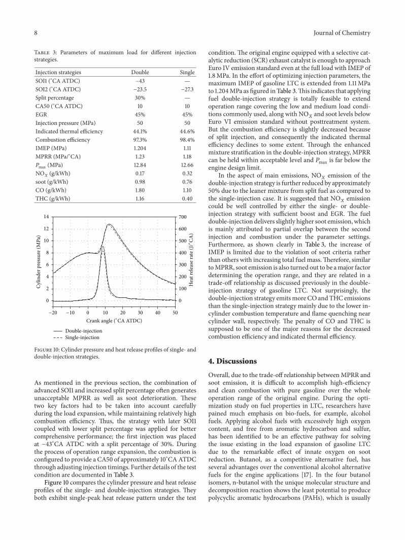
Figure 10: Cylinder pressure and heat release profiles of single- anddouble-injection strategies.
As mentioned in the previous section, the combination ofadvanced SOI1 and increased split percentage often generatesunacceptable MPRR as well as soot deterioration. Thesetwo key factors had to be taken into account carefullyduring the load expansion, while maintaining relatively highcombustion efficiency. Thus, the strategy with later SOI1coupled with lower split percentage was applied for bettercomprehensive performance; the first injection was placedat −43∘CA ATDC with a split percentage of 30%. Duringthe process of operation range expansion, the combustion isconfigured to provide a CA50 of approximately 10∘CAATDCthrough adjusting injection timings. Further details of the testcondition are documented in Table 3.
Figure 10 compares the cylinder pressure and heat releaseprofiles of the single- and double-injection strategies. Theyboth exhibit single-peak heat release pattern under the test
condition. The original engine equipped with a selective cat-alytic reduction (SCR) exhaust catalyst is enough to approachEuro IV emission standard even at the full load with IMEP of1.8MPa. In the effort of optimizing injection parameters, themaximum IMEP of gasoline LTC is extended from 1.11MPato 1.204MPa as figured in Table 3.This indicates that applyingfuel double-injection strategy is totally feasible to extendoperation range covering the low and medium load condi-tions commonly used, along with NO
𝑋and soot levels below
Euro VI emission standard without posttreatment system.But the combustion efficiency is slightly decreased becauseof split injection, and consequently the indicated thermalefficiency declines to some extent. Through the enhancedmixture stratification in the double-injection strategy, MPRRcan be held within acceptable level and 𝑃max is far below theengine design limit.
In the aspect of main emissions, NO𝑋emission of the
double-injection strategy is further reduced by approximately50% due to the leaner mixture from split fuel as compared tothe single-injection case. It is suggested that NO
𝑋emission
could be well controlled by either the single- or double-injection strategy with sufficient boost and EGR. The fueldouble-injection delivers slightly higher soot emission, whichis mainly attributed to partial overlap between the secondinjection and combustion under the parameter settings.Furthermore, as shown clearly in Table 3, the increase ofIMEP is limited due to the violation of soot criteria ratherthan others with increasing total fuel mass.Therefore, similartoMPRR, soot emission is also turned out to be amajor factordetermining the operation range, and they are related in atrade-off relationship as discussed previously in the double-injection strategy of gasoline LTC. Not surprisingly, thedouble-injection strategy emitsmore CO andTHC emissionsthan the single-injection strategy mainly due to the lower in-cylinder combustion temperature and flame quenching nearcylinder wall, respectively. The penalty of CO and THC issupposed to be one of the major reasons for the decreasedcombustion efficiency and indicated thermal efficiency.
4. Discussions
Overall, due to the trade-off relationship betweenMPRR andsoot emission, it is difficult to accomplish high-efficiencyand clean combustion with pure gasoline over the wholeoperation range of the original engine. During the opti-mization study on fuel properties in LTC, researchers havepained much emphasis on bio-fuels, for example, alcoholfuels. Applying alcohol fuels with excessively high oxygencontent, and free from aromatic hydrocarbon and sulfur,has been identified to be an effective pathway for solvingthe issue existing in the load expansion of gasoline LTCdue to the remarkable effect of innate oxygen on sootreduction. Butanol, as a competitive alternative fuel, hasseveral advantages over the conventional alcohol alternativefuels for the engine applications [17]. In the four butanolisomers, n-butanol with the unique molecular structure anddecomposition reaction shows the least potential to producepolycyclic aromatic hydrocarbons (PAHs), which is usually
Journal of Chemistry 9
considered to be the soot precursor [18]. Therefore, superiorengine performance and emissions can be attained usingeither neat n-butanol [19, 20] or its blend with conventionalfossil fuels [21]. However, how to achieve well-organizedcombustion with n-butanol needs much more studies in thefuture.
5. Conclusions
In the present work, experimental study has been conductedto investigate the effect of fuel injection strategies on theengine performance, emissions, and load expansion capabil-ity on a single-cylinder CI engine. The conclusions that canbe withdrawn from this paper are as follows.
(1) With the fixed CA50, the peak HRR is reduced byadvancing SOI1 and increasing split percentage.
(2) Higher indicated thermal efficiency, as well as lowerMPRR andCOVIMEP, can be achieved simultaneouslywith later SOI1 and higher split percentage.
(3) As split percentage increases, NO𝑋
emissiondecreases but soot emission increases. CO and THCemissions are increased by advancing SOI1, resultingin a slight decrease in combustion efficiency.
(4) Compared with the single-injection strategy, thedouble-injection strategy enables successful expan-sion of high-efficiency and clean combustion region,covering the commonly used engine loads. Butsoot, CO, and THC emissions are increased withthe double-injection strategy at high loads, slightlydeclining the combustion efficiency and indicatedthermal efficiency.
(5) MPRR and soot emission are thought to be thepredominant constraints to the load expansion ofgasoline LTC, while they are related to their trade-offrelationship.
Nomenclature
ATDC: After top dead centerCA: Crank angleCA50: The combustion phase of 50%
accumulative heat releaseCI: Compression ignitionCO: Carbon monoxideCO2: Carbon dioxide
COV: Coefficient of variabilityEGR: Exhaust gas recirculationFSN: Filter smoke meterH2: Hydrogen
HCCI: Homogenous charge compression ignitionHRR: Heat release rateIMEP: Indicated mean effective pressureLHV: Lower heating valueLTC: Low temperature combustionMPRR: Maximum pressure rise rateNO𝑋: Nitrogen oxides
PAHs: Polycyclic aromatic hydrocarbons
PCCI: Premixed charge compression ignitionPM: Particle matterPPC: Partially premixed combustionRON: Research octane numberrpm: Revolutions per minuteSCR: Selective catalytic reductionSOC: Start of the combustionSOI1: Start of the first injectionSOI2: Start of the second injectionTHC: Total hydrocarbon.
Conflict of Interests
The authors declare that there is no conflict of interestsregarding the publication of this paper.
Acknowledgments
The research is sponsored by Natural Science Foundation ofChina through the project of Outstanding Young ScholarshipAward (Grant no. 51125026) and Natural Science Foundationof China through its project (Grant no. 51176140).
References
[1] M. Yao, Z. Zheng, and H. Liu, “Progress and recent trends inhomogeneous charge compression ignition (HCCI) engines,”Progress in Energy and Combustion Science, vol. 35, no. 5, pp.398–437, 2009.
[2] W. L. Hardy and R. D. Reitz, “A study of the effects of high EGR,high equivalence ratio, and mixing time on emissions levels ina heavy-duty diesel engine for PCCI combustion,” SAE Paper2006-01-0026, 2006.
[3] M. Alriksson, T. Rente, and I. Denbratt, “Low soot, low NO𝑋in
a heavy duty diesel engine using high levels of EGR,” SAE Paper2005-01-3836, 2005.
[4] S. Kook, C. Bae, P. C. Miles, D. Choi, and L. M. Pickett, “Theinfluence of charge dilution and injection timing on low-temperature diesel combustion and emissions,” SAE Paper2005-01-3837, 2005.
[5] D. Turner, G. Tian, and H. Xu, “An experimental study ofdieseline combustion in a direct injection engine,” SAE Paper2009-01-1101, 2009.
[6] A.Weall and N. Collings, “Investigation into partially premixedcombustion in a light-duty multi-cylinder diesel engine fuelledwith a mixture of gasoline and diesel,” SAE Paper 2007-01-4058,2007.
[7] B. Johansson, “High-load partially premixed combustion in aheavy-duty diesel engine,” in Proceedings of the Directions inEngine Efficiency and Emissions Research Conference (DEER’05), 2005.
[8] V. Manente, B. Johansson, and W. Cannella, “Gasoline par-tially premixed combustion, the future of internal combustionengines?” International Journal of Engine Research, vol. 12, no.3, pp. 194–208, 2011.
[9] L. Hildingsson, G. Kalghatgi, N. Tait, B. Johansson, and A. Har-rison, “Fuel octane effects in the partially premixed combustionregime in compression ignition engines,” SAE Paper 2009-01-2648, 2009.
10 Journal of Chemistry
[10] G. T. Kalghatgi, P. Risberg, and H.-E. Angstrom, “Partiallypre-mixed auto-ignition of gasoline to attain low smoke andlow NOX at high load in a compression ignition engine andcomparison with a diesel fuel,” SAE Paper 2007-01-0006, 2007.
[11] R. Hanson, D. Splitter, and R. Reitz, “Operating a heavy-dutydirect-injection compression-ignition engine with gasoline forlow emissions,” SAE Paper 2009-01-1442, 2009.
[12] S. Ciatti and S. N. Subramanian, “An experimental investigationof low-octane gasoline in diesel engines,” Journal of Engineeringfor Gas Turbines and Power, vol. 133, no. 9, Article ID 092802,2011.
[13] H. Yang, S. Shuai, Z. Wang, and J. Wang, “Fuel octane effectson gasoline multiple premixed compression ignition (MPCI)mode,” Fuel, vol. 103, pp. 373–379, 2013.
[14] J. B. Heywood, Internal Combustion Engine Fundamentals,McGraw-Hill, New York, NY, USA, 1988.
[15] Afton Chemical Corporation, HiTEC 4140 Performance Addi-tive, 2009.
[16] W. D. Ojeda, P. Zoldak, R. Espinosa, and R. Kumar, “Devel-opment of a fuel injection strategy for partially premixedcompression ignition combustion,” SAE Paper 2009-01-1527,2009.
[17] C. Jin, M. Yao, H. Liu, C.-F. F. Lee, and J. Ji, “Progress in theproduction and application of n-butanol as a biofuel,” Renew-able and Sustainable Energy Reviews, vol. 15, no. 8, pp. 4080–4106, 2011.
[18] H. Jin, Y. Wang, K. Zhang, H. Guo, and F. Qi, “An experimentalstudy on the formation of polycyclic aromatic hydrocarbons inlaminar coflow non-premixed methane/air flames doped withfour isomeric butanols,” Proceedings of the Combustion Institute,vol. 34, no. 1, pp. 779–786, 2013.
[19] X. Han, M. Zheng, and J. Wang, “Fuel suitability for lowtemperature combustion in compression ignition engines,”Fuel,vol. 109, pp. 336–349, 2013.
[20] M. Zheng, T. Li, and X. Han, “Direct injection of neat n-butanolfor enabling clean low temperature combustion in a moderndiesel engine,” Fuel, vol. 142, pp. 28–37, 2015.
[21] B. Yang, M. Yao,W. K. Cheng, Z. Zheng, and L. Yue, “Regulatedand unregulated emissions from a compression ignition engineunder low temperature combustion fuelled with gasoline andn-butanol/gasoline blends,” Fuel, vol. 120, pp. 163–170, 2014.

Submit your manuscripts athttp://www.hindawi.com
Hindawi Publishing Corporationhttp://www.hindawi.com Volume 2014
Inorganic ChemistryInternational Journal of
Hindawi Publishing Corporation http://www.hindawi.com Volume 2014
International Journal ofPhotoenergy
Hindawi Publishing Corporationhttp://www.hindawi.com Volume 2014
Carbohydrate Chemistry
International Journal of
Hindawi Publishing Corporationhttp://www.hindawi.com Volume 2014
Journal of
Chemistry
Hindawi Publishing Corporationhttp://www.hindawi.com Volume 2014
Advances in
Physical Chemistry
Hindawi Publishing Corporationhttp://www.hindawi.com
Analytical Methods in Chemistry
Journal of
Volume 2014
Bioinorganic Chemistry and ApplicationsHindawi Publishing Corporationhttp://www.hindawi.com Volume 2014
SpectroscopyInternational Journal of
Hindawi Publishing Corporationhttp://www.hindawi.com Volume 2014
The Scientific World JournalHindawi Publishing Corporation http://www.hindawi.com Volume 2014
Medicinal ChemistryInternational Journal of
Hindawi Publishing Corporationhttp://www.hindawi.com Volume 2014
Chromatography Research International
Hindawi Publishing Corporationhttp://www.hindawi.com Volume 2014
Applied ChemistryJournal of
Hindawi Publishing Corporationhttp://www.hindawi.com Volume 2014
Hindawi Publishing Corporationhttp://www.hindawi.com Volume 2014
Theoretical ChemistryJournal of
Hindawi Publishing Corporationhttp://www.hindawi.com Volume 2014
Journal of
Spectroscopy
Analytical ChemistryInternational Journal of
Hindawi Publishing Corporationhttp://www.hindawi.com Volume 2014
Journal of
Hindawi Publishing Corporationhttp://www.hindawi.com Volume 2014
Quantum Chemistry
Hindawi Publishing Corporationhttp://www.hindawi.com Volume 2014
Organic Chemistry International
ElectrochemistryInternational Journal of
Hindawi Publishing Corporation http://www.hindawi.com Volume 2014
Hindawi Publishing Corporationhttp://www.hindawi.com Volume 2014
CatalystsJournal of