Embed Size (px)
Citation preview
www.wjert.org
118
Peter et al. World Journal of Engineering Research and Technology
EXPERIMENTAL INVESTIGATION OF FLOATING CONCRETE
STRUCTURE USING LIGHT WEIGHT (NATURAL PUMICE STONE)
AGGREGATE
Roshan Peter1*
and A. Anantha Kumar
2
1Civil Engineering, Department of Civil Engineering, M.A.M College of Engineering and
Technology, Trichy, India.
2Assistant Professor, Department of Civil Engineering, M.A.M College of Engineering and
Technology, Trichy, India.
Article Received on 11/02/2016 Article Revised on 02/03/2016 Article Accepted on 22/03/2016
ABSTRACT
This Project deals with the development of Floating type of concrete
by using lightweight aggregate (Pumice stone). In Design of concrete
structures, light weight concrete plays a prominent role in reducing the
density and to increase the thermal insulation. These may relate of both
structural integrity & serviceability. The new sources of Structural
aggregate which is produced from environmental waste is Natural
aggregates and synthetic light weight aggregate. The use of structural
grade light weight concrete reduces the self-weight and helps to
construct larger precast units. In this study, an attempt has been made
to study the Mechanical Properties of a structural grade light weight concrete M20 using the
light weight aggregate pumice stone as a partial replacement to coarse aggregate and mineral
admixture materials like Silica Fume. For this purpose, along with a Control Mix, 6 sets were
prepared to study the compressive strength. Each set comprises of 3 cubes. Slump test were
carried out for each mix in the fresh state. 7-days Compressive test were performed in the
hardened state. The test results showed an overall strength & difference in weight for various
ratios of mix and the best compressive strength is used for the floating structure.
KEYWORDS: Lightweight concrete, Natural aggregate, Pumice stone, Silica fumes,
Floating structure.
ISSN 2454-695X Research Article wjert, 2016, Vol. 2, Issue 2, 118 -129
World Journal of Engineering Research and Technology WJERT
www.wjert.org SJIF Impact Factor: 3.419
*Correspondence for
Author
Roshan Peter (B.E)
B.E, Civil Engineering,
Department of Civil
Engineering, M.A.M
College of Engineering &
Technology, Trichy, India.
www.wjert.org
119
Peter et al. World Journal of Engineering Research and Technology
I. INTRODUCTION
As the global warming possess a threat to human existence near coastal areas, new solutions
are sort after. One such solution is by building floating concrete homes, which are being
constructed in various parts of the world. In line with this thinking, I have endeavoured to
construct a concrete structure with much less weight and has a strength similar to that of a
conventional concrete by introducing pumice stone in place of gravels. Floating on water
means there should be an upward force which is the buoyancy force of the liquid. PUMICE is
a natural sponge-like material of volcanic origin composed of molten lava rapidly cooling
and trapping millions of tiny air bubbles. Pumice is the only rock that floats on water,
although it eventually becomes waterlogged and increases a little in weight. Worldwide, over
50 countries produce pumice products. The largest producer is Italy, which dominates
pozzolonic production. Other major pumice producers are Greece, Chile, Spain, Turkey, and
the United States. Pumice are used to make lightweight construction materials. About three-
quarters of pumice and pumicite are consumed annually for this purpose. The use of light
weight concrete permits greater design flexibility and, reduced dead load, improved cyclic
loading, structural response, better fire ratings and lower foundations costs. Light Weight
Aggregate is a relatively new material. In addition to the reduced dead weight, the lower
modulus of elasticity and adequate ductility of light weight concrete may be advantageous in
the seismic design of structures. Other inherent advantages of the material are its greater fire
resistance, low thermal conductivity, low coefficient of thermal expansion and lower erection
and transport costs for prefabricated members.
II. LITERATURE SURVEY
Floating platform: based on a concrete structure in 2013. This floating structure depends on
the buoyancy force in order to keep the structure floating on water body. Here the weight of
concrete is reduced by adding admixtures such as alumina powder to act as an air entering
agent and cause the concrete platform to reduce in weight. Therefore, making it float in
water.
Effect of silica Fumes on strength and durability parameters of concrete
This was done by Sree Narayana Gurukulam in the year 2012. Adding silica fumes to
Concrete at different ratios of 5% 10% 15% 20% and the compressive strength was noted.
The values of compressive strength were higher compared with control concrete. Even when
this concrete is immersed in hydrochloric acid it can resist better than control concrete.
www.wjert.org
120
Peter et al. World Journal of Engineering Research and Technology
Influence of Silica Fume on Normal Concrete
This was done by D. Dutta in the year 2013. He stated that when silica fumes are added with
concrete and Super plasticizer are added the water consumption reduces by 25% and still has
good workability. The reduce in water increases the strength of concrete. Even though the
super plasticizer helps in reducing the consumption of water the workability of concrete
remains the same.
Concrete canoes was first discovered by an American scientist in the year 2000. The
scientist stated that anything will float on water as long as the water dispersed should be
higher in weight compared to the structural weight floating on water. When a concrete boat is
constructed it is made to float by calculating the water displaced by the object. If the weight
of water displaced is higher than the structure, then the boat will float in water.
III. OBJECTIVE AND SCOPE OF EXPERIMENTAL INVESTIGATION
3.1 Experimental Investigation
The experimental investigation consists of casting and testing of 6 sets along with control
mix. Each set comprises of 3 cubes for determining the compressive strength. Pumice stone is
used in the study with different percentages as a partial replacement to natural weight coarse
aggregate along with the 5% percentages of the Silica Fume as admixture. Cube section
dimension is of 15cmx15cmx15cm, the moulds are applied with a lubricant before placing
the concrete. After a day of casting, the moulds are removed. The cubes are moved to the
curing tank carefully. Here to different batches are made one for 7 days curing and the other
for 28 days curing.
3.1.1 Materials
The constituent materials used in this study are given below:
1. Cement OPC.
2. Normal Weight Coarse Aggregate.
3. Fine Aggregate.
5. Silica Fume.
6. Pumice Stone (Light Weight Coarse Aggregate).
www.wjert.org
121
Peter et al. World Journal of Engineering Research and Technology
IV. MATERIAL PROPERTIES
4.1 Cement
The cement used was ordinary Portland cement of 53- grade conforming to IS 12269. The
cement should be fresh and of uniform consistency. Where there is evidence of lumps or any
foreign matter in the material, it should not be used. The cement should be stored under dry
conditions and for as short duration as possible.
4.2 Aggregates
A) Fine Aggregates
Sand shall be obtained from a reliable supplier and shall comply with ASTM standard C-33
for fine aggregates. It should be clean, hard, strong, and free of organic impurities and
deleterious substance. It should inert with respect to other materials used and of suitable type
with regard to strength, density, shrinkage and durability of mortar made with it. Grading of
the sand is to be such that a mortar of specified proportions is produced with a uniform
distribution of the aggregate, which will have a high density and good workability and which
will work into position without segregation and without use of high water content. The
fineness of the sand should be such that 100% of it passes standard sieve The fine aggregate
which is the inert material occupying 60 to 75 percent of the volume of mortar must get hard
strong nonporous and chemically inert. Fine aggregates conforming to grading zone II with
particles greater than 2.36 mm and smaller than 150 mm removed are suitable.
B) Normal Weight Coarse Aggregate
Machine crushed hard granite chips of 67% passing through 20mm sieve and retained on 12
mm sieve and 33% passing through 12 mm and retained on 10 mm sieve was used a coarse
aggregate throughout the work.
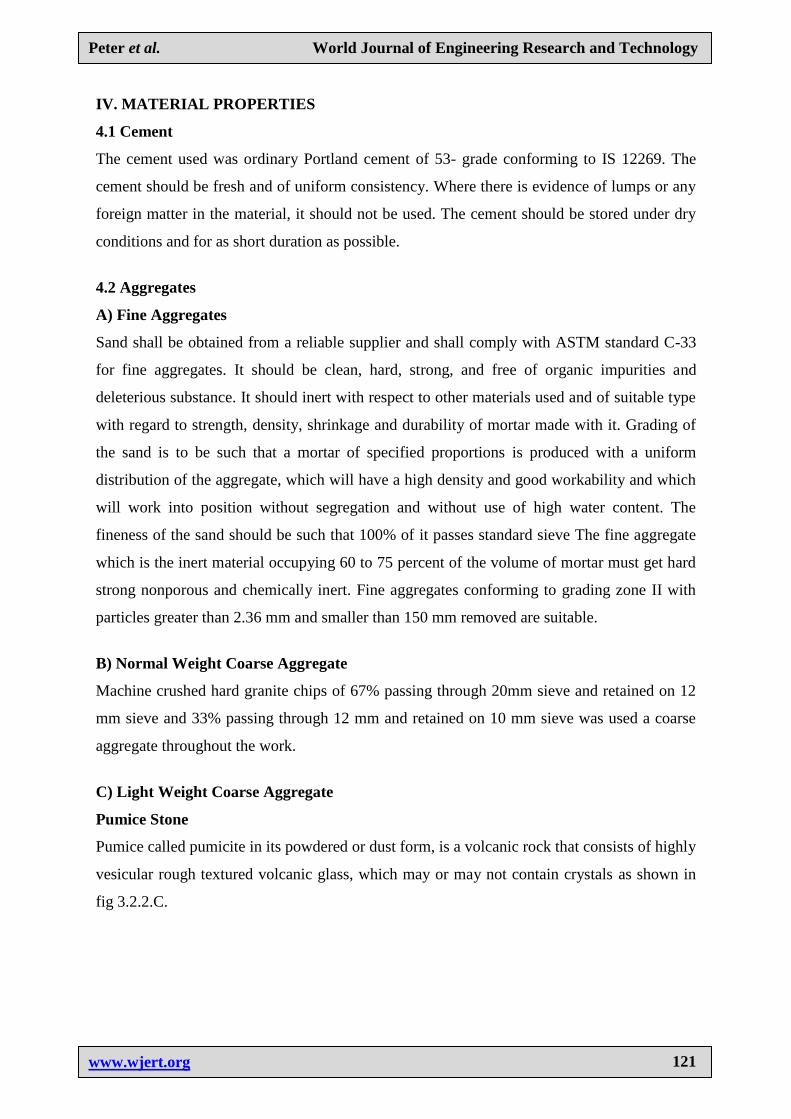
C) Light Weight Coarse Aggregate
Pumice Stone
Pumice called pumicite in its powdered or dust form, is a volcanic rock that consists of highly
vesicular rough textured volcanic glass, which may or may not contain crystals as shown in
fig 3.2.2.C.
www.wjert.org
122
Peter et al. World Journal of Engineering Research and Technology
Fig. 3.2.2.C Pumice Stone.
4.3 Water
Water used in the mixing is to be fresh and free from any organic and harmful solutions
which will lead to deterioration in the properties of the mortar. Salt water is not to be used.
Potable water is fit for use mixing water as well as for curing of beams.
Admixtures
4.4 Silica Fume
Silica fume is a by-product of producing silicon metal or ferrosilicon alloys. One of the most
beneficial uses for silica fume is in concrete. Because of its chemical and physical properties,
it is a very reactive pozzolonic. Concrete containing silica fume can have very high strength
and can be very durable. Silica fume is available from suppliers of concrete admixtures and,
when specified, is simply added during concrete production. Placing, finishing, and curing
silica-fume concrete require special attention on the part of the concrete contractor. Silicon
metal and alloys are produced in electric furnaces. The raw materials are quartz, coal, and
woodchips. The smoke that results from furnace operation is collected and sold as silica
fume, rather than being landfilled. Perhaps the most important use of this material is as a
mineral admixture in concrete. Silica fume consists primarily of amorphous (non-crystalline)
silicon dioxide (SiO2). The individual particles are extremely small, approximately 1/100th
the size of an average cement particle.
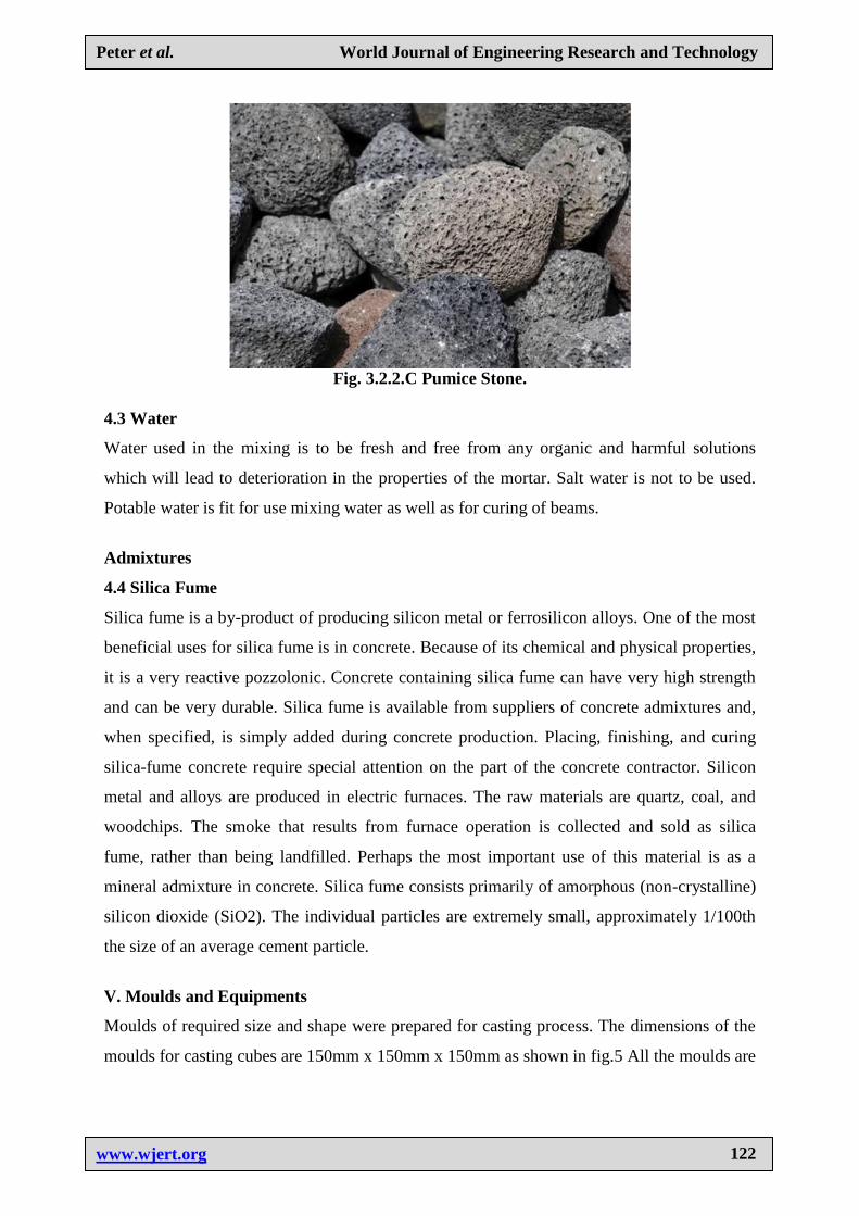
V. Moulds and Equipments
Moulds of required size and shape were prepared for casting process. The dimensions of the
moulds for casting cubes are 150mm x 150mm x 150mm as shown in fig.5 All the moulds are
www.wjert.org
123
Peter et al. World Journal of Engineering Research and Technology
applied lubricant before concreting. After a day of casting moulds are de moulded and then
cubes are moved to the curing tank carefully for curing.
Fig. 5. Mould.
VI. Mix Design
Mix design can be defined as the process of selecting suitable ingredients of concrete and
determining their relative proportions with the object of producing concrete of certain
minimum strength and durability as economically as possible. Mix design for each set having
different combinations are carried out by using IS: 10262 – 2009 method. The mix
proportion obtained for normal M20 grade concrete is 1:1.5:3 with a water-cement ratio of
0.45.
Preparation Of Concrete Cubes
Metal moulds, preferably steel or cast iron, strong enough to prevent distortion is required.
They are made in such a manner as to facilitate the removal of the moulded. Specimen
without damage and are so maintained that, when it is assembled, the dimensions and internal
faces are required to be accurate.
Compacting
The testing cube specimens are made as soon as possible after mixing and in such a manner
to produce full compaction of the concrete with neither segregation nor excessive bleeding.
Curing
The test specimens are stored in a place free from vibration in moist air of at least 90%
relative humidity and at a temperature of 27oC for 24 hours from the time of addition of water
to the dry ingredients. After this period, the specimens are marked and removed from the
moulds.
www.wjert.org
124
Peter et al. World Journal of Engineering Research and Technology
Testing
Compressive Strength
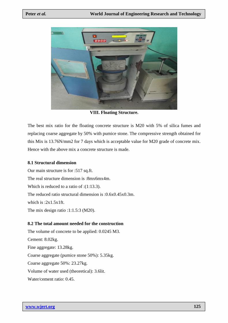
After 7 days curing, cubical specimens are placed on compression testing machine having a
maximum capacity of 3000 KN and a constant rate of loading of 40 kg/m2 per minute is
applied on test specimen. Ultimate load at which the cubical specimen fails is noted down
from dial gauge reading. This ultimate load divided by the area of specimen gives the
compressive strength of each cube.
VII. TEST RESULTS AND DISCUSSIONS
Table 6.1: Compressive strength for control concrete.
S.N. Grade Different
Ratios
Curing
Days
Weight
of Cube
Failure Load
in (KN)
Average
Compressive Strength
1. M20 Conventional
concrete 7 8.635 376 16.72
2. M20
Conventional
concrete + 5%
Silica fumes
7 8.692 439 19.55
3. M20 100% pumice
stone 7 5.453 118 5.27
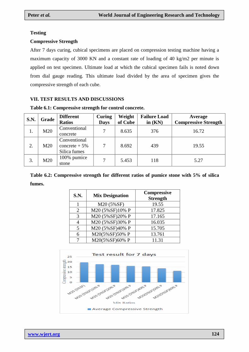
Table 6.2: Compressive strength for different ratios of pumice stone with 5% of silica
fumes.
S.N. Mix Designation Compressive
Strength
1 M20 (5%SF) 19.55
2 M20 (5%SF)10% P 17.825
3 M20 (5%SF)20% P 17.165
4 M20 (5%SF)30% P 16.035
5 M20 (5%SF)40% P 15.705
6 M20(5%SF)50% P 13.761
7 M20(5%SF)60% P 11.31
www.wjert.org
125
Peter et al. World Journal of Engineering Research and Technology
VIII. Floating Structure.
The best mix ratio for the floating concrete structure is M20 with 5% of silica fumes and
replacing coarse aggregate by 50% with pumice stone. The compressive strength obtained for
this Mix is 13.76N/mm2 for 7 days which is acceptable value for M20 grade of concrete mix.
Hence with the above mix a concrete structure is made.
8.1 Structural dimension
Our main structure is for :517 sq.ft.
The real structure dimension is :8mx6mx4m.
Which is reduced to a ratio of :(1:13.3).
The reduced ratio structural dimension is :0.6x0.45x0.3m.
which is :2x1.5x1ft.
The mix design ratio :1:1.5:3 (M20).
8.2 The total amount needed for the construction
The volume of concrete to be applied: 0.0245 M3.
Cement: 8.02kg.
Fine aggregate: 13.28kg.
Coarse aggregate (pumice stone 50%): 5.35kg.
Coarse aggregate 50%: 23.27kg.
Volume of water used (theoretical): 3.6lit.
Water/cement ratio: 0.45.
www.wjert.org
126
Peter et al. World Journal of Engineering Research and Technology
8.3 Design of the structure
The structure is constructed from the basics of Archimedes principle. Which states that any
structure will float on water as long as the weight of water displaced by the structure is more
than the structural weight. Keeping that in mind the structure is constructed with the modified
concrete for the ground floor alone. Here the entire ground floor will be constructed with
concrete which includes the floor and the 4 walls. They are constructed at a single stretch to
make one single structure.
8.4 Total weight of structure
After considering the factor of safety for the total weight of the structure the total weight
calculated for the structure is 63kg.
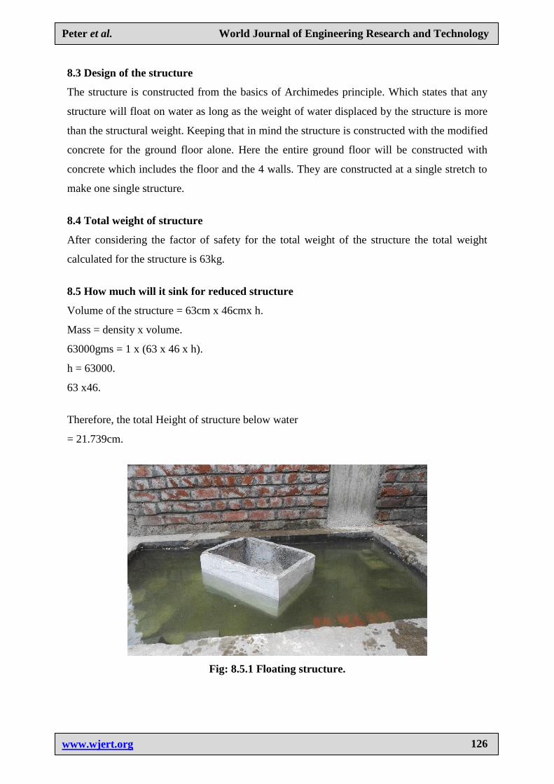
8.5 How much will it sink for reduced structure
Volume of the structure = 63cm x 46cmx h.
Mass = density x volume.
63000gms = 1 x (63 x 46 x h).
h = 63000.
63 x46.
Therefore, the total Height of structure below water
= 21.739cm.
Fig: 8.5.1 Floating structure.
www.wjert.org
127
Peter et al. World Journal of Engineering Research and Technology
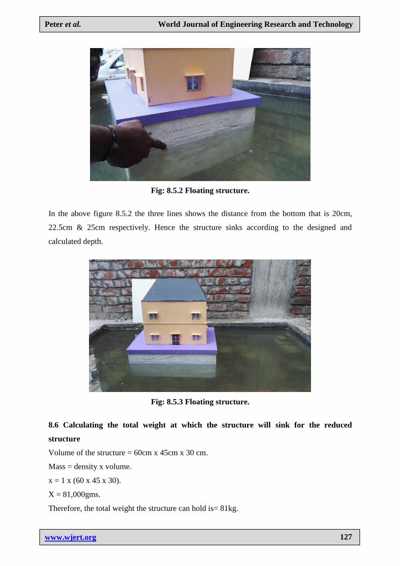
Fig: 8.5.2 Floating structure.
In the above figure 8.5.2 the three lines shows the distance from the bottom that is 20cm,
22.5cm & 25cm respectively. Hence the structure sinks according to the designed and
calculated depth.
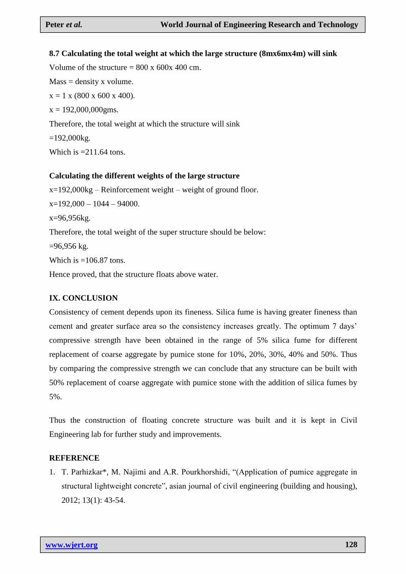
Fig: 8.5.3 Floating structure.
8.6 Calculating the total weight at which the structure will sink for the reduced
structure
Volume of the structure = 60cm x 45cm x 30 cm.
Mass = density x volume.
x = 1 x (60 x 45 x 30).
X = 81,000gms.
Therefore, the total weight the structure can hold is= 81kg.
www.wjert.org
128
Peter et al. World Journal of Engineering Research and Technology
8.7 Calculating the total weight at which the large structure (8mx6mx4m) will sink
Volume of the structure = 800 x 600x 400 cm.
Mass = density x volume.
x = 1 x (800 x 600 x 400).
x = 192,000,000gms.
Therefore, the total weight at which the structure will sink
=192,000kg.
Which is =211.64 tons.
Calculating the different weights of the large structure
x=192,000kg – Reinforcement weight – weight of ground floor.
x=192,000 – 1044 – 94000.
x=96,956kg.
Therefore, the total weight of the super structure should be below:
=96,956 kg.
Which is =106.87 tons.
Hence proved, that the structure floats above water.
IX. CONCLUSION
Consistency of cement depends upon its fineness. Silica fume is having greater fineness than
cement and greater surface area so the consistency increases greatly. The optimum 7 days’
compressive strength have been obtained in the range of 5% silica fume for different
replacement of coarse aggregate by pumice stone for 10%, 20%, 30%, 40% and 50%. Thus
by comparing the compressive strength we can conclude that any structure can be built with
50% replacement of coarse aggregate with pumice stone with the addition of silica fumes by
5%.
Thus the construction of floating concrete structure was built and it is kept in Civil
Engineering lab for further study and improvements.
REFERENCE
1. T. Parhizkar*, M. Najimi and A.R. Pourkhorshidi, “(Application of pumice aggregate in
structural lightweight concrete”, asian journal of civil engineering (building and housing),
2012; 13(1): 43-54.
www.wjert.org
129
Peter et al. World Journal of Engineering Research and Technology
2. N. Sivalinga Rao, Y. Radha Ratna Kumari, V. Bhaskar Desai, B.L.P. Swami, “Fibre
Reinforced Light Weight Aggregate (Natural Pumice Stone) Concrete”, International
Journal of Scientific & Engineering Research, May-2013; 4(5): 2229-5518.
3. Banthia, N. and Trottier, J., ‟Concrete reinforced deformed steel fibbers, part 1: Bond-slip
mechanisms,” ACI Material Journal, 1994; 91(5): 435-446.
4. Compione, G., Mindess, S. and Zingone, G., ‟compressive stress-strain behavior of
normal and high- strength Carbone- fiber concrete reinforced with steel spirals.” ACI
Materials Journal, 1999; 96(1): 27-34.
5. Balaguru, P.; and Ramakrishnan, V. ‟Properties of lightweight fiber reinforced concrete”,
Fiber Reinforced concrete-Properties and applications, SP105, American Concrete
Institute, Detroit, Michigan, 1987; 305-322.
6. Light weight concrete by: Jan Stroband in 2012 in Netherlands.
7. Floating platform: based on a concrete structure in 2013.
8. Concrete canoes: was first discovered by an American scientist in the year 2000.
9. Going to sea in concrete: This idea was first initiated in 1919.
10. Light weight concrete using Oil Palm Shell: This was first invented in 2006.
11. Effect of silica Fumes on strength and durability parameters of concrete: This was done
by Sree Narayana Gurukulam in the year 2012.
12. Influence of Silica Fume on Normal Concrete: This was done by D. Dutta in the year
2013.
13. Comparison of rebound number for M20 concrete with silica fumes: This was performed
by S.S. Kumar in the year 2014.