Embed Size (px)
Citation preview
Research ArticleDynamic Vibration Absorber with NegativeStiffness for Rotor System
Hongliang Yao, Zidong Chen, and BangchunWen
School of Mechanical Engineering and Automation, Northeastern University, Shenyang 110819, China
Correspondence should be addressed to Hongliang Yao; [email protected]
Received 11 July 2016; Revised 14 October 2016; Accepted 23 October 2016
Academic Editor: Mahmoud Bayat
Copyright © 2016 Hongliang Yao et al.This is an open access article distributed under the Creative Commons Attribution License,which permits unrestricted use, distribution, and reproduction in any medium, provided the original work is properly cited.
To suppress the vibration of a rotor system, a vibration absorber combining negative stiffness with positive stiffness together isproposed in this paper. Firstly, the negative stiffness producingmechanism using ring type permanentmagnets is presented and thecharacteristics of the negative stiffness are analyzed. Then, the structure of the absorber is proposed; the principles and nonlineardynamic characteristics of the absorber-rotor system are studied numerically. Finally, experiments are carried out to verify thenumerical conclusions. The results show that the proposed vibration absorber is effective to suppress the vibration of the rotorsystem, the nonlinearity of the negatives stiffness affects the vibration suppression effect little, and the negative stiffness can broadenthe effective vibration control frequency range of the absorber.
1. Introduction
Vibrations of rotor system are the source of many faultsin rotating machinery such as rotor-to-stator rub and shaftcrack growth. Tomaintain the safety operation of the rotatingmachinery, the excessive vibration of rotor system must becontrolled.
Many studies have been carried out about vibrationsuppression methods of rotor systems, which can be largelydivided into three kinds: vibration control by applying exter-nal forces, vibration reduction by adjusting parameters, andvibration absorbing by using dynamic vibration absorbers.
The first kind of method is by applying external forces,which are usually produced by active magnetic bearings oractive magnetic exciters [1–4]. The advantage of magneticforces is that they can be acted on the rotating parts contact-less, thus changing the structure of the rotor little.
The second kind of method is by adjusting parameters ofthe rotor system such as stiffness, damping, and eccentricity,which can be carried out by using shape memory alloymetals [5], discontinuous springs [6], and so forth. In allthese methods, the damping adjusting methods are morepopular and many approaches are used, such as squeezefilm dampers [7], eddy current damping [8, 9], piezoceramic
induced damping [10], magnetorheological elastomer damp-ing [11–13], and friction controlled damping [14]. Eccentricityadjusting is another kind of popular method and is mainlyrealized by using an automatic ball balancer [15, 16], whichcan be very efficient when the rotating speed is above thecritical speed.
The third kind of method is using a vibration absorberor a nonlinear energy sink, by which the vibration of therotor system can be “absorbed.” For example, the centrifugalpendulum vibration absorbers have long been widely usedin torsional vibration suppression [17]. In lateral vibrationattenuation, many studies are also carried out; the vibrationabsorbers are placed on the bearing or foundation [18, 19] orinside the rotating parts [20–22]. As the lateral vibrations ofrotor systemare in both the horizontal and vertical directions,ring type absorbers are widely used for vibration suppressionof the rotor system. For example, in [23], a new kind ofviscoelastic vibration absorber was designed for the rotatingsystem and the experiment results verified the vibrationsuppression effect; in [24], a tunable vibration absorber isdesigned to suppress regenerative chatter in milling process;in [25], a vibration absorber for a washing machine isproposed, which is mounted on the rotating basket of themachine; in [26], a circular shape vibration absorber to
Hindawi Publishing CorporationShock and VibrationVolume 2016, Article ID 5231704, 13 pageshttp://dx.doi.org/10.1155/2016/5231704
2 Shock and Vibration
2
3
x
y
x
Outermagnet Central
magnet Connectingpart
Rotor
Rollingbearing
RD1
Rd1
e
RD2
Rd2 z
y
h B
b1b2
1 2 3 4 5 67 8
→r 23→r 2→r 3
→r 23
→r 2
→r 3
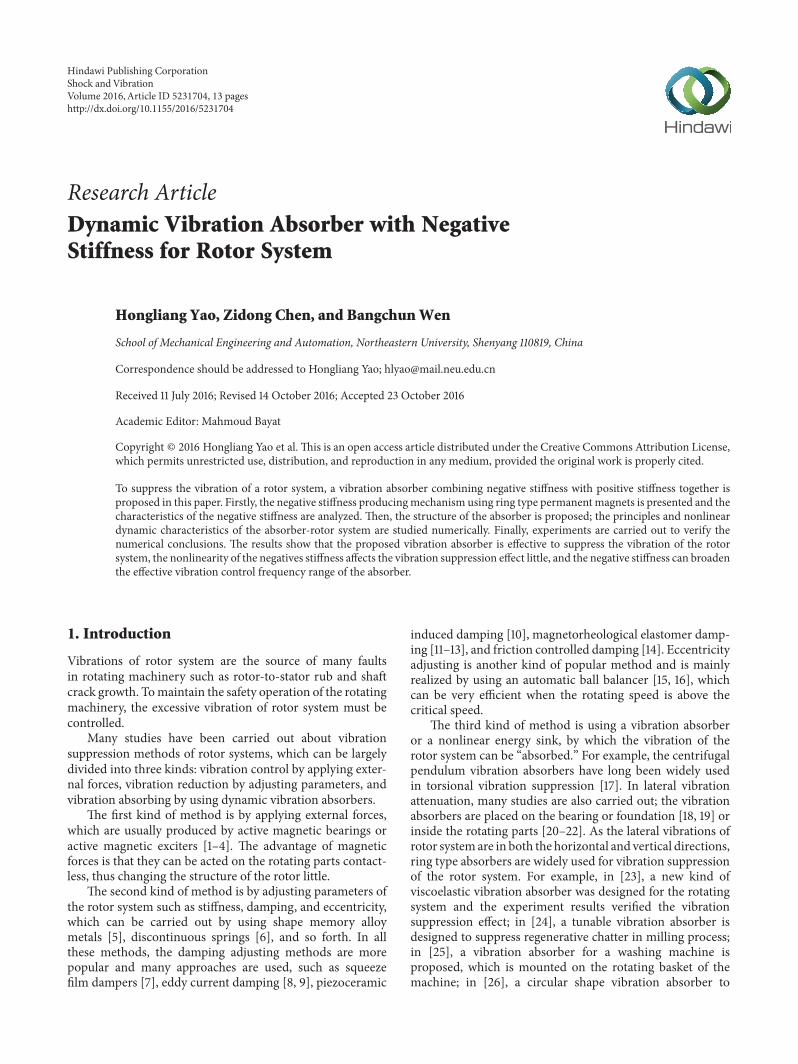
Figure 1: Structure of the magnetic spring with negative stiffness.
reduce the vibration caused by the imbalance of an opticaldisk drive is presented; the vibration absorber is speed-dependent and can keep resonance in a specific frequencyrange.
The vibration absorbers often become inefficient in thelow frequency range, because it is difficult to reduce thestiffness of absorber to very low values, as the low stiffnesswill cause large static deflection. Negative stiffness is a goodsolution for this problem and has been widely used invibration isolator design. Permanent magnets are a goodway to produce negative stiffness and have been widely usedin single-direction vibration suppression, such as vibrationisolators [27] or dynamic vibration absorbers [28], but, to theauthors’ knowledge, no permanent magnet has been used indynamic vibration absorber design for rotor system.
So, in this paper, a novel vibration absorber with negativestiffness produced by permanent magnet is proposed andits fundamental principles and characteristics are studied,and then experiments are carried out to verify the analyticalresults.
2. Negative Stiffness Spring Made Up ofPermanent Magnets
2.1. Structure of the Negative Stiffness Magnetic Spring. Thestructure is made up of ring type magnets and is shown asFigure 1.The outermagnets and centralmagnets aremountedin repulsive interaction, and the two central magnets areconnected by a connecting part which contains a rollingbearing.
As the outer magnet and the central magnet are inrepulsive interaction, a repulsive force in radial direction will
occur; the central magnet will leave the equilibrium positionand will not return without external force. So the centralmagnet acts as a spring with negative stiffness.
2.2. Magnet Force and Stiffness Calculation Using Equiva-lent Magnetic Charge Method. The magnet force generatedbetween the two parallel ring type magnets can be calculatedby using equivalent magnetic charge method [29, 30].
The outer diameter, inner diameter, and thickness ofthe outer magnets are 𝑅𝐷1, 𝑅𝑑1, and 𝑏1, and those of theinner magnets are 𝑅𝐷2, 𝑅𝑑2, and 𝑏2, respectively.The distancebetween the outer magnet and the central magnet is ℎ. Thewidth of the rolling bearing is 𝐵. According to the equivalentmagnetic charge method, the point charge of a point (𝑟2, 𝛼)in plane 2 (as shown in Figure 1) is
𝑞2 = 𝐵𝑟𝑟2d𝑟2d𝛼, (1)
where 𝐵𝑟 is the residual flux density.The point charge of a point (𝑟3, 𝛽) in plane 3 is
𝑞3 = 𝐵𝑟𝑟3d𝑟3d𝛽. (2)
The interaction force between the two points is
dF23 = 𝐵2𝑟4𝜋𝜇0𝑟2𝑟3d𝑟2d𝛼d𝑟3d𝛽𝑟223 r23, (3)
where 𝜇0 is the relative permeability of the permanentmagnets.
When the central magnets leave the equilibrium point fordistance 𝑒, the interaction force between planes 2 and 3 is
𝐹23 = 𝐵2𝑟4𝜋𝜇0 ∫2𝜋
0∫2𝜋0∫𝑅𝐷1𝑅𝑑1
∫𝑅𝐷2𝑅𝑑2
𝑟2𝑟3 (𝑟3 cos𝛽 − 𝑟1 cos𝛼 − 𝑒)[(𝑟3 cos𝛽 − 𝑟1 cos𝛼 − 𝑒)2 + (𝑟3 sin𝛽 − 𝑟1 sin𝛼)2 + ℎ2]3/2
d𝑟2d𝑟3d𝛼d𝛽. (4)
Shock and Vibration 3
Table 1: Parameters for numerical simulation of magnetic force andstiffness.
Parameter Value𝑅𝐷1 50mm𝑅𝑑1 25mm𝑏1 6mm𝑅𝐷2 50mm𝑅𝑑2 25mm𝑏2 6mm𝐵 15mm𝜇0 4𝜋 × 10−7N/A2𝐵𝑟 1.34 T
Table 2: Parameters for approximate stiffness.
ℎ (mm) 𝑘𝑚1 (N/mm) 𝑘𝑚2 (N/mm) 𝑘𝑚3 (N/mm)20 −1.212 0.012 −0.00115 −2.48 0.033 −0.00210 −5.898 0.112 −0.0085 −17.28 0.637 −0.0542.5 −35.88 3.238 −0.434
The interaction force between plane 2 and plane 𝑖 can bewritten as
𝐹2𝑖 = (−1)𝑖+1 𝐵2𝑟4𝜋𝜇0 ∫2𝜋
0∫2𝜋0∫𝑅𝐷1𝑅𝑑1
∫𝑅𝐷2𝑅𝑑2
𝑟2𝑟𝑖 (𝑟𝑖 cos𝛽 − 𝑟2 cos𝛼 − 𝑒)[(𝑟𝑖 cos𝛽 − 𝑟2 cos𝛼 − 𝑒)2 + (𝑟𝑖 sin𝛽 − 𝑟2 sin𝛼)2 + ℎ22𝑖]3/2
d𝑟2d𝑟𝑖d𝛼d𝛽(𝑖 = 3, . . . , 6) ,
(5)
where ℎ23 = ℎ, ℎ24 = ℎ + 𝑏2, ℎ25 = ℎ + 𝑏2 + 𝐵, and ℎ26 =2ℎ + 𝑏2 + 𝐵. Also, the interaction force between plane 1 and plane 𝑖 canbe written as
𝐹1𝑖 = (−1)𝑖 𝐵2𝑟4𝜋𝜇0 ∫2𝜋
0∫2𝜋0∫𝑅𝐷1𝑅𝑑1
∫𝑅𝐷2𝑅𝑑2
𝑟1𝑟𝑖 (𝑟𝑖 cos𝛽 − 𝑟1 cos𝛼 − 𝑒)[(𝑟𝑖 cos𝛽 − 𝑟1 cos𝛼 − 𝑒)2 + (𝑟𝑖 sin𝛽 − 𝑟1 sin𝛼)2 + (𝑏1 + ℎ2𝑖)2]3/2
d𝑟1d𝑟𝑖d𝛼d𝛽(𝑖 = 3, . . . , 6) .
(6)
As the structure is symmetrical, the interaction forcesbetween the right outer magnet and the central magnets areequal to those of the left ones. So the total force between thecentral magnets and the outer magnets is
𝐹𝑦 = 2 6∑𝑖=3
(𝐹1𝑖 + 𝐹2𝑖) . (7)
Equations (4)–(7) can be solved numerically. When thedifferent forces 𝐹𝑦 with different 𝑒 are obtained, the radialstiffness of the negative stiffness magnetic spring can beobtained by
𝑘𝑚 = d𝐹𝑦d𝑒 . (8)
2.3. Numerical Simulation and Stiffness Analysis. The param-eters used for numerical simulation are shown in Table 1.
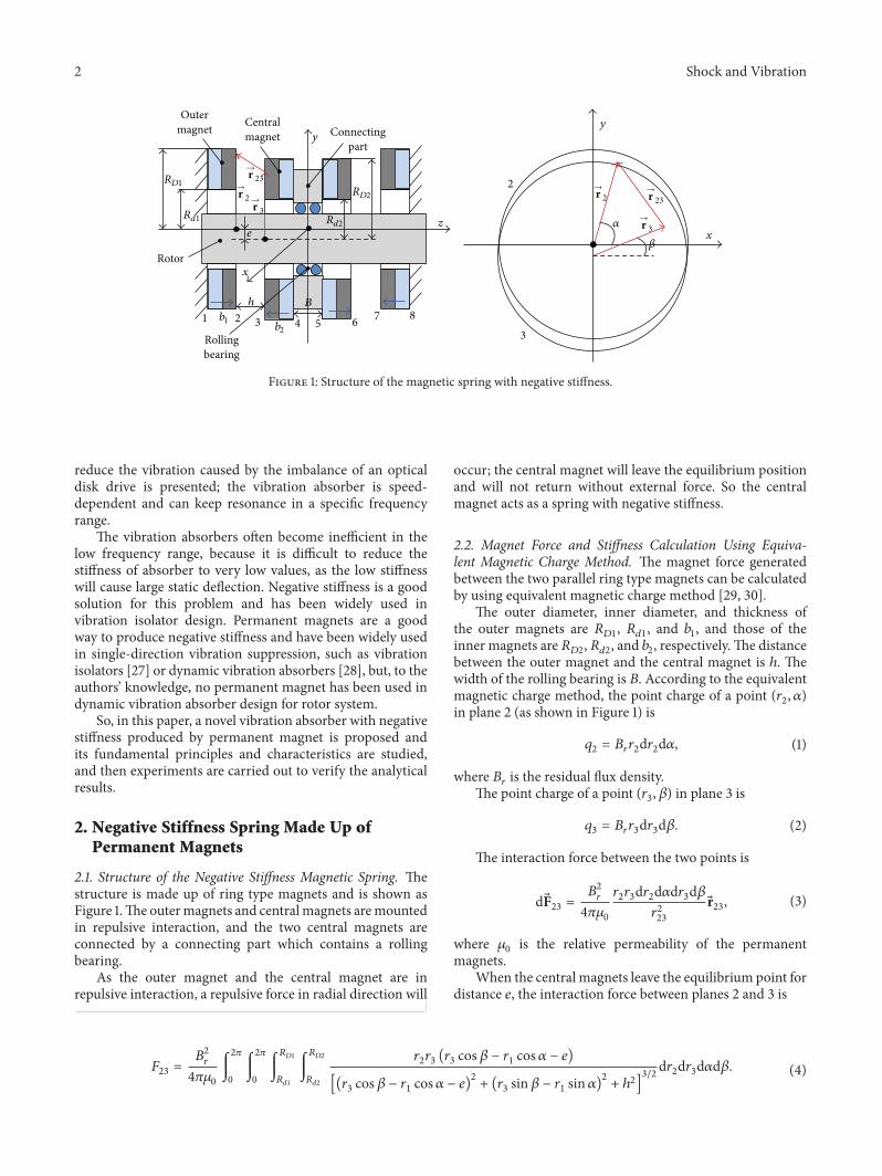
When the distance between the outer magnet and thecentral magnet changes from 1 to 5mm and the distancefrom the center of central magnet to the equilibrium pointchanges from 0 to 1mm, the magnetic force in the radialdirection is obtained and is shown in Figure 2. It can be seenfrom Figure 2 that the radial force changes violently when themagnet distance ℎ is small.
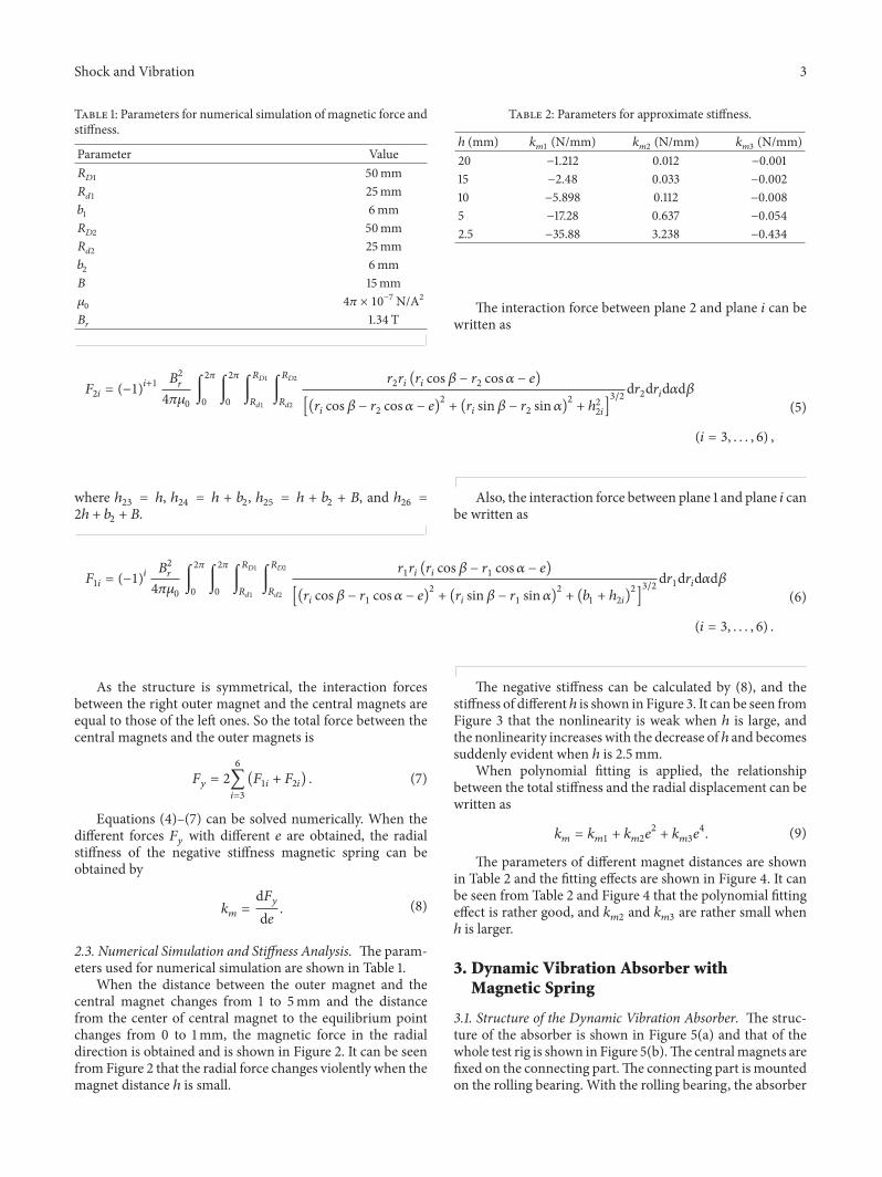
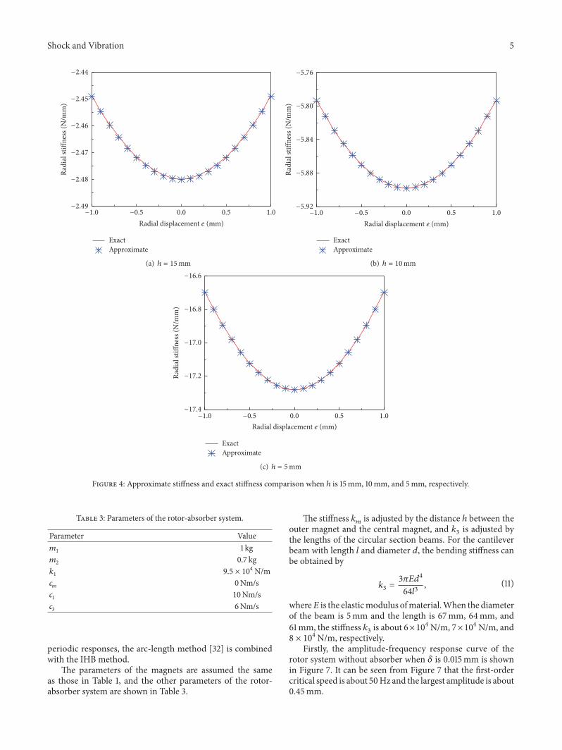
The negative stiffness can be calculated by (8), and thestiffness of different ℎ is shown in Figure 3. It can be seen fromFigure 3 that the nonlinearity is weak when ℎ is large, andthe nonlinearity increases with the decrease of ℎ and becomessuddenly evident when ℎ is 2.5mm.
When polynomial fitting is applied, the relationshipbetween the total stiffness and the radial displacement can bewritten as
𝑘𝑚 = 𝑘𝑚1 + 𝑘𝑚2𝑒2 + 𝑘𝑚3𝑒4. (9)
The parameters of different magnet distances are shownin Table 2 and the fitting effects are shown in Figure 4. It canbe seen from Table 2 and Figure 4 that the polynomial fittingeffect is rather good, and 𝑘𝑚2 and 𝑘𝑚3 are rather small whenℎ is larger.3. Dynamic Vibration Absorber withMagnetic Spring
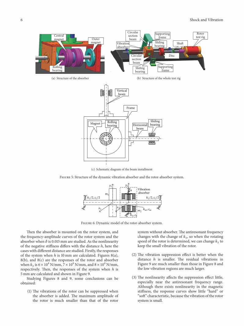
3.1. Structure of the Dynamic Vibration Absorber. The struc-ture of the absorber is shown in Figure 5(a) and that of thewhole test rig is shown in Figure 5(b).The centralmagnets arefixed on the connecting part.The connecting part is mountedon the rolling bearing. With the rolling bearing, the absorber
4 Shock and Vibration
50
0
−50
−100
−150
10.5
0−0.5
−1
5
4
32
1
Radi
al fo
rceF
(N)
Radial displacement e (mm) Magnet distance h
(mm)
Figure 2: Magnetic force of the negative stiffness structure.
20mm15mm10mm5mm2.5mm
Radi
al st
iffne
ss (N
/mm
)
Radial displacement e (mm)1.00.50.0−0.5−1.0
0
−10
−20
−30
−40
Figure 3: Stiffness of the magnetic spring when the distance is from 2.5 to 20mm.
will not rotate with the shaft together, so the electromagneticdamping between the central magnet and the frame of theabsorber can be avoided. The outer magnets are fixed on thealuminumplates, which are connected by beamswith circularsection. The circular section beams are connected to thesupporting frame by linear bearings, which ensure that thebeams have single-direction stiffness in the lateral vibrationplane: the vertical beam has stiffness in horizontal directionand the horizontal beam has stiffness in vertical direction,as shown in Figure 5(c). The beams act as positive stiffnesssprings and the magnet structure acts as negative stiffnessspring.
The dynamic model of the unbalanced rotor-absorbersystem is shown in Figure 6, and the dynamic equations ofthe system are
[𝑚1 00 𝑚2]{
𝑟1𝑟2} + [𝑐1 + 𝑐𝑚 −𝑐𝑚−𝑐𝑚 𝑐𝑚 + 𝑐3]{
𝑟1𝑟2}
+ [𝑘1 + 𝑘𝑚1 −𝑘𝑚1−𝑘𝑚1 𝑘𝑚1 + 𝑘3]{𝑟1𝑟2}
+ {{{𝑘𝑚2 (𝑟1 − 𝑟2)3 + 𝑘𝑚3 (𝑟1 − 𝑟2)5−𝑘𝑚2 (𝑟1 − 𝑟2)3 − 𝑘𝑚3 (𝑟1 − 𝑟2)5
}}}= {𝑚𝑒𝛿𝜔2𝑒𝑖𝜔𝑡0 } ,
(10)
where 𝑚1, 𝑘1, and 𝑐1 are the mass, stiffness, and damping ofthe rotor, respectively. 𝑘𝑚 and 𝑐𝑚 are the stiffness anddampingof the negative stiffness structure. 𝑚2 is the mass of the partof the absorber attached to the rotor and 𝑘3 is the stiffnessof the circular beam. 𝑟1 and 𝑟2 are the displacement vectors ofthe rotor and the absorber in the radial direction, respectively.𝑚𝑒 and 𝛿 are the eccentric mass and eccentric distance of thedisc, respectively. 𝜔 is the rotating speed of the rotor.
3.2. Numerical Simulation of the Dynamic Responses of theRotor-Absorber System. When the nonlinearity of the neg-ative stiffness is considered, numerical simulation must beapplied to study the responses of the rotor-absorber system.The Incremental Harmonic Balance (IHB) method [31] isapplied in the following analysis. To trace the unstable
Shock and Vibration 5
Radi
al st
iffne
ss (N
/mm
)
Radial displacement e (mm)
ExactApproximate
1.00.50.0−0.5−1.0
−2.44
−2.45
−2.46
−2.47
−2.48
−2.49
(a) ℎ = 15mm
Radi
al st
iffne
ss (N
/mm
)
Radial displacement e (mm)
ExactApproximate
1.00.50.0−0.5−1.0
−5.76
−5.80
−5.84
−5.88
−5.92
(b) ℎ = 10mm
Radi
al st
iffne
ss (N
/mm
)
Radial displacement e (mm)
ExactApproximate
1.00.50.0−0.5−1.0
−16.6
−16.8
−17.0
−17.2
−17.4
(c) ℎ = 5mm
Figure 4: Approximate stiffness and exact stiffness comparison when ℎ is 15mm, 10mm, and 5mm, respectively.
Table 3: Parameters of the rotor-absorber system.
Parameter Value𝑚1 1 kg𝑚2 0.7 kg𝑘1 9.5 × 10⁴N/m𝑐𝑚 0Nm/s𝑐1 10Nm/s𝑐3 6Nm/s
periodic responses, the arc-length method [32] is combinedwith the IHB method.
The parameters of the magnets are assumed the sameas those in Table 1, and the other parameters of the rotor-absorber system are shown in Table 3.
The stiffness 𝑘𝑚 is adjusted by the distance ℎ between theouter magnet and the central magnet, and 𝑘3 is adjusted bythe lengths of the circular section beams. For the cantileverbeam with length 𝑙 and diameter 𝑑, the bending stiffness canbe obtained by
𝑘3 = 3𝜋𝐸𝑑464𝑙3 , (11)
where𝐸 is the elasticmodulus ofmaterial.When the diameterof the beam is 5mm and the length is 67mm, 64mm, and61mm, the stiffness 𝑘3 is about 6×10⁴N/m, 7×10⁴N/m, and8 × 104N/m, respectively.
Firstly, the amplitude-frequency response curve of therotor system without absorber when 𝛿 is 0.015mm is shownin Figure 7. It can be seen from Figure 7 that the first-ordercritical speed is about 50Hz and the largest amplitude is about0.45mm.
6 Shock and Vibration
Outermagnet
Centralmagnet
Rollingbearing
(a) Structure of the absorber
Circularsectionbeam
Circularsectionbeam
Vibrationabsorber
Supportingframe
Supportingframe
Slidingbearing
Slidingbearing
Disc
Shaft
Rotortest rig
(b) Structure of the whole test rig
Slidingbearing
Verticalbeam
Frame
Magnet Rollingbearing Horizontal
beam
(c) Schematic diagram of the beam installment
Figure 5: Structure of the dynamic vibration absorber and the rotor-absorber system.
Vibrationabsorber
x1
m1
y1
x2
y2
m2
k3, c3
km, cm
k1/2, c1/2 k1/2, c1/2
Figure 6: Dynamic model of the rotor-absorber system.
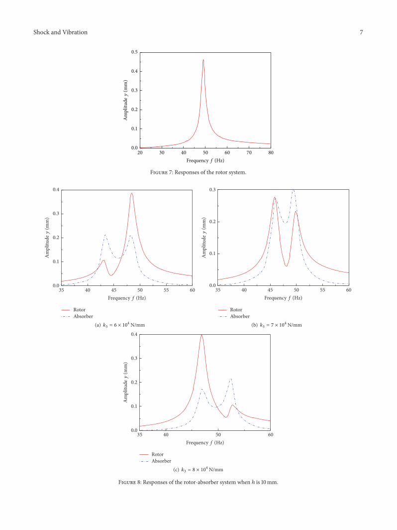
Then the absorber is mounted on the rotor system, andthe frequency-amplitude curves of the rotor system and theabsorber when 𝛿 is 0.015mm are studied. As the nonlinearityof the negative stiffness differs with the distance ℎ, here thecases with different distance are studied. Firstly, the responsesof the system when ℎ is 10mm are calculated. Figures 8(a),8(b), and 8(c) are the responses of the rotor and absorberwhen 𝑘3 is 6 × 10⁴N/mm, 7 × 10⁴N/mm, and 8 × 10⁴N/mm,respectively. Then, the responses of the system when ℎ is5mm are calculated and shown in Figure 9.
Studying Figures 8 and 9, some conclusions can beobtained:
(1) The vibrations of the rotor can be suppressed whenthe absorber is added. The maximum amplitude ofthe rotor is much smaller than that of the rotor
system without absorber. The antiresonant frequencychanges with the change of 𝑘3, so when the rotatingspeed of the rotor is determined, we can change 𝑘3 tokeep the small vibration of the rotor.
(2) The vibration suppression effect is better when thedistance ℎ is smaller. The residual vibrations inFigure 9 are much smaller than those in Figure 8 andthe low vibration regions are much larger.
(3) The nonlinearity affects the suppression effect little,especially near the antiresonant frequency range.Although there exists nonlinearity in the magneticstiffness, the response curves show little “hard” or“soft” characteristic, because the vibration of the rotorsystem is small.
Shock and Vibration 7
0.5
0.4
0.3
0.2
0.1
0.0
Am
plitu
dey
(mm
)
Frequency f (Hz)80706050403020
Figure 7: Responses of the rotor system.
0.4
0.3
0.2
0.1
0.0
Am
plitu
dey
(mm
)
Frequency f (Hz)
RotorAbsorber
605550454035
(a) 𝑘3 = 6 × 10⁴ N/mm
0.3
0.2
0.1
0.0
Am
plitu
dey
(mm
)
RotorAbsorber
Frequency f (Hz)605550454035
(b) 𝑘3 = 7 × 10⁴ N/mm
0.4
0.3
0.2
0.1
0.0
Am
plitu
dey
(mm
)
RotorAbsorber
Frequency f (Hz)60504035
(c) 𝑘3 = 8 × 10⁴ N/mm
Figure 8: Responses of the rotor-absorber system when ℎ is 10mm.
8 Shock and Vibration
0.4
0.3
0.2
0.1
0.0
Am
plitu
dey
(mm
)
RotorAbsorber
Frequency f (Hz)60555045403530
(a) 𝑘3 = 6 × 10⁴ N/mm
0.3
0.2
0.1
0.0
Am
plitu
dey
(mm
)
RotorAbsorber
Frequency f (Hz)60555045403530
(b) 𝑘3 = 7 × 10⁴ N/mm
0.4
0.3
0.2
0.1
0.0
Am
plitu
dey
(mm
)
RotorAbsorber
Frequency f (Hz)60555045403530
(c) 𝑘3 = 8 × 10⁴ N/mm
Figure 9: Responses of the rotor-absorber system when ℎ is 5mm.
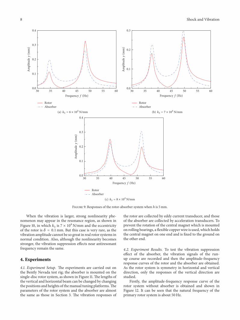
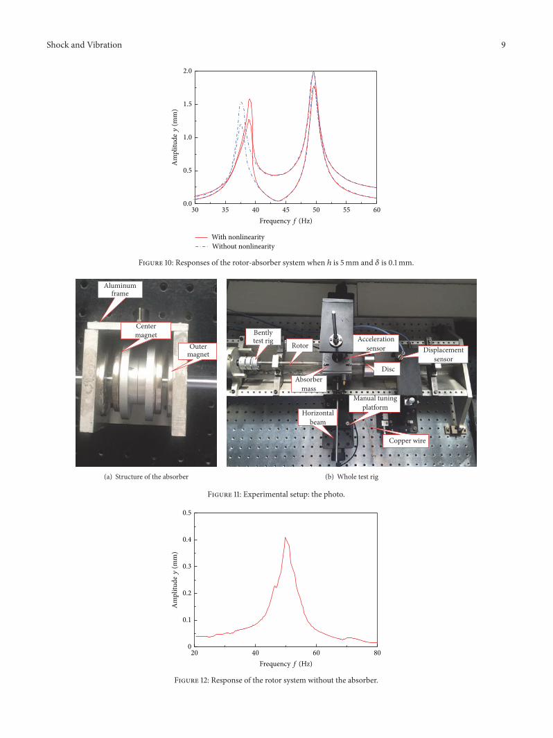
When the vibration is larger, strong nonlinearity phe-nomenon may appear in the resonance region, as shown inFigure 10, in which 𝑘3 is 7 × 10⁴N/mm and the eccentricityof the rotor is 𝛿 = 0.1mm. But this case is very rare, as thevibration amplitude cannot be so great in real rotor systems innormal condition. Also, although the nonlinearity becomesstronger, the vibration suppression effects near antiresonantfrequency remain the same.
4. Experiments
4.1. Experiment Setup. The experiments are carried out onthe Bently Nevada test rig; the absorber is mounted on thesingle-disc rotor system, as shown in Figure 11.The lengths ofthe vertical and horizontal beam can be changed by changingthe positions and heights of themanual tuning platforms.Theparameters of the rotor system and the absorber are almostthe same as those in Section 3. The vibration responses of
the rotor are collected by eddy current transducer, and thoseof the absorber are collected by acceleration transducers. Toprevent the rotation of the central magnet which is mountedon rolling bearings, a flexible copperwire is used, which holdsthe central magnet on one end and is fixed to the ground onthe other end.
4.2. Experiment Results. To test the vibration suppressioneffect of the absorber, the vibration signals of the run-up course are recorded and then the amplitude-frequencyresponse curves of the rotor and the absorber are obtained.As the rotor system is symmetry in horizontal and verticaldirection, only the responses of the vertical direction arestudied.
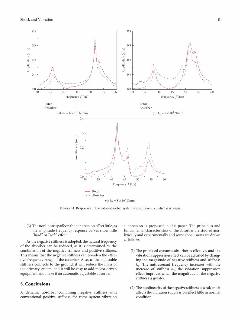
Firstly, the amplitude-frequency response curve of therotor system without absorber is obtained and shown inFigure 12. It can be seen that the natural frequency of theprimary rotor system is about 50Hz.
Shock and Vibration 9
Am
plitu
dey
(mm
)
Frequency f (Hz)60555045403530
2.0
1.5
1.0
0.5
0.0
With nonlinearityWithout nonlinearity
Figure 10: Responses of the rotor-absorber system when ℎ is 5mm and 𝛿 is 0.1mm.
Aluminumframe
Centermagnet
Outermagnet
(a) Structure of the absorber
Rotortest rigBently
Absorbermass
Horizontalbeam
Accelerationsensor
Disc
Manual tuningplatform
Copper wire
Displacementsensor
(b) Whole test rig
Figure 11: Experimental setup: the photo.
Am
plitu
dey
(mm
)
Frequency f (Hz)
0.4
0.3
0.2
0.1
0
0.5
20 40 60 80
Figure 12: Response of the rotor system without the absorber.
10 Shock and Vibration
RotorAbsorber
0.4
0.3
0.2
0.1
0.0
Am
plitu
dey
(mm
)
Frequency f (Hz)605550454035
0.5
(a) 𝑘3 = 6 × 10⁴ N/mm
RotorAbsorber
Frequency f (Hz)605550454035
0.3
0.2
0.1
0.0
Am
plitu
dey
(mm
)
(b) 𝑘3 = 7 × 10⁴ N/mm
RotorAbsorber
Frequency f (Hz)605550454035
0.4
0.3
0.2
0.1
0.0
Am
plitu
dey
(mm
)
0.5
(c) 𝑘3 = 8 × 10⁴ N/mm
Figure 13: Responses of the rotor-absorber system with different 𝑘3 when ℎ is 10mm.
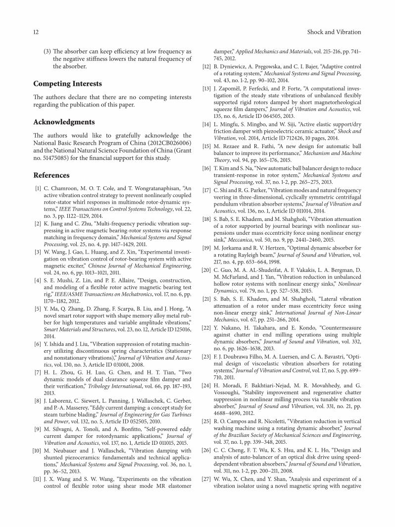
Then, the absorber is mounted on the rotor system andthe amplitude-frequency response curves of rotor system andthe absorber are obtained.The length 𝑙 of the absorber beamscan be adjusted. Figures 13(a)–13(c) present the experimentresults of the rotor and absorber responses when ℎ is 10mmand 𝑘3 is about 6 × 10⁴N/mm, 7 × 10⁴N/mm, and 8 ×10⁴N/mm, respectively. Figures 14(a)–14(c) are correspond-ing results when ℎ is 5mm.
Comparing the experimental results with the numericalsimulation results, it can be seen that there are still somedifferences between the experimental and the simulationresults.There are additional resonance peaks in experimentalresults that are not present in the simulation results. Thepossible reason is that the additional resonance peaks arecaused by rotational degree of freedom of the absorber. Inthe numerical simulations, the absorber is only modeled tomove in 𝑥 and 𝑦 directions constrained by the beams, butthe possibility of angular oscillations is not included. So
the affections to the movement by the rotational degree offreedom are neglected.
But the main principles of the absorber can be verifiedafter comparing the experimental results with the numericalsimulation results:
(1) The vibration suppression effect can be verified by theexperimental results. In all the cases, the vibrationamplitudes near the antiresonant frequency are verylow. Also, the antiresonant frequency of the rotorsystem moves to low frequency when the length ofthe beam increases, so the primary system can remainin low vibration state so far as the beam length isadjustable.
(2) The vibration suppression effect improves when thedistance between the central magnet and the outermagnet reduced, which can be verified by comparingFigure 13 with Figure 14.
Shock and Vibration 11
RotorAbsorber
Frequency f (Hz)605550454035
0.4
0.3
0.2
0.1
0.0
Am
plitu
dey
(mm
)
30
(a) 𝑘3 = 6 × 10⁴ N/mm
0.4
0.3
0.2
0.1
0.0
Am
plitu
dey
(mm
)
RotorAbsorber
Frequency f (Hz)60555045403530
(b) 𝑘3 = 7 × 10⁴ N/mm
0.4
0.3
0.2
0.1
0.0
Am
plitu
dey
(mm
)
RotorAbsorber
Frequency f (Hz)60555045403530
(c) 𝑘3 = 8 × 10⁴ N/mm
Figure 14: Responses of the rotor-absorber system with different 𝑘3 when ℎ is 5mm.
(3) The nonlinearity affects the suppression effect little, asthe amplitude-frequency response curves show little“hard” or “soft” effect.
As the negative stiffness is adopted, the natural frequencyof the absorber can be reduced, as it is determined by thecombination of the negative stiffness and positive stiffness.This means that the negative stiffness can broaden the effec-tive frequency range of the absorber. Also, as the adjustablestiffness connects to the ground, it will reduce the mass ofthe primary system, and it will be easy to add motor drivenequipment and make it an automatic adjustable absorber.
5. Conclusions
A dynamic absorber combining negative stiffness withconventional positive stiffness for rotor system vibration
suppression is proposed in this paper. The principles andfundamental characteristics of the absorber are studied ana-lytically and experimentally and some conclusions are drawnas follows:
(1) The proposed dynamic absorber is effective, and thevibration suppression effect can be adjusted by chang-ing the magnitude of negative stiffness and stiffness𝑘3. The antiresonant frequency increases with theincrease of stiffness 𝑘3; the vibration suppressioneffect improves when the magnitude of the negativestiffness is greater.
(2) Thenonlinearity of the negative stiffness isweak and itaffects the vibration suppression effect little in normalcondition.
12 Shock and Vibration
(3) The absorber can keep efficiency at low frequency asthe negative stiffness lowers the natural frequency ofthe absorber.
Competing Interests
The authors declare that there are no competing interestsregarding the publication of this paper.
Acknowledgments
The authors would like to gratefully acknowledge theNational Basic Research Program of China (2012CB026006)and theNationalNatural Science Foundation ofChina (Grantno. 51475085) for the financial support for this study.
References
[1] C. Chamroon, M. O. T. Cole, and T. Wongratanaphisan, “Anactive vibration control strategy to prevent nonlinearly coupledrotor-stator whirl responses in multimode rotor-dynamic sys-tems,” IEEE Transactions on Control Systems Technology, vol. 22,no. 3, pp. 1122–1129, 2014.
[2] K. Jiang and C. Zhu, “Multi-frequency periodic vibration sup-pressing in active magnetic bearing-rotor systems via responsematching in frequency domain,”Mechanical Systems and SignalProcessing, vol. 25, no. 4, pp. 1417–1429, 2011.
[3] W. Wang, J. Gao, L. Huang, and Z. Xin, “Experimental investi-gation on vibration control of rotor-bearing system with activemagnetic exciter,” Chinese Journal of Mechanical Engineering,vol. 24, no. 6, pp. 1013–1021, 2011.
[4] S. E. Mushi, Z. Lin, and P. E. Allaire, “Design, construction,and modeling of a flexible rotor active magnetic bearing testrig,” IEEE/ASMETransactions onMechatronics, vol. 17, no. 6, pp.1170–1182, 2012.
[5] Y. Ma, Q. Zhang, D. Zhang, F. Scarpa, B. Liu, and J. Hong, “Anovel smart rotor support with shape memory alloy metal rub-ber for high temperatures and variable amplitude vibrations,”SmartMaterials and Structures, vol. 23, no. 12, Article ID 125016,2014.
[6] Y. Ishida and J. Liu, “Vibration suppression of rotating machin-ery utilizing discontinuous spring characteristics (Stationaryand nonstationary vibrations),” Journal of Vibration and Acous-tics, vol. 130, no. 3, Article ID 031001, 2008.
[7] H. L. Zhou, G. H. Luo, G. Chen, and H. T. Tian, “Twodynamic models of dual clearance squeeze film damper andtheir verification,” Tribology International, vol. 66, pp. 187–193,2013.
[8] J. Laborenz, C. Siewert, L. Panning, J. Wallaschek, C. Gerber,and P.-A.Masserey, “Eddy current damping: a concept study forsteam turbine blading,” Journal of Engineering for Gas Turbinesand Power, vol. 132, no. 5, Article ID 052505, 2010.
[9] M. Silvagni, A. Tonoli, and A. Bonfitto, “Self-powered eddycurrent damper for rotordynamic applications,” Journal ofVibration and Acoustics, vol. 137, no. 1, Article ID 011015, 2015.
[10] M. Neubauer and J. Wallaschek, “Vibration damping withshunted piezoceramics: fundamentals and technical applica-tions,” Mechanical Systems and Signal Processing, vol. 36, no. 1,pp. 36–52, 2013.
[11] J. X. Wang and S. W. Wang, “Experiments on the vibrationcontrol of flexible rotor using shear mode MR elastomer
damper,”AppliedMechanics andMaterials, vol. 215-216, pp. 741–745, 2012.
[12] B. Dyniewicz, A. Pręgowska, and C. I. Bajer, “Adaptive controlof a rotating system,”Mechanical Systems and Signal Processing,vol. 43, no. 1-2, pp. 90–102, 2014.
[13] J. Zapomel, P. Ferfecki, and P. Forte, “A computational inves-tigation of the steady state vibrations of unbalanced flexiblysupported rigid rotors damped by short magnetorheologicalsqueeze film dampers,” Journal of Vibration and Acoustics, vol.135, no. 6, Article ID 064505, 2013.
[14] L. Mingfu, S. Mingbo, and W. Siji, “Active elastic support/dryfriction damper with piezoelectric ceramic actuator,” Shock andVibration, vol. 2014, Article ID 712426, 10 pages, 2014.
[15] M. Rezaee and R. Fathi, “A new design for automatic ballbalancer to improve its performance,”Mechanism and MachineTheory, vol. 94, pp. 165–176, 2015.
[16] T. Kim and S.Na, “New automatic ball balancer design to reducetransient-response in rotor system,” Mechanical Systems andSignal Processing, vol. 37, no. 1-2, pp. 265–275, 2013.
[17] C. Shi andR.G. Parker, “Vibrationmodes andnatural frequencyveering in three-dimensional, cyclically symmetric centrifugalpendulum vibration absorber systems,” Journal of Vibration andAcoustics, vol. 136, no. 1, Article ID 011014, 2014.
[18] S. Bab, S. E. Khadem, andM. Shahgholi, “Vibration attenuationof a rotor supported by journal bearings with nonlinear sus-pensions under mass eccentricity force using nonlinear energysink,”Meccanica, vol. 50, no. 9, pp. 2441–2460, 2015.
[19] M. Jorkama and R. V. Hertzen, “Optimal dynamic absorber fora rotating Rayleigh beam,” Journal of Sound and Vibration, vol.217, no. 4, pp. 653–664, 1998.
[20] C. Guo, M. A. AL-Shudeifat, A. F. Vakakis, L. A. Bergman, D.M. McFarland, and J. Yan, “Vibration reduction in unbalancedhollow rotor systems with nonlinear energy sinks,” NonlinearDynamics, vol. 79, no. 1, pp. 527–538, 2015.
[21] S. Bab, S. E. Khadem, and M. Shahgholi, “Lateral vibrationattenuation of a rotor under mass eccentricity force usingnon-linear energy sink,” International Journal of Non-LinearMechanics, vol. 67, pp. 251–266, 2014.
[22] Y. Nakano, H. Takahara, and E. Kondo, “Countermeasureagainst chatter in end milling operations using multipledynamic absorbers,” Journal of Sound and Vibration, vol. 332,no. 6, pp. 1626–1638, 2013.
[23] F. J. Doubrawa Filho, M. A. Luersen, and C. A. Bavastri, “Opti-mal design of viscoelastic vibration absorbers for rotatingsystems,” Journal of Vibration andControl, vol. 17, no. 5, pp. 699–710, 2011.
[24] H. Moradi, F. Bakhtiari-Nejad, M. R. Movahhedy, and G.Vossoughi, “Stability improvement and regenerative chattersuppression in nonlinear milling process via tunable vibrationabsorber,” Journal of Sound and Vibration, vol. 331, no. 21, pp.4688–4690, 2012.
[25] R. O. Campos and R. Nicoletti, “Vibration reduction in verticalwashing machine using a rotating dynamic absorber,” Journalof the Brazilian Society of Mechanical Sciences and Engineering,vol. 37, no. 1, pp. 339–348, 2015.
[26] C. C. Cheng, F. T. Wu, K. S. Hsu, and K. L. Ho, “Design andanalysis of auto-balancer of an optical disk drive using speed-dependent vibration absorbers,” Journal of Sound andVibration,vol. 311, no. 1-2, pp. 200–211, 2008.
[27] W. Wu, X. Chen, and Y. Shan, “Analysis and experiment of avibration isolator using a novel magnetic spring with negative
Shock and Vibration 13
stiffness,” Journal of Sound and Vibration, vol. 333, no. 13, pp.2958–2970, 2014.
[28] F. B. Sayyad and N. D. Gadhave, “Study of magnetic vibrationabsorber with permanent magnets along vibrating beam struc-ture,” Journal of Structures, vol. 2013, Article ID 658053, 5 pages,2013.
[29] J. Sun, C. Wang, and Y. Le, “Research on a novel high stiffnessaxial passive magnetic bearing for DGMSCMG,” Journal ofMagnetism and Magnetic Materials, vol. 412, pp. 147–155, 2016.
[30] B. Han, S. Zheng, Y. Le, and S. Xu, “Modeling and analysisof coupling performance between passive magnetic bearingand hybridmagnetic radial bearing for magnetically suspendedflywheel,” IEEE Transactions on Magnetics, vol. 49, no. 10, pp.5356–5370, 2013.
[31] J. X. Zhou and L. Zhang, “Incremental harmonic balancemethod for predicting amplitudes of a multi-d.o.f. non-linearwheel shimmy system with combined Coulomb and quadraticdamping,” Journal of Sound and Vibration, vol. 279, no. 1-2, pp.403–416, 2005.
[32] J. V. Ferreira and A. L. Serpa, “Application of the arc-lengthmethod in nonlinear frequency response,” Journal of Sound andVibration, vol. 284, no. 1-2, pp. 133–149, 2005.

International Journal of
AerospaceEngineeringHindawi Publishing Corporationhttp://www.hindawi.com Volume 2014
RoboticsJournal of
Hindawi Publishing Corporationhttp://www.hindawi.com Volume 2014
Hindawi Publishing Corporationhttp://www.hindawi.com Volume 2014
Active and Passive Electronic Components
Control Scienceand Engineering
Journal of
Hindawi Publishing Corporationhttp://www.hindawi.com Volume 2014
International Journal of
RotatingMachinery
Hindawi Publishing Corporationhttp://www.hindawi.com Volume 2014
Hindawi Publishing Corporation http://www.hindawi.com
Journal ofEngineeringVolume 2014
Submit your manuscripts athttp://www.hindawi.com
VLSI Design
Hindawi Publishing Corporationhttp://www.hindawi.com Volume 2014
Hindawi Publishing Corporationhttp://www.hindawi.com Volume 2014
Shock and Vibration
Hindawi Publishing Corporationhttp://www.hindawi.com Volume 2014
Civil EngineeringAdvances in
Acoustics and VibrationAdvances in
Hindawi Publishing Corporationhttp://www.hindawi.com Volume 2014
Hindawi Publishing Corporationhttp://www.hindawi.com Volume 2014
Electrical and Computer Engineering
Journal of
Advances inOptoElectronics
Hindawi Publishing Corporation http://www.hindawi.com
Volume 2014
The Scientific World JournalHindawi Publishing Corporation http://www.hindawi.com Volume 2014
SensorsJournal of
Hindawi Publishing Corporationhttp://www.hindawi.com Volume 2014
Modelling & Simulation in EngineeringHindawi Publishing Corporation http://www.hindawi.com Volume 2014
Hindawi Publishing Corporationhttp://www.hindawi.com Volume 2014
Chemical EngineeringInternational Journal of Antennas and
Propagation
International Journal of
Hindawi Publishing Corporationhttp://www.hindawi.com Volume 2014
Hindawi Publishing Corporationhttp://www.hindawi.com Volume 2014
Navigation and Observation
International Journal of
Hindawi Publishing Corporationhttp://www.hindawi.com Volume 2014
DistributedSensor Networks
International Journal of