Embed Size (px)
Citation preview

Research ArticleDesign and Analysis of Tubular PermanentMagnet Linear Wave Generator
Jikai Si Haichao Feng Peng Su and Lufeng Zhang
School of Electrical Engineering and Automation Henan Polytechnic University Jiaozuo 454000 China
Correspondence should be addressed to Jikai Si sijikai527126com
Received 2 March 2014 Revised 19 May 2014 Accepted 3 June 2014 Published 23 June 2014
Academic Editor Wenxiang Zhao
Copyright copy 2014 Jikai Si et al This is an open access article distributed under the Creative Commons Attribution License whichpermits unrestricted use distribution and reproduction in any medium provided the original work is properly cited
Due to the lack ofmature design program for the tubular permanentmagnet linear wave generator (TPMLWG) and poor sinusoidalcharacteristics of the air gap flux density for the traditional surface-mounted TPMLWG a design method and a new secondarystructure of TPMLWG are proposed An equivalent mathematical model of TPMLWG is established to adopt the transformationrelationship between the linear velocity of permanent magnet rotary generator and the operating speed of TPMLWG to determinethe structure parameters of the TPMLWG The new secondary structure of the TPMLWG contains surface-mounted permanentmagnets and the interior permanent magnets which form a series-parallel hybrid magnetic circuit and their reasonable structureparameters are designed to get the optimum pole-arc coefficient The electromagnetic field and temperature field of TPMLWGare analyzed using finite element method It can be included that the sinusoidal characteristics of air gap flux density of thenew secondary structure TPMLWG are improved the cogging force as well as mechanical vibration is reduced in the process ofoperation and the stable temperature rise of generator meets the design requirements when adopting the new secondary structureof the TPMLWG
1 Introduction
As coal oil natural gas and other nonrenewable energysources are drying up all countries in the world are pro-moting the development process of clean renewable waveenergy The permanent magnet linear wave generator whichcan convert wave energy directly and efficiently has got theattention of scholars
A permanentmagnet linear generator structure with nineskewed mounted permanent magnets on the mover wasproposed in [1 2] Reference [3] presented amultiphase tubu-lar linear wave generator which uses laminated permanentmagnets structure to form invalid poles on the mover In[4 5] a symmetry linear generator whose stator coil usesno vertical overlap structure is presented References [6ndash8] and [6] analyzed a new type of switch magnetic fluxpermanent magnet linear generator structure References [910] show stator teeth which are semicircular arc and thepermanent magnet is inserted in the middle of mover and
the coil windings are embedded in the side slot of moverReference [11] puts forward a novel permanent magnettubular linear generator buoy system for converting theocean waves into electrical energy In the novel technologyfor the design of TPMLWG such as a seawater air gap inthe generator between the magnet and armature coggingforce reduction techniques and radially oriented laminationswere proposed In [4] a short primary and long secondarypermanent magnet linear generator was designed to reducethe amount of copper Reference [12] described the designcriteria of a tubular linear motor with interior permanentmagnets Considering the effect of the motor dimensionsand PM materials force-to-volume ratio of different motordesign solutions has been compared In [13] tubular linearpermanent magnet motors including different topologiesthat is interior and surface-mounted PMs and slotted andslotless motors have been comprised of analysis using pre-liminary analytical considerations and the further 2D and3Dfinite-element analysisHowever there are someproblems
Hindawi Publishing Corporatione Scientific World JournalVolume 2014 Article ID 258109 7 pageshttpdxdoiorg1011552014258109
2 The Scientific World Journal
in existent permanent magnet motor such as lacking maturedesign program poor sinusoidal characteristics of air gap fluxdensity big magnetic flux leakage and low efficiency
Keeping in mind the above considerations a designmethod and a new secondary structure of the TPMLWGare proposed in this paper which have satisfactory stabletemperature rise and meanwhile improve the sinusoidalcharacteristics of air gap flux density as well as reducingthe cogging force and mechanical vibration in the operatingprocess of the TPMLWG
2 Structure Design
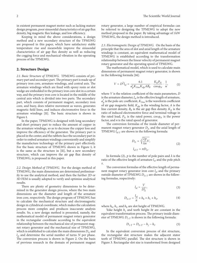
21 Basic Structure of TPMLWG TPMLWG consists of pri-mary part and secondary partThe primary part ismade up ofprimary iron core armature windings and central axis Thearmature windings which are fixed with epoxy resin or slotwedge are embedded in the primary iron core slot in a certainway and the primary iron core is located in the middle of thecentral axis which is divided into two parts The secondarypart which consists of permanent magnet secondary ironcore and buoy does relative movement as waves generatesmagnetic field lines and induces electromotive force in thearmature windings [11] The basic structure is shown inFigure 1
In the paper TPMLWG is designed with long secondaryand short primary part to reduce the amount of copper inthe armature windings so as to decrease the copper loss andimprove the efficiency of the generator The primary part isplaced in the center and the rabbets face the secondary part inorder to embed armature windings conveniently and simplifythe manufacture technology of the primary part effectivelyFor the basic structure of TPMLWG shown in Figure 1 itis the same as the structure in [11] but a new secondarystructure which can improve the air gap flux density ofTPMLWG is proposed in this paper
22 Design Method of TPMLWG For the design method ofTPMLWG the main dimensions are determined preliminar-ily to use the analytical method and then the further 2D or3D FEM is usually adopted to verify and optimize analyticalresults
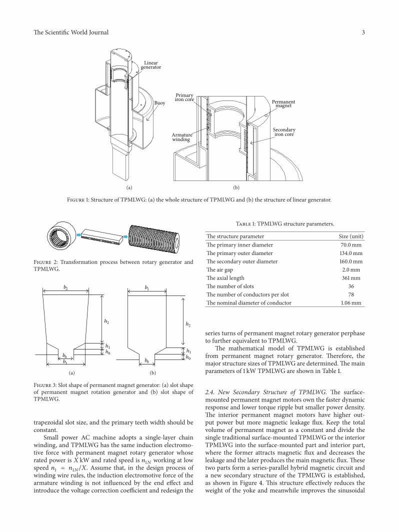
There are plenty of geometry dimensions to be deter-mined in the generator design process where the two maindimensions are the diameter and length of the armatureiron core respectively The design program of TPMLWG hasto calculate the mechanical structure and electromagneticdesign in cylindrical coordinate whichmakes the calculationprocess more complex and produces inaccurate analysisresults So a new design method is presented namely themathematical model of permanent magnet rotary generatorin the rectangular coordinate according to the equivalentrelationship between the mechanical size of permanent mag-net rotary generator and the mechanical size of TPMLWGwhich is established to calculate themain dimensions119863
1198941and
119897ef and determine the serial number of turns 119873 per phaseThe conversion process is shown in Figure 2 On the basisof previous research in the domain of permanent magnet
rotary generator a large number of empirical formulas canbe referred to designing the TPMLWG to adopt the newmethod proposed in the paper By taking advantage of 1 kWTPMLWG the design method is introduced
23 Electromagnetic Design of TPMLWG On the basis of theprinciple that the area of slot and axial length of the armaturewindings is constant an equivalent mathematical model ofTPMLWG is established according to the transformationrelationship between the linear velocity of permanentmagnetrotary generator and the operating speed of TPMLWG
Themathematical model which is used to calculate maindimensions of permanent magnet rotary generator is shownin the following formula [14]
119881 = 1198632119897ef =
61
1198861015840119901119870119873119898119870119889119901119860119861120575
sdot119870119864119875119873
cos120593119873
sdot1
119899 (1)
where V is the relation coefficient of the main parameters Dis the armature diameter 119897ef is the effective length of armature1198861015840
119901is the pole-arc coefficient119870
119873119898is the waveform coefficient
of air gap magnetic field 119870119889119901
is the winding factor A is theline current density 119861
120575is the air gap flux density 119870
119864is the
ratio of induced electromotive force and terminal voltage inthe rated load 119875
119873is the rated power cos120593
119873is the power
factor and 119899 is the rated speed of generatorThe conversion formulas of the inside diameter of per-
manent magnet rotary generator Di1 and the axial length ofTPMLWG 119897ef-119879 are shown in the following formula
1198631198941=3radic2119901
120582120587119881
119897ef-119879 = 1205871198631198941
(2)
In formula (2) 119901 is the number of pole pairs and 120582 is theratio of the effective length of armature 119897ef and the pole pitch120591
The conversion formulas of the effective length of perma-nent magnet rotary generator iron core 119897ef and the primaryoutside diameter of TPMLWG119863
1198941-119879 are shown in the follow-ing formulas respectively
119897ef =119881
1198632
1198941
(3)
1198631198941-119879 =119897ef120587+ ℎ0+ ℎ1+ ℎ2 (4)
where ℎ0 ℎ1 and ℎ
0are slot height of TPMLWG
Yoke height ℎ119895and teeth height ℎ119905 are constant in the
equivalent transformation processThe primary inside diam-eter of TPMLWG119863
1-119879 is shown in the following formula
1198631-119879 = 1198631198941-119879 minus ℎ119895 minus ℎ119905 (5)
In the equivalent conversion process of slot structurethe rectangular slot structure makes the adjacent statorteeth of TPMLWG parallel The slot structure is shown inFigure 3 Rectangular slot size is transformed from designed
The Scientific World Journal 3
Lineargenerator
Buoy
(a)
Permanentmagnet
Secondaryiron core
Primaryiron core
Armaturewinding
(b)
Figure 1 Structure of TPMLWG (a) the whole structure of TPMLWG and (b) the structure of linear generator
Figure 2 Transformation process between rotary generator andTPMLWG
b2
b0b1
h2
h1h0
(a)
b1
b0
h2
h1h0
(b)
Figure 3 Slot shape of permanent magnet generator (a) slot shapeof permanent magnet rotation generator and (b) slot shape ofTPMLWG
trapezoidal slot size and the primary teeth width should beconstant
Small power AC machine adopts a single-layer chainwinding and TPMLWG has the same induction electromo-tive force with permanent magnet rotary generator whoserated power is 119883 kW and rated speed is 119899
1119873working at low
speed 1198991= 1198991119873119883 Assume that in the design process of
winding wire rules the induction electromotive force of thearmature winding is not influenced by the end effect andintroduce the voltage correction coefficient and redesign the
Table 1 TPMLWG structure parameters
The structure parameter Size (unit)The primary inner diameter 700mmThe primary outer diameter 1340mmThe secondary outer diameter 1600mmThe air gap 20mmThe axial length 361mmThe number of slots 36The number of conductors per slot 78The nominal diameter of conductor 106mm
series turns of permanent magnet rotary generator perphaseto further equivalent to TPMLWG
The mathematical model of TPMLWG is establishedfrom permanent magnet rotary generator Therefore themajor structure sizes of TPMLWG are determinedThemainparameters of 1 kW TPMLWG are shown in Table 1
24 New Secondary Structure of TPMLWG The surface-mounted permanent magnet motors own the faster dynamicresponse and lower torque ripple but smaller power densityThe interior permanent magnet motors have higher out-put power but more magnetic leakage flux Keep the totalvolume of permanent magnet as a constant and divide thesingle traditional surface-mounted TPMLWG or the interiorTPMLWG into the surface-mounted part and interior partwhere the former attracts magnetic flux and decreases theleakage and the later produces the main magnetic fluxThesetwo parts form a series-parallel hybrid magnetic circuit anda new secondary structure of the TPMLWG is establishedas shown in Figure 4 This structure effectively reduces theweight of the yoke and meanwhile improves the sinusoidal
4 The Scientific World Journal
a
b
x
Armaturewinding
Permanentmagnets
Figure 4 The local section of the new secondary structure
Table 2 The structure parameters of permanent magnet
The structure parameter Size (unit)119886 6mm119887 2mm1198861015840
11990107
characteristics of the air gap flux density by changing thestructure parameters of permanent magnet x a b
The PM structure parameters of new secondary structureare shown in Table 2
3 The Simulation and Analysis UsingFinite-Element Method
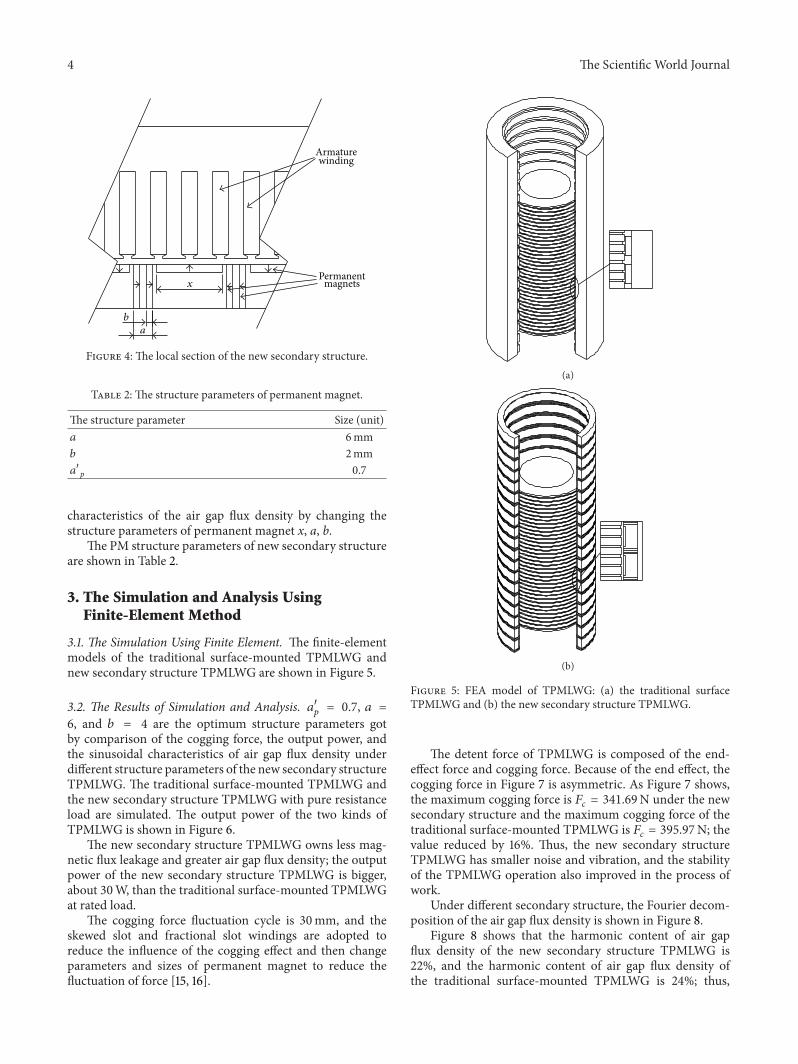
31 The Simulation Using Finite Element The finite-elementmodels of the traditional surface-mounted TPMLWG andnew secondary structure TPMLWG are shown in Figure 5
32 The Results of Simulation and Analysis 1198861015840119901= 07 119886 =
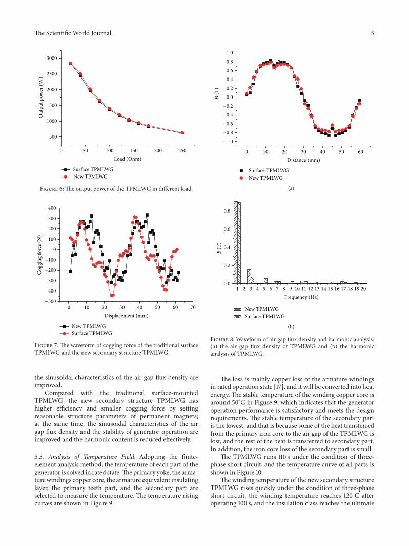
6 and 119887 = 4 are the optimum structure parameters gotby comparison of the cogging force the output power andthe sinusoidal characteristics of air gap flux density underdifferent structure parameters of the new secondary structureTPMLWG The traditional surface-mounted TPMLWG andthe new secondary structure TPMLWG with pure resistanceload are simulated The output power of the two kinds ofTPMLWG is shown in Figure 6
The new secondary structure TPMLWG owns less mag-netic flux leakage and greater air gap flux density the outputpower of the new secondary structure TPMLWG is biggerabout 30W than the traditional surface-mounted TPMLWGat rated load
The cogging force fluctuation cycle is 30mm and theskewed slot and fractional slot windings are adopted toreduce the influence of the cogging effect and then changeparameters and sizes of permanent magnet to reduce thefluctuation of force [15 16]
(a)
(b)
Figure 5 FEA model of TPMLWG (a) the traditional surfaceTPMLWG and (b) the new secondary structure TPMLWG
The detent force of TPMLWG is composed of the end-effect force and cogging force Because of the end effect thecogging force in Figure 7 is asymmetric As Figure 7 showsthe maximum cogging force is 119865
119888= 34169N under the new
secondary structure and the maximum cogging force of thetraditional surface-mounted TPMLWG is 119865
119888= 39597N the
value reduced by 16 Thus the new secondary structureTPMLWG has smaller noise and vibration and the stabilityof the TPMLWG operation also improved in the process ofwork
Under different secondary structure the Fourier decom-position of the air gap flux density is shown in Figure 8
Figure 8 shows that the harmonic content of air gapflux density of the new secondary structure TPMLWG is22 and the harmonic content of air gap flux density ofthe traditional surface-mounted TPMLWG is 24 thus
The Scientific World Journal 5
0 50 100 150 200 250
500
1000
1500
2000
2500
3000
Out
put p
ower
(W)
Load (Ohm)
Surface TPMLWGNew TPMLWG
Figure 6 The output power of the TPMLWG in different load
0 10 20 30 40 50 60 70
0
100
200
300
400
Cog
ging
forc
e (N
)
Displacement (mm)
New TPMLWGSurface TPMLWG
minus100
minus200
minus300
minus400
minus500
Figure 7 The waveform of cogging force of the traditional surfaceTPMLWG and the new secondary structure TPMLWG
the sinusoidal characteristics of the air gap flux density areimproved
Compared with the traditional surface-mountedTPMLWG the new secondary structure TPMLWG hashigher efficiency and smaller cogging force by settingreasonable structure parameters of permanent magnetsat the same time the sinusoidal characteristics of the airgap flux density and the stability of generator operation areimproved and the harmonic content is reduced effectively
33 Analysis of Temperature Field Adopting the finite-element analysis method the temperature of each part of thegenerator is solved in rated stateThe primary yoke the arma-turewindings copper core the armature equivalent insulatinglayer the primary teeth part and the secondary part areselected to measure the temperature The temperature risingcurves are shown in Figure 9
0 10 20 30 40 50 60
00
02
04
06
08
10
B (T
)
Distance (mm)
Surface TPMLWGNew TPMLWG
minus02
minus04
minus06
minus08
minus10
(a)
1 2 3 4 5 6 7 8 9 10 11 12 13 14 15 16 17 18 19 2000
02
04
06
08
Frequency (Hz)
New TPMLWGSurface TPMLWG
B (T
)
(b)
Figure 8 Waveform of air gap flux density and harmonic analysis(a) the air gap flux density of TPMLWG and (b) the harmonicanalysis of TPMLWG
The loss is mainly copper loss of the armature windingsin rated operation state [17] and it will be converted into heatenergy The stable temperature of the winding copper core isaround 50∘C in Figure 9 which indicates that the generatoroperation performance is satisfactory and meets the designrequirements The stable temperature of the secondary partis the lowest and that is because some of the heat transferredfrom the primary iron core to the air gap of the TPMLWG islost and the rest of the heat is transferred to secondary partIn addition the iron core loss of the secondary part is small
The TPMLWG runs 110 s under the condition of three-phase short circuit and the temperature curve of all parts isshown in Figure 10
The winding temperature of the new secondary structureTPMLWG rises quickly under the condition of three-phaseshort circuit the winding temperature reaches 120∘C afteroperating 100 s and the insulation class reaches the ultimate
6 The Scientific World Journal
0 5000 10000 15000 20000 25000 30000
20
25
30
35
40
45
50
Time (s)
1 primary yoke2 coils5 secondary parts
3 insulating layers4 primary teeth
Tem
pera
ture
(∘C)
Figure 9 Each part temperature rising curve of the new secondarystructure TPMLWG
0 20 40 60 80 100 120
20
40
60
80
100
120
140
Time (s)
CoilPrimary yokePrimary teeth
Secondary partInsulating layer
Tem
pera
ture
(∘C)
Figure 10 The temperature rising curve of the new secondarystructure TPMLWG in three-phase short circuit
temperature of E class which will expedite the insulationaging and even damage the armature windings severely
4 Conclusion
The design and optimization process of TPMLWG are pro-posed in the paper aiming at the designmethod of TPMLWGand optimization of secondary structure the following con-clusions are obtained
A new design method is proposed in this paper Theequivalent conversion mathematical model of main dimen-sions of the TPMLWG is established based on the relationshipbetween the linear velocity of the permanentmagnet rotationgenerator and the operation speed of the TPMLWG
A new secondary structure is presented in this paperThe secondary structure of TPMLWG contains both surface-mounted permanent magnets and interior permanent mag-nets which form the series-parallel hybrid excitation mag-netic circuit Compared with the traditional secondary struc-ture TPMLWG the efficiency of the new secondary structureis higher and the sinusoidal characteristic of the air gapflux density is improved and the cogging force and themechanical vibration are smaller during the work process
The insulation class of the insulating material is deter-mined by analyzing the temperature rise of each part whenTPMLWG is at rated state or the three-phase short circuitstate In rated state it is shown that the TPMLWG has lowstable temperature rise and excellent operation performanceUnder the three-phase short circuit state the temperaturerise of the TPMLWG reaches the ultimate temperature ofE insulation class for short time therefore some protectionequipment must be taken into account
Conflict of Interests
The authors declare that there is no conflict of interestsregarding the publication of this paper
Acknowledgments
This work was supported by the National Natural ScienceFoundation of China (51277054 U1361109) the Major pro-duction safety accident prevention program (2012-306) and2011 year guidance of scientific and technological researchprojects of China Coal Industry Association (MTKJ 2011-387MTKJ 2011-391 and MTKJ 2011-394)
References
[1] N M Kimoulakis P E Kakosimos and A G Kladas ldquoHybridtechnique for dynamic modeling of the performance of lineargenerators with skewed mounted permanent magnetsrdquo IEEETransactions on Magnetics vol 47 no 5 pp 906ndash909 2011
[2] N P Gargov A F Zobaa and I Pisica ldquoInvestigation of multi-phase tubular permanent magnet linear generator for waveenergy convertersrdquo Electric Power Components and Systems vol42 no 2 pp 124ndash131 2014
[3] L Huang H Yu M Hu C Liu and B Yuan ldquoResearch on atubular primary permanent-magnet linear generator for waveenergy conversionsrdquo IEEE Transactions on Magnetics vol 49no 5 pp 1917ndash1920 2013
[4] R Vermaak and M J Kamper ldquoDesign aspects of a noveltopology air-cored permanent magnet linear generator fordirect drive wave energy convertersrdquo IEEE Transactions onIndustrial Electronics vol 59 no 5 pp 2104ndash2115 2012
[5] N P Gargov and A F Zobaa ldquoMulti-phase air-cored tubularpermanent magnet linear generator for wave energy convert-ersrdquo IET Renewable Power Generation vol 6 no 3 pp 171ndash1762012
[6] L Huang H Yu M Hu J Zhao and Z Cheng ldquoA novel flux-switching permanent-magnet linear generator for wave energyextraction applicationrdquo IEEE Transactions onMagnetics vol 47no 5 pp 1034ndash1037 2011
The Scientific World Journal 7
[7] H S Yang H T Yu andMQHu ldquoOptimization of the tubularHalbach permanent magnet linear generator field structurerdquoMicro-Motor vol 2 no 49 pp 26ndash29 2010
[8] B Yuan H T Yu and M Q Hu ldquoPerformance analysis ofHalbach magnet structure tubular linear generatorrdquo Micro-Motor vol 2 no 42 pp 20ndash23 2011
[9] B D Bai J Lu and B Xu ldquoThe research of external buoy wavepermanent magnet linear generatorrsquos designrdquo in Proceedings ofthe International Conference on Electrical Machines and Systems(ICEMS rsquo11) Beijing China August 2011
[10] D Li B Bai Q Yu and B Zhu ldquoResearch on sea wave powergeneration system by using bouyrdquo Acta Energiae Solaris Sinicavol 32 no 10 pp 1566ndash1570 2011
[11] J Prudell M Stoddard E Amon T K A Brekken and A VonJouanne ldquoA permanent-magnet tubular linear generator forocean wave energy conversionrdquo IEEE Transactions on IndustryApplications vol 46 no 6 pp 2392ndash2400 2010
[12] N Bianchi S Bolognani and F Tonel ldquoDesign criteria of atubular linear IPM motorrdquo in Proceedings of the IEEE Interna-tional ElectricMachines and Drives Conference (IEMDC rsquo01) pp1ndash7 Cambridge Mass USA 2001
[13] N Bianchi S Bolognani D D Corte and F Tonel ldquoTubularlinear permanent magnet motors an overall comparisonrdquo IEEETransactions on Industry Applications vol 39 no 2 pp 466ndash475 2003
[14] R Tang Modern Permanent Magnet Machines Theory andDesign China Machine Press 2005
[15] J Faiz M Ebrahimi-Salari and G Shahgholian ldquoReduction ofcogging force in linear permanent-magnet generatorsrdquo IEEETransactions on Magnetics vol 46 no 1 pp 135ndash140 2010
[16] Q Liu H Yu M Hu et al ldquoCogging force reduction of double-sided linear flux-switching permanent magnet machine fordirect drivesrdquo IEEE Transactions onMagnetics vol 49 no 5 pp2275ndash2278 2013
[17] D Huang J Shih H Hsia and M Lin ldquoThree-phase linearmotor heat transfer analysis using the finite-element methodrdquoHeat Transfer Engineering vol 31 no 7 pp 617ndash624 2010
TribologyAdvances in
Hindawi Publishing Corporationhttpwwwhindawicom Volume 2014
International Journal of
AerospaceEngineeringHindawi Publishing Corporationhttpwwwhindawicom Volume 2014
FuelsJournal of
Hindawi Publishing Corporationhttpwwwhindawicom Volume 2014
Journal ofPetroleum Engineering
Hindawi Publishing Corporationhttpwwwhindawicom Volume 2014
Industrial EngineeringJournal of
Hindawi Publishing Corporationhttpwwwhindawicom Volume 2014
Power ElectronicsHindawi Publishing Corporationhttpwwwhindawicom Volume 2014
Advances in
CombustionJournal of
Hindawi Publishing Corporationhttpwwwhindawicom Volume 2014
Journal of
Hindawi Publishing Corporationhttpwwwhindawicom Volume 2014
Renewable Energy
Submit your manuscripts athttpwwwhindawicom
Hindawi Publishing Corporationhttpwwwhindawicom Volume 2014
StructuresJournal of
International Journal of
RotatingMachinery
Hindawi Publishing Corporationhttpwwwhindawicom Volume 2014
EnergyJournal of
Hindawi Publishing Corporationhttpwwwhindawicom Volume 2014
Hindawi Publishing Corporation httpwwwhindawicom
Journal ofEngineeringVolume 2014
Hindawi Publishing Corporation httpwwwhindawicom Volume 2014
International Journal ofPhotoenergy
Hindawi Publishing Corporationhttpwwwhindawicom Volume 2014
Nuclear InstallationsScience and Technology of
Hindawi Publishing Corporationhttpwwwhindawicom Volume 2014
Solar EnergyJournal of
Hindawi Publishing Corporationhttpwwwhindawicom Volume 2014
Wind EnergyJournal of
Hindawi Publishing Corporationhttpwwwhindawicom Volume 2014
Nuclear EnergyInternational Journal of
Hindawi Publishing Corporationhttpwwwhindawicom Volume 2014
High Energy PhysicsAdvances in
The Scientific World JournalHindawi Publishing Corporation httpwwwhindawicom Volume 2014
2 The Scientific World Journal
in existent permanent magnet motor such as lacking maturedesign program poor sinusoidal characteristics of air gap fluxdensity big magnetic flux leakage and low efficiency
Keeping in mind the above considerations a designmethod and a new secondary structure of the TPMLWGare proposed in this paper which have satisfactory stabletemperature rise and meanwhile improve the sinusoidalcharacteristics of air gap flux density as well as reducingthe cogging force and mechanical vibration in the operatingprocess of the TPMLWG
2 Structure Design
21 Basic Structure of TPMLWG TPMLWG consists of pri-mary part and secondary partThe primary part ismade up ofprimary iron core armature windings and central axis Thearmature windings which are fixed with epoxy resin or slotwedge are embedded in the primary iron core slot in a certainway and the primary iron core is located in the middle of thecentral axis which is divided into two parts The secondarypart which consists of permanent magnet secondary ironcore and buoy does relative movement as waves generatesmagnetic field lines and induces electromotive force in thearmature windings [11] The basic structure is shown inFigure 1
In the paper TPMLWG is designed with long secondaryand short primary part to reduce the amount of copper inthe armature windings so as to decrease the copper loss andimprove the efficiency of the generator The primary part isplaced in the center and the rabbets face the secondary part inorder to embed armature windings conveniently and simplifythe manufacture technology of the primary part effectivelyFor the basic structure of TPMLWG shown in Figure 1 itis the same as the structure in [11] but a new secondarystructure which can improve the air gap flux density ofTPMLWG is proposed in this paper
22 Design Method of TPMLWG For the design method ofTPMLWG the main dimensions are determined preliminar-ily to use the analytical method and then the further 2D or3D FEM is usually adopted to verify and optimize analyticalresults
There are plenty of geometry dimensions to be deter-mined in the generator design process where the two maindimensions are the diameter and length of the armatureiron core respectively The design program of TPMLWG hasto calculate the mechanical structure and electromagneticdesign in cylindrical coordinate whichmakes the calculationprocess more complex and produces inaccurate analysisresults So a new design method is presented namely themathematical model of permanent magnet rotary generatorin the rectangular coordinate according to the equivalentrelationship between the mechanical size of permanent mag-net rotary generator and the mechanical size of TPMLWGwhich is established to calculate themain dimensions119863
1198941and
119897ef and determine the serial number of turns 119873 per phaseThe conversion process is shown in Figure 2 On the basisof previous research in the domain of permanent magnet
rotary generator a large number of empirical formulas canbe referred to designing the TPMLWG to adopt the newmethod proposed in the paper By taking advantage of 1 kWTPMLWG the design method is introduced
23 Electromagnetic Design of TPMLWG On the basis of theprinciple that the area of slot and axial length of the armaturewindings is constant an equivalent mathematical model ofTPMLWG is established according to the transformationrelationship between the linear velocity of permanentmagnetrotary generator and the operating speed of TPMLWG
Themathematical model which is used to calculate maindimensions of permanent magnet rotary generator is shownin the following formula [14]
119881 = 1198632119897ef =
61
1198861015840119901119870119873119898119870119889119901119860119861120575
sdot119870119864119875119873
cos120593119873
sdot1
119899 (1)
where V is the relation coefficient of the main parameters Dis the armature diameter 119897ef is the effective length of armature1198861015840
119901is the pole-arc coefficient119870
119873119898is the waveform coefficient
of air gap magnetic field 119870119889119901
is the winding factor A is theline current density 119861
120575is the air gap flux density 119870
119864is the
ratio of induced electromotive force and terminal voltage inthe rated load 119875
119873is the rated power cos120593
119873is the power
factor and 119899 is the rated speed of generatorThe conversion formulas of the inside diameter of per-
manent magnet rotary generator Di1 and the axial length ofTPMLWG 119897ef-119879 are shown in the following formula
1198631198941=3radic2119901
120582120587119881
119897ef-119879 = 1205871198631198941
(2)
In formula (2) 119901 is the number of pole pairs and 120582 is theratio of the effective length of armature 119897ef and the pole pitch120591
The conversion formulas of the effective length of perma-nent magnet rotary generator iron core 119897ef and the primaryoutside diameter of TPMLWG119863
1198941-119879 are shown in the follow-ing formulas respectively
119897ef =119881
1198632
1198941
(3)
1198631198941-119879 =119897ef120587+ ℎ0+ ℎ1+ ℎ2 (4)
where ℎ0 ℎ1 and ℎ
0are slot height of TPMLWG
Yoke height ℎ119895and teeth height ℎ119905 are constant in the
equivalent transformation processThe primary inside diam-eter of TPMLWG119863
1-119879 is shown in the following formula
1198631-119879 = 1198631198941-119879 minus ℎ119895 minus ℎ119905 (5)
In the equivalent conversion process of slot structurethe rectangular slot structure makes the adjacent statorteeth of TPMLWG parallel The slot structure is shown inFigure 3 Rectangular slot size is transformed from designed
The Scientific World Journal 3
Lineargenerator
Buoy
(a)
Permanentmagnet
Secondaryiron core
Primaryiron core
Armaturewinding
(b)
Figure 1 Structure of TPMLWG (a) the whole structure of TPMLWG and (b) the structure of linear generator
Figure 2 Transformation process between rotary generator andTPMLWG
b2
b0b1
h2
h1h0
(a)
b1
b0
h2
h1h0
(b)
Figure 3 Slot shape of permanent magnet generator (a) slot shapeof permanent magnet rotation generator and (b) slot shape ofTPMLWG
trapezoidal slot size and the primary teeth width should beconstant
Small power AC machine adopts a single-layer chainwinding and TPMLWG has the same induction electromo-tive force with permanent magnet rotary generator whoserated power is 119883 kW and rated speed is 119899
1119873working at low
speed 1198991= 1198991119873119883 Assume that in the design process of
winding wire rules the induction electromotive force of thearmature winding is not influenced by the end effect andintroduce the voltage correction coefficient and redesign the
Table 1 TPMLWG structure parameters
The structure parameter Size (unit)The primary inner diameter 700mmThe primary outer diameter 1340mmThe secondary outer diameter 1600mmThe air gap 20mmThe axial length 361mmThe number of slots 36The number of conductors per slot 78The nominal diameter of conductor 106mm
series turns of permanent magnet rotary generator perphaseto further equivalent to TPMLWG
The mathematical model of TPMLWG is establishedfrom permanent magnet rotary generator Therefore themajor structure sizes of TPMLWG are determinedThemainparameters of 1 kW TPMLWG are shown in Table 1
24 New Secondary Structure of TPMLWG The surface-mounted permanent magnet motors own the faster dynamicresponse and lower torque ripple but smaller power densityThe interior permanent magnet motors have higher out-put power but more magnetic leakage flux Keep the totalvolume of permanent magnet as a constant and divide thesingle traditional surface-mounted TPMLWG or the interiorTPMLWG into the surface-mounted part and interior partwhere the former attracts magnetic flux and decreases theleakage and the later produces the main magnetic fluxThesetwo parts form a series-parallel hybrid magnetic circuit anda new secondary structure of the TPMLWG is establishedas shown in Figure 4 This structure effectively reduces theweight of the yoke and meanwhile improves the sinusoidal
4 The Scientific World Journal
a
b
x
Armaturewinding
Permanentmagnets
Figure 4 The local section of the new secondary structure
Table 2 The structure parameters of permanent magnet
The structure parameter Size (unit)119886 6mm119887 2mm1198861015840
11990107
characteristics of the air gap flux density by changing thestructure parameters of permanent magnet x a b
The PM structure parameters of new secondary structureare shown in Table 2
3 The Simulation and Analysis UsingFinite-Element Method
31 The Simulation Using Finite Element The finite-elementmodels of the traditional surface-mounted TPMLWG andnew secondary structure TPMLWG are shown in Figure 5
32 The Results of Simulation and Analysis 1198861015840119901= 07 119886 =
6 and 119887 = 4 are the optimum structure parameters gotby comparison of the cogging force the output power andthe sinusoidal characteristics of air gap flux density underdifferent structure parameters of the new secondary structureTPMLWG The traditional surface-mounted TPMLWG andthe new secondary structure TPMLWG with pure resistanceload are simulated The output power of the two kinds ofTPMLWG is shown in Figure 6
The new secondary structure TPMLWG owns less mag-netic flux leakage and greater air gap flux density the outputpower of the new secondary structure TPMLWG is biggerabout 30W than the traditional surface-mounted TPMLWGat rated load
The cogging force fluctuation cycle is 30mm and theskewed slot and fractional slot windings are adopted toreduce the influence of the cogging effect and then changeparameters and sizes of permanent magnet to reduce thefluctuation of force [15 16]
(a)
(b)
Figure 5 FEA model of TPMLWG (a) the traditional surfaceTPMLWG and (b) the new secondary structure TPMLWG
The detent force of TPMLWG is composed of the end-effect force and cogging force Because of the end effect thecogging force in Figure 7 is asymmetric As Figure 7 showsthe maximum cogging force is 119865
119888= 34169N under the new
secondary structure and the maximum cogging force of thetraditional surface-mounted TPMLWG is 119865
119888= 39597N the
value reduced by 16 Thus the new secondary structureTPMLWG has smaller noise and vibration and the stabilityof the TPMLWG operation also improved in the process ofwork
Under different secondary structure the Fourier decom-position of the air gap flux density is shown in Figure 8
Figure 8 shows that the harmonic content of air gapflux density of the new secondary structure TPMLWG is22 and the harmonic content of air gap flux density ofthe traditional surface-mounted TPMLWG is 24 thus
The Scientific World Journal 5
0 50 100 150 200 250
500
1000
1500
2000
2500
3000
Out
put p
ower
(W)
Load (Ohm)
Surface TPMLWGNew TPMLWG
Figure 6 The output power of the TPMLWG in different load
0 10 20 30 40 50 60 70
0
100
200
300
400
Cog
ging
forc
e (N
)
Displacement (mm)
New TPMLWGSurface TPMLWG
minus100
minus200
minus300
minus400
minus500
Figure 7 The waveform of cogging force of the traditional surfaceTPMLWG and the new secondary structure TPMLWG
the sinusoidal characteristics of the air gap flux density areimproved
Compared with the traditional surface-mountedTPMLWG the new secondary structure TPMLWG hashigher efficiency and smaller cogging force by settingreasonable structure parameters of permanent magnetsat the same time the sinusoidal characteristics of the airgap flux density and the stability of generator operation areimproved and the harmonic content is reduced effectively
33 Analysis of Temperature Field Adopting the finite-element analysis method the temperature of each part of thegenerator is solved in rated stateThe primary yoke the arma-turewindings copper core the armature equivalent insulatinglayer the primary teeth part and the secondary part areselected to measure the temperature The temperature risingcurves are shown in Figure 9
0 10 20 30 40 50 60
00
02
04
06
08
10
B (T
)
Distance (mm)
Surface TPMLWGNew TPMLWG
minus02
minus04
minus06
minus08
minus10
(a)
1 2 3 4 5 6 7 8 9 10 11 12 13 14 15 16 17 18 19 2000
02
04
06
08
Frequency (Hz)
New TPMLWGSurface TPMLWG
B (T
)
(b)
Figure 8 Waveform of air gap flux density and harmonic analysis(a) the air gap flux density of TPMLWG and (b) the harmonicanalysis of TPMLWG
The loss is mainly copper loss of the armature windingsin rated operation state [17] and it will be converted into heatenergy The stable temperature of the winding copper core isaround 50∘C in Figure 9 which indicates that the generatoroperation performance is satisfactory and meets the designrequirements The stable temperature of the secondary partis the lowest and that is because some of the heat transferredfrom the primary iron core to the air gap of the TPMLWG islost and the rest of the heat is transferred to secondary partIn addition the iron core loss of the secondary part is small
The TPMLWG runs 110 s under the condition of three-phase short circuit and the temperature curve of all parts isshown in Figure 10
The winding temperature of the new secondary structureTPMLWG rises quickly under the condition of three-phaseshort circuit the winding temperature reaches 120∘C afteroperating 100 s and the insulation class reaches the ultimate
6 The Scientific World Journal
0 5000 10000 15000 20000 25000 30000
20
25
30
35
40
45
50
Time (s)
1 primary yoke2 coils5 secondary parts
3 insulating layers4 primary teeth
Tem
pera
ture
(∘C)
Figure 9 Each part temperature rising curve of the new secondarystructure TPMLWG
0 20 40 60 80 100 120
20
40
60
80
100
120
140
Time (s)
CoilPrimary yokePrimary teeth
Secondary partInsulating layer
Tem
pera
ture
(∘C)
Figure 10 The temperature rising curve of the new secondarystructure TPMLWG in three-phase short circuit
temperature of E class which will expedite the insulationaging and even damage the armature windings severely
4 Conclusion
The design and optimization process of TPMLWG are pro-posed in the paper aiming at the designmethod of TPMLWGand optimization of secondary structure the following con-clusions are obtained
A new design method is proposed in this paper Theequivalent conversion mathematical model of main dimen-sions of the TPMLWG is established based on the relationshipbetween the linear velocity of the permanentmagnet rotationgenerator and the operation speed of the TPMLWG
A new secondary structure is presented in this paperThe secondary structure of TPMLWG contains both surface-mounted permanent magnets and interior permanent mag-nets which form the series-parallel hybrid excitation mag-netic circuit Compared with the traditional secondary struc-ture TPMLWG the efficiency of the new secondary structureis higher and the sinusoidal characteristic of the air gapflux density is improved and the cogging force and themechanical vibration are smaller during the work process
The insulation class of the insulating material is deter-mined by analyzing the temperature rise of each part whenTPMLWG is at rated state or the three-phase short circuitstate In rated state it is shown that the TPMLWG has lowstable temperature rise and excellent operation performanceUnder the three-phase short circuit state the temperaturerise of the TPMLWG reaches the ultimate temperature ofE insulation class for short time therefore some protectionequipment must be taken into account
Conflict of Interests
The authors declare that there is no conflict of interestsregarding the publication of this paper
Acknowledgments
This work was supported by the National Natural ScienceFoundation of China (51277054 U1361109) the Major pro-duction safety accident prevention program (2012-306) and2011 year guidance of scientific and technological researchprojects of China Coal Industry Association (MTKJ 2011-387MTKJ 2011-391 and MTKJ 2011-394)
References
[1] N M Kimoulakis P E Kakosimos and A G Kladas ldquoHybridtechnique for dynamic modeling of the performance of lineargenerators with skewed mounted permanent magnetsrdquo IEEETransactions on Magnetics vol 47 no 5 pp 906ndash909 2011
[2] N P Gargov A F Zobaa and I Pisica ldquoInvestigation of multi-phase tubular permanent magnet linear generator for waveenergy convertersrdquo Electric Power Components and Systems vol42 no 2 pp 124ndash131 2014
[3] L Huang H Yu M Hu C Liu and B Yuan ldquoResearch on atubular primary permanent-magnet linear generator for waveenergy conversionsrdquo IEEE Transactions on Magnetics vol 49no 5 pp 1917ndash1920 2013
[4] R Vermaak and M J Kamper ldquoDesign aspects of a noveltopology air-cored permanent magnet linear generator fordirect drive wave energy convertersrdquo IEEE Transactions onIndustrial Electronics vol 59 no 5 pp 2104ndash2115 2012
[5] N P Gargov and A F Zobaa ldquoMulti-phase air-cored tubularpermanent magnet linear generator for wave energy convert-ersrdquo IET Renewable Power Generation vol 6 no 3 pp 171ndash1762012
[6] L Huang H Yu M Hu J Zhao and Z Cheng ldquoA novel flux-switching permanent-magnet linear generator for wave energyextraction applicationrdquo IEEE Transactions onMagnetics vol 47no 5 pp 1034ndash1037 2011
The Scientific World Journal 7
[7] H S Yang H T Yu andMQHu ldquoOptimization of the tubularHalbach permanent magnet linear generator field structurerdquoMicro-Motor vol 2 no 49 pp 26ndash29 2010
[8] B Yuan H T Yu and M Q Hu ldquoPerformance analysis ofHalbach magnet structure tubular linear generatorrdquo Micro-Motor vol 2 no 42 pp 20ndash23 2011
[9] B D Bai J Lu and B Xu ldquoThe research of external buoy wavepermanent magnet linear generatorrsquos designrdquo in Proceedings ofthe International Conference on Electrical Machines and Systems(ICEMS rsquo11) Beijing China August 2011
[10] D Li B Bai Q Yu and B Zhu ldquoResearch on sea wave powergeneration system by using bouyrdquo Acta Energiae Solaris Sinicavol 32 no 10 pp 1566ndash1570 2011
[11] J Prudell M Stoddard E Amon T K A Brekken and A VonJouanne ldquoA permanent-magnet tubular linear generator forocean wave energy conversionrdquo IEEE Transactions on IndustryApplications vol 46 no 6 pp 2392ndash2400 2010
[12] N Bianchi S Bolognani and F Tonel ldquoDesign criteria of atubular linear IPM motorrdquo in Proceedings of the IEEE Interna-tional ElectricMachines and Drives Conference (IEMDC rsquo01) pp1ndash7 Cambridge Mass USA 2001
[13] N Bianchi S Bolognani D D Corte and F Tonel ldquoTubularlinear permanent magnet motors an overall comparisonrdquo IEEETransactions on Industry Applications vol 39 no 2 pp 466ndash475 2003
[14] R Tang Modern Permanent Magnet Machines Theory andDesign China Machine Press 2005
[15] J Faiz M Ebrahimi-Salari and G Shahgholian ldquoReduction ofcogging force in linear permanent-magnet generatorsrdquo IEEETransactions on Magnetics vol 46 no 1 pp 135ndash140 2010
[16] Q Liu H Yu M Hu et al ldquoCogging force reduction of double-sided linear flux-switching permanent magnet machine fordirect drivesrdquo IEEE Transactions onMagnetics vol 49 no 5 pp2275ndash2278 2013
[17] D Huang J Shih H Hsia and M Lin ldquoThree-phase linearmotor heat transfer analysis using the finite-element methodrdquoHeat Transfer Engineering vol 31 no 7 pp 617ndash624 2010
TribologyAdvances in
Hindawi Publishing Corporationhttpwwwhindawicom Volume 2014
International Journal of
AerospaceEngineeringHindawi Publishing Corporationhttpwwwhindawicom Volume 2014
FuelsJournal of
Hindawi Publishing Corporationhttpwwwhindawicom Volume 2014
Journal ofPetroleum Engineering
Hindawi Publishing Corporationhttpwwwhindawicom Volume 2014
Industrial EngineeringJournal of
Hindawi Publishing Corporationhttpwwwhindawicom Volume 2014
Power ElectronicsHindawi Publishing Corporationhttpwwwhindawicom Volume 2014
Advances in
CombustionJournal of
Hindawi Publishing Corporationhttpwwwhindawicom Volume 2014
Journal of
Hindawi Publishing Corporationhttpwwwhindawicom Volume 2014
Renewable Energy
Submit your manuscripts athttpwwwhindawicom
Hindawi Publishing Corporationhttpwwwhindawicom Volume 2014
StructuresJournal of
International Journal of
RotatingMachinery
Hindawi Publishing Corporationhttpwwwhindawicom Volume 2014
EnergyJournal of
Hindawi Publishing Corporationhttpwwwhindawicom Volume 2014
Hindawi Publishing Corporation httpwwwhindawicom
Journal ofEngineeringVolume 2014
Hindawi Publishing Corporation httpwwwhindawicom Volume 2014
International Journal ofPhotoenergy
Hindawi Publishing Corporationhttpwwwhindawicom Volume 2014
Nuclear InstallationsScience and Technology of
Hindawi Publishing Corporationhttpwwwhindawicom Volume 2014
Solar EnergyJournal of
Hindawi Publishing Corporationhttpwwwhindawicom Volume 2014
Wind EnergyJournal of
Hindawi Publishing Corporationhttpwwwhindawicom Volume 2014
Nuclear EnergyInternational Journal of
Hindawi Publishing Corporationhttpwwwhindawicom Volume 2014
High Energy PhysicsAdvances in
The Scientific World JournalHindawi Publishing Corporation httpwwwhindawicom Volume 2014
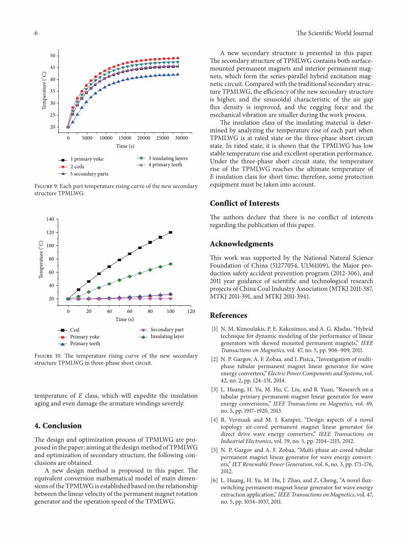