Embed Size (px)
Citation preview
Proceedings World Geothermal Congress 2015
Melbourne, Australia, 19-25 April 2015
1
Research and Teaching Capacities of the Geoenergetics Laboratory at Drilling, Oil and Gas
Faculty AGH University of Science and Technology in Kraków (Poland)
Tomasz Sliwa, Dariusz Knez, Andrzej Gonet, Aneta Sapinska-Sliwa, Bartlomiej Szlapa
AGH University of Science and Technology in Kraków, Drilling, Oil and Gas Faculty, al. Mickiewicza 30; 30-059 Kraków, Poland
[email protected]; [email protected]; [email protected]; [email protected]
Keywords: Geoenegetics laboratory, borehole heat exchangers (BHEs), heat pumps, thermal response test (TRT), geoenergetics,
geothermal energy, geothermal research, underground thermal energy storages (UTESs)
ABSTRACT
The dynamic development of renewable energy recovery systems and also rationalization of heat management gave spur to the
construction of the Geoenergetics Laboratory at Drilling, Oil and Gas Faculty AGH University of Science and Technology (DOGF
AGH-UST) in Kraków. One of the important factors deciding about the build are previous works on adapting depleted and negative
wells. Research carried out at the Laboratory up today and its usability functions are described in the paper.
The laboratory is based on various types of borehole heat exchangers. They were investigated in view of their design for their
effective thermal conductivity eff and thermal resistance Rb. The thermal response tests were used for elaborating BHE thermal
conductivity test. It can be used for optimizing the structure and technology of exploitation of large underground heat storages with
borehole heat exchangers.
This system can co-operate with various types of solar collectors which in an appropriate climate zone may be a perfect source to
be used for charging underground heat storage.
1. INTRODUCTION
At the end of 1990's the idea of borehole heat exchangers (BHE) started to be in focus at the Faculty of Drilling, Oil and Gas AGH-
UST, coinciding with the opening of a PhD procedure on the application of existing, old boreholes for heat recovery from the rock
mass (Sliwa 2002). The first works on underground heat stores were realized in 2006. As the use of the rock mass for
heating/cooling purposes covers many disciplines, a dedicated laboratory was worked out, where BHE design, performance and
exploitation, underground heat storages performance and modelling, as well as renewal of energy resources in underground
storages could be analyzed.
Rock mass can be a source of heat and cold energy for heating and heating/cooling installations making use of heat pumps. This
type of installations is more frequently realized in developed countries. Such systems rely not so much on recovering renewable
heat, as on rational managing of heat in objects. It lies in using heat of the rock for heating in the heating season, and making use of
cold of the rock to air-condition the interior space of buildings. Air conditioning is a reverse process to heating. Having borehole
heat exchangers, one may cyclically use the rock mass as a source of heat or cold. Instead of going up to the atmosphere, energy
flows are circulated between the receiver (building) and the rock mass. This process can be passive to some extent, i.e. without heat
pumps, which adjust energy (temperature) to the reception conditions.
As far as environmental protection and energy aspects are concerned, the driver-energy of heat pumps is very important. In the
Polish conditions, electrical energy mainly comes from coal combustion. The thermal capacity of heat pump as referred to the
primary energy of coal is slightly above 100 %. Heat pumps substitute electrical energy heating, hence are favorable energetically
and ecologically. If a local, traditional source of heat (coal, gas, oil) is replaced with a heat pump, the energy and environmental
effect will be less distinct. In the case of electrical energy production from renewable sources, e.g. in Scandinavia, the use of heat
pumps is unquestionably purposeful.
To enable designing and exploiting borehole heat exchangers, a specialist Laboratory of Geoenergetics was established at the
Faculty of Drilling, Oil and Gas AGH-UST. It is part of Interfaculty Field Station for Environmental Surveys. The Laboratory's
works were inaugurated in 2007, when the first in Poland commercial Thermal Response Test (TRT) was performed (Gonet and
Sliwa 2008).
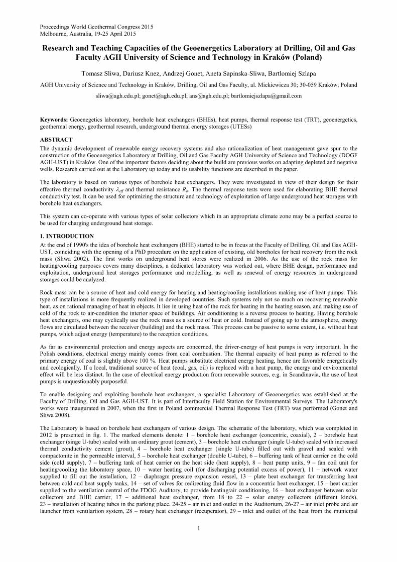
The Laboratory is based on borehole heat exchangers of various design. The schematic of the laboratory, which was completed in
2012 is presented in fig. 1. The marked elements denote: 1 – borehole heat exchanger (concentric, coaxial), 2 – borehole heat
exchanger (singe U-tube) sealed with an ordinary grout (cement), 3 – borehole heat exchanger (single U-tube) sealed with increased
thermal conductivity cement (grout), 4 – borehole heat exchanger (single U-tube) filled out with gravel and sealed with
compactonite in the permeable interval, 5 – borehole heat exchanger (double U-tube), 6 – buffering tank of heat carrier on the cold
side (cold supply), 7 – buffering tank of heat carrier on the heat side (heat supply), 8 – heat pump units, 9 – fan coil unit for
heating/cooling the laboratory space, 10 – water heating coil (for discharging potential excess of power), 11 – network water
supplied to fill out the installation, 12 – diaphragm pressure expansion vessel, 13 – plate heat exchanger for transferring heat
between cold and heat supply tanks, 14 – set of valves for redirecting fluid flow in a concentric heat exchanger, 15 – heat carrier
supplied to the ventilation central of the FDOG Auditory, to provide heating/air conditioning, 16 – heat exchanger between solar
collectors and BHE carrier, 17 – additional heat exchanger, from 18 to 22 – solar energy collectors (different kinds),
23 – installation of heating tubes in the parking place. 24-25 – air inlet and outlet in the Auditorium, 26-27 – air inlet probe and air
launcher from ventilartion system, 28 – rotary heat exchanger (recuperator), 29 – inlet and outlet of the heat from the municipal
Sliwa et al.
2
district heating. At this stage various types of BHEs were analyzed for their energy efficiency, and the results are presented in a
monograph (Gonet et al. 2011).
The task of the collectors (18-22) is to regenerate heat resources in the rock mass. Thank to solar collectors heat can be introduced
in the rock mass along with heat generated when air conditioning the Auditory (Sliwa 2012).
After winter season, the rock mass is cooled down as the energy used for heating has been already recuperated. This creates
possibilites for passive air conditioning. Upon reaching maximum temperature by the rock mass in the passive mode, the active air
conditioning mode making use of heat pumps is activated. The heat resources for the next heating season start being regenerated
with heat coming from solar collectors. Collectors are additionally investigated for their energy efficiency, and the dependence on
the design and way in which heat is transferrred (to heat and/or cold supply tank). Each of the five collectors has a different design
and is assembled differently (mobile and stable). The results of the investigations is a monograph by Sliwa (2012).
At the end of 2011, the Laboratory was also equipped with a system for snow melting and defrosting of the parking. The system
was so incorporated in the hydraulic system of the Laboratory as to enable analyses of heat recovery from the parking surface
before the Laboratory (23) to regenerate heat resources in the rock mass.
Figure 1: Schematic of heat transfer installation in the Laboratory of Geoenergetics, Faculty of Drilling, Oil and Gas AGH-
UST (Sliwa and Gonet 2011).
2. THE BEGINNING OF THE LABORATORY OF GEOENERGETICS
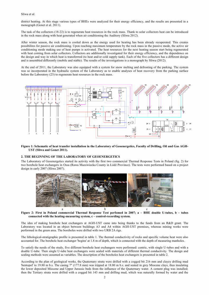
The Laboratory of Geoenergetics started its activity with the first two commercial Thermal Response Tests in Poland (fig. 2) for
two borehole heat exchangers in Ossa (Rawa Mazowiecka County in Łódź Province). The tests were performed based on a project
design in early 2007 (Sliwa 2007).
a b c
Figure 2: First in Poland commercial Thermal Response Test perfomed in 2007; a – BHE double U-tubes, b – tubes
connected with the heating-measuring system, c – control-recording system.
The idea of making borehole heat exchangers at AGH-UST came into being thanks to the funds from an R&D grant. The
Laboratory was located in an object between buildings A3 and A4 within AGH-UST premises, whereas mining works were
performed in the green area. The boreholes were drilled with two URB 2A rigs.
The lithological-stratigraphic profile is presented in table 1. The thermal conductivity of rocks and specific volume heat were also
accounted for. The borehole heat exchanger 'begins' at 1.8 m of depth, which is connected with the depth of measuring manholes.
To satisfy the needs of the study, five different borehole heat exchangers were performed: centric, with single U-tubes and with a
double U-tube. Then single U-tube heat exchangers were sealed with materials of different thermal conductivity. The design and
sealing methods were assumed as variables. The description of the boreholes heat exchangers is presented in table 2.
According to the plan of geological works, the Quaternary strata were drilled with a cogged bit 216 mm and clayey drilling mud
'bentopol' to 19.80 m b.s. The casing 7" (177.8 mm) was tripped at 18.80 m b.s. and seated in grey Miocene clays, thus insulating
the lower deposited Miocene and Upper Jurassic beds from the influence of the Quaternary water. A cement plug was installed;
then the Tertiary strata were drilled with a cogged bit 143 mm and drilling mud, which was naturally formed by water and the
Sliwa et al.
3
washed rock mass. A core barrel was used twice in the well AGH BHE-2 at the end depth, i.e. 84 m in intervals 60-63 m and 81-84
m. The top of Jurassic limestone strata was found in the lower interval.
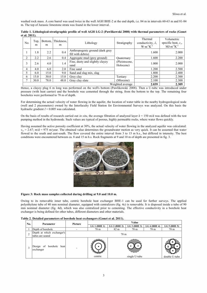
Table 1. Lithological-stratigraphic profile of well AGH LG-2 (Pawlikowski 2008) with thermal parameters of rocks (Gonet
et al. 2011).
No. Top,
m
Bottom,
m
Thickness,
m Lithology Stratigraphy
Thermal
conductivity, ,
Wm-1K-1
Volumetric
specific heat, cv,
MJm-3K-1
1 1.8 2.2 0.4 Anthropogenic ground (dark grey
fill with debris)
Quaternary
(Pleistocene,
Holocene)
1.600 2.000
2 2.2 2.6 0.4 Aggregate mud (grey ground) 1.600 2.200
3 2.6 4.0 1.4 Fine, dusty and slightly clayey
sand 1.000 2.000
4 4.0 6.0 2.0 Fine sand 1.200 2.500
5 6.0 15.0 9.0 Sand and slag mix, slag 1.800 2.400
6 15.0 30.0 15.0 Grey clay Tertiary
(Miocene)
2.200 2.300
7 30.0 78.0 48.0 Gray clay slate 2.100 2.300
Weighted average 2.039 2.309
Hence, a clayey plug 6 m long was performed on the well's bottom (Pawlikowski 2008). Then a U-tube was introduced under
pressure (with heat carrier) and the borehole was cemented through the string, from the bottom to the top. The remaining four
boreholes were performed to 78 m of depth.
For determining the actual velocity of water flowing in the aquifer, the location of water table in the nearby hydrogeological node
(well and 2 piezometers) owned by the Interfaculty Field Station for Environmental Surveys was analyzed. On this basis the
hydraulic gradient I = 0.005 was calculated.
On the basis of results of research carried out in situ, the average filtration of analyzed layer k = 150 m/d was defined with the test
pumping method in the hydronode. Such values are typical of porous, highly permeable rocks, where water flows quickly.
Having assumed the active porosity coefficient at 30%, the actual velocity of water flowing in the analyzed aquifer was calculated:
vrz = 2.67; m/d = 975 m/year. The obtained value determines the groundwater motion as very quick. It can be assumed that water
flowed to the south and east-south. The flow covered the entire interval from 3 to 15 m b.s., but differed in intensity. The best
conditions were encountered between ca. 8 and 15 m b.s. Rock fragments at 9 and 10 m of depth are presented in fig. 3.
Figure 3: Rock mass samples collected during drilling at 9.0 and 10.0 m.
Owing to its removable inner tube, centric borehole heat exchanger BHE-1 can be used for further surveys. The applied
polyethylene tube of 40 mm nominal diameter, equipped with centralizers (fig. 4c) is removable. It is disposed inside a tube of 90
mm nominal diameter (fig. 4d), which was also centralized prior to cementing. The effective conductivity in a borehole heat
exchanger is being defined for other tubes, different diameters and other materials.
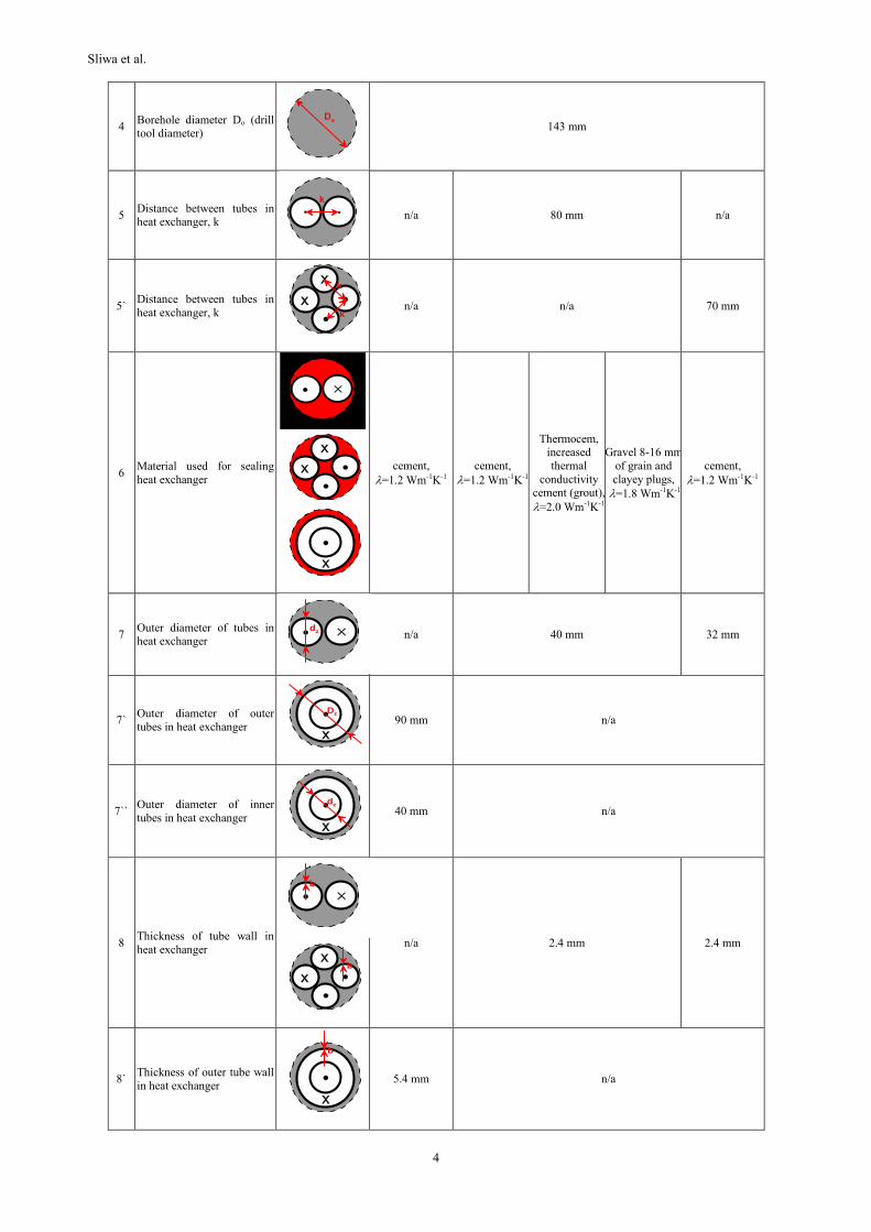
Table 2. Detailed parameters of borehole heat exchangers (Gonet et al. 2011).
No. Parameter Picture Value
LG 1 (BHE 1) LG 2 (BHE 2) LG 3 (BHE 3) LG 4 (BHE 4) LG 5 (BHE 5)
1 Depth of borehole - 78 m 82 m 78 m 78 m 78 m
2 Depth at which exchanger's
tubes are seated 78 m
3 Design of borehole heat
exchanger -
centric
single U-tube double U-tube
Sliwa et al.
4
4 Borehole diameter Do (drill
tool diameter)
143 mm
5 Distance between tubes in heat exchanger, k
n/a 80 mm n/a
5` Distance between tubes in
heat exchanger, k
k
k
n/a n/a 70 mm
6 Material used for sealing
heat exchanger
cement,
=1.2 Wm-1K-1
cement,
=1.2 Wm-1K-1
Thermocem, increased
thermal
conductivity cement (grout),
=2.0 Wm-1K-1
Gravel 8-16 mm
of grain and
clayey plugs,
=1.8 Wm-1K-1
cement,
=1.2 Wm-1K-1
7 Outer diameter of tubes in heat exchanger
n/a 40 mm 32 mm
7` Outer diameter of outer
tubes in heat exchanger
Dz
90 mm n/a
7`` Outer diameter of inner
tubes in heat exchanger
dz
40 mm n/a
8 Thickness of tube wall in
heat exchanger
b
n/a 2.4 mm 2.4 mm
8` Thickness of outer tube wall
in heat exchanger
b
5.4 mm n/a
Do
k
dz
b
Sliwa et al.
5
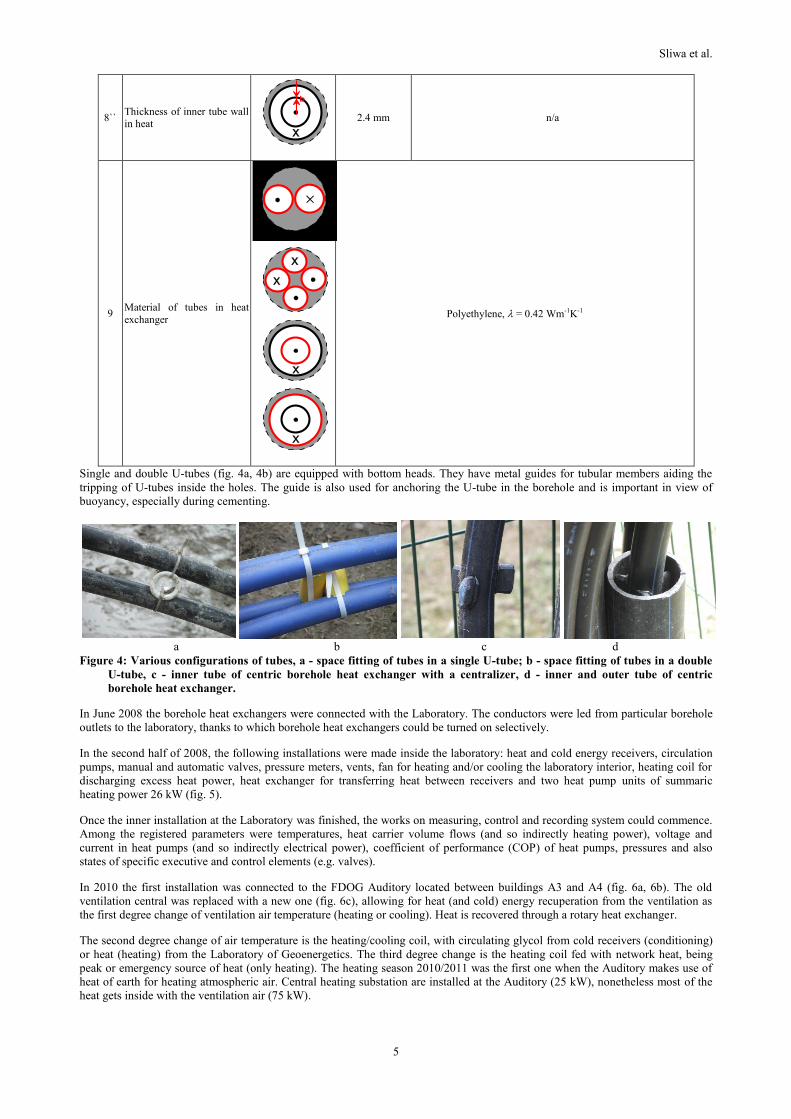
8`` Thickness of inner tube wall
in heat
b
2.4 mm n/a
9 Material of tubes in heat
exchanger
Polyethylene, = 0.42 Wm-1K-1
Single and double U-tubes (fig. 4a, 4b) are equipped with bottom heads. They have metal guides for tubular members aiding the
tripping of U-tubes inside the holes. The guide is also used for anchoring the U-tube in the borehole and is important in view of
buoyancy, especially during cementing.
a b c d
Figure 4: Various configurations of tubes, a - space fitting of tubes in a single U-tube; b - space fitting of tubes in a double
U-tube, c - inner tube of centric borehole heat exchanger with a centralizer, d - inner and outer tube of centric
borehole heat exchanger.
In June 2008 the borehole heat exchangers were connected with the Laboratory. The conductors were led from particular borehole
outlets to the laboratory, thanks to which borehole heat exchangers could be turned on selectively.
In the second half of 2008, the following installations were made inside the laboratory: heat and cold energy receivers, circulation
pumps, manual and automatic valves, pressure meters, vents, fan for heating and/or cooling the laboratory interior, heating coil for
discharging excess heat power, heat exchanger for transferring heat between receivers and two heat pump units of summaric
heating power 26 kW (fig. 5).
Once the inner installation at the Laboratory was finished, the works on measuring, control and recording system could commence.
Among the registered parameters were temperatures, heat carrier volume flows (and so indirectly heating power), voltage and
current in heat pumps (and so indirectly electrical power), coefficient of performance (COP) of heat pumps, pressures and also
states of specific executive and control elements (e.g. valves).
In 2010 the first installation was connected to the FDOG Auditory located between buildings A3 and A4 (fig. 6a, 6b). The old
ventilation central was replaced with a new one (fig. 6c), allowing for heat (and cold) energy recuperation from the ventilation as
the first degree change of ventilation air temperature (heating or cooling). Heat is recovered through a rotary heat exchanger.
The second degree change of air temperature is the heating/cooling coil, with circulating glycol from cold receivers (conditioning)
or heat (heating) from the Laboratory of Geoenergetics. The third degree change is the heating coil fed with network heat, being
peak or emergency source of heat (only heating). The heating season 2010/2011 was the first one when the Auditory makes use of
heat of earth for heating atmospheric air. Central heating substation are installed at the Auditory (25 kW), nonetheless most of the
heat gets inside with the ventilation air (75 kW).
Sliwa et al.
6
Figure 5: Two Stiebel Eltron heat pumps, a – heat pumps with switchboard and electrical energy counter, b – heat pumps
with heat receivers on the left, and cold receivers on the right.
a b c
Figure 6: FDOG Auditory, a – southern wall with windows, b – interior, c -new ventilation central with a rotary heat
exchanger.
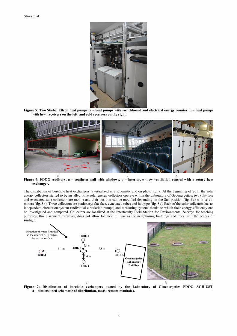
The distribution of borehole heat exchangers is visualized in a schematic and on photo fig. 7. At the beginning of 2011 the solar
energy collectors started to be installed. Five solar energy collectors operate within the Laboratory of Geoenergetics: two (flat-face
and evacuated tube collectors are mobile and their position can be modified depending on the Sun position (fig. 8a) with servo-
motors (fig. 8b). Three collectors are stationary: flat-face, evacuated tubes and hot pipe (fig. 8c). Each of the solar collectors has an
independent circulation system (individual circulation pumps) and measuring system, thanks to which their energy efficiency can
be investigated and compared. Collectors are localized at the Interfaculty Field Station for Environmental Surveys for teaching
purposes; this placement, however, does not allow for their full use as the neighboring buildings and trees limit the access of
sunlight.
a b
Figure 7: Distribution of borehole exchangers owned by the Laboratory of Geoenergetics FDOG AGH-UST,
a – dimensioned schematic of distribution, measurement manholes.
Sliwa et al.
7
a b c
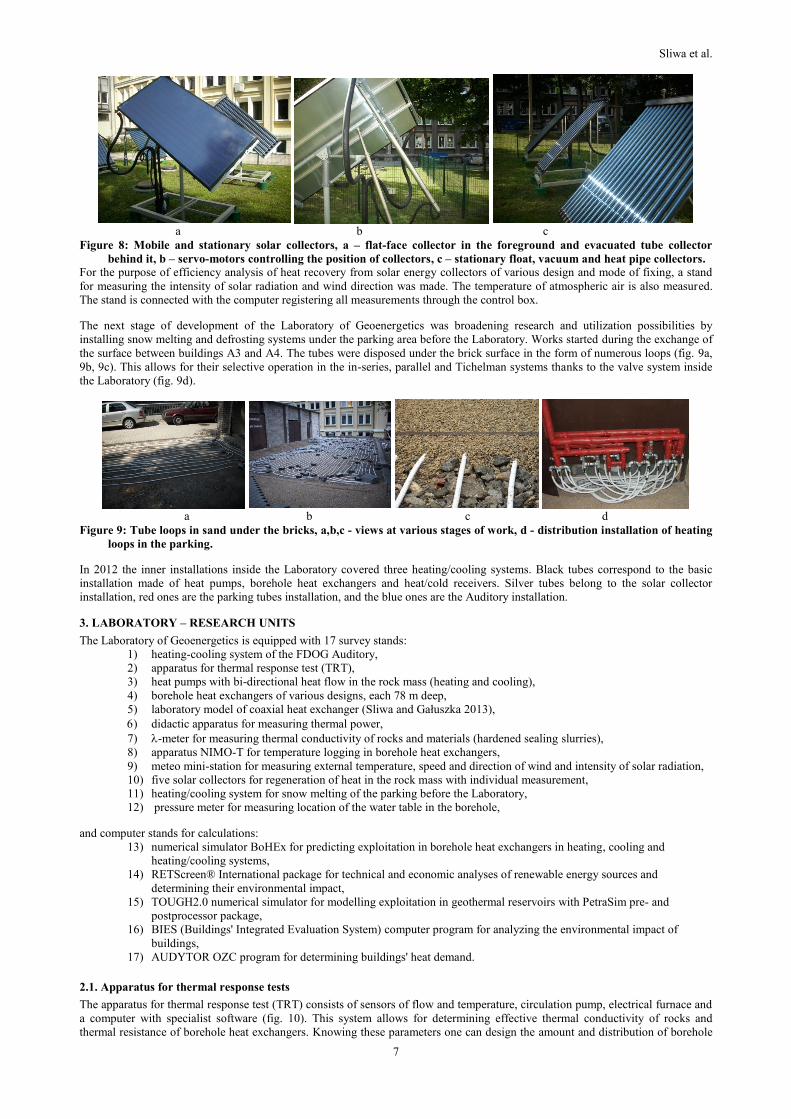
Figure 8: Mobile and stationary solar collectors, a – flat-face collector in the foreground and evacuated tube collector
behind it, b – servo-motors controlling the position of collectors, c – stationary float, vacuum and heat pipe collectors.
For the purpose of efficiency analysis of heat recovery from solar energy collectors of various design and mode of fixing, a stand
for measuring the intensity of solar radiation and wind direction was made. The temperature of atmospheric air is also measured.
The stand is connected with the computer registering all measurements through the control box.
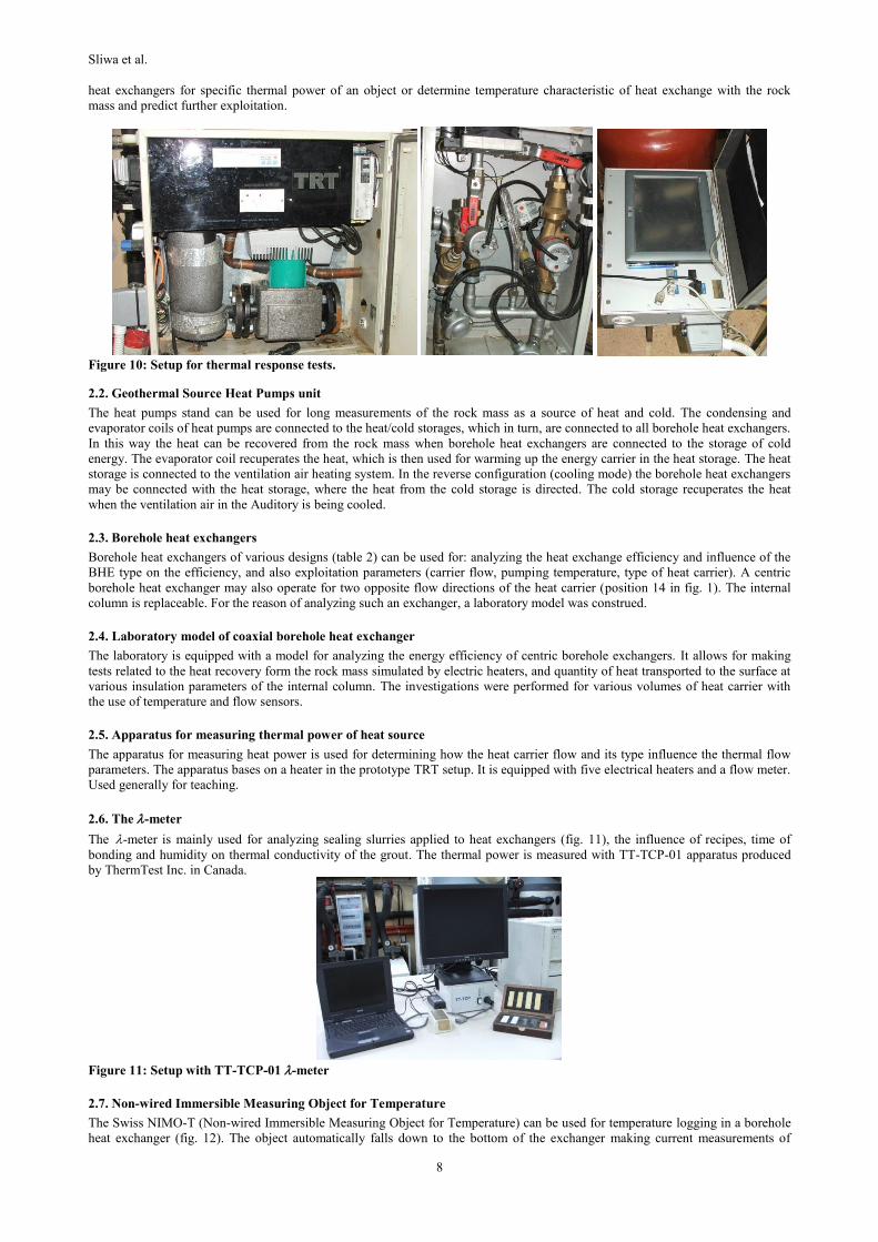
The next stage of development of the Laboratory of Geoenergetics was broadening research and utilization possibilities by
installing snow melting and defrosting systems under the parking area before the Laboratory. Works started during the exchange of
the surface between buildings A3 and A4. The tubes were disposed under the brick surface in the form of numerous loops (fig. 9a,
9b, 9c). This allows for their selective operation in the in-series, parallel and Tichelman systems thanks to the valve system inside
the Laboratory (fig. 9d).
a b c d
Figure 9: Tube loops in sand under the bricks, a,b,c - views at various stages of work, d - distribution installation of heating
loops in the parking.
In 2012 the inner installations inside the Laboratory covered three heating/cooling systems. Black tubes correspond to the basic
installation made of heat pumps, borehole heat exchangers and heat/cold receivers. Silver tubes belong to the solar collector
installation, red ones are the parking tubes installation, and the blue ones are the Auditory installation.
3. LABORATORY – RESEARCH UNITS
The Laboratory of Geoenergetics is equipped with 17 survey stands:
1) heating-cooling system of the FDOG Auditory,
2) apparatus for thermal response test (TRT),
3) heat pumps with bi-directional heat flow in the rock mass (heating and cooling),
4) borehole heat exchangers of various designs, each 78 m deep,
5) laboratory model of coaxial heat exchanger (Sliwa and Gałuszka 2013),
didactic apparatus for measuring thermal power,
7) -meter for measuring thermal conductivity of rocks and materials (hardened sealing slurries),
8) apparatus NIMO-T for temperature logging in borehole heat exchangers,
9) meteo mini-station for measuring external temperature, speed and direction of wind and intensity of solar radiation,
10) five solar collectors for regeneration of heat in the rock mass with individual measurement,
11) heating/cooling system for snow melting of the parking before the Laboratory,
12) pressure meter for measuring location of the water table in the borehole,
and computer stands for calculations:
13) numerical simulator BoHEx for predicting exploitation in borehole heat exchangers in heating, cooling and
heating/cooling systems,
14) RETScreen® International package for technical and economic analyses of renewable energy sources and
determining their environmental impact,
15) TOUGH2.0 numerical simulator for modelling exploitation in geothermal reservoirs with PetraSim pre- and
postprocessor package,
16) BIES (Buildings' Integrated Evaluation System) computer program for analyzing the environmental impact of
buildings,
17) AUDYTOR OZC program for determining buildings' heat demand.
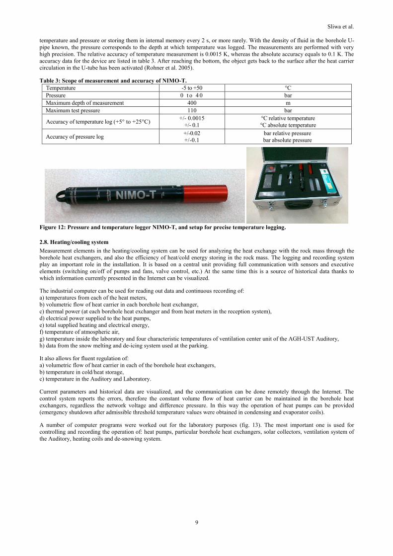
2.1. Apparatus for thermal response tests
The apparatus for thermal response test (TRT) consists of sensors of flow and temperature, circulation pump, electrical furnace and
a computer with specialist software (fig. 10). This system allows for determining effective thermal conductivity of rocks and
thermal resistance of borehole heat exchangers. Knowing these parameters one can design the amount and distribution of borehole
Sliwa et al.
8
heat exchangers for specific thermal power of an object or determine temperature characteristic of heat exchange with the rock
mass and predict further exploitation.
Figure 10: Setup for thermal response tests.
2.2. Geothermal Source Heat Pumps unit
The heat pumps stand can be used for long measurements of the rock mass as a source of heat and cold. The condensing and
evaporator coils of heat pumps are connected to the heat/cold storages, which in turn, are connected to all borehole heat exchangers.
In this way the heat can be recovered from the rock mass when borehole heat exchangers are connected to the storage of cold
energy. The evaporator coil recuperates the heat, which is then used for warming up the energy carrier in the heat storage. The heat
storage is connected to the ventilation air heating system. In the reverse configuration (cooling mode) the borehole heat exchangers
may be connected with the heat storage, where the heat from the cold storage is directed. The cold storage recuperates the heat
when the ventilation air in the Auditory is being cooled.
2.3. Borehole heat exchangers
Borehole heat exchangers of various designs (table 2) can be used for: analyzing the heat exchange efficiency and influence of the
BHE type on the efficiency, and also exploitation parameters (carrier flow, pumping temperature, type of heat carrier). A centric
borehole heat exchanger may also operate for two opposite flow directions of the heat carrier (position 14 in fig. 1). The internal
column is replaceable. For the reason of analyzing such an exchanger, a laboratory model was construed.
2.4. Laboratory model of coaxial borehole heat exchanger
The laboratory is equipped with a model for analyzing the energy efficiency of centric borehole exchangers. It allows for making
tests related to the heat recovery form the rock mass simulated by electric heaters, and quantity of heat transported to the surface at
various insulation parameters of the internal column. The investigations were performed for various volumes of heat carrier with
the use of temperature and flow sensors.
2.5. Apparatus for measuring thermal power of heat source
The apparatus for measuring heat power is used for determining how the heat carrier flow and its type influence the thermal flow
parameters. The apparatus bases on a heater in the prototype TRT setup. It is equipped with five electrical heaters and a flow meter.
Used generally for teaching.
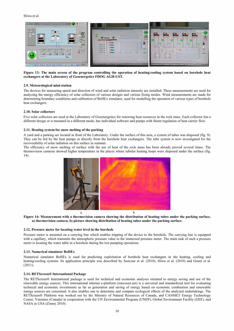
2.6. The -meter
The-meter is mainly used for analyzing sealing slurries applied to heat exchangers (fig. 11), the influence of recipes, time of
bonding and humidity on thermal conductivity of the grout. The thermal power is measured with TT-TCP-01 apparatus produced
by ThermTest Inc. in Canada.
Figure 11: Setup with TT-TCP-01 -meter
2.7. Non-wired Immersible Measuring Object for Temperature
The Swiss NIMO-T (Non-wired Immersible Measuring Object for Temperature) can be used for temperature logging in a borehole
heat exchanger (fig. 12). The object automatically falls down to the bottom of the exchanger making current measurements of
Sliwa et al.
9
temperature and pressure or storing them in internal memory every 2 s, or more rarely. With the density of fluid in the borehole U-
pipe known, the pressure corresponds to the depth at which temperature was logged. The measurements are performed with very
high precision. The relative accuracy of temperature measurement is 0.0015 K, whereas the absolute accuracy equals to 0.1 K. The
accuracy data for the device are listed in table 3. After reaching the bottom, the object gets back to the surface after the heat carrier
circulation in the U-tube has been activated (Rohner et al. 2005).
Table 3: Scope of measurement and accuracy of NIMO-T.
Temperature -5 to +50 °C
Pressure 0 t o 4 0 bar
Maximum depth of measurement 400 m
Maximum test pressure 110 bar
Accuracy of temperature log (+5° to +25°C) +/- 0.0015
+/- 0.1
°C relative temperature
°C absolute temperature
Accuracy of pressure log +/-0.02
+/-0.1
bar relative pressure
bar absolute pressure
Figure 12: Pressure and temperature logger NIMO-T, and setup for precise temperature logging.
2.8. Heating/cooling system
Measurement elements in the heating/cooling system can be used for analyzing the heat exchange with the rock mass through the
borehole heat exchangers, and also the efficiency of heat/cold energy storing in the rock mass. The logging and recording system
play an important role in the installation. It is based on a central unit providing full communication with sensors and executive
elements (switching on/off of pumps and fans, valve control, etc.) At the same time this is a source of historical data thanks to
which information currently presented in the Internet can be visualized.
The industrial computer can be used for reading out data and continuous recording of:
a) temperatures from each of the heat meters,
b) volumetric flow of heat carrier in each borehole heat exchanger,
c) thermal power (at each borehole heat exchanger and from heat meters in the reception system),
d) electrical power supplied to the heat pumps,
e) total supplied heating and electrical energy,
f) temperature of atmospheric air,
g) temperature inside the laboratory and four characteristic temperatures of ventilation center unit of the AGH-UST Auditory,
h) data from the snow melting and de-icing system used at the parking.
It also allows for fluent regulation of:
a) volumetric flow of heat carrier in each of the borehole heat exchangers,
b) temperature in cold/heat storage,
c) temperature in the Auditory and Laboratory.
Current parameters and historical data are visualized, and the communication can be done remotely through the Internet. The
control system reports the errors, therefore the constant volume flow of heat carrier can be maintained in the borehole heat
exchangers, regardless the network voltage and difference pressure. In this way the operation of heat pumps can be provided
(emergency shutdown after admissible threshold temperature values were obtained in condensing and evaporator coils).
A number of computer programs were worked out for the laboratory purposes (fig. 13). The most important one is used for
controlling and recording the operation of: heat pumps, particular borehole heat exchangers, solar collectors, ventilation system of
the Auditory, heating coils and de-snowing system.
Sliwa et al.
10
Figure 13: The main screen of the program controlling the operation of heating/cooling system based on borehole heat
exchangers at the Laboratory of Geoenergetics FDOG AGH-UST.
2.9. Meteorological mini-station
The devices for measuring speed and direction of wind and solar radiation intensity are installed. These measurements are used for
analyzing the energy efficiency of solar collectors of various designs and various fixing modes. Wind measurements are made for
determining boundary conditions and calibration of BoHEx simulator, used for modelling the operation of various types of borehole
heat exchangers.
2.10. Solar collectors
Five solar collectors are used at the Laboratory of Geoenergetics for renewing heat resources in the rock mass. Each collector has a
different design or is mounted in a different mode, has individual software and pumps with fluent regulation of heat carrier flow.
2.11. Heating system for snow melting of the parking
A yard and a parking are located in front of the Laboratory. Under the surface of this area, a system of tubes was disposed (fig. 9).
They can be fed by the heat pumps or directly from the borehole heat exchangers. The tube system is now investigated for the
recoverability of solar radiation on this surface in summer.
The efficiency of snow melting of surface with the use of heat of the rock mass has been already proved several times. The
thermovision cameras showed higher temperature in the places where tubular heating loops were disposed under the surface (fig.
14).
a b
Figure 14: Measurement with a thermovision camera showing the distribution of heating tubes under the parking surface,
a) thermovision camera, b) picture showing distribution of heating tubes under the parking surface.
2.12. Pressure meter for locating water level in the borehole
Pressure meter is mounted on a carrying line which enables tripping of the device to the borehole. The carrying line is equipped
with a capillary, which transmits the atmospheric pressure value to the immersed pressure meter. The main task of such a pressure
meter is locating the water table in a borehole during the test pumping operations.
2.13. Numerical simulator BoHEx
Numerical simulator BoHEx is used for predicting exploitation of borehole heat exchangers in the heating, cooling and
heating/cooling systems. Its application principle was described by Jaszczur et al. (2010), Sliwa et al. (2010) and Gonet et al.
(2011).
2.14. RETScreen® International Package
The RETScreen® International package is used for technical and economic analyses oriented to energy saving and use of the
renewable energy sources. This international internet e-platform (retscreen.net) is a universal and standardized tool for evaluating
technical and economic investments as far as generation and saving of energy based on economic combustion and renewable
energy sources are concerned. It also enables one to determine and compare ecological effects of the analyzed undertakings. The
RETScreen® Platform was worked out by the Ministry of Natural Resources of Canada, and CANMET Energy Technology
Center, Varennes (Canada) in cooperation with the UN Environmental Program (UNEP), Global Environment Facility (GEF), and
NASA in USA (Zimny 2010).
Sliwa et al.
11
The advanced didactic, instruction materials and high standard software are free and available to everyone who registers and
accepts the license conditions. The user of the e-platform has to be equipped with Microsoft Excel, where RETScreen® operartes
with its modules: Start, System Model, Cost Analysis, Emission Analysis, Financial Analysis, Risk Analysis and Tools (Zimny
2010).
2.15. Numerical simulator TOUGH2.0
Numerical simulator TOUGH2.0 is used for modelling exploitation of geothermal reservoirs. Together with the PetraSim pre- and
postprocessor PetraSim it constitutes the World's best known tool for predicting exploitation and injection of geothermal waters.
This program was elaborated at the Lawrence Berkeley National Laboratory and purchased by the Department of Energy U.S.
The numerical simulator TOUGH2.0 is well known software, frequently used for modelling of the heat exchange processes and
fluid flows within porous and fractured reservoirs. It is particularly popular for modelling effects related to the geothermal energy
use. The simulator is equipped with own generator of PetraSim mesh grids. It enables one to create a 3D mesh grid in a radially
symmetrical system. The nodes of the grid are ascribed coordinates, and the simulator itself does not make use of nodal
coordinates; this information is helpful at the stage of result data processing (Gonet et al. 2011).
The TOUGH2.0 code is the main simulator, based on which additional capabilities have been built. The most current version
(V2.1) is released by the Berkeley Lab Software Center. This version is an upgrade from TOUGH2 V2.0, released by the
Department of Energy's Energy Science and Technology Software Center since 1999. The most current version differs from the
previous version in that:
- all known bugs have been fixed,
- the core has been restructured to fully integrate the TMVOC and ECO2N modules,
- the new fluid property module ECO2M has been added to the suite, to analyze the use of CO2 as working fluid in enhanced
geothermal systems – EGS (esd.lbl.gov).
TOUGH2.0 offers the flexibility to handle different fluid mixtures, the properties of which are described in separate Equation-of-
State (EOS) modules. TOUGH2.0 uses an integral finite difference method for space discretization, and first-order fully implicit
time differencing. A choice of a sparse direct solver or various preconditioned conjugate gradient algorithms is available for linear
equation solution. Thermophysical properties of water are represented, within experimental accuracy, by steam table equations. The
program provides options for specifying injection or withdrawal of heat and fluids. Double-porosity, dual-permeability, and
multiple interacting continua (MINC) methods are available for modeling flow in fractured porous media (esd.lbl.gov).
Although primarily designed for geothermal reservoir studies and high-level nuclear waste isolation, TOUGH2.0 can be applied to
a wider range of problems in heat and moisture transfer, and in the drying of porous materials. The TOUGH2.0 simulator was
developed for problems involving strongly heat-driven flow. To describe these phenomena a multi-phase approach to fluid and heat
flow is used, which fully accounts for the movement of gaseous and liquid phases, their transport of latent and sensible heat, and
phase transitions between liquid and vapor. TOUGH2.0 takes account of fluid flow in both liquid and gaseous phases occurring
under pressure, viscous, and gravity forces according to Darcy's law. Interference between the phases is represented by means of
relative permeability functions. The code includes Klinkenberg effects and binary diffusion in the gas phase, and capillary and
phase adsorption effects for the liquid phase. Heat transport occurs by means of conduction (with thermal conductivity dependent
on water saturation), convection, and binary diffusion, which includes both sensible and latent heat (esd.lbl.gov).
2.16. Computer program for analyzing environmental impact of buildings
The computer program BIES (Buildings' Integrated Evaluation System) for analyzing the environmental impact of buildings
(Sapinska-Sliwa 2014) is similar to the British BREEM method. The Laboratory's works concentrated on sustained development in
view of geothermal and solar energy use and heat storing in the rock mass. The methods of buildings certification were analyzed at
the Faculty of Drilling, Oil and Gas. The most important programs of environmental impact of buildings were compared with
special emphasis on their energy certifications. Moreover, a model of building's evaluation in view of sustained development
criteria was created. Its sample templates are presented in literature (Sapinska-Sliwa 2014). This methodics is partly based on a few
already existing systems. The solutions of E-Audit and BREEM programs were used, introducing also solutions employed in other
systems. This model operates in MS Excel environment.
The buildings in this model were assessed similarly as in BREEM program, in 10 sections, each of them being ascribed its weight
to be later used for calculating the final weight. The evaluation covered:
1) managing the process of planning, realization and exploitation of the investment,
2) impact on health and well-being of users,
3) waste management,
4) rational energy management,
5) transport and logistics,
6) useful and waste water management,
7) used construction materials,
8) ecology and environmental impact,
9) emission of pollutions,
10) use of modern solutions.
2.17. The AUDYTOR OZC program
The AUDYTOR OZC program is an aid to be used for calculating designed heat load and determining seasonal demand for thermal
energy for heating of buildings. This program can be used for calculating heat objects in compliance with the relevant regulations.

Sliwa et al.
12
Despite complicated calculation methods and considerable amount of data to be introduced, the time in which the project is
performed is not excessively long. The software was purchased by the Faculty at the National Energy Conservation Agency.
The following parameters can be calculated with the use of this program:
- heat transfer coefficient for walls, floors, roofs and flat roofs,
- thermal power demand of particular rooms,
- thermal power demand of entire building,
- seasonal heat demand (heating of residential buildings),
- seasonal heat damand (Wereszczyński 1999).
4. FUNCTIONS OF THE LABORATORY
The basic function of the laboratories is conducting analyses with the use of available laboratory stands and setups for the needs of
grants and contracts with industry. Such laboratories also play a didactic function or, as it is in the case of the Laboratory of
Geoenergetics, have a utility aspect, i.e. are used for heating and air conditioning of rooms.
3.1. Scientific research
The most important function of the Laboratory is geothermal research. The research stands can be used for investigating borehole
heat exchangers in situ and in the field. Apart from it, the Laboratory is also used for analyzing heat flows in the rock mass:
absorption of heat for heating of the Auditory room in winter, and introduction of heat during passive and active air conditioning.
The recuperation of heat and cold is realized through a rotary exchanger. The threshold difference of temperatures at which
heat/cold recuperation is activated is 3 K.
The energy efficiency beyond the laboratory system and economics of such solutions was a subject of realized research grant. For
this reason a numerical simulator was construed thanks to which the exploitation of systems with a large number of borehole heat
exchangers could be predicted. Presently the calibration works are on-going.
Besides these functions, the Laboratory is used for working out simple installations with controllers. The software controlling such
systems is optimized in view of economic (maximization of NPV) and/or energy criterion (minimization of yearly consumption of
primary energy).
Apart from borehole heat exchangers, the Laboratory is also used for analyzing heat flows in the rock mass. Heat flows are
connected with the consumption of heat in winter for heating of the Auditory of the FDOG and introduction of heat during its
passive and active air conditioning.
The tubes installed under the surface of the parking are investigated and used for snow melting and de-icing of the surface. Works
continue on determining the usability of this installment for renewal of heat in the rock mass. The surface of parking can work in
summer as flat solar collector.
3.2. Teaching and promotion (demo function)
The second function of the Laboratory is didactics, i.e. familiarizing geologists and miners with heating issues, and getting heating
specialists known with geology and mining. Presently the Laboratory is open for the 2nd year part- and full-time MSc students of
Mining and Geology, specialization Drilling and Geoengineering, and postgraduate students of Geoenergetics and Geoengineering.
The solar collectors were so located as to match the didactic goals and make the place directly available for the students. As a result
of research conducted in the laboratory, a few M.Sc. theses and research papers, three monographs have been written.
Works ordered by industry are also realized at the Laboratory. The borehole heat exchangers are analyzed and their operation
mathematically modelled. Geoenergetical analyses and predictions of underground heat storage exploitation are also made. Two
research grants have been realized at the Laboratory so far. Apart from it, the Laboratory is used for demonstrating the use of rock
mass for energy purposes.
3.3. Heating and air conditioning
The third target of the Laboratory is supplying heat/cold to the Auditory room of the FDOG, and the Laboratory itself. The demand
for heat considerably exceeds that for the cold, especially that during summer season there are no classes, lectures or conferences
and the place is closed. Therefore the balance between heat consumed and heat introduced to the rock mass is disturbed. This
situation (especially in the case of bigger installations) leads to lowering of the temperature of the rock mass over the years of
exploitation due to insufficient regeneration of heat reserves during air conditioning periods. Accordingly, an additional source of
heat was introduced, which would regenerate the heat reserves in the rock mass. These are solar collectors of various designs.
Thanks to this solution an additional possibility of research on recuperation of solar heat became available. The collectors and the
laboratory are located in a place surrounded with high buildings therefore the thermal effects from only diffused radiation can be
additionally investigated.
3.4. Snow melting and de-icing
Another additional side-effect of the Laboratory's operation is snow melting of the parking in front of the buildings between blds.
A3 and A4 at AGH-UST. In this way the mechanical removal of snow, emission of pollutions and/or use of chemical (salt) are
reduced.
3.5. Regeneration of resources of an underground heat storage
The function of the Laboratory, which is connected with all the remaining tasks, is introduction of heat to the rock mass. The solar
heat (from air-conditioning system, solar collectors and snow melting installation) with natural water flow in the geological layer 3-
15 m under surface constitutes heat regeneration source for UTES (artificial and natural).
Sliwa et al.
13
4. CONCLUSIONS
1. Underground thermal energy storages (UTESs) become more and more popular in assuring suitable heat comfort in residential
and commercial buildings. Most of them are running based on borehole heat exchangers (BHEs).
2. BHEs give the opportunity to heat and air condition the indoors. The largest of this installations consist of more than 1000 BHEs,
e.g. at Ball State University, Indiana (Lund et al. 2010). Because of the growing interest in BHEs more and more research works
are being conducted. They aim at developing technical solutions. Installations formed at technical universities are intended for
heating or heating and cooling, demonstration and research works. Besides the Baal University w USA (cms.bsu.edu), BHEs with
depths in the range of 122-152 m run at Luleå University of Technology. The very first large-scale borehole heat store was
constructed in Luleå (Sweden) during 1982-83 (Nordell 1994); at VSB – Technical University of Ostrava (Czech Republic); at
University of Ontario Institute of Technology (Oshawa/Canada) (Koohi-Fayegh and Rosen 2012) and at AGH-UST.
3. The increase in prices of traditional energy carriers, desire for energy independence and the need of environmental protection in
terms of reducing emissions of combustion products into the atmosphere are primary arguments for the development of BHEs
installations. Systems based on BHEs fulfill two tasks. The first is to gain heat from the environment, which reduces the demand for
primary fuels. The second is to rationalize the use of heat, particularly evident in the heating and cooling systems.
4. Drilling, Oil and Gas Faculty at AGH University of Science and Technology is the first, where research works on BHE are being
conducted, researches has focused on the optimization and exploitation of BHEs in the aspect of the use of old oil&gas wells. The
specific scope of the work is the acquisition of geothermal energy based on existing deep oil&gas wells, which are intended to be
liquidated or on the wells being negative.
5. A very important task of geoenergetics systems at universities is a demonstration how those systems work as same as
demonstration its effects. These are the energy, environmental and economical effects (especially in the case of reverse heat
pump/BHEs systems). The use of local resources contributes to the reduction in export of other energy sources.
6. Another important task of the works being conducted is to develop own (Polish) methodology of designing deep BHEs, what
should allow to become technologically independent. A further increase in the prices of traditional energy carriers increases the
economic viability of installing deep BHE. Environmental aspects should be also taken into account.
ACKNOWLEDGEMENTS
The paper was carried out under the Statutory Research at the Faculty of Drilling, Oil and Gas, AGH University of Science and
Technology, financed from the funds of the Polish Ministry of Science and Higher Education.
REFERENCES
Ball State University web page (cms.bsu.edu) – 20 Mar 2014.
Berkeley Lab Earth Sciences Division web page (esd.lbl.gov) – 2 Mar 2014.
Gonet A., and Sliwa T.: Thermal response test on the example of borehole heat exchangers in Ecological Park of Education and Amusement “OSSA”, Transport & Logistics, 6 (2008) 42–47.
Gonet A., Sliwa T., Stryczek S., Sapinska-Sliwa A., Jaszczur M., Pająk L., and Złotkowski A.: Metodyka identyfikacji potencjału
cieplnego górotworu wraz z technologią wykonywania i eksploatacji otworowych wymienników ciepła (Methodology for the
identification of potential heat of the rock mass along with technology implementation and operation of the borehole heat
exchangers), ed. Andrzej Gonet, Wydawnictwa AGH, Krakow (2011) 439.
Jaszczur M., Sliwa T., and Gonet A.: Numerical analysis of the coaxial borehole heat exchanger construction parameters effect on
the heat transfer with soil, HTRSE 2010, Heat Transfer and Renewable Sources of Energy, Proceedings 13th International
Symposium, ed. A. A. Stachel, D. Mikielewicz, Polish Academy of Science, Committee of Thermodynamics and
Combustion, West Pomeranian University of Technology, Szczecin, Department of Heat Engineering, Dolna Odra Power
Plant Complex, Joint Stock Company, Wydawnictwo Uczelniane ZUT w Szczecinie (2010) 197–206. Koohi-Fayegh S., and Rosen M.A.: Examination of thermal interaction of multiple vertical ground heat exchangers, Applied
Energy, 97, (2012) 962-969.
Lund J. W., Gawell K., Boyd T. L., and Jennejohn D.:The United States of America Country Update 2010, Proceedings World Geothermal 2010, Bali, Indonesia, (2010) 1-18.
Nordell B.: A Large-scale Borehole Heat Store During Five Years of Operation, Proceedings ISRM International Symposium, International Society for Rock Mechanics, Madrid, Spain (1988) 583-587.
Pawlikowski B.: Dokumentacja geologiczna wierceń dla przyszłej instalacji otworowych wymienników ciepła w celach naukowo-badawczych, Miner-PBG Sp. z o.o., AGH w Krakowie (2008).
Rohner E., Rybach L., and Schärli U.: A New, Small, Wireless Instrument to Determine Ground Thermal Conductivity In-Situ for Borehole Heat Exchanger Design, Proceedings World Geothermal Congress 2005, Antalya, Turkey, (2005) 1-4.
Sapinska-Sliwa A., Hendel J., Durdziński P., Uruski Ł, Sliwa T., and Gonet A.: Analiza magazynowania ciepła w górotworze na tle
systemów oceny oddziaływania obiektu na środowisko (Analysis of underground thermal energy storage on the background
of evaluation systems of building influence on the environment), Energy Policy Journal, 17/1 (2014) 99-118.
Sliwa T., and Gałuszka L.: Study of the effect of medium flow parameters on the heat transfer in the laboratory coaxial model of borehole heat exchanger, Drilling Oil Gas, (2014) in press
Sliwa T., and Gonet A.: Otworowe wymienniki ciepła jako źródło ciepła lub chłodu na przykładzie Laboratorium Geoenergetyki
WWNiG AGH (Borehole heat exchangers as heat or cool source on the basis of Laboratory of Geothermics of Drilling, Oil
and Gas Faculty in AGH University of Science and Technology), Wiertnictwo, Nafta, Gaz (Drilling, Oil, Gas) 28/1–2 (2011) 419–430.

Sliwa et al.
14
Sliwa T., Jaszczur M., and Gonet A.: Analiza numeryczna wpływu własności górotworu na transport ciepła wokół otworowego
wymiennik ciepła (Numerical analysis of the rock properties effect on the heat transport around borehole heat exchanger),
SWCIM – 2010, Proceedings XIV Sympozjum Wymiany Ciepła i Masy, Polska Akademia Nauk, Komitet Termodynamiki
i Spalania, Zachodniopomorski Uniwersytet Technologiczny w Szczecinie, Katedra Techniki Cieplnej, Wydawnictwo Uczelniane ZUT, Szczecin, (2010) 551–562.
Sliwa T.: Badania podziemnego magazynowania ciepła za pomocą kolektorów słonecznych i wymienników otworowych (Research
on underground thermal energy storage by use solar collectors and borehole heat exchangers), Wydawnictwa AGH,
Kraków, (2012) 272.
Sliwa T.: Projekt porównawczych testów reakcji cieplnej próbnego wymiennika otworowego do projektu wykonawczego ujęcia i
magazynowania ciepła dla obiektu „Ekologiczny Park Edukacji i Rozrywki OSSA” w przedmiocie „Zintegrowany system grzewczo-chłodniczy”, Kraków (2007).
Sliwa T.: Techniczno-ekonomiczne problemy adaptacji wykorzystanych odwiertów na otworowe wymienniki ciepła (Technical and
economic problems of adaptation used wells into borehole heat exchangers), Ph.D. thesis, AGH University of Science and Technology in Krakow, Krakow (2002) 132.
Wereszczyński P.: Audytor OZC Wersja 3.0 Podręcznik użytkownika, Narodowa Agencja Poszanowania Energii S.A., Warszawa (1999) 159.
Zimny J.: Odnawialne źródła energii w budownictwie niskoenergetycznym (Renewable energy sources in low-energy buildings),
Polska Geotermalna Asocjacja, Akademia Górniczo-Hutnicza, Problemy Ekoenergetyki i Inżynierii Środowiska, ed. J. Zimny, Warszawa, Kraków, Wydawnictwa Naukowo-Techniczne (2010) 355.