Embed Size (px)
Citation preview

Requirements for Building Thermal Conditions under Normal and Emergency Operations in
Extreme Climates—Building Integrity
Raymond Patenaude, PE
William Rose, RA

Aim
Provide temperature and humidity recommendations for
• Climate
• Arctic
• Hot-humid
• Conditioning• Occupied (Blue skies)
• Interrupted (Black skies)
• Partially occupied
• Short term (2-5 days)
• Long-term interruption
• Performance• Working environment
• Process support
• Building integrity
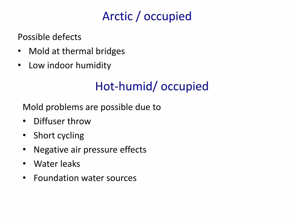
Arctic / occupied
Possible defects
• Mold at thermal bridges
• Low indoor humidity
Hot-humid/ occupied
Mold problems are possible due to
• Diffuser throw
• Short cycling
• Negative air pressure effects
• Water leaks
• Foundation water sources

Arctic and hot-humid / partially occupied
Interface between occupied and unoccupied zones. Requires
• Thermal insulation typical of exterior wall
• Vapor control typical of exterior wall
• Air barrier typical of exterior wall
• Structural requirements (sheathing) and water shedding details not required
• May be constructed in anticipation of emergency use or retrofitted.
• Range of possible wall details is wide, provided appropriate to the climate.

Arctic / interrupted / temperature half life
Modeling results for 10,000 sf building with R-20 insulation all sides, 0.25 cfm75/sf infiltration, 80 lb per (envelope) sf of total mass, constant exterior temperature.
• Baseline (described above): 1 week
• Half the infiltration or double the contents: 2 weeks
• Double the infiltration or half the contents: ½ week
Half Life is a property of the building and can be used with any interior or exterior climate conditions, steady-state or transient. Half life estimate may be used to determine time to a target temperature such as 0 degrees C.
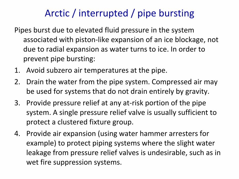
Arctic / interrupted / pipe bursting
Pipes burst due to elevated fluid pressure in the system associated with piston-like expansion of an ice blockage, not due to radial expansion as water turns to ice. In order to prevent pipe bursting:
1. Avoid subzero air temperatures at the pipe.
2. Drain the water from the pipe system. Compressed air may be used for systems that do not drain entirely by gravity.
3. Provide pressure relief at any at-risk portion of the pipe system. A single pressure relief valve is usually sufficient to protect a clustered fixture group.
4. Provide air expansion (using water hammer arresters for example) to protect piping systems where the slight water leakage from pressure relief valves is undesirable, such as in wet fire suppression systems.

Arctic / interrupted / building integrity
Arctic climate
≥40°F (4.4°C) Dry Bulb, where water piping is at risk
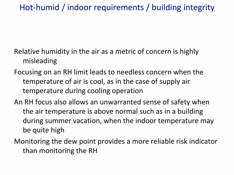
Hot-humid / indoor requirements / building integrity
Relative humidity in the air as a metric of concern is highly misleading
Focusing on an RH limit leads to needless concern when the temperature of air is cool, as in the case of supply air temperature during cooling operation
An RH focus also allows an unwarranted sense of safety when the air temperature is above normal such as in a building during summer vacation, when the indoor temperature may be quite high
Monitoring the dew point provides a more reliable risk indicator than monitoring the RH
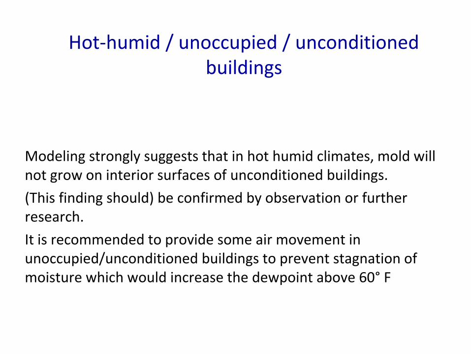
Hot-humid / unoccupied / unconditioned buildings
Modeling strongly suggests that in hot humid climates, mold will not grow on interior surfaces of unconditioned buildings.
(This finding should) be confirmed by observation or further research.
It is recommended to provide some air movement in unoccupied/unconditioned buildings to prevent stagnation of moisture which would increase the dewpoint above 60° F
Hot-humid / occupied / conditioned buildings
Mechanical systems and controls should maintain indoor dewpoint < 60° F. Mold will not grow under these conditions
Large size mechanical systems with building automation can easily maintain dewpoint < 60° F
Small size mechanical systems using a thermostat do not support directly monitoring/controlling indoor dewpoint
Sponsored development of a (residential) thermostat should be encouraged to control/maintain dewpoint < 60° F
Hot-humid / occupied / partially conditioned buildings
If electricity service to a building is limited but not absent, the building may be partially conditioned, with the zone of mission-critical facilities conditioned. In order to prevent mold growth at the interface between the conditioned and unconditioned space these strategies may be adopted:
Maintain interior dewpoint < 60F for the whole building. This may require operation of the air handler for long periods of time. It may require ensuring air exchange between the conditioned and unconditioned parts of the building. If a low dewpoint can be maintained in the building, then building surfaces of whatever temperature should remain mold-free.

Hot-humid / occupied / partially conditioned buildings
If the separation between conditioned and unconditioned parts
of the building is anticipated at design time, then the separation
should be designed and constructed as an exterior assembly.
One example may be 4” cmu with EIFS on the exterior
(unconditioned) and drywall at the interior (conditioned).
If the separation between the conditioned and unconditioned
parts of the building is not anticipated, then the separation
should be reconfigured as if it were an exterior assembly.
Drywall should be removed from any partitions that serve as
interface. An assembly of mold-resistant materials should be
used.

Hot-humid / interrupted / building integrityLater modeling results
Mold appearance may occur for many reasons associated with poor management of water flows. See discussion above of mold problems in occupied buildings.
In the absence of water management problems, will suspension of space conditioning alone lead to drywall mold formation?
Using ASHRAE Standard 160 with Mold Index calculation—NO.
This finding is consistent with the common use of drywall in unconditioned spaces in hot-humid climates such as garages.

QUESTIONS?

ADDITIONAL SLIDES IN CASE OF QUESTIONS REGARDING MODELING

ARCTIC BUILDINGS
Three principal factors affecting temperature
Conductive heat loss. This is modeled in the traditional way. One material with an assigned thermal resistance is used to represent the average conductive heat loss from the building. Foundation heat losses are included in the single-material averaging. Use
qcon=U · A · ΔT
Infiltration heat loss. See discussion below
Heat storage in the mass of the building and contents. See discussion below.

Infiltration heat loss
Infiltration heat loss in I-P units is usually represented by the expression qinf=60·Q·ρ·cp· ΔT. We may use 0.075 lbm/cf as the air density (ρ) and 0.24 (Btu/lbm ·°F) as the specific heat of air (cp) to simplify the expression to qinf=1.08·Q· ΔT, where Q is the natural air change rate in cfm.
We use the expression I for the building 75 Pascal blower door results divided by the 6-sided building surface area (cfm75/sf). Natural infiltration will vary widely depending on exposure, building height, outdoor conditions and other factors. To simplify, we use the value 0.112 (cfm/cfm75) as found in PNNL Report 18898 Infiltration Modeling Guidelines for Commercial Building Energy Analysis. This reduces to
qinf=0.12 · I · A · ΔT,
where A represents the 6-sided surface area of the building.

Conduction infiltration equivalence
We may note the similarity of form of the two equations for qcond and qinf. We can also determine the relative contribution of conduction and infiltration by determining what values of U and I offer the same heat loss using U = 0.12 · I. We can show this for typical values in Table 1.
I (cfm75/sf) U (Btu/hr·sf·°F) R (hr·sf·°F/Btu)
0.4 .048 21
0.25 .030 33
0.1 .012 83
Conduction and infiltration
Parallel paths of heat transfer
ignoring airflow reduction in insulation resistance
The fact that the paths are parallel help in setting up the model

Heat storage
Rate of heat dissipation depends heavily on heat stored in the building. (Imagine if there was nothing in the building, the indoor temperature would drop rapidly to the outdoor temperature.)
Imagine a 10,000 sf building weighing 1000 T—building plus contents. If we assign that weight by square foot of envelope area (24,000 sf), then the assignment is 84 lb/sf or 7.2 “ of concrete for a square foot.
Put it all together…

Modeled assembly, trial 1. Mass at walls.

Modeled assembly, trial 2. Mass in middle.

Material properties, base case
Notice:
Outdoor conditions on both sides
Air space in the middle. Monitor conditions in air space.

Result—2 months. Fixed outdoor temperature.

Log of decay for three airspaces, trials 1 and 2
y = -0.0043x + 4.2510R² = 1
-2
-1
0
1
2
3
4
5
0 200 400 600 800 1000 1200 1400 1600
Nat
ura
l lo
g o
f ai
rsp
ace
te
mp
era
ture
Interval into the study (hours)
Log of temperature data for three airspace positions
Am
Ac
Ai

Discussion of results
With fixed outdoor temperature (0 degrees C), the indoor temperature decays exponentially to the outdoor conditions.
Lumped capacitance provides good explanation of results.
What about the first few hours?

Airspace must adjust to lumped capacitance
54
56
58
60
62
64
66
68
70
72
1 2 3 4 5 6 7 8 9 10 11 12 13 14 15 16 17 18 19 20 21 22 23 24 25
De
gre
es
F in
th
e a
irsp
ace
Hour into the test
Startup of test with medium insulation, medium capacitance
Am middle airspace
Ac conduction side airspace
Ai infiltration side airspace
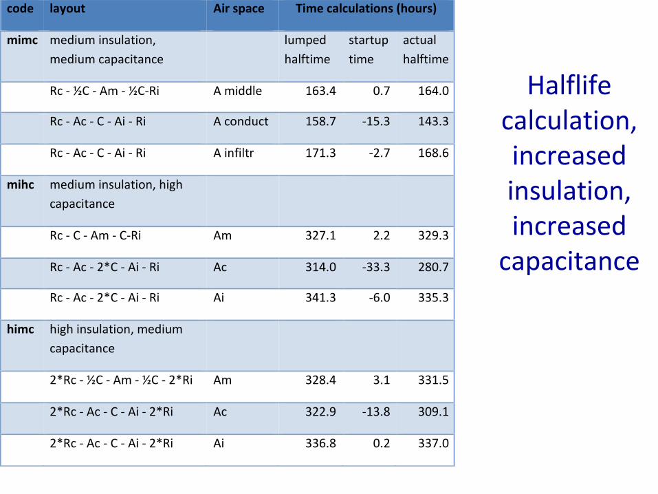
Halflifecalculation, increased insulation, increased
capacitance
code layout Airspace Timecalculations(hours)
mimc mediuminsulation,
mediumcapacitance
lumped
halftime
startup
time
actual
halftime
Rc-½C-Am-½C-Ri Amiddle 163.4 0.7 164.0
Rc-Ac-C-Ai-Ri Aconduct 158.7 -15.3 143.3
Rc-Ac-C-Ai-Ri Ainfiltr 171.3 -2.7 168.6
mihc mediuminsulation,high
capacitance
Rc-C-Am-C-Ri Am 327.1 2.2 329.3
Rc-Ac-2*C-Ai-Ri Ac 314.0 -33.3 280.7
Rc-Ac-2*C-Ai-Ri Ai 341.3 -6.0 335.3
himc highinsulation,medium
capacitance
2*Rc-½C-Am-½C-2*Ri Am 328.4 3.1 331.5
2*Rc-Ac-C-Ai-2*Ri Ac 322.9 -13.8 309.1
2*Rc-Ac-C-Ai-2*Ri Ai 336.8 0.2 337.0

Halflifecalculation,
lowered insulation, lowered
capacitance.
code layout Airspace Timecalculations(hours)
mimc mediuminsulation,
mediumcapacitance
lumped
halftime
startup
time
actual
halftime
Rc-½C-Am-½C-Ri Amiddle 163.4 0.7 164.0
Rc-Ac-C-Ai-Ri Aconduct 158.7 -15.3 143.3
Rc-Ac-C-Ai-Ri Ainfiltr 171.3 -2.7 168.6
milc mediuminsulation,low
capacitance
Rc-¼C-Am-¼C-Ri Am 79.7 -3.3 76.5
Rc-Ac-½C-Ai-Ri Ac 78.8 -9.7 69.1
Rc-Ac-½C-Ai-Ri Ai 84.5 -4.0 80.5
limc lowinsulation,medium
capacitance
½Rc-½C-Am-½C-½Ri Am 80.2 -2.7 77.5
½Rc-Ac-C-Ai-½Ri Ac 76.8 -16.6 60.2
½Rc-Ac-C-Ai-½Ri Ai 88.7 -4.7 84.0

Conclusions—arctic (temperature) conditions
For the base case, the decay halflife is approximately one week. For the two cases with doubled values of insulation or capacitance, the decay halflifeis about 2 weeks, and with halved insulation or capacitance, the decay halflife is about ½ week. The validity of this model must be calibrated against measured values.
Insulation and capacitance appear to have equivalent impacts on decay. This is to be expected. In lumped capacitance heat transfer, the time constant (similar in form but not in value to the halflife) is the product of Resistance and Capacitance.
If the capacitance material is between the airspace and the exterior, then the airspace temperature holds steady for a few hours as the system adjusts. If the capacitance material is inboard of the airspaces, then the adjustment will appear as a sharper drop in indoor temperature as the heat storage material adjusts to the lumped condition.

HOT HUMID CONDITIONS

Mold problems in buildings?
Mold may form on the interior surfaces of buildings in hot/humid climates for many reasons. These include both passive and active means.
Passive:
• Water leaks through the building walls or roofs.
• Water leaks into the building, perhaps through the foundation, leading to elevated indoor humidity.
Active:
• Diffuser directed at building surface leading to local chilling
• Building in negative air pressure combined with low-permeance interior finish (vinyl wall covering, for example)
• Short-cycling of air conditioning equipment leading to surface chilling with low moisture removal.
Mold problems for the reasons shown above are common, and they require correction of the underlying cause.
Aim
This investigation seeks to respond to the single question regarding whether or not an interruption in utility service to a building, by itself, will lead to mold growth on interior surfaces in hot/humid climates. It uses modeling to determine an answer.
ASHRAE Standard 160 makes use of recent research from Finland, which assigns a “mold index” to a surface subject to potentially mold-generating conditions in the surrounding air. If modeled results show a Mold Index in excess of 3.0, then mold is determined to be visible.
First study: assume the surface sees only outdoor temperature and RH.

Findings: Exterior conditions
Three sites were chosen to represent hot/humid climates: Houston, Tampa and Charleston. These are the three locations considered most hot/humid for which modeling weather data are available.
The first step in the analysis effort was to determine the Mold Index of the outdoor ambient conditions. This is equivalent to answering the question whether material simply stored outdoors, away from sun and rain and subject to a biome similar to that of indoors, would grow mold.
Outdoor appearance of mold was considered to be more likely than appearance indoors.

Mold Index
https://web.ornl.gov/sci/buildings/2016/docs/presentations/workshops/workshop-5/Workshop5_OjananViitanen.pdf
Research in Finland (VTT) by Viitanen et al. led to a means to calculate the visibility of mold on surfaces as a function of
• Surface sensitivity to mold
• Drying rate from surfaces
• Ambient temperature and humidity
• Time
The resulting Mold Index has been adopted into ASHRAE Standard 160 “ Criteria for Moisture-Control Design in Buildings”
Mold Index
Assume worst-case: sensitive surface and slow drying rate
Use Mold Index of 3 as upset value—first visible appearance of mold.
Mold begins to appear when ambient humidity is above critical humidity of 80%, and conditions are not too cold.

Tampa exterior. Note blue critical RH.

Mold index using weather tape for 3 cities
Findings for outdoor conditions
Charleston had the most severe climate—only Charleston showed a Mold Index > 3.

Indoor conditions study
This analysis makes use of transient hygrothermal modeling using WUFI version 4, together with the WUFI add-on Mold Index VTT 2.1. It constructs a model with components all set at an initial temperature and relative humidity, then applies outdoor conditions from the selected weather site to both sides of the model and allows the materials to come to equilibrium with those outdoor conditions. The interior of the building contains materials for heat storage and moisture storage.
There are two sides of the building represented in the model. One side (left side) is modeled using the known components of the assembly. The other side contains a single custom “material” with thermal conductance and water vapor permeance to correspond to the anticipated heat flux and moisture transfer by air movement through the building envelope. This may be pictured as parallel flows of heat and moisture via conduction/permeance, shown on the left side of the model, and airflow from the right side of the model.
Three years for the model run.
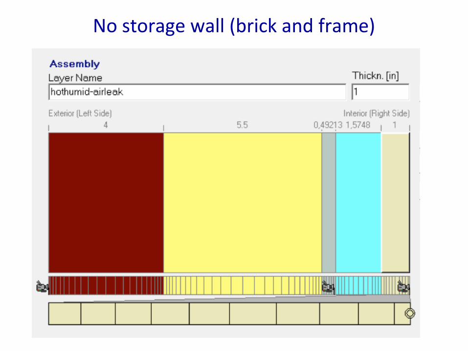
No storage wall (brick and frame)

Assembly of the no-storage wall
The components of the frame wall with the “no storage” condition are shown in Figure 1. Reading from the left to the right:
Frame wall assembly
Brick
2x6 framing cavity with fiberglass insulation
Gypsum drywall. The interior of the drywall has a 10-perm latex paint coating. There is a monitoring position (camera image) at the inside face of the drywall, which is considered to be the surface of concern for mold growth.
Building interior: Air space (blue). This represents the “no storage” condition.
Air exchange material (beige).

Storage wall assembly (cmu and fiberglass)

Mass wall assembly components
Mass wall assembly
Exterior 10 perm coating
8” cmu
¾” furring space with fiberglass insulation
Gypsum drywall. The interior of the drywall has a 10-perm latex paint coating. There is a monitoring position (camera image) at the inside face of the drywall, which is considered to be the surface of concern for mold growth.
Building interiorAirspace (blue)
0.78” of wood representing the heat and moisture storage capacity of 10 pounds of wood (representing all materials) per square foot of surface.
Airspace (blue)
Air exchange material (beige). See below.

“Airflow” material
Assume
outdoor conditions of 80F, 60% RH. Use psychrometric relations to calculate the vapor pressure (inHg), humidity ratio and specific volume of the outdoor air.
Airtightness of 0.25 cfm75/sf of the 6-sided building envelope.
We use a coefficient provided by Pacific National Lab to convert the blower door air exchange rate to a natural air exchange rate. The factor provided by PNNL is 0.112 cfm/cfm75, so the natural air change rate is 0.028 cfm/sf. This flow rate carries 11.0 grains/hour/sf at 0.62 inHg of outdoor vapor pressure.
Permeance equivalence in airflow material
There is a vapor pressure difference between the outdoor air and the indoor air. If the two vapor pressures were the same, then there would be no net change in indoor humidity with air exchange. If the vapor pressure indoors were 0, then the flow rate would be, as calculated above, 11.0 grains/hr/sf. Including this vapor pressure difference factor provides a permeance of 17 perms to represent 0.25 cfm75/sf. This study uses two tightness factors represented as permeances in the airflow material:
Tight building, 0.15 cfm75/sf, 10 perms
Loose building, 1.0 cfm75/sf. 70 perms.

Charleston results: note mold index < 0.7

Tampa results: note Mold Index < 0.025

Houston results: note Mold Index < 0.05

Conclusion for hot humid climates
Mold Index remains well below the ASHRAE 160 threshold of 3.
Interruption of space conditioning service in hot humid climates does not, by itself, lead to mold growth on surfaces.
Make sense? Yes. Unconditioned garages with drywall on walls and ceilings in hot humid climates do not show mold growth except when other wetting conditions are present.
More detailed discussion of the logic for setting 60°F dew point as a prudent limit for “normal” indoor humidity (and as a reasonable compromise with respect to energy use to maintain building dryness) can be found in the ASHRAE Humidity Control Design Guide, the ASHRAE Guide for Buildings in Hot & Humid Climates, and in Chapter 62 of the 2015 ASHRAE Handbook—Applications and in the Moisture Control Guidelines published by the U.S. EPA. (ASHRAE 2001, ASHRAE 2009, ASHRAE 2015 and EPA 2015)