Embed Size (px)
Citation preview


REQUIRED READINGREQUIRED READINGREQUIRED READINGREQUIRED READINGREQUIRED READING...............UNDERSTAND THIS MANUAL!UNDERSTAND THIS MANUAL!UNDERSTAND THIS MANUAL!UNDERSTAND THIS MANUAL!UNDERSTAND THIS MANUAL!
Thank You and Congratulations on purchasing the OUTLAWOUTLAWOUTLAWOUTLAWOUTLAW! Within this kit you will find a racewinning car with over 21 years worth of CUSTOM WORKSCUSTOM WORKSCUSTOM WORKSCUSTOM WORKSCUSTOM WORKS design and quality. In order for you torealize this race car’s winning potential it is important to follow the written text along with thepictures included. The steps required to build this car are very easy, as long as you read before youbuild.
The instructional format for building this car is to open each bag in alphabetical order. Each bag ofparts will be broken down into “Steps” thru the manual. All parts and hardware needed to completeall steps for each separate bag, will be found in each individual bag. There is no need to steal screwsfrom other bags. In the rare event you need to look in a different bag for a certain part, it will benoted clearly in the instructions.
Considering the various dirt or clay surfaces that Dirt Oval cars are raced on today, the Outlaw hasbeen designed to be competitive on either loose packed dirt with buggy tires or high bite clay withrubber or foam racing tires. The instructions will build the kit using the most verastale set-up CustomWorks has found in testing on different types of tracks, however there are various other suspensionconfigurations available to you that you may find more suitable for your local track. For updates andmore proven set-ups login to CustomWorksRC.com.
All hardware (screws, washers, nuts, etc…) are referred to by size and type in the instructions. Tohelp clarify which screw or nut the instruction is calling for refer to the HARDWARE REFERENCEsupplement. The size of the screw or nut should match the “shadow” of the same piece very closely.
Screw ID’s are: FHFHFHFHFH=Flat Head BHBHBHBHBH=Button Head SHSHSHSHSH=Socket Head SSSSSSSSSS=Set Screw
BUILDING TIPS:BUILDING TIPS:BUILDING TIPS:BUILDING TIPS:BUILDING TIPS:-Using some type of thread locking fluid is suggested for all parts where metal screws thread into othermetal parts. We suggest using a lite setting strength thread lock for the reason you may want to takethe screw out one day. Remember it only takes a very small amount to secure the screw.
-Do NOTNOTNOTNOTNOT use power screwdrivers to drive screws into parts. The fast rotation speed can easily melt andstrip plastic parts or cross-thread into the aluminum parts.
-Lightly sand the edges of graphite pieces using a medium grade sandpaper to avoid splinters. Run athin bead of Super Glue around the edges to give pieces greater durability.
SUGGESTED TOOLSSUGGESTED TOOLSSUGGESTED TOOLSSUGGESTED TOOLSSUGGESTED TOOLS
400 Grit Sandpaper Wire Cutters Blue LoctiteHobby Scissors X-Acto Knife 3/16" WrenchSmall Needle Nose Pliers Phillips Head Screw Driver
Front SuspensionFront SuspensionFront SuspensionFront SuspensionFront Suspension
4240
33325230
3258
3253
- Insert 4240 Inner Pin thru 3332 Susp Brace, then thrufirst leg of 3253 Susp Arm and into 3258 Front SuspMount.- Snap 5230 E-Clips to 4240 Susp Pin.- Arms should pivot freely on the mounts.
- Do NOT over-tighten thescrews into themount!
1272 Qty 1Front Shock Tower
1222 Qty 1Outlaw Chassis
5253 Qty 44-40 x 3/8 BH Screw
1:1
3253 Qty 2Front Susp Arms L&R
-Parts for Step#1
4240 Qty 2Front Inner Susp Pin
3258 Qty 2Front Susp Mount 1:13332 Qty 1
1.4” Front Susp Brace
-Parts for Step#2
1:1
5230 Qty 24E-Clip
1:1
5263 Qty 44-40 x 3/8 FH Screw
- Fasten the 1272 tower to the suspension assembly.- Fasten the suspension assembly and the 3228 Body Post to the 1222 Chassis.
1:1
Steering ComponentsSteering ComponentsSteering ComponentsSteering ComponentsSteering Components
-Parts for Step#1
-Parts for Step#2
3203 Qty 2 (Left Shown)25 Deg Castor Block
7200 Qty 2Front Axle
7209 Qty 2Spacer 1:13202 Qty 2
Steering Block L&R7209 Qty 2Ball Stud King Pin 1:1
1:1
5004 Qty 26-20 Set Screw
1:15249 Qty 4Steel Turnbuckle
5235 Qty 8Ball Cup 1:1
-Parts for Step#3
5230 Qty 24E-Clip
1:14241 Qty 2Front Outer Susp Pin 1:11255 Qty 2
Spacer
- Thread the 5235 Ball Cups onto the ends of the 5249 Turnbuckle.- NOTE: Turnbuckle has RIGHT and LEFT threads!
1:1 Assembled Camber Linkand Steering Linkage.
- Make 4 Linkages.5235 5249 5235
STEP #1
STEP #1 STEP #2
Bag ABag ABag ABag ABag A
Bag BBag BBag BBag BBag B
1272
5253
5263
1220
3228 Qty 1Set Screw
3228 Qty1Long Body Post
3228 Qty 1Post Collar
3229 Qty 18-32 x 1/2 FH Screw
1:1
SET SCREW
3229
3304 Qty 1Steering Slide
3304 Qty 1Steering Rack
5262 Qty 24-40 x 1/4 FH Screw
8122 Qty 6Ball Stud
1:1
5217 Qty 24-40 Lock Nut

-Mount the Castor Block to the Susp Arm with a1255 Spacer on each side of the Castor Block as itis fitted between the ears of the Susp Arm.-Insert the 4241 Susp Pin thru the Susp Arm,Spacer, and Castor Block-Retain the Susp Pin by attaching 5230 E-Clips toeach end.
7209
3202
4241 5230
- Thread the 8122 Ball Stud into the front face of 3304Steering Slide, back face of the shock tower, and top faceof the Steering Arm as shown.-Insert the Steering Slide into the 3304 Steering Rack,mount the rack to the chassis.-Mount the linkages from Step #1 by snapping the BallCups onto the Ball Studs.
- Insert the 7200 Axle into the3202 Steering Arm so theholes are in-line.-Align the Steering Arm intothe 3205 Castor Block andpress the 7209 Ball StudKingpin thru the assemblyas shown. 7209
7200
5230
1255 1255
5004
Rear SuspensionRear SuspensionRear SuspensionRear SuspensionRear Suspension
4234 Qty 2Rear Inner Susp Pin
3254 Qty 2Long Rear Susp Arm
5253 Qty 24-40 x 3/8 BH Screw
1:1
3305 Qty 1Tail Tank Tray
-Parts for Step#1
2230 Qty 23 Deg Toe Block
3257 Qty 2Tall Shock Ear
1:1
1273 Qty 1Rear Bulkhead
-Parts for Step#2
1:1
5230 Qty 24E-Clip
1:1
5263 Qty 44-40 x 3/8 FH Screw
1:1
5254 Qty 44-40 x 1/2 BH Screw
5264 Qty 64-40 x 1/2 FH Screw
3257
-Attach the 3257 Long Shock Ears tothe 1273 Bulk to the side facing awayin the diagram.-Attach the 3305 Tail Tank Tray asshown in the diagram. 3257
1273
3305
5253
5254
STEP #2
-Attach the 3254 SuspArm to the 2230 ToeBlock using the 4234Susp Pin.-Retain the pin with 5230E-Clips.-Make a RIGHT and LEFTassembly!
-LEFT Side Assembly Shown.
FRO
NT
FRO
NT
-NOTE: Back side of ToeBlock for proper direction!
STEP #1
STEP #3STEP #2
2230
3254
4234
5230
Bag CBag CBag CBag CBag C
52645264
5263
8122
8122
3304
3304
8122
8122
8122
8122
5262
-USE 5217 LOCKNUTSTO RETAIN

Rear SuspensionRear SuspensionRear SuspensionRear SuspensionRear Suspension
7216 Qty 2Rear CVD Axle
7211 Qty 2CVD Coupling
4235 Qty 2Rear Outer Susp Pin
-Parts for Step#1
7214 Qty 2Medium Dogbone
3241 Qty 2Bearing Carrier
1:1
XXXX Qty 4Ball Stud
-Parts for Step#2
1:1
5230 Qty 24E-Clip
-Parts for Step#3
1255 Qty 10Spacer
1:1
7211 Qty 2Rear CVD Pin
7211 Qty 2CVD Set Screw
7203 Qty 2Roll Pin1:15249 Qty 2
Steel Turnbuckle5235 Qty 4Ball Cup 1:1 5217 Qty 2
4-40 Lock Nut
1226 Qty 4Ball Bearing
1:1
1:1
7047 Qty 6Spacer
- Press 1226 Ball Bearings into the 3241 Bearing Carrier.- Attach the Bearing Carrier to the Susp Arm using 4235 Susp Pin with (2) 1255 Spacers on each side of the Bearing Carrier.- NOTE: The Suspension Pin will pass thru the UPPER hole in the Bearing Carrier.- Retain the Susp Pin using 5230 E-Clips.
- Apply grease to the areas shown.- Apply thread-lock (Loctite) to the set screw.- Align the holes as shown so that the 7211 CVD Pin can pass thru the Bone, Axle, and Coupling. Pin should be evenlyspaced in the DogBone.-Tighten the Set Screw by angling the Bone and Axle so the set-screw is able to be tightened.
LOC
TITE
GREASE
STEP #2
4235
5230
1226
STEP #11255
3241
8122 Qty 4Ball Stud
STEP #3 - Attach the 8122 Ball Stud to the Rear Bulkheadas shown using a 5217 Lock Nut.- Slide a 1255 Spcaer onto the Ball Stud andthread into the Bearing Carrier in the outer mosthole.- Insert the CVD assembly by sliding the axle thruthe bearings.- Slide (4) 7047 Shims onto the axle and retainusing the 7203 Roll Pin. Pin should be evenlyspaced in Axle.- Attach the Camber Link by snapping the BallCups onto the Ball Studs.
5205
7211(Pin)
7214
7216
7211 (Coupling)
7211(Set Screw)
8122
1255
8122
7203
7047
Bag DBag DBag DBag DBag D
1:1

Diff AssemblyDiff AssemblyDiff AssemblyDiff AssemblyDiff Assembly
1229 Qty 25/32 x 5/16 Bearing
1:1
4361 Qty 1Diff Bolt Cover
-Parts for Step#1
4362 Qty 1Diff Spring
4358 Qty 2Diff Ring
4365 Qty 1Right Outdrive
-Parts for Step#2
1:14361 Qty 1Diff Bolt
1:1
4204 Qty 6Thrust Balls
- Slide a 4205 Thrust Washer onto the Diff Bolt.- Apply a thick layer of Black Grease to the ThrustWasher, press (6) 4204 Thrust Balls into the BlackGrease.- Slide the other Thrust Washer on the Diff Bolt andinsert it into the 4402 Left Outdrive.- Press (1) 1229 Bearing into the Outdrive.- Put (1) 4404 Diff Ring on the Outdrive, apply Diff Lubeas shown.
- Put (1) 4358 Diff Ring onto the 4364 Right Outdrive, applyDiff Grease as shown.- Install the 4362 Diff Spring and 4361 T-nut into theOutdrive.- Carefully slide the diff assembly together so the Diff Boltpasses thru the entire assembly and threads into the T-nut.-Screw the Diff Bolt into the T-nut until you feel the DiffSpring fully compress. DO NOT OVERTIGHTEN!!!- Back the Diff Bolt off EXACTLY 1/8 of a turn. Diff motionshould be smooth and the Outdrives will turn in oppositedirections.
- Press a small amount of DiffGrease into each of the small holesin the 4356 Diff Gear.- Press (1) 1229 Bearing and the (12)4357 Diff Balls into the Diff Gear.
STEP #1 STEP #2
4205 Qty 2Thrust Washer
Transmission CasingTransmission CasingTransmission CasingTransmission CasingTransmission Casing
1230 Qty 23/8 x 5/8 Bearing
1226 Qty 43/16 x 3/8 Bearing
1:1-Parts for Step#1 & Step#2
4368 Qty 1Top Drive Shaft 1:1
4352 Qty 1Transmission Halfs
1:1
4355 Qty1Idler Pin
- Press the (2) 1230 Bearingsand (4) 1226 Bearings intoeach 4352 Transmission Half.- Slide 4370 Thin Washers on each side of the 4368 TopDrive Shaft as shown.- Insert the Diff Assembly,Top Drive Shaft, 4352 Pin,and Idler Gear into the RIGHTTrans Half. Diff Screw shouldbe on the RIGHT side!
STEP #1 STEP #2
- Press the 4406 Pininto the Drive Shaft.- Fasten 2225 MotorPlate by tighteningthe XXXX Screwswith 4352 Spacers.
4361
4361
4204
4205
4365
1229
4358
4365
43564357
1229
4358
4364
4362
4361
4364 Qty 1Left Outdrive
4356 Qty 1Diff Gear
4357 Qty 12Diff Balls
4361 Qty 1Diff T- Nut
4370 Qty 6Thin Spacer
4368
1226
4370 X3 4370 X2
7047
4354
1230
1230
4352RIGHT
4352LEFT
5291
4406
4406 Qty 1Top Shaft Roll Pin
Bag EBag EBag EBag EBag E
Bag FBag FBag FBag FBag F
CUSTOM-TIP!!!CUSTOM-TIP!!!CUSTOM-TIP!!!CUSTOM-TIP!!!CUSTOM-TIP!!! -Using 400 Grit Sandpaper in a“Figure 8” pattern, it is best to sand the surfaces of both the 4404 Diff Ring and 4205 Thrust Washers. The textured surface results in a smoother and longer lasting diff.
BLA
CK
GRE
ASE
DIFF LUBE
5263
4355
- Align the LEFT Trans Half over the gears.Space the Trans Halves apart using (2)1226 Shims per screw location.
4352
2225
- Diff Screw should be on theRIGHT side of the Trans!
LEFT RIGHT
4354 Qty1Idler Gear
1:1
5263 Qty 44-40 x 3/8 FH Screw
2225 Qty 1Motor Plate
4352 Qty 3Motor Plate Spacer
5291 Qty 34-40 x 1 1/8 BH Screw
1:1
7047 Qty 8Thin Shim
DIFF
LUBE
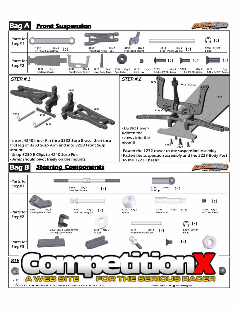
Spur Gear AssemblySpur Gear AssemblySpur Gear AssemblySpur Gear AssemblySpur Gear Assembly
5245 Qty 15-40 Locknut
1:1-Parts for Bag G
1:1
2228 Qty 1Spacer
2228 Qty 1Slipper Eliminator
4881 Qty 181T 48P Spur Gear
5252 Qty 24-40 x 1/4 BH Screw
- Press the 2228 Slipper Eliminator onto the TopDrive Shaft so that the Roll Pin keys into thegrooves.- Secure the assembly to the Top Shaft with the2228 Spacer and the 5245 Locknut. Do NOTovertighten the nut on the Top Shaft!- Mount the 4881 Spur Gear so the flat side facesAWAY from the transmission. Secure using (2)5252 Screws.
2228
4881
5252
2228
5245
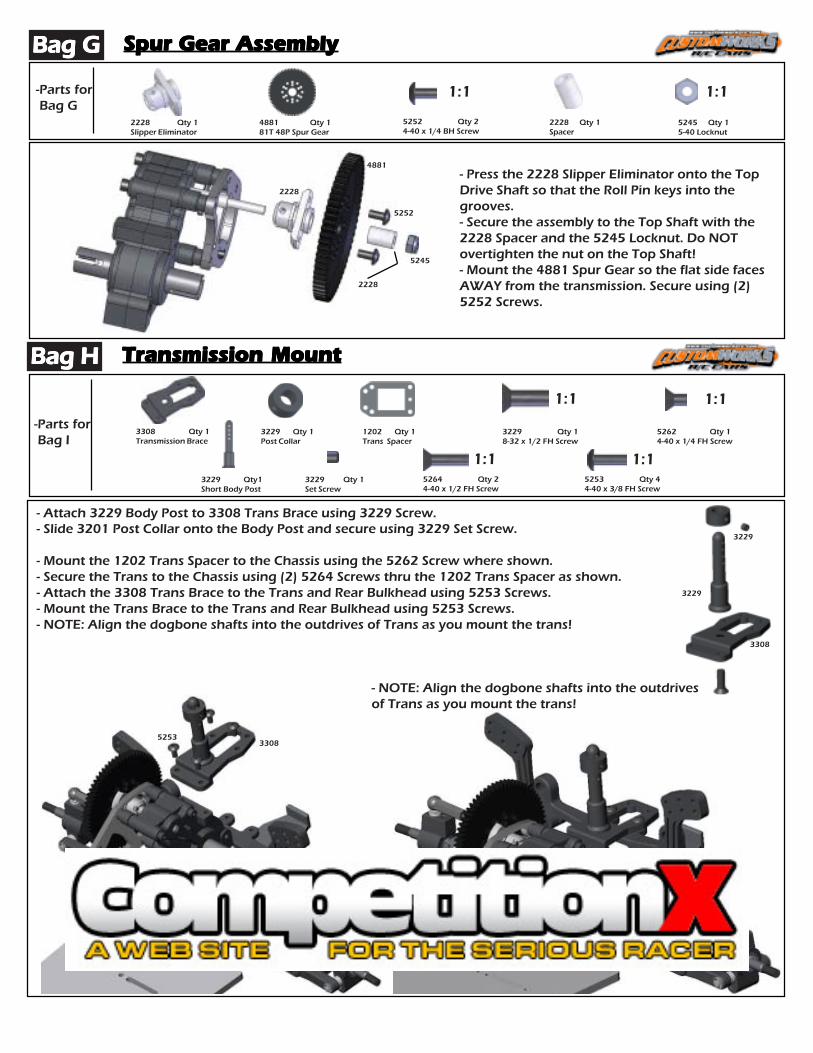
Transmission MountTransmission MountTransmission MountTransmission MountTransmission Mount
1:1
-Parts for Bag I
3229 Qty 1Set Screw
1:1
3308 Qty 1Transmission Brace
1:13229 Qty1Short Body Post
3229 Qty 1Post Collar
1202 Qty 1Trans Spacer
5264 Qty 24-40 x 1/2 FH Screw
5253 Qty 44-40 x 3/8 FH Screw
- Attach 3229 Body Post to 3308 Trans Brace using 3229 Screw.- Slide 3201 Post Collar onto the Body Post and secure using 3229 Set Screw.
- Mount the 1202 Trans Spacer to the Chassis using the 5262 Screw where shown.- Secure the Trans to the Chassis using (2) 5264 Screws thru the 1202 Trans Spacer as shown.- Attach the 3308 Trans Brace to the Trans and Rear Bulkhead using 5253 Screws.- Mount the Trans Brace to the Trans and Rear Bulkhead using 5253 Screws.- NOTE: Align the dogbone shafts into the outdrives of Trans as you mount the trans!
3229 Qty 18-32 x 1/2 FH Screw
1:1
Bag GBag GBag GBag GBag G
Bag HBag HBag HBag HBag H
5262 Qty 14-40 x 1/4 FH Screw
3229
3229
5264
5253
1202
5262
- NOTE: Align the dogbone shafts into the outdrivesof Trans as you mount the trans!
3308
3308
Bag JBag JBag JBag JBag J Shock AssemblyShock AssemblyShock AssemblyShock AssemblyShock Assembly
5274 Qty 44-40 x 1/2 SH Screw
-Parts for Step#1
1437 Qty 4Soft Bladder (BLUE)
1424 Qty 4Long Shock Body
-Parts for Step#2
1:1
1428 Qty4Long Shock Shaft
1250 Qty 8O- Ring
5230
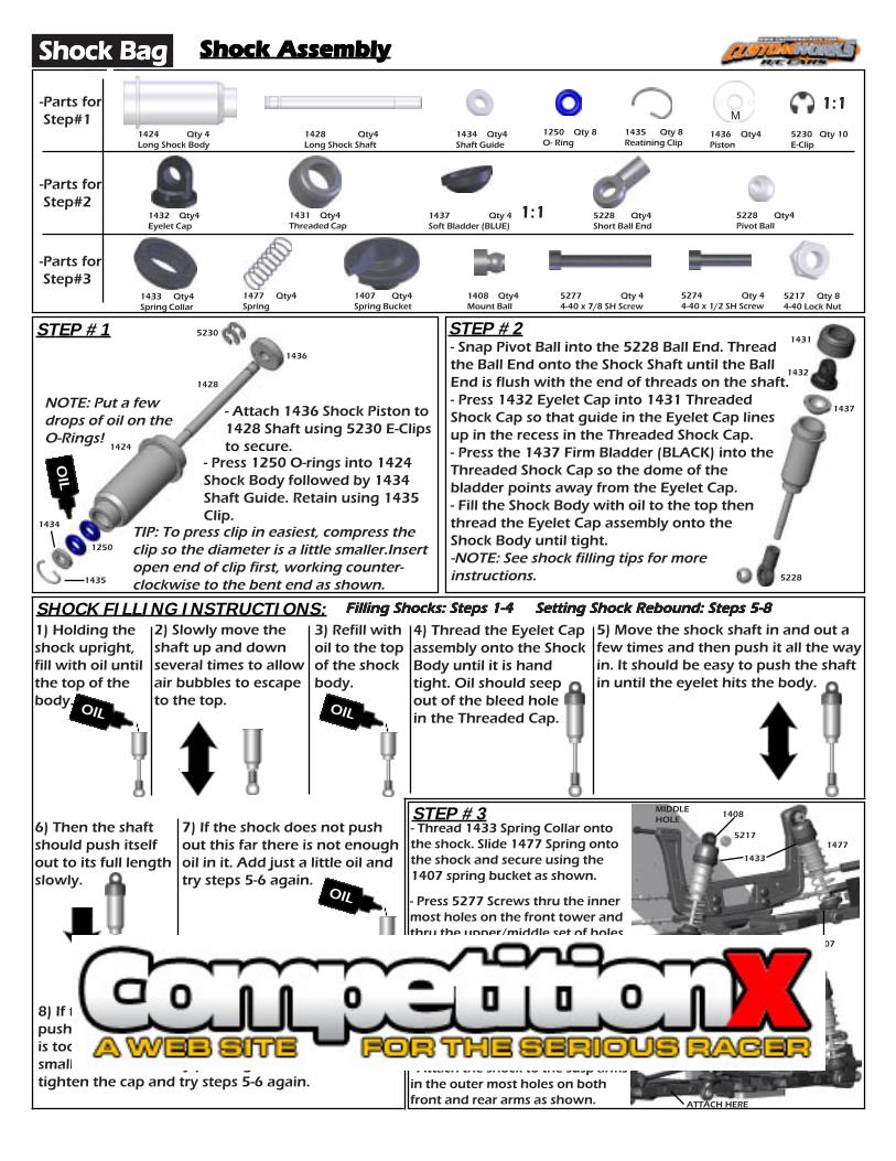
- Attach 1436 Shock Piston to1428 Shaft using 5230 E-Clipsto secure.
STEP #1 STEP #2
TIP: To press clip in easiest, compress theclip so the diameter is a little smaller.Insertopen end of clip first, working counter-clockwise to the bent end as shown.
- Snap Pivot Ball into the 5228 Ball End. Threadthe Ball End onto the Shock Shaft until the BallEnd is flush with the end of threads on the shaft.- Press 1432 Eyelet Cap into 1431 ThreadedShock Cap so that guide in the Eyelet Cap linesup in the recess in the Threaded Shock Cap.- Press the 1437 Firm Bladder (BLACK) into theThreaded Shock Cap so the dome of thebladder points away from the Eyelet Cap.- Fill the Shock Body with oil to the top thenthread the Eyelet Cap assembly onto theShock Body until tight.-NOTE: See shock filling tips for moreinstructions.
SHOCK FILLING INSTRUCTIONS:2) Slowly move theshaft up and downseveral times to allowair bubbles to escapeto the top.
1) Holding theshock upright,fill with oil untilthe top of thebody.
3) Refill withoil to the topof the shockbody.
5) Move the shock shaft in and out afew times and then push it all the wayin. It should be easy to push the shaftin until the eyelet hits the body.
Filling Shocks: Steps 1-4 Setting Shock Rebound: Steps 5-8Filling Shocks: Steps 1-4 Setting Shock Rebound: Steps 5-8Filling Shocks: Steps 1-4 Setting Shock Rebound: Steps 5-8Filling Shocks: Steps 1-4 Setting Shock Rebound: Steps 5-8Filling Shocks: Steps 1-4 Setting Shock Rebound: Steps 5-8
4) Thread the Eyelet Capassembly onto the ShockBody until it is handtight. Oil should seepout of the bleed holein the Threaded Cap.
6) Then the shaftshould push itselfout to its full lengthslowly.
7) If the shock does not pushout this far there is not enoughoil in it. Add just a little oil andtry steps 5-6 again.
8) If the shockrebounds too fast , or you cannotpush the shaft in until the eyelet hits the body, thereis too much oil. Loosen the cap and pump out asmall amount of oil by pushing the shaft in. Re-tighten the cap and try steps 5-6 again.
STEP #3
1434 Qty4Shaft Guide
1435 Qty 8Reatining Clip
1436 Qty4Piston
M5230 Qty 10E-Clip
1:1
-Parts for Step#3
1432 Qty4Eyelet Cap
1431 Qty4Threaded Cap
5228 Qty4Short Ball End
5228 Qty4Pivot Ball
1433 Qty4Spring Collar
1477 Qty4Spring
1407 Qty4Spring Bucket
1408 Qty4Mount Ball
5277 Qty 44-40 x 7/8 SH Screw
5217 Qty 84-40 Lock Nut
1436
1428
1424
1434
1435
1250
5228
1437
1432
1431
ATTACH HERE
ATTACH HERE
1477
1407
1408
OIL
NOTE: Put a fewdrops of oil on theO-Rings!
OILOIL
OIL
Shock BagShock BagShock BagShock BagShock Bag
- Press 1250 O-rings into 1424Shock Body followed by 1434Shaft Guide. Retain using 1435Clip.
UPPER/MIDDLEHOLE
MIDDLEHOLE
5217- Thread 1433 Spring Collar ontothe shock. Slide 1477 Spring ontothe shock and secure using the1407 spring bucket as shown.
- Attach the shock to the susp armsin the outer most holes on bothfront and rear arms as shown.
- Install the shocks onto the screwswith the shoulder of the 1408Mount Ball facing the tower, securewith 5217 Nut.
- Press 5277 Screws thru the innermost holes on the front tower andthru the upper/middle set of holeson the rear tower. Secure using5205 Nut.
1433

Bag KBag KBag KBag KBag KBattery MountBattery MountBattery MountBattery MountBattery Mount
-Parts for Bag J
3224 Qty 1Battery Tray
5263 Qty 44-40 x 3/8 FH Screw
STEP #1- Slide the 2004 Strap Mount thru the small loop on the3009 Battery Strap.- On the marked spots, drill the (4) holes in the 3224Battery Tray so they align with the holes in the chassis.- Mount the Tray to the Chassis using 5263 Screws thruthe Chassis and into the 2004 Strap Mount.- Peel apart both 3009 Battery Straps. Insert one Strapend thru the Buckle and re-attach to itself. Then slidethe end of the other Strap thru the Buckle, pull tight tothe Battery and attach to the velcro.NOTE: Battery packs come in a variety of widths, it may be necessaryto alter the Tray by cutting away the left side of the tray and/or re-aligning the holes it mounts in.
1:1
5263
2004
3224
5263
Servo and Linkage InstallationServo and Linkage InstallationServo and Linkage InstallationServo and Linkage InstallationServo and Linkage Installation
-Parts for Steps #1
5242 Qty 1Large Servo Saver
8130 Qty2Small Ball Cup
5281 Qty14-40 Stud
1:1
5253 Qty 44-40 x 3/8 BH Screw
1:1
5263 Qty 54-40 x 3/8 FH Screw
8122 Qty 2Ball Stud
5240 Qty2Servo Mount
3209 Qty1Antenna Mount
Bag IBag IBag IBag IBag I
Bag JBag JBag JBag JBag J
2004 Qty 2Strap Mount
3009 Qty 1Strap Buckle
3009 Qty 2Battery Strap
3009
STEP #1- Attach 5240 Servo Mounts to your steering servo in the position shownusing 5253 Screws.- Thread 8120 Ball Stud into the upper-most center hole in the 5242 ServoSaver.- Attach both 8130 Ball Cups to one another using the 5281 Stud until theBall Cups bottom out on one another. Snap a Ball Cup onto the Ball Stud onthe Servo Saver.- Determine which of the Spline Inserts are correct for your servo by pressingit over the drive on the servo. Align the servo so it has equal throw in bothdirections.- Press the Servo Saver onto the Spline Insert so that the Servo Saver is perpen-dicular to the servo, attach using the screw that came with your servo.
3234 Qty2Spacer
3234
8122
5205
5253
5240
8130
5281
STEP #2
- Mount the servos to the chassis using 5263 Screws as shown.- Thread 8122 Ball Stud with the 3234 Spacer into the top of the Steering Slide.- Snap the Ball Cup onto the Ball Stud threaded into the Steering Slide.- Attach 3209 Antenna Mount in either of the two holes shown below.NOTE: Steering movement should be bind free except for the restriction ofthe servo transmission.
3209
5263
5263
8122
3234

Cage BagCage BagCage BagCage BagCage Bag Cage AssemblyCage AssemblyCage AssemblyCage AssemblyCage Assembly
3421 Qty 2Wing Slide Bushing
3235 Qty 2Main Cage Half
-Parts for Step #1 & Step #2
3233 Qty 1Front Bumper
3233 Qty 2Rear Bumper
-Parts for Step#3 & Step#4
3233 Qty1Bumper Connector
3235 Qty 2Upper Cage Brace
- Mount the (2) 3233 Rear Bumpers together using 5253Screws and the 3233 Bumper Connector.
-Attach the Bumper Assembly to the Rear Bulkhead using5255 Screw into the upper bumper and 5254 Screw into thelower bumper as shown.
STEP #1
5253 Qty 24-40 x 3/8 BH Screw
1:11:1
5254 Qty 64-40 x 1/2 BH Screw
1:1
5255 Qty 44-40 x 5/8 BH Screw
3232 Qty 1Nerf Bar L & R
3232 Qty 1Nerf Support L & R
5280 Qty 2Hole Head Screw SHORT
5279 Qty 2Hole Head Screw LONG
5278 Qty 24-40 x 1” SH Screw
5274 Qty 44-40 x 1/2 SH Screw
1:1 1:1
1:1
1:1
- Assemble the Nerf Bar and Nerf Bar Support using5254 Screw.
NOTE: Right and Left Nerf Bars and Supports come inthe cage kit. Shown is the RIGHT assembled part.When using the correct Support with the Nerf Bar, thebottom foot of the Support and the short leg of theNerf Bar will be parallel.
STEP #3
Parallel toone another!
5254
STEP #2
5253
3233
5253
3233
3233
5255
5254
- Mount the 3239 Front Cage mount to the chassisusing 5262 Screws.
3239 Qty1Front Cage Mount
1:1
5262 Qty 24-40 x 1/4 FH Screw
5262
5262
3239
1:1
5264 Qty 34-40 x 1/2 FH Screw

- Place the cage between the front suspensiontower with the “HOOKS” slightly further forwardthe the front edge of the chassis.
- Guide the “HOOKS” into the Front Cage Mountwhile guiding the Short 5280 Hole Head Screwsinto the Rear Bulkhead.
- Position the (2) 5274 Screws that mount thebottom portions of the nerf bars to the Cage Halfinto the holes in the Chassis.
- Lock the cage by placing 9936 Clip into the Holein the Head of the 5280 Screw.
CAGE INSTALLATION AND REMOVAL:
- Mount 3233 Front Bumper using 5278 Screws.- Mount the 3421 Wing Slide Bushing to the Cage using 5254 Screws thru the Bushing and Cage and into the 3235 Upper Cage Brace.- Use the (2) Long 5279 Hole Head Screws mount the 3235 Upper Cage Braces onto the top of the Main Cage Halfs.- Use the remaining (2) Short 5280 Hole Head Screws in the back of the Main Cage Halfs. NOTE: Do NOT tighten all the way down, leave a gap of .100”between the screw head and cage.- After completing the Body Panel steps, Attach the rear of the Nerf Bar using the 5254 Screw thru the cage as shown. Attach the front of the Nerf Bar and the Nerf Bar Support to the bottom of the “legs” on the Main Cage Half using 5274 Screws.
STEP #4
5278
5279LONG
5255
3421
3233
3235
CAGE BRACE
5254
5274
5274
“HOOKS”
MAIN CAGE
5280SHORT
Body Panel BagBody Panel BagBody Panel BagBody Panel BagBody Panel Bag Body Panel Prep & MountingBody Panel Prep & MountingBody Panel Prep & MountingBody Panel Prep & MountingBody Panel Prep & Mounting
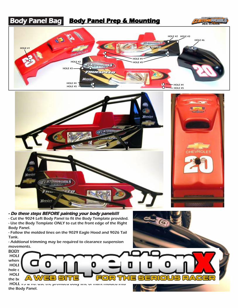
- Do these steps BEFORE painting your body panels!!!- Do these steps BEFORE painting your body panels!!!- Do these steps BEFORE painting your body panels!!!- Do these steps BEFORE painting your body panels!!!- Do these steps BEFORE painting your body panels!!!- Cut the 9024 Left Body Panel to fit the Body Template provided.- Use the Body Template ONLY to cut the front edge of the RightBody Panel.- Follow the molded lines on the 9029 Eagle Hood and 9026 TailTank.- Addtional trimming may be required to clearance suspensionmovements.BODY HOLE NOTES: HOLE #1: Fit the Side Panels and Hood to the Cage, make a markwhere the Body Post meets the Hood. HOLE #2 & #3: Use the marks in the body panel, make a smallhole only the screw can pass thru. HOLE #4: Use the marks provided so the nerf bar can pass thruthe body panel. HOLE #5 & #6: Use the provided body line or mark molded intothe Body Panel.
HOLE #4HOLE #4
HOLE #6
HOLE #1
HOLE #5HOLE #5
HOLE #4
HOLE #5
HOLE #2
HOLE #2
HOLE #3
HOLE #3

NOTE:NOTE:NOTE:NOTE:NOTE: In this step you will be using a fast drying super glueIn this step you will be using a fast drying super glueIn this step you will be using a fast drying super glueIn this step you will be using a fast drying super glueIn this step you will be using a fast drying super gluetype adhesive to secure the tires and wheels to each other. Betype adhesive to secure the tires and wheels to each other. Betype adhesive to secure the tires and wheels to each other. Betype adhesive to secure the tires and wheels to each other. Betype adhesive to secure the tires and wheels to each other. Bevery careful with this process as the glue can tend to run veryvery careful with this process as the glue can tend to run veryvery careful with this process as the glue can tend to run veryvery careful with this process as the glue can tend to run veryvery careful with this process as the glue can tend to run veryeasilly through the tire and may glue your finger to the tire oreasilly through the tire and may glue your finger to the tire oreasilly through the tire and may glue your finger to the tire oreasilly through the tire and may glue your finger to the tire oreasilly through the tire and may glue your finger to the tire orwheel before you know it. You must follow the directions andwheel before you know it. You must follow the directions andwheel before you know it. You must follow the directions andwheel before you know it. You must follow the directions andwheel before you know it. You must follow the directions andprecautions provided by the glue manufacturer to insure aprecautions provided by the glue manufacturer to insure aprecautions provided by the glue manufacturer to insure aprecautions provided by the glue manufacturer to insure aprecautions provided by the glue manufacturer to insure asecure bond.secure bond.secure bond.secure bond.secure bond.STEP #1:STEP #1:STEP #1:STEP #1:STEP #1: Using a reamer or a small drill bit make a hole in thecenter of each of the 4 wheels as shown in Figure 1.Figure 1.Figure 1.Figure 1.Figure 1.STEP #2:STEP #2:STEP #2:STEP #2:STEP #2: Place the foam inserts into the tires with the widerinserts going in the rear tires, the narrower in the fronts. Makesure the insert is laid into the tire evenly. As shown in Figure 2Figure 2Figure 2Figure 2Figure 2it should not be bunched up too much in any area.STEP #3:STEP #3:STEP #3:STEP #3:STEP #3: Place the wheel inside of the tire and work bothbeads of the tire into the channels on the outside edge of thewheel. Peel back a portion of the tire from the wheel andapply an even bead of tire glue between the wheel and thetire as shown in Figure 3.Figure 3.Figure 3.Figure 3.Figure 3. Repeat this step several timesworking your way around the tire until it is secure. You mayrepeat this process now for the remaining 3 tires BUT BEBUT BEBUT BEBUT BEBUT BESURE TO PLACE THE FRESHLY GLUED SIDE UPSURE TO PLACE THE FRESHLY GLUED SIDE UPSURE TO PLACE THE FRESHLY GLUED SIDE UPSURE TO PLACE THE FRESHLY GLUED SIDE UPSURE TO PLACE THE FRESHLY GLUED SIDE UP until it hasdried completely. Once dry it is a good idea to go back and re-seal the edges by applying another small bead of glue andletting it run around the edge of the tire at the gap betweentire and wheel.STEP #4:STEP #4:STEP #4:STEP #4:STEP #4: Once the tires have completely dried you may nowmount them to the car. Place one #1226 Bearing into eachside of the front wheels as shown in Figure 4.Figure 4.Figure 4.Figure 4.Figure 4.STEP #5:STEP #5:STEP #5:STEP #5:STEP #5: Refer to Figure 5 Figure 5 Figure 5 Figure 5 Figure 5 and place one 3/16” shim over thefront axle followed bye the front wheel and than another 3/16” shim. Now secure with one 5207 Locknut, be very carefulto not overtighten the nut. you want to tighten it just enoughto eliminate any slop from side to side but no more. Repeat forother side of car.
Tire BagTire BagTire BagTire BagTire Bag Tire & Wheel InstallationTire & Wheel InstallationTire & Wheel InstallationTire & Wheel InstallationTire & Wheel Installation
-Parts for Bag M
1:1
7047 Qty 6Spacer
1226 Qty 4Ball Bearing
1:1
5207 Qty 48-32 Lock Nut
6204 Qty 2Street-Trac FRONT
6214 Qty 2Street-Trac REAR
6220 Qty 2Soft Insert FRONT
6221 Qty 2Soft Insert REAR
6252 Qty 2Front Wheel
6253 Qty 2Rear Wheel
Figure 1
STEP #6:STEP #6:STEP #6:STEP #6:STEP #6: Now slide one of the rear wheels onto the rear axle as shown in Figure 6.Figure 6.Figure 6.Figure 6.Figure 6. Be sure to index the roll pin in theaxle so that it slides into the drive slot molded in the back of the wheel. Now secure with a 5207 locknut. Be sure notto over tighten as you can bend the roll pin.
Figure 2
Figure 3 Figure 4
Figure 6Figure 5
Top WingTop WingTop WingTop WingTop Wing Tire & Wheel InstallationTire & Wheel InstallationTire & Wheel InstallationTire & Wheel InstallationTire & Wheel Installation- Assemble the #9021 Wing Kit using the instructions provided inside the wing kit. Mount the wing to the carand it should now look just like the car shown below.

TUNING TIPS:TUNING TIPS:TUNING TIPS:TUNING TIPS:TUNING TIPS: These are some general guidelines for optimizing handling performance.None of these “tips” are EVER set in stone. On any given day this manual or any chassisengineering book or guru can be proved wrong by the stop watch. A good way to approachchassis set-up is to try one change, practice it, think how the car felt different from before, andcompare lap times from the stop watch…..this will never fail.
CONGRATULATIONS!!!CONGRATULATIONS!!!CONGRATULATIONS!!!CONGRATULATIONS!!!CONGRATULATIONS!!! You have now completed the assembly process of yournew Custom Works Nitro Outlaw. In the next section of this manual you will find some basicsetup hints and advice. It is important to remember that all tracks and racing surfaces aredifferent. Therefore the suggestions we give you are general in nature and should by nomeans be treated as the only options.
- Bent Suspension Pins: Remove shocks to checkfree movement.- Bound Ball Joint: Should spin free on ballswhile mounted to the car.- Bent or Loose Camber Links- Wore out Bearings or Completely SeizedBearings- Chunked Tire: Check to see if Foam or RubberTire is still glued to wheel.- Loose Screws: Especially Chassis Screws, addBlue Loctite to prevent.- Shocks: Either Bound-up or Out of Oil. Mustswivel freely on mounts.- Foreign Objects: Unlucky Dirt/Stonespreventing Suspension or Steering Movement.- Blown Differential- Radio Problem: Bad Servo, Weak Servo SaverSpring, Transmitter Pot blown.
- Decrease Wing Angle- Decrease Spoiler on Wing- Heavier Rear Spring- Softer Front Spring- Use Rear Sway Bar- Try Softer Front Compound Tire- Try Harder Rear Compound Tire- Lower Front Ride Height- Raise Rear Ride Height- Thread Shock Collar UP on Right Front- Thread Shock Collar DOWN onRight Rear- Decrease Rear Toe- Decrease Castor- Add Rear Toe Stagger orIncrease the difference
- Increase Wing Angle- Add Spoiler to Wing- Softer Rear Spring- Heavier Front Spring- Use Front Sway Bar- Try Harder Front Compound Tire- Try Softer Rear Compound Tire- Raise Front Ride Height- Lower Rear Ride Height- Thread Shock Collar DOWN on Right Front- Thread Shock Collar UP on Right Rear- Increase Rear Toe- Increase Castor- Decrease Rear Toe Stagger orDecrease the difference
Car Is Loose (oversteers):Car Is Loose (oversteers):Car Is Loose (oversteers):Car Is Loose (oversteers):Car Is Loose (oversteers):Car Pushes (understeers):Car Pushes (understeers):Car Pushes (understeers):Car Pushes (understeers):Car Pushes (understeers): Car Is Erratic:Car Is Erratic:Car Is Erratic:Car Is Erratic:Car Is Erratic:
MAINTENANCE:MAINTENANCE:MAINTENANCE:MAINTENANCE:MAINTENANCE: Occasionally dirt will get into the moving and pivoting locations in your car. It is best toperiodically clean your car to keep all the suspension components moving freely. Read the tipsbelow to keep your car running at its best!
- Begin by removing the majority of the dirt using a small brush, toothbrush, or compressed air. - Compressed air is ok to use, be mindful to not FORCE the dirt into the radio gear, transmission,bearings, or air filter. Typically these items only have dirt on them, hitting the dirt with thecompressed air puts dirt INININININ these parts! - Tires, either foam or rubber are best cleaned using water or cleaners like Simple Green (TM). SimpleGreen also does a great job cleaning car parts as well. Lightly spraying car parts (NOT radiocomponents, transmission, air filter, or bearings) with Simple Green and blowing off with compressedair or wiping the parts using the paint brush is a great way to clean in a hurry. - Another R/C friendly cleaner is WD-40 (TM). After the car is clean, very lightly spray the carcomponents and bearings (NOT radio components, transmission, or air filter). Use your brush orcompressed air to remove the extra WD-40. This will lube your bearings and leave a protectivecoating on the parts making it easier to remove dirt later. - Differential Maintenance is needed when the action of the diff feels “notchy”. Usually cleaning thediff parts, re-sand the thrust and diff plates with 400 paper, and lube appropriately will be all that isneeded to bring back to new. Ignoring your differential will lead to handling woes and increasetransmission temps, which will cause part failure.

Camber Gain:Camber Gain:Camber Gain:Camber Gain:Camber Gain: Angle of the Camber Link relative to the Suspension Arm. Lowering the camberlink on the shock tower OR raising the camber link on the castor block will INCREASE thecamber angle of the tire when the suspension is compressed. Raising the camber link on theshock tower OR lowering the camber link on the castor block will DECREASE the camberangle of the tire when the suspension is compressed. There is not a “correct” set-up and onceagain too much of anything is generally bad. This will help change the “feel” of the car thruthe turns.
Camber Link Length:Camber Link Length:Camber Link Length:Camber Link Length:Camber Link Length: Comparing this to the length of the Suspension Arm from each pivotpoint and keeping the Camber the same, making the link shorter will decrease traction forthat corner of the car while making it longer will increase traction for that corner of the car.Once the camber link is equal to or greater than the Suspension Arm pivots, the gain oftraction ends. Also a shorter camber link will increase camber gain and a longer decreasecamber gain.
Shock Angle:Shock Angle:Shock Angle:Shock Angle:Shock Angle: Leaning the shock toward the car is effectively like changing to a softer spring.Standing the shock closer to vertical is effectively like changing to a stiffer spring. Try whenthe car is working well and when one spring change is TOO much for your set-up.
Ride Height:Ride Height:Ride Height:Ride Height:Ride Height: Check by pushing the chassis down once or twice to simulate bumps on thetrack. Having the front end higher than the rear will make the car increase rear tractionespecially out of the turn. Having the front end lower than the front will make the car increasefront traction especially entering the turn. Generally its safe to start the car with the rideheights even.
Rear Toe-In:Rear Toe-In:Rear Toe-In:Rear Toe-In:Rear Toe-In: Front edge of car tires point toward the chassis as viewed from above the car.Increasing the angle toward the car will increase rear traction while decreasing front traction.Decreasing the angle will do the opposite.
SET-UP GLOSSARY:SET-UP GLOSSARY:SET-UP GLOSSARY:SET-UP GLOSSARY:SET-UP GLOSSARY:Caster:Caster:Caster:Caster:Caster: Angle of the kingpin in relation to a vertical plane as viewed from the side of the car.Increasing the angle will make the car more stable out of the turn and down the straights andincrease steering entering a turn. Decreasing the angle will make the car feel more “touchy” at highspeeds and help steering while exiting the turn.
SET-UP GUIDELINES:SET-UP GUIDELINES:SET-UP GUIDELINES:SET-UP GUIDELINES:SET-UP GUIDELINES:When looking for the “perfect set-up” it is important to remember 2 things... 1) Keeping things simple is best. 2) As you are making your set-up change, the track is changing too! Ask a local racer what thetrack usually does from begining to end, especially day to night.
- Start your car’s ride height with it equal at all four corners to start. Use the shock collars to adjustride height by measuring the distance under the chassis when the car is sitting on a FLAT & LEVELsurface. - Shock collars can only jack weight and adjust the car’s handling when the car makes ALL 4 shockssquat when the car is set down. Use the RF shock collar to adjust how the car ENTERS the corner.Use the RR shock collar to adjust how the car exits the corner ON-POWER. Use the LF shock collarto make the car turn in less, and off the corner more. - It is best to have a little bit of brake drag when you let off the gas, this will allow for a morecontrolable car in ALL conditions. Increasing how much the brake drags will make your car turninto the corner harder.
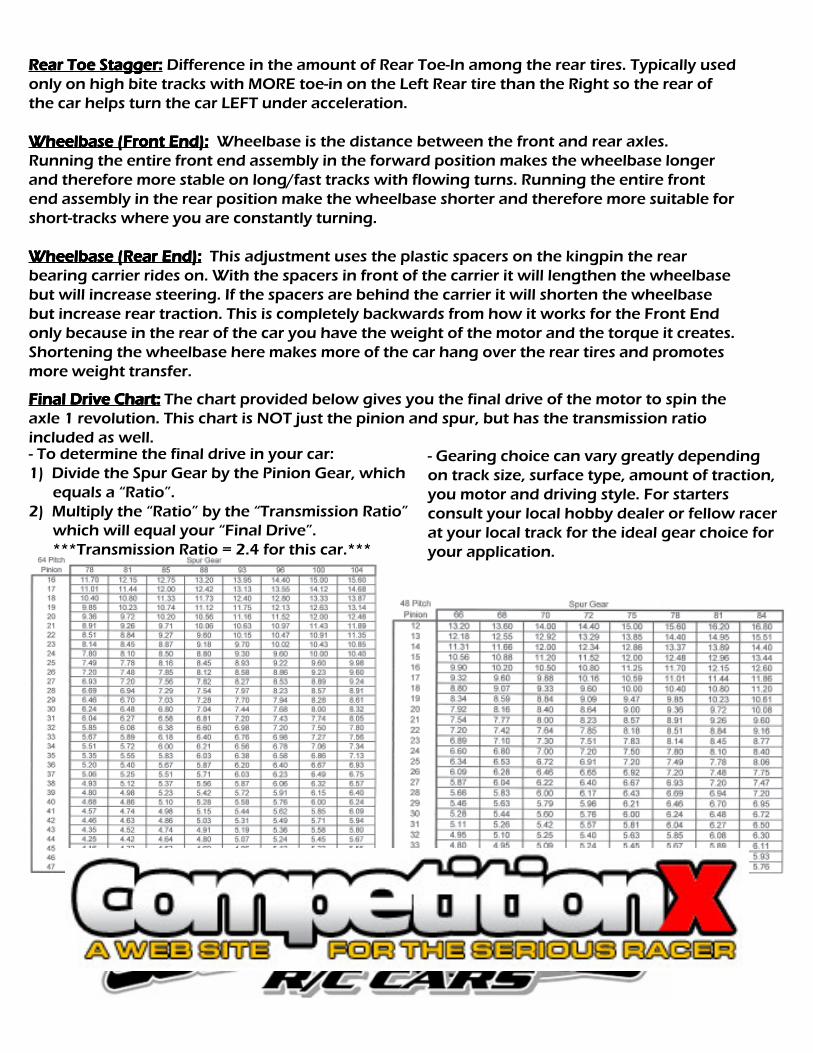
Final Drive Chart:Final Drive Chart:Final Drive Chart:Final Drive Chart:Final Drive Chart: The chart provided below gives you the final drive of the motor to spin theaxle 1 revolution. This chart is NOT just the pinion and spur, but has the transmission ratioincluded as well.
Rear Toe Stagger:Rear Toe Stagger:Rear Toe Stagger:Rear Toe Stagger:Rear Toe Stagger: Difference in the amount of Rear Toe-In among the rear tires. Typically usedonly on high bite tracks with MORE toe-in on the Left Rear tire than the Right so the rear ofthe car helps turn the car LEFT under acceleration.
Wheelbase (Front End):Wheelbase (Front End):Wheelbase (Front End):Wheelbase (Front End):Wheelbase (Front End): Wheelbase is the distance between the front and rear axles.Running the entire front end assembly in the forward position makes the wheelbase longerand therefore more stable on long/fast tracks with flowing turns. Running the entire frontend assembly in the rear position make the wheelbase shorter and therefore more suitable forshort-tracks where you are constantly turning.
Wheelbase (Rear End):Wheelbase (Rear End):Wheelbase (Rear End):Wheelbase (Rear End):Wheelbase (Rear End): This adjustment uses the plastic spacers on the kingpin the rearbearing carrier rides on. With the spacers in front of the carrier it will lengthen the wheelbasebut will increase steering. If the spacers are behind the carrier it will shorten the wheelbasebut increase rear traction. This is completely backwards from how it works for the Front Endonly because in the rear of the car you have the weight of the motor and the torque it creates.Shortening the wheelbase here makes more of the car hang over the rear tires and promotesmore weight transfer.
- To determine the final drive in your car:1) Divide the Spur Gear by the Pinion Gear, which equals a “Ratio”.2) Multiply the “Ratio” by the “Transmission Ratio” which will equal your “Final Drive”. ***Transmission Ratio = 2.4 for this car.***
- Gearing choice can vary greatly dependingon track size, surface type, amount of traction,you motor and driving style. For startersconsult your local hobby dealer or fellow racerat your local track for the ideal gear choice foryour application.