Embed Size (px)
Citation preview
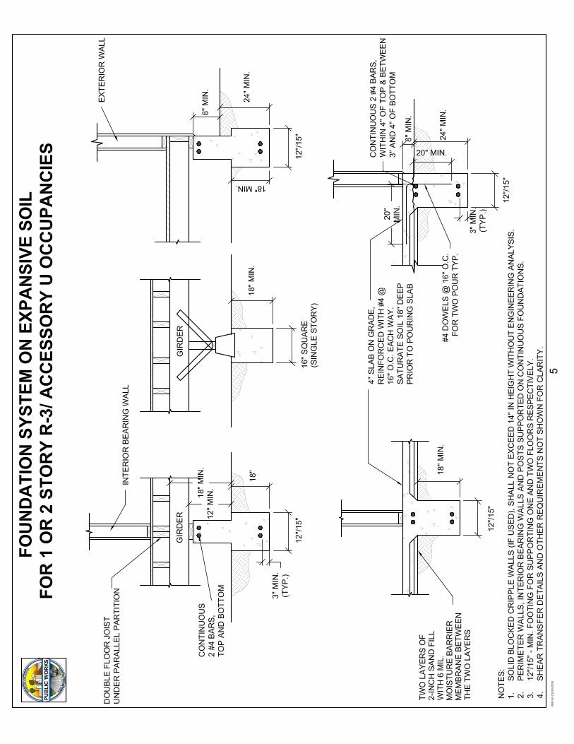
24" 11'-9" 24"2x6 16" 14'-1" 16"
12" 15'-6" 12"24" 14'-10" 24"
2x8 16" 18'-2" 16"12" 20'-5" 12"24" 18'-2" 24"
2x10 16" 22'-3" 16"12" 25'-8" 12"24" 21'-0" 24"
2x12 16" 25'-9" 16"12" 26'-0" 12"
Size 20' Building width
28' Building width
2-2x6 5'-5" w/ 1 NJ 4'-8" w/ 1 NJ2-2x8 6'-10" w/ 1 NJ 5'-11" w/ 2 NJ 12 202-2x10 8'-5" w/ 2 NJ 7'-3" w/ 2 NJ
24" 8'-1" 2-2x12 9'-9" w/ 2 NJ 8'-5" w/ 2 NJ16" 9'-9" 3-2x12 12'-2" w/ 2 NJ 10'-7" w/ 2 NJ 16 5 812" 10'-9"24" 10'-3"16" 12'-7"12" 14'-2"24" 12'-7" 16 4 616" 15'-5"12" 17'-9"24" 14'-7" 2-2x6 4'-6" w/ 1 NJ 3'-11" w/ 1 NJ16" 17'-10" 2-2x8 5'-9" w/ 1 NJ 5'-0" w/ 2 NJ12" 20'-7" 2-2x10 7'-0" w/ 2 NJ 6'-1" w/ 2 NJ 16 3 5
2-2x12 8'-1" w/ 2 NJ 7'-0" w/ 2 NJ3-2x12 10'-2" w/ 2 NJ 8'-10" w/ 2 NJ
Span rating Min. panel
Roof / floor span thickness (in.) Edge support (2x blocking) No edge support Total load Live load
24/0 3/8 24 20 40 3024/16 7/16 24 24 50 4032/16 15/32, 1/2 32 28 40 3040/20 19/32, 5/8 40 32 40 3048/24 23/32, 3/4 48 36 45 35
Rafter to plate
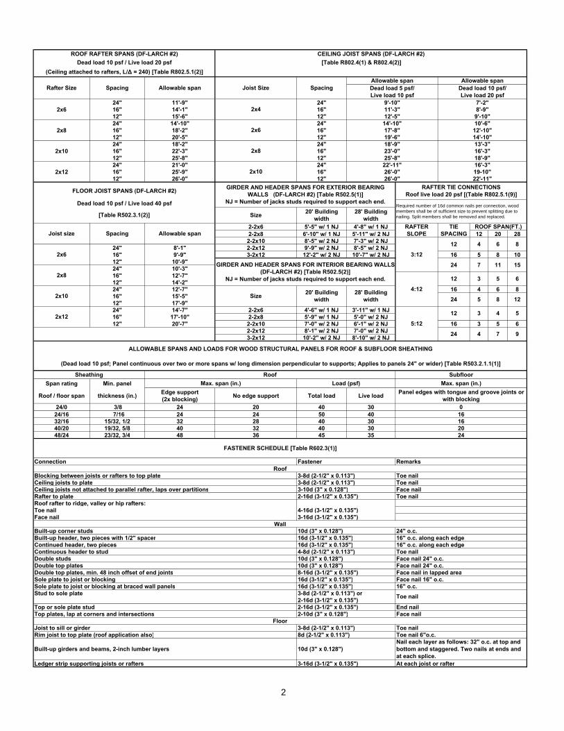
RAFTER TIE CONNECTIONSRoof live load 20 psf [(Table R802.5.1(9)]
Required number of 16d common nails per connection, wood members shall be of sufficient size to prevent splitting due to nailing. Split members shall be removed and replaced.
24
ALLOWABLE SPANS AND LOADS FOR WOOD STRUCTURAL PANELS FOR ROOF & SUBFLOOR SHEATHING
Load (psf)RoofSheathing
4
19-10"
GIRDER AND HEADER SPANS FOR EXTERIOR BEARING WALLS (DF-LARCH #2) [Table R502.5(1)]
NJ = Number of jacks studs required to support each end.
8
TIE SPACING
16d (3-1/2" x 0.135")4-8d (2-1/2" x 0.113")
11
3
26'-0"26'-0"
(Ceiling attached to rafters, L/∆ = 240) [Table R802.5.1(2)]
ROOF RAFTER SPANS (DF-LARCH #2)Dead load 10 psf / Live load 20 psf [Table R802.4(1) & R802.4(2)]
23'-0"25'-8"
CEILING JOIST SPANS (DF-LARCH #2)
Allowable spanDead load 5 psf/ Live load 10 psf
9'-10"2x4 11'-3"
12'-5"
Joist Size Spacing
12'-10"
Allowable span
7'-2"8'-9"9'-10"
14'-10"
22'-11"
17'-8"19'-6"18'-9" 13'-3"
16'-3"
Dead load 10 psf/ Live load 20 psf
10'-6"
16'-3"
Ceiling joists not attached to parallel rafter, laps over partitions
Blocking between joists or rafters to top plateCeiling joists to plate
20
FASTENER SCHEDULE [Table R602.3(1)]
18'-9"
22'-11"
Subfloor
12
16
Panel edges with tongue and groove joints or with blocking
0
4
3:12
Roof rafter to ridge, valley or hip rafters:
Toe nailToe nailFace nailToe nail
16
65:12
Max. span (in.)
28
24
Floor
Top or sole plate stud
10d (3" x 0.128")16d (3-1/2" x 0.135")
10
2-16d (3-1/2" x 0.135")
24 7
Double top plates, min. 48 inch offset of end jointsSole plate to joist or blocking
Built-up corner studsBuilt-up header, two pieces with 1/2" spacerContinued header, two piecesContinuous header to stud
Ledger strip supporting joists or rafters
Top plates, lap at corners and intersections
Stud to sole plate
Face nail
Double studsDouble top plates
4-16d (3-1/2" x 0.135")3-16d (3-1/2" x 0.135")
Wall
3-16d (3-1/2" x 0.135")
Sole plate to joist or blocking at braced wall panels
14'-10"
2x8
2x10
2x12
2x6
4:12
Max. span (in.)
3-8d (2-1/2" x 0.113")
Rafter Size Spacing Allowable span
FLOOR JOIST SPANS (DF-LARCH #2)
Dead load 10 psf / Live load 40 psf
3-8d (2-1/2" x 0.113")Roof
Connection Fastener
ROOF SPAN(FT.)
Remarks
RAFTER SLOPE
2x6
2x8
2x10
[Table R502.3.1(2)]
(Dead load 10 psf; Panel continuous over two or more spans w/ long dimension perpendicular to supports; Applies to panels 24" or wider) [Table R503.2.1.1(1)]
Joist size Spacing Allowable span
12 6 8
15
12 3 5 6
24 4 7 9
5
125 8
GIRDER AND HEADER SPANS FOR INTERIOR BEARING WALLS (DF-LARCH #2) [Table R502.5(2)]
NJ = Number of jacks studs required to support each end.
Size 20' Building width
28' Building width
8-16d (3-1/2" x 0.135")16d (3-1/2" x 0.135")
3-10d (3" x 0.128")
Toe nail
10d (3" x 0.128")10d (3" x 0.128")
2-16d (3-1/2" x 0.135")2-10d (3" x 0.128")
24" o.c.16" o.c. along each edge16" o.c. along each edgeToe nailFace nail 24" o.c.
Nail each layer as follows: 32" o.c. at top and bottom and staggered. Two nails at ends and at each splice.
Face nail 24" o.c.Face nail in lapped areaFace nail 16" o.c.16" o.c.
Joist to sill or girderRim joist to top plate (roof application also)
16d (3-1/2" x 0.135")3-8d (2-1/2" x 0.113") or2-16d (3-1/2" x 0.135")
At each joist or rafter
End nailFace nail
Toe nail
Toe nail
Built-up girders and beams, 2-inch lumber layers
3-8d (2-1/2" x 0.113")8d (2-1/2" x 0.113")
10d (3" x 0.128")
Toe nail 6"o.c.
2
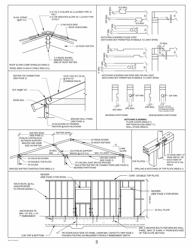
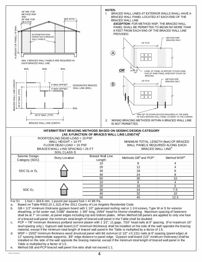
INTERMITTENT BRACING METHODS BASED ON SEISMIC DESIGN CATEGORY (AS A FUNCTION OF BRACED WALL LINE LENGTH)a
ROOF/CEILING DEAD LOAD = 15 PSF WALL HEIGHT = 10 FT
FLOOR DEAD LOAD = 10 PSF BRACED WALL LINE SPACING = 25 FT
SOIL CLASS D
MINIMUM TOTAL LENGTH (feet) OF BRACED WALL PANELS REQUIRED ALONG EACH
BRACED WALL LINEe
Seismic Design Category (SDC) Story Location Braced Wall Line
Length Methods GBb and PCPc Method WSPd
SDC D0 or D1
10 8 420 12 430 18 640 24 850 30 10
SDC D2
10 8 420 16 530 24 7.540 32 1050 40 12.5
For SI: 1 foot = 304.8 mm, 1 pound per square foot = 47.89 Pa. a. Based on Table R602.10.1.2(2) of the 2011 County of Los Angeles Residential Code. b. GB = 1/2” minimum thickness gypsum board with 1 1/2” galvanized roofing nail or 1 1/4 screws, Type W or S for exterior
sheathing, or 5d cooler nail, 0.086” diameter, 1 5/8” long, 15/64” head for interior sheathing. Maximum spacing of fasteners shall be at 7” on center, at panel edges including top and bottom plates. When Method GB panels are applied to only one face of a braced wall panel, the minimum total length of braced wall panel in the Table shall be doubled.
c. PCP = 7/8” minimum thickness portland cement plaster with 1 1/2”, 11 gage, 7/16” head nails at 6” spacing. (For maximum 16” stud spacing only.) Gypsum wall board (1/2” minimum thickness) shall be installed on the side of the wall opposite the bracing material, except if the minimum total length of braced wall panel in the Table is multiplied by a factor of 1.5.
d. WSP = 15/32” minimum thickness wood structural panel with 8d common (2 1/2” x 0.131) nails at 6” spacing (panel edge) at 12” spacing (intermediate supports), 3/8” edge distance to panel edge. Gypsum wall board (1/2” minimum thickness) shall be installed on the side of the wall opposite the bracing material, except if the minimum total length of braced wall panel in the Table is multiplied by a factor of 1.5.
e. Method GB and PCP braced wall panel h/w ratio shall not exceed 1:1.