Embed Size (px)
Citation preview

Report on testing to determine impact resistance of vehicle windscreens –
overpass screening project
Department of Main Roads Queensland Australia


Report on testing to determine impact resistance of vehicle windscreens – overpass screening project John Spathonis
© The State of Queensland, Department of Main Roads 2001

Acknowledgements
I would like to thank the staff of Perfect Glass Windscreen Industries Pty Ltd and Ferny Grove State High School for their assistance during this project.
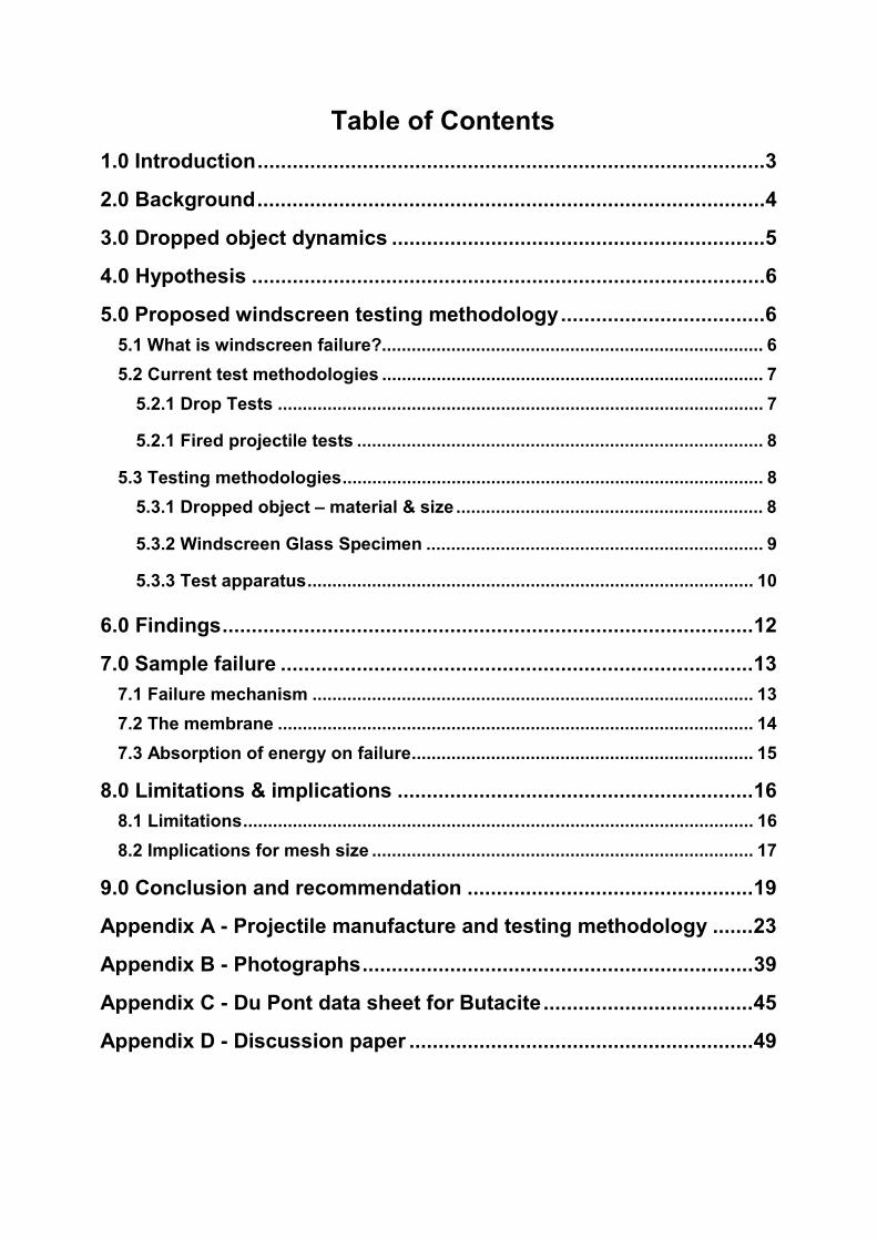
Table of Contents 1.0 Introduction.......................................................................................3
2.0 Background.......................................................................................4
3.0 Dropped object dynamics ................................................................5
4.0 Hypothesis ........................................................................................6
5.0 Proposed windscreen testing methodology...................................6
5.1 What is windscreen failure?............................................................................. 6
5.2 Current test methodologies ............................................................................. 7
5.2.1 Drop Tests .................................................................................................. 7
5.2.1 Fired projectile tests .................................................................................. 8
5.3 Testing methodologies..................................................................................... 8
5.3.1 Dropped object – material & size .............................................................. 8
5.3.2 Windscreen Glass Specimen .................................................................... 9
5.3.3 Test apparatus.......................................................................................... 10
6.0 Findings...........................................................................................12
7.0 Sample failure .................................................................................13
7.1 Failure mechanism ......................................................................................... 13
7.2 The membrane ................................................................................................ 14
7.3 Absorption of energy on failure..................................................................... 15
8.0 Limitations & implications .............................................................16
8.1 Limitations....................................................................................................... 16
8.2 Implications for mesh size ............................................................................. 17
9.0 Conclusion and recommendation .................................................19
Appendix A - Projectile manufacture and testing methodology .......23
Appendix B - Photographs...................................................................39
Appendix C - Du Pont data sheet for Butacite....................................45
Appendix D - Discussion paper ...........................................................49

Page 2

Page 3
1.0 Introduction The increasing densification of the road network within Queensland, particularly in southeast Queensland, has resulted in an increased number of vehicular and pedestrian overpasses. Overpasses are required to maintain links within the community and to improve traffic efficiency and safety. The large number of overpasses in south-east Queensland has increased the opportunity for objects to be deliberately thrown or dropped from them (refer to figure 1). These incidents pose a risk to vehicle occupants and other road users, such as pedestrians.
Overpass structure
Ap
pro
x. 7
m
V car
V projectile
V proj rel car
Figure 1. Typical object throwing scenario
The exterior of most passenger vehicles are a combination of thin metal panels and various forms of glass. The area of greatest risk to vehicle occupants is the penetration of objects through the front windscreen (windshield). This project was initiated to determine appropriate mesh aperture sizes if screening treatments are adopted on overpass structures as part of a holistic approach1 to reducing the likelihood of objects of damaging size being dropped or thrown from overpasses. To assist this determination, a testing methodology was devised to determine the impact resistance of windscreens used in Australian vehicles. Two possible scenarios have been identified2 :
1. Objects may be conveniently found adjacent to the structure. Typically these could include rocks, concrete fragments, bottles, drink cans, guide posts, manhole covers, road signs and posts etc.; or
2. Objects could be brought from other locations and from a considerable distance. The range of such objects capable of being thrown or dropped is infinite. Easily attainable and low cost objects include metal nuts and bolts, building bricks, steel rods, large rocks and slabs of concrete etc.
1 Main Roads screening of overpasses policy and technical guidelines 2 Appendix D – Main Roads Discussion paper – Protective screening of Overpass Structures, Section 4.4

Page 4
The first scenario could be regarded as ‘opportunistic’ and mitigating measures are possible. The second is a ‘premeditated’ act and therefore difficult to mitigate without resorting to drastic measures such as ensuring no apertures are present from overpasses (for example-solid screens). Also, premeditated acts could involve a perpetrator cutting of a large hole in a safety screen. This project will focus on addressing the opportunistic scenario. It is considered that scenario 2 could not be totally prevented. Future projects may extend to scenario 2 considerations. 2.0 Background While throwing objects from overpasses is not a common practice, it has the potential to cause severe injuries to road users and induce outrage in the community3. Little data and information on actual incidents is available or has been gathered by Main Roads or the Queensland Police Service to date. Currently, some states of the USA and South Africa are addressing the issue of screening of certain overpasses (i.e. pedestrian, railroads) with varying success4. Past practice has been to erect a screen along the outside of the overpass structure to reduce the risk to motorists. The protective screens have been manufactured from a variety of materials; ‘two inch’ chain wire mesh and 50mm x 50mm welded wire mesh are the most common4. The selection of screening materials used appears to be empirical with no evident research supporting choices. Consequently this study was undertaken to assess the degree of protection that these screens will afford to motorists. The need for a protective screen treatment and its design parameters are influenced to a large degree by the speed of underpass traffic. This is because the impact velocity of a dropped object relative to the vehicle being impacted is dependent on two factors, namely the drop height and the vehicle speed. However, for typical situations encountered on high-speed roads such as motorways and highways, vehicle speed is the dominant factor. The calculated impact velocity for various drop heights is shown in the table 1 below.
Vertical impact velocity Drop Height m metres/second kilometres/hour
5 10 36 7 12 42
10 14 50 15 17 62 20 20 71 25 22 80 30 24 87 35 26 94 40 28 101
Table 1. Impact velocity v drop height
3 AS 3845 – Risk Management 4Appendix D – Main Roads Discussion paper – Protective screening of Overpass Structures, Section 3 and Appendix A

Page 5
3.0 Dropped object dynamics When considering the consequences of vehicular impact with an object dropped from a relatively low height (7m), the underpass traffic ‘speed environment’ is the major determinant of the impact characteristics. A drop height of 7m was selected as a representative height for road overpasses. It is accepted traffic engineering practice to design for a traffic speed that is greater than the regulated speed. This speed is that which 85 percent of vehicles are observed to travel under free flowing conditions. A design figure commonly used by traffic engineers is the regulated speed limit plus 5 to 10 percent. For the experiments and conclusions of this paper, a 10 percent figure has been adopted. For example, in a 100km/h regulated speed zone, the design speed would be 110km/h (100km/h + 10 percent). Using simple vector algebra, figure 2 shows how the drop velocity and vehicle velocity combine to create an impact velocity relative to the vehicle. For a vehicle traveling at an actual speed of 110km/h (posted speed 100km/h) and with a projectile drop height of 7m, the impact velocity of the projectile relative to the windscreen is 118·4km/h or 32·9m/s. At 110km/h, the projectile would impact the windscreen at an angle of 20·5° to the horizontal. This is equivalent to a driver sitting in a stationary vehicle with a projectile fired at the windscreen at the 118·4km/h and at 20·5° to the horizontal.
Figure 2. Relative velocities of projectile and vehicle As a vehicle travels faster the impact angle measured from the horizontal decreases. Table 2 shows various values for vehicle velocity, relative velocity and impact angle.
Posted speed limit km/h
V car (posted speed limit + 10%) km/h (m/s)
V projectile km/h (m/s) (dropped 7m)
V projectile rel to car km/h (m/s)
Angle of impact to horizontal
80 88 (24) 42 (12) 97 (27) 26·7° 100 110 (30) 42 (12) 115 (32) 20·5° 110 121 (34) 42 (12) 126 (35) 18·9°
Table 2
V car
V projectileV proj rel car
Page 6
4.0 Hypothesis The underlying hypothesis for the experiments described in this report is that for each height of structure and underpass speed limit, there is an impact velocity where an object of specific characteristics will just penetrate a windscreen. It is further hypothesised that as the structure height or vehicle speed increase, the size of the object will decrease. The experiments are aimed at determining the critical object size for standard interchange overpass heights. If this critical object size is known, the maximum aperture size in protective screens can be determined. 5.0 Proposed windscreen testing methodology
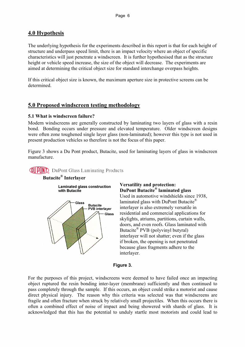
5.1 What is windscreen failure? Modern windscreens are generally constructed by laminating two layers of glass with a resin bond. Bonding occurs under pressure and elevated temperature. Older windscreen designs were often zone toughened single layer glass (non-laminated); however this type is not used in present production vehicles so therefore is not the focus of this paper. Figure 3 shows a Du Pont product, Butacite, used for laminating layers of glass in windscreen manufacture.
Butacite® Interlayer
Versatility and protection: DuPont Butacite® laminated glass Used in automotive windshields since 1938, laminated glass with DuPont Butacite® interlayer is also extremely versatile in residential and commercial applications for skylights, atriums, partitions, curtain walls, doors, and even roofs. Glass laminated with Butacite® PVB (polyvinyl butyral) interlayer will not shatter; even if the glass if broken, the opening is not penetrated because glass fragments adhere to the interlayer.
Figure 3. For the purposes of this project, windscreens were deemed to have failed once an impacting object ruptured the resin bonding inter-layer (membrane) sufficiently and then continued to pass completely through the sample. If this occurs, an object could strike a motorist and cause direct physical injury. The reason why this criteria was selected was that windscreens are fragile and often fracture when struck by relatively small projectiles. When this occurs there is often a combined effect of noise of impact and being showered with shards of glass. It is acknowledged that this has the potential to unduly startle most motorists and could lead to

Page 7
sudden manoeuvres or braking and subsequently lead to a secondary incident. However, as part of normal driving practice, motorists are often required to contend with this type of windscreen damage caused when vehicle tyres pick up and throw stones. Providing protective screens on overpasses to give full protection against small sized objects would be prohibitively costly. In summary, prevention of direct physical injury to a motorist by select types of projectiles fully penetrating a laminated windscreen was the criteria used for assessment.
5.2 Current test methodologies 5.2.1 Drop Tests Common windscreen testing methodologies are widely used by windscreen manufacturers5. Windscreen manufacturers ensure the quality of the windscreens by testing them to various standards. These test methodologies involve dropping steel balls of varying diameters from varying heights onto windscreen glass samples under controlled conditions. The drop-ball methodologies are widely used, well documented and are included in a number of standards for windscreen testing. A drop test is similar across a number of these standards5. The Australian Standard - Safety glass for land vehicles - AS/NZS 2080:1995 describes two tests involving dropping a steel ball onto a flat windscreen sample 305 ± 5mm square. The glass sample is supported in a standard frame (see figure 4).
Figure 4. Sample support frame and surcharge weight Testing criteria from the Australian Standard of each test are listed in table 3 below:
Test name Steel Ball
Diameter Ball Weight
Drop Distance
Impact Velocity
Energy of Steel ball
Fracture & Adhesion Test
38 mm 0·220 kg
9·1 m 13·4 m/s
19·7J
Impact Test 82·5 mm 2·25 kg 3·6 m 8·4 m/s 79·4J Table 3.
5 American Standard: - Drop test for evaluating laminated safety glass for use in automotive windshields - SAE J938 JUN84. European Standard: - Road vehicles - safety glazing materials - Mechanical tests - ISO 3537:1999(E) Australian Standard: - Safety glass for land vehicles - AS/NZS 2080:1995

Page 8
‘Dropping ball’ methodologies appear to offer a great deal of confidence in terms of repeatability and quantification of test results. The current steel ball test in windscreen testing standard methods appears to be empirical and the correlation with relative vehicle/object speed and steel ball characteristics (i.e. density, diameter) compared to actual field conditions is uncertain. From advise from a windscreen manufacturer, the standard tests are not concerned with determining a level of protection for the vehicle occupant per se, but rather to determine that a predetermined level of laminating adhesion strength between the resin membrane and glass layers has been achieved. The test velocities of dropped balls in the current windscreen standards are significantly lower than that experienced when an object, dropped from an overpass, collides with a moving vehicle. 5.2.1 Fired projectile tests Another test identified involved firing stone screenings at the windscreens of wrecked vehicles. This test relates to windscreen chipping due to large aggregate in ‘sanding’ of roads in areas subject to snowfall6. Presumably the testing will investigate ‘star’ cracking and surface damage to windscreens. The firing of stone screenings is not widely used and little documentation is presently available.
5.3 Testing methodologies After considering standard windscreen tests and the physical practicalities of testing, the following test methodology was adopted. 5.3.1 Dropped object – material & size It is envisaged that rocks are the most likely objects to be dropped due to their general availability in the vicinity of overpass structure sites. While figure 5 is not typical of all overpass structures it does highlight that past accepted engineering practices need to be reassessed because of the increase of objects being thrown from overpasses. The rubble drain in figure 5, although very practical and in keeping with the aesthetics of the area, may need reworking to securely bond stones into a concrete matrix.
Figure 5. Supply of stones in a rubble drain adjacent to a footbridge 6 Colorado Department of Transportation has commissioned a report into windscreen chipping

Page 9
Determining the shape of objects to be used in testing was narrowed by consideration of the type of accelerating mechanism to be employed. A spherical shape was adopted as it made firing simpler and more importantly a spherical object has the highest mass with minimum overall dimensions. Two characteristics of the projectiles needed replication – density and shape. For this reason it was determined that some form of manufactured concrete object (concrete has similar density to rock) would replicate the density of these dropped objects. Additionally, spherical steel projectiles (ball bearings) were used in testing. 5.3.2 Windscreen Glass Specimen For ease of experimentation it was decided to use a test method that uses the same size laminated windscreen samples and supporting frame as described in the Australian Standard, American Standard and International ISO Standard. This approach was adopted for the following reasons:
1. Windscreen stresses. Many modern vehicles use the windscreen as a stiffening/structural member in the vehicle design. Consequently for in situ windscreens, it is unknown what stresses exist in the windscreen especially in a vehicle which is old or been involved in a collision. Additionally, heat from sunlight induces thermal stresses in windscreens. As such, testing of windscreens in situ would have to occur on cool vehicles. This would mean providing shade or testing at night. Alternatively, the windscreens may be removed from the vehicles for testing.
2. Impact angle. Windscreens in modern passenger vehicles are seldom flat but are
curved and also are raked backward to streamline aerodynamics. Reproducibility of results would be difficult, as test results could be dependent on the shape of the windscreen, vehicle make and model, point of impact, its age and history. It was thought that windscreen curvature would contribute to a higher strength than a plain flat windscreen. (The rake angle of a number of passenger vehicles was measured. For a modern sedan (or derivative) the windscreen angle is generally about 300 to the horizontal. A dropped object impacting at an angle of 200 to the horizontal (refer table 2) would impact the windscreen at 400 off normal. Large trucks and buses have windscreens that are near vertical – the impact angle being 200 off normal.)
3. Setup of test rig. For in situ testing of windscreens, setting up the test rig to fire a
projectile at an angle that simulates on road conditions is problematic. 4. Variability of windscreen conditions in vehicles. Windscreen ageing, presence of
stresses, existing surface faults etc. are variables that could lead to inconsistency of results. This would have to be resolved by using a very large sample base.
5. Place of testing. Testing windscreens in situ in vehicles in say, a wrecking yard, could
present safety issues because of the proximity to the public and work personnel. While testing an entire windscreen would be safer if removed from the vehicle, a system to uniformly support a curved windscreen would be time consuming and would need careful attention.

Page 10
5.3.3 Test apparatus A compressed air gun was designed and manufactured to propel spherical projectiles at windscreen samples at known velocities (refer to figures 6, 7 & 8 below). Appendix A & B contain more detailed information on the construction of the air gun and projectiles. The apparatus used for testing consisted of a compressed air reservoir connected via an electrically operated valve to a short ‘gun’ barrel. 38mm and 50mm barrels were manufactured from precision bore steel hydraulic tube. The 25mm bore barrel was manufactured from cold drawn seamless steel tube.7 The test methodology involved firing concrete and steel projectiles (nominal diameter of balls - 25mm, 38mm and 50mm) at laminated windscreen samples - 305mm square supplied by Perfect Glass Windscreen Industries Pty Ltd. The projectiles were fired at laminated glass samples at various velocities to determine the point of full penetration. By regulating the air pressure in the air gun reservoir, the projectile velocity could be easily and accurately varied. The apparatus was calibrated by firing projectiles vertically upward and using the time of flight to calculate the initial velocity. Calibration curves are in Attachment 2.
Figure 6. Three different barrel sizes with steel and concrete projectiles (The device to the right of the 25mm barrel is a spring-loaded detent to retain the projectiles in the barrel when firing vertically downward)
7 Imperial bore tubing was used for all barrels – 1, 1.5 & 2 inch

Page 11
Figure 7. Calibrating air gun – shows compressed air reservoir,
12 volt solenoid valve and the 50mm barrel (each projectile type was individually calibrated)
Figure 8. Test rig, holding frame and glass sample prior to test

Page 12
6.0 Findings A total of 97 tests were performed on windscreen samples with glass thicknesses of 5mm and 6mm. A typical fracture pattern is shown in figure 9. What is visible at the impact point is the butacite membrane with a fine layer of adhering glass fragments. In this case both 3mm laminate layers of glass had been completely fragmented. A similar pattern occurs on the non-impact side. The glass from the non-impact side is shattered and projected away from the impact zone.
Figure 9. Typical fracture pattern For each projectile size and material, a series of tests were performed until complete penetration of the glass test sample was attained. The equivalent vehicle speeds for complete penetration of the windscreen were determined through testing. Results are set out in table 4.

Page 13
Diameter (mm) and material
Weight (g)
Projectile velocity for full penetration (m/s)
Glass thickness(mm)
Incident angle
Equivalent vehicle speed (km/h)
25 concrete 17 58 5 0 204 38 concrete 61 37·5 6 0 128 38 concrete 61 40·2 5 0 138 38 concrete 61 40·2 5 20 138 38 concrete 61 43·8 5 40 152 50 concrete 147 35 6 0 118 50 concrete 147 39 6 10 134 50 concrete 147 39 6 30 134 50 concrete 147 39·5 6 40 135
25 steel 64 34·3 5 0 116 25 steel 64 36·4 5 40 124 38 steel 226 24·8 6 0 78 50 steel 534 18·3 5 0 50 50 steel 534 19·5 6 0 55
Table 4. Summary of test results
Comments on results: 1. Changing the glass thickness from 5mm to 6mm did not result in a great increase in
resistance to complete penetration. 2. Of the concrete projectiles, the 50mm size has a high probability of penetrating a new
vehicle windscreen if the vehicle was traveling at 121km/h. 121km/h is the upper limit of vehicle speed (85th percentile) for vehicles traveling in 110km/h speed zones.
3. The steel projectiles penetrated the windscreen at significantly lower velocities (as would be expected).
Glass fragments are expected to spray inside a vehicle at low vehicle speeds even though the projectile does not penetrate into the vehicle cabin space. In these cases the windscreen does afford protection to vehicle occupants from being struck by the projectile. 7.0 Sample failure
7.1 Failure mechanism The failure mechanism of a laminated windscreen is very interesting and deserves comment. After testing it was found that the spherical concrete projectiles had concentric surface markings spaced approximately 3 to 4mm apart (see figure 10). A mode of failure that could explain these markings is that on impact, stress builds within the sample until the glass breaks away/fractures in a concentric pattern. The windscreen sample would at this point effectively have a hole punched in it. The sphere would then progress forward until it impacted the successive unbroken solid glass edge. This edge would create a circular mark on the sphere. Once the sphere impacted onto this edge, stresses would again build in the sample until a slightly larger concentric circular ring fractured away. This process would continue, creating

Page 14
the array of concentric circular markings. Other researchers may wish to use a high-speed camera to further investigate these observations.
Figure 10. Typical concentric markings on concrete projectile It is assumed that as the glass sample is fractured, the plastic bonding membrane (polyvinyl butyral resin) is gradually stretched. This stretching process absorbs a large proportion off the energy of the projectile. Therefore the energy of impact is absorbed by two mechanisms: 1. The fracturing of the glass (theoretically in concentric circles); 2. The stretching of the plastic bonding membrane.
7.2 The membrane To ascertain the extent of stretching of the plastic bonding membrane, a thin walled plasticine hemisphere was placed beneath the windscreen test piece under the impact zone. This shell was of very light construction thereby it was considered not to influence the test significantly. The aim was to record the maximum deformation of the bonding membrane as it distorted the plasticine shell at a test velocity just below that required for full penetration of the sample. Table 5 shows the typical deflection of the membrane for 38mm and 50mm concrete projectiles.
Diameter of concrete projectile Typical maximum deflection of bonding membrane 38mm Up to 110mm 50mm Up to 100mm
Table 5
Consequently it may be seen from table 5 and figure 11 that the polyvinyl butyral membrane plays a significant role in the failure mechanism of the windscreen. While the strength of the glass determining whether a windscreen shatters, the membrane is important in determining the
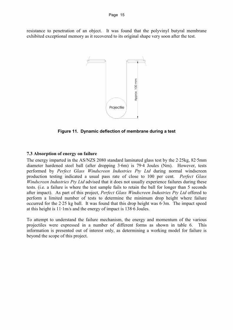
Page 15
resistance to penetration of an object. It was found that the polyvinyl butyral membrane exhibited exceptional memory as it recovered to its original shape very soon after the test.
Figure 11. Dynamic deflection of membrane during a test
7.3 Absorption of energy on failure The energy imparted in the AS/NZS 2080 standard laminated glass test by the 2·25kg, 82·5mm diameter hardened steel ball (after dropping 3·6m) is 79·4 Joules (Nm). However, tests performed by Perfect Glass Windscreen Industries Pty Ltd during normal windscreen production testing indicated a usual pass rate of close to 100 per cent. Perfect Glass Windscreen Industries Pty Ltd advised that it does not usually experience failures during these tests. (i.e. a failure is where the test sample fails to retain the ball for longer than 5 seconds after impact). As part of this project, Perfect Glass Windscreen Industries Pty Ltd offered to perform a limited number of tests to determine the minimum drop height where failure occurred for the 2·25 kg ball. It was found that this drop height was 6·3m. The impact speed at this height is 11·1m/s and the energy of impact is 138·6 Joules.
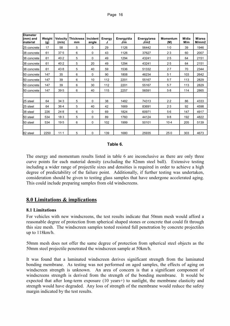
To attempt to understand the failure mechanism, the energy and momentum of the various projectiles were expressed in a number of different forms as shown in table 6. This information is presented out of interest only, as determining a working model for failure is beyond the scope of this project.
Projectile
App
rox.
100
mm
Page 16
Table 6.
The energy and momentum results listed in table 6 are inconclusive as there are only three curve points for each material density (excluding the 82mm steel ball). Extensive testing including a wider range of projectile sizes and densities is required in order to achieve a high degree of predictability of the failure point. Additionally, if further testing was undertaken, consideration should be given to testing glass samples that have undergone accelerated aging. This could include preparing samples from old windscreens. 8.0 Limitations & implications
8.1 Limitations For vehicles with new windscreens, the test results indicate that 50mm mesh would afford a reasonable degree of protection from spherical shaped stones or concrete that could fit through this size mesh. The windscreen samples tested resisted full penetration by concrete projectiles up to 118km/h. 50mm mesh does not offer the same degree of protection from spherical steel objects as the 50mm steel projectile penetrated the windscreen sample at 50km/h. It was found that a laminated windscreen derives significant strength from the laminated bonding membrane. As testing was not performed on aged samples, the effects of aging on windscreen strength is unknown. An area of concern is that a significant component of windscreens strength is derived from the strength of the bonding membrane. It would be expected that after long-term exposure (10 years+) to sunlight, the membrane elasticity and strength would have degraded. Any loss of strength of the membrane would reduce the safety margin indicated by the test results.
Diameter (mm) and material
Weight (g)
Velocity (m/s)
Thickness mm
Incident angle
Energy J
Energy/dia J/m
Energy/area J/m2
Momentum (M)
M/dia M/m
M/area M/mm2
25 concrete 17 58 5 0 29 1126 56442 1·0 39 1946 38 concrete 61 37·5 6 0 43 1126 37627 2·3 60 2007
38 concrete 61 40·2 5 0 49 1294 43241 2·5 64 2151 38 concrete 61 40·2 5 20 49 1294 43241 2·5 64 2151
38 concrete 61 43·8 5 40 59 1536 51332 2·7 70 2344
50 concrete 147 35 6 0 90 1808 46234 5·1 103 2642 50 concrete 147 39 6 10 112 2201 55167 5·7 113 2829
50 concrete 147 39 6 30 112 2201 55167 5·7 113 2829
50 concrete 147 39·5 6 40 115 2257 56591 5·8 114 2865
25 steel 64 34·3 5 0 38 1482 74313 2·2 86 4333 25 steel 64 36·4 5 40 42 1669 83691 2·3 92 4598
38 steel 226 24·8 6 0 69 1824 60971 5·6 147 4917 50 steel 534 18·3 5 0 89 1760 44124 9·8 192 4822
50 steel 534 19·5 6 0 102 1999 50101 10·4 205 5139
82 steel 2250 11·1 5 0 139 1680 25935 25·0 303 4673
Page 17
8.2 Implications for mesh size With regard to visual amenity, a structure with mesh of a high solidity percentage (ratio of solid area to total area) is more conspicuous and could also produce a ‘caged-in’ feeling for pedestrian traffic. As solidity percentage is increased, mesh may become more visually conspicuous — see table 7.
Mesh size mm Wire diameter mm Solidity Percent (Area of metal as % of total area)
25 x 25 3·15 23·6 25 x 50 3·15 18·1 25 x 50 4 22·7 25 x 75 4 20·5
25 x 100 4 19·4 50 x 50 4 15·4
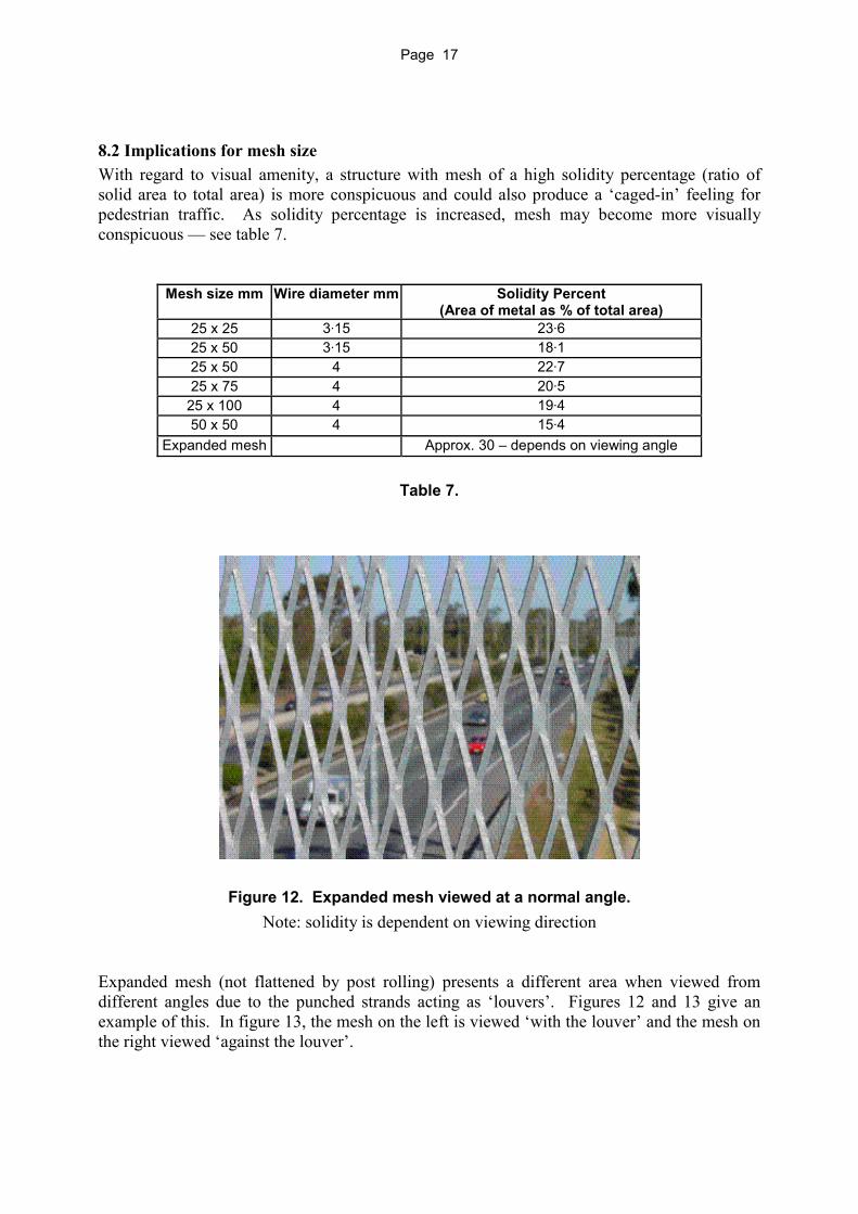
Expanded mesh Approx. 30 – depends on viewing angle
Table 7.
Figure 12. Expanded mesh viewed at a normal angle. Note: solidity is dependent on viewing direction
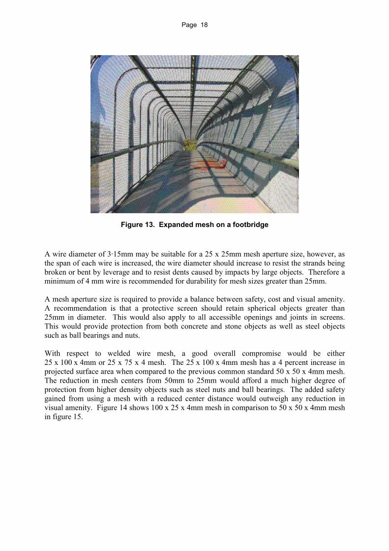
Expanded mesh (not flattened by post rolling) presents a different area when viewed from different angles due to the punched strands acting as ‘louvers’. Figures 12 and 13 give an example of this. In figure 13, the mesh on the left is viewed ‘with the louver’ and the mesh on the right viewed ‘against the louver’.
Page 18
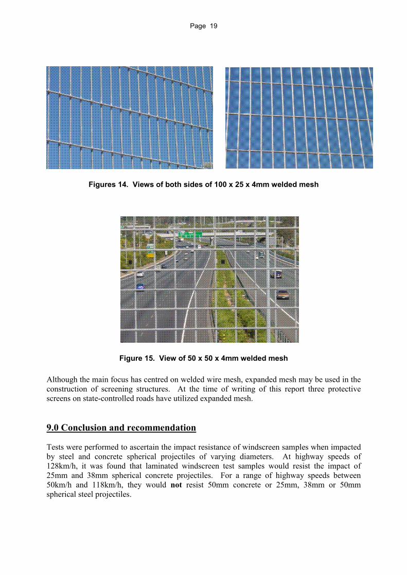
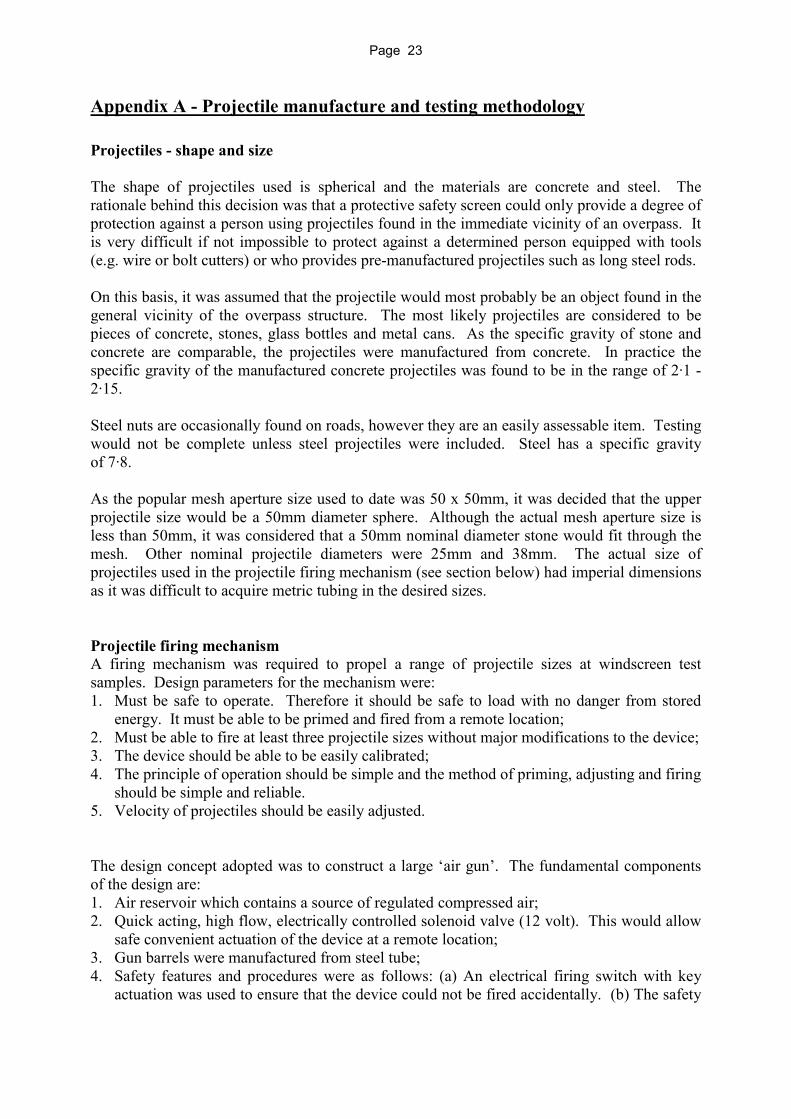
Figure 13. Expanded mesh on a footbridge A wire diameter of 3·15mm may be suitable for a 25 x 25mm mesh aperture size, however, as the span of each wire is increased, the wire diameter should increase to resist the strands being broken or bent by leverage and to resist dents caused by impacts by large objects. Therefore a minimum of 4 mm wire is recommended for durability for mesh sizes greater than 25mm. A mesh aperture size is required to provide a balance between safety, cost and visual amenity. A recommendation is that a protective screen should retain spherical objects greater than 25mm in diameter. This would also apply to all accessible openings and joints in screens. This would provide protection from both concrete and stone objects as well as steel objects such as ball bearings and nuts. With respect to welded wire mesh, a good overall compromise would be either 25 x 100 x 4mm or 25 x 75 x 4 mesh. The 25 x 100 x 4mm mesh has a 4 percent increase in projected surface area when compared to the previous common standard 50 x 50 x 4mm mesh. The reduction in mesh centers from 50mm to 25mm would afford a much higher degree of protection from higher density objects such as steel nuts and ball bearings. The added safety gained from using a mesh with a reduced center distance would outweigh any reduction in visual amenity. Figure 14 shows 100 x 25 x 4mm mesh in comparison to 50 x 50 x 4mm mesh in figure 15.
Page 19
Figures 14. Views of both sides of 100 x 25 x 4mm welded mesh
Figure 15. View of 50 x 50 x 4mm welded mesh Although the main focus has centred on welded wire mesh, expanded mesh may be used in the construction of screening structures. At the time of writing of this report three protective screens on state-controlled roads have utilized expanded mesh. 9.0 Conclusion and recommendation Tests were performed to ascertain the impact resistance of windscreen samples when impacted by steel and concrete spherical projectiles of varying diameters. At highway speeds of 128km/h, it was found that laminated windscreen test samples would resist the impact of 25mm and 38mm spherical concrete projectiles. For a range of highway speeds between 50km/h and 118km/h, they would not resist 50mm concrete or 25mm, 38mm or 50mm spherical steel projectiles.

Page 20
It was found that a laminated windscreen derives significant strength from the laminated bonding membrane. It is expected that the strength of this bonding membrane will reduce with age due to exposure to sun and heat. In this regard the testing overestimates the in-service strength of windscreen glass, as it does not consider the effects of windscreen age. In the absence of testing of aged windscreen samples, a cautious approach is recommended. Welded wire mesh aperture size is supplied in 25mm increments. 50 x 50 mesh could be used in low speed environments (50km/h and below) however, for design consistency it is recommended that a uniform approach be adopted which is independent of the speed environment. As a balance between safety (mesh aperture size), cost and visual amenity, a recommendation is that a protective screen should retain spherical objects greater than 25mm in diameter. This would apply to all accessible openings and joints in screens. Motorists would therefore be provided with a higher degree of protection from both concrete and stone objects as well as steel objects such as ball bearings and nuts.

Page 21
Appendix A - Testing and projectile manufacture

Page 22
Page 23
Appendix A - Projectile manufacture and testing methodology Projectiles - shape and size The shape of projectiles used is spherical and the materials are concrete and steel. The rationale behind this decision was that a protective safety screen could only provide a degree of protection against a person using projectiles found in the immediate vicinity of an overpass. It is very difficult if not impossible to protect against a determined person equipped with tools (e.g. wire or bolt cutters) or who provides pre-manufactured projectiles such as long steel rods. On this basis, it was assumed that the projectile would most probably be an object found in the general vicinity of the overpass structure. The most likely projectiles are considered to be pieces of concrete, stones, glass bottles and metal cans. As the specific gravity of stone and concrete are comparable, the projectiles were manufactured from concrete. In practice the specific gravity of the manufactured concrete projectiles was found to be in the range of 2·1 - 2·15. Steel nuts are occasionally found on roads, however they are an easily assessable item. Testing would not be complete unless steel projectiles were included. Steel has a specific gravity of 7·8. As the popular mesh aperture size used to date was 50 x 50mm, it was decided that the upper projectile size would be a 50mm diameter sphere. Although the actual mesh aperture size is less than 50mm, it was considered that a 50mm nominal diameter stone would fit through the mesh. Other nominal projectile diameters were 25mm and 38mm. The actual size of projectiles used in the projectile firing mechanism (see section below) had imperial dimensions as it was difficult to acquire metric tubing in the desired sizes. Projectile firing mechanism A firing mechanism was required to propel a range of projectile sizes at windscreen test samples. Design parameters for the mechanism were: 1. Must be safe to operate. Therefore it should be safe to load with no danger from stored
energy. It must be able to be primed and fired from a remote location; 2. Must be able to fire at least three projectile sizes without major modifications to the device; 3. The device should be able to be easily calibrated; 4. The principle of operation should be simple and the method of priming, adjusting and firing
should be simple and reliable. 5. Velocity of projectiles should be easily adjusted. The design concept adopted was to construct a large ‘air gun’. The fundamental components of the design are: 1. Air reservoir which contains a source of regulated compressed air; 2. Quick acting, high flow, electrically controlled solenoid valve (12 volt). This would allow
safe convenient actuation of the device at a remote location; 3. Gun barrels were manufactured from steel tube; 4. Safety features and procedures were as follows: (a) An electrical firing switch with key
actuation was used to ensure that the device could not be fired accidentally. (b) The safety

Page 24
procedure was to open a ball valve on the air gun reservoir to ensure no air pressure was present when working around the air gun. (c) The air supply ball valve was also closed.
To provide accurate and repeatable velocities, a number of factors were addressed at the design stage of the ‘air gun’: 1. The volume of gun air reservoir was made sufficiently large so that air leakage past the
projectile would not significantly reduce the pressure in the reservoir. This would lead to more consistent results. Also the pressure drop due to expansion of the air during firing would not be significantly affected. The capacity of reservoir is 6300cc;
2. The 12-volt solenoid valve had to have high flow characteristics and be of high quality so that it would ‘snap’ open in a consistent timeframe. The valve selected was a SMC solenoid valve VXP2390-20-6D. Refer to Attachment 1 data sheet for solenoid valve details;
3. The pressure in the reservoir had to be accurately set. A precision air pressure regulator and accurate air pressure gauge was used;
4. The projectiles had to be a close fit inside the barrel. The method of testing was as follows: 1. The glass test piece was centred beneath the barrel; 2. The projectile was loaded into the barrel until it snapped past the spring loaded detent; 3. The safety ball valve on the gun air reservoir was closed; 4. A plastic sheet was wrapped around the test rig to contain flying glass fragments; 5. At a safe remote location the air pressure regulator was adjusted to achieve the test
pressure. The delivery ball valve was then opened; 6. The safety switch to the solenoid valve was activated (followed by smashing of glass). The air pressure would create a force on the projectile that would accelerate the projectile along the barrel. As air expands inside the barrel with the movement of the projectile, the pressure will drop by an amount. The final projectile velocity was determined by the area of the barrel bore, volume of air reservoir, mass and diameter of the projectile, effective length of the barrel and flow characteristics of the solenoid valve. With a longer barrel, more time is allowed for the projectile to be accelerated hence a greater exit velocity. It was found that suitable performance was obtained by using an effective barrel length of 270mm. Department of Main Roads mechanical workshop at Nundah manufactured the test equipment to the author’s specifications. Manufacture of concrete projectiles Concrete projectiles were manufactured in three sizes – 25mm (1 inch), 38mm (1·5 inch) and 50mm (2 inch). As these projectiles were manufactured from concrete and had to be a close fit in the barrel, accurate moulds were necessary. 1 inch, 1·5 inch and 2 inch precision steel ball bearings were used to facilitate the manufacture of these moulds. The moulds were manufactured from epoxy resin and made in two halves. For the 38mm and 50mm nominal sizes, the moulds were firstly framed in timber and the parting joint plane fitted with two steel 6mm alignment pins. (The method was altered for the 25mm size as the mould was framed with 40mm PVC pipe.)

Page 25
First mould half This half was framed in timber and had a plywood base fitted. The ball bearing was centrally supported within the mould frame at the correct height and supported on a short length of 12mm diameter copper tubing. Measurements were taken to ensure that only half of the ball bearing was below the parting line. To facilitate release of the ball bearing after setting of the epoxy resin, the bearing was covered with a thin film of grease.
The mould was then filled with epoxy resin. The mould was overfilled slightly. After a 24 hour setup time the bearing was removed. The parting face was ground flat and smooth. This was accomplished by laying emery paper on a sheet of glass. Using a circular motion the excess epoxy was removed. The mould flatness was checked by the use of a straight edge. The first half of the mould was then complete and ready for pouring of the second half.
Second mould half The parting planes of the mould halves were lightly coated with grease. The first mould half was laid on a flat surface with the bearing cavity uppermost. The second mould half was assembled onto the first half utilising two 6mm diameter alignment pins. The two halves were then screwed together using 4 wood screws. The steel ball bearing was cleaned and recoated with a thin film of grease and inserted into the hemispherical cavity within the first mould half. The mould was then completely filled with epoxy resin. The finished moulds are shown in figure 1. It was found that the mould restrained the epoxy from shrinking as it cured. This caused shrinkage cracks in the epoxy. Reinforcing the epoxy with fibreglass fabric reduced this shrinkage. After 24 hours curing, the moulds were split and the ball bearing removed. In the first mould half, a hole was drilled through the 12mm copper support tube (which was blocked with epoxy resin) and through the plywood mould bottom. This hole facilitated topping up the mould with concrete.
Figure 1. Finished moulds - 50mm and 38mm with steel balls used to make moulds
Page 26
Casting concrete projectile The concrete blend was 3:1, fine sand/cement. The water/cement ratio was approximately 1:1 by volume. The minimum amount of water was added to obtain the desired degree of workability. Before casting a concrete projectile, the mould halves were thoroughly cleaned and all old grease removed. The exposed areas and the part line were coated with a thin film of fresh grease. The two hemispherical moulds were then individually filled with concrete. The concrete mix was very stiff and was compacted by gently tapping the sides of the mould. The two mould halves are then carefully assembled and screwed together. The mould was gently tapped to compact the concrete thereby driving entrapped air to the surface. The mould at this point was nearly full. The remaining concrete was placed in the mould by using a rod to tamp the concrete down through the center of the 12mm copper tube. The ‘green’ castings were removed from the mould after 24 hours, and cured under water for a minimum of 14 days. The projectiles were left a further 3 weeks (minimum) out of water before use.
Sizing the concrete projectiles It was found that the cured concrete spheres were slightly larger than the bore of the ‘air gun’. This then created a problem of how to uniformly reduce the size of the concrete spheres. Because the spheres were compacted by vibration it was felt that the composition near to the surface might not be uniform. If the diameter was reduced by tumbling in an abrasive media it was thought that the finished size might be irregular.
An alternate method was to reduce the diameter by wet lapping using emery paper. Lapping on a flat surface would be time consuming and would require considerable skill to produce a spherical finished product. The method adopted was to obtain a 400mm length of PVC pipe with an internal bore corresponding to the diameter of the projectile. The pipe was then cut longitudinally to create a ‘U’ shaped through. The through was then lined with 80 grit ‘wet and dry’ emery paper.
As the spheres were slightly larger in diameter than the emery lined PVC trough, they were a snug fit when pushed in place. The PVC flexed around the sphere thereby providing a reasonably even semicircular contact pressure. The sphere was then hand lapped (partially under water) using a rolling action. By constant rotation and frequent trial fitting in the barrel, it was found that the projectiles could be lapped to a degree of accuracy producing a reasonably close fit in the barrel.

Page 27
Calibration of projectile firing mechanism The velocity of the projectile as it left the barrel was calibrated against the air pressure in the firing mechanism air reservoir. This calibration was achieved by firing projectiles vertically into the air on a large oval8. The elapsed time of flight was recorded for a number of air pressure readings. Pressure readings were at 50kPa increments and between 3 to 4 time readings were taken at each pressure. The averaged time (t) was used to calculate the initial velocity (Vo). A correction was made to the calculated velocity for the initial height (h) from the ground.
Vo = exit velocity from barrel in metres/second t = total time of projectile flight in seconds
h = height of barrel discharge end from ground in metres (1.41m)
A spreadsheet was used to calculate a theoretical relationship between ‘projectile velocity’ v ‘air reservoir pressure’. This approach had limited application as the overall efficiency for each projectile diameter and material varied. For each projectile type, the efficiency also varied with air pressure. After field-testing the overall efficiencies were back calculated. Typical efficiencies are shown in table 1 below.
Projectile diameter and material � Efficiency % 25mm concrete 63 38mm concrete 56 50mm concrete 73
25mm steel 88 38mm steel 94 50mm steel 93
Table 1
Problems occurred in calibrating the 25mm concrete projectile, as it was extremely difficult to maintain sight of the projectile during flight due to its small size and high velocity (200 km/h). The calibration curve for 25mm concrete projectile was calculated using the barrel efficiencies obtained from a limited number of readings. The spreadsheet was then used to extrapolate the calibration curve. It is considered that any inaccuracies introduced during this process did not affect the overall outcome of testing. The velocity needed for a 25mm concrete projectile to penetrate a glass sample was 204km/h. Even a large error in calculating the calibration curve would still place the penetration velocity outside the upper road speed of 121km/h.
Windscreen sample testing The projectiles were fired vertically downward, impacting the windscreen test pieces at various angles. Impacts were within 25mm of the center of the each sample as per AS/NZS 2080. Test results were rejected where impacts were outside of the 25mm tolerance or where the projectile fractured.
8The cooperation of the staff at Ferny Grove State High School for permitting the use of their school oval is greatly appreciated
t
ht
Vo�
��
�2
89 2
Page 28
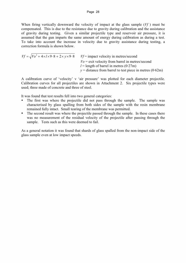
When firing vertically downward the velocity of impact at the glass sample (Vf ) must be compensated. This is due to the resistance due to gravity during calibration and the assistance of gravity during testing. Given a similar projectile type and reservoir air pressure, it is assumed that the gun imparts the same amount of energy during calibration as during a test. To take into account the increase in velocity due to gravity assistance during testing, a correction formula is shown below.
8928942��������� ylVoVf Vf = impact velocity in metres/second
Vo = exit velocity from barrel in metres/second l = length of barrel in metres (0·27m) y = distance from barrel to test piece in metres (0·62m) A calibration curve of ‘velocity’ v ‘air pressure’ was plotted for each diameter projectile. Calibration curves for all projectiles are shown in Attachment 2. Six projectile types were used; three made of concrete and three of steel. It was found that test results fell into two general categories: ��The first was where the projectile did not pass through the sample. The sample was
characterised by glass spalling from both sides of the sample with the resin membrane remained fully intact. Small tearing of the membrane was permitted.
��The second result was where the projectile passed through the sample. In these cases there was no measurement of the residual velocity of the projectile after passing through the sample. Tests such as this were deemed to fail.
As a general notation it was found that shards of glass spalled from the non-impact side of the glass sample even at low impact speeds.

Page 29
Attachment 1 - Valve Data Sheet

Page 30
Page 31
Attachment 2 – Calibration Curves
Calibration Curvefor 17 gram 25mm (1") Concrete Projectile
Height compensated
10
15
20
25
30
35
40
45
50
55
60
65
0 50 100 150 200 250 300 350Pressure kPa
Velo
city
Vf m
/s

Page 32
Calibration Curvefor 61 gram 38mm (1·5") Concrete Projectile
Height compensated
25
30
35
40
45
50
100 150 200 250 300 350 400Pressure kPa
Velo
city
Vf m
/s

Page 33
Calibration Curvefor 147 gram 50mm (2") Conctete Projectile
Height compensated
10
15
20
25
30
35
40
45
50 100 150 200 250 300 350 400 450Pressure kPa
Velo
city
Vf m
/s
Page 34
Calibration Curvefor 63·7 gram 25 mm Steel Projectile
Height compensated
15
20
25
30
35
40
100 150 200 250 300 350 400Pressure kPa
Velo
city
Vf m
/s

Page 35
Calibration Curvefor 226 gram 38mm (1·5") Steel Projectile
Height compensated
15
20
25
30
35
100 150 200 250 300 350 400 450Pressure kPa
Velo
city
Vf m
/s

Page 36
Calibration Curvefor 534 gram 50mm (2") Steel Projectile
Height compensated
10
15
20
25
30
100 150 200 250 300 350 400 450Pressure kPa
Velo
city
Vf m
/s

Page 37
Appendix B - Photographs

Page 38
Page 39
Appendix B - Photographs
Calibration of ‘air gun’ on school oval
Page 40
Vehicle with portable air compressor
Regulated air supply, battery and firing switch with key

Page 41
Test rig shrouded with plastic sheet prior to test
Glass sample after complete penetration by 50mm concrete projectile
(surcharge weight has been removed)

Page 42

Page 43
Appendix C - Du Pont data sheet for Butacite

Page 44
Page 45
Appendix C - Du Pont data sheet for Butacite

Page 46

Page 47
Appendix D - Discussion paper

Page 48
Page 49
Appendix D - Discussion paper
Discussion Paper:
Protective Screening
of
Overpass Structures
Road System Management Division and
Transport Technology Division Department of Main Roads
April 2000

Page 50
1.0 Introduction Over recent years incidents have occurred where objects of various shapes and sizes have been deliberately thrown or dropped onto passing vehicles from overhead road structures. The practice has resulted in serious injuries and death to motorists using the roadway below. The types of structures involved with these incidents include grade-separated roads with or without pedestrian footway facilities and dedicated pedestrian footbridges. The purpose of this discussion paper is to seek comment from Local Governments and other stakeholders on a number of issues relating to the provision of protective screens on overpass structures. The aim is to reduce the likelihood of, or prevent where possible, the incidence of objects of a size large enough to cause injury being thrown from these structures. This discussion paper relates to State-controlled roads and the operations of Main Roads. However, Local Governments may choose to apply the contents of the paper and future outcomes to the local road network. The discussion paper firstly sets out the background that provides the justification why this practice is of concern. It then presents current Australian and overseas practice and discusses the various related issues, and lastly provides recommendations and a conclusion. 2.0 Background There is an emerging and dangerous practice becoming apparent where objects are being deliberately thrown or dropped by vandals onto vehicles passing under overhead road structures. The likelihood of these incidents occurring poses an unacceptable risk to the occupants of vehicles thus targeted and other road users such as pedestrians in some situations. Such incidents are not limited to pedestrian overpasses. As an example, a fatality in New South Wales was caused by a rock, thrown from a two-lane vehicle-only overpass, onto a car passing below. A recent incident in Victoria (late October 1999) resulted in a stroller being thrown from an overbridge onto a vehicle passing below. Fortunately, the driver escaped death but the windscreen was shattered; this incident obviously had the potential for a more serious outcome. In Queensland (February 2000), an incident involved the throwing of a roadside guidepost from a road overbridge which smashed a vehicle windscreen and caused injuries to an elderly passenger. There is a risk that objects may be thrown from embankments and retaining walls as well as from overpasses. This aspect will be discussed in more detail in Section 5.6. It is believed that for every incident reported to authorities or incidents causing injury, there are many “near misses” which go unreported.
Page 51
In South-east Queensland there are approximately 150 structures on State-controlled roads where the potential exists for objects of damaging size to be dropped onto vehicles passing below. 3.0 Summary of Australian and International Screening Practice For more detail, please refer to Appendix A. 3.1 Australia
State Road Authority practices and experiences are briefly discussed in Sections 3.1.1 to 3.1.7 below
3.1.1 Victoria VicRoads has no policy on the screening of overhead road structures. It acknowledges that a problem exists and occasionally incidents involving projectiles being launched from overhead road structures have occurred. VicRoads has advised that it has been unable to correlate data that would allow prediction of the likely risk and prioritisation of sites for screening. VicRoads is waiting to see if a trend will emerge in future. 3.1.2 New South Wales The RTA has a formal policy about screening overhead road structures and is in the process of implementing this policy. A risk assessment table (Appendix B) is used to determine an overall risk value for a site or structure. The population of structures and sites is then ranked in priority order for treatment. 3.1.3 South Australia South Australia has no formal policy nor documentation on the issue of screening of overhead road structures. The Transport SA is aware of the potential problem but treats each overhead road structure on its merits. Risk is assessed by the Project Manager. To date, only one pedestrian bridge has been judged by a Project Manager to require screening. 3.1.4 Western Australia Main Roads Western Australia (MRWA) has neither formal policy nor documentation on the issue of screening of overhead road structures. Main Roads is aware of the problem and commissioned the Australian Road Research Board (ARRB) in 1998 to perform a literature search on national and international screening treatments. The rail authority in WA, Westrail, screens bridges for safety purposes where the rail corridor is electrified. 3.1.5 Tasmania Tasmania has neither formal policy nor documentation on the issue of screening of overhead road structures. The roads agency in Tasmania is aware of the problem and has had occasional incidents of projectiles from overhead road structures.

Page 52
Approximately 150 structures and/or sites have been identified as potential sites for thrown objects and 5 are listed as “high risk”. A policy and strategy is likely to be completed in the near future but implementation is expected to be slow because of limitations on funding and higher priorities for roads spending elsewhere. If a policy and strategy is developed, it is likely to be based on the RTA model. It is likely that pedestrian overpasses will be fully enclosed. 3.1.6 Northern Territory The Northern Territory has no policy on screening of overhead road structures. The road development division does not see the issue as a significant problem at present as it has no reported incidents of projectiles being launched from overhead road structures. 3.1.7 Queensland In Queensland, a small number of overpasses over major high-speed roads have been screened due to the assessed risk to traffic considered unacceptable. These include: a. Road overpass at Keil Mountain Road with single pedestrian footway. b. Beenleigh pedestrian overpass over the Pacific Motorway. c. Pedestrian footbridge over the Gateway Arterial at Deagon. At present, the Queensland Department of Main Roads does not have a policy on the provision of protective cages on road overpasses and only installs screening where there is some extraordinary circumstance. The present system involves the risk associated with each bridge being assessed on a case by case basis. The basis of this is commonly a reactive response to either a specific incident on the road or to local community pressures. The feasibility of retrofitting protective devices over twelve of the Pacific Motorway overpass bridges and stand-alone pedestrian bridges is currently under review by the Major Projects Section of Main Roads.
3.2 United States The US has found that the provision of screens on the outside extremities of structures has not been entirely effective in excluding all objects from being thrown onto vehicles passing under the structure. This configuration permits some objects to be thrown up and over the top of the screen. Heavier missiles are prevented, but objects of a size able to do damage have managed to be thrown over of the top of such screens. US respondents to Main Roads Qld enquiries have advised that the common practice is to build some form of cage or fence on an overhead structure. This involves, attaching to the overhead structure, a frame that then supports some form of fabric which, in turn, catches or prevents objects leaving the vicinity of the overhead structure. The fabric varies from solid (e.g. steel panels or plastic sheeting), wire mesh and heavy gauge fabric to decorative balustrading. The American Association of State Highway and Transport Officials (AASHTO) publishes “A Guide for Protective Screening of Overpass Structures”. This booklet has little in the way of providing any detail of screening overhead road structure. The
Page 53
frames are vertical or curved back over the walkway area and attached to the overhead structure with appropriate fasteners. AASHTO also publishes a “Guide for Design of Pedestrian Bridges”. Youthful misadventure combined with the challenge of walking along the top of a fully screened enclosure over a pedestrian footway has led to at least one fatality where the youth slipped and fell onto the roadway below. 3.3 South Africa The Western Cape Provincial Administration cages all pedestrian overpasses. Their risk management approach is similar to Florida DOT’s. Interestingly, South Africa does not cage the footways on mixed road/foot traffic overpasses.
3.4 Europe The only responses to date from European sources have been from Britain, where there is very little done about this issue and no formal policy. It is noted here that many overhead road structures in the UK, particularly those over motorways in the more densely populated areas, have enclosed restaurants integral to the non-traffic area. In these cases a ‘default’ screen would exist as these restaurants would block clear access to edge of the structure or provide an environment where malicious activity would be easily observed and dealt with. There are no British or European Standards that address screens specifically – the closest references are in terms of preventing pedestrians falling from overhead footways. 4.0 Discussion Issues The following major issues have been identified and need to be addressed in order to formulate administrative and operational requirements for reducing the potential for objects to be dropped onto vehicles from overpass structures: 1. Public education and culture change; 2. Methods for risk assessment; 3. Deterrents (video surveillance & lighting); 4. Determination of the maximum screen aperture size and screen configuration; 5. Screening design options (one side only, two sides etc.); 6. Aesthetic issues; 7. Adequate sight distances for road users; 8. Costs; 9. Implementation Strategies. Each of these issues is discussed/explored below.
Page 54
4.1 Public education and cultural change The consequences of objects being thrown from overhead structures onto road users below are potentially very dangerous. The issue is an emotive one, which has high potential for inducing public outrage9. This discussion paper provides technical considerations to reduce the incidence of objects of a size adequate to cause serious physical injury but does not purport to solve the societal problem of vandals or “thrill seekers” engaging in this dangerous practice. It discusses a remedy for the symptoms of a much larger problem. The act of throwing objects from overpasses onto road users is not a cause; it is a symptom. Dissipating or suppressing the symptom will not remove the root cause. The principal questions are whether a public awareness campaign should be mounted to combat this problem and would such a campaign educate potential wrongdoers of the dire consequences of their actions or would it inflame the present situation. It may have the positive outcome of making motorists more observant of persons involved in these activities, and reporting their presence to police. Any education campaign, if deemed desirable, could be integrated into Queensland Transport’s road safety programs. A campaign could be taken to primary and secondary schools. Additionally, signs could be erected on overbridges advising that dropping or throwing objects is a criminal offence, and in certain instances advise pedestrians that pedestrian activities are under video camera surveillance. These issues are complex and the advice of other more experienced practitioners such as physiologists is required to be sought. 4.2 Methods for risk assessment Presently, instigation of assessment of appropriate deterrents/preventative treatments is largely a reactive response to either an incident on the road or to local community pressures on a case-by-case basis. From information gathered to date, it may be concluded that risk assessment is not comprehensively addressed and that as the issues are complex no definitive solution is available. The AUSTROADS Road Safety Audit Technical Guide uses the following ratings for ranking hazards within the road environment: - Priority A: Those issues that have the highest priority for action from a safety
viewpoint. Priority B: Those issues for which action needs to be taken from a safety viewpoint. Priority C: Those issues which action is desirable from a safety viewpoint. Using Benefit Cost Ratio analysis (BCR) treatments to ameliorate the risk to motorists are then ranked within each priority category and any available funds allocated 9
AS3845 - 1999 Road Safety Barrier Systems
Page 55
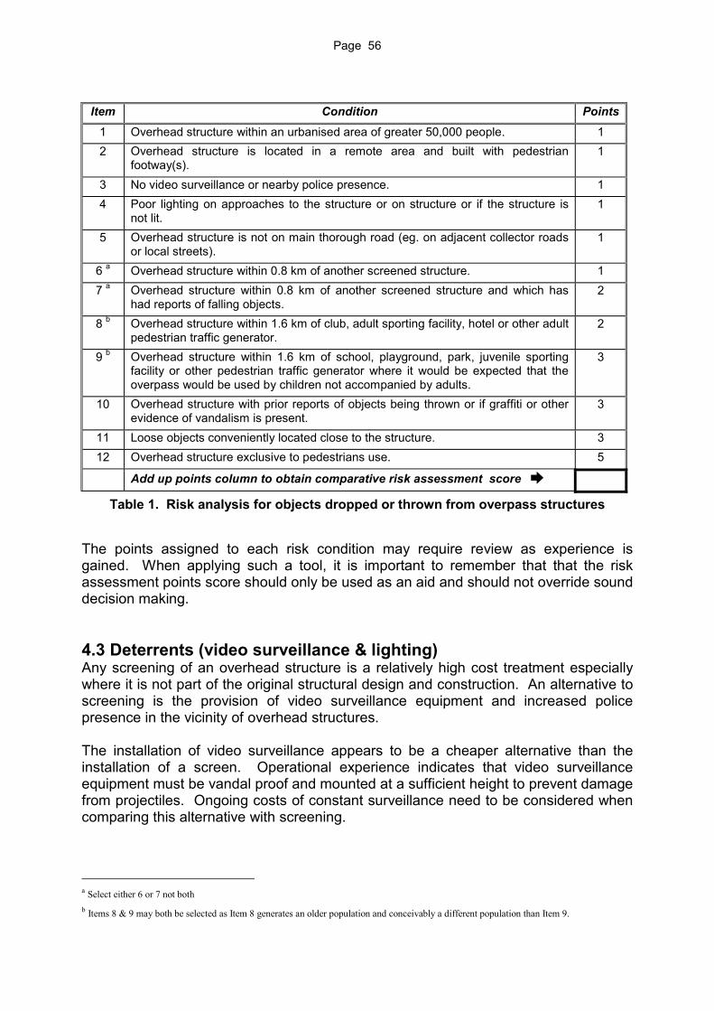
according to this ranking. The provision of a screened overpass commonly carries a BCR of approximately 3. Consequently, provision of screening may be warranted in some circumstances. A large body of literature exists in regard to risk management such as AS4360 – 1999 Risk Management. Road authorities around the world have not widely applied risk assessment techniques to screening overpasses in any sort of rigorous manner. The American Association of State Highway and Transport Officials (AASHTO) publishes “A Guide for Protective Screening of Overpass Structures”. Apart from this, only three States of the US address prevention of thrown objects from overpasses in terms of a methodology for determining: �� the relative risk to road users from any overpasses; �� a value system to judge the relative risk of one overpass against another. Of the other States in the USA that have a policy, a risk management approach has not been used to determine the relative risk of overpasses. Policies typically take an all or nothing approach. (e.g. “we do nothing” or “we cage them all”). From enquiries conducted by Transport Technology Division, the only country outside the USA or Australia that screens overpass structures is South Africa. They do not use a risk model, preferring instead to have a blanket ruling and thereby screen all pedestrian overpasses. However, South Africa does not screen road overbridges even if they incorporate footways. The RTA in New South Wales uses a risk assessment methodology whereby the risk exposure of each overpass structure is assessed in relative terms. Similarly, Transport Technology of Main Roads has formulated a risk assessment method. It would seem appropriate that the critical elements of AS4360 – 1999 Risk Management be applied to the issue of risk to motorists. The likely critical factors that affect the risk to motorists have been identified by Transport Technology Division of Main Roads and given a point rating. These risk management factors represent a compilation of those used by RTA (NSW) and the Ohio and Oregon DoT’s risk assessment methods. These factors and their relative point rating are incorporated into table 1 below. It is proposed that this table form the basis of assessment of risk. The intent is that, if the conditions are identified as being applicable to a site under investigation then, the associated points are summed to give an aggregate total. The higher the assessed score the higher the overall risk. Structures may then be ranked according to the score.
Page 56
Item Condition Points
1 Overhead structure within an urbanised area of greater 50,000 people. 1 2 Overhead structure is located in a remote area and built with pedestrian
footway(s). 1
3 No video surveillance or nearby police presence. 1 4 Poor lighting on approaches to the structure or on structure or if the structure is
not lit. 1
5 Overhead structure is not on main thorough road (eg. on adjacent collector roads or local streets).
1
6 a Overhead structure within 0.8 km of another screened structure. 1 7 a Overhead structure within 0.8 km of another screened structure and which has
had reports of falling objects. 2
8 b Overhead structure within 1.6 km of club, adult sporting facility, hotel or other adult pedestrian traffic generator.
2
9 b Overhead structure within 1.6 km of school, playground, park, juvenile sporting facility or other pedestrian traffic generator where it would be expected that the overpass would be used by children not accompanied by adults.
3
10 Overhead structure with prior reports of objects being thrown or if graffiti or other evidence of vandalism is present.
3
11 Loose objects conveniently located close to the structure. 3 12 Overhead structure exclusive to pedestrians use. 5
Add up points column to obtain comparative risk assessment score �
Table 1. Risk analysis for objects dropped or thrown from overpass structures
The points assigned to each risk condition may require review as experience is gained. When applying such a tool, it is important to remember that that the risk assessment points score should only be used as an aid and should not override sound decision making. 4.3 Deterrents (video surveillance & lighting) Any screening of an overhead structure is a relatively high cost treatment especially where it is not part of the original structural design and construction. An alternative to screening is the provision of video surveillance equipment and increased police presence in the vicinity of overhead structures. The installation of video surveillance appears to be a cheaper alternative than the installation of a screen. Operational experience indicates that video surveillance equipment must be vandal proof and mounted at a sufficient height to prevent damage from projectiles. Ongoing costs of constant surveillance need to be considered when comparing this alternative with screening.
a Select either 6 or 7 not both b Items 8 & 9 may both be selected as Item 8 generates an older population and conceivably a different population than Item 9.

Page 57
A further dimension of this treatment is that video surveillance may be able to identify perpetrators but generally only after an act has been committed. Covertly installed infrared lighting and video equipment may be used to record illicit activities however this will have no deterrent factor if secretly performed. The road user will still be at risk. Video surveillance has been included in the risk assessment model shown in Section 4.6 Table 1. The points allocated for this condition is small, in line with overseas experience. First hand experiences of others in this area are sought. Resources of the Queensland Police Service are stretched at present and an expectation that police would have sufficient surplus manpower to physically patrol these structures at all times during the day and night, is not feasible. In some instances the lighting on overhead structures is poor. For high-risk areas, an added deterrent would be to install a higher standard of lighting. Improved lighting will also be necessary if video camera surveillance is installed. For lower risk areas improved lighting alone may prove an adequate deterrent and may be considered as an incremental management approach.
4.4 Determination of screen aperture size and screen configuration When Road Authorities act to reduce the risk to motorists of injury from objects being dropped from overpass structures, after taking steps to reduce risk to motorists in other ways, they may decide to construct some form of screen or fence on the structure. This involves attaching to the sides of the structure a frame that then supports some form of material which, in turn, catches or prevents objects being thrown from the overhead structure. A variety of screening materials may be used. For example: - steel & aluminium sheeting, polycarbonate sheeting, toughened safety glass, steel mesh, steel fabric and decorative balustrades. Non-transparent sheeting has been used but there are issues of heat build-up and the possible obscuring of the walkway from surveillance scrutiny associated with the use of this material. It is thought that non-transparent sheeting may promote criminal activities. However, non-transparent sheeting has the advantage of removing from view the target vehicle thereby reducing the accuracy of delivery of an object. This issue is discussed later in this section. To determine the maximum screen aperture size some assumptions need to be made regarding the type of projectile which a vandal may project or drop onto motorists. There are two scenarios for a person throwing an object from an overpass structure: Scenario 1: The object is found in a convenient nearby location (road or embankment); or Scenario 2: The object was obtained at a remote location and brought to the site to
specifically fit through the screen. This is more malicious and harder to deal with.
In scenario 1, the assumption is that the object was to be found on the roadway or embankment and the act was “opportunistic”. The object would most likely be a stone or piece of concrete. If the assumption is made that the object was one of these items then a rational approach may be taken to determine maximum aperture size.

Page 58
Under scenario 2, if the object was manufactured or specifically selected (such as a long steel bar) the design criteria must be revised. The question raised is; given that a mesh screen has been provided, could it be foreseen that a determined and frustrated vandal would resort to the use of a steel bar? To overcome the design limitations of a screen how far can/should the designer proceed with respect to risk mitigation as well as comply with funding restraints. To address these issues, both scenarios will be reviewed individually. Scenario 1 - object is a small stone Without a screen, an object may be projected in any direction so that it has both a horizontal and vertical component of velocity. Unhindered by a screen this may be performed with a high degree of accuracy. However, an effective screen would limit the size of object and only permit an object to be dropped (thus eliminating the horizontal component of velocity). Not withstanding, objects may still be thrown over the top of a screen however with a lower degree of accuracy. Previous accident history indicates that occupant injury mainly occurs when the object crashes through the windscreen of the vehicle. To gain a better understanding of the situation, the dynamics of the process will be briefly looked at. The drop height from shoulder level on an overbridge to the windscreen level on a passenger car on the roadway below is typically 7 metres. The vertical component of velocity at impact with the car is 11.7 ms-1. The horizontal component of velocity of an object at impact for a car travelling at 100 km/hr is 27.8 ms-1. The total velocity of the object relative to the vehicle at impact is 30.1 ms-1 at an angle to the horizontal of 23 degrees. This is equivalent to sitting in a stationary vehicle and an object hitting the windscreen at 108 km/hr at a flat horizontal angle. The impact velocity of an object dropped from the bridge is 30.1 ms-1. If the object was suspended from the bridge instead of being dropped, the impact speed would be 27.8 ms-1. Thus it may be seen that the velocity gained from the 7 m fall did not have a major bearing on the final impact speed. The difference in the energy content between an object traveling at 27.8 km/hr and 30.1 km/hr is only 15%. The question is, for a stone traveling at 30.1 ms-1, what mass and therefore size, given a known density, is required for it to penetrate a windscreen? The standards for strength testing of windscreens of vehicles were investigated to help answer this question. The various standards are: American Standard: - Drop test for evaluating laminated safety glass for use in automotive windshields - SAE J938 JUN84. European Standard: - Road vehicles - safety glazing materials - Mechanical tests - ISO 3537:1999(E) Australian Standard: - Safety glass for land vehicles - AS/NZS 2080:1995 A common test for these standards is to drop a 2.25 kg steel ball (82.5 mm diameter), 3.6 metres onto a 305 mm square, flat test specimen. To pass the test, the impacted glass test piece must support the steel ball for more than 5 seconds for a minimum of 8 out of 10 times. The impact speed of the steel ball in this case is 8.4 ms-1.
Page 59
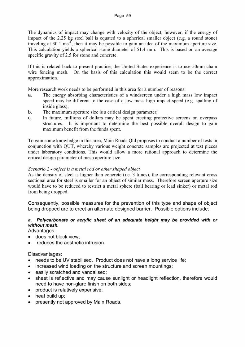
The dynamics of impact may change with velocity of the object, however, if the energy of impact of the 2.25 kg steel ball is equated to a spherical smaller object (e.g. a round stone) traveling at 30.1 ms-1, then it may be possible to gain an idea of the maximum aperture size. This calculation yields a spherical stone diameter of 51.4 mm. This is based on an average specific gravity of 2.5 for stone and concrete. If this is related back to present practice, the United States experience is to use 50mm chain wire fencing mesh. On the basis of this calculation this would seem to be the correct approximation. More research work needs to be performed in this area for a number of reasons: a. The energy absorbing characteristics of a windscreen under a high mass low impact
speed may be different to the case of a low mass high impact speed (e.g. spalling of inside glass);
b. The maximum aperture size is a critical design parameter; c. In future, millions of dollars may be spent erecting protective screens on overpass
structures. It is important to determine the best possible overall design to gain maximum benefit from the funds spent.
To gain some knowledge in this area, Main Roads Qld proposes to conduct a number of tests in conjunction with QUT, whereby various weight concrete samples are projected at test pieces under laboratory conditions. This would allow a more rational approach to determine the critical design parameter of mesh aperture size. Scenario 2 - object is a metal rod or other shaped object As the density of steel is higher than concrete (i.e. 3 times), the corresponding relevant cross sectional area for steel is smaller for an object of similar mass. Therefore screen aperture size would have to be reduced to restrict a metal sphere (ball bearing or lead sinker) or metal rod from being dropped. Consequently, possible measures for the prevention of this type and shape of object being dropped are to erect an alternate designed barrier. Possible options include: a. Polycarbonate or acrylic sheet of an adequate height may be provided with or without mesh. Advantages: �� does not block view; �� reduces the aesthetic intrusion. Disadvantages: �� needs to be UV stabilised. Product does not have a long service life; �� increased wind loading on the structure and screen mountings; �� easily scratched and vandalised; �� sheet is reflective and may cause sunlight or headlight reflection, therefore would
need to have non-glare finish on both sides; �� product is relatively expensive; �� heat build up; �� presently not approved by Main Roads.

Page 60
b. Toughened safety glass panel of an adequate height may be provided with or without mesh. Advantages: �� does not block view; �� reduces the aesthetic intrusion; �� an approved Main Roads material. Disadvantages: �� increased wind loading on the structure and screen mountings; �� sheet is may be reflective and may cause sunlight or headlight reflection; �� product is relatively expensive; �� heat build up; �� generally only available in 19 mm thickness. c. Solid galvanised or zincalume sheet (flat or profiled) of an adequate height. This may be provided with or without mesh. Advantages �� low cost; �� vandals cannot see the target vehicle approaching. Disadvantages �� reduced aesthetic appearance; �� blocks motorists and pedestrians view from overbridge; �� increased wind loading on the structure and screen mountings; �� illicit activities are shielded from scrutiny of motorists etc.; �� heat build up. d. Horizontal louvered aluminium or steel panels of an adequate height. This may be provided with or without mesh. Advantages �� limited view of the target vehicle; �� allows limited distant views through louver for pedestrians; �� smaller wind loading than solid screen; �� may provide opportunity to use coloured anodised aluminum to increase aesthetic
appeal. Disadvantages �� reduced aesthetic appearance; �� block motorists and pedestrian’s view from overbridge; �� product is expensive; �� illicit activities are shielded from scrutiny of motorists etc. e. A “catch” screen of an adequate width mounted at an angle slightly above horizontal at deck level and angled back toward the structure. Advantages �� does not interfere with views by motorists or pedestrian on overbridge; �� minimal wind loading impact;

Page 61
�� does not affect the profile of the structure and is only apparent to motorists as they approach the structure at close range;
�� will catch stones and other objects that would have otherwise passed through the screen above a solid barrier as outlined in a,b,&c above or through a plain screen. It acts as a secondary safety “net”.
Disadvantages �� rubbish collected on the screen would need to be periodically removed. This may
need, for example, an added safety rail on the outside of screen to attach a safety lifeline. This would require a workman to wear a safety harness, fall arrester and attachment devices;
�� may allow determined vandals to walk out on the screen and drop objects. 4.5 Screening design options There are various kinds of overhead/overpass structures from which objects may be dropped. For each of these structures there are a number of design options. These are discussed below. Overbridge with single pedestrian footway on one side only Options include:
Single screen on outside of structure adjacent to footway (other side unscreened). This option has the advantage that the cost of the treatment is halved, however, with this option an object may still be thrown from the footway across the road and over the unscreened side. Alternatively a person may cross the road on foot and directly throw the object from that side; Screen fully encloses footway. With respect to opportunistic dropping of objects, this method will prevent a large object from being thrown from the footway. However, a determined person can walk around the ends of the screen onto the roadway and throw objects from the unscreened side. Fitting an additional single screen on the unprotected side would help solve this problem. Screens located on each side of the structure. This option probably provided the best overall compromise. Objects may still be thrown over the top of a screen however the accuracy in hitting the target vehicle would be reduced.
Overbridge with pedestrian footway on both sides Options include:
Screens fitted on the extremities of structures adjacent to each footway; Fully enclosed footway screens.
With respect to opportunistic dropping of objects, both of these methods will prevent a large object from being thrown from the footway. Objects may still be

Page 62
thrown over the top of a screen however the accuracy in hitting the target vehicle would be reduced.
Pedestrian Overbridge Options include:
Two single screens one on each side with an open top. The screens will prevent large objects from being dropped but will not prevent objects from being thrown over the top. A fully enclosed screen. The benefits of a fully enclosed screen are obvious, particularly as very little extra materials are involved.
4.6 Aesthetic issues Protective screens will have an impact on the aesthetics of an overpass structure. To a large extent they will establish the visual character of an overpass structure. Once a protective screen is installed, it may become a prominent landscape feature, immediately changing the character of the visual environment. Existing protective screens often have low aesthetic appeal for motorists and pedestrians. They may also create an uncomfortable psychological experience for pedestrians. Searches of existing overseas policies found no discussion of aesthetic issues in relation to protective screening. The contribution by superficial cosmetic treatments only plays a small role in enhancing the overall aesthetic quality of a screen. Qualities must be present in the basic concept from the inception of a design. In terms of aesthetics, several viewers should be considered. These include: �� the distant observer who primarily perceives form and to a lesser extent colour; �� the high speed user who primarily perceives form and colour; �� the low speed user who will additionally perceive detail (eg. pedestrians). Cost obviously plays a large part in dictating overall design concepts. Costs should be properly balanced against social, economic, functional, environmental, aesthetic impacts and potential effects on the quality of life of users. The designer’s challenge is to optimise the design through creativity without requiring a significant increase in cost. The relationship of a protective screen to its surroundings will be the final test. This relationship will influence public acceptance of transportation infrastructure design. 4.7 Adequate sight distances for road users Overpass structures are required to integrate with service roads, exit and on ramps. The screening of structures should not interfere with the requirement to have a clear view of approaching traffic for vehicles performing manoeuvres in the vicinity of the structure. Reduced visibility would result in unsafe road conditions at intersections
Page 63
and would clearly be unacceptable. Sight distances must be considered when assessing treatment options. 4.8 Costs From the limited past experience in this matter, the cost associated with design, construction and fitting of screens to existing structure has been approximately $900 per metre of screen per side of the bridge. Similarly for new structures where the screen is integrated into the initial bridge design and fitted as part of the initial bridge construction, the cost is approximately $600 per metre of screen per side of the bridge. These figures are indicative only of past experience and are likely to increase with the addition of a secondary catch screen. It can be seen that there are considerable cost savings if screens are integrated and fitted as part of the initial bridge design and construction. An issue that requires resolution is the funding responsibility for the construction and maintenance of the protective screens fitted to overpass structures - Main Roads or Local Government or others? Some possible road combination scenarios are: Local road passes over a State-controlled road with Main Roads accepting the ownership (ie. structural maintenance) of the overpass structure; Local road passes over a State-controlled road with Local Government accepting the ownership (ie. structural maintenance) of the overpass structure; State-controlled road passes over a local road. Under legislation, both Main Roads and Local Government have a responsibility for the safety of motorists using roads under their control. The construction and maintenance costs should be consistent with the protocol agreement that exists between Main Roads and the Local Government Association of Queensland Inc. One proposal to the above issue could be that, the party responsible for the road impacted upon, funds the construction of the screen. However, where poor lighting on the overpass and approaches to the structure is a major contributing factor and is required to be remedied, it needs to be determined who then should be responsible for the installation and ongoing running costs of road lighting. A more detailed recommendation is outlined in Section 5.8. 4.9 Implementation Strategies The allocation of funds for addressing the issue of objects dropped/thrown from overpass structures needs to be considered in relation to other road safety issues. It is not envisaged at this time that additional or special funding would be allocated to ameliorate the risk of falling objects from overpass structures. The Main Roads’ policy, Advertising on or Near State-controlled Roads, and guidelines, Guide to the Management of Roadside Advertising, allow the sponsorship of high cost road infrastructure in return for commercial advertising. Where appropriate, consideration may be given to this method of funding where there are funding shortfalls.

Page 64
The expectation is that the majority of screens will be fitted to overpass structures where the speed environment of the spanned road is greater than 90 km/hr. The consequence of impact with an object dropped in a high-speed environment is far greater than for a low speed urban environment. However, the screening of structures in low speed environments will be considered. The relative risk to motorists in the vicinity of overpass structures can periodically be assessed (say maximum of 5 years) and amelioration works ranked accordingly. These works can be compared to other road safety initiatives (such as elimination of roadside hazards) and any treatments performed in line with available funding. As screens can generally be provided at lower costs for new structures, the question of whether screens should be incorporated in the design needs to be considered at the initial design stage. Future local development and population growth should be considered when performing the risk assessment to ascertain the need for a screen. There are a number of other areas and situations within the road network that exhibit a higher than average accident rate. Main Roads allocates funds to road safety initiatives on a priority needs basis. When considered under this context, a curve in a road with an accident history commonly may have a higher relative priority for the allocation of funds than retrofitting a screen to a bridge structure. Such active competition for funding ensures the most cost-effective use of the limited funds available. The substandard curve will commonly have a higher BCR and risk of accident. One factor that differentiates these two situations is that of how much the actions of the motorist may control or contribute to an accident. For a dangerous curve in a road the driver of the vehicle has, in most instances, some control over the outcome of the accident. For example the driver may reduce speed in wet weather. However, when an object is dropped from an overpass structure the driver is helpless to control the outcome of the incident. A motorist may be injured or killed regardless of whether s/he is an expert or novice driver. This helplessness factor contributes to community “rage”.
5.0 Recommendations about issues Main Roads Qld intends to develop a policy and technical guidelines on this issue before July 2000. Feedback on this paper will be considered and will be incorporated into the policy. Recommendations about Main Roads Qld’s position on issues is discussed in Sections 5.1 to 5.9.

Page 65
5.1 Public education and culture change Feedback is sought to determine if public education is likely to be successful in reducing the incidence of these events. If it determined that a campaign would be desirable then: Queensland Transport could integrate this problem into their public safety campaign in the most appropriate way; Queensland Police Service could become involved through road safety presentations and where practical include overpass “hotspots” in routine patrols; Reported incidents of objects thrown from overbridges are usually reported to the Police. The type of information required by Main Roads’ Officers for a technical assessment needs to be conveyed to Police. As this information may differ from that collected by Police for their requirements, a coordinated approach with the Queensland Police Service is necessary; Main Roads and Local Governments could erect warning signs on overhead structures warning of the dangers of throwing objects from structures and that such actions are a criminal offence. A maximum fine and term of imprisonment can also be included. 5.2 Methods for determining risk Overpass structures The model proposed in Table 1 in section 4.6 is an amalgamation of Roads and Traffic Authority NSW and the Ohio and Oregon DOTs’ risk assessment methods. It is proposed that this be adopted for performing a risk analysis. It is proposed that the final score for any given structure is obtained by the summation of the respective points and all structures prioritised on the basis of a final score. Comments are invited from stakeholders on the appropriateness of the conditions or magnitude of the points allocated for each condition. Vertical retaining structures Where a vertical retaining structure (e.g. reinforced earth wall) is constructed beside a road and the distance from the trafficked lane and structure is not great, its risk should be assessed similarly to that of an overhead structure. The aesthetic treatment for a screen in this case may be different from that of an overhead structure such as a road bridge. Embankments While there is a risk that objects may be thrown from embankments as well as overhead structures, overhead structures present a higher risk than embankments for the following reasons: �� for an overpass structure the object need only be dropped; �� more predictable outcome (easier to aim) on an overpass structure; �� heavy objects can be dropped from a overpass structure but cannot be similarly
launched from an embankment because of the weight and distance involved. However, where a particular embankment has a demonstrated history as a launch area for objects, the construction of screens may be considered. In these cases, a design similar to a noise barrier may be a more appropriate solution.

Page 66
5.3 Deterrents (video surveillance & lighting) The degree of hazard at any location would need to be individually assessed on a case-by-case basis. It is not proposed to make a blanket recommendation about additional lighting or video camera surveillance. The effect of any proposed lighting on local residents, both positive and negative effects, should be considered at the time of assessment.
5.4 Screen aperture size and configurations Because of aesthetic and wind loading considerations mesh or fabric screens are considered most suitable. These screens may be considered as a primary screen. A secondary horizontal screen would commonly be fitted to reduce the probability of a long slender object from falling onto the roadway. Concept designs are shown in Appendix B. It is proposed that laboratory testing of windscreen samples be performed to determine the maximum screen aperture size. Concrete samples will be projected at the samples at actual highway impact speeds. These results will allow the minimum size aperture for the screen to be determined. At present there are no test results or methodologies available. The fitment of other more intrusive but more effective measures such as solid screens or louvres could then be fitted if it is demonstrated that the existing treatment is patently not acceptable. The initial design should make provision for this latter possibility.
5.5 Screen design options Concept designs are shown in Appendix B. The concept designs have been presented for the purpose of demonstrating that there is sufficient scope to expand the design concept from just a flat vertical or horizontal screen. The concept designs indicate the major members that give the structure form and are not intended to show the full extent of the screening material. These designs contain a combination of vertical, horizontal, flat, curved and fully enclosed screens. Horizontal screens could be used alone, however, they would have to be very wide to provide significant protection. The height of vertical screens and reach of horizontal screens need to consideration to ensure they are effective. When considering any screen design, consideration should be given to its impact on over-width vehicles. While it is relatively simple to incorporate screen fixing and design loads into new bridge designs, construction of screens on existing structures may be more problematic. The preferred screening treatments are as follows:

Page 67
Overbridge with single pedestrian footway on one side only. The preferred option is to fit an individual mesh screen to each side of the structure. Overbridge with pedestrian footway on both sides. The preferred option is to fit an individual mesh screen to each side of the structure. Pedestrian overbridge. The preferred option is to fit a fully enclosed mesh screen to the structure.
The usage of horizontal catch screens in conjunction with vertical screens should be given consideration. Non translucent screen material such as solid metal sheet or metal louvres would be considered in specific locations. 5.6 Aesthetic issues The aesthetic appeal of any proposed treatment should be considered and improved where possible in the design. In the aesthetic evaluation, the viewing criteria of several observers should be considered. These would include the distant observer/motorist, the low-speed and high-speed motorist and pedestrians. Due to these variations, the proposed aesthetic design process includes two major design components, namely: �� development of the structure’s form and colour; and �� development of the structure’s architectural detailing.
5.7 Adequate sight distances for road users It should be insured that the design of any screening device does not adversely impact on the clear sight distances required for traffic safety. 5.8 Costs The issue of responsibility for the construction and maintenance of the screens and lighting (where necessary) needs to be addressed. The recent agreement, Cost Sharing based on Responsibilities within State-controlled Roads, adopts the position that Main Roads and Local Government are each responsible for the safety for road users under their control. This applies both to pedestrians as well as to motorists. The responsibilities for lighting and screening have been allocated on a 100% basis however some other split in costs may be more appropriate. The following responsibilities are proposed for discussion: a) Local road passes over a State-controlled road with Main Roads accepting the ownership of the overpass structure (includes pedestrian footbridge): Construction
Main Roads funds the initial construction of a screen. Local Government funds lighting enhancements on the local road.
Page 68
Maintenance Main Roads to be responsible for the structural maintenance of the screen. Local Government to be responsible for: �� visual amenity issues such as graffiti; �� litter collection on the screen; �� running costs for lighting on the local road.
b) Local road passes over a State-controlled road with Local Government accepting the ownership of the overpass structure (includes pedestrian footbridge): Construction
Main Roads funds the initial construction of a screen. Local Government funds lighting enhancements on the local road.
Maintenance
Local Government to be responsible for: �� structural maintenance of the screen; �� visual amenity issues such as graffiti; �� litter collection on the screen; �� running costs for lighting on the local road.
State-controlled road passes over a local road (includes pedestrian footbridge): Construction
Local Government funds the initial construction of a screen. Main Roads funds lighting enhancements on the State-controlled road.
Maintenance
Main Roads to be responsible for: �� structural maintenance of the screen; �� visual amenity issues such as graffiti; �� litter collection on the screen; �� Running costs for lighting on the State-controlled road.
As that there is a considerable price difference and thereby savings to be made by fitted a screen as part of a structure’s initial design and construction, the decision about fitting a screen to a new structure should be given serious consideration. In many cases, because of lower costs, (and therefore higher Bars), it may be appropriate to give priority to new structures.

Page 69
5.9 Implementation Strategies It is proposed that a risk analysis be performed on existing structures. Where a high-risk structure has been identified, the District should compare and rank the structure in order of priority to other road safety initiatives. Consideration should be given to ameliorate risk where possible by implementing lower cost options prior to a commitment to screening. These options may reduce the risk score for a structure and include: Improved maintenance in the vicinity of structures to remove loose stones, concrete fragments, litter and sundry foreign objects that could potentially be used as missiles; Replacement of timber delineator posts in the immediate vicinity of the structures with lightweight plastic alternatives; Modifying or removal of other road furniture that could be used as missiles; Consideration may be given to covering stony embankments (grade permitting) with mulch with the possible inclusion of small scrubs. Involvement by Community Groups in this sort of activity may be considered; Installation of lighting or enhanced lighting; Installation of surveillance cameras. These could be included at the same time with the upgrading of other traffic management strategies; Awareness of issues and discussions with local authorities and community groups; �� Increased Police visual presence; �� Supervision of bridge crossings before or after school by an adult. After further consideration, other strategies may be employed. Where it is determined that screening is required, it may be incorporated into the RIP within each Main Roads Region’s priorities, however, more emergent cases would be handled on a case-by-case basis within existing Regional funding allocations. Other alternatives for funding the provision of screens for overpass structures needs to be explored. One example would be through sponsorship agreements whereby screens are provided in return for advertising rights on structures. Such arrangements should be consistent with Main Roads’ policy and guidelines on roadside advertising. The primary considerations for advertising on overpass structures in this instance, are traffic safety and visual amenity. As visual amenity is affected, Main Roads and the relevant Local Government should both be in agreement with this method of funding. For new structures, the present and future situation should be assessed using a risk analysis. Where it is determined that a screen is required, its design and installation should be a component of the initial project costs. Included in the design should be allowance of possible fitment of solid or other screen options at a later time should they be needed.

Page 70
6.0 Conclusion The purpose of this discussion paper is to seek comment from Local Governments and other stakeholders on a number of issues relating to the provision of protective screens on overpass structures. The aim of a future policy is to give direction and thereby reduce, or prevent where possible, the incidence of objects being thrown from these structures thereby creating a safer State-road network for all Queenslanders, while ensuring scarce available funds are utilised in a cost effective way. Short of enclosing an entire overpass structure with a high security solid metal barrier, screening of structures will not provide a 100% guarantee of motorist safety. Screening will however, provide the highest degree of safety given the physical, social and economic constraints. However, other measures (some of which are listed above) and competing priorities need to be considered before overpass structures are screened. Worlds “best practice” on this issue is neither comprehensive nor extensive – it is in its infancy stage. There is a need to address the issue from a fundamental viewpoint in a structured manner so that the best value may be obtained from the limited funds available. Comments on this paper are sought from Local Governments and other stakeholders in order that a Main Roads policy position can be established. If possible it would be desirable for the policy to be a combined Main Roads/Local Government policy. 7.0 References 1. AS 4360 -1999 Risk Management 2. AS 3845 -1999 Road Safety Barrier Systems 3. SAE J938 JUN84 - Drop test for evaluating laminated safety glass for use in
automotive windshields 4. ISO 3537:1999(E) - Road vehicles - safety glazing materials - Mechanical tests 5. AS/NZS 2080:1995 - Safety glass for land vehicles 6. 1992 Austroads Bridge Design Code 7. Roads and Transit Authority, NSW - Risk Assessment Strategy for Overpass
Structures. 8. ARRB Report July 1999 – Review of Pedestrian Safety Issues on Roadway
Structures

Page 71
Appendix A International and Interstate Experience This appendix presents a summary of the actual comments received from practitioners in response to the posting of an electronic mail question on international traffic management newsgroup servers. The responses are reproduced here for information only and have not been edited in detail and do not necessarily reflect the opinions/policy either of the authors or of Main Roads. A1 Victoria As I am sure you aware, not every Australian state is trying to barricade off pedestrian (and road) overpasses. We here in Victoria are somewhat bemused by the efforts to prevent missiles being launched off overpasses, through construction of cages. It is not that we are unconcerned about the injuries, which might occur - far from it. We have also had a handful of horrific accidents caused by these cretins. It is just a question of how effective the expenditure on cages will actually be, and whether this is a wise allocation of very scarce public monies. The few cages I have seen are hideously ugly, obviously quite expensive to build and maintain, and despite all these efforts, a determined offender could still launch a missile, if they really tried to. After all, even a small stone or rock thrown off the edge of a bridge (or thrown onto the road from nearby) onto a road (or railway) can still smash a windscreen, damage a vehicle, cause drivers to swerve around an object, and so forth. At high speed, these are all potentially lethal events. I would personally rather see severe penalties handed out to offenders who are caught - for attempted manslaughter, reckless conduct endangering life, etc. and a beefed up enforcement system, rather than building cages. This might be one example of where it is futile to "build out" a problem by modifying the design - better instead to use a behaviour modification strategy (education, awareness, enforcement). I would sooner spend money treating accident black spots, or removing hazardous roadside furniture, or reinforcing bridge abutments to prevent vehicle breakthroughs, or resealing slippery pavements, etc. We are short of funds to treat even these known deficiencies, where we have tried and tested remedies. Still, I will be interested to see if anyone else overseas is pursuing a similar approach. A2.1 US General (Railways) Many bridges over railroads in the US are protected in this way to prevent stoning of trains.

Page 72
A2.2 Ohio Caged overpasses are almost automatic now in this area. There was an article in today's newspaper about someone killed by just such a thrown rock from an overpass without the fencing. I would be delighted to send you drawings of what we have. I need to know what you use for drafting, Microstation or AutoCAD. I can e-mail the files of you can pick them off on our ftp server. I can also fax hardcopies if you prefer. If you have Microstation or can convert Microstation files and you have a web browser, try typing this into the browser: ftp://ftp.odot.state.or.us/outgoing/protective_fencing We have two flavours of fencing, chain link and welded wire. The chain link type is on our standard drawing and costs about $130/meter installed. This price is without engineering and contingencies that we normally pad the estimate with, these are "installed" prices from past jobs. The more aesthetically pleasing type (welded wire) is often required by the City of Portland and cost about $400/meter. These prices (that will have to be converted to your currency) are heavily dependent on labour costs. The welded wire fence is a cut-to-measure deal with significant field location work required for a smooth installation. It is necessary to lay out the location of the posts so as not to interfere with existing equipment and expansion joints. In addition the fence panels must be fabricated to anticipate grade, 2% increments have worked out for us. Other things to watch out for are sight distances (a natural topic for a Traffic Engineer!) and structural capacity of the existing rail. We often find a need to update functionally obsolete rail when looking at protective fencing. The State of Ohio has instituted reviews of all overpasses in populated areas. They have a ranking system that takes into account when the next scheduled rebuild is, the amount of pedestrian use and other factors. Most if not all overpasses in populated areas now have the cage. It does not cover the entire bridge but rises 3 m and curves back away from the precipice. Obviously bridges not open to pedestrians (such as in the interior of interchanges) are not enclosed. Our laws and courts have also found the State of Ohio liable. The state has 2 basic designs and two heights. Either 1.85 m or 2.85 m high straight (above the parapet), or 2.7m or 3.0m high with a curve toward the street, to prevent throws up and over the fencing. The material is typically standard chain link fencing. A2.3 Florida Our guidelines dictate that we caged pedestrian footbridges only. We have not extended it to overpasses except where law enforcement agencies have requested we do so. Please let us know if you learn of anything interesting in this area. There have been some problems with people throwing things off of overpasses of late and our policies may be changed. Want to clarify one point. They don't use the cage design everywhere in Miami. Ped overpasses get them and there is at least one arterial with sidewalk (probably more) that has the fenced in design. It is in an interchange where rock throwing had become a real problem. Hope this clarification helps. In South Florida (Miami), FDOT has put
Page 73
in a number of "caged" overpasses to prevent exactly what you've referred to. We have had at least one fatality from a rock through a windshield that I can remember. We've also had garbage cans thrown from them. Most of this was 10-15 years ago but the overpasses built since then have been fenced. A2.4 Wisconsin The Wisconsin Department of Transportation (USA) has design details and warrant information in their Facilities Development Manual. You can visit their web site where you should be able to find a contact person. Basically, they have installed taller fences on overpasses in urbanised areas, or where there has been a history of this type of problem. The use of these fences was brought on by a fatality on a freeway where a bowling ball was dropped and went through a windshield resulting in a fatality. The State of Wisconsin, Department of Transportation, developed some guidelines for installation of fencing on overpasses several years ago. An installation program was initiated after the death of a motorist as a result of some juveniles throwing large rocks off an interstate bridge on I-94 in Eau Claire and a multi-car pile up on the interstate in the Milwaukee area caused by thrown objects. The rock hit and went through the windshield of the van. The father was driving and was killed when the rock hit him on the head. The family was in the van and they were returning home to Minneapolis on a Sunday night, from a weekend swimming meet. This was a very sad situation that gained a great deal of state-wide publicity. A2.5 Oregon Hello, I am the protective screening coordinator for the Oregon Department of Transportation. I am including a text only version of a public relations document that was put together for the program. If you would like the prioritisation method, refer to "Protective Screens on Bridge Railings, A Method for Evaluation and Prioritisation Their Need" by Raymond G. MacKay, Jr. P.E. in Public Works for June 1994.
Oregon Department of Transportation Overpass Protective Screening Program
History Oregon's overpass screening program was started in 1985 after an object thrown from the Talbot Overpass of I-5 between Salem and Albany injured a passenger. The Oregon Transportation Commission adopted the recommendation of the State Highway Engineer to screen 8 to 12 structures a year. Rather then screening all of the state's structures, He recommended screening those locations that appeared to be a potential problem. Oregon's overpass protective screening law was initiated by a Salem couple who were severely injured in 1988, when a 61-pound chunk of concrete which was dropped by a teenager from an unscreened freeway overpass in I-5 near Woodburn, smashed through their car windshield. The teenager was caught, convicted and sentenced to 25 years in prison. Action Taken In 1993, Governor Roberts signed House Bill 2507, which required ODOT to include protective screening on all new freeway overpasses and to install a minimum of 15 protective fences per year on existing freeway overpasses. The law also requires ODOT to first provide overpass protective screening on overpasses that pose the greatest potential risk to passing motorists. Completed Projects
Page 74
There are about 300 freeway overpasses in Oregon; 91 of which have already been retrofitted with protective screens, at a cost of $40,000 to $50,000 each, or approximately $4,550,000. At a scheduled rate of 15 to 20 screening projects per year, it will take ODOT between 10 and 14 years to screen the remaining overpasses, at an additional cost of approximately $10.1 million, for an overall project cost of approximately $14,750,000. These estimates may increase somewhat because of the increasing demand for special design screening that is more aesthetically pleasing. Criteria Projects are selected from a statewide priority list maintained by the ODOT Bridge Section in Salem. The list was compiled by Traffic Section with help and review from each region. The list is updated as needed. Prioritisation criteria are: �� Reported incidents �� Accidents �� Location and accessibility �� Proximity of pedestrian generators �� Illumination �� Existing on- and off-ramps �� and engineering judgement
Effectiveness The Oregon State Police report fewer complaints of rock-throwing incidents since the program's inception in 1989. While they receive approximately 60-80 reports of rock throwing incidents per year, most occur at non-screened structures. Future projects During the 1999-2002 period, the department is scheduled to spend $4 million to retrofit an additional 80 existing overpass structures. Conclusion While rock-throwing incidents from overpasses are random acts of violence that are difficult to
predict or prevent, the department is attempting to make it more difficult for these types of crimes to occur. While the protective fencing isn't foolproof, the department believes the
fencing makes it much more difficult for people to toss items, particularly large objects, onto traffic. The overall goal of the program is to improve the safety of motorists travelling on state
highways.
A3.1 South Africa The cage is only used on pedestrian footbridges - it forms sort of a tunnel and forms a complete enclosure. As I mentioned previously, I have never seen any fences used on vehicle bridges with pedestrian footpaths so I cannot really say what they look like. I do imagine however that such fences should be erected on or next to the balustrade i.e. a cage with an open top, perhaps with a slight overhang to the inside - sufficient to stop any projectiles originating from the pedestrian pavement. A3.2 South Africa Here in the Western Cape and Cape Town in particular we don't have very many pedestrian bridges, but those that we do have, all have 'cages'. We don't have a
Page 75
specific policy regarding this. For pedestrian and traffic safety reasons I think that it will be a standard requirement for all such footbridges in the future. As far as pedestrian walkways on bridges are concerned - to my knowledge fences have never been constructed and I doubt that we will consider something like that in the foreseeable future. We don't have the funds for it, and secondly we haven't had any problems with objects falling from these walkways. South Africa has many of these caged bridges, only pedestrian ones that I know about. I understand however that the decision to cage is made based on recorded incidents but without a formalisation of the warrants.
A4 United Kingdom No problem with your posting. The topic brings to mind an experience I had some 10 years ago while driving to Manchester Airport. Some kids threw a large wooden plank off a footbridge. Luckily I spotted them and was able to swerve to avoid it. If I hadn't seen them I could have been decapitated. I know some overbridges here have been 'caged', but generally (I think) only after incidents have already occurred. There have also been recent incidents of deaths by falling from such bridges (2 related ones on the M8 east of Glasgow in recent months). Frank Montgomery Institute for Transport Studies University of Leeds
In the UK we have done very little about this. It is certainly a problem, but I am unaware of legal action against any highway authority. With an increasingly US style legal system, however, litigation is probably a matter of time. Some bridges have fences, but these are usually to deter suicide rather than stop vandals. There may be a feeling that any barrier is merely a challenge to be surmounted.

Page 76

Page 77
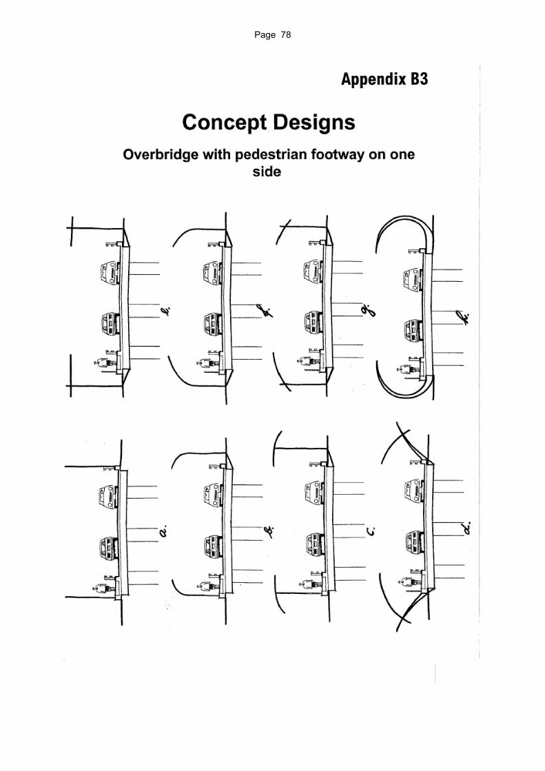
Page 78

End of report.