Embed Size (px)
Citation preview
Draft
REPORT ON HYDROGEN STORAGE
AND APPLICATIONS OTHER THAN
TRANSPORTATION
Prepared by
Sub-Committee on Hydrogen Storage and Applications
Other than Transportation of the Steering Committee
on Hydrogen Energy and Fuel Cells
Ministry of New and Renewable Energy,
Government of India, New Delhi February, 2016
FOREWORD
Storage forms an important link in the hydrogen utilization chain. There
are many challenges to storing hydrogen in efficient, safe and cost effective
manner for a variety of applications like stationary power generation or on-board/
mobile applications, mainly because hydrogen is a light gas and combustible.
Hydrogen may be stored in gaseous form at high pressures at normal
temperatures, in liquid form at cryogenic temperatures at normal pressures, and
in chemically bound solid state at normal temperatures and pressures. These
different storage modes are application dependent.
India is committed to contribute significantly to the climate change and has
been giving utmost importance to utilization of clean and renewable energy. In
this light, Hydrogen energy has also been a focus of attention. With this in mind,
the Ministry of New and Renewable Energy, Government of India constituted a
high power Steering Committee to prepare a status report and suggest the way
forward for hydrogen energy and fuel cell technologies in India. One of the five
sub-committees was entrusted under my Chairmanship with the responsibility of
preparing this document concerning “Hydrogen Storage and Applications other
than Transportation”.
I express my sincere thanks to all the members of the Sub-Committee
who shared their immense expertise, Dr. M. R. Nouni, Scientist ‘F’, Ministry of
New and Renewable Energy, and also other the officials of the Project
Management Unit – Hydrogen Energy and Fuel Cells at the Ministry, especially
Dr. Jugal Kishor and Dr. S. K. Sharma for their active role in organizing meetings
and preparing this document. It was my pleasure and honour working under the
guidance of the Chairman of the Steering Committee, Dr.Kasturirangan.
20th February, 2016
(Prof. S. Srinivasa Murthy), Chairman,
Sub- Committee on Hydrogen Storage and Applications other than Transportation
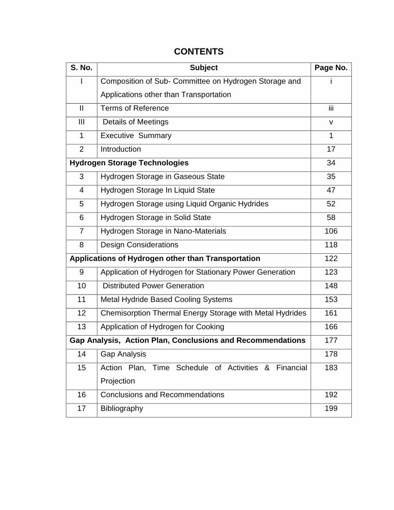
CONTENTS
S. No. Subject Page No.
I Composition of Sub- Committee on Hydrogen Storage and
Applications other than Transportation
i
II Terms of Reference iii
III Details of Meetings v
1 Executive Summary 1
2 Introduction 17
Hydrogen Storage Technologies 34
3 Hydrogen Storage in Gaseous State 35
4 Hydrogen Storage In Liquid State 47
5 Hydrogen Storage using Liquid Organic Hydrides 52
6 Hydrogen Storage in Solid State 58
7 Hydrogen Storage in Nano-Materials 106
8 Design Considerations 118
Applications of Hydrogen other than Transportation 122
9 Application of Hydrogen for Stationary Power Generation 123
10 Distributed Power Generation 148
11 Metal Hydride Based Cooling Systems 153
12 Chemisorption Thermal Energy Storage with Metal Hydrides 161
13 Application of Hydrogen for Cooking 166
Gap Analysis, Action Plan, Conclusions and Recommendations 177
14 Gap Analysis 178
15 Action Plan, Time Schedule of Activities & Financial
Projection
183
16 Conclusions and Recommendations 192
17 Bibliography 199
i
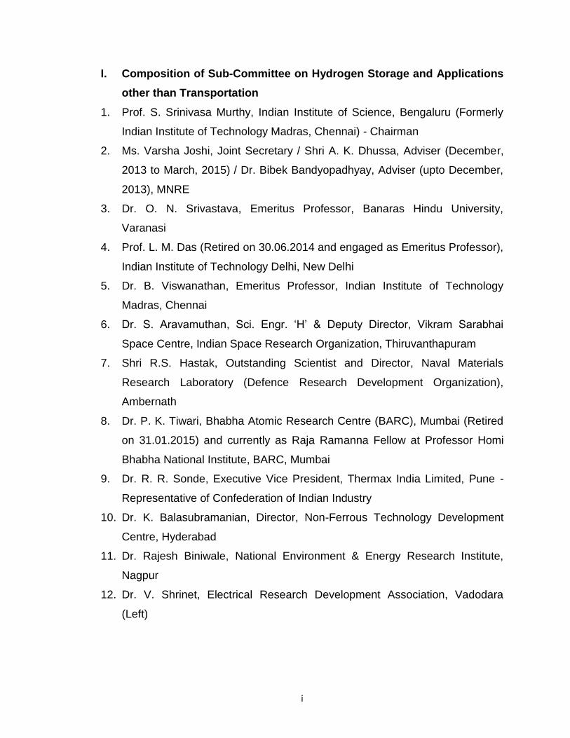
I. Composition of Sub-Committee on Hydrogen Storage and Applications
other than Transportation
1. Prof. S. Srinivasa Murthy, Indian Institute of Science, Bengaluru (Formerly
Indian Institute of Technology Madras, Chennai) - Chairman
2. Ms. Varsha Joshi, Joint Secretary / Shri A. K. Dhussa, Adviser (December,
2013 to March, 2015) / Dr. Bibek Bandyopadhyay, Adviser (upto December,
2013), MNRE
3. Dr. O. N. Srivastava, Emeritus Professor, Banaras Hindu University,
Varanasi
4. Prof. L. M. Das (Retired on 30.06.2014 and engaged as Emeritus Professor),
Indian Institute of Technology Delhi, New Delhi
5. Dr. B. Viswanathan, Emeritus Professor, Indian Institute of Technology
Madras, Chennai
6. Dr. S. Aravamuthan, Sci. Engr. ‘H’ & Deputy Director, Vikram Sarabhai
Space Centre, Indian Space Research Organization, Thiruvanthapuram
7. Shri R.S. Hastak, Outstanding Scientist and Director, Naval Materials
Research Laboratory (Defence Research Development Organization),
Ambernath
8. Dr. P. K. Tiwari, Bhabha Atomic Research Centre (BARC), Mumbai (Retired
on 31.01.2015) and currently as Raja Ramanna Fellow at Professor Homi
Bhabha National Institute, BARC, Mumbai
9. Dr. R. R. Sonde, Executive Vice President, Thermax India Limited, Pune -
Representative of Confederation of Indian Industry
10. Dr. K. Balasubramanian, Director, Non-Ferrous Technology Development
Centre, Hyderabad
11. Dr. Rajesh Biniwale, National Environment & Energy Research Institute,
Nagpur
12. Dr. V. Shrinet, Electrical Research Development Association, Vadodara
(Left)

ii
13. Dr. R. Ramamurthi, Visiting Professor, Indian Institute of Technology
Madras, Chennai & former Deputy Director, Liquid Propulsion System
Centre, Indian Space Research Organization
14. Shri S. B. Menon, SO/G, Chemical Technology Division, Bhabha Atomic
Research Centre, Mumbai
15. Dr. Hari Om Yadav, Scientist, Planning and Performance Division, DSIR,
New Delhi - Representative of DSIR
iii
II. Terms of Reference
1. To identify other applications of hydrogen and fuel cell technologies suitable
for Indian conditions and suggest technologies relevant for such applications
with their specifications.
2. To identify gaps in technology at national level compared to international
status of the technologies and to suggest strategy for bridging the gaps
quickly by developing in-house technologies with involvement of industries or
acquiring technologies from abroad.
3. To review national and international status of hydrogen storage methods and
suggest suitable strategies for on-board as well as stationary hydrogen
storage for Indian conditions.
4. To identify technological constraints in developing suitable hydrogen storage
materials to store adequate amount of on-board hydrogen for a given range of
travel and accordingly suggest RD&D projects to be supported.
5. To identify institutes to be supported for augmenting infrastructure for
development and testing of hydrogen storage materials / systems / other
applications of hydrogen including setting-up of Centre(s) of Excellence and
suggest specific support to be provided.
6. To provide recommendations for promoting use of surplus hydrogen for
supplying back-up power to telecom towers and for captive power generation.
7. To examine use of light weight composite for on-board hydrogen / CNG
storage and suggest the strategy to be adopted for indigenous production of
such cylinders.
8. To re-visit National Hydrogen Energy Road Map with reference to other
applications of hydrogen including storage.

iv
Note: In the 5th meeting of the Steering Committee on Hydrogen Energy and
Fuel Cells held on 11.08.2015 in the Ministry of New and Renewable Energy, it
was decided that in order to fill the gap between international and national state
of art technologies, the projects may be identified in three categories viz. Mission
Mode, Research and Development and Basic / Fundamental Research instead of
re-visiting of National Hydrogen Energy Road Map.
Additional Terms of Reference suggested by the Steering Committee
To identify technological constraints in developing suitable hydrogen storage
materials to store adequate amount of on-board hydrogen for a given range of
travel and accordingly suggest RD&D projects to be supported ‘
To provide recommendations for promoting use of surplus hydrogen for
supplying back-up power to telecom towers and for captive power generation
v
III. Details of Meetings of Sub-Committee on Hydrogen Storage and
Applications other than Transportation
The Sub-Committee on Hydrogen Storage and Applications other than
Transportation met twice i.e. on 28.10.2013 and 03.07.2015 in the Ministry of
New and Renewable Energy (MNRE). In the first meeting the expert members
made presentations in the areas of their expertise and had detailed discussions.
In the second meeting, the expert members presented and discussed write-ups,
based on which draft report on Hydrogen Storage and Applications other than
Transportation was prepared. The report, so prepared was presented in the 3rd
meeting of the Steering Committee on Hydrogen Energy and Fuel Cells on
26.03.2015 in MNRE. As decided in this meeting, the next meeting was held
with the selected members of the Sub-Committee on Hydrogen Storage and
Applications other than Transportation and other Sub-Committees under the
Chairmanship of Dr. K. Kasturirangan, Chairman, Steering Committee on
Hydrogen Energy and Fuel Cells at the Raman Research Institute (RRI),
Bengaluru on 22.07.2015 to discuss about on hydrogen storage aspects for
specific applications. The draft report was modified as per suggestions given
various meetings including the meeting (held on 11.09.2015, 16.12.2015 and
18.01.2016) of the Chairpersons of all five Sub-Committees on various aspects
of hydrogen energy and fuel cells (viz. Hydrogen Production; Fuel Cell
Development; Transportation through Hydrogen / Hydrogen Blend fueled
Vehicles; Hydrogen Storage & other Applications; and IPR, Safety, Standards,
PPP, Awareness & HRD).

1
EXECUTIVE SUMMARY
2
1.0 EXECUTIVE SUMMARY
PREAMBLE
1.1 The current global energy consumption is rapidly increasing together with
the demand for primary energy sources/fossil fuels, thereby causing rapid
depletion of these limited sources. The environmental pollution is also increasing
with the consumption of fossil fuels, which is affecting the health of living beings
on the earth. The influence of greenhouse gas emission on global warming is
also well documented. Thus, energy security and environmental degradation are
of global concern. The conventional / commercial energy sources are not likely
to meet the energy demand which necessitates alternate energy sources. This
has compelled to take initiatives to shift from carbon based to carbon neutral
technologies like solar, hydro, wind, biomass & biofuel based technologies, etc.
1.2 Hydrogen has been widely recognized as an alternate energy carrier to
address the three main concerns viz. energy security, environmental issues and
peak energy demand. Currently, global hydrogen production is 48% from natural
gas, 30% from oil, 18% from coal and 4% from water electrolysis. Several
industries, especially the chlor-alkali, produce substantial amounts of hydrogen
as byproduct. Hydrogen may also be produced from different kinds of urban and
industrial wastes etc.
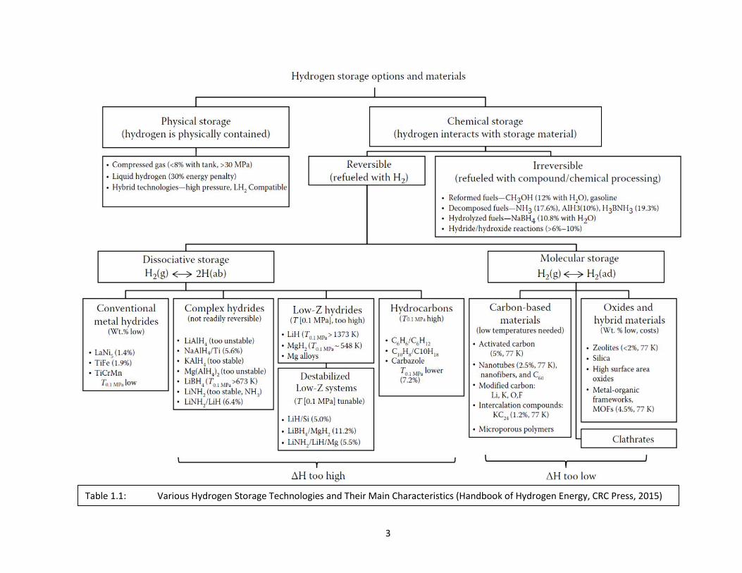
1.3 Safe and efficient storage and delivery of hydrogen is essential for the
success of hydrogen economy. Hydrogen can be stored by the following ways:-
(i) High-pressure gas cylinders (up to 800 bar)
(ii) Liquid hydrogen in cryogenic tanks (at 21oK)
(iii) Physi-sorbed hydrogen on materials with a large specific surface area
(iv) Chemi-sorbed on interstitial sites in host metals and Inter-metallics
(v) Chemically bonded in covalent and ionic compounds
(vi) Oxidation of reactive metals such as. Li, Na, Mg, Al, Zn with water.
A comprehensive list of hydrogen storage technologies is given in Table 1.1.
3
Table 1.1: Various Hydrogen Storage Technologies and Their Main Characteristics (Handbook of Hydrogen Energy, CRC Press, 2015)
4
STORAGE TECHNOLOGIES
Gas Storage
1.4 Hydrogen is generally stored as gas in compressed form because it is
very light with low density of 0.084 kg/m3. The energy content of hydrogen gas at
ambient pressure and temperature is 10 MJ/m3, which demands extremely large
volume for hydrogen storage. The conventional hydrogen storage tank is
significantly heavier than hydrocarbon storage tank for storing the equal amount
of energy. Hydrogen storage needs special attention due to embrittlement
(caused by hydrogen diffusion being smallest molecule in size) of materials of
construction of pressure vessels. Therefore, it becomes necessary to use special
alloys or composite fiber reinforced containers. Compressed gas storage also
poses issues of high potential energy and safety hazards due to possibility of
explosion of pressure vessels. However, it is possible to have necessary safety
practices with suitable blast walls and monitors/sensors and ensure compatible
and safe high pressure storage bottles. Hydrogen is being stored in gaseous
form on-board for transportation applications, with focus primarily on the driving
range of 500 km. Some automakers have demonstrated their prototype vehicles
qualifying this range.
1.5 Hydrogen in compressed mode has been widely used in on-board mobile
applications like in the vehicles for road transportation, stationary application for
dispensing hydrogen at re-fueling stations and at sites for stationary power
generation. Hydrogen, while storing at high pressures reacts with the materials
of construction of containers and makes them brittle; therefore, the containers
are made of special alloys and also with reinforced composite carbon fiber.
Currently, hydrogen is being stored in compressed form at 350 bar (5,000 psi) in
on-board in demonstration vehicles and 700 bar (10,000 psi) in Type IV carbon
composite cylinders. Carbon composite cylinders to store hydrogen at 700 bar
(10,000 psi) are not being manufactured in the country.
5
Liquid Storage
1.6 Storage and transportation of hydrogen as a liquid is another possibility.
The cryogenic hydrogen is to be stored in specially insulated vessels at (-)
252.880C. The energy required to liquefy hydrogen (gas at 300oK and 1 bar
pressure) is about 47 MJ / kg of hydrogen. The energy also is dependent on the
size of the plant. With improved technologies and small plants involving
magnetic regenerative liquefaction about half of this energy may be adequate.
Thus, energy required for bulk storage and transport cryogenic liquid hydrogen
gas can be about 10 to 20% lower. Like hydrogen in gaseous form, the liquid
hydrogen also has tendency to diffuse into the material of construction at high
pressures and make them brittle. To check this problem of embrittlement, the
storage vessels may be made of FCC (as material of construction) with special
insulation, comprising double walled with vacuum in between, opacifiers and
multi-layer insulations.
1.7 Hydrogen can be stored in liquid form in cryogenic conditions. So far, LH2
application has been mainly in space application. These forms of storage are not
suitable for widespread commercial application. Liquid organic hydrides are also
potential candidates for hydrogen storage and delivery. The concept has been
demonstrated successfully at laboratory level. Pilot level studies demonstrate
the efficacy of the system and possibilities of up-scaling. Considerable work has
also been carried out at National level leading to generation of IPR for country.
Further work is being conducted and expected to be supported by
government/industry may lead to development of a technology for safe hydrogen
storage and delivery at near ambient conditions for long distance transportation.
In order for the hydrogen program to be successful in India, development of
required testing facilities, standards codes and regulations for cylinders,
components, vehicles and fuel need to be developed in line with international
regulations.
6
Solid State Storage
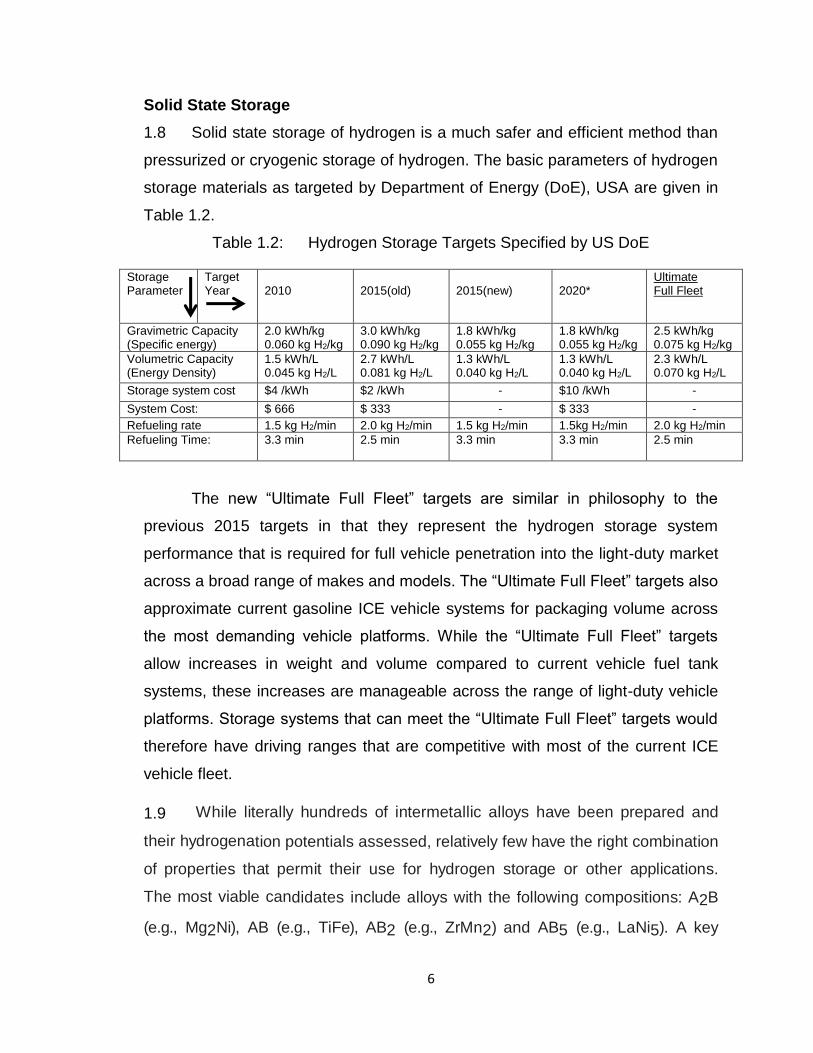
1.8 Solid state storage of hydrogen is a much safer and efficient method than
pressurized or cryogenic storage of hydrogen. The basic parameters of hydrogen
storage materials as targeted by Department of Energy (DoE), USA are given in
Table 1.2.
Table 1.2: Hydrogen Storage Targets Specified by US DoE
The new “Ultimate Full Fleet” targets are similar in philosophy to the
previous 2015 targets in that they represent the hydrogen storage system
performance that is required for full vehicle penetration into the light-duty market
across a broad range of makes and models. The “Ultimate Full Fleet” targets also
approximate current gasoline ICE vehicle systems for packaging volume across
the most demanding vehicle platforms. While the “Ultimate Full Fleet” targets
allow increases in weight and volume compared to current vehicle fuel tank
systems, these increases are manageable across the range of light-duty vehicle
platforms. Storage systems that can meet the “Ultimate Full Fleet” targets would
therefore have driving ranges that are competitive with most of the current ICE
vehicle fleet.
1.9 While literally hundreds of intermetallic alloys have been prepared and
their hydrogenation potentials assessed, relatively few have the right combination
of properties that permit their use for hydrogen storage or other applications.
The most viable candidates include alloys with the following compositions: A2B
(e.g., Mg2Ni), AB (e.g., TiFe), AB2 (e.g., ZrMn2) and AB5 (e.g., LaNi5). A key
Storage Parameter
Target Year
2010
2015(old)
2015(new)
2020*
Ultimate Full Fleet
Gravimetric Capacity (Specific energy)
2.0 kWh/kg 0.060 kg H2/kg
3.0 kWh/kg 0.090 kg H2/kg
1.8 kWh/kg 0.055 kg H2/kg
1.8 kWh/kg 0.055 kg H2/kg
2.5 kWh/kg 0.075 kg H2/kg
Volumetric Capacity (Energy Density)
1.5 kWh/L 0.045 kg H2/L
2.7 kWh/L 0.081 kg H2/L
1.3 kWh/L 0.040 kg H2/L
1.3 kWh/L 0.040 kg H2/L
2.3 kWh/L 0.070 kg H2/L
Storage system cost $4 /kWh $2 /kWh - $10 /kWh -
System Cost: $ 666 $ 333 - $ 333 -
Refueling rate 1.5 kg H2/min 2.0 kg H2/min 1.5 kg H2/min 1.5kg H2/min 2.0 kg H2/min
Refueling Time: 3.3 min 2.5 min 3.3 min 3.3 min 2.5 min
7
advantage of many intermetallic alloys is the ability to alter their hydrogen
sorption behavior by substitution for either or both the A and B metals that often
improve their performance in various applications.
A variety of solid-state hydrogen storage materials viz. MgH2, Mg2NiH4, NaAlH4,
other alanates, borohydrates (gravimetric capacity of >7wt%), commercial
hydrides such as FeTiH2 and LaNi5H6, adsorbents like carbon, nano-structured
carbons (including CNTs) MoFs and hydrogen clathrate hydrate have been
investigated for hydrogenation and dehydrogenation reaction conditions and their
kinetics, retention of cycling capacity, susceptibility to impurities and reversible
capacities. The need for material with practical operative conditions of pressure
(1-10 bar) and temperature (300C-1000C) has simulated the interest of many
researchers. Other major areas of research are improvement of kinetics of
hydrogen uptake/release and enhancement of cycling capacity.
1.10 Pure hydrogen physisorption has been demonstrated at cryogenic
temperatures (up to ca. 6 wt% H2) for which extremely high surface area carbon
is required. Pure atomic H-chemisorption has also been demonstrated to ca. 8
wt% H2, but the covalent-bound H is liberated only at impractically high
temperatures (above ca. 400°C). The activated carbon materials made from
carbon nanotubes, graphite nanofibers, known as next generation of energy
systems are capable of storing hydrogen. For example, porous carbons with a
specific surface area of 3220 m2/g are capable of storing hydrogen of 1.3 wt% at
room temperature.
1.11 Nanostructured systems including carbon nanotubes, nano-magnesium
based hydrides, complex hydride / carbon nanocomposites, boron nitride
nanotubes, sulphide nano-tubes of titanium and molybdenum, alanates, polymer
nanocomposites, and metal organic frameworks are considered to be potential
candidates for storing large quantities of hydrogen. The synergistic effects of
nanocrystalinity and nanocatalyst doping on the metal or complex hydrides
8
improve thermodynamics and hydrogen reaction kinetics. In addition, various
carbonaceous nanomaterials and novel sorbent systems (e.g. carbon nanotubes,
fullerenes, nanofibers, polyaniline nano-spheres and metal organic frameworks
etc.) and their hydrogen storage characteristics are considered. In spite of these
consistent and persistent efforts, these materials are yet to satisfy the required
characteristics like storage capacity of around 6 weight percent, favourable and
tuning thermodynamics around 30-55 KJ/mol of hydrogen and temperature of
operation around 373 K with about 1000s of cycles of operation.
Emerging Storage Technologies
1.12 Liquid organic hydrides consisting of various cycloalkanes can
conveniently be transported from one place to another. These hydrides may be
prepared by the reaction of hydrogen with toluene under specific conditions.
Hydrogen and toluene may be recovered by the dehydrogenation of the
cyclohexane at or near fueling stations for dispensing hydrogen into vehicles /
other applications. Toluene is transported back for reuse. The advantage
associated with these organic hydrides is higher storage capacity of hydrogen,
which is more than 6 wt% and 60 kg/m3.
1.13 Compressing hydrogen inside hollow glass microspheres or microcapsules
has been suggested to give high volumetric storage densities. Loading and
unloading of hydrogen gas in and out is based on the fact that gas permeation
through the solid shell increases exponentially with temperature. Hollow
microspheres are also called microcapsules, microcavities, microbubbles, or
microballoons. Hydrogen storage in hollow glass microspheres presents several
advantages. First, hollow microspheres have high gravimetric energy density.
Hydrogen can be stored under internal pressure higher than that inside
conventional cylinders. Hydrogen-filled hollow glass microspheres are also easy
and safe to handle at atmospheric pressure and ambient temperature and can be
poured or pumped in tanks of any arbitrary geometries made of lightweight
9
materials. The technology is inexpensive and requires low energy consumption
for producing large quantities of micro containers.
DESIGN CONSIDERATIONS
In order to achieve the optimum performance from a hydrogen storage
material in a given application, comprehensive system engineering must be
carried out with respect to the vessel design as well as the physical, chemical
and thermos-physical properties of the storage media and the components that
are used to enhance heat and mass transfer during both the charging and
discharging operations.
1.14 In addition to meeting high degrees of safety, efficiency and cost
effectiveness, the main challenge in all hydrogen storage systems design is to
meet the following basic requirements:
a) The weight and volume of hydrogen storage systems are presently too
high compared to conventional petroleum-fueled vehicles. Use of lightweight
materials and components are needed to enable more than 300-mile range for
the light-duty vehicles.
b) Optimized Thermal and Mechanical Design of the reactor ensures that
the storage capacity and kinetics are well balanced for a given application. High
efficiencies coupled with low total weights should be achieved by proper design
practices.
c) Energy efficiency is a challenge for all hydrogen storage approaches.
The energy required to get hydrogen in and out is an issue for reversible solid-
state materials. The energy associated with compression and liquefaction must
be considered for compressed and liquid hydrogen technologies.
d) Durability of hydrogen storage systems is required with a lifetime of 1500
cycles.
e) Refueling time may be targeted to less than three minutes.
10
f) Cost of on-board hydrogen storage systems is too high, particularly in
comparison with conventional storage systems for petroleum fuels. Low-cost
materials and components for hydrogen storage systems are needed, as well as
low-cost, high-volume manufacturing methods.
g) Applicable codes and standards for hydrogen storage systems and interface
technologies, which will facilitate implementation / commercialization and assure
safety and public acceptance, are to be established.
APPLICATIONS OTHER THAN TRANSPORTATION
1.15 Energy storage in the form of hydrogen obtained by electrolysis from wind
power has been demonstrated at the Electric Research Development Association,
Vadodara under a project supported by MNRE. This demonstration encouraged
to scale up wind hydrogen system particularly for remote locations such as
villages, islands. India also can explore possibility of acquiring this technology
(especially high pressure alkaline electrolyser). In addition, feasibility of such
projects in India may be studied in collaboration with stake holders like Oil and
Natural Gas Commission (ONGC), Gas Authority of India Limited (GAIL), and
PGCIL, Utilities, Central Electricity Authority (CEA). Projects for demonstration of
MW scale wind hydrogen system may be taken-up.
1.16 Hydrogen has the potential to replace LPG and CNG for cooking because
it has superior characteristics to LPG and PNG fuel in terms of ignitability, low
ignition delay and higher flame stability. A special design of fuel distribution
would be required for reasonable mixing of hydrogen with ambient air
entering at the bottom of the catalyst body. Therefore, a catalytic burning of
the hydrogen in the home cooker is the best way to use the hydrogen for
cooking. Several catalysts such as metals like Cu, Zn, Fe, Ni, Co; alloys like Co-
Mn-Ag; storage alloys like MmNi5, ZrFe2 can dissociate H2. There are two
catalytic techniques, which are relevant to hydrogen fueled catalytic cookers.
One is use of porous ceramic plate embedded with platinum in pores. This
produces flameless situation. Under the project supported by MNRE, BHU Group
11
has targeted development of catalysts including new catalysts for hydrogen
catalytic combustion cooker, synthesis and development of hydride of choice,
development and optimization of hydrogen catalytical combustion cooker,
optimization of safety aspects of hydrogen catalytic combustion cooker, etc.
However, safety related issues for handling H2 in Domestic Sectors must be
addressed.
1.17 Utilizing the exothermic and endothermic processes during sorption and
desorption of hydrogen respectively in metal hydrides, highly efficient, compact
and cost-effective chemi-sorption thermal energy storage devices can be
developed. This could significantly contribute to the widespread utilization of
solar thermal energy. Such demonstration systems suitable for small capacity
ORC power packs are being studied at IISc-Bangalore.
1.18 The hydrogen chemisorption – desorption heat exchanges during the
hydrogen sorption process in metal hydrides can also be utilized to develop a
variety of thermal devices, especially refrigeration and heat pump systems. The
temperatures can range from cryogenic to very high values. For example,
exhaust heat operated automobile air conditioners have been built by several
agencies. One such prototype was developed by IIT Madras in collaboration with
Thermax.
SUGGESTED ACTION PLANS
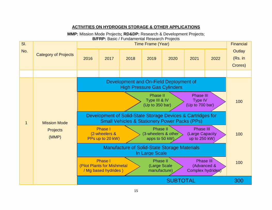
Action plans stretch up to 2022 in phases.
1.19 High Pressure Hydrogen Gaseous Storage: CNG cylinders may be
deployed in demonstration fleets of vehicles upto a pressure of 200 bar. For
pressure more than 200 and upto 400 bar, hydrogen cylinders may be imported
for the vehicle like buses and trucks. Such 50 vehicles may be taken-up for
public demonstration. Simultaneously, 500 to 1000 hydrogen fueled vehicles be
12
prepared in about 5 to 8 years for large scale demonstration. Consortium
collaboration approach may be followed among HINDALCO, Indore; NPL, New
Delhi; IOCL Nasik and BHEL (Hyderabad) to produce Al cylinders reinforced with
carbon fibre tapes and other high strength wrappings. This consortium may
prepare 50 such high pressure cylinders upto 400 bar and test them.
1.20 Solid State Storage (Metal, Intermetallic and Complex Hydrides):
Production of optimized, well known and already deployed Mischmetal based
hydride (India has one of the largest Mischmetal deposits in the world) e.g. Mm-
Ni-Fe may be taken-up on pilot plant level (100 kg to 1 Ton Level) and
simultaneously, its demonstration in the vehicles for on-board applications in
around 50 three wheelers (hydride requirement around 2000 kg); 10 small cars
(hydride requirement around 500 Kg).
1.21 Solid State Storage (Metal, Intermetallic and Complex Hydrides): The off-
board (Stationary) application for power generation in around 1000 Gen-Sets of
5-15 kW capacity (required hydride quantity 10 Tons) may be deployed. R&D
efforts may be intensified for obtaining gravimetric and volumetric efficiencies of
5 to 6wt% and 60 kg/m3 for metal hydrides particularly catalyzed MgH2 and
gravimetric efficiency of 3 to 6 wt% for other intermetallic hydrides e.g. Zr Fe2,
Mg2Ni type. R&D efforts may be upgraded for evaluation of reproducible high
efficiencies 5 to 6wt% in complex hydrides with particular emphasis on catalyzed
MgH2, NaAlH4, LiAlH4, NaAlH4- MgH2, Li-Mg-N-H system. Enhancement of R&D
efforts are required to increase hydrogen storage capacity from 1 to 3wt% at
ambient conditions and 5 to 8 wt% at Liquid N2 temperature in nano/porous
carbons.
1.22 Intensive developmental efforts may be taken up on Liquid Hydrides.
Petroleum industry may also be networked to support the pilot runs. There is
need to support R&D projects for further development of selective and stable
13
catalysts. A demonstration may be done by setting up pilot facilities near a
refinery and providing hydrogen to telecom towers in the range of 50 to 100 Km.
1.23 An Interdisciplinary, Inter-Institutional Center may be set up to evaluate
the thermodynamic, thermophysical and kinetic properties, cyclic stability,
performance augmentation based on mechanical and thermal design of solid
state storage devices. Testing and certification of such devices should also be
done by this facility.
1.24 Development of miscellaneous energy related applications of hydrogen
such as High Intensity Thermal Energy Storage and Heat Pump/Heat
Transformer may be encouraged at the Institutions which have shown the
feasibility, through demonstration projects.
1.25 Action plan may include efforts for the development, distribution and
monitoring of 1000 to 10,000 hydrogen fueled home cookers. It will sensitize the
public and this may be followed by 25% to 50% replacement of LPG by hydrogen
through manufacturing and use of home cookers through public-private
partnership.
1.26 Further developments on High Pressure Hydrogen Gaseous Storage may
be taken up based on the feedback received about the cylinders, 1,000 nos. may
be procured from the companies abroad and 9,000 nos. may be manufactured by
Bharat Pumps and Compressors and other similar companies in India. Efforts
are to be made to have 100% indigenous production during 2020-2035. These
cylinders may be used in hydrogen fueled 3 wheelers, buses, vans, cars and in
stationary systems like power generating system (>10kW) around 1000 IC
engine Gen Sets and 500 in fuel cells power generating systems. Area-wise
replacement of 50% diesel Gen Sets (10kW and higher) may be taken-up in
crowded areas in the country. Efforts may be made to use such vehicles and
Gen Sets to reach at least 30% of the total such devices in specific cities.
14
1.27 Solid State Storage (Metal, Intermetallic and Complex Hydrides):
Manufacturing of mischmetal based hydrides on pilot plant scale (1 Ton) may be
taken up. These may be manufactured on large scale for (i) on-board
applications in 500 three wheelers and 150 cars (ii) stationary application in 1000
Gen-Sets of 5 to 15 kW capacity and 500 fuel cells vehicles with 5 kW to 15kW
fuel cells systems. The non- mischmetal based viable intermetallic hydride
developed out of R&D efforts in Phase-I may be picked-up for initiation of
manufacturing at pilot plant level (1 to 10 Tons). R&D efforts may be intensified
on Mg/MgH2 hydrides to produce large quantities (100kg to 1 ton), to decrease
desorption, absorption temperature to about 2000C through the use of effective
catalysts, to enhance the desorption / absorption kinetics, to improve recyclability
from 100 to 1000 cycles through Mg agglomeration checking systems, to develop
MgH2 based vehicular transport, to optimize gravimetric and volumetric
efficiencies of complex hydrides (catalyzed NaAlH4, Mg (AlH4)2, LiAlH4 types)
coming out of R&D in phase-I, to evaluate reversibility and cyclability, to adopt
PEM fuel cell instead of IC Engines for 25% of the above said vehicles, to
enhance hydrogen storage in nano/porous carbon and to use it in small vehicles.
CONCLUDING REMARKS
1.28 Storage, Transportation and Distribution of hydrogen are important for the
success of ‘Hydrogen Economy’. Traditional methods of storage may not be
directly applicable for use of hydrogen as a ‘fuel’. The technologies and devices
should satisfy various stringent requirements such as; safety, economy,
efficiency, flexibility, durability and environmental / ecological standards. The
abovementioned actions can go a long way in facilitating the widespread use of
hydrogen in our country.
15
ACTIVITIES ON HYDROGEN STORAGE & OTHER APPLICATIONS
MMP: Mission Mode Projects; RD&DP: Research & Development Projects; B/FRP: Basic / Fundamental Research Projects
Sl.
No. Category of Projects
Time Frame (Year) Financial
Outlay
(Rs. in
Crores)
2016 2017 2018 2019 2020 2021 2022
1
Mission Mode
Projects
(MMP)
100
100
100
Phase I Type III
(Up to 250 bar)
SUBTOTAL 300
Development and On-Field Deployment of High Pressure Gas Cylinders
Phase II Type III & IV
(Up to 350 bar)
Phase III Type IV
(Up to 700 bar)
Development of Solid-State Storage Devices & Cartridges for Small Vehicles & Stationery Power Packs (PPs)
Phase I (2-wheelers &
PPs up to 20 kW)
Phase II (3-wheelers & other
apps to 50 kW)
Phase III (Large Capacity up to 250 kW)
Manufacture of Solid-State Storage Materials In Large Scale
Phase I (Pilot Plants for Mishmetal
/ Mg based hydrides )
Phase II (Large Scale manufacture)
Phase III (Advanced &
Complex hydrides)
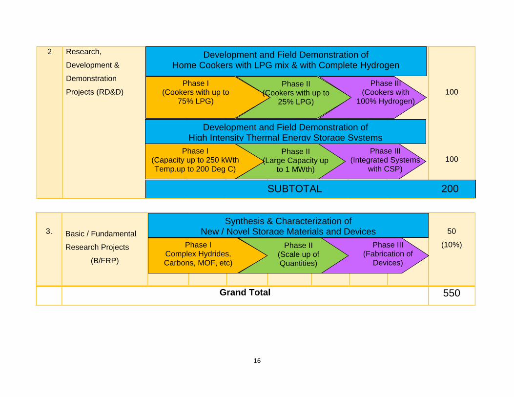
16
2 Research,
Development &
Demonstration
Projects (RD&D)
100
100
3. Basic / Fundamental
Research Projects
(B/FRP)
50
(10%)
Grand Total 550
Development and Field Demonstration of Home Cookers with LPG mix & with Complete Hydrogen
Phase I (Cookers with up to
75% LPG)
Phase II (Cookers with up to
25% LPG)
Phase III (Cookers with
100% Hydrogen)
Development and Field Demonstration of High Intensity Thermal Energy Storage Systems
Phase I (Capacity up to 250 kWth Temp.up to 200 Deg C)
Phase II (Large Capacity up
to 1 MWth)
Phase III (Integrated Systems
with CSP)
SUBTOTAL 200
Synthesis & Characterization of New / Novel Storage Materials and Devices
Phase I Complex Hydrides, Carbons, MOF, etc)
Phase II (Scale up of Quantities)
Phase III (Fabrication of
Devices)

17
INTRODUCTION
18
2.0 INTRODUCTION
2.1 Our current global energy consumption is rapidly increasing and while our
primarily energy sources (fossil fuels) are rapidly depleting. Furthermore, the
pollution and climate change represent undesirable side effects of global
concern. To meet these major challenges, it is needed to shift from carbon-based
non-renewable resources to carbon-neutral renewable sources of energy. The
possible alternative renewable sources of energy are solar, hydroelectric, wind
power, biofuels, etc. The major drawback in all these cases is that periods of
peak energy production do not necessarily coincide with periods of peak energy
consumption. Therefore a complete transition to such an alternative energy
source relies on efficient capture, conversion and storage, which is currently
being explored worldwide. In this context, Hydrogen has been considered as the
fuel of the future and an environmentally friendly alternative to depleting fossil
fuels. It can be created by splitting water into oxygen and hydrogen with many
clean renewable energy sources and when used the products are energy and
plain water again. The retrievable energy can be used in conventional
combustion, powering cars, heating houses, etc. or be used together with fuel
cells to produce electricity in large or small scale. Hydrogen has very high energy
content per kilogram, almost three times higher than gasoline. Hydrogen can be
an environmentally cleaner source of energy to end-users, particularly in
transportation applications, without release of pollutants (such as particulate
matter) or carbon dioxide at the point of end use. The technical obstacles in
hydrogen economy are hydrogen storage issues and the purity requirement of
hydrogen used in fuel cells – with current technology, an operating fuel cell
requires the purity of hydrogen to be as high as 99.999%. Currently, global
hydrogen production is 48% from natural gas, 30% from oil, and 18% from coal;
water electrolysis accounts for only 4%.
Hydrogen exhibits the highest heating value per mass of all chemical
fuels. Furthermore, hydrogen is regenerative and environmentally friendly. There
19
are two reasons why hydrogen is not the major fuel of today’s energy
consumption. First of all, hydrogen is just an energy carrier and, although it is the
most abundant element in the universe, it has to be produced, since on earth, it
only occurs in the form of water and hydrocarbons. This implies that we have to
pay for the hydrogen energy, which results in a difficult economy. The second
difficulty with hydrogen as an energy carrier is its low critical temperature of 33 K
(i.e. hydrogen is a gas at ambient temperature). For mobile and in many cases
also for stationary applications the volumetric and gravimetric density of
hydrogen in a storage material is crucial.
2.2 The storage and transportation of hydrogen remains a major challenge in
realizing hydrogen economy. Different strategies for hydrogen storage have been
developed.
Hydrogen can be stored using six different methods and phenomena: (1)
high-pressure gas cylinders (up to 800 bar), (2) liquid hydrogen in in dewars or
cryogenic tanks (at 21K), (3) adsorbed hydrogen on materials with a large
specific surface area adsorbents (Zeolites, Carbon materials and porous
coordination polymers or Metal-Organic Frameworks) (at T<100 K), (4) absorbed
on interstitial sites in a host metal (at ambient pressure and temperature), (5)
chemically bonded in covalent and ionic compounds (at ambient pressure), and
(6) through oxidation of reactive metals, e.g. Li, Na, Mg, Al, Zn with water.
Hydrogen storage can broadly be divided into two categories,
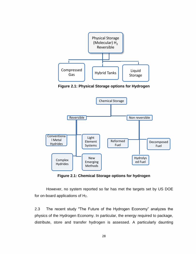
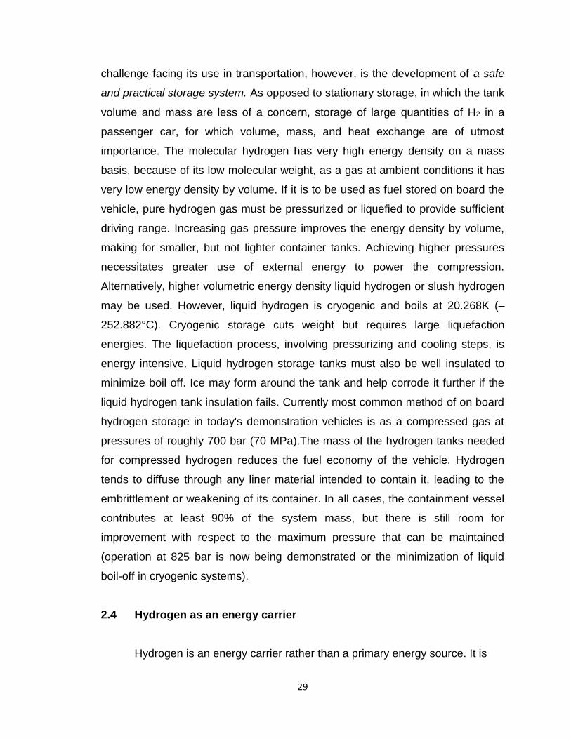
1. Physical Storage and 2. Chemical Storage.
The physical storage, i.e., storage of hydrogen in molecular form, includes
storage in the form of compressed gas, hybrid tanks and liquid/cryogenic storage
(Figure 2.1). The chemical storage involves reversible methods main metal
hydrides, whereas the other non-reversible chemical storage forms are reformed,
hydrolyzed or decomposed fuel (Figure 2.1). Table 2.1 gives a comprehensive
list of different hydrogen storage technologies.
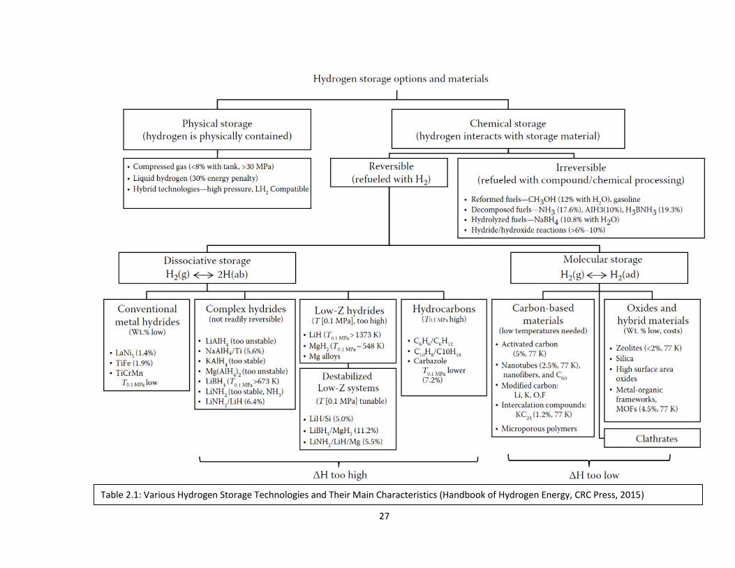
27
Table 2.1: Various Hydrogen Storage Technologies and Their Main Characteristics (Handbook of Hydrogen Energy, CRC Press, 2015)
28
Figure 2.1: Physical Storage options for Hydrogen
Figure 2.1: Chemical Storage options for hydrogen
However, no system reported so far has met the targets set by US DOE
for on-board applications of H2.
2.3 The recent study "The Future of the Hydrogen Economy” analyzes the
physics of the Hydrogen Economy. In particular, the energy required to package,
distribute, store and transfer hydrogen is assessed. A particularly daunting
Physical Storage (Molecular) H2
Reversible
Compressed Gas Hybrid Tanks
Liquid Storage
Chemical Storage
Reversible
Conventional Metal
Hydrides
Complex Hydrides
New Emerging Methods
Light Element Systems
Non reversible
Reformed Fuel
Hydrolysed Fuel
Decomposed Fuel
29
challenge facing its use in transportation, however, is the development of a safe
and practical storage system. As opposed to stationary storage, in which the tank
volume and mass are less of a concern, storage of large quantities of H2 in a
passenger car, for which volume, mass, and heat exchange are of utmost
importance. The molecular hydrogen has very high energy density on a mass
basis, because of its low molecular weight, as a gas at ambient conditions it has
very low energy density by volume. If it is to be used as fuel stored on board the
vehicle, pure hydrogen gas must be pressurized or liquefied to provide sufficient
driving range. Increasing gas pressure improves the energy density by volume,
making for smaller, but not lighter container tanks. Achieving higher pressures
necessitates greater use of external energy to power the compression.
Alternatively, higher volumetric energy density liquid hydrogen or slush hydrogen
may be used. However, liquid hydrogen is cryogenic and boils at 20.268K (–
252.882°C). Cryogenic storage cuts weight but requires large liquefaction
energies. The liquefaction process, involving pressurizing and cooling steps, is
energy intensive. Liquid hydrogen storage tanks must also be well insulated to
minimize boil off. Ice may form around the tank and help corrode it further if the
liquid hydrogen tank insulation fails. Currently most common method of on board
hydrogen storage in today's demonstration vehicles is as a compressed gas at
pressures of roughly 700 bar (70 MPa).The mass of the hydrogen tanks needed
for compressed hydrogen reduces the fuel economy of the vehicle. Hydrogen
tends to diffuse through any liner material intended to contain it, leading to the
embrittlement or weakening of its container. In all cases, the containment vessel
contributes at least 90% of the system mass, but there is still room for
improvement with respect to the maximum pressure that can be maintained
(operation at 825 bar is now being demonstrated or the minimization of liquid
boil-off in cryogenic systems).
2.4 Hydrogen as an energy carrier
Hydrogen is an energy carrier rather than a primary energy source. It is
30
therefore not generally suited for an efficient utilization based on a “well to wheel”
basis. Though hydrogen is available in plenty in nature around us and constitutes
almost 75% of matter in the universe, it exists invariably in a form which is
combined with other elements. We lost the element hydrogen in the early part of
the Earth’s evolution due to the molecular velocity of the heated hydrogen being
higher than what the Earth’s gravitational field could hold.
If hydrogen were to be used in the combined form that it is available in
nature, the oxygen or carbon or the other elements in water, hydrocarbon, etc.
needs to be first isolated or removed and the hydrogen could be employed as an
energy source. Work is therefore pursued to generate hydrogen from water by
different processes and so far they have been somewhat energy intensive.
Hydrogen combined with carbon as hydrocarbon is a very good energy source
since both the hydrogen and the carbon in it contribute to energy. However,
carbon in hydrocarbon leads to pollution and formation of global warming CO2.
This is especially true if the bonds between the hydrogen and carbon atom in the
hydrocarbon gets to be more complex than the simple single or double bond. If
hydrogen can be isolated from the hydrocarbon and used to generate energy by
its oxidation to water, the product water could be reused again to from more
hydrogen. We therefore have hydrogen as a renewable energy. Care should be
taken that the temperature of the oxidation process of hydrogen is kept rather low
such that oxides of hydrogen especially N2O, which is even a stronger global-
warming gas and pollutant than CO2, is not formed.
Hydrogen is a clean source of energy, if burnt with air at relatively low
temperatures or if used to generate power directly using fuel cells. The latter is
particularly attractive considering the near reversible process and relatively
higher thermodynamic efficiencies. The energy so generated can be used for
doing work in different propulsive applications or simply for generating power.
31
Hydrogen is an energy carrier like electricity and we can think of
generating hydrogen at a source from water, hydrocarbon or other substances
containing it and transporting it to the place where energy is required. The energy
carrier hydrogen is stored at the point of its production, moved or transported to
the point of application where it delivers its energy. It has one advantage over
electricity as an energy carrier in that it can be stored. In fact, the excess
electrical energy generated from hydroelectric power generation in Quebec in
Canada has been used to generate hydrogen. Similarly the excess wind energy
which is available during some seasons can be used to produce hydrogen which
thereafter can be used to generate power.
When power requirements are phenomenal but the high power is required
only for a short period of time, hydrogen comes to the rescue. The hydrogen
generated over a prolonged period is used up in a short period of time during
which the energy requirements are very intensive.
2.5 Storage and transportation of hydrogen
Hydrogen formed by different means say the “reforming” of hydrocarbon
or electrolysis of water or any other biochemical process or otherwise is
invariably produced as a gas. The gas is very light with a density of 0.084 kg/m3
which is about 1/10th of the lightest hydrocarbon gas methane. The energy
available per unit volume of the stored hydrogen gas is compared with crude oil
and other low grade fuels such as dry wood in the Table 2.2.
Table 2.2: Volumetric energy content per cubic meter of some fuels
Substance Energy in MJ/m3
Hydrogen gas at ambient pressure and temperature 10
Crude oil 37,000
Coal 42,000
Dry wood 10,000
32
The very low volumetric energy content of hydrogen demands extremely large
volumes of gas holders at the source of its production if any meaningful storage
of energy is desirable at ambient pressure. Even if stored at very high pressures
of about 50 MPa (about 500 bars) and room temperature, the energy available is
less than that in dry wood. The storage of hydrogen at high pressures is also not
straightforward due to hydrogen embrittlement of materials used in the
construction of pressure vessels; it becomes necessary to use special alloys or
composite fiber reinforced cases.
Compressed gas storage also poses issues of high potential energies and
safety hazards due to explosion. However, it is possible to institute necessary
safety practices with suitable blast walls and monitors/sensors and ensure
compatible and safe high pressure storage bottles. Storage and transportation of
hydrogen in liquid or solid state may be simpler and advantageous especially
from safety aspects.
2.6 Targets for storage capacity
Onboard hydrogen storage for transportation applications continues to be
one of the most technically challenging barriers to the widespread
commercialization of hydrogen-fueled light-duty vehicles. The DOE Office of
Energy Efficiency and Renewable Energy (EERE), Fuel Cell Technologies (FCT)
Program’s hydrogen storage activity focuses primarily on the applied research
and development (R&D) of low-pressure, materials-based technologies to allow
for a driving range of greater than 500 km while meeting packaging, cost, safety,
and performance requirements to be competitive with comparable vehicles in the
market place. While automakers have demonstrated progress with some
prototype vehicles traveling greater than 500 km on a single fill, this driving range
must be achievable across different vehicle makes and models and without
compromising customer expectations of space, performance, safety, or cost.
33
The DOE Hydrogen Program website and the FCT Program’s Multi-Year
Research, Development, and Demonstration Plan contain further information on
the Program and its objectives. The new “Ultimate Full Fleet” targets are similar
in philosophy to the previous 2015 targets in that they represent the hydrogen
storage system performance that is required for full vehicle penetration into the
light-duty market across a broad range of makes and models. The “Ultimate Full
Fleet” targets also approximate current gasoline ICE vehicle systems for
packaging volume across the most demanding vehicle platforms. While the
“Ultimate Full Fleet” targets allow increases in weight and volume compared to
current vehicle fuel tank systems, these increases are manageable across the
range of light-duty vehicle platforms. Storage systems that can meet the
“Ultimate Full Fleet” targets would therefore have driving ranges that are
competitive with most of the current ICE vehicle fleet. The DoE targets are given
in the Table 2.3.
Table 2.3 : US DoE Targets for Hydrogen Storage
Storage Parameter
Target Year
2010
2015(old)
2015(new)
2020*
Ultimate Full Fleet
Gravimetric Capacity (Specific energy)
2.0 kWh/kg 0.060 kg H2/kg
3.0 kWh/kg 0.090 kg H2/kg
1.8 kWh/kg 0.055 kg H2/kg
1.8 kWh/kg 0.055 kg H2/kg
2.5 kWh/kg 0.075 kg H2/kg
Volumetric Capacity (Energy Density)
1.5 kWh/L 0.045 kg H2/L
2.7 kWh/L 0.081 kg H2/L
1.3 kWh/L 0.040 kg H2/L
1.3 kWh/L 0.040 kg H2/L
2.3 kWh/L 0.070 kg H2/L
Storage system cost $4 /kWh $2 /kWh To be decided $10 /kWh To be decided
System Cost: $ 666 $ 333 To be decided $ 333 To be decided
Refueling rate 1.5 kg H2/min 2.0 kg H2/min 1.5 kg H2/min 1.5kg H2/min 2.0 kg H2/min
Refueling Time: 3.3 min 2.5 min 3.3 min 3.3 min 2.5 min
34
HYDROGEN STORAGE TECHNOLOGIES
35
HYDROGEN STORAGE IN GASEOUS
STATE
36
3.0 HYDROGEN STORAGE IN GASEOUS STATE
3.1 Introduction
3.1.1 Storage of gaseous Hydrogen at elevated pressure is indeed a necessity,
as a primary or supporting storage, given the fact that almost all energy
conversion applications of the fuel requires that the fuel is available in gaseous
state. The well-known industrial gas storage at around 150 bar in heavy steel /
aluminium cylinders is indeed the method in vogue currently. With the advent of
storing large quantities of hydrogen for multitude of applications including on-
board automobiles, methods which are much better in terms of volumetric and
gravimetric considerations have gained urgency and importance. The most
successful technological product that has emerged in the past decades in this
regard is composite high pressure cylinders. In fact, this has made hydrogen
based vehicles of equivalent traveling range to that use gasoline feasible, without
the need for a cryogenic storage on-board.
3.1.2 When taken in the free-state and placed under standard conditions,
hydrogen is a colourless, odorless, and tasteless gas having a density of 0.084
kg/m3. The latter means that 1 kg of hydrogen occupies a volume of 11 m3.
When in gaseous state and under any pressure, hydrogen possesses an energy
lower than that of natural gas, methanol, and propane, to say nothing of gasoline
(per unit volume). Liquid hydrogen (at a temperature of 20 K) occupies 1/700th of
the volume it takes in the gaseous state. When placed under a pressure of 80
MPa, gaseous hydrogen becomes virtually equivalent to liquid hydrogen in
specific content of energy per unit volume and mass. This has driven the world to
look for pressurized storage of gaseous Hydrogen at pressure levels of 700 to
800 bar. The success in the design and development of technologies on
composites as well as seamless thin pressure vessels together have yielded the
composite pressure vessels known today.
37
3.1.3 Enhancing the capabilities further, cylinders without the metal liner has
also become a reality. These cylinder with advanced polymeric liners are the so
called type IV class cylinders and offer significant weight advantages.
3.2 Composite high pressure vessel Type III – features and details
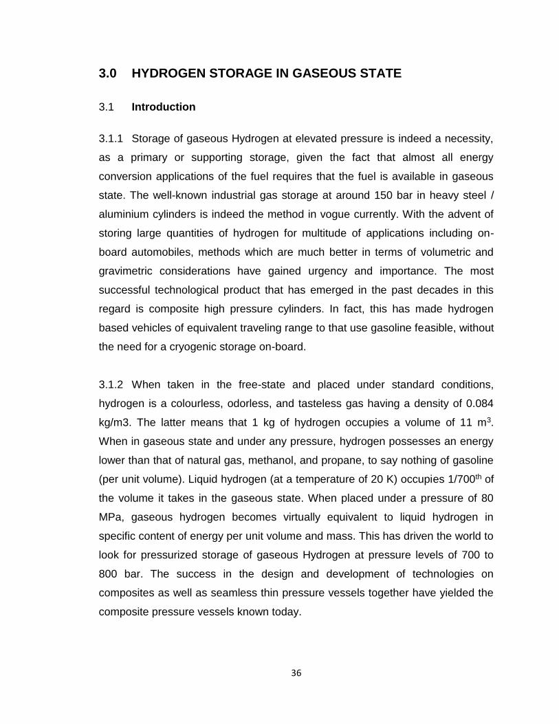
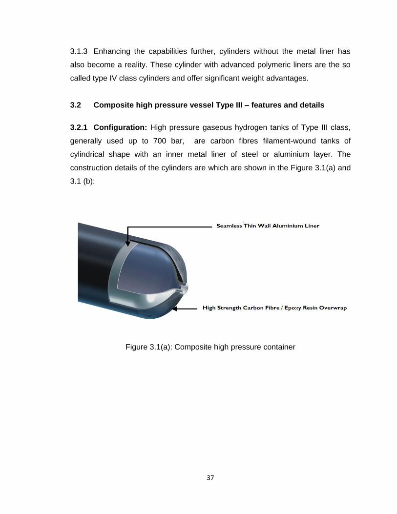
3.2.1 Configuration: High pressure gaseous hydrogen tanks of Type III class,
generally used up to 700 bar, are carbon fibres filament-wound tanks of
cylindrical shape with an inner metal liner of steel or aluminium layer. The
construction details of the cylinders are which are shown in the Figure 3.1(a) and
3.1 (b):
Figure 3.1(a): Composite high pressure container
38
Figure 3.1(b): Composite high pressure containers

39
3.2.2 Key features of typical composite pressure vessels that are available
today are as follows:
Non-permeable, seamless, aluminum liner
Metallic liner guarantees high impact resistance
Fast-fill capability without fill restrictions
Excellent resistance to heat exposure
Single and dual port configurations available
As a component to be plugged on board vehicles, they are also reported to be
assembly-line ready, Lightweight and are easily accessible for maintenance
and inspection
3.2.3 Protective measures: The following procedures are generally
recommended to prevent injury to personnel or damage to cylinder:
Cylinder shall be handled only under depressurized condition
There should not be any damage to the carbon fiber or the aluminum liner.
Safety shoes shall be used and hands shall be free of grease, grit and oil to
avoid possible damage to
Cylinder shall not be handled by their valves, fittings, pipings or pressure
devices.
3.2.4 Typical storage procedures are as follows:
Cylinders shall be restrained from moving / rolling and no impact shall be
permitted
Appropriate plastic plugs shall be used whenever necessary and entry of dirt,
water inside the cylinder shall be strictly prevented
Cylinder shall be protected from excessive heat, UV radiation (direct sunlight)
and corrosive environment
Rubber strips shall in place between cylinders and appropriate tools and
accessories shall be used while lifting and moving cylinders; possibility of
incurring any kind of damage to the fibers must be avoided
40
3.3 Environmental considerations
Generally, typical automobile environment is acceptable. Exposure to
highly corrosive acids and bases should be avoided. No protective coating shall
be applied and the thin transparent epoxy coating on the vessels is sufficient to
protect the fibers, and at the same time, revealing the health of the fibers readily.
Surface of the vessel shall not be subjected to any kind of abrasion, from gravel
or debris. Tap water or ordinary water shall not be allowed to enter cylinders.
Temperature of the medium (hydrogen gas) can be in the range of - 40 °C to 65
°C. Typical cylinders available in market specify Hydrogen gas composition
complying with ISO 14687.
3.4 Service Life
Typically, service life is specified in terms of number of cycles as well as
years. Cylinders have a maximum service life of 15 – 20 years, from the final
manufacturing inspection date. But, the actual date for decommissioning is
related to the number of cycles per year specified in the standard for the country
where it is used. Number of cycles specified for the cylinder (typical spec, more
than 1000 x service life in years) or service life in years, whichever is occurring
earlier, shall be the criteria for removing the cylinder from service.
3.5 Inspection & retesting
Periodic visual inspection at pre-determined intervals is very essential for
all cylinders in service. These inspections shall be done in accordance with
applicable standards and regulations of the country of use. Generally ISO 19078
is followed along with other standards specified for each country. In case a
hydraulic pressure test is mandatory, as part of the retest, only specially treated
shall be used and the exposure time shall be minimum.
41
3.6 Cylinders after collision or fire
Cylinders involved in collisions shall be subjected to detailed inspection by
authorised agency. If found unaffected, that there are no impact damage, the
same shall be returned to service. The cylinders subjected fire shall be removed
from service since it is possible that fire / heat could cause serious damage even
without any visible damage.
3.7 Installation and mounting
This shall be done only according to the prescribed procedure and
guidelines by the manufactures. Strict control shall be exercised and care shall
be taken to avoid any damage to the cyclinder surface / structure. All essential
safety devices viz., pressure relief valve, rupture disc etc shall be in place.
3.8 Protection and shielding
The cylinders shall be provided with sufficient protection and shielding,
especially for those mounted in a vehicle, to prevent possible damages from,
debris from road, contact with vehicle cargo and exposure to vehicle heat,
harmful liquids such as break-fluid and radiation (sun light). At the same time,
care shall be taken to avoid direct contact between shielding fuel storage tanks,
trapping of solid debris/liquid between the same and contact with vehicle
components such as frame members, brake lines, body panels and exhaust
systems. Generally open mesh type shielding is preferred as it avoid collection of
water and other liquids and enable easy access for inspection etc. There should
be a permanent electrically conductive connection between the cylinder and the
vehicle to prevent static charge build-up.
3.9 Basic design aspects
42
The cylinders have a distinct three layer configuration. A thin walled
aluminium (AA6061) liner forms the basic structure. This is uniformly and
completely intimately covered with carbon fibres, but for the openings. This layer
is provided with a wrapping by epoxy resin matrix.
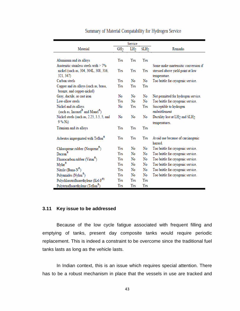
The selection of the materials of construction of the vessel is based on the
detailed assessment of their compatibility with the Hydrogen as well as the
mechanical properties. Brief details regarding selection of the materials are given
in Table 3.1.
3.10 Major tests and certification requirements
Important tests that the composite pressure vessels shall be subjected and
certified for shall include,
i) Hydrostatic burst test
ii) Ambient pressure cycle test
iii) Environmental
iv) Acid environment
v) Bonfire
vi) Laminate flaw tolerance
vii) Extreme temperature cycle
viii) Accelerated stress rupture
ix) Aluminum tensile
x) Laminate shear strength
xi) Glass transition
The tests shall be carried out in accordance with international standards
and findings shall be made available.
Table 3.1
43
3.11 Key issue to be addressed
Because of the low cycle fatigue associated with frequent filling and
emptying of tanks, present day composite tanks would require periodic
replacement. This is indeed a constraint to be overcome since the traditional fuel
tanks lasts as long as the vehicle lasts.
In Indian context, this is an issue which requires special attention. There
has to be a robust mechanism in place that the vessels in use are tracked and
44
periodically inspected during its life time. More importantly, the vessels that reach
its life must be removed from service, recovered and disposed safely and should
not be allowed to remain in public domain. There has to be a technological-
regulatory-fiscal frame work well in place to enforce this before the vessels are
allowed/put into use.
3.12 Type IV cylinders
This cylinder is the latest entrant in the high pressure gas storage
systems. For Hydrogen storage, though it could make significant weight saving,
widespread use is limited to the Type III category. This is mainly due to the
associated testing and certification requirements of enhanced nature to establish
mandatory safety levels. They are generally,
70% lighter than steel cylinders
Certified to NGV2-07 & ISO 11439
Capable of service pressure 3,600 psi (typ)
With life of 20 years (typ)
Safe, durable, and reliable
3.13 International Status - Technology and manufacturing
Today, globally, the technology of the cylinders is commercially ready.
Major manufacturers include M/s Quantum Technologies, M/s Luxfer Gas
Cylinders and M/s Dynetek Industries Limited. Cylinders are available in various
capacities. While there are many more manufacturers under this category,
capability to supply cylinders for Hydrogen gas of the high pressure levels
generally required for the present purpose that too with all mandatory safety tests
results, needs to be ascertained? Generally, the cylinders are made available
with due certifications and clearances. User level clearances in the country of
use alone is mostly left out. Large number of cylinders from the above
manufacturers are already in use on-board automobiles across the globe. Good
45
amount of data is already available with regard to their performance under typical
service environments. More importantly, they have been involved in accidents
and their behaviour under such conditions have been closely studied and
recorded.
3.14 National Status
The technology for realizing the carbon composite with aluminum liner
cylinder, type III, detailed above is not readily available in the country. Currently,
the cylinders are being imported for various applications of non-energy in nature
and, mostly, with air. The more popular, metal liner with Kevlar fiber wound type
are the kind which are widely used in the country. The agencies/personnel who
use such items today include ISRO, DRDO, Aviation industry, Medical Institution
for emergency oxygen, divers etc. Use of carbon composite wrapped metal liners
have also been initiated. The authority for certifying pressure vessels in the
country, CCoE, already has the clearance protocols in place for such items.
In-house developed technology for Kevlar composite titanium bottles for space
application is already there with VSSC-ISRO which are used typically with
Helium gas. Design, manufacturing, testing and use of these are already
established well.
Globally, Type IV cylinders are also available on commercial scale. Still its
use in the country is yet to start. Essential certifications/ clearance mechanisms
for this type is also understood to be in the evolving stage.
3.15 Work plan for India
India shall have a sound technological-regulatory-fiscal frame work in
place to track the composite bottles in service and replace and recover that
crosses the stipulated life period/cycles, on priority. Tracking of the numerous
cylinders that are going to be on-board automobiles and ensuring that they

46
recovered as and when each one crosses its life term is indeed new and complex
task requiring special attention.
a) Relevant policies, with regard to import/duties, shall be reviewed and
made ready for making the carbon composite-metal liner cylinders readily
available for various applications and use in the country.
b) Development of the same with a view to manufacturing it in the country
cost effectively, shall be pursued on priority.
c) Familiarization, certification and development of Type IV cylinders shall
also be taken up in the country concurrently to reap in benefit of this new
technology early.
47
HYDROGEN STORAGE IN LIQUID STATE
48
4.0 HYDROGEN STORAGE IN LIQUID STATE
4.1 About liquid hydrogen
4.1.1 The density of liquid hydrogen is 70.85 kg/m3 which is again small since
hydrogen is a quantum fluid. The zero point energy (835 J/mole) becomes
significant for the quantum hydrogen at the low temperature of 20 K with the
result that it is not possible to bring the atoms near to each other. If the hydrogen
is frozen or a mixture of liquid and solid hydrogen known as slush hydrogen is
formed at a temperature of about 15 K, the density does not significantly
increase. The gain is less than 10%. However, if very high pressure of the order
of Giga Pascal is applied one could get a high density solid hydrogen known as
metallic hydrogen. This is not yet reliably achieved though it is claimed to be
available in plenty in the gravitationally compressed interiors of planets Jupiter
and Saturn.
4.1.2 The only alternative to storing hydrogen as a gas is in the liquid form.
Slush or metallic hydrogen is not a contender for large storage. However, the
slush hydrogen has a high value of specific heats and is therefore as excellent
regenerative fuel for cooling and may be applicable in future for space
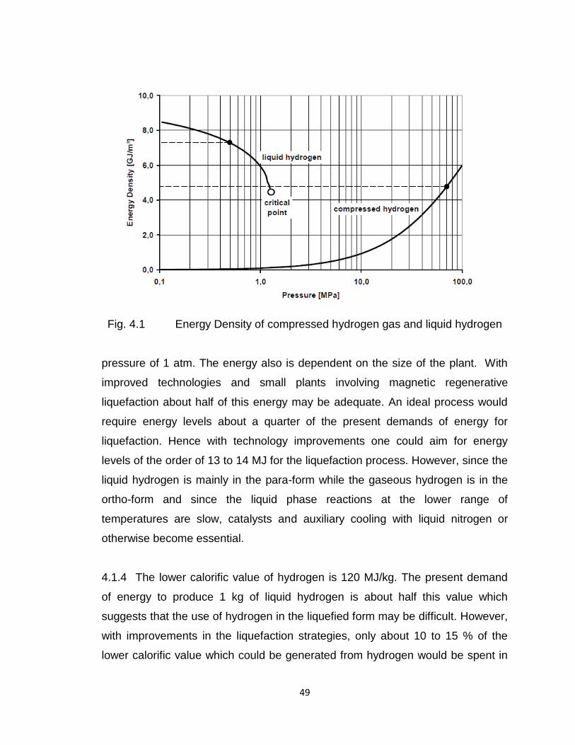
propulsion. Figure 4.1 taken from Krainz in “Automotive applications of hydrogen”
shows the higher energy density of liquid hydrogen as compared to high
pressure compressed hydrogen.
4.1.3 In order to liquefy hydrogen gas, it needs to be pre-cooled below its
maximum inversion temperature of 200K for the simple Linde Hampson or
Claude liquefaction process. Further, the temperature must be reduced below the
critical temperature of 33 K for the liquefaction. At 1 atmospheric pressure, the
temperature got to be reduced to about 20.2 K. The energy required to liquefy
1kg of hydrogen is about 47 MJ when the initial condition of the gas is 300 K at a
49
Fig. 4.1 Energy Density of compressed hydrogen gas and liquid hydrogen
pressure of 1 atm. The energy also is dependent on the size of the plant. With
improved technologies and small plants involving magnetic regenerative
liquefaction about half of this energy may be adequate. An ideal process would
require energy levels about a quarter of the present demands of energy for
liquefaction. Hence with technology improvements one could aim for energy
levels of the order of 13 to 14 MJ for the liquefaction process. However, since the
liquid hydrogen is mainly in the para-form while the gaseous hydrogen is in the
ortho-form and since the liquid phase reactions at the lower range of
temperatures are slow, catalysts and auxiliary cooling with liquid nitrogen or
otherwise become essential.
4.1.4 The lower calorific value of hydrogen is 120 MJ/kg. The present demand
of energy to produce 1 kg of liquid hydrogen is about half this value which
suggests that the use of hydrogen in the liquefied form may be difficult. However,
with improvements in the liquefaction strategies, only about 10 to 15 % of the
lower calorific value which could be generated from hydrogen would be spent in
50
the liquefaction process. On the other hand, the energy required in an ideal and
reversible isothermal compression, if hydrogen is stored as a high pressure gas
at 500 atm. is 7.8 MJ. With non-idealities in the compression process, efficiencies
of the compressors and cooling of the gases during the compression, the energy
required would be of the order of 10 MJ/kg. This is only marginally lower than the
energy requirements for the liquefaction.
4.1.6 In summary, the requirements of energy are about 10 to 20% of the lower
calorific value of hydrogen for bulk storage and transport hydrogen gas at high
pressures and for cryogenic liquid hydrogen. The other methods of storage such
as metal hydrides cannot cater to the large volume requirements involving
energy related applications.
4.1.7 The embrittlement problems associated with gas storage are present for
liquid storage also. As long as FCC materials of construction are used with good
insulation systems comprising double walled vacuum vessels, opacifiers and MLI
insulations which are developed, it is possible to store and transport hydrogen in
the liquid form.
4.2 Safety aspects of using hydrogen as a liquid
4.2.1 Since the flammability limits of hydrogen with air is very wide between 4%
and 75% of volume of hydrogen in the mixture, the chances of the mixture
catching fire is always a matter of concern. Further, at the stoichiometric
conditions, the energy required to ignite the mixture is extremely small at about
0.02 mJ which is less than can be produced by a stray electrostatic spark. In fact
the frictional energy dissipated by hydrogen gas flow over surfaces gives energy
of this magnitude. Hence well mixed hydrogen air mixture spontaneously catches
fire. However, the ease of ignition is a blessing in disguise since the hydrogen
burns away as soon as it encounters an electric spark. It does not accumulate as
51
does LPG and other hydrocarbon gases while waiting for a sufficiently larger
ignition source and this accumulated when ignited results in an explosion.
4.2.2 The diameter of hydrogen molecule is very small at 1.372x10⁻¹⁰ m and the
hydrogen is very susceptible to leak out of very small crevices. It also has a
higher value of diffusivity of about 1.13x10⁻³ m2/s. The high diffusivity prevents
the formation of a flammable mixture under different conditions of atmospheric
stability. This is also an advantage. Handling hydrogen gas in a confined
geometry is therefore not desirable since we do not allow it to escape. The
interaction with confinement often results in a detonation or an explosion.
4.2.3 Hydrogen gas if handled carefully is safer than most hydrocarbons. The
same applies for liquid hydrogen. The problems of low temperature burns,
asphyxiation, dense vapor generation and formation of flammable mixtures are
present. However, no major accident has been reported in its usage so far.
52
HYDROGEN STORAGE USING LIQUID
ORGANIC HYDRIDES
53
5.0 HYDROGEN STORAGE USING LIQUID ORGANIC
HYDRIDES
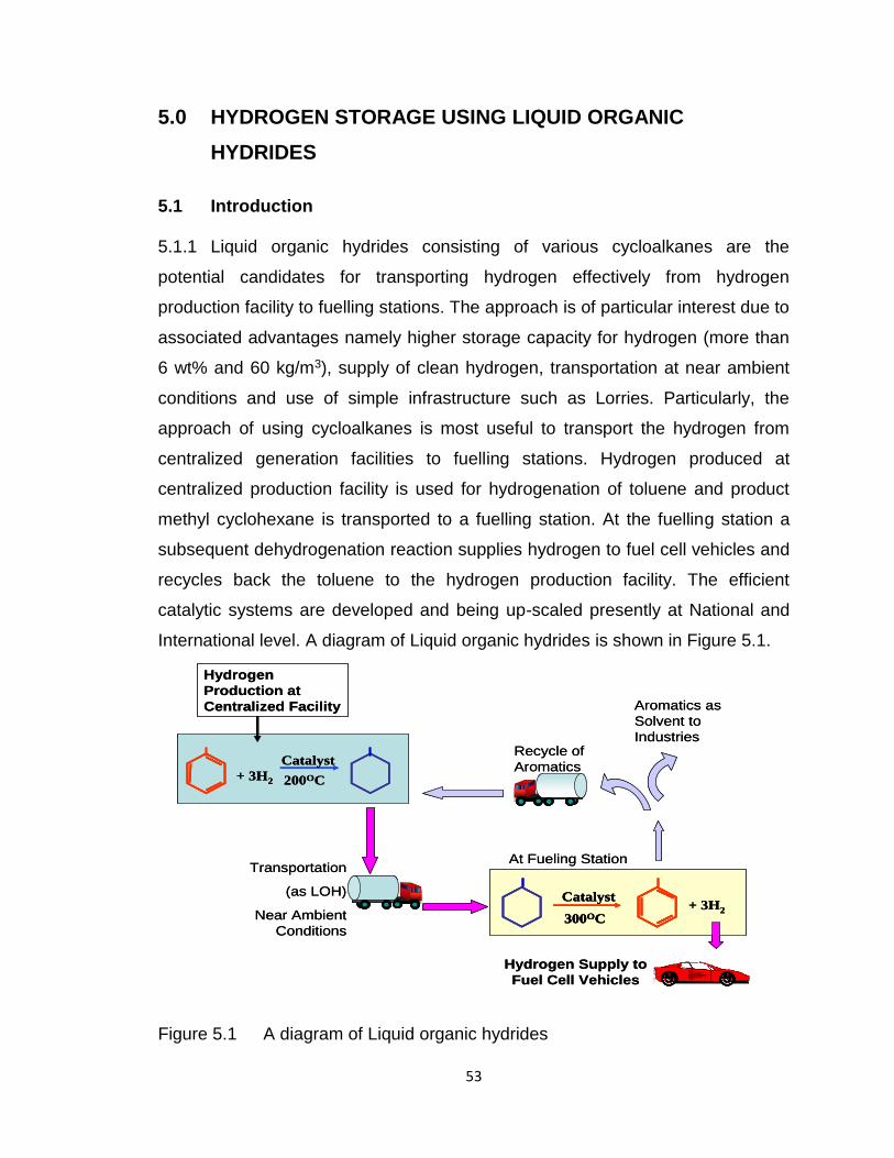
5.1 Introduction 5.1.1 Liquid organic hydrides consisting of various cycloalkanes are the
potential candidates for transporting hydrogen effectively from hydrogen
production facility to fuelling stations. The approach is of particular interest due to
associated advantages namely higher storage capacity for hydrogen (more than
6 wt% and 60 kg/m3), supply of clean hydrogen, transportation at near ambient
conditions and use of simple infrastructure such as Lorries. Particularly, the
approach of using cycloalkanes is most useful to transport the hydrogen from
centralized generation facilities to fuelling stations. Hydrogen produced at
centralized production facility is used for hydrogenation of toluene and product
methyl cyclohexane is transported to a fuelling station. At the fuelling station a
subsequent dehydrogenation reaction supplies hydrogen to fuel cell vehicles and
recycles back the toluene to the hydrogen production facility. The efficient
catalytic systems are developed and being up-scaled presently at National and
International level. A diagram of Liquid organic hydrides is shown in Figure 5.1.
Figure 5.1 A diagram of Liquid organic hydrides
Transportation
(as LOH)
Near Ambient
Conditions
Hydrogen
Production at
Centralized Facility
+ 3H2
Catalyst
200OC
Hydrogen Supply to
Fuel Cell Vehicles
+ 3H2
Catalyst
300OC
Recycle of
Aromatics
At Fueling Station
Aromatics as
Solvent to
Industries
Transportation
(as LOH)
Near Ambient
Conditions
Hydrogen
Production at
Centralized Facility
+ 3H2
Catalyst
200OC+ 3H2
Catalyst
200OC
Hydrogen Supply to
Fuel Cell Vehicles
+ 3H2
Catalyst
300OC+ 3H2
Catalyst
300OC
Catalyst
300OC
Recycle of
Aromatics
At Fueling Station
Aromatics as
Solvent to
Industries
54
5.2 International Status
5.2.1 On International level pioneering work on Liquid Organic Hydride (LOH)
was carried out in Japan at two different laboratories. In addition to Japan a
group in US EPA has worked on LOH. Subsequently several laboratories started
working on the various aspects of hydrogen storage and delivery using LOH. A
list of laboratories is given below:
• Catalysis Research Center, Hokkaido University, Sapporo, Japan
• Department of Industrial Chemistry, Faculty of Engineering, Tokyo
University of Science, Tokyo, Japan
• Department of Energy, USA and associate laboratories
• Chemical Engineering Department, Swiss Federal Institute of Technology,
Universitiitstr, Zurich, Switzerland
• Swiss Federal Laboratories for Materials Research and Testing,
Switzerland
• Department for General Energy Technology, Paul ScherrerInsitut,
Switzerland.
• Instituto de Carboquı´mica (C.S.I.C.), Miguel LuesmaCasta´n, Zaragoza,
Spain
• Petroleum Research and Studies Center, Kuwait Institute of Scientific
Research, Kuwait.
• Environmental Technology Centre, School of Chemical Engineering and
Analytical Science, The University of Manchester, UK.
• School of Chemical Engineering and Technology, Xian Jiaotong
University, China.
• Chemical and Environmental Systems Organization, GE Global Research,
NY, USA.
• Department of Chemistry, University of Rochester, NY, USA
5.2.1 Industrial Efforts
• R&D Centre, Chiyoda Corporation, Japan
55
• Sekisui Chemical Co., Ltd., Japan
• Exxon Research and Engineering Company, Annandale, USA
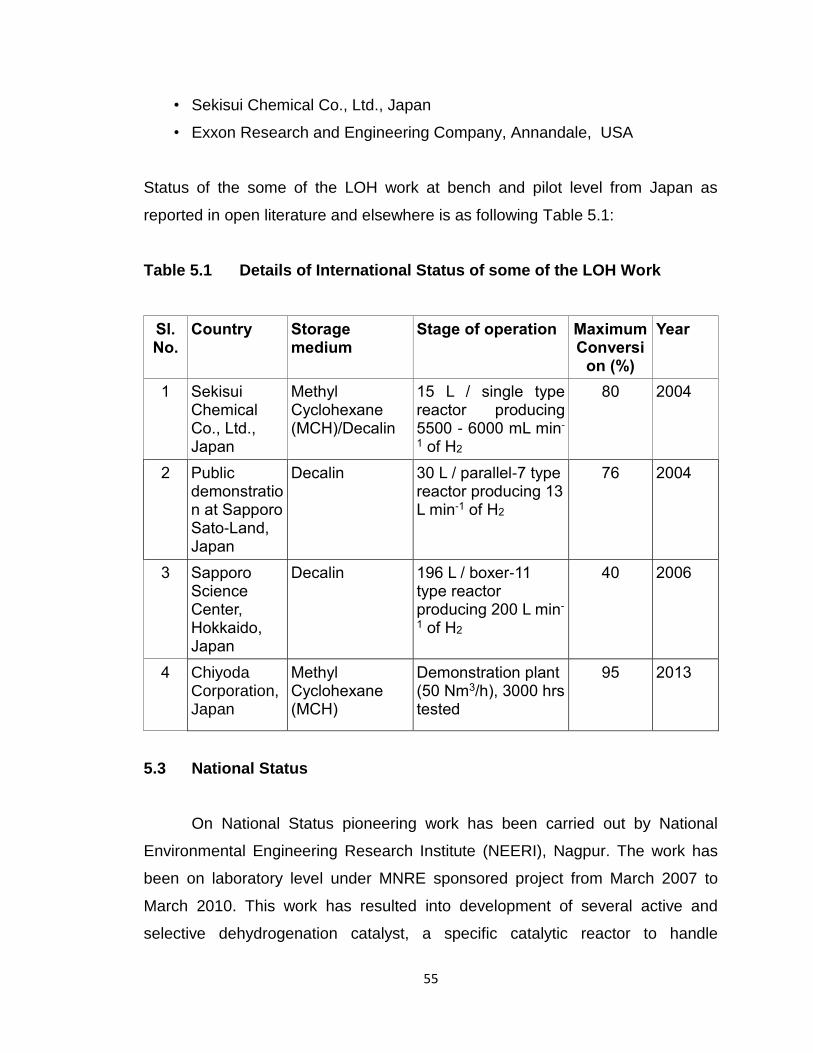
Status of the some of the LOH work at bench and pilot level from Japan as
reported in open literature and elsewhere is as following Table 5.1:
Table 5.1 Details of International Status of some of the LOH Work
Sl. No.
Country Storage medium
Stage of operation Maximum Conversi
on (%)
Year
1 Sekisui Chemical Co., Ltd., Japan
Methyl Cyclohexane (MCH)/Decalin
15 L / single type reactor producing 5500 - 6000 mL min-
1 of H2
80 2004
2 Public demonstration at Sapporo Sato-Land, Japan
Decalin 30 L / parallel-7 type reactor producing 13 L min-1 of H2
76 2004
3 Sapporo Science Center, Hokkaido, Japan
Decalin 196 L / boxer-11 type reactor producing 200 L min-
1 of H2
40 2006
4 Chiyoda Corporation, Japan
Methyl Cyclohexane (MCH)
Demonstration plant (50 Nm3/h), 3000 hrs tested
95 2013
5.3 National Status
On National Status pioneering work has been carried out by National
Environmental Engineering Research Institute (NEERI), Nagpur. The work has
been on laboratory level under MNRE sponsored project from March 2007 to
March 2010. This work has resulted into development of several active and
selective dehydrogenation catalyst, a specific catalytic reactor to handle
56
endothermic reactions and a complete process flow sheet. The salient results of
this work are catalytic system with 20NL/h flow of hydrogen with one step
catalytic efficiency of 98% conversion. The stability of the reaction was tested till
200 h. The national and international patents for the process has been filed.
Presently Cleaner Technology Centre, NEERI is working on development of a
pilot plant for hydrogen storage and delivery through LOH. The targeted scale of
the plant is 100Nm3/h of hydrogen delivery at usage point. The work is expected
to be completed by 2019.
5.4. Action Plan
In Indian context hydrogen production is possible at refineries and
recovery of hydrogen from chlor-alkali industries. Whereas the methods for
transportation of hydrogen to delivery points either for vehicle applications (fuel
stations) or to stationary applications required to be developed. Hydrogen
storage in LOH and transportation at near ambient conditions is a potential
method of hydrogen storage and delivery to long distance. Following action plan
may be considered;
Liquid organic hydrides and other liquid hydrocarbons are having high
hydrogen storage capacity (both gravimetric and volumetric). An intensive
research may be taken up by setting a Center of Excellence on Liquid
Hydrides with financial support from MNRE
Under proposed center of excellence, a few more laboratories and industries
working in the field of chemical process development may be networked
under lead of NEERI for rapid development of pilot plants. Petroleum industry
may be networked to support the pilot runs
R&D projects on further development of selective and stable catalysts may be
funded
International collaborative projects in mission mode with industrial
participation from both sides may be supported
57
A demonstration project is proposed to establish feasibility of the hydrogen
storage through Liquid Organic Hydrides by setting up the facilities near a
refinery and providing hydrogen to telecom towers in the range of 50 to 100
km. The project should demonstrate uninterrupted operation for at least one
year.
5.5 The National Environmental Engineering Research Institute, Nagpur has
received the financial supported from MNRE for the following projects on Liquid
Organic Hydrides:
a) Development of catalytic materials for storage and supply of clean
hydrogen liquid organic hydrides with Project Duration from March 2007 to
February, 2010 with Project Cost of Rs.29 lakhs
b) Development of Efficient Hydrogen Supply System through Liquid Organic
Hydrides with Project Duration from March 2014 to March 2019 and
Project Cost of Rs.535 lakhs.
58
HYDROGEN STORAGE IN SOLID STATE
59
6.0 HYDROGEN STORAGE IN SOLID STATE
6.1 Hydrogen storage is the stumbling block in harnessing hydrogen, be it the
use of Hydrogen in cold combustion in Fuel Cells or hot combustion in I.C.
Engine or Turbines.
Hydrogen is already produced to the tune of 50 Million Tonnes per year
worldwide by a variety of methods. This level of production can be easily
extended. Thus if storage issue is solved, it will mark the coming of Hydrogen in
market place. Therefore, vigorous R&D on storage aspects is being carried out.
Decades of research has revealed that the solid state storage in the form of
hydrides is the most efficient as well as safest storage mode. In view of this the
highest priority is in search of hydrides with requisite characteristics. Basic
parameters of hydrogen storage materials as decided by Dept. of Energy: DUE,
USA are given in Table 6.1.
Table 6.1 US : DOE Targets [revised 2009]
Target 2010 (new) 2010 (old) 2015 (new) 2015 (old)
System Gravimetric Density (% wt)
4.5 6 5.5 9
System Volumetric Density (g/L)
28 (0.9 kWh/L)
45 (1.5 kWh/L)
40 (1.3 kWh/L)
81 (2.7 kWh/L)
6.2 The early R&D efforts on hydrogen storage materials have been focused
on intermetallic hydrides typified by AB5 (LaNi5) AB2 (ZrV2), A2B(MgNi2) and
AB(FeTi). However even though volumetric storage capacity and reversibility for
these hydrides are excellent and meet the DOE limit, their gravimetric storage
capacity is at best upto about 2.0 wt% (highest being 2.4 wt%). Thus even
though R&D on Intermetallic Hydrides are still being carried out, the new
hydrides namely (a) elemental hydrides (b) complex hydrides & (c) altogether
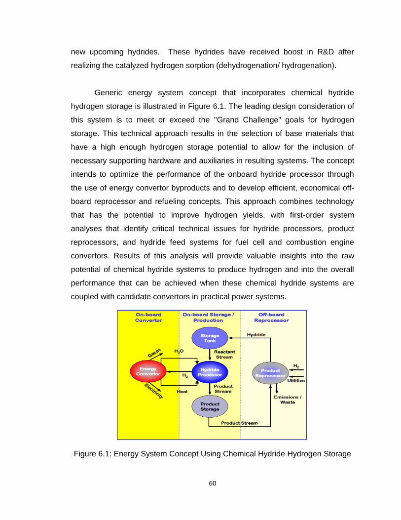
60
new upcoming hydrides. These hydrides have received boost in R&D after
realizing the catalyzed hydrogen sorption (dehydrogenation/ hydrogenation).
Generic energy system concept that incorporates chemical hydride
hydrogen storage is illustrated in Figure 6.1. The leading design consideration of
this system is to meet or exceed the "Grand Challenge" goals for hydrogen
storage. This technical approach results in the selection of base materials that
have a high enough hydrogen storage potential to allow for the inclusion of
necessary supporting hardware and auxiliaries in resulting systems. The concept
intends to optimize the performance of the onboard hydride processor through
the use of energy convertor byproducts and to develop efficient, economical off-
board reprocessor and refueling concepts. This approach combines technology
that has the potential to improve hydrogen yields, with first-order system
analyses that identify critical technical issues for hydride processors, product
reprocessors, and hydride feed systems for fuel cell and combustion engine
convertors. Results of this analysis will provide valuable insights into the raw
potential of chemical hydride systems to produce hydrogen and into the overall
performance that can be achieved when these chemical hydride systems are
coupled with candidate convertors in practical power systems.
Figure 6.1: Energy System Concept Using Chemical Hydride Hydrogen Storage
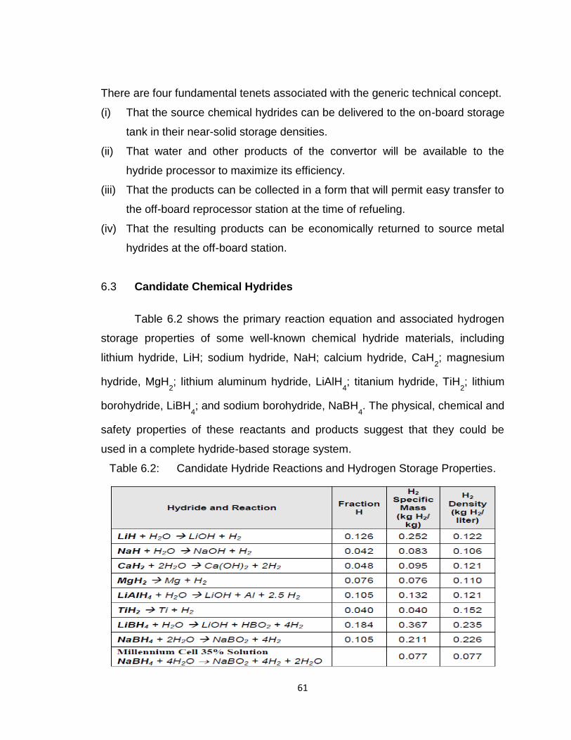
61
There are four fundamental tenets associated with the generic technical concept.
(i) That the source chemical hydrides can be delivered to the on-board storage
tank in their near-solid storage densities.
(ii) That water and other products of the convertor will be available to the
hydride processor to maximize its efficiency.
(iii) That the products can be collected in a form that will permit easy transfer to
the off-board reprocessor station at the time of refueling.
(iv) That the resulting products can be economically returned to source metal
hydrides at the off-board station.
6.3 Candidate Chemical Hydrides
Table 6.2 shows the primary reaction equation and associated hydrogen
storage properties of some well-known chemical hydride materials, including
lithium hydride, LiH; sodium hydride, NaH; calcium hydride, CaH2; magnesium
hydride, MgH2; lithium aluminum hydride, LiAlH
4; titanium hydride, TiH
2; lithium
borohydride, LiBH4; and sodium borohydride, NaBH
4. The physical, chemical and
safety properties of these reactants and products suggest that they could be
used in a complete hydride-based storage system.
Table 6.2: Candidate Hydride Reactions and Hydrogen Storage Properties.
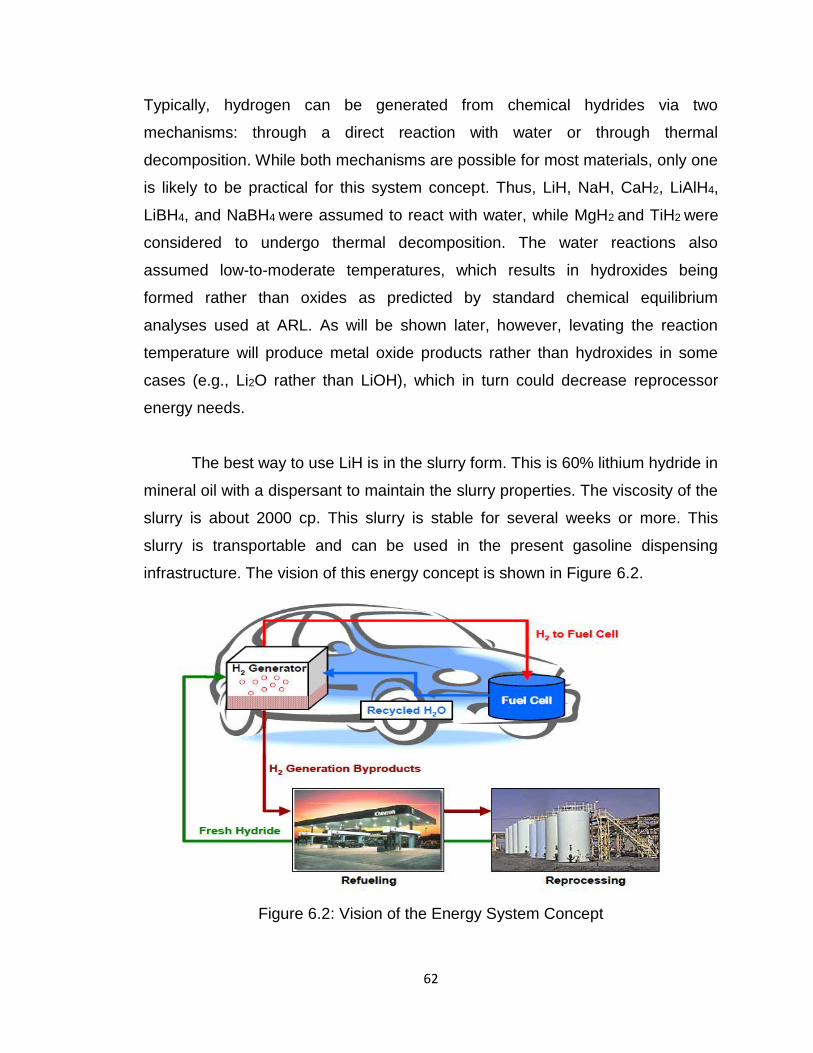
62
Typically, hydrogen can be generated from chemical hydrides via two
mechanisms: through a direct reaction with water or through thermal
decomposition. While both mechanisms are possible for most materials, only one
is likely to be practical for this system concept. Thus, LiH, NaH, CaH2, LiAlH4,
LiBH4, and NaBH4 were assumed to react with water, while MgH2
and TiH2
were
considered to undergo thermal decomposition. The water reactions also
assumed low-to-moderate temperatures, which results in hydroxides being
formed rather than oxides as predicted by standard chemical equilibrium
analyses used at ARL. As will be shown later, however, levating the reaction
temperature will produce metal oxide products rather than hydroxides in some
cases (e.g., Li2O rather than LiOH), which in turn could decrease reprocessor
energy needs.
The best way to use LiH is in the slurry form. This is 60% lithium hydride in
mineral oil with a dispersant to maintain the slurry properties. The viscosity of the
slurry is about 2000 cp. This slurry is stable for several weeks or more. This
slurry is transportable and can be used in the present gasoline dispensing
infrastructure. The vision of this energy concept is shown in Figure 6.2.
Figure 6.2: Vision of the Energy System Concept
63
6.4 The advantages of this energy system concept include:
o The potential to achieve high hydrogen storage density and attain
storage goals for 2015
o The ability of hydride processors to utilize products from an energy
convertor (for example, water and waste heat from a fuel cell) to
maintain high efficiency
o The use of hydride materials that are generally nontoxic and stable
until combined with water or thermally decomposed
o The ability to produce a low pressure, non-venting source of hydrogen
that can be regulated according to hydrogen demand
o The application of a system-level approach that attempts to integrate
all components associated with chemical hydride-based storage in
order to maximize efficiency
o The primary technical issues associated with its development include:
o Achieving high hydrogen yield from a compact hydride processor
o Developing efficient and cost competitive hydride reprocessing
technologies
o Developing effective and reliable methods of delivering hydride and
removing products
o Matching operational characteristics of the hydride reprocessor with
the energy convertor
o Developing compact, economical, reusable, and durable system
hardware
o Ensuring a high level of safety in both the operational system and the
refueling process
6.5 Elemental Hydrides (EH)
Out of the two elemental hydrides envisaged to be studied in the proposed
studies namely AlH3 and MgH2, we have at present stage focused on MgH2.
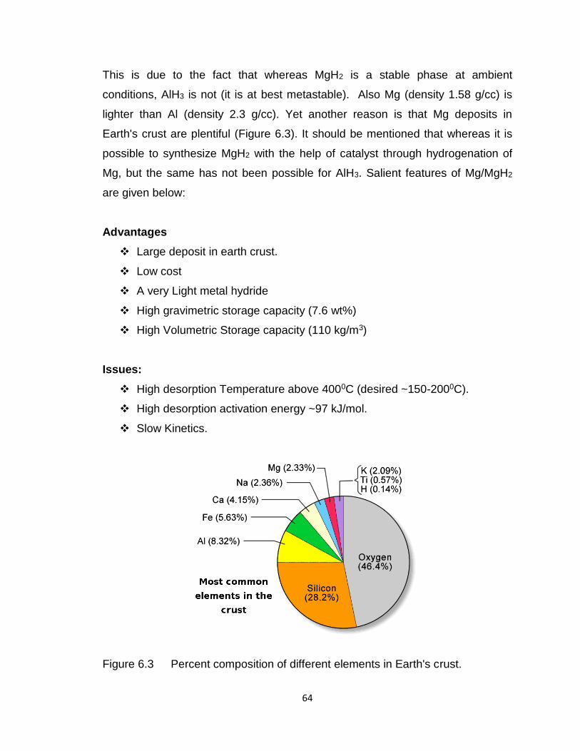
64
This is due to the fact that whereas MgH2 is a stable phase at ambient
conditions, AlH3 is not (it is at best metastable). Also Mg (density 1.58 g/cc) is
lighter than Al (density 2.3 g/cc). Yet another reason is that Mg deposits in
Earth's crust are plentiful (Figure 6.3). It should be mentioned that whereas it is
possible to synthesize MgH2 with the help of catalyst through hydrogenation of
Mg, but the same has not been possible for AlH3. Salient features of Mg/MgH2
are given below:
Advantages
Large deposit in earth crust.
Low cost
A very Light metal hydride
High gravimetric storage capacity (7.6 wt%)
High Volumetric Storage capacity (110 kg/m3)
Issues:
High desorption Temperature above 4000C (desired ~150-2000C).
High desorption activation energy ~97 kJ/mol.
Slow Kinetics.
Figure 6.3 Percent composition of different elements in Earth's crust.
65
6.6 Mg/MgH2 Storage System
MgH2 is considered to be one of the most favorable candidates due to its
high H2 storage capacity of 7.6 % by weight, availability, low-cost, reversibility
and non-toxicity. Owing to above said properties, Mg has attracted extensive
research in the last few decades. Since, magnesium (Mg) has a very strong
affinity to hydrogen and forms a very stable Mg-H bond due to which MgH2 has
two disadvantages. First is its very large decomposition enthalpy (~75 kJ mol-1
H2) which means that a very high temperature (~300-400oC) is required for
desorption and the second limitation is its slow de/rehydrogenation kinetics which
is not acceptable for on-board applications. To overcome these two limitations,
several efforts like alloying, nano-structuring, making composites, using metal
catalysts such as Zr, Ti, V, Mn, Co, Pd, Fe, Ni etc and oxide catalysts like,
MmO, Nb2O5, V2O3, Cr2O3, Mn2O3, Fe3O4 etc. have been employed. Out of all
the oxide catalysts, transition metals and their oxides shows excellent effects on
the hydrogen sorption, especially TiO2 which shows potential as a catalyst for
improving the hydrogen sorption properties of different H2 storage materials as it
can undergo reduction in hydrogen atmosphere and also has the same
tetragonal structure with the lattice parameter close to that of MgH2. It is found
that 5 wt. % of 50 nm TiO2 catalyst showed better catalytic effect in
rehydrogenation among 7, 25, 50, 100 and 250 nm sizes of TiO2 catalyst as a
catalyst with MgH2 system.
MgH2 (98% Alfa Aesar with lattice parameter of a= 4.517 Å & c=3.020 Å)
and 5 wt.% of 50 nm TiO2 rutile tetragonal phase (lattice parameter a= 4.593 Å,
and c=2.959 Å) were used as the starting material and were ball-milled using a
planetary ball-miller (Retsch. PM400). The ball to powder ratio of samples was
kept 30:1 by weight. The sample was ball-milled under 5 atm of H2-pressure at
an operating rotational speed of 170 rpm for 24 hrs in a stainless steel vial. This
resulted in the formation of MgH2 catalyzed through 5wt% of TiO2 i.e.
MgH2/(TiO2)(5wt%). For admixing the carbon nanostructures (CNS) namely,
66
SWCNT (MK Impex, Canada) was used as-received and graphene was
synthesized by thermal exfoliation method. Before using graphene-nano sheets
(GNS), residual gas analysis (RGA) treatment was performed at 150oC. 2 wt.% of
SWCNT and graphene (after RGA treatment) were admixed with MgH2/TiO2
sample in a locally fabricated admixer. Admixing of 2 wt% each of graphene and
SWCNT to MgH2/(TiO2)(5wt%) was done through the admixer.
Ball-milling MgH2 with 5 wt.% of TiO2 reduced the onset desorption temp.
of MgH2 to ~312oC but on admixing carbon nanostructures (SWNT & graphene)
in the sample, desorption temperature further gets reduced to ~295 & 280oC
respectively. In rehydrogenation study at 250oC under 30 atm, MgH2/TiO2(5wt%)/
GNS(2wt%) sample absorbed ~5 wt.% and MgH2/TiO2(5wt%)/ SWCNT(2wt%) absorbed
~4.4 wt.% of H2. In our findings, admixing of graphene shows more beneficial
effects in regards to kinetics as compared to the admixing of SWCNT in
MgH2/TiO2(5wt%). This enhancement in the sorption property is attributed to the co-
catalytic effect produced by both the catalysts i.e.TiO2 and graphene. This can be
explained by the fact that TiO2 undergoes reduction thereby enhancing its ability
as a catalyst, also the graphene provides better platform for homogeneous
distribution of reduced TiO2 np.
6.7 MgH2 catalyzed through a new catalyst: Leached Quasi Crystalline
alloy Al65Cu15Fe20
It is known that for making MgH2 a viable hydrogen storage material, new
catalyst is being searched interestingly. In an effort of this type, we have
developed an altogether new catalyst which has not been used so far by any
group. This new catalyst as will be shown in the following turns out to be the best
known so far for catalyzing MgH2. The quasicrystalline (QC) material was
discovered by Prof. Dan Shechtmanet.al. in 1984. The QC corresponds to a new
material phase which is neither crystalline nor amorphous. Its potential
application as a catalyst for reformation of methanol was first reported by
67
Nosakiet. al.in 1998. Since, quasicrystals (QCs) are stable, hard, brittle, high
specific surface area and several of them are stable up to high temperatures.
The thermally stable icosahedral phases Al-Cu-Fe leached with NaOH aquous
solution shows excellent activity for steam reforming of methanol (SRM).
Recently, the reason for the excellent performance of the QC as a catalyst is
credited to the formation of a homogenous leached layer generated by leaching
Al bearing QC materials. More recently, leaching has been carried out on the
surfaces of oriented single grain icosahedra Al-Cu-Fe, decagonal Al-Ni-Co and
polygrain Al-Pd-Re quasicrystalline materials.
To check the reversibility of the sample, cycling experiments were
performed on MgH2 catalyzed with LBACF received over 51 sorption cycles with
fairly minor kinetic degradation. It may be pointed out that the use of QC
Al65Cu2eFe15 as a catalyst for making hydrogen sorption amenable in MgH2 is a
new landmark research, not done earlier anywhere. Salient features are given
below:
Role of leaching AlCuFe
On leaching Al-Cu-fe alloy, Al atoms gets leached by chemical reaction
followed by dissolution leaving individually Cu & Fe atoms alone. Cu-Fe are
attached to Al-Cu-Fe base matrix so, it is expected that they will not agglomerate.
Temperature programmed desorption: In TPD profile, the onset
desorption temperature for MgH2 catalyzed with leached ball-milled Al-Cu-Fe QC
alloy gets lowered to ~210oC
Rehydrogenation: This system exhibits faster rehydrogenation kinetics by
absorbing ~6 wt. % of H2 in just 30 seconds under 20 atm H2 pressure at 250oC,
this research is a record for MgH2 and has been done for the first time for the
material MgH2.
68
It has shown better hydriding kinetics even at lower temperatures of 200oC &
150oC by absorbing ~ 5.5 wt. % within 1 minute and ~5 wt. % at 100oC in 30
minutes under the same condition of H2 pressure
Cyclic stability: The sample received over 51 sorption cycles with fairly minor
kinetic degradation. Further cycling experiments are going on to check the
reversibility upto 500 and 1000 cycles.
6.8 Effects of Ti-based catalysts and synergistic effect of SWCNTs-TiF3
on hydrogen uptake and release from MgH2
To improve the sorption behavior of Mg/MgH2, several catalysts have
already been used such as metal oxides, composite with intermetallic
compounds, transition metals and their compounds. Also the significant catalytic
effect of different carbon based nano structures has already been described by
the different research groups. Our earlier work on MgH2 also shows the beneficial
effect of different shaped carbon nanofibers on derehydrogenation characteristics
of nanocrystalline MgH2. Through the numerous studies, it is now well
understood that transition metals and their compounds are one of the most
effective catalysts for MgH2. Recently we have also investigated the co-catalytic
effect of the most effective transition metals Fe, Ti and Ni (for the case of MgH2)
on de/rehydrogenation characteristics of nanocrystalline MgH2. In the light of the
above, the aim of the study is to investigate the catalytic effect of Ti and Ti-based
compounds such as TiO2, TiCl3 and TiF3 on sorption behavior of MgH2. Out of all
the Ti additives, TiF3 is found to be most effect catalyst. Promising catalytic effect
of TiF3 in MgH2 was first observed by Ma et al. According to Ma et al., the main
problem of MgH2-TiF3 system is the decrease of hydrogen desorption capacity
with cycle. To address the problem of cycling, we have admixed SWCNTs as an
additive in MgH2-TiF3. The cyclability of the MgH2 catalyzed with TiF3 is improved
by the deployment of SWCNTs. The synergistic effect of SWCNTs and TiF3 have
described in details. The presence of SWCNTs in Mg/ MgH2 matrix reduces the
69
agglomeration of nano grains by providing support to nanoparticles and improves
the cyclability and kinetics of MgH2 catalyzed with TiF3.
6.9 Catalytic effect of carbon nanostructures on the hydrogen storage
properties of MgH2-NaAlH4 composite.
Among the solid-state storage mode of hydrogen, elemental hydride (like
MgH2) and alanate-based complex metal hydrides (like NaAlH4) are the
promising candidates as a hydrogen storage material. The promising elemental
hydride MgH2 desorbs hydrogen in a single step and releases 7.6 wt% (<410oC)
of hydrogen. MgH2 has already been studied by using various types of catalyst
including carbon nanostructures (CNS) (i.e. SWCNT, Multi wall carbon
nanotubes (MWCNT), planar graphitic nanofibre (PGNF), helical graphitic
nanofibre (HGNF) etc). Rodenaset. al. studied the beneficial effects of different
CNS on hydrogen desorption from MgH2. Amirkhiz et. al. and BHU have also
found that addition of CNS as catalyst in MgH2 improves the de/rehydrogenation
properties of MgH2. Key issues related with MgH2 like sluggish kinetics of H2
uptake and release, high de/rehydrogenation temperature & poor cyclability at an
appropriate temperature are still not completely solved.
Among light metal complex hydrides, NaAlH4 has been studied extensively for
practical application. NaAlH4 releases hydrogen through 3 sub steps having 7.2
wt.% (<500oC) out of which 5.5 wt% ( < 300oC) is considered to be useful for
practical application. Studies on NaAlH4 get picked up after the work of
Bogdanovicet. al which shows reversibility in NaAlH4 upon doping with Ti. After
this discovery of Bogdanovicet. Al., many research groups studied NaAlH4 using
different types of catalysts including metal, metal halide, metal oxide. NaAlH4 has
also been studied using carbon nanostructure (CNS). Selvanet. al. used carbon
nanotubes (CNTs), to lower the hydrogen desorption temperature of NaAlH4.
Hudson et.al. have also used various types of carbon nanostructures to improve
the de/rehydrogenation characteristics of NaAlH4. Theoretical and experimental
70
studies on NaAlH4 by Berseth et.al. also shows the beneficial effect of CNS on
de/rehydrogenation properties of NaAlH4. Recently, some other groups also
studied the promising effect of CNS on hydrogen sorption properties of NaAlH4.
Despite all these extensive efforts, the use of NaAlH4 is greatly hampered by
thermodynamic limitation and slow diffusion of hydrogen from NaAlH4.
In the light of the above, it will be opportune to study composite of MgH2-
NaAlH4 (optimized composition is 2:1 molar ratio of MgH2-NaAlH4).This
composite catalyzed through carbon nanostructures (which have various
microstructures are stable and light weight catalysts) has not been studied so far.
Therefore, the present investigation is focused on sorption (de/rehydrogenation)
studies of carbon nanostructures catalyzed MgH2-NaAlH4 composite.
Researchers at BHU have investigated the de/rehydrogenation behavior
of 2:1 molar ratio of MgH2-NaAlH4 composite, which offers beneficial hydrogen
storage properties as compared to pristine MgH2 and NaAlH4. Relating amount of
2wt% of CNS namely SWCNT and GNS have been used as catalyst to improve
the de/rehydrogenation properties of MgH2-NaAlH4. The GNS + SWCNT (1.5 +
0.5) wt.% is found to be most effective catalyst for de/rehydrogenation from
MgH2-NaAlH4. This can be attributed to co-catalytic effect of GNS and SWCNT in
2M-N 1.5 wt% GNS /0.5 wt.% SWCNT composite. SWCNT hinders the re-
stacking of GNS layer. This makes it more effective as micro-confinement agent.
The synergistic effect between GNS + SWCNT provides better thermal
conductivity and dispersive properties to GNS + SWCNT as compared to GNS &
SWCNT when used alone. This affirms that GNS + SWCNT is a better catalyst
as compared to GNS and SWCNT.
6.10 Effect of carbon nanofibres and titanium halide on hydrogen
sorption (dehydrogenation/rehydrogenation) properties of MgH2-
NaAlH4 composite.
71
The present study describes the synthesis of nano MgH2-NaAlH4 and its
hydrogen storage. It may be pointed out that in addition to carbon
nanostructures, halides of transition elements e.g. TiF3 has also been used for
catalyzing MgH2 and NaAlH4. Keeping this in view and also the fact that out of
various possible carbon nanostructures, BHU has already employed two of them
namely SWCNT and graphene nanosheets, Synergistic effect of catalyzing MgH2
with TiF3and carbon nanofibres (CNFs) has been investigated. Handling of
samples was performed in an argon filled glove box (mBRAM MB10 compact)
with H2O and O2 ≤ 1 ppm. The MgH2-NaAlH4 composite in which admixing of 2
wt.% PGNF was done will be labeled as 2M-N PGNF. Similarly, the other
composite will be labeled as 2M-N HGNF, 2M-N TiF3 and 2M-N TiF3 + HGNF.
2:1 molar mixture of MgH2 and NaAlH4 was ball milled and found to have
beneficial hydrogen sorption properties as compared to pristine MgH2 and
NaAlH4.Out of different CNS, HGNF shows better hydrogen sorption properties
due to more active carbon sites owing to its curved structure. Among CNS and
halide, TiF3 shows pronounced effect on Hydrogen sorption properties of TiF3 +
HGNF (due to well-known electronegative properties of fluoride). Synergistic
effects of TiF3 + HGNF is found to be beneficial for hydrogen sorption from 2M-N
as compared to TiF3 and HGNF catalyzed 2M-N alone.
6.11 Investigations on another complex hydride: corresponding to Li-Mg-
N-H system [Mg (NH2)2 + LiH]
In addition to MgH2 Alanates typified by NaAlH4 another complex built in
hydride is the system Li-Mg-N-H. It shows storage capacities between 5 and 6
wt%. One difficulty with this system is that the usual route for synthesis
corresponding to ball milling MgH2 and LiNH2 leads to only partial formation of the
desired phase Mg (NH2)2 /LiH. Unreacted amide/imide and some MgH2 gets left
behind even after prolonged ball milling, it has tried to use several transition
metal, compounds and alloys as catalyst for synthesis of pure phases. It has
been found that out of several catalysts studied, Zr Fe2 is the optimum one. It
72
does not get hydrogenated and dehydrided at temperatures and pressures used
for dehydrogenation/re-hydrogenation temperatures use for Mg bearing
amides/imides. The other advantage is that it is harder (hardness ~8mho) than
MgH2 (hardness ~4 mho) LiAlH2 (hardness ~6mho). This Zr Fe2 will have a
pulverizing effect and it will get ball milled in the form of a fine powder. It will,
therefore, get uniformly disturbed on Mg (NH2)2/LiH catalytic effect of Zr Fe2 will
be due to the transition nature of both Zr and Fe. We have been able to get pure
Mg(NH2)2 / LiH phases with hydrogen storage capacities of ~ 5 wt%. Further
R&D for making this complex hydride system is being made.
6.12 Work in Progress
(i) MgF2 catalyzed MgH2
(ii) Synthesis of Mg starting from magnesium
(iii) QC catalyzed NaAlH4
(iv) ZrFe2 catalyzed Magnesium amide
(v) Exploratory studies on other types of hydrides including intermetallic
hydrides
(vi) Studies of improving recyclability of elemental and complex hydride through
co-catalyzation and encapsulation of hydride.
As already stated, there are various ways of Hydrogen Storage. These are High
pressure gaseous storage, Storage as liquid hydrogen, Storage in intermetallic
hydrides, Storage in complex hydrides, Nanomaterial based hydride Metal
Organic Complexes, Clatherate H2-(H2O)2 and Hydrate H2-(CH4), Storage in
glass microspheres, Storage as liquid hydride (e.g. cyclohexane), Storage in
zeolites, Storage in aerogels, Storage in ammonia and amonium compounds,
Storage in depleted mines (underground storage). Nearly State of the Art
Storage Modes: (a) High Pressure Gaseous Storage (b) Liquid Hydrogen (c)
Metal / alloy based Hydrides.
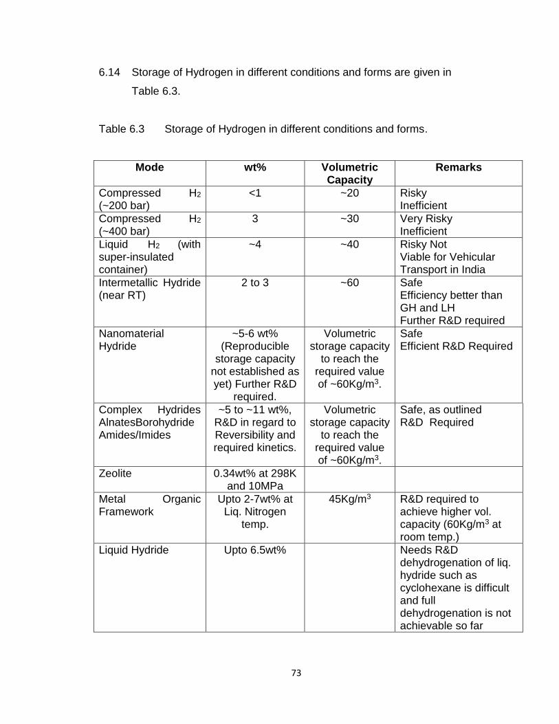
73
6.14 Storage of Hydrogen in different conditions and forms are given in
Table 6.3.
Table 6.3 Storage of Hydrogen in different conditions and forms.
Mode wt% Volumetric Capacity
Remarks
Compressed H2
(~200 bar) <1 ~20 Risky
Inefficient
Compressed H2
(~400 bar) 3 ~30 Very Risky
Inefficient
Liquid H2 (with super-insulated container)
~4 ~40 Risky Not Viable for Vehicular Transport in India
Intermetallic Hydride (near RT)
2 to 3 ~60 Safe Efficiency better than GH and LH Further R&D required
Nanomaterial Hydride
~5-6 wt% (Reproducible
storage capacity not established as yet) Further R&D
required.
Volumetric storage capacity
to reach the required value of ~60Kg/m3.
Safe Efficient R&D Required
Complex Hydrides AlnatesBorohydride Amides/Imides
~5 to ~11 wt%, R&D in regard to Reversibility and required kinetics.
Volumetric storage capacity
to reach the required value of ~60Kg/m3.
Safe, as outlined R&D Required
Zeolite
0.34wt% at 298K and 10MPa
Metal Organic Framework
Upto 2-7wt% at Liq. Nitrogen
temp.
45Kg/m3 R&D required to achieve higher vol. capacity (60Kg/m3 at room temp.)
Liquid Hydride Upto 6.5wt% Needs R&D dehydrogenation of liq. hydride such as cyclohexane is difficult and full dehydrogenation is not achievable so far
74
Presently unexplored and unknown storage modes e.g. (KSiH3)
Can reach from ~5 to ~9wt% R&D required
60 Kg/m3 Safe, R&D required
All the above methods have some disadvantages, but the most promising is solid
state route of hydrogen in the form of reversible hydrides appears to be hydrides.
Liquid hydrogen storage meets volumetric and gravimetric requirements, but ‘boil
off’ and refueling present safety hazards. In addition, liquefaction requires
significant energy. Storage as high-pressure gas will not meet volumetric density
requirements even at pressure of 650 bar; (at R.T. employing HPG storage mode
for storing 2 kg of hydrogen at atm. pressure, occupies a volume of ~45 meter
cubes ~a balloon of 3m diameter; this is apparently not a practical solution for a
hydrogen fueled vehicle where the volumetric storage capacity is crucial. Besides
significant energy is required for compression; and the high flammability of
hydrogen presents hazards in collisions. In Japan hydrogen cylinder with gas at
~400 atmospheres or higher is not allowed in road transport. However, for large
vehicles like buses, trucks hydrogen storage in the form of compressed gaseous
form may be viable both for IC Engine and Fuel Cell based transport.
6.15 International and National Efforts and Technology Gaps
International and National status of storage of hydrogen technology in
different conditions and forms and technology gaps are given in Table 6.4.
Table 6.4 International and National status of hydrogen storage technology in
different conditions and forms and Technology Gaps.
Aspects of Hydrogen
Energy
International Status
Indian Status
Gap Areas to be
Bridged
Magnesium and Magnesium
Leading groups: (a) C.M. Jenssen
(USA)
1. B.H.U. CNF catalyzed NaAlH4, LiAlH4, Mg (AlH4)2 at
The efforts are now focused on further lowering of desorption
75
Hydride MgH2
(b) Y. Kojima (Japan)
(c) L.L.aversenne (France)
(d) Luca Pasquini (Italy)
(desorption of 6.5 wt% at temperature ~ 3250C and absorption ~ 2000C)
2000C to 2500C absorption of 6 wt% at 3000C within 1 hour. Rajasthan university, Mg2Ni absorption / desorption of 3.5 wt%. TiF3, catalysed MgH2
temperature and improvement in cyclability of magnesium and magnesium based hydrides.
Amide-Hydride Mixture
(a) P. Chen (China) (b) Hui Wu (USA) (c) Ping Wang
(China) (d) El K. Stefanakos
(USA) (e) S Nayebossadri
(UK) (Desorption of 5
wt% at temperature 1400C)
2. BHU Mg-Li-N-H complex hydride.
The major limitations of Li-Mg-N-H system is poor rehydro-genation kinetics and liberation of ammonia with cycles. The acceptable amount of weight loss during cycling is 10% after 1000 cycle. For this case the weight loss with cycling is found to be 20%. Further R&D is required..
Alanates MAlH4 (M = Na, Li, Mg)
(a) Yuepeng Pang (China)
(b) B. Bagdanovic (Germany)
(c) A.C. Dillon (USA)
(Level : ~ 3.5 to 5.0 in catalyzed NAlH4 reproducible capacity at ~ 1500C
The potential of NaAlH4 as a kind of practical on-board hydrogen storage material is hindered owing to the high kinetic barriers of the dehydrogenation / hydrogenation reactions.
Hydrides Metal and alloy hydrides. Large R&D efforts in Japan, USA and several other countries. Some leading research groups are those of (i) Dr. E. Akiba (Japan), (ii) Dr. A. Zuttel (Switzerland), (iii) Dr. H. Itoh
BHU, IIT (M), ARC (Hyderabad), Jaipur University - ~ 2.4wt% by BHU in AB5, Mg based composite materials ~ 5 to 6 wt% hydride being developed at BHU. BHU is carrying out mission mode programme on ‘Hydrogen Storage in Hydrides (elemental,
The development of indigenous hydride synthesis technology is a must for hydrogen powered economy. Hydrides not only store hydrogen but also heat energy and can be used in a variety of applications e.g. hydrogen storage for vehicles and
76
(Japan) and (iv) Dr. R. Schulz (Canada). ~ 1.5 wt% to 2 wt% for ambient condition storage ~ 5 to 6 wt% for high temperature.
intermetallic, complex hydrides. Innovative results on Al65Cu20Fe15catalysed MgH2 have been obtained by BHU. Hydrogen absorption to the time of ~ 6 wt% is obtained within ~ 1 minute and desorption to 5.6wt% is obtained within ~ 30 minutes. These are record features. IIT (M) is carrying out a Mission Mode programme on hydrogen storage in various forms of carbon. NEERI (Nagpur) is carrying out work on liquid hydrides, NFTDC Hyderabad is doing work on ball milled and alloy catalyzed MgH2
power generating system, hydrogen compressors, hydrogen cookers, hydrogen based air-conditioners, Ni-MH battery etc. Low level support as compared to other countries including China and Japan for basic R&D in this area. R&D efforts to be strengthened and supported. Large scale hydride production
High pressure gaseous storage
Several companies e.g. Quantum (USA); Dynatejk Industries (Canada); Power Tec (Canada) are involved in development of high pressure (~ 350 to ~ 700 atmos) gaseous storage
No high pressure gaseous storage technology exists in the country (recently in 2004 HINDALCO has initiated a programme of making light weight Al cylinder)
High pressure gaseous storage efforts to be strengthened and supported. The development of indigenous high pressure gaseous storage technology is one of the essential ingredients for the success of hydrogen energy programme in India.
Liquid Hydrogen
Space Organizations like NASA (USA), AIREN (Europe)
Liquid H2 plant is installed near Trivendrum; No R&D efforts to test liquid H2 for vehicular transport or power generation have been made so far.
Efforts on development of Liquid Hydrogen Storage for vehicular transport to be developed by ISRO
77
Unusual routes
Efforts being made on several unusual routes such as storage in zeolite, glass microsphere, chemical hydrides, storage in depleted mines (underground storage) are being investigated
Hardly any efforts in these areas in India are being made
R&D efforts to be initiated and strengthened
Leading Groups: (a) C.M. Jenssen
(USA) (b) W. Schutz
(Germany) (c) B.
Bagdanovic (Germany)
(d) A.C. Dillon (USA)
(e) RTK Baker and N. Rodriguez
KSiH3
R&D in new materials to be strengthened and strongly supported since this route holds significant promise (solid state, storage modes and safest and also possess highest efficiency storage features) and at international level high priority R&D efforts are going on relating to hydrides, particularly complex and intermetallic and new hydrides.
Solid metal hydrides have been studied for many years, particularly for
understanding the process of metal embrittlement upon absorption of hydrogen
at interstitial sites. After surface adsorption, molecular hydrogen may dissociate
into atoms that form a solid solution of a hydride phase in the metal or alloy or
generate an intermetallic region. The uptake of hydrogen continues at nearly
constant pressure until the pure hydride phase is formed, which may have
volumetric densities of 150 kg H2 per m3 (Mg2NiH4).In favorable cases this
process is reversible and cycling can occur at desirable pressures (1–10 bar).
For materials with a significant capacity for hydrogen, however, desorption
usually occurs at a higher temperature than the targeted conditions. Improving
the uptake/release kinetics and retention of cycling capacity are currently the
78
major areas of materials research. The disadvantages of these compounds
include high cost, susceptibility to impurities, and low reversible gravimetric
capacity (typically less than 3 wt%). To circumvent some of these issues
chemical hydrides (also called complex or covalent hydrides) such as NaAlH4
have been studied and shown to reversibly cycle hydrogen on doping with a
catalyst. Other alanates and boro hydrides of Groups 1, 2, and 13 elements have
large gravimetric capacities (>7 wt%), but the extent to which their hydrogen
sorption is reversible requires continued investigation. Hydrolysis of alkali metals
and their hydrides is also a convenient route for hydrogen release, but requires
off-board recycling of the decomposition products. Most of these chemical
methods still require demonstration of both physical and economic viability.
Current barriers to practical storage schemes stem from the high pressure and
temperature conditions needed for hydride formation and hydrogen release. For
many potential systems hydriding and de hydriding kinetics and heat
management are also issues that need to be overcome. Another approach is to
adsorb molecular hydrogen on the surface of a solid storage material. Suggested
adsorbents include activated carbon, nano structured carbons (including CNTs),
MOFs, and hydrogen clathrate hydrate.
The storage methods presently under the most consideration are
physisorbents and chemical and metal hydrides. In addition to total storage
capacity, the kinetics and thermodynamics of release and recharging must be
considered. Undesirable kinetics and thermodynamics can not only limit the
release and recharging rate, but may also add unnecessary weight and volume
to the vehicle because of the need for extra heat exchangers—this leads to
consideration of the heat of formation of the hydrogen-carrying species or heat of
hydrogen adsorption of sorbents, ΔHf or ΔHads, when evaluating a potential
storage method. Chemisorption techniques, involving the formation of hydrides,
suffer from binding hydrogen too tightly, i.e., ΔHf too large—ranging from 50 to
over 200 kJ mol. For metal hydrides, such as LaNi5H6., the storage system must
operate above ambient temperature (often400 K) in order to release the
79
hydrogen fuel, while refueling liberates large amounts of energy. The
thermodynamics of chemical hydrides (such as LiNH2,LiBH4) are such that there
are questions regarding the reversibility of the hydrogen uptake and release,
while the chemical reaction which releases hydrogen only occurs at elevated
temperatures; additionally, the energy input to create the hydride reduces the
overall efficiency of the system. As a contrast, most physisorption techniques,
including carbon nanotubes and other porous materials (activated carbon,
zeolites, etc.), suffer from the opposite problem: ΔHads is typically small, less than
10 kJ/mol, and appreciable adsorption can only be achieved at very low
temperatures (typically,100 K).
Unfortunately, commercial hydrides such as FeTiH2 and LaNi5H6 suffer
from a low gravimetric efficiency, typically lower than 2wt%, while innovative
hydrides such as MgH2 and alanates present slow absorption and desorption
kinetics also at high temperatures. The need for a material able to overcome
these limits at practical operative conditions of pressure (1– 10 atm) and
temperature (30–100◦C) has stimulated the interest of many research
laboratories. An important step in the experimental research is the analysis of the
H2 storage efficiency of the new materials and the study of their absorption and
desorption kinetics. In favorable cases this process is reversible and cycling can
occur at desirable pressures (1–10 bar). For materials with a significant capacity
for hydrogen, however, desorption usually occurs at a higher temperature than
the targeted conditions. Improving the uptake/release kinetics and retention of
cycling capacity are currently the major areas of materials research. The
disadvantages of these compounds include high cost, susceptibility to impurities,
and low reversible gravimetric capacity (typically less than 3 wt%). To circumvent
some of these issues chemical hydrides (also called complex or covalent
hydrides) such as NaAlH4 have been studied and shown to reversibly cycle
hydrogen on doping with a catalyst.
80
The Department of Atomic Energy has set a number of short-term goals
against DOE targets for on-board hydrogen storage systems: 6.0 wt% and 45 g
L-1 by the year 2015, but current materials fall far short of this goal. These goals
should be met at near-ambient temperatures and applicable pressures (less than
100 bar), and any storage technology must minimize weight and volume
contributions to the potential fuel-cell powered vehicle.
6.16 Hydrogen Storage as chemical and metal hydrides and in Metal-
Organic Frameworks
Metal hydrides have been considered as potential candidates for
reversible on-board hydrogen storage and release at low temperatures and
pressures. Complex metal hydrides such as NaAlH4 have the potential for higher
gravimetric hydrogen storage capacities in the operational window.
NaAlH4 = 1/3 Na3AlH6 + 2/3 Al+H2
Na3AlH6 = 3 NaH + Al + 3/2 H2
But the main limitations of NaAlH4 are due to its slow uptake/release
kinetics and high hydrogen desorption temperature. The development of
enhanced hydrogen sorption by Ti-doped alanates opened up an entirely new
prospect for lightweight hydrogen storage. These materials have nearly ideal
equilibrium thermodynamics, high capacities, and moderate kinetics. However,
while the hydrogen capacity is 2 to 3 times better than commercial low-
temperature hydrides, it does not meet the DOE storage capacity targets. Thus,
other higher capacity reversible complex hydrides must be developed. At the
same time, Na alanates continue to provide a good working model to better
understand reversible hydrogen sorption in complex hydrides. Sandia's direct
synthesis process and new Ti-doping methods have led to a dramatic
improvement in the reversible hydrogen capacity and hydrogen absorption and
desorption rates. These methods will be employed to seek out advanced
81
complex hydrides with larger hydrogen storage capacities and better
performance.
Neat NaAlH4 desorbs 70% of its H2 at T ≈ 250 °C, this higher value of
desorption temperature has been reduced by incorporating it into a MOF
material. Allendorf and coworkers have infused the MOF, HKUST-1,
(Cu3(BTC)2)n with 4 wt% NaAlH4 and due to the uniform particle size (formed in
the rigid framework) and favorable chemical environment the sample was able to
desorb 80% of the total H2 at 155°C.These reports are promising for developing
new systems utilizing MOFs combined with metal hydrides for reversible storage
of hydrogen for on-board applications. Besides complex hydrides, amino-
borane (NH3BH3) has received much attention as promising hydrogen-storage
material because of its satisfactory air stability, relatively low molecular mass
(30.7 gmol-1), and remarkably high energy-storage densities (gravimetric and
volumetric hydrogen capacities are 19.6wt% and 140 gL-1, respectively).
However, the direct use of pristine NH3BH3 as a hydrogen energy carrier in
onboard/fuel-cell applications is prevented by its very slow dehydrogenation
kinetics below 100 °C and concurrent release of volatile by-products such as
ammonia, borazine, and diborane. Towards increasing the dehydrogenation
kinetics by reducing the high temperatures required, amino-borane has been
incorporated into porous MOF and its dehydrogenation behavior has been
studied. Interestingly, NH3BH3 incorporated within the MOF-74(Mg) has showed
clean and dramatically improved H2 release properties compared to pristine
NH3BH3. This is a promising result for future development of hydrogen storage
materials.
6.17 Metal Hydrides for reversible Hydrogen Storage Devices as DAE
targets.
The purpose of this project is to focus on complex metal hydrides with
high reversible hydrogen storage capacities and novel approaches to on-board
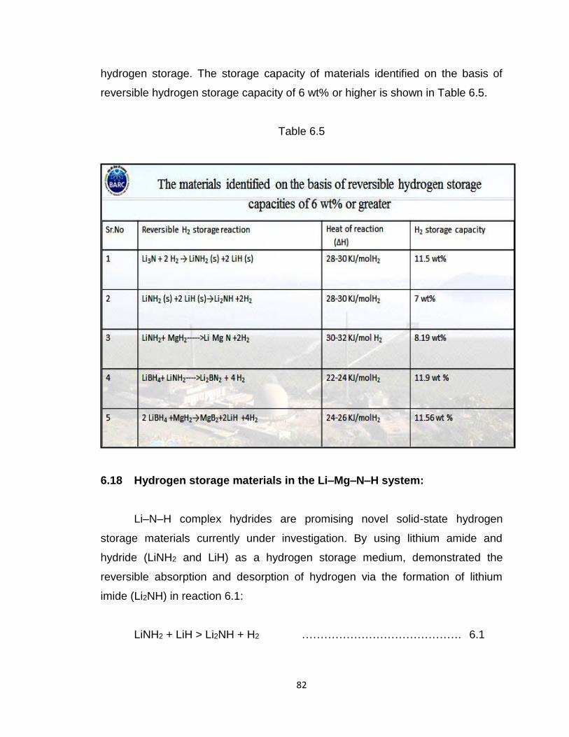
82
hydrogen storage. The storage capacity of materials identified on the basis of
reversible hydrogen storage capacity of 6 wt% or higher is shown in Table 6.5.
Table 6.5
6.18 Hydrogen storage materials in the Li–Mg–N–H system:
Li–N–H complex hydrides are promising novel solid-state hydrogen
storage materials currently under investigation. By using lithium amide and
hydride (LiNH2 and LiH) as a hydrogen storage medium, demonstrated the
reversible absorption and desorption of hydrogen via the formation of lithium
imide (Li2NH) in reaction 6.1:
LiNH2 + LiH > Li2NH + H2 ……………………………………. 6.1
83
This reaction has a theoretical gravimetric density of 6.5 wt.%. The measured
enthalpy of reaction (ΔH) is 66 kJ/mol H2, a value that is too high for near-
ambient reactions and translates to undesirable operating conditions involving
high-temperatures (and/or low-pressures).
Therefore, more efforts have focused on overcoming the thermodynamic
and kinetic barriers associated with the LiNH2/LiH system. The hydrogen
desorption temperature lowered by the substitution of LiH with MgH2 in Eq. (1).
Specifically, this substitution results in an effective decrease in the hydrogen
desorption temperature from 280 °C (Li–N–H) to180 °C (Mg–Li–N–H)
extrapolated to 1 bar hydrogen atmosphere via the reaction 6.2:
2LiNH2 + MgH2 ↔Li2Mg(NH)2 + 2H2
(6.2)
which contains a theoretical 5.5 wt.% H2. The intermediate phases Mg(NH2)2 and
LiH are formed upon heating ball milled starting materials under a hydrogen
atmosphere. In practice excess of MgH2 is also incorporated into the storage
mixture to circumvent the formation of ammonia arising from decomposition of
LiNH2. Importantly, based on the measured plateau pressures of reaction at
various temperatures, the corresponding van’t Hoff plot reveals that the enthalpy
of this reaction (39 kJ/mol H2) now approaches a thermodynamic value that is
suitable for on-board hydrogen vehicle applications. The Molten State Process,
Figure 6.4: Reversible storage capacity in wt% of different metal hydrides
against DOE targets.
MSP, was used to develop new hybrid amide compounds by combining or
“alloying” together different complex hydrides compounds.
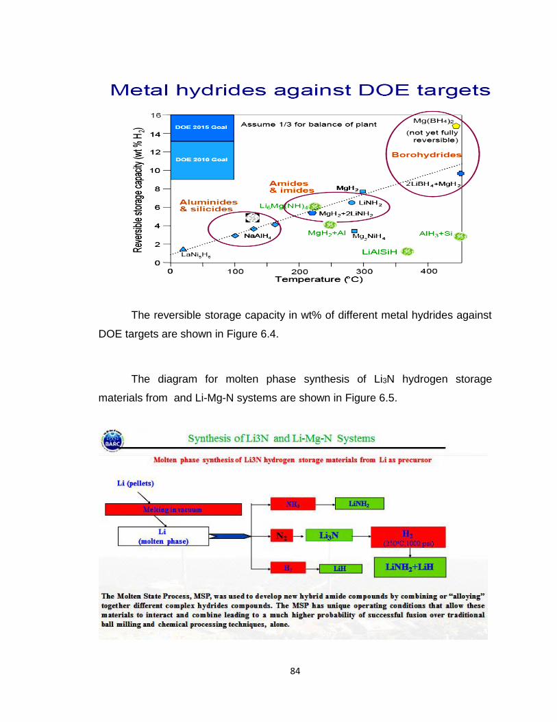
84
The reversible storage capacity in wt% of different metal hydrides against
DOE targets are shown in Figure 6.4.
The diagram for molten phase synthesis of Li3N hydrogen storage
materials from and Li-Mg-N systems are shown in Figure 6.5.
85
Figure 6.5
The PCI measurements were performed and used to evaluate and confirm the
ΔH as 41.6 kJ/mol H2 for the reversible hydrogen storage reaction. Although the
hydrogen release temperature is projected to be 90 °C to 1 bar, measurements
reveal that the reaction is kinetically limited, and is quite slow at 180 °C,
absorbing < 2 wt. % in 8 h at 110 bars. Additional work is required to develop and
incorporate an effective catalyst to overcome the current kinetic barriers and
further decrease the hydriding / dehydriding reaction temperatures to their
thermodynamically predicted values. Experimental realization of such theoretical
values would increase the practical feasibility of the Li–Mg–N–H system for on-
board storage applications.
6.19 Thermodynamics:
The reaction enthalpy (ΔH) and entropy (ΔS) for reaction were
characterized by measuring the PCI at 210, 220, 230, and 240 °C. The
corresponding van’t Hoff plot derived from the desorption PCI measurements.
Here, the observed ΔH is calculated to be 41.6 kJ/mol H2, a value that is
consistent with the other reported by Luo (39 kJ/mol H2).
6.20 Kinetics:
It is additionally assessed the hydrogen absorption kinetics for this storage
system at 180 and 220 °C in a hydrogen atmosphere of 110 bar. From these
data, it can be seen that the hydriding process is complete after 4.5 h at 220 °C,
with a corresponding 4.3 wt.% hydrogen uptake. However, the absorption
process is considerably slower at 180 °C, absorbing < 2 wt.% in 8 h. According to
measured thermodynamic values of ΔH and ΔS, the LiH and Mg(NH2)2 mixture
has an expected theoretical hydrogen desorption temperature of approximately
90 °C to 1 bar pressure, conditions that approach those that would be practical
for on-board storage applications. However, although the thermodynamics of this
86
reaction appears to be promising, it is clear from the data that this reaction is
kinetically hindered. Current experiments indicate that a much higher
temperature is required to provide the necessary activation energy for the
reversible reaction between Li2Mg(NH)2, Mg(NH2)2 and LiH to occur.
6.21 Metal organic frameworks (MOFs):
These are presently under substantial investigation due to their attractive
properties as a new class of porous materials suitable for broad range of
industrial applications such as gas storage [hydrogen storage], liquid absorption,
liquid or gas separation, catalysis, etc. Hydrogen storage in solids which involve
the use of high surface area sorbents are required to be studied for identifying
compact, safe, cost effective storage medium for hydrogen. The MOFs with the
combination of metal clusters and organic linkers offer great flexibility in the
unique structure design and porosity. Those 3D networks often contain
accessible pores and therefore they are ideal candidates for gas sorption. The
currentresearch efforts will mainly focus on the fallowing issues for high wt%
storage of hydrogen at ambient conditions (a) to develop porous MOF materials
with narrow pore sizes based on light metal ions, such as, Be, Mg, Al, etc. (b) to
enhance the heat of adsorption b/n H2 and the material by utilizing kubas-type
interactions. (c) to investigate the incorporation of metal hydrides, complex
hydrides into porous MOFs and study their H2 desorption kinetics, and also
notably, to a process for preparing it.
The synthesized metal–organic frameworks should be investigated for
Hydrogen adsorption by molecular simulation. The simulated and experimental
adsorption isotherms of pure H2 are needed to be compared. The simulation
study will provide quantitative microscopic insight into the adsorption mechanism
in MOFs. Novel chemistry approaches should be adopted for predicting crystal
structures and Non-Stoichiometry, crystal binding energies and decomposition
path ways to synthesize compounds for more easily reversible addition of gases.
87
Modeling, and simulation should be used to enhance our understanding of known
systems and enable the design of new hydrogen storage materials and of
catalysts to effect easy release and addition of H2 and also to obtain
thermodynamic and kinetic information to develop new methods and materials in
hydrogen storage. The selectivity of gases (isotopes) in MOFs increases with
increasing pressure and finally reaches a constant at certain pressure. Hence
pressure effect on interactions between above gases and the framework also
need to be investigated. In comparison to chemical storage (chemisorption) of
H2, physio-sorption in highly porous materials such as, Zeolites, Carbon materials
and porous coordination polymers or metal-organic frameworks (MOFs) has
attracted much attention due to the advantageous of non-activation, fast kinetics
and reversibility of hydrogen storage and release. Among the porous materials,
MOFs or porous coordination polymers have gained much attention due to their
ultra-high surface areas for high wt% H2 storage applications. MOFs are
crystalline solids with infinite network structures obtained by connecting the metal
ions (nodes) or clusters (SBU) with multifunctional organic spacers (linkers).The
main advantageous of MOFs over other traditional porous materials such as
zeolites is that the pore size, dimensionality, and functionality can be tuned by a
judicial choice of organic linkers. The use of rational design approach from
suitable building blocks has resulted MOF materials with unique properties for a
wide range of potential applications including catalysis, gas storage, nonlinear
optics, and sensing. The distinct features of MOFs are (a) Highly ordered
crystalline nature (b) Tunable morphology with suitable functionality (c) Structural
diversity (d) Flexible framework (e) Thermal stability, etc. Another interesting
feature of MOFs is the gated adsorption which depends on the flexibility of the
framework; that is, on hydrogen adsorption the framework structure expands and
shrinks upon desorption. This property can be used to load hydrogen at high
pressures and release at lower pressures. Although some MOFs store large
amounts of hydrogen (6-9.05 wt%) at low temperatures (77 K) but at room
temperature the hydrogen storage capacities reduce to 1 wt% or less. Hence,
there is an urgent need for efficient and cost-effective materials with high
88
hydrogen storage capacities at ambient conditions for realizing hydrogen
economy.
6.22 Theoretical studies to understand the experimental results and for
better design of storage material
It is very essential to understand the factors responsible for high storage
capacity of H2 with any materials. Understanding the nature of interaction
between material and the gases is crucial for improving the interaction energy
(heat of adsorption of H2) with the matrix. Hence, theoretical simulations shall be
carried out to understand the observed H2 storage capacities of the materials
synthesized and for further improvement in the design. First principles
calculations can predict thermodynamic properties. For known system, periodic
DFT will be used while for new system exhibiting weak van der Waal’s
interactions, quantum molecular cluster methods and Monte Carlo methods will
be used.
Solid metal hydrides are a promising class of materials for hydrogen
storage. They have attracted a lot of interest in recent years. However, many
questions remain concerning their thermodynamic behavior that is critical for
further improvement of their performance. In BARC we have recently developed
theoretical and computational capabilities to perform first-principles calculations
of thermodynamic properties of solid metal hydrides. Most energetic calculations
reported in the literature are performed at absolute zero temperature (i.e., 0 K).
However, practical mobile applications of such materials will inevitably involve
finite (even quite high) temperature and pressure. It is therefore critical that the
thermodynamic behavior of hydrogen storage materials be examined and
understood. Also completed an extensive computational study of the
thermodynamic properties of lithium amides. The obtained thermodynamic
functions are in excellent agreement with available experimental data. The full
set of calculated thermodynamic functions provides a reliable basis for the
89
construction of the pressure-temperature phase diagram of these materials. It
allows the examination of the hydrogen adsorption and desorption processes
under realistic operating conditions in anticipated applications. We have
implemented such calculations and examined the stability and reversibility of
hydrogen storage in several lithium amides and identified the phase boundaries
for reversible hydrogen storage.
6.23 Challenge in designing Hydrogen Storage Systems
The main challenge in all hydrogen storage systems design is to meet
three basic requirements, high safety, high efficiency and cost effectiveness at
the same time. a) The weight and volume of hydrogen storage systems are
presently too high, resulting in inadequate vehicle range compared to
conventional petroleum-fueled vehicles. Materials and components are needed
that allow compact, lightweight hydrogen storage systems while enabling greater
than 300-mile range in all light-duty vehicle. b) Energy efficiency is a challenge
for all hydrogen storage approaches. The energy required to get hydrogen in and
out is an issue for reversible solid-state materials. The energy associated with
compression and liquefaction must be considered for compressed and liquid
hydrogen technologies. c) Durability of hydrogen storage systems is inadequate.
Materials and components are needed that allow hydrogen storage systems with
a lifetime of 1500 cycles. d) Refueling times are too long. There is a need to
develop hydrogen storage systems with refueling times of less than three
minutes, over the lifetime of the system. e) The cost of on-board hydrogen
storage systems is too high, particularly in comparison with conventional storage
systems for petroleum fuels. Low-cost materials and components for hydrogen
storage systems are needed, as well as low-cost, high-volume manufacturing
methods. f) Applicable codes and standards for hydrogen storage systems and
interface technologies, which will facilitate implementation/ commercialization
and assure safety and public acceptance, have not been established.
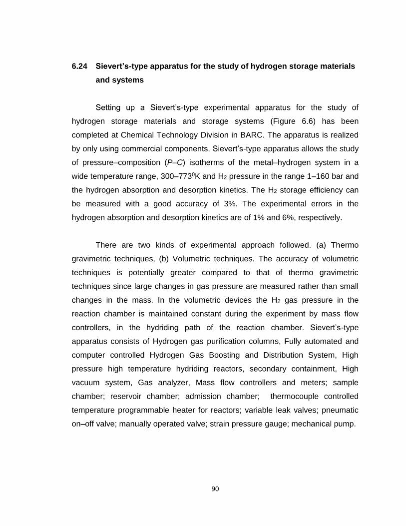
90
6.24 Sievert’s-type apparatus for the study of hydrogen storage materials
and systems
Setting up a Sievert’s-type experimental apparatus for the study of
hydrogen storage materials and storage systems (Figure 6.6) has been
completed at Chemical Technology Division in BARC. The apparatus is realized
by only using commercial components. Sievert’s-type apparatus allows the study
of pressure–composition (P–C) isotherms of the metal–hydrogen system in a
wide temperature range, 300–7730K and H2 pressure in the range 1–160 bar and
the hydrogen absorption and desorption kinetics. The H2 storage efficiency can
be measured with a good accuracy of 3%. The experimental errors in the
hydrogen absorption and desorption kinetics are of 1% and 6%, respectively.
There are two kinds of experimental approach followed. (a) Thermo
gravimetric techniques, (b) Volumetric techniques. The accuracy of volumetric
techniques is potentially greater compared to that of thermo gravimetric
techniques since large changes in gas pressure are measured rather than small
changes in the mass. In the volumetric devices the H2 gas pressure in the
reaction chamber is maintained constant during the experiment by mass flow
controllers, in the hydriding path of the reaction chamber. Sievert’s-type
apparatus consists of Hydrogen gas purification columns, Fully automated and
computer controlled Hydrogen Gas Boosting and Distribution System, High
pressure high temperature hydriding reactors, secondary containment, High
vacuum system, Gas analyzer, Mass flow controllers and meters; sample
chamber; reservoir chamber; admission chamber; thermocouple controlled
temperature programmable heater for reactors; variable leak valves; pneumatic
on–off valve; manually operated valve; strain pressure gauge; mechanical pump.
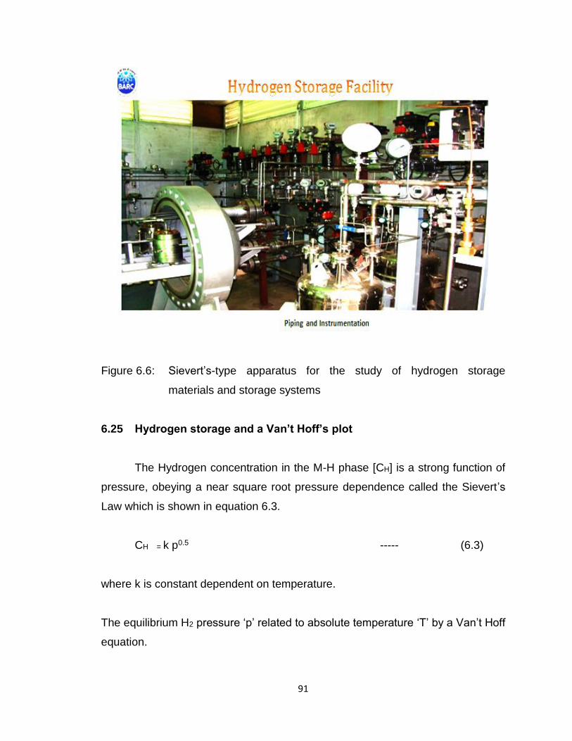
91
Figure 6.6: Sievert’s-type apparatus for the study of hydrogen storage
materials and storage systems
6.25 Hydrogen storage and a Van’t Hoff’s plot
The Hydrogen concentration in the M-H phase [CH] is a strong function of
pressure, obeying a near square root pressure dependence called the Sievert’s
Law which is shown in equation 6.3.
CH = k p0.5 ----- (6.3)
where k is constant dependent on temperature.
The equilibrium H2 pressure ‘p’ related to absolute temperature ‘T’ by a Van’t Hoff
equation.
92
Van’t Hoff equation relates the plateau hydrogen pressure P eq(bar) to absolute
temperature T, of the hydride, enthalpy change ∆H, Entropy change ∆S , and
universal gas constant Ru.
The equilibrium H2 pressure ‘p’ related to absolute temperature ‘T’ by a
Van’t Hoff equation which is shown in equation 6.3.
Ln p = ΔH/RT-ΔS/R -------- (6.4); where R is the gas constant.
A plot of lnpVs 1/T [a Van’t Hoff’s plot] ,will be straight line. The slope of which
gives ΔH and intercept [1/T =0] gives the value of ΔS .The value of ΔH can vary
widely from metal to metal and is a measure of strength of the M-H bond. This
will control hydriding and dehydriding properties of materials.
6.26 Hydrogen safety
Hydrogen has one of the widest explosive/ignition mix range with air of all
the gases with few exceptions such as acetylene, silane, and ethylene oxide.
That means that whatever the mix proportion between air and hydrogen, a
hydrogen leak will most likely lead to an explosion, not a mere flame, when a
flame or spark ignites the mixture. This makes the use of hydrogen particularly
dangerous in enclosed areas such as tunnels or underground parking. Pure
hydrogen-oxygen flames burn in the ultraviolet color range and are nearly
invisible to the naked eye, so a flame detector is needed to detect if a hydrogen
leak is burning. Hydrogen is odorless and leaks cannot be detected by smell.
Hydrogen codes and standards are codes and standards for the safe
handling and storage of hydrogen. Codes and standards have repeatedly been
identified as a major institutional control in deploying hydrogen technologies and
developing a hydrogen economy. To enable the commercialization of hydrogen
93
in consumer products, new model building codes, equipment and other technical
standards are to be developed and recognized by governments.
One of the measures on the roadmap is to implement higher safety
standards like early leak detection with hydrogen sensors. Hydrogen safety
issues are addressed in the Design and assembly of equipment, the integrity of
the primary container of Hydrogen is ensured for all normal operations,
anticipated operational occurrences, and withstand for the design basis
accidents. Hydrogen leak prevention, detection, containment/exhaust.
6.27 Solid State Hydrogen in Metallic and Metallic + Carbon composite
materials
Solid state storage of Hydrogen has been attempted by exploiting the
mechanism of physisorption, chemisorption (metastable proton + materials) of
hydrogen and inorganic compound formation such as alanates, clathrates and
metallic hydrides. The four important vectors of R & D have been on (i)
phenomena and mechanism; (ii) materials and performance (iii) design and
engineering of devices and (iv) energy economics, viz., energy cost of
hydrogenation plus dehydrogenation vs hydrogen caloric value realizable from a
material. This corresponds to the walking the technology readiness levels (TRL-
1 to 7). The status of various options and realization can be mapped to the
technology readiness levels.
6.28 Physi-sorption Phenomena and Carbon Based Materials:
Physio-sorption of hydrogen relies more on pressure and limited charge
transfer between hydrogen molecule/atom with the host material. From a
fundamental scientific point of view, feasibility of weak hydrogen and van der
Waals bond formation dictate the use of these materials for H2 storage. The
biggest advantage is lower desorption temperature and less energy input for
94
absorption & desorption. Many carbon based materials such as (a) natural
graphite, (b) expanded forms of graphite such as exfoliated graphite, (c) carbon
foams derived from natural polymers and agri-based systems such as seeds,
husk ash (d) synthetic carbon forms such as MWCNT and (e) graphenes. The
cost of these materials varies from very low for Expanded Natural Graphite
(ENG) to very high for MWCNTs. Gravimetric storage of these materials vary
from as low as 3% to as high as 30% in thin films. However, it is the lower end
materials such as expanded graphite and graphite foams that have reached
commercialization to a limited extent.
6.29 National Scene in Carbon based systems:
Two research groups studied in detail solid state storage using carbon
based materials in India. IIT M and partners studied all forms of carbon based
storage while NFTDC studied the process technology for obtaining various
carbon forms in bulk quantities which will enable scale - up not only for H2
storage but also for other applications. The carbon materials and processes
have to be taken together and summary of results are given hereunder.
6.30 Process Technologies for Carbon Based Materials
Process flow sheets for carbon based materials are simpler and are
summarized subsequent paragraphs.
6.31 Expanded carbon forms from natural graphite
For materials starting for natural carbon, the principal issue is the level of
inorganic oxide impurities, volatiles and sulphur in carbon. The separation
processes for removal of inorganics by acid /alkali leaching followed by thermal
treatment at 300-400C in air environment which activates the atomic sites.
Oxidants such as dichromates are used to expand along c-axis following the
95
thermal treatment. The trade secrets of many companies lie in the oxidant
additives. Fundamental studies on such synthesized carbon show graphene foils
in worm like structure together with glassy amorphous carbon and hexagonal
platelet carbon. The volume phase fraction of these forms vary in a wide range
depending of the process and the oxidant used which is the reason for such a
divergence in the H2 sorption percentage. The processes are being
standardized to obtain a repeatable phase fractions with an aim to increase the
graphene content. The technology readiness level is TRL 3 and very few
demonstrations have reached alpha prototypes (TRL-4)
6.32 Meso porous foams of carbon from natural materials
The natural materials comprise a wide range of polymers and agricultural
products. Natural polymers are a good source of carbon, particularly short
carbon fibres. Carbon - Carbon composites are derived from lignin obtained in
these natural polymers. Agro-waste is a potential effective source for obtaining
meso porous forms of carbon. Coconut shell, coir pith and corn cobs have been
investigated. Seeds of many fruits (e.g. tamarind) have a potential. The
important scientific knowledge that has been extracted from these studies show
the role played by other impurities such as Si, Fe, Mg, K, N, P and B in
enhancing H2 sorption characteristics. Of these, P and B seem to have the
maximum effect. Taking cue from these naturally occurring systems, it is now
possible to engineer such dopants.
The Process technology in general involves (i) crushing of solids after
external wash; (ii) chemical activation using zinc chloride, phosphoric acid or
sulphuric acid which remove the starchy matter and moisture to reveal basic
carbon scaffold; (iii) thermal treatment around 300-400 C in absence of air (note
in contrast natural graphite was thermal treated in air) which is similar to pyrolysis
to remove volatile hydrocarbons. Any dopant can be introduced in the taking
cognizance of chemical activating agents mentioned above. The dopant should
96
be part of the scaffold structure as potential sites. The technology and trade
secrets lie in the chemical agents to get the carbon scaffold. Large surface area
with highly active sites are achieved in these steps.
6.33 Chemisorption and Metal Hydrides
While the aforementioned carbon based systems are based on weak
hydrogen bonding with the host scaffold, metal hydrides and meta stable metal -
hydrogen systems (below the critical point in phase diagram depicting miscibility
gap) have been investigated over the last two decades. Rare earth systems
based on La, transition metals based on Ti and of late light metal based such as
Mg have been the candidates. Two crucial parameters determine the
performance metrics of metal hydrides, namely gravimetric percentage and
desorption temperature. As metal hydrides form a mixed bond with lattice
structure such as in MgH2, the chemical bond strength of M-H bond is high and
therefore, higher energy inputs are required to release the hydrogen. In other
words, higher the enthalpy of formation of hydride, higher is the temperature of
desorption. Of the metal hydrides investigated by various groups across the
world, two systems stand out, namely (i) La Ni5 with additions of Ce and Al to
tune the desorption temperature from as low as 40 C to 140 C, with maximum
storage of 1.2wt% H2 and (ii) Mg based materials with as high a storage as 6wt%
with penalty on desorption temperature of 250 - 300C. The lowest desorption
temperature achieved is 210C with 3.5 wt% storage capacity.
6.34 National Scene in Mg based systems.
Two research groups, one in NFTDC, Hyderabad and the other in BHU
studied the metal hydride based solutions. A gravimetric storage capacity of
close to 5 wt % and 270C desorption temperature was achieved with Mg-
Expanded Graphite composite. It is possible to reduce the desorption
temperature down to 200 - 250 C if we go down to nano size and fine tune the
structure and dopants in expanded carbon additive. Other systems studied have
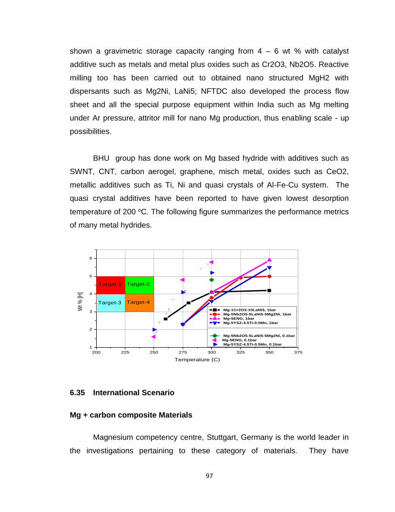
97
shown a gravimetric storage capacity ranging from 4 – 6 wt % with catalyst
additive such as metals and metal plus oxides such as Cr2O3, Nb2O5. Reactive
milling too has been carried out to obtained nano structured MgH2 with
dispersants such as Mg2Ni, LaNi5; NFTDC also developed the process flow
sheet and all the special purpose equipment within India such as Mg melting
under Ar pressure, attritor mill for nano Mg production, thus enabling scale - up
possibilities.
BHU group has done work on Mg based hydride with additives such as
SWNT, CNT, carbon aerogel, graphene, misch metal, oxides such as CeO2,
metallic additives such as Ti, Ni and quasi crystals of Al-Fe-Cu system. The
quasi crystal additives have been reported to have given lowest desorption
temperature of 200 oC. The following figure summarizes the performance metrics
of many metal hydrides.
200 225 250 275 300 325 350 375
1
2
3
4
5
6
Target-1
Mg-1Cr2O3-10LaNi5, 1bar
Mg-5Nb2O5-5LaNi5-5Mg2Ni, 1bar
Mg-5ENG, 1bar
Mg-5YSZ-4.5Ti-0.5Mn, 1bar
Mg-5Nb2O5-5LaNi5-5Mg2Ni, 0.1bar
Mg-5ENG, 0.1bar
Mg-5YSZ-4.5Ti-0.5Mn, 0.1bar
Wt %
[H]
Temperature (C)
Target-1 Target-2
Target-3 Target-4
6.35 International Scenario
Mg + carbon composite Materials
Magnesium competency centre, Stuttgart, Germany is the world leader in
the investigations pertaining to these category of materials. They have
98
investigated a large number of Mg-X-H compounds as the target to achieve lower
desorption temperatures as early as 2000. The present trend throughout seems
to be add both carbon based materials to Mg materials to achieve an
intermediate desorption temperature around 200C. These systems are suitable
for applications where waste heat or solar thermal is available close to usage
point. NFTDC's Mg + 5%ENG also follows the same pattern of composites.
Commercial Systems for large Applications
At present there are two companies involved in commercialisation of
technologies related to magnesium based solid state hydrogen storage. They
are
(i) Mc Phy, France (Mg based ) Storage and industrial applications of
hydrogen
(ii) Hydrexia, Australia (Mg based) , developed hydrogen storage device
McPhy uses Magnesium based materials in powder form together with expanded
natural graphite (ENG) to achieve a gravimetric storage capacity of 6wt %.
Hydrexia uses milled flakes from cast Mg-Ni alloy to obtain low cost manufacture.
During activation the flakes break down into smaller particles and subsequently
sinter during cycling to form a solid porous material. McPhy energy solution
involves a hydrogen generator based on water electrolysis, solid state hydrogen
storage and equipment as required for converting hydrogen to electricity. Mc
Phy’s hydrogen storage has two technologies namely,
a. ‘HDS technology’ which uses available heat (such as waste or solar) and
b. HES series (adiabatic storage) – Cartridges surrounding the storage
material are surrounded by phase change material.
Hydrexia‘s has come out ground storage products which use a scalable skid
based design for industrial energy requirements at customer site to serve as an
autonomous H2 storage system and the company also integrates Balance of
99
Plant. The capital costs are lower and four times storage capacity in Mg based
systems compared to compressed gas bottles is achieved at lower pressures of
only 10 bar thus providing an added advantage of safety.
Small portable Storage Devices based on LaNi5 systems
Small portable H2 canisters made of Al alloy for light weight and storing up
to 1.2wt% Al in LaNi5 is available in the international market from a few
companies. These canisters are now used for (i) camp sites and off grid to
generate small amount of power using PEMFC for lighting and communication
devices; (ii) one 2 wheeler EV vehicle in Taiwan (Asia Pacific Fuel Cell
Technology) company has even integrated these canisters with PEMFC and
motor to get 80 km range.
International Status on Materials Research
International efforts are focussed on size reduction with catalyst additives
to enhance the kinetics and there are innumerable reports similar to BHU and
NFTDC investigations. A noteworthy report of recent origin is from a team of
California Institute of Technology modelled Mg-H clusters and shown that MgH2
particles with sizes lesser than 2 nm show remarkable trend of lowering stability
due to modifications in thermodynamics. While, another group from Curtin
University of Technology has experimentally shown that thermodynamic tuning
can be achieved even for sizes up to 7 nm. In order to achieve absorption and
desorption small clusters are being impregnated on scaffolds which offer
durability and thermal stability. Alternative process such as severe plastic
deformation and accumulative roll bonding, equi channel angular pressing of
magnesium based alloys are also emerging.
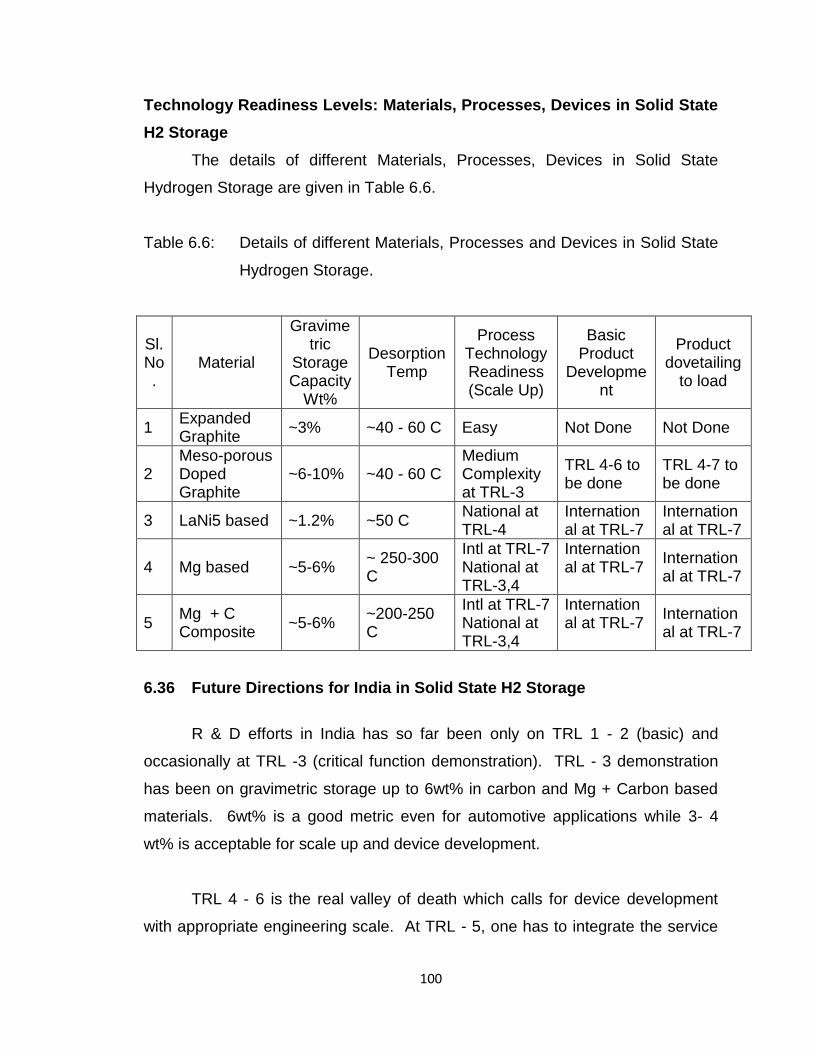
100
Technology Readiness Levels: Materials, Processes, Devices in Solid State
H2 Storage
The details of different Materials, Processes, Devices in Solid State
Hydrogen Storage are given in Table 6.6.
Table 6.6: Details of different Materials, Processes and Devices in Solid State
Hydrogen Storage.
Sl.No.
Material
Gravimetric
Storage Capacity
Wt%
Desorption Temp
Process Technology Readiness (Scale Up)
Basic Product
Development
Product dovetailing
to load
1 Expanded Graphite
~3% ~40 - 60 C Easy Not Done Not Done
2 Meso-porous Doped Graphite
~6-10% ~40 - 60 C Medium Complexity at TRL-3
TRL 4-6 to be done
TRL 4-7 to be done
3 LaNi5 based ~1.2% ~50 C National at TRL-4
International at TRL-7
International at TRL-7
4 Mg based ~5-6% ~ 250-300 C
Intl at TRL-7 National at TRL-3,4
International at TRL-7
International at TRL-7
5 Mg + C Composite
~5-6% ~200-250 C
Intl at TRL-7 National at TRL-3,4
International at TRL-7
International at TRL-7
6.36 Future Directions for India in Solid State H2 Storage
R & D efforts in India has so far been only on TRL 1 - 2 (basic) and
occasionally at TRL -3 (critical function demonstration). TRL - 3 demonstration
has been on gravimetric storage up to 6wt% in carbon and Mg + Carbon based
materials. 6wt% is a good metric even for automotive applications while 3- 4
wt% is acceptable for scale up and device development.
TRL 4 - 6 is the real valley of death which calls for device development
with appropriate engineering scale. At TRL - 5, one has to integrate the service
101
condition, in this case the load or the H2 consuming device such as fuel cell and
prove it in long duration testing and validation in TRL - 6 to iterate out the device
design and scale. At TRL - 7, we should go for pilot production of devices and
field testing and evaluation in large scale power production or automotive
propulsion or distributed power generation. The thrust of our next round of R & D
should be TRL 3 - 6 with device development and deployment in TRL - 7.
6.37 Materials
With regard to materials, India should spend its R & D resources on three
systems only, namely (a) processed carbon forms from natural graphite and
agricultural waste source and (b) Mg + carbon composites and (c) La based
materials which will serve both sorption cooling as well as H2 storage for small
applications. The former is for lower Temperature desorption and later for large
scale H2 storage. The aim should be to scale up the processes, achieve the
required nano sizes, embedded clusters, mesoporous structures so as to serve
the device developers. Process reactor design and engineering, process
equipment at a pilot plant level and product testing equipment are to be
streamlined in an end to end technology endeavour. Here again the aim should
be to develop process technologies to get the materials and process equipment
at system level design at TRL 4-6.
6.38 Device Development and dovetailing to load (materials to device to
deployment)
Here one should take a top down approach and decide on three major
platforms;
(i) for large scale static storage using Mg + Carbon based systems and H2
release using waste heat or solar thermal process heat (CSH) and electricity
production using PEMFC or SOFC depending on the impurity levels in H2; Mg
based materials H2 storage stack with SOFC coupling can utilize the exhaust
102
heat from SOFC at 500 - 600 C to release H2 at 250C, thus enhancing the
overall efficiency of the system. The unused H2 from fuel cell is also recovered
or used for methanol/CNG reformation for fuel cell.
(ii) Devices using Carbon based materials systems for portable applications to
take advantage of light weight and lower desorption temperature. This has to be
coupled to a PEMFC (not with an H2 IC engine) in an automotive platform. A two
wheeler vehicle platform is a useful starting point.
(iii) Small portable device development using LaNi5 (1.2wt%H2) materials which
will give 1 to 2 kWe power generation equivalence.
These exercises are system level developments and they necessarily involved
crossing TRL 4-6 with design, engineering and rendering work. The team size
has to be bigger and with multidisciplinary character. These product
development vectors with specific end use platform will give a fillip to the
backward integration of materials to device endeavours.
6.39 Conclusions and Suggested Action Plan
There are several methods of hydrogen storage, having advantages and
disadvantages over the other methods. It is important to note that any method
that is to be adapted should fit the present infrastructure to reduce the
infrastructure cost of the technology. The storage methods could be based on the
site and requirement; they can be segregated into bulk storage, small storage
capacities and mobile/on board storage.
Currently, hydrogen is stored either in high pressure tanks or in liquid form
in cryogenic tanks. These forms of storage are not suitable for widespread
commercial application. The alternative is to use solid materials for hydrogen
storage. But each of the solid materials being used or studied for hydrogen
storage has their inherent limitations. Metal hydrides are reversible under
ambient conditions but are too heavy. Simple chemical hydrides are reversible
103
but at very high pressure and temperature. Complex chemical hydrides have
high hydrogen density but suffer from poor reversibility. Sorbent materials offer
good reversibility but require very low temperatures. Theoretical calculations
have predicted many promising cluster-based materials, but they are hard to
synthesize. Nanostructured materials provide opportunities but are yet to emerge
as practical materials. Considering the impact that a successful hydrogen
economy can have on our energy needs and the progress that basic research
has made in the past decade in addressing issues and challenges in hydrogen
storage, it is imperative that the momentum of current research into a basic
understanding of hydrogen interaction in materials be accelerated.
After studying merits and demerits of different types of hydrides viz. MgH2,
Mg2NiH4, NaAlH4, other alanates, borohydrates (gravimetric hydrogen capacity of
>7wt%), commercial hydrides such as FeTiH2 and LaNi5H6, adsorbents like
carbon, nano-structured carbons (including CNTs) MoFs and hydrogen clathrate
hydrate were investigated for hydrogenation and dehydrogenation reaction
conditions and their kinetics, retention of cycling capacity, and reversible
capacities. MgH2 has the advantage of being stable at ambient conditions.
The major areas of research are improving kinetics of hydrogen uptake /
release and retention of cycling capacity.
It must be realized that any new energy technology takes few decades of
time period to get established. This is true for changeover from horse/bullock to
steam engine and then from steam engine to IC engine, based road transport.
Another aspect which should be realized is that the new technology, be it steam
engine or IC engine has not been cheaper to start with than the previous
technology whom they have replaced.
Hydrogen energy technology is helpful to India in two crucial ways. One it
provides relief from the very scant oil reserves in the country (whereas Russia
104
has ~ 13%, Saudia Arabia ~ 12%, USA ~10%, Iran ~ 5%, China ~ 5%, Iraq ~ 4%
of world oil reserves, India has only 1.04%) and the second is relief from
pressures exerted by developed countries on ‘Climate Change”.
For India to be slowly shifting to Hydrogen, the following steps are essential
and should be taken:
(i) Certain cities where hydrogen expertise exists should be declared Hydrogen
cities. Some such cities may be New Delhi, Varanasi, and Hyderabad to
start with. In these cities hydrogen filling stations (preferably PV driven
electrolysis) should be established. These cities should first establish fleets
of hydrogen fueled vehicular transport (3 wheelers and cars say 100 in
number). Whereas for car HPG storage mode should be tried, for 3 wheeler
and small car hydride storage mode should be preferred.
(ii) After about 3 years a certain fraction of vehicular transport (3 wheelers and
small cars), a certain fraction say 1 through 5 to 10% of total vehicular
population of these cities should be run hydrogen.
(iii) Exercise similar to (i) and (ii) should be done for heavy duty transport like
buses and trucks.
(iv) Zero emission / nearly zero emission laws should be passed say first for the
above cities and then for other cities / whole country.
(v) Carbon tax laws similar to that in (iii) above should be passed.
(vi) Hydrogen (clean fuel) incentive laws should be invoked. As per these,
special tax rebates, tax exemptions subsides etc. to all those who help
bringing in Hydrogen Energy and to Industries, corporate bodies who
support and are participating in R&D commercialization efforts.
The Hydrogen safety system design will ensure the safe operation of the
equipment, within designed parameters like pressure, temperature, gas/liquid
flow etc. and hence of preventing fire, explosion, release of toxic materials or
criticality which may lead to loss of material and property. This is achieved by a

105
built-in safety system incorporated in the design to ensure that operating
parameters are not exceeded beyond safety limits through interlocks which
control process parameters and alert operating staff by audio-visual signals, or
by action such as switching off power supply, cutting off feed etc.
106
HYDROGEN STORAGE IN NANO-
MATERIALS
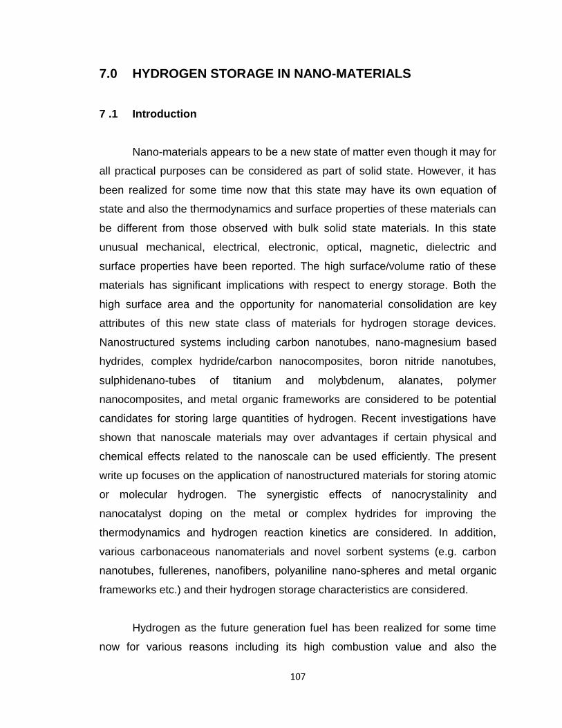
107
7.0 HYDROGEN STORAGE IN NANO-MATERIALS
7 .1 Introduction
Nano-materials appears to be a new state of matter even though it may for
all practical purposes can be considered as part of solid state. However, it has
been realized for some time now that this state may have its own equation of
state and also the thermodynamics and surface properties of these materials can
be different from those observed with bulk solid state materials. In this state
unusual mechanical, electrical, electronic, optical, magnetic, dielectric and
surface properties have been reported. The high surface/volume ratio of these
materials has significant implications with respect to energy storage. Both the
high surface area and the opportunity for nanomaterial consolidation are key
attributes of this new state class of materials for hydrogen storage devices.
Nanostructured systems including carbon nanotubes, nano-magnesium based
hydrides, complex hydride/carbon nanocomposites, boron nitride nanotubes,
sulphidenano-tubes of titanium and molybdenum, alanates, polymer
nanocomposites, and metal organic frameworks are considered to be potential
candidates for storing large quantities of hydrogen. Recent investigations have
shown that nanoscale materials may over advantages if certain physical and
chemical effects related to the nanoscale can be used efficiently. The present
write up focuses on the application of nanostructured materials for storing atomic
or molecular hydrogen. The synergistic effects of nanocrystalinity and
nanocatalyst doping on the metal or complex hydrides for improving the
thermodynamics and hydrogen reaction kinetics are considered. In addition,
various carbonaceous nanomaterials and novel sorbent systems (e.g. carbon
nanotubes, fullerenes, nanofibers, polyaniline nano-spheres and metal organic
frameworks etc.) and their hydrogen storage characteristics are considered.
Hydrogen as the future generation fuel has been realized for some time
now for various reasons including its high combustion value and also the
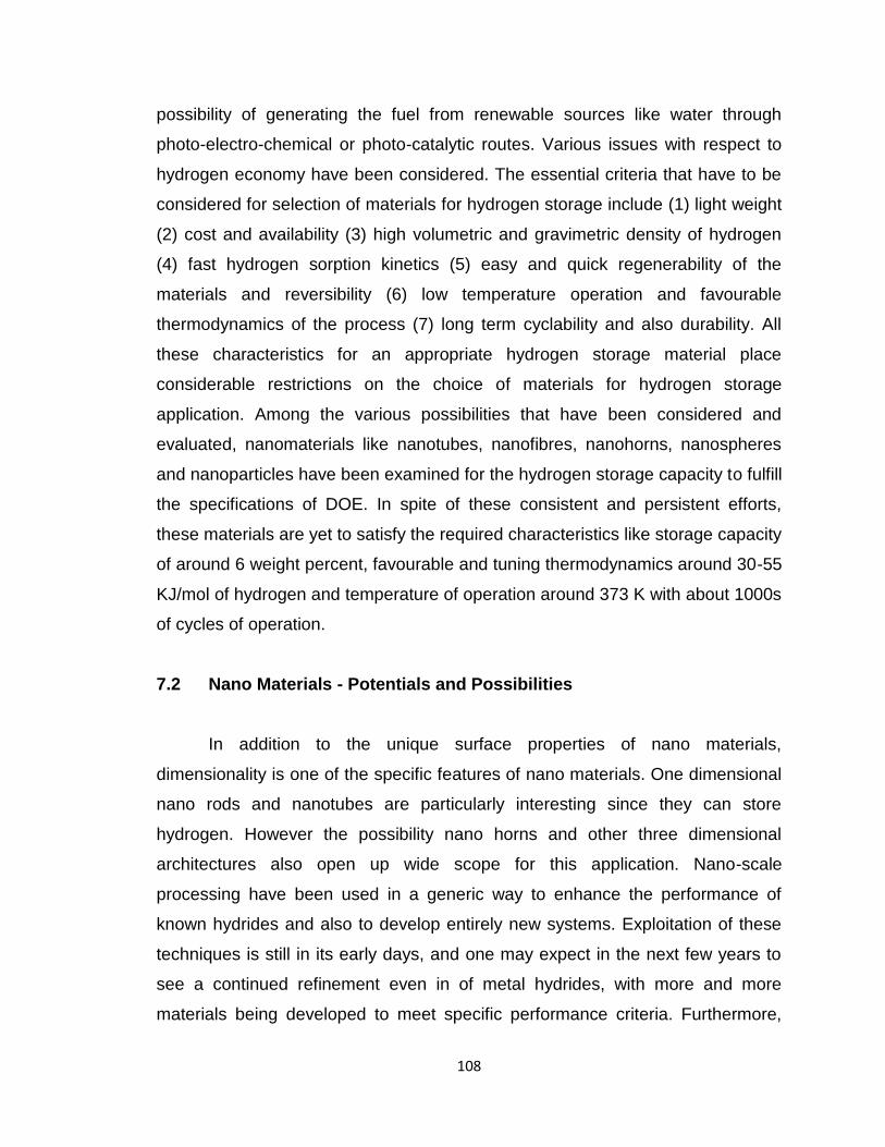
108
possibility of generating the fuel from renewable sources like water through
photo-electro-chemical or photo-catalytic routes. Various issues with respect to
hydrogen economy have been considered. The essential criteria that have to be
considered for selection of materials for hydrogen storage include (1) light weight
(2) cost and availability (3) high volumetric and gravimetric density of hydrogen
(4) fast hydrogen sorption kinetics (5) easy and quick regenerability of the
materials and reversibility (6) low temperature operation and favourable
thermodynamics of the process (7) long term cyclability and also durability. All
these characteristics for an appropriate hydrogen storage material place
considerable restrictions on the choice of materials for hydrogen storage
application. Among the various possibilities that have been considered and
evaluated, nanomaterials like nanotubes, nanofibres, nanohorns, nanospheres
and nanoparticles have been examined for the hydrogen storage capacity to fulfill
the specifications of DOE. In spite of these consistent and persistent efforts,
these materials are yet to satisfy the required characteristics like storage capacity
of around 6 weight percent, favourable and tuning thermodynamics around 30-55
KJ/mol of hydrogen and temperature of operation around 373 K with about 1000s
of cycles of operation.
7.2 Nano Materials - Potentials and Possibilities
In addition to the unique surface properties of nano materials,
dimensionality is one of the specific features of nano materials. One dimensional
nano rods and nanotubes are particularly interesting since they can store
hydrogen. However the possibility nano horns and other three dimensional
architectures also open up wide scope for this application. Nano-scale
processing have been used in a generic way to enhance the performance of
known hydrides and also to develop entirely new systems. Exploitation of these
techniques is still in its early days, and one may expect in the next few years to
see a continued refinement even in of metal hydrides, with more and more
materials being developed to meet specific performance criteria. Furthermore,
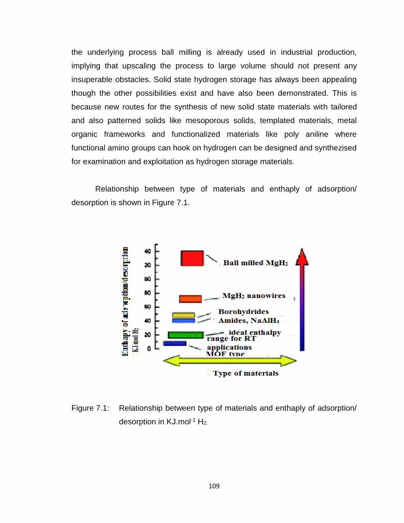
109
the underlying process ball milling is already used in industrial production,
implying that upscaling the process to large volume should not present any
insuperable obstacles. Solid state hydrogen storage has always been appealing
though the other possibilities exist and have also been demonstrated. This is
because new routes for the synthesis of new solid state materials with tailored
and also patterned solids like mesoporous solids, templated materials, metal
organic frameworks and functionalized materials like poly aniline where
functional amino groups can hook on hydrogen can be designed and synthezised
for examination and exploitation as hydrogen storage materials.
Relationship between type of materials and enthaply of adsorption/
desorption is shown in Figure 7.1.
Figure 7.1: Relationship between type of materials and enthaply of adsorption/
desorption in KJ.mol-1 H2.
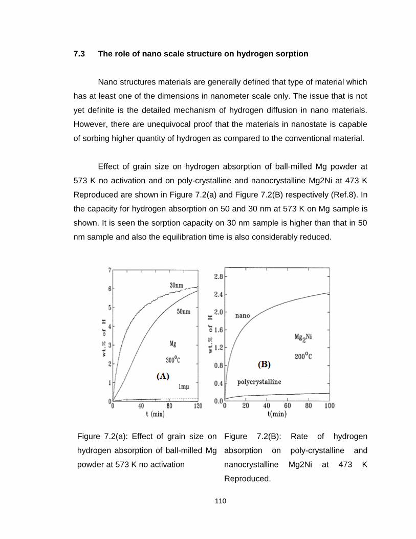
110
7.3 The role of nano scale structure on hydrogen sorption
Nano structures materials are generally defined that type of material which
has at least one of the dimensions in nanometer scale only. The issue that is not
yet definite is the detailed mechanism of hydrogen diffusion in nano materials.
However, there are unequivocal proof that the materials in nanostate is capable
of sorbing higher quantity of hydrogen as compared to the conventional material.
Effect of grain size on hydrogen absorption of ball-milled Mg powder at
573 K no activation and on poly-crystalline and nanocrystalline Mg2Ni at 473 K
Reproduced are shown in Figure 7.2(a) and Figure 7.2(B) respectively (Ref.8). In
the capacity for hydrogen absorption on 50 and 30 nm at 573 K on Mg sample is
shown. It is seen the sorption capacity on 30 nm sample is higher than that in 50
nm sample and also the equilibration time is also considerably reduced.
Figure 7.2(a): Effect of grain size on
hydrogen absorption of ball-milled Mg
powder at 573 K no activation
Figure 7.2(B): Rate of hydrogen
absorption on poly-crystalline and
nanocrystalline Mg2Ni at 473 K
Reproduced.
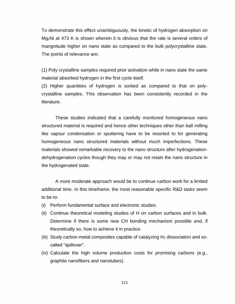
111
To demonstrate this effect unambiguously, the kinetic of hydrogen absorption on
Mg2Ni at 473 K is shown wherein it is obvious that the rate is several orders of
mangnitude higher on nano state as compared to the bulk polycrystalline state.
The points of relevance are:
(1) Poly crystalline samples required prior activation while in nano state the same
material absorbed hydrogen in the first cycle itself.
(2) Higher quantities of hydrogen is sorbed as compared to that on poly-
crystalline samples. This observation has been consistently recorded in the
literature.
These studies indicated that a carefully monitored homogeneous nano
structured material is required and hence other techniques other than ball milling
like vapour condensation or sputtering have to be resorted to for generating
homogeneous nano structured materials without much imperfections. These
materials showed remarkable recovery to the nano structure after hydrogenation-
dehydrogenation cycles though they may or may not retain the nano structure in
the hydrogenated state.
A more moderate approach would be to continue carbon work for a limited
additional time. In this timeframe; the most reasonable specific R&D tasks seem
to be to:
(i) Perform fundamental surface and electronic studies.
(ii) Continue theoretical modeling studies of H on carbon surfaces and in bulk.
Determine if there is some new CH bonding mechanism possible and, if
theoretically so, how to achieve it in practice.
(iii) Study carbon-metal composites capable of catalyzing H2 dissociation and so-
called “spillover”.
(iv) Calculate the high volume production costs for promising carbons (e.g.,
graphite nanofibers and nanotubes).
112
(v) Develop standard testing techniques for measuring H2 uptake and release
from small carbon samples.
(vi) Develop a carbon sample and activation procedure that can be used as an
international standard for researchers in the field. (This sample should have
a reversible room temperature capacity > 2 wt% H2).
7.4 Activated Carbon
Environmental destruction has increased the urgency to develop
technologies for the recycling of various materials. The disposal of biomass
waste from agricultural activities is an environmental problem. One of the
solutions to this problem is to produce functional and reusable materials from
biomass resources. Activated carbons fabricated from biomass resource have
been studied for use as functional materials. In particular, some activated
carbons with nano-meter size pores, i.e., micropores, offer high performance
because of their high specific surface areas. These activated carbon materials
are prepared from various raw materials such as coal, palm shell, coffee waste,
and rice husks. Such activated carbon materials are widely used because of their
high adsorption properties. These approaches have been applied to hydrogen
storage materials and adsorbent materials for gases.
From recent reports, it is apparent that various carbon materials made
from carbon nanotubes, graphite nanofibers, and activated carbons are capable
of storing hydrogen and have been considered for the next generation of energy
systems. For example, porous carbons with a specific surface area of 3220 m2/g
is capable of storing hydrogen of 1.3 wt% at room temperature. The reports
suggest the influence of specific surface area on the hydrogen storage efficiency
of the micro-pores. In activated carbons fabricated from biomass recourses, it
was reported that activated carbons with micro-pores in the pore structure were
fabricated from lignin. Lignin is product as of a residual material in the
manufacture process of cellulose pulps. Some researchers have used potassium
113
hydroxide (KOH) for the activation. The micro-pore structure found in activated
carbons fabricated with lignin following KOH activation is expected to be utilized
as hydrogen storage materials.
At 298K, the stored hydrogen content of the activated carbons increases
as the equilibrium pressure of hydrogen increases. The hysteresis of stored
contents was observed at 298K and 77K. These hystereses at 298K and 77K
indicate that a chemical sorption also slightly occurred by effect of KOH
activation. There results suggest that the micro-pore of activated carbons may
effectively act as the hydrogen adsorption site at 77K and can be used in solid
state hydrogen storage.
7.5 Nano-scale catalysis for improved hydrogen sorption
It is well known that the presence of small quantity of catalysts only affects
the kinetics of the process. However, this effect is perceptible only when the
catalyst particles are well dispersed in the system. In this case the catalyst and
sorbing material are all in nano scale and could be in intimate contact. In Fig 7.3,
a demonstrative example is shown wherein LaNi5 system showed remarkably
higher sorption of hydrogen when the nano crystalline alloy is mixed with
catalyst. The choice of the catalyst possibly depends on the basic hydrogen
sorbing system. Various different methodologies have been adopted like
introduction of hetero atoms in carbon material whose function can be
considered to be to dissociate hydrogen molecule and also facilitate the sorption
kinetics. The results shown in Fig.7.4 demonstrate the validity of these
postulates. The points of relevance are:
(i) The actual mechanism of action is yet to be fully understood and also the
choice and selection of catalyst materials for the sorbing system have to be
delineated.
(ii) Efficient dispersion methodologies have to be developed for the catalyst.
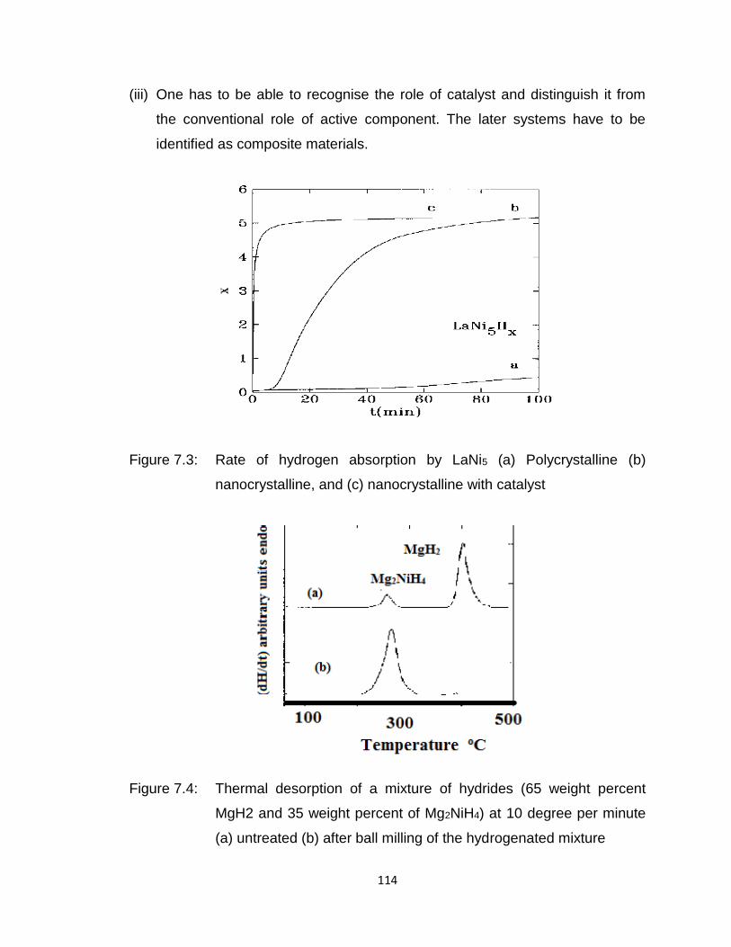
114
(iii) One has to be able to recognise the role of catalyst and distinguish it from
the conventional role of active component. The later systems have to be
identified as composite materials.
Figure 7.3: Rate of hydrogen absorption by LaNi5 (a) Polycrystalline (b)
nanocrystalline, and (c) nanocrystalline with catalyst
Figure 7.4: Thermal desorption of a mixture of hydrides (65 weight percent
MgH2 and 35 weight percent of Mg2NiH4) at 10 degree per minute
(a) untreated (b) after ball milling of the hydrogenated mixture
115
7.6 Nanocomposites
As stated before, nano composites are systems where more than one
active component is simultaneously present. To demonstrate this effect one
example is shown in Fig.7.4. In is seen from this figure, it is seen that desorption
temperature is considerably reduced in the composite system Mg2NiH4 and MgH2
composite system when it was subjected to ball milling. The points of relevance
for this class of nano materials for hydrogen sorption are: (1) The nature of
mutual synergestic effect is still intriguing and has yet to elucidated. (2) It has
been usually assumed that desorption kinetic behvaiour of the composite system
will be more like that the characteristic of the low temperature component. It is
possible to build a cascade of components with maximization of the sorption
capacity or improving the kinetics of the process or reducing the temperature of
operation.
7.7 Functional Nano-composites
The meaning of functional nano composites exhibits special function other
than catalysis or sorption capacity and the function improves the main property of
the composite. It can be the second component can facilitate the thermal
conductivity of the system, or facilitating the solid state reaction of the active
component or alter the hydrogenation thermodynamics in such a way that the
system can operate at lower temperature. This aspect has not yet been fully
exploited. In fact our understanding of this effect is minimal at this stage and
needs careful further intense investigation.
7.8 Nano Scale Reactions
There are two possibilities. In one case a normally non miscible two
components can become miscible in the presence of hydrogen and thus
generating a useful hydrogen absorption system. A second variation is a metallic
116
hydride and a non-absorbing system can give rise to a system as result of
hydrogen desorption from the first hydride. These two cases can be expressed in
terms of simple reactions.
(i) mA + nB+ x/2H2 , AmBnHx
(ii) AmHx +nB ,AMBn + x/2H2
Other variations of these reaction sequences are possible in nano-functional
systems for the generation of hydrides.
7.9 Perspective Aspects
There are still a number of issues that have to be answered before nano
systems and nano science can be exploited for formulating energy (hydrogen)
storage systems. Some of them are listed below:
(i) Even though the enhancement of hydrogen absorption in the nano state is
established unequivocally, the extent of enhancement and if it will reach the
level specified by DOE can be realized are still questions to be answered.
(ii) The factors like surface to volume ratio and also residual surface tension
forces are favourable for higher hydrogen absorption, the precise manner of
operation and how to optimize these residual forces are not yet clearly
delineated.
(iii) Hydrogen absorption itself is intriguing since it is the smallest atom, the
storage is due to simple trapping by van der Waals forces or due to
formation of specific bonds.
(iv) The optimum size of the nano materials and also the extent of dispersion of
nano catalysts have to be established with respect to individual species.
(v) In the case of carbon nano materials the hydrogen storage may have many
other implications as stated previously since dimensionality and also
possibility of carbon nano tubes, nano rods, nano cones all of them can

117
present various active sites and thus show enhanced hydrogen absorption.
These aspects have to be establiished unequivocally.
(vi) Various levels of theory have been employed at the level of DFT to
understand and rationalize the hydrogen absorption in variety of materials
and these will also be intensifed to formulate and design new materials. It is
possible there are other untrodden avenues for exploiting nano state for
hydrogen storage.

118
DESIGN CONSIDERATIONS
119
8.0 DESIGN CONSIDERATIONS
While the characteristics, properties and limitations of a storage material
are the initial considerations for any given application, numerous engineering
factors impact the design and performance of the integrated hydrogen storage
system. Reliable and safe containment of hydrogen is required over the entire
range of operating pressure and temperature during the projected lifetime
with adequate margins of safety. Hence, the materials used to fabricate the
storage devices and the components exposed to hydrogen should not be
susceptible to hydrogen embrittlement or other detrimental chemical reactions
especia l ly corrosion. In addition to the design for mechanical integrity, heat
and mass transfer re lated issues must also be addressed.
The designs of cylinders and refueling stations for H2 gas compressed
to high pressures should provide for accommodating heat generated during
both compression and the inverse Joule–Thomson effect under ambient
conditions in order to achieve efficient filling of the cyl inder .
The cryogenic storage of hydrogen as either liquid or cryo-compressed
gas requires designs that provide efficient thermal insulation that can
minimize loss of hydrogen by boil-off or excessive vaporization from
extraneous heat leaks.
For hydrogen storage using physical adsorption on activated carbon or
other high surface materials, the thermal conductivity within the sorbent bed
also needs to be augmented by metallic foams, fins, or meshes to manage
the heat of reaction during adsorption or desorption.
The reasonably high heats of reaction in the range of ∼20–100+ kJ/mol
for hydrogen absorption by the metal hydrides and complex hydrides
necessitate improved thermal conductivity of the packed beds within the
120
storage devices. Due to complexity of reactions associated with chemical
hydrogen systems where both the reactant materials and the products formed
during decomposition must be processed and/or separated dynamically as
hydrogen is released, extensive thermal management is needed for various
components and auxiliary subsystems. Because metal hydrides are commonly
known to have very poor thermal conductivities in powder form, extensive
efforts have been made to develop hydride bed designs with various
configurations that enhance the effective conductivity within the bed without
seriously impacting filling capacity, bed mass, and internal gas flow.
The thermal engineering issues may be summarized as follows:-
• Heat transfer is the major sorption/desorption rate controlling factor in
metal hydride beds.
• In order reduce the cycle time and to reduce the total weight, improvement
in the heat transfer characteristics of the bed is the most desirable.
• The hydriding and dehydriding reactions occur in the entire bed. However,
faster rate of reaction may be observed in a narrow region close to the
heat transfer boundary.
• Reactor configuration and geometric parameters are important in
obtaining the desired sorption / desorption performance from hydrogen
storage devices.
• Hydrogen supply pressure and coolant temperature are important
operating parameters in deciding the charging / discharging rates in
hydride devices.
• While storage material properties (Sorption, Thermodynamic,
Thermophysical) are important, the thermal design of the overall storage
device is crucial.
• Thermal masses of the heat transfer tubes, container, filters, distributors,
heat transfer fluid, etc have to be minimized.
121
In addition to meeting high degrees of safety, efficiency and cost effectiveness,
the main challenge in all hydrogen storage systems design is to meet the
following basic requirements:-
a) The weight and volume of hydrogen storage systems are presently too
high compared to conventional petroleum-fueled vehicles. Use of
lightweight materials and components are needed to enable more than
300-mile range for the light-duty vehicles.
b) Optimized Thermal and Mechanical Design of the reactor ensures that the
storage capacity and kinetics are well balanced for a given application.
High efficiencies coupled with low total weights should be achieved by
proper design practices.
c) Energy efficiency is a challenge for all hydrogen storage approaches. The
energy required to get hydrogen in and out is an issue for reversible solid-
state materials. The energy associated with compression and liquefaction
must be considered for compressed and liquid hydrogen technologies.
d) Durability of hydrogen storage systems is required with a lifetime of 1500
cycles.
e) Refueling time may be targeted to less than three minutes.
f) Cost of on-board hydrogen storage systems is too high, particularly in
comparison with conventional storage systems for petroleum fuels. Low-
cost materials and components for hydrogen storage systems are needed,
as well as low-cost, high-volume manufacturing methods.
g) Applicable codes and standards for hydrogen storage systems and
interface technologies, which will facilitate implementation /
commercialization and assure safety and public acceptance, are to be
established.
122
APPLICATIONS OF HYDROGEN OTHER
THAN TRANSPORTATION
123
APPLICATION OF HYDROGEN FOR
STATIONARY POWER GENERATION
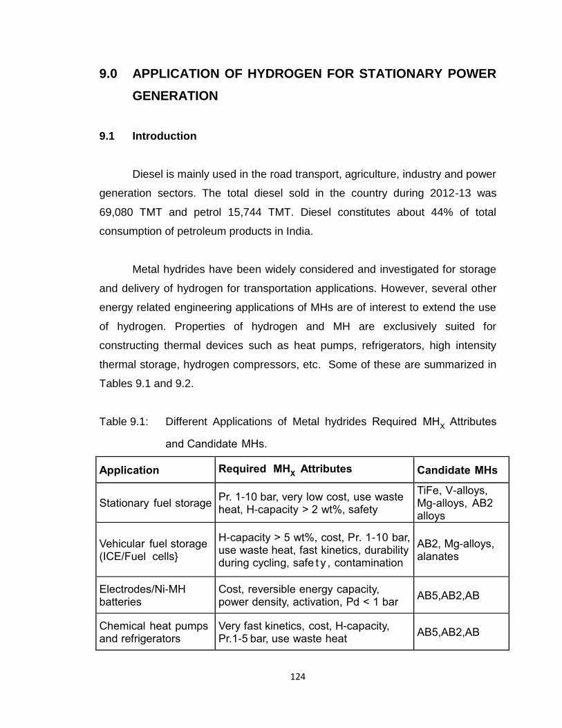
124
9.0 APPLICATION OF HYDROGEN FOR STATIONARY POWER
GENERATION
9.1 Introduction
Diesel is mainly used in the road transport, agriculture, industry and power
generation sectors. The total diesel sold in the country during 2012-13 was
69,080 TMT and petrol 15,744 TMT. Diesel constitutes about 44% of total
consumption of petroleum products in India.
Metal hydrides have been widely considered and investigated for storage
and delivery of hydrogen for transportation applications. However, several other
energy related engineering applications of MHs are of interest to extend the use
of hydrogen. Properties of hydrogen and MH are exclusively suited for
constructing thermal devices such as heat pumps, refrigerators, high intensity
thermal storage, hydrogen compressors, etc. Some of these are summarized in
Tables 9.1 and 9.2.
Table 9.1: Different Applications of Metal hydrides Required MHX Attributes
and Candidate MHs.
Application Required MHX Attributes Candidate MHs
Stationary fuel storage Pr. 1-10 bar, very low cost, use waste heat, H-capacity > 2 wt%, safety
TiFe, V-alloys, Mg-alloys, AB2 alloys
Vehicular fuel storage (ICE/Fuel cells}
H-capacity > 5 wt%, cost, Pr. 1-10 bar, use waste heat, fast kinetics, durability during cycling, safe t y , contamination
AB2, Mg-alloys, alanates
Electrodes/Ni-MH batteries
Cost, reversible energy capacity, power density, activation, Pd < 1 bar
AB5,AB2,AB
Chemical heat pumps and refrigerators
Very fast kinetics, cost, H-capacity, Pr.1-5 bar, use waste heat
AB5,AB2,AB
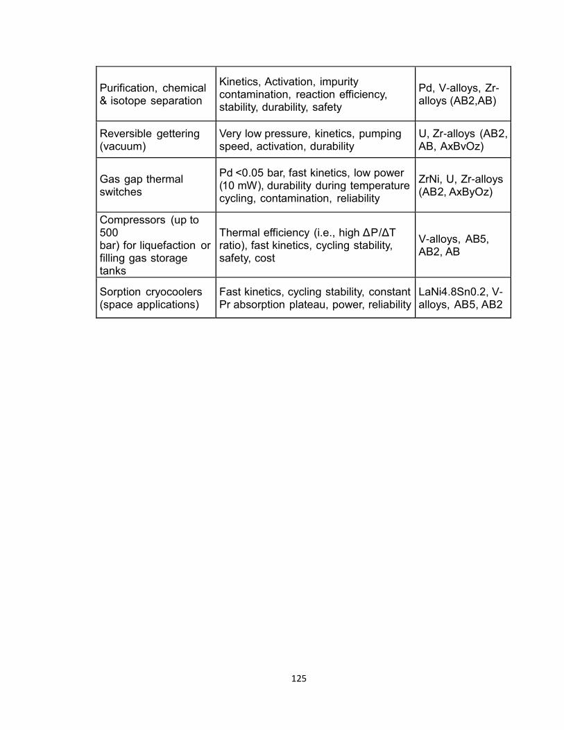
125
Purification, chemical & isotope separation
Kinetics, Activation, impurity contamination, reaction efficiency, stability, durability, safety
Pd, V-alloys, Zr-alloys (AB2,AB)
Reversible gettering (vacuum)
Very low pressure, kinetics, pumping speed, activation, durability
U, Zr-alloys (AB2, AB, AxBvOz)
Gas gap thermal switches
Pd <0.05 bar, fast kinetics, low power (10 mW), durability during temperature cycling, contamination, reliability
ZrNi, U, Zr-alloys (AB2, AxByOz)
Compressors (up to 500 bar) for liquefaction or filling gas storage tanks
Thermal efficiency (i.e., high ΔP/ΔT ratio), fast kinetics, cycling stability, safety, cost
V-alloys, AB5, AB2, AB
Sorption cryocoolers (space applications)
Fast kinetics, cycling stability, constant Pr absorption plateau, power, reliability
LaNi4.8Sn0.2, V-alloys, AB5, AB2
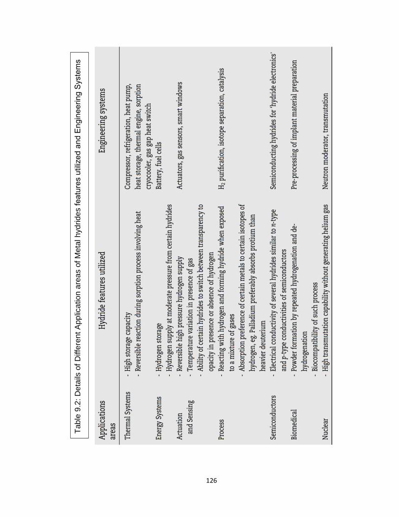
126
Tab
le 9
.2:
De
tails
of
Diffe
ren
t A
pp
lica
tio
n a
rea
s o
f M
eta
l h
yd
rid
es fea
ture
s u
tiliz
ed
an
d E
ngin
ee
rin
g S
yste
ms
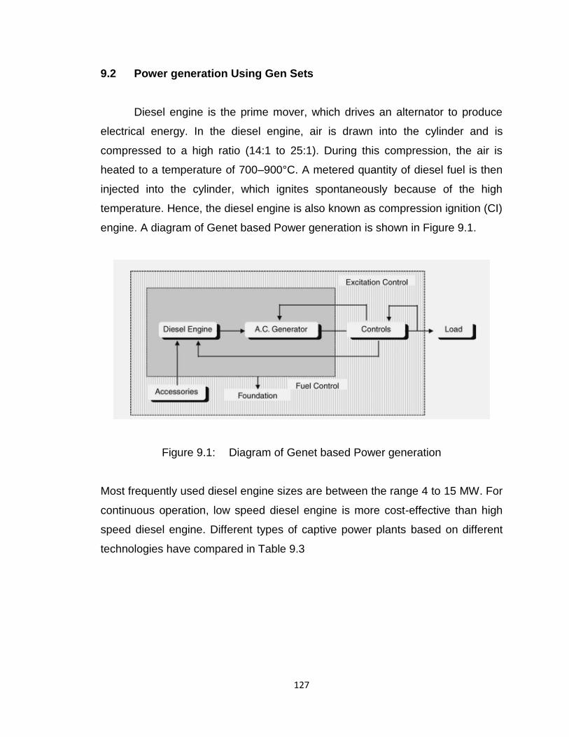
127
9.2 Power generation Using Gen Sets
Diesel engine is the prime mover, which drives an alternator to produce
electrical energy. In the diesel engine, air is drawn into the cylinder and is
compressed to a high ratio (14:1 to 25:1). During this compression, the air is
heated to a temperature of 700–900°C. A metered quantity of diesel fuel is then
injected into the cylinder, which ignites spontaneously because of the high
temperature. Hence, the diesel engine is also known as compression ignition (CI)
engine. A diagram of Genet based Power generation is shown in Figure 9.1.
Figure 9.1: Diagram of Genet based Power generation
Most frequently used diesel engine sizes are between the range 4 to 15 MW. For
continuous operation, low speed diesel engine is more cost-effective than high
speed diesel engine. Different types of captive power plants based on different
technologies have compared in Table 9.3
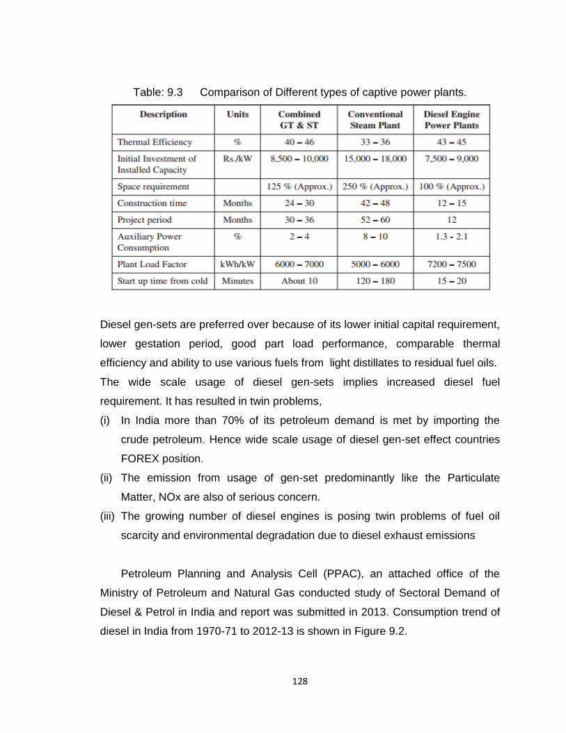
128
Table: 9.3 Comparison of Different types of captive power plants.
Diesel gen-sets are preferred over because of its lower initial capital requirement,
lower gestation period, good part load performance, comparable thermal
efficiency and ability to use various fuels from light distillates to residual fuel oils.
The wide scale usage of diesel gen-sets implies increased diesel fuel
requirement. It has resulted in twin problems,
(i) In India more than 70% of its petroleum demand is met by importing the
crude petroleum. Hence wide scale usage of diesel gen-set effect countries
FOREX position.
(ii) The emission from usage of gen-set predominantly like the Particulate
Matter, NOx are also of serious concern.
(iii) The growing number of diesel engines is posing twin problems of fuel oil
scarcity and environmental degradation due to diesel exhaust emissions
Petroleum Planning and Analysis Cell (PPAC), an attached office of the
Ministry of Petroleum and Natural Gas conducted study of Sectoral Demand of
Diesel & Petrol in India and report was submitted in 2013. Consumption trend of
diesel in India from 1970-71 to 2012-13 is shown in Figure 9.2.
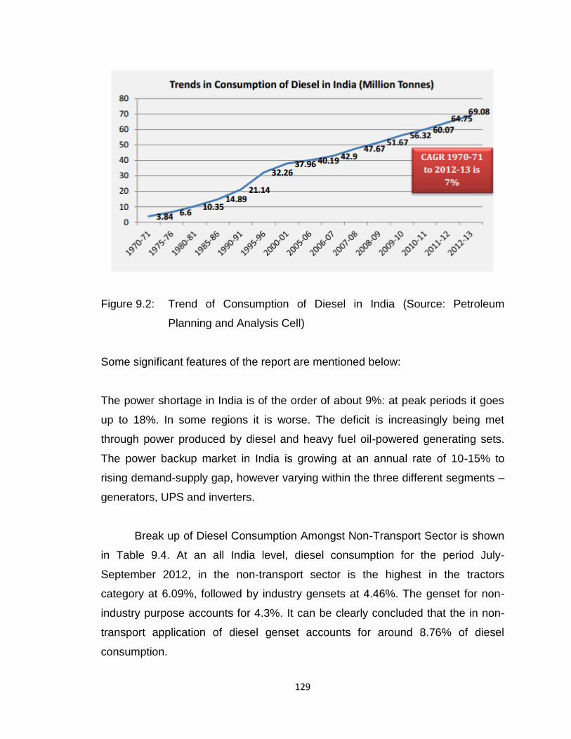
129
Figure 9.2: Trend of Consumption of Diesel in India (Source: Petroleum
Planning and Analysis Cell)
Some significant features of the report are mentioned below:
The power shortage in India is of the order of about 9%: at peak periods it goes
up to 18%. In some regions it is worse. The deficit is increasingly being met
through power produced by diesel and heavy fuel oil-powered generating sets.
The power backup market in India is growing at an annual rate of 10-15% to
rising demand-supply gap, however varying within the three different segments –
generators, UPS and inverters.
Break up of Diesel Consumption Amongst Non-Transport Sector is shown
in Table 9.4. At an all India level, diesel consumption for the period July-
September 2012, in the non-transport sector is the highest in the tractors
category at 6.09%, followed by industry gensets at 4.46%. The genset for non-
industry purpose accounts for 4.3%. It can be clearly concluded that the in non-
transport application of diesel genset accounts for around 8.76% of diesel
consumption.
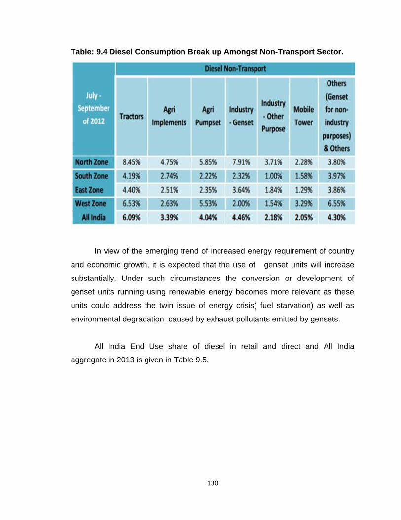
130
Table: 9.4 Diesel Consumption Break up Amongst Non-Transport Sector.
In view of the emerging trend of increased energy requirement of country
and economic growth, it is expected that the use of genset units will increase
substantially. Under such circumstances the conversion or development of
genset units running using renewable energy becomes more relevant as these
units could address the twin issue of energy crisis( fuel starvation) as well as
environmental degradation caused by exhaust pollutants emitted by gensets.
All India End Use share of diesel in retail and direct and All India
aggregate in 2013 is given in Table 9.5.
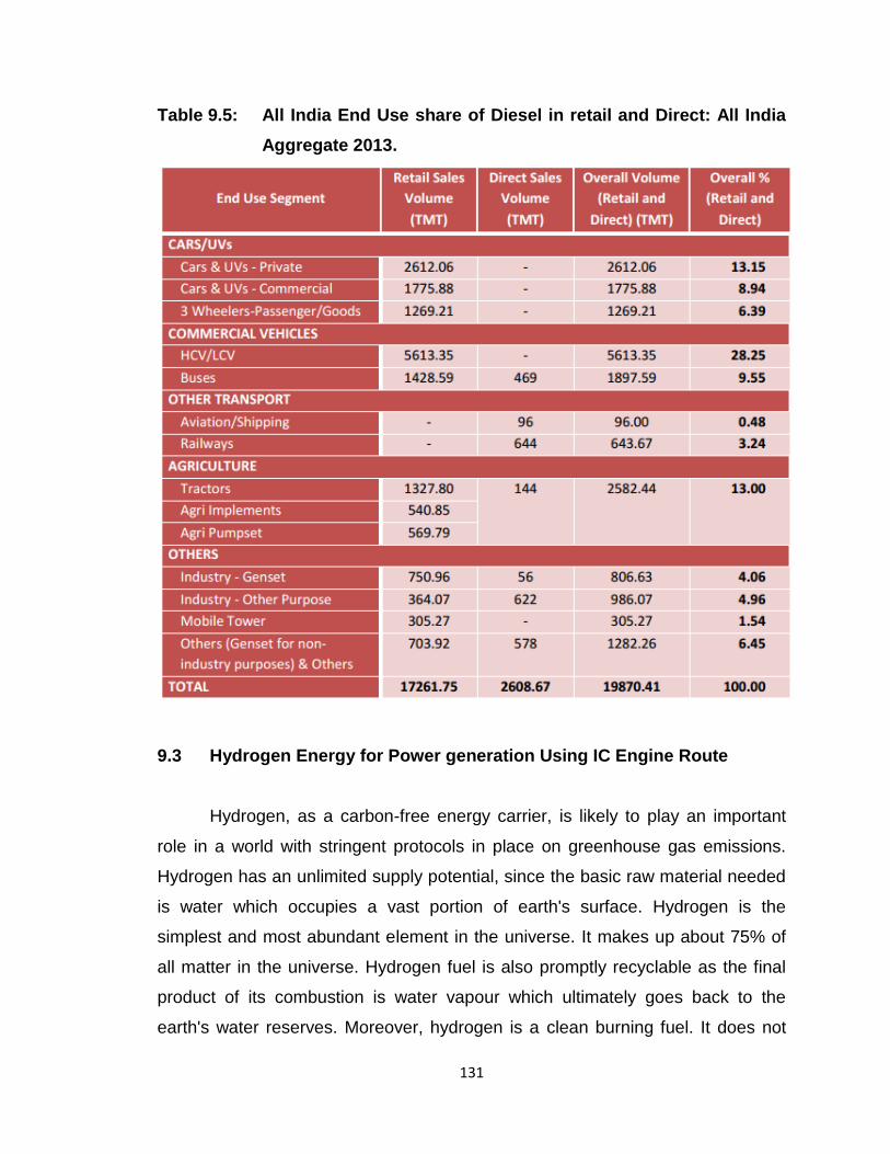
131
Table 9.5: All India End Use share of Diesel in retail and Direct: All India
Aggregate 2013.
9.3 Hydrogen Energy for Power generation Using IC Engine Route
Hydrogen, as a carbon-free energy carrier, is likely to play an important
role in a world with stringent protocols in place on greenhouse gas emissions.
Hydrogen has an unlimited supply potential, since the basic raw material needed
is water which occupies a vast portion of earth's surface. Hydrogen is the
simplest and most abundant element in the universe. It makes up about 75% of
all matter in the universe. Hydrogen fuel is also promptly recyclable as the final
product of its combustion is water vapour which ultimately goes back to the
earth's water reserves. Moreover, hydrogen is a clean burning fuel. It does not
132
contain ingredients like carbon or sulfur and hence, its combustion products,
unlike those of diesel oil, do not contain obnoxious pollutants such as carbon
monoxide, hydrocarbons and oxides of sulfur, etc.
Hydrogen is generated as a by-product in significant quantities by the
chemical industry. Production of chlorine, sodium chlorate and ethylene/styrene
are the largest sources. Currently, chemical manufacturers put this by-product
hydrogen to a variety of uses, like:
As chemical feed stock
Sell to hydrogen distributors
Vent out
The by-product hydrogen can be used to produce clean, zero-emission
electricity that is either sold back to the grid, through the electricity utility, or used
to o set power demand on site.
Use of hydrogen as a CI engine fuel can thus go a long way to meet the
challenge of the growing diesel fuel scarcity and also reduce the menace of
diesel smoke emissions. However, the problems due to oxides of nitrogen in the
exhaust needs to be carefully addressed.
There are several reasons for applying hydrogen as an additional fuel to
accompany diesel fuel in compression ignition (CI) engine. Firstly, it increases
the H/C ratio of the entire fuel. Secondly, injecting small amounts of hydrogen to
a diesel engine could decrease heterogeneity of a diesel fuel spray due to the
high diffusivity of hydrogen. This makes the combustible mixture better premixed
with air and more uniform. It could also reduce the combustion duration due to
hydrogen’s high speed of flame propagation in relation to other fuels. The laminar
flame speed for hydrogen is 1.9 m/s at normal pressure and temperature, and it
is almost five times higher when compared to 0.4 m/s for most hydrocarbon fuels.
Better homogeneity of the combustible mixture would provide better conditions
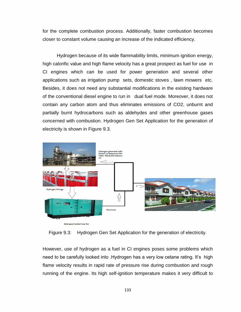
133
for the complete combustion process. Additionally, faster combustion becomes
closer to constant volume causing an increase of the indicated efficiency.
Hydrogen because of its wide flammability limits, minimum ignition energy,
high calorific value and high flame velocity has a great prospect as fuel for use in
CI engines which can be used for power generation and several other
applications such as irrigation pump sets, domestic stoves , lawn mowers etc.
Besides, it does not need any substantial modifications in the existing hardware
of the conventional diesel engine to run in dual fuel mode. Moreover, it does not
contain any carbon atom and thus eliminates emissions of CO2, unburnt and
partially burnt hydrocarbons such as aldehydes and other greenhouse gases
concerned with combustion. Hydrogen Gen Set Application for the generation of
electricity is shown in Figure 9.3.
Figure 9.3: Hydrogen Gen Set Application for the generation of electricity.
However, use of hydrogen as a fuel in CI engines poses some problems which
need to be carefully looked into .Hydrogen has a very low cetane rating. It’s high
flame velocity results in rapid rate of pressure rise during combustion and rough
running of the engine. Its high self-ignition temperature makes it very difficult to
134
ignite by compression alone in a conventional diesel engine. Practical Solution
to these problems is hinged upon the use of diesel oil as the ignition source and
thereby establishing dual fuel operation. Hydrogen combustion in atmospheric air
is easily ignited at concentrations from 4% to 75% by volume.. Hydrogen can be
used for a part diesel oil substitution without major engine modifications. The
engine can be operated as a dual fuel engine with hydrogen-air mixture induction
during suction and injection of a pilot diesel charge in the conventional manner to
trigger combustion.
There are some typical properties of hydrogen which are extremely critical
to engine operation and therefore must be looked at from application point of
view. It has an exceptional low density, which necessitates a high–pressure
injection to ensure sufficient fuel–masses within the cylinder even at high engine
loads. The wide ignition limits of H2/air–mixtures from λ = 0.14 up to λ = 10,
which allow for unthrottled operation within a wide operating range. Third, and for
the use in a CI engine most important, is the high self–ignition temperature,
which can be found to be ≈ 853 K, which is significantly higher than the
respective value of conventional Diesel fuels (≈ 523 K).
A stable and reliable ignition source is very important for compression
ignition engines. There can broadly be two methods for hydrogen ignition, the
hydrogen is first ignited following impingement on the continuously operated glow
plug
a) Surface Ignition
b) Diesel Pilot Injection
Surface Ignition
In the surface system ignition a single fuel injection pulse is provided. The
combustion evolution then sharply raises the chamber pressure and temperature,
and once better auto-ignition conditions are globally reached within the chamber,
135
then all of the hydrogen jets emerging from the multi holes injector ignite just
following the mixing with air. Assuming adequate glow plug surface temperature,
combustion starts as soon as one of the hydrogen jets reaches the glow plug.
Knock is avoided by the then quick combustion of the hydrogen already available
one working with hydrogen only but requiring a surface ignition, and one working
with a pilot Diesel injection preceding the main hydrogen injection. After the
combustion start-up phase, the injection of hydrogen in high temperatures gases
produces a combustion rate basically controlled by the rate of injection for the
hydrogen that then burns almost instantaneously following mixing with air and
temperature heating up.
Diesel Pilot Injection
Diesel fuel is delivered into the combustion chamber in its liquid phase
which upon combustion act as the ignition source for hydrogen. Other than
hydrogen, Diesel fuel consists of several groups of hydrocarbons. Volatile
substances with low evaporation as well as ignition–temperatures help to
alleviate the CI– process. Once endothermic chemical processes are started
further heat is generated to evaporate and burn non–volatile substances within
the fuel.
Fuel Injection System
Hydrogen has an exceptional low density, which necessitates a high–
pressure injection to guarantee sufficient fuel–masses within the cylinder even at
high engine loads. The application of hydrogen in CI engine require a source of
ignition which is provided by the pilot injection of diesel as indicated earlier. The
diesel oil direct injection system is usually made of a mechanical fuel pump and
injectors. Hydrogen injection system needs to be specifically design for engine
intake system. The hydrogen injection system location is chosen such that it
does not cause any major interference on the intake system in case of engine
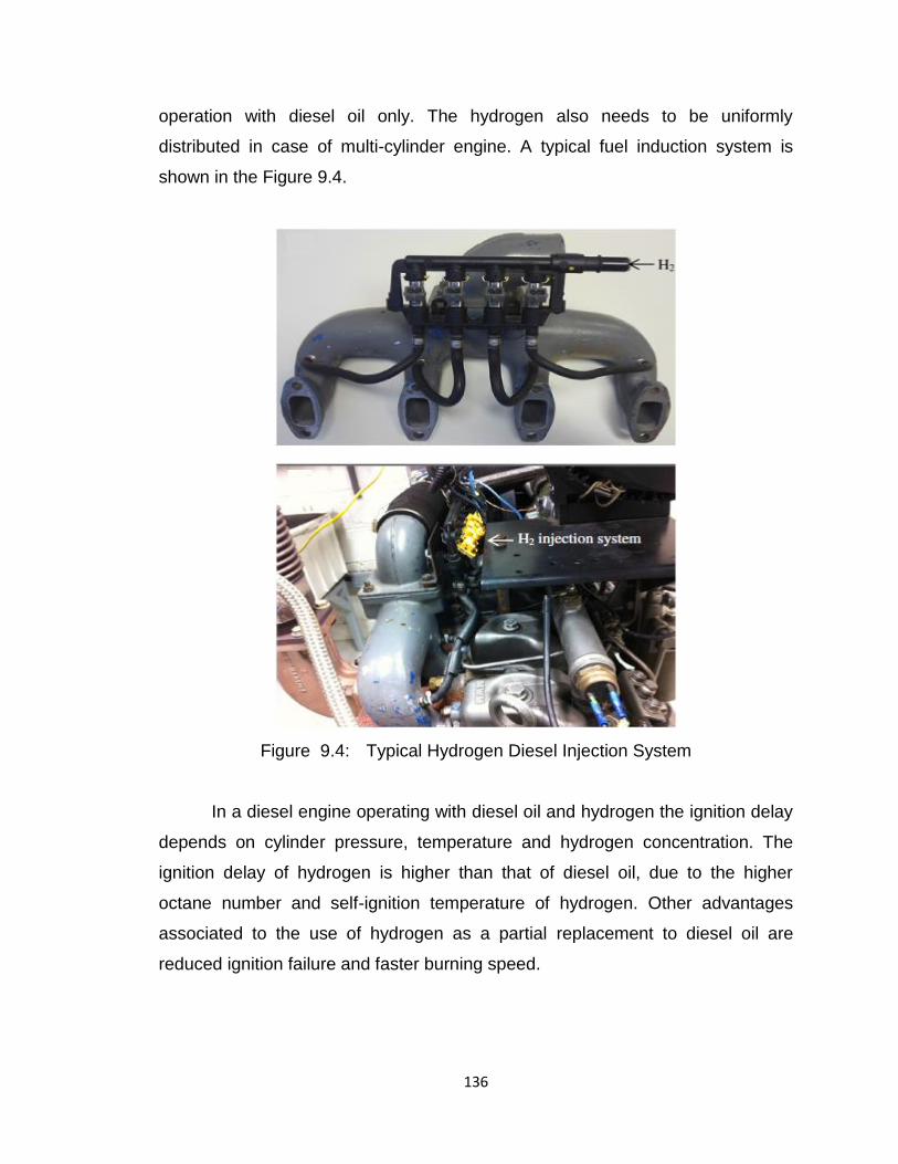
136
operation with diesel oil only. The hydrogen also needs to be uniformly
distributed in case of multi-cylinder engine. A typical fuel induction system is
shown in the Figure 9.4.
Figure 9.4: Typical Hydrogen Diesel Injection System
In a diesel engine operating with diesel oil and hydrogen the ignition delay
depends on cylinder pressure, temperature and hydrogen concentration. The
ignition delay of hydrogen is higher than that of diesel oil, due to the higher
octane number and self-ignition temperature of hydrogen. Other advantages
associated to the use of hydrogen as a partial replacement to diesel oil are
reduced ignition failure and faster burning speed.
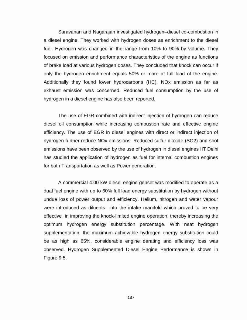
137
Saravanan and Nagarajan investigated hydrogen–diesel co-combustion in
a diesel engine. They worked with hydrogen doses as enrichment to the diesel
fuel. Hydrogen was changed in the range from 10% to 90% by volume. They
focused on emission and performance characteristics of the engine as functions
of brake load at various hydrogen doses. They concluded that knock can occur if
only the hydrogen enrichment equals 50% or more at full load of the engine.
Additionally they found lower hydrocarbons (HC), NOx emission as far as
exhaust emission was concerned. Reduced fuel consumption by the use of
hydrogen in a diesel engine has also been reported.
The use of EGR combined with indirect injection of hydrogen can reduce
diesel oil consumption while increasing combustion rate and effective engine
efficiency. The use of EGR in diesel engines with direct or indirect injection of
hydrogen further reduce NOx emissions. Reduced sulfur dioxide (SO2) and soot
emissions have been observed by the use of hydrogen in diesel engines IIT Delhi
has studied the application of hydrogen as fuel for internal combustion engines
for both Transportation as well as Power generation.
A commercial 4.00 kW diesel engine genset was modified to operate as a
dual fuel engine with up to 60% full load energy substitution by hydrogen without
undue loss of power output and efficiency. Helium, nitrogen and water vapour
were introduced as diluents into the intake manifold which proved to be very
effective in improving the knock-limited engine operation, thereby increasing the
optimum hydrogen energy substitution percentage. With neat hydrogen
supplementation, the maximum achievable hydrogen energy substitution could
be as high as 85%, considerable engine derating and efficiency loss was
observed. Hydrogen Supplemented Diesel Engine Performance is shown in
Figure 9.5.
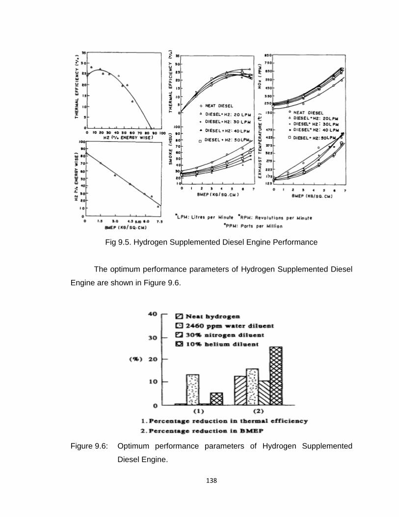
138
Fig 9.5. Hydrogen Supplemented Diesel Engine Performance
The optimum performance parameters of Hydrogen Supplemented Diesel
Engine are shown in Figure 9.6.
Figure 9.6: Optimum performance parameters of Hydrogen Supplemented
Diesel Engine.
139
Results from diesel engines operating with hydrogen fractions from 5% to
50% at different loads show reduced combustion duration, reduced heat transfer
rate to the cylinder walls and increased effective engine efficiency, with more
convincing results obtained for hydrogen concentrations below 30%.
Computational studies show that hydrogen increases effective engine
efficiency of a diesel engine mainly due to the differences of entropy between
hydrogen and hydrocarbon fuel combustion.
Hydrogen SI Engine Route for power generation
The SI engines which are used for power generation currently run on
natural gas, but they can be optimized to run on propane, gasoline, biogas, or
LPG etc. CI engines conventionally operate on diesel fuel. In developed
countries like US, European countries prefer to use SI engine for power
generation rather than CI engine due to the emissions from the later particularly
associated with NOx and PM. In India too SI engine operated power generation is
on the rise with major gen-set suppliers providing the Si variant. SI engines can
be operated in two modes
a) Pure Hydrogen Mode
b) In dual fuel mode
Pure Hydrogen Mode
Hydrogen is an excellent fuel for SI engines. Its wide ignition limits and
hence the ability to operate with limited throttling losses, high flame speed that
leads to near constant volume combustion and high thermal efficiency, good
mixing characteristics that allow high speed operation and formation of a
homogeneous mixture with ease, resistance to auto-ignition that allows relatively
high compression ratios to be used without end gas knocking and ability to be
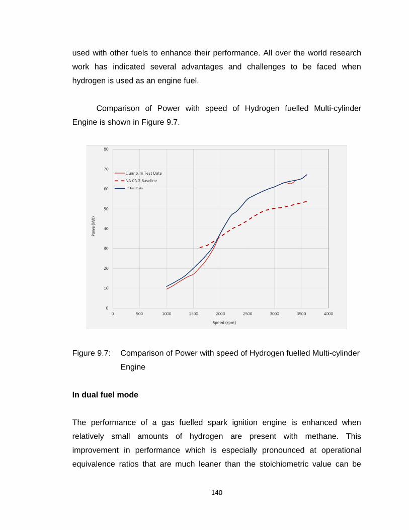
140
used with other fuels to enhance their performance. All over the world research
work has indicated several advantages and challenges to be faced when
hydrogen is used as an engine fuel.
Comparison of Power with speed of Hydrogen fuelled Multi-cylinder
Engine is shown in Figure 9.7.
Figure 9.7: Comparison of Power with speed of Hydrogen fuelled Multi-cylinder
Engine
In dual fuel mode
The performance of a gas fuelled spark ignition engine is enhanced when
relatively small amounts of hydrogen are present with methane. This
improvement in performance which is especially pronounced at operational
equivalence ratios that are much leaner than the stoichiometric value can be
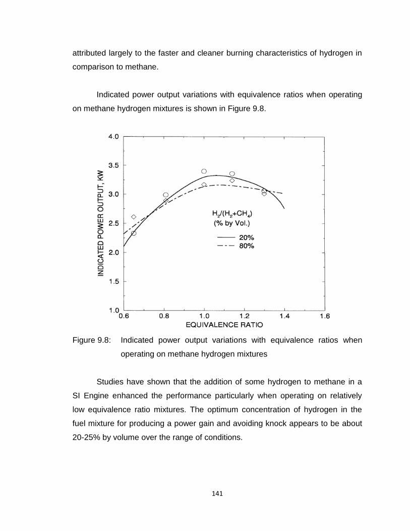
141
attributed largely to the faster and cleaner burning characteristics of hydrogen in
comparison to methane.
Indicated power output variations with equivalence ratios when operating
on methane hydrogen mixtures is shown in Figure 9.8.
Figure 9.8: Indicated power output variations with equivalence ratios when
operating on methane hydrogen mixtures
Studies have shown that the addition of some hydrogen to methane in a
SI Engine enhanced the performance particularly when operating on relatively
low equivalence ratio mixtures. The optimum concentration of hydrogen in the
fuel mixture for producing a power gain and avoiding knock appears to be about
20-25% by volume over the range of conditions.
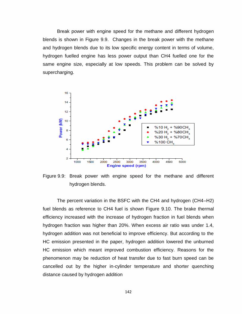
142
Break power with engine speed for the methane and different hydrogen
blends is shown in Figure 9.9. Changes in the break power with the methane
and hydrogen blends due to its low specific energy content in terms of volume,
hydrogen fuelled engine has less power output than CH4 fuelled one for the
same engine size, especially at low speeds. This problem can be solved by
supercharging.
Figure 9.9: Break power with engine speed for the methane and different
hydrogen blends.
The percent variation in the BSFC with the CH4 and hydrogen (CH4–H2)
fuel blends as reference to CH4 fuel is shown Figure 9.10. The brake thermal
efficiency increased with the increase of hydrogen fraction in fuel blends when
hydrogen fraction was higher than 20%. When excess air ratio was under 1.4,
hydrogen addition was not beneficial to improve efficiency. But according to the
HC emission presented in the paper, hydrogen addition lowered the unburned
HC emission which meant improved combustion efficiency. Reasons for the
phenomenon may be reduction of heat transfer due to fast burn speed can be
cancelled out by the higher in-cylinder temperature and shorter quenching
distance caused by hydrogen addition
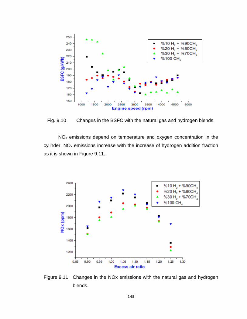
143
Fig. 9.10 Changes in the BSFC with the natural gas and hydrogen blends.
NOx emissions depend on temperature and oxygen concentration in the
cylinder. NOx emissions increase with the increase of hydrogen addition fraction
as it is shown in Figure 9.11.
Figure 9.11: Changes in the NOx emissions with the natural gas and hydrogen
blends.
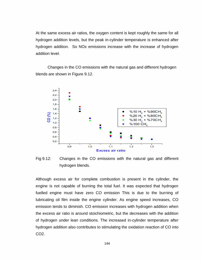
144
At the same excess air ratios, the oxygen content is kept roughly the same for all
hydrogen addition levels, but the peak in-cylinder temperature is enhanced after
hydrogen addition. So NOx emissions increase with the increase of hydrogen
addition level.
Changes in the CO emissions with the natural gas and different hydrogen
blends are shown in Figure 9.12.
Fig 9.12: Changes in the CO emissions with the natural gas and different
hydrogen blends.
Although excess air for complete combustion is present in the cylinder, the
engine is not capable of burning the total fuel. It was expected that hydrogen
fuelled engine must have zero CO emission This is due to the burning of
lubricating oil film inside the engine cylinder. As engine speed increases, CO
emission tends to diminish. CO emission increases with hydrogen addition when
the excess air ratio is around stoichiometric, but the decreases with the addition
of hydrogen under lean conditions. The increased in-cylinder temperature after
hydrogen addition also contributes to stimulating the oxidation reaction of CO into
CO2.
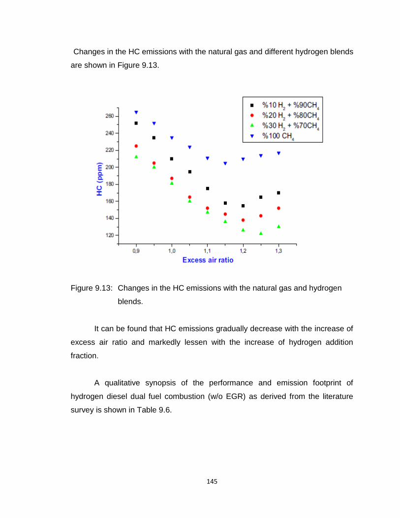
145
Changes in the HC emissions with the natural gas and different hydrogen blends
are shown in Figure 9.13.
Figure 9.13: Changes in the HC emissions with the natural gas and hydrogen
blends.
It can be found that HC emissions gradually decrease with the increase of
excess air ratio and markedly lessen with the increase of hydrogen addition
fraction.
A qualitative synopsis of the performance and emission footprint of
hydrogen diesel dual fuel combustion (w/o EGR) as derived from the literature
survey is shown in Table 9.6.
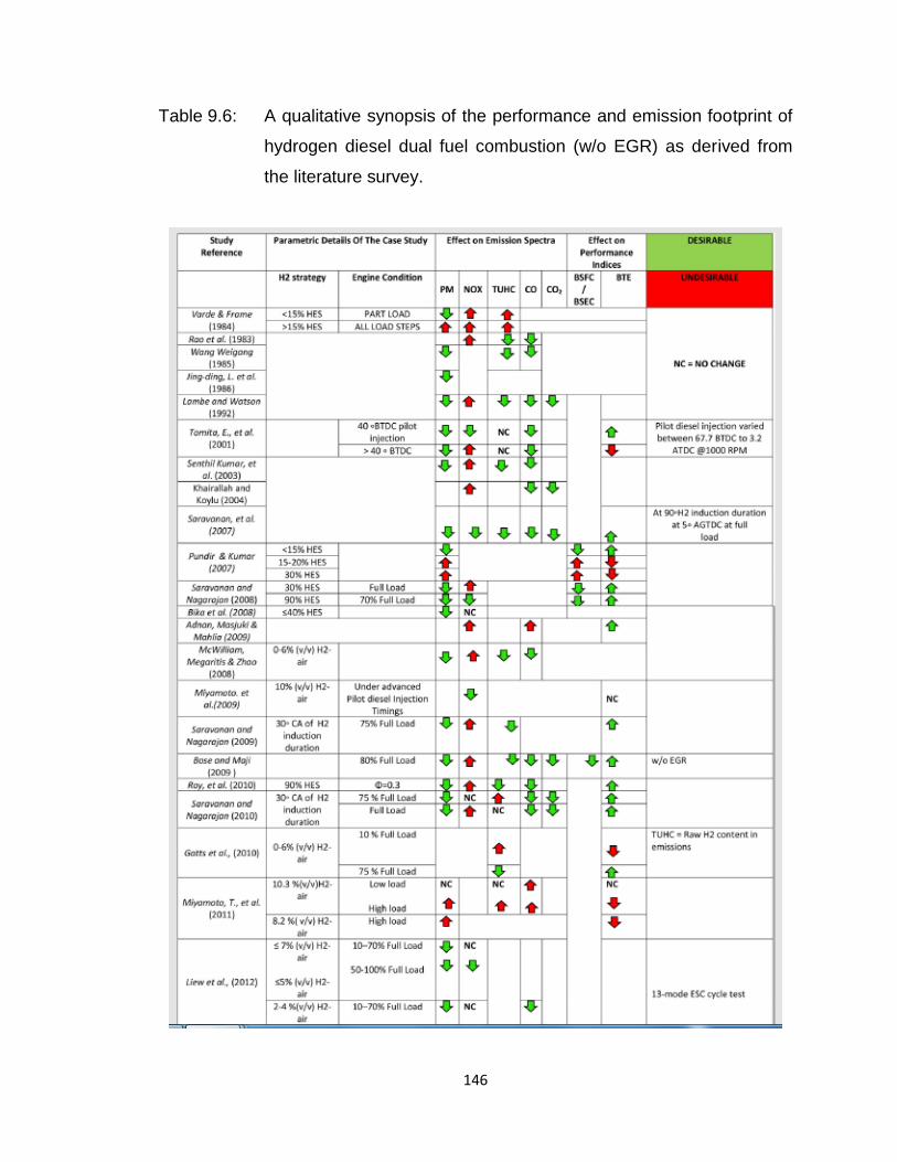
146
Table 9.6: A qualitative synopsis of the performance and emission footprint of
hydrogen diesel dual fuel combustion (w/o EGR) as derived from
the literature survey.

147

148
DISTRIBUTED POWER GENERATION
149
10.0 DISTRIBUTED POWER GENERATION
10.1 Introduction
While considerable amount of work is focused on hydrogen for
transportation, distributed power generation has not received much attention.
This initiative is very relevant for India today. Population of more than 300 million
in the world does not have access to the electrical grid, as it is expensive to
provide grid connectivity to populations located in remote, isolated, and
geographically difficult terrains. Unfortunately our country has largest such
population. Such communities primarily have two types of energy requirements-
first as electrical energy for lighting and for electrical appliances and secondly, for
meeting their energy needs of cooking. Renewable energy based distributed
generation is the right solution. To meet such types of energy demand through
renewable (e.g. solar and wind) alone becomes expensive, particularly for
cooking. The green power sources are renewable but not sustainable. These
cannot give power round the clock. That is why storage is required and hydrogen
is a good option of energy storage.
To make renewable energy sustainable, there is need to develop a
reliable, green, sustainable, and economical ESS (Energy Storage System).
There are several energy storage options are available but storage of excess
electrical energy in for of hydrogen has several advantages. Details of
Characteristics of different Energy Storage System are given in Table 10.1.
Table 10.1: Details of Characteristics of different Energy Storage System.
Characteristics Extra Large Scale Large Scale Medium Scale
Response time < 15 minutes < 15 minutes 1-30 seconds
Discharge
duration
Days to weeks Hours to days Minutes to hours
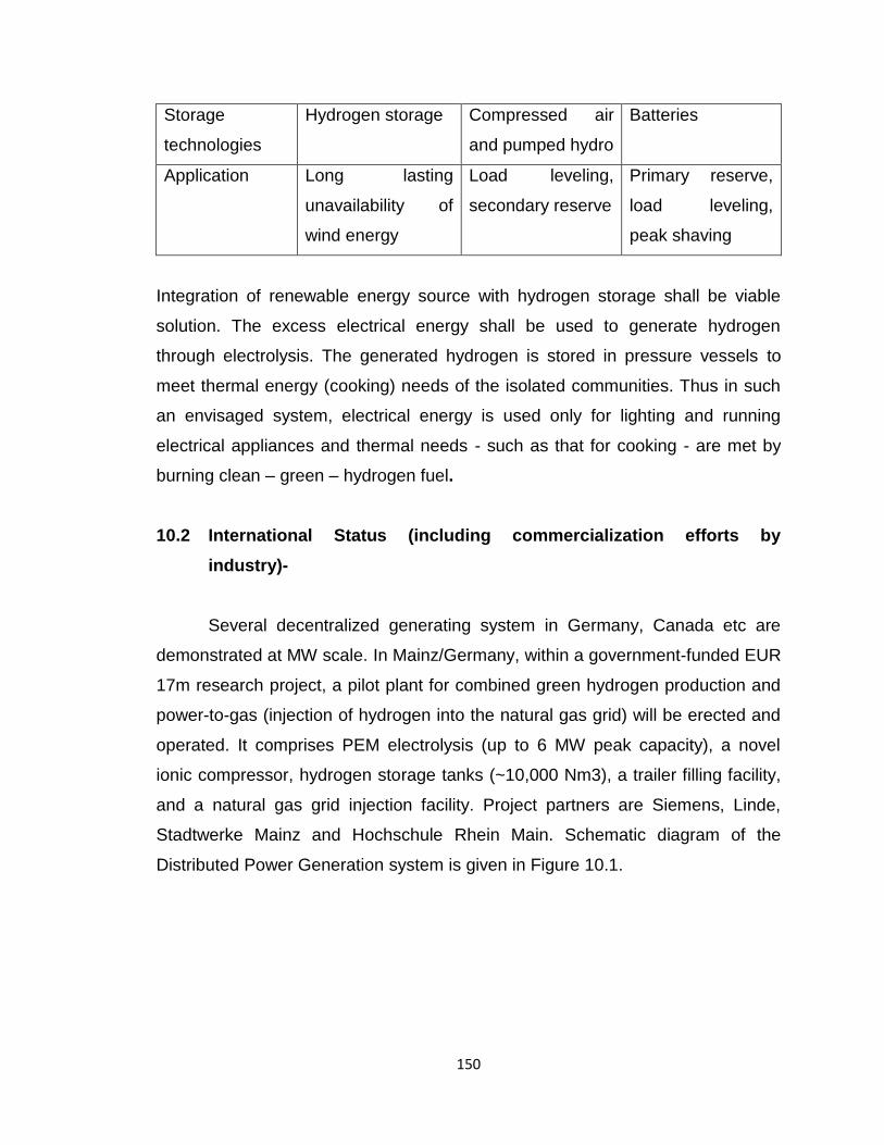
150
Storage
technologies
Hydrogen storage Compressed air
and pumped hydro
Batteries
Application Long lasting
unavailability of
wind energy
Load leveling,
secondary reserve
Primary reserve,
load leveling,
peak shaving
Integration of renewable energy source with hydrogen storage shall be viable
solution. The excess electrical energy shall be used to generate hydrogen
through electrolysis. The generated hydrogen is stored in pressure vessels to
meet thermal energy (cooking) needs of the isolated communities. Thus in such
an envisaged system, electrical energy is used only for lighting and running
electrical appliances and thermal needs - such as that for cooking - are met by
burning clean – green – hydrogen fuel.
10.2 International Status (including commercialization efforts by
industry)-
Several decentralized generating system in Germany, Canada etc are
demonstrated at MW scale. In Mainz/Germany, within a government-funded EUR
17m research project, a pilot plant for combined green hydrogen production and
power-to-gas (injection of hydrogen into the natural gas grid) will be erected and
operated. It comprises PEM electrolysis (up to 6 MW peak capacity), a novel
ionic compressor, hydrogen storage tanks (~10,000 Nm3), a trailer filling facility,
and a natural gas grid injection facility. Project partners are Siemens, Linde,
Stadtwerke Mainz and Hochschule Rhein Main. Schematic diagram of the
Distributed Power Generation system is given in Figure 10.1.
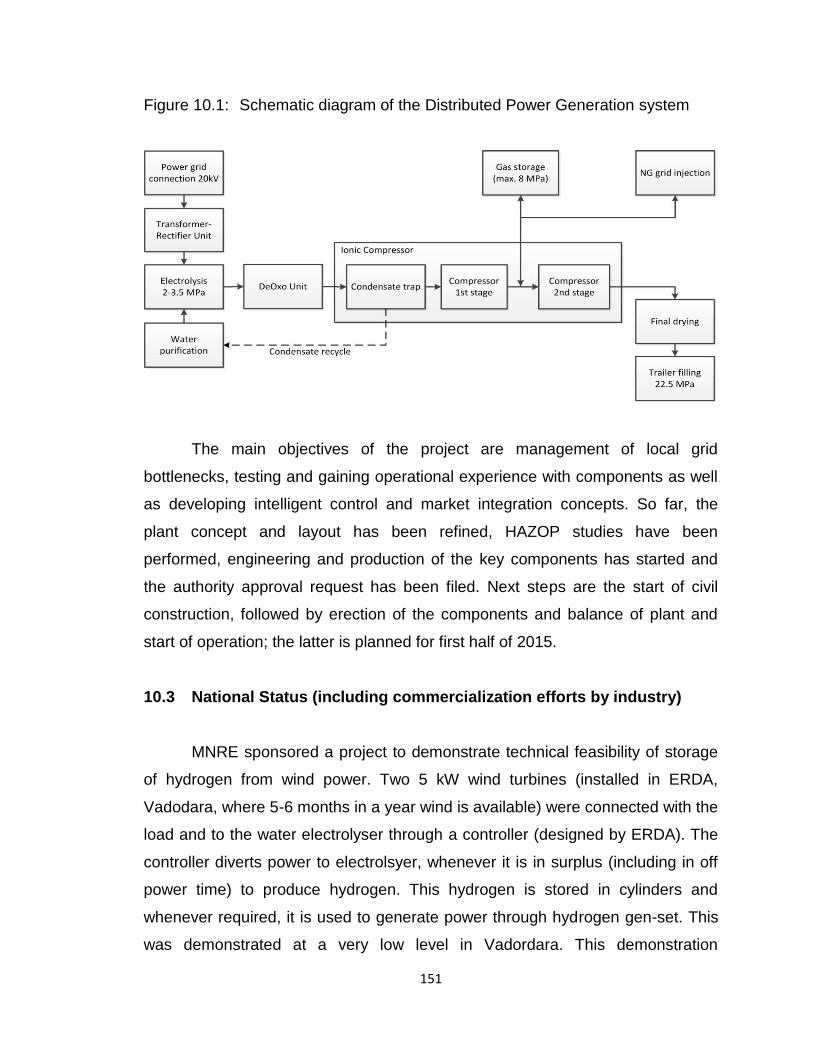
151
Figure 10.1: Schematic diagram of the Distributed Power Generation system
The main objectives of the project are management of local grid
bottlenecks, testing and gaining operational experience with components as well
as developing intelligent control and market integration concepts. So far, the
plant concept and layout has been refined, HAZOP studies have been
performed, engineering and production of the key components has started and
the authority approval request has been filed. Next steps are the start of civil
construction, followed by erection of the components and balance of plant and
start of operation; the latter is planned for first half of 2015.
10.3 National Status (including commercialization efforts by industry)
MNRE sponsored a project to demonstrate technical feasibility of storage
of hydrogen from wind power. Two 5 kW wind turbines (installed in ERDA,
Vadodara, where 5-6 months in a year wind is available) were connected with the
load and to the water electrolyser through a controller (designed by ERDA). The
controller diverts power to electrolsyer, whenever it is in surplus (including in off
power time) to produce hydrogen. This hydrogen is stored in cylinders and
whenever required, it is used to generate power through hydrogen gen-set. This
was demonstrated at a very low level in Vadordara. This demonstration
152
encourages to scale up wind hydrogen system particularly for remote locations
such as islands. India also can explore possibility of acquiring this technology
where it is already proven.
Water electrolyser is key component to succeed the hydrogen mission.
Among three electrolyser technologies, alkaline electrolyser is proven,
economical and available at large ratings. There are half a dozen alkaline
electrolyser manufacturers are available in India. However, there is need to
improve performance of indigenous alkaline electrolyser technology by
incorporation of feature to operate at higher pressure using new materials,
making more economical and efficient.
10.4 Action Plan (could consist of the following to the extent possible)
Following actions shall be considered:
(a) Feasibility of Power to gas project in India collaborations with all stake
holders such as ONGC, GAIL, and PGCIL, Utilities, CEA etc.
(b) Demonstration of hydrogen village where all energy requirement shall met
through renewable based distributed generation having hydrogen as energy
storage medium.
(c) Development of efficient, economical high pressure alkaline electrolyser
technology in collaboration with Indian industries.
(d) Application of hydrogen in chlore alkali industries
(e) Demonstration of MW scale wind hydrogen system
153
METAL HYDRIDE BASED COOLING
SYSTEMS
154
11.0 METAL HYDRIDE BASED COOLING SYSTEMS
11.1 While the hydrogen absorption-desorption property is used in applications
like hydrogen storage and purification, the reaction enthalpy changes can be
applied in making hydrogen compressors and thermal machines such as
refrigerators, heat pumps, etc.
The simple metal-hydrogen-thermodynamic machine, shown in Fig.11.1,
operated as a single-stage heat pump, consist of two reactors filled with
different materials A and B between which hydrogen is cyclically exchanged.
The machine is operated on three temperature levels (TD>TM>TC) and two
pressure levels (PH>PL). It is driven by heat input to A at the high
temperature TD, thereby desorbing hydrogen. The hydrogen flows to metal B
which absorbs it, thereby forming a hydride and releasing the absorption enthalpy
at a medium temperature level TM (first half cycle). In the second half cycle,
there is heat input to hydride B at a low temperature TC, e.g. from the
environment or other low temperature source, upgrading this heat to a higher
temperature level TM by desorption of B, then hydrogen flow to A,
absorption in A, releasing absorption enthalpy at TM. Between the two half
cycles there are transition periods, where the two reactors have to be cooled
down/heated up. The sensible heating up causes thermal losses which can be
(partly) compensated by internal heat recovery between respective reactors. In
the case of heat pump, there is a quasi-continuous heat output from the cyclically
operated machine.
In case of a refrigerator (TC<TA, TM≈TA) there is only one cold
generating half cycle. The same holds for the thermodynamically reversed heat
pump, the heat transformer; in which there is heat input at medium temperature
in each half cycle, but heat output at high temperature only in one half cycle. In
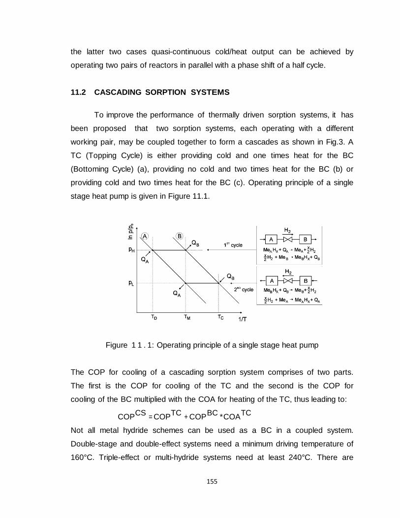
155
the latter two cases quasi-continuous cold/heat output can be achieved by
operating two pairs of reactors in parallel with a phase shift of a half cycle.
11.2 CASCADING SORPTION SYSTEMS
To improve the performance of thermally driven sorption systems, it has
been proposed that two sorption systems, each operating with a different
working pair, may be coupled together to form a cascades as shown in Fig.3. A
TC (Topping Cycle) is either providing cold and one times heat for the BC
(Bottoming Cycle) (a), providing no cold and two times heat for the BC (b) or
providing cold and two times heat for the BC (c). Operating principle of a single
stage heat pump is given in Figure 11.1.
Figure 1 1 . 1: Operating principle of a single stage heat pump
The COP for cooling of a cascading sorption system comprises of two parts.
The first is the COP for cooling of the TC and the second is the COP for
cooling of the BC multiplied with the COA for heating of the TC, thus leading to:
COPCS
= COPTC
+ COP BC
*COATC
Not all metal hydride schemes can be used as a BC in a coupled system.
Double-stage and double-effect systems need a minimum driving temperature of
160°C. Triple-effect or multi-hydride systems need at least 240°C. There are
156
some other sorption systems which can provide such temperatures, but their
efficiencies for cooling as well as heat pumping are rather low. Therefore only
metal hydride single-stage/single-effect systems are suitable for the use as a
BC. Such single-stage/single-effect systems can be operated with driving
temperatures between 90 and 130°C; the maximum COPs that can be obtained
are in the range of 0.5 to 0.7. If the use of metal hydride systems as a TC is
considered, the results are more promising. The requirements are a high
temperature of the released heat and either a very good COP or a very good
COA. In principle, every machine scheme can be used as TC. However, if a
single-stage system is used, there are no hydrides available which can deliver
high efficiencies for the typical thermal boundary conditions of refrigeration
conditions, and at the same time operate at pressure levels below 10MPa.
Multi-hydride systems have also some disadvantages. The heat is not released at
a constant temperature and the maximum COPs are around 0.9. To get good
COAs, the driving temperature has to be in the range of 400 to 500°C which is
difficult to handle with oil as heat transfer fluid. However, double-effect, triple-
effect and double- stage systems or their combinations can fulfill the requirements
for TC.
11.3 Metal Hydrides for Bottoming Cycles: Zeolite-water, salt-ammonia or
nitrate-water systems can be used as TC. A zeolite-water system with a driving
temperature of 310°C, providing heat at a temperature of 100°C can reach a
COP of 0.53 and a COA of 1.53. Coupling with an appropriate metal hydride
system with a driving temperature of 95°C and a COP of 0.65 would result in an
overall COP of 1.52. With the same metal hydride system, a salt-ammonia
system with a driving temperature of 290°C, a COP of 0.25 and a COA of 1.17
an overall COPCS of 1.01 can be reached.
11.4 Metal Hydrides for Topping Cycles: If metal hydride systems are used as
TC, silica gel-water or LiBr- water systems can be used as BC. For example,
silicagel-water systems can be driven with a temperature between 80 to 100°C
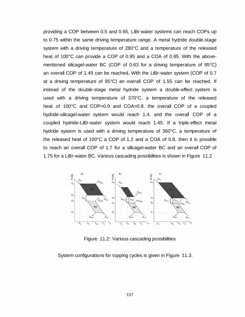
157
providing a COP between 0.5 and 0.65, LiBr-water systems can reach COPs up
to 0.75 within the same driving temperature range. A metal hydride double-stage
system with a driving temperature of 280°C and a temperature of the released
heat of 100°C can provide a COP of 0.95 and a COA of 0.85. With the above-
mentioned silicagel-water BC (COP of 0.63 for a driving temperature of 95°C)
an overall COP of 1.49 can be reached. With the LiBr-water system (COP of 0.7
at a driving temperature of 95°C) an overall COP of 1.55 can be reached. If
instead of the double-stage metal hydride system a double-effect system is
used with a driving temperature of 370°C, a temperature of the released
heat of 100°C and COP=0.9 and COA=0.8, the overall COP of a coupled
hydride-silicagel-water system would reach 1.4, and the overall COP of a
coupled hydride-LiBr-water system would reach 1.45. If a triple-effect metal
hydride system is used with a driving temperature of 360°C, a temperature of
the released heat of 100°C a COP of 1.2 and a COA of 0.8, then it is possible
to reach an overall COP of 1.7 for a silicagel-water BC and an overall COP of
1.75 for a LiBr-water BC. Various cascading possibilities is shown in Figure 11.2
Figure 11.2: Various cascading possibilities
System configurations for topping cycles is given in Figure 11.3.
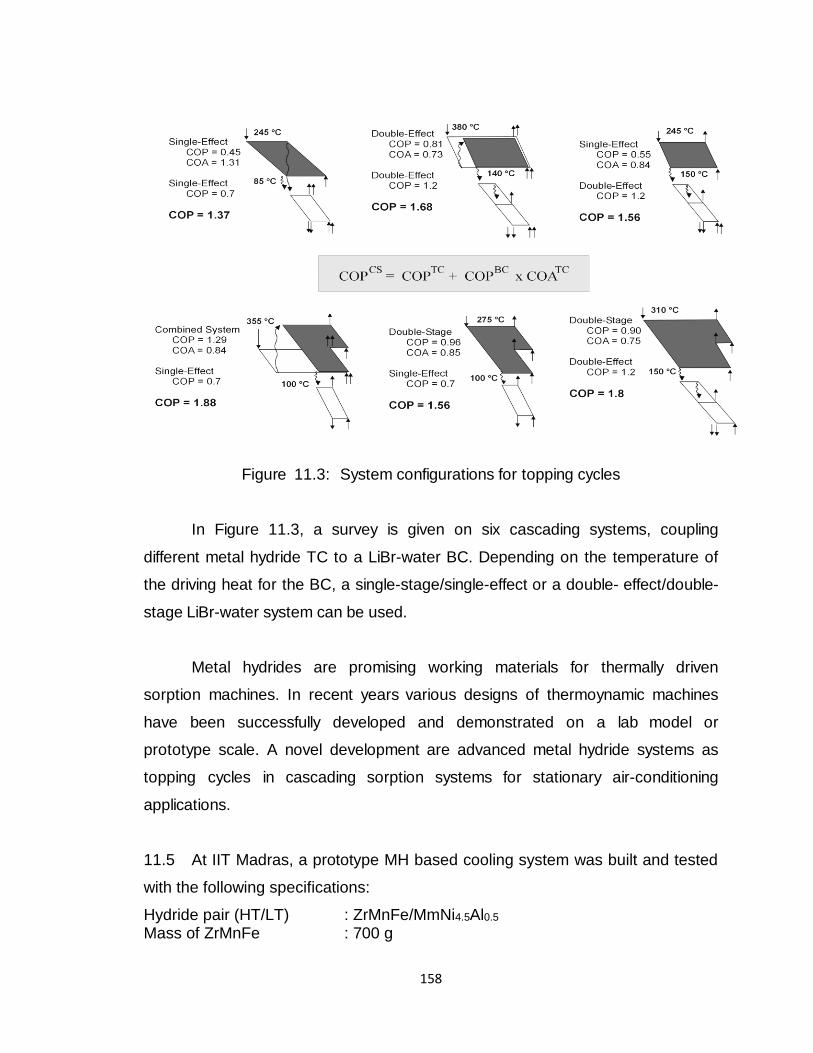
158
Figure 11.3: System configurations for topping cycles
In Figure 11.3, a survey is given on six cascading systems, coupling
different metal hydride TC to a LiBr-water BC. Depending on the temperature of
the driving heat for the BC, a single-stage/single-effect or a double- effect/double-
stage LiBr-water system can be used.
Metal hydrides are promising working materials for thermally driven
sorption machines. In recent years various designs of thermoynamic machines
have been successfully developed and demonstrated on a lab model or
prototype scale. A novel development are advanced metal hydride systems as
topping cycles in cascading sorption systems for stationary air-conditioning
applications.
11.5 At IIT Madras, a prototype MH based cooling system was built and tested
with the following specifications:
Hydride pair (HT/LT) : ZrMnFe/MmNi4.5Al0.5 Mass of ZrMnFe : 700 g
159
Mass of MmNi4.5Al0.5 : 800 g Cycle time : 3 to 12 minutes Heat source temperature : 110 to 130oC Heat sink temperature : 25 to 30oC Cold temperature : 5 to 15oC Cooling capacity : 50 to 100 Watts Cooling COP : 0.2 to 0.35
Further studies at IIT Madras also showed that MH based systems can be used
for small capacity portable freezers (e.g. vaccine or serum storage) of
performance better than the thermoelectric freezers, as seen in Table 11.1.
Table 11.1: Performance of MH based systems.
Hot Side MH / Cold Side MH Thot (oC)
Tambient (oC)
Tcold (oC)
P (atm)
COP
La Ni4.9Al0.1 / MmNi4.15Fe0.85 127/107 45/30 -12/-25 24/1.4 0.49
LaNi4.75Al0.25 / Ti0.8Zr0.2Cr0.8Mn1.2 132/112 45/30 -14/-26 14/0.6 0.50
LaNi4.83Al0.17 / Ti0.8Zr0.2Cr0.8Mn1.2 130/110 45/30 -11/-23 14/0.7 0.53
ZrMnFe / MmNi4.5Al0.5 132/125 45/30 -15/-20 8/0.5 0.46
Internationally, several types of MH based cooling systems have been
built and tested for applications such as automobile airconditioning, freezer food
storage, etc. While Israel has run buses with MH airconditioners, in Japan
several food freezer stores are in operation. Tokai University of Japan has
developed a MH freezer of 2 kW cooling capacity at 0 C using alloys of “Ti-Zr-
Mn-V-Fe-Al” (36 kg x 2 for H.T. and 30 kg x 2 for L.T.) with a single abs/des
cycle taking 7.5 hours. Cooling water from ground water and high temp (200 ℃)
waste heat from a steel factory were used.
Another Japanese study has shown that huge benefits in energy
conservation and CO2 reduction can be achieved with MH based systems. For
cooling capacity of 10 kW at -30C, typical vapour compression freezer consumed
about 7 kW electric power, whereas the MH based freezer consumed only about
2.3 kW in addition to about 20 kW of heat (which can be solar or waste heat)
leading to a significant reduction of CO2 emission by over 70 percent.
160
11.6 ACTION PLAN
Within the Country, capability exists to design and develop MH reactors of
wide-ranging specifications (capacities, temperatures, pressures, kinetics, etc.).
Specific application areas where MH based cooling systems would be beneficial
need to be identified. Automobile air conditioning wherein hydrogen storage
devices readily exist is a possible area. Food storage (both freezer and cooler) is
another application deserving attention. In addition to being environment friendly,
these systems can utilize waste heat from process industries and also solar
thermal energy.

161
CHEMI-SORPTION THERMAL ENERGY
STORAGE WITH METAL HYDRIDES
162
12.0 CHEMI-SORPTION THERMAL ENERGY STORAGE WITH
METAL HYDRIDES
12.1 Introduction
A major advantage of reversible thermochemical energy storage systems
is that the products are stored as stable chemicals, preferably at ambient
temperatures. Hence, they can be stored indefinitely without incurring thermal
losses, thereby greatly increasing overall system efficiency. Another advantage is
that the heat is released at a constant temperature if the heat can be removed
fast enough to prevent self-heating.
Metal hydrides provide an attractive possibility for thermal energy storage.
Compared to conventional thermo-chemical reactions, metal hydride based
systems offer several favorable features such as:
• Wide range of temperatures and kinetics are possible by tailoring the alloy
compositions
• Temperature upgradation of the heat source can be achieved by heat
pump/heat transformer effects
• Better heat and mass transfer characteristics and amenable to
augmentation techniques
• Comparable gravimetric / sometimes better volumetric energy storage
densities
• Cycling degradation (both physical and chemical) is minimal.
• Volume changes during absorption – desorption are minimal.
• Corrosion, toxicity, etc are avoided. Generally environment fiendly.
Flammability of H2 is an issue but can be easily handled.
• Cost is not prohibitive if one chooses suitable components and also
designs optimally. Sizing is an important issue.
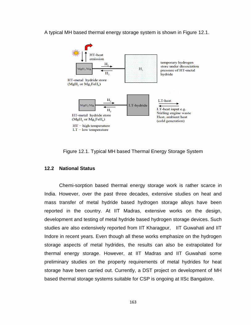
163
A typical MH based thermal energy storage system is shown in Figure 12.1.
Figure 12.1. Typical MH based Thermal Energy Storage System
12.2 National Status
Chemi-sorption based thermal energy storage work is rather scarce in
India. However, over the past three decades, extensive studies on heat and
mass transfer of metal hydride based hydrogen storage alloys have been
reported in the country. At IIT Madras, extensive works on the design,
development and testing of metal hydride based hydrogen storage devices. Such
studies are also extensively reported from IIT Kharagpur, IIT Guwahati and IIT
Indore in recent years. Even though all these works emphasize on the hydrogen
storage aspects of metal hydrides, the results can also be extrapolated for
thermal energy storage. However, at IIT Madras and IIT Guwahati some
preliminary studies on the property requirements of metal hydrides for heat
storage have been carried out. Currently, a DST project on development of MH
based thermal storage systems suitable for CSP is ongoing at IISc Bangalore.
164
12.3 International
Several studies are reported which deal with the effect of geometric and
operating parameters on the performance of the metal hydride based storage
device. Even internationally, metal hydride based chemi-sorption heat storage
studies are scarce. Yonezu et. Al. demonstrated heat storage system using
coupled metal hydride beds with heat pipes in beds of CaNi5 and LaNi5. CaNi5
operates in the temperature range of 40 to 100°C for heat storage and LaNi5
operates in a temperature range 20 to 40°C to collect and store the hydrogen
discharged from the CaNi5 hydride during heat storage phase. The stored heat is
recovered by reversing hydrogen transfer direction from LaNi5 to CaNi5. Later the
same group developed Zerconium based hydrides, ZrMn2-xCoxAly alloy with x =
0.4 to 0.7 and y<0.1 for use in temperature range of 100 to 200°C and ZrMn1.92-
xCoxV0.08 (0.2<x<0.4) for the temperature range 200 to 250°C. For high
temperature (300 to 500°C) heat storage applications Bogdanovic and his
coworkers studied Ni doped Mg/MgH2 systems. The system developed by them
is shown in Figure 2. Reiser et al. studied different Mg based systems for energy
storage. They found that Mg-Fe and Mg-Co systems exhibit low dissociation
pressures and these systems are of special interest for metal hydride based
cooling systems.
12.4 ACTION PLAN
Within the Country, capability exists to design and develop MH reactors of
wide-ranging specifications (capacities, temperatures, pressures, kinetics, etc.).
Specific application areas where MH based thermal storage systems would be
beneficial need to be identified. Several industrial processes (Food, Chemical,
Pharmaceutical, etc.) which utilize and also reject heat at various temperatures
are potential users of this technology. Concentrated solar power (CSP) systems,
especially of small capacity distributed type, can benefit from the use of MH
based thermal storage systems.
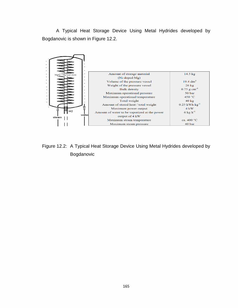
165
A Typical Heat Storage Device Using Metal Hydrides developed by
Bogdanovic is shown in Figure 12.2.
Figure 12.2: A Typical Heat Storage Device Using Metal Hydrides developed by
Bogdanovic

166
APPLICATION OF HYDROGEN FOR
COOKING
167
13.0 APPLICATION OF HYDROGEN FOR COOKING
13.1 Introduction
Future energy technology will utilize hydrogen with an increasing trend in
steady as well as unsteady combustion processes. Hydrogen allows particularly
low polluting processes without the necessity of taking care of in and out house
pollution. This contribution presents a short survey about the state of the art of
hydrogen combustion technology with particular emphasis as cooking source
replacing LPG and CNG. The necessary research and development effort will be
pointed out for the field of using H2 as cooking gas. Hydrogen is advantageous
over the conventional hydrocarbon fuels in the ease of catalytic ignition at low
temperatures. The feasibility of adoption of inexpensive wide range of catalysts.
However, it suffers from considerable non-uniform temperature distribution
over the catalyst surface in the diffusive mode of combustion. A special
design of fuel distribution would be required for reasonable mixing of
hydrogen with ambient air entering at the bottom of the catalyst body.
Therefore, a catalytic burning of the hydrogen in the home cooker is the best way
to use the hydrogen for cooking. The hydrogen can be used separately with
preheated catalyst as well as LPG–H2 mixed with preheated air in cooking
burner. The H2addition with LPG leads to a reduction in flame length and the
flame length is observed to be reduced with increasing reactant temperature.
However, the flame length is increased by increasing H2 addition with constant
LPG, which might have caused due to decrease in the Hydrogen and Carbon
ratio in the flame. The flame temperature decreases with increasing LPG ratio in
H2/LPG mixture.
13.2 Technical Issues
(i) Hydrogen Combustion: The combustion / burning of hydrogen in open or
nearly open ambience is a difficult exercise. This is due to the fact that self-
168
combustion / ignition energy of Hydrogen is extremely low. It is 0.02 mJ whereas
for LPG it is 0.29mJ. Thus, a hydrogen source can get ignited even by an
electrical spark or lightening. Therefore, controlled combustion of hydrogen in
open ambience is difficult. This combustion is quite different from confined
combustion of a certain fixed quantity of hydrogen as in cooker. The other
difficulty is that on combustion hydrogen produces a colorless flame. Therefore,
the effect of hydrogen burning in open ambience will be felt only when one enters
the invisible hydrogen fire.
It is in the light of the above that no other group in India (and very few
groups in the world) are doing any R & D and commercialization of device like
Hydrogen based cooker. Hydrogen Energy Group at B.H.U. has therefore,
undertaken the challenging project on “Development and Demonstration of
Hydrogen Catalytic Combustion Cooker” and has successfully completed the first
phase of the project.
(ii) The Hydrogen in Replacement of LPG: In India where most of the urban
population has switched over to LP instead of wood fuel, the consumption of LPG
has increased significantly. Thus whereas in 1980-81 the total requirement of
LPG was about 405 TMT, in 2000-2001 it rose up to 6,613 TMT and now in 2015
it has touched the gigantic figure of more than about 10,000 TMT. It may also
be pointed out that there is considerable subsidy on LPG. Thus at present
whereas the market price of LPG is ~Rs. 296 per cylinder, there is a subsidy of
Rs. ~316 (Real total price is Rs. 612/- per cylinder). Because of public reaction,
the GOI generally does not increase price of LPG even when there is a rise of
price on petrol and diesel. Finding substitute of LPG in Indian conditions appears
more urgent than for petrol and diesel. Another factor, which makes replacement
of LPG by clean fuel imperative, is the health aspect. According to WHO,
Chulhas using coal, wood and animal dung as fuel and the resulting indoor air
pollution has claimed 5 lacs lives in India in 2007. This is possibly the highest
number of deaths due to indoor air pollution.
169
(iii) The Hydrogen Based Catalytic Combustion Cooker: The first part of
investigation done in the BHU present project has been on determining the
conditions, which prevents kindling of Hydrogen in Air. Unlike LPG, this situation
arises due to altogether different physical properties of hydrogen. It has been
found that when the velocity of hydrogen air mixture is greater than the
combustion velocity of hydrogen, the combustion is not maintained and the flame
is blown out. With high combustion velocities of hydrogen-air mixtures (e.g. ~
3m/sec.), it does not appear feasible to maintain the necessary flow velocity over
the completely catalytic surface which is the desired complete combustion
condition.
To circumvent the above difficulty, we kept the hydrogen-air mixture
outside the combustion limits. For this, we took hydrogen content of less than ~
5 vol%. The catalyst surface is kept at a temperature lower than the self-ignition
temperature of hydrogen. It should be recognized that due to peculiar property of
hydrogen relating to the fact that it has a positive Joule Thomson coefficient, the
temperature rises in the gas at pressures higher than the atmospheric pressure.
In view of the above said criterion we kept, the surface of the catalytic
burner was optimized so that rate of heat generation did not exceed the
dissipation rate of heat. The optimum surface area corresponded to ~20cm2.
It should be realized that catalytic hydrogen cookers are pre-mixing
burners where the reaction rate and temperatures are dependent on the catalyst.
The basic difference between the catalytic combustion and direct combustion is
that the final temperature in the former can be varied. In the catalytic
combustion, cookers the envisaged temperatures are between ~ 200 to ~ 5000C.
The desired temperature is kept in between ~ 200 to ~5000C (temperature range
suitable for cooking) by controlling the feed rate of hydrogen. It should be
pointed out that in the cooker when the source of hydrogen is hydride there is no
170
danger of starting fire even when the temperature of the system is high (~e.g.
500oC).
(iv) The Catalyst and Catalytic Action in the Present Project (Catalytic
Combustion Cooker): Let us first outline the general considerations for catalysts
and catalytic action. The fault with the statement that man has had trouble with
combustion since Elijah and the burning bush lies in the fact that problem
probably arose long before then. The production of energy by oxidation has
always been desirable but has never been without difficulty. As a result, it seems
to be an unnecessary complication to involve a catalyst in the process.
Nevertheless, it has been found that advantages can be gained even though, as
expected, further problems arise.
Combustion itself is hard to control, occurs only within specific fuel: air
ratios and often produces pollutants. It is inefficient and energy recovery can be
difficult. The introduction of a heterogeneous catalyst allows better control of
oxidation over wider fuel: air ratios and produces less pollutants. On the debit
side, catalysts may poison under extreme operating conditions.
The principle of catalytic combustion is simple. Mixtures of fuel and air are
passed over a catalyst. Reaction occurs, liberating energy and oxidized products:
for organic fuels, these are carbon dioxide and water, which may be discharged
into the atmosphere. The reaction may be operated to generate energy (catalytic
heaters, catalytic boilers, and catalytic gas turbines) or to remove pollutants (car
exhaust clean-up catalysts etc.) In the case of hydrogen catalytic cookers,
reaction between hydrogen and oxygen occurs, producing heat energy and
steam/water which is non-polluting combustion.
There are several studies relating to catalytic combustion. The catalyst is used to
break hydrogen molecule in hydrogen atoms, which then burns with atmosphere
oxygen producing heat and steam/water. We may recall a well-known similar
171
catalytic reaction in ammonia synthesis. It is now well known that when a mixture
of nitrogen and hydrogen gas is passed over the catalyst, ammonia is formed.
When nitrogen molecules interact with iron atoms on the surface, they dissociate
at relatively low temperatures. Iron catalyses the dissociation of N2, in other
words it lowers the energy barrier so that two nitrogen atoms (of the molecule)
will separate easily. The iron atoms accomplish this by donating electrons to the
nitrogen molecule. As a result the iron atom forms a chemical bond with the
nitrogen molecule, and in a reciprocal manner, the bond between the two
nitrogen atoms in the molecule is weakened. The weak nitrogen-nitrogen bond
corresponds to a low energy barrier and facilitates N2 dissociation. This process
is typical of how catalysts work. The iron atom besides helping in dissociation of
iron performs two other important functions in the synthesis of ammonia. First
when hydrogen molecules H2 interact with the iron surface, the hydrogen-
hydrogen bond is weakened. Hydrogen atoms are thus easily freed and bind to
the surface so that they may react to form NH, NH2 and finally NH3, ammonia the
desired product.
Similar to the case of N2, there are several catalysts, which can dissociate
H2. Some of Cu, Zn these are Fe, Ni, Co, Ti some alloys like Co-Mn-Ag, storage
alloys like MmNi5, ZrFe2 etc. Of course Pt is known optimum catalyst for
hydrogen dissociation but it is ~100 to ~1000 times more expensive than the
above mentioned other catalysts. Unlike the use of Pt in hydrogen fueled
comparatively expensive devices like vehicles, for much cheaper devices like
hydrogen fueled cookers, use of Pt catalyst may not be feasible. Although we
used Pt derived from chloroplatinic acid, we have been using the following less
expensive but viable catalysts. Thus, the catalysts used correspond to Pt, Fe,
Cu, Zn and ZrFe2. There are two catalytic techniques which are relevant to
hydrogen fueled catalytic cookers. One is use of porous ceramic plate
embedded with platinum in pores. This produces flameless situation. Such as
approach has been followed by our chemical engineering group. A great
disadvantage of this method is the use of platinum (a very expensive and scarce
172
metal). The other catalytic technique relevant to hydrogen fueled cooker is based
on suggestions of Roger billing according to which for hydrogen, “flame assisted
catalysis” can also be produced. Thus when hydrogen air mixture is initially
ignited high temperature (> 12000C) flame is produced. Now if the metal around
the nozzle when heated with this flame the metal will start producing catalytic
action. Because of the catalytic action the burning temperature will come down
(e.g. 300 to 5000C). We have followed this strategy for our hydrogen based
cooker. Keeping in view the cost and ready machineability, we used brass metal
for fabrication of nozzle system of specific hole size. Some of these are stainless
steel, and copper. These were used in the form of wire mesh (2004) mapped
around the nozzle of the cooker.
13.3 INTERNATIONAL STATUS (INCLUDING COMMERCIALIZATION
EFFORTS BY INDUSTRY)
Several research groups all over the world are continuously working on
the catalytic combustion of hydrogen. The Government Industrial Research
Institute of Osaka, Japan, research group has done extensive work in the
experimental catalytic combustion of hydrogen. Their experimental study was
172tiliza on the effect of fundamental conditions of hydrogen fuelled
catalytic burners on their operating properties. In diffusive combustion, Pd-
power coated Ni foam with relatively large pores could offer the highest
combustion efficiency, however, it suffered from considerable non-uniform
distribution of surface temperature. It was demonstrated that a ceramic foam
coated with Co-Mn-Ag oxide was practically utilizable for catalytic
appliances operating on hydrogen fuel, although it required a little
preheating for initiating combustion. Premixing of air to a 40% stoichiometric
amount with hydrogen was effective in improving combustion efficiency. The
same group was also fabricated and tested two prototype heaters operating
on hydrogen. A prototype heater in which hydrogen was introduced only from
the bottom proved to yield inferior test results. This burner had appreciable
173
temperature non-uniformity and suffered from flame ignition invoked by hot
spots at the bottom of the catalyst. A modified prototype heater in which
hydrogen distribution was deliberately arranged exhibited relatively good test
results in temperature uniformity and overall combustion efficiency of
hydrogen. It could be operated at heat ratings from zero to 1.5 kcalcm -2h-1 with
sufficiently high combustion efficiencies. A notable difference in performance
was observed when Pt-impregnated nickel foam was replaced by the
oxide-coated one. However, combustion efficiencies exceeding 96% were
obtained up to a heat input of 1.0 kcal cm-2h-1. Other group from State Key
Laboratory of Multiphase Flow in Power Engineering, Xi’an Jiaotong University,
People’s Republic of China has done experimental study on the laminar flame
speed of hydrogen/carbon monoxide/air mixtures. They have demonstrated the
laminar flame speeds of H2, CO and H2/CO in a Bunsen burner at normal
temperature and pressure. The calculation of the laminar flame speeds was
based on the reaction zone area instead of the unburned flame area. The good
agreements among experimental results, and numerical simulations, and
previous works have validated. Other group from State Key Laboratory for
Turbulence and Complex Systems, Peking University, Beijing, China has studied
the effects of hydrogen addition on the propagation of spherical methane/air
flames. An experimental and numerical study on laminar burning characteristics
of the premixed methane–hydrogen–air flames was conducted at room
temperature and atmospheric pressure. The unstretched laminar burning velocity
and the Markstein length were obtained over a wide range of equivalence ratios
and hydrogen fractions. Moreover, for further understanding of the effect of
hydrogen addition on the laminar burning velocity, the sensitivity analysis and
flame structure were performed. The methane-dominated combustion regime
and the methane-inhibited hydrogen combustion regime, the laminar burning
velocity increases linearly with the increase of hydrogen fraction. However, in the
transition regime, the laminar burning velocity increases exponentially with the
increase of hydrogen fraction in the fuel blends.
174
Enhancement of chemical reaction with hydrogen addition as the increase
of H, O and OH radical mole fractions in the flame was also deliberated.
Research group from Department of Mechanical Engineering, University of
Maryland, USA has done R&D work on combustion characteristics of a lean
premixed LPG–H2 combustor. Other USA research group from Combustion and
Flame Dynamics Laboratory, School of Aerospace and Mechanical Engineering,
University of Oklahoma, has shown the effect of elliptic burner geometry and air
equivalence ratio on the nitric oxide emissions from turbulent hydrogen flames.
German Aerospace Research Establishment, Stuttgart, has also done extensive
R&D work on hydrogen combustion. Other German group from Fachhochschule
Stralsund, Komplexlabor Alternative Energie, Zur Schwedenschanze, Stralsund,
has established a non-stationary hydrogen cooker with portable hydride storage
and catalytic hydrogen burner. They have shown that for normal use the design
of the cooker was not favourable, so that the most important task is to adapt a
hydride material for the storage, which only requires the heat of the surrounding
air for dehydriding, but also has an acceptable mass-specific capacity. Then the
cooker could be constructed in two pieces, which makes the replacement of the
relatively heavy hydride storage easier. Furthermore, the cooker must be
constructed in a secure way, which both excludes any hazards in its use and
wrong operations of the cooker by the user.
A second way in the development of the cooker could be to construct
geometrically relatively small hydride storages, which are arranged underneath
the burner, to directly use the downward directed radiation. The UNIDO has also
considered the requirements for the installation of the autonomous zero-emission
energy supply system based on hydrogen as an energy carrier in developing
countries
13.4 NATIONAL STATUS (INCLUDING COMMERCIALIZATION EFFORTS
BY INDUSTRY)
175
In India, mainly four R&D groups are working in the area of application of
hydrogen for home cooking is being done mostly at our group at Banaras Hindu
University – Varanasi supported by MNRE. The main aim of this R&D was on
considerations/optimizations of hydrogen catalytic combustion, development of
catalysts including new catalysts for hydrogen catalytic combustion cooker,
synthesis and development of hydride of choice, development and optimization
of hydrogen catalytical combustion cooker, optimization of safety aspects of
hydrogen catalytic combustion cooker, feedback from users of hydrogen catalytic
combustion cookers. Where, the General considerations for development of
Hydrogen Catalytic Combustion Cooker have been worked out. Catalysts have
been identified. The Hydrides of choice for hydrogen storage for catalytic
combustion Hydrogen cooker have been selected. Some catalytic combustion
cookers have been fabricated and tests are being done. As outlined earlier
strategy of flame assisted catalyst has been used. This permits one to use
inexpensive catalyst. For a viable use of hydrogen cooker by general masses,
one rather serious issue has to be resolved. This relates to the fact that hydrogen
flame in the catalytic cooker, is nearly invisible. This is in one way quite risky.
Since it is difficult to see the hydrogen flame, one gets a feeling of it through
entering for example by the heating sensation it produces when you touch the
flame. The flame temperature for flame assisted catalytic hydrogen burning is
between 500 to 700oC and thus direct contact will produce burns and will be
injurious. One possible way out of it will be of use some sodium chloride NaCl to
burns with Brine. This turns invisible hydrogen flame visible by producing yellow
NaCl will dissociate when put to burn with the hydrogen flame. The Na ions will
emit yellow color. BHU R&D group looked into details of the flame developing
yellow color in order to optimize this way of making hydrogen flame, colored to
become visible and to find some better way of making the hydrogen flame visible.
When NaCl powder is placed around the burning port, it vaporizes producing Na
and Cl atoms (ions). The sodium vapor produces D line with a wavelength of
~589.5nm. This is one of the classified Fraunhofer lines observed in the visible
spectrum of sun. This wavelength corresponds to transitions in atomic sodium in
176
which the valence-electron transitions from a 3p to 3s electronic state. Closer
examination of the visible spectrum of atomic sodium reveals that the D-line
actually consists of two lines called the D1 and D2 lines at 589.6 nm and
589.0 nm, respectively. This fine structure results from a spin-orbit interaction of
the valence electron in the 3p electronic state. The spin-orbit interaction couples
the spin angular momentum and orbital angular momentum of a 3p electron to
form two states that are respectively notated as 3p(2P01/2) and 3p(2P0
3/2) in the LS
coupling scheme. The 3s state of the electron gives rise to a single state which is
notated as 3s(2S1/2) in the LS coupling scheme. The D1-line results from an
electronic transition between 3s(2S1/2) lower state and 3p(2P01/2) upper state. The
D2-line results from an electronic transition between 3s(2S1/2) lower state and
3p(2P03/2) upper state. Even closer examination of the visible spectrum of atomic
sodium would reveal that the D-line actually consists of a lot more than two lines.
These lines are associated with hyperfine structure of the 3p upper states and 3s
lower states. Many different transitions involving visible light near 589.5 nm may
occur between the different upper and lower hyperfine levels. The invisible
hydrogen flame turning yellow due to emission of sodium D line, is one
convenient and viable way of circumventing the risk involved with the invisible
hydrogen flame. However, there are certain disadvantages associated with this
which warrants development of an alternate way for making hydrogen color
visible. Another research group from Combustion Lab, Department of Aerospace
Engineering, Indian Institute of Technology, Kanpur, India has demonstrated the
experimental study of bluff-body stabilized LPG–H2jet diffusion flame with
preheated reactant. They have shown the emission index of NOx(EINOx) be
enhanced with increase in lip thickness and reactant temperature which may be
caused due to both enhanced residence time and thermal effect, respectively.

177
GAP ANALYSIS, ACTION PLAN,
CONCLUSIONS AND RECOMMENDATIONS

178
GAP ANALYSIS
179
14.0 GAP ANALYSIS
14.1 GAS HYDROGEN STORAGE
The development of ultralight but strong composite materials in recent
years has contributed to the development of lightweight high pressure storage
containers for hydrogen. These are categorized under Class 4 and can take
working pressures of 750 bar specified to make them applicable to mobile
applications. However, currently, such cylinders are to be imported. Within the
country, there are industries which are active on fabrication of components using
high performance composite materials. However, their entrance in to the high
pressure H2 cylinder market would depend on the demand for such cylinders.
For its in-house space related applications, ISRO is said to have developed wire-
wound composite high pressure cylinders. This technology may be taken up for
commercialization.
Cryogenic pressure vessels can store gaseous H2 at high densities
without evaporation losses at reasonable cost. They are more compact and
operate at lower pressures than conventional gas cylinders. However, these
require high performance insulations. Maintenance of low temperatures in mobile
devices is also an issue to be looked in to. There is a need for considering this
technology for use with automobiles.
14.2 LIQUID HYDROGEN STORAGE
The technology for handling LH2 is well established in space applications.
However, the cryogenic temperatures (20 K) associated with LH2 presents
serious technical and safety related challenges for automobile applications.
Moreover, liquefaction is an energy intensive process. This may be a possible
technology for large scale hydrogen transport, especially on barges using sea
routes.
180
14.3 SOLID STATE HYDROGEN STORAGE
Safety due to reasonable pressures and temperatures is the main
advantage of sorption based solid state storage. Significant developments have
been made on the synthesis and development of storage materials. However, the
major concern is still with the poor gravimetric capacities.
Capability to manufacture large quantities of both conventional (metal
hydrides) and novel (complex hydrides, MoFs, etc.) storage materials need to be
developed.
While the knowledge base for the mechanical and thermal design of
storage devices exists in the country, fabrication facilities for such large capacity
devices need to be established.
14.4 Institutions involved in different stages of development of the
products / processes and their infrastructure existing at present and
details of new infrastructure to be created
In the area of hydrogen storage R&D, emphasis has been on the solid
state materials led by Banaras Hindu University, Varanasi; Indian Institute of
Technology Madras, Chennai; Rajasthan University, Jaipur; International
Advanced Centre for Powder Metallurgy & New Materials (ARCI), Hyderabad;
Non-Ferrous Technology Development Centre (NFTDC), Hyderabad; etc.
Thermal and mechanical engineering design of solid state hydrogen
storage devices is extensively done by Indian Institute of Technology Madras,
Indian Institute of Technology Guwahati; Indian Institute of Science Bangalore;
Indian Institute of Technology Indore.
181
At the National Environmental Engineering Research Institute - Nagpur,
R&D activities related to hydrogen storage in liquid organic hydrides are being
carried out.
R&D on gas storage, especially on the development of composite
cylinders is rather scarce except at the Central Mechanical Engineering
Research Institute, Durgapur.
Indian Space Research Organization (ISRO) has extensive expertise in
handling both gaseous and liquid hydrogen for its space programs. This wealth
of knowledge needs to be tapped to extend hydrogen applications to automobiles
and power generation in the country.
The MNRE funded Centre of Excellence in Hydrogen Energy at BHU has
established facilities to synthesize and characterize storage materials of
reasonable quantities. However, most of the other academic and research
organisations have facilities for production and characterization of solid state
storage materials only in small quantities. Therefore, suitable industrials units
are required to be identified for production of materials in large quantities with a
view to commercialise the materials developed by R&D institutions in the country.
Such commercials units may also take up the job of production of canisters /
devices of different storage capacities and operating conditions.
There is an urgent need for establishing facilities for the design,
development and indigenous manufacturing of Type-III and Type-IV composite
cylinders, which are presently being imported.
The Centre of Excellence for Hydrogen Energy at BHU specializes on the
development, synthesis and characterisation of hydrogen storage materials. This
can be further strengthened to develop new materials. There is also a need for
setting up an exclusive Centre for the Technical Development of Storage Devices
182
and Systems. This should also include the estimation of Engineering and
Thermo-Physical properties needed for the design of storage devices,
accelerated life cycle testing, standardization of devices, etc.
14.5 To provide recommendations for promoting use of surplus hydrogen
for supplying back-up power to telecom towers and for captive
power generation
Presently, surplus hydrogen from chlor-alkali units is supplied in Type-I
metal cylinders to the interested users. There is a need of developing more
efficient methods of storing and transporting the surplus hydrogen from such
units to the point of use. The alternatives could be tube trailers, use of high
pressure composite cylinders, use of liquid organic hydrides and other innovative
methods that will ensure higher gravimetric and volumetric hydrogen storage.

183
ACTION PLAN, TIME SCHEDULE OF
ACTIVITIES & FINANCIAL PROJECTION
184
15.0 ACTION PLAN, TIME SCHEDULE OF ACTIVITIES &
FINANCIAL PROJECTION
Suggested Action Plans are given in detail in this Section. These should
be phased suitably (say in Three Phases) to complete by the year 2022. The
activities are divided in to Two levels as follows:
15.1 Action Plans for Immediate Action
15.1.1 High Pressure Gaseous Storage (HPG Hydrogen Storage)
(i) To carry out work of using hydrogen through (a) CNG cylinders (200
atm) and then (b) imported high pressure (250 to 400 atm) hydrogen
cylinders for road transport in large scale starting from demonstration
fleets. About 50 hydrogen fueled vehicles in each category may be
prepared for demonstration to public. Based on successful
demonstration of these vehicles, 500 to 1000 hydrogen fueled
vehicles be prepared for large scale demonstration in next 5 to 8
years duration.
(ii) To take steps to foster consortium collaboration between HINDALCO,
Indore and NPL, New Delhi to produce Aluminum cylinders reinforced
with carbon fibre tapes and other high strength wrappings. BHEL,
Hyderabad / IOCL, Nasik may also be roped in to join this effort. 50
cylinders (350 to 400 atm) may be prepared and tested online.
15.1.2 Solid State Storage: Metal, Intermetallic and Complex Hydrides
15.1.2.1 Vehicular (off board) Application
(a) Initiation of Large Scale Production of optimized, well known and
already deployed hydride Mischmetal based (Indian has one of the
185
largest Mischmetal deposits in the world) optimized hydride e.g. Mm-
Ni-Fe on pilot plant level (100 kg to 1 Ton Level).
(b) Vehicular Transport pilot level production of mischmetal based
Hydride for on board applications: Small vehicles: Like three
wheelers 50 in numbers (total required hydride quantities 2000 Kg);
10 nos. small cars (required hydride quantity 500 Kg).
15.1.2.2 Stationary (off board) Application
For the demonstration of 1000 Nos. Power Gen-Sets and production of
hydride quantity in the range of 1 to 10 Tons, the Institutions such as BHU, IITD,
CEL, MIDHANI, Mahindra Bajaj, TVS, Internationals Cars and Motors Ltd., and
other auto companies may be engaged in the process of development with
following assignments:
(i) Intensified R&D on material tailoring to obtain required parameters
(gravimetric and volumetric efficiencies of 5 to 6 wt% and 60 Kg/m3
hydrogen) for metal hydrides particularly catalyzed MgH2 [Suggested
Institution: BHU, Varanasi; NFTDC, Hyderabad; NEERI, Nagpur and other
Institution engaged in this area].
(ii) R&D on other intermetallic hydride e.g. Zr Fe2, Mg2Ni type (3 to 6 wt%).
(iii) Upgradation of R&D efforts for evaluation of reproducible high efficiencies 5
to 6 wt% hydrogen in complex hydrides with particular emphasis on
catalyzed MgH2, NaAlH4, LiAlH4, NaAlH4- MgH2, Li-Mg-N-H systems.
(iv) Enhanced R&D efforts on Hydrogen Storage in nano-porous carbon storage
capacity ~1 to 3 wt% at ambient conditions and 5 to 8 wt% at Liquid N2
temperature.
15.1.2.3. Intensive Thermal Storage using Metal Hydrides
Recognizing the fact that the enthalpy of chemi-sorption in certain metal
hydrides can lead to the high intensive and high efficiency thermal energy
186
storage, it is recommended that Thermal Storage Devices of different capacities
(500 kWth to 5 MWth) at different temperature levels (80 C to 300 C) may be
developed. For achieving this, the materials (mainly Magnesium based)
mentioned in the earlier mentioned Action Plans will be useful. Works related to
this technology development is underway at IISc Bangalore.
15.1.3 Liquid Organic Hydride
In Indian context surplus hydrogen production at refineries and byproduct
hydrogen from chloroalkali industries may be targeted for storage in liquid
organic hydride and its transportation to the delivery points, where hydrogen is
recovered for the use in vehicles (fuel stations) or stationary power generation
systems. Hydrogen storage in LOH and transportation at near ambient conditions
is a potential method of hydrogen storage and delivery to long distance.
Following action plan may be considered;
Intensive research on liquid organic hydrides and other liquid
hydrocarbons with high hydrogen storage capacity (both gravimetric and
volumetric) may be taken up by setting a Center of Excellence on Liquid
Hydrides with financial support from the Government.
Under proposed Center of Excellence, a few more laboratories and
industries working in the field of chemical process development may be
networked with lead Institute like NEERI for rapid development of pilot
plants. Petroleum industry may be networked to support the pilot runs
R&D projects on further development of selective and stable catalysts may
be funded
International collaborative projects in mission mode with industry
participation from both sides may be supported
A demonstration project may be taken-up to study feasibility of the
hydrogen storage through Liquid Organic Hydrides by setting up the
facilities near a refinery and providing hydrogen to telecom towers in the
187
range of 50 to 100 km. The project should demonstrate uninterrupted
operation at least for one year.
15.2 Advanced Action Plans
15.2.1 Vehicular and Stationary Hydrogen Storage
15.2.1.1 High Pressure Gaseous Storage (HPG Hydrogen Storage)
(i) To carry out work of using hydrogen through high pressure (250 to 400
atm) hydrogen cylinders for road transport in large scale starting from
demonstration fleets. Based on successful demonstration of 50 hydrogen
vehicles in Phase-I, 500 to 1000 hydrogen fueled vehicles be prepared for
large scale demonstration.
(ii) To get feedback from use of HPG (~350 to 400 atm) Hydrogen cylinders in
(i) Road Transport (Buses and Trucks) and (ii) Power Generation: Gen
Sets and Fuel Cells (>10kW), analyze these for future directions.
(iii) Based on these directions, production of indigenous high pressure
hydrogen cylinders (~350 to 400 atms) based on Hindalco, NPL & BHEL
technology; HPG Hydrogen cylinders to be manufactured (10,000 numbers
and higher) by Bharat Pumps and Compressors and other similar
companies. Attempts are to be made to shift to 100% indigenous
production (350 to 400 atms) during 2022-2027.
(iv) To extend use of HPG (350-400 atms) Hydrogen cylinders (1,000 numbers
to be produced from companies abroad and 10,000 numbers to be
manufactured in India), for (a) HPG cylinders to be used in Hydrogen
fueled small vehicles like 3 wheelers and large vehicles buses, vans cars
and (b) HPG cylinders in stationary systems like Power Generating system
(>10kW) 1000 Gen Sets and 500 in Fuel Cells.
(v) HPG Hydrogen cylinders Based on solid hydrides about 50% of present
Gen Sets (10kW and higher) may be replaced in the crowded areas (e.g.
188
Chandni Chowk at Delhi) (Chowk area at Varanasi) and similar other areas
in the country.
(vi) Efforts to use the number of HPG fueled vehicles and Gen Sets to reach at
least 30% of the total such devices in specific cities.
15.2.2 Solid State Storage: Metal, Intermetallic and Complex Hydrides
(i) Initiation of manufacturing of mischmetal based hydrides (1 Ton level)
[Suggested Institution: CEL, MIDHANI and other Institution]
(ii) Vehicular Transport large scale manufacture and deployment of mischmetal
based hydrides for, on board (a) 100 to 500 three wheelers, and 150 number
small cars for transport. Stationary use: 1000 number of Gen-Sets 5 kW to
15 kW and 500 numbers of 5 kW to 15 kW Fuel Cells.
(iii) Selection of other (non-mischmetal based) viable intermetallic hydride
coming out of R&D in I Phase; Initiation of pilot plant level (1 to 10 Tons)
production of these hydrides [suggested Institution: BHU, ARC (Hyderabad),
Jaipur University and other Institution].
(iv) Intensive R&D on Mg/MgH2 hydrides
Efforts of production of large quantities (100kgs to 1 ton)
to decrease desorption, absorption temperature to about 2000C and
lower, through the use of effective catalysts.
To enhance the desorption / absorption kinetics.
To improve recyclability from 100 to 1000 cycles through Mg
agglomeration checking systems.
To develop MgH2 based vehicular transport like
(v) Intensified R&D to optimize gravimetric and volumetric efficiencies of
complex hydrides (catalyzed NaAlH4, Mg (AlH4)2, LiAlH4 types) coming out
of R&D in I phase; Evaluation of reversibility and cyclability on these [BHU,
NFTDC (Hyderabad) and other Institutions].
(vi) Efforts on adopting PEM fuel cell instead of IC Engines for 25% of the above
said vehicles.
189
(vii) Efforts to enhance hydrogen storage in nano/porous carbon and to use it in
small vehicles.
15.2.3 Equipment using MH Thermal Energy Storage
Utilizing the technologies perfected in the earlier Action Plans for the
development MH based of thermal storage devices, it is proposed to ‘integrate’
them with solar dish collectors for Concentrated Solar Power (CSP) up to the
power capacity of 1 MWel for distributed power generation for remote non-grid
areas. Also, MH thermal storage integrated ‘Steam Generators’ of different
capacities may be demonstrated. IISc Bangalore is working on such
developmental projects.
15.2.4 Hydrogen Cooker
Hydrogen cooker may replace LPG as cooking medium and it may take-
up on priority, which will save huge quantity of the imported fossil fuel oil &
financial support to make it affordable by the common people and emit no
pollution.
An action plan has been suggested to further develop such hydrogen
fueled home cookers. These may be fabricated in 1000 to 10,000 nos.,
distributed to the households, where they can be monitored. After successful
demonstration, It may be followed by 25% to 50% replacement of LPG through
public-private partnership.
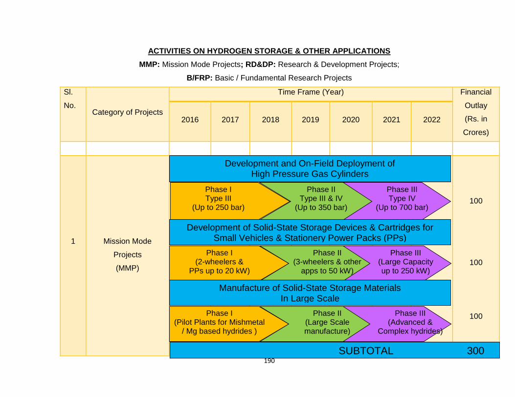
190
ACTIVITIES ON HYDROGEN STORAGE & OTHER APPLICATIONS
MMP: Mission Mode Projects; RD&DP: Research & Development Projects;
B/FRP: Basic / Fundamental Research Projects
Sl.
No. Category of Projects
Time Frame (Year) Financial
Outlay
(Rs. in
Crores)
2016 2017 2018 2019 2020 2021 2022
1
Mission Mode
Projects
(MMP)
100
100
100
Development and On-Field Deployment of High Pressure Gas Cylinders
Phase I Type III
(Up to 250 bar)
Phase II Type III & IV
(Up to 350 bar)
Phase III Type IV
(Up to 700 bar)
Development of Solid-State Storage Devices & Cartridges for Small Vehicles & Stationery Power Packs (PPs)
Phase I (2-wheelers &
PPs up to 20 kW)
Phase II (3-wheelers & other
apps to 50 kW)
Phase III (Large Capacity up to 250 kW)
Manufacture of Solid-State Storage Materials In Large Scale
Phase I (Pilot Plants for Mishmetal
/ Mg based hydrides )
Phase II (Large Scale manufacture)
Phase III (Advanced &
Complex hydrides)
SUBTOTAL 300
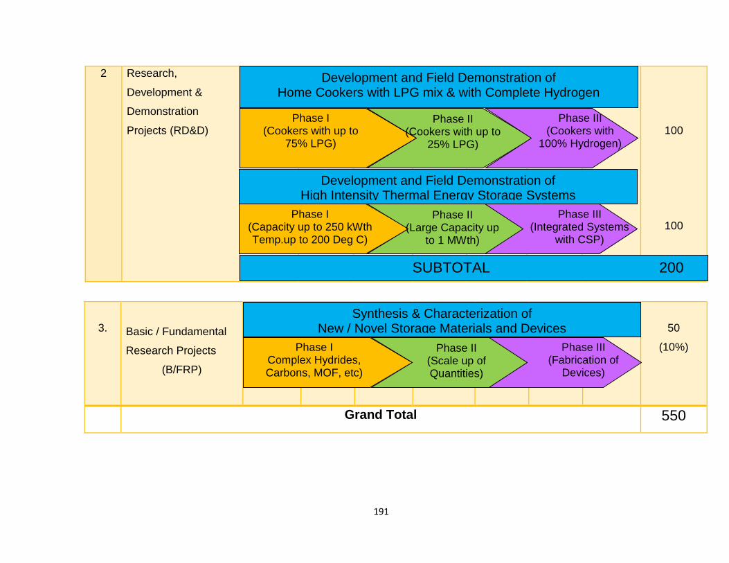
191
2 Research,
Development &
Demonstration
Projects (RD&D)
100
100
3. Basic / Fundamental
Research Projects
(B/FRP)
50
(10%)
Grand Total 550
Development and Field Demonstration of Home Cookers with LPG mix & with Complete Hydrogen
Phase I (Cookers with up to
75% LPG)
Phase II (Cookers with up to
25% LPG)
Phase III (Cookers with
100% Hydrogen)
Development and Field Demonstration of High Intensity Thermal Energy Storage Systems
Phase I (Capacity up to 250 kWth Temp.up to 200 Deg C)
Phase II (Large Capacity up
to 1 MWth)
Phase III (Integrated Systems
with CSP)
SUBTOTAL 200
Synthesis & Characterization of New / Novel Storage Materials and Devices
Phase I Complex Hydrides, Carbons, MOF, etc)
Phase II (Scale up of Quantities)
Phase III (Fabrication of
Devices)

192
CONCLUSIONS AND RECOMMENDATIONS
193
16.0 CONCLUSIONS AND RECOMMENDATIONS
16.1 Conclusions
16.1.1 Hydrogen in gaseous state is being utilized in various stationary or
mobile devices / systems for generation of motive power or electricity. Currently,
it is transported in compressed form (up to 200 bar pressure) in cylinders made
of steel / aluminium from the site of its availability / production to the site of utility.
The volumetric energy density of hydrogen is very low (i.e. ~12 MJ/m3) in
comparison to natural gas, methanol, and propane. In view of this drawback,
composite high pressure vessels of Type III have been developed. These
vessels have a maximum service life of 15 - 20 years with refilling cycles 1000
nos./year. The cylinders have thin walled aluminium (AA6061) liner covered with
carbon fibres. Over and above this layer epoxy resin matrix is wrapped. These
cylinders are to be tested periodically (say once in 5 years). The Type IV
cylinders with service life of 20 years and in various capacities have also been
developed, and are 70% lighter than steel cylinders. Major manufacturers are
M/s Quantum Technologies, M/s Luxfer Gas Cylinders and M/s Dynetek
Industries Limited. Large number of cylinders from these manufacturers are in
use for on-board applications in automobiles across the globe. Currently, carbon
composite with aluminum liner type-III cylinder are not manufactured in the
country. The metal liner with Kevlar fiber wound type cylinders are widely used
in the country. Use of carbon composite wrapped metal liners have also been
initiated. Use of type IV cylinders in the country is yet to start.
16.1.2 Hydrogen can be stored in liquid form in cryogenic conditions. So far, its
application has been confined to space applications. Presently, this form of
storage is not viable for widespread commercial applications. Liquid organic
hydrides are potential candidates for hydrogen storage and delivery. The concept
has been demonstrated successfully at laboratory level. Pilot level studies
demonstrate the efficacy of the system and possibilities of up-scaling.
194
Considerable work has also been carried out at National level leading to
generation of IPR for country. Further work is being conducted and expected to
be supported by government/ industry may lead to development of a technology
for safe hydrogen storage and delivery at near ambient conditions for long
distance transportation. In order for the hydrogen program to be successful in
India, development of required testing facilities, standards codes and regulations
for cylinders, components, vehicles and fuel need to be developed in line with
international regulations.
16.1.3 The alternative for gaseous hydrogen is the use of solid materials for on-
board storage of hydrogen. But these have inherent limitations. Metal hydrides
are reversible under ambient conditions, but are too heavy. Simple chemical
hydrides are reversible at very high pressure and temperature. Complex
chemical hydrides have high hydrogen density, but suffer from poor reversibility.
Sorbent materials offer good reversibility at very low temperatures. Solid state
storage in the form of hydrides is the most efficient as well as safest mode of
hydrogen storage. It may be used in small sized automobiles and other systems /
devices operating with hydrogen as fuel such as three wheelers, cars, fuel cell
based gen-sets of smaller capacities of the range 5 kW to 15 kW. On-board
hydrogen storage for transportation applications focuses primarily on low-
pressure and materials-based technologies to allow a driving range of more than
500 km for hydrogen-fueled light-duty vehicles as per Department of Energy
(DoE), USA. The DoE has set a short term goal against on-board hydrogen
storage i.e. 5.5 wt% and 40 g/l by the year 2015. MgH2, catalyzed with leached
ball milled Al-Cu-Fe quasi crystalline alloy showed better hydriding kinetics at
2000C & 1500C by absorbing 5.5 wt% in 1 minute and 5 wt% at 100oC in 30
minutes under 20 bar pressure. Kinetics of this hydride was degraded slightly
over 51 sorption cycles. Further experiments are going on to observe the
reversibility of this hydride up to 500 and 1000 cycles.
195
16.1.4 The use of hydrogen in gaseous form may be risky, because of low (0.2
mJ as against 0.24 for gasoline) self-ignition energy, if it is not properly handled.
Japanese and other agencies estimated that bursting of high pressure gas (HPG)
hydrogen cylinder will cover an area of about 6 meters diameter, in which human
beings cannot survive. Therefore, HPG hydrogen cylinders can only be used
safely in either for stationary storage or for large vehicles e.g. buses, trucks etc.
For small vehicular utilities e.g. two, three wheelers, small cars and small power
plants: Gen Sets, <10kW hydride storage modes are safe to practice.
16.1.5 Nano-materials can also be considered as part of solid state. These
materials have high surface/volume ratio for hydrogen storage. various
nanomaterials like nanotubes, nanofibres, nanohorns, nanospheres and
nanoparticles have been examined for the hydrogen storage, which are yet to
satisfy the required characteristics like storage capacity of around 6 weight
percent, favourable and tuning thermodynamics around 30-55 kJ/mol of
hydrogen and temperature of operation around 373 K with about 1000s of cycles
of operation. The techniques other than ball milling like vapour condensation or
sputtering can produce homogeneous nano structured materials without much
imperfections. These materials showed remarkable properties of nanostructure
after hydrogenation-dehydrogenation cycles.
16.1.6 Activated carbons fabricated from biomass resources like coal, palm
shell, coffee waste, and rice husks have been studied and showed high
performance because of their high specific surface areas. These are capable of
storing hydrogen of 1.3 wt% at room temperature. At 298K, the stored hydrogen
content of the activated carbons increases as the equilibrium pressure of
hydrogen increases. The presence of catalysts affects the kinetics of the
process. Catalyst LaNi5 showed remarkably higher sorption of hydrogen, when
the nanocrystalline alloy is mixed with catalyst. The nanocomposites system like
Mg2NiH4 and MgH2, desorption temperature is considerably reduced. The issues,
which are to be addressed to include optimization of size of the nano-particles
196
and establishment of the extent of dispersion of nanocatalysts in nanomaterials.
The application of nano-materials for hydrogen storage is still in R&D stage.
16.1.7 Use of hydrogen as a compression ignition (CI) engine fuel can go a long
way to meet the challenge of the growing diesel fuel scarcity, reducing menace of
diesel smoke and nitrogen oxides emissions. Hydrogen has good prospect,
because of its wide flammability limits, low ignition energy, high calorific value
and high flame velocity. It does not need any substantial modifications in the
existing hardware of the conventional diesel engine to run in dual fuel mode. The
introduction of hydrogen with diesel fuel in compression ignition (CI) engine
increases the H/C ratio, decreases heterogeneity of a diesel fuel spray due to the
high diffusivity of hydrogen making the mixture better premixed with air and more
uniform and reduces combustion duration due to hydrogen’s high speed of flame
propagation.
16.1.8 A commercial 4 kW diesel engine gen-set was modified to operate as a
dual fuel engine with up to 60% full load energy substitution by hydrogen without
undue loss of power output and efficiency. With neat hydrogen supplementation,
the maximum achievable hydrogen energy substitution could be as high as 85%.
Considerable engine derating and efficiency loss was observed.
16.1.9 The SI engines operate on natural gas, but they can be optimized to run
on propane, gasoline, biogas, or LPG etc. In India deployment of SI engines for
power generation is on the rise. The SI engines can be operated with hydrogen
only and in dual fuel mode also. Studies have shown that the addition of
hydrogen to methane in a SI Engine enhanced the performance particularly when
operating on relatively low equivalence ratio mixtures. The optimum
concentration of hydrogen in the fuel mixture for producing a power gain and
avoiding knock appears to be about 20-25% by volume over the range of
conditions.
197
16.1.10 In India, pollution from cooking using LPG, coal, wood and other bio-
products is a serious issue. Use of hydrogen can be an alternate fuel to address
this issue, since it has superior characteristics in comparison to LPG fuel in terms
of ignitability, low ignition delay, and higher flame stability. Hydrogen burner is so
designed that it prevents kindling of hydrogen in air (by maintaining hydrogen-air
mixture less than ~ 5 vol% hydrogen and catalyst surface at a temperature lower
than the self-ignition temperature of hydrogen) and surface area of the catalytic
burner was so designed and optimized (as ~20cm2) that heat generation rate did
not exceed the dissipation rate of heat and temperature could be maintained
between ~ 200 to ~ 5000C, which may be controlled by the feed rate of
hydrogen. Research groups in Japan, China, Germany, USA, have been
focusing on burner geometry, catalytic combustion of fuel, uniform distribution of
surface temperature, air equivalence ratio on nitric oxide emissions, premixing of
air to fuel, flame speed of fuel etc. where fuel contained H2, or H2/CO or methane
/ H2 or LPG/H2 mixture. The most important task is to adapt hydride material for
H2 storage, which requires the heat of the surrounding air for dehydriding, but it
should have adequate mass storage capacity in a safe way. In the country, a
few R&D groups have demonstrated cookers. However, flammability / safety
related issues for public consumption of hydrogen need to be addressed. An
action plan has been suggested to further develop such hydrogen fueled home
cookers.
16.1.11 High intensity, high temperature thermal energy storage using the chemi-
sorption heat when hydrogen reacts with metal hydrides is very promising for
integration with distributed solar thermal power systems. The conventional phase
change materials and molten salts have several operational drawbacks and also
are expensive. A variety of low cost metal hydrides (especially magnesium
based) which are ideal for thermal energy storage are available in the country
and are ready for field use. Several pilot units have been demonstrated by a
couple of research institutions. This will be very useful to the success of the
overall renewable energy program.
198
16.2 Recommendations
16.2.1 Considering merits and de-merits of all the modes of hydrogen storage
and specific applications other than transportation, following are recommended:
(i) Institution of cost analysis study for the use of solid state hydride storage of
hydrogen with compressed gaseous hydrogen in composite cylinders for
specific applications to be developed in the Mission Mode projects.
(ii) Project for acquisition of reformer technology and development of
indigenous reformer technology by Thermax and BHEL jointly with possible
association of IICT, Hyderabad and NCL, Pune.
(iii) Project for commercialization of Type III cylinders for buses and Type IV
cylinders for small vehicles (like 4- & 3-wheelers) by Tata Motors in
collaboration with ISRO. DRDO and BHEL may also be involved in this
effort.
(iv) Project for the development of a hydrogen storage device / cartridge for
specific purpose for fuel cell power pack jointly by BHU, IIT Guwahati,
NFTDC, IIT Indore and IISc Bangalore.
(v) Metal hydride based high intensity high efficiency thermal energy storage
system development of the type ongoing at IISc Bangalore should be
widened in terms of capacities and applications such as CSP and stand-
alone Steam Generators.
(vi) Organization of a Workshop with CII / FICCI for possible commercialization
of the devices / systems developed by the academic / research institutions.
MNRE may facilitate organization of the workshop.
(vii) Review of the activities of Hydrogen Energy Centre at BHU by a suitable
Expert Committee and utilization of their recommendations to establish a
Centre of Excellence. Also, establish a few Satellite Centers for specific
tasks such as development of high pressure cylinders, development of
sensors and controls, thermal, thermo-physical and mechanical properties
evaluation, etc.

199
BIBLIOGRAPHY
200
17.0 Bibliography
17.1 General
1. Handbook of Hydrogen Energy; Ed: S.A.Sheriff, D.Yogi Goswami, E.K.
Stefanakos and Aldo Steinfeld, CRC Press, 2015
2. Handbook of Hydrogen Storage: New Materials for Future Energy Storage;
Ed. Michael Hirscher, Wiley – VCH Verlag GmbH, 2010
3. Alternative Fuels-The Future Of Hydrogen (Second Edition); Michael Frank
Hordeski, CRC Press, 2008
4. Metal Hydrides: Recent Developments, M.V.C.Sastri, B.Viswanathan and
S.Srinivasa Murthy Springer Verlag / Narosa, 1998.
5. Klebanoff, L., J. Keller. Final report for the DOE Metal Hydride Center of
Excellence. Sandia Report: SAND2012-0786, 2012.
http://www1.eere.energy.gov/hydrogenandfuelcells/pdfs/metal_hydride_coe
_final_report.pdf.
17.2 Hydrogen Storage in Gaseous State
1. Product brochures of the composite pressure vessels
2. NASA NSS 1740.16, Safety standard for Hydrogen and Hydrogen
Systems
3. The Outlook for the Development of Hydrogen Power Engineering
Remains Highly Conjectural, G. S. Aslanyan, and B. F. Reutov, Ministry of
the Russian Federation for Education and Science, Tverskayaul. 11,
Moscow, 125009 RussiaISSN 0040-6015, Thermal Engineering, 2006,
Vol. 53, No. 4, pp. 316–324. © Pleiades Publishing, Inc., 2006.
201
17.3 Solid State Storage
The information required for making this report has been collected from
the sources given below:
(i) Bogdanovic’, B. and Schwickardi, M. 1997. “Tidopedalkali metal aluminum
hydrides as potential novel reversible hydrogen storage materials”,
J.Alloys and Compounds, 253:1.
(ii) Bogdanovic’, B., Brand, R.A., Marjanovic’, A.,Schwikardi, M., and Tölle, J.
2000. “Metaldoped sodium aluminum hydrides as potential new hydrogen
storage materials”, J. Alloys andCompounds, 302:36.
(iii) Majzoub, E., Gross, K., Proceedings of the International Symposium on
Metal HydrogenSystems, Annecy, France, 2-6 Sept. 2002, J. Al. Comp.
2003.
(iv) E. Kim, “Instability of carbon nanotubes: Molecular-dynamics Simulations”,
International Symposium on Materials Issues in Hydrogen Production and
Storage, Santa Barbara, CA, August 20–25, 2006.
(v) R. K. Ahluwalia, “Sodium Alanate Hydrogen Storage System for
Automotive Fuel Cells,” Submitted to International Journal of Hydrogen
Energy, 2005.
(vi) R. K. Ahluwalia, J-K Peng and T. Q. Hua, “On-Board Storage Systems
Analysis,” DOE and FreedomCAR& Fuel Partnership Analysis Workshop,
25 January 2006, Washington, DC.
(vii) XuezhiKe and Changfeng Chen, “Thermodynamic functions and pressure-
temperature phase diagram of lithium alanates by ab initio calculations”,
Physical Review B, in press (to appear in June 15, 2007 issue).
(viii) T. J. Dhilip Kumar, P. F. Weck, and N. Balakrishan, Evolution of small Ti
clusters and dissociative chemisorption of H2 on Ti, J. Phys. Chem. C
111, 7494 (2007)
(ix) P. F. Weck, T. J. Dhilip Kumar, E. Kim and N. Balakrishnan,
Computational study of hydrogen storage in organometallic compounds, J.
Chem. Phys. 126, 094703 (2007).
202
(x) “Synthesis and crystal structure of Na2LiAlD6”J. Alloys and Compounds
Volume 392, Issues 1-2, 19 April 2005, Pages 27-30, H.W. Brinks, B.C.
Hauback, C.M. Jensen and R. Zidan
(xi) “Synergistic effects of co-dopants on the dehydrogenation kinetics of
sodium aluminumhydride”J. alloys and compoundsVolume 391, Issues 1-
2, 5 April 2005, Pages 245-255 J. Wang, A.D. Ebner, R. Zidan and J.A.
Ritter
(xii) “Effect of graphite as a co-dopant on the dehydrogenation and
hydrogenation kinetics of Ti-doped sodium aluminumhydride”J. Alloys and
Compound, in press, Jun Wang, ArminD. Ebner, Tanya Prozorov,
RagaiyZidan and James A. Ritter.
(xiii) Gross, K.J., Majzoub, E., Thomas, G.J., and Sandrock, G. 2002. “Hydride
development for hydrogen storage”, in Proceedings U.S. DOEHydrogen
Program Review, NREL/CP-610-32405.Golden, CO.
(xiv) Bogdanovic’, B. and Schwickardi, M. 1997. “Tidoped alkali metal
aluminum hydrides as potentialnovel reversible hydrogen storage
materials”, J.Alloys and Compounds, 253:1.
(xv) Bogdanovic’, B., Brand, R.A., Marjanovic’, A .Schwikardi, M., and Tölle, J.
2000.“Metaldopedsodium aluminum hydrides as potential new hydrogen
storage materials”, J. Alloys andCompounds, 302:36.
(xvi) Zidan, R.A., Takara, S., Hee, A.G., and Jensen,C.M. J. Alloys and
Compounds, 285 (1999) 119.
(xvii) Ronnebro, E., Noreus, D., Kadir, K., Reiser, A,Bogdanovic’, B., J. Al.
Comp., 299 (1-2):101-6,2000.
(xviii) Majzoub, E., Gross, K., Proceedings of the International Symposium on
Metal Hydrogen Systems, Annecy, France, 2-6 Sept. 2002, in press J. Al.
Comp. 2003.
(xix) Gross, K.J., Majzoub, E.H., Spangler, S.W. “Theeffects of titanium
precursors on hydriding properties of alanates”, Submitted J. Alloys and
Comps 2002
203
(xx) Weiner, S.C., “Safety Practices and Lessons Learned: The Work of the
Hydrogen Safety Review Panel,” Hydrogen Safety and Risk Workshop,
University of Nevada, Las Vegas, April 10, 2006.
http://www.pnl.gov/energy/eed/policy-prog/pub.stm
(xxi) J. Graetz , J. Reilly, G. Sandrock, J. Johnson, W.-M. Zhou, and J.
Wegrzyn, “Aluminum hydride, AlH3, as a hydrogen storage compound”
TMSProceedings (2006).
(xxii) J. Graetz and J. J. Reilly, “Decomposition kinetics of the AlH3polymorphs”,
J. Phys. Chem. B, 10922181 (2005).
(xxiii) G. Sandrock, J. Reilly, J. Graetz, W.-M. Zhou, J. Johnson and J. Wegrzyn,
“Alkali metal hydride doping of α-AlH3for enhanced H2desorption
kinetics”J. Alloys Comp., (2005).
(xxiv) J. Graetz, Y. Lee, J. J. Reilly, S. Park and T. Vogt, “Structure and
thermodynamics of the mixed alkali alanates”, Phys. Rev. B, 71184115
(2005).
(xxv) M.A. Miller and N. Sridhar, Measurement and Prediction of Material
Performance Subject to Hydrogen Exposure, Hydrogen Gas
Embrittlement Workshop, ASTM T.G. 01.06.08, ASTM Meeting, Reno,
NV, May 17, 2005
17.4 Hydrogen Storage in Nano-Materials
(i) M.U.Niemann, S.S.Srinivasan, A.R.Phani, Ashok Kumar, D.Y.Goswami and
E.K.Stefanakos, Journal of Nanomaterials, doi:10.1155/2008/950967 (2008)
(ii) M.AuliceScibioh and B.Viswanathan, Hydrogen Future: Facts and Fallacies,
Bulletin of the catalysis Society of India, 3,72-81 (2004)
(iii) S.Satyapal, John Petrovic, caroleRead,George Thomas and Grace Ordaz,
The U.S. Department of Energy's National Hydrogen Storage Project:
Progress towards meeting hydrogen-powered vehicle requirements,
Catalysis Today, 120, 246-256 (2007).
204
(iv) L. Zaluski, S.Hosatte, P. Tessier, D.H. Ryan, J.O. Strom-Olsen, M.L.
Trudeau, R.Schulz, Metal Hydrogen Systems, M.R. Oldenburg, Verlg,
Uppsala, 1992 p.1067.
(v) L. Zaluski, A. Zaluska, P.Tessier, J.O.Strom-Olsen and R.Schulz, J.Material
Sci., 31,695 (1996).
(vi) L. Zaluski, A. Zaluska, and J.O. Strom-Olsen, J.Alloys.Compd., 253,70
(1997).
(vii) A.Zaluska, L.Zaluski, J.O.Srtom-Olsen, J.Alloys.Compd.,288,217 (1999)
and references therein.
(viii) A.Zaluska, L.Zaluski and J.O.Strom-Olsen, Structure, catalysis, and atomic
reactions on nano-scale: a systematic approach to metal hydrides for
hydrogen storage, Appl.Phys. A 72,157 (2001)and references therein
(ix) M.Sankaran and B.Viswanathan,carbon, 45,1628 (2007) and Int J Hydrogen
Energy,33,393(2008)
(x) B.Viswanathan, M.Sankaran, A.Ariharan and K.Lekhi, Heteroato substituted
carbon -potential hydrogen storage materials, Advanced porous materials,
1, 114-121 (2013)
(xi) L.Himakumar, C.V.Rao and B.Viswanathan, Catalytic e_ect on nitrogen
doped grapheme and carbon nanotubes additives on hydrogen storage
properties of sodium alanate, J. Mater. Chem. A, 2013, 1, 3355-3361
DOI:10.1039/c0xx00000x
17.5 Power Generation through hydrogen fueled IC engine
(1)www.beeindia.in nergy_managers_auditors/documents/guide_books/3Ch9.pdf
(2) All India Study on Sectoral Demand of Diesel & Petrol, Report by Petroleum
Planning and Analysis Cell 2013, Ministry of Petroleum and Natural Gas
(3) ww1.eere.energy.gov/hydrogenandfuelcells/pdfs/fct_h2_fuelcell_factsheet.pdf
(4) Das LM. Near-term introduction of hydrogen engines for automotive and
agricultural application. International Journal of Hydrogen Energy 2002;27:479-
87.
205
(5) Eichlseder H, Spuller C, Heindl R, Gerbig F, Heller K, New and innovative
combustion systems for the H2eICE: compression ignition and combined
processes. SAE P. 2009-01-1421, 2009.
(6) Andre Marcelino de Morais, Marco Aure´lio Mendes Justino et al. , Hydrogen
impacts on performance and CO2 emissions from a diesel power generator,
International Journal of Hydrogen Energy 38 (2013) 6857 -6864
(7) Lata D, Misra A. Analysis of ignition delay period of a dual fuel diesel engine
with hydrogen and LPG as secondary fuels. International Journal of Hydrogen
Energy 2011;36:3746-56
(8)Tsujimura T, Mikami S, Achiha N, Tokunaga Y, Senda J, Fujimoto H. A study
of direct injection diesel engine fuelled with hydrogen. SAE Technical Paper
2003; 2003-01-0761:1-16.
(9) Masood M, Ishrat M. Computer simulation of hydrogenediesel dual fuel
exhaust gas emissions with experimental verification. Fuel 2008;87:1372-8.
(10) Saravanan N, Nagarajan G. An experimental investigation of hydrogen-
enriched air induction in a diesel engine system. International Journal of
Hydrogen Energy 2008;33:1769-75.
(11) Saravanan N, Nagarajan G. Experimental investigation in optimizing the
hydrogen fuel on a hydrogen diesel dual-fuel engine. Energy & Fuels
2009;23:2646-57.
(12) Saravanan N, Nagarajan G. Performance and emission studies on port
injection of hydrogen with varied flow rates with diesel as an ignition source.
Applied Energy 2010;87:2218-29.
(13) H. B. MATHUR, L. M. DAS and T. N. PATRO, Hydrogen-fuelled diesel
engine: Performance improvement through Charge Dilution Techniques,
International Journal of Hydrogen Energy, Vol. 18, No. 5, pp. 421-4.31, 1993
(14) H. B. MATHUR, L. M. DAS and T. N. PATRO, Hydrogen fuel utilization in CI
Engine powered end utility systems, International Journal of Hydrogen Energy,
Vol. 17, No. 5, pp. 369-374, 1992
206
(15) Rakopoulos CD, Scott MA, Kyritsis DC, Giakoumis EG. Availability analysis
of hydrogen/natural gas blends combustion in internal combustion engines.
Energy 2008;33:248-55.
(16) S O Bade Shrestha G A Karim, Hydrogen as an additive to methane for
spark ignition engine applications, International Journal of Hydrogen Energy
24(1999)577-586.
(17) Baris Acıkgoz , Cenk Celik et.al. Emission characteristics of an hydrogen–
CH4 fuelled spark ignition engine, Fuel 159 (2015) 298–307
(18) Rahul Banerjee , Sumit Roy , Probir Kumar Bose, Hydrogen-EGR synergy
as a promising pathway to meet the PM-NOx-BSFC trade-off contingencies of
the diesel engine: A comprehensive review, International Journal of Hydrogen
Energy, 2015 1-24
17.6 MH based Thermal Energy Storage, Cooking, Heat Pumps,
Refrigeration, Compression, etc.
1. M. Haruta, Y. Souma And H. Sano, Int. J. Hydrogen Energy. Vol. 7,
No. 9. pp. 729-736. 1982
2. Chen Dong, Qulan Zhou, Qinxin Zhao, Yaqing Zhang, Tongmo Xu, Shien
Hui, Fuel 88 (2009) 1858–1863
3. Zheng Chen, International Journal of Hydrogen Energy 34 (2009) 6558–
6567
4. Erjiang Hu, Zuohua Huang, Jiajia He, Chun Jin, Jianjun Zheng, International
Journal of Hydrogen Energy 34 (2009) 4876–4888
5. Han S. Kim, Vaibhav K. Arghode, Ashwani K. Gupta, International Journal of
Hydrogen Energy 34 (2009) 1045–1053
6. Praveen Hariharan, Chendhil Periasamy, S.R. Gollahalli, International
Journal of Hydrogen Energy 32 (2007) 1095 – 1102
7. W. Peschka, Int. J. Hydrogen Energy, Vol. 12, No. 7, pp. 481-499, 1987
8. U.-P. Groûmann, J. Lehmann, F. Menzl, International Journal of Hydrogen
Energy 25 (2000) 87-90
207
9. Kaulfersch R. UNIDO Projekt Concept No. 25: Technology Transfer and
Training for Application of Hydrogen as an Energy Carrier. UNIDO, POB
300, A-1400 Vienna
10. D.P. Mishra and P. Kumar, Fuel 89 (2010) 212–218
11. Mohan G., Prakash Maiya M., Srinivasa Murthy S., 2007, Performance
simulation of metal hydride hydrogen storage device with embedded filters
and heat exchanger tubes,” International Journal of Hydrogen Energy, 32,
pp. 4978-4987.
12. Mohan G., Prakash Maiya M., Srinivasa Murthy S., 2008, “Performance of air
cooled hydrogen storage device with external fins”, International Journal of
Low Carbon Technologies, 3, pp. 265-281.
13. Mohan G., Prakash Maiya M., Srinivasa Murthy S., 2010, “The performance
simulation of air cooled hydrogen storage device with plate fins”,
International Journal of Low Carbon Technologies, 5, pp. 25-34.
14. S. Srinivasa Murthy, “Heat And Mass Transfer Issues in The Design of Solid
State Hydrogen Storage Devices” Keynote Paper IHTC14-23345,
International Heat Transfer Conference-IHTC14, Washington, DC, USA,
August 8-13, 2010
15. S.Srinivasa Murthy; Heat and mass transfer in solid state hydrogen storage:
A Review; Trans. ASME – Jr. of Heat Transfer, Vol.134, 2012, pp.1-11
16. S.Srinivasa Murthy and Anil Kumar E.; Advanced Materials for Solid State
Hydrogen Storage: Thermal Engineering Issues; International Symposium on
Innovative Materials for Processes in Energy Systems 2013 (IMPRES2013),
September 4–6, 2013, Fukuoka, Japan
17. Mazumdar S., Ram Gopal M., Bhattacharyya S., 2005, “Thermodynamic
analysis and optimization of compressor-driven metal hydride cooling
systems”, International Journal of Hydrogen Energy, 30, pp. 631-641.
18. Veerraju Ch., Ram Gopal M., 2009, “Heat and mass transfer studies on
elliptical metal hydride tubes and tube banks”, International Journal of
Hydrogen Energy, 34, pp. 4340-4350.
208
19. Satheesh A., Muthukumar P., 2010, “Simulation of double-stage double-
effect metal hydride heat pump”, International Journal of Hydrogen Energy,
35, pp. 1474-1484.
20. Muthukumar P., Madhavakrishna U., Anupam Dewan, 2007, “Parametric
studies on a metal hydride based hydrogen storage device”, International
Journal of Hydrogen Energy, 32, pp. 4988-4997.
21. B. Satya Sekhar, P. Suresh, P. Muthukumar; Performance tests on metal
hydride based hydrogen storage devices, International Journal of Hydrogen
Energy, Volume 38, Issue 22, 26 July 2013, Pages 9570-9577
22. P. Muthukumar, A. Singhal, G.K. Bansal; Thermal modeling and
performance analysis of industrial-scale metal hydride based hydrogen
storage container, International Journal of Hydrogen Energy, Volume 37,
Issue 19, October 2012, Pages 14351-14364
23. P.Muthukumar, Kevin Abraham, U.A.Rajendra Prasad, M.Prakash Maiya &
S. Srinivasa Murthy; Screening of Metal Hydrides for Engineering
Applications; Proc. 16th International Conference on Efficiency, Cost,
Optimization, Simulation and Environmental Impact of Energy Systems;
ECOS2003, Copenhagen, Denmark, 30 June - 2 July, 2003, pp. 93-100.
24. B. Satya Sekhar, P. P. Muthukumar, R. Saikia; Tests on a metal hydride
based thermal energy storage system, International Journal of Hydrogen
Energy, Volume 37, Issue 4, February 2012, Pages 3818-3824
25. Yonezu, K. Nasako, N. Honda and T. Sakao, Development of thermal energy
storage technology using metal hydrides, J. Less-Common Metals, 89, 1983,
p351.
26. Yonezu, S.Funitani, A. Furukawa K. Nasako, N. Yogensaki and T. Saito,
Characterstics of hydrogen absorbing Zr-Mn alloys for heat utilization, J.
Less-Common Metals, 168, 1991, p201
27. Bogdanovic, B., T. H. Hartwig and B. Spliethoff, The development, testing
and optimization of energy storage materials based on the MgH2 - Mg
system, Int. J. Hydrogen Energy, 18, 1993, pp575-589.
209
28. Reiser, A., B. Bogdanovic and K. Schlichte (2000) The application of Mg-
based metal hydrides as heat energy storage systems, Int. J. Hydrogen
Energy,25, 2000, pp425-430.
29. Bowman Jr RC, Sandrock G. Metal hydrides for Energy storage and
conversion applications. In: Proceedings of GLOBAL 2000 atoms for
prosperity, American Nuclear Society meeting, New Orleans, LA; Nov. 16-
20, 2003.
30. Schlapbach L, Zuttel A. Hydrogen-storage materials for mobile applications.
Nature 2001;414(6861):353-8.
31. Schuth F, Bogdanovic B, Felderhoff M. Light metal hydrides and complex
hydrides for hydrogen storage. Chem Commun 2004:2249-58.
32. Feng Z, Deyou B, Lijun J. Metal hydride compressor and its application in
cryogenic technology. J Alloys Compd, 1995;231(1e2):907-9.
33. Hopkins RR, Kim KJ. Hydrogen compression characteristics of a dual stage
Thermal compressor system utilizing LaNi5 and Ca0.6Mm0.4Ni5 as the
working metal hydrides. Int J Hydrogen Energy 2010;35(11):5693-702.
34. Kelly NA, Girdwood R. Evaluation of a thermally-driven metal-hydride-based
hydrogen compressor. Int J Hydrogen Energy 2012;37(14):10898-916.
35. Kim J, Park I, Kim KJ. A hydrogen-compression system using porous metal
hydride pellets of LaNi5exAlx. Int J Hydrogen Energy 2008;33(2):870-7.
36. Laurencelle F, Dehouche Z, Morin F. Experimental study on a metal hydride
based hydrogen compressor. J Alloys Compd 2009;475(1e2):810-6.
37. Li H, Wang X, Dong Z. A study on 70 MPa Metal hydride hydrogen
compressor. J Alloys Compd 2010;502(2):503-7.
38. Luo G, Chen JP, Li SL. Properties of La0.2Y0.8Ni5_xMnx alloys for high-
pressure hydrogen compressor. Int J Hydrogen Energy 2010;35(15):8262-7.
39. Muthukumar P, Prakash Maiya M, Srinivasa Murthy S. Experiments on a
metal hydride based hydrogen compressor. Int J Hydrogen Energy
2005;30(8):879-92.
210
40. Muthukumar P, Prakash Maiya M, Srinivasa Murthy S. Performance tests on
a thermally operated hydrogen compressor. Int J Hydrogen Energy
2008;33(1):463-9.
41. Talaga~nis BA, Esquivel MR, Meyer G. A two-stage hydrogen compressor
based on (La,Ce,Nd,Pr)Ni5 intermetallics obtained by low Energy
mechanical alloying e low temperature annealing treatment. Int J Hydrogen
Energy 2009;34(4):2062-8.
42. Wang XH, Bei YY, Song XC. Investigation on high-pressure metal hydride
hydrogen compressors. Int J Hydrogen Energy 2007;32(16):4011-5.
43. Lototskyy M, Klochko Y, Linkov V. Thermally driven metal hydride hydrogen
compressor for medium-scale applications. Energy Procedia 2012;29(0):347-
56.
44. Bhuiya MMH, Lee CY, Hwang T, Munira S, Hopkins R, Yoon H, et al.
Experimentally tuned dual stage hydrogen compressor for improved
compression ratio. Int J Hydrogen Energy 2014;39(24):12924-33.
45. Gopal MR, S.Srinivasa Murthy. Prediction of metal-hydride refrigerator
performance based on reactor heat and mass transfer. Int J Hydrogen
Energy 1995;20(7):607-14.
46. Klein H, Groll M. Development of a two-stage metal hydride system as
topping cycle in cascading sorption systems for cold generation. Appl Therm
Eng 2002;22(6):631-9.
47. Lloyd G, Razani A, Feldman Jr KT. Transitional reactor dynamics affecting
optimization of a heat-driven metal hydride refrigerator. Int J Heat Mass
Transf 1998;41(3):513-27.
48. Muthukumar P, Groll M. Metal hydride based heating and cooling systems: a
review. Int J Hydrogen Energy 2010;35(8):3817-31.
49. Paya J, Linder M, Mertz R. Analysis and optimization of a metal hydride
cooling system. Int J Hydrogen Energy 2011;36(1):920-30.
50. Gopal M, S.Srinivasa Murthy. Performance of a metal hydride cooling
system. Int J Refrig 1995;18(6):413-20.
211
51. Ahmed S,S.Srinivasa Murthy. Analysis of a novel metal hydride cycle for
simultaneous heating and cooling. Renew Energy 2004;29(4):615-31.
52. Suda S. What is required for the commercialization of metal hydride
refrigerators and heat pumps: surface engineering can solve the application
problems. Heat Recovery Syst CHP 1993;13(4):309-14.
53. Chernikov AS, Izhvanov LA, Solovey AI. An installation for water cooling
based on a metal hydride heat pump. J Alloys Compd 2002;330e332(0):907-
10.
54. Choi H, Mills AF. Heat and mass Transfer in metal hydride beds for heat
pump applications. Int J Heat Mass Transf 1990;33(6):1281-8.
55. Jang K, Fateev GA, Park J. Simulation of the metal hydride heat pump
system with the single and double reactors. Int J Hydrogen Energy
2001;26(3):237-41.
56. Kim KJ, Feldman Jr KT, Lloyd G. Compressor-driven metal hydride heat
pumps. Appl Therm Eng 1997;17(6):551-60.
57. Libowitz GG, Feldman Jr KT, Stein C. Thermodynamic properties of metal
hydrides for a novel heat pump configuration. J Alloys Compd
1997;253e254(0):673-6.
58. Linder M, Mertz R, Laurien E. Experimental results of a compact thermally
driven cooling system based on metal hydrides. Int J Hydrogen Energy
2010;35(14):7623-32.
59. Ni J, Liu H. Experimental research on refrigeration characteristics of a metal
hydride heat pump in auto air-conditioning. Int J Hydrogen Energy
2007;32(13):2567-72.
60. Park J, Jang K, Lee PS. The operating characteristics of the compressor-
driven metal hydride heat pump system. Int J Hydrogen Energy
2001;26(7):701-6.
61. Park J, Han S, Jang H. The development of compressor driven metal hydride
heat pump (CDMHHP) system as an air conditioner. Int J Hydrogen Energy
002;27(9):941-4.
212
62. Suda S, Komazaki Y, Narasaki H, Uchida M. Development of a double-stage
heat pump: experimental and analytical surveys. J Less Common Metals
1999;172-174:1092-110.
63. Dehouche Z, Jong WD, Willers E, Isselhorst A, Groll M. Modelling and
simulation of heating/air-conditioning systems using the multi-hydride
thermal wave concept.
64. Appl Therm Eng 1998;18:457-80.
65. Satheesh A, Muthukumar P. Performance investigation of double-stage
metal hydride based heat pump. Appl Therm Eng 2010;30(17e18):2698-707.
66. Altinisik K, Veziroglu TN. Metal hydride heat pumps. Int J Energy Res
1991;15:549e60.
67. Gopal M.R, S.Srinivasa Murthy. Experiments on a metal hydride cooling
system working with ZrMnFe/MmNi4.5Al0.5 pair. Int J Refrig 1999;22(2):137-
49.
68. Willers E, Groll M. Evaluation of metal hydride machines for heat pumping
and cooling applications. Int J Refrig 1999;22(1):47-58.
69. Satheesh A, Muthukumar P. Simulation of double-stage double-effect metal
hydride heat pump. Int J Hydrogen Energy 2010;35(3):1474-84.
70. Yang FS, Wang GX, Zhang ZX. Investigation on the influences of heat
Transfer enhancement measures in a thermally driven metal hydride heat
pump. Int J Hydrogen Energy 2010;35(18):9725-35.
71. Arteconi A, Hewitt NJ, Polonara F. State of the art of Thermal storage for
demand-side management. Appl Energy 2012;93(0):371-89.
72. Bogdanovi_c B, Ritter A, Spliethoff B. A process steam generator based on
the high temperature magnesium hydride/magnesium heat storage system.
Int J Hydrogen
73. Energy 1995;20(10):811-22.
74. Reiser A, Bogdanovi_c B, Schlichte K. The application of Mg based metal-
hydrides as heat energy storage systems. Int J Hydrogen Energy
2000;25(5):425-30.
213
75. Sakai T, Honda N, Yonezu I. Metal hydride container and metal hydride heat
storage system. J Heat Recovery Syst 1986;6(1):vii.
76. Wakao S, Sekine M, Endo H. A heat storage reactor for metal hydrides. J
Less Common Metals 1983;89(2):341-50.
77. Yang FS, Zhang ZX, Bao ZW. An extensive parametric analysis on the
performance of a single-stage metal hydride heat transformer. Int J
Hydrogen Energy 2012;37(3):2623-34.
78. Felderhoff M, Bogdanovic. High temperature metal hydrides as heat storage
materials for solar and related applications. Int J Mol Sci 2009;10(1):325-44.
79. Bhandari P, Prina M, Bowman Jr RC, Paine C, Pearson D, Nash A. Sorption
coolers using a continuous cycle to produce 20 K for the Planck flight
mission. Cryogenics 2004;44:395-401.
80. Bowman Jr RC. Development of metal hydride beds for sorption cryocoolers
in space applications. J Alloys Compd 2003;356-357:789-93.
81. Prina M, Kulleck JG, Bowman Jr RC. Assessment of ZreVeFe getter alloy for
gas-gap heat switches. J Alloys Compd 2002;330-332:886-91.
82. Kim T. Fully-integrated micro PEM fuel cell system with NaBH4 hydrogen
generator. Int J Hydrogen Energy 2012;37(3):2440-6.
83. Zhu L, Kim D, Kim H. Hydrogen generation from hydrides in millimeter scale
reactors for micro proton exchange membrane fuel cell applications. J Power
Sources, 2008;185(2):1334-9.
84. Mori D, Hirose K. Recent challenges of hydrogen storage technologies for
fuel cell vehicles. Int J Hydrogen Energy 2009;34(10):4569-74.
85. Sandrock G, Bowman Jr RC. Gas-Based hydride applications: recent
progress and future needs. J Alloys Compd 2003;356e357(0):794-9.
86. S.Srinivasa Murthy. Heat and mass transfer in solid state hydrogen storage:
a review. Trans ASME J Heat Transfer, 2012;134:1-11.
87. Prasad UAR, Maiya MP, S.Srinivasa Murt hy. Metal hydride water pumping
system for low head-high discharge applications. Int J Hydrogen Energy
2004;29(5):501-8.