Embed Size (px)
Citation preview

REPORT OF
THE FIFTH MEETING OF THE SURVEILLANCE IMPLEMENTATION
COORDINATION GROUP (SURICG/5)
Web-conference, 22 - 24 September 2020
Approved by the Meeting and published by the ICAO Asia and Pacific Office, Bangkok
INTERNATIONAL CIVIL AVIATION ORGANIZATION ASIA AND PACIFIC OFFICE
The views expressed in this Report should be taken as those of
the Meetings and not the Organization.

SURICG/5 Table of Contents i-2
HISTORY OF THE MEETING Page 1. Introduction ...................................................................................................................................... i-3 2. Opening of the Meeting ................................................................................................................... i-3 3. Attendance ....................................................................................................................................... i-3 4. Officers and Secretariat .................................................................................................................... i-3 5. Organization, working arrangements and language ......................................................................... i-3 6. Draft Conclusions, Draft Decisions and Decision of SURICG - Definition .................................... i-3 REPORT ON AGENDA ITEMS Agenda Item 1: Adoption of Agenda ............................................................................................... 1 Agenda Item 2: Review of outcomes of relevant meetings including ICAO 40th Assembly,
DGCA/56 and APANPIRG/30 on Surveillance ..................................................... 1 Agenda Item 3: Review of regional requirements for Surveillance in the e-ANP, Seamless
ANS Plan and the reported implementation status ................................................. 2 Agenda Item 4: Review the Action Items from SURICG/4 Meeting ............................................. 7 Agenda Item 5: Update on surveillance activities and explore potential
cooperation opportunities ....................................................................................... 8 Agenda Item 6: Review Report of SEA/BOB ADS-B WG/15 Meeting and
discuss possible options for future of SEA/BOB ADS-B WG ............................. 13 Agenda Item 7: Review Report of DAPs WG/3 Meeting ............................................................. 22 Agenda Item 8: Review ADS-B Implementation and Operations Guidance Document (AIGD) .. 26 Agenda Item 9: Next meetings & any other business .................................................................... 27 LIST OF ATTACHMENTS Attachment 1: List of Participants Attachment 2: List of Working/Information Papers and Presentations LIST OF APPENDICES Appendix A: Regional Supplement to the ASTERIX Interface Control Document (ICD)
for the ASIA/PAC Region (Third Edition) Appendix B: Updated List of Task/Action Items SURICG/5 Appendix B1: Action Items for SEA BOB ADS-B WG/15 Appendix C: Updated ADS-B Implementation Status in the ASIA/PAC Region Appendix D: ADS-B Data Sharing Implementation Status in the Asia/Pacific Region Appendix E1&E2: SEA & BOB Sub-regional ADS-B implementation plan/projects Appendix F1: Proposed amendment to the TOR of the SEA/BOB ADS-B WG Appendix F2: Proposed TOR for a regional ADS-B Working Group Appendix G: Mode S DAPs Implementation and Operations Guidance Document
(DAPs IGD v 2.0) Appendix H: Revised Terms of Reference of Mode S DAPs Working Group Appendix I: Revised ADS-B Implementation and Operations Guidance Document (AIGD v.13)

SURICG/5
i-3 History of the Meeting 1. Introduction
1.1 The Fifth Meeting of the Surveillance Implementation Coordination Group (SURICG/5) was held from 22 to 24 September 2020. The Meeting was an on-line meeting using MS Teams. 2. Opening of the Meeting 2.1 The meeting was opened by Mr. MH Hui, the Co-chair of SURICG. 2.2 In his opening remarks, Mr. MH Hui, welcomed participants and thanked the ICAO APAC Regional Office for hosting this meeting, which is the first time using video conference, with good facilities and meticulous preparations. He pointed out that the global aviation industry has been hit unprecedentedly by pandemic. This region is of no exception. He emphasized that the SURICG must therefore need to strike a balance in bringing forward new initiatives, while staying pragmatic and setting proper priorities in a harmonized manner, so as to cater for differences among states/administrations in their pace of recovery in air traffic. Mr. Hui also expressed his appreciation to the job well done by member States/Administrations in supporting the SURICG’s work in the past years. 2.3 He expressed great appreciation and thankfulness to the excellent leadership by Mr. Li Peng, former ICAO APAC Regional CNS Officer, in providing steering and guidance in not only surveillance, but also a broad spectrum of CNS services for the past 20 year, laying a good foundation for the SURICG to ride on and continue development. Mr. Hui was confident that the SURICG would continue to steer the way forward on Mode S and ADS-B surveillance for the region, and he looked to the active participation from the audience in the 3-day meeting. 3. Attendance
3.1 The Meeting was attended by 120 participants from 20 States/Administrations and 5 International Organizations and 1 service provider from industry, including Australia, China, Hong Kong-China, Macao China, DPR Korea, Fiji, India, Indonesia, Japan, Lao PDR, Malaysia, Myanmar, Nepal, Philippines, Republic of Korea, Singapore, Sri Lanka, Thailand, USA, Viet Nam, CANSO, EUROCAE, IATA, IFATCA, ICCAIA (AIREON) and PCCW Global. A list of participants is at Attachment 1. 4. Officers and Secretariat 4.1 Mr. Hui Man Ho, Acting Assistant Director-General of Civil Aviation (Air Traffic Engineering Services), Civil Aviation Department Hong Kong China, and Mr. Yeo Cheng Nam, Consultant (Aeronautical Telecommunications & Engineering) CAA Singapore co-chaired the Meeting. Mr. Luo Yi Regional Officer CNS, ICAO APAC Regional Office, acted as meeting secretary with the support of Ms. Bhabhinan Sirapongkosit, the Programme Assistant of the same office. 5. Organization, working arrangements and language
5.1 The online meeting was conducted around 3 and a half hours a day. The working language was English inclusive of all documentation and this Report. The meeting considered 8 working papers, 21 information papers, 1 presentation and 5 flimsies. A List of Papers presented at the meeting is at Attachment 2. 6. Draft Conclusions, Draft Decisions and Decisions of SURICG – Definition
6.1 SURICG recorded its actions in the form of Draft Conclusions, Draft Decisions and Decisions within the following definitions:

SURICG/5 History of the Meeting i-4
Draft Conclusions deal with matters that, according to APANPIRG terms of reference, require the attention of States, or action by the ICAO in accordance with established procedures; Draft Decisions deal with the matters of concern only to APANPIRG and its contributory bodies; and Decisions of SURICG that relate solely to matters dealing with the internal working arrangements of SURICG.
_ _ _ _ _ _ _ _ _ _ _ _ _ _ _

SURICG/5 Report on Agenda Items 1
Agenda Item 1: Adoption of Agenda 1.1 The provisional agenda items provided in WP/01 was adopted by the meeting as the agenda items for the meeting. Agenda Item 2: Review of outcomes of relevant meetings including ICAO 40th Assembly,
DGCA/56 and APANPIRG/30 on Surveillance Outcome of Relevant Meetings on Surveillance (WP/02) 2.1 Through the paper presented by the Secretariat, the meeting reviewed the related outcomes of ICAO 40th Assembly, the 56th Conference of Directors General of Civil Aviation Asia and Pacific Regions (DGCA/56) and APANPIRG/30 meeting on Surveillance Service. 2.2 The meeting was informed that there was no outstanding issue on surveillance in Assembly 40, however, some of the Assembly Resolutions were relevant to CNS area with reference to Resolutions adopted by the Assembly (Provisional Edition October 2019), as well as some paragraphs relevant to CNS incorporated in Technical Commission Report of 40th Assembly (Doc10137). The meeting also noted the latest update of Integrated Communications, Navigation, Surveillance and Spectrum Task Force (ICNSS-TF). 2.3 The DGCA/56 Conference developed 35 Action Items among which 14 Action Items were identified by SURICG/5 as relevant to implementation of CNS and services including 56/2; 56/3; 56/6; 56/11; 56/12; 56/15; 56/16; 56/21;56/29; 56/30; 56/32; 56/33; 56/34; 56/35. The meeting was informed that CNS SG/23 also reviewed the outcome of DGCA/56. 2.4 The meeting noted the Conclusions/Decisions related to surveillance implementation adopted by APANPIRG and follow-up actions taken by the Secretariat. In particular, through Conclusion APANPIRG/30/15 (CNS SG/23/14-SURICG/4/6), Revised Surveillance Strategy for the APAC Region was adopted, and the Edition 12 of the ADS-B Implementation and Operations Guidance Document (AIGD) and the first edition of Mode S DAPs Implementation and Operations Guidance Document were also adopted by the Twenty Third Meeting of CNS Sub-group on behalf of APANPIRG. The adopted documents were posted on the ICAO APAC website under e-Document. The Asia/Pacific ATM Automation System Task Force (ATMAS/TF) was established through Decision CNS SG/23/13 (SURICG/4/5), the first meeting of ATMAS/TF will be held from 28 to 30 October, 2020. 2.5 The meeting noted the Proposal for Amendment (PfA) to the Regional Supplementary Procedure (SUPP Doc 7030) from SURICG/2 has been processed in accordance with established procedure, and the approved PfAs were circulated to States on 18 June 2020 through a State Letter with reference: T8/11.2 – AP130/20 (CNS), and this change will be incorporated in the new Six Edition of Doc 7030/6 as part of the restructuring process of Doc 7030. 1090MHz Spectrum and 24-Bit Address Issues with UAS (IP/07) 2.6 The secretariat presented a brief summary on regional activities on 1090 MHz spectrum and 24-bit aircraft address issues associated with unmanned aircraft. The meeting noted the topic was firstly presented to the region by Chairperson of the ICAO Surveillance Panel (SP) on APAC Aeronautical Surveillance Workshop in November 2018, further discussed in SEA/BOB ADS-B WG/14 through Working Paper 07 Address and Spectrum Issues for Small UAS and developed Draft Conclusion 14/02 – Small UAS Cooperative Surveillance Equipage. As requested by the SURICG Co-chair, the ICAO SP chair presented Working Paper 12 Potential Issues Associated with RPAS Operating Exclusively at Low Altitudes (Less Than 500 Feet above Ground Level) to SURICG/4, the meeting

SURICG/5 2 Report on Agenda Items discussed and proposed a revised Draft Conclusion SURICG/4/2 - UAS Cooperative Surveillance Equipage. Finally, CNS SG/23 meeting adopted the proposal through Conclusion CNS SG/23/11. 2.7 The meeting noted that on 8 November 2019, ICAO issued a State Letter on the Subject: 1090 MHz spectrum issues and proper management of 24-bit aircraft addresses associated with unmanned aircraft operating exclusively at very low level, Ref.: SP 44/2 - 19/77. ICAO member States are urged to note the ongoing ICAO initiatives to ensure the continued safe and reliable operation of aeronautical surveillance systems, and encouraging State to make use of the guidance material enclosed in the letter. The meeting agreed to incorporate this guidance material into AIGD for easy reference in this region. Proposal for Amendment of Annex 10 regarding ACAS X (Flimsy/01) 2.8 The secretariat informed the meeting about the ICAO State Letter, Ref.: AN 7/1.3.105-20/42, issued on 8 April 2020, with the Subject: Proposals for the amendment of Annex 10, Volume IV regarding airborne collision avoidance system X (ACAS X). States are encouraged to make their comments to reach Montréal by 8 October 2020. Agenda Item 3: Review of regional requirements for Surveillance in the e-ANP, Seamless ANS
Plan and the reported implementation status PNG Deployment of Space Based ADS-B (IP/08) 3.1 After a successful Space based ADS-B trial using a VPN on the internet to deliver data, PNG has contracted for Space based ADS-B to serve the whole PNG FIR plus 50 miles. The system has been installed and data is now flowing, will bring improved safety and efficiency to the PNG FIR. Service acceptance testing will be performed by the ANSP, supported remotely by Aireon (due to COVID). It is expected to become operational later in 2020 and will operate in tandem with existing ADS-B and radar services. 3.2 The system will initially use dual MPLS lines to USA to receive the service, but PNG has joined CRV and expects to transition to a dual CRV solution in 2021.The CRV solution will use two Package C nodes, supported by 1 MPLS and one VSAT terminal. A CRV contract has been signed with PCCW to provide the CRV connections supporting AFTN/AMHS, Voice, AIDC, ADS-B ground station sharing and Space based ADS-B. Aireon was approved to connect to the CRV earlier in 2020 and can now deliver Space based ADS-B to other CRV customers potentially without additional communication links. 3.3 PNG also anticipates sharing ADS-B ground station data with Australia and Indonesia via CRV. 3.4 In response to various queries, ICCAIA provided further clarification to the meeting on the following issues:
applicable separation standards (5 nautical miles in airspace where VHF DCPC is available and probably procedural or ASEPS elsewhere);
top antenna and 125W transmit power is required to guarantee performance, but Aireon can “see” bottom antenna and lower power transmissions at lower probability of detection;

SURICG/5 Report on Agenda Items 3
VHF voice communication is used over the land mass, and VHF, CPDLC and HF is used in Oceanic airspace;
that PNG traffic only requires limited bandwidth consumption on the CRV link; and
Guaranteed availability is ensured by Aireon by using appropriate duplication of elements in the whole chain from aircraft to ATC.
FAA’s Operational Evaluation of Space-based ADS-B in the Caribbean (IP/09) 3.5 FAA shared with the meeting about its Operational Evaluation of Space-Based ADS-B (SBA) trials in the Caribbean, including an overview of the SBA trials, data analysis summary, and identified installation and performance issues. 3.6 ADS-B surveillance coverage in Miami ARTCC (ZMA) offshore airspace is limited to coverage provided by ground stations located on the Florida peninsula and Puerto Rico. There is a broad expanse of airspace in the corridor between these areas where existing ADS-B terrestrial coverage is unavailable and where existing cooperative surveillance sources have reliability/redundancy issues. Currently, the radar site at Grand Turk (GDT), in the Turks and Caicos Islands is a single point of failure, due to the lack of terrestrial ADS-B or redundant surveillance coverage, which can impact US managed airspace in the Caribbean. 3.7 Review of the received SBA data has highlighted the following potential issues:
1) Lack of detection for single antenna installations (e.g., Bottom only) 2) Poor performance (e.g. low power) from diversity installations 3) Short periods of time with single satellite coverage.
3.8 In order to assess SBA performance in the trial airspace, the following update threshold requirements were identified:
1) 8 second 97% 2) 30 second 99.9%
3.9 The 8 second 97% requirement is necessary to meet the RTCA DO-318 requirement for use of SBA in radar airspace. The 30 second 99.9% requirement is used by the FAA to track aircraft that have entered into a coasting condition, and is an “operational suitability” threshold defined by FAA controllers. 3.10 ZMA controllers have used the test area in Miami Centre to determine the feasibility of using SBA data operationally to separate aircraft transiting through the SBA trial airspace. During this testing, ZMA determined the number of aircraft exhibiting detection issues exceeds the minimum acceptable level required to begin using SBA to provide separation services. 3.11 The FAA, in collaboration with Aireon, have identified the following as potential mechanisms to improve airspace performance:
1) Identify poor performing aircraft for remediation; 2) Aireon to modify their system to optimize coverage and improve probability
of detection (Pd); and 3) FAA implement an exclusion list for poor performing aircraft

SURICG/5 4 Report on Agenda Items 3.12 The FAA will continue to analyse data to identify improvements made from coordinated work with Aireon and relevant stakeholders. This analysis and coordinated work will assist in identifying the potential impact that each issue is having on aircraft detection. If necessary, the FAA will also work with appropriate foreign counterparts to create an adequate Standard Operating Procedure (SOP) for handling aircraft with diversity antenna installations versus non-diversity installations. 3.13 During the discussion, the meeting was informed that the actual performance of SBA was dependant on many factors, including number of aircraft in the region (i.e., airspace density), 1090 MHz spectrum congestion, etc. The new software upgrade released by Aireon is focused on improving receiver performance and is applicable globally across their entire constellation. Long-range Air Traffic Surveillance Display System for ATFM (IP/12) 3.14 Hong Kong China has developed an in-house system for displaying long-range air traffic surveillance tracks up to 4000km from the Hong Kong International Airport, which is approximately 5 hours of flying time beyond airspace boundary. The system is designed to enhance the situational awareness of flow managers on the air traffic and assist in flow control decision making. It is currently used by Air Traffic Flow Management (ATFM) Unit of Hong Kong China in assessing the overall impacts of certain flow restriction imposed by other airspaces. 3.15 The long-range air traffic surveillance display system is based on terrestrial ADS-B data service for monitoring air traffic from “departure to destination”. Space-based ADS-B data is planned to be integrated into the system to strengthen the coverage by early 2021. The Human Machine Interface (HMI) of the display system has been specially designed for flow managers with an aim to reduce display clutter caused by various elements and enhance HMI efficiency. Space based ADS-B update (IP/13) 3.16 Aireon presented an Update regarding Space based ADS-B on behalf of ICCAIA. Space based ADS-B is now being operationally used around the world. The IRIDIUM NEXT constellation that hosts the Aireon ADS-B system consists of 66 satellites plus 9 spares orbit the earth and 6 additional satellites are available on the ground. 3.17 Aireon provides the end-to-end system and 24/7 support together with tools and reports to ANSPs to monitor key performance parameters. Aireon has now been certified by EASA as an ANSP. Service acceptance testing has been completed for 10 ANSPs, and is in the process of site acceptance readiness for 2 others outside Asia Pacific. 3.18 Within Asia Pacific, ANSPs in Singapore, India, PNG and Hong Kong have contracted for an operational service with Aireon and a trial deployment in Indonesia has been awarded. Aireon has also been approved to connect to the Asia Pacific CRV to allow delivery of Space based ADS-B data to ANSPs. 3.19 Aireon is very flexible in the way it delivers the services and in the applications it envisages for the data. Of particular note is the flexibility it has in the commercial arrangements especially in the current aviation environment. 3.20 However, Aireon noted that its data cannot be shared with other ANSPs without a formal agreement to ensure that both security and Aireon intellectual property is protected. Aireon noted that Space based ADS-B can be used to support Air Traffic Flow management and that it has contracted with Eurocontrol to progress the integration of the data into the European ETFMS. They are keen to

SURICG/5 Report on Agenda Items 5 work with any ANSPs and their ATFM vendors to progress AFTM support from departure to destination. Proposed Solutions for Sharing of Surveillance Data (WP/08) 3.21 Following the Conclusion CNS SG/23/10 (SURICG/4/1) - ADS-B and Flow Management, there is a need to share surveillance data to provide surveillance from “departure to destination”. 3.22 Singapore proposed solutions for sharing of surveillance data using SWIM/CRV (other networks and datalink may work as well), viz. Distributed, Single Source or Hybrid solutions. The paper discussed the advantages and drawbacks of each solution which offers States the freedom to choose for the implementation which best suits them. The paper also discussed the solutions in detail requiring technical and governance issues to be ironed out. The meeting proposed that a study group to be set up to explore the three solutions or other solutions that may be presented. PCCWG Solution on Surveillance Data over SWIM/CRV (Flimsy/02) 3.23 PCCW Global, the selected CRV service provider through ICAO TCB process, presented their capability to provide a hosted platform over SWIM/CRV for sharing of surveillance data. 3.24 The meeting discussed the draft decision proposed by Singapore in WP/08 to set up a multidisciplinary study group, to be led by SURICG, including experts from surveillance, SWIM and ATFM, etc. in APAC Region to further explore the solutions on surveillance data sharing, and agreed to take it as a SURICG ACTION ITEM at this stage, and invite interested member States / organization to join this study group by informing the secretariat. Singapore will take the lead to prepare working papers for SWIM TF/4 and CNS SG/24 on behalf of SURICG, and Hong Kong China will support this initiative. The meeting then formulated the following draft decision for consideration by CNS SG/24:
Draft Decision SURICG/5/1 - Establishment of a Study Group to Explore Solutions on Regional Surveillance Data Sharing
What: Noting the operational needs of this region to enhance surveillance data sharing and new technologies available, That, a study group comprising surveillance, SWIM and ATFM experts to be set up to study and recommend solutions on surveillance data sharing to provide surveillance from “departure to destination”.
Expected impact: ☐ Political / Global ☐ Inter-regional ☒ Economic ☒ Environmental ☒ Ops/Technical
Why: To enhance surveillance coverage, enhance surveillance data availability by providing additional layers of surveillance services, and support implementation of advanced Air Traffic Management (ATM) tools such as Air Traffic Flow Management (ATFM).
Follow-up: ☐Required from States
When: 4-Dec-20 Status: Draft to be adopted by Subgroup
Who: ☒Sub Groups ☐APAC States ☐ICAO APAC RO ☐ICAO HQ ☒Other: SURICG
Additional System Area Codes (SAC) for Surveillance Systems in APAC
and Update on Regional Supplement to ASTERIX ICD (WP/03)
SURICG/5 6 Report on Agenda Items 3.25 With the development and expansion of surveillance facilities, there is a need to introduce additional System Area Codes (SAC) for surveillance systems in APAC. Subsequently, the Regional Supplement will have to be updated to cater the new introduction. 3.26 The secretariat informed the meeting through the working paper that Australia had requested ICAO APAC Regional Office for an additional SAC for its surveillance facilities. According to the Recommendation in paragraph 3.1.2 of the ICD, ICAO APAC Regional office has accepted the A4hex to be the additional SAC as proposed by Australia. 3.27 The acceptable code A4hex is to be reflected into the next edition the Regional Supplement as in Table 1, and the System Identification Code (SIC) provided by Australia, Laos PDR and the Philippines, as well as the editorial updates on the binary representation of SAC of Brunei Darussalam are to be reflected into the next edition the Regional Supplement (draft) which is provided in Appendix A to this Report. The SAC SIC Code Allocation Management and Using in China (IP/20) 3.28 As multiple surveillance sources are connected to a certain set of ATM Automation Systems, a standardized configuration management of SAC and SIC codes can help in quickly locating the source of surveillance data. 3.29 CAAC ATMB has about 140 sets Radars, more than 300 sets ADS-B ground stations, about 20 sets MLAT, more than 40 sets ADS-B data processing center/data station, and 90 sets air traffic control ATM Automation System. CAAC ATMB has multiplexed SIC codes according to different air traffic control application systems and the network structure of surveillance data sources. ADS-B data is filtered, optimized, and fused through the ADS-B data center/data station before connecting into the ATM Automation System. Each ADS-B data center/ data station can be considered as a radar. Therefore, ADS-B data center/data station and radar equipment share China’s 256 SICs identification code resources for unified allocation and management. 3.30 China has also planned to multiplex SICs identification code in the ATM Automation Systems based on the geographic location of China’s radar construction, in order to make sure that when a radar is connected to the ATM Automation System in an adjacent control area, it does not have the same SIC parameters as the other surveillance equipment set in the system. 3.31 Considering the implementation of MLAT systems, Tower Integrated Automation Systems, and national Air Traffic Flow Management System and other equipment, 256 SIC codes will not meet the operational needs of ATS provision, and China recommended that ICAO APAC Office allocates about 5 additional SAC codes to allow CAAC ATMB easily identifying different types of surveillance source information to exclude potential risks in ATM system configuration. 3.32 During the discussion, the meeting recognized the need for the region to propose planning criteria to support ICAO APAC Office in coordinating additional SAC assignment to a State/Administration, and the meeting agreed to take this task as a SURICG ACTION ITEM to be reported on SURICG/6. ICAO APAC Office, in consultation of Co-chairs of SURICG, will put up a working paper with proposed criteria for discussion in SURICG/6. Following the previous practice for Australia, China is suggested to prepare a plan on using SAC/SIC with necessary reserved capacity, and submit the plan outlining the need of additional SAC through a formal letter to ICAO APAC Office. Myanmar informed the meeting about the submission of its SIC implementation plan to ICAO APAC Office, and it should be included in the third edition of Regional Supplement to ASTERIX Interface Control Document (ICD) for ASIA/PAC Region.

SURICG/5 Report on Agenda Items 7 Agenda Item 4: Review the Action Items from SURICG/4 Meeting 4.1 The meeting reviewed the action items of the SURICG through WP/04 presented by the Secretariat. The meeting further reviewed the table of DO260B compliant ADS-B ground stations in APAC Region based on the outcome of the SURICG/4 and noted the proposal from SEA/BOB WG/15 to stop the review of this historical table as almost all ground stations having been compliant with Version 2 (ADS-B DO260B). SURICG/5 agreed there is no need to further review this table, and the relevant action item was removed accordingly.
The ICAO Aircraft Address Monitoring in Japan (IP/14) 4.2 As an agreed action item by SURICG/4, Japan presented to the meeting on its experience on the ICAO Aircraft Address (Mode-S address) monitoring since 2007, which including monitoring activity, tool function, monitoring results and reporting paths. JCAB already took 6 correcting actions for Japanese civil aircraft and JSDF (Japan Self Defense Force) aircrafts in recent 4 years. The meeting thanked Japan for this sharing, and agreed to incorporate the main content of this paper into the AIGD. 4.3 During the discussion, the meeting highlighted the importance in correctly using 24- bit address, as duplicate addresses may impact surveillance system and controllers-pilots satellite communications, as well as cause risk to TCAS functionality. The regulator should ground the aircraft with wrong 24-bit address immediately for correction to address safety concerns. Introduction to the Management and Application of 24-Bit Aircraft Addresses for Chinese Civil Aviation (IP/17) 4.4 CAAC issued "Regulation for Aircraft Address Management of Civil Aircraft " to make use of aircraft addresses efficiently and standardly for civil aviation in China. The 24-bit address has a greater advantage to identify aircraft than the traditional SSR code. With the implementation of the National ADS-B Construction Project and the application of the Mode S radars, it becomes possible to identify aircraft by 24-bit aircraft address in ATM automation system. 4.5 The Radio Regulatory Office of CAAC is authorized to perform unified address management responsibility. The 24-bit aircraft addresses should be assigned to the civil aircraft registered in China, the civil aviation ground surveillance systems installed in China, the surface-operating vehicles in civil airport, and research activities. The 24-bit aircraft addresses used by ground surveillance systems and surface-operating vehicles are valid for no more than 10 years, and the validity period of the 24-bit addresses for research activities is no more than 1 year.
4.6 The aircraft addresses in China are divided into 64 blocks by CAAC, each block has 4,096 addresses. At present, 20 blocks have been used, mainly by aircraft. 2 blocks have been assigned to the ground surveillance systems and surface-operating vehicles. 4.7 ADS-B data quality analysis in China revealed 2 main problems about the application of 24-bit aircraft addresses. One is the duplication of 24-bit aircraft addresses, the other one is that the 24-bit aircraft addresses in FPL are not standardized. These two problems impacted the accuracy of aircraft identification and may cause wrongly track coupling in the ATM automation system. Mode S Radar Survey to Support II/SI Mixed Operation in China (IP/18) 4.8 According to the APANPIRG Conclusion 19/40, the Mode S interrogator installed in ICAO APAC region shall only use Interrogator Identifier (II) code. The Air Traffic Management Bureau of CAAC (ATMB of CAAC) is running more than 140 SSRs currently in China, among which 78 are Mode S capable. By the end of 2030, ATMB will operate around 220 Mode S interrogators. It will
SURICG/5 8 Report on Agenda Items become very difficult to operate all the Mode S interrogators by II code then. China hence conducted a Mode S radar capability survey to support II/SI mixed operation which is considered as the solution in future. 4.9 The survey covered all the Mode S interrogator models in China, including Thales, Selex (Leonardo), Indra, and domestic companies like Nriet, Suncreat and Jiuzhou. The survey was conducted in the laboratories of ATMB with support of domestic partners. The test bench composed of the radar systems and the RASS kits. The RASS event generator supported in simulating serials of II/SI mixed scenarios, and the radar systems were observed and analysed under these scenarios. The result of the survey shows that all the radar models operating in China now are capable of II/SI mixed operation. Considering the limited number of II code, APAC region is then requested to introduce SI code application. 4.10 The meeting thanked this informative sharing and noted this survey was conducted in simulated environment for Mode S interrogators. Considering the cooperative nature between ground facilities and airborne transponders, it is necessary to further study on the introduction of SI code to APAC region, including avionics equipage, operational experience in Europe and MID region, etc. DAPs WG is tasked on this ACTION ITEM and the outcome of this study is expected to polish the regional Mode S roadmap. 4.11 With the papers presented and the discussion under this agenda item, the meeting further reviewed and updated the list of Task/Action items, which is provided in Appendix B to this Report. Agenda Item 5: Update on surveillance activities and explore potential cooperation opportunities 5.1 Under this agenda item, the meeting reviewed a number of papers presented by member States/Administration.
Example of ADS-B Position Verification Performance (WP/07)
5.2 Compared with conventional means of aeronautical surveillance such as secondary surveillance radar (SSR), ADS-B can provide a better positional accuracy and update rate, but ADS-B has a security concern of spoofing, which is transmissions of signals containing false aircraft information by an attacker. An effective countermeasure against spoofing is a position verification method using Time Difference of Arrival (TDOA). 5.3 Electronic Navigation Research Institute (ENRI) of Japan conducted a performance evaluation of the position verification method in a spoofing experiment using a prototype WAM/ ADS-B system. As a result of the experiment, a good probability of detection was observed, and the probability of a false alarm was consistent with the threshold design. 5.4 This example of performance evaluated in the spoofing experiment is considered as information contributed to the SURICG activity and useful for ADS-B Implementation and Operations Guidance Document (AIGD) for incorporation as a guidance material for security issues associated with ADS-B. 5.5 Japan clarified the two ground stations used in the verification were provided from the same Japanese manufacturer. The meeting noted similar topics were discussed in previous meetings, and reiterated the challenge in implementation of TDOA while using ground stations from different vendors, as there was difference in the definition of timing. The meeting was also informed that TDOA mechanism was also implemented with Aireon space based ADS-B service, the output data was able to

SURICG/5 Report on Agenda Items 9 flagged as validated or not validated. It is necessary to consider the balance between required performance and the affordable cost under different operational environment equipped with various communication means and flight information provision to implement TDOA anti-spoofing. As the TDOA algorithm is not a complex calculation, the introduced latency met the operational requirements perfectly. 5.6 As some security related materials are considered as sensitive, the appropriate process to share technical information should be made through ICAO Regional Office upon request from State representatives. Update on ATC Surveillance Activities in Australia (IP/02) 5.7 Australia presented the current status of its surveillance projects, including terminal/enroute radar project, data transport migrating from dedicated serial lines to an IP based network, military ATC radar upgrading to support both civilian and Defence surveillance requirements, WAM upgrading, surface surveillance capability (A-SMGCS) extension for new runways, investigating various options in technology stacks to meet specific aerodrome service requirements at airports, ADS-B operations and additional project proposal, 3 nautical mile separation standards using ADS-B, ADS-B data sharing with Indonesia (6 sites in Indonesia and 4 sites in Australia), ADS-B use in surface movement, investigation on economic and safety benefits of space-based ADS-B, transponder regulations and mandates, lower cost ADS-B avionics for VFR, operational use of Flight ID from radar and safety enhancement by using DAPs. 5.8 The meeting thanked the informative sharing, and invited Australia to provide more specific papers to share its experience in future meetings, particularly on the ADS-B application for surface movement.
Implementation of New Surveillance System within Pyongyang FIR (IP/03) 5.9 This paper presented the information on the transition of surveillance system from SSR to ADS-B within Pyongyang FIR. The relevant information of new surveillance system implementation was issued by NOTAM early in February of this year and published the relevant AIRAC AIP AMDT effective from October 08, 2020 through the AIS. RAIM prediction NOTAM is planned in future and ADS-B data sharing with adjacent States is also proposed. Recent ADS-B Avionics Issues Observed in the United States (IP/04)
5.10 FAA presented to the meeting about recent ADS-B avionics issues observed in the U.S. with DO-260B/ED-102A systems (1090ES systems only) via the ADS-B Performance Monitor (APM) tool. It is an update of the IP/06 presented to SEA/BOB ADS-B WG/15. (ref. to paragraph 6.8-6.11 of this report)
B787 DO-260B/ED-102A track extrapolation issue
5.11 As of 9 Sep 2020, 32 B787 aircraft were on the FAA No Services Aircraft List (NSAL); 18 of these aircraft have been detected within U.S. ADS-B coverage during 2020. The FAA is coordinating with State Regulators who have operators with B787 aircraft on the NSAL. B787 operators who have applied Boeing Service Bulletin B787-81205-SB340036-00 to their aircraft must have their cognizant State regulator notify the FAA to remove them from the FAA NSAL. Such notification, including the ICAO aircraft addresses of the specific aircraft to which Boeing SB B787-81205-SB340036-00 was applied, should be sent to [email protected] with a copy to [email protected] and [email protected].

SURICG/5 10 Report on Agenda Items
B787 NACv=0 issue.
5.12 As of 9-Aug-2020, FAA has observed no significant occurrences of this issue within U.S. ADS-B coverage during the prior two months. Therefore, the FAA will not further report on this issue in the future. Revisions to FAA Advisory Circular (AC) 90-114, ADS-B Operations (IP/05)
5.13 This paper provided a summary of new and revised guidance included in FAA Advisory Circular (AC) 90-114B, ADS-B Operations, published on December 20, 2019, it briefly introduced the most significant part about Transponder operations during formation flying, Non-Performing Equipment (NPE), ADS-B performance during aerobatic flight, No Services Aircraft List (NSAL), Public ADS-B Performance Report (PAPR), Inoperative ADS-B and Non-ADS-B Operations, GPS Interference, Preflight requirements for certain operators, Service Availability Prediction Tool (SAPT) outages, Call-sign mismatch (CSMM), ADS-B Requirements for ADS-R and TIS-B, Automatic Dependent Surveillance-Same Link Rebroadcast (ADS-SLR) and Privacy ICAO Address (PIA). ADS-B Equipage and Quality Performance in the U.S. (IP/06)
5.14 This paper provided a summary of observed NIC/NACp performance compared to the requirements of the U.S. ADS B mandate, as well as ADS-B equipage trends in the U.S. As the scope of U.S. ADS-B monitoring coverage extended somewhat beyond the airspace where the U.S. ADS-B mandate (14 CFR 91.225) applied, during the most recent two-month analysis window ending on 9 August 2020, almost 25% (1,711 out of 6,882) of the observed aircraft were not registered in the U.S.
Observed NIC/NACp performance compared to 14 CFR 91.227 requirements 5.15 The number of air carrier aircraft has increased considerably over the two-year period (from 4,204 to 9,627 aircraft, before the traffic reductions due to COVID-19), the NIC results are relatively consistent over the analysis period. Note the increased reporting of NACp=8 and NACp=7 during 2019; this is believed to be due to late transponder retrofits of aircraft having pre-existing SA-On GPS position sources. Similar to the NIC results, once NACp falls below 7, the most likely value to be reported is NACp=0. Tracking ADS-B equipage trends in the U.S. 5.16 Since 1 October 2018, the number of ADS-B Version 0 aircraft has decreased from 5,091 to 788; the number of ADS-B Version 1 aircraft has decreased from 2,537 to 388, while ADS-B Version 2 aircraft equipage has more than doubled. During the period shown in the paper, the number of 1090ES-equipped aircraft has roughly doubled, the number of “Dual”-equipped aircraft has been roughly flat at just over 1,000 aircraft, and the number of UAT-equipped aircraft has more than quadrupled. The rapid increase in UAT equipage which began in late 2019 is due largely to the popularity of a UAT product which is packaged with either a wingtip or tailcone light and marketed as a “quick, easy and cheap” installation.
Airspace Applicability of the U.S. 2020 ADS-B Equipage Mandate (IP/11)
5.17 As an update of the IP/07 presented to SEA/BOB ADS-B WG/15, USA reminded the meeting of the U.S 2020 ADS-B equipage mandate from 1 January 2020. The FAA provides a Google Earth file on a public website (URL provided in the paper) showing polygons encompassing the airspace where ADS-B Version 2 is required after January 1, 2020 as specified in 14 CFR §91.225 (the U.S. ADS-B mandate). The U.S. ADS-B mandate applies only to the sovereign airspace of the United States,

SURICG/5 Report on Agenda Items 11 which is any airspace over the land regions comprising the constituent States of the U.S., the District of Columbia, Puerto Rico, Guam, and all other territories including the territorial waters surrounding these land regions out to 12 nautical miles from their coastlines. The meeting noted that in some U.S. managed airspace where the U.S. ADS-B mandate does not apply, aircraft which are equipped with ADS-B Version 2 (TSO-C166b) may receive preferential ATC services from the FAA. Operators without equipment meeting the performance requirements in TSO-C166b are expected to plan their routes of flight (including alternate airports) around U.S. sovereign airspace over specifically listed U.S. territories, and that such operators should train their flight crews to generally decline a voluntary ATC rerouting through this airspace unless required to safely operate their aircraft. 5.18 USA also called attention to several recently published Notices in the U.S. Federal Register as Docket No. FAA-2019-0239 and Docket No. FAA-2019-0539. Update on Surveillance Facilities in Indonesia (IP/15)
5.19 Indonesia considered to reduce the number of radar stations and replace them with ADS-B ground station. Radar will be kept at some moderate up to high density airspace/airport, and to support surveillance service at the FIR boundary. Nine of the twelve ATM systems have capability to process surveillance data (Mode A/C/S/ES and ADS-B) and the rest capable to process Mode A/C/S/ES. Only 3 of ATM systems have additional capability to receive input Mode S Downlinked Aircraft Parameters (DAPs). Indonesia has prioritized to upgrade several ATM systems that unable to process ADS-B data. A-SMGCS installation in Bali has been postponed due to the impact of Covid-19. Starting on 23rd April 2020, Indonesia has implemented mandatory ADS-B equipment for all transport category aircraft in 9 terminal areas and 10 airports. It was published in the AIRAC AIP Amendment Number 89 date 27th February 2020. ADS-B data sharing implemented with Singapore and Australia, more coordination are ongoing with Philippine, India, PNG, and Malaysia. ADS-C/CPDLC (PBCS) implemented in August 2020 at Ujung Pandang FIR, while trial operation in Jakarta FIR.
Discussion on Technical Methods to Prevent Runway Incursion with Operation Verification (IP/16)
5.20 Runway incursion is considered among the high-risk incident categories. China presented to the meeting on the concept of two kinds of technology means and methods to prevent runway incursion, as well as the test and verification of the runway incursion prevention system at Shanghai Hongqiao Airport based on this concept. 5.21 Technical means are mainly implemented to prevent the wrong behaviour that may cause runway incursion, or to provide warnings and reminders before or during runway incursion occurrence. It can be divided into two categories.
1) to enhance controllers’ ability to perceive the surface operation situation, detect conflicts in advance, send out warnings and prevent them from sending out wrong commands, through the system such as A-SMGCS, Tower Electronic Flight Strip System, Integrated Tower Automation System, etc.; and
2) to enhance pilots and vehicle drivers’ situational awareness by implementing stop
bar, runway status light system, airborne/vehicle mobile terminal system to provide them with the common situation information as the controllers, and provide them with clear runway safety tips.
5.22 As per the traffic and configuration of Shanghai Hongqiao Airport, a comprehensive demonstration and verification system for preventing runway incursion was successfully implemented by applying the relevant technical means aforementioned, which consisted of A-SMGCS, Vehicle

SURICG/5 12 Report on Agenda Items Mobile Terminal System, Video surveillance system, Runway Status Light system (RWSL). The system effectively prevented runway incursion by applying various technical means. 5.23 China further clarified that the video surveillance system used in the project is a technology defined in Digital Tower concept to provide panorama view, as enhancement to A-SMGCS by vision enhancement and MLAT information to improve the situational awareness of tower controller. The mobile terminal system is applicable to other airports, however, it may require application customization upon local constraints and user training. Update on ADS-B Implementation Project in Republic of Korea (IP/19) 5.24 The Republic of Korea originally operated a total of 15 radars. The ADS-B OUT Service agreement was established in 2013, and the project has been successfully completed and started operating for enroute air traffic control in May 2020, after finishing a flight inspection and operation acceptance test. ADS-B ground stations are located in 10 sites with 2 operations stations in Incheon ACC and Daegu ACC. This ADS-B system and the existing Radar are initially integrated to the ATC system and then the processed data is transmitted to the controller situation display. Consequently, ADS-B supplements existing surveillance systems, can detect and monitor aircraft position in Incheon FIR including Jeju southern region (e.g. ATOTI) which has higher route crossing point density. 5.25 ADS-B is commonly used to supplement existing surveillance systems, as a result, radar shutdown issues were immediately resolved through improving the amount and utility of surveillance data. ADS-B system prepared for malfunction of existing air route radars and overcome radar performance limits as well as improved overall ANS safety The Republic of Korea is gradually expanding its use of ADS-B and planning to install additional UAT ADS-B stations in the future. 5.26 Republic of Korea clarified to the meeting that the HMI refresh rate of ATM automation system was 4 seconds after the integration ADS-B data, and will decide ADS-B avionics equipage mandate plan in 2020. Updates the Action Plan for Surveillance in China (IP/21) 5.27 CAAC ATMB deployed primary surveillance radars (PSRs), secondary surveillance radars (SSRs) and ADS-B equipment for air surveillance. Surface Movement Radars (SMRs) and Multilateration (MLAT) systems have been implemented in major airports.
Radars
o Operational:29 PSR/SSR combined and 111 SSR
o under construction: 71 sets including12 PSR/SSR combined, 59 SSR
o In total, 31 PSR/SSR combined and 154 SSR.
ADS-B
o The CAAC ATMB established an ADS-B surveillance network with hierarchical architecture including ADS-B ground stations, level-3 local data processing stations, level-2 regional data processing centers and level-1 national data processing centers.
o ATMB installed 329 ADS-B ground stations,36 level-3 local data processing stations,8 level-2 regional data processing centers and 1 level-1 national data processing center

SURICG/5 Report on Agenda Items 13
in China. Trial operation of ADS-B systems have been carried out since October 2019 across the country.
Surface Movement Radar(SMR)
o A total of 28 busy airports in 24 different cities have planned SMRs, presently 20 busy
airports at 18 cities with SMR operation.
Multilateration (MLAT)
o MLAT system is mainly used in airports with complex surface operating environments. It is equipped with SMRs to monitor the airport activity areas, optimize ground taxiing, and improve operating efficiency. MLAT systems have been operated at busy airports of 11 different Chinese cities. new MLAT system in other 12 Chinese cities is under construction. Finally, 28 busy airports in 23 cities will have MLAT deployments.
Latest Update on ADS-B OUT Mandate in Europe (Flimsy/03) 5.28 Hong Kong China informed the meeting about the deferral of European ADS-B mandate from 7 June 2020 to 7 December 2020. The announcement by European Commission (EC) on 5 May 2020 also included new amendments allowing certain non-ADS-B operations.
Standards to Support Global Interoperability (SP/01) 5.29 As invited by the meeting, Mr. Christian Schleifer Heingärtner, the Secretary General of EUROCAE presented to the meeting on the role, function, process and available resources of this worldwide recognised industry standards-development organisation for aviation. The presentation also covered the domains of activities with highlights on surveillance related updates. 5.30 The meeting expressed its appreciation and gratitude to EUROCAE, encouraged States to nominate members to attend various technical WG meetings. EUROCAE suggested to focus on challenges and priorities to effectively balance the needs in different regional environments in making standards. As it is globally and publically open, EUROCAE encouraged SURICG members to make use of the online resources by subscribing the email service from EUROCAE webpage at www.eurocae.net to enhance the engagement with EUROCAE, and benefit from this open consultation process in the standards development, to gain visibility and have the possibility to provide comments on draft standards. The meeting highly recognized the value to explore more on better collaboration with EUROCAE during various meetings in APAC region. Agenda Item 6: Review Report of SEA/BOB ADS-B WG/15 Meeting and discuss possible options for future of SEA/BOB ADS-B WG Review Report of SEA/BOB ADS-B WG/15 Meeting (WP/05) 6.1 The Chairperson of SEA/BOB ADS-B WG/15 from CAA Singapore presented the Report of the Fifteenth Meeting of the South-East Asia/Bay of Bengal Sub-Regional ADS-B Implementation Working Group (SEA/BOB ADS-B WG/15), held in Singapore from 3 to 5 December 2019. The meeting noted updates of ADS-B projects and activities in the South East Asia and Bay of Bengal sub-regions presented in the meeting report.

SURICG/5 14 Report on Agenda Items 6.2 The meeting reviewed the ADS-B implementation information consolidated by SEA/BOB ADS-B WG/15 in the Table of ADS-B Implementation Status in the APAC Region, and further updated this table which is provided in Appendix C to this Report. 6.3 The ADS-B Data Sharing Implementation Status in the Asia/Pacific Region reviewed by SEA/BOB WG/15 meeting, was further reviewed and updated by this meeting to reflect significant development and achievements since the SEA/BOB WG/15. The latest status is provided in Appendix D to this Report. 6.4 The meeting discussed that surveillance data to support ATFM beyond adjacent FIRs would be required however, real time of surveillance data for ATFM applications might not be that critical. Such requirement could be met by a surveillance data base. Implementation and co-ordination activities and issues observed 6.5 The meeting noted the following updates and information on ADS-B implementation presented by States and ICCAIA:
- Surveillance Activities in Singapore (IP/10) - Updates on ADS-B Implementation in China (IP/08) - ADS-B current activities in Indonesia (IP/11) - ADS-B Updates in Malaysia (IP/13) - Ensuring Preparedness for the U.S. 2020 ADS-B Equipage Mandate (IP/07)
- Implementation of Space-Based ADS-B Services over Oceanic Region of Indian
FIRs (IP/03) - Space-Based ADS-B Update (IP/02) - ADS-B Application in Beijing ATM Automation System (IP/04) - Use of CRV for space-based ADS-B Surveillance Data distribution(IP/12)
6.6 Airports Authority of India (AAI) is planning to implement the Space-Based ADS-B to provide air traffic surveillance over entire oceanic region of Indian Flight Information Region. This information was also circulated as IP/09 at APANPIRG/30 meeting. Space-Based ADS-B data is available at Chennai and SAT 1 has been completed. The data is yet to be integrated. Next SAT 2 will be done after integration of data in Automation System by October 2020 after which, the operational use would be possible. Malaysia currently is evaluating space-based ADS-B as an alternative solution for data sharing to cover the small area of airspace within the Bay of Bengal that is without radar coverage. 6.7 Some performance issues were observed by China including duplicated aircraft addresses; mismatching on the aircraft status (airborne/on-the-ground); unavailability of Item 18 CODE/ in the flight plan and wrong Aircraft Identification (ACID) from the FMS system. China was invited to share the identified issues through the regional ADS-B database (APRD) which is available on the ICAO APAC website. China confirmed that they will input the identified issues into the database once further analysis and conclusions are made.
Recent ADS-B Avionics Issues Observed in the United States 6.8 USA provided information on four recent ADS-B avionics issues with 1090ES Version 2 systems:

SURICG/5 Report on Agenda Items 15
(1) Embraer 17x track jumping issue (2) Collins TSS 4100 Geometric Altitude Reporting as Pressure Altitude (3) B787 DO-260B/ED-102A track extrapolation issue (4) B787 NACv=0 issue
6.9 The first three issues have been discussed at prior SEA/BOB or SURICG meetings. The cause of the first issue remains unknown, though the issue has not been observed in just over a year. The second issue is a rare condition for which a software fix has been issued by Collins. 6.10 With regard to the third issue, the State regulators of several B787 operators have still not notified the FAA that the appropriate Boeing Service Bulletin has been applied to their aircraft, per Airworthiness Directive 2017 NM 118 AD. The paper provided an updated listing of B787 operators which are listed on the FAA No Services Aircraft List (NSAL), and noted that such aircraft will not be in compliance with 14 CFR 91.225 (the U.S. ADS B mandate) after January 1, 2020. The paper reminded States of the proper procedures to have listed B787s removed from the NSAL. 6.11 The fourth issue is newly reported by the U.S. and also impacts compliance with the U.S. ADS-B mandate if not resolved. Boeing has issued guidance to B787 operators not to intermix certain Integrated Navigation Receivers (INRs) until a software fix has been implemented for the B787 Integrated Surveillance System (ISS). This guidance was provided in Boeing Multi Operator Message MOM-MOM-19-0612-01B (dated 01 Nov 2019) and Boeing Fleet Team Digest 787-FTD-34-19005 (dated Nov. 3, 2019). Boeing reported that a Service Bulletin with the ISS software fix is targeted for availability by the end of December 2019. India’s Plan and Progress on Implementation of ADS-B Surveillance Data Sharing with Neighbouring States for Seamless ATM 6.12 India presented information regarding ADS-B surveillance data sharing with neighbouring States, and the potential Seamless ATM benefits which was also presented to APANPIRG/30 meeting through WP/18. 6.13 ADS-B data sharing between Myanmar and India had been commissioned in 2018. A Letter of Agreement (LOA) on ADS-B data sharing was signed between Myanmar and India on 5 May 2015. As per the agreement, data from the Agartala and Port Blair ADS-B stations from India were being shared with Yangon while the ADS-B data from Sittwe and Coco Islands from Myanmar were shared with India. 6.14 CANSO expressed congratulations for the successful implementation of data sharing between India and Myanmar and recalled that the agreement for the surveillance sharing between the two States was signed at a CANSO event in Japan few years ago. The meeting noted that Indian side is ready for ADS-B data sharing with Sri Lanka and Maldives.
6.15 The meeting noted that the ADS-B station at Campbell Bay was under installation and was not yet ready for data sharing with Indonesia and Malaysia. 6.16 The benefits for ADS-B implementation were highlighted including management of large scale deviations during monsoons, reduction of Large Height Deviations (LHDs), ATC situational awareness and improvement. As a consequence, India is ready to commence ADS-B data sharing with other States including Indonesia, Malaysia, Sri Lanka, Maldives and Bangladesh as and when possible. 6.17 An AIP Supplement had been promulgated on 25 October 2018 for mandating the carriage of ADS-B OUT equipage on all aircraft to fly between FL (flight level) 290 to FL 460 within Indian continental airspace, effective from 01 January 2020. In response to a query, India clarified that

SURICG/5 16 Report on Agenda Items ADS-B mandate issued by DGCA India was for whole Indian airspace. ADS-B will be used for awareness purpose for the near term. Using ADS-B for reduction of separation minima would also require for air/ground COM capability such as DCPC and/or CPDLC.
ADS-B Data Sharing between China/Myanmar & China/Laos PDR. 6.18 China provided updates on their surveillance data sharing plan with Myanmar and Laos PDR. It was informed that more than 190 flights per day currently passing LINSO, the Entry-Exit Point between Kunming and Yangon FIR and 160 flights per day passing SAGAG, the Entry-Exit Point between Kunming and Vientiane FIRs. China considered to build several passages including multiple parallel air routes of Kunming-Myanmar, Kunming-Laos which would realize the separation of air flows and meet the increasing traffic demand passing through these areas. 6.19 Kunming FIR is provided with 56 ADS-B ground stations, 5 of which are able to provide coverage for the boundary areas between China/Myanmar and China/Laos PDR. A level-2 ADS-B Data Processing Center (ADC) has also been commissioned for collecting all ADS-B ground stations data within Kunming FIR, verifying and fusing the ADS-B data, and providing real and reliable ADS-B data output. The ADC could customize the output of each version of ASTERIX CAT021 (such as V0.26, V1.4, V2.1), and could define the output data for specific airspace for the data users. Currently the ADS-B data from ADC is used by Kunming's ATC automation system and fused with radar data for track calculation.
6.20 China proposed to conduct the sharing of ADS-B data with Myanmar and Laos PDR in the following steps for consideration:
a) choose the existing ground transmission link for the ADS-B data sharing; or to
promote the opening of the CRV link;
b) consider the implementation of the transmission link according to the actual business promotion plan;
c) conduct signal routing, testing and evaluation; and
d) implement ADS-B data sharing and advance data-related applications. 6.21 Myanmar informed the meeting that the ADS-B ground station and surveillance data processor at Lashio will be installed by the end of February 2020 Myanmar will be ready for further discussion on surveillance data sharing with China in March 2020. Outcome of Ad Hoc Groups on South East Asia (SEA) and
Bay of Bengal (BOB) projects 6.22 The meeting reviewed the reports on the Sub-regional ADS-B implementation plan/projects presented by SEA and BOB Ad Hoc working groups (Singapore was Rapporteur for SEA while India was for BOB). The discussions were based on the outcome of previous meetings of the SEA/BOB ADS-B WG/14 and information made available to the meeting. The outcome of discussions by Ad Hoc groups is provided in Appendix E1 and Appendix E2 to this report which could serve as a basis for further development of the sub-regional implementation plans and follow-up actions for coordination by States/Administrations. States/Administrations concerned were urged to take follow-up actions to achieve early implementation of the identified projects. The Ad Hoc working groups had also consolidated information on the ADS-B data sharing projects.

SURICG/5 Report on Agenda Items 17 6.23 The meeting appreciated the updates including some new projects on data sharing made by both Ad Hoc working groups led by Singapore and India. The meeting urged India, Bangladesh, Sri Lanka, Maldives, China and Myanmar for negotiation on MOU as soon as possible in order to progress implementation of ADS-B surveillance data sharing among States as early as possible. Update on ADS-B Avionics Problem Reporting Database (APRD) 6.24 Hong Kong China updated the meeting on the latest status of ADS-B Avionic Problem Reporting Database (APRD) after its deployment in ICAO APAC web site in 2017. The APRD could contain useful information of generic ADS-B avionics performance problem commonly encountered in the Region as well as specific avionics issues that States/Administrations need to pay attention during the ADS-B Implementation. However, the usage of APRD by States/Administrations appears to be low since its deployment. States/Administrations were encouraged to make best use of the database to improve the quality of avionics equipage in ADS-B mandated airspace, report and share avionics issues. APRD direct link: https://applications.icao.int/ADSB-APRD/login.aspx 6.25 The States/Administrations, which have yet registered for APRD, to nominate point of contact to ICAO Regional Office for accessing the APRD. States/Administrations were also urged to report problems of ADS-B avionics and sharing of experience through the APRD. High Precision Timing on ADS-B 6.26 Singapore presented the usefulness of high precision timing in ADS-B messages for anti-spoofing purposes. Anti-spoofing can be done in a variety of ways. First method is to verify the ADS-B position against that reported by a “Wide Area Multi-lateration System”. Second method is to perform reasonableness check by checking the ADS-B reported position against the one using TDOA from two or more ADS-B stations from the same manufacturer. Third method is to perform reasonableness check by checking the ADS-B reported position against the one using TDOA from two or more ADS-B stations from different manufacturers. However, in this case, there is a need to perform a correction at the time stamping. After correction, the error on the TDOA position will be about 1.6nm, which is relatively large. However, it is still useful for anti-spoofing purposes. Even with a stand-alone receiver, it is possible to use dead-reckoning to determine whether the reported position is reasonable. 6.27 It was concluded from the examples given that high-precision time-stamping is key to TDOA for verification of ADS-B reported position. States are hence urged to request that high-precision timing field I021/074 of the ASTERIX CAT 21 be filled when purchasing ADS-B receivers. Mitigation of Spoofed/False ADS-B Reports 6.28 India introduced a feasible concept and schematic for mitigating the effect of spoofed ADS-B reports on ATM Automation System which would enhance the civil aviation safety. It requires some research & development work regarding algorithms. Validated ADS-B reports are authentic and the integrity of the report will depend on NUC value only. 6.29 Spoofing of tracks becomes very dangerous when the unreal tracks with similar characteristics are flooded to ATM Automation system. To make ADS-B system spoofing proof, there are two techniques / concepts or schematics.
a) First one is based on TDOA (time difference of arrived signal). It requires
minimum 4 Ground receivers, geographically separated as per requirement, number of data links and one central processor for calculating distance and direction of the RF source to validate the real track. However, this technic is considered quite expensive; and

SURICG/5 18 Report on Agenda Items
b) The other one technique / concept is integrating UHF direction finder with ADS-B ground receiver using an external server with algorithms for validating the real track and transmitting ASTERIX CAT. 21 Data to ATM Automation System for ATM purpose.
6.30 Some States mentioned that no spoofed reports had been received yet. Back up procedure control might be used in case of flooding spoofed data received. Cost and benefits should also be put into consideration for the solution. Oceanic Procedural Airspace Transition to Enroute Surveillance Airspace 6.31 Singapore and Aireon (a member of ICCAIA) jointly presented the technology changes and discussed a way in which Oceanic Air Traffic Control could become the same or very similar to Air Traffic Control as used in continental surveillance airspace. 6.32 The surveillance technology is now operationally available and the achievement of this transition now depends on the improvement in pilot to ATC communication. 6.33 ICAO will examine and likely develop a separation standard for DCPC type of Satellite voice communication and ADS-B. Whilst satellite voice communication is not yet used as sole communications method to support 5 NM separation, increasing performance, reliability and capability is expected to lead towards this objective. 6.34 Singapore and Canada have successfully demonstrated delivery of satellite voice calls to the ATC sector responsible for the flight, as well as ATC initiation of calls to aircraft. 6.35 The eventual consequences of such a transition would lead to harmonization of Continental and Oceanic airspace resulting in
- Saving for airlines, as efficiencies of enroute procedures were brought to Oceanic Airspace. Capacity increases would be provided; and
- Removal of the need for separate “Oceanic systems”. This has already occurred in
most Asia Pacific States. This will reduce hardware/software maintenance costs and potentially any remnant organizational silos.
6.36 The meeting reiterated the support to the Conclusion of APANPIRG/30/13 on the same subject. Consequently, the meeting urged States to review the use of new technologies to improve ATM and encouraged States/Administrations further evaluate satellite voice communication operational use scenarios and ICAO is invited to develop the relevant standards in this connection. Space-based ADS-B and supporting Long Range Communications 6.37 Singapore informed the meeting that Singapore had received the space-based ADS-B data from Aireon and had conducted flight checks. It was observed that using 125W transponder, the average Probability of Detection (based on 8 second update rate) is approximately 92%. As for commercial aircraft (with a transmitting power of around 200W), the Probability of Detection (based on 8 second update rate) is observed to be approximately 99%. 6.38 Singapore also shared with the meeting on the long range communication that can potentially be used with space-based ADS-B. With VHF, separation may be reduced to 5nm and 3nm. With CPDLC, separation can be reduced to 14nm. ICAO is currently evaluating the use of SATVOICE for radar-like separation. If space-based VHF is made available, radar-like separation may be applied.

SURICG/5 Report on Agenda Items 19 6.39 It was also noted that the ITU World Radio Conference in 2019 (WRC-19) had approved an agenda for allocation of frequency for space-based VHF (i.e. allowing VHF to be used in space) to be included for next WRC in 2023. Trials and evaluation will be carried out between 2019 to 2023. 6.40 Singapore also provided information on on-going developments of High-Altitude mobile stations-based VHF and information on wide Band HF which might achieve RCP240 as estimated by the industry without provision of strong justifications. 6.41 Upon a query, it was clarified that no difference in accuracy between the data derived from ADS-B ground station and those received from space-based ADS-B as both are the same position report broadcasted by aircraft. However, initially, there were some error data indicating high-jack received from space-based ADS-B reports while actually no such data had been sent from aircraft. Regarding ADS-B data reports delay, the data from space-based ADS-B reports would take slightly longer deliver time than those from local ADS-B stations however, such data sometimes received earlier than those received from remote ADS-B stations via VSAT. Demonstration on spaced based ADS-B data and DCPC SATVOICE trials 6.42 The meeting appreciated a brief demonstration presented by Singapore on the ADS-B data derived from space- based ADS-B and the audio recording of HF, VHF and DCPC type of SATVOICE conversations between ATC controllers and pilots for voice quality comparison. An in-house developed processing server can filter the ADS-B data for the specified airspace for display or for onwards transmission to another user.
Improvements in Spaced-based ADS-B Performance following Singapore iSAT 6.43 Reference to PTT presentation of the results of flight check using125 watt transponder (reduced to 125-watt minimum transmitting power) at iSAT Singapore (see the above paragraph 6.37). Improvement has been made by Airoen to enhance the probability of detection. A new flight testing will be conducted with CAA. Singapore to confirm. ADS-B data sharing with Space-based ADS-B 6.44 ICCAIA (Aireon) introduced the concept of some alternatives for ADS-B data sharing using space-based ADS-B. The adjacent FIRs can share traffic information derived from space-based ADS-B. One way would be ANSP FIR1 send part or all of its Space based ADS-B data to FIR 2 if suitable contractual arrangements can be agreed with the supplier. Another possibility is to consider a number of ANSPs as a single “consortium” and the space-based ADS-B service provider could provide a consolidated ADS-B data to each member of the consortium. In response to a query, ICCAIA confirmed that it could provide space-based ADS-B data to its customers (ANSPs) as and when it received the relevant data or at any interval without any additional cost. It could also supply to any of its customers the ADS-B reports received from aircraft within 100 NM outside the customer’s FIR boundaries at no extra cost. 6.45 In response to a query, ICCAIA confirmed that when setting up a space based service, the customer can choose (at no extra cost) whether the Aireon data is sent:
a. As it is received (called event driven) or b. On a periodic basis These modes are described in ED129B

SURICG/5 20 Report on Agenda Items 6.46 The meeting noted the proposed options and considered necessary to keep multi-layer of surveillance services to increase performance reliability at current stage. Emerging ADS-B Development and Potential Data Sharing collaborations 6.47 Singapore discussed how new technology can be used to help improve ADS-B coverage and/or provide additional layer(s) of surveillance services and other possible data sharing collaborations. 6.48 High altitude mobile stations (or high altitude unmanned aircraft) are being developed by various parties, including Loon, Thales and Airbus. Such stations are able to carry payloads to a height of 20km or more, over quasi-fixed locations. If ADS-B receivers are mounted on such platforms, ADS-B coverage can potentially be up to 420nm or more. Unlike space-based ADS-B which require many satellites to cover a particular area due to its orbit, high altitude mobile stations -based ADS-B only require minimal number of stations if the area to be covered is not too huge. The high altitude mobile stations-based ADS-B can form another surveillance layer, in addition to those of terrestrial and space-based ADS-B. These surveillance layers can back up each other to enhance the availability of surveillance data. 6.49 In addition to the usual benefits of situation awareness and minimizing large height deviations, the data may be used to enhance Air Traffic Flow Management (ATFM). These emerging technologies may be harnessed to enhanced ATM and surveillance services.
Possible ADS-B data sharing Collaborations 6.50 Following the Conclusion CNS SG/23/10 (SURICG/4/1) - ADS-B and Flow Management, there is a need to share surveillance data to provide surveillance from “departure to destination”. One possible way to achieve it is to set up one or more centralized ADS-B data bases to collect such data from States who are willing to contribute the data. Contributing States will be allowed to retrieve the data in accordance with the governance rules. Alternatively, surveillance data could be shared among a group of States via System Wide Information Management (SWIM). It is possible for a few States to share ADS-B data in a multi-lateral manner instead of the current bi-lateral arrangement. Under this concept, a few States will make available their ADS-B data for other contributing States to access via SWIM. 6.51 Similar to the CRV procurement process, States from a region may collectively procure space-based or high altitude mobile station-based ADS-B data. Each of these States will receive the data of the entire region and sieve out whatever it needs. Without such collective procurement, sharing of space-based or high altitude mobile station-based ADS-B data with other states may require commercial arrangements with the respective data service providers. 6.52 Open data sharing, i.e., multi-lateral collaboration instead of the current bi-lateral collaboration, may be required to support new ATM applications such as ATFM. 6.53 States/Administrations were encouraged to consider the applications of various technologies to provide alternative ADS-B services and consider open data sharing to support new ATM applications in the near future. Review Action Items and ToR of the WG 6.54 The Secretariat presented the current TOR of the SEA/BOB ADS-B Implementation Working Group for review by the meeting. The meeting recalled the discussions on the future focus of the working group at the previous meetings of the WG. The meeting also reviewed current action items resulted from the previous meeting as part of its work programme of the Working Group. The meeting

SURICG/5 Report on Agenda Items 21 closed 5 action items and keep three outstanding action items. The potential actions items derived from the proposed amendment to the TOR of SEA/BOB ADS-B Working Group and the proposed TOR of the regional ADS-B Working Group is also included into the list of action items for consideration by SURICG. The consolidated list of task/action items is provided in Appendix B1 to this Report. Achievement and future of SEA/BOB ADS-B WG 6.55 The meeting reviewed and discussed the paper jointly presented by Singapore, CANSO and the Secretariat. The meeting recalled that the SEA ADS-B WG was established by APANPIRG in 2007 through APANPIRG conclusion 18/38. In 2011, SEA ADS-B WG was renamed as SEA/BOB ADS WG. The meeting reviewed the achievements of the working group as listed below:
a) Producing the cost sharing framework; b) Producing the draft data sharing agreement; c) Producing the templates for ADS-B mandates; d) Working out the sub-regional implementation plan; e) Harmonization of avionics requirement; f) Successful implementation of data sharing; g) Reduction of separation from Singapore to Hong Kong China; and h) Implementation of the ADS-B Avionics Problem Reporting Database;
6.56 The meeting discussed next step and the possible future work for the ADS-B WG including a number of new tasks identified in the proposed amendment to TOR. These new items include required harmonisation for a regional ADS-B mandate for upper airspace; studying and contributing to drafting of standards by RTCA, EUROCAE and ICAO Panels; and promotion of open sharing ADS-B data via a regional data base and/or SWIM over CRV. 6.57 The meeting further reviewed the proposed amendment to current TOR to incorporate the above added items in Appendix F1 to this Report. The meeting also discussed whether the SEA/BOB ADS WG should be closed and a new working group – regional ADS-B working group be established to deal with identified new subject/works specified in the TOR provided in Appendix F2 to this Report. The meeting further considered an option to merge the work of the working group into work programme of SURICG. The meeting discussed benefits and cost of each option. The member States which participated in meeting expressed their preference for one of the following options:
a) Close SEA/BOB WG and transfer remaining tasks to SURICG: Supported by: Malaysia, China, Hong Kong China and Myanmar; (only one meeting per years versus– six-month interval, efficiency concerns)
b) Continue SEA/BOB ADS-B Implementation WG: Singapore; Indonesia; Bangladesh; Bhutan; India (small groups more effective for discussions and focusing ADS-B related deliverable) c) Establish a new regional dedicated ADS-B WG meeting: Thailand; Viet Nam prefer for establishment of a new group to deal with ADS-B related matters including the surveillance data sharing.
6.58 As SEA/BOB ADS-B WG/15 submitted the discussions outcome to SURICG for consider final decision on the way forward, in order to facilitate the discussion of SURICG/5, secretariat prepared the flimsy/05 to summarize the future options for SEA/BOB ADS-B WG in two options:
SURICG/5 22 Report on Agenda Items Option 1: To be integrated with SURICG
SEA/BOB ADS-B WG has completed most of their objectives. On-going tasks could be transferred to SURICG, and SURICG could be expanded from 3 to 4 days to cater for integration. With emerging task forces/working groups under CNS Sub-group, it would be appropriate to close long-established WG with objectives fulfilled.
Option 2: To be continued SEA/BOB ADS-B WG was an effective working group with focus on ADS-B matters and data-sharing projects. A smaller group structure can provide greater flexibilities. If needed, the scope and TOR of the WG could be expanded to suit the prevailing needs of the region.
6.59 The meeting further discussed pros and cons of Option 1 and Option 2, but could not reach a consensus by all members of SEA/BOB ADS-B WG. As such a vote was proposed and conducted among members of SEA/BOB ADS-B WG on the aforementioned two options. Australia, China, Hong Kong China, India, Indonesia, Malaysia, Myanmar, Thailand and IATA supported Option 1, while the Philippines, Singapore, Viet Nam and CANSO supported Option 2. Finally, based on the outcomes of the vote, the meeting agreed to formulate the following draft decision on the future of SEA/BOB ADS-B Working Group:
Draft Conclusion SURICG/5/2 - Dissolution of SEA/BOB ADS-B WG What: Noting that most of the tasks outlined in the TOR have been
achieved and the completion of residual part of action items will be performed by SURICG,
That, the SEA/BOB ADS-B WG be dissolved.
Expected impact: ☐ Political / Global ☐ Inter-regional ☒ Economic ☐ Environmental ☒ Ops/Technical
Why: The SEA/BOB ADS-B WG terms of reference have been completed and pending action items will be performed by SURICG.
Follow-up: ☐Required from States
When: 4-Dec-20 Status: To be adopted by Sub Group Who: ☒Sub groups ☒APAC States ☒ICAO APAC RO ☐ICAO HQ ☒APANPIRG ☒Other: SURICG
6.60 The meeting highly recognized the great achievements made by SEA/BOB ADS-B WG in past years, SURICG was requested to carefully design future meeting structure in four days to maintain the effectiveness in promoting ADS-B and implementing data sharing. 6.61 The meeting further updated the ADS-B data sharing between China and Myanmar, China and Lao PDR, as well as the alternative communication line between India and Myanmar. The meeting agreed to follow these issues as ACTION ITEMs of SURICG, and ICAO secretariat was requested to provide offline support. Agenda Item 7: Review Report of DAPs WG/3 Meeting 7.1 Under this agenda item, the meeting reviewed outcome of the Third Meeting of the Mode S DAPS Working Group through WP/06 presented by the co-chairs of the WG.

SURICG/5 Report on Agenda Items 23 7.2 The third meeting of the Mode S DAPS Working Group was held on 12 to 14 May 2020 via video conference. The meeting was attended by 64 participants from Australia, China, Hong Kong - China, India, Indonesia, Japan, Malaysia, Nepal, Philippines, Republic of Korea, Singapore, Sri Lanka, Thailand, United States, and IFALPA. The meeting report and papers discussed in the meeting is available at: https://www.icao.int/APAC/Meetings/Pages/2020-DAPs-WG3.aspx. Utilization of Mode-S DAPs Data for Weather Forecast 7.3 As advanced ATM, like Trajectory Based Operation (TBO), requires high-accurate trajectory prediction. One of major factors of estimated flight time error in TBO is weather uncertainty. DAPs data are expected to be useful for improving numerical weather prediction because temporal and spatial intervals of DAPs data are very short. Japan conducted experiments for improving weather forecast accuracy by utilizing DAPs data extracted from BDS 5,0 and BDS 6,0, and the experimental results indicated that Mode S DAPs data have a potential to improve weather forecasts. Guidance Material for Assignment of Interrogator Codes (IC)
for MLAT and ADS-B 7.4 In the previous Mode S DAPs WG meetings, there were discussions on which II codes should be used by MLAT and ADS-B with interrogators. In practice, interrogators for MLAT are assigned II code = 0. While its logical for II code = 0 to be used for such equipment, some of the content in the Annex 10 Vol 4 and Doc 9924 seemed to either contradict or do not give clear indication. For example: Section 3.1.2.5.2.1.2.3 of Annex 10 Vol 4 states that II Code = 0 shall only be used for supplementary acquisition in conjunction with acquisition based on lockout override. 7.5 While the ICAO provisions do provide some guidance on the use of II Codes = 0, it does not provide the reader with clear guidance whether interrogators installed with MLAT and ADS-B may use II Code = 0. 7.6 The ICAO Surveillance Panel (SP) Aeronautical Surveillance Working Group (ASWG) has been informed in Sep 2019 on the lack of guidance material relating to this issue. During the ASWG meeting, it was generally agreed that II=0 may be used for interrogators in both MLAT and ADS-B. It is expected that new text will be adopted by ASWG sometime this year. II/SI Operations 7.7 In order for radars to use SI codes, the aircraft have to be SI capable. Although ICAO mandated that all aircraft transponders have to be SI capable by 1 January 2003, but not all are SI capable. 7.8 Non SI capable transponders will only be able to recognize the last 4 bits, hence will mistakenly lock out to other radars with different SI codes, but with the same last 4 bits. To work around the situation, parts of Europe employed a special mode of operation known as the II/SI Operation. Under this operations, the radar will only lock-out aircraft with SI capable transponder but will not lock out non-SI capable transponder. Mode S Roadmap 7.9 MODE S DAPS WG/3 discussed the recommended the following roadmap for various Mode S DAPs related issues to be adopted by SURICG. Mode S Mandates 7.10 Considering that a number of applications will require Mode S, and that it would be easier for new aircraft to be fitted with Mode S upon delivery rather than to retrofit at a later date. It is also noted that EHS can support more applications than ELS, States are strongly encouraged to mandate forward fit of Mode S of EHS by 1 Jan 2022. IATA expressed support to Mode S in general. As for retrofitting existing airframes equipped with Mode A/C with Mode S transponders, the proposed

SURICG/5 24 Report on Agenda Items timeframe for 1 Jan 2022 was tight for airlines that had portions of their fleet with Mode A/C only. It was a challenging target date to meet in normal circumstances and with the impact of the COVID crisis on airline economics, it could become even more challenging. As such, the meeting agreed to defer retrofit of Mode S transponder to DAPs WG for further deliberation. IATA would also be invited to take part in discussion on Mode S roadmap/mandate in the coming meetings of DAPs WG.
Draft Conclusion SURICG/5/3(DAPS WG3/1) - Mode S Forward Fit Equipage in APAC Region
What: Regarding fitment of Mode S equipage, That, States/Administrations in APAC Region be strongly encouraged to mandate that registered aircraft with a maximum certified take-off mass exceeding 5 700 kg or having a maximum cruising true airspeed capability greater than 250 knots, with a date of manufacture on or after 1 January 2022 be equipped with Mode S avionics compliant with EHS.
Expected impact: ☐ Political / Global ☐ Inter-regional ☒ Economic ☐ Environmental ☒ Ops/Technical
Why: Considering that a number of DAPs applications will require Mode S, most aircraft already have Elementary Mode S and that it’s easy for new aircraft to be equipped with Enhanced Mode S.
Follow-up: ☐Required from States
When: 16-Dec-20 Status: To be adopted by PIRG Who: ☒Sub groups ☒APAC States ☒ICAO APAC RO ☒APANPIRG ☐ICAO HQ ☒Other: SURICG
Use of SI Codes 7.11 Parts of Asia Pacific may require the use of SI code due to high concentration of Mode S radars. Other parts may not. It is possible for certain regions in Asia Pacific to commence the use of SI codes first while the rest continue to uses the II code first. To overcome the issue with non SI-capable aircraft, the II/SI Code Operation may also be considered. Radar Clustering 7.12 Very few States are practicing radar clustering. States with the competency and operational requirement may apply such technique. Use of Conspicuity Code 7.13 Most Asia Pacific States still uses Mode A codes for flight plan coupling. In anticipation that Mode S codes would be used in future, it was agreed that the Mode A code of 1000 be reserved as the conspicuity code for Asia Pacific so as to match the European region. It is likely to take many years before all States can support this capability across APAC and EUR. The ATM systems must support the conspicuity code feature. In preparation on the use of the conspicuity code, States developing new automation systems are encouraged to include the conspicuity code capability into the system. Weather Reporting Capability 7.14 Based on information provided by aircraft manufacturers, there is currently no service bulletins that will help upgrade aircraft with such weather reporting capability. There is also currently no plan to develop such upgrades. It is envisaged that weather reporting capability will be available in the next generation transponder. Instead of mandating weather reporting capability, it may be more practical to Mandate Enhanced Mode S and derive weather information using algorithms.

SURICG/5 Report on Agenda Items 25 Datalink Map 7.15 Europe is experiencing very high usage of the 1090MHz frequency. In order to prevent States from over interrogating, Europe has a datalink map which restricts the registers that States can extract from. Europe even have rules stating that Mode S radars should not actively interrogate for Mode A and Flight ID unless there is a change. At this moment, the frequency congestion situation within Asia Pacific is not as severe as that in Europe. Hence it is not foreseen that such datalink map is required soon within APAC region. 7.16 The SURICG/5 meeting noted the effectiveness and achievements made by DAPs WG in last year, and recognized that the complex situation in publishing the regional roadmap on evolving Mode S technology, Mode S DAPs WG was then tasked to conduct more studies and further polish the roadmap, aiming to formulate a new version for consideration by SURICG/6 meeting in 2021. Amendments to the Guidance Materials 7.17 The edition 1.0 of the Mode S DAPs IGD has been adopted in 2019 to provide guidance for States in the implementation and operational application. The Mode S DAPs WG made further improvements to the Mode S DAPs IGD. The main changes include adding introduction of Mode S DAPs data source, additional text for Mode S mandates, supplement benefits to ATC operation brought by Mode S DAPs, revise procedure of DAPs extraction, refine the regulations and procedures related to the use of ICAO 24-bit Aircraft Address/Aircraft Identification and add one specific example of Mode S DAPs application. 7.18 The table below indicated the relevant sections with the amendments.
Section Contents 1.2.1 Mode S and DAPs 3 Reference 4.1 Mode S ELS 4.2 Mode S EHS 7.1 Mandating Mode S DAPs 7.3.4 Interrogate Comm-B Data 7.4.1 Elementary Surveillance 9.2 Use of ACAS RA Appendix 4 A Brief Introduction of Mode S DAPs Data
Source 7.19 Accordingly, the SURICG/5 formulated the following draft Conclusion for consideration by CNS SG/24 meeting.
Draft Decision SURICG/5/4(DAPS WG3/2) - Mode S DAPs IGD 2.0 What: That, the Mode S DAPs Implementation and Operation Guidance Document Edition 2.0 provided in Appendix G to this Report be adopted.
Expected impact: ☐ Political / Global ☐ Inter-regional ☐ Economic ☐ Environmental ☒ Ops/Technical
Why: Editorial correction and revision to reflect regional updates in implementation.
Follow-up: ☐Required from States
When: 4-Dec-20 Status: To be adopted by Sub group
Who: ☒Sub groups ☐APAC States ☐ICAO APAC RO ☐ICAO HQ ☐Other:

SURICG/5 26 Report on Agenda Items Allocation of 24-Bit Aircraft Addresses 7.20 The Mode S DAPs WG was briefed on possible changes to the allocation of 24-bit aircraft addresses. 7.21 Blocks of 24-bit aircraft addresses are assigned to States by ICAO. Each block is defined by a fixed pattern of the first 4, 6, 9, 12 or 14 bits of the 24-bit address. Thus, blocks of different sizes (1,048,576, 262,144, 32,768, 4,096 and 1,024 consecutive addresses) are made available. 7.22 In the last decade, some States with 1,024 addresses have developed their air hub and does not have enough addresses. The SP-ASWG has tasked its Technical Sub-group (TSG) to investigate/identify options for additional allocation of 24-bit aircraft addresses to States who currently have a small number of addresses (such as 1024). Other topics discussed 7.23 Other topics discussed include Mode S parameter sets, DAPs extraction strategy, Roll-call schedule management, aircraft parameters availability, experiences in SSR Mode S mixed mode (mode S and Mode A/C) and handling of empty Resolution Advisory messages. Terms of reference 7.24 The Mode S DAPs WG/3 reviewed the Terms of Reference that was adopted by SURICG/4 through Decision SURICG 4/4. The meeting proposed minor editorial changes to the TOR, and included Australia, Indonesia, Nepal and Sri Lanka as new members. USA will continue to join the DAPs WG activities as observer. The revised Terms of Reference is provided as Appendix H.
Decision SURICG/5/5 - Revised TOR of Mode S DAPs WG What: That, the revised Terms of Reference of Mode S DAPs Working Group provided in Appendix H to the Report be adopted.
Expected impact: ☐ Political / Global ☐ Inter-regional ☐ Economic ☐ Environmental ☒ Ops/Technical
Why: Editorial correction and revision to reflect regional updates in implementation.
Follow-up: ☐Required from States
When: 24-Sep-20 Status: Referred back to WG/TF Who: ☒Sub groups ☐APAC States ☐ICAO APAC RO ☐ICAO HQ ☒Other:SURICG
Agenda Item 8: Review ADS-B Implementation and Operations Guidance Document (AIGD) 8.1 Under this agenda, Hong Kong China led the discussion and incorporation of materials to update AIGD during the meeting with amendments including the content of WP/7, IP/4, IP/7 and IP14 presented by Japan, USA and secretariat, as well as retrofitting content of WP/6 from SURICG/2 presented by New Zealand. Proposed changes to AIGD are summarized as below:
Updated the status of known ADS-B avionics problems in Attachment A of Appendix 2 “List of known ADS-B avionics problems”, including: o B787 NACv = 0 Issue
Updated Section 5.1.4.5.1 on ICAO Aircraft Address Monitoring
Added the following new sections:

SURICG/5 Report on Agenda Items 27
o Use of ADS-B for Airport Surface Movement (Section 9.3.6) o 1090 MHz Spectrum and 24-bit Aircraft Address Issue with Unmanned
Aircraft Systems (UAS) (Section 9.3.7) o Measures for Enhancing the Security of ADS-B (Section 10.3) o Time Difference of Arrival (TDOA) Based Position Verification Method
(Section 10.3.1) 8.2 The meeting agreed to formulate the following draft Conclusion for consideration by CNS SG/24 meeting.
Draft Conclusion SURICG/5/6 - Revised ADS-B Implementation and Operations Guidance Document (AIGD)
What: That, the revised ADS-B Implementation and Operations Guidance Document (AIGD) provided in Appendix I to the Report, which consolidated all change proposals during SURICG/5, be adopted as Version 13.
Expected impact: ☐ Political / Global ☐ Inter-regional ☐ Economic ☐ Environmental ☒ Ops/Technical
Why: Updates and editorial correction Follow-up: ☐Required from States
When: 4 Dec 2020 Status: Draft to be adopted by Subgroup
Who: ☒CNS Sub group ☐APAC States ☒ICAO APAC RO ☐ICAO HQ
8.3 The meeting thanked Hong Kong China, Japan, USA and New Zealand for efforts in keeping the AIGD updated. Agenda Item 9: Next meeting & any other business SSR Reception Malfunction Caused by UAV Video Transmitter (IP/10)
9.1 This paper explained the dangers of video transmitter used in Unmanned Aerial Vehicle(UAV) through the recent SSR reception malfunction by RF-interference.
9.2 The first abnormal phenomenon caused by radio interference was occurred in signal processors of second surveillance radar(SSR). RF-interference on SSR can also affect DME. When SSR reception malfunction by RF-interference occurred, the reply efficiency of DME decreased significantly.
9.3 The UAV video transmitter device is using 1,080MHz to 1,200MHz, which overlapped the frequencies of SSR and DME, and may have a significant impact on SSR and DME.
Update of Surveillance Panel (ASWG) (Flimsy/04)
9.4 ICAO Surveillance Panel’s Aeronautical Surveillance Working Group (ASWG) met from Sept 21 to 25 September 2020 in VTC. SP member nominated by Singapore informed SURICG/5 on the relevant updates from the first three days of ASWG, including clarification on BDS 6,2 for Doc 9871, proposal on Common Clock Architecture of MLAT for Doc 9924, update to increase of squitter rate (Annex Vol 4), introduction of ACAS Xa Xo (Doc 9863), issues need to be addressed in using 1090 MHz, development of Version 3 transponder, proposal for allocation of additional 24-bit aircraft address, proposal to correct the Metric AC Altitude Field Encoding, assignment of II code for MLAT and ADS-B, and unwanted power of some newer type transmitter.

SURICG/5 28 Report on Agenda Items
Date and Venue for the Next Meeting 9.5 The meeting discussed the next time to meet, and agreed that SURICG/6 was tentatively scheduled for 27-30 April 2021. Note of appreciation 9.6 On behalf of the Group, Mr. MH Hui, Co-chair of SURICG from Hong Kong China, expressed thankfulness to the ICAO APAC Regional Office, all participants from member states/administrations, and international organizations, including CANSO, EUROCAE, IATA, ICCAIA, IFATCA and PCCW Global, for their significant contributions in making the meeting a successful and fruitful one. He gave a brief summary on the achievements by the SURICG in this meeting while highlighting the key issues discussed and addressed. He believed that with the strong dedication and unfailing support from all, the SURICG would upkeep our good work and momentum to continue taking a significant role in shaping the future direction of surveillance implementation for this region.
_ _ _ _ _ _ _ _ _ _ _ _

SURICG/5 Appendix A to the Report
INTERNATIONAL CIVIL AVIATION ORGANIZATION ASIA AND PACIFIC OFFICE
REGIONAL SUPPLEMENT
TO
THE ASTERIX INTERFACE CONTROL DOCUMENT (ICD) FOR THE ASIA/PAC REGION
THIRD EDITION
September 2020
Issued by the ICAO Asia/Pacific Regional Office, Bangkok

APX. A - 1
TABLE OF CONTENTS
Page 1. General .................................................................................................................................. 2 2. Syntax ................................................................................................................................... 2 3. Assignment of the Systems Identifiers ................................................................................. 3 4. System Area Code (SAC) Allotment Scheme ...................................................................... 4 Table 1 – System Area Codes 5. System Identification Code (SIC) Assignment ..................................................................... 5 Sample Format 6. System Identification Code (SIC) – Australia ...................................................................... 6 7. System Identification Code (SIC) – Brunei Darussalam ...................................................... 12 8. System Identification Code (SIC) – People’s Republic of China ......................................... 13 9. System Identification Code (SIC) – Hong Kong, China ....................................................... 15 10. System Identification Code (SIC) – Macao, China ............................................................... 16 11. System Identification Code (SIC) – Indonesia ..................................................................... 17 12. System Identification Code (SIC) – Lao People’s Democratic Republic ............................. 18 13. System Identification Code (SIC) – Malaysia ...................................................................... 19 14. System Identification Code (SIC) – Myanmar ..................................................................... 20 15. System Identification Code (SIC) – New Zealand ................................................................ 21 16. System Identification Code (SIC) – Papua New Guinea ...................................................... 22 17. System Identification Code (SIC) – Philippines ................................................................... 23 18. System Identification Code (SIC) – Republic of Korea........................................................ 24 19. System Identification Code (SIC) – Singapore ..................................................................... 25 20. System Identification Code (SIC) – Sri Lanka ..................................................................... 26 21. System Identification Code (SIC) – Thailand ...................................................................... 27 22. System Identification Code (SIC) – Vietnam ....................................................................... 28

APX. A - 2
Regional Supplement to the
All Purpose Structured Eurocontrol Surveillance
Information Exchange (ASTERIX) ICD
for the ASIA/PAC Region
System Area Code (SAC) and
System Identification Code (SIC)
ADDRESSING SCHEME OF RADAR DATA EXCHANGE
1. General
In order to avoid ambiguity, every radar system (i.e. radar sensor, radar data processing system, server) shall have a unique identification within the Asia and Pacific regions to represent either a radar source or a sink, participating in the radar data exchange.
2. Syntax
The format of System Identifier field of radar data exchange shall be composed of two subfields as illustrated below:
SAC
SIC Field Name Element Type Field Size
SAC System Area Code Binary One octet SIC System Identification Code Binary One octet
2.1 System Area Code (SAC) 2.1.1 The SAC field shall consist of an eight-bit number assigned to a country or a territory. 2.1.2 The SAC field format shall be as illustrated below:
MSB b8
b7
b6
b5
b4
b3
b2
b1
Where: b represents a binary digit and the MSB stands for Most Significant Bit
2.1.3 System Identification Code (SIC)
2.1.3.1 The SIC shall consist of an eight-bit number assigned to each radar system (radar sensor, processing system, server, etc.) located in the country or territory as defined by the SAC.

APX. A - 3
2.1.3.2 The SIC field format shall be as illustrated below: MSB
b8
b7
b6
b5
b4
b3
b2
b1
Where: b represents a binary digit and MSB stands for the Most Significant Bit
2.1.4 The individual SICs are assigned by the National Administration concerned within the area identified by the SAC and are published in the this Document.
2.1.5 Within a country or territory identified by a SAC up to 256 individual codes (SICs)
can be assigned. 2.1.6 The SICs shall be indicated by decimal and presented by binary in their relevant tables. 2.1.7 Recommendation The assignment of SICs could be divided into groups by different
functions and facilities categories. 3. Assignment of the Systems Identifiers 3.1 System Area Codes 3.1.1 One SAC is assigned to each country or territory. 3.1.2 Recommendation When needed, more than one SAC could be assigned to a single
country or territory, for example, to differentiate between civil and military applications.
3.1.3 The SACs allotment is provided in the Table 1 - System Area Codes (SAC) 3.1.4 Amendments to the System Area Codes (SAC) shall be coordinated by ICAO
ASIA/PAC Regional office.

APX. A - 4
System Area Code (SAC) Allotment Scheme (by country alphabet order and even hexadecimal numbers)
Table 1 - System Area Codes
SAC
(Hexad)
Country/
Geographical Area
Binary
Representation
SAC
(Hexad)
Country/
Geographical Area
Binary
Representation
02 04 A4 06 08 10 12 16 18 20 22 24 26 28 30 32 34 36 38 40 42 44 46 48
American Samoa Australia Australia Bangladesh Bhutan Brunei Darussalam Cambodia China Hong Kong, China Taibei, China Cook Islands DPR. of Korea Fiji French Polynesia India Indonesia Japan Kiribati Lao PDR. Macao, China Malaysia Maldives Marshall Islands Micronesia
0000 0010 0000 0100 1010 0100 0000 0110 0000 1000 0001 0000 0001 0010 0001 0110 0001 1000 0010 0000 0010 0010 0010 0100 0010 0110 0010 1000 0011 0000 0011 0010 0011 0100 0011 0110 0011 1000 0100 0000 0010 1010B 0100 0100 0100 0110 0100 1000
50 52 54 56 58 60 62 64 66 68 72 74 76 78 80 82 84 86 88 90 92 94 96
Mongolia Myanmar Nauru Nepal New Caledonia New Zealand Niue Island Pakistan Palau Papua New Guinea Philippines Republic of Korea Samoa Singapore Solomon Islands Sri Lanka Thailand Tonga Tuvalu United States Vanuatu Vietnam Wallis Islands
0101 0000 0101 0010 0101 0100 0101 0110 0101 1000 0110 0000 0110 0010 0110 0100 0110 0110 0110 1000 0111 0010 0111 0100 0111 0110 0111 1000 1000 0000 1000 0010 1000 0100 1000 0110 1000 1000 1001 0000 1001 0010 1001 0100 1001 0110
* 14, 70 is intentionally left blank

APX. A - 5
System Identification Codes (SIC) Assignment
by country alphabet order
(Sample Format)
SIC
(Decimal)
Radar Data System
Radar Type
Code
(Binary) Radars in Terminal Areas
001 002 003 065 066
Location A B C D E
PSR/SSR PSR/MSSR PSR/MSSR PSR/MSSR PSR/MSSR
0000 0001 0000 0010 0000 0011 0100 0001 0100 0010
Radars in En-Route Airspace
132 133 134 135 195 196
Location F G X Y Z
MSSR SSR MSSR MSSR SSR SSR
1000 0100 1000 0101 1000 0110 1000 0111 1100 0011 1100 0100
Processing Systems
228 229
ATCC - RDPA ATCC – RDPB
1110 0100 1110 0101
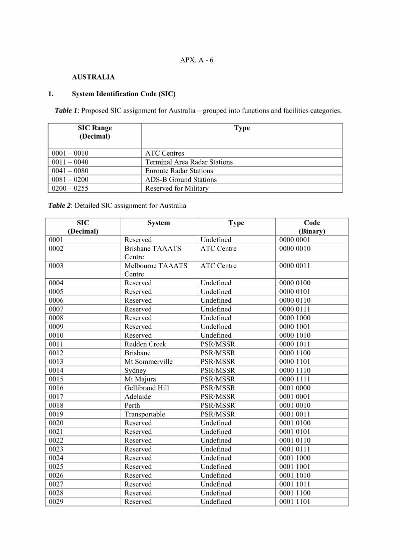
APX. A - 6
AUSTRALIA
1. System Identification Code (SIC)
Table 1: Proposed SIC assignment for Australia – grouped into functions and facilities categories.
SIC Range (Decimal)
Type
0001 – 0010 ATC Centres 0011 – 0040 Terminal Area Radar Stations 0041 – 0080 Enroute Radar Stations 0081 – 0200 ADS-B Ground Stations 0200 – 0255 Reserved for Military
Table 2: Detailed SIC assignment for Australia
SIC
(Decimal) System Type Code
(Binary) 0001 Reserved Undefined 0000 0001 0002 Brisbane TAAATS
Centre ATC Centre 0000 0010
0003 Melbourne TAAATS Centre
ATC Centre 0000 0011
0004 Reserved Undefined 0000 0100 0005 Reserved Undefined 0000 0101 0006 Reserved Undefined 0000 0110 0007 Reserved Undefined 0000 0111 0008 Reserved Undefined 0000 1000 0009 Reserved Undefined 0000 1001 0010 Reserved Undefined 0000 1010 0011 Redden Creek PSR/MSSR 0000 1011 0012 Brisbane PSR/MSSR 0000 1100 0013 Mt Sommerville PSR/MSSR 0000 1101 0014 Sydney PSR/MSSR 0000 1110 0015 Mt Majura PSR/MSSR 0000 1111 0016 Gellibrand Hill PSR/MSSR 0001 0000 0017 Adelaide PSR/MSSR 0001 0001 0018 Perth PSR/MSSR 0001 0010 0019 Transportable PSR/MSSR 0001 0011 0020 Reserved Undefined 0001 0100 0021 Reserved Undefined 0001 0101 0022 Reserved Undefined 0001 0110 0023 Reserved Undefined 0001 0111 0024 Reserved Undefined 0001 1000 0025 Reserved Undefined 0001 1001 0026 Reserved Undefined 0001 1010 0027 Reserved Undefined 0001 1011 0028 Reserved Undefined 0001 1100 0029 Reserved Undefined 0001 1101

APX. A - 7
AUSTRALIA (CONT’D)
SIC (Decimal)
System Type Code (Binary)
0030 Reserved Undefined 0001 1110 0031 Reserved Undefined 0001 1111 0032 Reserved Undefined 0010 0000 0033 Reserved Undefined 0010 0001 0034 Reserved Undefined 0010 0010 0035 Reserved Undefined 0010 0011 0036 Reserved Undefined 0010 0100 0037 Reserved Undefined 0010 0101 0038 Reserved Undefined 0010 0110 0039 Reserved Undefined 0010 0111 0040 Reserved Undefined 0010 1000 0041 Hans Tableland MSSR 0010 1001 0042 Mt Alma MSSR 0010 1010 0043 Swampy Ridge MSSR 0010 1011 0044 Tabletop MSSR 0010 1100 0045 Mt Hardgrave MSSR 0010 1101 0046 The Round Mountain MSSR 0010 1110 0047 Mt Boyce MSSR 0010 1111 0048 Mt Bobbora MSSR 0011 0000 0049 Mt Macedon MSSR 0011 0001 0050 Summertown MSSR 0011 0010 0051 Kalamunda MSSR 0011 0011 0052 Reserved Undefined 0011 0100 0053 Reserved Undefined 0011 0101 0054 Reserved Undefined 0011 0110 0055 Reserved Undefined 0011 0111 0056 Reserved Undefined 0011 1000 0057 Reserved Undefined 0011 1001 0058 Reserved Undefined 0011 1010 0059 Reserved Undefined 0011 1011 0060 Reserved Undefined 0011 1100 0061 Reserved Undefined 0011 1101 0062 Reserved Undefined 0011 1110 0063 Reserved Undefined 0011 1111 0064 Reserved Undefined 0100 0000 0065 Reserved Undefined 0100 0001 0066 Reserved Undefined 0100 0010 0067 Reserved Undefined 0100 0011 0068 Reserved Undefined 0100 0100 0069 Reserved Undefined 0100 0101 0070 Reserved Undefined 0100 0110 0071 Reserved Undefined 0100 0111 0072 Reserved Undefined 0100 1000 0073 Reserved Undefined 0100 1001 0074 Reserved Undefined 0100 1010 0075 Reserved Undefined 0100 1011

APX. A - 8
AUSTRALIA (CONT’D)
SIC (Decimal)
System Type Code (Binary)
0076 Reserved Undefined 0100 1100 0077 Reserved Undefined 0100 1101 0078 Reserved Undefined 0100 1110 0079 Reserved Undefined 0100 1111 0080 Reserved for ADS-B 0101 0000 0081 Reserved for ADS-B 0101 0001 0082 Reserved for ADS-B 0101 0010 0083 Reserved for ADS-B 0101 0011 0084 Reserved for ADS-B 0101 0100 0085 Reserved for ADS-B 0101 0101 0086 Reserved for ADS-B 0101 0110 0087 Reserved for ADS-B 0101 0111 0088 Reserved for ADS-B 0101 1000 0089 Reserved for ADS-B 0101 1001 0090 Reserved for ADS-B 0101 1010 0091 Reserved for ADS-B 0101 1011 0092 Reserved for ADS-B 0101 1100 0093 Reserved for ADS-B 0101 1101 0094 Reserved for ADS-B 0101 1110 0095 Reserved for ADS-B 0101 1111 0096 Reserved for ADS-B 0110 0000 0097 Reserved for ADS-B 0110 0001 0098 Reserved for ADS-B 0110 0010 0099 Reserved for ADS-B 0110 0011 0100 Reserved for ADS-B 0110 0100 0101 ADS-B Test bed ADS-B Ground Station 0110 0101 0102 Reserved for ADS-B 0110 0110 0103 Reserved for ADS-B 0110 0111 0104 Reserved for ADS-B 0110 1000 0105 Reserved for ADS-B 0110 1001 0106 Reserved for ADS-B 0110 1010 0107 Reserved for ADS-B 0110 1011 0108 Reserved for ADS-B 0110 1100 0109 Reserved for ADS-B 0110 1101 0110 Bundaberg (DSGK) GS#01 ADS-B Ground Station 0110 1110 0111 Bundaberg (DSGK) GS#02 ADS-B Ground Station 0110 1111 0112 Caiguna (CAG) GS#01 ADS-B Ground Station 0111 0000 0113 Caiguna (CAG) GS#02 ADS-B Ground Station 0111 0001 0114 Esperance (ESP) GS#01 ADS-B Ground Station 0111 0010 0115 Esperance (ESP) GS#02 ADS-B Ground Station 0111 0011 0116 Ayres Rock (AYE) GS#01 ADS-B Ground Station 0111 0100 0117 Ayres Rock (AYE) GS#02 ADS-B Ground Station 0111 0101 0118 Warburton (WBR) GS#01 ADS-B Ground Station 0111 0110 0119 Warburton (WBR) GS#02 ADS-B Ground Station 0111 0111 0120 Broken Hill (BHI) GS#01 ADS-B Ground Station 0111 1000

APX. A - 9
AUSTRALIA (CONT’D)
SIC (Decimal)
System Type Code (Binary)
0121 Broken Hill (BHI) GS#02 ADS-B Ground Station 0111 1001 0122 Jackson (JAK) GS#01 ADS-B Ground Station 0111 1010 0123 Jackson (JAK) GS#02 ADS-B Ground Station 0111 1011 0124 Birdsville (BDV) GS#01 ADS-B Ground Station 0111 1100 0125 Birdsville (BDV) GS#02 ADS-B Ground Station 0111 1101 0126 Billabong (BLB) GS#01 ADS-B Ground Station 0111 1110 0127 Billabong (BLB) GS#02 ADS-B Ground Station 0111 1111 0128 Thursday Is (TUD) GS#01 ADS-B Ground Station 1000 0000 0129 Thursday Is (TUD) GS#02 ADS-B Ground Station 1000 0001 0130 Meekathara (MEK) GS#01 ADS-B Ground Station 1000 0010 0131 Meekathara (MEK) GS#02 ADS-B Ground Station 1000 0011 0132 Oodnadatta (OOD) GS#01 ADS-B Ground Station 1000 0100 0133 Oodnadatta (OOD) GS#02 ADS-B Ground Station 1000 0101 0134 Karratha (KA) GS#01 ADS-B Ground Station 1000 0110 0135 Karratha (KA) GS#02 ADS-B Ground Station 1000 0111 0136 Longreach (LRE) GS#01 ADS-B Ground Station 1000 1000 0137 Longreach (LRE) GS#02 ADS-B Ground Station 1000 1001 0138 Doongan (DGN) GS#01 ADS-B Ground Station 1000 1010 0139 Doongan (DGN) GS#02 ADS-B Ground Station 1000 1011 0140 Woomeras (WRA) GS#01 ADS-B Ground Station 1000 1100 0141 Woomeras (WRA) GS#02 ADS-B Ground Station 1000 1101 0142 Newman (NWN) GS#01 ADS-B Ground Station 1000 1110 0143 Newman (NWN) GS#02 ADS-B Ground Station 1000 1111 0144 Leonora (LEO) GS#01 ADS-B Ground Station 1001 0000 0145 Leonora (LEO) GS#02 ADS-B Ground Station 1001 0001 0146 Balgo Hills (BGO) GS#01 ADS-B Ground Station 1001 0010 0147 Balgo Hills (BGO) GS#02 ADS-B Ground Station 1001 0011 0148 Mt Isa (MA) GS#01 ADS-B Ground Station 1001 0100 0149 Mt Isa (MA) GS#02 ADS-B Ground Station 1001 0101 0150 Tennant Creek (TNK) GS#01 ADS-B Ground Station 1001 0110 0151 Tennant Creek (TNK) GS#02 ADS-B Ground Station 1001 0111 0152 Nullabor (NUB) GS#01 ADS-B Ground Station 1001 1000 0153 Nullabor (NUB) GS#02 ADS-B Ground Station 1001 1001 0154 Broome (BRM) GS#01 ADS-B Ground Station 1001 1010 0155 Broome (BRM) GS#02 ADS-B Ground Station 1001 1011 0156 Mornington Is. (MTI) GS#01 ADS-B Ground Station 1001 1100 0157 Mornington Is. (MTI) GS#02 ADS-B Ground Station 1001 1101 0158 Mt Oxley (MXL) GS#01 ADS-B Ground Station 1001 1110 0159 Mt Oxley (MXL) GS#02 ADS-B Ground Station 1001 1111 0160 Alice Springs (AS) GS#01 ADS-B Ground Station 1010 0000 0161 Alice Springs (AS) GS#02 ADS-B Ground Station 1010 0001 0162 Mt Barrow (BOW) GS#01 ADS-B Ground Station 1010 0010 0163 Mt Barrow (BOW) GS#02 ADS-B Ground Station 1010 0011 0164 Telfer (TEF) GS#01 ADS-B Ground Station 1010 0100 0165 Telfer (TEF) GS#02 ADS-B Ground Station 1010 0101 0166 Reserved for ADS-B 1010 0110

APX. A - 10
AUSTRALIA (CONT’D)
SIC (Decimal)
System Type Code (Binary)
0167 Reserved for ADS-B 1010 0111 0168 Reserved for ADS-B 1010 1000 0169 Reserved for ADS-B 1010 1001 0170 Reserved for ADS-B 1010 1010 0171 Reserved for ADS-B 1010 1011 0172 Reserved for ADS-B 1010 1100 0173 Reserved for ADS-B 1010 1101 0174 Reserved for ADS-B 1010 1110 0175 Reserved for ADS-B 1010 1111 0176 Reserved for ADS-B 1011 0000 0177 Reserved for ADS-B 1011 0001 0178 Reserved for ADS-B 1011 0010 0179 Reserved for ADS-B 1011 0011 0180 Unused 1011 0100 0181 Unused 1011 0101 0182 Unused 1011 0110 0183 Unused 1011 0111 0184 Unused 1011 1000 0185 Unused 1011 1001 0186 Unused 1011 1010 0187 Unused 1011 1011 0188 Unused 1011 1100 0189 Unused 1011 1101 0190 Unused 1011 1110 0191 Unused 1011 1111 0192 Unused 1100 0000 0193 Unused 1100 0001 0194 Unused 1100 0010 0195 Unused 1100 0011 0196 Unused 1100 0100 0197 Unused 1100 0101 0198 Unused 1100 0110 0199 Unused 1100 0111 0200 Unused 1100 1000 0201 Reserved for Military Reserved - Restricted 1100 1001 0202 Reserved for Military Reserved - Restricted 1100 1010 0203 Reserved for Military Reserved - Restricted 1100 1011 0204 Reserved for Military Reserved - Restricted 1100 1100 0205 Reserved for Military Reserved - Restricted 1100 1101 0206 Reserved for Military Reserved - Restricted 1100 1110 0207 Reserved for Military Reserved - Restricted 1100 1111 0208 Reserved for Military Reserved - Restricted 1101 0000 0209 Reserved for Military Reserved - Restricted 1101 0001 0210 Reserved for Military Reserved - Restricted 1101 0010

APX. A - 11
AUSTRALIA (CONT’D)
SIC
(Decimal) System Type Code
(Binary) 0211 Reserved for Military Reserved - Restricted 1101 0011 0212 Reserved for Military Reserved - Restricted 1101 0100 0213 Reserved for Military Reserved - Restricted 1101 0101 0214 Reserved for Military Reserved - Restricted 1101 0110 0215 Reserved for Military Reserved - Restricted 1101 0111 0216 Reserved for Military Reserved - Restricted 1101 1000 0217 Reserved for Military Reserved - Restricted 1101 1001 0218 Reserved for Military Reserved - Restricted 1101 1010 0219 Reserved for Military Reserved - Restricted 1101 1011 0220 Reserved for Military Reserved - Restricted 1101 1100 0221 Reserved Reserved 1101 1101 0222 Reserved Reserved 1101 1110 0223 Reserved Reserved 1101 1111 0224 Reserved Reserved 1110 0000 0225 Reserved Reserved 1110 0001 0226 Reserved Reserved 1110 0010 0227 Reserved Reserved 1110 0011 0228 Reserved Reserved 1110 0100 0229 Reserved Reserved 1110 0101 0230 Reserved Reserved 1110 0110 0231 Reserved Reserved 1110 0111 0232 Reserved Reserved 1110 1000 0233 Reserved Reserved 1110 1001 0234 Reserved Reserved 1110 1010 0235 Reserved Reserved 1110 1011 0236 Reserved Reserved 1110 1100 0237 Reserved Reserved 1110 1101 0238 Reserved Reserved 1110 1110 0239 Reserved Reserved 1110 1111 0240 Reserved Reserved 1111 0000 0241 Reserved Reserved 1111 0001 0242 Reserved Reserved 1111 0010 0243 Reserved Reserved 1111 0011 0244 Reserved 0245 Reserved 0246 Reserved 0247 Reserved 0248 Reserved 0249 Reserved 0250 Reserved 0251 Reserved 0252 Reserved 0253 Reserved 0254 Reserved 0255 Reserved

APX. A - 12
BRUNEI DARUSSALAM
Radar in Terminal Area
SIC
Radar Data System
Radar Type
Code Binary
1
Brunei Terminal Area Radar
PSR/MSSR
0000 0001

APX. A - 13
CHINA
SIC
(Decimal)
Radar Data Source
Code
(Binary)
0 ~127 Reserved for non-civil aviation user
Flight Information Regions
128 129 130 131 132 133 134 135 136 137
138-143
Beijing FIR Shanghai FIR Shenyang FIR Wuhan FIR Guangzhou FIR Kunming FIR Lanzhou FIR Urumqi FIR Hongkong FIR Taibei FIR Reserved
1000 0000 1000 0001 1000 0010 1000 0011 1000 0100 1000 0101 1000 0110 1000 0111 1000 1000 1000 1001
Air Traffic
144 145 146 147 148 149 150 151 152 153 154 155 156 157 158 159 160 161 162 163 164 165 166 167 168 169 170
171-191
Shenyang ACC
Harbin ACC Hailar ACC Dalian ACC Beijing ACC Hohhot ACC Taiyuan ACC Shanghai ACC Jinan ACC Hefei ACC Nanchang ACC Xiamen ACC Wuhan ACC Zhengzhou ACC Guangzhou ACC Changsha ACC Nanning ACC Kunming ACC Guiyang ACC Chengdu ACC Xi-an ACC Lanzhou ACC Urumqi ACC Guilin ACC Hongkong ACC Qing Dao ACC Taibei ACC Reserved
1001 0000 1001 0001 1001 0010 1001 0011 1001 0100 1001 0101 1001 0110 1001 0111 1001 1000 1001 1001 1001 1010 1001 1011 1001 1100 1001 1101 1001 1110 1001 1111 1010 0000 1010 0001 1010 0010 1010 0011 1010 0100 1010 0101 1010 0110 1010 0111 1010 1000 1010 1001 1010 1010

APX. A - 14
CHINA (CONT’D)
Radar Station
192 193 194 195 196 197 198 199 200 201 202 203 204 205 206 207 208 209 210 211 212 213 214 215 216 217 218 219 220 221 222 223 224 225 226 227 228 229 230 231 232 233
234-258
Beijing-1 Beijing-2 Beijing-3 Tianjin Taiyuan Hohhot Guangzhou-1 Guangzhou-2 Shenzhen Sanya Changsha Enshi Wuhan Zhengzhou -1 Zhengzhou -2 Guilin Nanning Shantou Zhuhai Haikou Kunming Chengdu Guiyang -1 Guiyang -2 Chongqing Shanghai -1 Shanghai -2 Shanghai -3 Hefei Fuzhou Xiamen Lianyungang Nanjin Shenyang Dalian Xi’an Lanzhou Nanchang Qingdao Jinan Urumqi Harbin Reserved
SSR
PSR/SSR PSR/SSR
SSR SSR SSR
PSR/SSR SSR
PSR/SSR PSR/SSR
SSR SSR
PSR/SSR PSR/SSR PSR/SSR
SSR SSR SSR
PSR/SSR PSR/SSR
SSR PSR/SSR
SSR PSR/SSR PSR/SSR PSR/SSR
SSR PSR SSR SSR
PSR/SSR SSR
PSR/SSR PSR/SSR PSR/SSR
SSR SSR SSR SSR SSR
PSR/SSR PSR/SSR
1100 0000 1100 0001 1100 0010 1100 0011 1100 0100 1100 0101 1100 0110 1100 0111 1100 1000 1100 1001 1100 1010 1100 1011 1100 1100 1100 1101 1100 1110 1100 1111 1101 0000 1101 0001 1101 0010 1101 0011 1101 0100 1101 0101 1101 0110 1101 0111 1101 1000 1101 1001 1101 1010 1101 1011 1101 1100 1101 1101 1101 1110 1101 1111 1110 0000 1110 0001 1110 0010 1110 0011 1110 0100 1110 0101 1110 0110 1110 0111 1110 1000 1110 1001

APX. A - 15
HONG KONG, CHINA
SIC
(Decimal)
Radar Data System
Radar type
Code
(Binary)
Radars in Terminal Areas
001 Tai Mo Shan Terminal Area Radar
PSR/MSSR
0000 0001
002
Sha Chau Approach Surveillance Radar
PSR/MSSR
0000 0010
003
Beacon Hill Approach Secondary Surveillance Radar
MSSR
0000 0011
Radars in En-Route Airspace
101
Mount Parker Route Secondary Surveillance Radar
MSSR
0110 0101
111
Mount Parker Route surveillance Radar
PSR
0110 1111

APX. A - 16
MACAO, CHINA
SIC
(Decimal)
Radar Data System
Radar type
Code
(Binary)
Radars Systems
001 Coloane Approach Surveillance Radar
PSR/MSSR
1111 0001
002
Reserved for other Radar
003
Reserved for other Radar
004
Reserved for other Radar
005
Reserved for other Radar

APX. A - 17
INDONESIA
SIC
(Decimal)
Radar Data System
Radar type
Code
(Binary) Terminal areas and en-route airspace
001 Medan PRS/SSR 0000 0001 002 Pekanbaru PSR/SSR 0000 0010 003 Tanjung Pinang PSR/SSR 0000 0011 004 Palembang PSR/SSR 0000 0100 005 Jakarta/CGK PSR/MSSR 0000 0101 006 Pontianak PSR/SSR 0000 0110 007 Yogyakarta PSR/MSSR 0000 0111 008 Surabaya PSR/SSR 0000 1000 009 Makassar PSR/SSR 0000 1001 010 Benjarmasin PSR/SSR 0000 1010 011 Balikpapan PSR/SSR 0000 1011 012 Denpasar PSR/MSSR 0000 1100 013 Biak PSR/SSR 0000 1101
En-route airspace 101 Banda Aceh SSR 0110 0101 102 Natuna MSSR 0110 0110 103 Jakarta/HLP SSR 0110 0111 104 Semarang SSR 0110 1000 105 Manado SSR 0110 1001 106 Kendari SSR 0110 1010 107 Waingapu SSR 0110 1011 108 Ambon SSR 0110 1100
Processing systems 201 Jakarta/CGK 1100 1001 202 Medan 1100 1010 203 Denpasar 1100 1011 204 Makassar 1100 1100 205 Yogyakarta 1100 1101

APX. A - 18
LAOS
SIC (Decimal)
Radar Data System
Radar type
Code
(Binary)
Radar in Terminal Areas
001 Vientiane Terminal Area Radar
PSR/MSSR
0000 0001
Radar in En-Route Airspace
002 Savannakhet Secondary Surveillance Radar
MSSR
1000 0100
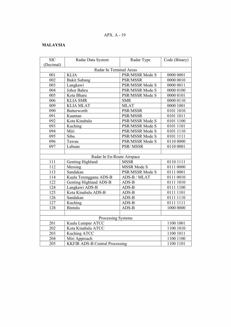
APX. A - 19
MALAYSIA
SIC (Decimal)
Radar Data System Radar Type Code (Binary)
Radar In Terminal Areas 001 KLIA PSR/MSSR Mode S 0000 0001 002 Bukit Subang PSR/MSSR 0000 0010 003 Langkawi PSR/MSSR Mode S 0000 0011 004 Johor Bahru PSR/MSSR Mode S 0000 0100 005 Kota Bharu PSR/MSSR Mode S 0000 0101 006 KLIA SMR SMR 0000 0110 009 KLIA MLAT MLAT 0000 1001 090 Butterworth PSR/MSSR 0101 1010 091 Kuantan PSR/MSSR 0101 1011 092 Kota Kinabalu PSR/MSSR Mode S 0101 1100 093 Kuching PSR/MSSR Mode S 0101 1101 094 Miri PSR/MSSR Mode S 0101 1110 095 Sibu PSR/MSSR Mode S 0101 1111 096 Tawau PSR/MSSR Mode S 0110 0000 097 Labuan PSR/ MSSR 0110 0001
Radar In En-Route Airspace
111 Genting Highland MSSR 0110 1111 112 Mersing MSSR Mode S 0111 0000 113 Sandakan PSR/MSSR Mode S 0111 0001 114 Kuala Terengganu ADS-B ADS-B / MLAT 0111 0010 122 Genting Highland ADS-B ADS-B 0111 1010 124 Langkawi ADS-B ADS-B 0111 1100 125 Kota Kinabalu ADS-B ADS-B 0111 1101 126 Sandakan ADS-B 0111 1110 127 Kuching ADS-B 0111 1111 128 Bintulu ADS-B 1000 0000
Processing Systems
201 Kuala Lumpur ATCC 1100 1001 202 Kota Kinabalu ATCC 1100 1010 203 Kuching ATCC 1100 1011 204 Miri Approach 1100 1100 205 KKFIR ADS-B Central Processing 1100 1101

APX. A - 20
MYANMAR
SIC
(Decimal)
Radar Data System
Radar type
Code
(Binary)
Radar in Terminal Areas
001 YANGON Approach Radar (ASR/SSR) PSR/MSSR
0000 0001
002 MANDALAY Approach Radar (ASR/SSR)
PSR/MSSR 0000 0010
Radar in En-Route Airspace
101 YANGON Radar (SSR) MSSR 0110 0101 102 MANDALAY Radar (SSR) MSSR 0110 0110 103 MYEIK Radar (SSR) MSSR 0110 0111 104 NAYPYITAW Radar (SSR) MSSR 0110 1000
ATM Automation System
200 YANGON Approach Automation System NEC 1100 1001 201 YANGON ACC Automation System THALES 1100 1010 202 MANDALAY Approach Automation System THALES 1100 1011
ADS-B in En-Route Airspace
129 COCO ISLAND ADS-B GS 1 ADS-B 1000 0001 130 COCO ISLAND ADS-B GS 2 ADS-B 1000 0010 131 SITTWE ADS-B GS 1 ADS-B 1000 0011 132 SITTWE ADS-B GS 2 ADS-B 1000 0100 133 MANDALAY ADS-B GS 1 ADS-B 1000 0101 134 MANDALAY ADS-B GS 2 ADS-B 1000 0110 135 MYEIK ADS-B GS 1A ADS-B 1000 0111 136 MYEIK ADS-B GS 1B ADS-B 1000 1000 151 MYEIK ADS-B GS 2A ADS-B 1001 0111 152 MYEIK ADS-B GS 2B ADS-B 1001 1000 145 YANGON ADS-B GS 1 ADS-B 1001 0001 146 YANGON ADS-B GS 2 ADS-B 1001 0010 147 LASHIO ADS-B GS 1A ADS-B 1001 0011 148 LASHIO ADS-B GS 2A ADS-B 1001 0100 149 LASHIO ADS-B GS 1B ADS-B 1001 0101 150 LASHIO ADS-B GS 2B ADS-B 1001 0110 151 TACHILEIK ADS-B GS 1 ADS-B 1001 0111 152 TACHILEIK ADS-B GS 2 ADS-B 1001 1000

APX. A - 21
NEW ZEALAND
SIC (Decimal)
Radar Data System
Radar type
Code
(Binary)
Radars Systems
001 Auckland
PSR
0000 0001
002
Rua-o-te-whenua
SSR
0000 0010
003
Te Wereaiti
SSR
0000 0011
004
Balance
SSR
0000 0100
005
Ohakea
PSR
0000 0101
006
Hawkins Hill
PSR/SSR
0000 0110
007
Mt. Robertson
SSR
0000 0111
008
Christchurch
PSR
0000 1000
009
Cass Peak
SSR
0000 1001

APX. A - 22
PAPUA NEW GUINEA
SIC
(Decimal)
Radar Data System
Radar Type
Code
(Binary)
Radar in Terminal Area
PSR/SSR
000 0001 001
Port Moresby Approach

APX. A - 23
PHILIPPINES
SIC (Decimal)
Radar Data System Radar Type Code (Binary)
Radars in Terminal Areas
001
Manila PSR/MSSR 0000 0001
002
Mactan PSR/SSR 0000 0010
003
Subic PSR/SSR 0000 0011
004
Clark* PSR/MSSR 0000 0100
Radars in En-Route Airspace
101 Tagaytay
SSR** 0110 0101
102 Laoag
MSSR 0110 0110
103 Mt. Luay, Cebu
MSSR 0110 0111
104
Palawan *** 0110 1000
105 Samal, Davao
*** 0110 1001
106 Zamboanga
*** 0110 1010
Radar Data Processing System
201
Manila APP – TRDP 1100 1001
202
Mactan APP – TRDP 1100 1010
203
Subic APP – TRDP 1100 1011
204
Clark APP – TRDP* 1100 1100
205
Manila ACC – RDP 1100 1101
206
Manila ACC – Wide Area TRDP*** 1100 1110
207
Manila ACC – ERDP *** 1100 1111
Note: * For installation in 2004 ** To be replaced in the CNS/ATM implementation; either MSSR or Mode - S
*** For installation in the CNS/ATM implementation; either MSSR or Mode - S

APX. A - 24
REPUBLIC OF KOREA
SIC (Decimal)
Radar Data System
Radar type
Code
(Binary)
Radars in Terminal Areas
001 Kimpo
PSR/MSSR
0000 0001
005
Kimhae
PSR/SSR
0000 0101
010
Cheju
PSR/MSSR
0000 1010
015
Inchon
PSR/MSSR (new installation)
0000 1111
020/025
Reserved for other Radar
031/050
Reserved for Military Radars
Radars in En-Route Airspace
119/138
Reserved for En-Route (Planned)
Processing Systems
210
Taegu ACC
1101 0010
215
Kimpo ARTS
1101 0111
220
Kimhae ARTS
1101 1100
225
Cheju ARTS
1110 0001
230
Inchon ARTS
1110 0110
236/255
Reserved for Military ARTS
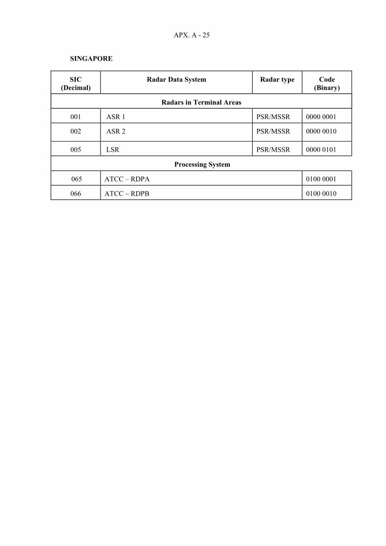
APX. A - 25
SINGAPORE
SIC (Decimal)
Radar Data System
Radar type
Code
(Binary)
Radars in Terminal Areas
001 ASR 1
PSR/MSSR
0000 0001
002
ASR 2
PSR/MSSR
0000 0010
005
LSR
PSR/MSSR
0000 0101
Processing System
065
ATCC – RDPA
0100 0001
066
ATCC – RDPB
0100 0010

APX. A - 26
SRI LANKA
SIC
(Decimal)
Radar Data System
Radar type
Code
(Binary)
Radars in Terminal Areas
001 Bandaranaike International Airport Colomblo
PSR
0000 0001
Radars in En-Route Airspace
011
Pidurutalagala
PSR/MSSR
0000 1011
021
Area Control Centre - Ratmalana Airport Colombo
0001 0101
022
Approach Control Centre - Bandaranaike International Airport, Colombo
0001 0110

APX. A - 27
THAILAND
SIC
(Decimal)
Radar Data System
Radar type
Code
(Binary)
Radars in Terminal Areas and En-Route Airspace
001 Donmuang
PSR/MSSR
0000 0001
006
Chiangmai
PSR/MSSR
0000 0110
007
Mae Hong Son
MSSR
0000 0111
012
Ubonratchathani
MSSR
0000 1100
016
Suratthani
PSR
0001 0000
021
Phuket
PSR
0001 0101
026
Hatyai
MSSR
00011010
Processing System
228
ATCC – RDPA
1110 0100
229
ATCC – RDPB
1110 0101

APX. A - 28
VIET NAM
SIC
(Decimal)
Radar Data System
Radar type
Code
(Binary)
Radars in Terminal Areas and En-Route Airspace
001 Noi Bai/Ha Noi (Radar Data head 1)
PSR/MSSR
0000 0001
002
Son Tra/Da Nang
PSR/MSSR
0000 0010
003
Tan son Nhat/Ho chi Minh
PSR/MSSR
0000 0011
Radars in En-Route Airspace
131
Noi Bai/Ha Noi (Radar Data Head 2)
PSR/SSR
1000 0011
132
Vinh
MSSR
1000 0100
133
Qui Nhon
MSSR
1000 0101
134
Ca Mau
MSSR
1000 0110
Processing Systems
221
ATCC - RDP Noi Bai/Ha Noi
1101 1101
222
ATCC - RDP Tan Son Nhat/Ho Chi Minh
1101 1110

SURICG/5 Appendix B to the Report
APX. B - 1
LIST OF ACTION ITMES FOR SURICG
No. Subject Forum Raised Status / Target Date Remarks /
follow-up Action Party Status
1
Develop and implement regional collaboration project for ADS-B out operational use including data sharing in South Pacific and report on implementation progress.
Previous meeting of ADS-B SITF and ADS-B SITF/14
SURICG/4 SURICG/6
South Pacific States On-going Transferred to SURICG
On-going Initial stage Report by Ad Hoc WG at ADS-B SITF14
2 Examine the density of Mode S radar installations in the Region to determine the need for development of a SI code allocation/implementation plan and related issues
SURICG/2 SURICG/4
Review the status of coordination for Mode S II CODEs allocation /SURICG/6
Secretariat in consultation with States. Tasked to ICAO sec. & DAPS WG
Updates to Modes S SI code still not very active by States. Current information shows that II code is still sufficient.
3
A Study Group to Explore Solutions on Surveillance Data Sharing in coordination with SWIM/ATFM experts (prepare a working paper to seek endorsement from CNS SG/24)
SURICG/5 SURICG/6 Report status
Led by Singapore, supported by HK
4 Regional planning criteria for additional SAC assignment SURICG/5 SURICG/6 Implemented by ICAO APAC
Co-chairs, concerned States
5 Study Mode S roadmap, including SI/II operation experience, 1030/1090MHz congestion and retrofit Mode S avionics
SURICG/5 SURICG/6 DAPs WG
6 Follow up the action items from SEA/BOB ADS-B WG/15 SURICG/5 SURICG/6
Co-chairs, ICAO APAC, concerned parties
7 Review SURICG TOR to incorporate SEA/BOB ADS-B WG TOR SURICG/5 SURICG/6 Co-chairs
*SURICG/2 agreed to keep subject list resulted from the ADS-B SITF/15 for consideration by States in preparation of further SURICG meetings.

Appendix B to the Report
APX. B - 2
All members States/Administrations to contribute with papers at next meeting on any of the following items.
ASBUs relating to ADS-B IN Implementation of Space Based ADS-B ASBU B0-NET using ADS-B Use of lower cost, lower performance ADS-B systems (TSO199) Use of Mode S DAPS in APAC region Use of electronic scan primary radars in APAC region Use of Mode C transponder veils in APAC region Use of Flight ID data from mode S interrogation and ADS-B Mode S problem reporting in APAC region Mode S analysis tools used in APAC region ADS-B test equipment used in APAC region Need to amend SUPPs 7030 on SIL matter Management issues with 24 bit ICAO codes in APAC Update and maintain ADS-B problem database Consider need for aircraft transponder Mode S mandates
_ _ _ _ _ _ _ _ _ _ _

SURICG/5 Appendix B1 to the Report
APX. B1 - 1
LIST OF ACTION ITMES (COMPLETED ACTION ITEMS HAVE BEEN REMOVED) No. Subject Forum Raised Status / Target Date Remarks /
follow-up Action Party
1. ATS operational letter of agreements between neighboring FIRs among South China Sea States for radar-like surveillance service (Operational agreement between Singapore and Viet Nam was signed first in Nov. 2013 and later updated in July 2014 for 30 NM separation, agreement for 20 NM was signed Oct. 2016) To further progress rest parts for major ATS Routes L642 and M771 to apply new separation criteria using ADS-B and other surveillance
SEA ADS-B WG/6
Ongoing – Reports at each meeting (need to coordination through SEACG for separation criteria to be applied) China, VN, are able to provide radar surveillance to L642,M771within the relevant FIRs. (SEA/BOB WG/15)
Report progress Consistent separation to be applied in 4 FIRs, new action item for 4 parties. Refer surveillance capability to ATM SG.
China, Hong Kong China, Viet Nam and Singapore On-going needs seamless agreement for the minima – major traffic flow; Hong Kong/Sanya Sanya/Ho Chi Minh
2. Develop and implement regional collaboration project for ADS-B out operational use including data sharing in Bay of Bengal area and report on implementation progress. Status updated at WG/11 A simple document containing projects for BoB data sharing to be prepared by India MOU for Bay of Bengal data sharing projects ( Consolidated in SEA/BOB WG/15)
SEA/BOB WG/11 SEA/BOB WG/13
Nov. 2018 SEA/BOB WG/14
Develop and implement sub-regional ADS-B collaboration projects. On-going Have the MOU between India/Sir Lanka; India/Malaysia and India/Indonesia agreed. On going
Bay of Bengal States Detailed needs to be finalized by SEA/BOB India, Sri Lanka Malaysia and Indonesia
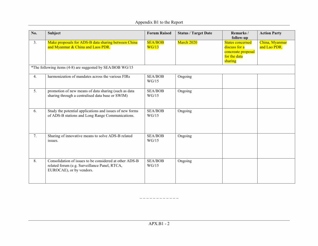
Appendix B1 to the Report
APX.B1 - 2
No. Subject Forum Raised Status / Target Date Remarks / follow-up
Action Party
3. Make proposals for ADS-B data sharing between China and Myanmar & China and Laos PDR.
SEA/BOB WG/13
March 2020 States concerned discuss for a concreate proposal for the data sharing
China, Myanmar and Lao PDR.
*The following items (4-8) are suggested by SEA/BOB WG/15
4. harmonization of mandates across the various FIRs SEA/BOB WG/15
Ongoing
5. promotion of new means of data sharing (such as data sharing through a centralised data base or SWIM)
SEA/BOB WG/15
Ongoing
6. Study the potential applications and issues of new forms of ADS-B stations and Long Range Communications.
SEA/BOB WG/15
Ongoing
7. Sharing of innovative means to solve ADS-B related issues.
SEA/BOB WG/15
Ongoing
8. Consolidation of issues to be considered at other ADS-B related forum (e.g. Surveillance Panel, RTCA, EUROCAE), or by vendors.
SEA/BOB WG/15
Ongoing
_ _ _ _ _ _ _ _ _ _ _ _

SURICG/5
Appendix C to the Report
APX. C - 1
ADS-B IMPLEMENTATION STATUS IN THE APAC REGION
State/ Administration
ADS-B Ground Infrastructure and ATC System readiness or
Implementation plan
Date of issue/ effectiveness date of equipage mandate
Mandated Airspace
and/or ATS-routes
Intended separation
criteria to be applied
Remarks
AFGHANISTAN
ADS-B & Multi Lateration system installed.
subject to safety assessment
AUSTRALIA
A total of 50 ADS-B ground stations and 28 WAM stations are operational (Total 78) ATC readiness since 2004 ADS-B data sharing with Indonesia operational since 2/2011. ADS-B data sharing planned with PNG ASMGCS using multilateration and ADS-B is operational in Brisbane, Sydney, Melbourne and Perth November 2016 – ADS-B converted to “radar like” Cat 48 for use in Melbourne Terminal Area and Perth Terminal Area in early 2017. CMATS replacing the current ATM system is expected to be fully operational in 2024 period.
2009/effective date of mandating in upper airspace 12/12/2013. An ADS-B mandate for all IFR aircraft applies from 2/2017. Some limited exemptions for foreign registered aircraft and some private operations.
All airspace for IFR aircraft from 2/2017
2.5NM, 3NM and 5 NM surveillance separations. 3/2016 - Manual of ATC updated to include 3 nautical mile separation using ADS-B in terminal control unit. 3/2017 – 2.5NM separation authorized using ADS-B when also used with radar. Vectoring allowed using ADS-B Precision Runway Monitoring for Sydney WAM
WAM is operating in Tasmania since 2010 with 5 NM separation service. WAM is also operating in Sydney for 3 NM separation service in TMA and for precision runway monitoring function. CASA has approved the use of reduced specification ADS-B avionics to support ADS-B IN and ATC situational awareness for VFR aircraft
BANGLADESH
Bangladesh has a plan to install four ADS-B ground stations to be installed at Dhaka, Cox’s Bazar, Saidpur and Barisal Airports by 2019. ADS-B data will be integrated with new ATM system at Dhaka. Bangladesh has also a plan to install MLAT stations to provide surface movement control at HSIA, Dhaka as well as TMA coverage as a backup and complimentary RADAR coverage to the Dhaka MSSR.
Bangladesh is willing to share ADS-B data with neighbouring States to enhance the safety and surveillance capability in the sub-region.

Appendix C to the Report
APX. C - 2
State/ Administration
ADS-B Ground Infrastructure and ATC System readiness or
Implementation plan
Date of issue/ effectiveness date of equipage mandate
Mandated Airspace
and/or ATS-routes
Intended separation
criteria to be applied
Remarks
BHUTAN
ADS-B ground infrastructure feasibility study will be completed in the middle of 2020.
Equipage mandate will be issued once after the completion of feasibility study.
BRUNEI DARUSSALAM
5 ADS-B ground stations with WAM functionality installed in 2015 and full operation in October 2016. ADS-B/WAM data are fused with radar data in the TopSky ATC Automation system (Thales) to enhance full radar surveillance coverage for Brunei Darussalam. Memorandum of Understanding (MOU) on ADS-B data sharing with Singapore and Brunei Darussalam is expected to sign in April 2019.
CAMBODIA
3 ADS-B ground stations installed at Phnom Penh, Siem Reap and Stung Treng City since 2011 and able to provide full surveillance coverage for Phnom Penh FIR. Cambodia is willing to share data with others.
CHINA
5 UAT ADS-B stations are used for flight training of CAFUC. The upgrade to 1090ES ADS-B stations project has already started in 2017, and the project is planned to finish by 2022. 308 ADS-B stations nationwide have already finished installation and SAT by the end of 2018. 4 ADS-B stations operational in Sanya FIR since 2008. Chengdu-Jiuzhai and Chendu - Lhasa route with 9 ADS-B stations. 9 ADS-B stations deployed on the routes H15 and Z1 by the end of 2015. 19 ADS-B stations at the small airport.
The operation of national ADS-B Service is implementing in step -by-step way. The phase 1-plan has been carried out since October 2019, details as fllows: ADS-B control
operation will be implemented in En-route area upper 8400m without Radar control ability; Radar/ADS-B
combined control operation will be implemented in En-route area upper 8400m with Radar control ability.

Appendix C to the Report
APX. C - 3
State/ Administration
ADS-B Ground Infrastructure and ATC System readiness or
Implementation plan
Date of issue/ effectiveness date of equipage mandate
Mandated Airspace
and/or ATS-routes
Intended separation
criteria to be applied
Remarks
The ADS-B mandate published in October, 2019, in a separated AIC named “Implementation of ADS-B Control Services”
HONG KONG CHINA
A larger-scale A-SMGCS covering the whole Hong Kong International Airport put into operational use in April 2009. Data collection/ analysis on aircraft ADS-B equipage in Hong Kong airspace conducted on quarterly basis since 2004. ADS-B trial using a dedicated ADS-B system completed in 2007. ADS-B out operations over PBN routes L642 and M771 at or above FL 290 within HK FIR was effective in December 2013 and within HK FIR at or above FL 290 has been effective since December 2016. ADS-B ground station infrastructure completed in 2013. ADS-B signal provided by Mainland China to cover southern part of Hong Kong FIR commenced in 2010 and has been put into operational use after commissioning of the new ATMS since November 2016.
AIP supplement issued on 29 Aug 2014 with 8 Dec 2016 as effective date.
HKFIR at or above FL290
5NM surveillance separation
Fully implemented ADS-B in HKFIR by phased approach to ensure safe and smooth integration of ADS-B into the Air Traffic Management System to provide aircraft separation service since November 2018.
MACAO, CHINA
Mode S MSSR coverage available for monitoring purposes.
Airspace – ATZ only
DEMOCRATIC PEOPLE’S REPUBLIC OF KOREA
ADS-B has been used as back-up surveillance of SSR since 2008.
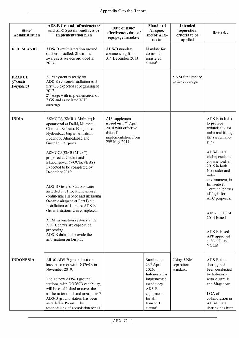
Appendix C to the Report
APX. C - 4
State/ Administration
ADS-B Ground Infrastructure and ATC System readiness or
Implementation plan
Date of issue/ effectiveness date of equipage mandate
Mandated Airspace
and/or ATS-routes
Intended separation
criteria to be applied
Remarks
FIJI ISLANDS
ADS- B /multilateration ground stations installed. Situations awareness service provided in 2013.
ADS-B mandate commencing from 31st December 2013
Mandate for domestic registered aircraft.
FRANCE (French
Polynesia)
ATM system is ready for ADS-B sensors/Installation of 5 first GS expected at beginning of 2017. 2nd stage with implementation of 7 GS and associated VHF coverage.
5 NM for airspace under coverage.
INDIA
ASMGCS (SMR + Multilat) is operational at Delhi, Mumbai, Chennai, Kolkata, Bangalore, Hyderabad, Jaipur, Amritsar, Lucknow, Ahmedabad and Guwahati Airports. ASMGCS(SMR+MLAT) proposed at Cochin and Bhubaneswar (VOCI&VEBS) Expected to be completed by December 2019. ADS-B Ground Stations were installed at 21 locations across continental airspace and including Oceanic airspace at Port Blair. Installation of 10 more ADS-B Ground stations was completed. ATM automation systems at 22 ATC Centres are capable of processing ADS-B data and provide the information on Display.
AIP supplement issued on 17th April 2014 with effective date of implementation from 29th May 2014.
ADS-B in India to provide redundancy for radar and filling the surveillance gaps.
ADS-B data trial operations commenced in 2015 in both Non-radar and radar environment, in En-route & Terminal phases of flight for ATC purposes.
AIP SUP 18 of 2014 issued ADS-B based APP approved at VOCL and VOCB
INDONESIA
All 30 ADS-B ground station have been met with DO260B in November 2019; The 18 new ADS-B ground stations, with DO260B capability, will be established to cover the traffic in terminal and area. The 7 ADS-B ground station has been installed in Papua. The rescheduling of completion for 11
Starting on 23rd April 2020, Indonesia has implemented mandatory ADS-B equipment for all transport aircraft
Using 5 NM separation standard.
ADS-B data sharing had been conducted by Indonesia with Australia and Singapore. LOA of collaboration in ADS-B data sharing has been

Appendix C to the Report
APX. C - 5
State/ Administration
ADS-B Ground Infrastructure and ATC System readiness or
Implementation plan
Date of issue/ effectiveness date of equipage mandate
Mandated Airspace
and/or ATS-routes
Intended separation
criteria to be applied
Remarks
ground stations in 4Q2021. The ADS-B ground stations has been integrated to 9 ATC systems and 3 others will follow after being upgraded.
category flying at all level (SFC up to FL600) in 2 ACCs, 9 TMAs and 10 Airports.
achieved with India. LOA of collaboration in ADS-B data sharing are under reviewing by Malaysia, Philippines and PNG.
JAPAN
Multilateration Systems for surface monitoring have been implemented at eight airports PRM (WAM) has been implemented at Narita Airport. En-route WAM system is manufacturing and will be put into operation in FY2018 Plan to evaluate accuracy of ADS-B information under RAD condition.
LAO PDR.
2 ADS-B ground stations were installed in Vientiane and Luangprabang Int’l Airport in 2015 and the ADS-B data is fused with MSSR data target in the ATM Automation system. 3 additional ADS-B ground stations (DO-260B compliant) will be completed the installation at existing MSSR sites (Xiengkhouang, Savannakhet and Champasack) by 2016 to Q1 of 2017 to enhance the full ADS-B coverage of Lao FIR.

Appendix C to the Report
APX. C - 6
State/ Administration
ADS-B Ground Infrastructure and ATC System readiness or
Implementation plan
Date of issue/ effectiveness date of equipage mandate
Mandated Airspace
and/or ATS-routes
Intended separation
criteria to be applied
Remarks
MALAYSIA
Ground Infrastructure: Kuala Lumpur FIR: 1. Installation of two (2) ADS-B GS in Langkawi and Genting has been completed in October 2017. 2. Upgrading of Kuala Terengganu ADS-B for ADS-B Version 2 capability is to be completed at the end of Dec 2021. 3. Operation of all three ADS-B in new Kuala Lumpur ATC System is to be completed in Dec 2021. Kota Kinabalu FIR: Four (4) new ADS-B will be installed in Kuching, Bintulu, Kota Kinabalu and Sandakan, to be completed in Dec 2021. Implementation Plan: Phase 1: ADS-B services on specific ATS routes and Flight Levels within Kuala Lumpur FIR, target date Mar 2021. Phase 2: ADS-B as secondary means of surveillance within the Kuala Lumpur FIR for en-route airspace. Target date: Mar 2022. Phase 3: ADS-B used as the primary means of surveillance for en-route airspace. (TBA)
AIC Issued on September 2017. AIP Supp on 16 Jan 2020.
Phase 1: On ATS routes N571, P628, L510, P627, L645 and P574 at FL 290 to FL 410 within Kuala Lumpur FIR Phase 2: En-route airspace
ICAO approved surveillance separation.
MALDIVES
4 ADS-B stations installed in Nov. 2012 (2 at Male’ Ibrahim Nasir Intl Airport, 1 at Kulhudhuffushi Island in the North and 1 at Fuah Mulah Island in the South to cover 95% of the FIR at/above FL290. Maldives’ ADS-B is integrated with the ATM system (in November 2013), and under observation prior to commencing trials. Maldives has planned to share ADS-B data with its adjacent FIRs. Updated by email
Seaplane in Maldives equipped with ADS-B for AOC purpose. These seaplanes have ADS-B IN functions as well.

Appendix C to the Report
APX. C - 7
State/ Administration
ADS-B Ground Infrastructure and ATC System readiness or
Implementation plan
Date of issue/ effectiveness date of equipage mandate
Mandated Airspace
and/or ATS-routes
Intended separation
criteria to be applied
Remarks
MONGOLIA
Ten ADS-B ground stations for combination SSR and filled the surveillance gaps implemented in 2015 and integrated with ATM system and trial operation in early 2016.
MYANMAR
a) The ADS-B Implementation Update - The five ADS-B ground stations have been installed in Myanmar. Among them, SITTWE and CoCo Island ground stations are installed in 2014, and are DO260 compliant. The other 3 stations, YANGON, MANDALAY and MYEIK airport ground stations are DO260B compliant and installations were finished in 2016. - All ADS-B data are fused with MSSR data in the TopSky ATC Automation system (Thales) in 2016 and using as MSSR backup in Yangon ACC. b) The ADS-B data sharing update between neighbouring States - Myanmar and India signed the MOU agreement for ADS-B data sharing on 6th May 2015. ADS-B data sharing test between Agartala (India) - Sittwe (Myanmar), and Port Blair (India) - CoCo Island (Myanmar) have been accomplished between technical teams since June 2018. At present, the shared ADS-B data from Myanmar side is now using as backup automation system at Kolkata for test purpose. But, Myanmar side is needed to discuss with ATM manufacturer for operational use of the India's Data at Yangon ACC. - Myanmar have planned to install new ADS-B Station in the 2nd quarter of 2019 at LASHIO Airport located in north-eastern
Doing ADS-B data analysis and statistic for ADS-B equipped Aircraft in Yangon FIR.
Supplement radar and fill the gaps to improve safety and efficiency ADS-C/CPDLC integrated in Yangon ACC since 2010.

Appendix C to the Report
APX. C - 8
State/ Administration
ADS-B Ground Infrastructure and ATC System readiness or
Implementation plan
Date of issue/ effectiveness date of equipage mandate
Mandated Airspace
and/or ATS-routes
Intended separation
criteria to be applied
Remarks
part of Myanmar closed to the China-Myanmar border near the LINSO transfer point on A599 ATS route. After the installation finished, the ADS-B data sharing process can be proceeded between Myanmar and China.
NEPAL
Four ADS-B ground stations have been installed in 2019 at Kathmandu (Phulchowki), Bhairahawa, Nepalgunj and Dhangadi.
Safety assessment will be done soon.
NEW CALEDONIA
Three ADS-B ground stations commissioned in 2010 to cover international traffic at La tontouta airport serving Tontouta ACC & APP. It is used for Situation awareness and SAR.
NEW ZEALAND
MLAT and ADS-B data is being used from the WAM system centred in the Queenstown area to provide surveillance coverage and surveillance separation (5 NM) over the southern half of the South Island of New Zealand. MLAT and ADS-B data from the Auckland MLAT system is used to support surface movement control at NZAA (Auckland). The New Zealand Navigation and Airspace and Air Navigation Plan “New Southern SKY” was issued in May 2014 34 ADS-B ground stations have been installed.
New Zealand introduced the following ADS-B OUT mandate as follows: ADS-B OUT equipment requirement for all aircraft operating in NZZC FIR controlled airspace above FL 245 from 31 December 2018 New Zealand has plans to introduce the following ADS-B OUT mandates: ADS-B OUT equipment requirement for all aircraft operating in any controlled airspace within the NZZC FIR from 31 December 2021. Since July 2018 all new aircraft registered in New Zealand, or any
All controlled airspace within the NZZC FIR above FL245
5 NM surveillance separation in en-route controlled airspace, and 3NM surveillance separation in terminal controlled airspace – where surveilled.

Appendix C to the Report
APX. C - 9
State/ Administration
ADS-B Ground Infrastructure and ATC System readiness or
Implementation plan
Date of issue/ effectiveness date of equipage mandate
Mandated Airspace
and/or ATS-routes
Intended separation
criteria to be applied
Remarks
currently registered aircraft upgrading transponder(s) are required to install DO260B transponder(s) which meet the relevant NZCAA rule set. The Rule specifies the minimum Technical Standing Orders (TSO), or transponder GNSS receiver models for position input into ADS-B.
PAKISTAN
Tender for procurement of 5 ADS-B stations issued to be installed at Pasni, Lakpass, Rojhan, Dalbandin and Laram-top. Contract expected to be finalized by end of 2016. These stations will be DO260B compliant and operational by end of 2017.
PAPUA NEW GUINEA
Initially 7 ADS-B sites to be deployed across PNG to provide seamless coverage above FL285. Three (3) sites installed as of December 2017. Two (2) of these are operational.First site to be installed May/June 2017, with remainder to be completed in 2018. Additional 7 sites to be rolled-out in the 2018/19 timeframe. Site location will be dependent on infrastructure, security and an analysis of Phase 1 site performance. PNGASL (ANSP) will commence a transition to new ATM automation system in May 2018. The system will support fusion of ADS-B and RADAR data.
An ADS-B mandate is on CASA PNG roadmap, however legislation yet to be developed. The Australian mandates will largely drive equipage for overflights (e.g. East-Asia to Australia/South Pacific). Expectation is that PNGASL (the ANSP) will lead development of ADS-B mandate framework. Initial steps may include mandate above F245 – but will depend on performance of Phase
None
Air Traffic
Control Approach/ Arrivals 2018 – 5NM 2019 – 3NM (approach) Upper Airspace (>FL245) 2017/18 – Situational awareness. 2018/19 – 5NM Note: Implementation dictated by training requirements and new ATM system transition priorities.

Appendix C to the Report
APX. C - 10
State/ Administration
ADS-B Ground Infrastructure and ATC System readiness or
Implementation plan
Date of issue/ effectiveness date of equipage mandate
Mandated Airspace
and/or ATS-routes
Intended separation
criteria to be applied
Remarks
5 mile separation to be provided using ADS-B and fused ADS-B/Radar from May 2018. From 2018 onwards, PNGASL will be looking to share ADS-B data with Indonesia and Australia.
1 ADS-B deployment. Country-wide mandate not envisaged before 2021/22.
Flight Service Directed Traffic (FIS) 2019 – Situational awareness
PHILIPPINES
One ADS-B GS installed at the Manila ATM Center for situational awareness. One ADS-B Ground Station installed at Bataraza, Palawan for data sharing with Singapore.
Additional ground stations are planned to be installed in Laoag Airport, Tagaytay, Jomalig Island, Puerto Princesa Airport, Mt. Majic Mactan, and General Santos “Tambler” Airport.
REPUBLIC OF KOREA
Currently, MLAT/ADS-B are being used for surface monitoring and situation awareness at some airports. For enroute surveillance , additional installation of 10 ADS-B Ground stations is now in progress. It will be completed by December 2019. 95% of Korean national carriers are equipped with ADS-B Out transponder as of 2018.
After trial operation in the first half of 2020, time for equipage mandate will be decided.
After trial operation in the first half of 2020, the scope of application will be decided .
After trial operation in the first half of 2020, separation criteria will be decided.
SINGAPORE
The airport MLAT system was installed in 2007 and “far-range” ADS-B sensor was installed in 2009. ATC system has been processing ADS-B data since 2013.
AIC was issued on 28 December 2010/effective from 12 Dec.2013. ADS-B OUT equipment requirement for all aircraft operating on selected ATS routes within the WSSS FIR from 27 January 2022.
At and above FL290, affecting the following ATS routes L642, L644, M753, M771, N891 & N892 At and above FL290, affecting the
40nm implemented on ATS routes L644 and N891. 20nm implemented on ATS routes L642, M771, M753 and N892.
Safety case was completed end of November. 2013.

Appendix C to the Report
APX. C - 11
State/ Administration
ADS-B Ground Infrastructure and ATC System readiness or
Implementation plan
Date of issue/ effectiveness date of equipage mandate
Mandated Airspace
and/or ATS-routes
Intended separation
criteria to be applied
Remarks
ADS-B OUT equipment requirement for all aircraft operating within the WSSS FIR from 26 January 2023. AIP updated in May 2018 to reflect the ADS-B equipment certified as meeting: a. EASA - (AMC 20-24), or b. EASA CS-ACNS (Subpart D - Surveillance - SUR), or c. FAA - Advisory Circular No: 20-165A (or later versions), or
d. The equipment configuration standards in Appendix XI of Civil Aviation Order 20.18 of CASA.
following ATS routes L517, L625, L649, M758, M767, M768, M772 & N884.
SRI LANKA
Total of 5 ADS-B Ground Receiving Stations and 01 Central Processing Station have been installed in March 2017. ADS-B Data is fused with Multi-sensor Data, including MSSR and ADS-C in the ATM system at Colombo ACC Ratmalana was launched for operational used on 15 Nov. 2017. New ATM system planned for operational at APP Centre in 2018 will also be capable of fusing Multi-sensor Data, including MSSR and ADS-B
Revised Date of Equipage mandate would be 31st Dec 2020. Ref: AIC A02/16 (Initially AIC A02/14 was issued in November 2014)
All ATS Routes within Colombo TMA
Initially 5 NM within Approach Radar Coverage, 8 Nm within Area Radar Coverage & Procedural Separation minima outside Radar Coverage.
On completion of a safety assessment, use of ADS-B alone for ATC separation purposes.
THAILAND
Six ADS-B ground stations (DO-260B compliant) have been installed since 2015 for the research and development purpose. Installation of more ADS-B ground stations to provide
Aircraft equipage mandate is expected to be issued in 2021 with the expected target effective date in 2026.

Appendix C to the Report
APX. C - 12
State/ Administration
ADS-B Ground Infrastructure and ATC System readiness or
Implementation plan
Date of issue/ effectiveness date of equipage mandate
Mandated Airspace
and/or ATS-routes
Intended separation
criteria to be applied
Remarks
coverage in terminal and airport areas is being assessed. The MLAT system have been implemented at VTBS and VTBD. At VTSP and VTCC, MLAT systems are being installed with expectation to be operational in 2020. Multiple surveillance sensor data such as Mode-S SSR, ADS-B, MLAT and WAM are integrated into the new ATM systems and expected to be operational in early 2020. The ATS surveillance data sharing with the adjacent FIRs was approved in principle in October 2018.
TONGA
Trial planned for 2017
UNITED STATES
The US identified required ADS-B Service Volumes in 2007. Using data from over 600 terrestrial radio sites, the US domestic ADS-B system became operational in 2014. As of 1 January 2020, ADS-B aircraft equipage is mandated in most controlled airspace within the US. Over 160,000 US registered aircraft are now equipped. ADS-B is available to U.S. air traffic control facilities for ATC separation; all En Route Centers and major Terminal facilities are using ADS-B for ATC separation.
The U.S. ADS-B Out rule (14 CFR 91.225 and 14 CFR 91.227) was issued in May 2010 and specifies that the ADS-B Out mandate is effective on 1 January 2020.
Class A, B, and C airspace, plus Class E airspace above 10,000 ft MSL. See 14 CFR 91.225 for details.
The U.S. is using both terminal and en route (5nm) separation criteria, depending on the specific airspace and available surveillance information. Terminal separation includes the following separation criteria: - 3nm - 2.5nm - independent parallel approach operations down to 3600 ft centreline separation - dependent
The U.S. has implemented integrated WAM/ADS-B in the following terminal areas: Charlotte LAX Implementation of integrated WAM/ADS-B is being considered for additional U.S. terminal areas.
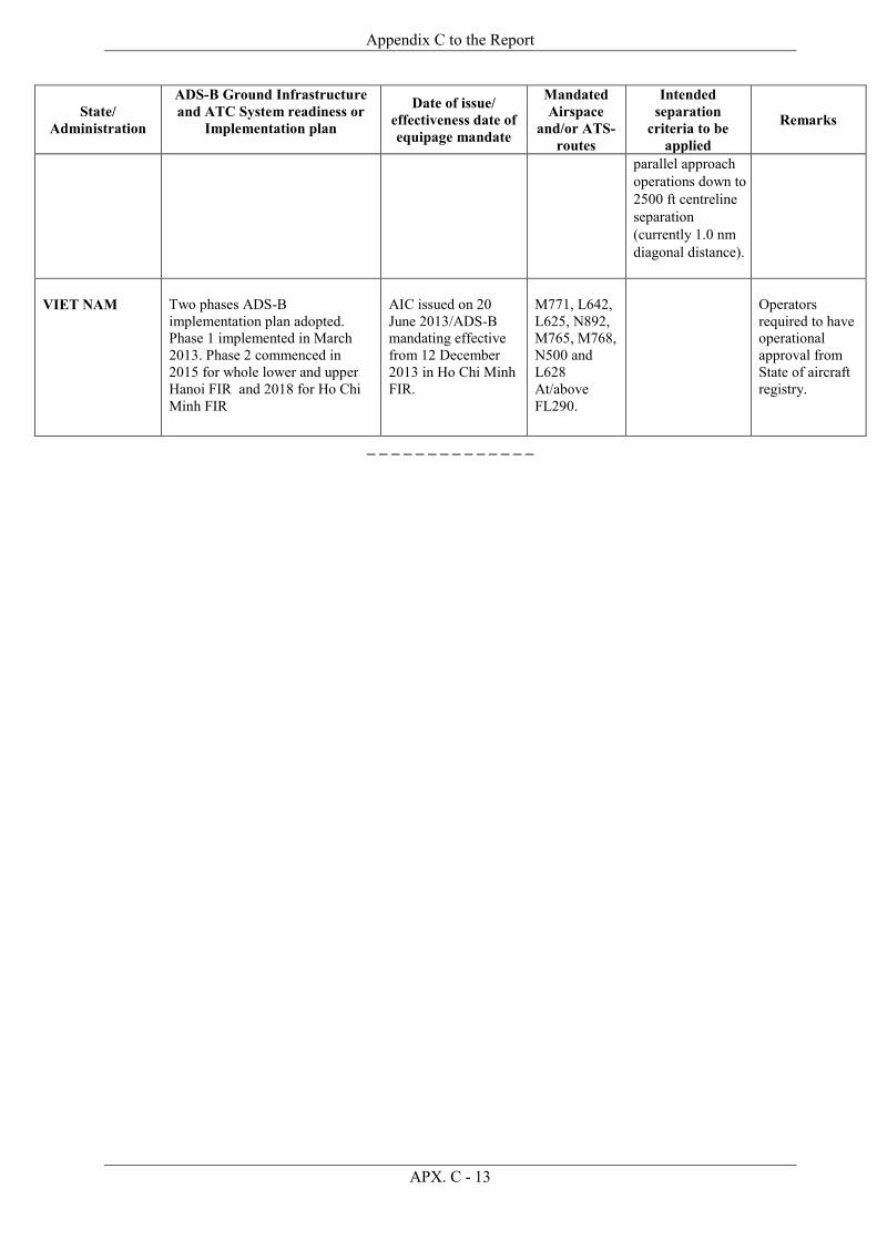
Appendix C to the Report
APX. C - 13
State/ Administration
ADS-B Ground Infrastructure and ATC System readiness or
Implementation plan
Date of issue/ effectiveness date of equipage mandate
Mandated Airspace
and/or ATS-routes
Intended separation
criteria to be applied
Remarks
parallel approach operations down to 2500 ft centreline separation (currently 1.0 nm diagonal distance).
VIET NAM
Two phases ADS-B implementation plan adopted. Phase 1 implemented in March 2013. Phase 2 commenced in 2015 for whole lower and upper Hanoi FIR and 2018 for Ho Chi Minh FIR
AIC issued on 20 June 2013/ADS-B mandating effective from 12 December 2013 in Ho Chi Minh FIR.
M771, L642, L625, N892, M765, M768, N500 and L628 At/above FL290.
Operators required to have operational approval from State of aircraft registry.
_ _ _ _ _ _ _ _ _ _ _ _ _ _
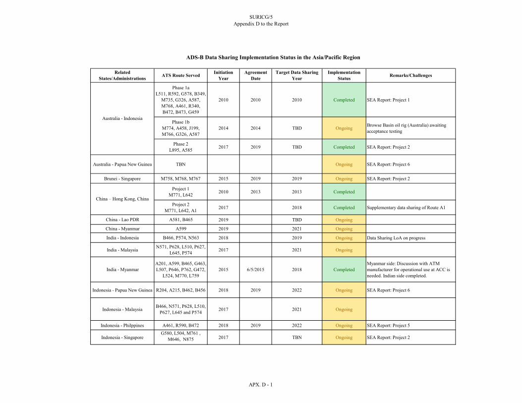
SURICG/5Appendix D to the Report
Phase 1aL511, R592, G578, B349,
M735, G326, A587, M768, A461, R340, B472, B473, G459
2010 2010 2010 Completed SEA Report: Project 1
Phase 1bM774, A458, J199, M766, G326, A587
2014 2014 TBD Ongoing Browse Basin oil rig (Australia) awaiting acceptance testing
Phase 2L895, A585 2017 2019 TBD Completed SEA Report: Project 2
Australia - Papua New Guinea TBN Ongoing SEA Report: Project 6
Brunei - Singapore M758, M768, M767 2015 2019 2019 Ongoing SEA Report: Project 2
Project 1M771, L642 2010 2013 2013 Completed
Project 2M771, L642, A1 2017 2018 Completed Supplementary data sharing of Route A1
China - Lao PDR A581, B465 2019 TBD Ongoing
China - Myanmar A599 2019 2021 Ongoing
India - Indonesia B466, P574, N563 2018 2019 Ongoing Data Sharing LoA on progress
India - Malaysia N571, P628, L510, P627, L645, P574 2017 2021 Ongoing
India - MyanmarA201, A599, B465, G463, L507, P646, P762, G472,
L524, M770, L7592015 6/5/2015 2018 Completed
Myanmar side: Discussion with ATM manufacturer for operational use at ACC is needed. Indian side completed.
Indonesia - Papua New Guinea R204, A215, B462, B456 2018 2019 2022 Ongoing SEA Report: Project 6
Indonesia - Malaysia B466, N571, P628, L510, P627, L645 and P574 2017 2021 Ongoing
Indonesia - Philppines A461, R590, B472 2018 2019 2022 Ongoing SEA Report: Project 5
Indonesia - SingaporeG580, L504, M761 ,
M646, N875 2017 TBN Ongoing SEA Report: Project 2
ATS Route Served Initiation Year
Agreement Date
Target Data Sharing Year
ADS-B Data Sharing Implementation Status in the Asia/Pacific Region
Related States/Administrations
Australia - Indonesia
China – Hong Kong, China
Implementation Status Remarks/Challenges
APX. D - 1

SURICG/5Appendix D to the Report
ATS Route Served Initiation Year
Agreement Date
Target Data Sharing Year
ADS-B Data Sharing Implementation Status in the Asia/Pacific Region
Related States/Administrations
Implementation Status Remarks/Challenges
Project 1M758, M768, L649, 2017 2021 Ongoing SEA Report: Project 2
Project 2M904, M765, N875,
N8912018 2021 Ongoing SEA Report: Project 2
Malaysia - ThailandN571, P628, L510, P627,
L645, P574 2018 2021 Ongoing
Myanmar - India
Project 1: Effect on Myanmar A201, A599, B465Effect India: G463, L507, P646, N895
2018 2015 2020/2021 OngoingData communication between Myanmar and India is unstable. Different Multiaircraft Address from India ADS-B Data
Project 2: L301, M7702019 2016 2020/2021 On trial
Philippines - Singapore N884, M522, M754, M767, M772, L649
2018 2018 Completed SEA Report: Project 2
Project 1N892, N891, M771,
M753, M758, L642, L6442007 2013 Completed SEA Report: Project 2
Project 2N892, N891, M771, M753, M758, M904,
L642, L644
2014 2016 2018 Completed SEA Report: Project 2
Singapore - Vietnam
Malaysia - Singapore
APX. D - 2

SURICG/5
Appendix E1 to the Report
APX. C1 - SEA/BOB ADS-B WG/15 APX. E1 - 1
REPORT FROM SOUTHEAST ASIA SUB GROUP
Singapore, 3-5 November 2019 States Present China Hong Kong China Indonesia Malaysia Singapore Thailand Vietnam Previously Identified Projects The South East Asia Group provide an update on the near term implementation of the following projects that were identified in previous meetings. Project 1 – ADS-B Data Sharing Between Australia and Indonesia Phase 1a Indonesia and Australia sharing ADS-B data from the following sites:
Saumlaki (Indonesia) (Installed) Merauke (Indonesia) (Installed) Waingapu (Indonesia) (Installed) Kintamani - Bali (Indonesia) (Installed) Thursday Island (Australia) (Installed) Gove (Australia) (Installed) Broome (Australia) (Installed) Doongan (Australia) (Installed)
Data Sharing Agreement signed in Nov 2010; Communications links between Australia and Indonesia were upgraded from VSAT to terrestrial links in Mar 2016. The service quality was improved.
Benefits Data used for air situational awareness and safety nets. Enhanced Safety at FIR boundary. Operational service commenced by Australia in 2010. Indonesia has been using the data for Tier 2 services since Sep 2014 Phase 1b Indonesia and Australia sharing ADS-B data from the following additional sites:
Timika (Indonesia) (Installed) - Commenced data sharing Kupang (Indonesia) (Installed) - Commenced data sharing Christmas Island (Australia) (Not yet installed) Browse Basin oil rig (Australia) (installed in 2018)

Appendix E1 to the Report
APX. C1 - SEA/BOB ADS-B WG/15 APX. E1 - 2
Data Sharing Agreement signed on 18 Jun 2014: Indonesia announced the use of ADS-B for situational awareness on 24 July 2014. Indonesia announced on 30 Apr 2015 that ADS-B will be used for separation from FL290 to FL460 (tier-1) with effect from 25 June 2015. The carriage of ADS-B equipment for flights between FL290 and FL460 remain optional until Dec 2017. From 1 Jan 2018, Indonesia implemented ADS-B mandate from FL290 to FL600 in Jakarta and Ujung Pandang FIRs. Phase 2 Data sharing between Australia and Indonesia already completed.
Cilacap (Indonesia) Project 2 – ADS-B Data Sharing In Southeast Asia Phase 1 Under the near term implementation plan, the parties have commenced ADS-B data sharing from the following sites:
Singapore (Singapore provide data to Indonesia) Natuna (Indonesia provide data to Singapore) Matak (Indonesia provide data to Singapore) Con Son (Viet Nam provide data to Singapore) Sanya FIR (China provide fused data from four ADS-B stations to Hong Kong China)
VHF radio communication services (DCPC) were provided from the following stations to Singapore and Hong Kong China. This is to enable implementation of radar-like separations in the non-radar areas within the Singapore FIR as well as routes L642 and M771.
Natuna VHF (Install for Singapore by Indonesia) (Installed) Matak VHF (Install for Singapore by Indonesia) (Installed) Con Son VHF (Install for Singapore by Viet Nam) (Installed) Sanya VHF (Install for Hong Kong China by China) (Installed)
ADS-B Data sharing and DCPC services agreement between Singapore and Indonesia signed in Dec 2010. ADS-B Data sharing and DCPC services agreement between Singapore and Vietnam signed in Nov 2011. DCPC services agreement between China and Hong Kong China signed in 2005. ADS-B Data sharing agreement between China and Hong Kong China signed in 2013. Operational Status Singapore agreed on separation minima with Viet Nam and have commenced on ADS-B operations since Dec 2013. Singapore commenced with 40nm separation and subsequently reduced to 30nm separation between Singapore and Ho Chi Minh FIR. Further reduction to 20nm longitudinal separation was implemented on 10 Nov 2016. All 4 administrations (China, Hong Kong China, Singapore and Viet Nam) agreed that operational approval is not required.
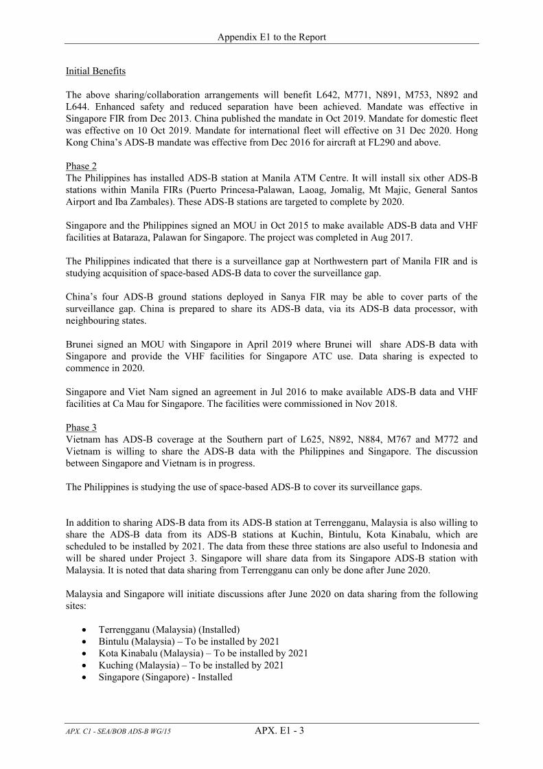
Appendix E1 to the Report
APX. C1 - SEA/BOB ADS-B WG/15 APX. E1 - 3
Initial Benefits The above sharing/collaboration arrangements will benefit L642, M771, N891, M753, N892 and L644. Enhanced safety and reduced separation have been achieved. Mandate was effective in Singapore FIR from Dec 2013. China published the mandate in Oct 2019. Mandate for domestic fleet was effective on 10 Oct 2019. Mandate for international fleet will effective on 31 Dec 2020. Hong Kong China’s ADS-B mandate was effective from Dec 2016 for aircraft at FL290 and above. Phase 2 The Philippines has installed ADS-B station at Manila ATM Centre. It will install six other ADS-B stations within Manila FIRs (Puerto Princesa-Palawan, Laoag, Jomalig, Mt Majic, General Santos Airport and Iba Zambales). These ADS-B stations are targeted to complete by 2020. Singapore and the Philippines signed an MOU in Oct 2015 to make available ADS-B data and VHF facilities at Bataraza, Palawan for Singapore. The project was completed in Aug 2017. The Philippines indicated that there is a surveillance gap at Northwestern part of Manila FIR and is studying acquisition of space-based ADS-B data to cover the surveillance gap. China’s four ADS-B ground stations deployed in Sanya FIR may be able to cover parts of the surveillance gap. China is prepared to share its ADS-B data, via its ADS-B data processor, with neighbouring states. Brunei signed an MOU with Singapore in April 2019 where Brunei will share ADS-B data with Singapore and provide the VHF facilities for Singapore ATC use. Data sharing is expected to commence in 2020. Singapore and Viet Nam signed an agreement in Jul 2016 to make available ADS-B data and VHF facilities at Ca Mau for Singapore. The facilities were commissioned in Nov 2018. Phase 3 Vietnam has ADS-B coverage at the Southern part of L625, N892, N884, M767 and M772 and Vietnam is willing to share the ADS-B data with the Philippines and Singapore. The discussion between Singapore and Vietnam is in progress. The Philippines is studying the use of space-based ADS-B to cover its surveillance gaps. In addition to sharing ADS-B data from its ADS-B station at Terrengganu, Malaysia is also willing to share the ADS-B data from its ADS-B stations at Kuchin, Bintulu, Kota Kinabalu, which are scheduled to be installed by 2021. The data from these three stations are also useful to Indonesia and will be shared under Project 3. Singapore will share data from its Singapore ADS-B station with Malaysia. It is noted that data sharing from Terrengganu can only be done after June 2020. Malaysia and Singapore will initiate discussions after June 2020 on data sharing from the following sites:
Terrengganu (Malaysia) (Installed) Bintulu (Malaysia) – To be installed by 2021 Kota Kinabalu (Malaysia) – To be installed by 2021 Kuching (Malaysia) – To be installed by 2021 Singapore (Singapore) - Installed

Appendix E1 to the Report
APX. C1 - SEA/BOB ADS-B WG/15 APX. E1 - 4
Initial benefits Enhanced Safety at FIR boundary and coverage redundancy Project 3 – ADS-B data sharing between Indonesia and Malaysia Indonesia and Malaysia are willing to share the ADS-B data from the following sites:
Pontianak (Indonesia) – Installed Tarakan (Indonesia) - Installed Bintulu (Malaysia) – To be installed by 2021 Kota Kinabalu (Malaysia) – To be installed by 2021 Kuching (Malaysia) – To be installed by 2021
Malaysia and Indonesia are reviewing the collaboration agreement. Initial benefits Enhanced Safety at FIR boundary and coverage redundancy Project 4 – ADS-B data sharing between Cambodia, Thailand and Viet Nam Cambodia is willing to share the ADS-B data from the following sites:
Phnom Penh International Airport (installed) Siem Reap International Airport (installed) Stung Treng City (installed)
Vietnam is planning to install stations in the HCM FIR from 2016 to 2020. Vietnam is willing to share data with Cambodia and Thailand. Initial benefits For redundancy Project 5 – ADS-B data sharing between Indonesia and the Philippines Indonesia and the Philippines initiated discussion in 2019 on data sharing: Melonguane (Indonesia) (will be installed in 2020) General Santos (The Philippines) (yet to install) Initial benefits Situational awareness Project 6 – ADS-B data sharing between Australia, Indonesia and Papua New Guinea Data Sharing between Australia and Papua New Guinea
Thursday Island (Australia) (installed) Gove (Australia) (installed) Kintore (Australia) Not yet installed – Target to be installed by 2019 Burns Peak – Port Moresby (PNG) (installed) Mt Robinson (PNG) (to be installed by 2018) or Mt Nauwein (to be installed by 2018)

Appendix E1 to the Report
APX. C1 - SEA/BOB ADS-B WG/15 APX. E1 - 5
Note that the above information was based on previous updates as both Australia and Papua New Guinea were not present at the meeting. Data Sharing between Indonesia and Papua New Guinea
Mt Nauwein (PNG) (to be installed by 2018)– Phase 1 Merauke (Indonesia) (installed) – Phase 1 Jayapura (Indonesia) (installed)– Phase 2
New ATM system installed in PNG. The parties will probably sign direct bi-lateral agreements in 2020. General remark for all the above projects: As agreed at previous APAC ADS-B Task Force and WG meetings, sharing of ADS-B data should include sharing of VHF radio facilities/services, where possible
_ _ _ _ _ _ _ _ _ _ _

SURICG/5 Appendix E2 to the Report
APX. C2 - SEA/BOB ADS-B WG/15 APX. E2 - 1
REPORT FROM BAY OF BENGAL AD HOC WORKING GROUP
SEA/BOB ADS-B WG/14 (Singapore, 3-5 December, 2019)
States Presented: Bangladesh Bhutan China Indonesia Malaysia Maldives Myanmar Thailand India Sri Lanka The participants met to update the status of implementation of ADS-B and possible Data sharing between the neighbouring States.
Implementation Updates 1. Bangladesh We are trying to modernize our systems through the implementation of ATM project. At first it was in PPP & now it is on G2G with France. This was under the process of government approval. Government approval is granted, and 5 ADS-B receivers will have been installed at detailed below, Cox’s Bazar, Barisal, Saidpur, Dhaka and Sylhet, there is another one for Extended Economic Zone at new area in the Bay of Bengal which is 200NM at south of the country. 2. Bhutan Bhutan cannot join previous SEA/BOB ADS-B meeting as we do have plan to implement ADS-B, but now we are targeting to complete ADS-B feasibility study by mid of 2019 and now it is extended up to mid of 2020.We found out that feasibility study (Coverage and ground station location) is necessary as Bhutan is surrounded by mountain terrain. As per the result of feasibility study we are going to implement installation of ground station. Bhutan do not have any national policy or regulation about data sharing, so we will be sharing data with any neighbouring countries/states as per the regional norms and conditions. 3. China China has been continuously promoting to push forward the application of ADS-B technology. China provided update on the installation and related activities regarding ADS-B surveillance system as follows:
5 UAT ADS-B stations are used for flight training of CAFUC. The upgrade to 1090ES ADS-B stations project has already started in 2017, and the project is planned to finish by 2022;
4 ADS-B station in operational in Sanya FIR since 2008;

Appendix E2 to the Report
APX. C2 - SEA/BOB ADS-B WG/15 APX. E2 - 2
Chengdu-Jiuzhai and Chendu - Lhasa route with 9 ADS-B stations; 9 ADS-B stations deployed on the routes H15 and Z1 by the end of 2015; 19 ADS-B station at the small airport; and 308 ADS-B stations nationwide have already finished installation and SAT by the end of 2018.
And there are 2 level-1 data processing centres working in main-standby mode for redundancy, 8 level-2 data processing centres to concentrate data from data stations within its area of responsibility, as well as 36 data stations to collect received data from GSs. All the installation and SAT of GSs, level-2 data processing centres and level-1 data processing centres have already complete. The trial operation has started from October 10, 2019 and the ADS-B mandate had also been published on October 1, 2019, which is effective from October 10.2019.
4. Indonesia Indonesia earlier informed that ADS-B ground station at Aceh is already operational and expressed willingness to share data with India (It was earlier decided to have Port Blair-Aceh data sharing, but for better coverage and usability it was suggested in the meeting to have data sharing of upcoming Campbell Bay ADS-B - Aceh when India is ready). Indonesia now will share the data with Campbell Bay ADS-B – Aceh only. Campbell Bay ADS-B is installed. Letter of Agreement between Indonesia and India regarding ADS-B data sharing is on progress Letter of agreement is agreed by Indonesia and India, yet to be signed. 5. Malaysia Malaysia has completed the installation of the two new ADS-B ground station in Langkawi and Genting and will be integrated into the ATM system in 2018. Both stations are compliance with DO-260B with output data handling function as plot and tracks (ASTERIX CAT21 rev. 0.23, rev. 0.26 and rev. 2.1.) Malaysia venturing to share data with Indonesia, India and Thailand. Data sharing from India (Port Blair or Campbell Bay ADS-B), or from Indonesia (Aceh ADS-B) or from Thailand will close the surveillance gap within the KL FIR. Malaysia available ADS-B data through ADS-B central processing system is integrated to existing ATC Systems via temporary node and only capable for legacy data exchange format. With that limitation and unavailability of other essential hardware, the existing ATC is not capable for data sharing. The new ATC system is in progress and only expected to be completed by 2H2019, thus Data Sharing target has to be shifted to 2H2021. However, Malaysia is reviewing the sample agreement proposed by India in 2018, and will revert as soon as possible. ATC system is in progress and only expected to be completed by 2Half of 2020. Data sharing will be clarified after that activity. 6. Maldives Not present Maldives started using ADS-B to enhance ATS surveillance capability in Male FIR on 7 th February 2016.

Appendix E2 to the Report
APX. C2 - SEA/BOB ADS-B WG/15 APX. E2 - 3
With 4 ground stations (2 autonomous stations at Male; 2 unduplicated ground stations: 1 at an island in the North and the other in the South), the ADS-B provides coverage up to 90% of Male FIR above FL290.
ADS-B serves as the backup for Male radar and is in use for vectoring and 5NM separation commensurate with Radars As part of the effort towards full implementation of ADS-B, from March 2017 aircraft imported for commercial air transport in the Maldives are required to be equipped with ADS-B Out, as published in AIP ENR 1.6-3. The full implementation, which would require carriage of ADS-B Out, is targeted for the year 2020 Maldives is making efforts to complete the airworthiness approval for all locally registered aircraft, already equipped with ADS-B. Out of the 73 aircraft registered for commercial air transport in the Maldives, 62 aircraft have given approval for ADS-B by Maldives Civil Aviation Authority (MCAA). This include 55 seaplanes (Twin Otter aircraft with floats) conducting commercial air transport between Velana International and resort islands. These aircraft, although operate on VFR, are fitted with ADS-B out functionality combined with GPS to give highly accurate positional information. 7. Myanmar The 5 ADS-B ground stations have been installed in Myanmar. Among them, Sittwe and Co Co Island ground stations are installed in 2014 and they are DO260 compliant, and Yangon, Mandalay and Myeik airports ground stations are DO260B compliant and installation was finished in 2016. All ADS-B data are fused with MSSR data target in the Top Sky ATC Automation system (Thales) in 2016, and using as MSSR backup and surveillance monitoring in Yangon ACC. In addition, Myanmar have planned to install new ADS-B Station in the First quarter of 2020 at Lashio Airport located in north-eastern part of Myanmar closed to the China-Myanmar border near the LINSO transfer point on A599 ATS route. After the installation finished, the ADS-B data sharing process can be proceeded between Myanmar and China after March, 2020. For the communication links between Yangon and Beijing, it can use the existing 2M E1 IPLC link which is now using for AFTN messaging and (AIDC Testing) Voice, and also can be used the existing Yangon-Beijing VSAT link as backup. Myanmar also willing to participate the special coordination meetings to promote relevant works in terms of the surveillance data sharing among the countries to enhance the safety and surveillance capability in the sub-region. Lashio installation will be completed by First quarter of 2020. Redundant Communication link via Land line / CRV / V-SAT is proposed under discussion.

Appendix E2 to the Report
APX. C2 - SEA/BOB ADS-B WG/15 APX. E2 - 4
8. Thailand Thailand provided update on the installation and related activities regarding ADS-B and other related surveillance system as follows: ADS-B Ground Infrastructure and ATC System Readiness or Implementation Plan MLAT has been in operation at VTBS since 2006 and has been installed at VTBD with the
expectation to be operational in 2020. At VTCC and VTSP, M-LAT is being installed with expectation to be operational in 2020.
Six ADS-B ground stations (DO-260B compliant) have been installed covering airspace at and above 20,000 feet primarily for research and development purpose and are being undergone the certification process by Civil Aviation Authority of Thailand (CAAT) with a target date by the end of 2020.
Additional ADS-B ground stations are planned to be installed aiming at providing coverage from ground to 11,000 feet for TMA and Airport operations.
Multiple surveillance sensor data including SSR, ADS-B and WAM are integrated into the new ATM systems and expected to be operational in early 2020.
Legal assessment regarding ADS-B data sharing with other states has been underway. Date of Issue/Effectiveness Date of Equipage Mandate Aircraft equipage mandate is expected to be issued in 2021 with the expected target effective date
in 2026. Data sharing ATS surveillance data sharing with adjacent FIRs was approved in principle in October 2018.
User requirements, particularly ATS routes to be served, and communication link test plan are
discussed in 2018-2019. 9. India (no update provided in 2018) India informed that 21 ADS-B ground receivers have already been installed and the information has been promulgated through AIP SUPP 18/2014 to use ADS-B in the provision of ATS surveillance service. The data sharing agreement between India and Myanmar has been signed on 06 th May 2015. India is willing to share ADS-B data with Indonesia, Malaysia and Sri Lanka. India has invited open tenders for procurement of ten more ADS-B Ground Stations for installation at Kadappa, Raipur, Pantnagar, Indore, Jabalpur, Bikaner, Goa, Aurangabad, Dhanbad and Campbell Bay (in Bay of Bengal near FIR boundaries of Chennai, Jakarta and Kuala Lumpur) is completed in third quarter of 2019. The The objective is to provide ADS-B coverage in areas where there is no or limited Secondary Surveillance Radar (SSR) coverage. The data from the above ADS-B ground stations is integrated with existing ATM systems at different Area Control Centres. India expects the ground stations to be DO-260B compliant and operational by the end of 2018. The ADS-B receivers are capable of DO-260B, but not all the ATM Automation Systems are capable of DO-260.

Appendix E2 to the Report
APX. C2 - SEA/BOB ADS-B WG/15 APX. E2 - 5
10. Sri Lanka (no update provided in 2018) Not Present Sri Lanka has installed 5, ADS-B stations and data received by the stations have been integrated and available for sharing. The ADS-B coverage is approximately 350NM from Piduruthalagala, the highest mountain situated in central Sri Lanka. Sri Lanka is willing to share this data with India and Maldives. India is requested to provide a soft copy of draft agreement for sharing of ADS-B data with Sri Lanka so as to enable Sri Lanka to look into the terms and conditions of draft agreement.
ADS-B Data Sharing Project 1 - ADS-B Data Sharing between China, Laos and Myanmar Phase 1 China and Laos sharing ADS-B data from following: Kunming ADS-B data processing Centre (china), which can customize the output of ADS-B data in version, specific area and height range depend on Laos’s requirement. Route to be affected B465. China and Myanmar sharing ADS-B data from the following sites: Lashio (Myanmar) Not yet installed – Target to be installed by March 2020.Route to be affected A599
China and Myanmar sharing ADS-B data from the following: Kunming ADS-B Data Processing Centre (China), which can customize the output of ADS-B data in version、specific area and height range depend on Myanmar's requirement. Operational Status N/A Expected benefits
Enhanced air navigation safety at FIRs boundary. Promoting air traffic control work efficiency.
Project 2 - ADS-B Data Sharing between India and Indonesia Phase 1 Aceh – Indonesia Camp Bell Bay – India Route to be affected B466, P574 and N563 Operational Status Camp Bell to Chennai link BSNL is under testing. Indonesia waiting till CRV scheduled 1st quarter 2020. India is getting ready for CRV by the end of first quarter 2020 with PCCW. Benefits Enhanced safety by reduction in occurrences of LHDs and LLDs in BOB region.

Appendix E2 to the Report
APX. C2 - SEA/BOB ADS-B WG/15 APX. E2 - 6
Project 3 - ADS-B Data Sharing between India and Malaysia Phase 1 Port Blair/Campbell-Langkawi (2H2021) Route to be affected N571, P628, L510, P627, L645 and P574 Operational Status New ATM system installation in June 2020. Expected benefits Enhanced safety by reduction in occurrences of LHDs and LLDs in BOB region. Project 4 - ADS-B Data Sharing between India and Myanmar Phase 1 The ADS-B data sharing between Kolkata and Yangon FIR was an initiative taken by India and Myanmar to enhance safety and reduce LHDs along Kolkata-Yangon FIR boundary. In 6 May 2015, Myanmar and India have signed the MOU agreement for ADS-B data sharing between the two countries. As per the data sharing agreement, ADS-B data sharing test between Agartala(India) and Sittwe (Myanmar) and Port Blair(India) and Coco Island(Myanmar) has been accomplished between technical teams since June 2018. Kolkata has integrated the ADS-B feed from Sittwe and Co Co Island in its Automation system. Presently the data is given in the back up automation system at Kolkata for test purpose and ADS B equipped aircrafts are tracked from as far as 250 nm west of Bangkok. But for Myanmar side, India’s data is just received to Yangon ACC technical management room and need to discuss with ATM Manufacturer (Thales) of Surveillance Display System to integrate India’s ADS-B data to existing Surveillance Display System for operational use in Yangon ACC. Because the multicast address and port from India’s ADS-B data are different with existing setup. The communication link used for ADSB data transfer between Yangon and Kolkata is the existing E1 IPLC link which is used for DSC phone between the two ATS units. Route to be affected A201, A599, B465, G463, L507, P646, P762, G472, L524, M770 and L759 Operational Status Operationalized for situational awareness. Expected benefits Enhanced safety by reduction in occurrences of LHDs and LLDs in BOB region. Project 5 - ADS-B Data Sharing between Indonesia and Malaysia Phase 1 Langkawi - Aceh (2H2019 2H2021) Route to be affected B466, N571, P628, L510, P627, L645 and P574

Appendix E2 to the Report
APX. C2 - SEA/BOB ADS-B WG/15 APX. E2 - 7
Operational Status New ATM Automation system installation by June 2020 then data sharing. Expected benefits Enhanced safety at FIR boundary Project 6 - ADS-B Data Sharing between Malaysia and Thailand Phase 1 Langkawi - Phuket General discussion about possibility to share ADS-B data for route N571, P628, L510, P627, L645 and P574 Operational Status N/A Expected benefits
Enhanced visibility of surveillance targets in Bay of Bengal. Enhanced situational awareness at FIR boundary.
Project 7 - ADS-B Data Sharing between India and Sri Lanka (no update provided in 2018, 2019) Phase 1 Trivandrum – Colombo (2H2018) Trichy-Colombo (2H2018) Route to be affected TBN Operational Status N/A Expected benefits Enhanced safety at FIR boundary
Important Notes 1. Terminology used in the region should be standardised and consistent, and recognise what crew
need to know.
2. States need to develop procedures for the use of DAPs in relation to operating procedures, for example the use of selected altitude information being displayed on the controllers’ screens and related pilot practices: pilots and controllers need to be aware of each other’s operating practices.

Appendix E2 to the Report
APX. C2 - SEA/BOB ADS-B WG/15 APX. E2 - 8
3. There is a need to consider the capture, storage, and potential uses of ADS-B data. For example, in some states those data might be used to draw premature conclusions about the causes of an accident or incident and result in inappropriate or unwarranted enforcement action. In addition, there were concerns about who can access ADS-B data and for what purposes. Examples of inaccurate data being used by members of the public to make complaints about aircraft flight paths and noise impost are a concern.
_ _ _ _ _ _ _ _ _ _ _ _

SURICG/5
Appendix F1 to the Report
APX. E - SEA/BOB ADS-B WG/15 APX. F1 - 1
TERMS OF REFERENCE FOR SEA/BOB ADS-B WG APANPIRG18 Conclusion 18/38 agreed to the establishment of a sub-regional ADS-B Implementation Working Group in the South-East Asia area (SEA ADS-B WG) by the end 2007 to develop the terms of cooperation and an implementation plan for near-term ADS-B applications in the sub-region. APANPIRG/22 Decision 22/34 agreed to rename the Southeast Asia Sub-regional ADS-B Implementation Working Group to “South East Asia and Bay of Bengal Sub-regional ADS-B Implementation Working Group” and tasked the new Working Group to develop a revised Terms of Cooperation and work programme in the sub-regions. The outcome of the ADS-B Working Group will report to APANPIRG through the Surveillance Implementation Coordination Group. The SEA/BOB ADS-B WG shall (a) Develop Terms of Co-operation which will include: • establishing model documents for possible use by States when:
o Agreeing to share ADS-B data, and DCPC (such as VHF radio voice communication) capability between adjoining States for various ADS-B applications (including a sample letter of agreement); or o Establishing ADS-B avionics fitment mandates
• identifying optimum coverage for ADS-B ground stations and associated VHF radio voice communication in the sub-regional FIR boundary areas. (b) Develop an implementation plan for near term ADS-B application which will delivery efficient airspace and increased safety on a regional basis that include: • schedule and priority dates to bring into effect ADS-B based services taking into account;
o Timing of any equipage mandates. o Timing of any ATC automation upgrades to support ADS-B. o Timing of commissioning of any ADS-B data and associated VHF radio voice communication facilities.
• consideration of major traffic flows • harmonization of mandates across the various FIRs • promotion of new means of data sharing (such as data sharing through a centralized data base or SWIM) (c) Coordination for implementation of the plan and identify implementation issues and solutions (d) Consolidation of issues to be considered at other ADS-B related forum (e.g. Surveillance Panel, RTCA, EUROCAE), or by vendors. (e) Sharing of innovative means to solve ADS-B related issues. (f) Study the potential applications and issues of new forms of ADS-B stations and Long Range Communications. Composition: The Group will be composed of experts nominated by States in the Sub-region including: Australia, Bangladesh, Brunei Darussalam, China, Hong Kong China, Cambodia, India, Indonesia, Malaysia, Maldives, Myanmar, Nepal, Pakistan, Philippines, Singapore, Sri Lanka, Thailand, Vietnam, IATA and CANSO. Reporting: The Group will present its report to Surveillance Implementation Coordination Group
_ _ _ _ _ _ _ _ _ _ _ _

SURICG/5
Appendix F2 to the Report
APX. F - SEA/BOB ADS-B WG/15 APX. F2 -1
DRAFT TERMS OF REFERENCE FOR ADS-B WG
An ADS-B Working Group is to be established under the Surveillance Implementation Coordination Group. The outcome of the ADS-B Working Group will report to the Surveillance Implementation Coordination Group. The ADS-B WG shall (a) Monitor and influence the developments of ADS-B related technologies and applications. (b) Develop an implementation plan for near term ADS-B technology and application, including provision of minimum layers of surveillance services. (c) Coordinate and monitor the implementation of ADS-B data sharing projects.
(d) Promotion of new means of data sharing (such as data sharing through a centralized data base or SWIM)
(e) Harmonization of mandates across the various FIRs
(f) Sharing of implementation and operation issues, and innovative means to solve such issues.
(g) Consolidation of implementation and operation issues and forward them to other ADS-B related forum (e.g. Surveillance Panel, RTCA, EUROCAE), or vendors for considerations.
Composition: The Group will be composed of experts nominated by States in Asia Pacific. IATA and CANSO. Reporting: The Group will present its report to Surveillance Implementation Coordination Group
_ _ _ _ _ _ _ _ _ _ _

Mode S Downlink Aircraft Parameters Implementation and Operations Guidance Document
Edition 2.0 - May 2020 G - 1
SURICG/5 Appendix G to the Report
MODE S DOWNLINK AIRCRAFT PARAMETERS IMPLEMENTATION AND OPERATIONS GUIDANCE DOCUMENT
Edition 2.0 - May 2020
INTERNATIONAL CIVIL AVIATION ORGANIZATION ASIA AND PACIFIC OFFICE

Mode S Downlink Aircraft Parameters Implementation and Operations Guidance Document
Edition 2.0 – May 2020 G - 2
Intentionally left blank

Mode S Downlink Aircraft Parameters Implementation and Operations Guidance Document
Edition 2.0 – May 2020 G - 3
TABLE OF CONTENTS
1. INTRODUCTION ............................................................................................................................................. 5
1.1 PURPOSE ..................................................................................................................................................... 5
1.2 BACKGROUND ............................................................................................................................................ 5
1.2.1 Mode S and DAPs ................................................................................................................................... 5
1.2.2 Benefit of Mode S and Use of DAPs ....................................................................................................... 6
1.3 ARRANGEMENT OF DAPS IGD .................................................................................................................. 6
1.4 DOCUMENT HISTORY AND MANAGEMENT ................................................................................................ 6
1.5 COPIES ........................................................................................................................................................ 6
1.6 CHANGES TO DAPS IGD ............................................................................................................................ 7
1.7 EDITING CONVENTIONS ............................................................................................................................. 7
1.8 DAPS IGD REQUEST FOR CHANGE FORM ................................................................................................ 8
1.9 AMENDMENT RECORD ............................................................................................................................... 9
2. ACRONYMS LIST ......................................................................................................................................... 10
3. REFERENCE DOCUMENTS ....................................................................................................................... 12
4. DESCRIPTION OF MODE S DAPS DATA ................................................................................................. 14
4.1 MODE S ELS ............................................................................................................................................ 14
4.2 MODE S EHS ............................................................................................................................................ 15
4.3 DAPS DATA EXCHANGE PROTOCOL BETWEEN SURVEILLANCE AND ATM AUTOMATION SYSTEM ..... 16
5. IMPLEMENTATION PRINCIPLES AND PHASES .................................................................................. 17
5.1 IMPLEMENTATION PRINCIPLES ................................................................................................................ 17
5.1.1 Stakeholders Coordination ................................................................................................................... 17
5.1.2 System Compatibility ............................................................................................................................ 17
5.1.3 DAPs Data Integrity ............................................................................................................................. 18
5.1.4 System Integration ................................................................................................................................ 18
5.2 IMPLEMENTATION CHECKLIST ............................................................................................................ 19
5.2.1 Activity Sequence .................................................................................................................................. 19
5.2.2 Concept Phase ...................................................................................................................................... 19
5.2.3 Design Phase ........................................................................................................................................ 20
5.2.4 Implementation Phase .......................................................................................................................... 21
6. SYSTEM INTEGRITY AND MONITORING ............................................................................................. 22
6.1 INTRODUCTION ......................................................................................................................................... 22
6.2 PERSONNEL LICENSING AND TRAINING ................................................................................................... 22
6.3 ATS SYSTEM VALIDATION ....................................................................................................................... 22
6.3.1 Safety Assessment Guidelines ............................................................................................................... 22
6.3.2 System Safety Assessment ..................................................................................................................... 22
6.3.3 Integration Test ..................................................................................................................................... 23
6.3.4 ATS Operation Manuals ....................................................................................................................... 23
6.4 SYSTEM MONITORING ............................................................................................................................. 23
6.4.1 Consideration for System Monitoring ................................................................................................... 23

Mode S Downlink Aircraft Parameters Implementation and Operations Guidance Document
Edition 2.0 – May 2020 G - 4
6.4.2 Mode S DAPs Problem Reports ............................................................................................................ 24
6.4.3 Example of Mode S DAPs Problem ...................................................................................................... 25
6.5 APPLICATION ANALYSIS ........................................................................................................................... 25
6.5.1 Data Recording ..................................................................................................................................... 26
6.5.2 Local Data Collection ........................................................................................................................... 26
6.5.3 Avionics Problem Identification and Correction ................................................................................... 26
6.6 IDENTIFIED ISSUES ................................................................................................................................... 26
7. REGULATIONS AND PROCEDURES ........................................................................................................ 27
7.1 MANDATING MODE S DAPS .................................................................................................................... 27
7.2 AVIONICS .................................................................................................................................................. 28
7.2.1 Mode S Transponder Capabilities ........................................................................................................ 28
7.2.2 Transition Guidelines ............................................................................................................................ 29
7.2.3 Interrogation of Transponders on Ground ............................................................................................ 29
7.3 MODE S INTERROGATOR ......................................................................................................................... 30
7.3.1 Working Principles ............................................................................................................................... 30
7.3.2 Interrogator Codes ............................................................................................................................... 30
7.3.3 Interrogation Methods .......................................................................................................................... 31
7.3.4 Interrogate Comm-B Data .................................................................................................................... 31
7.4 ATM AUTOMATION SYSTEM .................................................................................................................... 33
7.4.1 Elementary Surveillance ....................................................................................................................... 33
7.4.2 Enhanced Surveillance ......................................................................................................................... 34
7.5 FLIGHT PLANNING ................................................................................................................................... 35
7.5.1 ICAO Flight Plan Item 7 - Aircraft Identification ................................................................................. 35
7.5.2 Equipment (Surveillance Equipment /SSR Equipment) ......................................................................... 35
7.5.3 Inconsistency between Mode S Flight Planning and Surveillance Capability ...................................... 36
7.5.4 Setting Flight ID in Cockpits ................................................................................................................ 37
7.6 CONTINGENCY PLAN ................................................................................................................................ 37
8. TRAINING AND COMPETENCE ................................................................................................................ 38
8.1 INTRODUCTION ......................................................................................................................................... 38
8.2 TRAINING OF AN AIR TRAFFIC CONTROLLER (ATC) IN DAPS .............................................................. 38
8.3 TRAINING OF AN ATSEP IN DAPS ........................................................................................................... 38
8.4 COMPETENCY ASSESSMENT OF AN ATSEP IN DAPS............................................................................... 39
9. SPECIFIC EXAMPLES ON MODE S DAPS APPLICATION .................................................................. 40
9.1 USE OF SELECTED ALTITUDE ................................................................................................................... 40
9.2 USE OF ACAS RA..................................................................................................................................... 40
APPENDIX 1: MODE S DAPS ANALYSIS .......................................................................................................... 42
APPENDIX 2: LIST OF IDENTIFIED ISSUES ................................................................................................... 46
APPENDIX 3: LIST OF PARTICIPANTS ............................................................................................................ 50
APPENDIX 4: A BRIEF INTRODUCTION OF MODE S DAPS DATA SOURCE .......................................... 52

Mode S Downlink Aircraft Parameters Implementation and Operations Guidance Document
Edition 2.0 - May 2020 G - 5
1. INTRODUCTION
1.1 Purpose
This Mode S Downlink Aircraft Parameters Implementation and Operations Guidance Document (DAPs IGD) provides guidance for the planning, implementation and operational application of Mode S DAPs technology in the Asia and Pacific Regions.
The procedures and requirements for Mode S DAPs operations are detailed in the relevant States’ AIP. This IGD is intended to provide key information on Mode S DAPs performance, integration, principles, procedures and collaboration mechanisms.
The content is based upon the work to date of the Mode S DAPs Working Group and various ANC Panels for the operational use of Mode S DAPs.
1.2 Background
1.2.1 Mode S and DAPs
Mode S (Select) is an extension of conventional SSR which permits selective addressing of individual aircraft equipped with MODE S transponders. Additional data known as Downlink Aircraft Parameters (DAPs) may also be extracted from the aircraft, including aircraft identification which should correspond to the ACID entered in the flight plan.
Mode S operates on the same radio frequencies (1030 and 1090 MHz) as conventional SSR systems allowing for interrogation of older Mode A/C transponders and well as more modern Mode S transponders.
Each Mode S equipped aircraft is assigned a unique ICAO 24-bit aircraft address. Using the selective interrogation capability of the Mode S SSR, Mode S Sensors are able to first acquire and then selectively interrogate a specific aircraft via its unique ICAO 24-bit aircraft address. This significantly improves the radar’s detection and tracking performance, and therefore improving the ability of ATC to monitor and control the aircraft, as well as the others around it.
The innovation of Mode S resides in the use of selective addressing of aircraft which offers technical advantages over conventional SSR, such as reducing “fruit” and “garbling”, providing higher integrity radar tracks.
Mode S technology has the following characteristics:
a) selective interrogation,
b) individual aircraft address and
c) datalink capability.
The Mode S Application includes Mode S radar system, datalink Systems, MLAT Systems, etc.
Various avionics systems onboard an aircraft receive data from sensors to provide the DAPS output. The data mainly comes from several sets of sensors, such as air data sensors (including pitot probe, static port, temperature sensor, angle of attack sensor), inertial sensors (including position gyroscopes, rate gyroscopes and accelerometers) and magnetic sensor(s). Part of the parameters produced by other avionics systems (such as MCP/FCU, FMS, TCAS, etc.) are also defined as downlink aircraft parameters.

Mode S Downlink Aircraft Parameters Implementation and Operations Guidance Document
Edition 2.0 – May 2020 G - 6
These parameters are then sent to the transponder through standard data buses, and stored inside the relevant transponder’s 56-bit Binary Data Storages (BDS). Ground-based surveillance systems (such as MSSR or MLAT) can downlink the desired parameters using specific Mode S protocols.
For detailed information about DAPs data source, please refer to Appendix 4.
Mode S DAPs is an application of the Mode S Datalink System. The downlink standard length transaction interface shall deliver DAPs to the transponder which then makes data available to the ground surveillance systems. Each DAP shall be packed into the Comm-B format (‘MB’ field) and can be extracted using either the ground-initiated Comm-B (GICB) protocol, or using MSP downlink channel 3 via the dataflash application.
1.2.2 Benefit of Mode S and Use of DAPs
The Mode S Application reduces the weakness of Mode A/C, because of the selective interrogation reducing synchronous garble and asynchronous interference. The parity check technique improves reliability and integrity of surveillance data. The availability of almost 17 million unique aircraft addresses, in conjunction with the automatic reporting of flight identity, alleviates Mode 3/A code shortages and enables unambiguous aircraft identification, if the correct aircraft address and/or Aircraft Identification are entered in both the flight plan and aircraft systems. The datalink technique assists the acquisition of downlink aircraft parameters, and the additional track label information improves the air situational awareness. The controller and pilot are presented with improved situation awareness, which reduce the R/T workload.
1.3 Arrangement of DAPs IGD
The Mode S DAPs Implementation and Operations Guidance Document consists of the following parts:
Section 1 Introduction Section 2 Acronym Lists Section 3 Reference Documents Section 4 Description of Mode S DAPs Data Section 5 Implementation Principles and Phase Section 6 System Integrity and Monitoring Section 7 Regulations and Procedures Section 8 Training and Competence Section 9 Specific Examples on Mode S DAPs Applications
1.4 Document History and Management
The framework of this document was introduced in the first Working Group Meeting of Mode S Downlink Aircraft Parameters in March 2018. The Meeting agreed to further develop based on the proposed framework to a complete document for approval as regional guidance document. A working team, consisting of volunteers from China, Hong Kong-China, Japan, Malaysia, Singapore, Thailand and New Zealand was established by the Meeting to contribute to the content of the document. In July 2018, the completed draft of this document was ready for circulation among States for review and comment.
The aim of this document to supplement SARPs, PANS and relevant provisions contained in ICAO documentation and it will be regularly updated to reflect evolving provisions.
1.5 Copies

Mode S Downlink Aircraft Parameters Implementation and Operations Guidance Document
Edition 2.0 – May 2020 G - 7
Paper copies of this DAPs IGD are not distributed. Controlled and endorsed copies can be found at the following web site: http://www.icao.int/APAC/Pages/edocs.aspx and may be freely downloaded from the web site, or by emailing APANPIRG through the ICAO Asia and Pacific Regional Office who will send a copy by return email.
1.6 Changes to DAPs IGD
Whenever a user identifies a need for a change to this document, a Request for Change (RFC) Form (see Section 1.8 below) should be completed and submitted to the ICAO Asia and Pacific Regional Office. The Regional Office will collate RFCs for consideration by the Surveillance Implementation Coordination Group.
When an amendment has been agreed by a meeting of the Surveillance Implementation Coordination Group then a new version of the DAPs IGD will be prepared, with the changes marked by an “|” in the margin, and an endnote indicating the relevant RFC, so a reader can see the origin of the change. If the change is in a table cell, the outside edges of the table will be highlighted; e.g.:
Final approval for publication of an amendment to the DAPs IGD will be the responsibility of APANPIRG.
1.7 Editing Conventions
(Intentionally blank)

Mode S Downlink Aircraft Parameters Implementation and Operations Guidance Document
Edition 2.0 – May 2020 G - 8
1.8 DAPs IGD Request for Change Form
RFC Nr:
Please use this form when requesting a change to any part of this DAPs IGD. This form may be photocopied as required, emailed, faxed or e-mailed to ICAO Asia and Pacific Regional Office +66 (2) 537-8199 or [email protected]
1. SUBJECT: 2. REASON FOR CHANGE: 3. DESCRIPTION OF PROPOSAL: [expand / attach additional pages if necessary] 4. REFERENCE(S): 5. PERSON INITIATING: DATE: ORGANISATION: TEL/FAX/E-MAIL: 6. CONSULTATION RESPONSE DUE BY DATE: Organization Name Agree/Disagree Date 7. ACTION REQUIRED : 8. DAPs IGD EDITOR DATE REC’D : 9. FEEDBACK PASSED DATE :

Mode S Downlink Aircraft Parameters Implementation and Operations Guidance Document
Edition 2.0 – May 2020 G - 9
1.9 Amendment Record
Amendment Number
Date Amended by Comments
0.1 20 March 2018 China Hong Kong, China
Initial draft for consideration by Mode S DAPs WG/1
0.2 1 August 2018 China Hong Kong, China Japan Singapore Malaysia
First completed draft based on the agreed document framework in Mode S DAPs WG/1 for review and comment by States
0.3 23 August 2018 China Based on Version 0.2 draft, China hold a meeting to discuss problems respecting the first completed draft. This is a revised document according to content of this meeting.
0.3.1 26 September 2018 China Hong Kong, China Singapore New Zealand
Based on Version 0.3 draft, States make a full comment on the content of IGD. This is a revised document according to those comments.
0.3.2 6 November 2018 China New Zealand Hong Kong, China Singapore Malaysia
Based on Version 0.3.1 draft, States discussed all comments of IGD in the Mode S DAPs WG 1st Web Conference. This is revised by the meeting decisions.
0.4 27 December 2018 China New Zealand Singapore Australia
Based on Version 0.3.2, States review and comment on the IGD. This is a revised document according to those comments.
1.0 14 March 2019 China Japan Singapore Malaysia
Consideration by Mode S DAPs WG/2
1.1 17 February 2020 China New Zealand Singapore
Modify based on Version 1.0, States review and comment on the IGD.
2.0 Consideration by Mode S DAPs WG/3

Mode S Downlink Aircraft Parameters Implementation and Operations Guidance Document
Edition 2.0 - May 2020 G - 10
2. ACRONYMS LIST
AA Aircraft Address AC Altitude Code ACID Aircraft Identification ADS-B Automatic Dependent Surveillance-Broadcast AIP Aeronautical Information Publication ANC Air Navigation Conference ANSP Air Navigation Service Provider APAC Asia Pacific ATC Air Traffic Control ATM Air Traffic Management ATN Aeronautical Telecommunications Network ATS Air Traffic Service ATSEP Air Traffic Safety Electronic Personnel BDS Comm-B Data Selector CA Capability CDTI Cockpit Display Traffic Information CFL Cleared Flight Level CLAM Cleared Level Adherence Monitoring CNS Communications, Navigation and Surveillance DAPs Downlink Aircraft Parameters DF Downlink Format EASA European Aviation Safety Agency EHS Mode S Enhanced Surveillance ELM Extended Length Message ELS Mode S Elementary Surveillance ES Extended Squitter EUROCAE European Organization for Civil Aviation Equipment EUROCONTORL European Organisation for the Safety of Air Navigation FIR Flight Information Region FLTID Flight Identification (transmitted by aircraft) FMS Flight Management System FS Flight Status FRUIT False Relies Unsynchronized In Time GICB Ground-Initiated Comm-B HMI Human Machine Interface IC Interrogator Code ICAO International Civil Aviation Organization ID Identity IFR Instrument Flight Rules II Interrogator Identifier IRF Interrogation Repetition Frequency MHz Megahertz MIP Mode Interlace Patterns MIT Massachusetts Institute of Technology MLAT Multilateration MSAW Minimum Safe Altitude Warning MSP Mode S Specific Protocol SARPs (ICAO) Standards and Recommended Practices SFL Selected Flight Level SI Surveillance Identifier SSR Secondary Surveillance Radar

Mode S Downlink Aircraft Parameters Implementation and Operations Guidance Document
Edition 2.0 – May 2020 G - 11
STCA Short-Term Conflict Alert UTC Universal Time Coordinated WAM Wide Area Multilateration WG Working Group

Mode S Downlink Aircraft Parameters Implementation and Operations Guidance Document
Edition 2.0 - May 2020 G - 12
3. REFERENCE DOCUMENTS
Id Name of the document Edition Date Origin Domain 1 Aeronautical Telecommunications,
Annex 10 - Vol. III - Communication Systems
Edition 2 2007 ICAO
2 Aeronautical Telecommunications, Annex 10 - Vol. IV - Surveillance Radar and Collision Avoidance Systems
Edition 5 2014 ICAO
3 Doc 9871, Technical Provisions for Mode S Services and Extended Squitter.
Edition 2 2012 ICAO
4 Doc 9688 Manual on Mode S specific service.
Edition 2 2004 ICAO
5 ED-73E, Minimum Operational Performance Standards for Secondary Surveillance Radar Mode S Transponders.
Edition 1 May 2011
EUROCAE
6 ADS-B Implementation and Operations Guidance Document
Edition 11 April 2018 ICAO APAC
7 Concept of Operations Mode S in Europe (Mode S CONOPS)
Edition 2 November 2013
Eurocontrol
8 Mode S Elementary Surveillance (ELS) Operations Manual
Edition 1 January 2011
Eurocontrol
9 Asia/Pacific Seamless ATM Plan May 2015
ICAO APAC
10 Doc 9924 Aeronautical Surveillance Manual
Second Edition
2017 ICAO
11 Preliminary System Safety Analysis for the Mode S Elementary Surveillance
Edition 1.8
April 2004 Eurocontrol EATMP
12 Elementary Surveillance (ELS) and Enhanced Surveillance (EHS) validation via Mode S Secondary Radar
April 2008 MIT Lincoln
Laboratory
ATC Project
13 Aircraft Derived Data Validation Algorithms
August 2012
MIT Lincoln
Laboratory
ATC Project
14 Doc.4444 Procedures For Air Navigation Services Air Traffic Management
Sixteenth Edition
November 2016
ICAO
15 Clarification Mode S Transponder in an Airport/A-SMGCS Environment
Edition 1.1
3 May 2005
Eurocontrol

Mode S Downlink Aircraft Parameters Implementation and Operations Guidance Document
Edition 2.0 – May 2020 G - 13
16 Minimum Operational Performance Standards for Air Traffic Control Radar Beacon System /Mode Select (ATCRBS / Mode S) Airborne Equipment
Edition E 17 March 2011
RTCA
17 MARK 4 AIR TRAFFIC CONTROL TRANSPONDER (ATCRBS/MODE S)
Edition 4 15 November
2011
ARINC

Mode S Downlink Aircraft Parameters Implementation and Operations Guidance Document
Edition 2.0 - May 2020 G - 14
4. DESCRIPTION OF MODE S DAPs DATA
Inside the aircraft transponder, DAPs are stored in different BDS Registers for responding to DAPs interrogation requests by a Mode S ground system. Aircraft parameters are periodically delivered from aircraft sensors, flight management system, etc., to these registers via the downlink standard length transaction interface. BDS Registers, which have not been updated within the specified maximum update interval, are cleared or indicated as invalid and such aircraft parameters would be unavailable for ground interrogations. When a Mode S SSR sends an interrogation requesting the downlink of registers, DAPs are packed into Comm-B format (known as “MB” field) and are extracted using either the GICB protocol or Mode S specific protocols (MSPs) channel 3.
BDS Registers are identified by two-digit hex number. For example, BDS Register for selected vertical intention, which is identified by hex number 4016, is commonly written as BDS code 4, 0 in publications. Depending on the stage of Mode S implementation, i.e. Mode S ELS and Mode S EHS, the scope of Mode S DAPs data involved would be different as illustrated in the following subsections.
Detailed data format and maximum update interval of each BDS register are given in “ICAO Doc 9871 - Technical Provisions for Mode S Services and Extended Squitter”.
4.1 Mode S ELS
In Mode S ELS implementation, aircraft and ground Mode S system should be compliant of providing the following functionalities over traditional Mode A/C systems:
a) Selective interrogation;
b) Use of ICAO Aircraft Address;
c) Automatic reporting of ACID;
d) Report of transponder capability;
e) Altitude reporting with resolution of 25ft (subject to aircraft capability);
f) Provision of flight status to indicate airborne or on-the-ground (subject to aircraft capability);
g) Report of SI Code capability; and
h) ACAS active resolution advisory report (when equipped with TCAS)
DAPs associated with Mode S ELS are stored in BDS code 1,0, BDS code 1,7, BDS code 2,0 and BDS code 3,0 registers of aircraft’s transponder.
Table 4-1 DAPs in Mode S ELS
Register Name Usage
BDS code 1,0 Datalink Capability Report
To report the data link capability of the Mode S transponder/data link installation.
BDS code 1,7 Common Usage GICB Capability Report
To indicate common usage GICB services currently supported.
BDS code 2,0 Aircraft Identification To report aircraft identification to the ground.
BDS code 3,0 ACAS Resolution Advisory Report To report ACAS active resolution advisory

Mode S Downlink Aircraft Parameters Implementation and Operations Guidance Document
Edition 2.0 – May 2020 G - 15
With the above functionalities properly configured, Mode S ELS could bring the following benefits to ATC operations:
a) Provide unambiguous aircraft identification using the unique aircraft address and aircraft identification;
b) Help solving Mode 3/A code shortage in congested airspace, using the Mode S conspicuity code (A1000) instead of discrete Mode 3/A codes;
c) Improve surveillance data integrity by;
1) reducing synchronous garble*, 2) lessening over-interrogations, and 3) simplifying aircraft identification in case of false targets;
d) Improve the accuracy of multi-surveillance tracking and safety nets with more accurate target detection from Mode S radars and high resolution in altitude reporting; and
e) Able to process more aircraft tracks than conventional Mode A/C radars; and
f) Able to provide ACAS active resolution advisory from suitably equipped aircraft[AA1].
*Note, while Mode S will help to reduce data garble it will not totally resolve the issue. Issues around multi-path and different transponder types in close proximity (e.g. Mode A/C near a Mode S transponder) mean that the return received by the radar may not be correct. In the case of a Mode A/C transponder close to a Mode S transponder, instances have been recorded where the Mode S address has been transposed into the reply from the Mode A transponder.
4.2 Mode S EHS
Mode S EHS implementation includes all the features of Mode S ELS with the addition of DAPs stored in BDS code 4,0, BDS code 5,0 and BDS code 6,0 registers of aircraft’s transponder. The following table summarizes the details of DAPs of these three registers:
Table 4-2 DAPs in Mode S EHS
Register Name/Downlink Aircraft Parameters Usage
BDS code 4,0 Selected Vertical Intention
MCP/FCU Selected Altitude
To provide information about the aircraft’s current vertical intentions
FMS Selected Altitude Barometric Pressure Setting
MCP/FCU Mode Target Altitude Source
BDS code 5,0
Track and
Turn Report
Roll Angle
To provide track and turn data to the ground systems.
True Track Angle Ground Speed
Track Angle Rate True Air Speed
BDS code 6,0
Heading and
Speed Report
Magnetic Heading
To provide heading and speed data to ground systems.
Indicated Air Speed Mach Number
Barometric Altitude Rate Inertial Vertical Velocity

Mode S Downlink Aircraft Parameters Implementation and Operations Guidance Document
Edition 2.0 – May 2020 G - 16
In addition to those improvements contributed by Mode S ELS in Section 4.1, Mode S EHS implementation provides the following benefits to ATC operation:
a) Further improve multi-surveillance tracking accuracy and performance through the use of DAPs on track, turn, speed and heading of the aircraft in the track calculation;
b) Further improve the accuracy of safety nets, e.g. Short-Term Conflict Alert (STCA), through the provision of more accurate aircraft tracks;
c) Allow the implementation of new safety nets in ATM automation system for cross-checking selected aircraft vertical intention (i.e. Selected Altitude) with ATC controllers’ instruction as well as verifying the barometric pressure setting applied in the aircraft with QNH setting in ATM automation system; and
d) Improve situational awareness of ATC controllers by enabling the direct access of aircraft parameters in ATM automation system, e.g. Indicated Air Speed, Selected Altitude, Barometric Pressure Setting, etc.;
e) Progressive reduction of R/T workload per aircraft.
4.3 DAPs Data Exchange Protocol Between Surveillance and ATM Automation System
The decoding of DAPs data from downlink messages is handled by ground surveillance equipment such as radars, ADS-B, MLAT and WAM ground stations. The Surveillance Data Processor (SDP) within the ATM automation system can combine multiple downlink messages into single target report for display to controllers. All Purpose Structured EUROCONTROL Surveillance Information Exchange (ASTERIX) formats are commonly used as the protocol for target report transmission from surveillance systems to the ATM automation system.
ASTERIX formats are categorized based on the types of surveillance data involved. ASTERIX Category 20, ASTERIX Category 21 and ASTERIX Category 48 are responsible for the DAPs data transmission from MLAT systems, ADS-B systems and radars respectively. For each ASTERIX category, the protocol format is further divided into different editions with variations on the supported DAPs data. ANSP’s should carry out appropriate studies on the available protocol editions during the design stage to ensure the chosen format can cater for the scope of DAPs proposed to be implemented and that the Surveillance and ATM automation systems can correctly process the protocol selected.
For details, previous and current versions of ASTERIX Category 20, Category 21 and Category 48 specification documents can be downloaded from the following link of EUROCONTROL web sites:
https://www.eurocontrol.int/publications/cat020-multilateration-mlt-messages-part-14
https://www.eurocontrol.int/publications/cat021-automatic-dependent-surveillance-broadcast-ads-b-messages-part-12
https://www.eurocontrol.int/publications/cat048-monoradar-target-reports-part-4-next-version-cat-001

Mode S Downlink Aircraft Parameters Implementation and Operations Guidance Document
Edition 2.0 – May 2020 G - 17
5. IMPLEMENTATION PRINCIPLES AND PHASES
Implementation guidance is developed to progress the DAPs implementation from concept to operational use in ICAO APAC region. In this chapter, section one addresses the implementation principles, which describes the issues of international coordination, system compatibility, data integrity and system integration, while section two addresses the implementation phase, to assist States with the management of DAPs implementation activities.
5.1 Implementation Principles
5.1.1 Stakeholders Coordination
DAPs provide useful information from aircraft which can benefit ANSP and airspace users. Improvements in efficiency and safety can be achieved, however the resultant changes in operational procedures to provide the improvements, will affect ANSPs, Regulators, Airlines, and other related airspace users. Before implementation by any States, a coordination team should be formed to study, coordinate, support and consult the implementation plans and related activities. The coordination team should include field experts on avionics, data link, surveillance infrastructures and end users.
Changes in the ATM operational procedures as the result of the use of DAPs requires coordination among ATS providers, Regulators, Airlines, and where applicable, coordination among neighboring States to maximize the benefits. All States are encouraged to share their operational experiences, and to report anomalies through Mode S DAPs WG and the Surveillance Implementation Coordination Group.
Not all Surveillance and ATM automation systems are capable of processing and using DAPs, therefore investment in all related fields needs to be considered by all States. The coordination team should be consulted for the future investment plans and related activities considering the technical and operational aspects. Consideration needs to be given to achieve a balance between investment and benefits.
5.1.2 System Compatibility
a) Technical:
DAPs can be obtained by different surveillance technologies such as Mode S Radar, ADS-B, MLAT and WAM, however not all the transponders can support DAPs. Different surveillance technologies in ICAO APAC States mean that system compatibility should be considered.
Potential interference between different surveillance technologies should be fully considered before implementation, otherwise the efficiency and safety of the system cannot be ensured. Harmonization between different technologies should be considered and optimized to reduce the RF congestion on 1030MHz and 1090MHz.
Since not all aircraft are equipped with Mode S transponders, and not all the Mode S transponder have the ability to support DAPs, compatibility and efficiency should always be considered before implementation.
When DAPs are implemented, the data rate will increase compared to the conventional radar data, and the related BDS information extraction strategies should be considered. To reduce load on the 1090MHz spectrum, only those registers intended for operational use should be interrogated/extracted.
b) Operational:
Different processing systems can support DAPs in different levels, hence the quality and information of target may be different after the processed DAPs has been added. For example, some radar tracking

Mode S Downlink Aircraft Parameters Implementation and Operations Guidance Document
Edition 2.0 – May 2020 G - 18
algorithms will consider DAPs as an input to the tracking, so the quality and information of the target will be a little bit different, therefore there should be compatibility considerations between different systems before use of the target data.
There are different air traffic management and operation strategies used by neighboring States. So, the operational procedures should always consider the operational compatibilities. For example, Mode A/C transponders and Mode S transponders may be working in the same area.
5.1.3 DAPs Data Integrity
DAPs data integrity should always be the first consideration when putting DAPs data into use. Since the data integrity from the source are not delivered by any related BDS register now, States are encouraged to find a reliable methodology to ensure the data integrity prior to the use of the data. Additionally, ongoing means of determining data integrity should be implemented, along with an ability to exclude invalid DAPs data from ATM automation systems.
States which already have experience on data integrity are encouraged to share this information with other States. The coordination team could support and harmonize this activity, and provide a standard method to evaluate the data integrity, and share the method to all the States.
5.1.4 System Integration
By introducing DAPs, the target characteristic from the source to the end user may be different compared to pre-DAPs implementation. In different phases of the processing flow of target data, DAPs can be used by different systems to improve tracking performance. Some key points in the data flow are as follows:
a) Airborne Avionics Systems
As DAPs data comes from different kinds of sensors and avionics systems on the aircraft, the reliability of the data should be ensured before the data is used operationally. Research has shown that some BDS data is missing or not updated correctly. The reasons for this needs to be established as it can mean that use of some DAPs data is not suitable for implementation. Examples of issues include:
1) Older Flight Management Systems which do not provide all the DAPs data, and 2) Incorrect installation (e.g. onboard equipment wired to wrong registers)
b) Ground Sensor Systems
Ground sensors may use the DAPs to improve their target tracking performance, having an impact on the tracking function; the target data produced by this kind of sensors will show different characteristics to the pre-DAPs implemented tracking function, such as the turning rate, the kinematic movement and so on. Data users need to be aware of this performance improvement.
c) Ground Automation Systems
Ground automation systems can use DAPs information for a wide variety of uses, such as for tracking, safety net processing, situational awareness, en-route meteorological information sharing and so on. Ensuring DAPs information is processed and used in an appropriate way should be considered during implementation.
d) Other Surveillance Systems

Mode S Downlink Aircraft Parameters Implementation and Operations Guidance Document
Edition 2.0 – May 2020 G - 19
Any DAPs data should be capable of being integrated with other surveillance systems data, and any potential difference and impact should be considered before use. Some of the information can be cross checked by different surveillance technologies.
e) Other Related Systems
5.2 Implementation CHECKLIST
The purpose of this implementation checklist is to document the range of activities that needs to be completed to bring a DAPs application from an initial concept to operational use. Some activities of this checklist may be specific to individual stakeholders.
5.2.1 Activity Sequence
The activities are listed in an approximate sequential order. However, each activity does not have to be completed prior to starting the next activity. In many cases, a parallel and iterative process should be used to feed data and experience from one activity to another. It should be noted that not all activities will be required for all applications.
5.2.2 Concept Phase
a) Construct operational concept:
1) Purpose; 2) Operational environment; 3) ATM functions; and 4) Infrastructure;
b) Identify benefits:
1) Safety enhancements; 2) Efficiency; 3) Capacity; 4) Environmental; 5) Cost reductions; 6) Accessibility; and 7) Other metrics (e.g. predictability, flexibility, usefulness);
c) Identify constraints:
1) Air-Ground interoperability; 2) Compatibility with non-equipped aircraft; 3) Need for exclusive airspace; 4) Required ground infrastructure; 5) RF spectrum; 6) Integration with existing technology; 7) Technology availability; and 8) Actuality of existing infrastructure;

Mode S Downlink Aircraft Parameters Implementation and Operations Guidance Document
Edition 2.0 – May 2020 G - 20
d) Prepare business case:
1) Cost benefit analysis; and 2) Demand and justification.
5.2.3 Design Phase
a) Identify operational requirements:
1) Security; and 2) Systems interoperability;
b) Identify human factors issues:
1) Human-machine interfaces; 2) Training development and validation; 3) Workload demands; 4) Role of automation vs. role of human; 5) Crew coordination/pilot decision-making interactions; and 6) ATM collaborative decision-making.
c) Identify technical requirements:
1) Standards development; 2) Prevailing avionics standards; 3) Data required; 4) Functional processing; 5) Functional performance; 6) Required certification levels; and 7) Identify the infrastructure that needs upgrade.
d) Equipment development, test, and evaluation:
1) Prototype systems built to existing or draft standards/specifications; 2) Upgrade and test scheme for the existing infrastructure; 3) Developmental bench and flight tests; 4) Acceptance test parameters; Acceptance test should be performed to ensure all the key
indicators are met; and 5) Select and procure technology.
e) Develop procedures:
1) Pilot and controller actions and responsibilities; 2) Standardize the interaction and phraseologies; 3) Controller’s responsibility to maintain a monitoring function, if appropriate; 4) System certification procedure should be made. 5) Standard Operating Procedure should be made if the human machine interface of the
system is changed.

Mode S Downlink Aircraft Parameters Implementation and Operations Guidance Document
Edition 2.0 – May 2020 G - 21
6) Contingency procedures; For example duplicate Mode S address is detected; 7) Emergency procedures, for example ACAS message is received; 8) General procedures for unforeseen issues should be made; and 9) Develop AIP and Information documentation.
f) Prepare design phase safety case:
1) Safety rationale; 2) Safety budget and allocation; and 3) Functional hazard assessment.
5.2.4 Implementation Phase
a) Prepare implementation phase safety case;
b) Conduct operational test and evaluation:
1) Flight deck and ATC validation simulations; and 2) Flight tests and operational trials;
c) Obtain systems certification:
1) Aircraft equipment; and 2) Ground systems;
d) Obtain regulatory approvals:
1) Air traffic certification of use;
e) Impact Assessment
An impact assessment should be conducted to gauge the effect in terms of security, efficiency, operating regulations, human factors, infrastructure, environment, and so on.
f) Implementation transition:
1) Promulgate procedures; The regulatory authority shall promulgate general regulations to the participants. Each participant shall formulate corresponding detailed regulations.
2) Deliver training; Training should be conducted to ensure the personnel are familiar with standard, regulation, and technology of the Mode S DAPs implementation and operation. Licensing process could be executed if needed.
3) Continue data collection and analysis; 4) Resolve any unforeseen issues; and 5) Continue feedback into standards development processes;
g) Performance monitoring to ensure that the agreed performance is maintained.

Mode S Downlink Aircraft Parameters Implementation and Operations Guidance Document
Edition 2.0 - May 2020 G - 22
6. SYSTEM INTEGRITY AND MONITORING
6.1 Introduction
CNS and ATM environment is an integrated system including physical systems (hardware, software, and communication networks), human elements (pilots, controllers and engineers), and the operational procedures for its applications. The integration of Mode S DAPs with other surveillance technologies enables more information from an aircraft to be used to provide a safer service.
Because of the integrated nature of such system and the degree of interaction among its components, comprehensive system monitoring is recommended. The procedures described in this section aim to ensure system integrity by validation, identification, reporting and tracking of possible problems revealed during system monitoring with appropriate follow-up actions.
6.2 Personnel Licensing and Training
Prior to operating any element of the Mode S DAPs system, operational and technical personnel shall undertake appropriate training as determined by the ANSP or State Regulatory Authority, including compliance with the Convention on International Civil Aviation where applicable. With these the personnel will be familiar with regulation, standard and requirement of the Mode S DAPs implementation and operation.
6.3 ATS System Validation
6.3.1 Safety Assessment Guidelines
To meet system integrity requirements, ANSPs or States should conduct a validation process that confirms the integrity of their equipment and procedures. Such processes shall include:
a) A system safety assessment for new implementations is the basis for definitions of system performance requirements. Where existing systems are being modified to utilize additional services, the assessment demonstrates that the ATS Provider’s system will meet safety objectives.
b) Integration test results confirming interoperability for operational use of airborne and ground systems; and
c) Confirmation that the ATS operation procedure are compatible with those of adjacent providers where the system is used across a common boundary.
6.3.2 System Safety Assessment
The objective of the system safety assessment is to ensure that implementation and operation of Mode S DAPs is safe. The safety assessment should be conducted for implementation as well as any future enhancements and should include:
a) Identifying failure or error conditions;
b) Assigning levels of criticality;
c) Determining risks/probabilities for occurrence;
d) Identifying mitigating measures;

Mode S Downlink Aircraft Parameters Implementation and Operations Guidance Document
Edition 2.0 – May 2020 G - 23
e) Categorizing the degree of acceptability of risks; and
f) Operational hazard ID process.
Following the safety assessment, States should institute measures to offset any identified failure or error conditions that are not already categorized as acceptable. This should be done to reduce the probability of their occurrence to an acceptable level. This could be accomplished through automation of procedures.
6.3.3 Integration Test
States should conduct trials with suitably equipped aircraft to ensure the DAPs data meets the operational and technical requirements to provide ATS. The introduction of the Mode S DAPs will give more information about the aircraft, and should not affect the performance of the existing system. States should be satisfied by test results and analysis carried out by the ANSP.
6.3.4 ATS Operation Manuals
States may coordinate with adjacent States to confirm that their ATS operation manuals contain standard operating procedures to ensure harmonization of procedures that impact across common boundaries.
6.4 System Monitoring
During the implementation and operation of the Mode S DAPs technology, routine collection of data is necessary in order to ensure that the system continues to meet or exceed its performance, safety and interoperability requirements, and that operational service delivery and procedures are working as intended.
6.4.1 Consideration for System Monitoring
Mode S transponders may have been installed a long time ago to support mandatory ACAS functionality. The Mode A/C function has been permanently used by ATC, but the Mode S functions may not have been used. Any failure impacting Mode A/C would have been detected by ATC during normal operation and corrective action would have been undertaken. Before implementing Mode S for surveillance, system checks are usually made to ensure the correct operation of the Mode S transponders (e.g. continue to correctly process Mode A/C and Mode S replies), but possibly no system checks were made to ensure that the DAPs data was correct, so a number of undetected failures may have existed over the years of operation.
A number of Mode S transponder from different OEMs have been observed to be non-compliant with Annex 10 Volume IV requirements (e.g. no SI code capability, no reply to aircraft register extraction, incorrectly configured aircraft address, incorrect content of BDS registers), even though the transponder is certified to level 2. Although actions have been taken in some areas (mainly where Mode S has been implemented) to address these problems, some aircraft with MODE S which are not working correctly still operate (mostly in areas where Mode S has not yet been implemented).
During the initial deployment of European Mode S, it was discovered that avionics upgrade performed on some aircraft had resulted in erroneous transponder operations so that, in some cases, the aircraft could not even be detected by the ground radar. It is therefore recommended that before commencing Mode S surveillance operations in a given airspace, system monitoring be put in place for the purpose of timely detection and rectification of hidden transponder problems. This will enable the ANSP and aircraft operators to remedy identified issues prior to using Mode S operationally.

Mode S Downlink Aircraft Parameters Implementation and Operations Guidance Document
Edition 2.0 – May 2020 G - 24
The communication lines for transferring surveillance information in a Mode S radar require much higher data throughput as there is more information per aircraft. For example, compared to a Mode A/C radar, Mode S DAPs require up to three times more data throughput.
Mode S DAPs bring safety benefits even when only a portion of the traffic is properly equipped. Some aircraft can be configured to provide additional data items, but their use should be considered with caution since some airborne installations may not have been certified, hence data may be erroneous. System monitoring to validate the transmitted information is considered desirable for DAPs operation.
6.4.2 Mode S DAPs Problem Reports
During the application of the Mode S DAPs, some problem may be found during the observation of one or more specific events. Faulty Mode S DAPs data should be recorded and analyzed. Problems may be found during the routine analysis of application data. Any problem should be documented and reported to the DAPs WG.
After a problem has been found, the finder can attempt to resolve it with the appropriate party and report the solution to the DAPs WG. The problem and solution will be distributed to the DAPs WG members. If the problem has not been resolved, the problem should be reported to the DAPs WG, and members will be encouraged to resolve the problem. In many cases, a Mode S DAPs problem will be systematic across a particular aircraft or avionics configuration. Engagement with, and correction by the manufacturer may be required.
The mode S DAPs problem should be reported with the form as shown in Table 6-1.
Table 6-1 Mode S DAPs Problem Report Form
PRS# Start Time/Date UTC End Time/Date UTC Registration Aircraft ID Flight ID ICAO Aircraft Address Aircraft Type Flight Sector/ Location ATS Unit Description / additional information Originator Originator Reference number Organization
PRS#: A unique identification number assigned by the PRS Administrator to this problem report. Organizations writing problem reports are encouraged to maintain their own internal list of these problems for tracking purposes. Once the problems have been reported to the PRS and incorporated in the database, a number will be assigned by the PRS and used for tracking by the SURICG.
Start Time/Date UTC: UTC time/date when the event occurred. End Time/Date UTC: UTC time/date when the event ended. Registration: Registration number (tail number) of the aircraft involved. Aircraft ID: Coded equivalent of call sign as entered in FPL Item 7. Flight ID: The Flight ID/Flight Number downlinked from the aircraft.

Mode S Downlink Aircraft Parameters Implementation and Operations Guidance Document
Edition 2.0 – May 2020 G - 25
ICAO Aircraft Address: Unique aircraft address expressed in Hexadecimal form. Aircraft Type: The aircraft model involved. Flight Sector/Location: The departure airport and destination airport for the sector being flown
by the aircraft involved in the event. These should be the ICAO. Identifiers of those airports. Or if more descriptive, give the location of the aircraft during the event.
ATS Unit: ICAO identifier of the ATC center or tower controlling the aircraft at the time of the event.
Originator: Point of contact at the originating organization for this report (usually the author).
Organization: The name of the organization (airline, ATS provider or communications service provider) that created the report.
Description: This should provide as complete a description of the situation leading up to the problem as is possible. Where the organization reporting the problem is not able to provide all the information (e.g. the controller may not know everything that happens on the aircraft), it would be helpful if they would coordinate with the other parties to obtain the necessary information. The description should include:
a) A complete description of the problem that is being reported b) The route contained in the FMS and flight plan c) Any flight deck indications d) Any indications provided to the controller when the problem
occurred e) Any additional information that the originator of the problem
report considers might be helpful but is not included on the list above
If necessary, to contain all the information, additional pages may be added. if the originator considers it might be helpful, diagrams and other additional information (such as printouts of message logs) may be appended to the report.
6.4.3 Example of Mode S DAPs Problem
Through monitoring, it has been reported that erroneous DAPs data have been observed due to failure or improper setting/installation of Mode S equipment. A Working Paper of the ICAO Surveillance Panel Working Group (WP ASP12-20) has indicated that a lot of incorrect, outdated and even erroneous data and parameters are present for DAPs data. The errors and/or miss-matches can be frequent, including:
a) The ACID is not always correct (erroneous)
b) The Selected Altitude is not correct or is not updated (For example Selected Altitude data should be provided the MCP/FCU not by the FMS as the FMS data is usually incorrect).
c) Mode S DAPs data does not correspond to the content of the requested register.
6.5 Application Analysis

Mode S Downlink Aircraft Parameters Implementation and Operations Guidance Document
Edition 2.0 – May 2020 G - 26
During the Operation of Mode S DAPs, the application analysis is necessary to ensure that the system continues to meet or exceed its performance, safety and interoperability requirements. To analyze the Mode S DAPs applications, routine data should be recorded.
6.5.1 Data Recording
It is recommended that ATS providers and communication service providers retain the records defined below for at least 30 days to allow for accident/incident investigation processes. These records should be made available on request to the relevant State safety authority. Where data is sought from an adjacent State, the usual State to State channels should be used.
Where possible these recordings shall be in a form that permits a replay of the situation and identification of the messages that were received by the ATS system. Data exchange across borders may not be possible due to different Radar or ATM message formats or to State regulatory issues.
Not only the data from ground equipment, but also the data from aircraft equipment should be recorded. By analyzing the recorded data, the exact reason of the failures can be found.
6.5.2 Local Data Collection
ATS providers and communications service providers should identify and record Mode S DAPs system component failures that have the potential to negatively impact the safety of controlled flights or compromise service continuity.
6.5.3 Avionics Problem Identification and Correction
ATS providers should develop systems or procedures to:
a) detect Mode S DAPs avionics anomalies and faults
b) advise the regulators and where appropriate the aircraft operators on the detected Mode S DAPs avionics anomalies and faults
c) devise mechanisms and procedures to address identified faults
Regulators should ensure that appropriate corrective actions are taken to address identified faults.
An example of Mode S DAPs analysis is taken in Appendix 1.
6.6 Identified Issues
Several identified issues had already been recognized during the implementation of the Mode S DAPs data application in ATM automation system. Some of them even disrupted the operation of ATC services. Thus, it is necessary to ensure the reliability of DAPs for utilization for ATC operation. This section will present some issues for helping to figure them out.
Based on the experience gained from States, the common Mode S DAPs problems are summarized under different categories in Appendix 2. It is noted that many cases of wrong DAPs found in Mode S implementation were because of the aircraft avionics capability. There are also some issues that resulted of human factors. Experiences showed that it was important to keep close coordination with airlines to promote the DAPs application. Airlines should be informed of the issues in time and to check their aircraft Mode S transponders in a timely manner. At the same time, airlines need improve their working procedures including ensuring they file flight plans correctly.

Mode S Downlink Aircraft Parameters Implementation and Operations Guidance Document
Edition 2.0 - May 2020 G - 27
7. REGULATIONS AND PROCEDURES
Mode S DAPs involves the transmission of specific data from aircraft. These data messages can be interrogated by the ground equipment called Mode S interrogator. ATM use the data to show the more precise and integrated situation of the surveillance aircraft. The following procedures relate to the use of Mode S DAPs data in ATS ground surveillance applications.
The implementation of the Mode S DAPs system will support the provision of high-performance surveillance, enhancing flight safety, improving the controller efficiency and reducing the workload of both the controller and pilot.
7.1 Mandating Mode S DAPs
a) Depending on the type of operations that States are going to conduct, States will have to consider whether there is a need to publish mandates. Some operations will require all aircraft within an airspace to be suitably equipped while others can still work well on a ‘best equipped best served’ basis.
b) Use of Multilateration on airport surface is an example of an operation where it is recommended for all aircraft to be equipped with Mode S transponders. Another example is the conspicuity code environment, where Flight Identification may be used as the prime means to couple flight plans, allowing ANSPs to overcome the shortage of Mode A codes. Equipage mandates would be necessary for such operations.
c) With appropriate software, ATM automation systems can use Mode S DAPs to provide additional information to controllers, enabling a reduction in controller workload and the enhancement of Safety Net systems. Equipage mandates are not necessary, but consideration to the nature of the services required and/or a cost-benefit study, may warrant such mandates.
d) As at May 2018, examples of States which use Mode S DAPs without publishing mandates are Australia1, New Zealand and Singapore. Examples of States with published mandates for Mode S DAPs are France, Germany and the United Kingdom.
e) In publishing mandate/regulations, States should:
1) Define the standards applicable to the State. i. E.g. Joint Aviation Authorities (JAA) Temporary Guidance Leaflets (TGL) 13
Revision 1 for Elementary Surveillance in version 0 and version 1 transponders; or ii. E.g. European Aviation Safety Agency (EASA) Acceptable Means of Compliance
(AMC) 20-13 for Enhanced Surveillance in version 0 and version 1 transponders; or iii. E.g. Elementary Surveillance (ELS) requirements stated in European Aviation Safety
Agency (EASA) CS-ACNS-Subpart D, Section 2 (i.e. CS ACNS.D.ELS) for Elementary Surveillance in version 2 transponder; or
iv. E.g. Enhanced Surveillance (EHS) requirements stated in European Aviation Safety Agency (EASA) CS-ACNS-Subpart D, Section 3 (i.e. CS ACNS.D.EHS) for Enhanced Surveillance in Version 2 transponder
v. E.g. Mode S level 2 if the requirement is simply for Airport Surface Multilateration.
2) Define the airspace affected by the regulations
1 Australia has a mandate for Mode S transponders at selected airports utilising Multilateration for surface surveillance, but no widespread mandates for airborne DAPs usage

Mode S Downlink Aircraft Parameters Implementation and Operations Guidance Document
Edition 2.0 – May 2020 G - 28
i. E.g. Within the [FIR Authority] Flight Information Region above Flight Level XXX
3) Define the category of aircraft that the regulation applies to
i. E.g. Aircraft with a maximum certified take-off mass exceeding 5,700 kg or having a maximum cruising true airspeed capability greater than 250 kt; or
ii. E.g. All IFR aircraft
4) Define the timing of the regulations allowing sufficient time for operators to equip.
i. E.g. With effect from 1 Jan 2020.
7.2 Avionics
7.2.1 Mode S Transponder Capabilities
a) The various levels of capabilities for Mode S Transponders are described in subsequent paragraphs. State should select the capability as required by its operations.
b) According to ICAO Annex 10, Vol. 4, Mode S transponders shall conform to one of five levels of capability as follows:
1) Level 1 is the basic transponder. Level 1 permits surveillance based on Mode A/C as well as on Mode S. With a Mode S aircraft address, it comprises the minimum features for compatible operation with Mode S interrogators. It has no datalink capability and will not be used by international air traffic.
2) Level 2 has the same capabilities as Level 1 and permits standard length datalink communication from ground to air and air to ground. It includes automatic aircraft identification reporting. This is the minimum level permitted for international flights. Data parity with overlay control (ICAO Annex 10, Vol. 4, 3.1.2.6.11.2.5) for equipment certified on or after 1 January 2020.
3) Level 3 has the capabilities as level 2 and also those prescribed for ground-to-air ELM communications.
4) Level 4 has the capabilities as level 3 and also those prescribed for air-to-ground ELM communications.
5) Level 5 has the capabilities as level 4 and also those prescribed for enhanced Comm-B and ELM communications.
c) Other than the various levels, transponders also can have the following features:
1) Extended squitter - transponders that shall have the capabilities of level 2, 3, 4 or 5 and those prescribed for extended squitter operation.
2) SI Capability - Transponders with the ability to process SI codes shall have the capabilities of level 2, 3, 4 or 5 and those prescribed for SI code operation.
3) Data flash Application – transponders that implement the data flash mode. 4) Hijack Mode Capability – transponders that support the Hijack Mode and have the
capabilities of level 2, 3, 4 or 5. 5) ACAS Compatibility –transponders compatible with ACAS. 6) Antenna Diversity – in aircraft with transponder using two antennas, receivers and
transmitting channels. 7) According to ED-73E, Elementary Surveillance – elementary surveillance transponders
will require at least level 2 transponder and have the following capabilities:

Mode S Downlink Aircraft Parameters Implementation and Operations Guidance Document
Edition 2.0 – May 2020 G - 29
i. Flight status reporting; ii. Barometric pressure altitude reporting iii. Transponder capability (CA) iv. II and SI code capable v. Declaration of capability (BDS code 1,0) vi. Common usage GICB capability report (BDS code 1,7) vii. Mode S specific services capability (BDS code 1,8 to BDS code 1,C) viii. Flight identification (BDS code 2,0) ix. ACAS Active Resolution Advisory (BDS code 3,0) if equipped with ACAS II x. Aircraft register (BDS code 2,1) – optional
8) According to ED-73E, Enhanced Surveillance – enhanced surveillance transponders have the capabilities of elementary surveillance transponders, plus the capability to provide the following DAPs:
i. Magnetic Heading (BDS code 6,0) ii. Indicated Airspeed and/or Mach No. (BDS code 6,0) iii. Vertical Rate (climb/descend) (BDS code 6,0) iv. True Airspeed (provided if Track Angle Rate is not available) (BDS code 6,0) v. MCP/FCU Selected Altitude (BDS code 4,0) vi. Ground Speed (BDS code 5,0) vii. Roll Angle (BDS code 5,0) viii. Track Angle Rate (if available) (BDS code 5,0) ix. True Track Angle (BDS code 5,0) x. Barometric Pressure Setting (BDS code 4,0)
7.2.2 Transition Guidelines
a) Equipage of aircraft will be achieved over a period of time. Not all aircraft will be equipped with the necessary capability. A transition plan is required to accommodate varying degrees of aircraft equipment compliance.
b) As part of the formulation for a transition plan, States should assess the impact of having aircraft that are not suitably equipped within the affected airspace, to enable the implementation of suitable mitigating measures. States should also collect statistics on the readiness of the aircraft within the affected airspace.
c) For different operations, the mitigation measures in the transition plan could be different. For example, if the operation is just to use the Mode S DAPs to provide useful information to the controllers, the impact of having unequipped aircraft is minor. Mitigating measures could be as simple as making the controllers aware that not all aircraft are able to provide the information. On the other hand, where mode S is mandated for airport surface Multilateration, mitigating measures for having unequipped aircraft may include having special procedures for non-equipped aircraft or the deployment of a surface movement radar.
7.2.3 Interrogation of Transponders on Ground
Table 7-1 summarizes the requirements to inhibit or not inhibit replies from aircraft on the ground.
Table 7-1 The Requirements of Interrogation of Transponders on Ground

Mode S Downlink Aircraft Parameters Implementation and Operations Guidance Document
Edition 2.0 – May 2020 G - 30
Type of interrogations Transponder reply Mode A/C Should be inhibited Mode A/C/S All Call Shall always be inhibited Mode S only All Call (UF =11) Shall always be inhibited Mode S (Roll call UF=0,4,5,16,20,21,24) Shall not be inhibited
Acquisition Squitter (Short Squitter) Shall be inhibited if surface type of extended squitter is transmitted
Extended Squitter (Long Squitter) Shall not be inhibited
[Information obtained from Eurocontrol’s Clarification Mode S Transponder in an Airport/A-SMGCS Environment Ed 1.1 dated 3 May 2005]
a) Replies to Mode A/C/S all call and Mode S only all call interrogations shall always be inhibited when the aircraft declares the on the ground state. It shall not be possible to inhibit replies to discretely addressed Mode S interrogations regardless of whether the aircraft is airborne or on the ground.
b) Mode A/C replies should be inhibited (i.e. Mode A/C transponder set to standby) when the aircraft is on the ground to prevent interference when in close proximity to an interrogator or other aircraft. Mode S discretely addressed interrogations do not give rise to such interference. An exception on the recommendation to inhibit Mode A/C replies will be at airports having Multilateration systems working with Mode A/C.
c) Mode S transponders shall be set to the correct mode according to its flight status (i.e. airborne mode when it’s in the air and ground mode when on the ground). When an aircraft is in ground mode, replies to all call are inhibited. It is recommended that aircraft provide means to determine the on-the-ground state automatically and provide that information to the transponder.
7.3 Mode S Interrogator
7.3.1 Working Principles
The Mode S interrogators transmit interrogation to elicit replies for detection of Mode S transponders and more information from the aircraft. Use of a unique ICAO 24-bit aircraft address and provision of all the required aircraft data in one reply will reduces interrogation rates.
Each aircraft can be interrogated selectively, needing only one or two ‘hits’ per aircraft per scan and minimizing interference problems associated with SSR Mode A/C.
The operation of a Mode S interrogator will not interfere with the SSR performance of any aircraft equipped with a Mode A/C transponder.
A Mode S interrogator is capable of performing the conventional surveillance function with Mode A/C transponders.
7.3.2 Interrogator Codes
The Mode S system requires each interrogator to have an IC, which can be carried within the uplink and downlink transmissions. The 4-bit IC uplink field in UF11 shall contain either 4-bit II code or the lower 4 bits of the 6-bit SI codes. It is recommended that whenever possible an interrogator should operate using a single interrogator code.

Mode S Downlink Aircraft Parameters Implementation and Operations Guidance Document
Edition 2.0 – May 2020 G - 31
The II codes shall be assigned to interrogators in the range from 0 to 15. The II code value of 0 shall only be used for supplementary acquisition. The SI codes shall be assigned to interrogators in the range from 1 to 63. The SI code value of 0 shall not be used.
The assignment of interrogator II or SI codes, where necessary in areas of overlapping coverage, across international boundaries of flight information regions, shall be the subject of regional air navigation agreements. The ICAO Asia Pacific Regional Office maintains a register of II codes used – where States have provided this information to the office. States are encouraged to provide this information to the Regional Office and update it when changes are made.
7.3.3 Interrogation Methods[AA2]
The particular air traffic and environment of each interrogator will influence the selection of suitable interrogation periods, interrogation repeat frequency, MIP and Probability of Reply.
Figure.7-1 The Typical MIP
The repetition frequency and duration of the All-Call period is a local implementation issue (the stated ICAO maximum is 250Hz). The exact duration of either period will depend on the characteristics of the system such as the antenna revolution rate, the beam-width and the maximum range. There will normally be several all-call periods (and hence roll-call periods as one will always follow the other) available to interrogate all targets in range during one revolution.
There is a careful balance between the reliable acquisition of all targets and the potential of flooding the RF environment with unwanted replies to acquisition interrogations. It is necessary to choose an appropriate Mode Interlace Pattern to manage the acquisition activities to ensure minimal interference. The default objective is to define a MIP which effectively detects and performs surveillance on classical SSR Mode A/C aircraft using Mode A/C interrogations which also detects and acquires Mode S aircraft using Mode S interrogations. The MIP is constructed in order to separate Mode A/C and Mode S all-calls from Mode S selective (roll-call) activity. MIP defines the sequences of all-call interrogation types that might be made during cycles of all-call periods. Every interrogator is likely to have different needs and hence different ways of operating.
7.3.4 Interrogate Comm-B Data
The GICB procedure is initiated by a Mode S interrogator for eliciting the Mode S DAPs containing aircraft derived data from a Mode S aircraft installation.
The GICB protocol allows for the immediate transfer of data required by the ground and the extraction of information stored in the Mode S transponder. This information (if available) is contained in the reply to an interrogation specifying the address (BDS code) of the storage location containing that information.
The interrogation with specific BDS can elicit the corresponding Comm-B data where contained in Mode S transponder’s registers. The Mode S DAPs can be implemented in two stages: ELS and EHS.
The first processing step for any Mode S data link application is to obtain the transponder CA value from the aircraft. The 3-bit CA field is found in the “Mode S All-Call Reply” (DF=11) and the “Extended Squitter” (DF=17) downlinks. If CA=0, then this transponder is surveillance-only and supports no data link functions at all. If CA≥4 indicate that the Mode S transponder is fully capable of at least 56-bit

Mode S Downlink Aircraft Parameters Implementation and Operations Guidance Document
Edition 2.0 – May 2020 G - 32
short uplink and downlink message transfer. These Mode S transponders may support the ELS, EHS requirements. The values of CA= 1, 2, 3 are reserved.
Mode S aircraftAcquisition
CA FieldCheck
Surveillance Only
BDS 1,0 Request
BDS 3,0 RequestBDS 2,0 Request BDS 1,7 Request
BDS40/50/60Capable
Surveillance Only
Able to ExtractBDS40/50/60
Within Coverage
StopRequest
BDS40/50/60Request
Initial PhaseTracking Phase
CA=0
CA≥4
NO
YES
NO
YES
YES
NO
Figure.7-2 The Typical Procedure of DAPs Extraction
Given that the Mode S transponder’s CA value is 4 or greater, the second processing step for any Mode S data link application is to extract the transponder’s Mode S data link capability report register BDS code 1,0. Bits in this register indicate the support of such Mode S data link functions as aircraft identification (register BDS code 2,0), ACAS (register BDS code 3,0), common-usage capability (register BDS code 1,7) etc. The Mode S-Specific services capability bit in register BDS code 1,0 indicates whether the avionics installation supports further data link functions. If this bit is set, the Mode S data link application would next extract the common-usage capability register BDS code 1,7. All of the registers involved with the EHS application have bit flags assigned in this register BDS code 1,7. If the bit flag is set, it indicates that the corresponding register has been updated in a timely manner and contains valid

Mode S Downlink Aircraft Parameters Implementation and Operations Guidance Document
Edition 2.0 – May 2020 G - 33
data which can be extracted by the interrogator. The processing protocol is sufficient initialization for basic data link applications such as ELS, EHS since all their status and configuration information is available from register BDS code 1,0 and register BDS code 1,7.
So, the Mode S interrogator should transmit the selectively interrogation to elicit the Mode S transponder reply with the specific formats and Comm-B data contained in the corresponding registers.
Normally, the more Comm-B data requested by the Mode S interrogator, the more information can be extracted from the aircraft transponder registers. It will also help the ATC controller get the aircraft's flight status and flight intention. However, there should be some necessary limitations for the Comm-B data request to avoid the phenomenon of Comm-B data discontinuity because of the limited Roll-Call interrogation duration.
It is suggested that the number, periodicity and priority of BDS data extraction rule be reasonably and effectively implemented according to the requirements and the number of aircraft in the airspace. The scientific strategy can ensure the ATC controller get Comm-B data timely and effectively.
7.4 ATM Automation System
7.4.1 Elementary Surveillance
For the Elementary Surveillance, the following parameters of aircraft can be beneficial to the ATM automation system:
a) ICAO 24-bit Aircraft Address/Aircraft Identification
1) The ATM automation system should collect the real aircraft address/aircraft identification from the received message, and the aircraft address/aircraft identification can be shown on the control HMI to identify the aircraft.
2) The ATM automation system can use the aircraft address/aircraft identification to correlate an aircraft’s track with the flight plan, so the use of aircraft address/aircraft identity can alleviate the shortage of Mode 3/A code. Correlation between track and flight plans is normally based on either the 24-bit aircraft address, aircraft identification, or the Mode 3/A code. The correlation will depend on their weights and priority.
3) The ATM automation system can also utilize the aircraft address/aircraft identification to improve the tracking function.
4) The ATM automation system could provide DUPE warning between aircrafts which have the same ICAO 24-bit aircraft address, same aircraft identification or the same MODE 3/A code.
b) Transponder Capability Report
The ATM automation system can collect datalink capability of transponder from the receive message and show the information to the controller. The controller can estimate whether the aircraft with this transponder meets the requirement in the airspace
c) Altitude reporting in 25ft interval
The ATM automation system can collect aircraft altitude reporting in 25ft increments and provides valuable improvements to the quality of safety nets. The improvements should reduce the number of nuisance alerts and enhance the integrity of separation assurance.

Mode S Downlink Aircraft Parameters Implementation and Operations Guidance Document
Edition 2.0 – May 2020 G - 34
d) Flight status (airborne/on the ground)
The ATM automation system can collect the flight status of the aircraft. Whether the aircraft is airborne or on the ground can be shown in the system to improve situational awareness of the controller. Also, the flight status can be used to filter the aircraft on the ground in the system if necessary.
e) ACAS Resolution Advisory Report
The ATM automation system can collect the ACAS Resolution Advisory Report and the information can be shown in the system to improve situational awareness of the controller.
7.4.2 Enhanced Surveillance
For the Enhanced Surveillance, the following parameters of aircraft can be beneficial to the ATM automation system:
a) Selected Altitude
1) The ATM automation system can collect the selected altitude of the aircraft and show the information to the controller to improve the situational awareness of the controller.
2) The ATM automation system can generate an optimized CLAM alert when the SFL chosen by the crew does not match the cleared altitude given by the controller, alerting the controller to take appropriate action to remedy the issue.
3) The ATM automation system can also utilize the SFL to improve the accuracy of safety net.
b) Barometric data
The ATM automation system can collect the barometric data of the aircraft and show the information to the controller. The system can provide a warning when the barometric data transmitted by the aircraft does not match the parameter of the area where the aircraft is operating.
c) Roll Angle, Track Angle Rate, True Track Angle, Ground Speed, Magnetic Heading, True Airspeed
1) The ATM automation system can collect these parameters and may allow the display of some of the information to the controller to improve the situational awareness of the controller. Display of some parameters, provides a clearer picture to the controllers generating a reduction in radio calls with the pilot, so the R/T usage between controller and individual aircraft under service are reduced.
2) The system can utilize the kinematics information of the aircraft to perform a more precise tracking function and improve the accuracy of safety net.
3) The system may use True track angle, Magnetic Heading, True Airspeed and Ground Speed to calculate a wind direction and speed of a specific area, which will enable the updating of forecast winds and improve trajectory modeling in the system. The system may also show the wind information to the controller to improve situational awareness of the controller.
d) Vertical Rate
The ATM automation system can collect the vertical rate data of the aircraft to improve the precision of the compute altitude and the accuracy of the related alert. The system can make use of the data to realize an optimized CFL protection in STCA and MSAW analysis function.
e) Indicated Air Speed/Mach Number

Mode S Downlink Aircraft Parameters Implementation and Operations Guidance Document
Edition 2.0 – May 2020 G - 35
The ATM automation system can acquire indicated air speed/Mach number of the aircraft, allow ATC to monitor the aircrew compliance with the controller’s instructions, and if required provide a warning to the controller when there is a mismatch.
7.5 Flight Planning
7.5.1 ICAO Flight Plan Item 7 - Aircraft Identification
ACID must be accurately record in item 7 of the ICAO Flight Plan form as per the following instructions:
Aircraft Identification, not exceeding 7 alphanumeric characters and without hyphens or symbols is to be entered both in item 7 of the flight plan and replicated exactly when set in the aircraft (for transmission as Flight ID) as follows:
Either,
a) The ICAO designator for the aircraft operating agency followed by the flight identification (e.g. KLM511, NGA213, JTR25), when in radiotelephony the call sign to be used by the aircraft will consists of the ICAO telephony designator for the operating agency followed by the flight identification (e.g. KLM 511, NIGERIA213, JESTER25).
Or,
b) The nationality or common mark registration marking of the aircraft (e.g. EIAKO, 4XBCD, N2567GA), when:
1) in radiotelephony the callsign used by the aircraft will consists of this identification alone (e.g. CGAJS), or preceded by the ICAO telephony designator for the operating agency (e.g. BLIZZARD CGAJS),
2) the aircraft is not equipped with radio.
Note 1: No zeros, hyphens, dashes or spaces are to be added when the Aircraft Identification consists of less than 7 characters.
Note 2: Appendix 2 to ICAO DOC4444 (PANS-ATM 16th edition, 2016) refers.
Note 3: Standards for nationality, common and registration marks to be used are contained in Annex 7, section 3.
Note 4: Provisions for the use of radiotelephony call signs are contained in Annex 10, Volume II, Chapter 5. ICAO designators and telephony designators for aircraft operating agencies are contained in Doc 8585 — Designators for Aircraft Operating Agencies, Aeronautical Authorities and Services.
7.5.2 Equipment (Surveillance Equipment /SSR Equipment)
a) ICAO Flight Plan Item 10 – Surveillance Equipment and Capabilities
When an aircraft is equipped with a Mode S Transponder, appropriate Mode S designator shall be entered in item 10 of the flight plan to indicate that the flight is capable of transmitting Mode S DAPs messages.
These are defined in ICAO DOC 4444 as follows:
‘N’ No surveillance equipment for the route to be flown is carried, or the equipment is unserviceable

Mode S Downlink Aircraft Parameters Implementation and Operations Guidance Document
Edition 2.0 – May 2020 G - 36
SSR Mode A and C
‘A’ Mode A transponder
‘C’ Mode A and Mode C transponder
SSR Mode S
‘E’ Mode S transponder, including aircraft identification, pressure-altitude and extended squitter (ADS-B) capability
‘H’ Mode S transponder, including aircraft identification, pressure-altitude and enhanced surveillance capability
‘I’ Mode S transponder, including aircraft identification, but no pressure-altitude capability
‘L’ Mode S transponder, including aircraft identification, pressure-altitude, extended squitter (ADS-B) and enhanced surveillance capability
‘P’ Mode S transponder, including pressure-altitude, but no aircraft identification capability
‘S’ Mode S transponder, including both pressure altitude and aircraft identification capability
‘X’ Mode S transponder with neither aircraft identification nor pressure-altitude capability
Note: Enhanced surveillance capability is the ability of the aircraft to down-link aircraft derived data via a Mode S transponder.
b) ICAO Flight Plan Item 18 – Other Information
Where required by the appropriate authority the ICAO AA (24 Bit Code) may be recorded in Item 18 of the ICAO flight plan, in hexadecimal format as per the following example:
CODE/7C432B
Members or states should note that use of hexadecimal code may be prone to human error and is less flexible in regard to airframe changes for a notified flight.
7.5.3 Inconsistency between Mode S Flight Planning and Surveillance Capability
Inconsistency between flight planning of Mode S and surveillance capability of an aircraft can impact on ATC planning and situational awareness. States are encouraged to monitor for consistency between flight plan indicators and actual surveillance capability. Where discrepancies are identified aircraft operators should be contacted and instructed to correct flight plans, or general advice (as appropriate to the operational environment and type of flight planning problems) should be issued to aircraft operators.
Advice to Operators:
Concerning inconsistency between Mode S Flight Planning and Surveillance Capability:
a) ICAO AA (24 Bit Code) not submitted, or submitted incorrectly.
b) Mode S and surveillance capabilities indicators incorrectly.

Mode S Downlink Aircraft Parameters Implementation and Operations Guidance Document
Edition 2.0 – May 2020 G - 37
The flight planning requirements for aircraft are described in local document reference or ICAO DOC 4444 Appendix 2. The capability of the aircraft transponder and ADS-B capability will typically be available in the transponder manual or in the aircraft flight manual for the aircraft. If in doubt, consult the transponder manual, aircraft flight manual or the Licensed Aircraft Maintenance Engineer.
7.5.4 Setting Flight ID in Cockpits
a) Flight ID Principles
The Flight ID is the equivalent of the aircraft callsign and is used in both Mode S SSR and ADS-B technology. Up to seven characters long, it is usually set in airline aircraft by the flight crew via a cockpit interface. It enables air traffic controllers to identify an aircraft on a display and to correlate a radar or ADS-B track with the filed flight plan ACID. Flight ID is critical, so it must be entered carefully. Punching in the wrong characters can lead to ATC confusing one aircraft with another.
It is important that the Flight ID entered in the transponder exactly matches ACID entered in the flight plan.
Intuitive correlation between an aircraft’s flight identification and radio callsign enhances situational awareness and communication. Airlines typically use a three letter ICAO airline code in flight plans, NOT the two letter IATA codes.
b) Setting Flight ID
The callsign dictates the applicable option below for setting Mode S or ADS-B Flight ID:
1) The flight number using the ICAO three-letter designator for the aircraft operator if a flight number callsign is being used (e.g. QFA1 for Qantas 1, THA54 for Thai 54).
2) The nationality and registration mark (without hyphen) of the aircraft if the callsign is the full version of the registration (e.g. VHABC for international operations).
3) The registration mark alone of the aircraft if the callsign is the abbreviated version of the registration (e.g. ABC for domestic operations).
4) The designator corresponding to a particular callsign approved by the ANSP or regulator (e.g. SPTR13 for firespotter 13).
5) The designator corresponding to a particular callsign in accordance with the operations manual of the relevant recreational aircraft administrative organization (e.g. G123 for Gyroplane 123).
7.6 Contingency Plan
ANSPs should prepare appropriate contingency plans in the event of a system failure that prevents use of Mode S DAPs.

Mode S Downlink Aircraft Parameters Implementation and Operations Guidance Document
Edition 2.0 - May 2020 G - 38
8. TRAINING AND COMPETENCE
8.1 Introduction
Training and development play an important role in the effectiveness of organizations and to the experiences of people in work. Training on DAPs has implications in improving productivity, aviation safety and personal development. The primary goal of the training is to develop and maintain an appropriate level of trust in DAPs related module, i.e. to make ATC and ATSEP aware of the likely situations where DAPs will be effective and, more importantly, situations in which DAPs will not be so effective (e.g. sudden, unexpected maneuvers).
8.2 Training of an Air Traffic Controller (ATC) in DAPs
With the inclusion of DAPs into surveillance and ATM automation system, an ATC training plan should adopt a modular approach. This approach progressively introduces various features, functionality of the new system on one hand and allows for integration with the ATC operational procedures. Additional benefits include shorter, logical self-contained units, clear attainable goals, better evaluation of training effectiveness and simplified self-assessment.
The ANSP should develop familiarization and rating focused training to ATC prior to adoption of DAPs in Surveillance and ATM automation systems.
The ANSP should ensure that all ATC concerned are assessed as competent for the use of the relevant DAPs module.
8.3 Training of an ATSEP in DAPs
a) The ANSP should develop an ATSEP training programme that is acceptable to the ANS Regulator prior to its implementation.
b) As a minimum, the training programme should comprise three levels as described below:
1) Level 1 (Basic training). This should comprise training on the basic Surveillance and ATM automation systems operating in the State and their impacts on the safety of aircraft operations. The ANSP should ensure every ATSEP undergoes the basic training.
2) Level 2 (Qualification training). This should comprise training to develop knowledge and skills on Surveillance and ATM automation systems. The ANSP should ensure each ATSEP is trained in one or more domains depending on their job scope.
3) Level 3 (Specialized training). This should comprise training on specific Surveillance and ATM automation systems installed in the State, followed by on-the-job training.
c) The ANSP should conduct a yearly review of the training plan for each ATSEP at the beginning of the year to identify any gaps in competency or changes in training requirements and priorities the type of training required for the coming year in regards of DAPs development.
d) The ANSP should keep records of individual ATSEP training, competency assessment and approval history, where applicable, and associated documents. The records should be kept at least until the Surveillance and ATM automation system of which the ATSEP was trained on is no longer in use with the ANSP.
e) The individual training records for each of ATSEP should include a training plan detailing the courses completed as well as the time-frame for attending future courses as required under

Mode S Downlink Aircraft Parameters Implementation and Operations Guidance Document
Edition 2.0 – May 2020 G - 39
his/her training plan.
8.4 Competency Assessment of an ATSEP in DAPs
a) The ANSP should develop an assessment methodology to determine the competency of an ATSEP in accordance with the competency framework developed in PANS-Training and which should be adapted to suit the local context.
b) The ANSP may select a person to be a competency assessor only if the person –
1) is an ATSEP approved in accordance with paragraph 8.3 for the particular Surveillance and ATM automation system; and
2) has received adequate training in the conduct of competency assessment, practical checks and oral questionings.
c) A competency assessor should not conduct a competency assessment on an ATSEP who is under the direct supervision of the competency assessor, unless the assessment is done in the presence of a second independent assessor.
d) The assessment methodology should include a process for on-going competency checking and refresher training to ensure retention of competence.

Mode S Downlink Aircraft Parameters Implementation and Operations Guidance Document
Edition 2.0 - May 2020 G - 40
9. SPECIFIC EXAMPLES ON MODE S DAPs APPLICATION
9.1 Use of Selected Altitude
Since August 2013, Mode S data processing functions have been implemented in Chengdu ATM automation system. The system uses the select altitude data extracted from the Mode S DAPs to provide an optimized CLAM alert for controllers. The system will generate the alert when the SFL chosen by the crew does not match the cleared altitude recorded in the ATM automation system. And a time delay parameter is predefined for the response time of the flight after controllers input to the ATM automation system (typically at the time of instruction given to the pilot).
Thanks to this new kind of alert, controllers have a better awareness of the intention of the airplanes and may discover the crew’s mis-operation much earlier than the traditional CLAM, and then take actions timely to avoid the potential conflict.
In April 2017, an A320 aircraft was maintaining level flight at 27600 feet with another flight flying nearby at 26600 feet. Suddenly, the crew set an error altitude 22600 feet. The ATM automation system triggered the alert immediately even before the aircraft began to descend. The controller quickly noticed the alert and informed the crew in time. The aircraft successfully stopped descend at 27400 feet.
9.2 Use of ACAS RA[AA3]
With the advancement of the ASTERIX standards and DAPs application, an ATM system can handle the derived data from Aircraft, which is detected, received and transmitted through the Mode S Radar, ADS-B station, and WAM sensors . In the event that an Airborne Collision Avoidance System (ACAS) Resolution Advisory (RA), the ATM system is able to provide a visual and aural alarm warning and indicative pilot intention to the controller.
Resolution Advisory (RA) alerting function works as follows:
- A resolution advisory is present when, in the subfields I048/260, I020/260, I021/260, I021/260 or I062/380 subfield #12(ACS), the bits are set as follows:
• the first bit of the ARA field set to 1 and the RAT bit set to 0 or,
• the first bit of the ARA field set to 0, the MTE bit set to 1 and the RAT bit set to 0.
- A resolution advisory is removed when:
• the ACAS RA report subfield (I048/260, I020/260, I021/260 or I062/380 subfield #12(ACS)) contains the RAT bit set to 1, or
• An ACAS RA report is not received in the relevant Data Item of the ASTERIX report.
Besides, the Resolution Advisory Intention is populated base on the PILOT selection and according to the following table:
MTE (60)
ARA (41)
42 43 44 45 46 47 RA Selection RA Intention
1 0 Any 0 Any 1 Any Any Descend Positive descend (Descent

Mode S Downlink Aircraft Parameters Implementation and Operations Guidance Document
Edition 2.0 – May 2020 G - 41
to avoid the threat) 1 0 Any 1 Any 0 Any Any Climb Positive climb (Climb to
avoid the threat) 1 0 Any 0 Any 0 Any Any Other Other (reduce rate of climb
or descent, etc)
*NOTE: ACAS Airborne Collision Avoidance System, applied in the EURO Aviation System, has the same meaning as TCAS abbreviated to Traffic Alert and Collision Avoidance System in the USA Aviation System
_ _ _ _ _ _ _ _ _ _ _ _ _ _ _

Mode S Downlink Aircraft Parameters Implementation and Operations Guidance Document
Edition 2.0 - May 2020 G - 42
APPENDIX 1: Mode S DAPs Analysis
a) Data Recording Configuration
Figure 1 represents an example of a configuration for data recording. The Mode S sensor sends interrogations to an individual aircraft using a unique ICAO 24-bit aircraft address. The Mode S transponder has 255 BDS Registers. Each register stores aircraft parameters data derived from FMS or other sensors. An interrogation uses GICB protocol to request a specific BDS Register data. In response to the interrogation, Mode S transponder sends a reply which contains the BDS register data.
GICBcontroller
Radar datamonitor Data Storage
…
FMS
altimeter
weather sensor
interrogation
reply
Aircraft
BDS registersMode S Transponder
BDS01BDS02
…BDSff
Mode S Sensor
GICBcontroller
Radar datamonitor Data Storage
…
FMS
altimeter
weather sensor
interrogation
reply
Aircraft
BDS registersMode S Transponder
BDS01BDS02
…BDSff
Mode S Sensor
…
FMS
altimeter
weather sensor
…
FMS
altimeter
weather sensor
interrogation
reply
Aircraft
BDS registersMode S Transponder
BDS01BDS02
…BDSff
BDS registersMode S Transponder
BDS01BDS02
…BDSff
Mode S Sensor
Figure1 - Example of Data Recording Configuration
b) Data Analysis
As described above section, erroneous DAPs data have been observed due to failure or improper setting/installation of Mode S avionics equipment. Bad data hinders the use of DAPs by the ATM service. To employ DAPs for ATM services, the reliability of DAPs is important. Therefore, it is necessary to analyze the recorded data to ensure reliability of the DAPs data.
If a controller finds some problem during the application of the Mode S DAPs, the ATS providers can analyze the recorded data to find the exact reason which caused the problem. If the ATS equipment has a fault which caused the problem, the ATS provider should implement a solution as soon as possible. If the ATS provider proves that the problem is caused by an avionics fault, then the problem should be reported to the appropriate party to solve the problem. The ATS providers need to devise mechanisms and procedures to address identified faults.
ATS providers should develop systems to analyze the routine recorded data. From the analyses, ATS providers can provide more information of the transponder’s performance such as SI capability, datalink capability etc. The information can be used to improve the capability of the operation of Mode S DAPs equipment. By analyzing the recorded data, advice on avionics anomalies and faults, which have been detected, can be passed onto the regulators and the aircraft operators.
c) DAPs Data Validation
To ensure that Mode S DAPs are operating in conformance with the ICAO requirements, validating DAPs data is highly recommended. It has been noted that there are some drawbacks in the traditional methodology of executing tests for aircraft on the ground as follows:

Mode S Downlink Aircraft Parameters Implementation and Operations Guidance Document
Edition 2.0 – May 2020 G - 43
1) Avionics for DAPs consist of several devices and functional blocks. They are interconnected, and the configuration is complicated.
2) Avionics and configuration differ depending on each aircraft. 3) It is difficult to cover the possible test patterns completely. 4) Ground test methodology would not detect failures or anomalies that occur after the
testing.
Responding to these drawbacks, MIT Lincoln Laboratory developed and proposed a DAPs validation methodology, which monitors DAPs data received from actual flying aircraft to detect erroneous data. The MIT validation methodology is mainly categorized by two groups, static value tests and dynamic value tests.
Static value tests are executed to detect erroneous values of the bits and fields in BDS registers which do not change during a flight. Those bits and fields represent the avionics system’s configuration, capability, and status information. These tests verify that those bits and fields are proper values in compliance with the ICAO regulations for DAPs applications. Table 1 shows an example of static value tests. As can be seen by the table, failed data were detected in each BDS register test. For BDS Register 2016, failed data with wrong character coding were caused not due to equipment problem, but to faulty data input.
Table 1 Example of Static Value Tests
BDS Register
Test Item Total Count Aircraft
Executed Failed Executed Failed BDS code
1,0 Aircraft identification capability flag = ‘1’ 544,980 7,183 3,615 146
BDS code 2,0
Each character conforms to ICAO 6-bit character coding
737,993 1,516 3,596 144
BDS code 4,0
Unavailable data fields are set at zero 54,248,802 1,755 3,614 4
Dynamic value tests validate the values which dynamically change according to aircraft motion, such as aircraft speed and track angle. The tests compare the DAPs values with equivalent data like radar-measured positions. If the difference between DAPs values and radar-derived parameters exceeds the acceptability threshold, the DAPs value is accounted as an error. Figure 2 represents an example of dynamic value tests. This figure indicates that ground speed differences between DAPs data and radar-derived data fall inside the threshold range.

Mode S Downlink Aircraft Parameters Implementation and Operations Guidance Document
Edition 2.0 – May 2020 G - 44
Figure 2 - Example of Dynamic Value Tests

Mode S Downlink Aircraft Parameters Implementation and Operations Guidance Document
Edition 2.0 – May 2020 G - 45
left to blank

Mode S Downlink Aircraft Parameters Implementation and Operations Guidance Document
APX. G – SURICG/4 Edition 1.0 - March 2019 G - 46
APPENDIX 2: LIST OF IDENTIFIED ISSUES
Ref. Issue Cause Safety Implications to ATC
(Yes / No) Recommendations
1.
Wrong ground bits in DAPs led to the track decoupling
from the flight plan
Through joint investigation with the airlines, it found that parts of the aircraft A were exchanged with another aircraft B for test. The malfunction part was discovered when the wrong ground bits data was found coming from the aircraft B.
Yes The wrong ground bits in DAPs could make
ATM automation system display track decoupled with flight plan
2. Wrong aircraft identification
Many cases of wrong aircraft identification were found at the beginning of mode S operation. All related data collected and sent to the relevant airlines by the management department. Through joint investigation with the airlines, it was found that the issue is normally due to pilot’s error.
Yes Wrong aircraft identification could lead to
wrong flight plan coupling.
Through the joint efforts of ATMB and the airlines, the aircraft identification data
became more and more accurate.
3. Wrong Barometric
Pressure
Barometric Pressure, such as BARO or QNH, is available in Mode S BDS code 4,0. Initial testing found that data above the transition level for some aircraft types would not be useful due to a mismatch between what the crew set in the cockpit, and what the aircraft Downlinked.
Yes There will display a wrong Barometric
Pressure with aircraft in ATM automation system.
EASA Safety Information Bulletin SIB-2016-05R2
(“Incorrect Downlink Barometric Pressure Settings”)
covers this issue.
4.
Different processing between
Mode A/C and Mode S Altitude
Currently, the altitude accuracy of Mode A/C radar is 100ft, while that of Mode S radar is 25ft. The altitude tracking, and display mechanism of ATM automation systems could be received both precisions altitude data.
Yes In Mode S radar and Mode, A/C radar overlapped area, the ATM automation
systems might display an altitude jumping.
The altitude tracking, and display mechanism of ATM
automation systems need to be optimized to avoid altitude
jumping.

Mode S Downlink Aircraft Parameters Implementation and Operations Guidance Document
Edition 2.0 – May 2020 G- 47
5.
Mode S interrogators
request the aircraft transponder registers too
frequently in busy airspace
If Mode S interrogators request the aircraft transponder registers too frequently in busy airspace, it may appear that the transponder registers information cannot complete the whole transmission process. The BDS parameters requesting rule needs to be set by the Mode S interrogator reasonably.
Yes ATM automation system would display
track delay or intermittent interruption of radar data.
The data transmission rate of Mode S radar to feed ATM
automation system needs to be selected reasonably to meet the
requirements of ATC operations in busy airspace to
prevent track delay or intermittent interruption of
radar data.
6.
Mode S DAPs data does not
correspond to the content of the
requested register
It has been noted that from time to time Mode S DAPs data does not correspond to the content of the requested register. For example, the content of BDS code 5,0 is received when extracting BDS code 4,0. This phenomenon is called “BDS swap”.
Table 1 represents an example data of BDS swap. The table shows the data of BDS code 0,5/4,0/5,0 data downlink from an aircraft in three sequential scans. As can be seen by the table, BDS swap occurred at 08:05:45.
Yes Wrong information could display to controller.
Different options can be implemented to decrease the impact of such as: 1. limit the number of radars extracting aircraft registers 2. implement specific filters in radar or in the surveillance data processing to discard the erroneous data (e.g. when two different registers are received with the same content they are both discarded)

Mode S Downlink Aircraft Parameters Implementation and Operations Guidance Document
Edition 2.0 – May 2020 G- 48
7. Duplicated aircraft
address
One case was related to a local airline, wrong spare parts of the airplane were installed by mistake during maintenance. The airline replaced the spare parts after being informed. Another case was military aircraft. Another reason has been observed that in many cases the 24-bit aircraft address transmitted by the aircraft does not match its nationality (i.e. its State of Registry’s block) or is otherwise incorrectly configured in the transponder. Care needs to be taken to ensure that the registration and the 24- bit address of every aircraft are processed and assigned simultaneously by the regulatory authority, and reporting mechanisms are in place to rectify incorrect configurations.
Yes The possible consequences are as follows: 1. An aircraft may be locked out in error, if
it is the same beam. This may result in a new aircraft not being detected when it
enters Mode S radar coverage. 2. Possible track label swap for crossing
aircraft, this may result in incorrect labeling of an aircraft on the Radar screen.
3. In the technical operation of Mode S Elementary surveillance, duplicated address
may result in the possible loss of a track when the two aircraft are crossing due to the interrogation scheduling within the
ground station.
According to Annex 10, the aviation authority of each State
is responsible for assigning 24-bit addresses to all aircraft in its registry using the block
allocated by ICAO to that State.
The duplicate address should be detected and reported. Without duplicate address
detection, if an aircraft enters the range of the Mode S SSR with the same ICAO 24-bit
address as that of an existing target, the information of the
new aircraft could be erroneously associated with
the existing target. Once the Mode S DAPs
System detect more than one aircraft is transmitting the
same ICAO 24-address, it will initiate a duplicate address
report and a duplicate address condition shall be declared,
and when receive new information of this address, the
system should associate the information by ID or position
but not the address.
8. incorrect aircraft address in flight
plan
Although the overwhelming majority aircrafts are equipped with Mode S transponders, many flight plans are not filed with the correct aircraft address in
Yes This affects the function of aircraft address
correlation in ATM automation system.

Mode S Downlink Aircraft Parameters Implementation and Operations Guidance Document
Edition 2.0 – May 2020 G- 49
item 18.
9. incorrect wind
speed and direction
Aircrew round the system output figures from Spot Wind data was the main reason for variations by crew response. e.g. Recorded wind 283/42kts, crew response 280/40kts.
No
Table 1 Example Data of BDS Swap
BDS Register
Time of Scan 08:05:35 08:05:45
(BDS swap occurred) 08:05:55
BDS code 0,5 605f80c056966f a3280030a40000 605f845303ce8d BDS code 4,0 a3280030a40000 a3280030a40000 a3280030a40000 BDS code 5,0 fff8cf1f800489 a3280030a40000 ffb8cf1f80048a

Mode S Downlink Aircraft Parameters Implementation and Operations Guidance Document
Edition 2.0 – May 2020 G- 50
APPENDIX 3: LIST OF PARTICIPANTS
Name States/Administration Name States/Administration
Luo Yi ICAO Xie Yulan China
Cao Susu China Guo Jianhua China
Jin Lijie China Duan Bo China
Zhang Kai China Wang Xiaowei China
Chen Yang China Wang Yu China
Zhou Shuiping China Tang Weisheng China
Yao Yuan China Michael MH Chu Hong Kong, China
Charles Leung Charn Wai Hong Kong, China Hiromi Miyazaki Japan
Yasuhiro Otani Japan Ho Wee Sin Singapore
Mei Chin NG Singapore Chin Lin KWEK Singapore
Meng Soon KHOO Singapore Khairul Nazmi Bin Zainol Ariffin Malaysia
Mohd Shahrul Azree Bin Remly Malaysia Shairyzal B. Mohammad C. Azizan Malaysia
Alford Andy New Zealand Milns Alex Australia

Mode S Downlink Aircraft Parameters Implementation and Operations Guidance Document
Edition 2.0 – May 2020 G- 51
Left to blank

Mode S Downlink Aircraft Parameters Implementation and Operations Guidance Document
APX. G – SURICG/4 Edition 1.0 - March 2019 G - 52
APPENDIX 4: A Brief Introduction of Mode S DAPs Data Source
1. Introduction 1.1 During the 2nd meeting of ICAO APAC Mode S DAPs WG, China presented an information paper regarding the Mode S DAPs data source, the meeting was of the view that the content of the paper will help in the understanding of the basic mechanism of avionics relevant to surveillance application and implementation of DAPs. -Refer to Mode S DAPs WG/2 IP05 “Preliminary Study of DAPs Data Sources”
1.2 The Mode S DAPs provides useful information on aircraft that will enhance ATM operations. More attention should be paid when introducing Mode S DAPs and it’s important to clearly understand what these parameters are and where these parameters come from. This text provides give some brief information about the parameters. 2. Mode S DAPs ELS and EHS 2.1 Mode S DAPs-based surveillance includes ELS (Elementary Surveillance) and EHS (Enhanced Surveillance). 2.2 Most of the ELS parameters are capability parameters of the aircraft, hence are static. They can be used for improved aircraft identification, and have less direct impact on ATC operations. The ELS parameters are shown in Table 2.1.
Table 2.1 ELS Parameters Information
Register DAP Set Bits Units Quantity Range
ELS
24-Bit Aircraft Address (AA) NA NA NA NA Transponder Capability (CA) NA NA NA NA Flight Status (FS) NA NA NA NA Altitude Reporting in 25ft NA ft 25 [-1000, 50175]
BDS 1,0 Datalink Capability Report 56 NA NA NA BDS 1,7 Common GICB Capability Report 56 NA NA NA BDS 2,0 Aircraft Identification Report 56 NA NA NA BDS 3,0 ACAS Resolution Advisory Report 9-22 NA NA NA
2.3 EHS parameters are more related to the aircraft’s intention and status, and most of them are dynamic. The implementation of EHS parameters has a larger impact on controllers. The EHS parameters are shown in Table 2.2.
Table 2.2 EHS Parameters Information
Register DAP Set Bits Units Quantity Range
EHS BDS 4,0 Selected Altitude (MCP/FCU) 2-13 ft 16 [0, 65520] Selected Altitude (FMS) 15-26 ft 16 [0, 65520] Barometric Pressure Setting 28-39 mb 0.1 [0, 410]
BDS 5,0 Roll Angle 3-11 dg 45/256 [-90, +90]
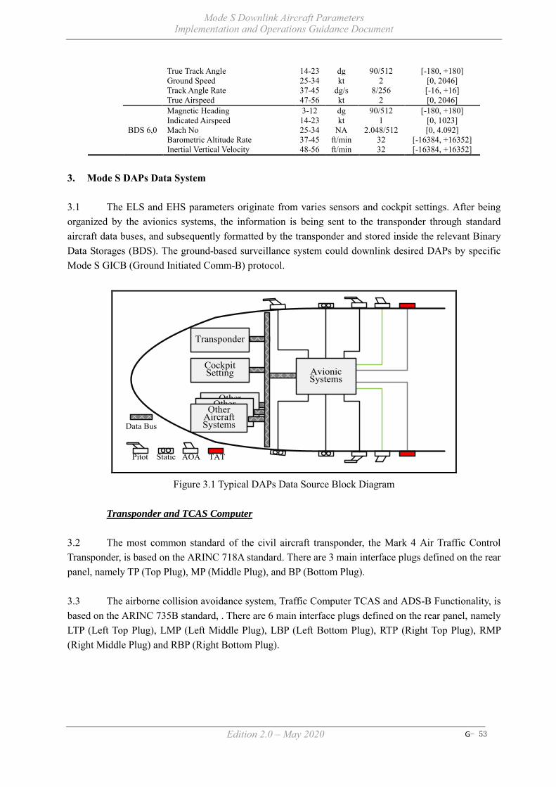
Mode S Downlink Aircraft Parameters Implementation and Operations Guidance Document
Edition 2.0 – May 2020 G- 53
True Track Angle 14-23 dg 90/512 [-180, +180] Ground Speed 25-34 kt 2 [0, 2046] Track Angle Rate 37-45 dg/s 8/256 [-16, +16] True Airspeed 47-56 kt 2 [0, 2046]
BDS 6,0
Magnetic Heading 3-12 dg 90/512 [-180, +180] Indicated Airspeed 14-23 kt 1 [0, 1023] Mach No 25-34 NA 2.048/512 [0, 4.092] Barometric Altitude Rate 37-45 ft/min 32 [-16384, +16352] Inertial Vertical Velocity 48-56 ft/min 32 [-16384, +16352]
3. Mode S DAPs Data System 3.1 The ELS and EHS parameters originate from varies sensors and cockpit settings. After being organized by the avionics systems, the information is being sent to the transponder through standard aircraft data buses, and subsequently formatted by the transponder and stored inside the relevant Binary Data Storages (BDS). The ground-based surveillance system could downlink desired DAPs by specific Mode S GICB (Ground Initiated Comm-B) protocol.
Other Aircraft SystemsOther
Aircraft Systems
Transponder
Other Aircraft Systems
Avionic Systems
Pitot Static AOA TAT
Data Bus
Cockpit Setting
Figure 3.1 Typical DAPs Data Source Block Diagram
Transponder and TCAS Computer
3.2 The most common standard of the civil aircraft transponder, the Mark 4 Air Traffic Control Transponder, is based on the ARINC 718A standard. There are 3 main interface plugs defined on the rear panel, namely TP (Top Plug), MP (Middle Plug), and BP (Bottom Plug). 3.3 The airborne collision avoidance system, Traffic Computer TCAS and ADS-B Functionality, is based on the ARINC 735B standard, . There are 6 main interface plugs defined on the rear panel, namely LTP (Left Top Plug), LMP (Left Middle Plug), LBP (Left Bottom Plug), RTP (Right Top Plug), RMP (Right Middle Plug) and RBP (Right Bottom Plug).

Mode S Downlink Aircraft Parameters Implementation and Operations Guidance Document
Edition 2.0 – May 2020 G- 54
TP
MP
BP
LTP
LMP
LBP
RTP
RMP
RBP
Figure 3.2 Transponder and TCAS Computer Examples from ACSS Data Bus
3.4 The most common data bus, the Digital Information Transfer System, is based on the ARINC 429 standard. The standard defines the data transfer between most of the avionics systems. There are also other standards such as the ARINC 629 used on Boeing B777, Airbus A330 and A350, as well as the ARINC 664 (AFDX, Avionics Full Duplex Switched Ethernet) used on A380 and B787.
Avionics and DAPs Data
3.5 The Aircraft Address (AA) is a parameter programmed [WSH(4]into the aircraft frame after the address is allocated by the State registration authority. Normally there are 2 ways to program this parameter, one is to program the pins of the MP (connected for “1”, open for “0”), and the other is to use Aircraft Personality Module (ARINC 607) to store the address, and then interface to the MP. Note: For more detailed information about Aircraft Address, refer to ARINC 718A Attachment 2B. For APM implementation guidelines, refer to ARINC 718A Attachment 9.
Figure 3.3 APM Example from ACSS
3.6 The Transponder Capability (CA) is a result of the combination of on-the-ground status and transponder capability level. Normally the on-the-ground status is automatically indicated by the weight sensor fitted on the aircraft, but some GA planes use manual means to indicate the status by switching the transponder knob to the GND option. The[AA5] transponder receives on-the-ground status from the TP

Mode S Downlink Aircraft Parameters Implementation and Operations Guidance Document
Edition 2.0 – May 2020 G- 55
pins (5J and 5K), make validation of the status with Ground Speed, Radio Altitude or Airspeed, and then announce the status. The transponder capability level is a static value which is fixed after manufacturing.
Figure 3.4 TT31 Mode S Transponder from TRIG
3.7 The Flight Status (FS) is a result of combination of the on-the-ground status, SPI, and Alert. The on-the-ground is the same as in 3.6, the SPI is from pushing IDENT function button of the transponder by pilot, and the Alert is produced by changing Mode A code (If changed to 7500, 7600, 7700, that’s permanent alert; and if changed to other codes, that’s 18 seconds temporary alert). 3.8 The Common Usage GICB Capability Report is generated by the transponder itself by detecting the corresponding input data availability, and then set the corresponding bit related to that GICB register. 3.9 The main source of Aircraft Identification is from FMS, input by pilot through Flight ID (or Flight No) menu, and the related data transmitted to transponder by specific data bus (ARINC 429 Labels 233~237). If the Flight ID is empty, then the Aircraft Registration data may be provided within another data bus (ARINC 429 Labels 301-303). 3.10 According to TCAS standard (ARINC 735B Chapter 3.3.4.1), the Datalink Capability Report and the Resolution Advisories Report are sent to the Transponder from TCAS Computer by specific protocol (TGD-TCAS to Transponder data transfer protocol, and Transponder to TCAS data transfer protocol is named XGD. The data bus used is ARINC 429 Label 270). The data are sent from RMP of the TCAS Computer to TP of the Transponder, related pins refer to Figure 3.5.
XPDR #1ARINC 718A
TCASARINC 735B
TP-5F Label270 RMP-15K
TP-5G RMP-14F
TP-5H RMP-14G
XPDR #2ARINC 718A
RMP-14A Label270 TP-5E
RMP-14B Label270 TP-5F
RMP-14H TP-5G
RMP-14J TP-5H
TP-5E Label270 RMP-15J
Figure 3.5 Illustrations of Datalink Capability and RA Report Transfer
3.11 There are 2 kinds of Selected Altitude, one is from MCP/FCU (Boeing’s Mode Control Panel and Airbus’s Flight Control Unit), and the other is from FMS (Flight Management System). The first one is set by the pilot in response to a controller’s [WSH(6]instruction during the flight, the second one is calculated by the FMS automatically to achieve the best cost-efficient[AA7].

Mode S Downlink Aircraft Parameters Implementation and Operations Guidance Document
Edition 2.0 – May 2020 G- 56
Figure 3.6 MCP of Boeing B787 & FCU of Airbus A380
3.12 The Barometric Pressure Setting (BPS) is also located in the MCP/FCU, and set by the pilot rotating the knob to the pressure value comes from the aerodrome’s ATIS (Automatic Terminal Information System). 3.13 The other parameters mainly come from the sensors onboard the aircraft, the sensors are organized in 3 groups, the air data sensors, the inertial sensors and the magnetic sensor. 3.14 The air data sensors are used to sense the medium through which the aircraft is flying, including pitot (static) probe, static port, temperature sensor, angle of attack sensor. Typical sensed parameters are total pressure (Pt), static pressure (Ps), pressure changing rate, air temperature (TAT), and angle of attack. Derived data includes Barometric Altitude (ALT), Indicated Airspeed (IAS), Vertical Speed (VS), Mach (M), Static Air Temperature (SAT), Total Air Temperature (TAT), True Airspeed (TAS) and Angle of Attack (AOA). The simplest system provides ALT and IAS.
Figure 3.7 Air Data Sensors and Integrated Sensor on Airbus A380

Mode S Downlink Aircraft Parameters Implementation and Operations Guidance Document
Edition 2.0 – May 2020 G- 57
3.15 The inertial sensors are used to detect the motion of the aircraft in a universal reference system, including position gyroscopes, rate gyroscopes and accelerometers. By detection of the 3D dynamic of the aircraft, derived data includes Ground Speed (GS), Wind Speed, Wind Direction, True Track Angle, Roll Angle, and Track Angle Rate and so on.
Figure 3.8 Gyro, Accelerometer and LASEREF IV IRU from Honeywell
3.16 The magnetic sensor is used to sense the direction and to find the magnetic north, and give out the main parameter of Magnetic Heading. The world magnetic model is show below:
Figure 3.9 World Magnetic Model 2000
3.17 Some airplane platform uses an integrated solution to process these data, each air data sensor is connected with an Air Data Module (ADM) which converts the analog data to digital data and make the compensation of the instrumental and positional error. These data then feed to the input of Air Data Inertial Reference Systems (ADIRS) to calculate all the parameters mentioned before. And after that the parameters are sent to transponder and other avionics systems by the Data Bus.

Mode S Downlink Aircraft Parameters Implementation and Operations Guidance Document
Edition 2.0 – May 2020 G- 58
Other Aircraft SystemsOther
Aircraft Systems
ADM ADMTransponder
ADM ADM
Other Aircraft Systems ADM
Standby Meters
ADIRSAir Data Inertial
Reference System
ADM
Pitot Static AOA TAT
Total Pressure
Static Pressure
Angle of Attack
Total Air Temp.
Data Bus
Figure 3.10 Typical ADIRS Architecture
3.18 The most commonly used data bus for parameters from ADIRS is ARINC 429 (and the newest evolution is AFDX invented by Airbus and implemented in varies new aircrafts like A380 and B787), and the standard ARINC 429 Labels used by these parameters are as follows:
Table 3.1 ADIRS Parameters Used Labels of ARINC 429 No DAP Item Label 1 Mach No. 205 2 Indicated Air Speed 206 3 True Air Speed 210 4 Barometric Altitude Rate 212 5 Ground Speed 312 6 True Track Angle 313 7 Magnetic Heading 320 8 Roll Angle 325 9 Track Angle Rate 335*
10 Inertial Vertical Velocity 365
*Note: This label in GAMA configuration is not used for Track Angle Rate 3.19 By using these parameters, the aircraft dynamic is illustrated as in Figure 3.11.
Track Angle Rate
Magnetic Heading
True Track Angle
TrueAirspeed
GroundSpeed
Roll Angle
VerticalRate
True North
Magnetic North
True East
WindEffect
Gravity
TurningRadius
Figure 3.11 Illustration of Aircraft Dynamic

Mode S Downlink Aircraft Parameters Implementation and Operations Guidance Document
Edition 2.0 – May 2020 G- 59

SURICG/5
Appendix H to the Report
APX. H - 1
REVISED TERMS OF REFERENCE OF MODE S DAPS WORKING GROUP
(by Mode S DAPs WG/3, 14 May 2020)
Working Arrangement of the Mode S DAPS WG Membership: The Mode S DAPS WG shall be composed of experts involved in technical and operation of surveillance services as well as operational experts. Member States of SURICG are encouraged to volunteer to form this Working Group. The working group shall normally invite representatives of International Organizations recognized by the ICAO Council and Industry Partners as required by the group which represent important civil aviation interests to participate in its work in a consultative capacity. Meetings: The Mode S DAPS WG shall convene annually with at least one face-to-face meeting per year, and supplemented with WebEx meetings as required. The outcome of the meetings shall be reported to the SURICG. Schedule and delivery: Subject to the extent of prioritized applications considered by the Mode S DAPS WG, the schedule for delivery of the working group shall be 3 years after initiation of the Mode S DAPS WG (28 March 2018). The delivery point(s) will be nominated by SURICG through discussion. The Mode S DAPS WG shall report to the APANPIRG via the SURICG. Terms of Reference. See next section. Term of Reference The Objectives of Mode S DAPs Working Group are to:
1) Ensure harmonized implementation of Mode S DAPs in the Asia and Pacific Regions according to Surveillance Strategy adopted by APANPIRG;
2) Facilitate the implementation of Mode S DAPs application in the Asia and Pacific Regions using the project management principles where appropriate to maximize its benefit to region; and
3) Review, identify and address major issues in technical, operational and regulatory aspects to facilitate the Mode S DAPs implementation in the Asia and Pacific Regions.
Deliverables to meet the Objectives: 1) Progress report to be submitted to SURICG addressing the Mode S DAPs Working Group deliverables (listed in 2 to 7 below); 2) To study and identify applicable Mode S DAPs applications in the Asia and Pacific Regions considering:
- Concept of use/operation; - Cost of system; - Requirement of surveillance systems (focusing on radar); - Matching functionality in ATC automation system; - Other currently available or emerging technologies; - ICAO Global Air Navigation Plan (GANP) and Aviation System Block Upgrades (ASBU); and - Evaluation method for Mode S DAPs performance.

Appendix H to the Report
APX. H - 2
3) To identify and develop the regional requirements of Mode S DAPs capability in the area of aircraft equipage, surveillance systems (focusing on radar) and ATC automation system, taking into account the relevant performance expectations of the Asia/Pacific Seamless ATMANS Plan; 4) To develop roadmap for Mode S DAPs application in the Asia and Pacific Regions taking into account of: - Available equipment standards; - Readiness of airspace users and ATS providers; and - Development of standardized and systematic approach to Mode S DAPs application. 5) To develop guidance materials to assist States and airspace users on the use of Mode S DAPs in the Asia and Pacific Regions; 6) To encourage research and development, trials and demonstrations in the field of Mode S DAPs application; and 7) Draft Conclusions and Decisions to be formulated relating to matters in the field of Mode S DAPS that come within the scope of the SURICG work plan. [Note: Mode S DAPS Working Group will report to SURICG and SURICG will coordinate with CNS Sub-group.] Current Members: The working group is currently comprised of representatives from Australia, Cambodia, China, Hong Kong China, India, Indonesia, Japan, Republic of Korea, Malaysia, Nepal, New Zealand, Philippines, Singapore, Sri Lanka, Thailand and Viet Nam, and is led by China and Singapore.

Appendix H to the Report
APX. H - 3
TERM OF REFERENCE
Efforts thus far The Objectives of Mode S DAPs Working Group are to: 1 Ensure harmonized implementation of Mode S DAPs in the Asia
and Pacific Regions according to Surveillance Strategy adopted by APANPIRG;
Discussed at this meeting.
2 Facilitate the implementation of Mode S DAPs application in the Asia and Pacific Regions using the project management principles where appropriate to maximize its benefit to region; and
High level principle is in the draft guidance material.
3 Review, identify and address major issues in technical, operational and regulatory aspects to facilitate the Mode S DAPs implementation in the Asia and Pacific Regions.
Issues are being discussed in the Working Group.
Deliverables to meet the Objectives: 1 Progress report to be submitted to SURICG addressing the Mode
S DAPs Working Group deliverables (listed in 2 to 7 below);
2 To study and identify applicable Mode S DAPs applications in the Asia and Pacific Regions considering: - Concept of use/operation - Cost of system - Requirement of surveillance systems (focusing on radar) - Matching functionality in ATC automation system - Other currently available or emerging technologies; - ICAO Global Air Navigation Plan (GANP) and Aviation System Block Upgrades (ASBU); - Evaluation method for Mode S DAPs performance.
Applications are being discussed in the Working Group.
3 To identify and develop the regional requirements of Mode S DAPs capability in the area of aircraft equipage, surveillance systems (focusing on radar) and ATC automation system, taking into account the relevant performance expectations of the Asia/Pacific Seamless ATMANS Plan;
Discussed at this meeting.
4 To develop roadmap with a view to formulate mandates for Mode S DAPs application in the Asia and Pacific Regions taking into account of: - Available equipment standards - Readiness of airspace users and ATS providers - Development of standardized and systematic approach to Mode S DAPs application;
Discussed at this meeting.
5 To develop guidance materials to educate States and airspace users on the use of Mode S DAPs in the Asia and Pacific Regions:
Guidance material to educated States is adopted by SURICG/4. No guidance material for airspace users available yet.
6 To encourage research and development, trials and demonstrations in the field of Mode S DAPs application; and
Research and development activities are being shared in the Working Group.

Appendix H to the Report
APX. H - 4
7 Draft Conclusions and Decisions to be formulated relating to matters in the field of Mode S DAPS that come within the scope of the SURICG work plan.
On-going.
_ _ _ _ _ _ _ _ _ _ _ _ _

ADS-B IMPLEMENTATION AND OPERATIONS GUIDANCE DOCUMENT
Edition 13.0 - September 2020
INTERNATIONAL CIVIL AVIATION ORGANIZATION ASIA AND PACIFIC OFFICE
SURICG/5 Appendix I to the Report

ADS-B Implementation and Operations Guidance Document
Edition 13.0 - September 2020 APX. I - 2
Intentionally left blank

ADS-B Implementation and Operations Guidance Document
Edition 13.0 - September 2020 APX. I - 3
TABLE OF CONTENTS
1. INTRODUCTION ............................................................................................................ 7 1.1 Arrangement of the AIGD .................................................................................................. 7 1.2 Document History and Management .................................................................................. 7 1.3 Copies ................................................................................................................................. 8 1.4 Changes to the AIGD .......................................................................................................... 8 1.5 Editing conventions ............................................................................................................ 8 1.6 AIGD Request for Change Form ........................................................................................ 9 1.7 Amendment Record .......................................................................................................... 10 2. ACRONYM LIST & GLOSSARY OF TERMS............................................................ 15 2.1 Acronym List .................................................................................................................... 15 2.2 Glossary of Terms ............................................................................................................. 16 3. REFERENCE DOCUMENTS………………………………………………………... 17 4. ADS-B DATA .................................................................................................................. 19 5. ADS-B IMPLEMENTATION ....................................................................................... 20 5.1 Introduction ....................................................................................................................... 20 5.1.1 Planning ................................................................................................................... 20 5.1.2 Implementation team to ensure international coordination ..................................... 20 5.1.3 System compatibility ............................................................................................... 20 5.1.4 Integration ................................................................................................................ 21 5.1.5 Coverage Predictions ............................................................................................... 24 5.2 Implementation checklist .................................................................................................. 25 5.2.1 Introduction .............................................................................................................. 25 5.2.2 Activity Sequence .................................................................................................... 25 5.2.3 Concept Phase .......................................................................................................... 25 5.2.4 Design Phase ............................................................................................................ 25 5.2.5 Implementation Phase .............................................................................................. 26 6. HARMONIZATION FRAMEWORK FOR ADS-B IMPLEMENTATION ....................................................................................... 28 6.1 Background ...................................................................................................................... 28 6.2 Template of Harmonization Framework for ADS-B Implementation .............................. 29 7. SYSTEM INTEGRITY AND MONITORING ............................................................ 32 7.1 Introduction ....................................................................................................................... 32 7.2 Personnel Licensing and Training .................................................................................... 32 7.3 System Performance Criteria for an ATC separation service ........................................... 32 7.4 ATC system validation ..................................................................................................... 33
ADS-B Implementation and Operations Guidance Document
Edition 13.0 - September 2020 APX. I - 4
7.4.1 Safety Assessment Guidelines ............................................................................. 33 7.4.2 System safety assessment .................................................................................... 33 7.4.3 Integration test ..................................................................................................... 34 7.4.4 ATS Operation Manuals ...................................................................................... 34 7.4.5 ATS System Integrity .......................................................................................... 34 7.5 System Monitoring ........................................................................................................... 35 7.5.1 Problem Reporting System (PRS) ....................................................................... 35 7.5.2 The monitoring process ....................................................................................... 35 7.5.3 Distribution of confidential information ............................................................. 36 7.5.4 ADS-B problem reports ....................................................................................... 36 7.5.5 ADS-B periodic status report............................................................................... 36 7.5.6 Processing of Reports .......................................................................................... 37 7.6 APANPIRG ....................................................................................................................... 37 7.7 Local Data Recording and Analysis ................................................................................. 37 7.7.1 Data recording ..................................................................................................... 37 7.7.2 Local data collection ............................................................................................ 38 7.7.3 Avionics problem identification and correction .................................................. 38 7.8 ADS-B Problem Report .................................................................................................... 39 7.8.1 Report Form ......................................................................................................... 39 7.8.2 Description of Fields ........................................................................................... 40 7.9 ADS-B Performance Report Form .................................................................................... 41 8. RELIABILITY & AVAILABILITY CONSIDERATIONS ....................................... 42 8.1 Reliability ......................................................................................................................... 42 8.2 Availability ....................................................................................................................... 42 8.3 Recommendations for high reliability/availability ADS-B systems ................................. 43 A: System design ......................................................................................................... 43 B: Logistics strategy ................................................................................................... 44 C: Configuration Management .................................................................................... 45 D: Training & Competency plans ................................................................................ 46 E: Data collection & Review ....................................................................................... 46 9. ADS-B REGULATIONS AND PROCEDURES .......................................................... 47 9.1 Introduction ....................................................................................................................... 47 9.2 ADS-B Regulations .......................................................................................................... 47 9.3 Factors to be considered when using ADS-B ................................................................... 48 9.3.1 Use of ADS-B Level data..................................................................................... 48 9.3.2 Position Reporting Performance .......................................................................... 48 9.3.3 GNSS Integrity Prediction Service ...................................................................... 49 9.3.4 Sharing of ADS-B Data........................................................................................ 49 9.3.5 Synergy between GNSS and ADS-B ................................................................... 50 9.3.6 Use of ADS-B for Airport Surface Movement .................................................... 51

ADS-B Implementation and Operations Guidance Document
Edition 13.0 - September 2020 APX. I - 5
9.3.7 1090 Mhz Spectrum and 24-bit Aircraft Address Issue With Unmanned Aircraft Systems (UAS) ..................................................................................................... 52
9.4 Reporting Rates ................................................................................................................ 53 9.4.1 General ................................................................................................................ 53 9.5 Separation ......................................................................................................................... 53 9.5.1 General ................................................................................................................. 53 9.5.2 Identification Methods ......................................................................................... 53 9.5.3 ADS-B Separation ................................................................................................ 53 9.5.4 Vertical Separation ............................................................................................... 53 9.6 Air Traffic Control Clearance Monitoring ....................................................................... 55 9.6.1 General ................................................................................................................. 55 9.6.2 Deviation from ATC clearances .......................................................................... 55 9.7 Alerting service ................................................................................................................. 54 9.8 Position Reporting ............................................................................................................ 55 9.8.1 Pilot position reporting requirements in ADS-B coverage .................................. 55 9.8.2 Meteorological reporting requirement in ADS-B airspace .................................. 55 9.9 Phraseology ....................................................................................................................... 55 9.9.1 Phraseology standard ........................................................................................... 55 9.9.2 Operations of Mode S Transponder and ADS-B ................................................. 56 9.10 Flight Planning .................................................................................................................. 57 9.10.1 ADS-B Flight Planning Requirement – Flight Identity ....................................... 57 9.10.2 ADS-B Flight Planning Requirements ................................................................. 58 9.10.3 Setting Flight Identification (Flight ID) in Cockpits ........................................... 59 9.11 Procedures to Handle Non-compliant ADS-B Aircraft or Mis-leading ADS-B Transmissions .................................................................................. 60 9.12 Emergency Procedures .................................................................................................... 63 9.13 Procedures to Handle GPS Time and Week Counter Rollover ........................................ 64 10. Security Issues Associated with ADS-B ........................................................................ 65 10.1 Introduction ....................................................................................................................... 65 10.2 Considerations .................................................................................................................. 65 10.3 Measures for Enhancing the Security of ADS-B .............................................................. 66 10.3.1 Time Difference of Arrival (TDOA) Based Position Verification Method ........ 66

ADS-B Implementation and Operations Guidance Document
Edition 13.0 - September 2020 APX. I - 6
Appendix 1 – An Example of Commissioning Checklist Appendix 2 – Guidance Materials on Monitoring and Analysis of ADS-B Avionics
Performance Appendix 3 – A Template for ADS-B Mandate/Regulations for Aircraft Avionics Appendix 4 – An Example of Advice to Operators Concerning Inconsistency between
ADS-B Flight Planning and Surveillance Capability Appendix 5 – Checklist of Common Items or Parameters for the Monitoring of ADS-B
System Appendix 6 – Baseline ADS-B Service Performance Parameters Appendix 7 – Guidance Material on Generation, Processing and Sharing of ASTERIX
Category 21 ADS-B Messages Appendix 8 – ICAO Guidance Material on 1 090 Mhz Spectrum Issues and Proper
Management of 24-Bit Aircraft Addresses Assoicated with Unmanned Aircraft

ADS-B Implementation and Operations Guidance Document
Edition 13.0 - September 2020 APX. I - 7
1. INTRODUCTION The Eleventh ICAO Air Navigation Conference held in 2003 recommended that States recognize ADS-B as an enabler of the global ATM concept bringing substantial safety and capacity benefits; support the cost-effective early implementation of it; and ensuring it is harmonized, compatible and interoperable with operational procedures, data linking and ATM applications. The Twelve ICAO Air Navigation Conference held in 2012 endorsed the Aviation System Block Upgrades (ASBU) to provide a framework for global harmonization and interoperability of seamless ATM systems. Among the Block Upgrades, the Block 0 module “Initial Capability for Ground Surveillance” recommends States to implement ADS-B which provides an economical alternative to acquire surveillance capabilities especially for areas where it is technically infeasible or commercially unviable to install radars. This ADS-B Implementation and Operations Guidance Document (AIGD) provides guidance material for the planning, implementation and operational application of ADS-B technology in the Asia and Pacific Regions. The procedures and requirements for ADS-B operations are detailed in the relevant States’ AIP. The AIGD is intended to provide key information on ADS-B performance, integration, principles, procedures and collaboration mechanisms. The content is based upon the work to date of the APANPIRG ADS-B Study and Implementation Task Force (SITF), the Surveillance Implementation Coordination Group (SURICG) and various ANC Panels developing provisions for the operational use of ADS-B. Amendment to the guidance material will be required as new/revised SARPs and PANS are published. 1.1 ARRANGEMENT OF THE AIGD The AIGD consists of the following Parts:
Section 1 Introduction Section 2 Acronyms and Glossary of Terms Section 3 Reference Documents Section 4 ADS-B Data Section 5 ADS-B Implementation Section 6 Template of Harmonization Framework for ADS-B
Implementation Section 7 System Integrity and Monitoring Section 8 Reliability and Availability Considerations Section 9 ADS-B Regulations and Procedures Section 10 Security Issues Associated with ADS-B
1.2 DOCUMENT HISTORY AND MANAGEMENT This document is managed by the APANPIRG. It was introduced as draft to the first Working Group meeting of the ADS-B SITF in Singapore in October 2004, at which it was agreed to develop the draft to an approved working document that provides implementation guidance for States. The first edition was presented to APANPIRG for adoption in August 2005. It is intended to supplement SARPs, PANS and relevant provisions contained in ICAO documentation and it will be regularly updated to reflect evolving provisions.

ADS-B Implementation and Operations Guidance Document
Edition 13.0 - September 2020 APX. I - 8
1.3 COPIES Paper copies of this AIGD are not distributed. Controlled and endorsed copies can be found at the following web site: http://www.icao.int/APAC/Pages/edocs.aspx Copy may be freely downloaded from the web site, or by emailing APANPIRG through the ICAO Asia and Pacific Regional Office who will send a copy by return email. 1.4 CHANGES TO THE AIGD Whenever a user identifies a need for a change to this document, a Request for Change (RFC) Form (see Section 1.6 below) should be completed and submitted to the ICAO Asia and Pacific Regional Office. The Regional Office will collate RFCs for consideration by the Surveillance Implementation Coordination Group. When an amendment has been agreed by a meeting of the Surveillance Implementation Coordination Group then a new version of the AIGD will be prepared, with the changes marked by an “|” in the margin, and an endnote indicating the relevant RFC, so a reader can see the origin of the change. If the change is in a table cell, the outside edges of the table will be highlighted; e.g.:
Final approval for publication of an amendment to the AIGD will be the responsibility of APANPIRG. 1.5 EDITING CONVENTIONS (Intentionally blank)

ADS-B Implementation and Operations Guidance Document
Edition 13.0 - September 2020 APX. I - 9
1.6 AIGD REQUEST FOR CHANGE FORM
RFC Nr:
Please use this form when requesting a change to any part of this AIGD. This form may be photocopied as required, emailed, faxed or e-mailed to ICAO Asia and Pacific Regional Office +66 (2) 537-8199 or [email protected] 1. SUBJECT: 2. REASON FOR CHANGE: 3. DESCRIPTION OF PROPOSAL: [expand / attach additional pages if necessary] 4. REFERENCE(S): 5. PERSON INITIATING: DATE: ORGANISATION: TEL/FA/X/E-MAIL: 6. CONSULTATION RESPONSE DUE BY DATE: Organization Name Agree/Disagree Date 7. ACTION REQUIRE : 8. AIGD EDITOR DATE REC’D : 9. FEEDBACK PASSED DATE :

ADS-B Implementation and Operations Guidance Document
Edition 13.0 - September 2020 APX. I - 10
1.7 AMENDMENT RECORD
Amendment Number
Date Amended by Comments
0.1 24 December 2004 W. Blythe H. Anderson
Modified draft following contributions from ADS-B SITF Working Group members. Incorporated to TF/3 Working Paper #3.
0.2 (1.0) 24 March 2005 H. Anderson Final draft prepared at ADS-B SITF WG/3
0.3 (1.1) 03 June 2005 Nick King Amendments following SASP WG/WHL meeting of May 2005
0.4 15 July 2005 CNS/MET SG/9 Editorial changes made
1.0 26 August 2005 APANPIRG/16 Adopted as the first Edition
2.0 25 August 2006 Proposed by ADS-B SITF/5 and adopted by APANPIRG/17
Adopted as the second Edition
3.0 7 September 2007
Proposed by ADS-B SITF/6 and adopted by APANPIRG/18
Adopted as the second amendment (3rd edition)
4.0 5 September 2011 Proposed by ADS-B SITF/10 and adopted by APANPIRG/22
Adopted amendment on consequential change to the Flight Plan and additional material on the reliability and availability for ADS-B ground system
5.0 14 September 2012 Proposed by ADS-B SITF/11 and adopted by APANPIRG/23
Included sample template on harmonization framework
6.0 June 2013 Proposed by ADS-B SITF/12 and adopted by APANPIRG/24
Revamped to include the latest ADS-B developments and references to guidance materials on ADS-B implementation
7.0 September 2014 Proposed by ADS-B SITF/13 and adopted by APANPIRG/25
(i) Included guidance materials on monitoring and analysis of ADS-B equipped aircraft
(ii) Included guidance materials on synergy between GNSS and ADS-B
(iii) Revised ATC Phraseology (iv) Included clarification on
Flight Planning 8.0 September 2015 Proposed by ADS-B SITF/14
and adopted by APANPIRG/26
(i) Updated the guidance materials on monitoring and analysis of ADS-B equipped aircraft
(ii) Updated the categories of reported ADS-B avionics problems
(iii) Updated the guidance materials on ADS-B flight

ADS-B Implementation and Operations Guidance Document
Edition 13.0 - September 2020 APX. I - 11
plan (iv) Updated the guidance
materials on disabling ADS-B transmissions
(v) Remove reference to operational approval for use of ADS-B Out by ATC
9.0 September 2016 Proposed by ADS-B SITF/15
and adopted by APANPIRG/27
(i) Included a list of additional functional requirements for ADS-B integration
(ii) Addition of a checklist of common items or parameters for monitoring of ADS-B System
(iii) Amendment to emphasize the issue on potential incorrect processing of DO-260B downlinks by ADS-B ground stations during upgrade
(iv) Updated the list of known ADS-B avionics problems
(v) Included a general recommendation of technical solution on acquisition of Mode 3/A code information via Mode S downlink for DO-260 aircraft in ADS-B implementation with Mode A/C SSR environment
10.0 June 2017 Proposed by SURICG/2 (i) Updated “B787 position error
with good NUC” in the list of known ADS-B avionics problems.
(ii) Included new problem type “Incorrect Ground Bit Setting in ADS-B Avionics Downlink Data” and “A350 ADS-B on-ground performance” in the list of known ADS-B avionics problems.
(iii) Amendment to the template for ADS-B Mandate / Regulations for Aircraft Avionics.
(iv) Included a general recommendation to use ADS-B in overcoming the limitations of Mode A/C radar technology.
(v) Included a general recommendation on carrying
ADS-B Implementation and Operations Guidance Document
Edition 13.0 - September 2020 APX. I - 12
out ICAO Aircraft Address Monitoring
(vi) Aligned to replace NACp for NAC throughout the document
(vii) Aligned to use ICAO Aircraft Address throughout the document
11.0 April 2018 Proposed by SURICG/3 (i) Editorial Updates – including
/replacing ADS-B SITF with SURICG (Sections 1, 1.4, 2.1, 7.5.1, 7.5.5, 7.5.6, 7.6, 7.8.2)
(ii) Correction of HPL Definition (Section 2.2)
(iii) Update of reference documents as in Attachment 2 of WP/02
(iv) Include reference to APRD (Section 7.5.1)
(v) Update of sample regulations (Section 9.2)
(vi) Update in Position Reporting Performance (Section 9.3.2)
(vii) Update in GNSS Integrity Prediction Service (Section 9.3.3)
(viii) Update name of RASMAG in Sharing of ADS-B Data (Section 9.3.4)
(ix) Clarification of reporting rate requirements (Section 9.4.1)
(x) Use of Ident during ADS-B emergencies.(Section 9.12)
(xi) Appendix 1 missing from Version 10 – reinstate.
(xii) Appendix 2 – update for available APRD.
(xiii) Update to B787 service bulletin status. (Attachment A in Appendix 2)
(xiv) replace "Date UTC" to "Start Time/Date UTC", replace "Time UTC" to "End Time/Date UTC" and related contents in the Report Form (Section 7.8.1)
(xv) replace description of "Date UTC" as "UTC Time/Date when the event occurred", replace description of "Time UTC" as "UTC Time/Date when the event ended" as

ADS-B Implementation and Operations Guidance Document
Edition 13.0 - September 2020 APX. I - 13
sometimes the problem will lasts across mid-night. (Section 7.8.2)
(xvi) In Remote Control & Monitoring (RCMS) part, suggest to replace "ASTERIX Output Load" to "ASTERIX Output Load and Link Status" (Appendix 5)
(xvii) Update on DO260A EMG issue (Section 9.12)
(xviii) Update the link to the Guidance Material on generation, processing and sharing of ASTERIX (Section 4)
(xix) Reference to Space based ADS-B and ATC automation as in WP12 is added under 5.1.4.4.6
(xx) Updated Section 4Managing the Problem in Appendix 2 to incorporate the General mechanism and procedure for blacklisting aircraft
(xxi) Updated the Attachment A to Appendix 2 – List of known ADS-B avionics problems
(xxii) Added Appendix 6 – Baseline ADS-B Service Performance Parameters
(xxiii) Added Appendix 7 – Guidance Material on Generation, Processing and Sharing of ASTERIX Category 21 ADS-B Messages
12.0 April 2019 Proposed by SURICG/4 (i) Added procedures on handling GPS time and week counters rollover (Section 9.13)
(ii) Added two new problem types
to Attachment A of Appendix 2 “List of known ADS-B avionics problems”, including:
o Rockwell TSS-4100
Geometric Altitude Reporting as Pressure Altitude
o Improper NACv reporting (iii) Updated the status of known
ADS-B avionics problems in Attachment A of Appendix 2
ADS-B Implementation and Operations Guidance Document
Edition 13.0 - September 2020 APX. I - 14
“List of known ADS-B avionics problems”, including:
o B787 position error with
good NIC o Rockwell TSS-4100 track
extrapolation issue o Embraer 170 track jumping
issue o Airbus Single Aisle
production wiring issue o Boeing 777-300ER
production wiring issue
13.0 September 2020 Proposed by SURICG/5 (i) Updated the status of known
ADS-B avionics problems in Attachment A of Appendix 2 “List of known ADS-B avionics problems”, including B787 NACv = 0 Issue
(ii) Updated Section 5.1.4.5.1 on
ICAO Aircraft Address Monitoring
(iii) Added the following new sections: o Use of ADS-B for Airport
Surface Movement (Section 9.3.6)
o 1090 Mhz Spectrum and 24-bit Aircraft Address Issue with Unmanned Aircraft Systems (UAS) (Section 9.3.7)
o Measures for Enhancing
the Security of ADS-B (Section 10.3)
o Time Difference of Arrival
(TDOA) Based Position Verification Method (Section 10.3.1)

ADS-B Implementation and Operations Guidance Document
Edition 13.0 - September 2020 APX. I - 15
2. ACRONYM LIST & GLOSSARY OF TERMS 2.1 ACRONYM LIST ACID Aircraft Identification ADS-C Automatic Dependent Surveillance - Contract ADS-B Automatic Dependent Surveillance - Broadcast AIGD ADS-B Implementation and Operations Guidance Document AIP Aeronautical Information Publication AIT ADS-B Implementation Team AMSL Above Mean Sea Level APANPIRG Asia/Pacific Air Navigation Planning and Implementation Regional Group APRD ADS-B Avionics Problem Reporting Database ARINC Aeronautical Radio Incorporate ATC Air Traffic Control (or Air Traffic Controller) ATM Air Traffic Management ATS Air Traffic Services ATSP ATS Provider ATSU ATS unit CNS Communications, Navigation, Surveillance CRC Cyclic Redundancy Check CDTI Cockpit Display Traffic Information DAIW Danger Area Infringement Warning FIR Flight Information Region FLTID Flight Identification FMS Flight Management System FOM Figure of Merit used in ASTERIX messaging GPS Global Positioning System (USA) HPL Horizontal Protection Level ICAO International Civil Aviation Organization MSAW Minimum Safe Altitude Warning MTBF Mean Time Between Failures MTCA Medium Term Conflict Alert MTTR Mean Time To Restore NACp Navigation Accuracy Category NIC Navigation Integrity Category PRS Problem Reporting System RAI Restricted Area Intrusion RAM Route Adherence Monitoring RAIM Receiver Autonomous Integrity Monitoring RFC Request for Change RNP Required Navigation Performance SIL Source Integrity Level SITF Study and Implementation Task Force STCA Short Term Conflict Alert SURICG Surveillance Implementation Coordination Group

ADS-B Implementation and Operations Guidance Document
Edition 13.0 - September 2020 APX. I - 16
2.2 GLOSSARY OF TERMS ADS-B In
An ADS-B system feature that enables the display of real time ADS-B tracks on a situation display in the aircraft cockpit.
ADS-B Out
An ADS-B system feature that enables the frequent broadcast of accurate aircraft position and vector data together with other information.
Asterix 21
Eurocontrol standard format for data message exchange
FOM (Figure of Merit) A numeric value that is used to determine the accuracy and integrity of associated position data.
HPL (Horizontal Position Limit)
The containment radius within which the true position of the aircraft will be found for 99.999% of the time, or the probability indicated by the reported SIL value (DO-260A/B).
NACp (Navigational Accuracy Category) Subfield used to announce the 95% accuracy limits for the horizontal position data being broadcast.
NIC (Navigational Integrity Category) Subfield used to specify the containment radius integrity associated with horizontal position data.
NUCp ( Navigation Uncertainty Category) A numeric value that announces the integrity of the associated horizontal position data being broadcast.
SIL (Source Integrity Level) Subfield used to specify the probability of the true position lying outside the containment radius defined by NIC without being alerted.

ADS-B Implementation and Operations Guidance Document
Edition 13.0 - September 2020 APX. I - 17
3. REFERENCE DOCUMENTS
Id Name of the document Reference Date Origin Domain 1 Annex 2: Rules of the Air Tenth Edition
Including Amendment 43 dated 10/11/16
July 2005 ICAO
2 Annex 4: Aeronautical Chart Eleventh Edition including Amendment 59 dated 10/11/16
July 2009 ICAO
3 Annex 10: Aeronautical Telecommunications, Vol. IV – Surveillance Radar and Collision Avoidance Systems
Fifth Edition
July 2014 ICAO
4 Annex 11: Air Traffic Services Fourteenth Edition
July 2016 ICAO
5 Annex 15: Aeronautical Information Services
Fifteenth Edition July 2016 ICAO
6 PAN-ATM (Doc 4444/ATM501) Sixteenth Edition November 2016
ICAO
7 Air Traffic Services Planning Manual (Doc 9426/AN924)
First Edition including Amendment 4 30/12/92
1984 ICAO
8 Manual on Airspace Planning Methodology for the Determination of Separation Minima (Doc 9689/AN953)
First Edition including Amendment 1 dated 30/8/02
1998 ICAO
9 Doc 9859 Safety Management Manual (SMM)
Third Edition 2013 ICAO
10 Technical Provisions for Mode S Services and Extended Squitter (Doc 9871/AN460)
Second Edition including Amendment 1 dated 09/01/17
2012 ICAO
11 Aeronautical Surveillance Manual (Doc 9924)
Second Edition 2017 ICAO
12 ICAO Circular 326 AN/188 “Assessment of ADS-B and Multilateration Surveillance to Support Air Traffic Services and Guidelines for Implementation”.
First Edition 2012 ICAO
13 Regional Supplementary Procedures (Doc 7030)
Fifth Edition including Amendment 9 dated 25/04/14
2008 ICAO
14 Minimum Operational Performance Standards (MOPS) for 1090 MHz Automatic Dependent Surveillance – Broadcast (ADS-B) – including Change 1
RTCA DO-260 September 13, 2000 Change 1 to
2000
2006
RTCA

ADS-B Implementation and Operations Guidance Document
Edition 13.0 - September 2020 APX. I - 18
RTCA DO-260 June 27, 2006
15 Minimum Operational Performance Standards for 1090 MHz Extended Squitter Automatic Dependent Surveillance – Broadcast (ADS-B) and Traffic Information Services – Broadcast (TIS-B) Minimum Operational Performance Standards for 1090 MHz Extended Squitter Automatic Dependent Surveillance – Broadcast (ADS-B) and Traffic Information Services – Broadcast (TIS-B) – Change 1 Minimum Operational Performance Standards for 1090 MHz Extended Squitter Automatic Dependent Surveillance – Broadcast (ADS-B) and Traffic Information Services – Broadcast (TIS-B) – Change 2
RTCA DO-260A April 10, 2003 RTCA DO-260A Change 1 June 27, 2006 RTCA DO-260A Change 2 December 13, 2006
2003 2006 2006
RTCA
16 Minimum Operational Performance Standards for 1090 MHz Extended Squitter Automatic Dependent Surveillance – Broadcast (ADS-B) and Traffic Information Services (TIS-B) Minimum Operational Performance Standards for 1090 MHz Extended Squitter Automatic Dependent Surveillance – Broadcast (ADS-B) and Traffic Information Services – Broadcast (TIS-B) – Corrigendum 1
RTCA DO-260B December 2, 2009 RTCA DO-260B December 13, 2011
2009 2011
RTCA

ADS-B Implementation and Operations Guidance Document
Edition 13.0 - September 2020 APX. I - 19
4. ADS-B DATA APANPIRG has decided to use 1090MHz Extended Squitter data link for ADS-B data exchange in the Asia and Pacific Regions. In the longer term an additional link type may be required. To ensure interoperability of ADS-B ground stations in the Asia Pacific (ASIA/PAC) Regions, during the 16th APANPIRG Meeting held in August 2005, the ASTERIX Category 21 version 0.23 (V0.23) which had incorporated DO260 standard was adopted as the baselined ADS-B data format for deployment of ADS-B ground stations and sharing of ADS-B data in the ASIA/PAC Regions. At this time, DO260A and DO260B standards were not defined. This baselined version provides adequate information so that useful ATC operational services, including aircraft separation, can be provided. V0.23 can be used with DO260, DO260A and DO260B ADS-B avionics/ground stations to provide basic ATC operational services. However, V0.23 cannot fully support the more advanced capabilities offered by DO260A and DO260B. As the avionics standards changed through the different versions of DO260, the ADS-B ground station processing also needed to change, so that downlinks received from aircraft would be correctly interpreted in construction of the ASTERIX Category 21 messages. It is important that States with “older generation” ADS-B ground stations designed to support DO260 or DO260A, take action to upgrade to support the latest ADS-B avionics standard as well as the older standards. DO260B avionics will become more common in the Asia Pacific region as the FAA and European ADS-B mandates for 2020 require this version. States intending to implement ADS-B surveillance and share ADS-B data with others might consider to adopt a more updated version of ASTERIX in order to make use of the advanced capabilities offered by DO260A and DO260B compliant avionics. A guidance material on generation, processing and sharing of ASTERIX Cat. 21 ADS-B messages is provided at Appendix 7 for reference by States. In this guidance material, the ADS-B data contained inside ASTERIX Cat 21 are classified as Group 1 (mandatory), Group 2 (Desirable) and Group 3 (Optional). It is required to transmit all data that are operationally desirable (Group 2), when such data are received from the aircraft, in addition to the data that are mandatory (Group 1) in ASTERIX messages. Whether Group 3 optional data will need to be transmitted or not should be configurable on item-by-item basis within the ADS-B ground station depending on specific operational needs. It is considered necessary that all data that are mandatory in ASTERIX messages (i.e. Group 1 data items) and operationally desirable (i.e. Group 2 data items) when such data are received from aircraft, should be included in data sharing. In the event that the data have to be filtered, the list of optional data items (i.e. Group 3 data items) needs to be shared will be subject to mutual agreement between the two data sharing parties concerned.

ADS-B Implementation and Operations Guidance Document
Edition 13.0 - September 2020 APX. I - 20
5. ADS-B IMPLEMENTATION 5.1 INTRODUCTION 5.1.1 Planning There are a range of activities needed to progress ADS-B implementation from initial concept
level to operational use. This section addresses the issues of collaborative decision making, system compatibility and integration, while the second section of this chapter provides a checklist to assist States with the management of ADS-B implementation activities.
5.1.2 Implementation team to ensure international coordination
5.1.2.1 Any decision to implement ADS-B by a State should include consultation with the wider ATM community. Moreover, where ADS-B procedures or requirements will affect traffic transiting between states, the implementation should also be coordinated between States and Regions, in order to achieve maximum benefits for airspace users and service providers.
5.1.2.2 An effective means of coordinating the various demands of the affected organizations is
to establish an implementation team. Team composition may vary by State or Region, but the core group responsible for ADS-B implementation planning should include members with multidiscipline operational expertise from affected aviation disciplines, with access to other specialists where required.
5.1.2.3 Ideally, such a team should comprise representatives from the ATS providers, regulators
and airspace users, as well as other stakeholders likely to be influenced by the introduction of ADS-B, such as manufacturers and military authorities. All identified stakeholders should participate as early as possible in this process so that their requirements can be identified prior to the making of schedules or contracts.
5.1.2.4 The role of the implementation team is to consult widely with stakeholders, identify
operational needs, resolve conflicting demands and make recommendations to the various stakeholders managing the implementation. To this end, the implementation team should have appropriate access to the decision-makers.
5.1.3 System compatibility
5.1.3.1 ADS-B has potential use in almost all environments and operations and is likely to become a mainstay of the future ATM system. In addition to traditional radar-like services, it is likely that ADS-B will also be used for niche application where radar surveillance is not available or possible. The isolated use of ADS-B has the potential to foster a variety of standards and practices that, once expanded to a wider environment, may prove to be incompatible with neighbouring areas.
5.1.3.2 Given the international nature of aviation, special efforts should be taken to ensure
harmonization though compliance with ICAO Standards and Recommended Practices (SARPs). The choice of systems to support ADS-B should consider not only the required performance of individual components, but also their compatibility with other CNS systems and prevailing avionics standards.

ADS-B Implementation and Operations Guidance Document
Edition 13.0 - September 2020 APX. I - 21
5.1.3.3 The future concept of ATM encompasses the advantages of interoperable and seamless transition across flight information region (FIR) boundaries and, where necessary, ADS-B implementation teams should conduct simulations, trials and cost/benefit analysis to support these objectives.
5.1.4 Integration
5.1.4.1 ADS-B implementation plans should include the development of both business and safety cases. The adoption of any new CNS system has major implications for service providers, regulators and airspace users and special planning should be considered for the integration of ADS-B into the existing and foreseen CNS/ATM system. The following briefly discusses each element.
5.1.4.2 Communication system 5.1.4.2.1 The communication system is an essential element within CNS. An air
traffic controller can now monitor an aircraft position in real time using ADS-B where previously only voice position reports were available. However, a communication system that will support the new services that result from the improved surveillance may be necessary. Consequently, there is an impact of the ongoing ADS-B related work on the communication infrastructure developments.
5.1.4.3 Navigation system infrastructure 5.1.4.3.1 ADS-B is dependent upon the data obtained from a navigation system
(typically GNSS), in order to enable its functions and performance. Therefore, the navigation infrastructure should fulfill the corresponding requirements of the ADS-B application, in terms of:
a) Data items; and b) Performance (e.g. accuracy, integrity, availability etc.).
5.1.4.3.2 This has an obvious impact on the navigation system development, which evolves in parallel with the development of the surveillance system. 5.1.4.4 Other surveillance infrastructure 5.1.4.4.1 ADS-B may be used to supplement existing surveillance systems or as the
principal source of surveillance data. Ideally, surveillance systems will incorporate data from ADS-B and other sources to provide a coherent picture that improves both the amount and utility of surveillance data to the user. The choice of the optimal mix of data sources will be defined on the basis of operational demands, available technology, safety and cost-benefit considerations.
5.1.4.4.2 ADS-B is one of the cost-effective means in complementing and
overcoming limitations of Mode A/C radars, including false targets, aircraft positions temporarily not displayed and split tracks, which could cause aircraft display issues on radar screens for ATC irrespective of brands of Air Traffic Management System being used. Within busy airspace, aircraft

ADS-B Implementation and Operations Guidance Document
Edition 13.0 - September 2020 APX. I - 22
could be managed at close lateral distance while vertically separated. In such situation, Mode A/C radars sometimes provide garbled detection, in the form of false targets due to overlapping replies from two or more aircraft. In the case of ADS-B, ADS-B data are broadcast in an omni-directional, random and periodic intervals without suffering from the same issue. In addition, automatic data validation is usually done at ADS-B receivers to ensure integrity of ADS-B information received from the aircraft.
5.1.4.4.3 A guidance material on issues to be considered in ATC multi-sensor fusion
processing including integration of ADS-B data is provided on the ICAO website http://www.icao.int/APAC/Pages/edocs.aspx for reference by States.
5.1.4.4.4 Acquisition of Mode 3/A code for DO-260 aircraft through Mode S
downlink There is a potential problem for some of the air traffic management systems
(ATMS) for fusion of ADS-B targets with Mode A/C SSR targets, because a common identifier to the aircraft, Mode 3/A code, is not available through ADS-B. Then ATMS can only rely on proximity analysis of aircraft position and Mode C altitude to determine whether detections from two distinct types of surveillance sources belong to the same aircraft. This matching technique might introduce ambiguity in associating ADS-B with Mode A/C SSR targets for fused display.
States may consider enhancing their ADS-B ground stations to listen to
Downlink Format 5 and 21 (DF 5 and 21) of Mode S interrogation replies which carry the Mode 3/A code of the same aircraft. As a result, ADS-B target reports of the same DO-260 aircraft can be filled with Mode 3/A code acquired from Mode S downlink to facilitate matching with Mode A/C SSR targets before transmitting to the ATMS.
The transmission of DF 5 and DF 21 messages from a Mode S aircraft
requires to be triggered by ground-based Mode S interrogators, either through active or passive interrogation. For active interrogation, Mode S interrogators can be installed alongside with ADS-B ground stations for actively triggering DF 5 and DF 21 messages transmission from the aircraft. The interrogators shall follow ICAO standard to perform periodic all-call and roll-call to the aircraft in range. For passive interrogation, the ADS-B ground stations will only passively listen to the DF messages from the aircraft for acquiring the Mode 3/A code. It is required to ensure that Mode S interrogations are performed by external systems, such as A-SMGCS, MLAT system or Mode S radar under their coverage.
The above provides an interim solution during transition from Mode A/C
SSR to Mode S SSR. After upgrading to Mode S SSR, ATMS can have an alternative means to make use of Flight ID or ICAO Aircraft Address to perform association between ADS-B and Mode S radar targets without ambiguity.

ADS-B Implementation and Operations Guidance Document
Edition 13.0 - September 2020 APX. I - 23
5.1.4.4.5 A guidance material on processing and displaying of ADS-B data at air traffic controller positions is provided on the ICAO website “http://www.icao.int/APAC/Pages/edocs.aspx” for reference by States.
5.1.4.4.6 Most of the ATC automation systems that support terrestrial ADS-B will
also support space-based ADS-B without modifications. For more guidance, reference can be made to WP/12 on "ATC Automation Requirement and Space-based ADS-B" delivered during 3rd meeting of the SURICG.
5.1.4.5 Additional Functional Requirements for ADS-B Integration
5.1.4.5.1 The following list of functions could be considered by each individual States to see whether they are suitable for their own operational needs or applicable to local environment from ADS-B integration point of view:
The priority of ADS-B sensor position data vs radar data could be
adaptable; For ADS-B aircraft, receipt of the Mode S conspicuity code could
trigger use of the Flight ID / ICAO Aircraft Address for flight plan correlation;
If, due to sensor or aircraft capability limitation, no SSR code is
received for an aircraft, the system could use Flight ID/ ICAO Aircraft Address for track correlation;
For correlation based on Flight ID, the received ID could exactly match
the ACID of the flight plan; For correlation based on ICAO Aircraft Address, the received address
could match the address entered in the flight plan item 18 CODE/ keyword;
The system could generate an alert for a correlated flight for which the
Flight ID from the track does not match the flight plan ACID and/or the ICAO Aircraft Address from the track does not match the code given in the flight plan Item 18 CODE/ keyword;
The system could allow the setting of ADS-B above or below the radar
sources within the Surveillance Data Processor Tile Set on a per-tile basis;
Priority could only apply to data received at or above the adapted NUCp,
NACp, NIC, and/or SIL thresholds; The system could be configurable to either discard ADS-B data or
display the track with an indication of ADS-B degradation if the received NUCp, NACp, NIC, or SIL is below an adapted threshold;
If the system is configured to display the degraded track, the degraded
position and status could only be displayed if there are no other surveillance sources available;

ADS-B Implementation and Operations Guidance Document
Edition 13.0 - September 2020 APX. I - 24
The system could allow the adaptation of ADS-B emergency codes to
map to special Mnemonics; The system could include an adaptable Downlinked Aircraft Parameters
(DAP) field that invokes a popup with the following information from Mode-S and ADS-B aircraft:
- Magnetic Heading - True Track Angle - Indicated Airspeed/Mach Number - Groundspeed - Track Angle Rate - True Airspeed - Roll Angle - Selected Altitude - Vertical Rate
The system could generate a conformance alert if the Selected Altitude
and the Cleared Flight Level do not match. The system could monitor1 the ICAO Aircraft Address of individual
aircraft and generate alert for the following cases: - ICAO Aircraft Address does not match with that specified in
flight planICAO Aircraft Address is all 0 or F (expressed in hexadecimal)
- ICAO Aircraft Address is not defined in ICAO’s allocation - Duplicate ICAO Aircraft Address detected within single sensor
in the same time-frame - Duplicate ICAO Aircraft Address detected within multi-sensors
in the same time-frameICAO Aircraft Address changes during the flight
- Aircrafts whose state identification number is not match with the state information registered in its flight plan
- Aircrafts whose state identification number is not defined in SARPs (Annex 10)
- Mode-S transponder of which P4 pulse was not detected - Mode-A/C transponder replied to Mode-S all call
5.1.5 Coverage Predictions
5.1.5.1 Reliable and robust analysis and planning of ADS-B coverage to support seamless ATM initiative requires accurate and reliable coverage modelling. States should ensure that surveillance engineering/technical teams are provided with modelling tools to provide accurate and reliable coverage predictions for ATM planning and analysis.
1 Monitoring could be done by ATM system or other systems of the States/Administration

ADS-B Implementation and Operations Guidance Document
Edition 13.0 - September 2020 APX. I - 25
5.2 IMPLEMENTATION CHECKLIST 5.2.1 Introduction The purpose of this implementation checklist is to document the range of activities that needs to be completed to bring an ADS-B application from an initial concept to operational use. This checklist may form the basis of the terms of reference for an ADS-B implementation team, although some activities may be specific to individual stakeholders. An example of the checklist used by AirServices Australia is given at Appendix 1. 5.2.2 Activity Sequence The activities are listed in an approximate sequential order. However, each activity does not have to be completed prior to starting the next activity. In many cases, a parallel and iterative process should be used to feed data and experience from one activity to another. It should be noted that not all activities will be required for all applications. 5.2.3 Concept Phase a) construct operational concept:
1) purpose; 2) operational environment; 3) ATM functions; and 4) infrastructure;
b) identify benefits:
1) safety enhancements; 2) efficiency; 3) capacity; 4) environmental; 5) cost reductions; 6) access; and 7) other metrics (e.g. predictability, flexibility, usefulness);
c) identify constraints:
1) pair-wise equipage; 2) compatibility with non-equipped aircraft; 3) need for exclusive airspace; 4) required ground infrastructure; 5) RF spectrum; 6) integration with existing technology; and 7) technology availability;
d) prepare business case:
1) cost benefit analysis; and 2) demand and justification.
5.2.4 Design Phase

ADS-B Implementation and Operations Guidance Document
Edition 13.0 - September 2020 APX. I - 26
a) identify operational requirements:
1) security; and 2) systems interoperability;
b) identify human factors issues:
1) human-machine interfaces; 2) training development and validation; 3) workload demands; 4) role of automation vs. role of human; 5) crew coordination/pilot decision-making interactions; and 6) ATM collaborative decision-making;
c) identify technical requirements:
1) standards development; 2) prevailing avionics standards; 3) data required; 4) functional processing; 5) functional performance; and 6) required certification levels;
d) equipment development, test, and evaluation:
1) prototype systems built to existing or draft standards/specifications; 2) developmental bench and flight tests; and 3) acceptance test parameters; and 4) select and procure technology;
e) develop procedures:
1) pilot and controller actions and responsibilities; 2) phraseologies; 3) separation/spacing criteria and requirements; 4) controller’s responsibility to maintain a monitoring function, if appropriate; 5) contingency procedures; 6) emergency procedures; and 7) develop AIP and Information documentation
f) prepare design phase safety case: 1) safety rationale; 2) safety budget and allocation; and 3) functional hazard assessment.
5.2.5 Implementation phase a) prepare implementation phase safety case; b) conduct operational test and evaluation:
1) flight deck and ATC validation simulations; and

ADS-B Implementation and Operations Guidance Document
Edition 13.0 - September 2020 APX. I - 27
2) flight tests and operational trials; c) obtain systems certification:
1) aircraft equipment; and 2) ground systems;
d) obtain regulatory approvals:
1) air traffic certification of use; e) implementation transition:
1) Promulgate procedures and deliver training 2) continue data collection and analysis; 3) resolve any unforeseen issues; and 4) continue feedback into standards development processes;
f) performance monitoring to ensure that the agreed performance is maintained. 5.2.5.1 Once the implementation project is complete, ongoing maintenance and upgrading of both ADS-B operations and infrastructure should continue to be monitored, through the appropriate forums.

ADS-B Implementation and Operations Guidance Document
Edition 13.0 - September 2020 APX. I - 28
6. HARMONIZATION FRAMEWORK FOR ADS-B IMPLEMENTATION 6.1 BACKGROUND 6.1.1 It is obvious that full benefits of ADS-B will only be achieved by its harmonized
implementation and seamless operations. During the 6th meeting of ADS-B SEA/WG in February 2011, Hong Kong, China initiated to strengthen collaboration among concerned States/Administrations for harmonized ADS-B implementation and seamless operations along two ATS routes L642 and M771 with major traffic flow (MTF). An ad-hoc workgroup comprising concerned CAAs/ANSPs from Hong Kong, China, Mainland China, Vietnam and Singapore was subsequently formed to elaborate and agree on a framework regarding implementation timelines, avionics standards, optimal flight levels, and ATC and engineering handling procedures. As a coherent effort, ADS-B implementation along ATS routes L642 and M771 has been harmonized while Hong Kong, China and Singapore have published respective Aeronautical Information Circulars and Airworthiness Notices on ADS-B mandates for these two routes with effect on 12 December 2013.
6.1.2 It is considered that the above implementation framework for ATS routes L642/M771
would serve as a useful template for extension to other high density routes to harmonize ADS-B implementation. Paragraph 6.2 shows the detailed framework.

ADS-B Implementation and Operations Guidance Document
Edition 13.0 - September 2020 APX. I - 29
6.2 TEMPLATE OF HARMONIZATION FRAMEWORK FOR ADS-B IMPLEMENTATION
Harmonization Framework for ADS-B Implementation along ATS Routes L642 and M771
No. What to harmonize What was agreed Issue / what needs to be further
discussed
1 Mandate Effective Singapore (SG), Hong Kong (HK), China (Sanya) :
12 Dec 2013
Vietnam (VN) : to be confirmed
2 ATC Operating Procedures No need to harmonize Refer to SEACG for consideration of the
impact of expanding ADS-B surveillance
on ATC Operating Procedures including
Large Scale Weather procedures.
3 Mandate Publish Date No need to harmonize To publish equipment requirements as
early as possible.

ADS-B Implementation and Operations Guidance Document
Edition 13.0 - September 2020 APX. I - 30
4 Flight Level SG, HK, CN : - At or Above FL290 (ADS-B airspace) - Below FL290 (Non-ADS-B airspace) VN to be confirmed
5 Avionics Standard (CASA/AMC2024) SG - CASA or AMC2024 or FAA AC No. 20-165 HK - CASA or AMC2024 or FAA AC No. 20-165 VN - CASA or AMC2024 or FAA AC No. 20-165 CN - CASA or AMC2024 or FAA AC No. 20-165
ADS-B Task Force agreed that DO260B will be accepted as well. SG, HK, and CN agreed their ADS-B GS will accept DO260, DO260A and DO260B by 1 July 2014 (Note 1)
6 Flight Planning Before 15 Nov 2012, as per AIGD On or after 15 Nov 2012, as per new flight plan format
7 Aircraft Equippage 7a) Procedures if Aircraft Not Equipped or
Aircraft without a Serviceable ADS-B Transmitting Equipment before Flight
SG, HK, CN : FL280 and Below VN to be confirmed

ADS-B Implementation and Operations Guidance Document
Edition 13.0 - September 2020 APX. I - 31
7b) Aircraft Equipped but Transmitting Bad
Data (Blacklisted Aircraft)
For known aircraft, treat as non ADS-B aircraft.
Share blacklisted aircraft among
concerned States/Administration
8 Contingency Plan
8a) Systemic Failure such as Ground System
/ GPS Failure
Revert back to current procedure.
8b) Avionics Failure or Equipped Aircraft
Transmitting Bad Data in Flight
Provide other form of separation, subject to bilateral
agreement.
From radar/ADS-B environment to ADS-B only
environment, ATC coordination may be able to
provide early notification of ADS-B failure.
Address the procedure for aircraft
transiting from radar to ADS-B airspace
and from ADS-B to ADS-B airspace.
9 Commonly Agreed Route Spacing SEACG Need for commonly agreed minimal in-
trail spacing throughout.
Note 1: Also included two ADS-B GS supplied by Indonesia at Matak and Natuna
_ _ _ _ _ _ _ _ _ _ _ _ _ _

ADS-B Implementation and Operations Guidance Document
Edition 13.0 - September 2020 APX. I - 32
7. SYSTEM INTEGRITY AND MONITORING 7.1 INTRODUCTION The Communications, Navigation, Surveillance and Air Traffic Management (CNS/ATM) environment is an integrated system including physical systems (hardware, software, and communication networks), human elements (pilots, controllers and engineers), and the operational procedures for its applications. ADS-B is a surveillance system that may be integrated with other surveillance technologies or may also operate as an independent source for surveillance monitoring within the CNS/ATM system. Because of the integrated nature of such system and the degree of interaction among its components, comprehensive system monitoring is recommended. The procedures described in this section aim to ensure system integrity by validation, identification, reporting and tracking of possible problems revealed during system monitoring with appropriate follow-up actions. These procedures do not replace the ATS incident reporting procedures and requirements, as specified in PANS-ATM (Doc 4444), Appendix 4; ICAO’s Air Traffic Services Planning Manual (Doc 9426), Chapter 3; or applicable State regulations, affecting the reporting responsibilities of parties directly involved in a potential ATS incident. 7.2 PERSONNEL LICENSING AND TRAINING Prior to operating any element of the ADS-B system, operational and technical personnel shall undertake appropriate training as determined by the States, including compliance with the Convention on International Civil Aviation where applicable. Notwithstanding the above requirement and for the purposes of undertaking limited trials of the ADS-B system, special arrangements may be agreed between the operator and an Air Traffic Services Unit (ATSU). 7.3 SYSTEM PERFORMANCE CRITERIA FOR AN ATC SEPARATION SERVICE A number of States have introduced ADS-B for the provision of Air Traffic Services, including for surveillance separation. The ICAO Separation and Airspace Safety Panel (SASP) has completed assessment on the suitability of ADS-B for various applications including provision of aircraft separation based on comparison of technical characteristics between ADS-B and monopulse secondary surveillance radar. It is concluded that that ADS-B surveillance is better or at least no worse than the referenced radar, and can be used to provide separation minima as described in PANS-ATM (Doc 4444) whether ADS-B is used as a sole means of ATC surveillance or used together with radar, subject to certain conditions to be met. The assessment result is detailed in the ICAO Circular 326 AN/188 “Assessment of ADS-B and Multilateration Surveillance to Support Air Traffic Services and Guidelines for Implementation”. Regarding the use of ADS-B in complex airspace (as discussed in ICAO Circular 326), complex airspace may be considered to be airspace with the following characteristics:
- Higher aircraft density - Higher route crossing point density - A higher mixture of different aircraft performance levels - A higher rate of aircraft manoeuvring (as distinct from straight and level flight).

ADS-B Implementation and Operations Guidance Document
Edition 13.0 - September 2020 APX. I - 33
The following recommendations need to be considered:
1. Whether complex or not, States are urged to consider whether the current or required surveillance system performance is better, equivalent or worse than the SASP reference. 2. If the current or required surveillance system used by a State is lower or equivalent in performance than the reference MSSR used in Circular 326 Appendix A, then that State may use the Appendix C performance criteria. 3. If the current or required surveillance system used by a State is higher performance than the reference MSSR used in Circular 326 Appendix A, then the State must ensure that the ADS-B system achieves the more demanding performance. 4. State should undertake, in all cases, a safety assessment that ensures that any additional risks and safety requirements already identified for the airspace where ADSB or MLAT is to be implemented, or any newly identified risks, are effectively controlled and risk is reduced to an acceptable level.
States intending to introduce ADS-B separation minima shall comply with provisions of PANS-ATM, Regional Supplementary Procedures (Doc 7030) and Annex 11 paragraph 3.4.1. States should adopt the guidelines contained in this document unless conformance with PANS-ATM specifications requires change. 7.4 ATC SYSTEM VALIDATION 7.4.1 Safety Assessment Guidelines To meet system integrity requirements, States should conduct a validation process that confirms
the integrity of their equipment and procedures. Such processes shall include:
a) A system safety assessment for new implementations is the basis for definitions of system performance requirements. Where existing systems are being modified to utilize additional services, the assessment demonstrates that the ATS Provider’s system will meet safety objectives;
b) Integration test results confirming interoperability for operational use of airborne and
ground systems; and c) Confirmation that the ATS Operation Manuals are compatible with those of adjacent
providers where the system is used across a common boundary. 7.4.2 System safety assessment
The objective of the system safety assessment is to ensure the State that introduction and operation of ADS-B is safe. This can be achieved through application of the provisions of Annex 11 paragraph 2.27 and PANS-ATM Chapter 2. The safety assessment should be conducted for initial implementation as well as any future enhancements and should include:
a) Identifying failure conditions; b) Assigning levels of criticality; c) Determining risks/ probabilities for occurrence;

ADS-B Implementation and Operations Guidance Document
Edition 13.0 - September 2020 APX. I - 34
d) Identifying mitigating measures and fallback arrangements; e) Categorising the degree of acceptability of risks; and f) Operational hazard ID process.
Following the safety assessment, States should institute measures to offset any identified failure conditions that are not already categorized as acceptable. This should be done to reduce the probability of their occurrence to a level as low as reasonably practicable. This could be accomplished through system automation or manual procedures. Guidance material on building a safety case for delivery of an ADS-B separation service is provided on the ICAO APAC website “http://www.icao.int/APAC/Pages/edocs.aspx” for reference by States.
7.4.3 Integration test
States should conduct trials with suitably equipped aircraft to ensure they meet the operational and technical requirements to provide an ATS. Alternatively, they may be satisfied by test results and analysis conducted by another State or organization deemed competent to provide such service. Where this process is followed, the tests conducted by another State or organization should be comparable (i.e. using similar equipment under similar conditions). Refer also to the Manual on Airspace Planning Methodology for the Determination of Separation Minima (Doc9689).
7.4.4 ATS Operation Manuals
States should coordinate with adjacent States to confirm that their ATS Operation Manuals contain standard operating procedures to ensure harmonization of procedures that impact across common boundaries.
7.4.5 ATS System Integrity
With automated ATM systems, data changes, software upgrades, and system failures can affect adjacent units. States shall ensure that:
a) A conservative approach is taken to manage any changes to the system; b) Aircrew, aircraft operating companies and adjacent ATSU(s) are notified of any planned
system changes in advance, where that system is used across a common boundary; c) ATSUs have verification procedures in place to ensure that following any system
changes, displayed data is both correct and accurate; d) In cases of system failures or where upgrades (or downgrades) or other changes may
impact surrounding ATS units, ATSUs should have a procedure in place for timely notification to adjacent units. Such notification procedures will normally be detailed in Letters of Agreement between adjacent units; and
e) ADS-B surveillance data is provided with equal to or better level of protection and
security than existing surveillance radar data.

ADS-B Implementation and Operations Guidance Document
Edition 13.0 - September 2020 APX. I - 35
7.5 SYSTEM MONITORING During the initial period of implementation of ADS-B technology, routine collection of data is necessary in order to ensure that the system continues to meet or exceed its performance, safety and interoperability requirements, and that operational service delivery and procedures are working as intended. The monitoring program is a two-fold process. Firstly, summarised statistical data should be produced periodically showing the performance of the system. This is accomplished through ADS-B Periodic Status Reports. Secondly, as problems or abnormalities arise, they should be identified, tracked, analyzed and corrected and information disseminated as required, utilizing the ADS-B Problem Report. Guidance materials on monitoring and analysis of ADS-B Avionics Performance are given at Appendix 2. Checklist of common items or parameters that could be considered for monitoring is summarized at Appendix 5 for reference. 7.5.1 Problem Reporting System (PRS)
The Problem Reporting System is tasked with the collection, storage and regular dissemination of data based on reports received from SURICG members. The PRS tracks problem reports and publish information from those reports to SURICG members. Problem resolution is the responsibility of the appropriate SURICG members.
The PRS Administrator shall: a) prepare consolidated problem report summaries for each SURICG meeting; b) collect and consolidate ADS-B Problem Reports; and c) maintain a functional website (with controlled access) to manage the problem reporting
function. The PRS is managed through the Asia Pacific ADS-B Avionics Problem Reporting Database (APRD) which is accessible to authorized users via https://applications.icao.int/ADSB-APRD/login.aspx.
7.5.2 The monitoring process
When problems or abnormalities are discovered, the initial analysis should be performed by the organization(s) identifying the problem. In addition, a copy of the problem report should be entered in to the PRS which will assign a tracking number. As some problems or abnormalities may involve more than one organization, the originator should be responsible for follow-up action to rectify the problem and forward the information to the PRS. It is essential that all information relating to the problem is documented and recorded and resolved in a timely manner.
The following groups should be involved in the monitoring process and problem tracking to ensure a comprehensive review and analysis of the collected data: a) ATS Providers;

ADS-B Implementation and Operations Guidance Document
Edition 13.0 - September 2020 APX. I - 36
b) Organizations responsible for ATS system maintenance (where different from the ATS provider);
c) Relevant State regulatory authorities; d) Communication Service Providers being used; e) Aircraft operators; and f) Aircraft and avionics manufacturers.
7.5.3 Distribution of confidential information
It is important that information that may have an operational impact on other parties be distributed by the authorised investigator to all authorised groups that are likely to be affected, as soon as possible. In this way, each party is made aware of problems already encountered by others, and may be able to contribute further information to aid in the solution of these problems. The default position is that all states agree to provide the data which will be de-identified for reporting and record keeping purposes.
7.5.4 ADS-B problem reports
Problem reports may originate from many sources, but most will fall within two categories; reports based on observation of one or more specific events, or reports generated from the routine analysis of data. The user would document the problem, resolve it with the appropriate party and forward a copy of the report to the PRS for tracking and distribution. While one occurrence may appear to be an isolated case, the receipt of numerous similar reports by the PRS could indicate that an area needs more detailed analysis.
To effectively resolve problems and track progress, the problem reports should be sent to the nominated point of contact at the appropriate organization and the PRS. The resolution of the identified problems may require:
a) Re-training of system operators, or revision of training procedures to ensure compliance
with existing procedures; b) Change to operating procedures;
c) Change to system requirements, including performance and interoperability; or
d) Change to system design.
7.5.5 ADS-B periodic status report
The ATS Providers should complete the ADS-B Periodic Status Report annually and deliver the report to the regional meeting of the SURICG. The Periodic Status Report should give an indication of system performance and identify any trend in system deficiencies, the resultant operational implications, and the proposed resolution, if applicable.
Communications Service Providers, if used, are also expected to submit Periodic Status Reports on the performance of the networks carrying ADS-B data at the annual regional meeting of the SURICG. These reports could also contain the details of planned or current upgrades to the network.

ADS-B Implementation and Operations Guidance Document
Edition 13.0 - September 2020 APX. I - 37
7.5.6 Processing of Reports
Each group in the monitoring process should nominate a single point of contact for receipt of problem reports and coordination with the other parties. This list will be distributed by the PRS Administrator to all parties to the monitoring process. Each State should establish mechanisms within its ATS Provider and regulatory authority to:
a) Assess problem reports and refer them to the appropriate technical or operational
expertise for investigation and resolution; b) Coordinate with aircraft operators; c) Develop interim operational procedures to mitigate the effects of problems until such
time as the problem is resolved; d) Monitor the progress of problem resolution; e) Prepare a report on problems encountered and their operational implications and
forward these to the PRS; f) Prepare the ADS-B periodic status report at pre-determined times and forward these to
the Secretary of the annual meeting of the SURICG; and g) Coordinate with any Communication Service Providers used.
7.6 APANPIRG APANPIRG, with the assistance of its contributory bodies, shall oversee the monitoring process to ensure the ADS-B system continues to meet its performance and safety requirements, and that operational procedures are working as intended. The APANPIRG’S objectives are to:
a) review Periodic Status Reports and any significant Problem Reports; b) highlight successful problem resolutions to SURICG members; c) monitor the progress of outstanding problem resolutions; d) prepare summaries of problems encountered and their operational implications; and e) assess system performance based on information in the PRS and Periodic Status Reports.
7.7 LOCAL DATA RECORDING AND ANALYSIS 7.7.1 Data recording
It is recommended that ATS Providers and Communication Service Providers retain the records defined below for at least 30 days to allow for accident/incident investigation processes. These records should be made available on request to the relevant State safety authority. Where data is sought from an adjacent State, the usual State to State channels should be used.

ADS-B Implementation and Operations Guidance Document
Edition 13.0 - September 2020 APX. I - 38
These recordings shall be in a form that permits a replay of the situation and identification of the messages that were received by the ATS system.
7.7.2 Local data collection
ATS providers and communications service providers should identify and record ADS-B system component failures that have the potential to negatively impact the safety of controlled flights or compromise service continuity.
7.7.3 Avionics problem identification and correction
ATS providers need to develop systems to: a) detect ADS-B avionics anomalies and faults b) advise the regulators and where appropriate the aircraft operators on the detected ADS-B avionics anomalies and faults c) devise mechanisms and procedures to address identified faults Regulators need to develop and maintain systems to ensure that appropriate corrective actions are taken to address identified faults.

ADS-B Implementation and Operations Guidance Document
Edition 13.0 - September 2020 APX. I - 39
7.8 ADS-B PROBLEM REPORT 7.8.1 Report Form
PRS # Start Time/Date UTC End Time/Date UTC Registration
Aircraft ID
Flight ID ICAO Aircraft Address
Aircraft Type Flight Sector/ Location
ATS Unit Description / additional information
Originator Originator Reference number
Organization

ADS-B Implementation and Operations Guidance Document
Edition 13.0 - September 2020 APX. I - 40
7.8.2 Description of Fields
Field Meaning Number A unique identification number assigned by the PRS
Administrator to this problem report. Organizations writing problem reports are encouraged to maintain their own internal list of these problems for tracking purposes. Once the problems have been reported to the PRS and incorporated in the database, a number will be assigned by the PRS and used for tracking by the SURICG.
Start Time/Date UTC
UTC time/date when the event occurred.
End Time/Date UTC
UTC time/date when the event ended.
Registration Registration number (tail number) of the aircraft involved. Aircraft ID (ACID) Coded equivalent of voice call sign as entered in FPL Item 7. ICAO Aircraft Address
Unique ICAO Aircraft Address expressed in Hexadecimal form (e.g. 7432DB)
Flight ID (FLTID) The identification transmitted by ADS-B for display on a controller situation display or a CDTI.
Flight Sector/Location
The departure airport and destination airport for the sector being flown by the aircraft involved in the event. These should be the ICAO identifiers of those airports. Or if more descriptive, the location of the aircraft during the event.
Originator Point of contact at the originating organization for this report (usually the author).
Aircraft Type The aircraft model involved. Organization The name of the organization (airline, ATS provider or communications
service provider) that created the report. ATS Unit ICAO identifier of the ATC Center or Tower controlling the aircraft at the
time of the event. Description This should provide as complete a description of the situation leading up to
the problem as is possible. Where the organization reporting the problem is not able to provide all the information (e.g. the controller may not know everything that happens on the aircraft), it would be helpful if they would coordinate with the other parties to obtain the necessary information. The description should include:
A complete description of the problem that is being reported The route contained in the FMS and flight plan Any flight deck indications
Any indications provided to the controller when the problem occurred
Any additional information that the originator of the problem report considers might be helpful but is not included on the list above
If necessary to contain all the information, additional pages may be added. if the originator considers it might be helpful, diagrams and other additional information (such as printouts of message logs) may be appended to the report.

ADS-B Implementation and Operations Guidance Document
Edition 13.0 - September 2020 APX. I - 41
7.9 ADS-B PERFORMANCE REPORT FORM Originating Organization Date of submission Originator Report Period TECHNICAL ISSUES OPERATIONAL ISSUES GENERAL COMMENTS

ADS-B Implementation and Operations Guidance Document
Edition 13.0 - September 2020 APX. I - 42
8. RELIABILITY & AVAILABILITY CONSIDERATIONS Reliability and Availability of ADS-B systems should normally be equivalent or better than the reliability and availability of radar systems. Guidance material on Reliability and Availability standards for ADS-B systems and supporting voice communications systems are included in the document “Baseline ADS-B Service Performance Parameters” at Appendix 6.
The “Baseline ADS-B Performance Parameters” document contains three Tiers of service performance parameters with different reliability and availability standards for each Tier. The appropriate Tier should be selected for the type of ADS-B service intended:
(a) Tier 1 standards are for a high performance traffic separation service;
(b) Tier 2 standards are for a traffic situational awareness service with procedural separation; and
(c) Tier 3 standards are for a traffic advisory service (flight information service)
To achieve high operational availability of ADS-B systems to support aircraft separation services, it is necessary to operate with duplicated/redundant systems. If one system fails, the service continues using an unduplicated system. This is acceptable for a short period, whilst the faulty system is being repaired, because the probability of a second failure during the short time window of repairing is low. However, it is necessary to ensure that the repair does not take too long. A long repair time increases the risk of an unexpected failure (loss of service continuity); which in turn, introduces potential loss of service (low availability) and loss of aircraft operational efficiency and/or safety impacts.
Checklist of common items or parameters that could be considered for monitoring is summarized at Appendix 5 for reference. 8.1 Reliability
8.1.1 Reliability is a measure of how often a system fails and is usually measured as Mean
Time Between Failure (MTBF) expressed in hours. Continuity is a measure equivalent to reliability, but expressed as the probability of system failure over a defined period. In the context of this document, failure means inability to deliver ADS-B data to the ATC centre. Ie: Failure of the ADS-B system rather than an equipment or component failure.
8.1.2 Poor system MTBF has a safety impact because typically it causes unexpected transition from one operating mode to another. For example, aircraft within surveillance coverage that are safely separated by a surveillance standard distance (say, 5 NM) are unexpectedly no longer separated by a procedural standard distance (say 15 mins), due to an unplanned surveillance outage.
8.1.3 In general, reliability is determined by design (see para 8.3 B below)
8.2 Availability
8.2.1 Availability is a measure of how often the system is available for operational use. It is
usually expressed as a percentage of the time that the system is available.
ADS-B Implementation and Operations Guidance Document
Edition 13.0 - September 2020 APX. I - 43
8.2.2 Poor availability usually results in loss of economic benefit because efficiencies are not
available when the ATC system is operating in a degraded mode (eg using procedural control instead of say 5 NM separation).
8.2.3 Planned outages are often included as outages because the efficiencies provided to the
Industry are lost, no matter what the cause of the outage. However, some organisations do not include planned outages because it is assumed that planned outages only occur when the facility is not required.
8.2.4 Availability is calculated as
Availability (Ao) = MTBF/(MTBF+MDT) where MTBF= Mean Time Between SYSTEM Failure MDT = Mean Down Time for the SYSTEM The MDT includes Mean Time To Repair (MTTR), Turn Around Time (TAT) for spares, and Mean Logistic Delay Time (MLDT) NB: This relates to the failure of the system to provide a service, rather than the time between individual equipment failures. Some organisations use Mean Time Between Outage (MTBO) rather than MTBF.
8.2.5 Availability is directly a function of how quickly the SYSTEM can be repaired. Ie: directly a function of MDT. Thus availability is highly dependent on the ability & speed of the support organisation to get the system back on-line.
8.3 Recommendations for high reliability/availability ADS-B systems
A: System design can keep system failure rate low with long MTBF. Typical techniques are: to duplicate each element and minimise single points of failure. Automatic changeover or
parallel operation of both channels keeps system failure rates low. Ie: the system keeps operating despite individual failures. Examples are : o Separate communication channels between ADS-B ground station and ATC centre
preferably using different technologies or service providers eg one terrestrial and one satellite
Consideration of Human factors in design can reduce the number of system failures due to human error. E.g. inadvertent switch off, incorrect software load, incorrect maintenance operation.
Take great care with earthing, cable runs and lightning protection to minimise the risks of system damage
Take great care to protect against water ingress to cables and systems Establish a system baseline that documents the achieved performance of the site that can be
later be used as a reference. This can shorten troubleshooting in future. System design can also improve the MDT by quickly identifying problems and alerting
maintenance staff. Eg Built in equipment test (BITE) can significantly contribute to lowering MDT.

ADS-B Implementation and Operations Guidance Document
Edition 13.0 - September 2020 APX. I - 44
B: Logistics strategy aims to keep MDT very low. Low MDT depends on logistic support providing short repair times. To achieve short repair times, ANSPs usually provide a range of logistics, including the following, to ensure that the outage is less than a few days:
ensure the procured system is designed to allow for quick replacement of faulty modules to
restore operations provide remote monitoring to allow maintainers to identify the faulty modules for transport
to site provide support tools to allow technicians to repair faulty modules or to configure/setup
replacement modules provide technicians training to identify & repair the faulty modules provide local maintenance depots to reduce the time it takes to access to the site provide documentation and procedures to “standardise” the process use an in-country spares pool to ensure that replacement modules are available within
reasonable times use a maintenance contract to repair faulty modules within a specified turnaround time.
I.e.: to replenish the spares pool quickly.
Whilst technical training and remote monitoring are usually considered by ANSPs, sometimes there is less focus on spares support.
Difficulties can be experienced if States : a) Fail to establish a spares pool – because procurement of spares at the time of failure can
bring extensive delays due to : b) obtaining funds c) obtaining approval to purchase overseas d) obtaining approval to purchase from a “sole source” e) difficulties and delays in obtaining a quotation f) delays in delivery because the purchase was unexpected by the supplier g) Fail to establish a module repair contract resulting in :
- long repair times - unplanned expenditure - inability for a supplier to repair modules because the supplier did not have adequate
certainty of funding of the work
Spares pool
ANSPs can establish, preferably as part of their acquisition purchase, adequate spares buffer stock to support the required repair times. The prime objective is to reduce the time period that the system operates un-duplicated. It allows decoupling of the restoration time from the module repair time.
Module repair contract
ANSPs can also enter into a maintenance repair contract, preferably as part of their acquisition purchase, to require the supplier to repair or replace and deliver failed modules within a specified time – preferably with contractual incentives/penalties for compliance. Such support contracts are best negotiated as part of the acquisition contract when competition between vendors is at play to keep costs down. Sometimes it is appropriate to demand that the support contractor also keep a certain level of buffer stock of spares “in country”.
ADS-B Implementation and Operations Guidance Document
Edition 13.0 - September 2020 APX. I - 45
It is strongly recommended that maintenance support is purchased under the same contract as the acquisition contract. The advantages of a module repair contract are:
- The price can be determined whilst in the competitive phase of acquisition – hence avoids excessive costs
- The contract can include the supplier bearing all shipping costs - Can be funded by a define amount per year, which support the budget
processes. If the costs are fixed, the supplier is encouraged to develop a reliable system minimising module repairs.
- It avoids delays and funding issues at the time of the module failure Other typical strategies are: Establish availability and reliability objectives that are agreed organization wide. In
particular agree System response times (SRT) for faults and system failure to ensure that MDT is achieved. An agreed SRT can help organizations to decide on the required logistics strategy including number, location and skills of staff to support the system.
Establish baseline preventative maintenance regimes including procedures and performance inspections in conjunction with manufacturer recommendations for all subsystems
Use remote control & monitoring systems to identify faulty modules before travel to site. This can avoid multiple trips to site and reduce the repair time
Have handbooks, procedures, tools available at the site or a nearby depot so that travel time
does not adversely affect down time Have adequate spares and test equipment ready at a maintenance depot near the site or at the
site itself. Vendors can be required to perform analysis of the number of spares required to achieve low probability of spare “stock out”
Have appropriate plans to cope with system and component obsolescence. It is possible to contractually require suppliers to regularly report on the ability to support the system and supply components.
Have ongoing training programs and competency testing to ensure that staff are able to perform the required role
The detailed set of operational and technical arrangements in place and actions required to maintain a system through the lifecycle are often documented in a Integrated Logistics Support Plan. C: Configuration Management aims to ensure that the configuration of the ground stations is maintained with integrity. Erroneous configuration can cause unnecessary outages. Normally configuration management is achieved by : Having clear organizational & individual responsibilities and accountabilities for system
configuration.
Having clear procedures in place which define who has authority to change configuration and records of the changes made including, inter alia

ADS-B Implementation and Operations Guidance Document
Edition 13.0 - September 2020 APX. I - 46
o The nature of the change including the reason o Impact of the change & safety assessment o An appropriate transition or cutover plan o Who approved the change o When the change was authorized and when the change was implemented
Having appropriate test and analysis capabilities to confirm that new configurations are
acceptable before operational deployment.
Having appropriate methods to deploy the approved configuration (Logistics of configuration distribution). Suggested methods;
o Approved configuration published on intranet web pages o Approved configuration distributed on approved media
D: Training & Competency plans aim to ensure that staff has the skills to safety repairs Normally this is achieved by: Conduct of appropriate Training Needs Analysis (TNA) to identify the gap between trainee
skill/knowledge and the required skill/knowledge.
Development and delivery of appropriate training to maintainers Competency based testing of trainees Ongoing refresher training to ensure that skills are maintained even when fault rates are low E: Data collection & Review :
Regular and scheduled review should be undertaken to determine whether reliability/availability objectives are being met. These reviews need to consider : Reports of actual achieved availability & reliability
Data regarding system failures including “down time” needs to be captured and analysed so
the ANSP actually knows what is being (or not being) achieved. Any failure trends that need to be assessed. This requires data capture of the root cause of
failures Any environmental impacts on system performance, such coverage obstructions such as
trees, planned building developments, corrosion, RFI etc. Changes in infrastructure may also be relevant including air conditioning (temperature/humidity etc.) and power system changes.
System problem reports especially those that relate to software deficiencies (design) System and component obsolescence Staff skills and need for refresher training

ADS-B Implementation and Operations Guidance Document
Edition 13.0 - September 2020 APX. I - 47
9. ADS-B REGULATIONS AND PROCEDURES 9.1 INTRODUCTION ADS-B involves the transmission of specific data messages from aircraft and vehicle systems. These data messages are broadcast at approximately 0.5 second intervals and received at compatible ground stations that relay these messages to ATSU(s) for presentation on ATS situation displays. The following procedures relate to the use of ADS-B data in ATS ground surveillance applications. The implementation of the ADS-B system will support the provision of high performance surveillance, enhancing flight safety, facilitating the reduction of separation minima and supporting user demands such as user-preferred trajectories. 9.2 ADS-B REGULATIONS As agreed at APANPRIG 22/8, States intending to implement ADS-B based surveillance services may designate portions of airspace within their area of responsibility by: (a) mandating the carriage and use of ADS-B equipment; or (b) providing priority for access to such airspace for aircraft with operative ADS-B equipment over those aircraft not operating ADS-B equipment. In publishing ADS-B mandate/regulations, States should consider to :
define the ADS-B standards applicable to the State. For interoperability and harmonization,
such regulations need to define both the standards applicable for the aircraft ADS-B position source and the ADS-B transmitter.
define the airspace affected by the regulations and the category of aircraft that the regulation
applies to.
define the timing of the regulations allowing sufficient time for operators to equip. Experience in Asia Pacific Regions is that major international carriers are having high equippage rates of ADS-B avionics. However the equippage rates of ADS-B avionics for some regional fleets, business jets and general aviation are currently low and more time will be required to achieve high equippage rates.
establish the technical and operational standards for the ground stations and air traffic management procedures used for ADS-B separation services, including the associated voice communications services.
States may refer to Appendix 3 on the template for ADS-B mandate/regulations for aircraft avionics. Some States listed below have published their ADS-B mandate/regulations on their web sites that could also be used for reference. (a) Civil Aviation Safety Authority (CASA) of Australia Civil Aviation Order 20.18 Compilation No. 4) 2014, Civil Aviation Order 82.1 (Compilation No. 13) , Civil Aviation Order 82.3 (No. 18), Civil Aviation Order 82.5 (No. 19) https://www.legislation.gov.au/Details/F2017C01115/Download” (b) Civil Aviation Department (CAD) of Hong Kong, China Aeronautical Information Publication Supplement No. A01/16 dated 1 February 2016

ADS-B Implementation and Operations Guidance Document
Edition 13.0 - September 2020 APX. I - 48
“https://www.ais.gov.hk/HK_AIP/supp/A01-16.pdf” (c) Civil Aviation Authority of Singapore (CAAS) Aeronautical Information Publication (eAIP) Part 2 ENR 1.8 – Regional Supplementary Procedures – Section 7 – Automatic Dependent Surveillance Broadcast (ADS-B) Out exclusive airspace within parts of the Singapore FIR “https://fpl-1.caasaim.gov.sg/aip/2018-03-14/final/2018-03-14/html/index-en-GB.html” (d) Federal Aviation Administration (FAA) ADS–B Out Performance Requirements To Support Air Traffic Control (ATC) Service, Final Rule http://www.gpo.gov/fdsys/pkg/FR-2010-05-28/pdf/2010-12645.pdf States are encouraged to mandate forward fit for newly manufactured aircraft on and after 1 January 2020, having a maximum certified takeoff weight of 5700kg or greater, or having a maximum cruising true airspeed capability of greater than 250 knots, with ADS-B avionics compliant to Version 2 ES (equivalent to RTCA DO-260B) or later version 2. 9.3 FACTORS TO BE CONSIDERED WHEN USING ADS-B 9.3.1 Use of ADS-B Level data
The accuracy and integrity of pressure altitude derived level information provided by ADS-B are equivalent to Mode C level data provided through an SSR sensor and subject to the same operational procedures as those used in an SSR environment. Where the ATM system converts ADS-B level data to display barometric equivalent level data, the displayed data should not be used to determine vertical separation until the data is verified by comparison with a pilot reported barometric level.
9.3.2 Position Reporting Performance
The ADS-B data from the aircraft will include a NUCp/NIC/SIL/NACp categorization of the integrity and accuracy of the horizontal position data. This figure is determined from NIC/ NACp/ SIL values for DO260A/B compliant avionics and NUC values for DO260/ED102 compliant avionics.
In general, for 5NM separation, if the HPL value used to generate ADS-B quality indicators (NUC or NIC) is greater than 2 nautical miles the data is unlikely to be of comparable quality to that provided by a single monopulse SSR. ADS-B data should not be used for separation unless a suitable means of determining data integrity is used. The key minimum performance requirements for an ADS-B system to enable the use of a 3 NM or 5 NM separation minimum in the provision of air traffic control is provided in the ICAO Circular 326 (especially Appendix C).
ADS-B reports with low integrity may be presented on situation displays, provided the controller is alerted (e.g. by a change in symbology and/or visual alert) to the change and the implications for the provision of separation. An ANS Provider may elect not to display ADS-B tracks that fail to meet a given position reporting performance criterion.
9.3.3 GNSS Integrity Prediction Service
2 Subject to endorsement by CNS/SG/22 in July 2018

ADS-B Implementation and Operations Guidance Document
Edition 13.0 - September 2020 APX. I - 49
ADS-B uses GNSS for position determination. As such, availability of GNSS data has a direct influence on the provision of a surveillance service.
ATS Providers may elect to use a GNSS integrity prediction service to assist in determining the future availability of useable ADS-B data. The integrity prediction service alerts users to potential future loss or degradation of the ADS-B service in defined areas. When these alerts are displayed, the system is indicating to its users that at some time in the future the ADS-B positional data may be inadequate to support the application of ADS-B separation. It is recommended that the prediction service is made available to each ATSU that is employing ADS-B to provide a separation service, to ensure that air traffic controllers are alerted in advance of any predicted degradation of the GNSS service and the associated reduction in their ability to provide ADS-B separation to flights that are within the affected area. This is similar to having advance warning of a planned radar outage for maintenance. ADS-B should not be used to provide separation between aircraft that will be affected by an expected period of inadequate position reporting integrity.
If an unpredicted loss of integrity occurs (including a RAIM warning report from aircrew) then; (a) ADS-B separation should not be applied by ATC to the particular aircraft reporting
until the integrity has been assured; and (b) The controller should check with other aircraft in the vicinity of the aircraft reporting
the RAIM warning, to determine if they have also been affected and establish alternative forms of separation if necessary.
9.3.4 Sharing of ADS-B Data
ADS-B Data-sharing for ATC Operations Member States should consider the benefits of sharing ADS-B data received from aircraft operating in the proximity of their international airspace boundaries with adjacent States that have compatible technology in an effort to maximize the service benefits and promote operational safety. Data sharing may involve the use of the data to provide separation services if all the requirements for delivery of separation services are satisfied. In some cases, States may choose to use a lower standard that supports surveillance safety nets and situational awareness whilst operations are conducted using procedural separation standards. Any agreement on the sharing of surveillance data should be incorporated in Letters of Agreement between the States concerned. Such agreements may also include the sharing of VHF communication facilities. A template for ADS-B data-sharing agreement is provided on the ICAO APAC website “http://www.icao.int/APAC/Pages/edocs.aspx” for reference by States. ADS-B Data-sharing for Safety Monitoring With endorsement of the methodology by both the ICAO Separation and Airspace Safety Panel (SASP) and the Regional Airspace Safety Monitoring Advisory Group (RASMAG), ADS-B data can be used for calculating the altimetry system error (ASE) which is a measure of the

ADS-B Implementation and Operations Guidance Document
Edition 13.0 - September 2020 APX. I - 50
height-keeping performance of an aircraft. It is an ICAO requirement that aircraft operating in RVSM airspace must undergo periodic monitoring on height-keeping performance. The existing methods to estimate aircraft ASE include use of a portable device, the Enhanced GPS Monitoring Unit, and ground-based systems called Height Monitoring Unit/Aircraft Geometric Height Measurement Element. The use of ADS-B data for height-keeping performance monitoring, on top of providing enhanced and alternative means of surveillance, will provide a cost-effective option for aircraft operators. States are encouraged to share ADS-B data to support the height-keeping performance monitoring of airframe. Civil/Military ADS-B Data-sharing Civil/military data sharing arrangements, including aircraft surveillance, were a key part of civil/military cooperation in terms of tactical operational responses and increasing trust between civil and military units. Aircraft operating ADS-B technology transmit their position, altitude and identity to all listeners, conveying information from co-operative aircraft that have chosen to equip and publicly broadcast ADS-B messages. Thus there should be no defence or national security issues with the use and sharing of such data. Some military transponders may support ADS-B using encrypted DF19 messages, but these data are normally not decoded or used at all by civil systems. In most cases today, tactical military aircraft are not ADS-B equipped or could choose to disable transmissions. In future, increasing numbers of military aircraft will be ADS-B capable, with the ability to disable these transmissions. ADS-B data sharing should not influence the decision by military authorities to equip or not equip with ADS-B. Moreover, it is possible for States to install ADS-B filters that prevent data from sensitive flights being shared. These filters can be based on a number of criteria and typically use geographical parameters to only provide ADS-B data to an external party if aircraft are near the boundary. A guidance material on advice to military authorities regarding ADS-B data sharing is provided on the ICAO APAC website “http://www.icao.int/APAC/Pages/edocs.aspx” for reference by States.
9.3.5 Synergy of ADS-B and GNSS States intending to implement GNSS/PBN or ADS-B should consider the efficiency of
implementing the other technology at the same time due to the inherent efficiencies in doing so. GNSS systems provide navigation solutions to IFR aircraft for the conduct of enroute, terminal and non-precision approaches. The use of GNSS/PBN can provide higher performance and higher safety. Transition to GNSS can avoid significant ground infrastructure costs.
ADS-B systems provide surveillance based upon GNSS position source. ADS-B provides high performance and high update surveillance for both air-air and ATC surveillance. Transition to ADS-B can avoid the costs associated with ground based radar infrastructure. ADS-B system installations rely on acceptable GNSS equipment being installed in the aircraft to provide the position source and integrity.
If the fleet is equipped with ADS-B, they will already have most of the requirements to use
GNSS for navigation satisfied. Similarly, if aircraft have suitable GNSS on board, they will have a position source to support ADS-B. It is noted however, that some care is needed to ensure that the requirements of GNSS/PBN and surveillance are both satisfied.

ADS-B Implementation and Operations Guidance Document
Edition 13.0 - September 2020 APX. I - 51
There is significantly less cost for these systems to be installed in an aircraft at the same time. A single installation of GNSS & ADS-B will involve : a single design activity instead of two a single downtime instead of two installation of the connection between GPS and ADS-B transponder a single test, certification and aircraft flight test
For the affected aviation community (ANSP, regulator and operator), the lessons learnt and issues faced in both GNSS and ADS-B have significant commonality. This can lead to efficiencies in Industry education and training.
9.3.6 Use of ADS-B for Airport Surface Movement
Both DO321/ED-163 and the EUROCONTROL guidance for the provision of ATS using ADS-B for Airport Surface Movement state the horizontal position accuracy needs to be ≤ 10 meters at 95%, which translates into a positional accuracy of NACp = 10. However, most of the currently deployed GNSS horizontal position sources provide values leading to either a NACp = 9 (30 meters) or a NACp = 8 (92 meters), whilst the actual position accuracy could reach 2 to 3 meters. Provided that the position source is GNSS-based, States can consider to use the following ADS-B quality indicators to determine the horizontal positional accuracy:
DO260
NUCp > 6
DO260A NACp ≥ 8 NIC > 0 SIL = 2
DO260B
NACp ≥ 8 NIC > 0 SIL = 3
Guidance documents recommend implementing some form of horizontal positional accuracy monitoring for using ADS-B positional data with accuracy down to NUCp > 6 or NACp ≥ 8 for airport surface movement. Visual monitoring by controllers of vehicles on taxiways and runways can be considered as an initial monitoring of the horizontal positional accuracy within the airport. In addition, States can consider to evaluate the performance of ADS-B tracks against reference tracks from proven surveillance systems, e.g. tracks from MLAT systems with certified accuracy, to show that ADS-B data is suitable for ground surveillance and falls within the requirements of international standards. For ADS-B only tracks with quality indicators below the required accuracy, States are encouraged to keep the display of the tracks in the surveillance display with due discrimination on the track symbols in order to enhance the situation awareness of controllers.

ADS-B Implementation and Operations Guidance Document
Edition 13.0 - September 2020 APX. I - 52
9.3.7 1090 Mhz Spectrum and 24-bit Aircraft Address Issue with Unmanned Aircraft Systems (UAS)
Proper and efficient utilization of available bandwidth and capacity at 1 090 MHz is a key element to ensure the safe and reliable operation of aeronautical surveillance systems, including secondary surveillance radar (SSR), automatic dependent surveillance broadcast (ADS-B) and airborne collision avoidance systems (ACAS). Studies conducted by ICAO expert groups have identified certain issues and potential technical concerns to the operation of these surveillance systems in the presence of large numbers of unmanned aircraft (UA), if those UA are equipped with an ADS-B OUT transmitter on 1 090 MHz and operating at very low levels. Recognizing issues associated with those UA which may adversely affect safety for all aircraft in the area, ICAO has developed guidance material (see Appendix 8) to assist States in validating the utilization of 1 090 MHz and for withholding 24-bit aircraft addresses to UA unless certain criteria have been met. States are encouraged to make use of the guidance material as well as any other related provisions to ensure that the surveillance capabilities being provided by the aforementioned surveillance systems.

ADS-B Implementation and Operations Guidance Document
Edition 13.0 - September 2020 APX. I - 53
9.4 Reporting Rates 9.4.1 General
The ADS-B system shall maintain a reporting rate that ensures at least an equivalent degree of accuracy, integrity and availability as specified by the performance requirements of a radar system that is used to provide a similar ATC service. The standard reporting rate is approximately 0.5 second from the aircraft, but the rate of update provided to the ATM system (for the situation display) may be less frequent (e.g. 5 seconds), provided performance requirements for the service are achieved. Reporting rate requirements are included in the document “Baseline ADS-B Service Performance Parameters” which is available at Appendix 6.
9.5 SEPARATION 9.5.1 General
ADS-B data may be used in combination with data obtained by other means of surveillance (such as radar, flight plan track, ADS-C) for the application of separation provided appropriate minima as determined by the State are applied. It should be noted that the quality of communications will have a bearing on the determination of appropriate minima.
All safety net features (MSAW, STCA, MTCA, RAM and DAIW/ RAI etc) should possess the same responsiveness as equivalent radar safety net features.
9.5.2 Identification Methods
Some of the methods approved by ICAO for establishing identification with radar, may be employed with ADS-B (see PANS-ATM chapter 8). One or more of the following identification procedures are suggested:
a) direct recognition of the aircraft identification in an ADS-B label on a situation display; b) transfer of ADS-B identification; c) observation of compliance with an instruction to TRANSMIT ADS-B IDENT. Note: In automated systems, the “IDENT” feature may be presented in different ways, e.g. as a flashing of all or part of the position indication and associated label.
9.5.3 ADS-B Separation
ADS-B Separation minima has been incorporated by ICAO in PANS-ATM (Doc 4444), and in Regional Supplementary Procedures (Doc 7030). In a mixed surveillance environment, States should use the larger separation standard applicable between aircraft in the conflict pair being considered.
9.5.4 Vertical separation 9.5.4.1 Introduction

ADS-B Implementation and Operations Guidance Document
Edition 13.0 - September 2020 APX. I - 54
The ADS-B level data presented on the controllers situation display shall normally be derived from barometric pressure altitude. In the event that barometric altitude is absent, geometric altitude shall not be displayed on displays used for provision of air traffic services. Geometric altitude may be used in ATM systems for other purposes.
9.5.4.2 Vertical tolerance standard
The vertical tolerances for ADS-B level information should be consistent with those applied to Mode C level information.
9.5.4.3 Verification of ADS-B level information
The verification procedures for ADS-B level information shall be the same as those employed for the verification of Mode C level data in a radar environment.
ADS-B Implementation and Operations Guidance Document
Edition 13.0 - September 2020 APX. I - 55
9.6 AIR TRAFFIC CONTROL CLEARANCE MONITORING 9.6.1 General ADS-B track data can be used to monitor flight path conformance with air traffic control
clearances. 9.6.2 Deviations from ATC clearances
The ATC requirements relating to monitoring of ADS-B traffic on the situation display should be similar to those contained in PANS-ATM Ch.8.
9.7 ALERTING SERVICE For ADS-B equipped aircraft, the provision of an alerting service should be based on the same criteria as applied within a radar environment. 9.8 POSITION REPORTING 9.8.1 Pilot position reporting requirements in ADS-B coverage States should establish voice and/or CPDLC position reporting procedures consistent with those
applicable with radar for aircraft that have been identified by ATC. 9.8.2 Meteorological reporting requirements in ADS-B airspace ATSUs may promulgate in the AIP meteorological reporting requirements that apply within the
nominated FIR. The meteorological reporting data required and the transmission methods to be used by aircrew shall be specified in AIP.
9.9 PHRASEOLOGY 9.9.1 Phraseology Standard
States should use common phraseology for both ADS-B and radar where possible, and should note the requirement for ADS-B specific phraseology in some instances. States shall refer to PANS ATM Chapter 12 for ADS-B phraseology: ADS-B EQUIPMENT DEGRADATION ADS-B OUT OF SERVICE (appropriate information as necessary). TO REQUEST THE CAPABILITY OF THE ADS-B EQUIPMENT a) ADVISE ADS-B CAPABILITY; *b) ADS-B TRANSMITTER (data link); *c) ADS-B RECEIVER (data link); *d) NEGATIVE ADS-B. * Denotes pilot transmission. Note: For (b) and (c) – the options are not available for aircraft that are not equipped. TO REQUEST RESELECTION OF AIRCRAFT IDENTIFICATION REENTER FLIGHT IDENTIFICATION.

ADS-B Implementation and Operations Guidance Document
Edition 13.0 - September 2020 APX. I - 56
Note: For some aircraft, this option is not available in-flight TERMINATION OF RADAR AND/OR ADS-B SERVICE IDENTIFICATION LOST [reasons] (instructions). TO REQUEST THE OPERATION OF THE MODE S OR ADS-B IDENT FEATURE SQUAWK IDENT. Note: For some standalone ADS-B equipage affecting General Aviation, the option of “TRANSMIT ADS-B IDENT” may be available TO REQUEST AIRCRAFT SWITCHING TO OTHER TRANSPONDER OR TERMINATION OF ADS-B TRANSMITTER OPERATION a) SWITCH TO OTHER TRANSPONDER b) STOP ADS-B TRANSMISSION. SQUAWK (code) ONLY. Note: a) In many cases the ADS-B transmitter cannot be operated independently of the SSR transponder and switching off the ADS-B transmission would also switch off the SSR transponder operation b) “STOP ADS-B TRANSMISSION” applies only to aircraft that have the facility to switch off the ADS-B transmission, while maintaining SSR operation.
9.9.2 Operations of Mode S Transponder and ADS-B It should be noted that independent operations of Mode S transponder and ADS-B will not be possible in many aircraft (e.g. where ADS-B is solely provided by 1090 MHz extended squitter emitted from the transponder). Additionally, some desirable but optional features of ADS-B transmitters may not be fitted in some aircraft. Controller training on this issue, as it relates to the following examples of radio telephony and/or CPDLC phraseology is recommended. 9.9.2.1 STOP ADSB TRANSMISSION or STOP SQUAWK Issue: In most commercial aircraft, a common “transponder control head” is used for SSR transponder, ACAS and ADS-B functionality. In this case, a pilot who complies with the instruction to stop operation of one system will also need to stop operation of the other systems – resulting in a loss of surveillance not intended or expected by the controller. ATC need to be aware that an instruction to “Stop ADS-B Transmission” may require the pilot to switch off their transponder that will then stop all other functions associated with the transponder operations (such as ACARs etc). Pilots need to be aware of their aircraft’s equipment limitations, the consequences of complying with this ATC instruction, and be aware of their company policy in regard to this. As with any ATC instruction issued, the pilot should advise ATC if they are unable to comply.
Recommendation: It is recommended that the concatenated phrases STOP ADSB TRANSMISSION, SQUAWK (code) ONLY or STOP SQUAWK, TRANSMIT ADSB ONLY are used. It is recommended that controller training highlights the possible consequences of issuing these instructions and that pilot training highlights the consequences of complying with this instruction. It is also recommended that aircraft operators have a clearly stated policy on procedures for this situation. Should a pilot respond with UNABLE then the controller should consider alternative solutions to the problem that do not remove the safety defences of the other surveillance technologies. This might include manual changes to flight data, coordination with other controllers and/or change of assigned codes or callsigns.

ADS-B Implementation and Operations Guidance Document
Edition 13.0 - September 2020 APX. I - 57
Very few aircraft provide the capability to turn off ADS-B without turning off TCAS. It is not recommended to switch off ATC transponders (& remove TCAS protection). The only action for most pilots of aircraft transmitting misleading ADS-B data in response to ATC requests is to recycle the transponder, or switch to the alternate transponder as appropriate. Besides, aircraft that do not support ADS-B OFF should have the details included in the flight manual including the undesirability of disabling TCAS.
9.9.2.2 STOP ADSB ALTITUDE TRANSMISSION [WRONG INDICATION or reason] and TRANSMIT ADSB ALTITUDE Issue: Most aircraft will not have separate control of ADSB altitude transmission. In such cases compliance with the instruction may require the pilot to stop transmission of all ADSB data and/or Mode C altitude – resulting in a loss of surveillance not intended or expected by the controller. Recommendation: It is recommended that, should the pilot respond with UNABLE, the controller should consider alternative solutions to the problem that do not remove the safety defences of other surveillance data. This might include a procedure that continues the display of incorrect level information but uses pilot reported levels with manual changes to flight data and coordination with other controllers. 9.9.2.3 TRANSMIT ADS-B IDENT Issue: Some aircraft may not be capable or the ADSB SPI IDENT control may be shared with the SSR SPI IDENT function. Recommendation: It is recommended that controllers are made aware that some pilots are unable to comply with this instruction. An alternative means of identification that does not rely on the ADSB SPI IDENT function should be used. 9.10 FLIGHT PLANNING 9.10.1 ADS-B Flight Planning Requirement – Flight Identity
The aircraft identification (ACID) must be accurately recorded in section 7 of the ICAO Flight Plan form as per the following instructions: Aircraft Identification, not exceeding 7 characters is to be entered both in item 7 of the flight plan and replicated exactly when set in the aircraft (for transmission as Flight ID) as follows: Either,
a) The ICAO three-letter designator for the aircraft operating agency followed by the
flight identification (e.g. KLM511, BAW213, JTR25), when:
in radiotelephony the callsign used consists of the ICAO telephony designator for the operating agency followed by the flight identification (e.g. KLM 511, SPEEDBIRD 213, HERBIE 25).
Or,
b) The registration marking of the aircraft (e.g. EIAKO, 4XBCD, OOTEK), when:
ADS-B Implementation and Operations Guidance Document
Edition 13.0 - September 2020 APX. I - 58
1) in radiotelephony the callsign used consists of the registration marking alone (e.g. EIAKO), or preceded by the ICAO telephony designator for the operating agency (e.g. SVENAIR EIAKO),
2) the aircraft is not equipped with radio.
Note 1: No zeros, hyphens, dashes or spaces are to be added when the Aircraft Identification consists of less than 7 characters.
Note 2: Appendix 2 to PANS-ATM refers. ICAO designators and telephony designators for aircraft operating agencies are contained in ICAO Doc 8585.
9.10.2 ADS-B Flight Planning Requirements 9.10.2.1 ICAO Flight Plan Item 10 – Surveillance Equipment and Capabilities
An appropriate ADS-B designator shall be entered in item 10 of the flight plan to indicate that the flight is capable of transmitting ADS-B messages. These are defined in ICAO DOC 4444 as follows:
B1 ADS-B with dedicated 1090 MHz ADS-B “out” capability B2 ADS-B with dedicated 1090 MHz ADS-B “out” and “in” capability U1 ADS-B “out” capability using UAT U2 ADS-B “out” and “in” capability using UAT V1 ADS-B “out” capability using VDL Mode 4 V2 ADS-B “out” and “in” capability using VDL Mode 4
During the ADS-B SITF/13 meeting held in April 2014, clarification of the B1 and B2 descriptors was recommended as follows. This will be progressed for change to ICAO DOC 4444, but may take some time for formal adoption:
B1 ADS-B “out” capability using 1090 MHz extended squitter B2 ADS-B “out” and “in” capability using 1090 MHz extended squitter
States should consider use of the revised descriptors in AIP.
9.10.2.2 ICAO Flight Plan Item 18 – Other Information
Where required by the appropriate authority the ICAO Aircraft Address (24 Bit Code) may be recorded in Item 18 of the ICAO flight plan, in hexadecimal format as per the following example: CODE/7C432B States should note that use of hexadecimal code may be prone to human error and is less flexible in regard to airframe changes for a notified flight.
9.10.2.3 Transponder Capabilities
When an aircraft is equipped with a mode S transponder, that transmits ADS-B messages, according to ICAO Doc 4444, an appropriate Mode S designator should also be entered in item 10; i.e.: either s

ADS-B Implementation and Operations Guidance Document
Edition 13.0 - September 2020 APX. I - 59
o E Transponder — Mode S, including aircraft identification, pressure-altitude and extended
squitter (ADS-B) capability, or o L Transponder — Mode S, including aircraft identification, pressure-altitude, extended squitter
(ADS-B) and enhanced surveillance capability.
During the ADS-B SITF/13 meeting held in April 2014, clarification of the E and L descriptors was recommended as follows. This will be progressed for change to ICAO DOC 4444, but may take some time for formal adoption:
o E Transponder — Mode S, including aircraft identification, pressure-altitude and ADS-B
capability, or o L Transponder — Mode S, including aircraft identification, pressure-altitude, ADS-B and
enhanced surveillance capability. States should consider use of the revised descriptors in AIP. 9.10.2.4 Inconsistency between ADS-B Flight Planning and Surveillance Capability
Inconsistency between flight planning of ADS-B and surveillance capability of an aircraft can impact on ATC planning and situational awareness. States are encouraged to monitor for consistency between flight plan indicators and actual surveillance capability. Where discrepancies are identified, aircraft operators should be contacted and instructed to correct flight plans, or general advice (as appropriate to the operational environment and type of flight planning problems) should be issued to aircraft operators. An example of such advice is provided at Appendix 4.
9.10.3 Setting Aircraft Identification (Flight ID) in Cockpits (a) Flight ID Principles
The aircraft identification (sometimes called the flight identification or FLTID) is the equivalent of the aircraft callsign and is used in both ADS-B and Mode S SSR technology. Up to seven characters long, it is usually set in airline aircraft by the flight crew via a cockpit interface. It enables air traffic controllers to identify and aircraft on a display and to correlate a radar or ADS-B track with the flight plan date. Aircraft identification is critical, so it must be entered carefully. Punching in the wrong characters can lead to ATC confusing once aircraft with another.
It is important that the identification exactly matches the aircraft identification (ACID) entered in the flight notification. Intuitive correlation between an aircraft’s identification and radio callsign enhances situational awareness and communication. Airline aircraft typically use a three letter ICAO airline code used in flight plans, NOT the two letter IATA codes. (b) Setting Flight ID The callsign dictates the applicable option below for setting ADS-B or Mode S Flight ID:
(i) the flight number using the ICAO three-letter designator for the aircraft operator if a
flight number callsign is being used (e.g. QFA1 for Qantas 1, THA54 for Thai 54).
(ii) the nationality and registration mark (without hyphen) of the aircraft if the callsign is the full version of the registration (e.g .VHABC for international operations).

ADS-B Implementation and Operations Guidance Document
Edition 13.0 - September 2020 APX. I - 60
(iii) The registration mark alone of the aircraft if the callsign is the abbreviated version of
the registration (eg ABC for domestic operations).
(iv) The designator corresponding to a particular callsign approved by the ANSP or regulator (e.g. SPTR13 for firespotter 3).
(v) The designator corresponding to a particular callsign in accordance with the operations
manual of the relevant recreational aircraft administrative organization (e.g. G123 for Gyroplane 123).
9.11 PROCEDURES TO HANDLE NON-COMPLANT ADS-B AIRCAFT OR MIS-LEADING ADS-B TRANSMISSIONS
ADS-B technology is increasingly being adopted by States in the Asia/Pacific Region. Asia/Pacific Region adopted 1090 extended squitter technology. Reliance on ADS-B transmissions can be expected to increase over the coming years. Currently a number of aircraft are transmitting ADS-B data which is misleading or non-compliant with the ICAO standards specified in Annex 10. Examples include:
a) aircraft broadcasting incorrect message formats;
b) aircraft broadcasting inertial positional data and occasionally indicating in the messages that the data has high integrity when it does not;
c) using GPS sources that do not generate correct integrity data, whilst indicating in the messages
that the data has high integrity;
d) transmitting ADS-B data with changing (and incorrect) flight identity; and
e) transmitting ADS-B data with incorrect flight identity continuously. If the benefits of ADS-B are to flow to the aviation industry, misleading and non-compliant ADS-B transmissions need to be curtailed to the extent possible. The transmission of a value of zero for the NUCp or the NIC or the NACp or the SIL by an aircraft indicates a navigational uncertainty related to the position of the aircraft or a navigation integrity issue that is too significant to be used by air traffic controllers. As such, the following procedure currently stipulated in the Regional Supplementary Procedures Doc 70303, shall be applicable in the concerned FIRs on commencement of ADS-B based surveillance services notified by AIP or NOTAM: If an aircraft operates within an FIR where ADS-B-based ATS surveillance service is provided, and a) carries 1090 extended squitter ADS-B transmitting equipment which does not comply with one of the
following:
3 SURICG/2 recommended States/Administrations to update their ADS-B Avionics Equipage Requirements to align with the template in Appendix 3
ADS-B Implementation and Operations Guidance Document
Edition 13.0 - September 2020 APX. I - 61
1) EASA AMC 20-24; or 2) the equipment configuration standards in Appendix XI of Civil Aviation Order 20.18 of the
Civil Aviation Safety Authority of Australia; or 3) installation in accordance with the FAA AC No. 20-165 – Airworthiness Approval of ADS-B;
or b) the aircraft ADS-B transmitting equipment becomes unserviceable resulting in the aircraft
transmitting misleading information; then: a) except when specifically authorized by the appropriate ATS authority, the aircraft shall not fly unless
the equipment is: 1) deactivated; or 2) transmits only a value of zero for the NUCp or NIC or NACp or SIL States may elect to implement a scheme to blacklist those non-compliant aircraft or aircraft consistently transmitting mis-leading ADS-B information, so as to refrain the aircraft from being displayed to ATC. Please refer Appendix 2 for guidance in implementing the blacklist scheme. A sample template is given below for reference by States to publish the procedures to handle non-compliant ADS-B aircraft or misleading ADS-B transmissions in their ADS-B mandate/regulations: After <insert earliest date that ADS-B may be used for any relevant operational purpose> if an aircraft carries ADS-B transmitting equipment which does not comply with :
(a) European Aviation Safety Agency - Certification Considerations for the Enhanced ATS in Non-Radar Areas using ADS-B Surveillance (ADS-B-NRA) Application via 1090 MHZ Extended Squitter (AMC 20-24), or
(b) European Aviation Safety Agency - Certification Specifications and Acceptable Means of Compliance for Airborne Communications, Navigation and Surveillance Subpart D — Surveillance (SUR) (CS-ACNS.D.ADS-B), or
(c) Federal Aviation Administration – Advisory Circular No: 20-165A (or later versions) Airworthiness Approval of Automatic Dependent Surveillance – Broadcast (ADS-B) Out Systems, or
(d) the equipment configuration standards in Appendix XI of Civil Aviation Order 20.18 of the Civil Aviation Safety Authority of Australia.
or the aircraft ADS-B transmitting equipment becomes unserviceable resulting in the aircraft transmitting misleading information; the aircraft must not fly unless equipment is: (a) deactivated; or (b) set to transmit only a value of zero for the NUCp or NIC or NACp or SIL. Note: 1. It is considered equivalent to deactivation if NUCp or NIC or NACp or SIL is set to continually transmit only a value of zero.

ADS-B Implementation and Operations Guidance Document
Edition 13.0 - September 2020 APX. I - 62
2. Regulators should take appropriate action to ensure that such regulations are complied with. 3. ATC systems should discard ADS-B data when NUC or NIC or NACp or SIL =0.

ADS-B Implementation and Operations Guidance Document
Edition 13.0 - September 2020 APX. I - 63
9.12 EMERGENCY PROCEDURES ATC surveillance systems should provide for the display of safety-related alerts and warnings, including conflict alert, minimum safe altitude warning, conflict prediction and unintentionally duplicated SSR codes and aircraft identifications. The ADS-B avionics may transmit emergency status messages to any ADS-B ground station within coverage. The controller receiving these messages should determine the nature of the emergency, acknowledge receipt if appropriate, and initiate any assistance required. An aircraft equipped with ADS-B might operate the emergency and/or urgency mode as follows:
a) emergency; b) no communications; c) unlawful interference; d) minimum fuel; and/or e) medical.
Selection of an emergency transponder code (e.g. 7600) automatically generates an emergency indication in the ADS-B message. However, some ADS-B transponders may only generate a generic emergency indication. That means, the specific type of emergency, e.g., communication failure, is not always conveyed to the controller in an ADS-B environment. The controller may only receive a generic emergency indication irrespective of the emergency codes being selected by the pilot. In some early ADS-B avionics configurations, when a generic emergency indication is being transmitted, a request to “Transmit ADS-B Ident” or “Squawk Ident” may not result in the Ident indication being displayed in the ATC System. This is because the emergency and ident flags share the same data elements in the ADS-B downlink message. Due to limitations of some ADS-B transponders, procedures should be developed for ATC to confirm the types of emergency with pilots based on operational needs of States. In contrast to DO260 avionics, for DO-260A avionics, the transmission of an Emergency/Priority status message in the ADS-B message set will also include the original MODE A code allocated by ATC. When the aircraft resets the MODE A code to the original allocated code the ground station can retain the Emergency/Priority status in the Asterix message, for up to 100 seconds, even though the aircraft is no longer squawking an emergency code. This situation can generate confusion as to the actual status of the aircraft. Executive control responsibility The responsibility for control of the flight rests with the ATSU within whose airspace the aircraft is operating. However, if the pilot takes action contrary to a clearance that has already been coordinated with another sector or ATSU and further coordination is not possible in the time available, the responsibility for this action would rest with the pilot in command, and performed under the pilot’s emergency authority. Emergency procedures The various circumstances surrounding each emergency situation preclude the establishment of exact detailed procedures to be followed. The procedures outlined in PANS-ATM Chapter 15 provide a general guide to air traffic services personnel and where necessary, should be adapted for the use of ADS-B.

ADS-B Implementation and Operations Guidance Document
Edition 13.0 - September 2020 APX. I - 64
9.13 PROCEDURES TO HANDLE GPS TIME AND WEEK COUNTER ROLLOVER The GPS system is often used in the ATC environment, including:
- to time stamp surveillance data with the “time of applicability” of the data. This allows positional data to be “extrapolated” to the time of display and allows old data to be discarded.
- to time synchronise ATC systems to the correct time, so that when it uses surveillance data, it can determine the “age” of the data.
- to time stamp recorded data and maintenance data
Thus accurate time is important to minimise incorrect positional data being presented to ATC and to ensure that valid data is not discarded – amongst other important technical roles in synchronising various computer servers in a network. 9.13.1 GPS TIME – COUNTERS AND LEAP SECONDS The GPS navigation message contains information about the current date and time in the form of a sequential week counter (representing the number of weeks elapsed since the last time this counter was reset to zero). This counter is 10 bits long and this resets to zero every 1024 weeks (19.6 years). GPS week zero started at 00:00:00 UTC on January 6, 1980, and the week number became zero again on August 21, 1999. A rollover event occurred on 6 April 2019. ATC systems use UTC. The difference between GPS time and UTC changes whenever a “leap second” is inserted in UTC. Wikipedia says that “one-second adjustment that is occasionally applied to civil time Coordinated Universal Time (UTC) to keep it close to the mean solar time at Greenwich, in spite of the Earth's rotation slowdown and irregularities”. This is done in coordination with the international community. The GPS messages sent by the satellites includes the difference between GPS time and UTC, thus allowing the GPS receivers to calculate UTC. 9.13.2 GPS RECEIVER ISSUES Each GPS receiver has firmware/software that computes UTC from the GPS time counters and from the known offset. In the past some GPS receivers have not coped well with these changes. The triggers occur very infrequently and in some cases they have not been adequately tested. This can cause incorrect UTC time to be output following some events such as:
- Software deficiencies highlighted by the week number rollover. The rollover occurs each 19.6 years
- Deficiencies at leap second introductions (at intervals greater than 1 year)
- Loss of GPS-UTC time offset (sometimes at power off in devices not using non-volatile
storage). Typically this can result in up to 15 minutes of incorrect time data until the offset is restored from the satellite messages.
Other problems such as receiver lock up (service failure) can occur when the GPS receiver is exposed to rare real world events or stimuli.

ADS-B Implementation and Operations Guidance Document
Edition 13.0 - September 2020 APX. I - 65
9.13.3 ATC SYSTEM RISKS AND MITIGATION ANSPs and regulators need to be aware of the potential issues that may arise from GPS receivers that inadequately process events and stimuli. Possible mitigations that could be considered include:
- Testing GPS receivers with a GPS test tool that simulates possible events/ stimuli
- Co-ordination with GPS receiver manufacturers
- Disconnect GPS receivers just before expected events – and check the output before reconnecting the GPS receiver. (in this case the ANSP would be relying on the ability of the ATC or surveillance system to operate for a period without the GPS synchronisation).
10. SECURITY ISSUES ASSOCIATED WITH ADS-B 10.1 INTRODUCTION ADS-B technologies are currently “open systems” and the openness is an essential component of successful use of ADS-B. It was also noted that ADS-B transmission from commercial aircraft is a “fact of life” today. Many commercial aircraft are already equipped with ADS-B and have been transmitting data for some time. It was noted that there has been considerable alarmist publicity regarding ADS-B security. To a large extent, this publicity has not considered the nature and complexity of ATC. Careful assessment of security policies in use today for ADS-B and other technologies can provide a more balanced view. 10.2 CONSIDERATIONS A list of ADS-B vulnerabilities categorised into threats to Confidentiality, Integrity and Availability has been reviewed and documented into the guidance material on security issues associated with ADS-B provided on the ICAO APAC website “http://www.icao.int/APAC/Pages/edocs.aspx” under “Restricted Site” for reference by States. States could contact ICAO Regional Office to get access to the guidance material. The following recommendations are made to States :
(a) While ADS-B is recognized as a key enabling technology for aviation with potential safety benefits, it is recommended that States made aware of possible ADS-B security specific issues;
(b) It is recommended that States note that much of the discussion of ADS-B issues in the Press has not considered the complete picture regarding the ATC use of surveillance data;
(c) For current ADS-B technology implementation, security risk assessment studies should be made in coordination with appropriate national organisations and ANSPs to address appropriate mitigation applicable in each operational environment, in accordance with ATM interoperability requirements; and
(d) Future development of ADS-B technology, as planned in the SESAR master plan for example, should address security issues. Studies should be made to identify potential encryption and authentication techniques, taking into consideration the operational need of

ADS-B Implementation and Operations Guidance Document
Edition 13.0 - September 2020 APX. I - 66
air to ground and air to air surveillance applications. Distribution of encryption keys to a large number of ADS-B receivers is likely to be problematic and solutions in the near and medium term are not considered likely to be deployed worldwide. Internet based encryption strategies are not deployable when ground stations are pass receivers.
10.3 MEASURES FOR ENHANCING THE SECURITY OF ADS-B
10.3.1 TIME DIFFERENCE OF ARRIVAL (TDOA) BASED POSITION VERIFICATION METHOD One of the technologies for enhancing ADS-B security is TDOA-based position verifiation,
which is able to mitigate false targets caused by spoofing. In a case of spoofing, the position of the emitter (attacker) is likely to differ from the position contained in the ADS-B signal. Such positional difference can be detected by means of TDOA.
When an emitter (aircraft or spoofing emitter) transmits an ADS-B signal, (at least) two receivers detect the signal and measure the time of arrival (TOA). The difference of the TOAs between the two receivers is a TDOA. Next, decoding the ADS-B signal obtains the position contained in the signal. A calculation using the ADS-B position and the known receiver positions obtains the expected TDOA.
True position (unknown)
ADS-B Position
Measured
TDOA
Expected
TDOA
Compare
Figure 10.3.1.1 Illustration of the Procedures of TDOA method
The measured and expected TDOAs are compared. The TDOA difference is large in a case of spoofing and small in a case of a legitimate aircraft, as illustrated in Figure 10.3.1.2 (a) and (b), respectively. Therefore, a threshold can be used to make a decision; if the TDOA difference is smaller than the threshold, the position is determined as valid. If the TDOA difference is larger than the threshold, the position is determined as anomalous (spoofing).
ADS-B Position
Hyperbola
of ADS-B Position
Hyperbola of Emitter
Emitter
Deviation: Anomaly Position
(a)
ADS-B Position
Hyperbola
of ADS-B Position
Hyperbola of Emitter
Emitter
Agreement: Valid Position
(b)
Figure 10.3.1.2 Illustration of (a) case of spoofing, and (b) case of legitimate aircraft
_ _ _ _ _ _ _ _ _ _ _ _ _ _ _

ADS-B Implementation and Operations Guidance Document
APX. B – SURICG/5 Edition 13.0 - September 2020 Appendix 1 - 1

ADS-B Implementation and Operations Guidance Document
APX. B – SURICG/5 Edition 13.0 - September 2020 Appendix 1 - 2
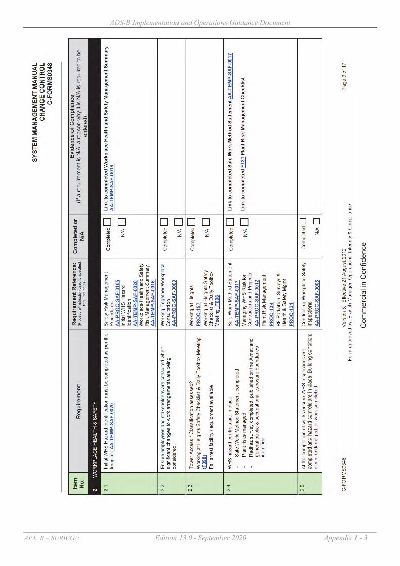
ADS-B Implementation and Operations Guidance Document
APX. B – SURICG/5 Edition 13.0 - September 2020 Appendix 1 - 3

ADS-B Implementation and Operations Guidance Document
APX. B – SURICG/5 Edition 13.0 - September 2020 Appendix 1 - 4

ADS-B Implementation and Operations Guidance Document
APX. B – SURICG/5 Edition 13.0 - September 2020 Appendix 1 - 5

ADS-B Implementation and Operations Guidance Document
APX. B – SURICG/5 Edition 13.0 - September 2020 Appendix 1 - 6

ADS-B Implementation and Operations Guidance Document
APX. B – SURICG/5 Edition 13.0 - September 2020 Appendix 1 - 7

ADS-B Implementation and Operations Guidance Document
APX. B – SURICG/5 Edition 13.0 - September 2020 Appendix 1 - 8

ADS-B Implementation and Operations Guidance Document
APX. B – SURICG/5 Edition 13.0 - September 2020 Appendix 1 - 9

ADS-B Implementation and Operations Guidance Document
APX. B – SURICG/5 Edition 13.0 - September 2020 Appendix 1 - 10

ADS-B Implementation and Operations Guidance Document
APX. B – SURICG/5 Edition 13.0 - September 2020 Appendix 1 - 11

ADS-B Implementation and Operations Guidance Document
APX. B – SURICG/5 Edition 13.0 - September 2020 Appendix 1 - 12

ADS-B Implementation and Operations Guidance Document
APX. B – SURICG/5 Edition 13.0 - September 2020 Appendix 1 - 13

ADS-B Implementation and Operations Guidance Document
APX. B – SURICG/5 Edition 13.0 - September 2020 Appendix 1 - 14

ADS-B Implementation and Operations Guidance Document
APX. B – SURICG/5 Edition 13.0 - September 2020 Appendix 1 - 15

ADS-B Implementation and Operations Guidance Document
APX. B – SURICG/5 Edition 13.0 - September 2020 Appendix 1 - 16

ADS-B Implementation and Operations Guidance Document
APX. B – SURICG/5 Edition 13.0 - September 2020 Appendix 1 - 17

ADS-B Implementation and Operations Guidance Document
APX. B – SURICG/5 Edition 13.0 - September 2020 Appendix 1 - 18
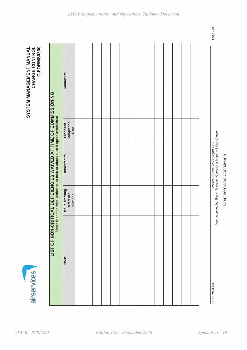
ADS-B Implementation and Operations Guidance Document
APX. B – SURICG/5 Edition 13.0 - September 2020 Appendix 1 - 19

ADS-B Implementation and Operations Guidance Document
Edition 13.0 September 2020 Appendix 2 - 1
Guidance Materials on Monitoring and Analysis of ADS-B Avionics Performance
1 Introduction
1.1 The APANPIRG has endorsed the following Conclusion during its 24th Meeting to encourage States/Administration to exchange their ADS-B performance monitoring results and experience gained from the process : Conclusion 24/45 - Exchange ADS-B Performance Monitoring Result “That, States be encouraged to exchange findings/result of their ADS-B performance monitoring including experience gained in conducting the required performance monitoring.”
1.2 Since the ADS-B mandate for some airspace in the Region became effective in
December 2013, monitoring and analysis on avionics performance of ADS-B equipped aircraft has become an increasingly important task for concerned States. The fully functional ADS-B Avionics Problem Reporting Database (APRD) was launched on the 21 July 2017. The database is placed at ICAO APAC website in the restricted area with name: APAC ADS-B Avionics Problem Reporting Database accessible via https://applications.icao.int/ADSB-APRD/login.aspx. States are encouraged to make full use of the APRD for reporting ADS-B avionics problems and sharing experience as well as follow-up actions through the APRD web-page.
1.3 This document serves to provide guidance materials on monitoring and analysis of avionics performance of ADS-B equipped aircraft, which is based on the experience gained by States.
2 Problem Reporting and Feedback 2.1 For ADS-B avionics problems, it is critical that an appropriate reporting and feedback
mechanism be established. It is highly desirable that those discovering the problems should report them to the appropriate parties to take action, such as study and analyse the problems, identify the root causes, and rectify them. Those action parties include :-
(a) Air Navigation Service Providers (ANSPs) – upon detection of any unacceptable
ADS-B reports from an aircraft, report the observed problem to the performance monitoring agent(s), if any, and the Aircraft Operators for investigation. In addition, ANSPs should take all actions to avoid using the ADS-B reports from the aircraft until the problem is rectified (e.g. black listing the aircraft), if usage of such reports could compromise safety.
(b) Regulators – to initiate any appropriate regulatory action or enforcement.
Appendix 2

ADS-B Implementation and Operations Guidance Document
Edition 13.0 September 2020 Appendix 2 - 2
(c) Aircraft Operators – to allow avionics specialists to examine the causes and as customers of the avionics manufacturers ensure that corrective action will take place.
(d) Avionics Manufacturers and Aircraft Manufacturers – to provide technical evidence and knowledge about the problem and problem rectification
2.2 Incentives should be received by those parties acting on the problems including :- (a) Regulations that require deficiencies to be rectified (b) Regulatory enforcement (c) Consequences if conduct of operations with problematic equipment (e.g. no access
to the airspace requiring healthy equipment)
2.3 When an ADS-B avionics problem is reported, it should come along with adequate details about the problem nature to the action parties. In addition, the problem should be properly categorised, so that appropriate parties could diagnose and rectify them systematically.
3 Problem Categorisation
3.1 Regarding ADS-B avionics, their problems are quite diversified in the Region but can
be categorized to ensure they will be examined and tackled systematically.
3.2 Based on the experience gained from States, the common ADS-B avionics problems in the Region are summarized under different categories in Attachment A. It is noted that only a relatively minor portion of the aircraft population exhibits these problems. It must be emphasized that aircraft transmitting incorrect positional data with NUC = 0 or NIC = 0 should not be considered a safety problem. The data transmitted have no integrity and shall not be used by ATC. This situation exists for many aircraft when their GNSS receivers are not connected to the transponders.
4 Managing the Problem 4.1 There are two major approaches to manage the problems :-
(a) Regulatory approach Regulations which require non-approved avionics to disable ADS-B transmission (or transmit “no integrity”), and the concerned operators to file flight plans to indicate no ADS-B equipage. APANPIRG has endorsed this approach which is reflected in the Regional Supplementary Procedures (Doc 7030).
(b) Blacklist approach Filtering out (“black listing”) any airframes that do not comply with the regulations or transmitting bad data, and advising the regulator of the non-

ADS-B Implementation and Operations Guidance Document
Edition 13.0 September 2020 Appendix 2 - 3
compliance. This approach is temporary which allows the ANSP to protect the system whilst regulatory action is underway. While deciding on whether an aircraft transmitting erroneous ADS-B data should be added into the blacklist, the following factors will be critically assessed:
i. Impact and risk to ATC operational safety
Use of erroneous ADS-B data to maintain separation may potentially contribute to loss of separation or ATC coordination error.
ii. Frequency of erroneous position
Whether it is occasional or frequently broadcast of erroneous position.
iii. Amount of deviation
This can be a track jumping problem which is of significant safety impact to ATC or just an occasional small position jump which is not detectable in ATC with insignificant impact.
iv. Others
Such as the ICAO aircraft address received from ADS-B being inconsistent with the aircraft registration, Flight ID entered via cockpit interface mismatched with aircraft callsign in the Flight Plan, etc.
After deciding to put an aircraft into the blacklist list, the following procedures will be carried out:
i. Informing the concerned aircraft operator/regulatory authority
The concerned aircraft operator/regularity authority will be notified of the decision and the rationale before putting the aircraft into the exclusion list.
ii. Pre-processing of flight plan concerned
As the blacklist mechanism involves filtering out the ADS-B data of the subject aircraft, from operational perspective, air traffic controllers need to be aware in advance that the concerned aircraft plans to operate in their FIR. A flight plan pre-processing system may locate the flight plan by checking against the 24-bit address or aircraft registration in the blacklist, and issue an alert to the air traffic controllers if appropriate, such as automatically insert a remark in the Item 18 of the concerned flight plan before feeding the flight plan into the ATC Automation System, and the ATC Automation System may issue an alert to the air traffic controllers with a specific label annotated in the corresponding electronic flight strips.
iii. Coordinate with adjacent Area Control Centre (ACC)
Upon posting of pending inbound flights with corresponding electronic flight strips indicating non-ADS-B equipage or in the blacklist, the air traffic controllers shall inform the upstream ACC that transfer of that particular flight will not be accepted at the ADS-B exclusive airspace. It is important to carry out this coordination action as early as possible as the upstream sector may have difficulty to adjust the flight route at the transfer stage.

ADS-B Implementation and Operations Guidance Document
Edition 13.0 September 2020 Appendix 2 - 4
iv. Handling of an aircraft for removal from the blacklist once rectification action had taken place
Once notification from the aircraft operators/regulatory authorities is received that the problem has been rectified, performance of the aircraft will be closely monitored when it flies to the concerned FIR. If the aircraft shows the observed problem has been resolved, the aircraft will be removed from the blacklist. The aircraft operator/regulatory authority will also be notified accordingly.
5 Systematic Monitoring and Analysis of the Problem
States using ADS-B should have in place systematic ways to identify and manage ADS-B deficiencies similar to that described below :-
5.1 Reporting Deficiencies
States using ADS-B should have in place systematic ways to identify ADS-B deficiencies including :- (a) Systematic capture of ATC reported events and engineering detected events into a
database; and (b) Manual or automatic detection of anomalous avionics behavior independent from
controller reports
5.1.1 ATC Reported Deficiencies ATC procedures should exist that allow services to continue to be provided safety, as
well as to capture relevant information for later analysis. This should include :-
(a) ATC request for the pilot to select the alternate transponder; and (b) ATC to adequately record the circumstances including Flight ID, ICAO Aircraft
Address (if readily available) accurate time, Flight plan, and pilot provided information.
5.1.2 Non ATC reported deficiencies
5.1.2.1 Where capability is available, States should also identify non ATC reported
deficiencies.
5.1.2.2 Without overlapping radar coverage: ADS-B data may be examined for the following :- (a) NUCp of each ADS-B reported position is smaller than required for service
delivery for more than 5% of total number of ADS-B updates; (b) NIC, NACp, SIL are smaller than required for service delivery for more than 5%
of total number of ADS-B updates;

ADS-B Implementation and Operations Guidance Document
Edition 13.0 September 2020 Appendix 2 - 5
(c) ICAO Aircraft Address (i.e. I021/080) is inconsistent with the flight planned registration (REG) based on each state’s ICAO Aircraft Address allocation methodology;
(d) Flight ID entered via cockpit interface and downlinked in ADS-B data (i.e. I021/170 in Asterix CAT 21) is a mismatch1 with aircraft callsign in the ATS Flight Plan;
(e) Inconsistent vertical rate compared to flight level change; and (f) Inconsistency of position reports and presence of "jumps.
5.1.2.3 Overlapping radar coverage: For States that have overlapping radar coverage, a systematic means to monitor and analyze ADS-B could be considered in addition to relying on ATC to report the problem, or utilising the evaluation criteria in 5.1.2.2 above. This can be achieved by comparing radar information with ADS-B reported position, velocity, flight level and vertical rate change data as well as examining the ADS-B quality indicators and Flight Identification (FLTID) contained in the ADS-B reports. For each ADS-B flight, its ADS-B data could be compared with its corresponding radar information. For example, this would allow analysis to determine if the following pre-defined criteria are met :- (a) Deviation between ADS-B reported position and independent referenced radar
position is greater than 1NM2, with the indication of good positional quality in the quality indicators for more than 5% of total number ADS-B updates. A sample screen shot of a system performing the analysis automatically is given at Attachment B for reference.
5.2 Managing and Processing Deficiencies
Whether detected by ATC or not, all deficiencies should trigger:
(a) Systematic recording of the details of each occurrence such as date/time of occurrence, ICAO aircraft address and flight plan information should be obtained. Graphical representations such as screen capture of radar and ADS-B history
1 A missing Flight ID, or a Flight ID with only “spaces” should not be considered a mismatch. 2 For example, the deviation between ADS-B and radar tracks could be set to 1NM in accordance with ICAO Circular 326 defining position integrity (0.5NM < HPL < 1NM) for 3NM aircraft separation use, on assumption that radar targets are close to actual aircraft position. The values of ADS-B quality indicators (NUCp, NACp, SIL, NIC) could be chosen based on the definition in ICAO Circular 326 on Position Accuracy and Position Integrity for 3NM aircraft separation minimum. A threshold of 5% is initially set to exclude aircraft only exhibiting occasional problems during their flight journey. The

ADS-B Implementation and Operations Guidance Document
Edition 13.0 September 2020 Appendix 2 - 6
tracks, graphs of NUCp/NIC value changes versus time and deviation between radar and ADS-B tracks along the flight journey would be desirable. Examples of typical graphical representations are shown below :-
`
(b) Systematic technical analysis of each detected issue using ADS-B recorded data, to ensure that all detected issues are examined and addressed. Typically this will need: systems to record ADS-B data, replay ADS-B data and analyze ADS-B data staff and procedures to analyze each report A database system to manage the status of each event and to store the results of
each analysis
above criteria should be made configurable to allow fine-turning in future. Evaluation of ADS-B vs radar may alternatively expose radar calibration issues requiring further investigation.

ADS-B Implementation and Operations Guidance Document
Edition 13.0 September 2020 Appendix 2 - 7
(c) Procedures to support engagement with operators (domestic & foreign), regulators, other ANSPs, Airframe OEMs and avionics vendors to ensure that each issue is investigated adequately and maximize the probability that the root cause of the event is determined. The procedures could include :- Data collection procedures; Telephone & email contact details; and Mechanisms for reporting, as appropriate, to the Asia Pacific ADS-B Avionics
Problem Reporting Database (APRD)
* * * * * * * *

ADS-B Implementation and Operations Guidance Document
Edition 13.0 September 2020 Appendix 2 - 8
Attachment A – List of known ADS-B avionics problems
Ref. Problem Cause Safety Implications to ATC
(Yes / No)
Recommendations
1. Track Jumping problem with Rockwell Collins TPR901 (See Figure1)
Software issue with TPR901 transponder initially only affecting Boeing aircraft. Does not occur in all aircraft with this transponder. Subsequent investigation by Rockwell Collins has found that the particular transponder, common to all of the aircraft where the position jumps had been observed, had an issue when crossing ±180 degrees longitude. On some crossings (10% probability), errors are introduced into the position longitude before encoding. These errors are not self-correcting and can only be removed by a power reset of the transponder. The problem, once triggered can last days, since many transponders are not routinely powered down.
Yes. Will present as a few wild/large positional jumps. Nearly all reports are tagged as low quality (NUC=0) and are discarded, however, some occasional non zero reports get through. Problem is very “obvious”. Could result in incorrect longitudinal position of Flight Data Record track. Can trigger RAM alerts.
Rockwell Collins has successfully introduced a Service Bulletin that solves the problem in Boeing aircraft. The problem is known to exist on Airbus aircraft. Rockwell has advised that a solution is available in their DO260B upgrade. Rockwell Collins may not have a fix for some time. Workaround solutions are being examined by Airbus, Operators and Airservices Australia. The only workaround identified at this time is to power down the transponders before flight to states using ADS-B – after crossing longitude 180. It can be noted that in Airbus aircraft it is not possible to safely power down the transponder in flight. Airbus have prepared a procedure to support power down before flight. Airservices Australia have negotiated with 2 airlines to enact this procedure prior to flights to

ADS-B Implementation and Operations Guidance Document
Edition 13.0 September 2020 Appendix 2 - 9
Ref. Problem Cause Safety Implications to ATC (Yes / No)
Recommendations
Australia. An additional partial workaround is : to ensure that procedures exist for ATC to ask the pilot to changeover transponders if the problem is observed. Since there is a 10% chance of the problem occurring on each crossing of ±180 degrees longitude, the chance that both transponders being affected is 1%. There is no complete workaround available for flights that operate across 180 degrees longitude directly to destination without replacing the transponder. Airbus advised that a new TPR901 transponder compliant with DO260B is available from December 2015. This new transponder does not have such problem.
2. Rockwell Collins TDR94 Old version. The pattern of erroneous positional data is very distinctive of the problem. (See Figure 2)
Old software typically before version -108. The design was completed before the ADS-B standards were established and the message definitions are different to the current DO260. Rockwell has recommended
Yes. Will present as a few wild positional jumps. Nearly all reports are tagged as low quality (NUC=0) and are discarded, however, some occasional non zero reports get through. Also causes incorrect altitude reports.
Problem well known. Particularly affects Gulfstream aircraft which unfortunately leave the factory with ADS-B enabled from this transponder model. Rockwell has issued a service bulletin recommending that ADS-B be disabled for aircraft with this

ADS-B Implementation and Operations Guidance Document
Edition 13.0 September 2020 Appendix 2 - 10
Ref. Problem Cause Safety Implications to ATC (Yes / No)
Recommendations
that ADS-B be disabled on these models.
Problem is very “obvious”.
transponder software. See Service Information Letter 1-05 July 19, 2005. It is easy to disable the transmission. If a new case is discovered, an entry needs to be made to the black list until rectification has been effected.
3. Litton GPS with proper RAIM processing
Litton GNSSU (GPS) Mark 1 design problem. (Does not apply to Litton Mark II). GPS does not output correct messages to transponder.
No. Perceived GPS integrity changes seemingly randomly. With the GPS satellite constellation working properly, the position data is good. However the reported integrity is inconsistent and hence the data is sometimes/often discarded by the ATC system. The effected is perceived extremely poor “coverage”. The data is not properly “protected” against erroneous satellite ranging signals – although this cannot be “seen” by ATC unless there is a rare satellite problem.
This GPS is installed in some older, typically Airbus, fleets. Data appears “Correct” but integrity value can vary. Performance under “bad” satellite conditions is a problem. Correction involves replacing the GNSSU (GPS) which is expensive. If a new case is discovered, an entry needs to be made to the black list until rectification has been effected.
4. SIL programming error for DO260A avionics
Installers of ADS-B avionics using the newer DO260A standard mis program “SIL”. a) This problem appears for
No. First report of detection appears good (and is good), all subsequent reports not displayed because the
Would NOT be included in a “black list”. Aircraft with “Dynon avionics” exhibit this behavior. They do not
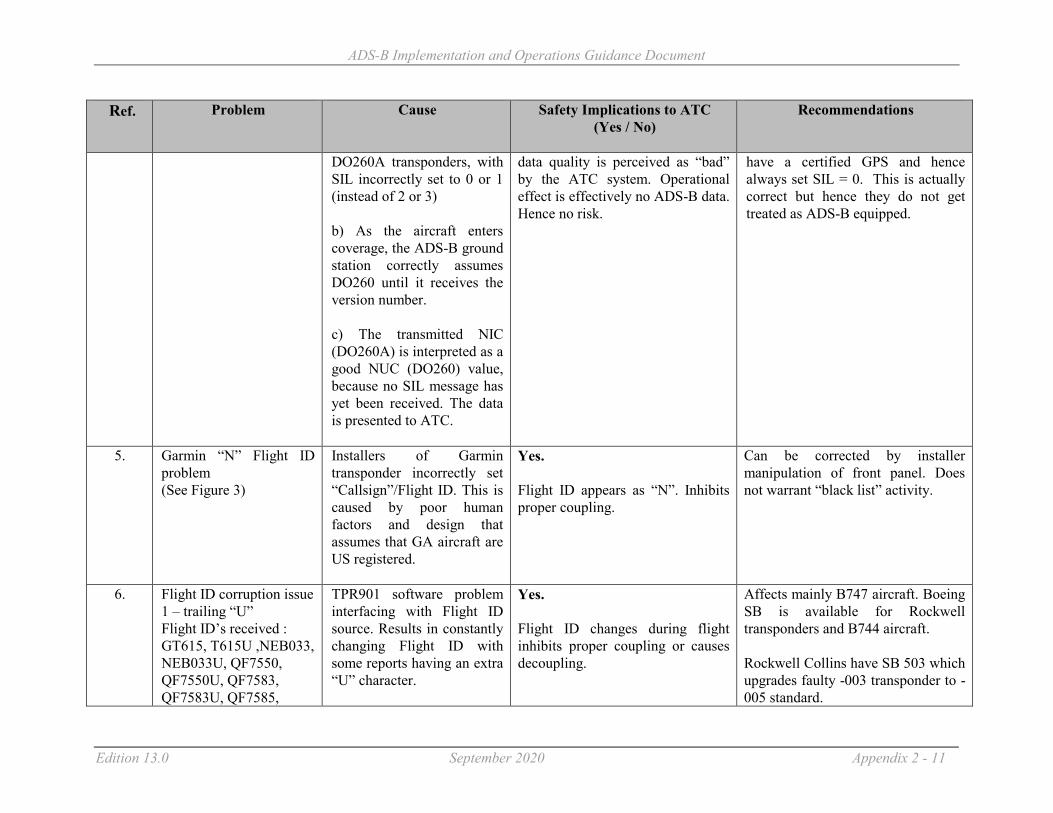
ADS-B Implementation and Operations Guidance Document
Edition 13.0 September 2020 Appendix 2 - 11
Ref. Problem Cause Safety Implications to ATC (Yes / No)
Recommendations
DO260A transponders, with SIL incorrectly set to 0 or 1 (instead of 2 or 3) b) As the aircraft enters coverage, the ADS-B ground station correctly assumes DO260 until it receives the version number. c) The transmitted NIC (DO260A) is interpreted as a good NUC (DO260) value, because no SIL message has yet been received. The data is presented to ATC.
data quality is perceived as “bad” by the ATC system. Operational effect is effectively no ADS-B data. Hence no risk.
have a certified GPS and hence always set SIL = 0. This is actually correct but hence they do not get treated as ADS-B equipped.
5. Garmin “N” Flight ID problem (See Figure 3)
Installers of Garmin transponder incorrectly set “Callsign”/Flight ID. This is caused by poor human factors and design that assumes that GA aircraft are US registered.
Yes. Flight ID appears as “N”. Inhibits proper coupling.
Can be corrected by installer manipulation of front panel. Does not warrant “black list” activity.
6. Flight ID corruption issue 1 – trailing “U” Flight ID’s received : GT615, T615U ,NEB033, NEB033U, QF7550, QF7550U, QF7583, QF7583U, QF7585,
TPR901 software problem interfacing with Flight ID source. Results in constantly changing Flight ID with some reports having an extra “U” character.
Yes. Flight ID changes during flight inhibits proper coupling or causes decoupling.
Affects mainly B747 aircraft. Boeing SB is available for Rockwell transponders and B744 aircraft. Rockwell Collins have SB 503 which upgrades faulty -003 transponder to -005 standard.

ADS-B Implementation and Operations Guidance Document
Edition 13.0 September 2020 Appendix 2 - 12
Ref. Problem Cause Safety Implications to ATC (Yes / No)
Recommendations
QF7585, QF7585U, QF7594, QFA7521, QFA7531, QFA7531, QFA7531U, QFA7532, QFA7532U, QFA7532W, QFA7550, QFA7552, QFA7581
If a new case is discovered, an entry needs to be made to the black list until rectification has been effected.
7. Flight ID corruption issue 2
ACSS software problem results in constantly changing Flight ID. Applies to ACSS XS950 transponder Pn 7517800- 110006 and Honeywell FMC (pn 4052508 952). ACSS fix was available in Sept 2007.
Yes. Flight ID changes during flight inhibits proper coupling or causes decoupling.
Software upgrade available. If a new case is discovered, an entry needs to be made to the black list until rectification has been effected.
8. No Flight ID transmitted Various causes No. Flight ID not available. Inhibits proper coupling.
Aircraft could “fail to couple with Flight Data Record”. Not strictly misleading – but could cause controller distraction.
9. ACSS Transponder 10005/6 without Mod A reports NUC based on HFOM.
Yes. Appears good in all respects until there is a satellite constellation problem (not normally detectable by ground systems).
Not approved and hence not compliant with CASA regulations. If known could be added to black list. Configuration is not permitted by regulation.
10. Occasional small position jump backwards (See Figure 4)
For some older Airbus aircraft, an occasional report may exhibit a small “jump
No. Not detectable in ATC due to
ATC ground system processing can eliminate these.

ADS-B Implementation and Operations Guidance Document
Edition 13.0 September 2020 Appendix 2 - 13
Ref. Problem Cause Safety Implications to ATC (Yes / No)
Recommendations
back” of less than 0.1 nm Root cause not known
extrapolation, use of latest data and screen ranges used.
11. Older ACSS transponders report integrity too conservatively
Design error reports integrity one value worse than reality
No. In poor GPS geometry cases the ATC system could discard the data when the data is in fact useable. Will be perceived as loss of ADS-B data.
Can be treated in the same manner as a loss of transponder capability.
12. Intermittent wiring GPS transponder
ADS-B transmissions switch intermittently between INS position and GPS position.
Yes. Normally the integrity data goes to zero when INS is broadcast, but sometimes during transition between INS and GPS, an INS position or two can be broadcast with “good” NUC value. Disturbing small positional jump.
If a new case is discovered, an entry needs to be made to the black list until rectification has been effected.
13. Wrong ICAO Aircraft Address
Installation error No. No direct ATC impact unless a rare duplicate is detected.
This is not a direct ADS-B problem, but relates to a Mode S transponder issue that can put TCAS at risk. Cannot be fixed by black list entry. Needs to be passed to regulator for resolution.

ADS-B Implementation and Operations Guidance Document
Edition 13.0 September 2020 Appendix 2 - 14
Ref. Problem Cause Safety Implications to ATC (Yes / No)
Recommendations
14. Toggling between high and low NUC (See Figure 5)
Faulty GPS receiver/ADS-B transponder
No. ATC will see tracks appear and disappear discretely. No safety implications to ATC.
While it is normal for NUC value to switch between a high and low figure based on the geometry of GPS satellites available, it is of the view that more should be done to examine this phenomenon. It is observed that such switching between high and low NUC occurs on certain airframe and not on others. The issue was raised to the airlines so as to get a better understanding. On one occasion, the airline replied that a module on their GPS receiver was faulty. On another occasion, the airline replied that one of the ADS-B transponder was faulty. Good NUC was transmitted when the working transponder was in use and poor NUC was transmitted when the faulty ADS-B transponder was in use.
15. Consistent Low NUC (See Figure 6)
GNSS receivers are not connected to the ADS-B transponders.
No. Data shall be filtered out by the system and not detectable in ATC
Not considered a safety problem but a common phenomenon in the Region – the concerned aircraft will be treated equivalent to “aircraft not equipped with ADS-B”. While it is normal for aircraft to transmit low NUC, it is of the view that “consistent low NUC’ could be due to the avionics problem (e.g. GNSS receiver is not connected to

ADS-B Implementation and Operations Guidance Document
Edition 13.0 September 2020 Appendix 2 - 15
Ref. Problem Cause Safety Implications to ATC (Yes / No)
Recommendations
the ADS-B transponder). It is recognised that operators may not be aware that their aircraft are transmitting unexpected low NUC / NIC values, due to equipment malfunction. Hence, it is desirable for States to inform the operators when unexpected low NUC values are transmitted, where practicable. Concerned airline operators are required to take early remedial actions. Otherwise, their aircraft will be treated as if non-ADS-B equipped which will be requested to fly outside the ADS-B airspace after the ADS-B mandate becomes effective.
16. ADS-B position report with good integrity (i.e. NUC >= “4”) but ADS-B position data are actually bad as compared with radar (met criteria 5.2(a))
Faulty ADS-B avionics Yes. As the ground system could not "automatically" discard ADS-B data with good integrity (i.e. NUC value >=4), there could be safety implications to ATC.
The problem should be immediately reported to the concerned CAA/operators for problem diagnosis including digging out the root causes, avionics/GPS types etc., and ensure problem rectification before the ADS-B data could be used by ATC. Consider to “blacklist” the aircraft before the problem is rectified.

ADS-B Implementation and Operations Guidance Document
Edition 13.0 September 2020 Appendix 2 - 16
Ref. Problem Cause Safety Implications to ATC (Yes / No)
Recommendations
17. FLTID transmitted by ADS-B aircraft does not match with callsign in flight plan (see Figures 7a – 7d)
Human errors Yes. Could lead to screen clutter - two target labels with different IDs (one for radar and another for ADS-B) being displayed, causing potential confusion and safety implications to ATC.
Issue regulations/letters to concerned operators urging them to set FLTID exactly match with callsign in flight plan.
18 B787 position error with good NIC
Issue 1: Software issue - surveillance system inappropriately “coasts” the position when data received by the transponder is split across multiple messages. System seems to self correct after some time. Can be corrected by surveillance system power off. Issue 2: Data packets were not being distributed to the transponder when the internal timing between different elements of the Integrated Surveillance System became synchronized.
Yes. Misleading position presentation which is typically detected by ATC observing aircraft “off track” when in fact it is “on-track”.
Boeing performed a change to the B787 Type Certificate for incorporation of the upgraded ISS software in March of 2017. All B787 aircraft delivered after Line number 541 have the upgraded ISS software which corrects this issue. Boeing released Service Bulletin B787-81205-SB340036-00 on 30 June 2017. Note that this Service Bulletin is available at no cost to the operator, and includes the concurrent requirement to implement Boeing Service Bulletin B787-81205-SB340005-00. On 5 Nov 2018, FAA issued Airworthiness Directive 2017-NM-118-AD, effective 10 Dec 2018, which requires application of Boeing

ADS-B Implementation and Operations Guidance Document
Edition 13.0 September 2020 Appendix 2 - 17
Ref. Problem Cause Safety Implications to ATC (Yes / No)
Recommendations
SB B787-81205-SB340036-00 by 10 Dec 2019. EASA has invoked this AD for States under its jurisdiction. States and Operators are urged to implement the service bulletin immediately and report to FAA or ICAO APAC Office. As of 9 Sep 2020, 32 B787 aircraft were on the NSAL; 18 of these aircraft have been detected within U.S. ADS-B coverage during 2020. The FAA is coordinating with State Regulators who have operators with B787 aircraft on the NSAL.
19 A number of airlines have reported or experienced ADS-B outages for complete flight sectors in A330 aircraft. Appears as low reliability ADS-B and has afflicted both A & B side at same time.
Being actively investigated. One airline has implemented on-board recording which confirms that the MMRs are not providing HIL/HPL to the transponder whilst continuing to provide HFOM, GPS alt etc
No. Equivalent to a failed transponder.
Aircraft must be managed procedurally if outside radar coverage.
20 A380 flight ID lost after landing
For the A380 fleet, it has been confirmed that for some seconds after landing, the flight ID is set as invalid by FMS to AESS. Consequently, the current AESS design uses, as per
No.
The correction to this logic is planned for next AESS standard release; planned for 2017.” Only a problem for arriving aircraft on surface surveillance systems.

ADS-B Implementation and Operations Guidance Document
Edition 13.0 September 2020 Appendix 2 - 18
Ref. Problem Cause Safety Implications to ATC (Yes / No)
Recommendations
design, the Aircraft Registration Number as a back-up source for A/C flight identification field in ADS-B broadcast messages.
21 A350 ADS-B On-ground Performance
On departure, A350 aircraft will initially use INS derived position for ADS-B reports when taxying and only use GNSS when entering the runway. INS positions can drift leading to inaccurate position reports.
Yes. where ADS-B is used for surface movement display
Airbus is in discussion with FAA and EUROCONTROL about this issue.
22
Incorrect Ground Bit Setting (GBS) in both Mode S Interrogation Reply and ADS-B Downlink
Occasionally, some airborne aircraft will incorrectly set ground bit as “1” meaning they are on ground, while some landed aircraft incorrectly set ground bit as “0” meaning they are airborne. This could confuse the ATC system, by not showing the airborne targets as the system thought they are on ground, or forming tracks for landed targets triggering alarms against other taking-off aircraft.
Yes. Misleading information shown on ATC system. Aircraft not visible to TCAS and will not reply to all-call interrogations.
States/Administrations contact the concerned airline operators for remedial actions.

ADS-B Implementation and Operations Guidance Document
Edition 13.0 September 2020 Appendix 2 - 19
Ref. Problem Cause Safety Implications to ATC (Yes / No)
Recommendations
23 Rockwell TSS-4100 track extrapolation issue.
The TSS-4100 shares software with the Rockwell Collins ISS transponder in the B787, and the software defect in the B787 ISS reported at SURICG/2 also exists in the TSS-4100.
Yes. Misleading position presentation which is typically shown on ATC system.
FAA Airworthiness Directive (AD) 2017-22-14 was issued on 20 Dec 2017. The compliance date for this AD is 20 Dec 2018 (or 750 hours in service, whichever occurs first). FAA has not detected any aircraft with this issue since the AD compliance date and will not further report on it, as it is considered resolved.
24 Embraer 170 track jumping issue
Unknown as being a random, occasional issue with no clear fault diagnosis available from Honeywell. FAA has decided that when the next E170 aircraft is detected with this issue, it will be immediately placed on the FAA’s No Services Aircraft List (NSAL). Simultaneously, FAA will notify Embraer and Honeywell of the affected aircraft and request that appropriate engineering personnel be sent to inspect and test the affected aircraft.
Yes. Misleading position presentation which is typically shown on ATC system.
In all of the cases of this issue to date, removing and replacing the transponders cleared whatever the issue was. This issue has never recurred on the same aircraft. Bench testing by Honeywell avionics engineering of the removed transponders has revealed no faults or anomalies. As such, States/Administrations to consider removing and replacing the transponders concerned if issue observed. The FAA has since learned from discussions with the OEM that most recent events detected by FAA generated an “ADS-B NOT AVAIL” Crew Alerting System (CAS)

ADS-B Implementation and Operations Guidance Document
Edition 13.0 September 2020 Appendix 2 - 20
Ref. Problem Cause Safety Implications to ATC (Yes / No)
Recommendations
message. When flight crews report this message, airline maintenance replaces the transponder(s), which resolves the problem. To date, this has consistently occurred before FAA monitoring detected the problem and engaged with the airline. The root cause for this issue remains unknown.
25 Airbus Single Aisle production wiring issue
FAA has observed 17 Airbus Single Aisle aircraft from two airlines with missing Length-Width Codes (LWC is a message element in DO-260B/ED-102A that is required by both the US and European mandates). FAA believes that this was a production line wiring issue.
No. Airbus released three Service Bulletins to correct this issue, which existed in 128 Airbus Single Aisle aircraft. As of 1-Dec-2018, all of the aircraft which operate at US airports with ADS-B surface surveillance were corrected. The FAA will not further report on this issue.
26 Boeing 777-300ER production wiring issue
FAA has observed at least 10 Boeing B777-300ER aircraft with missing or improper NACv/SDA/eCat/LWC message elements (these are message elements in DO-260B/ED-102A that are required by both the US and European mandates (eCat is FAA shorthand for Emitter Category). After notification,
No. On 7 July 2017, Boeing released Service Bulletin SB 777-34-0281 to correct this issue. Boeing has informed FAA that all affected B777 operators have been notified. The FAA will not further report on this issue.

ADS-B Implementation and Operations Guidance Document
Edition 13.0 September 2020 Appendix 2 - 21
Ref. Problem Cause Safety Implications to ATC (Yes / No)
Recommendations
Boeing reported to FAA that this was a production line parity pin wiring issue.
27 Rockwell TSS-4100 Geometric Altitude Reporting as Pressure Altitude
This issue exists in any TSS-4100 installed with TSSA-4100 software RCPN 810-0052-100, RCPN 810-0052-101, or RCPN 810-0052-102. All of the following must be true for the issue to occur: (1) TSS is the selected
transponder; (2) TSS is receiving valid
pressure altitude; (3) TSS is receiving valid
GPS data with an integrity of NIC 9 or better; and
(4) The mode of operation for the transponder must be "ALT OFF".
Note that in an SBAS service area, only condition (4) would be considered uncommon. When the issue exists, the TSS will insert geometric altitude information into the
Yes. At present, the FAA regulator has determined that this issue occurs too rarely to warrant issuing an Airworthiness Directive or a Special Airworthiness Information Bulletin (SAIB). Rockwell Collins has released updated software, RCPN 810-0052-110, to address this issue. Refer to SIL TSSA-4100-10-1 titled, "TSSA-4100 Field Loadable Software", RCPN 523-0818785.

ADS-B Implementation and Operations Guidance Document
Edition 13.0 September 2020 Appendix 2 - 22
Ref. Problem Cause Safety Implications to ATC (Yes / No)
Recommendations
ADS-B Airborne Position Squitter, but this altitude will be encoded as if it were pressure altitude. The net effect is that, when this issue occurs, the TSS-4100 reports geometric altitude information as if it were pressure altitude. In many cases, this will be incorrect altitude information.
28 NACv reporting greater than 2
The FAA has detected a number of aircraft which consistently report NACv = 3 and NACv = 4. Per FAA AC 20-165B section 3.3.3.7.3, “A NACv = 3 or NACv = 4 should not be set based on GNSS velocity accuracy unless you can demonstrate to the FAA that the velocity accuracy actually meets the requirement.” EASA CS-ACNS states that “There is currently no established guidance on establishing a NACv performance of
No. While there is no known urgent issue with these findings, as no known ATC or airborne application requires NACv values exceeding two, FAA does have long-term intentions of deploying surveillance tracking and alerting prediction algorithms in ATC automation which will use real-time NACv values. ICAO States planning to make similar improvements should be aware of this situation.

ADS-B Implementation and Operations Guidance Document
Edition 13.0 September 2020 Appendix 2 - 23
Ref. Problem Cause Safety Implications to ATC (Yes / No)
Recommendations
‘three’ or better.” Therefore, it appears that there are improperly configured ADS-B installations operating in the U.S.
29 B787 NACv = 0 Issue FAA noted certain B787s exhibiting a relatively high percentage of NACv =0 reports. Starting with line number 442 (June 2016), Honeywell Integrated Navigation Receiver (INR) P/N 940-2001-008 was introduced, which has an HFOMv output. Boeing investigations revealed a software flaw in the ISSPU that causes an erroneous NACv=0 reporting condition on B787s equipped with a mixed set of Honeywell INR part numbers. This condition occurs when the ISSPU switches between an INR with an HFOMv output and an INR without an HFOMv output.
No. The erroneous NACv=0 condition clears at the next power up of the ISSPU. Boeing has issued guidance urging B787 operators to not intermix INR P/N 940-2001-002 or -004 (which do not output HFOMv) with INR P/N 940-2001-008 (which does output HFOMv) until the ISSPU software has been updated per an available Boeing Service Bulletin. This guidance was provided in Boeing Fleet Team Digest 787-FTD-34-19005 (dated 21 Dec 2019). As of 9-Aug-2020, FAA has observed no significant occurrences of this issue within U.S. ADS-B coverage during the prior two months.

ADS-B Implementation and Operations Guidance Document
Edition 13.0 September 2020 Appendix 2 - 24
Figure 1 - Track Jumping problem with TPR901 Figure 3 - Garmin “N” Flight ID problem
Figure 2 - Rockwell Collins TDR94 Old version. The pattern of Figure 4 - Occasional small position jump backwards

ADS-B Implementation and Operations Guidance Document
Edition 13.0 September 2020 Appendix 2 - 25
erroneous positional data is very distinctive of the problem
Figure 5 - NUC value toggling Figure 6 – Consistent low NUC
NUC always 0

ADS-B Implementation and Operations Guidance Document
Edition 13.0 September 2020 Appendix 2 - 26
Figure 7a - Additional zero inserted Figure 7b - ICAO Airline Designator Code dropped
Figure 7c - Wrong numerical codes entered Figure 7d - IATA Airline Designator Code used
ADS-B
Radar
ADS-B
Radar
Radar
ADS-B ADS-B
Radar
NUC always 0

ADS-B Implementation and Operations Guidance Document
Edition 13.0 September 2020 Appendix 2 - 27
Attachment B - Sample screen shot of a system to monitor and analyse performance of ADS-B avionics

ADS-B Implementation and Operations Guidance Document
Edition 13.0 September 2020 Appendix 3 - 1
Appendix 3
A Template for ADS-B Mandate/Regulations for Aircraft Avionics
(1) On and after dd/mm/yyyy, if an aircraft carries 1090MHz extended squitter (1090ES) ADS-B transmitting equipment for operational use in xxxxxxxx territory, the equipment must have been certificated as meeting :1
(a) European Aviation Safety Agency - Certification Considerations for the Enhanced ATS in
Non-Radar Areas using ADS-B Surveillance (ADS-B-NRA) Application via 1090 MHZ Extended Squitter (AMC 20-24), or
(b) European Aviation Safety Agency - Certification Specifications and Acceptable Means of Compliance for Airborne Communications, Navigation and Surveillance Subpart D — Surveillance (SUR) (CS-ACNS.D.ADS-B), or
(c) Federal Aviation Administration – Advisory Circular No: 20-165A (or later versions) Airworthiness Approval of Automatic Dependent Surveillance – Broadcast (ADS-B) Out Systems, or
(d) the equipment configuration standards in Appendix XI of Civil Aviation Order 20.18 of the Civil Aviation Safety Authority of Australia.
(2) On and after dd/mm/yyyy, if an aircraft operates on airways (insert routes)…………at or above
FLXXX………(or in defined airspace boundaries ……………. at or above FLXXX):2
The aircraft must carry serviceable 1090MHz extended squitter (1090ES) ADS-B transmitting equipment that has been certificated as meeting :-
(a) European Aviation Safety Agency - Certification Considerations for the Enhanced ATS in
Non-Radar Areas using ADS-B Surveillance (ADS-B-NRA) Application via 1090 MHZ Extended Squitter (AMC 20-24), or
(b) European Aviation Safety Agency - Certification Specifications and Acceptable Means of Compliance for Airborne Communications, Navigation and Surveillance Subpart D — Surveillance (SUR) (CS-ACNS.D.ADS-B), or
(c) Federal Aviation Administration – Advisory Circular No: 20-165A (or later versions) Airworthiness Approval of Automatic Dependent Surveillance – Broadcast (ADS-B) Out Systems, or
(d) the equipment configuration standards in Appendix XI of Civil Aviation Order 20.18 of the Civil Aviation Safety Authority of Australia.
(3) An aircraft carrying 1 090 MHz extended squitter (1090ES) ADS-B equipment shall disable
ADS-B transmission unless:
(a) the aircraft emits position information of an accuracy and integrity consistent with the transmitted value of the position quality indicator; or
1 This paragraph ensures all aircraft operating in the airspace, if equipped with ADS-B, are compliant
to standards.
2 This paragraph provides mandate requirements within certain parts of the airspace

ADS-B Implementation and Operations Guidance Document
Edition 13.0 September 2020 Appendix 3 - 2
(b) the aircraft always transmits a value of 0 (zero) for one or more of the position quality indicators (NUCp, NIC, NACp or SIL); or
(c) the operator has received an exemption granted by the appropriate ATS authority. Note: States are urged to include at least the standards stated in the template. States may include other standards allowed by the State’s regulations.

ADS-B Implementation and Operations Guidance Document
Edition 13.0 September 2020 Appendix 4 - 1
Appendix 4
An Example of Advice to Operators Concerning Inconsistency Between ADS-B Flight Planning and Surveillance Capability
1 Background Newer technologies for aircraft surveillance are now available – such as Mode S and ADS-B – which in many aircraft are installed as replacements for older Mode A/C transponders. Air Traffic Control makes use of these new capabilities, and uses the Flight Plan information as a decision support tool – to allow the Air Traffic Controller to predict the surveillance capability of a particular aircraft before it enters radar or ADS-B coverage. Requirements for ADS-B and Mode S (insert local reference document if applicable) may mean that if flight planning does not accurately reflect the aircraft capability, services may be withheld (for example if ADS-B is mandatory, but not indicated on the flight plan – this section to be modified for local requirements).
2 Flight Planning Requirements for Transponder and ADS-B
The flight planning requirements for aircraft are described in (local document reference or ICAO DOC 4444 Appendix 2) and repeated below. Surveillance Equipment N if no surveillance equipment for the route to be flown is carried, or the equipment is unserviceable
OR
INSERT one or more of the following descriptors, to a maximum of 20 characters, to describe the serviceable surveillance equipment and/or capabilities on board:
SSR Modes A and C
A Transponder — Mode A (4 digits — 4 096 codes)
C Transponder — Mode A (4 digits — 4 096 codes) and Mode C
SSR Mode S
E Transponder — Mode S, including aircraft identification, pressure-altitude and extended squitter (ADS-B) capability
H Transponder — Mode S, including aircraft identification, pressure-altitude and enhanced surveillance capability

ADS-B Implementation and Operations Guidance Document
Edition 13.0 September 2020 Appendix 4 - 2
I Transponder — Mode S, including aircraft identification, but no pressure-altitude capability
L Transponder — Mode S, including aircraft identification, pressure-altitude, extended squitter (ADS-B) and enhanced surveillance capability
P Transponder — Mode S, including pressure-altitude, but no aircraft identification capability
S Transponder — Mode S, including both pressure altitude and aircraft identification capability
X Transponder — Mode S with neither aircraft identification nor pressure-altitude capability
Note : Enhanced surveillance capability is the ability of the aircraft to down-link aircraft derived data via a Mode S transponder.
ADS-B
B1 ADS-B with dedicated 1 090 MHz ADS-B “out” capability1
B2 ADS-B with dedicated 1 090 MHz ADS-B “out” and “in” capability1
U1 ADS-B “out” capability using UAT
U2 ADS-B “out” and “in” capability using UAT
V1 ADS-B “out” capability using VDL Mode 4
V2 ADS-B “out” and “in” capability using VDL Mode 4
3 Additional information The capability of your aircraft transponder, and ADS-B capability, will typically be available in the transponder manual, or in the aircraft flight manual for the aircraft. For General Aviation aircraft, the most common configurations for filing in the flight plan item10b will be (listed in order of capability). EB1 – An ADS-B equipped aircraft would typically file this to indicate the Mode S transponder capability with ADS-B out. S – The majority of Mode S transponders (without ADS-B) will support pressure altitude information and Flight ID transmission. C – For aircraft with an older Mode A/C transponder – most of which provide pressure altitude capability. Less common configurations in General Aviation will include:
1 Based on current version of ICAO Doc 4444
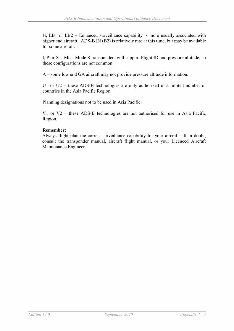
ADS-B Implementation and Operations Guidance Document
Edition 13.0 September 2020 Appendix 4 - 3
H, LB1 or LB2 – Enhanced surveillance capability is more usually associated with higher end aircraft. ADS-B IN (B2) is relatively rare at this time, but may be available for some aircraft. I, P or X – Most Mode S transponders will support Flight ID and pressure altitude, so these configurations are not common. A – some low end GA aircraft may not provide pressure altitude information. U1 or U2 – these ADS-B technologies are only authorized in a limited number of countries in the Asia Pacific Region. Planning designations not to be used in Asia Pacific: V1 or V2 – these ADS-B technologies are not authorised for use in Asia Pacific Region. Remember: Always flight plan the correct surveillance capability for your aircraft. If in doubt, consult the transponder manual, aircraft flight manual, or your Licenced Aircraft Maintenance Engineer.
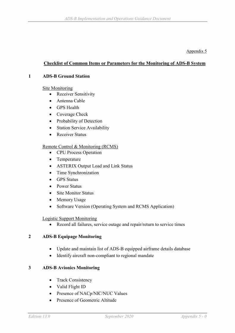
ADS-B Implementation and Operations Guidance Document
Edition 13.0 September 2020 Appendix 5 - 0
Appendix 5
Checklist of Common Items or Parameters for the Monitoring of ADS-B System
1 ADS-B Ground Station Site Monitoring
Receiver Sensitivity Antenna Cable GPS Health Coverage Check Probability of Detection Station Service Availability Receiver Status
Remote Control & Monitoring (RCMS)
CPU Process Operation Temperature ASTERIX Output Load and Link Status Time Synchronization GPS Status Power Status Site Monitor Status Memory Usage Software Version (Operating System and RCMS Application)
Logistic Support Monitoring
Record all failures, service outage and repair/return to service times
2 ADS-B Equipage Monitoring
Update and maintain list of ADS-B equipped airframe details database Identify aircraft non-compliant to regional mandate
3 ADS-B Avionics Monitoring
Track Consistency Valid Flight ID Presence of NACp/NIC/NUC Values Presence of Geometric Altitude

ADS-B Implementation and Operations Guidance Document
Edition 13.0 September 2020 Appendix 5 - 1
Correctness of ICAO Aircraft Address Avionics Configuration and Connections Update and maintain list of aircraft with faulty avionics
4 ADS-B Performance Monitoring
Percentage of aircraft with good integrity reports Accuracy of ADS-B Horizontal Position (Based on a reference sensor) Deviation between Geometric and Barometric Height Monitor the number of position jumps Message interval rate
5 ADS-B Display on ATC Display
Split Track – ADS-B reported position might be off Coupling Failure – Wrong aircraft ID Duplicated ICAO Aircraft Address Display of data block

ADS-B Implementation and Operations Guidance Document
Edition 13.0 September 2020 Appendix 6 - 1
Appendix 6 BASELINE ADS-B SERVICE PERFORMANCE PARAMETERS
The following table provides guidelines for various performance requirements of ADS-B Category (Tier) 1, 2 or 3 services that States may consider when acquisition of an ADS-B managed service agreement with a service provider: Service Parameter Guidance Category 1 (Tier 1)
5Nm separation capable commensurate with Radars (separation/vectoring/high performance with reliability, integrity & latency)
Category 2 (Tier 2) Situational awareness similar to ADS-C (safety-net alerts, SAR, supports procedural separation without voice, not 5nm separation)
Category 3 (Tier 3) Position Reporting with Enhanced Flight Operation
Aircraft Updates
Recommended 0.5 second < Interval < 5 seconds as Operationally required
0.5 second < Interval < 20 seconds as Operationally required
0.5 second < Interval < 60 seconds as Operationally required
Maximum 0.5 second < Interval < 10 seconds as Operationally required
Network Latency
Recommended
95%: < 2 seconds of receiver-station output
95%: < 15 seconds of receiver-station output
95%: < 60 seconds of receiver-station output
Reliability 1 Recommended
2 autonomous receiver-stations including antenna, each providing data, no common point of failure
1 unduplicated receiver-station including antenna
1 unduplicated receiver-station including antenna
Reliability 2 - MTBF
Recommended
Each receiver-station including antenna to have MTBF >10,000 hrs
Each receiver-station including antenna to have MTBF >10,000 hrs
Each receiver-station including antenna to have MTBF >10,000 hrs
Reliability – Communications Infrastructure
Recommended
Completely duplicated, no common point of failure
Unduplicated, MTBF > 400 hrs Unduplicated, MTBF> 200 hrs
Reliability – Total ADS-B Service
Recommended
Total Service MTBF >50,000 hrs Total Service MTBF > 400hrs Total Service MTBF> 200 hrs

ADS-B Implementation and Operations Guidance Document
Edition 13.0 September 2020 Appendix 6 - 2
Service Parameter Guidance Category 1 (Tier 1) 5Nm separation capable commensurate with Radars (separation/vectoring/high performance with reliability, integrity & latency)
Category 2 (Tier 2) Situational awareness similar to ADS-C (safety-net alerts, SAR, supports procedural separation without voice, not 5nm separation)
Category 3 (Tier 3) Position Reporting with Enhanced Flight Operation
Availability – Total ADS-B Service
Recommended
Total Service Availability > .999 Total Service Availability >.95 Total Service Availability >.90
Integrity – Ground Station
Recommended Site monitor System Monitoring
Site monitor System Monitoring
System Monitoring
Minimum System Monitoring Not required Not required Integrity – Data Communications & Processing
Recommended
All systems up to ATM system, errors < 1 x 10E-6
All systems up to ATM system, errors < 1 x 10E-6
All systems up to ATM system, errors < 1 x 10E-6
The choice of category (tier) could be based upon a number of factors including the following, a) The desired service b) The available budget c) The available ATC automation system & its capabilities and/or interim display systems d) ATC training and ratings e) Availability of appropriately tailored ATC procedures States could initially choose one level and transition to another at a later time. For example, Category (Tier) 2 could be used to add additional safety nets/situational awareness and gain operational experience during the initial stage, moving later to a full separation service using Category (Tier) 1. Note: The Performance Based Surveillance Sub Group of the ICAO Surveillance Panel is reviewing performance standards for surveillance systems generally. A future update to the requirements in the above table may be based on the outcomes of that panel.

ADS-B Implementation and Operations Guidance Document
Edition 13.0 September 2020 Appendix 7 - 1
Appendix 7
GUIDANCE MATERIAL ON GENERATION, PROCESSING & SHARING of ASTERIX
CATEGORY 21 ADS-B MESSAGES (Including Attachments A, B, C & D)
1. INTRODUCTION
1.1 The “All Purpose Structured Eurocontrol Surveillance Information Exchange” (ASTERIX) Category 21 is a data format standard globally accepted by the Air Traffic Management (ATM) system manufacturing industry for sharing of ADS-B data with ATM automation system.8 Asterix Category 21 data is used to convey ADS-B data from ADS-B receiver stations to ATC processing and display system. This guidance material discusses various aspects of this process. Since the ASTERIX Category 21 edition 0.23 was issued in November 2003, it has undergone continuous revisions with some 19 subsequent editions. The focus of this guidance material is to concentrate on 1090ES ADS-B data using:
a) RTCA DO-260 (Version 0); b) RTCA DO-260A (Version 1); and c) RTCA DO-260B (Version 2)
1.2 The ASTERIX Category 21 edition 1.0 issued in August 2008 fully incorporated the DO260A standard while edition 2.1 issued in May 2011 fully incorporated the latest DO260B standard. The latest edition (as at April 2018) is edition 2.4.
2. ASTERIX CAT 21 IN ASIA AND PACIFIC REGIONS
2.1 To ensure interoperability of ADS-B receiver stations in the Asia Pacific (ASIA/PAC) Regions, during the 16th APANPIRG Meeting held in August 2005, the ASTERIX Category 21 edition
0.23 which had incorporated DO260 standard was adopted as the baselined ADS-B data format for deployment of ADS-B receiver stations and sharing of ADS-B data in the ASIA/PAC Regions. At that time DO260A and DO260B standards were not defined.
3. CHOICE OF ASTERIX VERSION NUMBER
3.1 The Asterix standard has been developed over many years. Stability in the standard is desirable so that ADS-B receiver station designers and ATM automation designers and manufacturers can build interoperable systems with confidence. Because ADS-B technology has been evolving over the years, and will continue to do so, it is not surprising that the Asterix standard has also developed along with the ADS-B link technology standards to grasp the best benefits of its intended design.
3.2 During 2005, Asia Pacific decided to use Ed0.23 as the edition for sharing ADS-B data between states. This version provides adequate information so that useful ATC operational services can be provided including ATC 3 nautical mile and 5 nautical mile separation services. Ed0.23 can be used with
8 FAA utilise Asterix Cat 33 for ADS-B message distribution.

ADS-B Implementation and Operations Guidance Document
Edition 13.0 September 2020 Appendix 7 - 2
DO260, DO260A and DO260B ADS-B avionics/receiver stations to provide basic ATC operational services. However, Ed0.23 cannot fully support all the capabilities offered by DO260A and DO260B.
3.3 Nearly all Ed0.23 data items can be “re-constructed” from a received Ed2.1 data stream. However, most of the special DO260A/B data items cannot be “re-constructed” from an Ed0.23 data stream. In terms of domestic use and data sharing with other ANSPs concerning ADS-B data, several options exist for ANSPs as follows:
Option Domestic use Data sharing
1 Ed0.23 Ed0.23. This is the default and basic standard.
2 Ed2.1 Ed0.23. This will require some conversions to occur, probably through an ADS-B format conversion and filter system (see Paragraph 11), between a domestic system and a foreign system.
Difficulties may exist if the domestic ATM system requires special DO260A/B data items, since they cannot all be re-constructed from the external foreign Ed0.23 data stream.
3 Ed2.1 Ed2.1. Must negotiate bilaterally with data sharing partner regarding exact version to be used to achieve the intended functions.
Note: In this table, Ed2.1, a later DO260B compliant Asterix Cat 21 edition, is chosen as a representation of an Asterix Cat 21 edition after Ed0.23. There exists other Asterix CAT 21 editions (e.g. 0.26, 1.3, 2.4 etc.) after Ed0.23 that could be used by ANSPs for domestic and data sharing use.
4. SPECIFICATION OF ASTERIX MESSAGE PROCESSING
4.1 Care is needed to understand the difference in specifications :
4.2 Asterix Cat 21: Defines the characteristics of the data ON the interface including fields that are mandatory on the interface.
4.3 ADS-B receiver station specifications: To define the Asterix standard, the ANSP must also define which optional Asterix data items are required to be delivered on the Asterix interface, when the appropriate data is received from the aircraft. It is desirable that suppliers be required to:
a) indicate how the receiver station processes and outputs every received DO260, DO260A and DO260B data element into an Asterix data element/field; and
b) indicate which and how each Asterix data element and field presented at the output are
populated. 4.4 ATM automation system specifications: Defines which received Asterix data element and fields are processed and how they are processed. Also defines which Asterix optional data fields are required by the ATM automation systems (if any). ANSPs that specify ADS-B receiver stations and ATM automation systems need to consider carefully and clearly about what they desire to achieve. Specifications which simply require compliance with a particular Asterix edition will be inadequate in most circumstances. In particular ANSPs, together with their suppliers should :

ADS-B Implementation and Operations Guidance Document
Edition 13.0 September 2020 Appendix 7 - 3
a) Specify the Asterix standard edition to be used. This defines the message formats that are
placed on the link between ADS-B receiver station and downstream systems like ATM automation, recording & analysis systems, bypass ATC systems and foreign ANSPs. The edition will define which messages elements are mandatory in each message (very few fields) and a large number of optional fields. The optional fields can only be filled if relevant data is received from the aircraft. The optional fields will only be filled if the receiver station specification requires them to be filled.
b) Specify the ADS-B receiver station behaviour so that when data is received from the
aircraft, the receiver station is required to fill appropriate optional Asterix data fields.
c) Specify the ATM automation system behaviour including appropriate semantic and
syntax checks applied to the Asterix data, including any triggers for the system to discard data. The processing applied to each received Asterix data field should be specified. The ATC system should discard any messages with unexpected Asterix categories without discarding messages with known and defined Asterix categories.
5. MANDATORY FIELDS : ASTERIX AND 1090ES ADS-B
5.1 Asterix Cat 21 has been designed to support multiple datalinks. It has been defined to support data fields which are not available in the 1090ES standards. Therefore some data items and fields are not relevant when 1090ES is used.
5.2 The standard itself defines various items as optional or mandatory. This is defining what is ON the interface. It does NOT specify the behaviour of the transmitting receiver station nor the behaviour of the receiving ATM automation system.
5.3 When a single link technology has been chosen it may be sensible to diverge from the formal Ed0.23 standard to reduce the required Asterix datalink bandwidth. E.g.: in an environment with only 1090ES, it is unnecessary to transmit “Link Technology Indicator”. Asterix Cat 21 Ed 2.1 allows this selection.

ADS-B Implementation and Operations Guidance Document
Edition 13.0 September 2020 Appendix 7 - 4
Data Items
Description Mandatory (M) or Optional (O) items as per ASTERIX Category 21 Version 0.23 Specification
Version 2.1 Specification
I021/010 Data Source Identification M M I021/030 Time of Day M N/A I021/071 or I021/073
Time of Applicability of Position or Time of Message reception for position
N/A One of these is must be transmitted
I021/040 Target Report Descriptor M M
I021/080 Target Address M M I021/210 Link Technology Indicator/
MOPS version M O
6. GENERATION OF ASTERIX AT AN ADS-B RECEIVER STATION
6.1 The following general principles should be adopted:
6.2 Commensurate with link bandwidth availability, transmit all mandatory Asterix data items and also transmit those Asterix data items that are operationally desirable. That is, when the appropriate aircraft transmission is received by the ADS-B receiver station, the data should be transmitted to the ATC system for operational use or for technical recording and analysis use. If no aircraft transmission data is received to fill an Asterix data item during any update cycle, the data item should not be included in the Asterix data stream to reduce bandwidth requirements.
6.3 Group 1 (Mandatory Data Items): An Asterix Cat21 message should not be transmitted unless the mandatory data items defined in Appendix A are all present.
6.4 Group 2 (Desirable Data Items) : The data items defined in Appendix B are operationally desirable which should always be transmitted in the Asterix Cat 21 messages whenever the data are received by the 1090ES receiver station from aircraft (if allowed by the relevant Asterix standard chosen).
6.5 Group 3 (Optional Data Items) : The data items defined in Appendix C are considered optional and may or may not need to be transmitted depending on availability of such data from aircraft and/or other specific operational needs.
6.6. Group 4 (Future Data Items): The following data are defined in the DO260A and DO260B standards but are not yet defined in the Asterix standard. This group is provided for information only. It illustrates the need for system designers to provide for future adaptability when possible and when cost effective to do so. Not only will the Asterix standard continue to evolve, but changes to DO260 can also be anticipated within the decade.
a) Target heading: Information from DO260A/B Target state and status messages
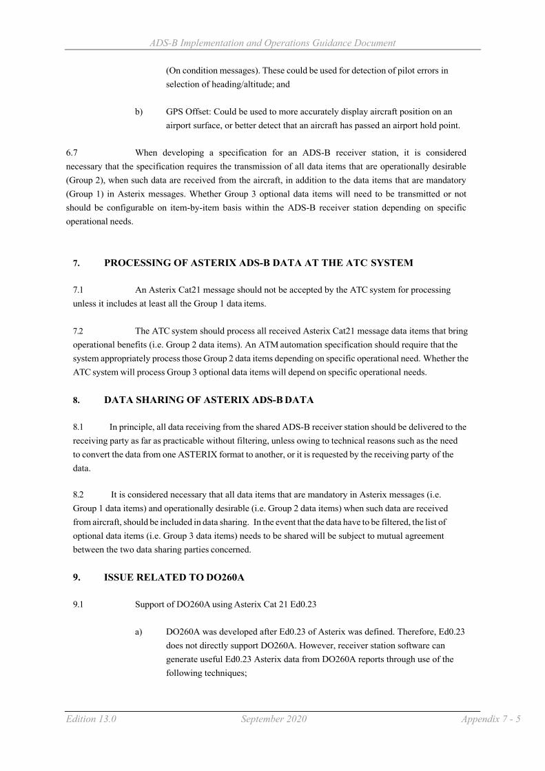
ADS-B Implementation and Operations Guidance Document
Edition 13.0 September 2020 Appendix 7 - 5
(On condition messages). These could be used for detection of pilot errors in selection of heading/altitude; and
b) GPS Offset: Could be used to more accurately display aircraft position on an
airport surface, or better detect that an aircraft has passed an airport hold point.
6.7 When developing a specification for an ADS-B receiver station, it is considered necessary that the specification requires the transmission of all data items that are operationally desirable (Group 2), when such data are received from the aircraft, in addition to the data items that are mandatory (Group 1) in Asterix messages. Whether Group 3 optional data items will need to be transmitted or not should be configurable on item-by-item basis within the ADS-B receiver station depending on specific operational needs.
7. PROCESSING OF ASTERIX ADS-B DATA AT THE ATC SYSTEM
7.1 An Asterix Cat21 message should not be accepted by the ATC system for processing unless it includes at least all the Group 1 data items.
7.2 The ATC system should process all received Asterix Cat21 message data items that bring operational benefits (i.e. Group 2 data items). An ATM automation specification should require that the system appropriately process those Group 2 data items depending on specific operational need. Whether the ATC system will process Group 3 optional data items will depend on specific operational needs.
8. DATA SHARING OF ASTERIX ADS-B DATA
8.1 In principle, all data receiving from the shared ADS-B receiver station should be delivered to the receiving party as far as practicable without filtering, unless owing to technical reasons such as the need to convert the data from one ASTERIX format to another, or it is requested by the receiving party of the data.
8.2 It is considered necessary that all data items that are mandatory in Asterix messages (i.e. Group 1 data items) and operationally desirable (i.e. Group 2 data items) when such data are received from aircraft, should be included in data sharing. In the event that the data have to be filtered, the list of optional data items (i.e. Group 3 data items) needs to be shared will be subject to mutual agreement between the two data sharing parties concerned.
9. ISSUE RELATED TO DO260A
9.1 Support of DO260A using Asterix Cat 21 Ed0.23
a) DO260A was developed after Ed0.23 of Asterix was defined. Therefore, Ed0.23
does not directly support DO260A. However, receiver station software can generate useful Ed0.23 Asterix data from DO260A reports through use of the following techniques;

ADS-B Implementation and Operations Guidance Document
Edition 13.0 September 2020 Appendix 7 - 6
b) A useful I021/090 Figure of Merit can be generated from DO260A messages. Some implementations have a table, which defines the FOM/PA to be generated for each combination of SIL, NIC and NAC. The contents of the table can be offline defined to generate the appropriate FOM/PA values. The downstream ATC system can then process DO260A reports as if they were DO260 reports; and
c) If there is a particular need for the ATC system to have access to the NIC/NAC
or SIL or other data item that exist in DO260A (but not in DO260), then users may need to consider a more recent version of Cat 21.
9.2 Support of DO260A using Asterix Cat 21 Ed 1.0 or Ed2.1 (or later versions)
a) When DO260A is used, then the ANSP could decide to use Asterix Cat 21
Ed1.0 (or later versions) or Ed2.1 (or later versions); and
b) Readers are invited to carefully examine the DO260A fields (see Appendix D) to
determine if the benefits of additional DO260A fields are large enough to warrant adoption of Asterix Cat 21 Ed1.0 (or later versions) or Ed2.1 (or later versions).
10. ISSUE RELATED TO DO260B
10.1 Support of DO260B using Asterix Cat 21 Ed0.23
a) DO260B was developed some years after DO260A. Therefore, Asterix Cat 21,
Ed0.23 does not directly support DO260B;
b) The same techniques used for processing DO260A can be used for processing DO260B, however, the table used must account for NIC supplement B & NIC supplement C, and may also wish to account for SDA; and
c) If there is a particular need for the ATC system to have access to the new data
items offered by DO260B, then users may need to consider a more recent version of Cat 21 (e.g. Ed2.1 or later versions).
10.2 Support of DO260B using Asterix Cat 21 Ed2.1 or later versions
a) If DO260B is used, then the ANSP could decide to use Asterix Cat 21 Ed2.1 or
later; and
b) Readers are invited to carefully examine the DO260B data items (see Appendix
D) to determine if the benefits of additional DO260B data items are large enough to warrant adoption of Asterix Cat 21 Version 2.1 or later.

ADS-B Implementation and Operations Guidance Document
Edition 13.0 September 2020 Appendix 7 - 7
11. ADS-B FORMAT CONVERSION AND FILTER SYSTEM
11.1 It is clear that the evolution of 1090ES ADS-B transmission will continue. Avionics software will be upgraded to provide additional or changed functionality. As a result Asterix standards will also continue to evolve, and ATC systems will need to be adaptable to be able to cope with new functionality requirements and new message standards.
11.2 The use of an ADS-B format conversion & filter (ADS-B FC&F) system between domestic ADS-B systems and data shared with other states is a cost-effective way to provide the necessary protection and flexibility in this evolution. Such a system provides ADS-B format conversion between domestic and foreign ADS-B systems. While decoupling one ADS-B Asterix environment from another, the system allows information that meets specific sharing criteria to be passed through for data sharing. By doing so, loading on the ATM automation systems to process ADS-B data and bandwidth requires to transmit the ADS-B data could then be reduced. The system also allows independent domestic format changes without disruption to the foreign environment. A typical structure could be as shown below:

ADS-B Implementation and Operations Guidance Document
Edition 13.0 September 2020 Appendix 7 - 8
7 Attachment A - Group 1 (Mandatory Data Items)
Data Items Description Ed
0.23
Ed
2.1
Remarks
I021/010 Data Source Identification X X Identifies source of data. Important if validity checks are performed as an anti spoofing capability. Validation that the data is received from an approved ADS-B receiverstation. Data received from a receiver station should not be processed if the position of the reported aircraft is an unreasonable distance away from the known location of the ADS-B receiver
station. Where space based ADS-B is used and a nominal station location is defined, such range processing limits will need to account for the coverage supplied.
I021/030 Time of Day X Necessary to extrapolate the ADS-B data to time of display. Data received with a Time of Day too far in the past should be discarded. This data is too old.
I021/071 or I021/073
Time of Applicability of Position or
Time of Message reception for position
X Necessary to extrapolate the ADS-B data to time of display. Data received with a Time of Day too far in the past should be discarded. This data is too old.
I021/040 Target Report Descriptor X X Indicates if report is a duplicate, on the receiver, is a simulated target, is a test target. This needs to be checked by ATC system prior to processing. If the data indicates that the report is a test target or a simulated target, it is normally processed differently to “real” targets.
I021/080 Target Address X X Included in all 1090ES downlink messages, so always available. Used for report/report linkage in ATC tracking.
I021/090 Figure of Merit/Quality Indicators
X X Position cannot be used without quality indicator. If the quality of the positional data does not meet the requirements the data should be discarded.
I021/130 Position in WGS-84 co-ordinates
X X Report cannot be used without position

ADS-B Implementation and Operations Guidance Document
Edition 13.0 September 2020 Appendix 7 - 9
Attachment B - Group 2 (Desirable Data Items)
Data Items Description Ed
0.23
Ed
2.1
Remarks
I021/008 Aircraft operational status X TCAS capability, Target state reporting capability, CDTI capability, Single/dual aircraft antenna. It is desirable to have immediate knowledge of RA event.
I021/020 Emitter Category X X Aircraft or vehicle type I021/140 Geometric Altitude/Height X X Useful for RVSM monitoring. Not normally used
for ATC application. Could perhaps be used as an indicator of correct QNH setting in aircraft.
I021/145 Flight Level X X Flight level is an important information to ATC
I021/155 Barometric Vertical Rate X X Used for predictive tools and safety nets. Either Barometric vertical rate or Geometric vertical rate is provided by the aircraft – not both.
However, the ATC system can calculate vertical rate from multiple flight level reports if these data items are not available.
I021/157 Geometric Vertical Rate X X
I021/160 Ground Vector X X Provides excellent vector to support extrapolation of positional data to time of display.
However, the ATC system can calculate the velocity vector (ground vector) from multiple position reports. I021/160 however, is normally far superior that ATC system calculation.
I021/170 Target Identification X X This is the callsign/Flight ID is extremely useful for ATC and matching to the flight plan (if any).
Target identification is only sent once per 5 seconds. Some receiver stations designs attach the target identification (if known from previous recent downlinks) even if not received in the last 5 seconds.
The field can be missing at the edge of ADS-B coverage – for flights inbound to coverage.

ADS-B Implementation and Operations Guidance Document
Edition 13.0 September 2020 Appendix 7 - 10
I021/200 Target Status X X This is the emergency type and is highly desirable.

ADS-B Implementation and Operations Guidance Document
Edition 13.0 September 2020 Appendix 7 - 11
Attachment C - Group 3 (Optional Data Items)
Data Items Description Ed
0.23
Ed
2.1
Remarks
I021/077 Time of report transmission X Time of applicability is relevant for ATC system processing. Time of transmission is less relevant.
I021/032 Time of Day Accuracy X Maximum error in Time of day. Normally the maximum value is known by the ANSP because of station design.
I021/095 Velocity Accuracy X If using GPS, velocity accuracy will be adequate if the Position quality is accurate.
I021/072 Time of applicability of velocity
X Can be managed by a velocity data time out in receiver station.
I021/075 Time of message reception of velocity
X Normally velocity is in the same Asterix message as position. Velocity data time out in receiver station.
I021/161 Track number X Tracking can be performed by ATC system. Also the 24 bit code (aircraft address) could be used as a pseudo track number.
I021/110 Trajectory Intent X X Defined in DO260 but not transmitted by any known product. Not defined in DO260A or DO260B
I021/146 (Intermediate) Selected Altitude
X X Target altitude : Information from DO260A/B Target state and status messages (On condition messages). These could be used for detection of pilot errors in selection of heading/altitude.
I021/148 Final State Selected Altitude X X
I021/015 Service identification X Type of Service (VDL4, Ext Squitter, UAT, TIS-B VDL4, TIS-B Ext Squitter, TIS-B UAT, FIS-B VDL4, GRAS VDL4, MLT). Not useful to most ATC systems.
I021/016 Service management X Update rate or whether data driven output from GS. Normally known by receiver.

ADS-B Implementation and Operations Guidance Document
Edition 13.0 September 2020 Appendix 7 - 12
Data Items Description Ed
0.23
Ed
2.1
Remarks
I021/074 Time of message reception of position – high resolution
X High resolution is designed to support MLAT system processing by receiver. Not required for pure ADS-B.
I021/076 Time of message reception of velocity – high resolution
X High resolution is designed to support MLAT system processing by receiver. Not required for pure ADS-B.
I021/210 MOPS version/ Link Technology Indicator
X X Maybe useful for statistics about equipage. Not operationally relevant
I021/070 Mode 3/A code X Could be used for legacy ATC system that do not use Flight ID
I021/165 Rate of Turn/Track Angle rate X X Not transmitted in DO260, DO260A or DO260B messages
I021/271 Surface capabilities and characteristics
X
I021/132 Message amplitude X Useful for technical analysis. Not operationally relevant
I021/250 Mode S MB data X
I021/260 ACAS resolution advisory report
X
I021/400 Receiver ID X
I021/295 Data ages X
I021/150 Air Speed X X Defined in standards but only sent in absence Ground vector information. Can’t be used for extrapolation unless wind speed known.
I021/151 True Air Speed X X
I021/152 Magnetic Heading X X Defined in standards but only sent in absence Ground vector information.
I021/220 Met Report X X Not transmitted in DO260, DO260A or DO260B messages
I021/230 Roll Angle X X Not transmitted in DO260, DO260A or DO260B messages
I021/131 Position in WGS-84 coordinates, high resolution
X

ADS-B Implementation and Operations Guidance Document
Edition 13.0 September 2020 Appendix 7 - 13
Attachment D - Differences among DO260, DO260A, DO260B
DO-260 DO-260A DO-260B Availability of data in Asterix CAT 21
Potential uses of additional information
Introduction of Navigation Integrity Category (NIC) to replace Navigation Uncertainty Category (NUCP)
NUCP is used. NIC is used to replace NUCP.
More levels of NIC available. Vertical component removed.
NIC is shown in Ed1.0 and above. More levels of NIC (shown as PIC) are available in v2.1.
The additional quantum levels of NIC would allow the ANSP more flexibility in deciding whether the NIC is considered as ‘good’ (if required)
However, for 3 NM & 5 NM separation with HPL 1Nm and 2 Nm respectively, this additional quantum is not useful.
Quality Indicator for Velocity (NUCR and NACV)
NUCR is used. Replaced with NACV. Definition remains the same.
Vertical component removed.
Available in Ed0.23 and above.
Vertical component is not available for DO260B.
Surveillance Integrity Level and Source Integrity Level (SIL)
Not available. Surveillance Integrity Level is used.
Renamed as Source Integrity Level. Definition is changed to exclude avionics fault.
Available in Ed1.0 and above.
The SIL will allow the user to further assess the integrity of the reported position (if required).
NB: An implied SIL exists for DO260 aircraft if they always use GPS. However DO260 aircraft do not provide SIL.
System Design Assurance (SDA)
Not available. Not available. To address probability of avionics fault.
Available in Ed2.1. The SDA will indicate the robustness of the system. ANSPs may decide on a minimum SDA for ADS-B services. If this action is taken then DO260 and DO260A aircraft will be unable to meet the criteria.

ADS-B Implementation and Operations Guidance Document
Edition 13.0 September 2020 Appendix 7 - 15
DO-260 DO-260A DO-260B Availability of data in
Asterix CAT 21 Potential uses of additional information
Navigation Accuracy Category (NACP)
Not available. Derived from HFOM and VFOM.
Relies only on HFOM.
Available in Ed1.0 and above.
A reported accuracy is not provided by DO260. However, an estimated accuracy can be derived from NUC – assuming that NUC is HPL based.
Geometric Vertical Accuracy (GVA)
Not available. Not available. Derived from VFOM.
Available in Ed2.1. Geometric altitude accuracy is not normally required for operational purposes.
Barometric Altitude Integrity Code (NICBARO)
Not available. To indicate integrity of barometric altitude.
Same as DO-260A
Available in Ed1.0 and above.
The NICBARO indicates the integrity of the barometric height.
ANSPs could indicate to the controller that Barometric data has not been verified, however, aircraft without dual barometric systems/air data computers may be unable to provide a non zero NICBARO as data could be unnecessarily discarded.
Length / Width of Aircraft
Not available. Provide an indication of aircraft size.
Same as DO-260A
Available in Ed1.0 and above.
The width / length indicate the size of the aircraft. This information may be used as an input for generating alerts on airport surface movement control.

ADS-B Implementation and Operations Guidance Document
Edition 13.0 September 2020 Appendix 7 - 16
DO-260 DO-260A DO-260B Availability of data in
Asterix CAT 21 Potential uses of additional information
Indication of Only show More Additional Available in Ed1.0 and Indication on the availability of 1090ES in / capabilities status of information information on above, except UAT in may allow the controller to anticipate a
TCAS and available type of ADS-B in availability of potential request for in-trail procedure clearance. CDTI. including (i.e. 1090ES in or 1090ES/UAT in and NB: ITP requires decision support aids which are capability to UAT in). information on GPS more complex than ADS-B IN alone. send Air antenna offset. Reference Velocity, Target State and Trajectory Change reports. Status of Identity Switch.
Status of Resolution Not available. Information on Same as Available in Ed1.0 and Indication of the resolution advisory status Advisory whether DO-260A above, allows the controller to know whether the pilots
Resolution were alerted about the potential conflict. Advisory is active.
GPS offset Not available. Indication on Information on GPS offset status is Indication on GPS offset may be one of the whether GPS GPS antenna available in Ed1.0 and inputs for generating alerts on airport surface offset is offset is above. Information on movement control. applied. provided. GPS offset is not available in ASTERIX
Intention Not available. Able to Same as Intended altitude is The intended heading and flight level can be indicate DO-260A available in Ed0.23. used as an input to the trajectory prediction intended Intended heading is not algorithm in the Short-Term Conflict Alert. altitude and available in ASTERIX. heading.

ADS-B Implementation and Operations Guidance Document
Edition 13.0 September 2020 Appendix 7 - 17
DO-260 DO-260A DO-260B Availability of data in
Asterix CAT 21 Potential uses of additional information
Target Status Not available. Not available. Indication of Autopilot mode, Vertical Navigation mode, Altitude Hold mode, Approach Mode and LNAV Mode.
Vertical Navigation mode, Altitude Hold mode and Approach Mode are available in Ed 0.23 and above
LNAV Mode is available in Ed2.1
The target status allows the controller to know the mode that the aircraft is in. i.e.: It could be presented to ATC.
Resolution Advisory Not available. Not available. Availability of Available in Ed1.0 and The Resolution Advisory will help the controller Active above. know the advisories that are provided to the Resolution pilots by the ACAS. This helps prevent the Advisories; controller from giving instructions that are in Resolution conflict with the ACAS. Advisory complement record, Resolution Terminated; Multiple Threat encounter; Threat Type indicator; and Threat Identity data.

ADS-B Implementation and Operations Guidance Document
Edition 13.0 September 2020 Appendix 7 - 18
DO-260 DO-260A DO-260B Availability of data in
Asterix CAT 21 Potential uses of additional information
Mode A DO260 Broadcasted Broadcasted Available in Ed0.26 and The Mode A allows flight plans to be coupled change 1, using test worldwide as a above. with the ADS-B tracks (supports legacy ATM allows this message in regular message. automation system). using test USA only.
message in USA only. This was not implemented in actual products.

ADS-B Implementation and Operations Guidance Document
Edition 13.0 September 2020 Appendix 8 - 1
Appendix 8

ADS-B Implementation and Operations Guidance Document
Edition 13.0 September 2020 Appendix 8 - 2

ADS-B Implementation and Operations Guidance Document
Edition 13.0 September 2020 Appendix 8 - 3
_ _ _ _ _ _ _ _ _ _ _ _ _
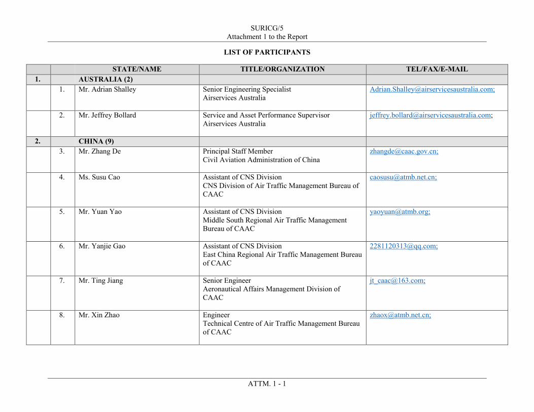
SURICG/5 Attachment 1 to the Report
ATTM. 1 - 1
LIST OF PARTICIPANTS
STATE/NAME TITLE/ORGANIZATION TEL/FAX/E-MAIL 1. AUSTRALIA (2) 1. Mr. Adrian Shalley Senior Engineering Specialist
Airservices Australia [email protected];
2. Mr. Jeffrey Bollard
Service and Asset Performance Supervisor Airservices Australia
2. CHINA (9) 3. Mr. Zhang De Principal Staff Member
Civil Aviation Administration of China
4. Ms. Susu Cao Assistant of CNS Division CNS Division of Air Traffic Management Bureau of CAAC
5. Mr. Yuan Yao Assistant of CNS Division Middle South Regional Air Traffic Management Bureau of CAAC
6. Mr. Yanjie Gao Assistant of CNS Division East China Regional Air Traffic Management Bureau of CAAC
7. Mr. Ting Jiang Senior Engineer Aeronautical Affairs Management Division of CAAC
8. Mr. Xin Zhao Engineer Technical Centre of Air Traffic Management Bureau of CAAC

Attachment 1 to the Report
ATTM. 1 - 2
STATE/NAME TITLE/ORGANIZATION TEL/FAX/E-MAIL 9. Mr. Siyuan Rong Deputy Director of CNS Division
North China Regional Air Traffic Management Bureau of CAAC
10. Mr. Guangming Zhang Professor Civil Aviation Flight University of China (CAFUC)
11. Mr. Deng Sheng Ji Project Manager The Second Research Institute of CAAC
3. HONG KONG, CHINA (6) 12. Mr. Hui Man Ho Acting Assistant Director-General of Civil Aviation
(Air Traffic Engineering Services) Civil Aviation Department Hong Kong, China
13. Mr. How Sze Lung Electronics Engineer Civil Aviation Department Hong Kong, China
14. Ms. Mak Yuet Yan, Annie Evaluation Officer Civil Aviation Department Hong Kong, China
15. Mr. Kwok Ching Ho, Daniel
Project Officer Civil Aviation Department Hong Kong, China
16. Mr. Suen Hoi Tak, Ava Project Officer Civil Aviation Department Hong Kong, China
17. Mr. Chung Ho Yin Air Traffic Control Officer II Civil Aviation Department Hong Kong, China
4. MACAO CHINA (5)

Attachment 1 to the Report
ATTM. 1 - 3
STATE/NAME TITLE/ORGANIZATION TEL/FAX/E-MAIL 18. Mr. Sun Shabo Consultant
Civil Aviation Authority of Macao, China
19. Mr. Lo Veng Tong, Freeman
Senior Safety Officer Civil Aviation Authority of Macao, China
20. Mr. Pun Sio Kuong, Samson
Safety Officer Civil Aviation Authority of Macao, China
21. Mr. Wong Pui Man, Cecil
Head of ICT Division Macau International Airport Co, Ltd.
22. Mr. Sun Keng Chong
Senior ICT Engineer Macau International Airport Co, Ltd.
5. DPR KOREA (5) 23. Mr. Kim Kun Ju Chief, Air Navigation Aids Section, Air Traffic
Management Department General Administration of Civil Aviation
24. Mr. Pak Tong Chol
Senior Officer, Air Navigation Aids Section Air Traffic Management Department General Administration of Civil Aviation
25. Mr. Kim Thae Ryong
Officer, International Organizations Department General Administration of Civil Aviation
26. Mr. Ho Kwang Sung
Engineer, Air Navigation Aids Section Air Traffic Management Department General Administration of Civil Aviation
27. Mr. Pak Hyon Chol
Engineer, Air Navigation Aids Section Air Traffic Management Department General Administration of Civil Aviation

Attachment 1 to the Report
ATTM. 1 - 4
STATE/NAME TITLE/ORGANIZATION TEL/FAX/E-MAIL 6. FIJI (2) 28. Mrs. Sereima Bolanavatu Air Navigation Service Inspector (CNS)
Civil Aviation Authority of Fiji
29. Mr. Shailendra Pandaram CNS/ATM Specialist Fiji Airports Limited
7. INDIA (2) 30. Mr. Sudhamay Maiti General Manager (CNS)
Airports Authority of India
[email protected]; [email protected]; [email protected];
31. Mr. Tony C. Tharayil Joint General Manager (CNS) Airports Authority of India
8. INDONESIA (11) 32. Mr. Taruna Jaya
Chief of Navigation Aid, Surveillance and Automation System Facilities
33. Mr. A.Budi Fathoni
Air Navigation Inspector Directorate of General Civil Aviation
34. Mrs. Emi Astuti
Air Navigation Inspector Directorate of General Civil Aviation
35. Mr. Guntur Wirayuda
Air Navigation Inspector Directorate of General Civil Aviation
36. Mr. M. Riza Semaryan Lubis
Air Navigation Inspector Directorate of General Civil Aviation
37. Mrs. Mardiana
Air Navigation Inspector Directorate of General Civil Aviation

Attachment 1 to the Report
ATTM. 1 - 5
STATE/NAME TITLE/ORGANIZATION TEL/FAX/E-MAIL 38. Mr. Dedy Iskandar
Surveillance and ATC Automation Readiness AirNav Indonesia Headquarter
39. Mr. Lanang Wibisono
Manager of System Planning and Service Facility – Operation Directorate AirNav Indonesia
40. Mr. Mohamad Ali Said
Junior Manager Design Facilities of Surveillance, ATC Automation and Instrument Landing System AirNav Indonesia
41. Mr. Herdianto
ATS System Specialist AirNav Indonesia
42. Mr. Sudrajat Wiharyoko
Specialist ATS System AirNav Indonesia
9. JAPAN (6) 43. Mr. Yasuhiro Otani
Special Assistant to the Director Japan Civil Aviation Bureau
44. Mr. Kenji Uehara
Chief Officer Japan Civil Aviation Bureau
45. Mr. Hiromi Miyazaki
Principal Officer Electronic Navigation Research Institute
46. Mr. Junichi Naganawa
Senior Researcher Electronic Navigation Research Institute
47. Mr. Shigcru Ozeki Technical Advisor Japan Radio Air Navigation Systems Association

Attachment 1 to the Report
ATTM. 1 - 6
STATE/NAME TITLE/ORGANIZATION TEL/FAX/E-MAIL 48. Mr. Takeo Fujimori
Chief Engineering Analyst Japan Radio Air Navigation Systems Association
10. LAO PDR (1) 49. Mr. Moukphamay Thammavongsa Air Navigation Systems Engineer
Lao Air Navigation Services (LANS)
11. MALAYSIA (3) 50. Mr. Mohd Shahrul Azree Bin Remly Assistant Director
Civil Aviation Authority of Malaysia
51. Mr. Mohd Fitri Bin Ishak
Senior Assistant Director Civil Aviation Authority of Malaysia
52. Mr. Mahyuddin Sajuri
Principal Assistant Director Civil Aviation Authority of Malaysia
12. MYANMAR (3) 53. Mr. Win Maw Deputy General Manager (CNS)
Department of Civil Aviation (Myanmar)
54. Mr. Htet Arkar Executive Engineer (CNS) Department of Civil Aviation (Myanmar)
55. Mr. Han Tun Aung
Assistant Engineer (CNS) Department of Civil Aviation (Myanmar)
13. NEPAL (3) 56. Mr. Devendra Joshi
Deputy Director Civil Aviation Authority of Nepal
57. Mr. Sanjeev Singh Kathayat
Deputy Director CNS Standards Division

Attachment 1 to the Report
ATTM. 1 - 7
STATE/NAME TITLE/ORGANIZATION TEL/FAX/E-MAIL 58. Ms. Aastha Pandey Deputy Manager
Civil Aviation Authority of Nepal
14. PHILIPPINES (4) 59. Mr. Joferand Joseph Y. Torrefranca
Acting Division Chief III, CNS/MET Division ANPPDD Airways Navigation Service Civil Aviation Authority of the Philippines
60. Mr. Julius Ruel D. Resquir
CNSSO V/ANS-FIC, Manila ATM Center Airways Navigation Service Civil Aviation Authority of the Philippines
61. Mr. Ariel J. Carabeo
Chief, Manila ACC Air Traffic Service Civil Aviation Authority of the Philippines
62. Mr. Joseph Tyrone R. Arias
Air Traffic Management Officer V Air Traffic Service Civil Aviation Authority of the Philippines
15. REPUBLIC OF KOREA (9) 63. Mr. Lee Jung Yoon Deputy Director
Ministry of Land, Infrastructure and Transport
64. Ms. Jeong Mi Jin Assistant Manager Ministry of Land, Infrastructure and Transport
65. Mr. Lee Jung Assistant Director of Air Navigation Facilities Division Incheon Air Traffic Control Regional Office

Attachment 1 to the Report
ATTM. 1 - 8
STATE/NAME TITLE/ORGANIZATION TEL/FAX/E-MAIL 66. Ms. Cha Yu Jin Assistant Director of Air Navigation Facilities
Division Incheon Air Traffic Control Regional Office
67. Mr. Kang Ho Deak Assistant Director of ATC Division Incheon Air Traffic Control Regional Office
68. Mr. Sung Yo Han Assistant Director of ATC Division Incheon Air Traffic Control Regional Office
69. Mr. Yang Hyun Bae General Manager Korea Airport Corporation
70. Mr. Lee Soo Ho Assistant Manager Korea Airport Corporation
71. Mr. Jung Yong Woo
Assistant Manager Korea Airport Corporation
16. SINGAPORE (8) 72. Mr. Yeo Cheng Nam Consultant (Aeronautical Telecommunications &
Engineering) Civil Aviation Authority of Singapore
73. Mr. Ho Wee Sin Deputy Director (Technical Standards and Support) Civil Aviation Authority of Singapore
74. Ms. Ng Mei Chin Head (Surveillance Projects) Civil Aviation Authority of Singapore
75. Mr. Chua Eng Leong Senior Engineer (Surveillance Systems) Civil Aviation Authority of Singapore

Attachment 1 to the Report
ATTM. 1 - 9
STATE/NAME TITLE/ORGANIZATION TEL/FAX/E-MAIL 76. Mr. Joe Chua Wee Jui Chief (Systems Planning)
Civil Aviation Authority of Singapore
77. Ms. June See Air Traffic Control Manager (Systems Planning) Civil Aviation Authority of Singapore
78. Mr. Aloysius Ang
Air Traffic Control Manager (Systems Planning) Civil Aviation Authority of Singapore
79. Mr. Bryan Cheng Principal Engineer (Surveillance Projects) Civil Aviation Authority of Singapore
17. SRI LANKA (7) 80. Ms. Sarojanie S.A.N.
Civil Aviation Inspector – AIS Civil Aviation Authority of Sri Lanka
81. Mr. Angage Upula Ranaraja Perera
Assistant Air Traffic Safety Electronics Engineer Airport & Aviation Services (S/L) Ltd.
82. Mr. H.A. Priyantha Electronics Engineer Airport & Aviation Services (S/L) Ltd.
83. Mr. Prasanna Wijeratne Electronics Engineer Airport & Aviation Services (S/L) Ltd.
84. Mr. K.S.P.K Patrinrana
Assistant Air Traffic Safety Electronics Engineer Airport & Aviation Services (S/L) Ltd.
85. Mr. Asanga Senarath Bandara Senior Electronics Engineer Airport & Aviation Services (S/L) Ltd.
86. Mr. Jananath Konara Rathninda Deputy Head of Electronics and Ai Navigation Engineering Airport & Aviation Services (S/L) Ltd.

Attachment 1 to the Report
ATTM. 1 - 10
STATE/NAME TITLE/ORGANIZATION TEL/FAX/E-MAIL 18. THAILAND (4) 87. Mr. Krisanapon Paisal CNS Officer
Civil Aviation Authority of Thailand
88. Mr. Nattapol Witsuwat
CNS Officer Civil Aviation Authority of Thailand
89. Mr. Chanyut Phrukkumwong
Director, Air Traffic Engineering Research and Development Department Aeronautical Radio of Thailand Ltd.
90. Mr. Ponlawat Wattayatin
Air Traffic Engineer Aeronautical Radio of Thailand Ltd.
19. USA (3) 91. Mr. Michael Watkins
Senior Air Traffic Representative, Asia Pacific Federal Aviation Administration Air Traffic Organization, System Operations
92. Mr. Paul VonHoene
Aviation Safety Inspector Federal Aviation Administration Aviation Safety Flight Technologies and Procedures Division Flight Operation Group
93. Mr. Alejandro Rodriguez
Senior Technical Advisor Federal Aviation Administration
20. VIET NAM (12) 94. Mr. Ho Sy Tung Deputy General Director
Viet Nam Air Traffic Management (VATM)

Attachment 1 to the Report
ATTM. 1 - 11
STATE/NAME TITLE/ORGANIZATION TEL/FAX/E-MAIL 95. Mr. Pham Hung Son Deputy Director of Technical Department
Viet Nam Air Traffic Management (VATM)
96. Mr. Nguyen Xuan Nhu Deputy Director of Project Management Department Viet Nam Air Traffic Management (VATM)
97. Mr. Dinh Nhat Minh Deputy Director of ATTECH Viet Nam Air Traffic Management (VATM)
98. Mr. Duong Thanh Nam Deputy Director of Technical Division, ATTECH Viet Nam Air Traffic Management (VATM)
99. Mr. Trinh Van Nghia Deputy Chief of CNS service Technical Supervision and Management Center, ATTECH Viet Nam Air Traffic Management (VATM)
100. Mr. Nguyen Viet Cuong Chief of CNS Unit, Technical Department Viet Nam Air Traffic Management (VATM)
101. Mr. Pham Cong Nam Officer of CNS Unit, Technical Department Viet Nam Air Traffic Management (VATM)
102. Mr. Tran Duc Phong Chief of Specialized Division, Project Management Department Viet Nam Air Traffic Management (VATM)
103. Mr. Ho Ngoc Thang Officer of Specialized Division, Project Management Department Viet Nam Air Traffic Management (VATM)
104. Mr. Nguyen Manh Tuan CNS Official, Air Navigation Department Civil Aviation Administration of Viet Nam (CAAV)

Attachment 1 to the Report
ATTM. 1 - 12
STATE/NAME TITLE/ORGANIZATION TEL/FAX/E-MAIL 105. Mr. Vu Ngoc Tuan CNS Official, Air Navigation Department
Civil Aviation Administration of Viet Nam (CAAV)
21. AIREON (1) 106. Mr. Greg Dunstone Sales Engineer
Aireon LLC International Coordinating Council of Aerospace Industries Associations (ICCAIA)
22. CANSO (1) 107. Mr. Hai Eng Chiang Director Asia Pacific Affairs
Civil Air Navigation Services Organization (CANSO)
23. EUROCARE (2) 108. Mr. Christian Schleifer Secretary General
EUROCAE
109. Ms. Anna von Groote Director Technical Programme
Director Technical Programme EUROCAE
24. IATA (5)
110. Mr. Honghai Yang Regional Director of Safety & Flight Operations International Air Transport Association (IATA)
111. Mr. David Rollo Assistant Director – Safety and Flight Operations – ASPAC International Air Transport Association (IATA)
112. Mr. John Moore Assistant Director – Safety and Flight Operations ASPAC

Attachment 1 to the Report
ATTM. 1 - 13
STATE/NAME TITLE/ORGANIZATION TEL/FAX/E-MAIL 113. Capt. Angadeep Singh Chopra Head – International Affairs and Investigations
Vistara
114. Mr. Bin Hu Manager, Safety and Flight Operations, North Asia International Air Transport Association (IATA)
25. IFATCA (1) 115. Mr. Anthony Ang EVP Asia Pacific
International Federation of Air Traffic Controllers' Associations (IFATCA)
26. PCCW (4) 116. Mr. Raymond Luk
Vice President, Strategic Account Management, Global Presales and Technology Engagement PCCW Global Limited
117. Mr. Benny Cheng
Assistant Vice President, Strategic Account Management PCCW Global Limited
118. Mr. Eddy Lee
Assistant Vice President, Strategic Account Management, Global Presales PCCW Global Limited
119. Mr. Bono Ng
Senior Business Development Manager, Aviation & Special projects Strategic Account Management PCCW Global Limited
27. ICAO (2)

Attachment 1 to the Report
ATTM. 1 - 14
STATE/NAME TITLE/ORGANIZATION TEL/FAX/E-MAIL 120. Mr. Luo Yi Regional Officer CNS
International Civil Aviation Organization Asia and Pacific Office 252/1, Vibhavadi Rangsit Road Ladyao, Chatuchak Bangkok 10900 THAILAND
Tel: +66 (2) 537 8189 ext. 155 Fax: +66 (2) 537 8199 E-mail: [email protected]
121. Ms. Bhabhinan Sirapongkosit Programme Assistant (CNS/MET/ENV) International Civil Aviation Organization Asia and Pacific Office 252/1, Vibhavadi Rangsit Road Ladyao, Chatuchak Bangkok 10900 THAILAND
Tel: +66 (2) 537 8189 ext. 49 Fax: +66 (2) 537 8199 E-mail: [email protected]

SURICG/5
Attachment 2 to the Report
ATTM. 2 - 1
LIST OF PAPERS
WP/IP/SP and Flimsy
No.
Agenda Item
Subject Presented by
LIST OF WORKING PAPERS
WP/01 - Provisional Agenda Secretariat
WP/02 2 Outcomes of Relevant Meetings on Surveillance Secretariat
WP/03 3 Additional System Area Codes (SAC) for Surveillance
Systems in APAC and Update on Regional Supplement to ASTERIX Interface Control Document (ICD)
Secretariat
WP/04 4 Action Items from SURICG/4 Secretariat
WP/05 6 Review Report of SEA/BOB ADS-B WG/15 Meeting
Chairperson and Secretariat
WP/06 7 Outcome of the Mode S DAPS WG/3 Co-chairs and Secretariat
WP/07 5 Example of ADS-B Position Verification Performance Japan/ENRI
WP/08 3 Proposed Solutions for Sharing of Surveillance Data Singapore
LIST OF INFORMATION PAPERS
IP/01 - Web-conference Bulletin Secretariat
IP/02 5 Update on ATC Surveillance Activities in Australia Australia
IP/03 5 The Implementation of New Surveillance System within
Pyongyang FIR Democratic People’s Republic of Korea
IP/04 5 Recent ADS-B Avionics Issues Observed in the United
States USA/FAA
IP/05 5 Revisions to FAA Advisory Circular (AC) 90-114, ADS-B
Operations USA/FAA
IP/06 5 ADS-B Equipage and Quality Performance in the U.S. USA/FAA
IP/07 2 1090 MHz Spectrum and 24-bit Aircraft Address Issues
with UAS Secretariat
IP/08 3 PNG Deployment of Space based ADS-B PNG and ICCAIA/Aireon
IP/09 3 FAA’s Operational Evaluation of Space-Based ADS-B in the Caribbean
USA/FAA
IP/10 9 SSR Reception Malfunction Caused by UAV Video
Transmitter Republic of Kora

Attachment 2 to the Report
ATTM. 2 - 2
WP/IP/SP and Flimsy
No.
Agenda Item
Subject Presented by
IP/11 5 Airspace Applicability of the U.S. 2020 ADS-B Equipage
Mandate USA/FAA
IP/12 3 Long-range Air Traffic Surveillance Display System for
Air Traffic Flow Management Hong Kong China
IP/13 3 Space based ADS-B Update ICCAIA/Aireon
IP/14 4 The ICAO Aircraft Address Monitoring in Japan Japan
IP/15 5 Update on Surveillance Facilities in Indonesia Indonesia
IP/16 5 Discussion on Technical Methods to Prevent Runway
Incursion with Operation Verification China
IP/17 4 Introduction to the Management and Application of 24-bit
Aircraft Addresses for Chinese Civil Aviation China
IP/18 4 Mode S Radar Survey to Support II/SI Mixed Operation in
China China
IP/19 5 Update on ADS-B Implementation Project in Republic of
Korea
Republic of Korea
IP/20 3 The SAC SIC Code Allocation Management and Using in China
China
IP/21 5 Updates the Action Plan for Surveillance in China China
LIST OF FLIMSY
Flimsy_01 2 Proposal for Amendment of Annex 10. Volume IV
regarding Airborne Collision Avoidance System X (ACAS X)
Secretariat
Flimsy_02 3 (b) CRV and SWIM Presentation PCCW Global
Flimsy_03 5 ADS-B Out Mandate in Europe Hong Kong, China
Flimsy_04 9 Update of Surveillance Panel (ASWG) Singapore
Flimsy_05 6 Discussion on Future SEA-BOB ADS-B WG Secretariat
LIST OF PRESENTATION
SP/01 5 Standards to Support Global Interoperability EUROCAE
_ _ _ _ _ _ _ _ _ _ _ _ _