Embed Size (px)
Citation preview

Mayor Adrian M. Fenty
Published October 2009, byDistrict of Columbia Department of Real Estate ServicesRobin-Eve Jasper, DirectorGerick T. Smith, Deputy Director of Construction Division
For
District of Columbia Department of Fire and Emergency Medical ServicesEngine Company No. 122225 5th Street, NEWashington, D.C. 20002
Report of
Comprehensive Facilities Condition Assessment& Space Utilization Survey
1725 DUKE STREET SUITE 200 ALEXANDRIA VA 22314 PH 703.684.6550 FX 703.684.8590
October 5, 2009
District of Columbia Department of Real Estate ServicesConstruction Services Division2000 14th Street, N.W., Fifth FloorWashington, D.C. 20009
Attention: Mr. Amar SinghProject Manager
Reference: Report of Comprehensive Facilities Condition Assessment & Space Utilization SurveyEngine Company No. 122225 5th Street NEWashington, D.C. 20002Faithful+Gould Project No. 55561-10District of Columbia Contract Number POAM-2004-C-0044-14-CA
Dear Mr. Singh:
Faithful+Gould, Inc. has completed a report of our Comprehensive Facility Condition Assessment and SpaceUtilization Survey of the Engine Company No. 12 building located at 2225 5th Street, NE in Washington, D.C. (“theProperty”).
This report provides a summary of the project information known to us at the time of the study, the scope of workperformed, an evaluation of the visually apparent condition of the Property, identification of potential sustainabilityimprovements, a forecast of capital and maintenance expenditures required over the next six-years anddevelopment of an occupancy profile to include production of floor plans and summarizing of the current utilization ofoccupiable space.
This report was completed in general accordance with the District of Columbia issued Statement of Works andFaithful+Gould’s revised proposal for Facility Condition Assessment as authorized under Purchase Order 287952 byMs. Diane B. Wooden of the District of Columbia Construction, Design and Building Renovation Commodity Groupon January 3, 2009.
It has been a pleasure working with you on this project, and we look forward to working with you on future projects.
Very Truly Yours,
Richard W. Monat Richard A. Needler, AIARegistered Architect Scope Compliance & Technical Review
cc. File

Engine Company No. 12 October 5, 20092225 5th Street, NE Page i of 72Washington D.C.
Report of Comprehensive Facilities Condition Assessment & Space Utilization Survey F+G Project No. 55561-10
TABLE OF CONTENTSPage
EXECUTIVE SUMMARY ...................................................................................................................................................1
FACILITY ATTRIBUTE TABLE.........................................................................................................................................2
FACILITY CONDITION INDEX SUMMARY ......................................................................................................................3
FACILITY CONDITION ASSESSMENT ............................................................................................................................4
A. SUBSTRUCTURE..............................................................................................................................................4
A10 FOUNDATIONS .........................................................................................................................................4
A20 BASEMENT CONSTRUCTION..................................................................................................................5
B. SHELL ...............................................................................................................................................................6
B10 SUPERSTRUCTURE .................................................................................................................................6
B20 EXTERIOR CLOSURE...............................................................................................................................8
B30 ROOFING.................................................................................................................................................12
C. INTERIORS......................................................................................................................................................15
C10 INTERIOR CONSTRUCTION...................................................................................................................15
C20 STAIRS.....................................................................................................................................................15
C30 INTERIOR FINISHES ...............................................................................................................................15
D. SERVICES .......................................................................................................................................................18
D10 CONVEYING ............................................................................................................................................18
D20 PLUMBING...............................................................................................................................................18
D30 HVAC........................................................................................................................................................23
D40 FIRE PROTECTION.................................................................................................................................28
D50 ELECTRICAL...........................................................................................................................................33
D60 SAFETY, SECURITY & ACCESS CONTROL .........................................................................................40
E. EQUIPMENT & FURNISHINGS.......................................................................................................................43
E10 EQUIPMENT.............................................................................................................................................43
E20 FURNISHINGS .........................................................................................................................................44

Engine Company No. 12 October 5, 20092225 5th Street, NE Page ii of 72Washington D.C.
Report of Comprehensive Facilities Condition Assessment & Space Utilization Survey F+G Project No. 55561-10
F. SPECIAL CONSTRUCTION............................................................................................................................46
F10 SPECIAL CONSTRUCTION.....................................................................................................................46
G. SITE FEATURES.............................................................................................................................................47
G10 SITE SYSTEMS .......................................................................................................................................47
H. ACCESSIBILITY ISSUES................................................................................................................................50
H10 ACCESSIBILITY ......................................................................................................................................50
I. HAZARDOUS MATERIALS ............................................................................................................................58
I10 HAZARDOUS MATERIALS ......................................................................................................................58
J. ENVIRONMENTAL ANALYSIS......................................................................................................................60
J10 LEED ANALYSIS.....................................................................................................................................60
J20 GREEN ROOF FEASIBILITY ...................................................................................................................66
J30 ENERGY EFFICIENCY.............................................................................................................................68
SPACE UTILIZATION SURVEY
A. INVENTORY & OCCUPANCY NUMBER.................................................................................................................66
B. FLOOR PLANS & AREA CALCULATIONS..............................................................................................................67
APPENDICES
APPENDIX A - SIX YEAR CAPITAL EXPENDITURE FORECASTAPPENDIX B - SIX YEAR MAINTENANCE EXPENDITURE FORECASTAPPENDIX C - PHOTOGRAPHSAPPENDIX D - INVENTORY AND CHECKLISTAPPENDIX E - PREVENTATIVE MAINTENANCE RECOMMENDATIONSAPPENDIX F - SCOPE OF SERVICES & DOCUMENT REVIEWAPPENDIX G - RESUMES

Engine Company No. 12 October 5, 20092225 5th Street, NE Page 1 of 72Washington D.C.
Report of Comprehensive Facilities Condition Assessment & Space Utilization Survey F+G Project No. 55561-10
EXECUTIVE SUMMARY
Engine Company No. 12 is located at 2225 5th Street in Northeast Washington D.C. (“the Property”) and is a one- and
two-story, concrete framed fire station. The Property, developed in 1987 and currently occupied by the District of
Columbia’s Fire and EMS Department, is of Construction Type I and situated on a 0.48 acre (21,199 gross square foot)
site. The site is bounded by Rhode Island Avenue NE on the northwest and 5th Street NE on the southwest, with
commercial properties on the remaining boundaries.
The Property is not currently listed on the District of Columbia’s Inventory of Historic Properties and is served by
Metrobus service, with stops along Rhode Island Avenue NE and the Rhode Island Avenue – Brentwood Metrorail
subway station is located approximately 0.5 mile to the northeast of the Property.
On March 17 and May 27, 2009, Richard W. Monat and Richard A. Needler of Faithful+Gould visited the Property to
observe and document the condition of the building and site components. During our site visit, Faithful+Gould was
briefly assisted by Fire Fighter John Chada.
The purpose of this report is to identify visually apparent deficiencies in the building and site systems, determine capital
and maintenance costs required over the next six-years calculate the Facility Condition Index (FCI) of the Property and
develop an occupancy profile to include production of floor plans. Based upon the calculated FCI, the Property is in
good condition, with a 0.10 rating reflective of a total Deferred Maintenance expenditure requirement of $228,077
over the six-year study period. Refer to the next page for further discussion of the Property’s Facility Condition Index.
The most pressing facility condition related issues affecting the Property are summarized in Table EX-1, Chart
EX-2, and the cost tables included within Appendices A and B.
Table EX-1 Primary Expenditures
Project Expenditure Type Cost Year
Exterior Closure Condition $95,400 2010
Interiors Condition $30,539 2010, 2011
Services Condition $72,021 2010 - 2015
Accessibility Issues Code Compliance $11,980 2010
Chart EX-2 Expenditure by System
Ex terior
Roofing
Interiors
Sy stems
Sitew ork
Accessibility
Hazmat
Env ironmental Analy sis

Engine Company No. 12 October 5, 2009 2225 5th Street, NE Page 2 of 72 Washington D.C.
Report of Comprehensive Facilities Condition Assessment & Space Utilization Survey F+G Project No. 55561-10
FACILITY ATTRIBUTE TABLE ENGINE COMPANY NO. 12
ADDRESS: 2225 5TH STREET, NE
WASHINGTON, DC 20002 NEAREST INTERSECTION: RHODE ISLAND AVENUE, NE & 5TH STREET, NE SQUARE: 0131 LOT: 0216 QUAD-WARD: NE-5 HISTORIC DISTRICT: YES NO HISTORIC BUILDING: YES NO GROSS SQUARE FOOTAGE OF BUILDING: 15,913 GROSS SQUARE FOOTAGE OF LAND: 21,199 (APPROX. 0.48 ACRES) YEAR OF CONSTRUCTION: 1987 NUMBER OF PARKING SPACES: APPROXIMATELY 21 SPACES OCCUPANCY STATUS: OCCUPIED VACANT PARTIALLY OCCUPIED ASSESSED BUILDING VALUE: $3,420,070 ASSESSED LAND VALUE: $1,059,950
PROPERTY DETAILS

Engine Company No. 12 October 5, 20092225 5th Street, NE Page 3 of 72Washington D.C.
Report of Comprehensive Facilities Condition Assessment & Space Utilization Survey F+G Project No. 55561-10
FACILITY CONDITION INDEX SUMMARY
As part of this evaluation, Faithful+Gould was requested to calculate the Facility Condition Index (“FCI”) of the Property.
This was calculated for the continued fire station use scenario. The FCI is the ratio of accumulated Deferred
Maintenance (DM) to the Current Replacement Value (CRV). The DM includes the total Capital Expenditure Forecast
amount indicated in Appendix A and the Maintenance Expenditure Forecast amount indicated in Appendix B, less
Environmental Analysis costs. The CRV is based on cost data provided by RS Means at a value of $148 per gross
square foot times the gross square footage of building floor area. The FCI of the constructed asset is calculated by
dividing DM (maintenance and capital costs) by the CRV as indicated by the following formula:
Deferred Maintenance / Current Replacement Value = Facility Condition Index
The FCI range is from zero for a newly constructed asset, to one for a constructed asset with a DM value equal to its
CRV. Acceptable ranges vary by “Asset Type’, but as a general guideline the FCI scoring system is as detailed in Table
FCI-1.
Table FCI-1 Facility Condition Index (FCI) Values
Numerical Value Condition
> 0.75 Poor
0.40 - 0.75 Fair
0.0 - 0.39 Good
We have calculated a Current Replacement Value of $2,355,124 (based on a value of $148 per gross square foot and a
floor area of 15,913 gross square feet) and a Deferred Maintenance value over the six-year study period of
$228,077. The Property is in good condition, indicative of its FCI ratio of 0.10 and this is generally a good reflection of
the building’s condition.
Capital Expenditure Forecast $ 0
Maintenance Expenditure Forecast $ 345,377
Subtotal $ 345,377
Less Sustainability Costs (LEED/Energy)
Analysis Expenditures
Capital Expenditure Forecast ($0)
Maintenance Expenditure Forecast ($117,300)
Subtotal ($117,300)
Deferred Maintenance (DM) $ 228,077
$228,077 DM / $2,355,124 CRV = 0.10 FCI

Engine Company No. 12 October 5, 20092225 5th Street, NE Page 4 of 72Washington D.C.
Report of Comprehensive Facilities Condition Assessment & Space Utilization Survey F+G Project No. 55561-10
FACILITY CONDITION ASSESSMENT
A. SUBSTRUCTURE
A10 FOUNDATIONS
Description
In the absence of structural drawings, we have based our description of the foundation systems upon our
visual observation (where possible) of the systems and our experience with similar structural systems. Based
upon the sizing, type and anticipated loadings of the superstructure systems and our visual observation of
geotechnical conditions, we anticipate that the superstructure of the building is founded on a series of
individual and continuous strip footings of mild-steel reinforced cast-in-place concrete.
Condition
The foundation systems appeared to be in good condition with no evidence of overloading, subsidence or
other visually indicative deterioration noted. Assuming the continued use of the building as a fire station and
no change in the building’s loading profile, we do not anticipate significant repairs or replacements of the
foundation systems within the six-year study period.
Projected Expenditures
Required Capital Expenditures:
Priority 1 (Immediate)
No required capital expenditures are anticipated at this time.
Priority 2 (2010)
No required capital expenditures are anticipated at this time.
Priority 3 (2011 – 2014)
No required capital expenditures are anticipated at this time.
Priority 4 (2015)
No required capital expenditures are anticipated at this time.

Engine Company No. 12 October 5, 20092225 5th Street, NE Page 5 of 72Washington D.C.
Report of Comprehensive Facilities Condition Assessment & Space Utilization Survey F+G Project No. 55561-10
Required Maintenance Expenditures:
Priority 1 (Immediate)
No required maintenance expenditures are anticipated at this time.
Priority 2 (2010)
No required maintenance expenditures are anticipated at this time.
Priority 3 (2011 – 2014)
No required maintenance expenditures are anticipated at this time.
Priority 4 (2015)
No required maintenance expenditures are anticipated at this time.
A20 BASEMENT CONSTRUCTION
The Property does not have a basement.

Engine Company No. 12 October 5, 20092225 5th Street, NE Page 6 of 72Washington D.C.
Report of Comprehensive Facilities Condition Assessment & Space Utilization Survey F+G Project No. 55561-10
B. SHELL
B10 SUPERSTRUCTURE
Description
Concrete Strength
In the absence of detailed structural drawings, we were unable to determine the design strength of the
concrete elements.
Floors
The ground floors are reinforced cast-in-place concrete slabs-on-grade, of a thickness such as 6” to 8”,
capable of supporting the heavy loads of the fire fighting equipment. The second floor is reinforced pre-cast
concrete twin-tee sections with concrete topping.
Superstructure
The superstructure is a combination of reinforced pre-cast concrete columns, beams and twin-tee decking and
reinforced cast-in-place concrete roof decks. Non-load-bearing 8” thick concrete masonry unit (CMU) walls
are used to infill the structural frame at the building exterior and certain interior walls (see Photograph 29 in
Appendix C). Columns are typically 20” square and spaced at 25’ on center. The pre-cast concrete twin tees
are 8’ wide, with the integral joists approximately 4’ on center and 30” deep.
The stairs to the second floor are steel-reinforced concrete, with painted metal pipe handrails.
Internal Walls & Ceilings
Interior walls are typically non-load-bearing and constructed of CMU and metal stud framed partitions. The
ceilings (see Photograph 15 in Appendix C) are typically acoustical grid systems suspended from the structural
system.
Exterior Walls
The exterior walls are non-load-bearing pre-cast concrete panels, anchored to CMU backup and the concrete
superstructure.
Roof Structure
The roof structure is a combination of reinforced cast-in-place concrete and pre-cast concrete decks,
approximately 4” to 6” thick, supported by the superstructure.

Engine Company No. 12 October 5, 20092225 5th Street, NE Page 7 of 72Washington D.C.
Report of Comprehensive Facilities Condition Assessment & Space Utilization Survey F+G Project No. 55561-10
Condition
The respective superstructure systems appeared to be in good condition with no evidence of overloading or
failure noted. We do not anticipate a requirement to complete significant repair, replacement or supplementing
of the superstructure system during the six-year study period.
Projected Expenditures
Required Capital Expenditures:
Priority 1 (Immediate)
No required capital expenditures are anticipated at this time.
Priority 2 (2010)
No required capital expenditures are anticipated at this time.
Priority 3 (2011 – 2014)
No required capital expenditures are anticipated at this time.
Priority 4 (2015)
No required capital expenditures are anticipated at this time.
Required Maintenance Expenditures:
Priority 1 (Immediate)
No required maintenance expenditures are anticipated at this time.
Priority 2 (2010)
No required maintenance expenditures are anticipated at this time.
Priority 3 (2011 – 2014)
No required maintenance expenditures are anticipated at this time.
Priority 4 (2015)
No required maintenance expenditures are anticipated at this time.

Engine Company No. 12 October 5, 20092225 5th Street, NE Page 8 of 72Washington D.C.
Report of Comprehensive Facilities Condition Assessment & Space Utilization Survey F+G Project No. 55561-10
B20 EXTERIOR CLOSURE
Description
Exterior Wall Systems
The building, rectangular in shape, was developed as two-stories originally and a single-story addition was
added to its northeast side in 2001-2002 (see Photographs 2, 3 and 8 in Appendix C). The exterior wall
system for the original building and its addition is unfinished pre-cast concrete panels on CMU and metal stud
backup. The pre-cast concrete panels are 8’ to 10’ wide twin-tee and ribbed types, with painted, smooth-faced
pre-cast concrete horizontal bands at the second floor and the roof line.
The exterior wall panels do not appear to be load-bearing, but are anchored to the concrete superstructure
and the CMU backup. The assembly of the exterior walls on the interior side is likely to be gypsum wallboard
on metal stud framing or furring, with batt insulation, attached to the CMU backup and façade panels.
Windows and Doors
The building contained a total of 23 windows, each a unit with fixed upper glazing and an operable hopper-
type section with hand-operated latches at the bottom. The windows are aluminum framed, thermally glazed
units sealed at the perimeter with variable thickness urethane-type sealant. The windows typically have
exterior decorative metal grilles attached to the façade.
Table B20-1 Window Systems
TYPE SIZE QUANT. LOCATION FRAME GLAZING OPER. OTHER
1
37” width
x
71½“
height
23
Each
Façade; 18
Units at the
2nd Floor, 6
Units at the
1st Floor
Dark,
Anodized
Aluminum
Tinted,
Insulated
Hopper,
Lower
Sash;
Fixed
Above
Aluminum-
framed
Storefront
Glazing at
Main
Entrance
The main entrance, on the southwest façade facing 5th Street NE is a single 3’-0” by 7’-0”, thermally glazed
standard storefront door, with sidelights of fixed glazing in aluminum framing. The other doors are typically
painted hollow-metal units in metal frames, with cylindrical exterior hardware and push-type panic interior
hardware. Some doors contained lites.
The entrances to the apparatus bays have motorized metal bi-fold type doors with tinted glazing in the original
building and metal sectional overhead doors in the addition. Interior doors are a combination of hollow-core
and solid-core wood and hollow-metal doors in metal frames. At the first floor watch room, fixed wire-glass
windows in metal frames are located adjacent to the room’s door. Interior door hardware was a combination of
cylindrical lock-sets and push-plates/pull bars. The exterior door frames were sealed along the perimeter with
variable thickness urethane sealant. Table B20-2 provides a summary of the door systems.

Engine Company No. 12 October 5, 20092225 5th Street, NE Page 9 of 72Washington D.C.
Report of Comprehensive Facilities Condition Assessment & Space Utilization Survey F+G Project No. 55561-10
Table B20-2 Exterior Door Systems
TYPE SIZE QUANTITY LOCATION MATERIAL FRAME OTHER
13’ x 7’ with
Sidelights1
Main Entrance,
Southwest
Façade Facing
5th Street NE
Tinted thermal
Glazing in
Anodized
Aluminum
Framing
Anodized
Aluminum
Storefront
2 3’ x 7’ 4
Each Façade
and Stairwell
Door to the Roof
Painted Metal,
Some with Lites
Painted
Metal
3 Pair 3’ x 7’ 1
Northeast
Façade of
Addition
Painted hollow
metal
Painted
hollow
metal
412’ x 14’
Bi-fold4
Southwest and
Northeast
Facades
Painted Metal
with Tinted
Glazing
Metal
Apparatus Bay
Doors;
Motorized
Openers
5
12’ x 14’
Sectional
Overhead
2
Northeast
Façade of
Addition
Pre-finished
Metal
Metal
Track
Apparatus Bay
Doors;
Motorized
Openers
Condition
Exterior Wall Systems
The exterior wall systems are generally in good condition. Items of repair include impact-damaged precast
concrete panels at the first floor level of the southeast façade. Vehicles using the adjacent parking area have
damaged the bottom corners of the panel projections, exposing reinforcement steel. Other items of repair
include faded and peeling paint on the smooth-faced pre-cast concrete panels at the second floor and roof
line, minor cracking in the pre-cast concrete panels along their bottom edges and dried and cracking sealant in
the joints between panels. We recommended budgeting for near-term repairs to the damaged panels,
repainting of the panels at the second floor and roof line and replacement of panel sealants.
Windows and Doors
Window systems are generally in good condition, with the perimeter sealants in fair condition (see Photograph
14 in Appendix C). The windows and exterior doors are the original installations, with minor seal damage
noted at a limited number of the hopper window sashes (see Photograph 36 in Appendix C). The decorative
metal window grilles, also of use for security reasons, are in good condition, but will require repainting during
the study term. The grille on a first floor window on the southeast façade was missing and its replacement is

Engine Company No. 12 October 5, 20092225 5th Street, NE Page 10 of 72Washington D.C.
Report of Comprehensive Facilities Condition Assessment & Space Utilization Survey F+G Project No. 55561-10
recommended. We have recommended budgeting for the near-term replacement of the perimeter sealants,
as part of the building façade sealant replacement work, as well as routine maintenance adjustments to the
window seals.
The exterior doors and frames appeared to be in generally good condition, but require near-term repairs to the
hardware. The exit door from the addition’s apparatus bay was taped off at the time of our assessment, with a
broken closer and door latch; the stairwell’s door to the roof also had a damaged closer, latch set and frame.
Minor, localized surface damage was noted to the doors and frames, and surface preparation and repainting
are recommended. As at the façade panels and window frames, the door frames’ perimeter sealant was dried
and cracking and we recommend its replacement.
The bi-fold apparatus bay doors appear to not fully close and seal, allowing wind and weather infiltration
during winter months. The door operators appear to be original, require frequent repairs and are approaching
the end of useful life. We recommend budgeting for the replacement of bi-fold door operators during the term
of study, as well painting of the doors at the time of other façade and door painting.
Projected Expenditures
Required Capital Expenditures:
Priority 1 (Immediate)
No required capital expenditures are anticipated at this time.
Priority 2 (2010)
No required capital expenditures are anticipated at this time.
Priority 3 (2011 – 2014)
No required capital expenditures are anticipated at this time.
Priority 4 (2015)
No required capital expenditures are anticipated at this time.
Required Maintenance Expenditures:
Priority 1 (Immediate)
No required maintenance expenditures are anticipated at this time.

Engine Company No. 12 October 5, 20092225 5th Street, NE Page 11 of 72Washington D.C.
Report of Comprehensive Facilities Condition Assessment & Space Utilization Survey F+G Project No. 55561-10
Priority 2 (2010)
1. We recommend repairs be completed to the pre-cast concrete façade panels, at locations of vehicle
impact damage and at minor locations of spalling or cracking in the panels. At the locations of vehicle
damage, we recommend removal of damaged concrete, cleaning of the adjacent surfaces and
reinforcement steel, installation of any necessary additional reinforcement and forming and pouring of
replacement concrete.
At locations of minor panel damage, patching with epoxy grout is recommended. Our opinion of the cost
for this work is $4,805 ($34.32 per square foot) for concrete repairs. To prevent additional damage to the
wall panels, we recommend installation of concrete-filled steel pipe bollards along the wall to prevent
vehicle contact. Our opinion of the cost for this work is $2,400 ($600 each) for installation of bollards.
Total cost for these repairs is $7,205.
2. We recommend repainting of the pre-cast concrete bands at the second floor and roof line. Our opinion
of the cost for this work is $4,125 ($1.25 per square foot).
3. We recommend replacement of the sealants in the façade panel joints. Our opinion of the cost for this
work is $36,720 ($13.60 per linear foot).
4. We recommend repairs to the exterior door hardware, replacing damaged closers, locksets and hinges.
Our opinion of costs for this work is $2,000 ($500 each).
5. We recommend replacement of the bi-fold apparatus bay door operators. Our opinion of the cost for this
work is $27,600 ($6,900 each).
6. We recommend painting the exterior doors and frames and the metal window grilles. Our opinion of
costs for this work is $7,250 ($250 each).
7. We recommend replacement of the perimeter sealant at the door and window frames. Our opinion of the
costs for this work is $10,500 ($13.60 per linear foot)
Priority 3 (2011 – 2014)
No required maintenance expenditures are anticipated at this time.
Priority 4 (2015)
No required maintenance expenditures are anticipated at this time.

Engine Company No. 12 October 5, 20092225 5th Street, NE Page 12 of 72Washington D.C.
Report of Comprehensive Facilities Condition Assessment & Space Utilization Survey F+G Project No. 55561-10
B30 ROOFING
Description
The building contains two low-slope roof areas, the main two-story building and the single-story addition. The
main building’s roofing is a multi-ply asphaltic-based built-up roofing (BUR) system, with a hot-mopped tar and
graveled surface. Styrene-butadiene-styrene (SBS) modified bitumen cap sheet material is used at the
parapet’s base flashing, equipment curbs and around roof drains (see Photograph 11 in Appendix C). The
addition’s roofing is SBS modified bitumen material BUR, with granular surface (see Photograph 5 in Appendix
C). Fire department personnel reported that the main roof system was replaced within the past five to six
years, while the addition’s roofing was installed approximately 10 years ago.
The roofing materials are installed over sloped roof decks and rigid tapered insulation to promote positive
drainage. The main roof drains via sheet flow to five 10” to 12” diameter roof drains with interior leaders. The
addition’s roof drains via sheet flow to one 10” to 12” diameter roof drain. Overflow drainage is provided at the
addition only by a through-wall scupper. Both roof areas are enclosed by low parapet walls that vary in height
from 6” to 10” (see Photograph 32 in Appendix C). The parapet walls are extensions of the main exterior walls
and are capped with metal cap flashing. The roofs’ field membranes are turned up and over the parapet walls
and covered by the cap flashing.
Overview of Roof Locations & Configuration
Table B30-1 provides a summary of the roof construction.

Engine Company No. 12 October 5, 20092225 5th Street, NE Page 13 of 72Washington D.C.
Report of Comprehensive Facilities Condition Assessment & Space Utilization Survey F+G Project No. 55561-10
Table B30-1 Summary of Roof Construction
Roof Component (Main) Low-Slope Roof (Addition) Low-Slope Roof
Age Approximately 6 years old Approximately 10 years old
Roof Area
(total / approx. square footage)6,900 SF 1,710 SF
Application/ Membrane Multi-Ply BUR SBS Modified Bitumen BUR
Manufacturer / Model Unknown Unknown
Surface Gravel in Hot-Mopped Tar Granular Surfaced
Deck Type Concrete Concrete
Insulation Tapered Rigid Insulation Tapered Rigid Insulation
Cover Board None None
Drainage 5 - 10” Diameter Roof Drains 1- 10” Diameter Roof Drain
Overflow Scuppers None 1 Through-Wall Scupper
Base FlashingsExtension of Field Plies and SBS
Modified BitumenSBS Modified Bitumen
Cap Flashings Pre-finished Metal Pre-finished Metal
Perimeter Enclosure 6”-10” Exterior Wall Extensions 6”-8” Exterior Wall Extensions
Warranty (Manufacturer) Unknown Unknown
Warranty (Contractor) Unknown Unknown
Condition
The roof systems appear to be in good condition (see Photograph 4 in Appendix C). However, the on-site
personnel reported that patching was recently required around the roof drain in the HVAC enclosure at the
southeast corner of the main building roof. The second floor storage room below this roof drain had stained
and damaged ceiling tile, indicating that additional patching may be required. The parapet and equipment
curb flashing and the parapet’s metal cap appeared to be in good condition. We recommend that additional
roofing repairs be completed at the main roof’s southeastern roof drain and that regular roof maintenance be
provided to extend the life of the roofs.
Projected Expenditures
Required Capital Expenditures:
Priority 1 (Immediate)
No required capital expenditures are anticipated at this time.
Priority 2 (2010)
No required capital expenditures are anticipated at this time.

Engine Company No. 12 October 5, 20092225 5th Street, NE Page 14 of 72Washington D.C.
Report of Comprehensive Facilities Condition Assessment & Space Utilization Survey F+G Project No. 55561-10
Priority 3 (2011 – 2014)
No required capital expenditures are anticipated at this time.
Priority 4 (2015)
No required capital expenditures are anticipated at this time.
Required Maintenance Expenditures:
Priority 1 (Immediate)
No required maintenance expenditures are anticipated at this time.
Priority 2 (2010)
1. We recommend that roofing field membrane and flashing repairs be completed in the area of active roof
leaking at the main roof’s southeastern drain. Our opinion of the cost for this work is $500 ($5 per square
foot).
Priority 3 (2011 – 2014)
2. We recommend annual inspection and maintenance to the roofing systems. Our opinion of the cost for
this work is $861 ($0.10 per square foot).
Priority 4 (2015)
3. We recommend annual inspection and maintenance to the roofing systems. Our opinion of the cost for
this work is $861 ($0.10 per square foot).

Engine Company No. 12 October 5, 20092225 5th Street, NE Page 15 of 72Washington D.C.
Report of Comprehensive Facilities Condition Assessment & Space Utilization Survey F+G Project No. 55561-10
C. INTERIORS
C10 INTERIOR CONSTRUCTION
The first floor contains the emergency vehicle apparatus bays (see Photographs 6 and 7 in Appendix C) and
adjacent support services, including staff restrooms, break rooms, community room with kitchen (see
Photographs 16 and 17 in Appendix C), equipment storage, an equipment/vehicle maintenance bay and
workshop, watch room, main electrical room and a hazardous materials storage room. The second floor
contains a credit union office for department employees, mechanical and electrical equipment rooms, open
staff sleeping quarters, private officers’ sleeping quarters, men’s and women’s locker rooms (see Photograph
13 in Appendix C), restrooms (see Photographs 11 and 12 in Appendix C) and fitness center.
C20 STAIRS
The one stairwell that provided for access to the second floor, located in the northeastern corner of the main
building, is constructed of reinforced concrete, with treads with steel nosings, concrete landings and painted
metal pipe railings. The stairs provides access to both floor and the roof and has walls of painted CMU and a
ceiling of painted concrete.
C30 INTERIOR FINISHES
Description
Interior finishes include ceilings of painted and unfinished, exposed structural concrete, painted gypsum
wallboard, and suspended acoustical tile in exposed grids. Flooring included unfinished, as well as sealed,
concrete, vinyl composition tile (VCT), ceramic and quarry tile in wet areas, such as restrooms and shower
rooms. Wall finishes included glazed and painted CMU and painted gypsum wallboard. Many wet areas
contained 4 ¼” x 4 ¼” glazed ceramic tile wainscots (of varying heights), with painted gypsum wallboard
above. Interior doors were generally painted, flush or glazed steel units in steel frames.
Condition
Interior construction is in good condition and interior finishes are generally in fair condition, due to aging of the
finishes and a lack of routine maintenance and repairs. Deficiencies observed included ten stained, as well as
missing, acoustical ceiling tiles in the second floor sleeping quarters, approximately 15 cracked VCT and
various cracked ceramic floor tile.
Several fire-rated doors were observed to be propped open, have damaged closers, hinges or latches,
including the stairwell doors at each floor, the second floor mechanical room door and the roof access door.
The building requires the normal repair and restoration of a building of its age and we recommend repairs /
replacements to all damaged surfaces mentioned above. In addition, we recommend painting of walls, doors
and frames during the study period.

Engine Company No. 12 October 5, 20092225 5th Street, NE Page 16 of 72Washington D.C.
Report of Comprehensive Facilities Condition Assessment & Space Utilization Survey F+G Project No. 55561-10
Projected Expenditures
Required Capital Expenditures:
Priority 1 (Immediate)
No required capital expenditures are anticipated at this time.
Priority 2 (2010)
No required capital expenditures are anticipated at this time.
Priority 3 (2011 – 2014)
No required capital expenditures are anticipated at this time.
Priority 4 (2015)
No required capital expenditures are anticipated at this time.
Required Maintenance Expenditures:
Priority 1 (Immediate)
No required maintenance expenditures are anticipated at this time.
Priority 2 (2010)
1. We recommend replacement of stained, damaged or missing acoustic ceiling tile. Our opinion of the cost
for this work is $489 ($6.11 per square foot).
2. We recommend replacement of damaged VCT and ceramic tile. Our opinion of the cost for this work is
$136 ($67.75 per square yard) for VCT and $435 ($17.41 per square foot) for ceramic tile, for a total of
$571.
3. We recommend repairs to interior doors, including installing a door at the second floor mechanical room
($979), replacing damaged hardware at 6 doors ($4,338 at $723 each), and adjusting closers and latch-
sets at 4 fire-rated doors to allow proper closing and latching ($600 at $150 each), for a total of 5,917.
Priority 3 (2011 – 2014)
4. We recommend painting of the CMU and gypsum board walls, the gypsum board ceilings and the interior
doors and frames in 2011. Our opinion of the cost for this work is $23,563 ($1.25 per square foot).

Engine Company No. 12 October 5, 20092225 5th Street, NE Page 17 of 72Washington D.C.
Report of Comprehensive Facilities Condition Assessment & Space Utilization Survey F+G Project No. 55561-10
Priority 4 (2015)
No required maintenance expenditures are anticipated at this time.

Engine Company No. 12 October 5, 20092225 5th Street, NE Page 18 of 72Washington D.C.
Report of Comprehensive Facilities Condition Assessment & Space Utilization Survey F+G Project No. 55561-10
D. SERVICES
D10 CONVEYING
The building does not contain conveyance systems.
D20 PLUMBING
The following information was obtained through our visual observations of the building systems. The plumbing
systems include the domestic cold and hot water systems, sanitary waste and vent systems, storm water
collection system and natural gas system.
Domestic Water Systems
Description
Domestic Cold Water
Domestic cold water enters the building at the first floor. The incoming line is ductile iron pipe, but copper
piping is used for throughout domestic water distribution system. There is no pressure booster system, with
the water service supplied directly from the street main’s pressure. Taps are made to the water line
downstream of the meter and routed to plumbing fixtures and equipment in the various areas of the building.
Domestic Hot Water
Domestic hot water is generated by two electric water heaters (see Photograph 18 and 19 in Appendix C).
Both water heaters are manufactured by Bradford White, approximately 120-gallon capacity and from five to
ten years old. One water heater is in a first floor housekeeping storage room and the other is in the second
floor mechanical room.
Cold water makeup for the how water system is from the domestic water system. Hot water supply pressure
into the building is supplied directly from the street main pressure.
Domestic Water Piping
Observed domestic water piping is primarily copper and some of the domestic hot water piping is insulated.
Condition
The domestic water systems appeared to be in good condition, which was confirmed by the on-site personnel.
No major problems were observed that could be attributed to age or deferred maintenance. Based upon our
experience with similar buildings in the District of Columbia, the incoming water line should be adequate to
serve for the needs of the building.
In order to address plumbing repair needs proactively, we recommend budgeting for an annual domestic water
system preventive maintenance program.

Engine Company No. 12 October 5, 20092225 5th Street, NE Page 19 of 72Washington D.C.
Report of Comprehensive Facilities Condition Assessment & Space Utilization Survey F+G Project No. 55561-10
Projected Expenditures
Required Capital Expenditures:
Priority 1 (Immediate)
No required capital expenditures are anticipated at this time.
Priority 2 (2010)
No required capital expenditures are anticipated at this time.
Priority 3 (2011 – 2014)
No required capital expenditures are anticipated at this time.
Priority 4 (2015)
No required capital expenditures are anticipated at this time.
Required Maintenance Expenditures:
Priority 1 (Immediate)
No required maintenance expenditures are anticipated at this time.
Priority 2 (2010)
1. We recommend budgeting for an allowance of $500 per year for as-needed repairs and replacements of
domestic water system equipment commencing in 2010.
Priority 3 (2011 – 2014)
2. We recommend budgeting for an allowance of $500 per year for as-needed repairs and replacements.
Priority 4 (2015)
3. We recommend budgeting for an allowance of $500 per year for as-needed repairs and replacements.

Engine Company No. 12 October 5, 20092225 5th Street, NE Page 20 of 72Washington D.C.
Report of Comprehensive Facilities Condition Assessment & Space Utilization Survey F+G Project No. 55561-10
Sanitary Waste and Vent Systems
Description
Sanitary waste is collected from multiple riser stacks throughout the building and tied into a single riser in the
first floor electrical room. This riser drains via gravity into a horizontal main and out of the building to the
municipal main under the public roadway.
Sanitary waste and vent piping materials vary, but most lines are cast iron piping, with some polyvinyl chloride
(PVC) plastic used. No sump or ejection pumps are required in the building.
Condition
The sanitary waste and venting systems appeared to be in good condition and no system problems were
reported by on site staff.
In order to address plumbing repair needs proactively, we recommend budgeting for an annual sanitary waste
and venting system preventive maintenance program.
Projected Expenditures
Required Capital Expenditures:
Priority 1 (Immediate)
No required capital expenditures are anticipated at this time.
Priority 2 (2010)
No required capital expenditures are anticipated at this time.
Priority 3 (2011 – 2014)
No required capital expenditures are anticipated at this time.
Priority 4 (2015)
No required capital expenditures are anticipated at this time.
Required Maintenance Expenditures:
Priority 1 (Immediate)
No required maintenance expenditures are anticipated at this time.

Engine Company No. 12 October 5, 20092225 5th Street, NE Page 21 of 72Washington D.C.
Report of Comprehensive Facilities Condition Assessment & Space Utilization Survey F+G Project No. 55561-10
Priority 2 (2010)
4. We recommend budgeting for an allowance of $500 per year for as-needed repairs and replacements of
sanitary waste and vent system piping commencing in 2010.
Priority 3 (2011 – 2014)
5. We recommend budgeting for an allowance of $500 per year for as-needed repairs and replacements of
sanitary waste and vent piping.
Priority 4 (2015)
6. We recommend budgeting for an allowance of $500 per year for as-needed repairs and replacements of
sanitary waste and vent piping.
Storm Water Systems
Description
The building is constructed with low-slope roofs, draining via roof drains to vertical risers and out of the
building through gravity lines to the municipal stormwater system. The observed riser piping was 6” to 8”
diameter cast iron, with PVC piping used in the northeastern building addition. An overflow scupper is
provided through the parapet wall in the addition, but scupper or overflow drains are not provided on the main
building’s roof
Condition
No problems with the storm water systems were observed and the on-site personnel reported that the drain
and piping system was in good condition.
Projected Expenditures
Required Capital Expenditures:
Priority 1 (Immediate)
No required capital expenditures are anticipated at this time.
Priority 2 (2010)
No required capital expenditures are anticipated at this time.

Engine Company No. 12 October 5, 20092225 5th Street, NE Page 22 of 72Washington D.C.
Report of Comprehensive Facilities Condition Assessment & Space Utilization Survey F+G Project No. 55561-10
Priority 3 (2011 – 2014)
No required capital expenditures are anticipated at this time.
Priority 4 (2015)
No required capital expenditures are anticipated at this time.
Required Maintenance Expenditures:
Priority 1 (Immediate)
No required maintenance expenditures are anticipated at this time.
Priority 2 (2010)
No required maintenance expenditures are anticipated at this time.
Priority 3 (2011 – 2014)
No required maintenance expenditures are anticipated at this time.
Priority 4 (2015)
No required maintenance expenditures are anticipated at this time.
Natural Gas Systems
Description
Underground natural gas service is provided by Washington Gas to the Property. The pressure regulator and
gas meter are located at northwest corner of the main building, along Rhode Island Avenue NE (see
Photograph 35 in Appendix C). Gas service is routed by black steel piping to the overhead infrared heaters in
the apparatus bays.
Condition
No problems were noted related to the natural gas distribution equipment or piping system.

Engine Company No. 12 October 5, 20092225 5th Street, NE Page 23 of 72Washington D.C.
Report of Comprehensive Facilities Condition Assessment & Space Utilization Survey F+G Project No. 55561-10
Projected Expenditures
Required Capital Expenditures:
Priority 1 (Immediate)
No required capital expenditures are anticipated at this time.
Priority 2 (2010)
No required capital expenditures are anticipated at this time.
Priority 3 (2011 – 2014)
No required capital expenditures are anticipated at this time.
Priority 4 (2015)
No required capital expenditures are anticipated at this time.
Required Maintenance Expenditures:
Priority 1 (Immediate)
No required maintenance expenditures are anticipated at this time.
Priority 2 (2010)
No required maintenance expenditures are anticipated at this time.
Priority 3 (2011 – 2014)
No required maintenance expenditures are anticipated at this time.
Priority 4 (2015)
No required maintenance expenditures are anticipated at this time.
D30 HVAC
The heating, ventilation and air conditioning systems include central and local heating and air conditioning
systems, air distribution systems, and exhaust and ventilation systems.

Engine Company No. 12 October 5, 20092225 5th Street, NE Page 24 of 72Washington D.C.
Report of Comprehensive Facilities Condition Assessment & Space Utilization Survey F+G Project No. 55561-10
Air Distribution Systems with Heating and Cooling
Description
Most areas of the building, particularly the second floor, are heated and cooled by individual electric package
terminal air conditioning (PTAC) units installed through the exterior walls. There are a total of 17 PTAC units,
manufactured by Trane, with heating capacities of 11,900 British Thermal Units per Hour (BTU/H) and cooling
capacities of 9,300 BTU/H (3/4-ton). The units are installed through the walls below windows and have
prefinished metal grilles at the exterior wall. Each PTAC unit is individually controlled by hand-operated
switches on the unit.
Heating in the first floor apparatus bays is provided by six infra-red radiant gas heaters mounted above the
large bay entrance doors on the southwest and northeast sides of the floor. The units, manufactured by
Space Ray, are suspended the width of the doors, are vented through the roof and are controlled by local
thermostats. Although specific unit capacity data could not be obtained due to their mounting heights,
manufacturer’s data indicates the units each have heating capacities of 30,000 to 50,000 BTU/H.
Other heating equipment in the apparatus bays included electric fan-coil unit heaters mounted overhead
above the bay entrance doors in the main building. A cabinet-type electric fan-coil unit heater supplies
supplemental heating in the stairwell.
Supplemental cooling is provided on the second floor by split system equipment manufactured by Carrier. An
air handling unit is located in the second floor mechanical room and a condensing unit is located on the roof.
With a cooling capacity of 10-tons, the unit, according to the manufacturer’s data, provides cooling only (see
Photographs 25 and 26 in Appendix C). The unit’s tempered air is provided by the air handling unit’s supply
fan through metal ductwork to ceiling diffusers.
A second air handling unit, manufactured by McQuay, is suspended overhead in the apparatus bays and
appears to be a heating-only unit for the large service vehicle area.
Condition
The PTAC units are original equipment, installed in 1987, and fire department personnel reported that the
cooling they provide is insufficient. It was reported that approximately 70% of the PTAC units are not
operational due to damaged control switches. We recommend replacing the inoperable PTAC units early in
the term of study.
The infra-red radiant heaters appear to have been recently installed and are considered to be in good
condition. The adjacent electric fan-coil units in the apparatus bays appear to be original equipment that is no
longer used, having been superseded by the infra-red radiant heaters.
The split system equipment was installed in 2008 is in good condition. However, the equipment’s 10-tons of
cooling capacity was intended to supplement the PTAC units and, with so many inoperable PTAC units, is not
sufficient alone to cool the second floor.

Engine Company No. 12 October 5, 20092225 5th Street, NE Page 25 of 72Washington D.C.
Report of Comprehensive Facilities Condition Assessment & Space Utilization Survey F+G Project No. 55561-10
Projected Expenditures
Required Capital Expenditures:
Priority 1 (Immediate)
No required capital expenditures are anticipated at this time.
Priority 2 (2010)
No required capital expenditures are anticipated at this time.
Priority 3 (2011 – 2014)
No required capital expenditures are anticipated at this time.
Priority 4 (2015)
No required capital expenditures are anticipated at this time.
Required Maintenance Expenditures:
Priority 1 (Immediate)
No required maintenance expenditures are anticipated at this time.
Priority 2 (2010)
1. We recommend budgeting for the replacement of 13 inoperable or poorly operating PTAC units. Our
opinion of cost for this work is $19,500 ($1,500 per unit), in 2010.
Priority 3 (2011 – 2014)
2. We recommend budgeting for the replacement of the 4 remaining original PTAC units. Our opinion of
cost for this work is $6,000 ($1,500 per unit), in 2011.
Priority 4 (2015)
No required maintenance expenditures are anticipated at this time.
Engine Company No. 12 October 5, 20092225 5th Street, NE Page 26 of 72Washington D.C.
Report of Comprehensive Facilities Condition Assessment & Space Utilization Survey F+G Project No. 55561-10
Ventilation and Exhaust Systems
Description
Outside air for ventilation of the occupied floors is supplied through operable windows, the PTAC units and the
split system equipment.
The building exhaust systems consist of five rooftop exhaust fans serving the first and second floor restrooms
and the second floor locker rooms. A sidewall exhaust fan serves the first floor kitchen’s cooking hood.
An exhaust system is provided in the main vehicle room specifically to remove vehicle exhaust fumes. The
ceiling-mounted vehicular exhaust extraction system includes mechanically-attached, ceiling-mounted steel
tracks with suspended flexible 6” diameter ducts that can be connected directly onto the exhaust system of the
vehicles while operating inside the building. The system included an exhaust fan, mounted on the exterior wall
at the southeast side of the building, manufactured by Cincinnati Fan Company.
Condition
The ventilation systems provided are adequately sized to comply with requirements for “natural ventilation”.
The exhaust systems appear to be in good to fair condition, with the exception of the kitchen fan. The on-site
personnel reported the fan was not operable and we recommend its replacement. The vehicle exhaust
system appears to have been installed in the past five to ten years and is in good condition.
Projected Expenditures
Required Capital Expenditures:
Priority 1 (Immediate)
No required capital expenditures are anticipated at this time.
Priority 2 (2010)
No required capital expenditures are anticipated at this time.
Priority 3 (2011 – 2014)
No required capital expenditures are anticipated at this time.
Priority 4 (2015)
No required capital expenditures are anticipated at this time.

Engine Company No. 12 October 5, 20092225 5th Street, NE Page 27 of 72Washington D.C.
Report of Comprehensive Facilities Condition Assessment & Space Utilization Survey F+G Project No. 55561-10
Required Maintenance Expenditures:
Priority 1 (Immediate)
No required maintenance expenditures are anticipated at this time.
Priority 2 (2010)
3. We recommend replacement of the kitchen’s sidewall cooking hood exhaust fan. Our opinion of the cost
for this work is $2,752.
Priority 3 (2011 – 2014)
No required maintenance expenditures are anticipated at this time.
Priority 4 (2015)
No required maintenance expenditures are anticipated at this time.
Temperature Control Systems
Description
Separate controls are located on each of the PTAC units, controlling heating and cooling modes. Control for
the split cooling system equipment consists of a local electric thermostat, mercury non-programmable type, on
the second floor. Controls for the infra-red radiant heaters are located near the units on the first floor.
Condition
The control systems are believed to be functional, but provide a minimum in flexibility to adapt systems
operations to changing conditions.
Projected Expenditures
Required Capital Expenditures:
Priority 1 (Immediate)
No required capital expenditures are anticipated at this time.
Priority 2 (2010)
No required capital expenditures are anticipated at this time.

Engine Company No. 12 October 5, 20092225 5th Street, NE Page 28 of 72Washington D.C.
Report of Comprehensive Facilities Condition Assessment & Space Utilization Survey F+G Project No. 55561-10
Priority 3 (2011 – 2014)
No required capital expenditures are anticipated at this time.
Priority 4 (2015)
No required capital expenditures are anticipated at this time.
Required Maintenance Expenditures:
Priority 1 (Immediate)
No required maintenance expenditures are anticipated at this time.
Priority 2 (2010)
No required maintenance expenditures are anticipated at this time.
Priority 3 (2011 – 2014)
No required maintenance expenditures are anticipated at this time.
Priority 4 (2015)
No required maintenance expenditures are anticipated at this time.
D40 FIRE PROTECTION
Fire and life safety elements observed included structural fire protection, fire-rated means of egress, handheld
fire extinguishers and minimal fire alarm signaling devices.
Structural Fire Protection
The structure consisted of reinforced CIP and pre-cast concrete decks, columns and beams. The building
construction resembles Construction Type I, per IBC Table 601. With this type of construction and structural
system, supplemental protection, such as spray-applied fireproofing or fire-rated gypsum wallboard
enclosures, is not required.

Engine Company No. 12 October 5, 20092225 5th Street, NE Page 29 of 72Washington D.C.
Report of Comprehensive Facilities Condition Assessment & Space Utilization Survey F+G Project No. 55561-10
Means of Egress
Description
The first floor of the building is provided with exiting through four doors, with secondary exiting available, when
open, through the large vehicle doors. Exit doors typically have push panic-type hardware and clear opening
widths of 34” per leaf.
The second floor exits through one stairwell at the northwest corner of the floor. The stair, access directly
from the second floor sleeping quarters, is enclosed with two-hour fire-rated CMU walls, has 90-minute fire-
rated doors and exits directly to the exterior at the northwest side of the building along Rhode Island Avenue
NE. Doors at offices and other spaces appear to have ¾-hour fire-rated doors.
Firefighters have use of poles in fire-rated enclosures for immediate access into the apparatus bays from the
second floor sleeping quarters.
The building contains illuminated exit signs with battery backup power and emergency exiting lights, both
assumed to be connected to a diesel-fueled emergency power generator.
Condition
The means of egress appeared to be generally compliant with the building codes in effect at the time of
construction. However, the exterior egress door in the stairwell is partially obstructed by equipment storage
lockers. The stairwell’s entrance doors on each floor were also propped open at the time of our assessment,
limiting the fire rating of the stairwell. We recommend that the stairwell’s doors be provided with full,
unobstructed access, that they remain closed as intended and that their hardware provide proper closing and
latching. The single means of egress from the second floor does not comply with current life safety codes, but
is considered to be acceptable as “grandfathered” under the building’s original construction code.
The exit signs were of the older, dimly illuminated type (see Photograph 24 in Appendix C). The egress
lighting was not tested at the time of our assessment, but appeared to be adequately located. On-site fire
department personnel reported that the exit signs and emergency lighting are not fully operational. We
recommend that the exit signs and emergency lighting be repaired and/or replaced as necessary, with
additional signs and lighting fixtures provided as needed for adequate life safety.
We noted that some of the fire-rated doors do not fully close and latch properly, due to normal wear and tear
that has damaged closers and lockset latches. Most doors and frames are in fair condition because of the
hardware, and the misalignment of the doors and frames, as well as marks, dents and damaged paint. We
recommend repairing the door hardware and painting the doors and frames, as indicated in Section C10,
Interior Construction.

Engine Company No. 12 October 5, 20092225 5th Street, NE Page 30 of 72Washington D.C.
Report of Comprehensive Facilities Condition Assessment & Space Utilization Survey F+G Project No. 55561-10
Projected Expenditures
Required Capital Expenditures:
Priority 1 (Immediate)
No required capital expenditures are anticipated at this time.
Priority 2 (2010)
No required capital expenditures are anticipated at this time.
Priority 3 (2011 – 2014)
No required capital expenditures are anticipated at this time.
Priority 4 (2015)
No required capital expenditures are anticipated at this time.
Required Maintenance Expenditures:
Priority 1 (Immediate)
No required maintenance expenditures are anticipated at this time.
Priority 2 (2010)
1. We recommend budgeting for the replacement of the exit signs with LED-type illuminated exit signs
throughout the building. Our opinion of cost for this work is $2,436 ($203 each).
Priority 3 (2011 – 2014)
No required maintenance expenditures are anticipated at this time.
Priority 4 (2015)
No required maintenance expenditures are anticipated at this time.
Engine Company No. 12 October 5, 20092225 5th Street, NE Page 31 of 72Washington D.C.
Report of Comprehensive Facilities Condition Assessment & Space Utilization Survey F+G Project No. 55561-10
Fire Suppression Systems
Description
The building does not have an automatic fire sprinkler system or standpipes with hose valve connections.
Handheld fire extinguishers are provided on the emergency vehicles and at a limited number of locations in
the facility.
Condition
On-site fire department personnel indicated that the number of fire extinguishers provided was limited and that
they were not routinely serviced. The service tag on the fire extinguisher observed in the main electrical room,
used to prop open the door, indicated the date of last service was June 2007. We recommend the installation
of additional fire extinguishers and budgeting for their annual testing and servicing of the extinguishers to
improve life safety within the Property.
Projected Expenditures
Required Capital Expenditures:
Priority 1 (Immediate)
No required capital expenditures are anticipated at this time.
Priority 2 (2010)
No required capital expenditures are anticipated at this time.
Priority 3 (2011 – 2014)
No required capital expenditures are anticipated at this time.
Priority 4 (2015)
No required capital expenditures are anticipated at this time.
Required Maintenance Expenditures:
Priority 1 (Immediate)
2. We recommend budgeting for the installation of 10 fire extinguishers throughout the building. Our opinion
of cost for this work is $750 ($75 each).

Engine Company No. 12 October 5, 20092225 5th Street, NE Page 32 of 72Washington D.C.
Report of Comprehensive Facilities Condition Assessment & Space Utilization Survey F+G Project No. 55561-10
Priority 2 (2010)
No required maintenance expenditures are anticipated at this time.
Priority 3 (2011 – 2014)
3. We recommend an annual budget allowance of $500 for inspection and servicing of fire extinguishers,
commencing in 2011.
Priority 4 (2015)
4. We recommend an annual budget allowance of $500 for inspection and servicing of fire extinguishers.
Fire Detection and Alarm Systems
Description
The building is protected by a hard-wired fire alarm system, with a Simplex main control panel located in the
electrical room, manual pull stations at the exterior egress doors and stairwell doors, interior and an exterior
alarm bells and smoke detectors. There is no external connection or supervision of the fire control panel, but it
a local alarming system only.
Condition
The fire alarm system, installed as part of original construction, appeared to be turned off and not operational
at the time of our assessment. Because of the age of the system and its current nonfunctional condition, we
recommend the replacement of the system, installing a local, zoned fire alarm system with manual pull
stations, horn/strobe alarm devices and smoke detectors throughout the building.
Projected Expenditures
Required Capital Expenditures:
Priority 1 (Immediate)
No required capital expenditures are anticipated at this time.
Priority 2 (2010)
No required capital expenditures are anticipated at this time.
Priority 3 (2011 – 2014)
No required capital expenditures are anticipated at this time.

Engine Company No. 12 October 5, 20092225 5th Street, NE Page 33 of 72Washington D.C.
Report of Comprehensive Facilities Condition Assessment & Space Utilization Survey F+G Project No. 55561-10
Priority 4 (2015)
No required capital expenditures are anticipated at this time.
Required Maintenance Expenditures:
Priority 1 (Immediate)
5. We recommend replacement of the fire alarm system, installing a local, zoned fire alarm system with
manual pull stations, horn/strobe alarm devices and smoke detectors throughout the building. Our
opinion of the cost for the system is $23,870 ($1.50 per square foot).
Priority 2 (2010)
No required maintenance expenditures are anticipated at this time.
Priority 3 (2011 – 2014)
No required maintenance expenditures are anticipated at this time.
Priority 4 (2015)
No required maintenance expenditures are anticipated at this time.
D50 ELECTRICAL
The electrical systems include the service entrance equipment, panelboards, safety switches, motor controls,
lighting fixtures, and emergency power generation.
Electrical Service and Distribution Equipment
Description
Electrical Service Equipment
The building receives electrical service underground from a pad-mounted transformer supplied by Potomac
Electric Power Company (PEPCO) located in the rear parking area, at the site’s northern corner (see
Photograph 20 in Appendix C). Service characteristics are 1,600-amps, 120/208-volt, 3-phase, 4-wire.
Underground ducts are routed from the utility company’s transformer to a current transformer (CT) cabinet
(see Photograph 22 in Appendix C) and the two-section main switchboard in the first floor main electrical
room.

Engine Company No. 12 October 5, 20092225 5th Street, NE Page 34 of 72Washington D.C.
Report of Comprehensive Facilities Condition Assessment & Space Utilization Survey F+G Project No. 55561-10
Numerous additional distribution and branch electrical panelboards and disconnect switches are located in the
main electrical room, with a limited number of panelboards also located throughout the building.
Power Distribution
Voltages
Large motors in the building (e.g. those serving the HVAC equipment, water heaters, and fans) are supplied at
480/277-volts, 3-phase. Light fixtures, general purpose receptacles, and small appliance and equipment loads
are served at 208/120-volts. A 300-kVA transformer is located in the main electrical room.
Wire and Conduit
Electrical distribution is typically accomplished using wiring in conduit. Observed wiring consisted of copper
with thermoplastic insulation (see Photograph 23 in Appendix C).
Conduit types varied in the building based on area and usage, with rigid metal conduit is used in areas subject
to constant moisture or physical damage and electrical metallic tubing (EMT) used in interior spaces.
Panelboards
Two types of panelboards are used in the building: a high amperage distribution panel, rated at 400-amps,
located in the main electrical room, and a lower amperage type of panelboard, rated at 200- and 100-amps,
located primarily in the main electrical room. Panels utilize circuit breakers for overcurrent and short circuit
protection of circuits.
Safety Switches
Fusible and non-fused type safety switches are also installed near equipment such as pumps and fans and
serve as the required local disconnecting means for the equipment.
Motor Control
The motor control for pumps and fans consists of individual motor starters located near the associated
equipment. The typical control unit consists of a magnetic contactor, overload relays, and associated control
wiring.

Engine Company No. 12 October 5, 20092225 5th Street, NE Page 35 of 72Washington D.C.
Report of Comprehensive Facilities Condition Assessment & Space Utilization Survey F+G Project No. 55561-10
Automatic Transfer Switch
An automatic transfer switch switches power to an automatic control scheme. Typically, the switch has a
control interlock with the normal utility power feed. The interlock controls the contactor for the switch and if the
main incoming power is interrupted, the interlock will engage the contactor and cause the switch to transfer
incoming power from primary utility power to emergency generator power. The typical control unit, located in
the main electrical room and manufactured by Generac, consists of a magnetic contactor, overload relays, and
associated control wiring.
Equipment Manufacturers
There is a variety of electrical equipment manufacturers represented in the building, including General Electric
and Cutler Hammer.
Condition
The electrical distribution system is considered to be in good to fair condition. Electrical equipment of the type
installed in this building is generally considered to have a service life of 30-years. Switches, panelboards,
motor starters, and wiring are often serviceable for 20 years or more beyond this time if properly maintained,
and not subjected to repeated overload or short circuit conditions. The Property’s equipment is primarily
original installation and is 22 years old and there is no indication that the equipment has received proper
maintenance.
Several panelboards were missing covers and wiring was exposed (see Photograph 23 in Appendix C) and
many panelboard lacked service directories. In the main electrical room, maintenance material and
emergency service equipment was stored in front of the panelboards, the main switchboards and transformer,
in violation of the posted warning signs to maintain 36” of clearance in front of equipment.
We recommend providing the required clearances in front of the electrical equipment, relocating the material
and equipment stored in the main electrical room. We recommend that all panelboard covers be properly
installed and service directories be completed. We also recommend that the electrical equipment receive
preventive maintenance, consisting of cleaning the interiors of all enclosures, and infrared scanning of
connections, fuses, and breakers in switches, panelboards, and motor starters. This maintenance service
should begin in 2010 and be repeated no more than every 3 years thereafter. Any items identified as
abnormal during the infrared scanning process should be corrected at that time.
Projected Expenditures
Required Capital Expenditures:
Priority 1 (Immediate)
No required capital expenditures are anticipated at this time.

Engine Company No. 12 October 5, 20092225 5th Street, NE Page 36 of 72Washington D.C.
Report of Comprehensive Facilities Condition Assessment & Space Utilization Survey F+G Project No. 55561-10
Priority 2 (2010)
No required capital expenditures are anticipated at this time.
Priority 3 (2011 – 2014)
No required capital expenditures are anticipated at this time.
Priority 4 (2015)
No required capital expenditures are anticipated at this time.
Required Maintenance Expenditures:
Priority 1 (Immediate)
No required maintenance expenditures are anticipated at this time.
Priority 2 (2010)
1. We recommend that the electrical equipment receive preventive maintenance as described above,
beginning in 2010 and repeating no more than every 3 years thereafter. Any items identified as abnormal
during the infrared scans should be corrected at the time. The estimated cost for this work is $2,387
($0.15 per square foot) per occurrence.
Priority 3 (2011 – 2014)
2. We recommend that the electrical equipment receive preventive maintenance as described above, in
2012 and repeating no more than every 3 years thereafter. Any items identified as abnormal during the
infrared scans should be corrected at the time. The estimated cost for this work is $2,387 ($0.15 per
square foot) per occurrence.
Priority 4 (2015)
No required maintenance expenditures are anticipated at this time.
Emergency Power Generation and Distribution Equipment
Description
Emergency power is supplied to a Generac automatic transfer switch (ATS) in the main electrical room, rated
at 120/208-volts. A diesel-fueled generator, located outside at the northwest side of the building (see
Photograph 21 in Appendix C), was manufactured by Generac (see Photograph 21 in Appendix C). The
generator has a rating of 30kW / 38kVA and was manufactured in 2002. The generator is fueled from an
above-ground tank located underneath the generator.

Engine Company No. 12 October 5, 20092225 5th Street, NE Page 37 of 72Washington D.C.
Report of Comprehensive Facilities Condition Assessment & Space Utilization Survey F+G Project No. 55561-10
Emergency power distribution within the building, assumed to be provided to the fire alarm system, emergency
lighting and F&EMS communications equipment, is similar in configuration to that for normal power. Wiring is
run in conduit, and cables are assumed to consist of copper conductors with rubber or thermoplastic
insulation. Conduit consisted of a combination of rigid metal conduits and electrical metallic tubing (EMT).
Condition
The generator is in good condition, and appears to be operated on a routine basis for its proper maintenance.
Projected Expenditures
Required Capital Expenditures:
Priority 1 (Immediate)
No required capital expenditures are anticipated at this time.
Priority 2 (2010)
No required capital expenditures are anticipated at this time.
Priority 3 (2011 – 2014)
No required capital expenditures are anticipated at this time.
Priority 4 (2015)
No required capital expenditures are anticipated at this time.
Required Maintenance Expenditures:
Priority 1 (Immediate)
No required maintenance expenditures are anticipated at this time.
Priority 2 (2010)
No required maintenance expenditures are anticipated at this time.
Priority 3 (2011 – 2014)
No required maintenance expenditures are anticipated at this time.
Engine Company No. 12 October 5, 20092225 5th Street, NE Page 38 of 72Washington D.C.
Report of Comprehensive Facilities Condition Assessment & Space Utilization Survey F+G Project No. 55561-10
Priority 4 (2015)
No required maintenance expenditures are anticipated at this time.
Lighting Systems
Description
Fluorescent lighting is typically used in the building, including wall-mounted 4’ long single and double-lamped
fixtures, ceiling-recess 2’ by 4’ fixtures and ceiling surface-mounted compact fluorescent fixtures.
Incandescent lighting is used in limited areas including small storage rooms. It appears that egress lighting,
located in the stairwell and common areas, is powered by the emergency power system. Lighting control is
via local switching in the respective rooms.
Condition
The lighting systems appeared to be in fair to poor condition, due to the age of the fixtures and limited
maintenance. Many fixtures have discolored, stained, or missing lenses. Within the stairwell, six of the wall-
mounted fixtures were damaged or missing lamps. Incandescent lamps in many equipment rooms and other
service areas were inoperable or had missing or failed lamps, leaving them with insufficient or no illumination.
We recommend budgeting for replacement of lighting fixtures in 2010.
Projected Expenditures
Required Capital Expenditures:
Priority 1 (Immediate)
No required capital expenditures are anticipated at this time.
Priority 2 (2010)
No required capital expenditures are anticipated at this time.
Priority 3 (2011 – 2014)
No required capital expenditures are anticipated at this time.
Priority 4 (2015)
No required capital expenditures are anticipated at this time.

Engine Company No. 12 October 5, 20092225 5th Street, NE Page 39 of 72Washington D.C.
Report of Comprehensive Facilities Condition Assessment & Space Utilization Survey F+G Project No. 55561-10
Required Maintenance Expenditures:
Priority 1 (Immediate)
No required maintenance expenditures are anticipated at this time.
Priority 2 (2010)
3. We recommend budgeting for the replacement of damaged or failed lighting fixtures. Our opinion of the
cost for this work is $5,375 ($215 each).
Priority 3 (2011 – 2014)
No required maintenance expenditures are anticipated at this time.
Priority 4 (2015)
No required maintenance expenditures are anticipated at this time.
Communications and Data Systems
Description
Telephone and data services enter the building underground on the first floor in the main electrical room.
Cabling and equipment within the building is maintained by the department staff or contractors.
Condition
The data and telephone infrastructure appeared to be in fair condition and access was obstructed by stored
material and equipment. Significant repair or replacement is not expected within the six-year study period.
Projected Expenditures
Required Capital Expenditures:
Priority 1 (Immediate)
No required capital expenditures are anticipated at this time.
Priority 2 (2010)
No required capital expenditures are anticipated at this time.

Engine Company No. 12 October 5, 20092225 5th Street, NE Page 40 of 72Washington D.C.
Report of Comprehensive Facilities Condition Assessment & Space Utilization Survey F+G Project No. 55561-10
Priority 3 (2011 – 2014)
No required capital expenditures are anticipated at this time.
Priority 4 (2015)
No required capital expenditures are anticipated at this time.
Required Maintenance Expenditures:
Priority 1 (Immediate)
No required maintenance expenditures are anticipated at this time.
Priority 2 (2010)
No required maintenance expenditures are anticipated at this time.
Priority 3 (2011 – 2014)
No required maintenance expenditures are anticipated at this time.
Priority 4 (2015)
No required maintenance expenditures are anticipated at this time.
D60 SAFETY, SECURITY & ACCESS CONTROL
Description
The Property was not provided with an intrusion detection system (IDS) or other monitored security or access
control system. However, the exterior doors contain keyed or numbered-combination access control locksets.
Other security measures include metal grilles placed over the windows.
Condition
The security and access control systems are in good condition.
Blast Shrapnel Protection
The windows were provided with limited blast shrapnel protection (see Photograph 1 in Appendix C) by the
security grilles, but the glazing is typical thermal pane material and does not provide blast shrapnel protection.

Engine Company No. 12 October 5, 20092225 5th Street, NE Page 41 of 72Washington D.C.
Report of Comprehensive Facilities Condition Assessment & Space Utilization Survey F+G Project No. 55561-10
Safety / Security Review
In addition to observation of the safety, security and access control systems, we completed a cursory level
safety and security review. The purpose of the review was to determine and document hazards and required
improvement in all areas of the building and surrounding site.
The rear of the Property perimeter is fully enclosed by precast concrete panel walls, approximately 8’ in height,
and rolling metal vehicle entry gates. The walls limit access to the entry gates, but the entry gates are no
longer operable and remain open at all times. The lower level windows are provided with steel security grating
and the exterior doors are hollow metal in steel frames. Based upon the installed systems, building design,
and the fact that the building is typically occupied, additional access control, intrusion detection and/or other
security systems are not considered necessary for enhanced security.
Projected Expenditures
Required Capital Expenditures:
Priority 1 (Immediate)
No required capital expenditures are anticipated at this time.
Priority 2 (2010)
No required capital expenditures are anticipated at this time.
Priority 3 (2011 – 2014)
No required capital expenditures are anticipated at this time.
Priority 4 (2015)
No required capital expenditures are anticipated at this time.
Required Maintenance Expenditures:
Priority 1 (Immediate)
No required maintenance expenditures are anticipated at this time.
Priority 2 (2010)
No required maintenance expenditures are anticipated at this time.

Engine Company No. 12 October 5, 20092225 5th Street, NE Page 42 of 72Washington D.C.
Report of Comprehensive Facilities Condition Assessment & Space Utilization Survey F+G Project No. 55561-10
Priority 3 (2011 – 2014)
No required maintenance expenditures are anticipated at this time.
Priority 4 (2015)
No required maintenance expenditures are anticipated at this time.

Engine Company No. 12 October 5, 20092225 5th Street, NE Page 43 of 72Washington D.C.
Report of Comprehensive Facilities Condition Assessment & Space Utilization Survey F+G Project No. 55561-10
E. EQUIPMENT & FURNISHINGS
E10 EQUIPMENT
Description
Equipment provided at the Property was included a system to manage and control Fire and EMS emergency
resources, standard office equipment (computers, printers, copiers), fitness equipment, commercial kitchen
equipment (gas range/oven with hood, refrigerator, dishwasher, stainless steel counter and shelving) and
commercial and residential type laundry equipment (washers and dryers).
Condition
The components of the system and other equipment appeared to be in fair condition.
Projected Expenditures
Required Capital Expenditures:
Priority 1 (Immediate)
No required capital expenditures are anticipated at this time.
Priority 2 (2010)
No required capital expenditures are anticipated at this time.
Priority 3 (2011 – 2014)
No required capital expenditures are anticipated at this time.
Priority 4 (2015)
No required capital expenditures are anticipated at this time.
Required Maintenance Expenditures:
Priority 1 (Immediate)
No required maintenance expenditures are anticipated at this time.
Priority 2 (2010)
No required maintenance expenditures are anticipated at this time.

Engine Company No. 12 October 5, 20092225 5th Street, NE Page 44 of 72Washington D.C.
Report of Comprehensive Facilities Condition Assessment & Space Utilization Survey F+G Project No. 55561-10
Priority 3 (2011 – 2014)
No required maintenance expenditures are anticipated at this time.
Priority 4 (2015)
No required maintenance expenditures are anticipated at this time.
E20 FURNISHINGS
Description
Furnishings provided at the Property were included office furniture (desks, chairs, filing cabinets, tables) and
sleeping quarters furniture (see Photograph 10 in Appendix C) (beds, dressers, lamps, tables and chairs).
Condition
Furnishings at the Property were in fair condition, but significant replacements should not be expected during
the term of study.
Projected Expenditures
Required Capital Expenditures:
Priority 1 (Immediate)
No required capital expenditures are anticipated at this time.
Priority 2 (2010)
No required capital expenditures are anticipated at this time.
Priority 3 (2011 – 2014)
No required capital expenditures are anticipated at this time.
Priority 4 (2015)
No required capital expenditures are anticipated at this time.
Required Maintenance Expenditures:
Priority 1 (Immediate)
No required maintenance expenditures are anticipated at this time.

Engine Company No. 12 October 5, 20092225 5th Street, NE Page 45 of 72Washington D.C.
Report of Comprehensive Facilities Condition Assessment & Space Utilization Survey F+G Project No. 55561-10
Priority 2 (2010)
No required maintenance expenditures are anticipated at this time.
Priority 3 (2011 – 2014)
No required maintenance expenditures are anticipated at this time.
Priority 4 (2015)
No required maintenance expenditures are anticipated at this time.
Engine Company No. 12 October 5, 20092225 5th Street, NE Page 46 of 72Washington D.C.
Report of Comprehensive Facilities Condition Assessment & Space Utilization Survey F+G Project No. 55561-10
F. SPECIAL CONSTRUCTION
F10 SPECIAL CONSTRUCTION
None.
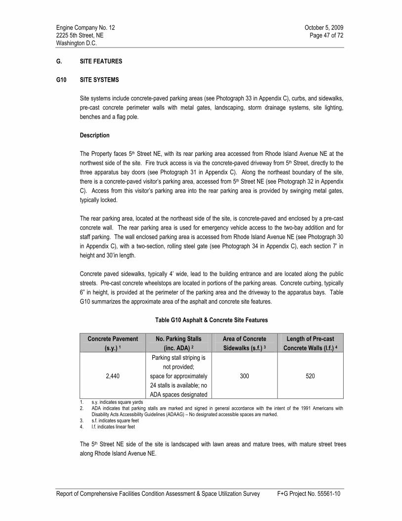
Engine Company No. 12 October 5, 20092225 5th Street, NE Page 47 of 72Washington D.C.
Report of Comprehensive Facilities Condition Assessment & Space Utilization Survey F+G Project No. 55561-10
G. SITE FEATURES
G10 SITE SYSTEMS
Site systems include concrete-paved parking areas (see Photograph 33 in Appendix C), curbs, and sidewalks,
pre-cast concrete perimeter walls with metal gates, landscaping, storm drainage systems, site lighting,
benches and a flag pole.
Description
The Property faces 5th Street NE, with its rear parking area accessed from Rhode Island Avenue NE at the
northwest side of the site. Fire truck access is via the concrete-paved driveway from 5th Street, directly to the
three apparatus bay doors (see Photograph 31 in Appendix C). Along the northeast boundary of the site,
there is a concrete-paved visitor’s parking area, accessed from 5th Street NE (see Photograph 32 in Appendix
C). Access from this visitor’s parking area into the rear parking area is provided by swinging metal gates,
typically locked.
The rear parking area, located at the northeast side of the site, is concrete-paved and enclosed by a pre-cast
concrete wall. The rear parking area is used for emergency vehicle access to the two-bay addition and for
staff parking. The wall enclosed parking area is accessed from Rhode Island Avenue NE (see Photograph 30
in Appendix C), with a two-section, rolling steel gate (see Photograph 34 in Appendix C), each section 7’ in
height and 30’in length.
Concrete paved sidewalks, typically 4’ wide, lead to the building entrance and are located along the public
streets. Pre-cast concrete wheelstops are located in portions of the parking areas. Concrete curbing, typically
6” in height, is provided at the perimeter of the parking area and the driveway to the apparatus bays. Table
G10 summarizes the approximate area of the asphalt and concrete site features.
Table G10 Asphalt & Concrete Site Features
Concrete Pavement
(s.y.) 1
No. Parking Stalls
(inc. ADA) 2
Area of Concrete
Sidewalks (s.f.) 3
Length of Pre-cast
Concrete Walls (l.f.) 4
2,440
Parking stall striping is
not provided;
space for approximately
24 stalls is available; no
ADA spaces designated
300 520
1. s.y. indicates square yards2. ADA indicates that parking stalls are marked and signed in general accordance with the intent of the 1991 Americans with
Disability Acts Accessibility Guidelines (ADAAG) – No designated accessible spaces are marked.3. s.f. indicates square feet4. l.f. indicates linear feet
The 5th Street NE side of the site is landscaped with lawn areas and mature trees, with mature street trees
along Rhode Island Avenue NE.

Engine Company No. 12 October 5, 2009 2225 5th Street, NE Page 48 of 72 Washington D.C.
Report of Comprehensive Facilities Condition Assessment & Space Utilization Survey F+G Project No. 55561-10
Wood and steel benches are located at the front of the building, with a 30’ aluminum flagpole near the main entrance. Exterior building illumination is provided by approximately 12 building mounted incandescent and HID fixtures. Storm water drainage is to pavement inlets in the rear parking area and to gutter catch basins along the public streets.
Condition
The concrete pavement is in good to fair condition, with several sections recently replaced in the rear parking area. However, remaining areas of parking area and driveway pavement that require repair include locations of exposed slab reinforcement steel and open cracking. The concrete sidewalks are in good condition, with only minor areas of isolated surface cracking. The rolling steel gates at the Rhode Island Avenue NE vehicle entrance are in poor condition, with damaged hardware that prevent their closing, peeling paint and rusting metal surfaces. We recommend near term replacement of the gates’ hardware and painting of all metal surfaces. The storm water system is reportedly in good condition. Exterior lighting appeared to be in good condition and is reportedly fully operational.
Projected Expenditures Required Capital Expenditures: Priority 1 (Immediate) No required capital expenditures are anticipated at this time. Priority 2 (2010) No required capital expenditures are anticipated at this time. Priority 3 (2011 – 2014) No required capital expenditures are anticipated at this time. Priority 4 (2015) No required capital expenditures are anticipated at this time.

Engine Company No. 12 October 5, 20092225 5th Street, NE Page 49 of 72Washington D.C.
Report of Comprehensive Facilities Condition Assessment & Space Utilization Survey F+G Project No. 55561-10
Required Maintenance Expenditures:
Priority 1 (Immediate)
No required maintenance expenditures are anticipated at this time.
Priority 2 (2010)
1. We recommend selective repairs to concrete pavement, totaling $1,980. These repairs include patching
spalling concrete surfaces and exposed welded-wire-fabric reinforcement in the northern corner of the
parking area near the pad-mounted electrical transformer at $1,680 ($15 per square foot) and open slab
cracking in the entrance driveway from Rhode Island Avenue NE at $300 ($10 per lineal foot).
2. We recommend repairs to the rolling gates at the entrance driveway from Rhode Island Avenue NE.
totaling $2,419. These repairs include replacement of the gate hardware at $848 ($424 each) and
preparing and painting the steel gates at $1995 ($2.10 per lineal foot).
Priority 3 (2011 – 2014)
No required maintenance expenditures are anticipated at this time.
Priority 4 (2015)
No required maintenance expenditures are anticipated at this time.

Engine Company No. 12 October 5, 20092225 5th Street, NE Page 50 of 72Washington D.C.
Report of Comprehensive Facilities Condition Assessment & Space Utilization Survey F+G Project No. 55561-10
H. ACCESSIBILITY ISSUES
H10 Accessibility
Introduction
As a publicly accessible facility, access to and within the building for disabled building users will be governed
(where applicable) by the 1991 Americans with Disability Act (ADA) Accessibility Guidelines. As the building in
its present condition likely received a Certificate of Occupancy prior to the above mentioned act coming into
effect, any continued occupancy of the current building would not be subject to the guidelines of the ADA.
Title I deals with employment discrimination, and requires that employers not discriminate against a disabled
person in hiring or employment. This can impact the configuration and features of buildings and those
employers are expected to make “reasonable accommodation”, including making facilities readily accessible to
disabled employees.
Title III requires that public accommodation provide goods and services to disabled patrons on an equal basis
with the non-disabled patrons. This title is the part of the Act with perhaps the greatest impact on buildings,
which provide public accommodations.
The ADA has provided a benchmark for measuring accessibility, primarily orientated towards new
construction. It also provides guidance for modification of existing facilities to eliminate barriers to access. This
benchmark is the ADA Accessibility Guidelines (ADAAG). The ADAAG was written by the Architectural and
Transportation Barriers Compliance Board, and first issued in final form in July 1991. The stated purpose of
the guidelines is to ensure that newly constructed facilities and altered portions of existing facilities covered by
the ADA are readily accessible to disabled persons.
This report has been based upon the ADAAG issued in July 1991. Discussion has been made by the
Architectural and Transportation Barriers Compliance Board for modification to the presently enforceable
ADAAG. The details and enforcement date of these modifications have yet to be released. In light of this
information, we recommend that prior to conducting any improvement, advice is sought from legal counsel and
current guidelines be adhered to.
Regulatory implementation of the ADA includes the following priorities for barrier removal in existing facilities:
Accessible Entrances. Providing access from public sidewalks, parking or public transportation
that enables disabled individuals to enter the facility.
Access to Goods and Services. Providing access to areas where goods and services are made
available to the public.
Usability of Restrooms. Providing access to restroom facilities.
Removal of Remaining Barriers. Providing access to the goods, services, facilities, privileges,
advantages, or accommodations.

Engine Company No. 12 October 5, 20092225 5th Street, NE Page 51 of 72Washington D.C.
Report of Comprehensive Facilities Condition Assessment & Space Utilization Survey F+G Project No. 55561-10
Applicability
The ADA in its purist form relates only to facilities occupied or significantly altered after March 13, 1991. For
facilities with Certificates of Occupancy issued prior to March 13, 1991 and not significantly altered after this
date, the ADA is seen as a “good practice guide” with a requirement to complete accessibility upgrades
typically made by civil suit and employee / user request.
The building received its initial Certificate of Occupancy prior to the March 13, 1991 implementation of the
ADA and has not been subject to major renovation since this date. As a result, under the current fire station
use, the building enjoys a grandfathered code status and is not required to complete accessibility upgrades.
However, we have recommended that allowances be budgeted for correction of ADA violations to make this
municipal facility fully accessible.
Accessibility Considerations
Accessible Entrances
The first consideration of the ADAAG relates to measures that will enable individuals with disabilities to
physically approach and enter a place of public accommodation. The priority of “getting through the door”
recognizes that providing actual physical access to a facility from public sidewalks, public transportation, or
parking, is generally preferable to any alternative arrangement in terms of both business efficiency and the
dignity of individuals with disabilities. In general terms this can mean exterior access to the building.
Persons traveling to the building by public transportation, specifically bus, will arrive at stops located near the
Property along Rhode Island Avenue NE. Access from the bus stops to the site is by sidewalks along the
public streets. Based upon our review, access to the site is ADA compliant.
Route of Travel
Disabled persons wishing to access the site and building are able to gain suitable by travel along the public
sidewalks and the main entry drive or the visitor parking area at the south side of the site. A separate
sidewalk connecting the public roadway’s sidewalk with the building entrance is not provided. However, the
main drive and the visitor parking area provides access to a sidewalk leading to the main pedestrian entrance
door at the east side of the building.
Accessible Parking
Parking spaces are not marked within the parking areas and no designated ADA accessible parking space is
provided. An accessible parking space should be located as close as possible to an ADA compliant entrance
to the building. We recommend budgeting for application of pavement striping and marking and installation of
an ADA compliant parking sign in the visitor parking area.

Engine Company No. 12 October 5, 20092225 5th Street, NE Page 52 of 72Washington D.C.
Report of Comprehensive Facilities Condition Assessment & Space Utilization Survey F+G Project No. 55561-10
Projected Expenditures
Required Capital Expenditures:
Priority 1 (Immediate)
No required capital expenditures are anticipated at this time.
Priority 2 (2010)
No required capital expenditures are anticipated at this time.
Priority 3 (2011 – 2014)
No required capital expenditures are anticipated at this time.
Priority 4 (2015)
No required capital expenditures are anticipated at this time.
Required Maintenance Expenditures:
Priority 1 (Immediate)
No required maintenance expenditures are anticipated at this time.
Priority 2 (2010)
1. We recommend striping of the pavement in the visitor parking area to provide a designated parking
space, with pavement markings and a posted sign. Our opinion of cost for the work is $250. The cost
includes parking stall striping, handicap accessible pavement markings, and a posted sign.
Priority 3 (2011 – 2014)
No required maintenance expenditures are anticipated at this time.
Priority 4 (2015)
No required maintenance expenditures are anticipated at this time.
Accessible Drop-Off and Pick-Up Areas
An accessible drop-off and pick-up area is not provided.

Engine Company No. 12 October 5, 20092225 5th Street, NE Page 53 of 72Washington D.C.
Report of Comprehensive Facilities Condition Assessment & Space Utilization Survey F+G Project No. 55561-10
Access to Goods & Services
The second consideration relates to measures that will enable individuals with disabilities to access areas
within the Property that provides goods and services.
Accessible Routes and Amenities
Horizontal and Vertical Circulation
The building is two-stories and does not contain an elevator or platform lift. Once within the building, a
disabled individual is provided with level and generally unrestricted access to the first floor only. The second
floor contains only living quarters for fire department personnel and, therefore, access by the disabled is not
considered to be required.
The handrails in the interior stairs do not comply with ADA requirements for a continuous, uninterrupted
handrail along the interior of the steps and extensions at the top and bottom risers. We recommend modifying
the handrails in the stairwell to comply with ADA requirements.
Projected Expenditures
Required Capital Expenditures:
Priority 1 (Immediate)
No required capital expenditures are anticipated at this time.
Priority 2 (2010)
No required capital expenditures are anticipated at this time.
Priority 3 (2011 – 2014)
No required capital expenditures are anticipated at this time.
Priority 4 (2015)
No required capital expenditures are anticipated at this time.
Required Maintenance Expenditures:
Priority 1 (Immediate)
No required maintenance expenditures are anticipated at this time.

Engine Company No. 12 October 5, 20092225 5th Street, NE Page 54 of 72Washington D.C.
Report of Comprehensive Facilities Condition Assessment & Space Utilization Survey F+G Project No. 55561-10
Priority 2 (2010)
2. We recommend budgeting $1,080 ($20 per lineal foot) for the modifications of interior handrails in the
stairway, making the interior handrails continuous and extending the wall railings beyond the top and
bottom risers.
Priority 3 (2011 – 2014)
No required maintenance expenditures are anticipated at this time.
Priority 4 (2015)
No required maintenance expenditures are anticipated at this time.
Door Widths and Signage
Section 4.1 (Minimum Requirements) of the ADAAG states that when accessible entrances are not all
accessible, then the inaccessible entrances shall have directional signage to indicate the route to the nearest
accessible entrance. The main building entrance is considered accessible. The interior doorways appear to
comply with ADA guidelines in terms of size, location, door opening pressure. However, the doors do not have
proper lever-type hardware.
The ADAAG requires that signs that identify permanent rooms and spaces, such as those identifying
restrooms and exits or providing classroom numbers, must have Braille and raised letters or numbers, so that
they may be read visually or tactilely. The signs must also meet specific requirements for mounting location,
color contrast, and non-glare surface. The interior of the building does not have proper signage and we
recommend it should include adequately specified and correctly mounted signage.
Projected Expenditures
Required Capital Expenditures:
Priority 1 (Immediate)
No required capital expenditures are anticipated at this time.
Priority 2 (2010)
No required capital expenditures are anticipated at this time.
Priority 3 (2011 – 2014)
No required capital expenditures are anticipated at this time.

Engine Company No. 12 October 5, 20092225 5th Street, NE Page 55 of 72Washington D.C.
Report of Comprehensive Facilities Condition Assessment & Space Utilization Survey F+G Project No. 55561-10
Priority 4 (2015)
No required capital expenditures are anticipated at this time.
Required Maintenance Expenditures:
Priority 1 (Immediate)
No required maintenance expenditures are anticipated at this time.
Priority 2 (2010)
3. We recommend installation of accessible lever-type hardware on all first floor doors. Our opinion of the
cost for this work is $2,750 ($250 each).
4. We recommend installation of interior signage in compliance with ADA guidelines. Our opinion of the
cost for this work is $2,387 ($0.15 per square foot).
Priority 3 (2011 – 2014)
No required maintenance expenditures are anticipated at this time.
Priority 4 (2015)
No required maintenance expenditures are anticipated at this time.
Usability of Restrooms
The third priority emphasizes those measures that will provide individuals with disabilities with access to
restroom facilities. The building contained men’s and women’s restrooms on each floor that are not compliant
with the ADAAG, due to lack of floor clearances, fixture heights and controls and accessories provided. We
recommend that one of the existing first floor restrooms be remodeled to make it fully compliant with the
ADAAG.
Projected Capital Expenditures
Projected Expenditures
Required Capital Expenditures:
Priority 1 (Immediate)
No required capital expenditures are anticipated at this time.

Engine Company No. 12 October 5, 20092225 5th Street, NE Page 56 of 72Washington D.C.
Report of Comprehensive Facilities Condition Assessment & Space Utilization Survey F+G Project No. 55561-10
Priority 2 (2010)
No required capital expenditures are anticipated at this time.
Priority 3 (2011 – 2014)
No required capital expenditures are anticipated at this time.
Priority 4 (2015)
No required capital expenditures are anticipated at this time.
Required Maintenance Expenditures:
Priority 1 (Immediate)
No required maintenance expenditures are anticipated at this time.
Priority 2 (2010)
5. We recommend budgeting for the complete reconfiguration and remodeling of one of the first floor
restrooms to function as a uni-sex restroom, to include required accessibility modifications as outlined in
the Americans with Disabilities Act. This work would include enlarging the restroom and its door to
provide maneuverability and installation of accessible fixtures, fittings and accessories. We have
recommended budgeting an allowance of $4,800 ($75 per square foot) for this work, to be constructed in
2010.
Priority 3 (2011 – 2014)
No required maintenance expenditures are anticipated at this time.
Priority 4 (2015)
No required maintenance expenditures are anticipated at this time.
Removal of Remaining Barriers
Drinking Fountains
The drinking fountain does not comply with Section 4.15 (Drinking Fountains and Water Coolers) of the
ADAAG for approach, spout height and operation. We recommend its replacement in 2010, in order to comply
with accessibility guidelines.

Engine Company No. 12 October 5, 20092225 5th Street, NE Page 57 of 72Washington D.C.
Report of Comprehensive Facilities Condition Assessment & Space Utilization Survey F+G Project No. 55561-10
Projected Expenditures
Required Capital Expenditures:
Priority 1 (Immediate)
No required capital expenditures are anticipated at this time.
Priority 2 (2010)
No required capital expenditures are anticipated at this time.
Priority 3 (2011 – 2014)
No required capital expenditures are anticipated at this time.
Priority 4 (2015)
No required capital expenditures are anticipated at this time.
Required Maintenance Expenditures:
Priority 1 (Immediate)
No required maintenance expenditures are anticipated at this time.
Priority 2 (2010)
6. We recommend replacement of the first floor drinking fountain with an accessible model installed in
compliance with accessible guidelines. Our opinion of cost for the work is $950.
Priority 3 (2011 – 2014)
No required maintenance expenditures are anticipated at this time.
Priority 4 (2015)
No required maintenance expenditures are anticipated at this time.

Engine Company No. 12 October 5, 20092225 5th Street, NE Page 58 of 72Washington D.C.
Report of Comprehensive Facilities Condition Assessment & Space Utilization Survey F+G Project No. 55561-10
I. HAZARDOUS MATERIALS
I10 Hazardous Materials
Faithful+Gould was not requested to perform an environmental assessment of the Property and has not
performed sampling or testing of materials as part of our assessment. However, as part of our assessment we
noted materials that may be hazardous. Previous condition assessment reports were not available for review.
It is recommended that a Hazardous Materials Study (Phase I Environmental Site Assessment) be conducted
at the subject property. Based upon our visual observation of the building, the building contains several
potentially hazardous materials as detailed below:
9” x 9” and 12” x 12” floor tiles and associated mastics throughout the building that may be asbestos
containing
Ceiling tiles of varying sizes throughout the building that may be asbestos containing
Pipe insulation at the mechanical room that may be asbestos containing
The hazardous materials observed during our evaluation varied in apparent condition from good (intact, non-
friable and contained/encapsulated) to fair (minor friability or damaged boiler and pipe insulation). However,
our evaluation consisted of a limited-scope visual assessment without the completion of sampling or
destructive analysis. The true condition of the hazardous materials and the extent of the hazard they present
will only be known after the completion of a more-in depth analysis.
Projected Capital Expenditures
Projected Expenditures
Required Capital Expenditures:
Priority 1 (Immediate)
No required capital expenditures are anticipated at this time.
Priority 2 (2010)
No required capital expenditures are anticipated at this time.
Priority 3 (2011 – 2014)
No required capital expenditures are anticipated at this time.
Priority 4 (2015)
No required capital expenditures are anticipated at this time.

Engine Company No. 12 October 5, 20092225 5th Street, NE Page 59 of 72Washington D.C.
Report of Comprehensive Facilities Condition Assessment & Space Utilization Survey F+G Project No. 55561-10
Required Maintenance Expenditures:
Priority 1 (Immediate)
No required maintenance expenditures are anticipated at this time.
Priority 2 (2010)
1. We recommend conducting and environmental assessment of the Property to determine the presence of
hazardous materials. Our opinion of the cost for this work is $10,000 in 2010.
Priority 3 (2011 – 2014)
No required maintenance expenditures are anticipated at this time.
Priority 4 (2015)
No required maintenance expenditures are anticipated at this time.

Engine Company No. 12 October 5, 20092225 5th Street, NE Page 60 of 72Washington D.C.
Report of Comprehensive Facilities Condition Assessment & Space Utilization Survey F+G Project No. 55561-10
J. ENVIRONMENTAL ANALYSIS
J10 LEED Analysis
MINIMUM PROGRAM REQUIREMENTS
The building must be fully occupied for at least 12 months preceding certification application; at least 75%
of the floor area must be physically occupied at normal capacity and the corresponding building systems
shall operate normally for a year.
The project scope must include 100% of the total floor area of each building in the certification
application, with the following exception: If operations are under separate management control for a
portion of the building, up to 10% of its floor area may be excluded for that reason. Other exemptions are
prohibited.
The building must be in compliance with federal, state, and local environmental laws and regulations,
including but not limited to those addressing asbestos, PCBs, water discharge, and water management.
At present, the percentage of physically occupied space within the building is more than 75%. The Engine
Company No. 12 facility meets the Minimum Program Requirements for LEED EB certification at this point.
The following sections will identify the areas in which the building can gain credits to become certified once the
minimum program requirements have been achieved.
PREREQUISITE CREDITS
To be eligible achieve LEED Certified status, the building is required to meet all the prerequisite criteria, all of
which are still to be achieved (refer to the LEED for Existing Buildings: Operations and Management Project
Checklist):
Water Efficiency (WE) Prerequisite 1: Minimum Indoor Plumbing Fixture and Fitting Efficiency.
To achieve this prerequisite, potable water usage must be reduced to the level of or below the designated
baseline for the building. The baseline is designated as 160% of the water usage that would occur if all the
plumbing fixtures met the International Plumbing Code (IPC) 2006 fixture and fitting performance
requirements. This baseline applies as the last major plumbing renovation was prior to 1993.
Energy & Atmosphere (EA) Prerequisite 1 – Minimum Efficiency Best Management Practices: Planning,
Documentation and Opportunity Assessment.
This prerequisite can be achieved by documenting the operations of the building, and preparing systems
narratives that describe the electrical and mechanical systems and the preventative maintenance required for
them.
EA Prerequisite 2 – Minimum Energy Efficiency Performance
To achieve this prerequisite, the building is required to score a minimum EPA rating of 69 using the Energy
Star Portfolio Manager tool.

Engine Company No. 12 October 5, 20092225 5th Street, NE Page 61 of 72Washington D.C.
Report of Comprehensive Facilities Condition Assessment & Space Utilization Survey F+G Project No. 55561-10
EA Prerequisite 3 – Refrigerant Management: Ozone Protection
To achieve this prerequisite, evidence must be submitted indicating that the HVAC&R base building systems
do not contain CFC-based refrigerants. If the current systems do contain CFC-based refrigerants, a phase out
plan must be created and implemented or a third party audit is required to calculate whether the systems’
replacement is economically feasible.
Materials & Resources (MR) Prerequisite 1 – Sustainable Purchasing Policy
This prerequisite requires that a sustainable purchasing policy is implemented for the building and site. This
policy should include the on-going consumables as illustrated in MR Credit 1, and at least one further
Sustainable purchasing credit, such as MR Credit 2: Sustainable Purchasing – Durable Goods.
MR Prerequisite 2 – Solid Waste Management Policy
This prerequisite can be achieved by providing a policy that identifies the requirements to achieve MR Credits
7, 8 and 9 which cover Ongoing Consumables, Durable Goods and Facility Alterations and Additions
respectively. The prerequisite requires only policies, not actual sustainable performance, with the exception of
the recycling of all mercury containing lamps.
Indoor Environmental Quality (EQ) Prerequisite 1 – Outdoor Air Introduction and Exhaust Systems
To achieve this prerequisite, evidence is required that the supply of outdoor air ventilation meets the rate
required by ASHRAE 62.1-2007 Ventilation Rate Procedure under all normal operating conditions.
Additionally; all air handlers are required to be measured for this prerequisite. An HVAC maintenance program
is required to ensure the proper operations and maintenance of HVAC components, and testing and
maintenance of all the building exhaust systems, including bathroom, shower, kitchen and parking exhaust
systems is also required.
EQ Prerequisite 2 – Environmental Tobacco Smoke (ETS) Control
To ensure this prerequisite is achieved, the designated smoking areas need to be located 25 feet from building
entries, outdoor air intakes and operable windows.
EQ Prerequisite 3 – Green Cleaning Policy
The policy required for this prerequisite covers the following points: the purchase of sustainable cleaning
products and equipment, the implementation of Standard Operating Procedures (SOPs) for the cleaning of the
building, hand hygiene strategies, chemical storage and handling standards, and staffing and training
requirements for the maintenance personnel of the building.
The prerequisites indicated above are all feasibly achievable with building improvements and the adoption of
sustainable building operations and maintenance policies.

Engine Company No. 12 October 5, 20092225 5th Street, NE Page 62 of 72Washington D.C.
Report of Comprehensive Facilities Condition Assessment & Space Utilization Survey F+G Project No. 55561-10
CURRENT LEED CREDITS
At the time of assessment, the building was not deemed eligible for any LEED Credits, based on the
conditions and operations observed and discussions with the on site staff. The score can be attributed to the
current condition of the building and its operation.
CREDITS AVAILABLE THROUGH RECOMMENDED IMPROVEMENTS
The recommendations included in the LEED for Existing Buildings: Operations and Management Project
Checklist provide opportunity for modifications to be made to the building or its operation in order to achieve
LEED credits. This section will identify credits that can be gained for the building with the work recommended
in the report and operations and maintenance policy and procedural changes.
Renovation of the restroom for accessibility for the disable will allow up to 3 credits to be gained in the Water
Efficiency section by specifying and installing water efficient fixtures. To achieve the maximum credits
possible, the new plumbing fixtures should reduce water consumption by at least 30% of the current base line
water usage. For the Engine No. 12 facility, this would mean the building’s plumbing fixtures and fittings must
meet the requirements of the International Plumbing Code (IPC) 2006 Edition.
Further points can be gained in the Water Efficiency section by installing a meter to measure the total potable
water use for the building, regularly recording the usage data and producing monthly and annual data
summaries. This would achieve one credit, with an additional credit to be gained through the installation of a
sub-meter to measure one of the following of water usage:
Indoor plumbing fixtures and fittings
HVAC system modifications
Domestic hot water
Other process water (dish washers, clothes washers, humidification systems etc)
The data from the metering of water usage in these systems must also be complied in monthly and annual
summaries.
Renovation of the HVAC, lighting, and interiors may allow up to 10 credits to be gained in the Energy and
Atmosphere section by specifying and installing equipment with an Energy Star rating of 69 or better,
commissioning of the building systems, ongoing commissioning, use of ozone friendly refrigerants, and
installation of a building automation system.
Renovation of the HVAC, lighting, and interiors may allow up to 4 credits to be gained in the Indoor
Environmental Quality section by the installation of monitoring of ventilation systems, integrating increased
ventilation rates on new air handlers, implementing an indoor air quality management plan for the construction
changes, and utilizing increased entry mats to reduce outside contaminates from entering the building.

Engine Company No. 12 October 5, 20092225 5th Street, NE Page 63 of 72Washington D.C.
Report of Comprehensive Facilities Condition Assessment & Space Utilization Survey F+G Project No. 55561-10
CREDITS AVAILABLE THROUGH STRATEGIC POLICY AND BEST PRACTICE
This section addresses the credits to be gained in operations and maintenance procedures which are not
mentioned otherwise in our recommendations. These procedures include credits to be gained through the
building management implementing Policies and Procedures that establish a more environmentally
sustainable and efficient way to operate and maintain the building. The following credits appear within this
category:
SS Credit 2.0 – Building Exterior and Hardscape Management Plan
One credit is available for the implementation of a management plan that reduces harmful chemical use,
energy waste, water waste, air pollution, solid waste, and/or chemical runoff in the management of the building
exterior and Hardscape areas. The plan is to cover the maintenance equipment, snow and ice removal,
cleaning of building exterior, paints and sealants on building exterior and the cleaning of sidewalks, pavement
and other Hardscape.
SS Credit 3.0 – Integrated Pest Management, Erosion Control and Landscape Management Plan
To achieve one point available for this credit, the building must have in place an environmentally sensitive
management plan for the site’s natural components. The plan must employ best management practices
that significantly reduce harmful chemical use, energy waste, water waste, air pollution, solid waste, and/or
chemical runoff (e.g., gasoline, oil, antifreeze, salts) compared with standard practices.
MR Credit 1.1 to 1.3 – Sustainable Purchasing: Ongoing Consumables
To achieve the 1 to 3 points available for this credit, the building has to maintain a sustainable purchasing
program covering materials with a low cost per unit that are regularly used and replaced through the course of
business. These materials include, but are not limited to, paper (printing or copy paper, notebooks, notepads,
envelopes), toner cartridges, binders, batteries, and desk accessories but exclude food and beverages.
MR Credit 2.1 and 2.2 – Sustainable Purchasing: Durable Goods
Two possible points are available for the adoption of a sustainable purchasing program for high unit cost
items, infrequently replaced and purchases that may require capital program outlays.
Credit 2.1 is concerned with the purchases of electronic equipment such as computers, printers,
monitors and appliances such as refrigerators and dishwashers (lists not exhaustive). To achieve
this credit, 40% of purchases are required to be sustainable.
Credit 2.2 is concerned with the purchases of furniture to achieve this credit, 40% of purchases are
required to be sustainable.
For the purposes of this assessment, a conservative estimate of 40% has been made, scoring two credits.
MR Credit 3.0 – Sustainable Purchasing: Facility Alterations and Additions

Engine Company No. 12 October 5, 20092225 5th Street, NE Page 64 of 72Washington D.C.
Report of Comprehensive Facilities Condition Assessment & Space Utilization Survey F+G Project No. 55561-10
One credit is available for maintaining a sustainable purchasing program for materials used for renovations,
demolitions, retrofits and new construction additions. This applies to items or elements permanently or semi-
permanently attached to the building, such as floor and ceiling finishes, and structural components such as
wall studs (list not exhaustive). To achieve the credit, 50% of purchases are required to be sustainable.
MR Credit 4.0 – Sustainable Purchasing: Reduced Mercury in Lamps
This credit is a requirement as part of MR Prerequisite 1: Sustainable Purchasing Policy. To achieve the points
in this credit, a sustainable purchasing policy needs is implemented for all lamp purchases in the study period
and beyond. To achieve the maximum of two points, at least 90% of mercury containing lamps must have a
maximum content of 70-picograms per lumen-hour. This credit does not cover the lamps currently installed
within the building.
EQ Credit 3.1 – Green Cleaning: High-Performance Cleaning Program
There is a point available for having a sustainable cleaning policy that addresses; appropriate staffing levels, a
training plan for maintenance personnel in the hazards, use, maintenance, disposal and recycling of cleaning
chemicals, dispensing equipment and packaging; the use of chemical concentrates; the use of sustainable
cleaning materials, products, equipment, janitorial paper products and trash bags; the use of sustainable
cleaning and hard floor and carpet care products meeting the sustainability criteria outlined in EQ Credit 3.4 –
3.6 and the use of cleaning equipment meeting the sustainability criteria outlined in EQ Credit 3.7.
EQ Credit 3.2 and 3.3 – Green Cleaning: Custodial Effectiveness Assessment
To achieve the 2 possible points for this credit the building must score 2 or less in an audit with APPA
Leadership in Educational Facilities “Custodial Staffing Guidelines” which will determine the appearance level
of the facility. The audit must cover a representative sample of the different types of spaces within the building
such as, offices, corridors etc.
EQ Credit 3.4 and 3.6 – Green Cleaning: Purchase of Sustainable Cleaning Products and Materials
The points in this credit are awarded for the percentage of cleaning products and materials purchase over the
course of the study period that meet the sustainable criteria. One point is awarded each 30% of purchases.
For the purposes of this assessment, we have targeted 60% of purchases to meet the criteria, scoring the
building 2 points.
EQ Credit 3.7 – Green Cleaning: Sustainable Cleaning Equipment
To achieve the one point available for this credit, the building has to have in place a program for the use of
janitorial equipment that reduces building contaminants and minimizes environmental impact. The cleaning
equipment program must meet sustainable criteria such as operation at less than 70dBA, “Green Label”,
Carpet and Rug Institute’s “Seal of Approval”, and equipped with environmentally friendly batteries.

Engine Company No. 12 October 5, 20092225 5th Street, NE Page 65 of 72Washington D.C.
Report of Comprehensive Facilities Condition Assessment & Space Utilization Survey F+G Project No. 55561-10
SUMMARY
The recommendations provided above identify the necessary steps required to achieve certified status at this
present time, using the LEED-Existing Buildings Operations and Maintenance rating system. A summary table
showing potential LEED points is included on the following page.
SUMMARY
Possible Maximum 92 points
LEED CERTIFIED Minimum 34 points
LEED SILVER Minimum 43 points
LEED GOLD Minimum 51 points
LEED PLATINUM Minimum 68 points
Pts
Existing Condition (1)From FCA (2)
To LEED Certification
(3)
Group Name
Pos
sibl
e Detail/No
of
Credits
Notes
Detail/No
of
Credits
Notes
Detail/No
of
Credits
Notes
Sustainable Sites 12 0 0 2
Water Efficiency 10 0 5 0
Energy and Atmosphere 30 0 10 0
Materials and Resources 14 0 0 7
Indoor Environmental Quality 19 0 4 6
Innovation in Operation, Upgrades & Maint. 7 0 0 0
Existing Condition (1) 92 0 Subtotal 19 Subtotal 15 Subtotal
From FCA (2) 19
Total after FCA 19
To LEED Certification (3) 15
LEED TOTAL POINTS 34 CERTIFIED
(1) Existing Condition Credits observed based on the facilities' condition and operations and maintenance
procedures in place at the time of assessment.
(2) From Facility Condition Assessment
(FCA)
Credits that can be achieved through the implementation of recommended
improvements included in this FCA.
(3) To LEED Certification Credits that can be achieved through the implementation of operations and
maintenance policies and procedures, without the use of FCA requirements.

Engine Company No. 12 October 5, 20092225 5th Street, NE Page 66 of 72Washington D.C.
Report of Comprehensive Facilities Condition Assessment & Space Utilization Survey F+G Project No. 55561-10
J20 Green Roof Feasibility
Faithful+Gould was requested to conduct a study for the design and installation of a green roof system to
support low impact development solutions. This study consisted of an evaluation of the existing roof structure,
subsurface components (i.e. roof system), drainage systems and structural load limits.
Introduction
A green roof system consists of a landscaped system
installed over the waterproofing membrane of a low-
slope roof. For the Property, this would consist of a
series of landscaped elements installed over the top of
the existing low-slope roof areas. The sectional detail of
a typical green roof system is as detailed in the
attached plan, and includes the roof membrane, a root
repellant system, a drainage system, filter cloth, an
irrigation system and a lightweight growing medium and
plants.
Options
The Property is faced with two principal options when deciding the type of green roof system to be installed.
1. Option one consists of an “Extensive Green Roof”. This type of system consists of a Soil Depth (Shallow
depth) of 0.8 – 6 inches, an imposed weight on the structural systems of 15 – 50 lbs/sf (depending on the
soil depth and type of substrate used), and require limited maintenance. The system is usually not meant
to be publicly accessible except for maintenance purposes. Plant selection and diversity is based on
hardiness and climate adaptability with plants typically chosen because of their shallow root systems. The
variety of plants that can be used is limited compared to an intensive green roof. The growing medium
consists of mineral-based mixture including gravel sand crushed brick, soil, lightweight expanded clay
aggregate, peat, and organic matter.
2. Option two consists of “Intensive Green Roofs”. This system is similar to a traditional garden or
manicured landscape Intensive green roofs are meant to be accessible or showcased for public use. Soil
Depth is typically 6 inches or more (typically 8 – 24 inches). Weight load on the structure is significant at
80-150 lbs/sf. Maintenance is aggressive with the system requiring regular watering and landscaping.
This system also requires a complex irrigation and drainage system
Based upon the configuration and extensive nature of the roof areas, no requirement for the green roof to be
accessible for public use, and anticipated cost and construction constraints, we have recommended that if
installed, an Extensive Green Roof be selected.

Engine Company No. 12 October 5, 20092225 5th Street, NE Page 67 of 72Washington D.C.
Report of Comprehensive Facilities Condition Assessment & Space Utilization Survey F+G Project No. 55561-10
Existing Roof Structure and Structural Load Limits
The low-slope roofs are installed over either cast-in-place or pre-cast concrete decks. Structural drawings
were not available to determine the designed live and dead loadings of the roof structures. Based upon the
observed structural systems, we anticipate that the roof structures were designed with a superimposed live
load sufficient enough to be of adequate capacity to allow installation of a green roof system.
Roof System & Drainage Systems
The building contained two adequately drained low-slope roof areas that, with proper maintenance, should be
adequately drained and generally suitable for the installation of a green roof system.
Installation Costs
The cost for the installation of green roofs can vary considerably and will include the following major
components:
Consultant fees: Structural analysis, designers, landscapers, and contractors fees
Structural analysis recommendations: Safety and repairs needed before installation of green roof.
Irrigation system: Drip system (permanently installed) or sprinkler and drainage costs
Garden materials: Growing medium, plants, fertilizers, substrate containers (extensive green roofs), and
pavers (to prevent spread of fire and allow accessibility).
Plants.
Maintenance: Initial (extensive green roofs) and sometimes long-term (intensive green roofs)
maintenance costs depending on the size and type of green roof installed. For example, extensive
green roofs regular maintenance is only needed for 6-12 months (after plants are established) after
which watering a weeding once a season is sufficient.
Professional assistance and permits.
Based upon these costs and the project constraints (i.e. multiple roof areas), we an allowance of $12 per
square foot is reasonable for this work. Our unit rate for this work is based upon the cost factors detailed
within Table J-20.
Table J-20 Green Roof Cost Factors
Component Costs Per Square Foot Cost Factors
Green Roof System (drainage,
filtering, paving, growing medium)$7
Growing medium (type and depth), pavers
(size and type), and square footage of the
green roof (project size)
Plants $2Season of installation, type of plants, and
size of seeds being planted
Installation and Labor $3
Equipment necessary to move materials on
to the roof (E.g. crane, if rented is: $
4,000/day), project size, design, and
planting methods

Engine Company No. 12 October 5, 20092225 5th Street, NE Page 68 of 72Washington D.C.
Report of Comprehensive Facilities Condition Assessment & Space Utilization Survey F+G Project No. 55561-10
Projected Expenditures
Required Capital Expenditures:
Priority 1 (Immediate)
No required capital expenditures are anticipated at this time.
Priority 2 (2010)
No required capital expenditures are anticipated at this time.
Priority 3 (2011 – 2014)
No required capital expenditures are anticipated at this time.
Priority 4 (2015)
No required capital expenditures are anticipated at this time.
Required Maintenance Expenditures:
Priority 1 (Immediate)
No required maintenance expenditures are anticipated at this time.
Priority 2 (2010)
1. The installation of a green roof system on the low slope roofs at the subject Property, if determined to be
desirable for this facility, is estimated to cost $82,800 ($12 per square foot).
Priority 3 (2011 – 2014)
No required maintenance expenditures are anticipated at this time.
Priority 4 (2015)
No required maintenance expenditures are anticipated at this time.
J30 Energy Efficiency
Faithful+Gould was requested to identify areas of the building that could be improved to increase energy
efficiency. Buildings make up 40% of total U.S. energy consumption (including two-thirds of the country’s

Engine Company No. 12 October 5, 20092225 5th Street, NE Page 69 of 72Washington D.C.
Report of Comprehensive Facilities Condition Assessment & Space Utilization Survey F+G Project No. 55561-10
electricity) and 16% of total U.S. water consumption. They are responsible for 40% of all material flows and
produce 15%– 40% of the waste in landfills within the D.C. market.
Older buildings such as the Property contribute significantly to this energy use and therefore provide a
potential source to reduce energy use through improving energy efficiency. The Property contains several
systems that although efficient at the time of installation now represent poorly efficient installations that can be
replaced or modified to achieve energy savings. Based upon our evaluation of the Property, we identified the
following as the primary source for energy savings:
Building Lighting Systems
Exit Signs
Plumbing Fixtures
Projected Expenditures
Required Capital Expenditures:
Priority 1 (Immediate)
No required capital expenditures are anticipated at this time.
Priority 2 (2010)
No required capital expenditures are anticipated at this time.
Priority 3 (2011 – 2014)
No required capital expenditures are anticipated at this time.
Priority 4 (2015)
No required capital expenditures are anticipated at this time.
Required Maintenance Expenditures:
Priority 1 (Immediate)
No required maintenance expenditures are anticipated at this time.
Priority 2 (2010)
1. Building Lighting: The Property uses outdated incandescent lamps and non-energy efficient ballasts.
These lamps use significant power. Replacing the existing building lights with energy efficient fluorescent
tube and compact fluorescent fixtures will result in significant cost savings. Based upon the quantity,
spacing and types of lights installed at the Property, we anticipate that existing lights each use between

Engine Company No. 12 October 5, 20092225 5th Street, NE Page 70 of 72Washington D.C.
Report of Comprehensive Facilities Condition Assessment & Space Utilization Survey F+G Project No. 55561-10
100 – 200 kilowatts per hour. Replacement compact fluorescent fixtures will typically use 58 – 104
kilowatts per hour providing immediate cost savings. The cost for this item is included in the lighting
replacement costs in Section D50, Electrical.
2. Exit Signs: Presently, there are limited existing exit signs. When exit signs are installed, the signs should
consist of LED fixtures that will result in significant cost savings. The cost for this item is included in the
exit and egress lighting costs of in Section D40, Fire Protection.
3. We also recommend budgeting $4,500 ($225 each) for various plumbing fixture upgrades, including flush
valves and low-flow fixtures to reduce the water consumption of the Property.
Priority 3 (2011 – 2014)
No required maintenance expenditures are anticipated at this time.
Priority 4 (2015)
No required maintenance expenditures are anticipated at this time.

Engine Company No. 12 October 5, 20092225 5th Street NE Page 1 of 7Washington D.C.
Report of Comprehensive Facilities Condition Assessment & Space Utilization Survey F+G Project No. 55561-10
SPACE UTILIZATION SURVEY
Faithful+Gould was requested to develop an occupancy profile for the Property to indicate current utilization of the
building. This effort consisted of producing a location and tenant specific inventory of furnishings and people,
developing a floor plan for each occupiable floor, and calculating various usable and gross floor area matrixes. The
process used to generate these deliverables along with the findings of our study are detailed below.
Inventory & Occupancy Number
Faithful+Gould walked the interior of each occupiable area of the Property, quantified major items of furniture and
counted the number of persons contained within those spaces. The intent is that this list will provide an inventory of
contained furnishings and details of the number of occupants within each area. Upon completion of our on-site
assessment, we entered our findings into a database system that allows sorting by any of the major system elements
(i.e. floor, tenant, furniture etc.). The results of this inventory and occupancy profile are included within the following
pages. A sample of this sheet is shown below.

Engine Company No. 12 October 5, 20092225 5th Street NE Page 2 of 7Washington D.C.
Report of Comprehensive Facilities Condition Assessment & Space Utilization Survey F+G Project No. 55561-10
Floor Plans & Area Calculations
In conjunction with the completion of our on-site inventory and occupancy survey, we completed detailed
measurements of the building interiors. Measurements were taken to determine the interior dimensions of each room
and common area, the interior area of each room, the location of all walls, partitions, doors, and windows, and the
location and extent of the building core area, including elevator shafts, toilets, storage area, public corridors and other
support areas.
At the conclusion of our on-site measurements we produced space level floor plans of each occupiable level using
AutoCAD. Floor plans were utilized to determine the key building measurements detailed below. On-site
measurements and floor area calculations were completed in accordance with the PBS National Business Assignment
Guide standards and ANSI/BOMA Z65.1-1996.
Gross Floor Area
Gross Measured Area is the total “constructed area” of a building (also referred to as Design Gross). NOTE: In Federal
and Leased buildings where the government is the sole tenant, this area is the Total Construction Area. However, in
Leased buildings where the government is a partial tenant, the Design Gross is the occupied portion plus the pro rated
share of the Common space.
The Gross Measured Area is typically used for measuring building value and/or building costs. It is calculated by
measuring to the outside dominant finished surface (without deductions) and adding the sum of all enclosed floors
including:
Basements and Sub-basements;
Mechanical equipment floors;
Penthouses;
Structured parking;

Engine Company No. 12 October 5, 20092225 5th Street NE Page 3 of 7Washington D.C.
Report of Comprehensive Facilities Condition Assessment & Space Utilization Survey F+G Project No. 55561-10
Crawl space.
Net Rentable Area
Rentable (ANSI Rentable) area is defined as the tenant’s usable area plus their share of Building Common area. Non-
assignable area(s) are not included in this calculation. Rentable is used to calculate the tenant’s rent bill and is
calculated as follows: Rentable = Usable area + Building Common.
Building Common
Building Common
Assigned as ANSI Category 02 and according to BOMA the Building Common area is “the areas of a building that
provide services or circulation to building tenants but which are not included in the Office or Storage area of any
specific tenant. EXCLUDED from Building Common are parking, portions of loading docks outside the building line and
major vertical penetrations (see above).” Specific examples and/or illustrations of Building Common are as follows:
Public corridors and main auxiliary lobbies used by all tenants in the building;
Tenant support or security areas such as concierges, security desks and fire control rooms;
Fully enclosed courtyards within the building line;
Mechanical and/or telephone rooms that service (support) more than one floor (i.e. the whole building) and are not
specialty spaces for a single tenant;
Public toilets used by all tenants that are required by the Uniform Building Code for the floor where they are
located. The public toilet square footage includes the associated plumbing chase and (according to BOMA) are
NOT vertical penetrations; and
Spaces used for the sole purpose of supporting building operations or upkeep, such as:
Property Management Office (PMO) specifically used to support or service the building in which it is located;

Engine Company No. 12 October 5, 20092225 5th Street NE Page 4 of 7Washington D.C.
Report of Comprehensive Facilities Condition Assessment & Space Utilization Survey F+G Project No. 55561-10
Spaces used to house or support building operations and maintenance, such as: storage rooms (doors, paint, light
bulbs, ceiling tiles…), maintenance offices and contractor space used specifically to support or service the
building in which it is located; and
Guard and building monitoring stations within the building, but are NOT used for other types of office functions.
Floor Common
Assigned as ANSI Category 03 and according to BOMA, the Floor Common Area is “the areas on a floor, such as
washrooms, janitorial closets, electrical and telephone rooms, mechanical rooms, elevator lobbies and public corridors
that are available primarily for the use of the tenants on that floor.” Specific examples and/or illustrations of Floor
Common are as follows:
Horizontal Circulation spaces such as public corridors and elevator lobbies;
Public toilets (and associated plumbing chases) required by the Uniform Building Code for the floor where they
are located; and
Support spaces such as janitorial closets, electrical, telephone, mechanical and equipment rooms that specifically
support the floor on which it is located.
Building Common is calculated by summing all of the following Space Types within a particular building:
Circulation Horizontal (CRH) Mechanical (MCH) Toilets (TLT) Custodial (CST)

Engine Company No. 12 October 5, 20092225 5th Street NE Page 5 of 7Washington D.C.
Report of Comprehensive Facilities Condition Assessment & Space Utilization Survey F+G Project No. 55561-10
Usable
Usable space (ANSI Usable) is defined as all Assignable and Joint Use space within the building. This is used for
calculating the actual space occupied by tenants. The calculation to determine usable square footage is to measure
the area(s) enclosed between the Finished Surfaces of Office Areas (ex. the office side of a corridor), the dominant
portion or major vertical penetration and the center of partitions that separate office spaces. No deduction is made for
columns and projections necessary to the building.
Vertical Penetrations
Assigned as ANSI Category 04 and according to BOMA, Vertical Penetrations are “the areas such as stairs, elevator
shafts, flues, pipe shafts, vertical ducts and their enclosing walls are considered vertical penetrations. Atria, lightwells
and similar penetrations above the finished floor are also included within this definition.” Specific examples and/or
illustrations of Vertical Penetrations are as follows:
Generally, the space must be large enough for a person to fit comfortably through the penetration
(approximately 9 square feet);
The space must be deducted from the floor slab it penetrates—however, sleeved slabs and/or openings for
plumbing, electrical or telephone chases are NOT vertical penetrations;
Examples of common vertical penetrations are:
o Atrium spaces that are NOT an amenity to a single tenant,
o Attic space on a mezzanine floor level,
o Elevator shafts,
o Incinerator chimneys,
o Fire egress stairwells,
o Public and or multi-tenant stairs, and
o Return/supply air chase; and
Vertical penetrations built specifically for the private use of a tenant are NOT classified as vertical
penetrations

Engine Company No. 12 October 5, 20092225 5th Street NE Page 6 of 7Washington D.C.
Report of Comprehensive Facilities Condition Assessment & Space Utilization Survey F+G Project No. 55561-10
Property Specific Calculations
Gross Floor Area
The Gross Measured Area is calculated by measuring to the outside dominant finished surface (without deductions)
and adding the sum of all enclosed floors including:
Basements and Sub-basements;
Mechanical equipment floors;
Penthouses;
Structured parking;
Crawl space.
Engine 12
Floor Number Gross Measured Area (SF)
1 8,758
2 7,155
TOTAL 15,913
Net Rentable Area
Rentable (ANSI Rentable) area is defined as the tenant’s usable area plus their share of Building Common area. Non-
assignable area(s) are not included in this calculation. Rentable is used to calculate the tenant’s rent bill and is
calculated as follows: Rentable = Usable area + Building Common.
Rentable = Usable Area + Building Common
Usable Area = Usable space is defined as all Assignable and
Joint Use space within the building. The calculation used to
determine usable square footage is to measure the area(s)
enclosed between the Finished Surfaces of Office Areas (ex.
the office side of a corridor), the dominant portion or major
vertical penetration and the center of partitions that separate
office spaces. No deduction is made for columns and
projections necessary to the building. The area shaded blue
on the attached plan is measured. The central core shown in
white is not measured.
Building Common = Building common is “the areas of a
building that provide services or circulation to building tenants
but which are not included in the Office or Storage area of
any specific tenant. EXCLUDED from Building Common are
parking, portions of loading docks outside the building line and major vertical penetrations.
As the building is configured for single tenant use the net rentable area is basically the floor area measured from the
interior face of the exterior walls minus the area of the major vertical penetrations. Major vertical penetrations consist of
vertical shafts, stairs and chimneys.

Engine Company No. 12 October 5, 20092225 5th Street NE Page 7 of 7Washington D.C.
Report of Comprehensive Facilities Condition Assessment & Space Utilization Survey F+G Project No. 55561-10
Net Rentable Area Calculation
Engine 12
Floor Number Net Measured Area (SF)
1 8,481
2 6,778
TOTAL 15,259
Tenant Profiles & Inventory
The building is 100% occupied by the Fire and Emergency Management Department and provides accommodation for17 people.

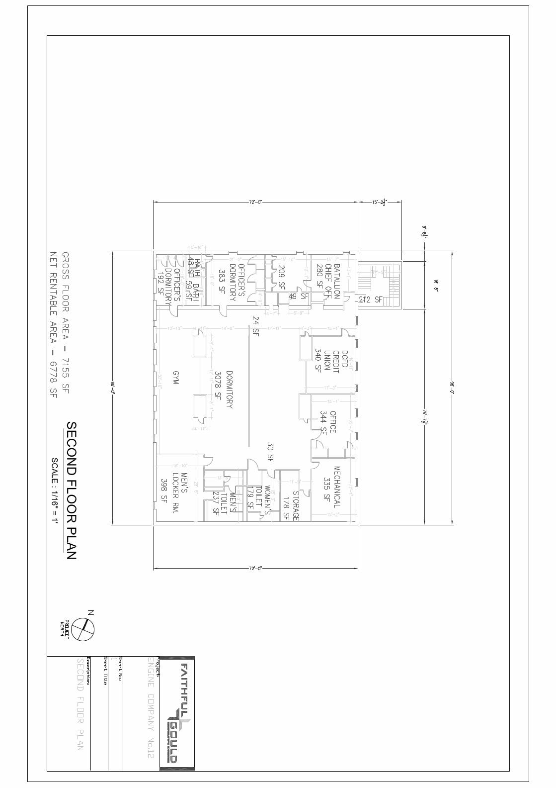

Inventory and Occupancy By Building

����������� ���
� ������� � � �� �� � � ������ � �� � ������ �� ��� ����
By Building
���������
�� �� �� ���� � � � ��� � � � � � ��� � � � ��� � � � �� � � � �� � � �� �� � � � � �� �
� ������ � �����
� � �� � ��! ��
" � � � � � ��� ��# � �� ��$
" � � � � � ��� ��#� �����$
� ��� �#� � �% � % $
� ���#� � �&����� �$ � � & � � � �% ���� �
� ! " � ���# $ ��� ��% & ! ' �' � �$ ���" ��( �% �
� ' �' ���) �* + ��,-� . ,,�% � . ,,�% � � � � � � � � � � ��
� ! " � ���# $ ��� ��% & ! ' �' � �$ ���" ��( �% �
��% ���% ' �/ ) ) $ ��% ���% ' � � � � � � � � � � � � ��0
� ! " � ���# $ ��� ��% & ! ' �' � �$ ���" ��( �% �
1 ' 2 3! ' �4 ) �� � + ) 5 4 ) �� � + ) 5 � � � � � � � � � � � ����
� ! " � ���# $ ��� ��% & ! ' �' � �$ ���" ��( �% �
4 ) $ ��-� / �� ��) ) $ / �� ��) ) $ � � � � � � � � � � � ����
� ! " � ���# $ ��� ��% & ! ' �' � �$ ���" ��( �% �
* ) $ $ � ���& / ) ) $ � � � �$ � �& � � � � � � � � � � ����
� ! " � ���# $ ��� ��% & ! ' �' � �$ ���" ��( �% �
6 ��% + ���� ����� 6 ��% + ���� ����� � � � 0 � � � � � � � ��0
� ! " � ���# $ ��� ��% & ! ' �' � �$ ���" ��( �% �
! ��-� / �� ��) ) $ / �� ��) ) $ � � � � � � � � � � � ���
� ! " � ���# $ ��� ��% & ! ' �' � �$ ���" ��( �% �
4 ' �% + / ) ) $ . ,,�% � � � � � � � � � � �� 7
� ! " � ���# $ ��� ��% & ! ' �' � �$ ���" ��( �% �
" �) �' � � " �) �' � � � � � � � � � � � � � �
� ! " � ���# $ ��� ��% & ! ' �' � �$ ���" ��( �% �
� 5 5 ' �' �� � � ' & � 5 5 ' �' �� � � � � � � � � � � � � �8 ���
� ! " � ���# $ ��� ��% & ! ' �' � �$ ���" ��( �% �
! ��-� 9 ) % � ��/ ) ) $ 9 ) % � ��/ ) ) $ � � � � � � � � � � �7��
� ' ��+ ,� �: ; ) � �� * ) �����) �� � � �� � $ ����' � ��) ,

����������� ���
� ������� � � �� �� � � ������ � �� � ������ �� ��� ����
By Building
���������
�� �� �� ���� � � � ��� � � � � � ��� � � � ��� � � � �� � � � �� � � �� �� � � � � �� �
� ������ � �����
� � �� � ��! ��
" � � � � � ��� ��# � �� ��$
" � � � � � ��� ��#� �����$
� ��� �#� � �% � % $
� ���#� � �&����� �$ � � & � � � �% ���
* ) ����� ��,�) $ 5 ��( �) � � 5 ' � �����
� �
� ! " � ���# $ ��� ��% & ! ' �' � �$ ���" ��( �% �
. ,,�% ��-� � ) �$ ��) �& . ,,�% � � � � � � � � � � �7�7
� ! " � ���# $ ��� ��% & ! ' �' � �$ ���" ��( �% �
. ,,�% ��-� � ) �$ ��) �& . ,,�% � � � � � � � � � � ���
� ! " � ���# $ ��� ��% & ! ' �' � �$ ���" ��( �% �
� * � � * �����< ��) � . ,,�% � � � � � � � � � � �7��
� ! " � ���# $ ��� ��% & ! ' �' � �$ ���" ��( �% �
� ) �$ ��) �& �; & $ � % % ) $ ) �' ��) ��� ����� �
�� � � � � � � � � � �7�0�
� ! " � ���# $ ��� ��% & ! ' �' � �$ ���" ��( �% �
. ,,�% � . ,,�% � 7 � � � � � � � �7��
� ! " � ���# $ ��� ��% & ! ' �' � �$ ���" ��( �% �
! ��-� / �� ��) ) $ / �� ��) ) $ � � � � � � � � � � � 70
� ! " � ���# $ ��� ��% & ! ' �' � �$ ���" ��( �% �
4 ) $ ��-� / �� ��) ) $ / �� ��) ) $ � � � � � � � � � � ��0�
� ! " � ���# $ ��� ��% & ! ' �' � �$ ���" ��( �% �
! " . ,,�% � . ,,�% � � � � � � � � � � � ��8 0
�0 � � � � � � � � � � � ��&� � ����������
�0 � � � � � � � � � � � ��&� � �' �� � � �
� ' ��+ ,� �: ; ) � �� * ) �����) �� � � �� � $ ����' � � ) ,

Inventory and Occupancy By Floor

����������� ���
� ������� � � �� �� � � ������ � �� � ������ �� ��� ����
By Floor
�
� � ��� �� � � � �� � � � � ��� � � �� � � � � � � � �� � � �� � � � � � � � �� �
� ���� �� � � �� ��
� � � �! �
" � � � �� �� � �#� � � � $
" � � � �� �� � �# �� � � $
� � � � � �# �� � � � � � $
� � � � �#� � % � � � $ %� � � � �� � � �
�� ���� � ! ! " �" �� � � " # � ! ! " �" �� �� $ % � � � � � � � � � � �& ���
�� ���� ��' ���' " �( ) ) * ��' ���' " �� $ % � � � � � � � � � � ��+
�� ���� , " - .$ " �/ ) �� � 0 ) ! / ) �� � 0 ) !� $ % � � � � � � � � � � ����
�� ���� / ) * ��1� ( �� ��) ) * ( �� ��) ) *� $ % � � � � � � � � � � ����
�� ���� 2 ) * * � ���# ( ) ) * � � � �* � �#� $ % � � � � � � � � � ����
�� ���� 3 ��' 0 ���� ����� 3 ��' 0 ���� ������ $ % � � + � � � � � � � ��+
�� ���� $ ��1� ( �� ��) ) * ( �� ��) ) *� $ % � � � � � � � � � � ���
�� ���� / " �' 0 ( ) ) * 4 55�' �� $ % � � � � � � � � �� 6
�� ���� % �) �" � � % �) �" � �� $ % � � � � � � � � � � �
�� ���� $ % 4 55�' � 4 55�' �� $ % � � � � � � � � � ��& +
� �� ��% � �� � �+ � � � � � �
&
� � ��� �� � � � �� � � � � ��� � � �� � � � � � � � �� � � �� � � � � � � � �� �
� ���� �� � � �� ��
� � � �! �
" � � � �� �� � �#� � � � $
" � � � �� �� � �# �� � � $
� � � � � �# �� � � � � � $
� � � � �#� � % � � � $ %� � � � �� � � �
�� ���� $ ��1� 7 ) ' � ��( ) ) * 7 ) ' � ��( ) ) *� $ % � � � � � � � � � � �6��
�� ���� 4 55�' ��1� � ) �* ��) �# 4 55�' �� $ % � � � � � � � � � �6�6
�� ���� 4 55�' ��1� � ) �* ��) �# 4 55�' �� $ % � � � � � � � � � ���
�� ���� � 2 � � 2 �����8 ��) � 4 55�' �� $ % � � � � � � � � � �6��
�� ���� � ) �* ��) �# �9 # * � ' ' ) * ) �" ��) ��� ����� �
� $ % �� � � � � � � � � � �6�+�
�� ���� 4 55�' � 4 55�' �� $ % 6 � � � � � � � �6��
�� ���� $ ��1� ( �� ��) ) * ( �� ��) ) *� $ % � � � � � � � � � � � 6+
�� ���� / ) * ��1� ( �� ��) ) * ( �� ��) ) *� $ % � � � � � � � � � � ��+�
�� ���� � " �" ���) �2 0 ��51� 4 55�' � 4 55�' �� $ % � � � � � � � � � ��
� �� ��% � �& �+ �� � � � � � � �
� �� ��% � �' � � �+ � � � � � � � � �
� " ��0 5� �: 9 ) � �� 2 ) �����) �� � � �� � * ����" � ��) 5�

Inventory and Occupancy By Space

����������� ���
� ������� � � �� �� � � ������ � �� � ������ �� ��� ����
By Space Name
�����������
� � � � � � � �������� � � � ��� � �� �� � �� � � � �� � � �� � � �� � � � ����
� ��� �� �� � � ��
� � �� � � � � �
! � �� ������ �"� ����� #
! � �� ������ �"� � � �� #
� �� �� ��"� �� � ��� #
� �� �� �"� � $� �� � � # � � $�� � ��� � � �� �
� ! " � ���# $ ��� ��% & ! ' �' � �$ ���" ��( �% �
�� ���� � ) ) ' �' �� � � � � � � � � � � � � �* ���
� � ����$� ������������� � � � � � � � � � � �
������� �� � �� $���� $$�� �
� � � � � � � �������� � � � ��� � �� �� � �� � � � �� � � �� � � �� � � � ����
� ��� �� �� � � ��
� � �� � � � � �
! � �� ������ �"� ����� #
! � �� ������ �"� � � �� #
� �� �� ��"� �� � ��� #
� �� �� �"� � $� �� � � # � � $�� � ��� � � �� �
� ! " � ���# $ ��� ��% & ! ' �' � �$ ���" ��( �% �
�� ���� + ,,�% � � � � � � � � � � ��
� � ����$� ��������� �� � �� $���� $$�� � � � � � � � � � �
� � % % � ���& � � %
� � � � � � � �������� � � � ��� � �� �� � �� � � � �� � � �� � � �� � � � ����
� ��� �� �� � � ��
� � �� � � � � �
! � �� ������ �"� ����� #
! � �� ������ �"� � � �� #
� �� �� ��"� �� � ��� #
� �� �� �"� � $� �� � � # � � $�� � ��� � � �� �
� ! " � ���# $ ��� ��% & ! ' �' � �$ ���" ��( �% �
�� ���� � � � �$ � �& � � � � � � � � � � ����
� � ����$� ��� � % % � ���& � � % � � � � � � � � � �
� � � � �� �� � ���� ��
� � � � � � � �������� � � � ��� � �� �� � �� � � � �� � � �� � � �� � � � ����
� ��� �� �� � � ��
� � �� � � � � �
! � �� ������ �"� ����� #
! � �� ������ �"� � � �� #
� �� �� ��"� �� � ��� #
� �� �� �"� � $� �� � � # � � $�� � ��� � � �� �
� ! " � ���# $ ��� ��% & ! ' �' � �$ ���" ��( �% �
�� ���� + ,,�% � � � � � � � � � � �-��
� � ����$� ��� � � � �� �� � ���� �� � � � � � � � � � �
� ' ��. ,� �/ 0 1 � �� 2 1 �����1 �� � � �� � $ ����' � ��1 ,*

����������� ���
� ������� � � �� �� � � ������ � �� � ������ �� ��� ����
By Space Name
� � �% ��� ��'�( %
� � � � � � � �������� � � � ��� � �� �� � �� � � � �� � � �� � � �� � � � ����
� ��� �� �� � � ��
� � �� � � � � �
! � �� ������ �"� ����� #
! � �� ������ �"� � � �� #
� �� �� ��"� �� � ��� #
� �� �� �"� � $� �� � � # � � $�� � ��� � � �� �
� ! " � ���# $ ��� ��% & ! ' �' � �$ ���" ��( �% �
�� ���� � % % 1 $ 1 �' ��1 ��� ����� �
�� � � � � � � � � � �-�3�
� � ����$� ��� � �% ��� ��'�( % �� � � � � � � � � � �
) �� � ���� ���& � � %
� � � � � � � �������� � � � ��� � �� �� � �� � � � �� � � �� � � �� � � � ����
� ��� �� �� � � ��
� � �� � � � � �
! � �� ������ �"� ����� #
! � �� ������ �"� � � �� #
� �� �� ��"� �� � ��� #
� �� �� �"� � $� �� � � # � � $�� � ��� � � �� �
� ! " � ���# $ ��� ��% & ! ' �' � �$ ���" ��( �% �
�� ���� ��% ���% ' � � � � � � � � � � � � ��3
� � ����$� ��) �� � ���� ���& � � % � � � � � � � � � � �
) * � �� $$�� �
� � � � � � � �������� � � � ��� � �� �� � �� � � � �� � � �� � � �� � � � ����
� ��� �� �� � � ��
� � �� � � � � �
! � �� ������ �"� ����� #
! � �� ������ �"� � � �� #
� �� �� ��"� �� � ��� #
� �� �� �"� � $� �� � � # � � $�� � ��� � � �� �
� ! " � ���# $ ��� ��% & ! ' �' � �$ ���" ��( �% �
�� ���� + ,,�% � � � � � � � � � � � ��* 3
� � ����$� ��) * � �� $$�� � � � � � � � � � � �
+ �, -* ���! � �� �� � �
� � � � � � � �������� � � � ��� � �� �� � �� � � � �� � � �� � � �� � � � ����
� ��� �� �� � � ��
� � �� � � � � �
! � �� ������ �"� ����� #
! � �� ������ �"� � � �� #
� �� �� ��"� �� � ��� #
� �� �� �"� � $� �� � � # � � $�� � ��� � � �� �
� ! " � ���# $ ��� ��% & ! ' �' � �$ ���" ��( �% �
�� ���� 4 1 �� � . 1 ) � � � � � � � � � � � ����
� � ����$� ��+ �, -* ���! � �� �� � � � � � � � � � � � � �
� ' ��. ,� �/ 0 1 � �� 2 1 �����1 �� � � �� � $ ����' � � 1 ,*

����������� ���
� ������� � � �� �� � � ������ � �� � ������ �� ��� ����
By Space Name
. ��� � � �'�� � � �
� � � � � � � �������� � � � ��� � �� �� � �� � � � �� � � �� � � �� � � � ����
� ��� �� �� � � ��
� � �� � � � � �
! � �� ������ �"� ����� #
! � �� ������ �"� � � �� #
� �� �� ��"� �� � ��� #
� �� �� �"� � $� �� � � # � � $�� � ��� � � �� �
� ! " � ���# $ ��� ��% & ! ' �' � �$ ���" ��( �% �
�� ���� 5 ��% . ���� ����� � � � 3 � � � � � � � ��3
� � ����$� ��. ��� � � �'�� � � � � � 3 � � � � � � � �
* � ���/ � � � � ��& � � %
� � � � � � � �������� � � � ��� � �� �� � �� � � � �� � � �� � � �� � � � ����
� ��� �� �� � � ��
� � �� � � � � �
! � �� ������ �"� ����� #
! � �� ������ �"� � � �� #
� �� �� ��"� �� � ��� #
� �� �� �"� � $� �� � � # � � $�� � ��� � � �� �
� ! " � ���# $ ��� ��% & ! ' �' � �$ ���" ��( �% �
�� ���� 6 1 % � ��7 1 1 $ � � � � � � � � � � �-��
� � ����$� ��* � ���/ � � � � ��& � � % � � � � � � � � � � �
* � ���& � ���� � %
� � � � � � � �������� � � � ��� � �� �� � �� � � � �� � � �� � � �� � � � ����
� ��� �� �� � � ��
� � �� � � � � �
! � �� ������ �"� ����� #
! � �� ������ �"� � � �� #
� �� �� ��"� �� � ��� #
� �� �� �"� � $� �� � � # � � $�� � ��� � � �� �
� ! " � ���# $ ��� ��% & ! ' �' � �$ ���" ��( �% �
�� ���� 7 �� ��1 1 $ � � � � � � � � � � � -3
� ! " � ���# $ ��� ��% & ! ' �' � �$ ���" ��( �% �
�� ���� 7 �� ��1 1 $ � � � � � � � � � � � ���
� � ����$� ��* � ���& � ���� � % � � � � � � � � � � �
� $$�� �
� � � � � � � �������� � � � ��� � �� �� � �� � � � �� � � �� � � �� � � � ����
� ��� �� �� � � ��
� � �� � � � � �
! � �� ������ �"� ����� #
! � �� ������ �"� � � �� #
� �� �� ��"� �� � ��� #
� �� �� �"� � $� �� � � # � � $�� � ��� � � �� �
� ! " � ���# $ ��� ��% & ! ' �' � �$ ���" ��( �% �
�� ���� + ,,�% � - � � � � � � � �-��
� � ����$� ��� $$�� � - � � � � � � � �
� ' ��. ,� �/ 0 1 � �� 2 1 �����1 �� � � �� � $ ����' � �-1 ,*

����������� ���
� ������� � � �� �� � � ������ � �� � ������ �� ��� ����
By Space Name
� $$�� � ����� � �% ��� �
� � � � � � � �������� � � � ��� � �� �� � �� � � � �� � � �� � � �� � � � ����
� ��� �� �� � � ��
� � �� � � � � �
! � �� ������ �"� ����� #
! � �� ������ �"� � � �� #
� �� �� ��"� �� � ��� #
� �� �� �"� � $� �� � � # � � $�� � ��� � � �� �
� ! " � ���# $ ��� ��% & ! ' �' � �$ ���" ��( �% �
�� ���� + ,,�% � � � � � � � � � � ���
� ! " � ���# $ ��� ��% & ! ' �' � �$ ���" ��( �% �
�� ���� + ,,�% � � � � � � � � � � �-�-
� � ����$� ��� $$�� � ����� � �% ��� � � � � � � � � � �
� �� ��� �
� � � � � � � �������� � � � ��� � �� �� � �� � � � �� � � �� � � �� � � � ����
� ��� �� �� � � ��
� � �� � � � � �
! � �� ������ �"� ����� #
! � �� ������ �"� � � �� #
� �� �� ��"� �� � ��� #
� �� �� �"� � $� �� � � # � � $�� � ��� � � �� �
� ! " � ���# $ ��� ��% & ! ' �' � �$ ���" ��( �% �
�� ���� " �1 �' � � � � � � � � � � � � � �
� � ����$� ��� �� ��� � � � � � � � � � � � �
! ��� � �& � � %
� � � � � � � �������� � � � ��� � �� �� � �� � � � �� � � �� � � �� � � � ����
� ��� �� �� � � ��
� � �� � � � � �
! � �� ������ �"� ����� #
! � �� ������ �"� � � �� #
� �� �� ��"� �� � ��� #
� �� �� �"� � $� �� � � # � � $�� � ��� � � �� �
� ! " � ���# $ ��� ��% & ! ' �' � �$ ���" ��( �% �
�� ���� + ,,�% � � � � � � � � � � �� -
� � ����$� ��! ��� � �& � � % � � � � � � � � �
� ' ��. ,� �/ 0 1 � �� 2 1 �����1 �� � � �� � $ ����' � ��1 ,*

����������� ���
� ������� � � �� �� � � ������ � �� � ������ �� ��� ����
By Space Name
! � % � ���& � ���� � %
� � � � � � � �������� � � � ��� � �� �� � �� � � � �� � � �� � � �� � � � ����
� ��� �� �� � � ��
� � �� � � � � �
! � �� ������ �"� ����� #
! � �� ������ �"� � � �� #
� �� �� ��"� �� � ��� #
� �� �� �"� � $� �� � � # � � $�� � ��� � � �� �
� ! " � ���# $ ��� ��% & ! ' �' � �$ ���" ��( �% �
�� ���� 7 �� ��1 1 $ � � � � � � � � � � � ����
� ! " � ���# $ ��� ��% & ! ' �' � �$ ���" ��( �% �
�� ���� 7 �� ��1 1 $ � � � � � � � � � � ��3�
� � ����$� ��! � % � ���& � ���� � % � � � � � � � � � � �
� � ����$� ��& � �� �� �3 � � � � � � � � �
� ' ��. ,� �/ 0 1 � �� 2 1 �����1 �� � � �� � $ ����' � �* 1 ,*

Appendix A Six Year Capital Expenditure Forecast

2010 2011 2012 2013 2014 2015
EUL RUL Unit Cost Quantity
Unit of
Measureme
nt
Priority Repair / PM Replace A/E Serv. GC Allow.Immediat
eYear 1 Year 2 Year 3 Year 4 Year 5 Year 6
TO
TA
L
Priority 1 Priority 2 Priority 4
$0
$0
$0
$0
$0
$0
$0
$0
$0
$0
$0
$0
$0
$0
$0
No Capital Expenditures are Forecasted
No Capital Expenditures are Forecasted
No Capital Expenditures are Forecasted
No Capital Expenditures are Forecasted
D20 Plumbing
B20 Exterior Closure
B10 Superstructure
SIX YEAR CAPITAL EXPENDITURE FORECAST
Engine Company #12
2225 5th Street, NE
Washington, D.C. 20002
SECTION SUBTOTALS =
A10 Foundations
No Capital Expenditures are Forecasted
Priority 3
A. SUBSTRUCTURE
ITEM
SECTION SUBTOTALS =
A20 Basement Construction
No Capital Expenditures are Forecasted
SUBSTRUCTURE TOTALS =
B. SHELL
SECTION SUBTOTALS =
No Capital Expenditures are Forecasted
C. INTERIORS
No Capital Expenditures are Forecasted
D. SERVICES
B30 Roofing
No Capital Expenditures are Forecasted
No Capital Expenditures are Forecasted
SECTION SUBTOTALS =
SECTION SUBTOTALS =
SHELL TOTALS =
SECTION SUBTOTALS =
INTERIORS TOTALS =
SECTION SUBTOTALS =
SECTION SUBTOTALS =
D10 Conveying
No Capital Expenditures are Forecasted
SERVICES TOTALS =
SECTION SUBTOTALS =
SECTION SUBTOTALS =
D30 HVAC
D40 Fire Protection
SECTION SUBTOTALS =
D50 Electrical

2010 2011 2012 2013 2014 2015
EUL RUL Unit Cost Quantity
Unit of
Measureme
nt
Priority Repair / PM Replace A/E Serv. GC Allow.Immediat
eYear 1 Year 2 Year 3 Year 4 Year 5 Year 6
TO
TA
L
Priority 1 Priority 2 Priority 4
SIX YEAR CAPITAL EXPENDITURE FORECAST
Engine Company #12
2225 5th Street, NE
Washington, D.C. 20002
Priority 3
ITEM
$0
$0
$0
$0
$0
$0
$0
$0
$0
$0
$0
$0
$0
$0
$0
$0 $0 $0 $0 $0 $0 $0 $0
$0 $0 $0 $0 $0 $0 $0 $0
Total Expenditures (current $) $345,377
$228,077
Current Replacement Value (current $) $2,355,124
Facility Condition Index (FCI) 0.10
SECTION SUBTOTALS =
I. HAZARDOUS MATERIALS
BUILDING SITEWORK TOTALS =
H. ACCESSIBILITY
H10 Site Improvements
ACCESSIBILITY TOTALS =
SECTION SUBTOTALS =
No Capital Expenditures are Forecasted
SECTION SUBTOTALS =
TOTALS (w/ Inflation @ 4%)
ENVIRONMENTAL ANALYSIS TOTALS =
TOTALS
SECTION SUBTOTALS =
SECTION SUBTOTALS =
J10 LEED Analysis
HAZARDOUS MATERIALS TOTALS =
No Capital Expenditures are Forecasted
No Capital Expenditures are Forecasted
SECTION SUBTOTALS =
F. SPECIAL CONSTRUCTION & DEMOLITION
F10 Special Construction
G. BUILDING SITEWORK
G10 Site Systems
No Capital Expenditures are Forecasted
SECTION SUBTOTALS =
No Capital Expenditures are Forecasted
J30 Energy Efficiency
J. ENVIRONMENTAL ANALYSIS
J20 Green Roof Feasibility
No Capital Expenditures are Forecasted
Expenditures Considered by FCI (Exc. Environ.
Analysis, Includes Maintenance)
No Capital Expenditures are Forecasted
FURNISHINGS & EQUIPMENT TOTALS =
SPECIAL CONSTRUCTION & DEMOLITION TOTALS =
SECTION SUBTOTALS =
No Capital Expenditures are Forecasted
E. FURNISHINGS & EQUIPMENT
E20 Furnishings
E10 Equipment
No Capital Expenditures are Forecasted

Appendix B Six Year Maintenance Forecast
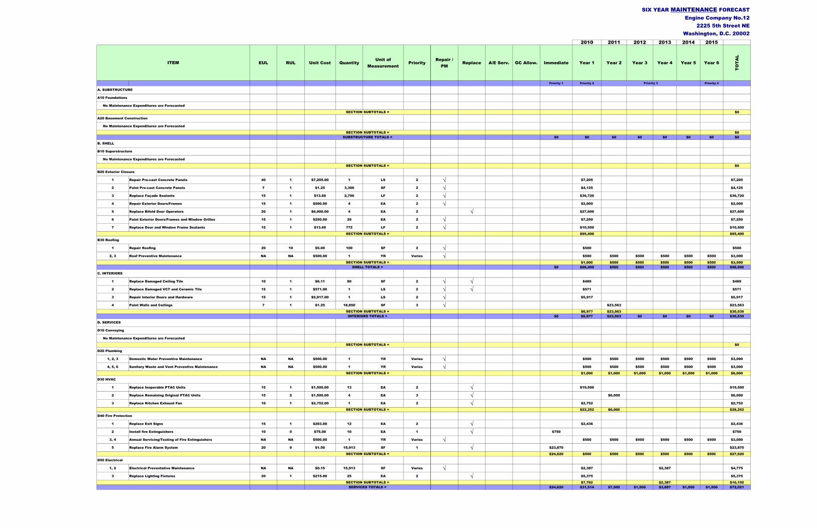
2010 2011 2012 2013 2014 2015
EUL RUL Unit Cost QuantityUnit of
MeasurementPriority
Repair /
PMReplace A/E Serv. GC Allow. Immediate Year 1 Year 2 Year 3 Year 4 Year 5 Year 6
TO
TA
L
Priority 1 Priority 2 Priority 4
$0
$0
$0 $0 $0 $0 $0 $0 $0 $0
$0
1 Repair Pre-cast Concrete Panels 40 1 $7,205.00 1 LS 2 √ $7,205 $7,205
2 Paint Pre-cast Concrete Panels 7 1 $1.25 3,300 SF 2 √ $4,125 $4,125
3 Replace Façade Sealants 15 1 $13.60 2,700 LF 2 √ $36,720 $36,720
4 Repair Exterior Doors/Frames 15 1 $500.00 4 EA 2 √ $2,000 $2,000
5 Replace Bifold Door Operators 20 1 $6,900.00 4 EA 2 √ $27,600 $27,600
6 Paint Exterior Doors/Frames and Window Grilles 15 1 $250.00 29 EA 2 √ $7,250 $7,250
7 Replace Door and Window Frame Sealants 15 1 $13.60 772 LF 2 √ $10,500 $10,500
$95,400 $95,400
1 Repair Roofing 20 10 $5.00 100 SF 2 √ $500 $500
2, 3 Roof Preventive Maintenance NA NA $500.00 1 YR Varies √ $500 $500 $500 $500 $500 $500 $3,000
$1,000 $500 $500 $500 $500 $500 $3,500
$0 $96,400 $500 $500 $500 $500 $500 $98,900
1 Replace Damaged Ceiling Tile 10 1 $6.11 80 SF 2 √ √ $489 $489
2 Replace Damaged VCT and Ceramic Tile 15 1 $571.00 1 LS 2 √ √ $571 $571
3 Repair Interior Doors and Hardware 15 1 $5,917.00 1 LS 2 √ $5,917 $5,917
4 Paint Walls and Ceilings 7 1 $1.25 18,850 SF 3 √ $23,563 $23,563
$6,977 $23,563 $30,539
$0 $6,977 $23,563 $0 $0 $0 $0 $30,539
$0
1, 2, 3 Domestic Water Preventive Maintenance NA NA $500.00 1 YR Varies √ $500 $500 $500 $500 $500 $500 $3,000
4, 5, 6 Sanitary Waste and Vent Preventive Maintenance NA NA $500.00 1 YR Varies √ $500 $500 $500 $500 $500 $500 $3,000
$1,000 $1,000 $1,000 $1,000 $1,000 $1,000 $6,000
1 Replace Inoperable PTAC Units 15 1 $1,500.00 13 EA 2 √ $19,500 $19,500
2 Replace Remaining Original PTAC Units 15 2 $1,500.00 4 EA 3 √ $6,000 $6,000
3 Replace Kitchen Exhaust Fan 10 1 $2,752.00 1 EA 2 √ $2,752 $2,752
$22,252 $6,000 $28,252
1 Replace Exit Signs 15 1 $203.00 12 EA 2 √ $2,436 $2,436
2 Install fire Extinguishers 10 0 $75.00 10 EA 1 √ $750 $750
3, 4 Annual Servicing/Testing of Fire Extinguishers NA NA $500.00 1 YR Varies √ $500 $500 $500 $500 $500 $500 $3,000
5 Replace Fire Alarm System 20 0 $1.50 15,913 SF 1 √ $23,870 $23,870
$24,620 $500 $500 $500 $500 $500 $500 $27,620
1, 2 Electrical Preventative Maintenance NA NA $0.15 15,913 SF Varies √ $2,387 $2,387 $4,775
3 Replace Lighting Fixtures 20 1 $215.00 25 EA 2 √ $5,375 $5,375
$7,762 $2,387 $10,150
$24,620 $31,514 $7,500 $1,500 $3,887 $1,500 $1,500 $72,021
D50 Electrical
SECTION SUBTOTALS =
SERVICES TOTALS =
SIX YEAR MAINTENANCE FORECAST
Engine Company No.12
2225 5th Street NE
Washington, D.C. 20002
SECTION SUBTOTALS =
A10 Foundations
No Maintenance Expenditures are Forecasted
A. SUBSTRUCTURE
ITEM
Priority 3
SUBSTRUCTURE TOTALS =
B. SHELL
SECTION SUBTOTALS =
A20 Basement Construction
No Maintenance Expenditures are Forecasted
B20 Exterior Closure
B10 Superstructure
SECTION SUBTOTALS =
SECTION SUBTOTALS =
C. INTERIORS
B30 Roofing
SHELL TOTALS =
SECTION SUBTOTALS =
No Maintenance Expenditures are Forecasted
SECTION SUBTOTALS =
SECTION SUBTOTALS =
D. SERVICES
No Maintenance Expenditures are Forecasted
SECTION SUBTOTALS =
D40 Fire Protection
SECTION SUBTOTALS =
SECTION SUBTOTALS =
D30 HVAC
D10 Conveying
INTERIORS TOTALS =
D20 Plumbing
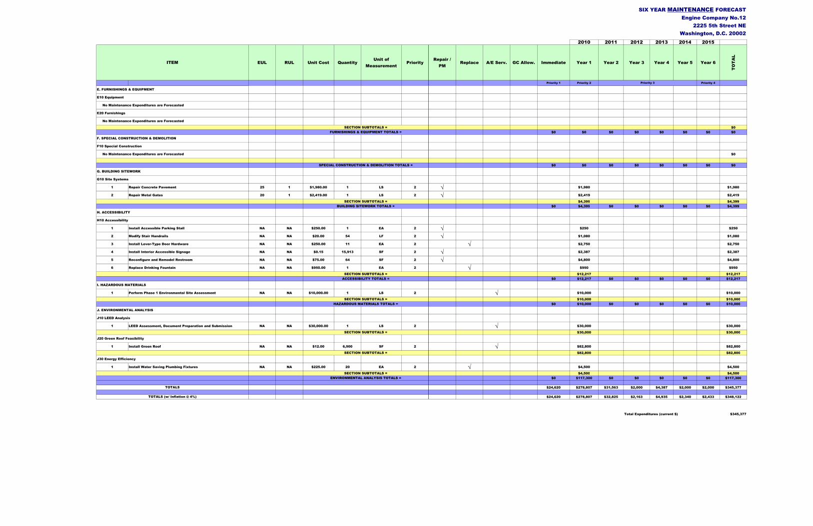
2010 2011 2012 2013 2014 2015
EUL RUL Unit Cost QuantityUnit of
MeasurementPriority
Repair /
PMReplace A/E Serv. GC Allow. Immediate Year 1 Year 2 Year 3 Year 4 Year 5 Year 6
TO
TA
L
Priority 1 Priority 2 Priority 4
SIX YEAR MAINTENANCE FORECAST
Engine Company No.12
2225 5th Street NE
Washington, D.C. 20002
ITEM
Priority 3
$0
$0 $0 $0 $0 $0 $0 $0 $0
$0
$0 $0 $0 $0 $0 $0 $0 $0
1 Repair Concrete Pavement 25 1 $1,980.00 1 LS 2 √ $1,980 $1,980
2 Repair Metal Gates 20 1 $2,419.00 1 LS 2 √ $2,419 $2,419
$4,399 $4,399
$0 $4,399 $0 $0 $0 $0 $0 $4,399
1 Install Accessible Parking Stall NA NA $250.00 1 EA 2 √ $250 $250
2 Modify Stair Handrails NA NA $20.00 54 LF 2 √ $1,080 $1,080
3 Install Lever-Type Door Hardware NA NA $250.00 11 EA 2 √ $2,750 $2,750
4 Install Interior Accessible Signage NA NA $0.15 15,913 SF 2 √ $2,387 $2,387
5 Reconfigure and Remodel Restroom NA NA $75.00 64 SF 2 √ $4,800 $4,800
6 Replace Drinking Fountain NA NA $950.00 1 EA 2 √ $950 $950
$12,217 $12,217
$0 $12,217 $0 $0 $0 $0 $0 $12,217
1 Perform Phase 1 Environmental Site Assessment NA NA $10,000.00 1 LS 2 √ $10,000 $10,000
$10,000 $10,000
$0 $10,000 $0 $0 $0 $0 $0 $10,000
1 LEED Assessment, Document Preparation and Submission NA NA $30,000.00 1 LS 2 √ $30,000 $30,000
$30,000 $30,000
1 Install Green Roof NA NA $12.00 6,900 SF 2 √ $82,800 $82,800
$82,800 $82,800
1 Install Water Saving Plumbing Fixtures NA NA $225.00 20 EA 2 √ $4,500 $4,500
$4,500 $4,500
$0 $117,300 $0 $0 $0 $0 $0 $117,300
$24,620 $278,807 $31,563 $2,000 $4,387 $2,000 $2,000 $345,377
$24,620 $278,807 $32,825 $2,163 $4,935 $2,340 $2,433 $348,122
Total Expenditures (current $) $345,377
BUILDING SITEWORK TOTALS =
ACCESSIBILITY TOTALS =
I. HAZARDOUS MATERIALS
H. ACCESSIBILITY
H10 Accessibility
SECTION SUBTOTALS =
F10 Special Construction
SPECIAL CONSTRUCTION & DEMOLITION TOTALS =
SECTION SUBTOTALS =
G10 Site Systems
G. BUILDING SITEWORK
FURNISHINGS & EQUIPMENT TOTALS =
F. SPECIAL CONSTRUCTION & DEMOLITION
SECTION SUBTOTALS =
SECTION SUBTOTALS =
SECTION SUBTOTALS =
J10 LEED Analysis
J20 Green Roof Feasibility
HAZARDOUS MATERIALS TOTALS =
J. ENVIRONMENTAL ANALYSIS
SECTION SUBTOTALS =
J30 Energy Efficiency
TOTALS (w/ Inflation @ 4%)
ENVIRONMENTAL ANALYSIS TOTALS =
TOTALS
E10 Equipment
No Maintenance Expenditures are Forecasted
E20 Furnishings
SECTION SUBTOTALS =
No Maintenance Expenditures are Forecasted
E. FURNISHINGS & EQUIPMENT
No Maintenance Expenditures are Forecasted

Appendix C Photographs

Engine Company No. 12 2225 5th Street, NE
Photograph No. 1
Front elevation facing 5thStreet, SE with three doors to apparatus bay, and gate to surface parking at right
Photograph No. 2
Site viewed from northwest, from across Rhode Island Avenue. Note side gate to parking and access to apparatus bay.
Photograph No. 3
Site viewed from rear (southeast), site’s pre-cast concrete wall, and rear of building (with two-bay addition).

Engine Company No. 12 2225 5th Street, NE
Photograph No. 4
Stone ballasted BUR upper roof and modified SBS BUR lower roof on the two bay addition and stair tower.
Photograph No. 5
Upper and lower roofs, with rear concrete-paved surface parking area beyond.
Photograph No. 6
Apparatus bay interior

Engine Company No. 12 2225 5th Street, NE
Photograph No. 7
Apparatus bay interior looking toward the two-bay expansion.
Photograph No. 8
Two bay apparatus bay expansion
Photograph No. 9
General office with PTAC unit

Engine Company No. 12 2225 5th Street, NE
Photograph No. 10
Dormitory on second floor
Photograph No. 11
Men’s 2nd Floor Restroom Lavatories
Photograph No. 12
Men’s 2nd Floor Restroom Toilet Stalls

Engine Company No. 12 2225 5th Street, NE
Photograph No. 13
2nd Floor Men’s Locker Room
Photograph No. 14
Semi-private Officer’s Quarters on 2nd Floor, with PTAC units.
Photograph No. 15
Exercise Room on Second Floor

Engine Company No. 12 2225 5th Street, NE
Photograph No. 16
First Floor’s Community Dining Room.
Photograph No. 17
Kitchen in the Community Dining Room.
Photograph No. 18 First Floor Water Heater in Janitor’s Closet

Engine Company No. 12 2225 5th Street, NE
Photograph No. 19
Water Heater in Second Floor Mechanical Room
Photograph No. 20
Pad-mounted Electrical Transformer in the Rear Parking Area
Photograph No. 21
Emergency Generator

Engine Company No. 12 2225 5th Street, NE
Photograph No. 22
Main Electrical Room with Main Service Switchboards and Sub-panels
Photograph No. 23
Exposed Wiring at Sub-panel in the Second Floor Mechanical Room
Photograph No. 24
Typical rear addition’s exit sign, emergency lighting, fire alarm pull station and horn, and panic-type door hardware; exit door was not operable on date of assessment due to damaged hardware.

Engine Company No. 12 2225 5th Street, NE
Photograph No. 25
Rooftop Split HVAC System Condenser
Photograph No. 26
Second Floor Split HVAC System Air Handling Unit
Photograph No. 27
Residential washer and dryer in second floor mechanical room

Engine Company No. 12 2225 5th Street, NE
Photograph No. 28
Commercial washer and dryer on first floor
Photograph No. 29
Stained ceiling tiles at 2nd floor sleeping quarters.
Photograph No. 30
Rhode Island Avenue NE entrance drive (with gates) to rear parking area and apparatus bays

Engine Company No. 12 2225 5th Street, NE
Photograph No. 31
Concrete drive from 5th Street, NE to apparatus bay doors (viewed from roof)
Photograph No. 32nce
Looking toward 5th Street NE beyond, with visitor’s parking area and entrance to the rear parking area.
Photograph No. 33
Concrete paved rear parking area, with two-bay addition at left; note the pre-cast concrete perimeter wall.

Engine Company No. 12 2225 5th Street, NE
Photograph No. 34
Metal rolling gates at the Rhode Island Avenue NE parking lot entrance requiring repair.
Photograph No. 35
Rhode Island Avenue NE building elevation, with site’s area without grass or landscaping used for visiting fire truck parking.
Photograph No. 36
Perimeter seal damaged at the operable sash of an exterior window.

Engine Company No. 12 2225 5th Street, NE
Photograph No. 37
Area of recent roofing repair adjacent to split HVAC system condensing unit.
Photograph No. 38
Second floor storage room ceiling below the roof drain shown in Photograph No. 37.
Photograph No. 39
First floor stairwell exit door partially obstructed by lockers.

Engine Company No. 12 2225 5th Street, NE
Photograph No. 40
Damaged pre-cast concrete panels at the side of the building.
Photograph No. 41
Vehicle exhaust extraction system fan mounted at the side of the building.
Photograph No. 42
Overhead vehicle exhaust extraction system with flexible ducts for attachment to vehicle tailpipes.

Appendix D Inventory & Checklist
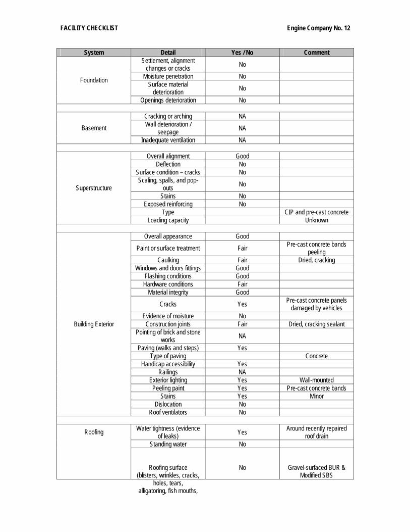
FACILITY CHECKLIST Engine Company No. 12
System Detail Yes / No Comment Settlement, alignment
changes or cracks No
Moisture penetration No Surface material
deterioration No Foundation
Openings deterioration No
Cracking or arching NA Wall deterioration /
seepage NA Basement
Inadequate ventilation NA
Overall alignment Good Deflection No
Surface condition – cracks No Scaling, spalls, and pop-
outs No
Stains No Exposed reinforcing No
Type CIP and pre-cast concrete
Superstructure
Loading capacity Unknown
Overall appearance Good
Paint or surface treatment Fair Pre-cast concrete bands peeling
Caulking Fair Dried, cracking Windows and doors fittings Good
Flashing conditions Good Hardware conditions Fair
Material integrity Good
Cracks Yes Pre-cast concrete panels damaged by vehicles
Evidence of moisture No Construction joints Fair Dried, cracking sealant
Pointing of brick and stone works NA
Paving (walks and steps) Yes Type of paving Concrete
Handicap accessibility Yes Railings NA
Exterior lighting Yes Wall-mounted Peeling paint Yes Pre-cast concrete bands
Stains Yes Minor Dislocation No
Building Exterior
Roof ventilators No
Water tightness (evidence of leaks) Yes Around recently repaired
roof drain Standing water No
Roofing
Roofing surface (blisters, wrinkles, cracks,
holes, tears, alligatoring, fish mouths,
No Gravel-surfaced BUR & Modified SBS

FACILITY CHECKLIST Engine Company No. 12
System Detail Yes / No Comment ballast)
Insulation Yes In BUR system Flashing (deterioration, holes or damages, open
joints) No
Drainage (alignment, corrosion) No
Parapets Yes Wall extensions Downspouts & gutters No
Type of roofing BUR Drains, downspouts – Nos.
& size Yes 6 – 10” dia. Drains; interior leaders
Loading limits Unknown
Roof Top Equipment Yes Condensing unit and exhaust fans
Floors, walls and ceilings (stains, holes, tears, etc.) Fair Tile ceiling stains, VCT and
ceramic tile damage Restrooms Yes Stairwells Yes One Building Interior
Surface damage (missing tiles and floor coverings) Yes
Stained & missing ceiling tiles; deteriorated VCT and
ceramic tile
Paving (walks and driveways) Concrete
Fountains NA Parking (number of spaces
& areas) Approx. 24 Not marked/striped
Fences No Pre-cast concrete walls Transformers Yes 1 pad-mounted
Site
Underground storage tank No
Leaks, dripping, running faucets and valves No
Pipe insulation Yes Hangers, supports and
clamps Good
Drain and waste connections Good
Mechanical / Plumbing
Adequate flow Yes
Condition of motors, fans, drive assembly and pumps
– rust and corrosion Good
Wiring and electrical controls Good
Thermal insulation Fair Air cooled condensers Yes Rooftop
Compressors Good 2008 installation Air distributors Ductwork
Mechanical / HVAC
Supply and return ducts – corrosion, cracks and air
No

FACILITY CHECKLIST Engine Company No. 12
System Detail Yes / No Comment leaks
Burner assembly NA Dampers, louvers and
grilles Yes
Heating and cooling capacity Fair
Many PTAC units not operating; insufficient
cooling Exhaust system Yes Air intake system Yes No. of Window Air Conditioning Units None
Transformer arching or
burning No
Exposed wiring Yes Panel missing cover in mechanical room
Missing breakers No Panel – marked No Most not marked
Incoming conduits – marked No
Panel schedule No Emergency generator Yes Exterior
Auto start and switch over Yes Cooling and exhaust Good
Exit signs Yes Minimal Emergency lighting Yes
Electrical Service and Distribution
Public address system Yes
Overall appearance Door operation Control systems
Noise Code compliance Handicap access Carriage lighting
Signage
Conveying System (elevators and escalators)
Floor alignment
NA
Exterior bearing walls Yes CMU with concrete frame Interior bearing walls No
Exterior non bearing walls No Structural frame Concrete
Permanent partitions Yes CMU and meta; studs/drywall
Shaft enclosures CMU Floor & ceiling / floor Concrete
Exterior doors & windows Metal panel and storefront
doors; thermal glazed windows with aluminum
framing
Fire Resistive Requirements
Stairway construction CMU walls, concrete
treads, risers, landings; metal railings

FACILITY CHECKLIST Engine Company No. 12
System Detail Yes / No Comment
Fire Alarm Required Provided Yes Appears inoperable
Draft Stops Provided Yes
Number 12 Exterior
Size See Schedule in Report
Section B20, Exterior Closure
Sealant – Type and LF Urethane type 772 LF, doors & windows Glazing Thermal pane Tinted Location Front, rear and side
Type Sectional overhead, bifold, swing types
Doors (Analyze doors for ratings in area separations,
occupancy separations, and rated exitways)
Hardware Operators on apparatus
bay doors; closers, cylindrical locksets,
Number 23
Size 37” x 71.5” Sealant – Type and LF Urethane type 772 LF, doors & windows
Glazing Two ¼” panes, tinted Location All facades
Type Fixed and hopper sash
Windows
Hardware Hand latches
Card Reader No Type of access control Number keypad locksets
X-Ray machine No Interior Cameras No
Exterior Cameras, Location No Intrusion Detection
Systems No
Access Control
Emergency Call Boxes No
Fire Stops Provided Yes
Number Required 4 Number Provided 4 Distance Required 59’ max Distance Provided <50’
Width Required 36” each Exits (From Building)
Width Provided 36” each Exterior exit from stairwell
partially obstructed by lockers
Number Provided 1 – 2 Fire Extinguishers Number Required 10

FACILITY CHECKLIST Engine Company No. 12
System Detail Yes / No Comment
Provided No Automatic Fire Suppression System Required No
ACCESSIBILITY
Accessible Parking No None provided Floor or Ground Surfaces Yes
Curbs / ramps Yes Elevators NA Public Access
Stairways including Treads, Risers, Nosing and
Handrails No
Risers +8”, treads 10”; railing not continuous, no
extensions
32” Clear opening Yes Clearances Yes
½” Maximum height threshold Yes
Door hardware (lever type) Yes Main Entry Door
Entry Doors and Doorways
Door – opening force Yes
Wheelchair Turning Space No Water Closets & Toilet
Compartments Including Location, Clearances,
Height, Size & Accessories No
Grab Bars (42” long on side wall, 24” long on back
wall) No
Urinals (17” max) No
Toilet Rooms
Lavatories and Sinks (34” Max. high) No
Clearances No Drinking Fountains Spout Height (36”) No
Audible Alarms Yes Inoperable system Alarms Visual Alarms No
Signage Signs No

Project Name/Address: Engine # 12, 2225 5th Street NE, Washington, D.C. 20002
Mechanical Equipment List
Equipment Type/Use Model Name/No. Serial No. Manufacturer’s Name Capacity/Rating Installation Date Comments
(17) Package Terminal AC (PTAC) Units PTDE0902GAA NA Trane 9,300 BTU/H Cooling
11,900 BTU/H Heating 1987 Reportedly, 60% to 70% of PTAC Units are not operating
Split System Rooftop Condensing 38ARZ012-601 2807G30197 Carrier 10-Tons 2008 Cooling provided not adequate
Split System Indoor Air-Handling Unit 40RM-012-B611HC 288U12999 Carrier 10-Tons 2008 2nd floor Mechanical Room
(4) Gas-fired Infrared Heaters Not Legible Not Legible Space Ray Not Legible Various Overhead at apparatus bay doors
(6) Electric Unit Heaters Not Indicated Not Indicated Not Indicated Not Indicated 1987 Overhead at apparatus bay doors
(1) Electric Fan-coil Unit Not Indicated Not Indicated Not Indicated Not Indicated 1987 1st floor Stairwell (5) Rooftop Exhaust
Fans Not Indicated Not Indicated Not Indicated Not Indicated 1987 Restrooms, locker rooms, mechanical rooms, electrical rooms
(1) Sidewall Exhaust Fan Not Indicated Not Indicated Not Indicated Not Indicated 1987 Kitchen; not operble
Project Name/Address: Engine # 12, 2225 5th Street NE, Washington, D.C. 20002
Plumbing Equipment List
Equipment Type/Use Model Name/No. Serial No. Manufacturer’s Name Capacity/Rating Installation
Date Comments
Electric Domestic Water
Heater M 1180 2A221871 Bradford White 119-Gallons Est. 2000 1st Floor Janitor’s Closet
Electric Domestic Water
Heater Not Legible Not Legible Bradford White 119-Gallons Est. 2000 2nd Floor Mechanical Room
Commercial Washer UW60P2OU1001 MO499145672 Unimac 60# Date Code:
0499 Sticker indicates serviced by Haynes
Commercial Dryer Unknown Unknown Unimac Approx. 100# Approx. 1993 Sticker indicates serviced by Haynes

Project Name/Address: Engine # 12, 2225 5th Street NE, Washington, D.C. 20002
Electrical Equipment List
Equipment Type/Use Model Name/No. Serial No. Manufacturer’s Name Capacity/Rating Installation
Date Comments
Panel HM Type NHB Style 3 General Electric 277/480-Volts 200 Amps 1987 2nd Floor Mechanical Room; No Directory
Panel (Unlabled) Type NLAB Style 5 General Electric 208/120-Volts 100-Amps 1987 2nd Floor Mechanical Room
Panel LB1 Type NLAB Style 5 General Electric 208/120-Volts 200-Amps 1987 2nd Floor Mechanical Room
Panel LB Type NLAB Style 5 General Electric 208/120-Volts 100-Amps 1987 2nd Floor Mechanical Room
Panel FM Type NLAB Style 5 General Electric 208/120-Volts 100-Amps 1987 1st Floor Electrical Room
Panel LE1 Type NLAB Style 5 General Electric 208/120-Volts 30-Amps 1987 1st Floor Electrical Room; No Directory
Panel LE2 Type NLAB Style 5 General Electric 208/120-Volts 100-Amps 1987 1st Floor Electrical Room
Main Switchboard 182-59578 NA General Electric 208/120-Volts
1,600-Amps 1987 1st Floor Electrical Room; 2 Sections
Transformer TM 9T23B3808 F General Electric 300 KVA 1987 1st Floor Electrical Room
Panel LA1 Type NLAB Style 2 General Electric 208/120-Volts 100-Amps 1987 1st Floor Electrical Room; No Directory
Panel LA Type NLAB Style 5 General Electric 208/120-Volts 200-Amps 1987 1st Floor Electrical Room
Panel HM1 Type NHB Style 3 General Electric 480/277-Volts 400-Amps 1987 1st Floor Electrical Room
Panel (Unlabled) NA NA Cutler Hammmer 120/208-Volts 100-Amps Est. 2003 Addition’s Apparatus Bays
Switch HM NP266240-B NA General Electric 400-Amps 1987 1st Floor Electrical Room
Switch TX NA NA Cutler Hammer 200-Amps 1987 1st Floor Electrical Room Emergency Generator Automatic Transfer Switch
MN0102-1 3556 Generac 120/208-Volts 105-Amps 2002 1st Floor Electrical Room
Fire Alarm Panel Type 2001-3081 U70641 Simplex 4-Zone 1987 1st Floor Electrical Room Emergency Generator 2594100300 2068918 Generac 30 KW
38 KVA 2002 2000 Series; diesel fuel tank in base

Appendix E Preventative Maintenance Recommendations

1.0. PM PROCEDURE NUMBER 1.1. Core 1 Split System Quarterly PM
2.0. GENERAL DESCRIPTION
2.1. Split A/C System (Various Manufacturers) 3.0. MATERIAL REQUIRED
3.1. Filters 3.2. Spare V-belts 3.3. Self-sealing quick disconnect refrigerant hose fittings, if applicable. 3.4. Approved refrigerant.
4.0. EQUIPMENT REQUIRED
4.1. Hand tools 4.2. Grease guns and oilers 4.3. Refrigeration gauges 4.4. Leak detector-electronic or halogen 4.5. Pocket thermometer 4.6. Clamp on meter (volt - ohm - amp meter) 4.7. Packing kit and packing 4.8. Vacuum cleaner. 4.9. Fin comb 4.10. Refrigerant recovery/recycling unit, if applicable. 4.11. EPA/DOT approved refrigerant storage tanks. 4.12. Electronic leak detector.
5.0. POWER REQUIRED 5.1. Standard electrical power outlet
6.0. SAFETY WARNINGS OR SPECIAL PRECAUTIONS 6.1. Personnel servicing this equipment must use appropriate Personal Protective Equipment (PPE). 6.2. WARNING: Lockout / Tag out procedures must be followed prior to servicing equipment.
6.3. Obtain and review manufacturer's instructions. Follow manufacturer’s instructions or procedures if different to these instructions or procedures.
6.4. Comply with the latest provisions of the Clean Air Act and
Environmental Protection Agency (EPA) regulations as they apply to protection of stratospheric ozone.
6.5. No intentional venting of refrigerants is permitted. During the
servicing, maintenance, and repair of refrigeration equipment, the refrigerant must be recovered.
6.6. Whenever refrigerant is added or removed from equipment, record
the quantities. 6.7. Recover, recycle, or reclaim the refrigerant as appropriate. 6.8. If disposal of the equipment item is required, follow regulations
concerning removal of refrigerants and disposal.

6.9. If materials containing refrigerants are discarded, comply with EPA regulations as applicable.
6.10. Refrigerant oils to be removed for disposal must be analyzed for
hazardous waste and handled accordingly.
7.0. OTHER REFERENCE DOCUMENTS 7.1. Material safety data sheets (MSDS) 7.2. Manufacturer’s manuals
8.0. PREVENTIVE MAINTENANCE PROCESS 8.1. Check all electrical connections for tightness/overheating. 8.2. Verify proper operation of compressor and condenser fan (amp draw).
8.3. Check/clean condenser coil as required. 8.4. Check all flared refrigerant connections for leakage. 8.5. Clean indoor unit air filter. 8.6. Verify proper operation of indoor unit. 8.7. Thoroughly inspect and clean interior and exterior of machine with vacuum (remove panels). 8.8. Clean drain pan and note excessive corrosion. Treat rusted areas with rust inhibitor. Ensure that the rust inhibitor chemical does not add volatile organic compounds or contaminants to the drain pan. If possible, rinse well after application or choose a less hazardous material. Consult the chemicals Material Safety Data Sheet (MSDS) for this information. 8.9. Chilled water units: 8.9.1. Check for chilled water leaks on all lines, valves, strainers,
coils, etc. If leaks are not able to be stopped or corrected, report leak status to supervisor.
8.9.2. Clean strainer on chilled water unit. Direct expansion units: 8.9.3. Check for refrigeration leaks on all lines, valves, fittings,
coils, etc., using a halogen leak detector or similar testing device. If leaks are not able to be stopped or corrected, report leak status.
8.10. Check condition of cooling and reheat coils. Use fin comb if need to straighten fins. 8.12. Drain and clean humidifier pan or pad, whichever applies. Replace pad if required. Remove corrosion as needed. 8.13. Clean and lubricate motor and squirrel cage fan(s). Check alignment of motor and fan. Check bearings for excessive wear.
8.14. Check belt tension and condition. Adjust or replace as required.
8.15. Replace pre-filters if needed.

8.16. Replace final filter if needed. 8.17. Run machine, check action of controls, relays, switches, etc., to see that: 8.17.1. Chilled water units:
8.17.1.1. Chilled water valve(s) are operating properly. 8.17.1.2. Reheat coils activate properly. 8.17.1.3. Humidistat activates humidifier.
8.17.1.4. Valves regulating water pressure are proper on cooling. 8.17.1.5. Discharge air temperature is set properly. 8.17.1.6. Check and record chilled water inlet and outlet temperatures.
8.17.2. Direct expansion units: 8.17.2.1. Humidistat activates humidifier. 8.17.2.2. Reheat coils activate properly.
8.18. Discharge air temperature is set properly. 8.19. Check and adjust vibration eliminator mountings if equipped. Repair or replace if required.
9.0. CLEANUP 9.1. Thoroughly clean work area once PM has been completed. Dispose of all waste and contaminated material properly.
10.0. REVISION (Employee, Date, Description)
10.1. Created: F+G 3-3-09

1.0. PM PROCEDURE NAME 1.1. OJS Exhaust Fan Quarterly PM
2.0. GENERAL EQUIPMENT DESCRIPTION
2.1. Exhaust Fan, Direct and Belt Driven (Various Manufacturers) 3.0. MATERIAL REQUIRED
3.1. Mobil EP2 grease or equivalent 4.0. EQUIPMENT REQUIRED
4.1. Hand tools 4.2. Hand grease gun
5.0. POWER REQUIRED
5.1. Standard Power Outlet 6.0. SAFETY WARNINGS OR SPECIAL PRECAUTIONS
6.1. Personnel servicing this equipment must use appropriate Personal Protective Equipment (PPE 6.2. WARNING: Lockout / Tagout procedures must be followed prior to servicing equipment. 6.3. Obtain and review manufacturer's instructions. Follow manufacturer’s instructions or procedures if different to these instructions or procedures.
6.4. NOTE 1: The following procedures are intended to be suitable to perform preventive maintenance on a variety of exhaust fan designs, including belt-driven, direct motor driven, with a variety of fan types and mounting styles.
7.0. OTHER REFERENCE DOCUMENTS 7.1. Material Safety Data Sheets (MSDS) 7.2. Manufacturer’s Manuals
8. PREVENTIVE MAINTENANCE PROCESS
8.1. All Exhaust Fans: 8.1.1. Observe fan during operation to check for excessive vibration or operating noise. Correct any discrepancies observed or place equipment out of service if failure and possible damage appear imminent. 8.1.2. Check that mounting fasteners are secure and free of corrosion. 8.1.3. Check electric service conduits and switches for damage. 8.1.4. Remove covers as necessary to inspect fan for corrosion damage, wear, or accumulation of process materials. Clean any accumulation of process materials or corrosion if present. 8.1.5. Check inlet duct for damage and effectiveness of seal and that rain collar is installed properly. 8.1.6. Check exhaust outlet and/or stack for proper sealing and that bird screens are installed and properly secured. On vertical stacks, inspect the guy wires for proper adjustment and that they are securely fastened to roof. 8.1.7. Check motor for presence of grease zerks. Apply grease if so equipped. Use Mobil EP2 grease (MRO# 40-0520).

8.2. Horizontal shaft belt driven fans: 8.2.1. Remove necessary covers to expose belts and sheaves. Examine belts for wear and all components for proper alignment and absence of visible wear. Correct any discrepant conditions. 8.2.2. Lubricate any pillow block bearings which have grease zerks using Mobil EP2 grease (MRO# 40-0520).
8.3. Vertical shaft fans and direct drive fans:
8.3.1. Check motor to fan coupling for damage or wear.
9.0. CLEANUP 9.1. Thoroughly clean work area once PM has been completed. Dispose of all waste and contaminated material properly.
10.0. REVISION (Employee, Date, Description)
10.1. Created : F+G 3-3-09

1.0. PM PROCEDURE NAME 1.1. DMV Condensing Unit Quarterly PM
2.0. GENERAL EQUIPMENT DESCRIPTION 2.1. Condensing Unit (Various Manufacturers)
3.0. MATERIAL REQUIRED
3.1. Non-detergent oil
4.0. EQUIPMENT REQUIRED 4.1. Hand tools 4.2. Air duster 4.3. High pressure washer 4.4. Fin comb 4.5. Refrigerant recovery/recycle unit
5.0. POWER REQUIRED 5.1. Standard Power Outlet
6.0. SAFETY WARNINGS OR SPECIAL PRECAUTIONS 6.1. Personnel servicing this equipment must use appropriate Personal Protective Equipment (PPE). 6.2. WARNING: Lockout / Tagout procedures must be followed prior to servicing equipment. 6.3. Review standard operating procedures for controlling hazardous energy sources. 6.4. Review standard operating procedures for selection, care, and use of respiratory protection. 6.5. No intentional venting of refrigerants is permitted. During the servicing, maintenance, and repair of refrigeration equipment, the refrigerant must be recovered. 6.6. Whenever refrigerant is added or removed from equipment, record the quantities on the appropriate forms. 6.7. Recover, recycle, or reclaim the refrigerant as appropriate. 6.8. If disposal of the equipment item is required, follow regulations concerning removal of refrigerants and disposal of the equipment.
7.0. OTHER REFERENCE DOCUMENTS 7.1. Lockout / Tagout Procedure 7.2. Material Safety Data Sheets (MSDS) 7.3. Manufacturer’s Manuals
8.0. PREVENTIVE MAINTENANCE PROCESS 8.1. Check fan motor and fan blade for cleanliness and lubrication. Clean and lubricate bearings, as necessary. 8.2. Check motor for proper amperage load

8.3. Clean condenser with a vacuum 8.4. Check electrical connections for tightness and control and for proper operation. 8.5. Check for signs of contactor or relay arcing. 8.6. Check to see that power and ground connections remain secure. 8.7. Inspect unit coils and clean fins, if necessary, with cold water and compressed air. 8.8. Check refrigerant charge pressures 8.9. Check for corrosion.
9.0. CLEANUP 9.1. Thoroughly clean work area once PM has been completed. Dispose of all waste and contaminated material properly.
10.0. REVISION (Employee, Date, Description) 10.1. Created: F+G 3-3-09

1.0. PM PROCEDURE NAME 1.1. Engine 12 Air Handling Unit Quarterly PM
2.0. GENERAL EQUIPMENT DESCRIPTION
2.1. Air Handling Units (Trane)
3.0. MATERIAL REQUIRED 3.1. Filters 3.2. Belts
4.0. EQUIPMENT REQUIRED 4.1. Hand tools
5.0. POWER REQUIRED
5.1. N/A 6.0. SAFETY WARNINGS OR SPECIAL PRECAUTIONS
6.1. Personnel servicing this equipment must use appropriate Personal Protective Equipment (PPE). 6.2. WARNING: Lockout / Tag out procedures must be followed prior to servicing equipment.
7.0. OTHER REFERENCE DOCUMENTS 7.1. Manufacturer’s Manuals 7.2. Lockout / Tagout Procedure 7.3. Material Safety Data Sheets (MSDS)
8.0. PREVENTIVE MAINTENANCE PROCESS 8.1. Check fan bearings for unusual noise and excessive bearing temperature. 8.2. Lubricate fan and motor bearings. 8.3. Check electrical components and wiring for evidence of overheating. Check wiring connections for tightness. 8.4. Check float switches for proper operation. 8.5. Observe fan motors in operation for noises which may indicate a problem or possible failure. 8.6. Check belts to fan units for proper adjustment and alignment and for wear. Replace belts if required. 8.7. Inspect the control valves for leaks and proper operation. 8.8. Clean blow-down strainers. 8.9. Check and replace disposable filters if required. 8.10. Check pressure gauges for proper operation. 8.11. Check Magnehelic gauge sensor lines and zero the Magnehelic gauge.

8.12. Record CFM reading. 8.13. Check condensate drain for obstructions and clear if necessary. 8.14. Check duct connections for proper sealing. 8.15. Check CW coils for build-up of dirt which interferes with air flow. 8.16. Check fan wheels and shaft for corrosion or build-up of dirt. Clean if required. 8.17. Check dampers, linkage, and operators for proper function. Clean as necessary. 8.18. Check door gaskets and repair/replace as required to ensure sealing of unit. 8.19. Check for corrosion.
9.0. CLEANUP 9.1. Thoroughly clean work area once PM has been completed. Dispose of all waste and contaminated material properly.
10.0. REVISION (Employee, Date, Description)
10.1. Created: F+G 3-3-095

1.0. PM PROCEDURE NAME 1.1. Engine 12 Domestic Water Heater Monthly Mechanical PM 2.0. GENERAL EQUIPMENT DESCRIPTION
2.1. Domestic Water Heater, Gas Fired (Various Manufacturers) 3.0. MATERIAL REQUIRED
3.1. Honeywell aquastat 3.2. Spark plug 3.3. Ceramic insulator 3.4. Bearings 3.5. Lubricant 3.6. Mechanical seal 3.7. Boiler chemicals as directed by competent water treatment company
4.0. EQUIPMENT REQUIRED
4.1. Hand tools 4.2. Calibrated temperature pressure gauge 4.3. Automatic pressure reducing regulator 4.4. Tubing cutters 4.5. Small acetylene outfit 4.6. Combustion testing equipment 4.7. Hydrostatic pump and safety valve gag 4.8. Vacuum cleaner wet/dry type
5.0. POWER REQUIRED
5.1. Standard Electrical Power Outlet
6.0. SAFETY WARNINGS OR SPECIAL PRECAUTIONS 6.1. Personnel servicing this equipment must use appropriate Personal Protective Equipment (PPE). 6.2. WARNING: Lockout / Tagout procedures must be followed prior to servicing equipment. 6.3. Obtain and review manufacturer's instructions. Follow manufacturer’s instructions or procedures if different to these instructions or procedures. Obtain and review ASME Boiler and Pressure Vessel Codes for boilers. 6.4. Review Standard Operating Procedures for Controlling Hazardous Energy Sources. 6.5. If materials to be worked on are known or suspected to contain asbestos, check the building's asbestos management plan to see if they have been tested for asbestos. If they are suspect but have not been tested, have them tested. Manage asbestos in accordance with the plan. 6.6. Account for all tools and materials before closing boiler.
7.0. OTHER REFERENCE DOCUMENTS 7.1. Lockout / Tagout Procedure 7.2. Material Safety Data Sheets (MSDS) 7.3. Manufacturer’s Manuals 7.4. ASME Boiler and Pressure Vessel Codes

8.0. PREVENTIVE MAINTENANCE PROCESS 8.1. Check all natural gas lines for leakage around valves and fittings. 8.2. Check that all valves operate properly and are leak free. 8.3. Check all water tank plumbing for leaks, corrosion, and/or alkali build-up. Replace gaskets, seals and/or bolts where needed. 8.4. Clean or flush all sediment or scale deposits from hot water storage tank. 8.5. Check/adjust the pilot. The main burner should light smoothly from pilot and burn with a blue flame with a minimum of yellow tips. 8.6. Visually check main burner for plugged orifices and proper flame adjustment. Clean orifices and/or adjust for a blue flame, void of yellow tips if necessary. 8.7. Check the safety relief valve and associated discharge piping for proper operation an installation. 8.8. Check that any temperature gages are functional and in good repair. Replace any that are not. 8.9. Check any hot water recirculation pumps for excessive vibration, bearing noise, over heating or leakage around seals or fittings. 8.10. Check that all hangers are free of missing or loose fasteners, and are properly supporting piping and equipment. 8.11. Inspect insulation around hot water tank and piping. Replace or repair as necessary. 8.12. Keep thermostat at 120 degrees.
9.0. CLEANUP 9.1. Thoroughly clean work area once PM has been completed. Dispose of all waste and contaminated material properly.
10.0. REVISION (Employee, Date, Description)
10.1. Created: F+G 3-3-09

1.0. PM PROCEDURE NAME 1.1. Engine 12 Generator Annual Mechanical PM
2.0. GENERAL EQUIPMENT DESCRIPTION
2.1. Emergency Diesel Generator (Various Manufacturers) 3.0. MATERIAL REQUIRED
3.1. Grease guns and oilers 3.2. Oil and Oil Filters 3.3. Belts
4.0. EQUIPMENT REQUIRED 4.1. Hand tools
5.0. POWER REQUIRED
5.1. Standard Power Outlet 6.0. SAFETY WARNINGS OR SPECIAL PRECAUTIONS
6.1. Personnel servicing this equipment must use appropriate Personal Protective Equipment (PPE). 6.2. WARNING: Lockout / Tagout procedures must be followed prior to servicing equipment. 6.3. Have approved type fire extinguishers readily available. 6.4. Allow no open flame or smoking in area. 6.5. Use safety type fuel cans only. 6.6. Obtain and review manufacturer's instructions. Follow manufacturer’s instructions or procedures if different to these instructions or procedures.
7.0. OTHER REFERENCE DOCUMENTS 7.1. Manufacturers Manual 7.2. National Fire Protection Association Form 18-D 7.3. Material Safety Data Sheets (MSDS)
8.0. PREVENTIVE MAINTENANCE PROCESS 8.1. Change fuel filters. 8.2. Inspect and adjust rack on unit injector or fuel distributor pump according to manufacturer's instructions. 8.3. Check governor, adjust for correct speed. 8.4. Determine fuel level, drain water from tank and inspect for contamination. Prior arrangements should be made for local procurement of fuel in emergencies. 8.5. Change engine oil and filter and perform other lubrication on engine and generator. 8.6. Inspect cooling system for leaks, air obstructions, "V" belt tension and proper anti-freeze solution. Make needed adjustments.

8.7. Inspect generator winding and clean if needed. 8.8. Clean commutator and collector rings. Check brush wear and tension in accordance with manufacturer's instructions. 8.9. Inspect generator heaters. 8.10. Remove old oil and diesel fuel from around generator area when maintenance is complete. 8.11. Check tank vents and overflow piping for obstructions. 8.12. Inspect fuel piping. 8.13. Inspect louver motor and controls. 8.14. Inspect exhaust system hangers and supports. 8.15. Inspect transfer switch main contacts. 8.16. Check the ignition system of the engine. 8.17. Clean electrical boxes, panels, and cabinets. 8.18. Check all fuses 8.19. Service the air cleaner for the engine. 8.20. Run the generator with its connected load for 30 minutes.
9.0. CLEANUP 9.1. Thoroughly clean work area once PM has been completed. Dispose of all waste and contaminated material properly.
10.0. REVISION (Employee, Date, Description)
10.1. Created : F+G 3-3-09

1.0. PM PROCEDURE NAME 1.1.Engine 12 Fire Alarm Control Panel
2.0. GENERAL EQUIPMENT DESCRIPTION
2.1. Fire Alarm Control Panel 3.0. MATERIAL REQUIRED
3.1. N/A 4.0. EQUIPMENT REQUIRED
4.1. Hand tools 4.2. Multimeter
5.0. POWER REQUIRED
5.1. N/A 6.0. SAFETY WARNINGS OR SPECIAL PRECAUTIONS
6.1. Personnel servicing this equipment must use appropriate Personal Protective Equipment (PPE). 6.2. WARNING: Lockout / Tagout procedures must be followed prior to servicing equipment.
7.0. OTHER REFERENCE DOCUMENTS 7.1. Manufacturer’s Manuals
8.0. PREVENTIVE MAINTENANCE PROCESS 8.1. Perform a full functionality, test according to the requirements of NFPA 72 and by the manufacturer’s procedure. 8.2. If required, disable audible/visual alarms and air handler shutdowns. 8.3. Clean the system control panel and internal components, so as to be free from debris and dust. Test indicator lamps and switches. 8.4. Inspect the transient suppressors. Lightning protection equipment shall be inspected and maintained per the manufacturer’s specifications. 8.5. Back-up batteries shall be tested on a separate PM #, less than annually. Amp hour capacity of batteries shall be recorded and records maintained in accordance with NFPA 72. 10.6.2.1 8.6. Test the fire alarm panel and the twelve remote power supplies for receipt of open battery circuit. 8.7. Test the fire alarm panel and the remote power supplies for loss of AC power. 8.8. Test the NACS for receipt of open circuits. 8.9. Test the NACS for receipt of ground faults. 8.10. Test the loop 1 and loop 2 signal line circuits for receipt of ground faults.

8.11. Test loop 1 and loop 2 signal line circuits for receipt of short circuit faults. 8.12. Test loop 1 and loop 2 signal line circuits for receipt of open circuit faults. 8.13. Test the four node network for an open circuit. 8.14. Panel and power supply locations
8.14.1. FACP and two 55AH batteries G.4-9.5 (break area, east of auditorium) 8.14.2. Three NAC power supplies and six 12 AH batteries, one beam, detector power supply and two 12 AH batteries D.5-6.9 (core, 2) 8.14.3. Three NAC power supplies and six 12 AH batteries, one beam, detector power supply and two 12 AH batteries D.5-10.0 (core, 3) 8.14.4. Three NAC power supplies and six 12 Ah batteries, one beam, detector power supply and two 12 ah batteries d.8-14.3 (Core, 4)
8.15. Verify that troubles are received at fire alarm panel.
9.0. CLEANUP 9.1. Thoroughly clean work area once PM has been completed. Dispose of all waste and contaminated material properly.
10.0. REVISION (Employee, Date, Description)
10.1. Created: F+G 3-3-09

1.0. PM PROCEDURE NAME 1.1. Engine 12 Generator Weekly Mechanical PM
2.0. GENERAL EQUIPMENT DESCRIPTION
2.1. Emergency Diesel Generator (Various Manufacturers) 3.0. MATERIAL REQUIRED
3.1. N/A 4.0. EQUIPMENT REQUIRED
4.1. Hand tools 5.0. POWER REQUIRED
5.1. Standard Power Outlet 6.0. SAFETY WARNINGS OR SPECIAL PRECAUTIONS
6.1. Personnel servicing this equipment must use appropriate Personal Protective Equipment (PPE). 6.2. WARNING: Lockout / Tagout procedures must be followed prior to servicing equipment.
7.0. OTHER REFERENCE DOCUMENTS 7.1. Manufacturers Manual 7.2. National Fire Protection Association Form 18-D 7.3. Material Safety Data Sheets (MSDS)
8.0. PREVENTIVE MAINTENANCE PROCESS 8.1. Drain water and sediment from water separator and fuel storage system. 8.2. Top off the fuel tank with number 2 diesel. Take necessary precautions to prevent the entrance of dirt, water, or other contaminates into the fuel system while fueling. 8.3. Check engine oil level and top up if necessary.
9.0. CLEANUP 9.1. Thoroughly clean work area once PM has been completed. Dispose of all waste and contaminated material properly.
10.0. REVISION (Employee, Date, Description)
10.1. Created: C. Bourgoin, 4-6-04 10.2. Rev: Muthart, 7-14-04 10.3. Rev: F+G/VFA, 6-10-08

Appendix F Scope of Services, Document Review and Limitations
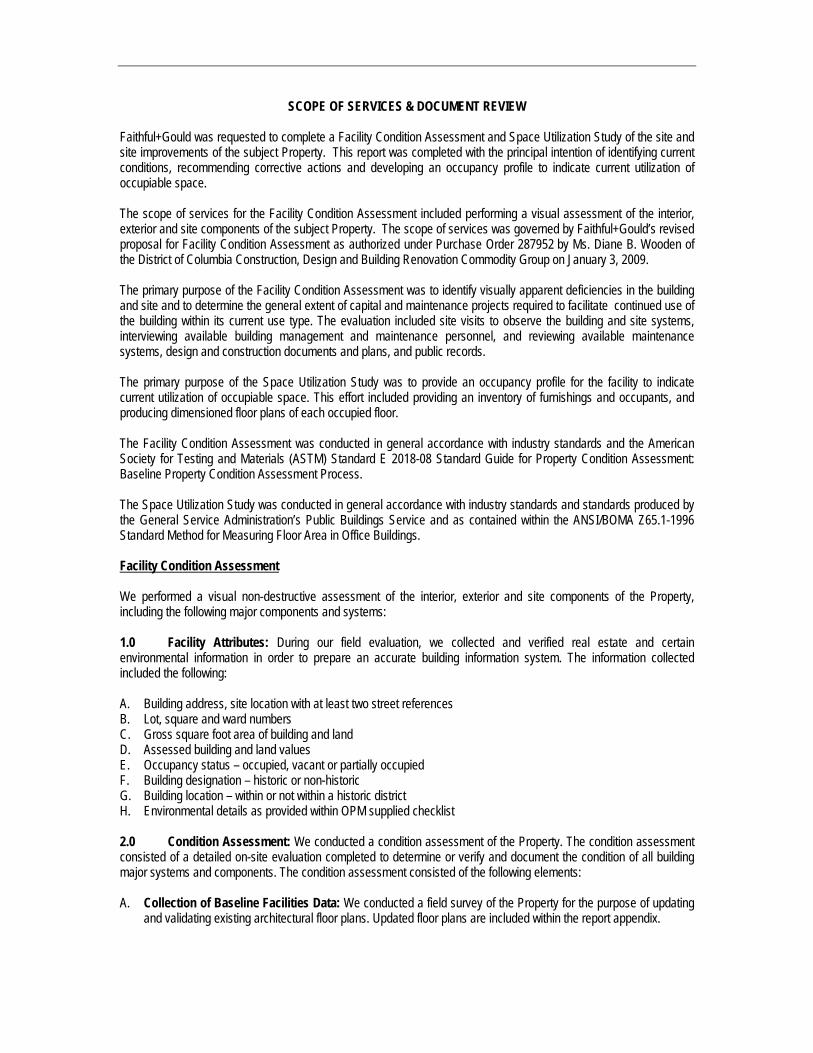
SCOPE OF SERVICES & DOCUMENT REVIEW Faithful+Gould was requested to complete a Facility Condition Assessment and Space Utilization Study of the site and site improvements of the subject Property. This report was completed with the principal intention of identifying current conditions, recommending corrective actions and developing an occupancy profile to indicate current utilization of occupiable space. The scope of services for the Facility Condition Assessment included performing a visual assessment of the interior, exterior and site components of the subject Property. The scope of services was governed by Faithful+Gould’s revised proposal for Facility Condition Assessment as authorized under Purchase Order 287952 by Ms. Diane B. Wooden of the District of Columbia Construction, Design and Building Renovation Commodity Group on January 3, 2009. The primary purpose of the Facility Condition Assessment was to identify visually apparent deficiencies in the building and site and to determine the general extent of capital and maintenance projects required to facilitate continued use of the building within its current use type. The evaluation included site visits to observe the building and site systems, interviewing available building management and maintenance personnel, and reviewing available maintenance systems, design and construction documents and plans, and public records. The primary purpose of the Space Utilization Study was to provide an occupancy profile for the facility to indicate current utilization of occupiable space. This effort included providing an inventory of furnishings and occupants, and producing dimensioned floor plans of each occupied floor. The Facility Condition Assessment was conducted in general accordance with industry standards and the American Society for Testing and Materials (ASTM) Standard E 2018-08 Standard Guide for Property Condition Assessment: Baseline Property Condition Assessment Process. The Space Utilization Study was conducted in general accordance with industry standards and standards produced by the General Service Administration’s Public Buildings Service and as contained within the ANSI/BOMA Z65.1-1996 Standard Method for Measuring Floor Area in Office Buildings. Facility Condition Assessment We performed a visual non-destructive assessment of the interior, exterior and site components of the Property, including the following major components and systems: 1.0 Facility Attributes: During our field evaluation, we collected and verified real estate and certain environmental information in order to prepare an accurate building information system. The information collected included the following: A. Building address, site location with at least two street references B. Lot, square and ward numbers C. Gross square foot area of building and land D. Assessed building and land values E. Occupancy status – occupied, vacant or partially occupied F. Building designation – historic or non-historic G. Building location – within or not within a historic district H. Environmental details as provided within OPM supplied checklist 2.0 Condition Assessment: We conducted a condition assessment of the Property. The condition assessment consisted of a detailed on-site evaluation completed to determine or verify and document the condition of all building major systems and components. The condition assessment consisted of the following elements: A. Collection of Baseline Facilities Data: We conducted a field survey of the Property for the purpose of updating
and validating existing architectural floor plans. Updated floor plans are included within the report appendix.

B. Facility Existing Condition Data: We identified the facility status data (i.e. age, historical status, construction
type, square footage, materials, user/tenants, and functional areas such as offices, mechanical / electrical rooms, etc.); architectural floor plans; and site plan/general development map data (surface man-made site features, and real estate boundary maps).
C. Condition Assessment Survey: As part of the condition assessment survey we:
i. Provided a description of systems along with manufacturer’s name for each major piece of equipment and the estimate age.
ii. Identified the current condition of the facilities and their components. This included a description of
the deficiencies indicating what the deficiency is, how much it is, and where it exists.
iii. We provided a description of the recommended corrective measures, the associated cost, the remaining service life of the building component or system if the deficiency is left uncorrected. We specifically included quantitative information on recommended work to include opinions of cost and recommended date of accomplishment. This information was presented within the OPM supplied cost spreadsheets.
iv. We prioritized the criticality of necessary repair, renovation and or replacement with estimated cost
forecast by the projected year.
v. We furnished the survey findings in the format supplied to us by OPM.
vi. We quantified deferred maintenance and furnish estimated costs within the format supplied to us by OPM.
vii. We provided an annual preventative maintenance schedule for the installed equipment.
2.1 Drawing and Maintenance Review: We reviewed any available construction documents (plans,
specifications, etc.) and maintenance and repair logs prior to visually assessing the buildings. In addition, we interviewed available maintenance personnel to determine the maintenance / repair history, and know defects in each building.
2.2 Included Components: We surveyed the physical components and systems of the identified facilities.
These will include the following for:
2.2.1 Substructure: We visually evaluated the condition of the foundation systems, slab-on-grade, basement excavation and walls, and other applicable substructure elements. We evaluated for signs of distress (cracking, displacement, insect infiltration etc.) and have documented and photographed our findings. 2.2.2 Core and Shell: We visually evaluated the condition of the superstructure (floors, bearing walls, columns, beams, roofs and related structures): exterior closure (exterior walls, windows and doors): and roofing systems. The evaluation included assessment of the accessible shell components and ancillary elements for signs of distress and documentation and photographing of our findings. This included cracking, displacement, and connection adequacy, continuity of flashing and seals, and evidence of other types of distress. We also checked for flashing and connections for proper drainage on walls and for the condition and proper placement of expansion joints. When assessing the roofing, we accessed the roofs to visually observe the condition of the system and any accessories and details to include flashings and penetrations. We also documented existing warranties, replacement costs and remaining useful life.
2.2.3 Interiors: We visually evaluated the interior construction (interior partitions, doors and specialties such as toilet accessories, lockers, storage shelving, etc.); stairway and finishes; and interior finishes (paint and other wall finishes, flooring and interior ceiling finishes and systems). The evaluation included documenting and photographing the condition of the interior finishes.

2.2.4 Services: We visually evaluated the condition of the conveyor systems (elevators, and other vertical transportation and conveying systems), plumbing systems (fixtures, domestic water distribution, sanitary waste, rain water drainage and special plumbing systems such as gasoline dispending, compressed air, etc.); HVAC Systems to include heat generation, rejection, distribution and transfer systems; HVAC controls and instrumentations and other HVAC support elements; Fire detection and suppression systems (alarm systems, monitoring systems, sprinkler systems, standpipe and hose systems, pumps, fire protection specialties, and special fire suppression systems); Electrical Systems (service and distribution, feeder type), lighting and branch wiring, communications and security systems, emergency generators, UPS systems, electrical controls and instrumentation, service points, meters and capacities.
For each item of service equipment we visually evaluated the conditions and code compliance of the service and photographed and documented our findings. For the conveying systems (where provided), we reviewed available maintenance records and reports on the equipment and evaluate the performance and anticipated service life of the systems. For plumbing, HVAC and electrical systems, we observed the age, condition and adequacy of the capacity and status of maintenance of these systems and have documented their condition, deficiencies and code violations. We also commented on renovations to the system that would prove beneficial to their overall efficiency or performance, and have stated the estimated expected remaining useful service life of each major piece of equipment with and without repair. For fire and life-safety systems, we listed all major components and identified those systems that require upgrades. Findings were supported with photographs. 2.2.5 Equipment and Furnishings: We evaluated the condition of fixed components of the structure and non-moveable furnishings, office or support equipment. Representative examples include security vaults, commercial laundry equipment, fixed audio-visual equipment, parking control equipment, kitchen and food service equipment, fixed casework and seating etc. For each applicable piece of equipment or furnishing that we visually evaluated, we documented and photographed conditions, and produced a tabulated inventory of the equipment to include rating / capacity, make and manufacturer, year of manufacture, and location. 2.2.6 Other Building Construction: We visually evaluated items of special construction and systems (i.e. special security systems, incinerators, kennels, storage tanks, building automation systems, special purpose rooms etc.).
2.2.7 Building Site Improvements: We evaluated the condition of site improvements to include grading and drainage, slope stabilization, protection and erosion control; roadways and parking lots (pavement, curb, gutter, steps etc.); site development (fences and gates, recreational facilities, exterior furniture, bridges, flag poles, exterior signage etc.); and landscaping (planting, irrigation systems, etc.). For each element we visually evaluated, photographed and documented our findings. For grading and drainage, we observed the site systems for removal of storm water, and identified any areas that appear under-capacity or distressed. We also evaluated the site with respect to flood potential. We reviewed and documented the condition of the pavements, curb and gutter, sidewalks and plazas, retaining walls, fences, signs, landscaping and irrigation systems and will present our finding supplemented with photographs.
2.2.8 Accessibility: We completed an evaluation of the Property to determine compliance with applicable accessibility guidelines. This evaluation included a site review to determine major barriers to access to and into the building, through the building, to restroom facilities, and to other service areas within the building.
2.2.9 Safety / Security: We considered the facility as a whole when completing this evaluation. The evaluation included evaluation of the performance and current ability of lower-level wall / window system with regard to blast shrapnel protection. The evaluation also included a safety and security review to determine and document hazards and needed improvements in all areas of the building and surrounding site.
2.2.10 Access Control: We evaluated, documented and photographed the condition of doors and windows, including hardware and other components; intrusion detection systems; and the access control

system. We also identified a pattern in faulty hardware systems and controls, and have conducted a review of potential points of access and determined and documented the effectiveness of the access control system.
2.2.11 Hazardous Materials: We identified for further analysis building components and stored materials suspected of containing hazardous materials such as asbestos, lead, petroleum products etc.
2.2.12 Equipment List: The report includes an equipment list in tabulated form indicating the make, model, manufacturer’s name, capacity / rating and installation date of each principal item of contained equipment.
At the completion of our on-site activities we issued this report of Facility Condition Assessment. The report includes detailed descriptions of installed systems, conditions and recommendations. The report also includes expenditures of anticipated capital and maintenance expenditures required over the next six-years. Expenditures are detailed in the year we recommend that they be completed and are prioritized as follows: • Priority 1 – Critical (immediate) need that may prevent the continued use of the facility or is required to address
issues of life safety and/or code compliance; • Priority 2 – Potentially Critical (one to two years) need addressing system, equipment or component failure that, if
not addressed promptly, may prohibit the continued use of the facility; • Priority 3 – Necessary (but not yet Critical, three to five years) need that, if left unaddressed, will result in a portion
or all of the facility to be unfit for continued use; • Priority 4 – Recommended (six years and greater) need that represents a good practice improvement or action
based on the observed conditions or the expected useful life of the component or system. The scope of services under which the Facility Condition Assessment was completed was visual in nature and not intended to be destructive to the Property to gain access to hidden conditions. We did not perform any destructive testing or uncover or expose any system members. We have documented the type and extent of visually apparent defects in the systems in order to perform the condition assessment. The scope of services includes only those items specifically indicated. The evaluation does not include any environmental services such as (without limitation) sampling, testing, or evaluation of asbestos, lead-based paint, lead-in-water, indoor air quality, PCB’s, radon, mold, or any other potentially hazard materials, air-borne toxins or issues not outlined in the previous scope of services. Space Utilization
We completed a space utilization survey to consist of providing an occupancy profile for the facility to indicate current utilization of occupiable space. Pertinent information collected will included: A floor plan for each facility. The floor plan produced indicates interior dimensions and room areas for each floor. We also calculated the gross floor area versus occupiable (net rentable) area of each individual floor. Our determination of gross floor area and occupiable area was governed by the guidelines and methodology established by the General Service Administration’s Public Buildings Service and as contained within the ANSI/BOMA Z65.1-1996 Standard Method for Measuring Floor Area in Office Buildings. • Building core area, including elevator shafts, toilets, storage area, public corridors, and other support areas • The location of all walls, partitions, doors, and windows • Location and size of all occupiable areas and the name of current tenant agency

• Personnel density that includes number of personnel, furniture, files, and equipment in occupied space. This
includes submission of the information gathered in written, graphic and digital format with floor and building summaries.
Document Review
None

Exclusions & Interpretation This report and the attached expenditure forecasts generally identify the Expected Useful Life (EUL) and the Remaining Useful Life (RUL) of observed systems and components. EUL is projected based upon industry-standard guidelines and our experience with similar systems. RUL is projected based upon our assessment of age, condition and maintenance / repair history. Our opinion of cost included within this report are based upon our experience with similar buildings and systems, industry-standard cost data, local cost data, discussions with contractors, and information provided by the current building management and maintenance staff. The costs provided are for planning purposes only and assuming open procurement of the recommended works. Actual project costs may vary significantly to those projected based upon inflationary factors, weather and time of season, unforeseen economic circumstances and market trends, contractor schedules, unusual owner requirements, and other factors beyond our control. Where recommended projects require the use of a registered architect, licensed engineer of other professional (collectively referred to as A/E) we have included an allowance of 10% of the base project fee for this retention. Where recommended projects are likely to involve the retention of a General Contractor, we have included a separate collective line item for this retention. This allowance includes a percentage fee based upon the base project cost of 15% for Project Management, 20% for Contractors Profit and Overhead and a Contingency allowance of 10%. Unless otherwise stated project line items included within the capital and maintenance forecasts do not include for A/E fees or General Contractor costs. When making the determination as to whether a General Contractor will be retained, we have generally considered that a General Contractor will only be retained when a project requires management of multiple contractors is required. A typical example would be brick repair and refurbishment resulting in management of masons, lintel installers, painters and related trades. An example of a project where we have considered that a General Contractor would not be required is pavement resurfacing. For this type of project, we have assumed that a single specialty contractor will be retained to complete and manage the project. Under this scenario, we have included the 45% allowance previously detailed into our unit rate. The timing of the projected expenditures and their associated costs represent our opinion considering the aforementioned factors. Alternative methods of managing the existing equipment or systems may be feasible over the six-year study period. However, these alternative methods will depend upon actual management practices, financing requirements, and the ability of the engineering staff to perform some of the repairs in-house. Alternative scenarios that have not been presented to Faithful+Gould have not been considered within this report. This report has been presented based upon our on-site observations, information provided to us, discussion with building management and maintenance staff listed in the executive summary, our review of available documentation (see scope of services and document review section) and our experience with similar systems. If any information becomes available that is not consistent with the observations or conclusions expressed within this report, we request that this information be immediately forwarded to us. The evaluation of existing structures requires that certain assumptions be made regarding existing conditions. This evaluation was based upon our visual non-destructive evaluation of accessible conditions of the Property. Furthermore, this evaluation was limited in time on-site, fee, and scope and was not based upon a comprehensive engineering evaluation. As such, our report is not intended to represent a complete review of all systems or system components or a check or validation of design professionals’ computations. Therefore, Faithful+Gould’s evaluation and this report do not represent, warranty or guarantee any system or system component or the future performance of any site improvement.

Appendix G Resumes

Benjamin Dutton, FFB, MCIOB, MRICS Project Coordinator Benjamin Dutton has over twelve years of experience in Facility Assessment, working in all sectors of the industry, from multi-family residential and ecclesiastical facilities to airports and resorts. He has been employed by property developers and consulting firms, and previously founded a multi-office facility assessment corporation. Benjamin has been working with Faithful+Gould since 2005, and is spearheading the expansion of the company’s already successful Facility Assessment sector. Projects Benjamin has completed include Facility Assessment and expenditure forecasting for the U.S. Senate House Office Buildings in Washington, DC, assessment, capital planning and maintenance evaluation for Washington Dulles International Airport and Ronald Reagan National Airport, maintenance evaluation and asset inventory for the University of Virginia and American University, facility assessment of a 42-building school facility, pre-acquisition due diligence surveys for a 19-building industrial portfolio in the Pacific Northwest, and construction monitoring and management of various residential and adult living centers.
SELECTED PROJECT EXPERIENCE
230 Park Avenue, New York, New York
Colliers Florida Portfolio, Miami, Florida
Rosa Parks Federal Center, Detroit, Michigan
National Institutes of Health, Bethesda, Maryland
202 State Street, Chicago, Illinois
Washington Dulles International Airport, Dulles, VA
Ronald Reagan Washington National Airport, Arlington, VA
George Washington University Acquisition Surveys, Washington, DC
Grace Episcopal High School, Alexandria, VA
American University, Washington, DC
University of Virginia, Charlottesville, VA
Our Lady of the Blessed Shroud, WI and IL
Pencader Industrial Portfolio, NJ and NY
Rams Horn Resort, Greenwood, CO
Education: Bachelor of Science, Building Surveying, 2000 Certifications/Affiliations: Professional Member, Royal Institution of Chartered Surveyors Professional Member, Chartered Institute of Building Fellow, Faculty of Building Member, Society for the Protection of Ancient Buildings Years of Experience: 10+

State Plaza Hotel, Washington, DC
Edge Lofts Apartment, Portland, OR
Table Rock Hotel, Laguna Beach, CA
Chown Pella Apartment, Portland, OR
River Island Office Estates, Eugene, OR
The Henry Apartments, Portland, OR
The Yachtsman Resort, Myrtle Beach, SC
Colony Woods Apartments, Seattle, WA
Logistics A and B Industrial Complex, Fort Lauderdale, FL
Newberry Plaza Apartments, Chicago, IL
Edgewater Beach Hotel, Chicago, IL
Carroll Avenue Apartments, Cleveland, OH
Ravinia Lofts Apartments, Chicago, IL
Worldgate Office Complex, Herndon, VA
Exploration V Office Complex, Columbia, MD
Clock Towers Apartments, Lancaster, PA
Alameda Towers Apartments, Kansas City, MO
Ground Round Restaurant Portfolio, Various Locations

Richard Needler, AIA Architectural (Interiors / Exteriors) As a Senior Consultant of Facility Assessment services, Richard Needler has nearly 20 years experience in the facility assessment and due diligence field. His experience has been in all sectors of the industry, including commercial office and retail, multifamily and military base housing, assisted living, hospitality and judicial facilities throughout the United States. Richard has provided condition assessment, pre-construction and construction monitoring services for property acquisitions and refinancing, equity investments and real estate development projects. His project management role has included performing the site visits and preparing facility assessment and due diligence documents, as well as directing teams of professionals in performing these services.
SELECTED PROJECT EXPERIENCE
Commercial/Retail 8515 Georgia Avenue Office Building, Silver Spring, MD Thirteen Property Wachovia Bank Portfolio, PA and VA Wachovia Park Office Building, Winston Salem, NC Sheet Metal Workers’ Union Office Building, Alexandria, VA Matthews Festival Shopping Center, Matthews, NC Security Square Mall, Baltimore, MD 230 Park Avenue, New York, New York Colliers Florida Portfolio, Miami, Florida Rosa Parks Federal Center, Detroit, Michigan National Institutes of Health, Bethesda, Maryland 202 State Street, Chicago, Illinois
Residential/Assisted Living Midtown Reston Condominiums, Reston, VA University View Apartments, College Park, MD Willow Lake Apartments, Indianapolis, IN Stoneridge at University Center Apartments, Ashburn, VA Ashbridge Manor Assisted Living Facility, Downingtown, PA Atlantic Shores Retirement Community, Virginia Beach, VA
Hospitality Staybridge Suites Hotel, Chantilly, VA Drake Hotel, Chicago, IL Red Roof Inn Portfolio, GA, AL and FL
Education: Bachelor of Architecture and Bachelor of Science – Environmental Design, Ball State University, College of Architecture and Planning, 1980 Professional Licenses: Registered Architect: Maryland, 1989; Colorado, 1982 Certifications/Affiliations: Member, American Institute of Architects (AIA) Certified Environmental Site Assessor, Georgia Institute of Technology, 1996 Years of Experience: 30+

Courthouses U.S. Courthouse, Des Moines, Southern District of Iowa Howard H. Baker, Jr. Federal Courthouse, Knoxville,
Eastern District of Tennessee Joel W. Solomon Federal Building and Courthouse,
Chattanooga, Eastern District of Tennessee Earl Cabell Federal Building and Courthouse, Dallas,
Northern District of Texas Eldon B. Mahon Federal Courthouse, Fort Worth, Northern
District of Texas Joseph P. Kinneary U.S. Courthouse, Columbus, Southern
District of Ohio Military Marine Corps Base Quantico Officers’ Family Housing,
Quantico, VA Naval Station Norfolk Military Housing, Norfolk, VA Little Creek Amphibious Base Military Housing, Norfolk, VA Oceana Naval Air Station Military Housing, Virginia Beach,
VA Naval Surface Warfare Center Military Housing, Annapolis,
MD

David Elwyn, P.E. Structural Design David Elwyn has over 28 years experience in the condition assessment industry. He is experienced in all aspects of construction ranging from design to cost and project management, claims management and dispute resolution, contract administration and close-out.
Mr. Elwyn’s professional experience includes 19 years with a leading architectural, engineering, and construction services firm, during which time he progressed from construction administrator to firm president and managing partner. He has developed and implemented computer applications for construction administration and facilities evaluation, established quality assurance procedures for design and document review, investigated and negotiated design defect claims and contract disputes, and developed project execution checklists and procedures. He is an experienced structural engineer, having served as lead design engineer on numerous public and private new construction and renovation projects, with particular expertise in masonry design and restoration, and structural forensic investigation and analysis. Mr. Elwyn’s project management experience includes serving as owner’s project representative, leading full service architectural and engineering design teams from project inception and contract negotiation through construction close-out, serving as consulting engineer team leader providing engineering services to major architectural design firms, structuring and executing design/manage performance contracts, and providing construction management services as agent of the Owner.
Representative Recent Project Experience
Cornell University, Ithaca, New York. Project coordinator for cost estimating services and cost reconciliation services for the University:
- New Sailing Center SD Estimate - Milstein Hall; DD and CD Estimates - Hollister Fluids Lab; DD and CD Estimates - Olin Library Suite 106 Renov; CD Estimate - Riley-Robb Hall 50% CD Estimate
Education: Clarkson University, Potsdam, New York. BSCE Suma Cum Laud – 1980. Professional Licences: Registered Professional Engineer: New York, 1989; New Jersey, 1988; Pennsylvania, 1993; Texas, 1986 (inactive). Affiliations: National Society of Professional Engineers (NSPE) Presentations: Construction Change Orders; Lorman Education, 2005 and 20006 Risk Management in Construction; Lorman Education, 2006 Energy Performance Contracting; Benefits, Problems, Solutions; White paper on performance contracting in New York public schools presented to members of the NYS legislature, 1997 Years of Experience: 28

- Morrison Hall Labs Renovation 50% CD Estimate - Uris Hall Vertibrate Animal Facility; 50% CD Est - Child Care Center; DD Estimate
Cornell University, Ithaca, New York
Project Manager, Senior Consultant for pre-project planning services for the University: - Livestock Teaching Arena Conceptual Estimate - Dairy Facility VE Study (to be conducted in May)
Syracuse Hancock International Airport, Syracuse, New York Senior Consultant for Independent Professional Services Fee Estimates.
- Obstruction Removal Project - Sound Attenuation Project
General Electric Energy, Schenectady, New York
Senior Consultant for conceptual cost estimates and pre-project planning services.
- Building 2 Reconstruction - Building 5 Reconstruction - Building 53 Reconstruction - Building 55 Reconstruction - Building 59E Renovation
United States Geological Survey Senior Consultant for Condition Assessment and Building Engineering Evaluation - Northern Appalachian Research Laboratory,
Wellsboro, PA - Florida Caribbean Science Center, Jacksonville,
Florida
Additional Experience
230 Park Avenue, New York, New York
Colliers Florida Portfolio, Miami, Florida
Rosa Parks Federal Center, Detroit, Michigan
National Institutes of Health, Bethesda, Maryland
202 State Street, Chicago, Illinois

Craig Thompson, PE Fire & Life Safety Mr. Thompson has over fifteen years of experience in the field of fire protection engineering and assessment. Mr. Thompson has specialized experience in smoke control/management systems, fire alarm and automatic sprinkler/suppression systems design and analysis, building codes and standards for both new and renovated structures, fire protection surveys, fire alarm and automatic sprinkler/suppression system inspections, site investigations and Fire Safety Evaluation System (FSES) surveys, NFPA 101A. He has also been involved in conducting complete building plan reviews, including means of egress calculations, analysis of use group, height area calculations and construction type.
Representative Experience • The Pennsylvania State University, University Park,
PA. Project Manager responsible for providing design and consulting services for the installation of sprinkler systems in 49 residence hall buildings totaling over 2.3 million sq. ft. Scope includes feasibility studies, master plans, system design and construction period services.
• The Pennsylvania State University, Commonwealth
Campus, PA. Project Manager responsible for providing design and consulting services for the installation of sprinkler systems in seven residence hall buildings totaling 280,000 sq. ft. Scope includes feasibility studies, master plans, system design and construction period services.
• Pattee Library, The Pennsylvania State University,
University Park, PA. Project Manager responsible for providing automatic suppression system design for the Pattee Library. Project includes feasibility studies, system design and construction period services.
• Howard Hughes Medical Institute, Janelia Farms
Campus, Loudoun County, VA. Project Manager responsible for fire protection code consulting during the design of a 400,000 square foot landscape building containing over 265,000 square feet of research laboratory spaces, conference center, and central plant. Separate facilities include conference facilities and housing and approximately 40 townhouse style facilities for visiting scientist housing. Additional project efforts include the renovation of a historic manor house located on the property.
PROFESSIONAL REGISTRATIONRegistered Professional Engineer, 1998, Maryland; 1999 Virginia EDUCATION Master of Engineering, Fire Protection Engineering, University of Maryland, College Park, MD, 2001 B.S., Fire Protection Engineering, University of Maryland, College Park, MD, 1992 MEMBERSHIPS/ AFFILIATIONS Member, National Fire Protection Association (NFPA) Member, Society of Fire Protection Engineers (SFPE)

• John F. Kennedy Center for the Performing Arts, Washington, D.C. Project Manager and Senior Fire Protection Engineer responsible for conducting life safety surveys and an egress study to identify and design upgrades as part of a renovation of this facility. He is currently providing automatic sprinkler system design and retrofit services for the Opera House’s public spaces and a water curtain design to supplement the existing proscenium fire curtain.
• Arts and Industries Building Renovation, Washington,
DC. Project Manager and Senior Fire Protection Engineer responsible for providing fire protection and life safety services for various phases of the renovation effort to the historic, 500,000 sq. ft., Smithsonian Institution’s Arts and Industries Building (AIB). Project scope calls for the design of fire alarm and sprinkler systems, as well as a building code compliance analysis for the main acceptable level of protection.
• Digex, Laurel, MD Headquarters. Project Manager
responsible for conducting field surveys, hydraulic calculations and fire protection conceptual design. The scope of the project included the determination of hazards, the preparation of fire alarm, FM-200 and automatic sprinkler conceptual design drawings and building and life safety code analysis. Additionally, the project included the review of the fire alarm, FM-200, and sprinkler shop drawings to ensure compliance with the codes and standards.
• Lake Anne Fellowship House, Reston, VA. Project
Manager for the fire alarm system retrofit of the 9-story nursing home. Project included the building assessment survey and design and installation of the addressable fire alarm and detection system.
• Wildwood Towers, Arlington, VA. Project Manager for
the fire alarm system retrofit of the 10-story apartment building. Project included the building assessment survey and design and installation of the ADA compliant addressable fire alarm and detection system.
• Wildwood Park, Arlington, VA. Project Manager for the
fire alarm system retrofit of the 10-story apartment building. Project included the building assessment survey and design and installation of the ADA compliant addressable fire alarm and detection system.

• Westfield Realty 1100 Wilson Blvd, Arlington, VA. Project Manager for the fire alarm system retrofit of the 30-story office building. Project included the building assessment survey and design and installation of the ADA compliant addressable fire alarm and detection system.
• Westfield Realty 1701 North Ft. Meyer Drive, Arlington,
VA. Project Manager for the fire alarm system retrofit of the 13-story office building. Project included the building assessment survey and design and installation of the ADA compliant addressable fire alarm and detection system.
• Brown’s Dulles Dodge, Chantilly, VA. Project Manager
for the fire alarm system of the 2-story office building. Project included the building assessment and design and installation of the ADA compliant addressable fire alarm and detection system.
• Building System Assessments. Project manager for
building system assessments to include site surveys for code compliance of the building construction, the building fire alarm and detection systems.
o 1000 Wilson Blvd, Arlington, VA o 1100 Wilson Blvd, Arlington, VA o 1401 Wilson Blvd, Arlington VA o 1701 North Ft. Meyer Drive, Arlington VA o 1515 Wilson Blvd, Arlington, VA o 1815 North Ft. Meyer Drive, Arlington, VA
• Arlington County Inspections, Arlington, Virginia. Fire Protection Engineer responsible for conducting complete building plan reviews to include means of egress calculations, building use classification, construction type classification, building height and area calculations, fire suppression specifications and fire alarm requirements; providing design review of fire alarm shop drawings; overseeing sprinkler plan reviews consisting of sprinkler head spacing, hazard classification, fire pump and standpipe sizing, and hydraulic calculations to meet standard specifications for both residential and/or commercial construction. Also responsible for training inspectors in the procedures for inspecting new fire suppression systems and assisted inspectors in fire alarm and fire suppression system inspections.
• Colliers Florida Portfolio, Miami, Florida • Rosa Parks Federal Center, Detroit, Michigan • National Institutes of Health, Bethesda, Maryland • 202 State Street, Chicago, Illinois

Maury Paslick, P.E. Mechanical, Electrical & Plumbing
As a Mechanical, Electrical and Plumbing (MEP) condition assessor, Mr. Paslick is responsible for assessing MEP systems for office buildings, hospitals, industrial/warehouse buildings, schools, and other commercial and institutional buildings.
With 33 years of MEP assessment experience, he supervises a staff of engineers and designers implementing those concepts. Much of his design experience involves renovation and adaptive reuse requiring analysis of existing conditions and evaluations and recommendations of systems suitable to the physical and operational constraints. Besides being a professional engineer, he is a certified commercial electrical, mechanical, and plumbing inspector and electrical, mechanical and plumbing plans examiner, as well as certified in Module 1 as a value engineer. He has also performed many condition assessments averaging two per month. He is well versed in life cycle cost analysis and cost estimating. He brings your projects the benefit of experience with a wide variety of systems and familiarity with analytical methods.
Representative Condition Assessments Projects
Fairfax County Schools/Fairfax, Virginia Chief Electrical Engineer for the team that evaluated all elementary schools for Virginia’s largest school division to assist with long-term planning.
Culpeper Public Schools/Culpeper County, Virginia Chief Engineer in charge of the team evaluating the MEP systems of all eight county schools. Following extensive surveys conducted during holiday times when students were on break, reports were prepared recommending and prioritizing repairs and upgrades and estimated costs were provided so that a long-term plan could be developed by county officials.
Mitre Buildings/Bedford, Massachusetts and McLean, Virginia MEP Engineer for the evaluation of MEP systems for these two multi-story corporate buildings.
Education: The Johns Hopkins University/BES/1975/Electrical Engineering Professional Licences: 1981/Texas/Professional Engineer - Electrical (inactive) 1990/Maryland/Professional Engineer - Electrical 1991/District of Columbia/Professional Engineer – Electrical 1996/Florida/Professional Engineer – Electrical 1999/North Carolina/Professional Engineer - Electrical
Affiliations: National Society of Professional Engineers (NSPE) Years of Experience: 28

230 Park Avenue Office Building/New York, New York MEP Engineer for the due diligence evaluation of this 5-story plus 3-story roof-level cupola high-rise riveted iron frame office building containing an approximate gross floor area of 1,300,000 SF. The building contains 38 office suites, a management-occupied suite and 2 ground level retail units. The property is on a .415-acre site.
One Judiciary Square/Washington, D.C. MEP Engineer for the condition assessment of this high-rise building constructed in 1987. There are 11 floors above grade, one concourse level below grade, and two parking levels below the concourse. The building has a nominal area of 850,000 SF.
LaCosta Resort/San Diego, California MEP Engineer for this hotel resort, including guest and meeting rooms, lobby area, administrative offices, and restaurants. The hotel and clubhouse were built in 1965, with renovations and expansions in 1970, 1985, 2003, 2006 and ongoing. There are 472 rooms in 22 one, two and three-story buildings. Other amenities surveyed included several pools, ballrooms, retail shops and spa.
USGS Florida Caribbean Science Center/Gainesville, Florida MEP Engineer for the condition assessment of this scientific research facility for the study of fish species on an 18-acre site with 20 buildings including chemical storage building, service garage, shop, main R & D building, portable office building, battery storage, incubator building, and formalin storage.
301 Howard Street/San Francisco, California MEP Engineer for the condition assessment of this 21-year-old office building on .415 acres.
1 East Broward/Fort Lauderdale, Florida MEP Engineer for the condition assessment of this 19-story, Class A office building.
Smithsonian Arts and Industries Building/Washington, D.C. MEP Engineer for the condition assessment of this building of about 185,000 SF originally opened as the U.S. National Museum which was constructed in 1881 and renovated in 1996. Leaks and flakes of rust prompted closing of the building in 2004, leaving a largely vacant building with some office space still in use. This condition assessment was conducted in 2006 in anticipation of a major rehabilitation project.

Prince William County McCoart Building/Prince William, Virginia MEP Engineer for condition assessment report of the MEP systems of this 60,000 SF County Administration Building built in the 1980’s.
MVI Post Building/Falls Church, Virginia MEP Engineer for the condition assessment of this 2-story, 20,000 SF building housing post-production audiovisual editing studios and support offices. This project also included schematic design and pricing for building MEP systems upgrades.
One Bethesda Office Building/Alexandria, Virginia MEP Engineer for the condition assessment of the central air handler unit and related system. A report was prepared on the remaining useful life and suggested timeframe for replacement.
1411 K Street Arlington Square Office Building/Washington, D.C. Chief Engineer for the extensive evaluation of the mechanical, electrical, and plumbing systems for this multi-story office building, the review of pertinent building documents and the preparation of a detailed report on the condition and recommendations with regard to each system.
Bethesda Towers/Bethesda, Maryland Chief Engineer for the review of the chilled water and air handler systems, garage ventilation systems, induction systems, all electrical systems including switchgear, lighting, distribution, emergency power systems, and plumbing systems including drainage and water systems for this condominium project with two multi-story residential towers.
1901 L Street Office Building/Washington, D.C. Chief Engineer for the review of the mechanical systems including the chilled water system, condenser water systems, air handling systems, exhaust systems, induction units, garage ventilation systems and controls, the electrical systems including switchgear, power distribution, emergency power and lighting systems and the plumbing systems including hot and cold water, sanitary drainage and storm water drainage for this multi-story office building.

Dulles Hilton/Sterling, Virginia Lead MEP Engineer for a two-phase survey and evaluation of this recently renovated and expanded business hotel. The first phase was to complete a construction punch list survey of 155 new guest rooms, a new conference center, and a new central mechanical plant to support the addition. The second phase included a condition assessment survey of the overall facility.
1310 North Courthouse Road/Arlington, Virginia MEP Engineer for the condition assessment and due diligence study of a 12-story, 380,000 SF office building.
USGS Hammond Bay Biological Station/Millersburg, MI MEP Engineer for the comprehensive condition assessment of the assets of this US Geological Survey facility dedicated to the study and control of sea lampreys in the Great Lakes. The facility is a converted Coast Guard Station originally constructed in the late 1800’s.
Sheraton Hotel/Sunnyvale, California MEP Engineer for the condition assessment of a 26-year old, 2-story, full service hotel with 173 rooms, meeting rooms, and restaurant.
Sheraton San Jose/Milpitas, California MEP Engineer for the condition assessment of an 18 year old, high rise full service hotel with 229 rooms, meeting rooms, and restaurant.
Sheraton Four Points/Pleasanton, California MEP Engineer for the condition assessment of a 23 year old, 2-story full service hotel with 198 guest rooms, meeting rooms, and restaurant.
Holiday Inn/Louisville, Kentucky MEP Engineer for the condition assessment of a 36 year old, high rise full service hotel with 169 guest rooms, meeting rooms, laundry and restaurant.
XM Radio Headquarters/Washington, D.C. MEP Engineer for the condition assessment of two adjacent buildings in the District that house corporate offices, 84 sound studios, broadcast control rooms, and data center. One building is 3-stories plus basement with an area of 248,000 SF. The second building is 2-stories with an area of 43,000 SF.

Verizon Center/Washington, D.C. MEP Engineer for the condition assessment of the MEP systems of this 1 million SF multi-sport complex built in 1996.
American University/Washington, D.C. Chief MEP Engineer for the team conducting a detailed inventory survey and condition assessment of assets and equipment in all buildings on the main campus, Tenley campus, and two nearby satellite facilities, including over 40 buildings. Team members inventoried the major mechanical, electrical, plumbing and fire protection systems components in each building, evaluated the remaining useful life of the equipment and systems, and provided budget costs for replacement. Manufacturers were contacted for information on recommended maintenance practices and preventive maintenance procedures were compiled for all major systems and components. The information gathered through this process was entered in a database and will be used to schedule routine maintenance and budget for future construction and alteration projects.
Metropolitan Police Department/Washington, D.C. Chief Electrical Engineer on the team that surveyed approximately 20 sites to determine the condition of mechanical, electrical, and plumbing systems. Prepared reports containing life expectancies and cost estimates.
U.S. Naval Flag Quarters/Various Locations Chief Electrical Engineer on the team responsible for the audit and survey of mechanical, electrical and plumbing systems of newly designated flag quarters for the automated facilities maintenance plan for the United States Navy. Sites inventoried included those in Annapolis, Mechanicsburg, New Orleans, and Patuxent.
Reston Town Center/Reston, Virginia Chief Electrical Engineer for the preparation of a condition assessment and due diligence report of a complex which included two 400,000 SF, 11-story office buildings with retail spaces at grade; a 14-story hotel with 4-story garage; a 40,000 SF 3-story retail and office building; and a separate 4-story garage.
□ Colliers Florida Portfolio, Miami, Florida
□ Rosa Parks Federal Center, Detroit, Michigan
□ National Institutes of Health, Bethesda, Maryland

□ 202 State Street, Chicago, Illinois
Ritz Carlton Hotel/Pentagon City, Virginia Prepared Condition Assessment and Due Diligence Report for this 18 story luxury hotel with two below grade levels and a mechanical penthouse level. The lowest level, designated Lower Level 1, housed some of the central mechanical and electrical equipment, the laundry and dry cleaning operations, the building engineering department, the security office, and the shipping and receiving area. The first level below grade, labeled Lower Level 2, consisted of covered parking, engineering shop areas, and miscellaneous storage. The main reception areas, administrative offices, kitchens, and dining areas were located on the first floor. The second floor was comprised of meeting rooms and the ballroom. The fitness center and some central mechanical, electrical, and plumbing equipment were located on the third floor. The fourth through eighteenth floors contained approximately 250 guest rooms. The heating water boilers, the cooling towers and the domestic water heaters were located in the mechanical penthouse.
Anthem Blue Cross/Blue Shield Complex/North Haven, Connecticut MEP Engineer who performed a condition assessment and reserve study of a four building complex built from the late 1970’s into the early 1990’s.
Prudential Office Tower/Jacksonville, Florida MEP Engineer who performed a due diligence survey and report of a 23-story office structure built in the late 1960s.
Watergate South Condominiums/Washington, D.C. Chief Electrical Engineer who performed a condition assessment and reserve study of a 12-story condominium complex built in the late 1960s. Facility involved three below grade levels with parking and equipment rooms.
Yorktown 50 Office Building/Fairfax, Virginia Chief Electrical Engineer who prepared a condition assessment and due diligence report of a 100,000 SF 6-story office building build in the mid-1970s.

The Somerset House 1 and 2 Condominiums/Washington, D.C. Chief Electrical Engineer who performed a condition assessment and reserve study of two condominium complexes that were built in 1987-88. Each 21-story building had one level of parking and support spaces below. Building entry and common spaces were located on the first floor. The additional twenty floors were residential.
The Northumberland Apartments/Washington, D.C. Chief Electrical Engineer who performed a condition assessment and reserve study of 67 apartments constructed in 1911.
The Westchester Condominium/Washington, D.C. Chief Electrical Engineer who performed a condition assessment and reserve study of a 560-unit, 5-building complex completed in the 1930s.
Washington Harbor/Washington, D.C. Chief Electrical Engineer who performed a condition assessment and reserve study of two multi-story towers located over a two-level garage. One tower had six stories and the other had seven stories. Each tower had retail space at grade and offices and condo on the upper levels. The structures were built in 1982-85.
Engineering Survey and Systems Evaluations for the Watergate Office Building/Washington, D.C. Engineering Project Director/Chief Electrical Engineer who performed a site investigation and analyzed the condition, appropriateness, performance and capacities of the MEP systems for this 300,000 SF office tower. The report included estimates of remaining expected life of the building's systems as well as estimated costs for systems replacements.
Interfin Office Complex/Houston, Texas Engineering Team Leader and Chief Electrical Engineer for the survey and condition assessment of 4 office buildings totaling over 4 million SF. The report addressed the general capacities of the engineering systems, current conditions and maintenance, expected life and compliance with current codes.
First Interstate Bank/Houston, Texas Engineering Team Leader for the engineering effort which surveyed and analyzed 5 downtown Houston office buildings as candidates for relocation of approximately 120,000 SF of banking support functions including a 40,000 SF data processing center.

AMI Doctors Hospital Expansion Study/Laredo, Texas AMI Highland Park Expansion Study/Covington,
Louisiana Chief Electrical Engineer who participated on the A/E team with the American Medical International (AMI) operational and strategic planners to develop comprehensive long range facility plans. This included condition assessments for major building systems at each site. Cost estimates and detailed plans of phased construction were developed.
Normandy Terrace Northeast and Southeast Nursing Homes, San Antonio, Texas Chief Electrical Engineer for the audit and inspection of existing MEP systems in the 200, 100 and 70 bed nursing home facility and hospitals. Work included preparing an audit of the existing HVAC, plumbing and fire protection systems that addressed the condition, operation and code compliance. The information in this report was used as a basis in development of a renovation plan.
Vanderbilt Neonatal and OB-GYN/Nashville, Tennessee Chief Electrical Engineer for the team that performed initial feasibility studies for this 50,000 SF structure in order to achieve the client goals of expanding and upgrading the Neonatal Intensive Care Units. The engineering team performed surveys and assessed existing conditions in order to define the needed scope of work.