Embed Size (px)
Citation preview

700 COMMITTEE ON SIGNALING SYSTEMS SS-1
Report of Committee on Signaling Systems
Correlating Committee
Carol E. B u r t n e r , Chairman, The Boe ing Company , Aerospace Group, P. O. Box. 3707, Seat t le , Wash . 98124
N o r m a n E. Carl3on, Secretary, ADT Company , Inc. , 155 S ix th Avenue, New York. N. Y. 10013
J.. R o b e r t A d a m s , The A t l a n t i c Com- panies .
J . W. F l o t r o n , J r . , Au toma t i c F i r e A l a r m Assn .
Chief W. C. MeDade, San ta Monica F i r e D e p a r t m e n t .
E. P. Re id , Cha i rman , Sec t iona l Com- mi t t e e on De tec t ion Devices .
E. S. R u t h , Na t iona l E l ec t r i c a l Code Commit tee .
George Saunde r s , U n d e r w r i t e r s ' Lab- o ra to r ies , Inc.
A lan Stevens , Cha i rman , Sectional C o m m i t t e e on De tec t i on and Sig- n a l i n g Sys tems .
Note : Also, C h a i r m a n of Sec t iona l C o m m i t t e e on Mun ic ipa l F i r e A l a r m S y s t e m s
ScoPE: T h i s C o m m i t t e e s e rves a s a p o l i c y - m a k i n g and c o r r e l a t i n g group to a d m i n i s t e r a n d p roces s r epo r t s of the va r ious Sect ional C o m m i t t e e s deal- i n g w i t h s i g n a l i n ~ s y s t e m s and de t ec t i on devices . All codes, s t anda rds . r e c o m m e n d e d p r a c U c e s and m a n u a l s p r e p a r e d by t he .Sec t i ona l commi . t t ees and h a v i n g rece ived a t l e a s t a t w o - t h l r o s a m r m a u v e y a t l o t toromhrtnne ~o~xlng r~oem tu- be r s of the r e spons ib l e Sect lonat u o m m t t t e e a re p r v ~ . . . . . . . . . . ~ . . . . . . . " mi t t ee p r i o r to s u b m i s s i o n to the Assoc ia t ion for act ion.
Sectional Committee on Detection Devices
E. P. Re id , Chairman, W a l t e r K i d d e & Co.. Inc. . 675 Main St., Bellev~lle. N. J. 07109
L. S. Shook, Secretary, W e s t e r n A c t u a r i a l Bureau , 222 W e s t A d a m s St ree t . Chicago. I l l . 60606
H. T. Ander son , J r . , U. S. N a v y Dept .
L. T. Chand le r , Na t iona l E lec t r i ca l M a n u f a c t u r e r s Assn.
Dona ld A. Diehl , P y r o t r o n i c s Inc. F r a n e i s C. Evans , Cen t r a l S t a t ion
F i r e P r o t e c t i o n Assn. R o b e r t A. Ha l l , G u a r d i a n I n d u s t r i e s
Inc. W. G. Ho lmes , P r o t e c t o w i r e Com-
pany . E d w a r d A. Marsden . U n d e r w r i t e r s '
L a b o r a t o r i e s of Canada.
O. J . Moses, F a c t o r y Mutua l Eng i - n e e r i n g Corpora t ion .
George Saunder s , U n d e r w r i t e r s ' Lab- o ra to r ies , Inc.
George V. Stafford, I m p r o v e d R i sk Mutua l s .
J . C. Thomson , J r . , N o r t h Carol ina F i r e I n s u r a n c e R a t i n g Bureau .
R e x f o r d Wi l son , U n i v e r s i t y of Mary- land.
F. W. W l s e h m e y e r , M a n u f a c t u r i n g Chemis t s ' Assn., Inc.
ScoPE: Covers the p r o p e r i n s t a l l a t i on , m a i n t e n a n c e a n d . u s . e of d e t e c t i n g and s ens in dev ices for fire p ro t ec t i on p u r p o s e s m c m d i n g t h e i r aeatrect per- fo rmance ~ a r a c t e r i s t i c s . and t he p, r o p e r A l o c a t i ~ t : o u d t ~ r t t b u t i ~ n a ~ t d n g m ~ s t ~ of such devices , t t e p o r t s to ~ne ,~eeu~,~,v, , C o r r e l a t i n g Commit tee .

SS-2 COMMITTEE ON SIGNALING SYSTEMS 701
Sectional Committee on Detection and Signaling Systems Alan Stevens, Chairman,
L i b e r t y Mutua l Insu rance Co.. 175 Berke ley St., Boston, Mass. 02117
George A. Smith , J r . , Secretary, Central S ta t ion Ala rm Company. 610 N. A k a r d St., Dallas, Texas 75221
(rep. In s t i t u t e of Electr ical and Elect ronics Eng ineers )
l • u n J a m l n B. Aycoek, Sou th -Eas t e rn n d e r w r l t e r s Assn.
G. E. Be rg lund , Fo rd Motor Com- pany.
H. C. Biggles tone , Pacific F i re R a t i n g Bureau.
Henry G. Bone, J r . , The Boeing Com- pany.
N. E. Carl~on, ADT Company. Inc. K. M. Dlx, Sch l rmer Eng inee r ing
Corp. William Eckles, Ph i lade lph ia F i re
Depar tment . J. W. F lo t ron , J r . , Automat ic F i re
Alarm Assn. S. K. Goodwin, F a c t o r y In su rance
Asan. Harold Gray , J r . , Centra l Sta t ion
Electrical P ro tec t ion Assn. F. E. Gulber t , Nat ional B u r g l a r &
Fire A l a r m Assn. Inc. Sidney J aeoby , Gas-Opera ted Ala rm
Indus t ry• H. V. Keepers , F i re Preven t ion &
Eng inee r ing Bureau of Texas.
E d w a r d A. Marsden, U nde rwr i t e r s ' Lab o r a t o r i e s of Canada•
O. J . Mo~e~, F a c t o r y Mutual Engi- neer ing Corporat ion•
Sam Raber , P y r o t r o n i e s Inc. G. It. I t a n g a n a t h , Canad ian Electr ical
M a n u f a c t u r e r s Assn• Jame~ H. Rlopelle, F i r e Marsha l s
Assn. of North America. E. S. Bu th , Nat ional Electr ical Code
Committee, Code-Making Pane l No. 16•
George W. Saunders , U nde rwr i t e r s ' Labora to r i e s , Inc.
W. F. Sehuehard , Nat iona l Elect r ica l Man u f ac t u r e r s Assn.
George V. Stafford, Improved Risk Mutuals .
Jame~ D. Taylor , General Motors Corp.
Roi B. Woolley, I n t e rna t i ona l Assn. of Fi re Chiefs•
Alternate. Norbe r t J . Pa tek , F a c t o r y I n s u r a n c e
Assn. (Al ternate to S. K. Goodwin.)
Corresponding Memberst Clive A. H o g a n , Worma ld Bros. (Aust . ) . P ty . , Ltd . , Water loo, Sydney . N.S•W.,
Austral ia . ~. W. Pie lmrd, F i re Offices Committee, London. Eng land .
ScoPE: Covers r equ i remen t s fo r the p rope r insta l la t ion, operat ion, and maintenance of all types of sys t ems in te rconnec t ing detect ion 8nd sens ing devices wi th a l a r m - s o u n d i n g equ ipment of the p rope r types ( inc lud ing local. propr ie tary , aux i l i a ry , remote s ta t ion a n d cen t ra l s ta t ion sys t ems) a n d to develop s t a n d a r d s on manua l fire a l a r m sy s t ems and wa tchmen services. Ire- ports to the Associa t ion t h rough the S igna l i ng Sys tems Cor re la t ing Committee•
Sectional Committee on Municipal Fire Alarm Systems Appointment o/Chairman pending
E. T. Mitchell , Secretary, Loui s i ana R a t i n g and F i re P reven t ion Bureau , P. O• Box 60730,
New Orleans , La. 70160 J. E. Ba r r , t Federa l Communica t ions J o h n A. Pau lus , I n t e rna t i ona l City
Commission. A. J . DeSmedt , Amer ican Telephone
& Te leg raph Co. , Donald L. Drumm, American In su r -
ance A~sn. H. V. Keepers , F i r e Preven t ion & En-
g inee r ing B u r e a u of Texas Raymond F. Larkhi tm, In t e rna t iona l
Municipal S ignal Assn. Rabert W. Lassel l , Bliss°Gamewel!
Company•
M a n a g e r s Assn. J . W. Ru t t e r , Ohio Inspec t ion Bu-
• r e a u .
Max R. 8chulman, Eag leop icher Co. Claude Tetherow, Notif ier Corpora-
tion. Asst . Chief D. E. White , Sal t Lake
City F i re Depar tment . Claronee J . Winquis t , Gage-Babcock
& Associates, Inc.
702 E X P L A N A T I O N OF C O M M I T T E E R E P O R T S SS-3
A l t e r n a t e s .
D. ~V. J o h n s o n , A m e r i c a n T e l e p h o n e A l f r e d J . Mello, I n t e r n a t i o n a l MUniei. a n d T e l e g r a p l l Co. ( A l t e r n a t e to pa l S i g n a l Assn . ( A l t e r n a t e to R a y . A. J . D e S m e d t . ) m o n d F . L a r k h a m . )
Donald E. M a g n e t s , A m e r i c a n I n s u r - J . J . MeCue , t F e d e r a l C o m m u n i c a . anee Assn . ( A l t e r n a t e to D o n a l d t i o n s C o m m i s s i o n , ( A l t e r n a t e to L. D r u m m . ) J . E . B a r t . )
ScoPE: C o v e r s t i le i n s t a l l a t i o n , m a i n t e n a n c e a n d u s e o f a l l t y p e s o f mun ic ipa l f i re a l a r m s y s t e m s o r o t h e r fac i t i t i e s xor n o t i f y i n ~ a m u n i c t p a k n r e oeP .a r tment t h a t a f i re h a s o c c u r r e d . R e p o r t s to t h e A s s o c m t i o n t n r o u g n t h e ~ l g n a l l n g Sys t emS " C o r r e l a t i n g Commi t t e e .
~'.Von-r'oting members.
Explanation Of Signaling Systems Committee Report
The report of the Signaling Systems Committee. this year is divided in seven parts. Parts I, II, IV and V contain proposed amendments to existing standards. Parts I I I and VI are proposed revisions of existing standards. Part VII is a proposed standard presented for official adoption to replace a tentative standard accepted at the 1966 Annual NFPA Meeting. The following re- marks are intended to .explain briefly the contents of each part.
Part !: NFPA No. 71, Standard on central Station Protective Signaling Systems. The principal additions to the.Standard are for clarifying previous changes in wiring requirements "in No. 71. Another change is an editorial addition to Par. 1154 for the purpose of establishing the proper order of the test procedure.
Part II: NFPA No. 72A, Standard on Local Protective Signaling Systems. The principal additions to the Standard extend the re- vised wiring requirements of No. 71 to No. 72A. There are also some revisions affecting gas-operated systems.
Part III" NFPA No. 72B, Standard on Auxiliary Protective Sig- Systems. This is an overall revision and includes additions extend the revised wiring requirements of No. 71 to No.
naling which 72B.
Part tective extend
IV: NFPA No. 72C, Standard on Remote Station Pro- Signaling Systems. The principal additions to the Standard the revised wiring requirements of No. 71 to No. 72C.
Part V: NFPA No. 72D, Standard 'for Proprietary Protective Signaling Systems. The principal additions to the Standard extend the revised wiring requirements of No. 71 to No. 72D.
Part VI: NFPA No. 73, Standard for Municipal Fire Alarm Sys- tems. The principal revisions apply to several portions of the Standard and include the addition of requirements for radio-type alarm box systems.

SS.4 VOTE STATEMENT 703
Par t V I I : N F P A No. 74, S t anda rd for Household Fire Warn ing Systems. Since its tentat ive adopt ion at the 1966 Annua l N F P A Meeting, this S t anda rd has had extensive review by interested orga- nizations and has been revised for official adopt ion action.
Vote Statement of the Signaling Systems Committees
The mater ia l presented has been submit ted to the Sect ional Com- mittees responsible for each par t and to the Corre la t ing Commi t tee for letter ballot. The following table presents the Vot ing Record to date. F ina l Vote S ta tement will be presented at the Annua l Meeting including any negative votes and the reasons for such negative ballots.
Sectional Correlating Committee Committee Devices (10 Mem- (11 Mem-
Part bers) ° bers)* Number Aft. Neg. N.V. Aft. Neg. N.V.
Part I 8 1 1 Part II 8 1 1 Part I I I 0 0 10 Part IV 8 1 1 Part V 8 1 1 Part VI 9 0 1 Part VII 8 1 1 11 0 0
Sectional Sectional Committee Committee
Systems Municipal (24 Mere- (11 Mem-
bers)* bers) ~ Aft. Neg. N.V. Aft. Neg. N.V.
17 5 2
22 ! ! 8 0 3 w~
*tAt the time of voting, this number was eligible to vote. Changes in the memb:rship of the Committees since that time will account for the dis- crepancies in totals wher~ the present memberships are considered.
t~*Ballots not returned, Messrs. Paulus, Tetherow, White.

704 COMMITTEE ON S I G N A L I N G SYSTEMS s8 !
: Part I
Proposed Amendments to :
Standard for the Installation,, Maintenance, and Use of
Central Station Protective Signaling Systems for Watchman, Fire Alarm, and Supervisory Service
. . . . . " ' N F P A N o . 7 1 ~ ] 9 6 6 "
(See Pages SS-I-SS-3 /or explanation and vote statement)
1. Par. 1'154. Add to the:present text ]ollowing the :~. si sentence:
~Vhere gate va lvesare also~supervisedl the check of the gate valves]must be conducted prior to waterflow testing on the respective risers. The waterflow must be made through the sprinkler draw-off after the alarms are tested through the inspector's test valve.
2. Par. 2131. Insert re]erence to Article 800 oJ the National Electrical Code in the present text, the revision to read:.
2131: Wiring circuits reserved solely for fire-profective sig- naling~services and complying wi th the'requirements of the National Electric~il Code (Artii:le 800) for communication cir- cuits are acceptable for outside wiring.
3. Par. 2141. Revise to read:
2141. All inside Wiring shall be in conformity with the requirements of the National Electrical Code (Article 725) for Class 1 Signal Systems except as otherwise permitted in this Ar- ticle, or other Articles, of this Standard. Flexible cords of the types described in Article 400 of the National Electrical Code shall not be used.
4. Sec. 2150. Revise heading by deleting words "General Cir- cuits."
5. Par. 2151. Revise to read:
2151. Special cable approved for the purpose may be used as detailed in paragraphs 2152, 2153, 2154, 2155, 2156.

SS-6 • A.MENDMENTS TO NFPA NO. 71 705
6. Par. 2152. Insert subhead and revise text to read:
2152. Low Voltage Applications. Cable for operation at 150 volts or less, shall be constructed as follows: "
a. Conductors shall be.of solid copper, not less than No. 14 AWG for single- and two-~onddctor cables,'not less than No. 18 AWG for three- and four-conductor cables, and not'less than No. 22 AWG for cables having more than 'four conductors.'
b. The individual conductors shall have approved insula- tion having a nominal thickness of not less than 1/32 inch.
c. 'The cable conductors shall have-a solid metallic Sheath or a moisture-resistant and flame-retardant jacket providing equivalent protection against mechanical injury to that obtained with nonmetallic s hea~ed cable described in the National Elec- trical Code.
7. Par. 2153. Add new text at end oj second sentence, the re- vision to ~read ;" . . . . . . . . . . .
2153. The special cables may be installed exposed on a ceiling and 0 n a side wall:-if not,less than 7 feet from the floor and if adequately protected-against injury. Concealed cable and cabl'e passed through a floor or located on a side wall within 7 feet of the floor shall be installed in conduit or"othe~ approved raceway, unless solid.metallic sheath is provided..Cable shall be adequately supported and terminated in approv, ed ,fittings.
8. .Sec. 2160:. Redesignate the section and paragra'phs. 2161, 2162, 2163 a's paragraphs 2154,'2155, 2156. ReVise old paragraph 2161 (new '2154), 2i62 (a),(b),(c) (new. 2155 (a),(b),(c)) 2163 a and b (new 2156 a and b) with the new text to read-
2154. ~ 'Limited Energy, Applications. Approved cable meeting the reqmrements of Paragraphs
2155 and ~2156~-may .be: used .in circuits having energy limiting character'istics as follows: ' • . ,.. .,
a. Circuit voltages not to exceed those shownin" Column I of Table 1. .
b. Maximum fault currents designed into the circuit not to exceed those shown in Column 2 of Table 1.
• c. Noninterchangeable overcurrent protection not to exceed th~it shown in Column.3 of Table 1:
! • ,
/d:~. E nervy. !imitat!ons no't to'.exceed those shown in Column

706 COMMITTEE ON SIGNALING SYSTEMS SS-7
4 of Table 1.
T a b l e I
1 z 3 4 Maximum fault current Noninterchangeable Energy Limitation
Voltage Range AC or DC overcurrent protectioa AC nC
200-250 0.1 a ~ ~
151-199 0.15 a - - - -
61-1$0 1.00 a 1.00 a m
31-60 m 1.6 a 100 va (See Note)
0-30 - - 3.2 a 100 va (See Note)
No~E: Where ,batteries are used ~ resistor shall be in the circuit to l imi t the faul t current to tha t obtained f rom a I00 va approved t ransformer of the same vol tage output . Rectifiers and generators shall have buil t- in energy l imit ing characteristics equivalent to those of a I00 va approved signaling transformer.
2155. Conductors of cable for use with limited energy cir- cuits shall be:
a. solid copper, bunch-tinned ('bonded) stranded copper or copper alloys of equivalen~ tensile strength
b. not smaller than I. 16 gauge single conductor copper
2. 19 gauge multi-conductor copper.
c. Covered by approved insulation having a 0.012 inch nomi- nal 0.010 inch minimum thickness for both the outside jacket and the conductors. A single conductor cable shall have a jacket not less than 0.035 inch nominal 0.030 inch minimum thickness. Two or more conductors may be in flat parallel construction with 0.023 inch nominal integral insulation jacket, minimum 0.020 inch and with 0.031 inch minimum web.
d. The insulating compound shall have a temperature rating not less than 105°C and the jacket compound shall have a high degree of abrasion resistance.
2156. Limited energy cable described in Paragraphs 2154 and 2155 may be installed as follows:
a. Exposed on surface of ceiling and sidewalls or "fished" in concealed spaces. Cable shall be adequately supported and terminated in approved fittings and installed in such a way that maximum protection against mechanical injury is afforded by building construction such as baseboards, door frames, ledges, etc.

SS-8 A M E N D M E N T S T O N F P A N O . 71 707
When located within 7 feet of the floor, cable shall be securely fastened in an approved manner, such as insulated stapling at intervals of not more than 18 inches.
b. As protection against mechanical injury, cable shall be installed in metal raceway when passing through a floor or wall to a height of 7 feet above the floor unless adequate protection can be afforded by building construction such as detailed in Para- graph 2156, unless solid metallic sheath is provided.
9. Section 2170. Renumber as section 2160 and renumber para- graph 2171 as paragraph 2161.
2161. Line type thermostats, including insulated copper tubing of pneumatically operated detectors employed for both de- tection and current-carrying ptirposes, shall be installed in con- formity with Paragraph 2153 and shall provide adequate insula- tion for the voltage applied to the thermostat. (See Paragraph 2~SS,)

708 COMMITTEE ON SIGNAUNG SYSTEMS SS-9
Part II
Proposed Amendments to
Standard for the installation, Maintenance, and Use of
Local Protective Signaling Systems
for Watchman, Fire Alarm and Supervisory Service NFPA No. 72A- -1966
(See Page SS-I--SS-8 for Explanation and Vote Statement)
1. Par. 2131. Insert reference to Article 800 of the Na- tional Electrical Code in the present text, the revision to read:
2131. Wiring circuits reserved solely for fire-protective signaling services and complying with the requirements of the National Electrical Code (Article 800) for communica- tion circuits are acceptable for outside wiring.
2. Par. 2151. Revise to read:
2141. All inside wiring shall be in conformity with the requirements of the National Electrical Code (Article 725) for Class 1 Signal Systems except as otherwise permit ted in this Article, or other Articles, of this Standard. Flexible cords of the types described in Article 400 of the National Electrical Code shall not be used.
3. Sec. 2150. Revise heading by deleting words: "General Circuits."
~. Par. 2151. Revise to read:
2151. Special cable approved for the purpose may be used as detailed in Paragraphs 2152, 2153, 2154, 2155, 2156.
5. Par. 2152. Insert subhead and revise text to read:
2152. Low Voltage Applications. Cable for operation at 150 volts or less, shall be constructed as follows:
a. Conductors shall be of solid copper, not less than No. 14 AWG for single- and two-conductor cables, not less
SS-10 AMENDMENTS TO NFPA NO. 72A 709
than No. 18 AWG for three- and four-conductor cables, and not less than No. 22 AWG for cables having more than four conductors.
b. The individual conductors shall have approved in- sulation having a nominal thickness of not less than 1/32 inch.
c. The cable conductors shall have a solid metallic sheath or a moisture-resistant and flame-retardant jacket providing equivalent protection against mechanical injury to that obtained with nonmetallic sheathed cable described in the National Electrical Code.
6. Add new Paragraph 2153 go read as follows:
2153. The special cables may be installed exposed on a ceiling and on a side wall if not less than 7 feet from the floor and if adequately protected against injury. Concealed cable and cable passed through a floor or located on a side wall within 7 f e e t of the floor shall be installed in conduit or other approved raceway, unless solid metallic sheath is provided. Cable shall be adequately supported and termi- nated in approved fittings.
7. Sec. 2160. Redesignate the Section and Paragraphs 2161, 2162 a s Paragraphs 2154, 2155. Revise old Para- graph 2161 (new 2155), 2162 (a), (b), (c) (new 2155 (a), (b), (c)) wi th the new text to read:
2154. Limited Energy Applications.
Approved cable meeting the requirements of Paragraphs 2155 and 2156 may be used in circuits having energy limit- ing characteristics as follows:
a. Circuit voltages not to exceed those shown in Column 1 of Table 1.
b. Maximum fault currents designed into the circuit not to exceed those shown in Column 2 of Table 1.
c. Noninterchangeable overcurrent protection not to ex- ceed that shown in CoIumn 3 of Table 1.
d. Energy limitations not to exceed those shown in Column 4 of Table 1.

710 COMMITTEE ON SIGNALING SYSTEMS SS-I1
Table 1
1 2 3 4 Maximum fault Noninterehangeable
current overeurrent Energy Limitat ion AC o r DC p r o t e c t i o n AC DC
0 . 1 a - - - - - -
0 . 1 5 a - - - - - -
1.00 a 1.00 a -- -- -- 1.6 a I00 va (See Note) -- 3.2 a I00 va (See Note)
Voltage Range 2 0 0 - 2 5 0
1 5 1 - 1 9 9
6 1 - 1 5 0
3 1 - 6 0
O - 3 0
NOTE: Where batteries are used a 'resistor shall be in the circuit to limit the fault current to that obtained from a 100 va ap- proved transformer of the same voltage output. Rectifiers and generators shall have built-in energy limiting characteristics equivalent to those of a 100va approved signaling transformer.
2155. Conductors of cable for use with limited energy circuits shall be:
a. solid copper, bunched-tinned (bonded) stranded cop- per, or coppe r alloys of equivalent tensile" strength
b. but no smaller than 1. 16 gauge single conductor copper 2. 19 gauge multi-conductor copper
c. Covered by approved insulation having a 0.012 inch nominal 0.010 inch minimum thickness for both the outside jacket and the conductors. A single conductor cable shall have a jacket not less than 0.035 inch nominal 0.030 inch minimum thickness. Two or more conductors may be in flat parallel construction with 0.023 inch nominal integral insulation jacket, minimum 0.020 inch and with 0.031 inch minimum web.
d. The insulating compound shall have a temperature rating not less than 105°C and the jacket compound shall have a high degree of abrasion resistance.
8. Add new Paragraph 2156 to read as follows:
2156. Limited energy cable described in Paragraphs 2154 and 2155 may be installed as follows:
a. Exposed on surface of ceiling and sidewalls or "fished" in concealed spaces. Cable shall be adequately sup- ported and terminated in approved fittings and installed in such a way that maximum protection against mechanical injury is afforded by building construction such as base-

SS-12 AMENDMEN'I~ TO NFPA NO. 72A 711
boards, door frames, ledges, etc. When located within 7 feet of the floor, cable shall be securely fastened in an approved manner, such as insulated stapling at intervals of not more than 18 inches.
b. As protection against mechanical injury, cable shall be installed in metal raceway when passing through a floor or wall to a height of 7 feet above the floor unless adequate protection can be afforded by building construction such as detailed in Paragraph 2156, unless solid metallic sheath is provided.
9. Delete Section 2170 and Paragraph 2171.
10. Section 2180. Renumber as Section 2160 and revise heading by deleting words "Electrical Systems."
11. Paragraph 2181. Renumber as Paragraph 2161 and revise text as follows:
2161. Line type thermostats, including insulated cop- per tubing of pneumatically operated detectors employed for both detection and current-carrying purposes, shall b e installed in conformity with Paragraph 2153 and shall pro- vide adequate insulation for the voltage applied to. the thermostat. (See Paragraph 2155.)
12. Paragraph 2482. Delete and replace wi th new 2432, and add a new Paragraph 2483.
2432. When only one compressed gas tank is used in a system to sound an alarm, this tank shall be supervised so that an audible trouble signal will be sounded if the tank loses enough gas to reduce the period of audible alarm signal to less than 5 minutes.
2433. Where each automatic detector has a compressed gas supply tank used to power all audible alarm signals, or where each audible alarm signal has its own compressed gas supply tank, and there are at least two or more audible alarm signals installed on the premises, so that the loss of one will not prevent the alarm from being clearly heard over the entire premises, an audible trouble signal is not required.

712 72B-4 A U X I L I A R Y P R O T E C T I O N S I G N A L I N G S Y S T E M S
Part III
Standard for the Installation, Maintenance and Use of Auxiliary Protective Signaling Systems
for Fire Alarm Service
NFPA No. 72B-1967
PREFACE To aid readers in utilizing this Standard, the following explanation is
presented of the organization of the text.
Three types of auxiliary alarm systems are covered as described in Paragraphs 1016 and 1017 and defined in Paragraphs 1042.(a), 1042.(b), and 1042.(c). The Paragraphs common to all types are noted in the follow- ing Table and then those applicable to each of the three types of systems:
All types of Local Energy Auxiliary Auxiliary Systems Alarm Systems
1010-1016 id ig . (a)
i0i7-1o42 idifi.(a)
idiLlO44 . . . . 2010-2043 i d i i
i6 i i -2047 fidifi . o . .
2050 . . . . . . . , . , o .
2052 . . . .
. . . . . . . .
2060-2121 . . . . . * * * o . . ,
2130-2142 . . . . i i i g
. . . . 2150-2163
i~]] 2i65-2171 ~ii~-3113 2210-2341 . . . . ~iii
3210-3235 3310-3331.... 3iid-3453
Shunt Auxiliary
Alarm Systems
idii.(h) idii.(b)
. . o .
.~dgi
. o , .
i l ia ; . .
~i64 (N;te : 2211)
. ,
, o o .
Direct Circuit Auxiliary
Alarm Systems
idi~.(c) i6ii (c)
i d i i
~6ia
½()5fi-2059
2150-2163
:~i65.2171 2210-2341
~ i i i 3210-3235
~ii6.3453

713 S C O P E A N D D E F I N I T I O N S 72B-5
CHAPTER 1. GENERAL
ARTICLE 100. Scope and Definitions
I010. General.
1011. An auxiliary alarm system provides protection to an indi- vidual occupancy or building or to a group of buildings of a single occupancy and utilizes the municipal fire alarm facilities to transmit an alarm to the fire department.
1012. Alarms from an auxiliary system are received at municipal fire alarm headquarters on the same equipment and by the same alerting methods as alarms transmitted from municipal fire alarm boxes located on streets.
1013. An auxiliary alarm system is maintained and supervised by a responsible person or corporation.
1014. An auxiliary alarm system deals with equipment and cir- cuits in the protected property which, of themselves, are insufficient /or notifying the fire department in the event of fire, but which, in combination with a suitable municipal fire alarm system, are arranged to summon fire department response when operated.
1015. Municipal fire alarm systems are covered by NFPA Stan- dard No. 73 which deals with the. municipal fire alarm system in its use by the public.
1016. This Standard includes three types of auxiliary alarm systems in use:
(a) The local energy type (Fig. 1 or Fig. 2) is electrically iso- lated from the municipal alarm system and has its own power supply. The tripping of the transmitting device does not depend on the current in the municipal circuit. Whether or not the alarm will be received by the fire department if the municipal circuit is accidentally opened, depends on the design of the transmitting device and the associated municipal fire alarm headquarters equip- ment: i.e., whether or not the municipal system is designed to receive alarms through manual or automatic ground operational facilities.
(b) The shunt type (Fig. 3) is electrically connected to, and is an integral part of, the municipal alarm system. A ground fault on the auxiliary circuit is a fault on the municipal circuit, and an accidental opening of the auxiliary circuit will send a needless (or

714 72B-6 AUXILIARY PROTECTION S I G N A L I N G S YS TEMS
CITY CCT.
SIGNAL TRIP 1 CONTACTS COIL - - "~
LOCAL ENERGY
Fig. 1.
~ AUTO.
So% RELAY
~ } T R O U B L E CCT.
Local Energy Type Auxiliary Alarm System.
c,TY COT ~ A L A R . S,GNAL ccT. sUPPLY ALARM. , - ~ RELAY RELAY~ I I
¥ _ ! 1 _ _ u
.L J. T" T~, ;
I _LI I.% I ~ TROUBLE> I < / < I ¢ ' 'T" I RELAY~I' 1 | :~ ~ =
SIGNAL 'TRIP J ~ i I-.-I : f CCT. CONTACTS COIL I
--'1" TROUBLE CCT.
LOCAL ENERGY
Fig. 2. Local Energy Type Auxiliary Alarm System.
r SI~
CITY CCT. 30 OHMS
I ~ LOW
TRIP [ [ M A N U A L COIl=
NAL CONTACTS
Fig. 3. Shunt Type Auxiliary Alarm System.

SCOPE AND DEFINITIONS 7 1 5
72B-7
g ALARM SIGNAL CCT. c ITY CCT.
RELAY
TROUBLE CCT.
s IGNAL TRIP coNTACTS COIL ---J-
LOCAL ' ENERGY Fig. 4. Shunt Type Master Box.
~UARM SIGNAL
; I R E C T CIRCUIT ITERMINAL STRIP SUPERVISORY
RESISTOR
oo ja,, L ND [ I I . I u-u / - - \ -
TROURLE~ AUTOMATIC MANUAL
SIGNAL "
ALARM STATION PROTECTED PREMISES
ALARM S I G N A L ~
L•EASE D
~ UITS
DIRECT CIRCUIT fTERMINAL ~xTR I P
r_ r - "-t
I ' ',)~ ~ V , S E D ' CIRCUIT [ ,U~ , O~-LOCAL ENERGY
I l /ALARM SYSTEM i r / / ~ - -~NORMALLY OPEN RELAY SUPERVISORY
RESISTOR
ALARM STATION PROTECTED PREMI5ES Fig. 5. Direct Circuit Aux i l ia ry Alarm System.

716 72B-8 AUXILIARY PROTECTION S IGNALING S YS TEMS
false) a larm to the municipal fire depar tment . An open circuit it the t ransmit t ing device trip coil will not be indicated either at th~ protected property, or at the municipal fire a larm headquarters; also if a signal initiating device is operated, an a larm will not he transmitted but an open circuit indication will be given at the mu. nicipal fire a la rm headquarters. I f a municipal circuit is open when a connected shunt type system is operated, the transmitt ing device will not trip until the municipal circuit returns to normal at which time the a la rm will be transmitted, unless the auxiliary circuit is first re turned to a normal condition.
NOTE: Such systems do n o t include local fire alarm system auxil- iarized by the addition of a relay whose coil is energized by a local power supply and whose normally closed contacts trip a shunt type master box (Fig. 4).
(c) A direct circuit auxiliary a larm system (Fig. 5) is a system in which alarms are transmitted over a circuit directly connected to the annuncia t ing switchboard a t fire headquarters, and termi- nated at the proper ty protected by an end-of-line resistor or equiva. lent. Such auxiliary systems are for connection to municipal fire a larm systems of the type in which each municipal a larm box an. nunciates at the fire a larm switchboard by individual circuit.
1017. T h e essential difference between the local energy or direct I circuit types and the shunt type auxiliary a l a r m system is that I accidental opening of the a larm initiating circuits will cause aa I a larm on the shunt type system only. Also, a ~ o u n d on the alarm] initiating circuit of either the shunt type and direct wire typel systems respectively, extends into the municipal box circuit or switchboard respectively, to which they are connected, thereby grounding these circuits. I f other grounds are present on the same circuit or a t the switchboard, a larm signal transmission could be
impaired or result. -. in
1018. Proprietary and local systems may be auxiliarized, which case this s tandard applies only to the circuitry between the proprietary or local system and the transmitt ing device.
NOTE 1: Since both the proprietary and the local systems have their own source of power and since there is no advantage to be gained by using the shunt trip type of transmitting device, the local energy type transmitting device shall be used.
NOTE 2: The values to be secured by , o r the troubles that mayarise because of these connections, are mainly dependent upon the condition and coverage of the proprietary or local systems that are so connected to the municipal system.

SCOPE AND DEFINITIONS 717
7 2 B - 9
1030. Definitions.
1031. Throughout this Standard the following meanings are intended:
1032. ALARM SIGNAL. A signal indicating an emergency requir- ing immediate action, as an alarm for fire from a manual box, a ~s.aterflow alarm, or an alarm from an automatic fire alarm system.
1033. TROUBLE SIGNAL. A signal indicating trouble of any k
nature such as a circuit break or ground, occurring in the devices or wiring associated with a protective signaling system.
1034. PROTECTIVE SYSTEMS, EQUIPMENT OR APPARATUS. Auto- matic sprinklers, standpipes, carbon dioxide systems, automatic OVers, and other devices used for extinguishing fires and for con- oiling temperatures or other conditions dangerous to life or
pert)'.
' 1035. PROTECTIVE SIGNALING SYSTEMS: Electrically operated circuits, instruments and devices, together with the necessary elec- trical energy,, designed to transmit alarms and trouble signals, nec- essary for the protection of life and property.
1036. ALARM SERVICE: The service required following the re- ceipt of an alarm signal. In auxiliary systems the alarm service is primarily prov!ded by the municipal fire department to which the ttansmission circuits are connected.
1037. MAINTENANCE: The repair service, including periodically recurrent inspection and tests, required to keep the protective signaling system and its component parts in an operative condition at all times, together with replacement of the system or of its com- ponents when for any reason they become undep.endable or inopera- :ive. In auxiliary systems maintenance service is provided by responsible individuals or corporations acceptable to the local authority having jurisdiction.
1038. MUNICIPAL FIRE ALARM Box: A specially manufactured enclosure housing a transmitting device that can only be operated manually.
1039. AUXILIARY TRANSMITTER: Municipal box that can only be tripped remotely.
1040. MASTER Box: A municipal fire alarm box that may also be operated by remote means.

718 72B-I0 A U X I L I A R y P R O T E C T I O N S I G N A L I N G S Y S T E M S
1041. Auxiliary Alarm Systems.
• 1042. AUXILIARY ALARM SYSTEM: A connection to the munic. ipal fire alarm system to transmit an alarm of fire to the fire de. partment. Fire alarms from an auxiliary alarm system are received at municipal fire alarm headquarters on the same equipment and by the same alerting methods as alarms transmitted from municipal fire alarm boxes located on streets.
(a) LOCAL ENERGY AUXILIARY ALARM SYSTEM: An auxil. iary alarm system which employs a locally complete arrangement of parts, initiating devices, relays, power supply, and associated components, t 9 automatically trip a municipal transmitter or master box over electric circuits which are electrically isolated from the municipal system circuits.
( b ) SHUNT AUXaLIARY ALARM SYSTEM: An auxiliary alarm system electrically connected to an integral part of the municipal alarm system extending the municipal circuit into the protected property to interconnect the actuating devices, which, when op- erated, open the municipal circuit shunted around the trip coil of the municipal transmitter or master box, which is thereupon energized to start transmission, without any assistance whatsoever from a local source of energy.
NOTE: The shunt system runs municipal power wires into protected premises. Thus the municipality may lose control of its circuit. In addition, an open circuit in this shunt loop will cause an alarm condi- tion. The use of a shunt type system is a matter of individual munic* ipal policy.
(C) DIRECT CIRCUIT ~kUXILIARY ALARM SYSTEM: An atmil. iary alarm system connected by a municipally controlled individual circuit to the protected property, to interconnect the actuating de. vices and the municipal fire alarm switchboard.
1043. AUXILIARIZED PROPRIETARY SYSTEM: A proprietary sys- tem (NFPA No. 72, Art. 400) that is connected to the municipal alarm facilities by means of an auxiliary alarm system. (See 1018.)
1044. AUXILIARIZED LOCAL SYSTEM: A local system (NFPA No. 72A) that is connected to the municipal alarm facilities by means of an auxiliary alarm system. (See 1018.)

719 OENERAL 72B- 11
CHAPTER 2. GENERAL
ARTICLE 200
2010. Scope.
2011. The intent and meaning of the terms used in this Stan- dard are, unless otherwise defined herein, the same as those of the National Electrical Code (NFPA No. 70).
2012. These auxiliary alarm systems consist of electrical circuits and associated instruments and devices having their operation un- der the control or domination of the owner or others interested in the property to be protected and of the municipality to whose alarm system they are connected; they include either owned or leased systems.
2020. Approval.
2021. Information. Complete information regarding the sys- tem, including specifications, wiring diagrams and floor plans, shall be submitted to the authority having jurisdiction, for approval prior to installation of equipment or wiring.
2022. Equipment. All devices, combinations of devices, and equipment constructed and installed in conformity with this stan- dard shall be approved for the purpose for which they are intended.
2023. Acceptance Tests. Upon completion of the installation of a system, a satisfactory test of the entire installation shall be made in the presence of a representative of the authority having jurisdiction.
2024. Maintenance Agreement. Systems shall be under the supervision of a responsible and qualified person or organization satisfactory to the authority having jurisdiction and to the munici- pal authorities, and who shall be under contractual agreement to make all inspections and tests and to promptly make repairs, and who shall receive prompt notification of trouble. The decision as to the responsibility for notification of the inspection authority having jurisdiction, on interruption of service shall be incorporated into the maintenance agreement.
2025. Municipal System. An auxiliary alarm system shall be used only in connection with a municipal fire alarm system which is suitable for the service and is well maintained. A system satis- factory to the authority having jurisdiction shall be considered as meeting this requirement.

720 72B-12 AUXILIARY P R O T E C T I O N S I G N A L I N G S Y S T E M S
2026. Permission. Permission for the connection of an auxi iary system to a municipal fire alarm system and acceptance of th type of municipal transmitter or master box, its actuating mecha nism, circuits and components connected thereto, shall be obtaine~ from the municipal authorities. (Equipment must also conforn to 2022.)
2030. Maintenance Service. j
2031. All actuating and transmitting devices (except thermo-I stats and noncoded manual fire alarm boxes) shall be testedl monthly, including transmission of signals to the fire department.] Noncoded manual fire alarm boxes shall be tested at least once ~ every six months. The system shall be inspected during monthly tests to observe condition of all components and to ascertain changes in the property which may affect the protection. Reports of test results and changes shall be furnished to the authority 1 having jurisdiction in accordance with its requirements.
2032. Detection and Notification of Trouble.
(a) The municipality should notify the owner or occupant of trouble on the municipal circuits which puts the auxiliary alarm system out of service, i
(b) When auxiliary alarm systems are not functioning "due I either to trouble on the auxiliary alarm system or the municipal I system, the owner or occupant shall notify the authority having I jurisdiction.
(c) In case of trouble on a system, the owner or occupant shall| notify the maintenance contractor and the fire department, that the system is out of service.
(d) The owner or occupant of a building equipped with a shunt type or direct connected type auxiliary alarm system shal~ receive notification by city officials when grounds in the municipa/I box circuit are traced to wiring in the shunt auxiliary circuit or to wires inside the premises. The owner or occupant shall imme- diately notify the maintenance contractor.
2033. Rewinding and Resetting. All apparatus requiring re- winding or resetting to maintain normal operation shall be restored to normal as promptly as possible after each test or alarm, and kept in normal condition for operation. The decision as to who will rewind and reset the municipal transmitter or master box after either test or alarm must be made by the fire alarm depaz.t- ment and incorporated into the maintenance agreement. All other apparatus in the system, requiring rewinding or resetting to main-

721 GENERAL 72B- 13
rain normal operation, shall be restored to normal by the owner or his authorized representative, as promptly as possible after each test or alarm.
2040. Design.
2041. Systems. All systems shall be installed in a workmanlike manner. The devices and circuits shall be so designed and installed as to meet successfully the most severe conditions liable to be met in practice, and no change, alteration or addition from previously approved job specifications shall be made without written approval of the authority having jurisdiction.
2042. Jarring. Devices shall be so located and mounted that accidental operation will not be caused by vibration or jarring. Actuated devices intended for use in shunt systems, shall be ap- proved and listed with the shunt trip mechanism for which they were intended to be used.
2043. Grounding. All systems shall test free of grounds except parts of circuits or equipment which are intentionally and per- manently grounded to provide ground fault detection, emergency ,ground signaling or circuit protective grounding. All systems shall be so designed that they do not depend upon the effectiveness of any ground connection for normal alarm operation.
2044. Delayed Alarms. Transmission of alarms to fire depart- ment shall not be delayed in cases where provision has been made for delaying evacuation alarm signals.
2045. Use Restriction. Fire alarm systems shall be used only for fire protective signaling purposes, except that local control functions necessary to make the premises safer in the event of fire, or to make it possible to hear fire alarm signals, may be automati- cally performed. In no case shall such circuit breakers or engine stops be installed in such a manner as to cut off the power for lighting or for operating elevators.
2046. Voltage Variation. A system shall be so designed and installed that it shall be capable of performing its intended func- tion at 85 percent and at 110 percent of the rated voltage.
2047. Local energy type auxiliary alarm systems may be of the coded or noncoded type. The shunt type and direct connected types shall be noncoded with respect to any remote electrical trip- ping or activating-devices.
2048. Coded Alarm Signal. A coded alarm signal shall con- sist of not less than three complete rounds of the number trans- mitted.

722 72B-14 AUXILIARY PROTECTION SIGNALING SYSTEMS
2050. Design Restrictions.
2051. Additional design restrictions for shunt type systems will be found in paragraph 2164 and may be found in municipalities.
2052. Except as provided in Sections 2122 and 2164 (shunt type systems), the system shall be so designed and arranged that a single fault on the auxiliary alarm system shall not jeopardize operation of the municipal system and shall not, in case of a single fault on either the auxiliary or municipal system, transmit a false alarm of fire on either system.
2053. A shunt type auxiliary system shall be used only for water. flow and/or manual alarm service.
2054. Auxiliary alarm systems shall be so arranged that one municipal transmitter or master box does not serve more than 100,000 square feet total fire area.
2055. When more than three municipal transmitters or master boxes serve one property, each group of such devices shall be on separate municipal circuits where available.
2056. An automatically operated auxiliary alarm system shall have at least one manual alarm box as a supplementary means of operating the system. If the municipal transmitter or master box is capable of manual operation, and is located in the normal path of exit from the area and arranged to sound local alarm devices, if any, it may be accepted as compliance with the foregoing. Sup- plementary manual alarm boxes shall be of the "break glass type."
2057. A separate municipal transmitter or master box shall be provided for each building or where permitted by the authority having jurisdiction for each group of buildings of single ownership or occupancy.
2058. When direct circuit municipal systems are auxiliarized, two methods may be used:
(a) The direct circuits are extended beyond the entrance ter- mination point to actuating devices with supervisory resistor beyond the last actuating device in the circuit.
(b) The supervisory resistor for the direct circuit is located at the entrance termination point. The tripping relay must be located immediately adjacent to the supervisory resistor and connected thereto with conductors not smaller than No. 14 AWG in conduit.
2059. Auxiliaries of the non-voice type connected to a direct cir- cuit system shall indicate with distinctive and different color than

723 G~.NER~L 72B-15
voice circuits and be grouped in a reserved separate section of the municipal fire alarm switchboard with adequate written warning that no voice is to be expected on these alarms and that the fire department must be dispatched on alarm light indication.
2060. Municipal Transmitters and Master Boxes.
2061. The same fire alarm box may be used as a municipal street box and as a transmitting device for an auxiliary alarm sys- tem when permitted by the authority having jurisdiction and the municipal authorities, provided that the box is located at the en- trance of the protected property.
NOTE: The fire department may require the box to be equipped with a signal light to differentiate between automatic and manual operation, unless local outside alarms at the protected property would serve the same purpose.
2062. A transmitting device which requires manual resetting after operation shall provide an audible and visible indication that it requires resetting. This indication shall be located within the protected property and may be cOmbined with the system trouble signal devices (See Section 2430).
2063. The transmitting device shall be located as required by municipal authority and the authority having jurisdiction. It shall be outside the building.
2064. A visual indicator at or near the transmitting device, or other location acceptable to the fire department shall be provided to show the location, by building and floor, of the operation of all alarm signal initiating devices. The provisions of this section may be modified by the authority having jurisdiction, where the size or other special conditions are such that these indications are not deemed essential.
2070. Signal Actuating Devices (Manual Stations, Waterflow Switches, etc.)
2071. Signal actuating devices and auxiliary attachments shall be approved for the purpose intended; auxiliary attachments shall also be approved for the particular type and design of transmitting device to which they are connected.
2072. Except as limited in paragraph 2053, signal actuating de- vices may be of manual or automatic type, such as water-flow devices, thermostats, etc., but shall be of such design as to minimize false alarms, and shall be used only to initiate a fire signal, or a signal considered as a fire signal.

724 72B-16 AUXILIARY P R O T E C T I O N S I G N A L I N G S Y S T E M S
2073. Stations of the manually operated type shall comply with Article 310.
ARTICLE 210. WIRING
2110. Scope. 2111. The provisions of this Section apply to installation wiring
for interconnecting system components.
2120. General. 2121. All wiring both inside and outside shall be installed in
conformity with the requirements of the National Electrical Code, Article 725, fo r Class 1 Signal Systems, except as otherwise in- dicated in this article. Signal wires shall not approach nearer than 2 inches to any electric light or power wires unless one system is in conduit, or the two systems are permanently separated by a con- tinuous and firmly fixed nonconductor additional to the insulation on the wires.
2122. Conductors for use with shunt type attxiliary alarm sys- tems shall be not smaller than No. 14 AWG and insulated as pre- scribed in Article 310 of the National Electrical Code.
2130. Exposure.
2131. Wiring Facilities. Wiring, cables, terminal and junction facilities unless adequately protected shall be located where they are not exposed to hazardous or corrosive atmospheres, stored com- bustible materials or other potential hazards which might cause disruption of service.
2132. Insulation. The insulating materials in conductors and cables shall be suitable for the normal conditions to which they are exposed in service.
Outside Wiring.
2140. Circuits.
2141. Wiring circuits reserved solely for fire-protective signaling services and complying with the requirements of the National Elec- trical Code (Article 800) for communication circuits are acceptable for outside wiring.
2142. To secure the greatest measure of protection and depend- ability in the operation of protective signaling systems, it is rec- ommended that all wires outside buildings be placed underground.

' 7 2 5 WXmNO 72B- 17
2143. Identification. Fire protective signaling circuits shall be marked for identification at multiple use terminal and junction lo- cations, to avoid interruption of service due to short-circuiting or other conditions of testing or servicing which may adversely affect the connected fire-protective signaling equipment.
Inside Wiring.
2150. General. 2151. All inside wiring shall he in conformity with the require-
ments of the National Electrical Code (Article 725) for Class 1 signal systems ex/:ePt as otherwise indicated in this Article or other Articles, of trtis standard. Flexible cords of the types described in Article 400 of the National Electrical Code shall not be used.
2160. Special Cables.
2161. Special cable approved for the purpose may be used as detailed in Paragraphs 2162, 2163, 2164, 2165, 2166.
2162. Low Voltage Application. Cable for use for general cir- curs operating at 150 volts or less, shall be constructed as follows:
(a) Conductors shall be of solid copper, not less than No. 14 AWG for single and two-conductor cables, not less than No. 18 AWG for three- and four-conductor cables, and not less than No. 22 AWG for cables having more than four conductors.
(b) The individual conductors shall have approved insulation having a nominal thickness of not less than 1/32 inch.
(c) The cable conductors shall have a solid metallic sheath or a moisture-resistant and flame-retardant jacket providing equivalent protection against mechanical injury to that obtained with non- metallic sheathed cable described in the National Electrical Code.
2163. The special cables may be installed exposed on a ceiling and On a side wall if not less than 7 feet from the floor and if ade- quately protected against injury. Concealed cable and cable passed through a floor or located on a side wall withifi 7 feet of the floor shall be installed in conduit or other approved raceway, unless solid metallic sheath is provided. Cable shall be adequately supported and terminated in approved fittings.
2164. Special Requirements for Shunt Circuit.
(a) All wires of the auxiliary circuits shall be installed in ac- cordance with Article 346 for Rigid Conduit or Article 348 for

726 72B-18 AUXILIARY PROTECTION SIGNALING SYSTEMS
Electrical Metallic Tubing, of the National Electrical Code. con- ' (b) Both sides of the auxiliary circuit shall be in the same
duit. (c) Municipal circuits should not enter private premises. How. L
ever, where a shunt loop is used, it shall not exceed a length of 750 feet of conduit.
2165. Limited-Energy Applications. Approved cable meeting the requirements of Paragraphs 2166 and 2167 may be used in cir- cuits having energy fimiting characteristics as follows:
(a) Circuit voltages not to exceed those shown in Column 1 of Table 1.
(b) Max imum fault currents designed into the circuit not to exceed those shown in Column 2 of Table 1.
(c) Noninterchangeable overcurrent protection not to exceed that shown in Column 3 of Table 1.
(d) Energy limitations not to exceed those shown in Column 4 of Table 1.
TABLE I
2 3 Maximum [ault Noninterchangeable 4
I current overcurrent Energy Limitation Voltage Range A C or DC protection AC DC
200-250 0.1 a - - - - - - 1 5 1 - 1 9 9 0 . 1 5 a - - - - - -
61-150 1.00 a 1.00 a m - - 31-60 - - 1.6 a 100 va (See Note)
0-30 - - 3.2 a 100 va (See Note)
N O T E : Where batteries are used a resistor shall be in the circuit to limit the fault current to that obtained from a 100 va approved transformer of the same voltage output. Rectifiers and generators shall have built-in energy limiting characteristics equivalent to those of a 100 va ap- proved signaling transformer.
2166. Conductors of cable for u se wi t h limited energy circuits shall be:
(a) solid copper, bunch-tinned (bonded) stranded copper, or copper alloys of equivalent tensile strength.
(b) not smaller than
1. 16 gage single conductor copper
2. 19 gage multi-conductor copper

727 '~'IRINO 72B- 19
(c) Covered by approved insulation having a 0.012 inch nom- inal 0.010 inch minimum thickness for both the outside jacket and the conductors. A single conductor cable shall have a jacket not less than 0.035 inch nominal 0.030 inch minimum thickness. Two or more conductors may be in flat parallel construction with 0.023 inch nominal integral insulation jacket, minimum 0.020 inch and with 0.031 inch minimum web.
(d) The insulating compound shall have a temperature rating not less than 105°(2 and the jacket compound shall have a high degree of abrasion resistance.
2167. Limited energy cable described in Paragraphs 2165 and 2166 may be installed as follows:
(a) Exposed on surface of ceiling and sidewalls or "fished" in concealed spaces. Cable shall be adequately supported and ter- minated in approved fittings and installed in such a way that maxi- mum protection against mechanical injury is afforded by building construction such as baseboards, door frames, ledges, etc. When lo- cated within 7 feet of the floor, cable shall be securely fastened in an approved manner, such as," insulated stapling at intervals of not ~ore than 18 inches.
(b) As protection against mechanical injury, cable shall be in- stalled in metal raceway when passing through a floor or wall to a height of 7 feet aboye the floor unless adequate protection can be afforded by building construction such as detailed in Para~aph 2167 (a), unless solid metallic sheath is provided.
2170. Line Thermostats.
2171. Line type thermostats, including insulated copper tubing of pneumatically operated detectors employed for both detection and wiring purposes, shall be installed in--conformity with the re- luirements for cables for exposed wiring of limited-energy circuits, Ls mentioned in Paragraph 2163 and shall provide adequate insula- tion for the voltage rating of the thermostat.

728 72B-20 AUXILIARY PROTECTION-SIGNALING SYSTEMS
A R T I C L E 220:. POWER ~ SUPPLY SOURCE
2210. '-General. -- -~: -' ~ ' -
2211. Power supply sources for Local Ene rgy~systems shail con. form to the provision of ,this Article,, subject to the acceptance by the authority having jurisdiction. ,- . ,:,, , , . "'
NOTg:"The power for shunt type auxiliary systems is. derK, ed from the municipal fire alarm system.
2212. All equipment shall be approved ~or the particula'r appli- cation. ' . . . . .
2213. All-power supply equipment (batteries, battery-chargers, rectifiers, switching facilities, transformers, voltage regulators, etc.) and wiring shall be installed•ih" conformity with the requirements of the National Electrical Code for such equipment, except as other. wise permitted in this Standard.
'2214. Sources of power supply are necessary for operation under I normal (or supervisoryi cor/ditions,.0peration under alarm trans- mission conditions and operation of trouble Signal receiving devices. These differing operating conditions are referred to in several of the provisions of this Standard. . .
NOTE: Capacity under"maximum'normal load" contemplates main- tenance of power under normal (or supervisory) condition load for a specified length of time ,following which' power shall be adequate to operate system under alarm transmlssion conditior/.
2215. Power supply sources shall be provided as follows:
(a) A primary power supply source for operation of the system (except for the operation of troub!e signals) under normal condi- tions Of power supply circ'uitsl ' '
(b) A secondary (stand-by pox~'er) supply for operation of the system in the event of failure of the primary power supply.
(c) A trouble signal supply for operation of trouble signals; except that secondary (stand-by power) supply may be used for this purpose.
2216. Failure of the primary power supply shall result in opera- tion of a visual or audible signal which may be received at the same locations where trouble signals are received or may be re- ceived at the protected premises. In order to avoid draining the secondary power supply source, a visual target drop is recom- mended as an acceptable trouble signal for this purpose; or provide an audible trouble signal powered by a leg of a single phase three-

POWER' S U P P L Y SOURCE
729 72B-21
wire or leg of a multi-phase three or four-wire light and power circuit not otherwise used for power in the auxiliary fire alarm system, and the continugus ui{fdsedneutral leg of this system.
2217. The" primary power supply shall be of a high degree of" reliability and may consist of (I) commercial light or power ser- vice utilized .directly, or (2) commercial light or power service utilized through a rectifier, or (3) coihmercial light or' power ser- vice utilized through a motor generator set.
2218. The secondary power supply source shall be independent of other sources, shall be of a high degree of reliability, and shall consist of (1) se t of storage batteries, or (2) an en~ne-driven generator set. The secondary source shall be arrahged as follows:
(a) It shall not operate through or be dependent upon the same motor generator, converter, or other device having moving parts which supplies the primary supply, except that no additional source of power is required when a.storagd battery floating on a rectifier or motor generator is employed.
(b) It shall be of sufficient capacity to operate the system un- der maximum normal load conditions for not less than 60 hours in case of interrupt!on, of the primary po3ver supply source.
(c) It shall:supply the circuit or circuits automatically within 30 seconds upon 10ss of the primary power supply source.
2220. Electric Light and Power Service. (Local Energy Systems O n l y )
2221. Connection to the commercial light or power service shall be made on the house side of the main meter but ahead of all dis- connecting means. An approved circuit disconnecting means shall be so installed that it will be accessible only to authorized personnel and shall be clearly marked as "Fife Alarm Circuit Control."
2230. Storage Batteries. (Local Energy Systems Only)
2231. The battery shall be capable of operating the system under the maximum normal load condition for not less than 60 con- secutive hours, with power supply to the charging source discon- nected.
NoxE: In the case of lead-acid batteries, transparent battery cases are preferable inasmuch as they facilitate inspection for excessive sedi- mentation.
2232. Storage batteries shall be so located or enclosed that the equipment of the signaling system, including over-current protective

730 72B-22 AUXILIARY P R O T E C T I O N S I G N A L I N G S Y S T E M S
devices, will not be adversely affected by battery gases.
2233. Cells shall be suitably insulated against grounds and crosses and shall be substantially mounted in such a manner as not to be subject to mechanical injury. Racks and frames shall he suitably protected against deterioration.
2234. Batteries shall be trickle-charged or float-charged from a reliable source of power of not more than 250 volts, adequate to maintain them fully charged under all conditions of normal operation. They shall be protected from injury due to an excessive rate of charge or to the reversal or interruption of supply current. Provisions shall be made to prevent spraying and electrolyte of the battery while being charged at the maximum rate permitted by its charging source.
2235. The battery shall be protected by over-current devices having a rating of not less than 150 percent and not more than 200 percent of the maximum operating load applied to the battery.
2240. Rectifiers. (Local Energy Systems Only)
2241. A rectifier employed in a power supply circuit without a floating battery shall be approved for the purpose and of adequate capacity to maintain voltage regulation between 130 percent of rated voltage at no load and 100 percent of rated voltag~ at maxi- mum load.
2250. Motor-Generator Sets. (Local Energy Systems Only)
2251. A motor-generator set shall be used only where an op- erator is on duty at all times.
2252. There shall be at least one spare motor-generator set for every five in service but not less than one spare motor-generator set. Spare motor-generator sets shall be available for immediate in- stallation.
2260. Engine.Driven Generator Sets. (Local Energy Systems Only)
2261. An engine-driven generator set shall be used only where a specifically trained operator is on duty at all times.
2262. The installation of such units should conform to the pro- visions of NFPA No. 37, Standard for Stationary Combustion En- gines and Gas Turbines, except as restricted by the provisions of this Section.

P O W E R SUPPLY SOURCE
731 72B-23
/
2263. Sufficient fuel shall be available for 12 hours of operation at full load if a reliable source of supply is available at any time on two hours' notice; if a source of supply is not reliable or readily available or if special arrangements must be made for re-fueling as necessary, a supply sufficient for 24 hours of operation a t full load must be maintained.
2264. The unit shall be of sufficient capacity so as to be able to operate the system under the maximum normal load conditions in addition to all other demands, such as emergency lighting, etc., which may be placed upon the unit.
2265. A storage battery should preferably be installed floating on the system and arranged to provide current for operating the system until the generator unit reaches operating speed as well as providing starting current for the internal combustion engine. The battery should have sufficient capacity for operation of the system for at least one hour.
2266. The generator should be operated weekly under load by disconnecting the normal supply to the system for a minimum of three hours in a continuous period. This should be carried out at a definitely scheduled time every week.
2270. Primary or Dry Cell Batteries. (Local Energy Systems Only)
2271. A primary battery (including dry cells) shall not be used as a main power supply source. It may be used:
(a) As a source of supply for operating trouble signal devices. (b) As a source of bias potential where depreciation of the bat-
tery results in a trouble signal when the circuit becomes inoperative.
2272. Primary batteries shall be located not less than 6 inches nor more than 6 feet above the floor in a clean, dry place where the ambient air temperature will not be less than 40°F and not more than 100°F.
2273. Primary batteries shall be housed in a locked substantial enclosure or otherwise suitably protected against movement, injury and moisture. Reliable separation between cells shall be provided to prevent contact between terminals of adjacent cells and between battery terminals and other metal parts which may result in deple- tion of the battery or other deterioration.
2274. Battery cells having containers constructed of other than suitable electrical insulating material shall be located on insulating supports.

732 72B-24 AUXILIARY PROTECTION SIGNALING SYSTEMS
2275. Battery cells shall be interconnected by suitable con. nectors.
2276. Each primary battery shall be inspected and tested to determine its terminal voltage while supplying the maximum load permitted by its application at least once each month. The battery shall be replaced when this voltage indicates its minimum rated discharge voltage.
2277. The maximum normal load of a primary battery shall not be more than 2 amperes per cell..
2278. A primary battery shall have sufficient capacity to supply 125 percent of the maximum normal load for not less than one year.
2279. (a) An individual dry battery cell rated ly2 volts (No. 6 size) shall be replaced when its short-circuit current is less than ten amperes or when a load of one ohm reduces the potential below one volt.
(b) A unit assembly of dry battery cells rated 6 volts shall be replaced when a load of four ohms reduces the potential below four volts.
ARTICLE 230. OVERCURRENT PROTECTION
2310. Batteries. (Local Energy Systems Only)
2311. See Paragraph 2235.
2320. Conductors. (Local Energy Systems Only)
2321. Conductors shall be protected in accordance with their rated current-carrying capacities as given in the National Electrical I Code, Article 240.
2330. System Control Units. (Local Energy Systems Only)
2331. A system control unit shall be protected on the supply side of over-current devices having a rating not greater than 150 percent of the rating of control unit.
2340. Transformers. (Local Energy Systems Only)
2341. A transformer shall be protected on either the primary or secondary side by over-current devices having a rating not greater than the continuous duty rating of the transformer unless the cur- rent is limited to the same value by other approved means.

ELECTRICAL SUPERVISION
733 72B-25
ARTICLE 240. ELECTRICAL SUPERVISION
2410. General.
2411. Except as otherwise indicated in this Standard, a system shall be electrically supervised so that the occurrence of a break or ~t ground fault condition of its installation-wiring circuit which pre- ven-ts the required operation of the system, or failure of its main power supply source, will be indicated by a, distinctive trouble signal.
NOTE 1: The provision of a double loop or other multiple-path conductor circuit to avoid electrical supervision is not acceptable.
NOTE 2: Electrical supervision of conductors for a short circuit fault is not contemplated by this requirement. A multiple ground con- dition is considered the equivalent of a short circuit fault.
2420. Electrical Supervision. The electrical supervision shall in- elude:
2421. Power Supply Circuits. All sources of energy sfiall be su- pervised except the following secondary sources:
(a) One employed for the operat ion of trouble signal circuit and appliances.
(b) One employed as an auxiliary means for maintaining the normal operation of the system following trouble signal indication ~hen the main supply source is interrupted.
(c) One employed as a means for operating a supplementary circuit, for alarm bells, annunciators, time stamps and similar cir- cuits, the failure of which will not prevent the operation of the system for the required signals.
(d) The battery leads of a trickle-charged battery. (e) The neutral of a three, four or five wire a-c or d-c supply
source.
2422. Signal Initiating Circuits. All circuits for signals initiated by the operation of fire alarm boxes, fire detectors, automatically operated transmitters, or other appliances or devices which initiate or transmit signals either manually or automatically, shall be su- pervised except:
(a) A noninterfering shunt circuit, provided that a fault con- dition of the shunt circuit wiring results only in the loss of the non- interfering feature of operation.
(b) The circuits of a supplementary signal annunciator, pro- tided that the fault condition of this circuit wiring results only in the loss of annunciation.

734 72B-26 AUXILIARY P R O T E C T I O N S I G N A L I N G S Y S T E M S
(c) The circuits within thermostats or detectors of a metallic tubing automatic fire alarm system where the wiring terminals of such devices are connected in multiple across electrically super. ~ vised circuits.
(d) The shunt loop of a shunt auxiliary system.
2423. Supplementary Control Circuit. A supplementary cir. cuit for operating fan motor stops or similar industrial control equipment intended to be actuated at the time of an alarm signal, need not be electrically supervised, provided a fault condition o f the circuit in no way affects the normal operation of the signal. ing syst~'/'h.
2424. Alarm Signal Sounding Circuits~ All circuits for operat. ing alarm sounding devices and appliances except:
(a) Alarm signal sounding appliances when (1) alternately connected to two or more 'circuits and approximately equally dis- tributed throughout the building, or (2) connected to a return loop circuit so that a break or ~ o u n d fault- does not prevent the operation of any sounding appliance and with means provided for testing the continuity of the circuit.
(b) A circuit employed to produce a supplementary local alarm signal to indicate the operation of an automatically operated alarm transmitter or a manual fire alarm box provided that an open or ground fault of the signal circuit conductor results only in the loss of the supplementary signal.
(e) The circuit of an alarm bell installecl in the same room with a system control unit, provided the bell circuit conductors are in- stalled in conduit or equivalently protected against mechanical injury and tampering. ..
(d) A trouble signal circuit.
2430. Trouble Signals.
2431. Distinctive Trouble Signals. Trouble signals shall be dis- tinctive from alarm signals and shall be 'indicated by the continuous operation of a sounding appliance or, where there is supervis, ory attendance at all times, by a suitable coded signal. An audible trouble signal may be common to several supervised circuits.
2432. Silencing Switch. A switch for silencing,the trouble sig- nal sounding appliance may be provided only if it transfers the trouble indication to a lamp or other acceptable visible indicator adjacent to the switch. The visible indicator shall remain in opera- tion until the silencing switch is restored to its normal position

ELECTRICAL S UP ERVIS ION 735
72B-27
unless the audible trouble signal will be obtained when a fault occurs without restoring the switch to normal.
2433. For systems having manual operation only, the trouble signal may be at the building protected; for systems having auto- matic or manual and automatic operation, the trouble signal shall be where there is someone on duty at all times with facilities for immediately notifying the repairman, or as specified by the author- ity having jurisdiction.

736 72B-28 AUXILIARY PROTECTION SIGNALING S YS TEMS
C H A P T E R 3. TYPI~S OF SIGNALING SERVICES
ARTICLE 300. SCOPE
3010. The provisions of this Chapte÷ apply to signaling services which m a y b e provided individually or; in combination by different types of systems except as otherwise indicated for each type of system. " . . . . . . .
A R TIC LE 310. MANUAL FIRE ALARM SERVICE
3110. Fire Alarm Boxes.
3111. General. Manual fire alarm boxes shall be approved for the particular application and shall be used only for fire alarm signaling purposes. (See Paragraph 2056.) Manual boxes shall be of break glass type.
3112. Mounting. Each box shall be securely mounted. It i~ recommended that the bottom of the box be not less than 4½ feet and not more than 6 feet above the floor level.
3113. Distribution. Manual fire alarm boxes shall be distrib. uted throughout the protected area so that they are unobstructed, readily accessible, and located in the normal path of exit from the area, a n d as follows:
(a) At least one box shall be provided on each floor. However, where the maximum fire area is 10,000 square feet per floor or less, at least one box shall be provided on the first floor and on each alternate floor.
(b) Additional boxes shall be provided on each floor to obtain a maximum horizontal travel distance of 200 feet to the nearest box.
3114. Coded Signal Designations. A coded fire alarm box shall produce not less than three signal impulses for each revolution o[ the coded signal wheel.
NOTE: The following suggested coded signal assignment for a build- ing having four floors and basements is provided as a guide:
Location Coded Signal
4th floor 2-4 3rd floor 2-3 2nd floor 2-2 1st floor 2-1 Basement 3-1 Sub-basement 3-2

737 A U T O M A T I C F I R E D E T E C T I O N SERVICE 72B-29
ARTICLE 320.
AUTOMATIC FIRE DETECTION SERVICE %.
3210. G e n e r a l . :
3211. The provisions of this Article apply only to Local Energy and Direct Circuit systems employed for automatic fire alarm signals.
3220. Supplementary Manual Alarm Signal Operation.
3221. Supplementary means for manually operating an auto- matic fire alarm system for an alarm signal shall be located ,~vhere designated by the authority having jurisdiction.
3230. Detecting Equipment.
3231. Location. Fire detecting, equipment shall be located on the ceiling or on the side walls near the ceiling. It shall be installed throughout all parts of the protected premises including all rooms, halls, storage areas, basements, attics, lofts and other sub-divisions and accessible spacesi' arid inside all closets, elevator shafts, enclosed stairways, dumb-x~'aiter shafts, chftes and othe'r minor sub-divisions and enclosures.
(a) Where codes, standards,.laws or authorities having jurisdic- tion require the protection of selected areas only, the specified areas shall be protected in accordan~:e ~:ith'this Standard.
(bi For the purposes of this Article the area underneath a deck, mezzanine, or floor landings of stairways having a minor di- mension of four (4) feet or more shall be considered a separate sub-division and shall be protected accordingly.
(c) Protection may be required under large benches, shelves, or tables and insjde cupboards and other enclosures not extending to the ceiling.
(d) Protection may also be required 'underneath open loading docks or platforms and their covers, and for accessible underfloor spaces of buildings without basements.
3232. High Temperature Areas. Special instructions shall, be obtained from the authority having jurisdiction regarding the use of high temperature degree thermostats in boiler rooms, heating boxes, skylights, etc.
3233. Spacing. Detector spacings shall not exceed the linear maximums indicated by tests of Underwriters' Laboratories, Inc., and laboratories of the Factory Mutual Engineering Division for the particular device used. Closer spacing may be required due to structural characteristics of the protected area, possible drafts, or

738 72B-30 AUXILIARY P R O T E C T I O N S I G N A L I N G S Y S T E M S
other conditions affecting detector operation. Detectors operating primarily on the heat convection principle and installed on a joisted ceiling should have their smooth ceiling spacing reduced where this spacing is measured at right angles to solid joist; in the case of spot detectors, i.e., thermostats, this spacing should be reduced 50 per- cent or less.
3234. Support. Detectors shall be supported in all cases inde. pendently of their attachment to the wires.
3235. Tests. Fire Detectors shall be tested periodically as speci- fied by the authority having jurisdiction.
ARTICLE 330.
SPRINKLER SYSTEM WATERFLOW ALARM SERVICE
3310. Scope.
3311. The provisions of this Article apply to sprinkler system signaling attachments for indicating the flow of water in the system.
3320. Waterflow Alarm Service.
3321. General. Provision shall be made to indicate the flow of water in a sprinkler system, except movement of water due to waste, surges, or variable pressure, by an alarm signal. The waterflaw fig- naling attachment shall operate to indicate any leak or flow of water occurring at a rate of ten or more gallons per minute.
3330. Supplementary Manual Alarm Signal Operation.
3331. Supplementary means for manually operating an auto- matic waterflow alarm system for an alarm signal shall be located where designated by the authority having jurisdiction.
ARTICLE 340. AUTOMATIC SMOKE ALARM SERVICE
3410. General.
3411. The provisions of this Article apply only to Local Energy and Direct Circuit systems.
3412. The authority having jurisdiction shall be consulted in all cases before installation of equipment.
3413. Supplementary means for manually operating an auto- marie smoke alarm system for an alarm signal shall be located where designated by the authority having jurisdiction.
739 AUTOMATIC S M O K E ALARM SERVICE 72B-31
3420. Signal Indication.
3421. Smoke alarm service may include provisions for connec- tion of a supplementary circuit for actuating of equipment control- ling blower, fans, shutters, etc. at the time of a smoke alarm signal.
3430. Location of Detectors.
3431. Smoke detectors shall be so located and adjusted to op- erate reliably in ease of smoke at any part of the area protected. The location of detectors should be based upon an engineering survey of the application of this form of protection to the area under consideration. These features include air velocity, number of detectors to provide adequate coverage of cross-sectional areas of the space with respect to travel, diffusion or stratification of smoke; location of detectors with respect to exhaust, intake or circulating blowers; air conditioning facilities, temperature variations, and the like. Such coriditi0ns vary with different installations and should be dealt with on the basis of experience in the service.
3432. Special consideration shali be given to the st9rage 6f con- tents of a protected space to provide unobstructed' openings for the travel of smoke to the smoke detector.
3433. Where air conditioning or ventilating equipment serves the space to be protected by a smoke detector, particular attention shall be given to the intake, exhaust and circulation of smoke under any condition of operation of the equipment to insure prompt detection.
3434. Photo-electric light beams shall be so located or enclosed or otherwise arranged that movement of objects within the space protected will not cause an alarm signal.
3435. Light sensitive equipn3ent shall be so located or shielded that light from any source other than intended to be applied to the equipment will have no effect upon the detector. The opening of any enclosure during normal servicing shall not cause a smoke alarm signal. A smoke detector shall be so installed as to minimize the possibility of operation due to accumulation of dust, moisture, de- terioration.of equipment, or any other condition of system operation not associated with fire or smoke.
3436. The conditions of occupancy of each space protected by a smoke detector shall be arranged to avoid operation of the detector due to the use of fumigants, or any other type of fog or mist pro- ducing materials, sweeping and cleaning resulting in dust circulation and the like.

740 72B-32 A U X I L I A R Y P R O T E C T I O N S I G N A L I N G S Y S T E M S
3437. The smoke detection combination shall be able to with- stand 110 percent of the rated voltage continuously without injury during the normal supervisory condition and shall operate success- fully during the normal signalingleondition at the increased vohage and also at 85 percent of the normal voltage.
3438. All smoke detecting equipment shall be s6cured reliably in place. The security of separate photo-electric light somzce and receiver units shall insure against the change of adjustment due to vibration, change in alignment of supporting surfaces, or the like.
3439. Provision shall be made to afford adequate protection of the smoke detection equip.ment from mechanical injury.
3440." Maintenance Servicing.
3441. All equipment requ'iring servicing shall be readily acces- sible and shal lprovide practical means for cleaning parts which accumulate dust, replacement of illuminating lamps, etc.
3442. Suitable and practical facilities shall be provided to per- mit periodic testing for sensitivity.
3443. The equipment shall be inspected monthly and main- tained in proper operating condition.
3450. Circuit Arrangement.
3451. The motor of a blower provided as a part of a smoke detector shall be electrically supervised to indicate stalling or burnout.
3452. The re, quireinents of Article 240 for electrical supervision of circuits applied to all wiring employed to interconnect separate units of a smoke detecting system and its power supply circuit wir- ing at the installation. In addition, the smoke detecting system shall provide electrical Supervision of all filaments of photo-electric cell illuminating lamps, and the filaments and heaters of all elec- tronic tubes, if their failure prevents normal operation for a smoke alarm signal. " " "
3453, The failure of elec~ically Supervised circuits and,par ts shall be indicated by a trouble signal which is distinctive from a smoke alarm signal,

COMMITTEE ON SIGNALING SYSTEMS
741 SS-13
l
Pad IV
Proposed Amendments to
Standard for the Installation, Maintenance, and Use of
Remote Station Protective Signaling Systems NFPA No. 72C--1966
(See Page SS-1--SS-3 for Explanation and Vote Statement)
1. Par. 2131. Insert reference to Article 800 of the Na- tional Electrical Code in the present text, the revision to .ead:
2131. Wiring circuits reserved solely for fire-protective signaling services and complying with the requirements of the National Electrical Code (Article 800) for communica- tion circuits are acceptable for outside wiring..
2. Par. 2141. Revise to read:
2141. All inside wiring shall be in conformity with the requirements of the National Electrical Code (Article 725) for Class 1 Signal Systems except as otherwise permit ted i n this Article, or other Articles, of this Standard. Flexible cords of the types described in Article 400 of the National Electrical Code shall not be used.
3. Section 2150. Revise heading by deleting words: "Gen- eral Circuits."
$. Par. 2151. Revise to read:
2151. Special cable approved for the purpose may be used as detailed in Paragraphs 2152, 2153, 2154, 2155, 2156.
5. Par. 2152. Insert subhead and revise text to read:
2152. Low Voltage Applications. Cable for operation at 150 volts or less, shall be constructed as follows:
a. Conductors shall be of solid copper, not less than No. 14 AWG for single- and two-conductor cables,, not less

742 SS-14 A M E N D M E N T S TO N F P A NO. 72C
than No. 18 AWG for three- and four-conductor cables, and not less than No. 22 AWG for cables having more than four conductors.
b. The individual conductors shall have approved in- sulation having a nominal thickness of not less than 1/32 inch.
c. The cable conductors-shall have a solid metallic sheath or a moisture-resistant and flame-retardant jacket providing equivalent protection against mechanical injury to that obtained with nonmetallic sheathed cable described in the National Electrical Code.
6, Add ne w Paragraph 2153 to read as f o l lows :
2153. The special cables may be installed exposed on a ceiling and on a side• wall if not less than 7 feet from the floor and if adequately protected against injury. Concealed cable and cable passed throtigh a floor or located on a side wall within 7 feet of the floor shall be installed in conduit or other approved raceway, unless solid metallic sheath' is provided. Cable shall be adequately supported and termi- nated in approved fittings.
7. Section 2160. Redesignate the Section and Paragraphs 2161, 2162 as Paragraphs 2154, 2155. Revise old Paragraph 2161 (new 2154), 2162 (a), (b), (c), (new 2155 (a); (b) , (c)) wi th the new text to read:
2154. Limited Energy Applications.
Approved cable meeting the requirements Of Paragraphs 2155 and 2156 may be used in circuits having energy limit- ing characteristics as follows:
a. Circuit voltages not to exceed those shown in Column I of Table 1.
b. Maximum fault currents designed into the circuit not to exceed those shown in Column 2 of Table 1.
c. Noninterchangeable overcurrent protection not to ex- ceed that shown in Column 3 of Table 1.
d. Energy limitations not to exceed those shown in Col- umn 4 of Table 1.

743 COMMITTEE ON SIGNALING SYSTEMS SS-15
T a b l e 1
1 2 $ 4 Maximum fault Noninterchangeable
current overeurrent E n e r g y Limitat ion AC or DC p ro tec t ion AC D e
0.i a -- -- --
0 .15 a - - - - - - 1.00 a 1.00 a -- --
-- 1.6 a I00 va (See Note)
-- 3.2 a I00 va (See Note)
Voltage R a n g e
2 0 0 - 2 5 0
1 5 1 - 1 9 ~ 6 1 - 1 5 0
3 1 - 6 0
0 - 3 0
NOTS: Where batteries are used a resistor shall be in the circuit to limit the fault current to that obtained from a 100 va ap- proved transformer of the same voltage output. Rectifiers and generators shall have built-in energy limiting characteristics equivalent to those of a 100 va approved signaling transformer.
2155. Conductors of cable for use with limited energy circuits shall be:
a. solid copper, bunched-tinned (bonded) stranded cop- per, or copper alloys of equivalent tensile strength-
b. Not smaller than 1. 16 gauge single conductor copper 2. 19 gauge multi-conductor copper
c. Covered by approved insulation having a 0.012 inch nominal 0.010 inch minimum thickness for both the outside jacket and the conductors. A single conductor cable shall have a jacket not less than 0.035 inch nominal 0.030 inch minimum thickness. Two or more conductors may be in fiat parallel construction with 0.023 inch nominal integral in- sulation jacket, minimum 0.020 inch and with 0.031 inch minimum web.
d. The insulating compound shall have a temperature rating not less than 105°C and the jacket compound shall have a high degree of abrasion resistance.
8. Add new Paragraph 2156 to read as follows:
2156. Limited energy cable described in Paragraphs 2154 and 2155 may be installed as follows:
a. Exposed on surface of ceiling and sidewalls or "fished" in concealed spaces. Cable shall be adequately sup- ported and terminated in approved fittings and installed in such a way that maximum protection against mechanical injury is afforded by building construction such as base-

744 SS-16 AMENDMENTS TO NFPA NO. 72C
boards, door frames, ledges, etc. When located within 7 feet of the floor, cable shall be securely fastened in an approved manner, such as insulated stapling at intervals of not more than 18 inches.
b. As protection against mechanical injury, cable shall be installed in metal raceway when passing through a floor or wall to a height of 7 feet above the floor unless adequate protection can be afforded by building construction such as detailed in Paragraph 2156, unless solid metallic sheath iz provided.
9. Delete Section 2170 and Paragraph 2171.
10. Section 2180. Renumber as Section 2160.
1I. Paragraph 2181. Renumber as Paragraph 2161 and revise text as follows:
2161. Line type thermostats, including insulated cop- per tubing of pneumatically operated detectors employed for both detection and current-carrying purposes, shall be installed in conformity with Paragraph 2153 and shall pro- vide adequate insulation for the voltage applied to the thermostat. (See Paragraph 2155.)
12. Paragraph 2424 (b) . Revise text to read as follows:
b. Circuits wholly within the protected premises extend- ing from one or more fire-detecting thermostats or other noncoded initiating devices other than waterflow devices to a transmitter or control unit, or

COMMITTEE ON SIGNALING SYSTEMS 745
SS-17
Part V
Proposed Amendments to Standard for the Installation, Maintenance, and Use of
PROPRIETARY PROTECTIVE SIGNALING SYSTEMS
for Watchman, Fire Alarm and Supervisory Service
No. 7 2 D ~ 1 9 6 6
(See Page SS-1-SS-3 for Explanation and Vote Statement)
1. Paragraph 2131. Insert reference to Article 800 of the ~Iational Electrical Code in the present text, the revision to read:
2131. Wiring circuits reserved solely for fire-protective signaling services and complying with the requirements of the National Electrical Code (Article 800) for communica- tion circuits are acceptable for outside wiring.
2. Paragraph 21~1. Revise to read:
2141. All inside wiring shall be in conformity with the requirements of the National Electrical Code (Article 725) for Class 1 signal systems except as otherwise permit ted in this Article, or other Articles, of this Standard. Flexible cords of the types described in Article 400 of the National Electrical Code shall not be used.
,3~ Section 2150. Revise heading by deleting words "Gen- eral Circuits."
~. Paragraph 2151. Revise to read:
2151. Special cable approved for the purpose may be used as detailed in Paragraphs 2152, 2153, 2154, 2155, 2156.
5. Paragraph 2152. Insert subhead and revise text to read:
2152. Low Voltage Applications. Cable for operation at 150 volts or less, shall be constructed as follows:
746 SS-18 AMENDMENTS TO NFPA NO. 721)
a. Conductors shall be of solid copper, not less than No. 14 AWG for single- and two-conductor cables, not less than No. 18 AWG for three- and four-conductor cables, and not less than No. 22 AWG for cables having more than four conductors.
b. The individual conductors shall have approved in- sulation having a nominal thickness of not less than 1/32 inch.
c. The cable conductors shall have a solid metallic sheath or a moisture-resistant and flame-retardant jacket providing equivalent protection against mechanical injury to that obtained with nonmetallic sheathed cable described in the National Electrical Code.
6. Add new Par. 2153 to read as follows:
2153. The special cables may be installed exposed on a ceiling and on a side wall if not less than 7 feet from the floor and if adequately protected against injury. Concealed cable and cable passed through a floor or located on a side wall within 7 feet of the floor shall be installed in conduit or other approved raceway, unless solid metallic sheath is provided. Cable shall be adequately supported and termi- nated in approved fittings.
7. Section 2160. Redesignate the Section and Paragraphs 2161, 2162 as Paragraphs 215$, 2155. Revise old Para- graph 2161 (new 215~), 2162 (new 2155) with the new text to read:
2154. Limited Energy Applications. Approved cable meeting the requirements of Paragraphs
2155 and 2156 may be used in circuits having energy limit- ing characteristics as follows:
a. Circuit voltages not to exceed those shown in Column 1 of Table 1.
b. Maximum fault currents designed into the circuit not to exceed those shown in Column 2 of Table 1.
c . Noninterchangeable overcurrent protection not to ex- ceed that shown in Column 3 of Table 1.
d. Energy limitations not to exceed those shown in Col- umn 4 of Table 1.

747 COMMITTEE ON SIGNALING SYSTEMS SS-19
T a b l e I
1
Voltage R a n g e
200-250 151-199 61-150 31-60
0-30
2 3 4 Maximum fault No~interelhangeable
current overcurrent Energy Limitation AC o r DC protection AC DC
0".1 a - - - - - - 0.15 a - - - - - - 1.00 a 1.00 a - - -- 1.6 a I00 va (See Note)
- - 3.2 a 100 v a (See N o t e )
NOTE: W h e r e b a t t e r i e s a r e u sed a r e s i s t o r s h a l l be in t h e c i r c u i t t o l imi t t h e f a u l t c u r r e n t to t h a t o b t a i n e d f r o m a 100 v a ap- p r o v e d t r a n s f o r m e r of t h e s a m e v o l t a g e o u t p u t , R e c t i f i e r s a n d g e n e r a t o r s sha l l h a v e bu i l t - i n e n e r g y l i m i t i ng e h a r a e t e r i s t i e s e q u i v a l e n t to t h o s e of a 100 v a a p p r o v e d s i g n a l i n g t r a n s f o r m e r .
2155. Conductors of.cable for use with limited energy circuits shall be:
a. solid copper, bunch-tinned (bonded) stranded copper or copper alloys, of equivalent tensile strength
b. not smaller than . 1. 16 gauge single cond.uctor eoppe~'
2. 19 gauge multi-conductor copper
c. Covered by approved insulation having a 0.012 inch nominal 0.010 inch minimum thickness for both the outside iacket and the conductors. A single conductor cable shall have a jacket not less than 0.085 inch nominal 0.030 inch minimum thickness. Two or more conductors may be in flat parallel construction with 0.023 inch nominal integral insulation jacket, minimum 0.020 inch and with 0.081 inch minimum web.
d. The insulating compound shall have a temperature rating not less than 105°C and the jacket compound shall have a high degree of abrasion resistance.
8. Add new Paragraph 2156 to read as follows:
2156. Limited energy cable described in Paragraphs 2154 and 2155 may be installed as follows:
a. Exposed on surface of ceiling and sidewalls or "fished" in concealed spaces. Cable shall be adequately sup- ported and terminated in approved fittings and installed in such a way that maximum protection against mechanical injury is afforded by building construction such as base-

748 SS-20 AMENDMENTS TO NFPA NO. "/21)
boards, door frames, ledges, etc. When located within 7 feet of the floor, cable shall be securely fastened in an approved manner, such as insulated stapling at intervals of not more than 18 inches.
b. As protection against mechanical injury, cable shall be installed in metal raceway when passing through a floor or wall to a height of 7 feet above the floor unless adequate protection can be afforded by building construction such as detailed in Paragraph 2156 unless solid metallic sheath is provided.
9. Delete Section 2070 and Paragraph 2171.
10. Section 2180. Renumber as Section 2160.
11. Paragraph 2181. Renumber as Paragraph 2161 and revise text to read as follows:
2161. Line type thermostats, including insulated copper tubing of pneumatically operated detectors employed for/ both detection and current-carrying purposes, shall be in-I stalled in conformity with paragraph 2153 and shall pro- vide adequate insulation for the voltage applied to the thermostat. (See paragraph 2155.)

M U N I C I P A L FIRE ALARM S YS TEM S
749
Part VI
Standard for the Installation, Maintenance and Use of
Muni(ipal Fire Alarm Systems NFPA No. '73-1967
C H A P T E R I. FUNDAMENTALS
ARTICLE 100. SCOPE
1010(a) This standard covers the installation, maintenance and use of all municipal fire alarm alerting facilities.
(b) A municipal fire alarm system is an electrically operated raeans of notifying a fire department that an emergency has oc- curred. A municipal fire alarm system fulfills two principal func- tions, that of receiving alarms from the public and that of trans- mitting signals to fire companies.
(c) Municipal fire alarm alerting facilities also include the pro- visions for receipt of emergency calls from persons using other means and also the provisions necessary to alert interested organi- zations, such as police and water departments, to a fire or other emergency condition.
(d) Radio systems are included if used to perform one or more of the above functions.
1020(a) An auxiliary fire alarm system provides protection to an individual occupancy or building or to a ,group of buildings of a ;ingle occupancy, and utilizes the municipal fire alarm facilities
transmit an alarm of fire to the fire department. Fire alarms from an auxiliary system are received at an alarm communication enter on the same equipment and by the same alerting methods ts alarms transmitted from fire alarm boxes located on streets.
(b) Installation requirements for an auxiliary fire alarm system within the protected premises and up to the point of connection to the municipal fire alarm facilities are contained in the Standard for Auxiliary Protective Signaling Systems (NFPA No. 72B).

750 DEFINITIONS 7 3 .
ARTIC.LE 110. DEFINITIONS
d When the words defined in this article are used in this Standar they have the meaning described below.
1101. ALARM COMMUNICATION CENTER: The building or pot. tion of a building used to house the central operating part of the/ fire alarm system; usually the place where the necessary testing, l switching, receiving, transmittifig and current supply devices are{ located; often referred to as Fire Alarm Headquarters.
II02. ALARM SIONAL: The signal or message from a person or l device indicating the existence of an emergency.
1 1 0 3 . BATTERY: ,
(a). COMMON (also termed master or local). The battery usedl to power recorders, transmitter, relays and other Alarm Communi.] cation Center equipmerit and, if used, Satellite' Communication( Center equipment. When Form 4 power is used this battery may also be used to power the converters for box and alarm circuits. /
(b) LINE: The battery or batteries used with Forms 1, 2 and[ 3 power supply to power the individual box and alarm circuits. [
(c) Box: The battery supplying power for an individual fire / alarm box where radio is used for the transmission of box alarm 1 signals. I
1104. Box (Fire Alarm): A manually operated device used to send an alarm signal in event of an emergency.
I
1105. CIRCUIT: The conductor, or radio channel, and associatedi equipment used to perform a definite function in connection with a fire alarm system, Specific types of circuits are defined below:
(a) ALARM' CIRCt/ITS are those circuits over which alarms are transmitted automatically or manually from Alarm Communica- tion Center to Fire Stations. I
(b) Box CIRCUITS are those circuits to which fire alarm boxes are connected a.nd in Type B. systems usually connect to receivin V equipment at Fire Stations.
(c) LOCAL CIRCUITS are circuits upon which the transmission or receipt of alarms from box or alarm circuits does not depend.
(d) TIE CIRCUITS are circuits connectingan Alarm Communi. cation Center and a Satellite Communication Center. i /
1106. CONCENTRATOR-IDENTIFmR: A system for switching signal! /
f

MUNICIPAL FIRE ALARM SYSTEMS 751
from telephone type box circuits over a smaller number of circuits to a fire alarm switchboard and identifying the operated box.
1107. CONVERTER: Any mechanical or electrical device that changes alternating current to direct current.
1108. DYNAMOTOa: A machine which combines both motor and generator action in one magnetic field, either with two armatures or one armature having two separate windings.
1109. ELECTRICAL SUPERVmION: The monitoring of circuits and other system components to reveal defects or faults that would in- terfere with receipt or transmission of an alarm signal.
1110. EMEROENCY: Any condition endangering, or thought to be endangering, life or property.
1111. ENOINE-DmVEN 'GENERATOR: A generator driven by an in- ternal combustion engine.
1112. FIRE STATION: A building occupied by mobile apparatus of the fire department. It may also include locations where other emergency equipment is housed.
1113. INVERTER: Any mechanical or electrical device that changes direct current to alternating current.
1114. MOTOR-GENERATOR: A machine which consists of a genera- tor driven by an electric motor.
1115. MUmCIPALITY: Any governmental unit, such as county. :ity, town or fire protection district.
1116. OPERATOR: A trained person in the Alarm Communication 2enter who receives an alarm signal and retransmits it to fire sta- :ions. Called in some areas the dispatcher or controller.
[117. RECTIFIER: A device without moving parts which changes alternating current to direct current.
[118. SATELLITE COMMUNICATION CENTER OR "SATELLITE"; T h e milding used to house part of the control equipment of a fire alarm ystem (see Section 1230).
[119. SOLAR CELL: A device that converts light or other radiant 'nergy into electrical energy.
[120. SUPERINTENDENT: The municipal employee responsible for ~peration, maintenance and administration of the municipal fire tlarm system.

752 T Y P E S O1~. F I R E A L A R M S Y S T E M S
1121. TRUNK LINE: .A telephone l ine.or channel between tele. phone central offices or switching devices including lines to the fire alarm telephone switchboard.
/
ARTICLE 120. TYPES OF FIRE ALARM SYSTEMS
1210. Type A Systems(Manual Retransmission) •
1211.. A Type A system is one where an alarm from a municipal fire alarm box requires an operator to,'receive; check .and :retrains. mit the alarm tO fire statior~ and, if used, to outside alerting de. vices.
1212. Type A system is permissible .for. any size municipality or area and is required where the number of emergency, calls, how. ever received, exceed :1,500 per ye{ir.
1220. Type B Systems (Automatic Ketransmission) !
:. 1221. A Type t~'s'ystem is one where an alarm received from municipal fire alarm box is automatically retransmitted to fir~ stations and, if used, to outside alerting devices.
1230. Satellite Communication Center 1231. It may be desirable for purposes of operational efficiency
or other local conditions to subdivide the system, teianinating some circuits at equipment located in various satellite communication centers in the protected area . .Such arrangements are basicall combinations of Type A and Type B.systems, suitably.coordinato and .connected.
:.-1232. The satellite coriamunication-center arrangements of thi section apply only to systems and equipment under, the jurisdictior of one fire authority. They do not apply to independent fire alarn "gysfems un'der separate fire*authorities, such a~ those interconnectec for mutual aid purposes. .~ ' . .;',~ . . . .
1233. Equipment at satellites shall comply' with applicable re quirements of this Standard . . . . " ' . . . . .
1234. When the number of alarms from municipal fire alarm boxes to a Type B .satellite. exceeds 1,500 per year, .the Type B' satellite shall become a Type A satellite or shall be.divided, into two or more Type B satellites.
1235. Satellite communication centers: with at le.as.t one opera, tor on duty at all times may operate independently within ani
I

73-8 . M U N I C I P A L F I R E A L A R M S Y S T E M S
753 assigned fire protection area. When operated independently all requirements for T y p e A or Type B systems shall be met.
1236. A separate tie circuit shall be'provided from the alarm communication center to each satellite communi.cation center. The tie circuit between the center and satellite shall not be used as one . of the required alarm i:ircuitsto a fire station, except 'where per- mitted under 1237.
1237. In a Type B system, when all boxes in the system are of succession tyi6e, the tie circuit from a Satellite may be used as an alarm circuit to fii'e stations.. " '
1238. In noncoded systems where a concen.trator-identifier or similar device is employed as satellite equipment, at least two tie circuits for the first 40 boxes connected shall be provided to the alarm communication center. A tie circuit shall be provided for each 40 additional noncoded boxes connected to the above named device.
ARTICLE' 130. F U N D A M E N T A L CHARACTERISTICS O F A MUNICIPAL FIRE ALARM SYSTEM
1310. G e n e r a l . ,
1311. Municipal fire alarln system shall be designed, installed. operated and maintained so as to provide the maximum practicable reliability for receipt and transmission of fire alarms. All devices shall be designed to function satisfactQrily under the climatic con- ditions to which they will be exposed.
1312. A system or device having materials, methods of opera- t tions or forms different frou'l those detailed in this Standard may be examined and tested by the authority having jurisdiction ac- cording to the intent of the requirel.nents and, if satisfactory, will be judged the equivalent.
1313. Plans'and.:information fegardiiag the system shail be sub- mitted to the authority having jurisd!ction for approval When re- quested before the construction of the aliarm communication center building or the installation of apparatus is begun, and preferably, before the awarding of contracts.
1314(a) 'The' fire alarm system may beadapted or tised for the transmission of other siglaals or calls of a public emergency nature provided such transmission does not interfere with receipt of fire alarms.

754 CHARACTERISTICS OF ALARM SYSTEMS 73 -9
(b) The system may be used as a signaling system for other municipal departments provided that the fire alarm operator is not required to answer routine calls (see 2428).
1320. Equipment and Installation
1321. The system shall be adequate in extent to protect all built-up sections of the city and shall be extended as needed to maintain adequacy.
1322. Means for transmission of alarms by the public shall be available on the streets within distances as specified for alarm boxes elsewhere in this Standard, shall be conspicuous and readily accessible for easy operation, and shall not depend upon voice transmission solely for designating the location.
1323. Simultaneous or concurrent operation of at least four boxes shall not result in the loss of an alarm or cause interference except as specifically permitted by 2425.
1324. The system shall be so designed and installed that it shall be capable of performing its intended fimction at 85 percent and at 110 percent of the rated voltage.
1325(a) All devices and equipment constructed and installed under the Standard shall be suitable for the purpose for which they are intended.
(b) All systems shaJl be installed in a workmanlike manner in accordance with established practices and applicable requirements of this Standard.
1326. Supervision
(a) To assure reliability, circuits upon which transmission and receipt of alarms depend shall be under constant electrical super- vision to give prompt warning of conditions adversely affecting reliability, except as specifically detailed in 1326(b).
(b) .Where each box is served by an individual wired circuit, an automatic periodic test at intervals of 6 minutes or less will be acceptable as electrical supervision.
(c) Warning of conditions adversely affecting reliability of circuits shall be visibly and audibly indicated automatically at the alarm communication center or other suitable municipal location.
1327. The normal operation of the system shall not require the use of a ground to secure any essential function. Circuits extending outside alarm communication center shall normally test free of

y3.10 M U N I C I P A L FIRE ALARM S YS TEM S 755
ground. This shall not prohibit the use of the g=ound to secure ~unctioning under abnormal line conditions, provided such use ~would not prevent reception or transmission of a signal under normal conditions if the circuit ~vas accidentally grounded.
1328. Upon completion of a system installation, a satisfactory itest of the entire equipment shall be made in the presence of an iauthorized representative of the purchaser and, if required by the authority having jurisdiction, in the presence of its representative.
1329. All apparatus shall be restored to normal conditions as promptly as possible after each test or alarm in which the apparatus functioned, and shall be maintained in the normal condition for operation.
!1330. Maintenance and Operation 1331. The system shall be under the supervision of a responsible
municipal employee. When maintenance and control is by an organization or .person other than the municipality or its employees, complete written records of the installation; maintenance, test, failure, repair and extension of the system-shall he forwarded to the supervising municipal employee as soon as possible; notice of failure and restoratiom of service shall be made immediately to the supervising municipal employee.
1332. Maintenance and control by an organization or person other than the municipality or a municipal employee shall be by written contract guaranteeing performance acceptable to the au- thority having jurisdiction.
1333. Fire alarm operators or other persons responsible for the receipt and transmission of alarms shall be specifically chosen for the position on the basis of competency and shall be thoroughly trained to perform the duties. When the responsibility is delegated to other than municipal employees, the arrangement shall be satis- factory to the authority having jurisdiction (see Article 300).
1334. A complete record shall be kept by the municipality of all test and alarm signals, all circuit interruptions and observations or reports of apparatus failures or derangements, and all seriously abnormal or defective circuit.conditions indicated by test or in- spection; these records shall include the date and time of all oc- currences (see Article 330).
1335. All alarms of fire received by the alarm communication center by any means whatever shall be promptly and accurately transmitted to the fire department for proper response of fire com- panies.

756 cmcurrs 73-11
CHAPTER II. FIRE ALARM FACILITIES AND INSTALLATION
ARTICLE 200. CIRCUITS
2010. G e n e r a l
2011. The National Electrical Safety Code, National Bureau of Standard Handbook H30*, shall be u~ed as a guide for installation of outdoor circuitry.
2012(a) All circuits upon.which receipt and transmission of alarms depend shall be. under constant electrical supervision except as permitted in 1326(b).
(b) Open local circuits within single buildings are permitted for the operation of alerting devices and alarm equipment addi- tional to that required by this Standard.
2013(a) All circuits" shall be so routed as to permit ready tracing of circuits for troui31e. However, main cables .should not be brought to terminals in box standards and the installation of test points on circuits shall be kept to a minimum. Where test points are essential, they should be in fire stations or other properly protected and accessible locations.
(b) In all installations, first consideration shall be given to continuity of service; particular attention should be given to lia- bility of mechanical injury, to disablement from heat incident to a fire, to injury by falling walls, and to damage by floods, corrosive vapors or other causes.
2020. Box Cir/:uits 2021. Box circuits shall be so routed as to permit easy patrol-
ling of any territory or area left without fire protection due to breakdown of a circuit. The interlacing of circuits is inadvisable, especially where circuits are in cable.
2022(a) Box circuits should not enter buildings or property which is not owned by or under the control of the municipality or the agency responsible for operating or maintaining the system, because of the possibility of damage to conductors or disruption of service.
(b) When a municipal fire alarm box is installed in a building, it shall be placed as near as practicable to the point of entrance
*Available from Superintendent of Documents, Washington, D.C.

73-12 M U N I C I P A L FIRE ALARM S Y S T E M S 757
of the circuit and the interior wires shall be installed in conduit or electrical metallic tubing, installed in accordance with Chapter 3 of the National Electrical Code (NFPA No. 70). Accessible and reliable means, available only to the authority in control of the municipal fire alarm system, shall be provided for disconnecting the loop to the box (es) inside the 'building, and definite notification shall be ,given. to occupants of the building when interior box (es) is not in service.
2023(a) Box circuits shall be sufficient in number and so laid out that the area which would be left without box protection in case of disruption of a circuit will not exceed that covered by 20 properly spaced boxes where all or any part of the circuit is of aerial open-wire, or 30 properly spaced boxes where the circuit is entirely in under~ound or messenger-supported cable.
(b) If all boxes on any individual circuit and associated equip- ment are designed and installed to provide for receipt of alarms through the ground in event of a break in the circuit, the circuit may serve twice the above figures for aerial open wire and cable circuits, respectively.
(c) The installation of additional boxes in an area served by the number of properly spaced boxes indicated above does not constitute overloading of a circuit.
(d) See 2433 for spacing of boxes•
(e) A separate frequency shall be provided for each 250 radio- type boxes.
2024. Fire alarm boxes shall not be connected to circuits con- necting satellite communication centers to alarm communication center.
2030. Alarm Circuits
2031. Two separate alarm circuit facilities shall be provided for transmitting alarms to fire stations except as permitted in 2034
, and 2762.
(a) One alarm circuit facility shall consist of a constantly super- vised circuit for transmission of coded signals or sig'nals for graphic recording. This circuit shall consist of one of the following:
(1) A wired circuit with duplicate power supply as outlined in Article 230.
(2) A radio circuit with duplicate transmitters and with power supply for transmitters and receiver as outlined in Article 230.

758 CIRCUIT CONDUCTORS 73-13
(b) The other alarm circuit facility may consist of metallic or radio circuits for transmission of coded signals, signals for graphic recording, or voice signals.
NOTE 1: When an unsupervised radio circuit is employed as one of the required alarm circuits, a separate frequency shall be provided in cities exceeding 200,000 population and should be provided in all citieS.
NOTE 2: A circuit to a telephone instrument only shall not be con- sidered as one of the required alarm circuits.
2032. A metallic alarm circuit shall not be connected to alarm instruments in more than five (5 ) f i r e stations.
2033. A metallic alarm circuit shall not enter buildings or prop. erty which is not owned by, or under the control of, the municipali. ty or the agency responsible for operating or maintaining the system because of possibility of damage to conductors or disruption of service.
NOTE: Alarm instruments installed in private residences or buildings not owned by or under control of the municipality should be on special circuits responsive to relays preferably located in nearby fire stations or other municipal buildings.
2034. Where teletype circuits and voice amplif icat ion circuits are used as one of the required alarm circuits, such circuits should be individual to each fire station, or instruments shall be connected in parallel.
2035. Means of acknowledging receipt of the alarm shall be provided from the fire station to the alarm-transmitting operator. Acknowledgement may be by radio (including that on apparatus when responding) or by wired electrical circuits (including de- partment telephone facilities).
2036. Retransmission of signals from radio fire alarm boxes, excluding relay stations, shall be on a frequency different from that assigned to boxes.
A R T I C L E 210. C I R C U I T C O N D U C T O R S
2110. F u n d a m e n t a l s
211 I. The integrity of any fire alarm system is dependent upon the materials used, construction, installation and the maintenance provided. In general, wires in cable, either underground or sus- pended by messenger wires, are preferable to overhead open wire construction. This applies especially to alarm circuits and to cir-

73-14 M U N I C I P A L FIRE ALARM S YS TEM S 759
curs serving boxes in areas and locations where high life hazards exist, and in mercantile and industrial areas.
2112. Wires shall be terminated so as to provide good electrical conductivity and prevent breaking from vibration or stress.
2113. Circuit conductors on terminal racks shall be identified and isolated from conductors of other systems whenever possible and shall be suitably protected from mechanical injury.
2114. Except as otherwise provided herein, cable and wire shall conform to International Municipal Signal Association specifications or equal.
2115. Fire alarm circuit conductors shall not pass under, over, through or be attached to buildings except those directly associated with the Fire Alarm System.
2120. Cables, General.
2121. The insulation and covering of cabled conductors shall have adequate dielectric and mechanical strength for the service to which it will be subjected and the ability to withstand any neces- sary abuse during installation.
NOTE 1: Cables which meet the requirements of Article 310 of the National Electrical Code (NFPA No. 70) for installation in wet lo- cations are satisfactory for overhead or underground installation except that direct-burial cable must be specifically approved for the purpose. NOTE 2: Paper or pressed pulp insulation is not considered satisfactory for emergency service such as a fire alarm system, except that cables containing conductors with such insulation may be acceptable if pres- surized with dry air or nitrogen. Loss of pressure in cables shall be indicated by a visual or audible warning system located where some- one is in constant attendance who can interpret the pressure readings and who has authority to have the indicated abnormal condition corrected. NOTE 3: Natural rubber-sheathed cable shall not be used where it may be exposed to oil, grease, or other substances or conditions which may tend to deteriorate the cable sheath. Braided-sheathed cable shall be used only inside of buildings when run in conduit or metal raceways.
2122. Wires shall have adequate mechanical strength and suit- able electrical conductivity for their intended usage.
NOTE: For guidance, see National Electrical Code (NFPA No. 70) and National Electrical Safety Code.
2123(a) Other municipally controlled signal wires may be in- stalled in the same cable with fire alarm wires. Cables controlled by, or containing wires of, private signaling organizations can he used for rite alarm purposes only by permission of the authority having jurisdiction,
76.0 CIRCUIT CONDUCTORS 73-15
' (b) signaling wires which, because of the source of current supply, might introduce a hazard, shall be protected and supplied as required, for lighting circuits (see Section 2360).
2124. All cables, when installed, with all taps and splices made, but before cofinection to terminals, shall be tested for insulatioa resistance. Such tests shall indicate an insulation resistance of at least 200 megohms per mi! e between any one conductor and all others, the sheath, and ground.
2130. Underground Cables 2131. Underground cables in duct or direct burial shall be
brought aboveground only at points where liability of mechanical injury, or of disablement from heat incident to fires in adjacent buildings, is minimized.
2132. Cables should be in duct systems and manholes contain- ing low-tension signaling system conductors only, except low-tension secondary piSwer Gables. If in .duct systems or manholes containing power circuit "conductors in excess of 250 volts to ground, fire alarm cables shall be located as far as possible from such power cables and shall be separated from them by a noncombustible barrier oi by such other means as may be practicable to protect the fire alarm cables from injury.
2133. All cables installed in manholes shall be :properly racked and marked for identification.
2134. All conduits or ducts entering buildings from under- ground duct systems shall be effectively sealed against moisture or gases entering the building.
2135. Cable joints shall be located only in manholes, fire sta- tions, and other buildings where proper accessibility is provided J and where there js little liability of injury to the cable by falling walls or by operations in the bflildings. Cable joints shall be so
• and :maintain conductivity, insulation andpro- made as to provxde _ " - - . . . . r tection at least equal to that afforded by the cames wmcn a e joined. Cable ends shall be sealed against moisture.
2136. Cables laid in direct burial without enclosure in 'ducts, shall be in grass plots, under sidewalks and in other places where the ground is not apt to be opened for: other underground con- struction. If splices are made, such splices shall, where practicable, be accessible for inspection and tests. Such cables shall be buried at least 18 inches deep and, where crossing streets or other areas likely tO be opened for other underground construction, shall, be in duct or conduit, or be covered by creosoted planking at least two

f 7 6 1 73-16 M U N I C I P A L F I R E A L A R M S Y S T E M S
i
inches thick and eight inches wide, or enclosed by two creosoted inch by 4 inch planks with half-round grooves, spiked or banded
[o ether after the cable is installed g 2140. Aerial Construction
2141. Fire.alarm wires shall be run under all other wires except o0mmunication wires. Suitable precautions shall be provided where passing through trees, under bridges, over railroads and other places
here injury or deterioration is possible. Wires and cables-shall aot be attached to a crossarm carrying electric light and power wires, except that circuits carrying up to 220 volts for municipal communication' use are permitted. Such 220-volt circuits shall be tagged or Otherwise identified.
2142. Aerial cable shall be supported by messenger wire of adequate tensile strength, except as permitted in 2143.
2143. Two-conductor cable should be messenger-supported. If not messenger-supported, the two-conductor cable shall have con- ductors of No. 19 gage or larger size and have mechanical strength equivalent to No. 10 hard drawn copper.
2144. Single wires may be bare or may have a covering or in- sulation.
NOTE 1:: A double- or triple-braided weather, resistant covering has litde dielectric strength and is not considered as an insulation. NoT~. 2: If a covering or insulation is desired, specifications of the International Municipal Signal Association are recommended.
2145. Single wire shall not be smaller than No. 10 Roebling gage if of galvanized iron or steel, No. 10 AWG if of hard-drawn copper, No. 12 AWG if of approved copper-covered steel, or No. 6 AWG aluminum. If spans exceed 150 feet, the wire cross-section shall be increased in the ratio of the squares of the lengths of span.
2146. Wires to buildings shall contact only intended supports and shall enter through an approved weather head or suitable sleeves slanting upward and inward. Drip loops shall be formed
Ion wires outside of buildings.
12150. Leads Down Poles
2151. Leads down poles including antenna leads shall be pro- tected against mechanical injury. Any metallic covering shall form a continuous conducting path to ground. Installation shall in all cases be such as to prevent water from entering the conduit or box.
NOTE: It is recommended that metallic covering not be extended with- in six feet of power lines.

7 6 2 • CIRCUIT P R O T E C T I O N 73-17
2152. Leads to boxes shall have 600 volt insulation approved for wet locations, as defined in t h e National Electrical Code (NFPA No. 70). Also see 2121 and 2122.
2160. Wiring Inside Buildings
2161. At alarm communication center, conductors shall extend as directly as possible to the operating room in conduits, ducts, shafts, raceways or overhead racks and troughs of a type construc. tion affording protection against mechanical injury.
2162. All conductors inside buildings, other than alarm corn. munication center building, shall be in conduit, electrical metallic tubing, metal molding, or raceways, except as permitted in 2774(b). Installation shall be in accordance with the National Electrical Code (NFPA No. 70).
2163. Conductors shall have an approved insulation; the in. sulation or other outer covering shall be flame-retardant and mois- ture-resistant.
2164. Conductors shall be installed as far as possible without i joints. Splices will be permitted only in conjunction or terminal | boxes. Wire terminals, splices and joints shall, conform with the | National Electrical Code (NFPA No. 70). ]
l 2165. Conductors bunched together in, a vertical run connecting ]
two or more floors shall have a flame-retardant coveririg" sufficient to prevent the carrying of fire from floor' to floor. Th is requirement shall not apply if the conductors are encased in a noncombustible enclosure, or are located in a fire-resistive shaft having fire stops at each floor.
2166 . Signal conductors and electric light and power wires may be run in the same shaft, if the two systems are separated at least two inches, or if either system is encased in a noncombustible enclosure.
2167. Where cables or wiring are exposed to unusual fire j hazards, they shall be properly protected:
AR TIC LE 220. C I R C U I T P R O T E C T I O N
2210. Generai 2211. Lighting arresters suitable for the purpose shall be pro-
vided on each side of each circuit, aerial or underground, and may permanently ground a Circuit only when the discharge potential

r 7 6 3 ;73-18 M U N I C I P A L FIRE ALARM S YS TEM S
is over 500 volt d.c. Lightning arresters shall be marked with the name of the manufacturer and model designation.
2212. All lightning arresters shall be connected to a suitable ground.
2213. To provide adequate mechanical strength an unenclosed No. 8 AWG copper wire or equivalent shall be used to connect a
grounding device to a suitable groundl If subject to play.sical damage, the wire shall be enclosed in a metal U-guard or in a metal pipe grounded in accordance with National Electrical Code (NFPA No. 70) 250-92, and the grounding conductor may then be a No. 14 AWG.
2214. All fuses shall be plainly marked with their rated ampere capacity.. All fuses rated over two amperes shall be of the enclosed type.
2220. Protection at Alarm Communication Center
2221. All conductors entering Alarm Communication Center shall be protected by the following devices, in the order n a m e d , starting from. the exterior circuit:
(a) A fuse rated at 3 ampere and not less than 2,000 volts;
(b) A lightning arrester meeting the requirement of 2211; and,
(c) A fuse rated at one-half ampere.
2230. Protection at Other Buildings
2231. Circuit protection required at Alarm Communication Center shall be provided in every building housing communication center equipment when such equipment is installed in more than one building.
2232. Each conductor entering fire station or other buildings from lines partly or entirely aerial shall be protected by a lightning arrester meeting the requirements of 2211.
2240. Protection on Aerial Construction !
2241. At junction points of open aerial conductors and cable, each conductor shall be protected by a lightning arrester of weatherproof type, or suitably protected from the weather, and meeting the requirements of 2211. There shall also be a connec- tion between the lightning arrester ground and any metallic sheath and messenger wire.

764 P OW ER S U P P L Y 73-19
2242. Aerial open wire and nonmessenger supported two-con. ductor cable circuits shall be protected by a lightning arrester meet. ing the requirements of 2211 at intervals of approximately 2,000 feet.
NOTE: Lightning arresters, other than air gap type, shall not be installed in fire alarm boxes.
2243. All protective devices shall be accessible for maintenance ifispection.
ARTICLE 230. POWER SUPPLY
2310. Fundamenta l s
2311. Power supply circuits, together with their associated mo- tors, generators, rectifiers, transformers, fuses and .controlling de. vices, shall be in accordance with the requirements of the Nationa Electrical Code (NFPA No. 70).
2312. The conductors of a f i re alarm system power supply circuit shall be connected to the line side of the main service of a commercial light or power supply circuit or to the. main con- ductors of an isolated power plant located on the premises. How- ever, in buildings housing fire alarm and other emergency facilities only, the power supply may be obtained from the load side of the main disconnect switch. The circuit disconnecting means shall be so installed that it will be accessible only to authorized personnel. Circuit protection, enclosed in a locked or sealed cabinet located immediately adjacent to the point of connection to the light and power conductors, shall be provided in series with each un- grounded conductor.
2313. Each 'box circuit, except as perm'itted by 2313(d), and each alarm circuit of each alarm transmitting or receiving device shall be provided with two sources of power. The secondary source shall be independent of other sources and of a high degree of reliability. The secondary source shall be arranged as follows:
(a) It shall not operate through or be dependent upon the same motor generator, converter, or other device having moving parts which supplies the primary or normal supply, except that a storage battery, floating on a rectifier o r generator, will be con- sidered as a secondary source.
(b) It shall b.e of such capacity and reliability as to assure operation in case of interruption of the normal supply.

73-20 M U N I C I P A L FIRE ALARM S Y S T E M S 765
(c) I t shall automatically supply the circuit or circuits upon ioss of the normal source with 30 seconds; in a Type A system this automatic feature may be omitted iif suitable provisions .are made for manually restoring service within 30 seconds.
(d) A fire alarm box with an individual power supply con- forming to the requirements of Section 23.40, is considered to meet the intent of the box circuit power supply requirement.
2314. The two sour.ces of power may include: I
(a) One supply circuit from a utility distribution system and a second from a storage battery or from a generator driven by a
i continuously available prime mover.
(b) Two supply circuits from separate utility distribution sys- tems, so serviced or connected that normal supply to one will not be affected by trouble which would put the other out of service.
NOTE:" This Would require supply from two building services on en- tirely separate ' distribution networks from independent generating sta- tions. '
r(C)a Two engine-driven generators with one unit supplying no 1 system power and the other "unit serving as stand-by with facilities to apply its power to the line within 10 seconds.
NOTE 1: If two engine-driven generators areused in lieu of a second source of supply from a utility distribution network, the fire alarm system 4 hou.r stand-by battery may be omitted. See 2315.
No'rE 2: When two engine-driven generators are used as the only two sources of power for a fire alarm system, a stand-by storage battery having a 4-hour capacity shall be provided.
2315. The forms and arrangements of current supply shall be classified as follows:
Form 1. Permissible for Type A systems only. Each box and alarm circuit served by duplicate sets of storage batteries. Each battery to alternately power its associated box or alarm circuit for 24 hours and then be recharged within the next 24-hour period. Batteries shall hav¢ 60-hour stand-by capacity.
Form 2. Permissible for Type A systems orily. Box or alarm , circuits served in multiple by:
(a) a rectifier or motor:generator powered from a single source of alternating current with a floating storage battery having a 24-hour stand-by capacity;
. (b) a rectifier or motor-generator powered from two sources of alternating current, with a floating storage battery, having a

766 • P O W E R S U P P L Y
4-hour s tand-by capaci ty;
(c). a rectifier + or ' motor -genera tor powered from two SOUrces of a l te rna t ing current with transfer facilities to apply power frora the secondary source to the system within 30 seconds (see 2313 and 2 3 1 4 ( c ) ) .
NOTE 1: This arrangement is permissible but is not recommended where circuits are wholly or partly open wire because of the possibility of trouble from multiple grounds.
NoTE 2: Batteries, motor-generators or rectifiers shall be sufficient: (a) to supply all connected circuits without exceeding the capacity of any battery or overloading any generator or rectifier; (b) to supply box circuits independently from alarm circuits; (c) so that circuits developing grounds or crosses with other circuits may be supplied each by an independent source to the extent required by Note 3 below,
NOTE 3: Provision shall be made in the operating room for supplying any circuit from any battery, generator or rectifier. Enclosed fuses shall be provided at points where supplies for individual circuits are taken from common leads. Necessary switches, testing and signal trans- mitting and receiving devices shall be provided to permit the isolation, control and test of each circuit, to the extent of at least 10 percent of the total number of box and alarm circuits, but never less than two.
NOTE 4: If common-current source systems are grounded, the ground shall not exceed 10 percent of resistance of any connected circuit and he located at one side of the battery. Visual and audible indicating devices shall be provided for each box and alarm circuit to give im- mediate Warning of ground leakage endangering operability.
Form 3. Each box and a la rm circuit served by:
(a) a r ec t i f i e r or motor -genera tor powered from a single source of a l ternat ing current with a floating storage ba t te ry having a 60-hour s tand-by capaci ty;
(b) a rectifier or motor -genera tor powered from two sources of a l te rna t ing current with a f loating storage bat tery having a 24. hour s tand-by capacity.
Form 4. Each box and a la rm circuit served by:
(a) an inverter receiving power from a common rectifier receiving power from a single source of a l t e r n a t i n g current , with a floating storage bat tery having a 24-hour s tand-by capaci ty ;
(b) an inverter receiving power from a common rectifier receiving power from two sources of a l t e rna t ing current , with a floating storage bat tery having a 4-hour s tand-by capaci ty ;
NOTE: For (a) and (b), the system load may be distributed between two or more common rectifiers and batteries.

' 7 6 7 73°22 MUNICIPAL FIRE ALARM SYSTEMS
(c) 'a_rectifier, converter or motor-generator receiving power from two sources of alternating-current with transfer facilities to spply power from the secondary source to the system within 30 seeonas, ace 2313 and 2314(c).
2316. Visual and audible means to indicate a 15 percent or greater reduction of. normal power supply (rated voltage) shall be provided.
2317. Local circuits at headquarters may be supplied either in common with box or alarm circuits or by a separate power supply. The source of power for local circuits on which the operation of essential features, of the system depend shall be supervised.
2320. Requirements for Constant-Current Systems ' ;
2321. Means shall be" provided for manually regulating current in box and alarm circuits so that operating current may be main- mined within 10 percent Of normal throughout changes in external circuit resistance from 20 percent above to 50 percent below normal.
2322. The voltage supplied to maintain normal line current on box or alarm circuits shall be not less than 10 volts nor exceed 150 volts, measured under "no load" 'conditions and shall be such that the line curren.t will not be reduced below safe operating value by the simultaneous operation Ofe igh t boxes.
2323. Visual and audible means ~ to indicate a 20 percent or greater reduction in the normal current in any box or alarm cir- cuit shall be provided. All devices connected in series with any box or alarm circuit shall function properly when the box or alarm circuit current is reduced to 70 percent of normal.
2324. Sufficient meters shall be provided to indicate the current in any box or alarm circuit and the voltage of any power source. /¢leters used.in common for several circuits shall be provided with cut-in devices designed to reduce the probability of cross-connect- ing circuits. '
2330. Batteries - - Communication Center
2331. Batteries used shall be of the storage type; primary batteries (dry cells), shall not be used, except as permitted by Section 2340. All cells shall be of the sealed type; lead-acid bat- teries shall be in jars of glass or other suitable transparent material; other types of batteries shall be' in containers suitable for the purpose.
2332. Batteries shall be located in the same building as the

768 " P O W E R S U P P L Y ," 73-2'
operating equipment, preferably on the same floor, readily accessi. ble for maintenance and inspection. The battery room shall be above ground level and shall be ventilated to prevent accumulation of explosive gas mixtures; special ventilation is required only for unsealed cells.
2333. Batteries shall be mounted in such a manner as to provide effective insulation from the ground and from other batteries. The mounting shall be suitably protected against deterioration and con. sideratiOn shall be given to stabilit)~, especially'in territory subject to seismic disturbance.
2334(a). Facilities shall be provided'for giving floating batteriest a charge at a rate not less than the normal 24-hour charge rate| recommended by the manufacturer on the basis Of one high mte~ charging source for each 10 sets of floating batteries, unless suffi, f cient capacity is provided in the individual normal charging sources, I The high rate charge may be applied while the battery is con, nected to line, provided that only one line battery i s charged at a time from any high rate source.
(b) A battery normally floating may be used alone to supply[ the circuit, for a period not exceeding one-half its operating capac~,~ ty in terms of hours of servicel just prior to an overcharge. |
2335. Batteriesshall b e protected by 'enclo.~ed fuses of not less! ! than 3-ampere capacity, nor more than 200 percent of maximum connected load. Fuses shall be suitably located so that they arel not subject to corrosion from battery gases. Battery leads of bot] polarities shall not be in the same conduit, tubing or cable betweer the battery, terminals and fuse.
2340. Batteries--Fire Alarm Box
2341. Batteries used to ~supply power for individual fire alarrr boxes may be of the primary type., but sl~all meet the requirement., of this section. ~.
2342. Battery operating characteristics shall be suitable for local temperature extremes. " :
2343. The battery shall be capable of transmitting the box signal when at 70 percent of rated voltage.
2344. The battery shall~ provide satisfactory service for normal signaling, including testing, for a period of at least 6 months with-f out need for replacement.
2345. Solar cell recharge of box batteries is permissible.

73-24 M U N I C I P A L F I R E A L A R M S Y S T E M S
769 2346. Indication shall be transmitted automatically to the
Alarm Communication Center when battery voltage is decreased to not less than 85 percent of rated voltage. This warning indica- tion shall be included in each signal, under normal operating con- ditions, for at least 15 days before the batteries become non- operational.
2350. Rectifiers, Converters, Motor-Generators, etc.
2351. Rectifiers shall be supplied through an isolating trans- former taking energy from a circuit of not to exceed 250 volts.
2352. Rectifier or motor-generators employed pursuant to Forms 2, 3 and 4 shall have reserve as follows: -
(a) For Form 2. There shall be at least two complete equip- ments so arranged that the batteries can be switched from one to the other.
(b) Forms 3 and 4. For systems exceeding 10 circuits, com- plete ready-to-use units, or spare parts, shall be available, equal to five percent of the total number of circuits.
2353. Leads from rectifiers o r m0tor-generators, with storage battery floating, shall have fuses i'ated at not less t han one ampere and not more than 200 percent of maximum conhected load. Where not provided with battery floating the fuse shall be not less than 3 amperes.
2360. Engine-driven Generator Sets.
2361. The provisions of this section shall apply to generators driven by internal combustion engines.
2362. The installation of such units shall conform to the pro- visions of the Standard for Stationary Combustion Engines and Gas Turbines (NFPA No. 37) except as restricted by the provisions of this section.
2363. The unit shall be located in an adequately ventilated cutoff area of the building housing the alarm communication center equipment; the room" shall be used for no other purpose except that new spare parts or equipment may be kept in storage in the room with suitable clearance from all sides of the unit. Exhaust fumes shall be discharged directly outside the building.
2364. Fuel shall be stored in outside underground tanks when- ever possible and gravity feed shall not be used. Sufficient fuel shall be available for 12 hours of operation at full load if a reliable source of supply is available at any time on two hours notice; if a source of supply is not reliable or readily available or if special
/-

770 P OW ER S U P P L Y 73-25
arrangements must be made for refueling as necessary, a supply sufficient for 24 hours of operation at full load shall be main. tained.
2365. The unit shall be of sufficient capacity to supply power at least for operating all fire alarm facilities, and emergency light. ing of the operating rooms or communication building.
2366. A "separate storage battery and automatic float charger shall be provided for starting the engine-driven generator.
2367.' The generator shall be Operated for a minimum of three hours continuously each. week, and with at least one period each month under normal load. I t is recommended that this be carried out at a definitely scheduled time every week.
2370. Current Supply to Designating Lights 2371. Current supply for designating lamps at street boxes
should preferably be secured at lamp location from the local electric utility company. '
2372. When the above is not possible, however, lighting circuit Wires for supplying such larrlps may be included in cable contain- .ing fire alarm wires. The lighting circuit wires shall be not larger than No. 10 AWG,and "the applied load shall not exceed 80 per- cent of the current carrying capacity of the conductor as rated by the National Electrical Code (NFPA No. 70). The lamps shall be connected in multiple and both wires of-the circuit shall be in the same cable. The potential between any lighting circuit wire and ground shall not exceed 150' volts and shall be supplied by special devices which effectively isolate the circuits from all 6ther electrical circuits. The special supply devices shall be energized by a permanently grounded supply of not more than 250 volts. The neutral wire of a three-wire circuit or one wife of a two-wire transformer secondary circuit shall be permanently grounded and each ungrounded wire shall be fused at its current carrying capaci- ty: as rated by the National Electrical Code. No lighting circuit wire shall be connected to any fire alarm signaling system terminal, junction or test board located outside of headquarters. Lighting circuit conductorsin box pedestals or sirrlilar places, where not in fire alarm cables under conditions as above, shall be installed in approved conduit or cable.
2373. Alternating current power may be superimposed on metallic fire alarm circuits fo r supplying designating lamps or for control or actuation of equipment and devices for fire alarm or other emergency signals, provided:
73-26 M U N I C I P A L FIRE ALARM S Y S T E M S 771
(a) Voltage between any wire and ground or betwen one wire and any other wire of the system shall not exceed 150 volts; the total resultant current in any line circuit shall not exceed one-quar- ter ampere.
(b) Coupling capacitors, transformers, choke, coils etc., shall be rated for 600 volts working voltage and have a break-down voltage of at least' twice the working voltage plus 1,000 volts.
(c) There is no interference with fire alarm service under any conditions.
A R T I C L E 240. F IRE A L A R M BOXES
2410. General
2411. Boxes should be securely mounted on poles or pedestals.
2412(a) I t is desirable that all fire alarm boxes, regardless of make or method of operation, be recognizable as such in all municipalities. Therefore, fire alarm boxes should be of conven- tional shape, closely resembling the "cottage" style, and should have instructions for use plainly marked on the otiter door.
(b) The operating device shall be readily available and of such design and so located as to make the method of its use apparent. It is recommended that essentially like methods of operating for use by the. public be provided for all boxes in the municipali ty.
2413. Box cases and parts at any time accessible to users, in- cluding antenna supports for radio type boxes, shall be of in- sulating materials or permanently and effectively grounded.
2414. All ground connections to boxes shall comply with the requirements of 2213.
2415. Boxes shall be as conspicuous as possible. The coloi" shall be distinctive and preferably bright red. Indicating lights of a dis- tinctive color, visible for at least 1,500 feet in all directions, shall be installed over. boxes in mercantile and manufacturing areas and should be installed in residential areas.
NOTE: Provision should be made so that the location of a box is visible from all directions. In general, a wide band of distinctive colors, preferably red and white, visible over the tops of parked cars, should be painted on supporting poles. Adequate signs, when com- pletely visible from all directions, are acceptable.
772 "FIRE ALARM BOXES 73-27
2420. Design of Boxes
2421. Noninterference devices, either mechanical or ~ electrical, shall be designed so that manipulation of box starting levers, singly, concurrently or consecutively will not, under any circumstances, result in an improper signal.
2422. Succession devices, either mechanical or electrical, shall be designed so that ~no signal will be lost if the starting levers of at least two boxes are pulled at or about the same time.
2423. Boxes transmitting a coded indication shall send three or four rounds of the box number. See 2783(b).
2424. Boxes transmitting a coded alarm, except for radio type boxes, shall be capable of being adjusted to a desired speed. For a Type A system they shall preferably Operate at 3 or more strokes per second but not slower than 2 strokes per second. For a Type B system they should operate at not slower than 1 stroke per second.
2425. Boxes shall be noninterfering and successive, except that in a Type A system operating at 3 or more strokes per second, i circuits may include boxes of plain interfering type if the area served is ~ of a residential nature composed of one- and two-family detached dwellings.
2426. Boxes, when in an abnormal condition, shall leave the circuit usable. Radio type boxes shall be designed so that re- cycling will not ,occur if the box actuating device i s held in the actuating position, but will be ready to transmit a new signal as soon as the actuating device is released.
2427. Boxes, when actuated, shall give a visual or audible in- dication to the user that the box is operating or that the signal has been received by the Alarm Communication Center. When a signal device is provided in a radio type box to indicate to the user the receipt of a signal by the Alarm Communication Center, a frequency different from the box transmitting frequency shall be used to actuate the signal device.
NOTE: When the operating mechanism of the box creates sufficient sound to be heard by the user, the' requirement may be satisfied..
2428. 'All signals from boxes should be received at alarm com- munication center, except Where facilities for selective switching of nonfire messages have been provided for use by the police or other authorized persons. See 1314.

73-28 M U N I C I P A L FIRE ALARM S Y S T E M S 773
2430. Location of Boxes
2431. Boxes shall be so located as to protect all built-up areas of the municipality.
2432. Boxes shall be installed at street intersections in a man- ner such that they are visible from" all intersecting streets whenever possible.
2433. A box should.be visible from the main entrance of any building in congested districts. In order to reach a fire alarm box it shall not be necessary to travel in excess of one block or 500 feet in mercantile o ' rmanufactur ing districts, with a distance of 300 feet being preferable, nor in excess of .two blocks or 800 feet in residential areas, with a distance of 500 feet being preferable..
2434. Schools, hospitals, nursing homes and places of public assembly should have a box at or near the main entrance.
2435. Where firemen are not normally on duty at fire stations, a fire alarm box shall be provided at each station, located where constantly accessible to the public. I t is recommended that a fire alarm box be installed at or near the entrance to all fire stations.
2436.. Box numbers should be assigned, as far as practicable, so that consecutive numbers will be closely grouped.
ARTICLE 250. C O M M E R C I A L T E L E P H O N E F A C I L I T I E S
2510. Genera l
2511. I t is generally recognized that there is no other thorough- ly satisfactory means of sending and receiving fire alarms than a municipal fire alarm system. Telephones in the home or place of business should not be relied upon to replace needed boxes on the street, nor to supplement any inadequacy in number or location of street boxes.
2512. The provisions of this Article apply to the facilities neces- sary to receive alarms transmitted by citizens using the commercial telephone system and the facilities necessary to provide communi- cation between the various fire department stations and offices.
2520. Public Telephone Service
2521 (a) A specific telephone number shall be assigned for fire alarm emergency service with a separate number assigned for nor-.

774 T E L E P H O N E FACILITIES 73-29
mal fire department business. Telephone directory listings shall be as follows:
ON THE INTRODUCTORY PAGES: "To report a fire, dial (or call) .................. (fire number)"
IN THE ALPHABETICAL SECTION: "FIRE DEPARTMENT To report a fire ............................................ (fire number!, Nonfire purposes .................................... (business number)
(b) The Fire Department listing shall also appear in the alpha- betical section under the name Of the municipality.
(c) If the directory covers an area which is protected by more than one fire department or-protection district, each such depart- ment or district shall be listed as outlined above.
NoT~.: It is recommended that the fire department distribute suitable "emergency telephone" number cards to all residences and places of business.
2522(a) At the alarm Communication center, at least one tele- phone line shall be assigned for fire alarm.emergency calls; in larger municipalities additional lines shall be so assigned, the num- ber to depend upon the traffic handled. Additional telephone lines i should be provided responsive to the business number as required by the department.
(b) For manual switching type telephone systems, connections to reserved lines shall be made only for fire reporting. Where dial system service is used, provisions shall be made for automatical- ly selecting the reserved lines first and progressing to the general business lines, when the emergency number is dialed, but the reserved lines shall not be made selective to a dialing of the gen- eral business numbers.
2523. The telephone Company supe~isor or other responsible employee, when called, should give special attention to all incoming alarms and oversee their proper transmission to the fire department.
2524. Outside alerting devices may be activated directly by the telephone company employees, under conditions satisfactory to and by consent of the authority having jurisdiction.
2530. Departmental Telephone Service
2531. Where there are two or more fire stations in the munici- pality, the telephone lines from the different fire stations should connect with a common switching point at the alarm communica- tion center. Facilities shall be provided for communications to fire

73-30 M U N I C I P A L FIRE ALARM S YS TEM S 775
stations and with all public telephone systems within the district of the connected fire stations, together with required alarm trans- mission means. .,
2532. A private switchboard, o r equivalent facilities operated by a person under control of the municipality, shall be provided in municipalities having six or more fire stations where men are normally on duty.
2533. Where one or more operators are required, such common switching points should be located in the operating room at alarm communication center.
2534. Receipt and transmission of fire alarms and other emer- gency calls by telephone shall be recorded automatically.
2540. Telephones in Fire Stations
2541. There shall be a telephone at each fire station, connected by individual lines to~ the departmental system. Such telephones shall be used exclusively for fire department purposes.
2542. Required telephones at fii'e stations should be arranged so that , they cannot be called by the public except:
(a) th'rough a common switching po in ta r ranged ' as outlined in 2531, and
(b) where there is but 0ne fire station in the community.
NOTE: This is not meant to apply to office of chief and other execu- tive officers or to the alarm communication center which may be housed in a fire station.
2543. Commercial telephones installed in fire stations for per- sonal use arid convenience of firemen shall not be listed in the telephone directory.
A R T I C L E 2'60. ALARM C O M M U N I C A T I O N C E NTER
2610. Building Location and Construction
26i l . The building should be located so as to be unexposed for a distance of at least 150 feet. If so located as to be exposed, then special attention shall be given to ,guard against damage from such exposure by protecting openings, and by constructing the roof so as to resist damage which might be caused by falling walls.
NOTE 1: It is desirable fo locate the building in a park or public square where the conditions of exposure can "be fully met.

776 FIRE ALARM EQUIPMENT 73-31
NOTE 2: An alarm communication center should not be located below grade unless the structure is specifically designed for such locations.
2612. The building shall be of fire-resistive (3-hour classifica- tion) construction as defined in the Standard Types of Building Construction (NFPA No. 220) and in the National Building Code published by American Insurance Association (NBFU).
NOTE: No combustible materials should be permitted in the construc- tion even for window or door trim, closets, instrument eases, etc. ; floor
surfacing, laid directly upon noncombustible base, may be of combus- tible material.
2613(a) The building should be used for no other purpose than that relating to municipal signaling or fire department service. When any portion of the building is occupied as a heater or boiler room, garage, machine shop or for storage purposes, the part so used shall be properly cut off.
(b) When building is occupied fog any purpose other than that outlined in 2613(a), the alarm communication center area • shall be separated by a t least 3-hour fire-resistive construction, preferably with entrance only from outside.
2614. Two approved portable extinguishers, suitable for the hazards involved, shall be provided for each 3,000 square feet of floor area.
2615. Operating room shall be arranged so that all lights are not dependent on a single branch line fuse. Sufficient emergency lighting shall be provided to permit necessary operations.
A R T I C L E 270. F IRE ALARM E Q U I P M E N T
2710. G e n e r a l
2711. All devices and instruments shall be mounted upon non- combustible bases, pedestals, switchboards, panels or cabinets. All mountings shall be of such design and construction that all com- ponents shall be readily accessible.
2712. Wires on switchboards, shall be not smaller than No..24 AWG. Unsupported wires and wires subject to vibration shall be not less than No. 18 AWG. The outer covering over the insula- tion of such wires, or the insulation itself if no outer covering is present, sha l lbe flame retardant and moisture resistant.
2713. Cable terminals and cross-connecting facilities shall be located in or' adjoining the operating room. All cable terminals

73-32 MUNICIPAL FIRE ALARM SYSTEMS 777
should be located in rooms having a floor above the outside ground level.
2714. Radio antenna supports .shall be effectively grounded.
2715. The protective devices shall be located close t o a n d may be combined with tile cable terminals.
2720. Facilities for Receipt of Alarms from Street Boxes.
2721. Alarms from fire alarm boxes shall be automatically re- ceived and recorded at alarm communication center.
2722. A recorded visual and all audible signal are required to indicate the receipt of an alarm. The recorded visual signal shall indicate the exact location from which the alarm is being trans- mitted. The audible signal may be common to several box circuits and may be arranged so that the fire alarm operator can manually silence the signal temporarily by a self-restoring switch.-,
2723. Facilities shall be provided which will automatically record the time o f receipt of each alarm and the exact location from which the alarm is transmitted. In addition, all voice trans- mission shall be recorded; separate equipment may be used for this purpose.
NoTE l: It is preferable to connect registering devices directly in the b o x a n d alarm circuits but relays may be provided for each cir- cuit of each class when needed in order to secure proper functioning of required operating facilities.
NOTE 2: A" reserve recorder shall be provided when systems have more than four box circuits, except that when boxes are on individual circuits a spare recorder need be provided only when the number of boxes exceeds 100.
NOTE 3: Automatic time recording equipment may be omitted when there are less than 5 box circuits..
9724. For a radio-type fire alarm system, dual receivers, each with two separate means of identifying, the signal (one of which must be an automatic printing recorder with time-date stamp), and an audible alerting device, and necessary associated equipment shall be provided. Both receivers shall be in c)peratiorl simultaneously. Facilities shall be so arranged that the failure of any unit, including an antenna, will not affect the receipt of signals from boxes.
2725. Relay stations for retransmission of signals from radio- type boxes shall have dual receivers, dual transmitters, and dual antennas. Receivers and transmitters shall operate simultaneously and provisions shall 16e made to indicate to the alarm communica- tion center malfunctioning of any device.

778 FIRE ALARM EQUIPMENT. 73-33
2730. Facilities for Transmission of Alarms
2731. Facilities shall be provided for transmitting alarms to fire stations by two separate means, consecutively, or concurrently, ex- cept as otherwise permitted by 2762(b).
2732. The facilities shall include automatic visual recording for alarms transmitted over the supervised alarm circuit. Provisions shall be made to automatically record the date and time of trans- mission•
NOT~.: Graphic indication of time and date by the operator is satis- factory when graphic symbol transmission is used. See also 2723.
2733. Transmitting devices shall be arranged for simultaneous transmission over associated alarm circuits for each class of signals involved.
2734. Devices for transmitting coded or other types of signals shall be arranged for manual setting and operation.
NOTE: Coded signals shall be transmitted not slower than two strokes per. second: I f outside alerting deyices are employed, transmission should be over separate circuits but shall be at a speed suitable for such devices.
2735(a) When radio transmissions (over a supervised carrier circuit) are employed "as outlined in Section 2030,. dual sfipervised transmitters, arranged for automatic switching from one to the other in case of trouble, shall be installed. When the transmitters are located where 'someone is always on duty, switchover facilities may be manually operated, if it can be carried out within 30 sec- onds. When the transmitters are located where no one is normally on duty, the circuit extending between Alarm Communication Cen- ter and the transmitter shall be superv!sed, all metallic, well in- stalled in underground or messenger-supported aerial cable.
(b) Relay stations shall have dual supervised transmitters, dual supervised receivers, dual antennas; and automatic switchover facilities. Receivers and transmitters shall operate simult~meously and provisions shall be ,made to indicate to-Alarm Communication Center the malfunction of any device.
2740. Supervisory' Facilities ~
2741 (a) Trouble signals shall be distinct from alarm signals and shall be indicated by both a'visual light and audible signal. The audible signal may be common to. several supervised circuits.
(b) Such indication shall be in the operating room.

73-34 M U N I C I P A L FIRE ALARM S YS TEM S 779
2742. A switch for silencing the audible trouble signal may be provided if the visual signal remains operated until the silencing switch is restored to its normal position. The audible signal must be responsive to faults on any other circuits which may occur prior to restoration of the silencing switch to normal.
2743. The power supply to all required circuits ~and devices of the system shall he supervised. The trouble signal shall be auto- matically activated upon the occurrence of a power interruption or dangerous diminution in current or voltage which would jeop- ardize operation of the system.
2750. Testing Facilities
2751. Testing facilities shall be installed at the alarm com- munication center and the satellite communication center, if used, except that, if satisfactory to the authority having jurisdiction, those facilities for systems leased from a nonmunicipal organization may be located elsewhere. This shall not be construed to mean that signals indicating occurrence or clearing of faults need not be in the alarm communication center with the operating equipment.
2752. Circuits operating on a constant-current basis shall have facilities for:
(a) Determining the current strength 'of each circuit.
(b) Determining the voltage across the line terminals of each circuit, inside of terminals of protective devices.
(c) Determining the voltage loss due to ground leakage for systems in which each circuit is supplied by an independent cur- rent source (Forms 1, 3 and 4) ; such facilities shall include means for testing voltage between ground and each side of each circuit inside terminals of protective devices. For common current source systems, Form 2, such facilities shall comprise means for testing voltage between ground and each terminal of each battery or other current source.
(d) Determining the voltage between one side of eacl~ circuit and opposite side of each of the other circuits. For common current source systems, Form 2, this will involve provisions for successively isolating each circuit from its normal supply source and testing for crosses between each circuit while so isolated and the current source or sources supplying all other circuits; such isolation to be accom- plished without causing any service interruptions.
NOTE: Facilities listed under (c) and (d) shall be operable without establishing crosses between circuits (except through the voltmeter), and may be combined in one set of devices.

780 Fn~d~ ALARM EQUIPMENT 73-35
2753. Facilities shall be provided for determination of current and voltage on each circuit when operating normally and when operating on the secondary supply.
2760. Special Requirements for Type B Systems
2761 (a) Each box circuit shall be connected to individual re- cording and sounding facilities, either at a fire station or at a location where an operator is constantly on duty.
(b) Radio type fire alarm systems may employ a single re- ceiver and associated equipment a t the Alarm Communication Center, provided all fire stations are equipped with a receiver and automatic recording and sounding facilities.
NOTE: If recording devices are installed in unmanned fire stations, sufficient outside alerting devices shall be provided to assure response of fire .d~partment personnel even though the recordingand sounding facilities in any one receiving location may be inoperative.
2762('a) A box circuit entering a .fire station and there con- nected to automatic recording and sounding~ facilities may be considered as one of the two alarm circuits required by Section 2030. , .
(b) The alarm circuit may be omitted in those cities which receive less than 600 alarms per year ~ or where all stations have recording and sounding devices responsive to each box circuit.
2763(a) Alarms received from any box circuit shall be auto- matically transmitted to all fire stations and outside sounding de- vices. The effectiveness of noninterference and succession functions between box circuits shall be no less t h a n between boxes in any one circuit. The disablement o f any box circuit shall cause a warn- ing signal in all other circuits and, thereafter, the circuit or circuits not otherwise broken shall be automatically restored to operative condition.
(b) Control facilities shall permit any or all circuits to be in- dividually connected to or disconnected from the repeating mecha- nism.
2764. Trouble signals shall actuate a sounding device located where there is always a responsible person on duty.
2765(a) Faciiities for transmitting alarms to fire stations shall be installed at the place where telephone alarms are received.
(b) Code transmitt'mg dex~ices shall be provided with means for transferring the facilities from one box circuit to another.

73-36 MUNICIPAL FIRE ALARM SYSTEMS 781
2770. Equipment in Fire Stations 2771(a) All equipment for receiving alanns shall be conve-
niently located and arranged to ensure the alerting of the fire company. .
(b) When watch is maintained at all times, instruments on all alarm circuits and the department telephone shall be located in the vicinity of the watch desk. Alarm instruments need not be located elsewhere in the fire station except as necessary to alert all firemen. Alerting facilities may be arranged for actuation by the watch.
(c) When watch is not maintained, sufficient, alarm devices shall be installed throughout the apparatus room, sleeping quarters and living and recreation areas to ensure that all members are alerted to alarms at any hour.
2772. Each fire station shall have two separate and distinct facilities for receiving notification from the alarm communication center that response of the apparatus and men is expected, except as permitted elsewhere in this standard. One facility shall include both audible and visual recorded indication of the point to which response shall be made. The second facility shall include at least. audible indication. An audible warning signal shall precede any alarm transmitted by voice (see Section 2030).
2773. When radio transmissions over a supervised carrier circuit are employed as outlined in 2031, a supervised receiver with suit- able visual and audible indication of the point to which response is to be made shall be provided. The visual indication shall be automatically recorded.
2774(a) Two sources of power supply meeting the requirements of Article 230 shall be provided for alarm receiving equipment' de- pendent for operation upon a source of power local to the station.
(b) The plug on a flexible cord used to connect the alarm re- ceiving device to a receptacle shall be of a type not easily removable.
(c) When required receiving units in fire stations are dependent for operation upon a local power supply, this power supply shall be visibly supervised by a normally illuminated light.
2780. Other Alerting Facilities 2781. Outside alerting devices indicating an alarm of fire should
be utilized only where no other effective means is provided for alerting volunteer or off-shift fire department personnel. Traffic warning signals may be provided, if required, at important in- tersections.

782 FIRE ALARM EQUIPMENT 73-37
2782. Alerting devices shall be tested daily by operation.
2783(a) Alerting devices may be either coded 'or uncoded, as required.
(b) If coded devices are not operable at speeds of at least one actuation per second, a speizial operating circuit shall be provided. Four rounds of coded signals are required where outside alerting devicesare operated for summoning firemen. A rrianual transmitter or automatic speed reducer may be utilized.
2784. Electrical power supply essential for operation of alerting devices shall meet the requirements of Article 230, Sections 2310 and 2350. This shall include power for control equipment such as relays, timers, coders, etc. and where required, fo r operation of the alerting device itself.
2785. Compressed air alerting devices shall have a distinctive tone; if coded, duration of blast shall be not less than Y2 second nor longer than 1 ~ seconds with silent intervals of 1 to 1 Y2 times the blast. Storage tanks shall comply with ASME specifications for unfired pressure vessels and be equipped with a safety-relief valve. Size shall be such that at 85 percent of normal pressure 8 times the largest number of blasts assigned to any box can-be sounded but not less than 50 blasts. Compressor shall have sufficient ca- pacity to fill storage tanks to normal pressure within 30 minutes. Piping of ferrous material shall be provided with adequate scale traps, acces.sible for ready cleaning. All piping shall be arranged to permit inspection and repair.
2786. Telephone or other alerting facilities provided for vol- unteer or off-duty firemen shall be so arranged that at least 50 percent of such personnel will be called. Such facilities shall not actuate an outside alerting device.

73-38 M U N I C I P A L FIRE ALARM S Y S T E M S 783
CHAPTER III. FIRE ALARM SYSTEM OPERATION AND MAINTENANCE
ARTICLE 300. FIRE ALARM OPERATORS
3010. Number Required 3011. For municipalities receiving less than 600 alarms per year,
alarms not retransmitted automatically shall .be received and re- transmitted to the fire force by a responsible, and competent person always on duty for the purpose, who may be:
(a) A specially designated person or persons, an. employee of the local telephone company, or ..
(b) A member of another municipal department, or
(c) The house watch at a fire station, with facilities for transfer of service to another municipal office if the house watch responds to fires.
3012(a) For municipalities receiving more than 600' anci less than 1,500 alarms per year, at least one operator, especially trained for the service, shall be on duty at all itimes.
(b) When a Fire Alarm System is'maintained, the operator shall be in the alarm communieati0ri center and be capable of operating the system, and also, testing the system unless other per- sons, qualified and on duty, are assigned this work.
3013(a) For municipalities receiving more than 1,500 alarms per year, at least two fully trained and competent operators shall be on duty.at all times.
(b) 3012(b) also applies.
30141 The numberof operators required to be on duty shall be increased to the satisfaction of the authority having jurisdiction when operators, are expected to perform duties, not directly con- nected ,with the receipt and transmission of fire alarms and other emergency traffic, except as otherwise provided in this Standard.
3020. Ability of Operators ,
3021. Systems shall be under the supervision of responsible per- sons who shall cause proper tests and inspections to be made at intervals not less frequent than those specified in this Standard.
3022. (~perators shall be i n good health and free from disabling physical and mental defects that would affect their ability to. ef- ficiently handle the duties assigned. They shall be temperamentally
784 F I R E A L A R M O P E R A T O R S - - T E S T I N G 73-39
suited to the position, including being able to remain calm and take decisive action during emergencies, to remain alert during periods of inactivity and when carrying out normal repetitive op. erations, and to work harmoniously with other persons.
3023. Operators shall be familiar With general fire department operations, with the location of streets, important structures in. cluding schools,, hospitals, and other buildings with a high life hazard, and congested and/or hazardous a r ea s . .
"3024. Operators shall have a working knowledge of the fire alarm system and be capable of making the prescribed tests. They shall be familiar with rulds and regulations relating to equipment in use, including those of the Federal Commianications Commission pertaining tt~ radio.
A R T I C L E 310. TESTING
3110. Power Supply
3111. Manual tests of the power supply for box and/or alarm circuits in wired systems shall be made and recorded at least 3 times in each 24 hours, of which each crew or shift of operators shall make at least one test; this may be reduced "to twice daily in Type B systems. Such test shall in~:lude:
(a) Current strength of each circuit. Changes in current of any circuit, amounting to 10 percen¢ of normal current, shall be investigated immediately.
(b) Voltage across terminals of each circuit, inside of terminals of protective devices. Changes in voltage of any circuit, amounting to 10 percent of normal voltage, shall be investigated immediately.
(c) Voltage between ground and circuits, For systems in which each circuit is supplied by an independent current source (Forms 1, 3 :md 4) -this will require tests between ground and each side of each circuit; and, for common current source systems (Form 2), this will involve voltage tests between ground and each terminal of each battery or other current source.
(d) Voltage across terminals of local battery, - on switchboard side of fuses. "
(e) Volt~ige between local battery terminals and ground."
NOTE: Tests 4 and 5 apply only to those systems using a local battery. If more than one local battery is used, then each local battery shall be tested.

73-40 M U N I C I P A L FIRE ALARM S YS TEM S 785
3112. Manual tests of voltage between circuit conductors shall be made and recorded at least weekly. For systems in which each circuit is supplied by an independent current source (Forms 1, 3 and 4) this will require tests between one side of one circuit and the opposite side of each of the other circuits; and, for common current source systems (For m 2), this will involve successively iso- lating each circuit from its normal current supply source, tempo- rarily associating such circuit with an independent source, and thereupon testing between one side of such circuit and the side of opposite polarity of the current source or sources supplying all other circmts. - :
3113. If Test 3 of 3111 or the test of 3112 slaows a reading in excess of 50 percent of that shown in Test 2 of 3111, the trouble should be immediately located and cleared; readings, in excess of 25 percent should be given early, attention. These readings should be taken with a Voltmeter of not lessthan !,000 ohms resistance per volt . -
3I 14. Tests of voltage Of common and line battery cells weekly. It is recommended that this test be made during the weekly, per- formance tests of batteries (see '3115).
3115. B.atteries shall be tested by operation at least weekly: batteries sh'aI1 supply the entire power supply to'the fire alarm sys- tem for a.'continuous period of'one-eighth the number of hours normal operating capacity required by Article 230. At least month- ly, batteries shall supply the entire power supply for a continuous period of one-third the rated" hour capacity. During the period of this test, a qualified operator shall be on duty in order to de- termine immediately if the system is in danger of interruption through failure of the battery or any of its components.
3H6. ' Emergency power supply other than batteries shall be operated to supply the system for a continuous perigd of three hours at least weekly.
3117. The tests in 3115 arid 3116 require simulated failure of the normal power' supply. It is recommended that a procedure be established for making the tests.
3120. Control Equipment '"
3121(a) Manual tests of box and alarm circuit instruments shall be made and recorded at least three times in each 24 hours, of which each crew or shift of operators shall make at least one test; this may be reduced to twice daily in Type B systems. Where applicable, all box circuit instruments shall be tested by the use of

786 OPERATION 73-41
operators' keys. Unless an alarm has-been transmitted within 24 hours, a test signal shall be sent out over both classes of alarm cir- cuits by the transmitting device or devices required.
(b)' Receivers arid associated equipment at the alarm communi. 'cati6n center for receiving signals from radio type fire alarm boxes shall be tested at least once each hour. Test signals as provided under 3133 'will suffice, if at least• one signal is received each hour.
, 3122. " At least twice dai lyal l telephone and voice amplification circuits shall be subjected t o talking tests and lines, for transmission of signals graphically shall be tested by a message tratismission. This shall not apply to box circuits.
3 1 3 0 . . B o x e s ' , ' , " •
• 313i. Fire ala boxesl including solar cells, used with radio type boxes, shall be examined, cleaned and tested~ at, least every 60 days. Boxes on circuits partly o r wholly, .aerial shall be .inspected after electrical storms and after high. tension crosses.
' 3132. Boxes shall l~e testgd by operation under conditions simu- lating actual use and tests shall be transmitted , .to and recorded at the alarm communication center.
N O T E : . Boxes ' which operate, by ,.voice. transmission shall be tested " through operation. The. person testing the box-should identify' himself
" and request the fire alarm operator to give him the: lbeation from which he is transmitting.
' 3133. Radio type boxes shali transmi't automatically a test signal at least once each 24 hours. " ' : "'
3134. In systems-using repeating facilities, the circuit on which the box is located may be disconnected from the repeating facilities and connected to a recording device, but at such times a competent operator shall be ' on duty at the alarm communication "center. Where repeating facilities are' depended upon, the test of ofie box from every circuit from which no alarm was trans/riifted during the past month shall be transmitted over the entire system.
ARTICLE 320. O P E R A T I O N
3210. Alarm Transmission
,. 3211. An alarm of.-fire, including requests for multiple, alarms, received in Alarm Communication' Center by any means Whatso- ever, shall, be transmitted to the 'proper. fire department companies over both classes of alarm circuits. :."

73-42 M U N I C I P A L FIRE ALARM SYSTEMS 787
3212. The alarm transmission shall provide at least the location to which the company shall respond. This may be the location of the alarm box or a street address or the nearest intersection.
3213. It is desirable that fire companies responding to an alarm be provided with all possible .information. Therefore, any infor- mation other than the location of the alarm should be transmitted to the fire companies by means of either the alarm circuits or by radio transmission to the fire companies enroute.
3214. If satisfactory to the authority having jurisdiction, an alarm may be received at fire stations at a watch desk where there is always a man on duty having the responsibility of alerting other members of the fire company.
3220. Trouble Signals
3221. When supervisory devices or tests indicate that trouble has occurred anywhere on the system the operator shall take ap- propriate steps to repair the fault or, if this is impossible, isolate the fault and notify the 6fficial responsible for maintenance.
3222. If interruption of a circuit or circuits would prevent re- ceipt of an alarm from any area of the city, particularly in those areas where high life hazard is present or high values are con- centrated, it is recommended that qualified persons be assigned, to patrol the area and be equipped with some means of transmitting an alarm.
ARTICLE 330. RECORDS
3310. General
3311. Records are of value in predicting future trends of fire alarm operation or conditions and in comparing present conditions with those at previous times. Therefore, a complete record shall be kept of all tests and alarm signals, all circuit interruptions and ob- servations or reports of apparatus failures or derangements, and all seriously abnormal or defective circuit conditions indicated bv test or inspection; these records shall show date-and time.
3312. Responsible personnel shall be in charge of maintaining records in an up-to-date condition whether the system is owned or leased by the municipality.

788 RECORDS 73"43
3320. Circuits
3321. Plans of all outside circuits and diagrams of all office wiring shall be kept up to date and on file. Outline plans of outside circuits, showing terminal numbers and sequences of box and build. ing connections shall be constantly available.
3330. Boxes
3331. Records of fire alarm boxes shall contain an'identifying number for each box together with location of installation, charac. teristics of design and operation and any damages or repairs to the box, including dates of painting.

74-4 H O U S E H O L D FIRE W A R N I N G S Y S T E M 789
Part VII Proposed Tentative Standard For The
Installation, Maintenance, and Use Of A
Household Fire Warning System NFPA NO. 74-T--1967
A device or system Of devices having materials or forms different from those detailed in this standard may be examined and tested according to the intent of the standard and if found equivalen.t; may be approved.
I N T R O D U C T I O N
This standard is intended to 'he lp provide reasonable fire safety for persons in ofle- and two-family dwellings. "Reasonable fire safety" can be produced through a four-point program.
1. Minimizing fire hazards 2. Sleeping iwith bedroom doors closed 3. Having and practicing an escape plan 4. Providirig a fire warning system.
This standard covers the re(tuirements ' of a fire warning sys- tem for the home.
There are two extremes of fire for which the household fire warning system must provide protection. One is the hot fire which produces mostly heat and little smoke, the other is the smoldering fire which produces little heat but a great deal of smoke; both can produce toxic gases.
Most people are not aware of the speed With which a hot fire can progress within a building. Many persons are familiar, how- ever, with fires in stoves, furnaces or fireplaces, or fires out of doors where the heat and smoke are carried away. When fire is enclosed by .a building and heat is not vented, the heat build- up can be rapid and this can promote very rapid spread of the flame. Like a fire in a fireplace with the damper closed, smoke can migrate quickly throughout the building, even without any heat driving it. When a fire builds up within a closet or a room and then suddenly breaks out, heat a n d smoke sI~read can be especially rapid.
To warn against a hot fire, this standard calls for heat operated detectors in all rooms, in all closets, and in all other enclosed areas where fires can occur.
The smoldering fire can be especially insidious at night when the occupants are asleep. This smoldering fire produces deadly

1
790 INTRODUCTION 7~. 5
gases which can overcome the occupants while they are asleep It will aso produce a dense smoke which reduces visibility. Mosi fire casualties are the victims of smoke and gas rather than burns.
To warn against a smoldering fire this standard also calls for smoke detectors located between a family "asleep and the rest of their house.
Thus, the standard requires a combination of smoke and heat detection that will give a family some advance warning of the development of conditions that will become dangerous to life within a short period of time. Such warning, however, may be wasted unless the' family has planned in advance for rapid exit from their home. The time interval between detection of the smoke or heat conditions and their becoming deadly can be no more than minutes.
Sleeping with bedroom doors closed will add minutes to the time available for escape.
Planning and practicing for fire conditions with accent on rapid exit from the home are important. Drills should be held so that all family members will know what to. do. Each person should plan for the possibility that exit out of the bedroom window may be necessary. An exit out of the house without requiring the opening of the bedroom door is essential.
This standard cannot protect all persons at all times. For in- stance, the standard will be helpless to protect against three tra- ditional fire killers:
1. Smoking in bed. 2. Leaving children home alone. 3. Cleaning parts or clothes with flammable liquids, such as
gasoline.
But use of this standard in concert with: 1. The development and use of an exit plan, 2. Th e thoughtful identification and careful elimination of
hazards, and. 3. Sleeping with bedroom doors closed, can lead to reason-
able safety from fire.

74-6 H O U S E H O L D FIRE W A R N I N G SYSTEM 791
CHAPTER 1. G E N M L
ARTICLE 100. DEFINITIONS
I010. Throughout this standard the following meanings are in- tended:
Household Fire Warning System: A system of devices that pro= duces an audible alarm signal in the household for the purpose of notifying the occupants, of t h e presence of .a fire so they may evacuate the premises.
Household: A one- or two-family private dwelling. Alarm Signal: An audible signal indicating a fire condition. Trouble Signal: An indication distinctive from the alarm sig-
nal warning of a failure of the system. Smoke Detector: A device which detects visible or invisible
products of combustion. Heat Detector: A device which detects abnormally high tem-
perature or rate-of-temperature rise. Single Station Alarm Device: An assembly incorporating the
detector and the alarm sounding device .i n one unit, operated from a power, supply either, at the unit, or obtained at the point of installatl0n.
Exit Plan: Plan for the:'emergency evacuation of the premises. Approved, Shall, Should: These three words, approved - - shall should, have specific key meanings as described on the inside
front cover of this standard.
ARTICLE 110. SCOPE
1110. General Provisions:
1111. The provisions of this standard contemplate an installa- tion having both smoke and heat detectors, and alarm signal(s) sufficiently loud to be heard in normally occupied parts of the household.
1112. The detection or alarm systems covered by this standard are for the sole use of the protected household. If the alarm is, to be extended to any other location such as a fire ,department the total system should follow, as applicable, NFPA standards Nos. 71, 72A, 72B or 72C, 72D; except that the requirements of article 240 of this standard shall be maintained.
1113. The standard is primarily concerned with life protec- tion, not with protection of property. It contemplates that the family has an exit plan.

792 POWER SUPPLY ~ . ~
ARTICLE 120. APPROVAL
1210. Equipment:
1211. All devices, combinations of devices, and equipment constructed and installed in conformity with this standard shall be "approved" for the purposes for which they are intended.
1212. The homeowner should satisfy himself that fall equipment has been listed or approved by a nationally recognized fire testing laboratory.
CHAPTER 2. BASIC REQUIREMENTS
ARTICLE 200. POWER SUPPLY
2010. Primary Power Supply
2011. The primary source of electrical power, where used, shall be a dependable, commercial light and power supply source. A "power on" visible indicator shall be provided.
2012. All electrical systems designed to be installed by other than a qualified electrician and wired in accordance with the Na- tional Electrical Code (NFPA No. 70) shall be powered with a Class 2 (low voltage, limited energy) power supply with an output voltage not in excess of 30 volts, as defined by Article 725 of the National Electrical Code. (Foi" further information, consult the local electrical inspector.)
2013. A cord connected installation is acceptable provided the installation is connected to a receptacle not subject to loss of power by a wall switch. A restraining means shall be used at the plug-in.
2014. The source of power for a nonelectrical portion of the system may consist of suitable tanks of non-flammable compressed or liquefied gas approved for the purpose, or suitable mechanically operated devices approved for the purpose. A visible indication shall be provided to show operating power is available.
2015. All power supplies shall be sufficient to operate the alarm signal(s) for at least 4 continuous minutes.
2016. Neither loss nor restoration of primary power shall cause an alarm signal.

74.8 H O U S E H O L D FIRE W A R N I N G S Y S T E M 793
2020. Secondary Power Supply:
2021. A secondary source of power is extremely desirable. When a secondary source of power is provided, it should be ,of. sufficient capacity to operate the system for 24 hours and there- after to sound alarm devices for not less than four minutes.
ARTICLE 210. E Q U I P M E N T
2110. Smoke Detectors:
211 I. Each smoke detector shall be capable of detecting smoke or other products of combustion.
2112. On smoke detectors requiring a light source for opera- tion, failure of the light source shall result in an audible trouble signal. The failure of the light source shall not cause an alarm signal.
2113. For each smoke detector requiting a light source, at least one spare light sofirce bulb shall be provided with the detector and mounted conveniently in or on the unit or associated control unit.
2120. Heat Detectors:
2121. Each heat detector shall be capable of detecting abnor- mally high temperature or rate-of-temperature rise.
2122. When fixed temperature detectors are used in areas of the home where ceiling temperatures do not exceed 100 ° F, detec- tors rated not lower than 135 ° F and not higher than 165 ° F shall be used.'
2123. When fixed temperature detectors are used in areas of the home where ceiling temperatures occasionally exceed 100 ° F, detectors rated not lower than 175 ° F and not higher than 225 ° F should be used. C o m m o n examples of such areas are attics, the space near hot air registers, and some furnace rooms.
2130. Sounding Devices:
2131. Every heat or smoke-detecting device shall cause the operation of alarm signaling device or devices Which shall be clearly audible in all bedrooms with all intervening doors closed.
2132. All alarm sounding devices shall be rated not less than 85 decibels a t 10 feet.

794 • E Q U I P M E N T B I N S T A L L A T I O N 74-9
2140. Control Circuit Equipment: . ,
2141. The c.ontrol circuit 'shall be ~iutomatically"restoring on restoi'ation of electrical-power.
t
2142. The control circuit shall be of a type that "locks• in', on an alarm condition.
2143. If a reset switch is provided, it shall be of the momentary contact type. - .
2144. An alarm silencing switch shall not be provided•
2145. Each electrical fire warning system shall have a self- restoring'test button or device permitting the householder to check the system.
-- A R T I C L E 2 2 0 . I N S T A L L A T I O N
2210. General Provisions:
2211. All systems shall be installed in a Workmanlike manner.
2212. A'll devices-shall be so located and mounted that acci- dental operation-will .not be causedby jarring or vibration.
2213. All apparatus shall be restored to normal as'promptly as possible after each alarm or. test. ° .
2214. U p o n Completion o f the system the installer in the pres- ence of the householder, shall test each self-restoring device for proper operation. He shall then instruct the owner on the operation and maintenance of the system.-
. 2215. The supplier or installing contractor shall provide the owner with:
(a) An instruction booklet illustrating typical installation layouts. : :.
(b) Instruction charts describingthe operation, testing, and proper maintenance' of the 'household fire warn!ng system.
(c) Pr in ted information for estab!ishing, a household emer- gency evacuation plan.
2216. The local fire authority shall be notified of the installation.
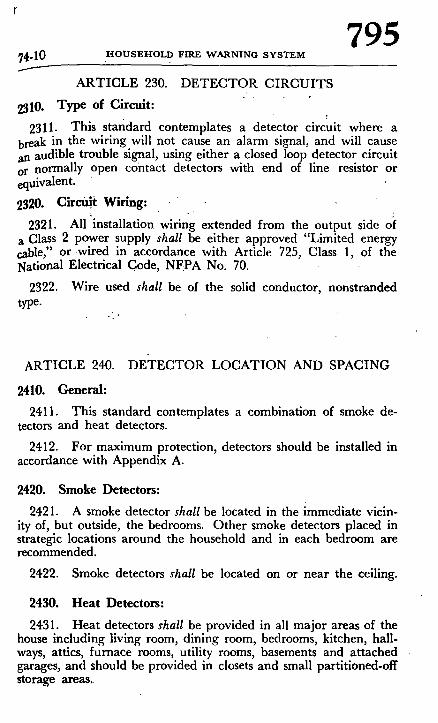
74.10 H O U S E H O L D FIRE WARNING. SYSTEM 795
......-
A R T I C L E 230. DETECTOR CIRCUITS
2310. Type of Circuit:
2311. This standard contemplates a detector circuit where a break in the wiring will not cause an alarm signal, and will cause an audible trouble signal, using either a closed loop detector circuit or normally open contact detectors with end of line resistor or equivalent.
2320. Circifit Wiring:
2321. All installation wiring extended from the output side of a Class 2 power supply shall be either approved "Limited energy cable," or wired in accordance wi th Article 725, Class 1, of the National Electrical Code, NFPA No. 70.
2322. Wire used shall be of the solid conductor, nonstranded type.
ARTICLE 240. DETECTOR LOCATION AND SPACING
2410. General:
2411. This standard contemplates a combination of smoke de- tectors and heat detectors.
2412. For maximum protection, detectors should be installed in accordance with Appendix A.
2420. Smoke Detectors:
2421. A smoke detector shall be located in the immediate vicin- ity of, but outside, the bedrooms. Other smoke detectors placed in strategic locations around the household and in each bedroom are recommended.
2422. Smoke detectors shall be located on or near the ceiling.
2430. Heat Detectors:
2431. Heat detectors shall be provided in all major areas of the house including living room, dining room, bedrooms, kitchen, hall- ways, attics, furnace rooms, utility rooms, basements and attached garages, and should be provided in closets and small partitioned-off storage areas.,

796 OUTSIDE ALARM 74-11
2432. Heat detectors shall be installed within the strict limita. tion of their listed spacing.
2433. For maximum protection, spot-type detectors should b~ installed on the ceilings as near the centers of the areas they protecl as practicable.
2434. On level ceilings with open joisl~s or beams, all detector. should be mounted on the bottom of such joists or beams.
2435. Reduced spacing may be required due to structural char. acteristics of the protected area, possible drafts, or other condition~ affecting detector operation. Detectors installed on a joisted ceilin~ should have their smooth ceiling spacing reduced where this spac ing is measured at right angles to solid joists: in the case of spo detectors this spacing should not exceed one half of the listec spacing.
ARTICLE 250J OUTSIDE ALARM
2510. Outside Alarm:
2511. Provision should be made for the installation of an outsid~ alarm sounding device or devices.

74-12 H O U S E H O L D F I R E W A R N I N G S Y S T E M 797
f
CHAPTER 3. CARE OF THE EQUIPMENT
ARTICLE 300. MAINTENANCE
3010. Instructions: 3011. Each supplier of equipment for installation by the house-
holder, or installer of equipment in the home shall furnish to the householder the booklets and charts specified in paragraph 2215.
~020. Maintenance:
3021. If primary batteries (dry cell type batteries) are used as a secondary source of energ, y they shall be replaced in accordance with the recommendations of the alarm equipment manufacturer.
3022. It is recommended that a maintenance contract be ex- ecuted with the installer wherever feasible.
ARTICLE 310. TESTS
3110. Testing:
3111. Tests and examinations, as recommended by the manu- facturer, should he made weekly by the householder. It is good practice to establish a definite day for these tests.

798 LOCATION OF DETECTION DEVICES 74-1~
APPENDIX A
THE LOCATION OF HEAT AND SMOKE DETECTION DEVICES !
One of the most critical parts of any fire alarm system installati0~ is the location of the fire detecting devices.
This Appendix is not a technical study. It is an attempt to stat some fundamentals on detector installation. For simplification, on] the "spot-type" heat detector and the smoke detector will be used illustrate the principles involved. Not covered in this Appendix art other types of detection devices (e.g., continuous "line-type" hea detectors, combustion products and flame-sensitive detectors) al though these detectors likewise must be installed with regard t~ their performance limitations and the principles involved. Also no covered in this Appendix are the special problems that requin engineering judgment, such as installation in attics and in rooms with high ceilings.
Installation of a Single "Spot-Type" Heat Detector
Each "spot-type" heat detector is capable ofsensing fire within al defined time limit when located within a certain distance of a] standard fire developed and used by Underwriters' Laboratoriesl Inc., Underwriters' Laboratories of Canada, or Factory Mutual En-1 gineering Division for testing these devices. Thus, each detector has an effective "square of protection." This square is based on the detector being mounted on a smooth ceiling. For normal ceiling heights, the "square of protection" on the ceiling extends down to the floor forming a space as shown in Figure 1. Any fire gen-
CEILING DETECTOR
I "~" ' / 1 1 ~ -! "~ SQUARE i ', I I I I I ', - ' o f ! , ~ I I I I I i P R O T E C T I O N
i ~ I IIII l
I / I I lXX FLOOR
Figure I. The space protected by e single detector extends from ceiling to floor within the square of protection.

799 i : , - 1 4 HOUSEI-IOt.. FIRE WARNINO SYSTZM
~rating sufficient heat within this space should be detected by the ~t If- ae t detector in the time limit established by test. i The figure given in the laboratory listing as the "distance of the ~detector) from any wall or partition" is the distance "D" shown "n Figure 2. This distance "D" is measured from the detector to he side of the largest square that can be effectively protected by
i ~ e detector. In the listings, distance "D" varies from 5 feet to 25 i/]~et with different detectors. / - -
, 9
DETECTOR
IY//21/// 41 Proper Location of the Detector
A single detector with a "D" of 10 feet mounted on a smooth ceiling in the middle of a 20 foot by 20 foot room will cover all the space in the room as shown in Figure 3.
: The space covered by the detector is tied to that detector. When the detector is moved, the space covered moves with it.
If, however, the same detector as the one shown in Figure 3 is v moved to a point on the ceiling near the left wall, three feet from ' the rear wall, then the ceiling coverage is reduced to 10 feet by 13 ~feet and about two-thirds of the space in the room is left "not properly covered" as shown in Figure 4.
Must Detectors be Mounted on the Ceiling?
Heat from a fire rises to the ceiling, spreads out across the ceil-
l ing surface and begins to bank down from the ceiling. The corner

800 LOCATION OF DETECTION DEVICES
2 0 '
!
Figure 1. Room properly covered by a, detector w;th a "D" of I0 feet.
20"
Y Figure 4. Roomnot prop- erly covered by a detec-
"for with a "D" of I0 feet.
J
" D E A D " A I R SPACE I ::.'. C E I L I N G ;' ' : ~1 ' "
/ / 7 / 7 7 7 ~ - / / / / / / . / / . / / r / / .
L F R O M " ~,. ;~<,~. F, .E - - . - \ J ' ~ - - , "
P L A C E ' DETECTOR HERE / - N E V E R H E R E . E ~ I ~
R A R E L Y H E R E ~ 7--/F/7-~. N E V E R HERE ,/.~// W_WAAoLL
L
Figure 5. Example of proper mounting for spot-type defectors.

74-16 H O U S E H O L D F I R E W A R N I N G S Y S T E M 801
where the ceiling and the wall meet is an air space into which heat has difficulty i n penetrating. In most fires, "this "dead" air space measures about 6 inches along the ceiling from the corner and 6 inches down the wall as shown in Figure 5. "Spot Ty.pe" detectors must not be placed in this "dead" air space.
The placement of the detector is critical if maximumspeed of fire detection is desired. If we could foretell the future, detectors could be located directly over the point where the next fire would originate. "Thisv iew of the future 'is not present. Thus, the most desirable location for a spot-type detector is the center "of the ceil- ing. At this location, the detector is closest to all areas of the room.
t I f the detector cannot be located in the center of the ceiling, a
location on the ceiling is preferred. In this off-center location, how- ever, heat from a fire on, the far side of the room will take longer to trigger the detector than a center ceiling mounting. The time lost in detection will be ..time tha t otherwise could have been used for evacuation. • ' "
, t . .
The least desirable location for mounting, spot-type detectors is on the side wall. In thislocation, heat from a fire across the room will reach the detector after it would have operated any ceiling mounted device. Should it be absolutely necessary to mount a de- tector on the side wall, care should be taken to avoid anything that might further prevent heat from reaching.the detector and further delaying the alarm. Any detector- mounted on the side wall should be located as near as possible to, the ceiling but below the "dead" air space. • detector mounted on ~he side wall should, thus, be located.at.least 6 and not more than 12 inches from the ceiling.
The Use.. o f Several - Detectors
In a room too large for protection by a single detector, several detectors must be used. I t is important that they be properly lo- cated so all parts of the room are covered. To pro.vide for this cov- erage, the Underwriters' L~/borat0ries or Factory Mutual Engineer- ing Division listings also give the distance between detectors on a smooth ceiling. This distance is twice the distance "D" illustrated in Figure 2 and is often called the detector "spacing" or "spacing guide."
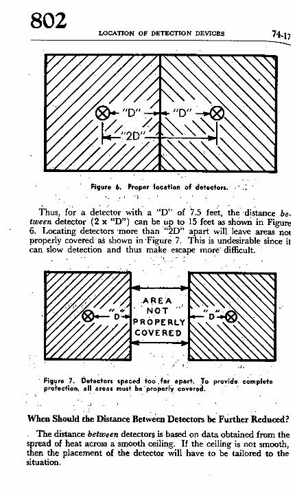
802 L O C A T I O N O F D E T E C T I O N D E V I C E S 74-17
Figure 6. Proper location of detectors. ;- .~
Thus, for a detector with' a "D" of ~7.5 feet, the :distance be. tween detector (2 x "D") can be up to 15 feet as shown in Figure 6. Locating detectors 'more than "'2D"apart will leave areas not properly covered a.~ shown in 'Figure 7. This is undesirable since it can slow detection and thus make escape more" difficult.
A R E A / " ' N o T "' PR0:PERLY C O V E R E D
•, . : j ,
Figure 7. Detectors spaced ~oo.far apart. To provide complete pro~mcflon, al! .areas must be'properly coverecl.
• • j
• t
When Should the Distance Between Detccton be Further Reduced?
The distance between detectors is based on data obtained from the spread of heat across a smooth ceiling. If the ceiling is not smooth, then the placement of the detector will have to be tailored to the situation.

74.18 H O U S E H O L D FIRE W A R N I N G S Y S T E M 803
"" D
~tO D
Figure.8. Open joists, attics and extra high-ceilings are some of the areas tha~' require s~pecial knowledge fo~r installation:
For instance, with open wood' joists heat travels freely down the joist,, channels so' that the maximum" " distance" between detectors ( 2D ) can be used. Heat, however, has trouble spreading across the joists so the distance in this direction should be one-half the distance allowed between detectors. Since Y2 x 2D is D, the dis, tance between detectors across open wood joists should not exceed "D" as shown in Figure 8 and the "distance to the wall" is reduced ( ~ x "D") to " ~ D . " Detectors should be mounted on the bottom of the joists and not up in the joist channels.
Walls, partitions, doorways, ceiling beams and open joists in- terrupt the normal flow of heat, thus creating new areas to be pro- tected.
What is Complete Protection?
Closets and bathrooms axe areas often improperly omitted from fire alarm system coverage. Such omissions produce a "hole" in the protection of a structure. These "holes" are dangerous since the initial progress of a fire in these areas will not be automatically detected. When fire breaks out from these spaces, it may be too late to escape. "Holes" are also created when detectors are placed at greater distances than their listing permits. Complete

804 LOCATION OF DETECTION DEVICES 74-19
protection exists only when all detectors have been installed in accordance with their distance limitations and all fire confining spaces have been covered.
What About Smoke?
The pattern of home fires varies, depending on circumstances. Some fires produce intense heat and limited smoke. Others produce little heat and intense volumes of smoke or "fire gases." A slow. burning fire in bedding and upholstery, for example, may generate enough smoke and deadly gas in a home to cause unconsciousness before producing sufficient heat to activate a heat detector.
Good practice dictates a detection system capable of sensing smoke or fire gases as well as flame or heat.
Where To Locate the Basic Smoke Detectors?
The prineipal threat to life in a dwelling is at night when every- one is asleep. With heat detectors standing guard throughout the house from fast, hot fires, smoke detectors should be provided to pick up the slow, smoky fire.
Since the principal threat to persons in sleeping areas comes from fires in the remainder of the house, basic smoke detectors should be located between the bedroom area and the rest of the house. In homes with only one bedroom area on one floor, only one smoke detector may be needed as shown in Figure 9.
DINING f~ITCHF'N
/ - - - x I
LIVING ROOM , ~ ~_~
/ D R O ~ OOM
BEDROOM
Figure 9. A smoke defector (indicated by cross) should be located between the sleeping area and the rest of the house.
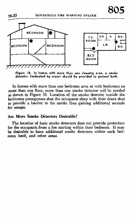
74-20 H O U S E H O L D FIRE W A R N I N G SYSTEM 805
Figure I 0 . In homes with more then one sleeping area. a smoke detector (indicated by cross) should be provided to protect both.
In homes with more than one bedroom area or with bedrooms on more than one floor, more than one smoke detector will be needed as shown in Figure 10. Location of the smoke detector outside the bedrooms presupposes that the occupants sleep with their doors shut to provide a barrier to the smoke thus gaining additional seconds for escape.
Are More Smoke Detectors Desirable?
The location of basic smoke detectors does not provide protection for the occupants from a fire starting within their bedroom. I t may be desirable to have additional smoke detectors within each bed- room itself, and other areas.


![Atmel AVR1610: Guide to IEC 60730 Class B …ww1.microchip.com/downloads/en/AppNotes/doc42008.pdfAtmel AVR1610: Guide to IEC 60730 Class B Compliance with XMEGA [APPLICATION NOTE]](https://img.pdfslide.us/doc/110x75/5abf9f6d7f8b9add5f8deb78/atmel-avr1610-guide-to-iec-60730-class-b-ww1-avr1610-guide-to-iec-60730-class.jpg)