Embed Size (px)
Citation preview
Report No. CG-D-05-8
CV, EVALUATION OF COMPOSITE ARMOR FORCOAST GUARD VESSELS
a,o0
(N' JAMES R. OSBORN
E. i. DuPont de Nemours & Co.
Textila Fibers Dept. /F&CDCP. O. Box 80702
Wilmington, DE 19880-702
F-W MON ~5AfMENT Ao ulctlosApproved fo publc ,eleaa
FINAL REPORTJUNE 1988
This document is available to the U.S. public thiough theNatbnal Technica: IlNornatn Sorvia,, SSpi'nteid, Virgnia 22161
Prepared for:
U.S. Coast Guard OTICResearch and Development Center ELECTEAvery Point JUNO 5 1989Groton, CT 06340-6096
and Ecvv
U.S. Department Of TransportationUnited States Coast GuardOffice of Engineering and DevelopmentWashington, DC 20593-0001
t89 6 05 014
NOTICE
This document is disseminated under the sponsorship of theDepartment of Transportation In the Interest of Informationexchange. The United States Government assumes noliability for its contents or use thereof.
The United States Government does not endorse products ormanufacturers. Trade or manufacturers' names appear hereinsolely because they are considered essential to the object ofthis report.
The contents of this report reflect the views of the CoastGuard Research and Development Center, which isresponsible for the facts and accuracy of date presented.This report does not constitute a standard. sp~clfication, orregulation.
SAMUEL F. POWEL, IIITechnical DirectorU.S. Coast Guard Research and Development CenterAvery Polhit, Groton, Connect;cut 06340-6096
13.
Technical eport Documentation Page1. Report No. 2. Government Accession No. 3. Recipient's Catalog No.
CG-DL05-89
4. Title and Subtitle.' 5. Report DateJune 1988
EVALUATION OF COMPOSITE ARMOR FORCOAST GUARD VESSELS 6. Performing Organization Code
7. Author(s) 8. Perming Organization Report No.
C D18 CR-TECH-88-3Jerras R. Osborn I'
9. Perfrminq Orpanization Name and Address 10. Work Unit No. (TRAIS)
F. I. Du,'c-4, i Nqmours & Co., xtjle Fibers Dept1JF -fC 11. Contract or Grant No.
P. 0. Box 80702WilmingIon, DE 19880-702 13. Type of Report and Period Coverad
12. Spo.lsoriig Agency Name and AddressU.S. Coast Guard Department of Transportation FINALPessarch ,nd Development Center U.S. Coast GuardAvefy Point Office of Engineering and Development 14. Sponsoring Agency CodeGroton, Connecticut 06340-6096 Washington, D.C. 20593
16. Supplementary Notes
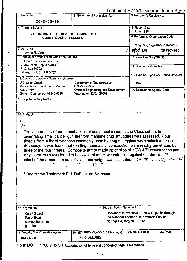
16. Abstract
The vulnerability of personnel and vital equipment inside Island Class cutters topenetrating small caliber gun fire from maritime drug smugglers was assessed. Fourthreats from a list of weapons commonly used by drug smugglers were selected for use inthis study. It was found that existing materials of construction were readily penetrated bythree of the four tnreats. Composite armor made up of plies of KEVLAR* woven fabric andvinyl ester resin was found to be a weight effective protection against the threats. Theeffect of the armor in a cutters cost and weight was estimated. ,.1s )r-, (ý t1,V /o t•- D,,
Registered Trademark E. I. DuPont de Nemours
17. Key Words 18. Distribution Statement
Coast Guard Document is available tu the U.S. public throughPatrol Boat the National Technical Infornation Servlce.cornposile armor Springlield, Virginia 22161gun fire
19. Security GCla1. (of this report) 20. SECURITY CLASSIF. (ol this pae) 21. No. of Pages 22. Pric
UNCLASSIFIED UNCLASSIFID
Form DOT F 1700.7 (8/72) Reproduction of form and connoeted page Is authorized
iii
N u
,' 0>,
0i
U)-
V I , t .0 t '0.2.2 CY
(D M M. 0- O
0) c, = -a~
0 (0
66 Cý -Lw
c QU
0 a
0 w - L
E 0 00
Inhe
E 8Z Z7 : :3 2 i
0
L CIL
z 5,a-m 6.I L 1.6I o
I ~~~U ',s11 ,"0 91
0 0 -O05 00
U ~~~~~ Q0 6 E A
oEr-~(n~
91~
tju wcao) n cc
3: eq 0 P
0. w
0.~
C','
10 4Ri-
TABLE OF CONTENTS
Page
1. INTRODUCTION ....................................................................................................... 1
2. THREAT DEFINITION .............................................................................................. 1
3. VULNERA BILITY ASSESSMENT ......................................................................... 2
a. Construction M aterials ................................................................................ 2
b. A ssessm ent Procedure ................................................................................. 2
(1) Test Facility ............................................................................................ 2
(2) Lethality ................................................................................................ 3
(3) Test Scheme ........................................................................................... 3
C. Results ............................................................................................................. 3
4. COM POSITE ARM OR .. .............................................. ......................................... 5
a. O bjective .......................................................................................................... 5
b. Arm or Construction ..................................................................................... 5
c. Test Procedure ............................................................................................... 5
d. Results ............................................................................................................ 6
5. SUM M ARY .. .. .................................................. ........................................... 7
a. Conclusion ...................................................................................................... 7
b. Im plem entation ............................................................................................ 7
c. Recom m endation ......................................................................................... 8
APPENDIX A - WITNESS MATES A-1
APPENDIX B - BALLISTIC LIMIT DA7IA B-I
Acooesson For
IITIS GRA&iDIIC TABUntrinouoc*d 0OTC ustification _-
By. . .. . -Distribution/
AvailabilitY Codes
I vaqi'~.ari/or
Di~t Specilel"V1 . .
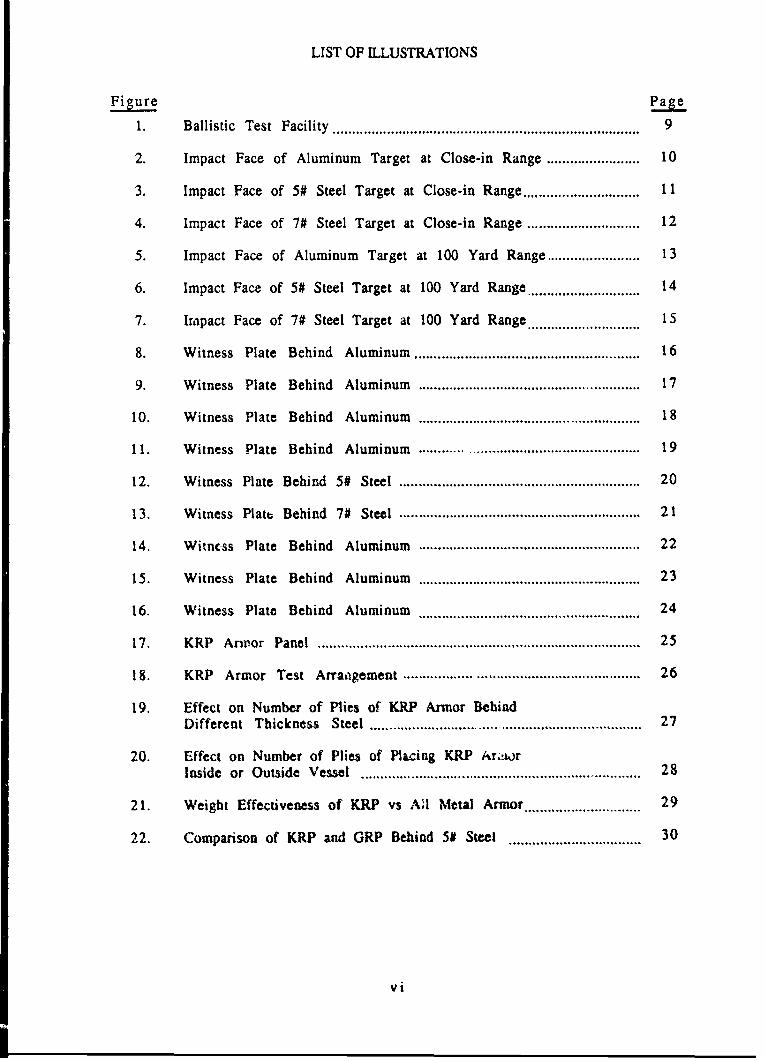
LIST OF ILLUSTRATIONS
Figure Page
1. Ballistic Test Facility ............................................................................... 9
2. Impact Face of Aluminum Target at Close-in Range ........................ 10
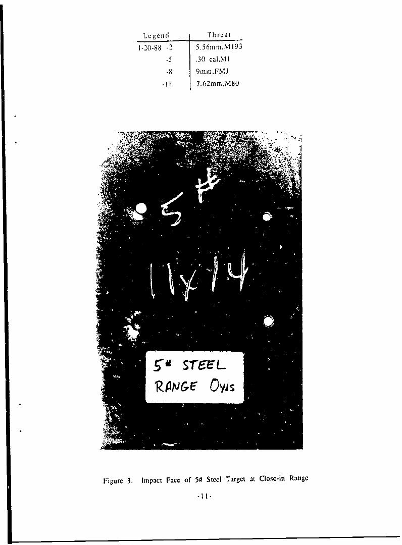
3. Impact Face of 5# Steel Target at Close-in Range .............................. 11
4. Impact Face of 7# Steel Target at Close-in Range ............................. 12
5. Impact Face of Aluminum Target at 100 Yard Range ........................ 13
6. Impact Face of 5# Steel Target at 100 Yard Range ............................ 14
7. Impact Face of 7# Steel Target at 100 Yard Range ............................ 15
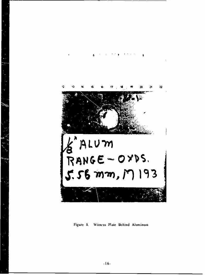
8. Witness Plate Behind Aluminum ......................................................... 16
9. Witness Plate Behind Aluminum ........................................................ 17
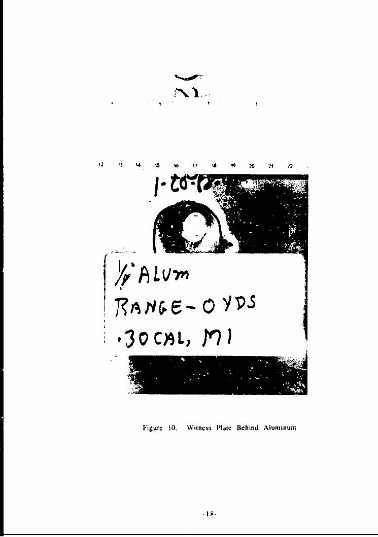
10. Witness Plate Behind Aluminum ........................................................ 18
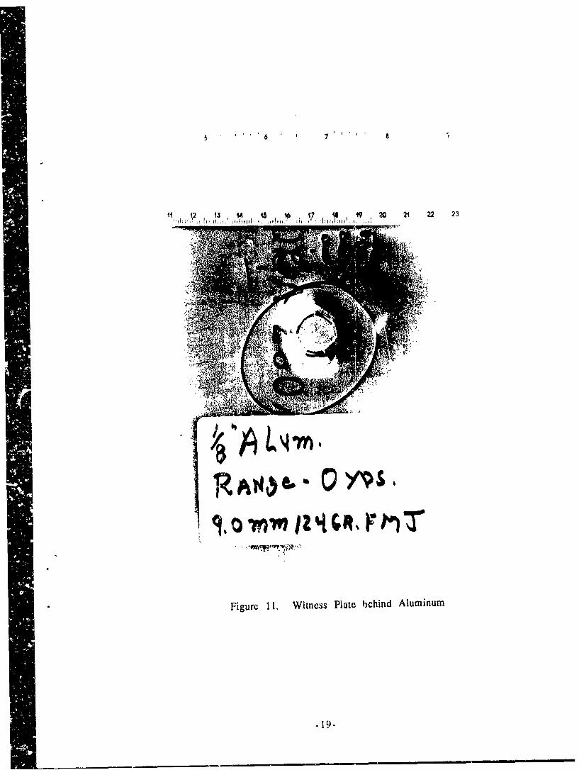
11. Witness Plate Behind Aluminum ....................................................... 19
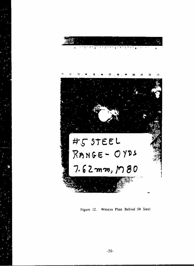
12. Witness Plate Behind 5# Steel ............................................................. 20
13. Witness Plate; Behind 7# Steel ............................................................. 21
14. Witncss Plate Behind Aluminum ........................................................ 22
15. Witness Plate Behind Aluminum ........................................................ 23
16. Witness Plate Behind Aluminum 24
17. KRP Anpor Panel ................................................................................... 25
18. KRP Armor Test Arraagement ............................................................ 26
19. Effect on Number of Plies of KRP Armor BehindDifferent Thickness Steel .................................................................... 27
20. Effect on Number of Plies of Placing KRP Ar.!orInside or Outside Vessel ........................................................................ 28
21. Weight Effectiveness of KRP vs A3I Metal Armor .............................. 29
22. Comparison of KRP and GRP Behind 5# Steel .................................. 30
vi
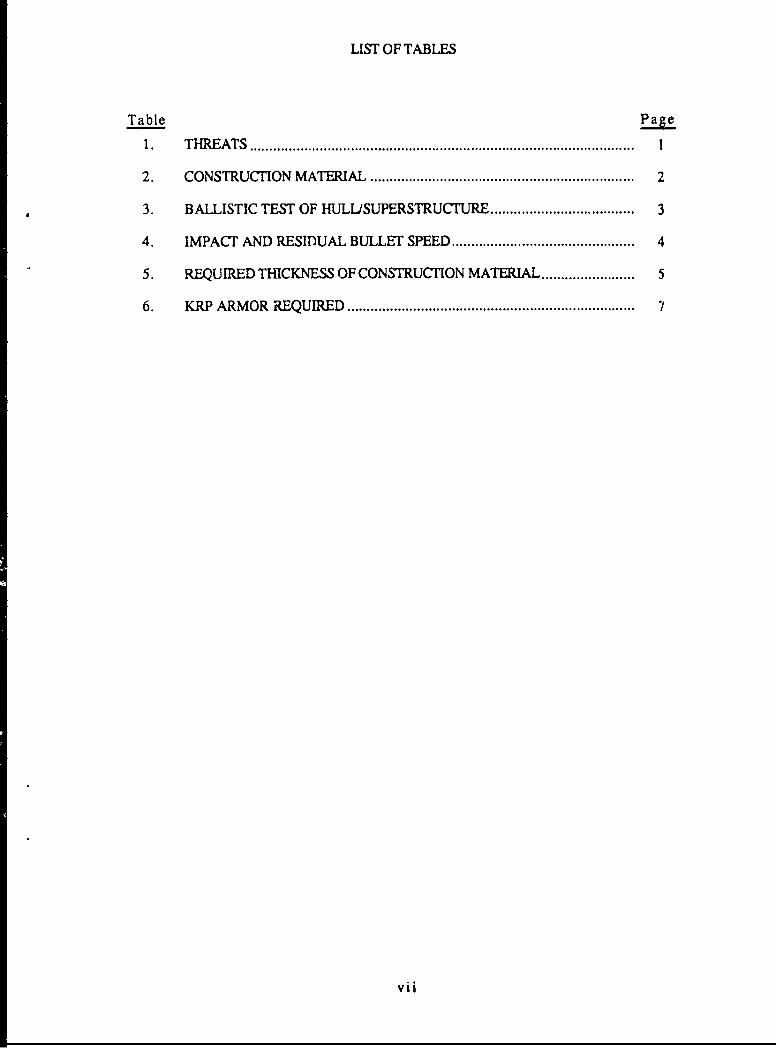
LIST OF TABLES
Table Page
1. T H RE A TS ................................................................................................... !
2. CONSTRUCTION MATERIAL .................................................................... 2
3. BALLISTIC TEST OF HULL/SUPERSTRUCTURE .................... 3
4. IMPACT AND RESIDUAL BULLET SPEED ............................................... 4
5. REQUIRED THICKNESS OF CONSTRUCTION MATERIAL ........................ 5
6. KRP ARMOR REQUIRED .......................................................................... 7
vii

[BLANK l
viii
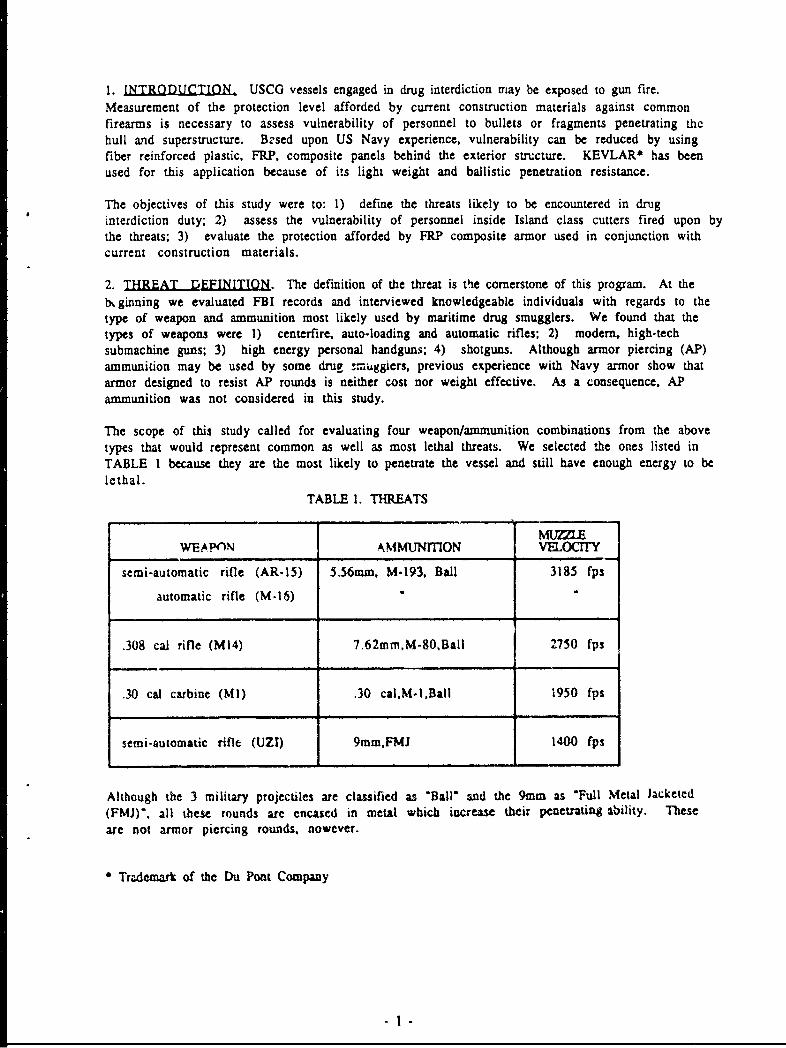
1. INTRODUCTION, USCO vessels engaged in drug interdiction may be exposed to gun fire.
Measurement of the protection level afforded by current construction materials against commonfirearms is necessary to assess vulnerability of personnel to bullets or fragments penetrating thehull and superstructure. Brsed upon US Navy experience, vulnerability can be reduced by usingfiber reinforced plastic, FRP, composite panels behind the exterior structure. KEVLAR* has beenused for this application because of its light weight and ballistic penetration resistance.
The objectives of this study were to: 1) define the threats likely to be encountered in druginterdiction duty; 2) assess the vulnerability of personnel inside Island class cutters fired upon bythe threats; 3) evaluate the protection afforded by FRP composite armor used in conjunction withcurrent construction materials.
2. THREAT DEFINITION. The definition of the threat is the cornerstone of this program. At thelx ginning we evaluated FBI records and interviewed knowledgeable individuals with regards to thetype of weapon and ammunition most likely used by maritime drug smugglers. We found that thetypes of weapons were 1) centerfire, auto-loading and automatic rifles; 2) modem, high-techsubmachine guns; 3) high energy personal handguns; 4) shotguns. Although armor piercing (AP)ammunition may be used by some drug -m ggiers, previous experience with Navy armor show thatarmor designed to resist AP rounds is neither cost nor weight effective. As a consequence, APammunition was not considered in this study.
The scope of this study called for evaluating four weapon/ammunition combinations from the abovetypes that would represent common as well as most lethal threats. We selected the ones listed inTABLE I because they are the most likely to penetrate the vessel and still have enough energy to belethal.
TABLE 1. THREATS
MUZZLE
WEAPflN AMMUTNITION VELOCirY
semi-automatic rifle (AR-15) 5.56mm, M-193, Ball 3185 fps
automatic rifle (M-16)
.308 cal rifle (M14) 7.62mm,M-80.Ball 2750 fps
.30 cal carbine (MI) .30 calM-I.Ball 1950 fps
semi-automatic rifle (UZI) 9mm.FMJ 1400 fps
Although the 3 military projectiles are classified as Ball" and the 9mm as "Full Metal Jacketed(FMJ)'. all these rounds are encased in metal which increase their penetrating Ability. Theseare not armor piercing rounds, nowever.
"Trademark of the Du Pont Company
l-1
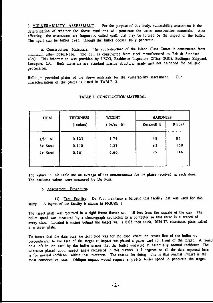
3. VULNERABILITY ASSESSMENT. For the purpose of this study, vulnerability assessment is the
determination of whether the above munitions will penetrate the cutter construction materials. Alsoaffecting the assessment are fragments, called spall, that may be formed by the impact of the bullet.The spall can be lethal even though the bullet doesn't fully penetrate.
a. Construction Materials. The superstructure of the Island Class Cutter is constructed from
aluminum alloy 5086H-116. The hull is constructed from steel manufactured to British Standard4360. This information was provided by USCG, Residence Inspectors Office (RIO), Bollinger Shipyard.Lockport, LA. Both materials are standard marine structural grade and not hardened for ballisticprotection.
Bollino, provided plates of the above materials for the vulnerability assessment. Ourcharacterization of the plats is listed in TABLE 2.
TABLE 2. CONSTRUCTION MATERIAL
ITEM THICKNESS WEIGHT HARDNESS
(inches) (lbs/sq ft) Rockwell B Brinell
1/8" Al 0.123 1.74 4 3 81
5# Steel 0.110 4.57 83 160
7# Steel 0.161 6.66 79 146
The values in this table ame an average of the measurements for 14 plates received in each item.
The hardness values were measured by Du Pont.
b. Assessment Procedure.
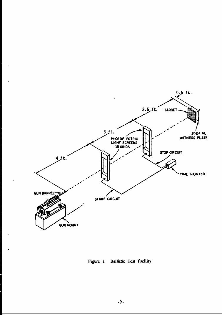
(1). jst .FaciliU. Du Pont maintains a ballistic test facility that was used for this
stidy. A layout of the facility is shown in FIGURE I.
The target plate was mounted in a rigid frame fixture soL 10 feet from the muzzle of the gun- The
bullet speed was reasured by a chronograph connected to a compuler so that there is a record of
every shot- Located 6 inches behind the target wL! a 0.02 inch thick. 2024-T3 aluminum plate calleda witness plate.
To insure that the daa base we generated was for the case ahere the center line of the bullet •
,erpendicular to the face of the target at impact we placed a paper card in front of the target. A round
hole left in the card by the bullet meams that the bullet impacted at essentially normal incidence. The
tolerance placed upon impact angle meased in this manner is 5 degrees so all the data reported here
is for normal incidence within that tolerance. The reason for doing this is that normal impact is the
most consmervative cas. Oblique impact would require a greazei buller speed to penetrate the target.
,2-
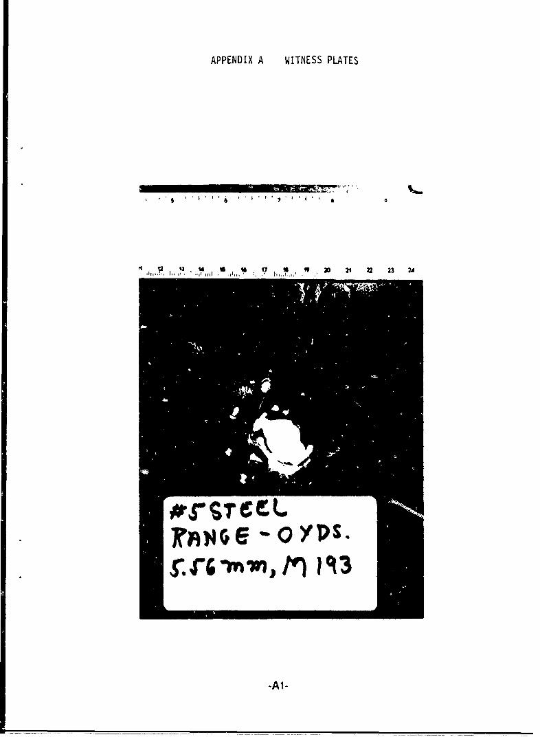
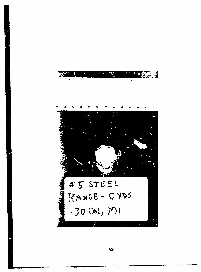
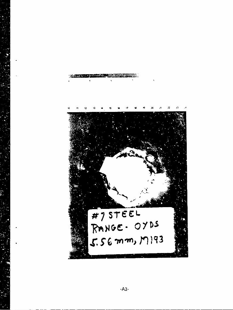
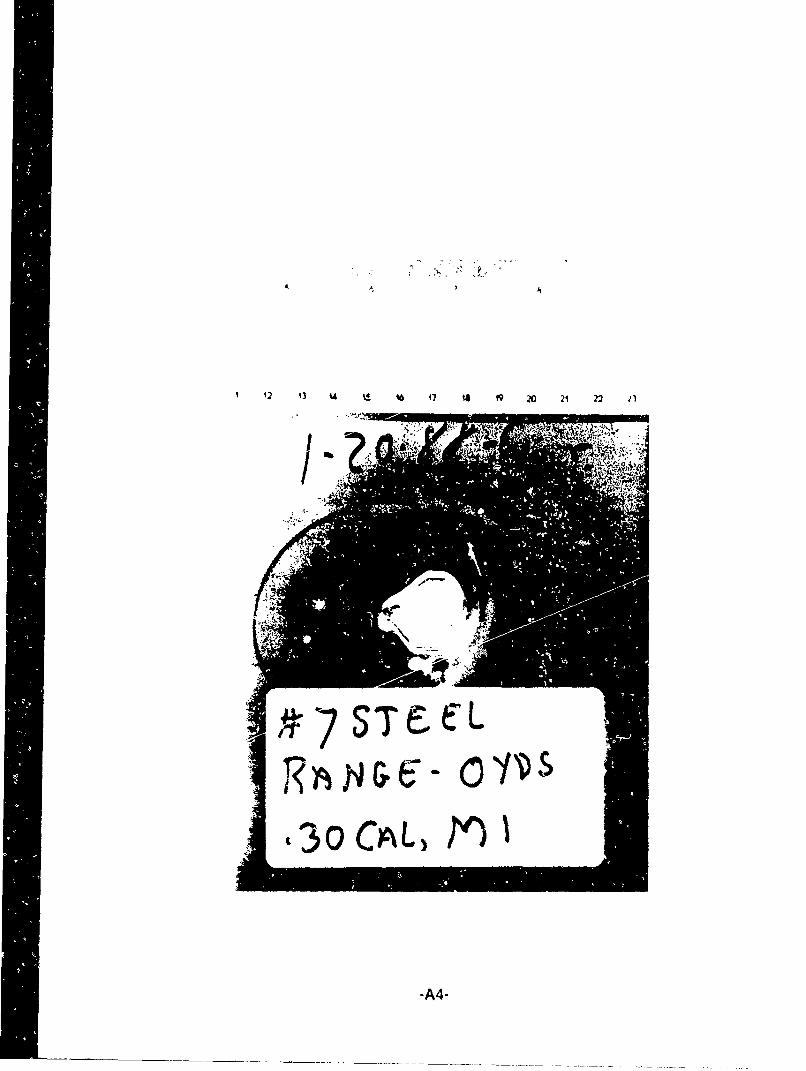
(2). Lethality The witness plate has been adopted by the Navy as the means ofdetermining penetration. If light could be seen through the witness plate following a shot at thetarget, then the shot was recorded as a penetration. For this study, any particle causing a hole in thewitness plate is considered lethal and so penetration of the witness plate is equivalent to lethality.
(3). Test Scheme. Each of the fcur threats was fired once at each of the three materialtest panels. For the first round of tests the bullet velocity was the muzzle velocity listed in TABLE 1.A second test was conducted using a new set of targets and reducing the bullet speed to simulate atarget to gun range of 100 yards. A new witness plate was installed after each round was fired and aphotograph was taken of each target and witness plate.
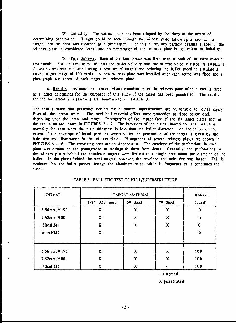
c. Results. As mentioned above, visual examination of the witness plate after a shot is firedat a target determines for the purposes of this study if the target has been penetrated. The resultsfor the vulnerability assessment are summarized in TABLE 3.
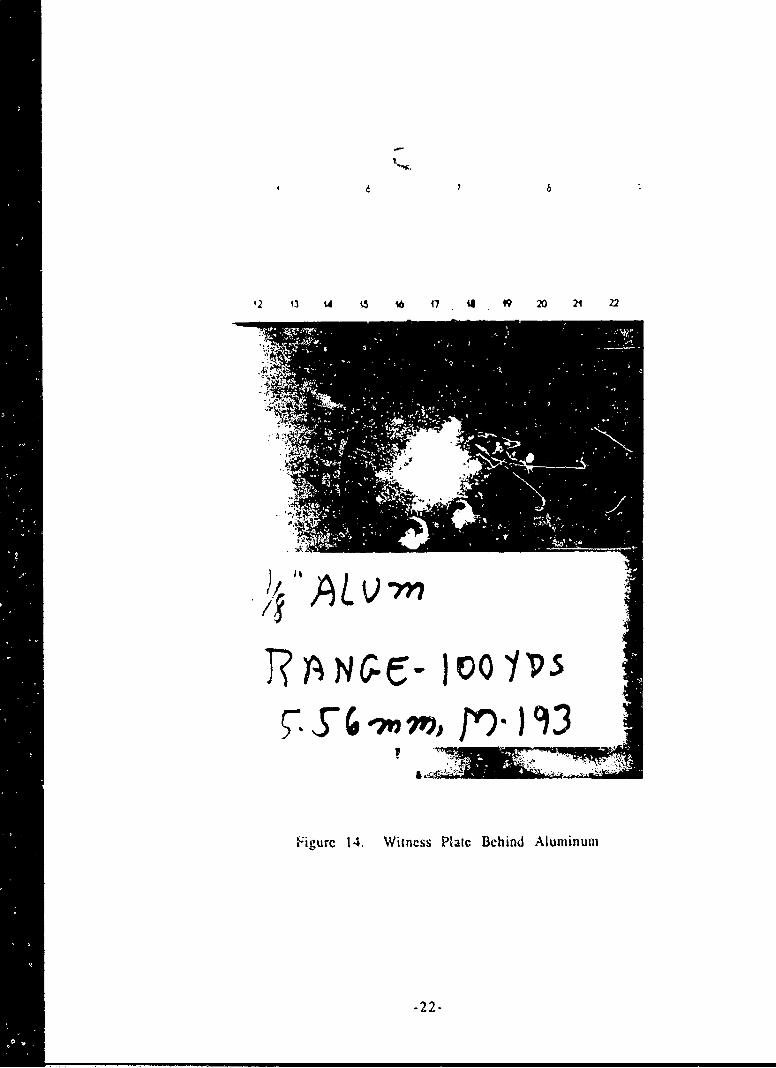
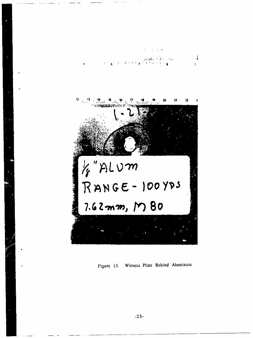
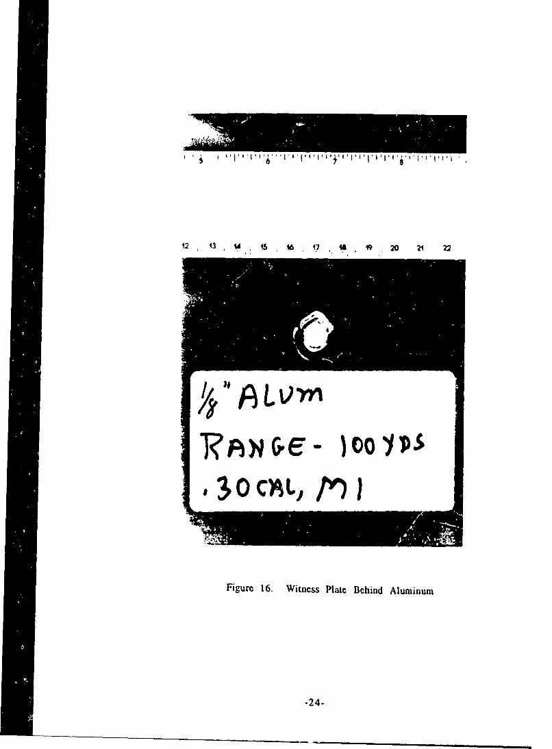
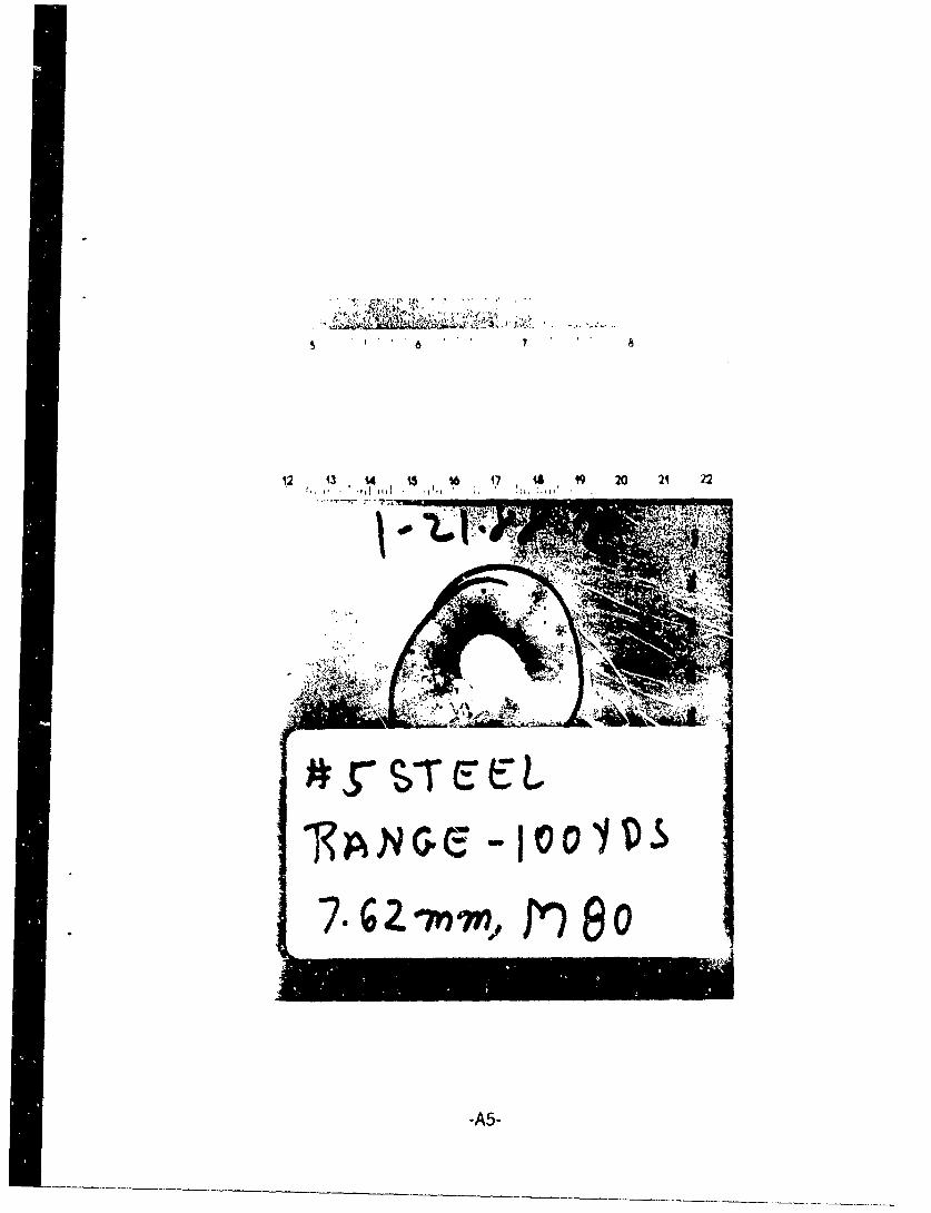
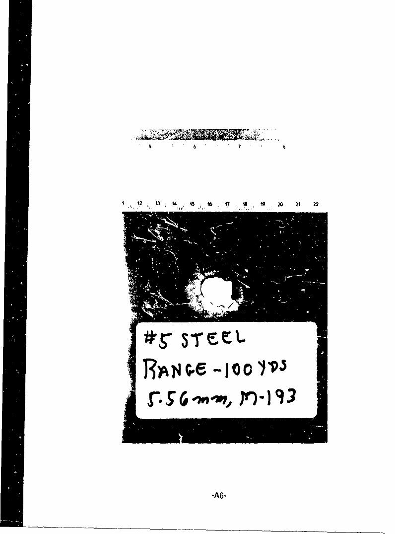
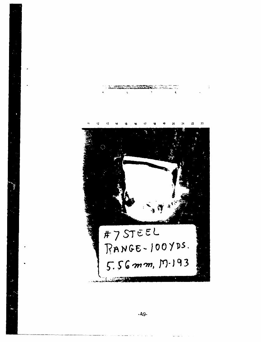
The results show that personnel behind the aluminum superstructure are vulnerable to lethal injuryfrom all the threats tested. The steel hull material offers some protection to those below deckdepending upon the threat and ;ange. Photographs of the impact face of the six target plates shot inthe evaluation are shown in FIGURES 2 - 7. The backsides of the plates showed no spall which isnormally the case when the plate thickness is less than the bullet diameter. An indication of theextent of the envelope of lethal particles generated by the penetration of the target is given by thehole size and distribution ;n the witness plate. Photographs of several witness plates are shown inFIGURES 8 - 16. The remaining ones are in Appendix A. The envelope of the perforations in eachplate was circled on the photographs to distinguish them from dents. Generally, the perforations inthe witness plates behind the aluminum targets were limited to a single hole about the diameter of thebullet. In the plates behind the steel targets, however, the envelope and hole size was larger. This isevidence that the bullet passes througA the aluminum intact while it fragments as it penetrates thesteel.
TABLE 3. BALLISTIC TEST OF HULIZ'UPERSTRUCTURE
THREAT TARGET MATERIAL RANGE
1/8" Aluminum So Steel 7# Steel (yard)
5.56mtm.M 193 X X X 0
7.62mm.MS0 X X X 0
.30cal.M I X X X 0
9mm.FM] X 0
5.56mm.M 193 X X X 100
7.62mm.M80 X X X 100
.30cal.M I X X 100
- stopped
X penetrated
-3-
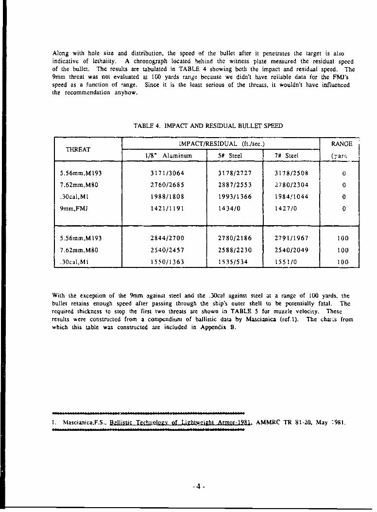
Along with hole size and distribution, the speed of the bullet after it penetrates the target is alsoindicative of lethaiity. A chronograph located behind the witness plate measured the residual speedof the bullet. The results are tabulated in TABLE 4 showing both the impact and residual speed. The9mm threat was not evaluated at 100 yards range because we didn't have reliable data for the FMJ'sspeed as a function of range. Since it is the least serious of the threats, it wouldn't have influencedthe recommendation anyhow.
TABLE 4. IMPACT AND RESIDUAL BULLET SPEED
'MPACT/RESIDUAL (ft./sec.) RANGETHREATT 1/8" Aluminum 5# Steel 7# Steel (yarri
5.56rm.M193 3171/3064 3178/2727 3178/2508 U
7.62mm,M80 2760/2685 2887/2553 2780/2304 0
.30calMl 1988/1808 1993/1366 1984!1044 0
t 9mm,FMJ 1421/1191 1434/0 1427/0 0
5.56mm.M193 2844/2700 2780/2186 2791/1967 100
7.62mm,M80 2540/2457 2588/2230 2540/2049 100
.30cal.Mi 1550/1363 1535/534 155110 100
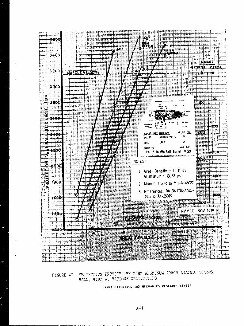
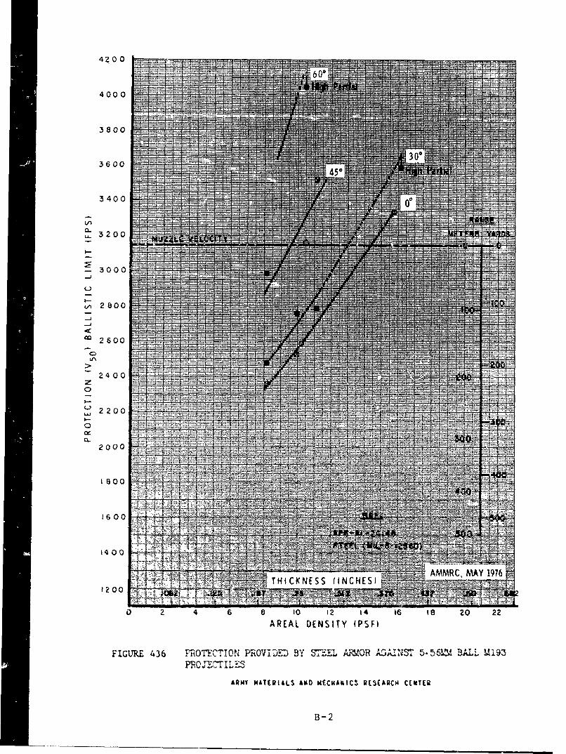
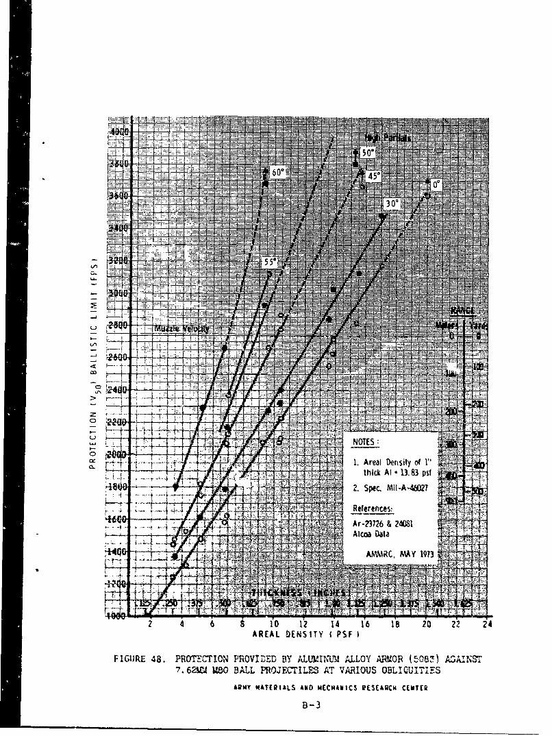
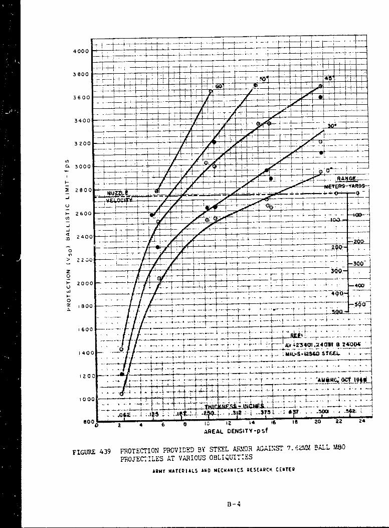
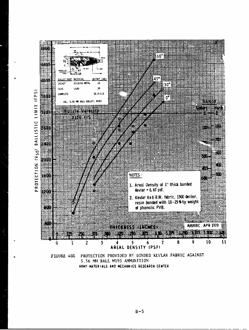
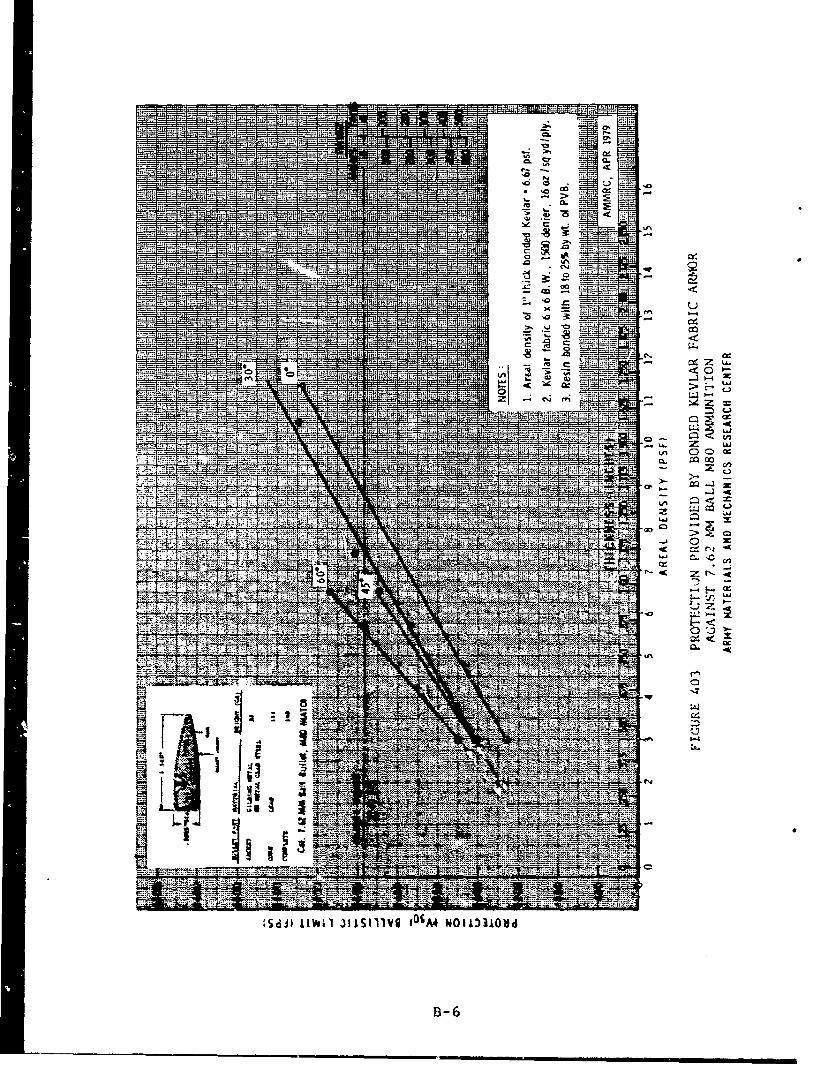
With the exception of the 9mm against steel and the .30cal against steel at a range of 100 yards, thebullet retains enough speed after passing through the ship's outer shell to be potentially fatal. Therequired thickness to stop the first two threats are shown in TABLE 5 for muzzle velocity. Theseresults were constructed from a compendium of ballistic data by Mascianica (ref.1). The char;s fromwhich this table was constructed are included in Appendix B.
I. Mascianica,F.S., Balstc eci~ L~g�.ie-wiitt Armor-1981, AMMRC TR 81-20. May *981.
-4-
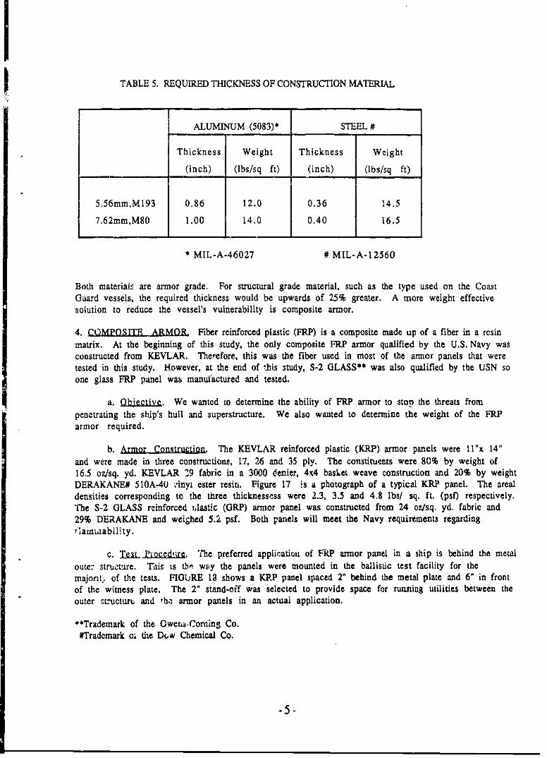
TABLE 5. REQUIRED THICKNESS OF CONSTRUCTION MATERIAL
ALUMINUM (5083)* STEEL #
Thickness Weight Thickness Weight
(inch) (lbs/sq ft) (inch) (lbs/sq ft)
5.56mm,M193 0.86 12.0 0.36 14.5
7.62mm,M80 1.00 14.0 0.40 16.5
* MIL-A-46027 # MIL-A-12560
Both materials are armor grade. For structural grade material, such as the type used on the CoastGuard vessels, the required thickness would be upwards of 25% greater. A more weight effectivesolution to reduce the vessel's vulnerability is composite armor.
4. COMPOSITE ARMOR, Fiber reinforced plastic (FRP) is a composite made up of a fiber in a resinmatrix. At the beginning of this study, the only composite FRP armor qualified by the U.S. Navy wasconstructed from KEVLAR. Therefore, this was the fiber used in most of the armor panels that weretested in this study. However, at the end of "his study, S-2 GLASS** was also qualified by the USN soone glass FRP panel was manufactured and tested.
a. Qbiective. We wanted to determine the ability of FRP armor to stop the threats frompenetrating the ship's hull and superstructure. We also wanted to determine the weight of the FRParmor required.
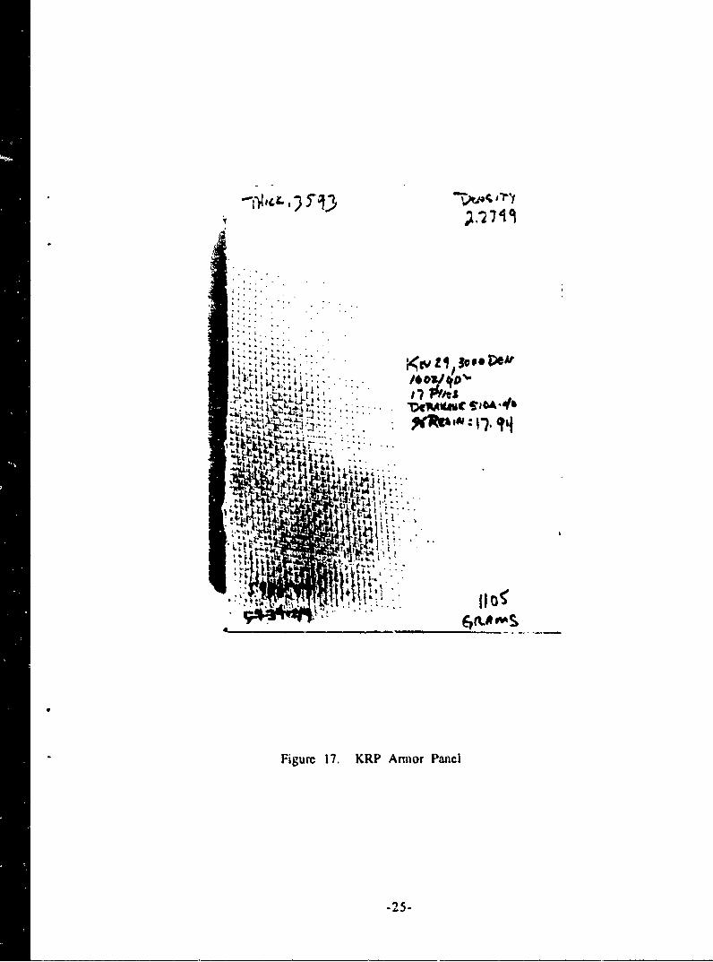
b. Armor Construction. The KEVLAR reinforced plastic (KRP) armor panels were l l"x 14"and were made in three constructions, 17, 26 and 35 ply. The constituents were 80% by weight of16.5 oz/sq. yd. KEVLAR 29 fabric in a 3000 denier, 4x4 basket weave construction and 20% by weightDERAKANE# 510A-40 -'inyi ester resin. Figure 17 is a photograph of a typical KRP panel. The arealdensities corresponding to the three thicknessess were 2.3, 3.5 and 4.8 lbs/ sq. ft. (psf) respectively.The S-2 GLASS reinforced ,lastic (GRP) armor panel was constructed from 24 oz/sq. yd. fabric and29% DERAKANE and weighed 5.2 psf. Both panels will meet the Navy requirements regardingiilamwaability.
c. T ._jLZoa"1. The preferred applicatiot of FR? armor panel in a ship is behind the metaloute: structure. This is tb-. way the panels were mounted in the ballistic test facility for themajont . of the tests. FIGURE 13 shows a KRP panel spaced 2" behind the metal plate and 6" in frontof the witness plate. The 2" stand-off was selected to provide space for running utilities between theouter structurt and th• armor panels in an actual application.
"**Trademark of the Owens-Cornin3 Co.
#Trademark oi the Dt, Chemical Co.
-5-
Several panels were tested in front of the metal plates, however, to evaluate the effectiveness of thisconfiguration in case a retrofit installation was required on short notice that did not permit mountingthe armor on the inside. In this application, the stand-off distance was increased to 38 to provideadequate room for the KRP panel to deflect when impacted by a bullet.
The threats used for the FRP armor evaluation were the 5.56mm, M193; 7.62mm, M80; .30 cal, MI.They were fired at their muzzie velocity which was measured and recorded as before. One round wasfired at each metal plate/FRP panel combination starting with the 17 ply panels. If penetrationoccurred, as determined by examining the witness plate, we went to the 26 ply panel, and so on untilthe bullet was stopped. When it was necessary to test panels thicker than 35 plies, two panels wereclamped together.
d. Results. All the results given here are for the 0 yard rpnge data which is the worst case.The results for KRP behind steel are shown in FIGURE 19. For protection against all three threatsbehind 7 psf steel, 26 plies of KRP armor are an upper limit, and behind 5 psf steel, 35 plies are anupper limit. The results for KRP behind of and in front of aluminum are shown in FIGURE 20. In thiscase, 61 plies provide an upper limit to the number of plies required to stop the worst threat, the7.62mm, M80.
The above results have been replotted in FIGURE 21 for the M80 bullet with total areal density of theKRP plus metal as the dependent variable. The areal density for the required thickness of metalalone to stop the M80, obtained from TABLE 5, is also plotted for comparison. It can be seen that KRPadded to the existini, *•'•-iaI of construction is more weight effective than inkcreasing the thicknessof the existing hdl .- ..j superstructure. The weight differential is even greater than shown here forseveral reasons. First, the aluminum and steel used in combination with KRP was not amor grade.Second, the tet we ran did no: determine the minimum amount of KRP that would stop the threat.That would be part of a Phase II program to be done in the future.
It should be nuted that even if the metal thickness was increased to stop the bullet, there is alwaysthe possibility that lethal metal fragments will spall off the back side of the metal when it isimpacted by a bullet. This is a common occurrence in thick metal armors which necessitates theaddition of FRP panels, c~lled spall liners.
A comparison of KRP and GRP panels behind steel is shown in FIGURE 22. For approximately thesame weight, the KRP armor panel stopped the bullet and the GRP did not.
-6-
5. SUMMARY,
a. Concusion. Up to a firing range of 100 yards, which was the limit of this study, personnelinside Island Class cutters are vulnerable to lethal rifle fire coming from drug smugglers. Testresults showed that unconditional protection for personnel inside can be obtained by adding KRParmor pianiels to the cutter. This is also a more weight effective solution thar increasing the thicknessof the hull and superstructure. Although it was found that placing the KRP either in front of orbehind the 1/8" aluminum wa5 equally effective, it should be noted that the aluminum by itself wasovermatched by the threats. In general, it is more efficieut to place the KRP behind metal.
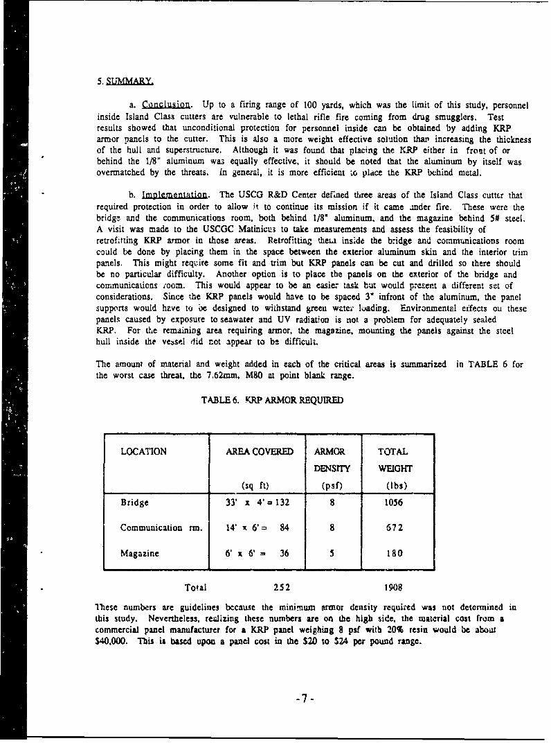
b. ImDlcI ntation. The USCG R&D Center defined three areas of the Island Class cuttfer thatrequired protection in order to allow it to continue its mission if it came ander fire. These were thebridge and the communications room, both behind 1/8" aluminum, and the magazine behind 5# steel.A visit was made to the USCGC Matinicus to take measurements and assess the feasibility ofretrofitting KRP armor in those areas. Retrofitting theu inside the bridge and communications roomcould be done by placing them in the space between the exterior aluminum skin and the interior trimpanels. This might require some fit and trim but KRP panels can be cut and drilled so there shouldbe no particular difficulty. Another option is to place the panels on the exterior of the bridge andcommunications room. This would appear to be an easier task but would present a different set ofconsiderations. Since the KRP panels would have to be spaced 3" infront of the aluminum, the panelsupports would hz.ve to 6e designed to withstand green wtei" loading. Environmental eifects ou thesepanels caused by exposure to seawater and UV radiation is not a problem for adequately sealedKRP. For the remaining area requiring armor, the magazine, mounting the panels against the steelhull inside the vessel did not appear to bh difficult.
The amount of material and weight added in each of the critical areas is summarized in TABLE 6 forthe worst case threat, the 7.62mm, M80 at point blank range.
TABLE 6. KRP ARMOR REQUIRED
LOCATION AREA COVERED ARMOR TOTAL
DENSITY WEIGHT
(sq ft) (psf) (lbs)
Bridge 33' x 4' - 132 8 1056
Communication rm. 14' x 6' • 84 8 672
Magazine 6. x 6' 36 5 180
Total 252 1908
These numbers are guidelines because the minimum armor density required was not determined inthis study. Nevertheless, realizing these numbers are on the high side, the material cost from acommercial panel manufacturer for a KRP panel weighing 8 pif with 20% resin would be about$40,000. This is basd upon a panel cost in the $20 to $24 per pound range.
-7-
Arothnr -actor when considering adding armor is it's ability to take a hit from a bullet and stillfunction effectively. The 11" x 14" panels evaluated in this study were still intact after three shots.It would be prudent, however, to replace a panel after it had taken four shots in a foot square area.Repair~ng a panel shot full of holes, however, is not an alternative to replacing it. The only instancein which a repair is feasible and justified is if a mounting hole is misdrilled and the alternative is tos r.. the panel. The U.S. Army's Material Technology Lab has funded a DuPont study to evaluate holeplugging repair techniques.
c. Recommendation. As a final step we recommend that compromises between armorprotection, cost, weight and patrol boat performance be addressed in a unified approach involving allajpropriate Coast Guard functions. We view these activities as part of the Phase II program when it isfunded.
,m8
0. f t.
2.5 ft. TARGET
3 t.-
2024 AL
K10YOEI.ECTRIC WITNESS PLATE
'-TIME COUNTER
Figurt 1. Ballistic Tws Facility
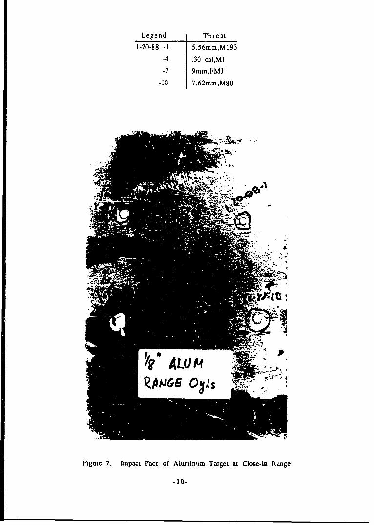
Legend Threat
1-20-88 -1 5.56mm,M193
-4 .30 cal,M1
-7 9mm,FMJ
-10 7.62mm,M80
Figurc 2. Impact Face of Aluminum Target at Close-in Range
.10-
Lcgcnd Threat
1-20-88 -2 5.i6tnim,M 193
-5 .30 cal,,MI
-8 9mm,FMJ
-11 7,62rnm,M80
Figurc 3. Impact Facc of 5# Stccl Targct at Closc-in Range
-1I1I-
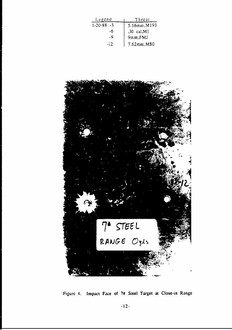
L ege n d Threat1-20-88 -3 5.56mm,M193
-6 .30 caiMI-9 9mm,FMJ
-12 7.62mm,M80
Migurc 4. Impact Face of 7# Steel Target at Close-in Range
-1I2I-
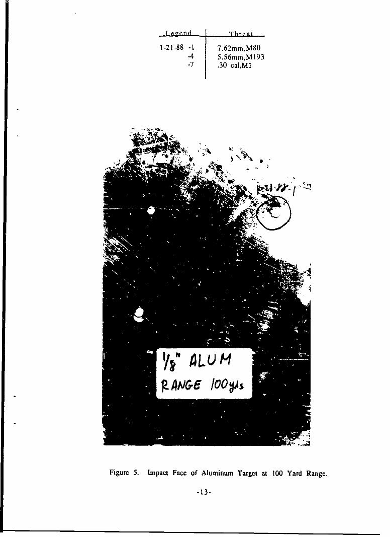
-LegendThreat
1-21-88 -1 7.62mm,M80-4 5.56mm,M193-7 .30 cal,MI
'II
g4NsGe 10O0
Figure S. Impact Face of Aluminum Target at 100 Yard Range.

Legend Threat
1-21-88 -2 7.62nim,M80
-5 5.56mmM193
-8 .30 cal.Mi
Figurc 6. Impact Facc of 5# Steel Target at 100 Yaird Rangc.
.14.

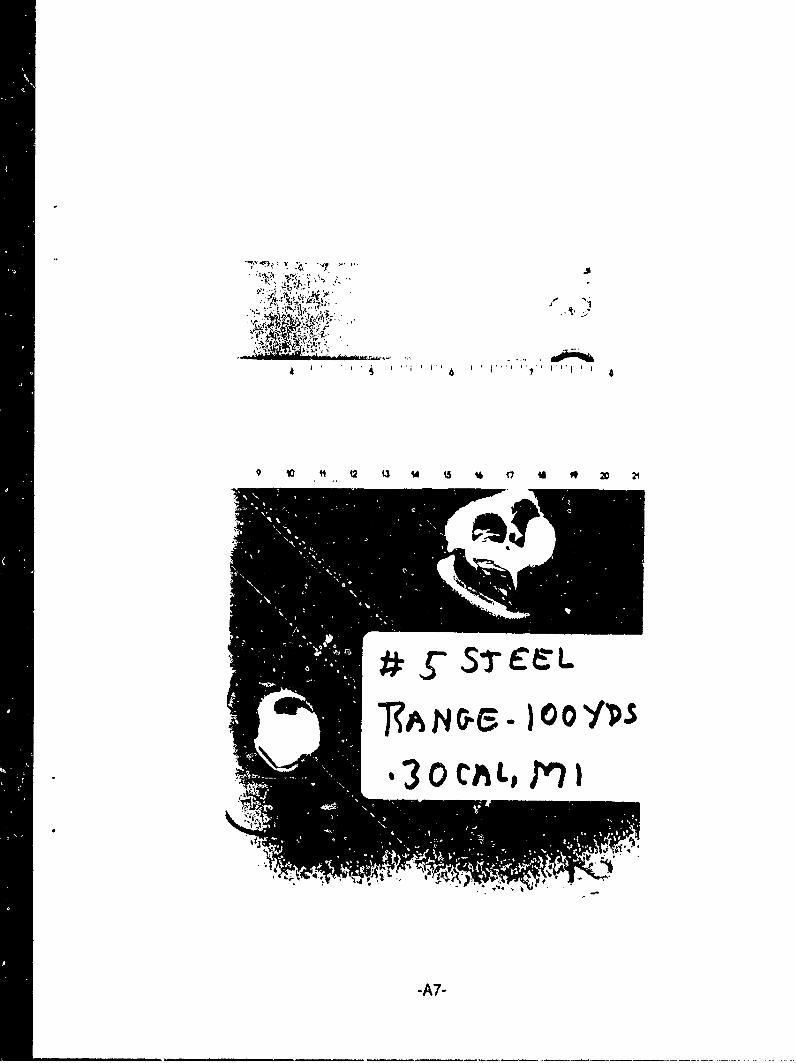
L Cellcd T Thre at1-21-88 -3 7.6 2rni ni, 801-21-98-6 5.56mrn,M 193
1-21-88-9 .30 cai.MI.30 cal,,MI
1 -21-88-10
F I
Figure 7. Impact Face of 7V Steel Target at 100 Yard Range
-15-
i6
M2 13 14 15 1 ¶7 A 19 20 21 22
Figure S. Wimnuss Plate Behind Aluminum
-16-
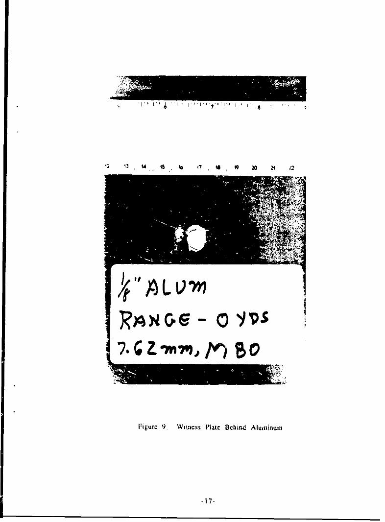
I.-iguric 9. Witness Platc Behind Alumninumn
is13 14 1 16 17 is 19 x0 24 n2
Figurc 10. Witness Plate Bchind Aluminum
-IN--
5 - I I I*6
li,1 13 U2
Figure I1. Witness Plate hehind Aluminum
.1 2 1,4A~ 417 711619 20 21 22 13
Figure 12. Witticss Piatc Bchind 5# S',ccl

A
Si s 1 6 t7 14 19 20 21 22 13 2A iS
Figurc 13. Wiucss Plate Bchind 70 Steel
-21-
2 13 i4 15 16 17 is 9 20 21 22
Higurc 14. Witness plalc Behind Aluminum
-22-
is131 15 17 A5 W 21 22 2
F~igure 15. Wittness Platc Behind Aluminum
-23-
12Q 3 Q U 6 17 jj 20 21 22
Figure 16. Witness Plate Behind Aluminum
-24-
MIT~
-25

L7 U
Figurc 18. KRP Armor Test Arrangcnicnt
.2 6-
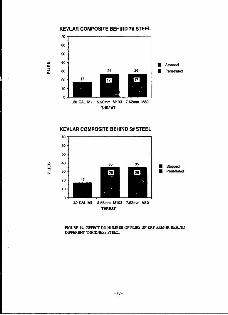
KEVLAR COMPOSITE BEHIND 7# STEEL70
60
50
cn 40-,U Stopped
" " 30 26 26 U Penetrated
20 17
10
0.30 CAL MI 5.56mm Mi 93 7.62mm M80
THREAT
KEVLAR COMPOSITE BEHIND 5# STEEL70O
60
50
U) 40 - 35 35- 41 Stopped
0. 306 Penetrated
20 17
10
0.30 CAL M1 5.56mm M193 7.62mm M80
THREAT
FIGURE 19. EFVFECT ON NUMBER OF PLIES OF KRP ARMOR BEHINDDIFFERENT THICKNESS STEEL
-27-
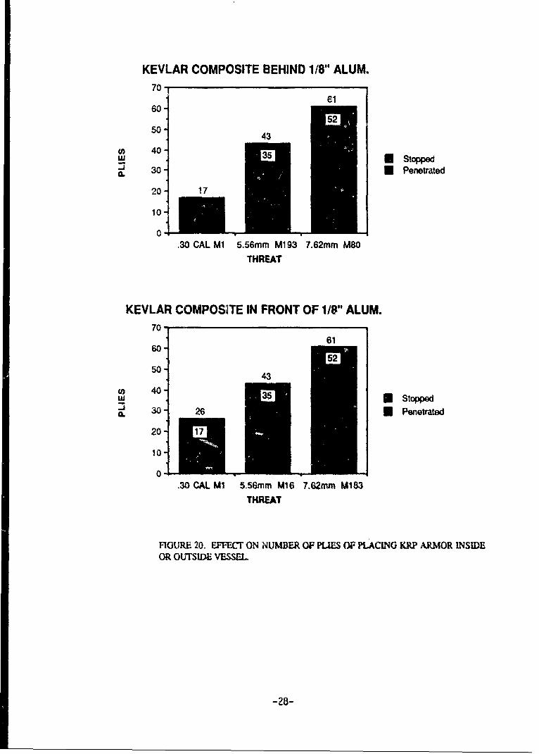
KEVLAR COMPOSITE BEHIND 1/8" ALUM.70
6160
55250 - 43
(I) 40O tapc__. Stopped
CL-1 30 Penetrated
20 17
10-
0-.30 CAL M1 5.56mm M1 93 7.62mm M80
THREAT
KEVLAR COMPOSITE IN FRONT OF 1/8" ALUM.70-
6160
5043
S 40•5Slopped
C 30 26 U Penetrated
10
.30 CAL M1 5.56mm M16 7.62mm M183
THREAT
FIGURE 20. EFFECT ON NUMBER OF PLIES OF PLACING KRP ARMOR INSIDEOR OUTSIDE VESSEL
-28-
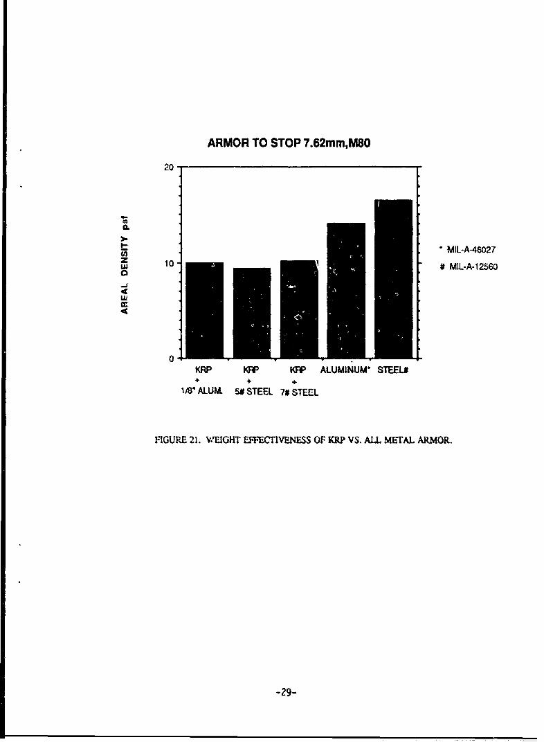
ARMOR TO STOP 7.62mM,M80
20
a.
- MIL-A-46027z 1
0 # MIL-A-12560a
0KRP F KRP ALUMINUM* STEEL#+ +, +
18* ALUM. SE STEEL 7# STEEL
FIGURE 21. WvEIGHT EFFECTIVENESS OF KRP VS. ALL METAL ARMOR.
-29-
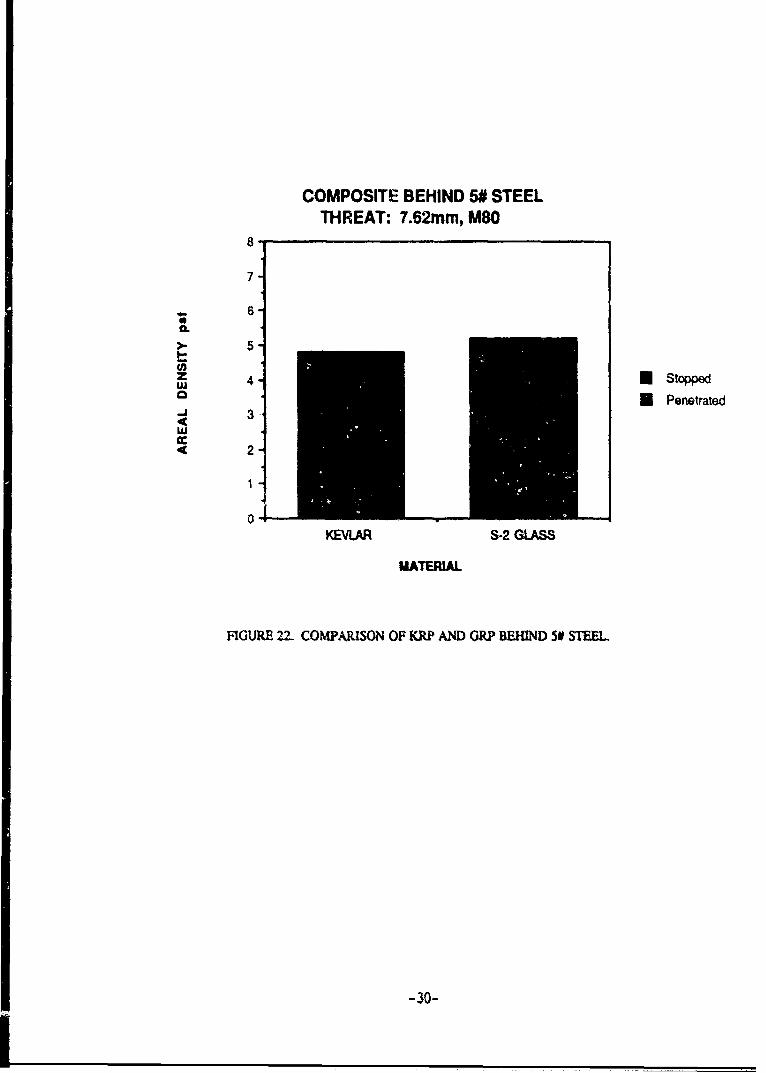
COMPOSITE BEHIND 5# STEELTHREAT: 7.62mm, M80
8
7
6
>- 5I-
4Z U Stoppeda U Penetrated
n-j3w
2
1
KEVLAR S.2 GLASS
MATERIAL
FIGURE 22- COMPARISON OF KRP AND GRP BEHIND 50 STEEL
-30-
APPENDIX A WITNESS PLATES
' $ ' 'I ' I ' ' P I '. I 0
'a , , 0 Is• 0, 3 21 72 2 3 2.I ., Jifll III,I , I I i. hh I.,
TAN L QYPS-
-A1-
*1 t 9A t 20 21 22 73
.3Q STC L
-A2-
'I)~~ ~ 194 3 U ¶5 1 7 i 20 21 22 3 .
-A3-
1ti 1 16 1? t4 19 20 21 22 2
t3Q CALIm
.A4-
48,
1. 3 '4 tSI 7 18 9 2 1 2
' *' ,1( ' • , :,. • . . ,
_ 7
1 2A 17 i6 19 20 21 22
-A6-
9 47
9 I 12 03 uJ t V 17 2
1?AN Or )OYDS
3lO)CAL, M Il
-A7-

m I
16 1U 144 19 2D 21 22 22 24
I.A8
- - --- A 8 -
1t 2 Q3 M4 t 16 17 1$ 9 20 74 22 23
3S
.A9-

[BLANK]
-A-1-
... .... ......... ....W.,n t "140- -N vq ion ii:n.: . 41 AMC . ......... ýýiýýE................... nn:H91 NEI W;Yom 441 vm:ýof n i;ii
-77 ý4 Ion -1:
tq
lee i VIMni t
..................................
JAWI PIPE: RAHE,
ýYvjl I:: iii E TE:% o i ., - , " ' --; - : .................
:ýT 4. _4........ .. n:.... ... 4;i :n-nn.n:I.. EfýiE T-v 4y"May:E E.* =Wow...
E:it ;ni
Inn it:*.,:ýia:i:,...;i:,.:::,ýýý'iý.:n
n-I 40iEi i 1-. F: EMS K
0
"wj.:niE% inn!=
E!::n:HnE........ ....
-1. =.n _PATERIAL IU2T JGIJ ;W4
S, 51 JACKV GILMM MOM K 'n2 iEIn
Ei-*r:=- -n-E, i SLUG LEAD 39 W H on
CCOWLETE 16 51.0 nay in 1son lEi H- F i
RýjýFR i Cal. 5.56 MM Bali BUllet. M193
n NOTES RE14 p 01E-,:H
+-i - 4 .......... .............
0 &3 n i 1R- Kýl nI n Areal Density of I" thick1.7-F 13. 83 psf. n 1 -4Aluminum
NAAFM 2. Manufactured to Mil-A-46027
3. References: DA-36-038 AMC-ý'n ...........NO TFR ......
-19 & Ar-250197,1- E
H, F,EZ
n nltn.n nn: MMRC, NOV 1979
-M;lu nji
N -74A
A
Vý-gag,Z zM's" E . ... T-t-'a--;-kz MnMEIN"I'ý71 ý-Rn
7--, &-40771K -A
j 3IN E,
FIGURE 45 P1007TION PROWE: BY 5287 ARMOR AWN37 5.504.1,
ARMY MATERIALS XWO WICKAWS WEARCK CE*T(Q
B-- I
4000
3800
3400
CAA
Lq=
-0 1
2600
z0
2200 ~ .....
2000 .. _r
~t7'
PR:tZ~ ..AtwgnY ,NgAtgRA AND", gEMI~RSERNCW
r .....3.2
EF:_1= Hv :rq_.j- 7ý
M --- ---
iiiiizm
.... ... ...
... ... ....-:::- - ;:, +'-. 0
0MEH, .... ......... .... ....... m
-- -- ------00. . ;. .:iR
1ýq: qf7-
isr fI---
.4=
..... .....
3ý7t-
- ----------- z w ............ ...........:77
Uzi.. ....... ..
Miq` _Hflzý:3 -- t=: qý:-, zx.
rin rI ::1A My 141 =4=,-- 2F56 v4%f
Jý
y I Y-. t- - NOTESM
CxCL -T 1. Areal Dosity of I"
L4 thick Al - 13.83 ps
2. Sper- Mil-A41W27T- _-N!
Referenceiz
Ar 3726 & 24MIAlcoa Data
WAWK, W y 1973
. . . .......T-j
J7
N _Vl
A.4 6 fo 1,2 14 f6 1`8 20 22 24
AREAL DENS ITY ( PSF )
FIGURE 48. PROTECTION PROVIDED BY 110-4111XV ALLOY ARVOR (5C87) ZAINST7.62&U U80 BALL PRO.)WrILES, AT VARIOUS OBLIQUITIF3
ARMY MATERIALS AND MECNAKICS RESEAQCW tENTER
B-3
4000
3800 11~'~--
r ~ I. . 7t-
3600 --- t
3400
3 200
-77__
CL 3000 1 __
4I-
240
0
10"
> 4 23 -0
0 2 4 6 8 C 12 4 IS lB 20 Z2 0
13-4
COMPLETE56.0-2.0
(-)
:.l
o~~~~~ .~T ..L. ..-- .. -t~:- 1. Area[ Density of V" thlick bonded
__War -MR APR 671 ps
S~~AMC AP6 19AL71.9A'~UIT. RM .~ TRIL .N .tKMC .EE C ...T.
5R135
CL.
hit C . ' ....
VI 0
-R.
:4.
-2$- n
Sdii~~~~~~ IIs1r-i~g(C NI~i~
13-6


![[014] ass 014 [1881]](https://img.pdfslide.us/doc/110x75/5695d38d1a28ab9b029e5607/014-ass-014-1881.jpg)