Embed Size (px)
Citation preview
Report N. FAA-RD-78-28
FfiR FunT:I jE
TESTS OF CRASH-RESISTANT FUEL SYSTEM
Ott FOR GENERAL AVIATION AIRCRAFT
William M. Perrella, Jr.
S Of
MARCH 1978
INTERIM REPORT
Document is available to the U.S. public throughthe National Technical Information Service,
Springfield, Virginia 22161.
Prorml for
U.S. DEPARTMENT OF TRANSPORTATIONFIERL AVIATION ANINIS1 -lOSytes R~arch & Develop i Savice
Wa'h.
NOTICE
The United States Government does not endorse productsor manufacturers. Trade or manufacturer's names appearherein solely because they are considered essential tothe object of this report.

Technical keti Dcumentation Page
(i A / 7 - 82. Government Accession No. 3 '
4. Titlea
TSSOF CRASH-.RESISTANTFUEL JYSTEM FORqNRLMr 7
8.Pefomng Organization Repart'Na.
William H. Perrella, Jr6# A--7_8T
Llanttc City, New Jersey 08405 184-521-100 _________
12. Spplsrinmen y N e adAdrs
16. Abstract
JA significant percentage of general aviation aircraft accidents result in post-crash fires due to the ignition of fuel spillage, often contributing injury ordeath to the aircraft occupants.
Testing was performed to demonstrate the performance of light-weight, flexible,crash-resistant fuel cells combined with the use of frangible fuel line couplings.Included in these tests were three full-scale crash tests of a typical light twinaircraft. In all of these tests, the crash-resistant fuel system performedsatisfactorily.
17. Key Words 18. Distribution Statemenit
Crash-Resistant Fuel Cells Document is available to the U.S. publicAircraft Fuel Tanks through the National Technical InformiationCrashworthy Fuel Cells Service, Springfield, Virginia 22161.
19. Security Clessif. (of this report) ~ .Security Claesf. (of this Page) I21. No. of Paes. 22. Pric
Unclassified Unclassified 46
Few, DOT F 1700.7 (8-72) Reproduction~ of completed page authotlaed
TABLE OF CONTENTS
Page
INTRODUCTION 1
DISCUSSION 1
Tank Construction 1Installation of Tanks in Aircraft 4Full-Scale Crash Tests 5
RESULTS 5
CONCLUS ION 8
REFERENCES 8
APPENDIX
..................... .............. ...
!AAL
ii

LIST OF ILLUSTRATIONS
Figure Page
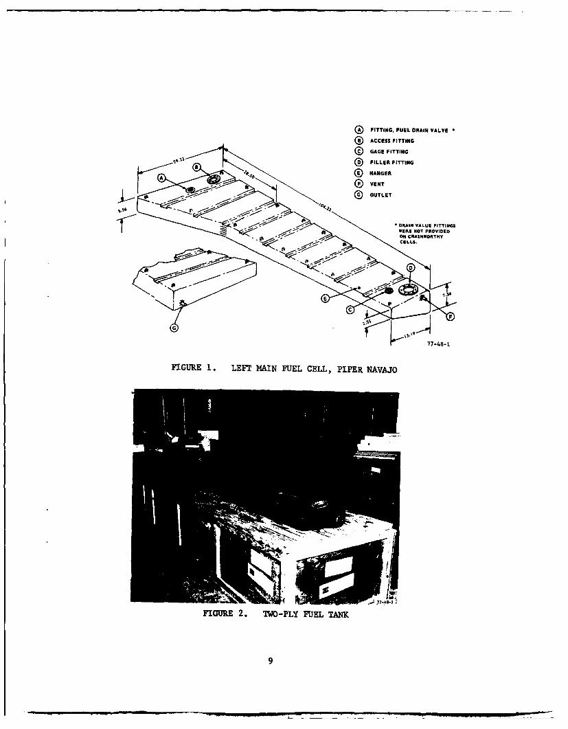
1 Left Main Fuel Cell, Piper Navajo 9
2 Two-Ply Fuel Tank 9
3 Installation of Two-Ply Fuel Tank 10
4 Frangible Coupling Mounted to Fuel Cell Mounting Flange 10
5 Typical Frangible Coupling Installation (Wing Root) 11
6 Duration and Magnitude of Spineward Acceleration Endured 11by Various Subjects (Taken from Reference 1)
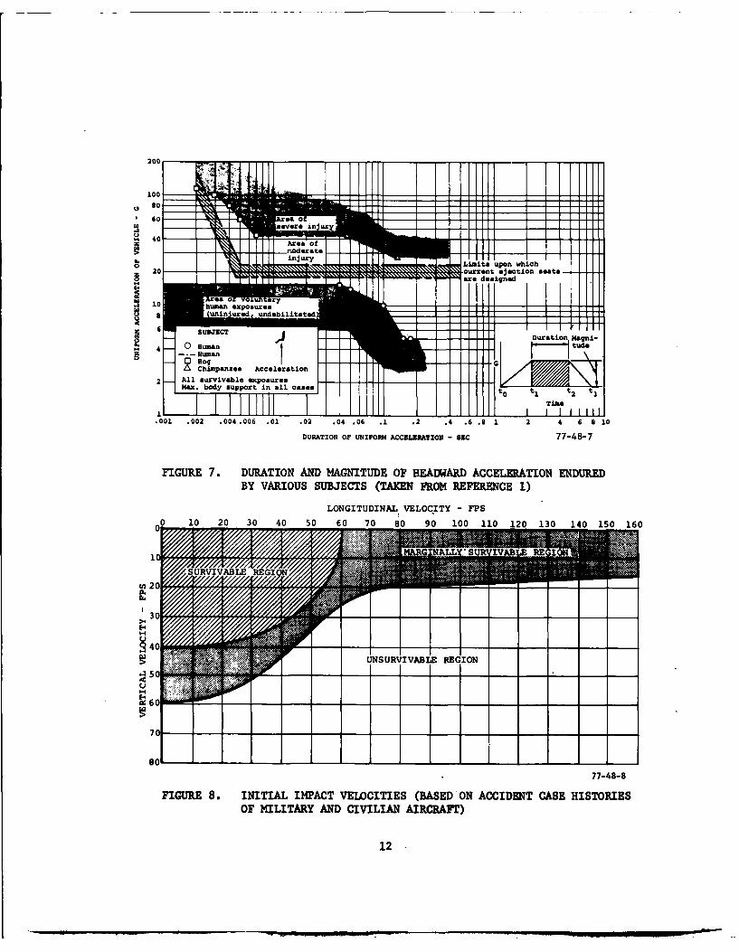
7 Duration and Magnitude of Headward Acceleration Endured by 12Various Subjects (Taken from Reference 1)
8 Initial Impact Velocities (Based on Accident Case Histories 12of Military and Civilian Aircraft)
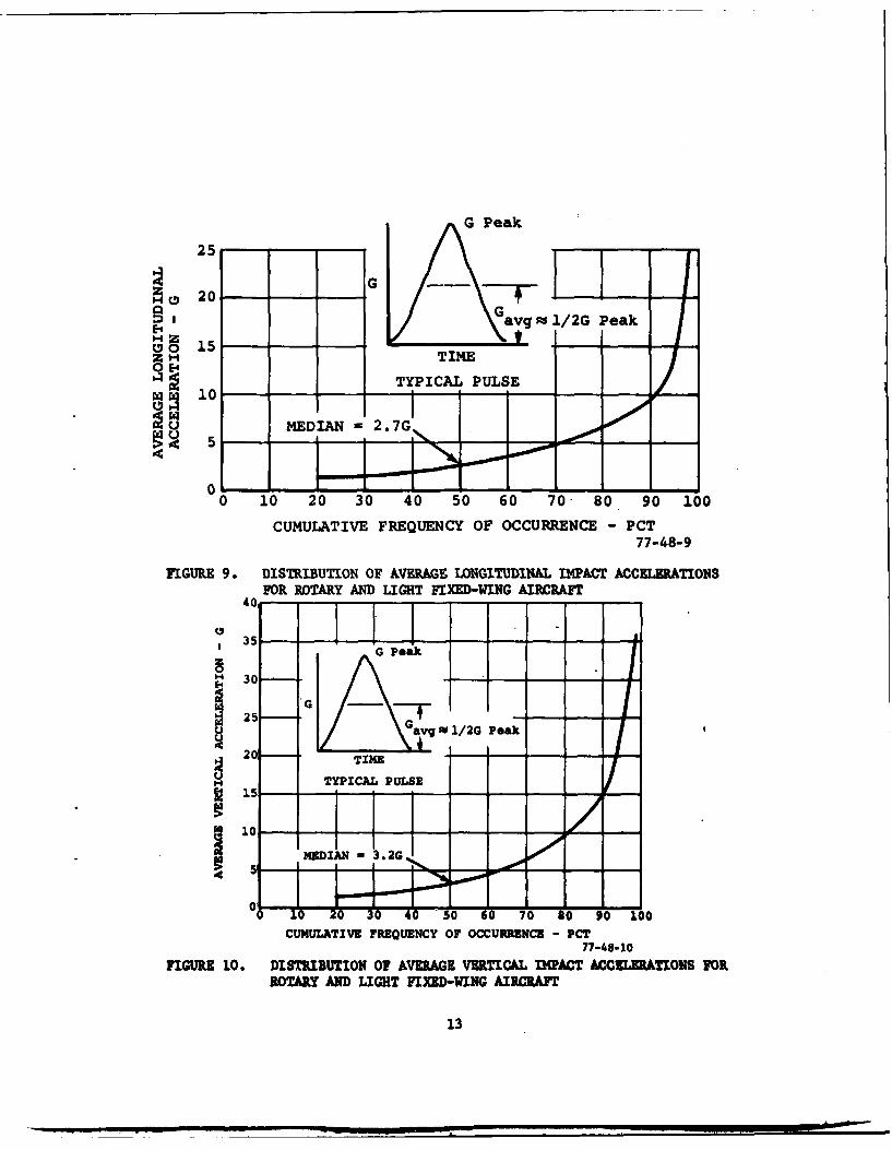
9 Distribution of Average Longitudinal Impact Accelerations 13for Rotary and Light Fixed-Wing Aircraft
10 Distribution of Average Vertical Impact Accelerations for 13Rotary and Light Fixed-Wing Aircraft
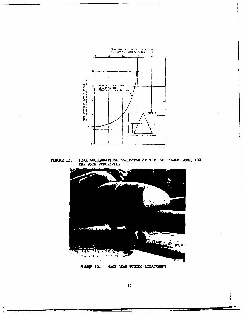
11 Peak Accelerations Estimated at Aircraft Floor Level for 14the 95th Percentile
12 Nose Gear Towing Attachment 14
13 Crash Test Site 15
14 Aircraft in Position for Test 15
15 Typical Acceleration Pulse 16
16 Damage to Left Wing Two-Ply Fuel Tank, Test 1 16
17 Failure of Main Spar, Left Wing, Test 1 17
18 Main Acceleration Pulse, Test 1 17
19 Aircraft Impact, Test 2, (Note Water Spray from Right Wing) 18
20 Damage to Right Wing, Original Aircraft Bladder Cell, 18Test 2
iv t
.. .. .. . . . ... . . .
LIST OF ILLUSTRATIONS (Continued)
Figure Page21 Damage to Right Wing, Original Aircraft Bladder Cell, 19
Test 2
22 Damage to Left Wing, Two-Ply Fuel Tank, Test 2 19
23 Regular (Non-Crash-Resistant) Bladder Cell after Impact 20
24 Damage to Regular Aircraft Cell due to Pole Impact 20(Inboard)
25 Damage to Regular Aircraft Cell due to Pole Impact 21(Outboard)
26 Main Acceleration Pulse, Test 2 21
27 Damage to Left Wing, Test 3 22
28 Damage to Right Wing, Test 3 22
29 Effect of Rock Impact, Test 3 23
30 Main Acceleration Pulse, Test 3 23
v

LIST OF TABLES
Table Page
1 Fuel Tank Characteristics 2
2 Physical Properties of Fuel Tank Construction (MIL-T- 327422B)
3 Crash Test Data 6
vi
INTRODUCTION
Studies of aircraft accident records show that a significant percentage offatalities result from postcrash fires. It is apparent that once ignitionoccurs in the presence of large quantities of spilled fuel, the survival chancesof the aircraft occupants are greatly reduced; even when fire-fighting equip-ment is immediately on the scene. The only feasible way to decrease the inci-dence of postcrash fires is by the reduction of fuel spillage and ignitionsources. Therefore, the Federal Aviation Administration (FAA) has initiatedthe present program to evaluate one way of preventing massive spillage of fuelduring a crash; i.e., crash-resistant flexible bladder cells used with self-sealing frangible couplings at critical points in the fuel lines.
The U.S. Army has unquestionably established that fuel can be contained byflexible fuel tanks, thereby eliminating the potential of postcrash fire.These tanks, while very effective, impose weight and cost penalties whichcould be significantly reduced for general aviation aircraft. Consequently,the major thrust of this program was to develop effective low-cost, light-weight, crash-resistant fuel cells.
A contract was awarded to the Uniroyal Corporation to design and fabricate sixcrashworthy tanks, three right-hand and three left-hand, for the Piper Navajoaircraft. These tanks were to be equipped with Aeroquip® type DE5175-1-8Afrangible couplings on the filler and vent fittings. The original contractspecification is shown in appendix A.
DISCUSSION
TANK CONSTRUCTION.
Construction materials devised by industry to meet MIL-T-27422B provided astarting point for the program. The initial contract called for the construc-tion of three left-hand tanks of two-ply construction, and three right-handtanks of three-ply construction. To assist in reducing construction weight,the drop test requirement of the above specification was reduced to 39 feet.All tank fittings were initially specified to meet MIL-T-27422B requirements.
On August 13, 1975, a left-hand two-ply tank was filled with 59.2 gallons ofwater and dropped from a height of 39 feet. The tank suceessfully withstoodthe impact on its leading edge with no visible damage. Based on that fact,and the results of a full-scale aircraft crash test described later, it wasdecided not to fabricate two of the three-ply cells. In place of these cells,two single-ply types were specified. The tanks were to be fitted with Uniroyaldesigned fittings similar to MS33581, with the addition of a third ring. Thesefittings are lighter in yeight and lower in cost than the Uniroyal WallExpansionO and Fibre-Lokw fittings used on the other tanks, and have beendemonstrated as satisfactory in 50-foot free-fall impacts when mounted in a
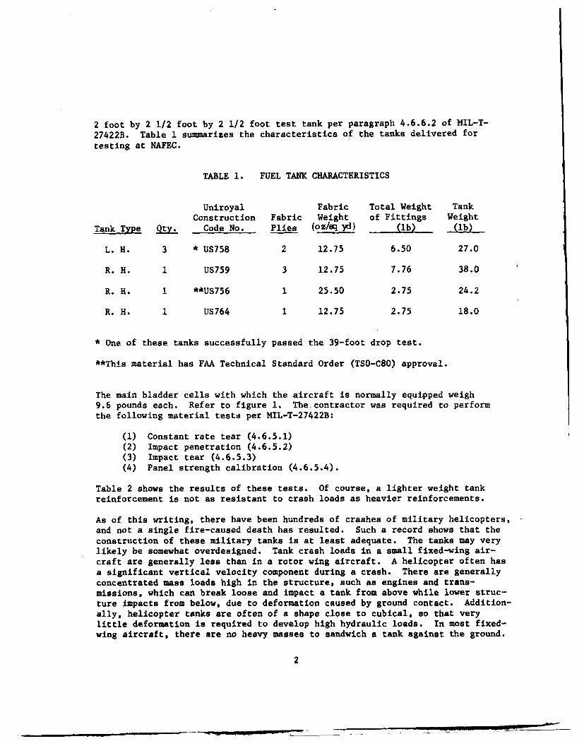
2 foot by 2 1/2 foot by 2 1/2 foot test tank per paragraph 4.6.6.2 of MIL-T-
27422B. Table 1 summarizes the characteristics of the tanks delivered for
testing at NAFEC.
TABLE 1. FUEL TANK CHARACTERISTICS
Uniroyal Fabric Total Weight TankConstruction Fabric Weight of Fittings Weight
Tank Type Qty. Code No. Plies (oz/sq Yd) (lb) (lb)
L. H. 3 * US758 2 12.75 6.50 27.0
R. H. 1 US759 3 12.75 7.76 38.0
R. H. 1 **US756 1 25.50 2.75 24.2
R. H. 1 US764 1 12.75 2.75 18.0
* One of these tanks successfully passed the 39-foot drop test.
**This material has FAA Technical Standard Order (TSO-C80) approval.
The main bladder cells with which the aircraft is normally equipped weigh9.6 pounds each. Refer to figure 1. The contractor was required to performthe following material tests per MIL-T-27422B:
(1) Constant rate tear (4.6.5.1)(2) Impact penetration (4.6.5.2)(3) Impact tear (4.6.5.3)(4) Panel strength calibration (4.6.5.4).
Table 2 shows the results of these tests. Of course, a lighter weight tankreinforcement is not as resistant to crash loads as heavier reinforcements.
As of this writing, there have been hundreds of crashes of military helicopters,and not a single fire-caused death has resulted. Such a record shows that the
construction of these military tanks is at least adequate. The tanks may verylikely be somewhat overdesigned. Tank crash loads in a small fixed-wing air-craft are generally less than in a rotor wing aircraft. A helicopter often hasa significant vertical velocity component during a crash. There are generallyconcentrated mass loads high in the structure, such as engines and trans-missions, which can break loose and impact a tank from above while lower struc-ture impacts from below, due to deformation caused by ground contact. Addition-ally, helicopter tanks are often of a shape close to cubical, so that verylittle deformation is required to develop high hydraulic loads. In most fixed-wing aircraft, there are no heavy masses to sandwich a tank against the ground.
2

u
.05 I N W 4CKn 0
In
,4o .0
0 *In. Neq
1 0
E-4-
0 1-.
ra 4 .Lfl N4 04I 444 04 -- 0a
ra-t l) N I
1-4
Oc'dC14 w 1) LA C r
PL.Ln ID 0 %0 o M C N
00
-4 -4
___-4 -. 4 =L = U . =
41 4vi d
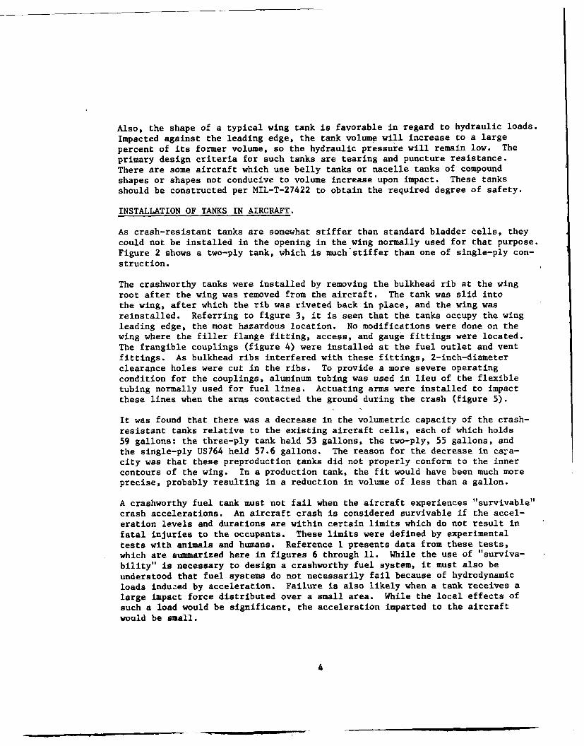
Also, the shape of a typical wing tank is favorable in regard to hydraulic loads.Impacted against the leading edge, the tank volume will increase to a largepercent of its former volume, so the hydraulic pressure will remain low. Theprimary design criteria for such tanks are tearing and puncture resistance.There are some aircraft which use belly tanks or nacelle tanks of compoundshapes or shapes not conducive to volume increase upon impact. These tanksshould be constructed per MIL-T-27422 to obtain the required degree of safety.
INSTALLATION OF TANKS IN AIRCRAFT.
As crash-resistant tanks are somewhat stiffer than standard bladder cells, theycould not be installed in the opening in the wing normally used for that purpose.Figure 2 shows a two-ply tank, which is much'stiffer than one of single-ply con-struction.
The crashworthy tanks were installed by removing the bulkhead rib at the wingroot after the wing was removed from the aircraft. The tank was slid intothe wing, after which the rib was riveted back in place, and the wing wasreinstalled. Referring to figure 3, it is seen that the tanks occupy the wingleading edge, the most hazardous location. No modifications were done on thewing where the filler flange fitting, access, and gauge fittings were located.The frangible couplings (figure 4) were installed at the fuel outlet and ventfittings. As bulkhead ribs interfered with these fittings, 2-inch-diameterclearance holes were cut in the ribs. To provide a more severe operatingcondition for the couplings, aluminum tubing was used in lieu of the flexibletubing normally used for fuel lines. Actuating arms were installed to impactthese lines when the arms contacted the ground during the crash (figure 5).
It was found that there was a decrease in the volumetric capacity of the crash-resistant tanks relative to the existing aircraft cells, each of which holds59 gallons: the three-ply tank held 53 gallons, the two-ply, 55 gallons, andthe single-ply US764 held 57.6 gallons. The reason for the decrease in cara-city was that these preproduction tanks did not properly conform to the innercontours of the wing. In a production tank, the fit would have been much moreprecise, probably resulting in a reduction in volume of less than a gallon.
A crashworthy fuel tank must not fail when the aircraft experiences "survivable"crash accelerations. An aircraft crash is considered survivable if the accel-eration levels and durations are within certain limits which do not result infatal injuries to the occupants. These limits were defined by experimentaltests with animals and humans. Reference 1 presents data from these tests,which are summarized here in figures 6 through 11. While the use of "surviva-bility" is necessary to design a crashworthy fuel system, it must also beunderstood that fuel systems do not necessarily fail because of hydrodynamicloads induzed by acceleration. Failure is also likely when a tank receives alarge impact force distributed over a small area. While the local effects ofsuch a load would be significant, the acceleration imparted to the aircraftwould be small.
4
FULL-SCALE CRASH TESTS.
The crath tests were performed at the National AviationFacilities Experimental
Center (NAFEC) catapult facility. A compressed-air catapult was used to accel-erate the test aircraft along a 90-foot track. At the end of the catapultstroke, the aircraft, which was pulled by its nose gear, was released to impactan earthen hill of 40 slope. At the base of the hill, a 12-inch by 12-inchI-beam was installed to break off the aircraft's landing gear. The nose gearwas strengthened to withstand the catapult pulling force (figure 12), whilethe main landing gear mounting bolts were sawed in half to effect an easierseparation from the wings. Spoilers were installed along the upper wingsurface. At a distance of 10 feet from the I-beam, poles were sunk into thehill to a depth of 18 inches. These poles were spaced symmetrically off thecenterline of the hill, at 42 inches and 108 inches each. The poles werehollow mild steel tubing, 4.375-inches outside diameter, 0.188-inch wall thick-ness, and were 10 feet in length. Small rock piles were located on the hillto further increase the severity of the crash condition (figures 13 and 14).There are no standards in general use for a crash site as is used in this typeof test; hence, the selection of the type of poles, rocks, and hill was arbi-trary. The crash site was intended to be at least as severe as a typicalcrash at an airfield involving airport structures such as approach lights.It is nevertheless recognized that the term "typical crash" is a misnomer. Thecrash accelerations were compared to case histories of actual crash accelera-tions obtained from reference 1 and presented in figures 9 and 10.
In all tests, the aircraft main tanks were filled with water. Accelerometers,CEC type 4-203-0001, were installed on the floor of the aircraft at thelongitudinal center of gravity location (station 126). Accelerations in thevertical and longitudinal direction were recorded on an oscillograph. Thedata were filtered at 90 hertz (Hz).
RESULTS
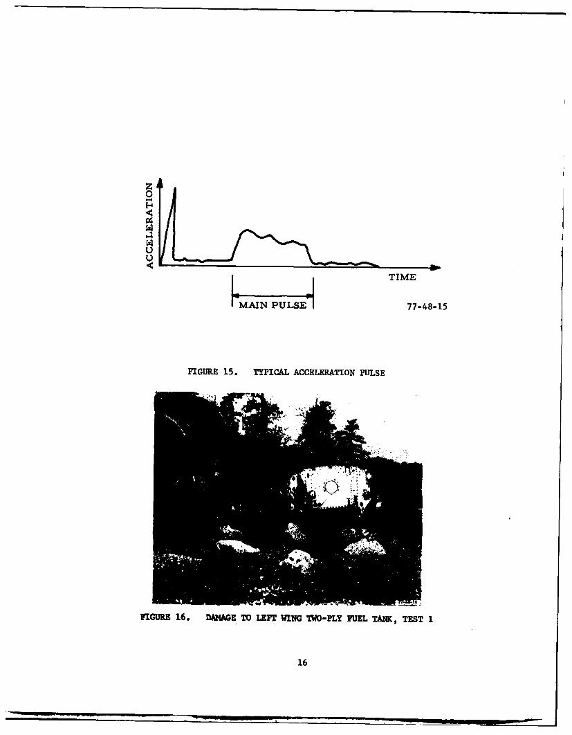
The acceleration pulses had the general form illustrated in figure 15. Timezero started as the nose gear struck the I-beam, resulting in the initialspike shown. This spike, typical in all tests, was about 100 g's longitudinal,for a duration of 5 milliseconds. Following this event, for a period of0.17 to 0.33 seconds or so, depending on the test, there was no one acceleration
peak distinguishable from the accelerations caused by the vibration of thestructure. The aircraft was decelerating at an average level of approximately2 g's. During this period of time, the main landing gear was broken off. Themain acceleration pulse was typically about 0.1-second duration, during whichthe aircraft was experiencing retarding forces from ground contact, as well asrock impacts. Only in test 3 did the pole impacts on the wing happen to coin-cide with the main acceleration pulse. After an analysis of the high-speedfilms, it was found that the pole impacts, which occurred approximately 0.21seconds into the crash event, did not produce any significant accelerationpeaks within the cabin of the aircraft. While the effect of these impacts onthe wing was severe, resulting in much damage, the inherent chordwise
5

flexibility of the wing prevented the force transferral to the fuselage. Thisparticular wing, as do most light aircraft wings, has a single spar to transmitwing-bending loads. Torsional stiffness is provided by two additional "spars",one near the leading edge, and one at the trailing edge. These are connectedat the fuselage with one bolt each per side. Upon wing impact with the poles,these bolted connections failed, resulting in very low chordwise stiffness.This characteristic is considered very beneficial in regard to crashworthiness,since not only does it eliminate high peak accelerations from wing impacts,but also reduces the chance of fatal postcrash fires, since the wing itself ismore readily torn from the aircraft than a stiffer type of wing.
It was necessary to keep the aircraft light in weight in order to obtain themost speed possible with the type of catapult used. In this regard, theempennage and engines were not installed on the airframe. From an analysis ofthe film, it was concluded that the probable effect of the engine mass on thelocal fuel cell impact loads would have been negligible. The dynamic behaviorof the wing and aircraft after the impacts would have been significantlydifferent, however, had the engines and empennage been installed.
Major results of the three crash tests are summarized in table 3. The firsttest evaluated three-ply and two-ply tanks. The left wing received the mostsevere impacts. It contained the two-ply tank, which, upon later visualinspection, was found to be undamaged. The self-sealing Aeroquip couplingsall actuated with no leakage. The left wing was nearly torn from the fuselage,with only a small part of the spar web holding it (figures 16 and 17). Accel-eration levels, shown in figure 11, show that this crash was survivable, withinjury of the occurpnrts likely if the standard aircraft seating and belts wereused. The impa. t speed of the aircraft was 93-feet pcr lecond (ft/s).
TABLE 3. CRASH TEST DATA
AircraftWeight Maximum
lb Impact Acceleration, gTest Fuel 'eank Fuel Tank Speed,_..4o. Date L. K. R. R. Epty Tanks Full Ft/s M P Damage
Z-Ply* 3-Ply None to either2/18/76 US758 US75, 1,;OO 2,600 93 15 5 tank
2-Ply ,rginal None to L. H. tank2 8/8/76 US758 Aircraft 1,710 2,660 93 29 7.5 R. N. tank ruptured
Bladder Cell
2-Ply Single-Ply None to either tank3 5/18/77 US758 US764 1,660 2,598 95 27 55
*This tank was previously drop tested from 39 ft.
6
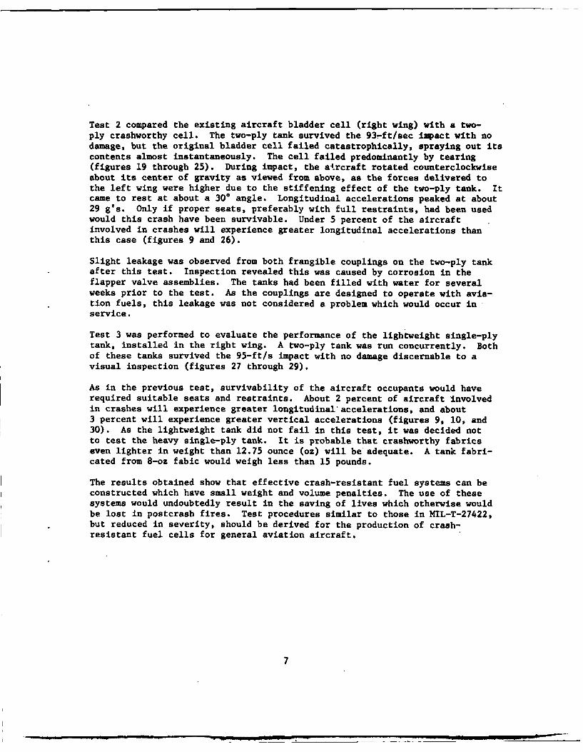
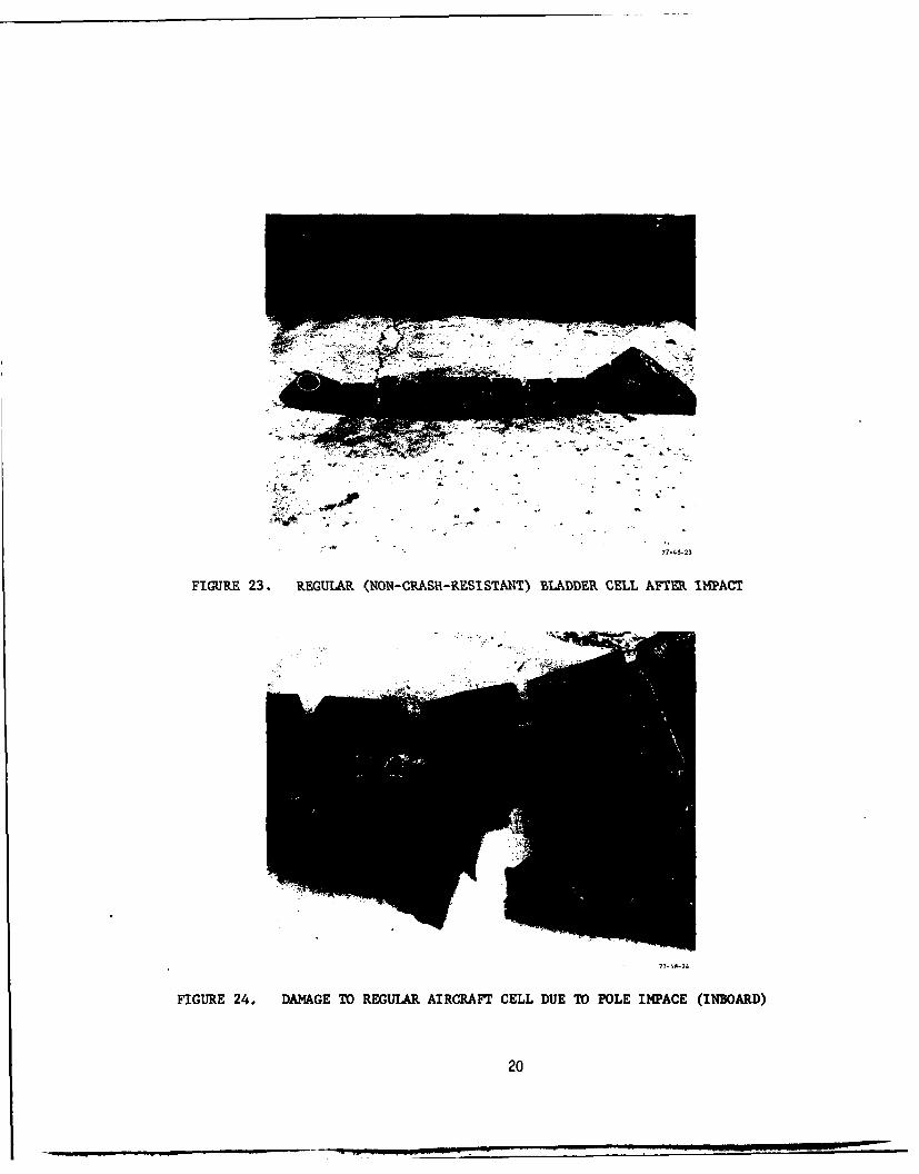
Test 2 compared the existing aircraft bladder cell (right wing) with a two-ply crashworthy cell. The two-ply tank survived the 93-ft/sec impact with nodamage, but the original bladder cell failed catastrophically, spraying out itscontents almost instantaneously. The cell failed predominantly by tearing(figures 19 through 25). During impact, the aircraft rotated counterclockwiseabout its center of gravity as viewed from above, as the forces delivered tothe left wing were higher due to the stiffening effect of the two-ply tank. Itcame to rest at about a 300 angle. Longitudinal accelerations peaked at about29 g's. Only if proper seats, preferably with full restraints, had been usedwould this crash have been survivable. Under 5 percent of the aircraftinvolved in crashes will experience greater longitudinal accelerations thanthis case (figures 9 and 26).
Slight leakage was observed from both frangible couplings on the two-ply tankafter this test. Inspection revealed this was caused by corrosion in theflapper valve assemblies. The tanks had been filled with water for severalweeks prior to the test. As the couplings are designed to operate with avia-tion fuels, this leakage was not considered a problem which would occur inservice.
Test 3 was performed to evaluate the performance of the lightweight single-plytank, installed in the right wing. A two-ply tank was run concurrently. Bothof these tanks survived the 95-ft/s impact with no damage discernable to avisual inspection (figures 27 through 29).
As in the previous test, survivability of the aircraft occupants would haverequired suitable seats and restraints. About 2 percent of aircraft involvedin crashes will experience greater longitudinal'accelerations, and about3 percent will experience greater vertical accelerations (figures 9, 10, and30). As the lightweight tank did not fail in this test, it was decided notto test the heavy single-ply tank. It is probable that crashworthy fabricseven lighter in weight than 12.75 ounce (oz) will be adequate. A tank fabri-cated from 8-oz fabic would weigh less than 15 pounds.
The results obtained show that effective crash-resistant fuel systems can beconstructed which have small weight and volume penalties. The use of thesesystems would undoubtedly result in the saving of lives which otherwise wouldbe lost in postcrash fires. Test procedures similar to those in MIL-T-27422,but reduced in severity, should be derived for the production of crash-resistant fuel cells for general aviation aircraft.
7
CONCLUSION
It has been demonstrated that light-weight, flexible, crash-resistant fuel
cells used with self-sealing frangible fuel-line couplings can effectivelyreduce postcrash fuel fires in general aviation aircraft equipped withwing tanks.
REFERENCES
1. Crash Survival Design Guide, USAAMRDL Technical Report 71-22.
2. Dynamic Response of Structures, Pergamon Press, N. Y., 1971.
3. Piper Navajo Fuel Tanks, FAA Crash Resistant Modifications, Tanks andTesting, Uniroyal Report FC-1641-77, March 1977.
8
GFITTING, FUEL DRAIN VALVE
GACCESS FITTING
Q GAGE FITTING
FIGURE ~ ~ ~ ~ ~ ILE FITTINGI UE ELPIE NVJ
FAR 2.6 TWOPLNFULEAN
9EN
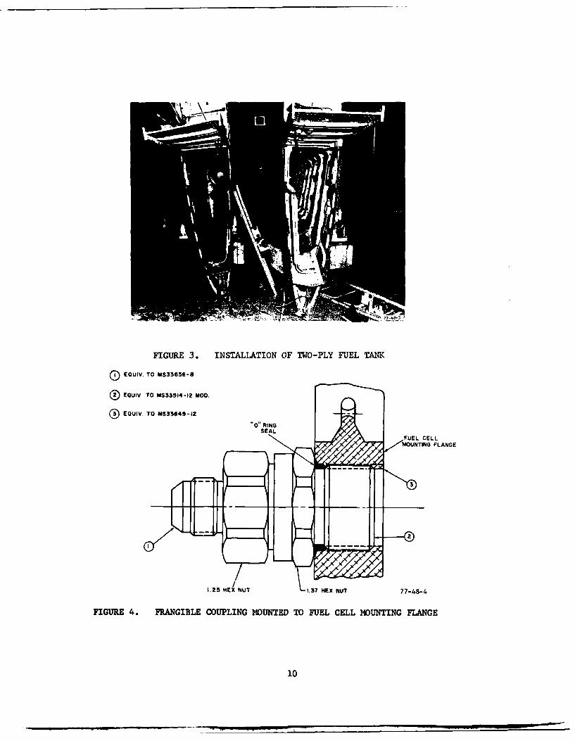
FIGURE 3. INSTALLATION OF TWO-PLY FUEL TANK
(D EQUIV. TO MS33656-8
®EOUIV. TO MS33514-12 MOD.
®EQUIV. TO MS33649-12
MONIGFLANGE
1.25 HEX NUT 1.37 HEX NUT 77-48-4
FIGURE 4. FRANGIBLE COUPLING MOUNTED TO FUEL CELL MOUNTING FLANGE
10

RIB (REF)
fit(( 0MAIN SPAR (REe)
LEADING EDGE (REF)
2. 0" DIA. CLEARANCE HOLE BULKHEAD FITTING
(CAPPED FAR SIDE)FRANGIBLECOUPLING FUEL LINE (0. 5' OD. .032'-
IMPACT ACTUATING ARM7-45DIRECTION7-85
FIGURE 5.* TYPICAL FRANGIBLE COUPLING INSTALLATION (WING ROOT)
~10
o Aral ofaio,
Shman eoe2t Al UYiured euoated
D4-TO 0P uniro. AACCULESATION j tW 7- 8-
FIUE6* DRTO0N ANTD FSIEADACLRTO NUEBY ChiOmpUaETS(TKNnROzRFRECE1
2 Al 8UriV~le GIPOSIC6 I z m11
0
0 nua whichrm
0 Area or evolunary itte
2 Al uvvable exposures
.001 .002 .004 .006 .01 .02 .04 .06 .1 .2 .4 .6 .6 1 2 4 6 a 10
DURATION OF UNIPORN ACCELZRATION - 8szC 77-48-7
FIGURE 7. DURATION AND MAGNITUDE OF HEA17IARD ACCELERATION ENDUREDBY VARIOUS SUBJECTS (TAKEN FROM REFERENCE 1)
LONGITUDINAL VELOCITY - FP'S0 10 20 30 40 50 60 70 80 90 100 110 120 130 140 150 160
E.
77-48-8
FIGURE 8. INITIAL IMPACT VELOCITIES (BASED ON ACCIDENT CASE HISTORIESOF MILITARY AND CIVILIAN AIRCRAFT)
12
G Peak
25--
Ho 20 Lol acjm /2GPeak
1 5 - - -TIME0E4
Ag TYPICAL PULSErg 10 -
5-
0 10 20 30 40 50 60 70. 80 90 100
CUMULATIVE FREQUENCY OF OCCURRENCE - PCT77-48-9
FIGURE 9.* DISTRIBUTION OF AVERAGE~ LONGITUDINAL IMPACT ACCELERATIONSFOR ROTARY AN~D LIGHT FIXED-WING AIRCRAFT
0J
3 -G Peak - - -
30 -+
25 G2 LGavg w1/2G Peak
20 TIME
TYPICAL PULSE
1- MEDIAN 2 3.2Z
or-0 2 3 -4 -5d6 70 g0 g0 l00CUMULATIVE FREQUENCY OF OCCURRENCE - PCT
77-48-10FIG=R 10.* DISTRIBUTION OF AVERAGE VERTICAL IMPACT ACCELERATIONS FOR
ROTARY AND LIGHT FIXED-WING AIRCRAFT
13
PEAK LONGITUDINAL ACCELERATION(RETARDING FORWARD MOTION) -G,
0 10 20 30 40 50
10
z 20 PEAK A CLERATIONS22 ESTIMATED IN
SURVI VAB LE ACCIDETS
L-PEAKC-C 40
GD-N
48-G2/so
ASSUMED PULSE SHAPE
60 --7 7-48-11
FIGUR ii. PEAK( ACCELERATIONS ESTIMTED AT AIRCRAFT~ FLOOR LEVEL FORTHE 95TH PERCENTILE
FIGUfRE 12.* NOSE GEAR TOWING ATTACHMENT
14
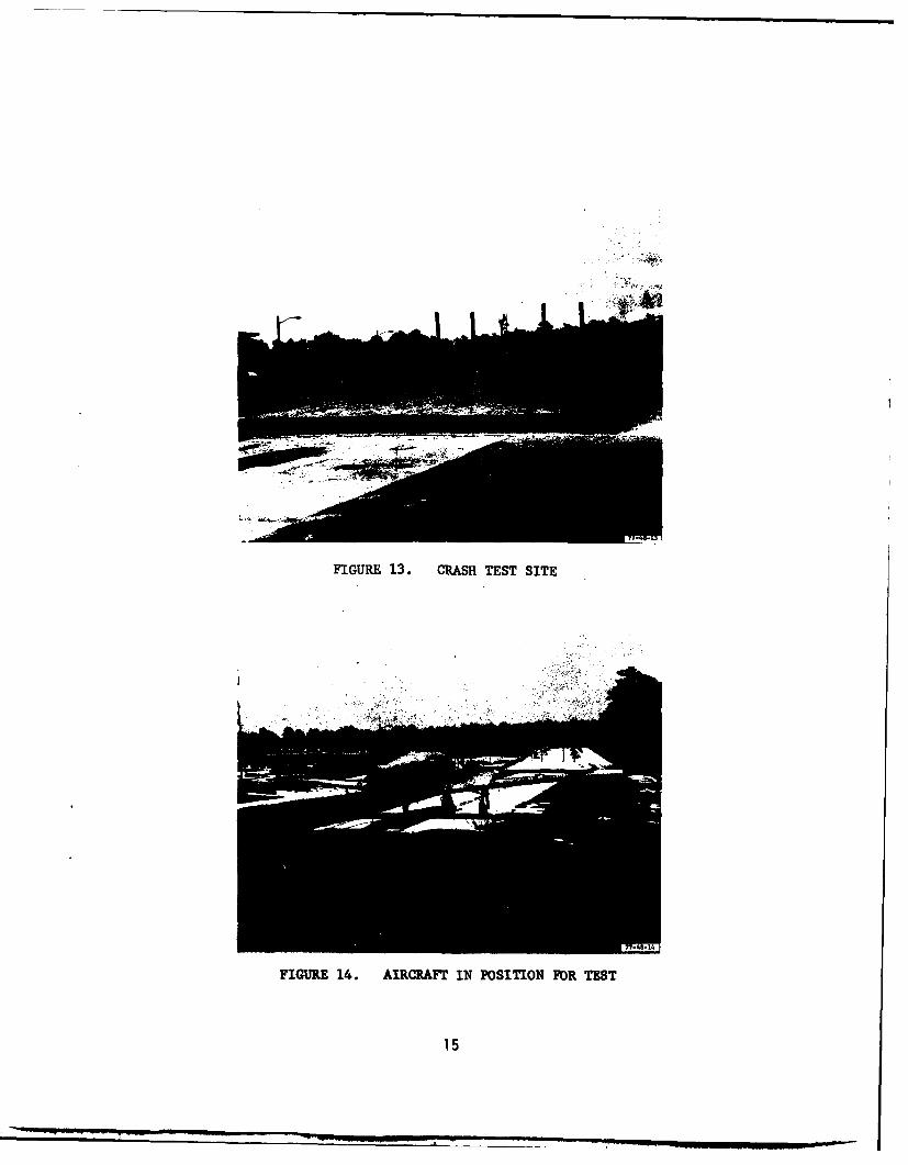
FIGURE 13. CRASH TEST SITE
FIGURE 14. AIRCRAFT IN POSITION FOR TEST
15
ZA0
TIME
MAIN PULSE 77-48-15
FIGURE 15. TYPICAL ACCELERATION PULSE
FIUE16. DAMAGE TO LEFT WING; TWO-PLY FUEL TANK, TEST 1
16
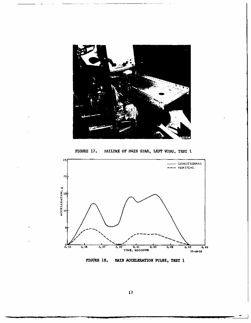
FIGURE 17. FAILURE OF MAIN SPAR, LEFT WING, TEST 1
-LONGITUDINAL
--- VERTICAL
20
C.. 10
0.33 0.35 0.37 0.39 0.41 0.43 0.45 0.47 0.49TIME, SECONDS 77-48-18
FIGURE 18. MAIN ACCELERATION PULSE, TEST 1
17

FIGURE 19. AIRCRAFT IM~PACT, TEST 2, (NOTE WATER SPRAY FRO1M RIGHT WING)
- - 4 . 4~;, 4-20
FIGURE 20. DAMGE TO RIGHT WING, ORIGINAL AIRCRAFT BLADDER CELL, TEST 2
18
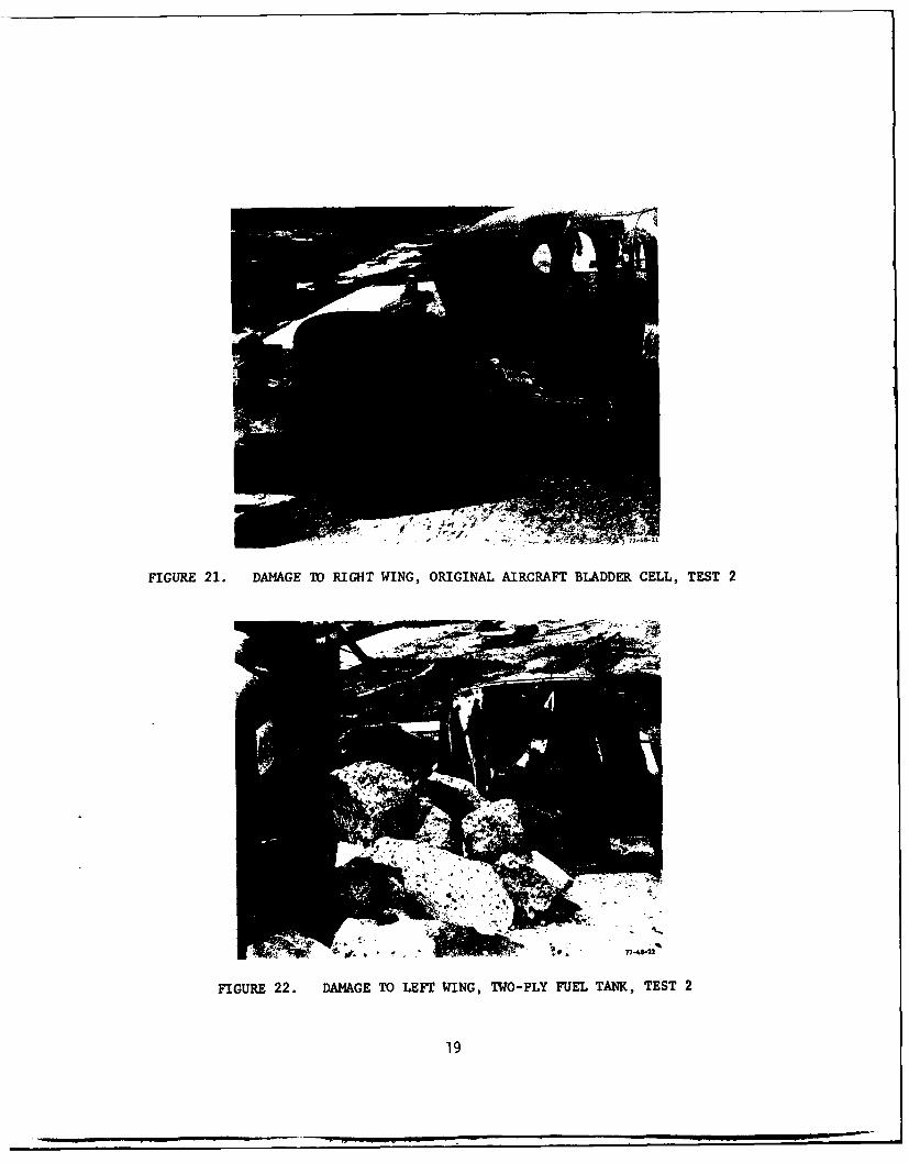
FIGURE 21. DAMAGE TO RIGHT WING, ORIGINAL AIRCRAFT BLADDER CELL, TEST 2
FIGURE 22. DAMAGE TO LEFT WING, TWO-PLY FUEL TANK, TEST 2
19
77-48-23
FIGURE 23. REGULAR (NON- CRASH-RESt STANT) BLADDER CELL AFTER IMPACT
7748-74
FIGURE 24. DAMAGE TO REGULAR AIRCRAFT CELL DUE TO POLE II4PACE (INBOARD)
20
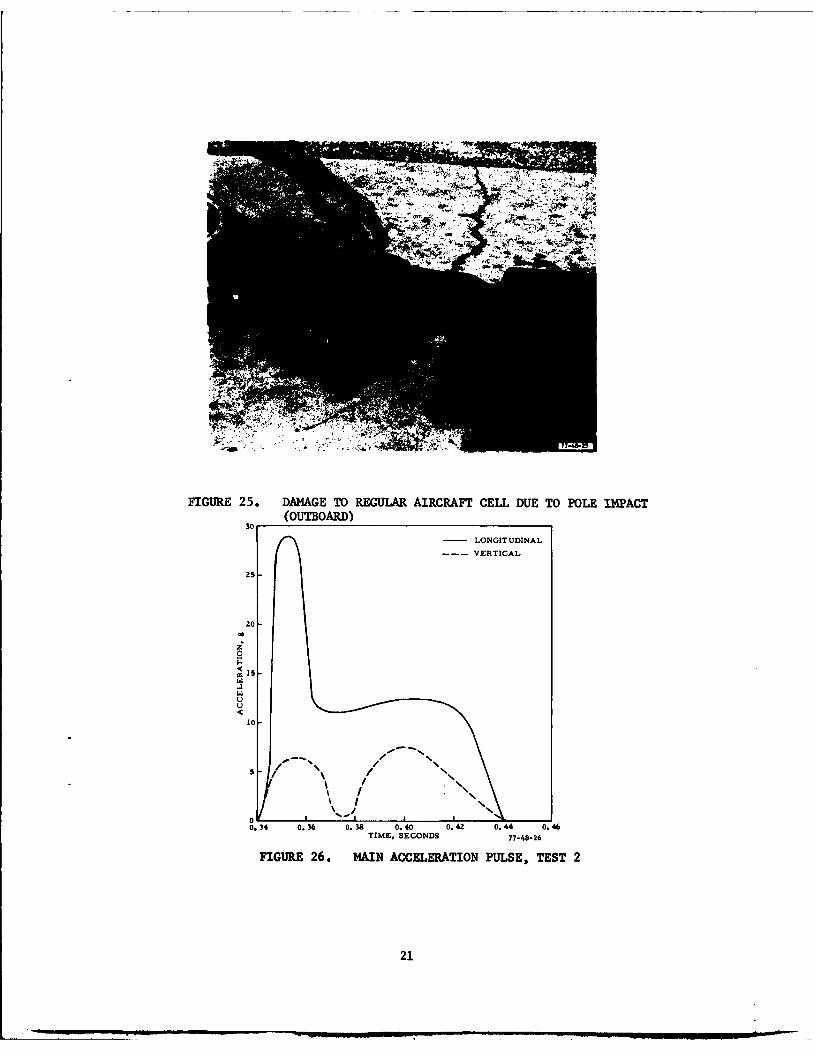
FIGURE 25. DAMAGE TO REGULAR AIRCRAFT~ CELL DUE TO POLE 114PACT(OUTWOARD)
-LONGITUDINAL
--- VERTICAL
20
22

FIGURE 27. DAMAGE TO) LEFT WING, TEST 3
FIGURE 28. DAMAGE TO RIGHT WING, TEST 3
22
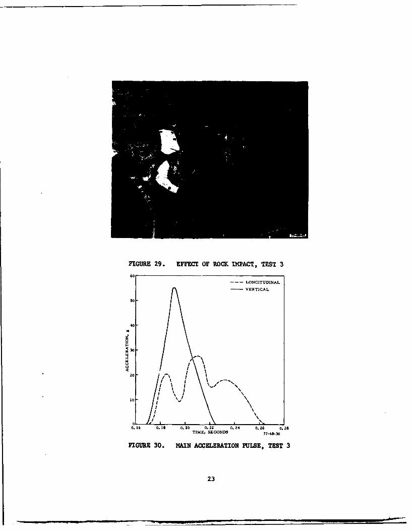
FIGURE 29.* EFFECT OF ROCK IM~PACT, TEST 3
6o--- LONGITUDINAL
-VERTICAL
so
40
z
0
430
4 0 I
10 -
0.1 0.1 .0 02 .4 o 6 02TIE SE ODI7-83
FIUR 30 ANACLRTOIUSTS
I 23
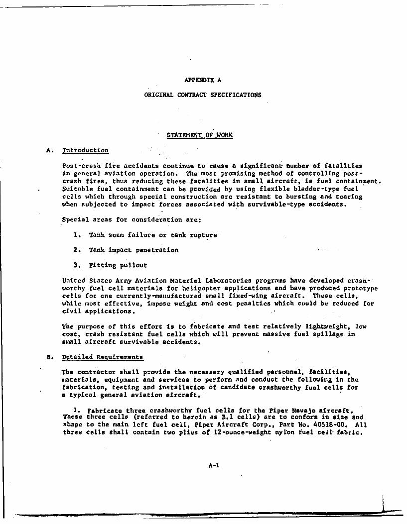
APPENDIX A
ORIGINAL CONTRACT SPECIFICATIONS
STAT[4ENT OF WORK
A. Introduction
Post-crash fire accidents continue to cause a significant number of fatalitiesin general aviation operation. The most promising method of controlling post-crash fires, thus reducing these fatalities in small aircraft, is fuel containment.Suitable fuel containment can be provided by using flexible bladder-type fuelcells which through special construction are resistant to bursting and tearingwhen subjected to impact forces associated with survivable-type accidents.
Special areas for consideration are:
1. Tank seam failure or tank rupture
2. Tank impact penetration
3. Fitting pullout
United States Army Aviation Materiel Laboratories programs have developed crash-worthy fuel cell materials for helicopter app11cations and have produced prototypecells for one currently-manufactured small fixed-wing aircraft. These cells,while most effective, impose weight and cost penalties which could be reduced forcivil applications.
The purpose of this effort is to fabricate and test relatively lightweight, lowcost, crash resistant fuel cells which will prevent massive fuel spillage insmall aircraft survivable accidents.
B. Detailed Requirements
The contractor shall provide the necessary qualified personnel, facilities,materials, equipment and services to perform and conduct the following in thefabrication, testing and installation of candidate crashworthy fuel cells fora typical general aviation aircraft.
1. Fabricate three crashworthy fuel cells for the Piper Navajo aircraft.These three cells (referred to herein as B.1 cells) are to conform in size andshape to the main left fuel cell, Piper Aircraft Corp., Part No. 40518-00. Allthree cells shall contain two plies of 12-ounce-weight nylon fuel cell fabric.
A-1
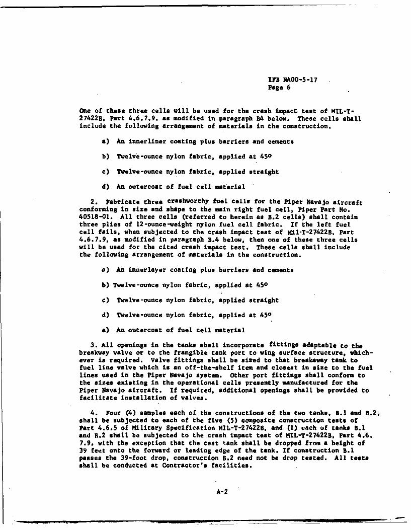
IFB NAOO-5-17
Page 6
One of these three cells will be used for'the crash Impact test of MIL-T-27422B, Part 4.6.7.9. as modified in paragraph B4 below. These cells shallinclude the following arrangement of materials in the construction.
a) An innerliner coating plus barriers and cements
b) Twelve-ounce nylon fabric, applied at 450
c) Twelve-ounce nylon fabric, applied straight
d) An outercoat of fuel cell material
2. Fabricate three crashworthy fuel cells for the Piper Navajo aircraftconforming in size and shape to the main right fuel cell, Piper Part No.40518-01. All three cells (referred to herein as B.2 cells) shall containthree plies of 12-ounce-weight nylon fuel cell fabric. If the left fuelcell fails, when subjected to the crash impact test of Nil-T-27422B, Part4.6.7.9, as modified in paragraph B.4 below, then one of these three cellswill be used for the cited crash impact test. These cells shall includethe following arrangement of materials in the construction.
a) An innerlayer coating plus barriers and cements
b) Twelve-ounce nylon fabric, applied at 450
c) Twelve-ounce nylon fabric, applied straight
d) Twelve-ounce nylon fabric, applied at 450
a) An outercoat of fuel cell material
3. All openings in the tanks shall incorporate fittings adaptable to thebreakway valve or to the frangible tank port to wing surface structure, which-ever is required. Valve fittings shall be sized to that breakaway tank tofuel line valve which is an off-the-shelf item and closest in size to the fuellines used in the Piper Navajo system. Other port fittings shall conform tothe sizes existing in the operational cells presently manufactured for thePiper Navajo aircraft. If required, additional openings shall be provided tofacilitate installation of valves.
4. Four (4) samples each of the constructions of the two tanks, B.1 and B.2,shall be subjected to each of the five (5) composite construction tests ofPart 4.6.5 of Military Specification MIL-T-274225, and (1) each of tanks 5.1and B.2 shall be subjected to the crash impact test of MIL-T-27422B, Part 4.6.7.9, with the exception that the test tank shall be dropped from a height of39 feet onto the forward or leading edge of the tank. If construction B.1passes the 39-foot drop, construction B.2 need not be drop tested. All testsshall be conducted at Contractor's facilities.
A-2
5. All materials, including the fittings, viii conform to the requirementsof MIL-T-2 7422B.
6. All workmanship will be in conformance with the high quality requirementfof MIL-T-27422B, and those of the aircraft industry.
A-3


![FAA - Metallic Materials Properties Development and Standardization [FAA 2003]](https://img.pdfslide.us/doc/110x75/55cf9817550346d03395859c/faa-metallic-materials-properties-development-and-standardization-faa-2003.jpg)
