Embed Size (px)
Citation preview

(NASA-CR-/_IT_ NEW TECHNOLOGIES
FOR SPACE AV[ON|C$, I993 Fin_|
Report (Lockheed Sanders) 7T p
N96-2519] ; , ............ . :_
--THRU--
N94-25196
Uncl as
G3/31 0206636 _. .... i
https://ntrs.nasa.gov/search.jsp?R=19940020711 2018-11-29T18:03:34+00:00Z

Report Documentation Paget_t o_.3l A_,_r'aUTCS anc_
1. Report No. 2. Government Accession No.
4. TitleandSubtitle
New Technologies for Space Avoinics
Final Report of GY 1993 Activities
7. Author(s)
David W. Aibel
David R. Harris
9. Performing Organization Nameand Addre_
Lockheed Sanders
P.O. Box 868, M/S PTP02-A001
Nashua, NH 03061-0868
12. Sponsoring AgencyNameand Address
Navigation, Control, and Aeronautics Division
National Aeronatucs and Space Administration
Lyndon B. Johnson Space Center, EG
Houston, TX 77058
3. Recipient's Catalog No.
5. Report Date
December 1993
6. Performing Organization Code
8. Performing Organization Report No.
10. Work Unit No.
11. Contract or Grant No.
NAS9-18873
13. TypeofReportandPeriodCovered
Contractor Final Report
Government Year 1993
14. Sponsoring Agency Code
15. SLJpplementary Notes
16. Abst_ct
The report reviews a 1993 effort that investigated issues associated with the
development of requirement s , with the practice of concurrent engineering and with
rapid prototyping in the development of a next-generation Reaction Jet Drive
Controller. This report details lessons learned, the current status of the
prototype and suggestions for future work. The report concludes with a discussion
of the vision of future avionics architectures based on the principles associated
with Open Architectures and Integrated Vehicle Health Management.
17. Key Words(SuggestedbyAuthor(s))
Process Improvemen t , Rapid Prototyping
Reaction Jet Drive Controller, Concurrent
Engineering
18. Distribution Statement
Unclassified - Unlimited
19. SecuriW Classif.(ofthisrepo_)
Unclassified
NASA FORM 1626 OCT 86
20. SecuriW Classif.(ofthispage)
Unclassified
21. No. of pages
78
22. Price

r_
1 Introduction
This report describes work at Lockheed Sanders performed during Government Year 1993 in
support of a NASA/JSC Research Announcement (NRA), contract number NAS 9-18873.
The work described is part of a multi-year effort, this report describes the work performed in
1993 and the work planned for 1994. This work specifically investigated potential improve-
ments to the engineering process utilized to design major subsystem elements of a typical
spacecraft avionics system.
During 1993, the effort addressed some of the issues associated with the development of
requirements, with the practice of concurrent engineering, and with rapid prototyping in the
development of a prototype of a next-generation Reaction Jet Drive (RJD) controller. In the
course of this work, two reports, one interim, one final (both attached as Appendix B and
C respectively), have been written to provide insight into the issues associated with process.
Additionally, an effort has been made to plan the future activities associated with this task,
a proposed Statement of Work for GY94 is also attached (attached as Appendix A). This
document continues with a section on some of the generic lessons learned during the GY93
effort, the current status of the prototype RJD development, and a discussion of the vision
of future Avionics architectures based on the principles associated with Open Architectures
and Integrated Vehicle Health Management.
L
__--___z
W
= =
t--=aw
1.1 Acknowledgements
As mentioned previously, this effort focused on new paradigms for engineering design. A
key component of these paradigms is the notion of the importance of teams in addressing
complex problems. This task could not have been accomplished without the aid of a devoted
and hard-working team which spanned several organizations as noted below. Grateful thanks
are offered for the contributions of:
• Dave Aibel, Lockheed Sanders
• Dave Bartlett, University of New Hampshire
• Steve Black, Lockheed Space Operations Company
• Dave Campagna, Lockheed Sanders
• Nancy Fernald, Lockheed Sanders
• Ray Garbos, Lockheed Sanders
• Dave Harris, Lockheed Sanders

• Mark Lanciault, Lockheed Sanders
• Rick Loffi, NASA/JSC
• Wayne McCandless, Lockheed Engineering & Sciences Company
Of course, this effort would not be possible at all without the substantial support and
direction provided by the technical management of the Navigation, Control, and Aeronautics
Division of the Johnson Space Center, most notably Aldo Bordano and Don Brown.
2 Lessons Learned
L
r_,_̧
L_
q_
In this section, we elaborate on some of the issues discussed in greater detail in the reports
in Appendix B and C and the specific impact of these issues on the development of the RJD
prototype. The goal of this effort is to investigate opportunities to reduce the time, and,
consequently the cost, to produce a useful avionics system element while incorporating a
holistic approach to design which attempts to consider the costs associated with an entire
life cycle of the element (also referred to=as design incorporating the principles of Integrated
Vehicle Health Management (IVHM) since, ultimately, the life cycle cost of the element
depned on the ability of the platform to meet its mission requirements.). The approach that
was used to provide a more useful product in a more timely fashion is based on an iterative
rapid prototyping process which has been developed to meet the needs of DoD labs and,
most particularly, the Advanced Research Projects Agency (ARPA).
This methodology is derived in part from the observation that many complex systems are
poorly described by specifications. Frequently finished systems are delivered which do not
meet the anticipations, either in terms of cost, performance, or longevity, of the customer
community. This happens, in part, due to the standard engineering process which dictates
an "over-the-wall" process wherein requirements are handed off to designers who work in an
isolated function to ameliorate risk. This desire to manage risk frequently results in systems
which suffer from an early design freeze which, since the design is immature, practically
guarantees a system with much inherent risk. Furthermore, since the end-user is continuously
learning more about his problem, the latest knowledge of the application is not captured
early in the design cycle resulting in extremely costly re-work. Consequently, success is
usually achieved only through close cooperation between designers, specifiers, and users (a
process which has come to be known as "concurrent engineering"). At Lockheed Sanders,
the concurrent engineering team approach has been combined with the relatively newly
developed electronic design environment to provide feedback as to the adequacy of decisions.
Central to this approach is the idea of doing many rapid iterations of a design, capturing
a little bit more of the ultimate functionality of the desired element in each subsequent

instantiation. At each stage, the prototype, be it a paper design, a computer simulation, a
hardware/software prototype, or, an engineering model using end item components, is tested
against the expectations and requirements of the end-users. The goal is to arrive at a final
element configuration which provides capabilities to the end-user without "surprises".
The RJD concurrent engineering team is composed of system engineers (Dave Harris and
Dave Aibel), hardware engineers (Mark Lanciault, analog design, Dave Campagna and Nancy
Fernald, digital designers), and representatives of the end-user community (Rick Loffi and
Wayne McCandless). The team communicates about once a week through teleconferences
and more frequently by way of electronic mail.
2.1 Maintain a Critical Mass of Designers
During the course of the RJD prototype design activity, it was noted that although good
designers are capable of performing well even when isolated from their peers, a significant im-
provement in time to design and an even greater improvement in risk reduction are achieved
when a critical mass of designers is available to provide continuous feedback on design ideas
and concepts. Consequently, rather than adopting the traditional program-oriented approach
and sequestering the RJD designers into an isolated program unique area, RJD designers
were encouraged to mingle with the designers working on other programs and to hold fre-
quent mini-reviews with their peers to discuss challenging issues. Furthermore, designers
were encouraged to attend the weekly team teleconferences to report on problems they had
or on progress that had been achieved.
2.2 Trades between New and Established Technologies
The RJD team faced the classic engineering problem of deciding between using the latest
state-of-the-art and established technologies to reduce risk. On the one hand, established
technologies offer the safety of clearly defined capabilities which meet clearly defined perfor-
mance and environmental conditions. Newer technology might offer a part which is capable
of better performance in a smaller package, but, there may be more risk associated with
delivery or performance. In an interesting development, there were three decisions which
resulted in three different approaches. In one case, documented in the RJD design docu-
mentation, the team had to respond to the user community's desire to have the capability
to turn off the R2D solenoids faster than what the current design will allow. One of the
factors controlling the response time of the current solenoids is that the current design limits
the amount of electromotive force (EMF) which is allowed to flow back from the solenoid
to the controller. The RJD design team accepted as a design goal the requirement that
the RJD controller be capable of withstanding a back EMF of at least 66 % more than the

current design. A careful survey of the MOSFET's available commercially turned up no
mature designs which could meet the RJD requirements for environmental conditions, could
handle the RJD current requirements and could handle the anticipated back EMF. After
much soul-searching, the designers opted for a new part which is designed for a more benign
environment (automotive) than that of the R,ID, but, which is capable of handling the de-
sired back EMF and which the manufacturer has indicated will be produced in a mil-spec
variety in the future. In this way, the designers attempted to trade a perceived high risk
item, the capability to handle back EMF, in return for accepting a potentially lower one,
that the part will not exist in a mil-spec or space-qualified configuration.
When, early in the RJD design cycle, it became clear that this design, based as it is on
the use of the Mil-STD-1553 bus, was going to require some digital logic to control its
functionality, the digital design team had to make a choice as to how that logic was going
to be instantiated. Because of the nature of the design process with its rapid iterations
and evolving requirements, the team chose not to get caught in a restrictive design dictated
by the demands of a high performance state of the art microprocessor design. Instead,
they chose to utilize the potentially lower performance of an implementation based on Field
Programmable Gate Arrays (FPCAs) which, since they are reconfigurable at the logic level,
offered the capability to adapt to the inevitable change in requirements.
Likewise, when the digital design team began to design a memory system which would holdthe data collected from the Built-In-Test circuitry on the analog board, they had to decide
between a low-cost (in terms of part cost) but high risk ( in terms of design time) dynamic
RAM implementation and a higher-cost ( again, in terms of part cost), lower risk (in terms of
design time) static RAM implementation. In this case, when the team knew that the current
iteration was not the design which was destined to be produced in any sort of quantity, they
opted to take the lower-risk path of using a static RAM memory implementation.
The pattern which exists here is that the designers are willing to manage risk by accepting
design compromises. They are willing to do this because the process consists of many rapid
spins and the design is not the physical hardware but rather the collections of desired func-
tionalities. The longer that the commitment to deliverable hardware can be postponed, the'
more likely that the high-risk immature components will mature and consequently represent
a lower risk to the deliverable design.
A related observation that can be derived from the notion that development consists of many
rapid iterations is that the design exists largely as a collection of desired functionalities. What
was instantiated in a logic equation in an FPCA in one spin might be realized as lines of
software code in the next spin. This suggests possible implications to the notion of logistics
as well. For instance, if it is possible to rapidly and inexpensively iterate on a design and
if the design of a replaceable unit exists as a functional specification, it may turn out to
be more cost effective to replace the unit with a new spin of the design utilizing the latest
4

v
r_A
u
f
t J
available technology rather than relying on an expensive to maintain stockpile of potentially
obsolete spares. This is a life cycle analysis which still needs to be performed.
2.3 Complete the Hard Parts of the Design First
As has been discussed, the approach to risk management adopted in the course of the RJD
development is to iterate a design concept rapidly so as to converge on a product which
meets the ultimate desires of the user community. The key to this method is to complete
the hard portions, those challenging due to either performance, packaging, or environmen-
tal conditions, of the design first, demonstrate those and then proceed to finish, in later
iterations, the easier portions of the overall design.
To this end, the RJD team demonstrated a prototype of the switching network of MOSFETs
to demonstrate the feasibility of that concept. Additionally, the RJD team has demonstrated
communications to the digital portion of the design over the Mil-STD-1553 bus. And, the
team has a working simulation of the logic which is currently resident in the Xilinx FPGA.
3 Prototype Status
One of the central themes of this NRA effort is to provide an illustration of the cost effective
development of a prototype which incorporates some of the principles of IVHM. To achieve
this, a methodology based on rapid iteration has been adopted. This strategy is reflected in
both the status of the current prototypes and the plans for 1994 activity.
3.1 Current Prototype Status
The current prototype represents a partial implementation of the anticipated design. As
mentioned above, the prototype incorporates a switch design and a 1553 interface which
each have been tested to ensure basic functionality. The prototype has yet to have the
analog and digital sections integrated with a solenoid to prove end-to-end functionality. A
schematic of Xilinx logic to provide functionality capable of illustrating many of the IVHM
capabilities, such as recording cumulative burntime and skewing the actuation of oxidizer
and fuel solenoids, is available for simulation, however, the current plan is to implement it
in the Xilinx after the fundamental end-to-end functionality is established.
5

3.2 GY 1994 Plans
During 1994, it is anticipated that the NRA will focus on further defining the requirements
of the next generation RJD controller by producing more iterations of the current design
concept and, also, investigate the phenomenology associated with the end of useful life of
the solenoids which control the flow of fluids through the plumbing of the Reaction Control
system. A more detailed proposed Statement of Work can be found in Attachment C.
3.2.1 Iterations
For GY 1994, it is anticipated that, consistent with the design methodologies which are
alluded to above and further elaborated in the reports of Appendix B and C, several iterations
of the current prototype will be required. It should be noted that the 1994 project will
focus more on results, in the form of prototypes, demonstrations, and new algorithms, than
engineering process.
Both of the iterations currently contemplated will be spins of the digital portion of the RJD
controller; analog upgrades will be executed as required.
3.2.1.1 FPGA As soon as it becomes possible to prove out end-to-end functionality, the
RJD will be integrated with a Mil-STD-1553 controller and the target solenoids and tested
for functionality. It is anticipated that at least one iteration of the FPGA-based board will
be needed to provide all of the desired functionality.
3.2.1.2 Microprocessor As the development process continues to spiral and more func-
tionality is added to successive prototypes, it is anticipated that the processing capabilities
provided by the logic of the Xilinx FPGA will be exhausted. In particular, as the investiga-
tion of the phenomenology of the Solenoid End-of-Useful-Life is developed, there may be a
need for extensive floating point processing power which is difficult to supply with conven-
tional FPGAs. Consequently, it anticipated that, in 1994, at least one iteration of the RJD
prototype will involve the switch to a microprocessor based digital design.
The precise selection of which microprocessor to use will depend on a variety of parameters.
Currently, the R3081 microprocessor from the MIPS Company seems attractive on at least
three counts:
• It is a single chip microprocessor
• Lockheed Sanders already owns (and, is familiar with) the software development tools
which are critical for successful use of an embedded processor.

tL=-.
_nL=i
• The Instruction Set Architecture of the R3000 microprocessor family was designed to be
inherently radiation resistant. (In fact, Lockheed Sanders proposed to use commercial
versions of the R3000 family for the MEDS program to upgrade the cockpit of the
Space Shuttle since several commercial sources offered standard chips which met the
radiation requirements of the Shuttle program.)
However, since the processing requirements of future RJD prototypes has not yet been
established (see next section), no decision as to which microprocessor will be used has yet
been reached.
3.2.2 Solenoid End-of-Life
As part of this effort, the Lockheed Sanders team solicited inputs from the operational
community at Kennedy Space Center. Wes Lineberry and Steve Black of LSOC supplied
information about testing that is routinely conducted on the solenoids of the Shuttle Main
Propulsion System and can also be performed on solenoids of the RCS subsystem. By
examining the current rise-time trace of the energizing signal, it is possible to predict the
impending failure of a solenoid (It has been suggested that this phenomenology is caused
by the slow deterioration of the insulation between the windings of the solenoid.). A typical
"good" curve is provided, in figure 1, as an illustration of what the data looks like.
One of the reasons that this test is not widely used is that it must currently be performed
by manually disconnecting the solenoid in question, attaching a current meter, conducting
the test, and re-attaching the normal wiring and then re-validating the connections of the
unit under test. This is a relatively expensive process.
The Lockheed Sanders team took on the challenge of providing the capability to automati-
cally test and monitor the "health" of the solenoid as measured by the characteristics of the
current rise time curves. The current baseline design provides sampling Analog-to-Digital
converters, and logic and memory to store the sampled waveforms for later analysis. How-
ever, the team was unable to obtain enough data to derive a mathematical characterization
of the phenomenon. It is proposed that acquisition of this data be actively pursued and an
algorithm for predicting impending End-of-Useful-Life be derived during 1994.
Once this algorithm is derived, the processing requirements of this algorithm will be used to
trade off processing options for the next iteration of the RJD prototype.
=
=

w
It*.
=
TEKTROHIX
I
I
i Iis;_o ¢'IIO_. m
=
u
r
w
w
4
Figure 1: A typical 'Good' Solenoid turn-on current trace
A Vision of the Future
The Reaction Jet Drive controller has been developed within the context of a larger vision
based on open architectures and rapid prototyping. Within this context, avionics systems of
the future will consist of federated subsystems responsible for the operation of the element
which they control• This will result in an avionics system architecture that relieves the
Flight Control System (FCS) of the requirement of maintaining intimate knowledge and
control of the vehicle subsystems (for instance, the Reaction Control System) and their
specific configurations• The benefit of this architecture is that future upgrades and changes
to the subsystem configuration are greatly simplified. This architecture will also provide
for a much simpler treatment of failure analysis, system diagnosis, and the design of fault
containment domains•
The design which the Lockheed Sanders team has been working on can serve as the building
blocks from which it should be possible to construct a generic "bread-box" capable of sup-
porting a reconfigurable number of reaction jets. The breadbox would have the logic and
control required to accept a command from the Flight Control System that would have the
content of a command such as "turn the vehicle left 5 degrees" and the box will be capable of
selecting which of several potential jets to fire for a given period of time to achieve the desired
results• The box will have the capability to monitor the health and status of the individual

jets to avoid failure conditions. As jets begin to age, the box will be capable of detectingthe changein performanceand adjust it's commands to the subsystems accordingly.
5 Summary
w
The work that has been described represents the first phase of a multi-year effort to inves-
tigate potential improvements to the engineering process utiized to design major subsystemelements of a typical spacecraft avionics system. The effort addressed some of the issues as-
sociated with the development of requirements, with the practice of concurrent engineering,
and with rapid prototyping in the development of a prototype of a next-generation Reaction
Jet Drive (RJD) controller.
Over approximately 8 months of calendar time and for a cost of approximately $50,000.00,the Lockheed Sanders team has:
v
w
l
• formed an integrated product development team consisting of representatives from
NASA, Lockheed Sanders, Lockheed Engineering and Sciences Company, Lockheed
Space Operations Company and the University of New Hampshire.
• defined meaningful requirements to address a real problem in current spacecraft design.
• initiated a rapid development process based on the concept of a spiral iteration of a
baseline design.
• selected, as a team, among design options to arrive at a baseline which incoporates
many illustrative IVHM capabilities.
Based on the successful progress of the team, the team has developed, on Lockheed funds,
the first hardware iteration of the RJD controller prototype. This prototype was available for
demonstration of basic functionalities in December of 1993, essentially 8 months after process
inception. The speed in which this first cycle of this improved design process represents an
improvement of at least twice the normal process and, as such, represents the success of the
program.
w


r
5 --S tN94- 25194
1.0 Statement of Work for FY '94
i.I This document describes Lockheed Sanders' overall goals for
the NRA effort "Rapid Design Process to Shuttle Reaction Jet
Amplifier" (contract no. NAS 9-18873), specific goals of the FY
'94 NRA, and the actual tasks that will be performed to achieve
these goals. Where appropriate, future tasks which will be
required to meet the ultimate goals are identified. An estimate of
required level of effort and a schedule for this work will be
provided.
2.0 Goals of the NRA effort
2.1 This NRA effort is devoted to developing new techniques andmethodologies which utilize and/or provide support to Integrated _ _
Vehicle Health Management (IVHM) concepts and techniques, modern
design processes and open architectures to realize:
_ [ An Avionics system architecture that relieves the Flight
Control System (FCS) of the requirement of maintaining intimate _
knowledge and control of the vehicle subsystems (for instance,
the Reaction Control System (RCS)). The benefit of this
architecture is that future upgrades and enhancements to the
system(s) or to individual components within the system(s) are
greatly simplified. This approach also allows a much more
straightforward treatment of failure analysis, system diagnosis, _
and the design of fault containment domains.
_ _, Capabilities to provide an available avionics system (and
subsystem(s)) at minimum operational cost. This thrust providesa direct benefit to NASA in that it seeks to accelerate the
design cycle to allow state of the art components and designs to
actually appear in the fielded system rather than merely in the
initial design. To achieve this, this effort is intended to
benefit from efforts already underway at Lockheed and other
major contractors. For instance, Lockheed Sanders is currently
engaged in a major DoD funded development program which has the
goal of cutting design cycle time of high performance
electronics by a factor of four while simultaneously improving
quality also by a factor of four. The early work on this program
was used to enable the rapid prototyping of the Reaction Jet
Drive Controller which was accomplished in 1993. Similarly,
maximum leverage will be derived from recent NASA and DoD
efforts to increase the content of high quality commercial grade
electronic components in systems for aerospace applications.
Both of these goals result in a system with enhanced cost
effectiveness, increased reliability, and greatly increased
performance compared to a system developed using a more
conventional approach.
2.2 The NRA will use the design and fabrication of a Reaction
Control System jet driver assembly as a test case to work the
newly developed paradigms. Potential target platforms under

active investigation include updates, retrofits and new vehiclessuch as:
• ATLAS and Delta expendable launch vehicles• Shuttle• Single Stage To Orbit (SSTO) vehicles• Commercial and Military Satellites• Transfer vehicles
2.3
For FY '94_ this NRA will focus on three tasks, described in
further detail in the following sections of this Statement of
Work:
• The development of Integrated Vehicle Health
Management (IVHM) requirements.
• The "productization" of the prototype Reaction JetDriver (RJD) controller that was developed during 1993.
• The investigation into methods of predicting the
impending End of Useful Life (EOUL) of thruster fuel andoxidizer control solenoids and other electromechanical
equipment and devices.
As mentioned previously, these tasks represent elaborations on and
further development of tasks begun during 1993.
3.0 System Concept for Integrated Vehicle Health Management(IVHM)
The preceding work on defining IVHM strategies have all focused on
the need to incorporate design for IVHM at the earliest stages of
a system's evolution. In addition to incorporating IVHM concepts
into a system concept early in the design cycle, it is important
to design in a top down fashion. Therefore, this effort will
develop an extensible system level architecture concept. From
these concepts, a set of consistent subsystem requirements will be
developed. Finally, some of these concepts will be demonstrated,
and their performance analyzed, using the prototype RJD controller
built during FY '93.
3.1 The aim of developing a system level architectural concept
is to design an avionics system which is capable of meeting
overall system level availability and fault tolerancerequirements. For instance, if an engine were to be shut down, the
avionics should be able to respond in such a fashion, perhaps by
changing the thrust angles of the remaining engines, to enable the
vehicle to still achieve its mission. In order to develop such a
top level system architecture for Vehicle Health Management it
will be necessary to coordinate among the various suppliers and
architects of such a system. Therefore, a key portion of this task
will involve meetings and interchanges with other airframe
manufacturers and avionics vendors, such as Honeywell and Martin

w
Marietta, and other design resources such as NASA/Ames to reach a
consensus architecture which addresses these high level
requirements.
To validate that this architecture can, in fact, be built and that
it will perform as designed, a subtask, which will not be fundedunder this effort, but, is a candidate for Lockheed internal
funding, is to model the architecture performance using a
commercially available architecture simulation tool like Opnet
(from MIL-3) or Bones (from Comdisco).
3.2 During FY '93, this NRA demonstrated some of the
fundamental requirements of a design that addresses Vehicle Health
Management principles at the subsystem (in this case, the RCS
subsystem) level. These requirements include:
• The elimination of single points of failure (i.e.,
thruster fail-on and fail-off).
• The incorporation of instrumentation necessary to
detect the occurrence of faults.
• The development of logic to respond to failure
conditions at the subsystem level.
• Provisions for predictive analysis of sensor data to
allow for the adaptation to changing environments.
During FY '94, an effort will be undertaken to develop the
requirements for Health Management at the next higher SubsystemLevel, which, in the case of the archetypical RCS subsystem, is
represented by the entire Vehicle Management System.
The result of this task will be a report.
3.3To demonstrate the implications of integrating Vehicle Health
Management at a component level, the RJD prototype controller will
be integrated into the Controls development Laboratory (CDL) and
the JSC Avionics Engineering Laboratory (JAEL) at NASA/JSC.Performance while interfaced with "standard" configurations will
be demonstrated. Error conditions will be introduced and the
limits of the built in fault detection, isolation, and recovery
will be explored.
This effort will be a joint collaboration requiring the support of
NASA/JSC, Lockheed Engineering & Sciences Company, and Lockheed
Sanders personnel.
4.0 Productization of the RJD Controller
During 1993, a prototype of a fault tolerant Reaction Jet Drive
Controller which incorporates a demonstration of IVHM principles
was designed and fabricated. During 1994, the prototype will be
re-designed to incorporate lessons learned from the exercising of
the prototype in the NASA/JSC JAEL and to provide for a redundant

L
digital control and status interface. This new design will be
repackaged into a form factor that conforms to the requirements
imposed by the launch vehicle environment. The RJD controller will
then be subjected to thermal, vibration, and vacuum testing to
verify that the controller is capable of controlling a Reaction
Jet on a launch vehicle.
Specific attention will be dedicated to exploring the costs andbenefits of modularizing the design, for example allowing common
building block elements to be assembled to control the desirednumber of thrusters. As a part of this effort, a study will be
made of the redundancy and robustness gains that may accrue from
such an approach.
5.0 Investigating the End Of Useful L_fe of Solenoids
During 1993, it was noted that the impending End Of Useful Life
(EOUL) of the solenoids which drive the valves of the Reaction
Control System (and control Main Propulsion System valves as wellas elements of other subsystems) can be predicted by examining a
plot of the rise time of the turn-on current for the given
solenoid. Unfortunately, this phenomenology has yet to be
mathematically characterized. During FY '94, Government furnished
data will be analyzed to derive some mathematical justification
for classifying a given rise time curve as either predictingtrouble free operation or impending failure. This reasoning will
then be captured in an algorithm which will be implemented and
demonstrated on the prototype equipment installed in the NASA/JSC
JAEL.
Having arrived at a suitable candidate residual life estimation
algorithm, we will then perform an assessment of the hardware that
would best host the algorithm. Conventional microprocessor,
digital signal processor (DSP), and Application Specific
Integrated Circuit (ASIC) approaches will be examined. Pending a
cost/performance trade, an approach will be selected and ademonstration system integrated and delivered as part of this
effort.
As noted, the successful completion of this task is dependent on
the active cooperation and participation of NASA/JSC personnel
and, potentially, vendors of solenoids.

6.0 Proposed Project Timeline
1.e
ProgramTasks
RJD Product.
Re-DesignRe-PackageQualification
IVHM Def.
System def.Subsys. req.Comp. Demc
End-of-Life
Define
ImplementDemo.
1/94 3/94 4/94] _94 6/94
y
7/94
r
8/94
Y
r
_4 10/94
l
[
11/9
[+(
_GY!

LOckheed .....Sanders ..... .

w
w
r--
w
Abstract:
Conventional processes often produce systems which are obsolete before they are fielded. This !
paper explores some of the reasons for this, and provides a vision of how we can do bet-
ter. This vision is based on our explorations in improved processes and system/software "
engineering tools.
1 Introduction
Over the past seven years our Signal Processing Center of Technology and in particular our
Rapid Development Group (RDG) has been vigorously developing and applying approaches
for complexity management and rapid development of complex systems with both hardware
and software components. Specifically, we have created laboratory prototypes which demon-
strate broad-based system requirements management support and we have applied key rapid
development methodologies for the production of signal processors and signal exploitation
systems such as electronic countermeasures systems, signal classifiers, and factory floor test
equipment.
As a component of this thrust, we have developed prototype tools for requlrements/specification
engineering. Recently on the "Requirements/Specification Facet for KBSA" project, Lock-
heed Sanders and Information Sciences Institute built an experimental specification envi-
ronment called ARms [5] _ which engineers may use to codify system specifications while
profiting from extensive machine support for evaluation and reuse. As part of this project
we have developed databases of specifications for signal processing components, for electronic
warfare techniques and tests, and for tracking and control within the domain of air traffic
control. ARIES is a product of the ongoing Knowledge-Based Software Assistant (KBSA)
program. KBSA, aS proposed in the 1983 report by the US Air Force's Rome Laboratories
[3], was conceived as an integrated knowledge-based system to support all aspects of the
software life cycle.
The key aspects of our multi-faceted approach build on advances in architectures which
support hybrid systems (i.e., mixes of pre-existing subsystems and new development) and
tool developments addressing automation issues at higher and higher abstraction levels.
With these changes taking place, there are many opportunities for improving engineering
processes, but several obstacles to be overcome as well.
We begin with a brief discussion of the fundamental problems inherent in the "conventional"
system development process. The well-documented reasons for long development cycle times
inherent in the conventional development processes are many and varied. Four significant
IARIES stands for Acquisition of Requirements and Incremental Evolution of Specifications.

.. i
7.,°
r_"_:_ActivityN+I
Activity N--E
t_t
"" Activity N-l=
"_ T O
(a) Current Sequential Process:
• Manual Transfer of Data
• Limited and Late Feedback
-- All Contribute to "Lost" Time --_
= _ _m
-_ Time
Figure 1: The conventional development cycle as a collection of discrete steps
problems characterize the state of the practice: early commitments under uncertainty, iso-
lated design activity, performance-orientation, and process control rather than observation.
All lead to long and costly development cycles.
• Forced Early Commitments
The conventional development cycle is really a collection of discrete sequential steps
(see Figure 1). Each step establishes a baseline and entails specific commitments. To
reduce schedule risk, engineers freeze implementation choices as early as possible -
prior to partitioning of design tasks to members of a development team. For example,
engineers may prematurely select a CPU, sensor component, or algorithm. Frequently,
a decision to commit to a particular implementation strategy is made before the systemrequirements have been fully analyzed and understood.
To ameliorate the effects of unforeseen, or poorly understood, requirements, system en-
gineers impose design margins (e.g., extra memory, extra throughput, stringent power
and size restrictions). The rationale behind these margins being that some physical
components will exceed expectations and some unforeseen problems can be corrected
by writing new software which crosses physical system boundaries. Unfortunately, to
3

achieve the margins mandated, engineers frequently introduce additional technical and
schedule risk since now the required capabilities push even harder against the edge of
achievable performance, power, and packaging.
If a surprise requirement is uncovered and the corrective action of utilizing software
which will achieve the design margins is invoked, this often occurs late in the devel-
opment cycle when typically the program is fully staffed and at the most expensive
portion of its costing profile. Consequently, even minor corrective actions can have
dramatic cost and schedule impacts.
• Isolated Design Activities
Engineers are often isolated from the design impact on production, and on fielded sys-
tem maintenance, support, and upgrade. Upstream design is isolated from downstream
activity. The feedback loop from design to manufacturing and back to design usually
takes several days.
Producibility guidelines, available on paper, and to a limited extent in advisor software
packages, help engineers avoid only the most obvious pitfalls such as exceeding bounds
on chip size.
The cost estimation tools available today (e.g., RCA's PRICE tin, Analytic Sciences
Corporations's LCCA tin) are not tightly integrated with the design process. These
estimation tools derive cost from abstract parametric data (e.g., team experience and
quality, mean time between failure, repair time, module cost, support equipment cost,
number of spares).
In reality, the situation is quite a bit more complex. Engineers are not always aware
of the relationship between abstract parameters and specific design decisions. Alter-
native designs can vary greatly in their production cost and what appears to be an
arbitrary decision to a engineer can have serious cost impact downstream. In addition,
engineers are often "backed into a corner" by stringent performance requirements (i.e.,
the margins mentioned above) that can only be achieved through a "custom" approach
which violates a guideline. Engineers need to know the sensitivity of custom solutions
to manufacturability and testability.
Closer collaboration among engineers, in-house manufacturing engineers, testing ex-
perts, purchasing departments, external foundries, and logistic engineers will clearly
improve the process. This is the institutional focus of concurrent engineering initia-
tives. However, this focus alone will not provide the rapid turn around times essential
for reducing schedule and cost. There is a need for computer-aided solutions as well.
• Emphasis on Performance
Conventional processes too often produce systems which are obsolete before they are
fielded. A primary cause is that technical program managers and engineers are lured
4

w
w
into giant leaps which attempt to solve all problems at once. As a result, reuse of pre-
vious work is very difficult and the goal of building systems out of pre-existing systems
can not be met. In compute-bound applications such as digital radar, target tracking,
and automatic target recognition (ATR), this tends to lead toward the production of
systems that are obsolete before they are fielded.
Tools lag behind state-of-the-art components. When engineers attempt to incorporate
state-of-the-art technology in their designs, the available tools support is frequently
obsolete. Libraries do not contain new product descriptions. Any attempts to translate
work products from one tool to the next are error-prone.
Engineers working within the conventional development process do not always have on-
line access to the results of various trades (e.g., hardware architecture trades, software
architecture trades, software performance, operating system performance). Denied
access to on-line libraries, these engineers must repeat trades from scratch.
Control Rather Than Observation of Progress - Paper-only validation
Management can not directly observe development and hence institutionalizes control
regimes which take on a life of their own. Unfortunately, in using these "arm's length"
regimes, the best efforts of interested observers may fail to get at the real requirements
that often can only be accurately stated when end-users have the opportunity to in-
teract with actual system implementations. A key reason for end-user disappointment
with a product is that during the long development cycle, these end-users receive in-
complete information on how the system will perform; once field and acceptance testing
begins, they can be "surprised".
User-centered Continuous Process Improvement We have attacked these problems
by establishing and defining more efficient processes and by utilizing advanced tool technol-
ogy to empower engineering. Figure 2 illustrates the evolutionary nature resulting change.
People can initiate change from modifications at any point in the diagram. Thus a change to
the Design Environment (e.g., new tools and software environments) creates tools that capture
and manipulate new Information which in turn helps engineers to select specific Architectures
and enable creation of Reusable Products whose development Methodology drives the need
for modifications to the Design Environment. The diagram can be read as well starting at
any other point on the circle. The impact of tools on process, suggests that we consider anyrecommendations in two waves:
• Policies and procedures for today - given a specific design environment maturity, what
are the best methodologies for system development today? For example, we may
choose to continue with some control-oriented practices because the requisite groupware
technology is not available for enabling observation-oriented improvements.

z
tures
defines
ReusableProducts
creates
Information
suppo_s
Figure 2: The process/tool dynamic: User-centered a_laptation of environments, information,
architectures, and methodology

!
w
u
r .
W
• Future directions - how do we transition to more automated processes - more expres-
sive power in modeling and simulation capabilities, effective reuse, improved synthesis
methods, automatic design?
We start in Section 2 with a case study of a small effort emphasizing progress that is possible
when we take prescriptive steps to avoid the above mentioned pitfalls. Section 3 presents a
vision of the future (i.e. a likely scenario within the next four to five years). Then in Section
4, we support this position with our experience and observations about prevailing trends.
Section 5 describes issues for tools and tool environments. Finally, in Section 6 we make
several specific recommendations for process improvement within the tool/process dynamic.
2 AIPS: A Case Study in Rapid Development
AIPS is a completed initiative which illustrates the opportunistic use of development tools,
the employment of a flexible process flow, and the advantages of virtual prototyping. In this
1991 project, RDG fully implemented a radar pulse feature extractor system in less than six
months. The system's sponsor required an advanced system operating at the 50MHz rate.
An existing prototype board running at 12.5 MHz demonstrated needed functionality, but
could not keep up with the required data rates. To bootstrap the effort, the sponsor furnished
a real world data set useful for validating designs, an interface specification document, and
only the'schematic for the prototype board. Hence, RDG faced a severe reverse engineering
task. In addition, scheduling constraints were very tight. The sponsor needed to have a
fielded system within nine months. Final testing would only be possible when the system
was integrated in the field.
During the first three months of the effort, RDG worked with sponsor system engineers to
explore possible ECL, ASIC, and FPGA solutions. The tight schedule was a major concern.
While ECL and ASIC solutions could achieve the needed speed, they presented a serious
design risk: the commitments made would have to be right, since there would not be time
to start over again. While size might need to be increased with an FPGA approach and
timing would not be optimized, this solution would adjust to changing requirements or
design miscalculations. Results of the analysis were not conclusive, but RDG opted for the
FPGA approach to minimize program risks.
u
w
Opportunistic Tool And Process Selection The engineers were well aware of the need
for critical point solution tools to achieve system goals. Figure 3 shows a subset of the tools
that were available on our Sun platforms. Although the tools were not all tightly-coupled
(i.e., within a unified framework), file-level transfers of information were easily accomplished.
RDG had considerable experience with all the tools and an awareness of the challenges
7

d
(..!
W
Work package justification
Algorithm Developmen t
Analysis
Translation
Simulations, netlist
Word & graphics processing
- MacProject
- Matlab
- )(ACT
- XNF2WIR
- Viewlogic
- Framemaker
w
w
W
W
Figure 3: A partial system development environment
associated with mixing manual and semi-automatic efforts to push through a design andimplementation within the remaining six months.
First, RDG generated a work package justification. MacProject, an automated project sched-
uler, was used to set up the program schedule. Figure 4 presents this initial schedule (the
white boxes) and a snapshot of program completeness (the percentages complete illustrated
with the black boxes). In order to put the schedule together, our engineers interacted byphone with component and tool vendors. RGD needed to be sure that FPGA simulationswould give reliable results at the 50MHz rate.
Next in an architectural analysis step, RDG investigated the possibifity of a multi-board
solution. This approach would provide fault-tolerance and required throughput, since a
multi-board system could route input to parallel boards running at less than the 50MHz
rate. The architectural analysis effort was performed with paper and pencil, white board
and marker. Since the overall program was in demonstration/validation phase, the sponsor
agreed that adding the additional boards and trading size for performance was a valid option.
Clearly, this is not always the case. But a lesson to be learned is that every job has such
opportunities that can be exploited - if design environments and methodologies are flexible.
Following the architectural analysis, RDG initiated two efforts in parallel. In the first effort,
they reverse engineered the prototype schematic to capture functionality in Matlab, an algo-
rithm development tool. By running Matlab scripts on the real data, RGD discovered that
8

Figure 4: Project ScheduleExample
somethreat situations were not properly characterizedby the original data sets. By goingback to the sponsorand demonstrating algorithm functionality, RDG wasable to convergeon a new specificationwhich more accuratelyreflectedreal world environments.
At the same time, RDG began the processof allocating functionality to the multi-boardconfiguration. RDG usedthe simple boxand arrow drawing capabilitiesof a word processorto capture designchoices.
Virtual Prototyping Having chosen_a baseline, RDG started down two independent
paths to speed up overall design time. In one, engineers used XACT tools to describe and
analyze the FPGAs, and in the other, engineers used Viewlogic tools to generate simulations
for the boards. While there was no on-line traz.eability between the functional allocation, the
Matlab scripts, and the schematic, RDG bootstrapped construction of the board schematic
by purchasing and integrating vendor models. The two independent design efforts were
automatically linked through Xilinx's XNF2WIR which translates XACT FPGA descriptions
to Viewlogic format. The resulting Viewlogic description is an example of a virtual prototype,
an executable model made up of a mixture of hardware or software fragments.
By using the virtual prototype, RDG identified errors in the external interface sp'ecification.
The specification incorrectly set the number of clock cycles for the handshaking protocol
between the platform control system and the signal processing subsystem. RDG used the
9

u
virtual prototype to demonstrate the problem to the sponsor and this helped convergence
on an improved interface specification.
Progress continued as RDG used Viewlogic tools to generate board layout placement. This
placement needed to be checked for thermal required data rates. While analysis tools were
available and might have been helpful at this point, RDG weighed the cost and schedule im-
pact of tool acquisition and training against the value-added to the program. The engineers
could not justify utilizing these tools. Rather, RDG relied on manual inspections. Clearly,
more automated verification would have been desirable, but this was not a justifiable option
given other development constraints.
When the analysis was completed, RDG electronically sent Viewlogic-produced netlists to a
board fabrication vendor. When the completed boards were received at Lockheed Sanders,
our operations department manually assembled them using RDG's schematic. Each board
was individually tested first at 33MHz (a sufficient rate to meet performance requirements
using four boards) and then at 50MHz (the desired target rate for a single board). Finally, the
sponsor placed the boards in the fielded system. While our system had met its acceptance
test criteria, the sponsor discovered that they had a problem: the AIPS system did not
correctly identify the features for an unanticipated class of pulse train types.
w
The Payoff for Virtual Prototypes RDG needed to find a way to identify and fix the
problem. Fortunately, the control system captured data at the entry and exit points of
the AIPS subsystem and RDG was able to run this data through the virtual prototype.
This identified the problem as an inappropriate threshold setting and RDG used the virtual
prototype to isolate the problem. This step by itself justified our choice of FPGAs. Engineers
found a modification entry point only slightly upstream from the point at which the error
was discovered. Using XACT, RDG created new PROMS which reprogrammed the FPGAs
and sent these PROMS to the sponsor for a successful upgrade of the fielded system.
In summary, the key points to the AIPS initiative included:
• The use of an integrated suite of development tools
• A very flexible approach to requirements acquisition
• The development of a virtual prototype
3 A Vision for the Future
Figure 5 illustrates several key features of the typical flow of design information in a fu-
ture scenario. Much of the process flow mirrors that of the AIPS effort, but the design
10

.- £
N
Engineer Decisions
• Select Off-the-Shelf Components• Follow Architectural Pdndples
• Use of Reconfigurable
Descdp_n of S_tsm Behavior
Component Description
ohio, I IProduct Desa'iptJons Malh Model Evolving System Descflption
I
J I I
Figure 5: Flow of design information
environment has dramatically shihed the operating point toward more effective machine-
mediation. Engineers work from statements of need, mission descriptions, conditions in the
environment of the proposed system, requirements for new systems or perhaps descriptions
of existing systems which are targeted for upgrade. As a first step, the engineer identifies
an appropriate tool set for handling the design and development. This tool set may contain
a system engineering requirements capture and traceability tool, a software modeling tool,and a hardware schematic capture environment. Since the design environment is tool inter-
operability-centered rather than centered on specific CAD tools or frameworks, the engineerwill mix and match tools to optimize engineering performance. Many of the selected tools
will be available on a "fee per use" basis. That is to say, rather than making outright pur-
chases of tools, companies will pay vendors for time spent in utilizing the tool. Importantly,
this technology lowers the entry cost for both developers and tool vendors, and "with moreplayers in the field we envision a dramatic increase in the rate of innovation.
As a first design step under machine-mediation, a system engineer and an applications expert
check plausibility of the requirements. This analysis is based on on-line access to application-
specific design rules and extensive databases of related reusable designs. In most eases, the
engineers find systems with very similar requirements descriptions and they quickly assem-
ble pre-existing module descriptions to bootstrap early simulations and basic algorithmic
flow. The engineering staff creates a virtual prototype which they present (either on-siteor over the network) to a sponsor. The sponsor will be able to run simulations and record
11

observations and concerns in the active project database. For many application, engineers
or sponsors will insert such simulations in distributed (i.e., with players located around the
country) simulations. This cycle will be repeated over and over again as initial virtual proto-
types crystallize into high fidelity simulations and then to mixes of real hardware-in-the-loop
combined with some simulated pieces.
As the design proceeds, the design environment provides immediate feedback to engineers
on the life cycle ramifications of their decisions. Specific warnings are provided when a
decision dramatically impacts a life cycle cost. For example, the use of a non-standard
interface will adversely effect reuse and upgrade potential. Similarly, the overloading of a
module may result in matched-pair packaging (i.e., coordinating the production of two or
more boards which are intended to be fielded in tandem) which drives up production and
field supportability costs. Hence, engineers will be able to perform on-line trade studies on
implementation technologies. The trade-off between performance, throughput power, cost-
centered development schedule, development time, development cost, and life cycle cost will
result in early realization of near optimal designs.
The use of detailed design rules will ensure a smooth transition to producible and easily field-
able systems. Engineers will express system descriptions in an architectural format which
is tightly coupled (i.e., maximizes the potential for automatic synthesis and traceability) to
implementations and is "reuse-oriented'. Through this process, engineers will employ a spe-
cific reusability methodology to place new designs into the databases, thereby bootstrappingthe next effort.
4 Our Approaches To Process Improvement
In this section, we briefly describe some standard engineering practices and then focus on
areas where we have demonstrated substantial capabilities beyond conventional approaches.
4.1 Standard Practice
Figure 6 provides a top level view of engineering activities Engineers acquire requirements
directly from discussions with end-users or through sponsor-authored documents. Engineers
then line up appropriate data sets, extant or emergent algorithms, feasibility studies, and
trade-off studies. They produce refined requirements which give sponsors confidence that
the right solution will be built. They generate algorithmic formulations and top-level designs
which are used to initiate downstream design, manufacture, and deployment. Additionally,
they identify the real world data and synthetic scenarios necessary for conducting down-
stream system verification.
12

v
m
User Feedback
• Refined Requlroments"Docurnontation
• Validation
SystemAnalysis
Requirements• Function
• Performance
• Power, Size .... Algorithm
•R&M __.__velopment
• Interfacing
,,o
Data Sets
• Training Data' Test Data Algorithmic• Data Models Formulation
w.
Constraints
Architectural
Definition
"l:op-Level Design
HW/SW Partitioning
Test Procedures
•Real-world data
"Synthetic scenarios
Figure 6: System Engineering Activities
Initially, engineers place considerable emphasis on estimations. Decisions are made based on
best guesses. Real system behavior only emerges as system prototypes are built and evalu-
ated. The process can best be described as a "steering" through the design space avoiding
known obstacles and pitfalls. Most of system engineering is performed at the start of the
system life cycle but system engineers anticipate and participate in downstream phases as
well - manufacturing, verification, deployment, training, operational effectiveness, support,
upgrades, and disposal. System engineers must analyze requirements, identify appropri-
ate algorithms, and define a system architecture (including allocation of responsibility to
software, analog hardware, signal processor, and embedded processor components).
4.1.1 Challenges for System Analysis
System analysis is the process of describing system functionality and managing constraints,
but avoiding premature commitment to particular implementations. Engineers match func-
tional and nonfunctional (e.g., performance, power, size, reliability) requirements against
known system and component capabilities. Since the process today is largely informal, it is
very difficult for engineers to avoid duplication of work (e.g., re-doing back-of-the-envelope
trade-off calculations, re-inventing architectures and design solutions) or creating errors in a
descriptions. Even well thought out specifications may contain missing references, ambiguous
terminology, and other forms of inconsistency.
13

4.1.2 The Products
Engineers produce textual requirements documents, describing the characteristics of the
system to be built. However, such documents are themselves but a means to achieve a
more fundamental goal, namely communication of requirements to engineers and sponsors
(end-users, procurement agents, etc.) and sponsors in related systems. In fact engineering
media - diagrams, outlines - used along the way toward producing a written document
can be extremely informative. Virtual prototypes are another useful product, both to help
communicate requirements and to validate the accuracy of those requirements.
4.2
4.2.1
Process Improvements
Making upgrade explicit: Working with Families of Systems
One aspect of rapid development goals is the use of up front requirements for entire fam-
ilies of systems. In this view, requirements are not developed from scratch and thrown
away. Rather, engineers continually look for opportunities to reuse requirements from other
systems or classes of systems, and to organize their requirements in such a way that they
might be usable for system upgrades and reusable on future projects. These requirements
provide a baseline for subsequent development and upgrades independent of specific hard-
ware/software solutions. That is to say, we recognize and plan on solutions that will change
considerably with time as new technology becomes available and/or the operating point for
person/machine interaction shifts toward higher degrees of automation.
4.2.2 Technologies for eliminating isolated design
Complex systems are extremely detailed and work must be divided among multiple engineers.
However, a balance must be struck between coordinated and independent work of engineers.
Not all engineered artifacts ai'e like program modules, that can be handed off to independent
coders to implement. There is inevitably significant overlap between them. They may share
a significant amount of common terminology between them and information expressed in
one functional area may have impact on other functional areas.
Although consistency is an important goal for the process to achieve, it cannot be guar-
anteed and maintained throughout without forcing engineers to constantly compare their
descriptions against each other. Therefore, consistency must be achieved gradually, at an
appropriate point in the development process. Nevertheless, it may not be possible to rec-
ognize all inconsistencies within a system description. One cause of inconsistency is the
employment of multiple models. For example, when engineers specify radar processing re-
14

v
quirements they must model the dynamics of aircraft motion to make sure that the system
is able to track aircraft under normal maneuver conditions. When specifying flight plan
monitoring, however, they can assume that aircraft will move in straight lines from point to
point, and change direction instantaneously, since the time required for a maneuver is very
short compared to the time typically spent following straight flight paths.
We have investigated structuring mechanisms that alleviate communication problems during
requirements development. Our approach to this issue has been to work on machine-mediated
ways to support separation and subsequent merging of work products, rather than to force
engineers to constantly coordinate whenever an area of potential common concern is identi-
fied. By explicitly controlling the degree of sharing between different parts of the data, we
lessen the risk of misinterpretation. Reuse of requirements fragments is facilitated, without
inadvertently introducing information that is in conflict with each engineer's conception of
the problem. This technology is described in Section 5 below.
4.2.3 Iterative Development - Substantial sponsor/contractor interaction
A third aspect is the commitment to iterative development. Iterative development involves
managing system decomposition, incremental attack on requirements issues, and the use of
flexible technologies with explicit upgrade paths. For example, engineers might employ an
FPGA solution initially with an intention of building the final system as an ASIC module.
To use iterative development, only a portion of the system goes through the iteration at a
time. That is to say, engineers make explicit choices about how they will iteratively add
more and more capability. For example, on a first pass, engineers might demonstrate that
system throughput requirements can be achieved while assuming additional requirements for
built-in-test, fault tolerance, design modularity can be ultimately resolved. For each itera-
tion, more functionality is added to the existing system. In our experience, there generally
are three to six such iterations which last two to four months each. Design activities are
performed to constrained subsets of the eventual system requirements. The scope of each
iteration gradually widens as the program matures, and various design fragments are tied
together.
4.2.4 Virtual prototyping and/or executable requirements
Rapid development technology enables the end-users to exercise system behavior and flesh
out a good set of requirements. The methodology of allowing for a series of validation
steps during the development process, progressing from a skeletal implementation to finished
product in highly observable steps is essential for validation. A byproduct of such validation
steps is that the need for expensive "paper" control is lessened.
15

4.2.5 Reuse
Engineers can reduce development time by using existing requirements, design and imple-
mentation fragments. We have approaches this important component of rapid developmentin two ways:
• Ad hoc Reuse
RDG has had good success with ad hoc reuse such as accessing appropriate hardware
or software descriptions and tools over the internet. The available software, includ-
ing compilers, graphics packages, and editors is often of high quality due to the large
number of users. These ad hoc approaches rely heavily on "word of mouth" among
expert developers for success. We are finding that retrieval issues are not significant
despite a lack of formalized trappings around each fragment. This approach is partic-
ularly successful for large relatively self contained software packages with well-defined
functionality (e.g., an object-oriented graphics package).
• Scalable modular architectures for reuse
In addition to the above abstract work to providing "reusability order" to system
requirements, we have worked on defining scalable modular hardware and software
architectures which specifically trade performance for reuse and upgrade potential.
Once a processing approach is validated for a particular application, in subsequent
design iterations it can be scaled up (if greater functional performance is required from
newly available technology) or down (if size, weight, or power reductions are called
for). At the same time, we conduct field demonstrations with a system design which
is functionally identical but, perhaps, not form and/or fit replaceable with the finalproduct.
v
In summary, we have developed technology which can improve the coordination of multiple
engineers (perhaps representing multiple disciplines) and we have demonstrated the effec-
tiveness of rapid prototyping methodologies which overcome some of the common pitfalls of
conventional large team engineering.
=
w
5 Design Environment Issues
In this section, we will examine some general themes for amplifying engineer performance
with software tools and environments. Our goal is to both provide specific recommendations
for tool/environment selection or realization and to investigate some emerging trends that
promise to dramatically change engineering processes.
16

=
| ! An appraisal of supporting computer tools is an important piece of the overall technology as-
sessment. Our AaIES work demonstrates that with emerging technology in place, significant
change occurs in the following four areas:
Engineers work with on-line multiple visualizations of complex system descriptions,
greatly increasing their ability to understand and manipulate system artifacts (e.g.,
requirements, simulations results, software and hardware implementations).
Engineers effectively reuse requirements fragments within entire families of develop-ments.
Synthesis and validation based on hybrid combinations of reasoning mechanisms greatly
improve productivity and catch requirements errors. Rapid prototyping and virtual
prototyping based on initial partial descriptions helps reduce the errors and brings down
the cost of subsequent development. Additional consistency checking, propagation of
the ramifications of decisions, and requirements critiquing all play a role in assisting
in the development of reliable systems.
Engineers evolve descriptions in a controlled fashion. Change is inevitable, but en-
gineers are able to rapidly respond to changing requirements and replay previous re-
quirements evolutions.
We will pick up these themes again in the sections which follow.
u
5.1 Requirements for Environments
Key components are support for heterogeneous tools, local and remote electronic access
to engineering data, dynamic cost and schedule models to support program management,
libraries of reusable hardware and software components, and flexible access to standard
hardware and commercial software integrated via standards.
5.1.1 Heterogeneous tools
It is essential for the design environment to be both open and heterogeneous. By open,
we mean that the environment permits the integration of any commercially available tools
suited for use in a phase of the development. By heterogeneous, we mean that multiple
hardware and software development tools (e.g., hardware synthesis, compilers, document
production, spread sheets, project management support, requirements traceability) are con-
currently supported by the environment, and that there are display terminals which can
17

l----
_ |mml
L6_,ep_nce SoftwareTest DesignProcedure
=--
Stw_d_rdData Stand4udda_-ASIC/FPGA Interch_mge InterchangeDe,_
_TP)
velopment _
AlgorithmDesign Func_onal
Simulation
Functional
Schematic,ModuleandBoardLayout
l.==l: Multi-chip Test Equipment: ModuteVendors _
ooooo ol 0
BoerdTest andPrint_ Circuit SyslernInte_mtk_nBo_l Vendor_
Figure 7: A typical integrated development environment
access any software application running on any of the host hardware platforms form a singlelocation.
The collection of commercially available tools for supporting engineering processes is growing
rapidly and what we work with today may be only the "tip of the iceberg" for what is
possible. As new tools are introduced we need to consider how they will be used within
existing informal or computer-realized development environments. While the development
(or re-implementation) of a tightly integrated solutions is sometimes feasible, from practical
considerations we seldom have the luxury to rebuild and tightly couple existing tools. As
illustration, Figure 7 shows the Lockheed Sanders integrated development environment thatis based on these principles.
Product standards such as PDES will help with tool inter-operability. However, no single
description can be expected to handle the intricacies of multiple domains. Individual problem
solvers may make use of idiosyncratic knowledge that need not be shared with other problem
solvers. This position is consistent with recent work on knowledge-sharing (e.g., [8]). We
need sharable vocabularies which convey enough information without requiring it to be theunion of all the internal vocabularies of the individual tools.
18

w
=--..c
=
5.1.2 Easy Access to Information
Substantial on-line data for making design and development decisions is readily accessible
today, but it is can not always be cheaply and quickly obtained, nor can it be applied at the
right places. The entire system development process needs to be much more open than is
the case today. For example, sponsors should be empowered to interact with and control the
development because they will have access to substantial amounts of data on how a system
will perform and on what options are available for development. In like manner, engineers
should have access to manufacturing and vendor products and models. Links need to exist
to proprietary and legacy design files so that engineers can economically integrate data into
their own work space. This easy interchange of design information within and across families
of systems is the key to effective reuse.
Concurrent engineering goals can be met through interactive computer models for production
and support costs (and other life-cycle dominant concerns). These models need to be coupled
closely to the engineers' design database. Reflecting life-cycle-cost, power, weight and other
inputs back to algorithm engineers, and system implementors is essential for high quality
design activity.
On the ARIE s project, we focused our own technology investigations on requirements reuse.
The primary units of organization are workspaces and folders. Each engineer has one or
more private workspaces -- collections of system descriptions that are to be interpreted in
a common context. Whenever an engineer is working on a problem, it is in the context of
a particular workspace. Each workspace consists of a set of folders, each of which contains
formal and/or informal definitions of interrelated system terminology or behavior. Engineers
can use folders to organize their work in such a way that they share some work and keep
some work separate.
The folders can be used to maintain alternative models of concepts, which engineers may
choose from when constructing a system description. Each model is suitable for different
purposes. An engineer selects folders by building a new folder that uses the folders containing
terminology he or she is interested in. Capabilities are provided for locating concepts in
related folders, and linking them to the current folder.
As illustration, within the ARIES project, we created a library of domain and requirements
knowledge is subdivided into folders. The ARIES knowledge base currently contains 122
folders comprising over 1500 concepts. These concepts include precise definitions of concepts,
as well as excerpts from published informal documents describing requirements for particular
domains, e.g., air traffic control manuals.
19
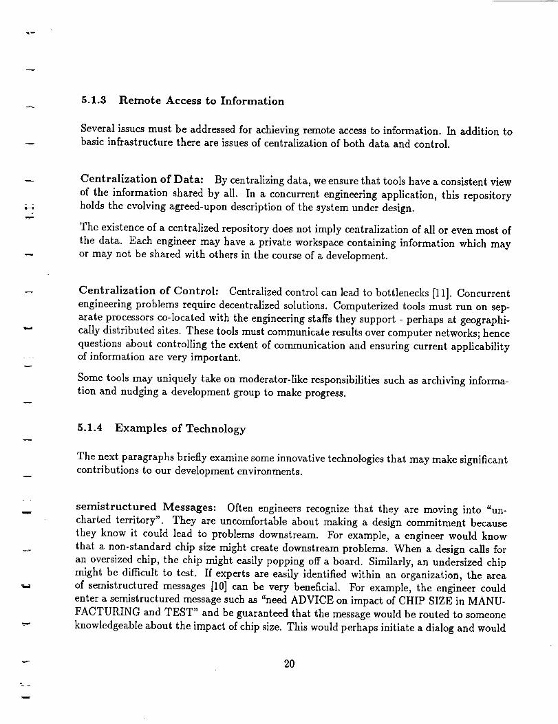
5.1.3 Remote Access to Information
Several issues must be addressed for achieving remote access to information. In addition to
basic infrastructure there are issues of centralization of both data and control.
Centralization of Data: By centralizing data, we ensure that tools have a consistent view
of the information shared by all. In a concurrent engineering application, this repository
holds the evolving agreed-upon description of the system under design.
The existence of a centralized repository does not imply centralization of all or even most of
the data. Each engineer may have a private workspace containing information which may
or may not be shared with others in the course of a development.
W
Centralization of Control: Centralized control can lead to bottlenecks [11]. Concurrent
engineering problems require decentralized solutions. Computerized tools must run on sep-
arate processors co-located with the engineering staffs they support - perhaps at geographi-
cally distributed sites. These tools must communicate results over computer networks; hence
questions about controlling the extent of communication and ensuring current applicabilityof information are very important.
Some tools may uniquely take on moderator-like responsibilities such as archiving informa-
tion and nudging a development group to make progress.
5.1.4 Examples of Technology
The next paragraphs briefly examine some innovative technologies that may make significant
contributions to our development environments.
Ei
semistructured Messages: Often engineers recognize that they are moving into "un-
charted territory". They are uncomfortable about making a design commitment because
they know it could lead to problems downstream. For example, a engineer would know
that a non-standard chip size might create downstream problems. When a design calls for
an oversized chip, the chip might easily popping off a board. Similarly, an undersized chip
might be difficult to test. If experts are easily identified within an organization, the area
of semistructured messages [10] can be very beneficial. For example, the engineer could
enter a semistructured message such as "need ADVICE on impact of CHIP SIZE in MANU-
FACTURING and TEST" and be guaranteed that the message would be routed to someone
knowledgeable about the impact of chip size. This would perhaps initiate a dialog and would
2O

gl;
lead to a solution in a timely fashion. Note that the message does not identify the message
recipient (or recipients). It is the responsibility of the machine to determine this information
from keywords in the message. The technical challenge lies in developing a -specific vocabu-
lary that can be used for the semistructured messages. The strength of this approach is that
it is an small incremental step beyond current communications protocols (e.g., distribution
lists in email, news subscriptions) and hence is easily achievable. The weakness of the ap-
proach is that it relies totally on the ability of engineers to be sensitive to potentially costly
design decisions.
Concurrent Engineering Support: At RPI, an emphasis has been placed on using
object-oriented database technology to control concurrent editing of evolving designs. They
are working on the problems of partitioning design data into coherent units to which changes
can be applied and for which versions can be associated with different versions of the total
design. The Palo Alto Collaborative Testbed (PACT) [2] integrates four extant concur-
rent engineering systems into a common framework. Experiments have explored engineering
knowledge exchange in the context of a distributed simulation and redesign scenario. The
strength of these approaches is that they address coordination aspects of multi-user problem
solving. This focus is significant for managing interactions in large organizations. Smaller
more focused teams will shift the design bottleneck more toward unrecognized impact aware-
ness and less toward missing information from team members.
Process Modeling Another approach builds symbolic models of some aspect of an enter-
prise or process. These models serve as the glue which holds a suite of tools together. For
example, enterprise integration has largely focused on symbol models of the manufacturing
environment. Individual nodes in these models, might serve as personal assistants for people
in-the-loop or might carry out some tasks (e.g., a task on the manufacturing floor) them-
selves. One example of this work is MKS [9], a framework for modeling a manufacturing
environment. Their emphasis has been on creating computerized assistants (i.e., small mod-
ular expert systems) which can interact directly through a dedicated message bus or through
shared databases. At MCC, a CAD Framework initiative [1] provides tool encapsulation (i.e.,
creating a layer of abstraction between tool and user), task abstractions, design tracing, and
process placement and control in a distributed, heterogeneous computing environment. It
has been used for compiling and linking a large CAD tool composed of approximately 300
modules. A number of systems use a planning metaphor for modeling a process. For ex-
ample, ADAM [6] unifies a number of design automation programs into a single framework.
The focus is on custom layout of integrated circuits. ADAM handles design decisions at
a very course grain level. It plans activities and resources to be used and determines the
parameters for each tool invocation. It then relies on the tools acting intelligently in concert
even though little information is passed between them. Recent USC work has focused on
synthesis from VHDL behavior level down to netlists for input to place and route tools.
21

=
w
Li .
V_
L,
tn_
L_
_m
In the software development arena, plan recognition techniques [4] have been used to plan
and execute sequences of commands using knowledge of process actions. In this "assistant"
approach, programmers supply decisions which are beyond the scope of the machine assistant.
5.2 Requirements for Tools
Tools can address either direct productivity-oriented (e.g., synthesis which transitions be-
tween levels of abstraction - specification to design, data flow to ASIC, high level language
code to machine code) or evolution-oriented (i.e., manipulation of information without chang-
ing abstraction level) needs.
While computer-aided software engineering (CASE) promises substantial improvements and
while considerable activity goes on in the research community, substantial portions of engi-
neering has not yet benefited in significant ways. Tools have limited notations for expressing
complex system concerns. For the most part tools have their origins in methodologies for
software design and do not adequately cover full life-cycle considerations. Moreover point
solutions for specific tasks (e.g., reliability analysis, maintainability analysis, availability
analysis, behavioral simulation, life cycle cost models) are not well-integrated.
To achieve computer-aided improvements covering all of the above concerns, we need tools
that are additive, have an open architecture, are formally-based, and are designed for evo-
lution support. Tools that are additive allow users to gracefully fall into lowest common
denominator (e.g., simple text editing) environments. Tools that have an open architec-
ture can be tailored to special processes, empowered with domain-specific solutions, and
can be easily extended as technology moves forward. Formally-based solutions allow for
adequate expression of engineering constructs - terminology, behavior restrictions, interac-
tions with the environment. In addition, formal approaches support requirements reuse, and
can effectively produce secondary artifacts (e.g., simulations, trade-off analysis, test plans,
documents) derivable from primary engineering constructs.
5.2.1 Examples of Technology
We briefly mention three areas where there is active investigations that can dramatically
change the ways tools help us with system development.
Design Assistants: Design Assistants take the view that it is possible to automate some
design decisions or at least offer on-line advice on design decisions. The manufacturing
or testing expert is now replaced with a program. The ARPA Initiative on Concurrent
Engineering (DICE) effort contains several examples of this approach. DICE's goal is to
22

-=
create a concurrent engineering environment that will result in reduced time to market, im-
proved quality, and lower cost. The DICE Design for Testability (DFT) Advisor contains
three components. A test specification generator helps engineers select a test strategy con-
sistent with sponsor requirements and project constraints; a test planner finds alternative
ways to test the components in a hierarchical design early in the design process; a test
plan assessor uses quantitative metrics for evaluating the test plans. The DICE Design for
Manufacture/Assembly system is a rule-based expert system with several components for
printed wire board design. It advises board engineers on manufacturability based on specific
board geometric and functional requirements and on assembly based on guidelines and cost
estimation. Our concerns with the design assistant approach are that it requires a substan-
tial investment to implement, significant maintenance is required since the domain is not
stationary, and integration with pre-existing synthesis tools is problematic.
w
Thermometer Displays: The goal of thermometers is to dramatically increase engineer's
awareness of unit cost and life cycle cost. Thermometers display cost, schedule, producibility,
reliability, and supportability estimates for a given partial design. Thermometers address an
important ingredient of the solution; they help to mitigate the downstream cost associated
with uninformed design commitments. Today's engineers have difficulty in giving adequate
consideration to the manufacturing, verification, and support impact of their decisions. The
technology is available for providing engineers with immediate feedback on this impact.
Credit-Blame Assignment Assistance: This approach aims at improving designs by
finding specific flaws and tracing them back to originating decisions which can be retracted
and/or avoided in subsequent design sessions. Domain independent and domain dependent
approaches have been considered.
A domain independent approach is the use of constraint propagation [cite Steele]. Depen-
dency networks keep track of the assertions which lead to some conclusion. If a conflict
occurs, original assertions can be revisited and modified without having to redo computa-
tions having no bearing on the conflict.
The ARIES system contains a constraint propagation system that is used for enforcing non-
functional requirements and for managing mathematical, logical, or domain-dependent engi-
neering interrelationships. Types of nonfunctional requirements include storage (e.g., mem-
ory), performance (e.g.,mtbf, response-time, processing-time, accuracy), physical (e.g, power,
size, weight), and operational-conditions (e.g., operational-temperatures, corrosivity, antic-
ipated wind-speeds). These properties are higly interrelated and severe requirement errors
occur from overlooking these relationships. A constraint propagation system addresses this
problem by performing local propagation of values and various forms of consistency check-
ing. Propagation occurs bi-directionally through propagation rules connected to nodes in
23
w

w
constraint networks. An underlying truth maintenance system is responsible for contradic-
tion detection, retraction, and tracing facts back to originating assertions.
This works in the following way. Engineers enter values for various nonfunctional characteris-
tics. The constraint processor uses a constraint network to compute additional characteristics
based on the values supplied by the engineer. The constraint processor detects contradic-
tions between requirements (e.g., 10mhz resolution can not achieved in 40 usec processing
time) and indicates what additional information is required in order to enable the constraint
processor to compute the value of a given characteristic (e.g., "in order to compute positional
error, you need to establish sensor error, sampling rate, and acceleration characteristics of
the aircraft").
It is instructive to contrast this approach to the the thermometers approach. Thermometers
assume uni-directional propagation (e.g., from design parameters to cost). Constraint prop-
agation makes no assumptions about the order or direction of computation, but does require
the availability of underlying formulas or logical dependencies which may not be available
(e.g., while it may be possible to deduce signal resolution from processing-time, one can not
deduce board components from unit cost specification). Our view it that an appropriate mix
of these two notions can provide substantial feedback to engineers on the ramifications oftheir decisions.
Domain dependent initiatives have addressed this issue as well. FAD [7] uses information
from earlier VLSI designs to determine resource interactions, perform credit-blame assign-
ments, and determine how early decisions in the previous iteration affect later design deci-
sions and ultimately the resource usage of the solution. These approaches require explicitknowledge of the connections among parameters.
5.3 Summary of Tools and Environment Issues
The road to achieving increased productivity and well managed efforts follows evolutionary
steps in which careful measurements determine what works and what does not work. This
view is important because without it we miss one of the key ingredients.: We must specifically
create technologies (architectures, methodologies, environments) that are responsive to thechanging technology base both now and into the future.
24

= _
IT
6 Conclusions and recommendations
6.1 Iterative Requirements Refinement
In order to reduce risks, we recommend committing to iterative requirement refinement. The
complexity of the systems we build today makes it almost impossible to acquire requirements
in a vacuum. Ill-composed or misunderstood requirements may lead to specifications and
implementations which do not match end-user needs. By encouraging iterative user/engineer
interaction and by demonstrating system capability even during requirements analysis, we
will develop systems that reflect real end-user needs. It is critical that we balance three things
for successful iterations: using available design fragments (the "State-of-the-Shelf"), rapidly
fabricating interfaces for gluing fragments together, and careful crafting of the requirements
subset that is tackled in a given cycle.
6.2 Life Cycle Cost Awareness
We recommend elevating engineering awareness of the impact on cost, schedule, and risk.
The current practice often ignores these parameters as a form of simplifying assumption -
get a functional description, then retrofit it to meet cost, schedule, risk constraints. This is
the wrong way to simplify. Imposing these constraints early on greatly reduces the design
search space and avoids subsequent errors.
6.3 State-of-the-Shelf Approaches
During the three to four years required to execute the conventional development processes,
the end-users and engineers get locked into system paradigms that are continually based
on emergent technology trends. When engineers respond to stringent system functionality,
performance, and cost restrictions by targeting next generation state-of-the-art technology,
they introduce tremendous uncertainty - inadequate tool and model support, unknown sys-
tem capabilities, and poorly understood requirement interactions. In the past this may have
been the only alternative. However, in today's environment, engineers need to seriously in-
vestigate the availability of on-the-shelf solutions. By considering cost/performance tradeoffs
engineers will be opting for the on-the-shelf solutions.
25

6.4 User-centered Tool Selection
The way that many design organizations function also contributes to the cost and schedule
risks of the conventional design process. Organizations may not maintain information on the
current market trends of development support tools. Consequently, either the organization
spends considerable time and effort up front selecting tools and technology, or it uses tools
and technology that have less capability than required. We recommend empowering devel-
opers by making tool selection and investigation an intrinsic part of in-cycle developments.
w
6.5 Open Heterogeneous Environments
A point solution provided today will not necessarily address the design issues faced in five
years. A single initial vision will not likely accommodate a wide range of future entrants in
the development technology arena. Design environments will need to be truly open and will
need to support a rich mixture of heterogeneous tools.
6.6 Team Composition
We recommend using narrow but deep problem decomposition to eliminate unnecessary com-
munication burdens. RDG has experimented with this approach and found that functions
can be handled by small independent groups who manage the evolving system description
from requirements to implementation. Good interfaces on the developed pieces are critical so
that the group can work independently of other teams. This approach avoids the error-prone
"throw it over the wall" mentality that we often see in top down approaches.
-- °
6.7 Unified Test Procedures
We recommend unified test procedures for all process phases (e.g., hardware development,
software development, integration, production). Identification of real-world data, validation
and verification questions and scenarios are critical system engineering products and should
be created and linked to system engineering algorithm and architecture commitments.
6.8 Targeting Early Technology Transfer
It very important to begin technology transfer early. Over the years, RDG has worked
extensively with product line efforts within Lockheed Sanders to transition the lessons we
26

w
have learned into company-wide process improvement strategies. As one illustration, we
worked with a Lockheed Sanders component of the Patriot program to introduce rapid
validation cycles into their methodology. Success was demonstrated later in the program.
When hardware designers developed the delivered hardware, integrators were able to couple
production-quality software with the real hardware in just a few days. Technology transfer
occurs when technology receivers are motivated (e.g., they can not build a product with
out the process) and they have confidence in the new processes (e.g., key people in an
organization understand, or better, are engineers of new processes)
7 Remaining Tasks
This paper is a partial fulfillment of our specific tasks on the effort. Over the coming months
we will be conducting several related tasks to round out the study. These tasks include the
following:
• The development of a formal Reaction Jet Driver Specification
• A report on tool interoperability issues
• A report on the interplay between application-oriented and market-oriented processflow
• A high level process diagram.
w
8 Acknowledgments
This article has grown out of the hard work of many technology developers and hard-
ware/software implementors. We wish to acknowledge the contributions of Dr. Webster
Dove and Dr. Cory Myers who have been instrumental in developing rapid development
approaches. Many of the key aspects that we present follow from their comments and rec-
ommendations. Tony Martuscello provided the information on the AIPS example. David
Campagna, Ken Streeter, and Rob Costantino of RGD have made written contributions and
provided key insights to our investigations. The work on the ARIES project was co-developed
with Information Sciences Institute. Specifically, we wish to acknowledge the contributions
of Dr. W. Lewis Johnson (ARISS principal investigator), Dr. Martin Feather, and Kevin
Benner. Other members of the ARms team included Jay Runkel and Paul Werkowski at
Lockheed Sanders. Additional technical direction was provided by Dr. Charles Rich who
has made a significant impact on all of our knowledge-based initiatives.
27

References
i
[1]
[2]
[3]
[4]
[5]
[6]
[7]
[8]
[9]
[10]
[11]
W. Allen, D. Rosenthal, and K Fiduk. The mcc cad framework methodology manage-
ment system. 28th A CM/IEEE Design Automation Conference, pages 694-698, 1991.
M.R. Cutkosy, T.R. Gruber, R. S. Englemore, W.S. Mark, R.E. Fikes, J. M. Tenenbaum,
M.R. Genesereth, and J. C. Weber. Pact: An experiment in integrating concurrent
engineering systems. Enterprise Integration Technology TR 92-02, 1992.
C. Green, D. Luckham, R. Balzer, T. Cheatham, and C. Rich. Report on a knowledge-
based software assistant. In Readings in Artificial Intelligence and Software Engineering.
Morgan Kaufmann, Los Altos, CA, 1986.
K.E. Huff and V.R. Lesser. The GRAPPLE plan formalism. Technical Report 87-08,
U. Mass. Department of Computer and Information Science, April 1987.
W.L. Johnson, M.S. Feather, and D.R. Harris. Representation and presentation of
requirements knowledge. IEEE Transactions on Software Engineering, 18(10):853-869,
1992.
D.W. Knapp and A.C. Parker. Representation and presentation of requirements knowl-
edge. IEEE Transactions on Computer-Aided Design, 10(7):829-846, 1991.
C.W. Liew, L.I. Steinberg, and C.H. Tong. Use of feedback to control redesign. Pro-
ceedings of the IFIP TC5/WGS.2 Working Conference on Intelligent Computer Aided
Design, 1991.
R. Neches, R.E. Fikes, T. Finin, R. Gruber, R. Patil, T. Senator, and W.R. Swartout.
Enabling technology for knowledge sharing. AI Magazine, 12(3), 1991.
J.Y.C. Pan and J.M. Tenenbaum. An intelligent agent framework for enterprise inte-
gration. IEEE Transactions on Systems, Man, and Cybernetics, 21(6):1391-1407, 1991.
Malone T. W., Grant K. R., Lai K., Rao R., and Rosenblitt D. Semistructured messages
are surprisingly useful for computer-supported coordination. In Irene Greif, editor,
Computer-Supported Cooperative Work: A Book of Readings, pages 311-334. Morgan
Kaufmann, Los Altos, CA, 1988.
R. Wesson, F. Hayes-Roth, J.W. Burge, C. Stasz, and C.A. Sunshine. Network struc-
tures for distributed situation assessment, in Readings in Distributed Artificial Intelli-
gence, pages 71-89. Morgan Kaufmann, 1988.
28

T • _ ,
w _ :
=:.:_- -_ 7- - .
-_ .
;_/APPENDIX _C-
Rapid Development Approaches for
System Engineering and Design
Final Technical Report
September 1993

N94- 25196
/'7"Abstract: _
Conventional system architectures, development processes, and tool environments often pro-
duce systems which exceed cost ezpectations and are obsolete before they are fielded. This
paper explores some of the reasons for this and provides recommendations for how we can do
better. These recommendations are based on DoD and NASA system developments and on
our exploration and development of system/software engineering tools.
1 Introduction
i
w
=
Over the past seven years our Signal Processing Center of Technology and in particular our
Rapid Development Group (RDG) has been vigorously developing and applying engineering
process approaches for complexity management and rapid development. The systems we
target have both hardware and software components and include applications such as elec-
tronic countermeasures systems, signal classifiers, factory floor test equipment, and reaction
jet drivers.
In this report the reader will find an analysis of flaws in conventional methodology, examples
of innovation, and several recommendations for improvement. The key aspects of our multi-
faceted approach build on architectural advances that enable hybrid system development
(i.e., mixes of pre-existing subsystems and new development), process improvement, and
tool developments addressing automation at higher and higher abstraction levels.
As a component of this thrust, we will report on our own prototype tools for require-
ments/specification engineering. Recently on the "Requirements/Specification Facet for
KBSA" project, Lockheed Sanders and Information Sciences Institute built an experimental
specification environment called ARIES [5] 1 which engineers may use to codify system spec-
ifications while profiting from extensive machine support for evaluation and reuse. ARms is
a product of the ongoing Knowledge-Based Software Assistant (KSSA) program. KRSA, as
proposed in the 1983 report by the US Air Force's Rome Laboratories [3], was conceived as
an integrated knowledge-based system to support all aspects of the software life cycle.
Historical Perspective
There are many opportunities for improving engineering processes, but several obstacles to be
overcome as well. We begin by describing the current practice as a baseline. Figure 1 provides
a top level view of "conventional" engineering activities. Engineers acquire requirements
directly from discussions with end-users or through sponsor-authored documents. Engineers
then line up appropriate data sets, extant or emergent algorithms, feasibility studies, and
trade-off studies. They produce refined requirements which give sponsors confidence that
1ARIES stands for Acquisition of Requirements and Incremental Evolution of Specifications.
2

User Feedback
• Refined Requirements
"Documentation
• Validation
Requirements• Function
• Performance
• Power, Size ....
"R&M
• Interfacing
Data Sets
• Training Data
• Test Data
• Data Modelsw.
SystemAnalysis
Consl]'aJnts
Algorithrn Architectural
Development _finition
AlgorithmicFormulation
Top-Level Design
HW/SW Partitioning
Test Procedures
•Real-world data
"Syrdhetic scenarios
Figure 1: System Engineering Activities
the right solution will be built.
System analysis is the process of describing system functionality and managing constraints,
but avoiding premature commitment to particular implementations. Engineers match func-
tional and nonfunctional (e.g., performance, power, size, reliability) requirements against
known system and component capabilities. Since the process today is largely informal, it is
very difficult for engineers to avoid duplication of work (e.g., re-doing back-of-the-envelope
trade-off calculations, re-inventing architectures and design solutions) or creating errors in a
descriptions. Even well thought out specifications may contain missing references, ambiguous
terminology, and other forms of inconsistency.
Engineers generate algorithmic formulations and top-level designs which are used to initiate
downstream design, manufacture, and deployment. Additionally, they identify the real world
data and synthetic scenarios necessary for conducting downstream system verification.
Engineers produce textual requirements documents, describing the characteristics of the
system to be built. However, such documents are themselves but a means to achieve a
more fundamental goal, namely communication of requirements to engineers and sponsors
(end-users, procurement agents, etc.) and sponsors in related systems. In fact engineering
media - diagrams, outlines - used along the way toward producing a written document can
be extremely informative. Simulations in many forms and executable prototypes are another
useful product, both to help communicate requirements and to validate the accuracy of those

w
requirements.
Forced Early Commitments:
As we move into implementation phases, we note that the conventional development cycle is
really a collection of discrete sequential steps (see Figure 2). Each step establishes a baseline
and entails specific commitments. To manage large team coordination and to reduce schedule
risk, engineers freeze implementation choices as early as possible - prior to partitioning of
design tasks to members of a development team. For example, engineers may prematurely
select a CPU, a sensor component, an algorithm, or an electronics part. Frequently, these
implementation decisions are made before the system requirements have been fully analyzed
and understood.
To ameliorate the effects of unforeseen, or poorly understood, requirements, system engineers
impose design margins (e.g., extra memory, extra throughput, stringent power and size
restrictions). The rationale behind these margins being that some physical components will
exceed expectations and some unforeseen problems can be corrected by subsequent margin
adjustments or, as a last resort, by writing new software whose functionality crosses physical
system boundaries. Unfortunately, to achieve the margins mandated, engineers frequently
introduce additional technical and schedule risk since now the required capabilities push
even harder against the edge of achievable performance, power, and packaging.
Fundamental Problems:
There are several fundamental problems inherent in the "conventional" system development
process. While the well-documented reasons for long development cycle times are many
and varied, four significant flaws characterize the state of the practice: arms-length valida-
tion, rigidity in process and tool selection, isolated design activity, and performance-driven
developments. Unfortunately, all contribute to long and costly development cycles.
w
A rms-length Validation
A key reason for end-user disappointment with a product is that during a long devel-
opment cycle, end-users receive incomplete informal information on how the system
will perform; once field and acceptance testing begins, end-users can be "surprised".
Management can not directly observe development and hence institutionalizes control
regimes which take on a life of their own. Unfortunately, in using these "arm's length"
regimes, the best efforts of interested observers may fail to get at the real requirements
- requirements that can only be accurately stated when end-users have the opportunity
to interact with actual system implementations.
If a surprise requirement is uncovered and a corrective action is taken (e.g., utilizing
software that will achieve the design margins), this often occurs late in the development
cycle when typically the program is fully staffed at the most expensive portion of its
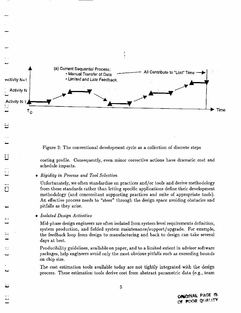
•_-ctivity N+I
Activity N_=_
Activity N- 1
-.,_ T o
(a) Current Sequential Process:• Manual Transfer of Data• Limited and Late Feedback
..__--------- All Contribute to "Lost" Time
• w • W
• al •
F.- Time
w
w
w
L
w
= .
_=
= .
w
Figure 2: The conventional development cycle as a collection of discrete steps
costing profile. Consequently, even minor corrective actions have dramatic cost and
schedule impacts.
Rigidity in Process and Tool Selection
Unfortunately, we often standardize on practices and/or tools and derive methodology
from these standards rather than letting specific applications define their development
methodology (and concomitant supporting practices and suite of appropriate tools).
An effective process needs to "steer" through the design space avoiding obstacles and
pitfalls as they arise.
Isolated Design Activities
Mid-phase design engineers are often isolated from system level requirements definition,
system production, and fielded system maintenance/support/upgrade. For example,
the feedback loop from design to manufacturing and back to design can take several
days at best.
Producibility guidelines, available on paper, and to a limited extent in advisor software
packages, help engineers avoid only the most obvious pitfalls such as exceeding bounds
on chip size.
The cost estimation tools available today are not tightly integrated with the design
process. These estimation tools derive cost from abstract parametric data (e.g., team
w
u
OIIi_NAL PAGE l_
0$ pOOR Qt_,_.!.tTY

ptures
V. " es[
creates
Figure 3: An engineer-centered model for the adaptation of architectures, processes, and
design environments
PRECEDING PAGE BLAr;K NOT i:}: L'_ED

Problem
Validation
Rigidity
_ Isolation
Drivers
Illustration of Approach Elements of the solution
(section 2) (section 3)
AIPS RJD Arch. Process Envir.
X
X
X
flexible
cost-driven
heterogeneous
information
x reuse
Z
Figure 4: Roadmap for the report
People initiate change from modifications at any point in the diagram. Architecture issues
include availability of reusable components and careful attention to modularity (fire walls
and internal health management) and interconnection issues.
Process requirements drive the need for modifications to the Design Environment (e.g., new
point solution tools and new software capabilities). Conversely, at some point (the elusive
paradigm shift), we find that the capabilities of new tools dramatically shift our conception
of process.
Throughout the report, we will stress the importance of viewing change management as a
design engineer's activity that is scheduled part part of the development process itself.
Overview of the report
Figure 4 cross references the problems above with descriptions of design data points and
enabling technologies as they are described in the paper below.
In Section 2, we provide case studies of two small effort emphasizing progress that is possible
when we take prescriptive steps to avoid some of the common pitfalls. Section 2.3 presents
a vision of the future through a scenario that is likely to occur within the next four to five
years. Section 3 supports this position by describing our experience and observations on
prevailing industry trends. Finally, in Section 4 we make several specific recommendations
for process improvement.
8

2 Rapid Development Data Points
This section contains two data points in process improvement and a goal scenario.
2.1 /kIPS: A Case Study in Rapid Development
AIPS is a completed digital hardware initiative which illustrates the opportunistic definition
and employment of a heterogeneous design environment and the employment of a flexible
process flow including the development of virtual prototypes for the target system. In this
1991 project, our RDG group implemented a radar pulse feature extractor system in less than
six months. The system's sponsor required an advanced system operating at the 50MHz rate.
An existing prototype board running at 12.5 MHz demonstrated needed functionality, but
could not keep up with the required data rates. To bootstrap the effort, the sponsor furnished
a real world data set useful for validating designs, an interface specification document, and
only the schematic for the prototype board. Hence, RDG faced a severe reverse engineering
task. In addition, scheduling constraints were very tight. The sponsor needed to have a
fielded system within nine months. Final testing would only be possible when the system
was integrated in the field.
During the first three months of the effort, RE)G worked with sponsor system engineers to
explore possible ECL, ASIC, and FPGA solutions. The tight schedule was a major concern.
While ECL and ASIC solutions could achieve the needed speed, they presented a serious
design risk: the commitments made would have to be right, since there would not be time
to start over again. While size might need to be increased with an FPGA approach and
timing would not be optimized, this solution would adjust to changing requirements or
design miscalculations. Results of the analysis were not conclusive, but RDG opted for the
FPGA approach to minimize program risks.
Opportunistic Tool And Process Selection
The engineers were well aware of the need for critical point solution tools to achieve sys-
tem goals. Figure 5 shows a subset of the tools that were available on our Sun platforms.
Although the tools were not all tightly-coupled (i.e., within a unified framework), file-level
transfers of information were easily accomplished. RDG had considerable experience with
all the tools and an awareness of the challenges associated with mixing manual and semi-
automatic efforts to push through a design and implementation within the remaining six
months.
First, RDG generated a work package justification. MacProject, an automated project sched-
uler, was used to set up the program schedule. Figure 6 presents this initial schedule (the
white boxes) and a snapshot of program completeness (the percentages complete illustrated
9
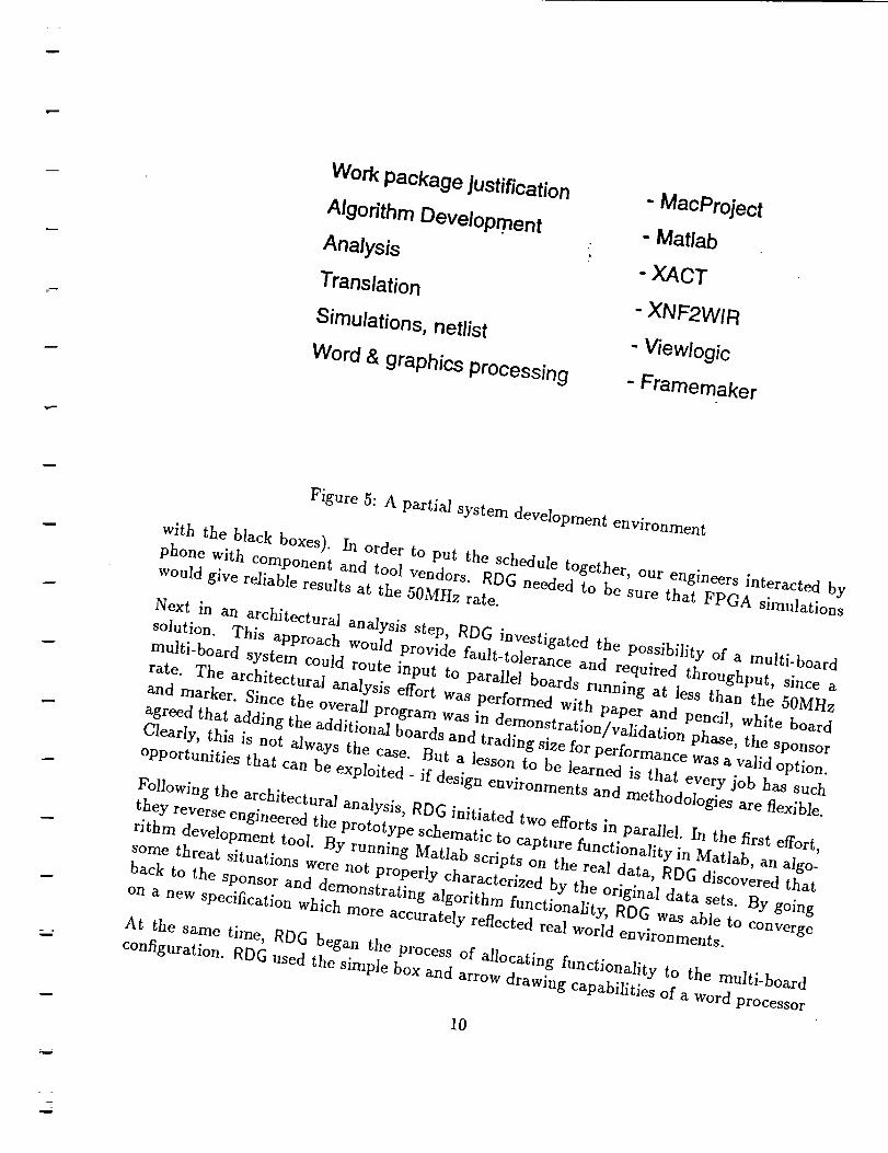
m
Work package justification
Algorithm Developmen t
Analysis
Translation
Simulations, netlist
Word & graphics processing
"MacProject
"Matlab
- XACT
XNF2WIR
" Viewlogic
"Framernaker
Figure 5: A partial system development environment
with the black boxes). In order to put the schedule together, our engineers interacted byphone with COmponent and tool vendors. RDG needed to be Sure that FPGA simulationswould give reliable results at the 50MHz rate.
Next in an architectural analysis step, RDG investigated the possibility of a multi-board
solution. This approach would provide fault-tolerance and required throughput, since a
multi-board system could route input to parallel boards running at less than the 50MHz
rate. The architectural analysis effort was performed with paper and pencil, white board
and marker. Since the overall program was in dem°nstration/validation phase, the Sponsor
agreed that adding the additional boards and trading size for performance was a valid option.
Clearly, this is not always the case. But a lesson to be/earned is that every job has such
opportunities that can be exploited, if design environments and methodologies are f/exible.
Following the architectural analysis, RDG initiated two efforts in parallel. In the first effort,
they reverse engineered the prototype SChematic to capture functionality in Matlab, an algo-
rithm development tool. By running Matlab scripts on the real data, RDG discovered that
some threat situations Were not properly characterized by the original data sets. By going
back to the sponsor and demonstrating algorithm functionality, RDG was able to convergeon a new specification Which more accurately reflected real world environments.
At the same time, RDG began the process of allocating functionality to the multi-board
configuration. RDG used the simple box and arrow drawing capabilities of a word processor
10
Zu

V
u
u
to capture design choices.
Virtual Prototyping
t
Figure 6: Project Schedule Example
/
.Having chosen a baseline, RDG Started down two independent paths to speed up overall
design time. In one, engineers used XACT tools to describe and analyze the FPGAs, and
Jn the other, engineers used Viewlogic tools to generate simulations for the boards. While
there was no on-line traceability between the functional allocation, the Matlab scripts, and
the schematic, RDG bootstrapped construction of the board SChematic by purchasing and
integrating vendor models. The two independent design efforts were automatically linked
through Xillnx's XNF2wIR which translates XACT FPGA descriptions to Viewlogic format.The resulting Viewlogic description is an example of a virtual prototvpe 'made up of a mixture of hardware or software fragments, an executable mode/
By using the virtual prototype, RDG identified errors in the external interface specification.
The specification incorrectly set the number of clock cycles for the handshaking protocol
between the platform control system and the signal processing subsystem. RDG used the
virtual prototype to demonstrate the problem to the sponsor and this helped convergenceon an improved interface Specification.
Progress continued as RDG used Viewlogic tools to generate board layout placement. This
placement needed to be checked for thermal required data rates. While analysis tools were
11 ONG1NAL PAGE IS
OF I_:)OR QUALITY

rb#
available and might have been helpful at this point, RDG weighed the cost and schedule im-
pact of tool acquisition and training against the value-added to the program. The engineers
could not justify utilizing these tools. Rather, RDG relied on manual inspections. Clearly,
more automated verification would have been desirable, but this was not a justifiable optiongiven other development constraints.
When the analysis was completed, RDG electronically sent Viewlogic-produced netlists to a
board fabrication vendor. When the completed boards were received at Lockheed Sanders,
our operations department manually assembled them using RDG's schematic. Each board
was individually tested first at 33MHz (a sufficient rate to meet performance requirements
using four boards) and then at 50MHz (the desired target rate for a single board). Finally, the
sponsor placed the boards in the fielded system. While our system had met its acceptance
test criteria, the sponsor discovered that they had a problem: the AIPS system did not
correctly identify the features for an unanticipated class of pulse train types.
The Payoff for Virtual Prototypes
RDG needed to find a way to identify and fix the problem. Fortunately, the control system
captured data at the entry and exit points of the AIPS subsystem and RDG was able to run
this data through the virtual prototype. This identified the problem as an inappropriate
threshold setting and RDG used the virtual prototype to isolate the problem. This step by
itselfjustifled our choice of FPGAs. Engineers found a modification entry point only slightly
upstream from the point at which the error was discovered. Using XACT, RDG created
new PROMS which reprogramrned the FPGAs and sent these PROMS to the sponsor for asuccessful upgrade of the fielded system.
In summary, the key points to the AIPS initiative included:
• The use of an integrated suite of development tools
• A very flexible approach to requirements acquisition
• The development of a virtual prototype
2.2 Reaction Jet Driver
The Reaction Jet Driver (RJD) is an analog and digital hardware system that is currently
under development. The RJD will interpret commands from a flight control system and
energize two solenoids to independently open and close valves which control reaction control
system fuel and oxidizer flow within a thruster. The RJD features health management
capability and will incorporate flight safety design features. RJD is being developed in two
phases. Phase I is a prototype system. This single jet system is intended as a precursor to a
12

R
w
w
w
£
Phase II, fully engineered system for initiating and monitoring jet firings for a wide vari/ °fplatforms. The multi-phase effort illustrates Several
_ area of architectures and process flow. Points for process improvement in 1Requirements Acquisition
The RJD prototype requirements evolved OVer several
dition to defining performance requirements months in the spring of
s/platforms for the d._ and Physical constraints, the analysis centere,• quest_ions. For examD1 .... .onseveral market-oriente
ch_°abJhty, itwas ;.... wor_. Whilewereco,-.e,,_eneedeatoident. 1993..Inac
new platforms. It ""por_ant to identify th .... galz,.d the need to _ lfy potenhal instal- -" eo_entlal ins ,-,:-- . develop health ,_:_, .
e-o,ua points ",__,1-_ . **,_la_al/]Was also important to layout a strategy for h, v',ans mr existing or
a form of virtual prototyping that extends across multiple programs.With all these concerns in mind, promotion of our technology _
for the RJD. we Came up with the following list of essential requirements
• Rec°ver!/Prom Failure: The prototype will recover from a single device failure on
oxidizer or fuel paths. The system shall be able to continue to control the solenoids inthe event of this Single localized failure.
• Independent Control: The prototype will be capable of independently controlling theoxidizer and fuel solenoids.
• SUpport Diagnostics: The RJD electronics wi//SUpport diagnostics to test the capabil.ities of the RJD subsystem to perform Specific firing sequences.
• Perform Initialization Built_In_Tes t (perform-lBlT):
Test is a process Which operates in the Startup Mode of the system and tests forRJD readiness. Perf°rm-Initialization.Built.in.
• Perform Continuous Built-In-Test (Perform-CBITj: Perf°rm-C°ntinuous.Built_in.Test
is a process Which operates in the NOrmal Mode of the system to continuously test theRJD operation and manages any error signals from RJD components.
• Determine Shorted Load During Jet Nin'ng Determination of ShortedVehicle Health Management concern. A Shorted load a load is also a
Reporting of this condition will be required may indicate a lack of jet firing.possible jet selection W°rk-arounds. for an understanding a
• Pressure Indication of jet integrity and
Processing: The RJD will process Pressure indications coming from
a pressure transducer in the jet chamber. Processed transducer signals will be digitized
and can either be stored in the digital circuitry or transmitted directly via the 1553
bus.
i3
_NAL PACIE I_
OF POOR QUALITY

• Solenoid End Of Useful Life (Solenoid-EOUL): This is a definite goal for the final
system, but will not be a capability of the prototype effort. The Capability to predict
solenoid-EOUL will be explored during prototype development. Degraded solenoid
performance has been observed immediately prior to solenoid failure. The degraded
performance has been identified in the SOlenoid turn-on current Waveform. The means
of determining when a solenoid has reached the end of its useful life prior to its failure
is being researched. Specific phenomenon seen in the solenoid turn-on current have not
been conclusively documented. Hence, the contractor shall consider Solenoid-EO[/k to
be an investigation issue but not a capability of the prototype. In support of post flight
evaluations and potential on-board vehicle health management needs, the prototype
shall effectively record as a minimum solenoid activation signatures for every 50th firing
of vernier jets and every 3rd firing of primary jets. It is estimated that in the Course
of a typical mission the vernier jets will fire up to 5000 times while the primary jetswill fire approximately 300 times.
In phase II, we will re-open many requirements issues as we move tOWard a fully engineered
system. Note that many typical hardware nonfunctional requirements (e.g., power, volume,
weight, environmental stress) are *NOT* in the above list. This is an intentional omission.
The prototype addresses health maintenance and a re-engineering of analog-based control
to a digital logic approach. This does not mean that other nonfunctional issues are totallyignored. Part of our approach has been to select high performance COmponents whenever
possible and to specifically record design decisions which will be subject to change whenupgrades are necessary.
Conceptual Design
Since, the digital circuitry appeared to be straight forward, we initiated the design with aheavy concentration on the analog portion of the system.
To a first approximation, RJD is a pair of "smart" switches. This concept is shown in Figure
7. Note that a single switch can be modelled as two series switches in parallel with two more
series switches. We choose this configuration due to the major design concern of preventinga failed switch device from powering a solenoid. This concern is heightened since the most
common failure mode for semiconductor power-switching devices is a main current path low
impedance connection. To avoid this sort of failure mode, we selected a series connection oftwo p°wer-switching devices.
At a conceptual level, the architectural COmponents of this design consist of primary ener-gizing paths, cross-over networks, and the controlling digital circuitry.
• The Prirnar! I Energizing Path
14

1553
bus
?
,/I
!
+28V (disabled during BITE)
BITEControl
FUEL SOL.CURRENT
fFUELDIRECT
FUEUOXCROSS1553
INTERFACE
ANDCONTROLLER OX/FUEL CROSS
OX DIRECT
A/D
OXSOL. ?
CURRENT / A/D
PRESSURE ? _OMPARATOR
PRESENT / ORA/D
FUELSOLENOID
Figure 7: Top level view of RJD
15

The primary energizingpath is a collection of four power-switching devices. Each
solenoid pair will have its own primary energizing path to be used the majority of
the time for energizing the solenoid. This satisfies the a specification for independent
control of solenoid circuits.
• Cross-over Networks
Failure recovery is provided in the event of either a power-switching device failure on
both device paths or a failure resulting in an inability to command the four main devices
in one of the other primary energizing path. The design contains an two additional
sets of two pass elements in series connecting the oxidizer and fuel main energizing
paths. These series connections form a network which allows the energizing of either
solenoid from a redundant energizing path.
• Digital Circuitry
Conceptually the digital circuitry divides into three parts: a controller, digital storage,
and 1553 bus interface. The controller will provide control signals for sampling and
addressing needed by the analog and power-switching circuitry. The storage will retain
all pertinent mission information for later processing. The 1553 bus interface will
provide for communications with the flight control system.
Each of the above three modules can be instantiated through many choices. For example,
we have selected Mosfets for the primary energing paths and cross-over network modules
and have selected Xilinx FPGA's for the digital side.
R2D upgrades
The prototype should be seen as an initial entry for a family of RJD realizations which play
well with system and subsystem-level vehicle health management strategies.
For example, a multi-jet RJD configuration may consist of several analog driver printed
circuit boards used in conjunction with a single controller board. This option will save
space and reduce digital software overhead since all communications are handled by a single
controller. In addition, the analog driver and controller boards can be contained within a
single card cage simplifying the construction. Note that the modular approach we have taken
in our design has successfully segmented the digital versus analog issues requisite for such
implementations.
It is envisioned that subsequent development will benefit from good predictive capabilities for
Solenoid-EOUL. This will enable local or flight control system management of jet firings to
maximize overall system effectiveness and reduce maintenance costs. By recording solenoid
signatures and other life-cycle histories on-board, we have taken a first step toward providing
sufficient diagnostic information flow to centralized or distributed situation assessment and
risk management processors.
16

Another capability to be explored is the introduction of-redundant fault tolerant 1553in-terface configurations. Specifically,we needto understand the throughput impact of usingquad-redundant interfacesin concertwith RJD's.
When implementation is finishedthis fall, the RJD will serveasa starting point for a numberof critical investigations.
In summary, the key points to the RJD initiative included:
• A highly iterative approach to requirements acquisition
• An exploration of analog engineering methodologies
• The tension between state of the shelf engineering and market-driven high performanceforces
2.3 A Vision for the Future
Figure 8 illustrates several key features of the typical flow of design information in a future
scenario. Much of the process flow mirrors that of the AIPS and RJD efforts, but the design
environment has dramatically shifted the operating point toward more effective machine-
mediation. Engineers work from statements of need, mission descriptions, conditions in the
environment of the proposed system, requirements for new systems or perhaps descriptions
of existing systems which are targeted for upgrade.
Design Environment
As a first step, the engineer identifies an appropriate tool set for handling the design and
development. The expectation is that there will be multiple entries for each type of required
tool and that tool selection will be driven by the needs of the specific application as these
needs flow down to methodological commitments. The resulting tool set will probably con-
tain one or more system engineering requirements capture and traceability tools, software
modeling tools, analog simulation environments, and hardware schematic capture tools.
Since the design environment is tool inter-operability-centered rather than centered on spe-
cific CAD tools or frameworks, the engineer will mix and match tools to optimize engineering
performance. Many of the selected tools will be available on a "fee per use" basis. That is
to say, rather than making outright purchases of tools, companies will pay vendors for time
spent in utilizing the tool. Importantly, this technology lowers the entry cost for both devel-
opers and tool vendors, and with more players in the field we envision a dramatic increasein the rate of innovation.
Substantial Machine Initiative
17

Engineer Derisions
• Select Off-the-Shelf Components• Follow ArchitscturaJ Pdndples
• Use of Reconflgurable
Description of System Behavior
L
E
t ,
E_
Component Description
Library ofProduct Descriptions
Evolving System Description
Data Flow 1
1 I
Figure 8: Achieving substantial process improvement through a free flow of design informa-
tion
As a first design step under machine-mediation, a system engineer and an applications expert
check plausibility of the requirements. This analysis is based on on-line access to application-
specific design rules and extensive databases of related reusable designs. In most cases, the
engineers find systems with very similar requirements descriptions and they quickly assem-
ble pre-existing module descriptions to bootstrap early simulations and basic algorithmic
flow. The engineering staff creates a virtual prototype which they present (either on-site
or over the network) to a sponsor. The sponsor will be able to run simulations and record
observations and concerns in the active project database. For many application, engineers
or sponsors will insert such simulations in distributed (i.e., with players located around the
country) simulations. This cycle will be repeated over and over again as initial virtual proto-
types crystallize into high fidelity simulations and then to mixes of real hardware-in-the-loop
combined with some simulated pieces.
Life Cycle Cost Impact Analysis
As the design proceeds, the design environment provides immediate feedback to engineers
on the life cycle ramifications of their decisions. Specific warnings are provided when a
decision dramatically impacts a life cycle cost. For example, the use of a non-standard
interface will adversely effect reuse and upgrade potential. Similarly, the overloading of a
module may result in matched-pair packaging (i.e., coordinating the production of two or
more boards which are intended to be fielded in tandem) which drives up production and
18
Li

N
field supportability costs. Hence, engineers will be able to perform on-line trade studies on
implementation technologies. The trade-off between performance, throughput power, cost-
centered development schedule, development time, development cost, and life cycle cost will
result in early realization of near optimal designs.
The use of detailed design rules will ensure a smooth transition to producible and easily
fieldable systems. Engineers will express system descriptions in an architectural format which
is tightly coupled (i.e., maximizes the potential for automatic synthesis and traceability) to
implementations and is "reuse-oriented'. Note that this implies a specific commitment to
select "state-of-the-shelf" components which may not immediately achieve full performance
gains. Through this process, engineers will employ a specific reusability methodology to
place new designs into the databases, thereby bootstrapping the next effort where higherperformance may be achieved.
E zm
3 Process Improvement
We are working to bring this vision into common practice and as an initial accessment of
our efforts we can point to architecture, process, and design environment innovations we areexploring.
3.1 System Architecture
Our architectural principles are driven by the need for reusability and upgradeability in oursystems.
3.1.1 Reuse
Engineers can reduce development time by using existing requirements, design and imple-
mentation fragments. We have approached this important component of rapid developmentin two ways:
• Ad hoc Reuse
RDG has had good success with ad hoc reuse such as accessing appropriate hardware
or software descriptions and tools over the internet. The available software, includ-
ing compilers, graphics packages, and editors is often of high quality due to the large
number of users. These ad hoc approaches rely heavily on "word of mouth" among
expert developers for success• We are finding that retrieval issues are not significant
19

_v
despite a lack of formalized trappings around each fragment. This approach is partic-
ularly successful for large relatively self contained software packages with well-defined
functionality (e.g., an object-oriented graphics package).
Scalable modular architectures for reuse
In addition to the above abstract work to providing "reusability order" to system
requirements, we have worked on defining scalable modular hardware and software
architectures which specifically trade performance for reuse and upgrade potential.
For example, in the signal processing arena it is possible to exploit essential pipeline
architectures and to maintain modular integrity albiet at the expense of maximum
performance. Once a processing approach is validated for a particular application, in
subsequent design iterations it can be scaled up (if greater functional performance is
required from newly available technology) or down (if size, weight, or power reductions
are called for). At the same time, we conduct field demonstrations with a system design
which is functionally identical but, perhaps, not form and/or fit replaceable with the
final product.
Workspaces and Folders
We focused our own technology investigations on requirements reuse. The primary
units of organization are workspaces and folders. Each engineer has one or more pri-
vate workspaces -- collections of system descriptions that are to be interpreted in a
common context. Whenever an engineer is working on a problem, it is in the context
of a particular workspace. Each workspace consists of a set of folders, each of which
contains formal and/or informal definitions of interrelated system terminology or be-
havior. Engineers can use folders to organize their work in such a way that they share
some work and keep some work separate.
The folders can be used to maintain alternative models of concepts, which engineers
may choose from when constructing a system description. Each model is suitable for
different purposes. An engineer selects folders by building a new folder that uses the
folders containing terminology he or she is interested in. Capabilities are provided for
locating concepts in related folders, and linking them to the current folder.
As illustration, within the ARIES project, we created a library of domain and require-
ments knowledge is subdivided into folders. The ARm s knowledge base currently con-
tains 122 folders comprising over 1500 concepts. These concepts include precise defi-
nitions of concepts, as well as excerpts from published informal documents describing
requirements for particular domains, e.g., air traffic control manuals.
In summary, we have developed technology which can improve the coordination of multiple
engineers (perhaps representing multiple disciplines) and we have demonstrated the effec-
tiveness of rapid prototyping methodologies which overcome some of the common pitfalls of
conventional large team engineering.
90

3.1.2 Making upgrade explicit: Working with Families of Systems
One aspect of rapid development goals is the use of up front requirements for entire fam-
ilies of systems. In this view, requirements are not developed from scratch and thrown
away. Rather, engineers continually look for opportunities to reuse requirements from other
systems or classes of systems, and to organize their requirements in such a way that they
might be usable for system upgrades and reusable on future projects. These requirements
provide a baseline for subsequent development and upgrades independent of specific hard-
ware/software solutions. That is to say, we recognize and plan on solutions that will change
considerably with time as new technology becomes available and/or the operating point for
person/machine interaction shifts toward higher degrees of automation.
For example, on the RJD work we have continually resisted design choices that would restrict
interoperability with sibling subsystems, or would require total redesign for insertion in
adverse environmental conditions (e.g., severe radiation) and/or limited volume allocation.
When such choices have been unavoidable, we have explicitly documented the status of our
intended system and have planned out specific upgrade paths which can be followed for
future systems with the same functionality.
3.2 Process
Process innovations include iterative requirements refinement, virtual prototyping, and man-
aging isolated design activity.
3.2.1 Iterative Requirements Refinement
This aspect of our commitments supports substantial sponsor/contractor interaction. Iter-
ative requirements refinement involves managing system decomposition, incremental attack
on requirements issues, and the use of flexible technologies with explicit upgrade paths.
The RJD program has exhibited this approach in two ways. First, requirements acquisition
was conducted over a period of time and involved NASA, LESC, and Sanders engineering
in a joint effort to generate a set of requirements that would enable substantial investiga-
tion of digital solutions and vehicle health management capabilities. Second, the selected
implementation technologies assume that requirements may need to be modified far into
the implementation phase. For example, RJD engineers have employed an FPGA solution
initially with an intention of building the final system as an ASIC module.
To use iterative requirements refinement, only a portion of the system goes through the
iteration at a time. That is to say, engineers make explicit choices about how they will
iteratively add more and more capability. For example, the RJD prototype currently under
21

developaddressesvehiclehealth managementissues,but makesno commitment on meetingthe radiation hardness,power,or volumerestrictions associatedwith a fieldedsystem.
For eachiteration, more functionality is added to the existing system. In our experience,there generally are three to six such iterations which last two to four months each. De-sign activities are performed to constrained subsetsof the eventual system requirements.The scopeof each iteration gradually widensas the program matures, and various designfragmentsare tied together.
w
L
3.2.2 Virtual prototyping and/or executable requirements
Rapid development technology enables the end-users to exercise system behavior and flesh
out a good set of requirements. The methodology of allowing for a series of validation
steps during the development process, progressing from a skeletal implementation to finished
product in highly observable steps is essential for validation. A byproduct of such validation
steps is that the need for expensive "paper" control is lessened.
The RJD prototype is of interest since it is forcing us to concurrently deal with analog and
digital simulation capabilities.
3.2.3 Managing isolated design
Complex systems are extremely detailed and work is typically divided among many engi-
neers. This division may correspond to physical system components or it may correspond to
different process phases. In either case, we need to find a balance between coordinated and
independent engineering since there is a significant overlap among the work partitioned outto individuals.
3.2.3.1 Capturing Design Rationale A first approach to this problem is to simply
provide a method for the easy capture of design rationales so that fellow workers (or an en-
gineer reviewing his or her own previous work) can understand the context for decisions. On
the RJD program, we employed database mechanisms which support engineers in expressing
engineering decisions and which enable various members of the team to browse through and
understand these decisions. For example, the items below show the nature of requirements
information expressed for two RJD requirements.
m
(defrequire independent-control
:print-name "Independent Control"
22

:ako flexibility
:text "The prototype will independently control the oxidizer and fuel
solenoids."
:implemented-by separate-circuits-for-each-solenoid
:why-choice "This option was selected to provide for independent
control of
the oxidizer and fuel channels.")
(defrequire recovery-from-failure
:8/(0 fault-tolerance
:print-name "Recovery from Failure"
:text "The prototype will recover from a single device failure on
oxidizer or fuel paths. The system shall be able to continue to
control the solenoids in the event of this single localized failure."
:implementation-alternatives cross-over-network-control
:implemented-by cross-over-network-control
:why-choice "This option was selected to provide for fault
tolerance without
excessive duplication of components and circuits.")
3.2.3.2 Design Assistants: For some aspects of the task it is possible to amplify a
single user's capability to handle large portions of an effort. Design Assistants take the
view that it is possible to automate some design decisions or at least offer on-line advice
on design decisions. The manufacturing or testing expert is now replaced with a program.
The ARPA Initiative on Concurrent Engineering (DICE) contains several examples of this
approach. DICE's goal is to create a concurrent engineering environment that will result in
reduced time to market, improved quality, and lower cost. For example, the DICE Design for
Testability (DFT) Advisor contains three components. A test specification generator helps
engineers select a test strategy consistent with sponsor requirements and project constraints;
a test planner finds alternative ways to test the components in a hierarchical design early
in the design process; a test plan assessor uses quantitative metrics for evaluating the test
plans. The DICE Design for Manufacture/Assembly system is a rule-based expert system
with several components for printed wire board design. It advises board engineers on manu-
facturability based on specific board geometric and functional requirements and on assembly
based on guidelines and cost estimation. The design assistant approach requires a substan-
tial implementation investment. In addition, significant maintenance is required when the
application domain is not stationary.
23

3.2.3.2.1 Design Thermometers: The goal of thermometers is to dramatically increase
engineer's awareness of unit cost and life cycle cost. Thermometers display cost, schedule,
producibility, reliability, and supportability estimates for a given partial design. Thermome-
ters address an important ingredient of the solution; they help to mitigate the downstream
cost associated with uninformed design commitments. Today's engineers have difficulty in
giving adequate consideration to the manufacturing, verification, and support impact of their
decisions. The technology is available for providing engineers with immediate feedback on
this impact. What is required for this approach is to connect easily optainable metrics from
evolving artifacts and to feed them into multi-faceted cost models.
3.2.3.2.2 Credit-Blame Assignment Assistants: This approach aims at improving
designs by finding specific flaws and tracing them back to originating decisions which can be
retracted and/or avoided in subsequent design sessions. Domain independent and domain
dependent approaches have been considered.
A domain independent approach is the use of constraint propagation [cite Steele]. Depen-
dency networks keep track of the assertions which lead to some conclusion. If a conflict
occurs, original assertions can be revisited and modified without having to redo computa-
tions having no bearing on the conflict.
The ARIES system contains a constraint propagation system that is used for enforcing non-
functional requirements and for managing mathematical, logical, or domain-dependent engi-
neering interrelationships. Types of nonfunctional requirements include storage (e.g., mem-
ory), performance (e.g.,mtbf, response-time, processing-time, accuracy), physical (e.g, power,
size, weight), and operational-conditions (e.g., operational-temperatures, corrosivity, antic-
ipated wind-speeds). These properties are hlgly interrelated and severe requirement errors
occur from overlooking these relationships. A constraint propagation system addresses this
problem by performing local propagation of values and various forms of consistency check-
ing. Propagation occurs bi-directionally through propagation rules connected to nodes in
constraint networks. An underlying truth maintenance system is responsible for contradic-
tion detection, retraction, and tracing facts back to originating assertions.
This works in the following way. Engineers enter values for various nonfunctional characteris-
tics. The constraint processor uses a constraint network to compute additional characteristics
based on the values supplied by the engineer. The constraint processor detects contradic-
tions between requirements (e.g., 10mhz resolution can not achieved in 40 usec processing
time) and indicates what additional information is required in order to enable the constraint
processor to compute the value of a given characteristic (e.g., "in order to compute positional
error, you need to establish sensor error, sampling rate, and acceleration characteristics of
the aircraft").
It is instructive to contrast this approach to the the thermometers approach. Thermometers
24

assumeuni-directional propagation (e.g., from designparametersto cost). Constraint prop-agation makesno assumptionsabout the order or direction of computation, but doesrequirethe availability of underlying formulas or logical dependencieswhich may not be available(e.g.,while it may be possibleto deduce signal resolution from processing-time, one can not
deduce board components from unit cost specification). Our view it that an appropriate mix
of these two notions can provide substantial feedback to engineers on the ramifications of
their decisions.
Domain dependent initiatives have addressed this issue as well. FAD [7] uses information
from earlier VLSI designs to determine resource interactions, perform credit-blame assign-
ments, and determine how early decisions in the previous iteration affect later design deci-
sions and ultimately the resource usage of the solution. These approaches require explicit
knowledge of the connections among parameters.
n :
L
3.2.3.3 Tolerance for Inconsistency It is also important to look at the nature of the
information that is to be shared. We have investigated mechanisms that alleviate communi-
cation problems during requirements development by making it possible to mix agreed upon
components with points of view that are held locally in conflict with a team's perspective.
To this end we have developed machine-mediated ways to support separation and subsequent
merging of work products, rather than to force engineers to constantly coordinate whenever
an area of potential common concern is identified. Although consistency is an important
goal for the process to achieve, it cannot be guaranteed and maintained throughout without
forcing engineers to constantly compare their descriptions against each other. One cause of
inconsistency is the employment of multiple models. For example, the RJD behavior can
be described as a smart switch which responds to continuous on-off commands or it can be
more carefully modelled as a device which responds to discrete changes in state which need
to be updated periodically to achieve continuous behavior. Consistency must be achieved
gradually, at an appropriate point in the development process. Nevertheless, it may not be
possible to recognize all inconsistencies within a system description.
3.3 Design Environment Issues
The potential impact of tools on process, suggests that we consider any recommendations in
two waves:
• Policies and procedures for today - given a specific design environment maturity, what
are the best methodologies for system development today? For example, we may
choose to continue with some control-oriented practices because the requisite groupware
technology is not available for enabling observation-oriented improvements.
25

w
• Future directions - how do we transition to more automated processes - more expres-
sive power in modeling and simulation capabilities, effective reuse, improved synthesis
methods, automatic design? For example, our ARIES work demonstrates that with
emerging technology in place, significant change occurs in the following four areas:
- Engineers work with on-line multiple visualizations of complex system descrip-
tions, greatly increasing their ability to understand and manipulate system arti-
facts (e.g., requirements, simulations results, software and hardware implementa-
tions).
- Engineers effectively reuse requirements fragments within entire families of devel-
opments.
- Synthesis and validation based on hybrid combinations of reasoning mechanisms
greatly improve productivity and catch requirements errors. Rapid prototyp-
ing and virtual prototyping based on initial partial descriptions helps reduce the
errors and brings down the cost of subsequent development. Additional consis-
tency checking, propagation of the ramifications of decisions, and requirements
critiquing all play a role in assisting in the development of reliable systems.
- Engineers evolve descriptions in a controlled fashion. Change is inevitable, but
engineers are able to rapidly respond to changing requirements and replay previous
requirements evolutions.
This work is currently experimental, but is well beyond the "toy" phase. It reflects
capabilities that should find there way into commercially available products within the
next few years.
3.3.1 Requirements for Environments
A description of capabilities of existing environments and tools is far beyond the scope of this
report. What we can do however is take a systems perspective and outline essential require-
ments for computerized environments. Key components are support for heterogeneous tools,
local and remote electronic access to engineering data, dynamic cost and schedule models to
support program management, libraries of reusable hardware and software components, and
flexible access to standard hardware and commercial software integrated via standards.
E .
3.3.1.1 Open and Heterogeneous It is essential for the design environment to be both
open and heterogeneous. By open, we mean that the environment permits the integration
of any commercially available tools suited for use in a phase of the development. By hetero-
geneous, we mean that multiple hardware and software development tools (e.g., hardware
26

rilhm _m=gn su_ l_s/gn
Simulation
Iml lm IAce_tan_ SoftwareTest DesignProcedure
veloprnent
ASICJFPGA
I--m I IAlgorithmDesign Func_onadHW, W
Sirnula_n
Functional
Standard Data SlandarddataInten_'m'_go In_n:hange
[ _ I : Mut_-chip Test EquipmentSchematic, ; ModuleModuleand Vendors _BoardLayout
roo gOO 0
Ullllllll]llll I[ III I
BoardTestandPdnted Circuit Sy=demIntografionBoardVondors
Fabral_n Inl_mlk>n andTest
Figure 9: A typical integrated development environment
synthesis, compilers, document production, spread sheets, project management support, re-
quirements traceability) are concurrently supported by the environment, and that there are
display terminals which can access any software application running on any of the host hard-
ware platforms from a single location. As illustration, Figure 9 shows the Lockheed Sanders
integrated development environment that is based on these principles.
This requirement grows out of the recognition that while the development (or re-implementation)
of a tightly integrated (homogeneous) solution is sometimes feasible, from practical consider-
ations we seldom have the luxury to rebuild and tightly couple existing tools. It is important
to recognize that the collection of commercially available tools for supporting engineering
processes is growing rapidly and what we work with today is only the "tip of the iceberg"
for what is possible. As new tools are introduced we need to consider how they will be used
within existing informal or computer-realized development environments.
Product standards such as PDES will help with tool inter-operability. However, no single
description can be expected to handle the intricacies of multiple domains. Individual problem
solvers may make use of idiosyncratic knowledge that need not be shared with other problem
solvers. This position is consistent with recent work on knowledge-sharing (e.g., [8]). We
need sharable vocabularies which convey enough information without requiring it to be theunion of all the internal vocabularies of the individual tools.
27

3.3.1.2 Easy Access to Information Substantial on-line data for making design and
development decisions is readily accessible today, but it is can not always be cheaply and
quickly obtained, nor can it be applied at the right places. The entire system development
process needs to be much more open than is the case today. The benefits are obvious.
For example, sponsors should be empowered to interact with and control the development
because they will have access to substantial amounts of data on how a system will perform
and on what options are available for development. In like manner, engineers should have
access to manufacturing and vendor products and models. Links need to exist to proprietary
and legacy design files so that engineers can economically integrate data into their own work
space. This easy interchange of design information within and across families of systems is
the key to effective reuse.
Concurrent engineering goals can be met through interactive computer models for production
and support costs (and other life-cycle dominant concerns). These models need to be coupled
closely to the engineers' design database. Reflecting life-cycle-cost, power, weight and other
inputs back to algorithm engineers, and system implementors is essential for high quality
design activity.
3.3.1.3 Explicit Notion of Process When a design environment contains some notion
of the process and standard practices, it can provide direction and guidance as work proceeds.
The next paragraphs briefly examine some innovative technologies that are making significant
contributions to our notion of development environments.
Semistructured Messages:
This technology falls between simple infrastructures which route uninterpreted messages
and deeper computation which dispatches on analysis of formalized descriptions of artifacts
and problems. One illustration should be sufficient to make the point. Often engineers
recognize that they are moving into "uncharted territory". They are uncomfortable about
making a design commitment because they know it could lead to problems downstream. For
example, a engineer would know that a non-standard chip size might create downstream
problems. When a design calls for an oversized chip, the chip might easily popping off a
board. Similarly, an undersized chip might be difficult to test. If experts are easily identified
within an organization, the area of semistructured messages [10] can be very beneficial.
For example, the engineer could enter a semistructured message such as "need ADVICE
on impact of CHIP SIZE in MANUFACTURING and TEST" and be guaranteed that the
message would be routed to someone knowledgeable about the impact of chip size. This
would perhaps initiate a dialog and would lead to a solution in a timely fashion. Note that
the message does not identify the message recipient (or recipients). It is the responsibility
of the machine to determine this information from keywords in the message. The technical
challenge lies in developing a specific vocabulary that can be used for the semistructured
28
L

W
w
messages. The strength of this approach is that it is an small incremental step beyond
current communications protocols (e.g., distribution lists in email, news subscriptions) and
hence is easily achievable. The weakness of the approach is that it relies totally on the ability
of engineers to be sensitive to potentially costly design decisions.
Concurrent Engineering Support:
At RPI, an emphasis has been placed on using object-oriented database technology to control
concurrent editing of evolving designs. They are working on the problems of partitioning
design data into coherent units to which changes can be applied and for which versions
can be associated with different versions of the total design. The Palo Alto Collaborative
Testbed (PACT) [2] integrates four extant concurrent engineering systems into a common
framework. Experiments have explored engineering knowledge exchange in the context of
a distributed simulation and redesign scenario. The strength of these approaches is that
they address coordination aspects of multi-user problem solving. This focus is important for
managing interactions in large organizations.
Pi'ocess Modeling
Another approach builds symbolic models of some aspect of an enterprise or process. These
models serve as the glue which holds a suite of tools together. For example, enterprise inte-
gration has largely focused on symbol models of the manufacturing environment. Individual
nodes in these models, might serve as personal assistants for people in-the-loop or might
carry out some tasks (e.g., a task on the manufacturing floor) themselves. One example
of this work is MKS [9], a framework for modeling a manufacturing environment. Their
emphasis has been on creating computerized assistants (i.e., small modular expert systems)
which can interact directly through a dedicated message bus or through shared databases.
At MCC, a CAD Framework initiative [1] provides tool encapsulation (i.e., creating a layer
of abstraction between tool and user), task abstractions, design tracing, and process place-
ment and control in a distributed, heterogeneous computing environment. It has been used
for compiling and linking a large CAD tool composed of approximately 300 modules. A
number of systems use a planning metaphor for modeling a process. For example, ADAM
[6] unifies a number of design automation programs into a single framework associated with
custom layout of integrated circuits. ADAM handles design decisions at a very course grain
level. It plans activities and resources to be used and determines the parameters for each
tool invocation. It then relies on the tools acting intelligently in concert even though little
information is passed between them. Recent USC work has focused on synthesis from VHDL
behavior level down to netlists for input to place and route tools.
In the software development arena, plan recognition techniques [4] have been used to plan
and execute sequences of commands using knowledge of process actions such as build and
release of software artifacts.
29

=
_ IL_
w
Distributed Problem Solving
Several issues must be addressed for achieving remote problem solving. In addition to basicinfrastructure there are issues of centralization of both data and control.
By centralizing data, we ensure that tools have a consistent view of the information shared by
all. In a concurrent engineering application, this repository holds the evolving agreed-upon
description of the system under design.
The existence of a centralized repository does not imply centralization of all or even most of
the data. Each engineer may have a private workspace containing information which may
or may not be shared with others in the course of a development.
Centralized control can lead to bottlenecks [11]. Concurrent engineering problems require
decentralized solutions. Computerized tools must run on separate processors co-located with
the engineering staffs they support - perhaps at geographically distributed sites. These tools
must communicate results over computer networks; hence questions about controlling the
extent of communication and ensuring current applicability of information are very impor-tant.
Some tools may uniquely take on moderator-hke responsibilities such as archiving informa-
tion and nudging a development group to make progress.
u
3.3.2 Requirements for Tools
Tools can address either direct productivity-oriented (e.g., synthesis which transitions be-
tween levels of abstraction - specification to design, data flow to ASIC, high level language
code to machine code) or evolution-oriented (i.e., manipulation of information without chang-
ing abstraction level) needs.
While computer-aided software engineering (CASE) promises substantial improvements and
while considerable activity goes on in the research community, substantial portions of engi-
neering has not yet benefited in significant ways. Tools have limited notations for expressing
complex system concerns. For the most part tools have their origins in methodologies for
software design and do not adequately cover full life-cycle considerations. Moreover point
solutions for specific tasks (e.g., reliability analysis, maintainability analysis, availability
analysis, behavioral simulation, llfe cycle cost models) may not be well-integrated.
To achieve computer-aided improvements covering all of the above concerns, we need tools
that are additive, have an open architecture, are formally-based, and are designed for evo-
lution support. Tools that are additive allow users to gracefully fall into lowest common
denominator (e.g., simple text editing) environments. Tools that have an open architec-
ture can be tailored to special processes, empowered with domain-specific solutions, and
3O

L
t
m
l_t_ .
can be easily extended as technology moves forward. Formally-based solutions allow for
adequate expression of engineering constructs - terminology, behavior restrictions, interac-
tions with the environment. In addition, formal approaches support requirements reuse, and
can effectively produce secondary artifacts (e.g., simulations, trade-off analysis, test plans,
documents) derivable from primary engineering constructs.
4 Conclusions and recommendations
While much of this work remains an art rather than a science, we are confident in making
several specific recommendations.
1. Iterative Requirements Refinement In order to reduce risks, we recommend committing
to iterative requirement refinement. The complexity of the systems we build today
makes it almost impossible to acquire requirements in a vacuum. Ill-composed or
misunderstood requirements may lead to specifications and implementations which do
not match end-user needs. By encouraging iterative user/engineer interaction and by
demonstrating system capability even during requirements analysis, we will develop
systems that reflect real end-user needs. It is critical that we balance three things
for successful iterations: using available design fragments (the "State-of-the-Shelf"),
rapidly fabricating interfaces for gluing fragments together, and careful crafting of the
requirements subset that is tackled in a given cycle.
2. Life Cycle Cost Awareness
We recommend elevating engineering awareness of the impact on cost, schedule, and
risk. The current practice often ignores these parameters as a form of simplifying
assumption - get a functional description, then retrofit it to meet cost, schedule, risk
constraints. This is the wrong way to simplify. Rather, byimposing these life cycle cost
constraints early, we will reduce the design search space and avoids subsequent errors.
3. State-of-the-Shelf Approaches
During the three to four years required to execute the conventional development pro-
cesses, the end-users and engineers get locked into system paradigms that are con-
tinually based on emergent technology trends. When engineers respond to stringent
system functionality, performance, and cost restrictions by targeting next generation
state-of-the-art technology, they introduce tremendous uncertainty - inadequate tool
and model support, unknown system capabilities, and poorly understood requirement
interactions. In the past this may have been the only alternative. However, in today's
environment, engineers need to seriously investigate the availability of on-the-shelf so-
lutions. By considering cost/performance tradeoffs engineers will be opting for the
on-the-shelf solutions.
31

z
E =
.
.
.
.
.
Engineer-centered Tool Selection
The way that many design organizations function also contributes to the cost and
schedule risks of the conventional design process. Organizations may not maintain
information on the current market trends of development support tools. Consequently,
either the organization spends considerable time and effort up front selecting tools and
technology, or it uses tools and technology that have less capability than required.
We recommend empowering developers by making tool selection and investigation an
intrinsic part of in-cycle developments.
Open Heterogeneous Environments
A point solution provided today will not necessarily address the design issues faced in
five years. A single initial vision will not likely accommodate a wide range of future
entrants in the development technology arena. Design environments will need to be
truly open and will need to support a rich mixture of heterogeneous tools.
Team Composition
We recommend using narrow but deep problem decomposition to eliminate unnecessary
communication burdens. RDG has experimented with this approach and found that
functions can be handled by small independent groups who manage the evolving system
description from requirements to implementation. Good interfaces on the developed
pieces are critical so that the group can work independently of other teams. This
approach avoids the error-prone "throw it over the wall" mentality that we often see
in top down approaches.
Unified Test Procedures
We recommend unified test procedures for all process phases (e.g., hardware devel-
opment, software development, integration, production). Identification of real-world
data, validation and verification questions and scenarios are critical system engineer-
ing products and should be created and linked to system engineering algorithm and
architecture commitments.
Targeting Early Technology Transfer
It very important to begin technology transfer early. Over the years, RDG has worked
extensively with product line efforts within Lockheed Sanders to transition the lessons
we have learned into company-wide process improvement strategies. As one illus-
tration, we worked with a Lockheed Sanders component of the Patriot program to
introduce rapid validation cycles into their methodology. Success was demonstrated
later in the program. When hardware designers developed the delivered hardware,
integrators were able to couple production-quality software with the real hardware in
just a few days. Technology transfer occurs when technology receivers are motivated
(e.g., they can not build a product with out the process) and they have confidence
32

t
• !
in the new processes (e.g., key people in an organization understand, or better, are
engineers of new processes)
4.1 Summary
The road to achieving increased productivity and well-managed efforts follows evolutionary
steps in which careful measurements on all of the above recommendations determine whatworks and what does not work. This view is important because without it, we miss the key
ingredient: technologies (architectures, methodologies, environments) that grow with the
changing technology base both now and into the future.
5 Acknowledgments
This article has grown out of the hard work of many technology developers and hard-
ware/software implementors. We wish to acknowledge the contributions of Dr. WebsterDove and Dr. Cory Myers who have been instrumental in developing rapid development
approaches. Many of the key aspects that we present follow from their comments and rec-
ommendations. Tony Martuscello provided the information on the AIPS example. Mark
Lanciault is the chief designer for the RJD work. David Campagna, Ken Streeter, and
Rob Costantino have made significant RDG contributions to numerous programs and have
helped formulate many of the ideas which we present. The work on the Attics project was
co-developed with Information Sciences Institute under contracts F30602-85-C-0221 (Rome
Laboratory sponsor) and F30602-89-C-0103 (Defense Advanced Research Projects sponsor).
Specifically, we wish to acknowledge the contributions of Dr. W. Lewis Johnson (ARIES prin-
cipal investigator), Dr. Martin Feather, and Kevin Benner. Other members of the AgIEsteam included Jay Runkel and Paul Werkowski at Lockheed Sanders. Additional technical
direction was provided by Dr. Charles Rich who has made a significant impact on all of our
knowledge-based initiatives.
References
[1] W. Allen, D. Rosenthal, and K Fiduk. The mcc cad framework methodology manage-
ment system. 28th ACM/IEEE Design Automation Conference, pages 694-698, 1991.
[2] M.R. Cutkosy, T.R. Gruber, R. S. Englemore, W.S. Mark, R.E. Fikes, J. M. Tenenbaum,
M.R. Genesereth, and J. C. Weber. Pact: An experiment in integrating concurrent
engineering systems. Enterprise Integration Technology TR 92-02, 1992.
33

[3] C. Green, D. Luckham, R. Balzer, T. Cheatham, and C. Rich. Report on a knowledge-
based software assistant. In Readings in Artificial Intelligence and Software Engineering.
Morgan Kaufmann, Los Altos, CA, 1986.
[4] K.E. Huff and V.R. Lesser. The GRAPPLE plan formalism. Technical Report 87-08,
U. Mass. Department of Computer and Information Science, April 1987.
[5] W.L. Johnson, M.S. Feather, and D.R. Harris. Representation and presentation of
requirements knowledge. IEEE Transactions on Software Engineering, 18(10):853-869,
1992.
[6] D.W. Knapp and A.C. Parker. Representation and presentation of requirements knowl-
edge. IEEE Transactions on Computer-Aided Design, 10(7):829-846, 1991.
[7]
[81
[91
[10]
[11]
C.W. Liew, L.I. Steinberg, and C.H. Tong. Use of feedback to control redesign. Pro-
ceedings of the IFIP TC5/WG5.2 Working Conference on Intelligent Computer Aided
Design, 1991.
R. Neches, R.E. Fikes, T. Finin, R. Gruber, R. Patil, T. Senator, and W.R. Swartout.
Enabling technology for knowledge sharing. AI Magazine, 12(3), 1991.
J.Y.C. Pan and J.M. Tenenbaum. An intelligent agent framework for enterprise inte-
gration. IEEE Transactions on Systems, Man, and Cybernetics, 21(6):1391-1407, 1991.
Malone T. W., Grant K. R., Lai K., Rao R., and Rosenblitt D. Semistructured messages
are surprisingly useful for computer-supported coordination. In Irene Greif, editor,
Computer-Supported Cooperative Work: A Book of Readings, pages 311-334. Morgan
Kaufmann, Los Altos, CA, 1988.
R. Wesson, F. Hayes-Roth, J.W. Burge, C. Stasz, and C.A. Sunshine. Network struc-
tures for distributed situation assessment. In Readings in Distributed Artificial Intelli-
gence, pages 71-89. Morgan Kaufmann, 1988.
w
L
34
L