Embed Size (px)
DESCRIPTION
go or no-go guage by Bhupesh
Citation preview


Introduction to Visual Basic
Starting visual basic: - The first thing we need to do is open a visual basic program.
From the windows start menu, choose programs, Microsoft visual basic 6.0, and
then Microsoft visual Basic 6.0.
When we start VB, we are taken to the visual basic Integrated Development
Environment (IDE) .This is our programming workbench, the place where we
create our program. The IDE presents what looks like an empty window containing
some dots and a little bar with the wordform 1. This window is a form, the primary
building block of a visual basic application. An application can have many form or
forms.
Over view of Visual Basic 6.0:- Visual Basic 6.0 has some interesting new features
is nothing short of an understatement. Visual Basic 6.0 has so many amazing new
features that overstatement is next to impossible because so much is new in so
many areas. New controls allow our applications to incorporate the look, feel, and
functions of Office 97 applications and internet explorer. No more do we have to
have at least one instance of a control on your form to create controls on-the-fly.
With Visual Basic (VB6) , we can add controls to our project dynamically with
only code , and we can make custom ActiveX controls leaner and meaner than
ever. We can even write server – side applications that use Dynamic HTML
embedded with internet information server DLLs.
The parts of the Integrated Development Environment (IDE):- The Visual Basic
IDE is a collection of menus, toolbars, and windows that make up our
programming workbench. Each part of the IDE has features that effect different
aspects of our programming activity. The menu bar lets us direct the overall
activity and management of our programming. The tool bar enables us to access

much of the menu bar’s functionality through various toolbars buttons. Forms- the
basic building blocks of the VB program- are presented in a form window. We use
the toolbox to add the controls to our project. The project explorer displays the
projects on which are working, as well as different parts of each of those projects.
We browse and set a control, form, and module’s properties within the properties
window. Finally position and view a form or forms onscreen within the form
layout window.
Viewing the IDE: - We can view the Visual Basic IDE in two ways : with the
Multiple Document Interference (MDI) or Single Document Interference (SDI).
MDI view shows all the distinct windows of the Visual Basic IDE as member
windows within one large IDE window.
In the SDI view distinct windows of the Visual Basic IDE exist independently of
each other. There is no master window to contain and provide a unified feel to the
IDE.
Forms and Controls: - In Visual Basic, the forms are the foundations we generally
use to build programs. A form is where we put all things that people interact with
as they use our program. Those things we put on the form are controls, which
enables the people who use our program to do things, such as enter text and click
buttons.
Intrinsic controls: - For the most part, we will a relatively small set of controls
when we program in Visual Basic. However, these controls are very powerful.
With them we can add buttons, check boxes, files and text boxes to our programs.
We can use them to see and read a database. These basic controls are intrinsic
controls, and they are available in every edition of Visual Basic 6.

Visual Basic Project: - In Visual Basic, a project is the group of all the files that
make up our program. These might includes forms, modules (blocks of code not
attached to a form), graphics, and ActiveX controls.
The first thing to keep in mind about a project is that as we create our program,
each form, module, graphic, and ActiveX control are saved as an individual file.
Common file types in a Visual Basic Project:
File type Description
FRM Form
BAS Module
FRX Automatically generated file for every graphic in our
project
OCX Active control
CLS Class module
VBP Visual Basic Project
Properties, Methods, and Events: - Put simply, properties describe objectives.
Methods cause an object to do something. Events are what happen when an object
does something. Every object, such as a form or control, has a set of properties that
describe it. We can see every property for a given control by looking at the
properties window in the IDE.

Common properties of visual basic controls: -
Property DescriptionLeft The position of the left side of a control with respect to its
container.Top The position of the top of a control with respect to its
container.Height A control’s height.Width A control’s width.Name The string value used to refer to a control.Enabled The Boolean (true/false) value that determines whether users
can manipulate the control.Visible The Boolean (true/false) value that determines whether users
can see the control.
Storing information in variables: - While the data is being processed in our
program, it’s stored in temporarily variables. For example if we think of a variable
as cup that can hold various amount of jelly beans; we never know how many jelly
beans are in the cup at any given time unless we look in the cup. The same is true
for a variable. A variable can store values many times.
We create a variable by using the following form:
Dim varname As Datatype
In the above written syntax
Dim is the keyword that tells visual basic that we want to declare a variable.
Varname is the name of the variable.
As is the keyword that tells the VB that we are defining the data type for
variable.

Datatype is the data type of the variable viz. Numeric, String, Boolean, Date,
Object, and Variant.
Math operators: - math operators are used to determine customer bills, interest due
on savings or credit card balances and many other tasks. VB supports a number of
different math operations that can be used in program statements.
Math operations and the corresponding Visual Basic operator symbol:
Operation Operator symbolAddition +Subtraction _Multiplication *Division /Integer division \Modulus modExponentiation ^
Making decisions in program
Most statements in our programs will be assignment statements, but other
statements are important for handling more complex task. These statements are
known collectively as control statements.
One type of control statement is the decision statement. These statements are used
to control the execution of parts in our program, based on conditions that exist at
the time statement encountered. Two main type of statements are:
If……then and select case.

LIMITS:-
Every manufacturing process is a combination of three elements man, material and
machine. A change in any one of them or all of them will results change in
manufactured parts. It is, therefore, obvious that some permissible variation in
dimension has to be allowed to account for variability.
Two extreme permissible sizes of a part between which the actual size is
contained are called limit.
FITS
When two parts are to be assembled the relation resulting from the difference
between their sizes before assembly is called a fit. The fit signifies the range of
tightness or looseness which may result from the application of a specific
combination of allowances and tolerances in the design of mating parts.
Types of Fits
There are three general types of fit between the mating parts
1. Clearance fit— A clearance fit is one having limits of size so prescribed that a
clearance always results when mating parts are assembled.
2. Interference fit — An interference fit is one having limits of size so prescribed
that an interference always results when mating parts are assembled.
3. Transition fit— A transition fit is one having limits of size so prescribed that
either a clearance or an interference may always result when mating parts are
assembled.
The three types of fits are shown in Fig. The disposition of tolerance zones for the
three classes of fit are shown in Fig. 4.2.

TOLERANCES:-

Tolerance is defined as the total permissible variation of a size. It is the difference
between maximum limit and minimum limit of size.
TERMINOLOGY
The terminology used in fits and tolerances is shown in Fig. 4.3 The importantterms are
Basic size — It is the exact theoretical size arrived at by design. It is also called
nominal size.
Actual size— The size of a part as may be found by measurement.
Maximum limit of size— The greater of the two limits of size.
Minimum limit of size— The smaller of the two limits of size.
Allowance—It is an intentional difference between maximum material limits of
mating parts. It is a minimum clearance or maximum interference between mating
parts.

Deviation—The algebraic difference between a size (actual, maximum, etc.) and
the corresponding basic size.
Actual deviation—The algebraic difference between the actual size and the
corresponding basic size.
Upper deviation—The algebraic difference between the maximum limit of size
and the corresponding basic size.
Upper deviation of hole = ES (&art Superior)
Upper deviation of shaft es
Lower deviation—The algebraic difference between the minimum limit of size
and the corresponding basic size.
Lower deviation of hole = El (Ecart Inferior)
Lower deviation of shaft = ei
Upper deviation Lower deviation + Tolerance
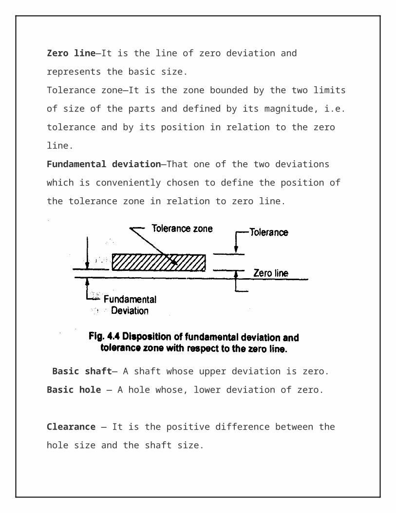
Zero line—It is the line of zero deviation and represents the basic size.
Tolerance zone—It is the zone bounded by the two limits of size of the parts and
defined by its magnitude, i.e. tolerance and by its position in relation to the zero
line.
Fundamental deviation—That one of the two deviations which is conveniently
chosen to define the position of the tolerance zone in relation to zero line.

Basic shaft— A shaft whose upper deviation is zero.
Basic hole — A hole whose, lower deviation of zero.
Clearance — It is the positive difference between the hole size and the shaft size.
Maximum clearance—The positive difference between the maximum size of a
hole and the minimum size of a shaft.
Minimum clearance—The positive difference between the minimum size of a
hole and the maximum size of a shaft.
DESIGNATION OF HOLES, SHAFTS AND FITS
A hole or shaft is completely described if the basic size, followed by the
appropriate letter( italic or roman- usually italic preferred) and by the number of
tolerance grade , is given. For example- a 25mm H-hole with the tolerance grade
IT8 is given as
25mmH8 or 25H8
Similarly a 25 mm f shaft with the tolerance grade IT7 is given as
25mm f 7 or 25f 7

A fit is indicated by combining the designations for both the hole and shaft with
the hole designation written first, regardless of the system (i.e. hole based or shaft
based). For example
25H8-f 7 or 25H8/f 7 or 25 H8 f 7
FUNDAMENTAL DEVIATION:-
As stated that setting of tolerance values is not a of itself sufficient to define
particular limit, the position of the tolerance zone relative to the basic size of the
feature must also be specified. This is done by establishing fundamental deviations
which are difference between the basic size and the nearest limit of tolerance.
Fundamental Deviations Letter F or Hole and Shaft Basis.
The Value for the Hole from "A" to "H" are positive (+), for the Shaft from "a" to "h" negative (-). The Value of the Hole from "J" to "K" either positive (+) or negative (-), for Shaft form "j" to "k" either positive (+) or negative (-).

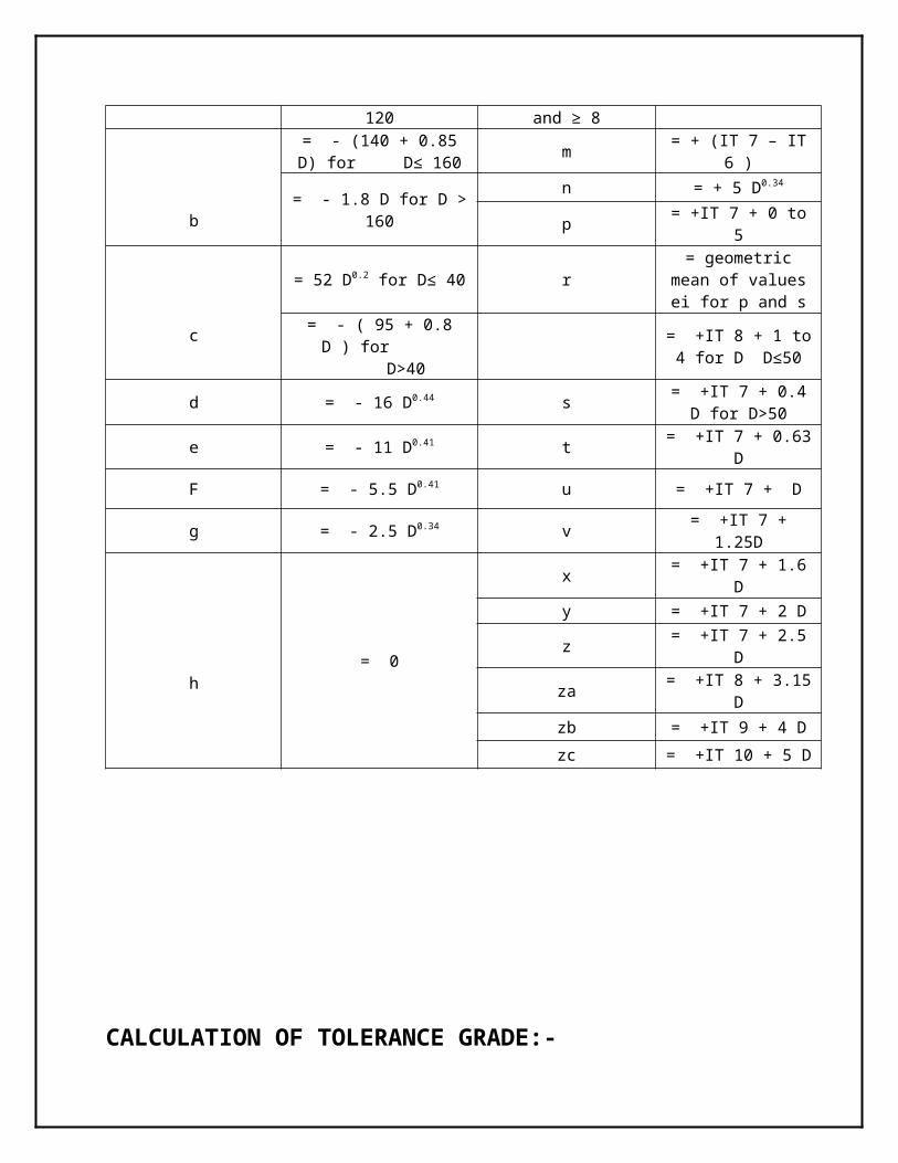
Table : Formulae for fundamental deviation for shafts for sizes : up to 500mm
For js : the two deviations are equal to ± IT / 2
Upper Deviation (es) Lower Deviation (ei)
Shaft Designation In Microns (for D in mm) Shaft DesignationIn Microns (for D in
mm)
a
= - (265 + 1.3 D) for D ≤ 120
j5 to j8 No formula
k4 to k7 = +0.6 (D)1/3
= - 3.5 D for D> 120 k for grades ≤ 3 and ≥ 8 = 0
= - (140 + 0.85 D) for D≤ 160
m = + (IT 7 – IT 6 )
= - 1.8 D for D > 160 n = + 5 D0.34

bp = +IT 7 + 0 to 5
c
= 52 D0.2 for D≤ 40 r= geometric mean of values ei for p and s
= - ( 95 + 0.8 D ) for D>40
= +IT 8 + 1 to 4 for D D≤50
d = - 16 D0.44 s= +IT 7 + 0.4 D for
D>50
e = - 11 D0.41 t = +IT 7 + 0.63 D
F = - 5.5 D0.41 u = +IT 7 + D
g = - 2.5 D0.34 v = +IT 7 + 1.25D
h= 0
x = +IT 7 + 1.6 D
y = +IT 7 + 2 D
z = +IT 7 + 2.5 D
za = +IT 8 + 3.15 D
zb = +IT 9 + 4 D
zc = +IT 10 + 5 D
CALCULATION OF TOLERANCE GRADE:-
For all sizes the values of the tolerance grades IT6 to IT16 inclusive are multiples
of tolerance unit i calculated using the R5 series of preferred numbers. The value
of the tolerance unit is obtained from the following formula for sizes up to
including 500mm.
i= 0.45 3√ D +0.001D
i is given of 0.001mm.
THE R5 SERIES
This is collection of five geometric progressions proposed by col. Charles Reynard
in1877. In geometric progression successive terms are obtained by continued
multiplication using a multiplier of a fixed value. The fixed multiplier, or common
ratio, is denoted by r. the formulae for common ratio in geometric progression is
r= (n-a) √ (b/a)
Where a is the first term in the progression
b is the final term in the progression
n is the number of terms in the progression
In case of first term a=1 and the final term is b= 10, r is i.5849.
This gives constant increase in 60% between successive tolerance values when
used to calculate the tolerance grades IT6 to IT16. The value of IT6 is 10i.
Table: Value of Tolerances Grades
Tolerance Grade Calculations Value
IT 6 = 10 i × 1.60 10 iIT 7 = 10 i × 1.61 16 iIT 8 = 10 i × 1.62 25 iIT 9 = 10 i × 1.63 40 iIT 10 = 10 i × 1.64 64 iIT 11 = 10 i × 1.65 100 iIT 12 = 10 i × 1.66 160 iIT 13 = 10 i × 1.67 250 iIT 14 = 10 i × 1.68 400 iIT 15 = 10 i × 1.69 640 iIT 16 = 10 i × 1.610 1000 i

Diameter Steps for sizes up to 500mm
General Cases Special Subdivisions
MillimetersAbove up to
MillimetersAbove up to
- 33 6 - -6 10
10 1810 1414 18
18 3018 2424 30
30 5030 4040 50
50 8050 6565 80
80 12080 100100 120
120 80120 140140 160160 180
180 250180 200200 225225 250
250 315250 280280 315
315 400 315 355

355 400
400 500400 450450 500
These are used in certain cases for the deviations a to c and r to zc or A to C and R to ZC.
CALCULATIONS OF TOLERANCES AND LIMITS OF SIZE:-
For example the calculations for 60H8/f 7 can be preceded in the following
manner:-
Because 60 mm dia. comes in the dia. step between 50-80mm hence
D=√(d¿1+d 2)¿
D=√(30¿+50)¿ = 63.25mm
Fundamental deviation for shaft = -5.5D0.41
= -5.5(63.25)0.41
=-30.113 microns = -0.030 mm
The tolerance unit i is:-
i=0.45 3√D+0.001D
i=0.453√ (63.25 )+0.001(63.25)
=1.856 microns
Tolerance Grade IT8:-

IT8 =25 i
=25(1.856)/1000
=0.046 mm
Tolerance Grade IT7:-
IT8 = 16 i
=16(1.856)/1000
=0.030 mm
Calculation for Limit:-
A. Hole
Low Limit = Basic size + fundamental deviation hole
= 60.00+0.00
= 60.00 mm
High Limit = Low Limit + Tolerance
= 60.00+0.046
= 60.046 mm
B. Shaft
High Limit = Basic size - fundamental deviation
= 60.00 – 0.030
= 59.970 mm
Low Limit = high limit - Tolerance
= 59.970 – 0.030
= 59.940 mm


![[MS-RPL]: Report Page Layout (RPL) Binary Stream Format€¦ · MS-RPL] —. stream report. report page. report report report](https://img.pdfslide.us/doc/110x75/5fd9f7a7a90b7c34145fa364/ms-rpl-report-page-layout-rpl-binary-stream-format-ms-rpl-a-stream-report.jpg)


![For The Region: Report, Report, Report [Eng]](https://img.pdfslide.us/doc/110x75/579079761a28ab6874c751c6/for-the-region-report-report-report-eng.jpg)