Embed Size (px)
Citation preview
Project under EU RTD 5th Framework Programme
Contract No EVK1-CT-2002-00111
Adaptive Decision Support System (ADSS) for the Integration of Stormwater Source Control into
Sustainable Urban Water Management Strategies
1
Report 5.1. Review of the Use of stormwater BMPs in Europe
prepared by Middlesex University
in collaboration withCereve at ENPC, Ingenieurgesellschaft Prof. Dr. Sieker GmbH, Water
Pollution Unit at Laboratoire Central des Ponts et Chaussées, Division ofSanitary Engineering at Lulea University of Technology and Department of
Water Resources Hydraulic and Maritime Works at National TechnicalUniversity of Athens
18 August 2003 final version
WP / Task / Deliverable N°: WP5 / T5.1 / D5.1Dissemination Level: PU
Literature review - BMPs in Europe18/08/2003
WP5/T5.1/D5.1 - PUFinal
2
Document patternsFile name: D5.1 version 2Sent : 2003-08-18 byM Revitt
Returned to author :J-C. Deutsch
Validated : WP5 / T5.1 / D5.1Diss. Level : PU
Received : 2003-08-18 Revised by authors :M Revitt, B Ellis andL Scholes
Validated by : Version : Final
Keywords (for the Database):
Stormwater management, BMPs, design, performance
AcknowledgementThe results presented in this publication have been obtained within the framework of the ECfunded research project DayWater "Adaptive Decision Support System for Stormwater PollutionControl", contract no EVK1-CT-2002-00111, co-ordinated by Cereve at ENPC (F) and includingTauw BV (Tauw) (NL), Department of Water Environment Transport at Chalmers University ofTechnology (Chalmers) (SE), Environment and Resources DTU at Technical University ofDenmark (DTU) (DK), Urban Pollution Research Centre at Middlesex University (MU) (UK),Department of Water resources Hydraulic and Maritime Works at National Technical Universityof Athens (NTUA) (GR), DHI Hydroinform, a.s. (DHI HIF) (CZ), Ingenieurgesellschaft Prof. Dr.Sieker GmbH (IPS) (D), Water Pollution Unit at Laboratoire Central des Ponts et Chaussées(LCPC) (F) and Division of Sanitary Engineering at Luleaa University of Technology (LTU) (SE).The programme is organised within the "Energy, Environment and Sustainable Development"Programme in the 5th Framework Programme for "Science Research and TechnologicalDevelopment" of the European Commission and is part of the CityNet Cluster, network ofEuropean research projects on integrated urban water management.
Literature review - BMPs in Europe18/08/2003
WP5/T5.1/D5.1 - PUFinal
3
EXECUTIVE SUMMARY
This report represents a comprehensive review of the current state of knowledge on the use andperformance of BMPs for stormwater treatment and control. It has been prepared as part of theEC funded DayWater project through contributions provided by several partners based on boththeir extensive knowledge and specific expertise of stormwater BMPs. An emphasis has beenplaced on the design, operation, maintenance and costing of stormwater BMPs, with particularregard to country specific factors. The accepted use of these systems varies with a wide rangeof structural and non- structural BMPs being employed in northern and temperate Europeancountries for stormwater control, whereas their applicability is less well developed in southernEuropean countries such as Spain, Italy, Greece and Portugal. An exception to this is streetcleaning, which appears to be a common practice throughout Europe. There also appear to bepatterns or trends in the types of BMPs preferred within various countries, with for example,rainwater harvesting being a popular stormwater BMP in France and Germany, but practised toa lesser extent in other European countries.
Different types of structural BMPs are evaluated against a range of factors which have beenidentified in terms of their influence on the selection and use of these systems. Thesecomparisons indicate that:? constructed wetlands, retention basins and extended detention basins appear to have the
fewest physical constraints on their use,? grass swales and filter strips perform best in terms of groundwater recharge potential and
pollutant removal capabilities,? infiltration systems, swales and retention basins may have some technological and
sustainable advantages over other source control devices.
A variety of methods are available to assist the design of structural BMPs based on parametersor criteria which are relevant to the treatment process. Examples which have commonly beenemployed include particle settling characteristics, capture of the first 10-15mm of effectiverunoff, residence time, return period, infiltration capability and pollutant removal capability.These overall approaches are available through the publication of a range of design manuals,guidelines and recommendations, with a wide selection of computer models routinely beingused to enable system performance to be evaluated under a variety of conditions.
Operation and maintenance (O&M) is a major concern when the use of stormwater BMPs isbeing considered. Although it is often stated that O&M requirements must be included in theinitial design and costing process, this is not always the case in practice. The issue of O&Mguidelines for the adoption of stormwater BMPs by an appropriate body is often problematic.However, this situation is now being addressed through, for example in the UK, the publicationof a draft Framework Agreement by the Environment Agency for England and Wales.
The use of stormwater BMPs is generally accepted to result in reductions in treatment costscompared to conventional systems with savings ranging from 18-50% having been reported fora range of BMPs. However, the initial capital costs can be elevated such as in the case of roadinfrastructure BMPs where more expensive surfacing materials may be used. Costs can alsovary considerably between sites depending upon local conditions, including engineeringconstraints (which will normally increase costs) and land constraints (which may lead todecreased costs but also a reduction in performance).
Literature review - BMPs in Europe18/08/2003
WP5/T5.1/D5.1 - PUFinal
4
A considerable amount of data on the performance of a range of BMPs is presented and thisdemonstrates that BMPs can effectively manage both the quantity and quality of stormwater innorthern and temperate European countries. There is currently little data available on theperformance of BMPs in southern European countries. Where poor or variable removalperformances have been reported, a range of reasons have been cited such as the re-entrainment of solids during high flows, short circuiting and low detention times. Key problemsare identified in the way performance data are determined and calculated and represent animportant area for consideration in future discussions of BMP performances.
The contribution that stormwater BMPs can make to sustainable urban development throughtheir potential to address the needs and concerns of a diverse group of stakeholders is nowbeing recognised. The environmental and urban community benefits offered by different BMPscan be compared through the development of a qualitative evaluation matrix. Both wetlandsand retention basins score highly through such an approach although these evaluations aresubjective, and there is a need to fully develop and apply robust and quantifiable sustainabilitycriteria. As an initial step to addressing this requirement, a generic list of primary sustainabilitycriteria is proposed as a starting point for the development of a multi-criteria methodology. Theidentified criteria could be quantified through benchmarks and hence compared with nationalsustainability targets.
This report provides a comprehensive review of the design, operation and performance of BMPsacross Europe. It provides stakeholders and end-users with detailed information on the abilityof BMPs to treat and control stormwater, whilst also discussing issues that have been a causeof concern (e.g. the adoption of O&M requirements) and highlighting areas for further research(e.g. development of quantifiable sustainability criteria). It can therefore be used as a balancedsource of information on the current use of stormwater BMPs within Europe.

Literature review - BMPs in Europe18/08/2003
WP5/T5.1/D5.1 - PUFinal
5
TABLE OF CONTENTS
SECTION TITLES
1 BACKGROUND TO THE USE OF BEST MANAGEMENT PRACTICES (BMPS) ANDOVERALL STRUCTURE OF THIS REVIEW ............................................................................10
2 NATIONAL APPROACHES TO THE USE OF BMPS .......................................................11
2.1 INTRODUCTION ...............................................................................................................112.2 STRUCTURAL BMPS........................................................................................................132.3 NON-STRUCTURAL BMPS ...............................................................................................14
2.3.1 Street cleaning and gullypot emptying ...................................................................152.3.2 Pollutant usage......................................................................................................162.3.3 Snow management and de-icing measures...........................................................162.3.4 Educational and training aspects ...........................................................................172.3.5 Rainwater harvesting.............................................................................................182.3.6 Flat roof storage ....................................................................................................192.3.7 Control of impervious area development ...............................................................20
3 APPLICATION CHARACTERISTICS OF BMPS ...............................................................24
3.1 GENERAL COMPARISON OF CONVENTIONAL SYSTEMS WITH BMPS .....................................243.2 FACTORS AFFECTING THE USE AND SELECTION OF BMPS ..................................................24
4 DESIGN, O&M AND COSTING ASPECTS OF STRUCTURAL BMPS..............................28
4.1 BMP DESIGN..................................................................................................................284.1.1 Published Manuals ................................................................................................284.1.2 Determination of design treatment volume.............................................................294.1.3 Swales...................................................................................................................304.1.4 Soakaways ............................................................................................................314.1.5 Infiltration trenches ................................................................................................324.1.6 Infiltration basins ...................................................................................................324.1.7 Sedimentation tank................................................................................................334.1.8 Lagoons ................................................................................................................334.1.9 Detention basins....................................................................................................344.1.10 Retention ponds ....................................................................................................344.1.11 Filter drains............................................................................................................364.1.12 Porous paving and reservoir structures .................................................................36
4.1.12.1 Selection of materials.....................................................................................374.1.12.2 Hydraulic approach........................................................................................39
4.1.13 Flat roof storage systems ......................................................................................414.1.14 Gullypots ...............................................................................................................434.1.15 Rainwater harvesting.............................................................................................434.1.16 Snow management strategy ..................................................................................434.1.17 Design innovations ................................................................................................44
4.2 BMP OPERATION AND MAINTENANCE PROCEDURES.........................................................454.2.1 Infiltration basins ...................................................................................................464.2.2 Sedimentation tank................................................................................................474.2.3 Retention ponds ....................................................................................................474.2.4 Constructed wetland systems................................................................................474.2.5 Porous paving and reservoir structures .................................................................51
Literature review - BMPs in Europe18/08/2003
WP5/T5.1/D5.1 - PUFinal
6
4.3 BMP COSTINGS..............................................................................................................53
5 BMP PERFORMANCE......................................................................................................59
5.1 PERFORMANCE INDICATORS ............................................................................................595.2 BMP PERFORMANCE DATA .............................................................................................62
5.2.1 Filter strips and swales ..........................................................................................625.2.1.1 Swales...............................................................................................................625.2.1.2 Filter strips.........................................................................................................635.2.1.3 Filter drains........................................................................................................64
5.2.2 Infiltration Systems ................................................................................................645.2.2.1 Soakaways ........................................................................................................645.2.2.2 Infiltration trenches ............................................................................................655.2.2.3 Infiltration basins................................................................................................65
5.2.3 Storage Facilities ...................................................................................................665.2.3.1 Flat roofs for storage..........................................................................................665.2.3.2 Storage tanks/chambers....................................................................................665.2.3.3 Lagoons.............................................................................................................675.2.3.4 Detention basins................................................................................................675.2.3.5 Extended detention basins.................................................................................675.2.3.6 Retention basins................................................................................................685.2.3.7 Constructed Wetlands .......................................................................................715.2.3.8 Combined stormwater runoff treatment systems................................................72
5.2.4 Alternative road structure.......................................................................................735.2.4.1 Porous paving....................................................................................................73
5.2.4.1.1 Effects on stormwater quality .....................................................................755.2.4.2 Porous Asphalt and Whisper Concrete ..............................................................78
5.2.5 Street cleaning ......................................................................................................785.2.6 Snow management................................................................................................80
5.2.6.1 Transportation to snow deposits ........................................................................805.2.6.2 Treatment of meltwater ......................................................................................815.2.6.3 Snow remaining within the city...........................................................................81
6 ENVIRONMENTAL ADVANTAGES AND SUSTAINABILITY ASPECTS...........................83
6.1 ENVIRONMENTAL ADVANTAGES .......................................................................................836.2 SUSTAINABILITY ASPECTS ...............................................................................................86
7 REFERENCES .................................................................................................................88
Literature review - BMPs in Europe18/08/2003
WP5/T5.1/D5.1 - PUFinal
7
TABLE OF TABLES
Table 2.1 BMP types found in the UK .......................................................................................11Table 2.2 Description of types of BMPs ....................................................................................13Table 2.3 Scottish BMPs Database...........................................................................................13Table 2.4 Constructed Wetlands in UK Urban Surface Drainage Systems within England and
Wales................................................................................................................................14Table 2.5 Non-structural BMPs .................................................................................................15Table 2.6 Recommended highway cleaning frequencies ..........................................................15Table 2.7 Mean annual pollutant concentrations and loading rates in rainwater in France ........19Table 2.8 Inter-regional variations of rainwater characteristics..................................................19Table 2.9 Main urban and sanitation projects with legal French threshold values .....................22Table 2.10 Threshold values for authorisation/declaration in high density and low density urban
areas.................................................................................................................................22Table 3.1 General comparison of conventional systems with BMPs..........................................24Table 3.2 SUDS technology evaluation matrix ..........................................................................27Table 4.1 Swedish design guidelines for retention ponds..........................................................35Table 4.2 Designs of reservoir structures..................................................................................37Table 4.3 Properties of porous materials ..................................................................................38Table 4.4 Distribution of contributing inputs and capacities of the sub-reservoirs in a shopping
centre/car park at Chemillé, France. .................................................................................41Table 4.5 Operation and maintenance schedule for a motorway service station .......................48Table 4.6 Operation and maintenance inspection sheet: wetland operation, maintenance and
management .....................................................................................................................49Table 4.7 Type, maintenance and operating conditions of alternative structures in Seine-Saint-
Denis in 1995....................................................................................................................51Table 4.8 The cost of various BMPs (not including land cost) according to CERTU (1998).......53Table 4.9 Economic indicators of stormwater drainage systems (Baptista et al., 2003) ............53Table 4.10 Particle pollution recovery cost according to various techniques .............................54Table 4.11 Capital and maintenance costs for BMP treatment systems (Revitt and Ellis, 2001)54Table 4.12 Annual and maintenance costs for different stormwater management measures ....58Table 5.1 Performance efficiency and value of BMP treatment systems ...................................60Table 5.2 Wetland and Dry/Wet Storage Basin Indicators.........................................................61Table 5.3 Evaluation of Wetland and Dry/Wet Basin Effectiveness Potential ............................61Table 5.4 Swale pollutant concentrations, loadings and removal efficiencies............................62Table 5.5 Loading criteria for biosolid disposal to land..............................................................63Table 5.6 Mean percentage annual removal efficiencies for a UK motorway filter drain treatment
system ..............................................................................................................................64Table 5.7 Mean percentage annual removal efficiencies for a UK motorway sedimentation tank
treatment system (Perry and McIntyre, 1986)....................................................................66Table 5.8 Mean percentage annual removal efficiencies for a UK motorway lagoon treatment
system ..............................................................................................................................67Table 5.9 Trap Efficiency of Wet Retention Basins ...................................................................68Table 5.10 Removal efficiencies in two Swedish stormwater ponds (Pettersson et al., 1999) ...70Table 5.11 Pollutant removal ability (%) of ponds in treating runoff in Minnesota......................71Table 5.12 Percentage pollutant removal rates in constructed wetlands ...................................71Table 5.13 Wetland treatment system melt/spring rain performance.........................................73Table 5.14 Analysis of drain outflow in relation to rainfall data ..................................................75Table 5.15 Extreme values of per-event losses ........................................................................75

Literature review - BMPs in Europe18/08/2003
WP5/T5.1/D5.1 - PUFinal
8
Table 5.16 Comparison of runoff water quality from a reservoir structure with a compositereference sample ..............................................................................................................76
Table 5.17 Pollutant loadings discharged from the reservoir structure and the referencecatchment area (per hectare) ............................................................................................76
Table 5.18 Comparison of the performance of different types of reservoir structures receivingstormwater runoff ..............................................................................................................76
Table 5.19 Masses of removed particulate material and heavy metals in street sweepingsediment ...........................................................................................................................80
Table 6.1 Conservation Value of Urban Wetlands.....................................................................85Table 6.2 Evaluation of stormwater management systems with regard to multifunctional use and
cost ...................................................................................................................................86Table 6.3 Primary criteria for assessing SUDS sustainability ....................................................87

Literature review - BMPs in Europe18/08/2003
WP5/T5.1/D5.1 - PUFinal
9
TABLE OF FIGURES
Figure 2.1 Infiltration facilities and their recommended use for runoff from different contributingsurfaces in Germany. ........................................................................................................21
Figure 3.1 BMP restrictions evaluation matrix ...........................................................................25Figure 3.2 BMP stormwater control evaluation matrix ...............................................................26Figure 4.1 Basic reservoir structure ..........................................................................................37Figure 4.2 Cross section of a reservoir structure on flat ground ................................................40Figure 4.3 Cross section of a sewage collector laying trench used to drain a reservoir structure
..........................................................................................................................................40Figure 4.4 Plan of shopping centre with sloping car park having a partitioned reservoir structure
..........................................................................................................................................41Figure 4.5 Flat roof drainage systems.......................................................................................42Figure 4.6 Section of a gullypot containing an additional filter ...................................................43Figure 4.7 Modified superficial trench systems developed in Germany .....................................44Figure 4.8 Design of a swale-trench system incorporating a pocket wetland.............................45Figure 4.9 Variation of clogging in a street with reservoir structure over a 3 year period. ..........51Figure 4.10 The location and extent of clogging in a porous asphalt top layer. .........................52Figure 4.11 Retention pond costs from literature and UK schemes compared to model results 55Figure 5.1 The Operational Performance of a Wet Retention Basin..........................................69Figure 5.2 Cross-section of a street fitted with a reservoir structure..........................................74Figure 5.3 Comparison of responses to a given rainfall event between a reservoir structure and
a conventional suburban catchment basin ........................................................................75Figure 5.4 Street surface particulate distribution and cleaning effectiveness.............................79Figure 6.1 The BMP triangle and relation to stakeholder interest and sustainability criteria ......83Figure 6.2 BMP Environmental and Urban Community Amenities Evaluation Matrix ................84

Literature review - BMPs in Europe18/08/2003
WP5/T5.1/D5.1 - PUFinal
10
1 BACKGROUND TO THE USE OF BEST MANAGEMENT PRACTICES (BMPS) ANDOVERALL STRUCTURE OF THIS REVIEW
The continued and rapid growth of urban areas across Europe places increasing importance onthe control of stormwater. However, the criteria defining what constitutes effective stormwatermanagement are themselves undergoing change. Comprehensive stormwater managementplans in both new and existing urban areas should not only address stormwater quantity andquality but also need to consider issues such as sustainable development. Furthermore, it isanticipated that the legal requirements for the control of stormwater, particularly with regard tothe protection of receiving waters, are likely to become much more stringent through theimplementation of the Water Framework Directive.
In order to meet these changing requirements a new approach to stormwater management isneeded, which has led to increasing interest in the use of BMPs. BMPs encompass a widerange of solutions which enables the planning, design and management of stormwater to betackled equally from hydrological, environmental and public amenity perspectives (CIRIA, 2001).BMPs can be used as an alternative to, or in combination with, conventional stormwaterdrainage systems.
This report is presented as Deliverable 5.1 of the DayWater project which is funded by theEuropean Commission as part of the 5th Framework Programme for "Science Research andTechnological Development" within the "Energy, Environment and Sustainable Development"Programme. The overall objective of the report is to outline the use of BMPs across Europe butwith particular attention to the adaptability and relevance of these systems to the differentEuropean climatic regions. This review consists of six sections which are supported by acomprehensive literature review. Following this introduction (Section 1), Section 2 describes thedifferent types of BMPs which have been applied within Europe with an emphasis on the non-structural versions. Comparisons of BMPs with conventional systems are made in Section 3together with descriptions of the criteria on which the use of BMPs can be based. Section 4provides detailed accounts of design and operation/maintenance requirements of specificstructural BMPs as well as some comments on costing implications. Section 5 concentrates onperformances of both structural and non-structural BMPs with regard to both water quantity andwater quality aspects and the report concludes (Section 6) with some comments on theenvironmental and sustainability benefits of BMPs.
The Urban Pollution Research Centre, Middlesex University, as the leaders of Work Package 5,have coordinated the preparation of this review. The lead authors (Professor Bryan Ellis, Dr LianScholes, and Professor Mike Revitt) are grateful to their project partners from Cereve at ENPC,Ingenieurgesellschaft Prof. Dr. Sieker GmbH, Water Pollution Unit at Laboratoire Central desPonts et Chaussées, Division of Sanitary Engineering at Lulea University of Technology andDepartment of Water Resources Hydraulic and Maritime Works at National Technical Universityof Athens for their valuable contributions which have made the depth and breadth of this reviewpossible.
Literature review - BMPs in Europe18/08/2003
WP5/T5.1/D5.1 - PUFinal
11
2 NATIONAL APPROACHES TO THE USE OF BMPS
2.1 Introduction
BMPs are divided into two main types as follows –
? structural BMPs (which involve the physical construction of a system for urban stormwatermanagement)
? non-structural BMPs (which involve either the introduction of a new management practice orthe modification of an existing management practice).
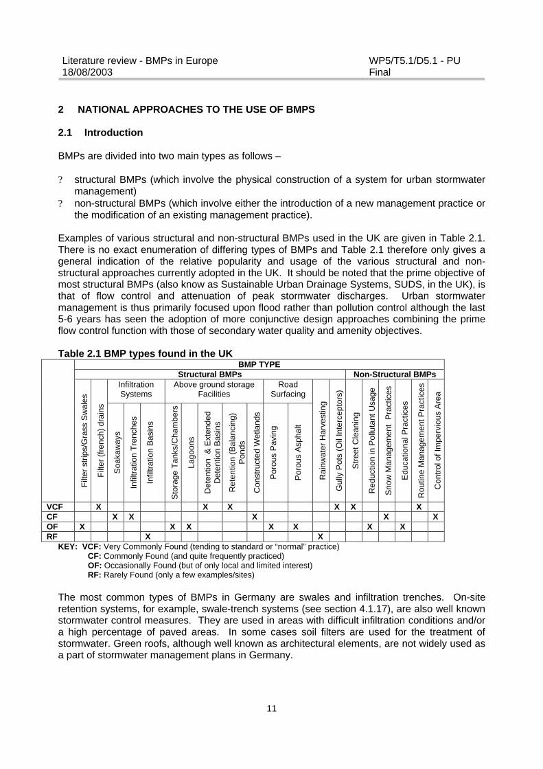
Examples of various structural and non-structural BMPs used in the UK are given in Table 2.1.There is no exact enumeration of differing types of BMPs and Table 2.1 therefore only gives ageneral indication of the relative popularity and usage of the various structural and non-structural approaches currently adopted in the UK. It should be noted that the prime objective ofmost structural BMPs (also know as Sustainable Urban Drainage Systems, SUDS, in the UK), isthat of flow control and attenuation of peak stormwater discharges. Urban stormwatermanagement is thus primarily focused upon flood rather than pollution control although the last5-6 years has seen the adoption of more conjunctive design approaches combining the primeflow control function with those of secondary water quality and amenity objectives.
Table 2.1 BMP types found in the UKBMP TYPE
Structural BMPs Non-Structural BMPsInfiltrationSystems
Above ground storageFacilities
RoadSurfacing
Filt
er s
trip
s/G
rass
Sw
ales
Filt
er (f
renc
h) d
rain
s
Soa
kaw
ays
Infil
trat
ion
Tre
nche
s
Infil
trat
ion
Bas
ins
Sto
rage
Tan
ks/C
ham
bers
Lago
ons
Det
entio
n &
Ext
ende
dD
eten
tion
Bas
ins
Ret
entio
n (B
alan
cing
)P
onds
Con
stru
cted
Wet
land
s
Por
ous
Pav
ing
Por
ous
Asp
halt
Rai
nwat
er H
arve
stin
g
Gul
ly P
ots
(Oil
Inte
rcep
tors
)
Str
eet C
lean
ing
Red
uctio
n in
Pol
luta
nt U
sage
Sno
w M
anag
emen
t P
ract
ices
Edu
catio
nal P
ract
ices
Rou
tine
Man
agem
ent P
ract
ices
Con
trol
of I
mpe
rvio
us A
rea
VCF X X X X X XCF X X X X XOF X X X X X X XRF X X
KEY: VCF: Very Commonly Found (tending to standard or “normal” practice) CF: Commonly Found (and quite frequently practiced) OF: Occasionally Found (but of only local and limited interest) RF: Rarely Found (only a few examples/sites)
The most common types of BMPs in Germany are swales and infiltration trenches. On-siteretention systems, for example, swale-trench systems (see section 4.1.17), are also well knownstormwater control measures. They are used in areas with difficult infiltration conditions and/ora high percentage of paved areas. In some cases soil filters are used for the treatment ofstormwater. Green roofs, although well known as architectural elements, are not widely used asa part of stormwater management plans in Germany.

Literature review - BMPs in Europe18/08/2003
WP5/T5.1/D5.1 - PUFinal
12
The increased occurrence of floods in France over the last 10 years has led to the widespreadacceptance of the use of BMPs, such as retention basins, by developers for stormwater control.This has been partly due to an appreciation of the fact that flood control needed to take placeupstream of the river basin, and also due to economic and aesthetic factors such as sewagecost reduction and landscaping. The use of porous paving with reservoir structures is also apopular BMP stormwater management measure in France. Initially, these systems were mostwidely used in regions where the authorities and developers were obliged to do so, such as inBordeaux. However, the use of porous paving and reservoir structures is now increasingthroughout the entire country.
In cold climate countries, such as Sweden and Denmark, retention ponds are frequently used toboth reduce peak flows and retain pollutants from separate sewage systems. Swales andinfiltration basins have also been used in cold climates to control both stormwater andmeltwater, with the use of swales offering an additional advantage as a potential deposit areafor snow.
The use of BMPs in Southern European countries, such as Greece, Italy, Spain and Portugal, islimited. However, interest in their use appears to be growing, with an increasing publicawareness of environmental issues appearing to provide a strong incentive to planners toconsider alternative treatment systems.
In Athens, Greece, the traditional approach to stormwater management is the use of separate,closed, drainage networks which convey runoff to the sea. The use of BMPs has been limitedpartly due to a lack of space for larger structures, such as detention and retention ponds, indensely populated urban areas and partly due to an unwillingness by developers to tryalternative techniques. However, this situation is changing as a combination of covering riversand rapid urbanisation has left the current system unable to cope and has increased thefrequency of flooding in downstream areas. The use of BMPs are being reconsidered to addressthese issues, with various case studies currently underway. For example, the Olympic rowingbasin is also being used as a detention basin (with pretreatment provided by a preliminarydetention and settlement pond) and oil separation and detention ponds have been included aspart of the stormwater control system at Athens airport. Municipalities in the Greater Athensarea have also modernised their street cleaning equipment and undertake street cleaning on aregular basis.
BMPs have not been widely used in Spain, where differences in rainfall between Mediterraneancountries and northern European countries (where BMPs are more common) have been citedas a potential concern. Most BMPs have been developed in regions where rain events are of along duration and low intensity whereas rainfall in Mediterranean Spain is of short duration withhigh peak intensity and concerns have been expressed that BMPs may not be efficient undersuch conditions. However, despite these concerns interest in their use in Spain is increasing,with, for example, the use of BMPs being promoted in the Master Drainage plan of Barcelona(1997), and infiltration ponds and porous paving systems having been utilised in the Olympicvillage.
Literature review - BMPs in Europe18/08/2003
WP5/T5.1/D5.1 - PUFinal
13
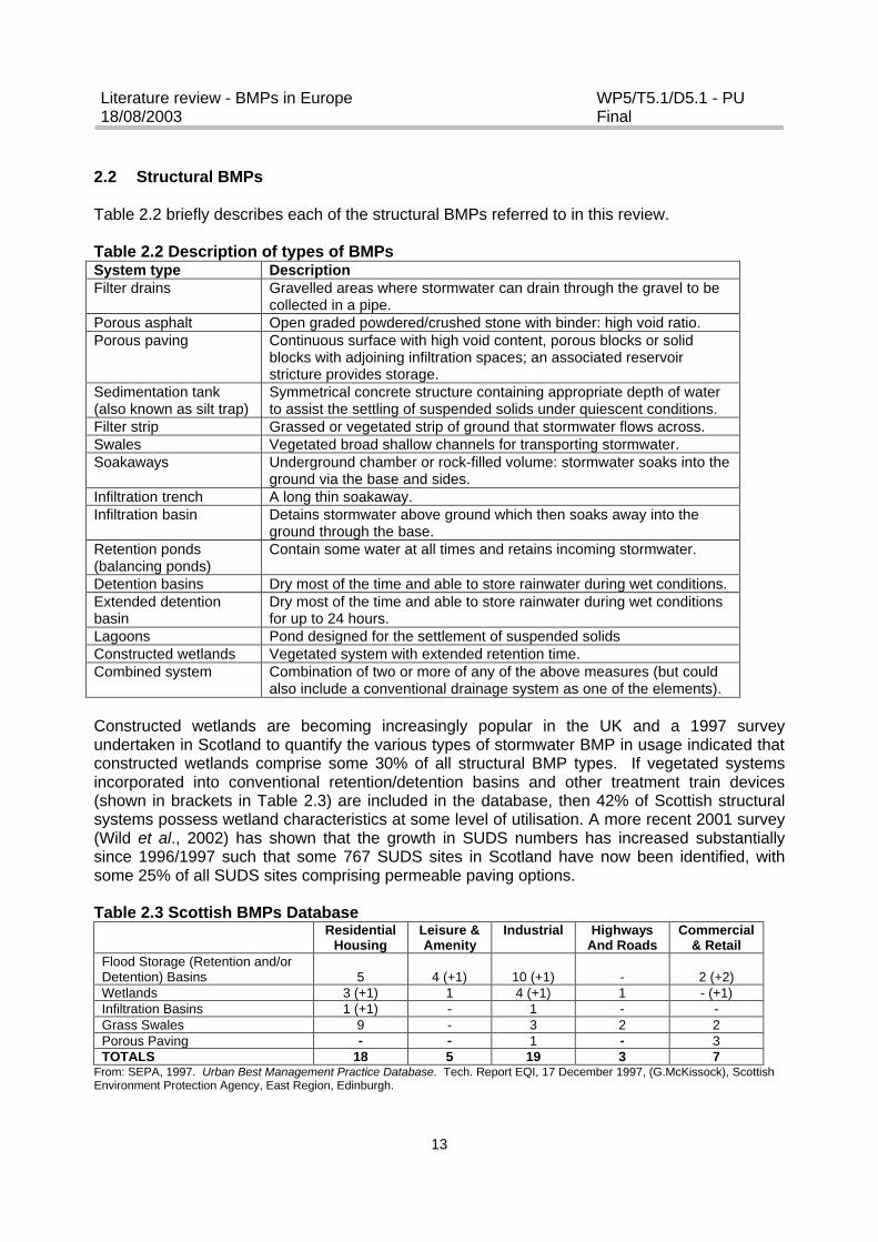
2.2 Structural BMPs
Table 2.2 briefly describes each of the structural BMPs referred to in this review.
Table 2.2 Description of types of BMPsSystem type DescriptionFilter drains Gravelled areas where stormwater can drain through the gravel to be
collected in a pipe.Porous asphalt Open graded powdered/crushed stone with binder: high void ratio.Porous paving Continuous surface with high void content, porous blocks or solid
blocks with adjoining infiltration spaces; an associated reservoirstricture provides storage.
Sedimentation tank(also known as silt trap)
Symmetrical concrete structure containing appropriate depth of waterto assist the settling of suspended solids under quiescent conditions.
Filter strip Grassed or vegetated strip of ground that stormwater flows across.Swales Vegetated broad shallow channels for transporting stormwater.Soakaways Underground chamber or rock-filled volume: stormwater soaks into the
ground via the base and sides.Infiltration trench A long thin soakaway.Infiltration basin Detains stormwater above ground which then soaks away into the
ground through the base.Retention ponds(balancing ponds)
Contain some water at all times and retains incoming stormwater.
Detention basins Dry most of the time and able to store rainwater during wet conditions.Extended detentionbasin
Dry most of the time and able to store rainwater during wet conditionsfor up to 24 hours.
Lagoons Pond designed for the settlement of suspended solidsConstructed wetlands Vegetated system with extended retention time.Combined system Combination of two or more of any of the above measures (but could
also include a conventional drainage system as one of the elements).
Constructed wetlands are becoming increasingly popular in the UK and a 1997 surveyundertaken in Scotland to quantify the various types of stormwater BMP in usage indicated thatconstructed wetlands comprise some 30% of all structural BMP types. If vegetated systemsincorporated into conventional retention/detention basins and other treatment train devices(shown in brackets in Table 2.3) are included in the database, then 42% of Scottish structuralsystems possess wetland characteristics at some level of utilisation. A more recent 2001 survey(Wild et al., 2002) has shown that the growth in SUDS numbers has increased substantiallysince 1996/1997 such that some 767 SUDS sites in Scotland have now been identified, withsome 25% of all SUDS sites comprising permeable paving options.
Table 2.3 Scottish BMPs DatabaseResidential
HousingLeisure &Amenity
Industrial HighwaysAnd Roads
Commercial& Retail
Flood Storage (Retention and/orDetention) Basins 5 4 (+1) 10 (+1) - 2 (+2)Wetlands 3 (+1) 1 4 (+1) 1 - (+1)Infiltration Basins 1 (+1) - 1 - -Grass Swales 9 - 3 2 2Porous Paving - - 1 - 3TOTALS 18 5 19 3 7
From: SEPA, 1997. Urban Best Management Practice Database. Tech. Report EQI, 17 December 1997, (G.McKissock), ScottishEnvironment Protection Agency, East Region, Edinburgh.
Literature review - BMPs in Europe18/08/2003
WP5/T5.1/D5.1 - PUFinal
14
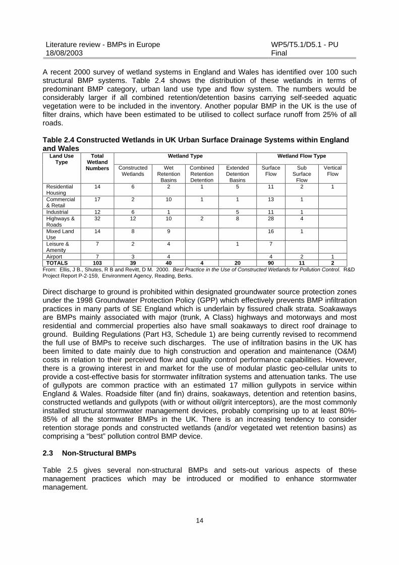
A recent 2000 survey of wetland systems in England and Wales has identified over 100 suchstructural BMP systems. Table 2.4 shows the distribution of these wetlands in terms ofpredominant BMP category, urban land use type and flow system. The numbers would beconsiderably larger if all combined retention/detention basins carrying self-seeded aquaticvegetation were to be included in the inventory. Another popular BMP in the UK is the use offilter drains, which have been estimated to be utilised to collect surface runoff from 25% of allroads.
Table 2.4 Constructed Wetlands in UK Urban Surface Drainage Systems within Englandand Wales
Wetland Type Wetland Flow TypeLand UseType
TotalWetlandNumbers Constructed
WetlandsWet
RetentionBasins
CombinedRetentionDetention
ExtendedDetention
Basins
SurfaceFlow
SubSurface
Flow
VerticalFlow
ResidentialHousing
14 6 2 1 5 11 2 1
Commercial& Retail
17 2 10 1 1 13 1
Industrial 12 6 1 5 11 1Highways &Roads
32 12 10 2 8 28 4
Mixed LandUse
14 8 9 16 1
Leisure &Amenity
7 2 4 1 7
Airport 7 3 4 4 2 1TOTALS 103 39 40 4 20 90 11 2
From: Ellis, J B., Shutes, R B and Revitt, D M. 2000. Best Practice in the Use of Constructed Wetlands for Pollution Control. R&DProject Report P-2-159, Environment Agency, Reading, Berks.
Direct discharge to ground is prohibited within designated groundwater source protection zonesunder the 1998 Groundwater Protection Policy (GPP) which effectively prevents BMP infiltrationpractices in many parts of SE England which is underlain by fissured chalk strata. Soakawaysare BMPs mainly associated with major (trunk, A Class) highways and motorways and mostresidential and commercial properties also have small soakaways to direct roof drainage toground. Building Regulations (Part H3, Schedule 1) are being currently revised to recommendthe full use of BMPs to receive such discharges. The use of infiltration basins in the UK hasbeen limited to date mainly due to high construction and operation and maintenance (O&M)costs in relation to their perceived flow and quality control performance capabilities. However,there is a growing interest in and market for the use of modular plastic geo-cellular units toprovide a cost-effective basis for stormwater infiltration systems and attenuation tanks. The useof gullypots are common practice with an estimated 17 million gullypots in service withinEngland & Wales. Roadside filter (and fin) drains, soakaways, detention and retention basins,constructed wetlands and gullypots (with or without oil/grit interceptors), are the most commonlyinstalled structural stormwater management devices, probably comprising up to at least 80%-85% of all the stormwater BMPs in the UK. There is an increasing tendency to considerretention storage ponds and constructed wetlands (and/or vegetated wet retention basins) ascomprising a “best” pollution control BMP device.
2.3 Non-Structural BMPs
Table 2.5 gives several non-structural BMPs and sets-out various aspects of thesemanagement practices which may be introduced or modified to enhance stormwatermanagement.

Literature review - BMPs in Europe18/08/2003
WP5/T5.1/D5.1 - PUFinal
15
Table 2.5 Non-structural BMPsManagement practice Examples of aspects which may be introduced/modifiedStreet Cleaning Cleaning frequency, type of cleaning equipmentReduction in Pollutant Usage Type and frequency of use of e.g. herbicidesSnow Management Practices Zoning of snow according to pollutant loadEducational Aspects Increase public awareness of e.g. litter controlRoutine Management Practices Frequency of e.g. grass cutting and sediment removalControl of Impervious AreaDevelopment
Consideration of the balance between impermeable andpermeable areas during planning and development
Flood Prevention Techniques Prioritisation of USWM in the early stages of the planning anddevelopment
2.3.1 Street cleaning and gullypot emptying
Street cleaning is undertaken on a regular basis within the UK, with local authorities statutorilyrequired (under Section 86 (9) of the 1974 Control of Pollution Act), to “keep roads andhighways clean, as far as is practicable” although responsibility for motorways lies with thenational Highways Agency. The work is usually undertaken under contracted arrangementsusing direct labour or independent agencies. Four standards of street cleanliness are describedin the “Code of Practice for Litter and Refuse” (DoE, 1991) ranging from Grade A (litter free) toGrade D (heavily littered), together with 11 urban land use zones divided according to intensityof use and traffic volumes. The non-statutory parts of the Code contain advice on “bestpractice” indicating the times (hours/days) within which an area should be restored to its gradeallocation if the cleanliness falls below the standard. However in practice, many authorities stillrefer to and use an earlier 1989 Code which sets out cleaning baselines for road/highwaycleaning (Table 2.6).
Table 2.6 Recommended highway cleaning frequenciesHighways Type Cleaning Frequency
Rural AreasUn-kerbed roadsKerbed Roads Category 2 Category 3 and 4
Cleaned/swept as the need arises
Twice per yearOnce per year
Urban AreasTown centres and principal shopping centres/areasCategory 2 and 3 roadsCategory 4 roads
WeeklyMonthlyQuarterly
From: Local Authorities Associations. 1989. Highway Maintenance: A Code of Good Practice. Association of County Councils,London.
Most urban drainage studies have indicated that conventional street cleaning is only of limitedeffect as a BMP management strategy in terms of stormwater pollution control, and that itlargely serves a “cosmetic” function. Despite this, street cleaning is carried out on a regularbasis in many European counties including Sweden, France and Greece. Studies in the first twoof these countries have investigated several aspects of street cleaning, including itsperformance as a stormwater control measure and the impact of increasing the frequency ofstreet cleaning operations, and data from these studies are presented in this review (seeSection 5.2.5).
Literature review - BMPs in Europe18/08/2003
WP5/T5.1/D5.1 - PUFinal
16
Roadside gullypot emptying is undertaken by vacuum tankers on at least an annual (or twiceannual) cleaning frequency with removed material disposed to landfill. Cleaning efficiency canrange from 20% to 85% depending on local car parking conditions (CIRIA, 1995). During theemptying process, some 10% of the sediment originally present in the gullypot can be washedinto the sewer line. Average unit costs range from €2 to €4 per gully.
2.3.2 Pollutant usage
The control of weeds on paved and highway surfaces within urban areas is necessary toprevent structural damage, to maintain safety and provide aesthetic improvements. A typicalannual load of herbicides applied by local authorities in the UK is 186 tonnes of which 94% areused in the weed control programmes of roads and highways, parks, amenity grass andmunicipal paved areas. The key factors that affect the runoff removal of herbicides applied tohard surfaces are persistence, adsorption, rainfall intensity and the time period betweenapplication and rainfall. EC directives incorporated into the UK Water Supply regulations specifya maximum admissible limit of 0.1 ?g/l for individual pesticides and 0.5 ?g/l for total pesticides.Research in an urban catchment in Essex, SE England, has consistently shown diuronconcentrations in excess of these levels in surface waters receiving runoff from highway andother urban hard surfaces (Revitt et al, 2002).
2.3.3 Snow management and de-icing measures
In cold regions, snow handling procedures place great demands on municipalities and theirengineers. Snow handling measures, such as ploughing and transport, are necessary in orderto achieve safe road conditions, but are expensive and can have a detrimental effect on theenvironment. The environmental impact of these measures will vary depending on the snow-handling strategy employed and whether the snow, and its associated pollutants, aretransported to a local or central deposit and dumped either on land or in a water body.
The benefits to be derived from the use of salt in winter road maintenance need to be weighedagainst the associated environmental costs. In Sweden, significant environmental effects areassociated with the high concentrations of chloride found in receiving waters during periods ofsnowmelt. The environmental risk due to chlorides is increased in stormwater managementfacilities, which may discharge chloride-laden runoff to groundwater aquifers. Potential impactsalso include toxic conditions in ponds and constructed wetlands, pollutant release from bottomsediment by ionic exchange, the leaching of metals and dissolved oxygen deficiency as a resultof chemical stratification due to impeded vertical mixing. However, it has also been reported thatmany of these issues can be addressed through the careful use of de-icers, adapting the designof BMPs to allow chloride dilution and by reducing or preventing chloride discharge to sensitivesurface receiving waters (Marsalek, 2003).
The reported impact of the use of chlorides in Sweden contrasts with the situation in the UKwhere, despite event mean concentration (EMC) chloride levels averaging 380 mg/l (andranging between 160 mg/l to 2174 mg/l) for motorways and trunk roads, there are no reports ofincreased chloride concentrations in British groundwaters. However, de-icing activities arereported to influence suspended solids (SS) concentrations in sewer dry weather flow duringwinter periods when road salt can represent up to 33% of accumulating solids on the roadsurface. Current UK recommended precautionary application rates for de-icing salt are 10g/m2
(increased to 15g/m2 if the salt is wet due to open storage) and 25g/m2 to 40g/m2 if freezingconditions are expected following rain or snow events.
Literature review - BMPs in Europe18/08/2003
WP5/T5.1/D5.1 - PUFinal
17
The selection of BMP type to manage snowmelt events can be largely dependent on the phaseof snowmelt being targeted and the location of the event. Treatment of chemically-inducedsnowmelts on heavily travelled urban roadways should focus on the collection and detention orfiltration of particulates, whereas BMPs used to treat runoff from early in the snowmelt in asuburban area should focus on infiltration and dilution. Diversion of flow to different BMPs canbe designed according to the nature of the pollutants being carried and the sensitivity of thereceiving water. For example, a chloride-laden early first-flush from a heavily-travelled roadwaycould be diverted to a holding area for later release when higher, less concentrated flows willoccur, thus diluting the effects of the chloride. Similarly, a metals-rich melt could be divertedaround a sensitive receiving water and directed downstream where a reduced sensitivity exists,or diverted to an infiltration area where soil filtration processes could provide treatment.
Understanding the movement of soluble pollutants from the snowpack is one of the biggestchallenges in managing the water quality of snowmelt, as determination of how and when thesepollutants move from the snowpack is the key to identifying the most appropriate treatment type(see Section 5.2.6). Research has suggested that in densely developed urban centres, thesoluble content of the melt is likely be low due to adsorption of dissolved species to particulates(Sansalone and Buchberger, 1996; Viklander, 1999). However, in less densely developedresidential areas, the proportion of solubles could be higher, thus promoting in situ infiltration ordiversion of melt to infiltration basins as effective BMPs.
2.3.4 Educational and training aspects
Improved water quality and landscaping of urban BMP structures enhance aesthetic values forecological, amenity and recreational use. Surveys carried out in Scotland have shown thatpublic attitudes towards wetlands and retention basins is much more positive than for otherBMP types, particularly valuing their wildlife and amenity benefits. The incorporation of natureconservation into urban flood storage facilities has stimulated many local authorities and localnature trusts to develop them as outdoor classrooms and nature trails for environmental studies.The establishment of field and information centres together with interpretation boards/leaflets,boardwalks, bird hides, pond dipping platforms etc., have collectively helped to raise both localpublic awareness of BMPs and their potential educational use.
In the UK, the success of the 1.3ha, 10,000m3 Anton Crescent stormwater wetland in theLondon Borough of Sutton and the Kings Cross Camley Street Local Nature Reserve wetlandare just two notable examples of the intrinsic value of this educational function. These wetlandsfully involve the local community, schools and colleges as integral elements in the operation ofthe nature reserves, fulfilling the objectives of Local Agenda 21. Over 350,000 people a yearvisit the Sandwell Valley stormwater wetlands near Birmingham where the Royal Society for theProtection of Birds (RSPB) operate an educational centre. A number of retention and wetlandbasins in the Milton Keynes area have active conservation groups and field centres offeringvisits, courses and environmental education training. Bray (2003) has described the adoption ofSUDS options on school sites by Worcestershire County Council which in addition to cost-effective drainage solutions, can also offer sports and play areas as well as wildlife habitat foreducation purposes.
There is an increasing requirement for developers in the UK to participate in consultation anddiscussions with landowners and the local community as well as regulatory bodies such as theEnvironment Agency and vested interest groups in respect of house design, road and drainage
Literature review - BMPs in Europe18/08/2003
WP5/T5.1/D5.1 - PUFinal
18
layout, landscaping both during the planning approval process and following site completion.This is particularly the case where use of BMPs is being considered and where there may becommunity amenity and/or recreation interests associated with the drainage facility.Countryside Properties Ltd for example have been closely involved in the Great Notley GardenCommunity Liason Group throughout the planning and post-development phases at this 188 hagreenfield site in Essex. This Community Liason Group is about to disband after 13 years post-project formation although the Residents Association will take over much of the Group remit andconcerns. The development company has worked up an Ecological Handbook as part of theirpost- project awareness and community educational programme.
SUDS training courses, mainly aimed at developers and planners, have been convened inScotland by a number of organizations including SEPA, the Scottish Institute for SustainableTechnology, the Construction Industry Environment Forum and the Urban WastewaterTechnology Centre at the University of Abertay, Dundee. Within the UK generally, CIRIA, HydroInternational Ltd., HR Wallingford, CIWEM and the University of Coventry have organized avariety of seminars and conferences focused on SUDS design, operation and implementationissues. The CIRIA Sustainable Drainage website receives about 5000 hits per month reflectingconsiderable stakeholder interest and concern.
2.3.5 Rainwater harvesting
The cost of water from rainwater harvesting has been found to be expensive in comparison toconventional water supplies and the resource savings may only be marginal (Mikkelsen et al.,1999). However, the general public increasingly sees stormwater harvesting for sub-potablewater supply in households and industry as a sustainable solution (Mikkelsen et al., 2002).
The potential to reuse stormwater has gained interest in those regions where surface water orgroundwater resources are scarce. This is generally not the case in Scandanavian countrieswhere rainwater harvesting also becomes difficult when precipitation falls as snow, which occursapproximately 50% of the time. The re-use of stormwater is a well-known technique in Germany(see section 4.1.15). It has also been widely practised in France over the last 80 years, withmany suburban houses having a specific tank to collect and store rainwater from roofs forgarden watering. Two major research programmes launched by the French Ministry ofEquipment and Housing have investigated the use of innovative and sustainable buildingtechnologies for rainwater harvesting. One of the main interests in harvesting rainwater is theopportunity it gives to reduce the amount of drinking water used for non-drinking purposes whenthe distributed water is of poor quality. This is the situation in the Lens area of northern Francewhere more than 500,000 inhabitants receive poor quality water from the public supply networkdue to a nitrate concentration in excess of 100 mg/l.
Rainwater can be re-used for a range of applications such as garden watering, surface cleaning,car washing and toilet flushing. The amount of water used for these purposes ranges from 30%to 60% of the total annual domestic consumption, and it has been estimated that, depending onthe annual rainfall of the location, rainwater could cover 50% to 80% of the total waterconsumption of a single device. France has an annual rainwater depth of 700 mm and, allowingfor water losses on the roof and in gutters, this figure has been used to calculate a meanrainwater recovery value of 600 L/year/m2 of roof surface area, in comparison to the meandomestic water consumption of 150m3/year for four people. A range of other uses, such as inair-conditioning, heating, fire-fighting, swimming-pools, skating rinks, washing machines and

Literature review - BMPs in Europe18/08/2003
WP5/T5.1/D5.1 - PUFinal
19
bathing and showering, have also been put forward, and some of these are currently beinginvestigated.
Rainwater harvesting to supply drinking and service water needs was once a traditional practicein Greece, particularly in the arid areas of the Aegean islands, Crete and the southeasternPeloponnese. However, this practice has been almost entirely abandoned as water supplynetworks have been developed throughout the country and technologies such as seawaterdesalination introduced.
A major issue associated with the reuse of rainwater is water quality, which varies with bothgeographical area and the level of local industrial activity (although there is no strict correlation).Tables 2.7 and 2.8 provide the mean values for a range of pollutants monitored in rainwater inFrance. A further concern is the presence of pesticides with a recent study having foundpesticides present in 52-67% of rainwater samples collected at 5 locations in Northern France.Between 8 and 14% of these rainwater samples contained pesticide concentrations in the rangeof 1-5 µg/L.
Table 2.7 Mean annual pollutant concentrations and loading rates in rainwater in FranceParameters Mean
concentration(mg/l)
Maximum concentrationfor potable water
(mg/l)
Range ofloading rates(mg/m2/year)
Sulphates 0.5 150 - 250 100 - 1000Nitrates 0.3 25 - 50 10 - 400Ammonium 0.3 – 0.6 0.1 100 - 1400Potassium 0.05 – 0.25 30 - 250Calcium 0.2 – 0.8 100 - 800Magnesium 0.05 – 0.9 30 - 700Chloride 0.2 – 10 250 200 - 10000Sodium 0.2 - 6 200 100 - 6000pH 5 6.5 – 8.5 4.8 – 5.6
Table 2.8 Inter-regional variations of rainwater characteristicsMinimum value Maximum value
pH (annual concentration) 4.7 Bas-Rhin (1991) 5.5 Alpes-Maritimes (1993)pH (monthly concentration) 3.8 Ardèche (1996) 7.8 Alpes-maritimes (2000)Sulphate (mg/m2/year) 70 Haute-Vienne (1991) 1050 Pyrénées-atlantiques (1993)Nitrates (mg/m2/year) 33 Haute-Vienne (1991) 640 Bas-Rhin (1995)Ammonium (mg/m2/year) 94 Haute-Vienne (1991) 1362 Nièvre (1994)
2.3.6 Flat roof storage
Flat roofs have been used as rainwater storage devices in France since the beginning of the1980s. For example, this technology was employed in a 25.6 ha urban catchment basin in theSouth of France, which mainly consisted of small buildings. The total flat roof surface area was7 ha, and had an impervious coefficient of 0.78. A comparison between monitored values andmodelling predictions have shown that, depending on the storm event, storage on flat roofs canreduce peak flows at the basin outlet by 30%. In spite of this performance, there has been aconsiderable delay in architects recommending flat roofs for rainwater storage due to concernsover the potential for water to leak into buildings.
Literature review - BMPs in Europe18/08/2003
WP5/T5.1/D5.1 - PUFinal
20
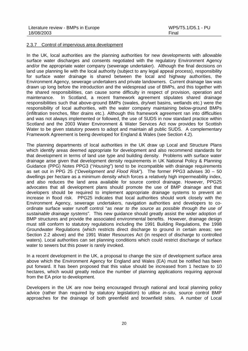
2.3.7 Control of impervious area development
In the UK, local authorities are the planning authorities for new developments with allowablesurface water discharges and consents negotiated with the regulatory Environment Agencyand/or the appropriate water company (sewerage undertaker). Although the final decisions onland use planning lie with the local authority (subject to any legal appeal process), responsibilityfor surface water drainage is shared between the local and highway authorities, theEnvironment Agency, sewerage undertakers and private landowners. Current drainage law wasdrawn up long before the introduction and the widespread use of BMPs, and this together withthe shared responsibilities, can cause some difficulty in respect of provision, operation andmaintenance. In Scotland, a recent framework agreement stipulates shared drainageresponsibilities such that above-ground BMPs (swales, dry/wet basins, wetlands etc.) were theresponsibility of local authorities, with the water company maintaining below-ground BMPs(infiltration trenches, filter drains etc.). Although this framework agreement ran into difficultiesand was not always implemented or followed, the use of SUDS in now standard practice withinScotland and the 2003 Water Environment & Water Services Act now provides for ScottishWater to be given statutory powers to adopt and maintain all public SUDS. A complementaryFramework Agreement is being developed for England & Wales (see Section 4.2).
The planning departments of local authorities in the UK draw up Local and Structure Planswhich identify areas deemed appropriate for development and also recommend standards forthat development in terms of land use type and building density. Problems with surface waterdrainage arise given that development density requirements in UK National Policy & PlanningGuidance (PPG) Notes PPG3 (“Housing”) tend to be incompatible with drainage requirementsas set out in PPG 25 (“Development and Flood Risk”). The former PPG3 advises 30 – 50dwellings per hectare as a minimum density which forces a relatively high impermeability index,and also reduces the land area available for source control drainage. However, PPG25advocates that all development plans should promote the use of BMP drainage and thatdevelopers should be required to implement appropriate drainage systems to prevent anincrease in flood risk. PPG25 indicates that local authorities should work closely with theEnvironment Agency, sewerage undertakers, navigation authorities and developers to co-ordinate surface water runoff control “as near to the source as possible through the use ofsustainable drainage systems”. This new guidance should greatly assist the wider adoption ofBMP structures and provide the associated environmental benefits. However, drainage designmust still conform to statutory regulations including the 1991 Building Regulations, the 1998Groundwater Regulations (which restricts direct discharge to ground in certain areas; seeSection 2.2 above) and the 1991 Water Resources Act (in respect of discharge to controlledwaters). Local authorities can set planning conditions which could restrict discharge of surfacewater to sewers but this power is rarely invoked.
In a recent development in the UK, a proposal to change the size of development surface areaabove which the Environment Agency for England and Wales (EA) must be notified has beenput forward. It has been proposed that this value should be increased from 1 hectare to 10hectares, which would greatly reduce the number of planning applications requiring approvalfrom the EA prior to development.
Developers in the UK are now being encouraged through national and local planning policyadvice (rather than required by statutory legislation) to utilise in-situ, source control BMPapproaches for the drainage of both greenfield and brownfield sites. A number of Local

Literature review - BMPs in Europe18/08/2003
WP5/T5.1/D5.1 - PUFinal
21
Authorities, County and District Councils are now adopting detailed policies for promoting BMPsin their Local and Structure Plans, Development Plans and Agenda 21 policy documents.
The national SUDS Working Group (NSWG) within England & Wales and the Sustainable UrbanDrainage Scotland Working Party (SUDSWP), together with the various CIRIA reports havecollectively raised knowledge and awareness regarding the opportunities offered by SUDS/BMPsolutions for stormwater drainage such that many outstanding institutional, legal, regulatory andmethodological issues are being addressed in one form or another.
In Germany, each state has its own water resources laws. In some states, for example, in NorthRhine-Westphalia, new buildings and other paved areas must have their own on-site stormwatertreatment facilities (North Rhine-Westphalia SS51a). In addition, the German Water Association(ATV) sets out in its technical standard ATV2002 the most appropriate type of control measurefor runoff from a variety of surfaces (Figure 2.1).
Figure 2.1 Infiltration facilities and their recommended use for runoff from differentcontributing surfaces in Germany.
In France, the Water Quality Law (January 3, 1992) strengthened the role of local authorities,assigning them new responsibilities in the area of drainage and sewerage. Article 35 of this law
Flä
che
Con
tant
of p
ollu
tant
s
Qua
lity
asse
ssm
ent
As:
Ai?
5
wid
e in
filtr
atio
n
5<A
s:A
i?15
sw
ales
, sw
ale-
tren
ch-s
yste
ms
5<A
s:A
i?15
cent
ral i
nfilt
ratio
n po
nds
tren
ches
infil
trat
ion
drai
ns (
shaf
ts?)
1 2 3 4 5 6 7 8
1 Green roofs, meadows, unpaved areas + + + + +
2 Roofs without metall; Terraces in housing areas + + + + (+)
3 Roofs with common shares of metal (uncoated, <10%) + + + (+) (+)
4 Footpathes in housing areas + + (+) (-) (-)
5Yards, parking lots and streets with less than 300 cars/day
+ + (+) (-) -
6 Streets with 300 - 5.000 cars/day + + (+) (-) -
7 Runways on airports + + (+) (-) -
8 Roofs in industrial areas + + (+) (-) -
9 Streets with 5.000 - 15.000 cars/day + + (+) - -
10 Parking lots with heaxy traffic (e.g. shopping malls) + (+) (+) - -
11Metal roofs; heavy polluted streets and yards (e.g. farms, markets)
+ (+) (+) - -
12 Streets with more than 15.000 cars/day; autobahns + (+) (+) - -
13 Streets and yards in industrial areas (-) (-) (-) - -
14special areas, e.g. parking lots for trucks, de-icing areas on airports
- - - - -
+ usually allowed As sealed area
(+) usually allowed with pre-treatment Ai infiltration area(-) usually not allowed- not allowed
not
tole
rabl
eSurface infiltration Underground infiltration
harm
les
sto
lera
ble

Literature review - BMPs in Europe18/08/2003
WP5/T5.1/D5.1 - PUFinal
22
stipulates that municipalities are to demarcate, subsequent to a public hearing, two types ofzones:
? the first pertains exclusively to either wastewater or a wastewater-stormwater mix, i.e. zonesdrained by means of collective and non-collective systems. As regards the latter,municipalities are compelled to perform the demarcation step;
? the second type pertains to stormwater and runoff; for this category, municipalities are tospecify not only the zones where measures must be adopted to limit soil impermeability andensure control over stormwater/runoff flow rate and volume, but also zones where it isnecessary to identify and lay out installations to collect, ultimately store and, if need be, treatboth stormwater and runoff whenever inflowing pollution has the potential to seriouslydisrupt drainage system efficiency.
Since specific measures or installations to be introduced have not been set forth in the pertinentlegislative or regulatory texts, the choice of control measure to attain the required outputthresholds is left up to each municipality. The facilities to be built will necessitate eitherconventional solutions (collection pipe networks, water treatment) or novel alternative solutionsthat depend on technical, economic and environmental considerations.
The 1992 Water Quality Law also requires that all French projects that use water resources,modify river flow or discharge into a river make a declaration to, or receive authorisation from,the State Administration, in accordance with a range of threshold values. The types of urbanand sanitation projects covered and threshold values involved are identified in Tables 2.9 and2.10.
Table 2.9 Main urban and sanitation projects with legal French threshold valuesHeading N° Threshold Declaration AuthorisationSewage plant 5.1.0 Pollution expressed in BOD5 12kg < Fp < 120 kg Fp ? 120 kgStorm overflow on asewer
5.2.0 Pollution expressed in BOD5 12kg < Fp < 120 kg Fp ? 120 kg
Storm overflow in ariver
5.3.0 Total area (in hectares) 1 < St < 20 ha St ? 20 ha
Sludges landdisposal
5.4.0 Annual quantity of sludges Qb > 50 000 m³or > 500 kg of BOD5
or > 1 tonne of nitrogen
Qb > 500 000 m³or > 5 tonnes of BOD5
or > 10 tonnes N
Control of stormwater 6.1.0 cost in millions of euros 1 < Ct < 1.8 M€ Ct ? 1.8 M€Creation ofimpervious zones
6.4.0 Surface (in hectares) none Se ? 5 ha
Key: Fp = permitted inlet pollution load/hour St = total areaQb = annual sludge load Ct = costSe = surface area
Table 2.10 Threshold values for authorisation/declaration in high density and low densityurban areasIn high density urban context:? Creation of impervious zones over 5 ha? Stormwater discharge in the river, the total area being over 20 ha, or between 1 and 20 ha
In low density urban context:? creation of ponds, with a surface between 0.2 and 3 hectares,
? authorisation
? authorisation? declaration
? declaration? authorisation

Literature review - BMPs in Europe18/08/2003
WP5/T5.1/D5.1 - PUFinal
23
with a surface over 3 hectares? drainage of wet lands
? authorisation
As well as the above declaration/authorisation requirement, the developer must also submit anenvironmental assessment to the State Administration which sets out measures to correct orreduce the impact on aquatic ecosystems and must also demonstrate its compatibility withSAGE and relevant water quality objectives.
In addition, in order to comply with the European Wastewater Treatment Directives, localauthorities in France must achieve strict effluent standards, including during rainfall events,when efficient treatment of wastewater/stormwater mixes is required. The considerable financialimplications associated with this legal requirement have resulted in considerable interest in theadoption of innovative drainage solutions.
With regard to future legislation, a significant new piece of European law, which aims to protectall waters across the European Union, is currently being developed. The Water FrameworkDirective will establish a framework for the protection of all surface waters, ground waters,coastal and estuarine waters. Its implementation will require the establishment of river basinmanagement plans (RBMPs) that will set out how a series of ecological objectives for each typeof water body will be met. The RBMPs will require a scientific, technological, environmental andeconomic assessment of all the options available to enable the most appropriate solutions to beselected. It is considered that BMPs will contribute an important role towards the achievement ofthese objectives.

Literature review - BMPs in Europe18/08/2003
WP5/T5.1/D5.1 - PUFinal
24
3 APPLICATION CHARACTERISTICS OF BMPS
3.1 General comparison of conventional systems with BMPs
Conventional systems and BMPs approach the issue of stormwater control from differentperspectives. The conventional approach to stormwater control is to directly drain stormwaterflows as quickly as possible to the nearest receiving watercourse or sewer system to avoid therisk of flooding and to protect human health. BMPs aim to treat stormwater as close as possibleto its source, reducing runoff volumes, pollutant loads and flow rates by collecting, temporarilystoring and subsequently discharging at a controlled rate to the soil or the downstream receivingwatercourse or sewer. As well as ensuring individual safety and flood protection, BMPs also aimto improve the urban environment through their potential for multifunctional use. For example,as well as providing stormwater control, retention basins can also act as recreational areas andprovide habitat for wildlife. Table 3.1 sets out a general comparison of the different approachesto stormwater control based on their underlying principles.
Table 3.1 General comparison of conventional systems with BMPsPiped systems BMPs
Cost to construct May be equivalent but potential of multifunctional use ofBMPs may reduce overall cost
Cost to operate andmaintain
Established Unclear for some systems: furtherwork required
On-site flood control Yes YesDown stream erosion andflood control
No Yes
Potential for water re-use No YesPotential for groundwaterrecharge
No Yes
Potential for pollutantremoval
Low High
Public amenity benefits No YesEducational benefits No YesPerformance lifetime Established Not established for some systems:
further work requiredLand take Not significant Dependent on type of system: varies
between significant and substantialDesign criteria Established Not established for some systems:
further work required
3.2 Factors affecting the use and selection of BMPs
There are a range of factors which can preclude or restrict to some extent the application ofBMP structures for urban stormwater control and Figure 3.1 provides a general guidance matrixon a range of such prejudicial factors. Inspection of the figure shows that wetlands togetherwith other wet storage facilities such as retention and extended detention basins, appear tohave fewer overall restrictions although they can score badly against important factors such asspace consumption (or land use) and adoption/management liability. The latter restriction iswidely viewed by adopting authorities as a major problem in terms of implementing SUDSschemes and a recent Scottish survey has highlighted the significant deterrence to the use ofSUDS (and especially ponds and wetlands) because of institutional concerns over adoption,
Literature review - BMPs in Europe18/08/2003
WP5/T5.1/D5.1 - PUFinal
25
Can be overcome with careful site design
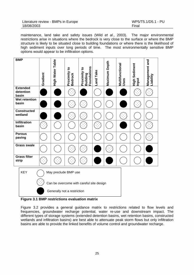
maintenance, land take and safety issues (Wild et al., 2003). The major environmentalrestrictions arise in situations where the bedrock is very close to the surface or where the BMPstructure is likely to be situated close to building foundations or where there is the likelihood ofhigh sediment inputs over long periods of time. The most environmentally sensitive BMPoptions would appear to be infiltration options.
BMP
Gra
die
nt
Hig
h W
ater
Tab
le
Pro
xim
ity
toB
edro
ck
Pro
xim
ity
toB
uild
ing
Fo
un
dat
ion
s
Lan
d T
ake
Max
imu
m D
epth
Mu
ltif
un
ctio
nal
Use
s
Hig
h S
edim
ent
Inp
ut
Man
agem
ent
and
Lia
bili
ty
ExtendeddetentionbasinWet retentionbasin
Constructedwetland
Infiltrationbasin
Porouspaving
Grass swale
Grass filterstrip
KEY May preclude BMP use
Generally not a restriction
Figure 3.1 BMP restrictions evaluation matrix
Figure 3.2 provides a general guidance matrix to restrictions related to flow levels andfrequencies, groundwater recharge potential, water re-use and downstream impact. Thedifferent types of storage systems (extended detention basins, wet retention basins, constructedwetlands and infiltration basins) are best able to attenuate peak storm flows but only infiltrationbasins are able to provide the linked benefits of volume control and groundwater recharge.
Literature review - BMPs in Europe18/08/2003
WP5/T5.1/D5.1 - PUFinal
26
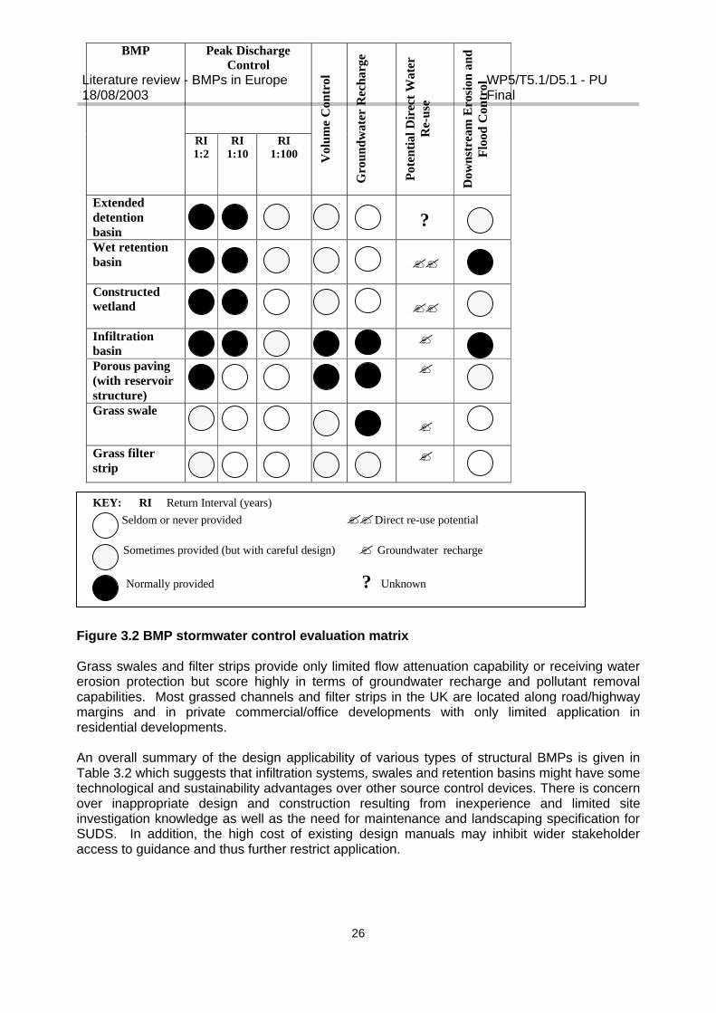
Figure 3.2 BMP stormwater control evaluation matrix
Grass swales and filter strips provide only limited flow attenuation capability or receiving watererosion protection but score highly in terms of groundwater recharge and pollutant removalcapabilities. Most grassed channels and filter strips in the UK are located along road/highwaymargins and in private commercial/office developments with only limited application inresidential developments.
An overall summary of the design applicability of various types of structural BMPs is given inTable 3.2 which suggests that infiltration systems, swales and retention basins might have sometechnological and sustainability advantages over other source control devices. There is concernover inappropriate design and construction resulting from inexperience and limited siteinvestigation knowledge as well as the need for maintenance and landscaping specification forSUDS. In addition, the high cost of existing design manuals may inhibit wider stakeholderaccess to guidance and thus further restrict application.
Sometimes provided (but with careful design) ? Groundwater recharge
Normally provided ? Unknown
Peak DischargeControl
BMP
RI1:2
RI1:10
RI1:100 V
olum
e C
ontr
ol
Gro
undw
ater
Rec
harg
e
Pote
ntia
l Dir
ect W
ater
Re-
use
Dow
nstr
eam
Ero
sion
and
Flo
od C
ontr
ol
Extendeddetentionbasin
?Wet retentionbasin ??
Constructedwetland ??
Infiltrationbasin
?
Porous paving(with reservoirstructure)
?
Grass swale?
Grass filterstrip
?
KEY: RI Return Interval (years) Seldom or never provided ?? Direct re-use potential

Literature review - BMPs in Europe18/08/2003
WP5/T5.1/D5.1 - PUFinal
27
Table 3.2 SUDS technology evaluation matrixCriterion
Infi
ltra
tio
nS
yste
ms
Po
rou
sP
avin
g (
wit
hre
serv
oir
stru
ctu
re)
Gra
ss S
wal
es
Gra
ss F
ilter
Str
ip
Wet
Ret
enti
on
Bas
ins
Co
nst
ruct
edW
etla
nd
s
Planning cost(Pre-planning and design)
+ o + o + -Construction cost(Capital investment)
+ o + o - oO & M cost(Including personnel, plantreplacement and sedimentdisposal)
+ + o + o o
Technical implementation effort(excavation, lifetimeO & M, decommissioning)
+ o + + - o
Water re-use(not including groundwaterrecharge)
- - - - + +
Whole-life cost(Duration, affordability, flexibilityfor retrofitting etc)
+ - + + + o
Reliability against Failure(Forced and planned outageduring lifetime)
- o + + + o
Planning and PracticalExperience(System performance knowledge)
o + o - + -
KEY:+ more advantageous as compared to other technologies
o neither advantageous nor disadvantageous as compared to other technologies
- less advantageous as compared to other technologies
Literature review - BMPs in Europe18/08/2003
WP5/T5.1/D5.1 - PUFinal
28
4 DESIGN, O&M AND COSTING ASPECTS OF STRUCTURAL BMPS
4.1 BMP Design
4.1.1 Published Manuals
In the UK, it is only in recent years that design manuals for urban BMP treatment systems havebeen published, and even now they only provide detailed coverage for infiltration, dry/wetretention basins and wetland systems. General technical guidance on BMPs including designcriteria principles, SUDS selection techniques and approval procedures are given in two CIRIA(C521 and C522, 2000) design manuals for Scotland & N Ireland and England & Wales,respectively, and there is also a more general “Best Practice Manual” (CIRIA Report C523,2001). Detailed design manuals have been published for soakaways (BRE, 1991; SoakawayDesign, BRE Digest 365, Building Research Establishment, Garston) and infiltration trenches(CIRIA, 1996; Infiltration Drainage: Manual of Good Practice, Report 156, Construction IndustryResearch & Information Association, London) and constructed pervious surfaces (CIRIA, 2002,“Source Control Using Constructed Pervious Surfaces”). The methods outlined in these twovolumes derive dimensions required for a range of 10 year RI storm events based on designstorm rainfall determined from Volume 3 of the Wallingford Procedure (Department of theEnvironment, 1981). However, despite the existence of these various guidance manuals, arecent Scottish survey indicates that they are not specific enough for most users, being limitedin terms of design and engineering detail as well as appropriate case examples (Wild et al.,2003). In particular, the available manuals lacked information on adoption and maintenanceissues. Nevertheless, the technical deficiencies in the manuals do not appear to have been asignificant barrier to SUDS implementation within the UK generally.
A number of publications provide detailed design guidance for wetland systems including the1998 CIRIA Report 180 (Review of the Design and Management of Constructed Wetlands) andthe 2003 Environment Agency Technical Report P2-159/TR1 (Constructed Wetlands and Linkswith Sustainable Drainage Systems). An earlier WRc report (1996) “Reed Beds andConstructed Wetlands for Wastewater Treatment” also provides some limited but useful designinformation for urban stormwater wetlands.
The Highways Agency have included reference to the design and use of BMPs for the controland treatment of highway runoff in Volume 11, Section 3, Part 10; Water Quality and Drainageof the 1998 Design Manual for Roads and Bridges (DMRB). Volume 4, Section 2, Part 1 (HA103/01) of the DMRB issued in 2001 also provides design detail for “Vegetative TreatmentSystems for Highway Runoff”. Design of fin and filter drains are covered in DMRB Volume 4,Section 2 Part 3 (HD 33/96) “Surface and Sub-surface Drainage Systems for Highways” and in“Notes for Guidance on the Specification for Highway Works” (Manual of Contract Documentsfor Highway Works, MCHW2, HMSO, London).
Ongoing CIRIA research projects include RP663 (“SUDS Techniques: Hydraulic, Structural andWater Quality Issues”) and a proposal with industry to review and update technical SUDSdesign and construction guidance. HR Wallingford are also currently undertaking research onthe “Use of SUDS for High Density Developments” in response to the increased housing densityrequirements set out in PPG3.
In France, general information on alternative techniques for stormwater drainage is given inTechniques alternatives en assainissement pluvial: Choix, conception, realisation et entretien
Literature review - BMPs in Europe18/08/2003
WP5/T5.1/D5.1 - PUFinal
29
(Azzout et al., 1994). More specific information on the design of stormwater retention basins isprovided by the technical guide Guide Technique des Bassins de Retenue d’Eaux Pluviales(Bergue and Ruperd, 1994).
4.1.2 Determination of design treatment volume
Traditionally, EA regulatory consent requirement for stormwater discharges from newdevelopments has been 5l/s/ha but throttle rates as low as 1 – 2l/s/ha need to be maintainedduring peak river flow periods to provide adequate receiving water protection levels (Kellagher,2002). This would require a two-tier design discharge approach with total runoff split between alimited period of very low rates and a more extended high flow rate. The higher discharge rateswould be dictated by the predicted greenfield runoff for high return period events, whilst thereduced discharge rates would be linked to the additional volume generated by the developmentcompared to the greenfield condition.
One contentious and unresolved issue in the various UK design manuals relates to thedetermination of the appropriate design treatment volume required for pollutant removal undervarying hydraulic retention times. Various methods have been advocated to determine suchtreatment volumes (Vt), mainly based on particle settling characteristics. The CIRIA C521 andC522 (2000) design manuals adopt the somewhat conservative Volume 3 WallingfordProcedure approach:
Vt (m3/total area, ha) = 9.D(SOIL/2 + (1 - SOIL/2). I
where SOIL = WRAP (winter rain acceptance potential) soil index i.e 1 to 5D = M5 – 60 rainfall depth (mm)I = Impervious decimal fraction (0.0 – 1.0)
Typically this relates to a treatment volume of 70 – 100 m3/ha for an average residentialdevelopment and, for a wet retention basin on a 370ha development in SE Scotland, wouldequate to approximately 280 – 400 m3/ha. The 1993 CIRIA “Design of Flood StorageReservoirs” volume suggests a treatment volume based on the first 12 – 15mm of storm runoffdistributed over the catchment area which would amount to 150m3/ha for a wet retention basinon the same Scottish urban catchment. The 2003 Environment Agency “Constructed Wetlandsand Links with Sustainable Drainage Systems” publication makes a similar recommendation butcapture volume is based on the first 10 – 15mm of effective runoff and uses local hourly rainfalltime series. An alternative suggestion is to utilise time series rainfall data to derive the capturevolume of all runoff from 90% of storm events or the runoff volume generated by 25mm ofrainfall over the catchment and to use the largest of these two depths as the design rainfall.The treatment volume can be calculated assuming all runoff from the impervious areas will drainto the treatment system and none from the pervious areas. If the 25mm design rainfall is used,the volume (in m3) is thus 0,025 x catchment area (in m2). If the impermeable percentage isextremely high or low, this estimation may be inaccurate. Based on the above approaches:
The design rainfall (R) should be the larger of:? 10 – 15mm of effective rainfall runoff (based on local hourly rainfall series analysis)? the one day, twice per year rainfall volume? rainfall volume from 90% of all storm events? 25mm rainfall volume distributed over the entire catchment
Literature review - BMPs in Europe18/08/2003
WP5/T5.1/D5.1 - PUFinal
30
The treatment volume (Vt; m3) is then calculated using:
Vt = (R x I x A) / 1000
Where R = Design rainfall (mm) I = Impermeability index A = Catchment area (m2)
The CIRIA 2000b design manual recommends that a satisfactory standard of service for waterquality should have a permanent pond volume (m3) equal to 4Vt. The 1996 WRc wetlandvolume gives guidance for the surface area of the treatment system of between 1% to 5% of thetotal catchment area which would equate to about 130 to 350 m3/ha. There is similar designguidance provided in US handbooks with the US Corp of Engineers STORM model beingperhaps the most widely used. This is based on:
Vt = 10890.Sd.I (where Sd = mean storm depth)
and for the 370ha Scottish development this would derive a value of 380 m3/ha for wetlands.
However, it should be remembered that “standard” SUDS design guidelines for the calculationof required storage volumes such as BRE (1991) or CIRIA (1996) are only acceptable if localconditions (e,g, rainfall, infiltration etc.) are fully taken into account and/or high safety factors areapplied (Scholz, 2003).
With regard to the sizing of BMPs in cold countries, Caraco and Claytor (1997) recommendincreasing the storage and treatment capacity of BMPs to cope with the large volumes of runoffgenerated in spring from a combination of meltwater and rainfall. As a snowmelt can occur overa period of several weeks, greater storage and treatment capacities are required compared tostorm events alone. A “rule-of-thumb” is to oversize BMPs when the average annual snowfalldepth is greater than the annual total precipitation depth, and it is suggested that no more than5% of the annual runoff volume should be permitted to bypass treatment during this spring melt(Caraco and Claytor, 1997). Novotny et al. (1999) recommend capturing and treating 90% of themelt volume. In addition it is recommended that all runoff design facilities should incorporatesome kind of pre-treatment to settle coarse-grained solids, have a maximum pond depth of 2.5m, a maximum flow velocity of approximately 1.5 m/s anywhere in the system and usevegetated buffers (Caraco and Claytor, 1997, Claytor and Scheuler, 1996).
4.1.3 Swales
When calculating the design flow for a grassed swale, a runoff return period of 10 years hasbeen considered suitable (Schwab and Frevert, 1985; SNRA, 1990). Erosion should be avoidedby an appropriate selection of base slope, grass mixture, and cross-section. A base slope ofless than 5% has been recommended (Schueler, 1987), with a typical value of approximately2% (SNRA, 1998; Larm 2000). Prosser et al. (1995) concluded that grass provides a substantialresistance to erosion as most of the shear stress is exerted on the plant stems deflectedbeneath the flow, and as a consequence, very low velocities occur close to the bed soil surface(Montes, 1998). Bermuda grass, buffalo grass, Kentucky bluegrass or common grass mixturesare all reported to inhibit erosion at water velocities of approximately 1m/s in grassed swaleswith base slopes of less than 10% (Schwab and Frevert, 1985; Ferguson, 1998; Montes, 1998).The infiltration capacity of a grassed swale is dependent upon a range of factors such as
Literature review - BMPs in Europe18/08/2003
WP5/T5.1/D5.1 - PUFinal
31
groundwater level, soil porosity, sediment load and density of surface vegetation (Stahre andUrbonas, 1990). According to Schueler (1987), underlying soils should have a permeability of12.7 mm/h or higher, and the groundwater table should be at least 0.6 m below the bottom ofthe swale. Stahre and Urbonas (1990) recommended a minimum saturated infiltration rate of 7.6mm/h and that the seasonal high groundwater level be more than 1.2 m below the infiltratingsurface. A swale can be used for stormwater infiltration as long as there is sufficient distancebetween the swale and the groundwater table. If the unsaturated zone is too shallow, there is asignificant risk that pollutants will reach the groundwater resource.
Swale design has traditionally been governed by the demand for stormwater conveyance ratherthan water quality improvement. Based on knowledge of pollutant removal in grassed swales,Ferguson (1998) developed the following empirical design criteria:? water velocity should be less than 0.15 m/s? swale length should be at least 60 m? residence time in the swale should be at least 9 minutes.
Yu et al. (2001) concluded that grassed swales should be a minimum of 75 m in length andhave a maximum longitudinal slope of 3%. It has been found that pollutant concentrationsdecline exponentially along the length of the swale (Wang et al., 1981; Coyne et al., 1998;Deletic, 1999), suggesting that the majority of pollutants are trapped in the first few metres ofthe swale. A similar behaviour is observed in filter strips.
Research by Barrett et al. (1998) concluded that long grassed medians are not required for theeffective removal of pollutants from highway runoff as most of the pollutant removal had alreadyoccurred in the side slopes of the median. Instead, as discussed by Ellis (1999), factors otherthan swale length, such as vegetation density and flow conditions, may be more important whendesigning grassed swales for stormwater pollution control. Further work by Bäckström (2002)suggested that there is an exponential relationship between grassed swale sediment removalpotential and mean hydraulic detention time, i.e. increasing the detention time increasesremoval efficiency. Furthermore, surface loading or specific swale area (i.e. the ratio betweenswale area and contributing impervious drainage area) might be used as design parameterswhen constructing grassed swales for pollution control.
4.1.4 Soakaways
Soakaways (or infiltration pits) provide attenuation of surface runoff by allowing gradualinfiltration into the surrounding soil and are extremely widely used in the UK especially for roadand highway runoff e.g over 60 soakaways are located in a 11km section of the M25 circularmotorway (between junctions 18 and 24) around London. There are two major designs basedon either the stone filled, perforated-ring soakaway or the chamber soakaway with both typesusually incorporating a sump to trap coarse sediment. Soakaways in the UK are designed toreceive a 2 hour storm having a return period (RI) of 10 years i.e 15 mm/hour. The infiltrationrate should ensure that the soakaway is half empty within 24 hours of the completion of a runoffevent.
Soakaway practice may provide little if any protection to groundwater from pollutants carried inthe surface drainage, and especially for highly soluble contaminants such as herbicides, MTBE,metal species such as zinc, cadmium and platinum, as well as monocyclic aromatichydrocarbons such as benzene or toluene or other organochlorine solvents. Whilst soakawaysare invariably above the water table, even the presence of a thick non-saturated zone may not

Literature review - BMPs in Europe18/08/2003
WP5/T5.1/D5.1 - PUFinal
32
guarantee sufficient aquifer protection. In chalk for example, the pore space in the unsaturatedzone is normally totally filled with water with only the fissures draining under gravity. Beneath asoakaway, the fissure space will rapidly fill after rainfall and the transit time to the water tablemay be only minutes. Tracer tests undertaken on soakaway drainage at the M1/M25 junction inHertfordshire, UK, indicated potential travel times of about 2 km/day via fissure flow within theunderlying chalk; the maximum recorded speed was 100 m/hour (Price et al., 1992). On thebasis of the tracer behaviour, it was estimated that pollutant concentrations reaching abstractionwells some 3-km away from the soakaway injection point, were likely to be about 4 ?g/l for everytonne of pollutant reaching the soakaway structure.
4.1.5 Infiltration trenches
Infiltration trenches are essentially a linear version of soakaways and operate in an identicalway. Infiltration trenches are filled with stone or rubble and in comparison to soakaways requirelower volumes of infiltration material for a given water inflow. Narrower systems save onconstruction costs but one reason for their lower popularity in the UK, compared to soakaways,is the commonly perceived design problem associated with accommodating the required trenchlength and width into the land area available. However, the ability to maximise the infiltrationsurface area in these systems enables higher treatment efficiencies to be achieved. Infiltrationtrenches can be covered with grass or have surrounding grassed strips to protect the infill fromexcess sediment and thus act as interceptors between the roadway and the trench as well asenhancing the aesthetic appearance of the installation. A suitable covering also prevents thewashing of the exposed surface medium during maintenance procedures.
4.1.6 Infiltration basins
Infiltration basins are designed to store surface water runoff and to allow it to slowly percolatethrough the soil of the basin floor or through a specially constructed under-drain systemcontaining gravel and/or sand filter beds. Two under-drain configurations have been previouslydescribed involving a “reduced sand bed with gravel layer” and a “trench design” (Ellis andRevitt, 1991). The base may also consist of or include a geotextile such that the base materialcan be replaced if its porosity is reduced e.g. by contamination. The walls of the basin may becovered with a geotextile or simply consist of the natural soil, either with or without vegetation.Infiltration basins can be constructed to the required aesthetic shape and are generally between0.5 and 3.0 m in depth with a freeboard of at least 200 mm above the maximum water level. Thebase should at all times be above the maximum water table. Infiltration basins may also includesome type of pre-treatment structure such as a grit chamber, oil remover or clarifier.
It is common practice to incorporate vegetation cover, consisting of indigenous plant and grassspecies, throughout the basin with the length of the grass kept to approximately 150 mm byregular mowing. Infiltration basins are best suited to soils with infiltration rates exceeding 15mm/hour (e.g sandy loams, sands, sandy gravels). An overall filtration rate of 5 m3/ha/m2
should provide for total solids removal efficiencies of between 64 - 98%. When infiltration basinsare designed for rare frequency events (i.e. the basins are large), they can be incorporated as alandscape feature for example, as a playing field or a leisure park. The basin can be equippedwith a regulated discharge to another outlet, generally the sewer system. The use of infiltrationbasins hence reduce peak flow volumes and flow rates.
Retention of pollutants within the first 30 cm of soil is very important. The use of limestone soilhelps achieve this. Over time there will be a deepening of the pollutant front as the soil becomes
Literature review - BMPs in Europe18/08/2003
WP5/T5.1/D5.1 - PUFinal
33
chemically saturated. If a geotextile is employed, it should be placed at a maximum depth of 30cm, although, areas of the basins under greater pressure e.g. water inlet and bottom zones, willrequire greater protection. In these areas, a geochemical semi-pervious barrier can be utilised(Didier and Norotte, 1999).
Research by Stenmark (1992) demonstrated that it was possible to use infiltration basins in thenorth of Sweden. However, it is essential that various cold climate and local conditions areconsidered when designing and maintaining these systems to enable optimum performance tobe achieved. The infiltration basin should be designed to cope with a decreased capacity duringthe snowmelt period, due to both a lower hydraulic capacity and the possibility of ice formationin the facility. When calculating the volume of a basin the statistical design storm volume shouldbe compared with meltwater inflow, with a corresponding decrease in hydraulic conductivityincorporated due to a higher viscosity at 0°C. Swedish guidelines (VAV P46, 1983) suggest amelt flow of 2 L/s per ha of contributing area (which includes frozen permeable surfaces) innorthern Sweden. In addition, the capacity of the basin has to be sufficient to take the intensivepart of the snowmelt without overflowing. It was found that the lower the hydraulic conductivity,the more important it was to consider the snowmelt. A generalised conclusion regarding when itwas more important to consider snowmelt rather than rain events during the design of theinfiltration basins could not be made because of the distribution of different types of surfaceswithin the drainage area. In non-cohesive soils (K>2x10⁻⁵ m/s) the primary design loadestimation criterion is usually based on rain flows, but the capacity of the basin during snowmeltshould be checked using a decreased hydraulic conductivity due to the increased viscosity ofthe water (Stenmark, 1992). If soil is used, Caraco and Claytor (1997) recommend the selectionof a soil with a minimum infiltration rate of approximately 1.3 cm/hour and a clay content of lessthan 30%. It has been noted that soils dry at the time of freeze-up will have a more effectiveporosity due to the lack of ice in pore spaces, and both Granger et al. (1984) and Novotny et al.(1999) have recommend keeping the top 30cm of soil dry before freeze-up to retain soilinfiltration capacity at melt. It was also noted that flat slopes are essential to encourageinfiltration and recommended that clogging should be minimised by, for example, pre-settling(Caraco and Claytor, 1997). Stenmark, 1992, also recommended locating infiltration basins inareas with vegetation and an untouched snow layer to insulate the basin thus decreasing frostpenetration.
4.1.7 Sedimentation tank
Using data obtained from an experimental study (see section 5.2.3.2) in which a 1500 Lsedimentation tank was located adjacent to the M1 motorway, Ellis and Revitt (1991) calculatedthe required dimensions of such a tank to provide 100% theoretical solids removal from runofffrom a 1 km length of highway (15 m width) draining through 20 road gullies spaced 50 m apart.A tank of 0.57 m depth and a volume of 57.6 m3 was predicted. Based on a length:width ratio ofapproximately 5 to 1, the sediment tank would have to be 21.97 m long and 4.55 m wide whichwould not be feasible in most instances. The size constraints together with the limited pollutantremoval efficiencies (see Table 5.7) and the safety factors associated with large open tanksnext to busy roads do not encourage the use of these systems.
4.1.8 Lagoons
Lagoons are similar to sedimentation tanks except that they are constructed by excavatingnatural earth basins which can be covered with vegetation whereas sedimentation tanks are
Literature review - BMPs in Europe18/08/2003
WP5/T5.1/D5.1 - PUFinal
34
entirely synthetic in construction. Lagoons may be lined where it is necessary to preventinfiltration and safety fencing is usually required.
4.1.9 Detention basins
Extended detention basins are naturally vegetated impounding systems which are dry duringnormal conditions (although a very shallow marsh may exist in the lowest levels of the basin)but provide storage of storm runoff during periods of heavy rainfall. A liner or membrane maybe incorporated into the design if it is essential to avoid infiltration to groundwater. Associatedwith their flow attenuation characteristics, such detention basins also encourage sedimentationof the coarser suspended materials although fine solids will be re-suspended during high flows.In Herning, Denmark, constructed wetlands have been used in combination with conventionaldetention basins to save costs. Basins have been built to contain the equivalent of a rainfalldepth of 2-4 mm over the contributing catchment. When a basin is full the overflow goes to awet pond (built to hold 25 mm or more), which also receives discharges from separatestormwater systems. From here excess water is then discharged in a controlled manner to anearby stream. The use of this combined system offers several clear advantages:? the stream is protected against erosion from peak flows? the overflow is less polluted following sedimentation and degradation processes in the pond? treatment plants are no longer subjected to large volumes of water as the basin empties? the system is much cheaper to construct than a concrete basin of the same volume
4.1.10 Retention ponds
The most widely used BMPs for the treatment of stormwater runoff in Sweden are retention anddetention basins. However, pond design criteria and guidelines are often presented in only avery general manner, which may result in their misinterpretation. Design equations for a specificstudy seldom express both the required pond area and volume, and it has been suggested thatdesign should be led by the pollutants targeted for reduction and by the level of treatmentrequired. For example, the removal of nutrients usually requires larger systems than thosetargeting the removal of pollutants that are more strongly bound to sediments e.g. lead. Thedesign should include control calculations for the residence time and water balance. A waterbalance should be carried out to ensure that the risk for overflow is acceptably low and that thebase flow will be larger than losses due evaporation and infiltration. The residence time shouldalso be optimised with respect to a variety of flow conditions. A series of guidelines put forwardby various authors are set out in Table 4.1.
The requirements and conditions for pollutant removal from meltwater in cold climates aredifferent from those for stormwater runoff under temperate conditions, which have been thefocus of many BMP systems. For example, retention typically relies upon settling and biologicalactivity for treatment. However, the treatment requirements are more complicated under winterconditions when an ice layer forms over the permanent storage pool and biological activity isslowed dramatically. Consequently, pollutant removal efficiencies in retention basins will beless effective under snowmelt conditions unless adaptations are made to accommodatemeltwater runoff (Oberts et al., 1989; Oberts, 1990; Marsalek, 1997). These adaptations areparticularly important in areas receiving runoff from densely developed urban areas androadways where solids are the predominant pollutants.

Literature review - BMPs in Europe18/08/2003
WP5/T5.1/D5.1 - PUFinal
35
Relating the use of retention (and detention basins) to the characteristics of meltwater is anessential first step in their use. Early in the melt sequence, a highly soluble first flush occurs.Ponds can be used to store this for later infiltration, dilution, slow release or settling. Thesalinity often associated with meltwater reduces the settling velocity, oxygen levels and thepartitioning coefficients for metals. The result of this is less settling of particulates, and possiblythe release of metals from previously settled bottom material. Use of BMPs for snowmeltconditions, therefore, should start with the reduction of soluble pollutants and those associatedwith fine-grained particulate matter, both of which are difficult to accomplish. Following thisprocess, the removal of particulate material, for which detention is better suited, can occur.
Table 4.1 Swedish design guidelines for retention pondsSize/comments Reference
Water depth Average depth 1.5-2 mMinimum depth 1.2 mMaximum depth 3.5 m
Urban Drainage and Flood ControlDistrict 1999; WEF and ASCE, 1998;SNRA,1998; SEPA, 1997; Hvitved-Jacobsen et al, 1994; Larm, 1994
Slide slope = 1:3 (= 1:4 over permanent surface);concerning safety, maintenance and thereduction of pollutant. Minimum 1:2 if theground is stable. Preferable 1:5 – 1:10, needsbigger area.
Urban Drainage and Flood ControlDistrict 1999; Persson, 1999; SNRA,1998; SEPA, 1997; Hvitved-Jacobsenet al, 1994; Larm, 1994
Length: Width >2:1 (= 3:1, recommended) Urban Drainage and Flood ControlDistrict 1999; Persson, 1999; Larm,1994
Absolute minimumarea
= 150 m2 (minimum width 8 m, minimum length20 m)
Fransson and Larm, 2000
Recommendedminimum area
>0.25 ha (2500 m2) Schueler, 1987
Permeability Infiltration rate of <10-9 m/s is preferable Fransson and Larm, 2000; UrbanDrainage and Flood Control District1999
Drainage area 10-100 ha Lönngren, 1995; Schueler, 1987Vegetation Can be planted in the shallow part of the pond.
Water plants can cover up to 20-25 % of thesurface.
SEPA, 1997, Urban Drainage and FloodControl District 1999; Schueler, 1992
Inlet The inlet should be constructed to distributethe incoming water evenly into the pond, e.g.stones
Urban Drainage and Flood ControlDistrict 1999; Persson, 1999; Stahreand Urbonas, 1993
Inlet and Outlet Stairs of stones at the in- and outlet can beused for aeration.
-
Outlet The outlets should be designed for anemptying time of 12-24 h (max 48 h).
Urban Drainage and Flood ControlDistrict 1999; Persson, 1999; Urbonas,Roesner and Guo, 1996; 20-40 haccording to Stahre and Urbonas, 1993
Outlet Emergency exit dimensions are required forrain events of 25-100-year return intervals(several emergency exits can be constructedwith the outflow higher up, from rain events for2 year up to 100 year)
Urban Drainage and Flood ControlDistrict 1999
Outlet A v-shaped weir or sewer at the outlet providesa flow compensation effect.
Persson, 1999
Outlet Cleaning bars at the outlet pipe are preferable. SNRA, 1998Maintenance Vehicular access to the inlet- and outlet should
be provided.Urban Drainage and Flood ControlDistrict 1999
Groundwaterprotection
The pond can be below the groundwaterlevel. The benefit of this is that a permanentwater body exists during the dry period.
-
Additional comments A sedimentation pond may be provided as a WEF and ASCE, 1998
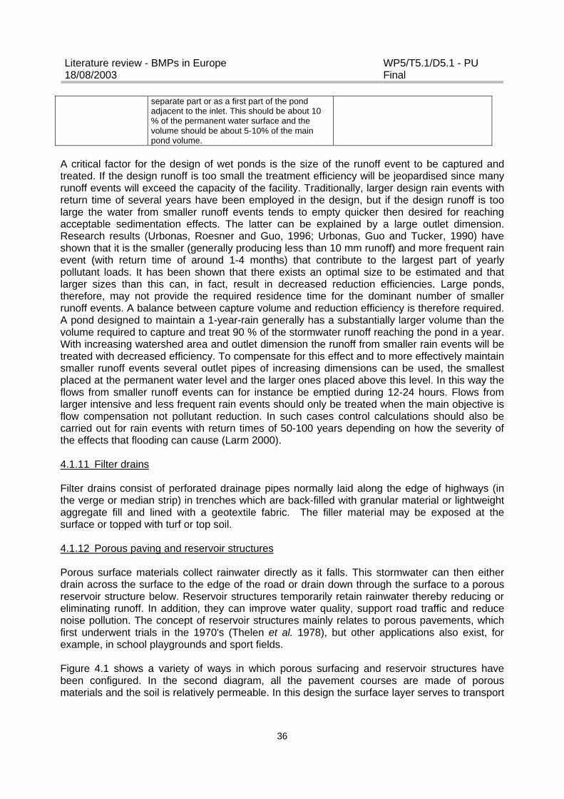
Literature review - BMPs in Europe18/08/2003
WP5/T5.1/D5.1 - PUFinal
36
separate part or as a first part of the pondadjacent to the inlet. This should be about 10% of the permanent water surface and thevolume should be about 5-10% of the mainpond volume.
A critical factor for the design of wet ponds is the size of the runoff event to be captured andtreated. If the design runoff is too small the treatment efficiency will be jeopardised since manyrunoff events will exceed the capacity of the facility. Traditionally, larger design rain events withreturn time of several years have been employed in the design, but if the design runoff is toolarge the water from smaller runoff events tends to empty quicker then desired for reachingacceptable sedimentation effects. The latter can be explained by a large outlet dimension.Research results (Urbonas, Roesner and Guo, 1996; Urbonas, Guo and Tucker, 1990) haveshown that it is the smaller (generally producing less than 10 mm runoff) and more frequent rainevent (with return time of around 1-4 months) that contribute to the largest part of yearlypollutant loads. It has been shown that there exists an optimal size to be estimated and thatlarger sizes than this can, in fact, result in decreased reduction efficiencies. Large ponds,therefore, may not provide the required residence time for the dominant number of smallerrunoff events. A balance between capture volume and reduction efficiency is therefore required.A pond designed to maintain a 1-year-rain generally has a substantially larger volume than thevolume required to capture and treat 90 % of the stormwater runoff reaching the pond in a year.With increasing watershed area and outlet dimension the runoff from smaller rain events will betreated with decreased efficiency. To compensate for this effect and to more effectively maintainsmaller runoff events several outlet pipes of increasing dimensions can be used, the smallestplaced at the permanent water level and the larger ones placed above this level. In this way theflows from smaller runoff events can for instance be emptied during 12-24 hours. Flows fromlarger intensive and less frequent rain events should only be treated when the main objective isflow compensation not pollutant reduction. In such cases control calculations should also becarried out for rain events with return times of 50-100 years depending on how the severity ofthe effects that flooding can cause (Larm 2000).
4.1.11 Filter drains
Filter drains consist of perforated drainage pipes normally laid along the edge of highways (inthe verge or median strip) in trenches which are back-filled with granular material or lightweightaggregate fill and lined with a geotextile fabric. The filler material may be exposed at thesurface or topped with turf or top soil.
4.1.12 Porous paving and reservoir structures
Porous surface materials collect rainwater directly as it falls. This stormwater can then eitherdrain across the surface to the edge of the road or drain down through the surface to a porousreservoir structure below. Reservoir structures temporarily retain rainwater thereby reducing oreliminating runoff. In addition, they can improve water quality, support road traffic and reducenoise pollution. The concept of reservoir structures mainly relates to porous pavements, whichfirst underwent trials in the 1970's (Thelen et al. 1978), but other applications also exist, forexample, in school playgrounds and sport fields.
Figure 4.1 shows a variety of ways in which porous surfacing and reservoir structures havebeen configured. In the second diagram, all the pavement courses are made of porousmaterials and the soil is relatively permeable. In this design the surface layer serves to transport
Literature review - BMPs in Europe18/08/2003
WP5/T5.1/D5.1 - PUFinal
37
the rain to the porous underlying layers, which act as a temporary reservoir before the delayedevacuation of the water by infiltration into the subsoil. This design thus perform three functions,rainwater collection, storage and discharge. The type of reservoir structure most appropriate fora particular project will depend on how it is decided each of these functions should beperformed. Table 4.2 gives some examples.
Figure 4.1 Basic reservoir structure
Table 4.2 Designs of reservoir structuresFUNCTION TYPE OF IMPLEMENTATION TECHNICAL SOLUTION
Distributed in space -infiltration through a permeable material onthe pavement surface.
Collectionof water Localised
-infiltration channels-rainwater gullies with distribution pipe in theporous medium.-diffusion network for external input.
Spatially distributed throughout the structure -porous material with adequate load bearingcapacity.Storage of water
Localised in only part of the structure -greater thickness of very porous material(adequate load-bearing capacity).
Distributed -infiltration into pavement subgrade.*
Evacuation of water Localised-drains to collector.-infiltration trenches to permeable levels.-calibrated orifice to collector..
*This solution requires special properties of the soil (permeability and sufficient bearing capacity in the presence ofwater) and special attention to the risks of ground water pollution.
4.1.12.1 Selection of materials
Literature review - BMPs in Europe18/08/2003
WP5/T5.1/D5.1 - PUFinal
38
The porous materials usually used by road engineers are porous asphalt (to reduce traffic noiseand increase wet-weather safety) and porous concrete (used mainly for the drainage ofconcrete pavements). Porous asphalt (or macadam) pavements consist of an open-gradedasphalt mix (powdered/crushed stone with a bitumen binder) with a coarse surface texture anda high void ratio. The open texture with continuous pore spaces allows rainfall to immediatelyinfiltrate the surface. It is usually laid some 50mm thick over new or existing impermeable roadsurfaces with stormwater flowing laterally across the highway within the porous asphalt layer tothe kerb or to a filter drain. Porous asphalt can also be used in conjunction with an underlyingreservoir structure.
The infiltration capacity of a newly constructed permeable asphalt surface has been shown tobe between 500 and 700 mm/min (Goransson and Jonsson, 1990) and it has been reported thatthe infiltration rate on a newly-laid paving may exceed 1000 mm/hour. Results from laboratorytests simulating a permeable asphalt surface that had been continuously used for a period of 30years indicated an infiltration capacity of 400 mm/min. All these values greatly exceed theapproximate 1mm/min infiltration rate which is considered sufficient to cope with an intense rainstorm. It has been recommended that the infiltration rate of the selected materials should beequal to or greater than the design rainfall intensity. It is, however, important to properlymaintain the permeable road surface, especially during the construction phase. The surfaceshould be protected against fine particles that will increase the rate of clogging. Sources of suchparticles include erosion from vegetated surfaces and flower-beds.
Porous materials used in reservoir structures include porous bitumen-stabilised materials (openmaterials with a lower bitumen content than porous asphalt), untreated crushed materials,secondary quarry crusher products (screened to eliminate the smallest parts), porous orgrooved setts (used mainly in pedestrian zones) and honeycomb plastic materials. Table 4.3compares the water storage (useful porosity) capability and relative costs of various materials.
Table 4.3 Properties of porous materialsMaterial Useful Porosity Cost/m3 of water storagePorous settsPorous asphaltPorous concretePorous bitumen stabilized materialsCrushed materials without sandHoneycomb plastic materials
10-20%10-20%10-20%10-20%30-40%>90%
+++++++++++++++
Generally, the majority of the water storage is performed in a layer of untreated crushedmaterials or honeycomb plastic materials at the base of the structure. A perviousasphalt/crushed aggregate construction, known as the unit superstructure, was developed inSweden (Hogland et al., 1987) which includes the use of a geotextile between the soil and sub-base to prevent fine soil mixing with the aggregate. The presence of a drainage pipe to collectinfiltrated waters is important where the surrounding soils posses low hydraulic conductivityvalues.
Mechanically, porous materials generally have a lower strength than non-porous materials. Thecomplex modulus of porous bituminous materials is half that of conventional materials, butfatigue test results are similar. Crushed porous materials without binders must be made withhard aggregates and are regarded, mechanically, as intermediate materials. From thecharacteristics measured on these materials, it has been possible to establish typical pavementcross sections in porous pavements which allow for the anticipated traffic and subgrade

Literature review - BMPs in Europe18/08/2003
WP5/T5.1/D5.1 - PUFinal
39
conditions. It has been recommended that where the paving is only subject to light loads, thepavement can be constructed on the subsoil with a thin 100 mm bedding sand and gravel layer.For more heavily trafficked surfaces, the underlying construction layers should include crushedstone with the sub-base being at least 300 mm thick.
Damage to roads and structures within the road body, such as pipes and manholes, are alsocommon problems in northern Sweden due to frost heave damage to the asphalt, storm waterinlets and ice blockages in pipes. Many of these problems could be avoided if the roadconstruction was homogenous with regard to the heat properties of the material used in the roadsub-base, thereby reducing uneven frost heave. Movement of pipe trenches to the side of theroad and replacement of stormwater pipes, which are closest to the surface and therefore mostaffected by frost, with the pervious asphalt construction mentioned above can also help toalleviate this problem (Stenmark, 1992).
4.1.12.2 Hydraulic approach
The use of porous paving and reservoir structures requires close liaison between engineers anddevelopers in the initial planning stage as the layout of a development can have a significantimpact on the possible use and performance of these systems. It is therefore essential that allthe participants in the project be fully informed with regard to the technique and its mode ofoperation to avoid any misunderstandings.
As storage facilities, these systems need to be built either under or downstream of the surfacesfrom which they are collecting rainfall. Water storage capacity is larger in a horizontal structurethan on sloping ground and the layout of development zones where such a type of drainage isplanned should take this constraint into account (Raimbault 1992). This can be achieved bybuilding roads parallel to contour lines for the maximum retention of stormwater, and then byjoining these roads by sloping streets, which do not possess a storage capacity.
The construction of reservoir structures on level ground offers the advantage of storage withoutthe risk of overflow. However, it also has the disadvantage that the emptying time is often toolong. It is therefore desirable to ensure that the porous base of the structure slopes slightly (>1%) to avoid local stagnations of water and to accelerate emptying. An appropriate slope can beconstructed in one of two ways, depending on the shape of the surface occupied by thereservoir structure. For compact smaller areas, for example, car parks, small slopes over shortlengths should direct the runoff to trenches with an outlet flow regulation device. During a periodof intense rainfall, the free water surface will rise throughout the structure while remaining verynearly horizontal. During the emptying phase after the rain event has finished, the trenches actas outlets and cause a lowering of the free surface in their vicinity Figure 4.2 shows the crosssection of a shopping centre car park system designed and built according to these principles. Italso shows the shape of the free water surface during and after an intense rain event.
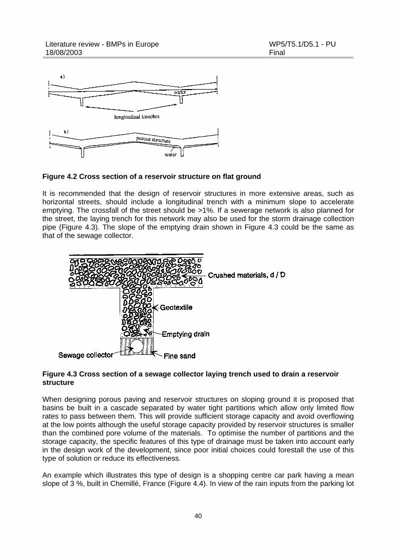
Literature review - BMPs in Europe18/08/2003
WP5/T5.1/D5.1 - PUFinal
40
Figure 4.2 Cross section of a reservoir structure on flat ground
It is recommended that the design of reservoir structures in more extensive areas, such ashorizontal streets, should include a longitudinal trench with a minimum slope to accelerateemptying. The crossfall of the street should be >1%. If a sewerage network is also planned forthe street, the laying trench for this network may also be used for the storm drainage collectionpipe (Figure 4.3). The slope of the emptying drain shown in Figure 4.3 could be the same asthat of the sewage collector.
Figure 4.3 Cross section of a sewage collector laying trench used to drain a reservoirstructure
When designing porous paving and reservoir structures on sloping ground it is proposed thatbasins be built in a cascade separated by water tight partitions which allow only limited flowrates to pass between them. This will provide sufficient storage capacity and avoid overflowingat the low points although the useful storage capacity provided by reservoir structures is smallerthan the combined pore volume of the materials. To optimise the number of partitions and thestorage capacity, the specific features of this type of drainage must be taken into account earlyin the design work of the development, since poor initial choices could forestall the use of thistype of solution or reduce its effectiveness.
An example which illustrates this type of design is a shopping centre car park having a meanslope of 3 %, built in Chemillé, France (Figure 4.4). In view of the rain inputs from the parking lot

Literature review - BMPs in Europe18/08/2003
WP5/T5.1/D5.1 - PUFinal
41
itself and those from adjacent buildings, the parking lot was divided into three sub-basins.Regulation devices were installed between them so as to ensure uniform emptying of the wholesystem. The distribution of rain inputs and the capacities of the various reservoirs are shown inTable 4.4.
Table 4.4 Distribution of contributing inputs and capacities of the sub-reservoirs in ashopping centre/car park at Chemillé, France.Sub-reservoirs: Feed area Downstream Intermediate UpstreamDownstream parking lotIntermediate parking lotUpstream parking lotWest part of buildingEast part of buildingEast roadService station
92 m3
55 m3
26 m3
70 m3
144 m3
13 m3
72 m3
117 m3
Total inputCapacity of sub reservoirs
173 m3
177 m3227 m3
233 m3189 m3
257 m3
Figure 4.4 Plan of shopping centre with sloping car park having a partitioned reservoirstructure
4.1.13 Flat roof storage systems
Flat roof storage systems are frequently used in France as a source control option forstormwater. A flat roof usually consists of several components including:
? a bearing material? a vapour guard and thermal insulation material? a water proof material (asphalt, fine gravel or soil and grass)
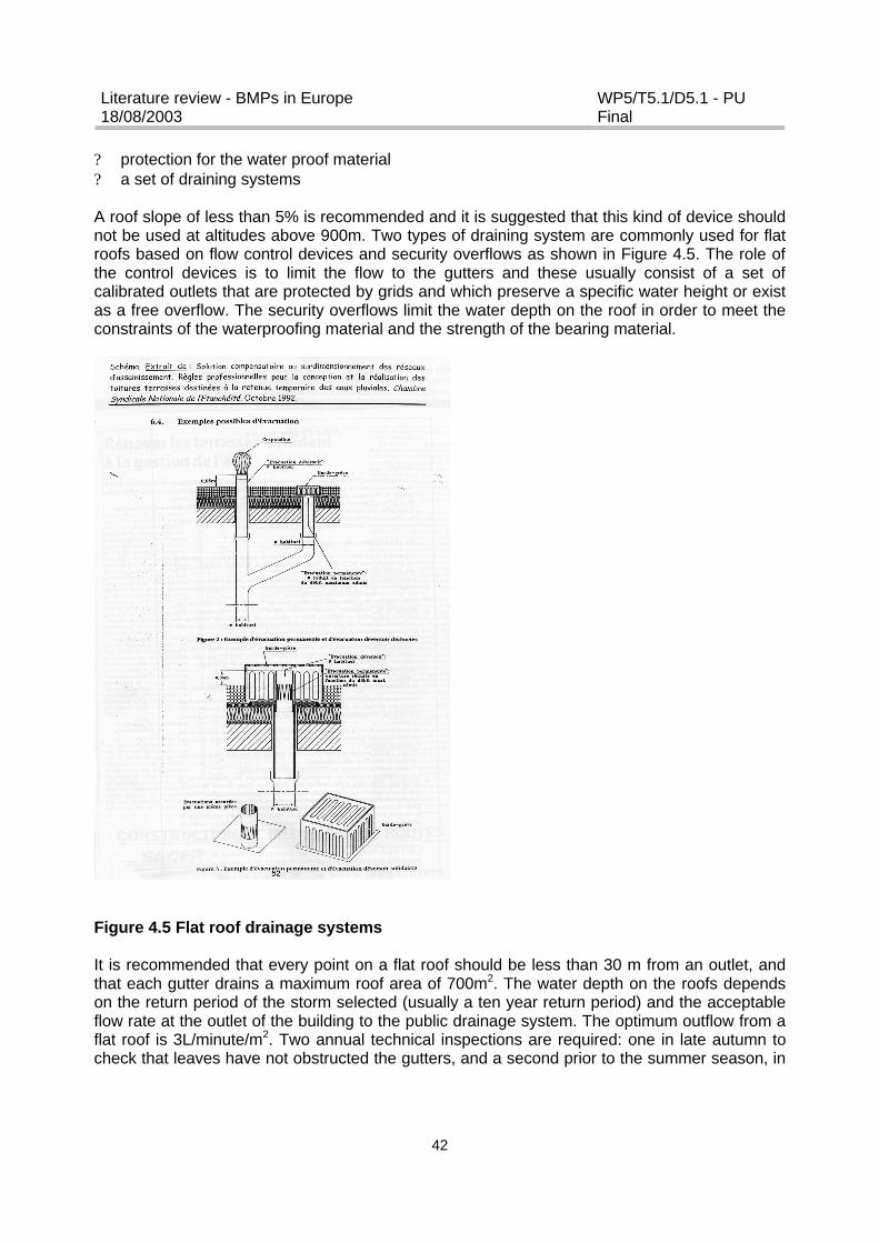
Literature review - BMPs in Europe18/08/2003
WP5/T5.1/D5.1 - PUFinal
42
? protection for the water proof material? a set of draining systems
A roof slope of less than 5% is recommended and it is suggested that this kind of device shouldnot be used at altitudes above 900m. Two types of draining system are commonly used for flatroofs based on flow control devices and security overflows as shown in Figure 4.5. The role ofthe control devices is to limit the flow to the gutters and these usually consist of a set ofcalibrated outlets that are protected by grids and which preserve a specific water height or existas a free overflow. The security overflows limit the water depth on the roof in order to meet theconstraints of the waterproofing material and the strength of the bearing material.
Figure 4.5 Flat roof drainage systems
It is recommended that every point on a flat roof should be less than 30 m from an outlet, andthat each gutter drains a maximum roof area of 700m2. The water depth on the roofs dependson the return period of the storm selected (usually a ten year return period) and the acceptableflow rate at the outlet of the building to the public drainage system. The optimum outflow from aflat roof is 3L/minute/m2. Two annual technical inspections are required: one in late autumn tocheck that leaves have not obstructed the gutters, and a second prior to the summer season, in

Literature review - BMPs in Europe18/08/2003
WP5/T5.1/D5.1 - PUFinal
43
order to maintain the draining systems. The property owners have to meet maintenance costsassociated with these inspections.
4.1.14 Gullypots
Gullypots in the UK mainly consist of a pot (or chamber) of 450mm diameter with a 90 litrestorage sump extending to a total depth of 600mm below the outgoing pipework (as specified inBritish Standard 5911, 1982). These roadside stormwater collection systems provide theprincipal reception system for pollutants flushed from the urban surface, with a single gullypottypically receiving flows from between 50 – 300m2 of impermeable “paved” surface”.
A German innovation in gullypot design involves incorporating an extra filter which can beplaced inside a gullypot to improve the treatment of stormwater from paved areas (Figure 4.6).
Figure 4.6 Section of a gullypot containing an additional filter
4.1.15 Rainwater harvesting
The technical standard DIN 1989 sets out the limits and design of measures for stormwaterreuse in Germany.
4.1.16 Snow management strategy
Development of an optimal snow handling system involves evaluating the whole process toallow the best practice possible to be selected with the lowest environmental impact at the mostreasonable cost. A snow handling strategy that takes the environment into account has beenput forward by by Malmqvist (1985) and SEPA (1990). According to this strategy, cities andtowns should be divided into different areas on the basis of the snow quality, which varies withlocation and time. The strategy involves dividing the city into white, grey and black zones, wherethe white zones represent areas with clean snow during the whole winter, the black zonesrepresent dirty snow throughout the whole winter and the grey zones represent snow that isclean at the beginning of the winter but dirty at the end. This zoning must be carried out for eachcity individually since conditions, and therefore snow quality, will obviously vary according tolocal conditions. The snow that is most polluted should be transported to snow deposits that areappropriately located, designed and operated to minimise any negative environmental effects. Incontrast, clean snow can be dumped at stormwater outlets. The use of this snow handling
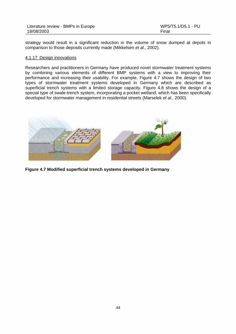
Literature review - BMPs in Europe18/08/2003
WP5/T5.1/D5.1 - PUFinal
44
strategy would result in a significant reduction in the volume of snow dumped at depots incomparison to those deposits currently made (Mikkelsen et al., 2002).
4.1.17 Design innovations
Researchers and practitioners in Germany have produced novel stormwater treatment systemsby combining various elements of different BMP systems with a view to improving theirperformance and increasing their usability. For example, Figure 4.7 shows the design of twotypes of stormwater treatment systems developed in Germany which are described assuperficial trench systems with a limited storage capacity. Figure 4.8 shows the design of aspecial type of swale-trench system, incorporating a pocket wetland, which has been specificallydeveloped for stormwater management in residential streets (Marselek et al., 2000).
Figure 4.7 Modified superficial trench systems developed in Germany
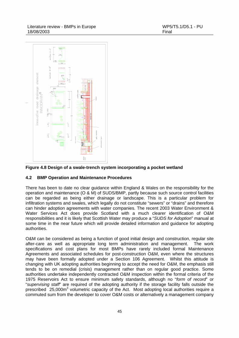
Literature review - BMPs in Europe18/08/2003
WP5/T5.1/D5.1 - PUFinal
45
Figure 4.8 Design of a swale-trench system incorporating a pocket wetland
4.2 BMP Operation and Maintenance Procedures
There has been to date no clear guidance within England & Wales on the responsibility for theoperation and maintenance (O & M) of SUDS/BMP, partly because such source control facilitiescan be regarded as being either drainage or landscape. This is a particular problem forinfiltration systems and swales, which legally do not constitute “sewers” or “drains” and thereforecan hinder adoption agreements with water companies. The recent 2003 Water Environment &Water Services Act does provide Scotland with a much clearer identification of O&Mresponsibilities and it is likely that Scottish Water may produce a “SUDS for Adoption” manual atsome time in the near future which will provide detailed information and guidance for adoptingauthorities.
O&M can be considered as being a function of good initial design and construction, regular siteafter-care as well as appropriate long term administration and management. The workspecifications and cost plans for most BMPs have rarely included formal MaintenanceAgreements and associated schedules for post-construction O&M, even where the structuresmay have been formally adopted under a Section 106 Agreement. Whilst this attitude ischanging with UK adopting authorities beginning to accept the need for O&M, the emphasis stilltends to be on remedial (crisis) management rather than on regular good practice. Someauthorities undertake independently contracted O&M inspection within the formal criteria of the1975 Reservoirs Act to ensure minimum safety standards, although no “form of record” or“supervising staff” are required of the adopting authority if the storage facility falls outside theprescribed 25,000m3 volumetric capacity of the Act. Most adopting local authorities require acommuted sum from the developer to cover O&M costs or alternatively a management company

Literature review - BMPs in Europe18/08/2003
WP5/T5.1/D5.1 - PUFinal
46
may be set up to maintain and manage the drainage and associated facilities with O&M coststaken from site rentals. Commuted sums taken through the local authority planning process aregenerally calculated over periods of 15 to 25 years and thus are unlikely to cover full lifetimecosts (including final disposal and any de-commissioning costs). On commercially managedsites and business parks and on sites managed by housing associations, SUDS O&M can bepaid for through annual rents or rates. However, it will be very difficult to levy a generalcommunity tax specifically for SUDS O&M or to pass such costs from the public to individualprivate owners.
The National SUDS Working Party (NSWG, 2003) has recently produced a SUDS Frameworkdocument for England & Wales which is currently out for consultation which will lead to a SUDSCode of Practice. The Framework covers planning and regulation, design standards, legalissues including adoption, ownership and O&M principles. Model Section 106 (Town & CountryPlanning Act, 1990) adoption agreements and outline maintenance agreements are included inthe Framework together with model sewerage undertaker deeds and basic source hazardassessment for SUDS. The lack of detailed O&M specifications for individual (and combined)SUDS schemes is likely to cause problems given the lack of experience of SUDS operation bymost adopting authorities. There is a potential liability on any owner or adopting authority interms of nuisance or impairment of owner rights caused by ineffective SUDS operation due tolack of maintenance.
4.2.1 Infiltration basins
Basin maintenance requirements must be considered as part of the initial design, ensuring theallocation of an appropriate budget to cover both maintenance and data collection. Thedetermination of various site conditions at the start of the design process, for example, soilhydraulic conductivity, mineral composition and pollutant concentration, are essential.
Problems associated with clogging have been reported in French investigations of the operationof infiltration basins (Gautier, 1998). The clogging process has been described as involving aninitial slow phase associated with mechanical processes (e.g. surface deposits and poreobtrusion) onto which a second variable and reversible process then developed due tobiological components. The second clogging phase was considered to be sensitive to seasonalchanges. Monitoring the hydraulic resistance of a basin can provide information on the cloggingprocess (Magali Deschesne, 2002). The amount and type of water depth measurements whichcan be taken will primarily depend on the budget allocated at the initial design stage. A low costoption is the use of a graduated rule, but this technique requires an on-site presence. As basinclogging can be quite a slow process, the use of sensors is more appropriate, enabling thecollection and analysis of continuous data. A sampling frequency of several events per year isconsidered sufficient.
Monitoring of the concentrations of pollutants in the basin soils enables both the sedimenttoxicity and the migration of the pollutant front to be determined. As pollutant build-up andmigration are slow processes, frequent sampling is not necessary. A good initial soilcharacterisation followed by the collection of samples at five year intervals is consideredsufficient. Soil samples should be from the surface, just under the geotextile and at a depth of20cm below the geotextile (when present).
The frequency of basin cleaning will depend on the hydraulic resistance and the quality of thesoil. In the first case it may be necessary to remove surface layers of sediment which collect

Literature review - BMPs in Europe18/08/2003
WP5/T5.1/D5.1 - PUFinal
47
over the infiltration surface. Where there is a high level of soil contamination, there is a risk ofsalting out leading to further contamination. If the pollution front is very deep, there is a risk ofgroundwater contamination and appropriate maintenance will be necessary. The site-managermust evaluate the cleaning cost in relation to the volume of infiltration material requiringremoval, the depth of excavation and the associated pollutant load. It should also be consideredwhether it is more efficient to carry out maintenance often to a shallow infiltration depth with anassociated low level of toxicity or to clean less frequently but to a greater depth and with acomparatively higher level of toxicity.
4.2.2 Sedimentation tank
Sedimentation tanks have high cost maintenance requirements. A study of a sedimentation tanklocated next to a motorway in the UK concluded that tank desludging would be required at 5yearly intervals.
4.2.3 Retention ponds
Results of a survey of 34 stormwater control ponds in Sweden by Farm (2003) showed that themaintenance of these systems was difficult due to poor access to the ponds. In 18 of the 34ponds, vegetation covered 50% or more of the surface area. Vegetation plays an important rolein sedimentation and filtration of particles in stormwater. The plants can also accumulatenutrients. However, too much vegetation may reduce the hydraulic function in the pond,increasing the retention time. This may result in algal blooms at certain periods of the year and,under these circumstances, some vegetation may need to be removed.
4.2.4 Constructed wetland systems
An outline O&M checklist recommended for stormwater constructed wetlands is given in Table4.5 where there is a substantial amenity element associated with the BMP device. This O&Msummary schedule covers a motorway service area having BMPs designed in a complextreatment train arrangement with extensive landscaping and water recycling. An alternativeO&M template is given in Table 4.6.

Literature review - BMPs in Europe18/08/2003
WP5/T5.1/D5.1 - PUFinal
48
Table 4.5 Operation and maintenance schedule for a motorway service station
Table from: R Bray. 2001. Maintenance of Sustainable Drainage. 93 – 104 in C J Pratt, J W Davies and J L Perry (Edits): Proc 1st
National Conference on Sustainable Drainage, June 2001. Coventry University, Coventry.

Literature review - BMPs in Europe18/08/2003
WP5/T5.1/D5.1 - PUFinal
49
Table 4.6 Operation and maintenance inspection sheet: wetland operation, maintenanceand managementName/Location:…………………………………. Site status:………………………….…Site Manager/Landscape Foreman:…………………………….. Reporting Office/Tel:…………………
Item Frequency Satisfactory orunsatisfactory
Tick(whenworkdone)
Date Initial
Wetland Vegetationmaintain 50% surface area coverage of wetland plants after2nd growing seasonnew plantingsDominant wetland plants; distribution according to landscapeplan?Evidence of invasive speciesWater depth; (maintain adequate water depths for desired wetlandplant species)Plant removal; dead plants and/or “choked” by sediment build-upEvidence of eutrophication
AnnuallyAs necessary
As necessaryAnnually
As necessary
As necessaryAs necessary
Pre-Treatment Pool/Sediment Forebaysediment removal (Depth < 50% design depth As necessaryInlet(s)ripraplitter screensblockagespontoonsboomsstilling area
AnnuallyQuarterly*As necessary*AnnuallyAs necessaryAs necessary
Outlet(s)riprap failurelitter screensdrain pipesblockagesendwalls/headwallsslope erosiondrop manholevalves
AnnuallyQuarterly*AnnuallyAs necessary*AnnuallyAnnuallyAnnually*Annually
Riser Pipeorifice obstructioncracking/spalling/corrosionsediment accumulation in risercontrol/drain valves
Annually*AnnuallyAnnually*Annually
Wetland Poolfloatables/gross debrisvisible pollution e.g. oilshoreline erosion
Annually*As necessary*As necessary
Peripheral Slopes/Buffer Zonegrass mowingerosion/rabbit and animal burrowsprune shrubs/trim edges etcspraying (Separate note below if undertaken)
As necessaryAnnuallyAnnuallyAs necessary
Othersignage problems (vandalism, repair etc.)boardwalks/seatingfencinggrafitticondition of access route(s)complaints (Separate note below)other public hazards (Separate note below)
As necessaryAs necessaryAs necessaryAs necessaryAnnuallyAs necessaryAs necessary
NOTES/COMMENTS…………………………………………………………………………………………………………………..………………………………………………………………………………………………………………………………………………………………….……………………………………………………………………………………………………………………………………………………….……………………………………………………………………………………………………………………………………………………….Signature:…………………………………. Position/Status:……………………………. Date:………………..
* = Also after Major Storms. Diagram from: J B Ellis, R B E Shutes and D M Revitt. 2003. “Constructed Wetlands and Links toSustainable Drainage Systems” Report P2-159/TR1, Water Research Centre, Swindon.

Literature review - BMPs in Europe18/08/2003
WP5/T5.1/D5.1 - PUFinal
50
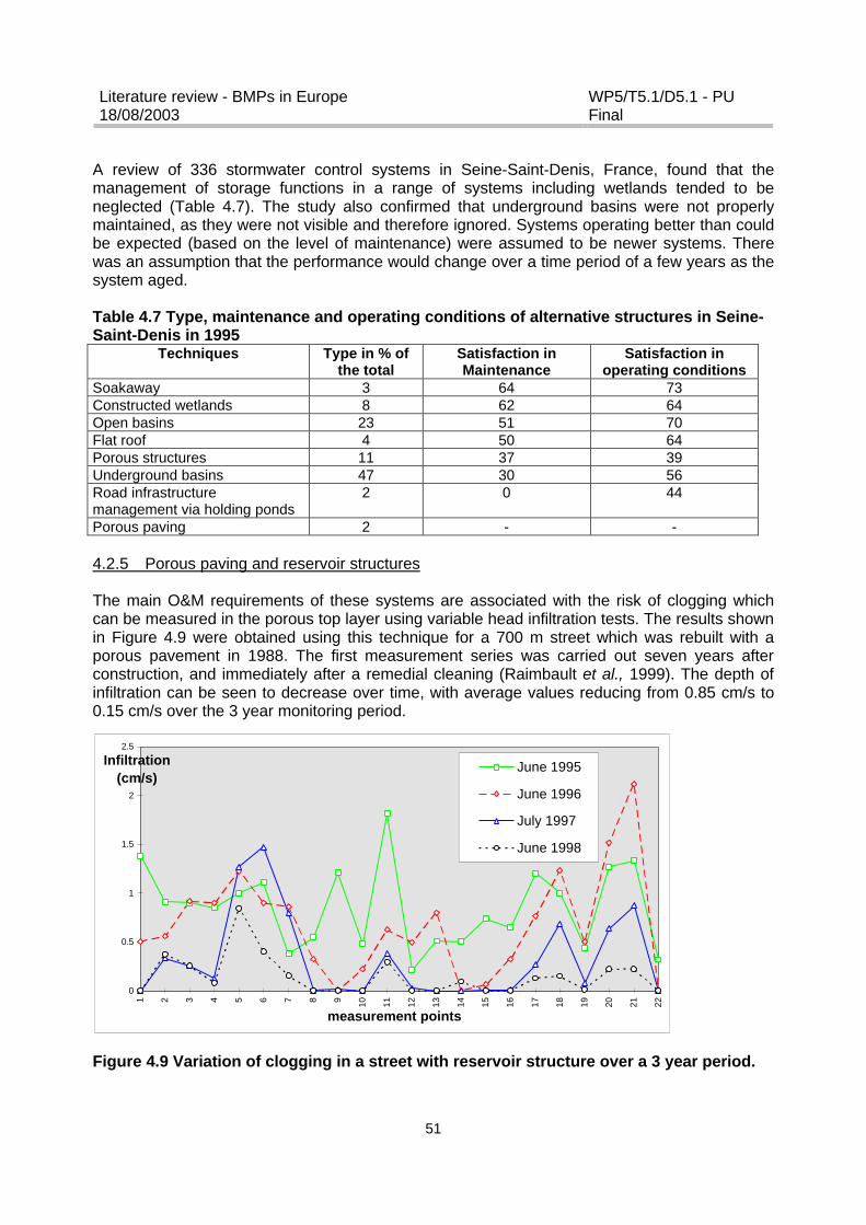
Literature review - BMPs in Europe18/08/2003
WP5/T5.1/D5.1 - PUFinal
51
A review of 336 stormwater control systems in Seine-Saint-Denis, France, found that themanagement of storage functions in a range of systems including wetlands tended to beneglected (Table 4.7). The study also confirmed that underground basins were not properlymaintained, as they were not visible and therefore ignored. Systems operating better than couldbe expected (based on the level of maintenance) were assumed to be newer systems. Therewas an assumption that the performance would change over a time period of a few years as thesystem aged.
Table 4.7 Type, maintenance and operating conditions of alternative structures in Seine-Saint-Denis in 1995
Techniques Type in % ofthe total
Satisfaction inMaintenance
Satisfaction inoperating conditions
Soakaway 3 64 73Constructed wetlands 8 62 64Open basins 23 51 70Flat roof 4 50 64Porous structures 11 37 39Underground basins 47 30 56Road infrastructuremanagement via holding ponds
2 0 44
Porous paving 2 - -
4.2.5 Porous paving and reservoir structures
The main O&M requirements of these systems are associated with the risk of clogging whichcan be measured in the porous top layer using variable head infiltration tests. The results shownin Figure 4.9 were obtained using this technique for a 700 m street which was rebuilt with aporous pavement in 1988. The first measurement series was carried out seven years afterconstruction, and immediately after a remedial cleaning (Raimbault et al., 1999). The depth ofinfiltration can be seen to decrease over time, with average values reducing from 0.85 cm/s to0.15 cm/s over the 3 year monitoring period.
Figure 4.9 Variation of clogging in a street with reservoir structure over a 3 year period.
0
0.5
1
1.5
2
2.5
1 2 3 4 5 6 7 8 9 10 11 12 13 14 15 16 17 18 19 20 21 22
measurement points
Infiltration (cm/s)
June 1995
June 1996
July 1997
June 1998
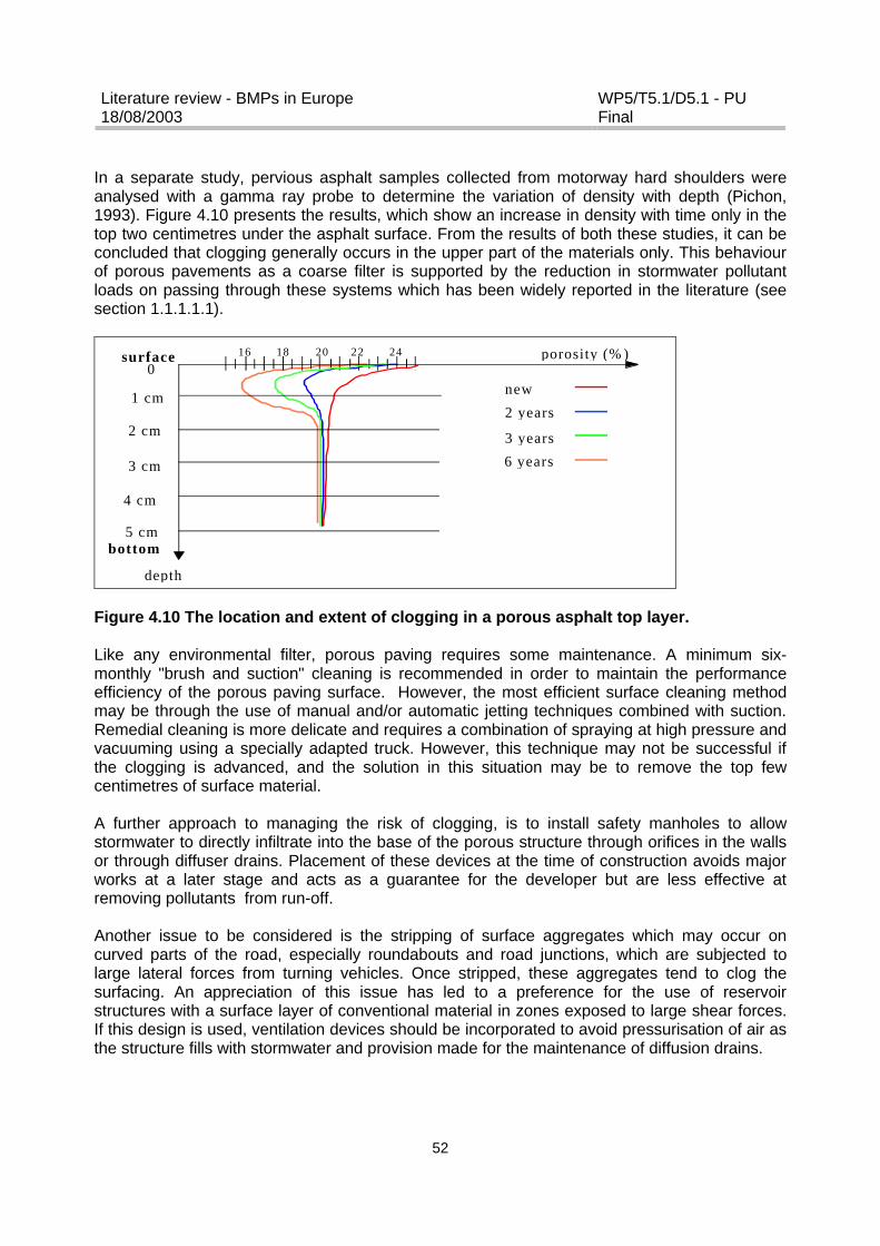
Literature review - BMPs in Europe18/08/2003
WP5/T5.1/D5.1 - PUFinal
52
In a separate study, pervious asphalt samples collected from motorway hard shoulders wereanalysed with a gamma ray probe to determine the variation of density with depth (Pichon,1993). Figure 4.10 presents the results, which show an increase in density with time only in thetop two centimetres under the asphalt surface. From the results of both these studies, it can beconcluded that clogging generally occurs in the upper part of the materials only. This behaviourof porous pavements as a coarse filter is supported by the reduction in stormwater pollutantloads on passing through these systems which has been widely reported in the literature (seesection 1.1.1.1.1).
surface
bottom
1 cm
4 cm
5 cm
2 cm
3 cm
porosity (% )
depth
0201816 22 24
new
2 years
6 years
3 years
Figure 4.10 The location and extent of clogging in a porous asphalt top layer.
Like any environmental filter, porous paving requires some maintenance. A minimum six-monthly "brush and suction" cleaning is recommended in order to maintain the performanceefficiency of the porous paving surface. However, the most efficient surface cleaning methodmay be through the use of manual and/or automatic jetting techniques combined with suction.Remedial cleaning is more delicate and requires a combination of spraying at high pressure andvacuuming using a specially adapted truck. However, this technique may not be successful ifthe clogging is advanced, and the solution in this situation may be to remove the top fewcentimetres of surface material.
A further approach to managing the risk of clogging, is to install safety manholes to allowstormwater to directly infiltrate into the base of the porous structure through orifices in the wallsor through diffuser drains. Placement of these devices at the time of construction avoids majorworks at a later stage and acts as a guarantee for the developer but are less effective atremoving pollutants from run-off.
Another issue to be considered is the stripping of surface aggregates which may occur oncurved parts of the road, especially roundabouts and road junctions, which are subjected tolarge lateral forces from turning vehicles. Once stripped, these aggregates tend to clog thesurfacing. An appreciation of this issue has led to a preference for the use of reservoirstructures with a surface layer of conventional material in zones exposed to large shear forces.If this design is used, ventilation devices should be incorporated to avoid pressurisation of air asthe structure fills with stormwater and provision made for the maintenance of diffusion drains.

Literature review - BMPs in Europe18/08/2003
WP5/T5.1/D5.1 - PUFinal
53
4.3 BMP Costings
The construction and O&M costs of various types of BMPs developed by CERTU (1998) andused by consulting firms and civil engineers in France are given in Table 4.8. It is generallyaccepted that the use of stormwater control BMPs will result in a 20% saving in sewage costs.Savings in the region of 20-50% have been confirmed for retention ponds by various consultingcompanies. However, such savings are not always the case. Road infrastructure BMPmeasures can require the use of expensive materials (e.g. open-textured asphalt concrete) andthe construction of porous structures. It has been calculated that construction usingconventional materials (sewer and pavement included) costs 183 €/linear metre in comparisonto 305-366 €/linear metre for reservoir structures. This latter value does not include the cost ofthe asphalt concrete for which a further 30% should be added. A survey by Baptista et al.,(2003) of 167 stormwater control sites (consisting mainly of retention basins) showed that theconstruction costs differed slightly from those put forward by CERTU (2003), with retentionbasins reported to cost more to both construct and maintain (Table 4.9). This study alsoconfirmed that natural basins were generally less expensive to construct than concrete basins.
Table 4.8 The cost of various BMPs (not including land cost) according to CERTU (1998)Technique Cost in euros (1998) Maintenance - cleaning ObservationFlat roof No overcostSoakaway 3 €/m² per treated area 0.15 €/m² per treated areaSwale 7.6 to 15 €/m3 stored or 15 to
30.5 € per linear metreDredge every 10 years, grassand leaves maintenance
Retention basin 9.1 to 61 €/m3 0.15 to 0.45 €/m3/year 6 to 7% of investment incivil engineering
Detention basin 9 to 91 €/m3
rural ? urbanMaintenanceof the open space : 0.3 to1.52 €/m3/year
Filter drain 30.5 to 38 €/m3 (excavation +filling + geosyntheticmembrane)
0.3 to 0.45 €/m²/year
Porous road surfacewith reservoirstructure
33.5 to 61 €/m3 0.15 to 0.75 €/m3/year Depreciation time : 10 to15 years for the opentexture asphalt concrete
Open concrete tanks 76 to 152 €/m3
70 % of civil engineering30% of equipment
civil engineering 1.5% of theinvestment per year
Depreciation time :30 years
Undergroundconcrete tanks
152 to 533 €/m3
Porous paving 152 to 228 €/m3 0.3 to 1.52 €/m3/year
Table 4.9 Economic indicators of stormwater drainage systems (Baptista et al., 2003)Investment
Cost in Euro 1999/m3Techniquesmean standard
deviation
MaintenanceEuro 1999/m3
Satisfaction and degree ofacceptance by the stakeholders
Underground storagetanks
224 1123 361 Underground basins seem tofunction less well than open ones
Water retention basin 140 152 3 Well perceived by the stakeholdersDry retention basin: 136 174 1.61 The environmental impact* Concrete open basins 225 201 5.6 is only seen under a visual aspect.* Dry basin with plants 108 157 0.83 The stakeholders don’t seem
concerned with the pollution* single purpose 146 203 -
Literature review - BMPs in Europe18/08/2003
WP5/T5.1/D5.1 - PUFinal
54
* multifunctional 113 87 -The removal efficiencies and costs of different French stormwater control measures to removesuspended solids are presented in Table 4.10 (Balades and Petitnicolas, 2002). It is suggestedthat measures for stormwater control can be grouped into two categories with the first grouphaving excellent recovery yields associated with small management and investmentrequirements. The second category either reports low recovery rates for solids or includessystems also serving another function which requires costly investment.
Table 4.10 Particle pollution recovery cost according to various techniquesTechnique Removal efficiency
of particles <100 µm(%)
Cost of removal ofparticles <100 µm (€/kg)
Total cost (includingeventual plantdepreciation)
Filter drain 80 – 90 0.6 to 0.91 0.83 to 1.18Swales/ditches 80 0.01 to 0.015 0.05 to 0.1Very open-texturedasphalt concrete(declogging)
60 – 70 1.4 to 2.5 1.4 to 2.5
Holding pond 80 0.015 to 0.038 Dry : 0.47 to 1.25Buried : 4.6 to 6.1
Lamellar decanters 50 0.12 to 0.33 1.67 to 3Street cleaning 40 – 20 8.38 to 13.7 8.38 to 13.7Roadside gully 10 - 15 1.37 to 3 Theoretical : 1.45 to 3.1
Real : ? 15
There is only limited data available on the relative costs of differing treatment systems toremove pollutants from urban stormwater runoff although capital costings for conventionaldrainage are well understood. Costs will vary between sites depending upon local conditionswhich will include engineering constraints (eg. site access, topography and size; liningrequirements; construction techniques etc.) and land constraints (legal and land purchase costs;access provision; the size, type and layout of treatment devices etc.). In general terms,engineering constraints will tend to increase the design costs whilst land constraints willdecrease costs but at the same time reduce performance. Table 4.11 provides a first-order costestimation of the ranges of capital and maintenance costs associated with various treatmentsystems although the combined use of individual devices in a treatment train would givereductions of about 20 – 25% in overall costings. However, the table does not take intoconsideration the full lifetime costs which would include monitoring and disposal costs as well asany risk and environmental costs/benefits.
Table 4.11 Capital and maintenance costs for BMP treatment systems (Revitt and Ellis,2001)Treatment Device Capital Cost
(€'000s)Maintenance Cost
(€/per yr)Comments
Gully/Carrier Pipe 220 – 320 1440 No fin drainage allowed for in costsFilter/French Drains 230- 260 - Requires replacement after 10-12 yearsGrass Swale 20-60 500 With no off-site disposal of cuttingsOil Interceptors 10-40 430-580Sedimentation tank 40-120 430-500Lagoon/Basin 70-150 720-2880InfiltrationTrench/Basin
30-70 2800-3600 Requires infill replacement every 5-10 years
Retention(Balancing) pond
20-430 500-1440 With no vegetation or off-site dewatering anddisposal of sludge and cuttings
Wetland Basin 20-2302880-3600
Annual maintenance for first 5 years.(declining to €1200-€1400 p/year after 3 years)
Combined 140-430 2880-4300 Assume grass swale, oil/grit interceptor,
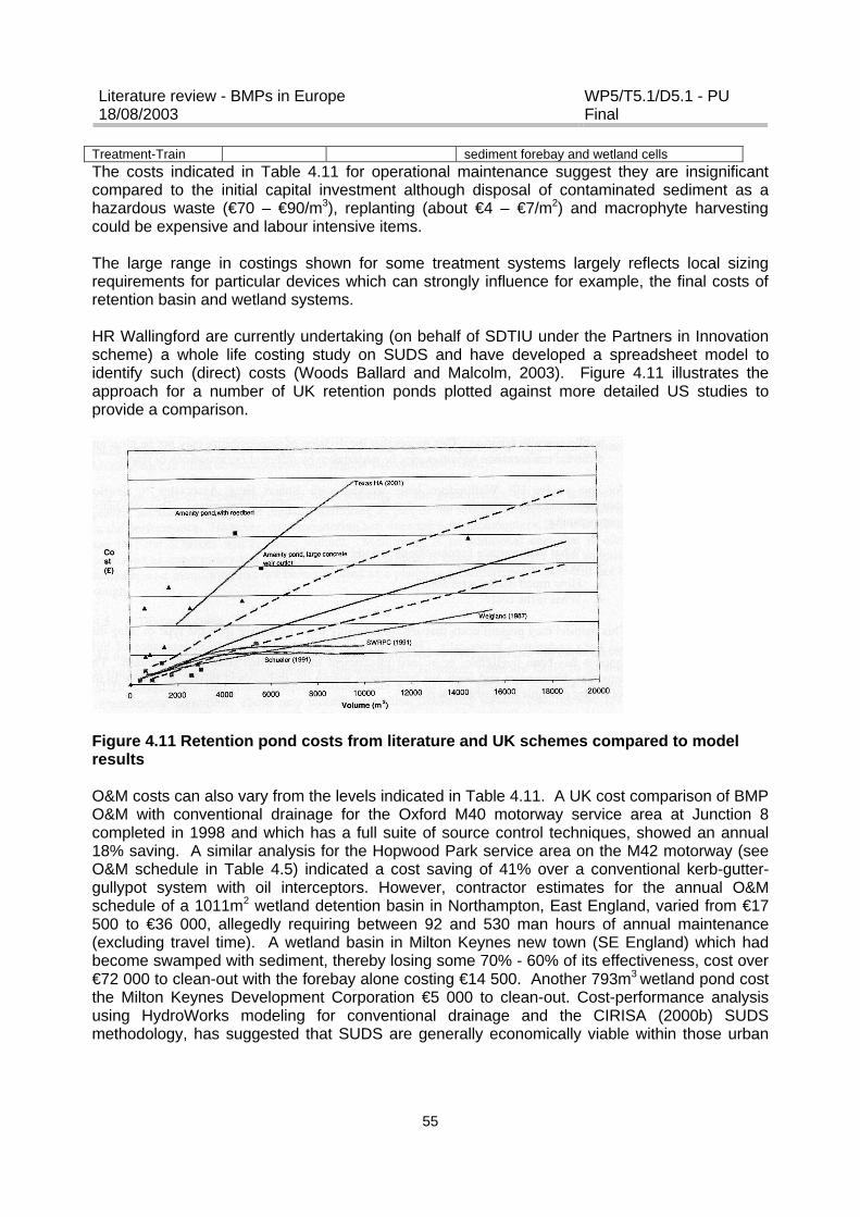
Literature review - BMPs in Europe18/08/2003
WP5/T5.1/D5.1 - PUFinal
55
Treatment-Train sediment forebay and wetland cellsThe costs indicated in Table 4.11 for operational maintenance suggest they are insignificantcompared to the initial capital investment although disposal of contaminated sediment as ahazardous waste (€70 – €90/m3), replanting (about €4 – €7/m2) and macrophyte harvestingcould be expensive and labour intensive items.
The large range in costings shown for some treatment systems largely reflects local sizingrequirements for particular devices which can strongly influence for example, the final costs ofretention basin and wetland systems.
HR Wallingford are currently undertaking (on behalf of SDTIU under the Partners in Innovationscheme) a whole life costing study on SUDS and have developed a spreadsheet model toidentify such (direct) costs (Woods Ballard and Malcolm, 2003). Figure 4.11 illustrates theapproach for a number of UK retention ponds plotted against more detailed US studies toprovide a comparison.
Figure 4.11 Retention pond costs from literature and UK schemes compared to modelresults
O&M costs can also vary from the levels indicated in Table 4.11. A UK cost comparison of BMPO&M with conventional drainage for the Oxford M40 motorway service area at Junction 8completed in 1998 and which has a full suite of source control techniques, showed an annual18% saving. A similar analysis for the Hopwood Park service area on the M42 motorway (seeO&M schedule in Table 4.5) indicated a cost saving of 41% over a conventional kerb-gutter-gullypot system with oil interceptors. However, contractor estimates for the annual O&Mschedule of a 1011m2 wetland detention basin in Northampton, East England, varied from €17500 to €36 000, allegedly requiring between 92 and 530 man hours of annual maintenance(excluding travel time). A wetland basin in Milton Keynes new town (SE England) which hadbecome swamped with sediment, thereby losing some 70% - 60% of its effectiveness, cost over€72 000 to clean-out with the forebay alone costing €14 500. Another 793m3 wetland pond costthe Milton Keynes Development Corporation €5 000 to clean-out. Cost-performance analysisusing HydroWorks modeling for conventional drainage and the CIRISA (2000b) SUDSmethodology, has suggested that SUDS are generally economically viable within those urban

Literature review - BMPs in Europe18/08/2003
WP5/T5.1/D5.1 - PUFinal
56
catchments (and especially Greenfield sites), having large areas or number of opportunities fortheir implementation, such as permeable soils and large open spaces (Walker, 2000).
None of the above costings make any reference to final disposal costs where the dredgedsediment may be classified as hazardous waste due to levels of contained oil and metals. Thiscan be a real and costly issue as indicated by the dredging and removal of a contaminatedreedbed and associated sediment from a 18,128m2 constructed wetland in NW London whereon-site storage was required for sediment de-watering (down to 2% dry weight), prior to landfilldisposal. Contained metal levels in the sediment averaged 219.8mg/kg, 841.0mg/kg,778.9mg/kg and 12.5mg/kg for copper, lead, zinc and cadmium respectively. These levels areconsiderably higher than threshold loading limits as defined under 1986 EU legislation forbiosolids and soil expressed in either annual or total accumulative loadings (see Table 5.5).Fencing, lighting, lagooning, berming and other security considerations were required as part ofthe on-site de-watering facility with costs for the disposal operation totalling nearly €360 000.Such O&M costings would be quite challenging to local authorities already under financial strain,and if they represent general O&M costing levels, may influence future decisions on adoption ofBMP facilities. There is undoubtedly some concern about the long term capability of UK localauthorities, who have adopted BMP facilities on the basis of their amenity potential, to sustainexpenditure levels on O&M
Where adopting local authorities undertake a formal O&M inspection which is independentlycontracted under the criteria of the 1975 Reservoirs Act, such inspections are normally separatecostable items. The London Borough of Harrow, for example, utilises such external agencyreviews and as a general estimate, O&M for their stormwater storage ponds costs about€575/m3 per annum with overall O&M costs for BMPs being some €2880/per annum per device.
In the UK, roadside gullypot emptying is undertaken by vacuum tankers on at least an annual(or twice annual) cleaning frequency, with arisings disposed of to landfill. Cleaning efficiencycan range from 20% to 85% depending on local car parking conditions. During the emptyingprocess, some 10% of the sediment originally present in the gullypot can be washed into thesewer line. Average unit costs range from €2 to €4 per gully. Manual sweeping (together withhydrojetting) remains the most effective street cleaning method and over 40% of UK localauthorities continue to use this type of BMP. A recent innovation has been the introduction of’rapid response teams’ to deal with severely littered public areas. Average costs for streetcleaning range from €7/km to €11/km.
An overview of the annual and maintenance costs for a wide range of stormwater controlmeasures (including both BMPs and non-BMPs) in Germany is given in Table 4.12. Funding israised from a separate stormwater fee based on the amount of paved area contributing runoff tothe sewer system. Currently 60% of the population pays this fee but the percentage is growing.A different approach to the maintenance of stormwater measures was taken in a commercialarea near Berlin, where the maintenance requirements were handed over to a private company.
In France, local municipalities provide the finance for stormwater control measures as part oftheir drinking water and wastewater system programmes. Water authorities, prior to 2002, werenot allowed to finance stormwater control although they could help fund retention basins oncombined sewer systems with a metric capacity of over 1000m3. However, this situation hasnow changed and water authorities may finance source control BMPs according to the level ofpollutant reduction with outflows of greater than 10 L/s/ha being costed at 600 €/m3.

Literature review - BMPs in Europe18/08/2003
WP5/T5.1/D5.1 - PUFinal
57
In Sweden, the advantages and disadvantages of different urban storm drainage systems havebeen discussed and during the first half of the 20th century the general view was that buried pipesystems were more economical than swales and ditches (Bäckman, 1984). Cost estimatesmade in 1925 showed that maintenance costs and land costs for swales where high incomparison to conventional piped systems and as a consequence, pipe systems were selectedas the default alternative for urban storm drainage in Sweden. More recently, Finley and Young(1993) pointed out that the use of swale systems reduced costs due to the elimination of curbsand gutters. However, if swales are to be used for road drainage they normally require widerrights-of-way which may, depending on land prices, lead to a considerable increase in overallcosts. The use of swales may also result in extra costs if special structures are required inconjunction with driveways and/or to maintain slopes (e.g. check dams) (Schueler, 1987; Li etal., 1998). Several authors have suggested that adjacent property owners can be expected tomaintain grassed swales situated in residential areas (e.g. Kercher et al., 1983; Schueler, 1987;Finley and Young, 1993), which would minimise the maintenance cost from a local governmentperspective. According to Bäckström (2002), grassed swales require lower amounts of naturalresources in terms of energy than a comparable stormwater pipe system. The primary target forreducing energy use of a grassed swale would be the fuel consumption needed fortransportation, excavation and grass mowing since these processes represent a major part ofthe total use of natural resources. The total cost of a grassed swale is largely dependent on siteconditions, such as land price and quality of the parent soil, and it has been concluded that agrassed swale is more cost-efficient than a pipe system in areas with low land prices and goodtopsoil.

Literature review - BMPs in Europe18/08/2003
WP5/T5.1/D5.1 - PUFinal
58
Table 4.12 Annual and maintenance costs for different stormwater managementmeasures

Literature review - BMPs in Europe18/08/2003
WP5/T5.1/D5.1 - PUFinal
59
5 BMP PERFORMANCE
5.1 Performance Indicators
Table 5.1 provides a general indicator summary of the ranges of pollutant removal percentagesthat have been reported from various UK urban BMP studies. The percentage removalefficiency is in most cases simply defined as: (Cin – Cout)/Cin x 100; where Cin and Cout are theinflow and outflow concentrations, respectively. Whilst total solids removal is generally good formost types of structural BMPs, there is considerable variation for other pollutant parameterswith some showing rather poor removal capabilities.
The efficiency performance data, being based on the average difference between inflow andoutflow storm event concentrations, may be misleading especially when inflow concentrationsare low. For example, a wet retention basin experiencing 500mg/L TSS in the inflow and 100mg/L in the outflow would yield an equivalent pollutant removal efficiency to a constructedwetland having 100mg/L and 20mg/L in the inflow and outflow respectively. Yet the final waterquality for the latter BMP device is clearly superior and provides more effective and efficientprotection of the receiving waterbody. The use of a percentage removal term is probably onlyreally appropriate for sites and BMP facilities subject to high pollutant input concentrations.
The US EPA National Stormwater Best Management Practices Database recommends the useof a normal probability plot of the inflow and outflow pollutant event mean concentrations(EMCs), with the EMC distribution matched against set (or target) receiving water qualitystandards (or against any discharge consent conditions). This would enable performance to bedescribed in terms of exceedance probability of target standards for differing flow conditionsand/or return periods. This statistical methodology would also enable anomalous results (suchas apparent negative efficiencies) to be identified, as well as determining whether a smallnumber of large storms are biasing the resulting overall efficiency value.
It is clear that a comparative assessment of the performance of structural BMP options iscurrently limited by a lack of data and the uncertainties associated with the simplifiedmethodology used to calculate percentage performance efficiency. In addition, for mostwetland/retention systems, given the dynamic nature of flow into and out of wet basins having apermanent pool, the recorded inflow and outflow concentrations are not normallycontemporaneous i.e. not generated by the same storm event. It is not yet feasible to providedefinitive BMP designs to meet specified and consistent performance requirements for givenstorm and catchment characteristics or to meet specific receiving water standards and stormreturn periods.
Whilst accepting these reservations, it is still nevertheless possible from the data andinformation currently available to broadly identify representative pollutant removal (Table 5.1)and attenuation capacities (Table 5.2) for differing BMP devices. However, this can onlyprovide a first-order screening evaluation of the robustness of the various BMP systems toachieve the stated functional objective. High design robustness gives a significant impact andprobability of performing as intended. Low robustness and impact implies that there are manyuncertainties with regard to how the BMP design will perform for that function.

Literature review - BMPs in Europe18/08/2003
WP5/T5.1/D5.1 - PUFinal
60
Table 5.1 Performance efficiency and value of BMP treatment systems% Removal Efficiency
Metals
TreatmentFacility
HydraulicDesignRobustness TSS Total
NitrogenBacteria Hydro-
carbons
Total Dissolved
MaintenanceRequirements
Habitat and Aesthetic Value
Gully/CarrierPipe System
High 10 - 30 - - 5 - 10 10 -20 0 Low to moderateCostly to replace
None
Filter (FrenchDrain)
Low -Moderate
60 - 90 20 - 30 20 - 40 70 - 90 70 - 90 10 - 20 Low to moderateCostly to replaceClogging potential
InconspicuousUnobtrusiveNo habitat value
InfiltrationBasin/Trench
Low - High 60 - 90 20 - 50 70 - 80 70 - 90 70 - 90 20 - 35 Moderate to highCostly to reinstateSusceptible to clogging
Inconspicuous, unobtrusiveLimited habitat value
Swales High 10 - 40 10 - 35 30 - 60 60 - 75 70 - 90 15 - 25 More costly thanconventional drainage
Moderate visual appealSelective planting can enhancehabitat value
SedimentationLagoon
Low -Moderate
50 - 85 10 - 20 45 - 80 60 - 90 60 - 90 20 - 30 Moderate to highCostly to desludge
Some aesthetic value
Dry DetentionBasin
Moderate toHigh
60 - 80 20 - 40 20 - 40 40 - 55 0 - 15 Moderate Limited
ExtendedDetentionBasin
High 30 - 60 5 - 20 10 - 35 30 - 50 20 - 50 0 - 5 Moderate Moderate visual appealCan enhance habitat value
DetentionBasin6-10 hourdetention16-24 hourdetention
High
High
40 - 80
50 - 90
20 - 40
20 - 40
40 - 50
60 - 75
30 - 60
50 - 75
30 - 60
45 - 85
5 - 10
10 - 25
Moderate to high
Moderate to high
High aesthetic appealModerate to high habitat valueespecially if vegetated
RetentionBasin
High 80 -90 20 –40 40 - 60 30 - 40 35 - 50 10 - 20 Moderate Moderate
Wetland Moderate -High
70 - 95 30 - 50 75 - 95 50 - 85 40 - 75 15 - 40 Moderate to highCostly to replace plants
High visual and habitat appeal
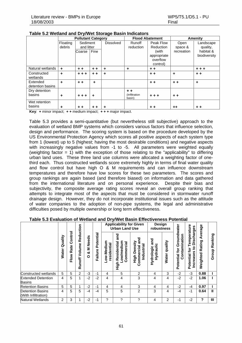
Literature review - BMPs in Europe18/08/2003
WP5/T5.1/D5.1 - PUFinal
61
Table 5.2 Wetland and Dry/Wet Storage Basin IndicatorsPollutant Category Flood Abatement Amenity
Sedimentand litter
Floatingdebris
Coarse Fine
Dissolved Runoffreduction
Peak FlowReduction
(withappropriate
overflowcontrol)
Openspace &
recreation
Landscapequality,
habitat &biodiversity
Natural wetlands + + + + + + + + + + + +Constructedwetlands
+ + + + + + + + + + + +
Extendeddetention basins
+ + + + + + + + +
Dry detentionbasins + + + + +
+ +(Infiltrationbasin)
+ + + + +
Wet retentionbasins + + + + + + + + ++ + +Key: + minor impact; + + medium impact; + + + major impact.
Table 5.3 provides a semi-quantitative (but nevertheless still subjective) approach to theevaluation of wetland BMP systems which considers various factors that influence selection,design and performance. The scoring system is based on the procedure developed by theUS Environmental Protection Agency which scores all positive aspects of each system typefrom 1 (lowest) up to 5 (highest; having the most desirable conditions) and negative aspectswith increasingly negative values from -1 to -5. All parameters were weighted equally(weighting factor = 1) with the exception of those relating to the "applicability" to differingurban land uses. These three land use columns were allocated a weighting factor of one-third each. Thus constructed wetlands score extremely highly in terms of final water qualityand flow control but have high O & M requirements and can influence downstreamtemperatures and therefore have low scores for these two parameters. The scores andgroup rankings are again based (and therefore biased) on information and data gatheredfrom the international literature and on personal experience. Despite their bias andsubjectivity, the composite average rating scores reveal an overall group ranking thatattempts to integrate most of the aspects that must be considered in stormwater runoffdrainage design. However, they do not incorporate institutional issues such as the attitudeof water companies to the adoption of non-pipe systems, the legal and administrativedifficulties posed by multiple ownership or long term effectiveness.
Table 5.3 Evaluation of Wetland and Dry/Wet Basin Effectiveness PotentialApplicability for Given
Urban Land UseDesign
robustness
Wat
er Q
ual
ity
Flo
w R
ate
Co
ntr
ol
Ru
no
ff V
olu
me
Red
uct
ion
O &
M N
eed
s
Fai
lure
Po
ten
tial
Lo
w-M
ediu
mre
sid
enti
al
Hig
h R
esid
enti
al a
nd
Lo
w/m
ediu
mC
om
mer
cial
Hig
h D
ensi
tyC
om
mer
cial
an
dIn
du
stri
al
Hyd
rolo
gic
an
dH
ydra
ulic
Wat
er q
ual
ity
Po
ten
tial
fo
r G
rou
nd
wat
erC
on
tam
inat
ion
Po
ten
tial
fo
r T
emp
erat
ure
Incr
ease
s to
Dis
char
ges
Wei
gh
ted
Rat
ing
Ave
rag
e
Gro
up
Ran
kin
g
Constructed wetlands 5 5 2 -3 -1 4 5 2 4 3 -2 -3 0.88 IExtended DetentionBasins
4 5 1 -2 -2 4 4 3 4 4 -2 -2 1.06 I
Retention Basins 5 5 1 -2 -1 4 4 3 4 4 -2 -4 0.97 IDetention Basins(With Infiltration)
4 5 5 -4 -4 5 5 2 3 4 -4 -1 0.64 II
Natural Wetlands 2 3 1 -2 -1 ? ? ? 4 2 -1 -2 ? III
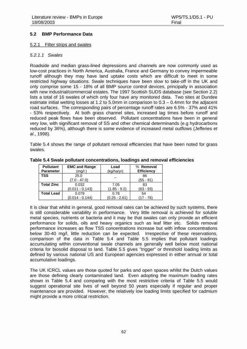
Literature review - BMPs in Europe18/08/2003
WP5/T5.1/D5.1 - PUFinal
62
5.2 BMP Performance Data
5.2.1 Filter strips and swales
5.2.1.1 Swales
Roadside and median grass-lined depressions and channels are now commonly used aslow-cost practices in North America, Australia, France and Germany to convey impermeablerunoff although they may have land uptake costs which are difficult to meet in somerestricted highway situations. Swale techniques have been slow to take-off in the UK andonly comprise some 15 - 18% of all BMP source control devices, principally in associationwith new industrial/commercial estates. The 1997 Scottish SUDS database (see Section 2.2)lists a total of 16 swales of which only four have any monitored data. Two sites at Dundeeestimate initial wetting losses at 1.2 to 5.0mm in comparison to 0.3 – 0.4mm for the adjacentroad surfaces. The corresponding pairs of percentage runoff rates are 6.5% - 37% and 41%- 53% respectively. At both grass channel sites, increased lag times before runoff andreduced peak flows have been observed. Pollutant concentrations have been in generalvery low, with significant removal of SS and other chemical determinands (e.g hydrocarbonsreduced by 36%), although there is some evidence of increased metal outflows (Jefferies etal., 1998).
Table 5.4 shows the range of pollutant removal efficiencies that have been noted for grassswales.
Table 5.4 Swale pollutant concentrations, loadings and removal efficiencies
It is clear that whilst in general, good removal rates can be achieved by such systems, thereis still considerable variability in performance. Very little removal is achieved for solublemetal species, nutrients or bacteria and it may be that swales can only provide an efficientperformance for solids, oils and heavy organics such as leaf litter etc. Solids removalperformance increases as flow TSS concentrations increase but with inflow concentrationsbelow 30-40 mg/l, little reduction can be expected. Irrespective of these reservations,comparison of the data in Table 5.4 and Table 5.5 implies that pollutant loadingsaccumulating within conventional swale channels are generally well below most nationalcriteria for biosolid disposal to land. Table 5.5 gives "trigger" or threshold loading limits asdefined by various national US and European agencies expressed in either annual or totalaccumulative loadings.
The UK ICRCL values are those quoted for parks and open spaces whilst the Dutch valuesare those defining clearly contaminated land. Even adopting the maximum loading ratesshown in Table 5.4 and comparing with the most restrictive criteria of Table 5.5 wouldsuggest operational site lives of well beyond 50 years especially if regular and propermaintenance are provided. However, the relatively low loading limits specified for cadmiummight provide a more critical restriction.
PollutantParameter
EMC and Range(mg/l )
Load(kg/ha/yr)
% RemovalEfficiency
TSS 25.0 (7.0 - 47.0)
_ 86 (55 - 91)
Total Zinc 0.032 (0.011 - 0.143)
7.05 (1.85 - 9.2)
83 (63 - 93)
Total Lead 0.079 (0.014 - 0.144)
0.78 (0.25 - 2.61)
54 (17 - 76)
COD 39.0 _ 62
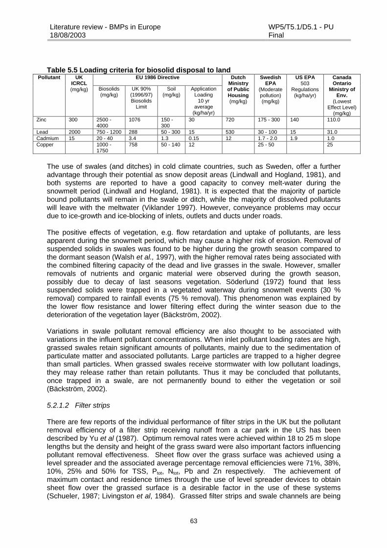
Literature review - BMPs in Europe18/08/2003
WP5/T5.1/D5.1 - PUFinal
63
Table 5.5 Loading criteria for biosolid disposal to landEU 1986 DirectivePollutant UK
ICRCL(mg/kg) Biosolids
(mg/kg)UK 90%
(1996/97)Biosolids
Limit
Soil(mg/kg)
ApplicationLoading
10 yraverage
(kg/ha/yr)
DutchMinistryof PublicHousing(mg/kg)
SwedishEPA
(Moderatepollution)(mg/kg)
US EPA503
Regulations(kg/ha/yr)
CanadaOntario
Ministry ofEnv.
(LowestEffect Level)
(mg/kg)Zinc 300 2500 -
40001076 150 -
30030 720 175 - 300 140 110.0
Lead 2000 750 - 1200 288 50 - 300 15 530 30 - 100 15 31.0Cadmium 15 20 - 40 3.4 1.3 0.15 12 1.7 - 2.0 1.9 1.0Copper 1000 -
1750758 50 - 140 12 25 - 50 25
The use of swales (and ditches) in cold climate countries, such as Sweden, offer a furtheradvantage through their potential as snow deposit areas (Lindwall and Hogland, 1981), andboth systems are reported to have a good capacity to convey melt-water during thesnowmelt period (Lindwall and Hogland, 1981). It is expected that the majority of particlebound pollutants will remain in the swale or ditch, while the majority of dissolved pollutantswill leave with the meltwater (Viklander 1997). However, conveyance problems may occurdue to ice-growth and ice-blocking of inlets, outlets and ducts under roads.
The positive effects of vegetation, e.g. flow retardation and uptake of pollutants, are lessapparent during the snowmelt period, which may cause a higher risk of erosion. Removal ofsuspended solids in swales was found to be higher during the growth season compared tothe dormant season (Walsh et al., 1997), with the higher removal rates being associated withthe combined filtering capacity of the dead and live grasses in the swale. However, smallerremovals of nutrients and organic material were observed during the growth season,possibly due to decay of last seasons vegetation. Söderlund (1972) found that lesssuspended solids were trapped in a vegetated waterway during snowmelt events (30 %removal) compared to rainfall events (75 % removal). This phenomenon was explained bythe lower flow resistance and lower filtering effect during the winter season due to thedeterioration of the vegetation layer (Bäckström, 2002).
Variations in swale pollutant removal efficiency are also thought to be associated withvariations in the influent pollutant concentrations. When inlet pollutant loading rates are high,grassed swales retain significant amounts of pollutants, mainly due to the sedimentation ofparticulate matter and associated pollutants. Large particles are trapped to a higher degreethan small particles. When grassed swales receive stormwater with low pollutant loadings,they may release rather than retain pollutants. Thus it may be concluded that pollutants,once trapped in a swale, are not permanently bound to either the vegetation or soil(Bäckström, 2002).
5.2.1.2 Filter strips
There are few reports of the individual performance of filter strips in the UK but the pollutantremoval efficiency of a filter strip receiving runoff from a car park in the US has beendescribed by Yu et al (1987). Optimum removal rates were achieved within 18 to 25 m slopelengths but the density and height of the grass sward were also important factors influencingpollutant removal effectiveness. Sheet flow over the grass surface was achieved using alevel spreader and the associated average percentage removal efficiencies were 71%, 38%,10%, 25% and 50% for TSS, Ptot, Ntot, Pb and Zn respectively. The achievement ofmaximum contact and residence times through the use of level spreader devices to obtainsheet flow over the grassed surface is a desirable factor in the use of these systems(Schueler, 1987; Livingston et al, 1984). Grassed filter strips and swale channels are being
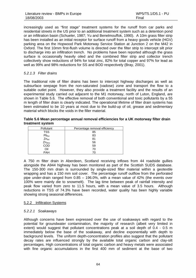
Literature review - BMPs in Europe18/08/2003
WP5/T5.1/D5.1 - PUFinal
64
increasingly used as “first stage” treatment systems for the runoff from car parks andresidential streets in the US prior to an additional treatment system such as a detention pondor an infiltration basin (Schueler, 1987; Yu and Benelmouffok, 1990). A 10m grass filter striphas been installed as an initial receptor for surface runoff from a heavy goods vehicle (HGV)parking area on the Hopwood Park Motorway Service Station at Junction 2 on the M42 inOxford. The first 10mm first-flush volume is directed over the filter strip to intercept silt priorto discharge into an infiltration trench. No problems have been reported although the grasssurface is occasionally heavily oiled and the combined filter strip and collector trenchcollectively show reductions of 94% for total zinc, 82% for total copper and 97% for lead aswell as 99% and 98% reductions for SS and BOD respectively (Bray, 2001).
5.2.1.3 Filter drains
The traditional role of filter drains has been to intercept highway discharges as well assubsurface seepage from the non-saturated (vadose) zone and transport the flow to asuitable outlet point. However, they also provide a treatment facility and the results of anexperimental study carried out adjacent to the M1 motorway, north of Luton, England, areshown in Table 5.6. The effective removal of both conventional and toxic pollutants by a 55m length of filter drain is clearly indicated. The operational lifetime of filter drain systems hasbeen estimated to be 10 years at most due to the build-up of oil, grease and sedimentarymaterial which blocks the voids in the filler material.
Table 5.6 Mean percentage annual removal efficiencies for a UK motorway filter draintreatment system
A 750 m filter drain in Aberdeen, Scotland receiving inflows from 44 roadside gulliesalongside the A944 highway has been monitored as part of the Scottish SUDS database.The 150-300 mm drain is surrounded by single-sized filter material within a geotextilewrapping and has a 150 mm soil cover. The percentage runoff outflow from the perforatedpipe under-drain ranged from 0.85 – 196.0%, with a mean value of 42% (the events over100% were mainly die to snowmelt). The lag time between peak of rainfall intensity andpeak flow varied from zero to 11.5 hours, with a mean value of 3.5 hours. Althoughreductions in TSS of 74.3% have been recorded, water quality has been highly variableshowing strong seasonal differences.
5.2.2 Infiltration Systems
5.2.2.1 Soakaways
Although concerns have been expressed over the use of soakaways with regard to thepotential for groundwater contamination, the majority of research (albeit very limited inextent) would suggest that pollutant concentrations peak at a soil depth of 0.4 - 0.5 mimmediately below the base of the soakaway, and decline exponentially with depth tobackground levels. The uniform depth-concentration profiles also suggest that the pollutantdecay rates are influenced strongly by the available total organic carbon and clay-siltpercentages. High concentrations of total organic carbon and heavy metals were associatedwith fine organic accumulations in the first 400 mm of sediment at the base of two
Pollutant Percentage removal efficiencyTSSPbtot
Zntot
Zndiss
CODOil
PAH
85838156597070
Literature review - BMPs in Europe18/08/2003
WP5/T5.1/D5.1 - PUFinal
65
soakaways investigated by Pratt (1996) at Brandon, Suffolk, UK. Similar results werereported in a study of a motorway soakaway on the M25 at junction 20 (near Kings Langley,Herts). Total quantified PAH in the basal soakaway sediments were recorded as 100,333?g/kg with an estimated annual loading of 0.20 – 0.33 kg per annum being delivered to thesoakaway (Barker et al., 1999). Below the base of both the Brandon and M25 soakaways,the pollution levels appeared to approach those of background levels. It was suggestedfrom both the above studies that the formation, and continued presence, of a sludge layer atthe base of the soakaway is important in terms of retaining pollutants by filtration andsorption. This inevitably results in a significant build-up of metals, PAH and halogens in thelower layer and if the site becomes saturated with the pollutant species, they would migratewith the runoff water to the unsaturated zone and to the groundwater. In addition, solublecomponents have the potential of being leached out to groundwater. Experimental workundertaken on a laboratory scale soakaway has suggested that up to half the availablesoakaway volume might be filled with sediment after 8 years of operation based on thecumulative annual mass of suspended solids discharged to the system (Pokrajac andDeletic, 2002).
Soakaways have been widely used in the UK for treating runoff from the impervious surfacesand roofs of individual properties. They are also used for the disposal of highway drainage,particularly when connected to single or multiple gully pots. The installation of multiplesoakaways (or soakaway fields) has also been used to increase the storage and infiltrationcapacity for highway runoff prior to overflow but the practice could lead to downstream build-ups of persistent pollutants. Where soakaway drainage is being disposed directly to groundoverlying Groundwater Resource Protection (GRP) zones, interception facilities will berequired. Under such circumstances, drainage from extensive stretches of highway(perhaps as much as 1 km) can be brought to lined oil interceptors and then to a group or"field" of soakaways. On the M40 and M25 motorways, the interceptors are sized to hold theequivalent of 6 minutes flow at the design discharge rate and have follow-on soakagelagoons to accept drainage overspill if all the soakaways should fill.
5.2.2.2 Infiltration trenches
An infiltration trench which forms part of a combined stormwater treatment system at theHopwood Park Motorway Service Station (Oxford, UK) is reported to have performedextremely well with regard to the removal of heavy metals, SS and BOD levels (see section5.2.1.2 for data), despite a problem with silt infilling which was also noted. A 1m deepdrainage blanket system has been installed below a traditional block-paved road/parkingarea in Cirencester, Wiltshire, which receives roof and road gully drainage but no informationon its performance is available. An infiltration trench in Aberdeen, Scotland, is currentlybeing monitored for both flow and pollutant attenuation, although again no information hasyet been published.
5.2.2.3 Infiltration basins
An infiltration system in Luton, Bedfordshire, UK, receiving peak discharges of 2.4 m3/s froma 26 ha residential site, showed incremental annual accumulation of zinc, copper andcadmium (averaging 0.8 - 1.5 mg/kg for Zn) at all depths in the basin but with an exponentialmobilisation of soluble species with depth. The exhaustion of the basin buffer capacity foracids make the long-term fixation in the underlying soil almost impossible. The results of thisstudy imply that average hydraulic conductivities in the unsaturated zone below infiltrationsystems should range from 10-4 m/s to 10-6 m/s, with the first 30 cm of the infiltration systemhaving a minimum hydraulic conductivity of 10-5 m/s. In addition, the top 0 - 30 cm of theinfill structure should be capable of maintaining a long term pH value of 5.5 - 8.0. This willreduce the probability of metal mobilisation and breakthrough arising from alkaline reactions
Literature review - BMPs in Europe18/08/2003
WP5/T5.1/D5.1 - PUFinal
66
due to the presence of water-soluble organic complexes. Finally, the groundwater levelshould be more than 1 m below the base of the infiltration device to ensure that theunsaturated zone can effectively adsorb downward moving colloidal metal species.The current evidence would suggest that the best use of infiltration basins is as finalpolishing systems in which the major treatment function is achieved by a precedingsedimentation or biofiltration system which in turn is fitted with a front-end oil/sediment trap.Infiltration basins are in effect a type of filter drain or soakaway having an expanded surfacearea. They are not suitable for spillage containment and have few ecological benefits.Although the use of infiltration basins has been recommended in Germany and France, theiruse in the UK is limited due to the high costs of construction and maintenance in relation totheir pollutant removal abilities.
Infiltration systems in cold countries may have problems with ice clogging during winter and,as a result, the infiltration capacity can be heavily reduced during the snowmelt period.However, the evaluation of an infiltration basin over a winter period reported there was aminimal risk of total ice blockage with temperatures down to -15°C (Stenmark, 1991), andthat the infiltration basin operated well during the snowmelt period. Bäckström and Viklander(2000) have also reported that both moderate runoff control and high pollution control can beachieved by using infiltration systems in cold climate regions.
Färm and Renman (1999) evaluated the performance of the infiltration component of astormwater management system in Västerås, Sweden. The complete system consisted of adetention pond, infiltration system and constructed wetland, and the drainage area includeda 4.3 ha highway area with a daily mean traffic density of 20,000 vehicles/day. The resultsfrom the infiltration system showed that the calcium silicate rock infiltration material cloggedduring winter, and that water was then unable to pass through the filter surfaces. Theclogging was probably caused by cementation of the material (Mikkelsen et al., 2002).
5.2.3 Storage Facilities
5.2.3.1 Flat roofs for storage
The water and sewerage department of Seine Saint-Denis County, France, demonstratedthe potential of flat roofs for rainwater storage in an experiment conducted on three types ofstorage system (open sky storage, storage in porous materials and storage underflagstones). The flat roof was able to store the water depth associated with a ten-year returnperiod storm (i.e. a depth of 40 mm). The edges of the roof measured 25 cm, and thestrength of the bearing material was 400 kg/m2. The system included two flow controldevices for the drainage of rainwater, each of which consisted of two 1 cm diameter outletswhich limited the flow rate to 0.5 l/s.
5.2.3.2 Storage tanks/chambers
Data on the performance of a sedimentation tank receiving runoff from a major motorway inthe UK are given in Table 5.7 (Ellis and Revitt, 1991). The relatively poor treatmentefficiencies found in this study have been supported by French motorway studies (Ruperd,1987; Ranchet and Ruperd, 1983) in which removals of 36%, 38%, 61%, 48% and 22%were obtained for COD, BOD, TSS, total lead and nitrate, respectively.
Table 5.7 Mean percentage annual removal efficiencies for a UK motorwaysedimentation tank treatment system (Perry and McIntyre, 1986)
Pollutant Removal efficiency (%)TSSPbtot
Zntot
524047

Literature review - BMPs in Europe18/08/2003
WP5/T5.1/D5.1 - PUFinal
67
Zndiss
CODOil
PAH
15352845
Due to the combination of size restrictions (see section 4.1.7), limited pollutant removalcapabilities (Table 5.7), high maintenance requirements (see section 4.2.2) and safetyconcerns of locating large open tanks next to busy roads, these systems would only be apreferred option if available land was to be so restricted as to necessitate a vertical sidedstructure or if there should be safety reasons to avoid an open water lagoon.
5.2.3.3 Lagoons
The UK motorway study referred to in section 5.2.1.3 also investigated the performance of a28m long by 2m wide polythene lined lagoon for the treatment of runoff from a 3172 m2 areaof road surface. The lagoon had a holding capacity of between 3 and 5 m3 according to theheight of an adjustable outlet pipe. The high pollutant removal efficiencies recorded for thissystem are shown in Table 5.8.
Table 5.8 Mean percentage annual removal efficiencies for a UK motorway lagoontreatment system
(Table from: R Perry and A E McIntyre. 1986. Impact of motorway runoff upon surface water quality. 53 – 67 in J F Solbe (Edit): Effects of Land Use on Freshwater. Ellis Horwood Ltd., Chichester.)
The results can be compared with those found for other treatment systems in the samelocation (see Table 5.6 and 5.7) from which it can be seen that the lagoon was more efficientthan the French drain which in turn was more efficient than the sedimentation tank. The hightreatment efficiencies of the lagoon were attributed to over-design of the system withcontributing factors being water loss due to seepage. Soakage lagoons at the junction of theA1(M) and M25 motorways to the north of London have shown persistent surface oil andscum problems despite the installation of booms and gate valves and recently some €86 500was spent de-silting both lagoons. Regular maintenance is essential to retain the long termeffective performance of sedimentation lagoons with the maintenance frequency beingdependent on the storage provision made for silt. However, such open water systems arerare stormwater BMP forms in the UK.
5.2.3.4 Detention basins
Detention ponds completely empty between storm events, and therefore the residence timeof stormwater is shorter in a detention basin than in a retention pond and settling of particlesand biochemical degradation of dissolved constituents is comparatively less efficient(Ferguson, 1998). However, a potential advantage of detention basins are that they can beused as a snow deposit area in cold countries during the winter months, although this couldcause severe problems during the snowmelt period when large volumes of melt-water flowinto the basin. (Bäckström and Viklander, 2000).
5.2.3.5 Extended detention basins
Pollutant Percentage Removal EfficiencyTSSPbtot
Zntot
Zndiss
CODOil
PAH
9290712554
>70>70

Literature review - BMPs in Europe18/08/2003
WP5/T5.1/D5.1 - PUFinal
68
Extended detention basins are detention basins which detain stormwater runoff for anextended period of time. Associated with their flow attenuation characteristics, detentionbasins encourage sedimentation of the coarser suspended materials although fine solids willbe re-suspended during high flows. US investigations have also demonstrated low removalefficiencies for soluble pollutants. No data has been reported for any UK extended detentionbasins although such facilities have been installed at North Weald, Essex and in Dundee,Scotland.
A series of French motorway studies (Balades et al, 1985; Cathelain et al, 1981; Ruperd,1987) have investigated the performance of detention basins and removal efficiencies in theranges of 0-73%, 0-75%, 0-73%, 1-67%, 0-48% and 7-86% were reported for BOD, COD,TSS, total Pb, total Zn and oil, respectively. The removal efficiencies were generally at thelower end of these ranges and the reasons given for the poor performances were the re-entrainment of solids during high flows (2.5 to 3.1 m3) through the basins. The use of front-end oil separators and sediment chambers were found to be beneficial to overall pollutantremoval performance yielding solids removal efficiencies of at least 50%. Stahre andUrbonas (1990) quote long term efficiencies for extended detention basins having 48 hourdetention times of 50 - 70% for TSS and hydrocarbons, 20 - 40% for BOD, 75 - 90% for leadand 30 - 60% for zinc. Even 4 - 10 hours detention is alleged to offer up to 50 - 60% TSSremovals. However, as most detention basins often have less than 2 hours detention time,the pollutant removal efficiencies are usually rather mediocre with TSS in the range of 15 -20% and BOD/COD generally less than 10%.
5.2.3.6 Retention basins
Retention basins (or balancing ponds) contain a permanent pool of open water (usuallyoccupying 50 to 75% of the surface area) around which emergent macrophyte vegetationmay be introduced. Such planting will assist in the treatment process by providing biologicalremoval of pollutants, particularly those in the dissolved phase. This re-inforces the removalof particulate associated pollutants through sedimentation within the relatively still waterbody which should be sized to contain at least 4 times the treatment volume in order toprovide retention of approximately 3 weeks during the wettest conditions.
The time-based trap efficiency of a 25000 m3 balancing pond receiving discharges from a60.7 ha residential development in NW London is given in Table 5.9 together with a bench-top determination of settleability. It is clear that even a few hours retention can provide abase-level treatment of stormwater runoff but that extended retention times are required toremove nutrients and organic loadings. For a retention time of 12 to 15 hours, thereductions which can be expected include some 60% of total SS, hydrocarbons, totalcoliforms and lead; 40% of BOD, phosphates and copper; and 10 – 20% of other pollutantssuch as cadmium, nitrate and ammoniacal nitrogen. The operational performance of thebalancing pond under stormflow conditions is shown in Figure 5.1 and the potential forsiltation at the inlet is clear from the high slug SS concentrations recorded at this location.
Table 5.9 Trap Efficiency of Wet Retention BasinsPollutant Imhoff
Settleability(24 hrs
average %)
BalancingPond 2 hrRemoval
(%)
Balancing Pond6 hr Removal
(%)
24hr BalancingPond Removal(Average %)
TSSBODPbOil/HydrocarbonsTotal PTotal Coliforms
683262694671
341330182060
824866625872
46 - 8429 - 5346 - 7820 - 7820 - 7054 - 73
(Table from: M J Hall, DL Hockin and J B Ellis. 1993. Design of Flood Storage Reservoirs. CIRIA, London)
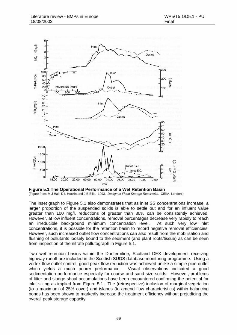
Literature review - BMPs in Europe18/08/2003
WP5/T5.1/D5.1 - PUFinal
69
Figure 5.1 The Operational Performance of a Wet Retention Basin(Figure from: M J Hall, D L Hockin and J B Ellis. 1993. Design of Flood Storage Reservoirs. CIRIA, London.)
The inset graph to Figure 5.1 also demonstrates that as inlet SS concentrations increase, alarger proportion of the suspended solids is able to settle out and for an influent valuegreater than 100 mg/l, reductions of greater than 80% can be consistently achieved.However, at low influent concentrations, removal percentages decrease very rapidly to reachan irreducible background minimum concentration level. At such very low inletconcentrations, it is possible for the retention basin to record negative removal efficiencies.However, such increased outlet flow concentrations can also result from the mobilisation andflushing of pollutants loosely bound to the sediment (and plant roots/tissue) as can be seenfrom inspection of the nitrate pollutograph in Figure 5.1.
Two wet retention basins within the Dunfermline, Scotland DEX development receivinghighway runoff are included in the Scottish SUDS database monitoring programme. Using avortex flow outlet control, good peak flow reduction was achieved unlike a simple pipe outletwhich yields a much poorer performance. Visual observations indicated a goodsedimentation performance especially for coarse and sand size solids. However, problemsof litter and sludge shoal accumulations have been encountered confirming the potential forinlet silting as implied from Figure 5.1. The (retrospective) inclusion of marginal vegetation(to a maximum of 25% cover) and islands (to amend flow characteristics) within balancingponds has been shown to markedly increase the treatment efficiency without prejudicing theoverall peak storage capacity.
Literature review - BMPs in Europe18/08/2003
WP5/T5.1/D5.1 - PUFinal
70
Although retention ponds are frequently used for stormwater control in countries with coldclimates, the performance of these systems is not generally well understood. Research inSweden on the performance of two retention ponds concluded that the ponds couldeffectively control pollution (Table 5.10) and that removal efficiencies increased with thespecific storage of the pond up to approximately 250m3/impervious ha (equivalent to a depthof 2.5 mm) (Pettersson et al., 1999). However, the pond sediments were found to be highlypolluted and therefore to ultimately require proper disposal e.g. to a controlled landfill site.This finding also led to the conclusion that ponds should be regarded primarily as treatmentfacilities and not as habitat for wildlife. The concentrations of heavy metals in the outflowwere found to be critically high compared to Swedish guidelines for lakes and streams(German, 2001). These findings were supported by a literature survey carried out to identifyfuture stormwater treatment systems for a part of Copenhagen which was being redeveloped(Moller, 2001).
In cold weather countries, formation of an ice-layer in a retention pond forces inflowingmeltwater under the ice which can result in the scouring of fine bottom material. When thesomewhat pressurised volume under the ice is exceeded, water flows over the ice surfaceand the storage volume is eliminated because of the impervious ice layer. The ice alsorestricts the air-water exchange, limiting the availability of oxygen to the water column whichis being progressively depleted throughout the winter due to organic decomposition. Thecold water flowing during the melt periods has a higher viscosity, thus reducing settlingvelocities of particles being carried into retention facilities. This decreases sedimentation andenables mobilisation of associated contaminants further down-stream. Research by Jokelaand Bacon (1990) has indicated that settling velocities are 50% faster at a water temperatureof 20 °C compared to 4 °C. It is anticipated that the impact of ice cover and low watertemperatures would be similar in constructed wetland systems.
Watt et al., (1997) have investigated the winter regime in a retention pond with a surfacearea of 0.52 ha and average depth of 1 m situated in Ontario, Canada. The results of studiescarried out over a period of two winters indicated the low potential of bottom sedimentscouring and pollutant release from the sediment. Anaerobic conditions occurred during twodays at the end of a period (one to two months) of constant freezing conditions. There wereindications of density stratification in the pond during winter. Studies on a stormwaterretention pond in Sweden with a surface area of 350 m2 and an average depth of 1.2 mshowed that the amount of dissolved oxygen decreased when the pond was ice-covered andno inflow or outflow of stormwater took place (Pettersson, 1996). The concentrations ofdissolved heavy metals (Zn, Pb, Cu and Cd) increased during the same period.
Table 5.10 Removal efficiencies in two Swedish stormwater ponds (Pettersson et al.,1999)Pollutant The Järnbrott Pond The Krubban Pond
Pond System*TSS (mg/l) 70 42 84Zinc (µg/l) 30 24 82Copper (µg/l) 30 24 75Lead (µg/l) 48 30 82Cadmium (µg/l) 11 12 50Nitrogen (mg/l) 7 80 33Phosphorus (µg/l) 40 27 74* Removal efficiency considering the by-pass upstream of the pond.(Mikkelsen, et al., 2002)
Oberts et al., (1989) have investigated the treatment performance of four different retentionponds in Minnesota, USA. The data collected during snowmelts indicated that the pondshave a wide range of pollutant removal abilities (Table 5.11). The data also show that there

Literature review - BMPs in Europe18/08/2003
WP5/T5.1/D5.1 - PUFinal
71
is a marked reduction in the ability of the retention ponds to treat snowmelt runoff incomparison to rainfall runoff (with the exception of the Woodbury pond which was notablyundersized). An explanation for this could be the different characteristics of meltwater incomparison to stormwater runoff. For example, studies of metal partitioning in a stormwaterpond have indicated that more metals are in the dissolved phase during snowmelt events, afinding thought to be associated with the higher conductivity of meltwater due to thepresence of road salts (Pettersson, 1999). Research by Oberts (1994) and Oberts andOsgood (1991) found that the removal efficiencies of all the monitored substancesdecreased during winter months with the lowest removal efficiencies reported for nutrients. Itwas noted that the ponds could become stratified during winter conditions because ofthermal and dissolved solids concentration gradients. This phenomenon was studied inCanada, where it was concluded that wind was an important parameter in determining theflow pattern during baseflow conditions without ice cover, and that a stable stratificationoccurred in the pond due to temperature and salinity gradients (German et al., 2003,Marsalek et al. 2000).
Table 5.11 Pollutant removal ability (%) of ponds in treating runoff in MinnesotaPercent pollutant removal
Snowmelt events(Rainfall events)
Pond TSS VSS TP DP COD TKN NO3 TPbMcCarrons(0.97 ha)
58(91)
58(95)
41(78)
38(57)
50(90)
22(88)
13(60)
40(85)
Lake Ridge(0.38 ha)
72(90)
63(70)
10(61)
6(11)
--
10(50)
19(10)
18(73)
McKnight Basin(2.24 ha)
85(85)
48(67)
30(48)
11(13)
--
10(31)
8(24)
59(67)
Woodbury(0.15 ha)
-60(46)
-46(32)
-17(24)
-12(21)
--
-27(14)
4(18)
-40(42)
5.2.3.7 Constructed Wetlands
Wetlands (both natural and constructed) have been widely used for the of treatment ofsewage and for urban, industrial and agricultural runoff although with less extensiveapplications for highway runoff. Sub-surface wetlands provide limited flood storage andtherefore, where significant flood storage is required, should be combined with a separatestorage facility. The balance between storage and treatment requirements will depend onthe land availability and where space is limited, the constructed wetland could be designedto only treat the first flush contained in the initial 5-10 mm of effective runoff. Table 5.12indicates the average range of pollutant removal efficiencies that have been reported in theliterature for constructed wetlands receiving highway runoff in the UK, France, Canada andthe United States.
Table 5.12 Percentage pollutant removal rates in constructed wetlands
A 3900m2 biofiltration (surface flow) wetland receiving runoff from the M25 London OrbitalMotorway recorded consistent metal removal efficiencies of about 90% confirming thepotential treatment effectiveness of such systems. Solids removal performance increasedas flow TSS concentrations increased but with inflow concentrations below 30 - 40 mg/l, onlyminimal reductions were achieved. A 1050 m3 constructed wetland on the A34 Newbury
WetlandType
TSS FaecalColiforms
Ntot Ptot Pbtot Zntot BOD/TOC
SubsurfaceFlows
Free SurfaceFlows
85(67-97)
73(13-99)
88(80-97)
92(86-99)
44(25-98)
33(10-99)
50(20-97)
43(2-98)
83(5-94)
69(41-83)
42(10-82)
58(31-75)
-
15(5-32)

Literature review - BMPs in Europe18/08/2003
WP5/T5.1/D5.1 - PUFinal
72
Bypass draining 16,000 m2 of road surface showed similar good TSS (90%) removal ratesbut metal removal efficiencies were highly variable particularly for zinc and copper. Thisvariability in performance (which can be noted from Table 5.12) has variously been attributedto short-circuiting, short detention and contact times, pollutant speciation mechanisms andremobilisation, seasonal vegetation effects etc.
5.2.3.8 Combined stormwater runoff treatment systems
A stormwater treatment system, consisting of an oil separator, sedimentation basins,grassed filter strip and ponds, was constructed in Flemmingsberg/Huddinge, Sweden, in1994-95 (Lännegren, 1998). The catchment area was 9.6 km2 and the detention time wasapproximately six days. The results of a three-year monitoring programme showed that leadand zinc concentrations were reduced by this system, while copper, mercury, chromium,suspended solids, COD and TOC concentrations increased. BOD remained constant. It wasalso noted that the wetland had a positive effect on the wildlife, with 10 to 12 different birdspecies and a variety of fish observed in and around the wetland area (Mikkelsen et al.,2002).
A combined stormwater control system at Lake Magelungen, Sweden, began operating in1992 (Rosen, 1996). The catchment area of 81.5 ha includes a city centre, roads and asports arena. The system includes a 1000 m2 grassed filter strip and a 10,000 m3 bankedbasin in Lake Magelungen. Sampling was carried out over a two year period to study thereduction of phosphorus and nitrogen. The discharge of P from the grassed filter strip varieddepending on the season, from washout (during the summer) to a reduction of 70-80%. Theremoval of nitrogen also varied, with the lowest reduction observed during the summer and ahigher removal of particulate bound N in comparison to the dissolved fraction. Theconductivity and metal concentrations increased across the surface of the grass filter. It wasconcluded that, rather than retaining the pollutants, pollutants were being washed out andthe grass filter was therefore taken out of use. These problems could be explained bydifficulties experienced in spreading the flow equally over the surface, which resulted inchannelling across the surface. The results for the pond showed that the main removalprocess was sedimentation (Rosen, 1996). The results also showed that denitrífication wasoccurring in the sedimentation basin (Mikkelsen et al., 2002).
The monitoring of oxygen and flow downstream of a combined detention pond andconstructed wetland system in Herning, Denmark, has shown that the receiving water cancope with the limited discharge from this system. The available data, although limited, showsa 40-70% reduction in concentrations of COD and nutrients, with concentrations dischargedfrom the ponds often being lower than those discharged from wastewater treatment plants(Mikkelsen, et al., 2002).
Research on a wetland in Minnesota, USA, demonstrates some of the issues associatedwith accurately determining treatment performance of these systems. Table 5.13 shows thetreatment performances of a 2.5 ha, six-chambered, low-head wetland treatment system onreceiving meltwater, and the treatment performances of the same wetland system during thefirst two rainfall events following this snowmelt event (Oberts and Osgood, 1988). Thewetland outlet was frozen shut for the entire winter, resulting in the slow accumulation of allsmall mid-winter events and baseflow in the final wetland chamber (approximately 1 ha).When the melt began, flow entering the final wetland chamber was detained until a smallopening in the outlet culvert gradually allowed all of the accumulated meltwater to discharge.Material that had settled out of the accumulated meltwater during the extended detentionperiod had, however, settled onto several layers of ice that had built-up over winter. Thesesettled pollutants were then largely washed through the system by the first of the two rainfallevents as the ice layers remained as an impervious surface over which the rainfall runoff

Literature review - BMPs in Europe18/08/2003
WP5/T5.1/D5.1 - PUFinal
73
freely flowed. Keeping the outlet open to prevent the formation of an ice layer over the entirewetland, and then allowing detention to occur in contact with the wetland soils could haveenhanced the treatment under these conditions.
Table 5.13 Wetland treatment system melt/spring rain performanceTSS VSS TP DP COD TKN NO3 TPb
Snowmelt 82 78 68 68 74 53 54 71Two rainfallsafter melt
4 15 6 -5 10 22 -20 39
5.2.4 Alternative road structure
5.2.4.1 Porous paving
Given that as much as 60% of the typical urban surface is taken up as “vehicle habitat” usewith some 10 parking spaces available per average single car, it is not surprising thatalternative forms of hard-standing have been developed to reduce the environmental impactof increasing traffic densities. Work in the 1980s on a concrete block-surfaced car park atNottingham Trent University using differing types of sub-base materials demonstrated 34% -47% reductions in total runoff discharges with initial wetting loss before drain dischargebeing 2.4 – 3.2 mm. Considerable improvements were also achieved in water quality withthe porous paving limiting TSS discharges from near zero to 50 mg/l maximum withhydrocarbons only found at trace levels. The work showed that pollutant retention occurredin the 50 mm layer immediately above the geotextile liner on which the porous blocks wereplaced. Observations on a similar concrete block surfacing at Shire Hall, Reading indicateda mean infiltration rate of 2600 mm/hour, six years after installation without any maintenance(Pratt, 1995). The surfacing allows the immediate infiltration of rainfall-runoff into theconstruction with the sub-base providing storage, treatment and pathways for downwardpercolation into the underlying soil or to perforated underdrains. The volume of water thatcan be stored and the outflow rates are dependent on the void ratio of the sub-base gravelor crushed stone. The presence of dirt and oil spillage on the paved surface significantlyreduced the infiltration rates for both the blocks and the gaps between them.
A 1500 m2 porous paved car park installed at the Scottish Civil Aviation Authority HQ inEdinburgh, whilst costing out some 15% more expensive than conventional "blacktop"asphalt, is showing significant attenuation (22% flow reduction) of the outlet hydrograph withthe first discharge only occurring several hours after the start of rainfall. In addition, TSS,COD and BOD outflow values are consistently below 20, 10 and 2 mg/l respectively withhydrocarbons below detection levels. Studies conducted on permeable pavements at theM40 Wheatley, Oxford service station and at the Wokingham Tesco car park site,demonstrated average storm peak reductions of 88% and 81% respectively with attenuationextended on average by a factor of 14 (Abbott et al., 2003). Newman et al., (2001) have alsoshown that properly installed permeable paving with the gravel bedding reinforced withlightweight clay aggregates or porous concrete granules, can provide considerable oil andwater retention. Experimental paving surfaces have given infiltration rates of some 4500mm/hour with overall oil retention capacities of 9542 g/m2 which would give an operationallife of over 40 years and an outflow effluent from the pavement of about 0.6 - 0.8 mg/l. Theuse of pre-fabricated plastic/polypropylene geo-cellular units under the sub-base beddinglayer has been shown to optimise oil and sediment removal capturing some 20 – 40% of theoil applied to the paved surface (Newman et al., 2003).
A porous concrete block-surface car park at the Bank of Scotland, South Gyle, Edinburghshowed outflow discharge to be under 50% of total rainfall-runoff with initial wetting lossbeing 1.65 mm. Lag times were typically within a range of 40 – 140 minutes. Both heavymetal (<0.068 – 1.7 ?g/l) and hydrocarbon (<3.5 mg/l) concentrations in the porous paving

Literature review - BMPs in Europe18/08/2003
WP5/T5.1/D5.1 - PUFinal
74
effluent were markedly reduced over raw surface runoff concentrations. A 6250 m2 porousconcrete-block surfaced car park at the M40 Wheatley Motorway Service Area near Oxfordhas provided similar observations to those in Scotland with outflows from the porouspavement being only 4% – 47% of the rainfall volume with lag times of up to 2 – 3 days.Block infiltration was assessed as varying between 250 – 14,000 mm/hour although after 10months of operation, this had reduced to zero. Infiltration through the gaps was howevermaintained at rates of 11,000 – 229,000 mm/hour. The results of these and similar studieselsewhere in Scotland have led SEPA to accept that oil interceptors are not required onpermeable car parking areas which have an approved engineering sub-base.
A 4-year study carried out near Nantes, France, monitored the flow rate upstream of a draincollecting runoff from 255 m of street surface. A cross-section of the porous pavementstructure is given in Figure 5.2, while Figure 5.3 displays the responses of both thepavement containing a reservoir structure and a reference basin site to a heavy storm event.
Examination of the complete data set demonstrated that the greatest proportion of waterinfiltrating into the pavement was not discharged via the drain. An analysis of drain operationin relation to daily precipitation height is given in Table 5.14. The absence of outflowindicates that the stormwater had infiltrated into the soil, been retained by aggregates and/orevaporated. The proportion of stormwater discharged by the drain varies from 0% to amaximum of 12.5%. Over the entire 4-year study period, the drain only served to discharge3.3% of total rainfall.
Figure 5.2 Cross-section of a street fitted with a reservoir structure
0
5
10
15
20
25
30
06-Jan 07-Jan 08-Jan 09-Jan 10-Jan 11-Jan 12-Jan
Temps (pas de temps horaire)
Déb
it (m
3/h
/ha)
0
2
4
6
8
10
Plu
ie (m
m/h
)
Hydrogramme du site deréférence
Hydrogramme de la CSR
Hyétogramme
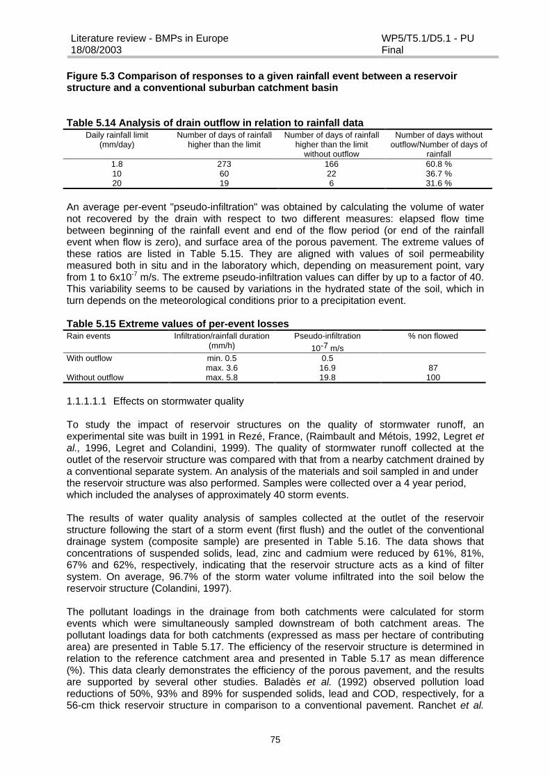
Literature review - BMPs in Europe18/08/2003
WP5/T5.1/D5.1 - PUFinal
75
Figure 5.3 Comparison of responses to a given rainfall event between a reservoirstructure and a conventional suburban catchment basin
Table 5.14 Analysis of drain outflow in relation to rainfall dataDaily rainfall limit
(mm/day)Number of days of rainfall
higher than the limitNumber of days of rainfall
higher than the limitwithout outflow
Number of days withoutoutflow/Number of days of
rainfall1.8 273 166 60.8 %10 60 22 36.7 %20 19 6 31.6 %
An average per-event "pseudo-infiltration" was obtained by calculating the volume of waternot recovered by the drain with respect to two different measures: elapsed flow timebetween beginning of the rainfall event and end of the flow period (or end of the rainfallevent when flow is zero), and surface area of the porous pavement. The extreme values ofthese ratios are listed in Table 5.15. They are aligned with values of soil permeabilitymeasured both in situ and in the laboratory which, depending on measurement point, varyfrom 1 to 6x10⁻⁷ m/s. The extreme pseudo-infiltration values can differ by up to a factor of 40.This variability seems to be caused by variations in the hydrated state of the soil, which inturn depends on the meteorological conditions prior to a precipitation event.
Table 5.15 Extreme values of per-event lossesRain events Infiltration/rainfall duration
(mm/h)Pseudo-infiltration
10-7 m/s% non flowed
With outflow min. 0.5 0.5max. 3.6 16.9 87
Without outflow max. 5.8 19.8 100
1.1.1.1.1 Effects on stormwater quality
To study the impact of reservoir structures on the quality of stormwater runoff, anexperimental site was built in 1991 in Rezé, France, (Raimbault and Métois, 1992, Legret etal., 1996, Legret and Colandini, 1999). The quality of stormwater runoff collected at theoutlet of the reservoir structure was compared with that from a nearby catchment drained bya conventional separate system. An analysis of the materials and soil sampled in and underthe reservoir structure was also performed. Samples were collected over a 4 year period,which included the analyses of approximately 40 storm events.
The results of water quality analysis of samples collected at the outlet of the reservoirstructure following the start of a storm event (first flush) and the outlet of the conventionaldrainage system (composite sample) are presented in Table 5.16. The data shows thatconcentrations of suspended solids, lead, zinc and cadmium were reduced by 61%, 81%,67% and 62%, respectively, indicating that the reservoir structure acts as a kind of filtersystem. On average, 96.7% of the storm water volume infiltrated into the soil below thereservoir structure (Colandini, 1997).
The pollutant loadings in the drainage from both catchments were calculated for stormevents which were simultaneously sampled downstream of both catchment areas. Thepollutant loadings data for both catchments (expressed as mass per hectare of contributingarea) are presented in Table 5.17. The efficiency of the reservoir structure is determined inrelation to the reference catchment area and presented in Table 5.17 as mean difference(%). This data clearly demonstrates the efficiency of the porous pavement, and the resultsare supported by several other studies. Baladès et al. (1992) observed pollution loadreductions of 50%, 93% and 89% for suspended solids, lead and COD, respectively, for a56-cm thick reservoir structure in comparison to a conventional pavement. Ranchet et al.
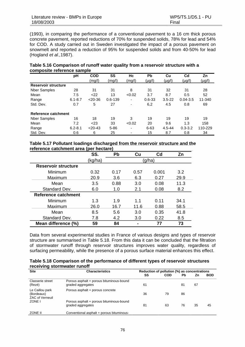
Literature review - BMPs in Europe18/08/2003
WP5/T5.1/D5.1 - PUFinal
76
(1993), in comparing the performance of a conventional pavement to a 16 cm thick porousconcrete pavement, reported reductions of 70% for suspended solids, 78% for lead and 54%for COD. A study carried out in Sweden investigated the impact of a porous pavement onsnowmelt and reported a reduction of 95% for suspended solids and from 40-50% for lead(Hogland et al.,1987).
Table 5.16 Comparison of runoff water quality from a reservoir structure with acomposite reference sample
pH COD SS Hc Pb Cu Cd Zn(mg/l) (mg/l) (mg/l) (µg/l) (µg/l) (µg/l) (µg/l)
Reservoir structureNber Samples 28 31 31 8 31 32 31 28Mean 7.5 <22 13 <0.02 3.7 8.7 0.5 52Range 6.1-8.7 <20-36 0.6-139 - 0.6-33 3.5-22 0.04-3.5 11-340Std. Dev. 0.7 5 27 - 6,2 4.5 0.8 69
Reference catchment Nber Samples 16 18 19 3 19 19 19 19Mean 7.2 <23 33 <0.02 20 9.6 1.3 158Range 6.2-8.1 <20-43 5-86 - 6-63 4.5-44 0.3-3.2 110-229Std. Dev. 0.6 6 25 - 15 8.7 0.8 34
Table 5.17 Pollutant loadings discharged from the reservoir structure and thereference catchment area (per hectare)
SS. Pb Cu Cd Zn(kg/ha) (g/ha)
Reservoir structureMinimum 0.32 0.17 0.57 0.001 3.2Maximum 20.9 3.6 6.3 0.27 29.9
Mean 3.5 0.88 3.0 0.08 11.3Standard Dev. 6.0 1.0 2.1 0.08 8.2
Reference catchmentMinimum 1.3 1.9 1.1 0.11 34.1Maximum 26.0 16.7 11.6 0.88 58.5
Mean 8.5 5.6 3.0 0.35 41.8Standard Dev. 7.8 4.2 3.0 0.22 8.5
Mean difference (%) 59 84 - 77 73
Data from several experimental studies in France of various designs and types of reservoirstructure are summarised in Table 5.18. From this data it can be concluded that the filtrationof stormwater runoff through reservoir structures improves water quality, regardless ofsurfacing permeability, while the presence of a porous surface material enhances this effect.
Table 5.18 Comparison of the performance of different types of reservoir structuresreceiving stormwater runoffSite Characteristics Reduction of pollution (%) as concentrations
SS COD Pb Zn BOD
Classerie street(Rezé)
Porous asphalt + porous bituminous-boundgraded aggregates 61 81 67
Le Caillou park(Bordeaux)
Porous asphalt + porous concrete36 79 86
ZAC of VerneuilZONE I
ZONE II
Porous asphalt + porous bituminous-boundgraded aggregates
Conventional asphalt + porous bituminous-
81 63 76 35 45

Literature review - BMPs in Europe18/08/2003
WP5/T5.1/D5.1 - PUFinal
77
ZONE III*
bound graded aggregates
Different reservoir structures
68
1
48
14
77
50
45
16
39
7* = data from this site is thought to have been influenced by infrastructure work
Analysis of clogging material, crushed material, the geotextile material and the underlyingsoil, indicated that metals were primarily located in the porous surfacing of the reservoirstructure and that the porous layers under the surfacing had only a minor effect on theretention of particulate pollution. Furthermore, the infiltration of stormwater into the porousasphalt over a period of more than 8 years did not cause any migration of particulate-boundmetals within the reservoir.
The overall findings from these French studies are summarised below.
? From a hydrological perspective, it appeared that more than 96 % of the annual rainfallinfiltrated into the soil underneath the reservoir structure significantly reducing both peakflow and runoff. The quality of water discharged from the reservoir structure was of ahigher quality than that discharged from a neighbouring reference catchment area. Inaddition, there was no evidence of soil contamination under the structure after 8 years ofoperation.
? From a mechanical perspective, despite water infiltration, the behaviour of the reservoirstructure was comparable to that of a conventional impervious structure.
? From an acoustic perspective, after 10 years and two maintenance operations(unclogging) the structure had retained sufficient porosity to achieve an acousticabsorption coefficient of 10-15%.
? From a performance perspective, the main problem was related to the clogging ofsurface porous materials. To maintain optimal performance regular cleaning would berequired, indicating that the use of these systems involves additional costs andconstraints in comparison to conventional pavement structures.
? The use of reservoir structures is primarily suited to the construction of large car parkingfacilities.
Another type of paving material is Grasscrete, a type of modular pavement well suited tooverflow car parks which require a grass surface that must be sufficiently hard wearing towithstand regular vehicle use. Such grass-concrete surfaces possess infiltration ratesbetween 0.2 to 1.0 mm/s (well in excess of most design storm rainfall intensities) and canhold up to 5 mm rainfall within one hour for subsequent evaporative loss. Filtration-sedimentation and adsorption processes within the structural reservoir of the surfacingmaterial can limit TSS outflows from near zero to 50 mg/l and typically remove between 40 -60% bacteria, 70 - 90% heavy metals and hydrocarbons. Pre-cast pavers over lattice slabsoffer the dual advantages of on-site infiltration and easy maintenance. The inevitableaccumulation of silt in the surface layers of the "reservoir" construction and "clay-bridging"between particles during wetting-drying cycles will lead to clogging and failure of thestructure although minimum lifetimes for properly installed and maintained structures can beof the order of 10 to 15 years. The pre-cast blocks and modular pavement can be easilylifted allowing the underlying gravel bed layer and geotextile to be replaced beforereinstating the paving surface.
Several researchers have reported that porous pavements with reservoir structures may besuitable for the control of both stormwater quantity and quality in regions with a cold climate(Hogland and Niemczynowicz, 1986; Hogland and Wahlman, 1990; Stenmark, 1995;Bäckström, 1999, Bäckström and Viklander, 2000). These studies found that the poroussurface maintained its draining function during snowmelt and that the porous pavement wasmore resistant to freezing and frost actions in comparison to impermeable roadconstructions. However, Fujita (1994) has suggested that porous pavements should beconstructed with drainage pipes to avoid the risk of damage during freezing.

Literature review - BMPs in Europe18/08/2003
WP5/T5.1/D5.1 - PUFinal
78
5.2.4.2 Porous Asphalt and Whisper Concrete
Porous asphalt surfacing has become popular because it forms a highway surface whichgenerates less vehicle noise; it reduces splash and spray and hence also reducesaquaplaning whilst enhancing driver visibility; and provides a durable, high-speed roadsurface. It can also perform a stormwater treatment function, with a study by Stotz andKrauth, 1994, reporting a retention of approximately 50% for suspended solidsdemonstrating its filtration ability.
Full scale trials are now taking place in the UK on a 2 km section of the M23 near GatwickAirport of "whisper concrete" inlays to overcome the problem of rutting on asphaltic highwaysurfaces subject to heavy trafficking. Serious rutting of the inside lane of motorways andtrunk roads can pose hazards due to increased risks of aquaplaning resulting from retainedwater as well as yielding increased solids, bitumen and oils to the surface runoff. The"whisper concrete" composition of the inlay makes it appear very similar to asphalt and it willreduce maintenance costs, extend durability and lifetime of the surface as well as reducingnoise and combating the effects that any future increase in vehicle axle weights might haveon highway life.
5.2.5 Street cleaning
Street cleaning is a common practice throughout Europe. However, the effectiveness of thisprocess as a stormwater source control measure is unclear as the pollutant load conveyedby runoff remains very high and, in most instances, unacceptable in comparison with thequality-based objectives of receiving watercourses. Figure 5.4 shows the relative cleaningeffectiveness of varying types of street sweeping procedures in the UK, based on field datafor a NW London catchment. The build-up of sediment against the kerb edge is indicated aswell as the lack of removal of the fine solids fraction (< 63?m), with which most of thepollutant load is associated, meaning that there is considerable deflationary re-distribution offines back across the road surface as well as an almost infinite contaminated sediment“reservoir” available for stormwater transport to the roadside gully during wet weatherevents.
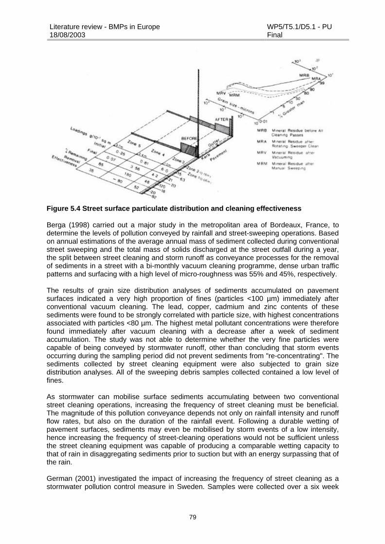
Literature review - BMPs in Europe18/08/2003
WP5/T5.1/D5.1 - PUFinal
79
Figure 5.4 Street surface particulate distribution and cleaning effectiveness
Berga (1998) carried out a major study in the metropolitan area of Bordeaux, France, todetermine the levels of pollution conveyed by rainfall and street-sweeping operations. Basedon annual estimations of the average annual mass of sediment collected during conventionalstreet sweeping and the total mass of solids discharged at the street outfall during a year,the split between street cleaning and storm runoff as conveyance processes for the removalof sediments in a street with a bi-monthly vacuum cleaning programme, dense urban trafficpatterns and surfacing with a high level of micro-roughness was 55% and 45%, respectively.
The results of grain size distribution analyses of sediments accumulated on pavementsurfaces indicated a very high proportion of fines (particles <100 µm) immediately afterconventional vacuum cleaning. The lead, copper, cadmium and zinc contents of thesesediments were found to be strongly correlated with particle size, with highest concentrationsassociated with particles <80 µm. The highest metal pollutant concentrations were thereforefound immediately after vacuum cleaning with a decrease after a week of sedimentaccumulation. The study was not able to determine whether the very fine particles werecapable of being conveyed by stormwater runoff, other than concluding that storm eventsoccurring during the sampling period did not prevent sediments from "re-concentrating". Thesediments collected by street cleaning equipment were also subjected to grain sizedistribution analyses. All of the sweeping debris samples collected contained a low level offines.
As stormwater can mobilise surface sediments accumulating between two conventionalstreet cleaning operations, increasing the frequency of street cleaning must be beneficial.The magnitude of this pollution conveyance depends not only on rainfall intensity and runoffflow rates, but also on the duration of the rainfall event. Following a durable wetting ofpavement surfaces, sediments may even be mobilised by storm events of a low intensity,hence increasing the frequency of street-cleaning operations would not be sufficient unlessthe street cleaning equipment was capable of producing a comparable wetting capacity tothat of rain in disaggregating sediments prior to suction but with an energy surpassing that ofthe rain.
German (2001) investigated the impact of increasing the frequency of street cleaning as astormwater pollution control measure in Sweden. Samples were collected over a six week
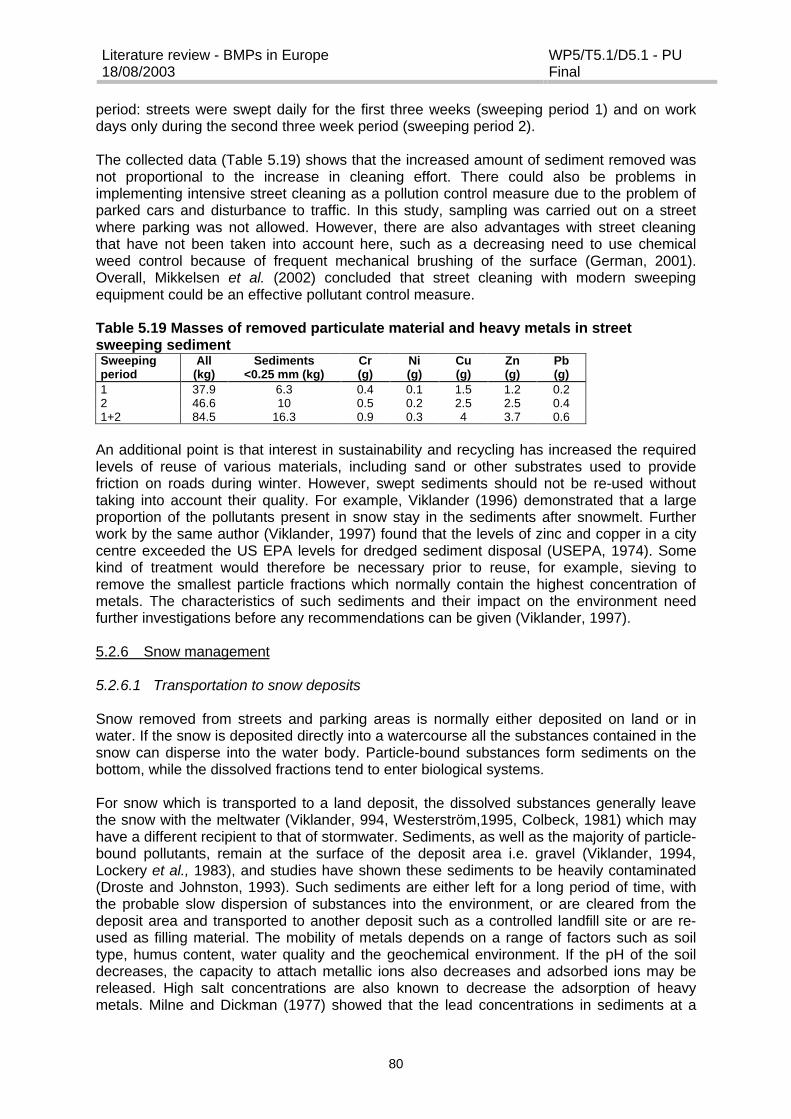
Literature review - BMPs in Europe18/08/2003
WP5/T5.1/D5.1 - PUFinal
80
period: streets were swept daily for the first three weeks (sweeping period 1) and on workdays only during the second three week period (sweeping period 2).
The collected data (Table 5.19) shows that the increased amount of sediment removed wasnot proportional to the increase in cleaning effort. There could also be problems inimplementing intensive street cleaning as a pollution control measure due to the problem ofparked cars and disturbance to traffic. In this study, sampling was carried out on a streetwhere parking was not allowed. However, there are also advantages with street cleaningthat have not been taken into account here, such as a decreasing need to use chemicalweed control because of frequent mechanical brushing of the surface (German, 2001).Overall, Mikkelsen et al. (2002) concluded that street cleaning with modern sweepingequipment could be an effective pollutant control measure.
Table 5.19 Masses of removed particulate material and heavy metals in streetsweeping sedimentSweepingperiod
All(kg)
Sediments<0.25 mm (kg)
Cr(g)
Ni(g)
Cu(g)
Zn(g)
Pb(g)
1 37.9 6.3 0.4 0.1 1.5 1.2 0.22 46.6 10 0.5 0.2 2.5 2.5 0.41+2 84.5 16.3 0.9 0.3 4 3.7 0.6
An additional point is that interest in sustainability and recycling has increased the requiredlevels of reuse of various materials, including sand or other substrates used to providefriction on roads during winter. However, swept sediments should not be re-used withouttaking into account their quality. For example, Viklander (1996) demonstrated that a largeproportion of the pollutants present in snow stay in the sediments after snowmelt. Furtherwork by the same author (Viklander, 1997) found that the levels of zinc and copper in a citycentre exceeded the US EPA levels for dredged sediment disposal (USEPA, 1974). Somekind of treatment would therefore be necessary prior to reuse, for example, sieving toremove the smallest particle fractions which normally contain the highest concentration ofmetals. The characteristics of such sediments and their impact on the environment needfurther investigations before any recommendations can be given (Viklander, 1997).
5.2.6 Snow management
5.2.6.1 Transportation to snow deposits
Snow removed from streets and parking areas is normally either deposited on land or inwater. If the snow is deposited directly into a watercourse all the substances contained in thesnow can disperse into the water body. Particle-bound substances form sediments on thebottom, while the dissolved fractions tend to enter biological systems.
For snow which is transported to a land deposit, the dissolved substances generally leavethe snow with the meltwater (Viklander, 994, Westerström,1995, Colbeck, 1981) which mayhave a different recipient to that of stormwater. Sediments, as well as the majority of particle-bound pollutants, remain at the surface of the deposit area i.e. gravel (Viklander, 1994,Lockery et al., 1983), and studies have shown these sediments to be heavily contaminated(Droste and Johnston, 1993). Such sediments are either left for a long period of time, withthe probable slow dispersion of substances into the environment, or are cleared from thedeposit area and transported to another deposit such as a controlled landfill site or are re-used as filling material. The mobility of metals depends on a range of factors such as soiltype, humus content, water quality and the geochemical environment. If the pH of the soildecreases, the capacity to attach metallic ions also decreases and adsorbed ions may bereleased. High salt concentrations are also known to decrease the adsorption of heavymetals. Milne and Dickman (1977) showed that the lead concentrations in sediments at a
Literature review - BMPs in Europe18/08/2003
WP5/T5.1/D5.1 - PUFinal
81
snow deposit area in Ottawa, Canada, were more than an order of magnitude greater thanthose of uncontaminated sediments. Research has also established that although somesodium chloride does leach from snow deposit soils during the summer months, the majorityof both salt and lead continues to accumulate from year to year (Scott, 1980, Viklander et al.,1998).
5.2.6.2 Treatment of meltwater
If the snow handling strategy set out in Section 4.1.16 is followed, the quantity of snowdeposited will be significantly reduced but the snow that is deposited will contain higherlevels of pollutants. If the meltwater from these deposits needs to be treated, it should not bedirected to the municipality treatment plant since snowmelt can occur over a short period oftime, generating large volumes of water which can inundate a treatment plant. Increases inthe incoming flow to treatment plants of up to 300% have been reported during the meltperiod (Bengtsson et al., 1980). In addition, the meltwater has a low temperature (close to0oC) which has negative effects on both the efficiency of treatment as well as on thepractical management of the plant. The concentrations of oil, other organic substances andheavy metals in meltwater differ from those in conventional sewage water, resulting in poortreatment and a risk that the sludge from the treatment plant could become contaminated bymetals and hydrocarbons transported by the meltwater.
Another factor which must be taken into consideration is the possibility of infiltration into theground below the snow deposit. The ground under the main snow deposit in Luleå, Sweden,was found to be partly thawed during the spring (Viklander, 1994), with the consequencethat meltwater could, and probably did infiltrate. However, it was also noted that the watersaturated soil caused a significant part of the meltwater to be transported as surface runoff.The optimal treatment system for meltwater will be dependent on a range of factors such asits typical characteristics, temperature, metals, hydrocarbons and salt content. During themelt period there are large variations in flow which will probably require some type ofdetention, but how this detention will affect the pollutants and particles transported in themeltwater has yet to be investigated (Viklander et al., 1998)
5.2.6.3 Snow remaining within the city
Snow left in city centres and in housing areas may be classified into snow on cleared anduncleared surfaces. The meltwater from uncleared surfaces may run off into a storm watersystem, a local watercourse or infiltrate into the ground. Snow on a grass surface will resultin the same environmental impact as rain. However, it should be emphasised that meltwaterfrom a large grassed area, such as a park, could cause an acid shock impact due to thepotentially large volume of runoff.
The cleared snow is either located on impermeable surfaces, grass surfaces or ditches. Forsnow on grass surfaces and in ditches, the pollutant pathways will be similar to those for asnow deposit. Meltwater from impermeable surfaces either enters the stormwater network orruns off directly to a receiving watercourse. The concentrations of pollutants in the snow willprobably be considerably higher than the concentrations of pollutants in the meltwater thatreach the drainage system. This is associated with melt intensity which largely determinesthe composition of the meltwater; during a long thaw period with low levels of flow, theparticles are left at the ground surface, while short thaws with large flows carry the solidsaway from the street area. Sediments left on the road surface are either swept away, re-suspended in the air or carried away by the next storm event. Some of the sediments areswept up in spring when the snow has melted.

Literature review - BMPs in Europe18/08/2003
WP5/T5.1/D5.1 - PUFinal
82
The pathways of snow, sediment and pollutants will not only depend on the snow handlingstrategy but also on the design of the city and the volumes of snow which differ from year toyear. A consequence of the variation in snow volume is that the amount of snow transportedto the snow deposits will vary, and consequently the paths of sediments and pollutants in thecity also vary (Viklander et al., 1998).
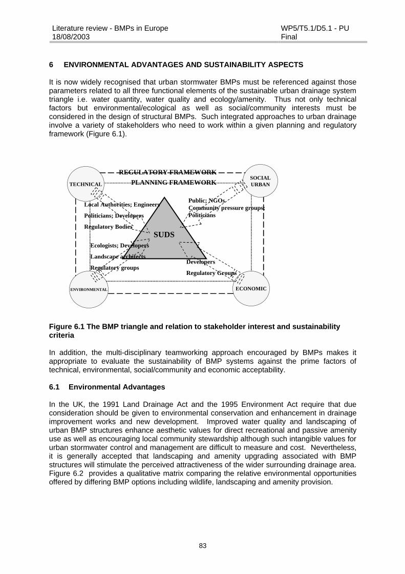
Literature review - BMPs in Europe18/08/2003
WP5/T5.1/D5.1 - PUFinal
83
6 ENVIRONMENTAL ADVANTAGES AND SUSTAINABILITY ASPECTS
It is now widely recognised that urban stormwater BMPs must be referenced against thoseparameters related to all three functional elements of the sustainable urban drainage systemtriangle i.e. water quantity, water quality and ecology/amenity. Thus not only technicalfactors but environmental/ecological as well as social/community interests must beconsidered in the design of structural BMPs. Such integrated approaches to urban drainageinvolve a variety of stakeholders who need to work within a given planning and regulatoryframework (Figure 6.1).
Ecologists; Developers
Landscape architects
Regulatory groups
Local Authorities; Engineers
Politicians; Developers
Regulatory Bodies
Developers
Regulatory Groups
SUDS
PLANNING FRAMEWORKREGULATORY FRAMEWORK
TECHNICAL
ENVIRONMENTAL
SOCIALURBAN
ECONOMIC
Public; NGOsCommunity pressure groups;Politicians
Figure 6.1 The BMP triangle and relation to stakeholder interest and sustainabilitycriteria
In addition, the multi-disciplinary teamworking approach encouraged by BMPs makes itappropriate to evaluate the sustainability of BMP systems against the prime factors oftechnical, environmental, social/community and economic acceptability.
6.1 Environmental Advantages
In the UK, the 1991 Land Drainage Act and the 1995 Environment Act require that dueconsideration should be given to environmental conservation and enhancement in drainageimprovement works and new development. Improved water quality and landscaping ofurban BMP structures enhance aesthetic values for direct recreational and passive amenityuse as well as encouraging local community stewardship although such intangible values forurban stormwater control and management are difficult to measure and cost. Nevertheless,it is generally accepted that landscaping and amenity upgrading associated with BMPstructures will stimulate the perceived attractiveness of the wider surrounding drainage area.Figure 6.2 provides a qualitative matrix comparing the relative environmental opportunitiesoffered by differing BMP options including wildlife, landscaping and amenity provision.
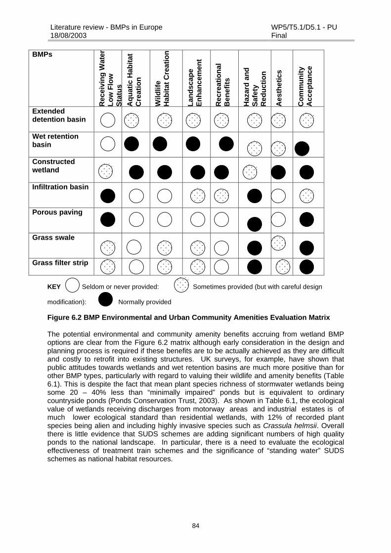
Literature review - BMPs in Europe18/08/2003
WP5/T5.1/D5.1 - PUFinal
84
BMPs
Rec
eivi
ng
Wat
erL
ow
Flo
wS
tatu
sA
qu
atic
Hab
itat
Cre
atio
n
Wild
life
Hab
itat
Cre
atio
n
Lan
dsc
ape
En
han
cem
ent
Rec
reat
ion
alB
enef
its
Haz
ard
an
dS
afet
yR
edu
ctio
n
Aes
thet
ics
Co
mm
un
ity
Acc
epta
nce
Extendeddetention basin
Wet retentionbasin
Constructedwetland
Infiltration basin
Porous paving
Grass swale
Grass filter strip
KEY Seldom or never provided: Sometimes provided (but with careful design
modification): Normally provided
Figure 6.2 BMP Environmental and Urban Community Amenities Evaluation Matrix
The potential environmental and community amenity benefits accruing from wetland BMPoptions are clear from the Figure 6.2 matrix although early consideration in the design andplanning process is required if these benefits are to be actually achieved as they are difficultand costly to retrofit into existing structures. UK surveys, for example, have shown thatpublic attitudes towards wetlands and wet retention basins are much more positive than forother BMP types, particularly with regard to valuing their wildlife and amenity benefits (Table6.1). This is despite the fact that mean plant species richness of stormwater wetlands beingsome 20 – 40% less than “minimally impaired” ponds but is equivalent to ordinarycountryside ponds (Ponds Conservation Trust, 2003). As shown in Table 6.1, the ecologicalvalue of wetlands receiving discharges from motorway areas and industrial estates is ofmuch lower ecological standard than residential wetlands, with 12% of recorded plantspecies being alien and including highly invasive species such as Crassula helmsii. Overallthere is little evidence that SUDS schemes are adding significant numbers of high qualityponds to the national landscape. In particular, there is a need to evaluate the ecologicaleffectiveness of treatment train schemes and the significance of “standing water” SUDSschemes as national habitat resources.
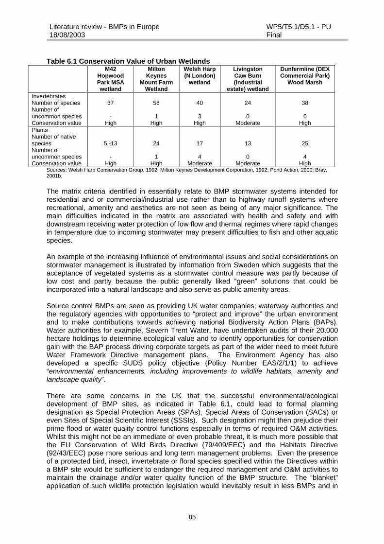
Literature review - BMPs in Europe18/08/2003
WP5/T5.1/D5.1 - PUFinal
85
Table 6.1 Conservation Value of Urban WetlandsM42
HopwoodPark MSAwetland
MiltonKeynes
Mount FarmWetland
Welsh Harp(N London)
wetland
LivingstonCaw Burn(Industrial
estate) wetland
Dunfermline (DEXCommercial Park)
Wood Marsh
InvertebratesNumber of speciesNumber ofuncommon speciesConservation value
37
-High
58
1High
40
3High
24
0Moderate
38
0High
PlantsNumber of nativespeciesNumber ofuncommon speciesConservation value
5 -13
-High
24
1High
17
4Moderate
13
0Moderate
25
4High
Sources: Welsh Harp Conservation Group, 1992; Milton Keynes Development Corporation, 1992; Pond Action, 2000; Bray,2001b.
The matrix criteria identified in essentially relate to BMP stormwater systems intended forresidential and or commercial/industrial use rather than to highway runoff systems whererecreational, amenity and aesthetics are not seen as being of any major significance. Themain difficulties indicated in the matrix are associated with health and safety and withdownstream receiving water protection of low flow and thermal regimes where rapid changesin temperature due to incoming stormwater may present difficulties to fish and other aquaticspecies.
An example of the increasing influence of environmental issues and social considerations onstormwater management is illustrated by information from Sweden which suggests that theacceptance of vegetated systems as a stormwater control measure was partly because oflow cost and partly because the public generally liked “green” solutions that could beincorporated into a natural landscape and also serve as public amenity areas.
Source control BMPs are seen as providing UK water companies, waterway authorities andthe regulatory agencies with opportunities to “protect and improve” the urban environmentand to make contributions towards achieving national Biodiversity Action Plans (BAPs).Water authorities for example, Severn Trent Water, have undertaken audits of their 20,000hectare holdings to determine ecological value and to identify opportunities for conservationgain with the BAP process driving corporate targets as part of the wider need to meet futureWater Framework Directive management plans. The Environment Agency has alsodeveloped a specific SUDS policy objective (Policy Number EAS/2/1/1) to achieve“environmental enhancements, including improvements to wildlife habitats, amenity andlandscape quality”.
There are some concerns in the UK that the successful environmental/ecologicaldevelopment of BMP sites, as indicated in Table 6.1, could lead to formal planningdesignation as Special Protection Areas (SPAs), Special Areas of Conservation (SACs) oreven Sites of Special Scientific Interest (SSSIs). Such designation might then prejudice theirprime flood or water quality control functions especially in terms of required O&M activities.Whilst this might not be an immediate or even probable threat, it is much more possible thatthe EU Conservation of Wild Birds Directive (79/409/EEC) and the Habitats Directive(92/43/EEC) pose more serious and long term management problems. Even the presenceof a protected bird, insect, invertebrate or floral species specified within the Directives withina BMP site would be sufficient to endanger the required management and O&M activities tomaintain the drainage and/or water quality function of the BMP structure. The “blanket”application of such wildlife protection legislation would inevitably result in less BMPs and in

Literature review - BMPs in Europe18/08/2003
WP5/T5.1/D5.1 - PUFinal
86
existing BMP structures being operated and managed in such a way that the conservationvalue is minimised.
Table 6.2 attempts to evaluate a range of different types of stormwater control systems withregard to potential multifunctional use and cost.
Table 6.2 Evaluation of stormwater management systems with regard tomultifunctional use and cost
Water FunctionsTechniques Landscape Swimming Recreation Fish
farmingIrrigation Animal
wateringIndustry
Perimeterwater
protectionSweeping ???? ???? ???? ???? ???? ???? ???? ????
tankstructure
? ? ? ? ? ? ?
porouscoating
? ? ? ? ? ? ?
trenches ?? ?? ?? ?? ?? ?? ?? ??
Alt
ern
ativ
es m
eth
od
s
swale/ditch
?? ?? ? ? ? ? ?
retentionbasin
? ?? ?? ?? ?? ?? ??
retentionbasin
??? ???? ???? ???? ??? ???
Ho
ldin
g b
asin
s
undergroundtank
???? ???? ???? ???? ???? ???? ????
Roadside gully ??? ??? ??? ??? ???Decanters ??? ??? ??? ??? ??? ???
In developing this table the optimal decision making processes of the various stakeholdershave been considered to enable the best solutions at the lowest possible cost to beidentified. Qualitative decisions have been taken bearing in mind that the water may havecontrasting functions such as landscaping, swimming, recreation, fish farming, irrigation,animal watering and industry, and the perimeter of water protection for groundwater uses.The chart uses shades of grey to indicate performance efficiency in comparison todetermined objectives, and stars to indicate cost in relation to the level of treatment achieved(i.e. value for money).
6.2 Sustainability Aspects
The biggest challenge is to convince stakeholders and particularly customers and financialregulators, that full-cost water and drainage services will provide demonstrable sustainablewhole-life investment. It must also be recognised that decisions in the field of urbanstormwater runoff are no longer taken exclusively by drainage engineers; a variety ofstakeholders need to be involved in the decision process in order that the preferred solutionis acceptable to all user and interest groups (Figure 6.1). Unfortunately, the evaluation ofBMP options for the control and treatment of polluted impermeable surface runoff has been,to date, mainly empirical and subjective in nature. There has been little development andapplication of robust quantifiable sustainability criteria and indicators. This is particularly thecase in respect of the evaluation of long-term performance, life-time costing and receivingwater impacts.
Methodologies are needed to support decisions taken on preferred drainage options whichallegedly derive reduced costs for urban stormwater and highway drainage infrastructurewhilst maintaining socially acceptable levels of service, enhancing community benefits and

Literature review - BMPs in Europe18/08/2003
WP5/T5.1/D5.1 - PUFinal
87
minimising environmental impacts. A basic structured approach to a multi-criteria, multi-objective methodology for the assessment of water resource systems was proposed withinthe 1998 UNESCO International Hydrological Programme (American Society of CivilEngineers & UNESCO, 1998). This study recommended a holistic conception of decision-making processes incorporating sustainability criteria and guidelines covering the economic,ecological, social and environmental factors which influence investment in and constructionof water resource systems. Thus technical, environmental/ecological, social/community andeconomic factors become prime potential sustainability criteria to facilitate comparisonsbetween, and accreditation of, drainage options with regard to capital cost, resource use,acceptability, performance, maintenance etc (Figure 6.1). It is therefore appropriate, if notnecessary, to evaluate the sustainability of urban source control drainage systems againstmulti-criteria and multi-objectives placed within an overall decision-support framework.
The primary components in the structure of any decision-making process must referenceand define generic performance criteria together with appropriate supporting multi-criteriadecision-making parameters. Table 6.3 provides such a generic listing of primary criteria forthe four categories shown in Figure 6.1 and which define the action field for BMPs. Thelisted criteria are sufficiently flexible and dynamic to be adapted and refined to meetchanging circumstances and constraints within differing organisations, regulations andcustomers. The multi-criteria methodology must also be capable of evaluating the “do-nothing” option as well as that offered by conventional drainage systems. In addition, it mustbe recognised that the final decision may well be driven or at least constrained by specificlocal considerations and hence result in a preferred option which may not be the mostsustainable.
Table 6.3 Primary criteria for assessing SUDS sustainabilitySUSTAINABILITY CRITERIACATEGORY PRIMARY CRITERIATECHNICAL &SCIENTIFICPERFORMANCE
System performance (Quality and Quality)System reliabilitySystem durabilitySystem flexibility and adaptability
ENVIRONMENTALIMPACTS
Water volume impactWater quality impactEcological impactResource useMaintenance, service provision and responsibilities
SOCIAL AND URBANCOMMUNITYBENEFITS
Amenity; aesthetics, access and community benefitsPublic information; education and awarenessStakeholder acceptability (perception and attitude to risks and benefitsHealth and safety risks
ECONOMICCOSTINGS
Financial risksAffordabilityLife cycle costs
The primary criteria listed in Table 6.3 can be further sub-divided and developed by the useof secondary indicators and benchmark standards which allow the criteria to be quantifiedand compared against national sustainability targets. This sort of approach, if adopted,would not only be consistent with governmental sustainability agendas but also withcomplementary, multi-criteria methodologies which are being developed within the waterindustries of a number of countries to support water asset resource investment (Ashley etal., 2001).
Literature review - BMPs in Europe18/08/2003
WP5/T5.1/D5.1 - PUFinal
88
7 REFERENCES
Abbott, C L., Weisgerber, A and Woods Ballard, B. (2003) Observed hydraulic benefits oftwo UK permeable pavement systems. 101 – 111 in C J Pratt., J W Davies., A P Newmanand J L Perry (Edits): Proc 2nd Nat. Conf. on Sustainable Drainage. Coventry University,Coventry.
Ashley, R M., Smith, H., Jowitt, P W., Butler, D., Blackwood, D J., Davies, J W., Gilmour, Dand Foxon, T. (2001) A multi-criteria analysis/risk management tool to assess the relativesustainability of water/wastewater systems: SWARD (Sustainable Water Industry AssetResource Decisions). 221 – 231 in C J Pratt., J W Davies and J L Perry (Edits): Proc. 1st
Nat. Conf. on Sustainable Drainage. Coventry University, Coventry.
Anchorage Bowl OGS Performance Modelling, Document No. WMP AP r98002, Municipalityof Anchorage Watershed management Program, December 1999
ATV-A 138 (2002) ATV-Arbeitsblatt A138: Planung, Bau und Betrieb von Anlagen zurVersickerung von Niederschlagswasser, Januar 2002.
Azzout, Y., Barraud, S., Cres, F N and Alfakih, E. (1994) Techniques alternatives enassainissement pluvial: Choix, conception, realisation et entretien" Tex et Doc, Lavoisier,Paris. 371pp.
Bäckman, H. (1984) A historical perspective on sewage pipes in Swedish cities(Avloppsledningar i svenska tätorter I ett historiskt perspektiv). Geohydrologiskaforskningsgruppen, Meddelande nr 74, Chalmers University of Technology, Gothenburg,Sweden. (In Swedish).
Bäckström, M. (1999) Porous pavement in a cold climate. Licentiate thesis 1997:21, Divisionof Sanitary Engineering, Lulea University of Technology.
Bäckström, M. and Viklander, M. (2000). Integrated stormwater management in coldclimates. Journal of Environmental Science and Health, Vol. A35, No. 8, 1237-1249.
Bäckström, M. (2002). Grassed Swales for Urban Storm Drainage. Doctoral thesis 2002:06.Division of Sanitary Engineering, Luleå University of Technology, Luleå, Sweden.
Baladès J.D. and Petitnicolas F. (2001) Les strategies de reduction des flux pollutants partemps de pluie a la source: approche technico-economique. Novatech, pp367 – 373.
Baladès, J.D., Cathelain, M., and Marchandise, P. (1985) Chronic pollution of intercitymotorway runoff waters. Water Science and Technology 17 (6-7): 1165-1174.
Baladès J.-D., Bourgogne P., Madiec H. (1992). Evaluation des flux de pollution transitantdans un type de solution compensatoire. Conf. Novatech, Lyon, pp. 66-75.
Woods Ballard, B. and Malcolm, M. (2003) Whole life costing for sustainable drainageschemes, p181-192 in C J Pratt, J W Davies, A P Newman and J L Perry (Edits): Proc 2ndNat.Conf. on Sustaoinable Drainage. June 2003. Coventry University, Coventry.
Baptista, M., Barraud, S. and Alfakih, E. (2001) Analyse de donnees pour l’elaborationd’indicateurs technico-economique de systemes alternatifs en assainissement pulvial.Novatech pp63-70.
Literature review - BMPs in Europe18/08/2003
WP5/T5.1/D5.1 - PUFinal
89
Barker, J., Burgess, W., Fellman, L., Licha, T., McArthur, J. and Robinson, N. (1999) TheImpact of Highway drainage on Groundwater Quality. Rs Report No. 3, Jackson Env Inst.,University of East Anglia, Norwich, ISSN 1465-458X.
Barret, M.E., Walsh, P.M., Malina, J.F. and Charbeneau, R.J. (1998). Performance ofvegetative controls for treating highway runoff. Journal of Environmental Engineering, Vol.124, No. 11, pp. 1121-1128.
Bengtsson, L., Johnsson, A., Malmqvist, P.-A., Särner, E., and Hällgren, J. (1980).Snöhantering i tätort. [Snow handling in built-up areas.], BFR report R 27:1980, The SwedishCouncil for Building Research, Stockholm. ISBN 91-540-3191-5. [In Swedish]
Berga P. (1998) Optimisation du nettoyage des voiries, Rapport CETE du Sud-Ouest,Ministère de l’Equipement, Bordeaux, 40 p.
Bergue, J-M. and Ruperd, Y. (1994) Guide Technique des Bassins de Retenue d'EauxPluviales. Tec et Doc, Lavoisier, Paris.
Bray, R. J. (2001) Environmental monitoring of sustainable drainage at Hopwood parkMotorway Service Area M42 Junction 2. 58 – 70 in C J Pratt, J W Davies and J L Perry(Edit): Proc.1st Nat. Conf on Sustainable Drainage. Coventry University, Coventry.
Bray, R. J. (2001b) Maintenance of Sustainable Drainage; Experience on two EADemonstration Sites in England. 93-104 in C J Pratt, J W Davies and J L Perry (Edits):Proc. 1st Nat. Conf on Sustainable Drainage. Coventry University, Coventry.
Bray, R J. (2003) Sustainable drainage solutions for local authority school sites. 51 – 61 inC J Pratt., J W Davies., A P Newman and J L Perry (Edits): Proc 2nd Nat. Conf. onSustainable Drainage. Coventry University, Coventry.
BRE, (1991) Soakaway Design. Digest 365. Building Research Establishment, Garston,Watford, Herts.
Caraco, D. and Claytor R. (1997) Stormwater BMP Design Supplement for Cold Climates.Center for Watershed Protection, Ellicott City, Maryland, USA.
Cathelain, H., Friant, G. and Olie, J.L. (1981) Les Eaux de Ruisellement de ChausseesAutoroutieres. Bull. Liason de Labs. Des Ponts et Chaussees, 116, 9-24
CERTU (1999). Chaussées Poreuses Urbaines. Guide technique. Ministère del’Equipement-CERTU Ed., Lyon, 150 pp
CIRIA. (Hall, M J., Hockin, D L and Ellis, J B) (1993) Design of flood storage reservoirs.Butterworth-Heinemann (also CIRIA), London.
CIRIA. (Butler, D and Clark, P). (1995) Sediment management in urban drainagecatchments. Report 134. Construction Industry Research & Information Association,London.
CIRIA (1996) Sustainable urban runoff management. Report 20. Construction IndustryResearch & Information Association, London.
CIRIA, (1996) Infiltration Drainage: Manual of Good Practice, Report 156, ConstructionIndustry Research & Information Association, London.
Literature review - BMPs in Europe18/08/2003
WP5/T5.1/D5.1 - PUFinal
90
CIRIA (1998) Report 180 Review of the Design and Management of Constructed Wetlands
CIRIA (2000a) Sustainable urban drainage systems: A design manual for Scotland and NIreland. Report C521, Construction Industry Research & Information Association, London.
CIRIA (2000b) Sustainable urban drainage systems: A design manual for England & Wales.Report C522, Construction Industry Research & Information Association, London.
CIRIA (2001) Sustainable urban drainage systems: Best Practice Manual. Report C523,Construction Industry Research & Information Association, London.
CIRIA (2002) Source control using constructed pervious surfaces. Report C582,Construction Industry Research & Information Association, London.
Claytor, R.A. and Scheuler, T.R. (1996) Design of stormwater filtering systems. Center forWatershed Protection, for the Chesapeake Research Consortium Inc.
Colandini, V. (1997). Effets des structures réservoirs à revêtement poreux sur les eauxpluviales : Qualité des eaux et devenir des métaux lourds. Thèse de Doctorat, Université dePau et des Pays de l’Adour, 171 pp.
Colebeck, S. C. (1981) A simulation of the enrichment of atmospheric pollutants in snowcover runoff. Water Resources Research, 17(5): 1383-1388.
Coyne, M.S., Gillfillen, R.A., Villalba, A., Zhang, Z., Rhodes, R., Dunn, L., and Blevins, R.L.(1998). Fecal bacteria trapping by grass filter strips during simulated rain. Journal of soil andWater Conservation, Vol. 53, No. 2, pp. 140-145.
Deletic, A., (1999). Sediment behaviour in grass filter strips. Water Science and Technology,Vol. 39, No. 9, pp.129-136.
Deschesne, M. (2002) Connaissance et modélisation du fonctionnement des bassinsd’infiltration d’eaux de ruissellement urbain pour l’évaluation des performances techniques etenvironnementales sur le long terme.
Design Manual for Roads and Bridges (1998) Water Quality and Drainage, Volume 11,Section 3, Part 10.
Design Manual for Roads and Bridges (2001) Vegetative Treatment Systems for HighwayRunoff, Volume 4.
Didier, G. and Norotte, V. (1999) Assainissement pluvial : par infiltration : acquisition deconnaissances, nouveaux procédés de traitement pour l’aide au choix, à la conception et àla gestion de politiques d‘infiltration. Rapport final de coordination du programme derecherche (génie urbain et environnement).
Droste, R.L., and Johnston, J.C., (1993) Urban snow dump quality and pollutant reductionin snowmelt by sedimentation, Canadian Journal of Civil Engineering, 20: 9-21.
Ekvall, J. (1998): Rening av vägdagvatten med lamellavskiljare. Stockholm Vatten AB,Rapport nr 46/1998. (In Swedish with an English summary).
Literature review - BMPs in Europe18/08/2003
WP5/T5.1/D5.1 - PUFinal
91
Ellis, J. B. (1999) The use of vegetative controls for the treatment of highway discharges inEllis, J.B. (Edit): Impacts of Urban Growth on Surface and Groundwater Quality, pp 357-363.Publication No. 259, IASH Press Ltd, Wallingford.
Ellis, J B and Revitt, D M. (1991) Drainage for roads: Control and treatment of highwayrunoff. Report NRA 43804/MID.012, National Rivers Authority, Reading.
Ellis, J B., Shutes, R B and Revitt, D M. (2000) Best Practice in the Use of ConstructedWetlands for Pollution Control. R&D Project Report P-2-159, Environment Agency,Reading, Berks.
Environment Agency (2003) Technical Report P2-159/TR1 Constructed Wetlands and Linkswith Sustainable Drainage Systems.
Environment Agency (2003) Framework for Sustainable Drainage Systems (SUDS) inEngland and Wales.
Färm, C., and Renman, G. (1999): Removal of pollutants from road runoff - The Vallbysystem in Sweden. 8ICUSD, Sydney, Australia, 1841-1846.
Färm, C. (2003) Investigation of detention systems for stormwater runoff regardingmaintenance, operation and handling of sediments. 1st International Conference on UrbanDrainage and Highway Runoff in Cold Climate, Riksgränsen Sweden, pp 213-221
Ferguson, B.K. (1998) Introduction to stormwater – concept, purpose, design. John Wiley &Sons.
Finley, S.M. and Young, G.K. (1993) Grassy swales to control highway water quality runoff.Transportation Resrarch Record, No. 1420, U.S. Transportation Research Board.
Fransson, T. and Larm T., (2000) Dimensionerande förutsättningar för hantering avvägdagvatten. PM VBB VIAK, Stockholm. (In Swedish)
Fujita, S. (1994) Infiltration structures in Tokyo. Water Science and Technology30 (1): 33-41.
Gautier, A. (1998) Contribution à la connaissance du fonctionnement d‘ouvrages d’infiltrationd’eau de ruissellement pluvial urbain, Thèse INSA, Lyon, France.
German, J. (2001): Stormwater sediments, removal and characteristics. Licentiate Thesis,Department of Water Environment Transport, Chalmers University of Technology, Göteborg,Sweden.
German, J., Svensson, G., Gustafsson, L.-G. and Vikstrom, M. (2003) Modelling oftemperature effects on removal efficiency and dissolved oxygen concentrations instormwater ponds. 1st International Conference on Urban Drainage and Highway Runoff inCold Climate, Riksgränsen Sweden, pp 223-233.
Goransson, K. and Jonsson, H. (1990). Environmental influence from using porous toppavement - a literature study. VATTEN 46:27-35. (In Swedish)
Granger, R.J., Gray, D.M. and Dyck, G.E. (1984) Snowmelt infiltration to frozen prairie soils.Canadian Journal of Earth Science, 21(6): 669-677.
Literature review - BMPs in Europe18/08/2003
WP5/T5.1/D5.1 - PUFinal
92
Hall, M. J., Hockin, D.L. and Ellis, J.B. (1993) Design of Flood Storage Reservoirs. CIRIA,London)
Hogland, W. and Niemczynowicz, J. (1986) The unit superstucutre – A new construction toprevent groundwater depletion. Proc. Budapest Symposium on Conjunctive Water Use, July1996. IAHS publ. No. 156.
Hogland, W. and Wahlman, T. (1990) The unit superstructure – effects on hydrology androad construction. Report R90:1990, Swedish Council for Building Res., (In Swedish).
Hogland W., Niemczynowicz J., and Wahlman T. (1987) The unit superstructure during theconstruction period. Sci. Total. Environ., 59, pp. 411-424.
Hvitved-Jacobsen, T., Johansen N.B. and Yousef Y.A. (1994). Treatment system for urbanand highway runoff in Denmark. The Science of the Total Environment 146/147, s. 499-506.
Jefferies, C., McKissock, G M., Logan, F., Gilmour, D and Aitken, A. (1998) PreliminaryReport on Swales in Scotland. Scottish SUDS Working Party, SEPA (SNIFFER), Edinburgh.
Jokela, J.B. and Bacon T.R. (1990) Design of urban sediment basins in Anchorage. Coldregions Hydrology and Hydraulics, American Society of Civil Engineers, NY, pp.761-789.
Kellagher, R. (2002) Guide for the drainage of development sites. HR Wallingford
Kercher, W.C., Landon, J.C., and Massarelli, R., (1983). Grassy swales prove cost-effectivefor water pollution control. Public Works, USA, 1983, Vol. 114, No. 4, pp.53-54.
Lännegren, C. (1998) Flemingsbergsvikens våtmarksanläggning. Erfarenheter och driftunder de tre första åren. Stockholm vatten. (In Swedish).
Larm, T, (1994). Dagvattnets sammansättning, recipientpåverkan och behandling. VA-FORSK rapport nr 1994-06. (In Swedish)
Larm, T. (2000). Watershed-based design of stormwater treatment facilities: modeldevelopment and applications. Doctoral Thesis, Division of water Resources Engineering,Royal Institute of Technology, Stockholm, Sweden.
Legret, M., Colandini V., and Le Marc C. (1996) Effects of a porous pavement with reservoirstructure on the quality of runoff water and soil. Sci. Total. Environ., 189/190, pp. 335-340
Legret, M. and Colandini V. (1999). Effects of a porous pavement with reservoir structure onrunoff water : water quality and fate of heavy metals. Wat. Sci. Technol., 39, pp.111-117.
Li, J., Orland, R., and Hogenbirk, T. (1998). Environmental road and lot drainage designs :alternatives to the curb-gutter-sewer system. Canadian Journal of Civil Engineering, 25, pp.26-39.
Lindwall, P. and Hogland, W. (1981). Operation aspects on stormwater infiltration. BFRreport R14:1981. Swedesh Council for Building Research. (In Swedish).
Livingstone, E., Cox, J., Sanzone, P. and Gourlie, N. (1984) The Florida DevelopmentManual: A Guide to Sound Land and Water Management. Florida Department ofEnvironmental Regulation, Tallahassee, Florida, USA.
Literature review - BMPs in Europe18/08/2003
WP5/T5.1/D5.1 - PUFinal
93
Local Authorities Associations. (1989) Highway Maintenance: A Code of Good Practice.Association of County Councils, London.
Lockery, A.R., Gavrailoff, T., and Hatcher, D. (1983) Lead levels in snow dumping sitesalong rivers in downtown Winnipeg, Manitoba, Canada, Journal of EnvironmentalManagement, 17: 185-190.
Lönngren, G, (1995) Våtmark: renare vatten och renare liv. MOVIUM, SverigesLantbrukaruniversitet, Alnarp. (In Swedish)
Malmqvist, P-A. (1985) Environmental effects of snow disposal in Sweden. Proc. OfWorkshop Minimizing the Environmental impact of the Disposal of Snow from Urban Areas,June 11-12, 1984. Report EPS 2/UP/1, October 1985. ISBN 0-662-14390-6
Marsalek, P.M. (1997) Special characteristics of an on-stream stormwater pond: winterregime and accumulation of sediment and associated contaminants. M.Sc. thesis, Dept. ofCivil Engineering, Queen’s University, Kingston, Ontario, Canada.
Marsalek, J. (2003) Road salt in urban stormwater: an emerging issue in stormwatermanagement in cold climates, 1st International Conference on Urban Drainage and HighwayRunoff in Cold Climate, Riksgränsen Sweden, pp 65-74
Mikkelsen, P. S., Adeler, O.F., Albrechtsen, H.-J. & Henze, M. (1999). Collected rainfall as awater source in Danich households – what is the potential and what are the cost? Wat. Sci.Tech. 39, (5), 49-56
Mikkelsen, P. S., Viklander, M., Linde J. J., Malmqvist P-A., (2002) BMPs in UrbanStormwater Management in Denmark and Sweden. Proc. Eng. Fnd. Conf. LinkingStormwater BMP Designs and Performance to Receiving Water Impact Mitigation, Aug 19-24 2001, Snowmass Village, Colorado/USA, pp 354-368. American Society of CivilEngineers.
Milne J. B., and Dickman M. (1977) Lead concentrations in algae and plants grown over leadcontaminated sediments taken from snow dump in Ottawa, Canada, Journal EnvironmentalScience Health, A12(4/5): 173-189.
Milton Keynes Development Corporation (1992) Monitoring Studies of Milton KeynesBalancing Lakes. Vols 1-6. Urban Pollution Research Centre, Middlesex University. MiltonKeynes Development Corporation, Milton Keynes.
Möller, J. (2001) Treatment systems for urban runoff water in Ørestad. M.Sc. thesis (inpreparation). Environmetn & Resources DTU, Technical University of Denmark.
Montes, S. (1998) Hydraulics of open channel flow. American Society of Civil Engineers,Usa, ISBN 0-7844-0357-0.
Newman, A P., Pratt, C J., Coupe, S J and Cresswell, N. (2001) Oil bio-degradation inpermeable pavements by inoculated and indigenous microbial communities. 425 – 432 in CJ Pratt, J W Davies and J L Perry (Edits): Proc 1st. Nat. Conf on Sustainable Drainage.Coventry University, Coventry.
Newman, A P., Shuttleworth, A., Puehmeier, T, Wing Ki, K and Pratt, CJ. 2003. Recentdevelopments in oil retarding porous pavements. 81 – 89 in C J Pratt., J W Davies., A P

Literature review - BMPs in Europe18/08/2003
WP5/T5.1/D5.1 - PUFinal
94
Newman and J L Perry (Edits): Proc 2nd Nat. Conf. on Sustainable Drainage. CoventryUniversity, Coventry.
Novotny, V., Smith, D.W., Kuemmel, D.A. Mastriano, J. and Bartosova, A. (1999) Urban andHighway Snowmelt: Minimising the Impact on Receiving Water. Water EnvironmentResearch Foundation, (WERF) Project 94-IRM-2.
NSWG (2003) Framework for sustainable drainage systems (SUDS) in England & Wales.Environment Agency, Bristol.
Oberts, G.L. and Osgood, R.A. (1988) Lake McCarrons Wetland Treatment System: Finalreport on the function of the Wetland Treatment System and the impacts on lake McCarrons.Metropolitan Council, St. Paul, Minnesota, publication No. 590-88-095, 227pp.
Oberts, G.L., Wotzka, P.J. and Hartsoe, J.A. (1989) The Water Quality Performance ofSelect Urban Runoff Treatment Systems. Metropolitan Council, St. Paul, Minnesota,publication No. 590-89-062a, 170pp.
Oberts, G.L. (1990) Design considerations for management of urban runoff in wintryconditions. In Proceedings, International Conference on Urban Hydrology under WintryConditions, Narvik, Norway.
Oberts, G.L. (1994) Influence of snowmelt dynamics on stormwater runoff quality.Watershed Protection Techniques, 1(2):55-61.
Oberts, G.L. and Osgood, R.A. (1991) Water quality effectiveness of a detention wetlandtreatment system and its effect on an urban lake. Environmental Management 15 (1): 131-138
Perry, R. and McIntyre, A. E. (1986) Impact of motorway runoff upon surface water quality.In J F Solbe (Edit): Effects of Land Use on Freshwater. Pp 53-67 Ellis Horwood Ltd.,Chichester.
Persson, (1999). Hydraulic efficiency in pond design. Thesis for the degree of Doctor ofPhilosophy. Department of Hydraulics, Chalmers University of Technology, Göteborg,Sweden.
Pettersson, T.J.R. (1996) Pollution reduction in stormwater detentions ponds. ChalmersUniversity of Technology, Sweden, Dep. Of Sanitary Eng., Licentiate theses, Report 1996:3.
Pettersson, T.; German J.; Svensson, G. (1999) Pollutant removal efficiency in twostormwater ponds in Sweden. Proc. 8th Int. Conf. on Urban Storm Drainage, Sydney,Australia.
Pichon, A. (1993). Colmatage de milieux poreux en génie civil : cas des enrobés drainantsde l’autooute du Nord, LMSGC LCPC/CNRS, thèse de doctorat, Université Paris VI.
Pokrajoc, D and Deletic, A. (2002) Clogging of infiltration drainage systems. In Proc SOM2002, 26 – 28 November 2002, University of Bradford, Bradford.
Pond Action (2000) An Assessment of the Ecological Value of Sustainable Urban DrainageSystems in Scotland. report by Pond Action, Oxford Brookes University. ScottishEnvironment protection Agency, Stirling.
Literature review - BMPs in Europe18/08/2003
WP5/T5.1/D5.1 - PUFinal
95
Ponds Conservation Trust (2003) Maximising the ecological benefits of SUDS schemes.Ponds Conservation Trust, Oxford Brookes University, Oxford.
Pratt. C J. (1995) Infiltration drainage: Case studies of UK practice. Project No. 22,Construction Industry Research and Information Association, London.
Pratt, C J. (1996) Research and Development in Methods of Soakaway Design. J. Insy.Water and Env Mangt, 10, 47-51.
Price, M., Arkinson, T.C., Barker, J.A. and Monkhouse, R.A. (1992) A tracer study of thedanger posed to a chalk aquifer by contaminated highway runoff. Proc. Inst. Civil. Eng.,(Water, Maritime and Energy), 96, 9-18.
Prosser, I.P., Dietrich, W.E., and Stevenson, J. (1995). Flow resistance and sedimenttransport by concentrated overland flow in a grassland valley. Geomorphology, Vol. 13,pp.71-86.
Raimbault, G. and Métois, M. (1992) Le site experimental de structure réservoir de Rezé.Conf. Novatech, Lyon, pp. 213-222.
Raimbault G. (1992) Structures réservoirs et topographie des aménagements urbains. Conf.Novatech, Lyon, pp. 400-409.
Raimbault G., Nadji, D. and Gauthier, C. (1999). Stormwater infiltration and porous materialclogging. 8th ICUSD, Sydney, pp. 1016-1024.
Ranchet, J. and Ruperd, Y. (1983) Moyens d’Action pour la Pollution due aux Eaux deRuisellement en Systeme Seperatif et Unitaire. Trib. Cebedeau, 36, 117-130.
Ranchet J., Penaud F., Le Grand R., Constant A., Oborg P., Soudien B. (1993).Comparaison d'une chaussée pavée et d'une chaussée drainante du point de vue de leurcomportement hydraulique et de leur impact sur la dépollution des eaux de pluie. Bull.Liaison Labo P. et Ch., 188, pp. 67-72.
Revitt, D.M. and Ellis, J.B. (2001) Drainage, Runoff and Groundwater. 67 – 102 in :Guidelines for the Environmental Management of Highways. Institution of Highways &Transportation, London.
Revitt, D.M., Ellis, J. B. and Llewellyn, N.R. (2002) Seasonal removal of herbicides in urbanrunoff. Urban Water 4, 13-19.
Rosen, K. (1996) Försöksanläggning för rening av dagvatten vid sjön Magelungen - Resultatefter tre års drift 1993-1995. Stockholm vatten.
Ruperd (1987) Efficacite des ouvrages de traitement des eaux de Ruisellement. ServiceTech. L’Urbanisme, Div Equip Urbains, Paris, France.
Sansalone, J.J. and Buchberger, S.G. (1996) Characterisation of metals and solids in urbanhighway winter snow and spring rainfall runoff. Trans Res Record, 1523: 147-159.
Scholz, M. (2003) Design, operation and maintenance optimization of sustainable urbanstormwater ponds. 31 – 41 in C J Pratt., J W Davies., A P Newman and J L Perry (Edits):Proc 2nd Nat. Conf. on Sustainable Drainage. Coventry University, Coventry.

Literature review - BMPs in Europe18/08/2003
WP5/T5.1/D5.1 - PUFinal
96
Schueler, T. (1987) Controlling urban runoff. Met Washington Council of Governments,Washigton DC.
Schueler, T. (1992) Design of stormwater wetland systems: guidelines for creating diverseand effective stormwater wetland in the mid-Atlantic Region. Metropolitan WashingtonCouncil of Governments, Washington, DC. USA.
Schwab, G.O. and Frevert, R.K. (1985) Elementary soil and water engineering. John Wileyand Sons, Inc.
Scott, W.S., (1980) Occurrence of salt and lead in snow dump sites, Water, Air and SoilPollution, 13: 187-195.
SEPA, (1990) Snöupplag, lokalisering och drift, [Snow deposits, location and operation], TheSwedish Environmental Protection Board, Report 3785. [In Swedish]
SEPA, (1997) Guidance document for evaluation of surface water best managementpractices. Draft May 1997. Prepared for Scottish Environment Protection Agency (SEPA) bySir Frederick Snow & Partners Ltd and Camp Dresser & McKee Inc.
SEPA, (1997) Urban Best Management Practice Database. Tech. Report EQI, 17December 1997, (G.McKissock), Scottish Environment Protection Agency, East Region,Edinburgh.
SNRA (1990) (Swedish National Road Administration) (1990). Hydraulic design of ditches,culverts, pipes, and basins. Swedish National Road Administration, publication 1990:11. (InSwedish).
SNRA (Vägverket), (1998) Rening av vägdagvatten – Preliminära råd vid dimensionering avenklare reningsanläggningar. Samarbetsprojekt mellan Vägavd. vid Vägverket i Borlängeoch Statens geotekniska institut (SGI). (In Swedish).
Söderlund, G. (1972). Stormwater treatment by a vegetated ditch. Research report,Allmänna Ingenjörsbyrån, Stockholm, Sweden, October, 1972. (In Swedish).
Stahre and Urbonas, B. (1990) Stormwater detention for drainage, water quality and CSOmanagement. Prentice-Hall, New Jersey, United States.
Stahre and Urbonas, B. (1993). Stormwater. Best management practices and detention forwater quality, drainage and CSO management. PTR Prentice Hall, Englewood Cliffs, NewYersey, USA.
Stenmark, C. (1991) The function of a percolation basin in a cold climate. Proc. 5th Int. Conf.In Urban Storm Drainage, Suita, Osaka, Japan, July 1990, 809-814.
Stenmark, C. (1992) Local disposal of storm water in cold climate. Licentiate Thesis1992:24, Luleå University of Technology.
Stenmark, C. (1995) An alternative road construction for stormwater management in coldclimates. Water Science and Technology, 32(1): 79-84.
Stotz, G. and Krauth, K. (1994). The pollution of effluents from pervious pavements of anexperimental highway section : first results. Sci. Total Environ., 146-147, pp. 465-470.
Literature review - BMPs in Europe18/08/2003
WP5/T5.1/D5.1 - PUFinal
97
Thelen E., Fielding, and Howe L. (1978) Porous pavement, The Franklin Institution Press.Philadelphia, Pensylvania.
Urbonas, B., Guo, and Tucker, (1990). Optimization of stormwater quality capture volume.Proceeding of an Engineering Foundation Conference, ASCE, October 1989 in Switzerland,Published in New York, Urban stormwater quality enhancement.
Urbonas, B., Roesner, and Guo (1996). Hydrology for optimal sizing of urban runofftreatment control systems. Water quality International, January/February 1996, London,England.
Urban Drainage and Flood Control District (1999) Urban storm drainage. Criteria manual.Volume 3 – best management practices. Denver, Colorado. USA
US EPA, (1974) Proposed guidelines for determining acceptability of dredged sedimentsdisposal in EPA Region VI., Dallas, USA.
VAV P46, (1983) Lokalt omhändertagande av dagvatten – LOD. Anvisningar ochkommentarer. Svenska vatten- och avloppsverksföreningen, VAV. (In Swedish).
Viklander, M. (1994) Melting of urban snow deposits. A water quality study. LicentiateThesis, 1994:19L, Division of Sanitary Engineering, Luleå University of Technology, Luleå,Sweden.
Viklander, M. (1996) Urban Snow Deposits - pathways of pollutants, The Science of theTotal Environment, 189/190: 379-384.
Viklander, M. (1997). Snow quality in urban areas. Doctoral thesis 1997:21. Division ofSanitary Engineering, Luleå University of Technology, Luleå, Sweden.
Viklander, M. (1997) Particle Size Distribution and Metal Content in Street Sediments in theCity of Luleå Sweden, Doctoral thesis 2002:06, Division of Sanitary Engineering, LuleåUniversity of Technology, Luleå, Sweden.
Viklander, M., Bäckström, M. and Malmqvist, P-A. (1998) Ecological storm water handling incold climate. Unpubl., report. Luleå University of Technology.
Viklander, M. (1999) Dissolved and particle-bound substances in urban snow. WaterScience and Technology 39(12): 27-32.
Walker, N. (2000) Retrofitting SUDS to sure CSO and flooding problems. HydroInternational Ltd Conference, 19 October 2002, Bradford.
Walsh, P.M., Barrett, M.E., Malina, J.F. and Charbeneau, R.J. (1997). Use of vegetativecontrols for treatment of highway runoff. Online report 97-5. Center for Research in WaterResources, The University of Texas at Austin, USA
Wang, T., Spyridiakis, D.E., Mar, B.W., and Horner, R.R. (1981). Transport, deposition andcontrol of heavy metals in highway runoff. Washington State Dept. of Transportation, Seattle,WA.
Watt, W.E., Marsalek, J. and Anderson, B.C. (1997) Stormwater pond perceptions vs.realities: a case study. Proc. Eng. Foundation Conference Sustaining urban water resourcesin the 21st century, September 7-12, 1997, Malmö, Sweden.
Literature review - BMPs in Europe18/08/2003
WP5/T5.1/D5.1 - PUFinal
98
WEF and ASCE, (1998) Urban runoff quality management. WEF manual of practice No. 23.ASCE manual and report on engineering practice No. 87. WEF, Water environmentFederation and ASCE, American Society of Civil Engineers. USA.
Welsh Harp Conservation Group (1992) Annual Report. London Borough of Barnet, Herts.
Westerström, G. (1995) Chemistry of snow melt from an urban lysimeter, Water QualityResearch Journal Canada, 30(2): 231-242.
Wild, T C., Jefferies, C and D’Arcy, B J. (2002) SUS in Scotland; The Scottish SUDSdatabase. Final report SR (02)09. SNIFFER, 11/13 Cumberland Street, Edinburgh.
Wild, T C, McKissock, G., D’Arcy, BJ, Shaffer, D and Elliott, C. (2003) An evaluation ofSUDS guidance in Scoitland. 1 – 12 in C J Pratt., J W Davies., A P Newman and J L Perry(Edits): Proc 2nd Nat. Conf. on Sustainable Drainage. Coventry University, Coventry.
Woods Ballard, B and Malcolm, M. (2003) Whole life costing for sustainable drainageschemes. 181 – 192 in C J Pratt., J W Davies., A P Newman and J L Perry (Edits): Proc 2nd
Nat. Conf. on Sustainable Drainage. Coventry University, Coventry.
WRc (1996) Reed Beds and Constructed Wetlands for Wastewater Treatment
Yu, S. L. and Benelmouffok, D. (1990) Field tests of urban best management practices forcontrolling stormwater pollution. 805 – 808 in Y Iwasa and T Sueishi (Edits): Proc 5th Int.Conf. On Urban Storm Drainage. Oasaka, Japan.
Yu, S. L., Norris, W. K. and Wyant, D. C. (1987) Urban BMP demonstration project in theAlbemarle/Charlottesville area. Final Report to Virginia Department of Conservation andHistoric Resources, University of Virginia, Charlottesville, Virginia.
Yu, S. L., Kuo, J.T., Fassman EA, (2001) Field test of a grassed-swale performance inremoving runoff pollution. Journal of Water Research PL-ASCE127 (3): 168-171.