Embed Size (px)
Citation preview
.
REPORT NO. 31.
DEVELOPMENT OF AIR SPEED NOZZLES.
By A. l?. Z-.
CONTENTS.
Pitot-vanturi nozzle No. 1:General features.Theory.Dsafgn dakManufacture.Calibration for head-on vekity.Calibration for pitch and yaw.‘ht for watapmofne33.Resistance and sbzorbed power.
14idIanwI16 air-aped MZZkS:
Gooseneck nozzle No. LThe Foxboro pitat-venturi.Small&e nozde of No. 1 type.Small Badin .dngktbmat venturi.A waterproof pitokA bighuction vedmri.
Double-throat air-speed nozzles.Bach doubIe venturi.Hooded double pitot+ventuxi.
—
PREFACE.
The work here outlined WEISdone to develop a suitabh speed nozzle for the fit fewthousand airpkmes made by the United States”during the recent war in Europe, and to furnisha bssis for more mature instruments in the future. Forty thousand of these nozzles wereordered by the Government, and 12,000 were made before the cassation of hostilities.
The prdiminary experiments were made by Messrs. L. Ofenstein and TW1.iamH. Gornsl;the later ones by Messrs. L. H. Croo~ G. J. Chaillet, and R. H. Smith; the illustrations werearranged by Messrs. L. Thorns and S. S. Rathbun; ti aeronautical assistants in the Construc-tion Department, ‘iVeshingtcmNavy Yard.
The manufacture and inspection of the tit nozzles for the Government were supervised, .respectively, by Naval Ckmstruchr Wtiam Mc13n&, U. S. N., for the Navy, and ?&j. C. E.Mendenhall, R. C. A. S., for the Army. !l%eir tests supplied some of the tabka here given forthe performance, in laboratory and field, of the fired standard nozzles joined to adequatepressure gauges.
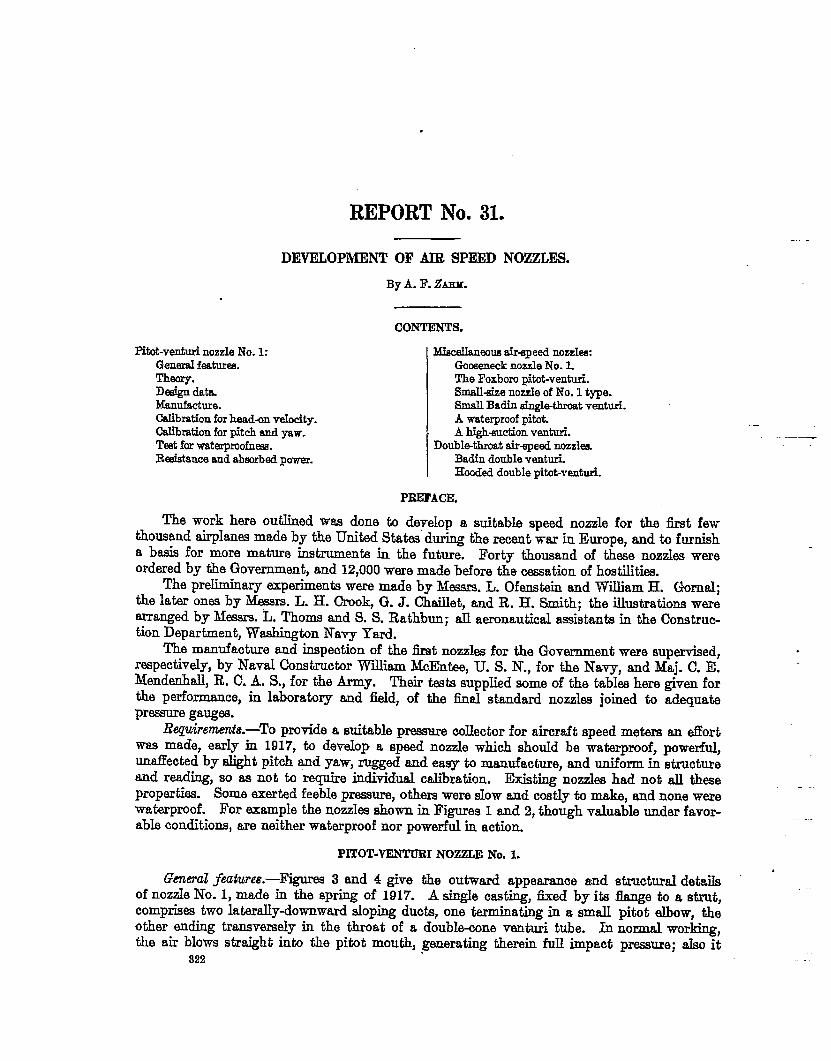
Re@wnen&.-To provide a suitable pressure collector for aircraft ~peed meters an tiortwas made, earIy in 1917, to develop a speed nozzle which should be waterproof, powerfid,unaffected by slight pitch and yaw, rugged and easy to manufacture, and uniform in structure~d reading, so as not to “&quire individual calibration. Efit@ nozzles had not ~ &eseproperties. Some exerted feeble pressure, others were SIOWand costly to make, and none werewaterproof. For example the nozzka shown in Figures 1 and 2, though valuable under favor-able conditions, are neither waterproof nor powerful in action.
. .
PITOT—VENTTJRINOZZLE No. L
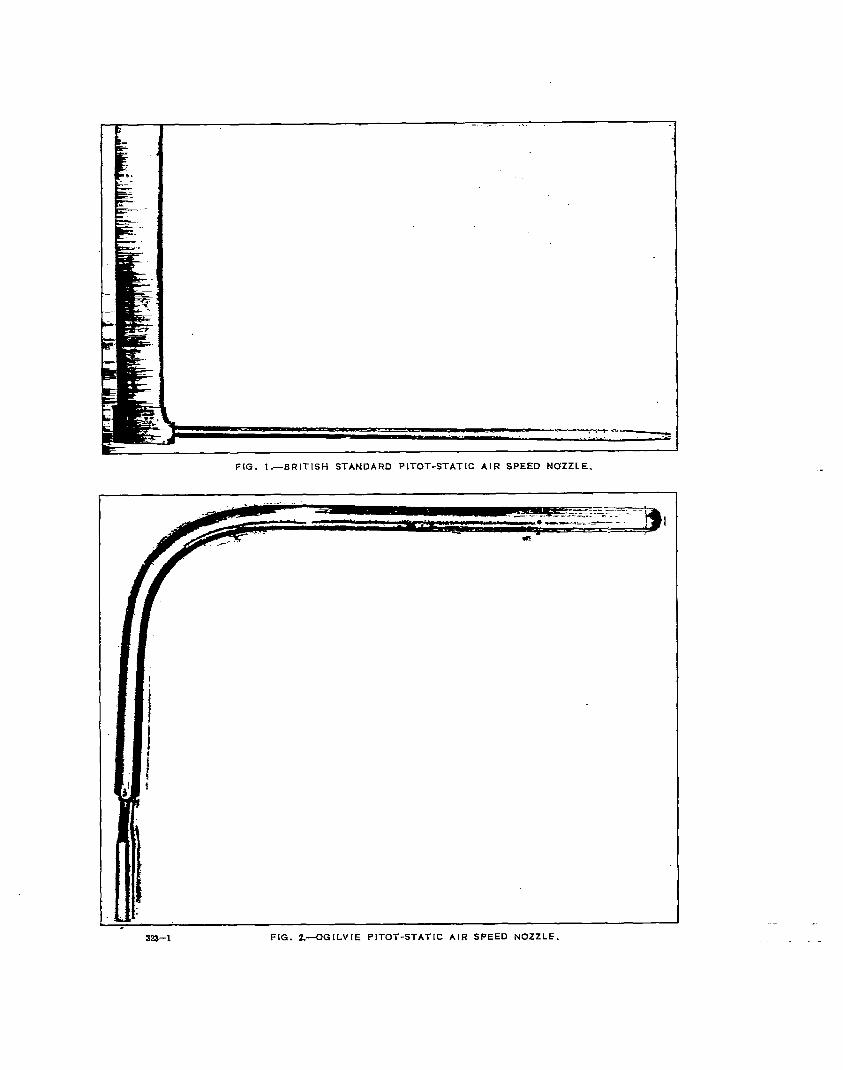
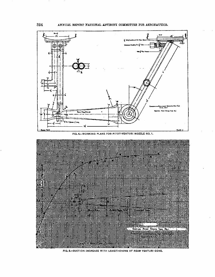
Gm9al features. —FigurM 3 and 4 give the outward appesxance and structural details ‘ __of nozzde No. 1, made in the spring of 1917. A aingIe cssting, &ed by its flange to a strut,comprises two laterally-downward sloping ducts, one terminating in a smaU pitd elbow, theother ending tramvenmly in the throat of a doubk-oone venturi tube. In normal working,the air blows straight into the pitat mouth, generating therein full impact pressure; also it
922
.!
,
.
.
----=:? ~
-
FIG. I.—BRITISH STANDARD PITOT-STATIC AIR SPEED NOZZLE.
e
..- .
. . .ma–l FIG. Z.-OG1LVIE PITOT-STAT[C AIR SPEED NOZZLE.
X23-m FIG. 3.—SAND. CAST ALUMINUM PITOT-VENTtJRl NOZZLE NO. 1.
DZVELOPMEli~OF AIB SPEEDKOZ~% 323
blows straight through the venturi, generating in its throat a suction many times SEintense a3
mid impact pressure. The pressure and suction are transmitted through their respectiveducts to the two nipples at the strut, and thence through tubing to a d.iilerential pressuregauge on the pilot’s instrument board. The gauge is so graduated as to give the true speedthrough air at normal density.
Theory.-The gauge of a pitot-venturi is actuatwi by the difference of the pressures at thepifot mouth and the venturi throat. The tit pressure increases indefinitely with the speed;the second decreases at frrst nearly as the square of the speed, then somewhat asymptoticallytoward zero. AQ adequate theory should give true mathematical expression to those pressures.’
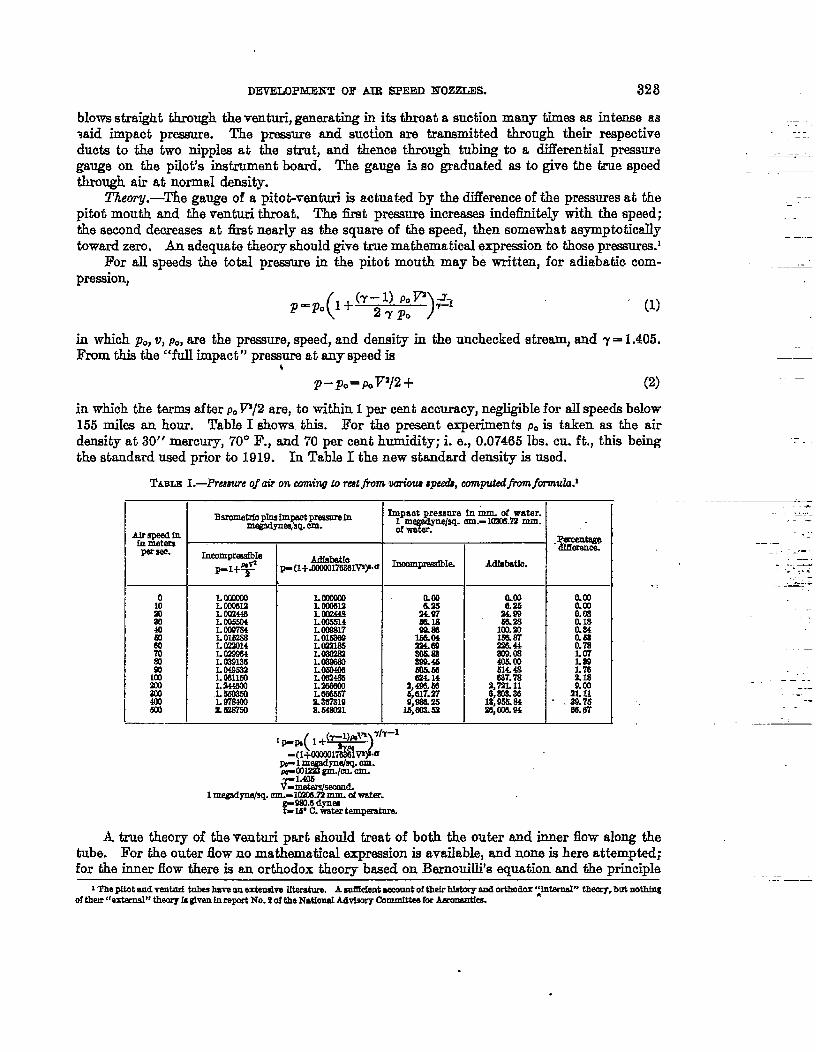
l?or W speeds the tmtd preamre in the pitot mouth maybe writtrm, for adiabatic com-pression,
p=po 1+(-) POP L( 27p. )7—1 (1)
in which PO, w, P., are the pressure, speed, and density in the unchecked stream, and 7 = 1.4o5.From this the “fill impact” pressure at any speed is
*P–PO=POV’12+ (2)
in which the terms after p.V/2 are, to tihhin 1 per cent accuracy, ne+jigible for alIspeeds below155 miks an hour. Table I shows this. For the present experiments p.is taken as the airdensity at 30” mercury, 70° F., and 70 per cent humidity; i. e., 0.07465 lbs. cu. ft., this beingthe st~dard used prior”ta 1910. In Ta~le I the new st=dard density is used.
TABLE L-Preeeure of air on mming to reetj%m variotu qweiik, camputedjvm formuIa.l
[0 ,_L 0W31!2
i! LWM!3al LW5W44Q L009784m L mszsa
L (QW14% LOZWUtm L W91Ww LD49SB
% ii%%m LWJCC50
% k%%L—— 1
.-
MfeImtfe)- (1+.ccem17mmvya
LCiXXWL 00W1%’LIIWASLW55ML WW17LM6W9L L122165LWCQSlL-LOW4W
H%%
i%?%ammn
Impmt pressure fR mm. of water.Ir&feg@sq. Lml.-mm%a mm.
AdMmth.
ILw
22Inn%%fima.03M&coQL 4a637.78
2,7X!L116,s9s. 38
18,9s6.8426,ces.’a4
.P&ce.&tt
O.wamamaIs0.s4rA5a0.7a*.
k%2? !?!
.39.75m.67
.=-.—
——..-
.
.+..
,-——. -a.. -
. ..—.. . . . ..
.:. -—---
..—
—. ..-
-.
j=Z-&&
1me@p@q. Ore.- mxml mm. d Wate.
RvY%%rtmlpaatum
A true theory of the venturi part should treat of both the outer and inner flow along thetube. For the o~ter flow no ma&matical expression is available, and none is here attem~ted;for the inner flow there is au orthodox theory based on BernouiUi’s equation and the principle
1 The pitotand ve.ntnrf talm bsve an exteoslve Iftemfare. A solE&nt eC.COUntOfthefr hhtOIY - Ol#OdOX‘:htord” thq, but nOth@of them‘rextamsl” theory Is ghn hreprt No. 2of the NationeI Advimry Committee h Aezmmtk
324 AN~UALREPORT~ATIONALADVISORYGOMMITTEllFORAXRONAUTIOS.
FIG. 4.-WORKING PLANS FOR PITOT-VENTURI NOZZLE NO. 1.
FIG. 5,—SUCTION INCREASE WITH LENGTHENING OF REAR VENTURI CONE.
DEKl?LOP~ OF AIE SPMIDNOZZLES. 325
of continuity. It teaches that, for all airphme speeds for which the air compression is negligible,the mesm velocity through the tube variea inversely sa the erosa-sectional area; also that thechange of presure aIong a stream line is proportional to the chfmge of tha velocity square.This theory may be valid for the flow antirely within a suitably designed tube, but indicatesnothing as to the speed of entry or pressure of exit of the air. It is obvious that the speed ofentry at the front cone depends on the auction outside the base of the rear cone.
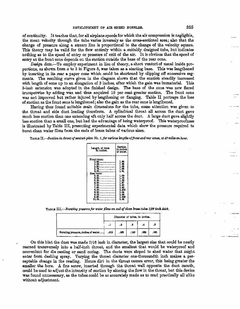
De&n dizikz.-To employ experiment in Iieu of theory, a short venturi of usual tilde pro-portions, as shown from a to bin Figure 5, was taken as a starting base. This was kngthenedby inser@~ in its rear a paper cone which could be shortened by clipping off successive seg-ments. The resulting curve given in the diagram shows that the suctioh steadily increasedwith length of cone up to an dongation of 3 inches, after which the gain was immaterial lhis3-inch extension was adopted in the finished design. The base of the cone was now flaredtrumpetwisa by adding wax and thus aoquired 10 per cent great= suction. The front conewas not impmved but rather injured by lengthening or flanging. Table II portrays the lossof suotion as the front mne is hmgthened; also the gain as the rear cone is Lmgthened.
Having thus found suitable main dimensions for the tube, some attention was given toIihe throat and side duct leading therefrom. A cylindrical throat all across the dud gavemuch less suotion than one extending aft only half across the duct. A large duct gave slightlyleassuction than a small one, but had the advantage of being waterproof. This vraterproofnessis iIMirated by Table III, presenting experimental data which show the pressure required toburst cIsan water films from the ends of brass tubes of various sizes.
TABLEIL-L9uctkminthroatof wnturL@ot No. I, for twious length offront andrcar cow, at 40 miles an hour.
Fron:t&#l’&. . . . . . . . . . . .
1.25.. . . . . . . . . . . . .1.60. . . . . . . . . . . . . .1.76. . . . . . . . . . . . . .
. . . . . . . . . . . . . .Fdgne:
. . . . . . . . . . . . . .&m . . . . . . . . . . . . . .&m. . . . . . . . . . . . . .13.m.............7.m . . . . . . . . . . . . .7.60. . . . . . . . . . . . .am.. . . . . . . . . . . .a s) . . . . . . . . . . . . . .
. . . . . . . . . . . . . .28. . . . . . . . . . . . .
mm._ . . . . . . ..-.
LIB1.76LmLa?L@)LW
wL96LW!SLW
..-.
TABLEHL-Bum@J pTWSUTefW’WtWTfilm on ed Of* h th 1/S2d tk’ck.
1~~1
,, On this hint the duct was made 7/16 inch in ditunetir, the largest size that could be neatlyreamed transversely into a half-inch throat, and the smslest that would be waterproof andconvenient for die casting or sand coring. The ducts were eloped ta shed water that mightentar from dashing spray. Varying the throat diameter on~thousandti inoh makes a per-
,. ceptable change in the reading. Hence dirt in the throat causes error, this being great~r theder the bore. A fine screw, inserted through the throat wall opposite the duct mouth,could be used to adjust the intensity of suotion by altering the flow in the throat.,but this devicewas found unnecessary, as the tubes could be sc accurately made as to read pradioally all alikewithout adjustment.
. . ..- -=,—
326 ANNUAL REPORTNATIOKALADVMOBY00MMl!l!T13RFORM3R0NAUTICS.
dfiznuf~re.-For cheapnes~ speed, and accuracy in making these tubes, three processeswere tried--die casting, copper depositing, sand casting with subsequent reaming. Samplesso produced and d sdiafactory are shown ir@&ures 3, 6, 7. The die castings were to bemade of aluminum or tin tdloy at the rate of four per minute with one die, all true to 1/1000inch inside} and at a remarkably low cost. But after sending a few good samples themanufacturer canceled his contract, owing to the press of other work and the cost of pm-fecting a suitable die. The samples were die east in two parts, telescoping together near wherethe single duet joins the venturi. The sand-cast nozzle is accurately reamed in its venturipart and where its duct enters the throat; at the flange end it is tapped for nipples, drilbxi forclamp screws,plugged at the outer ends of its duds. The coppwdeposited tubes were accuratewithout reaming, and had the advantage of resist~u sea water better than the cast tubes,which, for lightness, were made of aluminum. The copper nozzle was made in three partssoldered together-a cast flange, the pitot mouth and duct, the venturi and its duct. Thepitot and the venturi each was formed by copper plating soft metal cores which had been castin very accurate stael dies and could easily be melted out of their copper coats. The aluminumand the copper nozzleseach weighed about 12 ounces, the latter having muoh thinner walls.Smaller sizes were made subsequently, partly for lightness, partly for lessening the airresistance.But these odd not be cast all in one piece. IIenoe the ducts were made of narrow-drawntubes joining the venturi and flange as had been done with the earliest experimental nozzlesmade during this study.
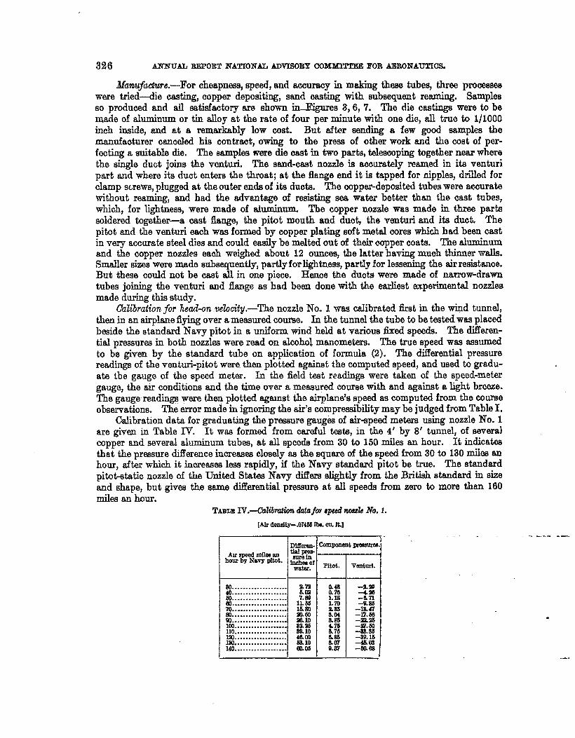
Calibrationfor head-on .ve?ocity.—The nozzle No. 1 was calibrated first in the wind tunnel,then in an airplane flying over a measured course. k the tunnel the tube to be testedwas placedbeside the standard Navy pitot in a uniform wind held at various fixed speeds. The differen-tial pressures in both nozzles were read on alcohol manometers. The true speed was assumedto be given by the standard tube on application of formula (2). The differential pressurereadings of the venturi-pitot were then plotted against the computed speed, and used to gradu-ata the gauge of the speed meter. In the field test readings were taken of the speed-metergauge, the air conditions and the time over a rneaeu~edcourse with and against a light breeze.The gaug~readin~ were then plotted against tlm airplane’s speed as computed from the comaeobservations. The error made in ignoring the air’s compressibility maybe judged from Table L
Calibration data for graduating the pressure gaug& of air-speed meters using nozzle No. 1are given in Table IV. It was formed from careful &te, in the 4’ by 8’ tunnel, of severs]copper and several aluminum tubes, at all speeds from 30 to 160 miles an hour. It indicatesthat the presmre diilerence incres9e3 closely se the square of the speed from 30 b 130 nilea anhour, after which it increasea less rapidly, if the Navy standard pit.ot be true. The standardpitot+tatic nozzle of the United States Navy dif?ere elightiy from the British standard in sizeand shape, but gives the same difkential pressure at all speeds from zero to more than 160mike an hour.
TABLEIV.—(M7mtimdatafw aped nesrh No.1.
[Airdensity-.O74Odb. an. ft.]
1 I )
~. ..... ..................................
&o. . . . . . . . . . . . . . . . . . . .
%::::::::::::::::::::so....................w....................ml.... . . . . . . . . . . . . . . .110. . . . . . . . . . . . . . . . . . .
&k:::::::::::::::::140. . . . . . . . . . . . . . . . . . .
an&m
1:%I&m
M’mmw.104am68.10m.05
-9.99-4. m-6 n–(L al
-la 47–17. bs-mm-97.60-as.85-w.M-4503-m.SE
.----- -—
.
.-.
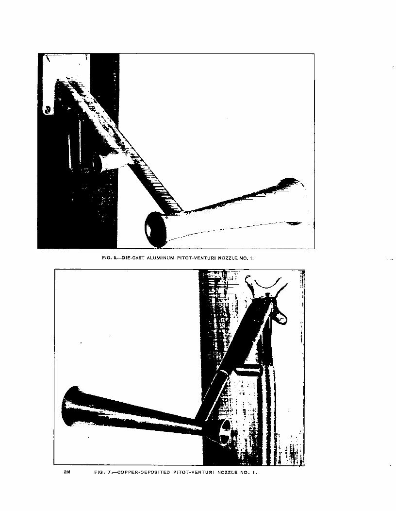
FIG. 6,—DIE-CAST ALUMINUM PITOT-VENTURI NOZZLE NO. 1.
!.
326 FIG. 7.+ OPPER-DEPOSITED PITOT-VENTUR[ NOZZLE NO. 1,
DEVELOPMENT! OF MB SPEED lTOZZLES. 327
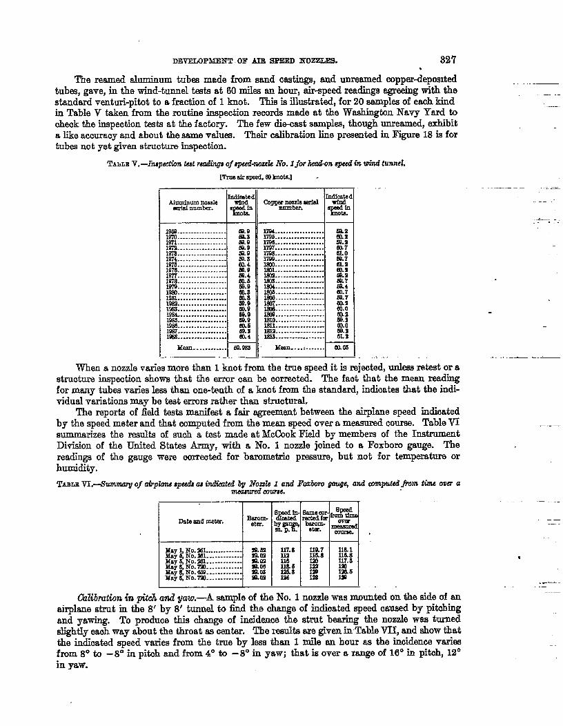
The reamed Auninum tub made froIusand testings, end unremned copper~epos~tedtubes, ga~e, in the wind-tunnel &ts at 60 miles an hour, air-speed readings sgreeing with thestandard venturi-pitot to a fraction of 1 knot. This is illustrated, for 20 samples of eaoh kindin Table V taken from the routine inspection reoords made at the WsshiD@n Navy Yard tooheck the inspection tests at the factory. The few die-east sampks, though unreamed, exhibita like accuracy and about the same values. Their calibration line presented in Figure 18 is fortubes not yet given structure inspection.
TAbLB V. —Iiup& tat reading;of speed-mod No. 1for head-on&in m“ndtunnel.
[Troedroped,a lknotll.] -
I
yw:..................................
p7&_. . . . . . . . . . .. . . . . . . . . . . . . . . . . .
197s. . . . . . . . . . . . . . . . . .1974. . . . . . . . . . . . . . . . . .~7vl . . . . . . . . . .._
. . . . . . . . . . . . . . . .1s77. . . . . . . . . . . . . . . . . .1’278. . . . . . . . . . . . . . . . .FJi’9..... . . . . . . . . . . ..-Ill . . . . . . . . . . . . . . . . . .Ill . . . . . . . . . . . . . . . . .rag. . . . . . . . . . . . . . . . . .I’d. . . -------------1% . . . . . . . . . . . . .. . . .K?8s.. . . . . . . . . . . . . . . .I’m . . . . . . . . . . . . . . . . .19s7... . . . . . . . . . . . . . . .Id.. . . . . . . . . . . . . . . . .
E&0EMmem. 9m. 950.8m.4
%2ah69.9Co.a
R:m. eE&‘aw. 9m669.sm4
Ma.. . . . . . . . . . . 69.985. ..— -—_,_—_
.-hdfdfbd
chpp9r_i-xIc#zzzmrld.
%%:
p& . . . . . . . . . . . . .. . . . . . . . . . . . . . . . .
H98..................1797..................1798..................17’92................
Ill::::::::::::::::IsJ2.................
.................
..................
.................
..................l~_..-...-----
.................w ..................
g:::::::::::::::
181a:::::::::::::::
mall . . . . . . . . . . .I=-’l4 [
—
..—_=
.—. -. . ..
.,---
When a nozzle wu’ies more than 1 knot from the truespeed itisrejechd,unlessretestor a
structure inspection shows that the error w be oorreoti= The fad- that the me= readingfor many tubes varies less than onQ-ttmthof a knot from the standard, indioates that the indi-vidwd variations maybe test errors rathm than structural.
The reports of fiald tests manifest a fair agreement between the airplane speed in&oat8dby the speed meter and that oamputed from the mean speed over ~ measured course. Table Wsumnmrizes the results of suoh a tad made at MK?OokField by members of the Instrument
———
I%ision of the United States Army, with a No. 1 nozzde joined to a Foxboro gauge. Thereadings of the gauge were oorreoted for barometric pressure, but not for temperature orhumidity.
TABUVL4umnuq of airpkw aped as indintid Q No@I 1 and Facboro gaug~ and computed jhn tixw over ameasved cwunu.
Data md meter. BaJoum-
May 1, No. 261... .. . . . ----- g.31by6 No. ml . . . . ---------May$No.201 . . . . . . . . . . . . . ~gMay&t.To. y.... . . . . . . . . .
. . . . . . . . . . . . . 9zm5%$!%:$’%-----------=09
, 1 f .—. .—
----4+4117.8 IIQ7 m. 1m Ills8 fl;:116 lalKL6 g l!M-125.8 Ins194 la m
u
[ I l.. r---..—
CWiUth in niikhand vaw.—A sande of the No. 1 nozzIe was mounted on the side of anairphme strut in &e 8’ by 8“’tunnel to fkd the ohange of inchated speed caused by pitching
and yawing. To produoe this change of incidenoe the strut bearing the nozzle was turnedslightly eaoh way about th throat as oentar. The mmlts are given in Table VII, and show thatthe indioated speed varies from the true by less than 1 mile an hour as the Wldenoe variesfrom 8° to -8° in pitoh and from 4° to –8° in yaw; that isover a range of 16° in pitoh, 12°in yaw.
328 Ki?NUALREPORT NATIOKMJADVISORY00M~TTEE FOEAEW3NAUTIOS.
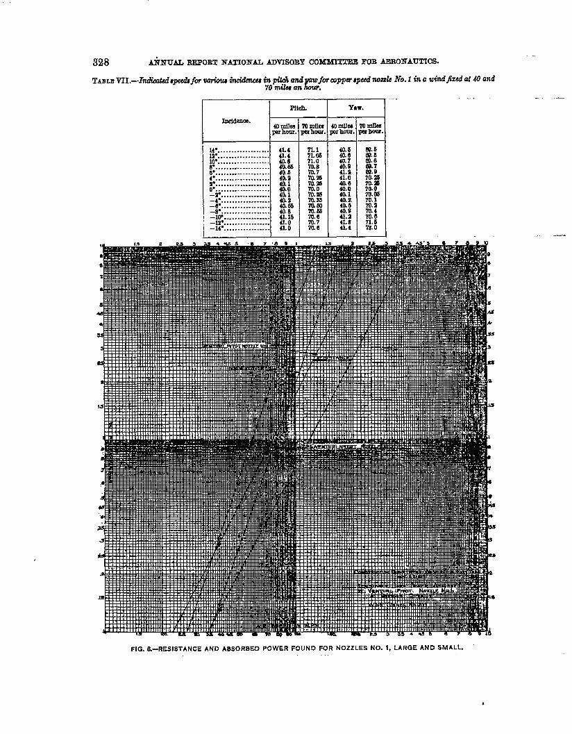
TABLE VH.—Indikt4i4peeei4 fw wiow incidhw in @t@ and pawfbrcopper qwl nozzk No. 1 in a windjazd at 40 and70 lnilu4 an hour.
I I Pltdl. ] Ysw.
SncIdalca.r40mikapmhour.
14”. . . . . . . . . . . . . . . . . . .1!2”. . . . . . . . . . . . . . . . . . .10”. . . . . . . . . . . . . . . . ..-B*. . . . . . . . . . . . . . . . . . . .
$:::::::::::::::::::9“o“::::::::::::::::::::-T . . . . . . . . . . . . . . . . . .-4” . . . . . . . . . . . . . . . . . .~ . . . . . . . . . . . . . . . . . .
. . . . . . . . . . . . . . . . . .-lW . .. . . . . . . . . . . . . . .-lo” . . . . . . . . . . . . . . . . .-14” . . . . . . . . . . . . . . . . .
41.441.440.840.6640.60!440.1&o4(I1&z40.63
$ ~b
4io
m70 mllea 40 denperhour. ~hour.
71.1 40.5‘/LOS71.0 R!70.8 40.970.77U!4S %:70.26
%.:% 4&170.86 4a s.mm 4a;70.E70.6 fig‘m.770.6 4L4
(0mawmhfm.
Eu.6W. a69.6#.7
%%7(LZ67ao70.m70.1
R70.671.678.0
. ..—
-. -K..
FIG. S.-RESISTANCE AND ABSORBEO POWER FOUND FOR NOZZLES NO. 1, LARGE AND SMALL.

?
t-.
-.
FIG. 9.-GOOSE NECK PITOT-VENTURI NOZZLE NO. 1.
m-- 1 FIG. 11 .—FOXBORO PITOT-VENTURI.
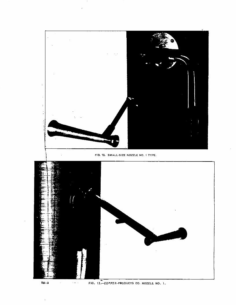
FIG. IL SMALL-SIZE NOZZLE NO. 1 TYPE.
32Q-!J .- FIG, 13,-COPPER-PRODUCTS CO. NOZZLE NO. 1.
DEVELOPMENT OF MB SPEED ITOZZLE% 329
Te& for uxzterproofne.w.—To ascertain whether in use the tubes would have their side ductmated with a water fihn, they were fit oleamd of o~ then exposed to a spray of hydrantwater in tho wind tunnel in an air current of 40 miles an hour. In and tests nozzle No. 1never clogged; the nozzdes of other makes, with fine statio holes, alwa,ysologged by the forma-tion of a film over the apertures. Reports from sea testsalso affirmthat inpracticea flm never
forms over theseven-sixteenth-inohduct.
R&w and absorbed pcww.— The air resistmce and horsepower absorbed are given inF~re 8 for nozzle No. I and a smaller one of similar make to be desoribed presently. Thesemeasurements are to be extanded to higher speeds. They indicata that the resistance incremesslightly less than as the square of the speed; also that the large tube has rather more thantwioe the resistance of the smaller. This item is not negligible for small airplanes of highestspeed. At 70 miles an hour the small nozzIe No. 1 absorbs 0.07 horsepower, the large one 0.16.
#“., MISCELLANEOUSAIRSPEED NOZZLES.
Incidental & the work on No. 1, various other forms of speed nozzle were developed. T&sehad for salient features convenience or suitability of plaoernent, or lightness, or minimumair resistance, etc. “
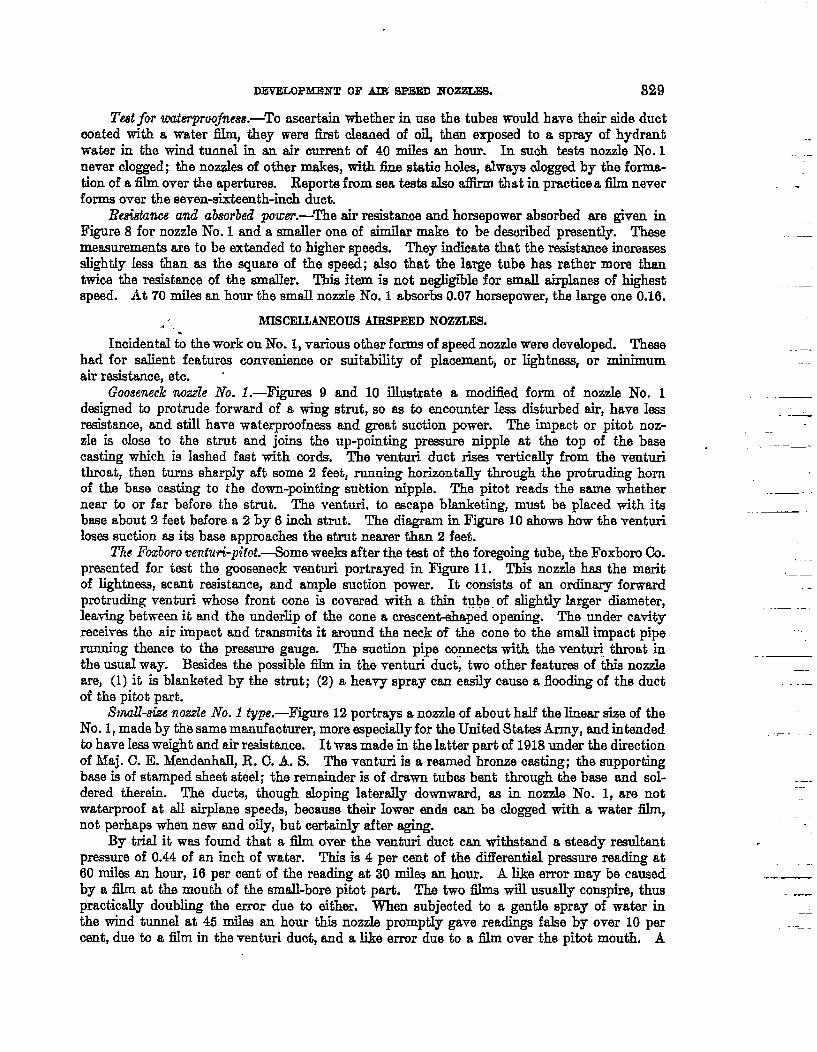
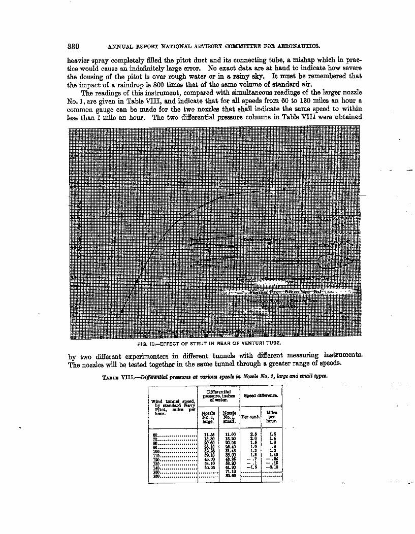
Goo8enecknozzle No. I.—Figures 9 and 10 illustrate a modified form of nozzle No. 1ddgned to protrude forward of a wing strut, so as ta encounter Iess disturbed air, have ksresistance, and still have waterproofnass and great suction power. The impact or pitot noz-zIe is dose to the strut and joins the up-pointing pressure nipple at the top of the basecasting which is lashed fast with cords. The venturi duct rises vertically from the venturithroat, then turns sharply aft some 2 feet, running horizontally through the protruding hornof the base casting to the down-pointing subtion nipple. The pitot reads the same whethernear to or far before the strut. The venturi, to escape blanketing, must be phwed with itsbase about 2 feet before a 2 by 6 inoh strut. The diagram in Figure 10 ahowe how the venturiloses suction as its base approaches the strut nearer than 2 feet.
Tle Fbdoro ven.turi-plot.-some weeks after the tat of the foregoing tube, the Foxbom Co.presented for test the gooseneck venturi portrayed in F- 11. This nozzle has the meritof lightness, scant resistance, and ample suction power. It consists of an ordinary forwardprotruding venturi whose front cme is covered with a thin tybe. of slight3y larger diameter,leaving between it and the underlip of the cane a ormcent+haped opening. The under cavityreceives the air impact and tramxnits it around the neck of the cone to the end impact piperunning thence to the pressure gauge. The suction pipe cognects with the ventti throat inthe usual way. Besidee the possible fihn in the venturi duct, two other features of this nozzle.are, (1) it is blanketed by the strut; (2) a heavy spray can easily cause a flooding of the ductof the pitot part.
Smu&ize nozzle No. 1 type.—Figure 12 portrays a nomde of about half the linear size of theNo. 1, made by the same manufacturer, more eepecitdly for the United Statw Army, and intendedto have 1- weight and air r&tance. It was made in the latter part of 1918 under the directionof hfaj. C. E. Mendauhall, R. C. A. S. The venturi is a reamed bronze casting; the supportingbase is of stamped sheet steel; the remainder is of drawn tubes bent through the base and sol-dered therein. The ducts, though eloping latxwslly downward, es in nozzle No. 1, are notwaterproof at all airplane speeds, beoause their lower ends can be clogged with a water fibn,not perhaps when new and oi3y, but certainly titer aging.
By trial it was found that a film over the venturi duct can withstand a steady rwultantpressure of 0.44 of an inch of water. This is 4 per cent of the dMerentiaI pressure reading at60 mihe an hour, 16 per cent of the reading at 30 miles an hour. A like error may be causedby a film at the mouth of the small-bore pitot par-t. The two films will usually conspire, thuspractica~y doubling the error due to either. When subjected to a gentle spray of water inthe wind tunnel at 45 milee an hour this nozzle promptly gave readings false by over 10 percant, due to a film in the venturi duct, and a like error due to a film over the pitd mouth. A
.---
.
——
,
...—
380 ANX’CTALREG?OR!J!NATIONAL ADVISOBY UOMhUTTEE FOR AEROI$IAUTIOS.
heavier spray completelyfled the pitotduct and itsconnectingtube,a mishap which in prac-
ticewould cause an indeflnitalylargeerror. No exact data areat hand to indicatehow severe
the dousing of the pit.disover rough watm or in a rainy sky. It must be remembered thatthe impact of a raindrop is 800 times that of the same volume of standard air.
The readings of this instrument, compared with simultaneous readings of the larger nozzleNo. 1, are given in Table VIII, and indicate that for all speeds from 60 to 130 miles an hour acommon gauge can be made for the two nozidea that shall indicate the same speed to withinless than 1 mile an hour. The two differential pressure columns in Table VIII were obtained
-
FIG. 1O.–EFFECT OF STRUT IN REAR OF VENTURI TUBE.
by two different experimenters in diilerent tunnels with Merent measuring inetrumentwThe nozzles will be &ted togetbw in the same tunmd through a greater range of speeds.
w.......... .. .... . ...70. . . . . . . . . . . . . . . . . . . .m....................w....................10.?...................no...................Ml130:::::::::::::::::::140. . . . . . . . . . . . . . . . ..-160. . . . . . . . . . . . . . . . . . . .160. . . . . . . . . . . . . . . . . . . .
,...
1LS6
:!
%?.96m.loamm.1000.0s................I
IL 00 !$!g! L5LO
8L45 1.9am L846.s -.76am6Lm :i;7L10 .......... .s160 .......... .
::1:~
LaL4J
::18-9.10
. . . . . . . . ... . . . . . . . .
. . ..-
1 I f 1 i
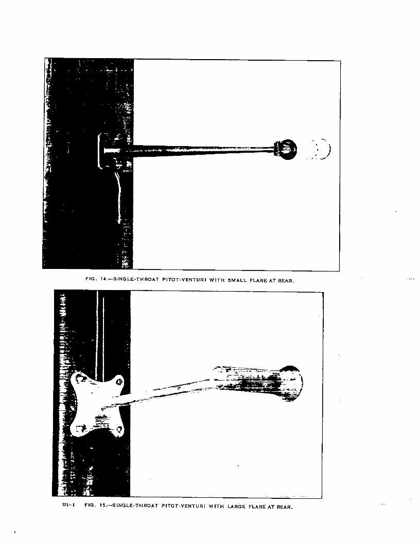
FIG. 14.—SINGLE-THROAT PITOT-VENTURI WITH SMALL FLARE AT RE4R.
.---
:H1-1 FIG. 15.—S[NGLE-THROAT PITOT-VENTURI WITH LARGE FLARE AT REAR.
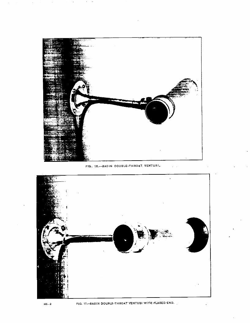
FIG. 16 .—BADIN DOUBLE-THROAT VENTURI.
+
k’ :
@..
u ._
,-
>
‘v._..—i. ‘---”. .. .. .
s ;. :*<_.
:1-.:1
t
.
:{11—2 FIG. 17.-SADIN DOUBLE-THROAT =NTUBI WIT’+++LA~ED ‘END.
DEN’E)X)PME?W!Ol?AIR SPEED 190ZZIE% 831
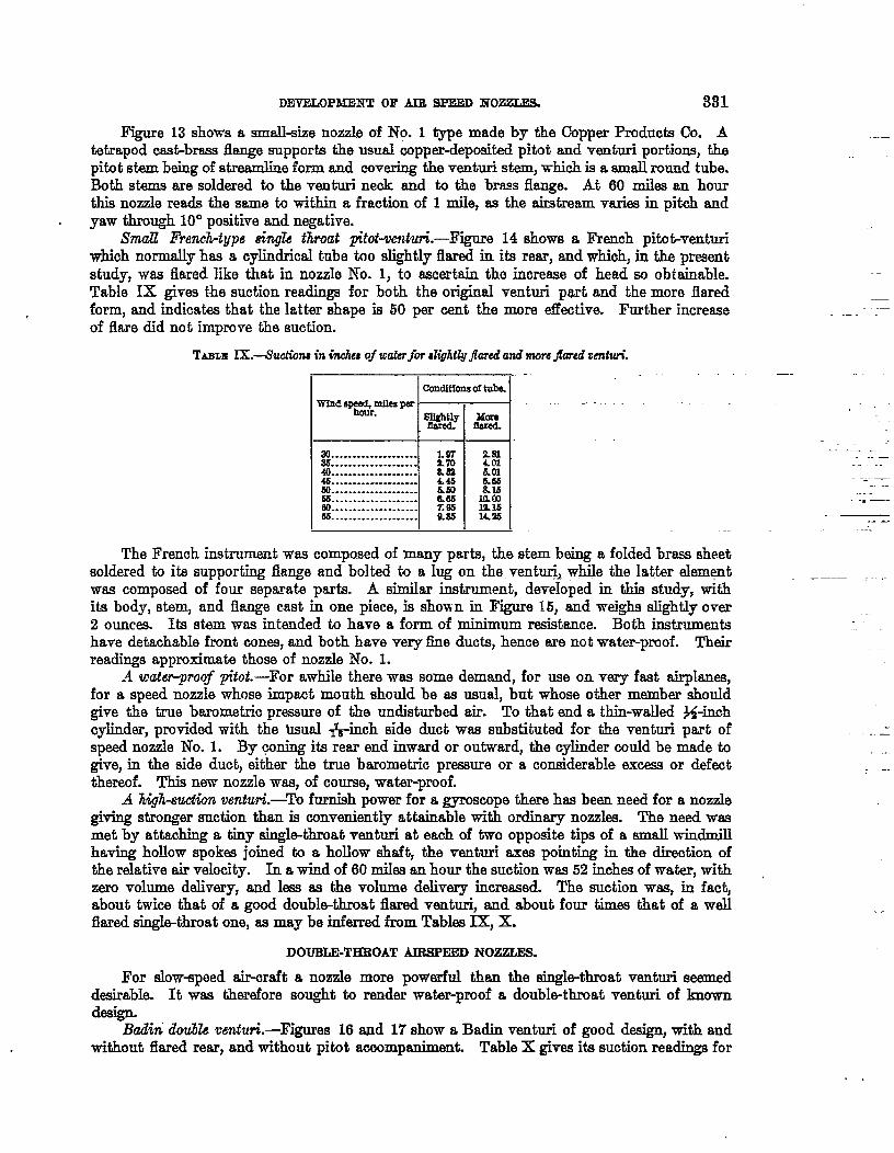
Figure 13 shows a smskize nozzle of No. 1 type made by the Copper Products Co. At.draped csst-brsss fknge supports the usual copperdeposited pitot and venturi portions, thepitot stem being of streunline form and covering the venturi stem, which is a small round tube.Both stems are soldered h the venturi neck snd to the brsss flange. At 60 miles an hourthis nozzle reds the same ta within a fraction of 1 mile, as the &stream vsries in pitch andyaw through 10° positive and negative.
Small French-type singk throat p“tot+cn$uri.-Figure 14 shows a French pitat+enturiwhich normally hss a cylindrical tube too slightly flared in its rear, snd which, in the presentstudy, was flared like that in nozzle No. 1, to sscerhin the increase of head so obtainable.Table IX gives the suction readings for both the origimd venturi pmt and the mom flaredform, and indicat~ that the latter shape is 50 per cent the more efkctive. Further increaseof flare did not improve the suction.
TABLEIX.-ISuctimu in {rich of ureterfm ali@tlyjhred and moreJtued wnfm”.
I IccmdItfonsc!ltubal
“mWindsF&mllea w
au...................85 !....................40....................4s. . . . . . . . . . . . . . . . . . . .51J. . . . . . . . . . . . . . . . . . .
. . . . . . . . . . . . . . . . . . .
%:::::::::::::::::::
k%’8.59L46&m6.6sX85aw$
The French instrument wcs composed of many parts, the stem being a folded brsss sheetscddered to ita supporting fiarge and bolted to a Iug on the venturii w~e the latter ekunwtwas composed of four sepsrate psrts. A simiIar instrument, developed in this study, withits body, stem, and flange cast in one piece, is shown in Figure 15} snd weighs slightly over2 ounces. Us stem was intended to have a form of minimum resistance. Both instrumentshave detaohable front cones, and both have very fine ducts, hence me not wat-proof. Theirreadings approximate those of nozzle No. 1.
A waiw-poo~ @.oi.—For awhile there wcs some demand, for use on very fast airphmes,for a speed nozzle whose impsct mouth should be ss ususl, but whose other member shouldgive the true bsrometic pressure of the undisturbed air. TO that end a thin-wa~ed ~-inchcylinder, provided with the tiual +nch side duct wcs substituted for the venturi part ofspeed nozzle No. 1. By wring its rear end inward or outwar~ the cylinder could be made togive, in the side duct, either the true barometric prtxwre or a considerable emxss or defectthereof. This new nozzle wss, of course, water-proof.
A Mg?i-suctionventuri.-To fd power for a gyroscope there hiis bees need for a nozzlegiving stronger suction than is conveniently attainable with ordinary nozzles. The need wasmet by attaching a tiny single-throat venturi at each of two oppositi tips of a small windmillhaving holIow spokes joined to a hollow shaft, the venturi axes pointing in the direction ofthe relative air velocity. In a wind of 60 roik an hour the suction wss 52 inch= of water, withzero volume delivery, and less = the volume delkq increased. The suction was, in fact,about twice that of a good doubldmoat fhred ventu@ snd about four times that of a wellflared singMhroat one, ss maybe inferred from Tables IX, X.
DOTJBLE-THEOAT AUMPEED NOZZLES.
.—
------- -..-. . ..
-. .-. ..J —.
.. -
_——-— ---, -
—
—
I’or slow-speed air-craft a nozzle more powerful thsn the single-throat venturi seemeddesirable. It wss therefore sought to render water-proof a double-throat venturi of knowndesign.
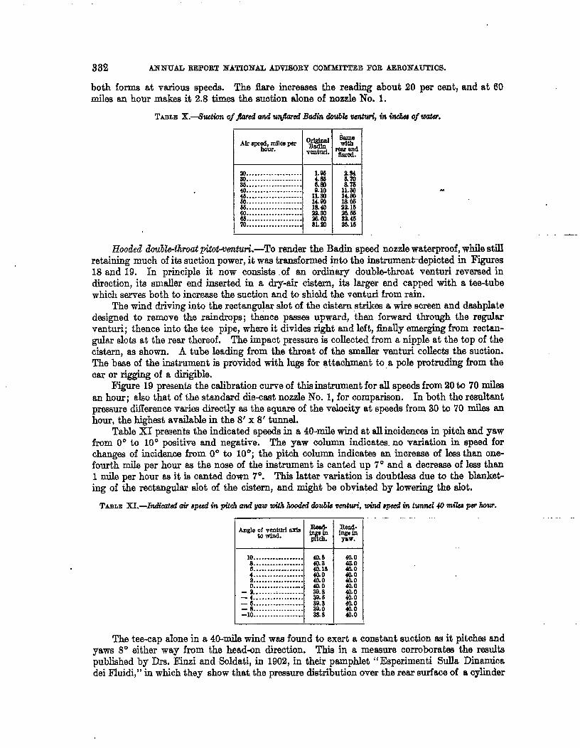
Badin double wnturi.-Figures 16 and 17 show a Badin venturi of good design, with andwithout flared rear, and without pitot accompaniment. Table X gives its suction readings for
332 ANNUAL REPORT NATIONAL ADVISORY COMMHTIH!i FOR AERONAUTICIS.
both forma at variousqeeds. The &ire increases the reading about 20 per cent, and at 60miles an hour makes it 2.8 times the suction alone of nozzle No. 1.
!I’ABmlL-s9u&m of j%nai and u@ared Badin doubb - m inch of watiw.
m
1.....................
20. . . . . . . . . . . . . . . . . . . . N36. . . . . . . . . . . . . . . . . . . &m40. . . . . . . . . . . . . . . . . . . .46.. =... . . . . . . . . . . . . . . xl:60. . . . . . . . . . . . . . . . . . . . 14.m55. . . . . . . . . . . . . . . . . . . . 1&40co. . . . . . . . . . . . . . . . . . . . 21.3066. . . . . . . . . . . . . . . . . . . . %60m .................... 8L21
*tie
Wlrwcl
9.34
i%11.3014.EC
2%E!m.M3Z45M.16
- —_
Hooded dou&k+hroa# titot-vemtuA-To render the Badin speed nozzle watermoof, while stillretaining much of its suction power, it was transformed inta th~ instrument+ep~cted h Figures18 and 19, In principle it now consists of an ordinary double-throat venturi reversed indnoction, ita smaller end inserted in a dryair cistern, its larger end capped with a tee-tubewhich serves both to increase the suction and to shield the venturi from rain.
The wind driving into the rectangular slot of the cistmn strikes a wire screen and dashplatedesigned to remove the raindrops; thence passes upward, then forward through the regularventuri; thence into the tee pipe, where it divides right and left, finaUy emerging from rectan-gular slots at the rear thereof. The impact pressure iEcollected from a nipple at the top of theCiSti, as shown. A tube leading from the throat of the smaller venturi collects the suction.The base of the instrument is provided with lugs for attachment to a pole protruding from thecar or rigging of a dirigible.
Figure 19 presents the ctibratkm curve of this instrument for alI speeds from 20 ta 70 milesan hour; also that of the standard die-cast nozzle hTo.1, for comparison. In both tho resultantpressure difference varies directly as the square of the velocity at speeds from 30 to 70 miles anhour, the highest available in the 8’ x 8’ tunnel.
Table XI presents the indicated speeds in a 40-mile wind at all incidencw in pitch and yawfrom 0° to 10° positive and negative. The yaw column indicates. no variation in speed forchanges of incidence from 0° to 10°; the pitch column indicates an increase of less than one-fourth mile per hour as the nose of the instrument is canted up 7° and a decrease of less than1 mile per hour as it is canted down 7°. This latter variation is doubtless due to the blanket-ing of the rectangular slot of the cistern, and might be obviatad by lowering the slot.
TABLE X. L-IiadLnt.wiaw apwd in pith and yaw with kxxiki doubk wn$tui, wind #pwd in tunnel 40 nub par hour.. ..—
710..................::.............-.:.:::::::::..................–k::::::::::::”::
— 4..,, . . . . . . . . . . . . . .— 6. . . . . . . . . . . . . . . ..-— 8. . . . . . . . . . . . . . . . . .-lo . . . . . . . . . . ..-.-.. I
40.s411846.1540.040.040.039.839.669.a39.0?88
! I J 1
The tee-cap alone in a 40-mile wind was found to exert a constant suction as it pitchw andyaws 8° either way from the head+m direction. This in a measure corroborates the resultspublished by Drs. E5nzi and ScJdati, in 1902, in their pamphlet “ Eaperimenti SuUa Dinamicadei Fluidi,” in which they show that the pressuredistribution over the rear surface of a oylinder
●
DEVELOPMENT OF MB SPEED NOZZLES. 333
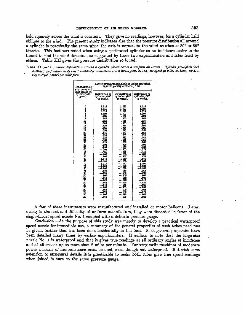
heldsquarelyacross thewind is constant. They gave no readings, however, for a cylinder heldobIique to the wind. The present study indicat= aIso that the pressure distribution aU arounda cylinder is practically the same when the axis is normal ta the wind as when at 80° or 85°thereto. This fact was noted when using a perforated cylinder es an incidence meter in thetunnel to find the wind direction, m suggested by those two experimenters and later tried byothers. ‘l!able XII gives the pressure distribution so found.
TABLRXII.-Au pIW8UW d&ributh around a c@der pkcedacmaaa un@?m air dream. Cphdh$rwightis inch
dimneikr; perfomhbn in h & 1 nttllhneb in dhnet.?r and 6 hchwfrom ii%end ati aped 40 mibs an how’; air den-
* o.074i5 @und per cubicfret.
Ddfnstfon ofrindtoaxi$ohololl~:
gre+!s).
o
:46
i
i?161s
ii2496!2824M404sm66
8707s80N
Iz110Izo
%169lec170180loo
=f=qsm.t,dti,om. atefdehdefnfnoh= ofaIcohL
GKdfmtkmof
tow’fmfoyKuder, O“
LO16LouL 014l.~
.S+3S
:%!.850.7S%5.760.676.610
:E. am.m
-“M.4s3-.060
-Tfi-LIOO-L 116-LIMO-1.mo-.9s)-.W!S-. 60)-.910-.fao-93S-.eio~.~
-.973-.990-.S93
tm?lfnrttfor.rof
f.UyI#lddw
I.mll.omLOiSI1.(OJ.985.96s.Sm.900
%.746.670
:E.44s.ss0
:E-.!axl-.486-.eao—.865-Lolo-L1OO~: g
-LW-.950-.m=.~
-.920-.cas-.M!!-.960-.m
=%-.s90
bdfneth of?y&miMiy
.
1.o16LWLO15l.cxl.WI.965.s36.s0).m.s05.760.636.616.640.465
:%
-:E-.410-.EM
=?6-Lcm4.1!
-L030-.W-.9!40-.WO-.K)O-.910-.930-. w
. -.-.E-.970-.9M-.S65
A few of these instruments were manufactured and installedon motm btdloons. lkter,
owing to the cost and difllculty of uniform manufacture, they were discarded in favor of thesingh+throat speed nozzle No. I coupled with a delicata prassure gauge.
Ccncluti.-iia the purpose of thisstudy was merely to deveIop a practicalwaterproof
speed nozzle for immediate use, a summary of the genersl propertiesof such tubes need notbe given, further than has been done incidentdy in the text. Such general properties havebeen detailed many times by earIier qerimenters. Iti sufiices to note that the Iarge+izenozzle No. 1 is waterproof and that it gives true readings at sl ordinary angles of incidenceand at dl speeds up to more than 2 miles per minute. For very swift machims of moderatepower a nozzle of less resistance must be used, even though not waterproof. But with someattantion to structural details it is practicable to make both tubes give true speed readingswhen joined in turn to the same pressure gauge.
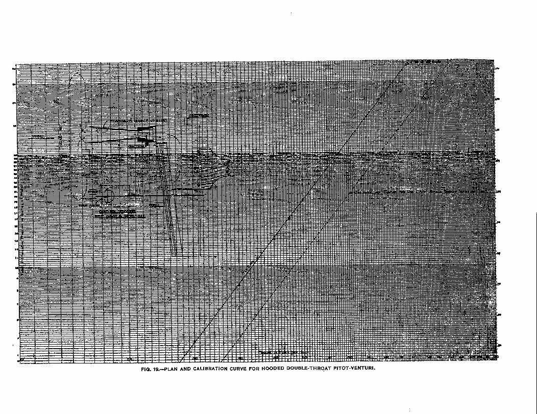
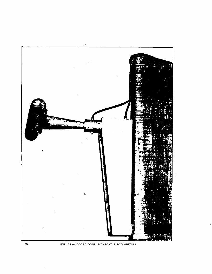
334 FIG. 18.—HOODED DOUBLE-THROAT PITOT-VENTUR1,