Embed Size (px)
Citation preview

Report 01-004
Boeing 767-319
ZK-NCH
failure of flap deflection control track
approach to Auckland International Aerodrome
19 May 2001
Abstract On Saturday 19 May 2001, at 1450, Boeing 767-319 ZK-NCH was on approach to land at Auckland International Aerodrome when a section of a wing flap deflection control track separated from the aeroplane. The 3 kg section penetrated the roof of an occupied warehouse and fell to the floor without causing personal injury. The crew of ZK-NCH were unaware of the event and continued with a successful landing. The flap control track failed owing to a fatigue crack. The failure of the track was accelerated by the coincidental inclusion of slag during manufacture and extended aircraft operations at very low temperatures but still within its flight envelope. The safety issue identified was the fatigue life of the flap control track. As a result of the incident other Boeing 767 maintenance organisations were informed and the operator initiated an additional regular inspection of the flap control track. The manufacturer subsequently reviewed the operation of the flap control track and began developing an inspection schedule to enable a cracked track to be identified before failure.


Report 01-004 Page i
Contents
List of Abbreviations .................................................................................................................................... ii
Glossary ....................................................................................................................................................... ii
Data Summary .............................................................................................................................................iii
1. Factual Information ....................................................................................................................... 1 1.1 History of the flights......................................................................................................... 1 1.2 Injuries to persons............................................................................................................. 3 1.3 Damage to aircraft ............................................................................................................ 3 1.4 Other damage.................................................................................................................... 3
Analysis 1 ......................................................................................................................... 3 1.5 Aircraft information.......................................................................................................... 4 1.6 Meteorological information.............................................................................................. 5 1.7 Flight recorders................................................................................................................. 5
Analysis 2 ......................................................................................................................... 5 1.8 Tests and research............................................................................................................. 5
Analysis 3 ......................................................................................................................... 7 1.9 Additional information ..................................................................................................... 8
Analysis 4 ......................................................................................................................... 8 2. Findings ......................................................................................................................................... 9
3. Safety Actions ............................................................................................................................... 9
Figures
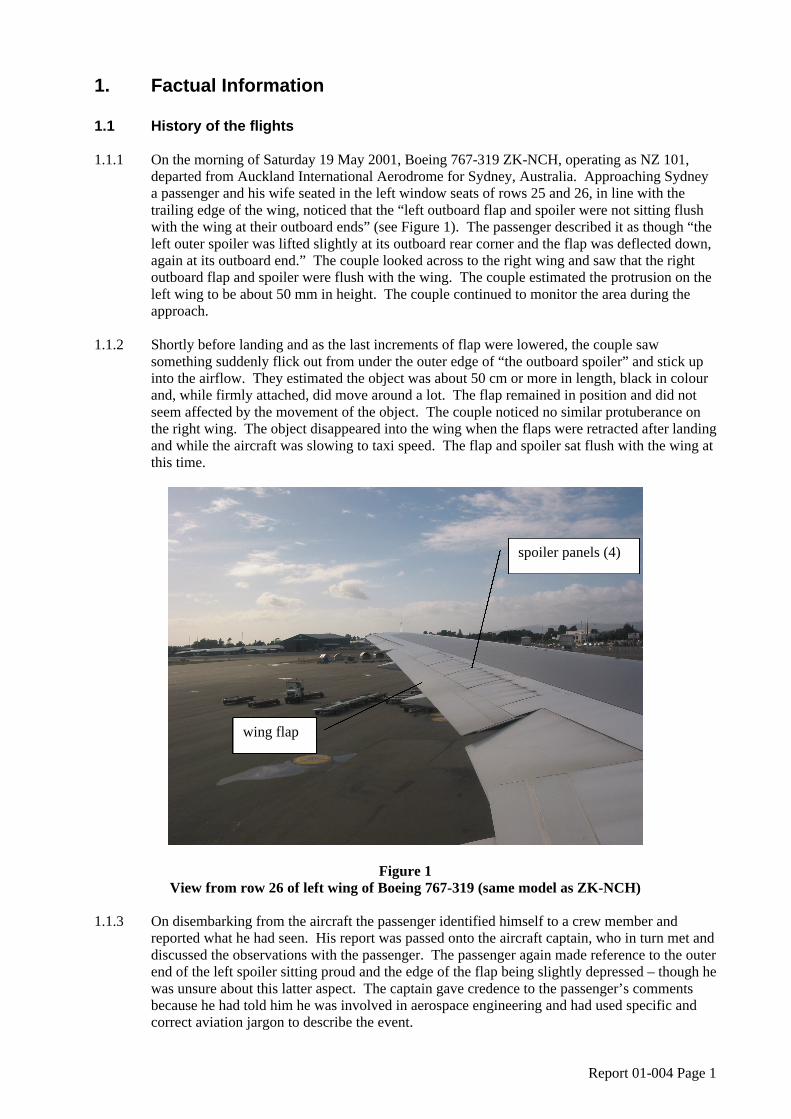
Figure 1 View from row 26 of left wing of Boeing 767-319 (same model as ZK-NCH)............................. 1
Figure 2 Left wing with flap fully extended and spoilers deployed ............................................................. 2
Figure 3 Flap deflection control track from ZK-NCH.................................................................................. 3
Figure 4 Fracture surface of flap control track ............................................................................................. 6
Figure 5 Fracture surface (close-up) ............................................................................................................. 7
Report 01-004 Page ii
List of Abbreviations
C Celsius
cm centimetre(s)
FDR flight data recorder
kg kilogram(s) km kilometre(s)
m metre(s) mm millimetre(s)
UTC Co-ordinated Universal Time
Glossary Cycle One take-off and landing Cold soaked The cooling of an entire object to the point that the characteristics of the metal change.
Report 01-004 Page iii
Data Summary Aircraft type, serial number Boeing 767-319, 26 264, and registration: ZK-NCH Number and type of engines: 2 General Electric CF6-80C2 turbo-fans Year of manufacture: 1994 Operator: Air New Zealand Date and time: 19 May 2001, 14501 Location: Auckland International Aerodrome latitude: 37°00.5′ south longitude: 174°47.5′ east Type of flight: scheduled passenger transport Persons on board: crew: 10
passengers: 148 Injuries: crew: nil passengers: nil Nature of damage: minor to aircraft panel and a 15 cm diameter
hole in warehouse roof Investigator-in-charge: I R McClelland
1 All times in this report are New Zealand Standard Time (UTC + 12).

Report 01-004 Page 1
1. Factual Information 1.1 History of the flights
1.1.1 On the morning of Saturday 19 May 2001, Boeing 767-319 ZK-NCH, operating as NZ 101,
departed from Auckland International Aerodrome for Sydney, Australia. Approaching Sydney a passenger and his wife seated in the left window seats of rows 25 and 26, in line with the trailing edge of the wing, noticed that the “left outboard flap and spoiler were not sitting flush with the wing at their outboard ends” (see Figure 1). The passenger described it as though “the left outer spoiler was lifted slightly at its outboard rear corner and the flap was deflected down, again at its outboard end.” The couple looked across to the right wing and saw that the right outboard flap and spoiler were flush with the wing. The couple estimated the protrusion on the left wing to be about 50 mm in height. The couple continued to monitor the area during the approach.
1.1.2 Shortly before landing and as the last increments of flap were lowered, the couple saw
something suddenly flick out from under the outer edge of “the outboard spoiler” and stick up into the airflow. They estimated the object was about 50 cm or more in length, black in colour and, while firmly attached, did move around a lot. The flap remained in position and did not seem affected by the movement of the object. The couple noticed no similar protuberance on the right wing. The object disappeared into the wing when the flaps were retracted after landing and while the aircraft was slowing to taxi speed. The flap and spoiler sat flush with the wing at this time.
Figure 1 View from row 26 of left wing of Boeing 767-319 (same model as ZK-NCH)
1.1.3 On disembarking from the aircraft the passenger identified himself to a crew member and
reported what he had seen. His report was passed onto the aircraft captain, who in turn met and discussed the observations with the passenger. The passenger again made reference to the outer end of the left spoiler sitting proud and the edge of the flap being slightly depressed – though he was unsure about this latter aspect. The captain gave credence to the passenger’s comments because he had told him he was involved in aerospace engineering and had used specific and correct aviation jargon to describe the event.
wing flap
spoiler panels (4)

Report 01-004 Page 2
1.1.4 The captain repeated the passenger’s comments to the ground engineers who had met the aircraft on arrival. The captain recorded the comments in the aircraft’s maintenance log, writing that the passenger reported the left outboard spoiler panel was slightly raised in flight and when full flaps were selected a dark object was seen streaming off or sticking up from the wing into the airflow. The object disappeared when flaps were retracted after landing.
1.1.5 With 2 engineers positioned near the left wing, the flaps were fully lowered and the spoilers
deployed (see Figure 2). A set of steps was used in the inspection of the spoilers and flap, concentrating on the upper surfaces and the flap area adjacent to the spoilers. The engineers checked for damage and loose items – none was found. The spoilers and ailerons were cycled several times and both appeared to function normally. The flaps were retracted and no abnormalities were noted. The certifying engineer reported to the captain that he was satisfied there were no defects and completed the maintenance log entry. The aircraft was cleared for the return flight to Auckland2.
1.1.6 The return flight to Auckland, then operating as NZ 102 but with the same crew, proceeded
uneventfully. At 1450 while on final approach to land at Auckland International Aerodrome, and at about the time full flap was selected, a section of the left outboard flap deflection control track assembly (the flap control track) separated from the aircraft and fell to the ground. The section of flap control track, weighing about 3 kg, struck the roof of a warehouse in Manukau, about 2 km from the aerodrome and in line with the runway centreline. The broken section penetrated the warehouse roof and bounced off an aisle stand before coming to rest on the floor. The warehouse was occupied but there were no injuries (see Figure 3).
1.1.7 As the aircraft performance was not affected, the crew were unaware of the event and so
continued with the landing. Warehouse personnel advised the Police of the incident and the broken section was identified as coming from an aircraft. The operator was notified and an aircraft check confirmed that the section had originated from ZK-NCH. The crew were informed, and they completed an incident report.
Figure 2 Left wing with flap fully extended and spoilers deployed
2 The Commission acknowledges the assistance of the Australian Transport Safety Bureau in the collation of some of this information.
left flap (extended)
location of flap control track
spoilers (deployed)

Report 01-004 Page 3
Figure 3 Flap deflection control track from ZK-NCH
1.2 Injuries to persons 1.2.1 There were no injuries. 1.3 Damage to aircraft 1.3.1 There was minor deformation to the wing skin of the aircraft, around the position where the flap
control track would be located. 1.4 Other damage 1.4.1 There was a small hole in the roof of the warehouse measuring about 15 cm in diameter, and
some minor damage to merchandise.
Analysis 1 1. The 2 flights were routine scheduled flights between Auckland and Sydney. Other
than the reported observation by the passenger after landing at Sydney, the crew were not aware of anything unusual during the flights.
2. The couple were diligent in firstly observing the unusual state of the wing and then in
reporting their concerns to the crew of the aircraft. Their initial observations that the flap and outboard spoiler were not sitting flush displayed a keen eye, as this area was located about 17 m out from their seating position.
part that separated from aircraft
part that remained attached to aircraft
fillet for flap rollers to follow
origin of failure

Report 01-004 Page 4
3. The lifting of the panels was probably due to the detached section of the flap control track not aligning correctly in position. The detached section was instead forced up into the top of the wing when the flaps were retracted after departing from Auckland. The passenger probably believed that the panel in front of the outboard end of the flap, and where he saw the protrusion, was a continuation of the aircraft’s spoiler system. However, the outboard end of the flap extended some 2 m past the last spoiler panel. This confusion was understandable considering the distance from the fuselage to the outboard end of the flap and the passenger not being familiar with the aircraft type.
4. During normal operation, rollers attached to the ends of each flap would run along
both sides of a fillet on the flap control tracks. The flap control tracks ensured the flaps were at the correct angles as they were extended or retracted. On ZK-NCH, the rollers on the end of the flap probably restrained the detached section of flap control track when it initially failed. As the final increments of flap were selected on approach to Sydney, the detached section of flap control track was able to slide along the rollers to stick up into the airflow above the wing. As the flaps were retracted, the rollers pulled the section into the wing once the air loads on the flaps reduced as the aircraft slowed. The section was probably pulled back into about its normal position.
5. The passenger accurately described events to the crew after landing. But by using
specific aviation terminology to describe the area where the protuberance was seen, namely the outboard spoiler, the passenger unwittingly concentrated attention on this area and not the outboard end of the flap – some 2 m past the spoilers.
6. The briefing by the captain and the inspection by the engineers were thorough and
correct – based on the information received. To be able to detect the broken flap control track, the engineers would have needed to specifically look at the track. While the captain could have obtained a visual confirmation from the passenger of the specific area concerned, the terminology used left little doubt in the minds of the people concerned as to what was meant.
7. The departure and return flight to Auckland proceeded normally. The detached
section of flap control track continued to remain restrained by the flap rollers. On selecting the final increments of flap approaching Auckland the section was this time able to come free of the rollers and fall from the aircraft. Fortunately no injuries were sustained when the section of flap control track struck the warehouse.
8. The loss of the flap control track did not significantly affect the control or safety of the
aircraft as it made its landing. Each flap section had 2 flap-deflection control tracks to assist in the control of the flap. The loss of one track did not reduce this control under the air loads present at the time.
9. The level of damage, both to the aircraft and the warehouse, was minimal. However,
the potential for damage or injury caused by an object falling from an aircraft was significant.
1.5 Aircraft information 1.5.1 ZK-NCH was a Boeing 767-319, serial number 26 264, twin-engine, all-metal aircraft
constructed in United States in October 1994. ZK-NCH was fitted with General Electric CF6-80C2 turbo-fan engines. On landing at Auckland on 19 May, ZK-NCH had flown 35 717.14 hours and completed 6555 cycles.
1.5.2 The flap control track support fitting assembly was mounted to the wing structure by the use of
2 support fittings. In recent years there had been a number of reported failures of the support fittings and as a result a redesigned flap control track assembly was produced and made

Report 01-004 Page 5
available to operators. In the meantime, an additional inspection of the support fittings was incorporated into the maintenance schedule for the aircraft.
1.5.3 The last relevant scheduled servicing of ZK-NCH, a 3A2 check, was completed on 26 April
2001. The servicing included the requirement to visually inspect the support fittings for the flap control track. The inspection directed the flaps to be lowered to ensure adequate access to the area. Records indicated that nothing unusual was noted and the support fittings were observed to be serviceable.
1.6 Meteorological information 1.6.1 No significant weather was encountered during the 2 flights. The captain reported some light
turbulence and heavy rain approaching Sydney, and the aircraft was vectored around several thunderstorms before entering cloud at about 5000 feet. After landing the weather improved and was reported to be fine during the time the inspection of the aircraft was completed.
1.6.2 The weather approaching Auckland was reported as fine with scattered cloud. 1.7 Flight recorders 1.7.1 After the incident the flight data recorder (FDR) for ZK-NCH was downloaded and the record
of the 2 flights processed for examination. The approaches, landings and departures at Sydney and Auckland were reviewed for any unusual events or excursions that might be associated with a failure of the flap control track – none was found. The departures and approaches, and specifically flap operation and the speeds flown, were in accordance with the operator’s instructions and manufacturer’s limits.
Analysis 2 1. The age, flight hours and cycles accrued by ZK-NCH were not statistically significant.
The first Boeing 767 flew in September 1981 and the first 767-300 model flew in January 1986. Nevertheless, the operator’s fleet of Boeing 767 aircraft was known to fly on consistently longer routes than most other Boeing 767 fleets.
2. The routine inspection of the area focused on the support fittings for the flap control
track and not the flap control track itself. Detection of a defect or small crack at the location where the flap control track on ZK-NCH failed would have been difficult to detect by visual inspection only.
3. The weather encountered during the 2 flights was not significant and was unlikely to
have contributed to the failure of the flap control track. The weather at Sydney did not hinder the external inspection of the aircraft.
4. The FDR information for the 2 flights confirmed that there was no unusual event
recorded that would cause the flap control track to fail. The approaches, landings and departures, those stages of flight where the flap was deployed, were normal. An earlier overload or overstress could not be ruled out; however, no such event was recorded or reported.
1.8 Tests and research 1.8.1 The 2 sections of the flap control track were subjected to independent metallurgy testing (see
Figures 4 and 5). The report on the testing is summarised as follows: The fracture resulted from fatigue initiated at a casting defect (slag inclusion) at the surface of the tension face of the guide fillet, which had subsequently developed fatigue
cracking. The fatigue crack had grown to a size (approximately 4 mm wide by 2.7 mm

Report 01-004 Page 6
deep) such that, at the applied stress level at the instant of failure, the part had fractured by a cleavage (fast, brittle) mechanism initiating at the fatigue cracking. The casting defect was of the nature of an extrinsic (chance) defect resulting from the
incorporation of a small amount of manganese-silicate slag into the liquid metal stream when the part was being poured, which had become trapped near the surface of the casting in this critical area of the structure.
Figure 4 Fracture surface of flap control track
1.8.2 Inspection of the 2 sections revealed paint contamination on the fracture face of the section that
separated from the aircraft. There was also similar coloured paint scraped onto several other surfaces of the same part. The 2 fracture surfaces did not display any evidence of having met and rubbed together after failure.
1.8.3 Analysis of the metal indicated that it was of the type approved for the construction of the flap
control track, namely alloy steel. 1.8.4 On completion of the initial testing the 2 sections were forwarded separately to the manufacturer
for further analysis. The manufacturer expressed the opinion that the static strength of the flap control track was within specifications. The slag inclusion was found to be “high in manganese and silicon oxides, typical of a slag product from the casting process”. Similar inclusions were found in other sectioned pieces of the flap control track.
1.8.5 The manufacturer contended that the “inclusions initiated the observed crack and note that they
are not detectable during the fabrication process.” The manufacturer further contended that the small size of the crack relative to the overall cross-section of the flap control track was due to it being under load while at very cold temperatures, around -55°C, during the approach and landing phase of flight3. “This is when the flap loads on the track are at the largest and when the track fractured.”
3 Although the ambient air temperature would increase during the descent, previously cooled metal components would continue to be at a colder temperature until some time after landing.
point of initiation

Report 01-004 Page 7
1.8.6 Post-incident fatigue analysis by the manufacturer predicted crack initiation to occur at about 5000 cycles for the 767-300ER model aeroplanes. The crack would grow to the critical size in about 1800 cycles.
Figure 5 Fracture surface (close-up)
Analysis 3 1. The failed flap control track met the design specifications for the part. The inclusion
of slag during the manufacturing process could normally be expected and the design of the flap control track should have allowed for this.
2. The failure occurred at about the point of maximum load. The slag acted as a further
stress concentrator and accelerated the fatigue process. The exposure of the flap control track to long periods of very low temperatures meant that the part became “cold soaked”. When the aircraft descended and the flap was lowered for an approach, the flap control track material acted in a brittle manner and was more susceptible to fatigue damage. This would account for the relatively smaller size of the crack at the time of the failure than would perhaps normally be expected.
3. The exposure of the aircraft and its components to very low temperatures, in the
region of -55°C, was routine and within the approved flight envelope for the aircraft. 4. The paint found on the separated flap control track matched that on the underside of
the upper wing surface, confirming the earlier analysis that the section was forced up against this area when the flaps were retracted after departing from Auckland. The lack of rubbing between the 2 fracture surfaces indicated that, while the 2 sections may have been in close proximity when the flaps were retracted after landing at, and taking off from, Sydney, they did not butt together.
overload area
fatigued area
location of slag inclusion

Report 01-004 Page 8
1.9 Additional information 1.9.1 On being made aware of the incident, the operator informed the manufacturer and a notice was
placed on the manufacturer’s web site for the Boeing 767 to inform maintenance organisations of the incident. No other operators reported having had a similar failure of the same part. However, the operator of ZK-NCH did advise that on 15 June 1999, during a routine inspection of another Boeing 767-319, ZK-NCE, the left outboard flap control track was found to have cracked.
1.9.2 The cracked flap control track was forwarded to the manufacturer for analysis, but some time
after the manufacturer received the cracked part it was lost and no further analysis was possible. A preliminary report by the operator, which included photographs, confirmed that the flap control track on ZK-NCE had cracked in the same location as the failed part on ZK-NCH.
1.9.3 ZK-NCE was manufactured in June 1991 and as at 15 June 1999 had flown 41 905 hours and
completed 7872 cycles, 1317 cycles and 6188 hours more than ZK-NCH had flown when its flap control track failed.
Analysis 4 1. The maximum loading on the flap control track normally occurs on approach and
landing where full or near full flap is extended, rather than on take-off where less flap is used. Considering what the 2 passengers saw as the aircraft started its approach to Sydney on 19 May 2001, it is highly likely that the component had failed on some previous sector, possibly on approach to Auckland the previous day.
2. That the crack or failure was not detected during the check servicing completed on 26
April or the pre-flight inspections at either Auckland or Sydney was logical when considering the initial size of the crack, the location of the flap control track and the information available to the aircrew and engineers.
3. The flap control track assembly is normally subjected to considerable loads when the
flaps are deployed during a flight. Nevertheless, the assembly was designed to withstand such loads and required only a visual inspection at regular intervals to ensure its continued airworthiness.
4. The failure of the flap control track on ZK-NCH occurred at fewer hours and cycles
than when the cracked flap control track was found on ZK-NCE in 1999. Again, when compared with the total Boeing 767 fleet there was nothing statistically significant about the age, cycles or hours flown on either ZK-NCH or ZK-NCE.
5. The failures on both ZK-NCH and ZK-NCE occurred in a region of high stress. The
failures probably occurred because of this stress concentration rather than the inclusion of slag at this point. However, the fatigue strength of the flap control track on ZK-NCH was compromised by the slag inclusion. This possibly accounts for the failure on ZK-NCH occurring at lower hours and cycles than when the cracked flap control track was found on ZK-NCE.

Report 01-004 Page 9
2. Findings Findings are listed in order of development and not in the order of priority.
2.1 ZK-NCH was maintained in accordance with the required maintenance schedule.
2.2 The incident flights were routine flights with no unusual events that could have contributed to
the failure of the flap control track. 2.3 The actions of the 2 passengers, the crew of ZK-NCH and the engineers at Sydney were
appropriate based on the information available. 2.4 The failure of the flap control track was due to a fatigue crack.
2.5 The failure was accelerated by the random inclusion of slag at a critical position in the flap
control track and the routine normal exposure of the aircraft to long periods of very cold temperatures.
2.6 A manufacturer’s inspection procedure needed to be developed to ensure cracked flap control
tracks were detected before failure. 2.7 The failure of the flap control track did not significantly affect the safety of the aircraft. 2.8 The loss of the flap control track had the potential to cause significantly greater damage,
including injury to the public.
3. Safety Actions 3.1 As a result of the incident, the operator notified both the manufacturer and a number of other
Boeing 767 operators to alert them to the incident. The manufacturer in turn ensured that all Boeing 767 operators were aware of the potential for the flap control track to fail and depart the aircraft.
3.2 The manufacturer undertook to develop an inspection procedure with repeat intervals that will
minimise the possibility of future track failures. The procedure was to be released as a service bulletin with the following requirements:
“For aeroplanes with the 113T8333-1 or -5 tracks: Threshold (Initial Inspection) will be at the
next available ‘1C’ maintenance check (3000 flight cycles) or within 18 months after release date of the service bulletin; whichever comes first. After the initial inspection has been completed, these aeroplanes will be inspected repeatedly every ‘1C’ check (3000 flight cycles) or within 18 months, whichever comes first.
For aeroplanes with the 113T8333-3 or -7 tracks: Threshold (Initial Inspection) will be at the
next available ‘1C’ maintenance check (3000 flight cycles) or within 18 months after the release date of the service bulletin; whichever comes first. After the initial inspection has been completed, these aeroplanes will be inspected repeatedly every ‘2C’ check (6000 flight cycles) or within 36 months, whichever comes first.”
The service bulletin was due to be released to operators and maintenance contractors by June 2002. 3.3 The manufacturer indicated that the difference in the 2 types of tracks was that the original
tracks had less cross-sectional area in the critical fatigue location where failure occurred.

Report 01-004 Page 10
“All 767-200 and 767-300 models were produced with the 113T8333-1 or -5 track before Line Number 787 (before 20 April 2000). Aft-lug thickness = 0.240 inches (about 6.1 mm).
All 767-200 and 767-300 models were produced with the 113T8333-3 or -7 tracks from Line
Number 787 and on (after 20 April 2000 and on). Aft-lug thickness = 0.580 inches (about 14.7 mm).
All 767-400ER models were produced with the 113T8333-7 tracks.” The manufacturer was studying the feasibility of redesigning the track to be common for all 767
models, such that the new track would eliminate the need for inspections identified in the proposed service bulletin.
3.4 The operator advised that it was replacing all Boeing 767 model 113T833-1, -3 or -5 flap track guides with the Boeing 767-400 model -7 series of flap track guide. Approved for publication 10 April 2002 Hon. W P Jeffries Chief Commissioner


![767 INDEX [] · 767 INDEX ... index](https://img.pdfslide.us/doc/110x75/5e6407d785e377181b6fee19/767-index-767-index-index-.jpg)