Embed Size (px)
Citation preview
November 2014Part Number 1500835
MANUALREPAIR PARTS
Serial number 000000 and after
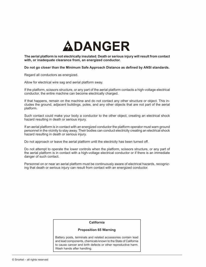
The aerial platform is not electrically insulated. Death or serious injury will result from contact with, or inadequate clearance from, an energized conductor.
Do not go closer than the Minimum Safe Approach Distance as defined by ANSI standards.
Regard all conductors as energized.
Allow for electrical wire sag and aerial platform sway.
If the platform, scissors structure, or any part of the aerial platform contacts a high-voltage electrical conductor, the entire machine can become electrically charged.
If that happens, remain on the machine and do not contact any other structure or object. This in-cludes the ground, adjacent buildings, poles, and any other objects that are not part of the aerial platform.
Such contact could make your body a conductor to the other object, creating an electrical shock hazard resulting in death or serious injury.
If an aerial platform is in contact with an energized conductor the platform operator must warn ground personnel in the vicinity to stay away. Their bodies can conduct electricity creating an electrical shock hazard resulting in death or serious injury.
Do not approach or leave the aerial platform until the electricity has been turned off.
Do not attempt to operate the lower controls when the platform, scissors structure, or any part of the aerial platform is in contact with a high-voltage electrical conductor or if there is an immediate danger of such contact.
Personnel on or near an aerial platform must be continuously aware of electrical hazards, recogniz-ing that death or serious injury can result from contact with an energized conductor.
© Snorkel – all rights reserved
California
Proposition 65 Warning
Battery posts, terminals and related accessories contain lead and lead components, chemicals known to the State of California to cause cancer and birth defects or other reproductive harm. Wash hands after handling.
S3219E/S4732E – 1500835
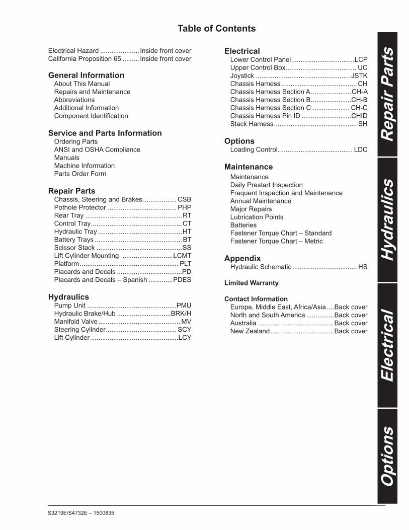
Table of Contents
Electrical Hazard ..................... Inside front coverCalifornia Proposition 65 ......... Inside front cover
General Information About This Manual Repairs and Maintenance Abbreviations Additional Information ComponentIdentification
Service and Parts Information Ordering Parts ANSI and OSHA Compliance Manuals Machine Information Parts Order Form
Repair Parts Chassis, Steering and Brakes .................. CSB Pothole Protector ..................................... PHP Rear Tray ....................................................RT Control Tray .................................................CT Hydraulic Tray .............................................HT Battery Trays ...............................................BT Scissor Stack ..............................................SS Lift Cylinder Mounting ...........................LCMT Platform ..................................................... PLT Placards and Decals ...................................PD Placards and Decals – Spanish .............PDES Hydraulics Pump Unit ................................................PMU Hydraulic Brake/Hub .............................BRK/H Manifold Valve ............................................ MV Steering Cylinder ...................................... SCY Lift Cylinder ...............................................LCY
Electrical Lower Control Panel ..................................LCP Upper Control Box ...................................... UC Joystick ...................................................JSTK Chassis Harness ......................................... CH Chassis Harness Section A ......................CH-A Chassis Harness Section B ......................CH-B Chassis Harness Section C .................... CH-C Chassis Harness Pin ID ...........................CHID Stack Harness ............................................. SH
Options Loading Control. ....................................... LDC
Maintenance Maintenance Daily Prestart Inspection Frequent Inspection and Maintenance Annual Maintenance Major Repairs Lubrication Points Batteries Fastener Torque Chart – Standard Fastener Torque Chart – Metric
Appendix Hydraulic Schematic ................................... HS
Limited Warranty
Contact Information Europe, Middle East, Africa/Asia ....Back cover North and South America ...............Back cover Australia .........................................Back cover New Zealand ..................................Back cover

S3219E/S4732E – 1500835
S3219E/S4732E – 1500835
General Information
About This ManualThis manual covers S1930E and S1932E aerial plat-forms. Information is included for machines that have been manufactured to conform to all applicable require-ments of the following organizations:
y American National Standards Institute (ANSI) y Canadian Standards Association (CSA) y European Committee for Standardization (CE) y AustralianStandards(AS)certification
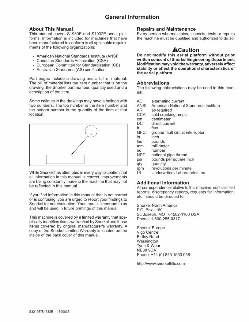
Part pages include a drawing and a bill of material. The bill of material lists the item number that is on the drawing, the Snorkel part number, quantity used and a description of the item.
Some callouts in the drawings may have a balloon with two numbers. The top number is the item number and the bottom number is the quantity of the item at that location.
WhileSnorkelhasattemptedineverywaytoconfirmthatall information in this manual is correct, improvements are being constantly made to the machine that may not bereflectedinthismanual.
Ifyoufindinformationinthismanualthatisnotcorrectorisconfusing,youareurgedtoreportyourfindingstoSnorkel for our evaluation. Your input is important to us and will be used in future printings of this manual.
This machine is covered by a limited warranty that spe-cificallyidentifiesitemswarrantiedbySnorkelandthoseitems covered by original manufacturer's warranty. A copy of the Snorkel Limited Warranty is located on the inside of the back cover of this manual.
Repairs and MaintenanceEvery person who maintains, inspects, tests or repairs themachinemustbequalifiedandauthorizedtodoso.
CautionDo not modify this aerial platform without prior written consent of Snorkel Engineering Department. Modification may void the warranty, adversely affect stability or affect the operational characteristics of the aerial platform.
AbbreviationsThe following abbreviations may be used in this man-ual.
AC alternating currentANSI American National Standards InstituteAR as requiredCCA cold cranking ampscm centimeterDC direct currentft feetGFCI ground fault circuit interruptorin inchlbs poundsmm millimeterno numberNPT national pipe threadpsi pounds per square inchqty quantityrpm revolutions per minuteUL Underwriters Laboratories Inc.
Additional InformationAllcorrespondencerelativetothismachine,suchasfieldreports, discrepancy reports, requests for information, etc., should be directed to:
Snorkel North AmericaP.O. Box 1160St. Joseph, MO 64502-1160 USAPhone: 1-800-255-0317
Snorkel EuropeVigo CentreBirtley RoadWashingtonTyne & WearNE38 9DAPhone: +44 (0) 845 1550 058
http://www.snorkellifts.com
S3219E/S4732E – 1500835
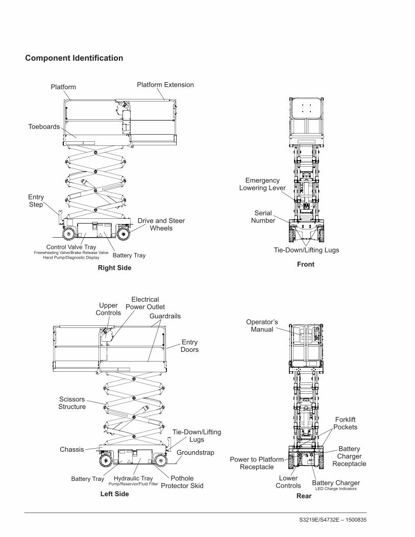
Component Identification
Scissors Structure
Right Side
Platform
Guardrails
Left Side
Lower Controls
Operator’sManual
Chassis
Upper Controls
EntryDoors
Battery Charger LED Charge Indicators
Tie-Down/Lifting Lugs
Platform Extension
Battery Tray
Rear
Front
Forklift Pockets
Drive and Steer Wheels
PotholeProtector Skid
Groundstrap
EmergencyLowering Lever
SerialNumber
Tie-Down/LiftingLugs
ElectricalPower Outlet
Power to PlatformReceptacle
Battery Tray
BatteryCharger
Receptacle
Hydraulic Tray Pump/Reservior/Fluid Filter
Control Valve Tray Freewheeling Valve/Brake Release Valve
Hand Pump/Diagnostic Display
EntryStep
Toeboards
S3219E/S4732E – 1500835
Service and Parts Information
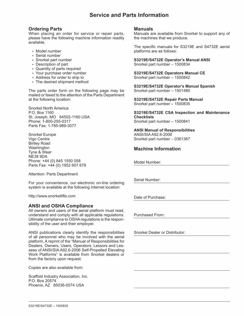
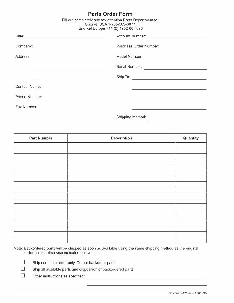
Ordering PartsWhen placing an order for service or repair parts, please have the following machine information readily available.
y Model number y Serial number y Snorkel part number y Description of part y Quantity of parts required y Your purchase order number y Address for order to ship to y The desired shipment method
The parts order form on the following page may be mailed or faxed to the attention of the Parts Department at the following location:
Snorkel North AmericaP.O. Box 1160St. Joseph, MO 64502-1160 USAPhone: 1-800-255-0317Parts Fax: 1-785-989-3077
Snorkel EuropeVigo CentreBirtley RoadWashingtonTyne & WearNE38 9DAPhone: +44 (0) 845 1550 058Parts Fax: +44 (0) 1952 607 678
Attention: Parts Department
For your convenience, our electronic on-line ordering system is available at the following Internet location:
http://www.snorkellifts.com
ANSI and OSHA ComplianceAll owners and users of the aerial platform must read, understand and comply with all applicable regulations. Ultimate compliance to OSHA regulations is the respon-sibility of the user and their employer.
ANSI publications clearly identify the responsibilities of all personnel who may be involved with the aerial platform. A reprint of the “Manual of Responsibilities for Dealers, Owners, Users, Operators, Lessors and Les-sees of ANSI/SIA A92.6-2006 Self-Propelled Elevating Work Platforms” is available from Snorkel dealers or from the factory upon request.
Copies are also available from:
Scaffold Industry Association, Inc.P.O. Box 20574Phoenix, AZ 85036-0574 USA
ManualsManuals are available from Snorkel to support any of the machines that we produce.
Thespecificmanuals forS3219EandS4732Eaerialplatforms are as follows:
S3219E/S4732E Operator’s Manual ANSISnorkel part number – 1500834
S3219E/S4732E Operators Manual CESnorkel part number – 1500842
S3219E/S4732E Operator’s Manual SpanishSnorkel part number – 1501480
S3219E/S4732E Repair Parts ManualSnorkel part number – 1500835
S3219E/S4732E CSA Inspection and Maintenance ChecklistsSnorkel part number – 1500841
ANSI Manual of Responsibilities ANSI/SIA A92.6-2006Snorkel part number – 0361367
Machine Information
Model Number:
Serial Number:
Date of Purchase:
Purchased From:
Snorkel Dealer or Distributor:
S3219E/S4732E – 1500835
Parts Order Form
Date:
Company:
Address:
Contact Name:
Phone Number:
Fax Number:
Account Number:
Purchase Order Number:
Model Number:
Serial Number:
Ship To:
Shipping Method:
Part Number Description Quantity
Note: Backordered parts will be shipped as soon as available using the same shipping method as the original order unless otherwise indicated below.
� Ship complete order only. Do not backorder parts.
� Ship all available parts and disposition of backordered parts.
� Otherinstructionsasspecified:
Fill out completely and fax attention Parts Department to:Snorkel USA 1-785-989-3077
Snorkel Europe +44 (0) 1952 607 678
Repair PartsChassis, Steering and Brakes ...................CSBPothole Protector ....................................... PHPRear Tray ......................................................RTControl Tray ..................................................CTHydraulic Tray...............................................HTBattery Trays ................................................BTScissor Stack ................................................SSLift Cylinder Mounting ..............................LCMTPlatform ...................................................... PLTPlacards and Decals.................................... PDPlacards and Decals – Spanish...............PDES

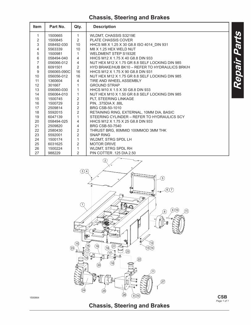
Chassis, Steering and Brakes
15
23
2
4 3
1
5
6 7
8 119 10
9 10
11
12
13 1419 2116
17
18
20
22
18
18
17
23
24 2526
27
Chassis, Steering and Brakes1500664
CSB
Page 1 of 1
1 1500665 1 WLDMT, CHASSIS S3219E 2 1500845 2 PLATE CHASSIS COVER 3 058492-030 10 HHCS M8 X 1.25 X 30 G8.8 ISO 4014_DIN 931 4 5563339 10 M8 X 1.25 HEX WELD NUT 5 1500981 1 WELDMENT STEP S1932E 6 058494-040 4 HHCS M12 X 1.75 X 40 G8.8 DIN 933 7 056066-012 4 NUT HEX M12 X 1.75 GR 8.8 SELF LOCKING DIN 985 8 6091501 2 HYD BRAKE/HUB BK10 – REFER TO HYDRAULICS BRK/H 9 056065-090C 16 HHCS M12 X 1.75 X 90 G8.8 DIN 931 10 056056-012 16 NUT HEX M12 X 1.75 GR 8.8 SELF LOCKING DIN 985 11 1360604 4 TIRE AND WHEEL ASSEMBLY 12 301667 1 GROUND STRAP 13 056060-030 1 HHCS M10 X 1.5 X 30 G8.8 DIN 933 14 056064-010 1 NUT HEX M10 X 1.50 GR 8.8 SELF LOCKING DIN 985 15 1500745 2 PLT, STEERING LINKAGE 16 1500729 2 PIN, .375DIA X .88L 17 2509814 2 BRG CSB-50-1010 18 5592015 2 RETAINING RING, EXTERNAL, 10MM DIA, BASIC 19 6047139 1 STEERING CYLINDER – REFER TO HYDRAULICS SCY 20 058494-025 4 HHCS M12 X 1.75 X 25 G8.8 DIN 933 21 2509820 4 BRG CSB-50-7540 22 2580430 2 THRUST BRG, 80MMID 100MMOD 3MM THK 23 5592001 2 SNAP RING 24 1500174 1 WLDMT, STRG SPDL LH 25 6031625 2 MOTOR DRIVE 26 1500224 1 WLDMT, STRG SPDL RH 27 988229 2 PIN COTTER .125 DIA 2.50
Item Part No. Qty. Description

1
2 3
4 5 6
7
8
10 11
15
12 13 14
16
9
18 17
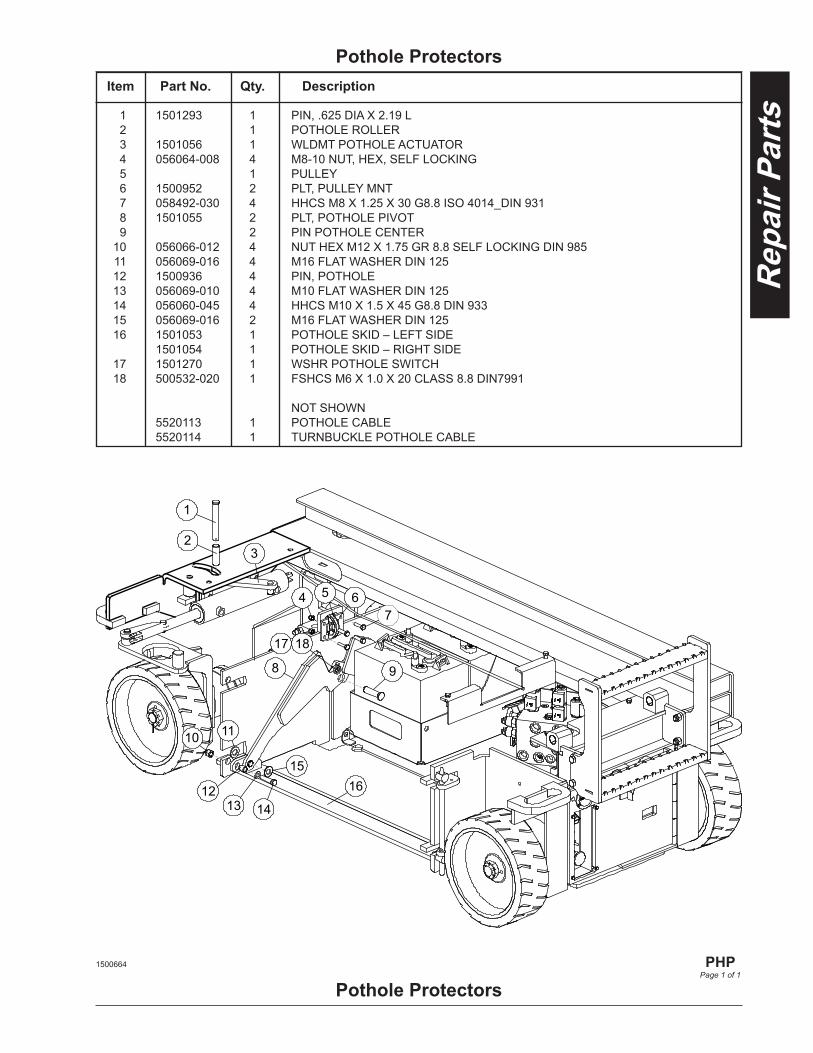
1 1501293 1 PIN, .625 DIA X 2.19 L 2 1 POTHOLE ROLLER 3 1501056 1 WLDMT POTHOLE ACTUATOR 4 056064-008 4 M8-10 NUT, HEX, SELF LOCKING 5 1 PULLEY 6 1500952 2 PLT, PULLEY MNT 7 058492-030 4 HHCS M8 X 1.25 X 30 G8.8 ISO 4014_DIN 931 8 1501055 2 PLT, POTHOLE PIVOT 9 2 PIN POTHOLE CENTER 10 056066-012 4 NUT HEX M12 X 1.75 GR 8.8 SELF LOCKING DIN 985 11 056069-016 4 M16 FLAT WASHER DIN 125 12 1500936 4 PIN, POTHOLE 13 056069-010 4 M10 FLAT WASHER DIN 125 14 056060-045 4 HHCS M10 X 1.5 X 45 G8.8 DIN 933 15 056069-016 2 M16 FLAT WASHER DIN 125 16 1501053 1 POTHOLE SKID – LEFT SIDE 1501054 1 POTHOLE SKID – RIGHT SIDE 17 1501270 1 WSHR POTHOLE SWITCH 18 500532-020 1 FSHCS M6 X 1.0 X 20 CLASS 8.8 DIN7991
NOT SHOWN 5520113 1 POTHOLE CABLE 5520114 1 TURNBUCKLE POTHOLE CABLE
Item Part No. Qty. Description
Pothole Protectors
Pothole Protectors1500664
PHP
Page 1 of 1

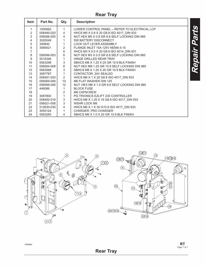
1 1500662 1 LOWER CONTROL PANEL – REFER TO ELECTRICAL LCP 2 058490-020 4 HHCS M5 X 0.8 X 20 G8.8 ISO 4017_DIN 933 3 056066-005 4 NUT HEX M5 X 0.8 GR 8.8 SELF LOCKING DIN 985 4 3020049 1 SW BATTERY DISCONNECT 5 300840 1 LOCK OUT LEVER ASSEMBLY 6 3069521 2 FLANGE INLET 15A 125V NEMA 5-15 7 6 HHCS M3 X 0.5 X 20 G8.8 ISO 4014_DIN 931 8 056066-003 6 NUT HEX M3 X 0.5 GR 8.8 SELF LOCKING DIN 985 9 5516346 1 HINGE DRILLED REAR TRAY 10 5563299 3 SBHCS M8 X 1.25 X 25 GR 10.9 BLK FINISH 11 056064-008 6 NUT HEX M8-1.25 GR 10.9 SELF LOCKING DIN 985 12 5563068 3 SBHCS M8 X 1.25 X 20 GR 10.9 BLK FINISH 13 3087787 1 CONTACTOR, 24V SEALED 14 058491-020 2 HHCS M6 X 1 X 20 G8.8 ISO 4017_DIN 933 15 056069-006 10 M6 FLAT WASHER DIN 125 16 056066-006 12 NUT, HEX M6 X 1.0 GR 8.8 SELF LOCKING DIN 985 17 446086 1 BLOCK FUSE 18 2 M6 CAPSCREW 19 3087800 1 PG TRIONICS EZLIFT 230 CONTROLLER 20 058492-016 3 HHCS M8 X 1.25 X 16 G8.8 ISO 4017_DIN 933 21 056021-008 3 WSHR LOCK M8 22 512630-030 4 HHCS M6 X 1 X 30 G10.9 ISO 4017_DIN 933 23 3050124 1 CHARGER, PRO CHARGER 24 5563283 4 SBHCS M6 X 1.0 X 20 GR 10.9 BLK FINISH
Rear TrayItem Part No. Qty. Description
Rear Tray
1
4
32
5
6
7 8
6
7 8
12 11
9
10 1113
14 15 16
17
16 1819
2021
22 16
23
24 15 16
1500664
RTPage 1 of 1


1 1501006 1 VALVE TRAY 2 5516345 1 LATCH, PADDLE BLK 3 1500947 1 PIN, TRAY HINGE 4 1500948 1 PLT, TRAY PIN KEEPER 5 1 METRIC IMPERIAL BUTTON HEAD CS 6 1 METRIC NYLON LOCKNUT 7 3087803 1 LCD SCREEN 8 3049978 1 ALARM, BEEPING 9 6019273 1 MANIFOLD – REFER TO HYDRAULICS MV 10 501868-000 1 HORN
Control TrayItem Part No. Qty. Description
Control Tray
2
13
4
5
6
7
89
10
1501176
CTPage 1 of 1

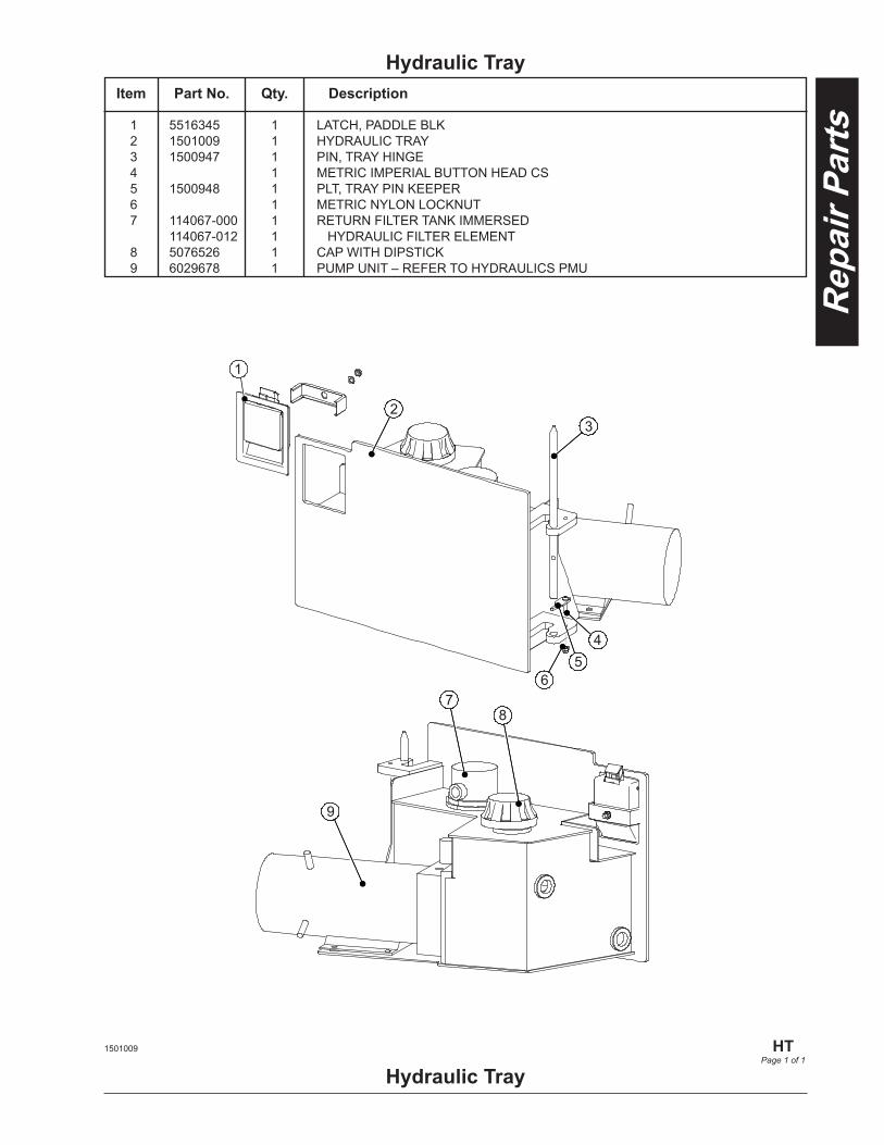
1 5516345 1 LATCH, PADDLE BLK 2 1501009 1 HYDRAULIC TRAY 3 1500947 1 PIN, TRAY HINGE 4 1 METRIC IMPERIAL BUTTON HEAD CS 5 1500948 1 PLT, TRAY PIN KEEPER 6 1 METRIC NYLON LOCKNUT 7 114067-000 1 RETURN FILTER TANK IMMERSED 114067-012 1 HYDRAULIC FILTER ELEMENT 8 5076526 1 CAP WITH DIPSTICK 9 6029678 1 PUMP UNIT – REFER TO HYDRAULICS PMU
Hydraulic TrayItem Part No. Qty. Description
Hydraulic Tray
1
23
45
67
8
9
1501009
HTPage 1 of 1

Battery Trays
Battery Trays
1 1
2 34
56
7
4
5
6
7
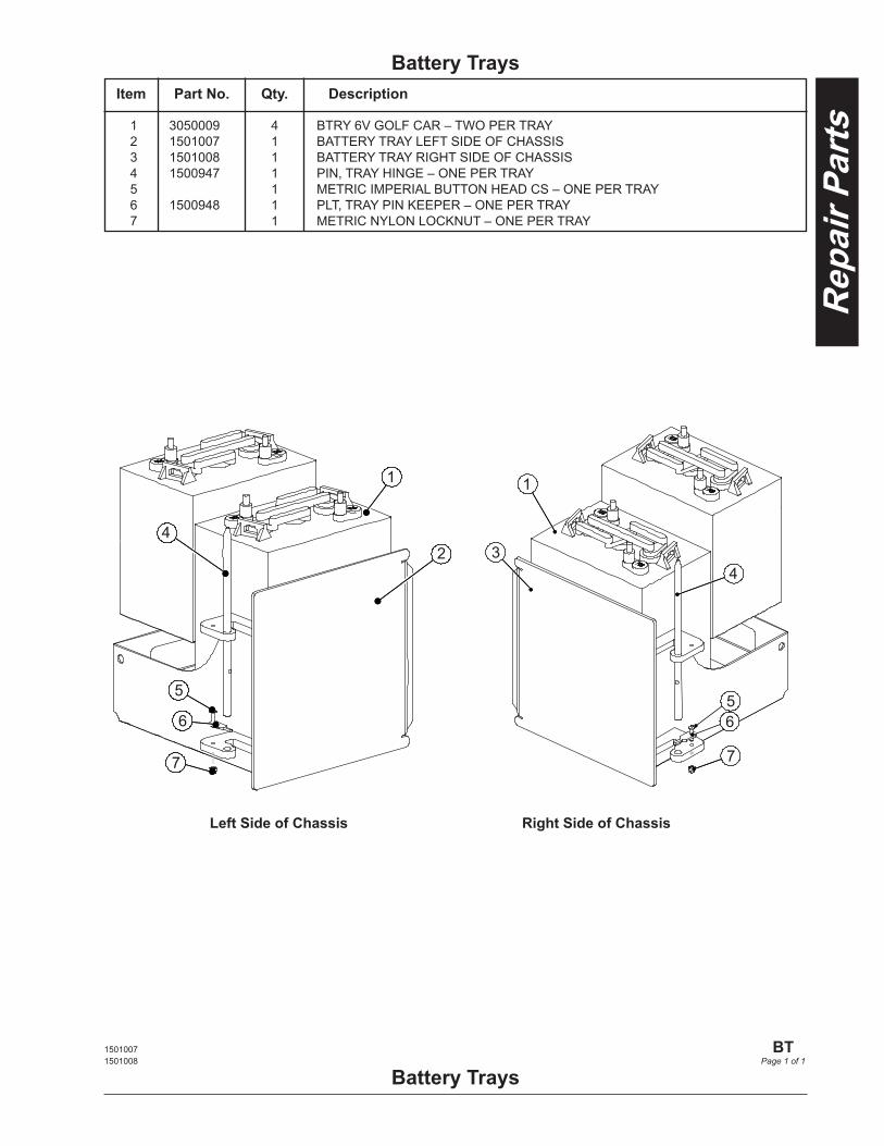
1 3050009 4 BTRY 6V GOLF CAR – TWO PER TRAY 2 1501007 1 BATTERY TRAY LEFT SIDE OF CHASSIS 3 1501008 1 BATTERY TRAY RIGHT SIDE OF CHASSIS 4 1500947 1 PIN, TRAY HINGE – ONE PER TRAY 5 1 METRIC IMPERIAL BUTTON HEAD CS – ONE PER TRAY 6 1500948 1 PLT, TRAY PIN KEEPER – ONE PER TRAY 7 1 METRIC NYLON LOCKNUT – ONE PER TRAY
Item Part No. Qty. Description
1501007 1501008
BT
Page 1 of 1
Left Side of Chassis Right Side of Chassis

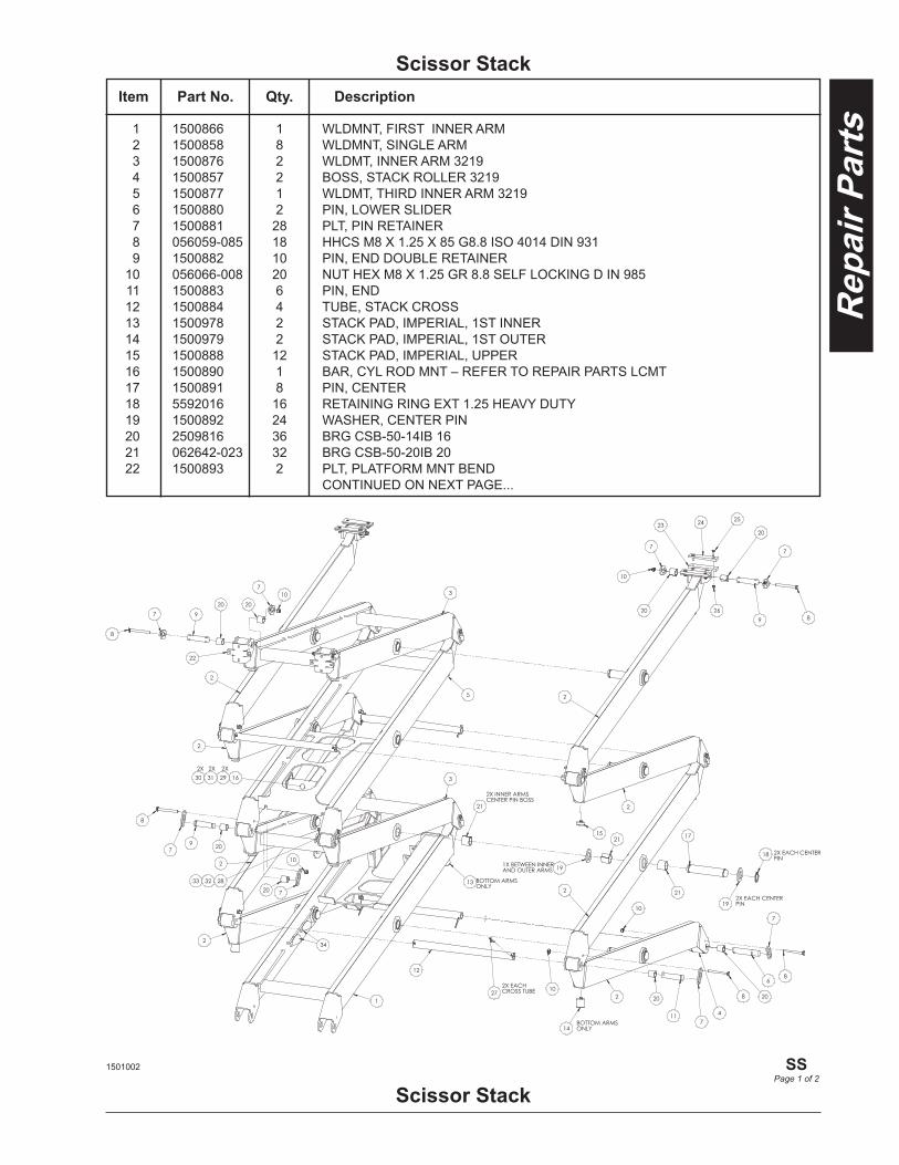
1 1500866 1 WLDMNT, FIRST INNER ARM 2 1500858 8 WLDMNT, SINGLE ARM 3 1500876 2 WLDMT, INNER ARM 3219 4 1500857 2 BOSS, STACK ROLLER 3219 5 1500877 1 WLDMT, THIRD INNER ARM 3219 6 1500880 2 PIN, LOWER SLIDER 7 1500881 28 PLT, PIN RETAINER 8 056059-085 18 HHCS M8 X 1.25 X 85 G8.8 ISO 4014 DIN 931 9 1500882 10 PIN, END DOUBLE RETAINER 10 056066-008 20 NUT HEX M8 X 1.25 GR 8.8 SELF LOCKING D IN 985 11 1500883 6 PIN, END 12 1500884 4 TUBE, STACK CROSS 13 1500978 2 STACK PAD, IMPERIAL, 1ST INNER 14 1500979 2 STACK PAD, IMPERIAL, 1ST OUTER 15 1500888 12 STACK PAD, IMPERIAL, UPPER 16 1500890 1 BAR, CYL ROD MNT – REFER TO REPAIR PARTS LCMT 17 1500891 8 PIN, CENTER 18 5592016 16 RETAINING RING EXT 1.25 HEAVY DUTY 19 1500892 24 WASHER, CENTER PIN 20 2509816 36 BRG CSB-50-14IB 16 21 062642-023 32 BRG CSB-50-20IB 20 22 1500893 2 PLT, PLATFORM MNT BEND CONTINUED ON NEXT PAGE...
Scissor StackItem Part No. Qty. Description
Scissor Stack1501002
SS
Page 1 of 2
Item Part No. Qty. Description
Scissor Stack
Scissor Stack1501002
SS
Page 2 of 2
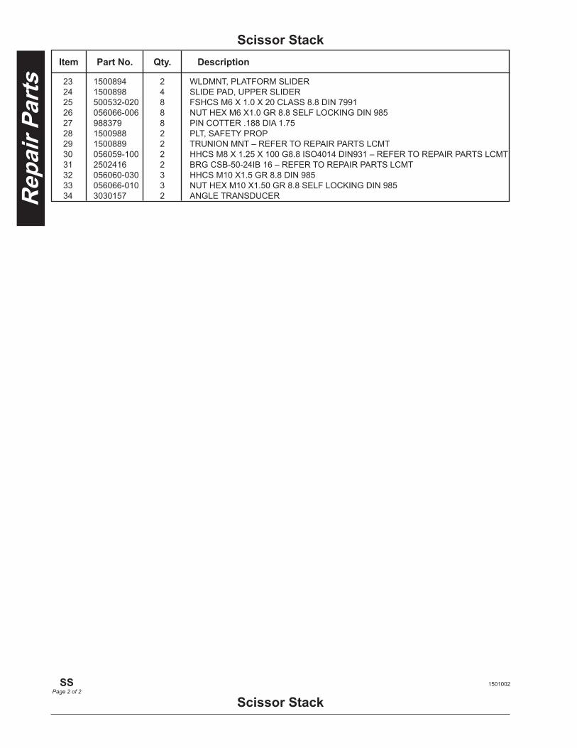
23 1500894 2 WLDMNT, PLATFORM SLIDER 24 1500898 4 SLIDE PAD, UPPER SLIDER 25 500532-020 8 FSHCS M6 X 1.0 X 20 CLASS 8.8 DIN 7991 26 056066-006 8 NUT HEX M6 X1.0 GR 8.8 SELF LOCKING DIN 985 27 988379 8 PIN COTTER .188 DIA 1.75 28 1500988 2 PLT, SAFETY PROP 29 1500889 2 TRUNION MNT – REFER TO REPAIR PARTS LCMT 30 056059-100 2 HHCS M8 X 1.25 X 100 G8.8 ISO4014 DIN931 – REFER TO REPAIR PARTS LCMT 31 2502416 2 BRG CSB-50-24IB 16 – REFER TO REPAIR PARTS LCMT 32 056060-030 3 HHCS M10 X1.5 GR 8.8 DIN 985 33 056066-010 3 NUT HEX M10 X1.50 GR 8.8 SELF LOCKING DIN 985 34 3030157 2 ANGLE TRANSDUCER
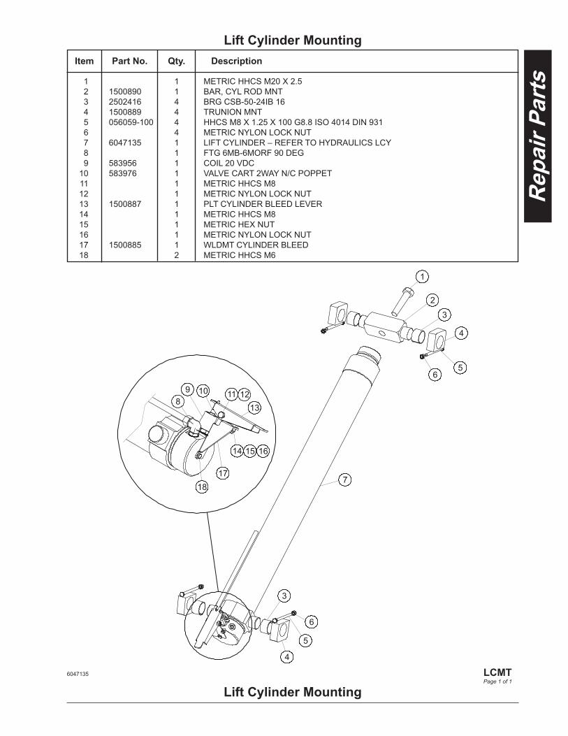
1 1 METRIC HHCS M20 X 2.5 2 1500890 1 BAR, CYL ROD MNT 3 2502416 4 BRG CSB-50-24IB 16 4 1500889 4 TRUNION MNT 5 056059-100 4 HHCS M8 X 1.25 X 100 G8.8 ISO 4014 DIN 931 6 4 METRIC NYLON LOCK NUT 7 6047135 1 LIFT CYLINDER – REFER TO HYDRAULICS LCY 8 1 FTG 6MB-6MORF 90 DEG 9 583956 1 COIL 20 VDC 10 583976 1 VALVE CART 2WAY N/C POPPET 11 1 METRIC HHCS M8 12 1 METRIC NYLON LOCK NUT 13 1500887 1 PLT CYLINDER BLEED LEVER 14 1 METRIC HHCS M8 15 1 METRIC HEX NUT 16 1 METRIC NYLON LOCK NUT 17 1500885 1 WLDMT CYLINDER BLEED 18 2 METRIC HHCS M6
Lift Cylinder MountingItem Part No. Qty. Description
Lift Cylinder Mounting6047135
LCMTPage 1 of 1
1
2
3
4
5 6
3
6
5
4
8 9 10
18 17
14 15 16
13 11
7
12

Platform
Platform
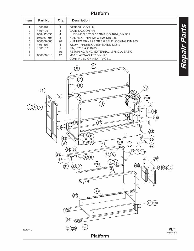
1 1500964 1 GATE SALOON LH 2 1501106 1 GATE SALOON RH 3 058492-055 4 HHCS M8 X 1.25 X 55 G8.8 ISO 4014_DIN 931 4 056067-508 4 NUT, HEX, THIN, M8 X 1.25 DIN 936 5 056066-008 20 NUT HEX M8 X1.25 GR 8.8 SELF LOCKING DIN 985 6 1501303 1 WLDMT HNDRL OUTER MAINS S3219 7 1501107 2 PIN, .375DIA X 10.83L 8 16 RETAINING RING, EXTERNAL, .375 DIA, BASIC 9 056069-010 12 M10 FLAT WASHER DIN 125 CONTINUED ON NEXT PAGE...
Item Part No. Qty. Description
1
7
2
5 4 3
6 8
8
9
11
12
13
14
5
1516 17 18
19
20 19
19 18
21
23
22
24
23
25
25
26
24
27
28
28
36
36
29
3031 32 8
32 8
34 33
18
19
35
19 9 3732 8
38 1939
40 5 42 41
435
1501344 C
PLTPage 1 of 2
Item Part No. Qty. Description
Platform
Platform1501344 C
PLT
Page 2 of 2
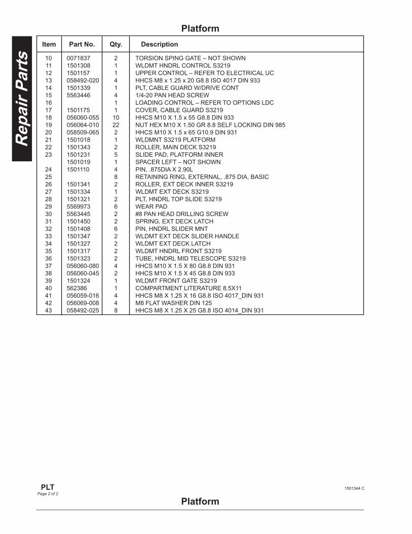
10 0071837 2 TORSION SPING GATE – NOT SHOWN 11 1501308 1 WLDMT HNDRL CONTROL S3219 12 1501157 1 UPPER CONTROL – REFER TO ELECTRICAL UC 13 058492-020 4 HHCS M8 x 1.25 x 20 G8.8 ISO 4017 DIN 933 14 1501339 1 PLT, CABLE GUARD W/DRIVE CONT 15 5563446 4 1/4-20 PAN HEAD SCREW 16 1 LOADING CONTROL – REFER TO OPTIONS LDC 17 1501175 1 COVER, CABLE GUARD S3219 18 056060-055 10 HHCS M10 X 1.5 x 55 G8.8 DIN 933 19 056064-010 22 NUT HEX M10 X 1.50 GR 8.8 SELF LOCKING DIN 985 20 058509-065 2 HHCS M10 X 1.5 x 65 G10.9 DIN 931 21 1501018 1 WLDMNT S3219 PLATFORM 22 1501343 2 ROLLER, MAIN DECK S3219 23 1501231 5 SLIDE PAD, PLATFORM INNER 1501019 1 SPACER LEFT – NOT SHOWN 24 1501110 4 PIN, .875DIA X 2.90L 25 8 RETAINING RING, EXTERNAL, .875 DIA, BASIC 26 1501341 2 ROLLER, EXT DECK INNER S3219 27 1501334 1 WLDMT EXT DECK S3219 28 1501321 2 PLT, HNDRL TOP SLIDE S3219 29 5569973 6 WEAR PAD 30 5563445 2 #8 PAN HEAD DRILLING SCREW 31 1501450 2 SPRING, EXT DECK LATCH 32 1501408 6 PIN, HNDRL SLIDER MNT 33 1501347 2 WLDMT EXT DECK SLIDER HANDLE 34 1501327 2 WLDMT EXT DECK LATCH 35 1501317 2 WLDMT HNDRL FRONT S3219 36 1501323 2 TUBE, HNDRL MID TELESCOPE S3219 37 056060-080 4 HHCS M10 X 1.5 X 80 G8.8 DIN 931 38 056060-045 2 HHCS M10 X 1.5 X 45 G8.8 DIN 933 39 1501324 1 WLDMT FRONT GATE S3219 40 562386 1 COMPARTMENT LITERATURE 8.5X11 41 056059-016 4 HHCS M8 X 1.25 X 16 G8.8 ISO 4017_DIN 931 42 056069-008 4 M8 FLAT WASHER DIN 125 43 058492-025 8 HHCS M8 X 1.25 X 25 G8.8 ISO 4014_DIN 931
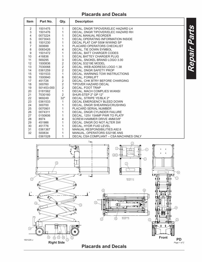
Placards and Decals
PD
Page 1 of 21501225 J
2 1501475 1 DECAL, DNGR TIPOVER/ELEC HAZARD LH 3 1501476 1 DECAL, DNGR TIPOVER/ELEC HAZARD RH 4 0073224 1 DECAL MANUAL REORDER 5 0073043 1 DECAL OPERATING INFORMATION INSIDE 6 1501230 1 DECAL PLAT CAP 550# W/WIND SP 7 300699 1 PLACARD OPERATORS CHECKLIST 8 0083426 4 DECAL, TIE DOWN SYMBOL 9 1501472 1 DECAL, BATT CHARGER CODES 10 416836 1 DECAL BATTEY CHARGER PLUG 11 569295 3 DECAL, SNOKEL BRAND LOGO 3.00 12 1500836 2 DECAL S3219E MODEL 13 7030068 2 DECAL, WEB ADDRESS LOGO 1.38 14 0361259 2 DECAL, DNGR SAFETY PROP 15 1501533 1 DECAL, WARNING TOW INSTRUCTIONS 16 1500840 6 DECAL, FORKLIFT 17 451726 2 DECAL, CHK BTRY BEFORE CHARGING 18 300760 2 TIPOVER HAZARD DECAL 19 501453-000 2 DECAL, FOOT TRAP 20 0181562 1 DECAL, MACH COMPLIES W/ANSI 21 7030160 2 SHUR-STEP 2" GP 12" 22 969249 32" DECAL, STRIPE YE/BLK 2" 23 0361533 1 DECAL EMERGENCY BLEED DOWN 24 300700 1 DECAL, DNGR SHEARING/CRUSHING 25 0070901 1 PLACARD SERIAL NUMBER 26 0074311 1 DECAL, DNGR CYLINDER FAILURE 27 0150606 1 DECAL, 125V 15AMP PWR TO PLATF 28 8974 4 SCREW-HAMMER DRIVE 4MM/3/8" 29 451986 1 DECAL. DNGR DO NOT ALTER SW 30 451776 1 DECAL, HYDR FUID LEVEL 31 0361367 1 MANUAL RESPONSIBILITIES A92.6 32 500834 1 MANUAL, OPERATORS S3219E ANS 0361528 1 DECAL CSA COMPLIANT – CSA MACHINES ONLY
Placards and DecalsItem Part No. Qty. Description
Right SideFront
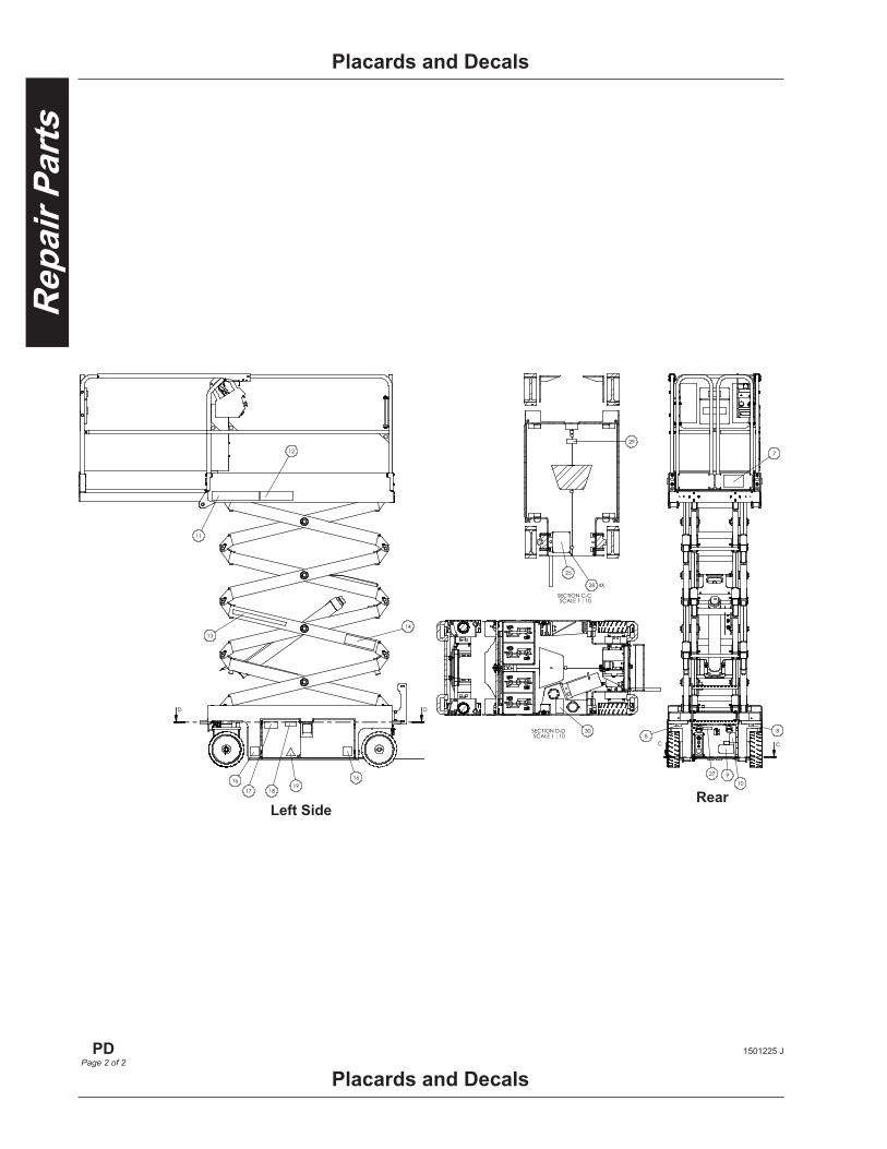
Placards and Decals
PD
Page 2 of 21501225 J
Placards and Decals
Left SideRear
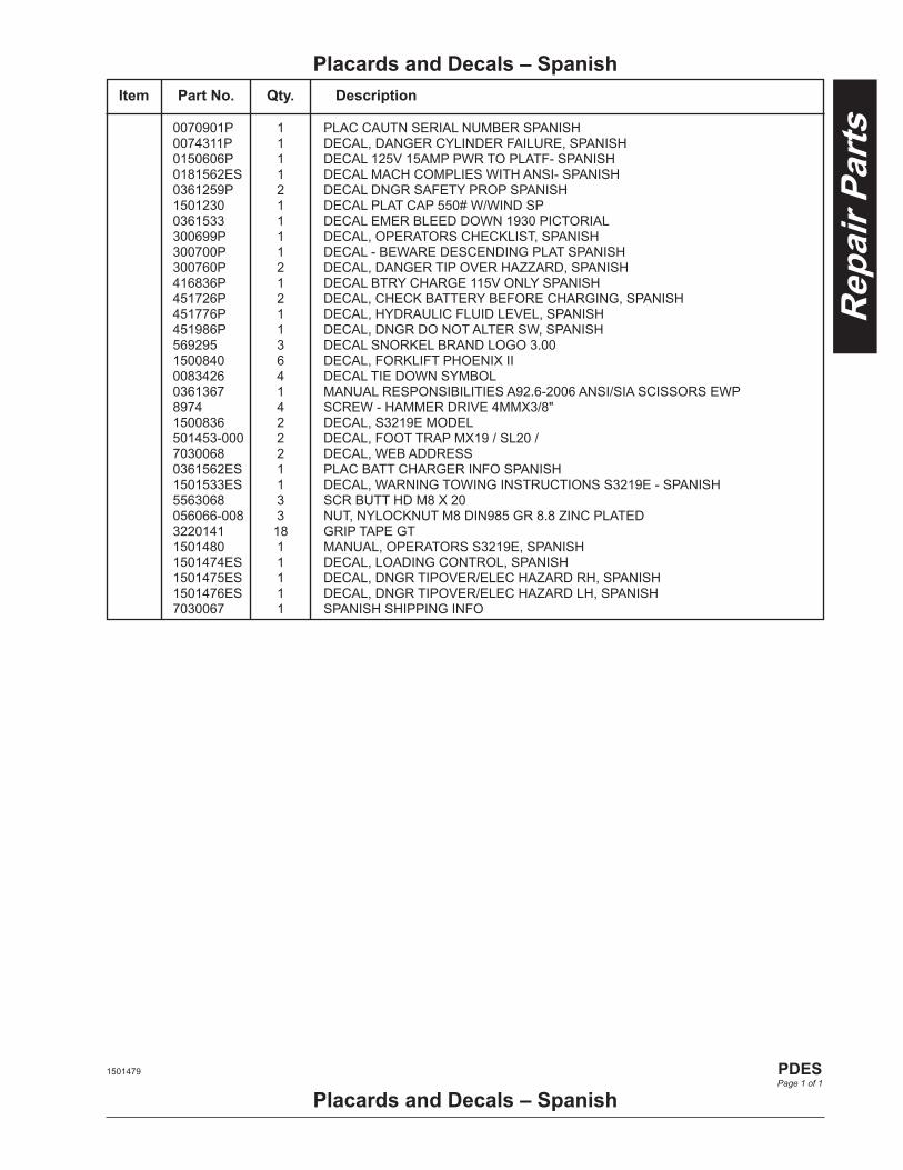
0070901P 1 PLAC CAUTN SERIAL NUMBER SPANISH 0074311P 1 DECAL, DANGER CYLINDER FAILURE, SPANISH 0150606P 1 DECAL 125V 15AMP PWR TO PLATF- SPANISH 0181562ES 1 DECAL MACH COMPLIES WITH ANSI- SPANISH 0361259P 2 DECAL DNGR SAFETY PROP SPANISH 1501230 1 DECAL PLAT CAP 550# W/WIND SP 0361533 1 DECAL EMER BLEED DOWN 1930 PICTORIAL 300699P 1 DECAL, OPERATORS CHECKLIST, SPANISH 300700P 1 DECAL - BEWARE DESCENDING PLAT SPANISH 300760P 2 DECAL, DANGER TIP OVER HAZZARD, SPANISH 416836P 1 DECAL BTRY CHARGE 115V ONLY SPANISH 451726P 2 DECAL, CHECK BATTERY BEFORE CHARGING, SPANISH 451776P 1 DECAL, HYDRAULIC FLUID LEVEL, SPANISH 451986P 1 DECAL, DNGR DO NOT ALTER SW, SPANISH 569295 3 DECAL SNORKEL BRAND LOGO 3.00 1500840 6 DECAL, FORKLIFT PHOENIX II 0083426 4 DECAL TIE DOWN SYMBOL 0361367 1 MANUAL RESPONSIBILITIES A92.6-2006 ANSI/SIA SCISSORS EWP 8974 4 SCREW - HAMMER DRIVE 4MMX3/8" 1500836 2 DECAL, S3219E MODEL 501453-000 2 DECAL, FOOT TRAP MX19 / SL20 / 7030068 2 DECAL, WEB ADDRESS 0361562ES 1 PLAC BATT CHARGER INFO SPANISH 1501533ES 1 DECAL, WARNING TOWING INSTRUCTIONS S3219E - SPANISH 5563068 3 SCR BUTT HD M8 X 20 056066-008 3 NUT, NYLOCKNUT M8 DIN985 GR 8.8 ZINC PLATED 3220141 18 GRIP TAPE GT 1501480 1 MANUAL, OPERATORS S3219E, SPANISH 1501474ES 1 DECAL, LOADING CONTROL, SPANISH 1501475ES 1 DECAL, DNGR TIPOVER/ELEC HAZARD RH, SPANISH 1501476ES 1 DECAL, DNGR TIPOVER/ELEC HAZARD LH, SPANISH 7030067 1 SPANISH SHIPPING INFO
Placards and Decals – SpanishItem Part No. Qty. Description
Placards and Decals – Spanish1501479
PDESPage 1 of 1

Hydraulics Pump Unit ................................................PMU Hydraulic Brake/Hub .............................BRK/H Manifold Valve ............................................ MV Steering Cylinder ...................................... SCY Lift Cylinder ...............................................LCY

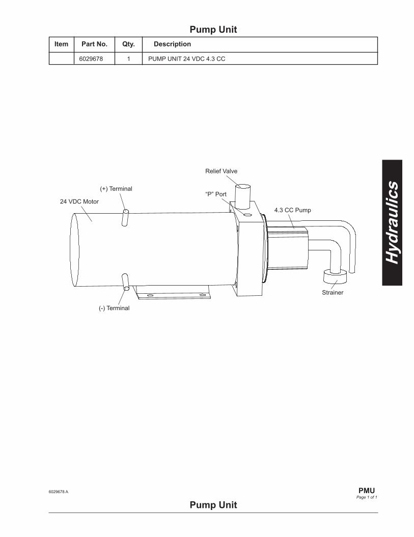
6029678 1 PUMP UNIT 24 VDC 4.3 CC
Pump UnitItem Part No. Qty. Description
Pump Unit6029678 A
PMU
Page 1 of 1
24 VDC Motor
Relief Valve
(+) Terminal
(-) Terminal
“P” Port
4.3 CC Pump
Strainer

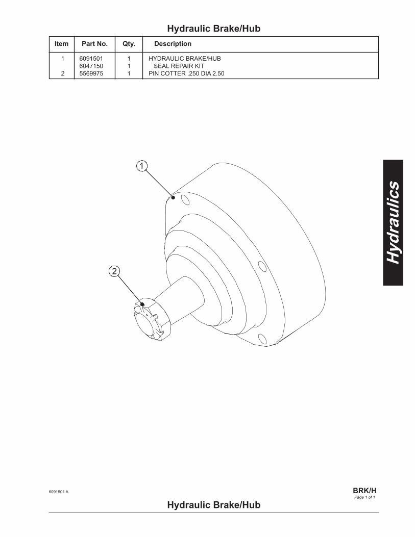
1 6091501 1 HYDRAULIC BRAKE/HUB 6047150 1 SEAL REPAIR KIT 2 5569975 1 PIN COTTER .250 DIA 2.50
Hydraulic Brake/HubItem Part No. Qty. Description
Hydraulic Brake/Hub
1
2
6091501 A
BRK/HPage 1 of 1

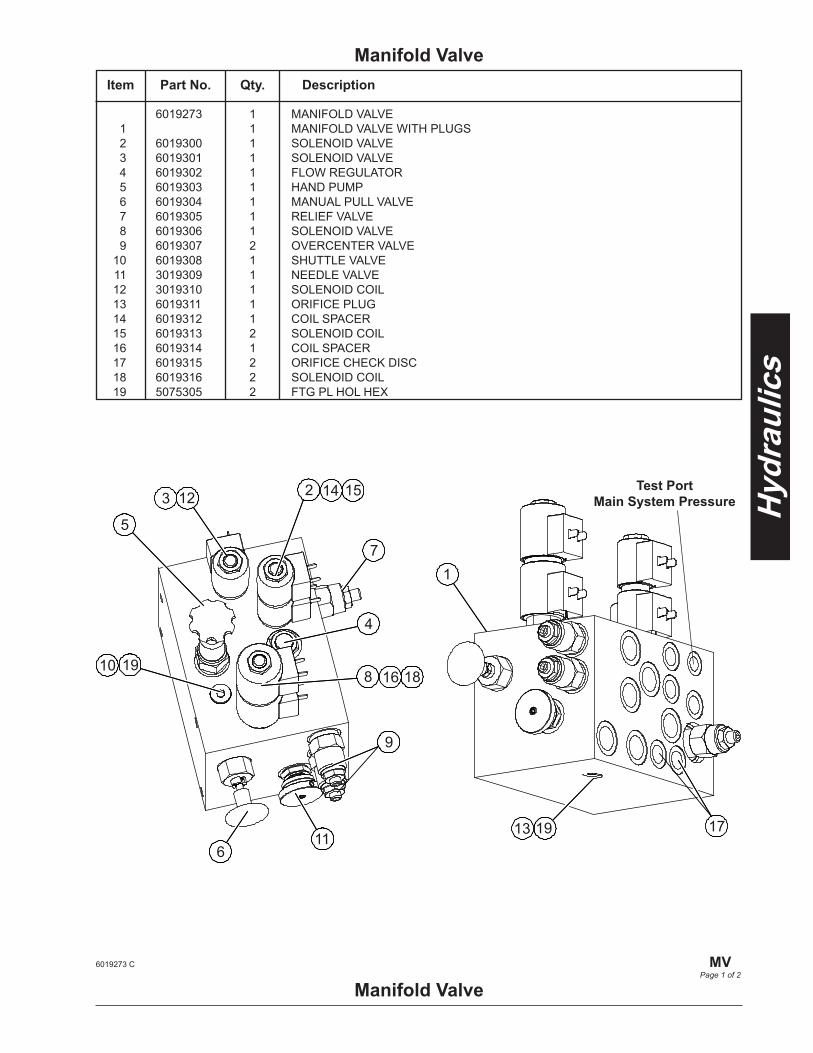
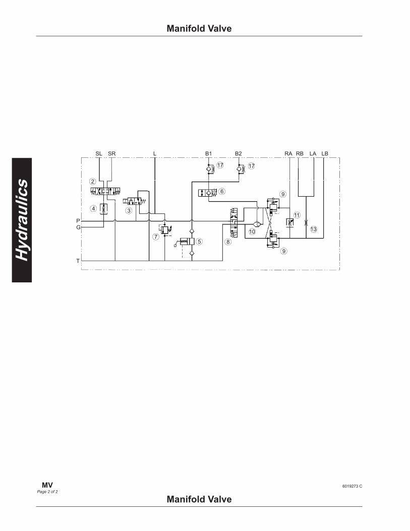
6019273 1 MANIFOLD VALVE 1 1 MANIFOLD VALVE WITH PLUGS 2 6019300 1 SOLENOID VALVE 3 6019301 1 SOLENOID VALVE 4 6019302 1 FLOW REGULATOR 5 6019303 1 HAND PUMP 6 6019304 1 MANUAL PULL VALVE 7 6019305 1 RELIEF VALVE 8 6019306 1 SOLENOID VALVE 9 6019307 2 OVERCENTER VALVE 10 6019308 1 SHUTTLE VALVE 11 3019309 1 NEEDLE VALVE 12 3019310 1 SOLENOID COIL 13 6019311 1 ORIFICE PLUG 14 6019312 1 COIL SPACER 15 6019313 2 SOLENOID COIL 16 6019314 1 COIL SPACER 17 6019315 2 ORIFICE CHECK DISC 18 6019316 2 SOLENOID COIL 19 5075305 2 FTG PL HOL HEX
Manifold ValveItem Part No. Qty. Description
Manifold Valve
5
123
19 10
611
9
8 18
4
2 1514
7
16
17 1913
1
6019273 C
MVPage 1 of 2
Test PortMain System Pressure
Manifold Valve
Manifold Valve
2
4 3
75
17 17
6 9
8
10
9
11
13
T
GP
SL SR L B1 B2 RA RB LA LB
6019273 C
MVPage 2 of 2

6047139 1 CYLINDER, STEERING 6047150 1 SEAL REPAIR KIT
Steering CylinderItem Part No. Qty. Description
Steering Cylinder6047139 B
SCY
Page 1 of 1

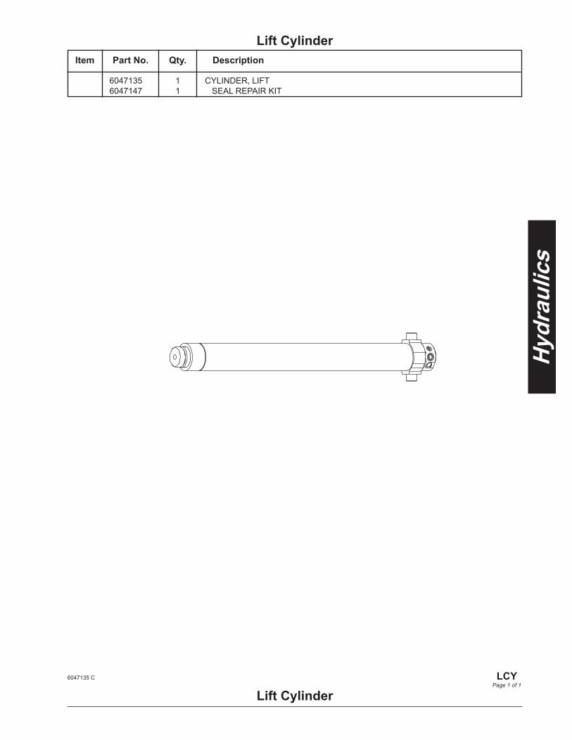
Lift Cylinder
Lift Cylinder6047135 C
LCY
Page 1 of 1
6047135 1 CYLINDER, LIFT 6047147 1 SEAL REPAIR KIT
Item Part No. Qty. Description

Electrical Lower Control Panel ..................................LCP Upper Control Box ...................................... UC Joystick ...................................................JSTK Chassis Harness ......................................... CH Chassis Harness Section A ......................CH-A Chassis Harness Section B ......................CH-B Chassis Harness Section C .................... CH-C Chassis Harness Pin ID ...........................CHID Stack Harness ............................................. SH

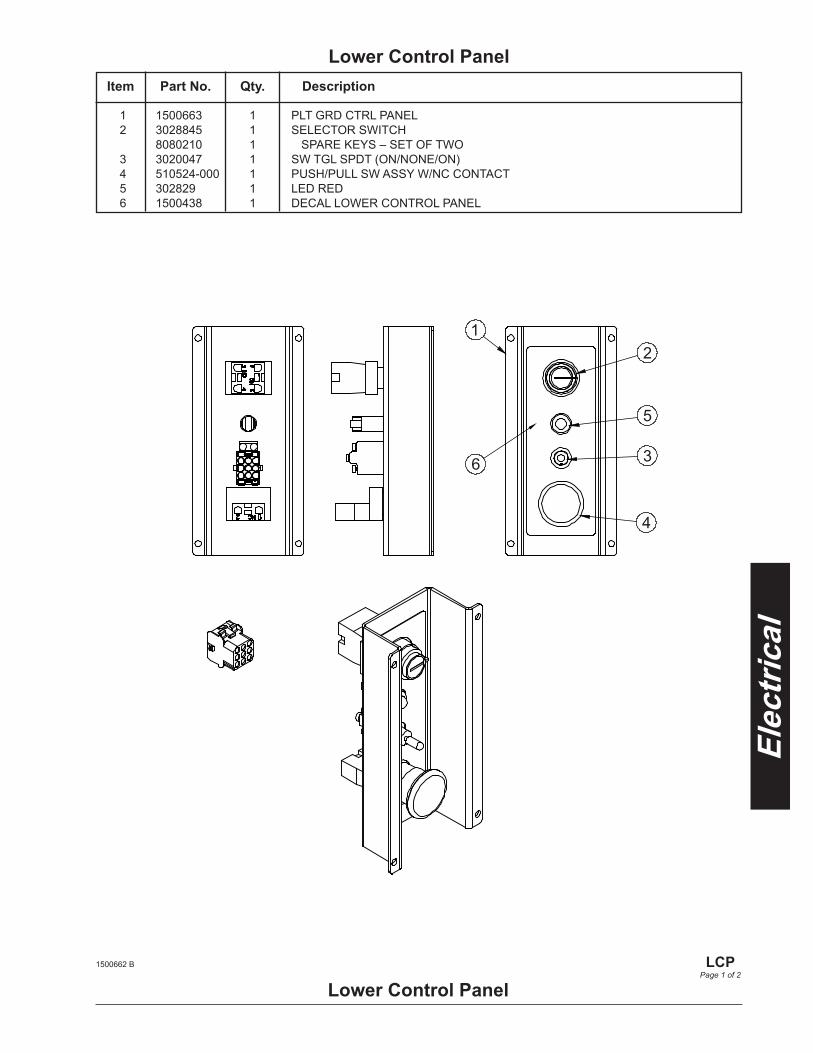
1 1500663 1 PLT GRD CTRL PANEL 2 3028845 1 SELECTOR SWITCH 8080210 1 SPARE KEYS – SET OF TWO 3 3020047 1 SW TGL SPDT (ON/NONE/ON) 4 510524-000 1 PUSH/PULL SW ASSY W/NC CONTACT 5 302829 1 LED RED 6 1500438 1 DECAL LOWER CONTROL PANEL
Lower Control PanelItem Part No. Qty. Description
Lower Control Panel
12
5
3
4
6
1500662 B
LCPPage 1 of 2
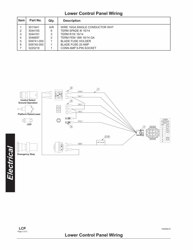
Lower Control Panel Wiring
Lower Control Panel Wiring
1PLAT
3
2
4
5 6
P4-1
P4-4
P4-5
P1-8
EMSFUSE HOLDER
9 7
6 4
3 1
7
LOWERCONTROLS1-480707-0CAV CKT
234
67
5
89
1P4-1P4-4P4-5
-EMS
-
PLAT-
P1-8
2
5
8
1500662 B
LCPPage 2 of 2
1 3011641 A/R WIRE 16GA SINGLE CONDUCTOR WHT 2 3044155 6 TERM SPADE 8I 16/14 3 3044161 3 TERM R10I 16/14 4 3046697 2 TERM FEM 188I 16/14 GA 5 509741-000 1 BLADE FUSE HOLDER 6 509740-000 1 BLADE FUSE 20 AMP 7 3220218 1 CONN AMP 9-PIN SOCKET
Item Part No. Qty. Description
Control SelectGround Operation
Platform Raise/Lower
LED
Emergency Stop

1 1501112 1 WLDMT, UPPER CONTROL BOX 2 510524-000 1 PUSH/PULL SW ASSY W/NC CONTACT 3 3020047 1 SW TGL SPDT (ON/NONE/ON) 4 510542-000 1 SW PUSH BUTTON\ 5 302829 1 LIGHT RED 24 VDC BEZEL MOUNT 6 1501158 1 PLAC, PLTFRM CONT BOX 7 1501159 1 PLAC, PLTFRM CONT BOX E-STOP/HORN 8 3040624 1 RECEPTICAL GFCI OUTLET 20 AMP 9 3040625 1 WEATHERPROOF PAD 10 512714-025 4 HHCS M4 X 0.7 x 25 G8.8 ISO 4014 DIN 931 11 056066-004 4 NUT HEX M4 X 0.70 GR 8.8 SELF LOCKING DIN 985 12 978629 4 BLT HEXHD SLFTPG .250-20 .500 13 1501116 1 PLT BOTTOM PLATFORM CONTROL BOX 14 1501359 1 PLAC LIFT/DRIVE 15 3087801 1 JOYSTICK – REFER TO ELECTRICAL – JSTK
Upper Control BoxItem Part No. Qty. Description
Upper Control Box
1
15
6
7
4
2
5
14
10 11
13
12
8 9
3
1501157 C
UCPage 1 of 2
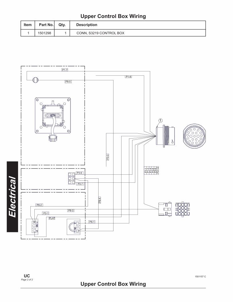
1 1501298 1 CONN, S3219 CONTROL BOX
Upper Control Box WiringItem Part No. Qty. Description
Upper Control Box Wiring
PLAT
P3-1
P8-2
P8-3
P8-1
P3-7
P3-6
P8-5
P1-7
P1-8
P3-
3
P8-
4
P1-
1P
1-3
P1-
4P
3-8
P3-
9P
3-12
1
1501157 C
UCPage 2 of 2
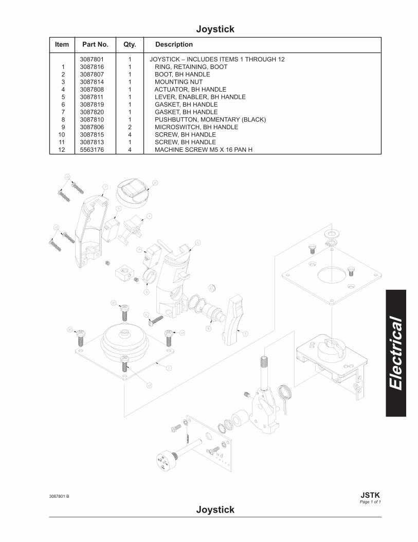
3087801 B
JSTKPage 1 of 1
Joystick
3087801 1 JOYSTICK – INCLUDES ITEMS 1 THROUGH 12 1 3087816 1 RING, RETAINING, BOOT 2 3087807 1 BOOT, BH HANDLE 3 3087814 1 MOUNTING NUT 4 3087808 1 ACTUATOR, BH HANDLE 5 3087811 1 LEVER, ENABLER, BH HANDLE 6 3087819 1 GASKET, BH HANDLE 7 3087820 1 GASKET, BH HANDLE 8 3087810 1 PUSHBUTTON, MOMENTARY (BLACK) 9 3087806 2 MICROSWITCH, BH HANDLE 10 3087815 4 SCREW, BH HANDLE 11 3087813 1 SCREW, BH HANDLE 12 5563176 4 MACHINE SCREW M5 X 16 PAN H
Item Part No. Qty. Description
Joystick

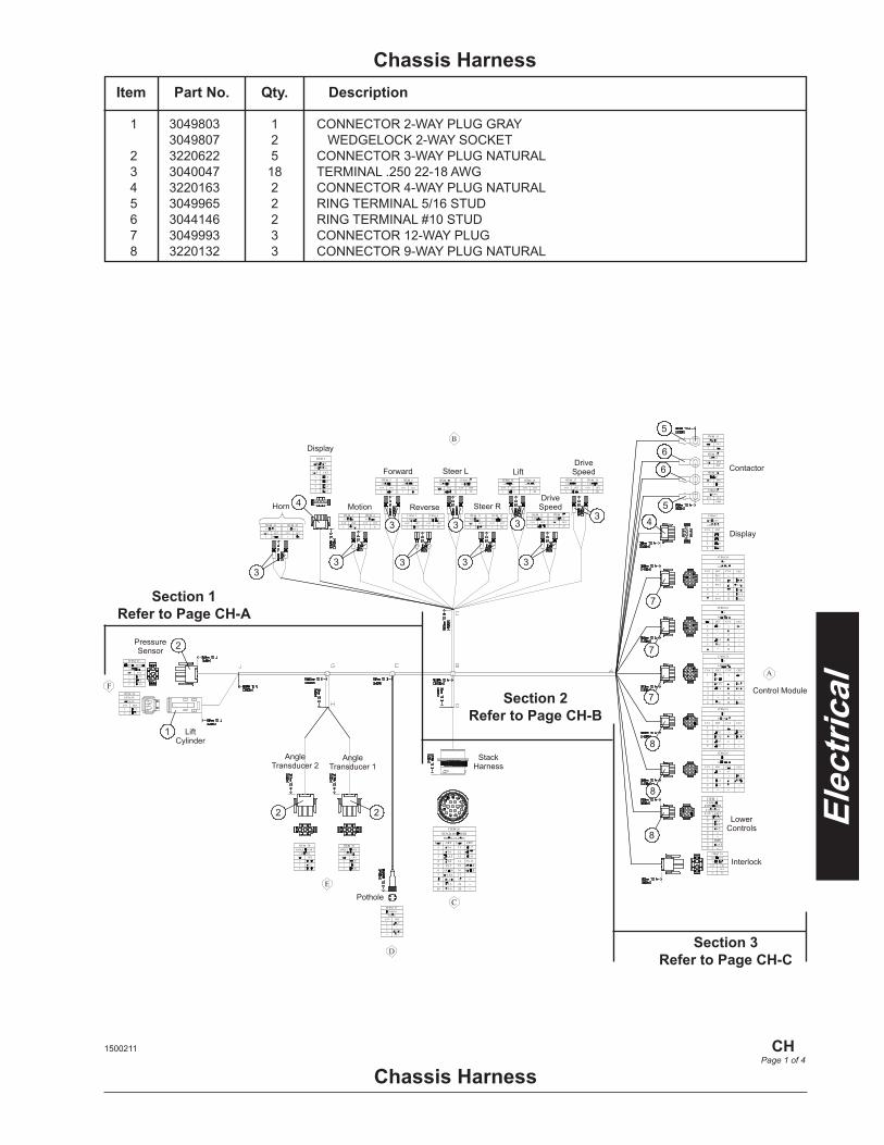
Chassis Harness
1
2
2 2
3 3 3 3 3
3 3 3 3
4
4
5
5
6
6
4
7
7
7
8
8
8
PressureSensor
Lift Cylinder
AngleTransducer 2
AngleTransducer 1
Pothole
StackHarness
Horn
Display
Motion Reverse Steer RDrive
Speed
Forward Steer L LiftDrive
Speed
Control Module
Contactor
Display
LowerControls
Interlock
1 3049803 1 CONNECTOR 2-WAY PLUG GRAY 3049807 2 WEDGELOCK 2-WAY SOCKET 2 3220622 5 CONNECTOR 3-WAY PLUG NATURAL 3 3040047 18 TERMINAL .250 22-18 AWG 4 3220163 2 CONNECTOR 4-WAY PLUG NATURAL 5 3049965 2 RING TERMINAL 5/16 STUD 6 3044146 2 RING TERMINAL #10 STUD 7 3049993 3 CONNECTOR 12-WAY PLUG 8 3220132 3 CONNECTOR 9-WAY PLUG NATURAL
Item Part No. Qty. Description
Chassis Harness1500211
CH
Page 1 of 4
Section 1Refer to Page CH-A
Section 2Refer to Page CH-B
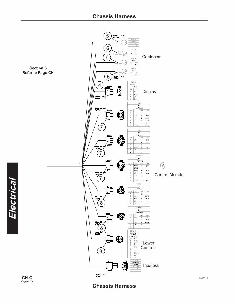
Section 3Refer to Page CH-C
Chassis Harness
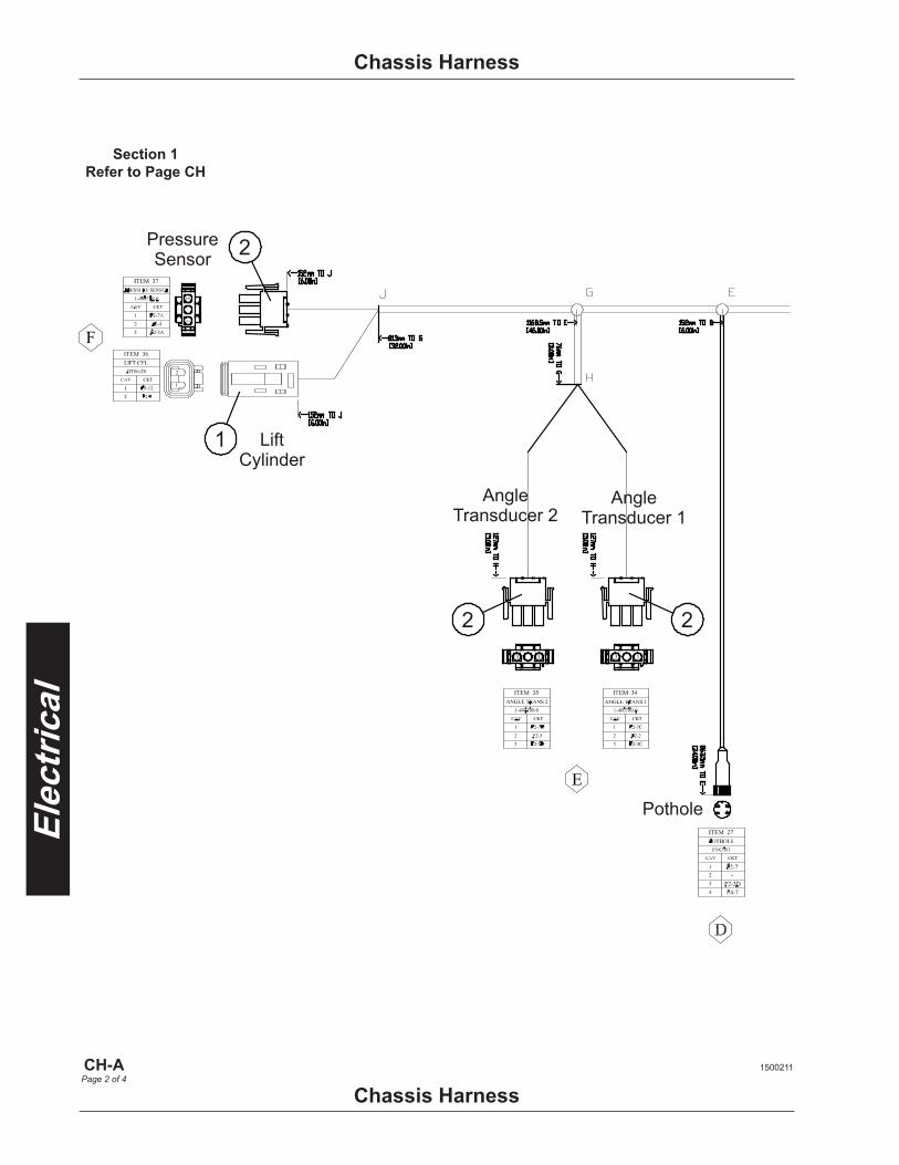
Chassis Harness
Section 1Refer to Page CH
1500211
CH-APage 2 of 4
1
2
2 2
PressureSensor
Lift Cylinder
AngleTransducer 2
AngleTransducer 1
Pothole
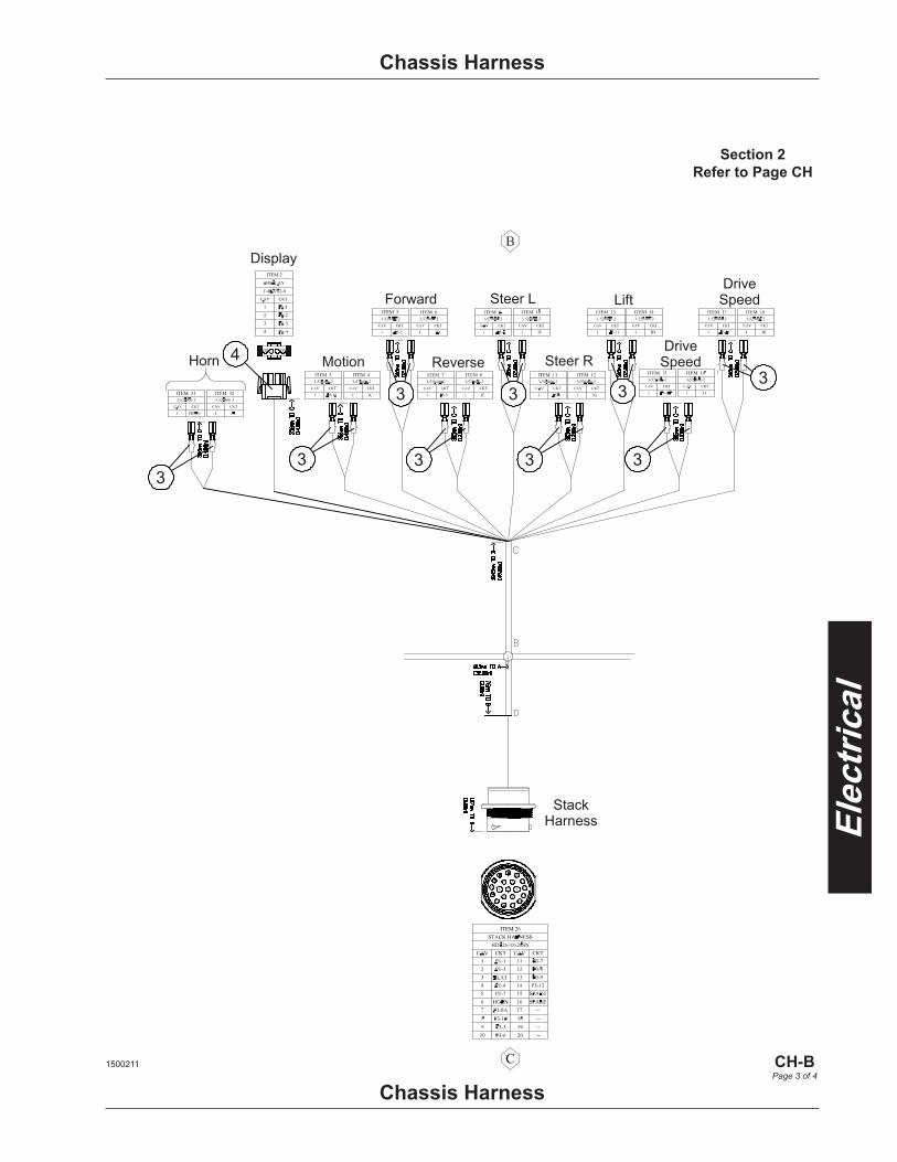
3 3 3 3 3
3 3 3 3
4
StackHarness
Horn
Display
Motion Reverse Steer RDrive
Speed
Forward Steer L LiftDrive
Speed
Chassis Harness
Chassis Harness
Section 2Refer to Page CH
1500211
CH-BPage 3 of 4
Chassis Harness
Chassis Harness
4
5
5
6
6
4
7
7
7
8
8
8
Control Module
Contactor
Display
LowerControls
Interlock
Section 3Refer to Page CH
1500211
CH-CPage 4 of 4
Chassis Harness – Electrical System Pin ID
Chassis Harness – Electrical System Pin ID
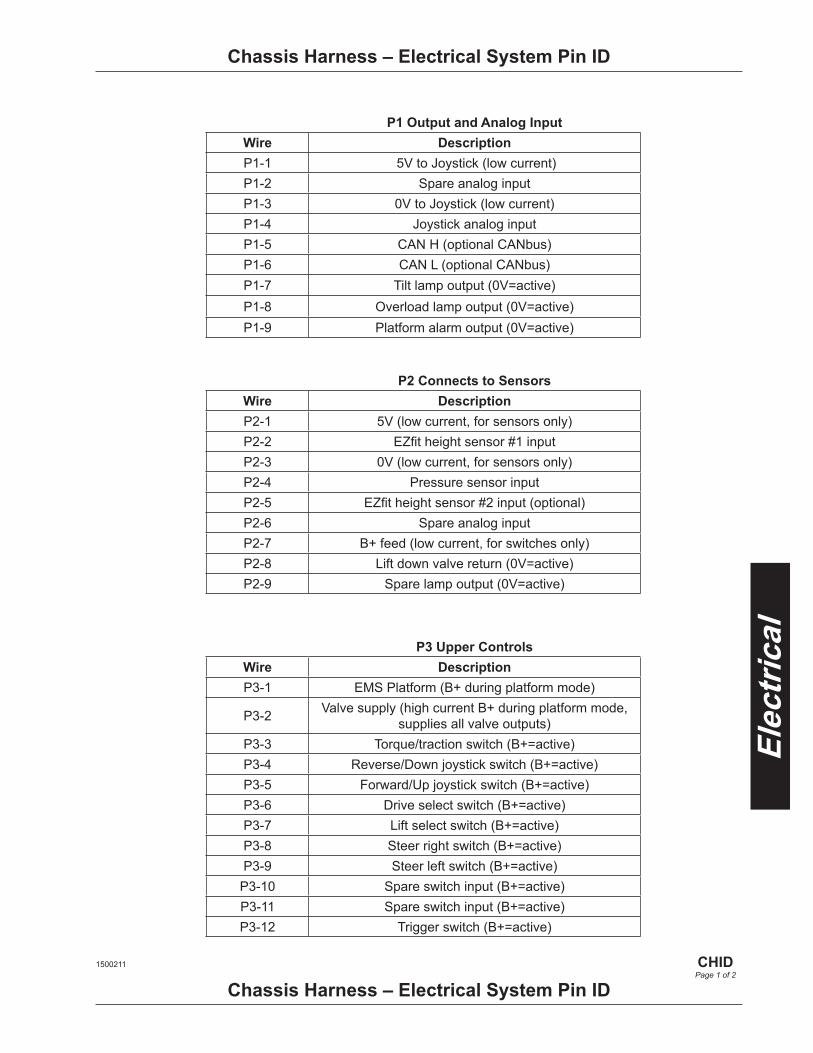
P1 Output and Analog InputWire DescriptionP1-1 5V to Joystick (low current) P1-2 Spare analog inputP1-3 0V to Joystick (low current) P1-4 Joystick analog input P1-5 CAN H (optional CANbus)P1-6 CAN L (optional CANbus)P1-7 Tilt lamp output (0V=active)P1-8 Overload lamp output (0V=active)P1-9 Platform alarm output (0V=active)
P2 Connects to SensorsWire DescriptionP2-1 5V (low current, for sensors only)P2-2 EZfit height sensor #1 inputP2-3 0V (low current, for sensors only)P2-4 Pressure sensor inputP2-5 EZfit height sensor #2 input (optional)P2-6 Spare analog inputP2-7 B+ feed (low current, for switches only)P2-8 Lift down valve return (0V=active)P2-9 Spare lamp output (0V=active)
P3 Upper ControlsWire DescriptionP3-1 EMS Platform (B+ during platform mode)
P3-2 Valve supply (high current B+ during platform mode, supplies all valve outputs)
P3-3 Torque/traction switch (B+=active)P3-4 Reverse/Down joystick switch (B+=active)P3-5 Forward/Up joystick switch (B+=active)P3-6 Drive select switch (B+=active)P3-7 Lift select switch (B+=active)P3-8 Steer right switch (B+=active)P3-9 Steer left switch (B+=active)
P3-10 Spare switch input (B+=active)P3-11 Spare switch input (B+=active)P3-12 Trigger switch (B+=active)
1500211
CHIDPage 1 of 2
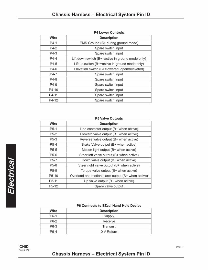
P6 Connects to EZcal Hand-Held DeviceWire DescriptionP6-1 SupplyP6-2 ReceiveP6-3 TransmitP6-4 0 V Return
P5 Valve OutputsWire DescriptionP5-1 Line contactor output (B+ when active)P5-2 Forward valve output (B+ when active)P5-3 Reverse valve output (B+ when active)P5-4 Brake Valve output (B+ when active)P5-5 Motion light output (B+ when active)P5-6 Steer left valve output (B+ when active)P5-7 Down valve output (B+ when active)P5-8 Steer right valve output (B+ when active)P5-9 Torque valve output (B+ when active)
P5-10 Overload and motion alarm output (B+ when active)P5-11 Up valve output (B+ when active)P5-12 Spare valve output
Chassis Harness – Electrical System Pin ID
Chassis Harness – Electrical System Pin ID
P4 Lower ControlsWire DescriptionP4-1 EMS Ground (B+ during ground mode)P4-2 Spare switch inputP4-3 Spare switch inputP4-4 Lift down switch (B+=active in ground mode only)P4-5 Lift up switch (B+=active in ground mode only)P4-6 Elevation switch (B+=lowered, open=elevated)P4-7 Spare switch inputP4-8 Spare switch inputP4-9 Spare switch input
P4-10 Spare switch inputP4-11 Spare switch inputP4-12 Spare switch input
1500211
CHIDPage 2 of 2
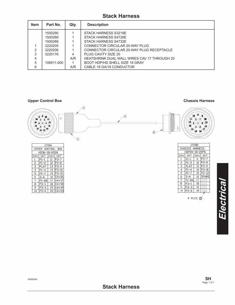
Stack Harness
1500290 1 STACK HARNESS S3219E 1500289 1 STACK HARNESS S4726E 1500288 1 STACK HARNESS S4732E 1 3220205 1 CONNECTOR CIRCULAR 20-WAY PLUG 2 3220206 1 CONNECTOR CIRCULAR 20-WAY PLUG RECEPTACLE 3 3220176 4 PLUG CAVITY SIZE 20 4 A/R HEATSHRINK DUAL WALL WIRES CAV 17 THROUGH 20 5 106911-000 1 BOOT HDP/HD SHELL SIZE 18 GRAY 6 A/R CABLE 18 GA/16 CONDUCTOR
Item Part No. Qty. Description
Stack HarnessA50002A
SH
Page 1 of 1
Upper Control Box Chassis Harness


OptionsLoading Control ......................................... LDC


1 3020016 1 SW TGL SPDT (M/OFF/M) 2 510542-000 1 PUSHBUTTON BLACK, FLUSH MOUNT 3 3020016 1 SW TGL SPDT (M/OFF/M) 4 5516349 1 MAGNETIC LATCH 5 1501352 1 HHCS M12 X 1.75 X 90 G8.8 DIN 931 6 4 STEEL POP RIVET 3.2 X 6.1 STEEL MANDREL 7 1501406 1 PLT CABLE COVER BOTTOM 8 5563446 4 1/4-20 PAN HEAD SCREW 9 1501474 1 DECAL, LOADING CONTROL
Loading ControlItem Part No. Qty. Description
Loading Control
1
2
3
4
5
6
7
8
9
1501344 C
LDCPage 1 of 1

AppendixHydraulic Schematic .................................... HS

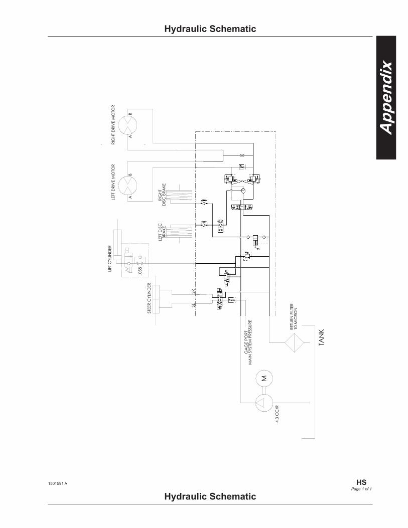
Hydraulic Schematic
Hydraulic Schematic1501591 A
HS
Page 1 of 1

© Snorkel International, Inc. – all rights reserved Printed in the U.S.A.
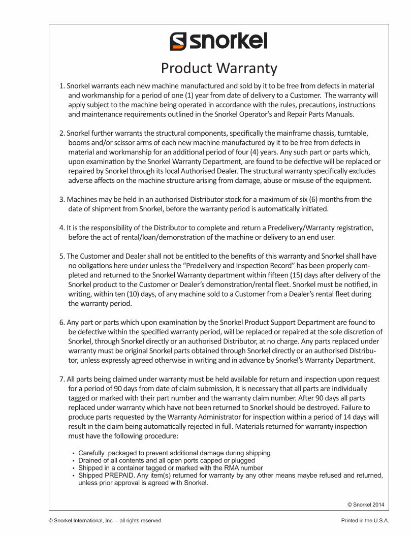
Product Warranty
© Snorkel 2014
1. Snorkel warrants each new machine manufactured and sold by it to be free from defects in material and workmanship for a period of one (1) year from date of delivery to a Customer. The warranty will apply subject to the machine being operated in accordance with the rules, precautions, instructions and maintenance requirements outlined in the Snorkel Operator's and Repair Parts Manuals.
2. Snorkel further warrants the structural components, specifically the mainframe chassis, turntable, booms and/or scissor arms of each new machine manufactured by it to be free from defects in material and workmanship for an additional period of four (4) years. Any such part or parts which, upon examination by the Snorkel Warranty Department, are found to be defective will be replaced or repaired by Snorkel through its local Authorised Dealer. The structural warranty specifically excludes adverse affects on the machine structure arising from damage, abuse or misuse of the equipment.
3. Machines may be held in an authorised Distributor stock for a maximum of six (6) months from the date of shipment from Snorkel, before the warranty period is automatically initiated.
4. It is the responsibility of the Distributor to complete and return a Predelivery/Warranty registration, before the act of rental/loan/demonstration of the machine or delivery to an end user.
5. The Customer and Dealer shall not be entitled to the benefits of this warranty and Snorkel shall have no obligations here under unless the “Predelivery and Inspection Record” has been properly com-pleted and returned to the Snorkel Warranty department within fifteen (15) days after delivery of the Snorkel product to the Customer or Dealer’s demonstration/rental fleet. Snorkel must be notified, in writing, within ten (10) days, of any machine sold to a Customer from a Dealer’s rental fleet during the warranty period.
6. Any part or parts which upon examination by the Snorkel Product Support Department are found to be defective within the specified warranty period, will be replaced or repaired at the sole discretion of Snorkel, through Snorkel directly or an authorised Distributor, at no charge. Any parts replaced under warranty must be original Snorkel parts obtained through Snorkel directly or an authorised Distribu-tor, unless expressly agreed otherwise in writing and in advance by Snorkel’s Warranty Department.
7. All parts being claimed under warranty must be held available for return and inspection upon request for a period of 90 days from date of claim submission, it is necessary that all parts are individually tagged or marked with their part number and the warranty claim number. After 90 days all parts replaced under warranty which have not been returned to Snorkel should be destroyed. Failure to produce parts requested by the Warranty Administrator for inspection within a period of 14 days will result in the claim being automatically rejected in full. Materials returned for warranty inspection must have the following procedure:
Carefully packaged to prevent additional damage during shippingDrained of all contents and all open ports capped or pluggedShipped in a container tagged or marked with the RMA numberShipped PREPAID. Any item(s) returned for warranty by any other means maybe refused and returned, unless prior approval is agreed with Snorkel.
© Snorkel 2014
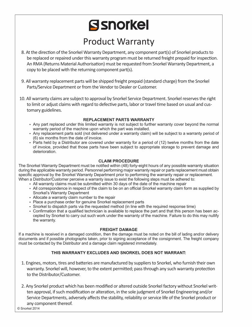
Product Warranty 8. At the direction of the Snorkel Warranty Department, any component part(s) of Snorkel products to
be replaced or repaired under this warranty program must be returned freight prepaid for inspection. An RMA (Returns Material Authorisation) must be requested from Snorkel Warranty Department, a copy to be placed with the returning component part(s).
9. All warranty replacement parts will be shipped freight prepaid (standard charge) from the Snorkel Parts/Service Department or from the Vendor to Dealer or Customer.
10. All warranty claims are subject to approval by Snorkel Service Department. Snorkel reserves the right to limit or adjust claims with regard to defective parts, labor or travel time based on usual and cus-tomary guidelines.
REPLACEMENT PARTS WARRANTYAny part replaced under this limited warranty is not subject to further warranty cover beyond the normal warranty period of the machine upon which the part was installed.Any replacement parts sold (not delivered under a warranty claim) will be subject to a warranty period of (6) six months from the date of invoice.Parts held by a Distributor are covered under warranty for a period of (12) twelve months from the date of invoice, provided that those parts have been subject to appropriate storage to prevent damage and deterioration.
CLAIM PROCEDUREThe Snorkel Warranty Department must be notified within (48) forty-eight hours of any possible warranty situation during the applicable warranty period. Personnel performing major warranty repair or parts replacement must obtain specific approval by the Snorkel Warranty Department prior to performing the warranty repair or replacement.When a Distributor/Customer perceive a warranty issue to exist the following steps must be adhered to:
All warranty claims must be submitted within 30 days of the date of the machine repairAll correspondence in respect of the claim to be on an official Snorkel warranty claim form as supplied by Snorkel’s Warranty DepartmentAllocate a warranty claim number to the repairPlace a purchase order for genuine Snorkel replacement partsSnorkel to dispatch parts via the requested method (in line with the required response time)Confirmation that a qualified technician is available to replace the part and that this person has been ac-cepted by Snorkel to carry out such work under the warranty of the machine. Failure to do this may nullify the warranty.
FREIGHT DAMAGEIf a machine is received in a damaged condition, then the damage must be noted on the bill of lading and/or delivery documents and if possible photographs taken, prior to signing acceptance of the consignment. The freight company must be contacted by the Distributor and a damage claim registered immediately.
THIS WARRANTY EXCLUDES AND SNORKEL DOES NOT WARRANT:
1. Engines, motors, tires and batteries are manufactured by suppliers to Snorkel, who furnish their own warranty. Snorkel will, however, to the extent permitted; pass through any such warranty protection to the Distributor/Customer.
2. Any Snorkel product which has been modified or altered outside Snorkel factory without Snorkel writ-ten approval, if such modification or alteration, in the sole judgment of Snorkel Engineering and/or Service Departments, adversely affects the stability, reliability or service life of the Snorkel product or any component thereof.
Product Warranty
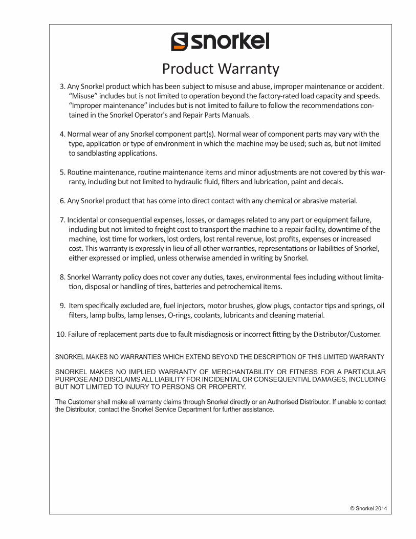
© Snorkel 2014
3. Any Snorkel product which has been subject to misuse and abuse, improper maintenance or accident. “Misuse” includes but is not limited to operation beyond the factory-rated load capacity and speeds. “Improper maintenance” includes but is not limited to failure to follow the recommendations con-tained in the Snorkel Operator's and Repair Parts Manuals.
4. Normal wear of any Snorkel component part(s). Normal wear of component parts may vary with the type, application or type of environment in which the machine may be used; such as, but not limited to sandblasting applications.
5. Routine maintenance, routine maintenance items and minor adjustments are not covered by this war-ranty, including but not limited to hydraulic fluid, filters and lubrication, paint and decals.
6. Any Snorkel product that has come into direct contact with any chemical or abrasive material.
7. Incidental or consequential expenses, losses, or damages related to any part or equipment failure, including but not limited to freight cost to transport the machine to a repair facility, downtime of the machine, lost time for workers, lost orders, lost rental revenue, lost profits, expenses or increased cost. This warranty is expressly in lieu of all other warranties, representations or liabilities of Snorkel, either expressed or implied, unless otherwise amended in writing by Snorkel.
8. Snorkel Warranty policy does not cover any duties, taxes, environmental fees including without limita-tion, disposal or handling of tires, batteries and petrochemical items.
9. Item specifically excluded are, fuel injectors, motor brushes, glow plugs, contactor tips and springs, oil filters, lamp bulbs, lamp lenses, O-rings, coolants, lubricants and cleaning material.
10. Failure of replacement parts due to fault misdiagnosis or incorrect fitting by the Distributor/Customer.
SNORKEL MAKES NO WARRANTIES WHICH EXTEND BEYOND THE DESCRIPTION OF THIS LIMITED WARRANTY
SNORKEL MAKES NO IMPLIED WARRANTY OF MERCHANTABILITY OR FITNESS FOR A PARTICULAR PURPOSE AND DISCLAIMS ALL LIABILITY FOR INCIDENTAL OR CONSEQUENTIAL DAMAGES, INCLUDING BUT NOT LIMITED TO INJURY TO PERSONS OR PROPERTY.
The Customer shall make all warranty claims through Snorkel directly or an Authorised Distributor. If unable to contact the Distributor, contact the Snorkel Service Department for further assistance.
© Snorkel 2014
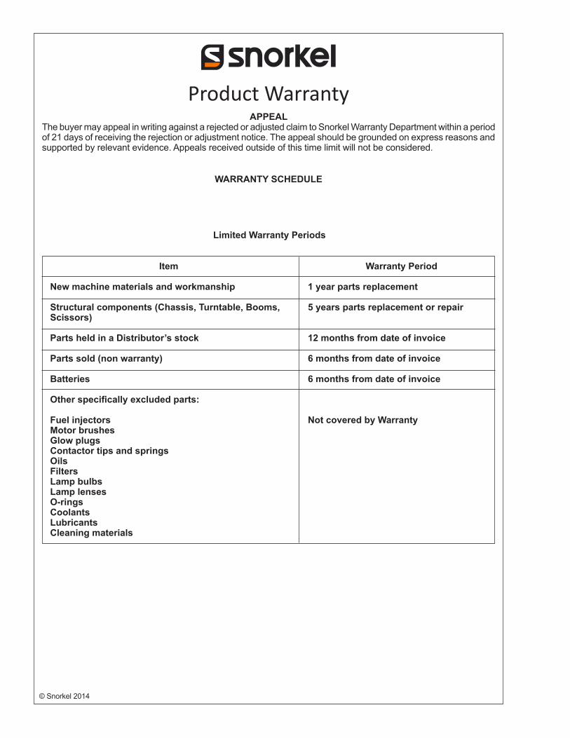
Product WarrantyAPPEAL
The buyer may appeal in writing against a rejected or adjusted claim to Snorkel Warranty Department within a period of 21 days of receiving the rejection or adjustment notice. The appeal should be grounded on express reasons and supported by relevant evidence. Appeals received outside of this time limit will not be considered.
WARRANTY SCHEDULE
Limited Warranty Periods
Item
New machine materials and workmanship
Structural components (Chassis, Turntable, Booms, Scissors)
Parts held in a Distributor’s stock
Parts sold (non warranty)
Batteries
Other specifically excluded parts:
Fuel injectorsMotor brushesGlow plugsContactor tips and springsOilsFiltersLamp bulbsLamp lensesO-ringsCoolantsLubricantsCleaning materials
Warranty Period
1 year parts replacement
5 years parts replacement or repair
12 months from date of invoice
6 months from date of invoice
6 months from date of invoice
Not covered by Warranty

Local Distributor / Lokaler Vertiebshändler / Distributeur localEl Distribuidor local / ll Distributore locale
EUROPE, MIDDLE EASTAFRICA & ASIA
PHONE: +44 (0) 845 1550 058FAX: +44 (0) 845 1557 756
NORTH & SOUTH AMERICAPHONE: +1 785 989 3000
TOLL FREE: +1 800 255 0317FAX: +1 785 989 3070
AUSTRALIAPHONE: +61 1300 700 450
FAX: +61 2 9609 3057
NEW ZEALANDPHONE: +64 6 3689 168
FAX: +64 6 3689 164