Embed Size (px)
Citation preview
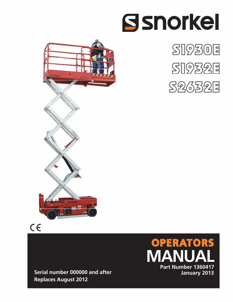
January 2013Part Number 1360417
MANUALOPERATORS
Serial number 000000 and afterReplaces August 2012


Table of Contents
S1930E/S1932E/S2632E – 1360417 1
Table of Contents
Table of ContentsEC Declaration of Conformity .....................................2Safety Rules ...............................................................3Fall Restraint Lanyar Anchor Points ...........................4Introduction .................................................................5Component Identification ............................................5Special Limitations......................................................6
Platform Capacity ....................................................6Manual Force ..........................................................6Drive/Lift Pothole Protector Interlock .......................6Drive/Lift Level Sensor Interlock .............................6Lowering Alarm .......................................................6Lowering Interrupt ...................................................6Overload Protection ................................................6Beaufort Scale .........................................................7
Controls and Indicators...............................................8Battery Disconnect Switch ..........................................8Lower Controls ...........................................................9
Emergency Stop Button ..........................................9Control Selector Switch ...........................................9Ground Operation Switch ........................................9Platform Raise/Lower Switch ..................................9
Upper Controls ...........................................................9Emergency Stop Button ..........................................9Drive/Lift Selector Switch ......................................10Joystick .................................................................10Interlock Switch .....................................................10Steer Switch ..........................................................10Drive Range Switch – S2632E Only .....................10Horn Button ...........................................................10Battery Condition Indicator ....................................10
Pre-Operation Safety Inspection ..............................10System Function Inspection ..................................... 11Operation ..................................................................12Preparing for Operation ............................................12Lower Controls .........................................................12Upper Controls .........................................................12Platform ....................................................................13
Raising and Lowering ............................................13Lowering Interrupt .................................................13Overload Protection ..............................................13Extending ..............................................................13
Driving and Steering .................................................14Drive Range Switch – S2632E Only .....................14Drive Speeds ........................................................14Drive/Lift Level Sensor Interlock ...........................14
Fold Down Guardrails ...............................................15Swing-Out Trays .......................................................15Emergency Lowering ................................................15Transporting the Machine .........................................16
Preparing for Transportation .................................16Transporting ..........................................................16Lifting With a Forklift ..............................................16Winching ...............................................................16Driving ...................................................................17Hoisting .................................................................17
Storage .....................................................................17
Maintenance .............................................................18Hydraulic Fluid ......................................................18Check Hydraulic Fluid ...........................................18Battery Maintenance .............................................18Battery Charging ...................................................18
Inspection and Maintenance Schedule.....................19Daily Preventative Maintenance Checklist ...............20
Preventative Maintenance Report .........................20Specifications – S1930E...........................................21
Aerial Platform .......................................................21Platform .................................................................21Function Speed .....................................................21Drive System .........................................................21Drive/Lift Level Sensor Interlock ...........................21Tires ......................................................................21Electrical System ...................................................21Hydraulic System ..................................................21Ambient Air Temperature Operating Range ..........21Maximum Wind Speed ..........................................21Vibration...................................................................21Sound Pressure Level ............................................21 Group Classification ................................................21
Specifications – S1932E...........................................22Aerial Platform .......................................................22Platform .................................................................22Function Speed .....................................................22Drive System .........................................................22Drive/Lift Level Sensor Interlock ...........................22Tires ......................................................................22Electrical System ...................................................22Hydraulic System ..................................................22Ambient Air Temperature Operating Range ..........22Maximum Wind Speed ..........................................22Vibration...................................................................22Sound Pressure Level ...........................................22Group Classification ................................................22
Specifications – S2632E...........................................23Aerial Platform .......................................................23Platform .................................................................23Function Speed .....................................................23Drive System .........................................................23Drive/Lift Level Sensor Interlock ...........................23Tires ......................................................................23Electrical System ...................................................23Hydraulic System ..................................................23Ambient Air Temperature Operating Range ..........23Maximum Wind Speed ..........................................23Vibration...................................................................23Sound Pressure Level ...........................................23Group Classification ................................................23
2 S1930E/S1932E/S2632E – 1360417
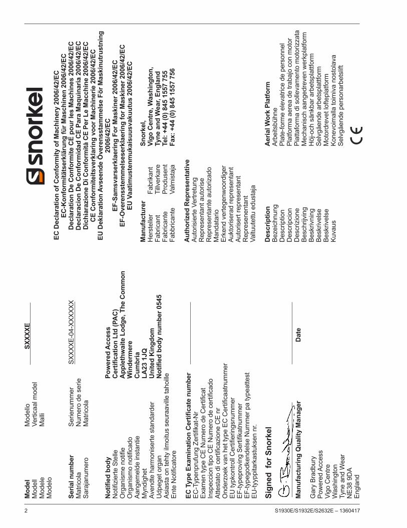
EC
Dec
lara
tion
of C
onfo
rmity
of M
achi
nery
200
6/42
/EC
EC-K
onfo
rmitä
tser
klär
ung
für M
asch
inen
200
6/42
/EC
Dec
lara
tion
De
Con
form
ite C
E po
ur le
s M
achi
nes
2006
/42/
ECD
ecla
raci
on D
e C
onfo
rmid
ad C
E Pa
ra M
aqui
naria
200
6/42
/EC
Dic
hiar
azio
ne D
i Con
form
ità C
E Pe
r Le
Mac
chin
e 20
06/4
2/EC
CE
Con
form
iteits
verk
larin
g vo
or M
achi
nerie
200
6/42
/EC
EU D
ekla
ratio
n Av
seen
de Ö
vere
nsst
amm
else
För
Mas
kinu
trus
tnin
g20
06/4
2/EC
EF-S
amsv
arse
rkla
erin
g Fo
r Mas
kine
r 200
6/42
/EC
EF-O
vere
nsst
emm
else
serk
laer
ing
for M
aski
ner 2
006/
42/E
CEU
Vaa
timus
tenm
ukai
suus
vaku
utus
200
6/42
/EC
Mod
el
Mod
ello
SX
XXXE
Mod
ell
Verti
caal
mod
elM
odel
e
M
alli
Mod
elo
Seria
l num
ber
Se
rienu
mm
er
SXX
XXE-
04-X
XXXX
X
Mat
ricol
a
Num
ero
de s
erie
Sara
janu
mer
o
Mat
ricol
a
Not
ified
bod
y
Pow
ered
Acc
ess
Not
ifizi
erte
Ste
lle
Cer
tific
atio
n Lt
d (P
AC
)O
rgan
ism
e no
tifie
A
pple
thw
aite
Lod
ge, T
he C
omm
on
Org
anis
mo
notif
icad
o
W
inde
rmer
eAa
ngem
elde
inst
antie
C
umbr
iaM
yndi
ghet
LA23
1JQ
Aven
dte
harm
onis
erte
sta
ndar
der
Uni
ted
Kin
gdom
Udp
eget
org
an
N
otifi
ed b
ody
num
ber 0
545
Asia
sta
on te
hty
ilmoi
tus
seur
aavi
lle ta
hoille
En
te N
otifi
cato
re
EC
Typ
e Ex
amin
atio
n C
ertif
icat
e nu
mbe
rEC
-Typ
enpr
ufun
g Ze
rtifik
at-N
rEx
amen
type
CE
Num
ero
de C
ertif
icat
Insp
ecci
on ti
po C
E N
umer
o de
cer
tific
ado
Atte
stat
o di
cer
tific
azio
ne C
E nr
O
nder
zoek
van
het
type
EC
Cer
tific
aatn
umm
erEU
typk
ontro
ll C
ertif
ierin
gsnu
mm
erEF
-type
prov
ing
Serti
fikat
num
mer
EF-ty
pego
dken
dels
e N
umm
er p
a ty
peat
test
EU-ty
yppi
tark
astu
ksen
nr.
Sign
ed f
or S
nork
el
Man
ufac
turin
g Q
ualit
y M
anag
er
D
ate
G
ary
Brad
bury
Pow
ered
Acc
ess
Vigo
Cen
treW
ashi
ngto
n
Tyne
and
Wea
r
N
E38
9DA
Engl
and
Man
ufac
ture
r
Sn
orke
l,
H
erst
elle
r Fa
brik
ant
Vigo
Cen
tre,
Was
hing
ton,
Fabr
ican
t Ti
llver
kare
Ty
ne a
nd W
ear,
Engl
and
Fabr
ican
te
Prod
usen
t Te
l: +4
4 (0
) 845
155
7 75
5Fa
bbric
ante
Va
lmis
taja
Fa
x: +
44 (0
) 845
155
7 75
6 A
utho
rized
Rep
rese
ntat
ive
Auto
risie
rte V
ertre
tung
Rep
rese
ntan
t aut
oris
e
Rep
rese
ntan
te a
utor
izad
o
Man
data
rio
Erke
nd v
erte
genw
oord
iger
Aukt
oris
erad
repr
esen
tant
Auto
riser
t rep
rese
ntan
tR
epre
sene
ntan
tVa
ltuut
ettu
edu
staj
a
Des
crip
tion
Aer
ial W
ork
Plat
form
Beze
ichn
ung
Arbe
itsbü
hne
Des
crip
tion
Plat
e-fo
rme
elev
atric
e de
per
sonn
elD
escr
ipci
on
Plat
form
a ae
rea
de tr
abaj
o co
n m
otor
Des
criz
ione
Pi
atta
form
a di
sol
leva
men
to m
otor
izza
taBe
schr
ijvin
g
M
echa
nisc
h aa
nged
reve
n w
erkp
latfo
rmBe
skriv
ning
H
öj-o
ch s
änkb
ar a
rbet
spla
ttfor
mBe
skriv
else
Se
lvgå
ende
arb
etsp
lattf
orm
Besk
rivel
se
Mot
ordr
evet
lofte
plat
form
Kuva
us
Kone
voim
alla
toim
iva
nost
olav
a
Se
lvgå
ende
per
sona
rbet
slift
S1930E/S1932E/S2632E – 1360417 3
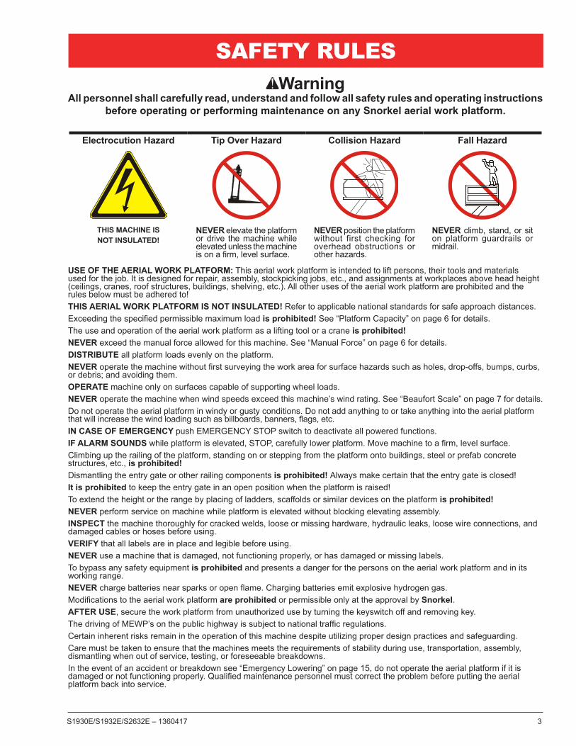
WarningAll personnel shall carefully read, understand and follow all safety rules and operating instructions
before operating or performing maintenance on any Snorkel aerial work platform.
Electrocution Hazard Tip Over Hazard Collision Hazard Fall Hazard
THIS MACHINE IS NOT INSULATED!
NEVER elevate the platform or drive the machine while elevated unless the machine is on a firm, level surface.
NEVER position the platform without first checking for overhead obstructions or other hazards.
NEVER climb, stand, or sit on platform guardrails or midrail.
USE OF THE AERIAL WORK PLATFORM: This aerial work platform is intended to lift persons, their tools and materials used for the job. It is designed for repair, assembly, stockpicking jobs, etc., and assignments at workplaces above head height (ceilings, cranes, roof structures, buildings, shelving, etc.). All other uses of the aerial work platform are prohibited and the rules below must be adhered to!THIS AERIAL WORK PLATFORM IS NOT INSULATED! Refer to applicable national standards for safe approach distances.Exceeding the specified permissible maximum load is prohibited! See “Platform Capacity” on page 6 for details.The use and operation of the aerial work platform as a lifting tool or a crane is prohibited!NEVER exceed the manual force allowed for this machine. See “Manual Force” on page 6 for details.DISTRIBUTE all platform loads evenly on the platform.NEVER operate the machine without first surveying the work area for surface hazards such as holes, drop-offs, bumps, curbs, or debris; and avoiding them.OPERATE machine only on surfaces capable of supporting wheel loads.NEVER operate the machine when wind speeds exceed this machine’s wind rating. See “Beaufort Scale” on page 7 for details.Do not operate the aerial platform in windy or gusty conditions. Do not add anything to or take anything into the aerial platform that will increase the wind loading such as billboards, banners, flags, etc.IN CASE OF EMERGENCY push EMERGENCY STOP switch to deactivate all powered functions.IF ALARM SOUNDS while platform is elevated, STOP, carefully lower platform. Move machine to a firm, level surface.Climbing up the railing of the platform, standing on or stepping from the platform onto buildings, steel or prefab concrete structures, etc., is prohibited!Dismantling the entry gate or other railing components is prohibited! Always make certain that the entry gate is closed!It is prohibited to keep the entry gate in an open position when the platform is raised!To extend the height or the range by placing of ladders, scaffolds or similar devices on the platform is prohibited!NEVER perform service on machine while platform is elevated without blocking elevating assembly.INSPECT the machine thoroughly for cracked welds, loose or missing hardware, hydraulic leaks, loose wire connections, and damaged cables or hoses before using.VERIFY that all labels are in place and legible before using.NEVER use a machine that is damaged, not functioning properly, or has damaged or missing labels.To bypass any safety equipment is prohibited and presents a danger for the persons on the aerial work platform and in its working range.NEVER charge batteries near sparks or open flame. Charging batteries emit explosive hydrogen gas.Modifications to the aerial work platform are prohibited or permissible only at the approval by Snorkel.AFTER USE, secure the work platform from unauthorized use by turning the keyswitch off and removing key.The driving of MEWP’s on the public highway is subject to national traffic regulations.Certain inherent risks remain in the operation of this machine despite utilizing proper design practices and safeguarding. Care must be taken to ensure that the machines meets the requirements of stability during use, transportation, assembly, dismantling when out of service, testing, or foreseeable breakdowns.In the event of an accident or breakdown see “Emergency Lowering” on page 15, do not operate the aerial platform if it is damaged or not functioning properly. Qualified maintenance personnel must correct the problem before putting the aerial platform back into service.
SAFETY RULES

4 S1930E/S1932E/S2632E – 1360417
Fall Restraint Lanyard Anchor PointsAll fall restraint lanyard anchor points on Snorkel aerial work platforms have been tested with a force of 3,650 lbs(61.3 KN) per person.
See below examples of anchor points used on Snorkel machines with their corresponding per person rating.
NOTE: There can be more anchor points in the platform than the maximum number of occupants allowed in theplatform. Refer to the machine specifications for the correct occupancy rating before use.
Type 1
Type 2
Type 3
Type 4
Top View Top View
Top View Top View
Front View
Front View
Anchor point Type 1 is rated for one lanyardattachment per loop. Refer to machine “Specifica-tions” and platform decals for maximum number of platform occupants.
Two LanyardsAttached
One LanyardAttached
Anchor point Type 2 is rated for two lanyardattachments per loop. Refer to machine “Specifications” and platform decals for maximum number of platform occupants.
Two LanyardsAttached
One LanyardAttached
Anchor point Type 3 is rated for one lanyardattachment per loop. Refer to machine “Specifications” and platform decals for maximum number of platform occupants.
One LanyardAttached
One LanyardAttached
Anchor point Type 4 is rated for one lanyardattachment per loop. Refer to machine “Specifications” and platform decals for maximum number of platform occupants.

Introduction
S1930E/S1932E/S2632E – 1360417 5
IntroductionThis manual covers the S1930E, S1932E, and S2632E Aerial Work Platforms.
This manual must be stored on the machine at all times.
Read, understand and follow all safety rules and operating instructions before attempting to operate the machine.
When contacting Snorkel for service or parts information, be sure to include the MODEL and SERIAL NUMBERS from the equipment nameplate. Should the nameplate be missing, the SERIAL NUMBER is also stamped on the front of the chassis.
Component Identification
Toeboards
Scissors Structure
Right Side
Platform
Guardrails
Left Side
Lower Controls
Operator’sManual
Chassis
EntryStep
Upper Controls
EntryGate
Battery Charge Indicator
Tie-Down/LiftingLugs
Tie-Down Lugs
Battery Tray Batteries • Charger Plug • Battery Disconnect
Platform Extension
Hydraulic Tray Hydraulic Reservoir • Hydraulic Fluid Filter
Serial Number Placard
Rear
EmergencyLowering Lever
S1930E/S1932E
Front
Lifting Lugs
Forklift Pockets
Drive and Steer Wheels
Pothole Protector Skid
Drive and Steer Wheels Groundstrap
SerialNumber
EmergencyLowering Handle
S2632E

Special Limitations
6 S1930E/S1932E/S2632E – 1360417
Special LimitationsTravel with the platform raised is limited to creep speed range. Elevating the platform is limited to firm, level surfaces only.
DangerThe elevating function shall ONLY be used when the work platform is level and on a firm surface.
The work platform is NOT intended to be driven over uneven, rough, or soft terrain.
Platform CapacityThe maximum platform capacity for the aerial platform is stated in the “Specifications” on pages 21-23.
DangerDO NOT exceed the maximum platform capacity or the platform occupancy limits for this machine.
Manual ForceManual force is the force applied by the occupants to objects such as walls or other structures outside the work platform.
The maximum allowable manual force is limited to 222 N (50 lbs) for S1932E machines. S1932E machines may be operated in windy conditions up to 12.5 m/s (28 mph).
The maximum allowable manual force is limited to 445 N (100 lbs) for S1930E and S2632E machines. S1930E and S2632E machines may be operated in zero wind condi-tions only.
DangerDO NOT exceed the maximum amount of manual force for this machine.
Drive/Lift Pothole Protector InterlockThe aerial platform drive and lift functions are interlocked through a limit switch inside the chassis that senses whether or not the pothole protection linkage is locked into position. The drive/lift pothole interlock operates when the platform is elevated approximately 1.8 m (6′).
If an obstruction under the skids, or some other impairment prevents the skids from locking into position, the drive and lift functions will not operate and an alarm will sound.
Lower the platform and remove the obstruction when the drive/lift pothole protector interlock alarm sounds.
Drive/Lift Level Sensor InterlockThe aerial platform drive and lift functions are interlocked through a level sensor system. The drive/lift level sensor interlock operates when the platform is elevated approxi-mately 1.8 m (6′).
If the chassis is tilted too far out of level, the drive and lift functions will not operate and an alarm will sound. Refer to the machine specifications for the level sensor factory setting.
Lower the platform and drive to a level surface when the drive/lift level sensor alarm sounds.
The drive/lift level sensor system is for added protection and does not justify operating on anything other than firm, flat, level surfaces.
Lowering AlarmWhen the joystick is moved out of neutral to lower the platform, the alarm emits a loud beeping sound to warn personnel in the work area to stand clear.
DangerPinch points exist on the scissors structure. Death or serious injury will result if the scissors structure lowers onto personnel within the scissors arms or under the raised platform. Stand clear while raising and lowering the platform.
Be careful when lowering the platform. Keep hands and fingers away from the scissors structures components.
Lowering InterruptWhen the platform is lowered to about 1.5 m (5′) lower-ing stops. The platform will not lower for five seconds regardless of the control position to allow personnel to clear the area of the scissors before the platform com-pletely lowers.
Center the control in neutral to reset the lowering function, then continue to lower the platform.
Overload ProtectionWhen the load in the platform is near or at rated capac-ity, an alarm will sound and the red light on the upper controls will flash.
The alarm and light warn the operator that the platform is close to becoming overloaded. All functions remain fully operational.
DangerThe aerial platform can tip over if it becomes unstable. Death or serious injury will result from a tip-over ac-cident. Do not exceed the capacity values indicated on the platform rating placard.
If the platform is fully lowered and is overloaded, when it is elevated just past 1.8 m (6′), a control module will stop the lift and drive functions and the alarm will sound and the warning light will flash. The platform can still be lowered to remove the excess load.
If the platform is elevated just past 1.8 m (6′) and material is added to the platform overloading it, a control module will stop the lift, drive and lower functions and the alarm will sound and the warning light will flash. In this case, remove the load in excess of rated capacity and cycle the emergency stop button at the upper controls to return to normal operation.

Special Limitations
S1930E/S1932E/S2632E – 1360417 7
BEAUFORT RATING
WIND SPEEDGROUND CONDITIONS
m/s km/h ft/s mph3 3,4~5,4 12,25~19,4 11.5~17.75 7.5~12.0 Papers and thin branches move, flags wave.4 5,4~8,0 19,4~28,8 17.75~26.25 12.0~18 Dust is raised, paper whirls up, and small branches sway.
5 8,0~10,8 28,8~38,9 26.25~35.5 18~24.25 Shrubs with leaves start swaying. Wave crests are apparent in ponds or swamps.
6 10,8~13,9 38,9~50,0 35.5~45.5 24.5~31 Tree branches move. Power lines whistle. It is difficult to open an umbrella.
7 13,9~17,2 50,0~61,9 45.5~56.5 31.~38.5 Whole trees sway. It is difficult to walk against the wind.
Figure 1 – Beaufort Scale
Beaufort ScaleNever operate an S1932E machine when wind speeds exceed 12.5 m/s (28 mph) [Beaufort scale 6]. Refer to Figure 1.
Never operate an S1930E or an S2632E machine out-doors, or indoors in any location where anything other than zero wind speeds exist.

Controls and Indicators
8 S1930E/S1932E/S2632E – 1360417
Figure 4 – Upper Controls and Indicators
DangerPinch points may exist between moving components. Death or serious injury will result from becoming trapped between components, buildings, structures, or other obstacles. Make sure all personnel stand clear while operating the aerial platform.
Controls to position the platform are located on the lower control panel on the chassis and on the upper control panel in the platform.
Controls to drive the aerial platform are located on the upper control panel only.
The diagnostic center LCD display is located in the hy-draulic tray next to the fluid reservoir (refer to Figure 5).
Figure 5 – Diagnostic Center LCD Display
The LCD display shows the accumulated aerial platform operating time and the available battery power to operate the machine, when the battery disconnect and emergency stop switch are in the on position.
Battery Disconnect SwitchThe battery disconnect switch is located at the rear of the chassis (refer to Figure 2).
•
•
Controls and IndicatorsThe operator shall know the location of each control and indicator and have a thorough knowledge of the function and operation of each before attempting to operate the machine.
Figure 2 – Battery Disconnect Switch
1. Battery disconnect switch
Figure 3 – Lower Controls and Indicators
2. Control selector switch 3. Ground operation switch 4. Emergency stop button 5. Platform raise/lower switch 6. Hour meter 7. Tilt/lowering alarm 8. Emergency stop button 9. Drive/lift selector switch10. Drive range switch – S2632E Only11. Joystick12. Interlock switch13. Steer switch14. Horn button15. Platform overload protection light16. Battery condition indicator – option
1
2
5
4 6 7
8
9
11
12
13
16
14
15
3
10

Controls and Indicators
S1930E/S1932E/S2632E – 1360417 9
The battery disconnect removes electrical power from all electrically controlled functions when in the off position.
Place the switch in the on position to electrically con-nect the battery to the electrical system.
CautionOnly authorized personnel should operate the aerial platform. Unqualified personnel may cause injury to coworkers or property damage. Lock the battery disconnect switch in the off position before leaving the aerial platform unattended.
Lock the battery disconnect switch in the off position to prevent unauthorized use of the aerial platform.
Lower ControlsThe lower controls (refer to Figure 3) are located on the right side of the chassis. Only platform functions can be operated from the lower controls.
The following are located on the lower control panel:
Emergency stop buttonControl selector switchGround operation switchPlatform raise/lower switch
Emergency Stop ButtonThe emergency stop is a two-position red push button.
Push the button inward to disconnect power to all control circuits.
Pull the button outward to restore power.
Control Selector SwitchInsert the key into the control selector switch.
Turn the switch to the lower controls position to oper-ate aerial platform functions from the lower controls. The upper controls will not operate while the control selector is in the lower position.
Turn the switch to the upper controls position to operate the aerial platform functions from the upper controls.
In the center position, aerial platform functions will not operate from the lower or upper controls.
Ground Operation SwitchThe ground operation switch prevents platform movement if the platform raise/lower switch is accidentally moved. This switch is spring returned to the off position.
Hold the ground operation switch upward continually to operate the machine from the lower controls.
•
•
••••
•
•
•
•
•
Platform Raise/Lower SwitchThe platform raise/lower switch is used to raise or lower the platform. The switch is spring returned to the center off position.
Hold the switch upward to raise the platform.
Hold the switch downward to lower the platform.
An alarm will sound as the platform lowers.
Upper ControlsThe upper controls (refer to Figure 4) are located on the control panel at the platform. Platform and drive functions can be operated from the upper controls.
WarningThe potential for an accident increases from improp-erly driving or steering the aerial platform. Death or serious injury could result from such accidents. Make sure the upper control panel is at the front of the platform, hooked on the guardrail, and hanging inside the platform.
Avoid driving the platform with the upper controls facing the rear or side of the machine. In this position the ma-chine is difficult to control because the drive and steer control movements and their resulting machine move-ments will not correspond.
Only operate the upper controls when the panel is at the front of the platform, hooked on the guardrail inside the platform, and facing the front of the machine.
The following controls are located on the upper control panel:
Emergency stop buttonDrive/lift selector switchJoystick to control platform lift, drive, and steer
The horn button and battery condition indicator gauge may also be located at the upper control station.
Emergency Stop ButtonThe emergency stop is a two-position, red push button on the front of the upper control panel.
Push the button inward to disconnect power from all control circuits at the upper controls.
Pull the button outward to restore power.
Push the button in when the upper controls are not in use to help protect against unintentional platform operation.
•
•
•
•••
•
•

Pre-Operation Safety Inspection
10 S1930E/S1932E/S2632E – 1360417
Drive/Lift Selector SwitchThe drive/lift selector switch is used to select either machine drive or lift functions. Both functions can not be operated at the same time.
Place the drive/lift selector switch in the drive position to drive the aerial platform using the joystick. The platform will not raise or lower while driving.
Place the drive/lift selector switch in the lift position to raise and lower the platform using the joystick.
JoystickUse the joystick to operate the following functions:
Aerial platform steeringAerial platform drive and speedPlatform raise/lower and speed
Movement of the joystick in a given direction produces a corresponding movement of the aerial platform. The steering and drive functions may be operated separately or simultaneously.
Interlock SwitchThe joystick has an interlock switch in the handle.
Engage the interlock by grasping the joystick and pulling the switch toward the handle.
Engage the interlock to activate the steering, drive, or lift functions.
Steer SwitchThe steer switch is a momentary contact, rocker switch on top of the drive joystick. This switch controls the two front wheels to steer the aerial platform.
To steer to the right, engage the interlock switch on the joystick and hold down the right side of the steer switch.
To steer to the left, engage the interlock switch on the joystick and hold down the left side of the steer switch.
NoteThe steering wheels are not self-centering. Set the steer-ing wheels straight ahead after completing a turn.
Drive Range Switch – S2632E OnlyThe drive range switch has two positions to select drive wheel operation:
High (Rabbit) – for normal driving conditions
Low (Turtle) – for driving on grades up to 25 per-cent that require low speed and high torque opera-tion, where high range is not sufficient to climb the grade.
•
•
•••
•
•
•
•
•
•
Horn ButtonThe horn button is on the left side of the upper control panel.
Press the button to sound the horn.
Battery Condition IndicatorThe optional battery condition indicator gauge is on the top of the upper control box. It indicates the level of avail-able battery power to operate the aerial platform.
Pre-Operation Safety Inspection
NoteCarefully read, understand and follow all safety rules, operating instructions, labels and National Safety Instruc-tions/Requirements. Perform the following steps each day before use.
1. Open the trays and inspect for damage, fluid leaks or missing parts.
2. Check the level of the hydraulic fluid with the platform fully lowered. The fluid level must be between the full and add marks. Add recommended hydraulic fluid if necessary. See “Specifications” on pages 21-23.
3. Check that the fluid level in the batteries is correct. See “Battery Maintenance” on page 18.
4. Verify that the batteries are charged.
5. Check that the AC extension cord has been discon-nected from the outlet on the side of the chassis.
6. Check that all guardrails are in place and all fasteners are properly tightened.
7. Inspect the machine thoroughly for cracked welds and structural damage, loose or missing hardware, hydraulic leaks, damaged control cable and loose wire connections.

System Function Inspection
S1930E/S1932E/S2632E – 1360417 11
System Function InspectionRefer to “Controls and Indicators” on page 8 for the loca-tions of various controls and indicators.
WarningSTAND CLEAR of the work platform while performing the following checks.
Before operating the machine, survey the work area for surface hazards such as holes, drop-offs, bumps and debris.
Check in ALL directions, including above the work platform, for obstructions and electrical conduc-tors.
1. Move the machine, if necessary, to an unobstructed area to allow for full elevation.
2. Pull the Lower Control Emergency Stop Switch to the ON position.
3. Pull the Upper Control Emergency Stop Switch to the ON position.
4. Visually inspect the elevating assembly, lift cylinder, and hoses for cracked welds and structural damage, loose hardware, hydraulic leaks, loose wire connec-tions, and erratic operation. Check for missing or loose parts.
5. Hold the ground operation switch upward. Test each machine function from the lower control station (refer to Figure 3).
6. Test the emergency lowering system for proper op-eration.
7. Push the Lower Control Emergency Stop Button to check for proper operation. All machine functions should be disabled. Pull the Lower Control Emer-gency Stop Button outward to resume.
8. Enter the platform and close the gate.
9. Check that the route is clear of obstacles (persons, obstructions, debris), is level, and is capable of sup-porting the wheel loads.
10. Test each machine function from the upper control station by engaging the interlock and operating the function controls (refer to Figure 4).
11. Push the Upper Control Emergency Stop Button to check for proper operation. All machine functions should be disabled. Pull the Upper Control Emer-gency Stop Button outward to resume.
Operation
12 S1930E/S1932E/S2632E – 1360417
OperationThe aerial platform may be operated from either the lower or upper controls.
DangerThe aerial platform is not electrically insulated. Death or serious injury will result from contact with, or in-adequate clearance from, an energized conductor. Do not go closer than the minimum safe approach distance as defined by ANSI or national safety regu-lations.
Pinch points may exist between moving components. Death or serious injury will result from becoming trapped between components, buildings, structures, or other obstacles. Make sure there is sufficient clearance around the machine before moving the chassis or platform. Allow sufficient room and time to stop movement to avoid contact with structures or other hazards.
The aerial platform can tip over if it becomes unstable. Death or serious injury will result from a tip-over accident. Operate the aerial platform on a firm, flat, level surface. Avoid travel speeds and/or rough ter-rain that could cause sudden changes in platform position. Do not drive or position the aerial platform for elevated use near any drop-off, hole, slope, soft or uneven ground, or other tip-over hazard. Do not operate the aerial platform in unapproved locations or wind conditions.
The platform rated work load is the total weight of the per-sonnel and equipment that may be lifted in the platform.
The work loads are stated on the platform rating placard at the entrance to the platform.
DangerThe aerial platform can tip over if it becomes unstable. Death or serious injury will result from a tip-over ac-cident. Do not exceed the capacity values indicated on the platform rating placard.
Capacity values indicate the rated lifting capacity and do not indicate aerial platform stability.
The operator bears ultimate responsibility for ensuring that the aerial platform is properly set up for the particular conditions encountered.
Preparing for OperationUse the following procedure to prepare the aerial platform for operation:
1. Perform a pre-operation safety and system function inspection.
2. Close and latch the battery and hydraulic trays.
3. Place the battery disconnect switch in the on position.
Lower ControlsOnly the platform raise and lower functions may be oper-ated from the lower controls. The lower controls may be used for initial set up of the aerial platform, and for testing and inspection.
Use the following procedure to raise or lower the platform using the lower controls.
1. Pull the emergency stop button outward (refer to Figure 3).
2. Insert the key into the control selector switch and turn the switch to the lower controls position.
3. Hold the ground operation switch upward. Hold the platform raise/lower toggle switch up to raise the platform and down to lower it.
4. Release the toggle switch to stop movement.
Upper ControlsThe upper controls may be used for driving and position-ing the aerial platform while on the job.
Before operating the upper controls, properly set up the aerial platform as described under Preparing for Opera-tion.
WarningThe potential for an accident increases from improp-erly driving or steering the aerial platform. Death or serious injury could result from such accidents. Make sure the upper control panel is at the front of the platform, hooked on the guardrail, and hanging inside the platform.
Avoid driving the platform with the upper controls facing the rear or side of the machine. In this position the ma-chine is difficult to control because the drive and steer control movements and their resulting machine move-ments will not correspond.
Only operate the upper controls when the panel is at the front of the platform, hooked on the guardrail inside the platform, and facing the front of the machine (refer to Figure 4).
Use the following procedure to operate the aerial platform from the upper controls:
1. From the lower controls, pull the emergency stop button outward (refer to Figure 3).
2. Insert the key into the control selector switch and turn the switch to the upper controls position.
NoteThe upper controls will not operate while the control selector is in the lower position.
Operation
S1930E/S1932E/S2632E – 1360417 13
3. Enter the platform and secure the gate.
4. From the upper controls, pull the emergency stop button outward (refer to Figure 4).
5. The aerial platform may be driven and the platform may be raised and lowered from the upper controls.
PlatformUse care when entering and exiting the platform to avoid slipping and/or falling. Securely close the safety gate when the platform is occupied.
DangerThe potential for an accident increases when the fold down rails are lowered. Death or serious injury can result in such accidents. Do not elevate the platform with the fold down rails lowered. Use extreme care when moving the aerial platform while the fold down rails are lowered.
Be sure the fold down guardrails are up and the hardware is securely tightened, anytime the machine is not being transported.
Raising and LoweringThe raise speed is proportional to the joystick position. The farther the joystick is moved, the faster the platform raises. There is only one lowering speed.
1. Place the drive/lift selector switch (refer to Figure 4) in the lift position.
2. Squeeze and hold the interlock switch against the joystick.
To raise the platform, slowly push the joystick forward until the desired height is reached.
To lower the platform, pull the joystick backward.
Lowering InterruptWhen the platform is lowered to about 1.5 m (5′) lowering stops. The platform will not lower for five seconds regard-less of the joystick position.
Center the joystick in neutral to reset the lowering func-tion, then continue to lower the platform.
Overload ProtectionWhen the load in the platform is near or at rated capac-ity, an alarm will sound and the red light on the upper controls will flash.
The alarm and light warn the operator that the platform is close to becoming overloaded. All functions remain fully operational.
DangerThe aerial platform can tip over if it becomes unstable. Death or serious injury will result from a tip-over ac-cident. Do not exceed the capacity values indicated on the platform rating placard.
If the platform is fully lowered and is overloaded, when it is elevated just past 1.8 m (6′), a control module will stop the lift and drive functions and the alarm will sound and the warning light will flash. The platform can still be lowered to remove the excess load.
If the platform is elevated just past 1.8 m (6′) and material is added to the platform overloading it, a control module will stop the lift, drive and lower functions and the alarm will sound and the warning light will flash. In this case, remove the load in excess of rated capacity and cycle the emergency stop button at the upper controls to return to normal operation.
ExtendingThe platform can be extended and securely locked into position.
Use the following procedure to extend the platform:
1. Enter the platform and close the gate.
CautionThe extension deck is free to move when the foot lever is depressed. Personal injury may result from accidentally extending or retracting the deck. Make certain the pin is engaged when the deck is extended in the working position and when it is stowed. Do not attempt to extend or retract the platform unless the aerial platform is on a level surface.
2. While facing the front of the platform, step down on the foot lever and push the top rail of the extension deck forward to extend the deck until the pin engages the mid or front stop.
3. Try to move the rails back and forth to make sure the platform extension deck is locked in position.
Use the following procedure to retract the platform:
1. Enter the platform and close the gate.
CautionThe extension deck is free to move when the foot lever is depressed. Personal injury may result from accidentally extending or retracting the deck. Make certain the pin is engaged when the deck is extended in the working position and when it is stowed. Do not attempt to extend or retract the platform unless the aerial platform is on a level surface.
2. While facing the front of the platform, step down on the foot lever and pull the top rail of the extension deck backward until the pin engages the mid or rear stop.

Operation
14 S1930E/S1932E/S2632E – 1360417
3. Try to move the rails back and forth to make sure the platform extension deck is locked in position.
Driving and Steering
DangerThe aerial platform can tip over if it becomes unstable. Death or serious injury will result from a tip-over ac-cident. Do not drive an elevated aerial platform on soft, uneven, or sloping surfaces. Do not drive on grades that exceed 25 percent.
A fully stowed machine may be operated on grades up to 25 percent. A grade of 25 percent is a 0.76 m (30″) vertical rise in 3.05 m (10′) horizontal length.
WarningDeath or serious injury could result from improperly driving or steering the aerial platform. Read and un-derstand the information in this manual and on the placards and decals on the machine before operating the aerial platform on the job.
Use the following procedure to operate the drive and steer functions.
1. Place the drive/lift selector switch (refer to Figure 4) in the drive position.
2. Push the drive joystick forward to move the chassis forward. Pull the joystick backward to move the chas-sis backward. The drive speed is proportional to the joystick position.
3. To stop drive motion, return the joystick to neutral.
NoteTo make an emergency stop push the emergency stop button inward to apply the parking brakes.
4. The steer switch is a momentary contact, rocker switch on top of the drive joystick. This switch controls the two front wheels to steer the aerial platform.
To steer to the right, hold down the right side of the steer switch.
To steer to the left, hold down the left side of the steer switch.
NoteHolding the steer switch down too long may result in a sharp turn. This is especially true when driving and steering at the same time. It may be easier to turn the wheels in small increments using a series of quick taps on the steer switch.
5. Set the steer wheels straight ahead after completing a turn. The steering wheels are not self-centering.
Drive Range Switch – S2632E OnlyThe drive range switch has two positions to select drive wheel operation:
High (Rabbit) – for normal driving conditions.
Low (Turtle) – for driving on grades up to 25 percent that require low speed and high torque operation, where high range is not sufficient to climb the grade.
In high the machine will travel up to 3.2 km/h (2 mph) when the platform is raised less than 2.4 m (8′) and up to 0.6 km/h (0.5 mph) when the platform is raised above 2.4 m (8′). Place the drive range switch in high for normal machine operation.
CautionThe extension deck is free to move when the pin is disengaged. Make certain the pin is engaged when the deck is extended in the working position and when it is stowed.
Place the drive range switch in low, with the platform fully lowered and the extension deck securely pinned, before driving up a ramp to load the machine for transport.
Drive Speeds The drive speed is proportional to the joystick position. The farther the joystick is moved, the faster the travel speed.
Always slow down before traveling over rough terrain or any sloped surface.
Drive speed ranges are interlocked through limit switches that sense the platform position.
When the platform is elevated below approximately 1.8 m (6′) the aerial platform may be driven with the full range of drive speeds.
When the platform is elevated above 1.8 m (6′) only the slowest drive speed will work.
WarningThe potential for an accident increases when safety devices do not function properly. Death or serious injury could result from such accidents. Do not alter, disable, or override any safety device.
Do not use the aerial platform if it drives faster than 0.6 km/h (0.4 mph), which is 5.3 m (7′ 7″) in 30 seconds, when elevated above 1.8 m (6′).
Drive/Lift Level Sensor InterlockWhen the platform is elevated above 1.8 m (6′), lift and drive functions are interlocked through a level sensor system. If the chassis is tilted more than specified side-to-side or front-to-rear (refer to “Specifications” on pages 21-23), platform raise and drive functions are disabled and an alarm sounds when those controls are activated.
•
•
•
•

Operation
S1930E/S1932E/S2632E – 1360417 15
If the drive/lift level sensor interlock shuts off the platform raise and drive functions, lower the platform and drive to a level surface.
Fold Down GuardrailsThe platform guardrails may be folded down to pass the machine under low height obstructions.
DangerThe potential for an accident increases when the fold down rails are lowered. Death or serious injury can result in such accidents. Do not elevate the platform with the fold down rails lowered. Use extreme care when moving the aerial platform while the fold down rails are lowered.
Use the following procedure to lower the platform guard-rails.
1. Remove all materials from the platform floor and retract the extension deck.
2. Remove the upper control panel from the side guard-rail and place it on the floor of the platform.
3. Remove the pin from the hinged top rail on the exten-sion deck. Fold the hinged rail in as far as it will go.
4. Lift the left hand extension deck rail up and fold it down inwards.
5. Remove the pin from the hinged top rail on the main deck. Fold the hinged rail in as far as it will go.
6. Lift the left hand main deck rail up and fold it in-wards.
7. Lift the right hand extension deck rail up and fold it down inwards.
8. Lift the right hand main deck rail up and fold it in-wards.
9. Reverse this procedure to reposition the rails.
Swing-Out TraysBatteries and hydraulic components are enclosed in swing-out trays on each side of the chassis.
The battery tray on the left side of the chassis con-tains the battery disconnect, batteries and the battery charger.
The hydraulic tray on the right side of the chassis contains the lower controls, the hydraulic reservoir, and the hydraulic fluid filter.
DangerThe aerial platform can tip over if it becomes unstable. Death or serious injury can result from a tip-over accident. Do not open the trays when the platform is elevated.
To open the swing-out tray, push down on the latch and swing the tray open.
Emergency LoweringUse the following procedure to operate the emergency lowering system.
WarningThe potential for an accident increases when safety devices do not function properly. Death or serious injury can result from such accidents. Immediately push the emergency stop button inward to disable the control system before using the emergency lowering system in the event of an emergency.
1. Immediately push the emergency stop button inward to disable the control system in the event of an emer-gency.
2. Retract the platform extension deck if possible.
3. Make sure there is nothing in the way to obstruct the platform when it lowers.
S1930E and S1932E machines – push downward on the lever to lower the platform.
S2632E machines – pull outward on the handle to lower the platform.
4. Make certain the lever/handle is fully released and the emergency lowering valve is fully closed before operating the aerial platform.
•
•
•
•

Transporting the Machine
16 S1930E/S1932E/S2632E – 1360417
Transporting the MachinePreparing for TransportationUse the following procedure to prepare the aerial platform for transportation.
1. Remove any unnecessary tools, materials, or other loose objects from the platform.
2. Close and latch the battery trays and cowling doors.
TransportingThe aerial platform may be moved on a transport vehicle. Depending on the particular situation, the aerial platform may be lifted with a forklift, driven, winched, or hoisted onto a vehicle such as a truck or trailer. Lifting with a forklift is the preferred method.
The equipment used to load, unload, and transport the aerial platform must have adequate capacity. The empty vehicle weight is listed in “Specifications” on pages 21-23 and is stamped on the serial number placard.
The user assumes all responsibility for:
Choosing the proper method of transportation.
Choosing the proper selection and use of transporta-tion and tie-down devices.
Making sure the equipment used is capable of sup-porting the weight of the aerial platform.
Making sure all manufacturer’s instructions and warn-ings, regulations and safety rules of their employer, the DOT, and/or any other state or federal law are followed.
Lifting With a ForkliftUse the following procedure to lift the aerial platform with a forklift.
1. Properly stow the aerial platform.
2. Remove all personnel, tools, materials, or other loose objects from the platform.
3. If lifting from the rear of the machine, insert the forklift forks into the pockets.
CautionLifting the aerial platform with the forklift forks posi-tioned improperly can produce enough force to dam-age machine components. When lifting the machine from the side, place the forklift forks directly under the designated lift points.
4. If lifting from either side of the machine, place the forklift forks directly under the designated points under the pothole protector skid.
•
•
•
•
5. Do not raise the aerial platform higher than necessary to transport it. Drive the forklift slowly and carefully when transporting the aerial platform.
WinchingUse a winch to load and unload the aerial platform on ramps that exceed the gradeability specification for the machine. Refer to “Specifications” pages 21-23. A winch may also be used when poor traction, uneven surfaces, or stepped ramp transition make driving hazardous.
Use the following procedure to winch the aerial platform onto the transport vehicle.
1. Position the transport vehicle so the aerial platform will not roll forward after it is loaded.
2. Remove any unnecessary tools, materials, or other loose objects from the platform.
3. Drive the machine to the foot of the loading ramp with the front wheels nearest the ramp. Make sure the machine is centered with the ramps and that the steering wheels are straight.
4. Properly stow the aerial platform.
WarningThe aerial platform is free to move when the brakes are released. Death or serious injury can result. Re-enable the brakes before operating the aerial platform.
5. Chock the wheels to prevent uncontrolled motion of the aerial platform.
6. Unlatch and swing out the hydraulic tray on the right side of the chassis. The brake release valve, pump, and free-wheeling valves are located on the hydraulic manifold. Press downward on the brake release valve to the fully open position.
7. Turn the free-wheeling valve counterclockwise to the fully open position. Push and release the brake release pump knob several times to release the brakes.
8. Attach the winch line to the tie-down lugs on the front of the chassis.
9. Remove the wheel chocks and use the winch to position the aerial platform on the transport vehicle.
10. Pull upward on the brake release valve and close the free-wheeling valve.
11. Drive the aerial platform forward or reverse and then stop to reset the parking brakes.
12. Verify that the drive system and brakes operate properly before operating the aerial platform.

Transporting the Machine
S1930E/S1932E/S2632E – 1360417 17
Driving
DangerThe aerial platform can tip over if it becomes unstable. Death or serious injury will result from a tip-over ac-cident. Do not drive on ramps that exceed 25 percent grade, or where conditions of the ramp could cause driving to be hazardous.
Use a winch to load and unload the aerial platform on ramps that exceed the gradeability specification for the machine. Refer to “Specifications” pages 21-23. A winch may also be used when poor traction, uneven surfaces, or stepped ramp transitions make driving hazardous.
Drive the aerial platform onto the transport vehicle if a winch is not available and the ramp incline is within the grade capability of the aerial platform.
Use the following procedure to drive the aerial platform onto the transport vehicle.
1. Position the transport vehicle so the aerial platform will not roll forward after it is loaded.
2. Chock the vehicle wheels so it cannot roll away from the ramp while the aerial platform is loaded.
3. Remove any unnecessary tools, materials, or other loose objects from the platform.
CautionThe extension deck is free to move when the pin is removed. Make certain the pin is in place when the deck is extended in the working position and when it is stowed.
4. Retract the platform extension deck and ensure the pin is in place. Fully lower the platform.
5. Drive the aerial platform to the foot of the loading ramp with the front wheels nearest the ramp. Make sure the aerial platform is centered with the ramps and that the steering wheels are straight.
6. On S2632E machines, place the drive range switch in low (turtle) for climbing or descending a ramp.
7. Drive the aerial platform on or off the transport vehicle in a straight line through the grade transitions with minimal turning.
HoistingUse a four point sling arrangement attached to the lifting lugs when hoisting the aerial platform. Machine damage can occur if the sling is attached anywhere else.
WarningThe potential for an accident increases when the aerial platform is lifted using improper equipment and/or lifting techniques. Death or serious injury could result
from such accidents. Use proper equipment and lifting techniques when lifting the aerial platform.
Know the weight of the aerial platform and the capacity of the lifting devices before hoisting.
Lifting devices include the hoist or crane, chains, straps, cables, hooks, sheaves, shackles, slings, and other hardware used to support the machine.
The empty vehicle weight is stamped on the serial num-ber placard and is listed in the machine specifications.
The user assumes all responsibility for:
Making sure the equipment used is capable of sup-porting the weight of the aerial platform.
Making sure all manufacturer’s instructions and warn-ings, regulations and safety rules of their employer and/or any state or federal law are followed.
Use the following procedure to hoist the aerial platform onto the transport vehicle: 1. Properly stow the aerial platform.
2. Inspect the front lifting lugs and the rear lifting lugs to make sure they are free of cracks and are in good condition. There are two lugs on the rear of the chas-sis and two on the front. Have any damage repaired by a qualified service technician before attempting to hoist the machine.
3. Remove all personnel, tools, materials, or other loose objects from the platform.
4. Connect the chains or straps to the lifting lugs using bolted shackles. Hooks that fit properly in the lugs and that have latching mechanisms to prevent them from falling out under a slack line condition may also be used.
Do not run the sling cable through the lifting lugs.
Cable damage and/or failure can result from the cable contacting the sharp corners of the lug.
There is no effective way of putting a corner protector in the hole of the lug.
StorageNo service is required when storing, or removing the machine from service, for less than one week.
If the machine functions are not cycled for longer than one week:
Grease exposed cylinder rods with a light, white lithium grease.
Periodically charge the batteries.
•
•
•
•

Maintenance
18 S1930E/S1932E/S2632E – 1360417
MaintenanceWarning
Always block the elevating assembly whenever it is necessary to perform maintenance while the platform is elevated.
Hydraulic FluidThe hydraulic fluid reservoir is located in the hydraulic tray. Refer to Figure 6.
Figure 6 – Hydraulic Fluid Reservoir
NoteNever add fluid if the platform is elevated.
Check Hydraulic Fluid 1. Make sure that the platform is fully lowered.
2. Visually check to make sure the fluid is between the full and add marks.
3. If necessary, remove the filler cap and add fluid of the proper type. Replace the cap making sure it is tightly in place. Refer to the machine specifications.
Battery Maintenance
WarningHazard of explosive gas mixture. Keep sparks, flame, and smoking material away from batteries.
Always wear safety glasses when working near bat-teries.
Battery fluid is highly corrosive. Thoroughly rinse away any spilled fluid with clean water.
Always replace batteries with manufacturer approved replacements.
Check the battery fluid level daily, especially if the machine is being used in a warm, dry climate.
If electrolyte level is lower than 6 mm (¼″) above the plates add distilled water only. DO NOT use tap
•
•
water with high mineral content, as it will shorten battery life.
Keep the terminals and tops of the batteries clean.
Refer to the Service Manual to extend battery life and for complete service instructions.
WarningAlways use manufacturer approved replacement parts.
Battery ChargingCharge the batteries at the end of each work shift or sooner if the batteries have been discharged.
WarningCharge the batteries in a well ventilated area.
Do not charge the batteries when the machine is near a source of sparks or flames.
Permanent damage to the batteries will result if the batteries are not immediately recharged after dis-charging.
Never disconnect the cables from the batteries when the charger is operating.
Keep the charger dry.
1. At the lower controls, turn the start switch to the off position.
2. Open the battery tray to access the batteries. Remove the caps from each battery.
3. Visually check the battery fluid level making sure the level is within 6 mm (¼″) of the bottom of the filler neck inside each hole. If needed, add distilled water.
4. Tightly replace the caps on each battery and replace and latch the battery tray covers.
5. Plug the battery charger into a properly grounded outlet (100-240 volt AC, 50/60 Hz) using a 3 conduc-tor, 1.5 mm (12 gauge) or larger extension cord. The extension cord must be as short as possible and in good electrical condition.
NoteThe aerial platform will not operate while the battery charger is plugged in.
6. Visually inspect the battery charge indicator for proper charging rate. The LED’s are visible on the battery tray.
AC Power On (Blue) – indicates that AC power is applied to the charger.
•
•
•

Inspection and Maintenance Schedule
S1930E/S1932E/S2632E – 1360417 19
Inspection and Maintenance Schedule
CautionFrequency and extent of periodic examinations may depend on national regulations.
The Complete Inspection consists of periodic visual and operational checks, along with periodic minor adjustments that assure proper performance. Daily inspection will pre-vent abnormal wear and prolong the life of all systems. The inspection and maintenance schedule should be performed at the specified intervals and after prolonged periods of storage before returning the machine to ser-vice. Inspection and maintenance shall be performed by personnel who are trained and familiar with mechanical and electrical procedures.
WarningBefore performing preventative maintenance, famil-iarize yourself with the operation of the machine. Always block the elevating assembly whenever it is necessary to perform maintenance while the platform is elevated.
The daily preventative maintenance checklist has been designed for machine service and maintenance. Please photocopy the Daily Preventative Maintenance Checklist and use the checklist when inspecting the machine.
Charge Status (Yellow) – blinks until the batteries are 80% charged and then remains solid from 80% to 100% charge.
Complete Charge (Green) – lights solid when the batteries are fully charged.
Fault (Red) – lights solid when there is a battery fault and blinks when there is a charger fault.
7. Leave the battery charger plugged in until it shuts itself off.
NoteIf the charging cycle exceeds 16 hours without the bat-teries being fully recharged, unplug the charger and have the batteries checked.
8. After the battery charger turns itself off, it is not nec-essary to immediately unplug the extension cord from the battery charger. The charger will monitor the charge state of the batteries and recharge them if the voltage drops off.
9. Release the latch on each side of the battery trays and remove the cover to access the batteries. Re-move the caps from each battery.
10. Visually check the battery fluid level making sure the level is within 6 mm (¼″) of the bottom of the filler neck inside each hole. If needed, add distilled water.
11. Tightly replace the caps on each battery and replace and latch the battery tray doors.
•
•
•
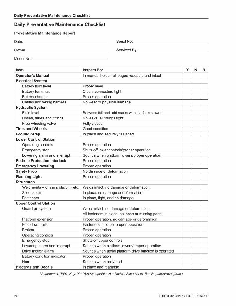
Daily Preventative Maintenance Checklist
20 S1930E/S1932E/S2632E – 1360417
Maintenance Table Key: Y = Yes/Acceptable, N = No/Not Acceptable, R = Repaired/Acceptable
Daily Preventative Maintenance Checklist
Preventative Maintenance Report
Date:
Owner:
Model No:
Serial No:
Serviced By:
Item Inspect For Y N ROperator’s Manual In manual holder, all pages readable and intactElectrical System
Battery fluid level Proper levelBattery terminals Clean, connectors tightBattery charger Proper operationCables and wiring harness No wear or physical damage
Hydraulic SystemFluid level Between full and add marks with platform stowedHoses, tubes and fittings No leaks, all fittings tightFree-wheeling valve Fully closed
Tires and Wheels Good conditionGround Strap In place and securely fastenedLower Control Station
Operating controls Proper operationEmergency stop Shuts off lower controls/proper operationLowering alarm and interrupt Sounds when platform lowers/proper operation
Pothole Protection Interlock Proper operationEmergency Lowering Proper operationSafety Prop No damage or deformationFlashing Light Proper operationStructures
Weldments – Chassis, platform, etc. Welds intact, no damage or deformationSlide blocks In place, no damage or deformationFasteners In place, tight, and no damage
Upper Control StationGuardrail system Welds intact, no damage or deformation
All fasteners in place, no loose or missing partsPlatform extension Proper operation, no damage or deformationFold down rails Fasteners in place, proper operationBrakes Proper operationOperating controls Proper operationEmergency stop Shuts off upper controlsLowering alarm and interrupt Sounds when platform lowers/proper operationDrive motion alarm Sounds when aerial platform drive function is operatedBattery condition indicator Proper operationHorn Sounds when activated
Placards and Decals In place and readable
Specifications
S1930E/S1932E/S2632E – 1360417 21
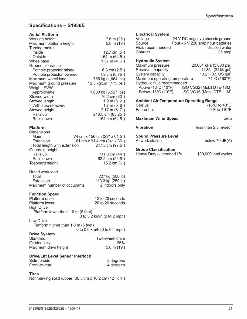
Specifications – S1930E
Aerial PlatformWorking height 7.6 m (25′)Maximum platform height 5.8 m (19′)Turning radius Inside 12.7 cm (5″) Outside 1.64 m (64.5″)Wheelbase 1.37 m (4′ 6″)Ground clearance Pothole protector raised 6.3 cm (2.5″) Pothole protector lowered 1.9 cm (0.75″)Maximum wheel load 755 kg (1,664 lbs)Maximum ground pressure 12.3 kg/cm² (175 psi)Weight, EVW Approximate 1,600 kg (3,527 lbs)Stowed width 76.2 cm (30″)Stowed length 1.9 m (6′ 2″) With step removed 1.7 m (5′ 6″)Stowed height 2.17 m (6′ 7″) Rails up 216.5 cm (85.25″) Rails down 164 cm (64.5″)
PlatformDimensions Main 74 cm x 156 cm (29″ x 61.5″) Extension 61 cm x 91.4 cm (24″ x 36″) Total length with extension 247.5 cm (97.5″)Guardrail height Rails up 111.8 cm (44″) Rails down 62.2 cm (24.5″)Toeboard height 15.2 cm (6″)
Rated work load Total 227 kg (500 lb) Extension 113.3 kg (250 lb)Maximum number of occupants 2 indoors only Function SpeedPlatform raise 12 to 20 secondsPlatform lower 20 to 26 secondsHigh Drive Platform lower than 1.8 m (6 feet) 0 to 3.2 km/h (0 to 2 mph)Low Drive Platform higher than 1.8 m (6 feet) 0 to 0.6 km/h (0 to 0.4 mph)Drive SystemStandard Two-wheel driveGradeability 25%Maximum drive height 5.8 m (19′)
Drive/Lift Level Sensor InterlockSide-to-side 2 degreesFront-to-rear 4 degrees
TiresNonmarking solid rubber 30.5 cm x 10.2 cm (12″ x 4″)
Electrical SystemVoltage 24 V DC negative chassis groundSource Four - 6 V 220 amp hour batteriesFluid recommended distilled waterCharger 25 amp
Hydraulic SystemMaximum pressure 20,684 kPa (3,000 psi)Reservoir capacity 11.35 l (3 US gal)System capacity 13.2 l (3.5 US gal)Maximum operating temperature 71°C (160°F)Hydraulic fluid recommended Above -13°C (10°F) ISO VG32 (Mobil DTE-13M) Below -13°C (10°F) ISO VG15 (Mobil DTE-11M) Ambient Air Temperature Operating RangeCelsius -18°C to 43°CFahrenheit 0°F to 110°F
Maximum Wind Speed zero
Vibration less than 2.5 m/sec²
Sound Pressure Level At work station below 70 dB(A)
Group Classification Heavy Duty – intended life 100,000 load cycles

Specifications
22 S1930E/S1932E/S2632E – 1360417
Specifications – S1932E
Aerial PlatformWorking height 7.6 m (25′)Maximum platform height 5.8 m (19′)Turning radius Inside 12.7 cm (5″) Outside 1.64 m (64.5″)Wheelbase 1.37 m (4′ 6″)Ground clearance Pothole protector raised 6.3 cm (2.5″) Pothole protector lowered 1.9 cm (0.75″)Maximum wheel load 755 kg (1,664 lbs)Maximum ground pressure 12.3 kg/cm² (175 psi)Weight, EVW Approximate 1,570 kg (3,461 lbs)Stowed width 81.3 cm (32″)Stowed length 1.9 m (6′ 2″) With step removed 1.7 m (5′ 6″)Stowed height 2.17 m (6′ 7″) Rails up 216.5 cm (85.25″) Rails down 164 cm (64.5″)
PlatformDimensions Main 74 cm x 156 cm (29″ x 61.5″) Extension 61 cm x 91.4 cm (24″ x 36″) Total length with extension 247.5 cm (97.5″)Guardrail height Rails up 111.8 cm (44″) Rails down 62.2 cm (24.5″)Toeboard height 15.2 cm (6″)
Rated work load Total 227 kg (500 lb) Extension 113.3 kg (250 lb)Maximum number of occupants 1 outdoors 2 indoors
Function SpeedPlatform raise 12 to 20 secondsPlatform lower 20 to 26 secondsHigh Drive Platform lower than 1.8 m (6 feet) 0 to 3.2 km/h (0 to 2 mph)Low Drive Platform higher than 1.8 m (6 feet) 0 to 0.6 km/h (0 to 0.4 mph)Drive SystemStandard Two-wheel driveGradeability 25%Maximum drive height 5.8 m (19′)
Drive/Lift Level Sensor InterlockSide-to-side 2 degreesFront-to-rear 4 degrees
TiresNonmarking solid rubber 30.5 cm x 10.2 cm (12″ x 4″)
Electrical SystemVoltage 24 V DC negative chassis groundSource Four - 6 V 220 amp hour batteriesFluid recommended distilled waterCharger 25 amp
Hydraulic SystemMaximum pressure 20,684 kPa (3,000 psi)Reservoir capacity 11.35 l (3 US gal)System capacity 13.2 l (3.5 US gal)Maximum operating temperature 71°C (160°F)Hydraulic fluid recommended Above -13°C (10°F) ISO VG32 (Mobil DTE-13M) Below -13°C (10°F) ISO VG15 (Mobil DTE-11M) Ambient Air Temperature Operating RangeCelsius -18°C to 43°CFahrenheit 0°F to 110°F
Maximum Wind SpeedGust or steady 12.5 m/s (28 mph)
Vibration less than 2.5 m/sec²
Sound Pressure Level At work station below 70 dB(A)
Group Classification Heavy Duty – intended life 100,000 load cycles

Specifications
S1930E/S1932E/S2632E – 1360417 23
Specifications – S2632E
Aerial PlatformWorking height 9.8 m (32′ 3″)Maximum platform height 8 m (26′ 3″)Turning radius Inside 25.4 cm (10″) Outside 234 cm (92″)Wheelbase 1.92 m (6′ 4″)Ground clearance Pothole protector raised 6.3 cm (2.5″) Pothole protector lowered 1.9 cm (0.75″)Maximum wheel load 1,112 kg (2,450 lbs)Maximum ground pressure 430 kg/cm² (190 psi)Weight, EVW Approximate 2,455 kg (5,413 lbs)Stowed width 81.3 cm (32″)Stowed length 2.37 m (93.25″) With step removed 2.37 m (93.25″)Stowed height Rails up 2.33 m (91.63″) Rails down 1.93 m (76″)
PlatformDimensions Main 74 cm x 231 cm (29″ x 91″) Extension 61 cm x 91.4 cm (24″ x 36″) Total length with extension 322.6 cm (127″)Guardrail height Rails up 111.8 cm (44″) Rails down 62.2 cm (24.5″)Toeboard height 15.2 cm (6″)
Rated work load Total 227 kg (500 lb) Extension 113.3 kg (250 lb)Maximum number of occupants 2 indoors only Function SpeedPlatform raise 12 to 20 secondsPlatform lower 20 to 26 secondsHigh Drive Platform lower than 1.8 m (6 feet) 0 to 3.2 km/h (0 to 2 mph)Low Drive Platform higher than 1.8 m (6 feet) 0 to 0.6 km/h (0 to 0.4 mph)Drive SystemStandard Two-wheel driveGradeability 25%Maximum drive height 8.0 m (26′ 3″)
Drive/Lift Level Sensor InterlockSide-to-side 1.5 degreesFront-to-rear 4 degrees
TiresNonmarking solid rubber 38.1 cm x 12.7 cm (15″ x 5″)
Electrical SystemVoltage 24 V DC negative chassis groundSource Four - 6 V 220 amp hour batteriesFluid recommended distilled waterCharger 25 amp
Hydraulic SystemMaximum pressure 20,684 kPa (3,000 psi)Reservoir capacity 25.7 l (6.8 US gal)System capacity 27.6 l (7.3 US gal)Maximum operating temperature 71°C (160°F)Hydraulic fluid recommended Above -13°C (10°F) ISO VG32 (Mobil DTE 10 XL32) Below -13°C (10°F) ISO VG15 (Mobil DTE 10 XL15) Ambient Air Temperature Operating RangeCelsius -18°C to 43°CFahrenheit 0°F to 110°F
Maximum Wind Speed zero
Vibration less than 2.5 m/sec²
Sound Pressure Level At work station below 70 dB(A)
Group Classification Heavy Duty – intended life 100,000 load cycles

Local Distributor / Lokaler Vertiebshändler / Distributeur localEl Distribuidor local / ll Distributore locale
EUROPE, MIDDLE EASTAFRICA & ASIA
PHONE: +44 (0) 845 1550 058FAX: +44 (0) 845 1557 756
NORTH & SOUTH AMERICAPHONE: +1 785 989 3000
TOLL FREE: +1 800 255 0317FAX: +1 785 989 3070
AUSTRALIAPHONE: +61 1300 700 450
FAX: +61 2 9609 3057
NEW ZEALANDPHONE: +64 6 3689 168
FAX: +64 6 3689 164