Embed Size (px)
Citation preview
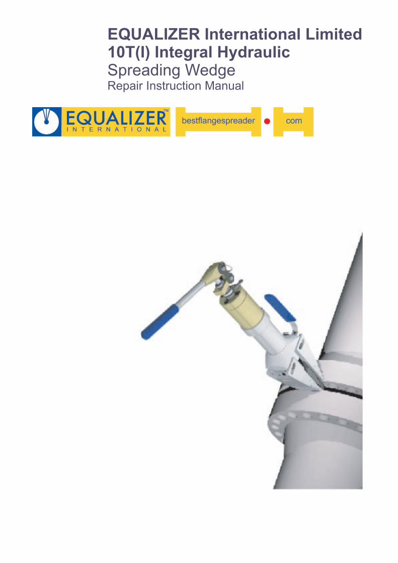
EQUALIZER International Limited 10T(I) Integral Hydraulic Spreading WedgeRepair Instruction Manual
INDEXTHE EQUALIZER 10T(I) Integral Hydraulic Wedge
SECTION CONTENTS PAGE NO (S)
01010203-04
05 - 06
06
070707 - 09
09
10-1212-1415-1818-23
01020304
05
06
070809
10
11121314
INTRODUCTIONTROUBLE SHOOTINGDETERMINE PUMP MODELSPARE PARTS WEDGE HEAD / SINGLE SPEED PUMP EXPLODED DRAWINGSPARE PARTS 10 T(I) DUAL SPEED PUMP UP TO SERIAL NO: 1340292SPARE PARTS 10T (I) DUAL SPEED PUMP FROM SERIAL NO: 1340293 ONWARDAIR VENT OBSTRUCTIONRELEASE VALVESERVICING INTERMEDIATE & OUTLET CHECK VALVEOIL LEAK FROM RESERVOIRAIR VENTDISMANTLING THE PUMPREMOVING THE WEDGE HEADSERVICING PISTON ROD ASSEMBLYBLEEDING THE SYSTEM
PAGE 1
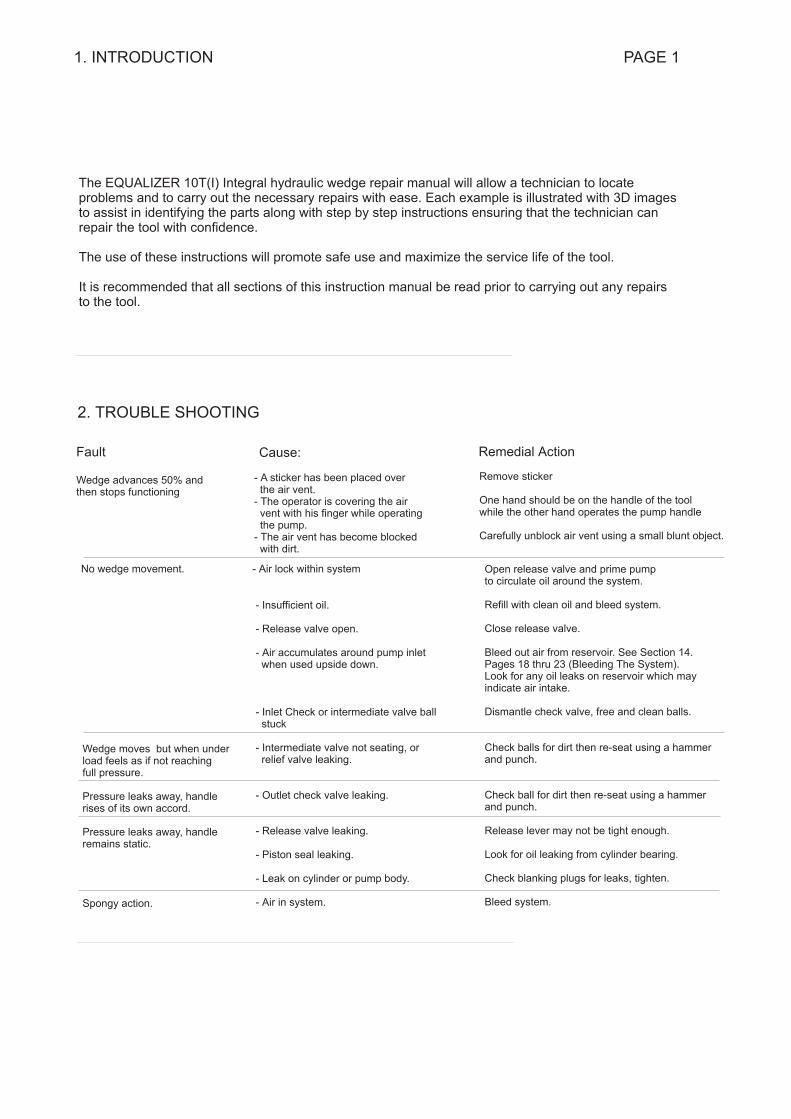
The EQUALIZER 10T(I) Integral hydraulic wedge repair manual will allow a technician to locate problems and to carry out the necessary repairs with ease. Each example is illustrated with 3D images to assist in identifying the parts along with step by step instructions ensuring that the technician can repair the tool with confidence.
The use of these instructions will promote safe use and maximize the service life of the tool.
It is recommended that all sections of this instruction manual be read prior to carrying out any repairs to the tool.
1. INTRODUCTION
Fault
Wedge advances 50% and then stops functioning
- A sticker has been placed over the air vent.- The operator is covering the air vent with his finger while operating the pump.- The air vent has become blocked with dirt.
Remove sticker
One hand should be on the handle of the tool while the other hand operates the pump handle
Carefully unblock air vent using a small blunt object.
Cause: Remedial Action
No wedge movement. - Air lock within system
Wedge moves but when under load feels as if not reaching full pressure.
Pressure leaks away, handle rises of its own accord.
Pressure leaks away, handleremains static.
Spongy action.
- Insufficient oil.
- Release valve open.
- Air accumulates around pump inlet when used upside down.
- Inlet Check or intermediate valve ball stuck
- Intermediate valve not seating, or relief valve leaking.
- Outlet check valve leaking.
- Release valve leaking.
- Piston seal leaking.
- Leak on cylinder or pump body.
- Air in system.
Open release valve and prime pump to circulate oil around the system.
Refill with clean oil and bleed system.
Close release valve.
Bleed out air from reservoir. See Section 14. Pages 18 thru 23 (Bleeding The System).Look for any oil leaks on reservoir which mayindicate air intake.
Dismantle check valve, free and clean balls.
Check balls for dirt then re-seat using a hammer and punch.
Check ball for dirt then re-seat using a hammer and punch.
Release lever may not be tight enough.
Look for oil leaking from cylinder bearing.
Check blanking plugs for leaks, tighten.
Bleed system.
2. TROUBLE SHOOTING
3.DETERMINE PUMP MODEL PAGE 2
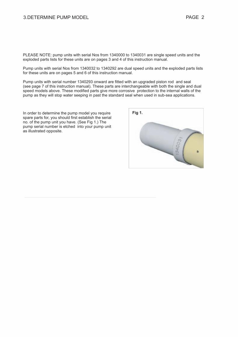
PLEASE NOTE: pump units with serial Nos from 1340000 to 1340031 are single speed units and the exploded parts lists for these units are on pages 3 and 4 of this instruction manual.
Pump units with serial Nos from 1340032 to 1340292 are dual speed units and the exploded parts lists for these units are on pages 5 and 6 of this instruction manual.
Pump units with serial number 1340293 onward are fitted with an upgraded piston rod and seal (see page 7 of this instruction manual). These parts are interchangeable with both the single and dual speed models above. These modified parts give more corrosive protection to the internal walls of the pump as they will stop water seeping in past the standard seal when used in sub-sea applications.
In order to determine the pump model you require spare parts for, you should first establish the serial no. of the pump unit you have. (See Fig 1.) The pump serial number is etched into your pump unit as illustrated opposite.
Fig 1.
02
03
04 05
06
07
08 09
1011
12
13
01
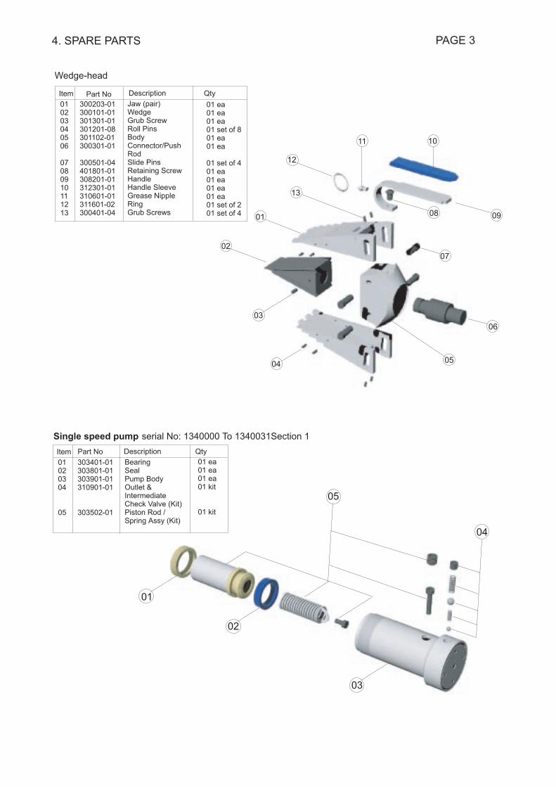
Wedge-head
Jaw (pair)WedgeGrub ScrewRoll Pins BodyConnector/Push RodSlide Pins Retaining ScrewHandleHandle SleeveGrease NippleRing Grub Screws
01 ea 01 ea 01 ea01 set of 801 ea01 ea
01 set of 4 01 ea01 ea01 ea01 ea01 set of 2 01 set of 4
QtyDescription300203-01300101-01301301-01301201-08301102-01300301-01
300501-04401801-01308201-01312301-01310601-01311601-02300401-04
Part No010203040506
07080910111213
Item
01
02
03
04
05
Single speed pump serial No: 1340000 To 1340031Section 1
01 ea 01 ea01 ea01 kit
01 kit
QtyBearingSealPump BodyOutlet & Intermediate Check Valve (Kit)Piston Rod / Spring Assy (Kit)
Description303401-01303801-01303901-01310901-01
303502-01
Part NoItem01020304
05
4. SPARE PARTS PAGE 3
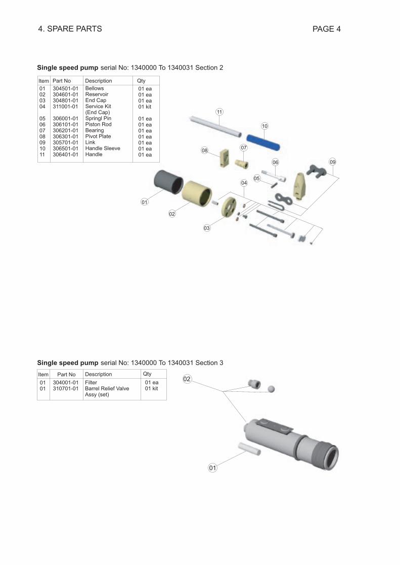
Single speed pump serial No: 1340000 To 1340031 Section 3QtyItem Part No Description
0101
FilterBarrel Relief Valve Assy (set)
01 ea 01 kit
304001-01310701-01
02
01
01
02
03
0504
0906
0708
10
11
Single speed pump serial No: 1340000 To 1340031 Section 2
01020304
05060708091011
BellowsReservoirEnd CapService Kit (End Cap)Springl PinPiston RodBearingPivot PlateLinkHandle SleeveHandle
304501-01304601-01304801-01311001-01
306001-01306101-01306201-01306301-01305701-01306501-01306401-01
01 ea 01 ea01 ea01 kit
01 ea 01 ea01 ea01 ea01 ea01 ea01 ea
Item Part No QtyDescription
4. SPARE PARTS PAGE 4
01
0203
04
0507 08
0910
11
14
15
1718
16
192022
242526
27
29
30
28
06 12
13
21
23
161718192021222324252627282930
“O”RingSpringBallInlet FittingFilter ElementClevisSpring PinLinkPiston rodBack-Up Ring“O” RingBearingPivot PlateHandle SleeveHandle
309501-01309601-01307301-01309701-01309801-01305801-01306001-01305701-01309901-01310101-01308601-01310201-01306301-01306501-01306401-01
01 ea01 ea01 ea01 ea01 ea01 ea01 ea01 ea01 ea01 ea01 ea01 ea01 ea01 ea01 ea
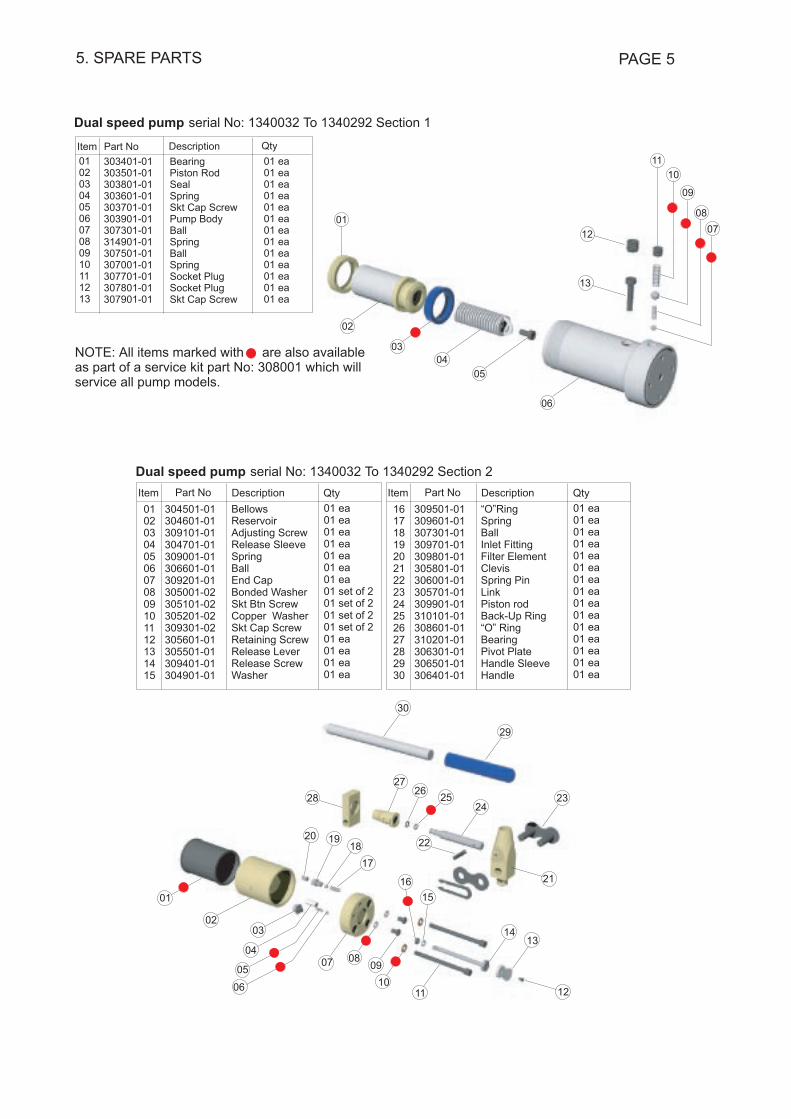
Item Part No QtyDescription010203040506070809101112131415
BellowsReservoirAdjusting ScrewRelease SleeveSpringBallEnd CapBonded WasherSkt Btn ScrewCopper WasherSkt Cap ScrewRetaining ScrewRelease LeverRelease ScrewWasher
304501-01304601-01309101-01304701-01309001-01306601-01309201-01305001-02305101-02305201-02309301-02305601-01305501-01309401-01304901-01
01 ea 01 ea01 ea01 ea01 ea01 ea01 ea01 set of 201 set of 201 set of 201 set of 201 ea01 ea01 ea01 ea
Item Part No QtyDescription
01020304050607080910111213
Bearing Piston Rod SealSpringSkt Cap ScrewPump BodyBallSpringBallSpringSocket PlugSocket PlugSkt Cap Screw
303401-01303501-01303801-01303601-01303701-01303901-01307301-01314901-01307501-01307001-01307701-01307801-01307901-01
01 ea 01 ea01 ea01 ea01 ea01 ea01 ea01 ea01 ea01 ea01 ea01 ea01 ea
Item Part No QtyDescription
01
02
0304
05
06
0708
09
1011
12
13
PAGE 55. SPARE PARTS
Dual speed pump serial No: 1340032 To 1340292 Section 1
NOTE: All items marked with are also available as part of a service kit part No: 308001 which will service all pump models.
Dual speed pump serial No: 1340032 To 1340292 Section 2
0102
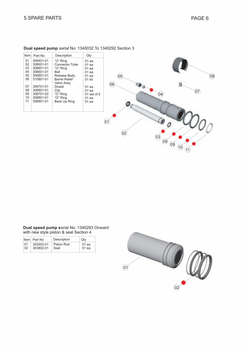
Piston RodSeal
303503-01303802-01
01 ea 01 ea
Item Part No QtyDescription
Dual speed pump serial No: 1340032 To 1340292 Section 3
5.SPARE PARTS PAGE 6
“O” RingConnector Tube“O” RingBallRelease BodyBarrel Relief Valve AssyDowalClip“O” Ring“O” RingBack Up Ring
01 ea 01 ea01 ea01 ea01 ea01 kit
01 ea01 ea01 set of 201 ea01 ea
QtyDescription308401-01308501-01308601-01306601-01306901-01310801-01
306701-01306801-01308701-02308801-01308901-01
Part NoItem010203040506
0708091011
01
02
0909
10 11
03
0704
08
02
05
06
01
Dual speed pump serial No: 1340293 Onwardwith new style piston & seal Section 4
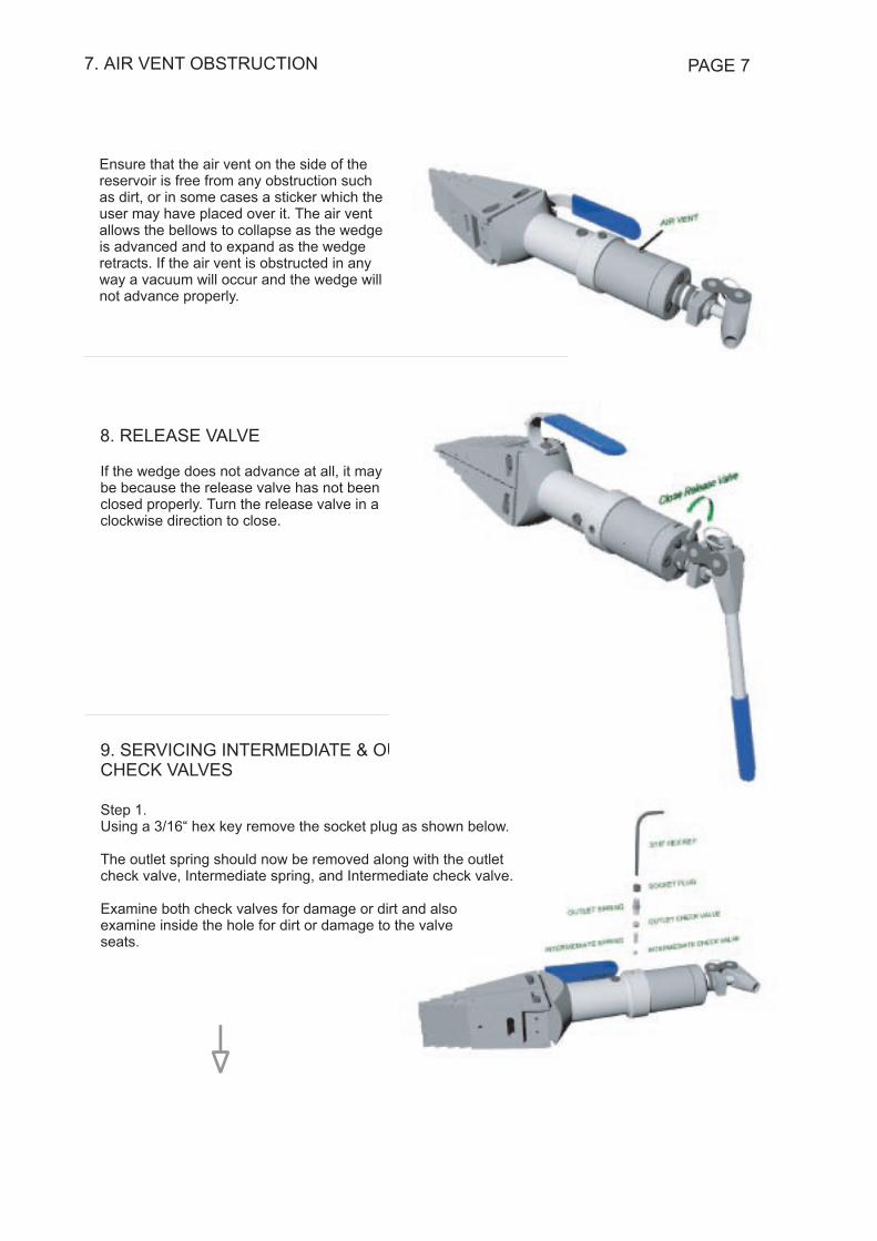
Ensure that the air vent on the side of the reservoir is free from any obstruction such as dirt, or in some cases a sticker which the user may have placed over it. The air vent allows the bellows to collapse as the wedge is advanced and to expand as the wedge retracts. If the air vent is obstructed in any way a vacuum will occur and the wedge will not advance properly.
7. AIR VENT OBSTRUCTION PAGE 7
8. RELEASE VALVE
If the wedge does not advance at all, it may be because the release valve has not been closed properly. Turn the release valve in a clockwise direction to close.
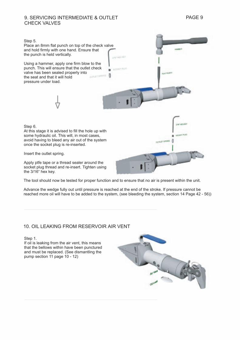
9. SERVICING INTERMEDIATE & OUTLET CHECK VALVES
Step 1.Using a 3/16“ hex key remove the socket plug as shown below.
The outlet spring should now be removed along with the outlet check valve, Intermediate spring, and Intermediate check valve.
Examine both check valves for damage or dirt and also examine inside the hole for dirt or damage to the valve seats.
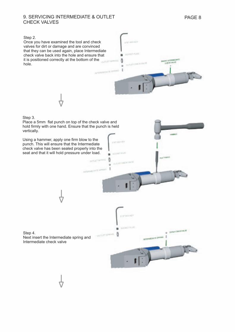
9. SERVICING INTERMEDIATE & OUTLET CHECK VALVES
PAGE 8
Step 2.Once you have examined the tool and check valves for dirt or damage and are convinced that they can be used again, place Intermediate check valve back into the hole and ensure that it is positioned correctly at the bottom of the hole.
Step 3.Place a 5mm flat punch on top of the check valve andhold firmly with one hand. Ensure that the punch is held vertically.
Using a hammer, apply one firm blow to the punch. This will ensure that the Intermediate check valve has been sealed properly into the seat and that it will hold pressure under load.
Step 4.Next insert the Intermediate spring and Intermediate check valve
9. SERVICING INTERMEDIATE & OUTLET CHECK VALVES
PAGE 9
Step 5.Place an 8mm flat punch on top of the check valve and hold firmly with one hand. Ensure that the punch is held vertically.
Using a hammer, apply one firm blow to the punch. This will ensure that the outlet check valve has been sealed properly into the seat and that it will hold pressure under load.
Step 6.At this stage it is advised to fill the hole up with some hydraulic oil. This will, in most cases, avoid having to bleed any air out of the system once the socket plug is re-inserted.
Insert the outlet spring.
Apply ptfe tape or a thread sealer around the socket plug thread and re-insert. Tighten using the 3/16“ hex key. The tool should now be tested for proper function and to ensure that no air is present within the unit.
Advance the wedge fully out until pressure is reached at the end of the stroke. If pressure cannot bereached more oil will have to be added to the system, (see bleeding the system, section 14 Page 42 - 56))
10. OIL LEAKING FROM RESERVOIR AIR VENT
Step 1.If oil is leaking from the air vent, this means that the bellows within have been punctured and must be replaced. (See dismantling the pump section 11 page 10 - 12)
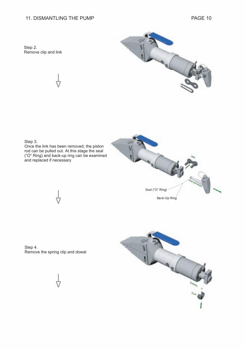
11. DISMANTLING THE PUMP PAGE 10
Step 2.Remove clip and link
Step 3.Once the link has been removed, the piston rod can be pulled out. At this stage the seal (“O” Ring) and back-up ring can be examined and replaced if necessary
Step 4.Remove the spring clip and dowal
Release Screw
End Cap
Release Screw Sleeve
Reservoir
Release Lever
Release Screw
Socket Cap Screw
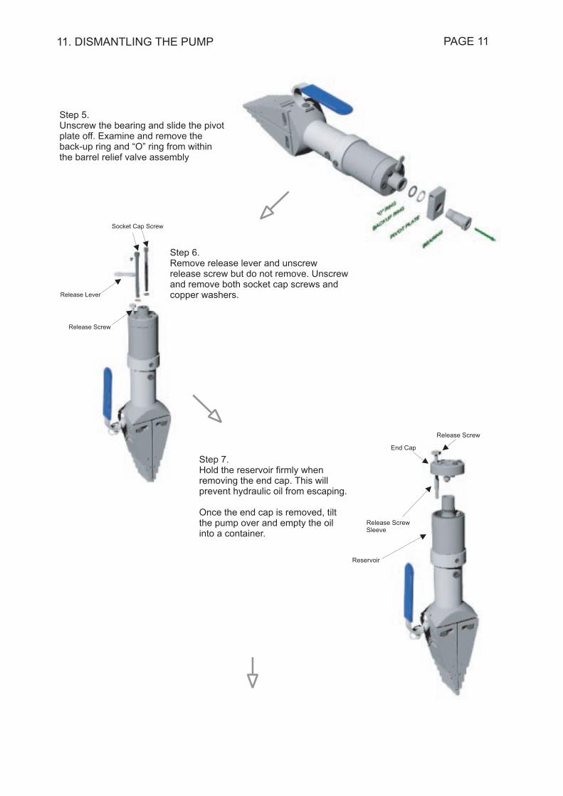
PAGE 11
Step 5.Unscrew the bearing and slide the pivot plate off. Examine and remove the back-up ring and “O” ring from within the barrel relief valve assembly
11. DISMANTLING THE PUMP
Step 6.Remove release lever and unscrew release screw but do not remove. Unscrew and remove both socket cap screws and copper washers.
Step 7.Hold the reservoir firmly when removing the end cap. This will prevent hydraulic oil from escaping.
Once the end cap is removed, tilt the pump over and empty the oilinto a container.
Release Valve Release Body
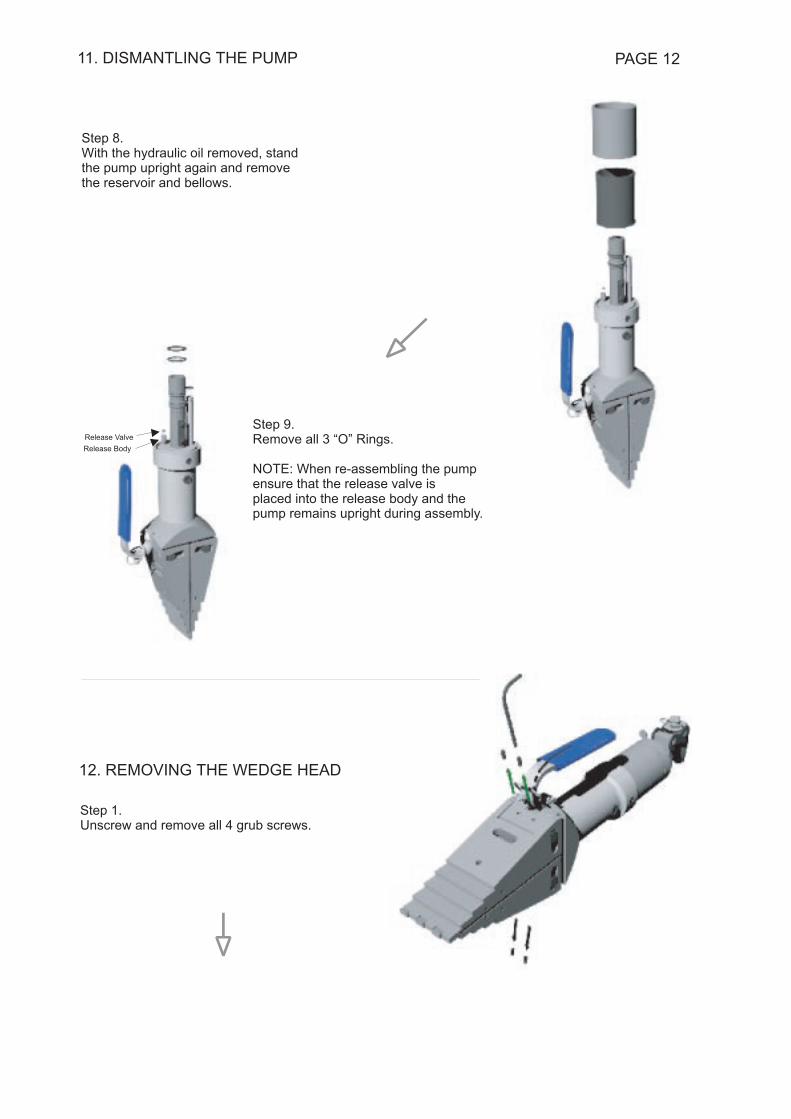
11. DISMANTLING THE PUMP PAGE 12
Step 8.With the hydraulic oil removed, stand the pump upright again and removethe reservoir and bellows.
Step 9.Remove all 3 “O” Rings.
NOTE: When re-assembling the pumpensure that the release valve is placed into the release body and the pump remains upright during assembly.
12. REMOVING THE WEDGE HEAD
Step 1.Unscrew and remove all 4 grub screws.
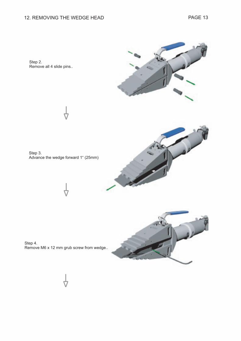
12. REMOVING THE WEDGE HEAD PAGE 13
Step 2.Remove all 4 slide pins..
Step 3.Advance the wedge forward 1“ (25mm)
Step 4.Remove M6 x 12 mm grub screw from wedge..
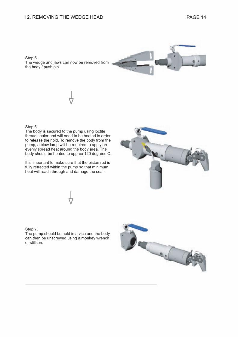
Step 5.The wedge and jaws can now be removed from the body / push pin
12. REMOVING THE WEDGE HEAD PAGE 14
Step 6.The body is secured to the pump using loctite thread sealer and will need to be heated in order to release the hold. To remove the body from the pump, a blow lamp will be required to apply an evenly spread heat around the body area. The body should be heated to approx 120 degrees C.
It is important to make sure that the piston rod is fully retracted within the pump so that minimum heat will reach through and damage the seal.
Step 7.The pump should be held in a vice and the body can then be unscrewed using a monkey wrench or stillson.
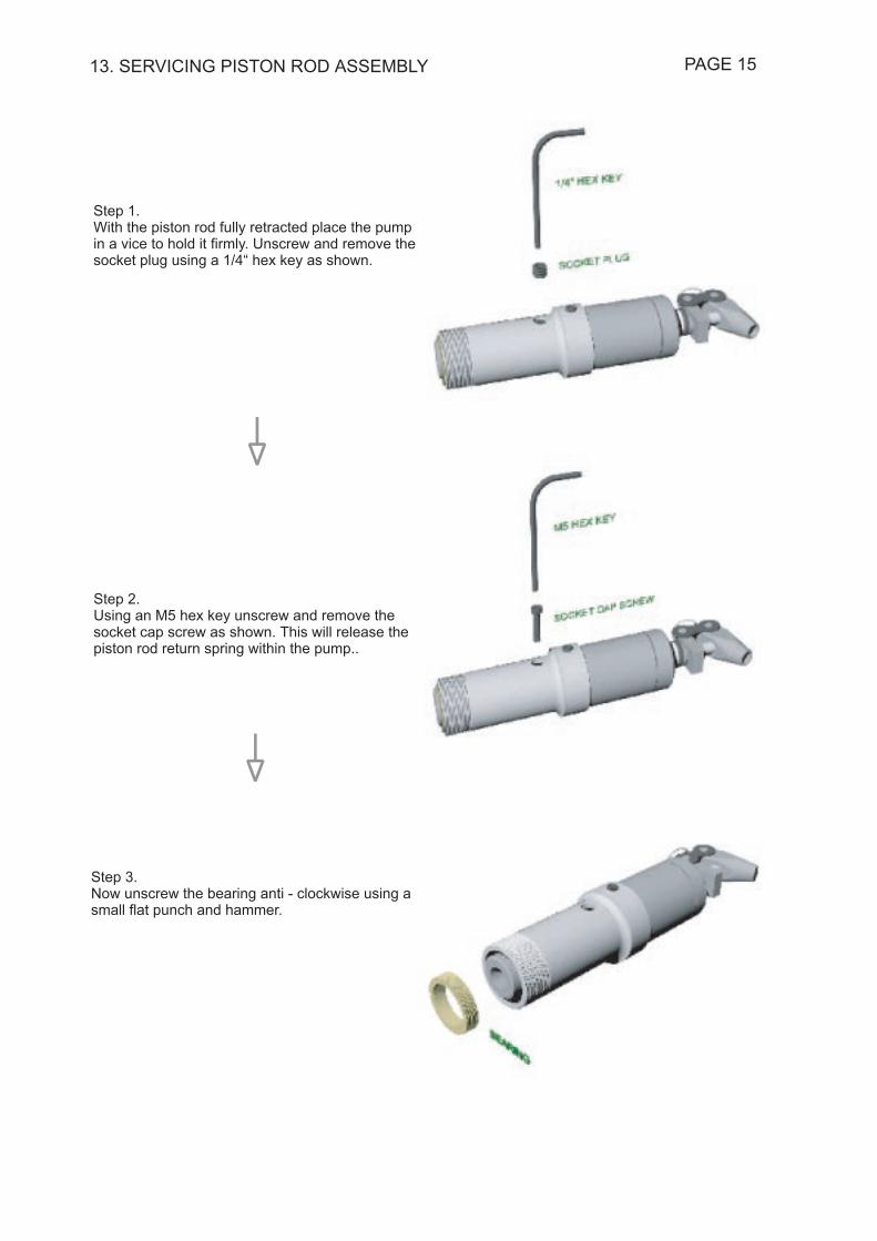
PAGE 1513. SERVICING PISTON ROD ASSEMBLY
Step 1.With the piston rod fully retracted place the pump in a vice to hold it firmly. Unscrew and remove the socket plug using a 1/4“ hex key as shown.
Step 2.Using an M5 hex key unscrew and remove the socket cap screw as shown. This will release the piston rod return spring within the pump..
Step 3.Now unscrew the bearing anti - clockwise using a small flat punch and hammer.
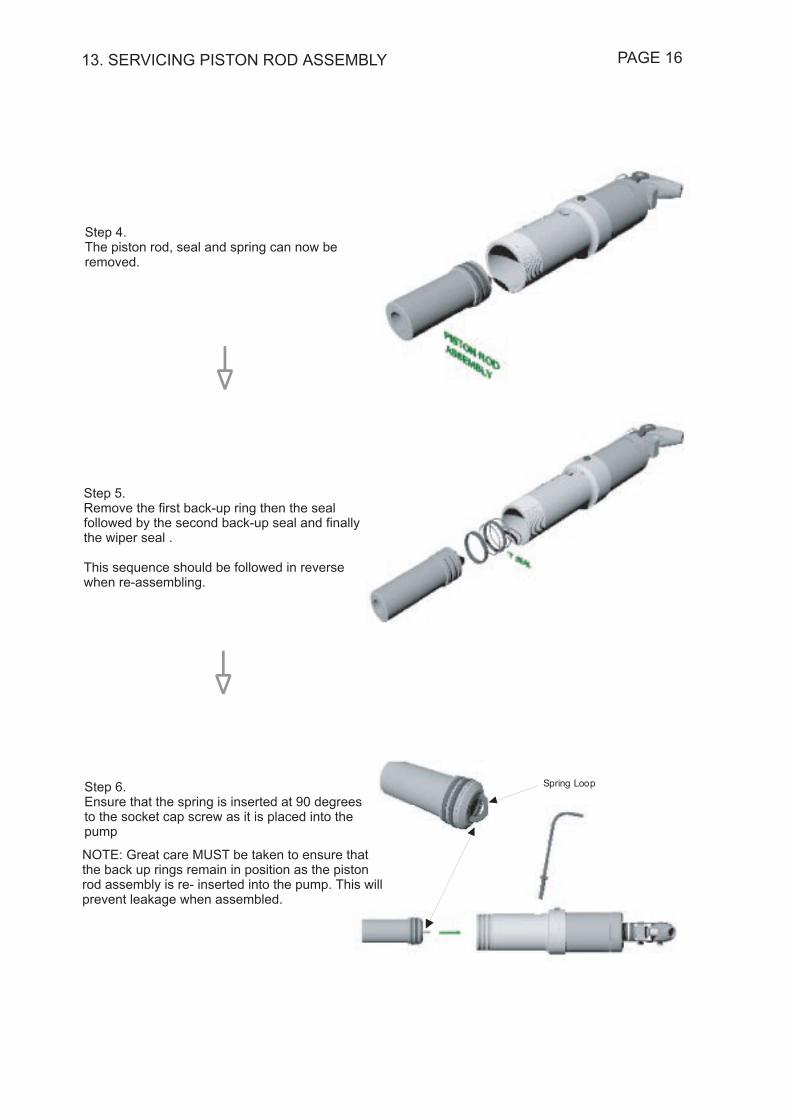
Spring Loop
13. SERVICING PISTON ROD ASSEMBLY PAGE 16
Step 4.The piston rod, seal and spring can now be removed.
Step 5.Remove the first back-up ring then the seal followed by the second back-up seal and finally the wiper seal .
This sequence should be followed in reverse when re-assembling.
Step 6.Ensure that the spring is inserted at 90 degrees to the socket cap screw as it is placed into the pump
NOTE: Great care MUST be taken to ensure that the back up rings remain in position as the piston rod assembly is re- inserted into the pump. This will prevent leakage when assembled.
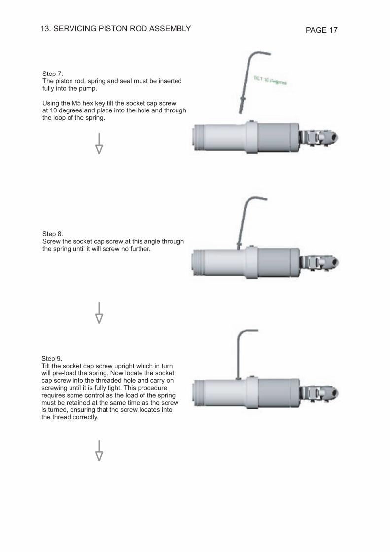
13. SERVICING PISTON ROD ASSEMBLY PAGE 17
Step 7.The piston rod, spring and seal must be inserted fully into the pump.
Using the M5 hex key tilt the socket cap screw at 10 degrees and place into the hole and through the loop of the spring.
Step 8.Screw the socket cap screw at this angle through the spring until it will screw no further.
Step 9.Tilt the socket cap screw upright which in turn will pre-load the spring. Now locate the socket cap screw into the threaded hole and carry on screwing until it is fully tight. This procedure requires some control as the load of the spring must be retained at the same time as the screw is turned, ensuring that the screw locates into the thread correctly.
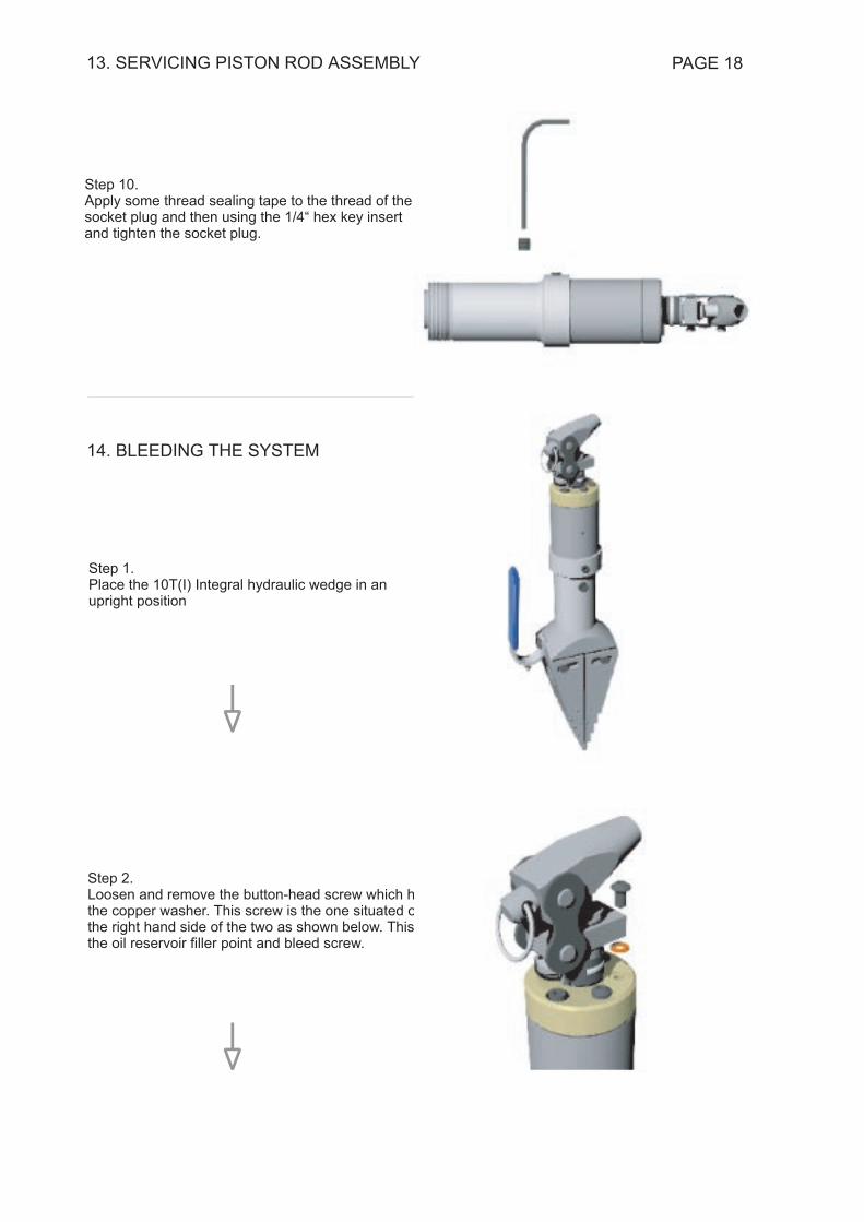
13. SERVICING PISTON ROD ASSEMBLY PAGE 18
Step 10.Apply some thread sealing tape to the thread of the socket plug and then using the 1/4“ hex key insert and tighten the socket plug.
14. BLEEDING THE SYSTEM
Step 1.Place the 10T(I) Integral hydraulic wedge in an upright position
Step 2.Loosen and remove the button-head screw which has the copper washer. This screw is the one situated on the right hand side of the two as shown below. This Is the oil reservoir filler point and bleed screw.
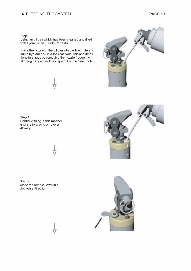
14. BLEEDING THE SYSTEM PAGE 19
Step 3.Using an oil can which has been cleaned and filled with hydraulic oil (Grade 32 centi).
Place the nozzle of the oil can into the filler hole and pump hydraulic oil into the reservoir. This should be done in stages by removing the nozzle frequently allowing trapped air to escape out of the bleed hole.
Step 4.Continue filling in this manner until the hydraulic oil is over-flowing.
Step 5.Close the release lever in a clockwise direction.
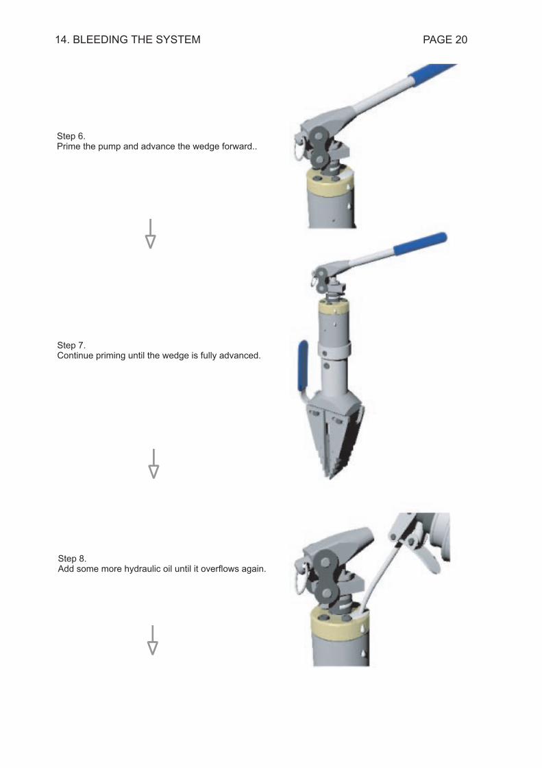
Step 6.Prime the pump and advance the wedge forward..
14. BLEEDING THE SYSTEM PAGE 20
Step 7.Continue priming until the wedge is fully advanced.
Step 8.Add some more hydraulic oil until it overflows again.
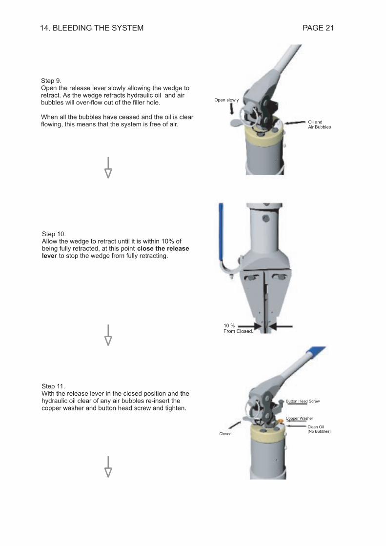
Copper Washer
Button Head Screw
Closed
Clean Oil(No Bubbles)
10 %From Closed.
Oil and Air Bubbles
Open slowly
14. BLEEDING THE SYSTEM PAGE 21
Step 9.Open the release lever slowly allowing the wedge to retract. As the wedge retracts hydraulic oil and air bubbles will over-flow out of the filler hole.
When all the bubbles have ceased and the oil is clear flowing, this means that the system is free of air.
Step 10.Allow the wedge to retract until it is within 10% of being fully retracted, at this point
to stop the wedge from fully retracting. close the release
lever
Step 11.With the release lever in the closed position and the hydraulic oil clear of any air bubbles re-insert the copper washer and button head screw and tighten.
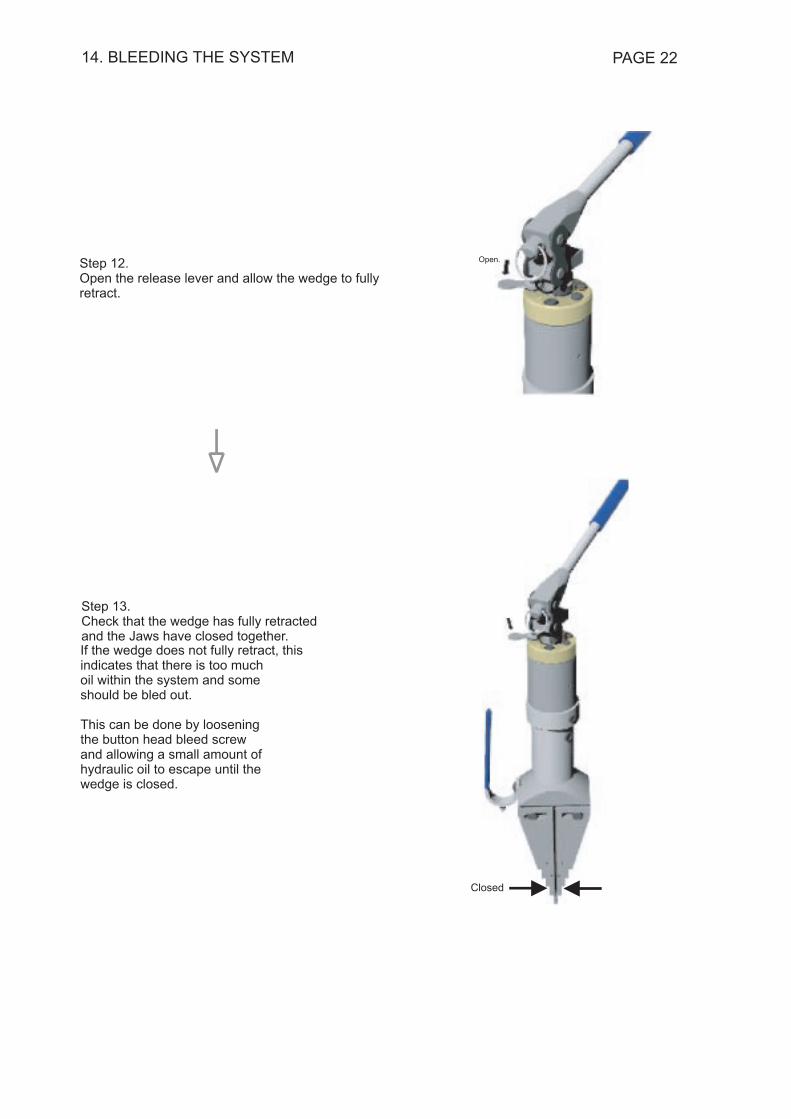
Closed
Open.
14. BLEEDING THE SYSTEM PAGE 22
Step 12.Open the release lever and allow the wedge to fully retract.
Step 13.Check that the wedge has fully retractedand the Jaws have closed together.If the wedge does not fully retract, this indicates that there is too much oil within the system and some should be bled out.
This can be done by loosening the button head bleed screw and allowing a small amount of hydraulic oil to escape until the wedge is closed.
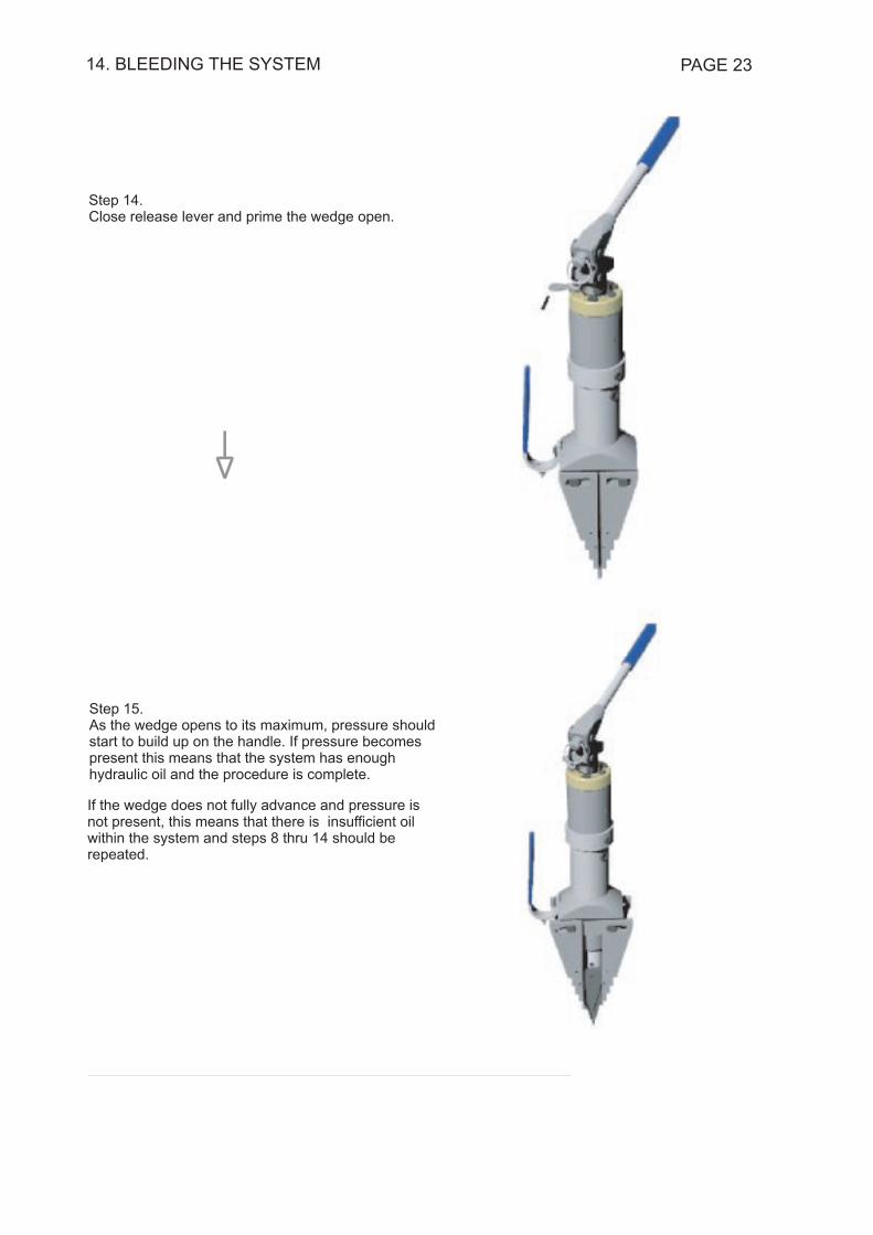
14. BLEEDING THE SYSTEM PAGE 23
Step 14.Close release lever and prime the wedge open.
Step 15.As the wedge opens to its maximum, pressure should start to build up on the handle. If pressure becomes present this means that the system has enough hydraulic oil and the procedure is complete.
If the wedge does not fully advance and pressure is not present, this means that there is insufficient oil within the system and steps 8 thru 14 should be repeated.
EQUALIZER INTERNATIONAL LIMITED Scotland UK,Tel: + 44 (0) 1358 789712 Fax: + 44 (0) 1358 789225 [email protected]
www.equalizerinternational.com