Embed Size (px)
Citation preview

REPAI R GLOBAL VI GI LANCE HANGAR, BUI LDI NG 1414 I FB NO. W912PL- 18- B- 0008EDWARDS AI R FORCE BASE, KERN COUNTY, CA
SECTI ON TABLE OF CONTENTS
DI VI SI ON 01 - GENERAL REQUI REMENTS
SECTI ON 01 32 01. 00 10
PROJECT SCHEDULE
02/15
PART 1 GENERAL
1. 1 REFERENCES 1. 2 SUBMI TTALS 1. 3 PROJECT SCHEDULER QUALI FI CATI ONS
PART 2 PRODUCTS
2. 1 SOFTWARE 2. 1. 1 Gover nment Def aul t Sof t war e 2. 1. 2 Cont r act or Sof t war e 2. 1. 2. 1 Pr i maver a 2. 1. 2. 2 Ot her Than Pr i maver a
PART 3 EXECUTI ON
3. 1 GENERAL REQUI REMENTS 3. 2 BASI S FOR PAYMENT AND COST LOADI NG 3. 2. 1 Act i v i t y Cost Loadi ng 3. 2. 2 Wi t hhol di ngs / Payment Rej ect i on 3. 3 PROJECT SCHEDULE DETAI LED REQUI REMENTS 3. 3. 1 Level of Det ai l Requi r ed 3. 3. 2 Act i v i t y Dur at i ons 3. 3. 3 Pr ocur ement Act i v i t i es 3. 3. 4 Mandat or y Tasks 3. 3. 5 Gover nment Act i v i t i es 3. 3. 6 St andar d Act i v i t y Codi ng Di ct i onar y 3. 3. 6. 1 Wor ker s Per Day ( WRKP) 3. 3. 6. 2 Responsi bl e Par t y Codi ng ( RESP) 3. 3. 6. 3 Ar ea of Wor k Codi ng ( AREA) 3. 3. 6. 4 Modi f i cat i on Number ( MODF) 3. 3. 6. 5 Bi d I t em Codi ng ( BI DI ) 3. 3. 6. 6 Phase of Wor k Codi ng ( PHAS) 3. 3. 6. 7 Cat egor y of Wor k Codi ng ( CATW) 3. 3. 6. 8 Feat ur e of Wor k Codi ng ( FOW) 3. 3. 7 Cont r act Mi l est ones and Const r ai nt s 3. 3. 7. 1 Pr oj ect St ar t Dat e Mi l est one and Const r ai nt 3. 3. 7. 2 End Pr oj ect Fi ni sh Mi l est one and Const r ai nt 3. 3. 7. 3 I nt er i m Compl et i on Dat es and Const r ai nt s 3. 3. 7. 3. 1 St ar t Phase 3. 3. 7. 3. 2 End Phase 3. 3. 8 Cal endar s 3. 3. 9 Open Ended Logi c 3. 3. 10 Def aul t Pr ogr ess Dat a Di sal l owed 3. 3. 11 Out - of - Sequence Pr ogr ess 3. 3. 12 Added and Del et ed Act i v i t i es
SECTI ON 01 32 01. 00 10 Page 1
REPAI R GLOBAL VI GI LANCE HANGAR, BUI LDI NG 1414 I FB NO. W912PL- 18- B- 0008EDWARDS AI R FORCE BASE, KERN COUNTY, CA
3. 3. 13 Or i gi nal Dur at i ons 3. 3. 14 Leads, Lags, and St ar t t o Fi ni sh Rel at i onshi ps 3. 3. 15 Ret ai ned Logi c 3. 3. 16 Per cent Compl et e 3. 3. 17 Remai ni ng Dur at i on 3. 3. 18 Cost Loadi ng of Cl oseout Act i v i t i es 3. 3. 18. 1 As- Bui l t Dr awi ngs 3. 3. 18. 2 O & M Manual s 3. 3. 19 Ear l y Compl et i on Schedul e and t he Ri ght t o Fi ni sh Ear l y 3. 4 PROJECT SCHEDULE SUBMI SSI ONS 3. 4. 1 Pr el i mi nar y Pr oj ect Schedul e Submi ssi on 3. 4. 2 I ni t i al Pr oj ect Schedul e Submi ssi on 3. 4. 3 Per i odi c Schedul e Updat es 3. 5 SUBMI SSI ON REQUI REMENTS 3. 5. 1 Dat a CD/ DVDs 3. 5. 2 Nar r at i ve Repor t 3. 5. 3 Schedul e Repor t s 3. 5. 3. 1 Act i v i t y Repor t 3. 5. 3. 2 Logi c Repor t 3. 5. 3. 3 Tot al Fl oat Repor t 3. 5. 3. 4 Ear ni ngs Repor t by CLI N 3. 5. 3. 5 Schedul e Log 3. 5. 4 Net wor k Di agr am 3. 5. 4. 1 Cont i nuous Fl ow 3. 5. 4. 2 Pr oj ect Mi l est one Dat es 3. 5. 4. 3 Cr i t i cal Pat h 3. 5. 4. 4 Bandi ng 3. 5. 4. 5 Cash Fl ow / Schedul e Var i ance Cont r ol ( SVC) Di agr am 3. 6 PERI ODI C SCHEDULE UPDATE 3. 6. 1 Per i odi c Schedul e Updat e Meet i ngs 3. 6. 2 Updat e Submi ssi on Fol l owi ng Pr ogr ess Meet i ng 3. 7 WEEKLY PROGRESS MEETI NGS 3. 8 REQUESTS FOR TI ME EXTENSI ONS 3. 8. 1 Just i f i cat i on of Del ay 3. 8. 2 Ti me I mpact Anal ysi s ( Pr ospect i ve Anal ysi s) 3. 8. 3 For ensi c Schedul e Anal ysi s ( Ret r ospect i ve Anal ysi s) 3. 8. 4 Fr agment ar y Net wor k ( Fr agnet ) 3. 8. 5 Ti me Ext ensi on 3. 8. 6 I mpact t o Ear l y Compl et i on Schedul e 3. 9 FAI LURE TO ACHI EVE PROGRESS 3. 9. 1 Ar t i f i c i al l y I mpr ovi ng Pr ogr ess 3. 9. 2 Fai l ur e t o Per f or m 3. 9. 3 Recover y Schedul e 3. 10 OWNERSHI P OF FLOAT 3. 11 TRANSFER OF SCHEDULE DATA I NTO RMS/ QCS 3. 12 PRI MAVERA P6 MANDATORY REQUI REMENTS
- - End of Sect i on Tabl e of Cont ent s - -
SECTI ON 01 32 01. 00 10 Page 2
REPAI R GLOBAL VI GI LANCE HANGAR, BUI LDI NG 1414 I FB NO. W912PL- 18- B- 0008EDWARDS AI R FORCE BASE, KERN COUNTY, CA
SECTI ON 01 32 01. 00 10
PROJECT SCHEDULE02/15
PART 1 GENERAL
1. 1 REFERENCES
The publ i cat i ons l i s t ed bel ow f or m a par t of t hi s speci f i cat i on t o t he ext ent r ef er enced. The publ i cat i ons ar e r ef er r ed t o wi t hi n t he t ext by t he basi c desi gnat i on onl y.
AACE I NTERNATI ONAL ( AACE)
AACE 29R- 03 ( 2011) For ensi c Schedul e Anal ysi s
AACE 52R- 06 ( 2006) Ti me I mpact Anal ysi s - As Appl i ed i n Const r uct i on
U. S. ARMY CORPS OF ENGI NEERS ( USACE)
ER 1- 1- 11 ( 1995) Admi ni st r at i on - - Pr ogr ess, Schedul es, and Net wor k Anal ysi s Syst ems
1. 2 SUBMITTALS
Gover nment appr oval i s r equi r ed f or submi t t al s wi t h a " G" desi gnat i on; submi t t al s not havi ng a " G" desi gnat i on ar e f or i nf or mat i on onl y. When used, a desi gnat i on f ol l owi ng t he " G" desi gnat i on i dent i f i es t he of f i ce t hat wi l l r evi ew t he submi t t al f or t he Gover nment . Submi t t al s wi t h an " S" ar e f or i ncl usi on i n t he Sust ai nabi l i t y Not ebook, i n conf or mance t o Section 01 33 29 SUSTAI NABI LI TY REPORTI NG. Submi t t he f ol l owi ng i n accor dance wi t h Sect i on 01 33 00 SUBMI TTAL PROCEDURES:
SD- 01 Pr econst r uct i on Submi t t al s
Pr oj ect Schedul er Qual i f i cat i ons; G
Pr el i mi nar y Pr oj ect Schedul e; G
I ni t i al Pr oj ect Schedul e; G
Per i odi c Schedul e Updat e; G
1. 3 PROJECT SCHEDULER QUALI FI CATI ONS
Desi gnat e an aut hor i zed r epr esent at i ve t o be r esponsi bl e f or t he pr epar at i on of t he schedul e and al l r equi r ed updat i ng and pr oduct i on of r epor t s. The aut hor i zed r epr esent at i ve must have a mi ni mum of 2- year s exper i ence schedul i ng const r uct i on pr oj ect s s i mi l ar i n s i ze and nat ur e t o t hi s pr oj ect wi t h schedul i ng sof t war e t hat meet s t he r equi r ement s of t hi s speci f i cat i on. Repr esent at i ve must have a compr ehensi ve knowl edge of CPM schedul i ng pr i nci pl es and appl i cat i on.
SECTI ON 01 32 01. 00 10 Page 3
REPAI R GLOBAL VI GI LANCE HANGAR, BUI LDI NG 1414 I FB NO. W912PL- 18- B- 0008EDWARDS AI R FORCE BASE, KERN COUNTY, CA
PART 2 PRODUCTS
2. 1 SOFTWARE
The schedul i ng sof t war e ut i l i zed t o pr oduce and updat e t he schedul es r equi r ed her ei n must be capabl e of meet i ng al l r equi r ement s of t hi s specification.
2. 1. 1 Gover nment Def aul t Sof t war e
The Gover nment i nt ends t o use Pr i maver a P6.
2. 1. 2 Cont r act or Sof t war e
Schedul i ng sof t war e used by t he cont r act or must be commer ci al l y avai l abl e f r om t he sof t war e vendor f or pur chase wi t h vendor sof t war e suppor t agr eement s avai l abl e. The sof t war e r out i ne used t o cr eat e t he r equi r ed sdef f i l e must be cr eat ed and suppor t ed by t he sof t war e manuf act ur er .
2. 1. 2. 1 Primavera
I f Pr i maver a P6 i s sel ect ed f or use, pr ovi de t he " xer " expor t f i l e i n a ver si on of P6 i mpor t abl e by t he Gover nment syst em.
2. 1. 2. 2 Ot her Than Pr i maver a
I f t he cont r act or chooses sof t war e ot her t han Pr i maver a P6, t hat i s compl i ant wi t h t hi s speci f i cat i on, pr ovi de f or t he Gover nment ' s use t wo l i censes, t wo comput er s, and t r ai ni ng f or t wo Gover nment empl oyees i n t he use of t he sof t war e. These comput er s wi l l be st and- al one and not connect ed t o Gover nment net wor k. Comput er s and l i censes wi l l be r et ur ned at pr oj ect compl et i on.
PART 3 EXECUTI ON
3. 1 GENERAL REQUI REMENTS
Pr epar e f or appr oval a Pr oj ect Schedul e, as speci f i ed her ei n, pur suant t o FAR Cl ause 52. 236- 15 Schedul es f or Const r uct i on Cont r act s. Show i n t he schedul e t he pr oposed sequence t o per f or m t he wor k and dat es cont empl at ed f or st ar t i ng and compl et i ng al l schedul e act i v i t i es. The schedul i ng of t he ent i r e pr oj ect i s r equi r ed. The schedul i ng of const r uct i on i s t he r esponsi bi l i t y of t he Cont r act or . Cont r act or management per sonnel must act i vel y par t i c i pat e i n i t s devel opment . Subcont r act or s and suppl i er s wor ki ng on t he pr oj ect must al so cont r i but e i n devel opi ng and mai nt ai ni ng an accur at e Pr oj ect Schedul e. Pr ovi de a schedul e t hat i s a f or war d pl anni ng as wel l as a pr oj ect moni t or i ng t ool . Use t he Cr i t i cal Pat h Met hod ( CPM) of net wor k cal cul at i on t o gener at e al l Pr oj ect Schedul es. Pr epar e each Pr oj ect Schedul e usi ng t he Pr ecedence Di agr am Met hod ( PDM) .
3. 2 BASI S FOR PAYMENT AND COST LOADI NG
The schedul e i s t he basi s f or det er mi ni ng cont r act ear ni ngs dur i ng each updat e per i od and t her ef or e t he amount of each pr ogr ess payment . The aggr egat e val ue of al l act i v i t i es coded t o a cont r act CLI N must equal t he val ue of t he CLI N.
SECTI ON 01 32 01. 00 10 Page 4
REPAI R GLOBAL VI GI LANCE HANGAR, BUI LDI NG 1414 I FB NO. W912PL- 18- B- 0008EDWARDS AI R FORCE BASE, KERN COUNTY, CA
3. 2. 1 Act i v i t y Cost Loadi ng
Act i v i t y cost l oadi ng must be r easonabl e and wi t hout f r ont - end l oadi ng. Pr ovi de addi t i onal document at i on t o demonst r at e r easonabl eness i f r equest ed by t he Cont r act i ng Of f i cer .
3. 2. 2 Wi t hhol di ngs / Payment Rej ect i on
Fai l ur e t o meet t he r equi r ement s of t hi s speci f i cat i on may r esul t i n t he di sappr oval of t he pr el i mi nar y, i ni t i al or per i odi c schedul e updat es and subsequent r ej ect i on of payment r equest s unt i l compl i ance i s met .
I n t he event t hat t he Cont r act i ng Of f i cer di r ect s schedul e r evi s i ons and t hose r evi s i ons have not been i ncl uded i n subsequent Pr oj ect Schedul e r evi s i ons or updat es, t he Cont r act i ng Of f i cer may wi t hhol d 10 per cent of pay r equest amount f r om each payment per i od unt i l such r evi s i ons t o t he pr oj ect schedul e have been made.
3. 3 PROJECT SCHEDULE DETAI LED REQUI REMENTS
3. 3. 1 Level of Det ai l Requi r ed
Devel op t he Pr oj ect Schedul e t o t he appr opr i at e l evel of det ai l t o addr ess maj or mi l est ones and t o al l ow f or sat i sf act or y pr oj ect pl anni ng and execut i on. Fai l ur e t o devel op t he Pr oj ect Schedul e t o an appr opr i at e l evel of det ai l wi l l r esul t i n i t s di sappr oval . The Cont r act i ng Of f i cer wi l l consi der , but i s not l i mi t ed t o, t he f ol l owi ng char act er i st i cs and r equi r ement s t o det er mi ne appr opr i at e l evel of det ai l :
3. 3. 2 Act i v i t y Dur at i ons
Reasonabl e act i v i t y dur at i ons ar e t hose t hat al l ow t he pr ogr essof ongoi ng act i v i t i es t o be accur at el y det er mi ned bet ween updat e per i ods. Less t han 2 per cent of al l non- pr ocur ement act i v i t i es may have Or i gi nal Dur at i ons ( OD) gr eat er t han 20 wor k days or 30 cal endar days.
3. 3. 3 Pr ocur ement Act i v i t i es
I ncl ude act i v i t i es associ at ed wi t h t he cr i t i cal submi t t al s and t hei r appr oval s, pr ocur ement , f abr i cat i on, and del i ver y of l ong l ead mat er i al s, equi pment , f abr i cat ed assembl i es, and suppl i es. Long l ead pr ocur ement act i v i t i es ar e t hose wi t h an ant i c i pat ed pr ocur ement sequence of over 90 cal endar days.
3. 3. 4 Mandat or y Tasks
I ncl ude t he f ol l owi ng act i v i t i es/ t asks i n t he i ni t i al pr oj ect schedul e and al l updat es.
a. Submi ssi on, r evi ew and accept ance of SD- 01 Pr econst r uct i on Submi t t al s ( i ndi v i dual act i v i t y f or each) .
b. Submi ssi on, r evi ew and accept ance of f eat ur es r equi r e desi gn compl et i on
c. Submi ssi on of mechani cal / el ect r i cal / i nf or mat i on syst ems l ayout drawings.
d. Long pr ocur ement act i v i t i es
SECTI ON 01 32 01. 00 10 Page 5
REPAI R GLOBAL VI GI LANCE HANGAR, BUI LDI NG 1414 I FB NO. W912PL- 18- B- 0008EDWARDS AI R FORCE BASE, KERN COUNTY, CA
e. Submi ssi on and appr oval of O & M manual s.
f . Submi ssi on and appr oval of as- bui l t dr awi ngs.
g. Submi ssi on and appr oval of DD1354 dat a and i nst al l ed equi pment l i s t s.
h. Submi ssi on and appr oval of t est i ng and ai r bal ance ( TAB) .
i . Submi ssi on of TAB speci al i st desi gn r evi ew r epor t .
j . Submi ssi on and appr oval of f i r e pr ot ect i on speci al i st .
k. Submi ssi on and appr oval of Bui l di ng Commi ssi oni ng Pl an, t est dat a, and r epor t s: Devel op t he schedul e l ogi c associ at ed wi t h t est i ng and commi ssi oni ng of mechani cal syst ems t o a l evel of det ai l consi st ent wi t h t he cont r act commi ssi oni ng r equi r ement s. Al l t asks associ at ed wi t h al l bui l di ng t est i ng and commi ssi oni ng wi l l be compl et ed pr i or t o submi ssi on of bui l di ng commi ssi oni ng r epor t and subsequent cont r act completion.
l . Ai r and wat er bal anci ng.
m. Bui l di ng commi ssi oni ng - Funct i onal Per f or mance Test i ng.
n. Cont r ol s t est i ng pl an submi ssi on.
o. Cont r ol s t est i ng.
p. Per f or mance Ver i f i cat i on t est i ng.
q. Ot her syst ems t est i ng, i f r equi r ed.
r . Cont r act or ' s pr e- f i nal i nspect i on.
s. Cor r ect i on of punch l i s t f r om Cont r act or ' s pr e- f i nal i nspect i on.
t . Gover nment ' s pr e- f i nal i nspect i on.
u. Cor r ect i on of punch l i s t f r om Gover nment ' s pr e- f i nal i nspect i on.
v. Fi nal i nspect i on.
3. 3. 5 Gover nment Act i v i t i es
Show Gover nment and ot her agency act i v i t i es t hat coul d i mpact pr ogr ess. These act i v i t i es i ncl ude, but ar e not l i mi t ed t o: approvals, envi r onment al per mi t appr oval s by St at e r egul at or s, i nspect i ons, ut i l i t y t i e- i n, Gover nment Fur ni shed Equi pment ( GFE) and Not i ce t o Pr oceed ( NTP) f or phasi ng r equi r ement s.
3. 3. 6 St andar d Act i v i t y Codi ng Di ct i onar y
Use t he act i v i t y codi ng st r uct ur e def i ned i n t he St andar d Dat a Exchange For mat ( SDEF) i n ER 1- 1- 11. Thi s exact st r uct ur e i s mandat or y. Devel op and assi gn al l Act i v i t y Codes t o act i v i t i es as det ai l ed her ei n. A t empl at e SDEF compat i bl e schedul e backup f i l e i s avai l abl e on t he QCS web site: http://rms.usace.army.mil .
SECTI ON 01 32 01. 00 10 Page 6

REPAI R GLOBAL VI GI LANCE HANGAR, BUI LDI NG 1414 I FB NO. W912PL- 18- B- 0008EDWARDS AI R FORCE BASE, KERN COUNTY, CA
The SDEF f or mat i s as f ol l ows:
Field Act i v i t y Code Length Description
1 WRKP 3 Wor ker s per day
2 RESP 4 Responsi bl e par t y
3 AREA 4 Ar ea of wor k
4 MODF 6 Modi f i cat i on Number
5 BIDI 6 Bi d I t em ( CLI N)
6 PHAS 2 Phase of wor k
7 CATW 1 Cat egor y of wor k
8 FOW 20 Feat ur e of wor k*
* Some syst ems r equi r e t hat FEATURE OF WORK val ues be pl aced i n sever al act i v i t y code f i el ds. The not at i on shown i s f or Pr i maver a P6. Ref er t o t he speci f i c sof t war e gui del i nes wi t h r espect t o t he FEATURE OF WORK f i el d r equi r ement s.
3. 3. 6. 1 Wor ker s Per Day ( WRKP)
Assi gn Wor ker s per Day f or al l f i el d const r uct i on or di r ect wor k act i v i t i es, i f di r ect ed by t he Cont r act i ng Of f i cer . Wor ker s per day i s based on t he aver age number of wor ker s expect ed each day t o per f or m a t ask f or t he dur at i on of t hat act i v i t y.
3. 3. 6. 2 Responsi bl e Par t y Codi ng ( RESP)
Assi gn r esponsi bi l i t y code f or al l act i v i t i es t o t he Pr i me Cont r act or , Subcont r act or ( s) or Gover nment agency( i es) r esponsi bl e f or per f or mi ng t he activity.
a. Act i v i t i es coded wi t h a Gover nment Responsi bi l i t y code i ncl ude, but ar e not l i mi t ed t o: Gover nment appr oval s, Gover nment desi gn r evi ews, envi r onment al per mi t appr oval s by St at e r egul at or s, Gover nment Fur ni shed Pr oper t y/ Equi pment ( GFP) and Not i ce t o Pr oceed ( NTP) f or phasi ng r equi r ement s.
b. Act i v i t i es cannot have mor e t han one Responsi bi l i t y Code. Exampl es of accept abl e act i v i t y code val ues ar e: DOR ( f or t he desi gner of r ecor d) ; ELEC ( f or t he el ect r i cal subcont r act or ) ; MECH ( f or t he mechani cal subcont r act or ) ; and GOVT ( f or USACE) .
3. 3. 6. 3 Ar ea of Wor k Codi ng ( AREA)
Assi gn Wor k Ar ea code t o act i v i t i es based upon t he wor k ar ea i n whi ch t he act i v i t y occur s. Def i ne wor k ar eas based on r esour ce const r ai nt s or space const r ai nt s t hat woul d pr ecl ude a r esour ce, such as a par t i cul ar t r ade or
SECTI ON 01 32 01. 00 10 Page 7
REPAI R GLOBAL VI GI LANCE HANGAR, BUI LDI NG 1414 I FB NO. W912PL- 18- B- 0008EDWARDS AI R FORCE BASE, KERN COUNTY, CA
cr af t wor k cr ew f r om wor ki ng i n mor e t han one wor k ar ea at a t i me due t o r est r ai nt s on r esour ces or space. Exampl es of Wor k Ar ea Codi ng i ncl ude di f f er ent ar eas wi t hi n a f l oor of a bui l di ng, di f f er ent f l oor s wi t hi n a bui l di ng, and di f f er ent bui l di ngs wi t hi n a compl ex of bui l di ngs. Act i v i t i es cannot have mor e t han one Wor k Ar ea Code.
Not al l act i v i t i es ar e r equi r ed t o be Wor k Ar ea coded. A l ack of Wor k Ar ea codi ng i ndi cat es t he act i v i t y i s not r esour ce or space const r ai ned.
3. 3. 6. 4 Modi f i cat i on Number ( MODF)
Assi gn a Modi f i cat i on Number Code t o any act i v i t y or sequence of act i v i t i es added t o t he schedul e as a r esul t of a Cont r act Modi f i cat i on, when appr oved by Cont r act i ng Of f i cer . Key al l Code val ues t o t he Gover nment ' s modi f i cat i on number i ng syst em. An act i v i t y can have onl y one Modi f i cat i on Number Code.
3. 3. 6. 5 Bi d I t em Codi ng ( BI DI )
Assi gn a Bi d I t em Code t o al l act i v i t i es usi ng t he Cont r act Li ne I t em Schedul e ( CLI N) t o whi ch t he act i v i t y bel ongs, even when an act i v i t y i s not cost l oaded. An act i v i t y can have onl y one BI DI Code.
3. 3. 6. 6 Phase of Wor k Codi ng ( PHAS)
Assi gn Phase of Wor k Code t o al l act i v i t i es. Exampl es of phase of wor k ar e pr ocur ement phase and const r uct i on phase. Each act i v i t y can have onl y one Phase of Wor k code.
a. Code pr oposed f ast t r ack desi gn and const r uct i on phases pr oposed t o al l ow f i l t er i ng and or gani z i ng t he schedul e by f ast t r ack desi gn and const r uct i on packages.
b. I f t he cont r act speci f i es phasi ng wi t h separ at el y def i ned per f or mance per i ods, i dent i f y a Phase Code t o al l ow f i l t er i ng and or gani z i ng t he schedul e accor di ngl y.
3. 3. 6. 7 Cat egor y of Wor k Codi ng ( CATW)
Assi gn a Cat egor y of Wor k Code t o al l act i v i t i es. Cat egor y of Wor k Codes i ncl ude, but ar e not l i mi t ed t o const r uct i on submi t t al , pr ocur ement , f abr i cat i on, weat her sensi t i ve i nst al l at i on, non- weat her sensi t i ve i nst al l at i on, st ar t - up, and t est i ng act i v i t i es. Each act i v i t y can have no mor e t han one Cat egor y of Wor k Code.
3. 3. 6. 8 Feat ur e of Wor k Codi ng ( FOW)
Assi gn a Feat ur e of Wor k Code t o appr opr i at e act i v i t i es based on t he Def i nabl e Feat ur e of Wor k t o whi ch t he act i v i t y bel ongs based on t he appr oved QC pl an.
Def i nabl e Feat ur e of Wor k i s def i ned i n Sect i on 01 45 00. 00 10 QUALI TY CONTROL. An act i v i t y can have onl y one Feat ur e of Wor k Code.
3. 3. 7 Cont r act Mi l est ones and Const r ai nt s
Mi l est one act i v i t i es ar e t o be used f or s i gni f i cant pr oj ect event s i ncl udi ng, but not l i mi t ed t o, pr oj ect phasi ng, pr oj ect st ar t and end act i v i t i es, or i nt er i m compl et i on dat es. The use of ar t i f i c i al f l oat
SECTI ON 01 32 01. 00 10 Page 8
REPAI R GLOBAL VI GI LANCE HANGAR, BUI LDI NG 1414 I FB NO. W912PL- 18- B- 0008EDWARDS AI R FORCE BASE, KERN COUNTY, CA
const r ai nt s such as " zer o f r ee f l oat " or " zer o t ot al f l oat " ar e pr ohi bi t ed.
Mandat or y const r ai nt s t hat i gnor e or ef f ect net wor k l ogi c ar e pr ohi bi t ed. No const r ai ned dat es ar e al l owed i n t he schedul e ot her t han t hose speci f i ed her ei n. Submi t addi t i onal const r ai nt s t o t he Cont r act i ng Of f i cer f or appr oval on a case by case basi s.
3. 3. 7. 1 Pr oj ect St ar t Dat e Mi l est one and Const r ai nt
The f i r st act i v i t y i n t he pr oj ect schedul e must be a st ar t mi l est one t i t l ed " NTP Acknowl edged, " whi ch must have a " St ar t On" const r ai nt dat e equal t o t he dat e t hat t he NTP i s acknowl edged.
3. 3. 7. 2 End Pr oj ect Fi ni sh Mi l est one and Const r ai nt
The l ast act i v i t y i n t he schedul e must be a f i ni sh mi l est one t i t l ed " End Project."
Const r ai n t he pr oj ect schedul e t o t he Cont r act Compl et i on Dat e i n such a way t hat i f t he schedul e cal cul at es an ear l y f i ni sh, t hen t he f l oat cal cul at i on f or " End Pr oj ect " mi l est one r ef l ect s posi t i ve f l oat on t he l ongest pat h. I f t he pr oj ect schedul e cal cul at es a l at e f i ni sh, t hen t he " End Pr oj ect " mi l est one f l oat cal cul at i on r ef l ect s negat i ve f l oat on t he l ongest pat h. The Gover nment i s under no obl i gat i on t o accel er at e Gover nment act i v i t i es t o suppor t a Cont r act or ' s ear l y compl et i on.
3. 3. 7. 3 I nt er i m Compl et i on Dat es and Const r ai nt s
Const r ai n cont r act ual l y speci f i ed i nt er i m compl et i on dat es t o show negat i ve f l oat when t he cal cul at ed l at e f i ni sh dat e of t he l ast act i v i t y i n t hat phase i s l at er t han t he speci f i ed i nt er i m compl et i on dat e.
3. 3. 7. 3. 1 St ar t Phase
Use a st ar t mi l est one as t he f i r st act i v i t y f or a pr oj ect phase. Cal l t he st ar t mi l est one " St ar t Phase X" wher e " X" r ef er s t o t he phase of wor k.
3. 3. 7. 3. 2 End Phase
Use a f i ni sh mi l est one as t he l ast act i v i t y f or a pr oj ect phase. Cal l t he f i ni sh mi l est one " End Phase X" wher e " X" r ef er s t o t he phase of wor k.
3. 3. 8 Calendars
Schedul e act i v i t i es on a Cal endar t o whi ch t he act i v i t y l ogi cal l y bel ongs. Devel op cal endar s t o accommodat e any cont r act def i ned wor k per i od such as a 7- day cal endar f or Gover nment Accept ance act i v i t i es, concr et e cur e t i mes, et c. Devel op t he def aul t Cal endar t o mat ch t he physi cal wor k pl an wi t h non- wor k per i ods i dent i f i ed i ncl udi ng weekends and hol i days. Devel op sSeasonal Cal endar ( s) and assi gn t o seasonal l y af f ect ed act i v i t i es as appl i cabl e.
I f an act i v i t y i s weat her sensi t i ve i t shoul d be assi gned t o a cal endar showi ng non- wor k days on a mont hl y basi s, wi t h t he non- wor k days sel ect ed at r andom acr oss t he weeks of t he cal endar , usi ng t he ant i c i pat ed adver se weat her del ay wor k days pr ovi ded i n t he Speci al Cont r act [ Cl auses] [ Requi r ement ns] . Assi gn non- wor k days over a seven- day week as weat her r ecor ds ar e compi l ed on seven- day weeks, whi ch may cause some of t he
SECTI ON 01 32 01. 00 10 Page 9
REPAI R GLOBAL VI GI LANCE HANGAR, BUI LDI NG 1414 I FB NO. W912PL- 18- B- 0008EDWARDS AI R FORCE BASE, KERN COUNTY, CA
weat her r el at ed non- wor k days t o f al l on weekends.
3. 3. 9 Open Ended Logi c
Onl y t wo open ended act i v i t i es ar e al l owed: t he f i r st act i v i t y " NTP Acknowl edged" may have no pr edecessor l ogi c, and t he l ast act i v i t y - " End Pr oj ect " may have no successor l ogi c.
Pr edecessor open ended l ogi c may be al l owed i n a t i me i mpact anal yses upon t he Cont r act i ng Of f i cer ' s appr oval .
3. 3. 10 Def aul t Pr ogr ess Dat a Di sal l owed
Act ual St ar t and Fi ni sh dat es must not aut omat i cal l y updat e wi t h def aul t mechani sms i ncl uded i n t he schedul i ng sof t war e. Updat i ng of t he per cent compl et e and t he r emai ni ng dur at i on of any act i v i t y must be i ndependent f unct i ons. Di sabl e pr ogr am f eat ur es t hat cal cul at e one of t hese par amet er s f r om t he ot her . Act i v i t y Act ual St ar t ( AS) and Act ual Fi ni sh ( AF) dat es assi gned dur i ng t he updat i ng pr ocess must mat ch t hose dat es pr ovi ded i n t he Cont r act or Qual i t y Cont r ol Repor t s. Fai l ur e t o document t he AS and AF dat es i n t he Dai l y Qual i t y Cont r ol r epor t wi l l r esul t i n di sappr oval of t he Cont r act or ' s schedul e.
3. 3. 11 Out - of - Sequence Pr ogr ess
Act i v i t i es t hat have pr ogr essed bef or e al l pr ecedi ng l ogi c has been sat i sf i ed ( Out - of - Sequence Pr ogr ess) wi l l be al l owed onl y on a case- by- case basi s subj ect t o appr oval by t he Cont r act i ng Of f i cer . Pr opose l ogi c cor r ect i ons t o el i mi nat e out of sequence pr ogr ess or j ust i f y not changi ng t he sequenci ng f or appr oval pr i or t o submi t t i ng an updat ed pr oj ect schedul e. Addr ess out of sequence pr ogr ess or l ogi c changes i n t he Nar r at i ve Repor t and i n t he per i odi c schedul e updat e meet i ngs.
3. 3. 12 Added and Del et ed Act i v i t i es
Do not del et e act i v i t i es f r om t he pr oj ect schedul e or add new act i v i t i es t o t he schedul e wi t hout appr oval f r om t he Cont r act i ng Of f i cer . Act i v i t y I D and descr i pt i on changes ar e consi der ed new act i v i t i es and cannot be changed wi t hout Cont r act i ng Of f i cer appr oval .
3. 3. 13 Or i gi nal Dur at i ons
Act i v i t y Or i gi nal Dur at i ons ( OD) must be r easonabl e t o per f or m t he wor k i t em. OD changes ar e pr ohi bi t ed unl ess j ust i f i cat i on i s pr ovi dedand appr oved by t he Cont r act i ng Of f i cer .
3. 3. 14 Leads, Lags, and St ar t t o Fi ni sh Rel at i onshi ps
Lags must be r easonabl e as det er mi ned by t he Gover nment and not used i n pl ace of r eal i st i c or i gi nal dur at i ons, must not be i n pl ace t o ar t i f i c i al l y absor b f l oat , or t o r epl ace pr oper schedul e l ogi c.
a. Leads ( negat i ve l ags) ar e pr ohi bi t ed.
b. St ar t t o Fi ni sh ( SF) r el at i onshi ps ar e pr ohi bi t ed.
3. 3. 15 Ret ai ned Logi c
Schedul e cal cul at i ons must r et ai n t he l ogi c bet ween pr edecessor s and
SECTI ON 01 32 01. 00 10 Page 10
REPAI R GLOBAL VI GI LANCE HANGAR, BUI LDI NG 1414 I FB NO. W912PL- 18- B- 0008EDWARDS AI R FORCE BASE, KERN COUNTY, CA
successor s ( " r et ai ned l ogi c" mode) even when t he successor act i v i t y( s) st ar t s and t he pr edecessor act i v i t y( s) has not f i ni shed ( out - of - sequence pr ogr ess) . Sof t war e f eat ur es t hat i n ef f ect sever t he t i e bet ween pr edecessor and successor act i v i t i es when t he successor has st ar t ed and t he pr edecessor l ogi c i s not sat i sf i ed ( " pr ogr ess over r i de" ) ar e not be allowed.
3. 3. 16 Per cent Compl et e
Updat e t he per cent compl et e f or each act i v i t y st ar t ed, based on t he r eal i st i c assessment of ear ned val ue. Act i v i t i es whi ch ar e compl et e but f or r emai ni ng mi nor punch l i s t wor k and whi ch do not r est r ai n t he i ni t i at i on of successor act i v i t i es may be decl ar ed 100 per cent compl et e t o al l ow f or pr oper schedul e management .
3. 3. 17 Remai ni ng Dur at i on
Updat e t he r emai ni ng dur at i on f or each act i v i t y based on t he number of est i mat ed wor k days i t wi l l t ake t o compl et e t he act i v i t y. Remai ni ng dur at i on may not mat hemat i cal l y cor r el at e wi t h per cent age f ound under par agr aph ent i t l ed Per cent Compl et e.
3. 3. 18 Cost Loadi ng of Cl oseout Act i v i t i es
Cost l oad t he " Cor r ect i on of punch l i s t f r om Gover nment pr e- f i nal i nspect i on" act i v i t y( i es) not l ess t han 1 per cent of t he pr esent cont r act val ue. Act i v i t y( i es) may be decl ar ed 100 per cent compl et e upon t he Gover nment ' s ver i f i cat i on of compl et i on and cor r ect i on of al l punch l i s t wor k i dent i f i ed dur i ng Gover nment pr e- f i nal i nspect i on( s) .
3. 3. 18. 1 As- Bui l t Dr awi ngs
I f t her e i s no separ at e cont r act l i ne i t em ( CLI N) f or as- bui l t dr awi ngs, cost l oad t he " Submi ssi on and appr oval of as- bui l t dr awi ngs" act i v i t y not l ess t han $35, 000 or 1 per cent of t he pr esent cont r act val ue, whi ch ever i s gr eat er , up t o $200, 000. Act i v i t y wi l l be decl ar ed 100 per cent compl et e upon t he Gover nment ' s appr oval .
3. 3. 18. 2 O & M Manual s
Cost l oad t he " Submi ssi on and appr oval of O & M manual s" act i v i t y not l ess t han $20, 000. Act i v i t y wi l l be decl ar ed 100 per cent compl et e upon t he Gover nment ' s appr oval of al l O & M manual s.
3. 3. 19 Ear l y Compl et i on Schedul e and t he Ri ght t o Fi ni sh Ear l y
An Ear l y Compl et i on Schedul e i s an I ni t i al Pr oj ect Schedul e ( I PS) t hat i ndi cat es al l scope of t he r equi r ed cont r act wor k wi l l be compl et ed bef or e t he cont r act ual l y r equi r ed compl et i on dat e.
a. No I PS i ndi cat i ng an Ear l y Compl et i on wi l l be accept ed wi t hout bei ng f ul l y r esour ce- l oaded ( i ncl udi ng cr ew si zes and manhour s) and t he Gover nment agr eei ng t hat t he schedul e i s r easonabl e and achi evabl e.
b. The Gover nment i s under no obl i gat i on t o accel er at e wor k i t ems i t i s r esponsi bl e f or t o ensur e t hat t he ear l y compl et i on i s met nor i s i t r esponsi bl e t o modi f y i ncr ement al f undi ng ( i f appl i cabl e) f or t he pr oj ect t o meet t he cont r act or ' s accel er at ed wor k.
SECTI ON 01 32 01. 00 10 Page 11
REPAI R GLOBAL VI GI LANCE HANGAR, BUI LDI NG 1414 I FB NO. W912PL- 18- B- 0008EDWARDS AI R FORCE BASE, KERN COUNTY, CA
3. 4 PROJECT SCHEDULE SUBMI SSI ONS
Pr ovi de t he submi ssi ons as descr i bed bel ow. The dat a CD/ DVD, r epor t s, and net wor k di agr ams r equi r ed f or each submi ssi on ar e cont ai ned i n par agr aph SUBMI SSI ON REQUI REMENTS. I f t he Cont r act or f ai l s or r ef uses t o f ur ni sh t he i nf or mat i on and schedul e updat es as set f or t h her ei n, t hen t he Cont r act or wi l l be deemed not t o have pr ovi ded an est i mat e upon whi ch a pr ogr ess payment can be made.
Revi ew comment s made by t he Gover nment on t he schedul e( s) do not r el i eve t he Cont r act or f r om compl i ance wi t h r equi r ement s of t he Cont r act Document s.
3. 4. 1 Pr el i mi nar y Pr oj ect Schedul e Submi ssi on
Wi t hi n 15 cal endar days af t er t he NTP i s acknowl edged submi t t he Pr el i mi nar y Pr oj ect Schedul e def i ni ng t he pl anned oper at i ons det ai l ed f or t he f i r st 90 cal endar days f or appr oval . The appr oved Pr el i mi nar y Pr oj ect Schedul e wi l l be used f or payment pur poses not t o exceed 90 cal endar days af t er NTP. Compl et el y cost l oad t he Pr el i mi nar y Pr oj ect Schedul e t o bal ance t he cont r act awar d CLI NS shown on t he Pr i ce Schedul e. The Pr el i mi nar y Pr oj ect Schedul e may be summar y i n nat ur e f or t he r emai ni ng per f or mance per i od. I t must be ear l y st ar t and l at e f i ni sh const r ai ned and l ogi cal l y t i ed as speci f i ed. The Pr el i mi nar y Pr oj ect Schedul e f or ms t he basi s f or t he I ni t i al Pr oj ect Schedul e speci f i ed her ei n and must i ncl ude al l of t he r equi r ed pl an and pr ogr am pr epar at i ons, submi ssi ons and appr oval s i dent i f i ed i n t he cont r act ( f or exampl e, Qual i t y Cont r ol Pl an, Saf et y Pl an, and Envi r onment al Pr ot ect i on Pl an) as wel l as desi gn act i v i t i es, pl anned submi ssi ons of al l ear l y desi gn packages, per mi t t i ng act i v i t i es, desi gn r evi ew conf er ence act i v i t i es, and ot her non- const r uct i on act i v i t i es i nt ended t o occur wi t hi n t he f i r st 90 cal endar days. Gover nment accept ance of t he associ at ed desi gn package( s) and al l ot her speci f i ed Pr ogr am and Pl an appr oval s must occur pr i or t o any pl anned const r uct i on act i v i t i es. Act i v i t y code any act i v i t i es t hat ar e summar y i n nat ur e af t er t he f i r st 90 cal endar days wi t h Bi d I t em ( CLI N) code ( BI DI ) , Responsi bi l i t y Code ( RESP) and Feat ur e of Wor k code ( FOW) .
3. 4. 2 I ni t i al Pr oj ect Schedul e Submi ssi on
Submi t t he I ni t i al Pr oj ect Schedul e f or appr oval wi t hi n 42 cal endar days af t er not i ce t o pr oceed i s i ssued. The schedul e must demonst r at e a r easonabl e and r eal i st i c sequence of act i v i t i es whi ch r epr esent al l wor k t hr ough t he ent i r e cont r act per f or mance per i od. No payment wi l l be made f or wor k i t ems not f ul l y det ai l ed i n t he Pr oj ect Schedul e.
3. 4. 3 Per i odi c Schedul e Updat es
Updat e t he Pr oj ect Schedul e on a r egul ar basi s, mont hl y at a mi ni mum. Pr ovi de a dr af t Per i odi c Schedul e Updat e f or r evi ew at t he schedul e updat e meet i ngs as pr escr i bed i n t he par agr aph PERI ODI C SCHEDULE UPDATE MEETI NGS. These updat es wi l l enabl e t he Gover nment t o assess Cont r act or ' s pr ogr ess.
a. Updat e i nf or mat i on i ncl udi ng Act ual St ar t Dat es ( AS) , Act ual Fi ni sh Dat es ( AF) , Remai ni ng Dur at i ons ( RD) , and Per cent Compl et e i s subj ect t o t he appr oval of t he Gover nment at t he meet i ng.
b. AS and AF dat es must mat ch t he dat e( s) r epor t ed on t he Cont r act or ' s Qual i t y Cont r ol Repor t f or an act i v i t y st ar t or f i ni sh.
SECTI ON 01 32 01. 00 10 Page 12
REPAI R GLOBAL VI GI LANCE HANGAR, BUI LDI NG 1414 I FB NO. W912PL- 18- B- 0008EDWARDS AI R FORCE BASE, KERN COUNTY, CA
3. 5 SUBMI SSI ON REQUI REMENTS
Submi t t he f ol l owi ng i t ems f or t he Pr el i mi nar y Schedul e, I ni t i al Schedul e, and ever y Per i odi c Schedul e Updat e t hr oughout t he l i f e of t he pr oj ect :
3. 5. 1 Dat a CD/ DVDs
Pr ovi de t wo set s of dat a CD/ DVDs cont ai ni ng t he cur r ent pr oj ect schedul e and al l pr evi ousl y submi t t ed schedul es i n t he f or mat of t he schedul i ng sof t war e ( e. g. . xer ) . Al so i ncl ude on t he dat a CD/ DVDs t he Nar r at i ve Repor t and al l r equi r ed Schedul e Repor t s. Label each CD/ DVD i ndi cat i ng t he t ype of schedul e ( Pr el i mi nar y, I ni t i al , Updat e) , f ul l cont r act number , Dat a Dat e and f i l e name. Each schedul e must have a uni que f i l e name and use pr oj ect speci f i c set t i ngs.
3. 5. 2 Nar r at i ve Repor t
Pr ovi de a Nar r at i ve Repor t wi t h each schedul e submi ssi on. The Nar r at i ve Repor t i s expect ed t o communi cat e t o t he Gover nment t he t hor ough anal ysi s of t he schedul e out put and t he pl ans t o compensat e f or any pr obl ems, ei t her cur r ent or pot ent i al , whi ch ar e r eveal ed t hr ough t hat anal ysi s. I ncl ude t he f ol l owi ng i nf or mat i on as mi ni mum i n t he Nar r at i ve Repor t :
a. I dent i f y and di scuss t he wor k schedul ed t o st ar t i n t he next updat e period.
b. A descr i pt i on of act i v i t i es al ong t he t wo most cr i t i cal pat hs wher e t he t ot al f l oat i s l ess t han or equal t o 20 wor k days.
c. A descr i pt i on of cur r ent and ant i c i pat ed pr obl em ar eas or del ayi ng f act or s and t hei r i mpact and an expl anat i on of cor r ect i ve act i ons t aken or r equi r ed t o be t aken.
d. I dent i f y and expl ai n why act i v i t i es based on t hei r cal cul at ed l at e dat es shoul d have ei t her st ar t ed or f i ni shed dur i ng t he updat e per i od but di d not .
e. I dent i f y and di scuss al l schedul e changes by act i v i t y I D and act i v i t y name i ncl udi ng what speci f i cal l y was changed and why t he change was needed. I ncl ude at a mi ni mum new and del et ed act i v i t i es, l ogi c changes, dur at i on changes, cal endar changes, l ag changes, r esour ce changes, and act ual st ar t and f i ni sh dat e changes.
f . I dent i f y and di scuss out - of - sequence wor k.
3. 5. 3 Schedul e Repor t s
The f or mat , f i l t er i ng, or gani z i ng and sor t i ng f or each schedul e r epor t wi l l be as di r ect ed by t he Cont r act i ng Of f i cer . Typi cal l y, r epor t s cont ai n Act i v i t y Number s, Act i v i t y Descr i pt i on, Or i gi nal Dur at i on, Remai ni ng Dur at i on, Ear l y St ar t Dat e, Ear l y Fi ni sh Dat e, Lat e St ar t Dat e, Lat e Fi ni sh Dat e, Tot al Fl oat , Act ual St ar t Dat e, Act ual Fi ni sh Dat e, and Per cent Compl et e. Pr ovi de t he r epor t s el ect r oni cal l y i n . pdf f or mat . Pr ovi de 3 set ( s) of har dcopy r epor t s. The f ol l owi ng l i s t s t ypi cal r epor t s t hat wi l l be r equest ed:
3. 5. 3. 1 Act i v i t y Repor t
Li st of al l act i v i t i es sor t ed accor di ng t o act i v i t y number .
SECTI ON 01 32 01. 00 10 Page 13
REPAI R GLOBAL VI GI LANCE HANGAR, BUI LDI NG 1414 I FB NO. W912PL- 18- B- 0008EDWARDS AI R FORCE BASE, KERN COUNTY, CA
3. 5. 3. 2 Logi c Repor t
Li st of det ai l ed pr edecessor and successor act i v i t i es f or ever y act i v i t y i n ascendi ng or der by act i v i t y number .
3. 5. 3. 3 Tot al Fl oat Repor t
A l i s t of al l i ncompl et e act i v i t i es sor t ed i n ascendi ng or der of t ot al f l oat . Li st act i v i t i es whi ch have t he same amount of t ot al f l oat i n ascendi ng or der of Ear l y St ar t Dat es. Do not show compl et ed act i v i t i es on t hi s r epor t .
3. 5. 3. 4 Ear ni ngs Repor t by CLI N
A compi l at i on of t he Tot al Ear ni ngs on t he pr oj ect f r om t he NTP t o t he dat a dat e, whi ch r ef l ect s t he ear ni ngs of act i v i t i es based on t he agr eement s made i n t he schedul e updat e meet i ng def i ned her ei n. Pr ovi ded a compl et e schedul e updat e has been f ur ni shed, t hi s r epor t ser ves as t he basi s of det er mi ni ng pr ogr ess payment s. Gr oup act i v i t i es by CLI N number and sor t by act i v i t y number . Pr ovi de a t ot al CLI N per cent ear ned val ue, CLI N per cent compl et e, and pr oj ect per cent compl et e. The pr i nt ed r epor t must cont ai n t he f ol l owi ng f or each act i v i t y: t he Act i v i t y Number , Act i v i t y Descr i pt i on, Or i gi nal Budget ed Amount , Ear ni ngs t o Dat e, Ear ni ngs t hi s per i od, Tot al Quant i t y, Quant i t y t o Dat e, and Per cent Compl et e ( based on cost ) .
3. 5. 3. 5 Schedul e Log
Pr ovi de a Schedul i ng/ Level i ng Repor t gener at ed f r om t he cur r ent pr oj ect schedul e bei ng submi t t ed.
3. 5. 4 Net wor k Di agr am
The Net wor k Di agr am i s r equi r ed f or t he Pr el i mi nar y, I ni t i al and Per i odi c Updat es. Depi ct and di spl ay t he or der and i nt er dependence of act i v i t i es and t he sequence i n whi ch t he wor k i s t o be accompl i shed. The Cont r act i ng Of f i cer wi l l use, but i s not l i mi t ed t o, t he f ol l owi ng condi t i ons t o r evi ew compl i ance wi t h t hi s par agr aph:
3. 5. 4. 1 Cont i nuous Fl ow
Show a cont i nuous f l ow f r om l ef t t o r i ght wi t h no ar r ows f r om r i ght t o l ef t . Show t he act i v i t y number , descr i pt i on, dur at i on, and est i mat ed ear ned val ue on t he di agr am.
3. 5. 4. 2 Pr oj ect Mi l est one Dat es
Show dat es on t he di agr am f or st ar t of pr oj ect , any cont r act r equi r ed i nt er i m compl et i on dat es, and cont r act compl et i on dat es.
3. 5. 4. 3 Cr i t i cal Pat h
Show al l act i v i t i es on t he cr i t i cal pat h. The cr i t i cal pat h i s def i ned as t he l ongest pat h.
3. 5. 4. 4 Banding
Or gani ze act i v i t i es usi ng t he WBS or as ot her wi se di r ect ed t o assi st i n
SECTI ON 01 32 01. 00 10 Page 14
REPAI R GLOBAL VI GI LANCE HANGAR, BUI LDI NG 1414 I FB NO. W912PL- 18- B- 0008EDWARDS AI R FORCE BASE, KERN COUNTY, CA
t he under st andi ng of t he act i v i t y sequence. Typi cal l y, t hi s f l ow wi l l gr oup act i v i t i es by maj or el ement s of wor k, cat egor y of wor k, wor k ar ea and/ or r esponsi bi l i t y .
3. 5. 4. 5 Cash Fl ow / Schedul e Var i ance Cont r ol ( SVC) Di agr am
Wi t h each schedul e submi ssi on, pr ovi de a SVC di agr am showi ng 1) Cash Fl ow S- Cur ves i ndi cat i ng pl anned pr oj ect cost based on pr oj ect ed ear l y and l at e act i v i t y f i ni sh dat es, and 2) Ear ned Val ue t o- dat e.
3. 6 PERI ODI C SCHEDULE UPDATE
3. 6. 1 Per i odi c Schedul e Updat e Meet i ngs
Conduct per i odi c schedul e updat e meet i ngs f or t he pur pose of r evi ewi ng t he pr oposed Per i odi c Schedul e Updat e, Nar r at i ve Repor t , Schedul e Repor t s, and pr ogr ess payment . Conduct meet i ngs at l east mont hl y wi t hi n f i ve days of t he pr oposed schedul e dat a dat e. Pr ovi de a comput er wi t h t he schedul i ng sof t war e l oaded and a pr oj ect or whi ch al l ows al l meet i ng par t i c i pant s t o v i ew t he pr oposed schedul e dur i ng t he meet i ng. The Cont r act or ' s aut hor i zed schedul er must or gani ze, gr oup, sor t , f i l t er , per f or m schedul e r evi s i ons as needed and r evi ew f unct i ons as r equest ed by t he Cont r act or and/ or Gover nment . The meet i ng i s a wor ki ng i nt er act i ve exchange whi ch al l ows t he Gover nment and Cont r act or t he oppor t uni t y t o r evi ew t he updat ed schedul e on a r eal t i me and i nt er act i ve basi s. The meet i ng wi l l l ast no l onger t han 8 hour s. Pr ovi de a dr af t of t he pr oposed nar r at i ve r epor t and schedul e dat a f i l e t o t he Gover nment a mi ni mum of t wo wor kdays i n advance of t he meet i ng. The Cont r act or ' s Pr oj ect Manager and schedul er must at t end t he meet i ng wi t h t he aut hor i zed r epr esent at i ve of t he Cont r act i ng Of f i cer . Super i nt endent s, f or emen and maj or subcont r act or s must at t end t he meet i ng as r equi r ed t o di scuss t he pr oj ect schedul e and wor k. Fol l owi ng t he per i odi c schedul e updat e meet i ng, make cor r ect i ons t o t he dr af t submi ssi on. I ncl ude onl y t hose changes appr oved by t he Gover nment i n t he submi ssi on and i nvoi ce f or payment .
3. 6. 2 Updat e Submi ssi on Fol l owi ng Pr ogr ess Meet i ng
Submi t t he compl et e Per i odi c Schedul e Updat e of t he Pr oj ect Schedul e cont ai ni ng al l appr oved pr ogr ess, r evi s i ons, and adj ust ment s, pur suant t o par agr aph SUBMI SSI ON REQUI REMENTS not l at er t han 4 wor k days af t er t he per i odi c schedul e updat e meet i ng.
3. 7 WEEKLY PROGRESS MEETI NGS
Conduct a weekl y meet i ng wi t h t he Gover nment ( or as ot her wi se mut ual l y agr eed t o) bet ween t he meet i ngs descr i bed i n par agr aph ent i t l ed PERI ODI C SCHEDULE UPDATE MEETI NGS f or t he pur pose of j oi nt l y r evi ewi ng t he act ual pr ogr ess of t he pr oj ect as compar ed t o t he as pl anned pr ogr ess and t o r evi ew pl anned act i v i t i es f or t he upcomi ng t wo weeks. Use t he cur r ent appr oved schedul e updat e f or t he pur poses of t hi s meet i ng and f or t he pr oduct i on and r evi ew of r epor t s. At t he weekl y pr ogr ess meet i ng, addr ess t he st at us of RFI s, RFPs and Submi t t al s.
3. 8 REQUESTS FOR TI ME EXTENSI ONS
Pr ovi de a j ust i f i cat i on of del ay t o t he Cont r act i ng Of f i cer i n accor dance wi t h t he cont r act pr ovi s i ons and cl auses f or appr oval wi t hi n 10 days of a del ay occur r i ng. Al so pr epar e a t i me i mpact anal ysi s f or each Gover nment r equest f or pr oposal ( RFP) t o j ust i f y t i me ext ensi ons.
SECTI ON 01 32 01. 00 10 Page 15
REPAI R GLOBAL VI GI LANCE HANGAR, BUI LDI NG 1414 I FB NO. W912PL- 18- B- 0008EDWARDS AI R FORCE BASE, KERN COUNTY, CA
3. 8. 1 Just i f i cat i on of Del ay
Pr ovi de a descr i pt i on of t he event ( s) t hat caused t he del ay and/ or i mpact t o t he wor k. As par t of t he descr i pt i on, i dent i f y al l schedul e act i v i t i es i mpact ed. Show t hat t he event t hat caused t he del ay/ i mpact was t he r esponsi bi l i t y of t he Gover nment . Pr ovi de a t i me i mpact anal ysi s t hat demonst r at es t he ef f ect s of t he del ay or i mpact on t he pr oj ect compl et i on dat e or i nt er i m compl et i on dat e( s) . Eval uat e mul t i pl e i mpact s chr onol ogi cal l y; each wi t h i t s own j ust i f i cat i on of del ay. Wi t h mul t i pl e i mpact s consi der any concur r ency of del ay. A t i me ext ensi on and t he schedul e f r agnet becomes par t of t he pr oj ect schedul e and al l f ut ur e schedul e updat es upon appr oval by t he Cont r act i ng Of f i cer .
3. 8. 2 Ti me I mpact Anal ysi s ( Pr ospect i ve Anal ysi s)
Pr epar e a t i me i mpact anal ysi s f or appr oval by t he Cont r act i ng Of f i cer based on i ndust r y st andar d AACE 52R- 06. Ut i l i ze a copy of t he l ast appr oved schedul e pr i or t o t he f i r st day of t he i mpact or del ay f or t he t i me i mpact anal ysi s. I f Cont r act i ng Of f i cer det er mi nes t he t i me f r ame bet ween t he l ast appr oved schedul e and t he f i r st day of i mpact i s t oo gr eat , pr epar e an i nt er i m updat ed schedul e t o per f or m t he t i me i mpact anal ysi s. Unl ess appr oved by t he Cont r act i ng Of f i cer , no ot her changes may be i ncor por at ed i nt o t he schedul e bei ng used t o j ust i f y t he t i me impact.
3. 8. 3 For ensi c Schedul e Anal ysi s ( Ret r ospect i ve Anal ysi s)
Pr epar e an anal ysi s f or appr oval by t he Cont r act i ng Of f i cer based on i ndust r y st andar d AACE 29R- 03.
3. 8. 4 Fr agment ar y Net wor k ( Fr agnet )
Pr epar e a pr oposed f r agnet f or t i me i mpact anal ysi s consi st i ng of a sequence of new act i v i t i es t hat ar e pr oposed t o be added t o t he pr oj ect schedul e t o demonst r at e t he i nf l uence of t he del ay or i mpact t o t he pr oj ect ' s cont r act ual dat es. Cl ear l y show how t he pr oposed f r agnet i s t o be t i ed i nt o t he pr oj ect schedul e i ncl udi ng al l pr edecessor s and successor s t o t he f r agnet act i v i t i es. The pr oposed f r agnet must be appr oved by t he Cont r act i ng Of f i cer pr i or t o i ncor por at i on i nt o t he pr oj ect schedul e.
3. 8. 5 Ti me Ext ensi on
The Cont r act i ng Of f i cer must appr ove t he Just i f i cat i on of Del ay i ncl udi ng t he t i me i mpact anal ysi s bef or e a t i me ext ensi on wi l l be gr ant ed. No t i me ext ensi on wi l l be gr ant ed unl ess t he del ay consumes al l avai l abl e Pr oj ect Fl oat and ext ends t he pr oj ect ed f i ni sh dat e ( " End Pr oj ect " mi l est one) beyond t he Cont r act Compl et i on Dat e. The t i me ext ensi on wi l l be i n cal endar days.
Act ual del ays t hat ar e f ound t o be caused by t he Cont r act or ' s own act i ons, whi ch r esul t i n a cal cul at ed schedul e del ay wi l l not be a cause f or an ext ensi on t o t he per f or mance per i od, compl et i on dat e, or any i nt er i m mi l est one dat e.
3. 8. 6 I mpact t o Ear l y Compl et i on Schedul e
No ext ended over head wi l l be pai d f or del ay pr i or t o t he or i gi nal Cont r act
SECTI ON 01 32 01. 00 10 Page 16
REPAI R GLOBAL VI GI LANCE HANGAR, BUI LDI NG 1414 I FB NO. W912PL- 18- B- 0008EDWARDS AI R FORCE BASE, KERN COUNTY, CA
Compl et i on Dat e f or an Ear l y Compl et i on I PS unl ess t he Cont r act or act ual l y per f or med wor k i n accor dance wi t h t hat Ear l y Compl et i on Schedul e. The Cont r act or must show t hat an ear l y compl et i on was achi evabl e had i t not been f or t he i mpact .
3. 9 FAI LURE TO ACHI EVE PROGRESS
Shoul d t he pr ogr ess f al l behi nd t he appr oved pr oj ect schedul e f or r easons ot her t han t hose t hat ar e excusabl e wi t hi n t he t er ms of t he cont r act , t he Cont r act i ng Of f i cer may r equi r e pr ovi s i on of a wr i t t en r ecover y pl an f or appr oval . The pl an must det ai l how pr ogr ess wi l l be made- up t o i ncl ude whi ch act i v i t i es wi l l be accel er at ed by addi ng addi t i onal cr ews, l onger wor k hour s, ext r a wor k days, et c.
3. 9. 1 Ar t i f i c i al l y I mpr ovi ng Pr ogr ess
Ar t i f i c i al l y i mpr ovi ng pr ogr ess by means such as, but not l i mi t ed t o, r evi s i ng t he schedul e l ogi c, modi f y i ng or addi ng const r ai nt s, shor t eni ng act i v i t y dur at i ons, or changi ng cal endar s i n t he pr oj ect schedul e i s pr ohi bi t ed. I ndi cat e assumpt i ons made and t he basi s f or any l ogi c, const r ai nt , dur at i on and cal endar changes used i n t he cr eat i on of t he r ecover y pl an. Any addi t i onal r esour ces, manpower , or dai l y and weekl y wor k hour changes pr oposed i n t he r ecover y pl an must be evi dent at t he wor k s i t e and document ed i n t he dai l y r epor t al ong wi t h t he Schedul e Nar r at i ve Repor t .
3. 9. 2 Fai l ur e t o Per f or m
Fai l ur e t o per f or m wor k and mai nt ai n pr ogr ess i n accor dance wi t h t he suppl ement al r ecover y pl an may r esul t i n an i nt er i m and f i nal unsat i sf act or y per f or mance r at i ng and may r esul t i n cor r ect i ve act i on di r ect ed by t he Cont r act i ng Of f i cer pur suant t o FAR 52. 236- 15 Schedul es f or Const r uct i on Cont r act s, FAR 52. 249- 10 Def aul t ( Fi xed- Pr i ce Const r uct i on) , and ot her cont r act pr ovi s i ons.
3. 9. 3 Recover y Schedul e
Shoul d t he Cont r act i ng Of f i cer f i nd i t necessar y, submi t a r ecover y schedul e pur suant t o FAR 52. 236- 15 Schedul es f or Const r uct i on Cont r act s.
3. 10 OWNERSHI P OF FLOAT
Except f or t he pr ovi s i on gi ven i n t he par agr aph I MPACT TO EARLY COMPLETI ON SCHEDULE, f l oat avai l abl e i n t he schedul e, at any t i me, may not be consi der ed f or t he excl usi ve use of ei t her t he Gover nment or t he Cont r act or i ncl udi ng act i v i t y and/ or pr oj ect f l oat . Act i v i t y f l oat i s t he number of wor k days t hat an act i v i t y can be del ayed wi t hout causi ng a del ay t o t he " End Pr oj ect " f i ni sh mi l est one. Pr oj ect f l oat ( i f appl i cabl e) i s t he number of wor k days bet ween t he pr oj ect ed ear l y f i ni sh and t he cont r act compl et i on dat e mi l est one.
3. 11 TRANSFER OF SCHEDULE DATA I NTO RMS/ QCS
I mpor t t he schedul e dat a i nt o t he Qual i t y Cont r ol Syst em ( QCS) and expor t t he QCS dat a t o t he Gover nment . Thi s dat a i s consi der ed t o be addi t i onal suppor t i ng dat a i n a f or m and det ai l r equi r ed by t he Cont r act i ng Of f i cer pur suant t o FAR 52. 232- 5 Payment s under Fi xed- Pr i ce Const r uct i on Cont r act s. The r ecei pt of a pr oper payment r equest pur suant t o FAR 52. 232- 27 Pr ompt Payment f or Const r uct i on Cont r act s i s cont i ngent upon t he
SECTI ON 01 32 01. 00 10 Page 17
REPAI R GLOBAL VI GI LANCE HANGAR, BUI LDI NG 1414 I FB NO. W912PL- 18- B- 0008EDWARDS AI R FORCE BASE, KERN COUNTY, CA
Gover nment r ecei v i ng bot h accept abl e and appr ovabl e har d copi es and mat chi ng el ect r oni c expor t f r om QCS of t he appl i cat i on f or pr ogr ess payment.
3. 12 PRI MAVERA P6 MANDATORY REQUI REMENTS
I f Pr i maver a P6 i s bei ng used, r equest a backup f i l e t empl at e ( . xer ) f r om t he Gover nment , i f one i s avai l abl e, pr i or t o bui l di ng t he schedul e. The f ol l owi ng set t i ngs ar e mandat or y and r equi r ed i n al l schedul e submi ssi ons t o t he Gover nment :
a. Act i v i t y Codes must be Pr oj ect Level , not Gl obal or EPS l evel .
b. Cal endar s must be Pr oj ect Level , not Gl obal or Resour ce l evel .
c. Act i v i t y Dur at i on Types must be set t o " Fi xed Dur at i on & Uni t s" .
d. Per cent Compl et e Types must be set t o " Physi cal " .
e. Ti me Per i od Admi n Pr ef er ences must r emai n t he def aul t " 8. 0 hr / day, 40 hr / week, 172 hr / mont h, 2000 hr / year " . Set Cal endar Wor k Hour s/ Day t o 8. 0 Hour days.
f . Set Schedul e Opt i on f or def i ni ng Cr i t i cal Act i v i t i es t o " Longest Pat h" .
g. Set Schedul e Opt i on f or def i ni ng pr ogr essed act i v i t i es t o " Ret ai ned Logic".
h. Set up cost l oadi ng usi ng a s i ngl e l ump sum l abor r esour ce. The Pr i ce/ Uni t must be $1/ hr , Def aul t Uni t s/ Ti me must be " 8h/ d" , and set t i ngs " Aut o Comput e Act ual s" and " Cal cul at e cost s f r om uni t s" selected.
i . Act i v i t y I D' s must not exceed 10 char act er s.
j . Act i v i t y Names must have t he most def i ni ng and det ai l ed descr i pt i on wi t hi n t he f i r st 30 char act er s.
- - End of Sect i on - -
SECTI ON 01 32 01. 00 10 Page 18
REPAI R GLOBAL VI GI LANCE HANGAR, BUI LDI NG 1414 I FB NO. W912PL- 18- B- 0008EDWARDS AI R FORCE BASE, KERN COUNTY, CA
SECTI ON TABLE OF CONTENTS
DI VI SI ON 01 - GENERAL REQUI REMENTS
SECTI ON 01 33 00
SUBMI TTAL PROCEDURES
05/11
PART 1 GENERAL
1. 1 SUMMARY 1. 2 DEFI NI TI ONS 1. 2. 1 Submi t t al Descr i pt i ons ( SD) 1. 2. 2 Appr ovi ng Aut hor i t y 1. 2. 3 Wor k 1. 3 SUBMI TTALS 1. 4 SUBMI TTAL CLASSI FI CATI ON 1. 4. 1 Desi gner of Recor d Appr oved ( DA) 1. 4. 2 Gover nment Appr oved ( G) 1. 4. 3 For I nf or mat i on Onl y 1. 4. 4 Sust ai nabi l i t y Repor t i ng Submi t t al s ( S) 1. 5 PREPARATI ON 1. 5. 1 Tr ansmi t t al For m 1. 5. 2 Sour ce Dr awi ngs f or Shop Dr awi ngs 1. 5. 2. 1 Ter ms and Condi t i ons 1. 5. 3 El ect r oni c Fi l e For mat 1. 6 QUANTI TY OF SUBMI TTALS 1. 6. 1 Number of Copi es of SD- 02 Shop Dr awi ngs 1. 6. 2 Number of Copi es of SD- 03 Pr oduct Dat a and SD- 08
Manuf act ur er ' s I nst r uct i ons 1. 6. 3 Number of Sampl es SD- 04 Sampl es 1. 6. 4 Number of Copi es SD- 05 Desi gn Dat a and SD- 07 Cer t i f i cat es 1. 6. 5 Number of Copi es SD- 06 Test Repor t s and SD- 09 Manuf act ur er ' s
Fi el d Repor t s 1. 6. 6 Number of Copi es of SD- 10 Oper at i on and Mai nt enance Dat a 1. 6. 7 Number of Copi es of SD- 01 Pr econst r uct i on Submi t t al s and SD- 11
Cl oseout Submi t t al s 1. 7 I NFORMATI ON ONLY SUBMI TTALS 1. 8 SUBMI TTAL REGI STER 1. 8. 1 Use of Submi t t al Regi st er 1. 8. 2 Cont r act or Use of Submi t t al Regi st er 1. 8. 3 Appr ovi ng Aut hor i t y Use of Submi t t al Regi st er 1. 8. 4 Copi es Del i ver ed t o t he Gover nment 1. 9 VARI ATI ONS 1. 9. 1 Consi der i ng Var i at i ons 1. 9. 2 Pr oposi ng Var i at i ons 1. 9. 3 War r ant i ng t hat Var i at i ons ar e Compat i bl e 1. 9. 4 Revi ew Schedul e Ext ensi on 1. 10 SCHEDULI NG 1. 11 GOVERNMENT APPROVI NG AUTHORI TY 1. 11. 1 Revi ew Not at i ons 1. 12 DI SAPPROVED[ OR REJECTED] SUBMI TTALS 1. 13 APPROVED[ / ACCEPTED] SUBMI TTALS 1. 14 APPROVED SAMPLES
SECTI ON 01 33 00 Page 1
REPAI R GLOBAL VI GI LANCE HANGAR, BUI LDI NG 1414 I FB NO. W912PL- 18- B- 0008EDWARDS AI R FORCE BASE, KERN COUNTY, CA
1. 15 WI THHOLDI NG OF PAYMENT 1. 16 STAMPS
PART 2 PRODUCTS
PART 3 EXECUTI ON
ATTACHMENTS:
Appendi x A - Submi t t al Regi st er
Appendi x B ENG For m 4025- R
- - End of Sect i on Tabl e of Cont ent s - -
SECTI ON 01 33 00 Page 2
REPAI R GLOBAL VI GI LANCE HANGAR, BUI LDI NG 1414 I FB NO. W912PL- 18- B- 0008EDWARDS AI R FORCE BASE, KERN COUNTY, CA
SECTI ON 01 33 00
SUBMI TTAL PROCEDURES05/11
PART 1 GENERAL
1. 1 SUMMARY
The Cont r act i ng Of f i cer may r equest submi t t al s i n addi t i on t o t hose speci f i ed when deemed necessar y t o adequat el y descr i be t he wor k cover ed i n t he r espect i ve sect i ons.
Uni t s of wei ght s and measur es used on al l submi t t al s ar e t o be t he same as t hose used i n t he cont r act dr awi ngs.
Each submi t t al i s t o be compl et e and i n suf f i c i ent det ai l t o al l ow r eady det er mi nat i on of compl i ance wi t h cont r act r equi r ement s.
Contractor's Qual i t y Cont r ol ( CQC) Syst em Manager t o check and appr ove al l i t ems pr i or t o submi t t al and st amp, s i gn, and dat e i ndi cat i ng act i on t aken. Pr oposed devi at i ons f r om t he cont r act r equi r ement s ar e t o be cl ear l y i dent i f i ed. I ncl ude wi t hi n submi t t al s i t ems such as: Cont r act or ' s, manuf act ur er ' s, or f abr i cat or ' s dr awi ngs; descr i pt i ve l i t er at ur e i ncl udi ng ( but not l i mi t ed t o) cat al og cut s, di agr ams, oper at i ng char t s or cur ves; t est r epor t s; t est cyl i nder s; sampl es; O&M manual s ( i ncl udi ng par t s l i s t ) ; cer t i f i cat i ons; war r ant i es; and ot her such r equi r ed submi t t al s.
Submi t t al s r equi r i ng Gover nment appr oval ar e t o be schedul ed and made pr i or t o t he acqui s i t i on of t he mat er i al or equi pment cover ed t her eby. Pi ck up and di spose of sampl es not i ncor por at ed i nt o t he wor k i n accor dance wi t h manuf act ur er ' s Saf et y Dat a Sheet s ( SDS) and i n compl i ance wi t h exi st i ng l aws and r egul at i ons.
A submi t t al r egi st er showi ng i t ems of equi pment and mat er i al s f or when submi t t al s ar e r equi r ed by t he speci f i cat i ons i s pr ovi ded as " Appendi x A - Submi t t al Regi st er " .
1. 2 DEFINITIONS
1. 2. 1 Submi t t al Descr i pt i ons ( SD)
Submi t t al s r equi r ement s ar e speci f i ed i n t he t echni cal sect i ons. Submi t t al s ar e i dent i f i ed by Submi t t al Descr i pt i on ( SD) number s and t i t l es as f ol l ows:
SD- 01 Pr econst r uct i on Submi t t al s
Submi t t al s whi ch ar e r equi r ed pr i or t o or t he st ar t of t he next maj or phase of t he const r uct i on on a mul t i - phase cont r act , i ncl udes schedul es, t abul ar l i s t of dat a, or t abul ar l i s t i ncl udi ng l ocat i on, f eat ur es, or ot her per t i nent i nf or mat i on r egar di ng pr oduct s, mat er i al s, equi pment , or component s t o be used i n t he wor k.
Cer t i f i cat es of i nsur ance
SECTI ON 01 33 00 Page 3
REPAI R GLOBAL VI GI LANCE HANGAR, BUI LDI NG 1414 I FB NO. W912PL- 18- B- 0008EDWARDS AI R FORCE BASE, KERN COUNTY, CA
Sur et y bonds
Li st of pr oposed Subcont r act or s
Li st of pr oposed pr oduct s
Const r uct i on pr ogr ess schedul e
Net wor k Anal ysi s Schedul e ( NAS)
Submi t t al r egi st er
Schedul e of pr i ces or Ear ned Val ue Repor t
Heal t h and saf et y pl an
Wor k pl an
Qual i t y Cont r ol ( QC) pl an
Envi r onment al pr ot ect i on pl an
SD- 02 Shop Dr awi ngs
Dr awi ngs, di agr ams and schedul es speci f i cal l y pr epar ed t o i l l ust r at e some por t i on of t he wor k.
Di agr ams and i nst r uct i ons f r om a manuf act ur er or f abr i cat or f or use i n pr oduci ng t he pr oduct and as ai ds t o t he Cont r act or f or i nt egr at i ng t he pr oduct or syst em i nt o t he pr oj ect .
Dr awi ngs pr epar ed by or f or t he Cont r act or t o show how mul t i pl e syst ems and i nt er di sci pl i nar y wor k wi l l be coor di nat ed.
SD- 03 Pr oduct Dat a
Cat al og cut s, i l l ust r at i ons, schedul es, di agr ams, per f or mance char t s, i nst r uct i ons and br ochur es i l l ust r at i ng s i ze, physi cal appear ance and ot her char act er i st i cs of mat er i al s, syst ems or equi pment f or some por t i on of t he wor k.
Sampl es of war r ant y l anguage when t he cont r act r equi r es ext ended pr oduct war r ant i es.
SD- 04 Sampl es
Fabr i cat ed or unf abr i cat ed physi cal exampl es of mat er i al s, equi pment or wor kmanshi p t hat i l l ust r at e f unct i onal and aest het i c char act er i st i cs of a mat er i al or pr oduct and est abl i sh st andar ds by whi ch t he wor k can be j udged.
Col or sampl es f r om t he manuf act ur er ' s st andar d l i ne ( or cust om col or sampl es i f speci f i ed) t o be used i n sel ect i ng or appr ovi ng col or s f or t he pr oj ect .
Fi el d sampl es and mock- ups const r uct ed on t he pr oj ect s i t e est abl i sh st andar ds by whi ch t he ensur i ng wor k can be j udged. I ncl udes assembl i es or por t i ons of assembl i es whi ch ar e t o be i ncor por at ed i nt o t he pr oj ect and t hose whi ch wi l l be r emoved at concl usi on of t he wor k.
SECTI ON 01 33 00 Page 4

REPAI R GLOBAL VI GI LANCE HANGAR, BUI LDI NG 1414 I FB NO. W912PL- 18- B- 0008EDWARDS AI R FORCE BASE, KERN COUNTY, CA
SD- 05 Desi gn Dat a
Desi gn cal cul at i ons, mi x desi gns, anal yses or ot her dat a per t ai ni ng t o a par t of wor k.
SD- 06 Test Repor t s
Repor t s i gned by aut hor i zed of f i c i al of t est i ng l abor at or y t hat a mat er i al , pr oduct or syst em i dent i cal t o t he mat er i al , pr oduct or syst em t o be pr ovi ded has been t est ed i n accor d wi t h speci f i ed r equi r ement s. Unl ess speci f i ed i n anot her sect i on, t est i ng must have been wi t hi n t hr ee year s of dat e of cont r act awar d f or t he pr oj ect .
Repor t whi ch i ncl udes f i ndi ngs of a t est r equi r ed t o be per f or med by t he Cont r act or on an act ual por t i on of t he wor k or pr ot ot ype pr epar ed f or t he pr oj ect bef or e shi pment t o j ob s i t e.
Repor t whi ch i ncl udes f i ndi ng of a t est made at t he j ob s i t e or on sampl e t aken f r om t he j ob s i t e, on por t i on of wor k dur i ng or af t er installation.
I nvest i gat i on r epor t s.
Dai l y l ogs and checkl i st s.
Fi nal accept ance t est and oper at i onal t est pr ocedur e.
SD- 07 Cer t i f i cat es
St at ement s pr i nt ed on t he manuf act ur er ' s l et t er head and si gned by r esponsi bl e of f i c i al s of manuf act ur er of pr oduct , syst em or mat er i al at t est i ng t hat t he pr oduct , syst em, or mat er i al meet s speci f i cat i on r equi r ement s. Must be dat ed af t er awar d of pr oj ect cont r act and cl ear l y name t he pr oj ect .
Document r equi r ed of Cont r act or , or of a manuf act ur er , suppl i er , i nst al l er or Subcont r act or t hr ough Cont r act or . The document pur pose i s t o f ur t her pr omot e t he or der l y pr ogr essi on of a por t i on of t he wor k by document i ng pr ocedur es, accept abi l i t y of met hods, or per sonnel qualifications.
Conf i ned space ent r y per mi t s.
Text of post ed oper at i ng i nst r uct i ons.
SD- 08 Manuf act ur er ' s I nst r uct i ons
Pr epr i nt ed mat er i al descr i bi ng i nst al l at i on of a pr oduct , syst em or mat er i al , i ncl udi ng speci al not i ces and ( SDS) concer ni ng i mpedances, hazar ds and saf et y pr ecaut i ons.
SD- 09 Manuf act ur er ' s Fi el d Repor t s
Document at i on of t he t est i ng and ver i f i cat i on act i ons t aken by manuf act ur er ' s r epr esent at i ve at t he j ob s i t e, i n t he v i c i ni t y of t he j ob s i t e, or on a sampl e t aken f r om t he j ob s i t e, on a por t i on of t he wor k, dur i ng or af t er i nst al l at i on, t o conf i r m compl i ance wi t h manuf act ur er ' s st andar ds or i nst r uct i ons. The document at i on must be
SECTI ON 01 33 00 Page 5
REPAI R GLOBAL VI GI LANCE HANGAR, BUI LDI NG 1414 I FB NO. W912PL- 18- B- 0008EDWARDS AI R FORCE BASE, KERN COUNTY, CA
si gned by an aut hor i zed of f i c i al of a t est i ng l abor at or y or agency and st at e t he t est r esul t s; and i ndi cat e whet her t he mat er i al , pr oduct , or syst em has passed or f ai l ed t he t est .
Fact or y t est r epor t s.
SD- 10 Oper at i on and Mai nt enance Dat a
Dat a t hat i s f ur ni shed by t he manuf act ur er , or t he syst em pr ovi der , t o t he equi pment oper at i ng and mai nt enance per sonnel , i ncl udi ng manuf act ur er ' s hel p and pr oduct l i ne document at i on necessar y t o mai nt ai n and i nst al l equi pment . Thi s dat a i s needed by oper at i ng and mai nt enance per sonnel f or t he saf e and ef f i c i ent oper at i on, mai nt enance and r epai r of t he i t em.
Thi s dat a i s i nt ended t o be i ncor por at ed i n an oper at i ons and mai nt enance manual or cont r ol syst em.
SD- 11 Cl oseout Submi t t al s
Document at i on t o r ecor d compl i ance wi t h t echni cal or admi ni st r at i ve r equi r ement s or t o est abl i sh an admi ni st r at i ve mechani sm.
Submi t t al s r equi r ed f or Gui di ng Pr i nci pl e Val i dat i on ( GPV) or Thi r d Par t y Cer t i f i cat i on ( TPC) .
Speci al r equi r ement s necessar y t o pr oper l y c l ose out a const r uct i on cont r act . For exampl e, Recor d Dr awi ngs and as- bui l t dr awi ngs. Al so, submi t t al r equi r ement s necessar y t o pr oper l y c l ose out a maj or phase of const r uct i on on a mul t i - phase cont r act .
1. 2. 2 Appr ovi ng Aut hor i t y
Of f i ce or desi gnat ed per son aut hor i zed t o appr ove submi t t al .
1. 2. 3 Work
As used i n t hi s sect i on, on- and of f - s i t e const r uct i on r equi r ed by cont r act document s, i ncl udi ng l abor necessar y t o pr oduce submi t t al s, except t hose SD- 01 Pr e- Const r uct i on Submi t t al s not ed above, const r uct i on, mat er i al s, pr oduct s, equi pment , and syst ems i ncor por at ed or t o be i ncor por at ed i n such const r uct i on.
1. 3 SUBMITTALS
Gover nment appr oval i s r equi r ed f or submi t t al s wi t h a " G" desi gnat i on; submi t t al s not havi ng a " G" desi gnat i on ar e [ f or Cont r act or QC appr oval . ] [ f or i nf or mat i on onl y. When used, a desi gnat i on f ol l owi ng t he " G" desi gnat i on i dent i f i es t he of f i ce t hat wi l l r evi ew t he submi t t al f or t he Gover nment . ] Submi t t al s wi t h an " S" ar e f or i ncl usi on i n t he Sust ai nabi l i t y eNot ebook, i n conf or mance t o Sect i on 01 33 29 SUSTAI NABI LI TY REPORTI NG. Submi t t he f ol l owi ng i n accor dance wi t h t hi s section.
SD- 01 Pr econst r uct i on Submi t t al s
Submi t t al Regi st er ; G
SECTI ON 01 33 00 Page 6
REPAI R GLOBAL VI GI LANCE HANGAR, BUI LDI NG 1414 I FB NO. W912PL- 18- B- 0008EDWARDS AI R FORCE BASE, KERN COUNTY, CA
1. 4 SUBMI TTAL CLASSI FI CATI ON
Submi t t al s ar e c l assi f i ed as f ol l ows:
1. 4. 1 Desi gner of Recor d Appr oved ( DA)
Desi gner of Recor d ( DOR) appr oval i s r equi r ed f or ext ensi ons of desi gn, cr i t i cal mat er i al s, any devi at i ons f r om t he sol i c i t at i on, t he accept ed pr oposal , or t he compl et ed desi gn, equi pment whose compat i bi l i t y wi t h t he ent i r e syst em must be checked, and ot her i t ems as desi gnat ed by t he Cont r act i ng Of f i cer . Wi t hi n t he t er ms of t he Cont r act Cl ause SPECI FI CATI ONS AND DRAWI NGS FOR CONSTRUCTI ON, t hey ar e consi der ed t o be " shop dr awi ngs. " Cont r act or t o pr ovi de t he Gover nment wi t h t he number of copi es desi gnat ed her ei naf t er of al l DOR appr oved submi t t al s. The Gover nment may r evi ew any or al l Desi gner of Recor d appr oved submi t t al s f or conf or mance t o t he Sol i c i t at i on, Accept ed Pr oposal and t he compl et ed desi gn. The Gover nment wi l l r evi ew al l submi t t al s desi gnat ed as devi at i ng f r om t he Sol i c i t at i on or Accept ed Pr oposal , as descr i bed bel ow. Desi gn submi t t al s t o be i n accor dance wi t h Sect i on 01 33 16. 00 10 DESI GN DATA ( DESI GN AFTER AWARD) . Gener al l y, desi gn submi t t al s shoul d be i dent i f i ed as SD- 05 Desi gn Dat a submi t t al s.
1. 4. 2 Gover nment Appr oved ( G)
Gover nment appr oval i s r equi r ed f or ext ensi ons of desi gn, cr i t i cal mat er i al s, devi at i ons, equi pment whose compat i bi l i t y wi t h t he ent i r e syst em must be checked, and ot her i t ems as desi gnat ed by t he Cont r act i ng Of f i cer . Wi t hi n t he t er ms of t he Cont r act Cl ause SPECI FI CATI ONS AND DRAWI NGS FOR CONSTRUCTI ON, t hey ar e consi der ed t o be " shop dr awi ngs. "
1. 4. 3 For I nf or mat i on Onl y
Submi t t al s not r equi r i ng Gover nment appr oval wi l l be f or i nf or mat i on onl y.They ar e not consi der ed t o be " shop dr awi ngs" wi t hi n t he t er ms of t he Cont r act Cl ause r ef er r ed t o above.
1. 4. 4 Sust ai nabi l i t y Repor t i ng Submi t t al s ( S)
Submi t t al s f or Gui di ng Pr i nci pl e Val i dat i on ( GPV) or Thi r d Par t y Cer t i f i cat i on ( TPC) ar e i ndi cat ed wi t h an " S" desi gnat i on. Submi t t he i nf or mat i on r equi r ed by t he t echni cal sect i ons t hat demonst r at es compl i ance wi t h t he sust ai nabl e r equi r ement , and f or i ncl usi on i n t he Sust ai nabi l i t y eNot ebook as r equi r ed by Sect i on 01 33 29 SUSTAI NABI LI TY REPORTI NG. A f ul l submi t t al f or an i t em may be pr ovi ded under anot her SD; however , f or t he " S" submi t t al , onl y pr ovi de t hat por t i on of t he submi t t al t hat demonst r at es compl i ance wi t h t he sust ai nabl e r equi r ement . I f t he sust ai nabl e submi t t al does r equi r e Gover nment Appr oval , i t may be t agged under anot her SD wi t h a " G. "
Schedul e submi t t al s f or t hese i t ems t hr oughout t he cour se of const r uct i on as pr ovi ded; do not wai t unt i l c l oseout .
1. 5 PREPARATION
1. 5. 1 Tr ansmi t t al For m
Use t he at t ached sampl e t r ansmi t t al f or m i n Appendi x B ENG For m 4025- R f or submi t t i ng bot h Gover nment appr oved and i nf or mat i on onl y submi t t al s i n accor dance wi t h t he i nst r uct i ons on t he r ever se si de of t he f or m. These
SECTI ON 01 33 00 Page 7
REPAI R GLOBAL VI GI LANCE HANGAR, BUI LDI NG 1414 I FB NO. W912PL- 18- B- 0008EDWARDS AI R FORCE BASE, KERN COUNTY, CA
f or ms [ wi l l be f ur ni shed t o t he Cont r act or ] [ ar e i ncl uded i n t he QCS sof t war e t hat t he Cont r act or i s r equi r ed t o use f or t hi s cont r act ] . Pr oper l y compl et e t hi s f or m by f i l l i ng out al l t he headi ng bl ank spaces and i dent i f y i ng each i t em submi t t ed. Exer ci se speci al car e t o ensur e pr oper l i s t i ng of t he speci f i cat i on par agr aph and sheet number of t he cont r act dr awi ngs per t i nent t o t he dat a submi t t ed f or each i t em.
1. 5. 2 Sour ce Dr awi ngs f or Shop Dr awi ngs
The ent i r e set of Sour ce Dr awi ng f i l es ( DWG) wi l l not be pr ovi ded t o t he Cont r act or . Onl y t hose r equest ed by t he Cont r act or t o pr epar e shop dr awi ngs may be pr ovi ded. Request t he speci f i c Dr awi ng Number onl y f or t he pr epar at i on of Shop Dr awi ngs. These dr awi ngs may onl y be pr ovi ded af t er awar d.
1. 5. 2. 1 Ter ms and Condi t i ons
Dat a cont ai ned on t hese el ect r oni c f i l es must not be used f or any pur pose ot her t han as a conveni ence i n t he pr epar at i on of const r uct i on dat a f or t he r ef er enced pr oj ect . Any ot her use or r euse shal l be at t he sol e r i sk of t he Cont r act or and wi t hout l i abi l i t y or l egal exposur e t o t he Gover nment . The Cont r act or must make no cl ai m and wai ves t o t he f ul l est ext ent per mi t t ed by l aw, any cl ai m or cause of act i on of any nat ur e agai nst t he Gover nment , i t s agent s or sub consul t ant s t hat may ar i se out of or i n connect i on wi t h t he use of t hese el ect r oni c f i l es. The Cont r act or must , t o t he f ul l est ext ent per mi t t ed by l aw, i ndemni f y and hol d t he Gover nment har ml ess agai nst al l damages, l i abi l i t i es or cost s, i ncl udi ng r easonabl e at t or ney' s f ees and def ense cost s, ar i s i ng out of or r esul t i ng f r om t he use of t hese el ect r oni c f i l es.
These el ect r oni c Sour ce Dr awi ng f i l es ar e not const r uct i on document s. Di f f er ences may exi st bet ween t he Sour ce Dr awi ng f i l es and t he cor r espondi ng const r uct i on document s. The Gover nment makes no r epr esent at i on r egar di ng t he accur acy or compl et eness of t he el ect r oni c Sour ce Dr awi ng f i l es, nor does i t make r epr esent at i on t o t he compat i bi l i t y of t hese f i l es wi t h t he Cont r act or har dwar e or sof t war e. I n t he event t hat a conf l i c t ar i ses bet ween t he si gned and seal ed const r uct i on document s pr epar ed by t he Gover nment and t he f ur ni shed Sour ce Dr awi ng f i l es, t he s i gned and seal ed const r uct i on document s gover n. The Cont r act or i s r esponsi bl e f or det er mi ni ng i f any conf l i c t exi st s. Use of t hese Sour ce Dr awi ng f i l es does not r el i eve t he Cont r act or of dut y t o f ul l y compl y wi t h t he cont r act document s, i ncl udi ng and wi t hout l i mi t at i on, t he need t o check, conf i r m and coor di nat e t he wor k of al l cont r act or s f or t he pr oj ect . I f t he Cont r act or uses, dupl i cat es or modi f i es t hese el ect r oni c Sour ce Dr awi ng f i l es f or use i n pr oduci ng const r uct i on dat a r el at ed t o t hi s cont r act , r emove al l pr evi ous i ndi c i a of owner shi p ( seal s, l ogos, s i gnat ur es, i ni t i al s and dat es) .
1. 5. 3 El ect r oni c Fi l e For mat
Pr ovi de submi t t al s i n el ect r oni c f or mat , wi t h t he except i on of mat er i al sampl es r equi r ed f or SD- 04 Sampl es i t ems. [ I n addi t i on t o t he el ect r oni c submi t t al , pr ovi de [ t hr ee] [ _____] har d copi es of t he submi t t al s. ] Compi l e t he submi t t al f i l e as a s i ngl e, compl et e document , t o i ncl ude t he Tr ansmi t t al For m descr i bed wi t hi n. Name t he el ect r oni c submi t t al f i l e speci f i cal l y accor di ng t o i t s cont ent s, coor di nat e t he f i l e nami ng convent i on wi t h t he Cont r act i ng Of f i cer . El ect r oni c f i l es must be of suf f i c i ent qual i t y t hat al l i nf or mat i on i s l egi bl e. Use PDF as t he el ect r oni c f or mat , unl ess ot her wi se speci f i ed or di r ect ed by t he
SECTI ON 01 33 00 Page 8

REPAI R GLOBAL VI GI LANCE HANGAR, BUI LDI NG 1414 I FB NO. W912PL- 18- B- 0008EDWARDS AI R FORCE BASE, KERN COUNTY, CA
Cont r act i ng Of f i cer . Gener at e PDF f i l es f r om or i gi nal document s wi t h bookmar ks so t hat t he t ext i ncl uded i n t he PDF f i l e i s bot h sear chabl e and can be copi ed. I f document s ar e scanned, Opt i cal Char act er Resol ut i on ( OCR) r out i nes ar e r equi r ed. I ndex and bookmar k f i l es exceedi ng 30 pages t o al l ow ef f i c i ent navi gat i on of t he f i l e. When r equi r ed, t he el ect r oni c f i l e must i ncl ude a val i d el ect r oni c s i gnat ur e, or scan of a s i gnat ur e.
Emai l el ect r oni c submi t t al document s f ewer t han 10MB t o an emai l addr ess as di r ect ed by t he Cont r act i ng Of f i cer . Pr ovi de el ect r oni c document s over 10MB on an opt i cal di sc, or t hr ough an el ect r oni c f i l e shar i ng syst em such as t he AMRDEC SAFE Web Appl i cat i on l ocat ed at t he f ol l owi ng websi t e: https://safe.amrdec.army.mil/safe/ .
Pr ovi de har d copi es of submi t t al s when r equest ed by t he Cont r act i ng Of f i cer . Up t o [ ____] addi t i onal har d copi es of any submi t t al may be r equest ed at t he di scr et i on of t he Cont r act i ng Of f i cer , at no addi t i onal cost t o t he Gover nment .
1. 6 QUANTI TY OF SUBMI TTALS
1. 6. 1 Number of Copi es of SD- 02 Shop Dr awi ngs
Submi t [ s i x] [ _____] copi es of submi t t al s of shop dr awi ngs r equi r i ng r evi ew and appr oval onl y by QC or gani zat i on and [ seven] [ _____] copi es of shop dr awi ngs r equi r i ng r evi ew and appr oval by Cont r act i ng Of f i cer .
1. 6. 2 Number of Copi es of SD- 03 Pr oduct Dat a and SD- 08 Manuf act ur er ' s Instructions
Submi t i n compl i ance wi t h quant i t y r equi r ement s speci f i ed f or shop drawings.
1. 6. 3 Number of Sampl es SD- 04 Sampl es
a. Submi t [ t wo] [ _____] sampl es, or [ t wo] [ _____] set s of sampl es showi ng r ange of var i at i on, of each r equi r ed i t em. One appr oved sampl e or set of sampl es wi l l be r et ai ned by appr ovi ng aut hor i t y and one wi l l be r et ur ned t o Cont r act or .
b. Submi t one sampl e panel or pr ovi de one sampl e i nst al l at i on wher e di r ect ed. I ncl ude component s l i s t ed i n t echni cal sect i on or as directed.
c. Submi t one sampl e i nst al l at i on, wher e di r ect ed.
d. Submi t one sampl e of non- sol i d mat er i al s.
1. 6. 4 Number of Copi es SD- 05 Desi gn Dat a and SD- 07 Cer t i f i cat es
Submi t i n compl i ance wi t h quant i t y r equi r ement s speci f i ed f or shop drawings.
1. 6. 5 Number of Copi es SD- 06 Test Repor t s and SD- 09 Manuf act ur er ' s Fi el d Reports
Submi t i n compl i ance wi t h quant i t y and qual i t y r equi r ement s speci f i ed f or shop dr awi ngs ot her t han f i el d t est r esul t s t hat wi l l be submi t t ed wi t h QC reports.
SECTI ON 01 33 00 Page 9
REPAI R GLOBAL VI GI LANCE HANGAR, BUI LDI NG 1414 I FB NO. W912PL- 18- B- 0008EDWARDS AI R FORCE BASE, KERN COUNTY, CA
1. 6. 6 Number of Copi es of SD- 10 Oper at i on and Mai nt enance Dat a
Submi t [ f i ve] [ t hr ee] [ _____] copi es of O&M Dat a t o t he Cont r act i ng Of f i cer f or r evi ew and appr oval .
1. 6. 7 Number of Copi es of SD- 01 Pr econst r uct i on Submi t t al s and SD- 11 Cl oseout Submi t t al s
Unl ess ot her wi se speci f i ed, submi t [ t wo] [ t hr ee] set s of admi ni st r at i ve submittals.
1. 7 I NFORMATI ON ONLY SUBMI TTALS
Nor mal l y submi t t al s f or i nf or mat i on onl y wi l l not be r et ur ned. Appr oval of t he Cont r act i ng Of f i cer i s not r equi r ed on i nf or mat i on onl y submi t t al s. The Gover nment r eser ves t he r i ght t o r equi r e t he Cont r act or t o r esubmi t any i t em f ound not t o compl y wi t h t he cont r act . Thi s does not r el i eve t he Cont r act or f r om t he obl i gat i on t o f ur ni sh mat er i al conf or mi ng t o t he pl ans and speci f i cat i ons; wi l l not pr event t he Cont r act i ng Of f i cer f r om r equi r i ng r emoval and r epl acement of nonconf or mi ng mat er i al i ncor por at ed i n t he wor k; and does not r el i eve t he Cont r act or of t he r equi r ement t o f ur ni sh sampl es f or t est i ng by t he Gover nment l abor at or y or f or check t est i ng by t he Gover nment i n t hose i nst ances wher e t he t echni cal speci f i cat i ons so pr escr i be.
1. 8 SUBMI TTAL REGI STER
Pr epar e and mai nt ai n submi t t al r egi st er , as t he wor k pr ogr esses. Do not change dat a whi ch i s out put i n col umns ( c) , ( d) , ( e) , and ( f ) as del i ver ed by Gover nment ; r et ai n dat a whi ch i s out put i n col umns ( a) , ( g) , ( h) , and ( i ) as appr oved. A submi t t al r egi st er showi ng i t ems of equi pment and mat er i al s f or whi ch submi t t al s ar e r equi r ed by t he speci f i cat i ons i s pr ovi ded as an at t achment . Thi s l i s t may not be al l i ncl usi ve and addi t i onal submi t t al s may be r equi r ed. Mai nt ai n a submi t t al r egi st er f or t he pr oj ect i n accor dance wi t h Sect i on 01 45 00. 15 10 RESI DENT MANAGEMENT SYSTEM CONTRACTOR MODE ( RMS CM) ) . [ The Gover nment wi l l pr ovi de t he i ni t i al submi t t al r egi st er ] [ i n el ect r oni c f or mat ] [ wi t h t he f ol l owi ng f i el ds compl et ed, t o t he ext ent t hat wi l l be r equi r ed by t he Gover nment dur i ng subsequent usage. ]
Col umn ( c) : Li st s speci f i cat i on sect i on i n whi ch submi t t al i s required.
Col umn ( d) : Li st s each submi t t al descr i pt i on ( SD No. and t ype, e. g. SD- 02 Shop Dr awi ngs) r equi r ed i n each speci f i cat i on sect i on.
Col umn ( e) : Li st s one pr i nci pal par agr aph i n speci f i cat i on sect i on wher e a mat er i al or pr oduct i s speci f i ed. Thi s l i s t i ng i s onl y t o f aci l i t at e l ocat i ng submi t t ed r equi r ement s. Do not consi der ent r i es i n col umn ( e) as l i mi t i ng pr oj ect r equi r ement s.
[ Ther eaf t er , t he Cont r act or i s t o t r ack al l submi t t al s by mai nt ai ni ng a compl et e l i s t , i ncl udi ng compl et i on of al l dat a col umns, i ncl udi ng dat es on whi ch submi t t al s ar e r ecei ved and r et ur ned by t he Gover nment .
]1. 8. 1 Use of Submi t t al Regi st er
Submi t submi t t al r egi st er . Submi t wi t h QC pl an and pr oj ect schedul e. Ver i f y t hat al l submi t t al s r equi r ed f or pr oj ect ar e l i s t ed and add mi ssi ng
SECTI ON 01 33 00 Page 10
REPAI R GLOBAL VI GI LANCE HANGAR, BUI LDI NG 1414 I FB NO. W912PL- 18- B- 0008EDWARDS AI R FORCE BASE, KERN COUNTY, CA
submi t t al s. Coor di nat e and compl et e t he f ol l owi ng f i el ds on t he r egi st er submi t t ed wi t h t he QC pl an and t he pr oj ect schedul e:
[ Col umn ( a) Act i v i t y Number : Act i v i t y number f r om t he pr oj ect schedule.
][ Col umn ( g) Cont r act or Submi t Dat e: Schedul ed dat e f or appr ovi ng aut hor i t y t o r ecei ve submi t t al s.
][ Col umn ( h) Cont r act or Appr oval Dat e: Dat e Cont r act or needs appr oval of submi t t al .
][ Col umn ( i ) Cont r act or Mat er i al : Dat e t hat Cont r act or needs mat er i al del i ver ed t o Cont r act or cont r ol .
] 1. 8. 2 Cont r act or Use of Submi t t al Regi st er
Updat e t he f ol l owi ng f i el ds[ i n t he Gover nment - f ur ni shed submi t t al r egi st er pr ogr am or equi val ent f i el ds i n pr ogr am ut i l i zed by Cont r act or ] wi t h each submi t t al t hr oughout cont r act .
Col umn ( b) Tr ansmi t t al Number : Cont r act or assi gned l i s t of consecut i ve number s.
Col umn ( j ) Act i on Code ( k) : Dat e of act i on used t o r ecor d Cont r act or ' s r evi ew when f or war di ng submi t t al s t o QC.
Col umn ( l ) Li st dat e of submi t t al t r ansmi ssi on.
Col umn ( q) Li st dat e appr oval r ecei ved.
1. 8. 3 Appr ovi ng Aut hor i t y Use of Submi t t al Regi st er
Updat e t he f ol l owi ng f i el ds[ i n t he Gover nment - f ur ni shed submi t t al r egi st er pr ogr am or equi val ent f i el ds i n pr ogr am ut i l i zed by Cont r act or ] .
Col umn ( b) Tr ansmi t t al Number : Cont r act or assi gned l i s t of consecut i ve number s.
Col umn ( l ) Li st dat e of submi t t al r ecei pt .
Col umn ( m) t hr ough ( p) Li st Dat e r el at ed t o r evi ew act i ons.
Col umn ( q) Li st dat e r et ur ned t o Cont r act or .
1. 8. 4 Copi es Del i ver ed t o t he Gover nment
Del i ver one copy of submi t t al r egi st er updat ed by Cont r act or t o Gover nment wi t h each i nvoi ce r equest .
1. 9 VARIATIONS
Var i at i ons f r om cont r act r equi r ement s r equi r e bot h Desi gner of Recor d ( DOR) and Gover nment appr oval pur suant t o cont r act Cl ause FAR 52. 236- 21 and wi l l be consi der ed wher e advant ageous t o Gover nment .
1. 9. 1 Consi der i ng Var i at i ons
Di scussi on wi t h Cont r act i ng Of f i cer pr i or t o submi ssi on, af t er consul t i ng
SECTI ON 01 33 00 Page 11
REPAI R GLOBAL VI GI LANCE HANGAR, BUI LDI NG 1414 I FB NO. W912PL- 18- B- 0008EDWARDS AI R FORCE BASE, KERN COUNTY, CA
wi t h t he DOR, wi l l hel p ensur e f unct i onal and qual i t y r equi r ement s ar e met and mi ni mi ze r ej ect i ons and r e- submi t t al s. When cont empl at i ng a var i at i on whi ch r esul t s i n l ower cost , consi der submi ssi on of t he var i at i on as a Val ue Engi neer i ng Change Pr oposal ( VECP) .
Speci f i cal l y poi nt out var i at i ons f r om cont r act r equi r ement s i n t r ansmi t t al l et t er s. Fai l ur e t o poi nt out devi at i ons may r esul t i n t he Gover nment r equi r i ng r ej ect i on and r emoval of such wor k at no addi t i onal cost t o t he Gover nment .
1. 9. 2 Pr oposi ng Var i at i ons
When pr oposi ng var i at i on, del i ver wr i t t en r equest t o t he Cont r act i ng Of f i cer , wi t h document at i on of t he nat ur e and f eat ur es of t he var i at i on and why t he var i at i on i s desi r abl e and benef i c i al t o Gover nment , i ncl udi ng t he DOR' s wr i t t en anal ysi s and appr oval . I f l ower cost i s a benef i t , al so i ncl ude an est i mat e of t he cost savi ngs. I n addi t i on t o document at i on r equi r ed f or var i at i on, i ncl ude t he submi t t al s r equi r ed f or t he i t em. Cl ear l y mar k t he pr oposed var i at i on i n al l document at i on.
Check t he col umn " var i at i on" of ENG For m 4025 f or submi t t al s whi ch i ncl ude pr oposed devi at i ons r equest ed by t he Cont r act or . Set f or t h i n wr i t i ng t he r eason f or any devi at i ons and annot at e such devi at i ons on t he submi t t al . The Gover nment r eser ves t he r i ght t o r esci nd i nadver t ent appr oval of submi t t al s cont ai ni ng unnot ed devi at i ons.
1. 9. 3 War r ant i ng t hat Var i at i ons ar e Compat i bl e
When del i ver i ng a var i at i on f or appr oval , Cont r act or , i ncl udi ng i t s Desi gner ( s) of Recor d, war r ant s t hat t hi s cont r act has been r evi ewed t o est abl i sh t hat t he var i at i on, i f i ncor por at ed, wi l l be compat i bl e wi t h ot her el ement s of wor k.
1. 9. 4 Revi ew Schedul e Ext ensi on
I n addi t i on t o nor mal submi t t al r evi ew per i od, a per i od of [ 10] [ _____] wor ki ng days wi l l be al l owed f or consi der at i on by t he Gover nment of submi t t al s wi t h var i at i ons.
1. 10 SCHEDULING
Schedul e and submi t concur r ent l y submi t t al s cover i ng component i t ems f or mi ng a syst em or i t ems t hat ar e i nt er r el at ed. I ncl ude cer t i f i cat i ons t o be submi t t ed wi t h t he per t i nent dr awi ngs at t he same t i me. No del ay damages or t i me ext ensi ons wi l l be al l owed f or t i me l ost i n l at e submi t t al s. An addi t i onal [ _____] cal endar days wi l l be al l owed and shown on t he r egi st er f or r evi ew and appr oval of submi t t al s f or [ f ood ser vi ce equi pment ] [ and] [ r ef r i ger at i on and HVAC cont r ol syst ems] .
a. Coor di nat e schedul i ng, sequenci ng, pr epar i ng and pr ocessi ng of submi t t al s wi t h per f or mance of wor k so t hat wor k wi l l not be del ayed by submi t t al pr ocessi ng. Al l ow f or pot ent i al r esubmi t t al of requirements.
b. Submi t t al s cal l ed f or by t he cont r act document s wi l l be l i s t ed on t he r egi st er . I f a submi t t al i s cal l ed f or but does not per t ai n t o t he cont r act wor k, t he Cont r act or i s t o i ncl ude t he submi t t al i n t he r egi st er and annot at e i t " N/ A" wi t h a br i ef expl anat i on. Appr oval by t he Cont r act i ng Of f i cer does not r el i eve t he Cont r act or of suppl y i ng
SECTI ON 01 33 00 Page 12
REPAI R GLOBAL VI GI LANCE HANGAR, BUI LDI NG 1414 I FB NO. W912PL- 18- B- 0008EDWARDS AI R FORCE BASE, KERN COUNTY, CA
submi t t al s r equi r ed by t he cont r act document s but whi ch have been omi t t ed f r om t he r egi st er or mar ked " N/ A. "
c. Re- submi t r egi st er and annot at e mont hl y by t he Cont r act or wi t h act ual submi ssi on and appr oval dat es. When al l i t ems on t he r egi st er have been f ul l y appr oved, no f ur t her r e- submi t t al i s r equi r ed.
d. Car ef ul l y cont r ol pr ocur ement oper at i ons t o ensur e t hat each i ndi v i dual submi t t al i s made on or bef or e t he Cont r act or schedul ed submi t t al dat e shown on t he appr oved " Submi t t al Regi st er . "
1. 11 GOVERNMENT APPROVI NG AUTHORI TY
When appr ovi ng aut hor i t y i s Cont r act i ng Of f i cer , t he Gover nment wi l l :
a. Not e dat e on whi ch submi t t al was r ecei ved.
b. Revi ew submi t t al s f or appr oval wi t hi n schedul i ng per i od speci f i ed and onl y f or conf or mance wi t h pr oj ect desi gn concept s and compl i ance wi t h cont r act document s.
c. I dent i f y r et ur ned submi t t al s wi t h one of t he act i ons def i ned i n par agr aph REVI EW NOTATI ONS and wi t h mar ki ngs appr opr i at e f or act i on indicated.
Upon compl et i on of r evi ew of submi t t al s r equi r i ng Gover nment appr oval , st amp and dat e submi t t al s. [ _____] copi es of t he submi t t al wi l l be r et ai ned by t he Cont r act i ng Of f i cer and [ _____] copi es of t he submi t t al wi l l be r et ur ned t o t he Cont r act or . I f t he Gover nment per f or ms a conf or mance r evi ew of ot her Desi gner of Recor d appr oved submi t t al s, t he submi t t al s wi l l be so i dent i f i ed and r et ur ned, as descr i bed above.
1. 11. 1 Revi ew Not at i ons
Cont r act i ng Of f i cer r evi ew wi l l be compl et ed wi t hi n [ _____] cal endar days af t er dat e of submi ssi on. Submi t t al s wi l l be r et ur ned t o t he Cont r act or wi t h t he f ol l owi ng not at i ons:
a. Submi t t al s mar ked " appr oved" or " accept ed" aut hor i ze t he Cont r act or t o pr oceed wi t h t he wor k cover ed.
b. Submi t t al s mar ked " appr oved as not ed" or " appr oved, except as not ed, r esubmi t t al not r equi r ed, " aut hor i ze t he Cont r act or t o pr oceed wi t h t he wor k cover ed pr ovi ded he t akes no except i on t o t he cor r ect i ons.
c. Submi t t al s mar ked " not appr oved" or " di sappr oved, " or " r evi se and r esubmi t , " i ndi cat e noncompl i ance wi t h t he cont r act r equi r ement s or desi gn concept , or t hat submi t t al i s i ncompl et e. Resubmi t wi t h appr opr i at e changes. No wor k shal l pr oceed f or t hi s i t em unt i l r esubmi t t al i s appr oved.
d. Submi t t al s mar ked " not r evi ewed" wi l l i ndi cat e submi t t al has been pr evi ousl y r evi ewed and appr oved, i s not r equi r ed, does not have evi dence of bei ng r evi ewed and appr oved by Cont r act or , or i s not compl et e. A submi t t al mar ked " not r evi ewed" wi l l be r et ur ned wi t h an expl anat i on of t he r eason i t i s not r evi ewed. Resubmi t submi t t al s r et ur ned f or l ack of r evi ew by Cont r act or or f or bei ng i ncompl et e, wi t h appr opr i at e act i on, coor di nat i on, or change.
SECTI ON 01 33 00 Page 13
REPAI R GLOBAL VI GI LANCE HANGAR, BUI LDI NG 1414 I FB NO. W912PL- 18- B- 0008EDWARDS AI R FORCE BASE, KERN COUNTY, CA
1. 12 DI SAPPROVED[ OR REJECTED] SUBMI TTALS
Make cor r ect i ons r equi r ed by t he Cont r act i ng Of f i cer . I f t he Cont r act or consi der s any cor r ect i on or not at i on on t he r et ur ned submi t t al s t o const i t ut e a change t o t he cont r act dr awi ngs or speci f i cat i ons; not i ce as r equi r ed under t he FAR cl ause ent i t l ed CHANGES, i s t o be gi ven t o t he Cont r act i ng Of f i cer . Cont r act or i s r esponsi bl e f or t he di mensi ons and desi gn of connect i on det ai l s and const r uct i on of wor k. Fai l ur e t o poi nt out devi at i ons may r esul t i n t he Gover nment r equi r i ng r ej ect i on and r emoval of such wor k at t he Cont r act or ' s expense.
I f changes ar e necessar y t o submi t t al s, make such r evi s i ons and submi ssi on of t he submi t t al s i n accor dance wi t h t he pr ocedur es above. No i t em of wor k r equi r i ng a submi t t al change i s t o be accompl i shed unt i l t he changed submi t t al s ar e appr oved.
1. 13 APPROVED[ / ACCEPTED] SUBMI TTALS
The Cont r act i ng Of f i cer ' s appr oval or accept ance of submi t t al s i s not t o be const r ued as a compl et e check, and i ndi cat es onl y t hat t he gener al met hod of const r uct i on, mat er i al s, det ai l i ng and ot her i nf or mat i on ar e satisfactory.
Appr oval or accept ance wi l l not r el i eve t he Cont r act or of t he r esponsi bi l i t y f or any er r or whi ch may exi st , as t he Cont r act or under t he Cont r act or Qual i t y Cont r ol ( CQC) r equi r ement s of t hi s cont r act i s r esponsi bl e f or di mensi ons, t he desi gn of adequat e connect i ons and det ai l s, and t he sat i sf act or y const r uct i on of al l wor k.
Af t er submi t t al s have been appr oved or accept ed by t he Cont r act i ng Of f i cer , no r esubmi t t al f or t he pur pose of subst i t ut i ng mat er i al s or equi pment wi l l be consi der ed unl ess accompani ed by an expl anat i on of why a subst i t ut i on i s necessar y.
1. 14 APPROVED SAMPLES
Appr oval of a sampl e i s onl y f or t he char act er i st i cs or use named i n such appr oval and i s not be const r ued t o change or modi f y any cont r act r equi r ement s. Bef or e submi t t i ng sampl es, t he Cont r act or t o assur e t hat t he mat er i al s or equi pment wi l l be avai l abl e i n quant i t i es r equi r ed i n t he pr oj ect . No change or subst i t ut i on wi l l be per mi t t ed af t er a sampl e has been appr oved.
Mat ch t he appr oved sampl es f or mat er i al s and equi pment i ncor por at ed i n t he wor k. I f r equest ed, appr oved sampl es, i ncl udi ng t hose whi ch may be damaged i n t est i ng, wi l l be r et ur ned t o t he Cont r act or , at hi s expense, upon compl et i on of t he cont r act . Sampl es not appr oved wi l l al so be r et ur ned t o t he Cont r act or at i t s expense, i f so r equest ed.
Fai l ur e of any mat er i al s t o pass t he speci f i ed t est s wi l l be suf f i c i ent cause f or r ef usal t o consi der , under t hi s cont r act , any f ur t her sampl es of t he same br and or make of t hat mat er i al . Gover nment r eser ves t he r i ght t o di sappr ove any mat er i al or equi pment whi ch pr evi ousl y has pr oved unsat i sf act or y i n ser vi ce.
Sampl es of var i ous mat er i al s or equi pment del i ver ed on t he si t e or i n pl ace may be t aken by t he Cont r act i ng Of f i cer f or t est i ng. Sampl es f ai l i ng t o meet cont r act r equi r ement s wi l l aut omat i cal l y voi d pr evi ous appr oval s. Cont r act or t o r epl ace such mat er i al s or equi pment t o meet
SECTI ON 01 33 00 Page 14
REPAI R GLOBAL VI GI LANCE HANGAR, BUI LDI NG 1414 I FB NO. W912PL- 18- B- 0008EDWARDS AI R FORCE BASE, KERN COUNTY, CA
cont r act r equi r ement s.
Appr oval of t he Cont r act or ' s sampl es by t he Cont r act i ng Of f i cer does not r el i eve t he Cont r act or of hi s r esponsi bi l i t i es under t he cont r act .
1. 15 WI THHOLDI NG OF PAYMENT
Payment f or mat er i al s i ncor por at ed i n t he wor k wi l l not be made i f r equi r ed appr oval s have not been obt ai ned.
1. 16 STAMPS
St amps used by t he Cont r act or on t he submi t t al dat a t o cer t i f y t hat t he submi t t al meet s cont r act r equi r ement s i s t o be si mi l ar t o t he f ol l owi ng:
SECTI ON 01 33 00 Page 15

REPAI R GLOBAL VI GI LANCE HANGAR, BUI LDI NG 1414 I FB NO. W912PL- 18- B- 0008EDWARDS AI R FORCE BASE, KERN COUNTY, CA
________________________________________________________________________ | CONTRACTOR | | | | ( Fi r m Name) | | | | | | | | _____ Appr oved | | | | | | _____ Appr oved wi t h cor r ect i ons as not ed on submi t t al dat a and/ or | | at t ached sheet s( s) | | | | | | | | SI GNATURE: __________________________________________________________ | | | | TI TLE: ______________________________________________________________ | | | | DATE: _______________________________________________________________ | | | | ________________________________________________________________________|
PART 2 PRODUCTS
Not Used
PART 3 EXECUTI ON
Not Used
- - End of Sect i on - -
SECTI ON 01 33 00 Page 16
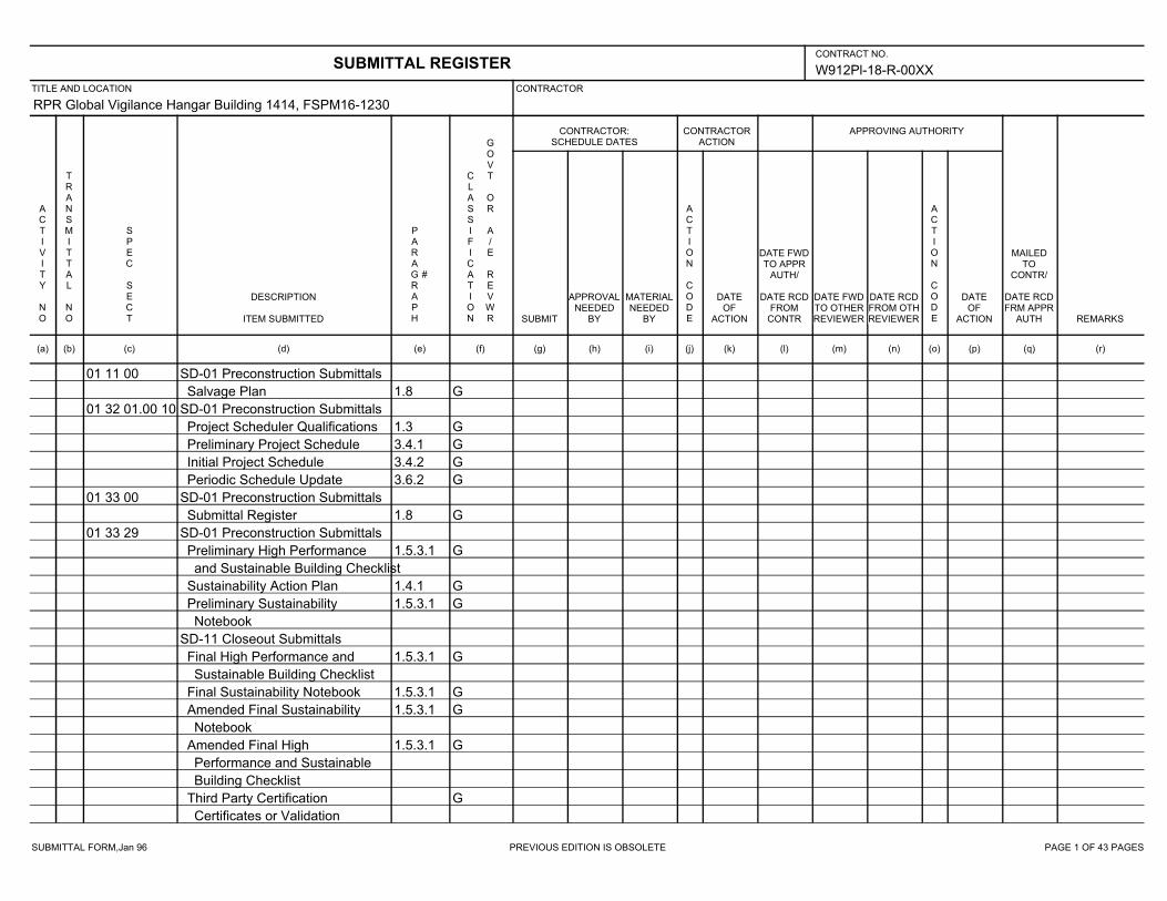
SUBMITTAL FORM,Jan 96 PREVIOUS EDITION IS OBSOLETE PAGE 1 OF 43 PAGES
W912Pl-18-R-00XX
RPR Global Vigilance Hangar Building 1414, FSPM16-1230
01 11 00 SD-01 Preconstruction Submittals
1.8 GSalvage Plan
01 32 01.00 10 SD-01 Preconstruction Submittals
1.3 GProject Scheduler Qualifications
3.4.1 GPreliminary Project Schedule
3.4.2 GInitial Project Schedule
3.6.2 GPeriodic Schedule Update
01 33 00 SD-01 Preconstruction Submittals
1.8 GSubmittal Register
01 33 29 SD-01 Preconstruction Submittals
1.5.3.1 GPreliminary High Performance
and Sustainable Building Checklist
1.4.1 GSustainability Action Plan
1.5.3.1 GPreliminary Sustainability
Notebook
SD-11 Closeout Submittals
1.5.3.1 GFinal High Performance and
Sustainable Building Checklist
1.5.3.1 GFinal Sustainability Notebook
1.5.3.1 GAmended Final Sustainability
Notebook
1.5.3.1 GAmended Final High
Performance and Sustainable
Building Checklist
GThird Party Certification
Certificates or Validation
SUBMITTAL REGISTERCONTRACT NO.
TITLE AND LOCATION CONTRACTOR
CONTRACTOR:SCHEDULE DATES
CONTRACTORACTION
APPROVING AUTHORITY
ACTIVITY NO
TRANSMITTAL NO
SPEC SECT
DESCRIPTION
ITEM SUBMITTED
PARAGRAPH
#
CLASSIFICATION
GOVT OR A/E REVWR SUBMIT
APPROVALNEEDED
BY
MATERIALNEEDED
BY
ACTION CODE
DATEOF
ACTION
DATE FWDTO APPR
AUTH/
DATE RCDFROM
CONTR
DATE FWDTO OTHERREVIEWER
DATE RCDFROM OTHREVIEWER
ACTION CODE
DATEOF
ACTION
MAILEDTO
CONTR/
DATE RCDFRM APPR
AUTH REMARKS
(a) (b) (c) (d) (e) (f) (g) (h) (i) (j) (k) (l) (m) (n) (o) (p) (q) (r)
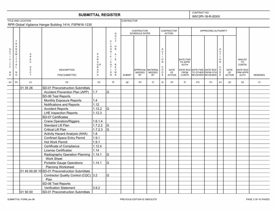
SUBMITTAL FORM,Jan 96 PREVIOUS EDITION IS OBSOLETE PAGE 2 OF 43 PAGES
W912Pl-18-R-00XX
RPR Global Vigilance Hangar Building 1414, FSPM16-1230
01 35 26 SD-01 Preconstruction Submittals
1.7 GAccident Prevention Plan (APP)
SD-06 Test Reports
1.4Monthly Exposure Reports
1.12Notifications and Reports
1.12.2 GAccident Reports
1.12.3LHE Inspection Reports
SD-07 Certificates
1.6.1.4Crane Operators/Riggers
1.7.2.2 GStandard Lift Plan
1.7.2.3 GCritical Lift Plan
1.8Activity Hazard Analysis (AHA)
1.9.1Confined Space Entry Permit
1.9.1Hot Work Permit
1.12.4Certificate of Compliance
1.14License Certificates
1.14.1 GRadiography Operation Planning
Work Sheet
1.14.1 GPortable Gauge Operations
Planning Worksheet
01 45 00.00 10 SD-01 Preconstruction Submittals
3.2 GContractor Quality Control (CQC)
Plan
SD-06 Test Reports
3.9.2Verification Statement
01 50 00 SD-01 Preconstruction Submittals
SUBMITTAL REGISTERCONTRACT NO.
TITLE AND LOCATION CONTRACTOR
CONTRACTOR:SCHEDULE DATES
CONTRACTORACTION
APPROVING AUTHORITY
ACTIVITY NO
TRANSMITTAL NO
SPEC SECT
DESCRIPTION
ITEM SUBMITTED
PARAGRAPH
#
CLASSIFICATION
GOVT OR A/E REVWR SUBMIT
APPROVALNEEDED
BY
MATERIALNEEDED
BY
ACTION CODE
DATEOF
ACTION
DATE FWDTO APPR
AUTH/
DATE RCDFROM
CONTR
DATE FWDTO OTHERREVIEWER
DATE RCDFROM OTHREVIEWER
ACTION CODE
DATEOF
ACTION
MAILEDTO
CONTR/
DATE RCDFRM APPR
AUTH REMARKS
(a) (b) (c) (d) (e) (f) (g) (h) (i) (j) (k) (l) (m) (n) (o) (p) (q) (r)
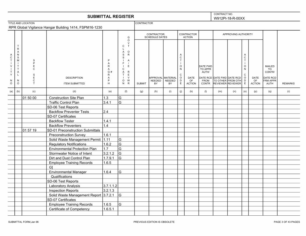
SUBMITTAL FORM,Jan 96 PREVIOUS EDITION IS OBSOLETE PAGE 3 OF 43 PAGES
W912Pl-18-R-00XX
RPR Global Vigilance Hangar Building 1414, FSPM16-1230
01 50 00 1.3 GConstruction Site Plan
3.4.1 GTraffic Control Plan
SD-06 Test Reports
2.4Backflow Preventer Tests
SD-07 Certificates
1.4.1Backflow Tester
1.4Backflow Preventers
01 57 19 SD-01 Preconstruction Submittals
1.6.1Preconstruction Survey
1.11 GSolid Waste Management Permit
1.6.2 GRegulatory Notifications
1.7 GEnvironmental Protection Plan
3.2.1.2 GStormwater Notice of Intent
1.7.9.1 GDirt and Dust Control Plan
1.6.5Employee Training Records
G]
1.6.4 GEnvironmental Manager
Qualifications
SD-06 Test Reports
3.7.1.1.2Laboratory Analysis
3.2.1.3Inspection Reports
3.7.2.1 GSolid Waste Management Report
SD-07 Certificates
1.6.5 GEmployee Training Records
1.6.5.1Certificate of Competency
SUBMITTAL REGISTERCONTRACT NO.
TITLE AND LOCATION CONTRACTOR
CONTRACTOR:SCHEDULE DATES
CONTRACTORACTION
APPROVING AUTHORITY
ACTIVITY NO
TRANSMITTAL NO
SPEC SECT
DESCRIPTION
ITEM SUBMITTED
PARAGRAPH
#
CLASSIFICATION
GOVT OR A/E REVWR SUBMIT
APPROVALNEEDED
BY
MATERIALNEEDED
BY
ACTION CODE
DATEOF
ACTION
DATE FWDTO APPR
AUTH/
DATE RCDFROM
CONTR
DATE FWDTO OTHERREVIEWER
DATE RCDFROM OTHREVIEWER
ACTION CODE
DATEOF
ACTION
MAILEDTO
CONTR/
DATE RCDFRM APPR
AUTH REMARKS
(a) (b) (c) (d) (e) (f) (g) (h) (i) (j) (k) (l) (m) (n) (o) (p) (q) (r)
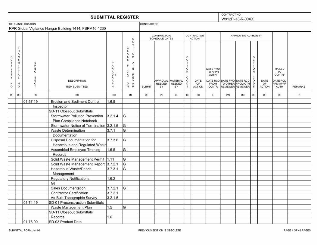
SUBMITTAL FORM,Jan 96 PREVIOUS EDITION IS OBSOLETE PAGE 4 OF 43 PAGES
W912Pl-18-R-00XX
RPR Global Vigilance Hangar Building 1414, FSPM16-1230
01 57 19 1.6.5Erosion and Sediment Control
Inspector
SD-11 Closeout Submittals
3.2.1.4 GStormwater Pollution Prevention
Plan Compliance Notebook
3.2.1.5 GStormwater Notice of Termination
3.7.1 GWaste Determination
Documentation
3.7.3.6 GDisposal Documentation for
Hazardous and Regulated Waste
1.6.5 GAssembled Employee Training
Records
1.11 GSolid Waste Management Permit
3.7.2.1 GSolid Waste Management Report
3.7.3.1 GHazardous Waste/Debris
Management
1.6.2Regulatory Notifications
G]
3.7.2.1 GSales Documentation
3.7.2.1Contractor Certification
3.2.1.5As-Built Topographic Survey
01 74 19 SD-01 Preconstruction Submittals
1.5 GWaste Management Plan
SD-11 Closeout Submittals
1.6Records
01 78 00 SD-03 Product Data
SUBMITTAL REGISTERCONTRACT NO.
TITLE AND LOCATION CONTRACTOR
CONTRACTOR:SCHEDULE DATES
CONTRACTORACTION
APPROVING AUTHORITY
ACTIVITY NO
TRANSMITTAL NO
SPEC SECT
DESCRIPTION
ITEM SUBMITTED
PARAGRAPH
#
CLASSIFICATION
GOVT OR A/E REVWR SUBMIT
APPROVALNEEDED
BY
MATERIALNEEDED
BY
ACTION CODE
DATEOF
ACTION
DATE FWDTO APPR
AUTH/
DATE RCDFROM
CONTR
DATE FWDTO OTHERREVIEWER
DATE RCDFROM OTHREVIEWER
ACTION CODE
DATEOF
ACTION
MAILEDTO
CONTR/
DATE RCDFRM APPR
AUTH REMARKS
(a) (b) (c) (d) (e) (f) (g) (h) (i) (j) (k) (l) (m) (n) (o) (p) (q) (r)

SUBMITTAL FORM,Jan 96 PREVIOUS EDITION IS OBSOLETE PAGE 5 OF 43 PAGES
W912Pl-18-R-00XX
RPR Global Vigilance Hangar Building 1414, FSPM16-1230
01 78 00 1.7.1Warranty Management Plan
1.7.5Warranty Tags
1.5Spare Parts Data
SD-08 Manufacturer’s Instructions
1.7.1Instructions
SD-10 Operation and Maintenance
Data
3.7 GOperation and Maintenance
Manuals
SD-11 Closeout Submittals
3.1 GAs-Built Drawings
3.3 GRecord Drawings
3.6As-Built Record of Equipment
and Materials
3.4Final Approved Shop Drawings
3.5Construction Contract
Specifications
2.3 GCertification of EPA Designated
Items
3.9 GInterim DD FORM 1354
3.9 GChecklist for DD FORM 1354
01 78 23 SD-10 Operation and Maintenance
Data
1.3 GO&M Database
3.1.1 GTraining Plan
3.1.3 GTraining Outline
SUBMITTAL REGISTERCONTRACT NO.
TITLE AND LOCATION CONTRACTOR
CONTRACTOR:SCHEDULE DATES
CONTRACTORACTION
APPROVING AUTHORITY
ACTIVITY NO
TRANSMITTAL NO
SPEC SECT
DESCRIPTION
ITEM SUBMITTED
PARAGRAPH
#
CLASSIFICATION
GOVT OR A/E REVWR SUBMIT
APPROVALNEEDED
BY
MATERIALNEEDED
BY
ACTION CODE
DATEOF
ACTION
DATE FWDTO APPR
AUTH/
DATE RCDFROM
CONTR
DATE FWDTO OTHERREVIEWER
DATE RCDFROM OTHREVIEWER
ACTION CODE
DATEOF
ACTION
MAILEDTO
CONTR/
DATE RCDFRM APPR
AUTH REMARKS
(a) (b) (c) (d) (e) (f) (g) (h) (i) (j) (k) (l) (m) (n) (o) (p) (q) (r)

SUBMITTAL FORM,Jan 96 PREVIOUS EDITION IS OBSOLETE PAGE 6 OF 43 PAGES
W912Pl-18-R-00XX
RPR Global Vigilance Hangar Building 1414, FSPM16-1230
01 78 23 3.1.2 GTraining Content
SD-11 Closeout Submittals
3.1.4 GTraining Video Recording
3.1.6 GValidation of Training Completion
01 91 00.15 SD-01 Preconstruction Submittals
1.7 GCommissioning Firm
1.7.1 GLead Commissioning Specialist
1.7.2 GTechnical Commissioning
Specialists
1.7 GCommissioning Firm's Contract
SD-06 Test Reports
GDesign Review Report
3.1.3.1 GInterim Construction Phase
Commissioning Plan
3.1.3.2 GFinal Construction Phase
Commissioning Plan
3.1.5.2 GPre-Functional Checklists
1.9Issues Log
3.2 GCommissioning Report
3.3.1 GPost-Construction Trend Log
Report
SD-07 Certificates
1.10 GCertificate of Readiness
SD-10 Operation and Maintenance
Data
3.1.6 GTraining Plan
SUBMITTAL REGISTERCONTRACT NO.
TITLE AND LOCATION CONTRACTOR
CONTRACTOR:SCHEDULE DATES
CONTRACTORACTION
APPROVING AUTHORITY
ACTIVITY NO
TRANSMITTAL NO
SPEC SECT
DESCRIPTION
ITEM SUBMITTED
PARAGRAPH
#
CLASSIFICATION
GOVT OR A/E REVWR SUBMIT
APPROVALNEEDED
BY
MATERIALNEEDED
BY
ACTION CODE
DATEOF
ACTION
DATE FWDTO APPR
AUTH/
DATE RCDFROM
CONTR
DATE FWDTO OTHERREVIEWER
DATE RCDFROM OTHREVIEWER
ACTION CODE
DATEOF
ACTION
MAILEDTO
CONTR/
DATE RCDFRM APPR
AUTH REMARKS
(a) (b) (c) (d) (e) (f) (g) (h) (i) (j) (k) (l) (m) (n) (o) (p) (q) (r)
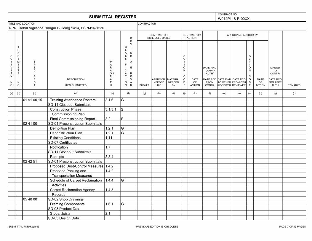
SUBMITTAL FORM,Jan 96 PREVIOUS EDITION IS OBSOLETE PAGE 7 OF 43 PAGES
W912Pl-18-R-00XX
RPR Global Vigilance Hangar Building 1414, FSPM16-1230
01 91 00.15 3.1.6 GTraining Attendance Rosters
SD-11 Closeout Submittals
3.1.3.1 SConstruction Phase
Commissioning Plan
3.2 SFinal Commissioning Report
02 41 00 SD-01 Preconstruction Submittals
1.2.1 GDemolition Plan
1.2.1 GDeconstruction Plan
1.11Existing Conditions
SD-07 Certificates
1.7Notification
SD-11 Closeout Submittals
3.3.4Receipts
02 42 51 SD-01 Preconstruction Submittals
1.4.2Proposed Dust-Control Measures
1.4.2Proposed Packing and
Transportation Measures
1.4.4 GSchedule of Carpet Reclamation
Activities
1.4.3Carpet Reclamation Agency
Records
05 40 00 SD-02 Shop Drawings
1.6.1 GFraming Components
SD-03 Product Data
2.1Studs, Joists
SD-05 Design Data
SUBMITTAL REGISTERCONTRACT NO.
TITLE AND LOCATION CONTRACTOR
CONTRACTOR:SCHEDULE DATES
CONTRACTORACTION
APPROVING AUTHORITY
ACTIVITY NO
TRANSMITTAL NO
SPEC SECT
DESCRIPTION
ITEM SUBMITTED
PARAGRAPH
#
CLASSIFICATION
GOVT OR A/E REVWR SUBMIT
APPROVALNEEDED
BY
MATERIALNEEDED
BY
ACTION CODE
DATEOF
ACTION
DATE FWDTO APPR
AUTH/
DATE RCDFROM
CONTR
DATE FWDTO OTHERREVIEWER
DATE RCDFROM OTHREVIEWER
ACTION CODE
DATEOF
ACTION
MAILEDTO
CONTR/
DATE RCDFRM APPR
AUTH REMARKS
(a) (b) (c) (d) (e) (f) (g) (h) (i) (j) (k) (l) (m) (n) (o) (p) (q) (r)

SUBMITTAL FORM,Jan 96 PREVIOUS EDITION IS OBSOLETE PAGE 8 OF 43 PAGES
W912Pl-18-R-00XX
RPR Global Vigilance Hangar Building 1414, FSPM16-1230
05 40 00 1.6.2 GMetal Framing Calculations
SD-07 Certificates
1.4Load-Bearing Cold-Formed Metal
Framing
3.2.1Welds
SD-11 Closeout Submittals
2.1 SRecycled Content of Steel
Products
05 51 33 SD-02 Shop Drawings
2.3Ladders
2.3.3Ship's Ladder
SD-03 Product Data
2.3Ladders
2.3.3Ship's Ladder
2.3.2Ladder Safety Devices
SD-07 Certificates
1.3Fabricator Certification for Ladder
Assembly
1.3Fabricator Certification for Ships
Ladder Assembly
07 22 00 SD-02 Shop Drawings
1.3 GInsulation Board Layout
1.3 GVerification of Existing Conditions
SD-03 Product Data
2.2 GInsulation
1.4 GCover Board
SUBMITTAL REGISTERCONTRACT NO.
TITLE AND LOCATION CONTRACTOR
CONTRACTOR:SCHEDULE DATES
CONTRACTORACTION
APPROVING AUTHORITY
ACTIVITY NO
TRANSMITTAL NO
SPEC SECT
DESCRIPTION
ITEM SUBMITTED
PARAGRAPH
#
CLASSIFICATION
GOVT OR A/E REVWR SUBMIT
APPROVALNEEDED
BY
MATERIALNEEDED
BY
ACTION CODE
DATEOF
ACTION
DATE FWDTO APPR
AUTH/
DATE RCDFROM
CONTR
DATE FWDTO OTHERREVIEWER
DATE RCDFROM OTHREVIEWER
ACTION CODE
DATEOF
ACTION
MAILEDTO
CONTR/
DATE RCDFRM APPR
AUTH REMARKS
(a) (b) (c) (d) (e) (f) (g) (h) (i) (j) (k) (l) (m) (n) (o) (p) (q) (r)
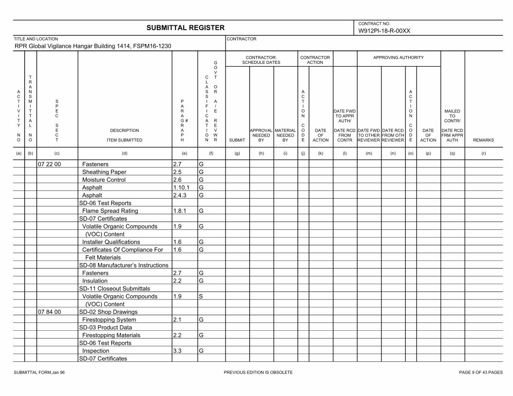
SUBMITTAL FORM,Jan 96 PREVIOUS EDITION IS OBSOLETE PAGE 9 OF 43 PAGES
W912Pl-18-R-00XX
RPR Global Vigilance Hangar Building 1414, FSPM16-1230
07 22 00 2.7 GFasteners
2.5 GSheathing Paper
2.6 GMoisture Control
1.10.1 GAsphalt
2.4.3 GAsphalt
SD-06 Test Reports
1.8.1 GFlame Spread Rating
SD-07 Certificates
1.9 GVolatile Organic Compounds
(VOC) Content
1.6 GInstaller Qualifications
1.6 GCertificates Of Compliance For
Felt Materials
SD-08 Manufacturer’s Instructions
2.7 GFasteners
2.2 GInsulation
SD-11 Closeout Submittals
1.9 SVolatile Organic Compounds
(VOC) Content
07 84 00 SD-02 Shop Drawings
2.1 GFirestopping System
SD-03 Product Data
2.2 GFirestopping Materials
SD-06 Test Reports
3.3 GInspection
SD-07 Certificates
SUBMITTAL REGISTERCONTRACT NO.
TITLE AND LOCATION CONTRACTOR
CONTRACTOR:SCHEDULE DATES
CONTRACTORACTION
APPROVING AUTHORITY
ACTIVITY NO
TRANSMITTAL NO
SPEC SECT
DESCRIPTION
ITEM SUBMITTED
PARAGRAPH
#
CLASSIFICATION
GOVT OR A/E REVWR SUBMIT
APPROVALNEEDED
BY
MATERIALNEEDED
BY
ACTION CODE
DATEOF
ACTION
DATE FWDTO APPR
AUTH/
DATE RCDFROM
CONTR
DATE FWDTO OTHERREVIEWER
DATE RCDFROM OTHREVIEWER
ACTION CODE
DATEOF
ACTION
MAILEDTO
CONTR/
DATE RCDFRM APPR
AUTH REMARKS
(a) (b) (c) (d) (e) (f) (g) (h) (i) (j) (k) (l) (m) (n) (o) (p) (q) (r)
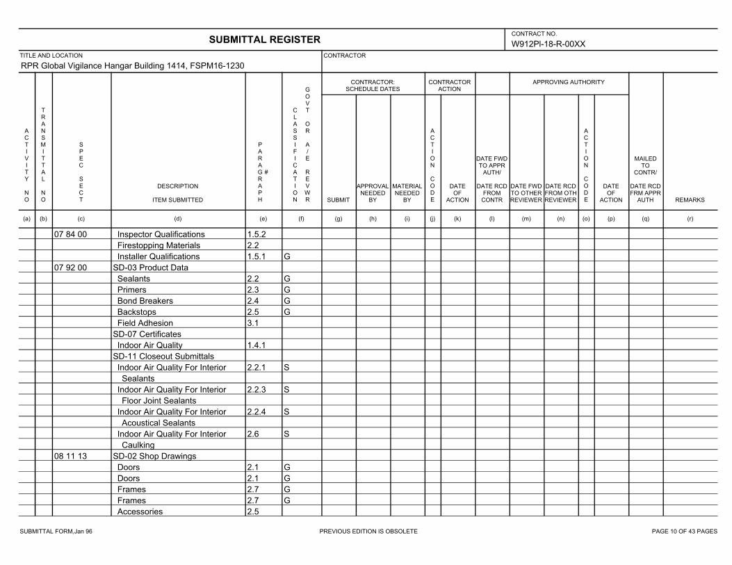
SUBMITTAL FORM,Jan 96 PREVIOUS EDITION IS OBSOLETE PAGE 10 OF 43 PAGES
W912Pl-18-R-00XX
RPR Global Vigilance Hangar Building 1414, FSPM16-1230
07 84 00 1.5.2Inspector Qualifications
2.2Firestopping Materials
1.5.1 GInstaller Qualifications
07 92 00 SD-03 Product Data
2.2 GSealants
2.3 GPrimers
2.4 GBond Breakers
2.5 GBackstops
3.1Field Adhesion
SD-07 Certificates
1.4.1Indoor Air Quality
SD-11 Closeout Submittals
2.2.1 SIndoor Air Quality For Interior
Sealants
2.2.3 SIndoor Air Quality For Interior
Floor Joint Sealants
2.2.4 SIndoor Air Quality For Interior
Acoustical Sealants
2.6 SIndoor Air Quality For Interior
Caulking
08 11 13 SD-02 Shop Drawings
2.1 GDoors
2.1 GDoors
2.7 GFrames
2.7 GFrames
2.5Accessories
SUBMITTAL REGISTERCONTRACT NO.
TITLE AND LOCATION CONTRACTOR
CONTRACTOR:SCHEDULE DATES
CONTRACTORACTION
APPROVING AUTHORITY
ACTIVITY NO
TRANSMITTAL NO
SPEC SECT
DESCRIPTION
ITEM SUBMITTED
PARAGRAPH
#
CLASSIFICATION
GOVT OR A/E REVWR SUBMIT
APPROVALNEEDED
BY
MATERIALNEEDED
BY
ACTION CODE
DATEOF
ACTION
DATE FWDTO APPR
AUTH/
DATE RCDFROM
CONTR
DATE FWDTO OTHERREVIEWER
DATE RCDFROM OTHREVIEWER
ACTION CODE
DATEOF
ACTION
MAILEDTO
CONTR/
DATE RCDFRM APPR
AUTH REMARKS
(a) (b) (c) (d) (e) (f) (g) (h) (i) (j) (k) (l) (m) (n) (o) (p) (q) (r)

SUBMITTAL FORM,Jan 96 PREVIOUS EDITION IS OBSOLETE PAGE 11 OF 43 PAGES
W912Pl-18-R-00XX
RPR Global Vigilance Hangar Building 1414, FSPM16-1230
08 11 13 2.9Weatherstripping
SD-03 Product Data
2.1 GDoors
2.7 GFrames
2.5Accessories
2.9Weatherstripping
SD-04 Samples
2.11.4 GFactory-applied enamel finish
08 14 00 SD-02 Shop Drawings
2.2Doors
SD-03 Product Data
2.2Doors
2.3Accessories
2.4.7Water-resistant Sealer
1.5Warranty
2.2.6Sound Transmission Class
Rating
2.2.7Fire Resistance Rating
SD-04 Samples
2.2Doors
2.4.6.4 GDoor Finish Colors
SD-06 Test Reports
2.5Cycle-Slam
2.5Hinge Loading Resistance
SD-07 Certificates
1.3.1Certificates of Grade
SUBMITTAL REGISTERCONTRACT NO.
TITLE AND LOCATION CONTRACTOR
CONTRACTOR:SCHEDULE DATES
CONTRACTORACTION
APPROVING AUTHORITY
ACTIVITY NO
TRANSMITTAL NO
SPEC SECT
DESCRIPTION
ITEM SUBMITTED
PARAGRAPH
#
CLASSIFICATION
GOVT OR A/E REVWR SUBMIT
APPROVALNEEDED
BY
MATERIALNEEDED
BY
ACTION CODE
DATEOF
ACTION
DATE FWDTO APPR
AUTH/
DATE RCDFROM
CONTR
DATE FWDTO OTHERREVIEWER
DATE RCDFROM OTHREVIEWER
ACTION CODE
DATEOF
ACTION
MAILEDTO
CONTR/
DATE RCDFRM APPR
AUTH REMARKS
(a) (b) (c) (d) (e) (f) (g) (h) (i) (j) (k) (l) (m) (n) (o) (p) (q) (r)

SUBMITTAL FORM,Jan 96 PREVIOUS EDITION IS OBSOLETE PAGE 12 OF 43 PAGES
W912Pl-18-R-00XX
RPR Global Vigilance Hangar Building 1414, FSPM16-1230
08 14 00 1.3.2Certified Sustainably Harvested
Wood
1.3.3 GIndoor Air Quality
SD-11 Closeout Submittals
2.2.1 SCertified Sustainably Harvested
Stile and Rail Wood Doors
2.2.2 SCertified Sustainably Harvested
Flush Wood Doors
2.2.2.2 SRecycled Content for Door Cores
2.2.2.2 SIndoor Air Quality for
Particleboard and Agrifiber Door
Cores
1.5Warranty
08 41 13 SD-01 Preconstruction Submittals
1.2.1 GSample Warranty
1.2.1 GList of Product Installations
SD-02 Shop Drawings
3.3Installation Drawings
G]
2.2 GFabrication Drawings
SD-03 Product Data
1.2.1 GManufacturer's Catalog Data
2.2.3 GFinish
SD-04 Samples
1.2.1Finish and Color Samples
G]
SUBMITTAL REGISTERCONTRACT NO.
TITLE AND LOCATION CONTRACTOR
CONTRACTOR:SCHEDULE DATES
CONTRACTORACTION
APPROVING AUTHORITY
ACTIVITY NO
TRANSMITTAL NO
SPEC SECT
DESCRIPTION
ITEM SUBMITTED
PARAGRAPH
#
CLASSIFICATION
GOVT OR A/E REVWR SUBMIT
APPROVALNEEDED
BY
MATERIALNEEDED
BY
ACTION CODE
DATEOF
ACTION
DATE FWDTO APPR
AUTH/
DATE RCDFROM
CONTR
DATE FWDTO OTHERREVIEWER
DATE RCDFROM OTHREVIEWER
ACTION CODE
DATEOF
ACTION
MAILEDTO
CONTR/
DATE RCDFRM APPR
AUTH REMARKS
(a) (b) (c) (d) (e) (f) (g) (h) (i) (j) (k) (l) (m) (n) (o) (p) (q) (r)
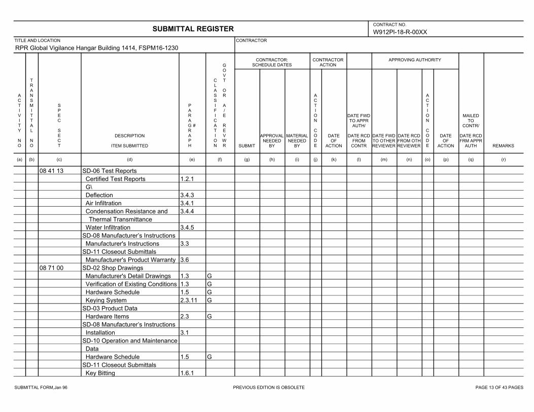
SUBMITTAL FORM,Jan 96 PREVIOUS EDITION IS OBSOLETE PAGE 13 OF 43 PAGES
W912Pl-18-R-00XX
RPR Global Vigilance Hangar Building 1414, FSPM16-1230
08 41 13 SD-06 Test Reports
1.2.1Certified Test Reports
G\
3.4.3Deflection
3.4.1Air Infiltration
3.4.4Condensation Resistance and
Thermal Transmittance
3.4.5Water Infiltration
SD-08 Manufacturer’s Instructions
3.3Manufacturer's Instructions
SD-11 Closeout Submittals
3.6Manufacturer's Product Warranty
08 71 00 SD-02 Shop Drawings
1.3 GManufacturer's Detail Drawings
1.3 GVerification of Existing Conditions
1.5 GHardware Schedule
2.3.11 GKeying System
SD-03 Product Data
2.3 GHardware Items
SD-08 Manufacturer’s Instructions
3.1Installation
SD-10 Operation and Maintenance
Data
1.5 GHardware Schedule
SD-11 Closeout Submittals
1.6.1Key Bitting
SUBMITTAL REGISTERCONTRACT NO.
TITLE AND LOCATION CONTRACTOR
CONTRACTOR:SCHEDULE DATES
CONTRACTORACTION
APPROVING AUTHORITY
ACTIVITY NO
TRANSMITTAL NO
SPEC SECT
DESCRIPTION
ITEM SUBMITTED
PARAGRAPH
#
CLASSIFICATION
GOVT OR A/E REVWR SUBMIT
APPROVALNEEDED
BY
MATERIALNEEDED
BY
ACTION CODE
DATEOF
ACTION
DATE FWDTO APPR
AUTH/
DATE RCDFROM
CONTR
DATE FWDTO OTHERREVIEWER
DATE RCDFROM OTHREVIEWER
ACTION CODE
DATEOF
ACTION
MAILEDTO
CONTR/
DATE RCDFRM APPR
AUTH REMARKS
(a) (b) (c) (d) (e) (f) (g) (h) (i) (j) (k) (l) (m) (n) (o) (p) (q) (r)

SUBMITTAL FORM,Jan 96 PREVIOUS EDITION IS OBSOLETE PAGE 14 OF 43 PAGES
W912Pl-18-R-00XX
RPR Global Vigilance Hangar Building 1414, FSPM16-1230
09 29 00 SD-03 Product Data
2.2.8Cementitious Backer Units
2.2.4Glass Mat Water-Resistant
Gypsum Tile Backing Board
2.2.3Water-Resistant Gypsum Backing
Board
2.2.5Glass Mat Covered or Reinforced
Gypsum Sheathing
2.2.5.1Glass Mat Covered or Reinforced
Gypsum Sheathing Sealant
2.2.6Abuse Resistant Gypsum Board
2.2.14Accessories
1.3Certifications
2.2.1Gypsum Board
SD-04 Samples
2.2.7 GPredecorated Gypsum Board
SD-07 Certificates
2.2 GAsbestos Free Materials
1.3.1 GIndoor Air Quality
SD-08 Manufacturer’s Instructions
Safety Data Sheets
SD-10 Operation and Maintenance
Data
Manufacturer Maintenance
Instructions
SD-11 Closeout Submittals
SUBMITTAL REGISTERCONTRACT NO.
TITLE AND LOCATION CONTRACTOR
CONTRACTOR:SCHEDULE DATES
CONTRACTORACTION
APPROVING AUTHORITY
ACTIVITY NO
TRANSMITTAL NO
SPEC SECT
DESCRIPTION
ITEM SUBMITTED
PARAGRAPH
#
CLASSIFICATION
GOVT OR A/E REVWR SUBMIT
APPROVALNEEDED
BY
MATERIALNEEDED
BY
ACTION CODE
DATEOF
ACTION
DATE FWDTO APPR
AUTH/
DATE RCDFROM
CONTR
DATE FWDTO OTHERREVIEWER
DATE RCDFROM OTHREVIEWER
ACTION CODE
DATEOF
ACTION
MAILEDTO
CONTR/
DATE RCDFRM APPR
AUTH REMARKS
(a) (b) (c) (d) (e) (f) (g) (h) (i) (j) (k) (l) (m) (n) (o) (p) (q) (r)
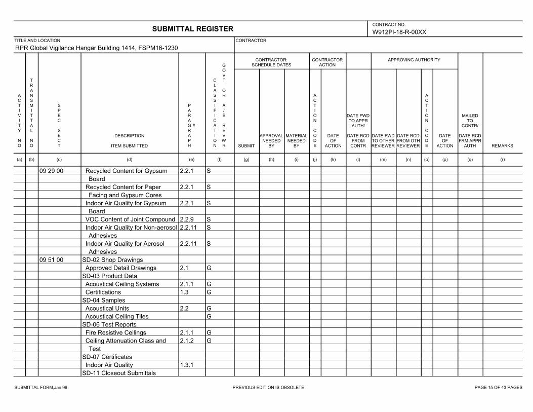
SUBMITTAL FORM,Jan 96 PREVIOUS EDITION IS OBSOLETE PAGE 15 OF 43 PAGES
W912Pl-18-R-00XX
RPR Global Vigilance Hangar Building 1414, FSPM16-1230
09 29 00 2.2.1 SRecycled Content for Gypsum
Board
2.2.1 SRecycled Content for Paper
Facing and Gypsum Cores
2.2.1 SIndoor Air Quality for Gypsum
Board
2.2.9 SVOC Content of Joint Compound
2.2.11 SIndoor Air Quality for Non-aerosol
Adhesives
2.2.11 SIndoor Air Quality for Aerosol
Adhesives
09 51 00 SD-02 Shop Drawings
2.1 GApproved Detail Drawings
SD-03 Product Data
2.1.1 GAcoustical Ceiling Systems
1.3 GCertifications
SD-04 Samples
2.2 GAcoustical Units
GAcoustical Ceiling Tiles
SD-06 Test Reports
2.1.1 GFire Resistive Ceilings
2.1.2 GCeiling Attenuation Class and
Test
SD-07 Certificates
1.3.1Indoor Air Quality
SD-11 Closeout Submittals
SUBMITTAL REGISTERCONTRACT NO.
TITLE AND LOCATION CONTRACTOR
CONTRACTOR:SCHEDULE DATES
CONTRACTORACTION
APPROVING AUTHORITY
ACTIVITY NO
TRANSMITTAL NO
SPEC SECT
DESCRIPTION
ITEM SUBMITTED
PARAGRAPH
#
CLASSIFICATION
GOVT OR A/E REVWR SUBMIT
APPROVALNEEDED
BY
MATERIALNEEDED
BY
ACTION CODE
DATEOF
ACTION
DATE FWDTO APPR
AUTH/
DATE RCDFROM
CONTR
DATE FWDTO OTHERREVIEWER
DATE RCDFROM OTHREVIEWER
ACTION CODE
DATEOF
ACTION
MAILEDTO
CONTR/
DATE RCDFRM APPR
AUTH REMARKS
(a) (b) (c) (d) (e) (f) (g) (h) (i) (j) (k) (l) (m) (n) (o) (p) (q) (r)

SUBMITTAL FORM,Jan 96 PREVIOUS EDITION IS OBSOLETE PAGE 16 OF 43 PAGES
W912Pl-18-R-00XX
RPR Global Vigilance Hangar Building 1414, FSPM16-1230
09 51 00 SRecycled Content for Type III
Ceiling Tiles
SRecycled Content for Type IV
Ceiling Tiles
SRecycled Content for Type IX
Ceiling Tiles
SRecycled Content for Type XII
Ceiling Tiles
2.3 SRecycled Content for Suspension
Systems
SIndoor Air Quality for Type III
Ceiling Tiles
SIndoor Air Quality for Type IV
Ceiling Tiles
2.2.3.1 SIndoor Air Quality for Type V
Ceiling Tiles
2.2.3.1 SIndoor Air Quality for Type VI
Ceiling Tiles
2.2.3.1 SIndoor Air Quality for Type VII
Ceiling Tiles
SIndoor Air Quality for Type IX
Ceiling Tiles
SIndoor Air Quality for Type X
Ceiling Tiles
SIndoor Air Quality for Type XI
Ceiling Tiles
SUBMITTAL REGISTERCONTRACT NO.
TITLE AND LOCATION CONTRACTOR
CONTRACTOR:SCHEDULE DATES
CONTRACTORACTION
APPROVING AUTHORITY
ACTIVITY NO
TRANSMITTAL NO
SPEC SECT
DESCRIPTION
ITEM SUBMITTED
PARAGRAPH
#
CLASSIFICATION
GOVT OR A/E REVWR SUBMIT
APPROVALNEEDED
BY
MATERIALNEEDED
BY
ACTION CODE
DATEOF
ACTION
DATE FWDTO APPR
AUTH/
DATE RCDFROM
CONTR
DATE FWDTO OTHERREVIEWER
DATE RCDFROM OTHREVIEWER
ACTION CODE
DATEOF
ACTION
MAILEDTO
CONTR/
DATE RCDFRM APPR
AUTH REMARKS
(a) (b) (c) (d) (e) (f) (g) (h) (i) (j) (k) (l) (m) (n) (o) (p) (q) (r)
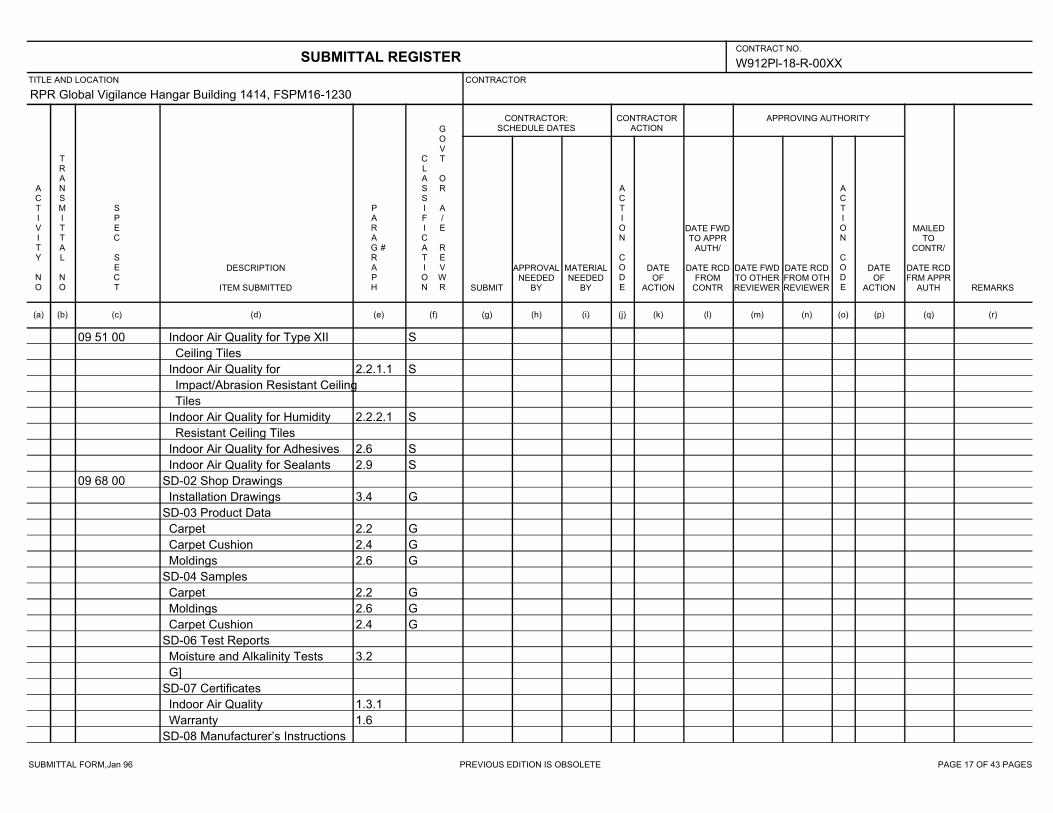
SUBMITTAL FORM,Jan 96 PREVIOUS EDITION IS OBSOLETE PAGE 17 OF 43 PAGES
W912Pl-18-R-00XX
RPR Global Vigilance Hangar Building 1414, FSPM16-1230
09 51 00 SIndoor Air Quality for Type XII
Ceiling Tiles
2.2.1.1 SIndoor Air Quality for
Impact/Abrasion Resistant Ceiling
Tiles
2.2.2.1 SIndoor Air Quality for Humidity
Resistant Ceiling Tiles
2.6 SIndoor Air Quality for Adhesives
2.9 SIndoor Air Quality for Sealants
09 68 00 SD-02 Shop Drawings
3.4 GInstallation Drawings
SD-03 Product Data
2.2 GCarpet
2.4 GCarpet Cushion
2.6 GMoldings
SD-04 Samples
2.2 GCarpet
2.6 GMoldings
2.4 GCarpet Cushion
SD-06 Test Reports
3.2Moisture and Alkalinity Tests
G]
SD-07 Certificates
1.3.1Indoor Air Quality
1.6Warranty
SD-08 Manufacturer’s Instructions
SUBMITTAL REGISTERCONTRACT NO.
TITLE AND LOCATION CONTRACTOR
CONTRACTOR:SCHEDULE DATES
CONTRACTORACTION
APPROVING AUTHORITY
ACTIVITY NO
TRANSMITTAL NO
SPEC SECT
DESCRIPTION
ITEM SUBMITTED
PARAGRAPH
#
CLASSIFICATION
GOVT OR A/E REVWR SUBMIT
APPROVALNEEDED
BY
MATERIALNEEDED
BY
ACTION CODE
DATEOF
ACTION
DATE FWDTO APPR
AUTH/
DATE RCDFROM
CONTR
DATE FWDTO OTHERREVIEWER
DATE RCDFROM OTHREVIEWER
ACTION CODE
DATEOF
ACTION
MAILEDTO
CONTR/
DATE RCDFRM APPR
AUTH REMARKS
(a) (b) (c) (d) (e) (f) (g) (h) (i) (j) (k) (l) (m) (n) (o) (p) (q) (r)

SUBMITTAL FORM,Jan 96 PREVIOUS EDITION IS OBSOLETE PAGE 18 OF 43 PAGES
W912Pl-18-R-00XX
RPR Global Vigilance Hangar Building 1414, FSPM16-1230
09 68 00 3.1Surface Preparation
SD-10 Operation and Maintenance
Data
3.5Cleaning and Protection
Maintenance Service
SD-11 Closeout Submittals
2.1.1 SRecycled Content for Carpeting
2.2.1 SRecycled Content for Carpeting
2.4.1 SRecycled Content for Fiber
Cushion
2.4.2 SRecycled Content for Rubber
Cushion
2.4.3 SRecycled Content for
Polyurethane-Foam Cushion
2.2.1 SIndoor Air Quality for Carpet
2.4.1 SIndoor Air Quality for Fiber
Cushion
2.4.2 SIndoor Air Quality for Rubber
Cushion
2.4.3 SIndoor Air Quality for
Polyurethane-Foam Cushion
2.5 SIndoor Air Quality for Aerosol
Adhesives and Sealants
2.5 SIndoor Air Quality for Non-Aerosol
Adhesives
SUBMITTAL REGISTERCONTRACT NO.
TITLE AND LOCATION CONTRACTOR
CONTRACTOR:SCHEDULE DATES
CONTRACTORACTION
APPROVING AUTHORITY
ACTIVITY NO
TRANSMITTAL NO
SPEC SECT
DESCRIPTION
ITEM SUBMITTED
PARAGRAPH
#
CLASSIFICATION
GOVT OR A/E REVWR SUBMIT
APPROVALNEEDED
BY
MATERIALNEEDED
BY
ACTION CODE
DATEOF
ACTION
DATE FWDTO APPR
AUTH/
DATE RCDFROM
CONTR
DATE FWDTO OTHERREVIEWER
DATE RCDFROM OTHREVIEWER
ACTION CODE
DATEOF
ACTION
MAILEDTO
CONTR/
DATE RCDFRM APPR
AUTH REMARKS
(a) (b) (c) (d) (e) (f) (g) (h) (i) (j) (k) (l) (m) (n) (o) (p) (q) (r)
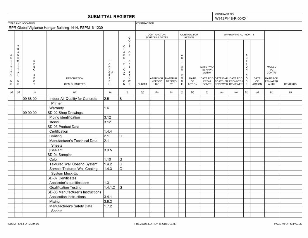
SUBMITTAL FORM,Jan 96 PREVIOUS EDITION IS OBSOLETE PAGE 19 OF 43 PAGES
W912Pl-18-R-00XX
RPR Global Vigilance Hangar Building 1414, FSPM16-1230
09 68 00 2.5 SIndoor Air Quality for Concrete
Primer
1.6Warranty
09 90 00 SD-02 Shop Drawings
3.12Piping identification
3.12stencil
SD-03 Product Data
1.4.4Certification
2.1 GCoating
2.1Manufacturer's Technical Data
Sheets
3.3.5[Sealant]
SD-04 Samples
1.10 GColor
1.4.2 GTextured Wall Coating System
1.4.3 GSample Textured Wall Coating
System Mock-Up
SD-07 Certificates
1.3Applicator's qualifications
1.4.1.2 GQualification Testing
SD-08 Manufacturer’s Instructions
3.4.1Application instructions
3.8.2Mixing
1.7.2Manufacturer's Safety Data
Sheets
SUBMITTAL REGISTERCONTRACT NO.
TITLE AND LOCATION CONTRACTOR
CONTRACTOR:SCHEDULE DATES
CONTRACTORACTION
APPROVING AUTHORITY
ACTIVITY NO
TRANSMITTAL NO
SPEC SECT
DESCRIPTION
ITEM SUBMITTED
PARAGRAPH
#
CLASSIFICATION
GOVT OR A/E REVWR SUBMIT
APPROVALNEEDED
BY
MATERIALNEEDED
BY
ACTION CODE
DATEOF
ACTION
DATE FWDTO APPR
AUTH/
DATE RCDFROM
CONTR
DATE FWDTO OTHERREVIEWER
DATE RCDFROM OTHREVIEWER
ACTION CODE
DATEOF
ACTION
MAILEDTO
CONTR/
DATE RCDFRM APPR
AUTH REMARKS
(a) (b) (c) (d) (e) (f) (g) (h) (i) (j) (k) (l) (m) (n) (o) (p) (q) (r)

SUBMITTAL FORM,Jan 96 PREVIOUS EDITION IS OBSOLETE PAGE 20 OF 43 PAGES
W912Pl-18-R-00XX
RPR Global Vigilance Hangar Building 1414, FSPM16-1230
09 90 00 SD-10 Operation and Maintenance
Data
2.1 GCoatings:
10 21 13 SD-02 Shop Drawings
2.1Fabrication Drawings
3.3 GInstallation Drawings
SD-03 Product Data
2.1Cleaning and Maintenance
Instructions
2.9Colors And Finishes
2.2.1Galvanized Steel Sheet
2.2.2Sound-Deadening Cores
2.2.3Anchoring Devices and Fasteners
2.2.5Hardware and Fittings
2.2.4Brackets
2.2.6Door Hardware
2.7Pilaster Shoes
2.2.5.2 GFinishes
SD-04 Samples
2.9 GColors and Finishes
2.2.5Hardware and Fittings
2.2.3Anchoring Devices and Fasteners
SD-07 Certificates
1.6Warranty
1.3.1Indoor Air Quality
SD-11 Closeout Submittals
SUBMITTAL REGISTERCONTRACT NO.
TITLE AND LOCATION CONTRACTOR
CONTRACTOR:SCHEDULE DATES
CONTRACTORACTION
APPROVING AUTHORITY
ACTIVITY NO
TRANSMITTAL NO
SPEC SECT
DESCRIPTION
ITEM SUBMITTED
PARAGRAPH
#
CLASSIFICATION
GOVT OR A/E REVWR SUBMIT
APPROVALNEEDED
BY
MATERIALNEEDED
BY
ACTION CODE
DATEOF
ACTION
DATE FWDTO APPR
AUTH/
DATE RCDFROM
CONTR
DATE FWDTO OTHERREVIEWER
DATE RCDFROM OTHREVIEWER
ACTION CODE
DATEOF
ACTION
MAILEDTO
CONTR/
DATE RCDFRM APPR
AUTH REMARKS
(a) (b) (c) (d) (e) (f) (g) (h) (i) (j) (k) (l) (m) (n) (o) (p) (q) (r)
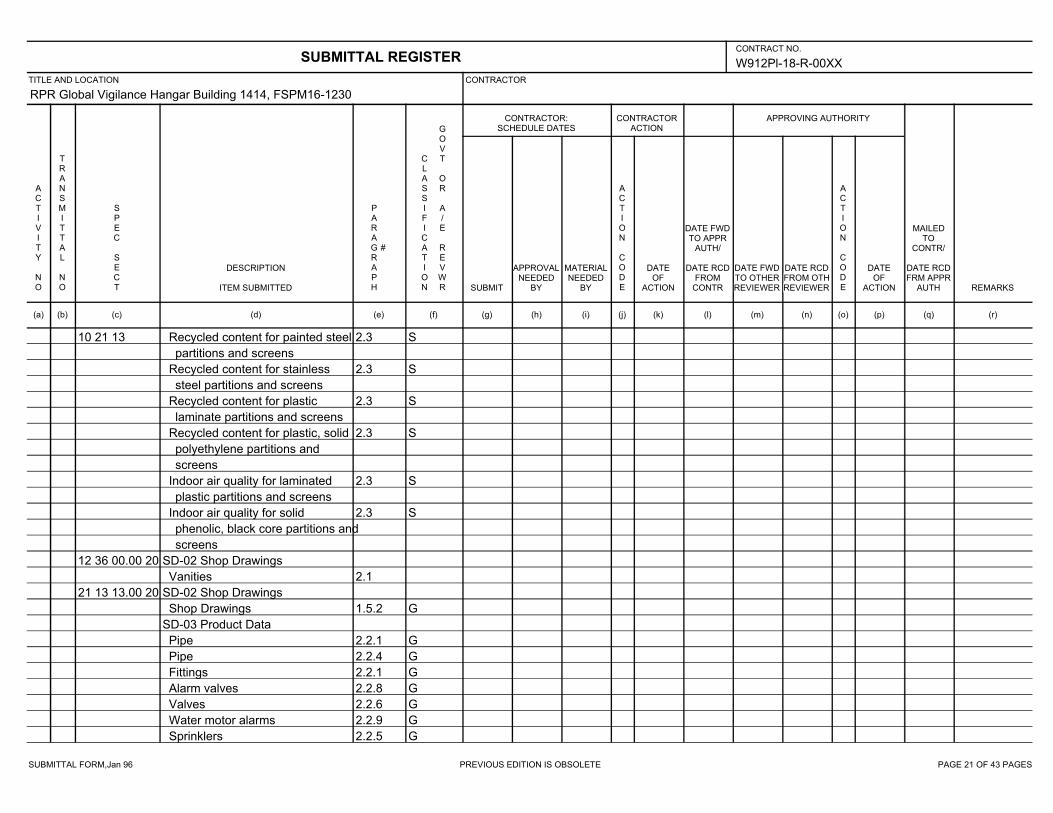
SUBMITTAL FORM,Jan 96 PREVIOUS EDITION IS OBSOLETE PAGE 21 OF 43 PAGES
W912Pl-18-R-00XX
RPR Global Vigilance Hangar Building 1414, FSPM16-1230
10 21 13 2.3 SRecycled content for painted steel
partitions and screens
2.3 SRecycled content for stainless
steel partitions and screens
2.3 SRecycled content for plastic
laminate partitions and screens
2.3 SRecycled content for plastic, solid
polyethylene partitions and
screens
2.3 SIndoor air quality for laminated
plastic partitions and screens
2.3 SIndoor air quality for solid
phenolic, black core partitions and
screens
12 36 00.00 20 SD-02 Shop Drawings
2.1Vanities
21 13 13.00 20 SD-02 Shop Drawings
1.5.2 GShop Drawings
SD-03 Product Data
2.2.1 GPipe
2.2.4 GPipe
2.2.1 GFittings
2.2.8 GAlarm valves
2.2.6 GValves
2.2.9 GWater motor alarms
2.2.5 GSprinklers
SUBMITTAL REGISTERCONTRACT NO.
TITLE AND LOCATION CONTRACTOR
CONTRACTOR:SCHEDULE DATES
CONTRACTORACTION
APPROVING AUTHORITY
ACTIVITY NO
TRANSMITTAL NO
SPEC SECT
DESCRIPTION
ITEM SUBMITTED
PARAGRAPH
#
CLASSIFICATION
GOVT OR A/E REVWR SUBMIT
APPROVALNEEDED
BY
MATERIALNEEDED
BY
ACTION CODE
DATEOF
ACTION
DATE FWDTO APPR
AUTH/
DATE RCDFROM
CONTR
DATE FWDTO OTHERREVIEWER
DATE RCDFROM OTHREVIEWER
ACTION CODE
DATEOF
ACTION
MAILEDTO
CONTR/
DATE RCDFRM APPR
AUTH REMARKS
(a) (b) (c) (d) (e) (f) (g) (h) (i) (j) (k) (l) (m) (n) (o) (p) (q) (r)
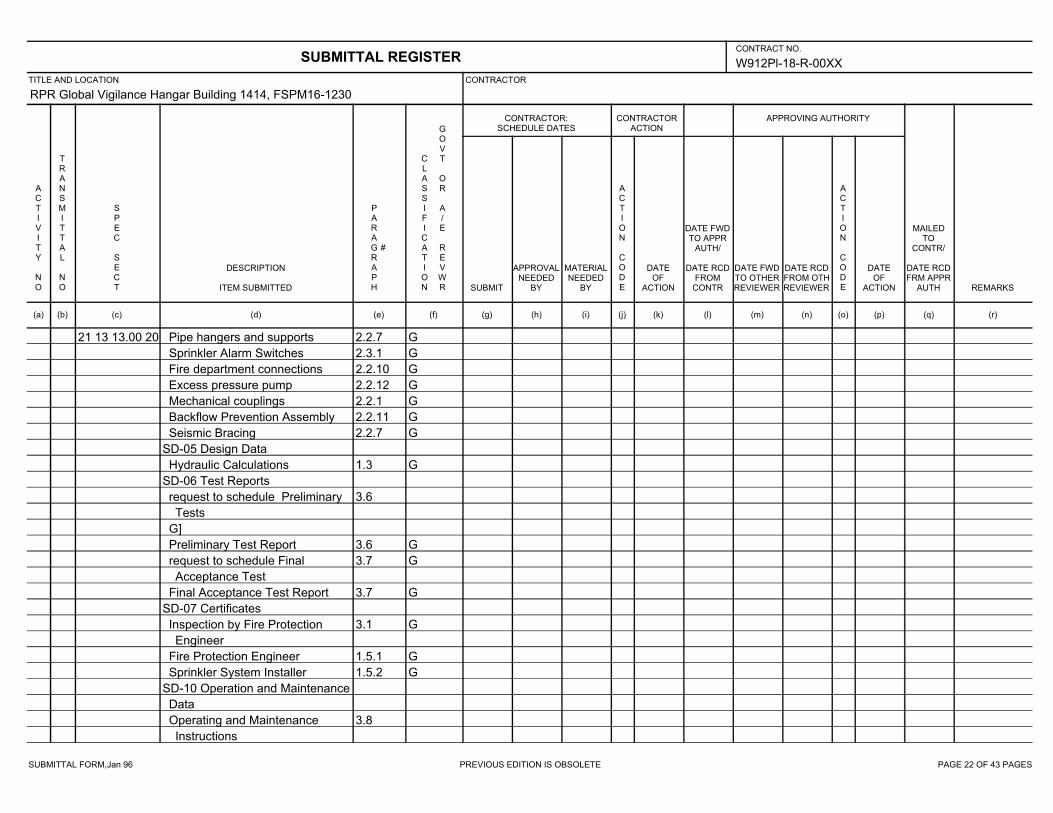
SUBMITTAL FORM,Jan 96 PREVIOUS EDITION IS OBSOLETE PAGE 22 OF 43 PAGES
W912Pl-18-R-00XX
RPR Global Vigilance Hangar Building 1414, FSPM16-1230
21 13 13.00 20 2.2.7 GPipe hangers and supports
2.3.1 GSprinkler Alarm Switches
2.2.10 GFire department connections
2.2.12 GExcess pressure pump
2.2.1 GMechanical couplings
2.2.11 GBackflow Prevention Assembly
2.2.7 GSeismic Bracing
SD-05 Design Data
1.3 GHydraulic Calculations
SD-06 Test Reports
3.6request to schedule Preliminary
Tests
G]
3.6 GPreliminary Test Report
3.7 Grequest to schedule Final
Acceptance Test
3.7 GFinal Acceptance Test Report
SD-07 Certificates
3.1 GInspection by Fire Protection
Engineer
1.5.1 GFire Protection Engineer
1.5.2 GSprinkler System Installer
SD-10 Operation and Maintenance
Data
3.8Operating and Maintenance
Instructions
SUBMITTAL REGISTERCONTRACT NO.
TITLE AND LOCATION CONTRACTOR
CONTRACTOR:SCHEDULE DATES
CONTRACTORACTION
APPROVING AUTHORITY
ACTIVITY NO
TRANSMITTAL NO
SPEC SECT
DESCRIPTION
ITEM SUBMITTED
PARAGRAPH
#
CLASSIFICATION
GOVT OR A/E REVWR SUBMIT
APPROVALNEEDED
BY
MATERIALNEEDED
BY
ACTION CODE
DATEOF
ACTION
DATE FWDTO APPR
AUTH/
DATE RCDFROM
CONTR
DATE FWDTO OTHERREVIEWER
DATE RCDFROM OTHREVIEWER
ACTION CODE
DATEOF
ACTION
MAILEDTO
CONTR/
DATE RCDFRM APPR
AUTH REMARKS
(a) (b) (c) (d) (e) (f) (g) (h) (i) (j) (k) (l) (m) (n) (o) (p) (q) (r)

SUBMITTAL FORM,Jan 96 PREVIOUS EDITION IS OBSOLETE PAGE 23 OF 43 PAGES
W912Pl-18-R-00XX
RPR Global Vigilance Hangar Building 1414, FSPM16-1230
21 13 13.00 20 SD-11 Closeout Submittals
3.7As-built drawings
3.8On-site training
21 13 20.00 20 SD-02 Shop Drawings
1.3.1.1 GFire extinguishing system
SD-03 Product Data
2.19.1 GPipe, fittings, and mechanical
couplings
2.1.3 G[Deluge] [Pre-action] valves
2.19.5 GValves
2.11.1 GWater motor alarms
2.1.1 GSprinkler heads
2.16 GMonitor nozzles
2.17 GHose and nozzles
2.19.4 GPipe hangers and supports
2.11.3.1 GPressure switch
2.19.11 GFire department inlet connections
2.12 GTank mounted air compressor
2.12 GAir pressure regulating device
2.3.1 GAir compressor
2.11.4 Gtrouble alarm
2.2 GDetection devices
2.2.2.1 GStorage batteries
2.11.2 GAlarm bells
2.11.2 GAlarm horns
2.2.1.3 GAnnunciator panel
SUBMITTAL REGISTERCONTRACT NO.
TITLE AND LOCATION CONTRACTOR
CONTRACTOR:SCHEDULE DATES
CONTRACTORACTION
APPROVING AUTHORITY
ACTIVITY NO
TRANSMITTAL NO
SPEC SECT
DESCRIPTION
ITEM SUBMITTED
PARAGRAPH
#
CLASSIFICATION
GOVT OR A/E REVWR SUBMIT
APPROVALNEEDED
BY
MATERIALNEEDED
BY
ACTION CODE
DATEOF
ACTION
DATE FWDTO APPR
AUTH/
DATE RCDFROM
CONTR
DATE FWDTO OTHERREVIEWER
DATE RCDFROM OTHREVIEWER
ACTION CODE
DATEOF
ACTION
MAILEDTO
CONTR/
DATE RCDFRM APPR
AUTH REMARKS
(a) (b) (c) (d) (e) (f) (g) (h) (i) (j) (k) (l) (m) (n) (o) (p) (q) (r)
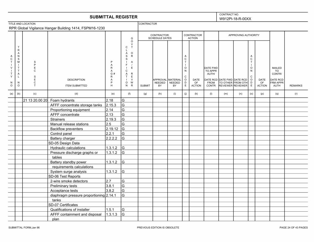
SUBMITTAL FORM,Jan 96 PREVIOUS EDITION IS OBSOLETE PAGE 24 OF 43 PAGES
W912Pl-18-R-00XX
RPR Global Vigilance Hangar Building 1414, FSPM16-1230
21 13 20.00 20 2.18 GFoam hydrants
2.15.3 GAFFF concentrate storage tanks
2.14 GProportioning equipment
2.13 GAFFF concentrate
2.19.3 GStrainers
2.5 GManual release stations
2.19.12 GBackflow preventers
2.2.1 GControl panel
2.2.2.2 GBattery charger
SD-05 Design Data
1.3.1.2 GHydraulic calculations
1.3.1.2 GPressure discharge graphs or
tables
1.3.1.2 GBattery standby power
requirements calculations
1.3.1.2 GSystem surge analysis
SD-06 Test Reports
2.7 G2-wire smoke detectors
3.8.1 GPreliminary tests
3.8.2 GAcceptance tests
2.14.1 Gdiaphragm pressure proportioning
tanks
SD-07 Certificates
1.5.1 GQualifications of installer
1.3.1.3 GAFFF containment and disposal
plan
SUBMITTAL REGISTERCONTRACT NO.
TITLE AND LOCATION CONTRACTOR
CONTRACTOR:SCHEDULE DATES
CONTRACTORACTION
APPROVING AUTHORITY
ACTIVITY NO
TRANSMITTAL NO
SPEC SECT
DESCRIPTION
ITEM SUBMITTED
PARAGRAPH
#
CLASSIFICATION
GOVT OR A/E REVWR SUBMIT
APPROVALNEEDED
BY
MATERIALNEEDED
BY
ACTION CODE
DATEOF
ACTION
DATE FWDTO APPR
AUTH/
DATE RCDFROM
CONTR
DATE FWDTO OTHERREVIEWER
DATE RCDFROM OTHREVIEWER
ACTION CODE
DATEOF
ACTION
MAILEDTO
CONTR/
DATE RCDFRM APPR
AUTH REMARKS
(a) (b) (c) (d) (e) (f) (g) (h) (i) (j) (k) (l) (m) (n) (o) (p) (q) (r)
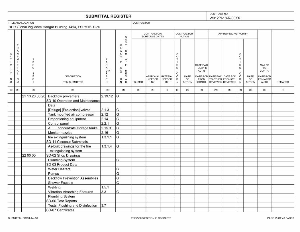
SUBMITTAL FORM,Jan 96 PREVIOUS EDITION IS OBSOLETE PAGE 25 OF 43 PAGES
W912Pl-18-R-00XX
RPR Global Vigilance Hangar Building 1414, FSPM16-1230
21 13 20.00 20 2.19.12 GBackflow preventers
SD-10 Operation and Maintenance
Data
2.1.3 G[Deluge] [Pre-action] valves
2.12 GTank mounted air compressor
2.14 GProportioning equipment
2.2.1 GControl panel
2.15.3 GAFFF concentrate storage tanks
2.16 GMonitor nozzles
1.3.1.1 Gfire extinguishing system
SD-11 Closeout Submittals
1.3.1.4 GAs-built drawings for the fire
extinguishing system
22 00 00 SD-02 Shop Drawings
GPlumbing System
SD-03 Product Data
GWater Heaters
GPumps
GBackflow Prevention Assemblies
GShower Faucets
1.5.1Welding
3.3 GVibration-Absorbing Features
Plumbing System
SD-06 Test Reports
3.7Tests, Flushing and Disinfection
SD-07 Certificates
SUBMITTAL REGISTERCONTRACT NO.
TITLE AND LOCATION CONTRACTOR
CONTRACTOR:SCHEDULE DATES
CONTRACTORACTION
APPROVING AUTHORITY
ACTIVITY NO
TRANSMITTAL NO
SPEC SECT
DESCRIPTION
ITEM SUBMITTED
PARAGRAPH
#
CLASSIFICATION
GOVT OR A/E REVWR SUBMIT
APPROVALNEEDED
BY
MATERIALNEEDED
BY
ACTION CODE
DATEOF
ACTION
DATE FWDTO APPR
AUTH/
DATE RCDFROM
CONTR
DATE FWDTO OTHERREVIEWER
DATE RCDFROM OTHREVIEWER
ACTION CODE
DATEOF
ACTION
MAILEDTO
CONTR/
DATE RCDFRM APPR
AUTH REMARKS
(a) (b) (c) (d) (e) (f) (g) (h) (i) (j) (k) (l) (m) (n) (o) (p) (q) (r)
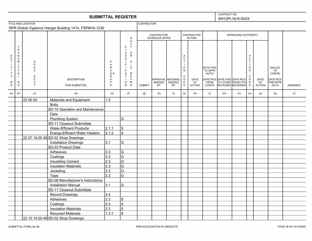
SUBMITTAL FORM,Jan 96 PREVIOUS EDITION IS OBSOLETE PAGE 26 OF 43 PAGES
W912Pl-18-R-00XX
RPR Global Vigilance Hangar Building 1414, FSPM16-1230
22 00 00 1.3Materials and Equipment
Bolts
SD-10 Operation and Maintenance
Data
GPlumbing System
SD-11 Closeout Submittals
2.1.1 SWater-Efficient Products
2.1.2 SEnergy-Efficient Water Heaters
22 07 19.00 40 SD-02 Shop Drawings
3.1 GInstallation Drawings
SD-03 Product Data
2.3 GAdhesives
2.3 GCoatings
2.3 GInsulating Cement
2.3 GInsulation Materials
2.3 GJacketing
2.3 GTape
SD-08 Manufacturer’s Instructions
3.1 GInstallation Manual
SD-11 Closeout Submittals
3.4Record Drawings
2.3 SAdhesives
2.3 SCoatings
2.3 SInsulation Materials
1.3.1 SRecycled Materials
22 15 14.00 40 SD-02 Shop Drawings
SUBMITTAL REGISTERCONTRACT NO.
TITLE AND LOCATION CONTRACTOR
CONTRACTOR:SCHEDULE DATES
CONTRACTORACTION
APPROVING AUTHORITY
ACTIVITY NO
TRANSMITTAL NO
SPEC SECT
DESCRIPTION
ITEM SUBMITTED
PARAGRAPH
#
CLASSIFICATION
GOVT OR A/E REVWR SUBMIT
APPROVALNEEDED
BY
MATERIALNEEDED
BY
ACTION CODE
DATEOF
ACTION
DATE FWDTO APPR
AUTH/
DATE RCDFROM
CONTR
DATE FWDTO OTHERREVIEWER
DATE RCDFROM OTHREVIEWER
ACTION CODE
DATEOF
ACTION
MAILEDTO
CONTR/
DATE RCDFRM APPR
AUTH REMARKS
(a) (b) (c) (d) (e) (f) (g) (h) (i) (j) (k) (l) (m) (n) (o) (p) (q) (r)
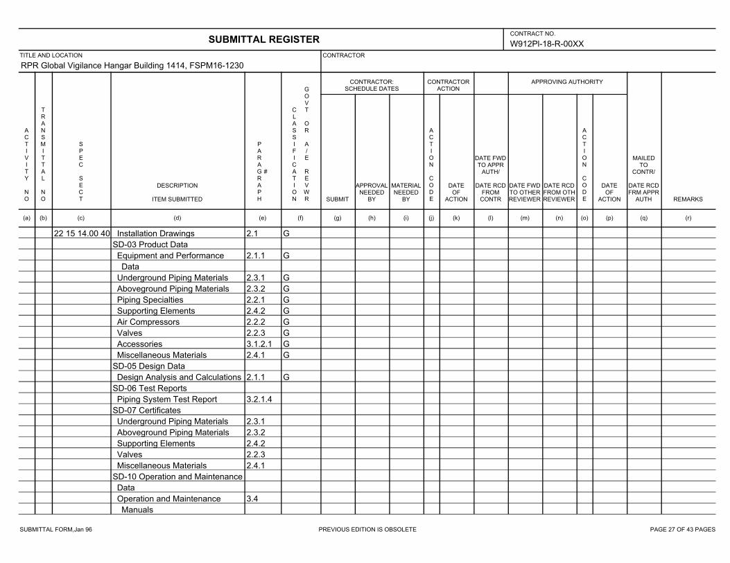
SUBMITTAL FORM,Jan 96 PREVIOUS EDITION IS OBSOLETE PAGE 27 OF 43 PAGES
W912Pl-18-R-00XX
RPR Global Vigilance Hangar Building 1414, FSPM16-1230
22 15 14.00 40 2.1 GInstallation Drawings
SD-03 Product Data
2.1.1 GEquipment and Performance
Data
2.3.1 GUnderground Piping Materials
2.3.2 GAboveground Piping Materials
2.2.1 GPiping Specialties
2.4.2 GSupporting Elements
2.2.2 GAir Compressors
2.2.3 GValves
3.1.2.1 GAccessories
2.4.1 GMiscellaneous Materials
SD-05 Design Data
2.1.1 GDesign Analysis and Calculations
SD-06 Test Reports
3.2.1.4Piping System Test Report
SD-07 Certificates
2.3.1Underground Piping Materials
2.3.2Aboveground Piping Materials
2.4.2Supporting Elements
2.2.3Valves
2.4.1Miscellaneous Materials
SD-10 Operation and Maintenance
Data
3.4Operation and Maintenance
Manuals
SUBMITTAL REGISTERCONTRACT NO.
TITLE AND LOCATION CONTRACTOR
CONTRACTOR:SCHEDULE DATES
CONTRACTORACTION
APPROVING AUTHORITY
ACTIVITY NO
TRANSMITTAL NO
SPEC SECT
DESCRIPTION
ITEM SUBMITTED
PARAGRAPH
#
CLASSIFICATION
GOVT OR A/E REVWR SUBMIT
APPROVALNEEDED
BY
MATERIALNEEDED
BY
ACTION CODE
DATEOF
ACTION
DATE FWDTO APPR
AUTH/
DATE RCDFROM
CONTR
DATE FWDTO OTHERREVIEWER
DATE RCDFROM OTHREVIEWER
ACTION CODE
DATEOF
ACTION
MAILEDTO
CONTR/
DATE RCDFRM APPR
AUTH REMARKS
(a) (b) (c) (d) (e) (f) (g) (h) (i) (j) (k) (l) (m) (n) (o) (p) (q) (r)
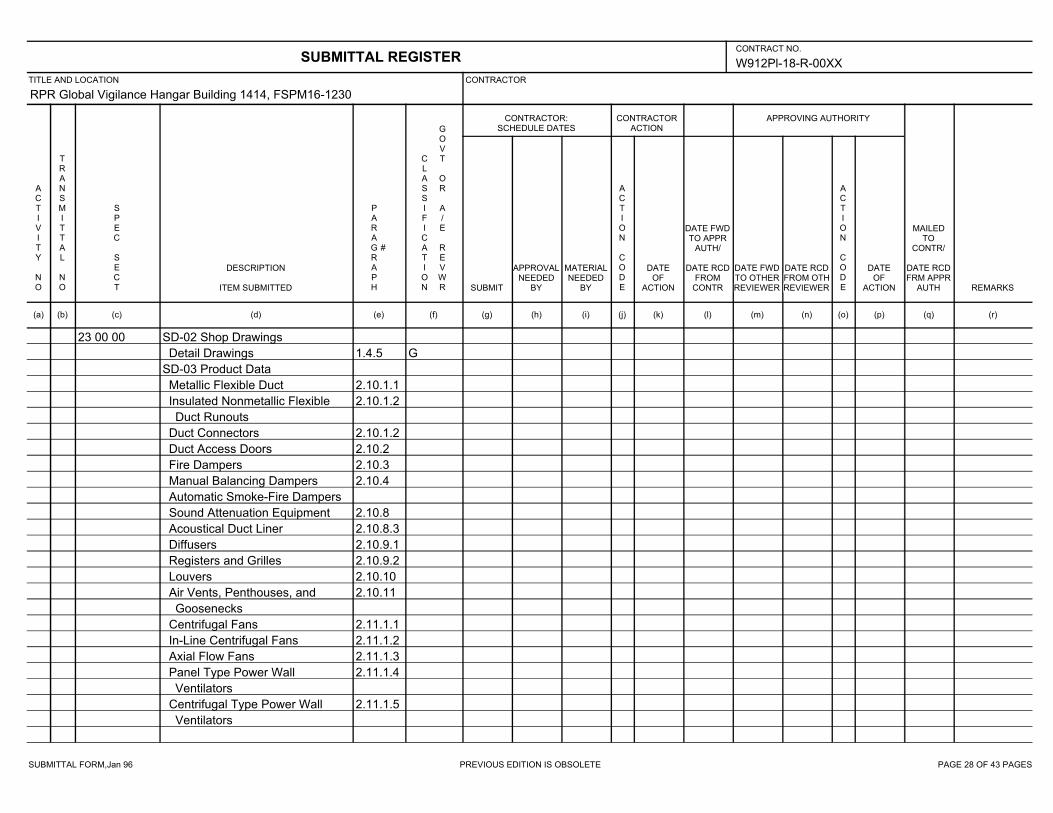
SUBMITTAL FORM,Jan 96 PREVIOUS EDITION IS OBSOLETE PAGE 28 OF 43 PAGES
W912Pl-18-R-00XX
RPR Global Vigilance Hangar Building 1414, FSPM16-1230
23 00 00 SD-02 Shop Drawings
1.4.5 GDetail Drawings
SD-03 Product Data
2.10.1.1Metallic Flexible Duct
2.10.1.2Insulated Nonmetallic Flexible
Duct Runouts
2.10.1.2Duct Connectors
2.10.2Duct Access Doors
2.10.3Fire Dampers
2.10.4Manual Balancing Dampers
Automatic Smoke-Fire Dampers
2.10.8Sound Attenuation Equipment
2.10.8.3Acoustical Duct Liner
2.10.9.1Diffusers
2.10.9.2Registers and Grilles
2.10.10Louvers
2.10.11Air Vents, Penthouses, and
Goosenecks
2.11.1.1Centrifugal Fans
2.11.1.2In-Line Centrifugal Fans
2.11.1.3Axial Flow Fans
2.11.1.4Panel Type Power Wall
Ventilators
2.11.1.5Centrifugal Type Power Wall
Ventilators
SUBMITTAL REGISTERCONTRACT NO.
TITLE AND LOCATION CONTRACTOR
CONTRACTOR:SCHEDULE DATES
CONTRACTORACTION
APPROVING AUTHORITY
ACTIVITY NO
TRANSMITTAL NO
SPEC SECT
DESCRIPTION
ITEM SUBMITTED
PARAGRAPH
#
CLASSIFICATION
GOVT OR A/E REVWR SUBMIT
APPROVALNEEDED
BY
MATERIALNEEDED
BY
ACTION CODE
DATEOF
ACTION
DATE FWDTO APPR
AUTH/
DATE RCDFROM
CONTR
DATE FWDTO OTHERREVIEWER
DATE RCDFROM OTHREVIEWER
ACTION CODE
DATEOF
ACTION
MAILEDTO
CONTR/
DATE RCDFRM APPR
AUTH REMARKS
(a) (b) (c) (d) (e) (f) (g) (h) (i) (j) (k) (l) (m) (n) (o) (p) (q) (r)
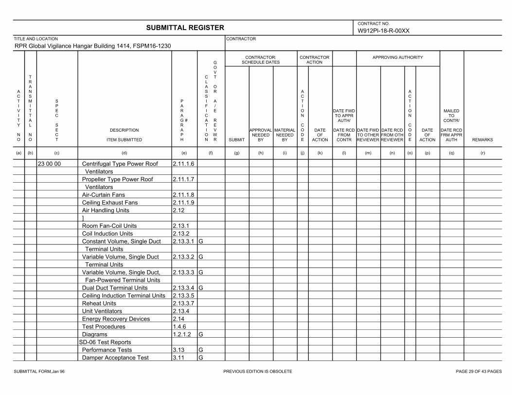
SUBMITTAL FORM,Jan 96 PREVIOUS EDITION IS OBSOLETE PAGE 29 OF 43 PAGES
W912Pl-18-R-00XX
RPR Global Vigilance Hangar Building 1414, FSPM16-1230
23 00 00 2.11.1.6Centrifugal Type Power Roof
Ventilators
2.11.1.7Propeller Type Power Roof
Ventilators
2.11.1.8Air-Curtain Fans
2.11.1.9Ceiling Exhaust Fans
2.12Air Handling Units
]
2.13.1Room Fan-Coil Units
2.13.2Coil Induction Units
2.13.3.1 GConstant Volume, Single Duct
Terminal Units
2.13.3.2 GVariable Volume, Single Duct
Terminal Units
2.13.3.3 GVariable Volume, Single Duct,
Fan-Powered Terminal Units
2.13.3.4 GDual Duct Terminal Units
2.13.3.5Ceiling Induction Terminal Units
2.13.3.7Reheat Units
2.13.4Unit Ventilators
2.14Energy Recovery Devices
1.4.6Test Procedures
1.2.1.2 GDiagrams
SD-06 Test Reports
3.13 GPerformance Tests
3.11 GDamper Acceptance Test
SUBMITTAL REGISTERCONTRACT NO.
TITLE AND LOCATION CONTRACTOR
CONTRACTOR:SCHEDULE DATES
CONTRACTORACTION
APPROVING AUTHORITY
ACTIVITY NO
TRANSMITTAL NO
SPEC SECT
DESCRIPTION
ITEM SUBMITTED
PARAGRAPH
#
CLASSIFICATION
GOVT OR A/E REVWR SUBMIT
APPROVALNEEDED
BY
MATERIALNEEDED
BY
ACTION CODE
DATEOF
ACTION
DATE FWDTO APPR
AUTH/
DATE RCDFROM
CONTR
DATE FWDTO OTHERREVIEWER
DATE RCDFROM OTHREVIEWER
ACTION CODE
DATEOF
ACTION
MAILEDTO
CONTR/
DATE RCDFRM APPR
AUTH REMARKS
(a) (b) (c) (d) (e) (f) (g) (h) (i) (j) (k) (l) (m) (n) (o) (p) (q) (r)
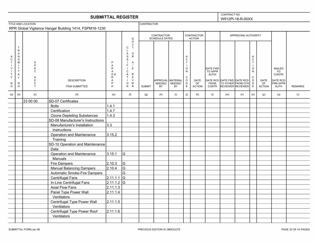
SUBMITTAL FORM,Jan 96 PREVIOUS EDITION IS OBSOLETE PAGE 30 OF 43 PAGES
W912Pl-18-R-00XX
RPR Global Vigilance Hangar Building 1414, FSPM16-1230
23 00 00 SD-07 Certificates
1.4.1Bolts
1.4.7Certification
1.4.3Ozone Depleting Substances
SD-08 Manufacturer’s Instructions
3.3Manufacturer's Installation
Instructions
3.15.2Operation and Maintenance
Training
SD-10 Operation and Maintenance
Data
3.15.1 GOperation and Maintenance
Manuals
2.10.3 GFire Dampers
2.10.4 GManual Balancing Dampers
GAutomatic Smoke-Fire Dampers
2.11.1.1 GCentrifugal Fans
2.11.1.2 GIn-Line Centrifugal Fans
2.11.1.3Axial Flow Fans
2.11.1.4Panel Type Power Wall
Ventilators
2.11.1.5Centrifugal Type Power Wall
Ventilators
2.11.1.6Centrifugal Type Power Roof
Ventilators
SUBMITTAL REGISTERCONTRACT NO.
TITLE AND LOCATION CONTRACTOR
CONTRACTOR:SCHEDULE DATES
CONTRACTORACTION
APPROVING AUTHORITY
ACTIVITY NO
TRANSMITTAL NO
SPEC SECT
DESCRIPTION
ITEM SUBMITTED
PARAGRAPH
#
CLASSIFICATION
GOVT OR A/E REVWR SUBMIT
APPROVALNEEDED
BY
MATERIALNEEDED
BY
ACTION CODE
DATEOF
ACTION
DATE FWDTO APPR
AUTH/
DATE RCDFROM
CONTR
DATE FWDTO OTHERREVIEWER
DATE RCDFROM OTHREVIEWER
ACTION CODE
DATEOF
ACTION
MAILEDTO
CONTR/
DATE RCDFRM APPR
AUTH REMARKS
(a) (b) (c) (d) (e) (f) (g) (h) (i) (j) (k) (l) (m) (n) (o) (p) (q) (r)

SUBMITTAL FORM,Jan 96 PREVIOUS EDITION IS OBSOLETE PAGE 31 OF 43 PAGES
W912Pl-18-R-00XX
RPR Global Vigilance Hangar Building 1414, FSPM16-1230
23 00 00 2.11.1.7Propeller Type Power Roof
Ventilators
]
2.11.1.8Air-Curtain Fans
2.11.1.9Ceiling Exhaust Fans
2.12Air Handling Units
2.13.1Room Fan-Coil Units
2.13.2Coil Induction Units
2.13.3.1Constant Volume, Single Duct
Terminal Units
2.13.3.2Variable Volume, Single Duct
Terminal Units
2.13.3.3Variable Volume, Single Duct,
Fan-Powered Terminal Units
2.13.3.4Dual Duct Terminal Units
2.13.3.5Ceiling Induction Terminal Units
2.13.3.7Reheat Units
2.13.4Unit Ventilators
2.14Energy Recovery Devices
SD-11 Closeout Submittals
2.1.1 SEnergy Efficient Equipment
2.1.2 SReduce Volatile Organic
Compounds (VOC)
3.1 SIndoor Air Quality During
Construction
SUBMITTAL REGISTERCONTRACT NO.
TITLE AND LOCATION CONTRACTOR
CONTRACTOR:SCHEDULE DATES
CONTRACTORACTION
APPROVING AUTHORITY
ACTIVITY NO
TRANSMITTAL NO
SPEC SECT
DESCRIPTION
ITEM SUBMITTED
PARAGRAPH
#
CLASSIFICATION
GOVT OR A/E REVWR SUBMIT
APPROVALNEEDED
BY
MATERIALNEEDED
BY
ACTION CODE
DATEOF
ACTION
DATE FWDTO APPR
AUTH/
DATE RCDFROM
CONTR
DATE FWDTO OTHERREVIEWER
DATE RCDFROM OTHREVIEWER
ACTION CODE
DATEOF
ACTION
MAILEDTO
CONTR/
DATE RCDFRM APPR
AUTH REMARKS
(a) (b) (c) (d) (e) (f) (g) (h) (i) (j) (k) (l) (m) (n) (o) (p) (q) (r)
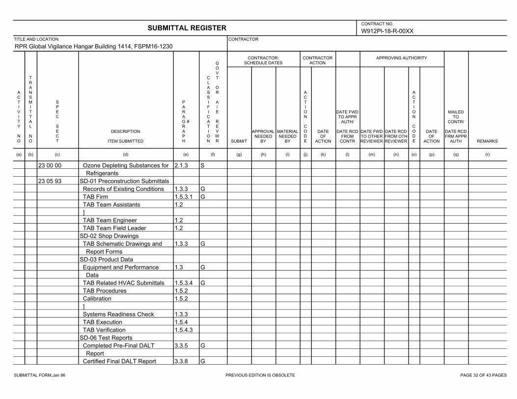
SUBMITTAL FORM,Jan 96 PREVIOUS EDITION IS OBSOLETE PAGE 32 OF 43 PAGES
W912Pl-18-R-00XX
RPR Global Vigilance Hangar Building 1414, FSPM16-1230
23 00 00 2.1.3 SOzone Depleting Substances for
Refrigerants
23 05 93 SD-01 Preconstruction Submittals
1.3.3 GRecords of Existing Conditions
1.5.3.1 GTAB Firm
1.2TAB Team Assistants
]
1.2TAB Team Engineer
1.2TAB Team Field Leader
SD-02 Shop Drawings
1.3.3 GTAB Schematic Drawings and
Report Forms
SD-03 Product Data
1.3 GEquipment and Performance
Data
1.5.3.4 GTAB Related HVAC Submittals
1.5.2TAB Procedures
1.5.2Calibration
]
1.3.3Systems Readiness Check
1.5.4TAB Execution
1.5.4.3TAB Verification
SD-06 Test Reports
3.3.5 GCompleted Pre-Final DALT
Report
3.3.8 GCertified Final DALT Report
SUBMITTAL REGISTERCONTRACT NO.
TITLE AND LOCATION CONTRACTOR
CONTRACTOR:SCHEDULE DATES
CONTRACTORACTION
APPROVING AUTHORITY
ACTIVITY NO
TRANSMITTAL NO
SPEC SECT
DESCRIPTION
ITEM SUBMITTED
PARAGRAPH
#
CLASSIFICATION
GOVT OR A/E REVWR SUBMIT
APPROVALNEEDED
BY
MATERIALNEEDED
BY
ACTION CODE
DATEOF
ACTION
DATE FWDTO APPR
AUTH/
DATE RCDFROM
CONTR
DATE FWDTO OTHERREVIEWER
DATE RCDFROM OTHREVIEWER
ACTION CODE
DATEOF
ACTION
MAILEDTO
CONTR/
DATE RCDFRM APPR
AUTH REMARKS
(a) (b) (c) (d) (e) (f) (g) (h) (i) (j) (k) (l) (m) (n) (o) (p) (q) (r)
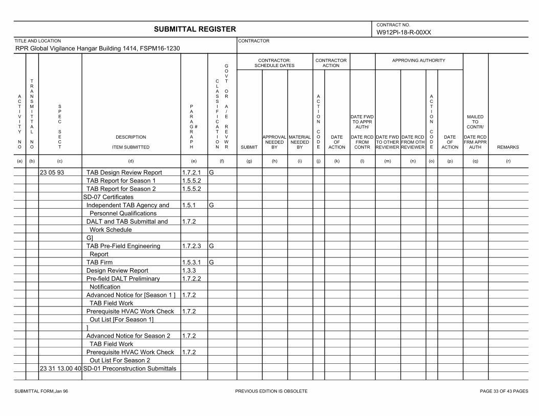
SUBMITTAL FORM,Jan 96 PREVIOUS EDITION IS OBSOLETE PAGE 33 OF 43 PAGES
W912Pl-18-R-00XX
RPR Global Vigilance Hangar Building 1414, FSPM16-1230
23 05 93 1.7.2.1 GTAB Design Review Report
1.5.5.2TAB Report for Season 1
1.5.5.2TAB Report for Season 2
SD-07 Certificates
1.5.1 GIndependent TAB Agency and
Personnel Qualifications
1.7.2DALT and TAB Submittal and
Work Schedule
G]
1.7.2.3 GTAB Pre-Field Engineering
Report
1.5.3.1 GTAB Firm
1.3.3Design Review Report
1.7.2.2Pre-field DALT Preliminary
Notification
1.7.2Advanced Notice for [Season 1 ]
TAB Field Work
1.7.2Prerequisite HVAC Work Check
Out List [For Season 1]
]
1.7.2Advanced Notice for Season 2
TAB Field Work
1.7.2Prerequisite HVAC Work Check
Out List For Season 2
23 31 13.00 40 SD-01 Preconstruction Submittals
SUBMITTAL REGISTERCONTRACT NO.
TITLE AND LOCATION CONTRACTOR
CONTRACTOR:SCHEDULE DATES
CONTRACTORACTION
APPROVING AUTHORITY
ACTIVITY NO
TRANSMITTAL NO
SPEC SECT
DESCRIPTION
ITEM SUBMITTED
PARAGRAPH
#
CLASSIFICATION
GOVT OR A/E REVWR SUBMIT
APPROVALNEEDED
BY
MATERIALNEEDED
BY
ACTION CODE
DATEOF
ACTION
DATE FWDTO APPR
AUTH/
DATE RCDFROM
CONTR
DATE FWDTO OTHERREVIEWER
DATE RCDFROM OTHREVIEWER
ACTION CODE
DATEOF
ACTION
MAILEDTO
CONTR/
DATE RCDFRM APPR
AUTH REMARKS
(a) (b) (c) (d) (e) (f) (g) (h) (i) (j) (k) (l) (m) (n) (o) (p) (q) (r)
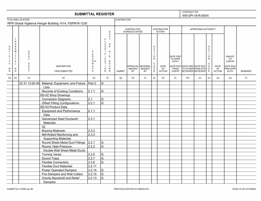
SUBMITTAL FORM,Jan 96 PREVIOUS EDITION IS OBSOLETE PAGE 34 OF 43 PAGES
W912Pl-18-R-00XX
RPR Global Vigilance Hangar Building 1414, FSPM16-1230
23 31 13.00 40 Part 2 GMaterial, Equipment, and Fixture
Lists
2.1.1 GRecords of Existing Conditions
SD-02 Shop Drawings
2.1 GConnection Diagrams
2.2.1 GOffset Fitting Configurations
SD-03 Product Data
2.1.1Equipment and Performance
Data
2.3.1Galvanized Steel Ductwork
Materials
G]
2.3.2Brazing Materials
2.3.3Mill-Rolled Reinforcing and
Supporting Materials
2.2.1 GRound Sheet Metal Duct Fittings
2.2.2 GRound, High-Pressure,
Double-Wall Sheet Metal Ducts
2.2.5 GTurning Vanes
2.2.7 GSound Traps
2.2.8 GFlexible Connectors
2.2.11Flexible Duct Materials
2.2.14 GPower Operated Dampers
2.2.15 GFire Dampers and Wall Collars
2.2.13 GGravity Backdraft and Relief
Dampers
SUBMITTAL REGISTERCONTRACT NO.
TITLE AND LOCATION CONTRACTOR
CONTRACTOR:SCHEDULE DATES
CONTRACTORACTION
APPROVING AUTHORITY
ACTIVITY NO
TRANSMITTAL NO
SPEC SECT
DESCRIPTION
ITEM SUBMITTED
PARAGRAPH
#
CLASSIFICATION
GOVT OR A/E REVWR SUBMIT
APPROVALNEEDED
BY
MATERIALNEEDED
BY
ACTION CODE
DATEOF
ACTION
DATE FWDTO APPR
AUTH/
DATE RCDFROM
CONTR
DATE FWDTO OTHERREVIEWER
DATE RCDFROM OTHREVIEWER
ACTION CODE
DATEOF
ACTION
MAILEDTO
CONTR/
DATE RCDFRM APPR
AUTH REMARKS
(a) (b) (c) (d) (e) (f) (g) (h) (i) (j) (k) (l) (m) (n) (o) (p) (q) (r)

SUBMITTAL FORM,Jan 96 PREVIOUS EDITION IS OBSOLETE PAGE 35 OF 43 PAGES
W912Pl-18-R-00XX
RPR Global Vigilance Hangar Building 1414, FSPM16-1230
23 31 13.00 40 2.2.12 GManual Volume Dampers
SD-05 Design Data
2.1.1 GDesign Analysis and Calculations
SD-06 Test Reports
3.4.2 GDuctwork Leakage Tests
3.4.1 GOperational Tests
SD-07 Certificates
1.3Listing of Product Installations
2.3.1Galvanized Steel Ductwork
Materials
2.3.2Brazing Materials
2.3.3Mill-Rolled Reinforcing and
Supporting Materials
2.2.1Round Sheet Metal Duct Fittings
2.2.2Round, High-Pressure,
Double-Wall Sheet Metal Ducts
2.2.5Turning Vanes
2.2.6Dampers
2.2.7Sound Traps
2.2.8Flexible Connectors
SD-10 Operation and Maintenance
Data
3.5.1 GOperation and Maintenance
Manuals
2.2.14Power Operated Dampers
2.2.15Fire Dampers and Wall Collars
SUBMITTAL REGISTERCONTRACT NO.
TITLE AND LOCATION CONTRACTOR
CONTRACTOR:SCHEDULE DATES
CONTRACTORACTION
APPROVING AUTHORITY
ACTIVITY NO
TRANSMITTAL NO
SPEC SECT
DESCRIPTION
ITEM SUBMITTED
PARAGRAPH
#
CLASSIFICATION
GOVT OR A/E REVWR SUBMIT
APPROVALNEEDED
BY
MATERIALNEEDED
BY
ACTION CODE
DATEOF
ACTION
DATE FWDTO APPR
AUTH/
DATE RCDFROM
CONTR
DATE FWDTO OTHERREVIEWER
DATE RCDFROM OTHREVIEWER
ACTION CODE
DATEOF
ACTION
MAILEDTO
CONTR/
DATE RCDFRM APPR
AUTH REMARKS
(a) (b) (c) (d) (e) (f) (g) (h) (i) (j) (k) (l) (m) (n) (o) (p) (q) (r)
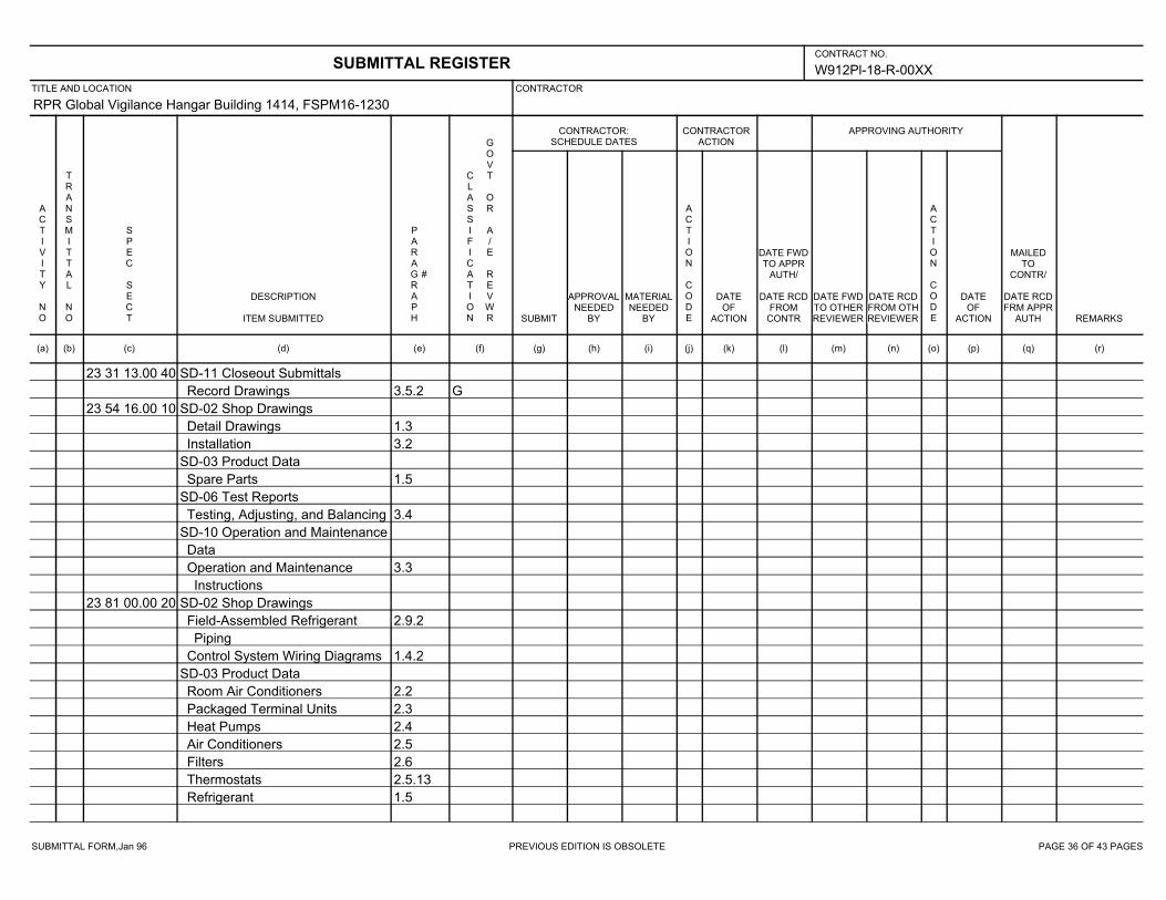
SUBMITTAL FORM,Jan 96 PREVIOUS EDITION IS OBSOLETE PAGE 36 OF 43 PAGES
W912Pl-18-R-00XX
RPR Global Vigilance Hangar Building 1414, FSPM16-1230
23 31 13.00 40 SD-11 Closeout Submittals
3.5.2 GRecord Drawings
23 54 16.00 10 SD-02 Shop Drawings
1.3Detail Drawings
3.2Installation
SD-03 Product Data
1.5Spare Parts
SD-06 Test Reports
3.4Testing, Adjusting, and Balancing
SD-10 Operation and Maintenance
Data
3.3Operation and Maintenance
Instructions
23 81 00.00 20 SD-02 Shop Drawings
2.9.2Field-Assembled Refrigerant
Piping
1.4.2Control System Wiring Diagrams
SD-03 Product Data
2.2Room Air Conditioners
2.3Packaged Terminal Units
2.4Heat Pumps
2.5Air Conditioners
2.6Filters
2.5.13Thermostats
1.5Refrigerant
SUBMITTAL REGISTERCONTRACT NO.
TITLE AND LOCATION CONTRACTOR
CONTRACTOR:SCHEDULE DATES
CONTRACTORACTION
APPROVING AUTHORITY
ACTIVITY NO
TRANSMITTAL NO
SPEC SECT
DESCRIPTION
ITEM SUBMITTED
PARAGRAPH
#
CLASSIFICATION
GOVT OR A/E REVWR SUBMIT
APPROVALNEEDED
BY
MATERIALNEEDED
BY
ACTION CODE
DATEOF
ACTION
DATE FWDTO APPR
AUTH/
DATE RCDFROM
CONTR
DATE FWDTO OTHERREVIEWER
DATE RCDFROM OTHREVIEWER
ACTION CODE
DATEOF
ACTION
MAILEDTO
CONTR/
DATE RCDFRM APPR
AUTH REMARKS
(a) (b) (c) (d) (e) (f) (g) (h) (i) (j) (k) (l) (m) (n) (o) (p) (q) (r)

SUBMITTAL FORM,Jan 96 PREVIOUS EDITION IS OBSOLETE PAGE 37 OF 43 PAGES
W912Pl-18-R-00XX
RPR Global Vigilance Hangar Building 1414, FSPM16-1230
23 81 00.00 20 2.9Refrigerant Piping and
Accessories
2.7Coatings for Finned Tube Coils
SD-06 Test Reports
2.11.1Salt-Spray Tests
3.9.3Start-Up and Initial Operational
Tests
SD-08 Manufacturer’s Instructions
2.2Room Air Conditioners
2.3Packaged Terminal Units
2.4Heat Pumps
2.5Air Conditioners
2.6Filters
2.5.13Thermostats
2.9Refrigerant Piping and
Accessories
SD-10 Operation and Maintenance
Data
2.2Room Air Conditioners
2.3Packaged Terminal Units
2.4Heat Pumps
2.5Air Conditioners
2.6Filters
2.5.13Thermostats
SD-11 Closeout Submittals
1.4.4Posted Operating Instructions
SUBMITTAL REGISTERCONTRACT NO.
TITLE AND LOCATION CONTRACTOR
CONTRACTOR:SCHEDULE DATES
CONTRACTORACTION
APPROVING AUTHORITY
ACTIVITY NO
TRANSMITTAL NO
SPEC SECT
DESCRIPTION
ITEM SUBMITTED
PARAGRAPH
#
CLASSIFICATION
GOVT OR A/E REVWR SUBMIT
APPROVALNEEDED
BY
MATERIALNEEDED
BY
ACTION CODE
DATEOF
ACTION
DATE FWDTO APPR
AUTH/
DATE RCDFROM
CONTR
DATE FWDTO OTHERREVIEWER
DATE RCDFROM OTHREVIEWER
ACTION CODE
DATEOF
ACTION
MAILEDTO
CONTR/
DATE RCDFRM APPR
AUTH REMARKS
(a) (b) (c) (d) (e) (f) (g) (h) (i) (j) (k) (l) (m) (n) (o) (p) (q) (r)
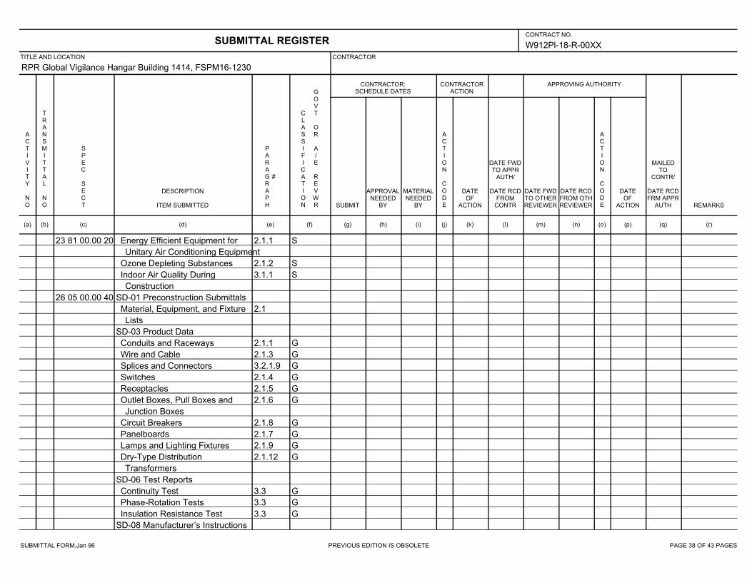
SUBMITTAL FORM,Jan 96 PREVIOUS EDITION IS OBSOLETE PAGE 38 OF 43 PAGES
W912Pl-18-R-00XX
RPR Global Vigilance Hangar Building 1414, FSPM16-1230
23 81 00.00 20 2.1.1 SEnergy Efficient Equipment for
Unitary Air Conditioning Equipment
2.1.2 SOzone Depleting Substances
3.1.1 SIndoor Air Quality During
Construction
26 05 00.00 40 SD-01 Preconstruction Submittals
2.1Material, Equipment, and Fixture
Lists
SD-03 Product Data
2.1.1 GConduits and Raceways
2.1.3 GWire and Cable
3.2.1.9 GSplices and Connectors
2.1.4 GSwitches
2.1.5 GReceptacles
2.1.6 GOutlet Boxes, Pull Boxes and
Junction Boxes
2.1.8 GCircuit Breakers
2.1.7 GPanelboards
2.1.9 GLamps and Lighting Fixtures
2.1.12 GDry-Type Distribution
Transformers
SD-06 Test Reports
3.3 GContinuity Test
3.3 GPhase-Rotation Tests
3.3 GInsulation Resistance Test
SD-08 Manufacturer’s Instructions
SUBMITTAL REGISTERCONTRACT NO.
TITLE AND LOCATION CONTRACTOR
CONTRACTOR:SCHEDULE DATES
CONTRACTORACTION
APPROVING AUTHORITY
ACTIVITY NO
TRANSMITTAL NO
SPEC SECT
DESCRIPTION
ITEM SUBMITTED
PARAGRAPH
#
CLASSIFICATION
GOVT OR A/E REVWR SUBMIT
APPROVALNEEDED
BY
MATERIALNEEDED
BY
ACTION CODE
DATEOF
ACTION
DATE FWDTO APPR
AUTH/
DATE RCDFROM
CONTR
DATE FWDTO OTHERREVIEWER
DATE RCDFROM OTHREVIEWER
ACTION CODE
DATEOF
ACTION
MAILEDTO
CONTR/
DATE RCDFRM APPR
AUTH REMARKS
(a) (b) (c) (d) (e) (f) (g) (h) (i) (j) (k) (l) (m) (n) (o) (p) (q) (r)
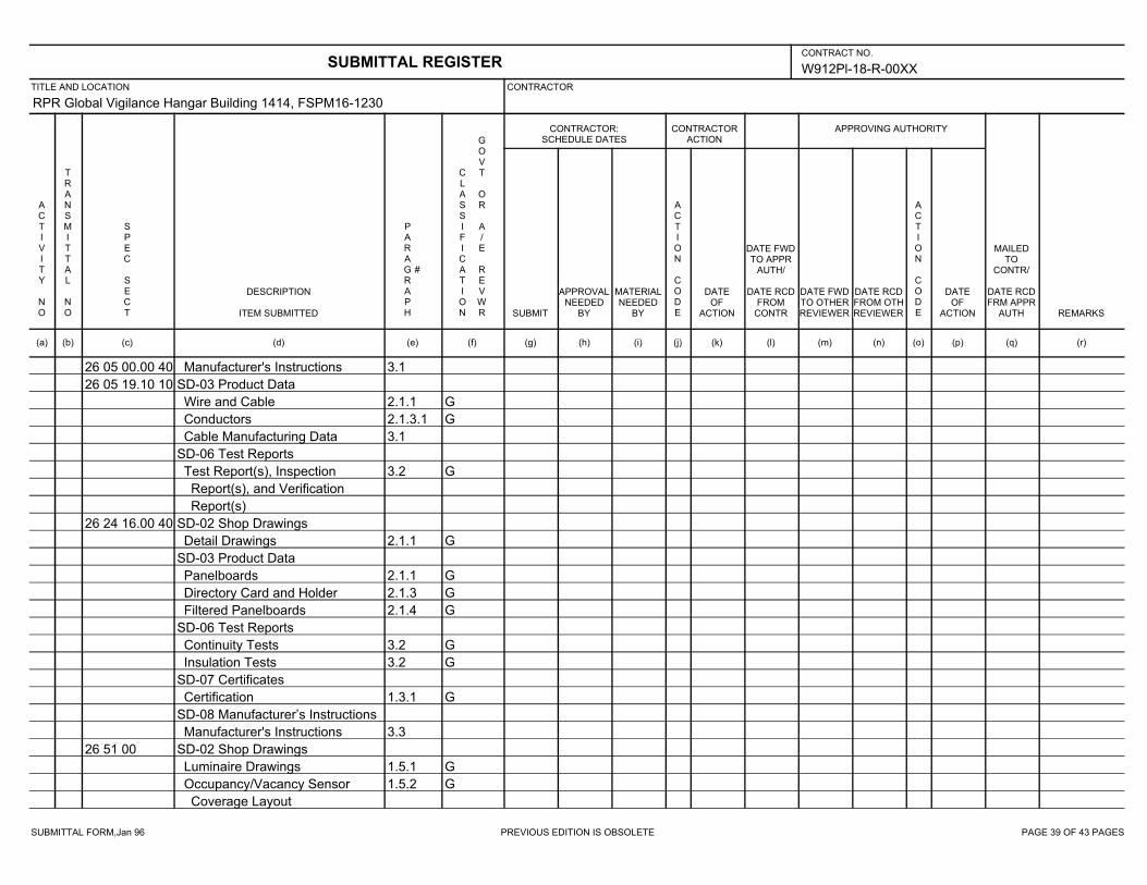
SUBMITTAL FORM,Jan 96 PREVIOUS EDITION IS OBSOLETE PAGE 39 OF 43 PAGES
W912Pl-18-R-00XX
RPR Global Vigilance Hangar Building 1414, FSPM16-1230
26 05 00.00 40 3.1Manufacturer's Instructions
26 05 19.10 10 SD-03 Product Data
2.1.1 GWire and Cable
2.1.3.1 GConductors
3.1Cable Manufacturing Data
SD-06 Test Reports
3.2 GTest Report(s), Inspection
Report(s), and Verification
Report(s)
26 24 16.00 40 SD-02 Shop Drawings
2.1.1 GDetail Drawings
SD-03 Product Data
2.1.1 GPanelboards
2.1.3 GDirectory Card and Holder
2.1.4 GFiltered Panelboards
SD-06 Test Reports
3.2 GContinuity Tests
3.2 GInsulation Tests
SD-07 Certificates
1.3.1 GCertification
SD-08 Manufacturer’s Instructions
3.3Manufacturer's Instructions
26 51 00 SD-02 Shop Drawings
1.5.1 GLuminaire Drawings
1.5.2 GOccupancy/Vacancy Sensor
Coverage Layout
SUBMITTAL REGISTERCONTRACT NO.
TITLE AND LOCATION CONTRACTOR
CONTRACTOR:SCHEDULE DATES
CONTRACTORACTION
APPROVING AUTHORITY
ACTIVITY NO
TRANSMITTAL NO
SPEC SECT
DESCRIPTION
ITEM SUBMITTED
PARAGRAPH
#
CLASSIFICATION
GOVT OR A/E REVWR SUBMIT
APPROVALNEEDED
BY
MATERIALNEEDED
BY
ACTION CODE
DATEOF
ACTION
DATE FWDTO APPR
AUTH/
DATE RCDFROM
CONTR
DATE FWDTO OTHERREVIEWER
DATE RCDFROM OTHREVIEWER
ACTION CODE
DATEOF
ACTION
MAILEDTO
CONTR/
DATE RCDFRM APPR
AUTH REMARKS
(a) (b) (c) (d) (e) (f) (g) (h) (i) (j) (k) (l) (m) (n) (o) (p) (q) (r)
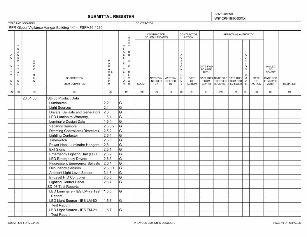
SUBMITTAL FORM,Jan 96 PREVIOUS EDITION IS OBSOLETE PAGE 40 OF 43 PAGES
W912Pl-18-R-00XX
RPR Global Vigilance Hangar Building 1414, FSPM16-1230
26 51 00 SD-03 Product Data
2.2 GLuminaires
2.4 GLight Sources
2.3 GDrivers, Ballasts and Generators
1.6.1 GLED Luminaire Warranty
1.5.4 GLuminaire Design Data
2.5.3.2 GVacancy Sensors
2.5.2 GDimming Controllers (Dimmers)
2.5.4 GLighting Contactor
2.5.5 GTimeswitch
2.8 GPower Hook Luminaire Hangers
2.6.1 GExit Signs
2.6.2 GEmergency Lighting Unit (EBU)
2.6.3 GLED Emergency Drivers
2.6.4 GFluorescent Emergency Ballasts
2.5.3.1 GOccupancy Sensors
3.1.8 GAmbient Light Level Sensor
2.5.6 GBi-Level HID Controller
2.5.7 GLighting Control Panel
SD-06 Test Reports
1.5.5 GLED Luminaire - IES LM-79 Test
Report
1.5.6 GLED Light Source - IES LM-80
Test Report
1.5.7 GLED Light Source - IES TM-21
Test Report
SUBMITTAL REGISTERCONTRACT NO.
TITLE AND LOCATION CONTRACTOR
CONTRACTOR:SCHEDULE DATES
CONTRACTORACTION
APPROVING AUTHORITY
ACTIVITY NO
TRANSMITTAL NO
SPEC SECT
DESCRIPTION
ITEM SUBMITTED
PARAGRAPH
#
CLASSIFICATION
GOVT OR A/E REVWR SUBMIT
APPROVALNEEDED
BY
MATERIALNEEDED
BY
ACTION CODE
DATEOF
ACTION
DATE FWDTO APPR
AUTH/
DATE RCDFROM
CONTR
DATE FWDTO OTHERREVIEWER
DATE RCDFROM OTHREVIEWER
ACTION CODE
DATEOF
ACTION
MAILEDTO
CONTR/
DATE RCDFRM APPR
AUTH REMARKS
(a) (b) (c) (d) (e) (f) (g) (h) (i) (j) (k) (l) (m) (n) (o) (p) (q) (r)
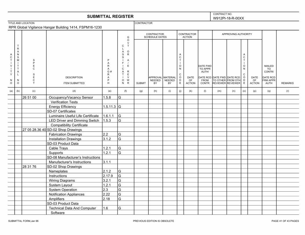
SUBMITTAL FORM,Jan 96 PREVIOUS EDITION IS OBSOLETE PAGE 41 OF 43 PAGES
W912Pl-18-R-00XX
RPR Global Vigilance Hangar Building 1414, FSPM16-1230
26 51 00 1.5.8 GOccupancy/Vacancy Sensor
Verification Tests
1.5.11.3 GEnergy Efficiency
SD-07 Certificates
1.6.1.1 GLuminaire Useful Life Certificate
1.5.3 GLED Driver and Dimming Switch
Compatibility Certificate
27 05 28.36 40 SD-02 Shop Drawings
2.2 GFabrication Drawings
3.1.2 GInstallation Drawings
SD-03 Product Data
1.2.1 GCable Trays
1.2.1 GSupports
SD-08 Manufacturer’s Instructions
3.1.1Manufacturer's Instructions
28 31 76 SD-02 Shop Drawings
2.1.2 GNameplates
2.17.9 GInstructions
3.2.1 GWiring Diagrams
1.2.1 GSystem Layout
2.3 GSystem Operation
2.22 GNotification Appliances
2.18 GAmplifiers
SD-03 Product Data
1.6 GTechnical Data And Computer
Software
SUBMITTAL REGISTERCONTRACT NO.
TITLE AND LOCATION CONTRACTOR
CONTRACTOR:SCHEDULE DATES
CONTRACTORACTION
APPROVING AUTHORITY
ACTIVITY NO
TRANSMITTAL NO
SPEC SECT
DESCRIPTION
ITEM SUBMITTED
PARAGRAPH
#
CLASSIFICATION
GOVT OR A/E REVWR SUBMIT
APPROVALNEEDED
BY
MATERIALNEEDED
BY
ACTION CODE
DATEOF
ACTION
DATE FWDTO APPR
AUTH/
DATE RCDFROM
CONTR
DATE FWDTO OTHERREVIEWER
DATE RCDFROM OTHREVIEWER
ACTION CODE
DATEOF
ACTION
MAILEDTO
CONTR/
DATE RCDFRM APPR
AUTH REMARKS
(a) (b) (c) (d) (e) (f) (g) (h) (i) (j) (k) (l) (m) (n) (o) (p) (q) (r)
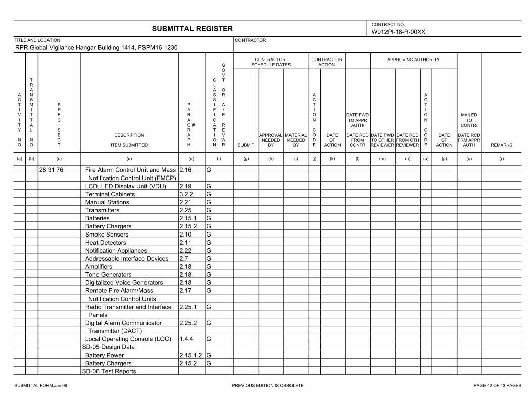
SUBMITTAL FORM,Jan 96 PREVIOUS EDITION IS OBSOLETE PAGE 42 OF 43 PAGES
W912Pl-18-R-00XX
RPR Global Vigilance Hangar Building 1414, FSPM16-1230
28 31 76 2.16 GFire Alarm Control Unit and Mass
Notification Control Unit (FMCP)
2.19 GLCD, LED Display Unit (VDU)
3.2.2 GTerminal Cabinets
2.21 GManual Stations
2.25 GTransmitters
2.15.1 GBatteries
2.15.2 GBattery Chargers
2.10 GSmoke Sensors
2.11 GHeat Detectors
2.22 GNotification Appliances
2.7 GAddressable Interface Devices
2.18 GAmplifiers
2.18 GTone Generators
2.18 GDigitalized Voice Generators
2.17 GRemote Fire Alarm/Mass
Notification Control Units
2.25.1 GRadio Transmitter and Interface
Panels
2.25.2 GDigital Alarm Communicator
Transmitter (DACT)
1.4.4 GLocal Operating Console (LOC)
SD-05 Design Data
2.15.1.2 GBattery Power
2.15.2 GBattery Chargers
SD-06 Test Reports
SUBMITTAL REGISTERCONTRACT NO.
TITLE AND LOCATION CONTRACTOR
CONTRACTOR:SCHEDULE DATES
CONTRACTORACTION
APPROVING AUTHORITY
ACTIVITY NO
TRANSMITTAL NO
SPEC SECT
DESCRIPTION
ITEM SUBMITTED
PARAGRAPH
#
CLASSIFICATION
GOVT OR A/E REVWR SUBMIT
APPROVALNEEDED
BY
MATERIALNEEDED
BY
ACTION CODE
DATEOF
ACTION
DATE FWDTO APPR
AUTH/
DATE RCDFROM
CONTR
DATE FWDTO OTHERREVIEWER
DATE RCDFROM OTHREVIEWER
ACTION CODE
DATEOF
ACTION
MAILEDTO
CONTR/
DATE RCDFRM APPR
AUTH REMARKS
(a) (b) (c) (d) (e) (f) (g) (h) (i) (j) (k) (l) (m) (n) (o) (p) (q) (r)

SUBMITTAL FORM,Jan 96 PREVIOUS EDITION IS OBSOLETE PAGE 43 OF 43 PAGES
W912Pl-18-R-00XX
RPR Global Vigilance Hangar Building 1414, FSPM16-1230
28 31 76 3.7Field Quality Control
3.7.1 GTesting Procedures
2.10.6 GSmoke Sensor Testing
SD-07 Certificates
1.7.1.4Installer
3.7.2.2Formal Inspection and Tests
3.7.2.3Final Testing
SD-09 Manufacturer’s Field
Reports
2.3 GSystem Operation
1.7.2.2Fire Alarm/Mass Notification
System
SD-10 Operation and Maintenance
Data
3.10 GOperation and Maintenance
(O&M) Instructions
3.8 GInstruction of Government
Employees
SD-11 Closeout Submittals
3.7.2.4As-Built Drawings
SUBMITTAL REGISTERCONTRACT NO.
TITLE AND LOCATION CONTRACTOR
CONTRACTOR:SCHEDULE DATES
CONTRACTORACTION
APPROVING AUTHORITY
ACTIVITY NO
TRANSMITTAL NO
SPEC SECT
DESCRIPTION
ITEM SUBMITTED
PARAGRAPH
#
CLASSIFICATION
GOVT OR A/E REVWR SUBMIT
APPROVALNEEDED
BY
MATERIALNEEDED
BY
ACTION CODE
DATEOF
ACTION
DATE FWDTO APPR
AUTH/
DATE RCDFROM
CONTR
DATE FWDTO OTHERREVIEWER
DATE RCDFROM OTHREVIEWER
ACTION CODE
DATEOF
ACTION
MAILEDTO
CONTR/
DATE RCDFRM APPR
AUTH REMARKS
(a) (b) (c) (d) (e) (f) (g) (h) (i) (j) (k) (l) (m) (n) (o) (p) (q) (r)
REPAI R GLOBAL VI GI LANCE HANGAR, BUI LDI NG 1414 I FB NO. W912PL- 18- B- 0008EDWARDS AI R FORCE BASE, KERN COUNTY, CA
SECTI ON TABLE OF CONTENTS
DI VI SI ON 01 - GENERAL REQUI REMENTS
SECTI ON 01 33 29
SUSTAI NABI LI TY REPORTI NG
02/17
PART 1 GENERAL
1. 1 REFERENCES 1. 2 SUMMARY 1. 3 SUBMI TTALS 1. 4 GUI DI NG PRI NCI PLES VALI DATI ON ( GPV) 1. 4. 1 Sust ai nabi l i t y Act i on Pl an 1. 4. 2 Cost s 1. 4. 3 Cal cul at i ons 1. 5 SUSTAI NABI LI TY SUBMI TTALS 1. 5. 1 Hi gh Per f or mance Sust ai nabl e Bui l di ng ( HPSB) Checkl i st 1. 5. 1. 1 HPSB Checkl i st Submi t t al s 1. 5. 2 " S" Submi t t al s f or Sust ai nabi l i t y Document at i on 1. 5. 3 Sust ai nabi l i t y Not ebook 1. 5. 3. 1 Sust ai nabi l i t y Not ebook Submi t t al Schedul e 1. 6 DOCUMENTATI ON REQUI REMENTS 1. 6. 1 Commi ssi oni ng 1. 6. 2 Ener gy Ef f i c i ent Pr oduct s 1. 6. 3 I ndoor Wat er Use 1. 6. 4 Reduce Vol at i l e Or gani c Compounds ( VOC) ( Low Emi t t i ng
Materials) 1. 6. 5 I ndoor Ai r Qual i t y Dur i ng Const r uct i on 1. 6. 6 Recycl ed Cont ent 1. 6. 7 Bi o- Based Pr oduct s 1. 6. 8 Ozone Depl et i ng Subst ances 1. 6. 9 Wast e Mat er i al Management ( Recycl i ng – Const r uct i on)
PART 2 PRODUCTS
PART 3 EXECUTI ON
3. 1 SUSTAI NABI LI TY COORDI NATI ON 3. 1. 1 Coor di nat i ng Sust ai nabi l i t y Document at i on Pr ogr ess
- - End of Sect i on Tabl e of Cont ent s - -
SECTI ON 01 33 29 Page 1
REPAI R GLOBAL VI GI LANCE HANGAR, BUI LDI NG 1414 I FB NO. W912PL- 18- B- 0008EDWARDS AI R FORCE BASE, KERN COUNTY, CA
SECTI ON 01 33 29
SUSTAI NABI LI TY REPORTI NG02/17
PART 1 GENERAL
1. 1 REFERENCES
The publ i cat i ons l i s t ed bel ow f or m a par t of t hi s speci f i cat i on t o t he ext ent r ef er enced. The publ i cat i ons ar e r ef er r ed t o wi t hi n t he t ext by t he basi c desi gnat i on onl y.
AMERI CAN SOCI ETY OF HEATI NG, REFRI GERATI NG AND AI R- CONDI TI ONI NG ENGI NEERS ( ASHRAE)
ASHRAE 189. 1 ( 2014; ERTA 1- 2 2015; ERTA 3- 4 2017) St andar d f or t he Desi gn of Hi gh- Per f or mance Gr een Bui l di ngs Except Low- Ri se Resi dent i al Bui l di ngs
COUNCI L ON ENVI RONMENTAL QUALI TY ( CEQ) ( WHI TE HOUSE)
HPSB Gui di ng Pr i nci pl es ( 2016) Gui di ng Pr i nci pl es f or Sust ai nabl e Feder al Bui l di ngs and Det er mi ni ng Compl i ance wi t h t he Gui di ng Pr i nci pl es f or Sust ai nabl e Feder al Bui l di ngs
SHEET METAL AND AI R CONDI TI ONI NG CONTRACTORS' NATI ONAL ASSOCI ATI ON (SMACNA)
ANSI / SMACNA 008 ( 2007) I AQ Gui del i nes f or Occupi ed Bui l di ngs Under Const r uct i on, 2nd Edi t i on
U. S. DEPARTMENT OF AGRI CULTURE ( USDA)
FSRI A 9002 Far m Secur i t y and Rur al I nvest ment Act Sect i on 9002 ( USDA Bi opr ef er r ed Pr ogr am)
U. S. DEPARTMENT OF ENERGY ( DOE)
Ener gy St ar ( 1992; R 2006) Ener gy St ar Ener gy Ef f i c i ency Label i ng Syst em ( FEMP)
U. S. ENVI RONMENTAL PROTECTI ON AGENCY ( EPA)
SNAP ( 2016) EPA' s Si gni f i cant New Al t er nat i ves Pol i cy Pr ogr am
U. S. NATI ONAL ARCHI VES AND RECORDS ADMI NI STRATI ON ( NARA)
40 CFR 247 Compr ehensi ve Pr ocur ement Gui del i ne f or Pr oduct s Cont ai ni ng Recover ed Mat er i al s
1. 2 SUMMARY
Thi s speci f i cat i on i ncl udes gener al r equi r ement s and pr ocedur es f or t hi s
SECTI ON 01 33 29 Page 2

REPAI R GLOBAL VI GI LANCE HANGAR, BUI LDI NG 1414 I FB NO. W912PL- 18- B- 0008EDWARDS AI R FORCE BASE, KERN COUNTY, CA
pr oj ect t o be const r uct ed and document ed per t he f eder al l y mandat ed HPSB Gui di ng Pr i nci pl es ( GP) , UFC 1- 200- 02, Hi gh Per f or mance and Sust ai nabl e Bui l di ng Requi r ement s, and ot her r equi r ement s i dent i f i ed i n t hi s specification.
1. 3 SUBMITTALS
Gover nment appr oval i s r equi r ed f or submi t t al s wi t h a " G" desi gnat i on; submi t t al s not havi ng a " G" desi gnat i on ar e f or i nf or mat i on onl y. When used, a desi gnat i on f ol l owi ng t he " G" desi gnat i on i dent i f i es t he of f i ce t hat wi l l r evi ew t he submi t t al f or t he Gover nment . Submi t t al s wi t h an " S" ar e f or i ncl usi on i n t he Sust ai nabi l i t y Not ebook, i n conf or mance t o t hi s sect i on. Submi t t he f ol l owi ng i n accor dance wi t h Sect i on 01 33 00 SUBMI TTAL PROCEDURES:
SD- 01 Pr econst r uct i on Submi t t al s
Pr el i mi nar y Hi gh Per f or mance and Sust ai nabl e Bui l di ng Checkl i st ; G
Sust ai nabi l i t y Act i on Pl an; G
Pr el i mi nar y Sust ai nabi l i t y Not ebook; G
SD- 11 Cl oseout Submi t t al s
Fi nal Hi gh Per f or mance and Sust ai nabl e Bui l di ng Checkl i st ; G
Fi nal Sust ai nabi l i t y Not ebook; G
Amended Fi nal Sust ai nabi l i t y Not ebook; G
Amended Fi nal Hi gh Per f or mance and Sust ai nabl e Bui l di ng Checkl i st ; G
Thi r d Par t y Cer t i f i cat i on Cer t i f i cat es or Val i dat i on; G
1. 4 GUI DI NG PRI NCI PLES VALI DATI ON ( GPV)
Pr ovi de const r uct i on r el at ed sust ai nabi l i t y document at i on t o ver i f y achi evement of HPSB Gui di ng Pr i nci pl es Val i dat i on ( GPV) . Pr ovi de t he f ol l owi ng f or GPV:
a. Ref er t o At t achment 1, HPSB Checkl i st at t he end of t hi s speci f i cat i on sect i on. ( Mul t i pl e checkl i st s i ndi cat e mul t i pl e bui l di ngs t hat r equi r e HPSB t r acki ng. )
b. Obt ai n appr oval of any changes t o t he HPSB Checkl i st f r om t he Cont r act i ng Of f i cer at t he Pr econst r uct i on Conf er ence. Cont r act i ng Of f i cer ' s appr oval est abl i shes i dent i f i ed HPSB Gui di ng Pr i nci pl es Requi r ement s as t he pr oj ect ' s sust ai nabi l i t y goal s.
No var i at i ons or subst i t ut i ons t o t he HPSB Checkl i st ar e al l owed wi t hout wr i t t en consent f r om t he Cont r act i ng Of f i cer . I mmedi at el y br i ng t o t he at t ent i on of t he Cont r act i ng Of f i cer any changes t hat i mpact meet i ng t he appr oved HPSB Gui di ng Pr i nci pl es Requi r ement s f or t hi s pr oj ect and demonst r at e t hat change wi l l not i ncur addi t i onal const r uct i on cost or i ncr ease t he l i f e cycl e cost .
c. Pr ovi de al l wor k, i ncl udi ng " S" submi t t al s, r equi r ed t o i ncor por at e
SECTI ON 01 33 29 Page 3
REPAI R GLOBAL VI GI LANCE HANGAR, BUI LDI NG 1414 I FB NO. W912PL- 18- B- 0008EDWARDS AI R FORCE BASE, KERN COUNTY, CA
t he appl i cabl e HPSB Gui di ng Pr i nci pl es Requi r ement s i ndi cat ed on t he HPSB Checkl i st and i n t hi s cont r act .
d. Pr ovi de Sust ai nabi l i t y Act i on Pl an
e. Pr ovi de const r uct i on r el at ed document at i on f or t he pr oj ect Sust ai nabi l i t y eNot ebook, and keep updat ed wi t h r egul ar l y- schedul ed const r uct i on meet i ngs. I ncl ude const r uct i on r el at ed document at i on cont ai ni ng t he f ol l owi ng component s;
( 1) HPSB Checkl i st
( 2) Sust ai nabi l i t y Act i on Pl an
( 3) Document at i on i l l ust r at i ng HPSB Gui di ng Pr i nci pl es Requi r ement s compl i ance ( i ncl udi ng " S" submi t t al s)
1. 4. 1 Sust ai nabi l i t y Act i on Pl an
I ncl ude t he f ol l owi ng i nf or mat i on i n t he Sust ai nabi l i t y Act i on Pl an:
a. Pl anned met hod t o achi eve each const r uct i on r el at ed GP r equi r ement .
b. For each desi gnat ed const r uct i on r el at ed HPSB Gui di ng Pr i nci pl es Requi r ement s t hat i s not achi eved, pr ovi de nar r at i ve expl ai ni ng how mi ssi on or act i v i t y pr ecl udes achi evi ng speci f i c sust ai nabi l i t y r equi r ement or goal . Pr ovi de anal ysi s of par t i cul ar r equi r ement and l evel t o whi ch pr oj ect i s abl e t o compl y. Fi nal gover nment - appr oved nar r at i ve( s) must be i ncl uded wi t h t he HPSB Checkl i st submi t t al .
c. Name and cont act i nf or mat i on f or : POC r esponsi bl e f or ensur i ng sust ai nabi l i t y goal s ar e accompl i shed and document at i on i s assembled.
d. I ncl ude t he I ndoor Ai r Qual i t y pl an wi t h t he Sust ai nabi l i t y Act i on Plan.
1. 4. 2 Costs
Bear al l cost s associ at ed wi t h const r uct i ng and demonst r at i ng t hat pr oj ect compl i es wi t h appr oved HPSB Gui di ng Pr i nci pl es Requi r ement s.
1. 4. 3 Calculations
Pr ovi de cal cul at i ons, pr oduct dat a, l abel s and cer t i f i cat i ons r equi r ed i n t hi s sect i on t o demonst r at e compl i ance wi t h t he HPSB Gui di ng Pr i nci pl es Requirements.
1. 5 SUSTAI NABI LI TY SUBMI TTALS
Pr ovi de HPSB Checkl i st and ot her document at i on i n t he Sust ai nabi l i t y Not ebook t o i ndi cat e compl i ance wi t h t he sust ai nabi l i t y r equi r ement s of t he pr oj ect .
1. 5. 1 Hi gh Per f or mance Sust ai nabl e Bui l di ng ( HPSB) Checkl i st
Pr ovi de const r uct i on document at i on t hat pr ovi des pr oof of and suppor t s compl i ance wi t h t he compl et ed HPSB Checkl i st .
SECTI ON 01 33 29 Page 4

REPAI R GLOBAL VI GI LANCE HANGAR, BUI LDI NG 1414 I FB NO. W912PL- 18- B- 0008EDWARDS AI R FORCE BASE, KERN COUNTY, CA
1. 5. 1. 1 HPSB Checkl i st Submi t t al s
Submi t updat ed HPSB Checkl i st wi t h each Sust ai nabi l i t y Not ebook submi t t al . At t ach f i nal HPSB Checkl i st t o dr af t f i nal DD1354 Real Pr oper t y Recor d Submi t t al .
1. 5. 2 " S" Submi t t al s f or Sust ai nabi l i t y Document at i on
Submi t t he GPV sust ai nabi l i t y document at i on r equi r ed i n t hi s speci f i cat i on as " S" submi t t al s i n al l af f ect ed UFGS Sect i ons. Hi ghl i ght GPV compl i ance dat a i n " S" submi t t al .
1. 5. 3 Sust ai nabi l i t y Not ebook
Pr ovi de and mai nt ai n a compr ehensi ve Sust ai nabi l i t y Not ebook t o document compl i ance wi t h t he sust ai nabi l i t y r equi r ement s i dent i f i ed i n t he appr oved HPSB Checkl i st . Sust ai nabi l i t y Not ebook must cont ai n al l r equi r ed dat a t o suppor t f ul l compl i ance wi t h t he HPSB Gui di ng Pr i nci pl es Requi r ement s, i ncl udi ng HPSB checkl i st , Sust ai nabl e Act i on Pl an, cal cul at i ons, l abel s, cer t i f i cat i ons . Sust ai nabi l i t y Not ebook i s i n t he f or m of an Adobe PDF f i l e; bookmar ked at each HPSB Gui di ng Pr i nci pl es Requi r ement and sub- bookmar ked at each document . Mat ch f or mat t o HPSB Gui di ng Pr i nci pl es number i ng syst em i ndi cat ed her ei n. Mai nt ai n up t o dat e i nf or mat i on, spr eadsheet s, t empl at es, and ot her r equi r ed document at i on wi t h each cur r ent submi t t al .
Cont r act i ng Of f i cer may deduct f r om t he mont hl y pr ogr ess payment accor di ngl y i f Sust ai nabi l i t y Not ebook i nf or mat i on i s not cur r ent , unt i l i nf or mat i on i s updat ed and on t r ack per pr oj ect goal s.
1. 5. 3. 1 Sust ai nabi l i t y Not ebook Submi t t al Schedul e
Pr ovi de Sust ai nabi l i t y Not ebook Submi t t al s at t he f ol l owi ng mi l est ones of t he pr oj ect :
a. Pr el i mi nar y Sust ai nabi l i t y Not ebook
Submi t pr el i mi nar y Sust ai nabi l i t y Not ebook f or appr oval at t he Pr e- const r uct i on conf er ence. I ncl ude Pr el i mi nar y Hi gh Per f or mance and Sust ai nabl e Bui l di ng Checkl i st ].
b. Const r uct i on Pr ogr ess Meet i ngs. Updat e GP document at i on i n t he Sust ai nabi l i t y Not ebook f or each meet i ng.
c. Fi nal Sust ai nabi l i t y Not ebook
Submi t updat ed Sust ai nabi l i t y eNot ebook at t he Benef i c i al Occupancy Dat e ( BOD) . Fi nal pr ogr ess payment r et ai nage may be hel d by Cont r act i ng Of f i cer unt i l f i nal sust ai nabi l i t y document at i on i s compl et e. Submi t t hr ee el ect r oni c copi es of t he Fi nal Sust ai nabi l i t y Not ebook on DVDs t o t he Gover nment . I ncl ude Fi nal Hi gh Per f or mance and Sust ai nabl e Bui l di ng Checkl i st .
d. Amended Fi nal Sust ai nabi l i t y Not ebook
Amend and r esubmi t t he Fi nal Sust ai nabi l i t y Not ebook t o i ncl ude post - occupancy cor r ect i ons, updat es, and r equi r ement s. I ncl ude Amended Fi nal Hi gh Per f or mance and Sust ai nabl e Bui l di ng Checkl i st .
SECTI ON 01 33 29 Page 5
REPAI R GLOBAL VI GI LANCE HANGAR, BUI LDI NG 1414 I FB NO. W912PL- 18- B- 0008EDWARDS AI R FORCE BASE, KERN COUNTY, CA
Fi nal pr ogr ess payment r et ai nage may be hel d by Cont r act i ng Of f i cer unt i l amended f i nal sust ai nabi l i t y document at i on i s compl et e. Submi t 3 f i nal el ect r oni c copi es of t he Amended Fi nal Sust ai nabi l i t y eNot ebook Submi t t al on DVDs t o t he Gover nment no l onger t han 30 days af t er t he GP[ , TPC] desi gnat ed dat a col l ect i on per i od.
1. 6 DOCUMENTATI ON REQUI REMENTS
a. I ncor por at e each of t he f ol l owi ng HPSB Gui di ng Pr i nci pl es Requi r ement s i nt o pr oj ect const r uct i on; and pr ovi de document at i on t hat pr oves compl i ance wi t h each l i s t ed r equi r ement . I t ems bel ow ar e or gani zed accor di ng t o t he HPSB Gui di ng Pr i nci pl es. For l i f e- cycl e cost anal ysi s r equi r ement s, one document wi t h al l anal yses i s accept abl e, wi t h Cont r act i ng Of f i cer appr oval .
b. For each of t he f ol l owi ng par agr aphs t hat r equi r e t he use of pr oduct s l i s t ed on Gover nment - r equi r ed websi t es, pr ovi de document at i on of t he pr ocess used t o sel ect pr oduct s, or pr ocess used t o det er mi ne why l i s t ed pr oduct s do not meet pr oj ect per f or mance r equi r ement s.
1. 6. 1 Commissioning
Submi t appr oved Fi nal Commi ssi oni ng Repor t r equi r ed by Sect i on 01 91 00. 15 TOTAL BUI LDI NG COMMI SSI ONI NG as pr oof of t hi s t r acki ng r equi r ement .
1. 6. 2 Ener gy Ef f i c i ent Pr oduct s
Pr ovi de onl y ener gy- usi ng pr oduct s t hat ar e Ener gy St ar r at ed, or have t he Feder al Ener gy Management Pr ogr am ( FEMP) r ecommended ef f i c i ency. Wher e Ener gy St ar or FEMP r ecommendat i ons have not been est abl i shed, pr ovi de most ef f i c i ent pr oduct s t hat ar e l i f e- cycl e cost ef f ect i ve. Pr ovi de onl y ener gy usi ng pr oduct s t hat meet FEMP r equi r ement s f or l ow st andby power consumpt i on. Ener gy ef f i c i ent pr oduct s can be f ound at : https://energy.gov/eere/femp/federal-energy-management-program and https://www.energystar.gov/ . Pr ovi de t he f ol l owi ng document at i on:
Pr oof t hat pr oduct s ar e l abel ed ener gy ef f i c i ent and compl y wi t h t he c i t ed requirements.
1. 6. 3 I ndoor Wat er Use
Pr ovi de onl y wat er - consumi ng pr oduct s t hat ar e EPA Wat er Sense l abel ed, or t he most ef f i c i ent wat er f i x t ur es avai l abl e t hat meet t he r equi r ement s of ASHRAE 189. 1 Sect i on 6. 3. 2, when EPA Wat er Sense pr oduct s ar e not avai l abl e. Pr ovi de t he f ol l owi ng document at i on:
For pr oduct s avai l abl e wi t h EPA Wat er Sense l abel i ng, pr oof t hat f i x t ur es ar e l abel ed EPA Wat er Sense or Ener gy St ar ; f or al l ot her f i x t ur es, pr oof t hey compl y wi t h t he c i t ed ef f i c i ency r equi r ement s.
1. 6. 4 Reduce Vol at i l e Or gani c Compounds ( VOC) ( Low Emi t t i ng Mat er i al s)
Meet t he r equi r ement s of Tabl e 3- 1 at t he end of t hi s speci f i cat i on. Pr ovi de t he f ol l owi ng document at i on:
Pr ovi de cer t i f i cat i ons or l abel s t hat demonst r at e compl i ance wi t h c i t ed requirements.
SECTI ON 01 33 29 Page 6

REPAI R GLOBAL VI GI LANCE HANGAR, BUI LDI NG 1414 I FB NO. W912PL- 18- B- 0008EDWARDS AI R FORCE BASE, KERN COUNTY, CA
1. 6. 5 I ndoor Ai r Qual i t y Dur i ng Const r uct i on
Pr i or t o const r uct i on, cr eat e i ndoor ai r qual i t y ( I AQ) pl an. Devel op and i mpl ement t he I AQ const r uct i on management pl an dur i ng const r uct i on and f l ush bui l di ng ai r bef or e occupancy.
For new const r uct i on and f or r enovat i on of unoccupi ed exi st i ng bui l di ngs, i ndoor ai r qual i t y pl an must meet t he r equi r ement s of ASHRAE 189. 1 Sect i on 10. 3. 1. 4. ( I ndoor Ai r Qual i t y ( I AQ) Const r uct i on Management ) , wi t h maxi mum out door ai r consi st ent wi t h achi evi ng r el at i ve humi di t y no gr eat er t han 60 per cent . For r enovat i on of occupi ed exi st i ng bui l di ngs, compl y wi t h ANSI / SMACNA 008 I AQ Gui del i nes f or Occupi ed Bui l di ngs Under Const r uct i on.
Pr ovi de document at i on showi ng t hat af t er const r uct i on ends and pr i or t o occupancy, HVAC f i l t er s wer e r epl aced and bui l di ng ai r was f l ushed out i n accor dance wi t h t he c i t ed st andar d.
1. 6. 6 Recycl ed Cont ent
Compl y wi t h 40 CFR 247. Ref er t o https://www.epa.gov/smm/comprehensive-procurement-guideline-cpg-program f or assi st ance i dent i f y i ng pr oduct s c i t ed i n 40 CFR 247. Sel ect ed pr oduct s must compl y wi t h non- pr opr i et ar y r equi r ement s of t he Feder al Acqui s i t i on Regul at i on, and must meet per f or mance r equi r ement s. Pr ovi de t he f ol l owi ng document at i on:
a. Manuf act ur er s’ document s st at i ng t he r ecycl ed cont ent by mat er i al , or wr i t t en j ust i f i cat i on f or c l ai mi ng one of t he except i ons al l owed on t he ci t ed websi t e.
b. Subst i t ut i ons: Submi t f or Gover nment appr oval , pr oposed al t er nat i ve pr oduct s or syst ems t hat pr ovi de equi val ent per f or mance and appear ance and have gr eat er cont r i but i on t o pr oj ect r ecycl ed cont ent r equi r ement s. For al l such pr oposed subst i t ut i ons, submi t wi t h t he Sust ai nabi l i t y Act i on Pl an accompani ed by pr oduct dat a demonst r at i ng equivalence.
1. 6. 7 Bi o- Based Pr oduct s
Pr ovi de pr oduct s and mat er i al composed of t he hi ghest per cent age of bi obased mat er i al s ( i ncl udi ng r api dl y r enewabl e r esour ces and cer t i f i ed sust ai nabl y har vest ed pr oduct s) , consi st ent wi t h FSRI A 9002 USDA Bi oPr ef er r ed Pr ogr am, t o t he maxi mum ext ent possi bl e wi t hout j eopar di z i ng t he i nt ended end use or det r act i ng f r om t he over al l qual i t y del i ver ed t o t he end user . Use onl y suppl i es and mat er i al s of a t ype and qual i t y t hat conf or m t o appl i cabl e speci f i cat i ons and st andar ds.
Compl y wi t h FSRI A 9002 USDA Bi oPr ef er r ed Pr ogr am. Ref er t o https://www.biopreferred.gov/BioPreferred/ f or t he pr oduct cat egor i es and Bi oPr ef er r ed Cat al og. Sel ect ed pr oduct s must compl y wi t h non- pr opr i et ar y r equi r ement s of t he Feder al Acqui s i t i on Regul at i on, and must meet per f or mance r equi r ement s. Pr ovi de t he f ol l owi ng document at i on:
USDA Bi oPr ef er r ed l abel f or each pr oduct ; f or bi o- based pr oduct s used on pr oj ect but not l i s t ed wi t h Bi oPr ef er r ed pr ogr am, pr ovi de bi o- based cont ent and per cent age.
SECTI ON 01 33 29 Page 7
REPAI R GLOBAL VI GI LANCE HANGAR, BUI LDI NG 1414 I FB NO. W912PL- 18- B- 0008EDWARDS AI R FORCE BASE, KERN COUNTY, CA
1. 6. 8 Ozone Depl et i ng Subst ances
Meet t he r equi r ement s of ASHRAE 189. 1 Sect i on 9. 3. 3 Ref r i ger ant s f or no CFC- based r ef r i ger ant s i n heat i ng vent i l at i on, ai r condi t i oni ng and r ef r i ger at i on syst ems ( except f or f i r e suppr essi on syst em r equi r ement s, cover ed el sewher e i n t hi s speci f i cat i on) . Wher e f easi bl e, use pr oduct s f r om U. S. EPA Si gni f i cant New Al t er nat i ves Pol i cy ( SNAP) (https://www.epa.gov/snap ) or meet t he cr i t er i a of SNAP. Pr ovi de t he f ol l owi ng document at i on:
a. SDS sheet s f or al l r ef r i ger ant s.
b. Pr ovi de l abel f or each pr oduct meet i ng t he ci t ed st andar ds.
1. 6. 9 Wast e Mat er i al Management ( Recycl i ng – Const r uct i on)
Di ver t const r uct i on debr i s f r om l andf i l l di sposal wher e mar ket s or on- si t e r ecycl i ng exi st s, and pr ovi de document at i on i n accor dance wi t h Sect i on 01 74 19 CONSTRUCTI ON AND DEMOLI TI ON WASTE MANAGEMENT.
PART 2 PRODUCTS
Not used.
PART 3 EXECUTI ON
3. 1 SUSTAI NABI LI TY COORDI NATI ON
3. 1. 1 Coor di nat i ng Sust ai nabi l i t y Document at i on Pr ogr ess
Pr ovi de sust ai nabi l i t y f ocus and coor di nat i on at t he f ol l owi ng meet i ngs t o achi eve sust ai nabi l i t y goal s. The Contractor's desi gnat ed sust ai nabi l i t y pr of essi onal r esponsi bl e f or GP document at i on must par t i c i pat e i n t he f ol l owi ng meet i ngs t o coor di nat e document at i on compl et i on.
a. Pr e- Const r uct i on Conf er ence: Di scuss t he f ol l owi ng: HPSB Checkl i st [ s] , Sust ai nabi l i t y Act i on Pl an, Const r uct i on submi t t al r equi r ement s and schedul e, i ndi v i dual s r esponsi bl e f or achi evi ng each Gui di ng Pr i nci pl e Requi r ement ] .
b. Const r uct i on Pr ogr ess Meet i ngs: Revi ew GP sust ai nabi l i t y r equi r ement s wi t h pr oj ect t eam i ncl udi ng cont r act or and sub- cont r act or r epr esent at i ves. Demonst r at e GP] document at i on i s bei ng col l ect ed and updat ed t o t he Sust ai nabi l i t y Not ebook.
( 1) Faci l i t y Tur nover Meet i ngs: Revi ew Sust ai nabi l i t y Not ebookf or compl et eness and i dent i f y any out st andi ng i ssues r el at i ng t o f i nal document at i on r equi r ement s.
( 2) Fi nal Sust ai nabi l i t y Not ebook Revi ew
- - End of Sect i on - -
SECTI ON 01 33 29 Page 8

REPAI R GLOBAL VI GI LANCE HANGAR, BUI LDI NG 1414 I FB NO. W912PL- 18- B- 0008EDWARDS AI R FORCE BASE, KERN COUNTY, CA
SECTI ON TABLE OF CONTENTS
DI VI SI ON 01 - GENERAL REQUI REMENTS
SECTI ON 01 35 26
GOVERNMENTAL SAFETY REQUI REMENTS
11/15
PART 1 GENERAL
1. 1 REFERENCES 1. 2 DEFI NI TI ONS 1. 2. 1 Compet ent Per son ( CP) 1. 2. 2 Compet ent Per son, Conf i ned Space 1. 2. 3 Compet ent Per son, Cr anes and Ri ggi ng 1. 2. 4 Compet ent Per son, Excavat i on/ Tr enchi ng 1. 2. 5 Compet ent Per son, Fal l Pr ot ect i on 1. 2. 6 Compet ent Per son, Scaf f ol di ng 1. 2. 7 Compet ent Per son ( CP) Tr ai ner 1. 2. 8 Hi gh Ri sk Act i v i t i es 1. 2. 9 Hi gh Vi s i bi l i t y Acci dent 1. 2. 10 Load Handl i ng Equi pment ( LHE) 1. 2. 11 Medi cal Tr eat ment 1. 2. 12 Near Mi ss 1. 2. 13 Oper at i ng Envel ope 1. 2. 14 Qual i f i ed Per son ( QP) 1. 2. 15 Qual i f i ed Per son, Fal l Pr ot ect i on ( QP f or FP) 1. 2. 16 USACE Pr oper t y and Equi pment 1. 2. 17 Load Handl i ng Equi pment ( LHE) Acci dent or Load Handl i ng
Equi pment Mi shap 1. 3 SUBMI TTALS 1. 4 MONTHLY EXPOSURE REPORTS 1. 5 REGULATORY REQUI REMENTS 1. 6 SI TE QUALI FI CATI ONS, DUTI ES, AND MEETI NGS 1. 6. 1 Per sonnel Qual i f i cat i ons 1. 6. 1. 1 Si t e Saf et y and Heal t h Of f i cer ( SSHO) 1. 6. 1. 1. 1 Addi t i onal Si t e Saf et y and Heal t h Of f i cer ( SSHO)
Requi r ement s and Dut i es 1. 6. 1. 2 Compet ent Per son Qual i f i cat i ons 1. 6. 1. 2. 1 Compet ent Per son f or Conf i ned Space Ent r y 1. 6. 1. 2. 2 Compet ent Per son f or Scaf f ol di ng 1. 6. 1. 2. 3 Compet ent Per son f or Fal l Pr ot ect i on 1. 6. 1. 3 Qual i f i ed Tr ai ner Requi r ement s 1. 6. 1. 4 Cr ane Oper at or s/ Ri gger s 1. 6. 2 Per sonnel Dut i es 1. 6. 2. 1 Dut i es of t he Si t e Saf et y and Heal t h Of f i cer ( SSHO) 1. 6. 3 Meet i ngs 1. 6. 3. 1 Pr econst r uct i on Conf er ence 1. 6. 3. 2 Saf et y Meet i ngs 1. 7 ACCI DENT PREVENTI ON PLAN ( APP) 1. 7. 1 Names and Qual i f i cat i ons 1. 7. 2 Pl ans 1. 7. 2. 1 Conf i ned Space Ent r y Pl an 1. 7. 2. 2 St andar d Li f t Pl an ( SLP)
SECTI ON 01 35 26 Page 1
REPAI R GLOBAL VI GI LANCE HANGAR, BUI LDI NG 1414 I FB NO. W912PL- 18- B- 0008EDWARDS AI R FORCE BASE, KERN COUNTY, CA
1. 7. 2. 3 Cr i t i cal Li f t Pl an - Cr ane or Load Handl i ng Equi pment 1. 7. 2. 3. 1 Cr i t i cal Li f t Pl an Pl anni ng and Schedul e 1. 7. 2. 3. 2 Li f t s of Per sonnel 1. 7. 2. 4 Mul t i - Pur pose Machi nes, Mat er i al Handl i ng Equi pment , and
Const r uct i on Equi pment Li f t Pl an 1. 7. 2. 5 Fal l Pr ot ect i on and Pr event i on ( FP&P) Pl an 1. 7. 2. 6 Rescue and Evacuat i on Pl an 1. 7. 2. 7 Hazar dous Ener gy Cont r ol Pr ogr am ( HECP) 1. 7. 2. 8 Excavat i on Pl an 1. 7. 2. 9 Asbest os Hazar d Abat ement Pl an 1. 7. 2. 10 Si t e Saf et y and Heal t h Pl an 1. 7. 2. 11 Si t e Demol i t i on Pl an 1. 8 ACTI VI TY HAZARD ANALYSI S ( AHA) 1. 8. 1 AHA Management 1. 8. 2 AHA Si gnat ur e Log 1. 9 DI SPLAY OF SAFETY I NFORMATI ON 1. 9. 1 Saf et y Bul l et i n Boar d 1. 9. 2 Saf et y and Occupat i onal Heal t h ( SOH) Def i c i ency Tr acki ng Syst em 1. 10 SI TE SAFETY REFERENCE MATERI ALS 1. 11 EMERGENCY MEDI CAL TREATMENT 1. 12 NOTI FI CATI ONS and REPORTS 1. 12. 1 Mi shap Not i f i cat i on 1. 12. 2 Acci dent Repor t s 1. 12. 3 LHE I nspect i on Repor t s 1. 12. 4 Cer t i f i cat e of Compl i ance and Pr e- l i f t Pl an/ Checkl i st f or LHE
and Ri ggi ng 1. 13 HOT WORK 1. 13. 1 Per mi t and Per sonnel Requi r ement s 1. 13. 2 Wor k Ar ound Fl ammabl e Mat er i al s 1. 14 RADI ATI ON SAFETY REQUI REMENTS 1. 14. 1 Radi ogr aphy Oper at i on Pl anni ng Wor k Sheet 1. 14. 2 Si t e Access and Secur i t y 1. 14. 3 Loss or Rel ease and Unpl anned Per sonnel Exposur e 1. 14. 4 Si t e Demar cat i on and Bar r i cade 1. 14. 5 Secur i t y of Mat er i al and Equi pment 1. 14. 6 Tr anspor t at i on of Mat er i al 1. 14. 7 Schedul e f or Exposur e or Unshi el di ng 1. 14. 8 Tr ansmi t t er Requi r ement s 1. 15 CONFI NED SPACE ENTRY REQUI REMENTS 1. 15. 1 Ent r y Pr ocedur es 1. 15. 2 For ced Ai r Vent i l at i on 1. 15. 3 Sewer Wet Wel l s 1. 15. 4 Rescue Pr ocedur es and Coor di nat i on wi t h Local Emer gency
Responders 1. 16 SEVERE STORM PLAN
PART 2 PRODUCTS
PART 3 EXECUTI ON
3. 1 CONSTRUCTI ON AND OTHER WORK 3. 1. 1 Wor ksi t e Communi cat i on 3. 1. 2 Hazar dous Mat er i al Excl usi ons 3. 1. 3 Unf or eseen Hazar dous Mat er i al 3. 2 UTI LI TY OUTAGE REQUI REMENTS 3. 3 OUTAGE COORDI NATI ON MEETI NG 3. 4 CONTROL OF HAZARDOUS ENERGY ( LOCKOUT/ TAGOUT) 3. 4. 1 Saf et y Pr epar at or y I nspect i on Coor di nat i on Meet i ng wi t h t he
SECTI ON 01 35 26 Page 2
REPAI R GLOBAL VI GI LANCE HANGAR, BUI LDI NG 1414 I FB NO. W912PL- 18- B- 0008EDWARDS AI R FORCE BASE, KERN COUNTY, CA
Gover nment or Ut i l i t y 3. 4. 2 Lockout / Tagout I sol at i on 3. 4. 3 Lockout / Tagout Removal 3. 5 FALL PROTECTI ON PROGRAM 3. 5. 1 Tr ai ni ng 3. 5. 2 Fal l Pr ot ect i on Equi pment and Syst ems 3. 5. 2. 1 Addi t i onal Per sonal Fal l Pr ot ect i on 3. 5. 2. 2 Per sonal Fal l Pr ot ect i on Har nesses 3. 5. 3 Fal l Pr ot ect i on f or Roof i ng Wor k 3. 5. 4 Hor i zont al Li f el i nes ( HLL) 3. 5. 5 Guar dr ai l s and Saf et y Net s 3. 5. 6 Rescue and Evacuat i on Pl an and Pr ocedur es 3. 6 WORK PLATFORMS 3. 6. 1 Scaf f ol di ng 3. 6. 2 El evat ed Aer i al Wor k Pl at f or ms ( AWPs) 3. 7 EQUI PMENT 3. 7. 1 Mat er i al Handl i ng Equi pment ( MHE) 3. 7. 2 Load Handl i ng Equi pment ( LHE) 3. 7. 3 Machi ner y and Mechani zed Equi pment 3. 7. 4 Base Mount ed Dr um Hoi st s 3. 7. 5 Use of Expl osi ves 3. 8 EXCAVATI ONS 3. 8. 1 Ut i l i t y Locat i ons 3. 8. 2 Ut i l i t y Locat i on Ver i f i cat i on 3. 8. 3 Ut i l i t i es Wi t hi n and Under Concr et e, Bi t umi nous Asphal t , and
Ot her I mper vi ous Sur f aces 3. 9 ELECTRI CAL 3. 9. 1 Conduct of El ect r i cal Wor k 3. 9. 2 Qual i f i cat i ons 3. 9. 3 Ar c Fl ash 3. 9. 4 Gr oundi ng 3. 9. 5 Test i ng
- - End of Sect i on Tabl e of Cont ent s - -
SECTI ON 01 35 26 Page 3
REPAI R GLOBAL VI GI LANCE HANGAR, BUI LDI NG 1414 I FB NO. W912PL- 18- B- 0008EDWARDS AI R FORCE BASE, KERN COUNTY, CA
SECTI ON 01 35 26
GOVERNMENTAL SAFETY REQUI REMENTS11/15
PART 1 GENERAL
1. 1 REFERENCES
The publ i cat i ons l i s t ed bel ow f or m a par t of t hi s speci f i cat i on t o t he ext ent r ef er enced. The publ i cat i ons ar e r ef er r ed t o wi t hi n t he t ext by t he basi c desi gnat i on onl y.
AMERI CAN SOCI ETY OF SAFETY ENGI NEERS ( ASSE/ SAFE)
ASSE/ SAFE A10. 22 ( 2007; R 2012) Saf et y Requi r ement s f or Rope- Gui ded and Non- Gui ded Wor ker s’ Hoi st s
ASSE/ SAFE A10. 34 ( 2001; R 2012) Pr ot ect i on of t he Publ i c on or Adj acent t o Const r uct i on Si t es
ASSE/ SAFE A10. 44 ( 2014) Cont r ol of Ener gy Sour ces ( Lockout / Tagout ) f or Const r uct i on and Demol i t i on Oper at i ons
ASSE/ SAFE Z244. 1 ( 2003; R 2014) Cont r ol of Hazar dous Ener gy Lockout / Tagout and Al t er nat i ve Met hods
ASSE/ SAFE Z359. 0 ( 2012) Def i ni t i ons and Nomencl at ur e Used f or Fal l Pr ot ect i on and Fal l Ar r est
ASSE/ SAFE Z359. 1 ( 2016) The Fal l Pr ot ect i on Code
ASSE/ SAFE Z359. 11 ( 2014) Saf et y Requi r ement s f or Ful l Body Harnesses
ASSE/ SAFE Z359. 12 ( 2009) Connect i ng Component s f or Per sonal Fal l Ar r est Syst ems
ASSE/ SAFE Z359. 13 ( 2013) Per sonal Ener gy Absor ber s and Ener gy Absor bi ng Lanyar ds
ASSE/ SAFE Z359. 14 ( 2014) Saf et y Requi r ement s f or Sel f - Ret r act i ng Devi ces f or Per sonal Fal l Ar r est and Rescue Syst ems
ASSE/ SAFE Z359. 15 ( 2014) Saf et y Requi r ement s f or Si ngl e Anchor Li f el i nes and Fal l Ar r est er s f or Per sonal Fal l Ar r est Syst ems
ASSE/ SAFE Z359. 2 ( 2007) Mi ni mum Requi r ement s f or a Compr ehensi ve Managed Fal l Pr ot ect i on Program
ASSE/ SAFE Z359. 3 ( 2007) Saf et y Requi r ement s f or Posi t i oni ng and Tr avel Rest r ai nt Syst ems
SECTI ON 01 35 26 Page 4
REPAI R GLOBAL VI GI LANCE HANGAR, BUI LDI NG 1414 I FB NO. W912PL- 18- B- 0008EDWARDS AI R FORCE BASE, KERN COUNTY, CA
ASSE/ SAFE Z359. 4 ( 2013) Saf et y Requi r ement s f or Assi st ed- Rescue and Sel f - Rescue Syst ems, Subsyst ems and Component s
ASSE/ SAFE Z359. 6 ( 2009) Speci f i cat i ons and Desi gn Requi r ement s f or Act i ve Fal l Pr ot ect i on Systems
ASSE/ SAFE Z359. 7 ( 2011) Qual i f i cat i on and Ver i f i cat i on Test i ng of Fal l Pr ot ect i on Pr oduct s
ASME I NTERNATI ONAL ( ASME)
ASME B30. 20 ( 2013; I NT Oct 2010 - May 2012) Bel ow- t he- Hook Li f t i ng Devi ces
ASME B30. 22 ( 2016) Ar t i cul at i ng Boom Cr anes
ASME B30. 23 ( 2011) Per sonnel Li f t i ng Syst ems Saf et y St andar d f or Cabl eways, Cr anes, Der r i cks, Hoi st s, Hooks, Jacks, and Sl i ngs
ASME B30. 26 ( 2015; I NT Jun 2010 - Jun 2014) Ri ggi ng Hardware
ASME B30. 3 ( 2016) Tower Cr anes
ASME B30. 5 ( 2014) Mobi l e and Locomot i ve Cr anes
ASME B30. 7 ( 2011) Wi nches
ASME B30. 8 ( 2015) Fl oat i ng Cr anes and Fl oat i ng Derricks
ASME B30. 9 ( 2014; I NT Feb 2011 - Nov 2013) Sl i ngs
ASTM I NTERNATI ONAL ( ASTM)
ASTM F855 ( 2015) St andar d Speci f i cat i ons f or Tempor ar y Pr ot ect i ve Gr ounds t o Be Used on De- ener gi zed El ect r i c Power Li nes and Equipment
I NSTI TUTE OF ELECTRI CAL AND ELECTRONI CS ENGI NEERS ( I EEE)
I EEE 1048 ( 2003) Gui de f or Pr ot ect i ve Gr oundi ng of Power Li nes
I EEE C2 ( 2017; Er r at a 1- 2 2017; I NT 1 2017) Nat i onal El ect r i cal Saf et y Code
NATI ONAL FI RE PROTECTI ON ASSOCI ATI ON ( NFPA)
NFPA 10 ( 2018; TI A 18- 1) St andar d f or Por t abl e Fi r e Ext i ngui sher s
NFPA 241 ( 2013; Er r at a 2015) St andar d f or Saf eguar di ng Const r uct i on, Al t er at i on, and Demol i t i on Oper at i ons
SECTI ON 01 35 26 Page 5
REPAI R GLOBAL VI GI LANCE HANGAR, BUI LDI NG 1414 I FB NO. W912PL- 18- B- 0008EDWARDS AI R FORCE BASE, KERN COUNTY, CA
NFPA 51B ( 2014) St andar d f or Fi r e Pr event i on Dur i ng Wel di ng, Cut t i ng, and Ot her Hot Wor k
NFPA 70 ( 2017; ERTA 1- 2 2017; TI A 17- 1; TI A 17- 2; TI A 17- 3; TI A 17- 4; TI A 17- 5; TI A 17- 6; TI A 17- 7; TI A 17- 8; TI A 17- 9; TI A 17- 10; TI A 17- 11; TI A 17- 12; TI A 17- 13; TI A 17- 14) Nat i onal El ect r i cal Code
NFPA 70E ( 2018; TI A 18- 1; TI A 81- 2) St andar d f or El ect r i cal Saf et y i n t he Wor kpl ace
TELECOMMUNI CATI ONS I NDUSTRY ASSOCI ATI ON ( TI A)
TIA-1019 ( 2012; R 2016) St andar d f or I nst al l at i on, Al t er at i on and Mai nt enance of Ant enna Suppor t i ng St r uct ur es and Ant ennas
TIA-222 ( 2005G; Add 1 2007; Add 2 2009; Add 3 2014; Add 4 2014; R 2014; R 2016) St r uct ur al St andar ds f or St eel Ant enna Tower s and Ant enna Suppor t i ng St r uct ur es
U. S. ARMY CORPS OF ENGI NEERS ( USACE)
EM 385- 1- 1 ( 2014) Saf et y and Heal t h Requi r ement s Manual
U. S. NATI ONAL ARCHI VES AND RECORDS ADMI NI STRATI ON ( NARA)
10 CFR 20 St andar ds f or Pr ot ect i on Agai nst Radi at i on
29 CFR 1910 Occupat i onal Saf et y and Heal t h St andar ds
29 CFR 1910. 146 Per mi t - r equi r ed Conf i ned Spaces
29 CFR 1910. 147 The Cont r ol of Hazar dous Ener gy ( Lock Out / Tag Out )
29 CFR 1910. 333 Sel ect i on and Use of Wor k Pr act i ces
29 CFR 1915 Conf i ned and Encl osed Spaces and Ot her Danger ous At mospher es i n Shi pyar d Employment
29 CFR 1915. 89 Cont r ol of Hazar dous Ener gy (Lockout/Tags-Plus)
29 CFR 1926 Saf et y and Heal t h Regul at i ons f or Construction
29 CFR 1926. 1400 Cr anes and Der r i cks i n Const r uct i on
29 CFR 1926. 16 Rul es of Const r uct i on
29 CFR 1926. 450 Scaffolds
29 CFR 1926. 500 Fal l Pr ot ect i on
SECTI ON 01 35 26 Page 6
REPAI R GLOBAL VI GI LANCE HANGAR, BUI LDI NG 1414 I FB NO. W912PL- 18- B- 0008EDWARDS AI R FORCE BASE, KERN COUNTY, CA
29 CFR 1926. 552 Mat er i al Hoi st s, Per sonal Hoi st s, and Elevators
29 CFR 1926. 553 Base- Mount ed Dr um Hoi st s
49 CFR 173 Shi pper s - Gener al Requi r ement s f or Shi pment s and Packagi ngs
CPL 02- 01- 056 ( 2014) I nspect i on Pr ocedur es f or Accessi ng Communi cat i on Tower s by Hoi st
CPL 2. 100 ( 1995) Appl i cat i on of t he Per mi t - Requi r ed Conf i ned Spaces ( PRCS) St andar ds, 29 CFR 1910.146
1. 2 DEFINITIONS
1. 2. 1 Compet ent Per son ( CP)
The CP i s a per son desi gnat ed i n wr i t i ng, who, t hr ough t r ai ni ng, knowl edge and exper i ence, i s capabl e of i dent i f y i ng, eval uat i ng, and addr essi ng exi st i ng and pr edi ct abl e hazar ds i n t he wor ki ng envi r onment or wor ki ng condi t i ons t hat ar e danger ous t o per sonnel , and who has aut hor i zat i on t o t ake pr ompt cor r ect i ve measur es wi t h r egar ds t o such hazar ds.
1. 2. 2 Compet ent Per son, Conf i ned Space
The CP, Conf i ned Space, i s a per son meet i ng t he compet ent per son r equi r ement s as def i ned EM 385- 1- 1 Appendi x Q, wi t h t hor ough knowl edge of OSHA’ s Conf i ned Space St andar d, 29 CFR 1910. 146, and desi gnat ed i n wr i t i ng t o be r esponsi bl e f or t he i mmedi at e super vi s i on, i mpl ement at i on and moni t or i ng of t he conf i ned space pr ogr am, who t hr ough t r ai ni ng, knowl edge and exper i ence i n conf i ned space ent r y i s capabl e of i dent i f y i ng, eval uat i ng and addr essi ng exi st i ng and pot ent i al conf i ned space hazar ds and, who has t he aut hor i t y t o t ake pr ompt cor r ect i ve measur es wi t h r egar d t o such hazar ds.
1. 2. 3 Compet ent Per son, Cr anes and Ri ggi ng
The CP, Cr anes and Ri ggi ng, as def i ned i n EM 385- 1- 1 Appendi x Q, i s a per son meet i ng t he compet ent per son, who has been desi gnat ed i n wr i t i ng t o be r esponsi bl e f or t he i mmedi at e super vi s i on, i mpl ement at i on and moni t or i ng of t he Cr ane and Ri ggi ng Pr ogr am, who t hr ough t r ai ni ng, knowl edge and exper i ence i n cr ane and r i ggi ng i s capabl e of i dent i f y i ng, eval uat i ng and addr essi ng exi st i ng and pot ent i al hazar ds and, who has t he aut hor i t y t o t ake pr ompt cor r ect i ve measur es wi t h r egar d t o such hazar ds.
1. 2. 4 Compet ent Per son, Excavat i on/ Tr enchi ng
A CP, Excavat i on/ Tr enchi ng, i s a per son meet i ng t he compet ent per son r equi r ement s as def i ned i n EM 385- 1- 1 Appendi x Q and 29 CFR 1926, who has been desi gnat ed i n wr i t i ng t o be r esponsi bl e f or t he i mmedi at e super vi s i on, i mpl ement at i on and moni t or i ng of t he excavat i on/ t r enchi ng pr ogr am, who t hr ough t r ai ni ng, knowl edge and exper i ence i n excavat i on/ t r enchi ng i s capabl e of i dent i f y i ng, eval uat i ng and addr essi ng exi st i ng and pot ent i al hazar ds and, who has t he aut hor i t y t o t ake pr ompt cor r ect i ve measur es wi t h r egar d t o such hazar ds.
SECTI ON 01 35 26 Page 7
REPAI R GLOBAL VI GI LANCE HANGAR, BUI LDI NG 1414 I FB NO. W912PL- 18- B- 0008EDWARDS AI R FORCE BASE, KERN COUNTY, CA
1. 2. 5 Compet ent Per son, Fal l Pr ot ect i on
The CP, Fal l Pr ot ect i on, i s a per son meet i ng t he compet ent per son r equi r ement s as def i ned i n EM 385- 1- 1 Appendi x Q and i n accor dance wi t h ASSE/ SAFE Z359. 0, who has been desi gnat ed i n wr i t i ng by t he empl oyer t o be r esponsi bl e f or i mmedi at e super vi s i ng, i mpl ement i ng and moni t or i ng of t he f al l pr ot ect i on pr ogr am, who t hr ough t r ai ni ng, knowl edge and exper i ence i n f al l pr ot ect i on and r escue syst ems and equi pment , i s capabl e of i dent i f y i ng, eval uat i ng and addr essi ng exi st i ng and pot ent i al f al l hazar ds and, who has t he aut hor i t y t o t ake pr ompt cor r ect i ve measur es wi t h r egar d t o such hazar ds.
1. 2. 6 Compet ent Per son, Scaf f ol di ng
The CP, Scaf f ol di ng i s a per son meet i ng t he compet ent per son r equi r ement s in EM 385- 1- 1 Appendi x Q, and desi gnat ed i n wr i t i ng by t he empl oyer t o be r esponsi bl e f or i mmedi at e super vi s i ng, i mpl ement i ng and moni t or i ng of t he scaf f ol di ng pr ogr am. The CP f or Scaf f ol di ng has enough t r ai ni ng, knowl edge and exper i ence i n scaf f ol di ng t o cor r ect l y i dent i f y, eval uat e and addr ess exi st i ng and pot ent i al hazar ds and al so has t he aut hor i t y t o t ake pr ompt cor r ect i ve measur es wi t h r egar d t o t hese hazar ds. CP qual i f i cat i ons must be document ed and i ncl ude exper i ence on t he speci f i c scaf f ol di ng syst ems/ t ypes bei ng used, assessment of t he base mat er i al t hat t he scaf f ol d wi l l be er ect ed upon, l oad cal cul at i ons f or mat er i al s and per sonnel , and er ect i on and di smant l i ng. The CP f or scaf f ol di ng must have a document ed, mi ni mum of 8- hour s of scaf f ol d t r ai ni ng t o i ncl ude t r ai ni ng on t he speci f i c t ype of scaf f ol d bei ng used ( e. g. mast - c l i mbi ng, adj ust abl e, t ubul ar f r ame) , i n accor dance wi t h EM 385- 1- 1 Sect i on 22. B. 02.
1. 2. 7 Compet ent Per son ( CP) Tr ai ner
A compet ent per son t r ai ner as def i ned i n EM 385- 1- 1 Appendi x Q, who i s qual i f i ed i n t he mat er i al pr esent ed, and who possesses a wor ki ng knowl edge of appl i cabl e t echni cal r egul at i ons, st andar ds, equi pment and syst ems r el at ed t o t he subj ect mat t er on whi ch t hey ar e t r ai ni ng Compet ent Per sons. A compet ent per son t r ai ner must be f ami l i ar wi t h t he t ypi cal hazar ds and t he equi pment used i n t he i ndust r y t hey ar e i nst r uct i ng. The t r ai ni ng pr ovi ded by t he compet ent per son t r ai ner must be appr opr i at e t o t hat speci f i c i ndust r y. The compet ent per son t r ai ner must eval uat e t he knowl edge and ski l l s of t he compet ent per sons as par t of t he t r ai ni ng process.
1. 2. 8 Hi gh Ri sk Act i v i t i es
Hi gh Ri sk Act i v i t i es ar e act i v i t i es t hat i nvol ve wor k at hei ght s, cr ane and r i ggi ng, excavat i ons and t r enchi ng, scaf f ol di ng, el ect r i cal wor k, and conf i ned space ent r y.
1. 2. 9 Hi gh Vi s i bi l i t y Acci dent
A Hi gh Vi s i bi l i t y Acci dent i s any mi shap whi ch may gener at e publ i c i t y or hi gh vi s i bi l i t y .
1. 2. 10 Load Handl i ng Equi pment ( LHE)
LHE i s a t er m used t o descr i be cr anes, hoi st s and al l ot her hoi st i ng equi pment ( hoi st i ng equi pment means equi pment , i ncl udi ng cr ane, der r i cks, hoi st s and power oper at ed equi pment used wi t h r i ggi ng t o r ai se, l ower or hor i zont al l y move a l oad) .
SECTI ON 01 35 26 Page 8
REPAI R GLOBAL VI GI LANCE HANGAR, BUI LDI NG 1414 I FB NO. W912PL- 18- B- 0008EDWARDS AI R FORCE BASE, KERN COUNTY, CA
1. 2. 11 Medi cal Tr eat ment
Medi cal Tr eat ment i s t r eat ment admi ni st er ed by a physi c i an or by r egi st er ed pr of essi onal per sonnel under t he st andi ng or der s of a physi c i an. Medi cal t r eat ment does not i ncl ude f i r st ai d t r eat ment even t hr ough pr ovi ded by a physi c i an or r egi st er ed per sonnel .
1. 2. 12 Near Mi ss
A Near Mi ss i s a mi shap r esul t i ng i n no per sonal i nj ur y and zer o pr oper t y damage, but gi ven a shi f t i n t i me or posi t i on, damage or i nj ur y may have occur r ed ( e. g. , a wor ker f al l s of f a scaf f ol d and i s not i nj ur ed; a cr ane swi ngs ar ound t o move t he l oad and nar r owl y mi sses a par ked vehi c l e) .
1. 2. 13 Oper at i ng Envel ope
The Oper at i ng Envel ope i s t he ar ea sur r oundi ng any cr ane or l oad handl i ng equi pment . I nsi de t hi s " envel ope" i s t he cr ane, t he oper at or , r i gger s and cr ane wal ker s, ot her per sonnel i nvol ved i n t he oper at i on, r i ggi ng gear bet ween t he hook, t he l oad, t he cr ane' s suppor t i ng st r uct ur e ( i . e. gr ound or r ai l ) , t he l oad' s r i ggi ng pat h, t he l i f t and r i ggi ng pr ocedur e.
1. 2. 14 Qual i f i ed Per son ( QP)
The QP i s a per son desi gnat ed i n wr i t i ng, who, by possessi on of a r ecogni zed degr ee, cer t i f i cat e, or pr of essi onal st andi ng, or ext ensi ve knowl edge, t r ai ni ng, and exper i ence, has successf ul l y demonst r at ed t hei r abi l i t y t o sol ve or r esol ve pr obl ems r el at ed t o t he subj ect mat t er , t he wor k, or t he pr oj ect .
1. 2. 15 Qual i f i ed Per son, Fal l Pr ot ect i on ( QP f or FP)
A QP f or FP i s a per son meet i ng t he r equi r ement s of EM 385- 1- 1 Appendi x Q, and ASSE/ SAFE Z359. 0, wi t h a r ecogni zed degr ee or pr of essi onal cer t i f i cat e and wi t h ext ensi ve knowl edge, t r ai ni ng and exper i ence i n t he f al l pr ot ect i on and r escue f i el d who i s capabl e of desi gni ng, anal yzi ng, and eval uat i ng and speci f y i ng f al l pr ot ect i on and r escue syst ems.
1. 2. 16 USACE Pr oper t y and Equi pment
I nt er pr et " USACE" pr oper t y and equi pment speci f i ed i n USACE EM 385- 1- 1 as Gover nment pr oper t y and equi pment .
1. 2. 17 Load Handl i ng Equi pment ( LHE) Acci dent or Load Handl i ng Equi pment Mishap
A LHE acci dent occur s when any one or mor e of t he ei ght el ement s i n t he oper at i ng envel ope f ai l s t o per f or m cor r ect l y dur i ng oper at i on, i ncl udi ng oper at i on dur i ng mai nt enance or t est i ng r esul t i ng i n per sonnel i nj ur y or deat h; mat er i al or equi pment damage; dr opped l oad; der ai l ment ; t wo- bl ocki ng; over l oad; or col l i s i on, i ncl udi ng unpl anned cont act bet ween t he l oad, cr ane, or ot her obj ect s. A dr opped l oad, der ai l ment , t wo- bl ocki ng, over l oad and col l i s i on ar e consi der ed acci dent s, even t hough no mat er i al damage or i nj ur y occur s. A component f ai l ur e ( e. g. , mot or bur nout , gear t oot h f ai l ur e, bear i ng f ai l ur e) i s not consi der ed an acci dent sol el y due t o mat er i al or equi pment damage unl ess t he component f ai l ur e r esul t s i n damage t o ot her component s ( e. g. , dr opped boom, dr opped l oad, or r ol l over ) .
SECTI ON 01 35 26 Page 9

REPAI R GLOBAL VI GI LANCE HANGAR, BUI LDI NG 1414 I FB NO. W912PL- 18- B- 0008EDWARDS AI R FORCE BASE, KERN COUNTY, CA
1. 3 SUBMITTALS
Gover nment appr oval i s r equi r ed f or submi t t al s wi t h a " G" desi gnat i on; submi t t al s not havi ng a " G" desi gnat i on ar e f or i nf or mat i on onl y. When used, a desi gnat i on f ol l owi ng t he " G" desi gnat i on i dent i f i es t he of f i ce t hat wi l l r evi ew t he submi t t al f or t he Gover nment . Submi t t al s wi t h an " S" ar e f or i ncl usi on i n t he Sust ai nabi l i t y Not ebook, i n conf or mance wi t h Section 01 33 29 SUSTAI NABI LI TY REPORTI NG. Submi t t he f ol l owi ng i n accor dance wi t h Sect i on 01 33 00 SUBMI TTAL PROCEDURES:
SD- 01 Pr econst r uct i on Submi t t al s
Acci dent Pr event i on Pl an ( APP) ; G
SD- 06 Test Repor t s
Mont hl y Exposur e Repor t s
Not i f i cat i ons and Repor t s
Acci dent Repor t s; G
LHE I nspect i on Repor t s
SD- 07 Cer t i f i cat es
Cr ane Oper at or s/ Ri gger s
St andar d Li f t Pl an; G
Cr i t i cal Li f t Pl an ; G
Act i v i t y Hazar d Anal ysi s ( AHA)
Conf i ned Space Ent r y Per mi t
Hot Wor k Per mi t
Cer t i f i cat e of Compl i ance
Li cense Cer t i f i cat es
Radi ogr aphy Oper at i on Pl anni ng Wor k Sheet ; G
Por t abl e Gauge Oper at i ons Pl anni ng Wor ksheet ; G
1. 4 MONTHLY EXPOSURE REPORTS
Pr ovi de a Mont hl y Exposur e Repor t and at t ach t o t he mont hl y bi l l i ng r equest . Thi s r epor t i s a compi l at i on of empl oyee- hour s wor ked each mont h f or al l s i t e wor ker s, bot h Pr i me and subcont r act or . Fai l ur e t o submi t t he r epor t may r esul t i n r et ent i on of up t o 10 per cent of t he voucher .
1. 5 REGULATORY REQUI REMENTS
I n addi t i on t o t he det ai l ed r equi r ement s i ncl uded i n t he pr ovi s i ons of t hi s cont r act , compl y wi t h t he most r ecent edi t i on of USACE EM 385- 1- 1,
SECTI ON 01 35 26 Page 10
REPAI R GLOBAL VI GI LANCE HANGAR, BUI LDI NG 1414 I FB NO. W912PL- 18- B- 0008EDWARDS AI R FORCE BASE, KERN COUNTY, CA
and t he f ol l owi ng f eder al , st at e, and l ocal l aws, or di nances, cr i t er i a, r ul es and r egul at i ons. Submi t mat t er s of i nt er pr et at i on of st andar ds t o t he appr opr i at e admi ni st r at i ve agency f or r esol ut i on bef or e st ar t i ng wor k. Wher e t he r equi r ement s of t hi s speci f i cat i on, appl i cabl e l aws, cr i t er i a, or di nances, r egul at i ons, and r ef er enced document s var y, t he most st r i ngent r equi r ement s gover n.
1. 6 SI TE QUALI FI CATI ONS, DUTI ES, AND MEETI NGS
1. 6. 1 Per sonnel Qual i f i cat i ons
1. 6. 1. 1 Si t e Saf et y and Heal t h Of f i cer ( SSHO)
Pr ovi de an SSHO t hat meet s t he r equi r ement s of EM 385- 1- 1 Sect i on 1. The SSHO must ensur e t hat t he r equi r ement s of 29 CFR 1926. 16 ar e met f or t he pr oj ect . Pr ovi de a Saf et y over si ght t eam t hat i ncl udes a mi ni mum of one ( 1) per son at each pr oj ect s i t e t o f unct i on as t he Si t e Saf et y and Heal t h Of f i cer ( SSHO) . The SSHO or an equal l y- qual i f i ed Al t er nat e SSHO must be at t he wor k s i t e at al l t i mes t o i mpl ement and admi ni st er t he Cont r act or ' s saf et y pr ogr am and gover nment - accept ed Acci dent Pr event i on Pl an. The SSHO and Al t er nat e SSHO must have t he r equi r ed t r ai ni ng, exper i ence, and qual i f i cat i ons i n accor dance wi t h EM 385- 1- 1 Sect i on 01. A. 17, and al l associ at ed sub- par agr aphs.
I f t he SSHO i s of f - s i t e f or a per i od l onger t han 24 hour s, an equal l y- qual i f i ed al t er nat e SSHO must be pr ovi ded and must f ul f i l l t he same r ol es and r esponsi bi l i t i es as t he pr i mar y SSHO. When t he SSHO i s t empor ar i l y ( up t o 24 hour s) of f - s i t e, a Desi gnat ed Repr esent at i ve ( DR) , as i dent i f i ed i n t he AHA may be used i n l i eu of an Al t er nat e SSHO, and must be on t he pr oj ect s i t e at al l t i mes when wor k i s bei ng per f or med. Not e t hat t he DR i s a col l at er al dut y saf et y posi t i on, wi t h saf et y dut i es i n addi t i on t o t hei r f ul l t i me occupat i on.
1. 6. 1. 1. 1 Addi t i onal Si t e Saf et y and Heal t h Of f i cer ( SSHO) Requi r ement s and Dut i es
The SSHO may not ser ve as t he Qual i t y Cont r ol Manager . The SSHO may not ser ve as t he Super i nt endent .
1. 6. 1. 2 Compet ent Per son Qual i f i cat i ons
Pr ovi de Compet ent Per sons i n accor dance wi t h EM 385- 1- 1, Appendi x Q and her ei n. Compet ent Per sons f or hi gh r i sk act i v i t i es i ncl ude conf i ned space, cr anes and r i ggi ng, excavat i on/ t r enchi ng, f al l pr ot ect i on, and el ect r i cal wor k. The CP f or t hese act i v i t i es must be desi gnat ed i n wr i t i ng, and meet t he r equi r ement s f or t he speci f i c act i v i t y ( i . e. compet ent per son, f al l pr ot ect i on) .
The Compet ent Per son i dent i f i ed i n t he Cont r act or ' s Saf et y and Heal t h Pr ogr am and accept ed Acci dent Pr event i on Pl an, must be on- si t e at al l t i mes when t he wor k t hat pr esent s t he hazar ds associ at ed wi t h t hei r pr of essi onal exper t i se i s bei ng per f or med. Pr ovi de t he cr edent i al s of t he Compet ent Per sons( s) t o t he t he Cont r act i ng Of f i cer f or i nf or mat i on i n consul t at i on wi t h t he Saf et y Of f i ce.
1. 6. 1. 2. 1 Compet ent Per son f or Conf i ned Space Ent r y
Pr ovi de a Conf i ned Space ( CP) Compet ent Per son who meet s t he r equi r ement s
SECTI ON 01 35 26 Page 11
REPAI R GLOBAL VI GI LANCE HANGAR, BUI LDI NG 1414 I FB NO. W912PL- 18- B- 0008EDWARDS AI R FORCE BASE, KERN COUNTY, CA
of EM 385- 1- 1, Appendi x Q, and her ei n. The CP f or Conf i ned Space Ent r y must super vi se t he ent r y i nt o each conf i ned space i n accor dance wi t h EM 385- 1- 1, Sect i on 34.
1. 6. 1. 2. 2 Compet ent Per son f or Scaf f ol di ng
Pr ovi de a Compet ent Per son f or Scaf f ol di ng who meet s t he r equi r ement s of EM 385- 1- 1, Sect i on 22. B. 02 and her ei n.
1. 6. 1. 2. 3 Compet ent Per son f or Fal l Pr ot ect i on
Pr ovi de a Compet ent Per son f or Fal l Pr ot ect i on who meet s t he r equi r ement s of EM 385- 1- 1, Sect i on 21. C. 04, 21. B. 03, and her ei n.
1. 6. 1. 3 Qual i f i ed Tr ai ner Requi r ement s
I ndi v i dual s qual i f i ed t o i nst r uct t he 40 hour cont r act saf et y awar eness cour se, or por t i ons t her eof , must meet t he def i ni t i on of a Compet ent Per son Tr ai ner , and, at a mi ni mum, possess a wor ki ng knowl edge of t he f ol l owi ng subj ect ar eas: EM 385- 1- 1, El ect r i cal St andar ds, Lockout / Tagout , Fal l Pr ot ect i on, Conf i ned Space Ent r y f or Const r uct i on; Excavat i on, Tr enchi ng and Soi l Mechani cs, and Scaf f ol ds i n accor dance wi t h 29 CFR 1926. 450, Subpar t L.
I nst r uct or s ar e r equi r ed t o:
a. Pr epar e c l ass pr esent at i ons t hat cover const r uct i on- r el at ed saf et y requirements.
b. Ensur e t hat al l at t endees at t end al l sessi ons by usi ng a c l ass r ost er s i gned dai l y by each at t endee. Mai nt ai n copi es of t he r ost er f or at l east f i ve ( 5) year s. Thi s i s a cer t i f i cat i on c l ass and must be at t ended 100 per cent . I n cases of emer gency wher e an at t endee cannot make i t t o a sessi on, t he at t endee can make i t up i n anot her c l ass sessi on f or t he same subj ect .
c. Updat e t r ai ni ng cour se mat er i al s whenever an updat e of t he EM 385- 1- 1 becomes avai l abl e.
d. Pr ovi de a wr i t t en exam of at l east 50 quest i ons. St udent s ar e r equi r ed t o answer 80 per cent cor r ect l y t o pass.
e. Request , r evi ew and i ncor por at e st udent f eedback i nt o a cont i nuous cour se i mpr ovement pr ogr am.
1. 6. 1. 4 Cr ane Oper at or s/ Ri gger s
Pr ovi de Oper at or s, Si gnal Per sons, and Ri gger s meet i ng t he r equi r ement s i n EM 385- 1- 1, Sect i on 15. B f or Ri gger s and Sect i on 16. B f or Cr ane Oper at or s and Si gnal Per sons. Pr ovi de pr oof of cur r ent qual i f i cat i on.
1. 6. 2 Per sonnel Dut i es
1. 6. 2. 1 Dut i es of t he Si t e Saf et y and Heal t h Of f i cer ( SSHO)
The SSHO must :
SECTI ON 01 35 26 Page 12
REPAI R GLOBAL VI GI LANCE HANGAR, BUI LDI NG 1414 I FB NO. W912PL- 18- B- 0008EDWARDS AI R FORCE BASE, KERN COUNTY, CA
a. Conduct dai l y saf et y and heal t h i nspect i ons and mai nt ai n a wr i t t en l og whi ch i ncl udes ar ea/ oper at i on i nspect ed, dat e of i nspect i on, i dent i f i ed hazar ds, r ecommended cor r ect i ve act i ons, est i mat ed and act ual dat es of cor r ect i ons. At t ach saf et y i nspect i on l ogs t o t he Cont r act or s ' dai l y pr oduct i on r epor t .
b. Conduct mi shap i nvest i gat i ons and compl et e r equi r ed acci dent r epor t s. Repor t mi shaps and near mi sses.
c. Use and mai nt ai n OSHA' s For m 300 t o l og wor k- r el at ed i nj ur i es and i l l nesses occur r i ng on t he pr oj ect s i t e f or Pr i me Cont r act or s and subcont r act or s, and make avai l abl e t o t he Cont r act i ng Of f i cer upon r equest . Post and mai nt ai n t he For m 300A on t he si t e Saf et y Bul l et i n Board.
d. Mai nt ai n appl i cabl e saf et y r ef er ence mat er i al on t he j ob s i t e.
e. At t end t he pr e- const r uct i on conf er ence, pr e- wor k meet i ngs i ncl udi ng pr epar at or y meet i ngs, and per i odi c i n- pr ogr ess meet i ngs.
f . Revi ew t he APP and AHAs f or compl i ance wi t h EM 385- 1- 1, and appr ove, s i gn, i mpl ement and enf or ce t hem.
g. Est abl i sh a Saf et y and Occupat i onal Heal t h ( SOH) Def i c i ency Tr acki ng Syst em t hat l i s t s and moni t or s out st andi ng def i c i enci es unt i l resolution.
h. Ensur e subcont r act or compl i ance wi t h saf et y and heal t h r equi r ement s.
i . Mai nt ai n a l i s t of hazar dous chemi cal s on si t e and t hei r mat er i al Saf et y Dat a Sheet s ( SDS) .
j . Mai nt ai n a weekl y l i s t of hi gh hazar d act i v i t i es i nvol v i ng ener gy, equi pment , excavat i on, ent r y i nt o conf i ned space, and el evat i on, and be pr epar ed t o di scuss det ai l s dur i ng QC Meet i ngs.
k. Pr ovi de and keep a r ecor d of s i t e saf et y or i ent at i on and i ndoct r i nat i on f or Cont r act or empl oyees, subcont r act or empl oyees, and si t e v i s i t or s.
Super i nt endent , QC Manager , and SSHO ar e subj ect t o di smi ssal i f t he above dut i es ar e not bei ng ef f ect i vel y car r i ed out . I f Super i nt endent , QC Manager , or SSHO ar e di smi ssed, pr oj ect wor k wi l l be st opped and wi l l not be al l owed t o r esume unt i l a sui t abl e r epl acement i s appr oved and t he above dut i es ar e agai n bei ng ef f ect i vel y car r i ed out .
1. 6. 3 Meetings
1. 6. 3. 1 Pr econst r uct i on Conf er ence
a. Cont r act or r epr esent at i ves who have a r esponsi bi l i t y or s i gni f i cant r ol e i n acci dent pr event i on on t he pr oj ect must at t end t he pr econst r uct i on conf er ence. Thi s i ncl udes t he pr oj ect super i nt endent , Si t e Saf et y and Occupat i onal Heal t h of f i cer , qual i t y cont r ol manager , or any ot her assi gned saf et y and heal t h pr of essi onal s who par t i c i pat ed i n t he devel opment of t he APP ( i ncl udi ng t he Act i v i t y Hazar d Anal yses ( AHAs) and speci al pl ans, pr ogr am and pr ocedur es associ at ed wi t h i t ) .
b. Di scuss t he det ai l s of t he submi t t ed APP t o i ncl ude i ncor por at ed
SECTI ON 01 35 26 Page 13
REPAI R GLOBAL VI GI LANCE HANGAR, BUI LDI NG 1414 I FB NO. W912PL- 18- B- 0008EDWARDS AI R FORCE BASE, KERN COUNTY, CA
pl ans, pr ogr ams, pr ocedur es and a l i s t i ng of ant i c i pat ed AHAs t hat wi l l be devel oped and i mpl ement ed dur i ng t he per f or mance of t he cont r act . Thi s l i s t of pr oposed AHAs wi l l be r evi ewed at t he conf er ence and an agr eement wi l l be r eached bet ween t he Cont r act or and t he Cont r act i ng Of f i cer as t o whi ch phases wi l l r equi r e an anal ysi s. I n addi t i on, est abl i sh a schedul e f or t he pr epar at i on, submi t t al , and Gover nment r evi ew of AHAs t o pr ecl ude pr oj ect del ays.
c. Def i c i enci es i n t he submi t t ed APP, i dent i f i ed dur i ng t he Cont r act i ng Of f i cer ' s r evi ew, must be cor r ect ed, and t he APP r e- submi t t ed f or r evi ew pr i or t o t he st ar t of const r uct i on. Wor k i s not per mi t t ed t o begi n unt i l an APP i s est abl i shed t hat i s accept abl e t o t he Cont r act i ng Of f i cer .
1. 6. 3. 2 Saf et y Meet i ngs
Conduct saf et y meet i ngs t o r evi ew past act i v i t i es, pl an f or new or changed oper at i ons, r evi ew per t i nent aspect s of appr opr i at e AHA ( by t r ade) , est abl i sh saf e wor ki ng pr ocedur es f or ant i c i pat ed hazar ds, and pr ovi de per t i nent Saf et y and Occupat i onal Heal t h ( SOH) t r ai ni ng and mot i vat i on. Conduct meet i ngs at l east once a mont h f or al l super vi sor s on t he pr oj ect l ocat i on. The SSHO, super vi sor s, f or emen, or CDSOs must conduct meet i ngs at l east once a week f or t he t r ade wor ker s. Document meet i ng mi nut es t o i ncl ude t he dat e, per sons i n at t endance, subj ect s di scussed, and names of i ndi v i dual ( s) who conduct ed t he meet i ng. Mai nt ai n document at i on on- si t e and f ur ni sh copi es t o t he Cont r act i ng Of f i cer on r equest . Not i f y t he Cont r act i ng Of f i cer of al l schedul ed meet i ngs 7 cal endar days i n advance.
1. 7 ACCI DENT PREVENTI ON PLAN ( APP)
A qual i f i ed per son must pr epar e t he wr i t t en s i t e- speci f i c APP. Pr epar e t he APP i n accor dance wi t h t he f or mat and r equi r ement s of EM 385- 1- 1, Appendi x A, and as suppl ement ed her ei n. Cover al l par agr aph and subpar agr aph el ement s i n EM 385- 1- 1, Appendi x A. The APP must be j ob- speci f i c and addr ess any unusual or uni que aspect s of t he pr oj ect or act i v i t y f or whi ch i t i s wr i t t en. The APP must i nt er f ace wi t h t he Cont r act or ' s over al l saf et y and heal t h pr ogr am r ef er enced i n t he APP i n t he appl i cabl e APP el ement , and made si t e- speci f i c . Descr i be t he met hods t o eval uat e past saf et y per f or mance of pot ent i al subcont r act or s i n t he sel ect i on pr ocess. Al so, descr i be i nnovat i ve met hods used t o ensur e and moni t or saf e wor k pr act i ces of subcont r act or s. The Gover nment consi der s t he Pr i me Cont r act or t o be t he " cont r ol l i ng aut hor i t y" f or al l wor k s i t e saf et y and heal t h of t he subcont r act or s. Cont r act or s ar e r esponsi bl e f or i nf or mi ng t hei r subcont r act or s of t he saf et y pr ovi s i ons under t he t er ms of t he cont r act and t he penal t i es f or noncompl i ance, coor di nat i ng t he wor k t o pr event one cr af t f r om i nt er f er i ng wi t h or cr eat i ng hazar dous wor ki ng condi t i ons f or ot her cr af t s, and i nspect i ng subcont r act or oper at i ons t o ensur e t hat acci dent pr event i on r esponsi bi l i t i es ar e bei ng car r i ed out . The APP must be si gned by an of f i cer of t he f i r m ( Pr i me Cont r act or seni or per son) , t he i ndi v i dual pr epar i ng t he APP, t he on- si t e super i nt endent , t he desi gnat ed SSHO, t he Cont r act or Qual i t y Cont r ol Manager , and any desi gnat ed Cer t i f i ed Saf et y Pr of essi onal ( CSP) or Cer t i f i ed Heal t h Physi c i st ( CI H) . The SSHO must pr ovi de and mai nt ai n t he APP and a l og of s i gnat ur es by each subcont r act or f or eman, at t est i ng t hat t hey have r ead and under st and t he APP, and make t he APP and l og avai l abl e on- si t e t o t he Cont r act i ng Of f i cer . I f Engl i sh i s not t he f or eman' s pr i mar y l anguage, t he Pr i me Cont r act or must pr ovi de an i nt er pr et er .
Submi t t he APP t o t he Cont r act i ng Of f i cer 15 cal endar days pr i or t o t he dat e of t he pr econst r uct i on conf er ence f or accept ance. Wor k cannot
SECTI ON 01 35 26 Page 14
REPAI R GLOBAL VI GI LANCE HANGAR, BUI LDI NG 1414 I FB NO. W912PL- 18- B- 0008EDWARDS AI R FORCE BASE, KERN COUNTY, CA
pr oceed wi t hout an accept ed APP. Once r evi ewed and accept ed by t he Cont r act i ng Of f i cer , t he APP and at t achment s wi l l be enf or ced as par t of t he cont r act . Di sr egar di ng t he pr ovi s i ons of t hi s cont r act or t he accept ed APP i s cause f or st oppi ng of wor k, at t he di scr et i on of t he Cont r act i ng Of f i cer , unt i l t he mat t er has been r ect i f i ed. Cont i nuousl y r evi ew and amend t he APP, as necessar y, t hr oughout t he l i f e of t he cont r act . Changes t o t he accept ed APP must be made wi t h t he knowl edge and concur r ence of t he Cont r act i ng Of f i cer , pr oj ect super i nt endent , SSHO and Qual i t y Cont r ol Manager . I ncor por at e unusual or hi gh- hazar d act i v i t i es not i dent i f i ed i n t he or i gi nal APP as t hey ar e di scover ed. Shoul d any sever e hazar d exposur e ( i . e. i mmi nent danger ) become evi dent , st op wor k i n t he ar ea, secur e t he ar ea, and devel op a pl an t o r emove t he exposur e and cont r ol t he hazar d. Not i f y t he Cont r act i ng Of f i cer wi t hi n 24 hour s of di scover y. El i mi nat e and r emove t he hazar d. I n t he i nt er i m, t ake al l necessar y act i on t o r est or e and mai nt ai n saf e wor ki ng condi t i ons i n or der t o saf eguar d onsi t e per sonnel , v i s i t or s, t he publ i c ( as def i ned by ASSE/ SAFE A10. 34) , and t he envi r onment .
1. 7. 1 Names and Qual i f i cat i ons
Pr ovi de pl ans i n accor dance wi t h t he r equi r ement s out l i ned i n Appendi x A of EM 385- 1- 1, i ncl udi ng t he f ol l owi ng:
a. Names and qual i f i cat i ons ( r esumes i ncl udi ng educat i on, t r ai ni ng, exper i ence and cer t i f i cat i ons) of s i t e saf et y and heal t h per sonnel desi gnat ed t o per f or m wor k on t hi s pr oj ect t o i ncl ude t he desi gnat ed Si t e Saf et y and Heal t h Of f i cer and ot her compet ent and qual i f i ed per sonnel t o be used. Speci f y t he dut i es of each posi t i on.
b. Qual i f i cat i ons of compet ent and of qual i f i ed per sons. As a mi ni mum, desi gnat e and submi t qual i f i cat i ons of compet ent per sons f or each of t he f ol l owi ng maj or ar eas: excavat i on; scaf f ol di ng; f al l pr ot ect i on; hazar dous ener gy; conf i ned space; heal t h hazar d r ecogni t i on, eval uat i on and cont r ol of chemi cal , physi cal and bi ol ogi cal agent s; and per sonal pr ot ect i ve equi pment and cl ot hi ng t o i ncl ude sel ect i on, use and mai nt enance.
1. 7. 2 Plans
Pr ovi de pl ans i n t he APP i n accor dance wi t h t he r equi r ement s out l i ned i n Appendi x A of EM 385- 1- 1, i ncl udi ng t he f ol l owi ng:
1. 7. 2. 1 Conf i ned Space Ent r y Pl an
Devel op a conf i ned or encl osed space ent r y pl an i n accor dance wi t h EM 385- 1- 1, appl i cabl e OSHA st andar ds 29 CFR 1910, 29 CFR 1915, and 29 CFR 1926, OSHA Di r ect i ve CPL 2. 100, and any ot her f eder al , st at e and l ocal r egul at or y r equi r ement s i dent i f i ed i n t hi s cont r act . I dent i f y t he qual i f i ed per son' s name and qual i f i cat i ons, t r ai ni ng, and exper i ence. Del i neat e t he qual i f i ed per son' s aut hor i t y t o di r ect wor k st oppage i n t he event of hazar dous condi t i ons. I ncl ude pr ocedur e f or r escue by cont r act or per sonnel and t he coor di nat i on wi t h emer gency r esponder s. ( I f t her e i s no conf i ned space wor k, i ncl ude a st at ement t hat no conf i ned space wor k exi st s and none wi l l be cr eat ed. )
1. 7. 2. 2 St andar d Li f t Pl an ( SLP)
Pl an l i f t s t o avoi d s i t uat i ons wher e t he oper at or cannot mai nt ai n saf e cont r ol of t he l i f t . Pr epar e a wr i t t en SLP i n accor dance wi t h EM 385- 1- 1,
SECTI ON 01 35 26 Page 15

REPAI R GLOBAL VI GI LANCE HANGAR, BUI LDI NG 1414 I FB NO. W912PL- 18- B- 0008EDWARDS AI R FORCE BASE, KERN COUNTY, CA
Sect i on 16. A. 03, usi ng For m 16- 2 f or ever y l i f t or ser i es of l i f t s ( i f dut y cycl e or r out i ne l i f t s ar e bei ng per f or med) . The SLP must be devel oped, r evi ewed and accept ed by al l per sonnel i nvol ved i n t he l i f t i n conj unct i on wi t h t he associ at ed AHA. Si gnat ur e on t he AHA const i t ut es accept ance of t he pl an. Mai nt ai n t he SLP on t he LHE f or t he cur r ent l i f t ( s) bei ng made. Mai nt ai n hi st or i cal SLPs f or a mi ni mum of 3 mont hs.
1. 7. 2. 3 Cr i t i cal Li f t Pl an - Cr ane or Load Handl i ng Equi pment
Pr ovi de a Cr i t i cal Li f t Pl an as r equi r ed by EM 385- 1- 1, Sect i on 16. H. 01, usi ng For m 16- 3. I n addi t i on, Cr i t i cal Li f t Pl ans ar e r equi r ed f or t he following:
a. Li f t s over 50 per cent of t he capaci t y of bar ge mount ed mobi l e cr ane' s hoist.
b. When wor ki ng ar ound ener gi zed power l i nes wher e t he wor k wi l l get c l oser t han t he mi ni mum cl ear ance di st ance i n EM 385- 1- 1 Tabl e 16- 1.
c. For l i f t s wi t h ant i c i pat ed bi ndi ng condi t i ons.
d. When er ect i ng cr anes.
1. 7. 2. 3. 1 Cr i t i cal Li f t Pl an Pl anni ng and Schedul e
Cr i t i cal l i f t s r equi r e det ai l ed pl anni ng and addi t i onal or unusual saf et y pr ecaut i ons. Devel op and submi t a cr i t i cal l i f t pl an t o t he Cont r act i ng Of f i cer 30 cal endar days pr i or t o cr i t i cal l i f t . Compl y wi t h l oad t est i ng r equi r ement s i n accor dance wi t h EM 385- 1- 1, Sect i on 16. F. 03.
1. 7. 2. 3. 2 Li f t s of Per sonnel
I n addi t i on t o t he r equi r ement s of EM 385- 1- 1, Sect i on 16. H. 02, f or l i f t s of per sonnel , demonst r at e compl i ance wi t h t he r equi r ement s of 29 CFR 1926. 1400 and EM 385- 1- 1, Sect i on 16. T.
1. 7. 2. 4 Mul t i - Pur pose Machi nes, Mat er i al Handl i ng Equi pment , and Const r uct i on Equi pment Li f t Pl an
Mul t i - pur pose machi nes, mat er i al handl i ng equi pment , and const r uct i on equi pment used t o l i f t l oads t hat ar e suspended by r i ggi ng gear , r equi r e pr oof of aut hor i zat i on f r om t he machi ne OEM t hat t he machi ne i s capabl e of maki ng l i f t s of l oads suspended by r i ggi ng equi pment . Wr i t t en appr oval f r om a qual i f i ed r egi st er ed pr of essi onal engi neer , af t er a saf et y anal ysi s i s per f or med, i s al l owed i n l i eu of t he OEM' s appr oval . Demonst r at e t hat t he oper at or i s pr oper l y t r ai ned and t hat t he equi pment i s pr oper l y conf i gur ed t o make such l i f t s and i s equi pped wi t h a l oad char t .
1. 7. 2. 5 Fal l Pr ot ect i on and Pr event i on ( FP&P) Pl an
The pl an must compl y wi t h t he r equi r ement s of EM 385- 1- 1, Sect i on 21. D and ASSE/ SAFE Z359. 2, be s i t e speci f i c , and addr ess al l f al l hazar ds i n t he wor k pl ace and dur i ng di f f er ent phases of const r uct i on. Addr ess how t o pr ot ect and pr event wor ker s f r om f al l i ng t o l ower l evel s when t hey ar e exposed t o f al l hazar ds above 6 f eet . A compet ent per son or qual i f i ed per son f or f al l pr ot ect i on must pr epar e and si gn t he pl an document at i on. I ncl ude f al l pr ot ect i on and pr event i on syst ems, equi pment and met hods
SECTI ON 01 35 26 Page 16
REPAI R GLOBAL VI GI LANCE HANGAR, BUI LDI NG 1414 I FB NO. W912PL- 18- B- 0008EDWARDS AI R FORCE BASE, KERN COUNTY, CA
empl oyed f or ever y phase of wor k, r ol es and r esponsi bi l i t i es, assi st ed r escue, sel f - r escue and evacuat i on pr ocedur es, t r ai ni ng r equi r ement s, and moni t or i ng met hods. Revi ew and r evi se, as necessar y, t he Fal l Pr ot ect i on and Pr event i on Pl an document at i on as condi t i ons change, but at a mi ni mum ever y s i x mont hs, f or l engt hy pr oj ect s, r ef l ect i ng any changes dur i ng t he cour se of const r uct i on due t o changes i n per sonnel , equi pment , syst ems or wor k habi t s. Keep and mai nt ai n t he accept ed Fal l Pr ot ect i on and Pr event i on Pl an document at i on at t he j ob s i t e f or t he dur at i on of t he pr oj ect . I ncl ude t he Fal l Pr ot ect i on and Pr event i on Pl an document at i on i n t he Acci dent Pr event i on Pl an ( APP) .
1. 7. 2. 6 Rescue and Evacuat i on Pl an
Pr ovi de a Rescue and Evacuat i on Pl an i n accor dance wi t h EM 385- 1- 1 Sect i on 21. N and ASSE/ SAFE Z359. 2, and i ncl ude i n t he FP&P Pl an and as par t of t he APP. I ncl ude a det ai l ed di scussi on of t he f ol l owi ng: met hods of r escue; met hods of sel f - r escue; equi pment used; t r ai ni ng r equi r ement ; speci al i zed t r ai ni ng f or t he r escuer s; pr ocedur es f or r equest i ng r escue and medi cal assi st ance; and t r anspor t at i on r out es t o a medi cal f aci l i t y .
1. 7. 2. 7 Hazar dous Ener gy Cont r ol Pr ogr am ( HECP)
Devel op a HECP i n accor dance wi t h EM 385- 1- 1 Sect i on 12, 29 CFR 1910. 147, 29 CFR 1910. 333, 29 CFR 1915. 89, ASSE/ SAFE Z244. 1, and ASSE/ SAFE A10. 44. Submi t t hi s HECP as par t of t he Acci dent Pr event i on Pl an ( APP) . Conduct a pr epar at or y meet i ng and i nspect i on wi t h al l ef f ect ed per sonnel t o coor di nat e al l HECP act i v i t i es. Document t hi s meet i ng and i nspect i on i n accor dance wi t h EM 385- 1- 1, Sect i on 12. A. 02. Ensur e t hat each empl oyee i s f ami l i ar wi t h and compl i es wi t h t hese pr ocedur es.
1. 7. 2. 8 Excavat i on Pl an
I dent i f y t he saf et y and heal t h aspect s of excavat i on, and pr ovi de and pr epar e t he pl an i n accor dance wi t h EM 385- 1- 1, Sect i on 25. A and Sect i on 31 00 00 EARTHWORK.
1. 7. 2. 9 Asbest os Hazar d Abat ement Pl an
I dent i f y t he saf et y and heal t h aspect s of asbest os wor k, and pr epar e i n accor dance wi t h Sect i on.
1. 7. 2. 10 Si t e Saf et y and Heal t h Pl an
I dent i f y t he saf et y and heal t h aspect s, and pr epar e i n accor dance wi t h Section 01 35 29. 13 HEALTH, SAFETY, AND EMERGENCY RESPONSE PROCEDURES FOR CONTAMI NATED SI TES.
1. 7. 2. 11 Si t e Demol i t i on Pl an
I dent i f y t he saf et y and heal t h aspect s, and pr epar e i n accor dance wi t h Section 02 41 00 DEMOLI TI ON AND DECONSTRUCTI ON and r ef er enced sour ces.
1. 8 ACTI VI TY HAZARD ANALYSI S ( AHA)
Bef or e begi nni ng each act i v i t y, t ask or Def i nabl e Feat ur e of Wor k ( DFOW)
SECTI ON 01 35 26 Page 17

REPAI R GLOBAL VI GI LANCE HANGAR, BUI LDI NG 1414 I FB NO. W912PL- 18- B- 0008EDWARDS AI R FORCE BASE, KERN COUNTY, CA
i nvol v i ng a t ype of wor k pr esent i ng hazar ds not exper i enced i n pr evi ous pr oj ect oper at i ons, or wher e a new wor k cr ew or subcont r act or i s t o per f or m t he wor k, t he Cont r act or ( s) per f or mi ng t hat wor k act i v i t y must pr epar e an AHA. AHAs must be devel oped by t he Pr i me Cont r act or , subcont r act or , or suppl i er per f or mi ng t he wor k, and pr ovi ded f or Pr i me Cont r act or r evi ew and appr oval bef or e submi t t i ng t o t he Cont r act i ng Of f i cer . AHAs must be si gned by t he SSHO, Super i nt endent , QC Manager and t he subcont r act or For eman per f or mi ng t he wor k. For mat t he AHA i n accor dance wi t h EM 385- 1- 1, Sect i on 1 or as di r ect ed by t he Cont r act i ng Of f i cer . Submi t t he AHA f or r evi ew at l east 15 wor ki ng days pr i or t o t he st ar t of each act i v i t y t ask, or DFOW. The Gover nment r eser ves t he r i ght t o r equi r e t he Cont r act or t o r evi se and r esubmi t t he AHA i f i t f ai l s t o ef f ect i vel y i dent i f y t he wor k sequences, speci f i c ant i c i pat ed hazar ds, s i t e condi t i ons, equi pment , mat er i al s, per sonnel and t he cont r ol measur es t o be i mpl ement ed.
AHAs must i dent i f y compet ent per sons r equi r ed f or phases i nvol v i ng hi gh r i sk act i v i t i es, i ncl udi ng conf i ned ent r y, cr ane and r i ggi ng, excavat i ons, t r enchi ng, el ect r i cal wor k, f al l pr ot ect i on, and scaf f ol di ng.
1. 8. 1 AHA Management
Revi ew t he AHA l i st per i odi cal l y ( at l east mont hl y) at t he Cont r act or super vi sor y saf et y meet i ng, and updat e as necessar y when pr ocedur es, schedul i ng, or hazar ds change. Use t he AHA dur i ng dai l y i nspect i ons by t he SSHO t o ensur e t he i mpl ement at i on and ef f ect i veness of t he r equi r ed saf et y and heal t h cont r ol s f or t hat wor k act i v i t y.
1. 8. 2 AHA Si gnat ur e Log
Each empl oyee per f or mi ng wor k as par t of an act i v i t y, t ask or DFOW must r evi ew t he AHA f or t hat wor k and si gn a s i gnat ur e l og speci f i cal l y mai nt ai ned f or t hat AHA pr i or t o st ar t i ng wor k on t hat act i v i t y. The SSHO must mai nt ai n a s i gnat ur e l og on si t e f or ever y AHA. Pr ovi de empl oyees whose pr i mar y l anguage i s ot her t han Engl i sh, wi t h an i nt er pr et er t o ensur e a c l ear under st andi ng of t he AHA and i t s cont ent s.
1. 9 DI SPLAY OF SAFETY I NFORMATI ON
1. 9. 1 Saf et y Bul l et i n Boar d
Wi t hi n one cal endar day( s) af t er commencement of wor k, er ect a saf et y bul l et i n boar d at t he j ob s i t e. Wher e si ze, dur at i on, or l ogi st i cs of pr oj ect do not f aci l i t at e a bul l et i n boar d, an al t er nat i ve met hod, accept abl e t o t he Cont r act i ng Of f i cer , t hat i s accessi bl e and i ncl udes al l mandat or y i nf or mat i on f or empl oyee and vi s i t or r evi ew, may be deemed as meet i ng t he r equi r ement f or a bul l et i n boar d. I ncl ude and mai nt ai n i nf or mat i on on saf et y bul l et i n boar d as r equi r ed by EM 385- 1- 1, Sect i on 01. A. 07. Addi t i onal i t ems r equi r ed t o be post ed i ncl ude:
a. Conf i ned space ent r y per mi t .
b. Hot wor k per mi t .
1. 9. 2 Saf et y and Occupat i onal Heal t h ( SOH) Def i c i ency Tr acki ng Syst em
Est abl i sh a SOH def i c i ency t r acki ng syst em t hat l i s t s and moni t or s t he st at us of SOH def i c i enci es i n chr onol ogi cal or der . Use t he t r acki ng syst em t o eval uat e t he ef f ect i veness of t he APP. A mont hl y eval uat i on of
SECTI ON 01 35 26 Page 18
REPAI R GLOBAL VI GI LANCE HANGAR, BUI LDI NG 1414 I FB NO. W912PL- 18- B- 0008EDWARDS AI R FORCE BASE, KERN COUNTY, CA
t he dat a must be di scussed i n t he QC or SOH meet i ng wi t h ever yone on t he pr oj ect . The l i s t must be post ed on t he pr oj ect bul l et i n boar d and updat ed dai l y, and pr ovi de t he f ol l owi ng i nf or mat i on:
a. Dat e def i c i ency i dent i f i ed;
b. Descr i pt i on of def i c i ency;
c. Name of per son r esponsi bl e f or cor r ect i ng def i c i ency;
d. Pr oj ect ed r esol ut i on dat e;
e. Dat e act ual l y r esol ved.
1. 10 SI TE SAFETY REFERENCE MATERI ALS
Mai nt ai n saf et y- r el at ed r ef er ences appl i cabl e t o t he pr oj ect , i ncl udi ng t hose l i s t ed i n par agr aph REFERENCES. Mai nt ai n appl i cabl e equi pment manuf act ur er ' s manual s.
1. 11 EMERGENCY MEDI CAL TREATMENT
Cont r act or s must ar r ange f or t hei r own emer gency medi cal t r eat ment i n accor dance wi t h EM 385- 1- 1. Gover nment has no r esponsi bi l i t y t o pr ovi de emer gency medi cal t r eat ment .
1. 12 NOTI FI CATI ONS and REPORTS
1. 12. 1 Mi shap Not i f i cat i on
Not i f y t he Cont r act i ng Of f i cer as soon as pr act i cal , but no mor e t han t went y- f our hour s, af t er any mi shaps, i ncl udi ng r ecor dabl e acci dent s, i nci dent s, and near mi sses, as def i ned i n EM 385- 1- 1 Appendi x Q, any r epor t of i nj ur y, i l l ness, or any pr oper t y damage. For LHE or r i ggi ng mi shaps, not i f y t he Cont r act i ng Of f i cer as soon as pr act i cal but not mor e t han 4 hour s af t er mi shap. The Cont r act or i s r esponsi bl e f or obt ai ni ng appr opr i at e medi cal and emer gency assi st ance and f or not i f y i ng f i r e, l aw enf or cement , and r egul at or y agenci es. I mmedi at e r epor t i ng i s r equi r ed f or el ect r i cal mi shaps, t o i ncl ude Ar c Fl ash; shock; uncont r ol l ed r el ease of hazar dous ener gy ( i ncl udes el ect r i cal and non- el ect r i cal ) ; l oad handl i ng equi pment or r i ggi ng; f al l f r om hei ght ( any l evel ot her t han same sur f ace) ; and under wat er di v i ng. These mi shaps must be i nvest i gat ed i n dept h t o i dent i f y al l causes and t o r ecommend hazar d cont r ol measur es.
Wi t hi n not i f i cat i on i ncl ude Cont r act or name; cont r act t i t l e; t ype of cont r act ; name of act i v i t y, i nst al l at i on or l ocat i on wher e acci dent occur r ed; dat e and t i me of acci dent ; names of per sonnel i nj ur ed; ext ent of pr oper t y damage, i f any; ext ent of i nj ur y, i f known, and br i ef descr i pt i on of acci dent ( f or exampl e, t ype of const r uct i on equi pment used and PPE used) . Pr eser ve t he condi t i ons and evi dence on t he acci dent s i t e unt i l t he Gover nment i nvest i gat i on t eam ar r i ves on- si t e and Gover nment i nvest i gat i on i s conduct ed. Assi st and cooper at e f ul l y wi t h t he Gover nment ' s i nvest i gat i on( s) of any mi shap.
1. 12. 2 Acci dent Repor t s
a. Conduct an acci dent i nvest i gat i on f or r ecor dabl e i nj ur i es and i l l nesses, pr oper t y damage, and near mi sses as def i ned i n EM 385- 1- 1, t o est abl i sh t he r oot cause( s) of t he acci dent . The Cont r act i ng
SECTI ON 01 35 26 Page 19
REPAI R GLOBAL VI GI LANCE HANGAR, BUI LDI NG 1414 I FB NO. W912PL- 18- B- 0008EDWARDS AI R FORCE BASE, KERN COUNTY, CA
Of f i cer wi l l pr ovi de copi es of any r equi r ed or speci al f or ms.
b. Near Mi sses: Near mi ss r epor t s ar e consi der ed posi t i ve and pr oact i ve Cont r act or saf et y management act i ons.
c. Conduct an acci dent i nvest i gat i on f or any l oad handl i ng equi pment acci dent ( i ncl udi ng r i ggi ng acci dent s) t o est abl i sh t he r oot cause( s) of t he acci dent . Compl et e t he LHE Acci dent Repor t ( Cr ane and Ri ggi ng Acci dent Repor t ) f or m and pr ovi de t he r epor t t o t he Cont r act i ng Of f i cer wi t hi n 30 cal endar days of t he acci dent . Do not pr oceed wi t h cr ane oper at i ons unt i l cause i s det er mi ned and cor r ect i ve act i ons have been i mpl ement ed t o t he sat i sf act i on of t he Cont r act i ng Of f i cer . The Cont r act i ng Of f i cer wi l l pr ovi de a bl ank copy of t he acci dent r epor t form.
1. 12. 3 LHE I nspect i on Repor t s
Submi t LHE i nspect i on r epor t s r equi r ed i n accor dance wi t h EM 385- 1- 1 and as speci f i ed her ei n wi t h Dai l y Repor t s of I nspect i ons.
1. 12. 4 Cer t i f i cat e of Compl i ance and Pr e- l i f t Pl an/ Checkl i st f or LHE and Rigging
Pr ovi de a FORM 16- 1 Cer t i f i cat e of Compl i ance f or LHE ent er i ng an act i v i t y under t hi s cont r act and i n accor dance wi t h EM 385- 1- 1. Post cer t i f i cat i ons on t he cr ane.
Devel op a St andar d Li f t Pl an ( SLP) i n accor dance wi t h EM 385- 1- 1, Sect i on 16. H. 03 usi ng For m 16- 2 St andar d Pr e- Li f t Cr ane Pl an/ Checkl i st f or each l i f t pl anned. Submi t SLP t o t he Cont r act i ng Of f i cer f or appr oval wi t hi n 15 cal endar days i n advance of pl anned l i f t .
1. 13 HOT WORK
1. 13. 1 Per mi t and Per sonnel Requi r ement s
Submi t and obt ai n a wr i t t en per mi t pr i or t o per f or mi ng " Hot Wor k" ( i . e. wel di ng or cut t i ng) or oper at i ng ot her f l ame- pr oduci ng/ spar k pr oduci ng devi ces, f r om t he Fi r e Di v i s i on. A per mi t i s r equi r ed f r om t he Expl osi ves Saf et y Of f i ce f or wor k i n and ar ound wher e expl osi ves ar e pr ocessed, st or ed, or handl ed. CONTRACTORS ARE REQUI RED TO MEET ALL CRI TERI A BEFORE A PERMI T I S I SSUED. Pr ovi de at l east t wo20 pound 4A: 20 BC r at ed ext i ngui sher s f or nor mal " Hot Wor k" . The ext i ngui sher s must be cur r ent i nspect i on t agged, and cont ai n an appr oved saf et y pi n and t amper r esi st ant seal . I t i s al so mandat or y t o have a desi gnat ed FI RE WATCH f or any " Hot Wor k" done at t hi s act i v i t y. The Fi r e Wat ch must be t r ai ned i n accor dance with NFPA 51B and r emai n on- si t e f or a mi ni mum of one hour af t er compl et i on of t he t ask or as speci f i ed on t he hot wor k per mi t .
When st ar t i ng wor k i n t he f aci l i t y , r equi r e per sonnel t o f ami l i ar i ze t hemsel ves wi t h t he l ocat i on of t he near est f i r e al ar m boxes and pl ace i n memor y t he emer gency Fi r e Di v i s i on phone number . REPORT ANY FI RE, NO MATTER HOW SMALL, TO THE RESPONSI BLE FI RE DI VI SI ON I MMEDI ATELY.
1. 13. 2 Wor k Ar ound Fl ammabl e Mat er i al s
Obt ai n per mi t appr oval f r om a NFPA Cer t i f i ed Mar i ne Chemi st f or " HOT WORK" wi t hi n or ar ound f l ammabl e mat er i al s ( such as f uel syst ems or wel di ng/ cut t i ng on f uel pi pes) or conf i ned spaces ( such as sewer wet
SECTI ON 01 35 26 Page 20
REPAI R GLOBAL VI GI LANCE HANGAR, BUI LDI NG 1414 I FB NO. W912PL- 18- B- 0008EDWARDS AI R FORCE BASE, KERN COUNTY, CA
wel l s, manhol es, or vaul t s) t hat have t he pot ent i al f or f l ammabl e or expl osi ve at mospher es.
Whenever t hese mat er i al s, except ber yl l i um and chr omi um ( VI ) , ar e encount er ed i n i ndoor oper at i ons, l ocal mechani cal exhaust vent i l at i on syst ems t hat ar e suf f i c i ent t o r educe and mai nt ai n per sonal exposur es t o wi t hi n accept abl e l i mi t s must be used and mai nt ai ned i n accor dance wi t h manuf act ur er ' s i nst r uct i on and suppl ement ed by except i ons not ed i n EM 385- 1- 1, Sect i on 06. H
1. 14 RADI ATI ON SAFETY REQUI REMENTS
Submit Li cense Cer t i f i cat es, empl oyee t r ai ni ng r ecor ds, and Leak Test Repor t s f or r adi at i on mat er i al s and equi pment t o t he Cont r act i ng Of f i cer and Radi at i on Saf et y Of f i ce ( RSO) f or al l speci al i zed and l i censed mat er i al and equi pment pr oposed f or use on t he const r uct i on pr oj ect ( excl udes por t abl e machi ne sour ces of i oni z i ng r adi at i on i ncl udi ng moi st ur e densi t y and X- Ray Fl uor escence ( XRF) ) . Mai nt ai n on- si t e r ecor ds whenever l i censed r adi ol ogi cal mat er i al s or i oni z i ng equi pment ar e on gover nment pr oper t y.
Pr ot ect wor ker s f r om r adi at i on exposur e i n accor dance wi t h 10 CFR 20, ensur i ng any per sonnel exposur es ar e mai nt ai ned As Low As Reasonabl y Achievable.
1. 14. 1 Radi ogr aphy Oper at i on Pl anni ng Wor k Sheet
Submi t a Gamma and X- Ray Radi ogr aphy Oper at i on Pl anni ng Wor k Sheet t o Cont r act i ng Of f i cer 14 days pr i or t o commencement of oper at i ons i nvol v i ng r adi oact i ve mat er i al s or r adi at i on gener at i ng devi ces. For por t abl e machi ne sour ces of i oni z i ng r adi at i on, i ncl udi ng moi st ur e densi t y and XRF, use and submi t t he Por t abl e Gauge Oper at i ons Pl anni ng Wor ksheet i nst ead. The Cont r act i ng Of f i cer wi l l r evi ew t he submi t t ed wor ksheet and pr ovi de quest i ons and comment s.
Cont r act or s must use pr i mar y dosi met er s pr ocess by a Nat i onal Vol unt ar y Labor at or y Accr edi t at i on Pr ogr am ( NVLAP) accr edi t ed l abor at or y.
1. 14. 2 Si t e Access and Secur i t y
Coor di nat e s i t e access and secur i t y r equi r ement s wi t h t he Cont r act i ng Of f i cer f or al l r adi ol ogi cal mat er i al s and equi pment cont ai ni ng i oni z i ng r adi at i on t hat ar e pr oposed f or use on a gover nment f aci l i t y . For gamma r adi ogr aphy mat er i al s and equi pment , a Gover nment escor t i s r equi r ed f or any t r avel s on t he I nst al l at i on. The Gover nment aut hor i zed r epr esent at i ve wi l l meet t he Cont r act or at a desi gnat ed l ocat i on out si de t he I nst al l at i on, ensur e saf et y of t he mat er i al s bei ng t r anspor t ed, and wi l l escor t t he Cont r act or f or gamma sour ces ont o t he I nst al l at i on, t o t he j ob s i t e, and of f t he I nst al l at i on. For por t abl e machi ne sour ces of i oni z i ng r adi at i on, i ncl udi ng moi st ur e densi t y and XRF, t he Gover nment aut hor i zed r epr esent at i ve wi l l meet t he Cont r act or at t he j ob s i t e.
Pr ovi de a copy of al l cal i br at i on r ecor ds, and ut i l i zat i on r ecor ds f or r adi ol ogi cal oper at i ons per f or med on t he si t e.
1. 14. 3 Loss or Rel ease and Unpl anned Per sonnel Exposur e
Loss or r el ease of r adi oact i ve mat er i al s, and unpl anned per sonnel exposur es must be r epor t ed i mmedi at el y t o t he Cont r act i ng Of f i cer , RSO, and Base Secur i t y Depar t ment Emer gency Number .
SECTI ON 01 35 26 Page 21

REPAI R GLOBAL VI GI LANCE HANGAR, BUI LDI NG 1414 I FB NO. W912PL- 18- B- 0008EDWARDS AI R FORCE BASE, KERN COUNTY, CA
1. 14. 4 Si t e Demar cat i on and Bar r i cade
Pr oper l y demar k and bar r i cade an ar ea sur r oundi ng r adi ol ogi cal oper at i ons t o pr ecl ude per sonnel ent r ance, i n accor dance wi t h EM 385- 1- 1, Nucl ear Regul at or y Commi ssi on, and Appl i cabl e St at e r egul at i ons and l i cense r equi r ement s, and i n accor dance wi t h r equi r ement s est abl i shed i n t he accept ed Radi ogr aphy Oper at i on Pl anni ng Wor k Sheet .
Do not c l ose or obst r uct st r eet s, wal ks, and ot her f aci l i t i es occupi ed and used by t he Gover nment wi t hout wr i t t en per mi ssi on f r om t he Cont r act i ng Officer.
1. 14. 5 Secur i t y of Mat er i al and Equi pment
Pr oper l y secur e t he r adi ol ogi cal mat er i al and i oni z i ng r adi at i on equi pment at al l t i mes, i ncl udi ng keepi ng t he devi ces i n a pr oper l y mar ked and l ocked cont ai ner , and secondar i l y l ocki ng t he cont ai ner t o a secur e poi nt i n t he Cont r act or ' s vehi c l e or ot her appr oved st or age l ocat i on dur i ng t r anspor t at i on and whi l e not i n use. Whi l e i n use, mai nt ai n a cont i nuous vi sual obser vat i on on t he r adi ol ogi cal mat er i al and i oni z i ng r adi at i on equi pment . I n i nst ances wher e r adi ogr aphy i s schedul ed near or adj acent t o bui l di ngs or ar eas havi ng l i mi t ed access or one- way door s, make no assumpt i ons as t o bui l di ng occupancy. Wher e necessar y, t he Cont r act i ng Of f i cer wi l l di r ect t he Cont r act or t o conduct an act ual bui l di ng ent r y, sear ch, and al er t . Wher e r emoval of per sonnel f r om such a bui l di ng cannot be accompl i shed and i t i s ot her wi se saf e t o pr oceed wi t h t he r adi ogr aphy, posi t i on a f ul l y i nst r uct ed empl oyee i nsi de t he bui l di ng or ar ea t o pr event exi t i ng whi l e ext er nal r adi ogr aphi c oper at i ons ar e i n pr ocess.
1. 14. 6 Tr anspor t at i on of Mat er i al
Compl y wi t h 49 CFR 173 f or Tr anspor t at i on of Regul at ed Amount s of Radi oact i ve Mat er i al . Not i f y Local Fi r e aut hor i t i es and t he si t e Radi at i on Saf et y of f i cer ( RSO) of any Radi oact i ve Mat er i al use.
1. 14. 7 Schedul e f or Exposur e or Unshi el di ng
Act ual exposur e of t he r adi ogr aphi c f i l m or unshi el di ng t he sour ce must not be i ni t i at ed unt i l af t er 5 p. m. on weekdays.
1. 14. 8 Tr ansmi t t er Requi r ement s
Adher e t o t he base pol i cy concer ni ng t he use of t r ansmi t t er s, such as r adi os and cel l phones. Obey Emi ssi ons cont r ol ( EMCON) r est r i ct i ons.
1. 15 CONFI NED SPACE ENTRY REQUI REMENTS
Conf i ned space ent r y must compl y wi t h Sect i on 34 of EM 385- 1- 1, OSHA 29 CFR 1926, OSHA 29 CFR 1910, OSHA 29 CFR 1910. 146, and OSHA Di r ect i ve CPL 2. 100. Any pot ent i al f or a hazar d i n t he conf i ned space r equi r es a per mi t syst em t o be used.
1. 15. 1 Ent r y Pr ocedur es
Pr ohi bi t ent r y i nt o a conf i ned space by per sonnel f or any pur pose, i ncl udi ng hot wor k, unt i l t he qual i f i ed per son has conduct ed appr opr i at e t est s t o ensur e t he conf i ned or encl osed space i s saf e f or t he wor k i nt ended and t hat al l pot ent i al hazar ds ar e cont r ol l ed or el i mi nat ed and
SECTI ON 01 35 26 Page 22
REPAI R GLOBAL VI GI LANCE HANGAR, BUI LDI NG 1414 I FB NO. W912PL- 18- B- 0008EDWARDS AI R FORCE BASE, KERN COUNTY, CA
document ed. Compl y wi t h EM 385- 1- 1, Sect i on 34 f or ent r y pr ocedur es. Hazar ds per t ai ni ng t o t he space must be r evi ewed wi t h each empl oyee dur i ng r evi ew of t he AHA.
1. 15. 2 For ced Ai r Vent i l at i on
For ced ai r vent i l at i on i s r equi r ed f or al l conf i ned space ent r y oper at i ons and t he mi ni mum ai r exchange r equi r ement s must be mai nt ai ned t o ensur e exposur e t o any hazar dous at mospher e i s kept bel ow i t s act i on l evel .
1. 15. 3 Sewer Wet Wel l s
Sewer wet wel l s r equi r e cont i nuous at mospher e moni t or i ng wi t h audi bl e al ar m f or t oxi c gas det ect i on.
1. 15. 4 Rescue Pr ocedur es and Coor di nat i on wi t h Local Emer gency Responder s
Devel op and i mpl ement an on- si t e r escue and r ecover y pl an and pr ocedur es. The r escue pl an must not r el y on l ocal emer gency r esponder s f or r escue f r om a conf i ned space.
1. 16 SEVERE STORM PLAN
I n t he event of a sever e st or m war ni ng, t he Cont r act or must :
a. Secur e out si de equi pment and mat er i al s and pl ace mat er i al s t hat coul d be damaged i n pr ot ect ed ar eas.
b. Check sur r oundi ng ar ea, i ncl udi ng r oof , f or l oose mat er i al , equi pment , debr i s, and ot her obj ect s t hat coul d be bl own away or agai nst exi st i ng facilities.
c. Ensur e t hat t empor ar y er osi on cont r ol s ar e adequat e.
PART 2 PRODUCTS
PART 3 EXECUTI ON
3. 1 CONSTRUCTI ON AND OTHER WORK
Compl y wi t h EM 385- 1- 1, NFPA 70, NFPA 70E, NFPA 241, t he APP, t he AHA, Feder al and St at e OSHA r egul at i ons, and ot her r el at ed submi t t al s and act i v i t y f i r e and saf et y r egul at i ons. The most st r i ngent st andar d prevails.
PPE i s gover ned i n al l ar eas by t he nat ur e of t he wor k t he empl oyee i s per f or mi ng. Use per sonal hear i ng pr ot ect i on at al l t i mes i n desi gnat ed noi se hazar dous ar eas or when per f or mi ng noi se hazar dous t asks. Saf et y gl asses must be wor n or car r i ed/ avai l abl e on each per son. Mandat or y PPE includes:
a. Har d Hat
b. Long Pant s
c. Appr opr i at e Saf et y Shoes
SECTI ON 01 35 26 Page 23

REPAI R GLOBAL VI GI LANCE HANGAR, BUI LDI NG 1414 I FB NO. W912PL- 18- B- 0008EDWARDS AI R FORCE BASE, KERN COUNTY, CA
d. Appr opr i at e Cl ass Ref l ect i ve Vest s
3. 1. 1 Wor ksi t e Communi cat i on
Empl oyees wor ki ng al one i n a r emot e l ocat i on or away f r om ot her wor ker s must be pr ovi ded an ef f ect i ve means of emer gency communi cat i ons ( i . e. , cel l ul ar phone, t wo- way r adi os, l and- l i ne t el ephones or ot her accept abl e means) . The sel ect ed communi cat i on must be r eadi l y avai l abl e ( easi l y wi t hi n t he i mmedi at e r each) of t he empl oyee and must be t est ed pr i or t o t he st ar t of wor k t o ver i f y t hat i t ef f ect i vel y oper at es i n t he ar ea/ envi r onment . An empl oyee check- i n/ check- out communi cat i on pr ocedur e must be devel oped t o ensur e empl oyee saf et y.
3. 1. 2 Hazar dous Mat er i al Excl usi ons
Not wi t hst andi ng any ot her hazar dous mat er i al used i n t hi s cont r act , r adi oact i ve mat er i al s or i nst r ument s capabl e of pr oduci ng i oni z i ng/ non- i oni z i ng r adi at i on ( wi t h t he except i on of r adi oact i ve mat er i al and devi ces used i n accor dance wi t h EM 385- 1- 1 such as nucl ear densi t y met er s f or compact i on t est i ng and l abor at or y equi pment wi t h r adi oact i ve sour ces) as wel l as mat er i al s whi ch cont ai n asbest os, mer cur y or pol ychl or i nat ed bi phenyl s, di - i socyanat es, l ead- based pai nt , and hexaval ent chr omi um, ar e pr ohi bi t ed. The Cont r act i ng Of f i cer , upon wr i t t en r equest by t he Cont r act or , may consi der except i ons t o t he use of any of t he above excl uded mat er i al s. Low mer cur y l amps used wi t hi n f l uor escent l i ght i ng f i x t ur es ar e al l owed as an except i on wi t hout f ur t her Cont r act i ng Of f i cer appr oval . Not i f y t he Radi at i on Saf et y Of f i cer ( RSO) pr i or t o except ed i t ems of r adi oact i ve mat er i al and devi ces bei ng br ought on base.
3. 1. 3 Unf or eseen Hazar dous Mat er i al
Cont r act document s i dent i f y mat er i al s such as PCB, l ead pai nt , and f r i abl e and non- f r i abl e asbest os and ot her OSHA r egul at ed chemi cal s ( i . e. 29 CFR Par t 1910. 1000) . I f mat er i al ( s) t hat may be hazar dous t o human heal t h upon di st ur bance ar e encount er ed dur i ng const r uct i on oper at i ons, st op t hat por t i on of wor k and not i f y t he Cont r act i ng Of f i cer i mmedi at el y. Wi t hi n 14cal endar days t he Gover nment wi l l det er mi ne i f t he mat er i al i s hazar dous. I f mat er i al i s not hazar dous or poses no danger , t he Gover nment wi l l di r ect t he Cont r act or t o pr oceed wi t hout change. I f mat er i al i s hazar dous and handl i ng of t he mat er i al i s necessar y t o accompl i sh t he wor k, t he Gover nment wi l l i ssue a modi f i cat i on pur suant t o FAR 52. 243- 4 Changes and FAR 52. 236- 2 Di f f er i ng Si t e Condi t i ons.
3. 2 UTI LI TY OUTAGE REQUI REMENTS
Appl y f or ut i l i t y out ages at l east 5 days i n advance. At a mi ni mum, t he wr i t t en r equest must i ncl ude t he l ocat i on of t he out age, ut i l i t i es bei ng af f ect ed, dur at i on of out age, any necessar y sket ches, and a descr i pt i on of t he means t o f ul f i l l ener gy i sol at i on r equi r ement s i n accor dance wi t h EM 385- 1- 1, Sect i on 11. A. 02 ( I sol at i on) . Some exampl es of ener gy i sol at i on devi ces and pr ocedur es ar e hi ghl i ght ed i n EM 385- 1- 1, Sect i on 12. D. I n accor dance wi t h EM 385- 1- 1, Sect i on 12. A. 01, wher e out ages i nvol ve Gover nment or Ut i l i t y per sonnel , coor di nat e wi t h t he Gover nment on al l act i v i t i es i nvol v i ng t he cont r ol of hazar dous ener gy.
These act i v i t i es i ncl ude, but ar e not l i mi t ed t o, a r evi ew of HECP and HEC pr ocedur es, as wel l as appl i cabl e Act i v i t y Hazar d Anal yses ( AHAs) . I n accor dance wi t h EM 385- 1- 1, Sect i on 11. A. 02 and NFPA 70E, wor k on ener gi zed
SECTI ON 01 35 26 Page 24
REPAI R GLOBAL VI GI LANCE HANGAR, BUI LDI NG 1414 I FB NO. W912PL- 18- B- 0008EDWARDS AI R FORCE BASE, KERN COUNTY, CA
el ect r i cal c i r cui t s must not be per f or med wi t hout pr i or gover nment aut hor i zat i on. Gover nment per mi ssi on i s consi der ed t hr ough t he per mi t pr ocess and submi ssi on of a det ai l ed AHA. Ener gi zed wor k per mi t s ar e consi der ed onl y when de- ener gi z i ng i nt r oduces addi t onal or i ncr eased hazar d or when de- ener gi z i ng i s i nf easi bl e.
3. 3 OUTAGE COORDI NATI ON MEETI NG
Af t er t he ut i l i t y out age r equest i s appr oved and pr i or t o begi nni ng wor k on t he ut i l i t y syst em r equi r i ng shut - down, conduct a pr e- out age coor di nat i on meet i ng i n accor dance wi t h EM 385- 1- 1, Sect i on 12. A. Thi s meet i ng must i ncl ude t he Pr i me Cont r act or , t he Pr i me and subcont r act or s per f or mi ng t he wor k, t he Cont r act i ng Of f i cer , and t he Publ i c Ut i l i t i es r epr esent at i ve. Al l par t i es must f ul l y coor di nat e HEC act i v i t es wi t h one anot her . Dur i ng t he coor di nat i on meet i ng, al l par t i es must di scuss and coor di nat e on t he scope of wor k, HEC pr ocedur es ( speci f i cal l y, t he l ock- out / t ag- out pr ocedur es f or wor ker and ut i l i t y pr ot ect i on) , t he AHA, assur ance of t r ade per sonnel qual i f i cat i ons, i dent i f i cat i on of compet ent per sons, and compl i ance wi t h HECP t r ai ni ng i n accor dance wi t h EM 385- 1- 1, Sect i on 12. C. Cl ar i f y when per sonal pr ot ect i ve equi pment i s r equi r ed dur i ng swi t chi ng oper at i ons, i nspect i on, and ver i f i cat i on.
3. 4 CONTROL OF HAZARDOUS ENERGY ( LOCKOUT/ TAGOUT)
Pr ovi de and oper at e a Hazar dous Ener gy Cont r ol Pr ogr am ( HECP) i n accor dance wi t h EM 385- 1- 1 Sect i on 12, 29 CFR 1910. 333, 29 CFR 1915. 89, ASSE/ SAFE A10. 44, NFPA 70E, and par agr aph HAZARDOUS ENERGY CONTROL PROGRAM (HECP).
3. 4. 1 Saf et y Pr epar at or y I nspect i on Coor di nat i on Meet i ng wi t h t he Gover nment or Ut i l i t y
For el ect r i cal di st r i but i on equi pment t hat i s t o be oper at ed by Gover nment or Ut i l i t y per sonnel , t he Pr i me Cont r act or and t he subcont r act or per f or mi ng t he wor k must at t end t he saf et y pr epar at or y i nspect i on coor di nat i on meet i ng, whi ch wi l l al so be at t ended by t he Cont r act i ng Of f i cer ' s Repr esent at i ve, and r equi r ed by EM 385- 1- 1, Sect i on 12. A. 02. The meet i ng wi l l occur i mmedi at el y pr ecedi ng t he st ar t of wor k and f ol l owi ng t he compl et i on of t he out age coor di nat i on meet i ng. Bot h t he saf et y pr epar at or y i nspect i on coor di nat i on meet i ng and t he out age coor di nat i on meet i ng must occur pr i or t o conduct i ng t he out age and commenci ng wi t h l ockout / t agout pr ocedur es.
3. 4. 2 Lockout / Tagout I sol at i on
Wher e t he Gover nment or Ut i l i t y per f or ms equi pment i sol at i on and l ockout / t agout , t he Cont r act or must pl ace t hei r own l ocks and t ags on each ener gy- i sol at i ng devi ce and pr oceed i n accor dance wi t h t he HECP. Bef or e any wor k begi ns, bot h t he Cont r act or and t he Gover nment or Ut i l i t y must per f or m ener gy i sol at i on ver i f i cat i on t est i ng whi l e wear i ng r equi r ed PPE det ai l ed i n t he Cont r act or ' s AHA and r equi r ed by EM 385- 1- 1, Sect i ons 05. I and 11. B. I nst al l per sonal pr ot ect i ve gr ounds, wi t h t ags, t o el i mi nat e t he pot ent i al f or i nduced vol t age i n accor dance wi t h EM 385- 1- 1, Sect i on 12.E.06.
3. 4. 3 Lockout / Tagout Removal
Upon compl et i on of wor k, conduct l ockout / t agout r emoval pr ocedur e i n accor dance wi t h t he HECP. I n accor dance wi t h EM 385- 1- 1, Sect i on 12. E. 08,
SECTI ON 01 35 26 Page 25

REPAI R GLOBAL VI GI LANCE HANGAR, BUI LDI NG 1414 I FB NO. W912PL- 18- B- 0008EDWARDS AI R FORCE BASE, KERN COUNTY, CA
each l ock and t ag must be r emoved f r om each ener gy i sol at i ng devi ce by t he aut hor i zed i ndi v i dual or syst ems oper at or who appl i ed t he devi ce. Pr ovi de f or mal not i f i cat i on t o t he Gover nment ( by compl et i ng t he Gover nment f or m i f pr ovi ded by Cont r act i ng Of f i cer ' s Repr esent at i ve) , conf i r mi ng t hat st eps of de- ener gi zat i on and l ockout / t agout r emoval pr ocedur e have been conduct ed and cer t i f i ed t hr ough i nspect i on and ver i f i cat i on. Gover nment or Ut i l i t y l ocks and t ags used t o suppor t t he Cont r act or ' s wor k wi l l not be r emoved unt i l t he aut hor i zed Gover nment empl oyee r ecei ves t he f or mal notification.
3. 5 FALL PROTECTI ON PROGRAM
Est abl i sh a f al l pr ot ect i on pr ogr am, f or t he pr ot ect i on of al l empl oyees exposed t o f al l hazar ds. Wi t hi n t he pr ogr am i ncl ude company pol i cy, i dent i f y r ol es and r esponsi bi l i t i es, educat i on and t r ai ni ng r equi r ement s, f al l hazar d i dent i f i cat i on, pr event i on and cont r ol measur es, i nspect i on, st or age, car e and mai nt enance of f al l pr ot ect i on equi pment and r escue and evacuat i on pr ocedur es i n accor dance wi t h ASSE/ SAFE Z359. 2 and EM 385- 1- 1, Sect i ons 21. A and 21. D.
3. 5. 1 Training
I nst i t ut e a f al l pr ot ect i on t r ai ni ng pr ogr am. As par t of t he Fal l Pr ot ect i on Pr ogr am, pr ovi de t r ai ni ng f or each empl oyee who mi ght be exposed t o f al l hazar ds. Pr ovi de t r ai ni ng by a compet ent per son f or f al l pr ot ect i on i n accor dance wi t h EM 385- 1- 1, Sect i on 21. C. Document t r ai ni ng and pr act i cal appl i cat i on of t he compet ent per son i n accor dance wi t h EM 385- 1- 1, Sect i on 21. C. 04 and ASSE/ SAFE Z359. 2 i n t he AHA.
3. 5. 2 Fal l Pr ot ect i on Equi pment and Syst ems
Enf or ce use of per sonal f al l pr ot ect i on equi pment and syst ems desi gnat ed ( t o i ncl ude f al l ar r est , r est r ai nt , and posi t i oni ng) f or each speci f i c wor k act i v i t y i n t he Si t e Speci f i c Fal l Pr ot ect i on and Pr event i on Pl an and AHA at al l t i mes when an empl oyee i s exposed t o a f al l hazar d. Pr ot ect empl oyees f r om f al l hazar ds as speci f i ed i n EM 385- 1- 1, Sect i on 21.
Pr ovi de per sonal f al l pr ot ect i on equi pment , syst ems, subsyst ems, and component s t hat compl y wi t h EM 385- 1- 1 Sect i on 21. I , 29 CFR 1926. 500 Subpar t M, ASSE/ SAFE Z359. 0, ASSE/ SAFE Z359. 1, ASSE/ SAFE Z359. 2, ASSE/ SAFE Z359. 3, ASSE/ SAFE Z359. 4, ASSE/ SAFE Z359. 6, ASSE/ SAFE Z359. 7, ASSE/ SAFE Z359. 11, ASSE/ SAFE Z359. 12, ASSE/ SAFE Z359. 13, ASSE/ SAFE Z359. 14, and ASSE/ SAFE Z359. 15.
3. 5. 2. 1 Addi t i onal Per sonal Fal l Pr ot ect i on
I n addi t i on t o t he r equi r ed f al l pr ot ect i on syst ems, ot her pr ot ect i on such as saf et y ski f f s, per sonal f l oat at i on devi ces, and l i f e r i ngs, ar e r equi r ed when wor ki ng above or next t o wat er i n accor dance wi t h EM 385- 1- 1, Sect i ons 21. O t hr ough 21. O. 06. Per sonal f al l pr ot ect i on syst ems and equi pment ar e r equi r ed when wor ki ng f r om an ar t i cul at i ng or ext endi bl e boom, swi ng st ages, or suspended pl at f or m. I n addi t i on, per sonal f al l pr ot ect i on syst ems ar e r equi r ed when oper at i ng ot her equi pment such as sci ssor l i f t s . The need f or t y i ng- of f i n such equi pment i s t o pr event ej ect i on of t he empl oyee f r om t he equi pment dur i ng r ai s i ng, l ower i ng, t r avel , or whi l e per f or mi ng wor k.
SECTI ON 01 35 26 Page 26
REPAI R GLOBAL VI GI LANCE HANGAR, BUI LDI NG 1414 I FB NO. W912PL- 18- B- 0008EDWARDS AI R FORCE BASE, KERN COUNTY, CA
3. 5. 2. 2 Per sonal Fal l Pr ot ect i on Har nesses
Onl y a f ul l - body har ness wi t h a shock- absor bi ng l anyar d or sel f - r et r act i ng l anyar d i s an accept abl e per sonal f al l ar r est body suppor t devi ce. The use of body bel t s i s not accept abl e. Har nesses must have a f al l ar r est at t achment af f i xed t o t he body suppor t ( usual l y a Dor sal D- r i ng) and speci f i cal l y desi gnat ed f or at t achment t o t he r est of t he syst em. Snap hooks and car abi ner s must be sel f - c l osi ng and sel f - l ocki ng, capabl e of bei ng opened onl y by at l east t wo consecut i ve del i ber at e act i ons and have a mi ni mum gat e st r engt h of 3, 600 l bs i n al l di r ect i ons. Use webbi ng, st r aps, and r opes made of synt het i c f i ber . The maxi mum f r ee f al l di st ance when usi ng f al l ar r est equi pment must not exceed 6 f eet , unl ess t he pr oper ener gy absor bi ng l anyar d i s used. Al ways t ake i nt o consi der at i on t he t ot al f al l di st ance and any swi ngi ng of t he wor ker ( pendul um- l i ke mot i on) , t hat can occur dur i ng a f al l , when at t achi ng a per son t o a f al l ar r est syst em. Al l f ul l body har nesses must be equi pped wi t h Suspensi on Tr auma Pr event er s such as st i r r ups, r el i ef st eps, or s i mi l ar i n or der t o pr ovi de shor t - t er m r el i ef f r om t he ef f ect s of or t host at i c i nt ol er ance i n accor dance wi t h EM 385- 1- 1, Sect i on 21. I . 06.
3. 5. 3 Fal l Pr ot ect i on f or Roof i ng Wor k
I mpl ement f al l pr ot ect i on cont r ol s based on t he t ype of r oof bei ng const r uct ed and wor k bei ng per f or med. Eval uat e t he r oof ar ea t o be accessed f or i t s st r uct ur al i nt egr i t y i ncl udi ng wei ght - bear i ng capabi l i t i es f or t he pr oj ect ed l oadi ng.
a. Low Sl oped Roof s:
( 1) For wor k wi t hi n 6 f eet of an edge, on a r oof havi ng a s l ope l ess t han or equal t o 4: 12 ( ver t i cal t o hor i zont al ) , pr ot ect per sonnel f r om f al l i ng by use of per sonal f al l ar r est / r est r ai nt syst ems, guar dr ai l s, or saf et y net s. A saf et y moni t or i ng syst em i s not adequat e f al l pr ot ect i on and i s not aut hor i zed. Pr ovi de i n accor dance wi t h 29 CFR 1926. 500.
( 2) For wor k gr eat er t han 6 f eet f r om an edge, er ect and i nst al l war ni ng l i nes i n accor dance wi t h 29 CFR 1926. 500 and EM 385- 1- 1, Sect i on L.
b. St eep- Sl oped Roof s: Wor k on a r oof havi ng a s l ope gr eat er t han 4: 12 ( ver t i cal t o hor i zont al ) r equi r es a per sonal f al l ar r est syst em, guar dr ai l s wi t h t oe- boar ds, or saf et y net s. Thi s r equi r ement al so appl i es t o r esi dent i al or housi ng t ype const r uct i on.
3. 5. 4 Hor i zont al Li f el i nes ( HLL)
Pr ovi de HLL i n accor dance wi t h EM 385- 1- 1, Sect i on 21. I . 08. d. 2. Commer ci al l y manuf act ur ed hor i zont al l i f el i nes ( HLL) must be desi gned, i nst al l ed, cer t i f i ed and used, under t he super vi s i on of a qual i f i ed per son, f or f al l pr ot ect i on as par t of a compl et e f al l ar r est syst em whi ch mai nt ai ns a saf et y f act or of 2 ( 29 CFR 1926. 500) . The compet ent per son f or f al l pr ot ect i on may ( i f deemed appr opr i at e by t he qual i f i ed per son) super vi se t he assembl y, di sassembl y, use and i nspect i on of t he HLL syst em under t he di r ect i on of t he qual i f i ed per son. Local l y manuf act ur ed HLLs ar e not accept abl e unl ess t hey ar e cust om desi gned f or l i mi t ed or s i t e speci f i c appl i cat i ons by a Regi st er ed Pr of essi onal Engi neer who i s qual i f i ed i n desi gni ng HLL syst ems.
SECTI ON 01 35 26 Page 27
REPAI R GLOBAL VI GI LANCE HANGAR, BUI LDI NG 1414 I FB NO. W912PL- 18- B- 0008EDWARDS AI R FORCE BASE, KERN COUNTY, CA
3. 5. 5 Guar dr ai l s and Saf et y Net s
Desi gn, i nst al l and use guar dr ai l s and saf et y net s i n accor dance wi t h EM 385- 1- 1, Sect i on 21. F. 01 and 29 CFR 1926 Subpar t M.
3. 5. 6 Rescue and Evacuat i on Pl an and Pr ocedur es
When per sonal f al l ar r est syst ems ar e used, ensur e t hat t he mi shap vi ct i m can sel f - r escue or can be r escued pr ompt l y shoul d a f al l occur . Pr epar e a Rescue and Evacuat i on Pl an and i ncl ude a det ai l ed di scussi on of t he f ol l owi ng: met hods of r escue; met hods of sel f - r escue or assi st ed- r escue; equi pment used; t r ai ni ng r equi r ement ; speci al i zed t r ai ni ng f or t he r escuer s; pr ocedur es f or r equest i ng r escue and medi cal assi st ance; and t r anspor t at i on r out es t o a medi cal f aci l i t y . I ncl ude t he Rescue and Evacuat i on Pl an wi t hi n t he Act i v i t y Hazar d Anal ysi s ( AHA) f or t he phase of wor k, i n t he Fal l Pr ot ect i on and Pr event i on ( FP&P) Pl an, and t he Acci dent Pr event i on Pl an ( APP) . The pl an must compl y wi t h t he r equi r ement s of EM 385- 1- 1, ASSE/ SAFE Z359. 2, and ASSE/ SAFE Z359. 4.
3. 6 WORK PLATFORMS
3. 6. 1 Scaffolding
Pr ovi de empl oyees wi t h a saf e means of access t o t he wor k ar ea on t he scaf f ol d. Cl i mbi ng of any scaf f ol d br aces or suppor t s not speci f i cal l y desi gned f or access i s pr ohi bi t ed. Compl y wi t h t he f ol l owi ng r equi r ement s:
a. Scaf f ol d pl at f or ms gr eat er t han 20 f eet i n hei ght must be accessed by use of a scaf f ol d st ai r syst em.
b. Ladder s commonl y pr ovi ded by scaf f ol d syst em manuf act ur er s ar e
pr ohi bi t ed f or accessi ng scaf f ol d pl at f or ms gr eat er t han 20 f eet maxi mum i n hei ght .
c. An adequat e gat e i s r equi r ed.
d. Empl oyees per f or mi ng scaf f ol d er ect i on and di smant l i ng must be qualified.
e. Scaf f ol d must be capabl e of suppor t i ng at l east f our t i mes t he maxi mum i nt ended l oad, and pr ovi de appr opr i at e f al l pr ot ect i on as del i neat ed i n t he accept ed f al l pr ot ect i on and pr event i on pl an.
f . St at i onar y scaf f ol ds must be at t ached t o st r uct ur al bui l di ng component s t o saf eguar d agai nst t i ppi ng f or war d or backwar d.
g. Speci al car e must be gi ven t o ensur e scaf f ol d syst ems ar e not overloaded.
h. Si de br acket s used t o ext end scaf f ol d pl at f or ms on sel f - suppor t ed scaf f ol d syst ems f or t he st or age of mat er i al ar e pr ohi bi t ed. The f i r st t i e- i n must be at t he hei ght equal t o 4 t i mes t he wi dt h of t he smal l est di mensi on of t he scaf f ol d base.
i . Scaf f ol di ng ot her t han suspended t ypes must bear on base pl at es upon wood mudsi l l s ( 2 i n x 10 i n x 8 i n mi ni mum) or ot her adequat e f i r m foundation.
j . Scaf f ol d or wor k pl at f or m er ect or s must have f al l pr ot ect i on dur i ng
SECTI ON 01 35 26 Page 28

REPAI R GLOBAL VI GI LANCE HANGAR, BUI LDI NG 1414 I FB NO. W912PL- 18- B- 0008EDWARDS AI R FORCE BASE, KERN COUNTY, CA
t he er ect i on and di smant l i ng of scaf f ol di ng or wor k pl at f or ms t hat ar e mor e t han 6 f eet .
k. Del i neat e f al l pr ot ect i on r equi r ement s when wor ki ng above 6 f eet or above danger ous oper at i ons i n t he Fal l Pr ot ect i on and Pr event i on ( FP&P) Pl an and Act i v i t y Hazar d Anal ysi s ( AHA) f or t he phase of wor k.
3. 6. 2 El evat ed Aer i al Wor k Pl at f or ms ( AWPs)
Wor ker s must be anchor ed t o t he basket or bucket i n accor dance wi t h manuf act ur er ' s speci f i cat i ons and i nst r uct i ons ( anchor i ng t o t he boom may onl y be used when al l owed by t he manuf act ur er and per mi t t ed by t he CP) . Lanyar ds used must be suf f i c i ent l y shor t t o pr ohi bi t wor ker f r om cl i mbi ng out of basket . The cl i mbi ng of r ai l s i s pr ohi bi t ed. Lanyar ds wi t h bui l t - i n shock absor ber s ar e accept abl e. Sel f - r et r act i ng devi ces ar e not accept abl e. Tyi ng of f t o an adj acent pol e or st r uct ur e i s not per mi t t ed unl ess a saf e devi ce f or 100 per cent t i e- of f i s used f or t he t r ansf er .
Use of AWPs must be oper at ed, i nspect ed, and mai nt ai ned as speci f i ed i n t he oper at i ng manual f or t he equi pment and del i neat ed i n t he AHA. Oper at or s of AWPs must be desi gnat ed as qual i f i ed oper at or s by t he Pr i me Cont r act or . Mai nt ai n pr oof of qual i f i cat i ons on si t e f or r evi ew and i ncl ude i n t he AHA.
3. 7 EQUIPMENT
3. 7. 1 Mat er i al Handl i ng Equi pment ( MHE)
a. Mat er i al handl i ng equi pment such as f or k l i f t s must not be modi f i ed wi t h wor k pl at f or m at t achment s f or suppor t i ng empl oyees unl ess speci f i cal l y del i neat ed i n t he manuf act ur er ' s pr i nt ed oper at i ng i nst r uct i ons. Mat er i al handl i ng equi pment f i t t ed wi t h per sonnel wor k pl at f or m at t achment s ar e pr ohi bi t ed f r om t r avel i ng or posi t i oni ng whi l e per sonnel ar e wor ki ng on t he pl at f or m.
b. The use of hooks on equi pment f or l i f t i ng of mat er i al must be i n accor dance wi t h manuf act ur er ' s pr i nt ed i nst r uct i ons. Mat er i al Handl i ng Equi pment Oper at or s must be t r ai ned i n accor dance wi t h OSHA 29 CFR 1910, Subpar t N.
c. Oper at or s of f or k l i f t s or power i ndust r i al t r ucks must be l i censed i n accor dance wi t h OSHA.
3. 7. 2 Load Handl i ng Equi pment ( LHE)
The f ol l owi ng r equi r ement s appl y. I n except i on, t hese r equi r ement s do not appl y t o commer ci al t r uck mount ed and ar t i cul at i ng boom cr anes used sol el y t o del i ver mat er i al and suppl i es ( not pr ef abr i cat ed component s, st r uct ur al st eel , or component s of a syst ems- engi neer ed met al bui l di ng) wher e t he l i f t consi st s of movi ng mat er i al s and suppl i es f r om a t r uck or t r ai l er t o t he gr ound; t o cr anes i nst al l ed on mechani cs t r ucks t hat ar e used sol el y i n t he r epai r of shor e- based equi pment ; t o cr ane t hat ent er t he act i v i t y but ar e not used f or l i f t i ng; nor t o ot her machi nes not used t o l i f t l oads suspended by r i ggi ng equi pment . However , LHE acci dent s occur r i ng dur i ng such oper at i ons must be r epor t ed.
a. Equi p cr anes and der r i cks as speci f i ed i n EM 385- 1- 1, Sect i on 16.
b. Not i f y t he Cont r act i ng Of f i cer 15 wor ki ng days i n advance of any LHE
SECTI ON 01 35 26 Page 29
REPAI R GLOBAL VI GI LANCE HANGAR, BUI LDI NG 1414 I FB NO. W912PL- 18- B- 0008EDWARDS AI R FORCE BASE, KERN COUNTY, CA
ent er i ng t he act i v i t y, i n accor dance wi t h EM 385- 1- 1, Sect i on 16. A. 02, so t hat necessar y qual i t y assur ance spot checks can be coor di nat ed. Cont r act or ' s oper at or must r emai n wi t h t he cr ane dur i ng t he spot check. Ri ggi ng gear must compl y wi t h OSHA, ASME B30. 9 St andar ds[ and host count r y] saf et y st andar ds.
c. Compl y wi t h t he LHE manuf act ur er ' s speci f i cat i ons and l i mi t at i ons f or er ect i on and oper at i on of cr anes and hoi st s used i n suppor t of t he wor k. Per f or m er ect i on under t he super vi s i on of a desi gnat ed per son ( as def i ned i n ASME B30. 5) . Per f or m al l t est i ng i n accor dance wi t h t he manuf act ur er ' s r ecommended pr ocedur es.
d. Compl y wi t h ASME B30. 5 f or mobi l e and l ocomot i ve cr anes, ASME B30. 22 f or ar t i cul at i ng boom cr anes, ASME B30. 3 f or const r uct i on t ower cranes, ASME B30. 8 f or f l oat i ng cr anes and f l oat i ng der r i cks, ASME B30. 9 f or s l i ngs, ASME B30. 20 f or bel ow t he hook l i f t i ng devi ces and ASME B30. 26 f or r i ggi ng har dwar e.
e. When oper at i ng i n t he v i c i ni t y of over head t r ansmi ssi on l i nes, oper at or s and r i gger s must be al er t t o t hi s speci al hazar d and f ol l ow t he r equi r ement s of EM 385- 1- 1 Sect i on 11, and ASME B30. 5 or ASME B30. 22 as appl i cabl e.
f . Do not use cr ane suspended per sonnel wor k pl at f or ms ( basket s) unl ess t he Cont r act or pr oves t hat usi ng any ot her access t o t he wor k l ocat i on woul d pr ovi de a gr eat er hazar d t o t he wor ker s or i s i mpossi bl e. Do not l i f t per sonnel wi t h a l i ne hoi st or f r i c t i on cr ane. Addi t i onal l y, submi t a speci f i c AHA f or t hi s wor k t o t he Cont r act i ng Of f i cer . Ensur e t he act i v i t y and AHA ar e t hor oughl y r evi ewed by al l i nvol ved personnel.
g. I nspect , mai nt ai n, and r echar ge por t abl e f i r e ext i ngui sher s as speci f i ed i n NFPA 10, St andar d f or Por t abl e Fi r e Ext i ngui sher s.
h. Al l empl oyees must keep cl ear of l oads about t o be l i f t ed and of suspended l oads, except f or empl oyees r equi r ed t o handl e t he l oad.
i . Use cr i bbi ng when per f or mi ng l i f t s on out r i gger s.
j . The cr ane hook/ bl ock must be posi t i oned di r ect l y over t he l oad. Si de l oadi ng of t he cr ane i s pr ohi bi t ed.
k. A physi cal bar r i cade must be posi t i oned t o pr event per sonnel access wher e accessi bl e ar eas of t he LHE' s r ot at i ng super st r uct ur e poses a r i sk of st r i k i ng, pi nchi ng or cr ushi ng per sonnel .
l . Mai nt ai n i nspect i on r ecor ds i n accor dance by EM 385- 1- 1, Sect i on 16. D, i ncl udi ng shi f t , mont hl y, and annual i nspect i ons, t he s i gnat ur e of t he per son per f or mi ng t he i nspect i on, and t he ser i al number or ot her i dent i f i er of t he LHE t hat was i nspect ed. Recor ds must be avai l abl e f or r evi ew by t he Cont r act i ng Of f i cer .
m. Mai nt ai n wr i t t en r epor t s of oper at i onal and l oad t est i ng i n accor dance with EM 385- 1- 1, Sect i on 16. F, l i s t i ng t he l oad t est pr ocedur es used al ong wi t h any r epai r s or al t er at i ons per f or med on t he LHE. Repor t s must be avai l abl e f or r evi ew by t he Cont r act i ng Of f i cer .
n. Cer t i f y t hat al l LHE oper at or s have been t r ai ned i n pr oper use of al l saf et y devi ces ( e. g. ant i - t wo bl ock devi ces) .
SECTI ON 01 35 26 Page 30
REPAI R GLOBAL VI GI LANCE HANGAR, BUI LDI NG 1414 I FB NO. W912PL- 18- B- 0008EDWARDS AI R FORCE BASE, KERN COUNTY, CA
o. Take st eps t o ensur e t hat wi nd speed does not cont r i but e t o l oss of cont r ol of t he l oad dur i ng l i f t i ng oper at i ons. At wi nd speeds gr eat er than 20 mph, t he oper at or , r i gger and l i f t super vi sor must cease al l cr ane oper at i ons, eval uat e condi t i ons and det er mi ne i f t he l i f t may pr oceed. Base t he det er mi nat i on t o pr oceed or not on wi nd cal cul at i ons per t he manuf act ur er and a r educt i on i n LHE r at ed capaci t y i f appl i cabl e. I ncl ude t hi s maxi mum wi nd speed det er mi nat i on as par t of t he act i v i t y hazar d anal ysi s pl an f or t hat oper at i on.
3. 7. 3 Machi ner y and Mechani zed Equi pment
a. Pr oof of qual i f i cat i ons f or oper at or must be kept on t he pr oj ect s i t e f or r evi ew.
b. Manuf act ur e speci f i cat i ons or owner ' s manual f or t he equi pment must be on- si t e and r evi ewed f or addi t i onal saf et y pr ecaut i ons or r equi r ement s t hat ar e somet i mes not i dent i f i ed by OSHA or USACE EM 385- 1- 1. I ncor por at e such addi t i onal saf et y pr ecaut i ons or r equi r ement s i nt o t he AHAs.
3. 7. 4 Base Mount ed Dr um Hoi st s
a. Oper at i on of base mount ed dr um hoi st s must compl y wi t h EM 385- 1- 1 and ASSE/ SAFE A10. 22.
b. Ri ggi ng gear must compl y wi t h appl i cabl e ASME/ OSHA st andar ds
c. When used on t el ecommuni cat i on t ower s, base mount ed dr um hoi st s must compl y wi t h TIA-1019 , TIA-222 , ASME B30. 7, 29 CFR 1926. 552, and 29 CFR 1926. 553.
d. When used t o hoi st per sonnel , t he AHA must i ncl ude a wr i t t en st andar d oper at i ng pr ocedur e. Oper at or s must have a physi cal exami nat i on i n accor dance wi t h EM 385- 1- 1 Sect i on 16. B. 05 and t r ai ned, at a mi ni mum, i n accor dance wi t h EM 385- 1- 1 Sect i on 16. U and 16. T. The base mount ed dr um hoi st must al so compl y wi t h OSHA I nst r uct i on CPL 02- 01- 056 and ASME B30. 23.
e. Mat er i al and per sonnel must not be hoi st ed si mul t aneousl y.
f . Per sonnel cage must be mar ked wi t h t he capaci t y ( i n number of per sons) and l oad l i mi t i n pounds.
g. Const r uct i on equi pment must not be used f or hoi st i ng mat er i al or per sonnel or wi t h t r ol l ey/ t ag l i nes. Const r uct i on equi pment may be used f or t owi ng and assi st i ng wi t h anchor i ng guy l i nes.
3. 7. 5 Use of Expl osi ves
Expl osi ves must not be used or br ought t o t he pr oj ect s i t e wi t hout pr i or wr i t t en appr oval f r om t he Cont r act i ng Of f i cer . Such appr oval does not r el i eve t he Cont r act or of r esponsi bi l i t y f or i nj ur y t o per sons or f or damage t o pr oper t y due t o bl ast i ng oper at i ons.
St or age of expl osi ves, when per mi t t ed on Gover nment pr oper t y, must be onl y wher e di r ect ed and i n appr oved st or age f aci l i t i es. These f aci l i t i es must be kept l ocked at al l t i mes except f or i nspect i on, del i ver y, and wi t hdr awal of expl osi ves.
SECTI ON 01 35 26 Page 31

REPAI R GLOBAL VI GI LANCE HANGAR, BUI LDI NG 1414 I FB NO. W912PL- 18- B- 0008EDWARDS AI R FORCE BASE, KERN COUNTY, CA
3. 8 EXCAVATIONS
Soi l c l assi f i cat i on must be per f or med by a compet ent per son i n accor dance with 29 CFR 1926 and EM 385- 1- 1.
3. 8. 1 Ut i l i t y Locat i ons
Pr ovi de a t hi r d par t y, i ndependent , pr i vat e ut i l i t y l ocat i ng company t o posi t i vel y i dent i f y under gr ound ut i l i t i es i n t he wor k ar ea i n addi t i on t o any st at i on l ocat i ng ser vi ce and coor di nat ed wi t h t he st at i on ut i l i t y department.
3. 8. 2 Ut i l i t y Locat i on Ver i f i cat i on
Physi cal l y ver i f y under gr ound ut i l i t y l ocat i ons, i ncl udi ng ut i l i t y dept h, by hand di ggi ng usi ng wood or f i ber gl ass handl ed t ool s when any adj acent const r uct i on wor k i s expect ed t o come wi t hi n 3 f eet of t he under gr ound system.
3. 8. 3 Ut i l i t i es Wi t hi n and Under Concr et e, Bi t umi nous Asphal t , and Ot her I mper vi ous Sur f aces
Ut i l i t i es l ocat ed wi t hi n and under concr et e s l abs or pi er st r uct ur es, br i dges, par ki ng ar eas, and t he l i ke, ar e ext r emel y di f f i cul t t o i dent i f y. Whenever cont r act wor k i nvol ves chi ppi ng, saw cut t i ng, or cor e dr i l l i ng t hr ough concr et e, bi t umi nous asphal t or ot her i mper vi ous sur f aces, t he exi st i ng ut i l i t y l ocat i on must be coor di nat ed wi t h st at i on ut i l i t y depar t ment s i n addi t i on t o l ocat i on and dept h ver i f i cat i on by a t hi r d par t y, i ndependent , pr i vat e l ocat i ng company. The t hi r d par t y, i ndependent , pr i vat e l ocat i ng company must l ocat e ut i l i t y dept h by use of Gr ound Penet r at i ng Radar ( GPR) , X- r ay, bor e scope, or ul t r asound pr i or t o t he st ar t of demol i t i on and const r uct i on. Out ages t o i sol at e ut i l i t y syst ems must be used i n c i r cumst ances wher e ut i l i t i es ar e unabl e t o be posi t i vel y i dent i f i ed. The use of hi st or i cal dr awi ngs does not al l evi at e t he Cont r act or f r om meet i ng t hi s r equi r ement .
3. 9 ELECTRICAL
Per f or m el ect r i cal wor k i n accor dance wi t h EM 385- 1- 1, Appendi x A, Sect i ons 11 and 12.
3. 9. 1 Conduct of El ect r i cal Wor k
As del i neat ed i n EM 385- 1- 1, el ect r i cal wor k i s t o be conduct ed i n a de- ener gi zed st at e unl ess t her e i s no al t er nat i ve met hod f or accompl i shi ng t he wor k. I n t hose cases obt ai n an ener gi zed wor k per mi t f r om t he Cont r act i ng Of f i cer . The ener gi zed wor k per mi t appl i cat i on must be accompani ed by t he AHA and a summar y of why t he equi pment / c i r cui t needs t o be wor ked ener gi zed. Under gr ound el ect r i cal spaces must be cer t i f i ed saf e f or ent r y bef or e ent er i ng t o conduct wor k. Cabl es t hat wi l l be cut must be posi t i vel y i dent i f i ed and de- ener gi zed pr i or t o per f or mi ng each cut . At t ach t empor ar y gr ounds i n accor dance wi t h ASTM F855 and I EEE 1048. Per f or m al l hi gh vol t age cabl e cut t i ng r emot el y usi ng hydr aul i c cut t i ng t ool . When r acki ng i n or l i ve swi t chi ng of c i r cui t br eaker s, no addi t i onal per son ot her t han t he swi t ch oper at or i s al l owed i n t he space dur i ng t he act ual oper at i on. Pl an so t hat wor k near ener gi zed par t s i s mi ni mi zed t o t he f ul l est ext ent possi bl e. Use of el ect r i cal out ages cl ear
SECTI ON 01 35 26 Page 32

REPAI R GLOBAL VI GI LANCE HANGAR, BUI LDI NG 1414 I FB NO. W912PL- 18- B- 0008EDWARDS AI R FORCE BASE, KERN COUNTY, CA
of any ener gi zed el ect r i cal sour ces i s t he pr ef er r ed met hod.
When wor ki ng i n ener gi zed subst at i ons, onl y qual i f i ed el ect r i cal wor ker s ar e per mi t t ed t o ent er . When wor k r equi r es wor k near ener gi zed ci r cui t s as def i ned by NFPA 70, hi gh vol t age per sonnel must use per sonal pr ot ect i ve equi pment t hat i ncl udes, as a mi ni mum, el ect r i cal har d hat , saf et y shoes, i nsul at i ng gl oves and el ect r i cal ar c f l ash pr ot ect i on f or per sonnel as r equi r ed by NFPA 70E. I nsul at i ng bl anket s, hear i ng pr ot ect i on, and swi t chi ng sui t s may al so be r equi r ed, dependi ng on t he speci f i c j ob and as del i neat ed i n t he Cont r act or ' s AHA. Ensur e t hat each empl oyee i s f ami l i ar wi t h and compl i es wi t h t hese pr ocedur es and 29 CFR 1910. 147.
3. 9. 2 Qualifications
El ect r i cal wor k must be per f or med by QP per sonnel wi t h ver i f i abl e cr edent i al s who ar e f ami l i ar wi t h appl i cabl e code r equi r ement s. Ver i f i abl e cr edent i al s consi st of St at e, Nat i onal and Local Cer t i f i cat i ons or Li censes t hat a Mast er or Jour neyman El ect r i c i an may hol d, dependi ng on wor k bei ng per f or med, and must be i dent i f i ed i n t he appr opr i at e AHA. Jour neyman/ Appr ent i ce r at i o must be i n accor dance wi t h St at e, Local [ and Host Nat i on] r equi r ement s appl i cabl e t o wher e wor k i s bei ng per f or med.
3. 9. 3 Ar c Fl ash
Conduct a hazar d anal ysi s/ ar c f l ash hazar d anal ysi s whenever wor k on or near ener gi zed par t s gr eat er t han 50 vol t s i s necessar y, i n accor dance with NFPA 70E.
Al l per sonnel ent er i ng t he i dent i f i ed ar c f l ash pr ot ect i on boundar y must be QPs and pr oper l y t r ai ned i n NFPA 70E r equi r ement s and pr ocedur es. Unl ess per mi t t ed by NFPA 70E, no Unqual i f i ed Per son i s per mi t t ed t o appr oach near er t han t he Li mi t ed Appr oach Boundar y of ener gi zed conduct or s and ci r cui t par t s. Tr ai ni ng must be admi ni st er ed by an el ect r i cal l y qual i f i ed sour ce and document ed.
3. 9. 4 Grounding
Gr ound el ect r i cal c i r cui t s, equi pment and encl osur es i n accor dance wi t h NFPA 70 and I EEE C2 t o pr ovi de a per manent , cont i nuous and ef f ect i ve pat h t o gr ound unl ess ot her wi se not ed by EM 385- 1- 1.
Check gr oundi ng ci r cui t s t o ensur e t hat t he c i r cui t bet ween t he gr ound and a gr ounded power conduct or has a r esi st ance l ow enough t o per mi t suf f i c i ent cur r ent f l ow t o al l ow t he f use or c i r cui t br eaker t o i nt er r upt t he cur r ent .
3. 9. 5 Testing
Tempor ar y el ect r i cal di st r i but i on syst ems and devi ces must be i nspect ed, t est ed and f ound accept abl e f or Gr ound- Faul t Ci r cui t I nt er r upt er ( GFCI ) pr ot ect i on, pol ar i t y, gr ound cont i nui t y, and gr ound r esi st ance bef or e i ni t i al use, bef or e use af t er modi f i cat i on and at l east mont hl y. Mont hl y i nspect i ons and t est s must be mai nt ai ned f or each t empor ar y el ect r i cal di st r i but i on syst em, and si gned by t he el ect r i cal CP or QP.
- - End of Sect i on - -
SECTI ON 01 35 26 Page 33
REPAI R GLOBAL VI GI LANCE HANGAR, BUI LDI NG 1414 I FB NO. W912PL- 18- B- 0008EDWARDS AI R FORCE BASE, KERN COUNTY, CA
SECTI ON TABLE OF CONTENTS
DI VI SI ON 01 - GENERAL REQUI REMENTS
SECTI ON 01 42 00
SOURCES FOR REFERENCE PUBLI CATI ONS
11/14
PART 1 GENERAL
1. 1 REFERENCES 1. 2 ORDERI NG I NFORMATI ON
PART 2 PRODUCTS
PART 3 EXECUTI ON
- - End of Sect i on Tabl e of Cont ent s - -
SECTI ON 01 42 00 Page 1

REPAI R GLOBAL VI GI LANCE HANGAR, BUI LDI NG 1414 I FB NO. W912PL- 18- B- 0008EDWARDS AI R FORCE BASE, KERN COUNTY, CA
SECTI ON 01 42 00
SOURCES FOR REFERENCE PUBLI CATI ONS11/14
PART 1 GENERAL
1. 1 REFERENCES
Var i ous publ i cat i ons ar e r ef er enced i n ot her sect i ons of t he speci f i cat i ons t o est abl i sh r equi r ement s f or t he wor k. These r ef er ences ar e i dent i f i ed i n each sect i on by document number , dat e and t i t l e. The document number used i n t he c i t at i on i s t he number assi gned by t he st andar ds pr oduci ng or gani zat i on ( e. g. ASTM B564 St andar d Speci f i cat i on f or Ni ckel Al l oy For gi ngs) . However , when t he st andar ds pr oduci ng or gani zat i on has not assi gned a number t o a document , an i dent i f y i ng number has been assi gned f or r ef er ence pur poses.
1. 2 ORDERI NG I NFORMATI ON
The addr esses of t he st andar ds publ i shi ng or gani zat i ons whose document s ar e r ef er enced i n ot her sect i ons of t hese speci f i cat i ons ar e l i s t ed bel ow, and i f t he sour ce of t he publ i cat i ons i s di f f er ent f r om t he addr ess of t he sponsor i ng or gani zat i on, t hat i nf or mat i on i s al so pr ovi ded.
AACE I NTERNATI ONAL ( AACE)1265 Suncr est Towne Cent r e Dr i veMor gant own, WV 26505- 1876 USAPh: 304- 296- 8444Fax: 304- 291- 5728E- mai l : i nf o@aacei . or gI nt er net : http://www.aacei.org
ACOUSTI CAL SOCI ETY OF AMERI CA ( ASA)1305 Wal t Whi t man Road, Sui t e 300Mel vi l l e, NY 11747- 4300Ph: 516- 576- 2360Fax: 631- 923- 2875E- mai l : asa@ai p. or gInternet: http://asa.aip.org
AI R CONDI TI ONI NG CONTRACTORS OF AMERI CA ( ACCA)2800 Shi r l i ngt on Road, Sui t e 300Ar l i ngt on, VA 22206Ph: 703- 575- 4477E- mai l : i nf o@acca. or gI nt er net : http://www.acca.org
AI R MOVEMENT AND CONTROL ASSOCI ATI ON I NTERNATI ONAL ( AMCA)30 West Uni ver si t y Dr i veAr l i ngt on Hei ght s, I L 60004- 1893Ph: 847- 394- 0150Fax: 847- 253- 0088E- mai l : amca@amca. or gI nt er net : http://www.amca.org
SECTI ON 01 42 00 Page 2
REPAI R GLOBAL VI GI LANCE HANGAR, BUI LDI NG 1414 I FB NO. W912PL- 18- B- 0008EDWARDS AI R FORCE BASE, KERN COUNTY, CA
AI R- CONDI TI ONI NG, HEATI NG AND REFRI GERATI ON I NSTI TUTE ( AHRI )2111 Wi l son Bl vd, Sui t e 500Ar l i ngt on, VA 22201Ph: 703- 524- 8800Fax: 703- 562- 1942Internet: http://www.ahrinet.org
ALUMI NUM ASSOCI ATI ON ( AA)Nat i onal Headquar t er s1525 Wi l son Boul evar d, Sui t e 600Ar l i ngt on, VA 22209Ph: 703- 358- 2960E- Mai l : i nf o@al umi num. or gI nt er net : http://www.aluminum.org
AMERI CAN ARCHI TECTURAL MANUFACTURERS ASSOCI ATI ON ( AAMA)1827 Wal den Of f i ce Squar e, Sui t e 550Schaumbur g, I L 60173- 4268Ph: 847- 303- 5664Fax: 847- 303- 5774E- mai l : cust omer ser vi ce@aamanet . or gI nt er net : http://www.aamanet.org
AMERI CAN ASSOCI ATI ON OF STATE HI GHWAY AND TRANSPORTATI ON OFFI CI ALS (AASHTO)444 Nor t h Capi t al St r eet , NW, Sui t e 249Washi ngt on, DC 20001Ph: 202- 624- 5800Fax: 202- 624- 5806E- Mai l : i nf o@aasht o. or gI nt er net : http://www.aashto.org
AMERI CAN ASSOCI ATI ON OF TEXTI LE CHEMI STS AND COLORI STS ( AATCC)1 Davi s Dr i veP. O. Box 12215Resear ch Tr i angl e Par k, NC 27709- 2215Ph: 919- 549- 8141Fax: 919- 549- 8933I nt er net : http://www.aatcc.org
AMERI CAN BEARI NG MANUFACTURERS ASSOCI ATI ON ( ABMA)2025 M St r eet , NW, Sui t e 800Washi ngt on, DC 20036Ph: 202- 367- 1155E- mai l : i nf o@amer i canbear i ngs. or gI nt er net : http://www.americanbearings.org
AMERI CAN CONCRETE I NSTI TUTE I NTERNATI ONAL ( ACI )38800 Count r y Cl ub Dr i veFar mi ngt on Hi l l s , MI 48331- 3439Ph: 248- 848- 3700Fax: 248- 848- 3701E- mai l : bkst or e@concr et e. or gI nt er net : http://www.concrete.org
AMERI CAN CONFERENCE OF GOVERNMENTAL I NDUSTRI AL HYGI ENI STS ( ACGI H)1330 Kemper Meadow Dr i veCi nci nnat i , OH 45240Ph: 513- 742- 2020 or 513- 742- 6163
SECTI ON 01 42 00 Page 3

REPAI R GLOBAL VI GI LANCE HANGAR, BUI LDI NG 1414 I FB NO. W912PL- 18- B- 0008EDWARDS AI R FORCE BASE, KERN COUNTY, CA
Fax: 513- 742- 3355E- mai l : mai l @acgi h. or gI nt er net : http://www.acgih.org
AMERI CAN FOREST FOUNDATI ON ( AFF)Amer i can Tr ee Far m Syst em2000 M St r eet , NW, Sui t e 550Washi ngt on, DC 20036Ph: 202- 765- 3660Fax: 202- 827- 7924Emai l : i nf o@t r eef ar msyst em. or gI nt er net : https://www.treefarmsystem.org/standards-review
AMERI CAN I NSTI TUTE OF STEEL CONSTRUCTI ON ( AI SC)One East Wacker Dr i ve, Sui t e 700Chi cago, I L 60601- 1802Ph: 312- 670- 2400Fax: 312- 670- 5403Bookst or e: 800- 644- 2400E- mai l : ai sc@war e- pak. comI nt er net : http://www.aisc.org
AMERI CAN I RON AND STEEL I NSTI TUTE ( AI SI )25 Massachuset t s Avenue, NW Sui t e 800Washi ngt on, DC 20001Ph: 202- 452- 7100I nt er net : http://www.steel.org
AMERI CAN LADDER I NSTI TUTE ( ALI )2025 M St . NWWashi ngt on, DC 20036Ph: 202- 367- 1217Fax: 202- 973- 8712E- mai l : i nf o@amer i canl adder i nst i t ut e. or gI nt er net : http://www.americanladderinstitute.org
AMERI CAN NATI ONAL STANDARDS I NSTI TUTE ( ANSI )1899 L St r eet , NW, 11t h Fl oorWashi ngt on, DC 20036Ph: 202- 293- 8020Fax: 202- 293- 9287E- mai l : st or emanager @ansi . or gI nt er net : http://www.ansi.org/
AMERI CAN SOCI ETY OF CI VI L ENGI NEERS ( ASCE)1801 Al exander Bel l Dr i veRest on, VA 20191Ph: 703- 295- 6300; 800- 548- 2723E- mai l : member @asce. or gI nt er net : http://www.asce.org
AMERI CAN SOCI ETY OF HEATI NG, REFRI GERATI NG AND AI R- CONDI TI ONI NG ENGI NEERS ( ASHRAE)1791 Tul l i e Ci r c l e, NEAt l ant a, GA 30329Ph: 800- 527- 4723 or 404- 636- 8400Fax: 404- 321- 5478E- mai l : ashr ae@ashr ae. or gI nt er net : http://www.ashrae.org
SECTI ON 01 42 00 Page 4
REPAI R GLOBAL VI GI LANCE HANGAR, BUI LDI NG 1414 I FB NO. W912PL- 18- B- 0008EDWARDS AI R FORCE BASE, KERN COUNTY, CA
AMERI CAN SOCI ETY OF SAFETY ENGI NEERS ( ASSE/ SAFE)1800 East Oakt on St r eetDes Pl ai nes, I L 60018Ph: 847- 699- 2929I nt er net : http://www.asse.org
AMERI CAN SOCI ETY OF SANI TARY ENGI NEERI NG ( ASSE)18927 Hi ckor y Cr eek Dr i ve, Sui t e 220Mokena, I L 60448Ph: 708- 995- 3019Fax: 708- 479- 6139E- mai l : st af f engi neer @asse- pl umbi ng. or gInternet: http://www.asse-plumbing.org
AMERI CAN WATER WORKS ASSOCI ATI ON ( AWWA)6666 West Qui ncy AvenueDenver , CO 80235- 3098Ph: 303- 794- 7711 E- mai l : di st r i but i on@awwa. or gI nt er net : http://www.awwa.org
AMERI CAN WELDI NG SOCI ETY ( AWS)13301 NW 47 AveMi ami , FL 33054
Ph: 888- WELDI NG, 305- 824- 1177, 305- 826- 6192Fax: 305- 826- 6195E- mai l : cust omer . ser vi ce@awspubs. comInternet: http://www.aws.org
APA - THE ENGI NEERED WOOD ASSOCI ATI ON ( APA)7011 Sout h 19t h St .Tacoma, WA 98466- 5333Ph: 253- 565- 6600Fax: 253- 565- 7265I nt er net : http://www.apawood.org
ARCHI TECTURAL WOODWORK I NSTI TUTE ( AWI )46179 West l ake Dr i ve, Sui t e 120Pot omac Fal l s, VA 20165Ph: 571- 323- 3636Fax: 571- 323- 3630E- mai l : i nf o@awi net . or gI nt er net : http://www.awinet.org
ASME I NTERNATI ONAL ( ASME)Two Par k Avenue, M/ S 10ENew Yor k, NY 10016- 5990Ph: 800- 843- 2763Fax: 973- 882- 1717E- mai l : cust omer car e@asme. or gI nt er net : http://www.asme.org
ASSOCI ATED AI R BALANCE COUNCI L ( AABC)1518 K St r eet , NWWashi ngt on, DC 20005Ph: 202- 737- 0202Fax: 202- 638- 4833
SECTI ON 01 42 00 Page 5
REPAI R GLOBAL VI GI LANCE HANGAR, BUI LDI NG 1414 I FB NO. W912PL- 18- B- 0008EDWARDS AI R FORCE BASE, KERN COUNTY, CA
E- mai l : i nf o@aabc. comI nt er net : http://www.aabc.com/
ASSOCI ATI ON OF HOME APPLI ANCE MANUFACTURERS ( AHAM)1111 19t h St r eet NW, Sui t e 402Washi ngt on, DC 20036Ph: 202- 872- 5955E- mai l : i nf o@aham. or gI nt er net : http://www.aham.org
ASTM I NTERNATI ONAL ( ASTM)100 Bar r Har bor Dr i ve, P. O. Box C700West Conshohocken, PA 19428- 2959Ph: 877- 909- 2786I nt er net : http://www.astm.org
BUI LDERS HARDWARE MANUFACTURERS ASSOCI ATI ON ( BHMA)355 Lexi ngt on Avenue, 15t h Fl oorNew Yor k, NY 10017Ph: 212- 297- 2122Fax: 212- 370- 9047I nt er net : http://www.buildershardware.com
CALI FORNI A AI R RESOURCES BOARD ( CARB)1001 I St r eetSacr ament o, CA 95814Ph: 800- 242- 445-Internet: http://www.arb.ca.gov
CALI FORNI A DEPARTMENT OF PUBLI C HEALTH ( CDPH)PO Box 997377, MS 0500Sacr ament o, CA 95899- 7377Ph: 916- 558- 1784I nt er net : http://www.cdph.ca.gov
CALI FORNI A ENERGY COMMI SSI ON ( CEC)Medi a and Publ i c Communi cat i ons Of f i ce1516 Ni nt h St r eet , MS- 29Sacr ament o, CA 95814- 5512Ph: 916- 654- 5106E- mai l : appl i ances@ener gy. ca. govInternet: http://www.energy.ca.gov /
CARPET AND RUG I NSTI TUTE ( CRI )P. O. Box 2048Dal t on, GA 30722- 2048Ph: 706- 278- 3176Fax: 706- 278- 8835I nt er net : http://www.carpet-rug.com
COMPRESSED AI R AND GAS I NSTI TUTE ( CAGI )1300 Sumner AvenueCl evel and OH 44115- 2851Ph: 216- 241- 7333Fax: 216- 241- 0105E- mai l : cagi @cagi . or gI nt er net : http://www.cagi.org/
SECTI ON 01 42 00 Page 6
REPAI R GLOBAL VI GI LANCE HANGAR, BUI LDI NG 1414 I FB NO. W912PL- 18- B- 0008EDWARDS AI R FORCE BASE, KERN COUNTY, CA
COUNCI L ON ENVI RONMENTAL QUALI TY ( CEQ) ( WHI TE HOUSE)722 Jackson Pl aceWashi ngt on DC 20506Internet: https://www.whitehouse.gov/administration/eop/ceq
CSA GROUP ( CSA)178 Rexdal e Bl vd.Tor ont o, ON, Canada M9W 1R3Ph: 416- 747- 4044Fax: 416- 747- 2510E- mai l : sal es@csagr oup. or gI nt er net : http://www.csagroup.org/us/en/home
ELECTRONI C COMPONENTS I NDUSTRY ASSOCI ATI ON ( ECI A)2214 Rock Hi l l Rd. , Sui t e 170Her ndon, VA 20170Ph: 571- 323- 0294Fax: 571- 323- 0245E- mai l : emi koski @ecaus. or gI nt er net : http://www.ecianow.org/
ELECTRONI C I NDUSTRI ES ALLI ANCE ( EI A)EI A has become par t of t he ELECTRONI C COMPONENTS I NDUSTRY ASSOCI ATI ON ( ECI A)
FM GLOBAL ( FM)270 Cent r al AvenueP. O. Box 7500Johnst on, RI 02919- 4923Ph: 877- 364- 6726Fax: 401- 275- 3029E- mai l : ser vi cedesk. myr i sk@f mgl obal . comI nt er net : http://www.fmglobal.com
FOREST STEWARDSHI P COUNCI L ( FSC)212 Thi r d Avenue Nor t h Sui t e 445Mi nneapol i s, MN 55401Ph: 612- 353- 4511E- mai l : i nf o@us. f cs. or gI nt er net : https://us.fsc.org/
FOUNDATI ON FOR CROSS- CONNECTI ON CONTROL AND HYDRAULI C RESEARCH (FCCCHR)Uni ver si t y of Sout h Cal i f or ni aResear ch Annex 2193716 Sout h Hope St r eetLos Angel es, CA 90089- 7700Ph: 213- 740- 2032 or 866- 545- 6340Fax: 213- 740- 8399E- mai l : f ccchr @usc. eduInternet: http://www.usc.edu/dept/fccchr
GREEN SEAL ( GS)1001 Connect i cut Avenue, NWSui t e 827Washi ngt on, DC 20036- 5525Ph: 202- 872- 6400Fax: 202- 872- 4324
SECTI ON 01 42 00 Page 7
REPAI R GLOBAL VI GI LANCE HANGAR, BUI LDI NG 1414 I FB NO. W912PL- 18- B- 0008EDWARDS AI R FORCE BASE, KERN COUNTY, CA
Internet: http://www.greenseal.org
GYPSUM ASSOCI ATI ON ( GA)6525 Bel cr est Road, Sui t e 480Hyat t svi l l e, MD 20782Ph: 301- 277- 8686Fax: 301- 277- 8747E- mai l : i nf o@gypsum. or gInternet: http://www.gypsum.org
I LLUMI NATI NG ENGI NEERI NG SOCI ETY ( I ES)120 Wal l St r eet , 17t h Fl oorNew Yor k, NY 10005- 4001Ph: 212- 248- 5000Fax: 212- 248- 5018E- mai l : I ES@I ES. or gI nt er net : http://www.IES.org
I NSTI TUTE OF ELECTRI CAL AND ELECTRONI CS ENGI NEERS ( I EEE)445 and 501 Hoes LanePi scat away, NJ 08854- 4141Ph: 732- 981- 0060 or 800- 701- 4333Fax: 732- 562- 9667E- mai l : onl i nesuppor t @i eee. or gI nt er net : http://www.ieee.org
I NSTI TUTE OF ENVI RONMENTAL SCI ENCES AND TECHNOLOGY ( I EST)2340 Sout h Ar l i ngt on Hei ght s Rd. Sui t e 620Ar l i ngt on Hei ght s, I L 60005- 4510Ph: 847- 981- 0100Fax: 847- 981- 4130E- mai l : i nf or mat i on@i est . or gI nt er net : http://www.iest.org
I NSULATED CABLE ENGI NEERS ASSOCI ATI ON ( I CEA)P. O. Box 1568Car r ol l t on, GA 30112E- mai l : http://www.icea.net/Public_Pages/Contact/Email_Contact.htmlInternet: http://www.icea.net
I NTERNATI ONAL CODE COUNCI L ( I CC)500 New Jer sey Avenue, NW 6t h Fl oor , Washi ngt on, DC 20001Ph: 800- 786- 4452 or 888- 422- 7233E- mai l : or der @i ccsaf e. or gInternet: www.iccsafe.org
I NTERNATI ONAL ELECTROTECHNI CAL COMMI SSI ON ( I EC)3, r ue de Var embeP. O. Box 131CH- 1211 Geneva 20, Swi t zer l andPh: 41- 22- 919- 02- 11Fax: 41- 22- 919- 03- 00I nt er net : http://www.iec.ch
I NTERNATI ONAL ORGANI ZATI ON FOR STANDARDI ZATI ON ( I SO)I SO Cent r al Secr et ar i atChemi n de Bl andonnet 8
SECTI ON 01 42 00 Page 8
REPAI R GLOBAL VI GI LANCE HANGAR, BUI LDI NG 1414 I FB NO. W912PL- 18- B- 0008EDWARDS AI R FORCE BASE, KERN COUNTY, CA
CP 401 - 1214 Ver ni er , GenevaSwitzerlandPh: 41- 22- 749- 01- 11Fax: 41- 22- 733- 34- 30E- mai l : cent r al @i so. chI nt er net : https://www.iso.org/contact-iso.html
I NTERNATI ONAL SOCI ETY OF AUTOMATI ON ( I SA)67 T. W. Al exander Dr i vePO Box 12277Resear ch Tr i angl e Par k, NC 27709Ph: 919- 549- 8411Fax: 919- 549- 8288E- mai l : i nf o@i sa. or gInternet: http://www.isa.org
MANUFACTURERS STANDARDI ZATI ON SOCI ETY OF THE VALVE AND FI TTI NGS I NDUSTRY ( MSS)127 Par k St r eet , NEVi enna, VA 22180- 4602Ph: 703- 281- 6613E- mai l : i nf o@mss- hq. comI nt er net : http://mss-hq.org/Store/index.cfm
MASTER PAI NTERS I NSTI TUTE ( MPI )2800 I ngl et on AvenueBur naby, BC CANADA V5C 6G7Ph: 1- 888- 674- 8937Fax: 1- 888- 211- 8708E- mai l : i nf o@pai nt i nf o. com or t echser vi ces@mpi . netI nt er net : http://www.mpi.net/
NACE I NTERNATI ONAL ( NACE)Houst on, TX 77084- 4906Ph: 281- 228- 6223Fax: 281- 228- 6300E- mai l : f i r st ser vi ce@nace. or gI nt er net : http://www.nace.org
NATI ONAL ASSOCI ATI ON OF ARCHI TECTURAL METAL MANUFACTURERS ( NAAMM)800 Roosevel t Road, Bl dg C, Sui t e 312Gl en El l yn, I L 60137Ph: 630- 942- 6591Fax: 630- 790- 3095E- mai l : wl ewi s7@cox. net ( Wes Lewi s, t echni cal consul t ant )I nt er net : http://www.naamm.org
NATI ONAL ELECTRI CAL MANUFACTURERS ASSOCI ATI ON ( NEMA)1300 Nor t h 17t h St r eet , Sui t e 900Ar l i ngt on, VA 22209Ph: 703- 841- 3200I nt er net : http://www.nema.org/
NATI ONAL ENVI RONMENTAL BALANCI NG BUREAU ( NEBB)8575 Gr ovemont Ci r c l eGai t her sbur g, MD 20877Ph: 301- 977- 3698Fax: 301- 977- 9589I nt er net : http://www.nebb.org
SECTI ON 01 42 00 Page 9

REPAI R GLOBAL VI GI LANCE HANGAR, BUI LDI NG 1414 I FB NO. W912PL- 18- B- 0008EDWARDS AI R FORCE BASE, KERN COUNTY, CA
NATI ONAL FI RE PROTECTI ON ASSOCI ATI ON ( NFPA)1 Bat t er ymar ch Par kQui ncy, MA 02169- 7471Ph: 617- 770- 3000Fax: 617- 770- 0700I nt er net : http://www.nfpa.org
PLUMBI NG AND DRAI NAGE I NSTI TUTE ( PDI )800 Tur npi ke St r eet , Sui t e 300Nor t h Andover , MA 01845Ph: 978- 557- 0720 or 800- 589- 8956E- Mai l : pdi @PDI onl i ne. or gI nt er net : http://www.pdionline.org
PROGRAMME FOR ENDORSEMENT OF FOREST CERTI FI CATI ON ( PEFC)10, Rout e de l ' Aer opor tCase Post al e 6381215 Geneva - Swi t zer l andPh: +41 ( 22) 799- 4540Fax: +41 ( 22) 799- 4550Internet: http://www.pefc.org
SCI ENTI FI C CERTI FI CATI ON SYSTEMS ( SCS)2000 Powel l St r eet , Sui t e 600Emer yvi l l e, CA 94608Ph: 800- 326- 3228E- mai l : i nf o@SCSgl obal ser vi ces. comI nt er net : http://www.scsglobalservices.com/
SHEET METAL AND AI R CONDI TI ONI NG CONTRACTORS' NATI ONAL ASSOCI ATI ON (SMACNA)4201 Laf ayet t e Cent er Dr i veChant i l l y , VA 20151- 1219Ph: 703- 803- 2980Fax: 703- 803- 3732I nt er net : http://www.smacna.org
SOCI ETY FOR PROTECTI VE COATI NGS ( SSPC)40 24t h St r eet , 6t h Fl oorPi t t sbur gh, PA 15222Ph: 412- 281- 2331Fax: 412- 281- 9992E- mai l : i nf o@sspc. or gInternet: http://www.sspc.org
SOCI ETY OF AUTOMOTI VE ENGI NEERS I NTERNATI ONAL ( SAE)400 Commonweal t h Dr i veWar r endal e, PA 15096Ph: 724- 776- 4970Fax: 877- 606- 7323E- mai l : cust omer ser vi ce@sae. or gI nt er net : http://www.sae.org
SOUTH COAST AI R QUALI TY MANAGEMENT DI STRI CT ( SCAQMD)21865 Copl ey Dr i veDi amond Bar , CA 91765Ph: 909- 396- 2000E- mai l : webi nqui r y@aqmd. gov
SECTI ON 01 42 00 Page 10
REPAI R GLOBAL VI GI LANCE HANGAR, BUI LDI NG 1414 I FB NO. W912PL- 18- B- 0008EDWARDS AI R FORCE BASE, KERN COUNTY, CA
I nt er net : http://www.aqmd.gov
STEEL DOOR I NSTI TUTE ( SDI / DOOR)30200 Det r oi t RoadWest l ake, OH 44145Ph: 440- 899- 0010Fax: 440- 892- 1404E- mai l : i nf o@st eel door . or gI nt er net : http://www.steeldoor.org
SUSTAI NABLE FOREST I NI TI ATI VE ( SFI )2121 K St r eet NWSui t e 750Washi ngt on, DC 20037Ph: 202- 596- 3450Fax: 202- 596- 3451Internet: http://www.sfiprogram.org
TELECOMMUNI CATI ONS I NDUSTRY ASSOCI ATI ON ( TI A)1320 N. Cour t house Rd. , Sui t e 200Ar l i ngt on, VA 22201Ph: 703- 907- 7700Fax: 703- 907- 7727I nt er net : http://www.tiaonline.org
U. S. ARMY CORPS OF ENGI NEERS ( USACE)CRD- C DOCUMENTS avai l abl e on I nt er net : http://www.wbdg.org/ccb/browse_cat.php?c=68Or der Ot her Document s f r om:USACE Publ i cat i ons DepotAt t n: CEHEC- I M- PD2803 52nd AvenueHyat t svi l l e, MD 20781- 1102Ph: 301- 394- 0081Fax: 301- 394- 0084E- mai l : pubs- ar my@usace. ar my. mi lI nt er net : http://www.publications.usace.army.mil/ or http://www.hnc.usace.army.mil/Missions/Engineering/TECHINFO.aspx
U. S. DEFENSE LOGI STI CS AGENCY ( DLA)
For t Bel voi r , VA
I nt er net : http://www.dla.mil
U. S. DEPARTMENT OF AGRI CULTURE ( USDA)Or der AMS Publ i cat i ons f r om:AGRI CULTURAL MARKETI NG SERVI CE ( AMS)Seed Regul at or y and Test i ng Br anch801 Summi t Cr ossi ng Pl ace, Sui t e CGast oni a, NC 28054- 2193Ph: 704- 810- 8871Fax: 704- 852- 4189E- mai l : seed. ams@usda. govI nt er net : http://www.ams.usda.gov/lsg/seed.htmOr der Ot her Publ i cat i ons f r om:U. S. Depar t ment of Agr i cul t ur e, Rur al Ut i l i t i es Pr ogr amUSDA Rur al Devel opment , Room 4051- S
SECTI ON 01 42 00 Page 11

REPAI R GLOBAL VI GI LANCE HANGAR, BUI LDI NG 1414 I FB NO. W912PL- 18- B- 0008EDWARDS AI R FORCE BASE, KERN COUNTY, CA
Mai l St op 1510 1400 I ndependence Avenue SW Washi ngt on, DC 20250- 1510 Phone: ( 202) 720- 9540 TTY: ( 800) 877- 8339 ( Feder al Rel ay Ser vi ce) Fax: ( 202) 720- 1725I nt er net : http://www.rurdev.usda.gov/utilities_lp.html
U. S. DEPARTMENT OF DEFENSE ( DOD)Or der DOD Document s f r om:Room 3A750- The Pent agon1400 Def ense Pent agonWashi ngt on, DC 20301- 1400Ph: 703- 571- 3343FAX: 215- 697- 1462E- mai l : cust omer ser vi ce@nt i s. govI nt er net : http://www.ntis.govObt ai n Mi l i t ar y Speci f i cat i ons, St andar ds and Rel at ed Publ i cat i ons from:Acqui s i t i on St r eaml i ni ng and St andar di zat i on I nf or mat i on Syst em (ASSIST)Depar t ment of Def ense Si ngl e St ock Poi nt ( DODSSP)Document Aut omat i on and Pr oduct i on Ser vi ce ( DAPS)Bui l di ng 4/ D700 Robbi ns AvenuePhi l adel phi a, PA 19111- 5094Ph: 215- 697- 6396 - f or account / passwor d i ssuesI nt er net : http://assist.daps.dla.mil/online/start/ ; account r egi st r at i on r equi r edObt ai n Uni f i ed Faci l i t i es Cr i t er i a ( UFC) f r om:Whol e Bui l di ng Desi gn Gui de ( WBDG)Nat i onal I nst i t ut e of Bui l di ng Sci ences ( NI BS)1090 Ver mont Avenue NW, Sui t e 700Washi ngt on, CD 20005Ph: 202- 289- 7800Fax: 202- 289- 1092I nt er net : http://www.wbdg.org/references/docs_refs.php
U. S. DEPARTMENT OF ENERGY ( DOE)1000 I ndependence Avenue Sout hwestWashi ngt on, D. C. 20585I nt er net : www.eere.energy.gov
U. S. ENVI RONMENTAL PROTECTI ON AGENCY ( EPA)Ar i el Ri os Bui l di ng1200 Pennsyl vani a Avenue, N. W.Washi ngt on, DC 20004Ph: 202- 272- 0167I nt er net : http://www2.epa.gov/libraries- - - Some EPA document s ar e avai l abl e onl y f r om: Nat i onal Techni cal I nf or mat i on Ser vi ce ( NTI S)5301 Shawnee RoadAl exandr i a, VA 22312Ph: 703- 605- 6050 or 1- 688- 584- 8332Fax: 703- 605- 6900E- mai l : i nf o@nt i s. govInternet: http://www.ntis.gov
SECTI ON 01 42 00 Page 12
REPAI R GLOBAL VI GI LANCE HANGAR, BUI LDI NG 1414 I FB NO. W912PL- 18- B- 0008EDWARDS AI R FORCE BASE, KERN COUNTY, CA
U. S. FEDERAL AVI ATI ON ADMI NI STRATI ON ( FAA)Or der f or sal e document s f r om:Super i nt endent of Document sU. S. Gover nment Pr i nt i ng Of f i ce ( GPO)710 Nor t h Capi t ol St r eet , NWWashi ngt on, DC 20401Ph: 202- 512- 1800Fax: 202- 512- 2104E- mai l : cont act cent er @gpo. govInternet: http://www.gpoaccess.govOr der f r ee document s f r om:Feder al Avi at i on Admi ni st r at i onDepar t ment of Tr anspor t at i on800 I ndependence Avenue, SWWashi ngt on, DC 20591Ph: 1- 866- 835- 5322I nt er net : http://www.faa.gov
U. S. FEDERAL HI GHWAY ADMI NI STRATI ON ( FHWA)FHWA, Of f i ce of Saf et y 1200 New Jer sey Ave. , SEWashi ngt on, DC 20590Ph: 202- 366- 4000Internet: http://www.fhwa.dot.govOr der f r om:Super i nt endent of Document sU. S. Gover nment Pr i nt i ng Of f i ce ( GPO)710 Nor t h Capi t ol St r eet , NWWashi ngt on, DC 20401Ph: 202- 512- 1800Fax: 202- 512- 2104E- mai l : cont act cent er @gpo. govInternet: http://www.gpoaccess.gov
U. S. GENERAL SERVI CES ADMI NI STRATI ON ( GSA)Gener al Ser vi ces Admi ni st r at i on1275 Fi r st St . NEWashi ngt on, DC 20417Ph: 202- 501- 1231I nt er net : http://www.gsaelibrary.gsa.gov/ElibMain/home.doObt ai n document s f r om:Acqui s i t i on St r eaml i ni ng and St andar di zat i on I nf or mat i on Syst em (ASSIST)I nt er net : https://assist.dla.mil/online/start/ ; account r egi st r at i on r equi r ed
U. S. NATI ONAL ARCHI VES AND RECORDS ADMI NI STRATI ON ( NARA)8601 Adel phi Road Col l ege Par k, MD 20740- 6001Ph: 866- 272- 6272Fax: 301- 837- 0483Internet: http://www.archives.govOr der document s f r om:Super i nt endent of Document sU. S. Gover nment Pr i nt i ng Of f i ce ( GPO)710 Nor t h Capi t ol St r eet , NWWashi ngt on, DC 20401Ph: 202- 512- 1800Fax: 202- 512- 2104
SECTI ON 01 42 00 Page 13
REPAI R GLOBAL VI GI LANCE HANGAR, BUI LDI NG 1414 I FB NO. W912PL- 18- B- 0008EDWARDS AI R FORCE BASE, KERN COUNTY, CA
E- mai l : cont act cent er @gpo. govI nt er net : http://www.gpoaccess.gov
UL ENVI RONMENT ( ULE)2211 Newmar ket Par kway, Sui t e 106Mar i et t a, GA 30067Ph: 770- 933- 0638Fax: 770- 980- 0072E- mai l : envi r onment @ul . comIntertet: http://www.ul.com/environment
UNDERWRI TERS LABORATORI ES ( UL)2600 N. W. Lake RoadCamas, WA 98607- 8542Ph: 877- 854- 3577E- mai l : CEC. us@us. ul . comI nt er net : http://www.ul.com/UL Di r ect or i es avai l abl e t hr ough I HS at http://www.ihs.com
WI NDOW AND DOOR MANUFACTURERS ASSOCI ATI ON ( WDMA)330 N Wabash Avenue, Sui t e 2000Chi cago, I L 60611Ph: 312- 321- 6802E- mai l : wdma@wdma. comI nt er net : http://www.wdma.com
WOOLMARK COMPANY ( WBI )Level 30, HSBC Cent r e580 Geor ge StSydney NSW 2000GPO Box 4177Sydney, NSW, Aust r al i a 2001Ph: 61 2 8295 3100Fax: 61 2 8295 4100E- mai l : f eedback@wool . cominternet: http:// www.woolmark.com
PART 2 PRODUCTS
Not used
PART 3 EXECUTI ON
Not used
- - End of Sect i on - -
SECTI ON 01 42 00 Page 14

REPAI R GLOBAL VI GI LANCE HANGAR, BUI LDI NG 1414 I FB NO. W912PL- 18- B- 0008EDWARDS AI R FORCE BASE, KERN COUNTY, CA
SECTI ON TABLE OF CONTENTS
DI VI SI ON 01 - GENERAL REQUI REMENTS
SECTI ON 01 45 00. 00 10
QUALI TY CONTROL
11/16
PART 1 GENERAL
1. 1 REFERENCES 1. 2 PAYMENT 1. 3 SUBMI TTALS
PART 2 PRODUCTS
PART 3 EXECUTI ON
3. 1 GENERAL REQUI REMENTS 3. 2 CONTRACTOR QUALI TY CONTROL ( CQC) PLAN 3. 2. 1 Cont ent of t he CQC Pl an 3. 2. 2 Accept ance of Pl an 3. 2. 3 Not i f i cat i on of Changes 3. 3 COORDI NATI ON MEETI NG 3. 4 QUALI TY CONTROL ORGANI ZATI ON 3. 4. 1 Per sonnel Requi r ement s 3. 4. 2 CQC Syst em Manager 3. 4. 3 CQC Per sonnel 3. 4. 4 Addi t i onal Requi r ement 3. 4. 5 Or gani zat i onal Changes 3. 5 SUBMI TTALS AND DELI VERABLES 3. 6 CONTROL 3. 6. 1 Pr epar at or y Phase 3. 6. 2 I ni t i al Phase 3. 6. 3 Fol l ow- up Phase 3. 6. 4 Addi t i onal Pr epar at or y and I ni t i al Phases 3. 7 TESTS 3. 7. 1 Test i ng Pr ocedur e 3. 7. 2 Test i ng Labor at or i es 3. 7. 2. 1 Capabi l i t y Check 3. 7. 2. 2 Capabi l i t y Recheck 3. 7. 3 Onsi t e Labor at or y 3. 8 COMPLETI ON I NSPECTI ON 3. 8. 1 Punch- Out I nspect i on 3. 8. 2 Pr e- Fi nal I nspect i on 3. 8. 3 Fi nal Accept ance I nspect i on 3. 9 DOCUMENTATI ON 3. 9. 1 Qual i t y Cont r ol Act i v i t i es 3. 9. 2 Ver i f i cat i on St at ement 3. 10 SAMPLE FORMS 3. 11 NOTI FI CATI ON OF NONCOMPLI ANCE
ATTACHMENTS:
SECTI ON 01 45 00. 00 10 Page 1

REPAI R GLOBAL VI GI LANCE HANGAR, BUI LDI NG 1414 I FB NO. W912PL- 18- B- 0008EDWARDS AI R FORCE BASE, KERN COUNTY, CA
Sampl e f or ms
- - End of Sect i on Tabl e of Cont ent s - -
SECTI ON 01 45 00. 00 10 Page 2
REPAI R GLOBAL VI GI LANCE HANGAR, BUI LDI NG 1414 I FB NO. W912PL- 18- B- 0008EDWARDS AI R FORCE BASE, KERN COUNTY, CA
SECTI ON 01 45 00. 00 10
QUALI TY CONTROL11/16
PART 1 GENERAL
1. 1 REFERENCES
The publ i cat i ons l i s t ed bel ow f or m a par t of t hi s speci f i cat i on t o t he ext ent r ef er enced. The publ i cat i ons ar e r ef er r ed t o wi t hi n t he t ext by t he basi c desi gnat i on onl y.
ASTM I NTERNATI ONAL ( ASTM)
ASTM D3740 ( 2012a) Mi ni mum Requi r ement s f or Agenci es Engaged i n t he Test i ng and/ or I nspect i on of Soi l and Rock as Used i n Engi neer i ng Desi gn and Const r uct i on
ASTM E329 ( 2014a) St andar d Speci f i cat i on f or Agenci es Engaged i n t he Test i ng and/ or I nspect i on of Mat er i al s Used i n Construction
1. 2 PAYMENT
Separ at e payment wi l l not be made f or pr ovi di ng and mai nt ai ni ng an ef f ect i ve Qual i t y Cont r ol pr ogr am. I ncl ude al l associ at ed cost s i n t he appl i cabl e [ Bi d] [ Pr i c i ng] Schedul e i t em.
1. 3 SUBMITTALS
Gover nment appr oval i s r equi r ed f or submi t t al s wi t h a " G" desi gnat i on; submi t t al s not havi ng a " G" desi gnat i on ar e f or i nf or mat i on onl y. When used, a desi gnat i on f ol l owi ng t he " G" desi gnat i on i dent i f i es t he of f i ce t hat wi l l r evi ew t he submi t t al f or t he Gover nment . Submi t t al s wi t h an " S" ar e f or i ncl usi on i n t he Sust ai nabi l i t y Not ebook, i n conf or mance t o Section 01 33 29 SUSTAI NABI LI TY REPORTI NG. Submi t t he f ol l owi ng i n accor dance wi t h Sect i on 01 33 00 SUBMI TTAL PROCEDURES:
SD- 01 Pr econst r uct i on Submi t t al s
Cont r act or Qual i t y Cont r ol ( CQC) Pl an; G
SD- 06 Test Repor t s
Ver i f i cat i on St at ement
PART 2 PRODUCTS
Not Used
SECTI ON 01 45 00. 00 10 Page 3
REPAI R GLOBAL VI GI LANCE HANGAR, BUI LDI NG 1414 I FB NO. W912PL- 18- B- 0008EDWARDS AI R FORCE BASE, KERN COUNTY, CA
PART 3 EXECUTI ON
3. 1 GENERAL REQUI REMENTS
Est abl i sh and mai nt ai n an ef f ect i ve qual i t y cont r ol ( QC) syst em t hat compl i es wi t h FAR 52. 246- 12 I nspect i on of Const r uct i on. QC consi st of pl ans, pr ocedur es, and or gani zat i on necessar y t o pr oduce an end pr oduct whi ch compl i es wi t h t he Cont r act r equi r ement s. The QC syst em cover s al l const r uct i on oper at i ons, bot h onsi t e and of f s i t e, and be keyed t o t he pr oposed const r uct i on sequence. The pr oj ect super i nt endent wi l l be hel d r esponsi bl e f or t he qual i t y of wor k and i s subj ect t o r emoval by t he Cont r act i ng Of f i cer f or non- compl i ance wi t h t he qual i t y r equi r ement s speci f i ed i n t he Cont r act . I n t hi s cont ext t he hi ghest l evel manager r esponsi bl e f or t he over al l const r uct i on act i v i t i es at t he s i t e, i ncl udi ng qual i t y and pr oduct i on i s t he pr oj ect super i nt endent . The pr oj ect super i nt endent mai nt ai ns a physi cal pr esence at t he s i t e at al l t i mes and i s r esponsi bl e f or al l const r uct i on and r el at ed act i v i t i es at t he s i t e, except as ot her wi se accept abl e t o t he Cont r act i ng Of f i cer .
3. 2 CONTRACTOR QUALI TY CONTROL ( CQC) PLAN
Submi t no l at er t han 15 [ days af t er r ecei pt of not i ce t o pr oceed, t he Cont r act or Qual i t y Cont r ol ( CQC) Pl an pr oposed t o i mpl ement t he r equi r ement s FAR 52. 246- 12 I nspect i on of Const r uct i on. The Gover nment wi l l consi der an i nt er i m pl an f or t he f i r st 60 days of oper at i on. Construction wi l l be per mi t t ed t o begi n onl y af t er accept ance of t he CQC Pl an or accept ance of an i nt er i m pl an appl i cabl e t o t he par t i cul ar f eat ur e of wor k t o be st ar t ed. Wor k out si de of t he accept ed i nt er i m pl an wi l l not be per mi t t ed t o begi n unt i l accept ance of a CQC Pl an or anot her i nt er i m pl an cont ai ni ng t he addi t i onal wor k.
3. 2. 1 Cont ent of t he CQC Pl an
I ncl ude, as a mi ni mum, t he f ol l owi ng t o cover al l const r uct i on- oper at i ons, bot h onsi t e and of f s i t e, i ncl udi ng wor k by subcont r act or s f abr i cat or s, suppl i er s and pur chasi ng agent s:
a. A descr i pt i on of t he qual i t y cont r ol or gani zat i on, i ncl udi ng a char t showi ng l i nes of aut hor i t y and acknowl edgment t hat t he CQC st af f wi l l i mpl ement t he t hr ee phase cont r ol syst em f or al l aspect s of t he wor k speci f i ed. I ncl ude a CQC Syst em Manager t hat r epor t s t o t he pr oj ect superintendent.
b. The name, qual i f i cat i ons ( i n r esume f or mat ) , dut i es, r esponsi bi l i t i es, and aut hor i t i es of each per son assi gned a CQC f unct i on.
c. A copy of t he l et t er t o t he CQC Syst em Manager s i gned by an aut hor i zed of f i c i al of t he f i r m whi ch descr i bes t he r esponsi bi l i t i es and del egat es suf f i c i ent aut hor i t i es t o adequat el y per f or m t he f unct i ons of t he CQC Syst em Manager , i ncl udi ng aut hor i t y t o st op wor k whi ch i s not i n compl i ance wi t h t he Cont r act . Let t er s of di r ect i on t o al l ot her var i ous qual i t y cont r ol r epr esent at i ves out l i ni ng dut i es, aut hor i t i es, and r esponsi bi l i t i es wi l l be i ssued by t he CQC Syst em Manager . Fur ni sh copi es of t hese l et t er s t o t he Cont r act i ng Of f i cer .
d. Pr ocedur es f or schedul i ng, r evi ewi ng, cer t i f y i ng, and managi ng submi t t al s, i ncl udi ng t hose of subcont r act or s, of f s i t e f abr i cat or s, suppl i er s, and pur chasi ng agent s. These pr ocedur es must be i n accor dance wi t h Sect i on 01 33 00 SUBMI TTAL PROCEDURES.
SECTI ON 01 45 00. 00 10 Page 4
REPAI R GLOBAL VI GI LANCE HANGAR, BUI LDI NG 1414 I FB NO. W912PL- 18- B- 0008EDWARDS AI R FORCE BASE, KERN COUNTY, CA
e. Cont r ol , ver i f i cat i on, and accept ance t est i ng pr ocedur es f or each speci f i c t est t o i ncl ude t he t est name, speci f i cat i on par agr aph r equi r i ng t est , f eat ur e of wor k t o be t est ed, t est f r equency, and per son r esponsi bl e f or each t est . ( Labor at or y f aci l i t i es appr oved by t he Cont r act i ng Of f i cer ar e r equi r ed t o be used. )
f . Pr ocedur es f or t r acki ng pr epar at or y, i ni t i al , and f ol l ow- up cont r ol phases and cont r ol , ver i f i cat i on, and accept ance t est s i ncl udi ng documentation.
g. Pr ocedur es f or t r acki ng const r uct i on def i c i enci es f r om i dent i f i cat i on t hr ough accept abl e cor r ect i ve act i on. Est abl i sh ver i f i cat i on pr ocedur es t hat i dent i f i ed def i c i enci es have been cor r ect ed.
h. Repor t i ng pr ocedur es, i ncl udi ng pr oposed r epor t i ng f or mat s.
i . A l i s t of t he def i nabl e f eat ur es of wor k. A def i nabl e f eat ur e of wor k i s a t ask whi ch i s separ at e and di st i nct f r om ot her t asks, has separ at e cont r ol r equi r ement s, and i s i dent i f i ed by di f f er ent t r ades or di sci pl i nes, or i t i s wor k by t he same t r ade i n a di f f er ent envi r onment . Al t hough each sect i on of t he speci f i cat i ons can gener al l y be consi der ed as a def i nabl e f eat ur e of wor k, t her e ar e f r equent l y mor e t han one def i nabl e f eat ur es under a par t i cul ar sect i on. Thi s l i s t wi l l be agr eed upon dur i ng t he coor di nat i on meeting.
j . Coor di nat e schedul ed wor k wi t h Speci al I nspect i ons r equi r ed by Sect i on 01 45 35 SPECI AL I NSPECTI ONS, t he St at ement of Speci al I nspect i ons and t he Schedul e of Speci al I nspect i ons. Wher e t he appl i cabl e Code i ssue by t he I nt er nat i onal Code Counci l ( I CC) cal l s f or i nspect i ons by t he Bui l di ng Of f i c i al , t he Cont r act or must i ncl ude t he i nspect i ons i n t he Qual i t y Cont r ol Pl an and must per f or m t he i nspect i ons r equi r ed by t he appl i cabl e I CC. The Cont r act or must per f or m t hese i nspect i ons usi ng i ndependent qual i f i ed i nspect or s. I ncl ude t he Speci al I nspect i on Pl an r equi r ement s i n t he QC Pl an.
3. 2. 2 Accept ance of Pl an
Accept ance of t he Cont r act or ' s pl an i s r equi r ed pr i or t o t he st ar t of const r uct i on. Accept ance i s condi t i onal and wi l l be pr edi cat ed on sat i sf act or y per f or mance dur i ng t he const r uct i on. The Gover nment r eser ves t he r i ght t o r equi r e t he Cont r act or t o make changes i n t he Cont r act or Qual i t y Cont r ol ( CQC) Pl an and oper at i ons i ncl udi ng r emoval of per sonnel , as necessar y, t o obt ai n t he qual i t y speci f i ed.
3. 2. 3 Not i f i cat i on of Changes
Af t er accept ance of t he CQC Pl an, not i f y t he Cont r act i ng Of f i cer i n wr i t i ng of any pr oposed change. Pr oposed changes ar e subj ect t o accept ance by t he Cont r act i ng Of f i cer .
3. 3 COORDI NATI ON MEETI NG
Af t er t he Pr econst r uct i on Conf er ence, bef or e st ar t of const r uct i on, and pr i or t o accept ance by t he Gover nment of t he CQC Pl an, meet wi t h t he Cont r act i ng Of f i cer and di scuss t he Cont r act or ' s qual i t y cont r ol syst em. Submi t t he CQC Pl an a mi ni mum of 14 cal endar days pr i or t o t he Coor di nat i on Meet i ng. Dur i ng t he meet i ng, a mut ual under st andi ng of t he
SECTI ON 01 45 00. 00 10 Page 5
REPAI R GLOBAL VI GI LANCE HANGAR, BUI LDI NG 1414 I FB NO. W912PL- 18- B- 0008EDWARDS AI R FORCE BASE, KERN COUNTY, CA
syst em det ai l s must be devel oped, i ncl udi ng t he f or ms f or r ecor di ng t he CQC oper at i ons, , cont r ol act i v i t i es, t est i ng, admi ni st r at i on of t he syst em f or bot h onsi t e and of f s i t e wor k, and t he i nt er r el at i onshi p of Cont r act or ' s Management and cont r ol wi t h t he Gover nment ' s Qual i t y Assur ance. Mi nut es of t he meet i ng wi l l be pr epar ed by t he Gover nment , s i gned by bot h t he Cont r act or and t he Cont r act i ng Of f i cer and wi l l become a par t of t he cont r act f i l e. Ther e can be occasi ons when subsequent conf er ences wi l l be cal l ed by ei t her par t y t o r econf i r m mut ual under st andi ngs or addr ess def i c i enci es i n t he CQC syst em or pr ocedur es whi ch can r equi r e cor r ect i ve act i on by t he Cont r act or .
3. 4 QUALI TY CONTROL ORGANI ZATI ON
3. 4. 1 Per sonnel Requi r ement s
The r equi r ement s f or t he CQC or gani zat i on ar e a Saf et y and Heal t h Manager , CQC Syst em Manager , and suf f i c i ent number of addi t i onal qual i f i ed per sonnel t o ensur e saf et y and Cont r act compl i ance. The Saf et y and Heal t h Manager r epor t s di r ect l y t o a seni or pr oj ect ( or cor por at e) of f i c i al i ndependent f r om t he CQC Syst em Manager . The Saf et y and Heal t h Manager wi l l al so ser ve as a member of t he CQC St af f Per sonnel i dent i f i ed i n t he t echni cal pr ovi s i ons as r equi r i ng speci al i zed ski l l s t o assur e t he r equi r ed wor k i s bei ng per f or med pr oper l y wi l l al so be i ncl uded as par t of t he CQC or gani zat i on. The Cont r act or ' s CQC st af f mai nt ai ns a pr esence at t he s i t e at al l t i mes dur i ng pr ogr ess of t he wor k and have compl et e aut hor i t y and r esponsi bi l i t y t o t ake any act i on necessar y t o ensur e Cont r act compl i ance. The CQC st af f wi l l be subj ect t o accept ance by t he Cont r act i ng Of f i cer . Pr ovi de adequat e of f i ce space, f i l i ng syst ems and ot her r esour ces as necessar y t o mai nt ai n an ef f ect i ve and f ul l y f unct i onal CQC or gani zat i on. Pr ompt l y compl et e and f ur ni sh al l l et t er s, mat er i al submi t t al s, shop dr awi ng submi t t al s, schedul es and al l ot her pr oj ect document at i on t o t he CQC or gani zat i on. The CQC or gani zat i on i s r esponsi bl e t o mai nt ai n t hese document s and r ecor ds at t he s i t e at al l t i mes, except as ot her wi se accept abl e t o t he Cont r act i ng Of f i cer .
3. 4. 2 CQC Syst em Manager
I dent i f y as CQC Syst em Manager an i ndi v i dual wi t hi n t he onsi t e wor k or gani zat i on t hat i s r esponsi bl e f or over al l management of CQC and has t he aut hor i t y t o act i n al l CQC mat t er s f or t he Cont r act or . The CQC Syst em Manager i s r equi r ed t o be [ a gr aduat e engi neer , gr aduat e ar chi t ect , or a gr aduat e of const r uct i on management , wi t h a mi ni mum of 5 year s const r uct i on exper i ence on const r uct i on s i mi l ar t o t hi s Cont r act . Thi s CQC Syst em Manager i s on t he si t e at al l t i mes dur i ng const r uct i on and i s empl oyed by t he pr i me Cont r act or . The CQC Syst em Manager i s assi gned no ot her dut i es I dent i f y i n t he pl an an al t er nat e t o ser ve i n t he event of t he CQC Syst em Manager ' s absence. The r equi r ement s f or t he al t er nat e ar e t he same as t he CQC Syst em Manager .
3. 4. 3 CQC Per sonnel
I n addi t i on t o CQC per sonnel speci f i ed el sewher e i n t he cont r act , pr ovi de as par t of t he CQC or gani zat i on speci al i zed per sonnel t o assi st t he CQC Syst em Manager f or t he f ol l owi ng ar eas: el ect r i cal , mechani cal , c i v i l , s t r uct ur al , envi r onment al , [ ar chi t ect ur al , Cx Agent / LEED Speci al i st , . These i ndi v i dual s or speci al i zed t echni cal compani es ar e di r ect l y empl oyed by t he pr i me Cont r act or and can not be empl oyed by a suppl i er or subcont r act or on t hi s pr oj ect ] ; be r esponsi bl e t o t he CQC Syst em Manager ; be physi cal l y pr esent at t he const r uct i on s i t e dur i ng wor k on t he
SECTI ON 01 45 00. 00 10 Page 6

REPAI R GLOBAL VI GI LANCE HANGAR, BUI LDI NG 1414 I FB NO. W912PL- 18- B- 0008EDWARDS AI R FORCE BASE, KERN COUNTY, CA
speci al i zed per onnel ' s ar eas of r esponsi bi l i t y ; have t he necessar y educat i on or exper i ence i n accor dance wi t h t he exper i ence mat r i x l i s t ed her ei n. These i ndi v i dual s can per f or m ot her dut i es but need t o be al l owed suf f i c i ent t i me t o per f or m t he speci al i zed per sonnel ' s assi gned qual i t y cont r ol dut i es as descr i bed i n t he Qual i t y Cont r ol Pl an.
Exper i ence Mat r i x
Area Qualifications
Civil Gr aduat e Ci vi l Engi neer or Const r uct i on Manager wi t h 2 year s exper i ence i n t he t ype of wor k bei ng per f or med on t hi s pr oj ect or t echni ci an wi t h 5 yr s r el at ed exper i ence
Mechanical Gr aduat e Mechani cal Engi neer wi t h 2 yr s exper i ence or per son wi t h 5 year s of exper i ence super vi s i ng mechani cal f eat ur es of wor k i n t he f i el d wi t h a const r uct i on company
Electrical Gr aduat e El ect r i cal Engi neer wi t h 2 year s r el at ed exper i ence or per son 5 year s of exper i ence super vi s i ng el ect r i cal f eat ur es of wor k i n t he f i el d wi t h a const r uct i on company
Structural Gr aduat e Ci vi l Engi neer ( wi t h St r uct ur al Tr ack or Focus) or Const r uct i on Manager wi t h 2 year s exper i ence or per son 5 year s of exper i ence super vi s i ng st r uct ur al f eat ur es of wor k i n t he f i el d wi t h a const r uct i on company
Architectural Gr aduat e Ar chi t ect wi t h 2 year s exper i ence or per son wi t h 5 year s r el at ed exper i ence
Environmental Gr aduat e Envi r onment al Engi neer wi t h 3 year s experience
SECTI ON 01 45 00. 00 10 Page 7

REPAI R GLOBAL VI GI LANCE HANGAR, BUI LDI NG 1414 I FB NO. W912PL- 18- B- 0008EDWARDS AI R FORCE BASE, KERN COUNTY, CA
Exper i ence Mat r i x
Area Qualifications
Test i ng, Adj ust i ng and Bal anci ng ( TAB) Per sonnel
Speci al i st must be a member of AABC or an exper i enced t echni ci an of t he f i r m cer t i f i ed by t he NEBB
3. 4. 4 Addi t i onal Requi r ement
I n addi t i on t o t he above exper i ence and educat i on r equi r ement s, t he Cont r act or Qual i t y Cont r ol ( CQC) Syst em Manager and Al t er nat e CQC Syst em Manager ar e r equi r ed t o have compl et ed t he Const r uct i on Qual i t y Management ( CQM) f or Cont r act or s cour se. I f t he CQC Syst em Manager does not have a cur r ent cer t i f i cat i on, obt ai n t he CQM f or Cont r act or s cour se cer t i f i cat i on wi t hi n 90 days of awar d. Thi s cour se i s per i odi cal l y of f er ed by t he Los Angel es Di st r i ct , Ar my Cor ps of Engi neer s. Cont act t he Cont r act i ng Of f i cer f or i nf or mat i on on t he next schedul ed cl ass.
The Const r uct i on Qual i t y Management Tr ai ni ng cer t i f i cat e expi r es af t er 5 year s. I f t he CQC Syst em Manager ' s cer t i f i cat e has expi r ed, r et ake t he cour se t o r emai n cur r ent .
3. 4. 5 Or gani zat i onal Changes
Mai nt ai n t he CQC st af f at f ul l s t r engt h at al l t i mes. When i t i s necessar y t o make changes t o t he CQC st af f , r evi se t he CQC Pl an t o r ef l ect t he changes and submi t t he changes t o t he Cont r act i ng Of f i cer f or accept ance.
3. 5 SUBMI TTALS AND DELI VERABLES
Submi t t al s, i f needed, have t o compl y wi t h t he r equi r ement s i n Sect i on 01 33 00SUBMI TTAL PROCEDURES. The CQC or gani zat i on i s r esponsi bl e f or cer t i f y i ng t hat al l submi t t al s and del i ver abl es ar e i n compl i ance wi t h t he cont r act r equi r ement s. When Sect i on 01 91 00. 15 TOTAL BUI LDI NG COMMI SSI ONI NG ar e i ncl uded i n t he cont r act , t he submi t t al s r equi r ed by t hose sect i ons have t o be coor di nat ed wi t h Sect i on 01 33 00 SUBMI TTAL PROCEDURES t o ensur e adequat e t i me i s al l owed f or each t ype of submi t t al required.
3. 6 CONTROL
CQC i s t he means by whi ch t he Cont r act or ensur es t hat t he const r uct i on, t o i ncl ude t hat of subcont r act or s and suppl i er s, compl i es wi t h t he r equi r ement s of t he cont r act . At l east t hr ee phases of cont r ol ar e r equi r ed t o be conduct ed by t he CQC Syst em Manager f or each def i nabl e f eat ur e of t he const r uct i on wor k as f ol l ows:
3. 6. 1 Pr epar at or y Phase
Thi s phase i s per f or med pr i or t o begi nni ng wor k on each def i nabl e f eat ur e of wor k, af t er al l r equi r ed pl ans/ document s/ mat er i al s ar e appr oved/ accept ed, and af t er copi es ar e at t he wor k s i t e. Thi s phase i ncl udes:
SECTI ON 01 45 00. 00 10 Page 8

REPAI R GLOBAL VI GI LANCE HANGAR, BUI LDI NG 1414 I FB NO. W912PL- 18- B- 0008EDWARDS AI R FORCE BASE, KERN COUNTY, CA
a. A r evi ew of each par agr aph of appl i cabl e speci f i cat i ons, r ef er ence codes, and st andar ds. Make avai l abl e dur i ng t he pr epar at or y i nspect i on a copy of t hose sect i ons of r ef er enced codes and st andar ds appl i cabl e t o t hat por t i on of t he wor k t o be accompl i shed i n t he f i el d. Mai nt ai n and make avai l abl e i n t he f i el d f or use by Gover nment per sonnel unt i l f i nal accept ance of t he wor k.
b. Revi ew of t he Cont r act dr awi ngs.
c. Check t o assur e t hat al l mat er i al s and equi pment have been t est ed, submi t t ed, and appr oved.
d. Revi ew of pr ovi s i ons t hat have been made t o pr ovi de r equi r ed cont r ol i nspect i on and t est i ng.
e. Exami nat i on of t he wor k ar ea t o assur e t hat al l r equi r ed pr el i mi nar y wor k has been compl et ed and i s i n compl i ance wi t h t he Cont r act .
f . Exami nat i on of r equi r ed mat er i al s, equi pment , and sampl e wor k t o assur e t hat t hey ar e on hand, conf or m t o appr oved shop dr awi ngs or submi t t ed dat a, and ar e pr oper l y st or ed.
g. Revi ew of t he appr opr i at e act i v i t y hazar d anal ysi s t o assur e saf et y r equi r ement s ar e met .
h. Di scussi on of pr ocedur es f or cont r ol l i ng qual i t y of t he wor k i ncl udi ng r epet i t i ve def i c i enci es. Document const r uct i on t ol er ances and wor kmanshi p st andar ds f or t hat f eat ur e of wor k.
i . Check t o ensur e t hat t he por t i on of t he pl an f or t he wor k t o be per f or med has been accept ed by t he Cont r act i ng Of f i cer .
j . Di scussi on of t he i ni t i al cont r ol phase.
k. The Gover nment needs t o be not i f i ed at l east 48 hour s i n advance of begi nni ng t he pr epar at or y cont r ol phase. I ncl ude a meet i ng conduct ed by t he CQC Syst em Manager and at t ended by t he super i nt endent , ot her CQC per sonnel ( as appl i cabl e) , and t he f or eman r esponsi bl e f or t he def i nabl e f eat ur e. Document t he r esul t s of t he pr epar at or y phase act i ons by separ at e mi nut es pr epar ed by t he CQC Syst em Manager and at t ach t o t he dai l y CQC r epor t . I nst r uct appl i cabl e wor ker s as t o t he accept abl e l evel of wor kmanshi p r equi r ed i n or der t o meet cont r act specifications.
3. 6. 2 I ni t i al Phase
Thi s phase i s accompl i shed at t he begi nni ng of a def i nabl e f eat ur e of wor k. Accompl i sh t he f ol l owi ng:
a. Check wor k t o ensur e t hat i t i s i n f ul l compl i ance wi t h cont r act r equi r ement s. Revi ew mi nut es of t he pr epar at or y meet i ng.
b. Ver i f y adequacy of cont r ol s t o ensur e f ul l cont r act compl i ance. Ver i f y r equi r ed cont r ol i nspect i on and t est i ng ar e i n compl i ance wi t h t he cont r act .
c. Est abl i sh l evel of wor kmanshi p and ver i f y t hat i t meet s mi ni mum accept abl e wor kmanshi p st andar ds. Compar e wi t h r equi r ed sampl e panel s
SECTI ON 01 45 00. 00 10 Page 9

REPAI R GLOBAL VI GI LANCE HANGAR, BUI LDI NG 1414 I FB NO. W912PL- 18- B- 0008EDWARDS AI R FORCE BASE, KERN COUNTY, CA
as appr opr i at e.
d. Resol ve al l di f f er ences.
e. Check saf et y t o i ncl ude compl i ance wi t h and upgr adi ng of t he saf et y pl an and act i v i t y hazar d anal ysi s. Revi ew t he act i v i t y anal ysi s wi t h each wor ker .
f . The Gover nment needs t o be not i f i ed at l east 48 hour s i n advance of begi nni ng t he i ni t i al phase f or def i nabl e f eat ur e of wor k. Pr epar e separ at e mi nut es of t hi s phase by t he CQC Syst em Manager and at t ach t o t he dai l y CQC r epor t . I ndi cat e t he exact l ocat i on of i ni t i al phase f or def i nabl e f eat ur e of wor k f or f ut ur e r ef er ence and compar i son wi t h f ol l ow- up phases.
g. The i ni t i al phase f or each def i nabl e f eat ur e of wor k i s r epeat ed f or each new cr ew t o wor k onsi t e, or any t i me accept abl e speci f i ed qual i t y st andar ds ar e not bei ng met .
3. 6. 3 Fol l ow- up Phase
Per f or m dai l y checks t o assur e cont r ol act i v i t i es, i ncl udi ng cont r ol t est i ng, ar e pr ovi di ng cont i nued compl i ance wi t h cont r act r equi r ement s, unt i l compl et i on of t he par t i cul ar f eat ur e of wor k. Recor d t he checks i n t he CQC document at i on. Conduct f i nal f ol l ow- up checks and cor r ect al l def i c i enci es pr i or t o t he st ar t of addi t i onal f eat ur es of wor k whi ch may be af f ect ed by t he def i c i ent wor k. Do not bui l d upon nor conceal non- conf or mi ng wor k.
3. 6. 4 Addi t i onal Pr epar at or y and I ni t i al Phases
Conduct addi t i onal pr epar at or y and i ni t i al phases on t he same def i nabl e f eat ur es of wor k i f : t he qual i t y of on- goi ng wor k i s unaccept abl e; i f t her e ar e changes i n t he appl i cabl e CQC st af f , onsi t e pr oduct i on super vi s i on or wor k cr ew; i f wor k on a def i nabl e f eat ur e i s r esumed af t er a subst ant i al per i od of i nact i v i t y; or i f ot her pr obl ems devel op.
3. 7 TESTS
3. 7. 1 Test i ng Pr ocedur e
Per f or m speci f i ed or r equi r ed t est s t o ver i f y t hat cont r ol measur es ar e adequat e t o pr ovi de a pr oduct whi ch conf or ms t o cont r act r equi r ement s. Upon r equest , f ur ni sh t o t he Gover nment dupl i cat e sampl es of t est speci mens f or possi bl e t est i ng by t he Gover nment . Test i ng i ncl udes oper at i on and accept ance t est s when speci f i ed. Pr ocur e t he ser vi ces of a Cor ps of Engi neer s appr oved t est i ng l abor at or y or est abl i sh an appr oved t est i ng l abor at or y at t he pr oj ect s i t e. Per f or m t he f ol l owi ng act i v i t i es and r ecor d and pr ovi de t he f ol l owi ng dat a:
a. Ver i f y t hat t est i ng pr ocedur es compl y wi t h cont r act r equi r ement s.
b. Ver i f y t hat f aci l i t i es and t est i ng equi pment ar e avai l abl e and compl y wi t h t est i ng st andar ds.
c. Check t est i nst r ument cal i br at i on dat a agai nst cer t i f i ed st andar ds.
d. Ver i f y t hat r ecor di ng f or ms and t est i dent i f i cat i on cont r ol number syst em, i ncl udi ng al l of t he t est document at i on r equi r ement s, have
SECTI ON 01 45 00. 00 10 Page 10

REPAI R GLOBAL VI GI LANCE HANGAR, BUI LDI NG 1414 I FB NO. W912PL- 18- B- 0008EDWARDS AI R FORCE BASE, KERN COUNTY, CA
been pr epar ed.
e. Recor d r esul t s of al l t est s t aken, bot h passi ng and f ai l i ng on t he CQC r epor t f or t he dat e t aken. Speci f i cat i on par agr aph r ef er ence, l ocat i on wher e t est s wer e t aken, and t he sequent i al cont r ol number i dent i f y i ng t he t est . I f appr oved by t he Cont r act i ng Of f i cer , act ual t est r epor t s ar e submi t t ed l at er wi t h a r ef er ence t o t he t est number and dat e t aken. Pr ovi de an i nf or mat i on copy of t est s per f or med by an of f s i t e or commer ci al t est f aci l i t y di r ect l y t o t he Cont r act i ng Of f i cer . Fai l ur e t o submi t t i mel y t est r epor t s as st at ed r esul t s i n nonpayment f or r el at ed wor k per f or med and di sappr oval of t he t est f aci l i t y f or t hi s Cont r act .
3. 7. 2 Test i ng Labor at or i es
Al l t est i ng l abor at or i es must be val i dat ed by t he USACE Mat er i al Test i ng Cent er ( MTC) f or t he t est s t o be per f or med. I nf or mat i on on t he USACE MTC wi t h web- l i nks t o bot h a l i s t of val i dat ed t est i ng l abor at or i es and f or t he l abor at or y i nspect i on r equest f or can be f ound at :
3. 7. 2. 1 Capabi l i t y Check
The Gover nment r eser ves t he r i ght t o check l abor at or y equi pment i n t he pr oposed l abor at or y f or compl i ance wi t h t he st andar ds set f or t h i n t he cont r act speci f i cat i ons and t o check t he l abor at or y t echni c i an' s t est i ng pr ocedur es and t echni ques. Labor at or i es ut i l i zed f or t est i ng soi l s, concr et e, asphal t , and st eel i s r equi r ed t o meet cr i t er i a det ai l ed i n ASTM D3740 and ASTM E329.
3. 7. 2. 2 Capabi l i t y Recheck
I f t he sel ect ed l abor at or y f ai l s t he capabi l i t y check, t he Cont r act or wi l l r ei mbur se t he Gover nment f or each succeedi ng r echeck of t he l abor at or y or t he checki ng of a subsequent l y sel ect ed l abor at or y. Such cost s wi l l be deduct ed f r om t he Cont r act amount due t he Cont r act or .
3. 7. 3 Onsi t e Labor at or y
The Gover nment r eser ves t he r i ght t o ut i l i ze t he Cont r act or ' s cont r ol t est i ng l abor at or y and equi pment t o make assur ance t est s, and t o check t he Cont r act or ' s t est i ng pr ocedur es, t echni ques, and t est r esul t s at no addi t i onal cost t o t he Gover nment .
3. 8 COMPLETI ON I NSPECTI ON
3. 8. 1 Punch- Out I nspect i on
Conduct an i nspect i on of t he wor k by t he CQC Syst em Manager near t he end of t he wor k, or any i ncr ement of t he wor k est abl i shed by a t i me st at ed i n FAR 52. 211- 10 Commencement , Pr osecut i on, and Compl et i on of Wor k, or by t he speci f i cat i ons. Pr epar e and i ncl ude i n t he CQC document at i on a punch l i s t of i t ems whi ch do not conf or m t o t he appr oved dr awi ngs and speci f i cat i ons, as r equi r ed by par agr aph DOCUMENTATI ON. I ncl ude wi t hi n t he l i s t of def i c i enci es t he est i mat ed dat e by whi ch t he def i c i enci es wi l l be cor r ect ed. Make a second i nspect i on t he CQC Syst em Manager or st af f t o ascer t ai n t hat al l def i c i enci es have been cor r ect ed. Once t hi s i s accompl i shed, not i f y t he Gover nment t hat t he f aci l i t y i s r eady f or t he Gover nment Pr e- Fi nal i nspect i on.
SECTI ON 01 45 00. 00 10 Page 11
REPAI R GLOBAL VI GI LANCE HANGAR, BUI LDI NG 1414 I FB NO. W912PL- 18- B- 0008EDWARDS AI R FORCE BASE, KERN COUNTY, CA
3. 8. 2 Pr e- Fi nal I nspect i on
The Gover nment wi l l per f or m t he pr e- f i nal i nspect i on t o ver i f y t hat t he f aci l i t y i s compl et e and r eady t o be occupi ed. A Gover nment Pr e- Fi nal Punch Li st may be devel oped as a r esul t of t hi s i nspect i on. Ensur e t hat al l i t ems on t hi s l i s t have been cor r ect ed bef or e not i f y i ng t he Gover nment , so t hat a Fi nal i nspect i on wi t h t he cust omer can be schedul ed. Cor r ect any i t ems not ed on t he Pr e- Fi nal i nspect i on i n a t i mel y manner . These i nspect i ons and any def i c i ency cor r ect i ons r equi r ed by t hi s par agr aph need t o be accompl i shed wi t hi n t he t i me sl at ed f or compl et i on of t he ent i r e wor k or any par t i cul ar i ncr ement of t he wor k i f t he pr oj ect i s di v i ded i nt o i ncr ement s by separ at e compl et i on dat es.
3. 8. 3 Fi nal Accept ance I nspect i on
The Cont r act or ' s Qual i t y Cont r ol I nspect i on per sonnel , pl us t he super i nt endent or ot her pr i mar y management per son, and t he Cont r act i ng Of f i cer ' s Repr esent at i ve i s r equi r ed t o be i n at t endance at t he f i nal accept ance i nspect i on. Addi t i onal Gover nment per sonnel i ncl udi ng, but not l i mi t ed t o, t hose f r om Base/ Post Ci v i l Faci l i t y Engi neer user gr oups, and maj or commands can al so be i n at t endance. The f i nal accept ance i nspect i on wi l l be f or mal l y schedul ed by t he Cont r act i ng Of f i cer based upon r esul t s of t he Pr e- Fi nal i nspect i on. Not i f y t he Cont r act i ng Of f i cer at l east 14 days pr i or t o t he f i nal accept ance i nspect i on and i ncl ude t he Cont r act or ' s assur ance t hat al l speci f i c i t ems pr evi ousl y i dent i f i ed t o t he Cont r act or as bei ng unaccept abl e, al ong wi t h al l r emai ni ng wor k per f or med under t he Cont r act , wi l l be compl et e and accept abl e by t he dat e schedul ed f or t he f i nal accept ance i nspect i on. Fai l ur e of t he Cont r act or t o have al l cont r act wor k accept abl y compl et e f or t hi s i nspect i on wi l l be cause f or t he Cont r act i ng Of f i cer t o bi l l t he Cont r act or f or t he Gover nment ' s addi t i onal i nspect i on cost i n accor dance FAR 52. 246- 12 I nspect i on of Construction.
3. 9 DOCUMENTATION
3. 9. 1 Qual i t y Cont r ol Act i v i t i es
Mai nt ai n cur r ent r ecor ds pr ovi di ng f act ual evi dence t hat r equi r ed qual i t y cont r ol act i v i t i es and t est s have been per f or med. I ncl ude i n t hese r ecor ds t he wor k of subcont r act or s and suppl i er s on an accept abl e f or m t hat i ncl udes, as a mi ni mum, t he f ol l owi ng i nf or mat i on:
a. The name and ar ea of r esponsi bi l i t y of t he Cont r act or / Subcont r act or .
b. Oper at i ng pl ant / equi pment wi t h hour s wor ked, i dl e, or down f or r epai r .
c. Wor k per f or med each day, gi v i ng l ocat i on, descr i pt i on, and by whom. When Net wor k Anal ysi s ( NAS) i s used, i dent i f y each phase of wor k per f or med each day by NAS act i v i t y number .
d. Test and cont r ol act i v i t i es per f or med wi t h r esul t s and r ef er ences t o speci f i cat i ons/ dr awi ngs r equi r ement s. I dent i f y t he cont r ol phase ( Pr epar at or y, I ni t i al , Fol l ow- up) . Li st of def i c i enci es not ed, al ong wi t h cor r ect i ve act i on.
e. Quant i t y of mat er i al s r ecei ved at t he s i t e wi t h st at ement as t o accept abi l i t y , st or age, and r ef er ence t o speci f i cat i ons/ dr awi ngs requirements.
SECTI ON 01 45 00. 00 10 Page 12
REPAI R GLOBAL VI GI LANCE HANGAR, BUI LDI NG 1414 I FB NO. W912PL- 18- B- 0008EDWARDS AI R FORCE BASE, KERN COUNTY, CA
f . Submi t t al s and del i ver abl es r evi ewed, wi t h Cont r act r ef er ence, by whom, and act i on t aken.
g. Of f s i t e sur vei l l ance act i v i t i es, i ncl udi ng act i ons t aken.
h. Job saf et y eval uat i ons st at i ng what was checked, r esul t s, and i nst r uct i ons or cor r ect i ve act i ons.
i . I nst r uct i ons gi ven/ r ecei ved and conf l i c t s i n pl ans and speci f i cat i ons.
3. 9. 2 Ver i f i cat i on St at ement
I ndi cat e a descr i pt i on of t r ades wor ki ng on t he pr oj ect ; t he number of per sonnel wor ki ng; weat her condi t i ons encount er ed; and any del ays encount er ed. Cover bot h conf or mi ng and def i c i ent f eat ur es and i ncl ude a st at ement t hat equi pment and mat er i al s i ncor por at ed i n t he wor k and wor kmanshi p compl y wi t h t he Cont r act . Fur ni sh t he or i gi nal and one copy of t hese r ecor ds i n r epor t f or m t o t he Gover nment dai l y wi t hi n 24 hour s af t er t he dat e cover ed by t he r epor t , except t hat r epor t s need not be submi t t ed f or days on whi ch no wor k i s per f or med. As a mi ni mum, pr epar e and submi t one r epor t f or ever y 7 days of no wor k and on t he l ast day of a no wor k per i od. Al l cal endar days need t o be account ed f or t hr oughout t he l i f e of t he cont r act . The f i r st r epor t f ol l owi ng a day of no wor k wi l l be f or t hat day onl y. Repor t s need t o be si gned and dat ed by t he Cont r act or Qual i t y Cont r ol ( CQC) Syst em Manager . I ncl ude copi es of t est r epor t s and copi es of r epor t s pr epar ed by al l subor di nat e qual i t y cont r ol per sonnel wi t hi n t he CQC Syst em Manager Repor t .
3. 10 SAMPLE FORMS
Sampl e f or ms encl osed at t he end of t hi s sect i on.
3. 11 NOTI FI CATI ON OF NONCOMPLI ANCE
The Cont r act i ng Of f i cer wi l l not i f y t he Cont r act or of any det ect ed noncompl i ance wi t h t he f or egoi ng r equi r ement s. Take i mmedi at e cor r ect i ve act i on af t er r ecei pt of such not i ce. Such not i ce, when del i ver ed t o t he Cont r act or at t he wor k s i t e, wi l l be deemed suf f i c i ent f or t he pur pose of not i f i cat i on. I f t he Cont r act or f ai l s or r ef uses t o compl y pr ompt l y, t he Cont r act i ng Of f i cer can i ssue an or der st oppi ng al l or par t of t he wor k unt i l sat i sf act or y cor r ect i ve act i on has been t aken. No par t of t he t i me l ost due t o such st op or der s wi l l be made t he subj ect of c l ai m f or ext ensi on of t i me or f or excess cost s or damages by t he Cont r act or .
- - End of Sect i on - -
SECTI ON 01 45 00. 00 10 Page 13
REPAI R GLOBAL VI GI LANCE HANGAR, BUI LDI NG 1414 I FB NO. W912PL- 18- B- 0008EDWARDS AI R FORCE BASE, KERN COUNTY, CA
SECTI ON TABLE OF CONTENTS
DI VI SI ON 01 - GENERAL REQUI REMENTS
SECTI ON 01 45 00. 15 10
RESI DENT MANAGEMENT SYSTEM CONTRACTOR MODE ( RMS CM)
11/16
PART 1 GENERAL
1. 1 REFERENCES 1. 2 MEASUREMENT AND PAYMENT 1. 3 CONTRACT ADMI NI STRATI ON 1. 3. 1 Cor r espondence and El ect r oni c Communi cat i ons 1. 3. 2 Ot her Fact or s 1. 4 RMS SOFTWARE 1. 5 SYSTEM REQUI REMENTS 1. 6 CONTRACT DATABASE - GOVERNMENT 1. 7 CONTRACT DATABASE - CONTRACTOR 1. 7. 1 Admi ni st r at i on 1. 7. 1. 1 Cont r act or I nf or mat i on 1. 7. 1. 2 Subcont r act or I nf or mat i on 1. 7. 1. 3 Cor r espondence 1. 7. 1. 4 Equi pment 1. 7. 1. 5 Repor t s 1. 7. 1. 6 Request For I nf or mat i on ( RFI ) 1. 7. 2 Fi nances 1. 7. 2. 1 Pay Act i v i t y Dat a 1. 7. 2. 2 Payment Request s 1. 7. 3 Qual i t y Cont r ol ( QC) 1. 7. 3. 1 Qual i t y Cont r ol ( QC) Repor t s 1. 7. 3. 2 Def i c i ency Tr acki ng. 1. 7. 3. 3 Thr ee- Phase Cont r ol Meet i ngs 1. 7. 3. 4 Labor and Equi pment Hour s 1. 7. 3. 5 Acci dent / Saf et y Repor t i ng 1. 7. 3. 6 Def i nabl e Feat ur es of Wor k 1. 7. 3. 7 Act i v i t y Hazar d Anal ysi s 1. 7. 4 Submi t t al Management 1. 7. 5 Schedul e 1. 7. 6 Cl oseout 1. 8 I MPLEMENTATI ON 1. 9 NOTI FI CATI ON OF NONCOMPLI ANCE
PART 2 PRODUCTS
PART 3 EXECUTI ON
- - End of Sect i on Tabl e of Cont ent s - -
SECTI ON 01 45 00. 15 10 Page 1
REPAI R GLOBAL VI GI LANCE HANGAR, BUI LDI NG 1414 I FB NO. W912PL- 18- B- 0008EDWARDS AI R FORCE BASE, KERN COUNTY, CA
SECTI ON 01 45 00. 15 10
RESI DENT MANAGEMENT SYSTEM CONTRACTOR MODE ( RMS CM)11/16
PART 1 GENERAL
1. 1 REFERENCES
The publ i cat i ons l i s t ed bel ow f or m a par t of t hi s sect i on t o t he ext ent r ef er enced. The publ i cat i ons ar e r ef er r ed t o wi t hi n t he t ext by t he basi c desi gnat i on onl y.
U. S. ARMY CORPS OF ENGI NEERS ( USACE)
EM 385- 1- 1 ( 2014) Saf et y and Heal t h Requi r ement s Manual
1. 2 MEASUREMENT AND PAYMENT
The wor k of t hi s sect i on i s not measur ed f or payment . The Cont r act or i s r esponsi bl e f or t he wor k of t hi s sect i on, wi t hout any di r ect compensat i on ot her t han t he payment r ecei ved f or cont r act i t ems.
1. 3 CONTRACT ADMI NI STRATI ON
The Gover nment wi l l use t he Resi dent Management Syst em ( RMS) t o assi st i n i t s moni t or i ng and admi ni st r at i on of t hi s cont r act . The Gover nment accesses t he syst em usi ng t he Gover nment Mode of RMS ( RMS GM) and t he Cont r act or accesses t he syst em usi ng t he Cont r act or Mode ( RMS CM) . The t er m RMS wi l l be used i n t he r emai nder of t hi s sect i on f or bot h RMS GM and RMS CM. The j oi nt Gover nment - Cont r act or use of RMS f aci l i t at es el ect r oni c exchange of i nf or mat i on and over al l management of t he cont r act . The Cont r act or accesses RMS t o r ecor d, mai nt ai n, i nput , t r ack, and el ect r oni cal l y shar e i nf or mat i on wi t h t he Gover nment t hr oughout t he cont r act per i od i n t he f ol l owi ng ar eas:
AdministrationFinancesQual i t y Cont r olSubmi t t al Moni t or i ngSchedulingCloseoutI mpor t / Expor t of Dat a
1. 3. 1 Cor r espondence and El ect r oni c Communi cat i ons
For ease and speed of communi cat i ons, exchange cor r espondence and ot her document s i n el ect r oni c f or mat t o t he maxi mum ext ent f easi bl e. Some cor r espondence, i ncl udi ng pay r equest s and payr ol l s, ar e al so t o be pr ovi ded i n paper f or mat wi t h or i gi nal s i gnat ur es. Paper document s wi l l gover n, i n t he event of di scr epancy wi t h t he el ect r oni c ver si on.
1. 3. 2 Ot her Fact or s
Ot her por t i ons of t hi s document have a di r ect r el at i onshi p t o t he
SECTI ON 01 45 00. 15 10 Page 2

REPAI R GLOBAL VI GI LANCE HANGAR, BUI LDI NG 1414 I FB NO. W912PL- 18- B- 0008EDWARDS AI R FORCE BASE, KERN COUNTY, CA
r epor t i ng accompl i shed t hr ough RMS. Par t i cul ar at t ent i on i s di r ect ed t o FAR 52. 236- 15 Schedul es f or Const r uct i on Cont r act s; FAR 52. 232- 27 Pr ompt Payment f or Const r uct i on Cont r act s; FAR 52. 232- 5 Payment s Under Fi xed- Pr i ced Const r uct i on Cont r act s; Sect i on 01 32 01. 00 10 PROJECT SCHEDULE; Sect i on 01 33 00 SUBMI TTAL PROCEDURES; Sect i on 01 35 26 GOVERNMENTAL SAFETY REQUI REMENTS; and Sect i on 01 45 00. 00 10 QUALI TY CONTROL.
1. 4 RMS SOFTWARE
RMS i s a Wi ndows- based pr ogr am t hat can be r un on a Wi ndows- based PC meet i ng t he r equi r ement s as speci f i ed i n par agr aph SYSTEM REQUI REMENTS. Downl oad, i nst al l and be abl e t o ut i l i ze t he l at est ver si on of t he RMS sof t war e wi t hi n 7 cal endar days of r ecei pt of t he Not i ce t o Pr oceed. RMS sof t war e, user manual s, access and i nst al l at i on i nst r uct i ons, pr ogr am updat es and t r ai ni ng i nf or mat i on ar e avai l abl e f r om t he RMS websi t e (http://rmsdocumentation.com ) . The Gover nment and t he Cont r act or wi l l have di f f er ent access aut hor i t i es t o t he same cont r act dat abase t hr ough RMS. The common dat abase wi l l be updat ed aut omat i cal l y each t i me a user f i nal i zes an ent r y or change.
1. 5 SYSTEM REQUI REMENTS
The f ol l owi ng i s t he r ecommended syst em conf i gur at i on t o r un t he Cont r act or Mode RMS f or f ul l ut i l i zat i on of al l f eat ur es f or al l t ypes and si zes of cont r act s. Smal l er , l ess compl i cat ed, pr oj ect s may not r equi r e t he conf i gur at i on l evel s descr i bed bel ow. Requi r ed conf i gur at i on al so not ed bel ow.
Recommended RMS Syst em Requi r ement s
Hardware
Wi ndows- based PC 1. 7 GHz i 3; AMD A6 3650 GHz or hi gher pr ocessor ( REQUI RED)
RAM 8 GB
Har d dr i ve di sk 100 GB space f or sol e use by RMS syst em
Monitor Scr een r esol ut i on 1366 x 768
Mouse or ot her poi nt i ng devi ce
Wi ndows compat i bl e pr i nt er Laser pr i nt er must have 4 MB+ of RAM
Connect i on t o t he I nt er net mi ni mum 4 Mbs per user
Software
MS Wi ndows Wi ndows 7 x 64 bi t ( RMS r equi r es 64 bi t O/ S) or newer ( REQUI RED)
Wor d Pr ocessi ng sof t war e Vi ewer f or MS Wor d 2013, MS Excel 2013 or newer ( REQUI RED)
E-mail MAPI compat i bl e ( REQUI RED)
SECTI ON 01 45 00. 15 10 Page 3
REPAI R GLOBAL VI GI LANCE HANGAR, BUI LDI NG 1414 I FB NO. W912PL- 18- B- 0008EDWARDS AI R FORCE BASE, KERN COUNTY, CA
Recommended RMS Syst em Requi r ement s
Vi r us pr ot ect i on sof t war e Regul ar l y upgr aded wi t h al l i ssued Manufacturer's updat es and i s abl e t o det ect most zer o day vi r uses ( REQUI RED)
1. 6 CONTRACT DATABASE - GOVERNMENT
The Gover nment wi l l ent er t he basi c cont r act awar d dat a i n RMS pr i or t o gr ant i ng t he Cont r act or access. The Gover nment ent r i es i nt o RMS wi l l gener al l y be r el at ed t o submi t t al r evi ews, cor r espondence st at us, and Qual i t y Assur ance( QA) comment s, as wel l as ot her mi scel l aneous admi ni st r at i ve i nf or mat i on.
1. 7 CONTRACT DATABASE - CONTRACTOR
Cont r act or ent r i es i nt o RMS est abl i sh, mai nt ai n, and updat e dat a t hr oughout t he dur at i on of t he cont r act . Cont r act or ent r i es gener al l y i ncl ude pr i me and subcont r act or i nf or mat i on, dai l y r epor t s, submi t t al s, RFI ' s, schedul e updat es and payment r equest s. RMS i ncl udes t he abi l i t y t o i mpor t at t achment s and expor t r epor t s i n many of t he modul es, i ncl udi ng submi t t al s. The Cont r act or r esponsi bi l i t i es f or ent r i es i n RMS t ypi cal l y i ncl ude t he f ol l owi ng i t ems:
1. 7. 1 Administration
1. 7. 1. 1 Cont r act or I nf or mat i on
Ent er al l cur r ent Cont r act or admi ni st r at i ve dat a and i nf or mat i on i nt o RMS wi t hi n 7 cal endar days of r ecei v i ng access t o t he cont r act i n RMS. Thi s i ncl udes, but i s not l i mi t ed t o, Cont r act or ' s name, addr ess, t el ephone number s, management st af f , and ot her r equi r ed i t ems.
1. 7. 1. 2 Subcont r act or I nf or mat i on
Ent er al l mi ssi ng subcont r act or admi ni st r at i ve dat a and i nf or mat i on i nt o RMS CM wi t hi n 7 cal endar days of r ecei v i ng access t o t he cont r act i n RMS or wi t hi n 7 cal endar days of t he s i gni ng of t he subcont r act or agr eement f or agr eement s s i gned at a l at er dat e. Thi s i ncl udes name, t r ade, addr ess, phone number s, and ot her r equi r ed i nf or mat i on f or al l subcont r act or s. A subcont r act or i s l i s t ed separ at el y f or each t r ade t o be performed.
1. 7. 1. 3 Correspondence
I dent i f y al l Cont r act or cor r espondence t o t he Gover nment wi t h a ser i al number . Pr ef i x cor r espondence i ni t i at ed by t he Cont r act or ' s s i t e of f i ce wi t h " S" . Pr ef i x l et t er s i ni t i at ed by t he Cont r act or ' s home ( mai n) of f i ce wi t h " H" . Let t er s ar e number ed st ar t i ng f r om 0001. ( e. g. , H- 0001 or S- 0001) . The Gover nment ' s l et t er s t o t he Cont r act or wi l l be pr ef i xed wi t h " C" or " RFP" .
1. 7. 1. 4 Equipment
Ent er and mai nt ai n a cur r ent l i s t of equi pment pl anned f or use or bei ng used on t he j obsi t e, i ncl udi ng t he most r ecent and pl anned equi pment
SECTI ON 01 45 00. 15 10 Page 4

REPAI R GLOBAL VI GI LANCE HANGAR, BUI LDI NG 1414 I FB NO. W912PL- 18- B- 0008EDWARDS AI R FORCE BASE, KERN COUNTY, CA
i nspect i on dat es.
1. 7. 1. 5 Reports
Tr ack t he st at us of t he pr oj ect ut i l i z i ng t he r epor t s avai l abl e i n RMS. The val ue of t hese r epor t s i s r ef l ect i ve of t he qual i t y of t he dat a i nput . These r epor t s i ncl ude t he Pr ogr ess Payment Request wor ksheet , Qual i t y Cont r ol ( QC) comment s, Submi t t al Regi st er St at us, and Thr ee- Phase Cont r ol wor ksheet s.
1. 7. 1. 6 Request For I nf or mat i on ( RFI )
Cr eat e and t r ack al l Request s For I nf or mat i on ( RFI ) i n t he RMS Admi ni st r at i on Modul e f or Gover nment r evi ew and r esponse.
1. 7. 2 Finances
1. 7. 2. 1 Pay Act i v i t y Dat a
Devel op and ent er a l i s t of pay act i v i t i es i n conj unct i on wi t h t he pr oj ect schedul e. The sum of pay act i v i t i es equal s t he t ot al cont r act amount , i ncl udi ng modi f i cat i ons. Each pay act i v i t y must be assi gned t o a Cont r act Li ne I t em Number ( CLI N) . The sum of t he act i v i t i es assi gned t o a CLI N equal s t he amount of each CLI N.
1. 7. 2. 2 Payment Request s
Pr epar e al l pr ogr ess payment r equest s usi ng RMS. Updat e t he wor k compl et ed under t he cont r act at l east mont hl y, measur ed as per cent or as speci f i c quant i t i es. Af t er t he updat e, gener at e a payment r equest and pr ompt payment cer t i f i cat i on usi ng RMS. Submi t t he s i gned pr ompt payment cer t i f i cat i on and payment r equest as wel l as suppor t i ng dat a ei t her el ect r oni cal l y or by har d copy. Unl ess wai ved by t he Cont r act i ng Of f i cer , a s i gned paper copy of t he appr oved payment cer t i f i cat i on and r equest i s al so r equi r ed and wi l l gover n i n t he event of di scr epancy wi t h t he el ect r oni c ver si on.
1. 7. 3 Qual i t y Cont r ol ( QC)
Ent er and t r ack i mpl ement at i on of t he 3- phase QC Cont r ol Syst em, QC t est i ng, t r ansf er r ed and i nst al l ed pr oper t y and war r ant i es i n RMS. Pr epar e dai l y r epor t s, i dent i f y and t r ack def i c i enci es, document pr ogr ess of wor k, and suppor t ot her Cont r act or QC r equi r ement s i n RMS. Mai nt ai n al l dat a on a dai l y basi s. I nsur e t hat RMS r ef l ect s al l qual i t y cont r ol met hods, t est s and act i ons cont ai ned wi t hi n t he Cont r act or Qual i t y Cont r ol ( CQC) Pl an and Gover nment r evi ew comment s of same wi t hi n 7 cal endar days of Gover nment accept ance of t he CQC Pl an.
1. 7. 3. 1 Qual i t y Cont r ol ( QC) Repor t s
The Cont r act or ' s Qual i t y Cont r ol ( QC) Dai l y Repor t i n RMS i s t he of f i c i al r epor t . The Cont r act or can use ot her suppl ement al f or mat s t o r ecor d QC dat a, but i nf or mat i on f r om any suppl ement al f or mat s ar e t o be consol i dat ed and ent er ed i nt o t he RMS QC Dai l y Repor t . Any suppl ement al i nf or mat i on may be ent er ed i nt o RMS as an at t achment t o t he r epor t . QC Dai l y Repor t s must be f i nal i zed and si gned i n RMS wi t hi n 24 hour s af t er t he dat e cover ed by t he r epor t . Pr ovi de t he Gover nment a pr i nt ed si gned copy of t he QC Dai l y Repor t , unl ess wai ved by t he Cont r act i ng Of f i cer .
SECTI ON 01 45 00. 15 10 Page 5

REPAI R GLOBAL VI GI LANCE HANGAR, BUI LDI NG 1414 I FB NO. W912PL- 18- B- 0008EDWARDS AI R FORCE BASE, KERN COUNTY, CA
1. 7. 3. 2 Def i c i ency Tr acki ng.
Use t he QC Dai l y Repor t Modul e t o ent er and t r ack def i c i enci es. Def i c i enci es i dent i f i ed and ent er ed i nt o RMS by t he Cont r act or or t he Gover nment wi l l be sequent i al l y number ed wi t h a QC or QA pr ef i x f or t r acki ng pur poses. Ent er each def i c i ency i nt o RMS t he same day t hat t he def i c i ency i s i dent i f i ed. Moni t or , t r ack and r esol ve al l QC and QA ent er ed def i c i enci es. A def i c i ency i s not consi der ed t o be cor r ect ed unt i l t he Gover nment i ndi cat es concur r ence i n RMS.
1. 7. 3. 3 Thr ee- Phase Cont r ol Meet i ngs
Mai nt ai n schedul ed and act ual dat es and t i mes of pr epar at or y and i ni t i al cont r ol meet i ngs i n RMS. Wor ksheet s f or t he t hr ee- phase cont r ol meet i ngs ar e gener at ed wi t hi n RMS.
1. 7. 3. 4 Labor and Equi pment Hour s
Ent er l abor and equi pment exposur e hour s on a dai l y basi s. Rol l up t he l abor and equi pment exposur e dat a i nt o a mont hl y exposur e r epor t .
1. 7. 3. 5 Acci dent / Saf et y Repor t i ng
Bot h t he Cont r act or and t he Gover nment ent er saf et y r el at ed comment s i n RMS as a def i c i ency. The Cont r act or must moni t or , t r ack and show r esol ut i on f or saf et y i ssues i n t he QC Dai l y Repor t ar ea of t he RMS QC Modul e. I n addi t i on, f ol l ow al l r epor t i ng r equi r ement s f or acci dent s and i nci dent s as r equi r ed i n EM 385- 1- 1, Sect i on 01 35 26 GOVERNMENTAL SAFETY REQUI REMENTS and as r equi r ed by any ot her appl i cabl e Feder al , St at e or l ocal agenci es.
1. 7. 3. 6 Def i nabl e Feat ur es of Wor k
Ent er each f eat ur e of wor k, as def i ned i n t he appr oved CQC Pl an, i nt o t he RMS QC Modul e. A f eat ur e of wor k may be associ at ed wi t h a s i ngl e or mul t i pl e pay act i v i t i es, however a pay act i v i t y i s onl y t o be l i nked t o a s i ngl e f eat ur e of wor k.
1. 7. 3. 7 Act i v i t y Hazar d Anal ysi s
I mpor t act i v i t y hazar d anal ysi s el ect r oni c document f i l es i nt o t he RMS QC Modul e ut i l i z i ng t he document package manager .
1. 7. 4 Submi t t al Management
Ent er al l cur r ent submi t t al r egi st er dat a and i nf or mat i on i nt o RMS wi t hi n 7 cal endar days of r ecei v i ng access t o t he cont r act i n RMS. The i nf or mat i on shown on t he submi t t al r egi st er f ol l owi ng t he speci f i cat i on Section 01 33 00 SUBMI TTAL PROCEDURES wi l l al r eady be ent er ed i nt o t he RMS dat abase when access i s gr ant ed. Gr oup el ect r oni c submi t t al document s i nt o t r ansmi t t al packages t o send t o t he Gover nment , except ver y l ar ge el ect r oni c f i l es, sampl es, spar e par t s, mock ups, col or boar ds, or wher e har d copi es ar e speci f i cal l y r equi r ed. Tr ack t r ansmi t t al s and updat e t he submi t t al r egi st er i n RMS on a dai l y basi s t hr oughout t he dur at i on of t he cont r act . Submi t har d copi es of al l submi t t al s unl ess wai ved by t he Cont r act i ng Of f i cer .
SECTI ON 01 45 00. 15 10 Page 6
REPAI R GLOBAL VI GI LANCE HANGAR, BUI LDI NG 1414 I FB NO. W912PL- 18- B- 0008EDWARDS AI R FORCE BASE, KERN COUNTY, CA
1. 7. 5 Schedule
Ent er and updat e t he cont r act pr oj ect schedul e i n RMS by ei t her manual l y ent er i ng al l schedul e dat a or by i mpor t i ng t he St andar d Dat a Exchange For mat ( SDEF) f i l e, based on t he r equi r ement s i n Sect i on 01 32 01. 00 13 PROJECT SCHEDULE.
1. 7. 6 Closeout
Cl oseout document s, pr ocesses and f or ms ar e managed and t r acked i n RMS by bot h t he Cont r act or and t he Gover nment . Ensur e t hat al l c l oseout document s ar e ent er ed, compl et ed and document ed wi t hi n RMS.
1. 8 IMPLEMENTATION
Use of RMS as descr i bed i n t he pr ecedi ng par agr aphs i s mandat or y. Ensur e t hat suf f i c i ent r esour ces ar e avai l abl e t o mai nt ai n cont r act dat a wi t hi n t he RMS syst em. RMS i s an i nt egr al par t of t he Cont r act or ' s r equi r ed management of qual i t y cont r ol .
1. 9 NOTI FI CATI ON OF NONCOMPLI ANCE
Take cor r ect i ve act i on wi t hi n 7 cal endar days af t er r ecei pt of not i ce of RMS non- compl i ance by t he Cont r act i ng Of f i cer .
PART 2 PRODUCTS
Not Used
PART 3 EXECUTI ON
Not Used
- - End of Sect i on - -
SECTI ON 01 45 00. 15 10 Page 7

REPAI R GLOBAL VI GI LANCE HANGAR, BUI LDI NG 1414 I FB NO. W912PL- 18- B- 0008EDWARDS AI R FORCE BASE, KERN COUNTY, CA
SECTI ON TABLE OF CONTENTS
DI VI SI ON 01 - GENERAL REQUI REMENTS
SECTI ON 01 50 00
TEMPORARY CONSTRUCTI ON FACI LI TI ES AND CONTROLS
08/09
PART 1 GENERAL
1. 1 REFERENCES 1. 2 SUBMI TTALS 1. 3 CONSTRUCTI ON SI TE PLAN 1. 4 BACKFLOW PREVENTERS CERTI FI CATE 1. 4. 1 Backf l ow Test er Cer t i f i cat e 1. 4. 2 Backf l ow Pr event i on Tr ai ni ng Cer t i f i cat e
PART 2 PRODUCTS
2. 1 TEMPORARY SI GNAGE 2. 1. 1 Bul l et i n Boar d 2. 1. 2 Pr oj ect and Saf et y Si gns 2. 2 TEMPORARY TRAFFI C CONTROL 2. 2. 1 Haul Roads 2. 2. 2 Bar r i cades 2. 2. 3 Fenci ng 2. 3 TEMPORARY WI RI NG 2. 4 BACKFLOW PREVENTERS
PART 3 EXECUTI ON
3. 1 EMPLOYEE PARKI NG 3. 2 TEMPORARY BULLETI N BOARD 3. 3 AVAI LABI LI TY AND USE OF UTI LI TY SERVI CES 3. 3. 1 Tempor ar y Ut i l i t i es 3. 3. 2 Payment f or Ut i l i t y Ser vi ces 3. 3. 3 Met er s and Tempor ar y Connect i ons 3. 3. 4 Sani t at i on 3. 3. 5 Tel ephone 3. 3. 6 Obst r uct i on Li ght i ng of Cr anes 3. 3. 7 Fi r e Pr ot ect i on 3. 4 TRAFFI C PROVI SI ONS 3. 4. 1 Mai nt enance of Tr af f i c 3. 4. 2 Pr ot ect i on of Tr af f i c 3. 4. 3 Rush Hour Rest r i ct i ons 3. 4. 4 Dust Cont r ol 3. 5 CONTRACTOR' S TEMPORARY FACI LI TI ES 3. 5. 1 Saf et y 3. 5. 2 Admi ni st r at i ve Fi el d Of f i ces 3. 5. 3 St or age Ar ea 3. 5. 4 Suppl ement al St or age Ar ea 3. 5. 5 Appear ance of Tr ai l er s 3. 5. 6 Mai nt enance of St or age Ar ea 3. 5. 7 New Bui l di ng
SECTI ON 01 50 00 Page 1

REPAI R GLOBAL VI GI LANCE HANGAR, BUI LDI NG 1414 I FB NO. W912PL- 18- B- 0008EDWARDS AI R FORCE BASE, KERN COUNTY, CA
3. 5. 8 Secur i t y Pr ovi s i ons 3. 5. 9 Weat her Pr ot ect i on of Tempor ar y Faci l i t i es and St or ed Mat er i al s 3. 5. 9. 1 Bui l di ng and Si t e St or m Pr ot ect i on 3. 6 TEMPORARY PROJECT SAFETY FENCI NG 3. 7 CLEANUP 3. 8 RESTORATI ON OF STORAGE AREA
- - End of Sect i on Tabl e of Cont ent s - -
SECTI ON 01 50 00 Page 2
REPAI R GLOBAL VI GI LANCE HANGAR, BUI LDI NG 1414 I FB NO. W912PL- 18- B- 0008EDWARDS AI R FORCE BASE, KERN COUNTY, CA
SECTI ON 01 50 00
TEMPORARY CONSTRUCTI ON FACI LI TI ES AND CONTROLS08/09
PART 1 GENERAL
1. 1 REFERENCES
The publ i cat i ons l i s t ed bel ow f or m a par t of t hi s speci f i cat i on t o t he ext ent r ef er enced. The publ i cat i ons ar e r ef er r ed t o wi t hi n t he t ext by t he basi c desi gnat i on onl y.
AMERI CAN WATER WORKS ASSOCI ATI ON ( AWWA)
AWWA C511 ( 2017) Reduced- Pr essur e Pr i nci pl e Backf l ow Pr event i on Assembl y
FOUNDATI ON FOR CROSS- CONNECTI ON CONTROL AND HYDRAULI C RESEARCH (FCCCHR)
FCCCHR Li st ( cont i nuousl y updat ed) Li st of Appr oved Backf l ow Pr event i on Assembl i es
FCCCHR Manual ( 10t h Edi t i on) Manual of Cr oss- Connect i on Control
NATI ONAL FI RE PROTECTI ON ASSOCI ATI ON ( NFPA)
NFPA 241 ( 2013; Er r at a 2015) St andar d f or Saf eguar di ng Const r uct i on, Al t er at i on, and Demol i t i on Oper at i ons
NFPA 70 ( 2017; ERTA 1- 2 2017; TI A 17- 1; TI A 17- 2; TI A 17- 3; TI A 17- 4; TI A 17- 5; TI A 17- 6; TI A 17- 7; TI A 17- 8; TI A 17- 9; TI A 17- 10; TI A 17- 11; TI A 17- 12; TI A 17- 13; TI A 17- 14) Nat i onal El ect r i cal Code
U. S. FEDERAL AVI ATI ON ADMI NI STRATI ON ( FAA)
FAA AC 70/ 7460- 1 ( 2015; Rev L) Obst r uct i on Mar ki ng and Lighting
U. S. FEDERAL HI GHWAY ADMI NI STRATI ON ( FHWA)
MUTCD ( 2015) Manual on Uni f or m Tr af f i c Cont r ol Devices
1. 2 SUBMITTALS
Gover nment appr oval i s r equi r ed f or submi t t al s wi t h a " G" desi gnat i on; submi t t al s not havi ng a " G" desi gnat i on ar e f or i nf or mat i on onl y. When used, a desi gnat i on f ol l owi ng t he " G" desi gnat i on i dent i f i es t he of f i ce t hat wi l l r evi ew t he submi t t al f or t he Gover nment . Submi t t al s wi t h an " S" ar e f or i ncl usi on i n t he Sust ai nabi l i t y Not ebook, i n conf or mance t o
SECTI ON 01 50 00 Page 3
REPAI R GLOBAL VI GI LANCE HANGAR, BUI LDI NG 1414 I FB NO. W912PL- 18- B- 0008EDWARDS AI R FORCE BASE, KERN COUNTY, CA
Section 01 33 29 SUSTAI NABI LI TY REPORTI NG. Submi t t he f ol l owi ng i n accor dance wi t h Sect i on 01 33 00 SUBMI TTAL PROCEDURES:
SD- 01 Pr econst r uct i on Submi t t al s
Const r uct i on Si t e Pl an; G
Tr af f i c Cont r ol Pl an; G
SD- 06 Test Repor t s
Backf l ow Pr event er Test s
SD- 07 Cer t i f i cat es
Backf l ow Test er Cer t i f i cat i on
Backf l ow Pr event er s Cer t i f i cat e of Ful l Appr oval
1. 3 CONSTRUCTI ON SI TE PLAN
Pr i or t o t he st ar t of wor k, submi t a s i t e pl an showi ng t he l ocat i ons and di mensi ons of t empor ar y f aci l i t i es ( i ncl udi ng l ayout s and det ai l s, equi pment and mat er i al st or age ar ea ( onsi t e and of f s i t e) , and access and haul r out es, avenues of i ngr ess/ egr ess t o t he f enced ar ea and det ai l s of t he f ence i nst al l at i on. I dent i f y any ar eas whi ch may have t o be gr avel ed t o pr event t he t r acki ng of mud. I ndi cat e i f t he use of a suppl ement al or ot her st agi ng ar ea i s desi r ed. Show l ocat i ons of saf et y and const r uct i on f ences, s i t e t r ai l er s, const r uct i on ent r ances, t r ash dumpst er s, t empor ar y sani t ar y f aci l i t i es, and wor ker par ki ng ar eas.
1. 4 BACKFLOW PREVENTERS CERTI FI CATE
Cer t i f i cat e of Ful l Appr oval f r om FCCCHR Li st , Uni ver si t y of Sout her n Cal i f or ni a, at t est i ng t hat t he desi gn, s i ze and make of each backf l ow pr event er has sat i sf act or i l y passed t he compl et e sequence of per f or mance t est i ng and eval uat i on f or t he r espect i ve l evel of appr oval . Cer t i f i cat e of Pr ovi s i onal Appr oval wi l l not be accept abl e.
1. 4. 1 Backf l ow Test er Cer t i f i cat e
Pr i or t o t est i ng, submi t t o t he Cont r act i ng Of f i cer cer t i f i cat i on i ssued by t he St at e or l ocal r egul at or y agency at t est i ng t hat t he backf l ow t est er has successf ul l y compl et ed a cer t i f i cat i on cour se sponsor ed by t he r egul at or y agency. Test er must not be af f i l i at ed wi t h any company par t i c i pat i ng i n any ot her phase of t hi s Cont r act .
1. 4. 2 Backf l ow Pr event i on Tr ai ni ng Cer t i f i cat e
Submi t a cer t i f i cat e r ecogni zed by t he St at e or l ocal aut hor i t y t hat st at es t he Cont r act or has compl et ed at l east 10 hour s of t r ai ni ng i n backf l ow pr event er i nst al l at i ons. The cer t i f i cat e must be cur r ent .
SECTI ON 01 50 00 Page 4

REPAI R GLOBAL VI GI LANCE HANGAR, BUI LDI NG 1414 I FB NO. W912PL- 18- B- 0008EDWARDS AI R FORCE BASE, KERN COUNTY, CA
] PART 2 PRODUCTS
2. 1 TEMPORARY SI GNAGE
2. 1. 1 Bul l et i n Boar d
I mmedi at el y upon begi nni ng of wor k, pr ovi de a weat her pr oof gl ass- cover ed bul l et i n boar d not l ess t han 36 by 48 i nches i n s i ze f or di spl ayi ng t he Equal Empl oyment Oppor t uni t y post er , a copy of t he wage deci s i on cont ai ned i n t he cont r act , Wage Rat e I nf or mat i on post er , and ot her i nf or mat i on appr oved by t he Cont r act i ng Of f i cer .
2. 1. 2 Pr oj ect and Saf et y Si gns
The r equi r ement s f or t he s i gns, t hei r cont ent , and l ocat i on ar e as speci f i ed i n Sect i on 01 58 00 PROJECT I DENTI FI CATI ON] . Er ect s i gns wi t hi n 15 days af t er r ecei pt of t he not i ce t o pr oceed. Cor r ect t he dat a r equi r ed by t he saf et y s i gn dai l y, wi t h l i ght col or ed met al l i c or non- met al l i c numerals.
2. 2 TEMPORARY TRAFFI C CONTROL
2. 2. 1 Haul Roads
Const r uct access and haul r oads necessar y f or pr oper pr osecut i on of t he wor k under t hi s cont r act . Const r uct wi t h sui t abl e gr ades and wi dt hs; shar p cur ves, bl i nd cor ner s, and danger ous cr oss t r af f i c ar e be avoi ded. Pr ovi de necessar y l i ght i ng, s i gns, bar r i cades, and di st i nct i ve mar ki ngs f or t he saf e movement of t r af f i c . The met hod of dust cont r ol , al t hough opt i onal , must be adequat e t o ensur e saf e oper at i on at al l t i mes. Locat i on, gr ade, wi dt h, and al i gnment of const r uct i on and haul i ng r oads ar e subj ect t o appr oval by t he Cont r act i ng Of f i cer . Li ght i ng must be adequat e t o assur e f ul l and cl ear v i s i bi l i t y f or f ul l wi dt h of haul r oad and wor k ar eas dur i ng any ni ght wor k oper at i ons.
2. 2. 2 Barricades
Er ect and mai nt ai n t empor ar y bar r i cades t o l i mi t publ i c access t o hazar dous ar eas. Whenever saf e publ i c access t o paved ar eas such as r oads, par ki ng ar eas or s i dewal ks i s pr event ed by const r uct i on act i v i t i es or as ot her wi se necessar y t o ensur e t he saf et y of bot h pedest r i an and vehi cul ar t r af f i c bar r i cades wi l l be r equi r ed. Secur el y pl ace bar r i cades cl ear l y v i s i bl e wi t h adequat e i l l umi nat i on t o pr ovi de suf f i c i ent v i sual war ni ng of t he hazar d dur i ng bot h day and ni ght .
2. 2. 3 Fencing
Pr ovi de f enci ng al ong t he const r uct i on s i t e at al l open excavat i ons and t unnel s t o cont r ol access by unaut hor i zed peopl e.
a. The saf et y f enci ng must be a hi gh vi s i bi l i t y or ange col or ed, hi gh densi t y pol yet hyl ene gr i d or appr oved equal , a mi ni mum of 48 i nches hi gh and maxi mum mesh si ze of 2 i nches, suppor t ed and t i ght l y secur ed t o st eel post s l ocat ed on maxi mum 10 f oot cent er s, const r uct ed at t he appr oved l ocat i on. I nst al l f enci ng t o be abl e t o r est r ai n a f or ce of at l east 250 pounds agai nst i t .
SECTI ON 01 50 00 Page 5
REPAI R GLOBAL VI GI LANCE HANGAR, BUI LDI NG 1414 I FB NO. W912PL- 18- B- 0008EDWARDS AI R FORCE BASE, KERN COUNTY, CA
2. 3 TEMPORARY WI RI NG
Pr ovi de t empor ar y wi r i ng i n accor dance wi t h NFPA 241 and NFPA 70. I ncl ude f r equent i nspect i on of al l equi pment and appar at us.
2. 4 BACKFLOW PREVENTERS
Reduced pr essur e pr i nci pl e t ype conf or mi ng t o t he appl i cabl e r equi r ement s AWWA C511. Pr ovi de backf l ow pr event er s compl et e wi t h 150 pound f l anged cast i r on, br ass mount ed gat e val ve and st r ai ner , 304 st ai nl ess st eel or br onze, i nt er nal par t s. The par t i cul ar make, model / desi gn, and si ze of backf l ow pr event er s t o be i nst al l ed must be i ncl uded i n t he l at est edi t i on of t he Li st of Appr oved Backf l ow Pr event i on Assembl i es i ssued by t he FCCCHR Li st and be accompani ed by a Cer t i f i cat e of Ful l Appr oval f r om FCCCHR Li st . Af t er i nst al l at i on conduct Backf l ow Pr event er Test s and pr ovi de t est r epor t s ver i f y i ng t hat t he i nst al l at i on meet s t he FCCCHR Manual St andar ds.
PART 3 EXECUTI ON
3. 1 EMPLOYEE PARKI NG
Cont r act or empl oyees wi l l par k pr i vat el y owned vehi c l es i n an ar ea desi gnat ed by t he Cont r act i ng Of f i cer . Thi s ar ea wi l l be wi t hi n r easonabl e wal k i ng di st ance of t he const r uct i on s i t e. Cont r act or empl oyee par ki ng must not i nt er f er e wi t h exi st i ng and est abl i shed par ki ng r equi r ement s of t he gover nment i nst al l at i on.
3. 2 TEMPORARY BULLETI N BOARD
Locat e t he bul l et i n boar d at t he pr oj ect s i t e i n a conspi cuous pl ace easi l y accessi bl e t o al l empl oyees, as appr oved by t he Cont r act i ng Of f i cer .
3. 3 AVAI LABI LI TY AND USE OF UTI LI TY SERVI CES
3. 3. 1 Tempor ar y Ut i l i t i es
Pr ovi de t empor ar y ut i l i t i es r equi r ed f or const r uct i on. Mat er i al s may be new or used, must be adequat e f or t he r equi r ed usage, not cr eat e unsaf e condi t i ons, and not v i ol at e appl i cabl e codes and st andar ds.
3. 3. 2 Payment f or Ut i l i t y Ser vi ces
a. The Gover nment wi l l make al l r easonabl y r equi r ed ut i l i t i es avai l abl e t o t he Cont r act or f r om exi st i ng out l et s and suppl i es, as speci f i ed i n t he cont r act . Unl ess ot her wi se pr ovi ded i n t he cont r act , t he amount of each ut i l i t y ser vi ce consumed wi l l be char ged t o or pai d f or by t he Cont r act or at pr evai l i ng r at es char ged t o t he Gover nment or , wher e t he ut i l i t y i s pr oduced by t he Gover nment , at r easonabl e r at es det er mi ned by t he Cont r act i ng Of f i cer . Car ef ul l y conser ve any ut i l i t i es f ur ni shed wi t hout char ge.
b. Reasonabl e amount s of t he f ol l owi ng ut i l i t i es wi l l be made avai l abl e t o t he Cont r act or wi t hout char ge.
SECTI ON 01 50 00 Page 6
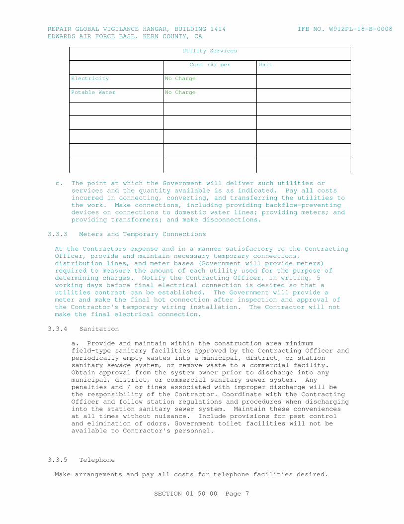
REPAI R GLOBAL VI GI LANCE HANGAR, BUI LDI NG 1414 I FB NO. W912PL- 18- B- 0008EDWARDS AI R FORCE BASE, KERN COUNTY, CA
Ut i l i t y Ser vi ces
Cost ( $) per Unit
Electricity No Char ge
Pot abl e Wat er No Char ge
c. The poi nt at whi ch t he Gover nment wi l l del i ver such ut i l i t i es or ser vi ces and t he quant i t y avai l abl e i s as i ndi cat ed. Pay al l cost s i ncur r ed i n connect i ng, conver t i ng, and t r ansf er r i ng t he ut i l i t i es t o t he wor k. Make connect i ons, i ncl udi ng pr ovi di ng backf l ow- pr event i ng devi ces on connect i ons t o domest i c wat er l i nes; pr ovi di ng met er s; and pr ovi di ng t r ansf or mer s; and make di sconnect i ons.
3. 3. 3 Met er s and Tempor ar y Connect i ons
At t he Cont r act or s expense and i n a manner sat i sf act or y t o t he Cont r act i ng Of f i cer , pr ovi de and mai nt ai n necessar y t empor ar y connect i ons, di st r i but i on l i nes, and met er bases ( Gover nment wi l l pr ovi de met er s) r equi r ed t o measur e t he amount of each ut i l i t y used f or t he pur pose of det er mi ni ng char ges. Not i f y t he Cont r act i ng Of f i cer , i n wr i t i ng, 5 wor ki ng days bef or e f i nal el ect r i cal connect i on i s desi r ed so t hat a ut i l i t i es cont r act can be est abl i shed. The Gover nment wi l l pr ovi de a met er and make t he f i nal hot connect i on af t er i nspect i on and appr oval of t he Cont r act or ' s t empor ar y wi r i ng i nst al l at i on. The Cont r act or wi l l not make t he f i nal el ect r i cal connect i on.
3. 3. 4 Sanitation
a. Pr ovi de and mai nt ai n wi t hi n t he const r uct i on ar ea mi ni mum f i el d- t ype sani t ar y f aci l i t i es appr oved by t he Cont r act i ng Of f i cer and per i odi cal l y empt y wast es i nt o a muni ci pal , di st r i ct , or st at i on sani t ar y sewage syst em, or r emove wast e t o a commer ci al f aci l i t y . Obt ai n appr oval f r om t he syst em owner pr i or t o di schar ge i nt o any muni ci pal , di st r i ct , or commer ci al sani t ar y sewer syst em. Any penal t i es and / or f i nes associ at ed wi t h i mpr oper di schar ge wi l l be t he r esponsi bi l i t y of t he Cont r act or . Coor di nat e wi t h t he Cont r act i ng Of f i cer and f ol l ow st at i on r egul at i ons and pr ocedur es when di schar gi ng i nt o t he st at i on sani t ar y sewer syst em. Mai nt ai n t hese conveni ences at al l t i mes wi t hout nui sance. I ncl ude pr ovi s i ons f or pest cont r ol and el i mi nat i on of odor s. Gover nment t oi l et f aci l i t i es wi l l not be avai l abl e t o Cont r act or ' s per sonnel .
3. 3. 5 Telephone
Make ar r angement s and pay al l cost s f or t el ephone f aci l i t i es desi r ed.
SECTI ON 01 50 00 Page 7
REPAI R GLOBAL VI GI LANCE HANGAR, BUI LDI NG 1414 I FB NO. W912PL- 18- B- 0008EDWARDS AI R FORCE BASE, KERN COUNTY, CA
3. 3. 6 Obst r uct i on Li ght i ng of Cr anes
Pr ovi de a mi ni mum of 2 avi at i on r ed or hi gh i nt ensi t y whi t e obst r uct i on l i ght s on t empor ar y st r uct ur es ( i ncl udi ng cr anes) over 100 f eet above gr ound l evel . Li ght const r uct i on and i nst al l at i on must compl y wi t h FAA AC 70/ 7460- 1. Li ght s must be oper at i onal dur i ng per i ods of r educed vi s i bi l i t y , dar kness, and as di r ect ed by t he Cont r act i ng Of f i cer .
3. 3. 7 Fi r e Pr ot ect i on
Pr ovi de t empor ar y f i r e pr ot ect i on equi pment f or t he pr ot ect i on of per sonnel and pr oper t y dur i ng const r uct i on. Remove debr i s and f l ammabl e mat er i al s dai l y t o mi ni mi ze pot ent i al hazar ds.
3. 4 TRAFFI C PROVI SI ONS
3. 4. 1 Mai nt enance of Tr af f i c
a. Conduct oper at i ons i n a manner t hat wi l l not c l ose any t hor oughf ar e or i nt er f er e i n any way wi t h t r af f i c on r ai l ways or hi ghways except wi t h wr i t t en per mi ssi on of t he Cont r act i ng Of f i cer at l east 15 cal endar days pr i or t o t he pr oposed modi f i cat i on dat e, and pr ovi de a Traffic Cont r ol Pl an det ai l i ng t he pr oposed cont r ol s t o t r af f i c movement f or appr oval . The pl an must be i n accor dance wi t h St at e and l ocal r egul at i ons and t he MUTCD, Par t VI . [ Make al l not i f i cat i ons and obt ai n any per mi t s r equi r ed f or modi f i cat i on t o t r af f i c movement s out si de St at i on' s j ur i sdi ct i on. ] . Cont r act or may move over si zed and sl ow- movi ng vehi c l es t o t he wor ksi t e pr ovi ded r equi r ement s of t he hi ghway aut hor i t y have been met .
b. Conduct wor k so as t o mi ni mi ze obst r uct i on of t r af f i c , and mai nt ai n t r af f i c on at l east hal f of t he r oadway wi dt h at al l t i mes. Obt ai n appr oval f r om t he Cont r act i ng Of f i cer pr i or t o st ar t i ng any act i v i t y t hat wi l l obst r uct t r af f i c .
c. Pr ovi de, er ect , and mai nt ai n, at cont r act or s expense, l i ght s, bar r i er s, s i gnal s, passageways, det our s, and ot her i t ems, t hat may be r equi r ed by t he Li f e Saf et y Si gnage, over head pr ot ect i on aut hor i t y havi ng j ur i sdi ct i on.
3. 4. 2 Pr ot ect i on of Tr af f i c
Mai nt ai n and pr ot ect t r af f i c on al l af f ect ed r oads dur i ng t he const r uct i on per i od except as ot her wi se speci f i cal l y di r ect ed by t he Cont r act i ng Of f i cer . Measur es f or t he pr ot ect i on and di ver si on of t r af f i c , i ncl udi ng t he pr ovi s i on of wat chmen and f l agmen, er ect i on of bar r i cades, pl aci ng of l i ght s ar ound and i n f r ont of equi pment t he wor k, and t he er ect i on and mai nt enance of adequat e war ni ng, danger , and di r ect i on s i gns, wi l l be as r equi r ed by t he St at e and l ocal aut hor i t i es havi ng j ur i sdi ct i on. Pr ot ect t he t r avel i ng publ i c f r om damage t o per son and pr oper t y. Mi ni mi ze t he i nt er f er ence wi t h publ i c t r af f i c on r oads sel ect ed f or haul i ng mat er i al t o and f r om t he si t e. I nvest i gat e t he adequacy of exi st i ng r oads and t hei r al l owabl e l oad l i mi t . Cont r act or i s r esponsi bl e f or t he r epai r of any damage t o r oads caused by const r uct i on oper at i ons.
3. 4. 3 Rush Hour Rest r i ct i ons
Do not i nt er f er e wi t h t he peak t r af f i c f l ows pr ecedi ng and dur i ng nor mal
SECTI ON 01 50 00 Page 8
REPAI R GLOBAL VI GI LANCE HANGAR, BUI LDI NG 1414 I FB NO. W912PL- 18- B- 0008EDWARDS AI R FORCE BASE, KERN COUNTY, CA
oper at i ons wi t hout not i f i cat i on t o and appr oval by t he Cont r act i ng Of f i cer .
3. 4. 4 Dust Cont r ol
Dust cont r ol met hods and pr ocedur es must be appr oved by t he Cont r act i ng Of f i cer . Tr eat dust abat ement on access r oads wi t h appl i cat i ons of cal c i um chl or i de, wat er spr i nkl er s, or s i mi l ar met hods or t r eat ment .
3. 5 CONTRACTOR' S TEMPORARY FACI LI TI ES
Cont r act or - owned or - l eased t r ai l er s must be i dent i f i ed by Gover nment assi gned number s. Si ze and l ocat i on of t he number wi l l compl y wi t h Cont r act i ng Of f i cer . Appl y t he number t o t he t r ai l er wi t hi n 14 cal endar days of not i f i cat i on, or sooner , i f di r ect ed by t he Gover nment .
3. 5. 1 Safety
Pr ot ect t he i nt egr i t y of any i nst al l ed saf et y syst ems or per sonnel saf et y devi ces. I f ent r ance i nt o syst ems ser vi ng saf et y devi ces i s r equi r ed, t he Cont r act or must obt ai n pr i or appr oval f r om t he Cont r act i ng Of f i cer . I f i t i s t empor ar i l y necessar y t o r emove or di sabl e per sonnel saf et y devi ces i n or der t o accompl i sh cont r act r equi r ement s, pr ovi de al t er nat i ve means of pr ot ect i on pr i or t o r emovi ng or di sabl i ng any per manent l y i nst al l ed saf et y devi ces or equi pment and obt ai n appr oval f r om t he Cont r act i ng Of f i cer .
3. 5. 2 Admi ni st r at i ve Fi el d Of f i ces
Pr ovi de and mai nt ai n admi ni st r at i ve f i el d of f i ce f aci l i t i es wi t hi n t he const r uct i on ar ea at t he desi gnat ed si t e. Gover nment of f i ce and war ehouse f aci l i t i es wi l l [ not ] be avai l abl e t o t he Cont r act or ' s per sonnel .
3. 5. 3 St or age Ar ea
Const r uct a t empor ar y 6 f oot hi gh chai n l i nk f ence ar ound t r ai l er s and mat er i al s. I ncl ude pl ast i c st r i p i nser t s, col or ed br own, so t hat v i s i bi l i t y t hr ough t he f ence i s obst r uct ed. Fence post s may be dr i ven, i n l i eu of concr et e bases, wher e soi l condi t i ons per mi t . Do not pl ace or st or e Tr ai l er s, mat er i al s, or equi pment out si de t he f enced ar ea unl ess such t r ai l er s, mat er i al s, or equi pment ar e assi gned a separ at e and di st i nct st or age ar ea by t he Cont r act i ng Of f i cer away f r om t he vi c i ni t y of t he const r uct i on s i t e but wi t hi n t he i nst al l at i on boundar i es. Tr ai l er s, equi pment , or mat er i al s must not be open t o publ i c v i ew wi t h t he except i on of t hose i t ems whi ch ar e i n suppor t of ongoi ng wor k on any gi ven day. Do not st ockpi l e mat er i al s out si de t he f ence i n pr epar at i on f or t he next day' s wor k. Par k mobi l e equi pment , such as t r act or s, wheel ed l i f t i ng equi pment , cr anes, t r ucks, and l i ke equi pment wi t hi n t he f enced ar ea at t he end of each wor k day.
3. 5. 4 Suppl ement al St or age Ar ea
Upon Cont r act or ' s r equest , t he Cont r act i ng Of f i cer wi l l desi gnat e anot her or suppl ement al ar ea f or t he Cont r act or ' s use and st or age of t r ai l er s, equi pment , and mat er i al s. Thi s ar ea may not be i n c l ose pr oxi mi t y of t he const r uct i on s i t e but wi l l be wi t hi n t he i nst al l at i on boundar i es. Fenci ng of mat er i al s or equi pment wi l l not be r equi r ed at t hi s s i t e; however , t he Cont r act or i s r esponsi bl e f or c l eanl i ness and or der l i ness of t he ar ea used and f or t he secur i t y of any mat er i al or equi pment st or ed i n t hi s ar ea. Ut i l i t i es wi l l not be pr ovi ded t o t hi s ar ea by t he Gover nment .
SECTI ON 01 50 00 Page 9
REPAI R GLOBAL VI GI LANCE HANGAR, BUI LDI NG 1414 I FB NO. W912PL- 18- B- 0008EDWARDS AI R FORCE BASE, KERN COUNTY, CA
3. 5. 5 Appear ance of Tr ai l er s
a. Tr ai l er s ut i l i zed by t he Cont r act or f or admi ni st r at i ve or mat er i al st or age pur poses must pr esent a c l ean and neat ext er i or appear ance and be i n a st at e of good r epai r . Tr ai l er s whi ch, i n t he opi ni on of t he Cont r act i ng Of f i cer , r equi r e ext er i or pai nt i ng or mai nt enance wi l l not be al l owed on i nst al l at i on pr oper t y.
b. Pai nt usi ng sui t abl e pai nt ] and mai nt ai n t he t empor ar y f aci l i t i es. Fai l ur e t o do so wi l l be suf f i c i ent r eason t o r equi r e t hei r r emoval .
3. 5. 6 Mai nt enance of St or age Ar ea
a. Keep f enci ng i n a st at e of good r epai r and pr oper al i gnment . Gr assed or unpaved ar eas, whi ch ar e not est abl i shed r oadways, wi l l be cover ed wi t h a l ayer of gr avel as necessar y t o pr event r ut t i ng and t he t r acki ng of mud ont o paved or est abl i shed r oadways, shoul d t he Cont r act or el ect t o t r aver se t hem wi t h const r uct i on equi pment or ot her vehi c l es; gr avel gr adat i on wi l l be at t he Cont r act or ' s di scr et i on. Mow and mai nt ai n gr ass l ocat ed wi t hi n t he boundar i es of t he const r uct i on s i t e f or t he dur at i on of t he pr oj ect . Gr ass and veget at i on al ong f ences, bui l di ngs, under t r ai l er s, and i n ar eas not accessi bl e t o mower s wi l l be edged or t r i mmed neat l y.
3. 5. 7 New Bui l di ng
I n t he event a new bui l di ng i s const r uct ed f or t he t empor ar y pr oj ect f i el d of f i ce, i t wi l l be a mi ni mum 12 f eet i n wi dt h, 16 f eet i n l engt h and have a mi ni mum of 7 f eet headr oom. Equi p t he bui l di ng wi t h appr oved el ect r i cal wi r i ng, at l east one doubl e conveni ence out l et and t he r equi r ed swi t ches and f uses t o pr ovi de 110- 120 vol t power . Pr ovi de a wor k t abl e wi t h st ool , desk wi t h chai r , t wo addi t i onal chai r s, and one l egal s i ze f i l e cabi net t hat can be l ocked. The bui l di ng must be wat er pr oof , suppl i ed wi t h a heat er , have a mi ni mum of t wo door s, el ect r i c l i ght s, a t el ephone, a bat t er y oper at ed smoke det ect or al ar m, a suf f i c i ent number of adj ust abl e wi ndows f or adequat e l i ght and vent i l at i on, and a suppl y of appr oved dr i nki ng wat er . Appr oved sani t ar y f aci l i t i es must be f ur ni shed. Scr een t he wi ndows and door s and pr ovi de t he door s wi t h dead bol t t ype l ocki ng devi ces or a padl ock and heavy dut y hasp bol t ed t o t he door . Door hi nge pi ns wi l l be non- r emovabl e. Ar r ange t he wi ndows t o open and t o be secur el y f ast ened f r om t he i nsi de. Pr ot ect gl ass panel s i n wi ndows by bar s or heavy mesh scr eens t o pr event easy access. I n war m weat her , f ur ni sh ai r condi t i oni ng capabl e of mai nt ai ni ng t he of f i ce at 50 per cent r el at i ve humi di t y and a r oom t emper at ur e 20 degr ees F bel ow t he out si de t emper at ur e when t he out si de t emper at ur e i s 95 degr ees F. Any new bui l di ng er ect ed f or a t empor ar y f i el d of f i ce must be mai nt ai ned by t he Cont r act or dur i ng t he l i f e of t he cont r act and upon compl et i on and accept ance of t he wor k become t he pr oper t y of t he Cont r act or and r emoved f r om t he si t e.
3. 5. 8 Secur i t y Pr ovi s i ons
Pr ovi de adequat e out si de secur i t y l i ght i ng at t he Cont r act or ' s t empor ar y f aci l i t i es. The Cont r act or wi l l be r esponsi bl e f or t he secur i t y of i t s own equi pment ; i n addi t i on, t he Cont r act or wi l l not i f y t he appr opr i at e l aw enf or cement agency r equest i ng per i odi c secur i t y checks of t he t empor ar y pr oj ect f i el d of f i ce.
SECTI ON 01 50 00 Page 10
REPAI R GLOBAL VI GI LANCE HANGAR, BUI LDI NG 1414 I FB NO. W912PL- 18- B- 0008EDWARDS AI R FORCE BASE, KERN COUNTY, CA
3. 5. 9 Weat her Pr ot ect i on of Tempor ar y Faci l i t i es and St or ed Mat er i al s
Take necessar y pr ecaut i ons t o ensur e t hat r oof openi ngs and ot her cr i t i cal openi ngs i n t he bui l di ng ar e moni t or ed car ef ul l y. Take i mmedi at e act i ons r equi r ed t o seal of f such openi ngs when r ai n or ot her det r i ment al weat her i s i mmi nent , and at t he end of each wor kday. Ensur e t hat t he openi ngs ar e compl et el y seal ed of f t o pr ot ect mat er i al s and equi pment i n t he bui l di ng f r om damage.
3. 5. 9. 1 Bui l di ng and Si t e St or m Pr ot ect i on
When a war ni ng of gal e f or ce wi nds i s i ssued, t ake pr ecaut i ons t o mi ni mi ze danger t o per sons, and pr ot ect t he wor k and near by Gover nment pr oper t y. Pr ecaut i ons must i ncl ude, but ar e not l i mi t ed t o, c l osi ng openi ngs; r emovi ng l oose mat er i al s, t ool s and equi pment f r om exposed l ocat i ons; and r emovi ng or secur i ng scaf f ol di ng and ot her t empor ar y wor k. Cl ose openi ngs i n t he wor k when st or ms of l esser i nt ensi t y pose a t hr eat t o t he wor k or any near by Gover nment pr oper t y.
3. 6 TEMPORARY PROJECT SAFETY FENCI NG
As soon as pr act i cabl e, but not l at er t han 15 days af t er t he dat e est abl i shed f or commencement of wor k, f ur ni sh and er ect t empor ar y pr oj ect saf et y f enci ng at t he wor k s i t e. Mai nt ai n t he saf et y f enci ng dur i ng t he l i f e of t he cont r act and, upon compl et i on and accept ance of t he wor k, wi l l become t he pr oper t y of t he Cont r act or and be r emoved f r om t he wor k s i t e.
3. 7 CLEANUP
Remove const r uct i on debr i s, wast e mat er i al s, packagi ng mat er i al and t he l i ke f r om t he wor k s i t e dai l y. Any di r t or mud whi ch i s t r acked ont o paved or sur f aced r oadways must be cl eaned away. St or e any sal vageabl e mat er i al s r esul t i ng f r om demol i t i on act i v i t i es wi t hi n t he f enced ar ea descr i bed above or at t he suppl ement al st or age ar ea. Neat l y st ack st or ed mat er i al s not i n t r ai l er s, whet her new or sal vaged.
3. 8 RESTORATI ON OF STORAGE AREA
Upon compl et i on of t he pr oj ect r emove t he bul l et i n boar d, s i gns, bar r i cades, haul r oads, and any ot her t empor ar y pr oduct s f r om t he si t e. Af t er r emoval of t r ai l er s, mat er i al s, and equi pment f r om wi t hi n t he f enced ar ea, r emove t he f ence t hat wi l l become t he pr oper t y of t he Cont r act or . Rest or e ar eas used by t he Cont r act or f or t he st or age of equi pment or mat er i al , or ot her use t o t he or i gi nal or bet t er condi t i on. Remove gr avel used t o t r aver se gr assed ar eas and r est or e t he ar ea t o i t s or i gi nal condi t i on, i ncl udi ng t op soi l and seedi ng as necessar y.
- - End of Sect i on - -
SECTI ON 01 50 00 Page 11
REPAI R GLOBAL VI GI LANCE HANGAR, BUI LDI NG 1414 I FB NO. W912PL- 18- B- 0008EDWARDS AI R FORCE BASE, KERN COUNTY, CA
SECTI ON TABLE OF CONTENTS
DI VI SI ON 01 - GENERAL REQUI REMENTS
SECTI ON 01 57 19
TEMPORARY ENVI RONMENTAL CONTROLS
11/15
PART 1 GENERAL
1. 1 REFERENCES 1. 2 DEFI NI TI ONS 1. 2. 1 Cl ass I and I I Ozone Depl et i ng Subst ance ( ODS) 1. 2. 2 Cont r act or Gener at ed Hazar dous Wast e 1. 2. 3 El ect r oni cs Wast e 1. 2. 4 Envi r onment al Pol l ut i on and Damage 1. 2. 5 Envi r onment al Pr ot ect i on 1. 2. 6 Hazar dous Debr i s 1. 2. 7 Hazar dous Mat er i al s 1. 2. 8 Hazar dous Wast e 1. 2. 9 I nst al l at i on Pest Management Coor di nat or 1. 2. 10 Land Appl i cat i on 1. 2. 11 Muni ci pal Separ at e St or m Sewer Syst em ( MS4) Per mi t 1. 2. 12 Nat i onal Pol l ut ant Di schar ge El i mi nat i on Syst em ( NPDES) 1. 2. 13 Oi l y Wast e 1. 2. 14 Pest i c i de 1. 2. 15 Pest i c i de Tr eat ment Pl an 1. 2. 16 Pest s 1. 2. 17 Pr oj ect Pest i c i de Coor di nat or 1. 2. 18 Regul at ed Wast e 1. 2. 19 Sedi ment 1. 2. 20 Sol i d Wast e 1. 2. 20. 1 Debr i s 1. 2. 20. 2 Gr een Wast e 1. 2. 20. 3 Mat er i al not r egul at ed as sol i d wast e 1. 2. 20. 4 Non- Hazar dous Wast e 1. 2. 20. 5 Recycl abl es 1. 2. 20. 6 Sur pl us Soi l 1. 2. 20. 7 Scr ap Met al 1. 2. 20. 8 Wood 1. 2. 21 Sur f ace Di schar ge 1. 2. 22 Wast ewat er 1. 2. 22. 1 St or mwat er 1. 2. 23 Wat er s of t he Uni t ed St at es 1. 2. 24 Wet l ands 1. 2. 25 Uni ver sal Wast e 1. 3 SUBMI TTALS 1. 4 ENVI RONMENTAL PROTECTI ON REQUI REMENTS 1. 4. 1 Conf or mance wi t h t he Envi r onment al Management Syst em 1. 5 SPECI AL ENVI RONMENTAL REQUI REMENTS 1. 6 QUALI TY ASSURANCE 1. 6. 1 Pr econst r uct i on Sur vey and Pr ot ect i on of Feat ur es 1. 6. 2 Regul at or y Not i f i cat i ons 1. 6. 3 Envi r onment al Br i ef
SECTI ON 01 57 19 Page 1
REPAI R GLOBAL VI GI LANCE HANGAR, BUI LDI NG 1414 I FB NO. W912PL- 18- B- 0008EDWARDS AI R FORCE BASE, KERN COUNTY, CA
1. 6. 4 Envi r onment al Manager 1. 6. 5 Empl oyee Tr ai ni ng Recor ds 1. 6. 5. 1 Pest Cont r ol Tr ai ni ng 1. 6. 6 Non- Compl i ance Not i f i cat i ons 1. 7 ENVI RONMENTAL PROTECTI ON PLAN 1. 7. 1 Gener al Over vi ew and Pur pose 1. 7. 1. 1 Descr i pt i ons 1. 7. 1. 2 Dut i es 1. 7. 1. 3 Pr ocedur es 1. 7. 1. 4 Communi cat i ons 1. 7. 1. 5 Cont act I nf or mat i on 1. 7. 2 Gener al Si t e I nf or mat i on 1. 7. 2. 1 Dr awi ngs 1. 7. 2. 2 Wor k Ar ea 1. 7. 2. 3 Document at i on 1. 7. 3 Management of Nat ur al Resour ces 1. 7. 4 Pr ot ect i on of Hi st or i cal and Ar chaeol ogi cal Resour ces 1. 7. 5 St or mwat er Management and Cont r ol 1. 7. 6 Pr ot ect i on of t he Envi r onment f r om Wast e Der i ved f r om
Cont r act or Oper at i ons 1. 7. 7 Pr event i on of Rel eases t o t he Envi r onment 1. 7. 8 Regul at or y Not i f i cat i on and Per mi t s 1. 7. 9 Cl ean Ai r Act Compl i ance 1. 7. 9. 1 Haul Rout e 1. 7. 9. 2 Pol l ut i on Gener at i ng Equi pment 1. 7. 9. 3 St at i onar y I nt er nal Combust i on Engi nes 1. 7. 9. 4 Ref r i ger ant s 1. 7. 9. 5 Ai r Pol l ut i on- engi neer i ng Pr ocesses 1. 7. 9. 6 Moni t or i ng 1. 7. 9. 7 Compl i ant Mat er i al s 1. 8 LI CENSES AND PERMI TS 1. 9 ENVI RONMENTAL RECORDS BI NDER 1. 10 PESTI CI DE DELI VERY, STORAGE, AND HANDLI NG 1. 10. 1 Del i ver y and St or age 1. 10. 2 Handl i ng Requi r ement s 1. 11 SOLI D WASTE MANAGEMENT PERMI T 1. 11. 1 Sol i d Wast e Management Repor t
PART 2 PRODUCTS
PART 3 EXECUTI ON
3. 1 PROTECTI ON OF NATURAL RESOURCES 3. 1. 1 Fl ow Ways 3. 1. 2 Veget at i on 3. 1. 3 St r eams 3. 2 STORMWATER 3. 2. 1 Const r uct i on Gener al Per mi t 3. 2. 1. 1 St or mwat er Pol l ut i on Pr event i on Pl an 3. 2. 1. 2 St or mwat er Not i ce of I nt ent f or Const r uct i on Act i v i t i es 3. 2. 1. 3 I nspect i on Repor t s 3. 2. 1. 4 St or mwat er Pol l ut i on Pr event i on Pl an Compl i ance Not ebook 3. 2. 1. 5 St or mwat er Not i ce of Ter mi nat i on f or Const r uct i on
Activities 3. 2. 2 Er osi on and Sedi ment Cont r ol Measur es 3. 2. 2. 1 Er osi on Cont r ol 3. 2. 2. 2 Sedi ment Cont r ol Pr act i ces 3. 2. 3 Wor k Ar ea Li mi t s
SECTI ON 01 57 19 Page 2
REPAI R GLOBAL VI GI LANCE HANGAR, BUI LDI NG 1414 I FB NO. W912PL- 18- B- 0008EDWARDS AI R FORCE BASE, KERN COUNTY, CA
3. 2. 4 Cont r act or Faci l i t i es and Wor k Ar eas 3. 2. 5 Muni ci pal Separ at e St or m Sewer Syst em ( MS4) Management 3. 3 SURFACE AND GROUNDWATER 3. 3. 1 Cof f er dams, Di ver si ons, and Dewat er i ng 3. 3. 2 Wat er s of t he Uni t ed St at es 3. 4 PROTECTI ON OF CULTURAL RESOURCES 3. 4. 1 Ar chaeol ogi cal Resour ces 3. 4. 2 Hi st or i cal Resour ces 3. 5 AI R RESOURCES 3. 5. 1 Pr econst r uct i on Ai r Per mi t s 3. 5. 2 Oi l or Dual - f uel Boi l er s and Fur naces 3. 5. 3 Bur ni ng 3. 5. 4 Cl ass I and I I ODS Pr ohi bi t i on 3. 5. 5 Acci dent al Vent i ng of Ref r i ger ant 3. 5. 6 EPA Cer t i f i cat i on Requi r ement s 3. 5. 7 Dust Cont r ol 3. 5. 7. 1 Par t i cul at es 3. 5. 7. 2 Abr asi ve Bl ast i ng 3. 5. 8 Odor s 3. 6 WASTE MI NI MI ZATI ON 3. 6. 1 Sal vage, Reuse and Recycl e 3. 6. 2 Nonhazar dous Sol i d Wast e Di ver si on Repor t 3. 7 WASTE MANAGEMENT AND DI SPOSAL 3. 7. 1 Wast e Det er mi nat i on Document at i on 3. 7. 1. 1 Sampl i ng and Anal ysi s of Wast e 3. 7. 1. 1. 1 Wast e Sampl i ng 3. 7. 1. 1. 2 Labor at or y Anal ysi s 3. 7. 1. 1. 3 Anal ysi s Type 3. 7. 2 Sol i d Wast e Management 3. 7. 2. 1 Sol i d Wast e Management Repor t 3. 7. 2. 2 Cont r ol and Management of Sol i d Wast es 3. 7. 3 Cont r ol and Management of Hazar dous Wast e 3. 7. 3. 1 Hazar dous Wast e/ Debr i s Management 3. 7. 3. 2 Wast e St or age/ Sat el l i t e Accumul at i on/ 90 Day St or age Ar eas 3. 7. 3. 3 Hazar dous Wast e Di sposal 3. 7. 3. 3. 1 Responsi bi l i t i es f or Cont r act or ' s Di sposal 3. 7. 3. 3. 1. 1 Ser vi ces 3. 7. 3. 3. 1. 2 Sampl es 3. 7. 3. 3. 1. 3 Anal ysi s 3. 7. 3. 3. 1. 4 Label i ng 3. 7. 3. 3. 2 Cont r act or Di sposal Tur n- I n Requi r ement s 3. 7. 3. 4 Uni ver sal Wast e Management 3. 7. 3. 5 El ect r oni cs End- of - Li f e Management 3. 7. 3. 6 Di sposal Document at i on f or Hazar dous and Regul at ed Wast e 3. 7. 4 Rel eases/ Spi l l s of Oi l and Hazar dous Subst ances 3. 7. 4. 1 Response and Not i f i cat i ons 3. 7. 4. 2 Cl ean Up 3. 7. 5 Mer cur y Mat er i al s 3. 7. 6 Wast ewat er 3. 7. 6. 1 Di sposal of wast ewat er must be as speci f i ed bel ow. 3. 7. 6. 1. 1 Tr eat ment 3. 7. 6. 1. 2 Sur f ace Di schar ge 3. 7. 6. 1. 3 Land Appl i cat i on 3. 8 HAZARDOUS MATERI AL MANAGEMENT 3. 9 PREVI OUSLY USED EQUI PMENT 3. 10 CONTROL AND MANAGEMENT OF ASBESTOS- CONTAI NI NG MATERI AL ( ACM) 3. 11 CONTROL AND MANAGEMENT OF LEAD- BASED PAI NT ( LBP) 3. 12 CONTROL AND MANAGEMENT OF POLYCHLORI NATED BI PHENYLS ( PCBS) 3. 13 CONTROL AND MANAGEMENT OF LI GHTI NG BALLAST AND LAMPS CONTAI NI NG
SECTI ON 01 57 19 Page 3

REPAI R GLOBAL VI GI LANCE HANGAR, BUI LDI NG 1414 I FB NO. W912PL- 18- B- 0008EDWARDS AI R FORCE BASE, KERN COUNTY, CA
PCBS 3. 14 PETROLEUM, OI L, LUBRI CANT ( POL) STORAGE AND FUELI NG 3. 14. 1 Used Oi l Management 3. 14. 2 Oi l St or age I ncl udi ng Fuel Tanks 3. 15 I NADVERTENT DI SCOVERY OF PETROLEUM- CONTAMI NATED SOI L OR HAZARDOUS
WASTES 3. 16 PEST MANAGEMENT 3. 16. 1 Appl i cat i on 3. 16. 2 Pest i c i de Tr eat ment Pl an 3. 17 CHLORDANE 3. 18 SOUND I NTRUSI ON 3. 19 POST CONSTRUCTI ON CLEANUP
- - End of Sect i on Tabl e of Cont ent s - -
SECTI ON 01 57 19 Page 4
REPAI R GLOBAL VI GI LANCE HANGAR, BUI LDI NG 1414 I FB NO. W912PL- 18- B- 0008EDWARDS AI R FORCE BASE, KERN COUNTY, CA
SECTI ON 01 57 19
TEMPORARY ENVI RONMENTAL CONTROLS11/15
PART 1 GENERAL
1. 1 REFERENCES
The publ i cat i ons l i s t ed bel ow f or m a par t of t hi s speci f i cat i on t o t he ext ent r ef er enced. The publ i cat i ons ar e r ef er r ed t o wi t hi n t he t ext by t he basi c desi gnat i on onl y.
U. S. ENVI RONMENTAL PROTECTI ON AGENCY ( EPA)
EPA SW- 846 ( Thi r d Edi t i on; Updat e I V) Test Met hods f or Eval uat i ng Sol i d Wast e: Physi cal / Chemi cal Met hods
U. S. NATI ONAL ARCHI VES AND RECORDS ADMI NI STRATI ON ( NARA)
29 CFR 1910. 120 Hazar dous Wast e Oper at i ons and Emer gency Response
40 CFR 112 Oi l Pol l ut i on Pr event i on
40 CFR 122. 26 St or m Wat er Di schar ges ( Appl i cabl e t o St at e NPDES Pr ogr ams, see sect i on 123. 25)
40 CFR 152 Pest i c i de Regi st r at i on and Cl assi f i cat i on Procedures
40 CFR 152 - 186 Pest i c i de Pr ogr ams
40 CFR 241 Gui del i nes f or Di sposal of Sol i d Wast e
40 CFR 243 Gui del i nes f or t he St or age and Col l ect i on of Resi dent i al , Commer ci al , and I nst i t ut i onal Sol i d Wast e
40 CFR 258 Subt i t l e D Landf i l l Requi r ement s
40 CFR 260 Hazar dous Wast e Management Syst em: Gener al
40 CFR 261 I dent i f i cat i on and Li st i ng of Hazar dous Waste
40 CFR 261. 7 Resi dues of Hazar dous Wast e i n Empt y Containers
40 CFR 262 St andar ds Appl i cabl e t o Gener at or s of Hazar dous Wast e
40 CFR 262. 31 St andar ds Appl i cabl e t o Gener at or s of Hazar dous Wast e- Label i ng
40 CFR 262. 34 St andar ds Appl i cabl e t o Gener at or s of
SECTI ON 01 57 19 Page 5
REPAI R GLOBAL VI GI LANCE HANGAR, BUI LDI NG 1414 I FB NO. W912PL- 18- B- 0008EDWARDS AI R FORCE BASE, KERN COUNTY, CA
Hazar dous Wast e- Accumul at i on Ti me
40 CFR 263 St andar ds Appl i cabl e t o Tr anspor t er s of Hazar dous Wast e
40 CFR 264 St andar ds f or Owner s and Oper at or s of Hazar dous Wast e Tr eat ment , St or age, and Di sposal Faci l i t i es
40 CFR 265 I nt er i m St at us St andar ds f or Owner s and Oper at or s of Hazar dous Wast e Tr eat ment , St or age, and Di sposal Faci l i t i es
40 CFR 266 St andar ds f or t he Management of Speci f i c Hazar dous Wast es and Speci f i c Types of Hazar dous Wast e Management Faci l i t i es
40 CFR 268 Land Di sposal Rest r i ct i ons
40 CFR 273 St andar ds For Uni ver sal Wast e Management
40 CFR 273. 2 St andar ds f or Uni ver sal Wast e Management - Batteries
40 CFR 273. 3 St andar ds f or Uni ver sal Wast e Management - Pesticides
40 CFR 273. 4 St andar ds f or Uni ver sal Wast e Management - Mer cur y Cont ai ni ng Equi pment
40 CFR 273. 5 St andar ds f or Uni ver sal Wast e Management - Lamps
40 CFR 279 St andar ds f or t he Management of Used Oi l
40 CFR 300 Nat i onal Oi l and Hazar dous Subst ances Pol l ut i on Cont i ngency Pl an
40 CFR 300. 125 Nat i onal Oi l and Hazar dous Subst ances Pol l ut i on Cont i ngency Pl an - Not i f i cat i on and Communi cat i ons
40 CFR 355 Emer gency Pl anni ng and Not i f i cat i on
40 CFR 403 Gener al Pr et r eat ment Regul at i ons f or Exi st i ng and New Sour ces of Pol l ut i on
40 CFR 50 Nat i onal Pr i mar y and Secondar y Ambi ent Ai r Qual i t y St andar ds
40 CFR 60 St andar ds of Per f or mance f or New St at i onar y Sour ces
40 CFR 61 Nat i onal Emi ssi on St andar ds f or Hazar dous Ai r Pol l ut ant s
40 CFR 63 Nat i onal Emi ssi on St andar ds f or Hazar dous Ai r Pol l ut ant s f or Sour ce Cat egor i es
SECTI ON 01 57 19 Page 6
REPAI R GLOBAL VI GI LANCE HANGAR, BUI LDI NG 1414 I FB NO. W912PL- 18- B- 0008EDWARDS AI R FORCE BASE, KERN COUNTY, CA
40 CFR 64 Compl i ance Assur ance Moni t or i ng
40 CFR 745 Lead- Based Pai nt Poi soni ng Pr event i on i n Cer t ai n Resi dent i al St r uct ur es
40 CFR 761 Pol ychl or i nat ed Bi phenyl s ( PCBs) Manuf act ur i ng, Pr ocessi ng, Di st r i but i on i n Commer ce, and Use Pr ohi bi t i ons
49 CFR 171 Gener al I nf or mat i on, Regul at i ons, and Definitions
49 CFR 172 Hazar dous Mat er i al s Tabl e, Speci al Pr ovi s i ons, Hazar dous Mat er i al s Communi cat i ons, Emer gency Response I nf or mat i on, and Tr ai ni ng Requi r ement s
49 CFR 172. 101 Hazar dous Mat er i al Regul at i on- Pur pose and Use of Hazar dous Mat er i al Tabl e
49 CFR 173 Shi pper s - Gener al Requi r ement s f or Shi pment s and Packagi ngs
49 CFR 178 Speci f i cat i ons f or Packagi ngs
1. 2 DEFINITIONS
1. 2. 1 Cl ass I and I I Ozone Depl et i ng Subst ance ( ODS)
Cl ass I ODS i s def i ned i n Sect i on 602( a) of The Cl ean Ai r Act . A l i s t of Cl ass I ODS can be f ound on t he EPA websi t e at t he f ol l owi ng webl i nk. http://www.epa.gov/ozone/science/ods/classone.html .
Cl ass I I ODS i s def i ned i n Sect i on 602( s) of The Cl ean Ai r Act . A l i s t of Cl ass I I ODS can be f ound on t he EPA websi t e at t he f ol l owi ng webl i nk. http://www.epa.gov/ozone/science/ods/classtwo.html .
1. 2. 2 Cont r act or Gener at ed Hazar dous Wast e
Cont r act or gener at ed hazar dous wast e i s mat er i al s t hat , i f abandoned or di sposed of , may meet t he def i ni t i on of a hazar dous wast e. These wast e st r eams woul d t ypi cal l y consi st of mat er i al br ought on si t e by t he Cont r act or t o execut e wor k, but ar e not f ul l y consumed dur i ng t he cour se of const r uct i on. Exampl es i ncl ude, but ar e not l i mi t ed t o, excess pai nt t hi nner s ( i . e. met hyl et hyl ket one, t ol uene) , wast e t hi nner s, excess pai nt s, excess sol vent s, wast e sol vent s, excess pest i c i des, and cont ami nat ed pest i c i de equi pment r i nse wat er .
1. 2. 3 El ect r oni cs Wast e
El ect r oni cs wast e i s di scar ded el ect r oni c devi ces i nt ended f or sal vage, r ecycl i ng, or di sposal .
1. 2. 4 Envi r onment al Pol l ut i on and Damage
Envi r onment al pol l ut i on and damage i s t he pr esence of chemi cal , physi cal , or bi ol ogi cal el ement s or agent s whi ch adver sel y af f ect human heal t h or wel f ar e; unf avor abl y al t er ecol ogi cal bal ances of i mpor t ance t o human l i f e; af f ect ot her speci es of i mpor t ance t o humanki nd; or degr ade t he
SECTI ON 01 57 19 Page 7

REPAI R GLOBAL VI GI LANCE HANGAR, BUI LDI NG 1414 I FB NO. W912PL- 18- B- 0008EDWARDS AI R FORCE BASE, KERN COUNTY, CA
envi r onment aest het i cal l y, cul t ur al l y or hi st or i cal l y.
1. 2. 5 Envi r onment al Pr ot ect i on
Envi r onment al pr ot ect i on i s t he pr event i on/ cont r ol of pol l ut i on and habi t at di sr upt i on t hat may occur t o t he envi r onment dur i ng const r uct i on. The cont r ol of envi r onment al pol l ut i on and damage r equi r es consi der at i on of l and, wat er , and ai r ; bi ol ogi cal and cul t ur al r esour ces; and i ncl udes management of v i sual aest het i cs; noi se; sol i d, chemi cal , gaseous, and l i qui d wast e; r adi ant ener gy and r adi oact i ve mat er i al as wel l as ot her pollutants.
1. 2. 6 Hazar dous Debr i s
As def i ned i n par agr aph SOLI D WASTE, debr i s t hat cont ai ns l i s t ed hazar dous wast e ( ei t her on t he debr i s sur f ace, or i n i t s i nt er st i ces, such as por e st r uct ur e) i n accor dance wi t h 40 CFR 261. Hazar dous debr i s al so i ncl udes debr i s t hat exhi bi t s a char act er i st i c of hazar dous wast e i n accor dance with 40 CFR 261.
1. 2. 7 Hazar dous Mat er i al s
Hazar dous mat er i al s as def i ned i n 49 CFR 171 and l i s t ed i n 49 CFR 172.
Hazar dous mat er i al i s any mat er i al t hat : I s r egul at ed as a hazar dous mat er i al i n accor dance wi t h 49 CFR 173; or r equi r es a Saf et y Dat a Sheet ( SDS) i n accor dance wi t h 29 CFR 1910. 120; or dur i ng end use, t r eat ment , handl i ng, packagi ng, st or age, t r anspor t at i on, or di sposal meet s or has component s t hat meet or have pot ent i al t o meet t he def i ni t i on of a hazar dous wast e as def i ned by 40 CFR 261 Subpar t s A, B, C, or D. Desi gnat i on of a mat er i al by t hi s def i ni t i on, when separ at el y r egul at ed or cont r ol l ed by ot her sect i ons or di r ect i ves, does not el i mi nat e t he need f or adher ence t o t hat hazar d- speci f i c gui dance whi ch t akes pr ecedence over t hi s sect i on f or " cont r ol " pur poses. Such mat er i al i ncl udes ammuni t i on, weapons, expl osi ve act uat ed devi ces, pr opel l ant s, pyr ot echni cs, chemi cal and bi ol ogi cal war f ar e mat er i al s, medi cal and phar maceut i cal suppl i es, medi cal wast e and i nf ect i ous mat er i al s, bul k f uel s, r adi oact i ve mat er i al s, and ot her mat er i al s such as asbest os, mer cur y, and pol ychl or i nat ed bi phenyl s ( PCBs) .
1. 2. 8 Hazar dous Wast e
Hazar dous Wast e i s any mat er i al t hat meet s t he def i ni t i on of a sol i d wast e and exhi bi t a hazar dous char act er i st i c ( i gni t abi l i t y , cor r osi v i t y, r eact i v i t y, or t oxi c i t y) as speci f i ed i n 40 CFR 261, Subpar t C, or cont ai ns a l i s t ed hazar dous wast e as i dent i f i ed i n 40 CFR 261, Subpar t D.
1. 2. 9 I nst al l at i on Pest Management Coor di nat or
I nst al l at i on Pest Management Coor di nat or ( I PMC) i s t he i ndi v i dual of f i c i al l y desi gnat ed by t he I nst al l at i on Commander t o over see t he I nst al l at i on Pest Management Pr ogr am and t he I nst al l at i on Pest Management Plan.
1. 2. 10 Land Appl i cat i on
Land Appl i cat i on means spr eadi ng or spr ayi ng di schar ge wat er at a r at e t hat al l ows t he wat er t o per col at e i nt o t he soi l . No sheet i ng act i on, soi l er osi on, di schar ge i nt o st or m sewer s, di schar ge i nt o def i ned dr ai nage
SECTI ON 01 57 19 Page 8
REPAI R GLOBAL VI GI LANCE HANGAR, BUI LDI NG 1414 I FB NO. W912PL- 18- B- 0008EDWARDS AI R FORCE BASE, KERN COUNTY, CA
ar eas, or di schar ge i nt o t he " wat er s of t he Uni t ed St at es" must occur . Compl y wi t h f eder al , st at e, and l ocal l aws and r egul at i ons.
1. 2. 11 Muni ci pal Separ at e St or m Sewer Syst em ( MS4) Per mi t
MS4 per mi t s ar e t hose hel d by i nst al l at i ons t o obt ai n NPDES per mi t cover age f or t hei r st or mwat er di schar ges.
1. 2. 12 Nat i onal Pol l ut ant Di schar ge El i mi nat i on Syst em ( NPDES)
The NPDES per mi t pr ogr am cont r ol s wat er pol l ut i on by r egul at i ng poi nt sour ces t hat di schar ge pol l ut ant s i nt o wat er s of t he Uni t ed St at es.
1. 2. 13 Oi l y Wast e
Oi l y wast e ar e t hose mat er i al s t hat ar e, or wer e, mi xed wi t h Pet r ol eum, Oi l s, and Lubr i cant s ( POLs) and have become separ at ed f r om t hat POLs. Oi l y wast es al so means mat er i al s, i ncl udi ng wast ewat er s, cent r i f uge sol i ds, f i l t er r esi dues or s l udges, bot t om sedi ment s, t ank bot t oms, and sor bent s whi ch have come i nt o cont act wi t h and have been cont ami nat ed by, POLs and may be appr opr i at el y t est ed and di scar ded i n a manner whi ch i s i n compl i ance wi t h ot her st at e and l ocal r equi r ement s.
Thi s def i ni t i on i ncl udes mat er i al s such as oi l y r ags, " k i t t y l i t t er " sor bent c l ay and or gani c sor bent mat er i al . These mat er i al s may be l and f i l l ed pr ovi ded t hat : I t i s not pr ohi bi t ed i n ot her st at e r egul at i ons or l ocal or di nances; t he amount gener at ed i s " de mi ni mus" ( a smal l amount ) ; i t i s t he r esul t of mi nor l eaks or spi l l s r esul t i ng f r om nor mal pr ocess oper at i ons; and f r ee- f l owi ng oi l has been r emoved t o t he pr act i cabl e ext ent possi bl e. Lar ge quant i t i es of t hi s mat er i al , gener at ed as a r esul t of a maj or spi l l or i n l i eu of pr oper mai nt enance of t he pr ocessi ng equi pment , ar e a sol i d wast e. As a sol i d wast e, per f or m a hazar dous wast e det er mi nat i on pr i or t o di sposal . As t hi s can be an expensi ve pr ocess, i t i s r ecommended t hat t hi s t ype of wast e be mi ni mi zed t hr ough good housekeepi ng pr act i ces and empl oyee educat i on.
1. 2. 14 Pesticide
Pest i c i de i s any subst ance or mi xt ur e of subst ances i nt ended f or pr event i ng, dest r oyi ng, r epel l i ng, or mi t i gat i ng any pest , or i nt ended f or use as a pl ant r egul at or , def ol i ant or desi ccant .
1. 2. 15 Pest i c i de Tr eat ment Pl an
A pl an f or t he pr event i on, moni t or i ng, and cont r ol t o el i mi nat e pest infestation.
1. 2. 16 Pests
Pest s ar e ar t hr opods, bi r ds, r odent s, nemat odes, f ungi , bact er i a, v i r uses, al gae, snai l s, mar i ne bor er s, snakes, weeds and ot her or gani sms ( except f or human or ani mal di sease- causi ng or gani sms) t hat adver sel y af f ect r eadi ness, mi l i t ar y oper at i ons, or t he wel l - bei ng of per sonnel and ani mal s; at t ack or damage r eal pr oper t y, suppl i es, equi pment , or veget at i on; or ar e ot her wi se undesi r abl e.
1. 2. 17 Pr oj ect Pest i c i de Coor di nat or
The Pr oj ect Pest i c i de Coor di nat or ( PPC) i s an i ndi v i dual who r esi des at a
SECTI ON 01 57 19 Page 9
REPAI R GLOBAL VI GI LANCE HANGAR, BUI LDI NG 1414 I FB NO. W912PL- 18- B- 0008EDWARDS AI R FORCE BASE, KERN COUNTY, CA
Ci vi l Wor ks Pr oj ect of f i ce and who i s r esponsi bl e over seei ng of pest i c i de appl i cat i on on pr oj ect gr ounds.
1. 2. 18 Regul at ed Wast e
Regul at ed wast e ar e sol i d wast es t hat have speci f i c addi t i onal f eder al , st at e, or l ocal cont r ol s f or handl i ng, st or age, or di sposal .
1. 2. 19 Sediment
Sedi ment i s soi l and ot her debr i s t hat have er oded and have been t r anspor t ed by r unof f wat er or wi nd.
1. 2. 20 Sol i d Wast e
Sol i d wast e i s a sol i d, l i qui d, semi - sol i d or cont ai ned gaseous wast e. A sol i d wast e can be a hazar dous wast e, non- hazar dous wast e, or non- Resour ce Conser vat i on and Recover y Act ( RCRA) r egul at ed wast e. Types of sol i d wast e t ypi cal l y gener at ed at const r uct i on s i t es may i ncl ude:
1. 2. 20. 1 Debris
Debr i s i s non- hazar dous sol i d mat er i al gener at ed dur i ng t he const r uct i on, demol i t i on, or r enovat i on of a st r uct ur e t hat exceeds 2. 5- i nch par t i c l e s i ze t hat i s: a manuf act ur ed obj ect ; pl ant or ani mal mat t er ; or nat ur al geol ogi c mat er i al ( f or exampl e, cobbl es and boul der s) , br oken or r emoved concr et e, masonr y, and r ock asphal t pavi ng; cer ami cs; r oof i ng paper and shi ngl es. I ner t mat er i al s [ may] [ may not ] be r ei nf or ced wi t h or cont ai n f er r ous wi r e, r ods, accessor i es and wel dment s. A mi xt ur e of debr i s and ot her mat er i al such as soi l or s l udge i s al so subj ect t o r egul at i on as debr i s i f t he mi xt ur e i s compr i sed pr i mar i l y of debr i s by vol ume, based on vi sual i nspect i on.
1. 2. 20. 2 Gr een Wast e
Gr een wast e i s t he veget at i ve mat t er f r om l andscapi ng, l and cl ear i ng and gr ubbi ng, i ncl udi ng, but not l i mi t ed t o, gr ass, bushes, scr ubs, smal l t r ees and sapl i ngs, t r ee st umps and pl ant r oot s. Mar ket abl e t r ees, gr asses and pl ant s t hat ar e i ndi cat ed t o r emai n, be r e- l ocat ed, or be r e- used ar e not i ncl uded.
1. 2. 20. 3 Mat er i al not r egul at ed as sol i d wast e
Mat er i al not r egul at ed as sol i d wast e i s nucl ear sour ce or bypr oduct mat er i al s r egul at ed under t he Feder al At omi c Ener gy Act of 1954 as amended; suspended or di ssol ved mat er i al s i n domest i c sewage ef f l uent or i r r i gat i on r et ur n f l ows, or ot her r egul at ed poi nt sour ce di schar ges; r egul at ed ai r emi ssi ons; and f l ui ds or wast es associ at ed wi t h nat ur al gas or cr ude oi l expl or at i on or pr oduct i on.
1. 2. 20. 4 Non- Hazar dous Wast e
Non- hazar dous wast e i s wast e t hat i s excl uded f r om, or does not meet , hazar dous wast e cr i t er i a i n accor dance wi t h 40 CFR 263.
1. 2. 20. 5 Recyclables
Recycl abl es ar e mat er i al s, equi pment and assembl i es such as door s, wi ndows, door and wi ndow f r ames, pl umbi ng f i xt ur es, gl azi ng and mi r r or s
SECTI ON 01 57 19 Page 10

REPAI R GLOBAL VI GI LANCE HANGAR, BUI LDI NG 1414 I FB NO. W912PL- 18- B- 0008EDWARDS AI R FORCE BASE, KERN COUNTY, CA
t hat ar e r ecover ed and sol d as r ecycl abl e, [ wi r i ng, ] [ i nsul at ed/ non- i nsul at ed copper wi r e cabl e, ] [ wi r e r ope, ] and st r uct ur al component s. I t al so i ncl udes commer ci al - gr ade r ef r i ger at i on equi pment wi t h Fr eon r emoved, househol d appl i ances wher e t he basi c mat er i al cont ent i s met al , c l ean pol yet hyl ene t er epht hal at e bot t l es, cooki ng oi l , used f uel oi l , t ext i l es, hi gh- gr ade paper pr oduct s and cor r ugat ed car dboar d, st ackabl e pal l et s i n good condi t i on, c l ean cr at i ng mat er i al , and cl ean r ubber / vehi c l e t i r es. Met al meet i ng t he def i ni t i on of l ead cont ami nat ed or l ead based pai nt cont ami nat ed [ may] [ may not ] be i ncl uded as r ecycl abl e i f sol d t o a scr ap met al company. Pai nt cans t hat meet t he def i ni t i on of empt y cont ai ner s i n accor dance wi t h 40 CFR 261. 7 may be i ncl uded as r ecycl abl e i f sol d t o a scr ap met al company.
1. 2. 20. 6 Sur pl us Soi l
Sur pl us soi l i s exi st i ng soi l t hat i s i n excess of what i s r equi r ed f or t hi s wor k, i ncl udi ng aggr egat es i nt ended, but not used, f or on- si t e mi xi ng of concr et e, mor t ar s, and pavi ng. Cont ami nat ed soi l meet i ng t he def i ni t i on of hazar dous mat er i al or hazar dous wast e i s not i ncl uded and must be managed i n accor dance wi t h par agr aph HAZARDOUS MATERI AL MANAGEMENT.
1. 2. 20. 7 Scr ap Met al
Thi s i ncl udes scr ap and excess f er r ous and non- f er r ous met al s such as r ei nf or ci ng st eel , st r uct ur al shapes, pi pe, and wi r e t hat ar e r ecover ed or col l ect ed and di sposed of as scr ap. Scr ap met al meet i ng t he def i ni t i on of hazar dous mat er i al or hazar dous wast e i s not i ncl uded.
1. 2. 20. 8 Wood
Wood i s di mensi on and non- di mensi on l umber , pl ywood, chi pboar d, har dboar d. Tr eat ed or pai nt ed wood t hat meet s t he def i ni t i on of l ead cont ami nat ed or l ead based cont ami nat ed pai nt i s not i ncl uded. Tr eat ed wood i ncl udes, but i s not l i mi t ed t o, l umber , ut i l i t y pol es, cr osst i es, and ot her wood pr oduct s wi t h chemi cal t r eat ment .
1. 2. 21 Sur f ace Di schar ge
Sur f ace di schar ge means di schar ge of wat er i nt o dr ai nage di t ches, st or m sewer s, cr eeks or " wat er s of t he Uni t ed St at es" . Sur f ace di schar ges ar e di scr et e, i dent i f i abl e sour ces and r equi r e a per mi t f r om t he gover ni ng agency. Compl y wi t h f eder al , st at e, and l ocal l aws and r egul at i ons.
1. 2. 22 Wastewater
Wast ewat er i s t he used wat er and sol i ds f r om a communi t y t hat f l ow t o a t r eat ment pl ant .
1. 2. 22. 1 Stormwater
St or mwat er i s any pr eci pi t at i on i n an ur ban or subur ban ar ea t hat does not evapor at e or soak i nt o t he gr ound, but i nst ead col l ect s and f l ows i nt o st or m dr ai ns, r i ver s, and st r eams.
1. 2. 23 Wat er s of t he Uni t ed St at es
Wat er s of t he Uni t ed St at es means Feder al l y j ur i sdi ct i onal wat er s, i ncl udi ng wet l ands, t hat ar e subj ect t o r egul at i on under Sect i on 404 of t he Cl ean Wat er Act or navi gabl e wat er s, as def i ned under t he Ri ver s and
SECTI ON 01 57 19 Page 11
REPAI R GLOBAL VI GI LANCE HANGAR, BUI LDI NG 1414 I FB NO. W912PL- 18- B- 0008EDWARDS AI R FORCE BASE, KERN COUNTY, CA
Har bor s Act .
1. 2. 24 Wetlands
Wet l ands ar e t hose ar eas t hat ar e i nundat ed or sat ur at ed by sur f ace or gr oundwat er at a f r equency and dur at i on suf f i c i ent t o suppor t , and t hat under nor mal c i r cumst ances do suppor t , a pr eval ence of veget at i on t ypi cal l y adapt ed f or l i f e i n sat ur at ed soi l condi t i ons.
1. 2. 25 Uni ver sal Wast e
The uni ver sal wast e r egul at i ons st r eaml i ne col l ect i on r equi r ement s f or cer t ai n hazar dous wast es i n t he f ol l owi ng cat egor i es: bat t er i es, pest i c i des, mer cur y- cont ai ni ng equi pment ( f or exampl e, t her most at s) , and l amps ( f or exampl e, f l uor escent bul bs) . The r ul e i s desi gned t o r educe hazar dous wast e i n t he muni ci pal sol i d wast e ( MSW) st r eam by maki ng i t easi er f or uni ver sal wast e handl er s t o col l ect t hese i t ems and send t hem f or r ecycl i ng or pr oper di sposal . These r egul at i ons can be f ound at 40 CFR 273.
1. 3 SUBMITTALS
Gover nment appr oval i s r equi r ed f or submi t t al s wi t h a " G" desi gnat i on; submi t t al s not havi ng a " G" desi gnat i on ar e [ f or Cont r act or Qual i t y Cont r ol appr oval . ] [ f or i nf or mat i on onl y. When used, a desi gnat i on f ol l owi ng t he " G" desi gnat i on i dent i f i es t he of f i ce t hat wi l l r evi ew t he submi t t al f or t he Gover nment . ] Submi t t al s wi t h an " S" ar e f or i ncl usi on i n t he Sust ai nabi l i t y eNot ebook, i n conf or mance wi t h Sect i on 01 33 29 SUSTAI NABI LI TY REPORTI NG. Submi t t he f ol l owi ng i n accor dance wi t h Sect i on 01 33 00 SUBMI TTAL PROCEDURES:
SD- 01 Pr econst r uct i on Submi t t al s
Pr econst r uct i on Sur vey
Sol i d Wast e Management Per mi t ; G
Regul at or y Not i f i cat i ons; G
Envi r onment al Pr ot ect i on Pl an; G
St or mwat er Not i ce of I nt ent ( f or NPDES cover age under t he gener al per mi t f or const r uct i on act i v i t i es) ; G
Di r t and Dust Cont r ol Pl an; G
Empl oyee Tr ai ni ng Recor ds; G]
Envi r onment al Manager Qual i f i cat i ons; G[
SD- 06 Test Repor t s
Labor at or y Anal ysi s
I nspect i on Repor t s
Sol i d Wast e Management Repor t ; G
SD- 07 Cer t i f i cat es
SECTI ON 01 57 19 Page 12
REPAI R GLOBAL VI GI LANCE HANGAR, BUI LDI NG 1414 I FB NO. W912PL- 18- B- 0008EDWARDS AI R FORCE BASE, KERN COUNTY, CA
Empl oyee Tr ai ni ng Recor ds; G
Cer t i f i cat e of Compet ency
Er osi on and Sedi ment Cont r ol I nspect or Qual i f i cat i ons
SD- 11 Cl oseout Submi t t al s
St or mwat er Pol l ut i on Pr event i on Pl an Compl i ance Not ebook; G
St or mwat er Not i ce of Ter mi nat i on ( f or NPDES cover age under t he gener al per mi t f or const r uct i on act i v i t i es) ; G
Wast e Det er mi nat i on Document at i on; G
Di sposal Document at i on f or Hazar dous and Regul at ed Wast e; G[,
Assembl ed Empl oyee Tr ai ni ng Recor ds; G
Sol i d Wast e Management Per mi t ; G
Sol i d Wast e Management Repor t ; G
Hazar dous Wast e/ Debr i s Management ; G
Regul at or y Not i f i cat i ons; G]
Sal es Document at i on; G
Cont r act or Cer t i f i cat i on
As- Bui l t Topogr aphi c Sur vey
1. 4 ENVI RONMENTAL PROTECTI ON REQUI REMENTS
Pr ovi de and mai nt ai n, dur i ng t he l i f e of t he cont r act , envi r onment al pr ot ect i on as def i ned. Pl an f or and pr ovi de envi r onment al pr ot ect i ve measur es t o cont r ol pol l ut i on t hat devel ops dur i ng const r uct i on pr act i ce. Pl an f or and pr ovi de envi r onment al pr ot ect i ve measur es r equi r ed t o cor r ect condi t i ons t hat devel op dur i ng t he const r uct i on of per manent or t empor ar y envi r onment al f eat ur es associ at ed wi t h t he pr oj ect . Pr ot ect t he envi r onment al r esour ces wi t hi n t he pr oj ect boundar i es and t hose af f ect ed out si de t he l i mi t s of per manent wor k dur i ng t he ent i r e dur at i on of t hi s Cont r act . Compl y wi t h f eder al , st at e, and l ocal r egul at i ons per t ai ni ng t o t he envi r onment , i ncl udi ng wat er , ai r , sol i d wast e, hazar dous wast e and subst ances, oi l y subst ances, and noi se pol l ut i on.
Test s and pr ocedur es assessi ng whet her const r uct i on oper at i ons compl y wi t h Appl i cabl e Envi r onment al Laws may be r equi r ed. Anal yt i cal wor k must be per f or med by qual i f i ed l abor at or i es; and wher e r equi r ed by l aw, t he l abor at or i es must be cer t i f i ed.
1. 4. 1 Conf or mance wi t h t he Envi r onment al Management Syst em
Per f or m wor k under t hi s cont r act consi st ent wi t h t he pol i cy and obj ect i ves i dent i f i ed i n t he i nst al l at i on' s Envi r onment al Management Syst em ( EMS) . Per f or m wor k i n a manner t hat conf or ms t o obj ect i ves and t ar get s of t he envi r onment al pr ogr ams and oper at i onal cont r ol s i dent i f i ed by t he EMS.
SECTI ON 01 57 19 Page 13
REPAI R GLOBAL VI GI LANCE HANGAR, BUI LDI NG 1414 I FB NO. W912PL- 18- B- 0008EDWARDS AI R FORCE BASE, KERN COUNTY, CA
Suppor t Gover nment per sonnel when envi r onment al compl i ance and EMS audi t s ar e conduct ed by escor t i ng audi t or s at t he Pr oj ect s i t e, answer i ng quest i ons, and pr ovi di ng pr oof of r ecor ds bei ng mai nt ai ned. Pr ovi de moni t or i ng and measur ement i nf or mat i on as necessar y t o addr ess envi r onment al per f or mance r el at i ve t o envi r onment al , ener gy, and t r anspor t at i on management goal s. I n t he event an EMS nonconf or mance or envi r onment al noncompl i ance associ at ed wi t h t he cont r act ed ser vi ces, t asks, or act i ons occur s, t ake cor r ect i ve and pr event at i ve act i ons. I n addi t i on, empl oyees must be awar e of t hei r r ol es and r esponsi bi l i t i es under t he i nst al l at i on EMS and of how t hese EMS r ol es and r esponsi bi l i t i es af f ect wor k per f or med under t he cont r act .
Coor di nat e wi t h t he i nst al l at i on' s EMS coor di nat or t o i dent i f y t r ai ni ng needs associ at ed wi t h envi r onment al aspect s and t he EMS, and ar r ange t r ai ni ng or t ake ot her act i on t o meet t hese needs. Pr ovi de t r ai ni ng document at i on t o t he Cont r act i ng Of f i cer . The I nst al l at i on Envi r onment al Of f i ce wi l l r et ai n associ at ed envi r onment al compl i ance r ecor ds. Make EMS Awar eness t r ai ni ng compl et i on cer t i f i cat es avai l abl e t o Gover nment audi t or s dur i ng EMS audi t s and i ncl ude t he cer t i f i cat es i n t he Empl oyee Tr ai ni ng Recor ds. See par agr aph EMPLOYEE TRAI NI NG RECORDS.
1. 5 SPECI AL ENVI RONMENTAL REQUI REMENTS
Compl y wi t h t he speci al envi r onment al r equi r ement s l i s t ed her ein and at t ached at t he end of t hi s sect i on.
1. 6 QUALI TY ASSURANCE
1. 6. 1 Pr econst r uct i on Sur vey and Pr ot ect i on of Feat ur es
Thi s par agr aph suppl ement s t he Cont r act Cl ause PROTECTI ON OF EXI STI NG VEGETATI ON, STRUCTURES, EQUI PMENT, UTI LI TI ES, AND I MPROVEMENTS. Pr i or t o st ar t of any onsi t e const r uct i on act i v i t i es, per f or m a Preconstruction Survey of t he pr oj ect s i t e wi t h t he Cont r act i ng Of f i cer , and t ake phot ogr aphs showi ng exi st i ng envi r onment al condi t i ons i n and adj acent t o t he s i t e. Submi t a r epor t f or t he r ecor d. I ncl ude i n t he r epor t a pl an descr i bi ng t he f eat ur es r equi r i ng pr ot ect i on under t he pr ovi s i ons of t he Cont r act Cl auses, whi ch ar e not speci f i cal l y i dent i f i ed on t he dr awi ngs as envi r onment al f eat ur es r equi r i ng pr ot ect i on al ong wi t h t he condi t i on of t r ees, shr ubs and gr assed ar eas i mmedi at el y adj acent t o t he s i t e of wor k and adj acent t o t he Cont r act or ' s assi gned st or age ar ea and access r out e( s) , as appl i cabl e. The Cont r act or and t he Cont r act i ng Of f i cer wi l l s i gn t hi s sur vey r epor t upon mut ual agr eement r egar di ng i t s accur acy and compl et eness. Pr ot ect t hose envi r onment al f eat ur es i ncl uded i n t he sur vey r epor t and any i ndi cat ed on t he dr awi ngs, r egar dl ess of i nt er f er ence t hat t hei r pr eser vat i on may cause t o t he wor k under t he Cont r act .
1. 6. 2 Regul at or y Not i f i cat i ons
Pr ovi de r egul at or y not i f i cat i on r equi r ement s i n accor dance wi t h f eder al , st at e and l ocal r egul at i ons. I n cases wher e t he Gover nment wi l l al so pr ovi de publ i c not i f i cat i on ( such as st or mwat er per mi t t i ng) , coor di nat e wi t h t he Cont r act i ng Of f i cer . Submi t copi es of r egul at or y not i f i cat i ons t o t he Cont r act i ng Of f i cer at l east 30 days pr i or t o commencement of wor k act i v i t i es. Typi cal l y, r egul at or y not i f i cat i ons must be pr ovi ded f or t he f ol l owi ng ( t hi s l i s t i ng i s not al l - i ncl usi ve) : demol i t i on, r enovat i on, NPDES def i ned si t e wor k, const r uct i on, r emoval or use of a per mi t t ed ai r emi ssi ons sour ce, and r emedi at i on of cont r ol l ed subst ances ( asbest os, hazar dous wast e, l ead pai nt ) .
SECTI ON 01 57 19 Page 14

REPAI R GLOBAL VI GI LANCE HANGAR, BUI LDI NG 1414 I FB NO. W912PL- 18- B- 0008EDWARDS AI R FORCE BASE, KERN COUNTY, CA
1. 6. 3 Envi r onment al Br i ef
At t end an envi r onment al br i ef t o be i ncl uded i n t he pr econst r uct i on meet i ng. Pr ovi de t he f ol l owi ng i nf or mat i on: t ypes, quant i t i es, and use of hazar dous mat er i al s t hat wi l l be br ought ont o t he i nst al l at i on; and t ypes and quant i t i es of wast es/ wast ewat er t hat may be gener at ed dur i ng t he Cont r act . Di scuss t he r esul t s of t he Pr econst r uct i on Sur vey at t hi s t i me.
Pr i or t o i ni t i at i ng any wor k on si t e, meet wi t h t he Cont r act i ng Of f i cer and i nst al l at i on Envi r onment al Of f i ce t o di scuss t he pr oposed Envi r onment al Pr ot ect i on Pl an ( EPP) . Devel op a mut ual under st andi ng r el at i ve t o t he det ai l s of envi r onment al pr ot ect i on, i ncl udi ng measur es f or pr ot ect i ng nat ur al and cul t ur al r esour ces, r equi r ed r epor t s, r equi r ed per mi t s, per mi t r equi r ement s ( such as mi t i gat i on measur es) , and ot her measur es t o be t aken.
1. 6. 4 Envi r onment al Manager
Appoi nt i n wr i t i ng an Envi r onment al Manager f or t he pr oj ect s i t e. The Envi r onment al Manager i s di r ect l y r esponsi bl e f or coor di nat i ng cont r act or compl i ance wi t h f eder al , st at e, l ocal , and i nst al l at i on r equi r ement s. The Envi r onment al Manager must ensur e compl i ance wi t h Hazar dous Wast e Pr ogr am r equi r ement s ( i ncl udi ng hazar dous wast e handl i ng, st or age, mani f est i ng, and di sposal ) ; i mpl ement t he EPP; ensur e envi r onment al per mi t s ar e obt ai ned, mai nt ai ned, and cl osed out ; ensur e compl i ance wi t h St or mwat er Pr ogr am r equi r ement s; ensur e compl i ance wi t h Hazar dous Mat er i al s ( st or age, handl i ng, and r epor t i ng) r equi r ement s; and coor di nat e any r emedi at i on of r egul at ed subst ances ( l ead, asbest os, PCB t r ansf or mer s) . Thi s can be a col l at er al posi t i on; however , t he per son i n t hi s posi t i on must be t r ai ned t o adequat el y accompl i sh t he f ol l owi ng dut i es: ensur e wast e segr egat i on and st or age compat i bi l i t y r equi r ement s ar e met ; i nspect and manage Sat el l i t e Accumul at i on ar eas; ensur e onl y aut hor i zed per sonnel add wast es t o cont ai ner s; ensur e Cont r act or per sonnel ar e t r ai ned i n 40 CFR r equi r ement s i n accor dance wi t h t hei r posi t i on r equi r ement s; coor di nat e r emoval of wast e cont ai ner s; and mai nt ai n t he Envi r onment al Recor ds bi nder and r equi r ed document at i on, i ncl udi ng envi r onment al per mi t s compl i ance and cl ose- out . Submi t Envi r onment al Manager Qual i f i cat i ons t o t he Cont r act i ng Officer.
1. 6. 5 Empl oyee Tr ai ni ng Recor ds
Pr epar e and mai nt ai n Empl oyee Tr ai ni ng Recor ds t hr oughout t he t er m of t he cont r act meet i ng appl i cabl e 40 CFR r equi r ement s. Pr ovi de Empl oyee Tr ai ni ng Recor ds i n t he Envi r onment al Recor ds Bi nder . [ Ensur e ever y empl oyee compl et es a pr ogr am of c l assr oom i nst r uct i on or on- t he- j ob t r ai ni ng t hat t eaches t hem t o per f or m t hei r dut i es i n a way t hat ensur es compl i ance wi t h f eder al , st at e and l ocal r egul at or y r equi r ement s f or RCRA Lar ge Quant i t y Gener at or . Pr ovi de a Posi t i on Descr i pt i on f or each empl oyee, by subcont r act or , based on t he Davi s- Bacon Wage Rat e desi gnat i on or ot her equi val ent met hod, eval uat i ng t he empl oyee' s associ at i on wi t h hazar dous and r egul at ed wast es. Thi s Posi t i on Descr i pt i on wi l l i ncl ude t r ai ni ng r equi r ement s as def i ned i n 40 CFR 265 f or a Lar ge Quant i t y Gener at or f aci l i t y . ] Submi t t hese Assembl ed Empl oyee Tr ai ni ng Recor ds t o t he Cont r act i ng Of f i cer at t he concl usi on of t he pr oj ect , unl ess ot her wi se directed.
Tr ai n per sonnel t o meet [ EPA] [ st at e] r equi r ement s. Conduct envi r onment al pr ot ect i on/ pol l ut i on cont r ol meet i ngs f or per sonnel pr i or t o commenci ng
SECTI ON 01 57 19 Page 15
REPAI R GLOBAL VI GI LANCE HANGAR, BUI LDI NG 1414 I FB NO. W912PL- 18- B- 0008EDWARDS AI R FORCE BASE, KERN COUNTY, CA
const r uct i on act i v i t i es. Cont act addi t i onal meet i ngs f or new per sonnel and when si t e condi t i ons change. I ncl ude i n t he t r ai ni ng and meet i ng agenda: met hods of det ect i ng and avoi di ng pol l ut i on; f ami l i ar i zat i on wi t h st at ut or y and cont r act ual pol l ut i on st andar ds; i nst al l at i on and car e of devi ces, veget at i ve cover s, and i nst r ument s r equi r ed f or moni t or i ng pur poses t o ensur e adequat e and cont i nuous envi r onment al pr ot ect i on/ pol l ut i on cont r ol ; ant i c i pat ed hazar dous or t oxi c chemi cal s or wast es, and ot her r egul at ed cont ami nant s; r ecogni t i on and pr ot ect i on of ar chaeol ogi cal s i t es, ar t i f act s, wat er s of t he Uni t ed St at es, and endanger ed speci es and t hei r habi t at t hat ar e known t o be i n t he ar ea. [ Pr ovi de copy of t he Er osi on and Sedi ment Cont r ol I nspect or [ Qual i f i cat i ons as def i ned by EPA] [ Cer t i f i cat i on as r equi r ed by[ st at e] ] . ]
1. 6. 5. 1 Pest Cont r ol Tr ai ni ng
Tr ai ned per sonnel i n pest cont r ol . Conduct a pest cont r ol meet i ng f or per sonnel pr i or t o commenci ng const r uct i on act i v i t i es. Conduct addi t i onal meet i ngs f or new per sonnel and when si t e condi t i ons change. I ncl ude i n t he t r ai ni ng and meet i ng agenda: met hods of det ect i ng and pest i nf est at i on; f ami l i ar i zat i on wi t h st at ut or y and cont r act ual pest cont r ol st andar ds; i nst al l at i on and car e of devi ces, and i nst r ument s, i f r equi r ed, f or moni t or i ng pur poses t o ensur e adequat e and cont i nuous pest cont r ol ; ant i c i pat ed hazar dous or t oxi c chemi cal s or wast es, and ot her r egul at ed cont ami nant s; r ecogni t i on and pr ot ect i on of wat er s of t he Uni t ed St at es, and endanger ed speci es and t hei r habi t at t hat ar e known t o be i n t he ar ea. Pr ovi de a Cer t i f i cat e of Compet ency f or t he per sonnel who wi l l be conduct i ng t he pest i c i de appl i cat i on and management of pest cont r ol .
1. 6. 6 Non- Compl i ance Not i f i cat i ons
The Cont r act i ng Of f i cer wi l l not i f y t he Cont r act or i n wr i t i ng of any obser ved noncompl i ance wi t h f eder al , st at e or l ocal envi r onment al l aws or r egul at i ons, per mi t s, and ot her el ement s of t he Cont r act or ' s EPP. Af t er r ecei pt of such not i ce, i nf or m t he Cont r act i ng Of f i cer of t he pr oposed cor r ect i ve act i on and t ake such act i on when appr oved by t he Cont r act i ng Of f i cer . The Cont r act i ng Of f i cer may i ssue an or der st oppi ng al l or par t of t he wor k unt i l sat i sf act or y cor r ect i ve act i on has been t aken. No t i me ext ensi ons wi l l be gr ant ed or equi t abl e adj ust ment s al l owed f or any such suspensi ons. Thi s i s i n addi t i on t o any ot her act i ons t he Cont r act i ng Of f i cer may t ake under t he cont r act , or i n accor dance wi t h t he Feder al Acqui s i t i on Regul at i on or Feder al Law.
1. 7 ENVI RONMENTAL PROTECTI ON PLAN
The pur pose of t he EPP i s t o pr esent an over vi ew of known or pot ent i al envi r onment al i ssues t hat must be consi der ed and addr essed dur i ng const r uct i on. I ncor por at e const r uct i on r el at ed obj ect i ves and t ar get s f r om t he i nst al l at i on' s EMS i nt o t he EPP. I ncl ude i n t he EPP measur es f or pr ot ect i ng nat ur al and cul t ur al r esour ces, r equi r ed r epor t s, and ot her measur es t o be t aken. Meet wi t h t he Cont r act i ng Of f i cer or Cont r act i ng Of f i cer Repr esent at i ve t o di scuss t he EPP and devel op a mut ual under st andi ng r el at i ve t o t he det ai l s f or envi r onment al pr ot ect i on i ncl udi ng measur es f or pr ot ect i ng nat ur al r esour ces, r equi r ed r epor t s, and ot her measur es t o be t aken. Submi t t he EPP wi t hi n 15 days af t er Cont r act awar d and not l ess t han 10 days bef or e t he pr econst r uct i on meet i ng. Revi se t he EPP t hr oughout t he pr oj ect t o i ncl ude any r epor t i ng r equi r ement s, changes i n s i t e condi t i ons, or cont r act modi f i cat i ons t hat change t he pr oj ect scope of wor k i n a way t hat coul d have an envi r onment al i mpact . No r equi r ement i n t hi s sect i on wi l l r el i eve t he Cont r act or of any
SECTI ON 01 57 19 Page 16

REPAI R GLOBAL VI GI LANCE HANGAR, BUI LDI NG 1414 I FB NO. W912PL- 18- B- 0008EDWARDS AI R FORCE BASE, KERN COUNTY, CA
appl i cabl e f eder al , st at e, and l ocal envi r onment al pr ot ect i on l aws and r egul at i ons. Dur i ng Const r uct i on, i dent i f y, i mpl ement , and submi t f or appr oval any addi t i onal r equi r ement s t o be i ncl uded i n t he EPP. Mai nt ai n t he cur r ent ver si on onsi t e.
The EPP i ncl udes, but i s not l i mi t ed t o, t he f ol l owi ng el ement s:
1. 7. 1 Gener al Over vi ew and Pur pose
1. 7. 1. 1 Descriptions
A br i ef descr i pt i on of each speci f i c pl an r equi r ed by envi r onment al per mi t or el sewher e i n t hi s Cont r act such as st or mwat er pol l ut i on pr event i on pl an, spi l l cont r ol pl an, sol i d wast e management pl an, wast ewat er management pl an, ai r pol l ut i on cont r ol pl an, cont ami nant pr event i on pl an,pest i c i de t r eat ment pl an, t r af f i c cont r ol pl an, Hazar dous, Toxi c and Radi oact i ve Wast e ( HTRW) Pl an, Non- Hazar dous Sol i d Wast e Di sposal Pl anbor r owi ng mat er i al pl an.
1. 7. 1. 2 Duties
The dut i es and l evel of aut hor i t y assi gned t o t he per son( s) on t he j ob s i t e who over see envi r onment al compl i ance, such as who i s r esponsi bl e f or adher ence t o t he EPP, who i s r esponsi bl e f or spi l l c l eanup and t r ai ni ng per sonnel on spi l l r esponse pr ocedur es, who i s r esponsi bl e f or mani f est i ng hazar dous wast e t o be r emoved f r om t he si t e ( i f appl i cabl e) , and who i s r esponsi bl e f or t r ai ni ng t he Cont r act or ' s envi r onment al pr ot ect i on personnel.
1. 7. 1. 3 Procedures
A copy of any st andar d or pr oj ect - speci f i c oper at i ng pr ocedur es t hat wi l l be used t o ef f ect i vel y manage and pr ot ect t he envi r onment on t he pr oj ect site.
1. 7. 1. 4 Communications
Communi cat i on and t r ai ni ng pr ocedur es t hat wi l l be used t o convey envi r onment al management r equi r ement s t o Cont r act or empl oyees and subcontractors.
1. 7. 1. 5 Cont act I nf or mat i on
Emer gency cont act i nf or mat i on cont act i nf or mat i on ( of f i ce phone number , cel l phone number , and e- mai l addr ess) .
1. 7. 2 Gener al Si t e I nf or mat i on
1. 7. 2. 1 Drawings
Dr awi ngs showi ng l ocat i ons of pr oposed t empor ar y excavat i ons or embankment s f or haul r oads, st r eam cr ossi ngs, j ur i sdi ct i onal wet l ands, mat er i al st or age ar eas, st r uct ur es, sani t ar y f aci l i t i es, st or m dr ai ns and conveyances, and st ockpi l es of excess soi l .
1. 7. 2. 2 Wor k Ar ea
Wor k ar ea pl an showi ng t he pr oposed act i v i t y i n each por t i on of t he ar ea and i dent i f y t he ar eas of l i mi t ed use or nonuse. I ncl ude measur es f or
SECTI ON 01 57 19 Page 17

REPAI R GLOBAL VI GI LANCE HANGAR, BUI LDI NG 1414 I FB NO. W912PL- 18- B- 0008EDWARDS AI R FORCE BASE, KERN COUNTY, CA
mar ki ng t he l i mi t s of use ar eas, i ncl udi ng met hods f or pr ot ect i on of f eat ur es t o be pr eser ved wi t hi n aut hor i zed wor k ar eas and met hods t o cont r ol r unof f and t o cont ai n mat er i al s on si t e, and a t r af f i c cont r ol plan.
1. 7. 2. 3 Documentation
A l et t er s i gned by an of f i cer of t he f i r m appoi nt i ng t he Envi r onment al Manager and st at i ng t hat per son i s r esponsi bl e f or managi ng and i mpl ement i ng t he Envi r onment al Pr ogr am as descr i bed i n t hi s cont r act . I ncl ude i n t hi s l et t er t he Envi r onment al Manager ' s aut hor i t y t o di r ect t he r emoval and r epl acement of non- conf or mi ng wor k.
1. 7. 3 Management of Nat ur al Resour ces
a. Land r esour ces
b. Tr ee pr ot ect i on
c. Repl acement of damaged l andscape f eat ur es
d. Tempor ar y const r uct i on
e. St r eam cr ossi ngs
f . Fi sh and wi l dl i f e r esour ces
g. Wet l and ar eas
1. 7. 4 Pr ot ect i on of Hi st or i cal and Ar chaeol ogi cal Resour ces
a. Obj ect i ves
b. Met hods
1. 7. 5 St or mwat er Management and Cont r ol
a. Gr ound cover
b. Er odi bl e soi l s
c. Tempor ar y measur es
( 1) St r uct ur al Pr act i ces
( 2) Tempor ar y and per manent st abi l i zat i on
d. Ef f ect i ve sel ect i on, i mpl ement at i on and mai nt enance of Best Management Pr act i ces ( BMPs) .
1. 7. 6 Pr ot ect i on of t he Envi r onment f r om Wast e Der i ved f r om Cont r act or Operations
Cont r ol and di sposal of sol i d and sani t ar y wast e. Cont r ol and di sposal of hazar dous wast e.
Thi s i t em consi st of t he management pr ocedur es f or hazar dous wast e t o be gener at ed. The el ement s of t hose pr ocedur es wi l l coi nci de wi t h t he I nst al l at i on Hazar dous Wast e Management Pl an. The Cont r act i ng Of f i cer
SECTI ON 01 57 19 Page 18
REPAI R GLOBAL VI GI LANCE HANGAR, BUI LDI NG 1414 I FB NO. W912PL- 18- B- 0008EDWARDS AI R FORCE BASE, KERN COUNTY, CA
wi l l pr ovi de a copy of t he I nst al l at i on Hazar dous Wast e Management Pl an. As a mi ni mum, i ncl ude t he f ol l owi ng:
a. Li st of t he t ypes of hazar dous wast es expect ed t o be gener at ed
b. Pr ocedur es t o ensur e a wr i t t en wast e det er mi nat i on i s made f or appr opr i at e wast es t hat ar e t o be gener at ed
c. Sampl i ng/ anal ysi s pl an, i ncl udi ng l abor at or y met hod( s) t hat wi l l be used f or wast e det er mi nat i ons and copi es of r el evant l abor at or y certifications
d. Met hods and pr oposed l ocat i ons f or hazar dous wast e accumul at i on/ st or age ( t hat i s , i n t anks or cont ai ner s)
e. Management pr ocedur es f or st or age, l abel i ng, t r anspor t at i on, and di sposal of wast e ( t r eat ment of wast e i s not al l owed unl ess speci f i cal l y not ed)
f . Management pr ocedur es and r egul at or y document at i on ensur i ng di sposal of hazar dous wast e compl i es wi t h Land Di sposal Rest r i ct i ons ( 40 CFR 268)
g. Management pr ocedur es f or r ecycl abl e hazar dous mat er i al s such as l ead- aci d bat t er i es, used oi l , and si mi l ar
h. Used oi l management pr ocedur es i n accor dance wi t h 40 CFR 279; Hazar dous wast e mi ni mi zat i on pr ocedur es
i . Pl ans f or t he di sposal of hazar dous wast e by per mi t t ed f aci l i t i es; and Pr ocedur es t o be empl oyed t o ensur e r equi r ed empl oyee t r ai ni ng r ecor ds ar e mai nt ai ned.
1. 7. 7 Pr event i on of Rel eases t o t he Envi r onment
Pr ocedur es t o pr event r el eases t o t he envi r onment
Not i f i cat i ons i n t he event of a r el ease t o t he envi r onment
1. 7. 8 Regul at or y Not i f i cat i on and Per mi t s
Li st what not i f i cat i ons and per mi t appl i cat i ons must be made. Some per mi t s r equi r e up t o 180 days t o obt ai n. Demonst r at e t hat t hose per mi t s have been obt ai ned or appl i ed f or by i ncl udi ng copi es of appl i cabl e envi r onment al per mi t s. The EPP wi l l not be appr oved unt i l t he per mi t s have been obt ai ned.
1. 7. 9 Cl ean Ai r Act Compl i ance
1. 7. 9. 1 Haul Rout e
Submi t t r uck and mat er i al haul r out es al ong wi t h a Di r t and Dust Cont r ol Plan f or cont r ol l i ng di r t , debr i s, and dust on I nst al l at i on r oadways. As a mi ni mum, i dent i f y i n t he pl an t he subcont r act or and equi pment f or c l eani ng al ong t he haul r out e and measur es t o r educe di r t , dust , and debr i s f r om r oadways.
SECTI ON 01 57 19 Page 19
REPAI R GLOBAL VI GI LANCE HANGAR, BUI LDI NG 1414 I FB NO. W912PL- 18- B- 0008EDWARDS AI R FORCE BASE, KERN COUNTY, CA
1. 7. 9. 2 Pol l ut i on Gener at i ng Equi pment
I dent i f y ai r pol l ut i on gener at i ng equi pment or pr ocesses t hat may r equi r e f eder al , st at e, or l ocal per mi t s under t he Cl ean Ai r Act . Det er mi ne r equi r ement s based on any cur r ent i nst al l at i on per mi t s and t he i mpact s of t he pr oj ect . Pr ovi de a l i s t of al l f i xed or mobi l e equi pment , machi ner y or oper at i ons t hat coul d gener at e ai r emi ssi ons dur i ng t he pr oj ect t o t he I nst al l at i on Envi r onment al Of f i ce ( Ai r Pr ogr am Manager ) .
1. 7. 9. 3 St at i onar y I nt er nal Combust i on Engi nes
I dent i f y por t abl e and st at i onar y i nt er nal combust i on engi nes t hat wi l l be suppl i ed, used or ser vi ced. Compl y wi t h 40 CFR 60 Subpar t I I I I , 40 CFR 60 Subpar t JJJJ, 40 CFR 63 Subpar t ZZZZ, and l ocal r egul at i ons as appl i cabl e. At mi ni mum, i ncl ude t he make, model , ser i al number , manuf act ur e dat e, s i ze ( engi ne br ake hor sepower ) , and EPA emi ssi on cer t i f i cat i on st at us of each engi ne. Mai nt ai n appl i cabl e r ecor ds and l og hour s of oper at i on and f uel use. Logs must i ncl ude r easons f or oper at i on and del i neat e bet ween emer gency and non- emer gency oper at i on.
1. 7. 9. 4 Refrigerants
I dent i f y management pr act i ces t o ensur e t hat heat i ng, vent i l at i on, and ai r condi t i oni ng ( HVAC) wor k i nvol v i ng r ef r i ger ant s compl i es wi t h 40 CFR 82 r equi r ement s. Techni c i ans must be cer t i f i ed, mai nt ai n copi es of cer t i f i cat i on on si t e, use cer t i f i ed equi pment and l og wor k t hat r equi r es t he addi t i on or r emoval of r ef r i ger ant . Any r ef r i ger ant r ecl ai med i s t he pr oper t y of t he Gover nment , coor di nat e wi t h t he I nst al l at i on Envi r onment al Of f i ce t o det er mi ne t he appr opr i at e t ur n i n l ocat i on.
1. 7. 9. 5 Ai r Pol l ut i on- engi neer i ng Pr ocesses
I dent i f y pl anned ai r pol l ut i on- gener at i ng pr ocesses and management cont r ol measur es ( i ncl udi ng, but not l i mi t ed t o, spr ay pai nt i ng, abr asi ve bl ast i ng, demol i t i on, mat er i al handl i ng, f ugi t i ve dust , and f ugi t i ve emi ssi ons) . Log hour s of oper at i ons and t r ack quant i t i es of mat er i al s used.
1. 7. 9. 6 Monitoring
For t he pr ot ect i on of publ i c heal t h, moni t or and cont r ol cont ami nant emi ssi ons t o t he ai r f r om Hazar dous, Toxi c, and Radi oact i ve Wast e r emedi al act i on ar ea sour ces t o mi ni mi ze shor t - t er m r i sks t hat mi ght be posed t o t he communi t y dur i ng i mpl ement at i on of t he r emedi al al t er nat i ve i n accor dance wi t h t he f ol l owi ng.
a. Per i met er Ai r Cont ami nant of Concer n .
b. Ti me Aver aged Per i met er Act i on Level s .
Concentration [_____]
Time [_____]
c. Per i met er Sampl i ng/ Moni t or i ng Locat i on[ s] .
d. Moni t or i ng I nst r ument s/ Sampl i ng and Anal ysi s Met hods .
SECTI ON 01 57 19 Page 20

REPAI R GLOBAL VI GI LANCE HANGAR, BUI LDI NG 1414 I FB NO. W912PL- 18- B- 0008EDWARDS AI R FORCE BASE, KERN COUNTY, CA
e. St af f i ng .
1. 7. 9. 7 Compl i ant Mat er i al s
Pr ovi de t he Gover nment a l i s t of and SDSs f or al l hazar dous mat er i al s pr oposed f or use on si t e. Mat er i al s must be compl i ant wi t h al l Cl ean Ai r Act r egul at i ons f or emi ssi ons i ncl udi ng sol vent and vol at i l e or gani c compound cont ent s, and appl i cabl e Nat i onal Emi ssi on St andar ds f or Hazar dous Ai r Pol l ut ant s r equi r ement s. The Gover nment may al t er or l i mi t use of speci f i c mat er i al s as needed t o meet i nst al l at i on per mi t r equi r ement s f or emi ssi ons.
1. 8 LI CENSES AND PERMI TS
Obt ai n l i censes and per mi t s r equi r ed f or t he const r uct i on of t he pr oj ect and i n accor dance wi t h FAR 52. 236- 7 Per mi t s and Responsi bi l i t i es. Not i f y t he Gover nment of al l gener al use per mi t t ed equi pment t he Cont r act or pl ans t o use on si t e. Thi s par agr aph suppl ement s t he Cont r act or ' s r esponsi bi l i t y under FAR 52. 236- 7 Per mi t s and Responsi bi l i t i es.
1. 9 ENVI RONMENTAL RECORDS BI NDER
Mai nt ai n on- si t e a separ at e t hr ee- r i ng Envi r onment al Recor ds Bi nder and submi t at t he compl et i on of t he pr oj ect . Make separ at e par t s wi t hi n t he bi nder t hat cor r espond t o each submi t t al l i s t ed under par agr aph CLOSEOUT SUBMI TTALS i n t hi s sect i on.
1. 10 PESTI CI DE DELI VERY, STORAGE, AND HANDLI NG
1. 10. 1 Del i ver y and St or age
Del i ver pest i c i des t o t he s i t e i n t he or i gi nal , unopened cont ai ner s bear i ng l egi bl e l abel s i ndi cat i ng t he EPA r egi st r at i on number and t he manuf act ur er ' s r egi st er ed uses. St or e pest i c i des accor di ng t o manuf act ur er ' s i nst r uct i ons and under l ock and key when unat t ended.
1. 10. 2 Handl i ng Requi r ement s
For mul at e, t r eat wi t h, and di spose of pest i c i des and associ at ed cont ai ner s i n accor dance wi t h l abel di r ect i ons and use t he cl ot hi ng and per sonal pr ot ect i ve equi pment speci f i ed on t he l abel i ng f or use dur i ng each phases of t he appl i cat i on. Fur ni sh SDSs f or pest i c i de pr oduct s.
1. 11 SOLI D WASTE MANAGEMENT PERMI T
Pr ovi de t he Cont r act i ng Of f i cer wi t h wr i t t en not i f i cat i on of t he quant i t y of ant i c i pat ed sol i d wast e or debr i s t hat i s ant i c i pat ed or est i mat ed t o be gener at ed by const r uct i on. I ncl ude i n t he r epor t t he l ocat i ons wher e var i ous t ypes of wast e wi l l be di sposed or r ecycl ed. I ncl ude l et t er s of accept ance f r om t he r ecei v i ng l ocat i on or as appl i cabl e; submi t one copy of t he r ecei v i ng l ocat i on st at e and l ocal Sol i d Wast e Management Per mi t or l i cense showi ng such agency' s appr oval of t he di sposal pl an bef or e t r anspor t i ng wast es of f Gover nment pr oper t y.
1. 11. 1 Sol i d Wast e Management Repor t
Mont hl y, submi t a sol i d wast e di sposal r epor t t o t he Cont r act i ng Of f i cer .
SECTI ON 01 57 19 Page 21
REPAI R GLOBAL VI GI LANCE HANGAR, BUI LDI NG 1414 I FB NO. W912PL- 18- B- 0008EDWARDS AI R FORCE BASE, KERN COUNTY, CA
For each wast e, t he r epor t wi l l s t at e t he c l assi f i cat i on ( usi ng t he def i ni t i ons pr ovi ded i n t hi s sect i on) , amount , l ocat i on, and name of t he busi ness r ecei v i ng t he sol i d wast e.
PART 2 PRODUCTS
Not Used
PART 3 EXECUTI ON
3. 1 PROTECTI ON OF NATURAL RESOURCES
Mi ni mi ze i nt er f er ence wi t h, di st ur bance t o, and damage t o f i sh, wi l dl i f e, and pl ant s, i ncl udi ng t hei r habi t at s. Pr i or t o t he commencement of act i v i t i es, consul t wi t h t he I nst al l at i on Envi r onment al Of f i ce, r egar di ng r ar e speci es or sensi t i ve habi t at s t hat need t o be pr ot ect ed. The pr ot ect i on of r ar e, t hr eat ened, and endanger ed ani mal and pl ant speci es i dent i f i ed, i ncl udi ng t hei r habi t at s, i s t he Cont r act or ' s r esponsi bi l i t y .
Pr eser ve t he nat ur al r esour ces wi t hi n t he pr oj ect boundar i es and out si de t he l i mi t s of per manent wor k. Rest or e t o an equi val ent or i mpr oved condi t i on upon compl et i on of wor k t hat i s consi st ent wi t h t he r equi r ement s of t he I nst al l at i on Envi r onment al Of f i ce or as ot her wi se speci f i ed. Conf i ne const r uct i on act i v i t i es t o wi t hi n t he l i mi t s of t he wor k i ndi cat ed or speci f i ed.
3. 1. 1 Fl ow Ways
Do not al t er wat er f l ows or ot her wi se si gni f i cant l y di st ur b t he nat i ve habi t at adj acent t o t he pr oj ect and cr i t i cal t o t he sur vi val of f i sh and wi l dl i f e, except as speci f i ed and per mi t t ed.
3. 1. 2 Vegetation
Except i n ar eas t o be cl ear ed, do not r emove, cut , def ace, i nj ur e, or dest r oy t r ees or shr ubs wi t hout t he Cont r act i ng Of f i cer ' s per mi ssi on. Do not f ast en or at t ach r opes, cabl es, or guys t o exi st i ng near by t r ees f or anchor ages unl ess aut hor i zed by t he Cont r act i ng Of f i cer . Wher e such use of at t ached r opes, cabl es, or guys i s aut hor i zed, t he Cont r act or i s r esponsi bl e f or any r esul t ant damage.
Pr ot ect exi st i ng t r ees t hat ar e t o r emai n t o ensur e t hey ar e not i nj ur ed, br ui sed, def aced, or ot her wi se damaged by const r uct i on oper at i ons. Remove di spl aced r ocks f r om uncl ear ed ar eas. Coor di nat e wi t h t he Cont r act i ng Of f i cer and I nst al l at i on Envi r onment al Of f i ce t o det er mi ne appr opr i at e act i on f or t r ees and ot her l andscape f eat ur es scar r ed or damaged by equi pment oper at i ons.
3. 1. 3 Streams
St r eam cr ossi ngs must al l ow movement of mat er i al s or equi pment wi t hout v i ol at i ng wat er pol l ut i on cont r ol st andar ds of t he f eder al , st at e, and l ocal gover nment s. Const r uct i on of st r eam cr ossi ng st r uct ur es must be i n compl i ance wi t h any r equi r ed per mi t s i ncl udi ng, but not l i mi t ed t o, Cl ean Wat er Act Sect i on 404, and Sect i on 401 Wat er Qual i t y.
The Cont r act i ng Of f i cer ' s appr oval and appr opr i at e per mi t s ar e r equi r ed bef or e any equi pment wi l l be per mi t t ed t o f or d l i ve st r eams. I n ar eas wher e f r equent cr ossi ngs ar e r equi r ed, i nst al l t empor ar y cul ver t s or
SECTI ON 01 57 19 Page 22
REPAI R GLOBAL VI GI LANCE HANGAR, BUI LDI NG 1414 I FB NO. W912PL- 18- B- 0008EDWARDS AI R FORCE BASE, KERN COUNTY, CA
br i dges. Obt ai n Cont r act i ng Of f i cer ' s appr oval pr i or t o i nst al l at i on. Remove t empor ar y cul ver t s or br i dges upon compl et i on of wor k, and r epai r t he ar ea t o i t s or i gi nal condi t i on unl ess ot her wi se r equi r ed by t he Cont r act i ng Of f i cer .
3. 2 STORMWATER
Do not di schar ge st or mwat er f r om const r uct i on s i t es t o t he sani t ar y sewer . I f t he wat er i s not ed or suspect ed of bei ng cont ami nat ed, i t may onl y be r el eased t o t he st or m dr ai n syst em i f t he di schar ge i s speci f i cal l y per mi t t ed. Obt ai n aut hor i zat i on i n advance f r om t he I nst al l at i on Envi r onment al Of f i ce f or any r el ease of cont ami nat ed wat er .
3. 2. 1 Const r uct i on Gener al Per mi t
Pr ovi de a Const r uct i on Gener al Per mi t as r equi r ed by 40 CFR 122. 26 or EPAt he St at e of California Gener al Per mi t . Under t he t er ms and condi t i ons of t he per mi t , i nst al l , i nspect , mai nt ai n BMPs, pr epar e st or mwat er er osi on and sedi ment cont r ol i nspect i on r epor t s, and submi t SWPPP i nspect i on r epor t s. Mai nt ai n const r uct i on oper at i ons and management i n compl i ance wi t h t he t er ms and condi t i ons of t he gener al per mi t f or st or mwat er di schar ges f r om const r uct i on act i v i t i es.
3. 2. 1. 1 St or mwat er Pol l ut i on Pr event i on Pl an
Submi t a pr oj ect - speci f i c St or mwat er Pol l ut i on Pr event i on Pl an ( SWPPP) t o t he Cont r act i ng Of f i cer f or appr oval , pr i or t o t he commencement of wor k. The SWPPP must meet t he r equi r ement s of 40 CFR 122. 26 and t he EPA Gener al Per mi t t he St at e Gener al Per mi t f or st or mwat er di schar ges f r om const r uct i on s i t es.
I ncl ude t he f ol l owi ng:
a. Compl y wi t h t er ms of t he EPA, st at e gener al per mi t f or st or mwat er di schar ges f r om const r uct i on act i v i t i es. Pr epar e SWPPP i n accor dance wi t h st at e, EPA r equi r ement s. Use st at e, EPA gui de Devel opi ng your St or mwat er Pol l ut i on Pr event i on Pl an l ocat ed at http://water.epa.gov/polwaste/npdes/stormwater/Stormwater-Pollution-Prevention-Plans-for-Construction-Activities.cfm t o pr epar e t he SWPPP.
b. Sel ect appl i cabl e BMPs f r om EPA Fact Sheet s l ocat ed at http://water.epa.gov/polwaste/npdes/swbmp/Construction-Site-StormWater-Run-Off-Control.cfm or i n accor dance wi t h appl i cabl e st at e or l ocal requirements.
c. I ncl ude a compl et ed copy of t he Not i ce of I nt ent , BMP I nspect i on Repor t Templ at e, and St or mwat er Not i ce of Ter mi nat i on, except f or t he ef f ect i ve dat e.
3. 2. 1. 2 St or mwat er Not i ce of I nt ent f or Const r uct i on Act i v i t i esPr epar e and submi t t he Not i ce of I nt ent f or NPDES cover age under t he gener al per mi t f or const r uct i on act i v i t i es t o t he Cont r act i ng Of f i cer f or r evi ew and appr oval .
Pr epar e and submi t a Not i ce of I nt ent as a co- per mi t t ee t o t he Cont r act i ng Of f i cer , f or r evi ew and appr oval .
Submi t t he appr oved NOI and appr opr i at e per mi t f ees ont o t he appr opr i at e f eder al or st at e agency f or appr oval . No l and di st ur bi ng act i v i t i es may
SECTI ON 01 57 19 Page 23
REPAI R GLOBAL VI GI LANCE HANGAR, BUI LDI NG 1414 I FB NO. W912PL- 18- B- 0008EDWARDS AI R FORCE BASE, KERN COUNTY, CA
commence wi t hout per mi t cover age. Mai nt ai n an appr oved copy of t he SWPPP at t he onsi t e const r uct i on of f i ce, and cont i nual l y updat e as r egul at i ons r equi r e, r ef l ect i ng cur r ent s i t e condi t i ons.
3. 2. 1. 3 I nspect i on Repor t s
Submi t " I nspect i on Repor t s" t o t he Cont r act i ng Of f i cer i n accor dance wi t h EPA, t he St at e of California Const r uct i on Gener al Per mi t .
3. 2. 1. 4 St or mwat er Pol l ut i on Pr event i on Pl an Compl i ance Not ebook
Cr eat e and mai nt ai n a t hr ee r i ng bi nder of document s t hat demonst r at e compl i ance wi t h t he Const r uct i on Gener al Per mi t . I ncl ude a copy of t he per mi t Not i ce of I nt ent , pr oof of per mi t f ee payment , SWPPP and SWPPP updat e amendment s, i nspect i on r epor t s and r el at ed cor r ect i ve act i on r ecor ds, copi es of cor r espondence wi t h t he EPA, t he St at e Per mi t t i ng Agency, and a copy of t he per mi t Not i ce of Ter mi nat i on i n t he bi nder . At pr oj ect compl et i on, t he not ebook becomes pr oper t y of t he Gover nment . Pr ovi de t he compl i ance not ebook t o t he Cont r act i ng Of f i cer .
3. 2. 1. 5 St or mwat er Not i ce of Ter mi nat i on f or Const r uct i on Act i v i t i es
Submi t a Not i ce of Ter mi nat i on t o t he Cont r act i ng Of f i cer f or appr oval once const r uct i on i s compl et e and f i nal st abi l i zat i on has been achi eved on al l por t i ons of t he s i t e f or whi ch t he per mi t t ee i s r esponsi bl e. Once appr oved, submi t t he Not i ce of Ter mi nat i on t o t he appr opr i at e st at e or f eder al agency. Pr epar e as- bui l t t opogr aphi c sur vey i nf or mat i on r equi r ed by t he per mi t t i ng agency f or cer t i f i cat i on of t he st or mwat er management syst em, and pr ovi de t o t he Cont r act i ng Of f i cer .
3. 2. 2 Er osi on and Sedi ment Cont r ol Measur es
Pr ovi de er osi on and sedi ment cont r ol measur es i n accor dance wi t h st at e and l ocal l aws and r egul at i ons. Pr eser ve veget at i on t o t he maxi mum ext ent practicable.
Er osi on cont r ol i nspect i on r epor t s may be compi l ed as par t of a st or mwat er pol l ut i on pr event i on pl an i nspect i on r epor t s.
3. 2. 2. 1 Er osi on Cont r ol
Pr event er osi on by mul chi ng, Compost Bl anket s, Geot ext i l es, t empor ar y s l ope dr ai ns, . St abi l i ze s l opes by chemi cal st abi l i zat i on, soddi ng, seedi ng, or such combi nat i on of t hese met hods necessar y f or ef f ect i ve er osi on cont r ol . Use of hay bal es i s pr ohi bi t ed.
Pr ovi de seedi ng i n accor dance wi t h Sect i on 32 92 19 SEEDI NG.
3. 2. 2. 2 Sedi ment Cont r ol Pr act i ces
I mpl ement sedi ment cont r ol pr act i ces t o di ver t f l ows f r om exposed soi l s, t empor ar i l y st or e f l ows, or ot her wi se l i mi t r unof f and t he di schar ge of pol l ut ant s f r om exposed ar eas of t he s i t e. I mpl ement sedi ment cont r ol pr act i ces pr i or t o soi l di st ur bance and pr i or t o cr eat i ng ar eas wi t h concent r at ed f l ow, dur i ng t he const r uct i on pr ocess t o mi ni mi ze er osi on and sedi ment l aden r unof f . I ncl ude t he f ol l owi ng devi ces: s i l t f ence, t empor ar y di ver si on di kes, st or m dr ai n i nl et pr ot ect i on, Locat i on and det ai l s of i nst al l at i on and const r uct i on ar e i ndi cat ed on t he dr awi ngs.
SECTI ON 01 57 19 Page 24

REPAI R GLOBAL VI GI LANCE HANGAR, BUI LDI NG 1414 I FB NO. W912PL- 18- B- 0008EDWARDS AI R FORCE BASE, KERN COUNTY, CA
3. 2. 3 Wor k Ar ea Li mi t s
Mar k t he ar eas t hat need not be di st ur bed under t hi s Cont r act pr i or t o commenci ng const r uct i on act i v i t i es. Mar k or f ence i sol at ed ar eas wi t hi n t he gener al wor k ar ea t hat ar e not t o be di st ur bed. Pr ot ect monument s and mar ker s bef or e const r uct i on oper at i ons commence. Wher e const r uct i on oper at i ons ar e t o be conduct ed dur i ng dar kness, any mar ker s must be vi s i bl e i n t he dar k. Per sonnel must be knowl edgeabl e of t he pur pose f or mar ki ng and pr ot ect i ng par t i cul ar obj ect s.
3. 2. 4 Cont r act or Faci l i t i es and Wor k Ar eas
Pl ace f i el d of f i ces, st agi ng ar eas, st ockpi l e st or age, and t empor ar y bui l di ngs i n ar eas desi gnat ed on t he dr awi ngs or as di r ect ed by t he Cont r act i ng Of f i cer . Move or r el ocat e t he Cont r act or f aci l i t i es onl y when appr oved by t he Gover nment . Pr ovi de er osi on and sedi ment cont r ol s f or onsi t e bor r ow and spoi l ar eas t o pr event sedi ment f r om ent er i ng near by wat er s. Cont r ol t empor ar y excavat i on and embankment s f or pl ant or wor k ar eas t o pr ot ect adj acent ar eas.
3. 2. 5 Muni ci pal Separ at e St or m Sewer Syst em ( MS4) Management
Compl y wi t h t he I nst al l at i on' s MS4 per mi t r equi r ement s.
3. 3 SURFACE AND GROUNDWATER
3. 3. 1 Cof f er dams, Di ver si ons, and Dewat er i ng
Const r uct i on oper at i ons f or dewat er i ng, r emoval of cof f er dams, t ai l r ace excavat i on, and t unnel c l osur e must be const ant l y cont r ol l ed t o mai nt ai n compl i ance wi t h exi st i ng st at e wat er qual i t y st andar ds and desi gnat ed uses of t he sur f ace wat er body. Compl y wi t h t he St at e of California wat er qual i t y st andar ds and ant i - degr adat i on pr ovi s i ons and t he Cl ean Wat er Act Sect i on 404, Nat i on Wi de Per mi t . Do not di schar ge excavat i on gr ound wat er t o t he sani t ar y sewer , st or m dr ai ns, or t o sur f ace wat er s wi t hout pr i or speci f i c aut hor i zat i on i n wr i t i ng f r om t he I nst al l at i on Envi r onment al Of f i ce. Di schar ge of hazar dous subst ances wi l l not be per mi t t ed under any ci r cumst ances. Use sedi ment cont r ol BMPs t o pr event const r uct i on s i t e r unof f f r om di r ect l y ent er i ng any st or m dr ai n or sur f ace wat er s.
I f t he const r uct i on dewat er i ng i s not ed or suspect ed of bei ng cont ami nat ed, i t may onl y be r el eased t o t he st or m dr ai n syst em i f t he di schar ge i s speci f i cal l y per mi t t ed. Obt ai n aut hor i zat i on f or any cont ami nat ed gr oundwat er r el ease i n advance f r om t he I nst al l at i on Envi r onment al Of f i cer and t he f eder al or st at e aut hor i t y, as appl i cabl e. Di schar ge of hazar dous subst ances wi l l not be per mi t t ed under any circumstances.
3. 3. 2 Wat er s of t he Uni t ed St at es
Do not ent er , di st ur b, dest r oy, or al l ow di schar ge of cont ami nant s i nt o wat er s of t he Uni t ed St at es except as aut hor i zed her ei n. The pr ot ect i on of wat er s of t he Uni t ed St at es shown on t he dr awi ngs i n accor dance wi t h par agr aph LI CENSES AND PERMI TS i s t he Cont r act or ' s r esponsi bi l i t y . Aut hor i zat i on t o ent er speci f i c wat er s of t he Uni t ed St at es i dent i f i ed does not r el i eve t he Cont r act or f r om any obl i gat i on t o pr ot ect ot her wat er s of t he Uni t ed St at es wi t hi n, adj acent t o, or i n t he v i c i ni t y of t he const r uct i on s i t e and associ at ed boundar i es.
SECTI ON 01 57 19 Page 25
REPAI R GLOBAL VI GI LANCE HANGAR, BUI LDI NG 1414 I FB NO. W912PL- 18- B- 0008EDWARDS AI R FORCE BASE, KERN COUNTY, CA
3. 4 PROTECTI ON OF CULTURAL RESOURCES
3. 4. 1 Ar chaeol ogi cal Resour ces
Exi st i ng ar chaeol ogi cal r esour ces wi t hi n t he wor k ar ea ar e shown on t he dr awi ngs. Pr ot ect t hese r esour ces and be r esponsi bl e f or t hei r pr eser vat i on dur i ng t he l i f e of t he Cont r act . I f , dur i ng excavat i on or ot her const r uct i on act i v i t i es, any pr evi ousl y uni dent i f i ed or unant i c i pat ed hi st or i cal , ar chaeol ogi cal , and cul t ur al r esour ces ar e di scover ed or f ound, act i v i t i es t hat may damage or al t er such r esour ces wi l l be suspended. Resour ces cover ed by t hi s par agr aph i ncl ude, but ar e not l i mi t ed t o: any human skel et al r emai ns or bur i al s; ar t i f act s; shel l , mi dden, bone, char coal , or ot her deposi t s; r ock or cor al al i gnment s, pavi ngs, wal l , or ot her const r uct ed f eat ur es; and any i ndi cat i on of agr i cul t ur al or ot her human act i v i t i es. Upon such di scover y or f i nd, i mmedi at el y not i f y t he Cont r act i ng Of f i cer so t hat t he appr opr i at e aut hor i t i es may be not i f i ed and a det er mi nat i on made as t o t hei r s i gni f i cance and what , i f any, speci al di sposi t i on of t he f i nds shoul d be made. Cease al l act i v i t i es t hat may r esul t i n i mpact t o or t he dest r uct i on of t hese r esour ces. Secur e t he ar ea and pr event empl oyees or ot her per sons f r om t r espassi ng on, r emovi ng, or ot her wi se di st ur bi ng such r esour ces. The Gover nment r et ai ns owner shi p and cont r ol over ar chaeol ogi cal r esour ces.
3. 4. 2 Hi st or i cal Resour ces
Exi st i ng hi st or i cal r esour ces wi t hi n t he wor k ar ea ar e shown on t he dr awi ngs. Pr ot ect t hese r esour ces and be r esponsi bl e f or t hei r pr eser vat i on dur i ng t he l i f e of t he Cont r act .
3. 5 AI R RESOURCES
Equi pment oper at i on, act i v i t i es, or pr ocesses wi l l be i n accor dance wi t h 40 CFR 64 and st at e ai r emi ssi on and per f or mance l aws and st andar ds.
3. 5. 1 Pr econst r uct i on Ai r Per mi t s
Not i f y t he Ai r Pr ogr am Manager , t hr ough t he Cont r act i ng Of f i cer , at l east 6 mont hs pr i or t o br i ngi ng equi pment , assembl ed or unassembl ed, ont o t he I nst al l at i on, so t hat ai r per mi t s can be secur ed. Necessar y per mi t t i ng t i me must be consi der ed i n r egar d t o const r uct i on act i v i t i es. Cl ean Ai r Act ( CAA) per mi t s must be obt ai ned pr i or t o br i ngi ng equi pment , assembl ed or unassembl ed, ont o t he I nst al l at i on.
Conf i r m t hat t hese per mi t s have been obt ai ned.
3. 5. 2 Oi l or Dual - f uel Boi l er s and Fur naces
Pr ovi de pr oduct dat a and det ai l s f or new, r epl acement , or r el ocat ed f uel f i r ed boi l er s, heat er s, or f ur naces t o t he I nst al l at i on Envi r onment al Of f i ce ( Ai r Pr ogr am Manager ) t hr ough t he Cont r act i ng Of f i cer . Dat a t o be r epor t ed i ncl ude: equi pment pur pose ( wat er heat er , bui l di ng heat , pr ocess) , manuf act ur er , model number , ser i al number , f uel t ype ( oi l t ype, gas t ype) s i ze ( MMBTU heat i nput ) . Pr ovi de i n accor dance wi t h par agr aph PRECONSTRUCTI ON AI R PERMI TS.
3. 5. 3 Burning
Bur ni ng i s pr ohi bi t ed on t he Gover nment pr emi ses.
SECTI ON 01 57 19 Page 26
REPAI R GLOBAL VI GI LANCE HANGAR, BUI LDI NG 1414 I FB NO. W912PL- 18- B- 0008EDWARDS AI R FORCE BASE, KERN COUNTY, CA
3. 5. 4 Cl ass I and I I ODS Pr ohi bi t i on
Cl ass I and I I ODS ar e Gover nment pr oper t y and must be r et ur ned t o t he Gover nment f or appr opr i at e management . Coor di nat e wi t h t he I nst al l at i on Envi r onment al Of f i ce t o det er mi ne t he appr opr i at e l ocat i on f or t ur n i n of al l r ecl ai med r ef r i ger ant .
3. 5. 5 Acci dent al Vent i ng of Ref r i ger ant
Acci dent al vent i ng of a r ef r i ger ant i s a r el ease and must be r epor t ed i mmedi at el y t o t he Cont r act i ng Of f i cer .
3. 5. 6 EPA Cer t i f i cat i on Requi r ement s
Heat i ng and ai r condi t i oni ng t echni c i ans must be cer t i f i ed t hr ough an EPA- appr oved pr ogr am. Mai nt ai n copi es of cer t i f i cat i ons at t he empl oyees' pl aces of busi ness; t echni c i ans must car r y cer t i f i cat i on wal l et car ds, as pr ovi ded by envi r onment al l aw.
3. 5. 7 Dust Cont r ol
Keep dust down at al l t i mes, i ncl udi ng dur i ng nonwor ki ng per i ods. Spr i nkl e or t r eat , wi t h dust suppr essant s, t he soi l at t he s i t e, haul r oads, and ot her ar eas di st ur bed by oper at i ons. Dr y power br oomi ng wi l l not be per mi t t ed. I nst ead, use vacuumi ng, wet moppi ng, wet sweepi ng, or wet power br oomi ng. Ai r bl owi ng wi l l be per mi t t ed onl y f or c l eani ng nonpar t i cul at e debr i s such as st eel r ei nf or ci ng bar s. Onl y wet cut t i ng wi l l be per mi t t ed f or cut t i ng concr et e bl ocks, concr et e, and bi t umi nous concr et e. Do not unnecessar i l y shake bags of cement , concr et e mor t ar , or plaster.
3. 5. 7. 1 Particulates
Dust par t i c l es, aer osol s and gaseous by- pr oduct s f r om const r uct i on act i v i t i es, and pr ocessi ng and pr epar at i on of mat er i al s ( such as f r om asphal t i c bat ch pl ant s) must be cont r ol l ed at al l t i mes, i ncl udi ng weekends, hol i days, and hour s when wor k i s not i n pr ogr ess. Mai nt ai n excavat i ons, st ockpi l es, haul r oads, per manent and t empor ar y access r oads, pl ant s i t es, spoi l ar eas, bor r ow ar eas, and ot her wor k ar eas wi t hi n or out si de t he pr oj ect boundar i es f r ee f r om par t i cul at es t hat woul d exceed 40 CFR 50, st at e, and l ocal ai r pol l ut i on st andar ds or t hat woul d cause a hazar d or a nui sance. Spr i nkl i ng, chemi cal t r eat ment of an appr oved t ype, baghouse, scr ubber s, el ect r ost at i c pr eci pi t at or s, or ot her met hods wi l l be per mi t t ed t o cont r ol par t i cul at es i n t he wor k ar ea. Spr i nkl i ng, t o be ef f i c i ent , must be r epeat ed t o keep t he di st ur bed ar ea damp. Pr ovi de suf f i c i ent , compet ent equi pment avai l abl e t o accompl i sh t hese t asks. Per f or m par t i cul at e cont r ol as t he wor k pr oceeds and whenever a par t i cul at e nui sance or hazar d occur s. Compl y wi t h st at e and l ocal v i s i bi l i t y r egul at i ons.
3. 5. 7. 2 Abr asi ve Bl ast i ng
Bl ast i ng oper at i ons cannot be per f or med wi t hout pr i or appr oval of t he I nst al l at i on Ai r Pr ogr am Manager . The use of s i l i ca sand i s pr ohi bi t ed i n sandblasting.
Pr ovi de t ar paul i n dr op cl ot hs and wi ndscr eens t o encl ose abr asi ve bl ast i ng oper at i ons t o conf i ne and col l ect dust , abr asi ve agent , pai nt chi ps, and
SECTI ON 01 57 19 Page 27
REPAI R GLOBAL VI GI LANCE HANGAR, BUI LDI NG 1414 I FB NO. W912PL- 18- B- 0008EDWARDS AI R FORCE BASE, KERN COUNTY, CA
ot her debr i s. Per f or m wor k i nvol v i ng r emoval of hazar dous mat er i al i n accor dance wi t h 29 CFR 1910.
3. 5. 8 Odors
Cont r ol odor s f r om const r uct i on act i v i t i es. The odor s must be i n compl i ance wi t h st at e r egul at i ons and l ocal or di nances and may not const i t ut e a heal t h hazar d.
3. 6 WASTE MI NI MI ZATI ON
Mi ni mi ze t he use of hazar dous mat er i al s and t he gener at i on of wast e. I ncl ude pr ocedur es f or pol l ut i on pr event i on/ hazar dous wast e mi ni mi zat i on i n t he Hazar dous Wast e Management Sect i on of t he EPP. Obt ai n a copy of t he i nst al l at i on' s Pol l ut i on Pr event i on/ Hazar dous Wast e Mi ni mi zat i on Pl an f or r ef er ence mat er i al when pr epar i ng t hi s par t of t he EPP. I f no wr i t t en pl an exi st s, obt ai n i nf or mat i on by cont act i ng t he Cont r act i ng Of f i cer . Descr i be t he ant i c i pat ed t ypes of t he hazar dous mat er i al s t o be used i n t he const r uct i on when r equest i ng i nf or mat i on.
3. 6. 1 Sal vage, Reuse and Recycl e
I dent i f y ant i c i pat ed mat er i al s and wast e f or sal vage, r euse, and r ecycl i ng. Descr i be act i ons t o pr omot e mat er i al r euse, r esal e or r ecycl i ng. To t he ext ent pr act i cabl e, al l scr ap met al must be sent f or r euse or r ecycl i ng and wi l l not be di sposed of i n a l andf i l l .
I ncl ude t he name, physi cal addr ess, and t el ephone number of t he haul er , i f t r anspor t ed by a f r anchi sed sol i d wast e haul er . I ncl ude t he dest i nat i on and, unl ess exempt ed, pr ovi de a copy of t he st at e or l ocal per mi t ( cover ) or l i cense f or r ecycl i ng.
3. 6. 2 Nonhazar dous Sol i d Wast e Di ver si on Repor t
Mai nt ai n an i nvent or y of nonhazar dous sol i d wast e di ver si on and di sposal of const r uct i on and demol i t i on debr i s. Submi t a r epor t t o t hr ough t he Cont r act i ng Of f i cer on t he f i r st wor ki ng day af t er each f i scal year quar t er , st ar t i ng t he f i r st quar t er t hat nonhazar dous sol i d wast e has been gener at ed. I ncl ude t he f ol l owi ng i n t he r epor t :
Const r uct i on and Demol i t i on ( C&D) Debr i s Disposed
[ _____] [ cubi c yar ds] [ t ons] , [ cubi c met er s] as appr opr i at e
C&D Debr i s Recycl ed [ _____] [ cubi c yar ds] [ t ons] , [ cubi c met er s] as appr opr i at e
Tot al C&D Debr i s Gener at ed [ _____] [ cubi c yar ds] [ t ons] , [ cubi c met er s] as appr opr i at e
Wast e Sent t o Wast e- To- Ener gy I nci ner at i on Pl ant ( Thi s amount shoul d not be i ncl uded i n t he r ecycl ed amount )
[ _____] [ cubi c yar ds] [ t ons] , [ cubi c met er s] as appr opr i at e
SECTI ON 01 57 19 Page 28
REPAI R GLOBAL VI GI LANCE HANGAR, BUI LDI NG 1414 I FB NO. W912PL- 18- B- 0008EDWARDS AI R FORCE BASE, KERN COUNTY, CA
3. 7 WASTE MANAGEMENT AND DI SPOSAL
3. 7. 1 Wast e Det er mi nat i on Document at i on
Compl et e a Wast e Det er mi nat i on f or m ( pr ovi ded at t he pr e- const r uct i on conf er ence) f or Cont r act or - der i ved wast es t o be gener at ed. Al l pot ent i al l y hazar dous sol i d wast e st r eams t hat ar e not subj ect t o a speci f i c excl usi on or exempt i on f r om t he hazar dous wast e r egul at i ons ( e. g. scr ap met al , domest i c sewage) or subj ect t o speci al r ul es, ( l ead- aci d bat t er i es and pr eci ous met al s) must be char act er i zed i n accor dance wi t h t he r equi r ement s of 40 CFR 261 or cor r espondi ng appl i cabl e st at e or l ocal r egul at i ons. Base wast e det er mi nat i on on user knowl edge of t he pr ocesses and mat er i al s used, and anal yt i cal dat a when necessar y. Consul t wi t h t he I nst al l at i on envi r onment al st af f f or gui dance on speci f i c r equi r ement s. At t ach suppor t document at i on t o t he Wast e Det er mi nat i on f or m. As a mi ni mum, pr ovi de a Wast e Det er mi nat i on f or m f or t he f ol l owi ng wast e ( t hi s l i s t i ng i s not i ncl usi ve) : oi l - and l at ex - based pai nt i ng and caul k i ng pr oduct s, sol vent s, adhesi ves, aer osol s, pet r ol eum pr oduct s, and cont ai ner s of t he or i gi nal mat er i al s.
3. 7. 1. 1 Sampl i ng and Anal ysi s of Wast e
3. 7. 1. 1. 1 Wast e Sampl i ng
Sampl e wast e i n accor dance wi t h EPA SW- 846. Cl ear l y mar k each sampl ed dr um or cont ai ner wi t h t he Cont r act or ' s i dent i f i cat i on number , and cr oss r ef er ence t o t he chemi cal anal ysi s per f or med.
3. 7. 1. 1. 2 Labor at or y Anal ysi s
Fol l ow t he anal yt i cal pr ocedur e and met hods i n accor dance wi t h t he 40 CFR 261. Pr ovi de anal yt i cal r esul t s and r epor t s per f or med t o t he Cont r act i ng Of f i cer .
3. 7. 1. 1. 3 Anal ysi s Type
I dent i f y hazar dous wast e by anal yzi ng f or t he f ol l owi ng char act er i st i cs: i gni t abi l i t y , cor r osi v i t y, r eact i v i t y, t oxi c i t y based on TCLP r esul t s.
3. 7. 2 Sol i d Wast e Management
3. 7. 2. 1 Sol i d Wast e Management Repor t
Pr ovi de copi es of t he wast e handl i ng f aci l i t i es ' wei ght t i cket s, r ecei pt s, bi l l s of sal e, and ot her sal es document at i on. I n l i eu of sal es document at i on, a st at ement i ndi cat i ng t he di sposal l ocat i on f or t he sol i d wast e t hat i s s i gned by an empl oyee aut hor i zed t o l egal l y obl i gat e or bi nd t he f i r m may be submi t t ed. The sal es document at i on Contractor certification must i ncl ude t he r ecei ver ' s t ax i dent i f i cat i on number and busi ness, EPA or st at e r egi st r at i on number , al ong wi t h t he r ecei ver ' s del i ver y and busi ness addr esses and t el ephone number s. For each sol i d wast e r et ai ned f or t he Cont r act or ' s own use, submi t t he i nf or mat i on pr evi ousl y descr i bed i n t hi s par agr aph on t he sol i d wast e di sposal r epor t . Pr i ces pai d or r ecei ved do not have t o be r epor t ed t o t he Cont r act i ng Of f i cer unl ess r equi r ed by ot her pr ovi s i ons or speci f i cat i ons of t hi s Cont r act or publ i c l aw.
SECTI ON 01 57 19 Page 29
REPAI R GLOBAL VI GI LANCE HANGAR, BUI LDI NG 1414 I FB NO. W912PL- 18- B- 0008EDWARDS AI R FORCE BASE, KERN COUNTY, CA
3. 7. 2. 2 Cont r ol and Management of Sol i d Wast es
Pi ck up sol i d wast es, and pl ace i n cover ed cont ai ner s t hat ar e r egul ar l y empt i ed. Do not pr epar e or cook f ood on t he pr oj ect s i t e. Pr event cont ami nat i on of t he s i t e or ot her ar eas when handl i ng and di sposi ng of wast es. At pr oj ect compl et i on, l eave t he ar eas cl ean. Empl oy segr egat i on measur es so t hat no hazar dous or t oxi c wast e wi l l become co- mi ngl ed wi t h non- hazar dous sol i d wast e. Tr anspor t sol i d wast e of f Gover nment pr oper t y and di spose of i t i n compl i ance wi t h 40 CFR 260, st at e, and l ocal r equi r ement s f or sol i d wast e di sposal . A Subt i t l e D RCRA per mi t t ed l andf i l l i s t he mi ni mum accept abl e of f s i t e sol i d wast e di sposal opt i on. Ver i f y t hat t he sel ect ed t r anspor t er s and di sposal f aci l i t i es have t he necessar y per mi t s and l i censes t o oper at e. [ Compl y wi t h s i t e pr ocedur es. Segr egat e and separ at e t r eat ed wood component s di sposed at a l i ned l andf i l l appr oved t o accept t hi s wast e i n accor dance wi t h l ocal and st at e r egul at i ons Sol i d wast e di sposal of f s i t e must compl y wi t h most st r i ngent l ocal , st at e, and f eder al r equi r ement s, i ncl udi ng 40 CFR 241, 40 CFR 243, and 40 CFR 258.
Manage hazar dous mat er i al used i n const r uct i on, i ncl udi ng but not l i mi t ed t o, aer osol cans, wast e pai nt , c l eani ng sol vent s, cont ami nat ed br ushes, and used r ags, i n accor dance wi t h 49 CFR 173.
3. 7. 3 Cont r ol and Management of Hazar dous Wast e
Do not di spose of hazar dous wast e on Gover nment pr oper t y. Do not di schar ge any wast e t o a sani t ar y sewer , st or m dr ai n, or t o sur f ace wat er s or conduct wast e t r eat ment or di sposal on Gover nment pr oper t y wi t hout wr i t t en appr oval of t he Cont r act i ng Of f i cer .
3. 7. 3. 1 Hazar dous Wast e/ Debr i s Management
I dent i f y const r uct i on act i v i t i es t hat wi l l gener at e hazar dous wast e or debr i s. Pr ovi de a document ed wast e det er mi nat i on f or r esul t ant wast e st r eams. I dent i f y, l abel , handl e, st or e, and di spose of hazar dous wast e or debr i s i n accor dance wi t h f eder al , st at e, and l ocal r egul at i ons, including 40 CFR 261, 40 CFR 262, 40 CFR 263, 40 CFR 264, 40 CFR 265, 40 CFR 266, and 40 CFR 268.
Manage hazar dous wast e i n accor dance wi t h t he appr oved Hazar dous Wast e Management Sect i on of t he EPP. St or e hazar dous wast es i n appr oved cont ai ner s i n accor dance wi t h 49 CFR 173 and 49 CFR 178. Hazar dous wast e gener at ed wi t hi n t he conf i nes of Gover nment f aci l i t i es i s i dent i f i ed as bei ng gener at ed by t he Gover nment . Pr i or t o r emoval of any hazar dous wast e f r om Gover nment pr oper t y, hazar dous wast e mani f est s must be si gned by per sonnel f r om t he I nst al l at i on Envi r onment al Of f i ce. Do not br i ng hazar dous wast e ont o Gover nment pr oper t y. Pr ovi de t he Cont r act i ng Of f i cer wi t h a copy of wast e det er mi nat i on document at i on f or any sol i d wast e st r eams t hat have any pot ent i al t o be hazar dous wast e or cont ai n any chemi cal const i t uent s l i s t ed i n 40 CFR 372- SUBPART D.
3. 7. 3. 2 Wast e St or age/ Sat el l i t e Accumul at i on/ 90 Day St or age Ar eas
Accumul at e hazar dous wast e at sat el l i t e accumul at i on poi nt s and i n compl i ance wi t h 40 CFR 262. 34 and appl i cabl e st at e or l ocal r egul at i ons. I ndi v i dual wast e st r eams wi l l be l i mi t ed t o 55 gal l ons of accumul at i on ( or 1 quar t f or acut el y hazar dous wast es) . I f t he Cont r act or expect s t o gener at e hazar dous wast e at a r at e and quant i t y t hat makes sat el l i t e accumul at i on i mpr act i cal , t he Cont r act or may r equest a t empor ar y 90 day
SECTI ON 01 57 19 Page 30
REPAI R GLOBAL VI GI LANCE HANGAR, BUI LDI NG 1414 I FB NO. W912PL- 18- B- 0008EDWARDS AI R FORCE BASE, KERN COUNTY, CA
accumul at i on poi nt be est abl i shed. Submi t a r equest i n wr i t i ng t o t he Cont r act i ng Of f i cer and pr ovi de t he f ol l owi ng i nf or mat i on ( At t ach Si t e Pl an t o t he Request ) :
Cont r act Number [_____]
Contractor [_____]
Haz/ Wast e or Regul at ed Wast e POC [_____]
Phone Number [_____]
Type of Wast e [_____]
Sour ce of Wast e [_____]
Emer gency POC [_____]
Phone Number [_____]
Locat i on of t he Si t e [_____]
At t ach a Wast e Det er mi nat i on f or m f or t he expect ed wast e st r eams. Al l ow 10 wor ki ng days f or pr ocessi ng t hi s r equest . Addi t i onal compl i ance r equi r ement s ( e. g. t r ai ni ng and cont i ngency pl anni ng) t hat may be r equi r ed ar e t he r esponsi bi l i t y of t he Cont r act or . Bar r i cade t he desi gnat ed ar ea wher e wast e i s bei ng st or ed and post a s i gn i dent i f y i ng as f ol l ows:
" DANGER - UNAUTHORI ZED PERSONNEL KEEP OUT"
3. 7. 3. 3 Hazar dous Wast e Di sposal
3. 7. 3. 3. 1 Responsi bi l i t i es f or Cont r act or ' s Di sposal
Pr ovi de hazar dous wast e mani f est t o t he I nst al l at i ons Envi r onment al Of f i ce f or r evi ew, appr oval , and si gnat ur e pr i or t o shi ppi ng wast e of f Gover nment property.
3. 7. 3. 3. 1. 1 Services
Pr ovi de ser vi ce necessar y f or t he f i nal t r eat ment or di sposal of t he hazar dous mat er i al or wast e i n accor dance wi t h 40 CFR 260, l ocal , and st at e, l aws and r egul at i ons, and t he t er ms and condi t i ons of t he Cont r act wi t hi n 60 days af t er t he mat er i al s have been gener at ed. These ser vi ces i ncl ude necessar y per sonnel , l abor , t r anspor t at i on, packagi ng, det ai l ed anal ysi s ( i f r equi r ed f or di sposal or t r anspor t at i on, i ncl ude mani f est i ng or compl et e wast e pr of i l e sheet s, equi pment , and compi l e document at i on) .
3. 7. 3. 3. 1. 2 Samples
Obt ai n a r epr esent at i ve sampl e of t he mat er i al gener at ed f or each j ob done t o pr ovi de wast e st r eam det er mi nat i on.
3. 7. 3. 3. 1. 3 Analysis
Anal yze each sampl e t aken and pr ovi de anal yt i cal r esul t s t o t he Cont r act i ng Of f i cer . See par agr aph WASTE DETERMI NATI ON DOCUMENTATI ON.
SECTI ON 01 57 19 Page 31
REPAI R GLOBAL VI GI LANCE HANGAR, BUI LDI NG 1414 I FB NO. W912PL- 18- B- 0008EDWARDS AI R FORCE BASE, KERN COUNTY, CA
3. 7. 3. 3. 1. 4 Labeling
Det er mi ne t he Depar t ment of Tr anspor t at i on' s ( DOT' s) pr oper shi ppi ng names f or wast e ( each cont ai ner r equi r i ng di sposal ) and demonst r at e t o t he Cont r act i ng Of f i cer how t hi s det er mi nat i on i s devel oped and suppor t ed by t he sampl i ng and anal ysi s r equi r ement s cont ai ned her ei n. Label al l cont ai ner s of hazar dous wast e wi t h t he wor ds " Hazar dous Wast e" or ot her wor ds t o descr i be t he cont ent s of t he cont ai ner i n accor dance wi t h 40 CFR 262. 31 and appl i cabl e st at e or l ocal r egul at i ons.
3. 7. 3. 3. 2 Cont r act or Di sposal Tur n- I n Requi r ement s
Hazar dous wast e gener at ed must be di sposed of i n accor dance wi t h t he f ol l owi ng condi t i ons t o meet i nst al l at i on r equi r ement s:
a. Dr ums must be compat i bl e wi t h wast e cont ent s and dr ums must meet DOT r equi r ement s f or 49 CFR 173 f or t r anspor t at i on of mat er i al s.
b. Band dr ums t o wooden pal l et s.
c. No mor e t han t hr ee 55 gal l on dr ums or t wo 85 gal l on over packs ar e t o be banded t o a pal l et .
d. Band usi ng 1- 1/ 4 i nch mi ni mum band on upper t hi r d of dr um.
e. Pr ovi de l abel i n accor dance wi t h 49 CFR 172. 101.
f . Leave 3 t o 5 i nches of empt y space above vol ume of mat er i al .
3. 7. 3. 4 Uni ver sal Wast e Management
Manage t he f ol l owi ng cat egor i es of uni ver sal wast e i n accor dance wi t h f eder al , st at e, and l ocal r equi r ement s and i nst al l at i on i nst r uct i ons:
a. Bat t er i es as descr i bed i n 40 CFR 273. 2
b. Lamps as descr i bed i n 40 CFR 273. 5
c. Mer cur y- cont ai ni ng equi pment as descr i bed i n 40 CFR 273. 4
d. Pest i c i des as descr i bed i n 40 CFR 273. 3
Mer cur y i s pr ohi bi t ed i n t he const r uct i on of t hi s f aci l i t y , unl ess speci f i ed ot her wi se, and wi t h t he except i on of mer cur y vapor l amps and f l uor escent l amps. Dumpi ng of mer cur y- cont ai ni ng mat er i al s and devi ces such as mer cur y vapor l amps, f l uor escent l amps, and mer cur y swi t ches, i n r ubbi sh cont ai ner s i s pr ohi bi t ed. Remove wi t hout br eaki ng, pack t o pr event br eakage, and t r anspor t out of t he act i v i t y i n an unbr oken condi t i on f or di sposal as di r ect ed.
3. 7. 3. 5 El ect r oni cs End- of - Li f e Management
Recycl e or di spose of el ect r oni cs wast e, i ncl udi ng, but not l i mi t ed t o, used el ect r oni c devi ces such comput er s, moni t or s, har d- copy devi ces, t el evi s i ons, mobi l e devi ces, i n accor dance wi t h 40 CFR 260- 262, st at e, and l ocal r equi r ement s, and i nst al l at i on i nst r uct i ons.
SECTI ON 01 57 19 Page 32
REPAI R GLOBAL VI GI LANCE HANGAR, BUI LDI NG 1414 I FB NO. W912PL- 18- B- 0008EDWARDS AI R FORCE BASE, KERN COUNTY, CA
3. 7. 3. 6 Di sposal Document at i on f or Hazar dous and Regul at ed Wast e
Cont act t he Cont r act i ng Of f i cer f or t he f aci l i t y RCRA i dent i f i cat i on number t hat i s t o be used on each mani f est .
Submi t a copy of t he appl i cabl e EPA and or st at e per mi t ( s) , mani f est ( s) , or l i cense( s) f or t r anspor t at i on, t r eat ment , st or age, and di sposal of hazar dous and r egul at ed wast e by per mi t t ed f aci l i t i es. Hazar dous or t oxi c wast e mani f est s must be r evi ewed, s i gned, and appr oved by t he Cont r act i ng Of f i cer bef or e t he Cont r act or may shi p wast e. To obt ai n speci f i c di sposal i nst r uct i ons, coor di nat e wi t h t he I nst al l at i on Envi r onment al Of f i ce. Ref er t o Sect i on 01 57 19. 01 20 SUPPLEMENTAL TEMPORARY ENVI RONMENTAL CONTROLS f or t he I nst al l at i on Poi nt of Cont act i nf or mat i on.
3. 7. 4 Rel eases/ Spi l l s of Oi l and Hazar dous Subst ances
3. 7. 4. 1 Response and Not i f i cat i ons
Exer ci se due di l i gence t o pr event , cont ai n, and r espond t o spi l l s of hazar dous mat er i al , hazar dous subst ances, hazar dous wast e, sewage, r egul at ed gas, pet r ol eum, l ubr i cat i on oi l , and ot her subst ances r egul at ed i n accor dance wi t h 40 CFR 300. Mai nt ai n spi l l c l eanup equi pment and mat er i al s at t he wor k s i t e. I n t he event of a spi l l , t ake pr ompt , ef f ect i ve act i on t o st op, cont ai n, cur t ai l , or ot her wi se l i mi t t he amount , dur at i on, and sever i t y of t he spi l l / r el ease. I n t he event of any r el eases of oi l and hazar dous subst ances, chemi cal s, or gases; i mmedi at el y ( wi t hi n 15 mi nut es) not i f y t he I nst al l at i on Fi r e Depar t ment , t he I nst al l at i on Command Dut y Of f i cer , t he I nst al l at i on Envi r onment al Of f i ce, t he Cont r act i ng Of f i cer [ and t he st at e or l ocal aut hor i t y] .
Submi t ver bal and wr i t t en not i f i cat i ons as r equi r ed by t he f eder al (40 CFR 300. 125 and 40 CFR 355) , st at e, l ocal r egul at i ons and i nst r uct i ons. Pr ovi de copi es of t he wr i t t en not i f i cat i on and document at i on t hat a ver bal not i f i cat i on was made wi t hi n 20 days. Spi l l r esponse must be i n accor dance wi t h 40 CFR 300 and appl i cabl e st at e and l ocal r egul at i ons. Cont ai n and cl ean up t hese spi l l s wi t hout cost t o t he Government.
3. 7. 4. 2 Cl ean Up
Cl ean up hazar dous and non- hazar dous wast e spi l l s . Rei mbur se t he Gover nment f or cost s i ncur r ed i ncl udi ng sampl e anal ysi s mat er i al s, c l ot hi ng, equi pment , and l abor i f t he Gover nment wi l l i ni t i at e i t s own spi l l c l eanup pr ocedur es, f or Cont r act or - r esponsi bl e spi l l s , when: Spi l l c l eanup pr ocedur es have not begun wi t hi n one hour of spi l l di scover y/ occur r ence; or , i n t he Gover nment ' s j udgment , spi l l c l eanup i s i nadequat e and t he spi l l r emai ns a t hr eat t o human heal t h or t he environment.
3. 7. 5 Mer cur y Mat er i al s
I mmedi at el y r epor t t o t he Envi r onment al Of f i ce and t he Cont r act i ng Of f i cer i nst ances of br eakage or mer cur y spi l l age. Cl ean mer cur y spi l l ar ea t o t he sat i sf act i on of t he Cont r act i ng Of f i cer .
Do not r ecycl e a mer cur y spi l l c l eanup; manage i t as a hazar dous wast e f or disposal.
SECTI ON 01 57 19 Page 33
REPAI R GLOBAL VI GI LANCE HANGAR, BUI LDI NG 1414 I FB NO. W912PL- 18- B- 0008EDWARDS AI R FORCE BASE, KERN COUNTY, CA
3. 7. 6 Wastewater
3. 7. 6. 1 Di sposal of wast ewat er must be as speci f i ed bel ow.
3. 7. 6. 1. 1 Treatment
Do not al l ow wast ewat er f r om const r uct i on act i v i t i es, such as onsi t e mat er i al pr ocessi ng, concr et e cur i ng, f oundat i on and concr et e c l ean- up, wat er used i n concr et e t r ucks, and f or ms t o ent er wat er ways or t o be di schar ged pr i or t o bei ng t r eat ed t o r emove pol l ut ant s. Di spose of t he const r uct i on- r el at ed wast e wat er [ of f - Gover nment pr oper t y i n accor dance with 40 CFR 403, st at e, r egi onal , and l ocal l aws and r egul at i ons. ] [ by col l ect i ng and pl aci ng i t i n a r et ent i on pond wher e suspended mat er i al can be set t l ed out or t he wat er can evapor at e t o separ at e pol l ut ant s f r om t he wat er . The si t e f or t he r et ent i on pond must be coor di nat ed and appr oved wi t h t he Cont r act i ng Of f i cer . The r esi due l ef t i n t he pond pr i or t o compl et i on of t he pr oj ect must be r emoved, t est ed, and di sposed of of f - Gover nment pr oper t y i n accor dance wi t h f eder al , st at e, and l ocal l aws and r egul at i ons. Backf i l l t he ar ea t o t he or i gi nal gr ade, t op- soi l ed, and seeded or sodded. [ Test t he wat er i n t he r et ent i on pond f or [ _____] and have t he r esul t s r evi ewed and appr oved by t he Cont r act i ng Of f i cer pr i or t o bei ng di schar ged or di sposed of of f - Gover nment pr oper t y] . ]
3. 7. 6. 1. 2 Sur f ace Di schar ge
For di schar ge of gr ound wat er , [ obt ai n a st at e or f eder al per mi t speci f i c f or pumpi ng and di schar gi ng gr ound wat er pr i or t o sur f ace di schar gi ng. ] [ Sur f ace di schar ge i n accor dance wi t h f eder al , st at e, and l ocal l aws and r egul at i ons. ] [ Sur f ace di schar ge i n accor dance wi t h t he r equi r ement s of t he NPDES or st at e STORMWATER DI SCHARGES FROM CONSTRUCTI ON SI TES per mi t . ]
3. 7. 6. 1. 3 Land Appl i cat i on
Wat er gener at ed f r om t he f l ushi ng of l i nes af t er [ di s i nf ect i on or di s i nf ect i on i n conj unct i on wi t h hydr ost at i c t est i ng] [ hydr ost at i c t est i ng] must be[ l and- appl i ed i n accor dance wi t h f eder al , st at e, and l ocal l aws and r egul at i ons f or l and appl i cat i on] [ di schar ged i nt o t he sani t ar y sewer wi t h pr i or appr oval and not i f i cat i on t o t he Wast ewat er Tr eat ment Pl ant ' s Oper at or ] .
3. 8 HAZARDOUS MATERI AL MANAGEMENT
I ncl ude hazar dous mat er i al cont r ol pr ocedur es i n t he Saf et y Pl an, i n accor dance wi t h Sect i on 01 35 26 GOVERNMENTAL SAFETY REQUI REMENTS. Addr ess pr ocedur es and pr oper handl i ng of hazar dous mat er i al s, i ncl udi ng t he appr opr i at e t r anspor t at i on r equi r ement s. Do not br i ng hazar dous mat er i al ont o Gover nment pr oper t y t hat does not di r ect l y r el at e t o r equi r ement s f or t he per f or mance of t hi s cont r act . Submi t an SDS and est i mat ed quant i t i es t o be used f or each hazar dous mat er i al t o t he Cont r act i ng Of f i cer pr i or t o br i ngi ng t he mat er i al on t he i nst al l at i on. Typi cal mat er i al s r equi r i ng SDS and quant i t y r epor t i ng i ncl ude, but ar e not l i mi t ed t o, oi l and l at ex based pai nt i ng and caul k i ng pr oduct s, sol vent s, adhesi ves, aer osol , and pet r ol eum pr oduct s. Use hazar dous mat er i al s i n a manner t hat mi ni mi zes t he amount of hazar dous wast e gener at ed. Cont ai ner s of hazar dous mat er i al s must have Nat i onal Fi r e Pr ot ect i on Associ at i on l abel s or t hei r equi val ent . Cer t i f y t hat hazar dous mat er i al s r emoved f r om t he si t e ar e hazar dous mat er i al s and do not meet t he def i ni t i on of hazar dous wast e, i n accor dance wi t h 40 CFR 261.
SECTI ON 01 57 19 Page 34
REPAI R GLOBAL VI GI LANCE HANGAR, BUI LDI NG 1414 I FB NO. W912PL- 18- B- 0008EDWARDS AI R FORCE BASE, KERN COUNTY, CA
3. 9 PREVI OUSLY USED EQUI PMENT
Cl ean pr evi ousl y used const r uct i on equi pment pr i or t o br i ngi ng i t ont o t he pr oj ect s i t e. Equi pment must be f r ee f r om soi l r esi dual s, egg deposi t s f r om pl ant pest s, noxi ous weeds, and pl ant seeds. Consul t wi t h t he U. S. Depar t ment of Agr i cul t ur e j ur i sdi ct i onal of f i ce f or addi t i onal c l eani ng requirements.
3. 10 CONTROL AND MANAGEMENT OF ASBESTOS- CONTAI NI NG MATERI AL ( ACM)
Manage and di spose of asbest os- cont ai ni ng wast e i n accor dance wi t h 40 CFR 61. Ref er t o [ Sect i on 02 82 13. 00 10 ASBESTOS ABATEMENT] [ Sect i on 02 82 16. 00 20 ENGI NEERI NG CONTROL OF ASBESTOS CONTAI NI NG MATERI ALS] . Mani f est asbest os- cont ai ni ng wast e and pr ovi de t he mani f est t o t he Cont r act i ng Of f i cer . Not i f i cat i ons t o t he st at e and I nst al l at i on Ai r Pr ogr am Manager ar e r equi r ed bef or e st ar t i ng any asbest os wor k.
3. 11 CONTROL AND MANAGEMENT OF LEAD- BASED PAI NT ( LBP)
Manage and di spose of l ead- cont ami nat ed wast e i n accor dance wi t h 40 CFR 745 and Sect i on 02 83 19. 13 10 LEAD- BASED PAI NT ABATEMENT. Mani f est any l ead- cont ami nat ed wast e and pr ovi de t he mani f est t o t he Cont r act i ng Officer.
3. 12 CONTROL AND MANAGEMENT OF POLYCHLORI NATED BI PHENYLS ( PCBS)
Manage and di spose of PCB- cont ami nat ed wast e i n accor dance wi t h 40 CFR 761 and Sect i on 02 84 33 REMOVAL AND DI SPOSAL OF POLYCHLORI NATED BI PHENYLS (PCBS).
3. 13 CONTROL AND MANAGEMENT OF LI GHTI NG BALLAST AND LAMPS CONTAI NI NG PCBS
Manage and di spose of cont ami nat ed wast e i n accor dance wi t h 40 CFR 761. Ref er t o Sect i on 02 84 16 HANDLI NG OF LI GHTI NG BALLASTS AND LAMPS CONTAI NI NG PCBS AND MERCURY.
3. 14 PETROLEUM, OI L, LUBRI CANT ( POL) STORAGE AND FUELI NG
POL pr oduct s i ncl ude f l ammabl e or combust i bl e l i qui ds, such as gasol i ne, di esel , l ubr i cat i ng oi l , used engi ne oi l , hydr aul i c oi l , mi ner al oi l , and cooki ng oi l . St or e POL pr oduct s and f uel equi pment and mot or vehi c l es i n a manner t hat af f or ds t he maxi mum pr ot ect i on agai nst spi l l s i nt o t he envi r onment . Manage and st or e POL pr oduct s i n accor dance wi t h EPA 40 CFR 112, and ot her f eder al , st at e, r egi onal , and l ocal l aws and r egul at i ons. Use secondar y cont ai nment s, di kes, cur bs, and ot her bar r i er s, t o pr event POL pr oduct s f r om spi l l i ng and ent er i ng t he gr ound, st or m or sewer dr ai ns, st or mwat er di t ches or canal s, or navi gabl e wat er s of t he Uni t ed St at es. Descr i be i n t he EPP ( see par agr aph ENVI RONMENTAL PROTECTI ON PLAN) how POL t anks and cont ai ner s must be st or ed, managed, and i nspect ed and what pr ot ect i ons must be pr ovi ded. St or age of f uel on t he pr oj ect s i t e must be i n accor dance wi t h EPA, st at e, and l ocal l aws and r egul at i ons and par agr aph OI L STORAGE I NCLUDI NG FUEL TANKS.
3. 14. 1 Used Oi l Management
Manage used oi l gener at ed on si t e i n accor dance wi t h 40 CFR 279. Det er mi ne i f any used oi l gener at ed whi l e onsi t e exhi bi t s a char act er i st i c of hazar dous wast e. Used oi l cont ai ni ng 1, 000 par t s per mi l l i on of sol vent s i s consi der ed a hazar dous wast e and di sposed of at t he
SECTI ON 01 57 19 Page 35

REPAI R GLOBAL VI GI LANCE HANGAR, BUI LDI NG 1414 I FB NO. W912PL- 18- B- 0008EDWARDS AI R FORCE BASE, KERN COUNTY, CA
Cont r act or ' s expense. Used oi l mi xed wi t h a hazar dous wast e i s al so consi der ed a hazar dous wast e. Di spose i n accor dance wi t h par agr aph HAZARDOUS WASTE DI SPOSAL.
3. 14. 2 Oi l St or age I ncl udi ng Fuel Tanks
Pr ovi de secondar y cont ai nment and over f i l l pr ot ect i on f or oi l st or age t anks. A ber m used t o pr ovi de secondar y cont ai nment must be of suf f i c i ent s i ze and st r engt h t o cont ai n t he cont ent s of t he t anks pl us 5 i nches f r eeboar d f or pr eci pi t at i on. Const r uct t he ber m t o be i mper vi ous t o oi l f or 72 hour s t hat no di schar ge wi l l per meat e, dr ai n, i nf i l t r at e, or ot her wi se escape bef or e c l eanup occur s. Use dr i p pans dur i ng oi l t r ansf er oper at i ons; adequat e absor bent mat er i al must be onsi t e t o c l ean up any spi l l s and pr event r el eases t o t he envi r onment . Cover t anks and dr i p pans dur i ng i ncl ement weat her . Pr ovi de pr ocedur es and equi pment t o pr event over f i l l i ng of t anks. I f t anks and cont ai ner s wi t h an aggr egat e abovegr ound capaci t y gr eat er t han 1320 gal l ons wi l l be used onsi t e ( onl y cont ai ner s wi t h a capaci t y of 55 gal l ons or gr eat er ar e count ed) , pr ovi de and i mpl ement a SPCC pl an meet i ng t he r equi r ement s of 40 CFR 112. Do not br i ng under gr ound st or age t anks t o t he i nst al l at i on f or Cont r act or use dur i ng a pr oj ect . Submi t t he SPCC pl an t o t he Cont r act i ng Of f i cer f or approval.
Moni t or and r emove any r ai nwat er t hat accumul at es i n open cont ai nment di kes or ber ms. I nspect t he accumul at ed r ai nwat er pr i or t o dr ai ni ng f r om a cont ai nment di ke t o t he envi r onment , t o det er mi ne t her e i s no oi l sheen present.
3. 15 I NADVERTENT DI SCOVERY OF PETROLEUM- CONTAMI NATED SOI L OR HAZARDOUS WASTES
I f pet r ol eum- cont ami nat ed soi l , or suspect ed hazar dous wast e i s f ound dur i ng const r uct i on t hat was not i dent i f i ed i n t he Cont r act document s, i mmedi at el y not i f y t he Cont r act i ng Of f i cer . Do not di st ur b t hi s mat er i al unt i l aut hor i zed by t he Cont r act i ng Of f i cer .
3. 16 PEST MANAGEMENT
I n or der t o mi ni mi ze i mpact s t o exi st i ng f auna and f l or a, coor di nat e wi t h t he I nst al l at i on Pest Management Coor di nat or ( I PMC) or Pr oj ect Pest i c i de Coor di nat or ( PPC) , t hr ough t he Cont r act i ng Of f i cer , at t he ear l i est possi bl e t i me pr i or t o pest i c i de appl i cat i on. Di scuss i nt egr at ed pest management st r at egi es wi t h t he [ I PMC] [ PPC] and r ecei ve concur r ence f r om t he [ I PMC] [ PPC] t hr ough t he Cont r act i ng Of f i cer pr i or t o t he appl i cat i on of any pest i c i de associ at ed wi t h t hese speci f i cat i ons. Pr ovi de I nst al l at i on Pr oj ect Of f i ce Pest Management per sonnel t he oppor t uni t y t o be pr esent at meet i ngs concer ni ng t r eat ment measur es f or pest or di sease cont r ol and dur i ng appl i cat i on of t he pest i c i de. The use and management of pest i c i des ar e r egul at ed under 40 CFR 152 - 186.
3. 16. 1 Application
Appl y pest i c i des usi ng a st at e- cer t i f i ed pest i c i de appl i cat or i n accor dance wi t h EPA l abel r est r i ct i ons and r ecommendat i on. The cer t i f i ed appl i cat or must wear c l ot hi ng and per sonal pr ot ect i ve equi pment as speci f i ed on t he pest i c i de l abel . The Cont r act i ng Of f i cer wi l l desi gnat e l ocat i ons f or wat er used i n f or mul at i ng. Do not al l ow t he equi pment t o over f l ow. I nspect equi pment f or l eaks, c l oggi ng, wear , or damage and r epai r pr i or t o appl i cat i on of pest i c i de.
SECTI ON 01 57 19 Page 36
REPAI R GLOBAL VI GI LANCE HANGAR, BUI LDI NG 1414 I FB NO. W912PL- 18- B- 0008EDWARDS AI R FORCE BASE, KERN COUNTY, CA
3. 16. 2 Pest i c i de Tr eat ment Pl an
I ncl ude and updat e a pest i c i de t r eat ment pl an, as i nf or mat i on becomes avai l abl e. I ncl ude i n t he pl an t he sequence of t r eat ment , dat es, t i mes, l ocat i ons, pest i c i de t r ade name, EPA r egi st r at i on number s, aut hor i zed uses, chemi cal composi t i on, f or mul at i on, or i gi nal and appl i ed concent r at i on, appl i cat i on r at es of act i ve i ngr edi ent ( t hat i s , pounds of act i ve i ngr edi ent appl i ed) , equi pment used f or appl i cat i on and cal i br at i on of equi pment . Compl y wi t h 40 CFR 152- 189, st at e, r egi onal , and l ocal pest management r ecor d- keepi ng and r epor t i ng r equi r ement s as wel l as any addi t i onal I nst al l at i on Pr oj ect Of f i ce speci f i c r equi r ement s i n conf or mance wi t h [ DA AR 200- 1 Chapt er 5, Pest Management , Sect i on 5- 4 " Pr ogr am r equi r ement s" ] f or dat a r equi r ed t o be r epor t ed t o t he Installation.
3. 17 CHLORDANE
Eval uat e excess soi l s and concr et e f oundat i on debr i s gener at ed dur i ng t he demol i t i on of housi ng uni t s or ot her wooden st r uct ur es f or t he pr esence of chl or dane or ot her pest i c i des pr i or t o r euse or f i nal di sposal .
3. 18 SOUND I NTRUSI ON
Make t he maxi mum use of l ow- noi se emi ssi on pr oduct s, as cer t i f i ed by t he EPA. Bl ast i ng or use of expl osi ves ar e not per mi t t ed wi t hout wr i t t en per mi ssi on f r om t he Cont r act i ng Of f i cer , and t hen onl y dur i ng t he desi gnat ed t i mes. Conf i ne pi l e- dr i v i ng oper at i ons t o t he per i od bet ween 7 a. m. and 5 p. m. ] , Monday t hr ough Fr i day, excl usi ve of hol i days, unl ess ot her wi se speci f i ed.
Keep const r uct i on act i v i t i es under sur vei l l ance and cont r ol t o mi ni mi ze envi r onment damage by noi se. Compl y wi t h t he pr ovi s i ons of t he St at e of California rules.
3. 19 POST CONSTRUCTI ON CLEANUP
Cl ean up ar eas used f or const r uct i on i n accor dance wi t h Cont r act Cl ause: " Cl eani ng Up" . Unl ess ot her wi se i nst r uct ed i n wr i t i ng by t he Cont r act i ng Of f i cer , r emove t r aces of t empor ar y const r uct i on f aci l i t i es such as haul r oads, wor k ar ea, st r uct ur es, f oundat i ons of t empor ar y st r uct ur es, st ockpi l es of excess or wast e mat er i al s, and ot her vest i ges of const r uct i on pr i or t o f i nal accept ance of t he wor k. Gr ade par ki ng ar ea and si mi l ar t empor ar i l y used ar eas t o conf or m wi t h sur r oundi ng cont our s.
- - End of Sect i on - -
SECTI ON 01 57 19 Page 37
REPAI R GLOBAL VI GI LANCE HANGAR, BUI LDI NG 1414 I FB NO. W912PL- 18- B- 0008EDWARDS AI R FORCE BASE, KERN COUNTY, CA
SECTI ON TABLE OF CONTENTS
DI VI SI ON 01 - GENERAL REQUI REMENTS
SECTI ON 01 74 19
CONSTRUCTI ON AND DEMOLI TI ON WASTE MANAGEMENT
01/07
PART 1 GENERAL
1. 1 GOVERNMENT POLI CY 1. 2 MANAGEMENT 1. 3 SUBMI TTALS 1. 4 MEETI NGS 1. 5 WASTE MANAGEMENT PLAN 1. 6 RECORDS 1. 7 COLLECTI ON 1. 7. 1 Sour ce Separ at ed Met hod. 1. 7. 2 Co- Mi ngl ed Met hod. 1. 7. 3 Ot her Met hods. 1. 8 DI SPOSAL 1. 8. 1 Reuse. 1. 8. 2 Recycl e. 1. 8. 3 Compost 1. 8. 4 Wast e. 1. 8. 5 Ret ur n
PART 2 PRODUCTS
PART 3 EXECUTI ON
- - End of Sect i on Tabl e of Cont ent s - -
SECTI ON 01 74 19 Page 1
REPAI R GLOBAL VI GI LANCE HANGAR, BUI LDI NG 1414 I FB NO. W912PL- 18- B- 0008EDWARDS AI R FORCE BASE, KERN COUNTY, CA
SECTI ON 01 74 19
CONSTRUCTI ON AND DEMOLI TI ON WASTE MANAGEMENT01/07
PART 1 GENERAL
1. 1 GOVERNMENT POLI CY
Gover nment pol i cy i s t o appl y sound envi r onment al pr i nci pl es i n t he desi gn, const r uct i on and use of f aci l i t i es. As par t of t he i mpl ement at i on of t hat pol i cy: ( 1) pr act i ce ef f i c i ent wast e management when si z i ng, cut t i ng, and i nst al l i ng pr oduct s and mat er i al s and ( 2) use al l r easonabl e means t o di ver t const r uct i on and demol i t i on wast e f r om l andf i l l s and i nci ner at or s and t o f aci l i t at e t hei r r ecycl i ng or r euse. Di ver t a mi ni mum of 60 per cent by wei ght of t ot al pr oj ect sol i d wast e f r om t he l andf i l l .
1. 2 MANAGEMENT
Devel op and i mpl ement a wast e management pr ogr am. Take a pr o- act i ve, r esponsi bl e r ol e i n t he management of const r uct i on and demol i t i on wast e and r equi r e al l subcont r act or s, vendor s, and suppl i er s t o par t i c i pat e i n t he ef f or t . Const r uct i on and demol i t i on wast e i ncl udes pr oduct s of demol i t i on or r emoval , excess or unusabl e const r uct i on mat er i al s, packagi ng mat er i al s f or const r uct i on pr oduct s, and ot her mat er i al s gener at ed dur i ng t he const r uct i on pr ocess but not i ncor por at ed i nt o t he wor k. I n t he management of wast e, consi der t he avai l abi l i t y of v i abl e mar ket s, t he condi t i on of t he mat er i al , t he abi l i t y t o pr ovi de t he mat er i al i n sui t abl e condi t i on and i n a quant i t y accept abl e t o avai l abl e mar ket s, and t i me const r ai nt s i mposed by i nt er nal pr oj ect compl et i on mandat es. I mpl ement any speci al pr ogr ams i nvol v i ng r ebat es or s i mi l ar i ncent i ves r el at ed t o r ecycl i ng of wast e. Revenues or ot her savi ngs obt ai ned f or sal vage, or r ecycl i ng accr ue t o t he Cont r act or . Appr opr i at el y per mi t f i r ms and f aci l i t i es used f or r ecycl i ng, r euse, and di sposal f or t he i nt ended use t o t he ext ent r equi r ed by f eder al , st at e, and l ocal r egul at i ons. Al so, pr ovi de on- si t e i nst r uct i on of appr opr i at e separ at i on, handl i ng, r ecycl i ng, sal vage, r euse, and r et ur n met hods t o be used by al l par t i es at t he appr opr i at e st ages of t he pr oj ect .
1. 3 SUBMITTALS
Gover nment appr oval i s r equi r ed f or submi t t al s wi t h a " G" desi gnat i on; submi t t al s not havi ng a " G" desi gnat i on ar e f or i nf or mat i on onl y. When used, a desi gnat i on f ol l owi ng t he " G" desi gnat i on i dent i f i es t he of f i ce t hat wi l l r evi ew t he submi t t al f or t he Gover nment . Submi t t al s wi t h an " S" ar e f or i ncl usi on i n t he Sust ai nabi l i t y Not ebook, i n conf or mance t o Section 01 33 29 SUSTAI NABI LI TY REPORTI NG. Submi t t he f ol l owi ng i n accor dance wi t h Sect i on 01 33 00 SUBMI TTAL PROCEDURES:
SD- 01 Pr econst r uct i on Submi t t al s
Wast e Management Pl an; G
SD- 11 Cl oseout Submi t t al s
Records ;
SECTI ON 01 74 19 Page 2
REPAI R GLOBAL VI GI LANCE HANGAR, BUI LDI NG 1414 I FB NO. W912PL- 18- B- 0008EDWARDS AI R FORCE BASE, KERN COUNTY, CA
1. 4 MEETINGS
Conduct Const r uct i on Wast e Management meet i ngs. Af t er awar d of t he Cont r act and pr i or t o commencement of wor k, schedul e and conduct a meet i ng wi t h t he Cont r act i ng Of f i cer t o di scuss t he pr oposed Wast e Management Pl an and t o devel op a mut ual under st andi ng r el at i ve t o t he det ai l s of wast e management . The r equi r ement s f or t hi s meet i ng may be f ul f i l l ed dur i ng t he coor di nat i on and mut ual under st andi ng meet i ng out l i ned i n Sect i on 01 45 00. 00 10 QUALI TY CONTROL. At a mi ni mum, di scuss envi r onment al and wast e management goal s and i ssues at t he f ol l owi ng addi t i onal meet i ngs:
a. Pr e- bi d meet i ng.
b. Pr econst r uct i on meet i ng.
c. Regul ar QC meet i ngs.
d. Wor k saf et y meet i ngs.
1. 5 WASTE MANAGEMENT PLAN
Submi t a wast e management pl an wi t hi n 15 days af t er cont r act awar d and not l ess t han 10 days bef or e t he pr econst r uct i on meet i ng. The pl an demonst r at es how t o meet t he t he pr oj ect wast e di ver si on goal . Al so, i ncl ude t he f ol l owi ng i n t he pl an:
a. Name of i ndi v i dual s on t he Cont r act or ' s st af f r esponsi bl e f or wast e pr event i on and management .
b. Act i ons t hat wi l l be t aken t o r educe sol i d wast e gener at i on, i ncl udi ng coor di nat i on wi t h subcont r act or s t o ensur e awar eness and par t i c i pat i on.
c. Descr i pt i on of t he r egul ar meet i ngs t o be hel d t o addr ess wast e management.
d. Descr i pt i on of t he speci f i c appr oaches t o be used i n r ecycl i ng/ r euse of t he var i ous mat er i al s gener at ed, i ncl udi ng t he ar eas on si t e and equi pment t o be used f or pr ocessi ng, sor t i ng, and t empor ar y st or age of wastes.
e. Char act er i zat i on, i ncl udi ng est i mat ed t ypes and quant i t i es, of t he wast e t o be gener at ed.
f . Name of l andf i l l and/ or i nci ner at or t o be used and t he est i mat ed cost s f or use, assumi ng t hat t her e woul d be no sal vage or r ecycl i ng on t he project.
g. I dent i f i cat i on of l ocal and r egi onal r euse pr ogr ams, i ncl udi ng non- pr of i t or gani zat i ons such as school s, l ocal housi ng agenci es, and or gani zat i ons t hat accept used mat er i al s such as mat er i al s exchange net wor ks and Habi t at f or Humani t y. I ncl ude t he name, l ocat i on, and phone number f or each r euse f aci l i t y t o be used, and pr ovi de a copy of t he per mi t or l i cense f or each f aci l i t y .
h. Li st of speci f i c wast e mat er i al s t hat wi l l be sal vaged f or r esal e, sal vaged and r eused on t he cur r ent pr oj ect , sal vaged and st or ed f or r euse on a f ut ur e pr oj ect , or r ecycl ed. I dent i f y t he r ecycl i ng f aci l i t i es by name, l ocat i on, and phone number , i ncl udi ng a copy of
SECTI ON 01 74 19 Page 3

REPAI R GLOBAL VI GI LANCE HANGAR, BUI LDI NG 1414 I FB NO. W912PL- 18- B- 0008EDWARDS AI R FORCE BASE, KERN COUNTY, CA
t he per mi t or l i cense f or each f aci l i t y .
i . I dent i f i cat i on of mat er i al s t hat cannot be r ecycl ed/ r eused wi t h an expl anat i on or j ust i f i cat i on, t o be appr oved by t he Cont r act i ng Officer.
j . Descr i pt i on of t he means by whi ch any wast e mat er i al s i dent i f i ed i n i t em ( h) above wi l l be pr ot ect ed f r om cont ami nat i on.
k. Descr i pt i on of t he means of t r anspor t at i on of t he r ecycl abl e mat er i al s ( whet her mat er i al s wi l l be s i t e- separ at ed and sel f - haul ed t o desi gnat ed cent er s, or whet her mi xed mat er i al s wi l l be col l ect ed by a wast e haul er and r emoved f r om t he si t e) .
l . Ant i c i pat ed net cost savi ngs det er mi ned by subt r act i ng Cont r act or pr ogr am management cost s and t he cost of di sposal f r om t he r evenue gener at ed by sal e of t he mat er i al s and t he i nci ner at i on and/ or l andf i l l cost avoi dance.
Revi se and r esubmi t Pl an as r equi r ed by t he Cont r act i ng Of f i cer . Appr oval of Cont r act or ' s Pl an wi l l not r el i eve t he Cont r act or of r esponsi bi l i t y f or compl i ance wi t h appl i cabl e envi r onment al r egul at i ons or meet i ng pr oj ect cumul at i ve wast e di ver si on r equi r ement . Di st r i but e copi es of t he Wast e Management Pl an t o each subcont r act or , t he Qual i t y Cont r ol Manager , and t he Cont r act i ng Of f i cer .
1. 6 RECORDS
Mai nt ai n r ecor ds t o document t he quant i t y of wast e gener at ed; t he quant i t y of wast e di ver t ed t hr ough sal e, r euse, or r ecycl i ng; and t he quant i t y of wast e di sposed by l andf i l l or i nci ner at i on. Make t he r ecor ds avai l abl e t o t he Cont r act i ng Of f i cer dur i ng const r uct i on, and del i ver t o t he Cont r act i ng Of f i cer upon compl et i on of t he const r uct i on.
1. 7 COLLECTION
Separ at e, st or e, pr ot ect , and handl e at t he s i t e i dent i f i ed r ecycl abl e and sal vageabl e wast e pr oduct s i n a manner t hat maxi mi zes r ecycl abi l i t y and sal vagabi l i t y of i dent i f i ed mat er i al s. Pr ovi de t he necessar y cont ai ner s, bi ns and st or age ar eas t o f aci l i t at e ef f ect i ve wast e management and cl ear l y and appr opr i at el y i dent i f y t hem. Pr ovi de mat er i al s f or bar r i er s and encl osur es ar ound r ecycl abl e mat er i al st or age ar eas whi ch ar e nonhazar dous and r ecycl abl e or r eusabl e. Locat e out of t he way of const r uct i on t r af f i c . Pr ovi de adequat e space f or pi ck- up and del i ver y and conveni ence t o subcont r act or s. Recycl i ng and wast e bi n ar eas ar e t o be kept neat and cl ean, and handl e r ecycl abl e mat er i al s t o pr event cont ami nat i on of mat er i al s f r om i ncompat i bl e pr oduct s and mat er i al s. Cl ean cont ami nat ed mat er i al s pr i or t o pl aci ng i n col l ect i on cont ai ner s. Use cl eani ng mat er i al s t hat ar e nonhazar dous and bi odegr adabl e. Handl e hazar dous wast e and hazar dous mat er i al s i n accor dance wi t h appl i cabl e r egul at i ons and coor di nat e wi t h Sect i on 01 57 19 TEMPORARY ENVI RONMENTAL CONTROLS. Separ at e mat er i al s by one of t he f ol l owi ng met hods:
1. 7. 1 Sour ce Separ at ed Met hod.
Separ at e wast e pr oduct s and mat er i al s t hat ar e r ecycl abl e f r om t r ash and sor t ed as descr i bed bel ow i nt o appr opr i at el y mar ked separ at e cont ai ner s
SECTI ON 01 74 19 Page 4
REPAI R GLOBAL VI GI LANCE HANGAR, BUI LDI NG 1414 I FB NO. W912PL- 18- B- 0008EDWARDS AI R FORCE BASE, KERN COUNTY, CA
and t hen t r anspor t ed t o t he r espect i ve r ecycl i ng f aci l i t y f or f ur t her pr ocessi ng. Del i ver mat er i al s i n accor dance wi t h r ecycl i ng or r euse f aci l i t y r equi r ement s ( e. g. , f r ee of di r t , adhesi ves, sol vent s, pet r ol eum cont ami nat i on, and ot her subst ances del et er i ous t o t he r ecycl i ng pr ocess) . Separ at e mat er i al s i nt o t he f ol l owi ng cat egor y t ypes as appr opr i at e t o t he pr oj ect wast e and t o t he avai l abl e r ecycl i ng and r euse pr ogr ams i n t he pr oj ect ar ea:
a. Land cl ear i ng debr i s.
b. Asphal t .
c. Concr et e and masonr y.
d. Met al ( e. g. bandi ng, st ud t r i m, duct wor k, pi pi ng, r ebar , r oof i ng, ot her t r i m, st eel , i r on, gal vani zed, st ai nl ess st eel , al umi num, copper , z i nc, l ead br ass, br onze) .
( 1) Fer r ous.
( 2) Non- f er r ous.
e. Wood ( nai l s and st apl es al l owed) .
f . Debr i s.
g. Gl ass ( col or ed gl ass al l owed) .
h. Paper .
( 1) Bond.
( 2) Newspr i nt .
( 3) Car dboar d and paper packagi ng mat er i al s.
i . Pl ast i c.
Type
1 Pol yet hyl ene Ter epht hal at e ( PET, PETE)
2 Hi gh Densi t y Pol yet hyl ene ( HDPE)
3 Vi nyl ( Pol yvi nyl Chl or i de or PVC)
4 Low Densi t y Pol yet hyl ene ( LDPE)
5 Pol ypr opyl ene ( PP)
6 Pol yst yr ene ( PS)
7 Ot her . Use of t hi s code i ndi cat es t hat t he package i n quest i on i s made wi t h a r esi n ot her t han t he si x l i st ed above, or i s made of mor e t han one r esi n l i st ed above, and used i n a mul t i - l ayer combi nat i on.
SECTI ON 01 74 19 Page 5
REPAI R GLOBAL VI GI LANCE HANGAR, BUI LDI NG 1414 I FB NO. W912PL- 18- B- 0008EDWARDS AI R FORCE BASE, KERN COUNTY, CA
j . Gypsum.
k. Non- hazar dous pai nt and pai nt cans.
l . Car pet .
m. Cei l i ng t i l es.
n. I nsul at i on.
o. Bever age cont ai ner s.
1. 7. 2 Co- Mi ngl ed Met hod.
Pl ace wast e pr oduct s and r ecycl abl e mat er i al s i nt o a s i ngl e cont ai ner and t hen t r anspor t t o a r ecycl i ng f aci l i t y wher e t he r ecycl abl e mat er i al s ar e sor t ed and pr ocessed.
1. 7. 3 Ot her Met hods.
Ot her pr oposed met hods may be used when appr oved by t he Cont r act i ng Officer.
1. 8 DISPOSAL
Cont r ol accumul at i on of wast e mat er i al s and t r ash. Recycl e or di spose of col l ect ed mat er i al s of f - s i t e at i nt er val s appr oved by t he Cont r act i ng Of f i cer and i n compl i ance wi t h wast e management pr ocedur es. Except as ot her wi se speci f i ed i n ot her sect i ons of t he speci f i cat i ons, di spose of i n accor dance wi t h t he f ol l owi ng:
1. 8. 1 Reuse.
Gi ve f i r st consi der at i on t o sal vage f or r euse si nce l i t t l e or no r e- pr ocessi ng i s necessar y f or t hi s met hod, and l ess pol l ut i on i s cr eat ed when i t ems ar e r eused i n t hei r or i gi nal f or m. Coor di nat e r euse wi t h t he Cont r act i ng Of f i cer . Consi der sal e or donat i on of wast e sui t abl e f or r euse.
1. 8. 2 Recycle.
Recycl e wast e mat er i al s not sui t abl e f or r euse, but havi ng val ue as bei ng r ecycl abl e. Recycl e al l f l uor escent l amps, HI D l amps, and mer cur y- cont ai ni ng t her most at s r emoved f r om t he si t e. Ar r ange f or t i mel y pi ckups f r om t he si t e or del i ver i es t o r ecycl i ng f aci l i t i es i n or der t o pr event cont ami nat i on of r ecycl abl e mat er i al s.
1. 8. 3 Compost
Consi der compost i ng on si t e i f a r easonabl e amount of compost abl e mat er i al wi l l be avai l abl e. Compost abl e mat er i al s i ncl ude pl ant mat er i al , sawdust , and cer t ai n f ood scr aps.
1. 8. 4 Waste.
Di spose of mat er i al s wi t h no pr act i cal use or economi c benef i t t o wast e- t o- ener gy pl ant s wher e avai l abl e. As t he l ast choi ce, di spose of mat er i al s at a l andf i l l or i nci ner at or .
SECTI ON 01 74 19 Page 6
REPAI R GLOBAL VI GI LANCE HANGAR, BUI LDI NG 1414 I FB NO. W912PL- 18- B- 0008EDWARDS AI R FORCE BASE, KERN COUNTY, CA
1. 8. 5 Return
Set asi de and pr ot ect mi sdel i ver ed and subst andar d pr oduct s and mat er i al s and r et ur n t o suppl i er f or cr edi t .
PART 2 PRODUCTS
Not used.
PART 3 EXECUTI ON
Not used. - - End of Sect i on - -
SECTI ON 01 74 19 Page 7
REPAI R GLOBAL VI GI LANCE HANGAR, BUI LDI NG 1414 I FB NO. W912PL- 18- B- 0008EDWARDS AI R FORCE BASE, KERN COUNTY, CA
SECTI ON TABLE OF CONTENTS
DI VI SI ON 01 - GENERAL REQUI REMENTS
SECTI ON 01 78 00
CLOSEOUT SUBMI TTALS
08/11
PART 1 GENERAL
1. 1 REFERENCES 1. 2 DEFI NI TI ONS 1. 2. 1 As- Bui l t Dr awi ngs 1. 2. 2 Recor d Dr awi ngs 1. 3 SOURCE DRAWI NG FI LES 1. 3. 1 Ter ms and Condi t i ons 1. 4 SUBMI TTALS 1. 5 SPARE PARTS DATA 1. 6 QUALI TY CONTROL 1. 7 WARRANTY MANAGEMENT 1. 7. 1 War r ant y Management Pl an 1. 7. 2 Per f or mance Bond 1. 7. 3 Pr e- War r ant y Conf er ence 1. 7. 4 Cont r act or ' s Response t o Const r uct i on War r ant y Ser vi ce
Requirements 1. 7. 5 War r ant y Tags
PART 2 PRODUCTS
2. 1 GOVERNMENT FURNI SHED MATERI ALS 2. 2 SYSTEM DESCRI PTI ON 2. 2. 1 Addi t i onal Dr awi ngs 2. 2. 1. 1 Sheet Number s and Fi l e Names 2. 3 CERTI FI CATI ON OF EPA DESI GNATED I TEMS
PART 3 EXECUTI ON
3. 1 AS- BUI LT DRAWI NGS 3. 1. 1 Mar kup Gui del i nes 3. 1. 2 As- Bui l t Dr awi ngs Cont ent 3. 2 RECORD DRAWI NG FI LES 3. 2. 1 Rename t he CAD Dr awi ng f i l es 3. 3 RECORD DRAWI NGS 3. 3. 1 Fi nal Recor d Dr awi ng Package 3. 4 FI NAL APPROVED SHOP DRAWI NGS 3. 5 CONSTRUCTI ON CONTRACT SPECI FI CATI ONS 3. 6 AS- BUI LT RECORD OF EQUI PMENT AND MATERI ALS 3. 7 OPERATI ON AND MAI NTENANCE MANUALS 3. 8 CLEANUP 3. 9 REAL PROPERTY RECORD
ATTACHMENTS:
dr af t DD FORM 1354
SECTI ON 01 78 00 Page 1
REPAI R GLOBAL VI GI LANCE HANGAR, BUI LDI NG 1414 I FB NO. W912PL- 18- B- 0008EDWARDS AI R FORCE BASE, KERN COUNTY, CA
- - End of Sect i on Tabl e of Cont ent s - -
SECTI ON 01 78 00 Page 2

REPAI R GLOBAL VI GI LANCE HANGAR, BUI LDI NG 1414 I FB NO. W912PL- 18- B- 0008EDWARDS AI R FORCE BASE, KERN COUNTY, CA
SECTI ON 01 78 00
CLOSEOUT SUBMI TTALS08/11
PART 1 GENERAL
1. 1 REFERENCES
The publ i cat i ons l i s t ed bel ow f or m a par t of t hi s speci f i cat i on t o t he ext ent r ef er enced. The publ i cat i ons ar e r ef er r ed t o wi t hi n t he t ext by t he basi c desi gnat i on onl y.
U. S. ARMY CORPS OF ENGI NEERS ( USACE)
ERDC/ I TL TR- 12- 1 ( 2015) A/ E/ C Gr aphi cs St andar d, Rel ease 2. 0
ERDC/ I TL TR- 12- 6 ( 2015) A/ E/ C CAD St andar d - Rel ease 6. 0
U. S. DEPARTMENT OF DEFENSE ( DOD)
UFC 1- 300- 08 ( 2009, wi t h Change 2) Cr i t er i a f or Tr ansf er and Accept ance of DoD Real Property
1. 2 DEFINITIONS
1. 2. 1 As- Bui l t Dr awi ngs
As- bui l t dr awi ngs ar e devel oped and mai nt ai ned by t he Cont r act or and depi ct act ual condi t i ons, i ncl udi ng devi at i ons f r om t he Cont r act Document s. These devi at i ons and addi t i ons may r esul t f r om coor di nat i on r equi r ed by, but not l i mi t ed t o: cont r act modi f i cat i ons; of f i c i al r esponses t o Cont r act or submi t t ed Request s f or I nf or mat i on; di r ect i on f r om t he Cont r act i ng Of f i cer ; desi gns whi ch ar e t he r esponsi bi l i t y of t he Cont r act or , and di f f er i ng s i t e condi t i ons. Mai nt ai n t he as- bui l t s t hr oughout const r uct i on as r ed- l i ned har d copi es on si t e and r ed- l i ned PDF files . These f i l es ser ve as t he basi s f or t he cr eat i on of t he r ecor d drawings.
1. 2. 2 Recor d Dr awi ngs
The r ecor d dr awi ngs ar e t he f i nal compi l at i on of act ual condi t i ons r ef l ect ed i n t he as- bui l t dr awi ngs.
1. 3 SOURCE DRAWI NG FI LES
Request t he f ul l set of el ect r oni c dr awi ngs, i n t he sour ce f or mat , f or Recor d Dr awi ng pr epar at i on, af t er awar d and at l east 30 days pr i or t o r equi r ed use.
1. 3. 1 Ter ms and Condi t i ons
Dat a cont ai ned on t hese el ect r oni c f i l es must not be used f or any pur pose ot her t han as a conveni ence i n t he pr epar at i on of const r uct i on drawings and dat a f or t he r ef er enced pr oj ect . Any ot her use or r euse shal l be at
SECTI ON 01 78 00 Page 3
REPAI R GLOBAL VI GI LANCE HANGAR, BUI LDI NG 1414 I FB NO. W912PL- 18- B- 0008EDWARDS AI R FORCE BASE, KERN COUNTY, CA
t he sol e r i sk of t he Cont r act or and wi t hout l i abi l i t y or l egal exposur e t o t he Gover nment . The Cont r act or must make no cl ai m and wai ves t o t he f ul l est ext ent per mi t t ed by l aw, any cl ai m or cause of act i on of any nat ur e agai nst t he Gover nment , i t s agent s or sub consul t ant s t hat may ar i se out of or i n connect i on wi t h t he use of t hese el ect r oni c f i l es. The Cont r act or must , t o t he f ul l est ext ent per mi t t ed by l aw, i ndemni f y and hol d t he Gover nment har ml ess agai nst al l damages, l i abi l i t i es or cost s, i ncl udi ng r easonabl e at t or ney' s f ees and def ense cost s, ar i s i ng out of or r esul t i ng f r om t he use of t hese el ect r oni c f i l es.
These el ect r oni c CAD dr awi ng f i l es ar e not const r uct i on document s. Di f f er ences may exi st bet ween t he CAD f i l es and t he cor r espondi ng const r uct i on document s. The Gover nment makes no r epr esent at i on r egar di ng t he accur acy or compl et eness of t he el ect r oni c CAD f i l es, nor does i t make r epr esent at i on t o t he compat i bi l i t y of t hese f i l es wi t h t he Cont r act or har dwar e or sof t war e. I n t he event t hat a conf l i c t ar i ses bet ween t he si gned and seal ed const r uct i on document s pr epar ed by t he Gover nment and t he f ur ni shed Sour ce dr awi ng f i l es, t he s i gned and seal ed const r uct i on document s gover n. The Cont r act or i s r esponsi bl e f or det er mi ni ng i f any conf l i c t exi st s. Use of t hese Sour ce Dr awi ng f i l es does not r el i eve t he Cont r act or of dut y t o f ul l y compl y wi t h t he cont r act document s, i ncl udi ng and wi t hout l i mi t at i on, t he need t o check, conf i r m and coor di nat e t he wor k of al l cont r act or s f or t he pr oj ect . I f t he Cont r act or uses, dupl i cat es or modi f i es t hese el ect r oni c sour ce dr awi ng f i l es f or use i n pr oduci ng construction drawings dat a r el at ed t o t hi s cont r act , r emove al l pr evi ous i ndi c i a of owner shi p ( seal s, l ogos, s i gnat ur es, i ni t i al s and dat es) .
1. 4 SUBMITTALS
Gover nment appr oval i s r equi r ed f or submi t t al s wi t h a " G" desi gnat i on; submi t t al s not havi ng a " G" desi gnat i on ar e f or i nf or mat i on onl y. When used, a desi gnat i on f ol l owi ng t he " G" desi gnat i on i dent i f i es t he of f i ce t hat wi l l r evi ew t he submi t t al f or t he Gover nment . Submi t t al s wi t h an " S" ar e f or i ncl usi on i n t he Sust ai nabi l i t y Not ebook, i n conf or mance t o Section 01 33 29 SUSTAI NABI LI TY REPORTI NG. Submi t t he f ol l owi ng i n accor dance wi t h Sect i on 01 33 00 SUBMI TTAL PROCEDURES:
SD- 03 Pr oduct Dat a
War r ant y Management Pl an
War r ant y Tags
Spar e Par t s Dat a
SD- 08 Manuf act ur er ' s I nst r uct i ons
Posted Instructions
SD- 10 Oper at i on and Mai nt enance Dat a
Oper at i on and Mai nt enance Manual s; G
SD- 11 Cl oseout Submi t t al s
As- Bui l t Dr awi ngs; G
Recor d Dr awi ngs; G
SECTI ON 01 78 00 Page 4

REPAI R GLOBAL VI GI LANCE HANGAR, BUI LDI NG 1414 I FB NO. W912PL- 18- B- 0008EDWARDS AI R FORCE BASE, KERN COUNTY, CA
As- Bui l t Recor d of Equi pment and Mat er i al s
Fi nal Appr oved Shop Dr awi ngs
Const r uct i on Cont r act Speci f i cat i ons
Cer t i f i cat i on of EPA Desi gnat ed I t ems; G
I nt er i m DD FORM 1354; G
Checkl i st f or DD FORM 1354; G
1. 5 SPARE PARTS DATA
Submi t t wo copi es of t he Spar e Par t s Dat a l i s t .
a. I ndi cat e manuf act ur er ' s name, par t number , nomencl at ur e, and st ock l evel r equi r ed f or mai nt enance and r epai r . Li st t hose i t ems t hat may be st andar d t o t he nor mal mai nt enance of t he syst em.
b. Suppl y 2 i t ems of each par t f or spar e par t s i nvent or y. Pr ovi s i on of spar e par t s does not r el i eve t he Cont r act or of r esponsi bi l i t i es l i s t ed under t he cont r act guar ant ee pr ovi s i ons.
1. 6 QUALI TY CONTROL
Addi t i ons and cor r ect i ons t o t he cont r act dr awi ngs must be equal i n qual i t y and det ai l t o t hat of t he or i gi nal s. Li ne col or s, l i ne wei ght s, l et t er i ng, l ayer i ng convent i ons, and symbol s must be t he same as t he or i gi nal l i ne col or s, l i ne wei ght s, l et t er i ng, l ayer i ng convent i ons, and symbols.
1. 7 WARRANTY MANAGEMENT
1. 7. 1 War r ant y Management Pl an
Devel op a war r ant y management pl an whi ch cont ai ns i nf or mat i on r el evant t o FAR 52. 246- 21 War r ant y of Const r uct i on] . At l east 30 days bef or e t he pl anned pr e- war r ant y conf er ence, submi t one set of t he war r ant y management pl an. I ncl ude wi t hi n t he war r ant y management pl an al l r equi r ed act i ons and document s t o assur e t hat t he Gover nment r ecei ves al l war r ant i es t o whi ch i t i s ent i t l ed. The pl an must be i n nar r at i ve f or m and cont ai n suf f i c i ent det ai l t o r ender i t sui t abl e f or use by f ut ur e mai nt enance and r epai r per sonnel , whet her t r adesmen, or of engi neer i ng backgr ound, not necessar i l y f ami l i ar wi t h t hi s cont r act . The t er m " st at us" as i ndi cat ed bel ow must i ncl ude due dat e and whet her i t em has been submi t t ed or was accompl i shed. War r ant y i nf or mat i on made avai l abl e dur i ng t he const r uct i on phase must be submi t t ed t o t he Cont r act i ng Of f i cer f or appr oval pr i or t o each mont hl y pay est i mat e. Assembl e appr oved i nf or mat i on i n a bi nder and t ur n over t o t he Gover nment upon accept ance of t he wor k. The const r uct i on war r ant y per i od wi l l begi n on t he dat e of pr oj ect accept ance and cont i nue f or t he f ul l pr oduct war r ant y per i od. A j oi nt 4 mont h and 9 mont h war r ant y i nspect i on wi l l be conduct ed, measur ed f r om t i me of accept ance, by t he Cont r act or , Cont r act i ng Of f i cer and t he Cust omer Repr esent at i ve. I ncl ude wi t hi n t he war r ant y management pl an , but not l i mi t ed t o, t he following:
a. Rol es and r esponsi bi l i t i es of al l per sonnel associ at ed wi t h t he
SECTI ON 01 78 00 Page 5
REPAI R GLOBAL VI GI LANCE HANGAR, BUI LDI NG 1414 I FB NO. W912PL- 18- B- 0008EDWARDS AI R FORCE BASE, KERN COUNTY, CA
war r ant y pr ocess, i ncl udi ng poi nt s of cont act and t el ephone number s wi t hi n t he or gani zat i ons of t he Cont r act or s, subcont r act or s, manuf act ur er s or suppl i er s i nvol ved.
b. Fur ni sh wi t h each war r ant y t he name, addr ess, and t el ephone number of each of t he guar ant or ' s r epr esent at i ves near est t o t he pr oj ect location.
c. Li st i ng and st at us of del i ver y of al l Cer t i f i cat es of War r ant y f or ext ended war r ant y i t ems, t o i ncl ude r oof s, HVAC bal anci ng, pumps, mot or s, t r ansf or mer s, and f or al l commi ssi oned syst ems such as f i r e pr ot ect i on and al ar m syst ems, spr i nkl er syst ems, l i ght ni ng pr ot ect i on syst ems, et c.
d. A l i s t f or each war r ant ed equi pment , i t em, f eat ur e of const r uct i on or syst em i ndi cat i ng:
( 1) Name of i t em.( 2) Model and ser i al number s.( 3) Locat i on wher e i nst al l ed.( 4) Name and phone number s of manuf act ur er s or suppl i er s.( 5) Names, addr esses and t el ephone number s of sour ces of spar e par t s.( 6) War r ant i es and t er ms of war r ant y. I ncl ude one- year over al l
war r ant y of const r uct i on, i ncl udi ng t he st ar t i ng dat e of war r ant y of const r uct i on. I t ems whi ch have ext ended war r ant i es must be i ndi cat ed wi t h separ at e war r ant y expi r at i on dat es.
( 7) Cr oss- r ef er ence t o war r ant y cer t i f i cat es as appl i cabl e.( 8) St ar t i ng poi nt and dur at i on of war r ant y per i od.( 9) Summar y of mai nt enance pr ocedur es r equi r ed t o cont i nue t he
war r ant y i n f or ce.( 10) Cr oss- r ef er ence t o speci f i c per t i nent Oper at i on and Mai nt enance
manuals.( 11) Or gani zat i on, names and phone number s of per sons t o cal l f or
war r ant y ser vi ce.( 12) Typi cal r esponse t i me and r epai r t i me expect ed f or var i ous
war r ant ed equi pment .
e. The pl ans f or at t endance at t he 4 and 9 mont h post - const r uct i on war r ant y i nspect i ons conduct ed by t he Gover nment .
f . Pr ocedur e and st at us of t aggi ng of al l equi pment cover ed by ext ended warranties.
g. Copi es of instructions t o be post ed near sel ect ed pi eces of equi pment wher e oper at i on i s cr i t i cal f or war r ant y and/ or saf et y r easons.
1. 7. 2 Per f or mance Bond
The Per f or mance Bond must r emai n ef f ect i ve t hr oughout t he const r uct i on period.
a. I n t he event t he Cont r act or f ai l s t o commence and di l i gent l y pur sue any const r uct i on war r ant y wor k r equi r ed, t he Cont r act i ng Of f i cer wi l l have t he wor k per f or med by ot her s, and af t er compl et i on of t he wor k, wi l l char ge t he r emai ni ng const r uct i on war r ant y f unds of expenses i ncur r ed by t he Gover nment whi l e per f or mi ng t he wor k, i ncl udi ng, but not l i mi t ed t o admi ni st r at i ve expenses.
b. I n t he event suf f i c i ent f unds ar e not avai l abl e t o cover t he
SECTI ON 01 78 00 Page 6

REPAI R GLOBAL VI GI LANCE HANGAR, BUI LDI NG 1414 I FB NO. W912PL- 18- B- 0008EDWARDS AI R FORCE BASE, KERN COUNTY, CA
const r uct i on war r ant y wor k per f or med by t he Gover nment at t he Cont r act or ' s expense, t he Cont r act i ng Of f i cer wi l l have t he r i ght t o r ecoup expenses f r om t he bondi ng company.
c. Fol l owi ng or al or wr i t t en not i f i cat i on of r equi r ed const r uct i on war r ant y r epai r wor k, r espond i n a t i mel y manner . Wr i t t en ver i f i cat i on wi l l f ol l ow or al i nst r uct i ons. Fai l ur e t o r espond wi l l be cause f or t he Cont r act i ng Of f i cer t o pr oceed agai nst t he Cont r act or .
1. 7. 3 Pr e- War r ant y Conf er ence
Pr i or t o cont r act compl et i on, and at a t i me desi gnat ed by t he Cont r act i ng Of f i cer , meet wi t h t he Cont r act i ng Of f i cer t o devel op a mut ual under st andi ng wi t h r espect t o t he r equi r ement s of t hi s sect i on. Communi cat i on pr ocedur es f or Cont r act or not i f i cat i on of const r uct i on war r ant y def ect s, pr i or i t i es wi t h r espect t o t he t ype of def ect , r easonabl e t i me r equi r ed f or Cont r act or r esponse, and ot her det ai l s deemed necessar y by t he Cont r act i ng Of f i cer f or t he execut i on of t he const r uct i on war r ant y wi l l be est abl i shed/ r evi ewed at t hi s meet i ng. I n connect i on wi t h t hese r equi r ement s and at t he t i me of t he Cont r act or ' s qual i t y cont r ol compl et i on i nspect i on, f ur ni sh t he name, t el ephone number and addr ess of a l i censed and bonded company whi ch i s aut hor i zed t o i ni t i at e and pur sue const r uct i on war r ant y wor k act i on on behal f of t he Cont r act or . Thi s poi nt of cont act wi l l be l ocat ed wi t hi n t he l ocal ser vi ce ar ea of t he war r ant ed const r uct i on, be cont i nuousl y avai l abl e, and be r esponsi ve t o Gover nment i nqui r y on war r ant y wor k act i on and st at us. Thi s r equi r ement does not r el i eve t he Cont r act or of any of i t s r esponsi bi l i t i es i n connect i on wi t h ot her por t i ons of t hi s pr ovi s i on.
1. 7. 4 Cont r act or ' s Response t o Const r uct i on War r ant y Ser vi ce Requi r ement s
Fol l owi ng or al or wr i t t en not i f i cat i on by t he Cont r act i ng Of f i cer , r espond t o const r uct i on war r ant y ser vi ce r equi r ement s i n accor dance wi t h t he " Const r uct i on War r ant y Ser vi ce Pr i or i t y Li st " and t he t hr ee cat egor i es of pr i or i t i es l i s t ed bel ow. Submi t a r epor t on any war r ant y i t em t hat has been r epai r ed dur i ng t he war r ant y per i od. I ncl ude wi t hi n t he r epor t t he cause of t he pr obl em, dat e r epor t ed, cor r ect i ve act i on t aken, and when t he r epai r was compl et ed. I f t he Cont r act or does not per f or m t he const r uct i on war r ant y wi t hi n t he t i mef r ame speci f i ed, t he Gover nment wi l l per f or m t he wor k and back char ge t he const r uct i on war r ant y payment i t em est abl i shed.
a. Fi r st Pr i or i t y Code 1. Per f or m onsi t e i nspect i on t o eval uat e s i t uat i on, and det er mi ne cour se of act i on wi t hi n 4 hour s, i ni t i at e wor k wi t hi n 6 hour s and wor k cont i nuousl y t o compl et i on or r el i ef .
b. Second Pr i or i t y Code 2. Per f or m onsi t e i nspect i on t o eval uat e s i t uat i on, and det er mi ne cour se of act i on wi t hi n 8 hour s, i ni t i at e wor k wi t hi n 24 hour s and wor k cont i nuousl y t o compl et i on or r el i ef .
c. Thi r d Pr i or i t y Code 3. Al l ot her wor k t o be i ni t i at ed wi t hi n 3 wor k days and wor k cont i nuousl y t o compl et i on or r el i ef .
d. The " Const r uct i on War r ant y Ser vi ce Pr i or i t y Li st " i s as f ol l ows:
Code 1- Li f e Saf et y Syst ems( 1) Fi r e suppr essi on syst ems.( 2) Fi r e al ar m syst em( s) i n pl ace i n t he bui l di ng.
Code 1- Ai r Condi t i oni ng Syst ems
SECTI ON 01 78 00 Page 7
REPAI R GLOBAL VI GI LANCE HANGAR, BUI LDI NG 1414 I FB NO. W912PL- 18- B- 0008EDWARDS AI R FORCE BASE, KERN COUNTY, CA
( 1) Recr eat i onal suppor t .( 2) Ai r condi t i oni ng l eak i n par t of bui l di ng, i f causi ng damage.( 3) Ai r condi t i oni ng syst em not cool i ng pr oper l y.
Code 1- Door s( 1) Over head door s not oper at i onal , causi ng a secur i t y, f i r e, or
saf et y pr obl em.( 2) I nt er i or , ext er i or per sonnel door s or har dwar e, not f unct i oni ng
pr oper l y, causi ng a secur i t y, f i r e, or saf et y pr obl em.
Code 3- Door s( 1) Over head door s not oper at i onal .( 2) I nt er i or / ext er i or per sonnel door s or har dwar e not f unct i oni ng
properly.
Code 1- El ect r i cal( 1) Power f ai l ur e ( ent i r e ar ea or any bui l di ng oper at i onal af t er 1600
hours).( 2) Secur i t y l i ght s( 3) Smoke det ect or s
Code 2- El ect r i cal( 1) Power f ai l ur e ( no power t o a r oom or par t of bui l di ng) .( 2) Recept acl e and l i ght s ( i n a r oom or par t of bui l di ng) .
Code 3- El ect r i calSt r eet l i ght s.
Code 1- Gas( 1) Leaks and br eaks.( 2) No gas t o f ami l y housi ng uni t or cant onment ar ea.
Code 1- Heat( 1) Ar ea power f ai l ur e af f ect i ng heat .( 2) Heat er i n uni t not wor ki ng.
Code 2- Ki t chen Equi pment( 1) Di shwasher not oper at i ng pr oper l y.( 2) Al l ot her equi pment hamper i ng pr epar at i on of a meal .
Code 1- Pl umbi ng( 1) Hot wat er heat er f ai l ur e.( 2) Leaki ng wat er suppl y pi pes.
Code 2- Pl umbi ng( 1) Fl ush val ves not oper at i ng pr oper l y.( 2) Fi xt ur e dr ai n, suppl y l i ne t o commode, or any wat er pi pe l eaki ng.( 3) Commode l eaki ng at base.
Code 3 - Pl umbi ngLeaky f aucet s.
Code 3- I nt er i or( 1) Fl oor s damaged.( 2) Pai nt chi ppi ng or peel i ng.( 3) Casewor k.
Code 1- Roof LeaksTempor ar y r epai r s wi l l be made wher e maj or damage t o pr oper t y i s
SECTI ON 01 78 00 Page 8
REPAI R GLOBAL VI GI LANCE HANGAR, BUI LDI NG 1414 I FB NO. W912PL- 18- B- 0008EDWARDS AI R FORCE BASE, KERN COUNTY, CA
occurring.
Code 2- Roof LeaksWher e maj or damage t o pr oper t y i s not occur r i ng, check f or l ocat i on of
l eak dur i ng r ai n and compl et e r epai r s on a Code 2 basi s.
Code 2- Wat er ( Ext er i or )No wat er t o f aci l i t y .
Code 2- Wat er ( Hot )No hot wat er i n por t i on of bui l di ng l i s t ed.
Code 3- Al l ot her wor k not l i s t ed above.
1. 7. 5 War r ant y Tags
At t he t i me of i nst al l at i on, t ag each war r ant ed i t em wi t h a dur abl e, oi l and wat er r esi st ant t ag appr oved by t he Cont r act i ng Of f i cer . At t ach each t ag wi t h a copper wi r e and spr ay wi t h a s i l i cone wat er pr oof coat i ng. Al so, submi t t wo r ecor d copi es of t he war r ant y t ags showi ng t he l ayout and desi gn. The dat e of accept ance and t he QC si gnat ur e must r emai n bl ank unt i l t he pr oj ect i s accept ed f or benef i c i al occupancy. Show t he f ol l owi ng i nf or mat i on on t he t ag.
Type of pr oduct / mat er i al
Model number
Ser i al number
Cont r act number
War r ant y per i od f r om/ t o
I nspect or ' s s i gnat ur e
Const r uct i on Cont r act or
Address
Tel ephone number
War r ant y cont act
Address
Tel ephone number
War r ant y r esponse t i me pr i or i t y code
SECTI ON 01 78 00 Page 9
REPAI R GLOBAL VI GI LANCE HANGAR, BUI LDI NG 1414 I FB NO. W912PL- 18- B- 0008EDWARDS AI R FORCE BASE, KERN COUNTY, CA
WARNI NG - PROJECT PERSONNEL TO PERFORM ONLY OPERATI ONAL MAI NTENANCE DURI NG THE WARRANTY PERI OD.
PART 2 PRODUCTS
2. 1 GOVERNMENT FURNI SHED MATERI ALS
The Gover nment wi l l pr ovi de an opt i cal di sc ( CD or DVD) at t he pr econst r uct i on conf er ence t hat cont ai ns t he f ol l owi ng:
a. One set of " as- desi gned" el ect r oni c CAD f i l es i n t he speci f i ed sof t war e and f or mat r evi sed t o r ef l ect al l amendment s and t he f i nal cont r act PDF dr awi ngs. The CAD f i l es ar e pr ovi ded t o enabl e pr epar at i on of as- bui l t or as- const r uct ed dr awi ngs. I f di scr epanci es exi st bet ween t he CAD f i l es and t he cont r act PDF dr awi ngs, cor r ect t he CAD f i l es t o show t he cont r act PDF dr awi ngs.
b. A submi t t al r egi st er dat a f i l e i n comma separ at ed val ue ( CSV) f or mat f or i mpor t i nt o t he Resi dent Management Syst em ( RMS) .
2. 2 SYSTEM DESCRI PTI ON
Pr epar e t he CAD dr awi ng f i l es i n Aut oCAD Rel ease 2013 f or mat compat i bl e wi t h a Wi ndows 7 oper at i ng syst em.
2. 2. 1 Addi t i onal Dr awi ngs
I f addi t i onal dr awi ngs ar e r equi r ed, pr epar e t hem usi ng t he speci f i ed el ect r oni c f i l e f or mat appl y i ng ERDC/ I TL TR- 12- 6 and ERDC/ I TL TR- 12- 1] . The t i t l e bl ock and dr awi ng bor der t o be used f or any new f i nal r ecor d dr awi ngs must be i dent i cal t o t hat used on t he cont r act dr awi ngs.
2. 2. 1. 1 Sheet Number s and Fi l e Names
I f a sheet needs t o be added bet ween t wo sequent i al sheet s, append a Suppl ement al Dr awi ng Desi gnat or i n accor dance wi t h ERDC/ I TL TR- 12- 6 Addi ng a dr awi ng sheet , and ERDC/ I TL TR- 12- 1 Addi ng or del et i ng dr awi ng sheet s and i ndex sheet pr ocedur es.
2. 3 CERTI FI CATI ON OF EPA DESI GNATED I TEMS
Submi t t he Cer t i f i cat i on of EPA Desi gnat ed I t ems as r equi r ed by FAR 52. 223- 9 Est i mat e of Per cent age of Recover ed Mat er i al Cont ent f or EPA Desi gnat ed I t ems. I ncl ude on t he cer t i f i cat i on f or m t he f ol l owi ng i nf or mat i on: pr oj ect name, pr oj ect number , Cont r act or name, l i cense number , Cont r act or addr ess, and cer t i f i cat i on. The cer t i f i cat i on wi l l r ead as f ol l ows and be si gned and dat ed by t he Cont r act or . [ " I her eby cer t i f y t he i nf or mat i on pr ovi ded her ei n i s accur at e and t hat t he r equi s i t i on/ pr ocur ement of al l mat er i al s l i s t ed on t hi s f or m compl y wi t h cur r ent EPA st andar ds f or r ecycl ed/ r ecover ed mat er i al s cont ent . The f ol l owi ng exempt i ons may appl y t o t he non- pr ocur ement of r ecycl ed/ r ecover ed cont ent mat er i al s:
1) The pr oduct does not meet appr opr i at e per f or mance st andar ds;2) The pr oduct i s not avai l abl e wi t hi n a r easonabl e t i me f r ame;3) The pr oduct i s not avai l abl e compet i t i vel y ( f r om t wo or mor e sour ces) ;4) The pr oduct i s onl y avai l abl e at an unr easonabl e pr i ce ( compar ed wi t h
SECTI ON 01 78 00 Page 10
REPAI R GLOBAL VI GI LANCE HANGAR, BUI LDI NG 1414 I FB NO. W912PL- 18- B- 0008EDWARDS AI R FORCE BASE, KERN COUNTY, CA
a compar abl e non- r ecycl ed cont ent pr oduct ) . "
Recor d each pr oduct used i n t he pr oj ect t hat has a r equi r ement or opt i on of cont ai ni ng r ecycl ed[ or bi obased] cont ent i n accor dance wi t h SECTI ON 01 33 29 SUSTAI NABI LI TY REPORTI NG, not i ng t ot al pr i ce, t ot al val ue of post - i ndust r i al r ecycl ed cont ent , t ot al val ue of post - consumer r ecycl ed cont ent , t ot al val ue of bi obased cont ent , exempt i ons ( 1, 2, 3, or 4, as i ndi cat ed) , and comment s. Recycl ed and bi obased cont ent val ues may be det er mi ned by wei ght or vol ume per cent , but must be consi st ent t hr oughout .
PART 3 EXECUTI ON
3. 1 AS- BUI LT DRAWI NGS
Pr ovi de and mai nt ai n t wo bl ack l i ne pr i nt copi es of t he PDF cont r act dr awi ngs f or As- Bui l t Dr awi ngs.
3. 1. 1 Mar kup Gui del i nes
Make comment s and mar kup t he dr awi ngs compl et e wi t hout r ef er ence t o l et t er s, memos, or mat er i al s t hat ar e not par t of t he As- Bui l t dr awi ng. Show what was changed, how i t was changed, wher e i t em( s) wer e r el ocat ed and change r el at ed det ai l s. These wor ki ng as- bui l t mar kup pr i nt s must be neat , l egi bl e and accur at e as f ol l ows:
a. Use base col or s of r ed, gr een, and bl ue. Col or code f or changes as follows:
( 1) Speci al ( Bl ue) - I t ems r equi r i ng speci al i nf or mat i on, coor di nat i on, or speci al det ai l i ng or det ai l i ng not es.
( 2) Del et i ons ( Red) - Over - st r i ke del et ed gr aphi c i t ems ( l i nes) , l et t er i ng i n not es and l eader s.
( 3) Addi t i ons ( Gr een) - Added i t ems, l et t er i ng i n not es and l eader s.
b. Pr ovi de a l egend i f col or s ot her t han t he " base" col or s of r ed, gr een, and bl ue ar e used.
c. Add and denot e any addi t i onal equi pment or mat er i al f aci l i t i es, ser vi ce l i nes, i ncor por at ed under As- Bui l t Revi s i ons i f not al r eady shown i n l egend.
d. Use f r equent wr i t t en expl anat i ons on mar kup dr awi ngs t o descr i be changes. Do not t ot al l y r el y on gr aphi c means t o convey t he r evi s i on.
e. Use l egi bl e l et t er i ng and pr eci se and cl ear di gi t al val ues when mar ki ng pr i nt s. Cl ar i f y ambi gui t i es concer ni ng t he nat ur e and appl i cat i on of change i nvol ved.
f . Wher ever a r evi s i on i s made, al so make changes t o r el at ed sect i on v i ews, det ai l s, l egend, pr of i l es, pl ans and el evat i on v i ews, schedul es, not es and cal l out desi gnat i ons, and mar k accor di ngl y t o avoi d conf l i c t i ng dat a on al l ot her sheet s.
g. For del et i ons, cr oss out al l f eat ur es, dat a and capt i ons t hat r el at e t o t hat r evi s i on.
h. For changes on smal l - scal e dr awi ngs and i n r est r i ct ed ar eas, pr ovi de
SECTI ON 01 78 00 Page 11
REPAI R GLOBAL VI GI LANCE HANGAR, BUI LDI NG 1414 I FB NO. W912PL- 18- B- 0008EDWARDS AI R FORCE BASE, KERN COUNTY, CA
l ar ge- scal e i nser t s, wi t h l eader s t o t he appl i cabl e l ocat i on.
i . I ndi cat e one of t he f ol l owi ng when at t achi ng a pr i nt or sket ch t o a mar kup pr i nt :
1) Add an ent i r e dr awi ng t o cont r act dr awi ngs
2) Change t he cont r act dr awi ng t o show
3) Pr ovi ded f or r ef er ence onl y t o f ur t her det ai l t he i ni t i al desi gn.
j . I ncor por at e al l shop and f abr i cat i on dr awi ngs i nt o t he mar kup dr awi ngs.
3. 1. 2 As- Bui l t Dr awi ngs Cont ent
Revi se As- Bui l t Dr awi ngs i n accor dance wi t h ERDC/ I TL TR- 12- 1[ and ] [ERDC/ I TL TR- 12- 6] . Pr ovi de 2 set s of paper copi es f r om PDF dr awi ngs t o show t he as- bui l t condi t i ons by r ed- l i ne pr ocess dur i ng t he execut i on of t he pr oj ect . Keep t hese wor ki ng as- bui l t mar kup dr awi ngs cur r ent on a weekl y basi s and at l east one set avai l abl e on t he j obsi t e at al l t i mes. Changes f r om t he cont r act dr awi ngs whi ch ar e made dur i ng const r uct i on or addi t i onal i nf or mat i on whi ch mi ght be uncover ed i n t he cour se of const r uct i on must be accur at el y and neat l y r ecor ded as t hey occur by means of det ai l s and not es. Submi t t he wor ki ng as- bui l t mar kup dr awi ngs f or appr oval pr i or t o submi ssi on of each mont hl y pay est i mat e. For f ai l ur e t o mai nt ai n t he wor ki ng and f i nal r ecor d dr awi ngs as speci f i ed her ei n, t he Cont r act i ng Of f i cer wi l l wi t hhol d 10per cent of t he mont hl y pr ogr ess payment unt i l appr oval of updat ed dr awi ngs. Show on t he as- bui l t dr awi ngs, but not l i mi t ed t o, t he f ol l owi ng i nf or mat i on:
a. The act ual l ocat i on, k i nds and si zes of al l sub- sur f ace ut i l i t y l i nes. I n or der t hat t he l ocat i on of t hese l i nes and appur t enances may be det er mi ned i n t he event t he sur f ace openi ngs or i ndi cat or s become cover ed over or obscur ed, show by of f set di mensi ons t o t wo per manent l y f i xed sur f ace f eat ur es t he end of each r un i ncl udi ng each change i n di r ect i on on t he r ecor d dr awi ngs. Locat e val ves, spl i ce boxes and si mi l ar appur t enances by di mensi oni ng al ong t he ut i l i t y r un f r om a r ef er ence poi nt . Al so r ecor d t he aver age dept h bel ow t he sur f ace of each r un.
b. The l ocat i on and di mensi ons of any changes wi t hi n t he bui l di ng structure.
c. Layout and schemat i c dr awi ngs of el ect r i cal c i r cui t s and pi pi ng.
d. Cor r ect gr ade, el evat i ons, cr oss sect i on, or al i gnment of r oads, ear t hwor k, st r uct ur es or ut i l i t i es i f any changes wer e made f r om cont r act pl ans.
e. Changes i n det ai l s of desi gn or addi t i onal i nf or mat i on obt ai ned f r om wor ki ng dr awi ngs speci f i ed t o be pr epar ed and/ or f ur ni shed by t he Cont r act or ; i ncl udi ng but not l i mi t ed t o shop dr awi ngs, f abr i cat i on, er ect i on, i nst al l at i on pl ans and pl aci ng det ai l s, pi pe s i zes, i nsul at i on mat er i al , di mensi ons of equi pment f oundat i ons, et c.
f . The t opogr aphy, i nver t el evat i ons and gr ades of dr ai nage i nst al l ed or af f ect ed as par t of t he pr oj ect const r uct i on.
g. Changes or Revi s i ons whi ch r esul t f r om t he f i nal i nspect i on.
SECTI ON 01 78 00 Page 12

REPAI R GLOBAL VI GI LANCE HANGAR, BUI LDI NG 1414 I FB NO. W912PL- 18- B- 0008EDWARDS AI R FORCE BASE, KERN COUNTY, CA
h. Wher e cont r act dr awi ngs or speci f i cat i ons pr esent opt i ons, show onl y t he opt i on sel ect ed f or const r uct i on on t he wor ki ng as- bui l t mar kup drawings.
i . I f bor r ow mat er i al f or t hi s pr oj ect i s f r om sour ces on Gover nment pr oper t y, or i f Gover nment pr oper t y i s used as a spoi l ar ea, f ur ni sh a cont our map of t he f i nal bor r ow pi t / spoi l ar ea el evat i ons.
j . Syst ems desi gned or enhanced by t he Cont r act or , such as HVAC cont r ol s, f i r e al ar m, f i r e spr i nkl er , and i r r i gat i on syst ems.
k. Changes i n l ocat i on of equi pment and ar chi t ect ur al f eat ur es.
j . Modi f i cat i ons ( i ncl ude wi t hi n change or der pr i ce t he cost t o change wor ki ng as- bui l t mar kup dr awi ngs t o r ef l ect modi f i cat i ons) .
l . Act ual l ocat i on of anchor s, const r uct i on and cont r ol j oi nt s, et c. , i n concrete.
m. Unusual or unchar t ed obst r uct i ons t hat ar e encount er ed i n t he cont r act wor k ar ea dur i ng const r uct i on.
n. Locat i on, ext ent , t hi ckness, and si ze of st one pr ot ect i on par t i cul ar l y wher e i t wi l l be nor mal l y submer ged by wat er .
3. 2 RECORD DRAWI NG FI LES
I f addi t i onal dr awi ngs ar e r equi r ed, pr epar e t hem usi ng t he speci f i ed el ect r oni c f i l e f or mat appl y i ng ERDC/ I TL TR- 12- 6 and ERDC/ I TL TR- 12- 1. The t i t l e bl ock and dr awi ng bor der t o be used f or any new f i nal r ecor d dr awi ngs must be i dent i cal t o t hat used on t he cont r act dr awi ngs. Accompl i sh addi t i ons and cor r ect i ons t o t he cont r act dr awi ngs usi ng CAD f i l es. Pr ovi de al l pr ogr am f i l es and har dwar e necessar y t o pr epar e f i nal PDF r ecor d dr awi ngs. The Cont r act i ng Of f i cer wi l l r evi ew f i nal PDF r ecor d dr awi ngs f or accur acy and r et ur n t hem t o t he Cont r act or f or r equi r ed cor r ect i ons, changes, addi t i ons, and del et i ons.
3. 2. 1 Rename t he CAD Dr awi ng f i l es
Rename t he CAD Dr awi ng f i l es usi ng t he cont r act number as t he Pr oj ect Code f i el d, ( e. g. , W91238- 15- C- 10A- 102. DWG) as i nst r uct ed i n t he Pr e- Const r uct i on conf er ence. Use onl y t hose r enamed f i l es f or t he Mar ked- up changes. Make al l changes on t he l ayer / l evel as t he or i gi nal item.
a. For Aut oCAD f i l es ( DWG) , ent er al l as- bui l t del t a changes and not at i ons on t he AS- BUI LT l ayer .
c. When f i nal r evi s i ons have been compl et ed, show t he wor di ng " RECORD DRAWI NG AS- BUI LTS" f ol l owed by t he name of t he Cont r act or i n l et t er s at l east 3/ 16 i nch hi gh on t he cover sheet dr awi ng. Dat e RECORD DRAWI NG AS- BUI LTS" dr awi ng r evi s i ons i n t he r evi s i on bl ock.
d. Wi t hi n 20 days af t er Gover nment appr oval of al l of t he wor ki ng r ecor d dr awi ngs f or a phase of wor k, pr epar e t he f i nal CAD r ecor d dr awi ngs f or t hat phase of wor k and submi t PDF dr awi ng f i l es and t wo set s of pr i nt s f or r evi ew and appr oval . The Gover nment wi l l pr ompt l y r et ur n one set of pr i nt s annot at ed wi t h any necessar y cor r ect i ons. Wi t hi n [ 10
SECTI ON 01 78 00 Page 13
REPAI R GLOBAL VI GI LANCE HANGAR, BUI LDI NG 1414 I FB NO. W912PL- 18- B- 0008EDWARDS AI R FORCE BASE, KERN COUNTY, CA
days r evi se t he CAD f i l es accor di ngl y at no addi t i onal cost and submi t one set of f i nal pr i nt s f or t he compl et ed phase of wor k t o t he Gover nment . Wi t hi n 20 days of subst ant i al compl et i on of al l phases of wor k, submi t t he f i nal r ecor d dr awi ng package f or t he ent i r e pr oj ect . Submi t one set of el ect r oni c CAD f i l es, and one set of t he appr oved wor ki ng r ecor d PDF f i l es on [ an] [ t hr ee] opt i cal di sc[ s] wi t h t wo set s of pr i nt s. The CAD f i l es must be compl et e i n al l det ai l s and i dent i cal i n f or m and f unct i on t o t he CAD dr awi ng f i l es suppl i ed by t he Gover nment . Pr epar e Aut oCAD f i l es f or t r ansmi t t al usi ng e-Transmit. Make any t r ansact i ons or adj ust ment s necessar y t o accompl i sh t hi s. The Gover nment r eser ves t he r i ght t o r ej ect any dr awi ng f i l es i t deems i ncompat i bl e wi t h t he cust omer ' s CAD syst em. Paper pr i nt s, dr awi ng f i l es and st or age medi a submi t t ed wi l l become t he pr oper t y of t he Gover nment upon f i nal appr oval . Fai l ur e t o submi t f i nal r ecor d PDF dr awi ng f i l es, CAD f i l es and mar ked pr i nt s as speci f i ed wi l l be cause f or wi t hhol di ng any payment due under t hi s cont r act . Appr oval and accept ance of f i nal r ecor d dr awi ngs must be accompl i shed bef or e f i nal payment i s made.
3. 3 RECORD DRAWI NGS
Pr epar e f i nal r ecor d dr awi ngs af t er t he compl et i on of each def i nabl e f eat ur eof wor k as l i s t ed i n t he Cont r act or Qual i t y Cont r ol Pl an ( Foundat i ons, Ut i l i t i es, St r uct ur al St eel , et c. , as appr opr i at e f or t he pr oj ect ) . Tr ansf er t he changes f r om t he appr oved wor ki ng as- bui l t mar kup dr awi ngs t o t he or i gi nal el ect r oni c CAD dr awi ng f i l es. Modi f y t he as- bui l t CAD dr awi ng f i l es t o cor r ect l y show t he f eat ur es of t he pr oj ect as- bui l t by br i ngi ng t he wor ki ng CAD dr awi ng set i nt o agr eement wi t h appr oved wor ki ng as- bui l t mar kup dr awi ngs, and addi ng such addi t i onal dr awi ngs as may be necessar y. Ref er t o ERDC/ I TL TR- 12- 1 Chapt er 11 Dr awi ng Revi s i ons. Joi nt l y r evi ew t he wor ki ng as- bui l t mar kup dr awi ngs wi t h pr i nt out s f r om wor ki ng as- bui l t CAD dr awi ng PDF f i l es f or accur acy and compl et eness. Mont hl y r evi ew of wor ki ng as- bui l t CAD dr awi ng PDF f i l e pr i nt out s must cover al l sheet s r evi sed si nce t he pr evi ous r evi ew. These PDF dr awi ng f i l es ar e par t of t he per manent r ecor ds of t hi s pr oj ect . Any dr awi ngs damaged or l ost must be sat i sf act or i l y r epl aced at no expense t o t he Gover nment .
a. Dr awi ng r evi s i ons ( i ncl ude wi t hi n change or der pr i ce t he cost t o change wor ki ng and f i nal r ecor d dr awi ngs t o r ef l ect r evi s i ons) and compl i ance wi t h t he f ol l owi ng pr ocedur es.
( 1) Fol l ow di r ect i ons i n t he r evi s i on f or post i ng descr i pt i ve changes.
( 2) The r evi s i on del t a s i ze must be 5/ 16 i nch unl ess t he ar ea wher e t he del t a i s t o be pl aced i s cr owded. Use a smal l er s i ze del t a f or cr owded ar eas.
( 3) Pl ace a r evi s i on del t a at t he l ocat i on of each del et i on.
( 4) For new det ai l s or sect i ons whi ch ar e added t o a dr awi ng, pl ace a r evi s i on del t a by t he det ai l or sect i on t i t l e.
( 5) For mi nor changes, pl ace a r evi s i on del t a by t he ar ea changed on t he dr awi ng ( each l ocat i on) .
( 6) For maj or changes t o a dr awi ng, pl ace a r evi s i on del t a by t he t i t l e of t he af f ect ed pl an, sect i on, or det ai l at each l ocat i on.
SECTI ON 01 78 00 Page 14
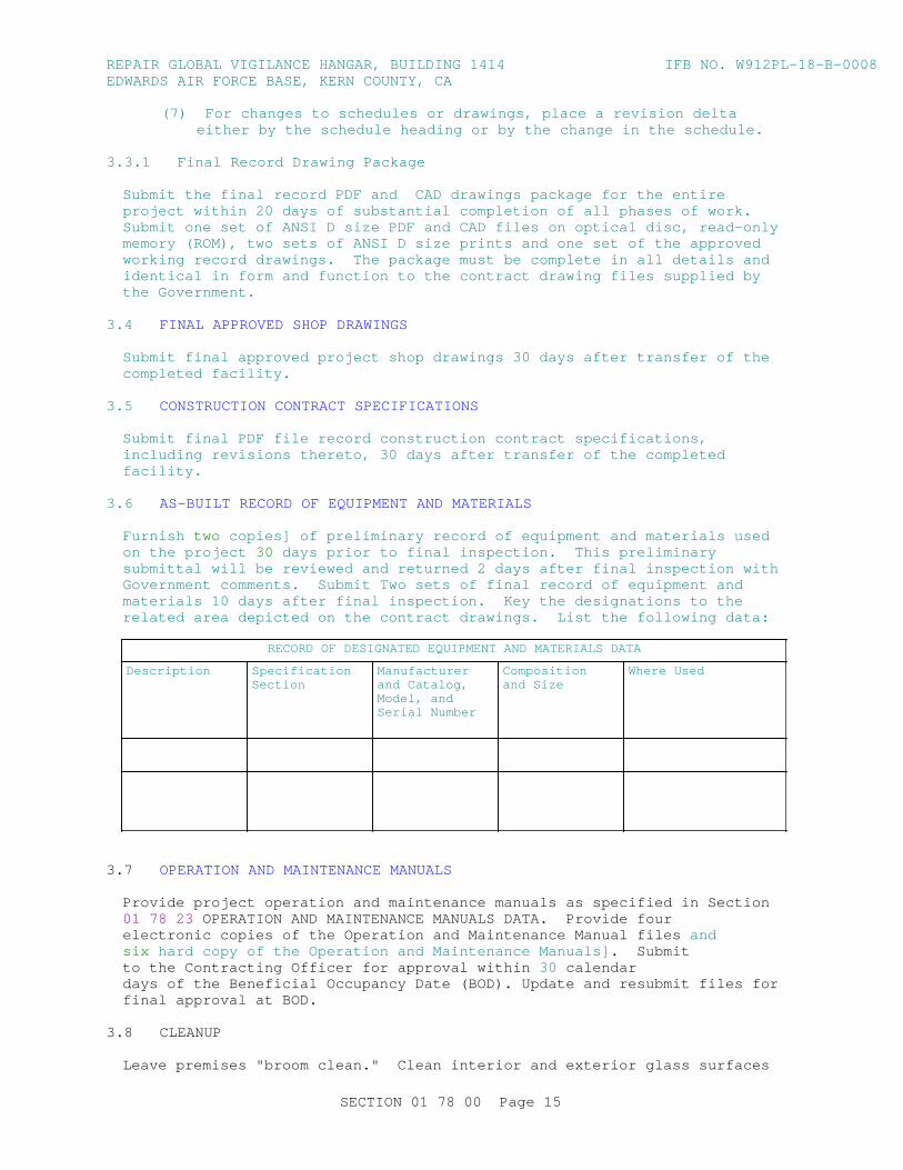
REPAI R GLOBAL VI GI LANCE HANGAR, BUI LDI NG 1414 I FB NO. W912PL- 18- B- 0008EDWARDS AI R FORCE BASE, KERN COUNTY, CA
( 7) For changes t o schedul es or dr awi ngs, pl ace a r evi s i on del t a ei t her by t he schedul e headi ng or by t he change i n t he schedul e.
3. 3. 1 Fi nal Recor d Dr awi ng Package
Submi t t he f i nal r ecor d PDF and CAD dr awi ngs package f or t he ent i r e pr oj ect wi t hi n 20 days of subst ant i al compl et i on of al l phases of wor k. Submi t one set of ANSI D si ze PDF and CAD f i l es on opt i cal di sc, r ead- onl y memor y ( ROM) , t wo set s of ANSI D si ze pr i nt s and one set of t he appr oved wor ki ng r ecor d dr awi ngs. The package must be compl et e i n al l det ai l s and i dent i cal i n f or m and f unct i on t o t he cont r act dr awi ng f i l es suppl i ed by t he Gover nment .
3. 4 FI NAL APPROVED SHOP DRAWI NGS
Submi t f i nal appr oved pr oj ect shop dr awi ngs 30 days af t er t r ansf er of t he compl et ed f aci l i t y .
3. 5 CONSTRUCTI ON CONTRACT SPECI FI CATI ONS
Submi t f i nal PDF f i l e r ecor d const r uct i on cont r act speci f i cat i ons, i ncl udi ng r evi s i ons t her et o, 30 days af t er t r ansf er of t he compl et ed facility.
3. 6 AS- BUI LT RECORD OF EQUI PMENT AND MATERI ALS
Furnish two copi es] of pr el i mi nar y r ecor d of equi pment and mat er i al s used on t he pr oj ect 30 days pr i or t o f i nal i nspect i on. Thi s pr el i mi nar y submi t t al wi l l be r evi ewed and r et ur ned 2 days af t er f i nal i nspect i on wi t h Gover nment comment s. Submi t Two set s of f i nal r ecor d of equi pment and mat er i al s 10 days af t er f i nal i nspect i on. Key t he desi gnat i ons t o t he r el at ed ar ea depi ct ed on t he cont r act dr awi ngs. Li st t he f ol l owi ng dat a:
RECORD OF DESI GNATED EQUI PMENT AND MATERI ALS DATA
Description Specification Section
Manufacturer and Cat al og, Model , and Ser i al Number
Composition and Si ze
Wher e Used
3. 7 OPERATI ON AND MAI NTENANCE MANUALS
Pr ovi de pr oj ect oper at i on and mai nt enance manual s as speci f i ed i n Sect i on 01 78 23 OPERATI ON AND MAI NTENANCE MANUALS DATA. Pr ovi de f ourel ect r oni c copi es of t he Oper at i on and Mai nt enance Manual f i l es andsix har d copy of t he Oper at i on and Mai nt enance Manual s] . Submi tt o t he Cont r act i ng Of f i cer f or appr oval wi t hi n 30 cal endardays of t he Benef i c i al Occupancy Dat e ( BOD) . Updat e and r esubmi t f i l es f orf i nal appr oval at BOD.
3. 8 CLEANUP
Leave pr emi ses " br oom cl ean. " Cl ean i nt er i or and ext er i or gl ass sur f aces
SECTI ON 01 78 00 Page 15

REPAI R GLOBAL VI GI LANCE HANGAR, BUI LDI NG 1414 I FB NO. W912PL- 18- B- 0008EDWARDS AI R FORCE BASE, KERN COUNTY, CA
exposed t o v i ew; r emove t empor ar y l abel s, st ai ns and f or ei gn subst ances; pol i sh t r anspar ent and gl ossy sur f aces; vacuum car pet ed and sof t sur f aces. Cl ean equi pment and f i xt ur es t o a sani t ar y condi t i on. [ Cl ean] [ Repl ace] f i l t er s of oper at i ng equi pment . Cl ean debr i s f r om r oof s, gut t er s, downspout s and dr ai nage syst ems. Sweep paved ar eas and r ake cl ean l andscaped ar eas. Remove wast e and sur pl us mat er i al s, r ubbi sh and const r uct i on f aci l i t i es f r om t he si t e. .
3. 9 REAL PROPERTY RECORD
Near t he compl et i on of Pr oj ect , but a mi ni mum of 60 days pr i or t o f i nal accept ance of t he wor k, compl et e[ , updat e dr af t DD FORM 1354 at t ached t o t hi s sect i on, ] and submi t an account i ng of al l i nst al l ed pr oper t y wi t h I nt er i m DD FORM 1354. I ncl ude any addi t i onal asset s, i mpr ovement s, and al t er at i ons f r om t he Dr af t DD FORM 1354. Cont act t he Cont r act i ng Of f i cer f or any pr oj ect speci f i c i nf or mat i on necessar y t o compl et e t he DD FORM 1354. Ref er t o UFC 1- 300- 08 f or i nst r uct i on on compl et i ng t he DD FORM 1354. For conveni ence, a bl ank f i l l abl e PDF DD FORM 1354 may be obt ai ned at t he f ol l owi ng l i nk: www.esd.whs.mil/Portals/54/Documents/DD/forms/dd/dd1354.pdf
Submi t t he compl et ed Checkl i st f or DD FORM 1354 of I nst al l ed Bui l di ng Equi pment i t ems. At t ach t hi s l i s t t o t he updat ed DD FORM 1354.
- - End of Sect i on - -
SECTI ON 01 78 00 Page 16
REPAI R GLOBAL VI GI LANCE HANGAR, BUI LDI NG 1414 I FB NO. W912PL- 18- B- 0008EDWARDS AI R FORCE BASE, KERN COUNTY, CA
SECTI ON TABLE OF CONTENTS
DI VI SI ON 01 - GENERAL REQUI REMENTS
SECTI ON 01 78 23
OPERATI ON AND MAI NTENANCE DATA
08/15
PART 1 GENERAL
1. 1 SUBMI TTALS 1. 2 OPERATI ON AND MAI NTENANCE DATA 1. 2. 1 Package Qual i t y 1. 2. 2 Package Cont ent 1. 2. 3 Changes t o Submi t t al s 1. 2. 4 Commi ssi oni ng Aut hor i t y Revi ew and Appr oval 1. 3 O&M DATABASE 1. 4 OPERATI ON AND MAI NTENANCE MANUAL FI LE FORMAT 1. 4. 1 Or gani zat i on 1. 4. 2 CD or DVD Label and Di sk Hol der or Case 1. 5 TYPES OF I NFORMATI ON REQUI RED I N O&M DATA PACKAGES 1. 5. 1 Oper at i ng I nst r uct i ons 1. 5. 1. 1 Saf et y Pr ecaut i ons and Hazar ds 1. 5. 1. 2 Oper at or Pr est ar t 1. 5. 1. 3 St ar t up, Shut down, and Post - Shut down Pr ocedur es 1. 5. 1. 4 Nor mal Oper at i ons 1. 5. 1. 5 Emer gency Oper at i ons 1. 5. 1. 6 Oper at or Ser vi ce Requi r ement s 1. 5. 1. 7 Envi r onment al Condi t i ons 1. 5. 1. 8 Oper at i ng Log 1. 5. 1. 9 Addi t i onal Requi r ement s f or HVAC Cont r ol Syst ems 1. 5. 2 Pr event i ve Mai nt enance 1. 5. 2. 1 Lubr i cat i on Dat a 1. 5. 2. 2 Pr event i ve Mai nt enance Pl an, Schedul e, and Pr ocedur es 1. 5. 3 Repai r 1. 5. 3. 1 Tr oubl eshoot i ng Gui des and Di agnost i c Techni ques 1. 5. 3. 2 Wi r i ng Di agr ams and Cont r ol Di agr ams 1. 5. 3. 3 Repai r Pr ocedur es 1. 5. 3. 4 Removal and Repl acement I nst r uct i ons 1. 5. 3. 5 Spar e Par t s and Suppl y Li st s 1. 5. 3. 6 Repai r Wor k- Hour s 1. 5. 4 Real Pr oper t y Equi pment 1. 5. 5 Appendi ces 1. 5. 5. 1 Pr oduct Submi t t al Dat a 1. 5. 5. 2 Manuf act ur er ' s I nst r uct i ons 1. 5. 5. 3 O&M Submi t t al Dat a 1. 5. 5. 4 Par t s I dent i f i cat i on 1. 5. 5. 5 War r ant y I nf or mat i on 1. 5. 5. 6 Ext ended War r ant y I nf or mat i on 1. 5. 5. 7 Per sonnel Tr ai ni ng Requi r ement s 1. 5. 5. 8 Test i ng Equi pment and Speci al Tool I nf or mat i on 1. 5. 5. 9 Test i ng and Per f or mance Dat a 1. 5. 5. 10 Fi el d Test Repor t s 1. 5. 5. 11 Cont r act or I nf or mat i on
SECTI ON 01 78 23 Page 1
REPAI R GLOBAL VI GI LANCE HANGAR, BUI LDI NG 1414 I FB NO. W912PL- 18- B- 0008EDWARDS AI R FORCE BASE, KERN COUNTY, CA
1. 6 SCHEDULE OF OPERATI ON AND MAI NTENANCE DATA PACKAGES 1. 6. 1 Dat a Package 1 1. 6. 2 Dat a Package 2 1. 6. 3 Dat a Package 3 1. 6. 4 Dat a Package 4 1. 6. 5 Dat a Package 5
PART 2 PRODUCTS
PART 3 EXECUTI ON
3. 1 TRAI NI NG 3. 1. 1 Tr ai ni ng Pl an 3. 1. 2 Tr ai ni ng Cont ent 3. 1. 3 Tr ai ni ng Out l i ne 3. 1. 4 Tr ai ni ng Vi deo Recor di ng 3. 1. 5 Unr esol ved Quest i ons f r om At t endees 3. 1. 6 Val i dat i on of Tr ai ni ng Compl et i on 3. 1. 7 Qual i t y Cont r ol Coor di nat i on
- - End of Sect i on Tabl e of Cont ent s - -
SECTI ON 01 78 23 Page 2
REPAI R GLOBAL VI GI LANCE HANGAR, BUI LDI NG 1414 I FB NO. W912PL- 18- B- 0008EDWARDS AI R FORCE BASE, KERN COUNTY, CA
SECTI ON 01 78 23
OPERATI ON AND MAI NTENANCE DATA08/15
PART 1 GENERAL
1. 1 SUBMITTALS
Gover nment appr oval i s r equi r ed f or submi t t al s wi t h a " G" desi gnat i on; submi t t al s not havi ng a " G" desi gnat i on ar e [ f or Cont r act or Qual i t y Cont r ol appr oval . ] [ f or i nf or mat i on onl y. When used, a desi gnat i on f ol l owi ng t he " G" desi gnat i on i dent i f i es t he of f i ce t hat wi l l r evi ew t he submi t t al f or t he Gover nment . ] Submi t t al s wi t h an " S" ar e f or i ncl usi on i n t he Sust ai nabi l i t y eNot ebook, i n conf or mance wi t h Sect i on 01 33 29 SUSTAI NABI LI TY REPORTI NG. Submi t t he f ol l owi ng i n accor dance wi t h Sect i on 01 33 00 SUBMI TTAL PROCEDURES:
SD- 10 Oper at i on and Mai nt enance Dat a
O&M Dat abase ; G
Tr ai ni ng Pl an ; G
Tr ai ni ng Out l i ne ; G
Tr ai ni ng Cont ent ; G
SD- 11 Cl oseout Submi t t al s
Tr ai ni ng Vi deo Recor di ng ; G
Val i dat i on of Tr ai ni ng Compl et i on ; G
1. 2 OPERATI ON AND MAI NTENANCE DATA
Submi t Oper at i on and Mai nt enance ( O&M) Dat a f or t he pr ovi ded equi pment , pr oduct , or syst em, def i ni ng t he i mpor t ance of syst em i nt er act i ons, t r oubl eshoot i ng, and l ong- t er m pr event i ve oper at i on and mai nt enance. Compi l e, pr epar e, and aggr egat e O&M dat a t o i ncl ude cl ar i f y i ng and updat i ng t he or i gi nal sequences of oper at i on t o as- bui l t condi t i ons. Or gani ze and pr esent i nf or mat i on i n suf f i c i ent det ai l t o c l ear l y expl ai n O&M r equi r ement s at t he syst em, equi pment , component , and subassembl y l evel . I ncl ude an i ndex pr ecedi ng each submi t t al . Submi t i n accor dance wi t h t hi s sect i on and Sect i on 01 33 00 SUBMI TTAL PROCEDURES.
1. 2. 1 Package Qual i t y
Document s must be f ul l y l egi bl e. Oper at i on and Mai nt enance dat a must be consi st ent wi t h t he manuf act ur er ' s st andar d br ochur es, schemat i cs, pr i nt ed i nst r uct i ons, gener al oper at i ng pr ocedur es, and saf et y pr ecaut i ons.
1. 2. 2 Package Cont ent
Pr ovi de dat a package cont ent i n accor dance wi t h par agr aph SCHEDULE OF OPERATI ON AND MAI NTENANCE DATA PACKAGES. Compl y wi t h t he dat a package r equi r ement s speci f i ed i n t he i ndi v i dual t echni cal sect i ons, i ncl udi ng t he
SECTI ON 01 78 23 Page 3
REPAI R GLOBAL VI GI LANCE HANGAR, BUI LDI NG 1414 I FB NO. W912PL- 18- B- 0008EDWARDS AI R FORCE BASE, KERN COUNTY, CA
cont ent of t he packages and addr essi ng each pr oduct , component , and syst em desi gnat ed f or dat a package submi ssi on, except as f ol l ows. Use Dat a Package 3] f or commi ssi oned i t ems wi t hout a speci f i ed dat a package r equi r ement i n t he i ndi v i dual t echni cal sect i ons. Pr ovi de a Dat a Package 3 i nst ead of Dat a Package 1 or 2, as speci f i ed i n t he i ndi v i dual t echni cal sect i on, f or i t ems t hat ar e commi ssi oned.
1. 2. 3 Changes t o Submi t t al s
Pr ovi de manuf act ur er - or i gi nat ed changes or r evi s i ons t o submi t t ed dat a i f a component of an i t em i s so af f ect ed subsequent t o accept ance of t he O&M Dat a. Submi t changes, addi t i ons, or r evi s i ons r equi r ed by t he Cont r act i ng Of f i cer f or f i nal accept ance of submi t t ed dat a wi t hi n 30 cal endar days of t he not i f i cat i on of t hi s change r equi r ement .
1. 2. 4 Commi ssi oni ng Aut hor i t y Revi ew and Appr oval
Submi t t he commi ssi oned syst ems and equi pment submi t t al s t o t he Commi ssi oni ng Aut hor i t y ( CxA) t o r evi ew f or compl et eness and appl i cabi l i t y . Obt ai n val i dat i on f r om t he CxA t hat t he syst ems and equi pment pr ovi ded meet t he r equi r ement s of t he Cont r act document s and desi gn i nt ent , par t i cul ar l y as t hey r el at e t o f unct i onal i t y, ener gy per f or mance, wat er per f or mance, mai nt ai nabi l i t y , sust ai nabi l i t y , syst em cost , i ndoor envi r onment al qual i t y, and l ocal envi r onment al i mpact s. The CxA communi cat es def i c i enci es t o t he Cont r act i ng Of f i cer . Submi t t he O&M manual s t o t he Cont r act i ng Of f i cer upon a successf ul r evi ew of t he cor r ect i ons, and wi t h t he CxA r ecommendat i on f or appr oval and accept ance of t hese O&M manual s. Thi s wor k i s i n addi t i on t o t he nor mal r evi ew pr ocedur es f or O&M dat a.
1. 3 O&M DATABASE
Devel op an edi t abl e, el ect r oni c spr eadsheet based on t he equi pment i n t he Oper at i on and Mai nt enance Manual s t hat cont ai ns t he i nf or mat i on r equi r ed t o st ar t a pr event i ve mai nt enance pr ogr am. As a mi ni mum, pr ovi de l i s t of syst em equi pment , l ocat i on i nst al l ed, war r ant y expi r at i on dat e, manuf act ur er , model , and ser i al number .
1. 4 OPERATI ON AND MAI NTENANCE MANUAL FI LE FORMAT
Assembl e dat a packages i nt o el ect r oni c Oper at i on and Mai nt enance Manual s. Assembl e each manual i nt o a composi t e el ect r oni cal l y i ndexed f i l e usi ng t he most cur r ent ver si on of Adobe Acr obat or s i mi l ar sof t war e capabl e of pr oduci ng PDF f i l e f or mat . Pr ovi de compact di sks ( CD) or dat a di gi t al ver sat i l e di sk ( DVD) as appr opr i at e, so t hat each one cont ai ns oper at i on, mai nt enance and r ecor d f i l es, pr oj ect r ecor d document s, and t r ai ni ng vi deos. I ncl ude a compl et e el ect r oni cal l y l i nked oper at i on and mai nt enance di r ect or y.
1. 4. 1 Organization
Bookmar k Pr oduct and Dr awi ng I nf or mat i on document s usi ng t he cur r ent ver si on of CSI Mast er f or mat number i ng syst em, and ar r ange submi t t al s usi ng t he speci f i cat i on sect i ons as a st r uct ur e. Use CSI Mast er f or mat and UFGS number s al ong wi t h descr i pt i ve bookmar ked t i t l es t hat expl ai n t he cont ent of t he i nf or mat i on t hat i s bei ng bookmar ked.
SECTI ON 01 78 23 Page 4
REPAI R GLOBAL VI GI LANCE HANGAR, BUI LDI NG 1414 I FB NO. W912PL- 18- B- 0008EDWARDS AI R FORCE BASE, KERN COUNTY, CA
1. 4. 2 CD or DVD Label and Di sk Hol der or Case
Pr ovi de t he f ol l owi ng i nf or mat i on on t he di sk l abel and di sk hol der or case:
a. Bui l di ng Number
b. Pr oj ect Ti t l e
c. Act i v i t y and Locat i on
d. Const r uct i on Cont r act Number
e. Pr epar ed For : ( Cont r act i ng Agency)
f . Pr epar ed By: ( Name, t i t l e, phone number and emai l addr ess)
g. I ncl ude t he di sk cont ent on t he di sk l abel
h. Dat e
i . Vi r us scanni ng pr ogr am used
1. 5 TYPES OF I NFORMATI ON REQUI RED I N O&M DATA PACKAGES
The f ol l owi ng ar e a det ai l ed descr i pt i on of t he dat a package i t ems l i s t ed i n par agr aph SCHEDULE OF OPERATI ON AND MAI NTENANCE DATA PACKAGES.
1. 5. 1 Oper at i ng I nst r uct i ons
Pr ovi de speci f i c i nst r uct i ons, pr ocedur es, and i l l ust r at i ons f or t he f ol l owi ng phases of oper at i on f or t he i nst al l ed model and f eat ur es of each system:
1. 5. 1. 1 Saf et y Pr ecaut i ons and Hazar ds
Li st per sonnel hazar ds and equi pment or pr oduct saf et y pr ecaut i ons f or oper at i ng condi t i ons. Li st al l r esi dual hazar ds i dent i f i ed i n t he Act i v i t y Hazar d Anal ysi s pr ovi ded under Sect i on 01 35 26 GOVERNMENT SAFETY REQUI REMENTS. Pr ovi de r ecommended saf eguar ds f or each i dent i f i ed hazar d.
1. 5. 1. 2 Oper at or Pr est ar t
Pr ovi de pr ocedur es r equi r ed t o i nst al l , set up, and pr epar e each syst em f or use.
1. 5. 1. 3 St ar t up, Shut down, and Post - Shut down Pr ocedur es
Pr ovi de nar r at i ve descr i pt i on f or St ar t up, Shut down and Post - shut down oper at i ng pr ocedur es i ncl udi ng t he cont r ol sequence f or each pr ocedur e.
1. 5. 1. 4 Nor mal Oper at i ons
Pr ovi de Cont r ol Di agr ams wi t h dat a t o expl ai n oper at i on and cont r ol of syst ems and speci f i c equi pment . Pr ovi de nar r at i ve descr i pt i on of Nor mal Oper at i ng Pr ocedur es.
SECTI ON 01 78 23 Page 5
REPAI R GLOBAL VI GI LANCE HANGAR, BUI LDI NG 1414 I FB NO. W912PL- 18- B- 0008EDWARDS AI R FORCE BASE, KERN COUNTY, CA
1. 5. 1. 5 Emer gency Oper at i ons
Pr ovi de Emer gency Pr ocedur es f or equi pment mal f unct i ons t o per mi t a shor t per i od of cont i nued oper at i on or t o shut down t he equi pment t o pr event f ur t her damage t o syst ems and equi pment . Pr ovi de Emer gency Shut down I nst r uct i ons f or f i r e, expl osi on, spi l l s , or ot her f or eseeabl e cont i ngenci es. Pr ovi de gui dance and pr ocedur es f or emer gency oper at i on of ut i l i t y syst ems i ncl udi ng r equi r ed val ve posi t i ons, val ve l ocat i ons and zones or por t i ons of syst ems cont r ol l ed.
1. 5. 1. 6 Oper at or Ser vi ce Requi r ement s
Pr ovi de i nst r uct i ons f or ser vi ces t o be per f or med by t he oper at or such as l ubr i cat i on, adj ust ment , i nspect i on, and r ecor di ng gauge r eadi ngs.
1. 5. 1. 7 Envi r onment al Condi t i ons
Pr ovi de a l i s t of Envi r onment al Condi t i ons ( t emper at ur e, humi di t y, and ot her r el evant dat a) t hat ar e best sui t ed f or t he oper at i on of each pr oduct , component or syst em. Descr i be condi t i ons under whi ch t he i t em equi pment shoul d not be al l owed t o r un.
1. 5. 1. 8 Oper at i ng Log
Pr ovi de f or ms, sampl e l ogs, and i nst r uct i ons f or mai nt ai ni ng necessar y oper at i ng r ecor ds.
1. 5. 1. 9 Addi t i onal Requi r ement s f or HVAC Cont r ol Syst ems
Pr ovi de Dat a Package 5 and t he f ol l owi ng f or cont r ol syst ems:
a. Nar r at i ve descr i pt i on on how t o per f or m and appl y f unct i ons, f eat ur es, modes, and ot her oper at i ons, i ncl udi ng unoccupi ed oper at i on, seasonal changeover , manual oper at i on, and al ar ms. I ncl ude det ai l ed t echni cal manual f or pr ogr ammi ng and cust omi zi ng cont r ol l oops and al gor i t hms.
b. Ful l as- bui l t sequence of oper at i ons.
c. Copi es of checkout t est s and cal i br at i ons per f or med by t he Cont r act or ( not Cx t est s) .
d. Ful l poi nt s l i s t . Pr ovi de a l i s t i ng of r ooms wi t h t he f ol l owi ng i nf or mat i on f or each r oom:
( 1) Fl oor
( 2) Room number
( 3) Room name
( 4) Ai r handl er uni t I D
( 5) Ref er ence dr awi ng number
( 6) Ai r t er mi nal uni t t ag I D
( 7) Heat i ng or cool i ng val ve t ag I D
( 8) Mi ni mum cf m
SECTI ON 01 78 23 Page 6
REPAI R GLOBAL VI GI LANCE HANGAR, BUI LDI NG 1414 I FB NO. W912PL- 18- B- 0008EDWARDS AI R FORCE BASE, KERN COUNTY, CA
( 9) Maxi mum cf m
e. Ful l pr i nt out of al l schedul es and set poi nt s af t er t est i ng and accept ance of t he syst em.
f . Ful l as- bui l t pr i nt out of sof t war e pr ogr am.
g. Mar ki ng of syst em sensor s and t her most at s on t he as- bui l t f l oor pl an and mechani cal dr awi ngs wi t h t hei r cont r ol syst em desi gnat i ons.
1. 5. 2 Pr event i ve Mai nt enance
Pr ovi de t he f ol l owi ng i nf or mat i on f or pr event i ve and schedul ed mai nt enance t o mi ni mi ze r epai r s f or t he i nst al l ed model and f eat ur es of each syst em. I ncl ude pot ent i al envi r onment al and i ndoor ai r qual i t y i mpact s of r ecommended mai nt enance pr ocedur es and mat er i al s.
1. 5. 2. 1 Lubr i cat i on Dat a
I ncl ude t he f ol l owi ng pr event i ve mai nt enance l ubr i cat i on dat a, i n addi t i on t o i nst r uct i ons f or l ubr i cat i on r equi r ed under par agr aph OPERATOR SERVI CE REQUIREMENTS:
a. A t abl e showi ng r ecommended l ubr i cant s f or speci f i c t emper at ur e r anges and appl i cat i ons.
b. Char t s wi t h a schemat i c di agr am of t he equi pment showi ng l ubr i cat i on poi nt s, r ecommended t ypes and gr ades of l ubr i cant s, and capaci t i es.
c. A Lubr i cat i on Schedul e showi ng ser vi ce i nt er val f r equency.
1. 5. 2. 2 Pr event i ve Mai nt enance Pl an, Schedul e, and Pr ocedur es
Pr ovi de manuf act ur er ' s schedul e f or r out i ne pr event i ve mai nt enance, i nspect i ons, condi t i on moni t or i ng ( pr edi ct i ve t est s) and adj ust ment s r equi r ed t o ensur e pr oper and economi cal oper at i on and t o mi ni mi ze r epai r s. Pr ovi de i nst r uct i ons st at i ng when t he syst ems shoul d be r et est ed. Pr ovi de manuf act ur er ' s pr oj ect i on of pr event i ve mai nt enance wor k- hour s on a dai l y, weekl y, mont hl y, and annual basi s i ncl udi ng cr af t r equi r ement s by t ype of cr af t . For per i odi c cal i br at i ons, pr ovi de manuf act ur er ' s speci f i ed f r equency and pr ocedur es f or each separ at e operation.
a. Def i ne t he ant i c i pat ed t i me r equi r ed t o per f or m each of each t est ( wor k- hour s) , t est appar at us, number of per sonnel i dent i f i ed by r esponsi bi l i t y , and a t est i ng val i dat i on pr ocedur e per mi t t i ng t he r ecor d oper at i on capabi l i t y r equi r ement s wi t hi n t he schedul e. Pr ovi de a r emar ks col umn f or t he t est i ng val i dat i on pr ocedur e r ef er enci ng oper at i ng l i mi t s of t i me, pr essur e, t emper at ur e, vol ume, vol t age, cur r ent , accel er at i on, vel oci t y, al i gnment , cal i br at i on, adj ust ment s, c l eani ng, or speci al syst em not es. Del i neat e pr ocedur es f or pr event i ve mai nt enance, i nspect i on, adj ust ment , l ubr i cat i on and cl eani ng necessar y t o mi ni mi ze r epai r s.
b. Repai r r equi r ement s must i nf or m oper at or s how t o check out , t r oubl eshoot , r epai r , and r epl ace component s of t he syst em. I ncl ude el ect r i cal and mechani cal schemat i cs and di agr ams and di agnost i c t echni ques necessar y t o enabl e oper at i on and t r oubl eshoot i ng of t he
SECTI ON 01 78 23 Page 7
REPAI R GLOBAL VI GI LANCE HANGAR, BUI LDI NG 1414 I FB NO. W912PL- 18- B- 0008EDWARDS AI R FORCE BASE, KERN COUNTY, CA
syst em af t er accept ance.
1. 5. 3 Repair
Pr ovi de manuf act ur er ' s r ecommended pr ocedur es and i nst r uct i ons f or cor r ect i ng pr obl ems and maki ng r epai r s.
1. 5. 3. 1 Tr oubl eshoot i ng Gui des and Di agnost i c Techni ques
Pr ovi de st ep- by- st ep pr ocedur es t o pr ompt l y i sol at e t he cause of t ypi cal mal f unct i ons. Descr i be c l ear l y why t he checkout i s per f or med and what condi t i ons ar e t o be sought . I dent i f y t est s or i nspect i ons and t est equi pment r equi r ed t o det er mi ne whet her par t s and equi pment may be r eused or r equi r e r epl acement .
1. 5. 3. 2 Wi r i ng Di agr ams and Cont r ol Di agr ams
Pr ovi de poi nt - t o- poi nt dr awi ngs of wi r i ng and cont r ol c i r cui t s i ncl udi ng f act or y- f i el d i nt er f aces. Pr ovi de a compl et e and accur at e depi ct i on of t he act ual j ob speci f i c wi r i ng and cont r ol wor k. On di agr ams, number el ect r i cal and el ect r oni c wi r i ng and pneumat i c cont r ol t ubi ng and t he t er mi nal s f or each t ype, i dent i cal l y t o act ual i nst al l at i on conf i gur at i on and number i ng.
1. 5. 3. 3 Repai r Pr ocedur es
Pr ovi de i nst r uct i ons and a l i s t of t ool s r equi r ed t o r epai r or r est or e t he pr oduct or equi pment t o pr oper condi t i on or oper at i ng st andar ds.
1. 5. 3. 4 Removal and Repl acement I nst r uct i ons
Pr ovi de st ep- by- st ep pr ocedur es and a l i s t of r equi r ed t ool s and suppl i es f or r emoval , r epl acement , di sassembl y, and assembl y of component s, assembl i es, subassembl i es, accessor i es, and at t achment s. Pr ovi de t ol er ances, di mensi ons, set t i ngs and adj ust ment s r equi r ed. Use a combi nat i on of t ext and i l l ust r at i ons.
1. 5. 3. 5 Spar e Par t s and Suppl y Li st s
Pr ovi de l i s t s of spar e par t s and suppl i es r equi r ed f or r epai r t o ensur e cont i nued ser vi ce or oper at i on wi t hout unr easonabl e del ays. Speci al consi der at i on i s r equi r ed f or f aci l i t i es at r emot e l ocat i ons. Li st spar e par t s and suppl i es t hat have a l ong l ead- t i me t o obt ai n.
1. 5. 3. 6 Repai r Wor k- Hour s
Pr ovi de manuf act ur er ' s pr oj ect i on of r epai r wor k- hour s i ncl udi ng r equi r ement s by t ype of cr af t . I dent i f y, and t abul at e separ at el y, r epai r t hat r equi r es t he equi pment manuf act ur er t o compl et e or t o par t i c i pat e.
1. 5. 4 Real Pr oper t y Equi pment
Pr ovi de a l i s t of i nst al l ed equi pment f ur ni shed under t hi s cont r act . I ncl ude al l i nf or mat i on usual l y l i s t ed on manuf act ur er ' s name pl at e. I n t he " EQUI PMENT- I N- PLACE LI ST" i ncl ude, as appl i cabl e, t he f ol l owi ng f or each pi ece of equi pment i nst al l ed: descr i pt i on of i t em, l ocat i on ( by r oom number ) , model number , ser i al number , capaci t y, name and addr ess of manuf act ur er , name and addr ess of equi pment suppl i er , condi t i on, spar e par t s l i s t , manuf act ur er ' s cat al og, and war r ant y. Submi t t he f i nal l i s t 30
SECTI ON 01 78 23 Page 8

REPAI R GLOBAL VI GI LANCE HANGAR, BUI LDI NG 1414 I FB NO. W912PL- 18- B- 0008EDWARDS AI R FORCE BASE, KERN COUNTY, CA
days af t er t r ansf er of t he compl et ed f aci l i t y .
Key t he desi gnat i ons t o t he r el at ed ar ea depi ct ed on t he cont r act dr awi ngs. Li st t he f ol l owi ng dat a:
RECORD OF DESI GNATED EQUI PMENT AND MATERI ALS DATA
Description Specification Section
Manufacturer and Cat al og, Model , and Ser i al Number
Composi t i on and Size
Wher e Used
1. 5. 5 Appendices
Pr ovi de i nf or mat i on r equi r ed bel ow and i nf or mat i on not speci f i ed i n t he pr ecedi ng par agr aphs but per t i nent t o t he mai nt enance or oper at i on of t he pr oduct or equi pment . I ncl ude t he f ol l owi ng:
1. 5. 5. 1 Pr oduct Submi t t al Dat a
Pr ovi de a copy of SD- 03 Pr oduct Dat a submi t t al s document ed wi t h t he r equi r ed appr oval .
1. 5. 5. 2 Manuf act ur er ' s I nst r uct i ons
Pr ovi de a copy of SD- 08 Manuf act ur er ' s I nst r uct i ons submi t t al s document ed wi t h t he r equi r ed appr oval .
1. 5. 5. 3 O&M Submi t t al Dat a
Pr ovi de a copy of SD- 10 Oper at i on and Mai nt enance Dat a submi t t al s document ed wi t h t he r equi r ed appr oval .
1. 5. 5. 4 Par t s I dent i f i cat i on
Pr ovi de i dent i f i cat i on and cover age f or t he par t s of each component , assembl y, subassembl y, and accessor y of t he end i t ems subj ect t o r epl acement . I ncl ude speci al har dwar e r equi r ement s, such as r equi r ement t o use hi gh- st r engt h bol t s and nut s. I dent i f y par t s by make, model , ser i al number , and sour ce of suppl y t o al l ow r eor der i ng wi t hout f ur t her i dent i f i cat i on. Pr ovi de cl ear and l egi bl e i l l ust r at i ons, dr awi ngs, and expl oded vi ews t o enabl e easy i dent i f i cat i on of t he i t ems. When i l l ust r at i ons omi t t he par t number s and descr i pt i on, bot h t he i l l ust r at i ons and separ at e l i s t i ng must show t he i ndex, r ef er ence, or key number t hat wi l l cr oss- r ef er ence t he i l l ust r at ed par t t o t he l i s t ed par t . Gr oup t he par t s shown i n t he l i s t i ngs by component s, assembl i es, and subassembl i es i n accor dance wi t h t he manuf act ur er ' s st andar d pr act i ce. Par t s dat a may cover mor e t han one model or ser i es of equi pment , component s, assembl i es, subassembl i es, at t achment s, or accessor i es, such as t ypi cal l y shown i n a mast er par t s cat al og.
1. 5. 5. 5 War r ant y I nf or mat i on
Li st and expl ai n t he var i ous war r ant i es and cl ear l y i dent i f y t he ser vi c i ng and t echni cal pr ecaut i ons pr escr i bed by t he manuf act ur er s or cont r act document s i n or der t o keep war r ant i es i n f or ce. I ncl ude war r ant y
SECTI ON 01 78 23 Page 9

REPAI R GLOBAL VI GI LANCE HANGAR, BUI LDI NG 1414 I FB NO. W912PL- 18- B- 0008EDWARDS AI R FORCE BASE, KERN COUNTY, CA
i nf or mat i on f or pr i mar y component sof t he syst em. Pr ovi de copi es of war r ant i es r equi r ed by Sect i on 01 78 00 CLOSEOUT SUBMI TTALS.
1. 5. 5. 6 Ext ended War r ant y I nf or mat i on
Li st al l war r ant i es f or pr oduct s, equi pment , component s, and sub- component s whose dur at i on exceeds one year . For each war r ant y l i s t ed, i ndi cat e t he appl i cabl e speci f i cat i on sect i on, dur at i on, st ar t dat e, end dat e, and t he poi nt of cont act f or war r ant y f ul f i l l ment . Al so, l i s t or r ef er ence t he speci f i c oper at i on and mai nt enance pr ocedur es t hat must be per f or med t o keep t he war r ant y val i d. Pr ovi de copi es of war r ant i es r equi r ed by Sect i on 01 78 00 CLOSEOUT SUBMI TTALS.
1. 5. 5. 7 Per sonnel Tr ai ni ng Requi r ement s
Pr ovi de i nf or mat i on avai l abl e f r om t he manuf act ur er s t hat i s needed f or use i n t r ai ni ng desi gnat ed per sonnel t o pr oper l y oper at e and mai nt ai n t he equi pment and syst ems.
1. 5. 5. 8 Test i ng Equi pment and Speci al Tool I nf or mat i on
I ncl ude i nf or mat i on on t est equi pment r equi r ed t o per f or m speci f i ed t est s and on speci al t ool s needed f or t he oper at i on, mai nt enance, and r epai r of component s. Pr ovi de f i nal set poi nt s.
1. 5. 5. 9 Test i ng and Per f or mance Dat a
I ncl ude compl et ed pr ef unct i onal checkl i st s, f unct i onal per f or mance t est f or ms, and moni t or i ng r epor t s. I ncl ude r ecommended schedul e f or r et est i ng and bl ank t est f or ms. Pr ovi de f i nal set poi nt s.
1. 5. 5. 10 Fi el d Test Repor t s
Pr ovi de a copy of Fi el d Test Repor t s ( SD- 06) submi t t al s document ed wi t h t he r equi r ed appr oval .
1. 5. 5. 11 Cont r act or I nf or mat i on
Pr ovi de a l i s t t hat i ncl udes t he name, addr ess, and t el ephone number of t he Gener al Cont r act or and each Subcont r act or who i nst al l ed t he pr oduct or equi pment , or syst em. For each i t em, al so pr ovi de t he name addr ess and t el ephone number of t he manuf act ur er ' s r epr esent at i ve and ser vi ce or gani zat i on t hat can pr ovi de r epl acement s most conveni ent t o t he pr oj ect s i t e. Pr ovi de t he name, addr ess, and t el ephone number of t he pr oduct , equi pment , and syst em manuf act ur er s.
1. 6 SCHEDULE OF OPERATI ON AND MAI NTENANCE DATA PACKAGES
Pr ovi de t he O&M dat a packages speci f i ed i n i ndi v i dual t echni cal sect i ons. The i nf or mat i on r equi r ed i n each t ype of dat a package f ol l ows:
1. 6. 1 Dat a Package 1
a. Saf et y pr ecaut i ons and hazar ds
b. Cl eani ng r ecommendat i ons
c. Mai nt enance and r epai r pr ocedur es
SECTI ON 01 78 23 Page 10

REPAI R GLOBAL VI GI LANCE HANGAR, BUI LDI NG 1414 I FB NO. W912PL- 18- B- 0008EDWARDS AI R FORCE BASE, KERN COUNTY, CA
d. War r ant y i nf or mat i on
e. Ext ended war r ant y i nf or mat i on
f . Cont r act or i nf or mat i on
g. Spar e par t s and suppl y l i s t
1. 6. 2 Dat a Package 2
a. Saf et y pr ecaut i ons and hazar ds
b. Nor mal oper at i ons
c. Envi r onment al condi t i ons
d. Lubr i cat i on dat a
e. Pr event i ve mai nt enance pl an, schedul e, and pr ocedur es
f . Cl eani ng r ecommendat i ons
g. Mai nt enance and r epai r pr ocedur es
h. Removal and r epl acement i nst r uct i ons
i . Spar e par t s and suppl y l i s t
j . Par t s i dent i f i cat i on
k. War r ant y i nf or mat i on
l . Ext ended war r ant y i nf or mat i on
m. Cont r act or i nf or mat i on
1. 6. 3 Dat a Package 3
a. Saf et y pr ecaut i ons and hazar ds
b. Oper at or pr est ar t
c. St ar t up, shut down, and post - shut down pr ocedur es
d. Nor mal oper at i ons
e. Emer gency oper at i ons
f . Envi r onment al condi t i ons
g. Oper at i ng l og
h. Lubr i cat i on dat a
i . Pr event i ve mai nt enance pl an, schedul e, and pr ocedur es
j . Cl eani ng r ecommendat i ons
k. Tr oubl eshoot i ng gui des and di agnost i c t echni ques
SECTI ON 01 78 23 Page 11
REPAI R GLOBAL VI GI LANCE HANGAR, BUI LDI NG 1414 I FB NO. W912PL- 18- B- 0008EDWARDS AI R FORCE BASE, KERN COUNTY, CA
l . Wi r i ng di agr ams and cont r ol di agr ams
m. Mai nt enance and r epai r pr ocedur es
n. Removal and r epl acement i nst r uct i ons
o. Spar e par t s and suppl y l i s t
p. Pr oduct submi t t al dat a
q. O&M submi t t al dat a
r . Par t s i dent i f i cat i on
s. War r ant y i nf or mat i on
t . Ext ended war r ant y i nf or mat i on
u. Test i ng equi pment and speci al t ool i nf or mat i on
v. Test i ng and per f or mance dat a
w. Cont r act or i nf or mat i on
x. Fi el d t est r epor t s
1. 6. 4 Dat a Package 4
a. Saf et y pr ecaut i ons and hazar ds
b. Oper at or pr est ar t
c. St ar t up, shut down, and post - shut down pr ocedur es
d. Nor mal oper at i ons
e. Emer gency oper at i ons
f . Oper at or ser vi ce r equi r ement s
g. Envi r onment al condi t i ons
h. Oper at i ng l og
i . Lubr i cat i on dat a
j . Pr event i ve mai nt enance pl an, schedul e, and pr ocedur es
k. Cl eani ng r ecommendat i ons
l . Tr oubl eshoot i ng gui des and di agnost i c t echni ques
m. Wi r i ng di agr ams and cont r ol di agr ams
n. Repai r pr ocedur es
o. Removal and r epl acement i nst r uct i ons
SECTI ON 01 78 23 Page 12

REPAI R GLOBAL VI GI LANCE HANGAR, BUI LDI NG 1414 I FB NO. W912PL- 18- B- 0008EDWARDS AI R FORCE BASE, KERN COUNTY, CA
p. Spar e par t s and suppl y l i s t
q. Repai r wor k- hour s
r . Pr oduct submi t t al dat a
s. O&M submi t t al dat a
t . Par t s i dent i f i cat i on
u. War r ant y i nf or mat i on
v. Ext ended war r ant y i nf or mat i on
w. Per sonnel t r ai ni ng r equi r ement s
x. Test i ng equi pment and speci al t ool i nf or mat i on
y. Test i ng and per f or mance dat a
z. Cont r act or i nf or mat i on
aa. Fi el d t est r epor t s
1. 6. 5 Dat a Package 5
a. Saf et y pr ecaut i ons and hazar ds
b. Oper at or pr est ar t
c. St ar t - up, shut down, and post - shut down pr ocedur es
d. Nor mal oper at i ons
e. Envi r onment al condi t i ons
f . Pr event i ve mai nt enance pl an, schedul e, and pr ocedur es
g. Tr oubl eshoot i ng gui des and di agnost i c t echni ques
h. Wi r i ng and cont r ol di agr ams
i . Mai nt enance and r epai r pr ocedur es
j . Removal and r epl acement i nst r uct i ons
k. Spar e par t s and suppl y l i s t
l . Pr oduct submi t t al dat a
m. Manuf act ur er ' s i nst r uct i ons
n. O&M submi t t al dat a
o. Par t s i dent i f i cat i on
p. Test i ng equi pment and speci al t ool i nf or mat i on
q. War r ant y i nf or mat i on
SECTI ON 01 78 23 Page 13
REPAI R GLOBAL VI GI LANCE HANGAR, BUI LDI NG 1414 I FB NO. W912PL- 18- B- 0008EDWARDS AI R FORCE BASE, KERN COUNTY, CA
r . Ext ended war r ant y i nf or mat i on
s. Test i ng and per f or mance dat a
t . Cont r act or i nf or mat i on
u. Fi el d t est r epor t s
v. Addi t i onal r equi r ement s f or HVAC cont r ol syst ems
PART 2 PRODUCTS
Not Used
PART 3 EXECUTI ON
3. 1 TRAINING
Pr i or t o accept ance of t he f aci l i t y by t he Cont r act i ng Of f i cer f or Benef i c i al Occupancy, pr ovi de compr ehensi ve t r ai ni ng f or t he syst ems and equi pment speci f i ed i n t he t echni cal speci f i cat i ons. The t r ai ni ng must be t ar get ed f or t he bui l di ng mai nt enance per sonnel , and appl i cabl e bui l di ng occupant s. I nst r uct or s must be wel l - ver sed i n t he par t i cul ar syst ems t hat t hey ar e pr esent i ng. Addr ess aspect s of t he [ Oper at i on and Mai nt enance Manual submi t t ed i n accor dance wi t h Sect i on 01 78 00 CLOSEOUT SUBMI TTALS. ] . Tr ai ni ng must i ncl ude cl assr oom or f i el d l ect ur es based on t he syst em oper at i ng r equi r ement s. The l ocat i on of c l assr oom t r ai ni ng r equi r es appr oval by t he Cont r act i ng Of f i cer .
3. 1. 1 Tr ai ni ng Pl an
Submi t a wr i t t en t r ai ni ng pl an t o t he Cont r act i ng Of f i cer f or appr oval at l east 60 cal endar days pr i or t o t he schedul ed t r ai ni ng. Tr ai ni ng pl an must be appr oved by t he Qual i t y Cont r ol Manager ( QC) pr i or t o f or war di ng t o t he Cont r act i ng Of f i cer . Al so, coor di nat e t he t r ai ni ng schedul e wi t h t he Cont r act i ng Of f i cer and QC. I ncl ude wi t hi n t he pl an t he f ol l owi ng elements:
a. Equi pment i ncl uded i n t r ai ni ng
b. I nt ended audi ence
c. Locat i on of t r ai ni ng
d. Dat es of t r ai ni ng
e. Obj ect i ves
f . Out l i ne of t he i nf or mat i on t o be pr esent ed and subj ect s cover ed i ncl udi ng descr i pt i on
g. St ar t and f i ni sh t i mes and dur at i on of t r ai ni ng on each subj ect
h. Met hods ( e. g. c l assr oom l ect ur e, v i deo, s i t e wal k- t hr ough, act ual oper at i onal demonst r at i ons, wr i t t en handout s)
i . I nst r uct or names and i nst r uct or qual i f i cat i ons f or each subj ect
SECTI ON 01 78 23 Page 14
REPAI R GLOBAL VI GI LANCE HANGAR, BUI LDI NG 1414 I FB NO. W912PL- 18- B- 0008EDWARDS AI R FORCE BASE, KERN COUNTY, CA
j . Li st of t ext s and ot her mat er i al s t o be f ur ni shed by t he Cont r act or t hat ar e r equi r ed t o suppor t t r ai ni ng
k. Descr i pt i on of pr oposed sof t war e t o be used f or v i deo r ecor di ng of t r ai ni ng sessi ons.
3. 1. 2 Tr ai ni ng Cont ent
The cor e of t hi s t r ai ni ng must be based on manuf act ur er ' s r ecommendat i ons and t he oper at i on and mai nt enance i nf or mat i on. The [ QC] [CxA] i s r esponsi bl e f or over seei ng and appr ovi ng t he cont ent and adequacy of t he t r ai ni ng. Spend 95 per cent of t he i nst r uct i on t i me dur i ng t he pr esent at i on on t he OPERATI ON AND MAI NTENANCE DATA. I ncl ude t he f ol l owi ng f or each syst em t r ai ni ng pr esent at i on:
a. St ar t - up, nor mal oper at i on, shut down, unoccupi ed oper at i on, seasonal changeover , manual oper at i on, cont r ol s set - up and pr ogr ammi ng, t r oubl eshoot i ng, and al ar ms.
b. Rel evant heal t h and saf et y i ssues.
c. Di scussi on of how t he f eat ur e or syst em i s envi r onment al l y r esponsi ve. Advi se adj ust ment s and opt i mi zi ng met hods f or ener gy conservation.
d. Desi gn i nt ent .
e. Use of O&M Manual Fi l es.
f . Revi ew of cont r ol dr awi ngs and schemat i cs.
g. I nt er act i ons wi t h ot her syst ems.
h. Speci al mai nt enance and r epl acement sour ces.
i . Tenant i nt er act i on i ssues.
3. 1. 3 Tr ai ni ng Out l i ne
Pr ovi de t he Oper at i on and Mai nt enance Manual Fi l es ( Bookmar ked PDF) and a wr i t t en cour se out l i ne l i s t i ng t he maj or and mi nor t opi cs t o be di scussed by t he i nst r uct or on each day of t he cour se t o each t r ai nee i n t he cour se. Pr ovi de t he cour se out l i ne 14 cal endar days pr i or t o t he t r ai ni ng.
3. 1. 4 Tr ai ni ng Vi deo Recor di ng
Recor d c l assr oom t r ai ni ng sessi on( s) on vi deo. Pr ovi de t o t he Cont r act i ng Of f i cer t wo copi es of t he t r ai ni ng sessi on( s) i n DVD vi deo r ecor di ng f or mat . Capt ur e wi t hi n t he r ecor di ng, i n v i deo and audi o, t he i nst r uct or s ' t r ai ni ng pr esent at i ons i ncl udi ng quest i on and answer per i ods wi t h t he at t endees. The r ecor di ng camer a( s) must be at t ended by a per son dur i ng t he r ecor di ng sessi ons t o assur e pr oper s i ze of exhi bi t s and pr oj ect i ons dur i ng t he r ecor di ng ar e v i s i bl e and r eadabl e when vi ewed as training.
3. 1. 5 Unr esol ved Quest i ons f r om At t endees
I f , at t he end of t he t r ai ni ng cour se, t her e ar e quest i ons f r om at t endees t hat r emai n unr esol ved, t he i nst r uct or must send t he answer s, i n wr i t i ng,
SECTI ON 01 78 23 Page 15
REPAI R GLOBAL VI GI LANCE HANGAR, BUI LDI NG 1414 I FB NO. W912PL- 18- B- 0008EDWARDS AI R FORCE BASE, KERN COUNTY, CA
t o t he Cont r act i ng Of f i cer f or t r ansmi t t al t o t he at t endees, and t he t r ai ni ng vi deo must be modi f i ed t o i ncl ude t he appr opr i at e c l ar i f i cat i ons.
3. 1. 6 Val i dat i on of Tr ai ni ng Compl et i on
Ensur e t hat each at t endee at each t r ai ni ng sessi on si gns a c l ass r ost er dai l y t o conf i r m Gover nment par t i c i pat i on i n t he t r ai ni ng. At t he compl et i on of t r ai ni ng, submi t a s i gned val i dat i on l et t er t hat i ncl udes a sampl e r ecor d of t r ai ni ng f or r epor t i ng what syst ems wer e i ncl uded i n t he t r ai ni ng, who pr ovi ded t he t r ai ni ng, when and wher e t he t r ai ni ng was per f or med, and copi es of t he s i gned cl ass r ost er s. Pr ovi de t wo copi es of t he val i dat i on t o t he Cont r act i ng Of f i cer , and one copy t o t he Oper at i on and Mai nt enance Manual Pr epar er f or i ncl usi on i nt o t he Manual ' s documentation.
3. 1. 7 Qual i t y Cont r ol Coor di nat i on
Coor di nat e t hi s t r ai ni ng wi t h t he QC i n accor dance wi t h Section 01 45 00. 00 10 QUALI TY CONTROL.
- - End of Sect i on - -
SECTI ON 01 78 23 Page 16
REPAI R GLOBAL VI GI LANCE HANGAR, BUI LDI NG 1414 I FB NO. W912PL- 18- B- 0008EDWARDS AI R FORCE BASE, KERN COUNTY, CA
SECTI ON TABLE OF CONTENTS
DI VI SI ON 01 - GENERAL REQUI REMENTS
SECTI ON 01 91 00. 15
TOTAL BUI LDI NG COMMI SSI ONI NG
05/16
PART 1 GENERAL
1. 1 SUMMARY 1. 2 SYSTEMS TO BE COMMI SSI ONED 1. 3 REFERENCES 1. 4 COMMUNI CATI ON WI TH THE GOVERNMENT 1. 5 SEQUENCI NG AND SCHEDULI NG 1. 5. 1 Sequenci ng 1. 5. 2 Pr oj ect Schedul e 1. 6 SUBMI TTALS 1. 7 COMMI SSI ONI NG FI RM 1. 7. 1 Lead Commi ssi oni ng Speci al i st 1. 7. 2 Techni cal Commi ssi oni ng Speci al i st s 1. 7. 3 Commi ssi oni ng St andar d 1. 8 SUSTAI NABI LI TY THI RD PARTY CERTI FI CATI ON ( TPC) 1. 9 I SSUES LOG 1. 10 CERTI FI CATE OF READI NESS
PART 2 PRODUCTS
PART 3 EXECUTI ON
3. 1 CONSTRUCTI ON PHASE 3. 1. 1 Const r uct i on Commi ssi oni ng Coor di nat i on Meet i ng 3. 1. 2 Desi gn Phase Commi ssi oni ng Pl an 3. 1. 3 Const r uct i on Phase Commi ssi oni ng Pl an 3. 1. 3. 1 I nt er i m Const r uct i on Phase Commi ssi oni ng Pl an 3. 1. 3. 1. 1 Checkl i st s 3. 1. 3. 1. 2 [ Ent er Appr opr i at e Subpar t Ti t l e Her e] 3. 1. 3. 2 Fi nal Const r uct i on Phase Commi ssi oni ng Pl an 3. 1. 3. 2. 1 Pr e- Funct i onal Checkl i st s 3. 1. 3. 2. 2 Funct i onal Per f or mance Test Checkl i st s 3. 1. 3. 2. 3 I nt egr at ed Syst ems Test Checkl i st s 3. 1. 4 Const r uct i on Submi t t al s 3. 1. 5 I nspect i on and Test i ng 3. 1. 5. 1 Commi ssi oni ng Team 3. 1. 5. 1. 1 Mechani cal Syst em Pr e- Funct i onal Checks Team 3. 1. 5. 1. 2 El ect r i cal Syst em Pr e- Funct i onal Checks Team 3. 1. 5. 1. 3 Mechani cal Syst ems Test Team 3. 1. 5. 1. 4 El ect r i cal Syst ems Test Team 3. 1. 5. 1. 5 Ot her Pr e- Funct i oanl and Funct i onal Per f or mance
Participants 3. 1. 5. 2 Pr e- Funct i onal Checks 3. 1. 5. 3 Test i ng, Adj ust i ng, and Bal anci ng ( TAB) Repor t and Fi el d
Accept ance Test i ng
SECTI ON 01 91 00. 15 Page 1

REPAI R GLOBAL VI GI LANCE HANGAR, BUI LDI NG 1414 I FB NO. W912PL- 18- B- 0008EDWARDS AI R FORCE BASE, KERN COUNTY, CA
3. 1. 5. 4 HVAC Cont r ol s Test Repor t s 3. 1. 5. 5 Test s 3. 1. 5. 5. 1 Funct i onal Per f or mance and I nt egr at ed Syst ems Test s 3. 1. 5. 5. 1. 1 Checkl i st 3. 1. 5. 5. 1. 2 Accept ance 3. 1. 5. 5. 2 HVAC Test Met hods 3. 1. 5. 5. 2. 1 Pr i or t o Test i ng 3. 1. 5. 5. 2. 2 Si mul at i ng Condi t i ons 3. 1. 5. 5. 2. 3 Set up 3. 1. 5. 5. 3 Sampl e St r at egy 3. 1. 5. 5. 4 Seasonal Test s 3. 1. 5. 5. 4. 1 I ni t i al Funct i onal Per f or mance Test s 3. 1. 5. 5. 4. 2 Ful l - Load Condi t i ons 3. 1. 5. 5. 4. 3 Syst em Accept ance 3. 1. 5. 5. 5 Abor t ed Test s and Re- Test i ng 3. 1. 5. 5. 5. 1 100 Per cent Sampl e 3. 1. 5. 5. 5. 2 Less t han 100 Per cent Sampl e 3. 1. 6 Tr ai ni ng Pl an 3. 1. 7 Syst ems Manual 3. 1. 8 Mai nt enance and Ser vi ce Li f e Pl ans 3. 1. 8. 1 Mai nt enance Pl an 3. 1. 8. 2 Ser vi ce Li f e Pl an 3. 2 COMMI SSI ONI NG REPORT 3. 3 POST- CONSTRUCTI ON SUPPORT 3. 3. 1 Post - Const r uct i on Endur ance Test 3. 3. 2 Post - Const r uct i on Si t e Vi s i t
ATTACHMENTS:
APPENDI X A - OWNER' S PROJECT REQUI REMENTS
APPENDI X B - BASI S OF DESI GN
APPENDI X C - DESI GN PHASE COMMI SSI ONI NG PLAN
- - End of Sect i on Tabl e of Cont ent s - -
SECTI ON 01 91 00. 15 Page 2
REPAI R GLOBAL VI GI LANCE HANGAR, BUI LDI NG 1414 I FB NO. W912PL- 18- B- 0008EDWARDS AI R FORCE BASE, KERN COUNTY, CA
SECTI ON 01 91 00. 15
TOTAL BUI LDI NG COMMI SSI ONI NG05/16
PART 1 GENERAL
1. 1 SUMMARY
Commi ssi on t he bui l di ng syst ems l i s t ed her ei n. Empl oy t he ser vi ces of an i ndependent Commi ssi oni ng Fi r m. The Commi ssi oni ng Fi r m must be a 1st t i er subcont r act or of t he Gener al or Pr i me Cont r act or and must be f i nanci al l y and cor por at el y i ndependent of al l ot her subcont r act or s. The Commi ssi oni ng Fi r m must empl oy a Lead Commi ssi oni ng Speci al i st t hat coor di nat es al l aspect s of t he commi ssi oni ng pr ocess. Conf or m t o t he commi ssi oni ng pr ocedur es out l i ned i n t hi s speci f i cat i on.
1. 2 SYSTEMS TO BE COMMI SSI ONED
Commi ssi on t he f ol l owi ng syst ems:
Heat i ng, Vent i l at i ng, Ai r Condi t i oni ng, and Ref r i ger at i on Syst ems (HVAC)Bui l di ng Aut omat i on Syst emUt i l i t y Moni t or i ng and Cont r ol Syst emLi ght i ng Syst emsPower Di st r i but i on Syst ems
Ser vi ce Wat er Heat i ng Syst emsPl umbi ng Syst emsNat ur al Gas and Pr opane Syst emsWat er Pumpi ng and Mi xi ng Syst ems
Compr essed Ai r and Vacuum Syst emsEner gy and Wat er Ut i l i t y Met er i ng Syst ems and Sub- Met er s
1. 3 REFERENCES
The publ i cat i ons l i s t ed bel ow f or m a par t of t hi s speci f i cat i on t o t he ext ent r ef er enced. The publ i cat i ons ar e r ef er r ed t o wi t hi n t he t ext by t he basi c desi gnat i on onl y.
AMERI CAN SOCI ETY OF HEATI NG, REFRI GERATI NG AND AI R- CONDI TI ONI NG ENGI NEERS ( ASHRAE)
ASHRAE 180 ( 2012) St andar d Pr act i ce f or I nspect i on and Mai nt enance of Commer ci al Bui l di ng HVAC Syst ems
ASHRAE 202 ( 2013) Commi ssi oni ng Pr ocess f or Bui l di ngs and Syst ems
SECTI ON 01 91 00. 15 Page 3
REPAI R GLOBAL VI GI LANCE HANGAR, BUI LDI NG 1414 I FB NO. W912PL- 18- B- 0008EDWARDS AI R FORCE BASE, KERN COUNTY, CA
ASSOCI ATED AI R BALANCE COUNCI L ( AABC)
ACG Commi ssi oni ng Gui del i ne ( 2005) Commi ssi oni ng Gui del i ne
NATI ONAL ENVI RONMENTAL BALANCI NG BUREAU ( NEBB)
NEBB Commi ssi oni ng St andar d ( 2009) Pr ocedur al St andar ds f or Whol e Bui l di ng Syst ems Commi ssi oni ng of New Const r uct i on; 3r d Edi t i on
SHEET METAL AND AI R CONDI TI ONI NG CONTRACTORS' NATI ONAL ASSOCI ATI ON (SMACNA)
SMACNA 1429 ( 1994) HVAC Syst ems Commi ssi oni ng Manual , 1st Edi t i on
1. 4 COMMUNI CATI ON WI TH THE GOVERNMENT
The Lead Commi ssi oni ng Speci al i st ( CxC) must submi t al l pl ans, schedul es, r epor t s, and document at i on di r ect l y t o t he Cont r act i ng Of f i cer Representative concur r ent wi t h submi ssi on t o t he CQC Syst em Manager . The Lead Commi ssi oni ng Speci al i st must have di r ect communi cat i on wi t h t he Cont r act i ng Of f i cer ' s Repr esent at i ve r egar di ng al l el ement s of t he commi ssi oni ng pr ocess; however , t he Gover nment has no di r ect cont r act aut hor i t y wi t h t he Lead Commi ssi oni ng Speci al i st .
1. 5 SEQUENCI NG AND SCHEDULI NG
1. 5. 1 Sequencing
Compl et e t he f ol l owi ng pr i or t o st ar t i ng Funct i onal Per f or mance Test s of mechani cal syst ems:
a. Al l equi pment and syst ems have been compl et ed, c l eaned, f l ushed, di s i nf ect ed, cal i br at ed, t est ed, and oper at e i n accor dance wi t h cont r act document s and const r uct i on pl ans and speci f i cat i ons.
b. Per f or mance Ver i f i cat i on Test s of t he cont r ol s syst ems have been compl et ed and t he Per f or mance Ver i f i cat i on Test Repor t has been submi t t ed and appr oved i n accor dance wi t h Speci f i cat i on Sect i on .
c. Test i ng, Adj ust i ng, and Bal anci ng has been compl et ed and t he Test i ng, Adj ust i ng, and Bal anci ng Repor t , has been submi t t ed and appr oved i n accor dance wi t h Speci f i cat i on Sect i on 23 05 93 TESTI NG, ADJUSTI NG, AND BALANCI NG FOR HVAC.
d. The bui l di ng envel ope i s encl osed accor di ng t o cont r act document s wi t h f i nal const r uct i on compl et ed.
e. The Pr e- Funct i onal Checkl i st s have been submi t t ed and appr oved.
f . The Cer t i f i cat e of Readi ness f or mechani cal syst ems has been submi t t ed and appr oved.
Compl et e t he f ol l owi ng pr i or t o st ar t i ng Funct i onal Per f or mance Test s of t he el ect r i cal syst ems:
a. Al l el ect r i cal , power gener at i on, and l i ght i ng equi pment and syst ems have been compl et ed, cal i br at ed, t est ed, and oper at e i n accor dance
SECTI ON 01 91 00. 15 Page 4
REPAI R GLOBAL VI GI LANCE HANGAR, BUI LDI NG 1414 I FB NO. W912PL- 18- B- 0008EDWARDS AI R FORCE BASE, KERN COUNTY, CA
wi t h cont r act document s and const r uct i on pl ans and speci f i cat i ons.
b. The bui l di ng envel ope i s encl osed accor di ng t o cont r act document s wi t h f i nal const r uct i on compl et ed.
c. Cei l i ng t i l es, f l oor cover i ngs, and wi ndow cover i ngs ar e i n pl ace.
d. The Cer t i f i cat e of Readi ness f or el ect r i cal syst ems has been submi t t ed and appr oved.
e. Lamps have compl et ed a mi ni mum 100 hour bur n- i n per i od.
f . Fur ni t ur e i s i n pl ace.
1. 5. 2 Pr oj ect Schedul e
I ncl ude t he f ol l owi ng t asks i n t he pr oj ect schedul e r equi r ed by Sect i on 01 32 01. 00 10 PROJECT SCHEDULE. Ensur e suf f i c i ent t i me i s schedul ed t o accommodat e t he r equi r ement s of t hi s speci f i cat i on sect i on. The or der of i t ems l i s t ed bel ow i s not i nt ended t o i mpl y a speci f i ed sequence:
a. Submi ssi on and appr oval of t he Commi ssi oni ng Fi r m and Commi ssi oni ng Specialist
b. Submi ssi on and appr oval of t he Test i ng, Adj ust i ng, and Bal anci ng ( TAB) Fi r m and TAB Speci al i st speci f i ed i n Sect i on 23 05 93 TESTI NG, ADJUSTI NG, AND BALANCI NG FOR HVAC
c. Submi ssi on of t he Desi gn Revi ew Repor t speci f i ed her ei n.
d. Submi ssi on of t he Desi gn Revi ew Repor t speci f i ed i n Sect i on 23 05 93 TESTI NG, ADJUSTI NG, AND BALANCI NG FOR HVAC.
e. Submi ssi on and appr oval of t he Const r uct i on Phase Commi ssi oni ng Pl an
f . I nst al l at i on of per manent ut i l i t i es ( gas, wat er , el ect r i c)
i . Ai r Bar r i er Pr essur e Test s speci f i ed i n Sect i on 07 05 23 PRESSURE TESTI NG AN AI R BARRI ER SYSTEM FOR AI R TI GHTNESS
j . Dr ai nage and Vent , Bui l di ng Sewer s, Wat er Suppl y Syst ems and Backf l ow Pr event i on Assembl y Test s speci f i ed i n Sect i on 22 00 00 PLUMBI NG, GENERAL PURPOSE
k. Fact or y Accept ance Test i ng f or each of t he syst ems t o be commi ssi oned as r equi r ed by t echni cal speci f i cat i ons
l . Manuf act ur er ' s Equi pment St ar t - Up f or each of t he syst ems t o be commissioned.
m. Pot abl e Wat er Syst em Fl ushi ng speci f i ed i n Sect i on 22 00 00 PLUMBI NG, GENERAL PURPOSE
n. Oper at i onal Test s of t he pl umbi ng syst em speci f i ed i n Sect i on 22 00 00 PLUMBI NG, GENERAL PURPOSE.
o. Pot abl e Wat er Syst em Di si nf ect i on speci f i ed i n Sect i on 22 00 00
SECTI ON 01 91 00. 15 Page 5

REPAI R GLOBAL VI GI LANCE HANGAR, BUI LDI NG 1414 I FB NO. W912PL- 18- B- 0008EDWARDS AI R FORCE BASE, KERN COUNTY, CA
PLUMBI NG, GENERAL PURPOSE
p. Submi ssi on and appr oval of t he TAB Schemat i c Dr awi ngs, Repor t For ms, and Pr ocedur es speci f i ed i n Sect i on 23 05 93 TESTI NG, ADJUSTI NG, AND BALANCI NG FOR HVAC.
q. Submi ssi on and appr oval of Duct Ai r Leakage Test Pr ocedur es speci f i ed i n Sect i on 23 05 93 TESTI NG, ADJUSTI NG, AND BALANCI NG FOR HVAC
r . Duct Ai r Leakage Test Execut i on speci f i ed i n Sect i on 23 05 93 TESTI NG, ADJUSTI NG, AND BALANCI NG FOR HVAC
s. Submi ssi on and appr oval of t he Fi nal Duct Ai r Leakage Test Repor t speci f i ed i n Sect i on 23 05 93 TESTI NG, ADJUSTI NG, AND BALANCI NG FOR HVAC
t . Test i ng, Adj ust i ng, and Bal anci ng ( TAB) Fi el d Wor k r equi r ed by Sect i on 23 05 93 TESTI NG, ADJUSTI NG, AND BALANCI NG FOR HVAC
u. Submi ssi on and appr oval of t he TAB Repor t speci f i ed i n Sect i on 23 05 93 TESTI NG, ADJUSTI NG, AND BALANCI NG FOR HVAC
v. TAB Fi el d Accept ance Test i ng r equi r ed by Sect i on 23 05 93 TESTI NG, ADJUSTI NG, AND BALANCI NG FOR HVAC
w. Submi ssi on and appr oval of t he St ar t - Up Test i ng Repor t speci f i ed i n Sect i on .
x. Submi ssi on and appr oval of t he Per f or mance Ver i f i cat i on Test Pr ocedur es speci f i ed i n Sect i on .
y. Per f or mance Ver i f i cat i on Test s r equi r ed by Sect i on
z. Per f or mance Ver i f i cat i on Test Repor t speci f i ed i n Sect i on
aa. Pr e- Funct i onal Checkl i st Submi t t al
bb. Funct i onal Per f or mance Test i ng f or each syst em t o be commi ssi oned
cc. I nt egr at ed Syst ems Test s
dd. Post - Test Def i c i ency Cor r ect i on f or each syst em t o be commi ssi oned
ee. Re- Test i ng
gg. Tr ai ni ng f or each of t he syst ems t o be commi ssi oned
i i . Seasonal Test i ng
1. 6 SUBMITTALS
Gover nment appr oval i s r equi r ed f or submi t t al s wi t h a " G" desi gnat i on; submi t t al s not havi ng a " G" desi gnat i on ar e f or i nf or mat i on onl y. When used, a desi gnat i on f ol l owi ng t he " G" desi gnat i on i dent i f i es t he of f i ce t hat wi l l r evi ew t he submi t t al f or t he Gover nment . Submi t t al s wi t h an " S"
SECTI ON 01 91 00. 15 Page 6

REPAI R GLOBAL VI GI LANCE HANGAR, BUI LDI NG 1414 I FB NO. W912PL- 18- B- 0008EDWARDS AI R FORCE BASE, KERN COUNTY, CA
ar e f or i ncl usi on i n t he Sust ai nabi l i t y Not ebook, i n conf or mance t o Section 01 33 29 SUSTAI NABI LI TY REPORTI NG. Submi t t he f ol l owi ng i n accor dance wi t h Sect i on 01 33 00 SUBMI TTAL PROCEDURES:
SD- 01 Pr econst r uct i on Submi t t al s
Commi ssi oni ng Fi r m; G
Lead Commi ssi oni ng Speci al i st ; G
Techni cal Commi ssi oni ng Speci al i st s; G
Commi ssi oni ng Fi r m' s Cont r act ; G
SD- 06 Test Repor t s
Desi gn Revi ew Repor t ; G,
I nt er i m Const r uct i on Phase Commi ssi oni ng Pl an; G
Fi nal Const r uct i on Phase Commi ssi oni ng Pl an; G
Pr e- Funct i onal Checkl i st s; G
I ssues Log
Commi ssi oni ng Repor t ; G
Post - Const r uct i on Tr end Log Repor t ; G
SD- 07 Cer t i f i cat es
Cer t i f i cat e of Readi ness; G
SD- 10 Oper at i on and Mai nt enance Dat a
Tr ai ni ng Pl an; G
Tr ai ni ng At t endance Rost er s; G
SD- 11 Cl oseout Submi t t al s
Const r uct i on Phase Commi ssi oni ng Pl an; S
Fi nal Commi ssi oni ng Repor t ; S
1. 7 COMMI SSI ONI NG FI RM
Pr ovi de a Commi ssi oni ng Fi r m t hat i s cer t i f i ed i n commi ssi oni ng by one of t he f ol l owi ng: t he AABC Commi ssi oni ng Gr oup ( ACG) ; t he Nat i onal Envi r onment al Bal anci ng Bur eau ( NEBB) ; t he I nt er nat i onal Cer t i f i cat i on Boar d/ Test i ng, Adj ust i ng, and Bal anci ng Bur eau ( I CB/ TABB) , t he Bui l di ng Commi ssi oni ng Associ at i on ( BCA) ; t he Associ at i on of Ener gy Engi neer s ( AEE) . The Commi ssi oni ng Fi r m may empl oy a commi ssi oni ng pr of essi onal cer t i f i ed by t he Uni ver si t y of Wi sconsi n- Madi son or t he Amer i can Soci et y of Heat i ng,
SECTI ON 01 91 00. 15 Page 7
REPAI R GLOBAL VI GI LANCE HANGAR, BUI LDI NG 1414 I FB NO. W912PL- 18- B- 0008EDWARDS AI R FORCE BASE, KERN COUNTY, CA
Ref r i ger at i on, and Ai r Condi t i oni ng Engi neer s ( ASHRAE) as r equi r ed i n par agr aph LEAD COMMI SSI ONI NG SPECI ALI ST as an al t er nat i ve t o cer t i f i cat i on of t he Commi ssi oni ng Fi r m. The Commi ssi oni ng Fi r m must be cer t i f i ed i n al l syst ems t o be commi ssi oned t o t he ext ent such cer t i f i cat i ons ar e avai l abl e f r om t he cer t i f y i ng body. Descr i be any l apses i n cer t i f i cat i on or di sci pl i nar y act i on t aken by t he cer t i f y i ng body agai nst t he pr oposed Commi ssi oni ng Fi r m or Lead Commi ssi oni ng Speci al i st i n det ai l . Any f i r m or commi ssi oni ng pr of essi onal t hat has been t he subj ect of di sci pl i nar y act i on by t he cer t i f y i ng body wi t hi n t he f i ve year s pr ecedi ng cont r act awar d i s not el i gi bl e t o per f or m any dut i es r el at ed t o commi ssi oni ng.
a. Submi t t he Commi ssi oni ng Fi r m' s cer t i f i cat i on of qual i f i cat i ons i ncl udi ng t he name of t he f i r m and cer t i f i cat i ons no l at er t han 30 cal endar days af t er Not i ce t o Pr oceed. Submi t one har d copy and an el ect r oni c copy.
b. The Commi ssi oni ng Fi r m' s and Commi ssi oni ng Speci al i st s ' cer t i f i cat i ons must be mai nt ai ned f or t he ent i r e dur at i on of t he dut i es speci f i ed her ei n. I f , f or any r eason, t he f i r m or a speci al i st l oses a cer t i f i cat i on dur i ng t hi s per i od, i mmedi at el y not i f y t he Contracting Of f i cer ' s Repr esent at i ve and submi t anot her Commi ssi oni ng Fi r m or Commi ssi oni ng Speci al i st f or appr oval . Al l wor k speci f i ed i n t hi s speci f i cat i on sect i on per f or med by t he Commi ssi oni ng Fi r m or associ at ed Commi ssi oni ng Speci al i st s i s i nval i d i f t he Commi ssi oni ng Fi r m or Commi ssi oni ng Speci al i st l oses i t s cer t i f i cat i on pr i or t o cont r act compl et i on and must be per f or med by an appr oved successor .
c. The Commi ssi oni ng Fi r m must over see and assi st t he Gener al or Pr i me Cont r act or wi t h t he wor k speci f i ed her ei n. [ Submi t t he Commissioning Fi r m' s Cont r act i ncl udi ng t he Scope of Wor k associ at ed wi t h t he par agr aph POST- CONSTRUCTI ON SUPPORT no l at er t han 30 cal endar days af t er appr oval of t he Commi ssi oni ng Fi r m. Submi t one har d copy and an el ect r oni c copy.
1. 7. 1 Lead Commi ssi oni ng Speci al i st
The Commi ssi oni ng Fi r m must pr ovi de a Lead Commi ssi oni ng Speci al i st ( CxC) t hat has a mi ni mum of f i ve year s of commi ssi oni ng exper i ence, i ncl udi ng t wo pr oj ect s of s i mi l ar s i ze and compl exi t y, and t hat i s one of t he f ol l owi ng: a NEBB qual i f i ed Syst ems Commi ssi oni ng Admi ni st r at or ( SCA) ; ACG Cer t i f i ed Commi ssi oni ng Aut hor i t y ( CxA) ; I CB/ TABB Cer t i f i ed Commi ssi oni ng Super vi sor ; BCA Cer t i f i ed Commi ssi oni ng Pr of essi onal ( CCP) ; AEE Cer t i f i ed Bui l di ng Commi ssi oni ng Pr of essi onal ( CBCP) ; Uni ver si t y of Wi sconsi n- Madi son Qual i f i ed Commi ssi oni ng Pr ocess Pr ovi der ( QCxP) ; ASHRAE Commi ssi oni ng Pr ocess Management Pr of essi onal ( CPMP) .
a. Submi t t he Lead Commi ssi oni ng Speci al i st ' s cer t i f i cat i on of qual i f i cat i ons i ncl udi ng t he name of t he speci al i st and f i r m; cer t i f i cat i ons; year s of exper i ence; and a l i s t i ng of r epr esent at i ve pr oj ect s of s i mi l ar s i ze and compl exi t y no l at er t han 30 cal endar days af t er Not i ce t o Pr oceed. Submi t one har d copy and an el ect r oni c copy.
b. The Lead Commi ssi oni ng Speci al i st s cer t i f i cat i ons must be mai nt ai ned f or t he ent i r e dur at i on of t he dut i es speci f i ed her ei n. I f , f or any r eason, t he speci al i st l oses a cer t i f i cat i on dur i ng t hi s per i od, i mmedi at el y not i f y t he Cont r act i ng Of f i cer ' s Repr esent at i ve and submi t anot her Lead Commi ssi oni ng Speci al i st f or appr oval . Al l wor k
SECTI ON 01 91 00. 15 Page 8
REPAI R GLOBAL VI GI LANCE HANGAR, BUI LDI NG 1414 I FB NO. W912PL- 18- B- 0008EDWARDS AI R FORCE BASE, KERN COUNTY, CA
speci f i ed i n t hi s speci f i cat i on sect i on t o be per f or med by t he Lead Commi ssi oni ng Speci al i st i s i nval i d i f t he Lead Commi ssi oni ng Speci al i st l oses i t s cer t i f i cat i on pr i or t o cont r act compl et i on and must be per f or med by an appr oved successor .
c. The Lead Commi ssi oni ng Speci al i st must l ead and over see t he commi ssi oni ng wor k speci f i ed her ei n and be t he pr i mar y poi nt of cont act f or t he Gover nment r egar di ng t he commi ssi oni ng wor k.
1. 7. 2 Techni cal Commi ssi oni ng Speci al i st s
Techni cal Commi ssi oni ng Speci al i st s, empl oyed by t he Commi ssi oni ng Fi r m and t hat have t he f ol l owi ng qual i f i cat i ons, must per f or m t he t echni cal wor k speci f i ed her ei n associ at ed wi t h each syst em t o be commi ssi oned:
a. The t echni cal wor k associ at ed wi t h mechani cal syst ems i ncl udi ng Heat i ng, Vent i l at i ng, Ai r Condi t i oni ng, and Ref r i ger at i on Syst ems; Bui l di ng Aut omat i on Syst em; Ut i l i t y Moni t or i ng and Cont r ol Syst em; Ser vi ce Wat er Heat i ng Syst ems; Pl umbi ng Syst ems; Wat er Pumpi ng and Mi xi ng Syst ems; Compr essed Ai r and Vacuum Syst ems; Ener gy and Wat er Ut i l i t y Met er i ng Syst ems must be per f or med by a Commi ssi oni ng Speci al i st cer t i f i ed by NEBB, ACG, I CB/ TABB, or BCA i n t he commi ssi oni ng of HVAC syst ems wi t h f i ve year s of exper i ence i n t he commi ssi oni ng of HVAC syst ems.
b. The t echni cal wor k associ at ed wi t h el ect r i cal syst ems i ncl udi ng Li ght i ng Syst ems; Power Di st r i but i on Syst ems; Renewabl e Ener gy Syst ems must be per f or med by an engi neer i ng t echni c i an cer t i f i ed by t he I nt er Nat i onal El ect r i cal Test i ng Associ at i on ( NETA) or t he Nat i onal I nst i t ut e f or Cer t i f i cat i on i n Engi neer i ng Technol ogi es ( NI CET) wi t h f i ve year s of exper i ence i nspect i ng, t est i ng, and cal i br at i ng el ect r i cal di st r i but i on and gener at i on equi pment , syst ems, and devi ces.
c. Submi t t he Techni cal Commi ssi oni ng Speci al i st ' s cer t i f i cat i on of qual i f i cat i ons i ncl udi ng t he name of t he speci al i st and f i r m; cer t i f i cat i ons; year s of exper i ence; and a l i s t i ng of r epr esent at i ve pr oj ect s of s i mi l ar s i ze and compl exi t y no l at er t han 30cal endar days af t er Not i ce t o Pr oceed. Submi t one har d copy and an el ect r oni c copy.
1. 7. 3 Commi ssi oni ng St andar d
Compl y wi t h t he r equi r ement s of t he commi ssi oni ng st andar d under whi ch t he Commi ssi oni ng Fi r m and Speci al i st s qual i f i cat i ons ar e appr oved. When t he f i r m and speci al i st s ar e cer t i f i ed by BCA, AEE, ASHRAE, or t he Uni ver si t y of Wi sconsi n- Madi son, compl y wi t h t he r equi r ement s of one of t he accept abl e st andar ds unl ess ot her wi se st at ed her ei n. The accept abl e st andar ds ar e ACG Commi ssi oni ng Gui del i ne, NEBB Commi ssi oni ng St andar d, SMACNA 1429, or ASHRAE 202. Compl y wi t h appl i cabl e NETA and NI CET t est i ng st andar ds f or el ect r i cal syst ems.
a. I mpl ement al l r ecommendat i ons and suggest ed pr act i ces cont ai ned i n t he Commi ssi oni ng St andar d and el ect r i cal t est st andar ds.
b. Use t he Commi ssi oni ng St andar d f or al l aspect s of Commi ssi oni ng, i ncl udi ng cal i br at i on of i nst r ument s.
c. Wher e t he i nst r ument manuf act ur er cal i br at i on r ecommendat i ons ar e mor e
SECTI ON 01 91 00. 15 Page 9
REPAI R GLOBAL VI GI LANCE HANGAR, BUI LDI NG 1414 I FB NO. W912PL- 18- B- 0008EDWARDS AI R FORCE BASE, KERN COUNTY, CA
st r i ngent t han t hose l i s t ed i n t he Commi ssi oni ng St andar d, adher e t o t he manuf act ur er cal i br at i on r ecommendat i ons.
d. Al l qual i t y assur ance pr ovi s i ons of t he Commi ssi oni ng St andar d such as per f or mance guar ant ees ar e par t of t hi s cont r act .
e. The Commi ssi oni ng Speci al i st s must devel op commi ssi oni ng pr ocedur es f or any syst ems or syst em component s not cover ed i n t he Commi ssi oni ng Standard.
f . Use any new r equi r ement s, r ecommendat i ons, and pr ocedur es publ i shed or adopt ed pr i or t o cont r act sol i c i t at i on by t he body r esponsi bl e f or t he Commi ssi oni ng St andar d.
1. 8 SUSTAI NABI LI TY THI RD PARTY CERTI FI CATI ON ( TPC)
The Commi ssi oni ng Speci al i st s must execut e and document t he commi ssi oni ng act i v i t i es r equi r ed of t he Commi ssi oni ng Aut hor i t y f or t he pur poses of compl yi ng wi t h t he Thi r d Par t y Cer t i f i cat i on ( TPC) r equi r ement s f or t he pr oj ect i n accor dance wi t h Sect i on 01 33 29 SUSTAI NABI LI TY REPORTI NG. Pr ovi de al l commi ssi oni ng document at i on r equi r ed t o meet t he TPC requirements.
1. 9 I SSUES LOG
The Lead Commi ssi oni ng Speci al i st must devel op and mai nt ai n an I ssues Log f or t r acki ng and r esol ut i on of al l def i c i enci es di scover ed t hr ough commi ssi oni ng r evi ew, i nspect i on, and t est i ng. I ncl ude t he dat e of f i nal r esol ut i on of i ssues as conf i r med by t he Commi ssi oni ng Speci al i st . Submi t t he I ssues Log on a mont hl y basi s at a mi ni mum. At any poi nt dur i ng const r uct i on, any commi ssi oni ng t eam member f i ndi ng def i c i enci es may communi cat e t hose def i c i enci es i n wr i t i ng t o t he Commi ssi oni ng Speci al i st f or i ncl usi on i nt o t he I ssues Log.
Tr ack const r uct i on def i c i enci es i dent i f i ed i n t he I ssues Log usi ng QCS as speci f i ed i n Speci f i cat i on Sect i on 01 45 00. 15 10 RESI DENT MANAGEMENT SYSTEM CONTRACTOR MODE( RMS CM) . .
1. 10 CERTI FI CATE OF READI NESS
Pr i or t o schedul i ng Funct i onal Per f or mance Test s f or each syst em, i ssue a Cer t i f i cat e of Readi ness f or t he syst em cer t i f y i ng t hat t he syst em i s r eady f or Funct i onal Per f or mance Test i ng. The Cer t i f i cat e of Readi ness must i ncl ude, f or each syst em t o be commi ssi oned, al l equi pment and syst em st ar t - up r epor t s; Per f or mance Ver i f i cat i on Test Repor t s; completed Pr e- Funct i onal Checkl i st s; Test i ng, Adj ust i ng, and Bal anci ng ( TAB) Repor t ; HVAC Cont r ol s St ar t - Up Repor t s[ ; and t he Ai r Leakage Test Repor t s and Di agnost i c Test Repor t s] t o t he ext ent appl i cabl e t o t he syst em. The Cont r act or ; t he Lead Commi ssi oni ng Speci al i st ; t he Cont r act or ' s Qual i t y Cont r ol Repr esent at i ve; t he Mechani cal , El ect r i cal , Cont r ol s, and TAB subcont r act or r epr esent at i ves must s i gn and dat e t he Cer t i f i cat e of Readi ness. Submi t t he Cer t i f i cat e of Readi ness f or each syst em no l at er t han 14 cal endar days pr i or t o Funct i onal Per f or mance Test s of t hat syst em. Submi t one har d copy and an el ect r oni c copy. Do not schedul e Funct i onal Per f or mance Test s f or a syst em unt i l t he Cer t i f i cat e of Readi ness f or t hat syst em r ecei ves appr oval by t he Gover nment .
SECTI ON 01 91 00. 15 Page 10
REPAI R GLOBAL VI GI LANCE HANGAR, BUI LDI NG 1414 I FB NO. W912PL- 18- B- 0008EDWARDS AI R FORCE BASE, KERN COUNTY, CA
PART 2 PRODUCTS
Not used
PART 3 EXECUTI ON
3. 1 CONSTRUCTI ON PHASE
3. 1. 1 Const r uct i on Commi ssi oni ng Coor di nat i on Meet i ng
The Lead Commi ssi oni ng Speci al i st must l ead a Const r uct i on Commi ssi oni ng Coor di nat i on Meet i ng no l at er t han 14 days af t er appr oval of t he Commi ssi oni ng Fi r m and Commi ssi oni ng Speci al i st s t o di scuss t he commi ssi oni ng pr ocess i ncl udi ng cont r act r equi r ement s, l i nes of communi cat i on, r ol es and r esponsi bi l i t i es, schedul es, document at i on r equi r ement s, i nspect i on and t est pr ocedur es, and l ogi st i cs as speci f i ed i n t hi s speci f i cat i on sect i on. The Cont r act or ' s Super i nt endent or Pr oj ect Manager , t he Cont r act or ' s Qual i t y Cont r ol Repr esent at i ve, and t he Gover nment must at t end t hi s meet i ng. I nvi t e t he User and a Base Ci vi l Engi neer Of f i ce Repr esent at i ve t o at t end t hi s meet i ng.
3. 1. 2 Desi gn Phase Commi ssi oni ng Pl an
A commi ssi oni ng pl an devel oped dur i ng desi gn phase i s pr ovi ded as Appendi x C f or i nf or mat i on onl y. The desi gn phase commi ssi oni ng pl an does not f or m a par t of t hi s cont r act and i s pr ovi ded f or commi ssi oni ng r evi ew pur poses only.
3. 1. 3 Const r uct i on Phase Commi ssi oni ng Pl an
3. 1. 3. 1 I nt er i m Const r uct i on Phase Commi ssi oni ng Pl an
The Lead Commi ssi oni ng Speci al i st ( CxC) must pr epar e t he I nt er i m Const r uct i on Phase Commi ssi oni ng Pl an. Submi t t he I nt er i m Construction Phase Commi ssi oni ng Pl an no l at er t han 30 cal endar days af t er t he Const r uct i on Commi ssi oni ng Coor di nat i on Meet i ng and no l at er t han 14 days pr i or t o t he st ar t of const r uct i on of t he bui l di ng envel ope. Submi t one har d copy and an el ect r oni c copy.
I dent i f y t he commi ssi oni ng and t est i ng st andar ds and out l i ne t he over al l commi ssi oni ng pr ocess, t he commi ssi oni ng schedul e, t he commi ssi oni ng t eam member s and r esponsi bi l i t i es, l i nes of communi cat i on, document at i on r equi r ement s f or t he const r uct i on phase of t he pr oj ect i n t he I nt er i m Const r uct i on Phase Commi ssi oni ng Pl an.
3. 1. 3. 1. 1 Checklists
Downl oad exampl e Pr e- Funct i onal Checkl i st s, Funct i onal Per f or mance Test Checkl i st s[ , and I nt egr at ed Syst ems Test Checkl i st s] f or speci f i cat i on section 01 91 00. 15 TOTAL BUI LDI NG COMMI SSI ONI NG at t he f ol l owi ng l ocat i on: http://www.wbdg.org/FFC/NAVGRAPH/graphtoc.pdf . The checkl i st s submi t t ed i n t he I nt er i m and Fi nal Const r uct i on Phase Commi ssi oni ng Pl ans must cont ai n t he same l evel of det ai l shown i n t he exampl es. The submi t t ed checkl i st s ar e not r equi r ed t o mat ch t he f or mat of t he exampl es.
SECTI ON 01 91 00. 15 Page 11
REPAI R GLOBAL VI GI LANCE HANGAR, BUI LDI NG 1414 I FB NO. W912PL- 18- B- 0008EDWARDS AI R FORCE BASE, KERN COUNTY, CA
3. 1. 3. 1. 2 [ Ent er Appr opr i at e Subpar t Ti t l e Her e]
3. 1. 3. 2 Fi nal Const r uct i on Phase Commi ssi oni ng Pl an
The Lead Commi ssi oni ng Speci al i st ( CxC) must pr epar e t he Fi nal Const r uct i on Phase Commi ssi oni ng Pl an. Submi t t he Fi nal Const r uct i on Phase Commi ssi oni ng Pl an no l at er t han 30 cal endar days pr i or t o t he st ar t of Pr e- Funct i onal Checks. Submi t one har d copy and an el ect r oni c copy.
I ncl ude t he i nf or mat i on pr ovi ded i n t he I nt er i m Const r uct i on Phase Commi ssi oni ng Pl an. I n addi t i on, t he Techni cal Commi ssi oni ng Speci al i st must devel op t he Pr e- Funct i onal Checkl i st s, I nt egr at ed Syst ems Test Checkl i st s, and Funct i onal Per f or mance Test Checkl i st s f or each bui l di ng, f or each syst em r equi r ed t o be commi ssi oned, and f or each component f or i ncl usi on i n t he Fi nal Const r uct i on Phase Commi ssi oni ng Pl an.
3. 1. 3. 2. 1 Pr e- Funct i onal Checkl i st s
The Pr e- Funct i onal Checkl i st s must i ncl ude i t ems f or physi cal i nspect i on or t est i ng t hat demonst r at e t hat i nst al l at i on and st ar t - up of equi pment and syst ems i s compl et e. See par agr aph Pr e- Funct i onal Checks f or mor e i nf or mat i on. Funct i onal Per f or mance [ and I nt egr at ed Syst ems Test ] t est pr ocedur es must expl ai n, st ep- by- st ep, t he act i ons and expect ed r esul t s t hat wi l l demonst r at e t hat t he syst em per f or ms i n accor dance wi t h t he cont r act i n t he Funct i onal Per f or mance Test [ and I nt egr at ed Syst ems Test ] Checkl i st s. See par agr aph Funct i onal Per f or mance[ and I nt egr at ed Syst ems] Test s f or mor e i nf or mat i on.
3. 1. 3. 2. 2 Funct i onal Per f or mance Test Checkl i st s
Funct i onal Per f or mance Test Checkl i st s must i ncl ude pr ocedur es t hat expl ai n, st ep- by- st ep, t he act i ons and expect ed r esul t s t hat wi l l demonst r at e t hat t he syst em per f or ms i n accor dance wi t h t he cont r act . See par agr aph Funct i onal Per f or mance and I nt egr at ed Syst ems Test s f or mor e i nf or mat i on. I ncl ude t he f ol l owi ng sect i ons and det ai l s appr opr i at e t o t he syst ems bei ng t est ed i n t he Funct i onal Per f or mance Test Checkl i st s:
a. Not abl e syst em f eat ur es i ncl udi ng i nf or mat i on about cont r ol s t o f aci l i t at e under st andi ng of syst em oper at i on
b. Concl usi ons and r ecommendat i ons. Concl usi ons must c l ear l y i ndi cat e i f syst em does or does not per f or m i n accor dance wi t h cont r act r equi r ement s. Recommendat i on must c l ear l y i ndi cat e t hat t he syst em shoul d or shoul d not be accept ed by t he Gover nment .
c. Test condi t i ons i ncl udi ng dat e, begi nni ng and endi ng t i me, and begi nni ng and endi ng out door ai r condi t i ons
d. At t endees
e. I dent i f i cat i on of t he equi pment i nvol ved i n t he t est
f . Cont r ol syst em f eat ur e i dent i f i cat i on
g. Poi nt - t o- poi nt obser vat i ons i ncl udi ng demonst r at i ng syst em f l ow met er s and sensor s have been cal i br at ed and ar e cor r ect l y di spl ayed on t he Oper at or wor k st at i on
h. Act uat or oper at i on obser vat i ons demonst r at i ng act uat or r esponses t o
SECTI ON 01 91 00. 15 Page 12
REPAI R GLOBAL VI GI LANCE HANGAR, BUI LDI NG 1414 I FB NO. W912PL- 18- B- 0008EDWARDS AI R FORCE BASE, KERN COUNTY, CA
commands f r om t he cont r ol syst em
i . As- f ound condi t i on of t he syst em oper at i on
j . Li st of t est i t ems wi t h st ep number s al ong wi t h t he cor r espondi ng f eat ur e or cont r ol oper at i on, i nt ended t est pr ocedur e, expect ed syst em r esponse, and pass/ f ai l i ndi cat i on.
k. Space f or comment s f or each t est i t em.
3. 1. 3. 2. 3 I nt egr at ed Syst ems Test Checkl i st s
I nt egr at ed Syst ems Test Checkl i st s must i ncl ude t est pr ocedur es t hat expl ai n, st ep- by- st ep, t he act i ons and expect ed r esul t s t hat wi l l demonst r at e t hat t he syst em per f or ms i n accor dance wi t h t he cont r act . See par agr aph Funct i onal Per f or mance and I nt egr at ed Syst ems Test s f or mor e i nf or mat i on. I ncl ude t he f ol l owi ng sect i ons i n t he I nt egr at ed Syst ems Test Checkl i st s:
a. Not abl e f eat ur es of t he i nt er connect ed syst ems or gani zed by di sci pl i ne i ncl udi ng i nf or mat i on t o f aci l i t at e under st andi ng of syst em oper at i on
b. Concl usi ons and r ecommendat i ons. Concl usi ons must c l ear l y i ndi cat e i f t he syst ems do or do not per f or m i n accor dance wi t h cont r act r equi r ement s. Recommendat i on must c l ear l y i ndi cat e t hat t he syst ems shoul d or shoul d not be accept ed by t he Gover nment
c. Test condi t i ons i ncl udi ng dat e and begi nni ng and endi ng t i me
d. At t endees
e. I dent i f i cat i on of t he equi pment and syst ems i nvol ved i n t he t est
f . Li st of t est i t ems wi t h st ep number s al ong wi t h t he cor r espondi ng f eat ur e or cont r ol oper at i on, i nt ended t est pr ocedur e, expect ed syst em r esponse, and pass/ f ai l i ndi cat i on.
g. Space f or comment s f or each t est i t em.
3. 1. 4 Const r uct i on Submi t t al s
Pr ovi de al l submi t t al s associ at ed wi t h t he syst ems t o be commi ssi oned, i ncl udi ng shop dr awi ngs; equi pment submi t t al s; t est pl ans, pr ocedur es, and r epor t s; and r esubmi t t al ' s t o t he Commi ssi oni ng Speci al i st s. The Techni cal Commi ssi oni ng Speci al i st must r evi ew t he submi t t al s t o t he ext ent necessar y ver i f y t hat t he equi pment and syst em i nst al l at i on wi l l compl y wi t h t he cont r act r equi r ement s and t he r equi r ement s of t he Basi s of Desi gn and t he Owner ' s Pr oj ect Requi r ement s.
3. 1. 5 I nspect i on and Test i ng
Demonst r at e t hat al l syst em component s have been i nst al l ed, t hat each cont r ol devi ce and i t em of equi pment oper at es, and t hat t he syst ems oper at e and per f or m, i ncl udi ng i nt er act i ve oper at i on bet ween syst ems, i n accor dance wi t h cont r act document s and t he Owner ' s Pr oj ect Requi r ement s. Requi r ement s i n r el at ed speci f i cat i on sect i ons ar e i ndependent f r om t he r equi r ement s of t hi s sect i on and do not sat i sf y any of t he r equi r ement s speci f i ed i n t hi s speci f i cat i on sect i on. Pr ovi de al l mat er i al s, ser vi ces, and l abor r equi r ed t o per f or m t he Pr e- Funct i onal Checks, I nt egr at ed
SECTI ON 01 91 00. 15 Page 13

REPAI R GLOBAL VI GI LANCE HANGAR, BUI LDI NG 1414 I FB NO. W912PL- 18- B- 0008EDWARDS AI R FORCE BASE, KERN COUNTY, CA
Syst ems Test s, and Funct i onal Per f or mance Test s.
3. 1. 5. 1 Commi ssi oni ng Team
Pr ovi de a commi ssi oni ng r epr esent at i ve f or each sub- cont r act or associ at ed wi t h t he syst ems t o be commi ssi oned. Each commi ssi oni ng r epr esent at i ve i s r esponsi bl e f or coor di nat i on of t hei r r espect i ve sub- cont r act or ' s execut i on of t he commi ssi oni ng act i v i t i es and par t i c i pat i on i n t he i nspect i on and t est i ng r equi r ed by t hi s speci f i cat i on sect i on. The desi gner s l i s t ed bel ow ar e t he desi gner s of r ecor d f or t hei r r espect i ve syst ems. Subst i t ut es must be appr oved by t he Cont r act i ng Of f i cer ' s Representative .
3. 1. 5. 1. 1 Mechani cal Syst em Pr e- Funct i onal Checks Team
The f ol l owi ng t eam member s must par t i c i pat e i n Pr e- Funct i onal checks of mechani cal syst ems:
Designation Function
CxM Mechani cal Syst em Techni cal Commi ssi oni ng Speci al i st
QAR Cont r act i ng Of f i cer ' s Qual i t y Assur ance Repr esent at i ve
CQC Cont r act or ' s Qual i t y Cont r ol Per sonnel
MC Cont r act or ' s Mechani cal Commi ssi oni ng Repr esent at i ve
EC Cont r act or ' s El ect r i cal Commi ssi oni ng Repr esent at i ve
CC Cont r act or ' s Cont r ol s Commi ssi oni ng Repr esent at i ve
TABC Cont r act or ' s TAB Commi ssi oni ng Repr esent at i ve
PC Cont r act or ' s Pl umbi ng Commi ssi oni ng Repr esent at i ve
IC Cont r act or ' s I r r i gat i on Commi ssi oni ng Repr esent at i ve
3. 1. 5. 1. 2 El ect r i cal Syst em Pr e- Funct i onal Checks Team
The f ol l owi ng t eam member s must par t i c i pat e i n Pr e- Funct i onal checks of el ect r i cal syst ems:
Designation Function
CxE Mechani cal Syst em Techni cal Commi ssi oni ng Speci al i st
QAR Cont r act i ng Of f i cer ' s Qual i t y Assur ance Repr esent at i ve
CQC Cont r act or ' s Qual i t y Cont r ol Per sonnel
EC Cont r act or ' s El ect r i cal Commi ssi oni ng Repr esent at i ve
SECTI ON 01 91 00. 15 Page 14
REPAI R GLOBAL VI GI LANCE HANGAR, BUI LDI NG 1414 I FB NO. W912PL- 18- B- 0008EDWARDS AI R FORCE BASE, KERN COUNTY, CA
3. 1. 5. 1. 3 Mechani cal Syst ems Test Team
The f ol l owi ng t eam member s must par t i c i pat e i n Funct i onal Per f or mance, Seasonal , and I nt egr at ed Syst ems Test i ng of mechani cal syst ems:
Designation Function
CxM Mechani cal Syst em Techni cal Commi ssi oni ng Speci al i st
QAR Cont r act i ng Of f i cer ' s Qual i t y Assur ance Repr esent at i ve
CQC Cont r act or ' s Qual i t y Cont r ol Per sonnel
MC Cont r act or ' s Mechani cal Commi ssi oni ng Repr esent at i ve
EC Cont r act or ' s El ect r i cal Commi ssi oni ng Repr esent at i ve
CC Cont r act or ' s Cont r ol s Commi ssi oni ng Repr esent at i ve
TABC Cont r act or ' s TAB Commi ssi oni ng Repr esent at i ve
PC Cont r act or ' s Pl umbi ng Commi ssi oni ng Repr esent at i ve
IC Cont r act or ' s I r r i gat i on Commi ssi oni ng Repr esent at i ve
MD Mechani cal Desi gner
PD Pl umbi ng Desi gner
ID I r r i gat i on Desi gner
3. 1. 5. 1. 4 El ect r i cal Syst ems Test Team
The f ol l owi ng t eam member s must par t i c i pat e i n Funct i onal Per f or mance [ and I nt egr at ed Syst ems ] Test i ng of el ect r i cal syst ems:
Designation Function
CxE Mechani cal Syst em Techni cal Commi ssi oni ng Speci al i st
QAR Cont r act i ng Of f i cer ' s Qual i t y Assur ance Repr esent at i ve
CQC Cont r act or ' s Qual i t y Cont r ol Per sonnel
EC Cont r act or ' s El ect r i cal Commi ssi oni ng Repr esent at i ve
ED El ect r i cal Desi gner
3. 1. 5. 1. 5 Ot her Pr e- Funct i oanl and Funct i onal Per f or mance Par t i c i pant s
The f ol l owi ng may par t i c i pat e as t eam member s dur i ng Pr e- Funct i onal Checks and Funct i onal Per f or mance Test i ng:
SECTI ON 01 91 00. 15 Page 15
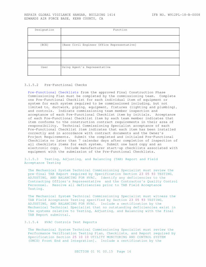
REPAI R GLOBAL VI GI LANCE HANGAR, BUI LDI NG 1414 I FB NO. W912PL- 18- B- 0008EDWARDS AI R FORCE BASE, KERN COUNTY, CA
Designation Function
[BCE] [ Base Ci vi l Engi neer Of f i ce Repr esent at i ve]
User Usi ng Agent ' s Repr esent at i ve
3. 1. 5. 2 Pr e- Funct i onal Checks
Pr e- Funct i onal Checkl i st s f r om t he appr oved Fi nal Const r uct i on Phase Commi ssi oni ng Pl an must be compl et ed by t he commi ssi oni ng t eam. Compl et e one Pr e- Funct i onal Checkl i st f or each i ndi v i dual i t em of equi pment or syst em f or each syst em r equi r ed t o be commi ssi oned i ncl udi ng, but not l i mi t ed t o, duct wor k, pi pi ng, equi pment , f i x t ur es ( l i ght i ng and pl umbi ng) , and cont r ol s. I ndi cat e commi ssi oni ng t eam member i nspect i on and accept ance of each Pr e- Funct i onal Checkl i st i t em by i ni t i al s. Accept ance of each Pr e- Funct i onal Checkl i st i t em by each t eam member i ndi cat es t hat i t em conf or ms t o t he const r uct i on cont r act r equi r ement s i n t hei r ar ea of r esponsi bi l i t y . Techni cal Commi ssi oni ng Speci al i st accept ance of each Pr e- Funct i onal Checkl i st i t em i ndi cat es t hat each i t em has been i nst al l ed cor r ect l y and i n accor dance wi t h cont r act document s and t he Owner ' s Pr oj ect Requi r ement s. Submi t t he compl et ed and i ni t i al ed Pr e- Funct i onal Checkl i st s no l at er t han 7 cal endar days af t er compl et i on of i nspect i on of al l checkl i st s i t ems f or each syst em. Submi t one har d copy and an el ect r oni c copy. I ncl ude manuf act ur er st ar t - up checkl i st s associ at ed wi t h equi pment wi t h t he submi ssi on of t he Pr e- Funct i onal Checkl i st s.
3. 1. 5. 3 Test i ng, Adj ust i ng, and Bal anci ng ( TAB) Repor t and Fi el d Accept ance Test i ng
The Mechani cal Syst em Techni cal Commi ssi oni ng Speci al i st must r evi ew t he pr e- f i nal TAB Repor t r equi r ed by Speci f i cat i on Sect i on 23 05 93 TESTI NG, ADJUSTI NG, AND BALANCI NG FOR HVAC. I dent i f y any def i c i enci es t o t he Cont r act i ng Of f i cer ' s Repr esent at i ve and t he Cont r act or ' s Qual i t y Cont r ol Per sonnel . Resol ve al l def i c i enci es pr i or t o TAB Fi el d Accept ance Testing.
The Mechani cal Syst em Techni cal Commi ssi oni ng Speci al i st must wi t ness t he TAB Fi el d Accept ance Test i ng speci f i ed by Sect i on 23 05 93 TESTI NG, ADJUSTI NG, AND BALANCI NG FOR HVAC. I ncl ude a cer t i f i cat i on by t he Mechani cal Techni cal Speci al i st t hat no out st andi ng def i c i enci es exi st i n t he syst ems r el at i ve t o Test i ng, Adj ust i ng, and Bal anci ng wi t h t he f i nal TAB Repor t submi t t al .
3. 1. 5. 4 HVAC Cont r ol s Test Repor t s
The Mechani cal Syst em Techni cal Commi ssi oni ng Speci al i st must r evi ew t he Per f or mance Ver i f i cat i on Test i ng Pl an, Checkl i st s, and Repor t r equi r ed by Speci f i cat i on Sect i on 25 10 10 UTI LI TY MONI TORI NG AND CONTROL SYSTEM ( UMCS) Fr ont End and I nt egr at i on] . I ncl ude a cer t i f i cat i on by t he
SECTI ON 01 91 00. 15 Page 16

REPAI R GLOBAL VI GI LANCE HANGAR, BUI LDI NG 1414 I FB NO. W912PL- 18- B- 0008EDWARDS AI R FORCE BASE, KERN COUNTY, CA
Mechani cal Syst em Techni cal Commi ssi oni ng Speci al i st t hat t he submi t t al s cont ai n no def i c i enci es or t hat t he submi t t al s do not i ndi cat e any def i c i enci es i n t he HVAC syst ems or HVAC cont r ol syst ems wi t h each of t hese submi t t al s.
3. 1. 5. 5 Tests
3. 1. 5. 5. 1 Funct i onal Per f or mance and I nt egr at ed Syst ems Test s
Schedul e Funct i onal Per f or mance Test s f or each syst em onl y af t er t he Cer t i f i cat e of Readi ness has been appr oved by t he Gover nment f or t he syst em. Cor r ect al l def i c i enci es i dent i f i ed t hr ough any pr i or r evi ew, i nspect i on, or t est act i v i t y bef or e t he st ar t of Funct i onal Per f or mance Test s. Per f or m I nt egr at ed Syst ems Test s onl y af t er t he Funct i onal Per f or mance Test s f or each associ at ed syst em ar e compl et ed wi t h al l def i c i enci es r esol ved and af t er t he r el at ed Funct i onal Per f or mance Test Checkl i st s have been si gned by each commi ssi oni ng t eam member .
a. Funct i onal Per f or mance Test s and I nt egr at ed Syst ems Test s must be per f or med wi t h t he Cont r act i ng Of f i cer ' s Qual i t y Assur ance Repr esent at i ve pr esent .
b. Abor t Funct i onal Per f or mance Test s or I nt egr at ed Syst ems Test s when any syst em def i c i ency pr event s t he successf ul compl et i on of t he t est .
c. Techni cal Commi ssi oni ng Speci al i st s must l ead and document al l Funct i onal Per f or mance Test s and I nt egr at ed Syst ems Test s f or t he syst ems t o be commi ssi oned wi t h t he Cont r act or and appr opr i at e sub- cont r act or s per f or mi ng t he Funct i onal Per f or mance Test s and I nt egr at ed Syst ems Test s. The r epr esent at i ves l i s t ed i n t he par agr aph Commi ssi oni ng Team must at t end t he t est s. Abor t Funct i onal Per f or mance Test s or I nt egr at ed Syst ems Test s when any r equi r ed commi ssi oni ng t eam member i s not pr esent f or t he t est .
3. 1. 5. 5. 1. 1 Checklist
Use t he Funct i onal Per f or mance Test and I nt egr at ed Syst ems Test Checkl i st s f r om t he appr oved Fi nal Const r uct i on Phase Commi ssi oni ng Pl an t o gui de t he Funct i onal Per f or mance Test s and I nt egr at ed Syst ems Test ] . Funct i onal Per f or mance Test s must be per f or med f or each i t em of equi pment and each syst em r equi r ed t o be commi ssi oned and ver i f y al l sensor cal i br at i ons, cont r ol r esponses, saf et i es, i nt er l ocks, oper at i ng modes, sequences of oper at i on, capaci t i es, l i ght i ng l evel s, and al l ot her per f or mance r equi r ement s compl y wi t h const r uct i on cont r act r egar dl ess of t he speci f i c i t ems l i s t ed wi t hi n t he Funct i onal Per f or mance Test and I nt egr at ed Syst ems Test Checkl i st s pr ovi ded. Test i ng must pr ogr ess f r om equi pment or component s t o subsyst ems t o syst ems t o i nt er l ocks and connect i ons bet ween syst ems. I nt egr at ed Syst ems Test s must be per f or med f or t he i nt er act i ve oper at i on bet ween syst ems such as HVAC syst ems, f i r e pr ot ect i on syst ems, back- up el ect r i cal suppl y, ener gy gener at i on syst ems, and ot her syst ems, and ver i f y cor r ect i nt er act i ve oper at i on, accept abl e speed of r esponse, and ot her cont r act r equi r ement s f or bot h nor mal and f ai l ur e modes. Exampl es of I nt egr at ed Syst ems Test s i ncl ude t he cor r ect oper at i on of HVAC syst ems dur i ng emer gency syst em act i vat i on, cor r ect oper at i on of uni nt er r upt i bl e power suppl i es or ener gy gener at or s and connect ed syst ems, or l i ght i ng syst em oper at i on dur i ng power out age or emer gency syst em activation. The or der of component s and syst ems t o be t est ed must be det er mi ned by t he Techni cal Commi ssi oni ng Speci al i st s.
SECTI ON 01 91 00. 15 Page 17
REPAI R GLOBAL VI GI LANCE HANGAR, BUI LDI NG 1414 I FB NO. W912PL- 18- B- 0008EDWARDS AI R FORCE BASE, KERN COUNTY, CA
3. 1. 5. 5. 1. 2 Acceptance
I ndi cat e accept ance of each i t em of equi pment and syst ems t est ed by s i gnat ur e of each commi ssi oni ng t eam member f or each Funct i onal Per f or mance Test or I nt egr at ed Syst ems Test Checkl i st . The Cont r act or ' s Qual i t y Cont r ol Repr esent at i ve and t he Techni cal Commi ssi oni ng Speci al i st s must i ndi cat e accept ance af t er t he equi pment and syst ems ar e f r ee of deficiencies.
3. 1. 5. 5. 2 HVAC Test Met hods
Per f or m Funct i onal Per f or mance Test s i n accor dance wi t h t he f ol l owi ng:
3. 1. 5. 5. 2. 1 Pr i or t o Test i ng
Pr i or t o t est i ng oper at i ng modes, sequences of oper at i on, i nt er l ocks, and saf et i es, compl et e cont r ol poi nt - t o- poi nt obser vat i ons, t est sensor cal i br at i ons, and t est act uat or commands.
3. 1. 5. 5. 2. 2 Si mul at i ng Condi t i ons
Over - wr i t i ng cont r ol i nput val ues t hr ough t he cont r ol s syst em i s not accept abl e, unl ess appr oved by t he Cont r act i ng Of f i cer ' s Repr esent at i ve . I dent i f y pr oposed except i ons i n a pr ot ocol submi t t ed t o t he Contracting Of f i cer ' s Repr esent at i ve f or appr oval . Bef or e s i mul at i ng condi t i ons, over wr i t i ng val ues ( i f appr oved) , or changi ng set - poi nt s, cal i br at e al l sensor s, t r ansducer s and devi ces. Bel ow ar e sever al exampl es of except i ons t hat woul d be consi der ed accept abl e:
a. When var yi ng st at i c pr essur es i nsi de duct wor k can not be si mul at ed wi t hi n t he duct , and wher e a sensor s i gnal s t he cont r ol s syst em t o i ni t i at e sequences at var i ous duct st at i c pr essur es, i t i s accept abl e t o s i mul at e t he var i ous pr essur es wi t h a Pneumat i c Squeeze- Bul b Type Si gnal i ng Devi ce wi t h gauge t empor ar i l y at t ached t o t he sensi ng t ube l eadi ng t o t he t r ansmi t t er . I t i s not accept abl e t o r eset t he var i ous set - poi nt s, nor t o s i mul at e an el ect r i c anal og si gnal ( unl ess appr oved as not ed above) .
b. Di r t y f i l t er pr essur e dr ops can be si mul at ed usi ng sheet s of car dboar d at f i l t er f ace.
c. Fr eeze- st at saf et i es can be si mul at ed by packi ng por t i on of sensor wi t h i ce.
d. Hi gh out si de ai r t emper at ur es can be si mul at ed wi t h a hai r bl ower .
e. Hi gh ent er i ng cool i ng coi l t emper at ur es can be used t o s i mul at e ent er i ng cool i ng coi l condi t i ons.
f . Do not use si gnal gener at or s t o s i mul at e sensor s i gnal s unl ess appr oved by t he Cont r act i ng Of f i cer ' s Repr esent at i ve , as not ed above, f or speci al cases.
g. Cont r ol set poi nt s can be al t er ed. For exampl e, t o see t he ai r condi t i oni ng compr essor l ockout wor k at an out si de ai r t emper at ur e below 55 degr ees F, when t he out si de ai r t emper at ur e i s above 55 degr ees F, t empor ar i l y change t he l ockout set poi nt t o be 0 degr ees F above t he cur r ent out si de ai r t emper at ur e. Caut i on: Set poi nt s ar e not t o be r ai sed or l ower ed t o a poi nt such t hat damage t o t he component s,
SECTI ON 01 91 00. 15 Page 18
REPAI R GLOBAL VI GI LANCE HANGAR, BUI LDI NG 1414 I FB NO. W912PL- 18- B- 0008EDWARDS AI R FORCE BASE, KERN COUNTY, CA
syst ems, or t he bui l di ng st r uct ur e and/ or cont ent s wi l l occur .
h. Test duct mount ed smoke det ect or s i n accor dance wi t h t he manuf act ur er ' s r ecommendat i ons. Per f or m t he t est s wi t h ai r syst em at mi ni mum ai r f l ow condi t i on i n duct wor k.
i . Test cur r ent sensi ng r el ays used f or f an and pump st at us s i gnal s t o cont r ol syst em t o i ndi cat e uni t f ai l ur e and r un st at us by r eset t i ng t he set poi nt on t he r el ay t o s i mul at e a l ost bel t or uni t f ai l ur e whi l e t he uni t i s r unni ng. Conf i r m t hat t he f ai l ur e al ar m was gener at ed and r ecei ved at t he cont r ol syst em. Af t er t he t est i s conduct ed, r et ur n t he set poi nt t o i t s or i gi nal set - poi nt or a set - poi nt as i ndi cat ed by t he Cont r act i ng Of f i cer ' s Repr esent at i ve .
3. 1. 5. 5. 2. 3 Setup
Per f or m each t est under condi t i ons t hat s i mul at e act ual condi t i ons as c l ose as i s pr act i cal l y possi bl e. Pr ovi de al l necessar y mat er i al s and syst em modi f i cat i ons t o pr oduce t he necessar y f l ows, pr essur es, t emper at ur es, and ot her condi t i ons necessar y t o execut e t he t est accor di ng t o t he speci f i ed condi t i ons. At compl et i on of t he t est , r et ur n t he af f ect ed bui l di ng equi pment and syst ems t o t hei r pr e- t est condi t i on.
3. 1. 5. 5. 3 Sampl e St r at egy
Per f or m Funct i onal Per f or mance Test s usi ng t he f ol l owi ng sampl e st r at egy. Pr epar e and compl et e a Funct i onal Per f or mance Test Checkl i st f or each i t em of equi pment or syst em t o be t est ed.
3. 1. 5. 5. 4 Seasonal Test s
3. 1. 5. 5. 4. 1 I ni t i al Funct i onal Per f or mance Test s
Per f or m I ni t i al Funct i onal Per f or mance Test s as soon as al l cont r act wor k i s compl et ed, r egar dl ess of t he season. Devel op and i mpl ement means of ar t i f i c i al l oadi ng t o demonst r at e, t o a r easonabl e l evel of conf i dence, t he abi l i t y of t he HVAC syst ems t o handl e peak seasonal l oads.
3. 1. 5. 5. 4. 2 Ful l - Load Condi t i ons
I n addi t i on t o t he I ni t i al Funct i onal Per f or mance Test s, per f or m Funct i onal Per f or mance Test s of HVAC syst ems under f ul l - l oad condi t i ons dur i ng peak heat i ng and cool i ng seasons dur i ng out door ai r condi t i on desi gn ext r emes. Test cool i ng equi pment and syst ems wi t h t he bui l di ng f ul l y occupi ed when per f or mi ng t he Funct i onal Per f or mance Test s dur i ng peak cool i ng season.
Schedul e Seasonal Funct i onal Per f or mance Test s i n coor di nat i on wi t h t he Government.
3. 1. 5. 5. 4. 3 Syst em Accept ance
Syst ems may be par t i al l y accept ed pr i or t o seasonal t est i ng i f t hey compl y wi t h al l const r uct i on cont r act t hat can be t est ed dur i ng i ni t i al Funct i onal Per f or mance Test s. Al l Funct i onal Per f or mance Test pr ocedur es
SECTI ON 01 91 00. 15 Page 19
REPAI R GLOBAL VI GI LANCE HANGAR, BUI LDI NG 1414 I FB NO. W912PL- 18- B- 0008EDWARDS AI R FORCE BASE, KERN COUNTY, CA
must be compl et ed pr i or t o f ul l syst ems accept ance.
3. 1. 5. 5. 5 Abor t ed Test s and Re-Testing
Abor t Funct i onal Per f or mance Test s, I nt egr at ed Syst ems Test s, or Seasonal Test s i f any def i c i ency pr event s successf ul compl et i on of t he t est or i f any r equi r ed commi ssi oni ng t eam member i s not pr esent f or t he t est . r ei mbur se t he Gover nment f or al l cost s associ at ed wi t h ef f or t l ost due t o r e- t est i ng due t o t est f ai l ur es and abor t ed t est s. These cost s must i ncl ude sal ar y, t r avel cost s, and per di em f or Gover nment commi ssi oni ng t eam member s. Re- t est onl y af t er al l def i c i enci es i dent i f i ed dur i ng t he or i gi nal t est s have been cor r ect ed.
3. 1. 5. 5. 5. 1 100 Per cent Sampl e
Syst ems or equi pment f or whi ch 100 per cent sampl e s i ze ar e t est ed f ai l i f one or mor e of t he t est pr ocedur es r esul t s i n di scover y of a def i c i ency and t he def i c i ency cannot be r esol ved wi t hi n 5 mi nut es dur i ng t he t est .
Re- t est t o t he ext ent necessar y t o conf i r m t hat t he def i c i enci es have been cor r ect ed wi t hout negat i vel y i mpact i ng t he per f or mance of t he r est of t he system.
3. 1. 5. 5. 5. 2 Less t han 100 Per cent Sampl e
For syst ems t est s wi t h a sampl e s i ze l ess t han 100 per cent , i f one or mor e of t he t est pr ocedur es f or an i t em of equi pment or a syst em r esul t s i n di scover y of a def i c i ency, r egar dl ess of whet her t he def i c i ency i s cor r ect ed dur i ng t he sampl e t est s, t he i t em of equi pment or syst em f ai l s t he t est .
a. I f t he syst em f ai l ur e r at e i s 5 per cent or l ess, meani ng t hat 5 per cent or l ess of t he equi pment or syst ems had at l east one def i c i ency, r e- t est onl y on t he i t ems whi ch exper i enced t he i ni t i al failures.
b. I f t he syst em f ai l ur e r at e i s hi gher t han 5 per cent , meani ng t hat mor e t han 5 per cent of equi pment or syst ems t est ed had at l east one def i c i ency, r e- t est t he i t ems whi ch exper i enced t he i ni t i al f ai l ur es t o t he ext ent necessar y t o conf i r m t hat t he def i c i enci es have been cor r ect ed . I n addi t i on, t est anot her r andom sampl e of t he same si ze as t he i ni t i al sampl e f or t he f i r st t i me. I f t he second r andom sampl e set has any f ai l ur es, r e- t est t hose f ai l ed i t ems and al l r emai ni ng equi pment and syst ems t o compl et e 100 per cent t est i ng of t hat syst em type.
3. 1. 6 Tr ai ni ng Pl an
Devel op a t r ai ni ng pl an whi ch i dent i f i es al l t r ai ni ng r equi r ed by speci f i cat i on sect i ons associ at ed wi t h commi ssi oned syst ems. I ncl ude a mat r i x l i s t i ng each t r ai ni ng r equi r ement , cont ent of t he t r ai ni ng, t he t r ai ner name, t r ai ner cont act i nf or mat i on, and schedul e and l ocat i on of t r ai ni ng. Submi t one har d copy and an el ect r oni c copy of t he Tr ai ni ng Pl an t o t he Commi ssi oni ng Speci al i st s and t he Gover nment no l at er t han 30 cal endar days pr i or t o t he associ at ed t r ai ni ng.
Document t r ai ni ng at t endance usi ng t r ai ni ng at t endance r ost er s and pr ovi de compl et ed at t endance r ost er s t o t he Commi ssi oni ng Speci al i st s and t he Gover nment no l at er t han 7 cal endar days f ol l owi ng t he compl et i on of
SECTI ON 01 91 00. 15 Page 20
REPAI R GLOBAL VI GI LANCE HANGAR, BUI LDI NG 1414 I FB NO. W912PL- 18- B- 0008EDWARDS AI R FORCE BASE, KERN COUNTY, CA
t r ai ni ng f or each syst em t o be commi ssi oned. Submi t one har d copy and an el ect r oni c copy. .
3. 1. 7 Syst ems Manual
Pr epar e and submi t a Syst ems Manual , Comput er i zed Mai nt enance Management Syst em Manual ] i ncl udi ng, f or al l commi ssi oned syst ems, t he Basi s of Desi gn, syst em si ngl e l i ne di agr ams, as- bui l t sequences of oper at i on and cont r ol s dr awi ngs, as- bui l t cont r ol set poi nt s, r ecommended schedul e f or sensor and act uat or cal i br at i on, r ecommended schedul e of mai nt enance when not i n t he O&M manual s, r ecommended r e- t est i ng schedul e wi t h pr oposed t est i ng f or ms, and f ul l equi pment war r ant y i nf or mat i on. Updat e and r esubmi t t he Syst ems Manual based on any cor r ect i ve act i on t aken dur i ng t he war r ant y per i od. The Techni cal Commi ssi oni ng Speci al i st s must r evi ew t he Syst ems Manual . I ncl ude a s i gned cer t i f i cat i on or l et t er f r om t he Lead Commi ssi oni ng Speci al i st st at i ng t hat t he Syst ems Manual i s compl et e, c l ear , and accur at e wi t h t he submi t t al .
Submi t Syst ems Manual , Comput er i zed Mai nt enance Management Syst em Manual no l at er t han 30 cal endar days f ol l owi ng compl et i on of Funct i onal Per f or mance Test s. Submi t t hr ee har d copi es and an el ect r oni c copy.
3. 1. 8 Mai nt enance and Ser vi ce Li f e Pl ans
3. 1. 8. 1 Mai nt enance Pl an
Pr epar e and submi t a Mai nt enance Pl an f or t he pr oj ect mechani cal , el ect r i cal , pl umbi ng, and f i r e pr ot ect i on syst ems. Pr epar e t he HVAC and r ef r i ger at i on sect i ons of t he Mai nt enance Pl an i n accor dance wi t h ASHRAE 180. Devel op r equi r ed i nspect i on and mai nt enance t asks s i mi l ar t o Sect i on 5 of ASHRAE 180 f or t he ot her commi ssi oned syst ems and f i r e pr ot ect i on syst ems.
Submi t t he Mai nt enance Pl an no l at er t han 30 cal endar days f ol l owi ng t he compl et i on of Funct i onal Per f or mance t est s. Submi t t hr ee har d copi es and an el ect r oni c copy.
3. 1. 8. 2 Ser vi ce Li f e Pl an
Pr epar e and submi t a Ser vi ce Li f e Pl an f or t he bui l di ng envel ope, st r uct ur al syst ems, and si t e har dscape t hat i ncl udes t he f ol l owi ng f or each assembl y or component :
a. A descr i pt i on of each i ncl udi ng t he mat er i al s or pr oduct s.
b. The est i mat ed ser vi ce l i f e, i n year s.
c. The est i mat ed mai nt enance f r equency and descr i pt i on of mai nt enance tasks.
d. The poi nt of mai nt enance access f or t he component s wi t h est i mat ed ser vi ce l i f e l ess t han ser vi ce l i f e of t he bui l di ng.
Submi t t he Ser vi ce Li f e Pl an no l at er t han 30 cal endar days f ol l owi ng t he compl et i on of Funct i onal Per f or mance t est s. Submi t t hr ee har d copi es and an el ect r oni c copy.
SECTI ON 01 91 00. 15 Page 21
REPAI R GLOBAL VI GI LANCE HANGAR, BUI LDI NG 1414 I FB NO. W912PL- 18- B- 0008EDWARDS AI R FORCE BASE, KERN COUNTY, CA
3. 2 COMMI SSI ONI NG REPORT
Fol l owi ng t he compl et i on of Funct i onal Per f or mance Test s[ and I nt egr at ed Syst ems Test s] , wi t h t he except i on of Seasonal Test s, t he Lead Commi ssi oni ng Speci al i st must pr epar e a Commi ssi oni ng Repor t .
a. I ncl ude an execut i ve summar y descr i bi ng t he over al l commi ssi oni ng pr ocess, t he r esul t s of t he commi ssi oni ng pr ocess, any out st andi ng def i c i enci es and r ecommended r esol ut i ons, and any seasonal t est i ng t hat must be schedul ed f or a l at er dat e. I ndi cat e, i n t he execut i ve summar y, whet her t he syst ems meet t he r equi r ement s of t he const r uct i on cont r act and t he Owner ' s Pr oj ect Requi r ement s.
b. Det ai l any def i c i enci es di scover ed dur i ng t he commi ssi oni ng pr ocess and t he cor r ect i ve act i ons t aken i n t he r epor t . I ncl ude t he compl et ed Pr e- Funct i onal Checkl i st s, Funct i onal Per f or mance Test Checkl i st s, [ I nt egr at ed Syst ems Test Checkl i st s, ] t he Commi ssi oni ng Pl ans, t he I ssues Log, Per f or mance Ver i f i cat i on Test Repor t s, Tr ai ni ng At t endance Rost er s, t he Desi gn Revi ew Repor t , t he f i nal TAB Repor t .
c. Submi t t he Commi ssi oni ng Repor t no l at er t han 14 cal endar days f ol l owi ng commi ssi oni ng t eam accept ance of al l Funct i onal Per f or mance Test s [ and I nt egr at ed Syst ems Test s ] wi t h t he except i on of Seasonal Test s. Submi t t hr eehar d copi es and an el ect r oni c copy.
d. Fol l owi ng any Seasonal Test s or Post - Const r uct i on Act i v i t i es, updat e the Fi nal Commi ssi oni ng Repor t t o r ef l ect any changes and r esubmi t .
3. 3 POST- CONSTRUCTI ON SUPPORT
3. 3. 1 Post - Const r uct i on Endur ance Test
The Mechani cal Syst em Commi ssi oni ng Speci al i st s must r evi ew t he t r end l ogs f r om t he Endur ance Test s t o ensur e t hat t he syst ems have st abl e oper at i on and oper at e as r equi r ed by t he const r uct i on cont r act , and t he Owner ' s Pr oj ect Requi r ement s. The Commi ssi oni ng Speci al i st s must pr ovi de a Post - Const r uct i on Tr end Log Repor t t hat i dent i f i es any def i c i enci es not ed i n oper at i on and i ncl udes a gr aphi cal r epr esent at i on of t he t r ends. Pr ovi de one Tr end Log Repor t f or t he peak cool i ng season and one Tr end Log Repor t f or t he peak heat i ng season. Submi t one har d copy and one el ect r oni c copy of t he Post - Const r uct i on Tr end Log Repor t s no l at er t han 14 cal endar days f ol l owi ng r ecei pt of t he t r end l og dat a by t he Commi ssi oni ng Speci al i st .
3. 3. 2 Post - Const r uct i on Si t e Vi s i t
The Commi ssi oni ng Speci al i st s must v i s i t t he bui l di ng s i t e t o i nspect bui l di ng syst em equi pment and r evi ew bui l di ng oper at i on wi t h t he bui l di ng oper at i ng/ mai nt enance st af f . The Commi ssi oni ng Speci al i st s must i dent i f y any def i c i ency of t he bui l di ng syst ems t o oper at e i n accor dance wi t h t he cont r act r equi r ement s and t he Owner ' s Pr oj ect Requi r ement s. The Commi ssi oni ng Speci al i st s must advi se t he Cont r act i ng Of f i cer ' s Representative of any i dent i f i ed def i c i enci es and t he pr oposed cor r ect i ve act i on. Submi t an updat ed commi ssi oni ng r epor t and syst ems manual document i ng t he r esul t s of t he post - const r uct i on i nspect i on.
SECTI ON 01 91 00. 15 Page 22

REPAI R GLOBAL VI GI LANCE HANGAR, BUI LDI NG 1414 I FB NO. W912PL- 18- B- 0008EDWARDS AI R FORCE BASE, KERN COUNTY, CA
SECTI ON 01 91 00. 15 Page 23
REPAI R GLOBAL VI GI LANCE HANGAR, BUI LDI NG 1414 I FB NO. W912PL- 18- B- 0008EDWARDS AI R FORCE BASE, KERN COUNTY, CA
APPENDI X A - OWNER' S PROJECT REQUI REMENTS
SECTI ON 01 91 00. 15 Page 24

REPAI R GLOBAL VI GI LANCE HANGAR, BUI LDI NG 1414 I FB NO. W912PL- 18- B- 0008EDWARDS AI R FORCE BASE, KERN COUNTY, CA
OWNER' S PROJECT REQUI REMENTS DOCUMENT
Pr oj ect : Pr oj ect , Locat i on, PN #####
Appr oved: Name Desi gn Agent ' s Repr esent at i ve Dat e
Name Owner ' s Repr esent at i ve Dat e
SECTI ON 01 91 00. 15 Page 25
REPAI R GLOBAL VI GI LANCE HANGAR, BUI LDI NG 1414 I FB NO. W912PL- 18- B- 0008EDWARDS AI R FORCE BASE, KERN COUNTY, CA
OWNER' S PROJECT REQUI REMENTS DOCUMENT
Contents
1. Owner and User Requi r ement s a. Pr i mar y Pur pose, Pr ogr am, and Use b. Pr oj ect Hi st or y c. Br oad Goal s i . Fut ur e Expansi on i i . Fl exi bi l i t y i i i . Qual i t y of Mat er i al s i v . Const r uct i on Cost s v. Oper at i onal Cost s2. Envi r onment al and Sust ai nabi l i t y Goal s a. LEED or Gr een Gl obes Goal b. Ot her3. Ener gy Ef f i c i ency Goal s a. Goal s/ Pol i cy b. Syst ems and Feat ur e Ener gy I mpact4. I ndoor Envi r onment al Qual i t y Requi r ement s a. Space Type 1 i . I nt ended Use i i . Occupancy Schedul e i i i . Envi r onment al Requi r ement s i v . Occupant Syst em Cont r ol Abi l i t y v. Type of Li ght i ng v i . Af t er - hour Use Accommodat i on b. Space Type 2 i . I nt ended Use i i . Occupancy Schedul e i i i . Envi r onment al Requi r ement s i v . Occupant Syst em Cont r ol Abi l i t y v. Type of Li ght i ng v i . Af t er - hour Use Accommodat i on5. Equi pment and Syst em Expect at i ons a. HVAC Syst ems i . Qual i t y and Rel i abi l i t y i i . Type i i i . Aut omat i on i v . Fl exi bi l i t y v. Mai nt enance Requi r ement s b. Li ght i ng Syst ems i . Qual i t y and Rel i abi l i t y i i . Type i i i . Aut omat i on i v . Fl exi bi l i t y v. Mai nt enance Requi r ement s c. Domest i c Hot Wat er Syst ems i . Qual i t y and Rel i abi l i t y i i . Type i i i . Aut omat i on i v . Fl exi bi l i t y v. Mai nt enance Requi r ement s
Cont ent s ( cont i nued)
SECTI ON 01 91 00. 15 Page 26
REPAI R GLOBAL VI GI LANCE HANGAR, BUI LDI NG 1414 I FB NO. W912PL- 18- B- 0008EDWARDS AI R FORCE BASE, KERN COUNTY, CA
d. On- si t e Power Syst ems i . Qual i t y and Rel i abi l i t y i i . Type i i i . Aut omat i on i v . Fl exi bi l i t y v. Mai nt enance Requi r ement s e. Ot her Syst ems i . Qual i t y and Rel i abi l i t y i i . Type i i i . Aut omat i on i v . Fl exi bi l i t y v. Mai nt enance Requi r ement s6. Bui l di ng Occupant and O&M Per sonnel Requi r ement s a. Faci l i t y Oper at i on b. UMCS ( EMCS or FMCS) c. Occupant Tr ai ni ng and Or i ent at i on d. O&M St af f Tr ai ni ng and Or i ent at i on
SECTI ON 01 91 00. 15 Page 27
REPAI R GLOBAL VI GI LANCE HANGAR, BUI LDI NG 1414 I FB NO. W912PL- 18- B- 0008EDWARDS AI R FORCE BASE, KERN COUNTY, CA
1. Owner and User Requi r ement s
a. Pr i mar y Pur pose, Pr ogr am, and Use
Expl ai n t he pur pose, pr ogr am, and use of t he f aci l i t y . ( i . e. Ar my Reser ve Cent er used f or t r ai ni ng r eser ve uni t s. Tr ai ni ng i ncl udes spaces such as weapons, medi cal , vehi c l e r epai r , cooki ng, et c. )
b. Pr oj ect Hi st or y
Expl ai n t he hi st or y of t he pr oj ect r el at ed t o desi gn/ const r uct i on ( i . e. D/ B/ B, D/ B, I DI Q, JOC, COE i n- house, A/ E, et c. ) . Expl ai n any addi t i onal pr oj ect backgr ound t hat woul d i mpact ener gy/ sust ai nabi l i t y goal s.
c. Br oad Goal s
i . Fut ur e Expansi on: Expl ai n goal s r el at ed t o pot ent i al f ut ur e expansion.
i i . Fl exi bi l i t y : Expl ai n goal s r el at ed t o f l exi bi l i t y f or l ayout and use of t he bui l di ng. ( i . e. hi gh r at e of of f i ce chur n, expect ed f r equency of r enovat i on, et c. )
i i i . Qual i t y of Mat er i al s: Expl ai n goal s r el at ed t o qual i t y of mat er i al s. ( i . e. hi ghest qual i t y mat er i al s, 50 yr l i f e, 25 yr l i f e, hi ghest qual i t y wi t hi n budget , et c. )
i v . Const r uct i on Cost s: Expl ai n goal s r el at ed t o const r uct i on cost s. ( i . e. how l ow can you go, set pr oj ect amount , sel ect s i mpl est syst ems f or l ow cost , et c. )
v. Oper at i onal Cost s: Expl ai n goal s r el at ed t o oper at i onal cost s. ( i . e. l ow ut i l i t i es based on wat er and ener gy conser vat i on, t r ade- of f al l owabl e on mai nt enance cost s t o r educe ut i l i t y cost , ut i l i t y cost uni mpor t ant compar ed t o const r uct i on cost , et c. )
SECTI ON 01 91 00. 15 Page 28

REPAI R GLOBAL VI GI LANCE HANGAR, BUI LDI NG 1414 I FB NO. W912PL- 18- B- 0008EDWARDS AI R FORCE BASE, KERN COUNTY, CA
2. Envi r onment al and Sust ai nabi l i t y Goal s
a. LEED/ Gr een Gl obes Goal
Set LEED/ Gr een Gl obes goal and expl ai n sust ai nabl e f eat ur es per mi ssi bl e or pr ef er r ed t o be i ncor por at ed. Expl ai n r el at i ve i mpor t ance of LEED/ Gr een Gl obes goal wi t hi n pr oj ect scope. I ndi cat e r equi r ement f r om ser vi ce or agency speci f i c cr i t er i a and pol i cy.
b. Ot her
Expl ai n any speci al sust ai nabi l i t y or envi r onment al goal s associ at ed wi t h t he pr oj ect . I dent i f y speci f i c sust ai nabi l i t y f eat ur es t hat may be r equi r ed or desi r ed. ( i . e. hydr o- power , sol ar power , on- si t e wat er t r eat ment , on- si t e wat er i nf i l t r at i on, i mper vi ous cover r educt i on, par ki ng capaci t y, et c. )
SECTI ON 01 91 00. 15 Page 29
REPAI R GLOBAL VI GI LANCE HANGAR, BUI LDI NG 1414 I FB NO. W912PL- 18- B- 0008EDWARDS AI R FORCE BASE, KERN COUNTY, CA
3. Ener gy Ef f i c i ency Goal s
a. Goal s/ Pol i cy
Expl ai n t he speci f i c pr oj ect goal s and r equi r ement s r egar di ng ener gy ef f i c i ency. I ncor por at e t he r equi r ement s of UFC 1- 200- 02 Hi gh Per f or mance and Sust ai nabl e Bui l di ng Requi r ement s and/ or ot her r el evant agency pol i c i es.
b. Syst ems and Feat ur e Ener gy I mpact s
I dent i f y and expl ai n envel ope, syst em, or s i t e and bui l di ng f eat ur es t hat wi l l be i ncor por at ed t o maxi mi ze ener gy ef f i c i ency. I dent i f y f eat ur es t hat must be i ncor por at ed t hat wi l l r educe or l i mi t ener gy ef f i c i ency.
SECTI ON 01 91 00. 15 Page 30
REPAI R GLOBAL VI GI LANCE HANGAR, BUI LDI NG 1414 I FB NO. W912PL- 18- B- 0008EDWARDS AI R FORCE BASE, KERN COUNTY, CA
4. I ndoor Envi r onment al Qual i t y Requi r ement s
a. Space Type 1
i . I nt ended Use: Expl ai n how t he space wi l l be used ( i . e. c l assr oom occasi onal l y used as conf er ence r oom) .
i i . Occupancy Schedul e: Descr i be t he occupancy i ncl udi ng number of peopl e at var i ous t i mes ( i . e. dr i l l weekend- maxi mum capaci t y, weekdays- 20 per cent ; or 0700- 0900 - none, 0900- 1400 - 30 peopl e, 1400- 1600 - none) .
i i i . Envi r onment al Requi r ement s: Descr i be t he envi r onment al r equi r ement s of t he space. I ncl ude descr i pt i on of t emper at ur es, humi di t y l evel s, vent i l at i on r at es, ai r qual i t y, l i ght i ng l evel s, or any ot her speci f i c par amet er s desi r ed ( i . e. 75 deg F, 50 per cent r h, 30 f c, et c. ) .
i v . Occupant Syst em Cont r ol Abi l i t y : Descr i be t he desi r ed l evel of cont r ol t he occupant s wi l l have over t he t her mal comf or t and l i ght i ng syst ems. ( i . e. adj ust abl e t her most at f or ever y per son, adj ust abl e t her most at i n al l pr i vat e of f i ces, no adj ust abl e t her most at s, adj ust abl e t her most at i n seni or r ank al so cont r ol l i ng ot her of f i ces, occupancy sensor s f or l i ght i ng, adj ust abl e di mmi ng, et c. )
v. Type of Li ght i ng: Descr i be t he t ype of l i ght i ng desi r ed ( i . e. t ask l i ght i ng wi t h mi ni mal over head, maxi mi ze dayl i ght wi t h di mmi ng on over head, accent l i ght i ng, par t i cul ar f i x t ur es, et c. ) .
v i . Af t er - hour Use Accommodat i ons: Descr i be whet her and how of t en t he space may be used af t er hour s. Descr i be t he syst ems t hat act i vat e when an occupant uses t he bui l di ng af t er - hour s. Descr i be t he l evel of cont r ol of af t er - hour use HVAC.
( Exampl e: Space i s r ar el y used af t er - hour s by f ew occupant s. HVAC and l i ght i ng syst em shoul d act i vat e when occupant s ent er af t er - hour s. The HVAC oper at i on wi l l be l i mi t ed t o t hat r equi r ed t o pr ovi de heat i ng, A/ C, and vent i l at i on t o t he occupi ed space al one. ) ( Exampl e: Space i s r ar el y used af t er - hour s by f ew occupant s. Li ght i ng and heat i ng syst ems shoul d act i vat e. Vent i l at i on and cool i ng shoul d r emai n i n nor mal af t er - hour oper at i on. )
b. Space Type 2
SECTI ON 01 91 00. 15 Page 31
REPAI R GLOBAL VI GI LANCE HANGAR, BUI LDI NG 1414 I FB NO. W912PL- 18- B- 0008EDWARDS AI R FORCE BASE, KERN COUNTY, CA
5. Equi pment and Syst em Expect at i ons
a. HVAC Syst ems
i . Qual i t y and Rel i abi l i t y : Expl ai n t he l evel of qual i t y and r el i abi l i t y r equi r ed of t he HVAC syst ems.
( Exampl e: Equi pment ef f i c i ency shoul d meet ASHRAE [ _____] and FEMP/ Ener gy St ar r equi r ement s. Due t o cr i t i cal nat ur e of f aci l i t y , addi t i onal r edundancy i n t he cool i ng and heat i ng syst ems i s r equi r ed, i . e. mul t i pl e chi l l er s, boi l er s, and pumps. ) ( Exampl e: No speci f i c qual i t y or r el i abi l i t y r equi r ement s speci f i ed. Equi pment shoul d r emai n ser vi ceabl e over l i f e of bui l di ng or t o t he ext ent t ypi cal of t he t ype of equi pment . )
i i . Type: Expl ai n t he t ype of equi pment desi r ed. ( Exampl e: Boi l er s shoul d be condensi ng t ype. Use hydr oni c heat i ng and cool i ng. Use sel f - cont ai ned A/ C uni t s i n comput er r ooms. )
i i i . Aut omat i on: Expl ai n t he l evel of aut omat i on i n t he HVAC Syst em desi r ed.
( Exampl e: Si ngl e l oop HVAC syst ems per mi ssi bl e. Use packaged cont r ol s onl y. ) ( Exampl e: Cont r ol HVAC syst ems f r om DDC syst em connect ed t o t he base UMCS. ) ( Exampl e: Boi l er s shoul d have packaged cont r ol s connect ed t o t he DDC syst em. )
i v . Fl exi bi l i t y : Descr i be t he desi r ed l evel of f l exi bi l i t y of t he HVAC syst em.
( Exampl e: Syst em shoul d accommodat e f r equent of f i ce l ayout changes i ncl udi ng pr i vat e of f i ce wal l movement . ) ( Exampl e: Layout wi l l r emai n most l y unchanged; no f l exi bi l i t y r equi r ed. ) ( Exampl e: Accommodat e pot ent i al f or conf er ence and cl assr ooms t o change t o of f i ces. )
v. Mai nt enance Requi r ement s: Descr i be t he l evel of mai nt enance avai l abl e or t he r equi r ement s of t he equi pment r egar di ng mai nt ai nabi l i t y .
( Exampl e: Equi pment shoul d be l ocat ed t o al l ow easy mai nt enance access. Equi pment vendor s or r epai r ser vi ce shoul d be abl e t o r espond wi t hi n 24 hr s. )
b. Li ght i ng Syst ems
i . Qual i t y and Rel i abi l i t y : Expl ai n t he l evel of qual i t y and r el i abi l i t y r equi r ed of t he l i ght i ng syst em cont r ol s. ( Exampl e: The bui l di ng l i ght i ng syst em shoul d meet ASHRAE 90. 1 - I P requirements.)
i i . Type: Expl ai n t he t ype of l i ght i ng or cont r ol equi pment desi r ed. ( Exampl e: Hi gh- ef f i c i ency f l uor escent l amps wi t h hi gh- ef f i c i ency bal l ast s wi l l be speci f i ed. I ndi r ect l i ght i ng wi l l be used i n al l of f i ce and cl assr oom spaces. Li ght i ng f oot - candl e l evel s may be r educed t o 45 f oot - candl es i n l i eu of t he t ypi cal 50 f oot - candl es when i ndi r ect l i ght i ng i s used. )
i i i . Aut omat i on: Expl ai n t he l evel of aut omat i on i n t he l i ght i ng cont r ol
SECTI ON 01 91 00. 15 Page 32
REPAI R GLOBAL VI GI LANCE HANGAR, BUI LDI NG 1414 I FB NO. W912PL- 18- B- 0008EDWARDS AI R FORCE BASE, KERN COUNTY, CA
syst em desi r ed.
( Exampl e: Pr ovi de occupancy sensor s i n r est r ooms, cor r i dor s, and st or age ar eas. )
i v . Fl exi bi l i t y : Descr i be t he desi r ed l evel of f l exi bi l i t y of t he l i ght i ng syst em and cont r ol syst ems.
( Exampl e: Pr ovi de dual l evel swi t chi ng i n c l assr ooms and conf er ence r ooms. )
v. Mai nt enance Requi r ement s: Descr i be t he l evel of mai nt enance avai l abl e or t he r equi r ement s of t he equi pment r egar di ng mai nt ai nabi l i t y . ( Exampl e: )
c. Domest i c Hot Wat er Syst ems
i . Qual i t y and Rel i abi l i t y : Expl ai n t he l evel of qual i t y and r el i abi l i t y r equi r ed of t he domest i c hot wat er syst ems.
( Exampl e: Equi pment ef f i c i ency shoul d meet ASHRAE and FEMP/ Ener gy St ar r equi r ement s. Due t o cr i t i cal nat ur e of f aci l i t y , addi t i onal r edundancy i n t he wat er heat i ng syst ems i s r equi r ed, i . e. mul t i pl e hot wat er heat er s and ci r cul at i on pumps. ) ( Exampl e: No speci f i c qual i t y or r el i abi l i t y r equi r ement s speci f i ed. Equi pment shoul d r emai n ser vi ceabl e over l i f e of bui l di ng or t o t he ext ent t ypi cal of t he t ype of equi pment . )
i i . Type: Expl ai n t he t ype of equi pment desi r ed.
( Exampl e: Gas- f i r ed st or age t ank wat er heat er wi t h mi xi ng val ve f or t emper at ur e cont r ol . ) ( Exampl e: I nst ant aneous el ect r i c wat er heat er at l avat or i es. ) ( Exampl e: I nst ant aneous el ect r i c wat er heat er wi t h i nt egr al cont r ol syst em f or eyewash/ shower s. )
i i i . Aut omat i on: Expl ai n t he l evel of aut omat i on i n t he domest i c hot wat er cont r ol syst em desi r ed.
( Exampl e: Occupancy schedul e cont r ol f or r eci r cul at i on l oop and gas bur ner . Connect package cont r ol s t o DDC syst em. )
i v . Fl exi bi l i t y : Descr i be t he desi r ed l evel of f l exi bi l i t y of t he domest i c hot wat er syst ems.
( Exampl e: No ant i c i pat ed changes t o r est r oom l ayout ; no addi t i onal f l exi bi l i t y r equi r ed. )
v. Mai nt enance Requi r ement s: Descr i be t he l evel of mai nt enance avai l abl e or t he r equi r ement s of t he equi pment r egar di ng mai nt ai nabi l i t y . ( Exampl e: Equi pment shoul d be l ocat ed t o al l ow easy mai nt enance access. Equi pment vendor s or r epai r ser vi ce shoul d be abl e t o r espond wi t hi n 24 hr s. )
d. On- si t e Power Syst ems
i . Qual i t y and Rel i abi l i t y : Expl ai n t he l evel of qual i t y and r el i abi l i t y r equi r ed of t he on- si t e power syst em.
SECTI ON 01 91 00. 15 Page 33

REPAI R GLOBAL VI GI LANCE HANGAR, BUI LDI NG 1414 I FB NO. W912PL- 18- B- 0008EDWARDS AI R FORCE BASE, KERN COUNTY, CA
i i . Type: Expl ai n t he t ype of on- si t e power syst em desi r ed.
i i i . Aut omat i on: Expl ai n t he l evel of aut omat i on i n t he on- si t e power syst em desi r ed.
i v . Fl exi bi l i t y : Descr i be t he desi r ed l evel of f l exi bi l i t y of t he on- si t e power syst em.
v. Mai nt enance Requi r ement s: Descr i be t he l evel of mai nt enance avai l abl e or t he r equi r ement s of t he on- si t e power syst em r egar di ng mai nt ai nabi l i t y .
e. Ot her Syst ems
i . Qual i t y and Rel i abi l i t y : Expl ai n t he l evel of qual i t y and r el i abi l i t y r equi r ed of t he syst em.
i i . Type: Expl ai n t he t ype of syst em desi r ed.
i i i . Aut omat i on: Expl ai n t he l evel of aut omat i on i n t he syst em desi r ed.
i v . Fl exi bi l i t y : Descr i be t he desi r ed l evel of f l exi bi l i t y of t he system.
v. Mai nt enance Requi r ement s: Descr i be t he l evel of mai nt enance avai l abl e or t he r equi r ement s of t he syst em r egar di ng mai nt ai nabi l i t y .
SECTI ON 01 91 00. 15 Page 34
REPAI R GLOBAL VI GI LANCE HANGAR, BUI LDI NG 1414 I FB NO. W912PL- 18- B- 0008EDWARDS AI R FORCE BASE, KERN COUNTY, CA
6. Bui l di ng Occupant and O&M Per sonnel Requi r ement s
a. Faci l i t y Oper at i on
Descr i be how t he f aci l i t y wi l l be oper at ed. Who oper at es t he f aci l i t y? Who mai nt ai ns t he f aci l i t y? Who pays t he ut i l i t y bi l l s?
b. UMCS ( EMCS or FMCS)
Wi l l t he bui l di ng be t i ed t o an UMCS/ EMCS/ FMCS? What syst em wi l l be connect ed t o? Pr ovi de i nf or mat i on r egar di ng connect i on r equi r ement s, pr ot ocol s, and cont r ol , schedul i ng and moni t or i ng poi nt s.
c. Occupant Tr ai ni ng and Or i ent at i on
How much t r ai ni ng and or i ent at i on i s desi r ed f or bui l di ng occupant s? Wi l l t r ai ni ng need t o be pr ovi ded f or al l syst ems? To what ext ent do t he occupant s need t o under st and and use t he syst ems?
d. O&M St af f Tr ai ni ng and Or i ent at i on
How much t r ai ni ng and or i ent at i on i s desi r ed f or bui l di ng occupant s? Wi l l t r ai ni ng need t o be pr ovi ded f or al l syst ems? To what ext ent do t he occupant s need t o under st and and use t he syst ems?
SECTI ON 01 91 00. 15 Page 35

REPAI R GLOBAL VI GI LANCE HANGAR, BUI LDI NG 1414 I FB NO. W912PL- 18- B- 0008EDWARDS AI R FORCE BASE, KERN COUNTY, CA
APPENDI X B - BASI S OF DESI GN
SECTI ON 01 91 00. 15 Page 36

REPAI R GLOBAL VI GI LANCE HANGAR, BUI LDI NG 1414 I FB NO. W912PL- 18- B- 0008EDWARDS AI R FORCE BASE, KERN COUNTY, CA
APPENDI X C - DESI GN PHASE COMMI SSI ONI NG PLAN
- - End of Sect i on - -
SECTI ON 01 91 00. 15 Page 37

SECTION 02 41 00
DEMOLITION AND DECONSTRUCTION05/10
PART 1 GENERAL
1.1 REFERENCES
The publications listed below form a part of this specification to the extent referenced. The publications are referred to within the text by the basic designation only.
AIR-CONDITIONING, HEATING AND REFRIGERATION INSTITUTE (AHRI)
AHRI Guideline K (2009) Guideline for Containers for Recovered Non-Flammable Fluorocarbon Refrigerants
AMERICAN SOCIETY OF SAFETY ENGINEERS (ASSE/SAFE)
ASSE/SAFE A10.6 (2006) Safety Requirements for Demolition Operations
U.S. ARMY CORPS OF ENGINEERS (USACE)
EM 385-1-1 (2014) Safety and Health Requirements Manual
U.S. DEPARTMENT OF DEFENSE (DOD)
DOD 4000.25-1-M (2006) MILSTRIP - Military Standard Requisitioning and Issue Procedures
MIL-STD-129 (2014; Rev R) Military Marking for Shipment and Storage
U.S. NATIONAL ARCHIVES AND RECORDS ADMINISTRATION (NARA)
40 CFR 61 National Emission Standards for Hazardous Air Pollutants
40 CFR 82 Protection of Stratospheric Ozone
49 CFR 173.301 Shipment of Compressed Gases in Cylinders and Spherical Pressure Vessels
Page 1

1.2 PROJECT DESCRIPTION
1.2.1 Demolition/Deconstruction Plan
Prepare a Demolition Plan and submit proposed demolition and removal procedures for approval before work is started. Include in the plan procedures for careful removal and disposition of materials specified to be salvaged, coordination with other work in progress[ a disconnection schedule of utility services,a detailed description of methods and equipment to be used for each operation and of the sequence of operations]. Coordinate with Waste Management Plan. Provide procedures for safe conduct of the work in accordance with EM 385-1-1. Plan shall be approved by Contracting Officer prior to work beginning.
1.2.2 General Requirements
Do not begin demolition or deconstruction until authorization is received from the Contracting Officer. Remove rubbish and debris from the project site; do not allow accumulations [inside or outside the building. [The work includes [demolition,] [deconstruction], salvage of identified items and materials, and removal of resulting rubbish and debris. Remove rubbish and debris from Government property daily, unless otherwise directed. Store materials that cannot be removed daily in areas specified by the Contracting Officer.] In the interest of occupational safety and health, perform the work in accordance with EM 385-1-1, Section 23, Demolition, and other applicable Sections.
1.3 ITEMS TO REMAIN IN PLACE
Take necessary precautions to avoid damage to existing items to remain in place, to be reused, or to remain the property of the Government. Repair or replace damaged items as approved by the Contracting Officer. Coordinate the work of this section with all other work indicated. Construct and maintain shoring, bracing, and supports as required. Ensure that structural elements are not overloaded. Increase structural supports or add new supports as may be required as a result of any cutting, removal, deconstruction, or demolition work performed under this contract. Do not overload structural elements. Provide new supports and reinforcement for existing construction weakened by demolition, deconstruction, or removal work. Repairs, reinforcement, or structural replacement require approval by the Contracting Officer prior to performing such work.
1.3.1 Existing Construction Limits and Protection
Do not disturb existing construction beyond the extent indicated or necessary for installation of new construction. Provide temporary shoring and bracing for support of building components to prevent settlement or other movement. Provide protective measures to control accumulation and migration of dust and dirt in all work areas. Remove dust, dirt, and debris from work areas daily.
Page 2

1.3.2 Utility Service
Maintain existing utilities indicated to stay in service and protect against damage during demolition and deconstruction operations. Prior to start of work, [utilities serving each area of alteration or removal will be shut off by the Government and disconnected and sealed by the Contractor.
1.3.3 Facilities
Protect electrical and mechanical services and utilities. Where removal of existing utilities and pavement is specified or indicated, provide approved barricades, temporary covering of exposed areas, and temporary services or connections for electrical and mechanical utilities. Floors, roofs, walls, columns, pilasters, and other structural components that are designed and constructed to stand without lateral support or shoring, and are determined to be in stable condition, must remain standing without additional bracing, shoring, or lateral support until demolished or deconstructed, unless directed otherwise by the Contracting Officer. Ensure that no elements determined to be unstable are left unsupported and place and secure bracing, shoring, or lateral supports as may be required as a result of any cutting, removal, deconstruction, or demolition work performed under this contract.
1.4 BURNING
The use of burning at the project site for the disposal of refuse and debris will not be permitted.
1.5 SUBMITTALS
Government approval is required for submittals with a "G" designation; submittals not having a "G" designation are for contractor Quality Control approval. When used, a designation following the "G" designation identifies the office that will review the submittal for the Government. Submittals with an "S" are for inclusion in the Sustainability Notebook, in conformance to Section 01 33 29 SUSTAINABILITY REPORTING. Submit the following in accordance with Section 01 33 00 SUBMITTAL PROCEDURES:
SD-01 Preconstruction Submittals
Demolition Plan; GDeconstruction Plan; GExisting Conditions
Page 3
1.6 QUALITY ASSURANCE
Submit timely notification of demolition projects to Federal, State, regional, and local authorities in accordance with 40 CFR 61, Subpart M. Notify the [Regional Office of the United States Environmental Protection Agency (USEPA)] [State's environmental protection agency] [local air pollution control district/agency] and the Contracting Officer in writing 10 working days prior to the commencement of work in accordance with 40 CFR 61, Subpart M. Comply with federal, state, and local hauling and disposal regulations. In addition to the requirements of the "Contract Clauses," conform to the safety requirements contained in ASSE/SAFE A10.6. Comply with the Environmental Protection Agency requirements specified. Use of explosives will not be permitted.
1.6.1 Dust and Debris Control
Prevent the spread of dust and debris to occupied portions of the building and avoid the creation of a nuisance or hazard in the surrounding area. Do not use water if it results in hazardous or objectionable conditions such as, but not limited to, ice, flooding, or pollution. Vacuum and dust the work area daily.
1.7 PROTECTION
1.7.1 Protection of Personnel
Before, during and after the demolition work continuously evaluate the condition of the structure being demolished and take immediate action to protect all personnel working in and around the project site. No area, section, or component of floors, roofs, walls, columns, pilasters, or other structural element will be allowed to be left standing without sufficient bracing, shoring, or lateral support to prevent collapse or failure while workmen remove debris or perform other work in the immediate area.
1.8 RELOCATIONS
Perform the removal and reinstallation of relocated items as indicated with workmen skilled in the trades involved. Repair or replace items to be relocated which are damaged by the Contractor with new undamaged items as approved by the Contracting Officer.
1.9 EXISTING CONDITIONS
Before beginning any demolition or deconstruction work, survey the site and examine the drawings and specifications to determine the extent of the work. Record existing conditions in the presence of the Contracting Officer showing the condition of structures and other facilities adjacent to areas of alteration or removal. Photographs sized 4 inch will be acceptable as a record of existing conditions. Include in the record the elevation of the top of foundation walls, finish floor elevations, possible conflicting electrical conduits, plumbing lines, alarms systems, the location and extent of existing cracks and other damage and description of surface conditions that exist prior to before starting work. It is the Contractor's responsibility to verify and document all required outages which will be required during the course of work, and to note these outages on the record document. Submit survey results.
Page 4
PART 2 EXECUTION
2.1 DISPOSITION OF MATERIAL
2.1.1 Title to Materials
Except for salvaged items specified in related Sections, and for materials or equipment scheduled for salvage, all materials and equipment removed and not reused or salvaged, shall become the property of the Contractor and shall be removed from Government property. Title to materials resulting from demolition and deconstruction, and materials and equipment to be removed, is vested in the Contractor upon approval by the Contracting Officer of the Contractor's demolition, deconstruction, and removal procedures, and authorization by the Contracting Officer to begin demolition and deconstruction. The Government will not be responsible for the condition or loss of, or damage to, such property after contract award. Showing for sale or selling materials and equipment on site is prohibited.
2.1.2 Reuse of Materials and Equipment
Remove and store materials and equipment listed in the Demolition Plan indicated to be reused or relocated to prevent damage, and reinstall as the work progresses.
2.1.3 Salvaged Materials and Equipment
Remove materials and equipment that are listed in the Demolition Plan indicated to be removed by the Contractor and that are to remain the property of the Government, and deliver to a storage site as directed within two miles of the work site.
a. Salvage items and material to the maximum extent possible.
b. Store all materials salvaged for the Contractor as approved by the Contracting Officer and remove from Government property before completion of the contract. On site sales of salvaged material is prohibited.
c. Remove salvaged items to remain the property of the Government in a manner to prevent damage, and packed or crated to protect the items from damage while in storage or during shipment. Items damaged during removal or storage must be repaired or replaced to match existing items. Properly identify the contents of containers. Deliver the following items reserved as property of the Government to the areas designated by the Contracting Officer.
2.1.4 Unsalvageable and Non-Recyclable Material
Dispose of unsalvageable and non-recyclable non-combustible material in the disposal area located off this site. The fill in the disposal area shall remain below elevation of adjoining grade and after disposal is completed, the disposal area shall be uniformly graded to drain. Dispose of unsalvageable and non-recyclable combustible material in the sanitary fill area located off the site.
2.2 CLEANUP
Page 5
Remove debris and rubbish from basement and similar excavations. Remove and transport the debris in a manner that prevents spillage on streets or adjacent areas. Apply local regulations regarding hauling and disposal.
2.3 DISPOSAL OF REMOVED MATERIALS
2.3.1 Regulation of Removed Materials
Dispose of debris, rubbish, scrap, and other non-salvageable materials resulting from removal operations with all applicable federal, state and local regulations as contractually specified in the Waste Management Plan. Storage of removed materials on the project site is prohibited.
2.3.2 Removal to Spoil Areas on Government Property
Transport noncombustible materials removed from demolition and deconstruction structures to designated spoil areas on Government property.
2.3.3 Removal from Government Property
Transport waste materials removed from demolished and deconstructed structures, except waste soil, from Government property for legal disposal. Dispose of waste soil as directed.
-- End of Section --
Page 6
SECTION 02 42 51
CARPET REMOVAL AND RECLAMATION02/12
PART 1 GENERAL
1.1 REFERENCES
The publications listed below form a part of this specification to the extent referenced. The publications are referred to within the text by the basic designation only.
AMERICAN SOCIETY OF SAFETY ENGINEERS (ASSE/SAFE)
ASSE/SAFE A10.6 (2006) Safety Requirements for Demolition Operations
U.S. ENVIRONMENTAL PROTECTION AGENCY (EPA)
EPA 340/1-90/018 (1990) Asbestos/NESHAP Regulated Asbestos Containing Materials Guidance
EPA AP-42 (1995) Compilation of Air Pollution Emission Factors
U.S. NATIONAL ARCHIVES AND RECORDS ADMINISTRATION (NARA)
40 CFR 247 Comprehensive Procurement Guideline for Products Containing Recovered Materials
40 CFR 61-SUBPART M National Emission Standard for Asbestos
1.2 SUMMARY
Furnish a contract for used carpet reclamation, including planned procedures for removal and reclamation of used carpet.
Refer to related Section 09 68 00 CARPETING for floor preparation prior to installation of new carpet.
1.3 SUBMITTALS
Government approval is required for submittals with a "G" designation; submittals not having a "G" designation are Submittals with an "S" are for inclusion in the Sustainability eNotebook, in conformance to Section 01 33 29 SUSTAINABILITY REPORTING. Submit the following in accordance with Section 01 33 00 SUBMITTAL PROCEDURES:
SD-01 Preconstruction Submittals
Proposed Dust-Control Measures
Proposed Packing and Transportation Measures
Schedule of Carpet Reclamation Activities
Page 1

Carpet Reclamation Agency Records
1.4 QUALITY CONTROL
1.4.1 Carpet Reclamation Agency
Provide documentation of being a Carpet America Recovery Efforts (CARE) approved carpet removal contractor (or designated agent firm) providing used carpet recycling under the most current EPA recognized Carpet Reclamation Program, or equivalent from alternate recycling agent.
1.4.2 Carpet Remover Requirements
Submit details for the following:
Proposed dust-control measures
Proposed packing and transportation measures
1.4.3 Carpet Reclamation Agency Submittal
Submit a copy of carpet reclamation agency records verifying receipt and disposition of used carpet.
1.4.4 Regulatory Requirements
Comply with governing regulations; including, but not limited to:
EPA 340/1-90/018
EPA AP-42
40 CFR 61-SUBPART M
ASSE/SAFE A10.6
40 CFR 247
Comply with hauling and disposal regulations of authorities having jurisdiction. Record and maintain records of all off-site removal of debris and materials.
Provide the following information regarding the removed materials withinthe schedule of carpet reclamation activities:
a. Time and Date of Removal.
b. Type of Material.
c. Weight and Quantity of Materials.
d. Final Destination of Materials.
1.4.4.1 Carpet Reclamation Agency and Carpet Remover Certification
Certify in writing that used carpet was removed and recycled in accordance
Page 2
with the most current EPA recognized Carpet Reclamation Program. Do not place removed carpet and associated materials in a landfill.
1.5 PROJECT/SITE CONDITIONS
1.5.1 Environmental Requirements
Obtain approval of Owner before performing operations which generate contaminants.
PART 2 PRODUCTS
2.1 SYSTEM DESCRIPTION
2.1.1 Carpet Reclamation Agency
The current approved reclamation agency is Carpet America Recovery Effort (CARE).
2.1.2 Carpet Removers
Submit documentation of being a CARE approved carpet removal contractor.
2.2 MATERIALS
2.2.1 Adhesive Removal Solvents
Comply with Carpet and Rug Institute Publication 104.
2.2.2 Used Carpet
Maintain possession of removed used carpet. Immediately remove from site and place in container or trailer.
Carefully remove, store, and protect designated materials and equipment for re-installation under other Sections or for retention by Owner.
2.2.3 Carpet Pad
Provide recycling of carpet padding where locally available or as designated by Carpet Reclamation Agency.
PART 3 EXECUTION
3.1 EXAMINATION
3.1.1 Verification of Conditions
Examine areas and conditions under which work is to be performed; identify conditions detrimental to proper or timely completion. Do not proceed until unsatisfactory conditions have been corrected.
3.2 PREPARATION
Provide, erect, and maintain barricades, lighting, and guardrails as required to protect general public, workers, and adjoining property.
Page 3
Vacuum used carpet before removal.
3.3 APPLICATION
3.3.1 Carpet Removal
Remove used carpets in large pieces, roll tightly, and pack neatly in container. Include carpet scrap and waste from new installation.
Deposit only clean, dry carpet in containers. "Clean" is defined as free from demolition debris, asbestos contamination, garbage, and tack strips.
Remove adhesive according to recommendations of the Carpet and Rug Institute (CRI).
3.3.2 Container Disposal
Place used carpet in fully-enclosed, front loading 40-yard container supplied by Carpet Reclamation Agency. Place only used commercial carpeting in collection container. Keep container locked or supervised.
Use effective packing techniques to maximize the amount of material in the container. On average, a container holds 2,000-3,000 square yards. Neatly stack carpet tiles or repack in cardboard boxes before placing in container.
When container is full, contact Carpet Reclamation Agency to coordinate pickup and drop-off of replacement container. If container is locked for security purposes, remove lock before pickup.
3.3.3 Truck Trailer Disposal
Place used carpet in a 53-foot trailer supplied by Carpet Reclamation Agency. Place only used commercial carpeting in trailer. Keep trailer locked or supervised.
Use effective packing techniques to maximize the amount of material in the trailer. Comply with Department of Transportation regulations for weight limits. Typical maximum weight of used carpet on trailers is 45,000 pounds.
Neatly stack carpet tiles or repack in cardboard boxes before placing in trailer. Do not stack higher than 6 feet. When trailer is full, contact Carpet Reclamation Agency to coordinate pickup and drop-off of replacement trailer. If trailer is locked for security purposes, remove lock before pickup.
3.3.4 Interior Operations
Seal doors and other openings with duct tape at heads, jambs, and sills to contain contaminants from work which occurs within a single room.
Use window exhaust systems to establish negative pressure in contaminant-producing work areas, ensuring continuous flow of air into work area.
Do not open windows in work area except when an exhaust fan is used. Close windows at end of each work shift. Seal exhaust system ductwork which might leak into building or mechanical systems.
Page 4

Damp mop hard surface floors in work area daily to minimize tracking of contaminants from work area. In carpeted areas, protect carpet with plastic and plywood. Provide hard-surfaced area at entrances for daily damp mopping.
-- End of Section --
Page 5
SECTION 05 40 00
COLD-FORMED METAL FRAMING05/15
PART 1 GENERAL
1.1 REFERENCES
The publications listed below form a part of this specification to the extent referenced. The publications are referred to within the text by the basic designation only.
AMERICAN CONCRETE INSTITUTE INTERNATIONAL (ACI)
ACI 318 (2014; Errata 1-2 2014; Errata 3-5 2015; Errata 6 2016; Errata 7 2017) Building Code Requirements for Structural Concrete and Commentary
AMERICAN IRON AND STEEL INSTITUTE (AISI)
AISI S100 (2012) North American Specification for the Design of Cold-Formed Steel Structural Members
AISI S110 (2007; Suppl 1; Reaffirmed 2012) Standard for Seismic Design of Cold-Formed Steel Structural Systems - Special Bolted Moment Frames
AISI S200 (2007) North American Standard for Cold-Formed Steel Framing - General Provision
AISI S201 (2007) North American Standard for Cold-Formed Steel Framing - Product Data
AISI S202 (2011) Code of Standard Practice for Cold-formed Steel Structural Framing
AISI S211 (2007) North American Standard for Cold-Formed Steel Framing - Wall Stud Design
AISI S212 (2007) North American Standard for Cold-Formed Steel Framing - Header Design
AISI S213 (2007; Suppl 1 2009) North American Standard for Cold-Formed Steel Framing - Lateral Design
AISI S214 (2012) North American Standard for Cold-Formed Steel Framing – Truss Design
Page 1
AMERICAN WELDING SOCIETY (AWS)
AWS D1.1/D1.1M (2015; Errata 1 2015; Errata 2 2016) Structural Welding Code - Steel
AWS D1.3/D1.3M (2008; Errata 2008) Structural Welding Code - Sheet Steel
ASTM INTERNATIONAL (ASTM)
ASTM A1003/A1003M (2015) Standard Specification for Steel Sheet, Carbon, Metallic- and Nonmetallic-Coated for Cold-Formed Framing Members
ASTM A123/A123M (2015) Standard Specification for Zinc (Hot-Dip Galvanized) Coatings on Iron and Steel Products
ASTM A153/A153M (2016) Standard Specification for Zinc Coating (Hot-Dip) on Iron and Steel Hardware
ASTM A307 (2014; E 2017) Standard Specification for Carbon Steel Bolts, Studs, and Threaded Rod 60 000 PSI Tensile Strength
ASTM A370 (2016) Standard Test Methods and Definitions for Mechanical Testing of Steel Products
ASTM A653/A653M (2015; E 2016) Standard Specification for Steel Sheet, Zinc-Coated (Galvanized) or Zinc-Iron Alloy-Coated (Galvannealed) by the Hot-Dip Process
ASTM C1007 (2011a) Standard Specification for Installation of Load Bearing (Transverse and Axial) Steel Studs and Related Accessories
ASTM C1513 (2013) Standard Specification for Steel Tapping Screws for Cold-Formed Steel Framing Connections
ASTM C955 (2017) Standard Specification for Cold-Formed Steel Structural Framing Members
ASTM E119 (2016a) Standard Test Methods for Fire Tests of Building Construction and Materials
Page 2
ASTM E329 (2014a) Standard Specification for Agencies Engaged in the Testing and/or Inspection of Materials Used in Construction
ASTM E488/E488M (2015) Standard Test Methods for Strength of Anchors in Concrete and Masonry Elements
ASTM F1554 (2015; E 2016; E 2017) Standard Specification for Anchor Bolts, Steel, 36, 55, and 105-ksi Yield Strength
ASTM F1941 (2010) Standard Specification for Electrodeposited Coatings on Threaded Fasteners (Unified Inch Screw Threads (UN/UNR))
ASTM F2329 (2013) Zinc Coating, Hot-Dip, Requirements for Application to Carbon and Alloy Steel Bolts, Screws, Washers, Nuts, and Special Threaded Fasteners
INTERNATIONAL CODE COUNCIL (ICC)
ICC IBC (2015) International Building Code
U.S. DEPARTMENT OF DEFENSE (DOD)
UFC 3-301-01 (2013; with Change 1) Structural Engineering
1.2 SUBMITTALS
Government approval is required for submittals with a "G" designation; submittals not having a "G" designation are for information only. When used, a designation following the "G" designation identifies the office that will review the submittal for the Government. Submittals with an "S" are for inclusion in the Sustainability eNotebook, in conformance to Section 01 33 29, SUSTAINABITY REPORTING. Submit the following in accordance with Section 01 33 00 SUBMITTAL PROCEDURES:
SD-02 Shop Drawings
Framing Components; G
SD-03 Product Data
Steel Studs, Joists, Tracks, Bracing, Bridging and Accessories
[ SD-05 Design Data
Metal Framing Calculations; G
SD-07 Certificates
Load-Bearing Cold-Formed Metal Framing
Page 3

Welds
SD-11 Closeout Submittals
Recycled Content of Steel Products; S
1.3 DELIVERY, STORAGE, AND HANDLING
Steel framing and related accessories shall be stored and handled in accordance with the AISI S202, "Code of Standard Practice for Cold-Formed Steel Structural Framing".
1.4 LOAD-BEARING COLD-FORMED METAL FRAMING
Include top and bottom tracks, bracing, fastenings, and other accessories necessary for complete installation. Framing members shall have the structural properties indicated. Where physical structural properties are not indicated, they shall be as necessary to withstand all imposed loads. [Design framing in accordance with Non-load-bearing metal framing, furring, and ceiling suspension systems are specified in Section 09 22 00 SUPPORTS FOR PLASTER AND GYPSUM BOARD.
Submit mill certificates or test reports from independent testing agency, qualified in accordance with ASTM E329, showing that the steel sheet used in the manufacture of each cold-formed component complies with the minimum yield strengths and uncoated steel thickness specified. Test reports shall be based on the results of three coupon tests in accordance with ASTM A370.
1.5 MAXIMUM DEFLECTION
Deflections of structural members shall not exceed the more restrictive of the limitations of ICC IBC and UFC 3-301-01.
1.6 QUALITY ASSURANCE
a. Product Tests: Mill certificates or data from a qualified independent testing agency[, or in-house testing with calibrated test equipment] indicating steel sheet complies with requirements, including base-metal thickness, yield strength, tensile strength, total elongation, chemical requirements, and metallic-coating thickness.
b. Welding Qualifications: Qualify procedures and personnel according to the following:
(1) AWS D1.1/D1.1M, "Structural Welding Code - Steel".
(2) AWS D1.3/D1.3M, "Structural Welding Code - Sheet Steel".
c. Fire-Test-Response Characteristics: Where indicated, provide cold-formed metal framing identical to that of assemblies tested for fire resistance per ASTM E119 by, and displaying a classification label from, a testing and inspecting agency acceptable to authorities having jurisdiction.
Page 4
d. AISI Specifications and Standards: Comply with:
(1) AISI S100, "North American Specification for the Design of Cold-Formed Steel Structural Members".
(2) AISI S110, "Standard for Seismic Design of Cold-Formed Steel Structural Systems - Special Bolted Moment Frames".
(3) AISI S200, "North American Standard for Cold-Formed Steel Framing - General Provision".
(4) AISI S201, "North American Standard for Cold-Formed Steel Framing - Product Data".
(5) AISI S202, "Code of Standard Practice for Cold-Formed Steel Structural Framing".
(6) AISI S211, "North American Standard for Cold-Formed Steel Framing - Wall Stud Design".
(7) AISI S212, "North American Standard for Cold-Formed Steel Framing - Header Design".
(8) AISI S213, "North American Standard for Cold-Formed Steel Framing - Lateral Design".
(9) AISI S214, "North American Standard for Cold-Formed Steel Framing - Truss Design".
1.6.1 Drawing Requirements
Submit framing components to show sizes, thicknesses, layout, material designations, methods of installation, and accessories including the following:
a. Cross sections, plans, and/or elevations showing component types and locations for each framing application; including shop coatings and material thicknesses for each framing component.
b. Connection details showing fastener type, quantity, location, and other information to assure proper installation.
c. Drawings depicting panel configuration, dimensions, components, locations, and construction sequence if the Contractor elects to install prefabricated/prefinished frames.
PART 2 PRODUCTS
2.1 STEEL STUDS, JOISTS, TRACKS, BRACING, BRIDGING AND ACCESSORIES
Framing components shall comply with ASTM C955 and the following.
a. Recycled Content of Steel Products: Provide products with an average recycled content of steel products so postconsumer recycled content plus one half of preconsumer recycled content not less than 25 percent.
Page 5
c. Steel Studs: Manufacturer's standard C-shaped steel studs, of web depths indicated, punched, with stiffened flanges, and as follows:
(1) Minimum Base-Metal Thickness: 0.0329 inch
(2) Flange Width: 1-1/4 inches
d. Steel Track: Manufacturer's standard U-shaped steel track, of web depths indicated, unpunched, with straight flanges, and as follows:
(1) Minimum Base-Metal Thickness: 0.0329 inch
(2) Flange Width: 31.75 mm 1-1/4 inches
2.1.1 Sizes, Thickness, Section Modulus, and Other Structural Properties
Size and thickness as required.
2.2 MARKINGS
Studs and track shall have product markings stamped on the web of the section. The markings shall be repeated throughout the length of the member at a maximum spacing of 4 feet on center and shall be legible and easily read. The product marking shall include the following:
a. An ICC number.
b. Manufacturer's identification.
c. Minimum delivered uncoated steel thickness.
d. Protective coating designator.
e. Minimum yield strength.
2.3 CONNECTIONS
2.3.1 Steel-To-Concrete Connections
a. Power-Actuated Fasteners: Fabricated from corrosion-resistant materials with allowable load capacities in accordance with ICC-ES AC 70 greater than or equal to the design load as determined by testing per ASTM E1190 conducted by a qualified testing agency
2.3.2 Steel-To-Steel Connections
a. Screws: ASTM C1513, corrosion-resistant-coated, self-drilling, self-tapping steel screws of the type and size indicated. Provide low-profile head beneath sheathing and manufacturer's standard elsewhere. Electroplated to a minimum of 5 micron zinc coating per ASTM F1941 or hot-dipped galvanized per ASTM A123/A123M or ASTM A153/A153M.
b. Bolts: ASTM A307 coated by hot-dip process per ASTM F2329 or zinc-coated by mechanical-deposition process per ASTM B695, Class 55.
Page 6
2.4 PLASTIC GROMMETS
Supply plastic grommets for stud webs as recommended by stud manufacturer, to protect electrical wires and plumbing piping. Prevent metal-to-metal contact between wiring/piping and studs.
2.5 SEALER GASKET
Closed-cell neoprene foam, 1/4-inch thick, selected from manufacturer's standard widths to match width of bottom track on concrete slab or foundation.
PART 3 EXECUTION
3.1 FASTENING
Fasten framing members together by welding or by using self-drilling, self-tapping screws. Electrodes and screw connections shall be as required and indicated in the design calculations.
3.1.1 Screws
Screws shall be of the self-drilling self-tapping type, size, and location [as indicated][as required]. Screw penetration through joined materials shall not be less than three exposed threads. Minimum spacings and edge distances for screws shall be as specified in AISI S100. Screws covered by sheathing materials shall have low profile heads.
3.1.2 Anchors
Anchors shall be of the type, size, and location as required.
3.1.3 Powder-Actuated Fasteners
Powder-actuated fasteners shall be of the type, size, and location as required.
3.2 INSTALLATION
Install cold-formed framing in accordance with ASTM C1007 and AISI S200.
Install cold-formed steel framing according to AISI S202 and to manufacturer's written instructions unless more stringent requirements are indicated.
3.2.1 Tracks
Provide accurately aligned runners at top and bottom of studs. Install sealer gasket under bottom of track on concrete slab or foundation. Anchor tracks as indicated in design calculations. Butt weld joints in tracks or splice with stud inserts. Fasteners shall be at least 3 inches from the edge of concrete slabs.
Page 7

3.2.2 Studs
Cut studs square and set with firm bearing against webs of top and bottom tracks. Position studs vertically in tracks and space as indicated in design. Do not splice studs. Provide at least two studs at jambs of doors and other openings 2 feet wide or larger. Provide jack studs over openings, as necessary, to maintain indicated stud spacing. Provide tripled studs at corners, positioned to receive interior and exterior finishes. Fasten studs to top and bottom tracks by welding or screwing both flanges to the tracks. Framed wall openings shall include headers and supporting components as shown on the drawings. Headers shall be installed in all openings that are larger than the stud spacing in a wall. In curtain wall construction, provide for vertical movement where studs connect to the structural frame. Provide horizontal bracing in accordance with the design calculations and AISI S100. Bracing shall be not less than the following:
LOAD HEIGHT BRACING
Wind load only Up to 10 feet One row at mid-height
Over 10 feet Rows 5'-0" o.c. maximum
Axial load Up to 10 feet Two rows at 1/3 points
Over 10 feet Rows 3'-4" o.c. maximum
3.2.3 Erection Tolerances
a. Framing members which will be covered by finishes such as wallboard shall be within the following limits:
(1) Layout of walls and partitions: 1/4 inch from intended position;
(2) Plates and runners: 1/4 inch in 8 feet from a straight line;
(3) Studs: 1/4 inch in 8 feet out of plumb, not cumulative; and
(4) Face of framing members: 1/4 inch in 8 feet from a true plane.
-- End of Section --
Page 8

SECTION 05 51 33
METAL LADDERS02/16
PART 1 GENERAL
1.1 REFERENCES
The publications listed below form a part of this specification to the extent referenced. The publications are referred to within the text by the basic designation only.
ALUMINUM ASSOCIATION (AA)
AA DAF45 (2003; Reaffirmed 2009) Designation System for Aluminum Finishes
AMERICAN LADDER INSTITUTE (ALI)
ALI A14.3 (2008) Standard for Fixed Ladders and Safety Requirements
AMERICAN WELDING SOCIETY (AWS)
AWS D1.1/D1.1M (2015; Errata 1 2015; Errata 2 2016) Structural Welding Code - Steel
ASTM INTERNATIONAL (ASTM)
ASTM A123/A123M (2015) Standard Specification for Zinc (Hot-Dip Galvanized) Coatings on Iron and Steel Products
ASTM A153/A153M (2016) Standard Specification for Zinc Coating (Hot-Dip) on Iron and Steel Hardware
ASTM A36/A36M (2014) Standard Specification for Carbon Structural Steel
ASTM A47/A47M (1999; R 2014) Standard Specification for Ferritic Malleable Iron Castings
ASTM A500/A500M (2013) Standard Specification for Cold-Formed Welded and Seamless Carbon Steel Structural Tubing in Rounds and Shapes
ASTM A53/A53M (2012) Standard Specification for Pipe, Steel, Black and Hot-Dipped, Zinc-Coated, Welded and Seamless
ASTM A653/A653M (2015; E 2016) Standard Specification for Steel Sheet, Zinc-Coated (Galvanized) or Zinc-Iron Alloy-Coated (Galvannealed) by
Page 1
the Hot-Dip Process
ASTM A780/A780M (2009; R 2015) Standard Practice for Repair of Damaged and Uncoated Areas of Hot-Dip Galvanized Coatings
ASTM A924/A924M (2017) Standard Specification for General Requirements for Steel Sheet, Metallic-Coated by the Hot-Dip Process
ASTM B108/B108M (2015) Standard Specification for Aluminum-Alloy Permanent Mold Castings
ASTM B209 (2014) Standard Specification for Aluminum and Aluminum-Alloy Sheet and Plate
ASTM B209M (2014) Standard Specification for Aluminum and Aluminum-Alloy Sheet and Plate (Metric)
ASTM B221 (2014) Standard Specification for Aluminum and Aluminum-Alloy Extruded Bars, Rods, Wire, Profiles, and Tubes
ASTM B221M (2013) Standard Specification for Aluminum and Aluminum-Alloy Extruded Bars, Rods, Wire, Profiles, and Tubes (Metric)
ASTM B26/B26M (2014; E 2015) Standard Specification for Aluminum-Alloy Sand Castings
ASTM D1187/D1187M (1997; E 2011; R 2011) Asphalt-Base Emulsions for Use as Protective Coatings for Metal
MASTER PAINTERS INSTITUTE (MPI)
MPI 79 (Oct 2009) Alkyd Anti-Corrosive Metal Primer
SOCIETY FOR PROTECTIVE COATINGS (SSPC)
SSPC SP 3 (1982; E 2004) Power Tool Cleaning
SSPC SP 6/NACE No.3 (2007) Commercial Blast Cleaning
U.S. NATIONAL ARCHIVES AND RECORDS ADMINISTRATION (NARA)
29 CFR 1910.27 Fixed Ladders
1.2 SUBMITTALS
Government approval is required for submittals with a "G" designation; submittals not having a "G" designation are Submittals with an "S" are for inclusion in the Sustainability eNotebook, in conformance with Section 01 33 29 SUSTAINABILITY REPORTING. Submit the following in accordance with Section 01 33 00 SUBMITTAL PROCEDURES:
Page 2

SD-02 Shop Drawings
Ladders, Installation Drawings
Ship's Ladder (With or Without Guards), Installation Drawings
SD-03 Product Data
Ladders
Ship's Ladder (With or Without Guards)
Ladder Safety Devices
SD-07 Certificates
Fabricator Certification for Ladder Assembly
Fabricator Certification for Ships Ladder Assembly
1.3 CERTIFICATES
Provide fabricator certification for ladder assembly stating that the ladder and associated components have been fabricated according to the requirements of 29 CFR 1910.27.
Provide fabricator certification for ships ladder assembly stating that the ships ladder and associated components have been fabricated according to the requirements of 29 CFR 1910.27.
1.4 QUALIFICATION OF WELDERS
Qualify welders in accordance with AWS D1.1/D1.1M. Use procedures, materials, and equipment of the type required for the work.
1.5 DELIVERY, STORAGE, AND PROTECTION
Protect from corrosion, deformation, and other types of damage. Store items in an enclosed area free from contact with soil and weather. Remove and replace damaged items with new items.
PART 2 PRODUCTS
2.1 MATERIALS
2.1.1 Structural Carbon Steel
ASTM A36/A36M.
2.1.2 Structural Tubing
ASTM A500/A500M.
2.1.3 Steel Pipe
ASTM A53/A53M, Type E or S, Grade B.
Page 3

2.1.4 Fittings for Steel Pipe
Standard malleable iron fittings ASTM A47/A47M.
2.1.5 Aluminum Alloy Products
Conform to ASTM B209 for sheet plate, ASTM B221 for extrusions and ASTM B26/B26M or ASTM B108/B108M for castings, as applicable. Provide aluminum extrusions at least 1/8 inch thick and aluminum plate or sheet at least 0.050 inch thick.
2.2 FABRICATION FINISHES
2.2.1 Galvanizing
Hot-dip galvanize items specified to be zinc-coated, after fabrication where practicable. Galvanizing: ASTM A123/A123M, ASTM A153/A153M, ASTM A653/A653M or ASTM A924/A924M, G90, as applicable.
2.2.2 Galvanize
Anchor bolts, washers, and parts or devices necessary for proper installation, unless indicated otherwise.
2.2.3 Repair of Zinc-Coated Surfaces
Repair damaged surfaces with galvanizing repair method and paint conforming to ASTM A780/A780M or by application of stick or thick paste material specifically designed for repair of galvanizing, as approved by Contracting Officer. Clean areas to be repaired and remove slag from welds. Heat surfaces to which stick or paste material is applied, with a torch to a temperature sufficient to melt the metallics in stick or paste; spread molten material uniformly over surfaces to be coated and wipe off excess material.
2.2.4 Shop Cleaning and Painting
2.2.4.1 Surface Preparation
Blast clean surfaces in accordance with SSPC SP 6/NACE No.3. Surfaces that will be exposed in spaces above ceiling or in attic spaces, crawl spaces, furred spaces, and chases may be cleaned in accordance with SSPC SP 3 in lieu of being blast cleaned. Wash cleaned surfaces which become contaminated with rust, dirt, oil, grease, or other contaminants with solvents until thoroughly clean.
2.2.4.2 Pretreatment, Priming and Painting
Apply pretreatment, primer, and paint in accordance with manufacturer's printed instructions. On surfaces concealed in the finished construction or not accessible for finish painting, apply an additional prime coat to a minimum dry film thickness of 1.0 mil. Tint additional prime coat with a small amount of tinting pigment.
2.2.5 Nonferrous Metal Surfaces
Protect by plating, anodic, or organic coatings.
Page 4
2.2.6 Aluminum Surfaces
2.2.6.1 Surface Condition
Before finishes are applied, remove roll marks, scratches, rolled-in scratches, kinks, stains, pits, orange peel, die marks, structural streaks, and other defects which will affect uniform appearance of finished surfaces.
2.2.6.2 Aluminum Finishes
Unexposed plate and extrusions may have mill finish as fabricated. Sandblast castings' finish, medium, AA DAF45. Unless otherwise specified, provide all other aluminum items with standard mill finish. Provide a coating thickness not less than that specified for protective and decorative type finishes for items used in interior locations or architectural Class I type finish for items used in exterior locations in AA DAF45.
2.3 LADDERS
Fabricate vertical ladders conforming to 29 CFR 1910.27and Section 5 of ALI A14.3. Use 2 1/2 by 3/8 inch steel flats for stringers and 3/4 inch diameter steel rods for rungs. Rungs must not be less than 16 inches wide, spaced one foot apart, plug welded or shouldered and headed into stringers. Install ladders so that the distance from the rungs to the finished wall surface will not be less than 7 inches. Provide heavy clip angles riveted or bolted to the stringer and drilled for not less than two 1/2 inch diameter expansion bolts as indicated. Provide intermediate clip angles not over 48 inches on centers. The top rung of the ladder must be level with the top of the access level, parapet or landing served by the ladder except for hatches or wells. Extend the side rails of through or side step ladders 42 inches above the access level. Provide ladder access protective swing gates at the top of access/egress level. The drawings must indicate ladder locations and details of critical dimensions and materials.
2.3.1 Ladder Cages
Conform to 29 CFR 1910.27. Fabricate 2 by 1/4 inchhorizontal bands and 1 1/2 by 3/16 inch vertical bars. Provide attachments for fastening bands to the side rails of ladders or directly to the structure. Provide and fasten vertical bars on the inside of the horizontal bands. Extend cages not less than 27 inches or more than 28 inches from the centerline of the rungs, excluding the flare at the bottom of the cage, and not less than 27 inches in width. Clear the inside of the cage of projections.
2.3.2 Ladder Safety Devices
Conform to 29 CFR 1910.27 and Section 7 of ALI A14.3. Install ladder safety devices on ladders over 20 feet long or more. The ladder safety systems must meet the design requirement of the ladders which they serve. The ladder safety system must be capable of sustaining a static load of 1,000 pounds.
2.3.3 Ship's Ladder
Fabricate stringers and framing of steel plate or shapes. Bolt, rivet or
Page 5
weld connections and anchor to supporting construction. Provide treads with non-slip surface as specified for safety treads. Aluminum ladders may be provided, subject to approval of treads, materials, and shop drawings. Requirements shown or specified for steel apply. Provide anchor items of zinc-coated steel. Design assembly, including tread connections and methods of attachment, to support a live load of 300 pounds per tread. Provide railings as specified for metal handrails.
PART 3 EXECUTION
3.1 GENERAL INSTALLATION REQUIREMENTS
Install items at locations indicated, according to manufacturer's instructions. Verify all measurements and take all field measurements necessary before fabrication. Provide Exposed fastenings of compatible materials, generally matching in color and finish, and harmonize with the material to which fastenings are applied. Include materials and parts necessary to complete each item, even though such work is not definitely shown or specified. Poor matching of holes for fasteners will be cause for rejection. Conceal fastenings where practicable. Thickness of metal and details of assembly and supports must provide strength and stiffness. Formed joints exposed to the weather to exclude water. Items listed below require additional procedures.
3.2 WORKMANSHIP
Metalwork must be well formed to shape and size, with sharp lines and angles and true curves. Drilling and punching must produce clean true lines and surfaces. Continuously weld along the entire area of contact. Do not tack weld exposed connections of work in place. Grid smooth exposed welds. Provide smooth finish on exposed surfaces of work in place, unless otherwise approved. Where tight fits are required, mill joints. Cope or miter corner joints, well formed, and in true alignment. Install in accordance with manufacturer's installation instructions and approved drawings, cuts, and details.
3.3 ANCHORAGE, FASTENINGS, AND CONNECTIONS
Provide anchorage where necessary for fastening metal items securely in place. Include for anchorage not otherwise specified or indicated slotted inserts, expansion anchors,and powder-actuated fasteners, when approved for concrete; toggle bolts and through bolts for masonry; machine bolts, carriage bolts and powder-actuated threaded studs for steel; through bolts, lag bolts, and screws for wood. Do not use wood plugs in any material. Provide non-ferrous attachments for non-ferrous metal. Make exposed fastenings of compatible materials, generally matching in color and finish, to which fastenings are applied. Conceal fastenings where practicable.
3.4 WELDING
Perform welding, welding inspection, and corrective welding, in accordance with AWS D1.1/D1.1M. Use continuous welds on all exposed connections. Grind visible welds smooth in the finished installation.
3.5 FINISHES
3.5.1 Dissimilar Materials
Page 6
Where dissimilar metals are in contact, protect surfaces with a coat conforming to MPI 79 to prevent galvanic or corrosive action. Where aluminum is in contact with concrete, plaster, mortar, masonry, wood, or absorptive materials subject to wetting, protect with ASTM D1187/D1187M, asphalt-base emulsion.
3.5.2 Field Preparation
Remove rust preventive coating just prior to field erection, using a remover approved by the rust preventive manufacturer. Surfaces, when assembled, must be free of rust, grease, dirt and other foreign matter.
3.5.3 Environmental Conditions
Do not clean or paint surface when damp or exposed to foggy or rainy weather, when metallic surface temperature is less than 5 degrees F above the dew point of the surrounding air, or when surface temperature is below 45 degrees F or over 95 degrees F, unless approved by the Contracting Officer.
3.6 LADDERS
Secure to the adjacent construction with the clip angles attached to the stringer. Install intermediate clip angles not over 48 inches on center.
Page 7

Install brackets as required for securing of ladders welded or bolted to structural steel or built into the masonry or concrete. Ends of ladders must not rest upon finished roof.
-- End of Section --
Page 8
Section 07 22 00 Page1
SECTION 07 22 00
ROOF DECK AND INSULATION
PART 1 – GENERAL
1.1 RELATED DOCUMENTS
Drawings and general provisions of the Contract, including the
Conditions of the Contract and Division 01 Specification Sections
apply to this section.
1.2 SUMMARY
Section includes roof insulation over the properly prepared deck
substrate.
Related Sections:
Section 07 54 23 – PVC/KEE Thermoplastic Membrane Roofing
Section 07 62 00 – Sheet Metal Flashing and Trim.
1.3 REFERENCES
American Society for Testing and materials (ASTM):
ASTM A167 Standard Specification for Stainless and Heat-
Resisting Chromium Nickel Steel Plate, Sheet and
Strip.
ASTM A653 Standard Specification for Steel Sheet, Zinc-Coated
(Galvanized) or Zinc-Iron Alloy-Coated (Galvanized)
by the Hot-Dip Process.
ASTM B29 Standard Specification for Refined Lead.
ASTM B32 Standard Specification for Solder Metal.
ASTM C165 Standard Test Method for Measuring Compressive
Properties of Thermal Insulation.
ASTM C208 Standard Specification for Cellulosic Fiber
Insulation Board.
ASTM C209 Standard Test Method for Cellulosic Fiber Insulating
Board.
Section 07 22 00 Page2
ASTM C272 Standard Test Method for Water Absorption of Core
Materials for Structural Sandwich Constructions.
ASTM C1396 Standard Specification for Gypsum Wallboard.
ASTM C518 Standard Test Method for Steady-State Heat Flux
Measurements and Thermal Transmission Properties by
Means of the Heat Flow Meter Apparatus.
ASTM C578 Standard Specification for Perlite Thermal Insulation
Board.
ASTM C728 Standard Test Methods for Fire Test of Roof
Coverings.
ASTM C1289 Standard Specification for Faced Rigid
Polyisocyanurate Thermal Insulation.
ASTM D5 Standard Test Method for Penetration of Bituminous
Materials.
ASTM D36 Standard Test Method for Softening Point of Bitumen
(Ring and Ball Apparatus).
ASTM D312 Standard Specification for Asphalt Used in Roofing.
ASTM D412 Standard Test Methods for Vulcanized Rubber and
Thermoplastic Rubbers and Thermoplastic Elastomers-
Tension.
ASTM D1621 Standard Test Method for Compressive Properties of
Rigid Cellular Plastics.
ASTM D1622 Standard Test Method for Apparent Density of Rigid
Cellular Plastics.
ASTM D1863 Standard Specification for Mineral Aggregate Used on
Built-Up Roofs.
ASTM D2126 Standard Test Method for Response off Rigid Cellular
Plastics to Thermal Humid Aging.
ASTM D2178 Standard Specification for Asphalt Glass Felts used
in Roofing and Waterproofing.
ASTM D4601 Standard Specification for Asphalt-Coated Glass Fiber
Base Sheet Used in Roofing.
ASTM D5147 Standard Sampling and Testing Modified Bituminous
Sheet Material.
Cast Iron Soil Pipe Institute, Washington, D.C. (CISPI)
Factory Mutual Research (FM):
Section 07 22 00 Page3
Roof Assembly Classifications.
National Roofing Contractors ASsociation (NRCA):
Roofing and Waterproofing Manual.
Underwriters Laboratories, Inc. (UL):
Fire Hazard Classifications.
Warnock Hersey (WH):
Fire Hazard Classifications.
Sheet Metal and Air Conditioning Contractors National Association
(SMACNA)
Steel Deck Institute, St. Louis, Missouri (SDI)
Southern Pine Inspection Bureau, Pensacola, Florida (SPIB)
Insulation Board, Polyisocyanurate (FS HH-I-1972)
Insulation Board, Thermal (Fiberboard) (FS LLL-1-535B)
1.4 SUBMITTALS
A. Product Data: Provide manufacturer’s specification data sheets
for each product in accordance with Division 01 Section
Submittal Procedures. 01300.
B. Provide approval letters from insulation manufacturer for use
of their insulation within this particular roofing system
type.
C. Provide a sample of each insulation type.
Section 07 22 00 Page4
D. Shop Drawings
1. Submit manufacturer’s shop drawings indicating complete
installation details of tapered insulation system,
including identification of each insulation block,
sequence of installation, layout, drain locations, roof
slopes, thicknesses, crickets and saddles.
2. Shop drawing shall include: Outline of roof, location of
drains, a complete board layout of tapered insulation
components, thickness and the average “R” value for the
completed insulation system.
E. Certification
1. Submit roof manufacturer’s certification that insulation
fasteners furnished are acceptable to roof manufacturer.
2. Submit roof manufacturer’s certification that insulation
furnished is acceptable to roofing manufacturer as a
component of roofing system and is eligible for roof
manufacturer’s system warranty.
1.5 QUALITY ASSURANCE
A. Fire Classification, ASTM E-108.
B. Manufacturer’s Certificate: Certify that roof system furnished
is approved by Factory Mutual, Underwriters Laboratories,
Warnock Hersey or approved third party testing facility in
accordance with ASTM E108, Class A for external fire and meets
local or nationally recognized building codes.
C. Manufacturer’s Certificate: Certify that the roof system is
adhered properly to meet or exceed the requirements of FM [1-
90].
D. Pre-installation meeting: Refer to Division 07 roofing
specifications for pre-installation meeting requirements.
Section 07 22 00 Page5
1.6 DELIVERY, STORAGE AND HANDLING
A. Deliver products to site with seals and labels intact, in
manufacturer’s original containers, dry and undamaged.
B. Store all insulation materials in a manner to protect them
from the wind, sun and moisture damage prior to and during
installation. Any insulation that has been exposed to any
moisture shall be removed from the project site.
C. Keep materials enclosed in a watertight, ventilated enclosure
(i.e. tarpaulins).
D. Store materials off the ground. Any warped, broken or wet
insulation boards shall be removed from the site.
PART 2 – PRODUCTS
2.1 PRODUCTS, GENERAL
A. Refer to Division 01 Section “Common Product Requirements.”
B. Basis of Design: Commercial Innovations / Garland Industries:
Materials, manufacturer’s product designations, and/or
manufacturer’s names specified herein shall be regarded as the
minimum standard of quality required for work of this Section.
Comply with all manufacturer and contractor/fabricator quality
and performance criteria specified in Part 1.
C. Substitutions: Products proposed as equal to the products
specified in this Section shall be submitted in accordance
with Bidding Requirements and Division 01 provisions.
1. Proposals shall be accompanied by a copy of the
manufacturer’s standard specification section. That
specification section shall be signed and sealed by a
professional engineer licensed in the state in which the
installation is to take place. Substitution requests
containing specifications without licensed engineer
certification shall be rejected for non-conformance.
Section 07 22 00 Page6
2. Include a list of three (3) projects of similar type and
extent, located within a one hundred mile radius from the
location of the project. In addition, the three projects
must be at least five (5) years old and be available for
inspection by the Architect, Owner or Owner’s
Representative.
3. Equivalency of performance criteria, warranty terms,
submittal procedures, and contractual terms will
constitute the basis of acceptance.
4. The Owner’s decision regarding substitutions will be
considered final. Unauthorized substitutions will be
rejected.
2.2 INSULATION MATERIALS
A. Thermal Insulation Properties and Approved Insulation Boards.
1. Rigid Polyisocyanurate Roof Insulation; ASTM C1289:
a. Qualities: Rigid, closed cell polyisocyanurate foam
core bonded to heavy duty glass fiber mat facers.
b. Thickness: Minimum 2”
c. R-Value: Minimum R-11
d. Compliances: UL, WH or FM listed under Roofing
Systems
Federal Specification HH-I-1972, Class 1.
e. Acceptable Products:
1) Commercial Innovations – Or Equal
2. Tapered Polyisocyanurate Roof Insulation; ASTM C1289:
a. Qualities: Factory Tapered, closed cell
polyisocyanurate foam core bonded to heavy duty
glass fiber mat facers.
b. Tapered Slope: ¼”:12”
c. Compliances: UL, WH or FM listed under Roofing
Systems Federal Specification HH-I-1972, Class 1
d. Acceptable Products:
1) Commercial Innovations – Or Equal
3. Dens-Deck Prime Roof Board
Section 07 22 00 Page7
a. Qualities: Nonstructural glass mat faced,
noncombustible, water-resistant treated gypsum core
panel.
b. Board Size: Four feet by eight feet (4’x8’).
c. Thickness: ½”
d. R-Value: .56
e. Compliances: UL, WH or FM listed under Roofing
Systems.
2.3 RELATED MATERIALS
A. Fiber Cant and Tapered Edge Strips: Performed rigid insulation
units of sizes/shapes indicated, matching insulation board or
of perlite or organic fiberboard, as per the approved
manufacturer.
1. Acceptable Manufacturers:
a. Commercial Innovations
b. Approved Equivalent
B. Protection Board: Pre-molded semi-rigid asphalt composition
board one half (1/2) inch.
C. Roof Board Joint Tape: Six (6) inches wide glass fiber mat
with adhesive compatible with insulation board facers.
D. Asphalt: ASTM D312, Type III Steep Asphalt.
E. Roof Deck Insulation Adhesive: Insul-Lock E HR - Dual-
component, high rise foam adhesive with 45% rapidly renewable
material content as recommended by insulation manufacturer and
approved by FM indicated ratings.
1. Tensile Strength (ASTM D412)……250 psi 2. Density (ASTM D1875)……..8.5 lbs./gal.
3. Viscosity (ASTM D2556)……22,000 to 60,000 cP.
4. 2 ˋPeel Strength (ASTM D903)…..17 lb/in.
5. 3 ˋFlexibility (ASTM D816)……Pass @ -70°F
Section 07 22 00 Page8
F. Fasteners: Corrosion resistant screw fastener as recommended
by roof membrane manufacturer.
1. Factory Mutual Tested and Approved with three (3) inches
coated disc for I-90 rating, length required to penetrate
metal deck one inch.
PART 3 – EXECUTION
3.1 EXECUTION, GENERAL
Comply with requirements of Division 01 Section “Common Execution
Requirements.”
3.2 INSPECTOR OF SURFACES
Roofing contractor shall be responsible for preparing an adequate
substrate to receive insulation.
1. Verify that work which penetrates roof deck has been
completed.
2. Verify that wood nailers are properly and securely
installed.
3. Examine surfaces for defects, rough spots, ridges,
depressions, foreign material, moisture, and unevenness.
4. Do not proceed until defects are corrected.
5. Do not apply insulation until substrate is sufficiently
dry.
6. Broom clean substrate immediately prior to application.
7. Use additional insulation to fill depressions and low
spots that would otherwise cause ponding water.
8. Verify that temporary roof has been completed.
3.3 INSTALLATION
A. Attachment with Insulation Adhesive Approved by Factory Mutual
(FM).
1. Ensure all surfaces are clean, dry, free of dirt, debris,
oils, loose ore embedded gravel, unadhered coatings,

Section 07 22 00 Page9
deteriorated membrane and other contaminants that may
inhibit adhesion.
2. Apply insulation adhesive directly to the substrate using
a ribbon pattern with one quarter to one half (1/4-1/2)
inch wide beads 12 inches o.c., using either the manual
applicator or an automatic applicator, at a rate of one
(1) gallon per one hundred (150) square feet per
cartridge.
3. Immediately place insulation boards into wet adhesive.
Do not slide boards into place. Do not allow the
adhesive to skin over before installing insulation
boards.
4. Briefly step each board into place to ensure contact with
the adhesive. Substrates with irregular surfaces may
prevent the insulation board from making positive contact
with the adhesive. Relief cuts or temporary weights may
be required to ensure proper contact.
5. All boards shall be cut and fitted where the roof deck
intersects a vertical surface. The boards shall be cut
to fit a minimum of one quarter (1/4) inch away from the
vertical surface.
6. Tape joints of insulation as per manufacturer’s
requirements.
3.4 CLEANING
Remove debris and cartons from roof deck. Leave insulation clean
and dry, ready to receive roofing membrane.
3.5 CONSTRUCTION WASTE MANAGEMENT
Remove and properly dispose of waste products generated during
installation. Comply with requirements of authorities having
jurisdiction.
--End of Section--

Section 07 55 0 0 Page1
SECTION 07 54 23
PVC/KEE THERMOPLASTIC MEMBRANE ROOFING
PART 1 GENERAL
1.1 SCOPE OF WORK
a. Scope is but not limited to the following: Provide all labor,
equipment, and non-owner supplied materials to install the new roof
system over the properly prepared substrate.
1. Remove and dispose of all roofing, insulation, and edge metal
down to structural deck.
2. Mechanically fasten 2” of polyiso insulation per wind uplift
calculation.
3. Adhere ½” densdeck prime in insulation adhesive per wind uplift
calculation.
4. Fully adhere membrane in adhesive foam per wind uplift
calculation.
5. Install ANSI-SPRI ES-1 approved pre formed edge metal.
1.2 SECTION INCLUDES
Single-Ply Thermoplastic Membrane Roofing
Thermoplastic Clad Flashing Metal
Flexible Membrane Base Flashings
Counter Flashings
Accessories
1.3 RELATED SECTIONS
a. Insulation- Section 07 22 00
b. Sheet Metal Flashing and Trim – Section 07 61 00
Section 07 55 0 0 Page2
1.4 REFERENCES
ASTM D412 Standard Test Methods for Vulcanized Rubber and The
Thermoplastic Rubbers and Thermoplastic Elastomers-
Tension.
ASTM D 6754 – 02 Standard Specification for Ketone Ethylene Ester
(KEE) Sheet Membranes.
ASTM D624 Standard Test Method for Tear Strength of
Conventional Vulcanized Rubber and Thermoplastics
Elastomers.
ASTM D746 Standard Test Method for Brittleness Temperature of
Plastic Elastomers by Impact.
ASTM D1004 Standard Test Method for Initial Tear Resistance of
Plastic Film.
ASTM D1004 Standard Terminology Relating to Roofing,
Waterproofing, and Bituminous Materials.
ASTM E96 Standard Test Method for Water Vapor Transmission
ASTM E903 Standard Test Method for Solar Absorption,
Reflectance, and Transmission of Materials Using
Integrating Spheres.
ASTM E 108 Standard Test Methods for Fire Test of Roof Coverings
National Roofing Contractors Association (NRCA):
Roofing and Waterproofing Manual.
Sheet Metal and Air Conditioning Contractors National Association, Inc.
(SMACNA) - Architectural Sheet Metal Manual.
Underwriters Laboratories, Inc. (UL):
Fire Hazard Classifications.
Warnock Hersey (WH):
Fire Hazard Classifications.
Section 07 55 0 0 Page3
ANSI-SPRI ES-1 Wind Design Standard for Edge Systems used with Low Slope
Roofing Systems.
ASCE 7, Minimum Design Loads for Buildings and Other Structures
UL - Fire Resistance Directory.
CRCC – Cool Roof Rating Council – Product Rating Program CRCC-1.
CBC – California Building Code, (CCR) California Code of Regulations,
Title 24, Part 6.
1.5 SYSTEM DESCRIPTION
Thermoplastic Sheet Membrane Conventional Roofing System: PVC/KEE
Single Ply Membrane Roofing System, Mechanically Attached, With Heat
Welded Seams.
1.6 DESIGN / PERFORMANCE REQUIREMENTS
i. Perform work in accordance with all federal, state and
local codes.
ii. Design Requirements:
iii. Uniform Wind Uplift Load Capacity (Site Specific)
a. Installed roof system shall withstand negative (uplift) design wind loading pressures
complying with the following criteria.
i. Design Code: ASCE 7, Method 2 for
Components and Cladding.
ii. Roof system shall be designed to
withstand uplifts speeds up to 140 mph.
iv. UL 790 Class A Fire Hazard Classification.
v. System must meet ASTM D 6754 requiring KEE Membranes to
have at least 52% Evaloy in membrane sheet.
vi. Energy Star: Roof System shall comply with the initial and
aged reflectivity required by the U.S. Federal Government's
Energy Star program.
vii. Roof system shall have been tested in compliance with the
Section 07 55 0 0 Page4
following codes and test requirements:
1. Cool Roof Rating Council: a. CRRC Directory CRRC
viii. Provide an installed single-ply roofing membrane and base
flashing system that does not permit the passage of water,
and will withstand the wind uplift design pressure as
indicated by site specific uplift calculations.
1.7 SUBMITTALS
a. Submit under provisions of Section 01 33 00.
b. Product Data: Manufacturer's data sheets on each product to be used,
including:
1. Preparation instructions and recommendations.
2. Storage and handling requirements and recommendations.
3. Installation instructions.
c. Design Pressure Calculations: Submit design pressure calculations
for the roof area in accordance with ASCE 7 and 140mph uplift
speeds. Include a roof system attachment analysis report, certifying
the system's compliance with applicable wind load requirements
before Work begins. Report shall be signed and sealed by a
Professional Engineer registered in the State of the Project who has
provided roof system attachment analysis for not less than 5
consecutive years.
d. Plumbing Calculation: roofing system manufacturer’s engineering
department shall provide a primary drain and overflow drain or
overflow scupper calculation per CBC, Chapter 11. Calculations
shall be stamped by a CA licensed mechanical engineer.
e. Verification Samples: For each modified bituminous membrane ply
product specified, two samples, minimum size 6 inches (150 mm)
square, representing actual product, color, and patterns.
f. Provide notarized signature from manufacturer’s representative
stating compliance with manufacturers required site inspections as
outlined in Section 3.6.
g. Applicator Qualifications: Submit manufacturer’s written acceptance
Section 07 55 0 0 Page5
of applicator.
h. Shop Drawings: Indicate size and materials. Show locations and
installation procedures. Include details of joints, attachments,
fastening patterns, and clearances. Submit 1 electronic original and
retain approved copies at the job site.
i. Warranty: Provide sample warranty of specified manufacturer’s
warranty and sample warranty of contractor’s workmanship warranty.
j. Architectural Indemnification: submit sample of manufacturer’s
architectural indemnification agreement.
k. Closeout Submittals: Provide manufacturer's maintenance instructions
that include recommendations for periodic inspection and maintenance
of all completed roofing work. Provide product warranty executed by
the manufacturer. Assist Owner in preparation and submittal of roof
installation acceptance certification as may be necessary in
connection with fire and extended coverage insurance on roofing and
associated work.
1.8 QUALITY ASSURANCE
a. Perform Work in accordance with NRCA Roofing and Waterproofing
Manual.
b. Manufacturer Qualifications: Company specializing in manufacturing
products specified with documented ISO 9001 certification and
minimum of twelve years of documented experience and must not have
been in Chapter 11 bankruptcy during the last five years.
c. Installer Qualifications: Company specializing in performing Work of
this section with minimum five years documented experience and a
certified Pre-Approved Garland Contractor.
d. Installer's Field Supervision: Maintain a full-time
Supervisor/Foreman on job site during all phases of roofing work
while roofing work is in progress.
e. Product Certification: Provide manufacturer's certification that
materials are manufactured in the United States and conform to
requirements specified herein, are chemically and physically
Section 07 55 0 0 Page6
compatible with each other, and are suitable for inclusion within
the total roof system specified herein.
f. Source Limitations: Obtain all components of roof system from a
single manufacturer. Roof system includes: roof membrane,
insulation, fasteners, insulation adhesive, edge metal, etc. Upon
request of the Architect or Owner, submit Manufacturer's written
approval of secondary components in list form, signed by an
authorized agent of the Manufacturer.
1.9 PRE-INSTALLATION MEETINGS
a. Convene minimum two weeks prior to commencing Work of this section
in accordance with Section 01 31 00
b. Review installation procedures and coordination required with
related Work.
c. Inspect and make notes of job conditions prior to installation:
1. Identify all outstanding issues in writing designating the
responsible party for follow-up action and the timetable for
completion.
2. Installation of roofing system shall not begin until all
outstanding issues are resolved to the satisfaction of the
Architect/Owner.
1.10 DELIVERY, STORAGE, AND HANDLING
a. Deliver and store products in manufacturer's unopened packaging with
labels intact until ready for installation in accordance with
provisions in Section 01 61 00.
b. Store all roofing materials in a dry place, on pallets or raised
platforms, out of direct exposure to the elements until time of
application. Store materials at least 4 inches above ground level
and covered with "breathable" tarpaulins.
c. Stored in accordance with the instructions of the manufacturer prior
to their application or installation. Store roll goods on end on a
clean flat surface except store KEE-Stone FB 60 rolls flat on a
clean flat surface. No wet or damaged materials will be used in the
application.

Section 07 55 0 0 Page7
d. Store at room temperature wherever possible, until immediately prior
to installing the roll. During winter, store materials in a heated
location with a 50 degree F (10 degree C) minimum temperature,
removed only as needed for immediate use. Keep materials away from
open flame or welding sparks.
e. Avoid stockpiling of materials on roofs without first obtaining
acceptance from the Architect/Engineer.
f. Adhesive storage shall be between the range of above 50 degree F (10
degree C) and below 80 degree F (27 degree C). Area of storage
shall be constructed for flammable storage.
1.11 COORDINATION
a. Coordinate Work with installing associated metal flashings as work
of this section proceeds in accordance with provisions in Section 01
31 00.
1.12 PROJECT CONDITIONS
a. Maintain environmental conditions (temperature, humidity, and
ventilation) within limits recommended by manufacturer for optimum
results. Do not install products under environmental conditions
outside manufacturer's absolute limits.
1.13 WARRANTY
a. Upon completion of the work, provide the Manufacturer's written and
signed Warranty, warranting that, if a leak develops in the roof
during the term of this warranty, due either to defective material
or defective workmanship by the installing contractor, the
manufacturer shall provide the Owner, at the Manufacturer's expense,
with the labor and material necessary to return the defective area
to a watertight condition.
1. Warranty Period:
a. 20 years from date of acceptance.
2. Sole Source Warranty:
a. Warranty shall be sole source and include all the
materials supplied by a sole source manufacturer. This
includes: roof membrane, roof membrane adhesives,

Section 07 55 0 0 Page8
insulation adhesives, insulation, fasteners and plates,
cover board, detail flashings, and edge metal.
b. Installer is to guarantee all work against defects in materials and
workmanship for a period indicated following final acceptance of the
Work.
1. Warranty Period: 3 years from date of acceptance.
PART 2 PRODUCTS
2.1 MANUFACTURERS
a. Owner Supplied Material From: The Garland Company, 3800 E. 91st St.,
Cleveland, OH 44105. ASD. Toll Free: 800-321-9336. Phone: 216-641-
7500. Fax: 216-641-0633. Local Representative: Doug Clark – Phone:
925-784-6701 – Email: [email protected]
b. Accessories Manufacturer: Commercial Innovations / Garland
Industries; or Equal. 3800 E 91st St., Cleveland, OH 44105. ASD.
Toll Free: 800-312-9336. Phone: 216-641-7500. Fax: 216-641-0633.
Local Representative: Doug Clark – Phone: 925-784-6701 – Email:
2.2 COMPONENTS
A. Membrane: KEE-Stone FB 60 - Fleece back 60-mil ethylene interpolymer
(EIP) membrane, reinforced with a 7.5 oz knitted polyester fabric as
manufactured by Garland Industries, exceeding all requirements
outlined in ASTM D 6754 – 02 Standard Specification for Ketone
Ethylene Ester (KEE) Sheet Membranes.
B. Membrane Adhesives: KEE-Lock Foam – two-component, highly
elastometic, low-rise polyurethane foam adhesive. Adhesive contains
0 VOC with a tensile strength of 250psi.
C. Thinner and Cleaner: AS recommended by adhesive manufacture.
D. Insulation: Basis of Design: Rigid foam insulation as specified in
Section 07 22 00.
E. Barrier Board: Glass Matte gypsum protection board as specified in
Section 07 22 00.
Section 07 55 0 0 Page9
F. Flexible Membrane Base Flashing: Same material as field membrane.;
white color.
G. Flashing Edge Metal: R-Mer Force 7.25” Fascia
H. Counterflashing: Galvanized sheet metal, as specified in Section 07
62 00.
I. Prefabricated Control or Expansion Joint Flashing: KEE Membrane over
polypropylene foam backing rod sized 1.5 x joint width. Seamed to
roof membrane.
2.3 ACCESSORIES
A. Tapered Edge Strips: As specified in Section 07 22 00.
B. Roofing Nails and Screws: Galvanized or non-ferrous type, Size as
required to suit application with compatible plates.
C. Sealants: As recommended by membrane manufacture. Shall meet South
Coast Air Quality Management District Rule 1168.
D. Sealing Mastic: One part gun grade butyl.
E. Stack Boots: Prefabricated felixble molded PVC/KEE boot and collar
for pipe stack penetrations through membrane and stainless steel
clamping bands. 0.075 inch thick. Size to accommodate round and
square tubes.
F. Fall Protection: CB-12 Anchor Point by Guardian Fall Protection, or
Equal.
G. Safety Ladder: OSHA Compliant Fixed Steel Safety Ladder with safety
hoop cage, retaining cage, and landing platform. Marble Cream
Color.
PART 3 EXECUTION
3.1 EXAMINATION
a. Coordinate project conditions under the provisions of Section 01 31
00.
b. Do not begin installation until substrates have been properly
Section 07 55 0 0 Page10
prepared.
c. Inspect and approve the deck condition, slopes and fastener backing
if applicable, parapet walls, expansion joints, roof drains, stack
vents, vent outlets, nailers and surfaces and elements.
d. Verify that work penetrating the roof deck, or which may otherwise
affect the roofing, has been properly completed.
e. If substrate preparation and other conditions are the responsibility
of another installer, notify Architect of unsatisfactory preparation
before proceeding.
3.2 PREPARATION
a. General: Clean surfaces thoroughly prior to installation.
1. Prepare surfaces using the methods recommended by the
manufacturer for achieving the best result for the substrate
under the project conditions.
2. Fill substrate surface voids that are greater than 1/4 inch
wide with an acceptable fill material.
3. Roof surface to receive roofing system shall be smooth, clean,
free from loose gravel, dirt and debris, dry and structurally
sound.
4. Wherever necessary, all surfaces to receive roofing materials
shall be power broom and vacuumed to remove debris and loose
matter prior to starting work.
5. Do not apply roofing during inclement weather. Do not apply
roofing membrane to damp, frozen, dirty, or dusty surfaces.
6. Fasteners and plates for fastening components mechanically to
the substrate shall provide a minimum pull-out capacity of 300
lbs. (136 k) per fastener. Base or ply sheets attached with cap
nails require a minimum pullout capacity of 40 lb. per nail.
7. Prime decks where required, in accordance with requirements and
recommendations of the primer and deck manufacturer.
Section 07 55 0 0 Page11
b. Metal Deck:
Metal deck shall be installed as specified in Section
1. Fastening of the deck should comply with the anticipated live
and dead loads pertaining to the building as well as applicable
Code.
2. Suitable insulation shall be mechanically attached as
recommended by the insulation manufacturer.
3.3 INSTALLATION - GENERAL
a. Install KEE membranes and flashings in accordance with
manufacturer's instructions and with the recommendations provided by
the National Roofing Contractors Association's Roofing &
Waterproofing Manual and applicable codes.
b. General: Avoid installation of membranes at temperatures lower than
40-45 degrees F. When work at such temperatures unavoidable use the
following precautions:
1. Take extra care during cold weather installation and when
ambient temperatures are affected by wind or humidity, to
ensure adequate bonding is achieved between the surfaces to be
joined. Use extra care at material seam welds and where
adhesion of the applied product to the appropriately prepared
substrate as the substrate can be affected by such temperature
constraints as well.
2. Unrolling of cold materials, under low ambient conditions must
be avoided to prevent the likelihood of unnecessary stress
cracking. Rolls must be at least 40 degrees F at the time of
application. If the membrane roll becomes stiff or difficult to
install, it must be replaced with roll from a heated storage
area.
c. Commence installation of the roofing system at the lowest point of
the roof (or roof area), working up the slope toward the highest
point. Lap sheets shingle fashion so as to constantly shed water

Section 07 55 0 0 Page12
3.4 INSTALLATION FULLY ADHERED MEMBRANE
a. Thermoplastic Cap Ply
Allow plies to relax before installing. Install in interplay
adhesive applied at the rate required by the manufacturer. Shingle
sheets uniformly over the prepared substrate to achieve the number
of plies specified. Shingle in proper direction to shed water on
each large area of roofing.
1. All field seams exceeding 10 feet in length shall be welded
with an approved automatic welder.
2. All field seams must be clean and dry prior to initiating any
field welding. Remove foreign materials from the seams (dirt,
oils, etc.) with acetone or authorized alternative. Use CLEAN
WHITE COTTON cloths and allow approximately five minutes for
solvents to dissipate before initiating the automatic welder.
Do not use denim or synthetic rags for cleaning.
3. Contaminated areas within a membrane seam will inhibit proper
welding and will require a membrane patch or strip.
4. All welding shall be performed only by qualified personnel to
ensure the quality and continuity of the weld. The lap or seam
area of the membrane may be intermittently tack welded to hold
the membrane in place.
5. The back interior edge of the membrane shall be welded first,
with a thin, continuous weld to concentrate heat along the
exterior edge of the lap during the final welding pass.
6. Follow local code requirements for electric supply, grounding
and surge protection. The use of a dedicated, portable
generator is highly recommended to ensure a consistent
electrical supply, without fluctuations that can interfere with
weld consistency.
7. Properly welded seams shall utilize a 1.5 inch wide nozzle, to
create a homogeneous weld, a minimum of 1.5 inches in width.
Section 07 55 0 0 Page13
3.5 FIBROUS CANT STRIPS:
Provide non-combustible perlite INSTALLATION KEE MEMBRANE FLASHINGS
a. Clean all vents, pipes, conduits, tubes, walls, and stacks to bare metal. All protrusions must be properly secured to the roof deck with
approved fasteners. Remove and discard all lead, pipes and drain
flashing. Flash all penetrations according to approved details.
b. Remove all loose and/or deteriorated cant strips and flashing. c. Flash all curbs, parapets and interior walls in strict accordance with
approved details.
d. All flashing shall be adhered to properly prepared, approved substrate(s) with KEE-Lock Mastic applied in sufficient quantity to
ensure total adhesion.
e. The base flange of all membrane flashing shall extend out on to the plane of the deck, beyond the wood nailers to a maximum width of 8
inches. Vertical flashing shall be terminated no less than 8 inch above
the plane of the deck with approved termination bar and counter-
flashing or metal cap flashing. When using Mastic as the adhesive,
vertical wall flashing termination shall not exceed 30 inches without
supplemental mechanical attachment of the flashing between the deck and
the termination point of the flashing.
f. Complete all inside and outside corner flashing details with pre-formed corners or an approved field fabrication detail.
g. Probe all seams with a dull, pointed probe to ensure the weld has created a homogeneous bond.
h. Install penetration accessories in strict accordance with approved details. Ensure penetration accessories have not impeded in any way the
working specification. (Refer to the related trade for the technical
specification).
3.6 METAL FLASHINGS a) All perimeter edge details are to be installed following R-Mer Edge
fascia detail design meeting ANSI-SPRI ES-1.
b) Ensure all fascia extend a minimum of 2 inch lower than the bottom of the wood nailers.
c) Fasten all metal flashing to wood nailers or approved substrate with approved fasteners 8 inches on center.
Section 07 55 0 0 Page14
d) Break and install SolarClad metal in accordance with approved details, ensuring proper attachment, maintaining 1/2 inch expansion joints and
the installation of a minimum 2 inch bond breaker tape prior to sealing
the joint.
e) Solidly weld SolarClad expansion joints with a 6 inch strip of membrane welded to the SolarClad, covering the bond breaker tape (cover plates
are optional).
f) Roof Drains 1. Flash all roof drains in accordance with roof drain details.
2. Replace all worn or broken parts that may cut the membrane or
prevent a watertight seal. This includes the clamping ring and
strainer basket.
3. Replace all drain bolts or clamps used to hold the drain
compression ring to the drain bowl.
4. Non-reinforced 60 mil membrane shall be used for flashing the
drain assembly. Drain assemblies and basins or "sumps" must be
free of any asphalt or coal tar pitch residue prior to
installation.
5. The drain target sheet should be sized and installed to provide
for a minimum of 12 inch of exposed 60 mil on all sides of the
drain.
3.7 EXPANSION JOINTS
Flash all expansion joints in accordance with authorized details.
Fasten all expansion joint material according to details. Ensure
the expansion material has sufficient material to expand to the
widest point in expansion without causing undue stress on the
expansion joint material.
3.8 SEALANTS
a. Apply authorized sealant(s) to all surface mounted reglets and per project requirements. Sealant(s) are to shed water. Follow all
manufacturer's instructions and installation guides.
b. Use primer when recommended by the manufacturer. c. Sealants will require periodic maintenance by the building owner’s
maintenance personnel.
Section 07 55 0 0 Page15
3.9 TEMPORARY SEALS
a. At the end of each working day or at the sign of rain, install temporary, 100% watertight seal(s) where the completed new roofing
adjoins the uncovered deck or existing roof surface.
b. The authorized roofing contractor shall create and maintain the temporary seal in such a manner to prevent water from traveling beneath
the new and/or existing roof system.
c. The use of plastic roofing cement is permissible when sealing to an existing built up roof.
a. If water is allowed to enter beneath the newly completed roofing, the affected area(s) shall be removed and replaced at no additional expense
to the building owner.
b. Prior to the commencement of work, cut out and remove all contaminated membrane, insulation, roof cement or sealant and properly dispose off
site.
3.10 WALKWAYS
a. Solar Brite walkways and protection pads shall be installed at staging
areas for roof top equipment maintenance or areas subject to regular
foot traffic.
b. Walkway Installation a. Roofing membrane to receive walkway material shall be clean and
dry.
b. Cut and position the walkway material as directed by the specifications or agreement.
c. Hot air weld the entire perimeter of the walk way to the previously cleaned roofing membrane. Avoid excessive heating of
the walk way material to prevent scorching the underlying roofing
membrane.
3.11 CLEANING
a. Clean-up and remove daily from the site all wrappings, empty
containers, paper, loose particles and other debris resulting from
these operations.
Section 07 55 0 0 Page16
b. Remove asphalt markings from finished surfaces.
c. Repair or replace defaced or disfigured finishes caused by Work of
this section.
3.12 PROTECTION
a. Provide traffic ways, erect barriers, fences, guards, rails,
enclosures, chutes and the like to protect personnel, roofs and
structures, vehicles and utilities.
b. Protect exposed surfaces of finished walls with tarps to prevent
damage.
c. Plywood for traffic ways required for material movement over
existing roofs shall be not less than 5/8 inch (16 mm) thick.
d. In addition to the plywood listed above, an underlayment of minimum
1/2 inch (13 mm) recover board is required on new roofing.
e. Special permission shall be obtained from the Manufacturer before
any traffic shall be permitted over new roofing.
3.13 FIELD QUALITY CONTROL
Inspection: Provide manufacturer's field observations at minimum of (3)
days per week. Provide a final inspection upon completion of the Work.
1. Warranty shall be issued upon manufacturer's acceptance of the
installation.
2. Field observations shall be performed by a Sales Representative
employed full-time by the manufacturer and whose primary job
description is to assist, inspect and approve membrane
installations for the manufacturer.
3. Provide observation reports from the Sales Representative
indicating procedures followed, weather conditions and any
discrepancies found during inspection.
4. Provide a final report from the Sales Representative,
certifying that the roofing system has been satisfactorily
installed according to the project specifications, approved
details and good general roofing practice.
Section 07 55 0 0 Page17
3.14 OWNER SUPPLIED MATERIALS
Contractor must include in their base bid any additional materials
to complete the roofing project. Contractor must provide all labor
to install owner supplied materials as part of their bid. All
materials not specifically included in the owner supplied materials
section will be the responsibility of the contractor to provide and
install in compliance with section 07550-10. Freight charges of
Owner supplied materials will be the responsibility of the Owner.
Contractor must take delivery of materials, properly cover and store
at jobsite or their shop. Contractor must be able to provide
certification in writing from roof system manufacturer that the
contractor is approved to install the specified roof system and
provide all warranty requirements of Section 07550-10. The Owner
will supply the following materials and quantities.
a. BASE BID
1. KEE-Stone FB 60 Mil Membrane – 92 Rolls
2. KEE-Stone FB FB Flashing – 15 Rolls
3. KEE-Stone Utility Roll – 15 Rolls
4. KEE-Lock Foam – 122 Cases
5. KEE-Lock Mastic – 15 Buckets
6. R-Mer Edge Fascia – 1375 Linear Feet
7. Insul-Lock HR – 122 Cases
8. Green-Lock Sealant XL – 10 Cases
-- END OF SECTION --

Section 07 61 00 Page 1
SECTION 07 61 00
SHEET METAL FLASHING AND TRIM
PART 1 GENERAL
1.01 SECTION INCLUDES
Fabricated sheet metal items, including flashings, counter flashings,
and other items indicated on drawings and as follows:
1. Metal edge system with continuous cleats.
2. Surface mounted counterflashing.
3. Skirt flashing at curbs.
4. “L” flashing and step flashing.
5. Ladders.
6. Hatches.
7. Coping.
1.02 REFERENCE STANDARDS
ASTM A 653/A 653M Standard Specification for Steel Sheet, Zinc-
Coated (Galvanized) or Zinc-Iron Alloy-Coated
Galvannealed) by the Hot-Dip Process.
ASTM A 666 Standard Specification for Annealed or Cold-
Worked Austenitic Stainless Steel Sheet, Strip,
Plate, and Flat Bar.
ASTM A792 Steel Sheet, Aluminum-Zinc Alloy-Coated, by the
Hot-Dip Process
ASTM B 32 Standard Specification for Solder Metal.
ASTM B486 Paste Solder
ASTM B 749 Standard Specification for Lead and Lead Alloy
Strip, Sheet, and Plate Products.
ASTM D 226 Standard Specification for Asphalt-Saturated
Organic Felt Used in Roofing and Waterproofing.
ASTM D 2178 Standard Specification for Asphalt Glass Felt
Used in Roofing and Waterproofing.
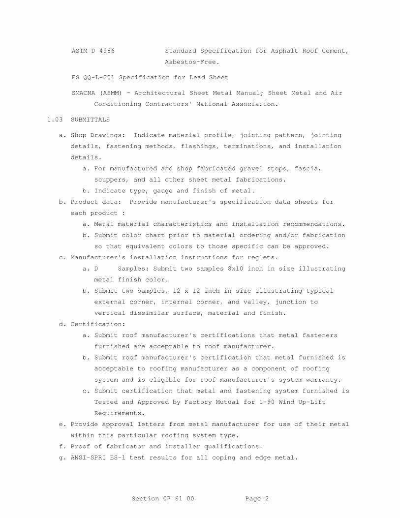
Section 07 61 00 Page 2
ASTM D 4586 Standard Specification for Asphalt Roof Cement,
Asbestos-Free.
FS QQ-L-201 Specification for Lead Sheet
SMACNA (ASMM) - Architectural Sheet Metal Manual; Sheet Metal and Air
Conditioning Contractors' National Association.
1.03 SUBMITTALS
a. Shop Drawings: Indicate material profile, jointing pattern, jointing details, fastening methods, flashings, terminations, and installation
details.
a. For manufactured and shop fabricated gravel stops, fascia, scuppers, and all other sheet metal fabrications.
b. Indicate type, gauge and finish of metal. b. Product data: Provide manufacturer's specification data sheets for
each product :
a. Metal material characteristics and installation recommendations. b. Submit color chart prior to material ordering and/or fabrication
so that equivalent colors to those specific can be approved.
c. Manufacturer’s installation instructions for reglets. a. D Samples: Submit two samples 8x10 inch in size illustrating
metal finish color.
b. Submit two samples, 12 x 12 inch in size illustrating typical external corner, internal corner, and valley, junction to
vertical dissimilar surface, material and finish.
d. Certification: a. Submit roof manufacturer's certifications that metal fasteners
furnished are acceptable to roof manufacturer.
b. Submit roof manufacturer's certification that metal furnished is acceptable to roofing manufacturer as a component of roofing
system and is eligible for roof manufacturer's system warranty.
c. Submit certification that metal and fastening system furnished is Tested and Approved by Factory Mutual for 1-90 Wind Up-Lift
Requirements.
e. Provide approval letters from metal manufacturer for use of their metal within this particular roofing system type.
f. Proof of fabricator and installer qualifications. g. ANSI-SPRI ES-1 test results for all coping and edge metal.

Section 07 61 00 Page 3
1.04 QUALITY ASSURANCE
a. Perform work in accordance with SMACNA Architectural Sheet Metal Manual requirements, except as otherwise indicated.
b. Factory Mutual Loss Prevention Data Sheet 1-49 windstorm resistance: 1-90.
c. Manufacturer's Warranty: Pre-finished metal material shall require a written 20-year non-prorated warranty covering fade,
chalking and film integrity. The material shall not show a color
change greater than 5 NBS color units per ASTM D-2244 or chalking
excess of 8 units per ASTM D-659. If either occurs material
shall be replaced per warranty, at no cost to the Owner.
d. Contractor's Warranty: The Contractor shall provide the Owner with a notarized written warranty assuring that all sheet metal
work including caulking and fasteners to be water-tight and
secure for a period of five years from the date of final
acceptance of the building. Warranty shall include all materials
and workmanship required to repair any leaks that develop, and
make good any damage to other work or equipment caused by such
leaks or the repairs thereof.
1.05 DELIVERY, STORAGE, AND HANDLING
a. Deliver materials in manufacturer's original, unopened containers or packages with labels intact and legible.
b. Stack material to prevent twisting, bending, and abrasion, and to provide ventilation. Slope metal sheets to ensure drainage.
c. Prevent contact with materials that could cause discoloration or staining.
PART 2 PRODUCTS
2.01 SHEET MATERIALS
A. Aluminum, ASTM B209, alloy 3105-H14, in thickness.040” nom.
2.02 ACCESSORIES
Fasteners:
1. Corrosion resistant screw fastener as recommended by metal
manufacturer. Finish exposed fasteners same as flashing
metal.
2. Fastening shall conform to Factory Mutual 1-90 requirements
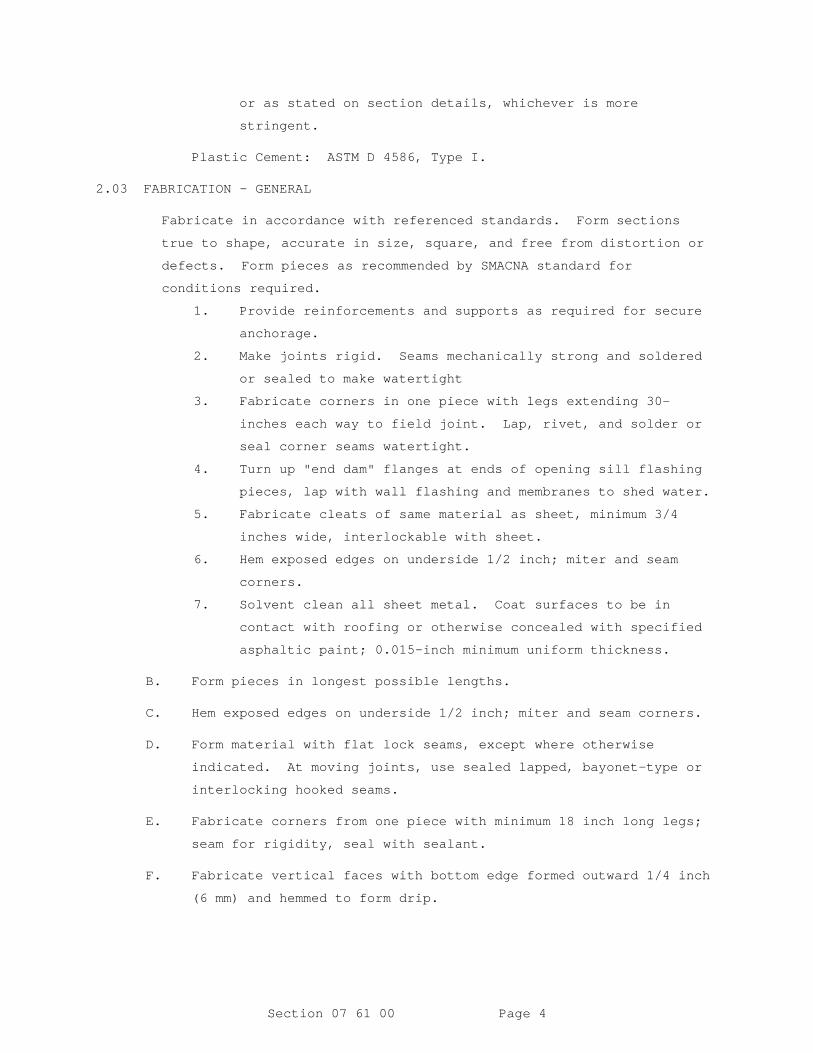
Section 07 61 00 Page 4
or as stated on section details, whichever is more
stringent.
Plastic Cement: ASTM D 4586, Type I.
2.03 FABRICATION - GENERAL
Fabricate in accordance with referenced standards. Form sections
true to shape, accurate in size, square, and free from distortion or
defects. Form pieces as recommended by SMACNA standard for
conditions required.
1. Provide reinforcements and supports as required for secure
anchorage.
2. Make joints rigid. Seams mechanically strong and soldered
or sealed to make watertight
3. Fabricate corners in one piece with legs extending 30-
inches each way to field joint. Lap, rivet, and solder or
seal corner seams watertight.
4. Turn up "end dam" flanges at ends of opening sill flashing
pieces, lap with wall flashing and membranes to shed water.
5. Fabricate cleats of same material as sheet, minimum 3/4
inches wide, interlockable with sheet.
6. Hem exposed edges on underside 1/2 inch; miter and seam
corners.
7. Solvent clean all sheet metal. Coat surfaces to be in
contact with roofing or otherwise concealed with specified
asphaltic paint; 0.015-inch minimum uniform thickness.
B. Form pieces in longest possible lengths.
C. Hem exposed edges on underside 1/2 inch; miter and seam corners.
D. Form material with flat lock seams, except where otherwise
indicated. At moving joints, use sealed lapped, bayonet-type or
interlocking hooked seams.
E. Fabricate corners from one piece with minimum 18 inch long legs;
seam for rigidity, seal with sealant.
F. Fabricate vertical faces with bottom edge formed outward 1/4 inch
(6 mm) and hemmed to form drip.

Section 07 61 00 Page 5
2.04 EDGE METAL SYSTEM AND METAL COPING SYSTEM
R-mer Edge Fascia system by The Garland Company or approved equal.
ANSI SPRI ES-1 tested and certified.
2.05 ROOF-RELATED SHEET METAL AND FLASHINGS
Roof-Related Sheet Metal and Flashings: As indicated, as specified
in related sections, as required by roofing material manufacturers
and referenced standards. Coordinate work of this section with
related sections. Provide complete systems without conflict or
omission.
2.06 LADDERS, DRAINS AND HATCHES
a. Hatch: Bilco or approved equal. i. Type S, all aluminum construction. b. Roof Drains: zurn Z-100 or equal. c. Ladder: Alaco Ladder i. Fixed ladders of all aluminum costruction.
PART 3 EXECUTION
3.01 EXAMINATION
a. Verify roof openings, curbs, pipes, sleeves, ducts, and vents through roof are solidly set, reglets in place, and nailing
strips located.
b. Verify roofing termination and base flashings are in place, sealed, and secure.
c. Beginning of installation means acceptance of existing conditions.
d. Field measure site conditions prior to fabricating work.
3.02 PREPARATION
a. Install starter and edge strips, and cleats before starting installation.
b. Back paint concealed metal surfaces with protective backing paint to a minimum dry film thickness of 15 mil.
3.03 INSTALLATION
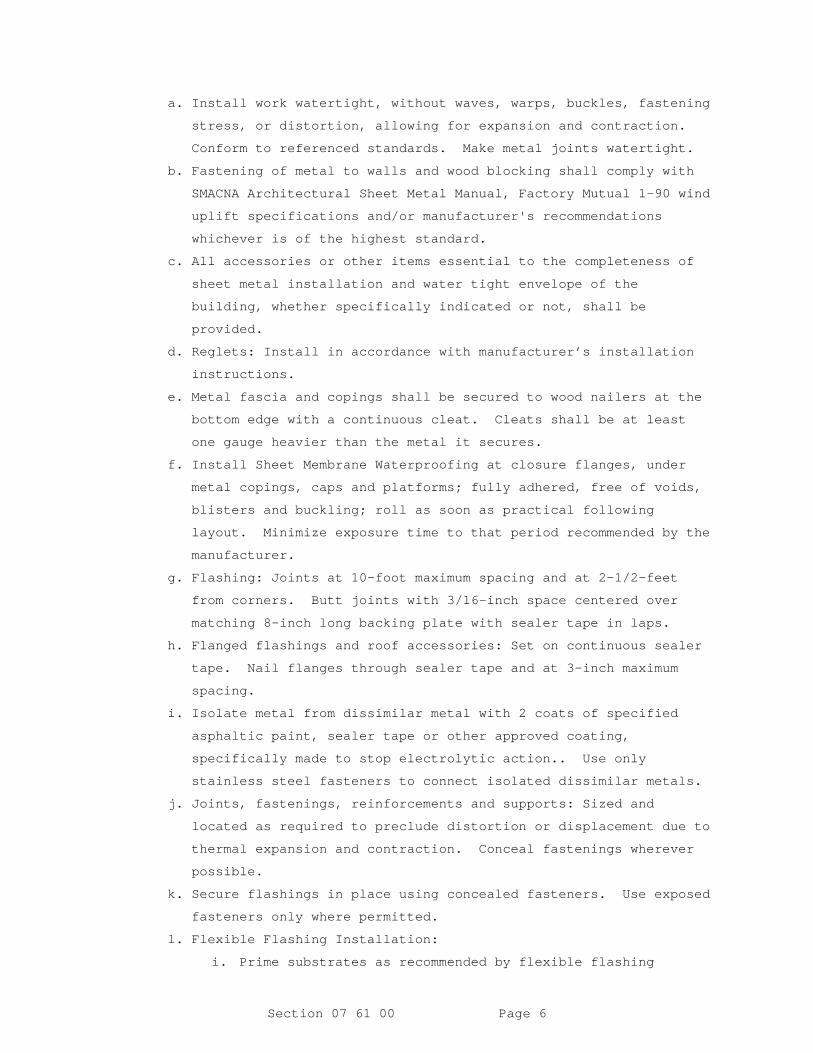
Section 07 61 00 Page 6
a. Install work watertight, without waves, warps, buckles, fastening stress, or distortion, allowing for expansion and contraction.
Conform to referenced standards. Make metal joints watertight.
b. Fastening of metal to walls and wood blocking shall comply with SMACNA Architectural Sheet Metal Manual, Factory Mutual 1-90 wind
uplift specifications and/or manufacturer's recommendations
whichever is of the highest standard.
c. All accessories or other items essential to the completeness of sheet metal installation and water tight envelope of the
building, whether specifically indicated or not, shall be
provided.
d. Reglets: Install in accordance with manufacturer’s installation instructions.
e. Metal fascia and copings shall be secured to wood nailers at the bottom edge with a continuous cleat. Cleats shall be at least
one gauge heavier than the metal it secures.
f. Install Sheet Membrane Waterproofing at closure flanges, under metal copings, caps and platforms; fully adhered, free of voids,
blisters and buckling; roll as soon as practical following
layout. Minimize exposure time to that period recommended by the
manufacturer.
g. Flashing: Joints at 10-foot maximum spacing and at 2-1/2-feet from corners. Butt joints with 3/16-inch space centered over
matching 8-inch long backing plate with sealer tape in laps.
h. Flanged flashings and roof accessories: Set on continuous sealer tape. Nail flanges through sealer tape and at 3-inch maximum
spacing.
i. Isolate metal from dissimilar metal with 2 coats of specified asphaltic paint, sealer tape or other approved coating,
specifically made to stop electrolytic action.. Use only
stainless steel fasteners to connect isolated dissimilar metals.
j. Joints, fastenings, reinforcements and supports: Sized and located as required to preclude distortion or displacement due to
thermal expansion and contraction. Conceal fastenings wherever
possible.
k. Secure flashings in place using concealed fasteners. Use exposed fasteners only where permitted.
l. Flexible Flashing Installation: i. Prime substrates as recommended by flexible flashing
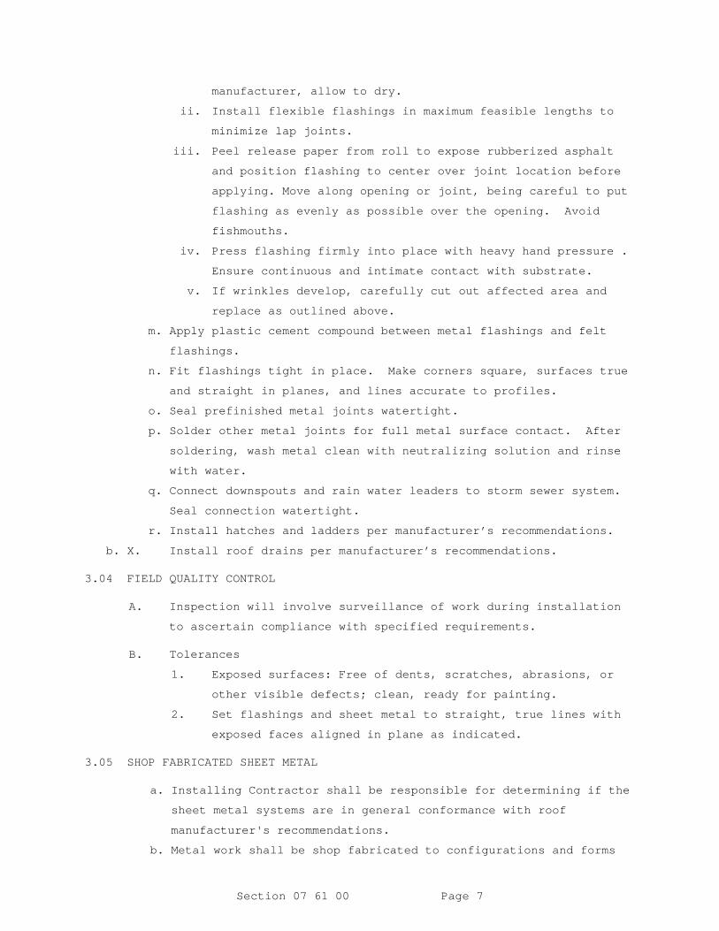
Section 07 61 00 Page 7
manufacturer, allow to dry.
ii. Install flexible flashings in maximum feasible lengths to
minimize lap joints.
iii. Peel release paper from roll to expose rubberized asphalt
and position flashing to center over joint location before
applying. Move along opening or joint, being careful to put
flashing as evenly as possible over the opening. Avoid
fishmouths.
iv. Press flashing firmly into place with heavy hand pressure .
Ensure continuous and intimate contact with substrate.
v. If wrinkles develop, carefully cut out affected area and
replace as outlined above.
m. Apply plastic cement compound between metal flashings and felt flashings.
n. Fit flashings tight in place. Make corners square, surfaces true and straight in planes, and lines accurate to profiles.
o. Seal prefinished metal joints watertight. p. Solder other metal joints for full metal surface contact. After
soldering, wash metal clean with neutralizing solution and rinse
with water.
q. Connect downspouts and rain water leaders to storm sewer system. Seal connection watertight.
r. Install hatches and ladders per manufacturer’s recommendations. b. X. Install roof drains per manufacturer’s recommendations.
3.04 FIELD QUALITY CONTROL
A. Inspection will involve surveillance of work during installation
to ascertain compliance with specified requirements.
B. Tolerances
1. Exposed surfaces: Free of dents, scratches, abrasions, or
other visible defects; clean, ready for painting.
2. Set flashings and sheet metal to straight, true lines with
exposed faces aligned in plane as indicated.
3.05 SHOP FABRICATED SHEET METAL
a. Installing Contractor shall be responsible for determining if the sheet metal systems are in general conformance with roof
manufacturer's recommendations.
b. Metal work shall be shop fabricated to configurations and forms
Section 07 61 00 Page 8
in accordance with recognized sheet metal practices.
c. Hem exposed edges. d. Angle bottom edges of exposed vertical surfaces to form drip. e. All corners for sheet metal shall be lapped with adjoining pieces
fastened and set in sealant.
f. Joints for gravel stop fascia system, cap flashing, and surface-mount counterflashing shall be formed with a 1/4" opening between
sections. The opening shall be covered by a cover plate or
backed by an internal drainage plate formed to the profile of
fascia piece. The cover plate shall be embedded in mastic,
fastened through the opening between the sections and loose
locked to the drip edges.
g. Install sheet metal to comply with Architectural Sheet Metal manual, Sheet Metal and Air Conditioning Contractor's National
Associations, Inc.
--END OF SECTION--

Section 07 61 00 Page 9
SECTION 07 84 00
FIRESTOPPING05/10
PART 1 GENERAL
1.1 SUMMARY
Furnish and install tested and listed firestopping systems, combination of materials, or devices to form an effective barrier against the spread of flame, smoke and gases, and maintain the integrity of fire resistance rated walls, partitions, floors, and ceiling-floor assemblies, including through-penetrations and construction joints and gaps.
a. Through-penetrations include the annular space around pipes, tubes, conduit, wires, cables and vents.
b. Construction joints include those used to accommodate expansion, contraction, wind, or seismic movement; firestopping material shall not interfere with the required movement of the joint.
Gaps requiring firestopping include gaps between the curtain wall and the floor slab and between the top of the fire-rated walls and the roof or floor deck above and at the intersection of shaft assemblies and adjoining fire resistance rated assemblies.
1.2 REFERENCES
The publications listed below form a part of this specification to the extent referenced. The publications are referred to within the text by the basic designation only.
ASTM INTERNATIONAL (ASTM)
ASTM E119 (2016a) Standard Test Methods for Fire Tests of Building Construction and Materials
ASTM E1399/E1399M (1997; E 2013;R 2013) Cyclic Movement and Measuring the Minimum and Maximum Joint Widths of Architectural Joint Systems
ASTM E1966 (2015) Fire-Resistive Joint Systems
ASTM E2174 (2014b) Standard Practice for On-Site Inspection of Installed Fire Stops
ASTM E2307 (2015a) Standard Test Method for Determining Fire Resistance of Perimeter Fire Barrier Systems Using Intermediate-Scale, Multi-story Test Apparatus
ASTM E2393 (2010a) Standard Practice for On-Site
Page 1
Inspection of Installed Fire Resistive Joint Systems and Perimeter Fire Barriers
ASTM E699 (2009) Standard Practice for Evaluation of Agencies Involved in Testing, Quality Assurance, and Evaluating of Building Components
ASTM E814 (2013a; R 2017) Standard Test Method for Fire Tests of Penetration Firestop Systems
ASTM E84 (2016) Standard Test Method for Surface Burning Characteristics of Building Materials
FM GLOBAL (FM)
FM 4991 (2013) Approval of Firestop Contractors
FM APP GUIDE (updated on-line) Approval Guide http://www.approvalguide.com/
INTERNATIONAL CODE COUNCIL (ICC)
ICC IBC (2015) International Building Code
UNDERWRITERS LABORATORIES (UL)
UL 1479 (2015) Fire Tests of Through-Penetration Firestops
UL 2079 (2004; Reprint Dec 2014) Tests for Fire Resistance of Building Joint Systems
UL 723 (2008; Reprint Aug 2013) Test for Surface Burning Characteristics of Building Materials
UL Fire Resistance (2014) Fire Resistance Directory
1.3 SEQUENCING
Coordinate the specified work with other trades. Apply firestopping materials, at penetrations of pipes and ducts, prior to insulating, unless insulation meets requirements specified for firestopping. Apply firestopping materials. at building joints and construction gaps, prior to completion of enclosing walls or assemblies. Cast-in-place firestop devices shall be located and installed in place before concrete placement. Pipe, conduit or cable bundles shall be installed through cast-in-place device after concrete placement but before area is concealed or made inaccessible. Firestop material shall be inspected and approved prior to final completion and enclosing of any assemblies that may conceal installed firestop.
Page 2
1.4 SUBMITTALS
Government approval is required for submittals with a "G" designation; submittals not having a "G" designation are for [Contractor Quality Control approval.] [information only. When used, a designation following the "G" designation identifies the office that will review the submittal for the Government.] Submittals with an "S" are for inclusion in the Sustainability eNotebook, in conformance to Section 01 33 29 SUSTAINABILITY REPORTING. Submit the following in accordance with Section 01 33 00 SUBMITTAL PROCEDURES:
SD-02 Shop Drawings
Firestopping System; G
SD-03 Product Data
Firestopping Materials; G
SD-06 Test Reports
Inspection; G
SD-07 Certificates
Inspector QualificationsFirestopping MaterialsInstaller Qualifications; G
1.5 QUALITY ASSURANCE
1.5.1 Installer
Engage an experienced Installer who is:
a. FM Research approved in accordance with FM 4991, operating as a UL Certified Firestop Contractor, or
b. Certified, licensed, or otherwise qualified by the firestopping manufacturer as having the necessary staff, training, and a minimum of 3 years experience in the installation of manufacturer's products in accordance with specified requirements. Submit documentation of this experience. A manufacturer's willingness to sell its firestopping products to the Contractor or to an installer engaged by the Contractor does not in itself confer installer qualifications on the buyer. The Installer shall have been trained by a direct representative of the manufacturer (not distributor or agent) in the proper selection and installation procedures. The installer shall obtain from the manufacturer and submit written certification of training, and retain proof of certification for duration of firestop installation.
Page 3

1.5.2 Inspector Qualifications
The inspector shall[ meet the criteria contained in ASTM E699 for agencies involved in quality assurance and shall] have a minimum of two years experience in construction field inspections of firestopping systems, products, and assemblies. The inspector shall be completely independent of, and divested from, the installer, the manufacturer, and the supplier of any material or item being inspected. The inspector shall not be a competitor of the installer, the contractor, the manufacturer, or supplier of any material or item being inspected. Include in the qualifications submittal a notarized statement assuring compliance with the requirements stated herein.
1.6 DELIVERY, STORAGE, AND HANDLING
Deliver materials in the original unopened packages or containers showing name of the manufacturer and the brand name. Store materials off the ground, protected from damage and exposure to elements and temperatures in accordance with manufacturer requirements. Remove damaged or deteriorated materials from the site. Use materials within their indicated shelf life.
PART 2 PRODUCTS
2.1 FIRESTOPPING SYSTEM
Submit detail drawings including manufacturer's descriptive data, typical details conforming to UL Fire Resistance or other details certified by another nationally recognized testing laboratory, installation instructions or UL listing details for a firestopping assembly in lieu of fire-test data or report. For those firestop applications for which no UL tested system is available through a manufacturer, a manufacturer's engineering judgment, derived from similar UL system designs or other tests, shall be submitted for review and approval prior to installation. Submittal must indicate the firestopping material to be provided for each type of application. When more than a total of 5 penetrations and/or construction joints are to receive firestopping, provide drawings that indicate location, "F" "T" and "L" ratings, and type of application.
Also, submit a written report indicating locations of and types of penetrations and types of firstopping used at each location; record type by UL list printed numbers.
2.2 FIRESTOPPING MATERIALS
Provide firestopping materials, supplied from a single domestic manufacturer, consisting of commercially manufactured, asbestos-free, nontoxic products FM APP GUIDE approved, or UL listed, for use with applicable construction and penetrating items, complying with the following minimum requirements:
2.2.1 Fire Hazard Classification
Material shall have a flame spread of 25 or less, and a smoke developed rating of 50 or less, when tested in accordance with ASTM E84 or UL 723. Material shall be an approved firestopping material as listed in UL Fire Resistance or by a nationally recognized testing laboratory.
Page 4
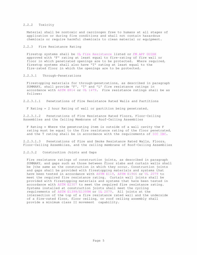
2.2.2 Toxicity
Material shall be nontoxic and carcinogen free to humans at all stages of application or during fire conditions and shall not contain hazardous chemicals or require harmful chemicals to clean material or equipment.
2.2.3 Fire Resistance Rating
Firestop systems shall be UL Fire Resistance listed or FM APP GUIDE approved with "F" rating at least equal to fire-rating of fire wall or floor in which penetrated openings are to be protected. Where required, firestop systems shall also have "T" rating at least equal to the fire-rated floor in which the openings are to be protected.
2.2.3.1 Through-Penetrations
Firestopping materials for through-penetrations, as described in paragraph SUMMARY, shall provide "F", "T" and "L" fire resistance ratings in accordance with ASTM E814 or UL 1479. Fire resistance ratings shall be as follows:
2.2.3.1.1 Penetrations of Fire Resistance Rated Walls and Partitions
F Rating = 2 hour Rating of wall or partition being penetrated.
2.2.3.1.2 Penetrations of Fire Resistance Rated Floors, Floor-Ceiling Assemblies and the Ceiling Membrane of Roof-Ceiling Assemblies
F Rating = Where the penetrating item is outside of a wall cavity the F rating must be equal to the fire resistance rating of the floor penetrated, and the T rating shall be in accordance with the requirements of ICC IBC.
2.2.3.1.3 Penetrations of Fire and Smoke Resistance Rated Walls, Floors, Floor-Ceiling Assemblies, and the ceiling membrane of Roof-Ceiling Assemblies
2.2.3.2 Construction Joints and Gaps
Fire resistance ratings of construction joints, as described in paragraph SUMMARY, and gaps such as those between floor slabs and curtain walls shall be [the same as the construction in which they occur. Construction joints and gaps shall be provided with firestopping materials and systems that have been tested in accordance with ASTM E119, ASTM E1966 or UL 2079 to meet the required fire resistance rating. Curtain wall joints shall be provided with firestopping materials and systems that have been tested in accordance with ASTM E2307 to meet the required fire resistance rating. Systems installed at construction joints shall meet the cycling requirements of ASTM E1399/E1399M or UL 2079. All joints at the intersection of the top of a fire resistance rated wall and the underside of a fire-rated floor, floor ceiling, or roof ceiling assembly shall provide a minimum class II movement capability.
Page 5

PART 3 EXECUTION
3.1 PREPARATION
Areas to receive firestopping must be free of dirt, grease, oil, or loose materials which may affect the fitting or fire resistance of the firestopping system. For cast-in-place firestop devices, formwork or metal deck to receive device prior to concrete placement must be sound and capable of supporting device. Prepare surfaces as recommended by the manufacturer.
3.2 INSTALLATION
Completely fill void spaces with firestopping material regardless of geometric configuration, subject to tolerance established by the manufacturer. Firestopping systems for filling floor voids 4 inches or more in any direction must be capable of supporting the same load as the floor is designed to support or be protected by a permanent barrier to prevent loading or traffic in the firestopped area. Install firestopping in accordance with manufacturer's written instructions. Provide tested and listed firestop systems in the following locations, except in floor slabs on grade:
a. Penetrations of duct, conduit, tubing, cable and pipe through floors and through fire-resistance rated walls, partitions, and ceiling-floor assemblies.
b. Penetrations of vertical shafts such as pipe chases, elevator shafts, and utility chutes.
c. Gaps at the intersection of floor slabs and curtain walls, including inside of hollow curtain walls at the floor slab.
d. Gaps at perimeter of fire-resistance rated walls and partitions, such as between the top of the walls and the bottom of roof decks.
e. Construction joints in floors and fire rated walls and partitions.
f. Other locations where required to maintain fire resistance rating of the construction.
3.2.1 Insulated Pipes and Ducts
Thermal insulation shall be cut and removed where pipes or ducts pass through firestopping, unless insulation meets requirements specified for firestopping. Replace thermal insulation with a material having equal thermal insulating and firestopping characteristics.
3.2.2 Fire Dampers
Install and firestop fire dampers in accordance with Section 23 00 00 AIR SUPPLY, DISTRIBUTION, VENTILATION, AND EXHAUST SYSTEM. Firestop installed with fire damper must be tested and approved for use in fire damper system. Firestop installed with fire damper must be tested and approved for use in fire damper system.
Page 6

3.2.3 Data and Communication Cabling
Cabling for data and communication applications shall be sealed with re-enterable firestopping products and devices as indicated.
3.2.3.1 Re-Enterable Devices
Firestopping devices shall be pre-manufactured modular devices, containing built-in self-sealing intumescent inserts. Firestopping devices shall allow for cable moves, additions or changes without the need to remove or replace any firestop materials. Devices must be capable of maintaining the fire resistance rating of the penetrated membrane at 0 percent to 100 percent visual fill of penetrants; while maintaining "L" rating of <10 cfm/sf [measured at ambient temperature and 400 degrees F] at 0 percent to 100 percent visual fill.
3.2.3.2 Re-Sealable Products
Provide firestopping pre-manufactured modular products, containing self-sealing intumescent inserts. Firestopping products shall allow for cable moves, additions or changes. Devices shall be capable of maintaining the fire resistance rating of the penetrated membrane at 0 percent to 100 percent visual fill of penetrants.
3.3 INSPECTION
For all projects,the firestopped areas shall not be covered or enclosed until inspection is complete and approved by the Contracting Officer. Inspect the applications initially to ensure adequate preparations clean surfaces suitable for application, etc. and periodically during the work to assure that the completed work has been accomplished according to the manufacturer's written instructions and the specified requirements. Submit written reports indicating locations of and types of penetrations and types of firestopping used at each location; type shall be recorded by UL listed printed numbers.
3.3.1 Inspection Standards
Inspect all firestopping in accordance to ASTM E2393 and ASTM E2174 for firestop inspection, and document inspection results to be submitted.
-- End of Section --
Page 7

SECTION 07 92 00
JOINT SEALANTS08/16
PART 1 GENERAL
1.1 REFERENCES
The publications listed below form a part of this specification to the extent referenced. The publications are referred to within the text by the basic designation only.
ASTM INTERNATIONAL (ASTM)
ASTM C1193 (2013) Standard Guide for Use of Joint Sealants
ASTM C734 (2015) Low-Temperature Flexibility of Latex Sealants After Artificial Weathering
ASTM C919 (2012; R 2017) Standard Practice for Use of Sealants in Acoustical Applications
ASTM C920 (2014a) Standard Specification for Elastomeric Joint Sealants
ASTM D217 (2017) Standard Test Methods for Cone Penetration of Lubricating Grease
ASTM E84 (2016) Standard Test Method for Surface Burning Characteristics of Building Materials
CALIFORNIA DEPARTMENT OF PUBLIC HEALTH (CDPH)
CDPH SECTION 01350 Standard Method for the Testing and Evaluation of Volatile Organic Chemical Emissions from Indoor Sources using Environmental Chambers
SCIENTIFIC CERTIFICATION SYSTEMS (SCS)
SCS SCS Global Services (SCS)Indoor Advantage
SOUTH COAST AIR QUALITY MANAGEMENT DISTRICT (SCAQMD)
SCAQMD Rule 1168 (1989; R 2005) Adhesive and Sealant Applications
UNDERWRITERS LABORATORIES (UL)
UL 2818 (2013) GREENGUARD Certification Program For Chemical Emissions For Building Materials, Finishes And Furnishings
Page 1
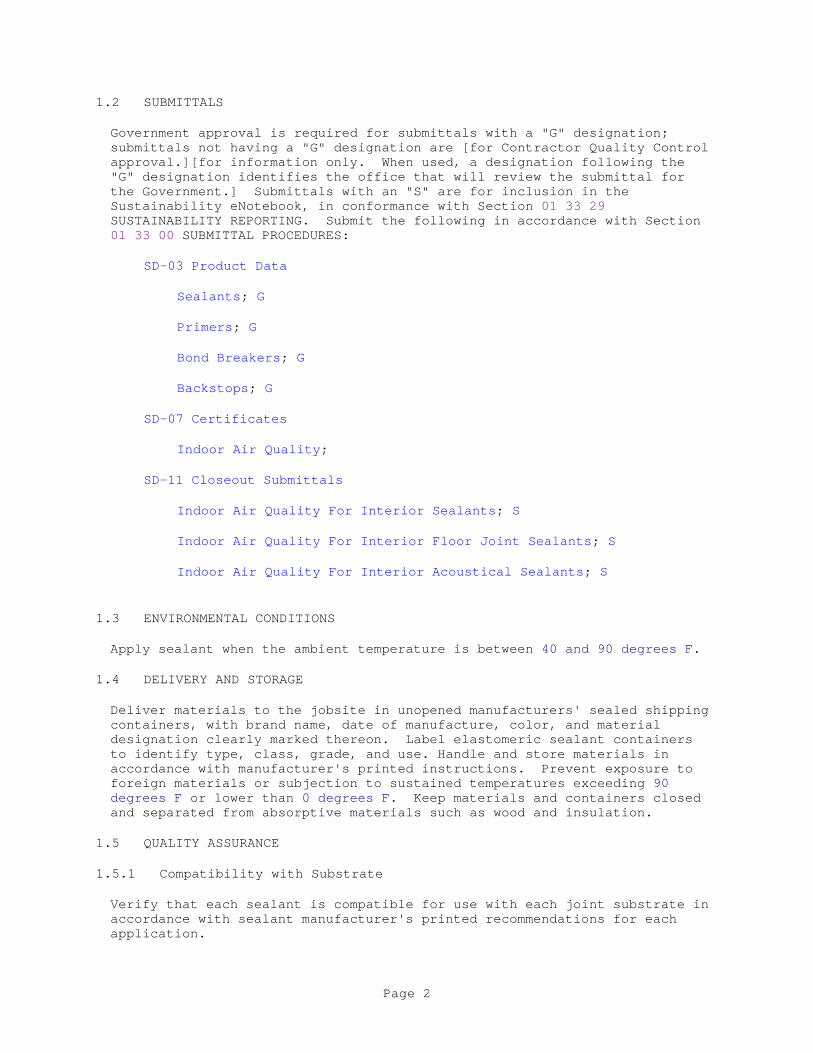
1.2 SUBMITTALS
Government approval is required for submittals with a "G" designation; submittals not having a "G" designation are [for Contractor Quality Control approval.][for information only. When used, a designation following the "G" designation identifies the office that will review the submittal for the Government.] Submittals with an "S" are for inclusion in the Sustainability eNotebook, in conformance with Section 01 33 29 SUSTAINABILITY REPORTING. Submit the following in accordance with Section 01 33 00 SUBMITTAL PROCEDURES:
SD-03 Product Data
Sealants; G
Primers; G
Bond Breakers; G
Backstops; G
SD-07 Certificates
Indoor Air Quality;
SD-11 Closeout Submittals
Indoor Air Quality For Interior Sealants; S
Indoor Air Quality For Interior Floor Joint Sealants; S
Indoor Air Quality For Interior Acoustical Sealants; S
1.3 ENVIRONMENTAL CONDITIONS
Apply sealant when the ambient temperature is between 40 and 90 degrees F.
1.4 DELIVERY AND STORAGE
Deliver materials to the jobsite in unopened manufacturers' sealed shipping containers, with brand name, date of manufacture, color, and material designation clearly marked thereon. Label elastomeric sealant containers to identify type, class, grade, and use. Handle and store materials in accordance with manufacturer's printed instructions. Prevent exposure to foreign materials or subjection to sustained temperatures exceeding 90 degrees F or lower than 0 degrees F. Keep materials and containers closed and separated from absorptive materials such as wood and insulation.
1.5 QUALITY ASSURANCE
1.5.1 Compatibility with Substrate
Verify that each sealant is compatible for use with each joint substrate in accordance with sealant manufacturer's printed recommendations for each application.
Page 2
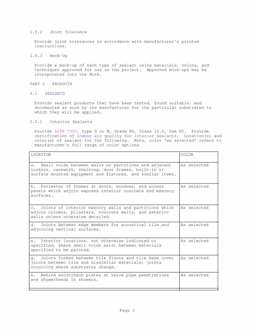
1.5.2 Joint Tolerance
Provide joint tolerances in accordance with manufacturer's printed instructions.
1.5.3 Mock-Up
Provide a mock-up of each type of sealant using materials, colors, and techniques approved for use on the project. Approved mock-ups may be incorporated into the Work.
PART 2 PRODUCTS
2.1 SEALANTS
Provide sealant products that have been tested, found suitable, and documented as such by the manufacturer for the particular substrates to which they will be applied.
2.1.1 Interior Sealants
Provide ASTM C920, Type S or M, Grade NS, Class 12.5, Use NT. Provide certification of indoor air quality for interior sealants. Location(s) and color(s) of sealant for the following. Note, color "as selected" refers to manufacturer's full range of color options
LOCATION COLOR
a. Small voids between walls or partitions and adjacent lockers, casework, shelving, door frames, built-in or surface mounted equipment and fixtures, and similar items.
As selected
b. Perimeter of frames at doors, windows, and access panels which adjoin exposed interior concrete and masonry surfaces.
As selected
c. Joints of interior masonry walls and partitions which adjoin columns, pilasters, concrete walls, and exterior walls unless otherwise detailed.
As selected
d. Joints between edge members for acoustical tile and adjoining vertical surfaces.
As selected
e. Interior locations, not otherwise indicated or specified, where small voids exist between materials specified to be painted.
As selected
g. Joints formed between tile floors and tile base cove; joints between tile and dissimilar materials; joints occurring where substrates change.
As selected
h. Behind escutcheon plates at valve pipe penetrations and showerheads in showers.
As selected
Page 3

2.1.2 Floor Joint Sealants
ASTM C920, Type S or M, Grade P, Class 25, Use T. Provide certification of indoor air quality for interior floor joint sealants. Provide location(s) and color(s) of sealant as follows. Note, color "as selected" refers to manufacturer's full range of color options:
LOCATION COLOR
a. Seats of metal thresholds for exterior doors.
As selected
b. Control and expansion joints in floors, slabs, ceramic tile, and walkways.
As selected
2.1.3 Acoustical Sealants
Rubber or polymer based acoustical sealant in accordance with ASTM C919 to have a flame spread of 25 or less and a smoke developed rating of 50 or less when tested in accordance with ASTM E84. Provide non-staining acoustical sealant with a consistency of 250 to 310 when tested in accordance with ASTM D217. Acoustical sealant must remain flexible and adhesive after 500 hours of accelerated weathering as specified in ASTMC734. Provide certification of indoor air quality for interior acoustical sealants.
2.2 PRIMERS
Non-staining, quick drying type and consistency as recommended by the sealant manufacturer for the particular application. Provide primers for interior applications that meet the indoor air quality requirements of the paragraph SEALANTS above.
2.3 BOND BREAKERS Type and consistency as recommended by the sealant manufacturer to prevent adhesion of the sealant to the backing or to the bottom of the joint. Provide bond breakers for interior applications that meet the indoor air quality requirements of the paragraph SEALANTS above.
2.4 BACKSTOPS
Provide glass fiber roving, neoprene, butyl, polyurethane, or polyethylene foams free from oil or other staining elements as recommended by sealant manufacturer. Provide 25 to 33 percent oversized backing for closed cell and 40 to 50 percent oversized backing for open cell material, unless otherwise indicated. Provide backstop material that is compatible with sealant. Do not use oakum or other types of absorptive materials as backstops.
2.5 CLEANING SOLVENTS
Provide type(s) recommended by the sealant manufacturer and in accordance with environmental requirements herein. Provide solvents for interior applications that meet the indoor air quality requirements of the paragraph
Page 4
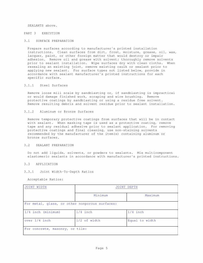
SEALANTS above.
PART 3 EXECUTION
3.1 SURFACE PREPARATION
Prepare surfaces according to manufacturer's printed installation instructions. Clean surfaces from dirt, frost, moisture, grease, oil, wax, lacquer, paint, or other foreign matter that would destroy or impair adhesion. Remove oil and grease with solvent; thoroughly remove solvents prior to sealant installation. Wipe surfaces dry with clean cloths. When resealing an existing joint, remove existing caulk or sealant prior to applying new sealant. For surface types not listed below, provide in accordance with sealant manufacturer's printed instructions for each specific surface.
3.1.1 Steel Surfaces
Remove loose mill scale by sandblasting or, if sandblasting is impractical or would damage finished work, scraping and wire brushing. Remove protective coatings by sandblasting or using a residue free solvent. Remove resulting debris and solvent residue prior to sealant installation.
3.1.2 Aluminum or Bronze Surfaces
Remove temporary protective coatings from surfaces that will be in contact with sealant. When masking tape is used as a protective coating, remove tape and any residual adhesive prior to sealant application. For removing protective coatings and final cleaning, use non-staining solvents recommended by the manufacturer of the item(s) containing aluminum or bronze surfaces.
3.2 SEALANT PREPARATION
Do not add liquids, solvents, or powders to sealants. Mix multicomponent elastomeric sealants in accordance with manufacturer's printed instructions.
3.3 APPLICATION
3.3.1 Joint Width-To-Depth Ratios
Acceptable Ratios:
JOINT WIDTH JOINT DEPTH
Minimum Maximum
For metal, glass, or other nonporous surfaces:
1/4 inch (minimum) 1/4 inch 1/4 inch
over 1/4 inch 1/2 of width Equal to width
For concrete, masonry, or tile:
Page 5

JOINT WIDTH JOINT DEPTH
Minimum Maximum
1/4 inch (minimum) 1/4 inch 1/4 inch
over 1/4 inch to 1/2 inch 1/4 inch Equal to width
over 1/2 inch to 1 inch 1/2 inch 5/8 inch
Over 1 inch prohibited
Unacceptable Ratios: Where joints of acceptable width-to-depth ratios have not been provided, clean out joints to acceptable depths and grind or cut to acceptable widths without damage to the adjoining work. Grinding is prohibited at metal surfaces.
3.3.2 Masking Tape
Place masking tape on the finished surface on one or both sides of joint cavities to protect adjacent finished surfaces from primer or sealant smears. Remove masking tape within 10 minutes of joint filling and tooling.
3.3.3 Backstops
Provide backstops dry and free of tears or holes. Tightly pack the back or bottom of joint cavities with backstop material to provide joints in specified depths. Provide backstops where indicated and where backstops are not indicated but joint cavities exceed the acceptable maximum depths specified in JOINT WIDTH-TO-DEPTH RATIOS Table.
3.3.4 Primer
Clean out loose particles from joints immediately prior to application of. Apply primer to joints in concrete masonry units, wood, and other porous surfaces in accordance with sealant manufacturer's printed instructions. Do not apply primer to exposed finished surfaces.
3.3.5 Bond Breaker
Provide bond breakers to surfaces not intended to bond in accordance with, sealant manufacturer's printed instructions for each type of surface and sealant combination specified.
3.3.6 Sealants
Provide sealants compatible with the material(s) to which they are applied. Do not use a sealant that has exceeded its shelf life or has jelled and cannot be discharged in a continuous flow from the sealant gun. Apply sealants in accordance with the manufacturer's printed instructions with a gun having a nozzle that fits the joint width. Work sealant into joints so as to fill the joints solidly without air pockets. Tool sealant after application to ensure adhesion. Apply sealant uniformly smooth and free of wrinkles. Upon completion of sealant application, roughen partially filled or unfilled joints, apply additional sealant, and tool smooth as
Page 6
specified. Apply sealer over sealants in accordance with the sealant manufacturer's printed instructions.
3.4 PROTECTION AND CLEANING
3.4.1 Protection
Protect areas adjacent to joints from sealant smears. Masking tape may be used for this purpose if removed 5 to 10 minutes after the joint is filled and no residual tape marks remain.
3.4.2 Final Cleaning
Upon completion of sealant application, remove remaining smears and stains and leave the work in a clean and neat condition.
a. Masonry and Other Porous Surfaces: Immediately remove fresh sealant that has been smeared on adjacent masonry, rub clean with a solvent, and remove solvent residue, in accordance with sealant manufacturer's
Page 7
printed instructions. Allow excess sealant to cure for 24 hour then remove by wire brushing or sanding. Remove resulting debris.
b. Metal and Other Non-Porous Surfaces: Remove excess sealant with a solvent moistened cloth. Remove solvent residue in accordance with solvent manufacturer's printed instructions.
-- End of Section --
Page 8
SECTION 08 11 13
STEEL DOORS AND FRAMES02/10
PART 1 GENERAL
1.1 REFERENCES
The publications listed below form a part of this specification to the extent referenced. The publications are referred to in the text by the basic designation only.
AMERICAN WELDING SOCIETY (AWS)
AWS D1.1/D1.1M (2015; Errata 1 2015; Errata 2 2016) Structural Welding Code - Steel
ASTM INTERNATIONAL (ASTM)
ASTM A653/A653M (2015; E 2016) Standard Specification for Steel Sheet, Zinc-Coated (Galvanized) or Zinc-Iron Alloy-Coated (Galvannealed) by the Hot-Dip Process
ASTM A879/A879M (2012) Standard Specification for Steel Sheet, zinc Coated by the Electrolytic Process for Applications Requiring Designation of the Coating Mass on Each Surface
ASTM A924/A924M (2017) Standard Specification for General Requirements for Steel Sheet, Metallic-Coated by the Hot-Dip Process
ASTM C578 (2016) Standard Specification for Rigid, Cellular Polystyrene Thermal Insulation
ASTM C591 (2016) Standard Specification for Unfaced Preformed Rigid Cellular Polyisocyanurate Thermal Insulation
ASTM C612 (2014) Mineral Fiber Block and Board Thermal Insulation
ASTM D2863 (2013) Measuring the Minimum Oxygen Concentration to Support Candle-Like Combustion of Plastics (Oxygen Index)
ASTM E1300 (2016) Standard Practice for Determining Load Resistance of Glass in Buildings
ASTM E283 (2004; R 2012) Determining the Rate of Air Leakage Through Exterior Windows, Curtain Walls, and Doors Under Specified Pressure Differences Across the Specimen
Page 1
ASTM F2248 (2012) Standard Practice for Specifying an Equivalent 3-Second Duration Design Loading for Blast Resistant Glazing Fabricated with Laminated Glass
BUILDERS HARDWARE MANUFACTURERS ASSOCIATION (BHMA)
ANSI/BHMA A156.115 (2016) Hardware Preparation in Steel Doors and Steel Frames
NATIONAL ASSOCIATION OF ARCHITECTURAL METAL MANUFACTURERS (NAAMM)
NAAMM HMMA HMM (1999; R2000) Hollow Metal Manual
NATIONAL FIRE PROTECTION ASSOCIATION (NFPA)
NFPA 105 (2016; TIA 16-1) Standard for Smoke Door Assemblies and Other Opening Protectives
NFPA 252 (2017) Standard Methods of Fire Tests of Door Assemblies
NFPA 80 (2016; TIA 16-1) Standard for Fire Doors and Other Opening Protectives
STEEL DOOR INSTITUTE (SDI/DOOR)
SDI/DOOR 111 (2009) Recommended Selection and Usage Guide for Standard Steel Doors, Frames and Accessories
SDI/DOOR 113 (2001; R2006) Standard Practice for Determining the Steady State Thermal Transmittance of Steel Door and Frame Assemblies
SDI/DOOR A250.11 (2001) Recommended Erection Instructions for Steel Frames
SDI/DOOR A250.3 (2007; R 2011) Test Procedure and Acceptance Criteria for Factory Applied Finish Painted Steel Surfaces for Steel Doors and Frames
SDI/DOOR A250.4 (2011) Test Procedure and Acceptance Criteria for Physical Endurance for Steel Doors and Hardware Reinforcing
SDI/DOOR A250.6 (2003; R2009) Recommended Practice for Hardware Reinforcing on Standard Steel Doors and Frames
SDI/DOOR A250.8 (2003; R2008) Recommended Specifications for Standard Steel Doors and Frames
UNDERWRITERS LABORATORIES (UL)
Page 2
UL 10C (2016) UL Standard for Safety Positive Pressure Fire Tests of Door Assemblies
1.2 SUBMITTALS
Government approval is required for submittals with a "G" designation; submittals not having a "G" designation are [for Contractor Quality Control approval.][for information only. When used, a designation following the "G" designation identifies the office that will review the submittal for the Government.] Submittals with an "S" are for inclusion in the Sustainability eNotebook, in conformance to Section 01 33 29 SUSTAINABILITY REPORTING. Submit the following in accordance with Section 01 33 00 SUBMITTAL PROCEDURES:
SD-02 Shop Drawings
Doors; G
Frames; G
Accessories
[Weatherstripping]
Show elevations, construction details, metal gages, hardware provisions, method of glazing, and installation details.
Schedule of doors; G
Schedule of frames; G
Submit door and frame locations.
SD-03 Product Data
Doors; G
Frames; G
Accessories
Submit manufacturer's descriptive literature for doors, frames, and accessories. Include data and details on door construction, panel (internal) reinforcement, insulation, and door edge construction. When "custom hollow metal doors" are provided in lieu of "standard steel doors," provide additional details and data sufficient for comparison to SDI/DOOR A250.8 requirements.
1.3 DELIVERY, STORAGE, AND HANDLING
Deliver doors, frames, and accessories undamaged and with protective wrappings or packaging. Store doors and frames on platforms under cover in clean, dry, ventilated, and accessible locations, with 1/4 inch airspace between doors. Remove damp or wet packaging immediately and wipe affected surfaces dry. Replace damaged materials with new.
PART 2 PRODUCTS
Page 3
2.1 STANDARD STEEL DOORS
SDI/DOOR A250.8, except as specified otherwise. Prepare doors to receive door hardware as specified in Section 08 71 00. Undercut where indicated. Exterior doors shall have top edge closed flush and sealed to prevent water intrusion. Doors shall be 1-3/4 inch thick, unless otherwise indicated.
2.1.1 Classification - Level, Performance, Model2.1.1.1 Extra Heavy Duty Doors
SDI/DOOR A250.8, Level 3, physical performance Level A, Model 3 with core construction as required by the manufacturer for indicated exterior doors, of size(s) and design(s) indicated. Where vertical stiffener cores are required, the space between the stiffeners shall be filled with mineral board insulation.
2.2 CUSTOM HOLLOW METAL DOORS
Provide custom hollow metal doors where nonstandard steel doors are indicated. At the Contractor's option, custom hollow metal doors may be provided in lieu of standard steel doors. Door size(s), design(s), materials, construction, gages, and finish shall be as specified for standard steel doors and shall comply with the requirement of NAAMM HMMA HMM. Fill all spaces in doors with insulation. Close top and bottom edges with steel channels not lighter than 16 gage. Close tops of exterior doors flush with an additional channel and seal to prevent water intrusion. Prepare doors to receive hardware specified in Section 08 71 00 DOOR HARDWARE. Doors shall be 1-3/4 inch thick, unless otherwise indicated.
2.3 STANDARD STEEL FRAMES
SDI/DOOR A250.8, Level 3, except as otherwise specified. Form frames to sizes and shapes indicated, with welded corners. Provide steel frames for doors, unless otherwise indicated.
2.3.1 Welded Frames
Continuously weld frame faces at corner joints. Mechanically interlock or continuously weld stops and rabbets. Grind welds smooth.
Weld frames in accordance with the recommended practice of the Structural Welding Code Sections 1 through 6, AWS D1.1/D1.1M and in accordance with the practice specified by the producer of the metal being welded.
2.3.2 Mullions and Transom Bars
Mullions and transom bars shall be closed or tubular construction and be a member with heads and jambs butt-welded thereto . Bottom of door mullions shall have adjustable floor anchors and spreader connections.
2.3.3 Stops and Beads
Form stops and beads from 20 gage steel. Provide for glazed and other openings in standard steel frames. Secure beads to frames with oval-head, countersunk Phillips self-tapping sheet metal screws or concealed clips and fasteners. Space fasteners approximately 12 to 16 inch on center. Miter molded shapes at corners. Butt or miter square or rectangular beads at
Page 4
corners.
2.3.4 Cased Openings
Fabricate frames for cased openings of same material, gage, and assembly as specified for metal door frames, except omit door stops and preparation for hardware.
2.3.5 Anchors
Provide anchors to secure the frame to adjoining construction. Provide steel anchors, zinc-coated or painted with rust-inhibitive paint, not lighter than 18 gage.
2.3.5.1 Floor Anchors
Provide floor anchors drilled for 1/2 inch slide bolts at bottom of frame at both sides of door with 1 inch depth into the structural floor slab.
2.4 WEATHERSTRIPPING
As specified in Section 08 71 00 DOOR HARDWARE.
2.4.1 Integral Gasket
Black synthetic rubber gasket with tabs for factory fitting into factory slotted frames, or extruded neoprene foam gasket made to fit into a continuous groove formed in the frame, may be provided in lieu of head and jamb seals specified in Section 08 71 00 DOOR HARDWARE. Insert gasket in groove after frame is finish painted. Air leakage of weatherstripped doors shall not exceed 0.5 cubic feet per minute of air per square foot of door area when tested in accordance with ASTM E283.
2.5 HARDWARE PREPARATION
Provide minimum hardware reinforcing gages as specified in SDI/DOOR A250.6. Drill and tap doors and frames to receive finish hardware. Prepare doors and frames for hardware in accordance with the applicable requirements of SDI/DOOR A250.8 and SDI/DOOR A250.6. For additional requirements refer to ANSI/BHMA A156.115. Drill and tap for surface-applied hardware at the project site. Build additional reinforcing for surface-applied hardware into the door at the factory. Locate hardware in accordance with the requirements of SDI/DOOR A250.8, as applicable. Punch door frames to receive a minimum of two rubber or vinyl door silencers on lock side of single doors and one silencer for each leaf at heads of double doors. Set lock strikes out to provide clearance for silencers.
2.6 FINISHES
2.6.1 Electrolytic Zinc-Coated Anchors and Accessories
Provide electrolytically deposited zinc-coated steel in accordance with ASTM A879/A879M, Commercial Quality, Coating Class A. Phosphate treat and factory prime zinc-coated surfaces as specified in SDI/DOOR A250.8.
2.7 FABRICATION AND WORKMANSHIP
Page 5
Finished doors and frames shall be strong and rigid, neat in appearance, and free from defects, waves, scratches, cuts, dents, ridges, holes, warp, and buckle. Molded members shall be clean cut, straight, and true, with joints coped or mitered, well formed, and in true alignment. Dress exposed welded and soldered joints smooth. Design door frame sections for use with the wall construction indicated. Corner joints shall be well formed and in true alignment. Conceal fastenings where practicable.
PART 3 EXECUTION
3.1 INSTALLATION
3.1.1 Frames
Set frames in accordance with SDI/DOOR A250.11. Plumb, align, and brace securely until permanent anchors are set. Anchor bottoms of frames with expansion bolts or powder-actuated fasteners. Build in or secure wall anchors to adjoining construction.
3.1.2 Doors
Hang doors in accordance with clearances specified in SDI/DOOR A250.8. After erection and glazing, clean and adjust hardware.
3.2 PROTECTION
Protect doors and frames from damage. Repair damaged doors and frames prior to completion and acceptance of the project or replace with new, as directed. Wire brush rusted frames until rust is removed. Clean thoroughly. Apply an all-over coat of rust-inhibitive paint of the same type used for shop coat.
3.3 CLEANING
Upon completion, clean exposed surfaces of doors and frames thoroughly. Remove mastic smears and other unsightly marks.
-- End of Section --
Page 6

SECTION 08 14 00
WOOD DOORS08/16
PART 1 GENERAL
1.1 REFERENCES
The publications listed below form a part of this specification to the extent referenced. The publications are referred to in the text by the basic designation only.
AMERICAN FOREST FOUNDATION (AFF)
ATFS STANDARDS (2015) American Tree Farm System Standards of Sustainability 2015-2020
ARCHITECTURAL WOODWORK INSTITUTE (AWI)
AWI AWS (2nd Edition) Architectural Woodwork Standards
ASTM INTERNATIONAL (ASTM)
ASTM E2226 (2015a) Standard Practice for Application of Hose Stream
ASTM E283 (2004; R 2012) Determining the Rate of Air Leakage Through Exterior Windows, Curtain Walls, and Doors Under Specified Pressure Differences Across the Specimen
ASTM E90 (2009) Standard Test Method for Laboratory Measurement of Airborne Sound Transmission Loss of Building Partitions and Elements
CALIFORNIA AIR RESOURCES BOARD (CARB)
CARB 93120 (2007) Airborne Toxic Control Measure (ATCM) to Reduce Formaldehyde Emissions from Composite Wood Products
CALIFORNIA DEPARTMENT OF PUBLIC HEALTH (CDPH)
CDPH SECTION 01350 Standard Method for the Testing and Evaluation of Volatile Organic Chemical Emissions from Indoor Sources using Environmental Chambers
CSA GROUP (CSA)
CSA Z809-08 (R2013) Sustainable Forest Management
FOREST STEWARDSHIP COUNCIL (FSC)
Page 1
FSC STD 01 001 (2000) Principles and Criteria for Forest Stewardship
NATIONAL ELECTRICAL MANUFACTURERS ASSOCIATION (NEMA)
ANSI/NEMA LD 3 (2005) Standard for High-Pressure Decorative Laminates
NATIONAL FIRE PROTECTION ASSOCIATION (NFPA)
NFPA 105 (2016; TIA 16-1) Standard for Smoke Door Assemblies and Other Opening Protectives
NFPA 252 (2017) Standard Methods of Fire Tests of Door Assemblies
NFPA 80 (2016; TIA 16-1) Standard for Fire Doors and Other Opening Protectives
PROGRAMME FOR ENDORSEMENT OF FOREST CERTIFICATION (PEFC)
PEFC ST 2002:2013 (2015) PEFC International Standard Chain of Custody of Forest Based Products Requirements
SUSTAINABLE FOREST INITIATIVE (SFI)
SFI 2015-2019 (2015) Standards, Rules for Label Use, Procedures and Guidance
UNDERWRITERS LABORATORIES (UL)
UL 10B (2008; Reprint Feb 2015) Fire Tests of Door Assemblies
WINDOW AND DOOR MANUFACTURERS ASSOCIATION (WDMA)
ANSI/WDMA I.S.1A (2013) Interior Architectural Wood Flush Doors
ANSI/WDMA I.S.6A (2013) Interior Architectural Stile and Rail Doors
1.2 SUBMITTALS
Government approval is required for submittals with a "G" designation; submittals not having a "G" designation are [for Contractor Quality Control approval.][for information only. When used, a designation following the "G" designation identifies the office that will review the submittal for the Government.] Submittals with an "S" are for inclusion in the Sustainability eNotebook, in conformance with Section 01 33 29 SUSTAINABILITY REPORTING. Submit the following in accordance with Section 01 33 00 SUBMITTAL PROCEDURES:
SD-02 Shop Drawings
Doors;
Page 2
Submit drawings or catalog data showing each type of door unit [; include descriptive data of head and jamb weatherstripping with installation instructions]. Indicate within drawings and data the door types and construction, sizes, thickness, [methods of assembly,] [door louvers,] and [glazing,].
SD-03 Product Data
Doors;
Accessories
Water-resistant Sealer
Sample Warranty
[ Sound Transmission Class Rating;
][ Fire Resistance Rating;
] SD-04 Samples
Doors
Prior to the delivery of wood doors, submit a sample section of each type of door which shows the stile, rail, veneer, finish, and core construction.
Door Finish Colors;
Submit a minimum of three color selection samples, for selection by the Contracting Officer.
SD-06 Test Reports
Cycle-Slam
Hinge Loading Resistance
Submit cycle-slam test report for doors tested in accordance with ANSI/WDMA I.S.1A, and hinge loading resistance test report for doors tested in accordance with ANSI/WDMA I.S.6A.
SD-07 Certificates
Certificates of Grade
[ Certified Sustainably Harvested Wood;
][ Indoor Air Quality:
] SD-11 Closeout Submittals
[ Certified Sustainably Harvested Stile and Rail Wood Doors; S
][ Certified Sustainably Harvested Flush Wood Doors; S
Page 3
][ Recycled Content for Door Cores; S
][ Indoor Air Quality for Particleboard and Agrifiber Door Cores; S
] Warranty
1.3 CERTIFICATIONS
1.3.1 Certified Wood Grades
Provide certificates of grade from the grading agency on acoustical doors, and fire doors.
1.3.2 Certified Sustainably Harvested Wood
Provide wood certified as sustainably harvested by FSC STD 01 001[, ATFS STANDARDS, CSA Z809-08, SFI 2015-2019, or other third party program certified by PEFC ST 2002:2013]. Provide a letter of Certification of Sustainably Harvested Wood signed by the wood supplier. Identify certifying organization and their third party program name and indicate compliance with chain-of-custody program requirements. Submit sustainable wood certification data; identify each certified product on a line item basis. Submit copies of invoices bearing certification numbers.
1.3.3 Indoor Air Quality Certification
1.3.3.1 Composite Wood, Wood Structural Panel and Agrifiber Products
For purposes of this specification, composite wood and agrifiber products include particleboard, medium density fiberboard (MDF), wheatboard, strawboard, panel substrates, and door cores. Products must contain no added urea-formaldehyde resins. Provide products certified to meet emissions requirements of either CARB 93120 or CDPH SECTION 01350 (limit requirements for either office or classroom spaces regardless of space type). Provide current product certification documentation from certification body.
1.4 DELIVERY, STORAGE, AND HANDLING
Deliver doors to the site in an undamaged condition and protect against damage and dampness. Stack doors flat under cover. Support on blocking, a minimum of 4 inch thick, located at each end and at the midpoint of the door. Store doors in a well-ventilated building so that they will not be exposed to excessive moisture, heat, dryness, direct sunlight, or extreme changes of temperature and humidity. [Do not store in a building under construction until concrete, masonry work, and plaster are dry.] Replace defective or damaged doors with new ones.
1.5 WARRANTY
Warrant doors free of defects as set forth in the door manufacturer's standard door warranty.
PART 2 PRODUCTS
2.1 PRODUCT SUSTAINABILITY CRITERIA
Page 4
For products in this section, where applicable and to extent allowed by performance criteria, provide and document the following:
2.1.1 Recycled Content for Wood Doors
Recycled content is identified for some products in this section; provide documentation in accordance with Section 01 33 29 SUSTAINABILITY REPORTING paragraph RECYCLED CONTENT. Other products listed in this section may be available with recycled content; identify those products that meet project requirements for recycled content, and provide documentation in accordance with Section 01 33 29 SUSTAINABILITY REPORTING paragraph RECYCLED CONTENT.
2.1.2 Reduce Volatile Organic Compounds (VOC) (Low-Emitting Materials) for Products
Reduced VOC content is identified for some products in this section; provide documentation in accordance with Section 01 33 29 SUSTAINABILITY REPORTING paragraph REDUCE VOLATILE ORGANIC COMPOUNDS (VOC) (LOW-EMITTING MATERIALS). Other products listed in this section may be available with reduced VOC content; identify those products that meet project requirements for reduced VOC content, and provide documentation in accordance with Section 01 33 29 SUSTAINABILITY REPORTING paragraph REDUCE VOLATILE ORGANIC COMPOUNDS (VOC) (LOW-EMITTING MATERIALS).
2.2 DOORS
Provide doors of the types, sizes, and designs specified free of urea-formaldehyde resins.
2.2.1 Stile and Rail Doors
Standard grade Ponderosa Pine doors or standard stile and rail doors conforming to ANSI/WDMA I.S.6A. Furnish laminate panels in not less than three ply thickness. Provide flat panels with a minimum finished panel thickness of 1/2 inch and 3/4 inch thickness for raised panels.
2.2.2 Flush Doors
Conform to ANSI/WDMA I.S.1A for flush doors. Provide hollow core doors with lock blocks and 1 inch minimum thickness hinge stile. Hardwood stile edge bands of doors receives a natural finish, compatible with face veneer. Provide mill option for stile edge of doors scheduled to be painted. No visible finger joints will be accepted in stile edge bands. When used, locate finger-joints under hardware.
2.2.2.1 Interior Flush Doors
Provide solid core, Type II flush doors conforming to ANSI/WDMA I.S.1A with faces of birch hardwood veneers. Finish plastic laminate faced doors on both vertical edges with wood of color matching faces. Door cores must have a minimum recycled content of 45 percent. Provide data identifying percentage of recycled content for door cores.
2.2.3 Fire Doors
Provide doors specified or indicated to have a fire resistance rating conforming to the requirements of UL 10B, ASTM E2226, or NFPA 252 for the
Page 5
class of door indicated. Affix a permanent metal label with raised or incised markings indicating testing agency's name and approved hourly fire rating to hinge edge of each door.
2.2.4 Prehung Doors
Frames for prehung interior doors to be for clear finish, with 3 piece adjustable jamb units. Provide doors complete with frame, hinges, and prepared to receive finish hardware.
2.3 ACCESSORIES
2.3.1 Door Louvers
Fabricate from wood and of sizes indicated. Provide louvers with a minimum of 35 percent free air. Equip louvers with slat type. Mount louvers in the door with flush wood moldings.
2.3.2 Door Light Openings
Provide glazed openings with the manufacturer's standard wood moldings. Provide moldings for doors to receive natural finish of the same wood species and color as the wood face veneers. Provide moldings on the exterior doors with sloped surfaces.
2.3.3 Weatherstripping
Provide weatherstripping that is a standard cataloged product of a manufacturer regularly engaged in the manufacture of this specialized item. Provide weatherstripping tempered spring bronze or looped neoprene or vinyl held in an extruded non-ferrous metal housing. Install bronze weatherstripping with a minimum thickness of 0.0089 inch for sills, and a minimum thickness of 0.0063 inch elsewhere. Air leakage of weatherstripped doors not to exceed 1.25 cubic feet per minute of air per square foot of door area when tested in accordance with ASTM E283.
2.3.4 Additional Hardware Reinforcement
Provide the minimum lock blocks to secure the specified hardware. The measurement of top, bottom, and intermediate rail blocks are a minimum 125 mm 5 inch by full core width. Comply with the manufacturer's labeling requirements for reinforcement blocking, but not mineral material similar to the core.
2.4 FABRICATION
2.4.1 Marking
Stamp each door with a brand, stamp, or other identifying mark indicating quality and construction of the door.
2.4.2 Quality and Construction
Identify the standard on which the construction of the door was based and identify doors having a Type I glue bond.
2.4.3 Preservative Treatment
Page 6
Treat doors scheduled for restrooms, janitor closets and other possible wet locations including exterior doors with a water-repellent preservative treatment and so marketed at the manufacturer's plant.
2.4.4 Adhesives and Bonds
ANSI/WDMA I.S.1A. Use Type I bond for exterior doors and Type II bond for interior doors. Provide a nonstaining adhesive on doors with a natural finish.
2.4.5 Prefitting
Provide factory prefinished factory prefitted doors for the specified hardware, door frame and door-swing indicated. Machine and size doors at the factory by the door manufacturer in accordance with the standards under which the doors are produced and manufactured. The work includes sizing, beveling edges, mortising, and drilling for hardware and providing necessary beaded openings for glass and louvers. Provide the door manufacturer with the necessary hardware samples, and frame and hardware schedules to coordinate the work.
2.4.6 Finishes
2.4.6.1 Field Painting
Factory prime or seal doors, and field paint.
2.4.6.2 Factory Finish
Provide doors finished at the factory by the door manufacturer as follows: AWI AWS Section 1500, specification for System No. 4 Conversion varnish alkyd urea or System No. 5 Vinyl catalyzed. WDMA System TR-8 (UV cured acrylated polyester/urethane) or TR-2 (catalyzed lacquer) or TR-4 (conversion varnish) factory finish systems that utilize water-based stains and finishes with ultraviolet UV protection. The coating is AWI AWS premium, medium rubbed sheen, closed grain effect. Use stain when required to produce the finish specified for color. Seal edges, cutouts, trim, and wood accessories, and apply two coats of finish compatible with the door face finish. Touch-up finishes that are scratched or marred, or where exposed fastener holes are filled, in accordance with the door manufacturer's instructions. Match color and sheen of factory finish using materials compatible for field application.
2.4.6.3 Plastic Laminate Finish
Factory applied, ANSI/NEMA LD 3, General or Specific purpose type, 0.050 inch minimum thickness. Glue laminated plastic for hollow core doors to wood veneer, plywood, or hardboard backing to form door panel. Provide a combined thickness of laminate sheet and backing of 0.10 inch minimum.
2.4.6.4 Color
Provide door finish colors in accordance with Section 09 06 00 SCHEDULES FOR FINISHES.
2.4.7 Water-Resistant Sealer
Page 7
Provide manufacturer's standard water-resistant sealer compatible with the specified finish.
2.5 SOURCE QUALITY CONTROL
Meet or exceed the following minimum performance criteria of stiles of "B" and "C" label fire doors utilizing standard mortise leaf hinges:
a. Cycle-slam: Standard Duty Doors: 250,000 cycles with no loose hinge screws or other visible signs of failure when tested in accordance with the requirements of ANSI/WDMA I.S.1A.
b. Hinge loading resistance: Averages of ten test samples not less than Standard Duty doors: 400 pounds force. Do not use a steel plate to reinforce screw area.
PART 3 EXECUTION
3.1 INSTALLATION
Do not install building construction materials that show visual evidence of biological growth.
Before installation, seal top and bottom edges of doors with the approved water-resistant sealer. Seal cuts made on the job immediately after cutting using approved water-resistant sealer. Fit, trim, and hang doors with a 1/16 inch minimum, 1/8 inch maximum clearance at sides and top, and a 3/16 inch minimum, 1/4 inch maximum clearance over thresholds. Provide 3/8 inch minimum, 7/16 inch maximum clearance at bottom where no threshold occurs. Bevel edges of doors at the rate of 1/8 inch in 2 inch. Door warp must not exceed 1/4 inch when measured in accordance with ANSI/WDMA I.S.1A.
3.1.1 Fire and Smoke Doors
Install fire doors in accordance with NFPA 80. Install smoke doors in accordance with NFPA 105. ]Do not paint over labels.
3.1.2 Prehung Doors
Install doors in accordance with the manufacturer's instructions and details. Provide fasteners for stops and casing trim within 3 inch of each end and spaced 11 inch on center maximum. Provide side and head jambs joined together with a dado or notch of 3/16 inch minimum depth.
3.1.3 Weatherstripping
Install doors in strict accordance with the door manufacturer's printed installation instructions and details. Weatherstrip exterior swing-type doors at sills, heads and jambs to provide weathertight installation. Apply weatherstripping at sills to bottom rails of doors and hold in place with a brass or bronze plate. Apply weatherstripping to door frames at jambs and head. Shape weatherstripping at sills to suit the threshold. [Meeting stiles of exterior double-doors must be made weathertight by means
Page 8

of [a looped vinyl or neoprene strip in an extruded nonferrous metal housing applied to the edge of one door leaf] [a neoprene, vinyl or spring-bronze weatherstripped astragal secured to the inactive door leaf].
-- End of Section --
Page 9

SECTION 08 41 13
ALUMINUM-FRAMED ENTRANCES AND STOREFRONTS11/16
PART 1 GENERAL
1.1 REFERENCES
The publications listed below form a part of this specification to the extent referenced. The publications are referred to within the text by the basic designation only.
ALUMINUM ASSOCIATION (AA)
AA DAF45 (2003; Reaffirmed 2009) Designation System for Aluminum Finishes
AMERICAN ARCHITECTURAL MANUFACTURERS ASSOCIATION (AAMA)
AAMA 1503 (2009) Voluntary Test Method for Thermal Transmittance and Condensation Resistance of Windows, Doors and Glazed Wall Sections
AAMA 2605 (2013) Voluntary Specification, Performance Requirements and Test Procedures for Superior Performing Organic Coatings on Aluminum Extrusions and Panels
AAMA 501 (2015) Methods of Test for Exterior Walls
AAMA 611 (2014) Voluntary Specification for Anodized Architectural Aluminum
AAMA 800 (2010) Voluntary Specifications and Test Methods for Sealants
AMERICAN SOCIETY OF CIVIL ENGINEERS (ASCE)
ASCE 7 (2017) Minimum Design Loads for Buildings and Other Structures
ASTM INTERNATIONAL (ASTM)
ASTM B221 (2014) Standard Specification for Aluminum and Aluminum-Alloy Extruded Bars, Rods, Wire, Profiles, and Tubes
ASTM B221M (2013) Standard Specification for Aluminum and Aluminum-Alloy Extruded Bars, Rods, Wire, Profiles, and Tubes (Metric)
ASTM E1105 (2015) Standard Test Method for Field Determination of Water Penetration of Installed Exterior Windows, Skylights, Doors, and Curtain Walls, by Uniform or
Page 1
Cyclic Static Air Pressure Difference
ASTM E1424 (1991; R 2016) Standard Test Method for Determining the Rate of Air Leakage Through Exterior Windows, Curtain Walls, and Doors Under Specified Pressure and Temperature Differences Across the Specimen
ASTM E1886 (2013a) Standard Test Method for Performance of Exterior Windows, Curtain Walls, Doors, and Impact Protective Systems Impacted by Missile(s) and Exposed to Cyclic Pressure Differentials
ASTM E1996 (2014a) Standard Specification for Performance of Exterior Windows, Curtain Walls, Doors, and Impact Protective Systems Impacted by Windborne Debris in Hurricanes
ASTM E283 (2004; R 2012) Determining the Rate of Air Leakage Through Exterior Windows, Curtain Walls, and Doors Under Specified Pressure Differences Across the Specimen
ASTM E330/E330M (2014) Structural Performance of Exterior Windows, Doors, Skylights and Curtain Walls by Uniform Static Air Pressure Difference
ASTM E331 (2000; R 2016) Standard Test Method for Water Penetration of Exterior Windows, Skylights, Doors, and Curtain Walls by Uniform Static Air Pressure Difference
ASTM E783 (2002; R 2010) Standard Test Method for Field Measurement of Air Leakage Through Installed Exterior Windows and Doors
ASTM F1642/F1642M (2017) Standard Test Method for Glazing and Glazing Systems Subject to Airblast Loadings
BUILDERS HARDWARE MANUFACTURERS ASSOCIATION (BHMA)
ANSI/BHMA A156.10 (2017) Power Operated Pedestrian Doors
ANSI/BHMA A156.4 (2013) Door Controls - Closers
INTERNATIONAL CODE COUNCIL (ICC)
ICC IBC (2015) International Building Code
U.S. GENERAL SERVICES ADMINISTRATION (GSA)
FS TT-P-645 (Rev C) Primer, Paint, Zinc-Molybdate, Alkyd Type
Page 2
UNDERWRITERS LABORATORIES (UL)
UL 325 (2017) UL Standard for Safety Door, Drapery, Gate, Louver, and Window Operators and Systems
1.2 ADMINISTRATIVE REQUIREMENTS
1.2.1 Pre-Installation Meetings
Conduct a meeting before installation begins to verify the project requirements, substrate conditions, manufacturer's installation instructions, and manufacturer's warranty requirements.
Within 30 days of the Contract Award, submit the following for review and approval by the Contracting Officer:
a. List of product installations
b. Sample warranty
c. Finish and color samples
d. Manufacturer's catalog data
Concurrently submit certified test reports showing compliance with specified performance characteristics and UL 325 for the following:
a. Wind Load (Resistance) in accordance with AAMA 501
b. Deflection in accordance with ASTM F1642/F1642M
c. Condensation Resistance and Thermal Transmittance Performance Requirements in accordance with AAMA 1503
d. Water Infiltration in accordance with ASTM E331
e. Structural Requirements in accordance with ASTM F1642/F1642M
1.3 SUBMITTALS
Government approval is required for submittals with a "G" designation; submittals not having a "G" designation are Submittals with an "S" are for inclusion in the Sustainability eNotebook, in conformance to Section 01 33 29 SUSTAINABILITY REPORTING. Submit the following in accordance with Section 01 33 00 SUBMITTAL PROCEDURES:
SD-01 Preconstruction Submittals
Sample Warranty; G
List of Product Installations; G
SD-02 Shop Drawings
Installation Drawings; G
Page 3
SD-03 Product Data
Manufacturer's Catalog Data; G
Finish; G
SD-04 Samples
Finish and Color Samples; G
SD-06 Test Reports
Certified Test Reports; G
Deflection
Air Infiltration
Condensation Resistance and Thermal Transmittance
Water Infiltration
SD-08 Manufacturer's Instructions
Manufacturer's Instructions
SD-11 Closeout Submittals
Manufacturer's Product Warranty
1.4 QUALITY CONTROL
1.4.1 Qualifications
1.4.1.1 Installer Qualifications
Provide documentation of the installer's experience as determined by the Contractor in performing the work specified in this section.
Ensure that the installers have specialized in work similar to that required for this project, and that they are acceptable to product manufacturer.
1.4.1.2 Manufacturer Qualifications
Ensure that manufacturers meet the requirements specified in this section and project drawings.
Ensure that the manufacturer is capable of providing field service representation during construction, approving acceptable iinstallers and approving application methods.
1.4.2 Single-Source Responsibility
When aluminum entrances are part of a building enclosure system, that includes storefront framing, windows, a curtain wall system, and related
Page 4

products, provide building enclosure system products from a single-source manufacturer.
Use a single source manufacturer with sole responsibility for providing design, structural engineering, and custom fabrication for door portal systems and for supplying components, materials, and products. Do not use products provided from numerous sources for assembly at the site.
1.5 DELIVERY, STORAGE, AND HANDLING
1.5.1 Ordering
To avoid construction delays, comply with the manufacturer's lead-time requirements and instructions for ordering.
1.5.2 Packing, Shipping, Handling and Unloading
Deliver materials in the manufacturer's original, unopened, undamaged containers with identification labels intact.
1.5.3 Storage and Protection
Store materials in a way that protects them from exposure to harmful weather conditions. Avoid damaging the storefront material and components during handling. Protect storefront material against damage from elements, construction activities, and other hazards before, during, and after storefront installation.
Do not use adhesive papers or sprayed coatings that become firmly bonded when exposed to sunlight. Do not leave coating residue on surfaces.
1.6 PROJECT / SITE CONDITIONS
1.6.1 Field Measurements
Verify actual measurements or openings by taking field measurements before fabrication; record these measurements on shop drawings. To avoid construction delays, coordinate field measurements, and fabrication schedule with construction progress.
1.7 WARRANTY
Provide a written manufacturer's warranty, executed by a company official, warranting against defects in materials and products for 2 years from the date of shipment. Warrant that the door corner construction is for the life of the project.
PART 2 PRODUCTS
2.1 SYSTEM DESCRIPTION
Provide aluminum entrances, with glass and glazing, door hardware, and components.
Aluminum entrances include impact resistance entrances; medium stile, 3 1/2 inch vertical face dimension, 1 3/4 inch depth, for interior structural silicone glaze, for high-traffic/impact-resistant applications.:
Page 5
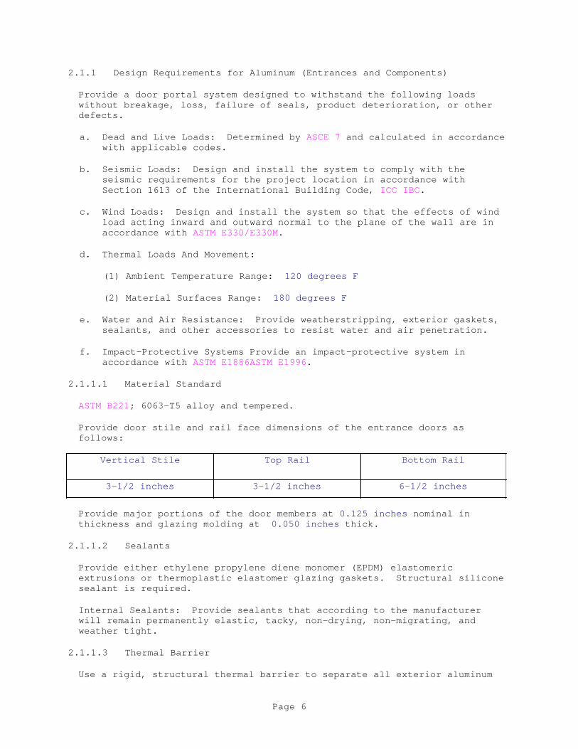
2.1.1 Design Requirements for Aluminum (Entrances and Components)
Provide a door portal system designed to withstand the following loads without breakage, loss, failure of seals, product deterioration, or other defects.
a. Dead and Live Loads: Determined by ASCE 7 and calculated in accordance with applicable codes.
b. Seismic Loads: Design and install the system to comply with the seismic requirements for the project location in accordance with Section 1613 of the International Building Code, ICC IBC.
c. Wind Loads: Design and install the system so that the effects of wind load acting inward and outward normal to the plane of the wall are in accordance with ASTM E330/E330M.
d. Thermal Loads And Movement:
(1) Ambient Temperature Range: 120 degrees F
(2) Material Surfaces Range: 180 degrees F
e. Water and Air Resistance: Provide weatherstripping, exterior gaskets, sealants, and other accessories to resist water and air penetration.
f. Impact-Protective Systems Provide an impact-protective system in accordance with ASTM E1886ASTM E1996.
2.1.1.1 Material Standard
ASTM B221; 6063-T5 alloy and tempered.
Provide door stile and rail face dimensions of the entrance doors as follows:
Vertical Stile Top Rail Bottom Rail
3-1/2 inches 3-1/2 inches 6-1/2 inches
Provide major portions of the door members at 0.125 inches nominal in thickness and glazing molding at 0.050 inches thick.
2.1.1.2 Sealants
Provide either ethylene propylene diene monomer (EPDM) elastomeric extrusions or thermoplastic elastomer glazing gaskets. Structural silicone sealant is required.
Internal Sealants: Provide sealants that according to the manufacturer will remain permanently elastic, tacky, non-drying, non-migrating, and weather tight.
2.1.1.3 Thermal Barrier
Use a rigid, structural thermal barrier to separate all exterior aluminum
Page 6

from interior aluminum. For purposes of this specification, a structural thermal barrier is defined as a system that transfers shear during bending and, therefore, promotes composite action between the exterior and interior extrusions. Do not use a nonstructural thermal barrier. Ensure that the thermal barrier provides a structural connection between the two sides of the door.
2.2 FABRICATION
Provide the following information when submitting fabrication drawings for custom fabrications:
a. Indicate elevations, detailed design, dimensions, member profiles, joint locations, arrangement of units, and member connections.
b. Show the following items:
(1) Details of special shapes.
(2) Reinforcing.
(3) Anchorage system.
(4) Interfacing with building construction.
(5) Provisions for expansion and contraction.
c. Indicate typical glazing details, and internal sealant requirements as recommended by the sealant manufacturer.
d. Clearly indicate locations of exposed fasteners and joints.
e. Clearly show where and how the manufacturer's system deviates from Contract drawings and these specifications.
2.2.1 Entrance System Fabrication
Provide door corner construction consisting of mechanical clip fastening, SIGMA deep penetration plug welds and 1 1/8 inch long fillet welds inside and outside all four corners. Provide a hook-in type exterior glazing stop with EPDM glazing gaskets reinforced with non-stretchable cord. Provide an interior glazing stop that is mechanically fastened to the door member and that incorporates a silicone-compatible spacer used with silicone sealant.
Accurately fit and secure joints and corners. Make joints hairline in appearance. Remove burrs and smooth edges. Prepare components with internal reinforcement for door hardware. Arrange fasteners and attachments so that they are concealed from view.
Separate dissimilar metals with protective coating or pre-formed separators in order to prevent contact and corrosion.
2.2.2 Shop Assembly
Fabricate and assemble units with joints only at the intersection of aluminum members with hairline joints; rigidly secure these units, and seal them in accordance with the manufacturer's recommendations.
Page 7
2.2.2.1 Welding
Conceal welds on aluminum members in accordance with AWS recommendations or methods recommended by the manufacturer. Members showing welding bloom or discoloration on finish or material distortion will be rejected by the Contacting Officer.
2.2.3 Finish
Before fabrication, clean the units and give them a AA-M-10-C22-A42 (color) anodized finish in accordance with the requirements of the AA DAF45. The finish thickness is A42, 0.7 mil or greater.
a. Organic Coating (high-performance exterior coating):
(1) Comply with requirements of AAMA 2605.
(2) Clean surfaces and pretreat them with a conversion coating before applying 0.3 mil dry-film thickness of epoxy or acrylic primer according to the recommendations of the finish coat manufacturer.
(3) Apply a finish coat of 70 percent minimum fluoropolymer resin fused to primed surfaces at the temperature recommended by the manufacturer and at a minimum dry film thickness of 1.0 mil.
(4) Use a 2-, 3-, or 4-coat system as required for the color selected.
c. Color Anodized: Conforming to AA-M12C22A 44 and AAMA 611
Select and edit the following items for appropriate finish; delete types that do not apply.
(1) Architectural Class I
(2) Etched, medium matte
(3) Black anodic coating, 0.7 mil minimum thickness
]2.2.4 Fabrication Tolerance
Fabricate and assemble units with joints only at intersection of aluminum members with hairline joints; rigidly secure these units, and seal them in accordance with the manufacturer's recommendations.
Fabricate aluminum entrances in accordance with the entrance manufacturer's prescribed tolerances.
2.2.4.1 Material Cuts
Square to 1/32 inch off square, over largest dimension; proportionate amount of 1/32 inch on the two dimensions.
2.2.4.2 Joints
Between adjacent members in same assembly: Joints are hairline and square to the adjacent member.
Page 8
2.2.4.3 Variation
In squaring diagonals for doors and fabricated assemblies: 1/16 inch.
2.2.4.4 Flatness
For doors and fabricated assemblies: plus/minus 1/16 inch of neutral plane.
2.3 MATERIALS
2.3.1 Sealants
Refer to Section 07 92 00 JOINT SEALANTS. Ensure that all sealants conform to AAMA 800.
2.3.2 Glass
Refer to Section 08 81 00 GLAZING.
2.4 ACCESSORIES
2.4.1 Fasteners
Provide stainless steel fasteners in areas where the fasteners are exposed.
Use non-corrosive and compatible fasteners with components being fastened. Do not use exposed fasteners, except where unavoidable for application of hardware.
In areas where fasteners are not exposed, use aluminum, non-magnetic stainless steel, or other materials warranted by the manufacturer.
For exposed locations, provide countersunk Phillips head screws when items with a matching finish are fastened. For concealed locations, provide the manufacturer's standard fasteners.
Provide nuts or washers that have been designed with a means to prevent disengagement; do not deform fastener threads.
2.4.2 Perimeter Anchors
When steel anchors are used, provide insulation between steel material and aluminum material in order to prevent galvanic action.
2.4.2.1 Inserts and Anchorage Devices
Provide manufacturer's standard formed or fabricated assemblies, steel or aluminum, of shapes, plates, bars, or tubes. Shop-coat steel assemblies after fabrication with an alkyd zinc chromate primer complying with FS TT-P-645.
2.4.3 Standard Entrance Hardware
2.4.3.1 Weatherstripping
Equip meeting stiles on pairs of doors with an adjustable astragal using
Page 9
wool pile with a polymeric fin.
Provide door weatherstripping on a single-acting offset pivot or butt-hung door and frame (single or pairs) consisting of a thermoplastic elastomer weatherstripping on a tubular shape with a semi-rigid polymeric backing.
Provide sill-sweep strips: Provide an EPDM blade gasket sweep strip in an aluminum extrusion applied to the interior exposed surface of the bottom rail with concealed fasteners. (Provide as necessary to meet specified performance tests.)
2.4.3.2 Threshold
Provide an extruded aluminum threshold, one piece per door opening, with ribbed surface.
2.4.3.3 Offset Pivots
Provide the manufacturer's standard top and bottom pivots with one intermediate offset pivot.
2.4.3.4 Panic Device
Provide the manufacturer's recommended standard panic hardware.
2.4.3.5 Closer
Provide a surface closer in accordance with ANSI/BHMA A156.4.
2.4.3.6 Security Lock or Dead Lock
Provide A/R MS 1850A lock with two A/R 1871 cylinder operated flush bolts.
2.4.3.7 Cylinder(s)/Thumb-turn
Provide the manufacturer's recommended standard.
2.4.3.8 Cylinder Guard
Provide the manufacturer's recommended standard.
PART 3 EXECUTION
3.1 EXAMINATION
3.1.1 Site Verification of Conditions
Verify that the condition of substrate previously installed under other sections is acceptable for product installation in accordance with the manufacturer's instructions.
Verify that openings are sized to receive the storefront system and that the sill plate is level in accordance with the manufacturer's acceptable tolerances.
3.2 PREPARATION
Page 10
Field-verify dimensions before fabricating components for the door portal assembly.
Coordinate requirements for locations of blockouts for anchorage of door portal columns and other embedded components with Section 03 30 00 CAST-IN-PLACE CONCRETE.
Coordinate the erection of door portal with installation of surrounding glass wall and door assemblies. Ensure that the door portals can provide support and anchorage for assembly components.
Coordinate electrical requirements for electrified door hardware to ensure proper power source, conduit, wiring, and boxes.
3.2.1 Adjacent Surfaces Protection
Protect adjacent work areas and finish surfaces from damage during product installation.
3.2.2 Aluminum Surface Protection
Protect aluminum surfaces from contact with lime, mortar, cement, acids, and other harmful contaminants.
3.3 INSTALLATION
Submit installation drawings for review and approval.
Install the entrance system in accordance with the manufacturer's instructions and the AAMA storefront and entrance guide specifications manual. Attach the entrance system to the structure, allowing it to be adjusted to accommodate construction tolerances and other irregularities. Provide alignment attachments and shims to permanently fasten the system to the building structure. Align the assembly so that it is plumb and level, and free of warp and twist. Maintain assembly dimensional tolerances aligning with adjacent work.
Set thresholds in a bed of mastic and secure the thresholds. Protect aluminum members in contact with masonry, steel, concrete, or dissimilar materials using nylon pads or a bituminous coating. Shim and brace the aluminum system before anchoring the system to the structure. Verify that weep holes are open, and the metal joints are sealed in accordance with the manufacturer's installation instructions. Seal metal-to-metal joints using a sealant recommended by the system manufacturer.
3.3.1 Tolerances
Ensure that tolerances for wall thickness and other cross-sectional dimensions of entrance members are nominal and in compliance with Aluminum Standards and Data, published by the Aluminum Association.
3.3.2 Adjusting
Adjust operating hardware for smooth operation, and as recommended by the manufacturer.
3.3.3 Related Products Installation Requirements
Page 11
3.3.3.1 Sealants (Perimeter)
Refer to Section 07 92 00 JOINT SEALANTS.
3.3.3.2 Glass
Refer to Section 08 81 00 GLAZING.
3.4 FIELD QUALITY CONTROL
3.4.1 Air Infiltration
Test air infiltration in accordance with ASTM E783
Submit certified test reports showing compliance with specified performance characteristics as follows:
a. For single-acting offset pivot, butt hung, or continuous geared hinge entrances in the closed and locked position, test the specimen in accordance with ANSI/BHMA A156.10, and ASTM E283 at a pressure differential of 1.57 psf for pairs of doors; ensure that maximum infiltration for a pair of 7 foot by 8 foot entrance doors and frame is 1.2 cfm/square foot.
b. Ensure the maximum allowable infiltration for a completed storefront system does not exceed 0.06 cfm/square foot when tested in accordance with ASTM E1424 at a differential static pressure of 6.24 psf.
3.4.2 Deflection
Submit certified test reports showing that the maximum allowable deflection in a member when tested in accordance with ASTM E330/E330M with allowable stress is L/175 or 3/4 inches maximum.
3.4.3 Condensation Resistance and Thermal Transmittance
Submit certified test reports showing compliance with specified performance characteristics as follows:
a. U-Value Requirements:
(1) Perform test in accordance with the AAMA 1503 procedure and on the configuration specified therein.
(2) Thermal Transmittance ("U" Value) maximum 0.65 (6250) BTU/hr/sf/deg F at 15 mph exterior wind.
b. CRF Class Requirements:
(1) Perform a test in accordance with AAMA 1503.
(2) Condensation Resistance Factor Requirements (CRF) minimum .
3.4.4 Water Infiltration
Submit certified test reports showing that the system is designed to provide no uncontrolled water when tested in accordance with ASTM E1105 at
Page 12
a static pressure of 8 psf.
3.5 ADJUSTING AND CLEANING
3.5.1 Protection
Protect the installed product's finish surfaces from damage during construction. Protect the aluminum storefront system from damage from grinding and polishing compounds, plaster, lime, acid, cement, or other harmful contaminants.
3.5.2 Cleaning
Repair or replace damaged installed products. Clean installed products in accordance with manufacturer's instructions before acceptance remove excess mastic, mastic smears, and other foreign materials. Remove construction debris from the project site and legally dispose of this debris.
3.6 WARRANTY
Submit three signed copies of the manufacturer's product warranty for the entrance system as follows:
a. Warranty Period: Five years from Date of Substantial Completion of the project, provided that the Limited Warranty begins no later than six months from the date of shipment by the manufacturer. In addition, support welded door corner construction with a limited lifetime warranty for the life of the door under normal use.
Page 13

Ensure that the Warranty's language is identical to the "As Approved" version of the sample warranty submitted to and returned from the Contracting Officer.
-- End of Section --
Page 14

SECTION 08 71 00
DOOR HARDWARE02/16
PART 1 GENERAL
1.1 REFERENCES
The publications listed below form a part of this specification to the extent referenced. The publications are referred to in the text by the basic designation only.
ASTM INTERNATIONAL (ASTM)
ASTM E283 (2004; R 2012) Determining the Rate of Air Leakage Through Exterior Windows, Curtain Walls, and Doors Under Specified Pressure Differences Across the Specimen
ASTM F883 (2013) Padlocks
BUILDERS HARDWARE MANUFACTURERS ASSOCIATION (BHMA)
ANSI/BHMA A156.1 (2016) Butts and Hinges
ANSI/BHMA A156.10 (2011) Power Operated Pedestrian Doors
ANSI/BHMA A156.13 (2017) Mortise Locks & Latches Series 1000
ANSI/BHMA A156.15 (2015) Release Devices Closer Holder, Electromagnetic and Electromechanical
ANSI/BHMA A156.16 (2013) Auxiliary Hardware
ANSI/BHMA A156.17 (2014) Self Closing Hinges & Pivots
ANSI/BHMA A156.18 (2016) Materials and Finishes
ANSI/BHMA A156.19 (2013) Power Assist & Low Energy Power Operated Doors
ANSI/BHMA A156.2 (2017) Bored and Preassembled Locks and Latches
ANSI/BHMA A156.21 (2014) Thresholds
ANSI/BHMA A156.22 (2012) Door Gasketing and Edge Seal Systems
ANSI/BHMA A156.23 (2010) Electromagnetic Locks
ANSI/BHMA A156.24 (2012) Delayed Egress Locking Systems
ANSI/BHMA A156.25 (2013) Electrified Locking Devices
Page 1
ANSI/BHMA A156.26 (2012) Continuous Hinges
ANSI/BHMA A156.29 (2012) Exit Locks, Exit Alarms, Alarms for Exit Devices
ANSI/BHMA A156.3 (2014) Exit Devices
ANSI/BHMA A156.30 (2014) High Security Cylinders
ANSI/BHMA A156.31 (2013) Electric Strikes and Frame Mounted Actuators
ANSI/BHMA A156.36 (2010) Auxiliary Locks
ANSI/BHMA A156.4 (2013) Door Controls - Closers
ANSI/BHMA A156.5 (2014) Cylinder and Input Devices for Locks
ANSI/BHMA A156.6 (2015) Architectural Door Trim
ANSI/BHMA A156.7 (2016) Template Hinge Dimensions
ANSI/BHMA A156.8 (2015) Door Controls - Overhead Stops and Holders
NATIONAL FIRE PROTECTION ASSOCIATION (NFPA)
NFPA 101 (2015; ERTA 2016) Life Safety Code
NFPA 252 (2017) Standard Methods of Fire Tests of Door Assemblies
NFPA 70 (2017; ERTA 1-2 2017; TIA 17-1; TIA 17-2) National Electrical Code
NFPA 72 (2016) National Fire Alarm and Signaling Code
NFPA 80 (2016; TIA 16-1) Standard for Fire Doors and Other Opening Protectives
STEEL DOOR INSTITUTE (SDI/DOOR)
SDI/DOOR A250.8 (2003; R2008) Recommended Specifications for Standard Steel Doors and Frames
U.S. NATIONAL ARCHIVES AND RECORDS ADMINISTRATION (NARA)
36 CFR 1191 Americans with Disabilities Act (ADA) Accessibility Guidelines for Buildings and Facilities; Architectural Barriers Act (ABA) Accessibility Guidelines
UNDERWRITERS LABORATORIES (UL)
UL 14C (2006; Reprint May 2013) Swinging Hardware
Page 2
for Standard Tin-Clad Fire Doors Mounted Singly and in Pairs
UL Bld Mat Dir (updated continuously online) Building Materials Directory
1.2 SUBMITTALS
Government approval is required for submittals with a "G" designation; submittals not having a "G" designation are Submittals with an "S" are for inclusion in the Sustainability eNotebook, in conformance with Section 01 33 29 SUSTAINABILITY REPORTING. Submit the following in accordance with Section 01 33 00 SUBMITTAL PROCEDURES:
SD-02 Shop Drawings
Manufacturer's Detail Drawings; G
Verification of Existing Conditions; G
Hardware Schedule; G
Keying System; G
SD-03 Product Data
Hardware Items; G
SD-08 Manufacturer's Instructions
Installation
SD-10 Operation and Maintenance Data
Hardware Schedule Items, Data Package 1; G
SD-11 Closeout Submittals
Key Bitting
1.3 SHOP DRAWINGS
Submit manufacturer's detail drawings indicating all hardware assembly components and interface with adjacent construction.Indicate power components and wiring coordination for electrified hardware. Base shop drawings on verified field measurements and include verification of existing conditions.
1.4 PRODUCT DATA
Indicate fire-ratings at applicable components. Provide documentation of ABA/ADA accessibility compliance of applicable components, as required by 36 CFR 1191 Appendix D - Technical.
1.5 HARDWARE SCHEDULE
Page 3

Prepare and submit hardware schedule in the following form:
Hardware Item
Quantity Size Reference Publi-cation Type No.
Finish Mfr Name and Catalog No.
Key ControlSymbols
UL Mark (If fire- rated and listed)
BHMA Finish Desig-nation
In addition, submit hardware schedule data package 1 in accordance with Section 01 78 23 OPERATION AND MAINTENANCE DATA.
1.6 KEY BITTING CHART REQUIREMENTS
1.6.1 Requirements
Submit key bitting charts to the Contracting Officer prior to completion of the work. Include:
a. Complete listing of all keys (e.g. AA1 and AA2).
b. Complete listing of all key cuts (AA1-123456, AA2-123458).
c. Tabulation showing which key fits which door.
d. Copy of floor plan showing doors and door numbers.
e. Listing of 20 percent more key cuts than are presently required in each master system.
1.7 QUALITY ASSURANCE
1.7.1 Hardware Manufacturers and Modifications
Provide, as far as feasible, locks, hinges and closers of one lock, hinge, or closer manufacturer's make. Modify hardware as necessary to provide features indicated or specified.
1.7.2 Key Shop Drawings Coordination Meeting
Prior to the submission of the key shop drawing, the Contracting Officer, Contractor, Door Hardware Subcontractor, using Activity and Base Locksmith must meet to discuss and coordinate key requirements for the facility.
1.8 DELIVERY, STORAGE, AND HANDLING
Deliver hardware in original individual containers, complete with necessary appurtenances including fasteners and instructions. Mark each individual container with item number as shown on hardware schedule. Deliver permanent keys to the Contracting Officer, either directly or by certified mail. Deliver construction master keys with the locks.
Page 4

PART 2 PRODUCTS
2.1 TEMPLATE HARDWARE
Hardware applied to metal or to prefinished doors must be manufactured using a template. Provide templates to door and frame manufacturers in accordance with ANSI/BHMA A156.7 for template hinges. Coordinate hardware items to prevent interference with other hardware.
2.2 HARDWARE FOR FIRE DOORS AND EXIT DOORS
Provide all hardware necessary to meet the requirements of NFPA 72 for door alarms, NFPA 80 for fire doors, NFPA 101 for exit doors, NFPA 252 for fire tests of door assemblies, ABA/ADA accessibility requirements, and all other requirements indicated, even if such hardware is not specifically mentioned in paragraph HARDWARE SCHEDULE. Provide swinging hardware for tin-clad fire doors in accordance with UL 14C. Provide Underwriters Laboratories, Inc. labels for such hardware in accordance with UL Bld Mat Dir or equivalent labels in accordance with another testing laboratory approved in writing by the Contracting Officer.
2.3 HARDWARE ITEMS
Clearly and permanently mark with the manufacturer's name or trademark, hinges, pivots, locks, latches, exit devices, bolts and closers where the identifying mark is visible after the item is installed. For closers with covers, the name or trademark may be beneath the cover. Coordinate electrified door hardware components with corresponding components specified in Division 28 ELECTRONIC SECURITY SYSTEMS (ESS).
2.3.1 Hinges
Provide in accordance with ANSI/BHMA A156.1. Provide hinges that are 4-1/2 by 4-1/2 inch unless otherwise indicated. Construct loose pin hinges for interior doors and reverse-bevel exterior doors so that pins are non-removable when door is closed. Other anti-friction bearing hinges may be provided in lieu of ball bearing hinges.
2.3.2 Continuous Hinges
Where continuous hinges are required, provide in accordance with ANSI/BHMA A156.26.
2.3.3 Locks and Latches
2.3.3.1 Mortise Locks and Latches
Provide in accordance with ANSI/BHMA A156.13, Series 1000, Operational Grade 1, Security Grade 2. Provide factory installed lead lining in locks for lead shielded doors. Provide mortise locks with escutcheons not less than 7 by 2-1/4 inch with a bushing at least 1/4 inch long. Cut escutcheons to fit cylinders and provide trim items with straight, beveled, or smoothly rounded sides, corners, and edges. Provide knobs and roses of mortise locks with screwless shanks and no exposed screws.
2.3.4 Exit Devices
Page 5
Provide in accordance with ANSI/BHMA A156.3, tested to exceed at least 3 times the number of cycles required for Grade 1.
2.3.5 Cylinders and Cores
Provide cylinders and cores for new locks, including locks provided under other sections of this specification. Provide cylinders and cores with seven pin tumblers. Provide cylinders from the products of one manufacturer, and provide cores from the products of one manufacturer.Rim cylinders, mortise cylinders, and knobs of bored locksets have interchangeable cores which are removable by special control keys. Stamp each interchangeable core with a key control symbol in a concealed place on the core.
2.3.6 Electrified Hardware
Comply with the requirements of NFPA 70 for wiring of electrified hardware.
2.3.6.1 Electric Strikes and Frame Mounted Actuators
Provide in accordance with ANSI/BHMA A156.31, Grade 1. Provide electric strikes and actuators as required to meet operational requirements. Provide electric strikes that remain secure during power failure. Provide strikes and actuators with a minimum opening force of 2300 pounds.
Provide facility interface devices that use direct current (dc) power to energize the solenoids. Provide electric strikes and actuators that incorporate end-of-line resistors to facilitate line supervision by the system. If not incorporated into the electric strike or local controller, provide metal oxide resistors (MOVs) to protect the controller from reverse current surges.
2.3.6.1.1 Solenoid
Provide actuating solenoid for strikes and actuators that are rated for continuous duty, cannot dissipate more than 12 Watts and must operate on 12 or 24 Volts dc. Inrush current cannot exceed 1 ampere and the holding current cannot be greater than 500 milliamperes. Actuating solenoid must move from fully secure to fully open positions in less than 500 milliseconds.
2.3.6.1.2 Signal Switches
Provide strikes and actuators with signal switches to indicate to the system when the bolt is not engaged or the strike mechanism is unlocked. Signal switches must report a forced entry to the system.
2.3.6.1.3 Coordination
Provide electric strikes and actuators of a size, weight and profile compatible with each specified door frame. Field verify installation clearances prior to procurement.
2.3.6.1.4 Mounting Method
Provide electric strikes and actuators suitable for use with single and double doors, with mortise or rim type hardware specified, and for right or
Page 6

left hand mounting as specified. In double door installations, locate the lock in the active leaf and monitor the fixed leaf.
2.3.6.2 Electrified Mortise Locks
Provide in accordance with ANSI/BHMA A156.25, Grade 1. Provide electrified mortise locks that remain secure during power failure. Provide facility interface devices that use dc power to energize solenoids. Provide solenoids, resisters, and signal switches in accordance with paragraph ELECTRIC STRIKES AND FRAME MOUNTED ACTUATORS.
2.3.6.2.1 Power Transfer Hinges
Provide power transfer hinges with each electrified lock that route power and monitoring signals from the lockset to the door frame. Coordinate power transfer hinges with door frames.
2.3.6.3 Card Readers and Keypad Access Control Hardware
Provide in accordance with ANSI/BHMA A156.5 and ANSI/BHMA A156.25, Grade 1 components. Provide devices that are tamper alarmed, tamper and vandal resistant, solid state, and do not contain electronics which could compromise the access control subsystem should the subsystem be attacked. Provide surface, semi-flush, pedestal devices as specified for each individual location. Each device to contain a visual display, either mounted on the face, or on an integral part of the device, to indicate access or exit request processing, request approval, and request denial. Provide proximity type card readers capable of reading proximity type access control cards. Coordinate access control hardware with corresponding devices and systems specified in Division 28 ELECTRONIC SECURITY SYSTEMS (ESS).
2.3.7 Keying System
Provide an extension of the existing keying system. Existing locks were manufactured by Enquire with EAFB and have interchangeable cores.
2.3.8 Lock Trim
Provide cast, forged, or heavy wrought construction and commercial plain design for lock trim.
2.3.8.1 Knobs and Roses
Provide in accordance with ANSI/BHMA A156.2 and ANSI/BHMA A156.13 for knobs, roses, and escutcheons. For unreinforced knobs, roses, and escutcheons, provide a 0.050 inch thickness. For reinforced knobs, roses, and escutcheons, provide an outer shell thickness of 0.035 inch and a combined total thickness of 0.070 inch, except at knob shanks. Provide knob shanks 0.060 inch thick.
2.3.8.2 Lever Handles
Provide lever handles. Provide in accordance with ANSI/BHMA A156.3 for mortise locks of lever handles for exit devices. Provide lever handle locks with a breakaway feature (such as a weakened spindle or a shear key) to prevent irreparable damage to the lock when force in excess of that
Page 7
specified in ANSI/BHMA A156.13 is applied to the lever handle. Provide lever handles return to within 1/2 inch of the door face.
2.3.8.3 Texture
Provide knurled or abrasive coated knobs or lever handles for doors which are accessible to blind persons and which lead to dangerous areas.
2.3.9 Keys
Provide one file key, one duplicate key, and one working key for each key change and for each master keying system. Provide one additional working key for each lock of each keyed-alike group. Provide great grand master keys for removable cores.Provide a quantity of key blanks equal to 20 percent of the total number of file keys. Stamp each key with appropriate key control symbol and "U.S. property - do not duplicate." Do not place room number on keys.Provide seven change keys for each interchangeable core, provide two control keys, six maters keys, and six construction master keys. Provide a quantity of key blanks equal to 20 percent of the total number of change keys. Stamp each key with appropriate key control symbol and "U.S. property - do not duplicate." Do not place room numbers on keys.
]2.3.10 Closers
Provide in accordance with ANSI/BHMA A156.4, Series C02000, Grade 1, with PT 4C. Provide with brackets, arms, mounting devices, fasteners and other features necessary for the particular application. Size closers in accordance with manufacturer's printed recommendations, or provide multi-size closers, Sizes 1 through 6, and list sizes in the Hardware Schedule. Provide manufacturer's 10 year warranty.
2.3.10.1 Identification Marking
Engrave each closer with manufacturer's name or trademark, date of manufacture, and manufacturer's size designation in locations that will be visible after installation.
2.3.11 Door Protection Plates
Provide in accordance with ANSI/BHMA A156.6.
2.3.11.1 Sizes of Kick Plates
2 inch less than door width for single doors; 1 inch less than door width for pairs of doors. Provide 10 inch kick plates for flush door and inch less than height of bottom rail for panel doors.
2.3.12 Door Stops and Silencers
Provide in accordance with ANSI/BHMA A156.16. Silencers Type L03011. Provide three silencers for each single door, two for each pair.
2.3.13 Weatherstripping Gasketing
Provide in accordance with ANSI/BHMA A156.22. Provide the type and function designation where specified in paragraph HARDWARE SCHEDULE.
Page 8

Provide a set to include head and jamb seals, sweep strips and, for pairs of doors, astragals. Air leakage of weatherstripped doors not to exceed 1.25 cubic feet per minute of air per square foot of door area when tested in accordance with ASTM E283. Provide weatherstripping with one of the following:
2.3.13.1 Extruded Aluminum Retainers
Extruded aluminum retainers not less than 0.050 inch wall thickness with vinyl, neoprene, silicone rubber, or polyurethane inserts. Provide clear anodized aluminum.
2.4 FASTENERS
Provide fasteners of type, quality, size, and quantity appropriate to the specific application. Fastener finish to match hardware. Provide stainless steel or nonferrous metal fasteners in locations exposed to weather. Verify metals in contact with one another are compatible and will avoid galvanic corrosion when exposed to weather.
2.5 FINISHES
Provide in accordance with ANSI/BHMA A156.18. Provide hardware in BHMA 630 finish satin stainless steel, unless specified otherwise. Provide items not manufactured in stainless steel in BHMA 626 finish (satin chromium plated) over brass or bronze, except prime coat finish for surface door closers, and except BHMA 652 finish (satin chromium plated) BHMA 600 finish primed for painting for steel hinges. Furnish exit devices in BHMA 626 finish in lieu of BHMA 630 finish except where BHMA 630 is specified under paragraph HARDWARE SETS. Match exposed parts of concealed closers to lock and door trim. Match hardware finish for aluminum doors to the doors.
PART 3 EXECUTION
3.1 INSTALLATION
Provide hardware in accordance with manufacturers' printed installation instructions. Fasten hardware to wood surfaces with full-threaded wood screws or sheet metal screws. Provide machine screws set in expansion shields for fastening hardware to solid concrete and masonry surfaces. Provide toggle bolts where required for fastening to hollow core construction. Provide through bolts where necessary for satisfactory installation.
3.1.1 Weatherstripping Installation
Provide full contact, weathertight seals that allow operation of doors without binding the weatherstripping.
3.1.1.1 Stop Applied Weatherstripping
Fasten in place with color matched sheet metal screws not more than 9 inch on center after doors and frames have been finish painted.
3.1.2 Soundproofing Installation
Provide as specified for stop applied weatherstripping.
Page 9

3.2 FIRE DOORS AND EXIT DOORS
Provide hardware in accordance with NFPA 72 for door alarms, NFPA 80 for fire doors, NFPA 101 for exit doors, and NFPA 252 for fire tests of door assemblies.
3.3 HARDWARE LOCATIONS
Provide in accordance with SDI/DOOR A250.8, unless indicated or specified otherwise.
a. Kick Plates: Push side of single-acting doors.
3.4 FIELD QUALITY CONTROL
After installation, protect hardware from paint, stains, blemishes, and other damage until acceptance of work. Submit notice of testing 15 days before scheduled, so that testing can be witnessed by the Contracting Officer. Adjust hinges, locks, latches, bolts, holders, closers, and other items to operate properly. Demonstrate that permanent keys operate respective locks, and give keys to the Contracting Officer. Correct, repair, and finish, errors in cutting and fitting and damage to adjoining work.
3.5 HARDWARE SETS
Page 10

Provide hardware for aluminum doors under this section. Deliver Hardware templates and hardware, except field applied hardware, to the aluminum door and frame manufacturer for use in fabricating doors and frames.
-- End of Section --
Page 11

SECTION 09 29 00
GYPSUM BOARD08/16
PART 1 GENERAL
1.1 REFERENCES
The publications listed below form a part of this specification to the extent referenced. The publications are referred to within the text by the basic designation only.
AMERICAN NATIONAL STANDARDS INSTITUTE (ANSI)
ANSI A108.11 (1992; Reaffirmed 2005) Specifications for Interior Installation of Cementitious Backer Units
ASTM INTERNATIONAL (ASTM)
ASTM C1002 (2014) Standard Specification for Steel Self-Piercing Tapping Screws for the Application of Gypsum Panel Products or Metal Plaster Bases to Wood Studs or Steel Studs
ASTM C1047 (2014a) Standard Specification for Accessories for Gypsum Wallboard and Gypsum Veneer Base
ASTM C1177/C1177M (2013) Standard Specification for Glass Mat Gypsum Substrate for Use as Sheathing
ASTM C1178/C1178M (2013) Standard Specification for Glass Mat Water-Resistant Gypsum Backing Panel
ASTM C1396/C1396M (2014a) Standard Specification for Gypsum Board
ASTM C1629/C1629M (2015) Standard Classification for Abuse-Resistant Nondecorated Interior Gypsum Panel Products and Fiber-Reinforced Cement Panels
ASTM C475/C475M (2015) Joint Compound and Joint Tape for Finishing Gypsum Board
ASTM C514 (2004; R 2014) Standard Specification for Nails for the Application of Gypsum Board
ASTM C557 (2003; E 2009; R 2009) Adhesives for Fastening Gypsum Wallboard to Wood Framing
Page 1
ASTM C840 (2016) Standard Specification for Application and Finishing of Gypsum Board
ASTM C954 (2015) Steel Drill Screws for the Application of Gypsum Panel Products or Metal Plaster Bases to Steel Studs from 0.033 in. (0.84 mm) to 0.112 in. (2.84 mm) in Thickness
ASTM D1037 (2012) Evaluating Properties of Wood-Base Fiber and Particle Panel Materials
ASTM D1149 (2007; R 2012) Standard Test Method for Rubber Deterioration - Surface Ozone Cracking in a Chamber
ASTM D226/D226M (2009) Standard Specification for Asphalt-Saturated Organic Felt Used in Roofing and Waterproofing
ASTM D2394 (2005; R 2011) Simulated Service Testing of Wood and Wood-Base Finish Flooring
ASTM D3273 (2016) Standard Test Method for Resistance to Growth of Mold on the Surface of Interior Coatings in an Environmental Chamber
ASTM D412 (2015a) Standard Test Methods for Vulcanized Rubber and Thermoplastic Elastomers - Tension
ASTM D5420 (2016) Standard Test Method for Impact Resistance of Flat, Rigid Plastic Specimen by Means of a Strike Impacted by a Falling Weight (Gardner Impact)
ASTM D624 (2000; R 2012) Tear Strength of Conventional Vulcanized Rubber and Thermoplastic Elastomers
ASTM E695 (2003; R 2015; E 2015) Measuring Relative Resistance of Wall, Floor, and Roof Construction to Impact Loading
ASTM E84 (2016) Standard Test Method for Surface Burning Characteristics of Building Materials
CALIFORNIA DEPARTMENT OF PUBLIC HEALTH (CDPH)
CDPH SECTION 01350 (2004; Add 2004-01) Standard Practice for the Testing Of Volatile Organic Emissions from Various Sources Using Small-Scale Environmental Chambers
Page 2
FM GLOBAL (FM)
FM APP GUIDE (updated on-line) Approval Guide http://www.approvalguide.com/
GREEN SEAL (GS)
GS-36 (2011) Commercial Adhesives
GYPSUM ASSOCIATION (GA)
GA 214 (2010) Recommended Levels of Gypsum Board Finish
GA 216 (2010) Application and Finishing of Gypsum Panel Products
GA 224 (2008) Installation of Predecorated Gypsum Board
GA 253 (2012) Application of Gypsum Sheathing
GA 600 (2009) Fire Resistance Design Manual
SCIENTIFIC CERTIFICATION SYSTEMS (SCS)
SCS SCS Global Services (SCS)Indoor Advantage
SOUTH COAST AIR QUALITY MANAGEMENT DISTRICT (SCAQMD)
SCAQMD Rule 1168 (1989; R 2005) Adhesive and Sealant Applications
UNDERWRITERS LABORATORIES (UL)
UL 2818 (2013) GREENGUARD Certification Program For Chemical Emissions For Building Materials, Finishes And Furnishings
UL Fire Resistance (2014) Fire Resistance Directory
1.2 SUBMITTALS
Government approval is required for submittals with a "G" designation; submittals not having a "G" designation are [for Contractor Quality Control approval.][for information only. When used, a designation following the "G" designation identifies the office that will review the submittal for the Government.] Submittals with an "S" are for inclusion in the Sustainability Notebook, in conformance with Section 01 33 29 SUSTAINABILITY REPORTING. Submit the following in accordance with Section 01 33 00 SUBMITTAL PROCEDURES:
Page 3
SD-03 Product DataAbuse Resistant Gypsum Board
Accessories
Submit for each type of gypsum board and for cementitious backer units.
Certifications
Gypsum Board
SD-07 Certificates
Asbestos Free Materials; G
Certify that gypsum board types, gypsum backing board types, cementitious backer units, and joint treating materials do not contain asbestos.
Indoor Air Quality; G
SD-08 Manufacturer's Instructions
Material Safety Data Sheets
SD-10 Operation and Maintenance Data
Manufacturer Maintenance Instructions
SD-11 Closeout Submittals
Recycled Content for Gypsum Board; S
Recycled Content for Paper Facing and Gypsum Cores; S
Indoor Air Quality for Gypsum Board; S
VOC Content of Joint Compound; S
Indoor Air Quality for Non-aerosol Adhesives; S
Indoor Air Quality for Aerosol Adhesives; S
1.3 CERTIFICATIONS
1.3.1 Indoor Air Quality Certifications
Submit required indoor air quality certifications in one submittal package.
Page 4
1.3.1.1 Wall Systems
[Provide products certified to meet indoor air quality requirements by UL 2818 Gold, SCS Global Services Indoor Advantage Gold or provide validation by other third-party program that products meet the requirements of this paragraph. Provide current product certification documentation from certification body. ]Gypsum wall board and panels must meet the emissions requirements of CDPH SECTION 01350 (limit requirements for either office or classroom spaces regardless of space type).
1.3.1.2 Adhesives and Sealants
Provide products certified to meet indoor air quality requirements by UL 2818 Gold, SCS Global Services Indoor Advantage Gold or provide validation by other third-party program that products meet the requirements of this paragraph. Sealants and non-aerosol adhesive products used on the interior of the building must meet either emissions requirements of CDPH SECTION 01350 limit requirements for either office or classroom spaces regardless of space type or VOC content requirements of SCAQMD Rule 1168. Aerosol adhesive products used on the interior of the building must meet either emissions requirements of CDPH SECTION 01350 limit requirements for either office or classroom spaces regardless of space type or VOC content requirements of GS-36. Provide current product certification documentation from certification body.
1.4 DELIVERY, STORAGE, AND HANDLING
1.4.1 Delivery
Deliver materials in the original packages, containers, or bundles with each bearing the brand name, applicable standard designation, and name of manufacturer, or supplier.
1.4.2 Storage
Keep materials dry by storing inside a sheltered building. Where necessary to store gypsum board and cementitious backer units outside, store off the ground, properly supported on a level platform, and protected from direct exposure to rain, snow, sunlight, and other extreme weather conditions. Provide adequate ventilation to prevent condensation. Store per manufacturer's recommendations for allowable temperature and humidity range. Do not store panels near materials that may offgas or emit harmful fumes, such as kerosene heaters, fresh paint, or adhesives. Do not use materials that have visible moisture or biological growth.
1.4.3 Handling
Neatly stack gypsum board and cementitious backer units flat to prevent sagging or damage to the edges, ends, and surfaces.
1.5 QUALIFICATIONS
Furnish type of gypsum board work specialized by the installer with a minimum of 3 years of documented successful experience.
Page 5
1.6 ENVIRONMENTAL REQUIREMENTS
Do not expose the gypsum board to excessive sunlight prior to gypsum board application. Maintain a continuous uniform temperature of not less than 50 degrees F and not more than 80 degrees F for at least one week prior to the application of gypsum board work, while the gypsum board application is being done, and for at least one week after the gypsum board is set. Shield air supply and distribution devices to prevent any uneven flow of air across the plastered surfaces. Provide ventilation to exhaust moist air to the outside during gypsum board application, set, and until gypsum board jointing is dry. In glazed areas, keep windows open top and bottom or side to side 3 to 4 inches. Reduce openings in cold weather to prevent freezing of joint compound when applied. For enclosed areas lacking natural ventilation, provide temporary mechanical means for ventilation. In unglazed areas subjected to hot, dry winds or temperature differentials from day to night of 20 degrees F or more, screen openings with cheesecloth or similar materials. Avoid rapid drying. During periods of low indoor humidity, provide minimum air circulation following gypsum boarding and until gypsum board jointing complete and is dry.
PART 2 PRODUCTS
2.1 PRODUCT SUSTAINABILITY CRITERIA
For products in this section, where applicable and to extent allowed by performance criteria, provide and document the following:
2.1.1 Recycled Content for Gypsum Board Materials
Recycled content is identified for some products in this section; provide documentation in accordance with Section 01 33 29 SUSTAINABILITY REPORTING paragraph RECYCLED CONTENT. Other products listed in this section may be available with recycled content; identify those products that meet project requirements for recycled content, and provide documentation in accordance with Section 01 33 29 SUSTAINABILITY REPORTING paragraph RECYCLED CONTENT.
2.2 MATERIALS
Conform to specifications, standards and requirements specified. Provide gypsum board types, gypsum backing board types, cementitious backing units, and joint treating materials manufactured from asbestos free materials only.
2.2.1 Gypsum Board
ASTM C1396/C1396M. Gypsum board must contain a minimum of 10 percent post-consumer recycled content, or a minimum of 40 percent post-industrial recycled content. Provide data identifying percentage of recycled content for gypsum board. Paper facings must contain a minimum of 100 percent post-consumer recycled paper content. Gypsum cores must contain a minimum of 95 percent post-industrial recycled gypsum content. Provide data identifying percentage of recycled content for paper facing and gypsum cores. Provide certification of indoor air quality for gypsum board.
Page 6
2.2.1.1 Regular
48 inch wide,5/8 inch thick, tapered and featured edges.
2.2.2 Fasteners
2.2.2.1 Screws
ASTM C1002, Type "G", Type "S" or Type "W" steel drill screws for fastening gypsum board to gypsum board, wood framing members and steel framing members less than 0.033 inch thick. ASTM C954 steel drill screws for fastening gypsum board to steel framing members 0.033 to 0.112 inch thick. Provide cementitious backer unit screws with a polymer coating.
2.2.3 Adhesives
Provide certification of indoor air quality for non-aerosol adhesives applied on the interior of the building (inside of the weatherproofing system). Provide certification of indoor air quality for aerosol adhesives used on the interior of the building (inside of the weatherproofing system).
2.2.3.1 Adhesive for Fastening Gypsum Board to Metal Framing
Not permitted.
2.2.4 Water
Provide clean, fresh, and potable water.
PART 3 EXECUTION
3.1 EXAMINATION
3.1.1 Framing and Furring
Verify that framing and furring are securely attached and of sizes and spacing to provide a suitable substrate to receive gypsum board and cementitious backer units. Verify that all blocking, headers and supports are in place to support plumbing fixtures and to receive soap dishes, grab bars, towel racks, and similar items. Do not proceed with work until framing and furring are acceptable for application of gypsum board and cementitious backer units.
3.1.2 Gypsum Board and Framing
Verify that surfaces of gypsum board and framing to be bonded with an adhesive are free of dust, dirt, grease, and any other foreign matter.Do not proceed with work until surfaces are acceptable for application of gypsum board with adhesive.
3.1.3 Building Construction Materials
Do not install building construction materials that show visual evidence of biological growth.
Page 7
3.2 APPLICATION OF GYPSUM BOARD
Apply gypsum board to framing and furring members in accordance with ASTM C840 or GA 216 and the requirements specified. Apply gypsum board with separate panels in moderate contact; do not force in place. Stagger end joints of adjoining panels. Neatly fit abutting end and edge joints. Use gypsum board of maximum practical length; select panel sizes to minimize waste. Cut out gypsum board to make neat, close, and tight joints around openings. In vertical application of gypsum board, provide panels in lengths required to reach full height of vertical surfaces in one continuous piece. Lay out panels to minimize waste; reuse cutoffs whenever feasible. Surfaces of gypsum board and substrate members may [not ]be bonded together with an adhesive[, except where prohibited by fire rating(s)]. Treat edges of cutouts for plumbing pipes, screwheads, and joints with water-resistant compound as recommended by the gypsum board manufacturer. Provide type of gypsum board for use in each system specified herein as indicated.
3.2.1 Application of Gypsum Board to Steel Framing and Furring
Apply in accordance with ASTM C840, System VIII or GA 216.
3.3 FINISHING OF GYPSUM BOARD
Tape and finish gypsum board in accordance with ASTM C840, GA 214 and GA 216. Finish plenum areas above ceilings to Level 1 in accordance with GA 214. Finish walls and ceilings to receive a heavy-grade wall covering or heave textured finish before painting to Level 3 in accordance with GA 214. Finish walls and ceilings without critical lighting to receive flat paints, light textures, or wall coverings to Level 4 in accordance with GA 214. Unless otherwise specified, finish all gypsum board walls, partitions and ceilings to Level 5 in accordance with GA 214. Provide joint, fastener depression, and corner treatment. Tool joints as smoothly as possible to minimize sanding and dust. Do not use self-adhering fiber glass mesh tape with conventional drying type joint compounds; use setting or hardening type compounds only. Provide treatment for water-resistant gypsum board as recommended by the gypsum board manufacturer. Protect workers, building occupants, and HVAC systems from gypsum dust.
3.3.1 Uniform Surface
Wherever gypsum board is to receive eggshell, semigloss or gloss paint finish, or where severe, up or down lighting conditions occur, finish gypsum wall surface in accordance to GA 214 Level 5. In accordance with GA 214 Level 5, apply a thin skim coat of joint compound to the entire gypsum board surface, after the two-coat joint and fastener treatment is complete and dry.
3.3.2 Metal Trim for Predecorated Gypsum Board
Finish edges, ends, and joints of predecorated gypsum board, except prefinished vee joints and monolithic type joints, with metal or plastic trim selected to match the gypsum board finish.
Page 8

3.4 SEALING
Seal openings around pipes, fixtures, and other items projecting through gypsum board and cementitious backer units as specified in Section 07 92 00 JOINT SEALANTS. Apply material with exposed surface flush with gypsum board or cementitious backer units.
3.4.1 Sealing for Glass Mat or Reinforced Gypsum Board Sheathing
Apply silicone sealant in a 3/8 inch bead to all joints and trowel flat. Apply enough of the same sealant to all fasteners penetrating through the glass mat gypsum board surface to completely cover the penetration when troweled flat. [Do not place construction and materials behind sheathing until a visual inspection of sealed joints during daylight hours has been completed by Contracting Officer.]
3.5 PATCHING
Patch surface defects in gypsum board to a smooth, uniform appearance, ready to receive finishes. Remove predecorated gypsum board which cannot be restored to like-new condition. Provide new predecorated gypsum board.
-- End of Section --
Page 9

SECTION 09 51 00
ACOUSTICAL CEILINGS08/17
PART 1 GENERAL
1.1 REFERENCES
The publications listed below form a part of this specification to the extent referenced. The publications are referred to within the text by the basic designation only.
ASTM INTERNATIONAL (ASTM)
ASTM A1008/A1008M (2016) Standard Specification for Steel, Sheet, Cold-Rolled, Carbon, Structural, High-Strength Low-Alloy, High-Strength Low-Alloy with Improved Formability, Solution Hardened, and Bake Hardenable
ASTM A167 (2011) Standard Specification for Stainless and Heat-Resisting Chromium-Nickel Steel Plate, Sheet, and Strip
ASTM A489 (2012) Standard Specification for Carbon Steel Lifting Eyes
ASTM A580/A580M (2016) Standard Specification for Stainless Steel Wire
ASTM A641/A641M (2009a; R 2014) Standard Specification for Zinc-Coated (Galvanized) Carbon Steel Wire
ASTM A653/A653M (2015; E 2016) Standard Specification for Steel Sheet, Zinc-Coated (Galvanized) or Zinc-Iron Alloy-Coated (Galvannealed) by the Hot-Dip Process
ASTM B633 (2015) Standard Specification for Electrodeposited Coatings of Zinc on Iron and Steel
ASTM C423 (2009a) Sound Absorption and Sound Absorption Coefficients by the Reverberation Room Method
ASTM C635/C635M (2013a) Manufacture, Performance, and Testing of Metal Suspension Systems for Acoustical Tile and Lay-In Panel Ceilings
ASTM C636/C636M (2013) Standard Practice for Installation of Metal Ceiling Suspension Systems for Acoustical Tile and Lay-In Panels
Page 1
ASTM C834 (2017) Standard Specification for Latex Sealants
ASTM E119 (2016a) Standard Test Methods for Fire Tests of Building Construction and Materials
ASTM E1264 (2014) Acoustical Ceiling Products
ASTM E1414/E1414M (2011a; E 2014) Airborne Sound Attenuation Between Rooms Sharing a Common Ceiling Plenum
ASTM E1477 (1998a; R 2013) Luminous Reflectance Factor of Acoustical Materials by Use of Integrating-Sphere Reflectometers
ASTM E580/E580M (2014) Standard Practice for Installation of Ceiling Suspension Systems for Acoustical Tile and Lay-in Panels in Areas Subject to Earthquake Ground Motions
ASTM E795 (2016) Standard Practices for Mounting Test Specimens During Sound Absorption Tests
ASTM E84 (2016) Standard Test Method for Surface Burning Characteristics of Building Materials
CALIFORNIA DEPARTMENT OF PUBLIC HEALTH (CDPH)
CDPH SECTION 01350 Standard Method for the Testing and Evaluation of Volatile Organic Chemical Emissions from Indoor Sources using Environmental Chambers
GREEN SEAL (GS)
GS-36 (2011) Commercial Adhesives
SCIENTIFIC CERTIFICATION SYSTEMS (SCS)
SCS SCS Global Services (SCS)Indoor Advantage
SOUTH COAST AIR QUALITY MANAGEMENT DISTRICT (SCAQMD)
SCAQMD Rule 1168 (1989; R 2005) Adhesive and Sealant Applications
U.S. DEPARTMENT OF DEFENSE (DOD)
UFC 3-310-04 (2013) Seismic Design for Buildings
Page 2

UNDERWRITERS LABORATORIES (UL)
UL 2818 (2013) GREENGUARD Certification Program For Chemical Emissions For Building Materials, Finishes And Furnishings
1.2 SUBMITTALS
Government approval is required for submittals with a "G" designation; submittals not having a "G" designation are for [Contractor Quality Control approval.] [information only. When used, a designation following the "G" designation identifies the office that will review the submittal for the Government.] Submittals with an "S" are for inclusion in the Sustainability eNotebook, in conformance to Section 01 33 29 SUSTAINABILITY REPORTING. Submit the following in accordance with Section 01 33 00 SUBMITTAL PROCEDURES:
SD-02 Shop Drawings
Approved Detail Drawings; G
SD-03 Product Data
Acoustical Ceiling Systems; G
Certifications; G
SD-04 Samples
Acoustical Units; G
Acoustical Ceiling Tiles; G
SD-06 Test Reports
Fire Resistive Ceilings; G
Ceiling Attenuation Class and Test; G
SD-07 Certificates
Indoor Air Quality
1.3 CERTIFICATIONS
1.3.1 Indoor Air Quality Certifications
1.3.1.1 Ceiling Tiles
Provide products certified to meet indoor air quality requirements by UL 2818 (Greenguard) Gold, SCS Global Services Indoor Advantage Gold or provide certification or validation by other third-party programs that products meet the requirements of this Section. Provide current product certification documentation from certification body.
Page 3
[1.3.1.2 Adhesives and Sealants
Provide products certified to meet indoor air quality requirements by UL 2818 (Greenguard) Gold, SCS Global Services Indoor Advantage Gold or provide certification or validation by other third-party programs that products meet the requirements of this Section. Provide current product certification documentation from certification body.
]1.4 DELIVERY, STORAGE. AND HANDLING
Deliver materials to the site in the manufacturer's original unopened containers with brand name and type clearly marked. Carefully handle and store materials in dry, watertight enclosures. Immediately before installation, store acoustical units for not less than 24 hours at the same temperature and relative humidity as the space where they will be installed in order to assure proper temperature and moisture acclimation.
1.5 ENVIRONMENTAL REQUIREMENTS
Maintain a uniform temperature of not less than 60 degrees F nor more than 85 degrees F and a relative humidity of not more than 70 percent for 24 hours before, during, and 24 hours after installation of acoustical units.
1.6 SCHEDULING
Complete and dry interior finish work such as plastering, concrete and terrazzo work before ceiling installation. Complete mechanical, electrical, and other work above the ceiling line; install and start operating heating, ventilating, and air conditioning systems in order to maintain temperature and humidity requirements.
1.7 WARRANTY
Provide manufacturer's standard performance guarantees or warranties that extend beyond a one year period. Include an agreement to repair or replace acoustical panels that fail within the warranty period in the standard performance guarantee or warranty. Failures include, but are not limited to, sagging and warping of panels; rusting and manufacturers defects of grid system.
1.8 EXTRA MATERIALS
Furnish spare tiles, from the same lot as those installed, of each color at the rate of 5 tiles for each 1000 tiles installed.
PART 2 PRODUCTS
2.1 ACOUSTICAL UNITS
Submit two samples of each type of acoustical unit and each type of suspension grid tee section showing texture, finish, and color. Conform acoustical units to ASTM E1264, Class A, and the following requirements:
2.1.1 Units for Exposed-Grid System A
2.1.1.1 Type
Page 4

XII fiberglass base with membrane-faced overlay. Provide Type XII Acoustical Ceiling Tiles containing a minimum of 25 percent recycled content. Provide data identifying percentage of recycled content for Type XII ceiling tiles.
2.1.1.2 Flame Spread
Class A, 25 or less
2.1.1.3 Pattern
Grid
2.1.1.4 Minimum NRC
0.50 in all other rooms and areas when tested on mounting Type E-400 of ASTM E795.
2.1.1.5 Minimum Light Reflectance CoefficientLR-1, 0.75 or greater
2.1.1.6 Nominal Size
24 by 24 inch
2.1.1.7 Edge Detail
Square
2.1.1.8 Finish
Factory-applied standard finish
2.1.1.9 Minimum CAC
40
2.1.2 Humidity Resistant Composition Units
2.1.2.1 Type
Non-asbestos mineral or glass fibers bonded with ceramic, moisture resistant thermo-setting resin, or other moisture resistant material and having a factory applied white paint finish. Provide panels that do not sag or warp under conditions of heat, high humidity or chemical fumes.
Provide certification of indoor air quality for Humidity Resistant Ceiling Tiles.
2.1.2.2 Flame Spread
Class: A, 25 or less
2.1.2.3 Pattern
E
Page 5
2.1.2.4 Minimum NRC
Minimum .50 when tested on Mounting Type E-400 of ASTM E795.
2.1.2.5 Minimum Light Reflectance Coefficient
LR-1, 0.75 or greater
2.1.2.6 Nominal Size
24 by 24 inch
2.1.2.7 Edge Detail
Square
2.2 SUSPENSION SYSTEM
Provide standard exposed-gridsuspension system conforming toASTM C635/C635Mfor intermediate-duty systems. Provide surfaces exposed toview of aluminum or steel with a factory-applied white baked-enamel finish.Provide wall molding having a flange of not less than 15/16 inch.Provide inside and outside corner caps. Suspended ceiling framing systemmust have the capability to support the finished ceiling, light fixtures,air diffusers, and accessories, as shown. Provide a suspension systemwith a maximum deflection of 1/360 of the span length. Conform seismicdetails to the guidance in UFC 3-310-04 and ASTM E580/E580M.
2.3 HANGERS
Provide hangers and attachment capable of supporting a minimum 300 pound ultimate vertical load without failure of supporting material or attachment.
2.3.1 Wires
Conform wires to ASTM A641/A641M, Class 1, 0.08 inch (12 gauge) indiameter.
2.4 ACCESS PANELS
Provide access panels that match adjacent acoustical units, designed and equipped with suitable framing and fastenings for removal and replacement without damage. Size panel to be 24 by 24 inch.
a. Attach an identification plate of 0.032 inch thick aluminum, 3/4 inch in diameter, stamped with the letters "AP" and finished the same as the unit, near one corner on the face of each access panel.
b. Identify ceiling access panel by a number utilizing white identification plates or plastic buttons with contrasting numerals. Provide plates or buttons of minimum 1 inch diameter and securely attached to one corner of each access unit. Provide a typewritten card framed under glass listing the code identification numbers and corresponding system descriptions listed above. Mount the framed card where directed and furnish a duplicate card to the Contracting Officer. Code identification system is as follows:
Page 6
1 Fire detection/alarm system
2 Air conditioning controls
3 Plumbing system
4 Heating and steam systems
5 Air conditioning duct system
6 Sprinkler system
7 Intercommunication system
8 Pneumatic tube system
9 Program entertainment
10 Telephone junction boxes
2.5 ADHESIVE
Use adhesive as recommended by tile manufacturer.
2.6 FINISHES
Use manufacturer's standard textures, patterns and finishes as specified for acoustical units and suspension system members. Treat ceiling suspension system components to inhibit corrosion.
2.7 COLORS AND PATTERNS
Use colors and patterns for acoustical units and suspension system components as indicated on drawings
2.8 ACOUSTICAL SEALANT
Conform acoustical sealant to ASTM C834.
PART 3 EXECUTION
3.1 INSTALLATION
Examine surfaces to receive directly attached acoustical units for unevenness, irregularities, and dampness that would affect quality and execution of the work. Rid areas, where acoustical units will be cemented, of oils, form residue, or other materials that reduce bonding capabilities of the adhesive. Complete and dry interior finish work such as plastering, concrete, and terrazzo work before installation. Complete and approve mechanical, electrical, and other work above the ceiling line prior to the start of acoustical ceiling installation. Provide acoustical work complete with necessary fastenings, clips, and other accessories required for a complete installation. Do not expose mechanical fastenings in the finished work. Lay out hangers for each individual room or space. Provide hangers to support framing around beams, ducts, columns, grilles, and other penetrations through ceilings. Keep main runners and carrying channels
Page 7
clear of abutting walls and partitions. Provide at least two main runners for each ceiling span. Wherever required to bypass an object with the hanger wires, install a subsuspension system so that all hanger wires will be plumb.
3.1.1 Suspension System
Install suspension system in accordance with ASTM C636/C636M and as specified herein. Do not suspend hanger wires or other loads from underside of steel decking.
3.1.1.1 Plumb Hangers
Install hangers plumb and not pressing against insulation covering ducts and pipes. Where lighting fixtures are supported from the suspended ceiling system, provide hangers at a minimum of four hangers per fixture and located not more than 6 inch from each corner of each fixture.
3.1.1.2 Splayed Hangers
Where hangers must be splayed (sloped or slanted) around obstructions, offset the resulting horizontal force by bracing, countersplaying, or other acceptable means.
3.1.2 Wall Molding
Provide wall molding where ceilings abut vertical surfaces. Miter corners where wall moldings intersect or install corner caps. Secure wall molding not more than 3 inch from ends of each length and not more than 16 inch on centers between end fastenings. Provide wall molding springs at each acoustical unit in semi-exposed or concealed systems.
3.1.3 Acoustical Units
Install acoustical units in accordance with the approved installation instructions of the manufacturer. Ensure that edges of acoustical units are in close contact with metal supports, with each other, and in true alignment. Arrange acoustical units so that units less than one-half width are minimized. Hold units in exposed-grid system in place with manufacturer's standard hold-down clips, if units weigh less than 1 psf or if required for fire resistance rating.
3.1.4 Caulking
Seal all joints around pipes, ducts or electrical outlets penetrating the ceiling. Apply a continuous ribbon of acoustical sealant on vertical web of wall or edge moldings.
3.2 CEILING ACCESS PANELS
Locate ceiling access panels directly under the items which require access.
3.3 CLEANING
Following installation, clean dirty or discolored surfaces of acoustical units and leave them free from defects. Remove units that are damaged or improperly installed and provide new units as directed.
Page 8

3.4 RECLAMATION PROCEDURES
Neatly stack ceiling tile, designated for recycling by the Contracting Officer, on 4 by 4 foot pallets not higher than 4 foot. Panels must be completely dry. Shrink wrap and symmetrically stack pallets on top of each other without falling over.
-- End of Section --
Page 9

SECTION 09 68 00
CARPETING11/17
PART 1 GENERAL
1.1 REFERENCES
The publications listed below form a part of this specification to the extent referenced. The publications are referred to within the text by the basic designation only.
AMERICAN ASSOCIATION OF TEXTILE CHEMISTS AND COLORISTS (AATCC)
AATCC 107 (2013) Colorfastness to Water
AATCC 134 (2016) Electrostatic Propensity of Carpets
AATCC 16 (2004; E 2008; E 2010) Colorfastness to Light
AATCC 165 (2013) Colorfastness to Crocking: Textile Floor Coverings - Crockmeter Method
AATCC 174 (2016) Antimicrobial Activity Assessment of New Carpets
ASTM INTERNATIONAL (ASTM)
ASTM D1335 (2017) Standard Test Method for Tuft Bind of Pile Yarn Floor Coverings
ASTM D1667 (2017) Standard Specification for Flexible Cellular Materials - Poly (Vinyl Chloride) Foam (Closed-Cell)
ASTM D2859 (2016) Standard Test Method for Ignition Characteristics of Finished Textile Floor Covering Materials
ASTM D297 (2015) Rubber Products - Chemical Analysis
ASTM D3278 (1996; R 2011) Flash Point of Liquids by Small Scale Closed-Cup Apparatus
ASTM D3574 (2017) Standard Test Methods for Flexible Cellular Materials—Slab, Bonded, and Molded Urethane Foams
ASTM D3676 (2013) Rubber Cellular Cushion Used for Carpet or Rug Underlay
ASTM D5793 (2013) Binding Sites Per Unit Length or Width of Pile Yarn Floor Coverings
Page 1
ASTM D5848 (2010; E 2010) Mass Per Unit Area of Pile Yarn Floor Coverings
ASTM D6859 (2011) Standard Test Method for Pile Thickness of Finished Level Pile Yarn Floor Coverings
ASTM D7330 (2015) Standard Test Method for Assessment of Surface Appearance Change in Pile Floor Coverings Using Standard Reference Scales
ASTM E648 (2017) Standard Test Method for Critical Radiant Flux of Floor-Covering Systems Using a Radiant Heat Energy Source
CALIFORNIA DEPARTMENT OF PUBLIC HEALTH (CDPH)
CDPH SECTION 01350 Standard Method for the Testing and Evaluation of Volatile Organic Chemical Emissions from Indoor Sources using Environmental Chambers
CARPET AND RUG INSTITUTE (CRI)
CRI CIS (2011) Carpet Installation Standard
CRI GLP QM (2015) Green Label Plus Quality Manual
Too many characters (2015) Standard Test Method for the Evaluation of Texture Appearance Retention of Carpet Standards Program
GREEN SEAL (GS)
GS-36 (2011) Commercial Adhesives
INTERNATIONAL ORGANIZATION FOR STANDARDIZATION (ISO)
ISO 2551 (1981) Machine-made Textile Floor Coverings - Determination of Dimensional Changes Due to the Effects of Varied Water and Heat Conditions
SCIENTIFIC CERTIFICATION SYSTEMS (SCS)
SCS SCS Global Services (SCS)Indoor Advantage
SOUTH COAST AIR QUALITY MANAGEMENT DISTRICT (SCAQMD)
SCAQMD Rule 1113 (2004) Architectural Coatings
SCAQMD Rule 1168 (1989; R 2005) Adhesive and Sealant Applications
U.S. NATIONAL ARCHIVES AND RECORDS ADMINISTRATION (NARA)
16 CFR 1630 Standard for the Surface Flammability of
Page 2
Carpets and Rugs (FF 1-70)
UNDERWRITERS LABORATORIES (UL)
UL 2818 (2013) GREENGUARD Certification Program For Chemical Emissions For Building Materials, Finishes And Furnishings
WOOLMARK COMPANY (WBI)
Woolmark (1964) Certification for Use of 100 Percent Wool
1.2 SUBMITTALS
Government approval is required for submittals with a "G" designation; submittals not having a "G" designation are for Submittals with an "S" are for inclusion in the Sustainability eNotebook, in conformance to Section 01 33 29 SUSTAINABILITY REPORTING. Submit the following in accordance with Section 01 33 00 SUBMITTAL PROCEDURES:
SD-02 Shop Drawings
Installation Drawings; G
SD-03 Product Data
Carpet; G
Carpet Cushion; G
Moldings; GSD-04 Samples
Carpet; G
Moldings; G
Carpet Cushion; G
SD-06 Test Reports
Moisture and Alkalinity Tests; G
SD-07 Certificates
Indoor Air Quality
Warranty
SD-08 Manufacturer's Instructions
Surface Preparation
SD-10 Operation and Maintenance Data
Page 3
Cleaning and Protection
Maintenance Service
SD-11 Closeout Submittals
Recycled Content for Carpeting; S
Recycled Content for Fiber Cushion; S
Recycled Content for Rubber Cushion; S
Recycled Content for Polyurethane-Foam Cushion; S
Indoor Air Quality for Carpet; S
Indoor Air Quality for Fiber Cushion; S
Indoor Air Quality for Rubber Cushion; S
Indoor Air Quality for Polyurethane-Foam Cushion; S
Indoor Air Quality for Aerosol Adhesives and Sealants; S
Indoor Air Quality for Non-Aerosol Adhesives; S
Indoor Air Quality for Concrete Primer; S
Warranty
1.3 CERTIFICATIONS
1.3.1 Indoor Air Quality Certifications
1.3.1.1 Floor Covering Materials
Provide carpet and cushion products certified to meet indoor air quality requirements by UL 2818 (GreenGuard) Gold, SCS Global Services Indoor Advantage Gold, CRI GLP QM or provide validation by other third-party program that products meet the requirements of this paragraph. Products must meet emissions requirements of CDPH SECTION 01350. Provide current product certification documentation from certification body.
1.3.1.2 Paints and Coatings
Concrete primer products used on the interior of the building (defined as inside of the weatherproofing system) must meet either emissions requirements of CDPH SECTION 01350 (limit requirements for either office or classroom spaces regardless of space type) or VOC content requirements of SCAQMD Rule 1113. Provide current product certification documentation from certification body.
1.3.1.3 Adhesives and Sealants
Sealants and non-aerosol adhesive products used on the interior of the building (defined as inside of the weatherproofing system) must meet either
Page 4

emissions requirements of CDPH SECTION 01350 (limit requirements for either office or classroom spaces regardless of space type) or VOC content requirements of SCAQMD Rule 1168. Aerosol adhesive products used on the interior of the building (defined as inside of the weatherproofing system) must meet either emissions requirements of CDPH SECTION 01350 (limit requirements for either office or classroom spaces regardless of space type) or VOC content requirements of GS-36. Provide current product certification documentation from certification body.
1.4 DELIVERY, STORAGE, AND HANDLING
Deliver materials to the site in the manufacturer's original wrappings and packages clearly labeled with the manufacturer's name, brand name, size, dye lot number, and related information. Remove materials from packaging and store them in a clean, dry, well ventilated area and maintain at a temperature above 60 degrees F for 2 days prior to installation. Do not store carpet near materials that may off gas or emit harmful fumes, such as kerosene heaters, fresh paint, or adhesives.
1.5 AMBIENT CONDITIONS
Maintain areas in which carpeting is to be installed at a temperature above 60 degrees F and below 90 degrees F for 2 days before installation, during installation, and for 2 days after installation. Provide temporary ventilation during work of this section. Maintain a minimum temperature of 55 degrees F thereafter for the duration of the contract.
1.6 WARRANTY
Provide manufacturer's standard performance guarantees or warranties including minimum ten year wear warranty, two year material and workmanship and ten year tuft bind and delamination.
PART 2 PRODUCTS
2.1 PRODUCT SUSTAINABILITY CRITERIA
For products in this section, where applicable and to extent allowed by performance criteria, provide and document the following:
[2.1.1 Recycled Content for Carpeting Materials
Recycled content is identified for some products in this section; provide documentation in accordance with Section 01 33 29 SUSTAINABILITY REPORTING paragraph RECYCLED CONTENT. Other products listed in this section may be available with recycled content; identify those products that meet project requirements for recycled content, and provide documentation in accordance with Section 01 33 29 SUSTAINABILITY REPORTING paragraph RECYCLED CONTENT.
]2.1.2 Reduce Volatile Organic Compounds (VOC) (LOW-EMITTING MATERIALS) for Products
Reduced VOC content is identified for some products in this section; provide documentation in accordance with Section 01 33 29 SUSTAINABILITY REPORTING paragraph REDUCE VOLATILE ORGANIC COMPOUNDS (VOC) (LOW-EMITTING MATERIALS). Other products listed in this section may be available with reduced VOC content; identify those products that meet project requirements
Page 5
for reduced VOC content, and provide documentation in accordance with Section 01 33 29 SUSTAINABILITY REPORTING paragraph REDUCE VOLATILE ORGANIC COMPOUNDS (VOC) (LOW-EMITTING MATERIALS).
2.2 CARPET
Furnish first quality carpet that is free of visual blemishes, streaks, poorly dyed areas, fuzzing of pile yarn, spots or stains, and other physical and manufacturing defects. Provide carpet materials and treatments as reasonably nonallergenic and free of other recognized health hazards. Provide a static control construction on all grade carpets which gives adequate durability and performance. Submit manufacturer's catalog data and printed documentation stating physical characteristics, durability, resistance to fading, and flame resistance characteristics for each type of carpet material and installation accessory. Submit manufacturer's Product Data for 1) Carpet, 2) Moldings, and 3) Carpet Cushion. Also, submit Samples of the following:
a. Carpet: Two "Production Quality" samples 18 by 18 inches of each carpet proposed for use, showing quality, pattern, and color specified
b. Moldings: Two samples of each type minimum 12 inches long
c. Carpet Cushion: Two samples minimum 6 by 6 inches
2.2.1 Recycled Content
Carpeting must contain a minimum of 40 percent post-consumer recycled content, or a minimum of 40 percent post-industrial recycled content. Provide data identifying percentage of recycled content for carpeting.
Provide certification of indoor air quality for carpet.
2.2.2 Physical Characteristics for Modular Tile Carpet
2.2.2.1 Carpet Construction
Woven, Tufted or Fusion bonded
2.2.2.2 Type
Modular tile 24 by 24 inch square with 0.15 percent growth/shrink rate in accordance with ISO 2551.
2.2.2.3 Pile Type
Multilevel loop
2.2.2.4 Pile Fiber
Commercial 100 percent branded by fiber producer, nylon continuous filament, nylon-6.
2.2.2.5 Gauge or Pitch
Minimum 1/12 inch in accordance with ASTM D5793
Page 6
2.2.2.6 Stitches or Rows/Wires
Minimum 11.0 per square inch
2.2.2.7 Surface Pile Weight
Minimum 24 ounces per square yard. This does not include weight of backings. Determine weight in accordance with ASTM D5848.
2.2.2.8 Pile Thickness
Minimum 0.113 inch in accordance with ASTM D6859
2.2.2.9 Pile Density
Minimum 4.068
2.2.2.10 Dye Method
Solution dyed
2.2.2.11 Backing Materials
Provide primary backing materials like non woven synthetic material. Provide secondary backing to High performance precoat laminated to a proprietary thermoplastic polyolefin compound with a fiberglass reinforced layer. Backing must contain a minimum of 40 percent recycled content and be SCS NSF 140 Platinum certified. Backing should be recyclable, PVC free, free of 4-PCH, brominated flame retardants, and phthalate plastizers.
2.2.2.12 Attached Cushion
Provide an attached cushion [chemically frothed polyurethane with minimum weight of 18 oz/sq. yard, minimum density of 11 lb/cubic foot] [mechanically frothed polyurethane with minimum weight of 22 oz/sq. yard, minimum density of 14 lb/cubic foot, minimum thickness of 0.100 inch, and maximum compression resistance of 5 psi, and compression set of 15 percent in accordance with ASTM D3676]. Do not exceed the maximum ash content of 50 percent when tested in accordance with ASTM D297. Pass the accelerated aging test in accordance with [ASTM D3676] [ASTM D1667] for the cushion.
2.3 PERFORMANCE REQUIREMENTS
2.3.1 Texture Appearance Retention Rating (TARR)
Provide carpet with a greater than or equal to 3.5 (Severe) TARR traffic level classification in accordance with ASTM D7330 or CRI Test Method 103 Technical Bulletin.
2.3.2 Static Control
Provide static control to permanently regulate static buildup to less than 20 V when tested at 20 percent relative humidity and 70 degrees F in accordance with AATCC 134.
2.3.3 Flammability and Critical Radiant Flux Requirements
Page 7
Comply with 16 CFR 1630 or ASTM D2859. Provide carpet in corridors and exits with a minimum average critical radiant flux of [0.22] [0.45] watts per square centimeter when tested in accordance with ASTM E648.
2.3.4 Tuft Bind
Comply with ASTM D1335 for tuft bind force required to pull a tuft or loop free from carpet backing with a minimum [10 pound average force for loop pile broadloom] [3 pound average force for cut pile broadloom] [8 pound average force for modular carpet tile].
2.3.5 Colorfastness to Crocking
Comply dry and wet crocking with AATCC 165 and with a Class 4 minimum rating on the AATCC Color Transference Chart for all colors.
2.3.6 Colorfastness to Light
Comply colorfastness to light with AATCC 16, Test Option E "Water-Cooled Xenon-Arc Lamp, Continuous Light" and with a minimum 4 grey scale rating after 40 hours.
2.3.7 Colorfastness to Water
Comply colorfastness to water with AATCC 107 and with a minimum 4.0 gray scale rating and a minimum 4.0 transfer scale rating.
2.3.8 Delamination Strength
Provide delamination strength for tufted carpet with a secondary back of minimum 2.5 lbs/inch.
2.3.9 Antimicrobial
Nontoxic antimicrobial treatment in accordance with AATCC 174 Part I (qualitative), guaranteed by the carpet manufacturer to last the life of the carpet.
2.4 CARPET CUSHION
[2.4.1 Fiber Cushion
[Rubberized hair, mothproofed and sterilized] [Rubberized jute [with minimum 40 percent recycled content], mothproofed and sterilized] [Synthetic with minimum [___] percent recycled content] [Resinated, recycled textile]. [Provide data identifying percentage of recycled content for fiber cushion.
Provide certification of indoor air quality for fiber cushion.]
2.4.1.1 Weight
[ ] oz./sq. yd.
2.4.1.2 Thickness
[ ] inches plus 5 percent maximum
Page 8

2.4.1.3 Density
[ ] lb/cu.ft.
][2.4.2 Rubber Cushion
[Flat][Rippled waffle][Textured flat][Reinforced][, with minimum 60 percent recycled content. Provide data identifying percentage of recycled content for rubber cushion.
Provide certification of indoor air quality for rubber cushion.]
2.4.2.1 Weight
[ ] oz./sq. yd.
2.4.2.2 Thickness
[ ] inches plus 5 percent maximum
2.4.2.3 Compression Resistance
[ ] kg/sq. mm[ ] lb/sq. in. at [25][65] percent in accordance with ASTM D3574.
2.4.2.4 Density
[ ] lb/cu.ft.
][2.4.3 Polyurethane-Foam Cushion
[Grafted prime] [Densified] [Bonded] [Mechanically frothed] [, with minimum 15 percent recycled content. Provide data identifying percentage of recycled content for polyurethane-foam cushion.
Provide certification of indoor air quality for polyurethane-foam cushion.]
2.4.3.1 Compression Force Deflection at 65 Percent
[ ] lb/sq.in. of polymer density in accordance with ASTM D3574
2.4.3.2 Thickness
[ ] inches plus 5 percent maximum
2.4.3.3 Density
[ ] kg/cu.m[ ] lb/cu.ft.
]2.4.4 Performance Requirements - Critical Radiant Flux
Provide carpet cushion in corridors and exits with a minimum average critical radiant flux of [0.22][0.45] watts per square centimeter when tested in accordance with ASTM E648.
2.5 ADHESIVES AND CONCRETE PRIMER
Page 9

Comply with applicable regulations regarding toxic and hazardous materials. Provide water resistant, mildew resistant, nonflammable, and nonstaining adhesives and concrete primers for carpet installation as required by the carpet manufacturer. Provide release adhesive for modular tile carpet as recommended by the carpet manufacturer. Provide adhesives flashpoint of minimum 140 degrees F in accordance with ASTM D3278. Provide certification of indoor air quality for aerosol adhesives and sealants. Provide certification of indoor air quality for non-aerosol adhesives. Provide certification of indoor air quality for concrete primer.
2.6 MOLDINGS
Provide carpet moldings where floor covering material changes or carpet edge does not abut a vertical surface. Provide [a heavy-duty [vinyl] [rubber] molding designed for the type of carpet being installed. Provide floor flange of a minimum [1 1/2 inches] wide. Provide color to match resilient base. an aluminum molding, pinless clamp-down type, designed for the type of carpet being installed. Provide natural color anodized prefinished color finish. Provide a floor flange of a minimum 1-1/2 inch wide and face a minimum 5/8 inch wide.
2.7 COLOR, TEXTURE, AND PATTERN
Provide color, texture, and pattern in accordance with the drawings.
PART 3 EXECUTION
3.1 SURFACE PREPARATION
Do not install carpet on surfaces that are unsuitable and will prevent a proper installation. Prepare subfloor in accordance with flooring manufacturer's recommended instructions. Repair holes, cracks, depressions, or rough areas using material recommended by the carpet or adhesive manufacturer. Free floor of any foreign materials and sweep clean. Before beginning work, test subfloor with glue and carpet to determine "open time" and bond. Submit three copies of the manufacturer's printed Installation instructions for the carpet, including Surface Preparation, seaming techniques, and recommended adhesives and tapes.
3.2 MOISTURE AND ALKALINITY TESTS
Test concrete slab for moisture content and excessive alkalinity in accordance with CRI CIS. Submit three copies of reports of Moisture and Alkalinity Tests including content of concrete slab stating date of test, person conducting the test, and the area tested.
3.3 PREPARATION OF CONCRETE SUBFLOOR
Do not commence installation of the carpeting until concrete substrate is at least 90 days old. Prepare the concrete surfaces in accordance with the carpet manufacturer's instructions. Match carpet, when required, and adhesives to prevent off-gassing to a type of curing compounds, leveling agents, and concrete sealer.
3.4 INSTALLATION
Perform all work by manufacturer's approved installers. Conduct
Page 10

installation in accordance with the manufacturer's printed instructions and CRI CIS. Protect edges of carpet meeting hard surface flooring with molding and install in accordance with the molding manufacturer's printed instructions. Follow ventilation, personal protection, and other safety precautions recommended by the adhesive manufacturer. Continue ventilation during installation and for at least 72 hours following installation. Do not permit traffic or movement of furniture or equipment in carpeted area for 24 hours after installation. Complete other work which would damage the carpet prior to installation of carpet. Submit three copies of Installation Drawings for 1) Carpet, 2) Carpet Cushion, and 3) Moldings indicating areas receiving carpet, carpet types, patterns, direction of pile, location of seams, and locations of edge molding.
Do not install building construction materials that show visual evidence of biological growth.
3.5 CLEANING AND PROTECTION
Submit 3 copies of carpet manufacturer's maintenance instructions describing recommended type of cleaning equipment and material, spotting and cleaning methods, and cleaning cycles.
3.5.1 Cleaning
As specified in Section 01 78 00 CLOSEOUT SUBMITTALS. After installation of the carpet, remove debris, scraps, and other foreign matter. Remove soiled spots and adhesive from the face of the carpet with appropriate spot remover. Cut off and remove protruding face yarn. Vacuum carpet clean.
3.5.2 Protection
Protect the installed carpet from soiling and damage with heavy, reinforced, nonstaining kraft paper, plywood, or hardboard sheets. Lap and secure edges of kraft paper protection to provide a continuous cover. Restrict traffic for at least 48 hours. Remove protective covering when directed by the Contracting Officer.
3.6 REMNANTS
Manage waste as specified in the Waste Management Plan. [Provide remnants remaining from the installation, consisting of scrap pieces more than 2 feet in dimension with more than 6 square feet total [to the Government] [to local non-profit such as Habitat for Humanity as directed by the Government]]. [Set aside and return non-retained scraps to manufacturer for recycling into new product] [Remove non-retained scraps from site and recycle appropriately].
3.7 MAINTENANCE
3.7.1 Extra Materials
Provide extra material from same dye lot consisting of [and] for future maintenance. Provide a minimum of 3 percent of total square yards of each carpet type, pattern, and color. Furnish three percent extra of total adhesive tabs.
-- End of Section --
Page 11

SECTION 09 90 00
PAINTS AND COATINGS05/11
PART 1 GENERAL
1.1 REFERENCES
The publications listed below form a part of this specification to the extent referenced. The publications are referred to within the text by the basic designation only.
AMERICAN CONFERENCE OF GOVERNMENTAL INDUSTRIAL HYGIENISTS (ACGIH)
ACGIH 0100 (2015; Suppl 2002-2016) Documentation of the Threshold Limit Values and Biological Exposure Indices
ASME INTERNATIONAL (ASME)
ASME A13.1 (2015) Scheme for the Identification of Piping Systems
ASTM INTERNATIONAL (ASTM)
ASTM C920 (2014a) Standard Specification for Elastomeric Joint Sealants
ASTM D235 (2002; R 2012) Mineral Spirits (Petroleum Spirits) (Hydrocarbon Dry Cleaning Solvent)
ASTM D2824/D2824M (2013) Aluminum-Pigmented Asphalt Roof Coatings, Non-Fibered, Asbestos Fibered, and Fibered without Asbestos
ASTM D4214 (2007; R 2015) Standard Test Method for Evaluating the Degree of Chalking of Exterior Paint Films
ASTM D4263 (1983; R 2012) Indicating Moisture in Concrete by the Plastic Sheet Method
ASTM D4444 (2013) Use and Calibration of Hand-Held Moisture Meters
ASTM D523 (2014) Standard Test Method for Specular Gloss
ASTM D6386 (2016) Standard Practice for Preparation of Zinc (Hot-Dip Galvanized) Coated Iron and Steel Product and Hardware Surfaces for Painting
ASTM E2129 (2010) Standard Practice for Data Collection for Sustainability Assessment
Page 1

of Building Products
ASTM F1869 (2016) Standard Test Method for Measuring Moisture Vapor Emission Rate of Concrete Subfloor Using Anhydrous Calcium Chloride
MASTER PAINTERS INSTITUTE (MPI)
MPI 1 (Oct 2009) Aluminum Paint
MPI 10 (Oct 2009) Exterior Latex, Flat, MPI Gloss Level 1
MPI 101 (Oct 2009) Epoxy Anti-Corrosive Metal Primer
MPI 107 (Oct 2009) Rust Inhibitive Primer (Water-Based)
MPI 108 (Oct 2009) High Build Epoxy Coating, Low Gloss
MPI 11 (Oct 2009) Exterior Latex, Semi-Gloss, MPI Gloss Level 5
MPI 113 (Oct 2009) Exterior Pigmented Elastomeric Coating (Water Based)
MPI 116 (Oct 2009) Epoxy Block Filler
MPI 119 (Oct 2009) Exterior Latex, Gloss
MPI 13 (Oct 2009) Exterior Solvent-Based Semi-Transparent Stain
MPI 134 (Oct 2009) Galvanized Primer (Waterbased)
MPI 138 (Oct 2009) Interior High Performance Latex, MPI Gloss Level 2
MPI 139 (Oct 2009) Interior High Performance Latex, MPI Gloss Level 3
MPI 140 (Oct 2009) Interior High Performance Latex, MPI Gloss Level 4
MPI 141 (Oct 2009) Interior High Performance Latex MPI Gloss Level 5
MPI 144 (Oct 2009) Institutional Low Odor / VOC Interior Latex, MPI Gloss Level 2
MPI 145 (Oct 2009) Institutional Low Odor / VOC Interior Latex, MPI Gloss Level 3
MPI 146 (Oct 2009) Institutional Low Odor/VOC Interior Latex, MPI Gloss Level 4
Page 2

MPI 147 (May 2016) Institutional Low Odor / VOC Interior Latex, Semi-Gloss, MPI Gloss Level 5
MPI 151 (Oct 2009) Interior W.B. Light Industrial Coating, MPI Gloss Level 3
MPI 153 (Oct 2009) Interior W.B. Light Industrial Coating, Semi-Gloss, MPI Gloss Level 5
MPI 154 (Oct 2009) Interior W.B. Light Industrial Coating, Gloss, MPI Gloss Level 6
MPI 16 (Oct 2009) Exterior Latex-Based Solid Hide Stain
MPI 161 (Oct 2009) Exterior W.B. Light Industrial Coating, MPI Gloss Level 3
MPI 163 (Oct 2009) Exterior W.B. Light Industrial Coating, Semi-Gloss, MPI Gloss Level 5
MPI 164 (Oct 2009) Exterior W.B. Light Industrial Coating, Gloss, MPI Gloss Level 6
MPI 19 (Oct 2009) Inorganic Zinc Rich Primer
MPI 2 (Oct 2009) Aluminum Heat Resistant Enamel (up to 427 C and 800 F
MPI 21 (Oct 2009) Heat Resistant Enamel, Gloss (up to 205 degrees C and 400 degrees F), MPI Gloss Level 6
MPI 22 (Oct 2009) Aluminum Paint, High Heat (up to 590 degrees C and 1100 degrees F.
MPI 23 (Oct 2009) Surface Tolerant Metal Primer
MPI 26 (Oct 2009) Cementitious Galvanized Metal Primer
MPI 27 (Oct 2009) Exterior / Interior Alkyd Floor Enamel, Gloss
MPI 31 (Oct 2009) Polyurethane, Moisture Cured, Clear Gloss
MPI 39 (Oct 2009) Interior Latex-Based Wood Primer
MPI 4 (Oct 2009) Interior/Exterior Latex Block Filler
MPI 42 (Oct 2009) Latex Stucco and Masonry Textured Coating
MPI 44 (Oct 2009) Interior Latex, MPI Gloss Level
Page 3
2
MPI 45 (Oct 2009) Interior Alkyd Primer Sealer
MPI 46 (Oct 2009) Interior Enamel Undercoat
MPI 47 (Oct 2009) Interior Alkyd, Semi-Gloss, MPI Gloss Level 5
MPI 48 (Oct 2009) Interior Alkyd, Gloss, MPI Gloss Level 6
MPI 49 (Oct 2009) Interior Alkyd, Flat, MPI Gloss Level 1
MPI 50 (Oct 2009) Interior Latex Primer Sealer
MPI 51 (Oct 2009) Interior Alkyd, Eggshell, MPI Gloss Level 2
MPI 52 (Oct 2009) Interior Latex, MPI Gloss Level 3
MPI 54 (Oct 2009) Interior Latex, Semi-Gloss, MPI Gloss Level 5
MPI 56 (Oct 2009) Interior Oil Modified Urethane Clear Gloss
MPI 57 (Oct 2009) Interior Oil Modified Urethane Clear Satin
MPI 59 (Oct 2009) Interior/Exterior Floor Enamel, Low Gloss
MPI 6 (Oct 2009) Exterior Latex Wood Primer
MPI 60 (Oct 2009) Interior/Exterior Latex Floor Paint, Low Gloss
MPI 68 (Oct 2009) Interior/Exterior Latex Floor Enamel, Gloss
MPI 71 (Oct 2009) Polyurethane, Moisture Cured, Clear, Flat
MPI 72 (Oct 2009) Polyurethane, Two Component, Pigmented, Gloss
MPI 77 (Oct 2009) Epoxy Gloss
MPI 79 (Oct 2009) Alkyd Anti-Corrosive Metal Primer
MPI 90 (Oct 2009) Interior Wood Stain, Semi-Transparent
Page 4
MPI 94 (Oct 2009) Exterior Alkyd, Semi-Gloss, MPI Gloss Level 5
MPI 95 (Oct 2009) Quick Drying Primer for Aluminum
SCIENTIFIC CERTIFICATION SYSTEMS (SCS)
SCS SCS Global Services (SCS)Indoor Advantage
SCS SP-01 (2000) Environmentally Preferable Product Specification for Architectural and Anti-Corrosive Paints
SOCIETY FOR PROTECTIVE COATINGS (SSPC)
SSPC 7/NACE No.4 (2007; E 2004) Brush-Off Blast Cleaning
SSPC Guide 6 (2015) Guide for Containing Surface Preparation Debris Generated During Paint Removal Operations
SSPC Guide 7 (2004; E 2004) Guide to the Disposal of Lead-Contaminated Surface Preparation Debris
SSPC PA 1 (2016) Shop, Field, and Maintenance Coating of Metals
SSPC PA Guide 3 (1982; E 1995) A Guide to Safety in Paint Application
SSPC Paint 18 (1982; E 2004) Chlorinated Rubber Intermediate Coat Paint
SSPC QP 1 (2012; E 2012) Standard Procedure for Evaluating Painting Contractors (Field Application to Complex Industrial Structures)
SSPC SP 1 (2015) Solvent Cleaning
SSPC SP 10/NACE No. 2 (2007) Near-White Blast Cleaning
SSPC SP 12/NACE No.5 (2002) Surface Preparation and Cleaning of Metals by Waterjetting Prior to Recoating
SSPC SP 2 (1982; E 2000; E 2004) Hand Tool Cleaning
SSPC SP 3 (1982; E 2004) Power Tool Cleaning
SSPC SP 6/NACE No.3 (2007) Commercial Blast Cleaning
SSPC VIS 1 (2002; E 2004) Guide and Reference Photographs for Steel Surfaces Prepared by Dry Abrasive Blast Cleaning
SSPC VIS 3 (2004) Guide and Reference Photographs for
Page 5

Steel Surfaces Prepared by Hand and Power Tool Cleaning
SSPC VIS 4/NACE VIS 7 (1998; E 2000; E 2004) Guide and Reference Photographs for Steel Surfaces Prepared by Waterjetting
U.S. ARMY CORPS OF ENGINEERS (USACE)
EM 385-1-1 (2014) Safety and Health Requirements Manual
U.S. DEPARTMENT OF DEFENSE (DOD)
MIL-PRF-680 (2010; Rev C; Notice 1 2015) Degreasing Solvent
MIL-STD-101 (2014; Rev C) Color Code for Pipelines and for Compressed Gas Cylinders
U.S. ENVIRONMENTAL PROTECTION AGENCY (EPA)
EPA Method 24 (2000) Determination of Volatile Matter Content, Water Content, Density, Volume Solids, and Weight Solids of Surface Coatings
U.S. FEDERAL AVIATION ADMINISTRATION (FAA)
FAA AC 70/7460-1 (2015; Rev L) Obstruction Marking and Lighting
U.S. GENERAL SERVICES ADMINISTRATION (GSA)
FED-STD-313 (2014; Rev E) Material Safety Data, Transportation Data and Disposal Data for Hazardous Materials Furnished to Government Activities
FED-STD-595 (Rev C; Notice 1) Colors Used in Government Procurement
U.S. GREEN BUILDING COUNCIL (USGBC)
LEED NC (2009) Leadership in Energy and Environmental Design(tm) New Construction Rating System
U.S. NATIONAL ARCHIVES AND RECORDS ADMINISTRATION (NARA)
29 CFR 1910.1000 Air Contaminants
29 CFR 1910.1001 Asbestos
29 CFR 1910.1025 Lead
29 CFR 1926.62 Lead
Page 6
UL ENVIRONMENT (ULE)
ULE Greenguard UL Greenguard Certification Program
1.2 SUBMITTALS
Government approval is required for submittals with a "G" designation; submittals not having a "G" designation are [for Contractor Quality Control approval.][for information only. When used, a designation following the "G" designation identifies the office that will review the submittal for the Government.] Submittals with an "S" are for inclusion in the Sustainability eNotebook, in conformance to Section 01 33 29 SUSTAINABILITY REPORTING. Submit the following in accordance with Section 01 33 00 SUBMITTAL PROCEDURES:
The current MPI, "Approved Product List" which lists paint by brand, label, product name and product code as of the date of contract award, will be used to determine compliance with the submittal requirements of this specification. The Contractor may choose to use a subsequent MPI "Approved Product List", however, only one list may be used for the entire contract and each coating system is to be from a single manufacturer. All coats on a particular substrate must be from a single manufacturer. No variation from the MPI Approved Products List is acceptable.
Samples of specified materials may be taken and tested for compliance with specification requirements.
SD-01 Product Data
Coating; G
Manufacturer's Technical Data Sheets
[Sealant]
SD-02 Samples
Color; G
Submit manufacturer's samples of paint colors. Cross reference color samples to color scheme as indicated.
Textured Wall Coating System; G
Sample Textured Wall Coating System Mock-Up; G
SD-03 Certificates
Applicator's qualifications
Qualification Testing laboratory for coatings; G
SD-04 Manufacturer's Instructions
Application instructions
Page 7
Mixing
Detailed mixing instructions, minimum and maximum application temperature and humidity, potlife, and curing and drying times between coats.
Manufacturer's Safety Data Sheets
Submit manufacturer's Safety Data Sheets for coatings, solvents, and other potentially hazardous materials, as defined in FED-STD-313.
SD-05 Operation and Maintenance Data
Coatings: G
Preprinted cleaning and maintenance instructions for all coating systems shall be provided.
1.3 APPLICATOR'S QUALIFICATIONS
1.3.1 Contractor Qualification
Submit the name, address, telephone number, FAX number, and e-mail address of the contractor that will be performing all surface preparation and coating application. Submit evidence that key personnel have successfully performed surface preparation and application of coatings on [_____] on a minimum of three similar projects within the past three years. List information by individual and include the following:
a. Name of individual and proposed position for this work.
b. Information about each previous assignment including:
Position or responsibility
Employer (if other than the Contractor)
Name of facility owner
Mailing address, telephone number, and telex number (if non-US) of facility owner
Name of individual in facility owner's organization who can be contacted as a reference
Location, size and description of structure
Dates work was carried out
Description of work carried out on structure
1.4 QUALITY ASSURANCE
1.4.1 Field Samples and Tests
Page 8
The Contracting Officer may choose up to two coatings that have been delivered to the site to be tested at no cost to the Government. Take samples of each chosen product as specified in the paragraph "Sampling Procedures." Test each chosen product as specified in the paragraph "Testing Procedure." Products which do not conform, shall be removed from the job site and replaced with new products that conform to the referenced specification. Testing of replacement products that failed initial testing shall be at no cost to the Government.
1.4.1.1 Sampling Procedure
The Contracting Officer will select paint at random from the products that have been delivered to the job site for sample testing. The Contractor shall provide one quart samples of the selected paint materials. The samples shall be taken in the presence of the Contracting Officer, and labeled, identifying each sample. Provide labels in accordance with the paragraph "Packaging, Labeling, and Storage" of this specification.
1.4.1.2 Testing Procedure
Submit name, address, telephone number, FAX number, and e-mail address of the independent third party laboratory selected to perform testing of coating samples for compliance with specification requirements. Submit documentation that laboratory is regularly engaged in testing of paint samples for conformance with specifications, and that employees performing testing are qualified.
1.5 REGULATORY REQUIREMENTS
1.5.1 Environmental Protection
In addition to requirements specified elsewhere for environmental protection, provide coating materials that conform to the restrictions of the local Air Pollution Control District and regional jurisdiction. Notify Contracting Officer of any paint specified herein which fails to conform.
1.5.2 Lead Content
Do not use coatings having a lead content over 0.06 percent by weight of nonvolatile content.
1.5.3 Chromate Content
Do not use coatings containing zinc-chromate or strontium-chromate.
1.5.4 Asbestos Content
Materials shall not contain asbestos.
1.5.5 Mercury Content
Materials shall not contain mercury or mercury compounds.
1.5.6 Silica
Abrasive blast media shall not contain free crystalline silica.
Page 9
1.5.7 Human Carcinogens
Materials shall not contain ACGIH 0100 confirmed human carcinogens (A1) or suspected human carcinogens (A2).
1.6 PACKAGING, LABELING, AND STORAGE
Paints shall be in sealed containers that legibly show the contract specification number, designation name, formula or specification number, batch number, color, quantity, date of manufacture, manufacturer's formulation number, manufacturer's directions including any warnings and special precautions, and name and address of manufacturer. Pigmented paints shall be furnished in containers not larger than 5 gallons. Paints and thinners shall be stored in accordance with the manufacturer's written directions, and as a minimum, stored off the ground, under cover, with sufficient ventilation to prevent the buildup of flammable vapors, and at temperatures between 40 to 95 degrees F.
1.7 SAFETY AND HEALTH
Apply coating materials using safety methods and equipment in accordance with the following:
Work shall comply with applicable Federal, State, and local laws and regulations.
1.7.1 Safety Methods Used During Coating Application
Comply with the requirements of SSPC PA Guide 3.
1.7.2 Toxic Materials
To protect personnel from overexposure to toxic materials, conform to the most stringent guidance of:
a. The applicable manufacturer's Safety Data Sheets (SDS) or local regulation.
b. 29 CFR 1910.1000.
c. ACGIH 0100, threshold limit values.
d. The appropriate OSHA standard in 29 CFR 1910.1025 and 29 CFR 1926.62 for surface preparation on painted surfaces containing lead. Removal and disposal of coatings which contain lead is specified in [Section 02 83 19.13 10 LEAD-BASED PAINT ABATEMENT][Section 02 83 13.00 20 LEAD IN CONSTRUCTION][Section 02 82 33.13 20 REMOVAL/CONTROL AND DISPOSAL OF PAINT WITH LEAD." Additional guidance is given in SSPC Guide 6 and SSPC Guide 7. Refer to drawings for list of hazardous materials located on this project. Contractor to coordinate paint preparation activities with this specification section.
1.8 ENVIRONMENTAL CONDITIONS
Comply, at minimum, with manufacturer recommendations for space ventilation during and after installation. [Isolate area of application from rest of
Page 10
building when applying high-emission paints or coatings.]
1.8.1 Coatings
Do not apply coating when air or substrate conditions are:
a. Less than 5 degrees F above dew point;
b. Below 50 degrees F or over 95 degrees F, unless specifically pre-approved by the Contracting Officer and the product manufacturer. Under no circumstances shall application conditions exceed manufacturer recommendations.
1.9 SUSTAINABLE DESIGN REQUIREMENTS
1.9.1 Local/Regional Materials
Use materials or products extracted, harvested, or recovered, as well as manufactured, within aradius from the project site, if available from a minimum of three sources.See Section 01 33 29 LEED(tm) DOCUMENTATION for cumulative total local material requirements. Paint and coating materials may be locally available.
1.10 COLOR SELECTION
Colors of finish coats shall be as indicated or specified. Where notindicated or specified, colors shall be selected by the ContractingOfficer with EAFB approval. Manufacturers' names and color identification are used for the purpose of color identification only. Named products are acceptable for use only if they conform to specified requirements. Products of other manufacturers are acceptable if the colors approximate colors indicated and the product conforms to specified requirements.
Tint each coat progressively darker to enable confirmation of the number of coats.
Color, texture, and pattern of wall coating systems shall be as per EAFB.
1.11 LOCATION AND SURFACE TYPE TO BE PAINTED
1.11.1 Painting Included
Where a space or surface is indicated to be painted, include the following unless indicated otherwise.
a. Surfaces behind portable objects and surface mounted articles readily detachable by removal of fasteners, such as screws and bolts.
b. New factory finished surfaces that require identification or color coding and factory finished surfaces that are damaged during performance of the work.
c. Existing coated surfaces that are damaged during performance of the work.
1.11.1.1 Interior Painting
Page 11
Includes new surfaces and uncoated surfaces of the building[s] and appurtenances as indicated and existing coated surfaces made bare by cleaning operations. Where a space or surface is indicated to be painted, include the following items, unless indicated otherwise.
a. Exposed columns, girders, beams, joists, and metal deck; and
b. Other contiguous surfaces.
1.11.2 Painting Excluded
Do not paint the following unless indicated otherwise.
a. Surfaces concealed and made inaccessible by panelboards, fixed ductwork, machinery, and equipment fixed in place.
b. Surfaces in concealed spaces. Concealed spaces are defined as enclosed spaces above suspended ceilings, furred spaces, attic spaces, crawl spaces, elevator shafts and chases.
c. Steel to be embedded in concrete.
d. Copper, stainless steel, aluminum, brass, and lead except existing coated surfaces.
e. Hardware, fittings, and other factory finished items.
1.11.3 Mechanical and Electrical Painting
Includes field coating of interior and exterior new and existing surfaces.
a. Where a space or surface is indicated to be painted, include the following items unless indicated otherwise.
(1) Exposed piping, conduit, and ductwork;
(2) Supports, hangers, air grilles, and registers;
(3) Miscellaneous metalwork and insulation coverings.
b. Do not paint the following, unless indicated otherwise:
(1) New zinc-coated, aluminum, and copper surfaces under insulation
(2) New aluminum jacket on piping
(3) New interior ferrous piping under insulation.
1.11.3.1 Fire Extinguishing Sprinkler Systems
Clean, pretreat, prime, and paint new fire extinguishing sprinkler systems including valves, piping, conduit, hangers, supports, miscellaneous metalwork, and accessories. Apply coatings to clean, dry surfaces, using clean brushes. Clean the surfaces to remove dust, dirt, rust, and loose mill scale. Immediately after cleaning, provide the metal surfaces with one coat primer per schedules. Shield sprinkler heads with protective covering while painting is in progress. Upon completion of painting,
Page 12

remove protective covering from sprinkler heads. Remove sprinkler heads which have been painted and replace with new sprinkler heads. Provide primed surfaces with the following:
a. Piping in Unfinished Areas: Provide primed surfaces with one coat of red alkyd gloss enamel applied to a minimum dry film thickness of 1.0 mil in attic spaces, spaces above suspended ceilings, crawl spaces, pipe chases, mechanical equipment room, and spaces where walls or ceiling are not painted or not constructed of a prefinished material. [In lieu of red enamel finish coat, provide piping with 2 inch wide red enamel bands or self-adhering red plastic bands spaced at maximum of 20 foot intervals.]
b. Piping in Finished Areas: Provide primed surfaces with two coats of paint to match adjacent surfaces, except provide valves and operating accessories with one coat of red alkyd gloss enamel applied to a minimum dry film thickness of 1.0 mil. Provide piping with 2 inch wide red enamel bands or self-adhering red plastic bands spaced at maximum of 20 foot intervals throughout the piping systems.
1.11.4 Definitions and Abbreviations
1.11.4.1 Qualification Testing
Qualification testing is the performance of all test requirements listed in the product specification. This testing is accomplished by MPI to qualify each product for the MPI Approved Product List, and may also be accomplished by Contractor's third party testing lab if an alternative to Batch Quality Conformance Testing by MPI is desired.
1.11.4.2 Batch Quality Conformance Testing
Batch quality conformance testing determines that the product provided is the same as the product qualified to the appropriate product specification. This testing shall only be accomplished by MPI testing lab.
1.11.4.3 Coating
A film or thin layer applied to a base material called a substrate. A coating may be a metal, alloy, paint, or solid/liquid suspensions on various substrates (metals, plastics, wood, paper, leather, cloth, etc.). They may be applied by electrolysis, vapor deposition, vacuum, or mechanical means such as brushing, spraying, calendaring, and roller coating. A coating may be applied for aesthetic or protective purposes or both. The term "coating" as used herein includes emulsions, enamels, stains, varnishes, sealers, epoxies, and other coatings, whether used as primer, intermediate, or finish coat. The terms paint and coating are used interchangeably.
1.11.4.4 DFT or dft
Dry film thickness, the film thickness of the fully cured, dry paint or coating.
1.11.4.5 DSD
Degree of Surface Degradation, the MPI system of defining degree of surface
Page 13
degradation. Five (5) levels are generically defined under the Assessment sections in the MPI Maintenance Repainting Manual.
1.11.4.6 EPP
Environmentally Preferred Products, a standard for determining environmental preferability in support of Executive Order 13101.
1.11.4.7 EXT
MPI short term designation for an exterior coating system.
1.11.4.8 INT
MPI short term designation for an interior coating system.
1.11.4.9 micron / microns
The metric measurement for 0.001 mm or one/one-thousandth of a millimeter.
1.11.4.10 mil / mils
The English measurement for 0.001 in or one/one-thousandth of an inch, equal to 25.4 microns or 0.0254 mm.
1.11.4.11 mm
The metric measurement for millimeter, 0.001 meter or one/one-thousandth of a meter.
1.11.4.12 MPI Gloss Levels
MPI system of defining gloss. Seven (7) gloss levels (G1 to G7) are generically defined under the Evaluation sections of the MPI Manuals. Traditionally, Flat refers to G1/G2, Eggshell refers to G3, Semigloss refers to G5, and Gloss refers to G6.
Gloss levels are defined by MPI as follows:
Gloss Description Units UnitsLevel at 60 degrees at 85 degrees
G1 Matte or Flat 0 to 5 10 maxG2 Velvet 0 to 10 10 to 35G3 Eggshell 10 to 25 10 to 35G4 Satin 20 to 35 35 minG5 Semi-Gloss 35 to 70 G6 Gloss 70 to 85G7 High Gloss
Gloss is tested in accordance with ASTM D523. Historically, the Government has used Flat (G1 / G2), Eggshell (G3), Semi-Gloss (G5), and Gloss (G6).
1.11.4.13 MPI System Number
The MPI coating system number in each Division found in either the MPI Architectural Painting Specification Manual or the Maintenance Repainting
Page 14

Manual and defined as an exterior (EXT/REX) or interior system (INT/RIN). The Division number follows the CSI Master Format.
1.11.4.14 Paint
See Coating definition.
1.11.4.15 REX
MPI short term designation for an exterior coating system used in repainting projects or over existing coating systems.
1.11.4.16 RIN
MPI short term designation for an interior coating system used in repainting projects or over existing coating systems.
PART 2 PRODUCTS
2.1 MATERIALS
Conform to the coating specifications and standards referenced in PART 3. Submit manufacturer's technical data sheets for specified coatings and solvents. Comply with applicable regulations regarding toxic and hazardous materials.
PART 3 EXECUTION
3.1 PROTECTION OF AREAS AND SPACES NOT TO BE PAINTED
Prior to surface preparation and coating applications, remove, mask, or otherwise protect, hardware, hardware accessories, machined surfaces, radiator covers, plates, lighting fixtures, public and private property, and other such items not to be coated that are in contact with surfaces to be coated. Following completion of painting, workmen skilled in the trades involved shall reinstall removed items. Restore surfaces contaminated by coating materials, to original condition and repair damaged items.
3.2 REPUTTYING
Remove cracked, loose, and defective putty or glazing compound on glazed sash and provide new putty compound. Where defective putty compound constitutes 30 percent or more of the putty at any one light, remove the glass and putty or glazing compound and reset the glass. Remove putty or glazing compound without damaging sash or glass. Clean rabbets to bare wood or metal and prime prior to reglazing. Putty for wood sash shall be a linseed oil putty. Patch surfaces to provide smooth transition between existing and new surfaces. Finish putty compound to a neat and true bead. Allow glazing compound time to cure, in accordance with manufacturer's recommendation, prior to coating application. Allow putty to set one week prior to coating application.
3.3 SURFACE PREPARATION
Remove dirt, splinters, loose particles, grease, oil, [disintegrated coatings,] and other foreign matter and substances deleterious to coating
Page 15
performance as specified for each substrate before application of paint or surface treatments. Oil and grease shall be removed prior to mechanical cleaning. Cleaning shall be programmed so that dust and other contaminants will not fall on wet, newly painted surfaces. Exposed ferrous metals such as nail heads on or in contact with surfaces to be painted with water-thinned paints, shall be spot-primed with a suitable corrosion-inhibitive primer capable of preventing flash rusting and compatible with the coating specified for the adjacent areas.
3.3.1 Additional Requirements for Preparation of Surfaces With Existing Coatings
Before application of coatings, perform the following on surfaces covered by soundly-adhered coatings, defined as those which cannot be removed with a putty knife:
a. Test existing finishes for lead before sanding, scraping, or removing. If lead is present, refer to paragraph Toxic Materials.
b. Wipe previously painted surfaces to receive solvent-based coatings, except stucco and similarly rough surfaces clean with a clean, dry cloth saturated with mineral spirits, ASTM D235. Allow surface to dry. Wiping shall immediately precede the application of the first coat of any coating, unless specified otherwise.
c. Sand existing glossy surfaces to be painted to reduce gloss. Brush, and wipe clean with a damp cloth to remove dust.
d. The requirements specified are minimum. Comply also with the application instructions of the paint manufacturer.
e. Previously painted surfaces [specified to be repainted] [damaged during construction] shall be thoroughly cleaned of all grease, dirt, dust or other foreign matter.
f. Blistering, cracking, flaking and peeling or other deteriorated coatings shall be removed.
g. Chalk shall be removed so that when tested in accordance with ASTM D4214, the chalk resistance rating is no less than 8.
h. Slick surfaces shall be roughened. Damaged areas such as, but not limited to, nail holes, cracks, chips, and spalls shall be repaired with suitable material to match adjacent undamaged areas.
i. Edges of chipped paint shall be feather edged and sanded smooth.
j. Rusty metal surfaces shall be cleaned as per SSPC requirements. Solvent, mechanical, or chemical cleaning methods shall be used to provide surfaces suitable for painting.
k. New, proposed coatings shall be compatible with existing coatings.
3.3.2 Removal of Existing Coatings
Remove existing coatings from the following surfaces:
Page 16
a. Surfaces containing large areas of minor defects;
b. Surfaces containing more than 20 percent peeling area; and
c. Surfaces designated by the Contracting Officer, such as surfaces where rust shows through existing coatings.
3.3.3 Substrate Repair
a. Repair substrate surface damaged during coating removalb. Sand edges of adjacent soundly-adhered existing coatings so they are
tapered as smooth as practical to areas involved with coating removal; and
c. Clean and prime the substrate as specified.
3.4 PREPARATION OF METAL SURFACES
3.4.1 Existing and New Ferrous Surfaces
a. Ferrous Surfaces including Shop-coated Surfaces and Small Areas That Contain Rust, Mill Scale and Other Foreign Substances: Solvent clean or detergent wash in accordance with SSPC SP 1 to remove oil and grease. Where shop coat is missing or damaged, clean according to SSPC SP 2, SSPC SP 3, SSPC SP 6/NACE No.3, or SSPC SP 10/NACE No. 2. Brush-off blast remaining surface in accordance with SSPC 7/NACE No.4; Shop-coated ferrous surfaces shall be protected from corrosion by treating and touching up corroded areas immediately upon detection.
b. Surfaces With More Than 20 Percent Rust, Mill Scale, and Other Foreign Substances: Clean entire surface in accordance with SSPC SP 6/NACE No.3/SSPC SP 12/NACE No.5 WJ-3 SSPC SP 10/NACE No. 2/SSPC SP 12/NACE No.5 WJ-2.
3.4.2 Final Ferrous Surface Condition:
For tool cleaned surfaces, the requirements are stated in SSPC SP 2 and SSPC SP 3. As a visual reference, cleaned surfaces shall be similar to photographs in SSPC VIS 3.
For abrasive blast cleaned surfaces, the requirements are stated in SSPC 7/NACE No.4, SSPC SP 6/NACE No.3, and SSPC SP 10/NACE No. 2. As a visual reference, cleaned surfaces shall be similar to photographs in SSPC VIS 1.
For waterjet cleaned surfaces, the requirements are stated in SSPC SP 12/NACE No.5. As a visual reference, cleaned surfaces shall be similar to photographs in SSPC VIS 4/NACE VIS 7.
3.4.3 Galvanized Surfaces
a. New or Existing Galvanized Surfaces With Only Dirt and Zinc Oxidation Products: Clean with solvent, steam,or non-alkaline detergent solution ]in accordance with SSPC SP 1. If the galvanized metal has been passivated or stabilized, the coating shall be completely removed by brush-off abrasive blast. New galvanized steel to be coated shall not be "passivated" or "stabilized" If the absence of hexavalent stain inhibitors is not documented, test as described in ASTM D6386, Appendix
Page 17

X2, and remove by one of the methods described therein.
3.4.4 Non-Ferrous Metallic Surfaces
Aluminum and aluminum-alloy, lead, copper, and other nonferrous metal surfaces.
Surface Cleaning: Solvent clean in accordance with SSPC SP 1 and wash with mild non-alkaline detergent to remove dirt and water soluble contaminants
3.4.5 Existing Surfaces with a Bituminous or Mastic-Type Coating
Remove chalk, mildew, and other loose material by washing with a solution of 1/2 cup trisodium phosphate, 1/4 cup household detergent, one quart 5 percent sodium hypochlorite solution and 3 quarts of warm water.
3.5 APPLICATION
3.5.1 Coating Application
Apply paint to new fire extinguishing sprinkler systems including valves, piping, conduit, hangers, supports, miscellaneous metal work, and accessories. Shield sprinkler heads with protective coverings while painting is in progress. Remove sprinkler heads which have been painted and replace with new sprinkler heads. For piping in unfinished spaces, provide primed surfaces with one coat of red alkyd gloss enamel to a minimum dry film thickness of 1.0 mil. Unfinished spaces include attic spaces, spaces above suspended ceilings, crawl spaces, pipe chases, mechanical equipment room, and space where walls or ceiling are not painted or not constructed of a prefinished material. For piping in finished areas, provide prime surfaces with two coats of paint to match adjacent surfaces, except provide valves and operating accessories with one coat of red alkyd gloss enamel. Upon completion of painting, remove protective covering from sprinkler heads.
a. Drying Time: Allow time between coats, as recommended by the coating manufacturer, to permit thorough drying, but not to present topcoat adhesion problems. Provide each coat in specified condition to receive next coat.
b. Primers, and Intermediate Coats: Do not allow primers or intermediate coats to dry more than 30 days, or longer than recommended by manufacturer, before applying subsequent coats. Follow manufacturer's recommendations for surface preparation if primers or intermediate coats are allowed to dry longer than recommended by manufacturers of subsequent coatings. Each coat shall cover surface of preceding coat or surface completely, and there shall be a visually perceptible difference in shades of successive coats.
c. Finished Surfaces: Provide finished surfaces free from runs, drops, ridges, waves, laps, brush marks, and variations in colors.
3.5.2 Mixing and Thinning of Paints
Reduce paints to proper consistency by adding fresh paint, except when thinning is mandatory to suit surface, temperature, weather conditions,
Page 18
application methods, or for the type of paint being used. Obtain written permission from the Contracting Officer to use thinners. The written permission shall include quantities and types of thinners to use.
When thinning is allowed, paints shall be thinned immediately prior to application with not more than 0.125 L 1 pint of suitable thinner per liter. gallon. The use of thinner shall not relieve the Contractor from obtaining complete hiding, full film thickness, or required gloss. Thinning shall not cause the paint to exceed limits on volatile organic compounds. Paints of different manufacturers shall not be mixed.
3.5.3 Two-Component Systems
Two-component systems shall be mixed in accordance with manufacturer's instructions. Any thinning of the first coat to ensure proper penetration and sealing shall be as recommended by the manufacturer for each type of substrate.
3.5.4 Coating Systems
a. Systems by Substrates: Apply coatings that conform to the respective specifications listed in the following Tables:
Table
Division 3. Interior Concrete Paint Table Division 5. Interior Metal, Ferrous and Non-Ferrous Paint Table Division 6. Interior Wood Paint Table Division 9: Interior Plaster, Gypsum Board, Textured Surfaces Paint Table b. Minimum Dry Film Thickness (DFT): Apply paints, primers, varnishes,
enamels, undercoats, and other coatings to a minimum dry film thickness of 1.5 mil each coat unless specified otherwise in the Tables. Coating thickness where specified, refers to the minimum dry film thickness.
c. Coatings for Surfaces Not Specified Otherwise: Coat surfaces which have not been specified, the same as surfaces having similar conditions of exposure.
d. Existing Surfaces Damaged During Performance of the Work, Including New Patches In Existing Surfaces: Coat surfaces with the following:
(1) One coat of primer.
(2) One coat of undercoat or intermediate coat.
(3) One topcoat to match adjacent surfaces.
e. Existing Coated Surfaces To Be Painted: Apply coatings conforming to the respective specifications listed in the Tables herein, except that pretreatments, sealers and fillers need not be provided on surfaces where existing coatings are soundly adhered and in good condition. Do not omit undercoats or primers.
3.6 COATING SYSTEMS FOR METAL
Page 19
Apply coatings of Tables in Division 5 for Exterior and Interior.
a. Apply specified ferrous metal primer on the same day that surface is cleaned, to surfaces that meet all specified surface preparation requirements at time of application.
b. Inaccessible Surfaces: Prior to erection, use one coat of specified primer on metal surfaces that will be inaccessible after erection.
c. Shop-primed Surfaces: Touch up exposed substrates and damaged coatings to protect from rusting prior to applying field primer.
d. Surface Previously Coated with Epoxy or Urethane: Apply MPI 101, 1.5 mils DFT immediately prior to application of epoxy or urethane coatings.
e. Pipes and Tubing: The semitransparent film applied to some pipes and tubing at the mill is not to be considered a shop coat, but shall be overcoated with the specified ferrous-metal primer prior to application of finish coats.
f. Exposed Nails, Screws, Fasteners, and Miscellaneous Ferrous Surfaces. On surfaces to be coated with water thinned coatings, spot prime exposed nails and other ferrous metal with latex primer MPI 107.
3.7 PIPING IDENTIFICATION
Piping Identification, Including Surfaces In Concealed Spaces: Provide in accordance with [MIL-STD-101][ASME A13.1]. Place stenciling in clearly visible locations. On piping not covered by [MIL-STD-101][ASME A13.1], stencil approved names or code letters, in letters a minimum of 1/2 inch high for piping and a minimum of 2 inches high elsewhere. Stencil arrow-shaped markings on piping to indicate direction of flow using black stencil paint.
3.8 INSPECTION AND ACCEPTANCE
In addition to meeting previously specified requirements, demonstrate mobility of moving components, including swinging and sliding doors, cabinets, and windows with operable sash, for inspection by the Contracting Officer. Perform this demonstration after appropriate curing and drying times of coatings have elapsed and prior to invoicing for final payment.
3.9 WASTE MANAGEMENT
As specified in the Waste Management Plan and as follows. Do not use kerosene or any such organic solvents to clean up water based paints. Properly dispose of paints or solvents in designated containers. Close and seal partially used containers of paint to maintain quality as necessary for reuse. Store in protected, well-ventilated, fire-safe area at moderate temperature. Place materials defined as hazardous or toxic waste in designated containers. Set aside extra paint for future color matches or reuse by the Government. Where local options exist for leftover paint recycling, collect all waste paint by type and provide for delivery to recycling or collection facility for reuse by local organizations.
3.10 PAINT TABLES
Page 20
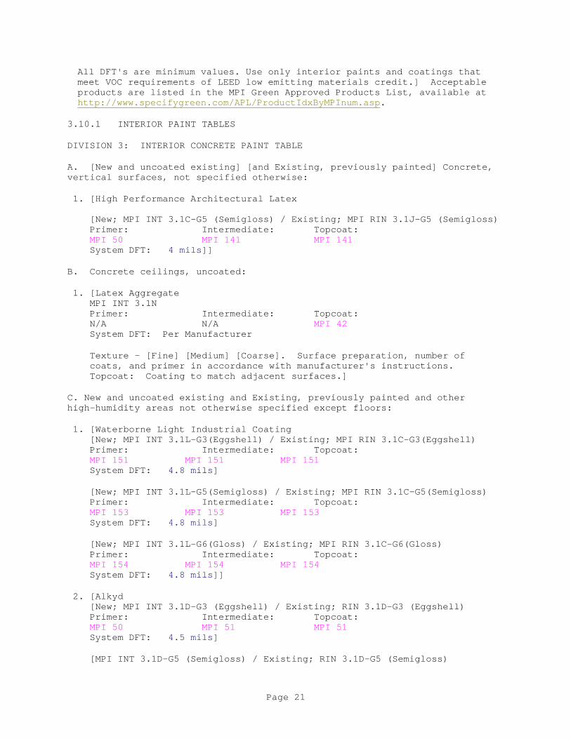
All DFT's are minimum values. Use only interior paints and coatings that meet VOC requirements of LEED low emitting materials credit.] Acceptable products are listed in the MPI Green Approved Products List, available at http://www.specifygreen.com/APL/ProductIdxByMPInum.asp.
3.10.1 INTERIOR PAINT TABLES
DIVISION 3: INTERIOR CONCRETE PAINT TABLE
A. [New and uncoated existing] [and Existing, previously painted] Concrete, vertical surfaces, not specified otherwise:
1. [High Performance Architectural Latex [New; MPI INT 3.1C-G5 (Semigloss) / Existing; MPI RIN 3.1J-G5 (Semigloss) Primer: Intermediate: Topcoat: MPI 50 MPI 141 MPI 141 System DFT: 4 mils]]
B. Concrete ceilings, uncoated:
1. [Latex Aggregate MPI INT 3.1N Primer: Intermediate: Topcoat: N/A N/A MPI 42 System DFT: Per Manufacturer
Texture - [Fine] [Medium] [Coarse]. Surface preparation, number of coats, and primer in accordance with manufacturer's instructions. Topcoat: Coating to match adjacent surfaces.]
C. New and uncoated existing and Existing, previously painted and other high-humidity areas not otherwise specified except floors:
1. [Waterborne Light Industrial Coating [New; MPI INT 3.1L-G3(Eggshell) / Existing; MPI RIN 3.1C-G3(Eggshell) Primer: Intermediate: Topcoat: MPI 151 MPI 151 MPI 151 System DFT: 4.8 mils]
[New; MPI INT 3.1L-G5(Semigloss) / Existing; MPI RIN 3.1C-G5(Semigloss) Primer: Intermediate: Topcoat: MPI 153 MPI 153 MPI 153 System DFT: 4.8 mils]
[New; MPI INT 3.1L-G6(Gloss) / Existing; MPI RIN 3.1C-G6(Gloss) Primer: Intermediate: Topcoat: MPI 154 MPI 154 MPI 154 System DFT: 4.8 mils]]
2. [Alkyd [New; MPI INT 3.1D-G3 (Eggshell) / Existing; RIN 3.1D-G3 (Eggshell) Primer: Intermediate: Topcoat: MPI 50 MPI 51 MPI 51 System DFT: 4.5 mils]
[MPI INT 3.1D-G5 (Semigloss) / Existing; RIN 3.1D-G5 (Semigloss)
Page 21
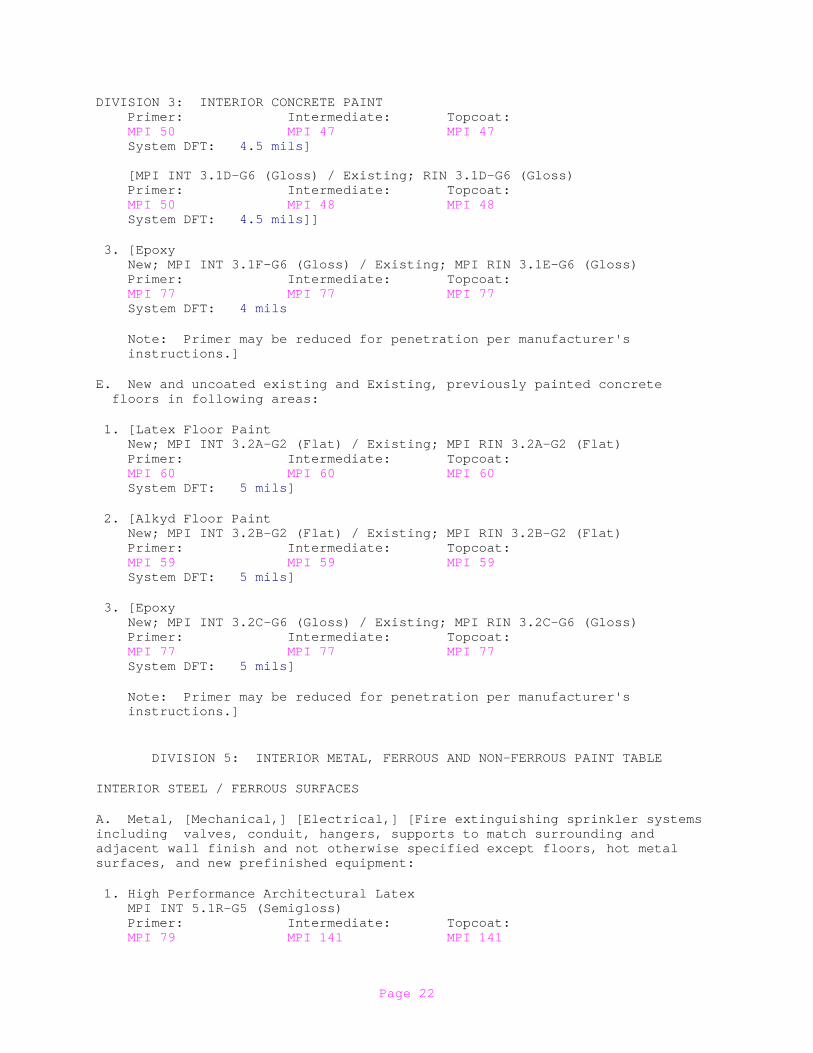
DIVISION 3: INTERIOR CONCRETE PAINT Primer: Intermediate: Topcoat: MPI 50 MPI 47 MPI 47 System DFT: 4.5 mils] [MPI INT 3.1D-G6 (Gloss) / Existing; RIN 3.1D-G6 (Gloss) Primer: Intermediate: Topcoat: MPI 50 MPI 48 MPI 48 System DFT: 4.5 mils]]
3. [Epoxy New; MPI INT 3.1F-G6 (Gloss) / Existing; MPI RIN 3.1E-G6 (Gloss) Primer: Intermediate: Topcoat: MPI 77 MPI 77 MPI 77 System DFT: 4 mils
Note: Primer may be reduced for penetration per manufacturer's instructions.]
E. New and uncoated existing and Existing, previously painted concrete floors in following areas:
1. [Latex Floor Paint New; MPI INT 3.2A-G2 (Flat) / Existing; MPI RIN 3.2A-G2 (Flat) Primer: Intermediate: Topcoat: MPI 60 MPI 60 MPI 60 System DFT: 5 mils]
2. [Alkyd Floor Paint New; MPI INT 3.2B-G2 (Flat) / Existing; MPI RIN 3.2B-G2 (Flat) Primer: Intermediate: Topcoat: MPI 59 MPI 59 MPI 59 System DFT: 5 mils]
3. [Epoxy New; MPI INT 3.2C-G6 (Gloss) / Existing; MPI RIN 3.2C-G6 (Gloss) Primer: Intermediate: Topcoat: MPI 77 MPI 77 MPI 77 System DFT: 5 mils]
Note: Primer may be reduced for penetration per manufacturer's instructions.]
DIVISION 5: INTERIOR METAL, FERROUS AND NON-FERROUS PAINT TABLE
INTERIOR STEEL / FERROUS SURFACES
A. Metal, [Mechanical,] [Electrical,] [Fire extinguishing sprinkler systems including valves, conduit, hangers, supports to match surrounding and adjacent wall finish and not otherwise specified except floors, hot metalsurfaces, and new prefinished equipment:
1. High Performance Architectural Latex MPI INT 5.1R-G5 (Semigloss) Primer: Intermediate: Topcoat: MPI 79 MPI 141 MPI 141
Page 22
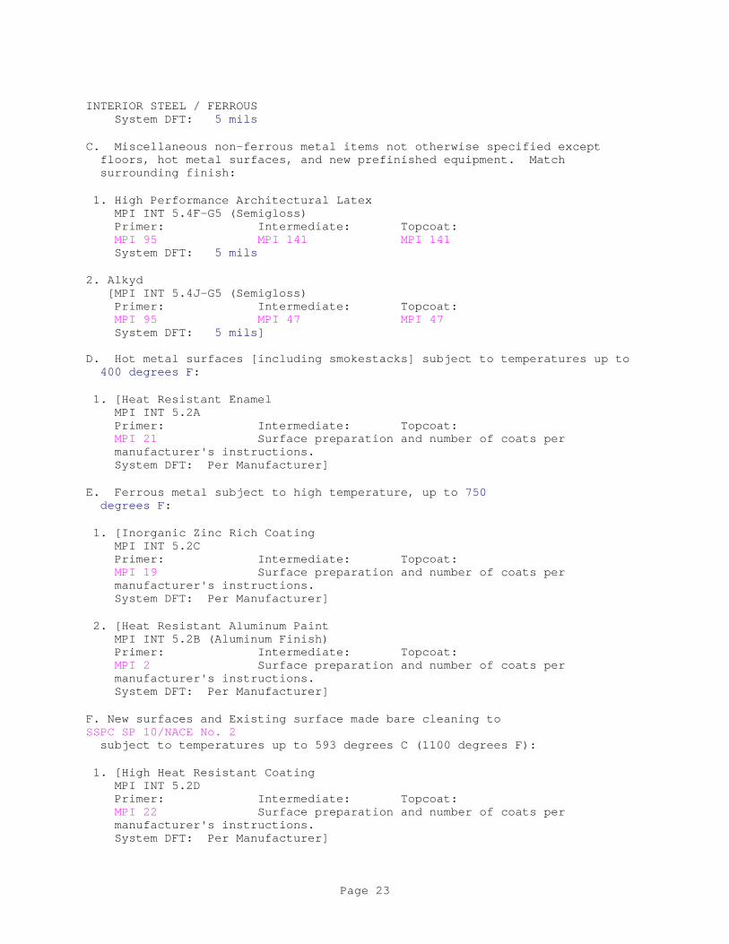
INTERIOR STEEL / FERROUS System DFT: 5 mils
C. Miscellaneous non-ferrous metal items not otherwise specified except floors, hot metal surfaces, and new prefinished equipment. Match surrounding finish:
1. High Performance Architectural Latex MPI INT 5.4F-G5 (Semigloss) Primer: Intermediate: Topcoat: MPI 95 MPI 141 MPI 141 System DFT: 5 mils
2. Alkyd [MPI INT 5.4J-G5 (Semigloss) Primer: Intermediate: Topcoat: MPI 95 MPI 47 MPI 47 System DFT: 5 mils] D. Hot metal surfaces [including smokestacks] subject to temperatures up to 400 degrees F:
1. [Heat Resistant Enamel MPI INT 5.2A Primer: Intermediate: Topcoat: MPI 21 Surface preparation and number of coats per manufacturer's instructions. System DFT: Per Manufacturer]
E. Ferrous metal subject to high temperature, up to 750 degrees F:
1. [Inorganic Zinc Rich Coating MPI INT 5.2C Primer: Intermediate: Topcoat: MPI 19 Surface preparation and number of coats per manufacturer's instructions. System DFT: Per Manufacturer]
2. [Heat Resistant Aluminum Paint MPI INT 5.2B (Aluminum Finish) Primer: Intermediate: Topcoat: MPI 2 Surface preparation and number of coats per manufacturer's instructions. System DFT: Per Manufacturer]
F. New surfaces and Existing surface made bare cleaning to SSPC SP 10/NACE No. 2 subject to temperatures up to 593 degrees C (1100 degrees F):
1. [High Heat Resistant Coating MPI INT 5.2D Primer: Intermediate: Topcoat: MPI 22 Surface preparation and number of coats per manufacturer's instructions. System DFT: Per Manufacturer]
Page 23
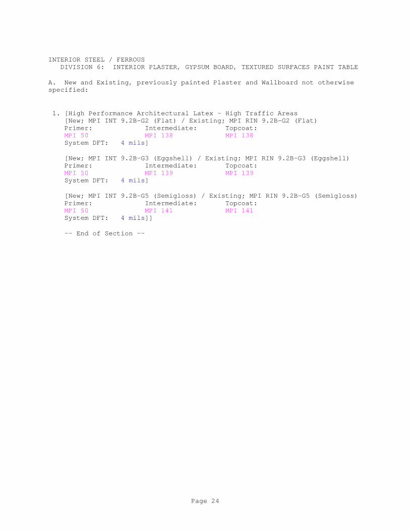
INTERIOR STEEL / FERROUS DIVISION 6: INTERIOR PLASTER, GYPSUM BOARD, TEXTURED SURFACES PAINT TABLE
A. New and Existing, previously painted Plaster and Wallboard not otherwise specified:
1. [High Performance Architectural Latex - High Traffic Areas [New; MPI INT 9.2B-G2 (Flat) / Existing; MPI RIN 9.2B-G2 (Flat) Primer: Intermediate: Topcoat: MPI 50 MPI 138 MPI 138 System DFT: 4 mils]
[New; MPI INT 9.2B-G3 (Eggshell) / Existing; MPI RIN 9.2B-G3 (Eggshell) Primer: Intermediate: Topcoat: MPI 50 MPI 139 MPI 139 System DFT: 4 mils]
[New; MPI INT 9.2B-G5 (Semigloss) / Existing; MPI RIN 9.2B-G5 (Semigloss) Primer: Intermediate: Topcoat: MPI 50 MPI 141 MPI 141 System DFT: 4 mils]]
-- End of Section --
Page 24

SECTION 10 21 13
TOILET COMPARTMENTS08/17
PART 1 GENERAL
1.1 REFERENCES
The publications listed below form a part of this specification to the extent referenced. The publications are referred to within the text by the basic designation only.
ALUMINUM ASSOCIATION (AA)
AA DAF45 (2003; Reaffirmed 2009) Designation System for Aluminum Finishes
ASTM INTERNATIONAL (ASTM)
ASTM A123/A123M (2015) Standard Specification for Zinc (Hot-Dip Galvanized) Coatings on Iron and Steel Products
ASTM A167 (2011) Standard Specification for Stainless and Heat-Resisting Chromium-Nickel Steel Plate, Sheet, and Strip
ASTM A336/A336M (2015) Standard Specification for Alloy Steel Forgings for Pressure and High-Temperature Parts
ASTM A385/A385M (2017) Standard Practice for Providing High-Quality Zinc Coatings (Hot-Dip)
ASTM A653/A653M (2015; E 2016) Standard Specification for Steel Sheet, Zinc-Coated (Galvanized) or Zinc-Iron Alloy-Coated (Galvannealed) by the Hot-Dip Process
ASTM B221 (2014) Standard Specification for Aluminum and Aluminum-Alloy Extruded Bars, Rods, Wire, Profiles, and Tubes
ASTM B221M (2013) Standard Specification for Aluminum and Aluminum-Alloy Extruded Bars, Rods, Wire, Profiles, and Tubes (Metric)
ASTM B36/B36M (2013) Standard Specification for Brass Plate, Sheet, Strip, and Rolled Bar
ASTM B456 (2017) Standard Specification for Electrodeposited Coatings of Copper Plus Nickel Plus Chromium and Nickel Plus
Page 1

Chromium
ASTM B86 (2013) Standard Specification for Zinc and Zinc-Aluminum (ZA) Alloy Foundry and Die Castings
ASTM D6386 (2016) Standard Practice for Preparation of Zinc (Hot-Dip Galvanized) Coated Iron and Steel Product and Hardware Surfaces for Painting
ASTM D7611/D7611M (2013; E 2014) Standard Practice for Coding Plastic Manufactured Articles for Resin Identification
CALIFORNIA DEPARTMENT OF PUBLIC HEALTH (CDPH)
CDPH SECTION 01350 Standard Method for the Testing and Evaluation of Volatile Organic Chemical Emissions from Indoor Sources using Environmental Chambers
INTERNATIONAL CODE COUNCIL (ICC)
ICC A117.1 COMM (2017) Standard And Commentary Accessible and Usable Buildings and Facilities
SCIENTIFIC CERTIFICATION SYSTEMS (SCS)
SCS SCS Global Services (SCS)Indoor Advantage
SOCIETY OF AUTOMOTIVE ENGINEERS INTERNATIONAL (SAE)
SAE AMS2460 (2013; Rev A) Plating, Chromium
U.S. GENERAL SERVICES ADMINISTRATION (GSA)
CID A-A-60003 (Basic) Partitions, Toilet, Complete
U.S. NATIONAL ARCHIVES AND RECORDS ADMINISTRATION (NARA)
36 CFR 1191 Americans with Disabilities Act (ADA) Accessibility Guidelines for Buildings and Facilities; Architectural Barriers Act (ABA) Accessibility Guidelines
UNDERWRITERS LABORATORIES (UL)
UL 2818 (2013) GREENGUARD Certification Program For Chemical Emissions For Building Materials, Finishes And Furnishings
1.2 SUBMITTALS
Government approval is required for submittals with a "G" designation; submittals not having a "G" designation are for [Contractor Quality Control approval.] [information only. When used, a designation following the "G"
Page 2
designation identifies the office that will review the submittal for the Government.] Submittals with an "S" are for inclusion in the Sustainability eNotebook, in conformance to Section 01 33 29 SUSTAINABILITY REPORTING. Submit the following in accordance with Section 01 33 00 SUBMITTAL PROCEDURES:
SD-02 Shop Drawings
Fabrication Drawings
Installation Drawings; G
SD-03 Product Data
Cleaning and Maintenance Instructions
Colors And Finishes
Galvanized Steel Sheet
Sound-Deadening Cores
Anchoring Devices and Fasteners
Hardware and Fittings
Brackets
Door Hardware
Pilaster Shoes
Finishes; G
SD-04 Samples
Colors and Finishes; G
Hardware and Fittings
Anchoring Devices and Fasteners
SD-07 Certificates
Warranty
SD-11 Closeout Submittals
Recycled content for plastic laminate partitions and screens; S
Indoor air quality for laminated plastic partitions and screens; S
1.3 CERTIFICATIONS
1.3.1 Indoor Air Quality
Page 3
1.3.1.1 Laminated Plastic and Solid Phenolic Products
Provide products certified to meet indoor air quality requirements by UL 2818 (Greenguard) Gold, SCS Global Services Indoor Advantage Gold or provide certification or validation by other third-party program that products meet the requirements of this Section. Provide current product certification documentation from certification body.
1.4 REGULATORY REQUIREMENTS
Conform to ICC A117.1 COMM code for access for the handicapped operation of toilet compartment door and hardware.
1.5 DELIVERY, STORAGE, AND HANDLING
Deliver materials in the manufacturer's original unopened packages with the brand, item identification, and project reference clearly marked. Store components in a dry location that is adequately ventilated; free from dust, water, other contaminants, and damage during delivery, storage, and construction.
1.6 WARRANTY
Provide certification or warranties that toilet partitions will be free of defects in materials, fabrication, finish, and installation and will remain so for a period of not less than 2 years after completion.
PART 2 PRODUCTS
2.1 SYSTEM REQUIREMENTS
Provide a complete and usable toilet partition system, including toilet enclosures, room entrance screens, urinal screens, system of panels, hardware, and support components. Furnish the partition system from a single manufacturer, with a standard product as shown in the most recent catalog data. Submit Fabrication Drawings for metal toilet partitions and urinal screens consisting of fabrication and assembly details to be performed in the factory. Submit manufacturer's Cleaning and Maintenance Instructions with Fabrication Drawings for review.
2.2 MATERIALS
2.2.1 Galvanized Steel Sheet
Provide galvanized steel sheet cold-rolled, stretcher-level, commercial quality material, conforming to ASTM A653/A653M. Conform surface preparation of material for painting to ASTM D6386, Method A.
2.2.2 Sound-Deadening Cores
Provide sound deadening consisting of treated kraft paper honeycomb cores with a cell size of not more than 1 inch. Resin-material content must weigh not less than 11 percent of the finished core weight. Expanded cores must be faced on both sides with kraft paper.
2.2.3 Anchoring Devices and Fasteners
Page 4
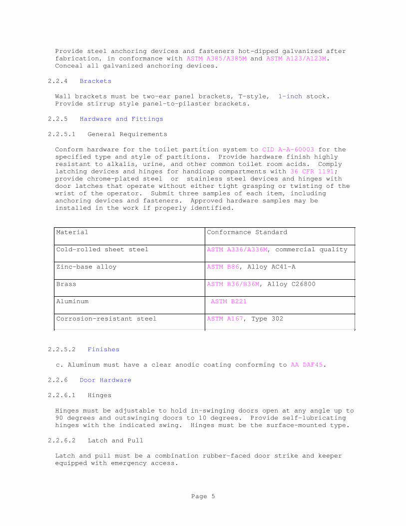
Provide steel anchoring devices and fasteners hot-dipped galvanized after fabrication, in conformance with ASTM A385/A385M and ASTM A123/A123M. Conceal all galvanized anchoring devices.
2.2.4 Brackets
Wall brackets must be two-ear panel brackets, T-style, 1-inch stock. Provide stirrup style panel-to-pilaster brackets.
2.2.5 Hardware and Fittings
2.2.5.1 General Requirements
Conform hardware for the toilet partition system to CID A-A-60003 for the specified type and style of partitions. Provide hardware finish highly resistant to alkalis, urine, and other common toilet room acids. Comply latching devices and hinges for handicap compartments with 36 CFR 1191; provide chrome-plated steel or stainless steel devices and hinges with door latches that operate without either tight grasping or twisting of the wrist of the operator. Submit three samples of each item, including anchoring devices and fasteners. Approved hardware samples may be installed in the work if properly identified.
Material Conformance Standard
Cold-rolled sheet steel ASTM A336/A336M, commercial quality
Zinc-base alloy ASTM B86, Alloy AC41-A
Brass ASTM B36/B36M, Alloy C26800
Aluminum ASTM B221
Corrosion-resistant steel ASTM A167, Type 302
2.2.5.2 Finishes
c. Aluminum must have a clear anodic coating conforming to AA DAF45.
2.2.6 Door Hardware
2.2.6.1 Hinges
Hinges must be adjustable to hold in-swinging doors open at any angle up to 90 degrees and outswinging doors to 10 degrees. Provide self-lubricating hinges with the indicated swing. Hinges must be the surface-mounted type.
2.2.6.2 Latch and Pull
Latch and pull must be a combination rubber-faced door strike and keeper equipped with emergency access.
Page 5
2.2.6.3 Coat Hooks
Coat hooks must be combination units with hooks and rubber tipped pins.
2.3 PARTITION PANELS AND DOORS
Fabricate partition panels and doors not less than 1 inch thick with face sheets not less than 0.0396 inch thick.
Provide plastic laminate toilet partitions and screens with recycled content of 45 percent minimum. Provide data identifying percentage of recycled content for plastic laminate partitions and screens.
Provide laminated plastic and solid phenolic toilet partitions and urinal screens to meet the emissions requirements of CDPH SECTION 01350 (limit requirements for either office or classroom spaces regardless of space type). Provide certification of indoor air quality for laminated plastic partitions and screens.
2.3.1 Toilet Enclosures
Provide and conform toilet enclosures to CID A-A-60003, Type I, Style C, overhead braced F, overhead braced-alcove. Furnish width, length, and height of toilet enclosures as shown. Finish surface of panels must be laminated plastic, Finish 3; water resistant; graffiti resistant; non-absorbent; . Reinforce panels indicated to receive toilet paper holders or grab bars for mounting of the items required. Provide grab bars to withstand a bending stress, shear stress, shear force, and a tensile force induced by 250 lbf. Grab bars must not rotate within their fittings.
2.3.2 Urinal Screens
Provide and conform urinal screens to CID A-A-60003, Type III, Style E, floor to ceiling post supported. Provide finish for surface of screens as laminated plastic, Finish 3; water resistant; graffiti resistant; non-absorbent; with plastic face sheets permanently fused to plastic core; 1/4 inch radius beveled edges. Furnish width and height of urinal screens as shown. Provide thickness of 1 inch. Secure wall hung urinal screens with a minimum of three wall stirrup brackets. Fabricate screens from the same types of panels and pilasters as the toilet partitions. Use corrosion-resistant steel fittings and fasteners.
2.4 OVERHEAD-BRACED PARTITIONS
Pilasters must be not less than 1-1/4 inch thick with face sheets not less than 0.0393 inch thick. Provide anchoring device at the bottom of the pilaster consisting of a channel-shaped floor stirrup fabricated from not less than 0.0635 inch thick material and a leveling bolt. Secure the stirrup to the pilaster with not less than a 3/16 inch bolt and nut after the pilaster is leveled. Secure the stirrup to the floor with not less than two lead expansion shields and sheetmetal screws. Fabricate overhead brace from a continuous extruded aluminum tube not less than 1 inch wide by 1-1/2 inch high, 0.125-inch wall thickness. Finish must be AA-C22A31 in accordance with AA DAF45. Set and secure brace into the top of each pilaster. Fabricate 3 inch high trim piece at the floor from not less than 0.030 inch thick corrosion-resistant steel.
Page 6

2.5 PILASTER SHOES
Provide shoes at pilasters to conceal floor-mounted anchorage. Pilaster shoes must be stainless steel. Height must be 3 inches.
2.6 HARDWARE
Provide hardware for the toilet partition system that conforms to CID A-A-60003 for the specified type and style of partitions. Use a hardware finish that is highly resistant to alkalis, urine, and other common toilet room acids. Provide latching devices and hinges for handicap compartments complying with 36 CFR 1191 and chrome-plated steel door latches that operate without either tight grasping or twisting of the wrist of the operator.
2.7 COLORS AND FINISHES
2.7.1 Colors
Provide manufacturer's standard color charts for color of finishes for toilet partition system components. Submit three samples showing a finished edge on two adjacent sides and core construction, each not less than 12-inch square
2.7.2 Finishes No. 1 Through No. 3
Conform partitions, panels, screen, and door finishes to CID A-A-60003 finished with Finish No. 3, laminated plastic.
PART 3 EXECUTION
3.1 PREPARATION
Take field measurements prior to the preparation of drawing and fabrication to ensure proper fits. Verify that field measurements, surfaces, substrates and conditions are as required, and ready to receive work. Verify correct spacing of plumbing fixtures. Verify correct location of built in framing, anchorage, and bracing. Report in writing to Contracting Officer prevailing conditions that will adversely affect satisfactory execution of the work of this section. Do not proceed with work until unsatisfactory conditions have been corrected.
3.2 METAL PARTITION FABRICATION
a. Fabricate metal Partition Panels, doors, screens, and pilasters required for the project from galvanized-steel face sheets with formed edges. Face sheets must be pressure-laminated to the sound-deadening core with edges sealed with a continuous locking strip and corners mitered and welded. Ground all welds smooth. Provide concealed reinforcement for installation of hardware, fittings, and accessories. Surface of face sheets must be smooth and free from wave, warp, or buckle.
b. Before application of an enamel coating system, solvent-clean galvanized-steel surfaces to remove processing compounds, oils, and other contaminants harmful to coating-system adhesion. After cleaning,coat the surfaces with a metal-pretreatment phosphate
Page 7
coating. After pretreatment, finish exposed galvanized-steel surfaces with a baked-enamel coating system as specified.
c. Provide an enamel coating system consisting of a factory-applied baked acrylic enamel coating system. Coating system must be a durable, washable, stain-resistant, mar-resistant finish.
3.3 INSTALLATION
Do not install items that show visual evidence of biological growth. Install partitions rigid, straight, plumb, and level, with the panels centered between the fixtures. Provide a panel clearance of not more than 1/2 inch and secure the panels to walls and pilasters with not less than two wall brackets attached near the top and bottom of the panel. Locate wall brackets so that holes for wall bolts occur in masonry or tile joints. Secure Panels to pilasters with brackets matching the wall brackets. Provide for adjustment due to minor floor variations. Locate head rail joints at pilaster center lines. Install adjacent components for consistency of line and plane. Equip each door with hinges, one door latch, and one coat hook and bumper. Align hardware to uniform clearance at vertical edges of doors.
a. Secure panels to hollow plastered walls with toggle bolts using not less than 1/4-20 screws of the length required for the wall thickness. Toggle bolts must have a load-carrying strength of not less than 600 pounds per anchor.
b. Secure panels to ceramic tile on hollow plastered walls or hollow concrete-masonry walls with toggle bolts using not less than 1/4-20 screws of the length required for the wall thickness. Toggle bolts must have a load-carrying strength of not less than 600 pounds per anchor.
c. Secure panels to solid masonry or concrete with lead or brass expansion shields designed for use with not less than 1/4-20 screws, with a shield length of not less than 1-1/2 inch. Expansion shields must have a load-carrying strength of not less than 600 pounds per anchor.
d. Submit Installation Drawings for metal toilet partitions and urinal screens showing plans, elevations, details of construction, hardware, reinforcing and blocking, fittings, mountings and escutcheons. Indicate on drawings the type of partition, location, mounting height, cutouts, and reinforcement required for toilet-room accessories.
3.4 CEILING-HUNG PARTITIONS
Secure pilasters to the structural support above with the anchorage device specified. Make all leveling devices readily accessible for leveling, plumbing, and tightening the installation. Level the bottoms of doors with bottoms of pilasters when doors are in a closed position.
3.5 FLOOR-ANCHORED PARTITIONS
Secure pilasters to the floor with the anchorage device specified. Make all leveling devices readily accessible for leveling, plumbing, and tightening the installation. Level tops of doors with tops of pilasters when doors are in a closed position. Expansion shields must have a minimum
Page 8

2-inch penetration into the concrete slab.
3.6 OVERHEAD-BRACED PARTITIONS
Secure pilasters to the floor with the anchorage device specified. Make all leveling devices readily accessible for leveling, plumbing, and tightening the installation. Secure overhead brace to the pilaster face with not less than two fasteners per face. Expansion shields must have a minimum 2-inch penetration into the concrete slab. Make tops of doors parallel with the overhead brace when doors are in a closed position.
3.7 FINAL ADJUSTMENT
After completion of the installation, make final adjustments to the pilaster-leveling devices, door hardware, and other working parts of the partition assembly. Doors must have a uniform vertical edge clearance of approximately 3/16 inch and must rest open at approximately 30 degrees when unlatched.
3.8 CLEANING
Baked enamel finish must be touched up with the same color of paint that was used for the finish. Clean all surfaces of the work, and adjacent surfaces soiled as a result of the work, in an approved manner compliant
Page 9

with the manufacturer's recommended cleaning and protection from damage procedures until accepted. Remove all equipment, tools, surplus materials, and work debris from the site.
-- End of Section --
Page 10
SECTION 12 36 00.00 20
MANUFACTURED VANITIES08/11
PART 1 GENERAL
1.1 REFERENCES
The publications listed below form a part of this specification to the extent referenced. The publications are referred to within the text by the basic designation only.
APA - THE ENGINEERED WOOD ASSOCIATION (APA)
APA L870 (2010) Voluntary Product Standard, PS 1-09, Structural Plywood
U.S. GENERAL SERVICES ADMINISTRATION (GSA)
CID A-A-50565 (Basic) Cabinet, Storage; Wardrobe, Three Drawer
FED-STD-595 (Rev C; Notice 1) Colors Used in Government Procurement
1.2 SUBMITTALS
Government approval is required for submittals with a "G" designation; submittals not having a "G" designation are [for Contractor Quality Control approval.][for information only. When used, a designation following the "G" designation identifies the office that will review the submittal for the Government.] Submittals with an "S" are for inclusion in the Sustainability eNotebook, in conformance to Section 01 33 29 SUSTAINABILITY REPORTING. Submit the following in accordance with Section 01 33 00 SUBMITTAL PROCEDURES:
SD-02 Shop Drawings
Vanities;
Show configuration, materials, thicknesses, hardware, finishes, and colors of vanities for the project.
1.3 DELIVERY, STORAGE, AND HANDLING
Deliver vanities undamaged and store in a safe, dry, and clean location. Handle so as to prevent damage.
PART 2 PRODUCTS
2.1 VANITIES
Provide, The type and size shall be as indicated in drawing inches wide, and except as specified herein. Wood construction shall be used. Particleboard shall not be used. Countertop, doors, and all wood panels
Page 1
shall be 3/4 inch plywood, APA L870, Exterior Type, Grade A-A. Chromium-plated brass pulls or aluminum pulls and chromium-plated, spring-loaded, self-closing, adjustable, European type hinges may be used in lieu of pulls, hinges, and magnetic catches.
2.1.1 Quantity
As indicated.
2.2 FINISHES
Five-digit designations refer to FED-STD-595.
2.2.1 Exposed Surfaces
Exterior of doors and exposed surfaces of cabinet body shall be decorative laminated plastic of color and pattern specified.
2.2.2 Concealed Surfaces
Interior of doors and cabinet body, and concealed exterior surfaces of cabinet body, shall be nondecorative laminated plastic.
2.3 END CURBS
Provide end curbs to match back splash where end of countertop abuts a wall.
2.4 DRAWERS
Where drawers are indicated in vanities, comply with CID A-A-50565 for drawers, drawer slides, and slide supports.
PART 3 EXECUTION
3.1 INSTALLATION
3.1.1 Final Assembly
Distribute vanities to rooms as directed. Uncrate, assemble, adjust as necessary, and place as specified or indicated, complete with accessories and hardware. Position vanities as directed.
3.1.2 Fastening
Fasten wood vanities as indicated on the drawings and as specified. Fasten steel vanities through the holes in vanity back flanges. Fasteners shall be appropriate for use with the wall construction. Seal joint between back splash and wall and between end curb and wall as specified in Section 07 92 00 JOINT SEALANTS.
-- End of Section --
Page 2
SECTION 21 13 13.00 20
WET PIPE SPRINKLER SYSTEM, FIRE PROTECTION04/08
PART 1 GENERAL
1.1 REFERENCES
The publications listed below form a part of this specification to the extent referenced. The publications are referred to within the text by the basic designation only.
FM GLOBAL (FM)
FM APP GUIDE (updated on-line) Approval Guide http://www.approvalguide.com/
NATIONAL FIRE PROTECTION ASSOCIATION (NFPA)
NFPA 13 (2016; TIA 16-1; TIA 16-2; TIA 16-3 2016; Errata 17-1; Errata 17-2) Standard for the Installation of Sprinkler Systems
NFPA 24 (2013) Standard for the Installation of Private Fire Service Mains and Their Appurtenances
UNDERWRITERS LABORATORIES (UL)
UL 262 (2004; Reprint Oct 2011) Gate Valves for Fire-Protection Service
UL 789 (2004; Reprint May 2017) UL Standard for Safety Indicator Posts for Fire-Protection Service
UL Fire Prot Dir (2012) Fire Protection Equipment Directory
1.2 SYSTEM DESCRIPTION
Design and provide new automatic wet pipe fire extinguishing sprinkler systems for complete fire protection coverage throughout Global Vigilance Hangar - Building 1414.
1.3 SPRINKLER SYSTEM DESIGN
Except as modified herein, design automatic wet pipe fire extinguishing sprinkler systems in accordance with the required and advisory provisions of NFPA 13 , including all recommendations and advisory portions, which shall be considered mandatory; this includes advisory provisions listed in the appendices of such standard(s), as though the word "shall" had been substituted for the word "should" wherever it appears. Design system by hydraulic calculations for uniform distribution of water over the design area. Locate sprinklers in a consistent pattern with ceiling grid, lights, and air supply diffusers. Provide sprinklers and piping system layout. All Devices and equipment for fire protection service shall be
Page 1

UL Fire Prot Dir listed or FM APP GUIDE approved for use in wet pipe sprinkler systems. Provide seismic protection for the sprinkler system. Design and install seismic protection in accordance with the requirements of NFPA 13 section titled "Protection of Piping Against Damage Where Subject to Earthquakes."
1.3.1 Location of Sprinklers
Sprinklers in relation to the ceiling and the spacing of sprinklers shall not exceed that permitted by NFPA 13 for the hazards indicated on the contract drawings. Uniformly space sprinklers on the branch piping. Sprinklers shall provide coverage throughout 100 percent of the building.
1.3.2 Water Distribution
Distribution shall be uniform throughout the area in which the sprinklers will open. Discharge from individual sprinklers in hydraulically most remote area shall be between 100 percent and 120 percent of the specified density.
1.3.3 Density of Application of Water
Size pipe to provide the specified density when the system is discharging the specified total maximum required flow. Application to horizontal surfaces below the sprinklers shall be 0.2 gpm per sq ft.Size pipe to provide the specified density when the system is discharging the specified total maximum required flow.
1.3.4 Sprinkler Discharge Area
Area shall be the hydraulically most remote 5000 sq ft Area reductions and increases from NFPA 13 shall not be applied to this area.
1.3.5 Outside Hose Allowances
Hydraulic calculations shall include a hose allowance of 5000 gpm for outside hose streams
1.3.6 Water Supply
Base hydraulic calculations on operation of the existing fire pumps.
1.4 SUBMITTALS
Government approval is required for submittals with a "G" designation.
Partial submittals and submittals not fully complying with the requirements and recommended practices of NFPA 13 and this specification section shall be returned disapproved without review. This contract stipulation is non-negotiable.
Submit the following in accordance with Section 01 33 00 SUBMITTAL PROCEDURES:
SD-02 Shop Drawings
Shop Drawings; G
Page 2
Prepare 24 by 36 inch detail working drawings of sprinklers and piping. Floor plans shall be drawn to a scale not less than 1/8" = 1'-0". Show data essential for proper installation of each system. Show details, plan view, elevations and sections of the systems supply and piping. Show piping schematic of systems supply, devices, valves, pipe and fittings. Show point to point electrical wiring diagrams. Submit drawings signed by a registered fire protection engineer. Provide three copies of the Sprinkler System Shop Drawings, no later than 21 days prior to the start of sprinkler system installation.
SD-03 Product Data
Pipe; G Fittings ; G Valves, including gate, check, and globe ; G Sprinklers ; G Pipe hangers and supports ; G Sprinkler Alarm Switches; G Fire department connections ; G Mechanical couplings ; G Seismic Bracing ; G
Annotate descriptive data to show the specific model, type, and size of each item. Catalog cuts shall also indicate UL Listing/FM Approval and country of manufacture.
SD-05 Design Data
Hydraulic Calculations; G
Submit computer program generated hydraulic calculations to substantiate compliance with hydraulic design requirements. Calculations shall be performed by computer using software intended specifically for fire protection system design. Calculations shall include isometric diagram indicating hydraulic nodes and pipe segments.Submit name of software program used.
SD-06 Test Reports
request to schedule Preliminary Tests; G
Preliminary Test Report; G
Provide Three copies of the completed Preliminary Test Report, no later than 7 days after the completion of the Preliminary Tests. The Preliminary Tests Report shall include both the Contractor's Material and Test Certificate for Underground Piping and the Contractor's Material and Test Certificate for Aboveground Piping. All items in the Preliminary Tests Report shall be signed by the Fire Protection Engineer.
request to schedule Final Acceptance Test; G
Page 3
Final Acceptance Test Report; G
Provide Three copies of the completed Final Acceptance Tests Reports, no later than 7 days after the completion of the Final Acceptance Tests. All items in the Final Acceptance Report shall be signed by the Fire Protection Engineer.
SD-07 Certificates
Inspection by Fire Protection Engineer; G
Concurrent with the Final Acceptance Test Report, certification by the Fire Protection Engineer that the sprinkler system is installed in accordance with the contract requirements, including signed approval of the Preliminary and Final Acceptance Test Reports.
Fire Protection Engineer; G
The name and documentation of certification of the proposed Fire Protection Engineer, no later than 14 days after the Notice to Proceed and prior to the submittal of the sprinkler system drawings and hydraulic calculations.
Sprinkler System Installer; G
Submit data showing the Sprinkler System Installer has successfully installed systems of the same type and design as specified herein, Data shall include names and locations of at least two installations where the Contractor, or the subcontractor referred to above, has installed such systems. Indicate type and design of each system and certify that each system has performed satisfactorily in the manner intended for not less than 18 months. Provide NICET certification of the system technician. Contractor shall submit data along with submittal of the Fire Protection Engineer Qualifications.
SD-10 Operation and Maintenance Data
Operating and Maintenance Instructions
Submit in accordance with Section 01 78 23 OPERATION AND MAINTENANCE DATA as supplemented and modifies by this specification section.
Provide six manuals in accordance with NFPA 13. The manuals shall include the manufacturer's name, model number, parts list, list of parts and tools that should be kept in stock by the owner for routine maintenance including the name of a local supplier, simplified wiring and controls diagrams, troubleshooting guide, and recommended service organization (including address and telephone number) for each item of equipment.
SD-11 Closeout Submittals
As-built drawings
Page 4
As-built shop drawings, at no later than 14 days after completion of the Final Tests. The Sprinkler System Drawings shall be updated to reflect as-built conditions after all related work is completed. Provide electronic drawings in dwg or pdf format.
On-site training
1.5 QUALIFICATIONS
1.5.1 Fire Protection Engineer
A Fire Protection Engineer is a registered professional engineer (P.E.) who has passed the fire protection engineering written examination administered by the National Council of Examiners for Engineering and Surveys (NCEES).
1.5.2 Sprinkler System Installer
The Sprinkler System Installer shall be regularly engaged in the installation of the type and complexity of system specified in the Contract documents, and shall have served in a similar capacity for at least three systems that have performed in the manner intended for a period of not less than 6 months. Installation drawings, shop drawings and as-built drawings shall be prepared, by or under the supervision of, an system technician who is experienced with the types of works specified herein, and is currently certified by the National Institute for Certification in Engineering Technologies (NICET) as an engineering technician with minimum Level III certification in Automatic Sprinkler System program or by a fire protection engineer.
1.6 QUALITY ASSURANCE
1.6.1 Material and Equipment Qualifications
Provide materials and equipment that are standard products of manufacturers regularly engaged in the manufacture of such products, which are of a similar material, design and workmanship. Standard products shall have been in satisfactory commercial or industrial use for 2 years prior to bid opening. The 2-year use shall include applications of equipment and materials under similar circumstances and of similar size. The product shall have been for sale on the commercial market through advertisements, manufacturers' catalogs, or brochures during the 2 year period.
1.6.2 Alternative Qualifications
Products having less than a two-year field service record will be acceptable if a certified record of satisfactory field operation for not less than 6000 hours, exclusive of the manufacturer's factory or laboratory tests, can be shown.
1.6.3 Manufacturer's Nameplate
Each item of equipment shall have a nameplate bearing the manufacturer's name, address, model number, and serial number securely affixed in a conspicuous place; the nameplate of the distributing agent will not be acceptable.
1.6.4 Field Fabricated Nameplates
Page 5
ASTM D709. Provide laminated plastic nameplates for each equipment enclosure, relay, switch, and device; as specified in the technical sections or as indicated on the drawings. Each nameplate inscription shall identify the function and, when applicable, the position. Nameplates shall be melamine plastic, 0.125 inch thick, white with black center core. Surface shall be matte finish. Corners shall be square. Accurately align lettering and engrave into the core. Minimum size of nameplates shall be one by 2.5 inches. Lettering shall be a minimum of 0.25 inch high normal block style.
1.7 ACCESSIBILITY
Install all work so that parts requiring periodic inspection, operation, maintenance, and repair are readily accessible. Install concealed valves, expansion joints, controls, dampers, and equipment requiring access, in locations freely accessible through access doors.
1.8 DELIVERY, STORAGE AND HANDLING
All equipment delivered and placed in storage shall be housed in a manner to preclude any damage from the weather, humidity and temperature variations, dirt and dust, or other contaminants. Additionally, all pipes shall either be capped or plugged until installed.
PART 2 PRODUCTS
2.1 UNDERGROUND PIPING COMPONENTS
2.1.1 Pipe
Pipe shall comply with NFPA 24. Minimum pipe size shall be 6 inches. Piping more than 5 feet outside the building walls shall comply with Section 33 11 00 WATER UTILITY DISTRIBUTION PIPING.
2.1.2 Gate Valve and Indicator Posts
Installation shall comply with NFPA 24. Gate valves for use with indicator post shall conform to UL 262. Indicator posts shall conform to UL 789. Provide each indicator post with one coat of primer and two coats of red enamel paint.
2.1.3 Valve Boxes
Except where indicator posts are provided, for each buried valve, provide cast-iron, ductile-iron, or plastic valve box of a suitable size. Plastic boxes shall be constructed of acrylonitrile-butadiene-styrene (ABS) or inorganic fiber-reinforced black polyolefin. Provide cast-iron, ductile-iron, or plastic cover for valve box with the word "WATER" cast on the cover. The minimum box shaft diameter shall be 5.25 inches. Coat cast-iron and ductile-iron boxes with bituminous paint applied to a minimum dry-film thickness of 10 mils.
2.1.4 Buried Utility Warning and Identification Tape
Provide detectable aluminum foil plastic backed tape or detectable magnetic plastic tape manufactured specifically for warning and identification of buried piping. Tape shall be detectable by an electronic detection
Page 6
instrument. Provide tape in rolls, 3 inches minimum width, color coded for the utility involved with warning and identification imprinted in bold block letters continuously and repeatedly over the entire tape length. Warning and identification shall read "CAUTION BURIED WATER PIPING BELOW" or similar wording. Use permanent code and letter coloring unaffected by moisture and other substances contained in trench backfill material.
2.2 ABOVEGROUND PIPING COMPONENTS
All components of the aboveground piping shall fully comply with the requirements and recommended practices of NFPA 13 and this specification section. Aboveground piping shall be steel.
2.2.1 Steel Pipe
Pipe shall be rigidblack steel. Steel piping shall be Schedule 40 for sizes less than 8 inches and Schedule 10 for sizes 8 inches or larger. Fittings into which sprinklers, sprinkler riser nipples, or drop nipples are threaded shall be welded, threaded, or grooved-end type. Plain-end fittings with mechanical couplings, fittings that use steel gripping devices to bite into the pipe and segmented welded fittings shall not be permitted. Rubber gasketed grooved-end pipe and fittings with mechanical couplings shall be permitted in pipe sizes 1.5 inches and larger. Fittings, mechanical couplings, and rubber gaskets shall be supplied by the same manufacturer. Steel piping with wall thickness less than Schedule 30 shall not be threaded. Side outlet tees using rubber gasketed fittings shall not be permitted.Sprinkler pipe and fittings shall be metal. Roll grooving of galvanized pipe is prohibited
2.2.2 Grooved Mechanical Joints and Fittings
Grooved couplings, fittings and grooving tools shall be products of the same manufacturer.
2.2.3 Sprinklers
Provide nominal 0.50 inch or 0.53 inch orifice sprinklers. Sprinklers with internal O-rings shall not be used. Sprinklers shall be used in accordance with their listed coverage limitations. Provide Concealed, Recessed,Flush, Pendent, Upright,Sidewall, quick response sprinklers. Sprinklers shall have a brass or polished chrome finish. Temperature classification shall be as indicated. Sprinklers in high heat areas including attic spaces or in close proximity to unit heaters shall have temperature classification in accordance with NFPA 13. Extended coverage sprinklers shall not be used. Provide corrosion-resistant sprinklers and sprinkler guards as required by NFPA 13. Deflector shall not be more than 3 inches below suspended ceilings. Ceiling plates shall not be more than 0.5 inch deep. Ceiling cups shall not be permitted. Sprinkler temperature rating within the Hamgar Bay area shall be intermediate temperature rating of 200 F.
2.2.4 Valves
Provide valves of types approved for fire service. Valves shall open by counterclockwise rotation. Check valves shall be clear opening swing-check type with inspection and access cover plate for sizes 8 inches and larger. Each control valve shall be electrically supervised; minimum contact ratings shall be 2.5 amps at 24 volts DC. Provide supervision against valve closure or tampering of valve.
Page 7
2.2.5 Pipe Supports
Provide Pipe hangers and supports and Seismic Bracing in accordance with NFPA 13.
2.2.6 Fire Department Connections
Fire department connection shall be projecting type with cast brass body, matching wall escutcheon lettered "Auto Spkr" with a chromium plated finish. The connection shall have two inlets with individual self-closing clappers, caps with drip drains and chains. Female inlets shall have 2-1/2 inch diameter American National Fire Hose Connection Screw Threads (NH) per NFPA 1963.
2.3 ALARM INITIATING AND SUPERVISORY DEVICES
2.3.1 Sprinkler Alarm Switches
Provide vane type flow switch(es) with circuit opener or closer for the automatic transmittal of an alarm over the facility fire alarm system. Connection of switch shall be under Section 28 31 76 INTERIOR FIRE ALARM AND MASS NOTIFICATION SYSTEM.Vane type Alarm actuating devices shall have mechanical diaphragm controlled retard device adjustable from 10 to 60 seconds and shall instantly recycle.
2.3.2 Valve Supervisory (Tamper) Switch
Switch shall be suitable for mounting to the type of control valve to be supervised open. The switch shall be tamper resistant and contain one set of SPDT (Form C) contacts arranged to transfer upon removal of the housing cover or closure of the valve of more than two rotations of the valve stem.
2.4 ACCESSORIES
2.4.1 Sprinkler Cabinet
Provide metal cabinet with extra sprinklers[, including a representative sample of dry pendent type sprinklers] and sprinkler wrench adjacent to each alarm valve. The number and types of extra sprinklers shall be as specified in NFPA 13.
2.4.2 Pipe Escutcheon
Provide split hinge metal plates for piping entering walls, floors, and ceilings in exposed spaces. Provide polished stainless steel plates or chromium-plated finish on copper alloy plates in finished spaces. Provide paint finish on metal plates in unfinished spaces.
PART 3 EXECUTION
3.1 INSPECTION BY FIRE PROTECTION ENGINEER
The Fire Protection Engineer shall inspect the sprinkler system periodically during the installation to assure the sprinkler system is being provided and installed in accordance with the contract requirements and the approved sprinkler system submittal(s). The Fire Protection Engineer shall attend both the preliminary and final tests, and shall sign
Page 8

the test results. After the preliminary testing has been completed, the Fire Protection Engineer, shall certify in writing the system is ready for the final inspections and tests. This report shall document any discrepancies found and what actions will be taken to correct. Any discrepancy noted during the periodic site visits or the preliminary testing shall be brought to the attention of the Contracting Officer in writing, no later than three working days after the discrepancy is discovered.
3.2 UNDERGROUND PIPING INSTALLATION
The methods of fabrication and installation of the underground piping shall fully comply with the requirements and recommended practices of NFPA 13, NFPA 24 and the contract drawings.
3.3 ABOVEGROUND PIPING INSTALLATION
The methods of fabrication and installation of the aboveground piping shall fully comply with the requirements and recommended practices of NFPA 13 and this specification section.
3.3.1 Piping in Finished Areas
In areas with suspended or dropped ceilings and in areas with concealed spaces above the ceiling, piping shall be concealed above ceilings. Piping shall be inspected, tested and approved before being concealed. Risers and similar vertical runs of piping in finished areas shall be concealed.
3.3.2 Pendent Sprinklers
Where sprinklers are installed below suspended or dropped ceilings, drop nipples shall be cut such that sprinkler ceiling plates or escutcheons are of a uniform depth throughout the finished space. The outlet of the reducing coupling shall not extend more than 1 inch below the underside of the ceiling. Pendent sprinklers in suspended ceilings shall be a minimum of 6 inches from ceiling grids.
3.3.3 Reducers
Reductions in pipe sizes shall be made with one-piece tapered reducing fittings. Bushings are prohibited.
3.3.4 Pipe Penetrations
Cutting structural members for passage of pipes or for pipe-hanger fastenings will not be permitted. Pipes that must penetrate concrete or masonry walls or concrete floors shall be core-drilled and provided with pipe sleeves. Each sleeve shall be Schedule 40 galvanized steel, ductile iron or cast iron pipe and shall extend through its respective wall or floor and be cut flush with each wall surface. Sleeves shall provide required clearance between the pipe and the sleeve per NFPA 13. The space between the sleeve and the pipe shall be firmly packed with mineral wool insulation. Where pipes penetrate fire walls, fire partitions, or floors, pipes shall be fire stopped in accordance with Section 07 84 00 FIRESTOPPING. In penetrations that are not fire-rated or not a floor penetration, the space between the sleeve and the pipe shall be sealed at both ends with plastic waterproof cement that will dry to a firm but
Page 9
pliable mass or with a mechanically adjustable segmented elastomer seal.
3.3.5 Inspector's Test Connection
Provide test connections approximately 6 feet above the floor for each sprinkler system or portion of each sprinkler system equipped with an alarm device. Provide test connection piping to a drain location that can accept full flow where the discharge will be readily visible and where water may be discharged without property damage. Discharge to floor drains, janitor sinks or similar fixtures shall not be permitted. Provide discharge orifice of same size as corresponding sprinkler orifice. The penetration of the exterior wall shall be no greater than 2 feet above finished grade.
3.3.6 Drains
Main drain piping shall be provided to discharge at a safe point outside the building. Auxiliary drains shall be provided as required by NFPA 13.
3.3.7 Installation of Fire Department Connection
Connection shall be mounted on the exterior wall approximately 3 feet above finished grade. The piping between the connection and the check valve shall be provided with an automatic drip in accordance with NFPA 13 and arranged to drain to the outside.
3.3.8 Identification Signs
Signs shall be affixed to each control valve, inspector test valve, main drain, auxiliary drain, test valve, and similar valves as appropriate or as required by NFPA 13. Valve identification signs shall be minimum 6 inches wide by 2 inches high with enamel baked finish on minimum 18 gauge steel or 0.024 inch aluminum with red letters on a white background or white letters on red background. Hydraulic design data nameplates shall be permanently affixed to each sprinkler riser as specified in NFPA 13.
3.4 ELECTRICAL WORK
Except as supplemented and modified herein, electric equipment and wiring shall be in accordance with Section 26 20 00 INTERIOR DISTRIBUTION SYSTEM. Alarm signal wiring connected to the building fire alarm control system shall be in accordance with 28 31 76 INTERIOR FIRE ALARM AND MASS NOTIFICATION SYSTEM.
3.5 PIPE PAINTING AND COLOR CODE MARKING
Paint and color code mark sprinkler piping system as specified in Section 09 90 00 PAINTS AND COATINGS.
3.6 PRELIMINARY TESTS
The system, including the underground water mains, and the aboveground piping and system components, shall be tested to assure that equipment and components function as intended. The underground and aboveground interior piping systems and attached appurtenances subjected to system working pressure shall be tested in accordance with NFPA 13 and NFPA 24.Submit request to schedule Preliminary Tests, no later than 14 days prior to the proposed start of the tests. Upon completion of specified tests,
Page 10
the Contractor shall submit for approval a Preliminary Test Report.
3.6.1 Underground Piping
3.6.1.1 Flushing
Underground piping shall be flushed in accordance with NFPA 24.
3.6.1.2 Hydrostatic Testing
New underground piping shall be hydrostatically tested in accordance with NFPA 24.
3.6.2 Aboveground Piping
3.6.2.1 Hydrostatic Testing
Aboveground piping shall be hydrostatically tested in accordance with NFPA 13.
3.7 FINAL ACCEPTANCE TEST
Final Acceptance Test shall begin only when the Preliminary Test Report has been approved. Submit request to schedule Final Acceptance Test, no later than 14 days prior to the proposed start of the tests. Notification shall include a copy of the Contractor's Material & Test Certificates.
The Fire Protection Engineer shall conduct the Final Acceptance Test and shall provide a complete demonstration of the operation of the system. This shall include operation of control valves and flowing of inspector's test connections to verify operation of associated waterflow alarm switches. After operation of control valves has been completed, the main drain test shall be repeated to assure that control valves are in the open position. In addition, the representative shall have available copies of as-built drawings and certificates of tests previously conducted. The installation shall not be considered accepted until identified discrepancies have been corrected and test documentation is properly completed and received. The Contractor shall submit the Final Acceptance Test Report as specified in the Submittals paragraph.
3.8 ON-SITE TRAINING
Submit request to schedule the On-site Training, at least 14 days prior to the start of related training but prior to the final inspections and tests. The sprinkler contractor shall conduct a training course for operating and maintenance personnel as designated by the Contracting Officer. Training shall be provided for a period of hours of normal
Page 11

working time and shall start after the system is functionally complete and after the Final Acceptance Test. The On-Site Training shall cover all of the items contained in the approved Operating and Maintenance Instructions.
-- End of Section --
Page 12

SECTION 21 13 20.00 20
FOAM FIRE EXTINGUISHING FOR AIRCRAFT HANGARS11/09
PART 1 GENERAL
1.1 REFERENCES
The publications listed below form a part of this specification to the extent referenced. The publications are referred to within the text by the basic designation only.
AMERICAN WATER WORKS ASSOCIATION (AWWA)
AWWA C651 (2014) Standard for Disinfecting Water Mains
ASTM INTERNATIONAL (ASTM)
ASTM A53/A53M (2012) Standard Specification for Pipe, Steel, Black and Hot-Dipped, Zinc-Coated, Welded and Seamless
FM GLOBAL (FM)
FM APP GUIDE (updated on-line) Approval Guide http://www.approvalguide.com/
NATIONAL FIRE PROTECTION ASSOCIATION (NFPA)
NFPA 11 (2016; ERTA 2016) Standard for Low-, Medium- and High- Expansion Foam
NFPA 13 (2016; TIA 16-1; TIA 16-2; TIA 16-3 2016; Errata 17-1; Errata 17-2) Standard for the Installation of Sprinkler Systems
NFPA 24 (2013) Standard for the Installation of Private Fire Service Mains and Their Appurtenances
NFPA 409 (2016; ERTA 2016) Standard on Aircraft Hangars
NFPA 70 (2017; ERTA 1-2 2017; TIA 17-1; TIA 17-2) National Electrical Code
NFPA 72 (2016) National Fire Alarm and Signaling Code
SOCIETY FOR PROTECTIVE COATINGS (SSPC)
SSPC SP 11 (2012) Power Tool Cleaning to Bare Metal
U.S. DEPARTMENT OF DEFENSE (DOD)
Page 1
MIL-F-24385 (1992; Rev F; Am 1 1994) Fire Extinguishing Agent, Aqueous Film Forming Foam (AFFF) Liquid Concentrate, for Fresh and Seawater
U.S. GENERAL SERVICES ADMINISTRATION (GSA)
CID A-A-58092 (Basic; Notice 1) Tape, Antiseize, Polytetrafluoroethylene
FS WW-S-2739 (Basic; Notice 1; Notice 2) Strainers, Sediment: Pipeline, Water, Air, Gas, Oil, or Steam
UNDERWRITERS LABORATORIES (UL)
UL Fire Prot Dir (2012) Fire Protection Equipment Directory
1.2 RELATED REQUIREMENTS
Section 23 03 00.00 20 BASIC MECHANICAL MATERIALS AND METHODS, applies to this section, with the additions and modifications specified herein.
1.3 SYSTEM DESCRIPTION
1.3.1 Design Requirements
Design and provide a new high expansion foam sprinkler system(s) for under-wing supplemental protection system for building 1414 The design, equipment, materials, installation, and workmanship shall be in strict accordance with the required and advisory provisions of NFPA 11, NFPA 13,NFPA 24, NFPA 30, NFPA 70, NFPA 72, and NFPA 409, except as modified herein. Each system shall be designed for earthquakes and shall include all materials, accessories and equipment necessary to provide each system complete and ready for use. Design and install each system to give full consideration to blind spaces, piping, electrical equipment, ductwork, and all other construction and equipment to provide complete coverage in accordance with the drawings to be submitted for approval. Devices and equipment for fire protection service shall be of a make and type listed by the Underwriter's Laboratories Inc. in the UL Fire Prot Dir, or approved by the Factory Mutual System and listed in FM APP GUIDE. In the publications referred to herein, the advisory provisions shall be considered to be mandatory, as though the word "shall" had been substituted for "should" wherever it appears; reference to the "authority having jurisdiction" shall be interpreted to mean the Corps of Engineers Contracting Officer. Begin work at the point indicated.
1.3.1.1 Shop Drawings
Prepare shop drawings for fire extinguishing system in accordance with the requirements for "Plans" as specified in NFPA 11 and "Working Plans" as specified in NFPA 13. Each drawing shall be 34 by 22 inches. Do not commence work until the design of each system and the various components have been approved. Show:
a. Room, space or area layout and include data essential to the proper installation of each system
Page 2
b. Sprinkler heads, discharge nozzles and system piping layout annotated with reference points for design calculations
c. Field wiring diagrams showing locations of devices and points of connection and terminals used for all electrical field connections in the system, with wiring color code scheme
d. UV-IR detector manufacturer's recommended detector layout (plan view) including horizontal and vertical angles for correct aiming.
1.3.1.2 Calculations
Submit design calculations for the system.
a. Hydraulic calculations showing basis for design in accordance with NFPA 11 and NFPA 13.
b. Pressure discharge graphs or tables showing pressure discharge relationship for foam generators.
c. System surge analysis showing surge pressure occurring throughout the system at both design flow and nonflow conditions.
1.3.1.3 As-Built Drawings for the Fire Extinguishing System
Upon completion, and before final acceptance of the work, submit a complete set of as-built drawings for the fire extinguishing system in AutoCad electronic format, including complete as-built circuit diagrams,. Submit 34 by 22 inch reproducible as-built drawings on mylar film with 8 by 4 inch title block similar to contract drawings. Submit as-built drawings in addition to the record drawings required by Division 1.
1.3.2 System Operation
Flow of water andfoam concentrate shall be controlled by deluge valves. Foam proportioning equipment shall activate automatically upon tripping of the deluge valve(s) for the corresponding foam system(s). Deluge valves shall be tripped by independent detection systems. Foam system shall also be activated by the operation of a foam manual release button. No valve will be operated by the building fire evacuation alarm system. Use of motor-operated valves is prohibited. Once activated, system(s) shall operate until shut down manually. Provide separate circuits from the control panel to each zone of initiating devices. Transmission of signals from more than one zone over a common circuit is prohibited.
1.4 SUBMITTALS
Government approval is required for submittals with a "G" designation; submittals not having a "G" designation are for Contractor Quality Control approval. Submit the following in accordance with Section 01 33 00 SUBMITTAL PROCEDURES:
The Contracting officer's representative will review the submittals.
SD-02 Shop Drawings
Fire extinguishing system; G
Page 3

SD-03 Product Data
Pipe, fittings, and mechanical couplings; G
Deluge valves; G
Valves, including gate, check, and globe; G
Pipe hangers and supports; G
Pressure switch; G
Foam Generators; G
Foam Concentrate Storage Tanks; G
Proportioning equipment; G
Foam concentrate; G
Foam System Releasing panel; G
Foam system notification appliances; G
Foam discharge stations; G
Flame detectors; G
Strainers; G
Control panel
Data which describe more than one type of item shall be clearly marked to indicate which type the Contractor intends to provide. Submit only originals. Photocopies will not be accepted. Partial submittals will not be accepted.
Please note that only the Del-Tronics Triple IR detection and foam releasing panel is approved for installation.
SD-05 Design Data
Hydraulic calculations; G
Pressure discharge graphs or tables; G
Battery standby power requirements calculation
SD-06 Test Reports
Preliminary tests; G
Acceptance tests; G
Submit for all inspections and tests specified under paragraph entitled "Field Quality Control."
Page 4
Hydrostatic testing of the diaphragm pressure proportioning tanks; G
SD-07 Certificates
Qualifications of installer; G
Submit installers qualifications as required under paragraph entitled Qualifications of Installer."
Foam containment and disposal plan; G
SD-10 Operation and Maintenance Data
Deluge valves, Data Package 3; G
Proportioning equipment, Data Package 3; G
Control panel, Data Package 3; G
Foam concentrate storage tanks, Data Package 3; G
Foam Generators, Data Package 3; G
Instructions for operating the fire extinguishing system, Data Package 4; G
Submit in accordance with Section 01 78 23 OPERATION AND MAINTENANCE DATA. Furnish one complete set of data prior to the time that final acceptance tests are performed, and furnish the remaining sets before the contract is completed.
SD-11 Closeout Submittals
As-built drawings for the fire extinguishing system; G
1.5 QUALITY ASSURANCE
1.5.1 Qualifications of Installer
Prior to commencing work, submit data showing that the Contractor has successfully installed automatic foam fire extinguishing sprinkler systems of the same type and design as specified herein, or that he has a firm contractual agreement with a subcontractor having the required experience. Include the names and locations of at least two installations where the Contractor, or the subcontractor referred to above, has installed such systems. Indicate the type and design of each system, and certify that the system has performed satisfactorily for a period of at least 18 months.
Qualifications of System Technician: Installation drawings, shop drawing and as-built drawings shall be prepared, by or under the supervision of, an individual who is experienced with the types of works specified herein, and is currently certified by the National Institute for Certification in Engineering Technologies (NICET) as an engineering technician with minimum Level-III certification in Special Hazard System program. Contractor shall submit data for approval showing the name and certification of all involved individuals with such qualifications at or prior to submittal of drawings.
Page 5
1.6 SPARE PARTS
Furnish the following spare parts:
a. 2 of each type of detector installed.
b. 1 of each type of audible and/or visual alarm device installed.
c. 2 of each type of fuse required by the system.
d. 5 complete sets of system keys.
PART 2 PRODUCTS
2.1 DESIGN OF FOAM SYSTEMS
Provide a high expansion foam (HI-EX foam) system to protect all areas of the aircraft servicing areas (hangar bay) as shown on the drawings.
a. Provide the number and capacity of HI-EX foam generators shown on the drawings. Generators shall be mounted beneath the hangar roof deck.
b. Basis of design for the local application system calculations for discharge rate described in NFPA 11 and UFC 4-211-01 is as follows:
1. HI-EX foam must cover 90% of the aircraft silhouette area in one minute or less.
2. Provide a 3.2 ft depth of foam across the hangar bay floor area in four minutes or less.
3. The rate of discharge shall be between 2.6 ft3min/ft2 to meet the performance requirements.
c. Provide for a HI-EX foam proportioning system with HI-EX foam concentrate for initial tank filling, testing, and refilling at the conclusion of final acceptance testing. HI-EX foam concentrate tank shall have the capacity shown on the drawings. A reserve supply of HI-EX foam concentrate is not required.
2.1.1 Foam Concentrate Storage Tank
Foam Concentrate Storage Tank must be a vertical, double-walled, high density cross-linked polyethylene storage tank compatible with the required concentrate. Tank capacity must be the volume required to fully submerge the inductor dip tube plus the design volume to operate the foam generators for not less than 15 minutes plus 60 gallons. The inductor dip tube must enter through the top of the tank, and no taps are permitted in the bottom or sides of the tank. Provide a closeable fill opening and vent assembly. Provide either a translucent shell or clear vertical window to indicate fill level with permanent capacity markings at least every 50 gallons. The capacity markings will not include the unsuckable amount of concentration at the bottom of the tank. Mount concentrate tank on a minimum 2 inch reinforced concrete housekeeping pad. See pad thickness requirements on drawings. The double wall tank does not require spill or secondary containment. For testing purposes, equip the concentrate supply system with fittings to accommodate an auxiliary tank of alternate test liquid is to be
Page 6

used during testing. A second foam concentrate tank or reserve concentrate supply is not required.
2.1.2 Hi-Ex Foam Concentrate
Provide Hi-Ex foam concentrate listed/approved for use with the foam generation system. Provide a concentrate storage tank with a supply of concentrate to support a 15 minute discharge at the hydraulically calculated waterflow rate and 130% of the nominal concentrate injection rate.
2.1.3 Foam Inductor
Provide a single foam inductor per foam/water riser meeting the requirements outlined below. Where more than one foam inductor is used, they may take suction from a common concentrate tank. Do not supply more than one fire area from a single inductor.
• Use a venturi to induct concentrate and proportion such concentrate into the flow stream reliably at the design system flow rate.
• Tune the inductor specifically for the system required flow rate, inlet pressure, back pressure, concentrate type, proportioning ratio, and lift height of a near empty concentrate tank. Off the shelf pre-tuned generic model inductors are not permitted.
• Design the inductor to 115% of the nominal injection rate such as the inductor for 3% HI-EX would be designed for a 3.45% injection rate.
• Size inductor for the exact orifice of foam/water pipe.
• Fit concentrate suction line of the inductor with a low loss brass, bronze, or stainless check valve assembly by the manufacturer that is included in the device's hydraulic design.
• Provide a design that indicates the inductor's flow rate, inlet pressure, back pressure, and concentrate lift height for a near empty concentrate tank. Hydraulically calculate the back pressure for the inductor using the Hazen-Williams equation with a C-factor of a 100 for all piping downstream of the inductor.
• Potential manufacturers at the time of this publication include Fomtec, Skum, Matre Maskin, Wilson Foam, Ansul, Chemguard, and Delta Fire.
Install inductor in the horizontal piping over the top of the concentrate tank. Provide the minimum straight pipe on both sides of the inductor in accordance with the manufacturer. Install these sections of piping free of elbows, tees, and reducers. Provide liquid filled gauges, located no closer than 2 ft. before and after the inductor..
2.1.4 Flow Control Valve
Provide a flow control valve with remote resetting capability for each foam/water system. Provide flow control valve with automatic re-closing feature and adjustable speed control. Where an inductor is used for foam/water proportioning, provided field adjustable pressure reducing trim. Install the manual release for the flow control valve no higher than 5 ft.
Page 7
above finished floor. For hydraulic calculations, include the manufacturer’s minimum pressure drop across flow control valve for the features indicated.
2.1.5 Hi-Ex Foam Generator
The generators shall be water motor operated. They shall have stainless steel screen for forming the foam. Locate generators so that foam discharge falls close to but not directly on the aircraft fuselage or wings. Initial discharge of foam must protect the under aircraft and under wing area and then spread to the remaining hangar floor area.
2.1.6 Valves
a. Valves in Contact with Water or HI-EX foam Solution
1. All valves shall be UL listed or FM approved for their intended use.
2. Valves shall be of cast iron construction and shall be rated for a working pressure of not less than 175 psi.
3. OS&Y valves shall be UL listed. Butterfly valves shall not be accepted as a substitution where OS&Y valves are indicated.
4. Valves indicated as supervised shall be provided with a UL listed valve supervisory switch, connected to the fire alarm system.
b. Valves in Contact with HI-EX foam Concentrate
1. Valves shall be of stainless steel, brass or bronze construction, and shall be rated for a working pressure of not less than 175 psi.
2. Seat and seal material for valves in contact with HI-EX foam concentrate shall be compatible with HI-EX foam concentrate.
3. Valves indicated as supervised shall be provided with a UL listed valve supervisory switch, connected to the fire alarm system.
c. The pressure ratings of all valves shall meet or exceeed maximum working pressure available within the system.
2.1.7 Pressure Gages for Water or HI-EX Foam System
a. The pressure gages shall be installed as indicated on the drawings.
b. The gages shall have a range of 0 - 300 psi.
c. The dial size shall be 3 1/2 inches in diameter, minimum. The dial shall be white with black graduations and numerals.
d. Gages shall be provided with shock isolators.
2.1.8 Automated HI-EX Foam Concentrate Valves
a. Automated HI-EX foam concentrate valves shall be hydraulically controlled ball valves. All automated HI-EX foam concentrate valves provided shall be of the same type.
Page 8
b. Hydraulically Controlled Ball Valves
1. Hydraulically controlled ball valve shall be a full port, 1/4 turn ball valve, of the same nominal size as the connecting HI-EX foam concentrate piping.
2. The valve body shall be bronze or stainless steel. The valve ball shall be stainless steel.
3. The valve shall be provided with a hydraulic actuator, designed for on/off operation of 1/4 turn ball valves. The actuator cylinder shall be designed for operation by water pressure, and shall be rated for not less than 125 psi of water pressure.
4. The valve shall be in the closed position until the HI-EX foam system is operated. Water pressure to the actuator shall be provided from the alarm line of the deluge valve.
5. A means of disengaging the cylinder, or releasing its water pressure, for manually overriding the valve shall be provided.
6. The valve shall have an external mechanical position indicator.
2.1.9 Surge (Expansion) Tank
a. Surge (expansion) tanks shall be diaphragm type hydropneumatic expansion tanks, conforming to Section VIII of the ASME Boiler and Pressure Vessel Code. Tanks shall be ASME approved, stamped and labeled for a maximum working pressure of 275 psi or greater.Surge suppressors shall be listed or approved for fire suppression system service.
b. Tanks shall be of steel construction, and factory painted on the exterior.
c. Tanks shall be vertical type, with an end (bottom) flanged fluid port, suitable for mounting on top of a tee fitting in system piping.
d. Each tank shall be equipped with an air pressure charging valve, a pressure gage, a drain valve and a system connection.
e. Tanks shall be of the size and capacity as indicated on the Contract Drawings.
2.1.10 Friction Losses
Calculate losses in pipe in accordance with the Hazen-Williams Formula with 'C' value of 100 for steel pipe.
2.1.11 Water Supply
Base hydraulic calculations on fire pump(s) running.
2.1.12 Test Header
Provide a linear test header to meet the fire water demand of the foam/water system.
Page 9

Provide one 2-1/2 inch hose valve connection for each 375 gpm of flow, rounding up. Provide a control valve to isolate the test header from the remainder of the system.
Locate test header directly outside the fire protection equipment room on an exterior wall.
2.2 ELECTRIC DETECTION DEVICES
Provide electric smoke detectors, and combination ultraviolet-infrared detectors. All wiring shall be supervised and installed in protective metal conduit or tubing.
2.2.1 Control Panel
FOAM SYSTEM CONTROL PANEL (FSCP)A. Provide a FSCP for all suppression and detection functions in the aircraft area. The FACP and the FSCP shall not be combined in one control unit. The FSCP must be fully compatible with the base fire alarm receiving system, without field modifications to any system hardware or software.
B. FSCP and all releasing panels must be Det-Tronics Eagle Quantum Premier Fire Detection/ Releasing System, must be furnished complete with minimum 60-node Safety Systems Software (S3) configuration/logic programming/diagnostic tools software package including USB dongle key and RS232 cable. FSCP alarm, supervisory, and trouble signal reporting to the Fire Alarm Control Panel must be via discrete dry contact output points. Modular type panel installed in a surface mounted NEMA Type 4 painted steel cabinet with hinged door and cylinder lock. All detectors must be listed for use with that panel. IR detectors must be networked with the panel so that during commissioning IR detectors can be calibrated from the releasing panel. The FSCP must provide a real time display of current IR levels at any detector, have the ability to set the detector sensitivity for each detector from the panel, be able to download detector level log history, have remote test and diagnostics capability (manual self-test, lens dirty, sensor failure, power out of tolerance, device non-responsive), and remote setup and programing of detector options (lens heater power level, detector alarm LED function, alarm latching or non-latching, device address, sensitivity level, timing and gate count for alarm). FSCP must be electro-magnetic interference/radio frequency interference (EMI)/(RFI) tolerant and rated to SIL level 2 capability (IEC 61508), a safety assessment evaluation which evaluates critical fault paths, redundancies, and statistical measurement/prediction to ensure a specific level of long term reliable performance and stability to coexist with aircraft radar systems. In certain situations a redundant foam suppression control panel may be need, verify redundancy requirements with agency and mission.
C. The FSCP must transmit a separate and distinctive fire signal to the fire department upon activation of any portion of the hangar fire suppression system.
D. Shall provide solid state relay board with a minimum of 8 relays to activate fire\supervisory and trouble signals for transmission to the fire department. Dry contacts (no c nc).
Page 10

E. The FSCP shall activate the FACP and record a history event for HEF alarm at both the FACP and FSCP.
F. Foam/Water and preaction Supervised Sloenoid Disconnect
Provide a key operated supervised disconnect switch to physically disable the solenoid for each foam/water and preaction riser (if provided). Provide switch that disables the releasing functions without the use of programming, while leaving all other functions of the panel operational. Do not provide a trouble signal upon operation of the disconnect. Monitor the disconnect switch at the FSCP. Provide a supervisory signal to the receiving station upon operation of the disconnect.Locate the disconnect switch in the riser room, in a readily accessible location near the solenoid. Provide a sign near the disconnect switch with a white background and a minimum 1/2 inch wide blue border, with "DISABLE FOAM SYSTEM" or "DISABLE PREACTION SYSTEM" in red lettering not less than 1 inch (25.4 mm) high. Provide engraved labels on the disconnect switch indicating when the system is "ENABLED" or "DISABLED". Do not install backboxes or route conduit in front of sign in a manner that obstructs any lettering.
G. Optical Flame Detection Inhibit SwitchProvide a 2-position non-key operated switch located within the FSCP enclosure, that when activated disables the releasing function of all optical flame detectors in the hangar bay through programming at the FSCP. When the switch is placed in inhibit mode, only the releasing functions of the optical flame detectors are disabled while leaving all other functions of the FSCP operational. Monitor the inhibit switch at the FSCP. Provide a supervisory signal to the receiving station indicating the optical flame detectors are inhibited, a trouble signal is not permitted. Label the switch "INHIBIT OPTICAL FLAME DETECTION." Provide engraved labels on the inhibit switch indicating when the optical flame detectors are in "NORMAL" or "INHIBIT" mode.
H. Surge Protection Devices (SPD)
1. Provide SPD to protect all power supply circuits to FACP and FSCP panels, including any subpanels (e.g. Mass Notification Panels, Amplifier Panels, NAC Booster Panels). Provide SPD to protect all fire alarm circuits leaving or entering the building. Devices mounted on an exterior wall do not require an SPD when lighting protection is provided on the building (e.g. wall mounted exterior speaker.) SPDs will be in accordance with UFC 3-520-01 and will be mounted in a separate enclosure, unless listed and installed by the factory (e.g. Installing the SPD in the FACP or FSCP is not permitted). SPD2.
2. Alternating Current (ac) Power SPD Devices. These devices will have been tested in accordance with UL 1449, Standard for Safety Transient Voltage Surge Suppressors, Second Edition, and UL 1283, latest edition, by a nationally recognized testing laboratory. The SPD devices must provide normal sine wave tracking, with Category A1 ring wave suppression (2000 volts [V], 67 amperes, 180 degrees) of less than 50 V for nominal 120 V alternating current (Vac) legs. The SPD will provide independent, distinct, and dedicated circuitry for each possible protection mode (i.e., line-to-line, lineto- neutral, line-to-ground, neutral-to-ground). SPD device circuitry must be fully encapsulated for protection of the circuitry and to provide longer life expectancy.
Page 11
3. Data, Signal, and Control Wire SPD Devices. The SPD devices must be designed by the same manufacturer as the ac power SPD devices to ensure overall compatibility and system reliability. The SPD manufacturer will provide the SPD devices based on evaluation of individual system parameters, including: conductor size and length, number of conductors, shield type, peak current and voltage, signal type, signal baud rate, frequency bandwidth, maximum attenuation, maximum standing-wave ratio, and maximum reflection coefficient. SPD device circuitry must be fully encapsulated for protection of the circuitry and to provide longer life expectancy.
4. Approved method for all circuits entering and exiting a facility: Bring a two wire circuit from each tamper, water level or other required sensor back to a NEMA enclosure mounted on the exterior wall. Each circuit shall pass through a surge suppressor, properly grounded with ground rod IAW NEC70 760 located at the enclosure. Each circuit shall then be connected to a monitor module mounted inside the building. Use isolator module on each side of the group of monitor modules connected to the outdoor switches.
5. Control panels activating deluge, pre-action, or nozzle systems must be Det-Tronics Eagle Quantum Premier Fire Detection/ Releasing System and listed/approved as releasing panels. All releasing panels must be specifically listed/approved for use with the automatic water control valves/solenoid release valves specified for the fire suppression system. Provide a switch within the lockable control panel to disable the releasing functions of the panel while leaving all detection and other functions of the panel operational. Activation of this switch will transmit a supervisory signal to the fire department from a separate zone on the BTX transceiver.
2.2.2 Alarms and Becons
Provide blue visual alarm signals (rotating beacons) within the aircraft servicing area to indicate foam system activation. Provide blue beacons not less than 400 cd (208/120VAC) powered from the FSCP. The FSCP will control beacon initiation. Beacons will be mounted 20 – 30 ft. above the floor of the hangar bay. For single door hangars, provide one beacon centered on each of the three walls. For drive through hangars, provide one beacon 10-25 ft. from each corner of the hangar bay. Provide additional beacons where at least one beacon is not viewable from normally occupied areas of the hangar bay. Design will take into account facility construction, type of aircraft, aircraft configuration and positioning, fixed and mobile equipment within the aircraft servicing area.
The foam alarm horns shall be distinct from the fire alarm horn sound. The tone shall be 15 db above the ambient noise level in the center of the hangar. Unless Hurlburt personnel provide updated values during submittal review the ambient noise level is 85 db. Each horn and strobe shall be continuously supervised. Provide an adequate quantity of horns to ensure the sound is heard throughout the hangar bay during working hours. There shall be a minimum of the number of horns shown on the drawings.
The installing contractor should be aware of the intelligibility requirements.
2.2.3 Auxiliary Power Supply
Page 12
2.2.3.1 Storage Batteries
Provide sealed lead calcium, batteries and charger. Drycell batteries are not acceptable. House batteries in the control panel or in a well constructed vented steel cabinet with cylinder lock, non-corrosive base, and louvered vents. Provide batteries of adequate ampere-hour rating to operate the system under supervisory conditions for 60 hours, at the end of which time batteries shall be capable of operating the entire system in a full alarm condition for not less than 30 minutes. Provide calculations substantiating the battery capacity. Provide reliable separation between cells to prevent contact between terminals of adjacent cells and between battery terminals and other metal parts. Provide batteries with post-and-nut, "L"-blade, or similar terminals. Slip-on tab type terminals are not acceptable. When a separate battery cabinet is used, provide a fuse block for battery leads within the cabinets. Finish the cabinet on the inside and outside with enamel paint. Locate the top of the battery cabinet not more than 4 feet above floor level.
2.2.3.2 Battery Charger
Provide completely automatic high/low charging rate type charger capable of recovery of the batteries from full discharge to full charge in 24 hours or less. Provide an ammeter for recording rate of charge and a voltmeter to indicate the state of battery charge under load. Meters shall be factory installed, or factory-supplied plug-in modules. Field installation of meters other than the panel manufacturer's plug-in modules is prohibited. Provide a trouble light to indicate when batteries are manually placed on a high rate of charge as part of the unit assembly if a high-rate switch is provided. House charger in the control panel or battery cabinet.
2.3 MANUAL RELEASE STATIONS
A. Provide manual foam discharge stations inside the aircraft servicing area at exits to actuate the low-level high-expansion fire suppression systems.
B. Provide NEMA 250 Type 4 manual foam stop stations of the "dead-man" type at each manual releasing stations. The stop stations must be used in conjunction with valves and equipment that will prohibit or stop the discharge of foam/water from the foam suppression system. The stations must have distinctive signage at each device. Provide a red mushroom type push button and include the word “PUSH”. Colored portions of tamper cover must be blue and lettering on the cover must be “STOP”; the words “FIRE”, “ALARM”, or “AGENT” must not appear on the cover. A manual foam stop station will be provided at each manual foam releasing station. Once depressed, and so long as the button is held down, the stop station will prevent/stop discharge from the foam system regardless of whether or not the foam system was activated automatically or manually and whether or not the activation occurs prior to or after the stop station is pressed and held. Unless the FSCP has been reset and all activation alarms (manual and automatic) have been cleared; when the foam stop station button is released, the FSCP will instantaneously restore system operation and foam discharge. When the foam stop station button is depressed under full flow, the time to fully close the flow control valve will not exceed 15 seconds. The time for the flow control valve to fully open upon release of the foam stop station button will not exceed 5 seconds. Manual foam stop stations will be protected from
Page 13
mechanical damage and water infiltration (minimum NEMA 4X). The stop stations must be explosion proof if the environment is designated as an explosion proof area. Manual foam stop stations will be provided with a clear plastic tamper cover that must be lifted prior to actuating the station. Conduits will enter the station back box from the bottom. Back box and conduits will not be placed in front of signage, and a breather and drain (at the low point in the conduit) will be provided. Where manual stop stations and foam releasing stations are provided at an exit door, they will be located on opposite sides of doorway from fire alarm manual pull station. Where not located at an exit door opening, the manual stop stations and foam releasing stations will be located at least 5 feet apart.
Provide two separate but adjacent 24 inch high by 18 inch wide metal signs. There will be no more than 12 inches of separation between the two signs. The words “FIRE”, “ALARM”, or “AGENT” will not appear on these signs. The sign for the manual releasing station will have a yellow or lime-yellow background with “START FOAM SYSTEM” in red lettering not less than 3 inches high. The manual release station with tamper cover will be located on the lower center portion of the sign. The word “START” will be written in minimum 1 inch high green lettering placed directly above the activation station. The sign for the manual stop station will have a white background with a minimum 1/2 inch wide blue boarder with “STOP FOAM SYSTEM” in blue lettering not less than 3inches high. The manual stop station with tamper cover will be located on the lower center portion of the sign. The word “STOP” will be written in minimum 1 inch high red lettering placed directly above the manual stop station.
C. Actuation of any manual foam discharge stations will cause the FSCP to:
1. Activate the High expansion foam fire suppression systems.
2. Activate the facility fire evacuation alarm system and the foam system annunciation signal
3. Transmit a HEF release alarm signal to the fire department via a separate zone on the BTX transceiver
2.4 COMBINATION ULTRAVIOLET-INFRARED FLAME DETECTORS
Optical flame detection will be the X3301 Multispectrum IR Flame Detector manufactured by Det-Tronics. Optical flame detection system will use triple infrared (IR) flame detectors listed/approved for the expected fuel hazards in the hangar bay. The detectors will be immune to radar and radio frequency emissions. Provide shielding for the detectors and their circuits from radio frequency interference. All circuiting from the FSCP to the detectors will be shielded, and shielding will be grounded at one end. Optical flame detector alarm signals to the FSCP will be latching. Detectors must be mounted in accordance with their listing at approximately 8 ft. above the finished floor of the hangar. The specifics for each design must take into account facility construction, type of aircraft, aircraft configuration and positioning, fixed and mobile equipment within the aircraft servicing area, and all other relevant factors. Do not mount optical detectors in inaccessible locations. The detectors will be angled and blinds will be provided such that the cone-of-vision does not extend
Page 14
more than 5 ft. (1.5 m) outside the hangar bay. The horizontal and vertical axis of the detector determined during commissioning will be permanently marked on each detector. The optical flame detectors will be installed with 5 ft. of flexible conduit to allow for any minor adjustments during testing or changes in mission of the hangar. Provide a sufficient number of optical flame detectors such that a fire at any position within the hangar bay will be within the range and cone-of vision of at least one detector. With the exception of a manual foam release station, the cross-zoning of two optical flame detectors in the hangar bay is required to release the foam suppression system. Drawings must come from the manufacturer.
Provide a sufficient number of optical flame detectors around the perimeter of the hangar bay, such that all portions of the hangar bay are within the range and cone-of-vision of at least three detectors. Exception: The area of the hangar bay within 5 ft. (1.5 m) of the perimeter wall is not required to be within the cone-of-vision of an optical flame detector. No aircraft silhouette will be solely visible from optical flame detectors located on one side of the fuselage. A minimum of two optical flame detectors covering the aircraft silhouette are required on each side of the fuselage.
Angle detectors and provide blinds (field of view inhibitors) so the cone-of-vision is contained within its designated suppression zone and does not extend more than 5 ft. (1.5 m) outside the hangar bay, into another fire area such as through a normally open roll-up fire door, or is within the view of hot sources such as radiant heaters. Locate optical flame detectors at a sufficient distance per the manufacturer's recommendations from sources that may cause false alarms such as welding, solar glare, radiant heaters, aircraft engine exhaust, strobes, hot surfaces and other relevant sources.
2.5 ELECTRICAL WORK
Electrical work is specified in Section 26 20 00 INTERIOR DISTRIBUTION SYSTEM, except for control and fire alarm wiring. Fire alarm system is specified in Section 28 31 76 INTERIOR FIRE ALARM AND MASS NOTIFICATION SYSTEM.
2.5.1 Wiring
Provide control wiring and connections to fire alarm systems, under this section and conforming to NFPA 70 and NFPA 72. Wire for 120 volt circuits shall be No. 12 AWG minimum solid conductor. Wire for low voltage DC circuits shall be No. 14 AWG minimum solid conductor . All wiring shall be color coded. Wiring, conduit and devices exposed to water or foam discharge shall be weatherproof. Wiring, conduit and devices located in hazardous atmospheres, as defined by NFPA 70, shall be explosion proof. All conduit shall be minimum 3/4 inch size.
For all foam alarm system circuiting in the hangar bay, provide watertight conduit/connections and NEMA 4X junction boxes, back boxes, and enclosures. If the environment is explosion proof all these items must be explosion proof. Initiating devices such as Start Stations, Stop Stations, and Flame Detectors require conduit to enter the bottom of the back box, and the low point of the conduit will be provided with a drain. Where the conduit is in a hazardously classified area, additionally provide breathers in isolated portions of the conduit
Page 15

(e.g. sealed off from the remaining conduit system). Drains and breathers shall be rated for the hazardous classification in which they are installed, but shall not be less than NEMA 4X (or shall be explosion proof depending on the environment). Install releasing modules and monitor modules integral to the release of the foam system in a normally occupied conditioned space within the building. The location selected must be maintained between 60-80ºF and does not exceed 85% relative humidity at 80ºF.
2.5.2 Operating Power
Power shall be 120 volts AC service, transformed through a two winding isolation type transformer and rectified to 24 volts DC for operation of all signal initiating, signal sounding, trouble signal, and actuating (releasing) circuits. Provide secondary DC power supply for operation of system in the event of failure of the AC supply. Transfer from normal to emergency power or restoration from emergency to normal power shall be fully automatic and shall not cause transmission of a false alarm. Obtain AC operating power for control panel, and battery charger from the line side of the incoming building power source ahead of all building services. Provide independent properly fused safety switch, with provisions for locking the cover and operating handle in the "POWER ON" position for these connections and locate adjacent to the main distribution panel. Paint switch box red and suitably identify by a lettered designation.
2.5.3 Conductor Identification
Identify circuit conductors within each enclosure where a tap, splice or termination is made. Identify conductors by plastic coated self sticking printed markers or by heat-shrink type sleeves. Attach the markers in a manner that will not permit accidental detachment. Properly identify control circuit terminations.
2.6 SYSTEM ACTIVATION
2.6.1 Overhead System Activation
Each zone shall encompass the area protected by each riser of one hangar bay. Upon activation of the detection system or overhead system manual release station(s), the corresponding overhead system protecting that area shall activate.
2.7 ALARMS
2.7.1 Fire Alarm
Provide equipment for the automatic transmittal of an alarm over the building fire alarm system. Arrange so that the detection system and the flow of solution in each system will actuate the alarm. [Activation of a single UV-IR detector shall not cause activation of the foam system but shall cause activation of the fire alarm system].
2.7.1.1 Pressure Switch
Provide switch with SPDT contacts to automatically transmit alarms upon flow of water or AFFF. Alarm actuating device shall [have mechanical diaphragm controlled retard device adjustable from 10 to 60 seconds and
Page 16

shall] instantly recycle.
2.8 ABOVEGROUND PIPING SYSTEMS
2.8.1 Pipe, Fittings, and Mechanical Couplings
NFPA 13, except steel piping shall be Schedule 40 for sizes smaller than 8 inches, and Schedule 30 or 40 for sizes 8 inches and larger. Pipe nipples 6 inches long and shorter shall be Schedule 80 steel pipe. Water motor alarm piping shall be zinc-coated steel pipe and fittings. Rubber gasketed grooved-end pipe and fittings with mechanical couplings shall only be permitted in pipe sizes 1 1/2 inches and larger. Rubber gaskets shall be UL listed for use in dry-pipe sprinkler systems. Use of restriction orifices, reducing flanges, and plain-end fittings with mechanical couplings (which utilize steel gripping devices to bite into the pipe when pressure is applied) are not permitted. Pipe and fittings in contact with AFoam concentrate shall bestainless steel. Fittings on concentrate lines shall be flanged or welded only. Screwed or mechanical fittings will not be permitted.
2.8.2 Jointing Material
CID A-A-58092, Polytetrafluoroethylene (PTFE) tape. Pipe joint compound (pipe dope) is not acceptable.
2.8.3 Pipe Hangers and Supports
NFPA 13.
2.8.4 Valves
Provide valves as required by NFPA 13 and of types approved for fire service. Gate valves shall open by counterclockwise rotation. Check valves shall be flanged clear opening swing check type with flanged inspection and access cover plate for sizes 4 inches and larger. Provide an OS&Y valve beneath each deluge valve in each riser, when more than one valve is supplied from the same water supply pipe. Butterfly valves are not acceptable.
2.8.5 Identification Signs
Attach properly lettered approved metal signs conforming to NFPA 13 to each valve and alarm device. Permanently affix design data nameplates to the riser of each system.
2.8.6 Main Drains
Provide drain piping to discharge at safe points outside each building or to sight cones attached to drains of adequate size to readily receive the full flow from each drain under maximum pressure. Provide auxiliary drains as required by NFPA 13.
2.8.7 Pipe Sleeves
Provide where piping passes through walls, floors, roofs, and partitions. Secure sleeves in proper position and location during construction. Provide sleeves of sufficient length to pass through entire thickness of walls,
Page 17
floors, roofs, and partitions. Provide not less than 1/4 inch space between exterior of piping and interior of sleeve. Firmly pack space with insulation and caulk at both ends of the sleeve with plastic waterproof cement.
2.8.7.1 Sleeves in Masonry and Concrete Walls, Floors, Roofs
ASTM A53/A53M, schedule 40 or standard weight, zinc-coated steel pipe sleeves. Extend sleeves in floor slabs 3 inches above the finished floor.
2.8.7.2 Sleeves in Partitions
Provide zinc-coated steel sheet having a nominal weight of not less than 0.90 pounds per square foot.
2.8.8 Escutcheon Plates
Provide one piece or split hinge type plates for piping passing through floors, walls and ceilings, in both exposed and concealed areas. Provide chromium plated metal plates where pipe passes through finished ceilings. Provide other plates of steel or cast iron with aluminum paint finish. Securely anchor plates in place.
2.8.9 Fire Department Inlet Connections
Two way type with 2 1/2 inch National Standard female hose threads with plug, chain, and identifying fire department connection escutcheon plate. Provide inlet connections about 3 feet above grade.
2.9 BURIED PIPING SYSTEMS
2.9.1 Pipe and Fittings
NFPA 24, outside coated cement lined ductile iron pipe and fittings for piping under the building and to a point 5 feet outside the building walls. Anchor the joints in accordance with NFPA 24 using pipe clamps and steel rods. Minimum pipe size shall be 6 inches. Minimum depth of cover shall be 3 feet. Piping more than 5 feet outside the building walls shall be outside coated cement lined ductile iron pipe and fittings conforming to NFPA 24.
2.9.2 Valves
Provide as required by NFPA 24 for fire service. Gate valves shall conform to AWWA C500 or UL 262 with cast iron body and bronze trim, and shall open by counterclockwise rotation.
2.9.3 Post Indicator Valves
Provide with operating nut located about 3 feet above grade. Gate valves for use with indicator post shall conform to UL 262. Indicator posts shall conform to UL 789. Paint each indicator post with one coat of primer and two coats of red enamel paint.
2.9.4 Valve Boxes
Except where indicator posts are provided, provide each gate valve in
Page 18
buried piping with an adjustable cast-iron valve box of a size suitable for the valve on which it is to be used. Boxes outside of paved areas may be of Acrylonitrile-Butadiene-Styrene (ABS) plastic or of inorganic fiber reinforced black polyolefin plastic. The head shall be round and the lid shall have the word WATER cast on it. The least diameter of the shaft of the box shall be 5 1/4 inches. Coat each cast-iron box with bituminous paint.
2.9.5 Buried Utility Warning and Identification Tape
Provide detectable aluminum foil plastic-backed tape or detectable magnetic plastic tape manufactured specifically for warning and identification of buried piping. Tape shall be detectable by an electronic detection instrument. Provide tape in rolls, 3 inches minimum width, color coded for the utility involved, with warning and identification imprinted in bold black letters continuously and repeatedly over entire tape length. Warning and identification shall be CAUTION BURIED WATER PIPING BELOW or similar. Use permanent code and letter coloring unaffected by moisture and other substances contained in trench backfill material. Bury tape with the printed side up at a depth of 12 inches below the top surface of earth or the top surface of the subgrade under pavements.
PART 3 EXECUTION
3.1 CONNECTIONS TO EXISTING WATER SUPPLY SYSTEMS
Notify the Contracting Officer in writing at least 15 calendar days prior to the date the connections are required; approval shall be received before any service is interrupted. Furnish all material required to make connections into the existing water supply systems, and perform all excavating, backfilling, and other incidental labor as required.
3.2 FOAM SYSTEM INSTALLATION
Equipment, materials, installation, workmanship, fabrication, assembly, erection, examination, inspection, and testing shall be in accordance with the NFPA standards referenced herein. Install piping straight and true to bear evenly on hangers and supports. Conceal piping to the maximum extent possible. Piping shall be inspected, tested and approved before being concealed. Provide fittings for changes in direction of piping and for all connections. Make changes in piping sizes through standard reducing pipe fittings; do not use bushings. Cut pipe accurately and work into place without springing or forcing. Ream pipe ends and free pipe and fittings from burrs. Clean with solvent to remove all varnish and cutting oil prior to assembly. Make screw joints with PTFE tape applied to male thread only.
3.3 Hi-Ex Foam Generator Installation
Install Hi-Ex generators to provide a minimum 20 inches (510 mm) clearance in front of the generator inlet. Seismically brace generators regardless of geographic location. Base bracing calculations on an Ss of 0.95 or as indicated in the seismic analysis, whichever is greater. The use of all-thread rod or cabling for supporting or seismically bracing generators is not permitted.
Tap the generator foam/water supply piping with a valve to allow for the attachment of a pressure gauge or sampling hose during testing.
Page 19
Locate Hi-Ex generators to discharge within close proximity, but not directly upon the aircraft or surrounding maintenance platforms. When mounting generators in the horizontal position, take into account the throw pattern of the Hi-Ex foam discharge. Do not locate the generator where the Hi-Ex foam discharge is obstructed by items such as structural members, lighting fixtures, or bird screen or in areas that obstruct the use of service equipment such as the crane travel path. Use the initial discharge from the foam generators to protect under the aircraft fuselage and underwing area, prior to spreading to the remaining hangar bay floor area.
Do not provide generators in locations where the developing foam blanket will block exits from the hangar bay within the first minute of discharge. Blocked exits are defined as an exit that is obstructed by a foam blanket exceeding 5 ft. in depth. In small hangar bays where the entire floor may be covered with foam within the first minute, provide generator locations so exits are one of the last areas blocked.
3.4 FIELD PAINTING
Clean, prime, and paint new foam systems including valves, piping, conduit, hangers, miscellaneous metal work, and accessories. Apply coatings to clean dry surfaces using clean brushes. Clean the surfaces in accordance with SSPC SP 3. Immediately after cleaning, prime the metal surfaces with one coat of SSPC Paint 25 or SSPC Paint 25primer applied to a minimum dry film thickness of 1.5 mils. Exercise care to avoid the painting of sprinkler heads and operating devices. Upon completion of painting, remove materials which were used to protect sprinkler heads and operating devices while painting is in process. Remove sprinkler heads and operating devices which have been inadvertently painted and provide new clean sprinkler heads and operating devices of the proper type. Finish primed surfaces as follows:
3.4.1 Foam Systems in Unfinished Areas
Unfinished areas are defined as attic spaces, spaces above suspended ceilings, crawl spaces, foam rooms, pump rooms, pipe chases, and other spaces where ceilings are not painted or not constructed of a prefinished material. Paint primed surfaces with one coat of CID A-A-2962 red enamel applied to a minimum dry film thickness of 1.5 mils.
3.4.2 Foam Systems in All Other Areas
Paint primed surfaces with two coats of paint to match adjacent surfaces, except paint valves and operating accessories with one coat of CID A-A-2962 red enamel applied to a minimum dry film thickness of 1.5 mils. Provide piping with 2 inch wide red bands spaced at maximum 20 foot intervals throughout the piping systems. Bands shall be red enamel or self adhering red plastic tape.
3.4.3 Piping Labels
Provide permanent labels in foam rooms, spaced at 20 foot maximum intervals along pipe, indicating "WATER", "FOAM CONCENTRATE", and "FOAM SOLUTION" on corresponding piping.
3.4.4 Field Touch-Up
Page 20
Clean damaged areas of shop coated tanks in accordance with SSPC SP 11 and coat cleaned areas with the same materials used for the shop applied coating system.
3.5 ELECTRICAL WORK
Electrical work is specified in Section 26 20 00 INTERIOR DISTRIBUTION SYSTEM, except for control and fire alarm wiring. Fire alarm system is specified in Section 28 31 76 INTERIOR FIRE ALARM AND MASS NOTIFICATIONSYSTEM.
3.5.1 Wiring
Provide control wiring, and connections to fire alarm systems, under this section in accordance with NFPA 70 and NFPA 72. Provide wiring in rigid metal conduit or intermediate metal conduit, except electrical metallic tubing may be used in dry locations not enclosed in concrete or where not subject to mechanical damage. Do not run low voltage DC circuits in the same conduit with AC circuits. Run wiring to UV-IR detectors alone in separate conduit if required by the detector manufacturer.
3.6 FLUSHING
Flush the piping system with potable water in accordance with NFPA 13. Continue flushing operation until water is clear, but for not less than 10 minutes.
3.7 FIELD QUALITY CONTROL
Prior to initial operation, inspect equipment and piping systems for compliance with drawings, specifications, and manufacturer's submittals. Perform tests in the presence of the Contracting Officer to determine conformance with the specified requirements.
Provide a Qualified Fire Protection Engineer (QFPE) meeting the requirements of UFC 3-600-01 for the witnessing and/or review of testing/reports as outlined in this section.
At a minimum, provide a factory authorized representative for the startup and/or testing of the following systems as outlined below:
• Fire Suppression System (Preliminary and Final Testing)• Foam Proportioning System (Preliminary and Final Testing)• Fire Alarm and Mass Notification System (FACU/ACU) (Preliminary and Final Testing)• Foam/Water Releasing System (RSFACU) (Preliminary and Final Testing)
3.7.1 Foam/Water Discharge Testing Plan
Provide a testing plan certified by the QFPE that includes the following:
• Who will perform the testing and who will be the onsite factory authorized representatives.
• What are the safety precautions taken during testing.
• How will the foam/water system be tested to demonstrate the performance
Page 21
criteria has been met.
• How will the event be recorded for future review.
• What are the testing procedures to demonstrate the coordination and communication of the fire protection systems associated with the foam/water discharge.
• How will the hangar bay be protected during the discharge of foam.
• How will the foam be captured during the discharge and disposed.
3.7.2 Preliminary Tests
Each piping system shall be hydrostatically tested at 200 psig in accordance with NFPA 13 and shall show no leakage or reduction in gage pressure after 2 hours. The Contractor shall conduct complete preliminary tests, which shall encompass all aspects of system operation. Individually test all detectors, manual actuation stations, alarms, control panels, and all other components and accessories to demonstrate proper functioning. Test water flow alarms by flowing water through the inspector's test connection. When tests have been completed and all necessary corrections made, submit to the Contracting Officer a signed and dated certificate, similar to that specified in NFPA 13, attesting to the satisfactory completion of all testing and stating that the system is in operating condition. Also include a written request for a formal inspection and test.
• Contractor’s Material and Testing Certificate for Underground Piping per NFPA 13 and 24. Provide photos of installation prior to burial. (Reviewed by the QFPE)
• Contractor’s Material and Test Certificate for Aboveground Piping per NFPA 13 for each riser, manifold, and fire department connection. (Reviewed by the QFPE)
• Fire pump test report demonstrating compliance with NFPA 20 acceptance testing criteria. Where a concentrate pumping system is also provided, demonstrate compliance with NFPA 11 and 20 acceptance testing criteria. (Reviewed by QFPE)
• With the use of a time stamped video, demonstrate the performance criteria for foam coverage is within the limitations upon the actuation of a manual foam releasing station. The use of foam concentrate for this test is required to demonstrate preliminary compliance. (Witnessed by the QFPE)
• Demonstrate the performance criteria for opening and closing the flow control valve is met upon actuation of the manual foam stop stations. A water only test is acceptable. (Witnessed by the QFPE)
• Provide the residual pressure at the most remote nozzle or generator with only the foam/water system operating. Provide the inlet and outlet pressures of the flow control valve and inductor. A water only test is acceptable. Use this information to verify the hydraulic performance of the system. (Reviewed by the QFPE)
• Provide a proportioning system test report demonstrating compliance in accordance with NFPA 11. (Reviewed by the QFPE)
Page 22
• System record of Inspection and Testing, Notification appliance supplementary Record of Inspection and Testing, Initiating Device Supplementary Record of Inspection and Testing, Interface Component Supplementary Record of Inspection and Testing, and Mass NotificationSystem Supplementary Record of Inspection and Testing per NFPA 72 for the FACU and RSFACU. (Reviewed by the QFPE)
• Test the mass notification system in accordance with the requirements of UFC 4-021-01. At a minimum provide sound power levels (Decibel A Weighted Scale (dbA)) and intelligibility scores (CIS) throughout the facility. (Reviewed by the QFPE)
• Demonstrate the functionality of the fire alarm system is in compliance with the FACU and RFSACU functional matrixes. (Witnessed by the QFPE)
• Demonstrate the performance requirements of the optical flame detector coverage has been met through pan fire acceptance testing. Use the expected fuel in a 2 ft. x 2 ft. test pan, with closable lid. The use of a cleaner burning fuel may be used where acceptable to the Authority Having Jurisdiction (AHJ). Refer to Figure E-17: Example of Fire Pan, for Acceptance Test of Optical Detectors. At a minimum, place the test fire in each designated aircraft parking position. To pass, all detectors within the cone-of-vision of this test fire must activate within 30 seconds of full fire development (minimum of three). Centered the test fire 10 ft. outside the hangar bay opening. To pass, no detectors should active after 30 seconds of full fire development. (witnessed by the QFPE)
3.7.3 Formal Inspection and Tests (Acceptance Tests)
The Contracting Officer Representative, will witness formal tests and approve all systems before they are accepted. The system shall be considered ready for such testing only after all necessary preliminary tests have been made and all deficiencies found have been corrected to the satisfaction of the equipment manufacturer's technical representative and written certification to this effect is received by the Division Fire Protection Engineer. Submit the request for formal inspection at least 15 working days prior to the date the inspection is to take place. The control panel(s) and detection system(s) shall be in continuous service for a "break-in" period of at least 15 consecutive days prior to the formal inspection. Experienced technicians regularly employed by the Contractor in the installation of both the mechanical and electrical portions of such systems shall be present during the inspection and shall conduct the testing. All FOAM concentrate, instruments, including UV-IR detector test lamp and function test kit, personnel, appliances and equipment for testing shall be furnished by the Contractor. All necessary tests encompassing all aspects of system operation shall be made including the following, and any deficiency found shall be corrected and the system retested at no cost to the Government. The final acceptance test shall be witnessed by an AFCEC representive.
3.7.3.1 Systems and Device Testing
The entire initiating, alarm, actuation systems shall be operated. As a minimum, operation and supervision of the following functions and devices shall be demonstrated:
a. All operational and supervisory functions of the control and annunciator panels.
Page 23
b. Each manual actuation station and associated circuit(s).
c. All detectors and associated circuits.
d. All alarms and associated circuits.
e. All actuator circuits and system control valve(s) (without foam discharge).
f. Activation of the building fire evacuation alarm system.
g. Activation of the Base fire alarm system (receipt of fire alarm at alarm office).
h. All of the above tests shall then be repeated with the system on battery power only.
3.7.3.2 Foam Discharge and Concentration Testing
When all of the initiating, alarm, actuation, and supervisory functions of the system operate to the satisfaction of the system manufacturer's technical representative and the Division Fire Protection Engineer, a complete discharge test of each system shall be performed to demonstrate satisfactory performance, proper FOAM concentration, mechanical operation and operation of valves, release devices, alarms, and interlocks which control the protected areas. These tests shall be conducted by experienced personnel according to the equipment and FOAM manufacturers' recommendations.
a. Test each deluge system by full flow of foam solution from the individual systems or combination of systems to achieve maximum design flow rate for at least 60 seconds.
The manufacturer's representative shall test samples of foam solution taken from each system to ensure proper AFFF concentration. Provide protection for all electrical fixtures and equipment exposed to possible damage during tests and protect doors and other openings leading from the protected area(s), to prevent migration of foam solution into other areas or spaces.
3.7.3.3 Flushing and Rinsing
After completion of tests flush all piping carrying FOAM concentrate and solution with fresh water. Piping normally containing FOAM concentrate when the system is in standby mode need not be flushed. Rinse with fresh water all equipment and building surfaces exposed to FOAM discharge.
3.7.4 Additional Tests
When deficiencies, defects or malfunctions develop during the tests required, all further testing of the system shall be suspended until proper adjustments, corrections or revisions have been made to assure proper performance of the system. If these revisions require more than a nominal delay, the Contracting Officer shall be notified when the additional work has been completed, to arrange a new inspection and test of the system. All tests required shall be repeated prior to final acceptance, unless directed otherwise. The flame detector test shall be conducted by a representative from Del-Tronics.
Page 24

3.7.5 Foam Concentrate Storage Tanks Fill-Up
Fill storage tanks including reserve tanks and piping normally containing concentrate when the system is in standby mode with Contractor furnished Foam concentrate after acceptance of the system.
3.7.6 Manufacturer's Representative
Provide the services of representatives or technicians from the manufacturers of the foam system, control panel , and UV-IR detectors, experienced in the installation and operation of the type of system being provided, to supervise installation, adjustment, preliminary testing, and final testing of the system and to provide instruction to Government personnel.
3.8 OPERATING INSTRUCTIONS
Provide operating instructions at control equipment and at each remote control station. Instructions shall clearly indicate all necessary steps for the operation of the system. Submit the proposed legend for operating instructions for approval prior to installation. Instructions shall be in engraved white letters on red rigid plastic or red enameled steel backgrounds and shall be of adequate size to permit them to be easily read.
3.9 TRAINING REQUIREMENTS
Prior to final acceptance, the Contractor shall provide two sessions of 4 hours each of operation and maintenance training to the Base Fire Department and Civil Engineering personnel on two different days to accommodate both shifts of the Base Fire Department. Each training session shall include emergency procedures, and unique maintenance and safety requirements. Training areas will be provided by the Government in the same building as the protected areas. The training conducted shall use operation and maintenance manuals specified in paragraph entitled "Operations and Maintenance Manuals". Dates and times of the training period shall be coordinated through the Contracting Officer not less than
Page 25

two weeks prior to the session.
-- End of Section --
Page 26
SECTION 22 00 00
PLUMBING, GENERAL PURPOSE
11/15
PART 1 GENERAL
1.1 REFERENCES
The publications listed below form a part of this specification to the
extent referenced. The publications are referred to within the text by the
basic designation only.
AIR-CONDITIONING, HEATING AND REFRIGERATION INSTITUTE (AHRI)
AHRI 1010 (2002) Self-Contained, Mechanically
Refrigerated Drinking-Water Coolers
AMERICAN NATIONAL STANDARDS INSTITUTE (ANSI)
ANSI Z21.22/CSA 4.4 (2015) Relief Valves for Hot Water Supply
Systems
AMERICAN SOCIETY OF HEATING, REFRIGERATING AND AIR-CONDITIONING
ENGINEERS (ASHRAE)
ASHRAE 90.1 - IP (2013) Energy Standard for Buildings
Except Low-Rise Residential Buildings
AMERICAN SOCIETY OF SANITARY ENGINEERING (ASSE)
ASSE 1001 (2016) Performance Requirements for
Atmospheric Type Vacuum Breakers
ASSE 1003 (2009) Performance Requirements for Water
Pressure Reducing Valves for Domestic
Water Distribution Systems - (ANSI
approved 2010)
ASSE 1010 (2004) Performance Requirements for Water
Hammer Arresters (ANSI approved 2004)
ASSE 1011 (2004; Errata 2004) Performance
Requirements for Hose Connection Vacuum
Breakers (ANSI approved 2004)
ASSE 1012 (2009) Performance Requirements for
Backflow Preventer with an Intermediate
Atmospheric Vent - (ANSI approved 2009)
ASSE 1018 (2001) Performance Requirements for Trap
Seal Primer Valves - Potable Water
Page 1
Supplied (ANSI Approved 2002
ASSE 1019 (2011; R 2016) Performance Requirements
for Wall Hydrant with Backflow Protection
and Freeze Resistance
ASSE 1020 (2004; Errata 2004; Errata 2004)
Performance Requirements for Pressure
Vacuum Breaker Assembly (ANSI Approved
2004)
ASSE 1037 (2015) Performance Requirements for
Pressurized Flushing Devices
(Flushometers) for Plumbing Fixtures
AMERICAN WATER WORKS ASSOCIATION (AWWA)
AWWA 10084 (2005) Standard Methods for the
Examination of Water and Wastewater
AWWA B300 (2010; Addenda 2011) Hypochlorites
AWWA B301 (2010) Liquid Chlorine
AWWA C606 (2015) Grooved and Shouldered Joints
AWWA C700 (2015) Standard for Cold Water Meters -
Displacement Type, Bronze Main Case
AMERICAN WELDING SOCIETY (AWS)
AWS A5.8/A5.8M (2011; Amendment 2012) Specification for
Filler Metals for Brazing and Braze Welding
AWS B2.2/B2.2M (2016) Specification for Brazing Procedure
and Performance Qualification
ASME INTERNATIONAL (ASME)
ASME A112.1.2 (2012; R 2017) Air Gaps in Plumbing
Systems (For Plumbing Fixtures and
Water-Connected Receptors)
ASME A112.14.1 (2003; R 2017) Backwater Valves
ASME A112.19.1/CSA B45.2 (2013) Enameled Cast Iron and Enameled
Steel Plumbing Fixtures
ASME A112.19.2/CSA B45.1 (2013) Standard for Vitreous China
Plumbing Fixtures and Hydraulic
Requirements for Water Closets and Urinals
ASME A112.19.3/CSA B45.4 (2017; Errata 2017) Stainless Steel
Plumbing Fixtures
ASME A112.19.5 (2017) Flush Valves and Spuds for Water
Closets, Urinals, and Tanks
Page 2
ASME A112.36.2M (1991; R 2017) Cleanouts
ASME A112.6.1M (1997; R 2017) Floor Affixed Supports for
Off-the-Floor Plumbing Fixtures for Public
Use
ASME A112.6.3 (2016) Standard for Floor and Trench Drains
ASME A112.6.4 (2003: R 2012) Roof, Deck and Balcony
Drains
ASME B1.20.1 (2013) Pipe Threads, General Purpose (Inch)
ASME B16.12 (2009; R 2014) Cast Iron Threaded Drainage
Fittings
ASME B16.15 (2013) Cast Copper Alloy Threaded Fittings
Classes 125 and 250
ASME B16.18 (2012) Cast Copper Alloy Solder Joint
Pressure Fittings
ASME B16.21 (2011) Nonmetallic Flat Gaskets for Pipe
Flanges
ASME B16.22 (2013) Standard for Wrought Copper and
Copper Alloy Solder Joint Pressure Fittings
ASME B16.23 (2011) Cast Copper Alloy Solder Joint
Drainage Fittings - DWV
ASME B16.24 (2011) Cast Copper Alloy Pipe Flanges and
Flanged Fittings: Classes 150, 300, 600,
900, 1500, and 2500
ASME B16.29 (2012) Wrought Copper and Wrought Copper
Alloy Solder Joint Drainage Fittings - DWV
ASME B16.3 (2011) Malleable Iron Threaded Fittings,
Classes 150 and 300
ASME B16.34 (2017) Valves - Flanged, Threaded and
Welding End
ASME B16.39 (2014) Standard for Malleable Iron
Threaded Pipe Unions; Classes 150, 250,
and 300
ASME B16.4 (2011) Standard for Gray Iron Threaded
Fittings; Classes 125 and 250
ASME B16.5 (2013) Pipe Flanges and Flanged Fittings:
NPS 1/2 Through NPS 24 Metric/Inch Standard
ASME B16.50 (2013) Wrought Copper and Copper Alloy
Braze-Joint Pressure Fittings
Page 3
ASME B31.1 (2016; Errata 2016) Power Piping
ASME B31.5 (2016) Refrigeration Piping and Heat
Transfer Components
ASME B40.100 (2013) Pressure Gauges and Gauge
Attachments
ASME BPVC SEC IX (2010) BPVC Section IX-Welding and Brazing
Qualifications
ASTM INTERNATIONAL (ASTM)
ASTM A105/A105M (2014) Standard Specification for Carbon
Steel Forgings for Piping Applications
ASTM A183 (2014) Standard Specification for Carbon
Steel Track Bolts and Nuts
ASTM A193/A193M (2016) Standard Specification for
Alloy-Steel and Stainless Steel Bolting
Materials for High-Temperature Service and
Other Special Purpose Applications
ASTM A47/A47M (1999; R 2014) Standard Specification for
Ferritic Malleable Iron Castings
ASTM A515/A515M (2010) Standard Specification for Pressure
Vessel Plates, Carbon Steel, for
Intermediate- and Higher-Temperature
Service
ASTM A516/A516M (2010; R 2015) Standard Specification for
Pressure Vessel Plates, Carbon Steel, for
Moderate- and Lower-Temperature Service
ASTM A518/A518M (1999; R 2012) Standard Specification for
Corrosion-Resistant High-Silicon Iron
Castings
ASTM A53/A53M (2012) Standard Specification for Pipe,
Steel, Black and Hot-Dipped, Zinc-Coated,
Welded and Seamless
ASTM A536 (1984; R 2014) Standard Specification for
Ductile Iron Castings
ASTM A733 (2013) Standard Specification for Welded
and Seamless Carbon Steel and Austenitic
Stainless Steel Pipe Nipples
ASTM A74 (2016) Standard Specification for Cast
Iron Soil Pipe and Fittings
ASTM A888 (2013a) Standard Specification for Hubless
Cast Iron Soil Pipe and Fittings for
Page 4
Sanitary and Storm Drain, Waste, and Vent
Piping Applications
ASTM B111/B111M (2011) Standard Specification for Copper
and Copper-Alloy Seamless Condenser Tubes
and Ferrule Stock
ASTM B152/B152M (2013) Standard Specification for Copper
Sheet, Strip, Plate, and Rolled Bar
ASTM B306 (2013) Standard Specification for Copper
Drainage Tube (DWV)
ASTM B32 (2008; R 2014) Standard Specification for
Solder Metal
ASTM B42 (2015a) Standard Specification for
Seamless Copper Pipe, Standard Sizes
ASTM B584 (2014) Standard Specification for Copper
Alloy Sand Castings for General
Applications
ASTM B75/B75M (2011) Standard Specification for Seamless
Copper Tube
ASTM B813 (2016) Standard Specification for Liquid
and Paste Fluxes for Soldering of Copper
and Copper Alloy Tube
ASTM B828 (2016) Standard Practice for Making
Capillary Joints by Soldering of Copper
and Copper Alloy Tube and Fittings
ASTM B88 (2016) Standard Specification for Seamless
Copper Water Tube
ASTM C564 (2014) Standard Specification for Rubber
Gaskets for Cast Iron Soil Pipe and
Fittings
ASTM C920 (2014a) Standard Specification for
Elastomeric Joint Sealants
ASTM D1004 (2013) Initial Tear Resistance of Plastic
Film and Sheeting
ASTM D1248 (2012) Standard Specification for
Polyethylene Plastics Extrusion Materials
for Wire and Cable
ASTM D1785 (2012) Standard Specification for
Poly(Vinyl Chloride) (PVC), Plastic Pipe,
Schedules 40, 80, and 120
ASTM D2000 (2012; R 2017) Standard Classification
System for Rubber Products in Automotive
Page 5

Applications
ASTM D2235 (2004; R 2016) Standard Specification for
Solvent Cement for
Acrylonitrile-Butadiene-Styrene (ABS)
Plastic Pipe and Fittings
ASTM D2241 (2015) Standard Specification for
Poly(Vinyl Chloride) (PVC) Pressure-Rated
Pipe (SDR Series)
ASTM D2464 (2015) Standard Specification for Threaded
Poly(Vinyl Chloride) (PVC) Plastic Pipe
Fittings, Schedule 80
ASTM D2466 (2017) Standard Specification for
Poly(Vinyl Chloride) (PVC) Plastic Pipe
Fittings, Schedule 40
ASTM D2467 (2015) Standard Specification for
Poly(Vinyl Chloride) (PVC) Plastic Pipe
Fittings, Schedule 80
ASTM D2564 (2012) Standard Specification for Solvent
Cements for Poly(Vinyl Chloride) (PVC)
Plastic Piping Systems
ASTM D2657 (2007; R 2015) Heat Fusion Joining
Polyolefin Pipe and Fittings
ASTM D2661 (2014) Standard Specification for
Acrylonitrile-Butadiene-Styrene (ABS)
Schedule 40, Plastic Drain, Waste, and
Vent Pipe and Fittings
ASTM D2665 (2014) Standard Specification for
Poly(Vinyl Chloride) (PVC) Plastic Drain,
Waste, and Vent Pipe and Fittings
ASTM D2672 (2014) Joints for IPS PVC Pipe Using
Solvent Cement
ASTM D2683 (2014) Standard Specification for
Socket-Type Polyethylene Fittings for
Outside Diameter-Controlled Polyethylene
Pipe and Tubing
ASTM D2855 (2015) Standard Practice for Making
Solvent-Cemented Joints with Poly(Vinyl
Chloride) (PVC) Pipe and Fittings
ASTM D3138 (2004; R 2016) Standard Specification for
Solvent Cements for Transition Joints
Between Acrylonitrile-Butadiene-Styrene
(ABS) and Poly(Vinyl Chloride) (PVC)
Non-Pressure Piping Components
Page 6
ASTM D3139 (1998; R 2011) Joints for Plastic Pressure
Pipes Using Flexible Elastomeric Seals
ASTM D3212 (2007; R 2013) Standard Specification for
Joints for Drain and Sewer Plastic Pipes
Using Flexible Elastomeric Seals
ASTM D3311 (2017) Standard Specification for Drain,
Waste, and Vent (DWV) Plastic Fittings
Patterns
ASTM D4101 (2014; E 2016) Standard Specification for
Polypropylene Injection and Extrusion
Materials
ASTM D4551 (2012) Poly(Vinyl Chloride) (PVC) Plastic
Flexible Concealed Water-Containment
Membrane
ASTM D638 (2014) Standard Test Method for Tensile
Properties of Plastics
ASTM E1 (2014) Standard Specification for ASTM
Liquid-in-Glass Thermometers
ASTM E96/E96M (2016) Standard Test Methods for Water
Vapor Transmission of Materials
ASTM F1290 (1998a; R 2011) Electrofusion Joining
Polyolefin Pipe and Fittings
ASTM F1760 (2016) Standard Specification for
Coextruded Poly(Vinyl Chloride) (PVC)
Non-Pressure Plastic Pipe Having
Reprocessed-Recycled Content
ASTM F409 (2017) Standard Specification for
Thermoplastic Accessible and Replaceable
Plastic Tube and Tubular Fittings
ASTM F477 (2014) Standard Specification for
Elastomeric Seals (Gaskets) for Joining
Plastic Pipe
ASTM F628 (2012; E 2013; E 2016) Standard
Specification for
Acrylonitrile-Butadiene-Styrene (ABS)
Schedule 40 Plastic Drain, Waste, and Vent
Pipe with a Cellular Core
ASTM F891 (2016) Standard Specification for
Coextruded Poly (Vinyl Chloride) (PVC)
Plastic Pipe with a Cellular Core
CAST IRON SOIL PIPE INSTITUTE (CISPI)
CISPI 301 (2009) Hubless Cast Iron Soil Pipe and
Page 7

Fittings for Sanitary and Storm Drain,
Waste, and Vent Piping Applications
CISPI 310 (2011) Coupling for Use in Connection with
Hubless Cast Iron Soil Pipe and Fittings
for Sanitary and Storm Drain, Waste, and
Vent Piping Applications
COPPER DEVELOPMENT ASSOCIATION (CDA)
CDA A4015 (2010) Copper Tube Handbook
CSA GROUP (CSA)
CSA B45.5-11/IAPMO Z124 (2011; Update 1 2012) Plastic Plumbing
Fixtures - First Edition
INTERNATIONAL ASSOCIATION OF PLUMBING AND MECHANICAL OFFICIALS
(IAPMO)
IAPMO PS 117 (2005b) Press Type Or Plain End Rub
Gasketed W/ Nail CU & CU Alloy Fittings 4
Install On CU Tubing
IAPMO UPC (2003) Uniform Plumbing Code
INTERNATIONAL CODE COUNCIL (ICC)
ICC A117.1 COMM (2017) Standard And Commentary Accessible
and Usable Buildings and Facilities
ICC IPC (2015) International Plumbing Code
INTERNATIONAL SAFETY EQUIPMENT ASSOCIATION (ISEA)
ANSI/ISEA Z358.1 (2014) American National Standard for
Emergency Eyewash and Shower Equipment
MANUFACTURERS STANDARDIZATION SOCIETY OF THE VALVE AND FITTINGS
INDUSTRY (MSS)
MSS SP-110 (2010) Ball Valves Threaded,
Socket-Welding, Solder Joint, Grooved and
Flared Ends
MSS SP-25 (2013) Standard Marking System for Valves,
Fittings, Flanges and Unions
MSS SP-44 (2017) Steel Pipeline Flanges
MSS SP-58 (1993; Reaffirmed 2010) Pipe Hangers and
Supports - Materials, Design and
Manufacture, Selection, Application, and
Installation
MSS SP-67 (2017) Butterfly Valves
Page 8
MSS SP-72 (2010a) Ball Valves with Flanged or
Butt-Welding Ends for General Service
MSS SP-78 (2011) Cast Iron Plug Valves, Flanged and
Threaded Ends
MSS SP-80 (2013) Bronze Gate, Globe, Angle and Check
Valves
MSS SP-83 (2014) Class 3000 Steel Pipe Unions Socket
Welding and Threaded
NACE INTERNATIONAL (NACE)
NACE SP0169 (2015) Control of External Corrosion on
Underground or Submerged Metallic Piping
Systems
NATIONAL ELECTRICAL MANUFACTURERS ASSOCIATION (NEMA)
NEMA 250 (2014) Enclosures for Electrical Equipment
(1000 Volts Maximum)
NEMA MG 1 (2016; SUPP 2016) Motors and Generators
NEMA MG 11 (1977; R 2012) Energy Management Guide for
Selection and Use of Single Phase Motors
NATIONAL FIRE PROTECTION ASSOCIATION (NFPA)
NFPA 54 (2015) National Fuel Gas Code
NFPA 90A (2018) Standard for the Installation of
Air Conditioning and Ventilating Systems
NSF INTERNATIONAL (NSF)
NSF 372 (2011) Drinking Water System Components -
Lead Content
NSF/ANSI 14 (2017b) Plastics Piping System Components
and Related Materials
NSF/ANSI 61 (2016) Drinking Water System Components -
Health Effects
PLASTIC PIPE AND FITTINGS ASSOCIATION (PPFA)
PPFA Fire Man (2010) Firestopping: Plastic Pipe in Fire
Resistive Construction
PLUMBING AND DRAINAGE INSTITUTE (PDI)
PDI G 101 (2010) Testing and Rating Procedure for
Hydro Mechanical Grease Interceptors with
Appendix of Installation and Maintenance
Page 9
PDI WH 201 (2010) Water Hammer Arresters Standard
SOCIETY OF AUTOMOTIVE ENGINEERS INTERNATIONAL (SAE)
SAE J1508 (2009) Hose Clamp Specifications
U.S. DEPARTMENT OF ENERGY (DOE)
Energy Star (1992; R 2006) Energy Star Energy
Efficiency Labeling System (FEMP)
U.S. ENVIRONMENTAL PROTECTION AGENCY (EPA)
EPA SM 9223 (2004) Enzyme Substrate Coliform Test
PL 93-523 (1974; A 1999) Safe Drinking Water Act
U.S. NATIONAL ARCHIVES AND RECORDS ADMINISTRATION (NARA)
10 CFR 430 Energy Conservation Program for Consumer
Products
21 CFR 175 Indirect Food Additives: Adhesives and
Components of Coatings
40 CFR 141.80 National Primary Drinking Water
Regulations; Control of Lead and Copper;
General Requirements
PL 109-58 Energy Policy Act of 2005 (EPAct05)
UNDERWRITERS LABORATORIES (UL)
UL 174 (2004; Reprint Apr 2015) Household
Electric Storage Tank Water Heaters
UL 1951 (2011; Reprint Aug 2017) UL Standard for
Safety Electric Plumbing Accessories
UL 430 (2009; Reprint Dec 2014) Standard for
Waste Disposers
UL 499 (2014; Reprint Feb 2016) UL Standard for
Safety Electric Heating Appliances
1.2 SUBMITTALS
Government approval is required for submittals with a "G" designation;
submittals not having a "G" designation are for Contractor Quality Control
approval. When used, a designation following the "G" designation
identifies the office that will review the submittal for the Government.
Submittals with an "S" are for inclusion in the Sustainability eNotebook,
in conformance to Section 01 33 29 SUSTAINABILITY REPORTING. Submit the
following in accordance with Section 01 33 00 SUBMITTAL PROCEDURES:
SD-02 Shop Drawings
Page 10
Plumbing System; G
Detail drawings consisting of schedules, performance charts,
instructions, diagrams, and other information to illustrate the
requirements and operations of systems that are not covered by the
Plumbing Code. Detail drawings for the complete plumbing system
including piping layouts and locations of connections; dimensions
for roughing-in, foundation, and support points; schematic
diagrams and wiring diagrams or connection and interconnection
diagrams. Detail drawings shall indicate clearances required for
maintenance and operation. Where piping and equipment are to be
supported other than as indicated, details shall include loadings
and proposed support methods. Mechanical drawing plans,
elevations, views, and details, shall be drawn to scale.
SD-03 Product Data
Fixtures
List of installed fixtures with manufacturer, model, and flow
rate.
Flush Valve Water Closets
Flush Valve Urinals
Countertop Lavatories
Kitchen Sinks
Service Sinks
Drinking-Water Coolers; G
Water Heaters; G
Pumps; G
Backflow Prevention Assemblies; G
Welding
A copy of qualified procedures and a list of names and
identification symbols of qualified welders and welding operators.
Vibration-Absorbing Features; G
Details of vibration-absorbing features, including arrangement,
foundation plan, dimensions and specifications.
Plumbing System
Diagrams, instructions, and other sheets proposed for posting.
Manufacturer's recommendations for the installation of bell and
spigot and hubless joints for cast iron soil pipe.
SD-06 Test Reports
Page 11
Tests, Flushing and Disinfection
Test reports in booklet form showing all field tests performed
to adjust each component and all field tests performed to prove
compliance with the specified performance criteria, completion and
testing of the installed system. Each test report shall indicate
the final position of controls.
Test of Backflow Prevention Assemblies; G
Certification of proper operation shall be as accomplished in
accordance with state regulations by an individual certified by
the state to perform such tests. If no state requirement exists,
the Contractor shall have the manufacturer's representative test
the device, to ensure the unit is properly installed and
performing as intended. The Contractor shall provide written
documentation of the tests performed and signed by the individual
performing the tests.
SD-07 Certificates
Materials and Equipment
Where equipment is specified to conform to requirements of the
ASME Boiler and Pressure Vessel Code, the design, fabrication, and
installation shall conform to the code.
Bolts
Written certification by the bolt manufacturer that the bolts
furnished comply with the specified requirements.
SD-10 Operation and Maintenance Data
Plumbing System; G
Submit in accordance with Section 01 78 23 OPERATION AND
MAINTENANCE DATA.
SD-11 Closeout Submittals
Water-Efficient Products; S
Energy-Efficient Water Heaters; S
1.3 STANDARD PRODUCTS
Specified materials and equipment shall be standard products of a
manufacturer regularly engaged in the manufacture of such products.
Specified equipment shall essentially duplicate equipment that has
performed satisfactorily at least two years prior to bid opening. Standard
products shall have been in satisfactory commercial or industrial use for 2
years prior to bid opening. The 2-year use shall include applications of
equipment and materials under similar circumstances and of similar size.
The product shall have been for sale on the commercial market through
advertisements, manufacturers' catalogs, or brochures during the 2 year
period.
Page 12
1.3.1 Alternative Qualifications
Products having less than a two-year field service record will be
acceptable if a certified record of satisfactory field operation for not
less than 6000 hours, exclusive of the manufacturer's factory or laboratory
tests, can be shown.
1.3.2 Service Support
The equipment items shall be supported by service organizations. Submit a
certified list of qualified permanent service organizations for support of
the equipment which includes their addresses and qualifications. These
service organizations shall be reasonably convenient to the equipment
installation and able to render satisfactory service to the equipment on a
regular and emergency basis during the warranty period of the contract.
1.3.3 Manufacturer's Nameplate
Each item of equipment shall have a nameplate bearing the manufacturer's
name, address, model number, and serial number securely affixed in a
conspicuous place; the nameplate of the distributing agent will not be
acceptable.
1.3.4 Modification of References
In each of the publications referred to herein, consider the advisory
provisions to be mandatory, as though the word, "shall" had been
substituted for "should" wherever it appears. Interpret references in
these publications to the "authority having jurisdiction", or words of
similar meaning, to mean the Contracting Officer.
1.3.4.1 Definitions
For the International Code Council (ICC) Codes referenced in the contract
documents, advisory provisions shall be considered mandatory, the word
"should" shall be interpreted as "shall." Reference to the "code official"
shall be interpreted to mean the "Contracting Officer." For Navy owned
property, references to the "owner" shall be interpreted to mean the
"Contracting Officer." For leased facilities, references to the "owner"
shall be interpreted to mean the "lessor." References to the "permit
holder" shall be interpreted to mean the "Contractor."
1.3.4.2 Administrative Interpretations
For ICC Codes referenced in the contract documents, the provisions of
Chapter 1, "Administrator," do not apply. These administrative
requirements are covered by the applicable Federal Acquisition Regulations
(FAR) included in this contract and by the authority granted to the Officer
in Charge of Construction to administer the construction of this project.
References in the ICC Codes to sections of Chapter 1, shall be applied
appropriately by the Contracting Officer as authorized by his
administrative cognizance and the FAR.
1.4 DELIVERY, STORAGE, AND HANDLING
Handle, store, and protect equipment and materials to prevent damage before
and during installation in accordance with the manufacturer's
Page 13
recommendations, and as approved by the Contracting Officer. Replace
damaged or defective items.
1.5 PERFORMANCE REQUIREMENTS
1.5.1 Welding
[Piping shall be welded in accordance with qualified procedures using
performance-qualified welders and welding operators. Procedures and
welders shall be qualified in accordance with ASME BPVC SEC IX. Welding
procedures qualified by others, and welders and welding operators qualified
by another employer, may be accepted as permitted by ASME B31.1. The
Contracting Officer shall be notified 24 hours in advance of tests, and the
tests shall be performed at the work site if practicable. Welders or
welding operators shall apply their assigned symbols near each weld they
make as a permanent record.
1.5.2 Cathodic Protection and Pipe Joint Bonding
Cathodic protection and pipe joint bonding systems shall be in accordance
with .
1.6 REGULATORY REQUIREMENTS
Unless otherwise required herein, plumbing work shall be in accordance with
ICC IPC. Energy consuming products and systems shall be in accordance with
PL 109-58 and ASHRAE 90.1 - IP
1.7 PROJECT/SITE CONDITIONS
The Contractor shall become familiar with details of the work, verify
dimensions in the field, and advise the Contracting Officer of any
discrepancy before performing any work.
1.8 INSTRUCTION TO GOVERNMENT PERSONNEL
When specified in other sections, furnish the services of competent
instructors to give full instruction to the designated Government personnel
in the adjustment, operation, and maintenance, including pertinent safety
requirements, of the specified equipment or system. Instructors shall be
thoroughly familiar with all parts of the installation and shall be trained
in operating theory as well as practical operation and maintenance work.
Instruction shall be given during the first regular work week after the
equipment or system has been accepted and turned over to the Government for
regular operation. The number of man-days (8 hours per day) of instruction
furnished shall be as specified in the individual section. When more than
4 man-days of instruction are specified, use approximately half of the time
for classroom instruction. Use other time for instruction with the
equipment or system.
When significant changes or modifications in the equipment or system are
made under the terms of the contract, provide additional instruction to
acquaint the operating personnel with the changes or modifications.
1.9 ACCESSIBILITY OF EQUIPMENT
Page 14

Install all work so that parts requiring periodic inspection, operation,
maintenance, and repair are readily accessible. Install concealed valves,
expansion joints, controls, dampers, and equipment requiring access, in
locations freely accessible through access doors.
PART 2 PRODUCTS
2.1 PRODUCT SUSTAINABILITY CRITERIA
For products in this section, where applicable and to extent allowed by
performance criteria, provide and document the following:
2.1.1 Water-Efficient Products
Provide documentation in conformance with Section 01 33 29 SUSTAINABILITY
REPORTING that the following products meet water efficiency requirements as
outlined in this section and when applicable, that they are EPA WaterSense
labeled products:
a. Fixtures
b. Flush valve water closets
c. Flush valve urinals
f. Countertop lavatories
g. Kitchen sinks
h. Service sinks
i. Drinking-water coolers
j. Water heaters
k. Pumps
2.1.2 Energy-Efficient Water Heaters
Provide documentation in conformance with Section 01 33 29 SUSTAINABILITY
REPORTING that the following products meet energy efficiency requirements
as outlined in this section and when applicable, that they are Energy Star
certified or FEMP-designated products:
a. Electric Resistance Water Heaters
2.2 Materials
Materials for various services shall be in accordance with TABLES I and
II. Pipe schedules shall be selected based on service requirements. Pipe
fittings shall be compatible with the applicable pipe materials. Plastic
pipe, fittings, and solvent cement shall meet NSF/ANSI 14 and shall be NSF
listed for the service intended. Plastic pipe, fittings, and solvent
cement used for potable hot and cold water service shall bear the NSF seal
"NSF-PW." Polypropylene pipe and fittings shall conform to dimensional
requirements of Schedule 40, Iron Pipe size and shall comply with
NSF/ANSI 14, NSF/ANSI 61 and ASTM F2389. Polypropylene piping that will be
Page 15

exposed to UV light shall be provided with a Factory applied UV resistant
coating. Pipe threads (except dry seal) shall conform to ASME B1.20.1.
Grooved pipe couplings and fittings shall be from the same manufacturer.
Material or equipment containing a weighted average of greater than 0.25
percent lead shall not be used in any potable water system intended for
human consumption, and shall be certified in accordance with NSF/ANSI 61,
Annex G or NSF 372. In line devices such as water meters, building valves,
check valves, meter stops, valves, fittings and back flow preventers shall
comply with PL 93-523 and NSF/ANSI 61, Section 8. End point devices such
as drinking water fountains, lavatory faucets, kitchen and bar faucets,
residential ice makers, supply stops and end point control valves used to
dispense water for drinking must meet the requirements of NSF/ANSI 61,
Section 9. Hubless cast-iron soil pipe shall not be installed underground,
under concrete floor slabs, or in crawl spaces below kitchen floors.
Plastic pipe shall not be installed in air plenums. Plastic pipe shall not
be installed in a pressure piping system in buildings greater than three
stories including any basement levels.
2.2.1 Pipe Joint Materials
Grooved pipe and hubless cast-iron soil pipe shall not be used
underground. Solder containing lead shall not be used with copper pipe.
Cast iron soil pipe and fittings shall be marked with the collective
trademark of the Cast Iron Soil Institute. Joints and gasket materials
shall conform to the following:
a. Coupling for Cast-Iron Pipe: for hub and spigot type ASTM A74,
AWWA C606. For hubless type: CISPI 310
b. Coupling for Steel Pipe: AWWA C606.
c. Couplings for Grooved Pipe: [Ductile Iron ASTM A536 (Grade 65-45-12)]
[Malleable Iron ASTM A47/A47M, Grade 32510]. [Copper ASTM A536].
d. Flange Gaskets: Gaskets shall be made of non-asbestos material in
accordance with ASME B16.21. Gaskets shall be flat, 1/16 inch thick,
and contain Aramid fibers bonded with Styrene Butadiene Rubber (SBR) or
Nitro Butadiene Rubber (NBR). Gaskets shall be the full face or self
centering flat ring type. Gaskets used for hydrocarbon service shall
be bonded with NBR.
e. Brazing Material: Brazing material shall conform to AWS A5.8/A5.8M,
BCuP-5.
f. Brazing Flux: Flux shall be in paste or liquid form appropriate for
use with brazing material. Flux shall be as follows: lead-free; have
a 100 percent flushable residue; contain slightly acidic reagents;
contain potassium borides; and contain fluorides.
g. Solder Material: Solder metal shall conform to ASTM B32.
h. Solder Flux: Flux shall be liquid form, non-corrosive, and conform to
ASTM B813, Standard Test 1.
i. PTFE Tape: PTFE Tape, for use with Threaded Metal or Plastic Pipe.
Page 16
j. Rubber Gaskets for Cast-Iron Soil-Pipe and Fittings (hub and spigot
type and hubless type): ASTM C564.
k. Rubber Gaskets for Grooved Pipe: ASTM D2000, maximum temperature 230
degrees F.
l. Flexible Elastomeric Seals: ASTM D3139, ASTM D3212 or ASTM F477.
m. Bolts and Nuts for Grooved Pipe Couplings: Heat-treated carbon steel,
ASTM A183.
n. Solvent Cement for Transition Joints between ABS and PVC Nonpressure
Piping Components: ASTM D3138.
o. Plastic Solvent Cement for ABS Plastic Pipe: ASTM D2235.
p. Plastic Solvent Cement for PVC Plastic Pipe: ASTM D2564 and ASTM D2855.
q. Plastic Solvent Cement for CPVC Plastic Pipe: ASTM F493.
r. Flanged fittings including, but not limited to, flanges, bolts, nuts
and bolt patterns shall be in accordance with ASME B16.5 class 150 and
shall have the manufacturer's trademark affixed in accordance with
MSS SP-25. Flange material shall conform to ASTM A105/A105M. Blind
flange material shall conform to ASTM A516/A516M cold service and
ASTM A515/A515M for hot service. Bolts shall be high strength or
intermediate strength with material conforming to ASTM A193/A193M.
s. Plastic Solvent Cement for Styrene Rubber Plastic Pipe: ASTM D3122.
t. Press fittings for Copper Pipe and Tube: Copper press fittings shall
conform to the material and sizing requirements of ASME B16.18 or
ASME B16.22 and performance criteria of IAPMO PS 117. Sealing elements
for copper press fittings shall be EPDM, FKM or HNBR. Sealing elements
shall be factory installed or an alternative supplied fitting
manufacturer. Sealing element shall be selected based on
manufacturer's approved application guidelines.
u. Copper tubing shall conform to ASTM B88, Type K, L or M.
v. Heat-fusion joints for polypropylene piping: ASTM F2389.
2.2.2 Miscellaneous Materials
Miscellaneous materials shall conform to the following:
a. Water Hammer Arrester: PDI WH 201. [Water hammer arrester shall be
[diaphragm][ or ][piston] type.]
b. Copper, Sheet and Strip for Building Construction: ASTM B370.
c. Asphalt Roof Cement: ASTM D2822/D2822M.
d. Hose Clamps: SAE J1508.
Page 17

e. Supports for Off-The-Floor Plumbing Fixtures: ASME A112.6.1M.
f. Metallic Cleanouts: ASME A112.36.2M.
g. Plumbing Fixture Setting Compound: A preformed flexible ring seal
molded from hydrocarbon wax material. The seal material shall be
nonvolatile nonasphaltic and contain germicide and provide watertight,
gastight, odorproof and verminproof properties.
h. Coal-Tar Protective Coatings and Linings for Steel Water Pipelines:
AWWA C203.
i. Hypochlorites: AWWA B300.
j. Liquid Chlorine: AWWA B301.
k. Gauges - Pressure and Vacuum Indicating Dial Type - Elastic Element:
ASME B40.100.
l. Thermometers: ASTM E1. Mercury shall not be used in thermometers.
2.2.3 Pipe Insulation Material
Insulation shall be as specified in Section 23 07 00 THERMAL INSULATION FOR
MECHANICAL SYSTEMS.
2.3 PIPE HANGERS, INSERTS, AND SUPPORTS
Pipe hangers, inserts, and supports shall conform to MSS SP-58.
2.4 VALVES
Valves shall be provided on supplies to equipment and fixtures. Valves
2-1/2 inches and smaller shall be bronze with threaded bodies for pipe and
solder-type connections for tubing. Valves 3 inches and larger shall have
flanged iron bodies and bronze trim. Pressure ratings shall be based upon
the application. Grooved end valves may be provided if the manufacturer
certifies that the valves meet the performance requirements of applicable
MSS standard. Valves shall conform to the following standards:
Description Standard
Butterfly Valves MSS SP-67
Cast-Iron Gate Valves, Flanged and
Threaded Ends
MSS SP-70
Cast-Iron Swing Check Valves, Flanged
and Threaded Ends
MSS SP-71
Ball Valves with Flanged Butt-Welding
Ends for General Service
MSS SP-72
Page 18

Ball Valves Threaded, Socket-Welding,
Solder Joint, Grooved and Flared Ends
MSS SP-110
Cast-Iron Plug Valves, Flanged and
Threaded Ends
MSS SP-78
Bronze Gate, Globe, Angle, and Check
Valves
MSS SP-80
Steel Valves, Socket Welding and
Threaded Ends
ASME B16.34
Cast-Iron Globe and Angle Valves,
Flanged and Threaded Ends
MSS SP-85
Backwater Valves ASME A112.14.1
Vacuum Relief Valves ANSI Z21.22/CSA 4.4
Water Heater Drain Valves ASME BPVC SEC IV, Part HLW-810:
Requirements for Potable-Water
Heaters Bottom Drain Valve
Trap Seal Primer Valves ASSE 1018
Temperature and Pressure Relief
Valves for Hot Water Supply Systems
ANSI Z21.22/CSA 4.4
Temperature and Pressure Relief
Valves for Automatically Fired Hot
Water Boilers
ASME CSD-1
Safety Code No., Part CW, Article 5
2.4.1 Backwater Valves
Backwater valves shall be either separate from the floor drain or a
combination floor drain, P-trap, and backwater valve, as shown. Valves
shall have cast-iron bodies with cleanouts large enough to permit removal
of interior parts. Valves shall be of the flap type, hinged or pivoted,
with revolving disks. Hinge pivots, disks, and seats shall be nonferrous
metal. Disks shall be slightly open in a no-flow no-backwater condition.
Cleanouts shall extend to finished floor and be fitted with threaded
countersunk plugs.
2.4.2 Wall Faucets
Page 19

Wall faucets with vacuum-breaker backflow preventer shall be brass with 3/4
inch male inlet threads, hexagon shoulder, and 3/4 inch hose connection.
Faucet handle shall be securely attached to stem.
2.4.3 Wall Hydrants (Frostproof)
ASSE 1019 with vacuum-breaker backflow preventer shall have a nickel-brass
or nickel-bronze wall plate or flange with nozzle and detachable key
handle. A brass or bronze operating rod shall be provided within a
galvanized iron casing of sufficient length to extend through the wall so
that the valve is inside the building, and the portion of the hydrant
between the outlet and valve is self-draining. A brass or bronze valve
with coupling and union elbow having metal-to-metal seat shall be
provided. Valve rod and seat washer shall be removable through the face of
the hydrant. The hydrant shall have 3/4 inch exposed hose thread on spout
and 3/4 inch male pipe thread on inlet.
2.4.4 Relief Valves
Water heaters and hot water storage tanks shall have a combination pressure
and temperature (P&T) relief valve. The pressure relief element of a P&T
relief valve shall have adequate capacity to prevent excessive pressure
buildup in the system when the system is operating at the maximum rate of
heat input. The temperature element of a P&T relief valve shall have a
relieving capacity which is at least equal to the total input of the
heaters when operating at their maximum capacity. Relief valves shall be
rated according to ANSI Z21.22/CSA 4.4. Relief valves for systems where
the maximum rate of heat input is less than 200,000 Btuh shall have 3/4 inch
minimum inlets, and 3/4 inch outlets. Relief valves for systems where the
maximum rate of heat input is greater than 200,000 Btuh shall have 1 inch
minimum inlets, and 1 inch outlets. The discharge pipe from the relief
valve shall be the size of the valve outlet.
2.4.5 Thermostatic Mixing Valves
Provide thermostatic mixing valve for lavatory faucets. Mixing valves,
thermostatic type, pressure-balanced or combination thermostatic and
pressure-balanced shall be line size and shall be constructed with rough or
finish bodies either with or without plating. Each valve shall be
constructed to control the mixing of hot and cold water and to deliver
water at a desired temperature regardless of pressure or input temperature
changes. The control element shall be of an approved type. The body shall
be of heavy cast bronze, and interior parts shall be brass, bronze,
corrosion-resisting steel or copper. The valve shall be equipped with
necessary stops, check valves, unions, and sediment strainers on the
inlets. Mixing valves shall maintain water temperature within 5 degrees F
of any setting.
2.5 FIXTURES
Fixtures shall be water conservation type, in accordance with ASHRAE 189.1
Section 6.3.2.1 (Plumbing fixtures and Fittings). Water closet
replacements in major renovations may have a flush valve of up to 1.6 GPF
to accommodate existing plumbing capacity. Fixtures for use by the
physically handicapped shall be in accordance with ICC A117.1 COMM.
ASME A112.19.3/CSA B45.4 302 stainless steel or Vitreous China,
nonabsorbent, hard-burned, and vitrified throughout the body shall be
provided. Porcelain enameled ware shall have specially selected, clear
Page 20
white, acid-resisting enamel coating evenly applied on surfaces. No
fixture will be accepted that shows cracks, crazes, blisters, thin spots,
or other flaws. Fixtures shall be equipped with appurtenances such as
traps, faucets, stop valves, and drain fittings. Each fixture and piece of
equipment requiring connections to the drainage system shall be equipped
with a trap. Brass expansion or toggle bolts capped with acorn nuts shall
be provided for supports, and polished chromium-plated pipe, valves, and
fittings shall be provided where exposed to view. Fixtures with the supply
discharge below the rim shall be equipped with backflow preventers.
Internal parts of flush valves and flushometer valves, pop-up stoppers of
lavatory waste drains, and pop-up stoppers and overflow tees [may contain
acetal resin, fluorocarbon, nylon, acrylonitrile-butadiene-styrene (ABS) or
other plastic material, if the material has provided satisfactory service
under actual commercial or industrial operating conditions for not less
than 2 years shall be copper alloy with all visible surfaces chrome plated.
Plastic in contact with hot water shall be suitable for 180 degrees F water
temperature.
2.5.1 Automatic Controls
Flushing and faucet systems shall consist of solenoid-activated valves with
light beam sensors. Flush valve for water closet shall include an override
pushbutton. Flushing devices shall be provided as described in paragraph
FIXTURES AND FIXTURE TRIMMINGS.
2.5.2 Flush Valve Water Closets
ASME A112.19.2/CSA B45.1, white vitreous china, [ASME A112.19.3/CSA B45.4
302 Stainless Steel,] siphon jet, elongated bowl, floor-mounted, floor
outlet. Top of toilet seat height above floor shall be 14 to 15 inches,
except 17 to 19 inches for wheelchair water closets. Provide wax bowl ring
including plastic sleeve. Provide white solid plastic elongated open-front
seat.
Water flushing volume of the water closet and flush valve combination shall
not exceed 1.28 gallons per flush. Provide a dual-flush water closet and
flush valve combination that will also provide a second flushing water
volume not to exceed 1.28 gallons per flush. Water closets must meet the
EPA WaterSense product definition specified in
http://www.epa.gov/watersense/partners/product_program_specs.html and must
be EPA WaterSense labeled products.
Provide large diameter flush valve including angle control-stop valve,
vacuum breaker, tail pieces, slip nuts, and wall plates; exposed to view
components shall be chromium-plated or polished stainless steel. Flush
valves shall be nonhold-open type. Mount flush valves not less than 11
inches above the fixture. Mounted height of flush valve shall not
interfere with the hand rail in ADA stalls.
2.5.3 Flush Valve Urinals
ASME A112.19.2/CSA B45.1, white vitreous china,floor mounted, floor outlet,
siphon jet, integral trap, and extended side shields. Provide urinal with
the rim 17 inches above the floor. Water flushing volume of the urinal
and flush valve combination shall not exceed [0.5][0.125] gallons per
flush. Urinals must meet the specifications of
http://www.epa.gov/watersense/partners/product_program_specs.html and must
be EPA WaterSense labeled products. Provide ASME A112.6.1M concealed chair
Page 21
carriers with vertical steel pipe supports. Provide large diameter flush
valve including angle control-stop valve, vacuum breaker, tail pieces, slip
nuts, and wall plates; exposed to view components shall be chromium-plated
or polished stainless steel. Flush valves shall be nonhold-open type.
Mount flush valves not less than 11 inches above the fixture.
2.5.4 Wheelchair Flush Valve Type Urinals
ASME A112.19.2/CSA B45.1, white vitreous china,wall-mounted, wall outlet,
blowout action, integral trap, elongated projecting bowl, 20 inches long
from wall to front of flare, and ASME A112.19.5 trim. Provide large
diaphragm (not less than 2.625 inches upper chamber inside diameter at the
point where the diaphragm is sealed between the upper and lower chambers),
nonhold-open flush valve of chrome plated cast brass conforming to ASTM B584,
including vacuum breaker and angle (control-stop) valve with back check.
The water flushing volume of the flush valve and urinal combination shall
not exceed [0.5][0.125] gallon per flush. Urinals must meet the
specifications of
http://www.epa.gov/watersense/partners/product_program_specs.html and must
be EPA WaterSense labeled products. Furnish urinal manufacturer's
certification of conformance. Provide ASME A112.6.1M concealed chair
carriers. Mount urinal with front rim a maximum of 17 inches above floor
and flush valve handle a maximum of 44 inches above floor for use by
handicapped on wheelchair. [Provide solenoid-activated flush valves
including electrical-operated light-beam-sensor to energize the solenoid.]
2.5.5 Countertop Lavatories
ASME A112.19.2/CSA B45.1, white vitreous china,self-rimming, minimum
dimensions of 19 inches wide by 17 inches front to rear, with supply
openings for use with top mounted centerset faucets. Furnish template and
mounting kit by lavatory manufacturer. Provide aerator with faucet.
]Water flow rate shall not exceed 0.5 gpm when measured at a flowing water
pressure of 60 psi. Lavatory faucets and lavatory faucet accessories must
meet the EPA WaterSense product definition specified in
http://www.epa.gov/watersense/partners/product_program_specs.html and must
be EPA WaterSense labeled products. Mount counter with the top surface 34
inches above floor and with 29 inches minimum clearance from bottom of the
counter face to floor. Provide top mounted washerless centerset lavatory
faucets. Provide top-mounted solenoid-activated lavatory faucets including
electrical-operated light-beam-sensor to energize the solenoid. Provide
filters for chlorine in supply piping to faucets.
2.5.6 Kitchen Sinks
ASME A112.19.3/CSA B45.4, 20 gage stainless steel with integral mounting
rim for flush installation, minimum dimensions of 33 inches wide by 21
inches front to rear, two compartments, with undersides fully sound
deadened, with supply openings for use with top mounted washerless sink
faucets with hose spray, and with 3.5 inch drain outlet. [Provide aerator
with faucet. ]Water flow rate shall not exceed 2.2 gpm when measured at a
flowing water pressure of 60 psi. Provide stainless steel drain outlets
and stainless steel cup strainers. Provide separate 1.5 inch P-trap and
drain piping to vertical vent piping from each compartment. Provide top
mounted washerless sink faucets with hose spray. [Provide filters for
chlorine in supply piping to faucets.] [Provide UL 430 waste disposer in
right compartment.] [Provide pedal valve for foot-operated flow control.]
[Provide secondary kitchen sink that drains to graywater system. Provide
Page 22
sink with disposal chute to compost bucket under sink.
2.5.7 Service Sinks
ASME A112.19.2/CSA B45.1,white vitreous china with integral back and wall
hanger supports, minimum dimensions of 22 inches wide by 20 inches front to
rear, with two supply openings in 10 inch high back. Provide floor
supported wall outlet cast iron P-trap and stainless steel rim guards as
recommended by service sink manufacturer. Provide back mounted washerless
service sink faucets with vacuum breaker and 0.75 inch external hose
threads.
2.5.8 Wheelchair Drinking Water cooler
AHRI 1010, wall-mounted bubbler style with ASME A112.6.1M concealed chair
carrier, air-cooled condensing unit, 4.75 gph minimum capacity, stainless
steel splash receptor, and all stainless steel cabinet, with 27 inch
minimum knee clearance from front bottom of unit to floor and 36 inch
maximum spout height above floor and bottle filler. Bubblers shall also be
controlled by push levers, by push bars, or touch pads one on each side or
one on front and both sides of the cabinet. Provide filters for chlorine in
supply piping to faucets.
2.5.9 Precast Terrazzo Mop Sinks
Terrazzo shall be made of marble chips cast in white portland cement to
produce 3000 psi minimum compressive strength 7 days after casting.
Provide floor or wall outlet copper alloy body drain cast integral with
terrazzo, with polished stainless steel strainers.
2.5.10 Emergency Eyewash and Shower
ANSI/ISEA Z358.1, floor supported free standing unit. Provide deluge
shower head, stay-open ball valve operated by pull rod and ring or
triangular handle. Provide eyewash and stay-open ball valve operated by
foot treadle or push handle.
2.6 BACKFLOW PREVENTERS
Backflow prevention devices must be approved by the State or local
regulatory agencies. If there is no State or local regulatory agency
requirements, the backflow prevention devices must be listed by the
Foundation for Cross-Connection Control & Hydraulic Research, or any other
approved testing laboratory having equivalent capabilities for both
laboratory and field evaluation of backflow prevention devices and
assemblies.
Reduced pressure principle assemblies, double check valve assemblies,
atmospheric (nonpressure) type vacuum breakers, and pressure type vacuum
breakers shall be meet the above requirements.
Backflow preventers with intermediate atmospheric vent shall conform to
ASSE 1012. Reduced pressure principle backflow preventers shall conform to
ASSE 1013. Hose connection vacuum breakers shall conform to ASSE 1011.
Pipe applied atmospheric type vacuum breakers shall conform to ASSE 1001.
Pressure vacuum breaker assembly shall conform to ASSE 1020. Air gaps in
plumbing systems shall conform to ASME A112.1.2.
Page 23
2.7 DRAINS
2.7.1 Floor Drains
Floor and shower drains shall consist of a galvanized body, integral
seepage pan, and adjustable perforated or slotted chromium-plated bronze,
nickel-bronze, or nickel-brass strainer, consisting of grate and threaded
collar. Floor drains shall be cast iron except where metallic
waterproofing membrane is installed. Drains shall be of double drainage
pattern for embedding in the floor construction. The seepage pan shall
have weep holes or channels for drainage to the drainpipe. The strainer
shall be adjustable to floor thickness. A clamping device for attaching
flashing or waterproofing membrane to the seepage pan without damaging the
flashing or waterproofing membrane shall be provided when required. Drains
shall be provided with threaded connection. Between the drain outlet and
waste pipe, a neoprene rubber gasket conforming to ASTM C564 may be
installed, provided that the drain is specifically designed for the rubber
gasket compression type joint. Floor and shower drains shall conform to
ASME A112.6.3. [Provide drain with trap primer connection, trap primer,
and connection piping. Primer shall meet ASSE 1018.
2.7.2 Area Drains
Area drains shall be plain pattern with polished stainless steel perforated
or slotted grate and bottom outlet. The drain shall be circular or square
with a 12 inch nominal overall width or diameter and 10 inch nominal
overall depth. Drains shall be cast iron with manufacturer's standard
coating. Grate shall be easily lifted out for cleaning. Outlet shall be
suitable for inside caulked connection to drain pipe. Drains shall conform
to ASME A112.6.3.
2.7.3 Floor Sinks
Floor sinks shall be square, with 12 inch nominal overall width or diameter
and 10 inch nominal overall depth. Floor sink shall have an acid-resistant
enamel interior finish with cast-iron body, [aluminum][ABS] sediment
bucket, and perforated grate of cast iron in industrial areas and stainless
steel in finished areas. The outlet pipe size shall be as indicated or of
the same size as the connecting pipe.
2.7.4 Boiler Room Drains
Boiler room drains shall have combined drain and trap, hinged grate,
removable bucket, and threaded brass cleanout with brass backwater valve.
The removable galvanized cast-iron sediment bucket shall have rounded
corners to eliminate fouling and shall be equipped with hand grips. Drain
shall have a minimum water seal of 4 inches. The grate area shall be not
less than 100 square inches.
2.7.5 Roof Drains and Expansion Joints
Roof drains shall conform to ASME A112.6.4, with dome and integral flange,
and shall have a device for making a watertight connection between roofing
and flashing. The whole assembly shall be galvanized heavy pattern cast
iron. For aggregate surface roofing, the drain shall be provided with a
gravel stop. On roofs other than concrete construction, roof drains shall
be complete with underdeck clamp, sump receiver, and an extension for the
insulation thickness where applicable. A clamping device for attaching
Page 24

flashing or waterproofing membrane to the seepage pan without damaging the
flashing or membrane shall be provided when required to suit the building
construction. Strainer openings shall have a combined area equal to twice
that of the drain outlet. The outlet shall be equipped to make a proper
connection to threaded pipe of the same size as the downspout. An
expansion joint of proper size to receive the conductor pipe shall be
provided. The expansion joint shall consist of a heavy cast-iron housing,
brass or bronze sleeve, brass or bronze fastening bolts and nuts, and
gaskets or packing. The sleeve shall have a nominal thickness of not less
than 0.134 inch. Gaskets and packing shall be close-cell neoprene, O-ring
packing shall be close-cell neoprene of 70 durometer. Packing shall be
held in place by a packing gland secured with bolts.
2.8 TRAPS
Unless otherwise specified, traps shall be [plastic per ASTM F409] [or]
[copper-alloy adjustable tube type with slip joint inlet and swivel].
Traps shall be without a cleanout. [Provide traps with removable access
panels for easy clean-out at sinks and lavatories. ]Tubes shall be copper
alloy with walls not less than 0.032 inch thick within commercial
tolerances, except on the outside of bends where the thickness may be
reduced slightly in manufacture by usual commercial methods. Inlets shall
have rubber washer and copper alloy nuts for slip joints above the
discharge level. Swivel joints shall be below the discharge level and
shall be of metal-to-metal or metal-to-plastic type as required for the
application. Nuts shall have flats for wrench grip. Outlets shall have
internal pipe thread, except that when required for the application, the
outlets shall have sockets for solder-joint connections. The depth of the
water seal shall be not less than 2 inches. The interior diameter shall be
not more than 1/8 inch over or under the nominal size, and interior
surfaces shall be reasonably smooth throughout. A copper alloy "P" trap
assembly consisting of an adjustable "P" trap and threaded trap wall nipple
with cast brass wall flange shall be provided for lavatories. The assembly
shall be a standard manufactured unit and may have a rubber-gasketed swivel
joint.
2.9 WATER HEATERS
Water heater types and capacities shall be as indicated. Each water heater
shall have replaceable anodes. Each primary water heater shall have
controls with an adjustable range that includes 90 to 160 degrees F. Each
gas-fired water heater and booster water heater shall have controls with an
adjustable range that includes 120 to 180 degrees F. Hot water systems
utilizing recirculation systems shall be tied into building off-hour
controls. The thermal efficiencies and standby heat losses shall conform
to TABLE III for each type of water heater specified. The only exception
is that storage water heaters and hot water storage tanks having more than
500 gallons storage capacity need not meet the standard loss requirement if
the tank surface area is insulated to R-12.5 and if a standing light is not
used. Plastic materials polyetherimide (PEI) and polyethersulfone (PES)
are forbidden to be used for vent piping of combustion gases. A factory
pre-charged expansion tank shall be installed on the cold water supply to
each water heater. Expansion tanks shall be specifically designed for use
on potable water systems and shall be rated for 200 degrees F water
temperature and 150 psi working pressure. The expansion tank size and
acceptance volume shall be as indicated.
2.9.1 Automatic Storage Type
Page 25

Heaters shall be complete with control system,control system, temperature
gauge, and pressure gauge, and shall have ASME rated combination pressure
and temperature relief valve. Automatic storage type heaters must meet the
Energy Star product definition specified in
https://www.energystar.gov/products/spec and must be Energy Star certified.
2.9.1.1 Electric Type
Electric type water heaters shall conform to UL 174 with dual heating
elements. Each element shall be 4.5 KW. The elements shall be wired so
that only one element can operate at a time.
2.9.2 Phenolic Resin Coatings for Heater Tubes
The phenolic resin coating system shall be applied at either the coil or
coating manufacturer's factory in accordance with manufacturer's standard
proven production process. The coating system shall be a product
specifically intended for use on the material the water heating tubes/coils
are made of and shall be acceptable for use in potable water systems. The
coating system shall be capable of withstanding temperatures up to 400
degrees F dry bulb; and meet the requirements of 21 CFR 175.
The entire exterior surface and the first 5 to 8 inches inside the tubes of
each coil shall be coated with phenolic resin coating system.
2.9.2.1 Standard Product
Provide a phenolic resin coating system that is a standard products of a
manufacturer regularly engaged in the manufacturing of products that are of
a similar material, design and workmanship.
Standard products are defined as components and equipment that have been in
satisfactory commercial or industrial use in similar applications of
similar size for at least two years before bid opening.
Prior to this two year period, these standard products were sold on the
commercial market using advertisements in manufacturers' catalogs or
brochures. These manufacturers' catalogs, or brochures shall have been
copyrighted documents or be identified with a manufacturer's document
number.
2.10 COMPRESSED AIR SYSTEM
2.10.1 Air Compressors
Air compressor unit shall be a factory-packaged assembly, including 3
phase, 460 volt motor controls, switches, wiring, accessories, and motor
controllers, in a NEMA 250, Type 4 enclosure. Tank-mounted air compressors
shall be manufactured to comply with UL listing requirements. Air
compressors shall have manufacturer's name and address, together with trade
name, and catalog number on a nameplate securely attached to the
equipment. Each compressor shall start and stop automatically at upper and
lower pressure limits of the system regulate pressure by constant speed
compressor loading and unloading have a manual-off-automatic switch that
when in the manual position, the compressor loads and unloads to meet the
demand and, in the automatic position, a time delay relay shall allow the
compressor to operate for an adjustable length of time unloaded, then stop
Page 26

the unit. Guards shall shield exposed moving parts. Each duplex
compressor system shall be provided with manual alternation system. Each
compressor motor shall be provided with an across-the-line-type magnetic
controller, complete with low-voltage release. An intake air filter and
silencer shall be provided with each compressor. Aftercooler and moisture
separator shall be installed between compressors and air receiver to remove
moisture and oil condensate before the air enters the receiver.
Aftercoolers shall be either air- or water-cooled, as indicated. The air
shall pass through a sufficient number of tubes to affect cooling. Tubes
shall be sized to give maximum heat transfer. Water to unit shall be
controlled by a solenoid or pneumatic valve, which opens when the
compressors start and closes when the compressors shut down. Cooling
capacity of the aftercooler shall be sized for the total capacity of the
compressors. Means shall be provided for draining condensed moisture from
the receiver by an automatic float type trap. Capacities of air
compressors and receivers shall be as indicated.
2.10.2 Air Receivers
Receivers shall be designed for 200 psi working pressure. Receivers shall
be factory air tested to 1-1/2 times the working pressure. Receivers shall
be equipped with safety relief valves and accessories, including pressure
gauges and automatic and manual drains. The outside of air receivers may
be galvanized or supplied with commercial enamel finish. Receivers shall
be designed and constructed in accordance with ASME BPVC SEC VIII D1 and
shall have the design working pressures specified herein. A display of the
ASME seal on the receiver or a certified test report from an approved
independent testing laboratory indicating conformance to the ASME Code
shall be provided.
2.10.3 Intake Air Supply Filter
Dry type air filter shall be provided having a collection efficiency of 99
percent of particles larger than 10 microns. Filter body and media shall
withstand a maximum 125 psi, capacity as indicated.
2.10.4 Pressure Regulators
The air system shall be provided with the necessary regulator valves to
maintain the desired pressure for the installed equipment. Regulators
shall be designed for a maximum inlet pressure of 125 psi and a maximum
temperature of 200 degrees F. Regulators shall be single-seated,
pilot-operated with valve plug, bronze body and trim or equal, and threaded
connections. The regulator valve shall include a pressure gauge and shall
be provided with an adjustment screw for adjusting the pressure
differential from 0 to 125 psi. Regulator shall be sized as indicated.
2.11 DOMESTIC WATER SERVICE METER
The requirements for metering and submetering are specified in Section
33 11 00 WATER UTILITY DISTRIBUTION PIPING.
Cold water meters 2 inches and smaller shall be positive displacement type
conforming to AWWA C700. Cold water meters 2-1/2 inches and larger shall
be turbine type conforming to AWWA C701. Meter register may be round or
straight reading type, as provided by the local utility. Meter shall be
provided with a pulse generator, remote readout register and all necessary
wiring and accessories.
Page 27

Provide water meters to monitor use in building consuming indoor and
outdoor water as required by DODI 4170.11 (Installation Energy
Management). Implement sub-metering when authorized in writing by the
installation. Refer to ASHRAE 189.1 Section 7.3.3 (Energy Consumption
Management) for subsystem implementation.
Meters must be connected to the base wide energy and utility monitoring and
control system using the installation's advanced metering protocols.
2.12 ELECTRICAL WORK
Provide electrical motor driven equipment specified complete with motors,
motor starters, and controls as specified herein and in Section 26 20 00
INTERIOR DISTRIBUTION SYSTEM. Provide internal wiring for components of
packaged equipment as an integral part of the equipment. Provide [high
efficiency type, single-phase, fractional-horsepower alternating-current
motors, including motors that are part of a system, corresponding to the
applications in accordance with NEMA MG 11. In addition to the
requirements of Section 26 20 00 INTERIOR DISTRIBUTION SYSTEM, provide
polyphase, squirrel-cage medium induction motors with continuous ratings,
including motors that are part of a system, that meet the efficiency
ratings for premium efficiency motors in accordance with NEMA MG 1.
Provide motors in accordance with NEMA MG 1 and of sufficient size to drive
the load at the specified capacity without exceeding the nameplate rating
of the motor.
Motors shall be rated for continuous duty with the enclosure specified.
Motor duty requirements shall allow for maximum frequency start-stop
operation and minimum encountered interval between start and stop. Motor
torque shall be capable of accelerating the connected load within 20
seconds with 80 percent of the rated voltage maintained at motor terminals
during one starting period. Motor bearings shall be fitted with grease
supply fittings and grease relief to outside of the enclosure.
Controllers and contactors shall have auxiliary contacts for use with the
controls provided. Manual or automatic control and protective or signal
devices required for the operation specified and any control wiring
required for controls and devices specified, but not shown, shall be
provided. For packaged equipment, the manufacturer shall provide
controllers, including the required monitors and timed restart.
Power wiring and conduit for field installed equipment shall be provided
under and conform to the requirements of Section 26 20 00 INTERIOR
DISTRIBUTION SYSTEM.
2.13 MISCELLANEOUS PIPING ITEMS
2.13.1 Escutcheon Plates
Provide one piece or split hinge metal plates for piping entering floors,
walls, and ceilings in exposed spaces. Provide chromium-plated on copper
alloy plates or polished stainless steel finish in finished spaces.
Provide paint finish on plates in unfinished spaces.
2.13.2 Pipe Sleeves
Provide where piping passes entirely through walls, ceilings, roofs, and
Page 28
floors. Sleeves are not required where supply drain, waste, and vent (DWV)
piping passes through concrete floor slabs located on grade, except where
penetrating a membrane waterproof floor.
2.13.2.1 Sleeves in Masonry and Concrete
Provide steel pipe sleeves or schedule 40 PVC plastic pipe sleeves.
Sleeves are not required where drain, waste, and vent (DWV) piping passes
through concrete floor slabs located on grade. Core drilling of masonry
and concrete may be provided in lieu of pipe sleeves when cavities in the
core-drilled hole are completely grouted smooth.
2.13.2.2 Sleeves Not in Masonry and Concrete
Provide 26 gage galvanized steel sheet or PVC plastic pipe sleeves.
2.13.3 Pipe Hangers (Supports)
Provide MSS SP-58 Type 1 with adjustable type steel support rods, except as
specified or indicated otherwise. Attach to steel joists with Type 19 or
23 clamps and retaining straps. Attach to Steel W or S beams with Type 21,
28, 29, or 30 clamps. Attach to steel angles and vertical web steel
channels with Type 20 clamp with beam clamp channel adapter. Attach to
horizontal web steel channel and wood with drilled hole on centerline and
double nut and washer. Attach to concrete with Type 18 insert or drilled
expansion anchor. Provide Type 40 insulation protection shield for
insulated piping.
2.13.4 Nameplates
Provide 0.125 inch thick melamine laminated plastic nameplates, black matte
finish with white center core, for equipment, gages, thermometers, and
valves; valves in supplies to faucets will not require nameplates.
Accurately align lettering and engrave minimum of 0.25 inch high normal
block lettering into the white core. Minimum size of nameplates shall be
1.0 by 2.5 inches. Key nameplates to a chart and schedule for each system.
Frame charts and schedules under glass and place where directed near each
system. Furnish two copies of each chart and schedule.
2.13.5 Labels
Provide labels for sensor operators at flush valves and faucets. Include
the following information on each label:
a. Identification of the sensor and its operation with graphic or written
or Braille description.
b. Range of the sensor.
c. Battery replacement schedule.
PART 3 EXECUTION
3.1 GENERAL INSTALLATION REQUIREMENTS
Piping located in air plenums shall conform to NFPA 90A requirements.
Piping located in shafts that constitute air ducts or that enclose air
Page 29
ducts shall be noncombustible in accordance with NFPA 90A. Installation of
plastic pipe where in compliance with NFPA may be installed in accordance
with PPFA Fire Man. The plumbing system shall be installed complete with
necessary fixtures, fittings, traps, valves, and accessories. Water and
drainage piping shall be extended 5 feet outside the building, unless
otherwise indicated. A gate valve or full port ball valve or ball valve
and drain shall be installed on the water service line inside the building
approximately 6 inches above the floor from point of entry. Piping shall
be connected to the exterior service lines or capped or plugged if the
exterior service is not in place. Sewer and water pipes shall be laid in
separate trenches, except when otherwise shown. Exterior underground
utilities shall be at least 12 inches below the average local frost depth
finish grade or as indicated on the drawings. If trenches are closed or
the pipes are otherwise covered before being connected to the service
lines, the location of the end of each plumbing utility shall be marked
with a stake or other acceptable means. Valves shall be installed with
control no lower than the valve body.
3.1.1 Water Pipe, Fittings, and Connections
3.1.1.1 Utilities
The piping shall be extended to fixtures, outlets, and equipment. The
hot-water and cold-water piping system shall be arranged and installed to
permit draining. The supply line to each item of equipment or fixture,
except faucets, flush valves, or other control valves which are supplied
with integral stops, shall be equipped with a shutoff valve to enable
isolation of the item for repair and maintenance without interfering with
operation of other equipment or fixtures. Supply piping to fixtures,
faucets, hydrants, shower heads, and flushing devices shall be anchored to
prevent movement.
3.1.1.2 Cutting and Repairing
The work shall be carefully laid out in advance, and unnecessary cutting of
construction shall be avoided. Damage to building, piping, wiring, or
equipment as a result of cutting shall be repaired by mechanics skilled in
the trade involved.
3.1.1.3 Protection of Fixtures, Materials, and Equipment
Pipe openings shall be closed with caps or plugs during installation.
Fixtures and equipment shall be tightly covered and protected against dirt,
water, chemicals, and mechanical injury. Upon completion of the work, the
fixtures, materials, and equipment shall be thoroughly cleaned, adjusted,
and operated. Safety guards shall be provided for exposed rotating
equipment.
3.1.1.4 Mains, Branches, and Runouts
Piping shall be installed as indicated. Pipe shall be accurately cut and
worked into place without springing or forcing. Structural portions of the
building shall not be weakened. Aboveground piping shall run parallel with
the lines of the building, unless otherwise indicated. Branch pipes from
service lines may be taken from top, bottom, or side of main, using
crossover fittings required by structural or installation conditions.
Supply pipes, valves, and fittings shall be kept a sufficient distance from
other work and other services to permit not less than 1/2 inch between
Page 30
finished covering on the different services. Bare and insulated water
lines shall not bear directly against building structural elements so as to
transmit sound to the structure or to prevent flexible movement of the
lines. Water pipe shall not be buried in or under floors unless
specifically indicated or approved. Changes in pipe sizes shall be made
with reducing fittings. Use of bushings will not be permitted except for
use in situations in which standard factory fabricated components are
furnished to accommodate specific accepted installation practice. Change
in direction shall be made with fittings, except that bending of pipe 4
inches and smaller will be permitted, provided a pipe bender is used and
wide sweep bends are formed. The center-line radius of bends shall be not
less than six diameters of the pipe. Bent pipe showing kinks, wrinkles,
flattening, or other malformations will not be acceptable.
3.1.1.5 Pipe Drains
Pipe drains indicated shall consist of 3/4 inch hose bibb with renewable
seat and gate or full port ball or ball valve ahead of hose bibb. At other
low points, 3/4 inch brass plugs or caps shall be provided. Disconnection
of the supply piping at the fixture is an acceptable drain.
3.1.1.6 Expansion and Contraction of Piping
Allowance shall be made throughout for expansion and contraction of water
pipe. Each hot-water and hot-water circulation riser shall have expansion
loops or other provisions such as offsets and changes in direction where
indicated and required. Risers shall be securely anchored as required or
where indicated to force expansion to loops. Branch connections from
risers shall be made with ample swing or offset to avoid undue strain on
fittings or short pipe lengths. Horizontal runs of pipe over 50 feet in
length shall be anchored to the wall or the supporting construction about
midway on the run to force expansion, evenly divided, toward the ends.
Sufficient flexibility shall be provided on branch runouts from mains and
risers to provide for expansion and contraction of piping. Flexibility
shall be provided by installing one or more turns in the line so that
piping will spring enough to allow for expansion without straining. If
mechanical grooved pipe coupling systems are provided, the deviation from
design requirements for expansion and contraction may be allowed pending
approval of Contracting Officer.
3.1.1.7 Thrust Restraint
Plugs, caps, tees, valves and bends deflecting 11.25 degrees or more,
either vertically or horizontally, in waterlines 4 inches in diameter or
larger shall be provided with thrust blocks, where indicated, to prevent
movement. Thrust blocking shall be concrete of a mix not leaner than: 1
cement, 2-1/2 sand, 5 gravel; and having a compressive strength of not less
than 2000 psi after 28 days. Blocking shall be placed between solid ground
and the fitting to be anchored. Unless otherwise indicated or directed,
the base and thrust bearing sides of the thrust block shall be poured
against undisturbed earth. The side of the thrust block not subject to
thrust shall be poured against forms. The area of bearing will be as
shown. Blocking shall be placed so that the joints of the fitting are
accessible for repair. Steel rods and clamps, protected by galvanizing or
by coating with bituminous paint, shall be used to anchor vertical down
bends into gravity thrust blocks.
3.1.1.8 Commercial-Type Water Hammer Arresters
Page 31

Commercial-type water hammer arresters shall be provided on hot- and
cold-water supplies and shall be located as generally indicated, with
precise location and sizing to be in accordance with PDI WH 201. Water
hammer arresters, where concealed, shall be accessible by means of access
doors or removable panels. Commercial-type water hammer arresters shall
conform to ASSE 1010. Vertical capped pipe columns will not be permitted.
3.1.2 Compressed Air Piping (Non-Oil Free)
Compressed air piping shall be installed as specified for water piping and
suitable for 125 psig working pressure. Compressed air piping shall have
supply lines and discharge terminals legibly and permanently marked at both
ends with the name of the system and the direction of flow.
3.1.3 Joints
Installation of pipe and fittings shall be made in accordance with the
manufacturer's recommendations. Mitering of joints for elbows and notching
of straight runs of pipe for tees will not be permitted. Joints shall be
made up with fittings of compatible material and made for the specific
purpose intended.
3.1.3.1 Threaded
Threaded joints shall have American Standard taper pipe threads conforming
to ASME B1.20.1. Only male pipe threads shall be coated with graphite or
with an approved graphite compound, or with an inert filler and oil, or
shall have a polytetrafluoroethylene tape applied.
3.1.3.2 Mechanical Couplings
Mechanical couplings may be used in conjunction with grooved pipe for
aboveground, ferrous or non-ferrous, domestic hot and cold water systems,
in lieu of unions, brazed, soldered, welded, flanged, or threaded joints.
Mechanical couplings are permitted in accessible locations including behind
access plates. Flexible grooved joints will not be permitted, except as
vibration isolators adjacent to mechanical equipment. Rigid grooved joints
shall incorporate an angle bolt pad design which maintains metal-to-metal
contact with equal amount of pad offset of housings upon installation to
ensure positive rigid clamping of the pipe.
Designs which can only clamp on the bottom of the groove or which utilize
gripping teeth or jaws, or which use misaligned housing bolt holes, or
which require a torque wrench or torque specifications will not be
permitted.
Grooved fittings and couplings, and grooving tools shall be provided from
the same manufacturer. Segmentally welded elbows shall not be used.
Grooves shall be prepared in accordance with the coupling manufacturer's
latest published standards. Grooving shall be performed by qualified
grooving operators having demonstrated proper grooving procedures in
accordance with the tool manufacturer's recommendations.
The Contracting Officer shall be notified 24 hours in advance of test to
demonstrate operator's capability, and the test shall be performed at the
work site, if practical, or at a site agreed upon. The operator shall
Page 32

demonstrate the ability to properly adjust the grooving tool, groove the
pipe, and to verify the groove dimensions in accordance with the coupling
manufacturer's specifications.
3.1.3.3 Unions and Flanges
Unions, flanges and mechanical couplings shall not be concealed in walls,
ceilings, or partitions. Unions shall be used on pipe sizes 2-1/2 inches
and smaller; flanges shall be used on pipe sizes 3 inches and larger.
3.1.3.4 Grooved Mechanical Joints
Grooves shall be prepared according to the coupling manufacturer's
instructions. Grooved fittings, couplings, and grooving tools shall be
products of the same manufacturer. Pipe and groove dimensions shall comply
with the tolerances specified by the coupling manufacturer. The diameter
of grooves made in the field shall be measured using a "go/no-go" gauge,
vernier or dial caliper, narrow-land micrometer, or other method
specifically approved by the coupling manufacturer for the intended
application. Groove width and dimension of groove from end of pipe shall
be measured and recorded for each change in grooving tool setup to verify
compliance with coupling manufacturer's tolerances. Grooved joints shall
not be used in concealed locations.
3.1.3.5 Cast Iron Soil, Waste and Vent Pipe
Bell and spigot compression and hubless gasketed clamp joints for soil,
waste and vent piping shall be installed per the manufacturer's
recommendations.
3.1.3.6 Copper Tube and Pipe
a. Brazed. Brazed joints shall be made in conformance with AWS B2.2/B2.2M,
ASME B16.50, and CDA A4015 with flux and are acceptable for all pipe
sizes. Copper to copper joints shall include the use of
copper-phosphorus or copper-phosphorus-silver brazing metal without
flux. Brazing of dissimilar metals copper to bronze or brass shall
include the use of flux with either a copper-phosphorus,
copper-phosphorus-silver or a silver brazing filler metal.
b. Soldered. Soldered joints shall be made with flux and are only
acceptable for piping 2 inches and smaller. Soldered joints shall
conform to ASME B31.5 and CDA A4015. Soldered joints shall not be used
in compressed air piping between the air compressor and the receiver.
c. Copper Tube Extracted Joint. Mechanically extracted joints shall be
made in accordance with ICC IPC.
d. Press connection. Copper press connections shall be made in strict accordance with the manufacturer's installation instructions for
manufactured rated size. The joints shall be pressed using the tool(s)
approved by the manufacturer of that joint. Minimum distance between fittings shall be in accordance with the manufacturer's requirements.
3.1.3.7 Plastic Pipe
Acrylonitrile-Butadiene-Styrene (ABS) pipe shall have joints made with
Page 33

solvent cement. PVC and CPVC pipe shall have joints made with solvent
cement elastomeric, threading, (threading of Schedule 80 Pipe is allowed
only where required for disconnection and inspection; threading of Schedule
40 Pipe is not allowed), or mated flanged.
3.1.3.8 Corrosive Waste Plastic Pipe
Joints for polyolefin pipe and fittings shall be made by mechanical joint
or electrical fusion coil method in accordance with ASTM D2657 and
ASTM F1290. Joints for filament-wound reinforced thermosetting resin pipe
shall be made in accordance with manufacturer's instructions. Unions or
flanges shall be used where required for disconnection and inspection.
3.1.3.9 Polypropylene Pipe
Joints for polypropylene pipe and fittings shall be made by heat fusion
welding socket-type or butt-fusion type fittings and shall comply with
ASTM F2389.
3.1.3.10 Other Joint Methods
3.1.4 Dissimilar Pipe Materials
Connections between ferrous and non-ferrous copper water pipe shall be made
with dielectric unions or flange waterways. Dielectric waterways shall
have temperature and pressure rating equal to or greater than that
specified for the connecting piping. Waterways shall have metal
connections on both ends suited to match connecting piping. Dielectric
waterways shall be internally lined with an insulator specifically designed
to prevent current flow between dissimilar metals. Dielectric flanges
shall meet the performance requirements described herein for dielectric
waterways. Connecting joints between plastic and metallic pipe shall be
made with transition fitting for the specific purpose.
3.1.5 Corrosion Protection for Buried Pipe and Fittings
Ductile iron, cast iron, and steel pipe, fittings, and joints shall have a
protective coating. Additionally, ductile iron, cast iron, and steel
pressure pipe shall have a cathodic protection system and joint bonding.
The cathodic protection system, protective coating system, and joint
bonding for cathodically protected pipe shall be in accordance with .
Coatings shall be selected, applied, and inspected in accordance with
NACE SP0169 and as otherwise specified. The pipe shall be cleaned and the
coating system applied prior to pipe tightness testing. Joints and
fittings shall be cleaned and the coating system applied after pipe
tightness testing. For tape coating systems, the tape shall conform to
AWWA C203 and shall be applied with a 50 percent overlap. Primer utilized
with tape type coating systems shall be as recommended by the tape
manufacturer.
3.1.6 Pipe Sleeves and Flashing
Pipe sleeves shall be furnished and set in their proper and permanent
location.
3.1.6.1 Sleeve Requirements
Page 34

Unless indicated otherwise, provide pipe sleeves meeting the following
requirements:
Secure sleeves in position and location during construction. Provide
sleeves of sufficient length to pass through entire thickness of walls,
ceilings, roofs, and floors.
A modular mechanical type sealing assembly may be installed in lieu of a
waterproofing clamping flange and caulking and sealing of annular space
between pipe and sleeve. The seals shall consist of interlocking synthetic
rubber links shaped to continuously fill the annular space between the pipe
and sleeve using galvanized steel bolts, nuts, and pressure plates. The
links shall be loosely assembled with bolts to form a continuous rubber
belt around the pipe with a pressure plate under each bolt head and each
nut. After the seal assembly is properly positioned in the sleeve,
tightening of the bolt shall cause the rubber sealing elements to expand
and provide a watertight seal between the pipe and the sleeve. Each seal
assembly shall be sized as recommended by the manufacturer to fit the pipe
and sleeve involved.
Sleeves shall not be installed in structural members, except where
indicated or approved. Rectangular and square openings shall be as
detailed. Each sleeve shall extend through its respective floor, or roof,
and shall be cut flush with each surface, except for special circumstances.
Pipe sleeves passing through floors in wet areas such as mechanical
equipment rooms, lavatories, kitchens, and other plumbing fixture areas
shall extend a minimum of 4 inches above the finished floor.
Unless otherwise indicated, sleeves shall be of a size to provide a
minimum of 1/4 inch or one inch clearance between bare pipe or insulation
and inside of sleeve or between insulation and inside of sleeve. Sleeves
in bearing walls and concrete slab on grade floors shall be steel pipe or
cast-iron pipe. Sleeves in nonbearing walls or ceilings may be steel pipe,
cast-iron pipe, galvanized sheet metal with lock-type longitudinal seam, or
plastic.
Except as otherwise specified, the annular space between pipe and sleeve,
or between jacket over insulation and sleeve, shall be sealed as indicated
with sealants conforming to ASTM C920 and with a primer, backstop material
and surface preparation as specified in Section 07 92 00 JOINT SEALANTS.
The annular space between pipe and sleeve, between bare insulation and
sleeve or between jacket over insulation and sleeve shall not be sealed for
interior walls which are not designated as fire rated.
Sleeves through below-grade walls in contact with earth shall be recessed
1/2 inch from wall surfaces on both sides. Annular space between pipe and
sleeve shall be filled with backing material and sealants in the joint
between the pipe and concrete or masonry wall as specified above. Sealant
selected for the earth side of the wall shall be compatible with
dampproofing/waterproofing materials that are to be applied over the joint
sealant. Pipe sleeves in fire-rated walls shall conform to the
requirements in Section 07 84 00 FIRESTOPPING.
3.1.6.2 Flashing Requirements
Pipes passing through roof shall be installed through a 16 ounce copper
flashing, each within an integral skirt or flange. Flashing shall be
suitably formed, and the skirt or flange shall extend not less than 8 inches
Page 35

from the pipe and shall be set over the roof or floor membrane in a solid
coating of bituminous cement. The flashing shall extend up the pipe a
minimum of 10 inches. For cleanouts, the flashing shall be turned down
into the hub and caulked after placing the ferrule. Pipes passing through
pitched roofs shall be flashed, using lead or copper flashing, with an
adjustable integral flange of adequate size to extend not less than 8 inches
from the pipe in all directions and lapped into the roofing to provide a
watertight seal. The annular space between the flashing and the bare pipe
or between the flashing and the metal-jacket-covered insulation shall be
sealed as indicated. Flashing for dry vents shall be turned down into the
pipe to form a waterproof joint. Pipes, up to and including 10 inches in
diameter, passing through roof or floor waterproofing membrane may be
installed through a cast-iron sleeve with caulking recess, anchor lugs,
flashing-clamp device, and pressure ring with brass bolts. Flashing shield
shall be fitted into the sleeve clamping device. Pipes passing through
wall waterproofing membrane shall be sleeved as described above. A
waterproofing clamping flange shall be installed.
3.1.6.3 Waterproofing
Waterproofing at floor-mounted water closets shall be accomplished by
forming a flashing guard from soft-tempered sheet copper. The center of
the sheet shall be perforated and turned down approximately 1-1/2 inches to
fit between the outside diameter of the drainpipe and the inside diameter
of the cast-iron or steel pipe sleeve. The turned-down portion of the
flashing guard shall be embedded in sealant to a depth of approximately
1-1/2 inches; then the sealant shall be finished off flush to floor level
between the flashing guard and drainpipe. The flashing guard of sheet
copper shall extend not less than 8 inches from the drainpipe and shall be
lapped between the floor membrane in a solid coating of bituminous cement.
If cast-iron water closet floor flanges are used, the space between the
pipe sleeve and drainpipe shall be sealed with sealant and the flashing
guard shall be upturned approximately 1-1/2 inches to fit the outside
diameter of the drainpipe and the inside diameter of the water closet floor
flange. The upturned portion of the sheet fitted into the floor flange
shall be sealed.
3.1.6.4 Optional Counterflashing
Instead of turning the flashing down into a dry vent pipe, or caulking and
sealing the annular space between the pipe and flashing or
metal-jacket-covered insulation and flashing, counterflashing may be
accomplished by utilizing the following:
a. A standard roof coupling for threaded pipe up to 6 inches in diameter.
b. A tack-welded or banded-metal rain shield around the pipe.
3.1.6.5 Pipe Penetrations of Slab on Grade Floors
Where pipes, fixture drains, floor drains, cleanouts or similar items
penetrate slab on grade floors, except at penetrations of floors with
waterproofing membrane as specified in paragraphs FLASHING REQUIREMENTS and
WATERPROOFING, a groove 1/4 to 1/2 inch wide by 1/4 to 3/8 inch deep shall
be formed around the pipe, fitting or drain. The groove shall be filled
with a sealant as specified in Section 07 92 00 JOINT SEALANTS.
3.1.6.6 Pipe Penetrations
Page 36
Provide sealants for all pipe penetrations. All pipe penetrations shall be
sealed to prevent infiltration of air, insects, and vermin.
3.1.7 Fire Seal
Where pipes pass through fire walls, fire-partitions, fire-rated pipe chase
walls or floors above grade, a fire seal shall be provided as specified in
Section 07 84 00 FIRESTOPPING.
3.1.8 Supports
3.1.8.1 General
Hangers used to support piping 2 inches and larger shall be fabricated to
permit adequate adjustment after erection while still supporting the load.
Pipe guides and anchors shall be installed to keep pipes in accurate
alignment, to direct the expansion movement, and to prevent buckling,
swaying, and undue strain. Piping subjected to vertical movement when
operating temperatures exceed ambient temperatures shall be supported by
variable spring hangers and supports or by constant support hangers. In
the support of multiple pipe runs on a common base member, a clip or clamp
shall be used where each pipe crosses the base support member. Spacing of
the base support members shall not exceed the hanger and support spacing
required for an individual pipe in the multiple pipe run. Threaded
sections of rods shall not be formed or bent.
3.1.8.2 Pipe Supports and Structural Bracing, Seismic Requirements
Piping and attached valves shall be supported and braced to resist seismic
loads as specified in Section 13 48 00 SEISMIC PROTECTION FOR MISCELLANEOUS
EQUIPMENT and [as shown]. Structural steel required for reinforcement to
properly support piping, headers, and equipment, but not shown, shall be
provided. Material used for supports shall be as specified in[ Section
05 12 00 STRUCTURAL STEEL][ Section 05 50 13 MISCELLANEOUS METAL
FABRICATIONS][ Section 05 51 33 METAL LADDERS][ Section 05 52 00 METAL
RAILINGS][ Section 05 51 00 METAL STAIRS].
3.1.8.3 Pipe Hangers, Inserts, and Supports
Installation of pipe hangers, inserts and supports shall conform to
MSS SP-58 except as modified herein.
a. Types 5, 12, and 26 shall not be used.
b. Type 3 shall not be used on insulated pipe.
c. Type 18 inserts shall be secured to concrete forms before concrete is
placed. Continuous inserts which allow more adjustment may be used if
they otherwise meet the requirements for type 18 inserts.
d. Type 19 and 23 C-clamps shall be torqued per MSS SP-58 and shall have
both locknuts and retaining devices furnished by the manufacturer.
Field-fabricated C-clamp bodies or retaining devices are not acceptable.
e. Type 20 attachments used on angles and channels shall be furnished with
an added malleable-iron heel plate or adapter.
Page 37
f. Type 24 may be used only on trapeze hanger systems or on fabricated
frames.
g. Type 39 saddles shall be used on insulated pipe 4 inches and larger
when the temperature of the medium is 60 degrees F or higher. Type 39
saddles shall be welded to the pipe.
h. Type 40 shields shall:
(1) Be used on insulated pipe less than 4 inches.
(2) Be used on insulated pipe 4 inches and larger when the temperature
of the medium is 60 degrees F or less.
(3) Have a high density insert for all pipe sizes. High density
inserts shall have a density of 8 pcf or greater.
i. Horizontal pipe supports shall be spaced as specified in MSS SP-58 and
a support shall be installed not over 1 foot from the pipe fitting
joint at each change in direction of the piping. Pipe supports shall
be spaced not over 5 feet apart at valves. Operating temperatures in
determining hanger spacing for PVC or CPVC pipe shall be 120 degrees F
for PVC and 180 degrees F for CPVC. Horizontal pipe runs shall include
allowances for expansion and contraction.
j. Vertical pipe shall be supported at each floor, except at
slab-on-grade, at intervals of not more than 15 feet nor more than 8
feet from end of risers, and at vent terminations. Vertical pipe
risers shall include allowances for expansion and contraction.
k. Type 35 guides using steel, reinforced polytetrafluoroethylene (PTFE)
or graphite slides shall be provided to allow longitudinal pipe
movement. Slide materials shall be suitable for the system operating
temperatures, atmospheric conditions, and bearing loads encountered.
Lateral restraints shall be provided as needed. Where steel slides do
not require provisions for lateral restraint the following may be used:
(1) On pipe 4 inches and larger when the temperature of the medium is
60 degrees F or higher, a Type 39 saddle, welded to the pipe, may
freely rest on a steel plate.
(2) On pipe less than 4 inches a Type 40 shield, attached to the pipe
or insulation, may freely rest on a steel plate.
(3) On pipe 4 inches and larger carrying medium less that 60 degrees F
a Type 40 shield, attached to the pipe or insulation, may freely
rest on a steel plate.
l. Pipe hangers on horizontal insulated pipe shall be the size of the
outside diameter of the insulation. The insulation shall be continuous
through the hanger on all pipe sizes and applications.
m. Where there are high system temperatures and welding to piping is not
desirable, the type 35 guide shall include a pipe cradle, welded to the
guide structure and strapped securely to the pipe. The pipe shall be
separated from the slide material by at least 4 inches or by an amount
adequate for the insulation, whichever is greater.
Page 38

n. Hangers and supports for plastic pipe shall not compress, distort,
cut or abrade the piping, and shall allow free movement of pipe except
where otherwise required in the control of expansion/contraction.
3.1.8.4 Structural Attachments
Attachment to building structure concrete and masonry shall be by cast-in
concrete inserts, built-in anchors, or masonry anchor devices. Inserts and
anchors shall be applied with a safety factor not less than 5. Supports
shall not be attached to metal decking. Supports shall not be attached to
the underside of concrete filled floor or concrete roof decks unless
approved by the Contracting Officer. Masonry anchors for overhead
applications shall be constructed of ferrous materials only.
3.1.9 Welded Installation
Plumbing pipe weldments shall be as indicated. Changes in direction of
piping shall be made with welding fittings only; mitering or notching pipe
to form elbows and tees or other similar type construction will not be
permitted. Branch connection may be made with either welding tees or
forged branch outlet fittings. Branch outlet fittings shall be forged,
flared for improvement of flow where attached to the run, and reinforced
against external strains. Beveling, alignment, heat treatment, and
inspection of weld shall conform to ASME B31.1. Weld defects shall be
removed and repairs made to the weld, or the weld joints shall be entirely
removed and rewelded. After filler metal has been removed from its
original package, it shall be protected or stored so that its
characteristics or welding properties are not affected. Electrodes that
have been wetted or that have lost any of their coating shall not be used.
3.1.10 Pipe Cleanouts
Pipe cleanouts shall be the same size as the pipe except that cleanout
plugs larger than 4 inches will not be required. A cleanout installed in
connection with cast-iron soil pipe shall consist of a long-sweep 1/4 bend
or one or two 1/8 bends extended to the place shown. An extra-heavy
cast-brass or cast-iron ferrule with countersunk cast-brass head screw plug
shall be caulked into the hub of the fitting and shall be flush with the
floor. Cleanouts in connection with other pipe, where indicated, shall be
T-pattern, 90-degree branch drainage fittings with cast-brass screw plugs,
except plastic plugs shall be installed in plastic pipe. Plugs shall be
the same size as the pipe up to and including 4 inches. Cleanout tee
branches with screw plug shall be installed at the foot of soil and waste
stacks, at the foot of interior downspouts, on each connection to building
storm drain where interior downspouts are indicated, and on each building
drain outside the building. Cleanout tee branches may be omitted on stacks
in single story buildings with slab-on-grade construction or where less than
18 inches of crawl space is provided under the floor. Cleanouts on pipe
concealed in partitions shall be provided with chromium plated bronze,
nickel bronze, nickel brass or stainless steel flush type access cover
plates. Round access covers shall be provided and secured to plugs with
securing screw. Square access covers may be provided with matching frames,
anchoring lugs and cover screws. Cleanouts in finished walls shall have
access covers and frames installed flush with the finished wall. Cleanouts
installed in finished floors subject to foot traffic shall be provided with
a chrome-plated cast brass, nickel brass, or nickel bronze cover secured to
the plug or cover frame and set flush with the finished floor. Heads of
fastening screws shall not project above the cover surface. Where
Page 39
cleanouts are provided with adjustable heads, the heads shall be [cast
iron] [or] [plastic].
3.2 WATER HEATERS AND HOT WATER STORAGE TANKS
3.2.1 Relief Valves
No valves shall be installed between a relief valve and its water heater or
storage tank. The P&T relief valve shall be installed where the valve
actuator comes in contact with the hottest water in the heater. Whenever
possible, the relief valve shall be installed directly in a tapping in the
tank or heater; otherwise, the P&T valve shall be installed in the
hot-water outlet piping. A vacuum relief valve shall be provided on the
cold water supply line to the hot-water storage tank or water heater and
mounted above and within 6 inches above the top of the tank or water heater.
3.2.2 Heat Traps
Piping to and from each water heater and hot water storage tank shall be
routed horizontally and downward a minimum of 2 feet before turning in an
upward direction.
3.2.3 Connections to Water Heaters
Connections of metallic pipe to water heaters shall be made with dielectric
unions or flanges.
3.2.4 Expansion Tank
A pre-charged expansion tank shall be installed on the cold water supply
between the water heater inlet and the cold water supply shut-off valve.
The Contractor shall adjust the expansion tank air pressure, as recommended
by the tank manufacturer, to match incoming water pressure.
3.3 FIXTURES AND FIXTURE TRIMMINGS
Polished chromium-plated pipe, valves, and fittings shall be provided where
exposed to view. Angle stops, straight stops, stops integral with the
faucets, or concealed type of lock-shield, and loose-key pattern stops for
supplies with threaded, sweat or solvent weld inlets shall be furnished and
installed with fixtures. Where connections between copper tubing and
faucets are made by rubber compression fittings, a beading tool shall be
used to mechanically deform the tubing above the compression fitting.
Exposed traps and supply pipes for fixtures and equipment shall be
connected to the rough piping systems at the wall, unless otherwise
specified under the item. Floor and wall escutcheons shall be as
specified. Drain lines and hot water lines of fixtures for handicapped
personnel shall be insulated and do not require polished chrome finish.
Plumbing fixtures and accessories shall be installed within the space shown.
3.3.1 Fixture Connections
Where space limitations prohibit standard fittings in conjunction with the
cast-iron floor flange, special short-radius fittings shall be provided.
Connections between earthenware fixtures and flanges on soil pipe shall be
made gastight and watertight with a closet-setting compound or neoprene
gasket and seal. Use of natural rubber gaskets or putty will not be
Page 40
permitted. Fixtures with outlet flanges shall be set the proper distance
from floor or wall to make a first-class joint with the closet-setting
compound or gasket and fixture used.
3.3.2 Flushometer Valves
Flushometer valves shall be secured to prevent movement by anchoring the
long finished top spud connecting tube to wall adjacent to valve with
approved metal bracket. [Flushometer valves for water closets shall be
installed 39 inches above the floor, except at water closets intended for
use by the physically handicapped where flushometer valves shall be mounted
at approximately 30 inches above the floor and arranged to avoid
interference with grab bars. In addition, for water closets intended for
handicap use, the flush valve handle shall be installed on the wide side of
the enclosure.] [Bumpers for water closet seats shall be installed on the
[wall] [flushometer stop] [flushometer spud].]
3.3.3 Height of Fixture Rims Above Floor
Lavatories shall be mounted with rim 31 inches above finished floor.
Wall-hung drinking fountains and water coolers shall be installed with rim
42 inches above floor. Wall-hung service sinks shall be mounted with rim
28 inches above the floor. Installation of fixtures for use by the
physically handicapped shall be in accordance with ICC A117.1 COMM.
3.3.4 Fixture Supports
Fixture supports for off-the-floor lavatories, urinals, water closets, and
other fixtures of similar size, design, and use, shall be of the
chair-carrier type. The carrier shall provide the necessary means of
mounting the fixture, with a foot or feet to anchor the assembly to the
floor slab. Adjustability shall be provided to locate the fixture at the
desired height and in proper relation to the wall. Support plates, in lieu
of chair carrier, shall be fastened to the wall structure only where it is
not possible to anchor a floor-mounted chair carrier to the floor slab.
3.3.4.1 Support for Concrete-Masonry Wall Construction
Chair carrier shall be anchored to floor slab. Where a floor-anchored
chair carrier cannot be used, a suitable wall plate shall be fastened to
the concrete wall using through bolts and a back-up plate.
3.3.4.2 Support for Steel Stud Frame Partitions
Chair carrier shall be used. The anchor feet and tubular uprights shall be
of the heavy duty design; and feet (bases) shall be steel and welded to a
square or rectangular steel tube upright. Wall plates, in lieu of
floor-anchored chair carriers, shall be used only if adjoining steel
partition studs are suitably reinforced to support a wall plate bolted to
these studs.
3.3.5 Backflow Prevention Devices
Plumbing fixtures, equipment, and pipe connections shall not cross connect
or interconnect between a potable water supply and any source of nonpotable
water. Backflow preventers shall be installed where indicated and in
accordance with [IAPMO UPC] at all other locations necessary to preclude a
Page 41
cross-connect or interconnect between a potable water supply and any
nonpotable substance. In addition backflow preventers shall be installed
at all locations where the potable water outlet is below the flood level of
the equipment, or where the potable water outlet will be located below the
level of the nonpotable substance. Backflow preventers shall be located so
that no part of the device will be submerged. Backflow preventers shall be
of sufficient size to allow unrestricted flow of water to the equipment,
and preclude the backflow of any nonpotable substance into the potable
water system. Bypass piping shall not be provided around backflow
preventers. Access shall be provided for maintenance and testing. Each
device shall be a standard commercial unit.
3.3.6 Access Panels
Access panels shall be provided for concealed valves and controls, or any
item requiring inspection or maintenance. Access panels shall be of
sufficient size and located so that the concealed items may be serviced,
maintained, or replaced. Access panels shall be as specified in[ Section
05 50 13 MISCELLANEOUS METAL FABRICATIONS][ Section 05 51 33 METAL
LADDERS][ Section 05 52 00 METAL RAILINGS][ Section 05 51 00 METAL STAIRS].
3.3.7 Sight Drains
Sight drains shall be installed so that the indirect waste will terminate 2
inches above the flood rim of the funnel to provide an acceptable air gap.
3.3.8 Traps
Each trap shall be placed as near the fixture as possible, and no fixture
shall be double-trapped. Traps installed on cast-iron soil pipe shall be
cast iron. Traps installed on steel pipe or copper tubing shall be
recess-drainage pattern, or brass-tube type. Traps installed on plastic
pipe may be plastic conforming to ASTM D3311. Traps for acid-resisting
waste shall be of the same material as the pipe.
3.4 VIBRATION-ABSORBING FEATURES
Mechanical equipment, , shall be isolated from the building structure by
approved vibration-absorbing features, unless otherwise shown. Each
foundation shall include an adequate number of standard isolation units.
Each unit shall consist of machine and floor or foundation fastening,
together with intermediate isolation material, and shall be a standard
product with printed load rating. Piping connected to mechanical equipment
shall be provided with flexible connectors. Isolation unit installation
shall limit vibration to percent of the lowest equipment rpm.
3.4.1 Foundation-Mounted Compressors
[Foundation attachment shall be as recommended by the compressor
manufacturer.] [Foundation shall be as recommended by the compressor
manufacturer, except the foundation shall weigh not less than three times
the weight of the moving parts.]
3.5 WATER METER REMOTE READOUT REGISTER
The remote readout register shall be mounted at the location indicated or
as directed by the Contracting Officer.
Page 42
3.6 IDENTIFICATION SYSTEMS
3.6.1 Identification Tags
Identification tags made of brass, engraved laminated plastic, or engraved
anodized aluminum, indicating service and valve number shall be installed
on valves, except those valves installed on supplies at plumbing fixtures.
Tags shall be 1-3/8 inch minimum diameter, and marking shall be stamped or
engraved. Indentations shall be black, for reading clarity. Tags shall be
attached to valves with No. 12 AWG, copper wire, chrome-plated beaded
chain, or plastic straps designed for that purpose.
3.6.2 Pipe Color Code Marking
Color code marking of piping shall be as specified in Section 09 90 00
PAINTS AND COATINGS.
3.6.3 Color Coding Scheme for Locating Hidden Utility Components
Scheme shall be provided in buildings having suspended grid ceilings. The
color coding scheme shall identify points of access for maintenance and
operation of operable components which are not visible from the finished
space and installed in the space directly above the suspended grid ceiling.
The operable components shall include valves, dampers, switches, linkages
and thermostats. The color coding scheme shall consist of a color code
board and colored metal disks. Each colored metal disk shall be
approximately 3/8 inch in diameter and secured to removable ceiling panels
with fasteners. The fasteners shall be inserted into the ceiling panels so
that the fasteners will be concealed from view. The fasteners shall be
manually removable without tools and shall not separate from the ceiling
panels when panels are dropped from ceiling height. Installation of
colored metal disks shall follow completion of the finished surface on
which the disks are to be fastened. The color code board shall have the
approximate dimensions of 3 foot width, 30 inches height, and 1/2 inch
thickness. The board shall be made of wood fiberboard and framed under
glass or 1/16 inch transparent plastic cover. Unless otherwise directed,
the color code symbols shall be approximately 3/4 inch in diameter and the
related lettering in 1/2 inch high capital letters. The color code board
shall be mounted and located in the mechanical or equipment room. The
color code system shall be as indicated below:
Color System Item Location
[_____] [_____] [_____] [_____]
3.7 ESCUTCHEONS
Escutcheons shall be provided at finished surfaces where bare or insulated
piping, exposed to view, passes through floors, walls, or ceilings, except
in boiler, utility, or equipment rooms. Escutcheons shall be fastened
securely to pipe or pipe covering and shall be satin-finish,
corrosion-resisting steel, polished chromium-plated zinc alloy, or polished
chromium-plated copper alloy. Escutcheons shall be either one-piece or
split-pattern, held in place by internal spring tension or setscrew.
3.8 PAINTING
Page 43
Painting of pipes, hangers, supports, and other iron work, either in
concealed spaces or exposed spaces, is specified in Section 09 90 00 PAINTS
AND COATINGS.
3.8.1 Painting of New Equipment
New equipment painting shall be factory applied or shop applied, and shall
be as specified herein, and provided under each individual section.
3.8.1.1 Factory Painting Systems
Manufacturer's standard factory painting systems may be provided subject to
certification that the factory painting system applied will withstand 125
hours in a salt-spray fog test, except that equipment located outdoors
shall withstand 500 hours in a salt-spray fog test. Salt-spray fog test
shall be in accordance with ASTM B117, and for that test the acceptance
criteria shall be as follows: immediately after completion of the test,
the paint shall show no signs of blistering, wrinkling, or cracking, and no
loss of adhesion; and the specimen shall show no signs of rust creepage
beyond 0.125 inch on either side of the scratch mark.
The film thickness of the factory painting system applied on the equipment
shall not be less than the film thickness used on the test specimen. If
manufacturer's standard factory painting system is being proposed for use
on surfaces subject to temperatures above 120 degrees F, the factory
painting system shall be designed for the temperature service.
3.8.1.2 Shop Painting Systems for Metal Surfaces
Clean, pretreat, prime and paint metal surfaces; except aluminum surfaces
need not be painted. Apply coatings to clean dry surfaces. Clean the
surfaces to remove dust, dirt, rust, oil and grease by wire brushing and
solvent degreasing prior to application of paint, except metal surfaces
subject to temperatures in excess of 120 degrees F shall be cleaned to bare
metal.
Where more than one coat of paint is specified, apply the second coat after
the preceding coat is thoroughly dry. Lightly sand damaged painting and
retouch before applying the succeeding coat. Color of finish coat shall be
aluminum or light gray.
a. Temperatures Less Than 120 Degrees F: Immediately after cleaning, the
metal surfaces subject to temperatures less than 120 degrees F shall
receive one coat of pretreatment primer applied to a minimum dry film
thickness of 0.3 mil, one coat of primer applied to a minimum dry film
thickness of one mil; and two coats of enamel applied to a minimum dry
film thickness of one mil per coat.
b. Temperatures Between 120 and 400 Degrees F: Metal surfaces subject to
temperatures between 120 and 400 degrees F shall receive two coats of
400 degrees F heat-resisting enamel applied to a total minimum
thickness of 2 mils.
c. Temperatures Greater Than 400 Degrees F: Metal surfaces subject to
temperatures greater than 400 degrees F shall receive two coats of 600
degrees F heat-resisting paint applied to a total minimum dry film
Page 44
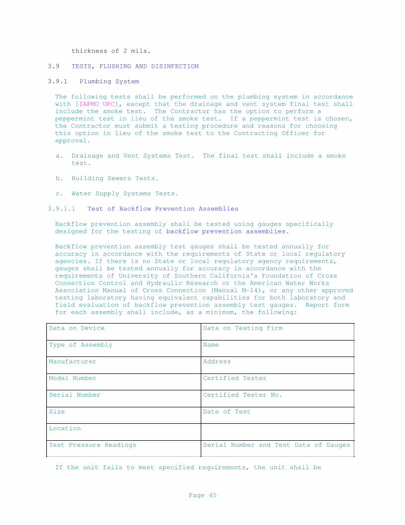
thickness of 2 mils.
3.9 TESTS, FLUSHING AND DISINFECTION
3.9.1 Plumbing System
The following tests shall be performed on the plumbing system in accordance
with [IAPMO UPC], except that the drainage and vent system final test shall
include the smoke test. The Contractor has the option to perform a
peppermint test in lieu of the smoke test. If a peppermint test is chosen,
the Contractor must submit a testing procedure and reasons for choosing
this option in lieu of the smoke test to the Contracting Officer for
approval.
a. Drainage and Vent Systems Test. The final test shall include a smoke
test.
b. Building Sewers Tests.
c. Water Supply Systems Tests.
3.9.1.1 Test of Backflow Prevention Assemblies
Backflow prevention assembly shall be tested using gauges specifically
designed for the testing of backflow prevention assemblies.
Backflow prevention assembly test gauges shall be tested annually for
accuracy in accordance with the requirements of State or local regulatory
agencies. If there is no State or local regulatory agency requirements,
gauges shall be tested annually for accuracy in accordance with the
requirements of University of Southern California's Foundation of Cross
Connection Control and Hydraulic Research or the American Water Works
Association Manual of Cross Connection (Manual M-14), or any other approved
testing laboratory having equivalent capabilities for both laboratory and
field evaluation of backflow prevention assembly test gauges. Report form
for each assembly shall include, as a minimum, the following:
Data on Device Data on Testing Firm
Type of Assembly Name
Manufacturer Address
Model Number Certified Tester
Serial Number Certified Tester No.
Size Date of Test
Location
Test Pressure Readings Serial Number and Test Data of Gauges
If the unit fails to meet specified requirements, the unit shall be
Page 45
repaired and retested.
3.9.1.2 Compressed Air Piping (Nonoil-Free)
Piping systems shall be filled with oil-free dry air or gaseous nitrogen to
150 psig and hold this pressure for 2 hours with no drop in pressure.
3.9.2 Defective Work
If inspection or test shows defects, such defective work or material shall
be replaced or repaired as necessary and inspection and tests shall be
repeated. Repairs to piping shall be made with new materials. Caulking of
screwed joints or holes will not be acceptable.
3.9.3 System Flushing
3.9.3.1 During Flushing
Before operational tests or disinfection, potable water piping system shall
be flushed with [hot] potable water. Sufficient water shall be used to
produce a water velocity that is capable of entraining and removing debris
in all portions of the piping system. This requires simultaneous operation
of all fixtures on a common branch or main in order to produce a flushing
velocity of approximately 4 fps through all portions of the piping system.
In the event that this is impossible due to size of system, the Contracting
Officer (or the designated representative) shall specify the number of
fixtures to be operated during flushing. Contractor shall provide adequate
personnel to monitor the flushing operation and to ensure that drain lines
are unobstructed in order to prevent flooding of the facility. Contractor
shall be responsible for any flood damage resulting from flushing of the
system. Flushing shall be continued until entrained dirt and other foreign
materials have been removed and until discharge water shows no
discoloration. All faucets and drinking water fountains, to include any
device considered as an end point device by NSF/ANSI 61, Section 9, shall
be flushed a minimum of 0.25 gallons per 24 hour period, ten times over a
14 day period.
3.9.3.2 After Flushing
System shall be drained at low points. Strainer screens shall be removed,
cleaned, and replaced. After flushing and cleaning, systems shall be
prepared for testing by immediately filling water piping with clean, fresh
potable water. Any stoppage, discoloration, or other damage to the finish,
furnishings, or parts of the building due to the Contractor's failure to
properly clean the piping system shall be repaired by the Contractor. When
the system flushing is complete, the hot-water system shall be adjusted for
uniform circulation. Flushing devices and automatic control systems shall
be adjusted for proper operation according to manufacturer's instructions.
Comply with ASHRAE 90.1 - IP for minimum efficiency requirements. Unless
more stringent local requirements exist, lead levels shall not exceed
limits established by 40 CFR 141.80 (c)(1). The water supply to the
building shall be tested separately to ensure that any lead contamination
found during potable water system testing is due to work being performed
inside the building.
3.9.4 Operational Test
Page 46
Upon completion of flushing and prior to disinfection procedures, the
Contractor shall subject the plumbing system to operating tests to
demonstrate satisfactory installation, connections, adjustments, and
functional and operational efficiency. Such operating tests shall cover a
period of not less than 8 hours for each system and shall include the
following information in a report with conclusion as to the adequacy of the
system:
a. Time, date, and duration of test.
b. Water pressures at the most remote and the highest fixtures.
c. Operation of each fixture and fixture trim.
d. Operation of each valve, hydrant, and faucet.
f. Temperature of each domestic hot-water supply.
g. Operation of each floor and roof drain by flooding with water.
h. Operation of each vacuum breaker and backflow preventer.
j. Compressed air readings at each compressor and at each outlet. Each
indicating instrument shall be read at 1/2 hour intervals. The report
of the test shall be submitted in quadruplicate. The Contractor shall
furnish instruments, equipment, and personnel required for the tests;
the Government will furnish the necessary water and electricity.
3.9.5 Disinfection
After all system components are provided and operational tests are
complete, the entire domestic hot- and cold-water distribution system shall
be disinfected. Before introducing disinfecting chlorination material,
entire system shall be flushed with potable water until any entrained dirt
and other foreign materials have been removed.
Water chlorination procedure shall be in accordance with AWWA C651 and
AWWA C652 as modified and supplemented by this specification. The
chlorinating material shall be hypochlorites or liquid chlorine. The
chlorinating material shall be fed into the water piping system at a
constant rate at a concentration of at least 50 parts per
million (ppm). Feed a properly adjusted hypochlorite solution injected
into the system with a hypochlorinator, or inject liquid chlorine into
the system through a solution-feed chlorinator .
Test the chlorine residual level in the water at 6 hour intervals for a
continuous period of 24 hours. If at the end of a 6 hour interval, the
chlorine residual has dropped to less than 25 ppm, flush the piping
including tanks with potable water, and repeat the above chlorination
procedures. During the chlorination period, each valve and faucet
shall be opened and closed several times.
After the second 24 hour period, verify that no less than 25 ppm
Page 47
chlorine residual remains in the treated system. The 24 hour
chlorination procedure must be repeated until no less than 25 ppm
chlorine residual remains in the treated system.
Upon the specified verification, the system including tanks shall then
be flushed with potable water until the residual chlorine level is
reduced to less than one part per million. During the flushing period,
each valve and faucet shall be opened and closed several times.
Take additional samples of water in disinfected containers, for
bacterial examination, at locations specified by the Contracting Officer
Test these samples for total coliform organisms (coliform bacteria,
fecal coliform, streptococcal, and other bacteria) in accordance with [
EPA SM 9223] [AWWA 10084]. The testing method used shall be EPA
approved for drinking water systems and shall comply with applicable
local and state requirements.
Disinfection shall be repeated until bacterial tests indicate the
absence of coliform organisms (zero mean coliform density per 100
milliliters) in the samples for at least 2 full days. The system will
not be accepted until satisfactory bacteriological results have been
obtained.
3.10 POSTED INSTRUCTIONS
Framed instructions under glass or in laminated plastic, including wiring
and control diagrams showing the complete layout of the entire system,
shall be posted where directed. Condensed operating instructions
explaining preventive maintenance procedures, methods of checking the
system for normal safe operation, and procedures for safely starting and
stopping the system shall be prepared in typed form, framed as specified
above for the wiring and control diagrams and posted beside the diagrams.
The framed instructions shall be posted before acceptance testing of the
systems.
3.11 PERFORMANCE OF WATER HEATING EQUIPMENT
Standard rating condition terms are as follows:
EF = Energy factor, minimum overall efficiency.
ET = Minimum thermal efficiency with 70 degrees F delta T.
SL = Standby loss is maximum (Btu/h) based on a 70 degrees F
temperature difference between stored water and ambient requirements.
V = Rated volume in gallons
Q = Nameplate input rate in kW (Btu/h)
3.11.1 Storage Water Heaters
3.11.1.1 Electric
a. Storage capacity of 60 gallons shall have a minimum energy factor (EF)
of 0.93 or higher per FEMP requirements.
Page 48
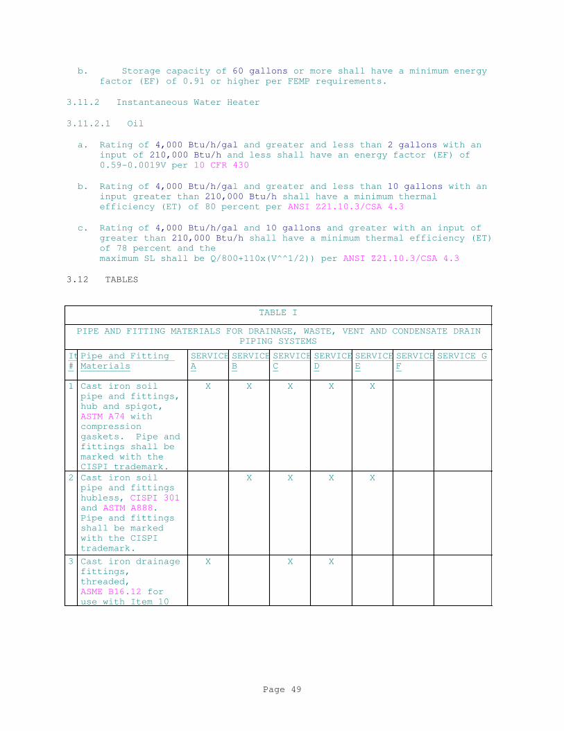
b. Storage capacity of 60 gallons or more shall have a minimum energy
factor (EF) of 0.91 or higher per FEMP requirements.
3.11.2 Instantaneous Water Heater
3.11.2.1 Oil
a. Rating of 4,000 Btu/h/gal and greater and less than 2 gallons with an
input of 210,000 Btu/h and less shall have an energy factor (EF) of
0.59-0.0019V per 10 CFR 430
b. Rating of 4,000 Btu/h/gal and greater and less than 10 gallons with an
input greater than 210,000 Btu/h shall have a minimum thermal
efficiency (ET) of 80 percent per ANSI Z21.10.3/CSA 4.3
c. Rating of 4,000 Btu/h/gal and 10 gallons and greater with an input of
greater than 210,000 Btu/h shall have a minimum thermal efficiency (ET)
of 78 percent and the
maximum SL shall be Q/800+110x(V^^1/2)) per ANSI Z21.10.3/CSA 4.3
3.12 TABLES
TABLE I
PIPE AND FITTING MATERIALS FOR DRAINAGE, WASTE, VENT AND CONDENSATE DRAIN
PIPING SYSTEMS
Item
#
Pipe and Fitting
Materials
SERVICE
A
SERVICE
B
SERVICE
C
SERVICE
D
SERVICE
E
SERVICE
F
SERVICE G
1 Cast iron soil
pipe and fittings,
hub and spigot,
ASTM A74 with
compression
gaskets. Pipe and
fittings shall be
marked with the
CISPI trademark.
X X X X X
2 Cast iron soil
pipe and fittings
hubless, CISPI 301
and ASTM A888.
Pipe and fittings
shall be marked
with the CISPI
trademark.
X X X X
3 Cast iron drainage
fittings,
threaded,
ASME B16.12 for
use with Item 10
X X X
Page 49
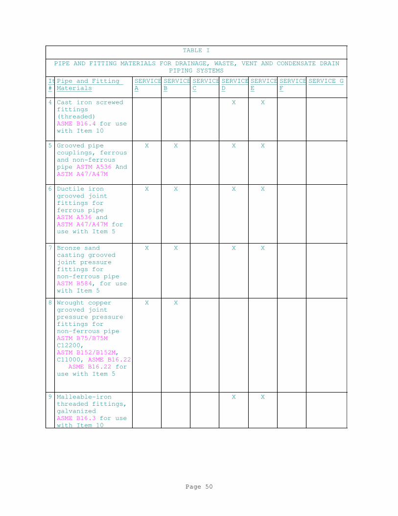
TABLE I
PIPE AND FITTING MATERIALS FOR DRAINAGE, WASTE, VENT AND CONDENSATE DRAIN
PIPING SYSTEMS
Item
#
Pipe and Fitting
Materials
SERVICE
A
SERVICE
B
SERVICE
C
SERVICE
D
SERVICE
E
SERVICE
F
SERVICE G
4 Cast iron screwed
fittings
(threaded)
ASME B16.4 for use
with Item 10
X X
5 Grooved pipe
couplings, ferrous
and non-ferrous
pipe ASTM A536 And
ASTM A47/A47M
X X X X
6 Ductile iron
grooved joint
fittings for
ferrous pipe
ASTM A536 and
ASTM A47/A47M for
use with Item 5
X X X X
7 Bronze sand
casting grooved
joint pressure
fittings for
non-ferrous pipe
ASTM B584, for use
with Item 5
X X X X
8 Wrought copper
grooved joint
pressure pressure
fittings for
non-ferrous pipe
ASTM B75/B75M
C12200,
ASTM B152/B152M,
C11000, ASME B16.22
ASME B16.22 for
use with Item 5
X X
9 Malleable-iron
threaded fittings,
galvanized
ASME B16.3 for use
with Item 10
X X
Page 50
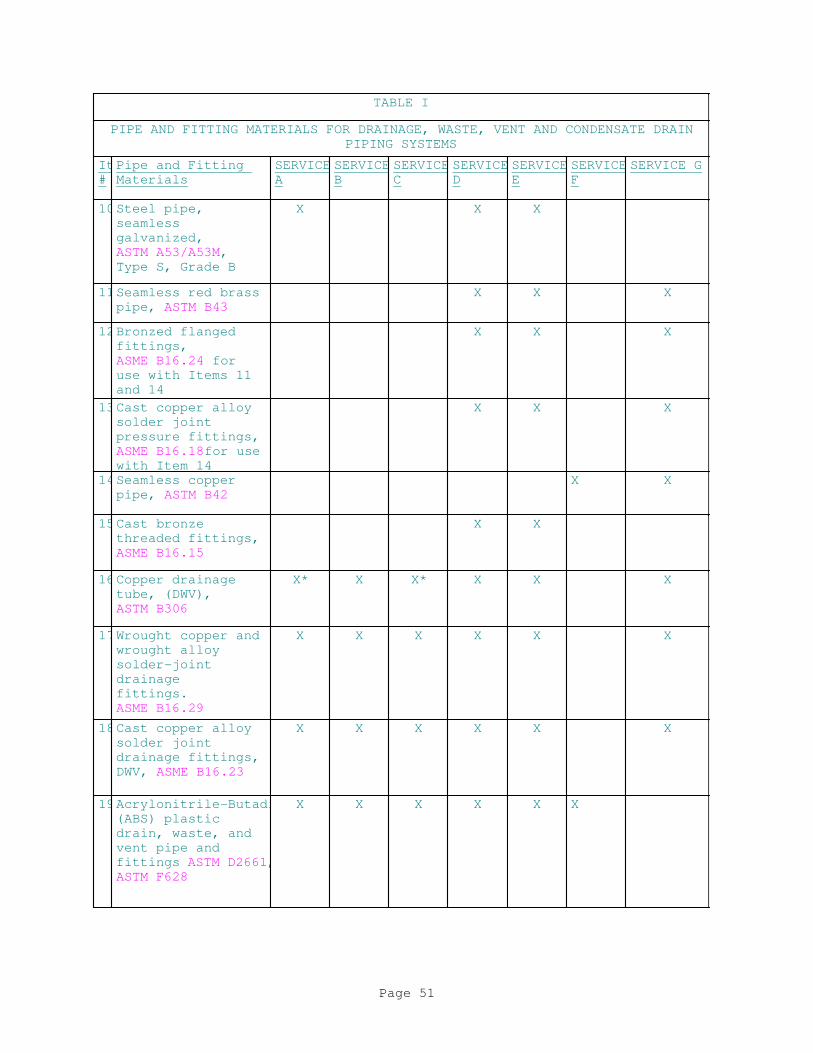
TABLE I
PIPE AND FITTING MATERIALS FOR DRAINAGE, WASTE, VENT AND CONDENSATE DRAIN
PIPING SYSTEMS
Item
#
Pipe and Fitting
Materials
SERVICE
A
SERVICE
B
SERVICE
C
SERVICE
D
SERVICE
E
SERVICE
F
SERVICE G
10Steel pipe,
seamless
galvanized,
ASTM A53/A53M,
Type S, Grade B
X X X
11Seamless red brass
pipe, ASTM B43
X X X
12Bronzed flanged
fittings,
ASME B16.24 for
use with Items 11
and 14
X X X
13Cast copper alloy
solder joint
pressure fittings,
ASME B16.18for use
with Item 14
X X X
14Seamless copper
pipe, ASTM B42
X X
15Cast bronze
threaded fittings,
ASME B16.15
X X
16Copper drainage
tube, (DWV),
ASTM B306
X* X X* X X X
17Wrought copper and
wrought alloy
solder-joint
drainage
fittings.
ASME B16.29
X X X X X X
18Cast copper alloy
solder joint
drainage fittings,
DWV, ASME B16.23
X X X X X X
19Acrylonitrile-Butadiene-Styrene
(ABS) plastic
drain, waste, and
vent pipe and
fittings ASTM D2661,
ASTM F628
X X X X X X
Page 51

TABLE I
PIPE AND FITTING MATERIALS FOR DRAINAGE, WASTE, VENT AND CONDENSATE DRAIN
PIPING SYSTEMS
Item
#
Pipe and Fitting
Materials
SERVICE
A
SERVICE
B
SERVICE
C
SERVICE
D
SERVICE
E
SERVICE
F
SERVICE G
20Polyvinyl Chloride
plastic drain,
waste and vent
pipe and fittings,
ASTM D2665,
ASTM F891, (Sch
40) ASTM F1760
X X X X X X X
21Process glass pipe
and fittings,
ASTM C1053
X
22High-silicon
content cast iron
pipe and fittings
(hub and spigot,
and mechanical
joint),
ASTM A518/A518M
X X X
23Polypropylene (PP)
waste pipe and
fittings,
ASTM D4101
X
24Filament-wound
reinforced
thermosetting
resin (RTRP) pipe,
ASTM D2996
X
SERVICE:
A - Underground Building Soil, Waste and Storm Drain
B - Aboveground Soil, Waste, Drain In Buildings
C - Underground Vent
D - Aboveground Vent
E - Interior Rainwater Conductors Aboveground
F - Corrosive Waste And Vent Above And Belowground
G - Condensate Drain Aboveground
* - Hard Temper
Page 52
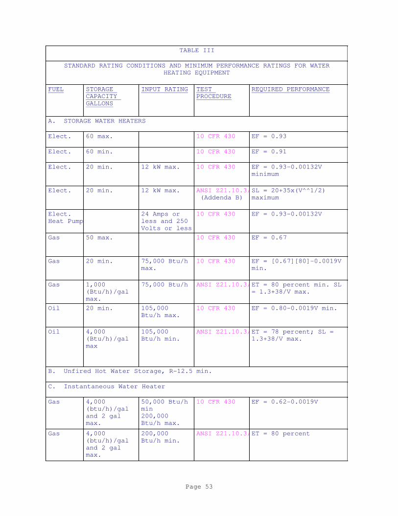
TABLE III
STANDARD RATING CONDITIONS AND MINIMUM PERFORMANCE RATINGS FOR WATER
HEATING EQUIPMENT
FUEL STORAGE
CAPACITY
GALLONS
INPUT RATING TEST
PROCEDURE
REQUIRED PERFORMANCE
A. STORAGE WATER HEATERS
Elect. 60 max. 10 CFR 430 EF = 0.93
Elect. 60 min. 10 CFR 430 EF = 0.91
Elect. 20 min. 12 kW max. 10 CFR 430 EF = 0.93-0.00132V
minimum
Elect. 20 min. 12 kW max. ANSI Z21.10.3/CSA 4.3
(Addenda B)
SL = 20+35x(V^^1/2)
maximum
Elect.
Heat Pump
24 Amps or
less and 250
Volts or less
10 CFR 430 EF = 0.93-0.00132V
Gas 50 max. 10 CFR 430 EF = 0.67
Gas 20 min. 75,000 Btu/h
max.
10 CFR 430 EF = [0.67][80]-0.0019V
min.
Gas 1,000
(Btu/h)/gal
max.
75,000 Btu/h ANSI Z21.10.3/CSA 4.3ET = 80 percent min. SL
= 1.3+38/V max.
Oil 20 min. 105,000
Btu/h max.
10 CFR 430 EF = 0.80-0.0019V min.
Oil 4,000
(Btu/h)/gal
max
105,000
Btu/h min.
ANSI Z21.10.3/CSA 4.3ET = 78 percent; SL =
1.3+38/V max.
B. Unfired Hot Water Storage, R-12.5 min.
C. Instantaneous Water Heater
Gas 4,000
(btu/h)/gal
and 2 gal
max.
50,000 Btu/h
min
200,000
Btu/h max.
10 CFR 430 EF = 0.62-0.0019V
Gas 4,000
(btu/h)/gal
and 2 gal
max.
200,000
Btu/h min.
ANSI Z21.10.3/CSA 4.3ET = 80 percent
Page 53
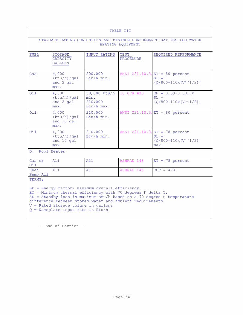
TABLE III
STANDARD RATING CONDITIONS AND MINIMUM PERFORMANCE RATINGS FOR WATER
HEATING EQUIPMENT
FUEL STORAGE
CAPACITY
GALLONS
INPUT RATING TEST
PROCEDURE
REQUIRED PERFORMANCE
Gas 4,000
(btu/h)/gal
and 2 gal
max.
200,000
Btu/h min.
ANSI Z21.10.3/CSA 4.3ET = 80 percent
SL =
(Q/800+110x(V^^1/2))
Oil 4,000
(btu/h)/gal
and 2 gal
max.
50,000 Btu/h
min.
210,000
Btu/h max.
10 CFR 430 EF = 0.59-0.0019V
SL =
(Q/800+110x(V^^1/2))
Oil 4,000
(btu/h)/gal
and 10 gal
max.
210,000
Btu/h min.
ANSI Z21.10.3/CSA 4.3ET = 80 percent
Oil 4,000
(btu/h)/gal
and 10 gal
max.
210,000
Btu/h min.
ANSI Z21.10.3/CSA 4.3ET = 78 percent
SL =
(Q/800+110x(V^^1/2))
max.
D. Pool Heater
Gas or
Oil
All All ASHRAE 146 ET = 78 percent
Heat
Pump All
All All ASHRAE 146 COP = 4.0
TERMS:
EF = Energy factor, minimum overall efficiency.
ET = Minimum thermal efficiency with 70 degrees F delta T.
SL = Standby loss is maximum Btu/h based on a 70 degree F temperature
difference between stored water and ambient requirements.
V = Rated storage volume in gallons
Q = Nameplate input rate in Btu/h
-- End of Section --
Page 54

SECTION 22 07 19.00 40
PLUMBING PIPING INSULATION
08/16
PART 1 GENERAL
Section 22 00 00 PLUMBING, GENERAL PURPOSE applies to work specified in
this section.
1.1 REFERENCES
The publications listed below form a part of this specification to the
extent referenced. The publications are referred to within the text by the
basic designation only.
ASTM INTERNATIONAL (ASTM)
ASTM A240/A240M (2016) Standard Specification for Chromium
and Chromium-Nickel Stainless Steel Plate,
Sheet, and Strip for Pressure Vessels and
for General Applications
ASTM B209 (2014) Standard Specification for Aluminum
and Aluminum-Alloy Sheet and Plate
ASTM B209M (2014) Standard Specification for Aluminum
and Aluminum-Alloy Sheet and Plate (Metric)
ASTM C1136 (2017) Standard Specification for
Flexible, Low Permeance Vapor Retarders
for Thermal Insulation
ASTM C195 (2007; R 2013) Standard Specification for
Mineral Fiber Thermal Insulating Cement
ASTM C449 (2007; R 2013) Standard Specification for
Mineral Fiber Hydraulic-Setting Thermal
Insulating and Finishing Cement
ASTM C533 (2013) Standard Specification for Calcium
Silicate Block and Pipe Thermal Insulation
ASTM C534/C534M (2016) Standard Specification for
Preformed Flexible Elastomeric Cellular
Thermal Insulation in Sheet and Tubular
Form
ASTM C547 (2017) Standard Specification for Mineral
Fiber Pipe Insulation
ASTM C552 (2016a) Standard Specification for
Cellular Glass Thermal Insulation
ASTM C553 (2013) Standard Specification for Mineral
Fiber Blanket Thermal Insulation for
Page 1
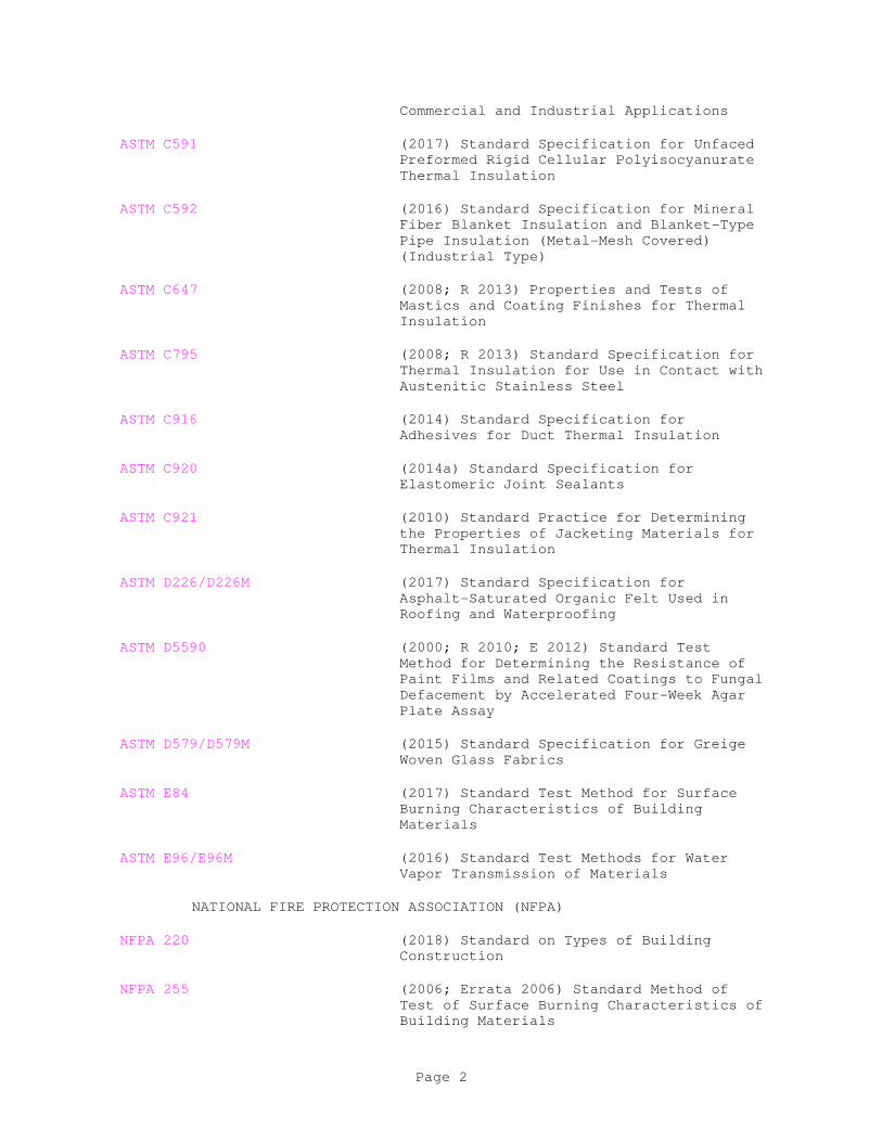
Commercial and Industrial Applications
ASTM C591 (2017) Standard Specification for Unfaced
Preformed Rigid Cellular Polyisocyanurate
Thermal Insulation
ASTM C592 (2016) Standard Specification for Mineral
Fiber Blanket Insulation and Blanket-Type
Pipe Insulation (Metal-Mesh Covered)
(Industrial Type)
ASTM C647 (2008; R 2013) Properties and Tests of
Mastics and Coating Finishes for Thermal
Insulation
ASTM C795 (2008; R 2013) Standard Specification for
Thermal Insulation for Use in Contact with
Austenitic Stainless Steel
ASTM C916 (2014) Standard Specification for
Adhesives for Duct Thermal Insulation
ASTM C920 (2014a) Standard Specification for
Elastomeric Joint Sealants
ASTM C921 (2010) Standard Practice for Determining
the Properties of Jacketing Materials for
Thermal Insulation
ASTM D226/D226M (2017) Standard Specification for
Asphalt-Saturated Organic Felt Used in
Roofing and Waterproofing
ASTM D5590 (2000; R 2010; E 2012) Standard Test
Method for Determining the Resistance of
Paint Films and Related Coatings to Fungal
Defacement by Accelerated Four-Week Agar
Plate Assay
ASTM D579/D579M (2015) Standard Specification for Greige
Woven Glass Fabrics
ASTM E84 (2017) Standard Test Method for Surface
Burning Characteristics of Building
Materials
ASTM E96/E96M (2016) Standard Test Methods for Water
Vapor Transmission of Materials
NATIONAL FIRE PROTECTION ASSOCIATION (NFPA)
NFPA 220 (2018) Standard on Types of Building
Construction
NFPA 255 (2006; Errata 2006) Standard Method of
Test of Surface Burning Characteristics of
Building Materials
Page 2
SOCIETY OF AUTOMOTIVE ENGINEERS INTERNATIONAL (SAE)
SAE AMS 3779 (2016; Rev B) Tape Adhesive, Pressure
Sensitive Thermal Radiation Resistant,
Aluminum Foil/Glass Cloth
U.S. DEPARTMENT OF DEFENSE (DOD)
MIL-A-3316 (1987; Rev C; Am 2 1990) Adhesives,
Fire-Resistant, Thermal Insulation
MIL-PRF-19565 (1988; Rev C) Coating Compounds, Thermal
Insulation, Fire- and Water-Resistant,
Vapor-Barrier
U.S. GENERAL SERVICES ADMINISTRATION (GSA)
FED-STD-595 (Rev C; Notice 1) Colors Used in
Government Procurement
1.2 SUBMITTALS
Government approval is required for submittals with a "G" designation;
submittals not having a "G" designation are for Contractor Quality Control
approval. Submittals with an "S" are for inclusion in the Sustainability
eNotebook, in conformance to Section 01 33 29 SUSTAINABILITY REPORTING.
Submit the following in accordance with Section 01 33 00 SUBMITTAL
PROCEDURES:
SD-02 Shop Drawings
Installation Drawings; G
SD-03 Product Data
Adhesives; G
Coatings; G
Insulating Cement; G
Insulation Materials; G
Jacketing; G
Tape; G
SD-08 Manufacturer's Instructions
Installation Manual; G
SD-11 Closeout Submittals
Record Drawings
Adhesives; S
Page 3
Coatings; S
Insulation Materials; S
Recycled Materials; S
1.3 QUALITY CONTROL
1.3.1 Recycled Materials
Provide thermal insulation containing recycled materials to the extent
practicable, provided that the material meets all other requirements of
this section. The minimum recycled material content of the following
insulation types are:
a. Rock Wool - 75 percent slag by weight
b. Fiberglass - 20-25 percent glass cullet by weight
c. Plastic Rigid Foam - 9 percent recovered material
d. Polyisocyanurate/Polyurethane - 9 percent recovered material
e. Rigid Foam - 9 percent recovered material
Submit recycled materials documentation indicating percentage of
post-industrial and post-consumer recycled content per unit of product.
Indicate relative dollar value of recycled content products to total dollar
value of products included in project.
PART 2 PRODUCTS
2.1 SYSTEM DESCRIPTION
2.1.1 Performance Requirements
Provide noncombustible thermal-insulation system materials, as defined by
NFPA 220. Provide adhesives, coatings, sealants, facings, jackets, and
thermal-insulation materials, except cellular elastomers, with a
flame-spread classification (FSC) of 25 or less, and a smoke-developed
classification (SDC) of 50 or less. Determine these maximum values in
accordance with [ASTM E84] [NFPA 255]. Provide coatings and sealants that
are nonflammable in their wet state.
Provide adhesives, coatings, and sealants with published or certified
temperature ratings suitable for the entire range of working temperatures
normal for the surfaces to which they are to be applied.
2.2 COMPONENTS
2.2.1 Insulation
2.2.1.1 Mineral Fiber Insulation
Provide mineral fiber insulation conforming to [ASTM C592] [ASTM C553]and
suitable for surface temperatures up to 370 degrees F. Provide insulation
with a density not less than 4-pound per cubic foot and with thermal
Page 4
conductivity not greater than 0.26 Btu-inch per hour per square foot per
degree F at 150 degrees F mean.
For pipe sizes 10-inches and larger, in lieu of fibrous glass pipe
insulation, fiber pipe wrap insulation having an insulating efficiency not
less than that of the specified thickness of fibrous glass pipe insulation
may be provided.
2.2.1.2 Cellular Elastomer Insulation
Provide cellular elastomer insulation conforming to ASTM C534/C534M.
Ensure the water vapor permeability does not exceed 0.30 grain per foot per
inch per hour per square foot mercury pressure difference for 1-inch
thickness of cellular elastomer.
2.2.1.3 Cellular Glass Insulation
Conform to ASTM C552, Type II, Grade 2, pipe covering for Cellular Glass.
Substitutions for this material are not permitted. Ensure minimum
thickness is not less than 1-1/2 inches.
2.2.1.4 Calcium Silicate Insulation
Conform to ASTM C533. Ensure the apparent thermal conductivity does not
exceed 0.54 Btu-inch per hour per square foot per degree F at 200 degrees F
mean.
2.2.1.5 Fiberglass Insulation
Conform to ASTM C547. Ensure the apparent thermal conductivity does not
exceed 0.54 Btu-inch per hour per square foot per degree F at 200 degrees F
mean.
Fiber glass pipe insulation having an insulating efficiency not less than
that of the specified thickness of mineral fiber pipe insulation may be
provided in lieu of mineral fiber pipe insulation for aboveground piping.
2.2.1.6 Polyisocyanurate Pipe Insulation
Conform to ASTM C591 for polyisocyanurate, minimum density of 1.7 pounds
per cubic foot.
2.2.1.7 Pipe Barrel
For temperatures up to and including 1200 degrees F, use pipe barrel
insulation Type II, Molded, Grade A or Type III, Precision V-Groove, Grade
A.
2.2.1.8 Pipe Fittings
Provide molded pipe fitting insulation covering for use at temperatures up
to and including 1200 degrees F.
2.2.1.9 Flexible Blankets
Provide flexible blankets and felts for use at temperatures up to and
including 350 degrees F with a density of 1 pound per cubic foot. Ensure
Page 5
thermal conductivity is no greater than 0.26 Btu per hour per square foot
per degree F at 75 degrees F mean.
2.2.2 Adhesives
2.2.2.1 Lagging Adhesive
Lagging is the material used for thermal insulation, especially around a
cylindrical object. This may include the insulation as well as the
cloth/material covering the insulation. To resist mold/mildew, ensure
lagging adhesive conforms to ASTM D5590 with 0 growth rating. Provide
nonflammable and fire-resistant lagging adhesives with a maximum flame
spread index of 25 and a maximum smoke developed index of 50 when tested in
accordance with ASTM E84. Adhesive are MIL-A-3316, Class 1, pigmented
white or red and suitable for bonding fibrous glass cloth to faced and
unfaced fibrous glass insulation board; for bonding cotton brattice cloth
to faced and unfaced fibrous glass insulation board; for sealing edges of
and bonding glass tape to joints of fibrous glass board; for bonding
lagging cloth to thermal insulation; or Class 2 for attaching fibrous glass
insulation to metal surfaces. Apply lagging adhesives in strict accordance
with the manufacturer's recommendations for pipe and duct insulation.
2.2.2.2 Vapor-Barrier Material Adhesives
Ensure adhesives conform to the requirements of ASTM C916, Type I, when
attaching fibrous-glass insulation to metal surfaces or attaching
insulation to itself, to metal, and to various other substrates.
2.2.2.3 Cellular Elastomer Insulation Adhesive
For cellular elastomer insulation adhesive, provide a solvent cutback
chloroprene elastomer conforming to ASTM C916, Type I, and is approved by
the manufacturer of the cellular elastomer for the intended use.
2.2.3 Insulating Cement
2.2.3.1 General Purpose Insulating Cement
Provide general purpose insulating cement, mineral fibe, conforming to
ASTM C195. Ensure composite is rated for1800 degrees F service, with a
thermal-conductivity maximum of 0.85 Btu per inch per hour per square foot
for each degree F temperature differential at 200 degrees F mean
temperature for a 1 inch thickness.
2.2.3.2 Finishing Insulating Cement
Provide finishing insulating cement of a mineral-fiber, hydraulic-setting
type conforming to ASTM C449.
2.2.4 Caulk
Provide elastomeric joint sealant in accordance with ASTM C920, Type S,
Grade NS, Class 25, Use A.
2.2.5 Corner Angles
Provide a nominal 0.016 inch thick aluminum 1 by 1 inch corner angle piping
Page 6

insulation with factory applied kraft backing. Ensure aluminum conforms to
ASTM B209, Alloy [3003] [3105] [5005].
2.2.6 Jacketing
2.2.6.1 Aluminum Jacket
Provide aluminum jackets conforming ASTM B209, Temper H14, minimum
thickness of 0.016 inch, with factory-applied polyethylene and kraft paper
moisture barrier on the inside surface. Provide smooth surface jackets for
jacket outside diameters less than 8 inches. Provide corrugated surface
jackets for jacket outside diameters 8 inches and larger. Provide
stainless steel bands, minimum width of 0.5 inch. Provide factory
prefabricated aluminum covers for insulation on fittings, valves, and
flanges. Provide aboveground jackets and bands with factory-applied
baked-on semi-gloss brown color conforming to Federal Standard FED-STD-595,
"Colors," color chip number 20062.
2.2.6.2 Asphalt-Saturated Felt
Provide asphalt-saturated felt conforming to ASTM D226/D226M, without
perforations, minimum weight of 10 pounds per 100 square feet.
2.2.6.3 Stainless Steel Jacket
Provide stainless steel jackets conforming to ASTM A240/A240M; Type 304,
minimum thickness of 0.010 inch, smooth surface with factory-applied
polyethylene and kraft paper moisture barrier on inside surface. Provide
stainless steel bands, minimum width of 0.5 inch. Provide factory
prefabricated stainless steel covers for insulation on fittings, valves,
and flanges.
2.2.6.4 Glass Cloth Jacket
Provide plain-weave glass cloth conforming to ASTM D579/D579M, Style 141,
weighing not less than 7.23 ounces per square yard before sizing. Factory
apply cloth wherever possible.
Provide leno weave glass reinforcing cloth, 26-end and 12-pick thread
conservation, with a warp and fill tensile strength of 45 and 30 pounds per
inch of width, respectively, and a weight of not less than 1.5 ounces per
square yard.
2.2.6.5 PVC Jacket
Provide 0.010 inch thick, factory-premolded polyvinylchloride, one-piece
fitting pipe-barrel sheeting vapor-barrier jacketing that is
self-extinguishing, with high-impact strength and moderate chemical
resistance. Ensure jacket has a permeability rating of 0.01 grain per hour
per square foot per inch of mercury pressure difference, determined in
accordance with ASTM E96/E96M. Provide manufacturer's standard
solvent-weld type vapor-barrier joint adhesive.
Ensure conformance to ASTM C1136 for, Type I, low-vapor transmission,
high-puncture resistance vapor barriers.
2.2.7 Coatings
Page 7
2.2.7.1 Outdoor Vapor-Barrier Finishing
Provide a nonasphaltic, hydrocarbon polymer, mastic coating. Ensure the
coating conforms to the requirements of ASTM C1136 and ASTM C921.
2.2.7.2 Indoor Vapor-Barrier Finishing
Provide a pigmented resin and solvent compound coatings conforming to
ASTM C1136, Type II.
2.2.7.3 Outdoor and Indoor Nonvapor-Barrier Finishing (NBF)
Provide a pigmented polymer-emulsion as recommended by the insulation
material manufacturer for the surface to be coated.
2.2.7.4 Vapor Retarder
The vapor retarder coating shall be fire and water resistant and
appropriately selected for either outdoor or indoor service. Color shall
be white. The water vapor permeance of the compound shall be 0.013 perms
or less at 43 mils dry film thickness as determined according to procedure
B of ASTM E96/E96M utilizing apparatus described in ASTM E96/E96M. The
coating shall be nonflammable, fire resistant type. To resist mold/mildew,
coating shall meet ASTM D5590 with 0 growth rating. Coating shall meet
MIL-PRF-19565 Type II if selected for indoor service and be Qualified
Products Database listed. All other application and service properties
shall be in accordance with ASTM C647.
2.2.7.5 Cellular-Elastomer Finishing
Provide a polyvinylchloride lacquer coating recommended by the manufacturer
of the cellular elastomer finish.
2.2.7.6 Coating Color
Provide as specified by the Contracting Officer for the coating color.
2.2.8 Tape
Provide a knitted elastic cloth glass lagging specifically suitable for
continuous spiral wrapping of insulated pipe bends and fittings that
produces a smooth, tight, wrinkle-free surface. Conform to requirements of
SAE AMS 3779, ASTM D579/D579M, and ASTM C921 for tape, weighing not less
than 10 ounces per square yard.
2.3 MATERIALS
Submit manufacturer's catalog data for the following items:
a. Adhesives
b. Coatings
c. Insulating Cement
d. Insulation Materials
Page 8
e. Jacketing
f. Tape
Provide compatible materials that do not contribute to corrosion, soften,
or otherwise attack surfaces to which applied, in either the wet or dry
state. Meet ASTM C795 requirements for materials to be used on stainless
steel surfaces. Provide materials that are asbestos free.
PART 3 EXECUTION
Apply insulation only to the system or component surfaces that have
previously been tested and approved by the Contracting Officer.
3.1 PREPARATION
Submit installation drawings for pipe insulation, conforming with the
adhesive manufacturer's written instructions for installation. Submit
installation manual clearly stating the manufacturer's instructions for
insulation materials.
Clean surfaces to remove oil and grease before insulation adhesives or
mastics are applied. Provide solvent cleaning required to bring metal
surfaces to such condition.
3.2 INSTALLATION OF INSULATION SYSTEMS
Apply materials in conformance with the recommendations of the manufacturer.
Install smooth and continuous contours on exposed work. Smoothly and
securely paste down cemented laps, flaps, bands, and tapes. Apply
adhesives on a full-coverage basis.
Install insulation lengths tightly butted against each other at joints.
Where lengths are cut, provide smooth and square and without breakage of
end surfaces. Where insulation terminates, neatly taper and effectively
seal ends, or finish as specified. Direct longitudinal seams of exposed
insulation away from normal view.
Use insulation meeting maximum value conductance as tested at any point, do
not use an average. Meet or exceed the specified maximum conductance by
adding additional insulation thickness.
3.2.1 Dual-Temperature (Hot- and Chilled-) Water Piping
Install a mineral fiber with vapor barrier jacket, Type T-1 insulation,
with a thickness of not less than 1 inch. Insulate aboveground pipes,
valve bodies, fittings, unions, and flanges.
3.2.2 Hot-Water, Steam, and Condensate-Return Piping
Install a mineral fiber insulation with glass cloth jacket, Type T-2, with
a thickness of not less than 1 inch. Insulate aboveground pipes, valve
bodies, fittings, unions, flanges, and miscellaneous surfaces.
3.2.3 Cold-Water and Condensate-Drain Piping
Page 9
Insulate aboveground pipes, valve bodies, fittings, unions, flanges, and
miscellaneous surfaces.
Provide 3/8 inch mineral fiber insulation with glass cloth jacket, Type
T-2, with a thickness of not less than 1 inch.
Install a cellular-elastomer insulation conforming to ASTM C534/C534M, with
a water-vapor permeability not exceeding 0.1 grain per square foot per hour
per inch mercury pressure-differential for 1 inch thickness.
Provide flexible cellular-elastomeric thermal insulation for cold water
piping, Type T-3, with a thickness of 3/8 or 1/2 inch. Use expanded,
closed-cell pipe insulation only aboveground, not for underground piping.
3.2.4 Refrigerant Suction Piping
Install a cellular-elastomer insulation, Type T-3, with a nominal thickness
of 3/4-inch. Insulate surfaces, including valve, fittings, unions, and
flanges.
3.3 APPLICATION
3.3.1 Type T-1, Mineral Fiber with Vapor-Barrier Jacket
Apply factory and field attached vapor barrier jacket to piping insulated
with mineral fiber. Maintain vapor seal. Securely cement jackets, jacket
laps, flaps, and bands in place with vapor-barrier adhesive. Provide
jacket overlaps not less than 1-1/2 inches and jacketing bands for butt
joints 3-inches in width.
Insulate exposed-to-view fittings and valve bodies with preformed
mineral-fiber of the same thickness as the pipe-barrel insulation.
Temporarily secure fitting insulation in place with light cord ties. Apply
a 60-mil coating of white indoor vapor-barrier coating and, while still
wet, wrap with glass lagging tape with 50 percent overlap, and smoothly
blend into the adjacent jacketing. Apply additional coating as needed with
rubber-gloved hands to smooth fillets or contour coating. Allow to fully
cure before the finish coating is applied. Field fabricate and install
insulation for concealed fittings and special configurations. Build up
insulation from mineral fiber and a special mastic consisting of a mixture
of insulating cement and lagging adhesive diluted with 3 parts water.
Where standard vapor-barrier jacketing cannot be used, make the surfaces
vapor tight by using coating and glass lagging cloth or tape as previously
specified.
In lieu of materials and methods previously specified, fittings may be
wrapped with a twine-secured, mineral-wool blanket to the required
thickness and covered with premolded polyvinylchloride jackets. Make seams
vapor tight with a double bead of manufacturer's standard vapor-barrier
adhesive applied in accordance with the manufacturer's instructions. Hold
all jacket ends in place with AISI 300 series corrosion-resistant steel
straps,15-mils thick by 1/2-inch wide.
Set pipe insulation into an outdoor vapor-barrier coating applied
intermittently over a minimum length of 6 inches at maximum 12 feet
spacing. Seal the ends of the insulation to the jacketing with the same
coating material to provide an effective vapor-barrier stop.
Page 10
Do not use staples as a means to apply insulation. Install continuous
vapor-barrier materials over all surfaces, including areas inside pipe
sleeves, hangers, and other concealment.
Provide piping insulation at hangers consisting of 13-pounds per cubic foot
density; fibrous-glass inserts or expanded, rigid, closed-cell,
polyvinylchloride. Where required, seal junctions with vapor-barrier
jacket, glass-cloth mesh tape, and vapor-barrier coating.
Expose white-bleached kraft paper side of the jacketing to view.
Finish exposed-to-view insulation with not less than a 6-mil dry-film
thickness of nonvapor-barrier coating suitable for painting.
3.3.2 Type T-2, Mineral Fiber with Glass Cloth Jacket
Apply factory attached presized, white, glass cloth jacket to piping
insulated with mineral fiber. Securely cement jackets, jacket laps, flaps,
and bands in place with vapor-barrier adhesive. Provide jacket overlaps
not less than 1-1/2 inches and jacketing bands for butt joints 3 inches
wide.
Insulate exposed-to-view fittings with preformed mineral-fiber of the same
thickness as the pipe insulation. Temporarily secure in place with light
cord ties. Install impregnated glass lagging tape with indoor
vapor-barrier on 50 percent overlap basis. Blend tape smoothly into the
adjacent jacketing. Apply additional coating as needed, using rubber
gloved hands to a smooth fillets or contour coatings. Tape ends of
insulation to the pipe at valves 2 inches and smaller. Field fabricate and
install insulation for concealed fittings and special configurations.
Build up insulation from mineral fiber and a mixture of insulating cement
and lagging adhesive, diluted with 3 parts water. Finish surfaces with
glass cloth or tape lagging.
Cover all valves 2-1/2 inches and larger and all flanges with preformed
insulation of the same thickness as the adjacent insulation.
Finish exposed-to-view insulation with a minimum 6-mil dry-film thickness
of nonvapor-barrier coating suitable for painting.
In lieu of materials and methods specified above, fittings may be wrapped
with a twine-secured, mineral-wool blanket to the required thickness and
covered with premolded polyvinylchloride jackets. Hold all jacket ends in
place with AISI 300 series corrosion-resistant steel straps, 15 mils thick
by 1/2-inch wide. Provide fitting insulation, thermally equivalent to
pipe-barrel insulation to preclude surface temperatures detrimental to
polyvinylchloride.
3.3.3 Type T-3, Cellular Elastomer
Cover piping-system surfaces with flexible cellular-elastomer sheet or
preformed insulation. Maintain vapor seal. Cement insulation into
continuous material using a solvent cutback chloroprene adhesive
recommended by the manufacturer for the specific purpose. Apply adhesive
to both of the contact surfaces on a 100-percent coverage basis to a
minimum thickness of 10-mils wet or approximately 150 square feet per gallon
of undiluted adhesive.
Page 11
Set cold water piping insulation into an outdoor vapor-barrier coating
applied intermittently over a minimum length of 6 inches at maximum
intervals of 12 feet. At piping supports, ensure insulation is continuous
by using outside-carrying type clevis hangers with insulation shield.
Install Cork or Wood dowel load-bearing inserts between the pipe and
insulation shields to prevent insulation compression.
Insulate hot-water, cold-water, and condensate drain pipes to the extent
shown with nominal 3/8 or 1/2-inch thick, fire retardant (FR), cellular
elastomer, preformed pipe insulation. Seal joints with adhesive.
At pipe hangers or supports where the insulation rests on the pipe hanger
strap, cut the insulation with a brass cork borer and insert a [No. 3]
superior grade cork. Seal seams with approved adhesive. Insulate sweat
fitting with miter-cut pieces of cellular elastomer insulation of the same
nominal pipe size and thickness as the insulation on the adjacent piping or
tubing. Join miter-cut pieces with approved adhesive. Slit and snap
covers over the fitting, and seal joints with approved adhesive.
Insulate screwed fittings with sleeve-type covers formed from miter-cut
pieces of cellular elastomer thermal insulation having an inside diameter
large enough to overlap adjacent pipe insulation. Lap pipe insulation
against fittings, and overlap not less than 1 inch. Use adhesive to join
cover pieces and cement the cover to the pipe insulation.
Finish surfaces exposed to view or ultraviolet light with not less than a 2
mil minimum dry-film thickness application of a polyvinylchloride lacquer
recommended by the manufacturer. Apply in not less than two coats.
3.3.4 Type T-4, Cellular Glass with Vapor-Barrier Jacket
Apply factory and field attached vapor barrier jacket to piping insulated
with cellular glass. Maintain vapor seal. Securely cement jackets, jacket
laps, flaps, and bands in place with vapor-barrier adhesive. Provide
jacket overlaps not less than 1 1/2 inches. Provide jacket bands for butt
joints of not less than 3 inches width. Provide insulation continuous
through hangers. Bed insulation in an outdoor vapor-barrier coating
applied to all piping surfaces.
Insulate flanges, unions, valves, anchors, and fittings with factory
premolded or prefabricated or field fabricated segments of insulation of
the same material and thickness as the adjoining pipe insulation. When
segments of insulation are used, provide elbows with not less than three
segments. For other fittings and valves, cut segments to the required
curvature or nesting size.
Secure segments of the insulation in place with twine or copper wire.
After the insulation segments are firmly in place, apply a vapor-barrier
coating over the insulation in two coats with glass tape imbedded between
coats. Vary the tint of the first coat from the expected white color of
the second coat to ensure the complete application of the two coats. Apply
coatings to a total dry-film thickness of 1/16 inch minimum. Overlap glass
tape seams not less than 1 inch and tape ends not less than 4 inches.
In lieu of materials and methods specified above, fittings may be wrapped
with 3/8-inch thick, vapor-barrier, adhesive-coated strips of cellular
elastomer insulation. Install insulation under tension, compressed to 25
percent of original thickness, and wrapped until overall thickness is equal
Page 12
to adjacent insulation. Secure cellular elastomer in place with twine and
sealed with vapor-barrier coating applied to produce not less than
1/16-inch dry-film thickness. Cover fittings with premolded
polyvinylchloride jackets. Make seams vapor-tight with a double bead of
manufacturer's standard vapor-barrier adhesive applied in accordance with
the manufacturer's instructions. Hold jacket ends in place with AISI 300
series corrosion-resistant steel straps, 15-mils thick by 1/2-inch wide.
To prevent condensation, insulate anchors secured directly to piping for
not less than 6 inches from the surface of the pipe insulation.
Install white-bleached kraft paper side of jacket exposed to view.
Finish exposed-to-view insulation with not less than a 6-mil dry-film
thickness of nonvapor-barrier coating suitable for painting.
3.3.5 Type T-5, Calcium Silicate with Glass Cloth Jacket (Piping)
Apply factory attached presized, white glass cloth jacket to piping
insulated with calcium silicate. Field apply jackets when required.
Securely cement jackets, jacket laps, flaps, and bands in place with
vapor-barrier adhesive. Ensure jacket overlap is not less than 1-1/2 inches
and jacketing bands for butt joints are 4 inches wide. Fabricate fittings
from segmented pipe barrel sections bedded in general purpose insulating
cement and wired in place. Fill voids with a general purpose insulating
cement with not less than 1/4 inch thick, final coating. Apply glass
lagging tape with a minimum overlap of 50 percent glass lagging tape with
lagging adhesive, blended smoothly into adjacent jacketing. Apply
additional adhesive as needed using rubber-gloved hands to smooth filets
and contour coatings.
3.3.6 Type T-6, Mineral Fiber with Aluminum Jacket
Apply factory or field attached aluminum jacket to piping insulated with
mineral fiber.
Insulate fittings and valve bodies with preformed mineral-fiber of the same
thickness as the pipe-barrel insulation. Temporarily secure fitting
insulation in place with light cord ties. Apply a 60-mil coating of
vapor-barrier mastic, and while still tacky, wrap with glass lagging tape.
Apply additional mastic as needed using rubber-gloved hands to smooth
fillets or contour coatings. Field fabricate and install insulation for
special configurations. Build up insulation from mineral fiber and a
mixture of insulating cement and lagging adhesive diluted with 3 parts
water. Only where standard aluminum jacketing cannot be used, make the
surfaces vapor-tight by using mastic and glass lagging cloth or tape as
specified above with an added finish coat of mastic.
Set pipe insulation into outdoor vapor-barrier coating applied
intermittently over a minimum length of 6-inches with a maximum coating
application of 12-foot. Seal ends of the insulation to the jacketing with
the same coating material to provide effective vapor barrier stops.
Install continuous vapor barrier over all surfaces, including areas inside
pipe sleeves, hangers, and other concealment.
Page 13
Apply piping insulation to both sides of pipe hangers. Insulate junctions
with a special mastic mixture, glass cloth mesh tape, and mastic as
previously specified.
Securely cement jacket laps, flaps, and bands in place with aluminum jacket
sealant. Provide 6 inch wide minimum jacketing bands for butt joints.
Wherever possible, lap joints against the weather so that the water runs
off the lower edge and in accordance with the pipe drainage pitch. Locate
longitudinal laps on horizontal lines 45 degrees below the horizontal
centerline and alternately staggered 1 inch. Lap jacketing material a
minimum of 2 inches, circumferentially sealed with mastic, and strapped to
provide a waterproof covering throughout. Locate straps 8 inches on center
and pull up tight to hold jacketing securely in place. Use screws in
addition to straps when necessary to obtain a waterproof covering. Place
extra straps on each side of supporting devices and at openings. Where
flanging access occurs, strap a chamfer sheet to the pipe at jacketing.
Stiffen exposed longitudinal edges of aluminum jacketing by bending a 1 inch
hem on one edge.
Provide expansion joints for maximum and minimum dimensional fluctuations.
To prevent corrosion, do not allow the aluminum jacketing to come in direct
contact with other types of metal.
At openings in jacket, apply an outdoor vapor-barrier coating for 2 inches
in all directions. Apply jacketing while waterproofing is tacky.
Use screws at each corner of each sheet, at fitting jackets, and as
necessary for the service. Place Number 7, 3/8 inch long, binding-head
aluminum sheet metal screws through the mastic seal.
3.3.7 Type T-7, Calcium Silicate with Glass Cloth Jacket (Surfaces)
Cover surfaces with insulation block bedded in an insulating cement and
covered with glass cloth jacketing.
Clean surfaces with a chlorinated solvent. Mix general purpose insulating
cement with 3 parts water to 1 part nonvapor-barrier adhesive to bring to
application consistency. Set block into bedding and joints and fill spaces
with a bedding mix and wrap with galvanized chicken wire mesh well laced
into an envelope. Trowel a 3/8 inch thick coating of bedding mix jacket on
the nonvapor-barrier adhesive and glass cloth. Finish surfaces with not
less than a 6-mil dry-film thickness of nonvapor-barrier coating.
Aluminum sheet jacketing may be used in lieu of glass cloth.
3.3.8 Type T-9, Cellular Elastomer
Clean pump surfaces with solvent. Apply not less than 1 inch of general
purpose insulating cement, mixed with nonvapor-barrier adhesive diluted
with 3 parts water, to achieve smooth surface and configuration contours.
After all water has been removed, cover surfaces with 1/2 inch thick
cellular elastomer insulation, attached and joined into a continuous sheet
with an outdoor vapor-barrier coating recommended by the insulation
manufacturer for the specific purpose. Apply coating to both of the
Page 14
contact surfaces on a 100-percent coverage basis with a minimum thickness of
10 mils wet. Blend coating into the adjacent flange insulation. Cover
joint with a band of cellular elastomer equal to the flange assembly
width. Use same coating to seal insulation to the casing at penetrations
and terminations. Insulate pumps in a manner that permits insulation to be
removed to repair or replace pumps.
Finish insulation with a 2 mil minimum dry-film application of a
polyvinylchloride lacquer coating recommended by the manufacturer and
applied in not less than two coats.
3.3.9 Type T-10, Mineral-Fiber Fill
Pack voids surrounding pipe with mineral-fiber fill.
3.3.10 Type T-17, Calcium Silicate Weatherproof Jacket
Cover piping system surfaces with calcium silicate insulation. Cover
fittings and valve bodies with preformed insulation of the same material
and thickness as the adjoining pipe insulation.
3.4 CLOSEOUT ACTIVITIES
Final acceptance of the performed work is dependent upon providing Record
Drawings details to the Contracting Officer. Include construction details,
by building area, the insulation material type, amount, and installation
method. An illustration or map of the pipe routing locations may serve
this purpose.
Provide a cover letter/sheet clearly marked with the system name, date, and
Page 15

the words "Record Drawings Insulation/Material" for the data. Forward to
the Systems Engineer and Condition Monitoring Office Predictive Testing
Group for inclusion in the Maintenance Database."
-- End of Section --
Page 16
SECTION 22 15 14.00 40
GENERAL SERVICE COMPRESSED-AIR SYSTEMS, LOW PRESSURE
11/17
PART 1 GENERAL
Section 40 17 30.00 40 WELDING GENERAL PIPING applies to work specified in
this section.
Section 23 00 00 AIR SUPPLY, DISTRIBUTION, VENTILATION, AND EXHAUST SYSTEMS
applies to work specified in this section.
1.1 REFERENCES
The publications listed below form a part of this specification to the
extent referenced. The publications are referred to within the text by the
basic designation only.
AMERICAN INSTITUTE OF STEEL CONSTRUCTION (AISC)
AISC 360 (2016) Specification for Structural Steel
Buildings
AMERICAN WATER WORKS ASSOCIATION (AWWA)
AWWA C504 (2015) Standard for Rubber-Seated
Butterfly Valves
AMERICAN WELDING SOCIETY (AWS)
AWS WHB-2.9 (2004) Welding Handbook; Volume 2, Welding
Processes, Part 1
AWS-03 (2011) Welding Handbook, Volumes 1 thru 4
ASME INTERNATIONAL (ASME)
ASME A112.18.1/CSA B125.1 (2012; R 2017) Plumbing Supply Fittings
ASME B16.3 (2011) Malleable Iron Threaded Fittings,
Classes 150 and 300
ASME B16.39 (2014) Standard for Malleable Iron
Threaded Pipe Unions; Classes 150, 250,
and 300
ASME B16.5 (2013) Pipe Flanges and Flanged Fittings:
NPS 1/2 Through NPS 24 Metric/Inch Standard
ASME B16.9 (2012) Standard for Factory-Made Wrought
Steel Buttwelding Fittings
ASME B18.2.2 (2015) Nuts for General Applications:
Machine Screw Nuts, Hex, Square, Hex
Flange, and Coupling Nuts (Inch Series)
Page 1
ASME B31.1 (2016; Errata 2016) Power Piping
ASME B31.3 (2016) Process Piping
ASME B40.100 (2013) Pressure Gauges and Gauge
Attachments
ASME BPVC (2010) Boiler and Pressure Vessels Code
ASME BPVC SEC VIII D1 (2015) BPVC Section VIII-Rules for
Construction of Pressure Vessels Division 1
ASTM INTERNATIONAL (ASTM)
ASTM A181/A181M (2014) Standard Specification for Carbon
Steel Forgings, for General-Purpose Piping
ASTM A183 (2014) Standard Specification for Carbon
Steel Track Bolts and Nuts
ASTM A197/A197M (2000; R 2015) Standard Specification for
Cupola Malleable Iron
ASTM A216/A216M (2016) Standard Specification for Steel
Castings, Carbon, Suitable for Fusion
Welding, for High-Temperature Service
ASTM A234/A234M (2017) Standard Specification for Piping
Fittings of Wrought Carbon Steel and Alloy
Steel for Moderate and High Temperature
Service
ASTM A307 (2014; E 2017) Standard Specification for
Carbon Steel Bolts, Studs, and Threaded
Rod 60 000 PSI Tensile Strength
ASTM A53/A53M (2012) Standard Specification for Pipe,
Steel, Black and Hot-Dipped, Zinc-Coated,
Welded and Seamless
ASTM A666 (2015) Standard Specification for Annealed
or Cold-Worked Austenitic Stainless Steel
Sheet, Strip, Plate and Flat Bar
ASTM B164 (2003; R 2014) Standard Specification for
Nickel-Copper Alloy Rod, Bar, and Wire
ASTM C920 (2014a) Standard Specification for
Elastomeric Joint Sealants
ASTM D2000 (2012; R 2017) Standard Classification
System for Rubber Products in Automotive
Applications
ASTM D2239 (2012) Standard Specification for
Polyethylene (PE) Plastic Pipe (SIDR-PR)
Based on Controlled Inside Diameter
Page 2
ASTM E1 (2014) Standard Specification for ASTM
Liquid-in-Glass Thermometers
ASTM F104 (2011) Standard Classification System for
Nonmetallic Gasket Materials
ASTM F568M (2007) Standard Specification for Carbon
and Alloy Steel Externally Threaded Metric
Fasteners
COMPRESSED AIR AND GAS INSTITUTE (CAGI)
CAGI B19.1 (2010) Safety Standard for Compressor
Systems
INTERNATIONAL SOCIETY OF AUTOMATION (ISA)
ISA 7.0.01 (1996) Quality Standard for Instrument Air
MANUFACTURERS STANDARDIZATION SOCIETY OF THE VALVE AND FITTINGS
INDUSTRY (MSS)
MSS SP-58 (1993; Reaffirmed 2010) Pipe Hangers and
Supports - Materials, Design and
Manufacture, Selection, Application, and
Installation
MSS SP-67 (2017) Butterfly Valves
MSS SP-72 (2010a) Ball Valves with Flanged or
Butt-Welding Ends for General Service
MSS SP-80 (2013) Bronze Gate, Globe, Angle and Check
Valves
NATIONAL AERONAUTICS AND SPACE ADMINISTRATION (NASA)
RCBEA GUIDE (2004) NASA Reliability Centered Building
and Equipment Acceptance Guide
U.S. GENERAL SERVICES ADMINISTRATION (GSA)
CID A-A-1922 (Rev A; Notice 2) Shield, Expansion
(Caulking Anchors, Single Lead)
CID A-A-1923 (Rev A; Notice 2) Shield, Expansion (Lag,
Machine and Externally Threaded Wedge Bolt
Anchors)
CID A-A-1924 (Rev A; Notice 2) Shield, Expansion (Self
Drilling Tubular Expansion Shell Bolt
Anchors
CID A-A-55614 (Basic; Notice 2) Shield, Expansion
(Non-Drilling Expansion Anchors)
1.2 SUBMITTALS
Page 3
Government approval is required for submittals with a "G" designation;
submittals not having a "G" designation are [for Contractor Quality Control
approval.][for information only. When used, a designation following the
"G" designation identifies the office that will review the submittal for
the Government.] Submittals with an "S" are for inclusion in the
Sustainability eNotebook, in conformance to Section 01 33 29 SUSTAINABILITY
REPORTING. Submit the following in accordance with Section 01 33 00
SUBMITTAL PROCEDURES:
SD-02 Shop Drawings
Installation Drawings; G
SD-03 Product Data
Equipment and Performance Data; G
Aboveground Piping Materials; G
Piping Specialties; G
Supporting Elements; G
Air Compressors; G
Valves; G
Accessories; G
Miscellaneous Materials; G
SD-05 Design Data
Design Analysis and Calculations; G
SD-06 Test Reports
Piping System Test Report
SD-07 Certificates
Underground Piping Materials
Aboveground Piping Materials
Supporting Elements
Valves
Miscellaneous Materials
SD-10 Operation and Maintenance Data
Operation and Maintenance Manuals
PART 2 PRODUCTS
Page 4

2.1 SYSTEM DESCRIPTION
Submit installation drawings for low-pressure compressed air systems in
accordance with the paragraphs titled ABOVEGROUND PIPING MATERIALS and
UNDERGROUND PIPING MATERIALS.
Accompany drawings with curves indicating that an essentially flat
reduced-pressure curve for the capacity demand of the system is met by the
proposed valves.
In lieu of separate hangers, a shop drawing of trapeze hangers with solid
or split-ring clamps may be submitted for approval.
2.1.1 Design Requirements
Provide equipment and performance data submitted for piping systems showing
conformance with ASME Code.
Provide design analysis and calculations for low-pressure compressed air
systems that have flow rates, air distribution, pressure, and insulation
that meet the requirements of the standards cited in this section.
2.2 EQUIPMENT
2.2.1 Piping Specialties
2.2.1.1 Air-Pressure-Reducing Stations
Install a pressure-reducing station complete with a relieving
pressure-reducing valve, valve bypass, particle filter, pressure indicator
upstream of station, pressure indicator downstream of station, and
regulated air-pressure relief valve.
Construct the pressure regulator body of zinc or aluminum die castings that
are rated for the service. Use a diaphragm material that is a reinforced
air-, oil-, and water-resistant elastomer. Ensure that all components
exposed to the fluid stream being controlled are made of suitable
nonmetallic materials. Ensure that valves are a balanced
construction-relieving type that will automatically prevent excess pressure
buildup.
Construct filters of aluminum die castings, rated for the service, and
furnished with iron pipe size (ips) connections. Ensure that bowl
materials are aluminum and that the filter is serviceable by bowl
quick-disconnect devices. Equip the bowl with a manual drain cock.
Separate liquid particles by centrifugal and quiet zone action. Remove
solid particles up to 15 micrometers by filter elements of
corrosion-resistant steel mesh.
Combination manual drain filter-regulator units conforming to the above
requirements are acceptable in lieu of separate units.
Provide pressure-relief valves rated for the pressure experienced on the
high-pressure side and sized for the full installed capacity of the
pressure regulating station at the pressure experienced on the low-pressure
side. Set the valve so that the pressure does not exceed the correct
low-side pressure by greater than 20 percent. Rate and label the valve.
Page 5
Ensure that the seat material is suitable for the service.
2.2.1.2 Air Line Lubricators
Install air line lubricators that feed the lubricant in pulses and that
have a pickup tube, polycarbonate resin bowl, large fill opening, metering
rod flow adjuster, sight ball, and drain cock.
Use lubricators suitable for 200 psig at 165 degrees F.
2.2.1.3 Compressed-Air Receivers
Ensure that the compressed air receivers conform to the sizes and
capacities specified. Design such vessels for working pressures and
service in accordance with the ASME BPVC SEC VIII D1, and label the
receivers with this information.
Provide complete vessels, with connections for drain, supports, and other
required accessories.
2.2.1.4 Grooved Pipe Couplings and Fittings
Fabricate the housing for couplings in at least 2 parts of malleable iron
castings. Provide molded synthetic rubber coupling gaskets conforming to
ASTM D2000. Provide oval-neck track-head coupling bolts with hexagonal
heavy nuts, conforming to ASTM A183.
Fabricate pipe fittings used with couplings of malleable iron castings.
Where a manufacturer's standard size malleable iron fitting pattern is not
available, use fabricated fittings.
Fabricate fittings from Schedule 40 in accordance with ASTM A53/A53M, Grade
B, seamless steel pipe. Ensure that the wall thickness of the long-radius
seamless welding fittings match the wall thickness of the pipe, and conform
to ASTM A234/A234M and ASME B16.9.
2.2.1.5 Pressure Gages
Ensure that the pressure gages conform to ASME B40.100 and are Type I,
Class 1, (pressure) for the pressures indicated. Provide a pressure gage
size that is 3 1/2 inches. Ensure the cases are constructed of
corrosion-resistant steel conforming to ASTM A666 with an ASM No. 4
standard commercial polish or better. Equip the gages with a damper screw
adjustment in the inlet connection.
Equip the gages with an adjustable, red marking indicator.
2.2.1.6 Thermometers
Provide the thermometers that conform to ASTM E1 and that are industrial
pattern Type I, Class 3. Ensure that thermometers installed 6 feet or
higher above the floor have an adjustable angle body. Ensure the scale is
at least 7-inches long. Ensure the case face is constructed of the
manufacturer's standard polished aluminum. Ensure that the thermometer
range meets the service requirements. Provide a thermometer with
nonferrous separable wells.
Page 6
2.2.1.7 Line Strainers
Provide Y-type strainers with a removable basket. Ensure that strainers of
2 inch ips or smaller have screwed ends and that strainers of 2 1/2 inch ips
or larger have flanged ends. Ensure that the body working pressure rating
exceeds the maximum service pressure of the system by at least 50 percent.
Ensure that the body has cast-in arrows to indicate the direction of flow.
Ensure that the strainer bodies fitted with screwed screen retainers have
straight threads and are gasketed with nonferrous metal. Ensure that the
strainer bodies fitted with bolted-on screen retainers have offset blowdown
holes. Fit strainers larger than 2 1/2 inches with the manufacturer's
standard blowdown valve. Provide [cast bronze conforming to ASTM B62]
[cast iron conforming to ASTM A278/A278M Class 30] [ductile iron conforming
to ASTM A536] body material. Where the system material is nonferrous,
provide a nonferrous strainer body material.
Ensure the minimum free-hole area of the strainer element is equal to at
least 3.4 times the internal area of connecting piping. Ensure that the
strainer screens for air service have a mesh cloth smaller than 0.006 inch
and that the screens have finished ends fitted to machined screen chamber
surfaces to preclude bypass flow. Ensure that the strainer element
material is AISI Type 304 corrosion-resistant steel.
2.2.2 Air Compressors
Provide a standard piston air compressor complete with air tank, air dryer
and other appurtenances. Ensure that the compressor and installation
conforms to CAGI B19.1. Ensure that the compressor capacity is as required
for service and provide continuous control air when operating on a 1/3-on
2/3-off cycle. Provide an oil-level sight indicator on the compressor and
a coalescing oil filter on the compressor discharge line. Provide
mass-refrigerated air dryer that maintain the air in the system with a dew
point low enough to prevent condensation at 13 degrees F at 18 psi main
pressure. Locate the air dryer at the outlet of the tank. Ensure that the
control air delivered to the system conforms to ISA 7.0.01.
2.2.3 Valves
2.2.3.1 Ball Valves (BAV)
Ensure that ball valves conform to MSS SP-72 and are Style [1] [3].
Ensure that grooved end ball valves are used only if the manufacturer
certifies valve performance in accordance with MSS SP-72.
Provide valves rated for service at 175 or more psi at 200 degrees F.
For valve bodies of 2 inch ips or smaller, use screwed end connections
constructed of Class A copper alloy.
For valve bodies in sizes 2 1/2 inch ips or larger, use flanged-end
connections constructed of Class [D] [E] [F] material.
Provide balls and stems for valves 2 inch or smaller ips are the
manufacturer's standard Class A copper alloy with 900 Brinell hard chrome
plating finish. Ensure that electroless nickel plating conforms to
ASTM B733.
Page 7
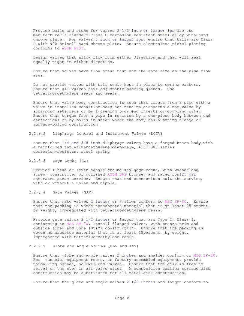
Provide balls and stems for valves 2-1/2 inch or larger ips are the
manufacturer's standard Class C corrosion-resistant steel alloy with hard
chrome plate. For valves 6 inch or larger ips, ensure that balls are Class
D with 900 Brinell hard chrome plate. Ensure electroless nickel plating
conforms to ASTM B733.
Design valves that allow flow from either direction and that will seal
equally tight in either direction.
Ensure that valves have flow areas that are the same size as the pipe flow
area.
Do not provide valves with ball seals kept in place by spring washers.
Ensure that all valves have adjustable packing glands. Use
tetrafluoroethylene seats and seals.
Ensure that valve body construction is such that torque from a pipe with a
valve in installed condition does not tend to disassemble the valve by
stripping setscrews or by loosening body end inserts or coupling nuts.
Ensure that torque from a pipe is resisted by a one-piece body between end
connections or by bolts in shear where the body has a mating flange or
surface-bolted construction.
2.2.3.2 Diaphragm Control and Instrument Valves (DCIV)
Ensure that 1/4 and 3/8 inch diaphragm valves have a forged brass body with
a reinforced tetrafluoroethylene diaphragm, AISI 300 series
corrosion-resistant steel spring.
2.2.3.3 Gage Cocks (GC)
Provide T-head or lever handle ground key gage cocks, with washer and
screw, constructed of polished ASTM B62 bronze, and rated for125 psi
saturated steam service. Ensure that end connections suit the service,
with or without a union and nipple.
2.2.3.4 Gate Valves (GAV)
Ensure that gate valves 2 inches or smaller conform to MSS SP-80. Ensure
that the packing is woven nonasbestos material that is at least 25 ercent,
by weight, impregnated with tetrafluoroethylene resin.
Provide gate valves 2 1/2 inches or larger that are Type I, Class 1,
conforming to MSS SP-70. Install flanged valves, with bronze trim and
outside screw and yoke (OS&Y) construction. Ensure that the packing is
woven nonasbestos material that is at least 25percent, by weight,
impregnated with tetrafluoroethylene resin.
2.2.3.5 Globe and Angle Valves (GLV and ANV)
Ensure that globe and angle valves 2 inches and smaller conform to MSS SP-80.
For tunnels, equipment rooms, or factory-assembled equipment, provide
union-ring bonnet, screwed-end valves. Ensure that the disk is free to
swivel on the stem in all valve sizes. A composition seating surface disk
construction may be substituted for all metal disk construction.
Ensure that the globe and angle valves 2 1/2 inches and larger conform to
Page 8

MSS SP-80. Provide valve bodies of cast iron conforming to ASTM A126,
Class A, as specified for Class 1 valves under MSS SP-70. Provide flange
valve ends that conform with ASME B16.1, and ensure that outside stem and
yoke (OS&Y) valves are used.
For packing, use a woven material that is at least 25 percent, by weight,
impregnated with tetrafluoroethylene resin.
2.2.3.6 Eccentric Plug Valves (EPV)
Provide eccentric plug valves in sizes 2 inches and smaller constructed of
[manufacturer's standard brass] [bronze materials conforming to [ASTM B61] [
ASTM B62]. Ensure that the valves are rated for service at 175 psi maximum
nonshock pressure at 200 degrees F. Use a valve body with screwed ends.
Coat eccentric plug surfaces in contact with flow with a 60 to 70 Shore A
durometer hardness elastomer resistant to compressed air.
Ensure that material for eccentric plug valves in sizes 2 1/2 inches or
larger consists of [Type 2 nickel alloy iron conforming to ASTM A436] .
Ensure that the valves are rated for service at 175 psi maximum nonshock
pressure at200 degrees F. Use valve bodies with screwed ends. Coat
eccentric plug surfaces with a 60 to 70 Shore A durometer hardness
elastomer that is resistant to compressed air. For specified applications,
in sizes to 5 inch ips, the cross-sectional area of the valve bore, when
open, equals the pipe inlet area. Ensure that the valves used for
combination shutoff and balancing service are fitted with a memory device.
Provide a memory device or mechanism that permits a valve set at a balance
point to be opened or closed, but not beyond the balance point. Fit valves
up to 6 inch ips with a removable lever operator. Fit valves of 6 inch ips
or larger, with a totally enclosed flood-lubricated worm gear drive such
that the operating torque does not exceed 50 foot-pounds.
2.3 MATERIALS
2.3.1 Underground Piping Materials
2.3.1.1 Piping Types
Ensure that BCS-PS black carbon steel piping with a polyethylene sheath
conforms to ASTM A53/A53M, Type [E] [S], in sizes through 10 inch ips. For
pipe in sizes 12 inches and larger, select Schedule 40 or be 0.375 inch
thick.
Make sheath joints with a thermally fitted shrinking sleeves applied with
factory-approved shrinking devices. Make taped fitting protection and
repairs in accordance with manufacturer's instructions. Ensure that the
electrical flaw detection testing at the factory requires 10,000 volts to
be impressed across the sheath. Sheath breakdown voltage is at least
13,000 volts.
2.3.1.2 Fittings
Provide long-radius butt-weld carbon steel fittings conforming to
ASTM A234/A234M and ASME B16.9 to match pipe wall thickness. Do not use
pipe bending. Ensure that aboveground terminal fittings are 150-pound
working steam pressure (wsp) forged-steel weld-neck flanges to match the
wall thickness, conforming to ASME B16.5 and ASTM A181/A181M Class 60.
Page 9

2.3.2 Aboveground Piping Materials
2.3.2.1 Compressed Air Systems 125 Psig And Less
a. Type BCS Black Carbon Steel
For pipe 1/8 through 1 1/2 inches provide Schedule 40, furnace butt welded,
black carbon steel, conforming to ASTM A53/A53M, Type F, Grade A.
For pipe 2 through 10 inches, provide Schedule 40, seamless, black carbon
steel, conforming to ASTM A53/A53M, Grade B, Type S. Use Grade A pipe for
permissible field bending.
For pipe 12 inches and over use a a 0.375 inch wall, provide seamless,
black carbon steel, conforming to ASTM A53/A53M, Grade B, Type S.
For fittings 2 inches and under, provide 150 (psig) wsp, banded, black
malleable iron, screwed, conforming to ASTM A197/A197M and ASME B16.3.
For unions 2 inches and under, provide 250 psig wsp, female, screwed, black
malleable iron, with brass-to-iron seat and a ground joint conforming to
ASME B16.39. Use ductile iron conforming to ASTM A536 for grooved pipe
couplings.
For couplings 2 inches and under, provide standard weight, screwed, black
carbon steel
For fittings 2 1/2 inches and over, provide steel, butt welded, to match
pipe wall thickness, conforming to ASTM A234/A234M and ASME B16.9.
For flanges 2 1/2 inches and over, provide 150-psig wsp, forged steel,
welding neck to match pipe wall thickness, conforming to ASME B16.5.
For grooved pipe couplings and fittings 2 1/2 inches and over, use
malleable iron couplings and fittings conforming to the paragraph PIPING
SPECIALTIES.
2.4 ACCESSORIES
2.4.1 Miscellaneous Materials
2.4.1.1 Bolting
For flange and general-purpose bolting, use hex-head bolts and conform to
ASTM A307, Grade B. Ensure that the heavy hex-nuts conform to ASME B18.2.2.
Square-head bolts are not acceptable.
For grooved couplings, use heat-treated carbon steel bolts and nuts
conforming to ASTM A183.
2.4.1.2 Elastomer Caulk
Provide a two-component polyurethane-base elastomer caulking material
conforming to ASTM C920.
2.4.1.3 Escutcheons
Page 10

Provide escutcheons manufactured from nonferrous metals and chrome plated
except when AISI 300 series corrosion-resistant steel is provided. Select
the metals and finish in accordance with ASME A112.18.1/CSA B125.1.
Provide one-piece escutcheons. Ensure that escutcheons maintain a fixed
position against a surface by means of internal spring tension devices or
setscrews.
2.4.1.4 Flashing
Ensure that the sheet lead conforms to ASTM B749, Grade [B] [C] [D] and
weighs at least 4 pounds per square foot.
Ensure that the sheet copper conforms to ASTM B370 and weighs at least 16
ounces per square foot.
2.4.1.5 Flange Gaskets
Ensure that the compressed non-asbestos sheet conforms to ASTM F104, Type
1, and is coated on both sides with graphite.
Ensure that the gasketing for grooved flange adapters is a
pressure-responsive elastomer conforming to ASTM D2000.
2.4.1.6 Pipe Thread Compounds
Use tetrafluoroethylene tape at least 2 mils thick for pipe sizes to and
including 1 inch ips.
Tetrafluoroethylene dispersions and other suitable compounds may be used
for other applications upon approval by the Contracting Officer.
2.4.2 Supporting Elements
Provide all necessary piping system components and miscellaneous required
supporting elements. Ensure that supporting elements are suitable for
stresses imposed by system pressures and temperatures, and natural and
other external forces.
Ensure that the supporting elements are UL-listed and conform to
requirements of ASME B31.3, and MSS SP-58, except as otherwise noted. Type
devices specified herein are defined in MSS standards unless otherwise
noted.
2.4.2.1 Building Structure Attachments
Use concrete and masonry anchor devices that conform to requirements of
CID A-A-1922, CID A-A-1923, CID A-A-1924, CID A-A-55614.
Install cast-in floor-mounted equipment anchor devices that provide
adjustable positions.
Use built-in masonry anchor devices, unless otherwise approved by the
Contracting Officer.
Do not use power-actuated anchoring devices to support mechanical systems
components.
Page 11

Ensure that beam clamps are center-loading Type 21,28,29,30 UL-listed,
cataloged, and load-rated, and commercially manufactured.
Use clamps to support piping that is 1 1/2 inches and smaller. Provide
FM-approved and UL-listed C-clamps with hardened cup tip, setscrew,
locknut, and retaining strap. Use a retaining strap section of at least
[1/8 by 1] inch. Ensure that the thickness of beam flanges to which clamps
are attached does not exceed 0.60 inch.
Construct concrete inserts in accordance with the requirements of MSS SP-58
for Type 18 hangars. When applied to piping of 2 inch ips or larger and
where otherwise required by imposed loads, insert a 1-foot length of
1/2-inch reinforcing rod that is wired through wing slots. Proprietary
designs for continuous inserts may be used upon approval by the Contracting
Officer.
2.4.2.2 Horizontal Pipe Attachments
Use Type 6 solid malleable-iron pipe rings to support piping in sizes to
and including 2 inch ips. Split-band rings may be used for piping up to 1
inch ips.
Use Types 1 or 3 or 4 attachments to support piping in sizes through 8 inch
ips.
Use Type 41 or 49 pipe rolls to support piping in sizes larger than 8 inch
ips.
Use trapeze hangers fabricated from approved structural steel shapes, and
use U-bolts in congested areas and where multiple pipe runs occur.
Structural steel shapes are a commercially available, proprietary-design,
rolled steel.
2.4.2.3 Vertical Pipe Attachments
Use Type 8 vertical pipe attachments.
2.4.2.4 Hanger Rods and Fixtures
Use only circular cross-section rod hangers to connect building structure
attachments to pipe support devices. Pipe, straps, or bars of equivalent
strength may be used for hangers only where approved by the Contracting
Officer.
Provide turnbuckles, swing eyes, and clevises as required by support system
to accommodate pipe accessibility and adjustment for load and pitch.
2.4.2.5 Supplementary Steel
Where it is necessary to frame structural members between existing members
or where structural members are used in lieu of commercially rated
supports, design and fabricate such supplementary steel in accordance with
AISC 360.
PART 3 EXECUTION
3.1 INSTALLATION
Page 12
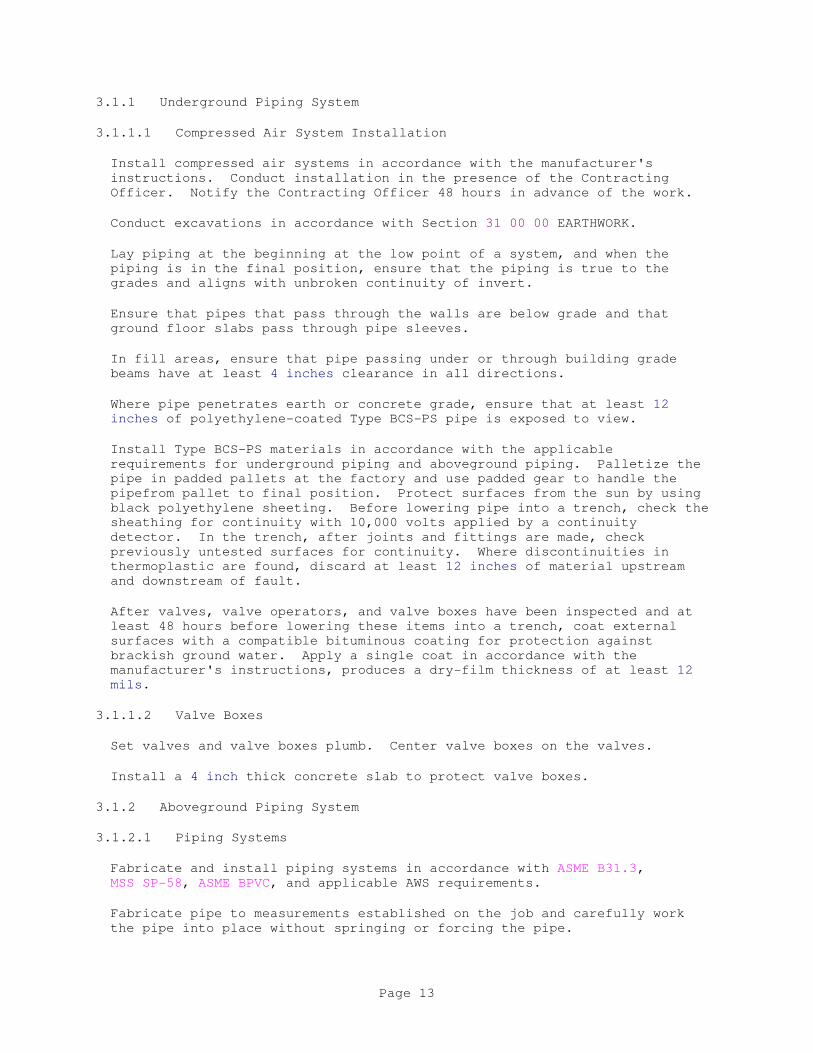
3.1.1 Underground Piping System
3.1.1.1 Compressed Air System Installation
Install compressed air systems in accordance with the manufacturer's
instructions. Conduct installation in the presence of the Contracting
Officer. Notify the Contracting Officer 48 hours in advance of the work.
Conduct excavations in accordance with Section 31 00 00 EARTHWORK.
Lay piping at the beginning at the low point of a system, and when the
piping is in the final position, ensure that the piping is true to the
grades and aligns with unbroken continuity of invert.
Ensure that pipes that pass through the walls are below grade and that
ground floor slabs pass through pipe sleeves.
In fill areas, ensure that pipe passing under or through building grade
beams have at least 4 inches clearance in all directions.
Where pipe penetrates earth or concrete grade, ensure that at least 12
inches of polyethylene-coated Type BCS-PS pipe is exposed to view.
Install Type BCS-PS materials in accordance with the applicable
requirements for underground piping and aboveground piping. Palletize the
pipe in padded pallets at the factory and use padded gear to handle the
pipefrom pallet to final position. Protect surfaces from the sun by using
black polyethylene sheeting. Before lowering pipe into a trench, check the
sheathing for continuity with 10,000 volts applied by a continuity
detector. In the trench, after joints and fittings are made, check
previously untested surfaces for continuity. Where discontinuities in
thermoplastic are found, discard at least 12 inches of material upstream
and downstream of fault.
After valves, valve operators, and valve boxes have been inspected and at
least 48 hours before lowering these items into a trench, coat external
surfaces with a compatible bituminous coating for protection against
brackish ground water. Apply a single coat in accordance with the
manufacturer's instructions, produces a dry-film thickness of at least 12
mils.
3.1.1.2 Valve Boxes
Set valves and valve boxes plumb. Center valve boxes on the valves.
Install a 4 inch thick concrete slab to protect valve boxes.
3.1.2 Aboveground Piping System
3.1.2.1 Piping Systems
Fabricate and install piping systems in accordance with ASME B31.3,
MSS SP-58, ASME BPVC, and applicable AWS requirements.
Fabricate pipe to measurements established on the job and carefully work
the pipe into place without springing or forcing the pipe.
Page 13
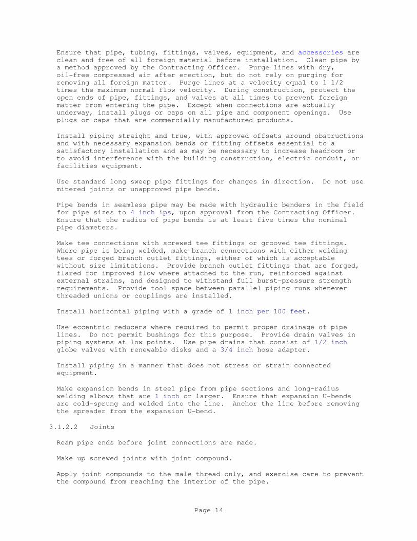
Ensure that pipe, tubing, fittings, valves, equipment, and accessories are
clean and free of all foreign material before installation. Clean pipe by
a method approved by the Contracting Officer. Purge lines with dry,
oil-free compressed air after erection, but do not rely on purging for
removing all foreign matter. Purge lines at a velocity equal to 1 1/2
times the maximum normal flow velocity. During construction, protect the
open ends of pipe, fittings, and valves at all times to prevent foreign
matter from entering the pipe. Except when connections are actually
underway, install plugs or caps on all pipe and component openings. Use
plugs or caps that are commercially manufactured products.
Install piping straight and true, with approved offsets around obstructions
and with necessary expansion bends or fitting offsets essential to a
satisfactory installation and as may be necessary to increase headroom or
to avoid interference with the building construction, electric conduit, or
facilities equipment.
Use standard long sweep pipe fittings for changes in direction. Do not use
mitered joints or unapproved pipe bends.
Pipe bends in seamless pipe may be made with hydraulic benders in the field
for pipe sizes to 4 inch ips, upon approval from the Contracting Officer.
Ensure that the radius of pipe bends is at least five times the nominal
pipe diameters.
Make tee connections with screwed tee fittings or grooved tee fittings.
Where pipe is being welded, make branch connections with either welding
tees or forged branch outlet fittings, either of which is acceptable
without size limitations. Provide branch outlet fittings that are forged,
flared for improved flow where attached to the run, reinforced against
external strains, and designed to withstand full burst-pressure strength
requirements. Provide tool space between parallel piping runs whenever
threaded unions or couplings are installed.
Install horizontal piping with a grade of 1 inch per 100 feet.
Use eccentric reducers where required to permit proper drainage of pipe
lines. Do not permit bushings for this purpose. Provide drain valves in
piping systems at low points. Use pipe drains that consist of 1/2 inch
globe valves with renewable disks and a 3/4 inch hose adapter.
Install piping in a manner that does not stress or strain connected
equipment.
Make expansion bends in steel pipe from pipe sections and long-radius
welding elbows that are 1 inch or larger. Ensure that expansion U-bends
are cold-sprung and welded into the line. Anchor the line before removing
the spreader from the expansion U-bend.
3.1.2.2 Joints
Ream pipe ends before joint connections are made.
Make up screwed joints with joint compound.
Apply joint compounds to the male thread only, and exercise care to prevent
the compound from reaching the interior of the pipe.
Page 14

Provide screwed unions, welded unions, or bolted flanges wherever required
to permit convenient removal of equipment, valves, and piping accessories
from the piping system.
Assemble flanged joints with appropriate flanges, gaskets, and bolting.
Provide clearance between flange faces such that the connections can be
gasketed and bolted tight without putting undue strain on the piping
system. Ensure that flange faces are parallel and that the bores are
concentric. Center gaskets on the flange faces without projecting into the
bore. Lubricate bolting with oil and graphite before assembly to ensure
uniform bolt stressing. Draw up and tighten flange bolts in a staggered
sequence to prevent unequal gasket compression and deformation of the
flanges. Wherever a flange with a raised face is joined to a companion
flange with a flat face, machine the raised face to a smooth matching
surface, and use a full-face gasket. After the piping system has been
tested and is in service at its maximum temperature, tighten bolts again.
Use only hex-head nuts and bolts. Provide fresh stock gasket material,
1/16-inch thick.
Ensure that field-welded joints conform to the requirements of AWS-03 and
ASME B31.3.
Use square-cut copper tubing for solder joints and use cutting and reaming
tools to remove burrs. Clean the inside surfaces of fittings and the
outside surfaces of tubes in the joint area before assembly of the joint.
Apply the joint flux, solder, and heat source in accordance with the
manufacturer's instructions, using capillary action to fill the socket
space and achieve 100 percent of the shear-line strength capability.
Ensure that the valves in copper piping have screwed ends with end adapters
to suit mechanical connections, unless solder joining is specified for a
given application. Remake copper joints that fail pressure tests with new
materials, including pipe or tubing fittings and filler metal.
Use square-cut, tubing for mechanical joints and remove burrs. Exercise
care to avoid work-hardened copper surfaces and cut off or anneal tube
ends. Meet heating temperature and air-cooling requirements in accordance
with the manufacturer's instructions.
3.1.2.3 Control and Instrument Air Tubing
Conceal tubing, except in mechanical rooms or areas where other piping is
exposed.
Use hard-drawn copper tubing in exposed areas. Do not use annealed copper
in concealed locations.
For supply system copper tubing, use wrought copper solder joint-type
fittings, except at the connection to the apparatus where brass mechanical
and ips thread adapter fittings are used. Tool-made bends in lieu of
fittings are acceptable. Neatly nest multiple tube runs.
Use fittings for plastic tubing in accordance with the manufacturer's
instructions.
Plastic tubing, sheathed or unsheathed, may be used in lieu of copper
tubing, provided:
Page 15
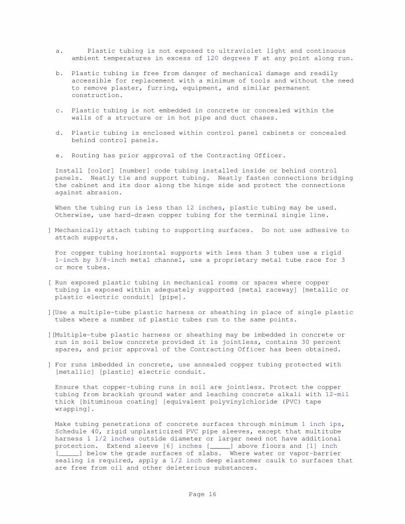
a. Plastic tubing is not exposed to ultraviolet light and continuous
ambient temperatures in excess of 120 degrees F at any point along run.
b. Plastic tubing is free from danger of mechanical damage and readily
accessible for replacement with a minimum of tools and without the need
to remove plaster, furring, equipment, and similar permanent
construction.
c. Plastic tubing is not embedded in concrete or concealed within the
walls of a structure or in hot pipe and duct chases.
d. Plastic tubing is enclosed within control panel cabinets or concealed
behind control panels.
e. Routing has prior approval of the Contracting Officer.
Install [color] [number] code tubing installed inside or behind control
panels. Neatly tie and support tubing. Neatly fasten connections bridging
the cabinet and its door along the hinge side and protect the connections
against abrasion.
When the tubing run is less than 12 inches, plastic tubing may be used.
Otherwise, use hard-drawn copper tubing for the terminal single line.
] Mechanically attach tubing to supporting surfaces. Do not use adhesive to
attach supports.
For copper tubing horizontal supports with less than 3 tubes use a rigid
1-inch by 3/8-inch metal channel, use a proprietary metal tube race for 3
or more tubes.
[ Run exposed plastic tubing in mechanical rooms or spaces where copper
tubing is exposed within adequately supported [metal raceway] [metallic or
plastic electric conduit] [pipe].
][Use a multiple-tube plastic harness or sheathing in place of single plastic
tubes where a number of plastic tubes run to the same points.
][Multiple-tube plastic harness or sheathing may be imbedded in concrete or
run in soil below concrete provided it is jointless, contains 30 percent
spares, and prior approval of the Contracting Officer has been obtained.
] For runs imbedded in concrete, use annealed copper tubing protected with
[metallic] [plastic] electric conduit.
Ensure that copper-tubing runs in soil are jointless. Protect the copper
tubing from brackish ground water and leaching concrete alkali with 12-mil
thick [bituminous coating] [equivalent polyvinylchloride (PVC) tape
wrapping].
Make tubing penetrations of concrete surfaces through minimum 1 inch ips,
Schedule 40, rigid unplasticized PVC pipe sleeves, except that multitube
harness 1 1/2 inches outside diameter or larger need not have additional
protection. Extend sleeve [6] inches [_____] above floors and [1] inch
[_____] below the grade surfaces of slabs. Where water or vapor-barrier
sealing is required, apply a 1/2 inch deep elastomer caulk to surfaces that
are free from oil and other deleterious substances.
Page 16

Systematically purge tubing with [dry, oil-free compressed air] [nitrogen]
to rid the system of impurities [generated during joint-making and
installation] and atmospheric moisture before connection to control
instruments.
3.1.2.4 General Service Valve Locations
Provide valves to permit isolation of branch piping and each equipment item
from the balance of the system, to allow safe and convenient access without
moving equipment, and to require a minimum of piping and equipment
disassembly.
Provide valves in piping mains and branches at equipment and equipment
items.
Provide riser and downcomer drains above piping shutoff valves in piping 2
1/2 inches or larger. Tap and fit shutoff valve body with a 1/2 inch
plugged globe valve.
Provide three-valve bypass around each pressure-regulating valve.
Provide access panels for valves unavoidably located in furred or other
normally inaccessible places.
3.1.2.5 Bypass Throttling Valves
Install globe valves with a metallic disc.
3.1.2.6 Supporting Elements Installation
Provide supporting elements in accordance with the requirements of
ASME B31.1, and MSS SP-58. Hang piping from building construction. Do not
hang piping from the roof deck or from other pipe.
Whenever possible, use approved cast-in concrete inserts to attach to
structures made of concrete. Use built-in anchors to attach to structures
made of solid masonry. Where attachment by either of the above methods is
not possible, specified masonry anchor devices may be used with written
approval from the Contracting Officer.
Embed fish plates in the concrete to transmit hanger loads to the
reinforcing steel where hanger rods exceed 7/8 inch diameter.
Use masonry anchors only for overhead application of ferrous material.
Install masonry anchors conforming to CID A-A-1922, CID A-A-1923,
CID A-A-1924, CID A-A-55614 in rotary, nonpercussion, electric-drilled
holes. Group III self-drilling anchors may be used provided masonry
drilling is done with electric hammers that do not cause concrete spalling
or cracking, whether the defects are visible or invisible. Do not use
pneumatic tools
Use percussive-action electric hammers, and combination rotary-electric
hammers to install self-drilling anchors selected in accordance with the
following guide:
a. For anchor devices of 1/4 through 1/2 inch, use a hammer only or a
Page 17
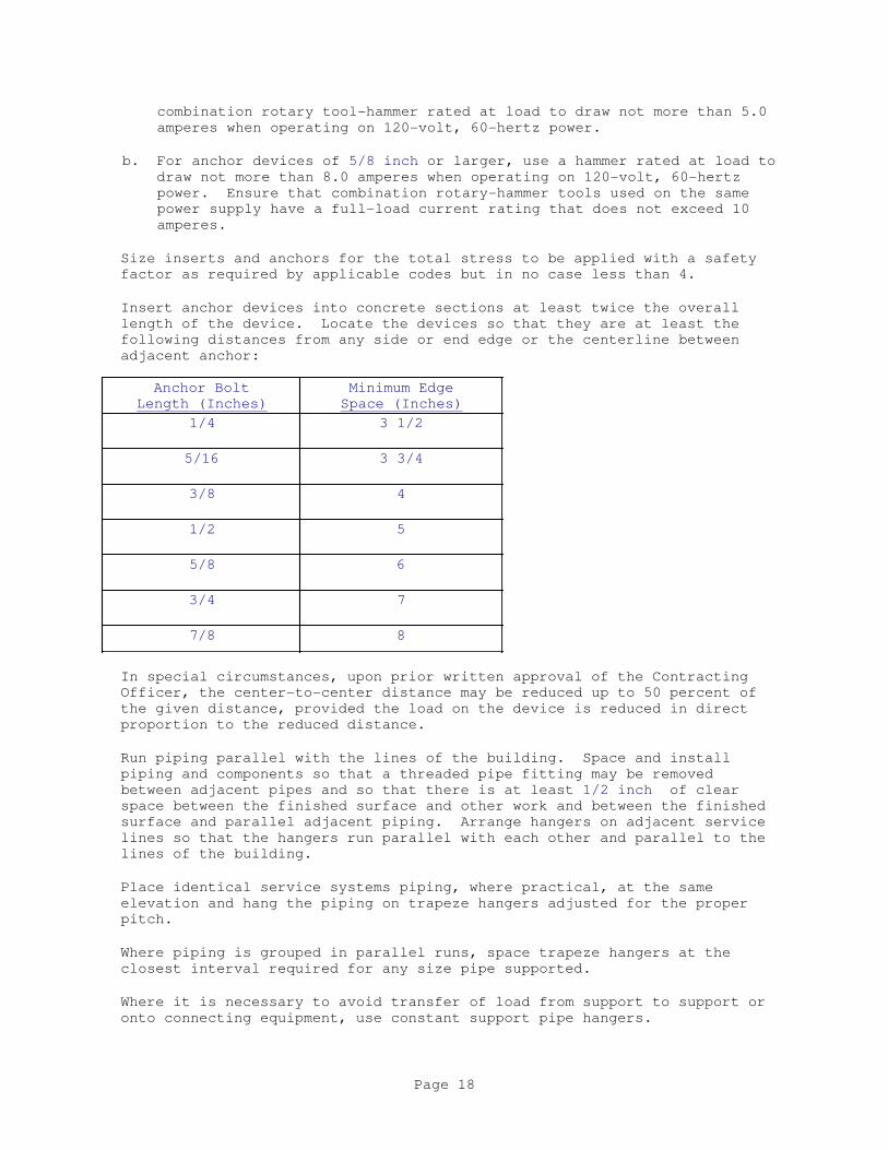
combination rotary tool-hammer rated at load to draw not more than 5.0
amperes when operating on 120-volt, 60-hertz power.
b. For anchor devices of 5/8 inch or larger, use a hammer rated at load to
draw not more than 8.0 amperes when operating on 120-volt, 60-hertz
power. Ensure that combination rotary-hammer tools used on the same
power supply have a full-load current rating that does not exceed 10
amperes.
Size inserts and anchors for the total stress to be applied with a safety
factor as required by applicable codes but in no case less than 4.
Insert anchor devices into concrete sections at least twice the overall
length of the device. Locate the devices so that they are at least the
following distances from any side or end edge or the centerline between
adjacent anchor:
Anchor Bolt
Length (Inches)
Minimum Edge
Space (Inches)
1/4 3 1/2
5/16 3 3/4
3/8 4
1/2 5
5/8 6
3/4 7
7/8 8
In special circumstances, upon prior written approval of the Contracting
Officer, the center-to-center distance may be reduced up to 50 percent of
the given distance, provided the load on the device is reduced in direct
proportion to the reduced distance.
Run piping parallel with the lines of the building. Space and install
piping and components so that a threaded pipe fitting may be removed
between adjacent pipes and so that there is at least 1/2 inch of clear
space between the finished surface and other work and between the finished
surface and parallel adjacent piping. Arrange hangers on adjacent service
lines so that the hangers run parallel with each other and parallel to the
lines of the building.
Place identical service systems piping, where practical, at the same
elevation and hang the piping on trapeze hangers adjusted for the proper
pitch.
Where piping is grouped in parallel runs, space trapeze hangers at the
closest interval required for any size pipe supported.
Where it is necessary to avoid transfer of load from support to support or
onto connecting equipment, use constant support pipe hangers.
Page 18
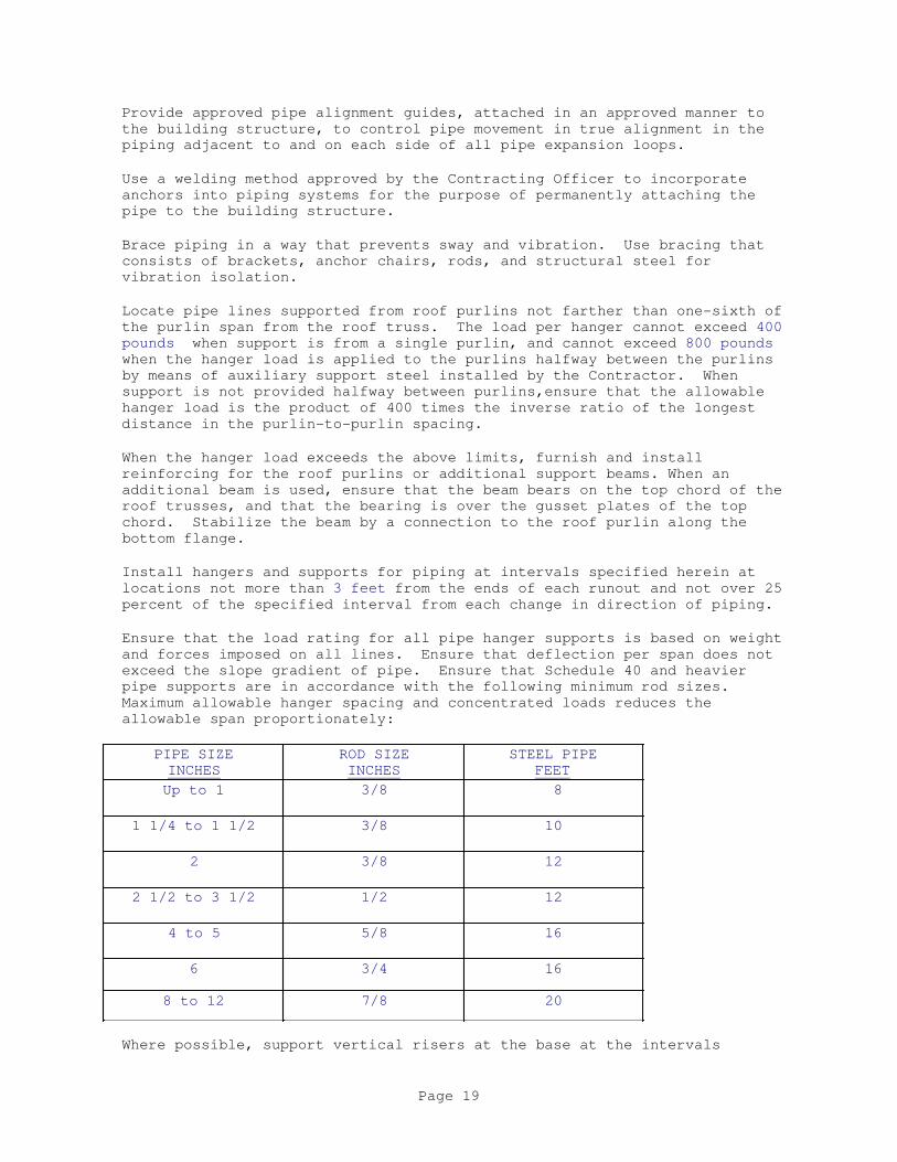
Provide approved pipe alignment guides, attached in an approved manner to
the building structure, to control pipe movement in true alignment in the
piping adjacent to and on each side of all pipe expansion loops.
Use a welding method approved by the Contracting Officer to incorporate
anchors into piping systems for the purpose of permanently attaching the
pipe to the building structure.
Brace piping in a way that prevents sway and vibration. Use bracing that
consists of brackets, anchor chairs, rods, and structural steel for
vibration isolation.
Locate pipe lines supported from roof purlins not farther than one-sixth of
the purlin span from the roof truss. The load per hanger cannot exceed 400
pounds when support is from a single purlin, and cannot exceed 800 pounds
when the hanger load is applied to the purlins halfway between the purlins
by means of auxiliary support steel installed by the Contractor. When
support is not provided halfway between purlins,ensure that the allowable
hanger load is the product of 400 times the inverse ratio of the longest
distance in the purlin-to-purlin spacing.
When the hanger load exceeds the above limits, furnish and install
reinforcing for the roof purlins or additional support beams. When an
additional beam is used, ensure that the beam bears on the top chord of the
roof trusses, and that the bearing is over the gusset plates of the top
chord. Stabilize the beam by a connection to the roof purlin along the
bottom flange.
Install hangers and supports for piping at intervals specified herein at
locations not more than 3 feet from the ends of each runout and not over 25
percent of the specified interval from each change in direction of piping.
Ensure that the load rating for all pipe hanger supports is based on weight
and forces imposed on all lines. Ensure that deflection per span does not
exceed the slope gradient of pipe. Ensure that Schedule 40 and heavier
pipe supports are in accordance with the following minimum rod sizes.
Maximum allowable hanger spacing and concentrated loads reduces the
allowable span proportionately:
PIPE SIZE
INCHES
ROD SIZE
INCHES
STEEL PIPE
FEET
Up to 1 3/8 8
1 1/4 to 1 1/2 3/8 10
2 3/8 12
2 1/2 to 3 1/2 1/2 12
4 to 5 5/8 16
6 3/4 16
8 to 12 7/8 20
Where possible, support vertical risers at the base at the intervals
Page 19

specified and guide the risers for lateral stability. Place clamps under
fittings wherever possible. Support carbon steel pipe at each floor at not
more than 15 foot intervals for pipe 2 inches and smaller and at not more
than 20 foot intervals for pipe 2 1/2 inches and larger.
After the piping systems have been installed, tested, and placed in
satisfactory operation, tighten the hanger rod nuts and jam nuts to prevent
movement.
3.1.2.7 Sound Stopping
Provide effective sound stopping and provide an operating clearance that is
sufficient to prevent the piping from making contact with the structure
where the piping penetrates walls, floors, or ceilings in occupied spaces
adjacent to equipment rooms, where similar penetrations occur between
occupied spaces, and where penetrations occur from pipe chases that
penetrate occupied spaces. Occupied spaces includes the space above
ceilings where no special acoustic treatment of the ceiling is provided.
Create finished penetrations compatible with the surface being penetrated.
Ensure that sound stopping materials and procedures are the same as those
specified under the paragraph SLEEVES.
Ensure that sound stopping and vapor barrier sealing of pipe shafts and
large floor and wall openings are accomplished by packing properly
supported mineral fiber to high density, or, where ambient or surface
temperatures do not exceed 120 degrees F, by foaming in place with
self-extinguishing, 2-pound density polyurethane foam to a depth of at least
6 inches. Finish foam with a rasp. Ensure the vapor barrier consists of
at least a 1/8 inch thickness of vinyl coating applied to visible and
accessible surfaces. Where high temperatures and fire-stopping are a
consideration, use only mineral fiber. In addition, cover openings with
16-gagesheet metal.
Ensure that all mineral materials conform to the requirements specified
under the paragraph SLEEVES in this section.
Leadwool and viscoelastic damping compounds may be proposed for use where
other sound-stopping methods are not practical, provided temperature and
fire-resistance characteristics of the compounds are suitable for the
service.
3.1.2.8 Sleeves
Provide sleeves where piping passes through roofs, through masonry or
concrete walls, or through floors.
Lay out and set sleeve work before placement of slabs or construction of
walls and roof. Furnish the sleeves needed to complete the work.
Where pipe sleeves are required after slabs and masonry are installed,
create holes to accommodate these sleeves with core drills. Set the
sleeves in place with a two-component epoxy adhesive system approved by the
Contracting Officer. Carry no load by such sleeves unless approved by the
Contracting Officer.
Ensure that the sleeves are flush with all ceilings.
Page 20
Ensure that the sleeves are flush with the floor in finished spaces and
extend 2 inches above the floor in unfinished spaces.
Ensure that sleeves passing though steel decks are continuously welded.
Fabricate sleeves that continuously extend through floors, roofs, and
load-bearing walls, and sleeves that run through fire barriers, from
Schedule 40 steel pipe with welded anchor lugs. Other sleeves may be
formed by molded linear polyethylene liners or similar materials that are
removable. Ensure that the sleeve diameter is large enough to accommodate
pipe, insulation, and jacketing without touching the sleeve and provide at
least 3/8 inch clearance. Select a sleeve size that will accommodate
mechanical and thermal motion of pipe in order not to transmit vibration to
walls and generate noise.
Solidly pack the space between a pipe, bare or insulated, and the inside of
a pipe sleeve or a construction surface penetration with a mineral fiber
conforming to ASTM C592, Form B, Class 8. Provide similar packing whenever
the piping passes through firewalls, equipment room walls, floors and
ceilings connected to occupied spaces, and other locations where sleeves or
construction surface penetrations occur between occupied spaces. Where
sleeves or construction surface penetrations occur between conditioned and
unconditioned spaces, fill the space between a pipe, bare or insulated, and
the inside of a pipe sleeve or construction surface penetration with an
elastomer caulk to a depth of 1/2 inch. Ensure that the caulked surfaces
are oil- and grease-free.
Caulk watertight with lead and oakum or Make watertight with mechanically
expandable chloroprene inserts with mastic sealed metal components exterior
wall sleeves.
Ensure that the sleeve extends 12 inches above the surface of the roof.
3.1.2.9 Escutcheons
Provide escutcheons where piping penetrates finished areas. Where finished
areas are separated by partitions through which piping passes, provide
escutcheons on both sides of the partition. In areas where suspended
ceilings are installed, provide plates only on the underside of such
ceilings. In areas where insulated pipes are used, install plates large
enough to fit around the insulation. In occupied spaces, use chrome-plated
escutcheons that are large enough to conceal openings in building
construction. Firmly attach escutcheons with setscrews.
3.1.2.10 Flashings
Provide flashings at locations where mechanical systems penetrate the
building boundaries.
3.1.3 Compressed-Air Systems Identification
Protect and keep identification plates clean. Replace damaged and
illegible identification plates at no additional expense.
Label and arrow piping at each point of entry and exit of piping passing
through walls; at each change in direction, such as at elbows and tees; and
in congested or hidden areas, at each point required to clarify service or
Page 21
indicate a hazard. Label each riser.
In long, straight runs, locate labels at distances that allow a label to be
seen from the location of another label, but in no case allow the distance
between labels to exceed 75 feet. Ensure that labels are legible from the
primary service and operating area.
3.2 FIELD QUALITY CONTROL
3.2.1 Compressed-Air Systems Testing
Prior to acceptance of the work, pressure-test completed systems in the
presence of the Contracting Officer.
Conduct testing in two stages: preliminary stage and acceptance stage,
including gage tests.
Perform no testing until personnel not directly involved in the test have
been evacuated from the area.
Contractor may conduct tests for their own purposes in addition to the
preliminary test and the acceptance test specified below.
3.2.1.1 Preliminary Stage Tests
Conduct pneumatic tests with dry, oil-free compressed air. Use carbon
dioxide or nitrogen in metallic systems.
Ensure that each system test includes a preliminary test in which the
joints under test are swabbed with a standard high-strength film soap
solution, so that bubbles, if any exist, can be observed at internal
pressures of 5 psi or less.
When testing reveals that leakage exceeds specified limits, isolate and
repair the leaks, replace defective materials where necessary, and retest
the system until specified limits are met. Remake leaking gaskets with new
gaskets and new flange bolting, and discard used bolting and gaskets.
Other than standard piping flanges, plugs, caps and valves, only use
commercially manufactured expandable elastomer plugs for sealing off piping
for test purposes. Ensure that the published safe test pressure rating of
any plug used is at least three times the actual test pressure being
applied. During pneumatic testing or hydrostatic testing, evacuate
personnel from areas where plugs are used.
Remove components that could be damaged by test pressure from the piping
systems to be tested.
Perform valve-operating tests and drainage tests according to cited
standards.
Check piping system components, such as valves, for proper operation under
the system test pressure.
Do not add test media to a system during a test for a period specified or
determined by the Contracting Officer.
Page 22
Duration of a test is determined by the Contracting Officer and will be for
a minimum of 15 minutes with a maximum of 24 hours. Test may be terminated
by direction of the Contracting Officer at any point after it has been
determined that the leakage rate is within limits.
Only use potable water for hydrostatic testing. Government will supply
testing water at a location determined by the Contracting Officer.
Contractor is responsible for approved disposal of contaminated water.
Ensure that the temperature of water used for testing is not low enough to
cause condensation of atmospheric moisture on system surfaces. Provide
supplementary heat when necessary.
To preclude injury and damage, take necessary precautions by venting the
expansive force of compressed air trapped during high-pressure hydrostatic
testing. When purging or vent valves are not provided, the Contracting
Officer may require the removal of system component such as plugs or caps
to verify that the water has reached all parts of the system.
Upon completion of testing, drain and purge the system with dry air.
Verify system dryness by hygrometer comparison with purging air.
Immediately repair visible leaks or defects in the pipeline.
3.2.1.2 Test Gages
Ensure that test gages conform to ASME B40.100 and have a dial size of
8-inches or larger. The maximum permissible scale range for a given test
is such that the pointer during a test has a starting position at midpoint
of the dial or within the middle third of the scale range. Ensure that the
certification of accuracy and correction table bears a date no more than 90
calendar days before the gage is used in a test, and that it indicated the
test gage number and the project number, unless otherwise approved by the
Contracting Officer.
3.2.1.3 Acceptance Pressure Testing
Ensure that the testing takes place during steady-state ambient temperature
conditions.
Test ferrous piping systems at 1-1/2 times the maximum operating pressure.
Maintain test pressure for at least 2 hours with an allowable pressure drop
of 2 psi during that time unless otherwise approved by the Contracting
Officer.
Test control and instrumentation tubing systems at 30 psi. Maintain the
test pressure for at least 24 hours with essentially no pressure drop
during that time.
Each acceptance test requires the signature of the Contracting Officer.
Deliver two record copies to the Contracting Officer after acceptance.
3.2.1.4 Piping System Test Report
Prepare and maintain test records of all piping systems tests. Ensure the
records show the responsibilities of Governmental and Contractor test
personnel, dates, test gage identification numbers, ambient temperatures,
Page 23
pressure ranges, rates of pressure drop, and leakage rates. Submit reports
to the Contracting Officer.
3.3 ADJUSTING AND CLEANING
Remove rust and dirt from the bore and exterior surface of all piping and
equipment. Clean pipeline strainers, temporary and permanent, during
purging operations, after startup, and immediately prior to final
acceptance by the Government.
Flush and clean new steel piping with a suitable degreasing agent, until
visible grease, dirt, and other contaminants have been removed. Dispose of
degreased waste material including the degreaser itself in accordance with
written instructions received from the Environmental Authority having
jurisdiction through the Contracting Officer and in accordance with all
local, State, and Federal Regulations.
3.4 CLOSEOUT ACTIVITIES
Submit 6 copies of the operation and maintenance manuals 30 calendar days
prior to testing the low-pressure compressed air system. Update and
resubmit data for final approval no later than 30 calendar days prior to
contract completion.
-- End of Section --
Page 24
SECTION 23 00 00
AIR SUPPLY, DISTRIBUTION, VENTILATION, AND EXHAUST SYSTEMS
08/10
PART 1 GENERAL
Packaged gas/electric air conditoners are specified in section 23 81 00
UNITARY AIR CONDITIONERS EQUIPMENT. Infrared gas space heaters are specified
in section 23 54 16 HEATING SYTEMS, GAS FIRED HEATERS.
1.1 REFERENCES
The publications listed below form a part of this specification to the
extent referenced. The publications are referred to within the text by the
basic designation only.
ADHESIVE AND SEAL COUNCIL (ASC)
ASC-A4001C Standard for Adhesives for Duct liner
MOVEMENT AND CONTROL ASSOCIATION INTERNATIONAL (AMCA)
AMCA 201 (2002; R 2011) Fans and Systems
AMCA 211 (2016) Laboratory Methods of Testing Fans
for Aerodynamic Performance Rating
AMCA 300 (2014) Reverberant Room Method for Sound
Testing of Fans
AIR-CONDITIONING, HEATING AND REFRIGERATION INSTITUTE (AHRI)
AHRI 260 I-P (2012) Sound Rating of Ducted Air Moving
and Conditioning Equipment
AHRI 880 I-P (2011) Performance Rating of Air Terminals
AHRI 885 (2008; Addendum 2011) Procedure for
Estimating Occupied Space Sound Levels in
the Application of Air Terminals and Air
Outlets
AMERICAN BEARING MANUFACTURERS ASSOCIATION (ABMA)
ABMA 9 (2015) Load Ratings and Fatigue Life for
Ball Bearings
AMERICAN SOCIETY OF HEATING, REFRIGERATING AND AIR-CONDITIONING
ENGINEERS (ASHRAE)
ASHRAE 62.1 (2010) Ventilation for Acceptable Indoor
Air Quality
Page 1

ASHRAE 70 (2006; R 2011) Method of Testing for
Rating the Performance of Air Outlets and
Inlets
ASHRAE 90.1 - IP (2013) Energy Standard for Buildings
Except Low-Rise Residential Buildings
ASTM INTERNATIONAL (ASTM)
ASTM A123/A123M (2015) Standard Specification for Zinc
(Hot-Dip Galvanized) Coatings on Iron and
Steel Products
ASTM A924/A924M (2017a) Standard Specification for General
Requirements for Steel Sheet,
Metallic-Coated by the Hot-Dip Process
ASTM B117 (2016) Standard Practice for Operating
Salt Spray (Fog) Apparatus
ASTM C1071 (2016) Standard Specification for Fibrous
Glass Duct Lining Insulation (Thermal and
Sound Absorbing Material)
ASTM C553 (2013) Standard Specification for Mineral
Fiber Blanket Thermal Insulation for
Commercial and Industrial Applications
ASTM C916 (2014) Standard Specification for
Adhesives for Duct Thermal Insulation
ASTM D3359 (2017) Standard Test Methods for Rating
Adhesion by Tape Test
ASTM D520 (2000; R 2011) Zinc Dust Pigment
ASTM E2016 (2015) Standard Specification for
Industrial Woven Wire Cloth
ASTM E84 (2017) Standard Test Method for Surface
Burning Characteristics of Building
Materials
NATIONAL ELECTRICAL MANUFACTURERS ASSOCIATION (NEMA)
NEMA MG 1 (2016; SUPP 2016) Motors and Generators
NATIONAL FIRE PROTECTION ASSOCIATION (NFPA)
NFPA 70 (2017; ERTA 1-2 2017; TIA 17-1; TIA 17-2;
TIA 17-3) National Electrical Code
NFPA 701 (2015) Standard Methods of Fire Tests for
Flame Propagation of Textiles and Films
NFPA 90A (2018) Standard for the Installation of
Air Conditioning and Ventilating Systems
Page 2

SCIENTIFIC CERTIFICATION SYSTEMS (SCS)
SCS SCS Global Services (SCS)Indoor Advantage
SHEET METAL AND AIR CONDITIONING CONTRACTORS' NATIONAL ASSOCIATION
(SMACNA)
SMACNA 1819 (2002) Fire, Smoke and Radiation Damper
Installation Guide for HVAC Systems, 5th
Edition
SMACNA 1966 (2005) HVAC Duct Construction Standards
Metal and Flexible, 3rd Edition
SMACNA 1981 (2008) Seismic Restraint Manual Guidelines
for Mechanical Systems, 3rd Edition
U.S. NATIONAL ARCHIVES AND RECORDS ADMINISTRATION (NARA)
40 CFR 82 Protection of Stratospheric Ozone
PL 109-58 Energy Policy Act of 2005 (EPAct05)
UL ENVIRONMENT (ULE)
ULE Greenguard UL Greenguard Certification Program
UNDERWRITERS LABORATORIES (UL)
UL 181 (2013; Reprint Apr 2017) UL Standard for
Safety Factory-Made Air Ducts and Air
Connectors
UL 555 (2006; Reprint Aug 2016) UL Standard for
Safety Fire Dampers
UL 586 (2009; Reprint Sep 2014) Standard for
High-Efficiency Particulate, Air Filter
Units
UL 705 (2017) UL Standard for Safety Power
Ventilators
UL 723 (2008; Reprint Aug 2013) Test for Surface
Burning Characteristics of Building
Materials
UL 900 (2015) Standard for Air Filter Units
UL Bld Mat Dir (updated continuously online) Building
Materials Directory
UL Fire Resistance (2014) Fire Resistance Directory
Page 3
1.2 SYSTEM DESCRIPTION
Furnish ductwork, fans, VAV terminals, air outlets, fittings, and
accessories as required to provide a complete installation. Coordinate the
work of the different trades to avoid interference between equipment,
structural, and electrical work. Provide complete, in place, all necessary
offsets in piping and ductwork, and all fittings, and other components,
required to install the work as indicated and specified.
1.2.1 Mechanical Equipment Identification
Mount charts and diagrams in the mechanical equipment rooms. Where more
than one chart or diagram per space is required, mount these in edge
pivoted, swinging leaf, extruded aluminum frame holders which open to 170
degrees.
1.2.1.1 Charts
Provide chart listing of equipment by designation numbers and capacities
such as flow rates, heating and cooling capacities, horsepower and voltage
and current characteristics.
1.2.1.2 Diagrams
Submit proposed diagrams, at least 2 weeks prior to start of related
testing. provide neat mechanical drawings provided with extruded aluminum
frame under 1/8-inch glass or laminated plastic, system diagrams that show
the layout of equipment and ductwork, and typed condensed operation manuals
explaining preventative maintenance procedures, methods of checking the
system for normal, safe operation, and procedures for safely starting and
stopping the system. After approval, post these items where directed.
1.2.2 Service Labeling
Label equipment, including fans,packaged air conditioners, terminal units,
etc. with labels made of self-sticking, plastic film designed for permanent
installation. Labels shall be in accordance with the typical examples
below:
SERVICE LABEL AND TAG DESIGNATION
Air Conditioning unit Number AC - [_____]
Exhaust Fan Number EF - [_____]
VAV Box Number VAV - [_____]
1.3 SUBMITTALS
Government approval is required for submittals with a "G" designation;
submittals not having a "G" designation are for Contractor Quality Control
approval. Submittals with an "S" are for inclusion in the Sustainability
eNotebook, in conformance to Section 01 33 29 SUSTAINABILITY REPORTING.
Page 4
Submit the following in accordance with Section 01 33 00 SUBMITTAL
PROCEDURES:
SD-02 Shop Drawings
Detail Drawings; G
SD-03 Product Data
Metallic Flexible Duct
Insulated Nonmetallic Flexible Duct Runouts
Duct Connectors
Fire Dampers
Duct Liner
VAV Diffusers
Registers and Grilles
Centrifugal Fans
Ceiling Exhaust Fans
Variable Volume, Single Duct Terminal Units; G
Test Procedures;G
Diagrams; G
SD-06 Test Reports
Performance Tests; G
Damper Acceptance Test; G
SD-07 Certificates
Bolts
Ozone Depleting Substances
SD-08 Manufacturer's Instructions
Manufacturer's Installation Instructions
Operation and Maintenance Training
SD-10 Operation and Maintenance Data
Operation and Maintenance Manuals; G
Fire Dampers; G
Manual Balancing Dampers; G
Automatic Smoke-Fire Dampers; G
Centrifugal Fans; G
VAV Diffusers;G
In-Line Centrifugal Fans; G
SD-11 Closeout Submittals
Reduce Volatile Organic Compounds (VOC); S
Indoor Air Quality During Construction; S
1.4 QUALITY ASSURANCE
Except as otherwise specified, approval of materials and equipment is based
on manufacturer's published data.
Page 5

a. Where materials and equipment are specified to conform to the
standards of the Underwriters Laboratories, the label of or listing
with reexamination in UL Bld Mat Dir, and UL 6 is acceptable as
sufficient evidence that the items conform to Underwriters Laboratories
requirements. In lieu of such label or listing, submit a written
certificate from any nationally recognized testing agency, adequately
equipped and competent to perform such services, stating that the items
have been tested and that the units conform to the specified
requirements. Outline methods of testing used by the specified
agencies.
b. Where materials or equipment are specified to be constructed or tested,
or both, in accordance with the standards of the ASTM International
(ASTM), the ASME International (ASME), or other standards, a
manufacturer's certificate of compliance of each item is acceptable as
proof of compliance.
c. Conformance to such agency requirements does not relieve the item from
compliance with other requirements of these specifications.
1.4.1 Prevention of Corrosion
Protect metallic materials against corrosion. Manufacturer shall provide
rust-inhibiting treatment and standard finish for the equipment
enclosures. Do not use aluminum in contact with earth, and where connected
to dissimilar metal. Protect aluminum by approved fittings, barrier
material, or treatment. Ferrous parts such as anchors, bolts, braces,
boxes, bodies, clamps, fittings, guards, nuts, pins, rods, shims, thimbles,
washers, and miscellaneous parts not of corrosion-resistant steel or
nonferrous materials shall be hot-dip galvanized in accordance with
ASTM A123/A123M for exterior locations and cadmium-plated in conformance
with ASTM B766 for interior locations.
1.4.2 Asbestos Prohibition
Do not use asbestos and asbestos-containing products.
1.4.3 Use of Ozone Depleting Substances, Other than Refrigerants
The use of Class I or Class II ODS's listed as nonessential in 40 CFR 82
Part 82.66 Subpart C is prohibited. These prohibited materials and uses
include:
a. Any plastic party spray streamer or noise horn which is propelled by a
chlorofluorocarbon
b. Any cleaning fluid for electronic and photographic equipment which
contains a chlorofluorocarbon; including liquid packaging, solvent
wipes, solvent sprays, and gas sprays.
c. Any plastic flexible or packaging foam product which is manufactured
with or contains a chlorofluorocarbon, including, open cell foam, open
cell rigid polyurethane poured foam, closed cell extruded polystyrene
sheet foam, closed cell polyethylene foam and closed cell polypropylene
foam except for flexible or packaging foam used in coaxial cabling.
Page 6
d. Any aerosol product or other pressurized dispenser which contains a
chlorofluorocarbon, except for those listed in 40 CFR 82 Part 82.66
Subpart C.
Request a waiver if a facility requirement dictates that a prohibited
material is necessary to achieve project goals. Submit the waiver request
in writing to the Contracting Officer. The waiver will be evaluated and
dispositioned.
1.4.4 Detail Drawings
Submit detail drawings showing equipment layout, including assembly and
installation details and electrical connection diagrams; ductwork layout
showing the location of all supports and hangers, typical hanger details,
gauge reinforcement, reinforcement spacing rigidity classification, and
static pressure and seal classifications. Include any information required
to demonstrate that the system has been coordinated and functions properly
as a unit on the drawings and show equipment relationship to other parts of
the work, including clearances required for operation and maintenance.
Submit drawings showing bolt-setting information, and foundation bolts
prior to concrete pad construction for all equipment indicated or required
to have concrete foundations. Submit function designation of the equipment
and any other requirements specified throughout this Section with the shop
drawings.
1.4.5 Test Procedures
Submit proposed test procedures and test schedules for the performance
tests of systems, at least 2 weeks prior to the start of related testing.
1.5 DELIVERY, STORAGE, AND HANDLING
Protect stored equipment at the jobsite from the weather, humidity and
temperature variations, dirt and dust, or other contaminants.
Additionally, cap or plug all pipes until installed.
PART 2 PRODUCTS
2.1 PRODUCT SUSTAINABILITY CRITERIA
For products in this section, where applicable and to extent allowed by
performance criteria, provide and document the following:
2.1.1 Energy Efficient Equipment
Provide documentation in conformance with Section 01 33 29 SUSTAINABILITY
REPORTING paragraph ENERGY EFFICIENT EQUIPMENT that the following products
meet energy efficiency requirements as outlined in this section:
a. Centrifugal Fans
b. Ceiling Exhaust Fans
2.1.2 Reduce Volatile Organic Compounds (VOC) for sealants, coatings or
adhesives
Low or no VOC's and no added urea formaldehyde for duct sealants, coatings
or adhesives, in conformance with Section 01 33 29 SUSTAINABILITY REPORTING
Page 7

paragraph REDUCE VOLATILE ORGANIC COMPOUNDS (VOC).
2.2 IDENTIFICATION PLATES
In addition to standard manufacturer's identification plates, provide
engraved laminated phenolic identification plates for each piece of
mechanical equipment. Identification plates are to designate the function
of the equipment. Submit designation with the shop drawings.
Identification plates shall be three layers, black-white-black, engraved to
show white letters on black background. Letters shall be upper case.
Identification plates 1-1/2-inches high and smaller shall be 1/16-inch
thick, with engraved lettering 1/8-inch high; identification plates larger
than 1-1/2-inches high shall be 1/8-inch thick, with engraved lettering of
suitable height. Identification plates 1-1/2-inches high and larger shall
have beveled edges. Install identification plates using a compatible
adhesive.
2.3 EQUIPMENT GUARDS AND ACCESS
Fully enclose or guard motors, shafts, and other rotating parts exposed to
personnel contact according to OSHA requirements. The requirements for
scaffolding platforms, ladders, and guardrails are specified in Section
05 50 13 MISCELLANEOUS METAL FABRICATIONS.
2.4 ELECTRICAL WORK
a. Provide motors with their respective pieces of equipment. Provide
electrical equipment, including motors and wiring, as specified in
Section 26 20 00INTERIOR DISTRIBUTION SYSTEM. Provide manual control
for the operation specified and control wiring required for controls
and devices specified. For packaged equipment, include manufacturer
provided controllers with the required monitors and timed restart.
b. For single-phase motors, provide high-efficiency type,
fractional-horsepower alternating-current motors, including motors that
are part of a system, in accordance with NEMA MG 11.
c. For polyphase motors, provide squirrel-cage medium induction motors,
including motors that are part of a system , and that meet the
efficiency ratings for premium efficiency motors in accordance with
NEMA MG 1. Select premium efficiency polyphase motors in accordance
with NEMA MG 10.
d. Provide motors in accordance with NEMA MG 1 and of sufficient size to
drive the load at the specified capacity without exceeding the
nameplate rating of the motor. Provide motors rated for continuous
duty with the enclosure specified. Provide motor duty that allows for
maximum frequency start-stop operation and minimum encountered interval
between start and stop. Provide motor torque capable of accelerating
the connected load within 20 seconds with 80 percent of the rated
voltage maintained at motor terminals during one starting period.
Provide motor starters complete with thermal overload protection and
other necessary appurtenances. Fit motor bearings with grease supply
fittings and grease relief to outside of the enclosure.
2.5 ANCHOR BOLTS
Page 8
Provide anchor bolts for equipment placed on concrete equipment pads or on
concrete slabs. Bolts to be of the size and number recommended by the
equipment manufacturer and located by means of suitable templates.
Installation of anchor bolts shall not degrade the surrounding concrete.
Anchor bolts for outdoor fans shall be stainless or cadmium plated as per
ASTMB 766
2.6 SEISMIC ANCHORAGE
Anchor equipment in accordance with applicable seismic criteria for the
area and as defined in SMACNA 1981
2.7 PAINTING
Paint equipment units in accordance with approved equipment manufacturer's
standards unless specified otherwise. Field retouch only if approved.
Otherwise, return equipment to the factory for refinishing.
2.8 INDOOR AIR QUALITY
Provide equipment and components that comply with the requirements of
ASHRAE 62.1 unless more stringent requirements are specified herein.
2.9 DUCT SYSTEMS
2.9.1 Metal Ductwork
Provide metal ductwork construction, including all fittings and components,
that complies with SMACNA 1966, as supplemented and modified by this
specification .
[a][b]. Provide radius type elbows with a centerline radius of 1.5 times
the width or diameter of the duct where space permits. Otherwise,
elbows having a minimum radius equal to the width or diameter of the
duct or square elbows with factory fabricated turning vanes are allowed.
b. Provide ductwork that meets the requirements of Seal Class [A][C].
Provide ductwork in VAV systems upstream of the VAV boxes that meets
the requirements of Seal Class A.
[c][d]. Provide sealants that conform to fire hazard classification
specified in Section 23 07 00 THERMAL INSULATION FOR MECHANICAL SYSTEMS
and are suitable for the range of air distribution and ambient
temperatures to which it is exposed. Do not use pressure sensitive
tape as a sealant.
2.9.1.1 Metallic Flexible Duct
a. Provide duct that conforms to UL 181 and NFPA 90A with factory-applied
insulation, vapor barrier, and end connections. Provide duct assembly
that does not exceed 25 for flame spread and 50 for smoke developed.
Provide ducts designed for working pressures of 2 inches water gauge
positive and 1.5 inches water gauge negative. Provide flexible round
duct length that does not exceed 5 feet. Secure connections by
applying adhesive for 2 inches over rigid duct, apply flexible duct 2
inches over rigid duct, apply metal clamp, and provide minimum of three
No. 8 sheet metal screws through clamp and rigid duct.
Page 9
b. Inner duct core: Provide interlocking spiral or helically
corrugated flexible core constructed of zinc-coated steel, aluminum, or
stainless steel; or constructed of inner liner of continuous galvanized
spring steel wire helix fused to continuous, fire-retardant, flexible
vapor barrier film, inner duct core.
c. Insulation: Provide inner duct core that is insulated with mineral
fiber blanket type flexible insulation, minimum of 1 inch thick.
Provide insulation covered on exterior with manufacturer's standard
fire retardant vapor barrier jacket for flexible round duct.
2.9.1.2 Insulated Nonmetallic Flexible Duct Runouts
Use flexible duct runouts only where indicated. Runout length is not to
exceed 5 feet. Provide runouts that are preinsulated, factory fabricated,
and that comply with NFPA 90A and UL 181. Provide either field or factory
applied vapor barrier. Provide not less than 20 ounce glass fabric duct
connectors coated on both sides with neoprene. Insulated flexible
connectors are allowed as runouts. Provide insulated material and vapor
barrier that conform to the requirements of SMACNA 1966 and UL 181. Do not
expose the insulation material surface to the air stream.
2.9.1.3 General Service Duct Connectors
Provide a flexible duct connector approximately 6 inches in width where
sheet metal connections are made to fans or where ducts of dissimilar
metals are connected. For round ducts, secure the flexible material by
stainless steel or zinc-coated, iron clinch-type draw bands. For
rectangular ducts, install the flexible material locked to metal collars
using normal duct construction methods. Provide a composite connector
system that complies with NFPA 701 and is classified as "flame-retardent
fabrics" in UL Bld Mat Dir.
2.9.1.4 Aluminum Ducts
ASTM B209, alloy 3003-H14 for aluminum sheet and alloy 6061-T6 or
equivalent strength for aluminum connectors and bar stock.
2.9.2 Duct Access Doors
Provide access doors conforming to SMACNA 1966 in ductwork at fire dampers
and other apparatus requiring service and inspection in the duct system.
Provide access doors upstream and downstream of air flow measuring
primaries and heating and cooling coils. Where duct size does not
accommodate this size door, make the doors as large as practicable. Equip
doors 24 by 24 inches or larger with fasteners operable from inside and
outside the duct. Use insulated type doors in insulated ducts.
2.9.3 Fire Dampers
Use 1.5 hour rated fire dampers in fire walls (if any). Provide fire
dampers that conform to the requirements of NFPA 90A and UL 555. Perform
the fire damper test as outlined in NFPA 90A. Provide automatic operating
fire dampers with a dynamic rating suitable for the maximum air velocity
and pressure differential to which it is subjected. Provide fire dampers
approved for the specific application, and install according to their
listing. Equip fire dampers with a steel sleeve or adequately sized frame
Page 10

installed in such a manner that disruption of the attached ductwork, if
any, does not impair the operation of the damper. Equip sleeves or frames
with perimeter mounting angles attached on both sides of the wall opening.
Provide curtain type with damper blades or single blade type or multi-blade
type fire dampers. Install dampers that do not reduce the duct or the air
transfer opening cross-sectional area. Install dampers so that the
centerline of the damper depth or thickness is located in the centerline of
the wall thickness. Comply with the installation details given in
SMACNA 1819 and in manufacturer's instructions for fire dampers. Perform
acceptance testing of fire dampers according to paragraph Fire Damper
Acceptance Test and NFPA 90A.
2.9.4 Air Supply And Exhaust Air Dampers
Where outdoor air supply and exhaust air dampers are required they shall
have a maximum leakage rate when tested in accordance with AMCA 500-D as
required by ASHRAE 90.1 - IP, including maximum Damper Leakage for:
a. Climate Zones 1,2,6,7,8 the maximum damper leakage at 1.0 inch w.g. for
motorized dampers is 4 cfm per square foot of damper area and
non-motorized dampers are not allowed.
b. All other Climate Zones the maximum damper leakage at 1.0 inch w.g. is
10 cfm per square foot and for non-motorized dampers is 20 cfm per
square foot of damper area.
Dampers smaller than 24 inches in either direction may have leakage of 40
cfm per square foot.
2.9.5 Air Deflectors (Volume Extractors) and Branch Connections
Provide air deflectors (volume extractors) at all duct mounted supply
outlets, at takeoff or extension collars to supply outlets, at duct branch
takeoff connections, and at 90 degree elbows, as well as at locations as
indicated on the drawings or otherwise specified. Conical branch
connections or 45 degree entry connections are allowed in lieu of
deflectors for branch connections. Furnish all air deflectors (volume
extractors), except those installed in 90 degree elbows, with an approved
means of adjustment. Provide easily accessible means for adjustment inside
the duct or from an adjustment with sturdy lock on the face of the duct.
When installed on ducts to be thermally insulated, provide external
adjustments with stand-off mounting brackets, integral with the adjustment
device, to provide clearance between the duct surface and the adjustment
device not less than the thickness of the thermal insulation. Provide
factory-fabricated air deflectors consisting of curved turning vanes or
louver blades designed to provide uniform air distribution and change of
direction with minimum turbulence or pressure loss. Provide factory or
field assembled air deflectors (volume extractors). Make adjustment from
the face of the diffuser or by position adjustment and lock external to the
duct. Provide stand-off brackets on insulated ducts as described herein.
Provide fixed air deflectors (volume extractors), also called turning
vanes, in 90 degree elbows.
2.9.6 Plenums and Casings for Field-Fabricated Units
2.9.6.1 Plenum and Casings
Fabricate and erect plenums and casings as shown in SMACNA 1966, as
Page 11
applicable. Construct system casing of not less than 16 gauge galvanized
sheet steel. Furnish cooling coil drain pans with 1 inch threaded outlet
to collect condensation from the cooling coils. Fabricate drain pans from
not lighter than 16 gauge steel, galvanized after fabrication or of 18 gauge
corrosion-resisting sheet steel conforming to ASTM A167, Type 304, welded
and stiffened. Thermally insulate drain pans exposed to the atmosphere to
prevent condensation. Coat insulation with a flame resistant waterproofing
material. Provide separate drain pans for each vertical coil section, and
a separate drain line for each pan. Size pans to ensure capture of
entrained moisture on the downstream-air side of the coil. Seal openings
in the casing, such as for piping connections, to prevent air leakage.
Size the water seal for the drain to maintain a pressure of at least 2 inch
water gauge greater than the maximum negative pressure in the coil space.
2.9.6.2 Casing
Terminate casings at the curb line and bolt each to the curb using
galvanized angle, as indicated in SMACNA 1966.
2.9.6.3 Access Doors
Provide access doors in each section of the casing. Weld doorframes in
place, gasket each door with neoprene, hinge with minimum of two brass
hinges, and fasten with a minimum of two brass tension fasteners operable
from inside and outside of the casing. Where possible, make doors 36 by 18
inches and locate them 18 inches above the floor. Where the space
available does not accommodate doors of this size, use doors as large as
the space accommodates. Swing doors so that fan suction or pressure holds
doors in closed position, airtight. Provide a push-button station, located
inside the casing, to stop the supply.
2.9.6.4 Factory-Fabricated Insulated Sheet Metal Panels
Factory-fabricated components are allowed for field-assembled units,
provided all requirements specified for field-fabricated plenums and
casings are met. Provide panels of modular design, pretested for
structural strength, thermal control, condensation control, and acoustical
control. Seal and insulate panel joints. Provide and gasket access doors
to prevent air leakage. Provide panel construction that is not less than
20 gauge galvanized sheet steel, assembled with fasteners treated against
corrosion. Provide standard length panels that deflect not more than 1/2
inch under operation. Construct details, including joint sealing, not
specifically covered, as indicated in SMACNA 1966. Construct the plenums
and casings to withstand the specified internal pressure of the air systems.
2.9.6.5 Duct Liner
Unless otherwise specified, duct liner is not permitted.
2.9.7 Diffusers and Grilles
Provide factory-fabricated units of steel or aluminum that distribute the
specified quantity of air evenly over space intended without causing
noticeable drafts, air movement faster than 50 fpm in occupied zone, or
dead spots anywhere in the conditioned area. Provide outlets for
diffusion, spread, throw, and noise level as required for specified
performance. Provide sound rated and certified inlets and outlets according
to ASHRAE 70. Provide diffusers and registers with volume damper with
Page 12
accessible operator; or if standard with the manufacturer, an automatically
controlled device is acceptable. Where the inlet and outlet openings are
located less than 7 feet above the floor, protect them by a grille or
screen according to NFPA 90A.
2.9.7.1 Diffusers
Provide diffuser types indicated on Drawing M601. Furnish ceiling mounted
units with anti-smudge devices, unless the diffuser unit minimizes ceiling
smudging through design features. Provide diffusers with air deflectors of
the type indicated. Provide air handling troffers or combination light and
ceiling diffusers conforming to the requirements of UL Electrical Constructn
for the interchangeable use as cooled or heated air supply diffusers or
return air units. Install ceiling mounted units with rims tight against
ceiling. Provide sponge rubber gaskets between ceiling and surface mounted
diffusers for air leakage control. Provide suitable trim for flush mounted
diffusers. For connecting the duct to diffuser, provide duct collar that
is airtight and does not interfere with volume controller. Provide return
or exhaust units that are similar to supply diffusers.
2.9.7.2 VAV Diffusers
Provide VAV diffuser for the private offices and small conference rooms in
the towers. VAv diffusers shall have a damper actuated by an internal
thermostat controlling a wax filled brass cylinder. The internal thermostat
shall have adjustable heating and cooling set points which are accessible
through the face of the diffuser. The VAV diffuser shall change over the
actuator to maintain room temperature with cool or warm air. VAV difuser
details are indicated in the air outlet schedule on drawing on M601.
2.9.7.3 Grilles
Provide griles as indicated on the project drawing M601.
2.9.8 Bird Screens and Frames
Provide bird screens that conform to ASTM E2016, No. 2 mesh, aluminum or
stainless steel. Provide "medium-light" rated aluminum screens. Provide
"light" rated stainless steel screens. Provide removable type frames
fabricated from either stainless steel or extruded aluminum.
2.10 AIR SYSTEMS EQUIPMENT
2.10.1 Exhaust Fans
Test and rate fans according to AMCA 211. Calculate system effect on air
moving devices in accordance with AMCA 201 where installed ductwork differs
from that indicated on drawings. Install air moving devices to minimize
fan system effect. Where system effect is unavoidable, determine the most
effective way to accommodate the inefficiencies caused by system effect on
the installed air moving device. The sound power level of the fans shall
not exceed 85 dBA when tested according to AMCA 300 and rated in accordance
with AMCA 301. Provide all fans with an AMCA seal. Connect fans to the
motors directly. Select each fan to produce the capacity required at the
fan static pressure indicated. Provide standard AMCA arrangement, rotation,
and discharge as indicated. Provide power ventilators that conform to
UL 705 and have a UL label.
Page 13

2.10.1.1 Centrifugal Fans
Provide fully enclosed, single-width single-inlet centrifugal fans, with
AMCA Pressure Class I as required or indicated for the design system
pressure. Provide impeller wheels that are rigidly constructed and
accurately balanced both statically and dynamically. Provide
backward-inclined airfoil design fan blades in wheel sizes up to 30 inches.
Provide ball-type bearings with accessible grease fittings or permanently
lubricated type. Provide L50 rated bearing life at not less than 200,000
hours as defined by ABMA 9. Provide fan outlets of ample proportions,
designed for the attachment of angles and bolts for attaching flexible
connections. Provide motors that do not exceed rpm and have totaly enclosed
enclosures.
2.10.1.2 Ceiling Exhaust Fans
Provide centrifugal type, direct driven suspended cabinet-type ceiling
exhaust fans. Provide fans with acoustically insulated housing. Provide
chatter-proof backdraft damper. Provide egg-crate design or louver design
integral face grille. Mount fan motors on vibration isolators. Furnish
unit with mounting flange for hanging unit from above. Provide U.L. listed
fans.
Provide 8 new exhaust fans for the restrooms in the towers as indicated in
the schedule on contract drawing M601. The RR exhaust fans shall have a
centrifugal wheel and motor on resilient motor mounts in a steel housing.
The fan shall rotate at not more than 830 RPN and 3 sones of sound at
0.25" w.g. ESP. The fans shall be UL listed and conform to ACMA 211 and
311. Accessories shall include a back-draft damper, ceiling grille and
wall-mounted 120V switch. Exhaust fan weight shall be 20 pounds minimum.
2.10.2 Air Filters
List air filters according to requirements of UL 900.
2.10.2.1 Extended Surface Pleated Panel Filters
Provide 2 inch depth, sectional, disposable type filters of the size
indicated with a MERV of 8 when tested according to ASHRAE 52.2. Provide
initial resistance at 500 fpm that does not exceed 0.36 inches water gauge.
Provide UL Class 2 filters, and nonwoven cotton and synthetic fiber mat
media. Attach a wire support grid bonded to the media to a moisture
resistant fiberboard frame. Bond all four edges of the filter media to the
inside of the frame to prevent air bypass and increase rigidity.
2.11 GAS/ELECTRIC AIR CONDITIONER
Refer to section 23 81 00, UNITARY AIR CONDITIONERS for requirements.
2.12 TERMINAL UNITS
2.12.1 VARIABLE AIR VOLUME (VAV) AND DUAL DUCT TERMINAL UNITS
a. Provide VAV on Drawing M601 terminal units that are the type, size, and
capacity shown, mounted in the ceiling. Provide actuators and controls
as specified in paragraph SUPPLEMENTAL COMPONENTS/SERVICES,
subparagraph CONTROLS. For each VAV terminal unit, provide a
temperature sensor in the room.
Page 14
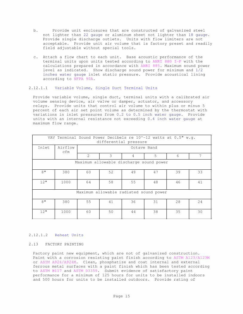
b. Provide unit enclosures that are constructed of galvanized steel
not lighter than 22 gauge or aluminum sheet not lighter than 18 gauge.
Provide single discharge outlets. Units with flow limiters are not
acceptable. Provide unit air volume that is factory preset and readily
field adjustable without special tools.
c. Attach a flow chart to each unit. Base acoustic performance of the
terminal units upon units tested according to AHRI 880 I-P with the
calculations prepared in accordance with AHRI 885. Maximum sound power
level as indicated. Show discharge sound power for minimum and 1/2
inches water gauge inlet static pressure. Provide acoustical lining
according to NFPA 90A.
2.12.1.1 Variable Volume, Single Duct Terminal Units
Provide variable volume, single duct, terminal units with a calibrated air
volume sensing device, air valve or damper, actuator, and accessory
relays. Provide units that control air volume to within plus or minus 5
percent of each air set point volume as determined by the thermostat with
variations in inlet pressures from 0.2 to 0.5 inch water gauge. Provide
units with an internal resistance not exceeding 0.4 inch water gauge at
maximum flow range.
VAV Terminal Sound Power Decibels re 10^-12 watts at 0.5" w.g.
differential pressure
Inlet Airflow
cfm
Octave Band
2 3 4 5 6 7
Maximum allowable discharge sound power
8" 380 60 52 49 47 39 33
12" 1000 64 58 55 48 46 41
Maximum allowable radiated sound power
8" 380 55 41 36 31 28 24
12" 1000 60 50 44 38 35 30
2.12.1.2 Reheat Units
2.13 FACTORY PAINTING
Factory paint new equipment, which are not of galvanized construction.
Paint with a corrosion resisting paint finish according to ASTM A123/A123M
or ASTM A924/A924M. Clean, phosphatize and coat internal and external
ferrous metal surfaces with a paint finish which has been tested according
to ASTM B117 and ASTM D3359. Submit evidence of satisfactory paint
performance for a minimum of 125 hours for units to be installed indoors
and 500 hours for units to be installed outdoors. Provide rating of
Page 15
failure at the scribe mark that is not less than 6, average creepage not
greater than 1/8 inch. Provide rating of the inscribed area that is not
less than 10, no failure. On units constructed of galvanized steel that
have been welded, provide a final shop docket of zinc-rich protective paint
on exterior surfaces of welds or welds that have burned through from the
interior according to ASTM D520 Type I.
Factory painting that has been damaged prior to acceptance by the
Contracting Officer shall be field painted in compliance with the
requirements of paragraph FIELD PAINTING OF MECHANICAL EQUIPMENT.
2.14 SUPPLEMENTAL COMPONENTS/SERVICES
2.14.1 Controls
The requirements for controls are specified in Section 23 09 00
INSTRUMENTATION AND CONTROL FOR HVAC and Section 23 09 53.00 20 SPACE
TEMPERATURE CONTROL SYSTEMS.
PART 3 EXECUTION
3.1 CONSTRUCTION-RELATED SUSTAINABILITY CRITERIA
Perform and document Indoor Air Quality During Construction. Provide
documentation showing that after construction ends, and prior to occupancy,
new filters were installed in conformance with Section 01 33 29
SUSTAINABILITY REPORTING paragraph INDOOR AIR QUALITY DURING CONSTRUCTION.
3.2 EXAMINATION
After becoming familiar with all details of the work, verify all dimensions
in the field, and advise the Contracting Officer of any discrepancy before
performing the work.
3.3 INSTALLATION
a. Install materials and equipment in accordance with the requirements of
the contract drawings and approved manufacturer's installation
instructions. Accomplish installation by workers skilled in this type
of work. Perform installation so that there is no degradation of the
designed fire ratings of walls, partitions, ceilings, and floors.
b. No installation is permitted to block or otherwise impede access to any
existing machine or system. Install all hinged doors to swing open a
minimum of 120 degrees. Provide an area in front of all access doors
that clears a minimum of 3 feet.
3.3.1 Equipment and Installation
Set floor-mounted equipment on not less than 6 inch concrete pads or curbs
doweled in place unless otherwise indicated. Make concrete foundations
heavy enough to minimize the intensity of the vibrations transmitted to the
duct work and the surrounding structure, as recommended in writing by the
equipment manufacturer. Make the concrete pad block a mass not less than
three times the weight of the components to be supported. Submit foundation
drawings as specified in paragraph DETAIL DRAWINGS. Provide concrete for
foundations as specified in Section 03 30 00.00 10 CAST-IN-PLACE CONCRETE.
Page 16

3.3.2 Access Panels
Install access panels for concealed controls, and actuators so that the
concealed items are easily serviced and maintained or completely removed
and replaced.
3.3.3 Flexible Duct
Install pre-insulated flexible duct in accordance with the latest printed
instructions of the manufacturer to ensure a vapor tight joint. Provide
hangers, when required to suspend the duct, of the type recommended by the
duct manufacturer and set at the intervals recommended.
3.3.4 Metal Ductwork
Install ductwork and suppoerts according to SMACNA 1966. Do not use
friction beam clamps indicated in SMACNA 1966. Erect supports on the risers
that allow free vertical movement of the duct. Attach supports only to
structural framing members or struts and concrete slabs. Do not anchor
supports to metal decking unless a means is provided and approved for
preventing the anchor from puncturing the metal decking. Where supports
are required between structural framing members, provide suitable
intermediate metal framing. Where C-clamps are used, provide retainer
clips.
3.3.5 Duct Lining insulation
Apply 2 inch lining in cut-to-size pieces attached to the interior of the
duct with nonflammable fire resistant adhesive conforming to ASTM C916,
Type I, NFPA 90A, UL 723, and ASTM E84. Provide top and bottom pieces that
lap the side pieces and are secured with welded pins, adhered clips of
metal, nylon, or high impact plastic, and speed washers or welding cup-head
pins installed according to SMACNA 1966. Provide welded pins, cup-head
pins, or adhered clips that do not distort the duct, burn through, nor mar
the finish or the surface of the duct. Make pins and washers flush with
the surfaces of the duct liner and seal all breaks and punctures of the
duct liner coating with the nonflammable, fire resistant adhesive. Coat
exposed edges of the liner at the duct ends and at other joints where the
lining is subject to erosion with a heavy brush coat of the nonflammable,
fire resistant adhesive, to prevent delamination of glass fibers. Apply
duct liner to flat sheet metal prior to forming duct through the sheet
metal brake. Additionally secure lining at the top and bottom surfaces of
the duct by welded pins or adhered clips as specified for cut-to-size
pieces. Other methods indicated in SMACNA 1966 to obtain proper
installation of duct liners in sheet metal ducts, including adhesives and
fasteners, are acceptable.
3.3.6 Dust Control
To prevent the accumulation of dust, debris and foreign material during
construction, perform temporary dust control protection. Protect the
distribution system (supply and return) with temporary seal-offs at all
inlets and outlets at the end of each day's work. Keep temporary
protection in place until system is ready for startup.
3.3.7 External Insulation
Page 17
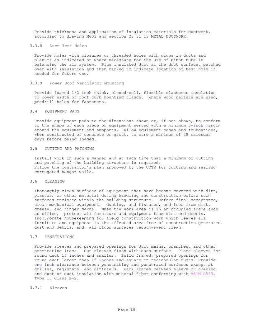
Provide thickness and application of insulation materials for ductwork,
according to drawing M601 and section 23 31 13 METAL DUCTWORK.
3.3.8 Duct Test Holes
Provide holes with closures or threaded holes with plugs in ducts and
plenums as indicated or where necessary for the use of pitot tube in
balancing the air system. Plug insulated duct at the duct surface, patched
over with insulation and then marked to indicate location of test hole if
needed for future use.
3.3.9 Power Roof Ventilator Mounting
Provide foamed 1/2 inch thick, closed-cell, flexible elastomer insulation
to cover width of roof curb mounting flange. Where wood nailers are used,
predrill holes for fasteners.
3.4 EQUIPMENT PADS
Provide equipment pads to the dimensions shown or, if not shown, to conform
to the shape of each piece of equipment served with a minimum 3-inch margin
around the equipment and supports. Allow equipment bases and foundations,
when constructed of concrete or grout, to cure a minimum of 28 calendar
days before being loaded.
3.5 CUTTING AND PATCHING
Install work in such a manner and at such time that a minimum of cutting
and patching of the building structure is required.
Follow the contractor's plan approved by the COTR for cutting and sealing
corrugated hangar walls.
3.6 CLEANING
Thoroughly clean surfaces of equipment that have become covered with dirt,
plaster, or other material during handling and construction before such
surfaces enclosed within the building structure. Before final acceptance,
clean mechanical equipment, ducting, and fixtures, and free from dirt,
grease, and finger marks. When the work area is in an occupied space such
as office, protect all furniture and equipment from dirt and debris.
Incorporate housekeeping for field construction work which leaves all
furniture and equipment in the affected area free of construction generated
dust and debris; and, all floor surfaces vacuum-swept clean.
3.7 PENETRATIONS
Provide sleeves and prepared openings for duct mains, branches, and other
penetrating items. Cut sleeves flush with each surface. Place sleeves for
round duct 15 inches and smaller. Build framed, prepared openings for
round duct larger than 15 inches and square or rectangular ducts. Provide
one inch clearance between penetrating and penetrated surfaces except at
grilles, registers, and diffusers. Pack spaces between sleeve or opening
and duct or duct insulation with mineral fiber conforming with ASTM C553,
Type 1, Class B-2.
3.7.1 Sleeves
Page 18

Fabricate sleeves from 20 gauge thick mill galvanized sheet metal.
3.7.2 Framed Prepared Openings
Fabricate framed prepared openings from 20 gauge galvanized steel.
3.7.3 Insulation
Provide duct insulation in continuous through sleeves and prepared openings
except firewall penetrations. Terminate duct insulation at fire dampers
and flexible connections.
3.7.4 Firestopping
Where ducts pass through fire-rated walls, fire partitions, and fire rated
chase walls, seal the penetration with fire stopping materials as specified
in Section 07 84 00 FIRESTOPPING.
3.8 FIELD PAINTING OF GRAVITY VENTILATORS
Clean, pretreat, prime and paint metal surfaces; except aluminum surfaces
need not be painted. Apply coatings to clean dry surfaces. Clean the
surfaces to remove dust, dirt, rust, oil and grease by wire brushing and
solvent degreasing prior to application of paint apply a second coat after
the preceding coat is thoroughly dry. Lightly sand damaged painting and
retouch before applying the succeeding coat. Provide finish coat to match
original color, or as directed by the COTR.
3.8.1 Exposed Bare metal surfaces
Immediately after cleaning, apply one coat of pretreatment primer applied
to a minimum dry film thickness of 0.3 mil, one coat of primer applied to a
minimum dry film thickness of one mil; and two coats of enamel applied to a
minimum dry film thickness of one mil per coat to metal surfaces subject to
temperatures less than 120 degrees F.
3.8.2 Finish Painting
The requirements for finish painting of items only primed at the factory,
and surfaces not specifically noted otherwise, are specified in Section
09 90 00 PAINTS AND COATINGS.
3.8.3 Color Coding Scheme for Locating Hidden Utility Components
Use scheme in buildings having suspended grid ceilings. Provide color
coding scheme that identifies points of access for maintenance and
operation of components and equipment that are not visible from the
finished space and are accessible from the ceiling grid, consisting of a
color code board and colored metal disks. Make each colored metal disk
approximately 3/8 inch diameter and secure to removable ceiling panels with
fasteners. Insert each fastener into the ceiling panel so as to be
concealed from view. Provide fasteners that are manually removable without
the use of tools and that do not separate from the ceiling panels when the
panels are dropped from ceiling height. Make installation of colored metal
disks follow completion of the finished surface on which the disks are to
be fastened. Provide color code board that is approximately 3 foot wide,
30 inches high, and 1/2 inches thick. Make the board of wood fiberboard
Page 19

and frame under glass or 1/16 inch transparent plastic cover. Make the
color code symbols approximately 3/4 inch in diameter and the related
lettering in 1/2 inch high capital letters. Mount the color code board
[where indicated] [in the mechanical or equipment room]. Make the color
code system as indicated below:
Color System Item Location
[_____] [_____] [_____] [_____]
3.8.4 DUCTWORK LEAK TESTS
The requirements for ductwork leak tests are specified in Section 23 05 93
TESTING, ADJUSTING AND BALANCING FOR HVAC.
3.9 FIRE DAMPER ACCEPTANCE TEST
Submit the proposed schedule, at least 2 weeks prior to the start of test.
Operate all fire dampers under normal operating conditions, prior to the
occupancy of a building to determine that they function properly. Test
each fire damper equipped with fusible link by having the fusible link cut
in place. Test dynamic fire dampers with the air handling and distribution
system running. Reset all fire dampers with the fusible links replaced
after acceptance testing. To ensure optimum operation and performance,
install the damper so it is square and free from racking.
3.10 TESTING, ADJUSTING, AND BALANCING
The requirements for testing, adjusting, and balancing are specified in
Section 23 05 93 TESTING, ADJUSTING AND BALANCING FOR HVAC. Begin testing,
adjusting, and balancing only when the air supply and distribution,
including controls, has been completed, with the exception of performance
tests.
3.11 PERFORMANCE TESTS
After testing, adjusting, and balancing is complete as specified, test each
system as a whole to see that all items perform as integral parts of the
system and temperatures and conditions are evenly controlled throughout the
building. Record the testing during the applicable season. Make
corrections and adjustments as necessary to produce the conditions
indicated or specified. Conduct temperature tests and general operating
tests by an experienced engineer. Provide tests that cover a period of not
less than 2 days for each system and demonstrate that the entire system is
functioning according to the specifications. Make coincidental chart
recordings at points indicated BELOW for the duration of the time period
and record the temperature at space thermostats or space sensors and the
ambient temperature and humidity in a shaded and weather protected area.
Submit test reports for the performance tests in booklet form, upon
completion of testing. Document phases of tests performed including
initial test summary, repairs/adjustments made, and final test results in
the reports.
Page 20
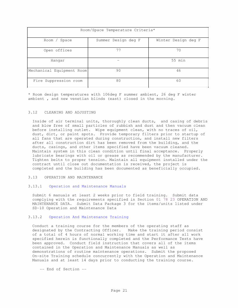
Room/Space Temperature Criteria*
Room / Space Summer Design deg F Winter Design deg F
Open offices 77 70
Hangar - 55 min
Mechanical Equipment Room 90 46
Fire Suppression room 80 60
* Room design temperatures with 106deg F summer ambient, 26 deg F winter
ambient , and new venetian blinds (east) closed in the morning.
3.12 CLEANING AND ADJUSTING
Inside of air terminal units, thoroughly clean ducts, and casing of debris
and blow free of small particles of rubbish and dust and then vacuum clean
before installing outlet. Wipe equipment clean, with no traces of oil,
dust, dirt, or paint spots. Provide temporary filters prior to startup of
all fans that are operated during construction, and install new filters
after all construction dirt has been removed from the building, and the
ducts, casings, and other items specified have been vacuum cleaned.
Maintain system in this clean condition until final acceptance. Properly
lubricate bearings with oil or grease as recommended by the manufacturer.
Tighten belts to proper tension. Maintain all equipment installed under the
contract until close out documentation is received, the project is
completed and the building has been documented as beneficially occupied.
3.13 OPERATION AND MAINTENANCE
3.13.1 Operation and Maintenance Manuals
Submit 6 manuals at least 2 weeks prior to field training. Submit data
complying with the requirements specified in Section 01 78 23 OPERATION AND
MAINTENANCE DATA. Submit Data Package 3 for the items/units listed under
SD-10 Operation and Maintenance Data
3.13.2 Operation And Maintenance Training
Conduct a training course for the members of the operating staff as
designated by the Contracting Officer. Make the training period consist
of a total of 4 hours of normal working time and start it after all work
specified herein is functionally completed and the Performance Tests have
been approved. Conduct field instruction that covers all of the items
contained in the Operation and Maintenance Manuals as well as
demonstrations of routine maintenance operations. Submit the proposed
On-site Training schedule concurrently with the Operation and Maintenance
Manuals and at least 14 days prior to conducting the training course.
-- End of Section --
Page 21
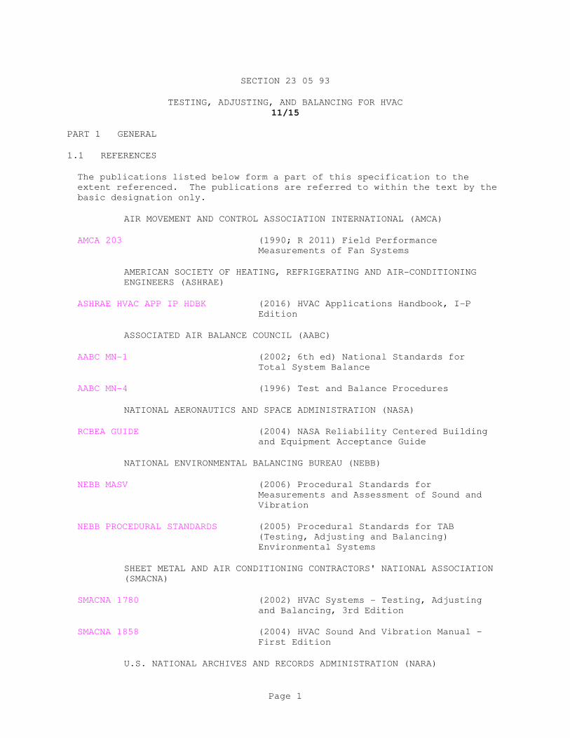
SECTION 23 05 93
TESTING, ADJUSTING, AND BALANCING FOR HVAC
11/15
PART 1 GENERAL
1.1 REFERENCES
The publications listed below form a part of this specification to the
extent referenced. The publications are referred to within the text by the
basic designation only.
AIR MOVEMENT AND CONTROL ASSOCIATION INTERNATIONAL (AMCA)
AMCA 203 (1990; R 2011) Field Performance
Measurements of Fan Systems
AMERICAN SOCIETY OF HEATING, REFRIGERATING AND AIR-CONDITIONING
ENGINEERS (ASHRAE)
ASHRAE HVAC APP IP HDBK (2016) HVAC Applications Handbook, I-P
Edition
ASSOCIATED AIR BALANCE COUNCIL (AABC)
AABC MN-1 (2002; 6th ed) National Standards for
Total System Balance
AABC MN-4 (1996) Test and Balance Procedures
NATIONAL AERONAUTICS AND SPACE ADMINISTRATION (NASA)
RCBEA GUIDE (2004) NASA Reliability Centered Building
and Equipment Acceptance Guide
NATIONAL ENVIRONMENTAL BALANCING BUREAU (NEBB)
NEBB MASV (2006) Procedural Standards for
Measurements and Assessment of Sound and
Vibration
NEBB PROCEDURAL STANDARDS (2005) Procedural Standards for TAB
(Testing, Adjusting and Balancing)
Environmental Systems
SHEET METAL AND AIR CONDITIONING CONTRACTORS' NATIONAL ASSOCIATION
(SMACNA)
SMACNA 1780 (2002) HVAC Systems - Testing, Adjusting
and Balancing, 3rd Edition
SMACNA 1858 (2004) HVAC Sound And Vibration Manual -
First Edition
U.S. NATIONAL ARCHIVES AND RECORDS ADMINISTRATION (NARA)
Page 1
40 CFR 82 Protection of Stratospheric Ozone
1.2 DEFINITIONS
a. AABC: Associated Air Balance Council
b. COTR: Contracting Officer's Technical Representative
c. DALT: Duct air leakage test
d. CCD : Construction completion date
e. HVAC: Heating, ventilating, and air conditioning; or heating,
ventilating, and cooling
f. NEBB: National Environmental Balancing Bureau
g. Out-of-tolerance data: Pertains only to field acceptance testing of
Final DALT or TAB report. When applied to DALT work, this phase
means When applied to TAB work this phase means "a measurement taken
during TAB field acceptance testing which does not fall within the
range of plus 5 to minus 5 percent of the original measurement reported
on the TAB Report for a specific parameter."
h. Season of maximum heating load: The time of year when the outdoor
temperature at the project site remains within plus or minus 25 degrees
Fahrenheit of the project site's winter outdoor design temperature,
throughout the period of TAB data recording.
i. Season of maximum cooling load: The time of year when the outdoor
temperature at the project site remains within plus or minus 5 degrees
Fahrenheit of the project site's summer outdoor design temperature,
throughout the period of TAB data recording.
j. Season 1, Season 2: Depending upon when the project HVAC is completed
and ready for TAB, Season 1 is defined, thereby defining Season 2.
Season 1 could be the season of maximum heating load, or the season of
maximum cooling load.
k. TAB: Testing, adjusting, and balancing (of HVAC systems)
l. TAB'd: HVAC Testing/Adjusting/Balancing procedures performed
m. TAB Agency: TAB Firm
n. TABB: Testing Adjusting and Balancing Bureau
1.2.1 Similar Terms
In some instances, terminology differs between the Contract and the TAB
Standard primarily because the intent of this Section is to use the
industry standards specified, along with additional requirements listed
herein to produce optimal results.
The following table of similar terms is provided for clarification only.
Contract requirements take precedent over the corresponding AABC, NEBB, or
TABB requirements where differences exist.
Page 2

SIMILAR TERMS
Contract Term AABC Term NEBB Term TABB Term
TAB Standard National
Standards for
Testing and
Balancing
Heating,
Ventilating, and
Air Conditioning
Systems
Procedural
Standards for
Testing,
Adjusting and
Balancing of
Environmental
Systems
International
Standards for
Environmental
Systems Balance
TAB Specialist TAB Engineer TAB Supervisor TAB Supervisor
Systems Readiness
Check
Construction
Phase Inspection
Field Readiness
Check &
Preliminary Field
Procedures
Field Readiness
Check & Prelim.
Field Procedures
1.3 WORK DESCRIPTION
The work includes duct air leakage testing (DALT) and testing, adjusting,
and balancing (TAB) of [new][ and existing] heating, ventilating, and
cooling (HVAC) air distribution systems including equipment and performance
data, ducts which are located within, on, and adjacent to buildings.
Perform TAB in accordance with the requirements of the TAB procedural
standard recommended by the TAB trade association that approved the TAB
Firm's qualifications. Comply with requirements of AABC MN-1,
NEBB PROCEDURAL STANDARDS, or SMACNA 1780 (TABB) as supplemented and
modified by this specification section. All recommendations and suggested
practices contained in the TAB procedural standards are considered
mandatory.
Conduct DALT and TAB of the indicated existing systems and equipment and
submit the specified DALT and TAB reports for approval. Conduct DALT and
TAB work in accordance with the requirements of this section.
1.3.1 Air Distribution Systems
Test, adjust, and balance system[s] (TAB) in compliance with this section.
Obtain Contracting Officer's written approval before applying insulation
over the pilot test tube ports.
1.3.2 TAB SCHEMATIC DRAWINGS
Show the following information on TAB Schematic Drawings:
1. A unique number or mark for each piece of equipment or terminal.
2. Air quantities at air terminals.
3. Air quantities and temperatures in schedules.
Page 3
4. Ductwork Construction and Leakage Testing Table that defines the
DALT test requirements, including each applicable HVAC duct system ID
or mark, duct pressure class, duct seal class, and duct leakage allowed.
Submit three copies of the TAB Schematic Drawings and Report Forms to the
Contracting Officer, no later than 21 days prior to the start of TAB field
measurements.
1.4 SUBMITTALS
Government approval is required for submittals with a "G" designation;
SD-01 Preconstruction Submittals
Records of Existing Conditions; G
SD-02 Shop Drawings
TAB Schematic Drawings and Report Forms; G
SD-03 Product Data
Equipment and Performance Data; G
TAB Related HVAC Submittals; G
SD-06 Test Reports
Completed Pre-Final DALT Report; G
Certified Final DALT Report; G
SD-07 Certificates
Independent TAB Agency and Personnel Qualifications; G
DALT and TAB Submittal and Work Schedule; G
TAB Pre-Field Engineering Report; G
1.5 QUALITY ASSURANCE
1.5.1 Independent TAB Agency and Personnel Qualifications
To secure approval for the proposed agency, submit information certifying
that the TAB agency is a first tier subcontractor who is not affiliated
with any other company participating in work on this contract, including
design, furnishing equipment, or construction. Further, submit the
following, for the agency, to Contracting Officer for approval:
a. Independent AABC or NEBB or TABB TAB agency:
TAB agency: AABC registration number and expiration date of
current certification; or NEBB certification number and expiration
Page 4

date of current certification; or TABB certification number and
expiration date of current certification.
TAB team supervisor: Name and copy of AABC or NEBB or TABB TAB
supervisor certificate and expiration date of current
certification.
TAB team field leader: Name and documented evidence that the team
field leader has satisfactorily performed full-time supervision of
TAB work in the field for not less than 3 years immediately
preceding this contract's bid opening date.
TAB team field technicians: Names and documented evidence that
each field technician has satisfactorily assisted a TAB team field
leader in performance of TAB work in the field for not less than
one year immediately preceding this contract's bid opening date.
Current certificates: Registrations and certifications are
current, and valid for the duration of this contract. Renew
Certifications which expire prior to completion of the TAB work,
in a timely manner so that there is no lapse in registration or
certification. TAB agency or TAB team personnel without a current
registration or current certification are not to perform TAB work
on this contract.
b. TAB Team Members: TAB team approved to accomplish work on this
contract are full-time employees of the TAB agency. No other personnel
is allowed to do TAB work on this contract.
c. Replacement of TAB team members: Replacement of members may occur if
each new member complies with the applicable personnel qualifications
and each is approved by the Contracting Officer.
PART 2 PRODUCTS
Not Used
PART 3 EXECUTION
3.1 WORK DESCRIPTIONS OF PARTICIPANTS
Comply with requirements of this section.
3.2 PRE-DALT/TAB MEETING
Meet with the Contracting Officer's technical representative (COTR) to
develop a mutual understanding relative to the details of the TAB work
requirements. Ensure that the TAB supervisor is present at this meeting.
Requirements to be discussed include required submittals, work schedule,
and field quality control.
3.3 DALT PROCEDURES
3.3.1 Instruments, Consumables and Personnel
Provide instruments, consumables and personnel required to accomplish the
DALT field work. Follow the same basic procedure specified below for TAB
Page 5
Field Work, including maintenance and calibration of instruments, accuracy
of measurements, preliminary procedures, field work, workmanship and
treatment of deficiencies. Calibrate and maintain instruments in
accordance with manufacturer's written procedures.
3.3.2
On completion of the installation of each duct system indicated to be
DALT'd, notify the Contracting Officer in writing prior to the COTR's duct
selection field visit.
3.3.3 Ductwork To Be DALT'd
The supply air ductwork in the ceilings of each office building will be
leak tested.
3.3.4 DALT Testing
Perform DALT on the HVAC supply air ducts in the office celings.
SA duct leakage shall be determined by subtracting the sum of the branch
air flows from the total air flow measured by the pilot tube at the main
(see Appendix D). SA duct leakage shall not exceed 100 cfm for the 6TR
sytem or 120 cfm for the 7 1/2 TR systems (4%). Is SA duct leakage exceeds
4% of totald esign airflow for any system, report the condition to the
mechanical contractor and the COTR.
3.3.5 Quality Assurance - COTR DALT Field Acceptance Testing
In the presence of the COTR and TAB team field leader, verify for accuracy
Pre-final DALT Report data selected by the COTR. For each duct system,
this acceptance testing shall be conducted on a maximum of 50 percent of
the duct sections DALT'd.
Further, if any data on the Pre-final DALT report form for a given duct
section is out-of-tolerance, then field acceptance testing shall be
conducted on data for one additional duct section, preferably in the same
duct system, in the presence of the COTR.
3.3.6 Additional COTR Field Acceptance Testing
If any of the duct sections checked for a given system are determined to
have a leakage rate measured that exceeds the leakage rate allowed by
SMACNA Leak Test Manual for an indicated duct construction class and
sealant class, terminate data checking for that section. The associated
Pre-final DALT Report data for the given duct system will be disapproved.
Make the necessary corrections and prepare a revised Pre-final DALT
Report. Reschedule a field check of the revised report data with the COTR.
3.4 TAB PROCEDURES
3.4.1 TAB Field Work
Test, adjust, and balance the HVAC systems until measured air flow rates
are within plus or minus 5 percent of the design flow rates as specified or
indicated on the contract documents.
That is, comply with the the requirements of AABC MN-1 or SMACNA 1780
Page 6
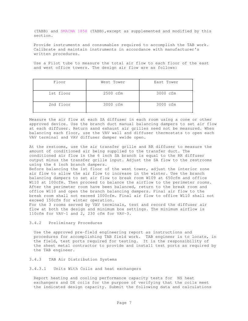
(TABB) and SMACNA 1858 (TABB),except as supplemented and modified by this
section.
Provide instruments and consumables required to accomplish the TAB work.
Calibrate and maintain instruments in accordance with manufacturer's
written procedures.
Use a Pilot tube to measure the total air flow to each floor of the east
and west office towers. The design air flow are as follows:
Floor West Tower East Tower
1st floor 2500 cfm 3000 cfm
2nd floor 3000 cfm 3000 cfm
Measure the air flow at each SA diffuser in each room using a cone or other
approved device. Use the branch duct manual balancing dampers to set air flow
at each diffuser. Return aand exhaust air grilles need not be measured. When
balancing each floor, use the VAV wall and diffuser thermostats to open each
VAV terminal and VAV diffuser damper wwide open.
At the restooms, use the air transfer grille and RR diffuser to measure the
amount of conditioned air being supplied to the transfer duct. The
conditioned air flow in the 6 inch SA branch is equal to the RR diffuser
output minus the transfer grille input. Adjust the SA flow to the restrooms
using the 6 inch branch dampers.
Before balancing the 1st floor of the west tower, adjust the interior zone
air flow to allow the air flow to increase in the winter. Use the branch
balancing dampers to set air flow to break room W109 at 650cfm and office
W110 at 100cfm. Then proceed to balance the airflow to the perimeter rooms.
After the perimeter room have been balanced, return to the break room and
office W110 and open the branch balancing dampers. Final air flow to the
break room shall not exceed 1000cfm. Final air flow to office W110 shall not
exceed 150cfm for winter operation.
For the 3 rooms served by VAV terminals, test and record the diffuser air
flow at both the design and minimum box settings. The minimum airflow is
110cfm for VAV-1 and 2, 230 cfm for VAV-3.
3.4.2 Preliminary Procedures
Use the approved pre-field engineering report as instructions and
procedures for accomplishing TAB field work. TAB engineer is to locate, in
the field, test ports required for testing. It is the responsibility of
the sheet metal contractor to provide and install test ports as required by
the TAB engineer.
3.4.3 TAB Air Distribution Systems
3.4.3.1 Units With Coils and heat exchangers
Report heating and cooling performance capacity tests for NS heat
exchangers and DX coils for the purpose of verifying that the coils meet
the indicated design capacity. Submit the following data and calculations
Page 7
with the coil test reports:
a. For units with capacities of 7.5 tons (90,000 Btu) or less, such as
gas/electric packaged air conditioners
Determine the apparent coil capacity by calculations using single point
measurement of entering and leaving dry bulb temperatures; submit the
calculations with the coil reports.
3.4.3.2 Gas/electric packaged Air Conditioning
Gas/electric packaged air conditioning systems including fans, coils, ducts
and air distribution devices for supply air, return air, and outside air.
3.4.3.3 Exhaust Fans
Exhaust fan systems including fans, ducts and grilles for exhaust air.
3.4.3.4 Infrared gas space heaters
Tubular gas heaters, including reflectors.
3.4.4 TAB Work on Performance Tests With Seasonal Limitations
3.4.5 Workmanship
Balance the diffusers in the towers to within -5% to +5% of the summer
design airflows indicated on the drawings M401 through M405. Balance the
two interior rooms in the 1st floor of the west tower for upto 200% of the
summer design airflow when the VAV dampers are 100% open. Demonstrate that
the buildings are at positive pressure with the RR exhaust fans operating.
Further, this TAB work includes changing out fan sheaves and pump impellers
if required to obtain air flow rates specified or indicated. If, with
these adjustments and equipment changes, the specified or indicated design
flow rates cannot be attained, contact the Contracting Officer for
direction.
3.4.6 Deficiencies
Strive to meet the intent of this section to maximize the performance of
the equipment as designed and installed. However, if deficiencies in
equipment design or installation prevent TAB work from being accomplished
within the range of design values specified in the paragraph WORKMANSHIP,
provide written notice as soon as possible to the Contractor and the
Contracting Officer describing the deficiency and recommended correction.
Responsibility for correction of installation deficiencies is the
Contractor's. If a deficiency is in equipment design, call the TAB team
supervisor for technical assistance. Responsibility for reporting design
deficiencies to Contractor is the TAB team supervisor's.
3.4.7 TAB Reports
3.4.8 Quality Assurance - COTR TAB Field Acceptance Testing
3.4.8.1 TAB Field Acceptance Testing
Page 8
During the field acceptance testing, verify, in the presence of the COTR,
random selections of data air quantities, air motion, sound level readings
recorded in the TAB Report. Points and areas for field acceptance testing
are to be selected by the COTR. Measurement and test procedures are the
same as approved for TAB work for the TAB Report.
Field acceptance testing includes verification of TAB Report data recorded
for the following equipment groups:
Group 1: Air handling units (gas/electric).
Group 2: 25 percent of the VAV terminal boxes and associated diffusers
and VAV diffusers.
Group 3: 25 percent of the supply diffusers and grilles associated
with the air handling units.
Group 4: 25 percent of the exhaust fans
Further, if any data on the TAB Report for Groups 2 through 4 is found not
to fall within the range of plus 5 to minus 5 percent of the TAB Report
data, additional group data verification is required in the presence of the
COTR. Verify TAB Report data for one additional piece of equipment in that
group. Continue this additional group data verification until
out-of-tolerance data ceases to be found.
3.4.8.2 Additional COTR TAB Field Acceptance Testing
If any of the acceptance testing measurements for a given equipment group
is found not to fall within the range of plus 5 to minus 5 percent of the
TAB Report data, terminate data verification for all affected data for that
group. The affected data for the given group will be disapproved. Make
the necessary corrections and prepare a revised TAB Report. Reschedule
acceptance testing of the revised report data with the COTR.
3.4.8.3 Prerequisite for Approval
Compliance with the field acceptance testing requirements of this section
is a prerequisite for the final Contracting Officer approval of the TAB
Report submitted.
3.5 MARKING OF SETTINGS
Upon the final TAB work approval, permanently mark the settings of HVAC
adjustment devices including valves, gauges, splitters, and dampers so that
adjustment can be restored if disturbed at any time. Provide permanent
markings clearly indicating the settings on the adjustment devices which
result in the data reported on the submitted TAB report.
3.6 MARKING OF TEST PORTS
The TAB team is to permanently and legibly mark and identify the location
points of the duct test ports. If the ducts have exterior insulation, make
these markings on the exterior side of the duct insulation. Show the
location of test ports on the as-built mechanical drawings with dimensions
given where the test port is covered by exterior insulation.
Page 9
3.7 THERMOSTAT SETTINGS
Upon completion of the diffuser balancing the TAB contractor will test the
temperature set point is for the wall thermostats and in the VAV diffusers in
the private offices. Set the control temperature at 68 deg F in the winter,
fall and spring and 75 deg F in the summer. Note that the VAV diffsers can
accept both a heating set point (68 deg) and a cooling set point (75 deg
summer or 68 deg winter).
-- End of Section --
Page 10
SECTION 23 31 13.00 40
METAL DUCTS
05/16
PART 1 GENERAL
Section 23 00 00 AIR SUPPLY, DISTRIBUTION, VENTILATION, AND EXHAUST SYSTEMS
applies to work specified in this section.
]1.1 REFERENCES
The publications listed below form a part of this specification to the
extent referenced. The publications are referred to within the text by the
basic designation only.
AMERICAN INSTITUTE OF STEEL CONSTRUCTION (AISC)
AISC 325 (2017) Steel Construction Manual
AMERICAN SOCIETY OF HEATING, REFRIGERATING AND AIR-CONDITIONING
ENGINEERS (ASHRAE)
ASHRAE EQUIP IP HDBK (2012) Handbook, HVAC Systems and
Equipment (IP Edition)
AMERICAN WELDING SOCIETY (AWS)
AWS A5.8/A5.8M (2011; Amendment 2012) Specification for
Filler Metals for Brazing and Braze Welding
ASTM INTERNATIONAL (ASTM)
ASTM A123/A123M (2015) Standard Specification for Zinc
(Hot-Dip Galvanized) Coatings on Iron and
Steel Products
ASTM A36/A36M (2014) Standard Specification for Carbon
Structural Steel
ASTM A653/A653M (2015; E 2016) Standard Specification for
Steel Sheet, Zinc-Coated (Galvanized) or
Zinc-Iron Alloy-Coated (Galvannealed) by
the Hot-Dip Process
ASTM A924/A924M (2017a) Standard Specification for General
Requirements for Steel Sheet,
Metallic-Coated by the Hot-Dip Process
ASTM C1071 (2016) Standard Specification for Fibrous
Glass Duct Lining Insulation (Thermal and
Sound Absorbing Material)
NATIONAL FIRE PROTECTION ASSOCIATION (NFPA)
Page 1

NFPA 90A (2018) Standard for the Installation of
Air Conditioning and Ventilating Systems
Page 2

SHEET METAL AND AIR CONDITIONING CONTRACTORS' NATIONAL ASSOCIATION
(SMACNA)
SMACNA 1966 (2005) HVAC Duct Construction Standards
Metal and Flexible, 3rd Edition
SMACNA 1987 (2006) HVAC Duct Systems Inspection Guide,
3rd Edition
UNDERWRITERS LABORATORIES (UL)
UL 181 (2013; Reprint Apr 2017) UL Standard for
Safety Factory-Made Air Ducts and Air
Connectors
UL 555 (2006; Reprint Aug 2016) UL Standard for
Safety Fire Dampers
1.2 SUBMITTALS
Government approval is required for submittals with a "G" designation;
submittals not having a "G" designation are for contractor quality control
approval. Submit the following in accordance with Section 01 33 00
SUBMITTAL PROCEDURES:
SD-01 Preconstruction Submittals
Material, Damper, and Insulation Lists; G
Records of Existing Conditions; G
SD-02 Shop Drawings
Connection Diagrams; G
Offset Fitting Configurations; G
SD-03 Product Data
Galvanized Steel Ductwork Materials; G
Gravity Backdraft Dampers; G
Mill-Rolled Reinforcing and Supporting Materials
Round Sheet Metal Duct Fittings; G
Turning Vanes; G
Flexible Duct Materials
Power Operated Dampers; G
Fire Dampers and Wall Collars; G
Page 3
Manual Volume Dampers; G
SD-05 Design Data
Design Analysis and Calculations; G
Duct supports and Penetrations on exterior walls; G
SD-06 Test Reports
Ductwork Leakage Tests; G
Operational Tests; G
SD-07 Certificates
Listing of Ductwork Installations
Galvanized Steel Ductwork Materials
Brazing Materials
Mill-Rolled Reinforcing and Supporting Materials
Round Sheet Metal Duct Fittings
Round, High-Pressure, Double-Wall Sheet Metal Ducts
Turning Vanes
Dampers
Sound Traps
Flexible Connectors
SD-11 Closeout Submittals
Record Drawings; G
1.3 QUALITY CONTROL
When furnishing the listing of installations for low pressure ductwork
systems include identification of at least 5 units, similar to those
proposed for use, that have been in successful service for a minimum period
of 5 years. Include purchaser, address of installation and date of
installation.
PART 2 PRODUCTS
Include the manufacturer's style or catalog numbers, specification for
ductwork materials and drawing reference numbers, warranty information, and
fabrication site information within equipment lists.
2.1 SYSTEM DESCRIPTION
Page 4
Provide low-pressure systems ductwork where maximum air velocity is
1,000-feet per minute(fpm) and maximum static pressure is 1-inch water gage
(wg), positive or negative.
All ductwork shall be sheet metal except the following : 1) run-outs from
the last fitting to the air outlet, not to exceed 10 feet, 2)transfer ducts,
and 3) connections where indicated in the contract drawings sheet notes.
Submit connection diagrams for low pressure ductwork systems indicating the
connection of new ductwork and apparatus by showing the general physical
layout of all controls, the interconnection of one system with another.
2.1.1 Design Requirements
Submit records of existing conditions including the results of a survey
consisting of work area conditions, and features of existing ductwork and
structures.
Submit design analysis and calculations or references for ductwork exterior
wall supports. Submit sketches and description of wall penetrations for
approval by the COTR.
2.2 COMPONENTS
2.2.1 Round Sheet Metal Duct Fittings
Submit offset duct and fitting configurations if any for approval. Shop
fabricate fittings.
2.2.1.1 Fittings Construction
Manufacture as separate fittings, not as tap collars welded or brazed
into duct sections, except as indiacted on the contract drawings.
Provide two-piece type miter elbows for angles less than 31 degrees,
three-piece type for angles 31 through 60 degrees, and five-piece type
for angles 61 through 90 degrees. Ensure centerline radius of elbows is
1-1/2 times fitting cross section diameter.
Provide 45-degree lateral tees, and 90-degree shpe-type tees where there
is insufficient distance for lateral fitting.
Ensure cutouts in fitting body are equal to branch tap dimension or,
where smaller, excess material is flared and rolled into smooth radius
nozzle configuration.
2.2.1.2 Square Elbows
Square and rectangular elbows shall be the miter type with turning vanes,
or the radius type. Half radius, half miter elbows are not acceptable.
2.2.1.3 Turning Vanes
Provide single thickness vanes in miter elbows upto 12 inches. Provide
double wall turning vanes over 12 inches, commercialy manufactured with 2
inch maximum vane radius on approx 2 1/2 inch centers.
Page 5
2.2.2 Duct Hangers
For duct hangers in contact with galvanized duct surfaces, provide
galvanized steel or black carbon steel painted with inorganic zinc.
2.2.3 Mill-Rolled Reinforcing and Supporting Materials
Provide mill-rolled structural steel conforming to ASTM A36/A36M. Whenever
in contact with sheet metal ducting, provide galvanized steel in accordance
with ASTM A123/A123M.
In lieu of mill-rolled structural steel, submit equivalent strength,
proprietary-design, rolled-steel structural support systems for approval.
2.2.4 Flexible Duct Materials
Ensure flexible duct connectors comply with NFPA 90A, and conform with
UL 181, Class 1 material.
Provide wire-reinforced fibrous-glass duct consisting of a minimum 1 1/2
pound/cubic foot density fibrous glass, bonded to and supported by
corrosion-protected spring helix. The core surrounding the wire helix shall
be either woven fibreglass or tripple ply aluminum foil/ polyster laminate.
Vapor barriers are a minimum of 4 mil, metalized polyster film. Ensure
duct is bendable without damage through 180 degrees with an inside bend
radius not greater than two duct diameters. Minimum wall thickness is 1
-inch. Thermal conductivity is not greater than 0.24 BTU per hour per
square foot per degrees Fat\ 75 degrees F mean temperature. Ensure
permeance is not greater than 0.05perm. Working pressure range is from
minus 1/2-inch wg to plus 1-1/2-inches wg. Working temperature ranges from
minus 20 to plus 250 degrees F. Minimum sustained velocity without
delamination is 2,400fpm. Metalized polyster jacket shall have puncture
resistance of not less than 50 beach units. Use materials conforming to
NFPA 90A.
2.2.5 Manual Volume Dampers
Conform to SMACNA 1966 for volume damper construction.
Equip dampers with an indicating quadrant regulator with a locking feature
externally located and easily accessible for adjustment and standoff
brackets to allow mounting outside external insulation. Where damper rod
lengths exceed 30-inches, provide a regulator at each end of damper shaft.
2.2.5.1 Damper Construction
Provide all damper shafts with two-end bearings in around fitting with a
looking quadrant.
Ensure damper is 18-gage sheet metal minimum.
2.2.6 Gravity Backdraft Dampers
Construct frames of not less than 1 1/2 x 4 inch reinforced 16 gauge
galvanizes carbon steel. Provide oil-impregnated shaft bearings. Blade
material shall be 16-gauge galvanized steel, 18-gauge AISI 18-8 corrosion -
resistant steel, or 6063 or 5052 alloy aluminum. Provide blades with
Page 6
mechanically retained seals and 90 degree limit stops. Solidly secure frames
in the ducts and seal with elastomer caulking against air bypass.
2.3 MATERIALS
2.3.1 Galvanized Steel Ductwork Materials
Provide hot-dip galvanized carbon steel ductwork sheet metal of
lock-forming quality, with regular spangle-type zinc coating, conforming to
ASTM A924/A924M and ASTM A653/A653M, Designation G90.
Conform to ASHRAE EQUIP IP HDBK, Chapter 16 and SMACNA 1966 for sheet metal
gages and reinforcement thickness.
Low pressure ductwork minimum thicknesses are:
MINIMUM SHEET METAL THICKNESS
DUCT WIDTH
INCHES
GAGE
0-12 26
13-30 24
31-60 22
ROUND DUCT AND FITTINGS
MINIMUM SHEET METAL GAUGES
DIAMETER INCHES SPIRAL SEAM DUCT LONGITUDNAL SEAM
DUCT
FITTINGS
5 TO 8 28 GAUGE 26 GAUGE 26 GAUGE
9 TO 12 26 GAUGE 24 GAUGE 24 GAUGE
15 TO 20 24 GAUGE 22 GAUGE 22 GAUGE
2.3.2 Mill-Rolled Reinforcing and Supporting Materials
Conform to ASTM A36/A36M for mill-rolled structural steel. Wherever in
contact with sheet metal ducting, galvanize to conform with ASTM A123/A123M.
In lieu of mill-rolled structural steel, submit for approval, equivalent
strength, proprietary design, rolled-steel structural support systems.
PART 3 EXECUTION
3.1 PREPARATION
For sheet metal surfaces to be painted, and surfaces to which adhesives are
to be applied, clean surface of oil, grease, and deleterious substances.
3.1.1 Construction Standards
Provide sheet metal construction in accordance with the recommendations for
Page 7
best practices in ASHRAE EQUIP IP HDBK, Chapter 16, ASHRAE FUN IP, Chapter
32, SMACNA 1966, and NFPA 90A.
Design and fabricate supplementary steel in accordance with AISC 360 and
AISC 325.
Where construction methods for certain items are not described in the
referenced standards or herein, perform the work in accordance with
recommendations for best practices.
3.2 INSTALLATION
Fabricate an airtight system. Include reinforcements, bracing, supports,
framing, gasketing, sealing, and fastening to provide rigid construction
and freedom from vibration, airflow-induced motion, noise, and excessive
deflection at specified maximum system air pressure and velocity.
Provide offsets and transformations as required to avoid interference with
the building construction, piping, or equipment.
3.2.1 Wall Collars
Wherever ducts pass through firewalls or through walls dividing conditioned
spaces from unconditioned spaces, provide a flanged segment collar in that
surface during surface construction.
3.2.1.1 Ductwork Cleaning Provisions
After demolition and prior to new duct insulation, vacuum the interior of
remaining duct mains using the branch openings. Protect open ducting from
construction dust and debris in a manner approved by the Contracting
Officer. Clean dirty assembled ducting by subjecting all main and branch
interior surfaces to airstreams moving at velocities two times specified
working velocities, at static pressures within maximum ratings. This may
be accomplished by: filter-equipped portable blowers which remain the
Contractor's property; wheel-mounted, compressed-air operated perimeter
lances which direct the compressed air and which are pulled in the
direction of normal airflow; or other means approved by the Contracting
Officer. Use water- and oil- free compressed air for cleaning ducting.
After construction is complete, and prior to acceptance of the work, remove
construction dust and debris from exterior surfaces.
The contactor may submit alternate cleaing method such as those in SMACNA
1987 for review and approval by COTR.
3.3 APPLICATION
3.3.1 Low Pressure Sheet Metal Ducts
Select sheet metal gauges and reinforcement for rectanugular and round
ducts in accordance with ASHRAE IP EQUIPMENT HDBK, CHAPTER 16 and SMACNA
standards 1966, as modified by section 2.3.1 of this specification.
Weld angle iron frames at corners and ends, whenever possible. Rivet or
weld angle iron reinforcements to ducts not more than 6 inches on center,
with not less than two points of attachment. Spot welding, where used, is
3-inches on center.
Page 8
Seal standard seam joints with an elastomer compound to comply with
SMACNA 1966 Seal Class A, B or C as applicable.
Limit crossbreaking to 4-feet and provide on all ducts 8-inches wide and
wider. Provide bead reinforcement in lieu of crossbreaking where panel
popping may occur. Where rigid insulation is applied, crossbreaking is not
required.
3.3.1.1 Longitudinal Duct Seams
Provide Pittsburgh lock corner seams.
3.3.1.2 Joints and Gaskets
Bolt the duct flanges to AC-1,2,3,and 4 in accordance with the
manufacturers instructions. Gasket flanged joints with chloroprene
full-face gaskets 1/8-inch thick, with Shore A 40 durometer hardness. Use
one piece gaskets, vulcanized or dovetailed at joints.
3.3.1.3 Flexible Duct Joints
Between flexible duct without sheet metal collars and round metal ductwork
connections make joints by trimming the ends, coating the inside of the
flexible duct for a distance equal to depth of insertion with elastomer
caulk, and by securing with sheet metal screws or binding with a strap
clamp.
3.3.1.4 Square Elbows
Provide single-vane duct turns in accordance with SMACNA 1966, use on ducts
12 inches in width and narrower. The vane shall be spacing 1 1/2 inches.
Provide double-vane duct turns in accordance with
SMACNA 1966 for vanes longer than 12 inch. Vane spacing shall not exeed 2 1/2 inches.
3.3.1.5 Radius Elbows
Radius elbows may be sustituted for square elbows on the Drawing. Conform
to SMACNA 1966 for radius elbows. Provide an inside radius equal to one
half of the width of the duct. Where installation conditions preclude use
of standard elbows, the inside radius may be reduced to a minimum of 0.25
times duct width. Install splitter vanes in accordance with SMACNA 1966.
3.3.1.6 Main Duct Outlets, Inlets, and Duct Branches
Use the existing outlets and balancing dampers. Install branches, inlets nad
outlets so that air turbulence is reduced to a minimum and air volume
properly apportioned.
3.3.1.7 Round Duct and Joints
Provide factory manufactured spiral lockset ducts. Prepare slip joints by
coating the male fitting with elastomer sealent, exercising care to prevent
the mastic from entering the fitting lore. Leave only a thin annular mastic
line exposed internally. Use sheet metal screws for rigidity, with not less
tham 4 screws on 6 inch centers, maximum. Do not use pop rivets or draw
bannds. Tape all transverse round joints.
Page 9
3.3.1.8 Duct Transitions
Where the shape of a duct changes, ensure the angle of the side of the
transition piece does not exceed 15 degrees from the straight run of duct
connected thereto.
Make transitions VAV boxes 3 diameters upstream to the inlet neck.
3.3.1.9 Manual Volume Dampers
Provide balancing dampers of the butterfly type, to balance each
respective branch duct.
Where ceiling is of removable construction, set regulators above the
ceiling, and mark the location on ceiling in a manner acceptable to the
Contracting Officer.
3.3.1.10 Flexible Connectors for Sheet Metal
Connect air handling equipment ducts to upstream and downstream components
by treated woven-cloth connectors. AHU flex connections are not required if
the fan motor stand is isolated from the cabinet.
3.3.2 Duct and Equipment Supports
Install duct supports in accordance with ASHRAE EQUIP IP HDBK, Chapter 16,
ASHRAE FUN IP, Chapter 32 and SMACNA 1966. Brace ducts and equipment
against seismic forces in accordance to SMACNA 1981 and 1988.
Attach supports to duct surfaces by solid rivet or bolt 4-inches on center.
Take the following into account in selection of a hanging system:
a. Location and precedence of work under other sections
b. Interferences of various piping and electrical conduit
c. Equipment,and building configuration
d. Structural and safety factor requirements
e. Vibration, and imposed loads under normal and seismic service conditions
Support sizes, configurations, and spacing are given to show the minimal
type of supporting components required. If installed loads are excessive
for the specified hanger spacing, hangers, and accessories provide
heavier-duty components or reduce hanger spacing. After system startup,
replace any duct support device which due to length, configuration, or
size, vibrates or causes possible failure of a member. Do not use a
ductwork support system that allows a cascade-type failure to occur.
Do not hang ductwork and equipment from roof deck, piping, or other ducts
or equipment. Maximum span between any two points is 10-feet, with lesser
spans as required by duct assemblies, interferences, and permitted loads
imposed.
3.3.2.1 Hangars
Page 10
Attach hanger rods, angles, and straps to beam clamps. Receive approval
from the Contracting Officer for concrete inserts, masonry anchors, and
fasteners for the application.
For round ducts, hardened high-carbon spring-steel fasteners fitted onto
beams and miscellaneous structural steel are acceptable upon prior approval
of each proposed application and upon field demonstration of conformance to
specification requirements. Make fasteners from steel conforming to AISI
Type 1055 or 1070, treated and finished in conformance with SAE AMS 2480,
Type Z (zinc phosphate base). Verify a 72-hour load-carrying capacity by a
certified independent laboratory.
Hang VAV boxes independently of the ductwork by means of rods or angles of
sizes adequate to support the load.
Cross-brace hangers to preclude swaying both vertically and laterally.
3.3.2.2 Installation
Ensure hanger spacing gives a 20-to-1 safety factor for supported load.
Maximum load supported by any two fasteners is 100 pounds.
Install hangers on both sides of all duct turns, branch fittings, and
transitions.
Friction rod assemblies are not acceptable.
3.3.2.3 Strap-type Hangars
Support rectangular ducts up to 36-inches by strap-type hangers attach to
rectangular ducts at not less than three places to not less than two duct
surfaces in different planes.
Perforated strap hangers are not acceptable.
3.3.2.4 Joist and Purlins Loads
Joists used for supporting fire-protection sprinkler mains, electrical
lighting fixtures, electrical power ducts, or cable trays are considered
fully loaded. Provide supplemental reinforcing or auxiliary support steel
for these purlins when used to support ductwork.
3.3.3 Flexible Connectors for Steel Metal
Connect air-handling equipment to SA and RA ducts with treated woven-cloth
connectors.
3.3.4 New Insulation
New Duct insulation for new ducts shall be applied so that it matches the
existing exterior insulation or linear on the duct mains.
3.3.4.1 Exterior Duct Insulation for Indoor ducts
Wrap indoor ducts as required by drawing M101 with fibreglass having an
thermal conductivity no higher than 0.24 Btu-inch/hr-sq-ft and a resistance
Page 11
of 4.2 sqft-hr/Btu. The insulation wrapper and attachment shall match the
existing. Round sheet metal ducts shall be wrapped with 1 inch of fibre
glass insulation having a resistance of 4.2 and vapor barrier.
3.3.4.2 Duct Insulation liner
For ducts outdoors, provide internal insulation for the new rectangular
ducts. Duct lining shall have resistance of 8sqft - hr - F,shall have
acrylic coated surface and edges and shall conform to ATSM standards C1071.
The duct lining shall be installed with pins and adhesive to conform to
ATSM C916, in accordance with the manufacturer's instructions. Metal
nosings shall be installed over liner edges that face and are exposed to
the air stream.
3.3.5 Exisitng duct insulation
Patch holes and tears in the existing main duct insulation with fibreglass
and adhesive for neat appearance and approval by the contracting officer.
3.3.6 Duct Probe Access
Provide holes with neat patches, threaded plugs, or threaded or twist-on
caps where indicated on Drawing M 401 for pitot tube access. Provide
extended-neck fittings where probe access area is insulated.
3.3.7 Openings In Walls
Submit proposal for cutting into sheild wall for approval by the
contracting officer.
3.3.8 Duct Supports on Roof and Exterior walls
Steel supports for the ducts on the equipment room roof shall be as
indicated in detail 9 on project drawing M501, or rqual aproved by the
COTR. Duct supports on and penetrations through corrugated iron walls shall
be designed by the contracor for approval by the COTR.
3.4 FIELD QUALITY CONTROL
3.4.1 Fire Damper Tests
Perform operational tests on each fire damper if any in the presence of the
Contracting Officer by enervating a fusible link with localized heat.
Provide and install new links after successful testing.
3.4.2 Ductwork Leakage Tests
Supply air duct leakage shall not exceed 4 percent of fan airflow as
determined by the TAB contractor in accordance with Section 23 05 93
TESTING, ADJUSTING, AND BALANCING FOR HVAC. Perform tests prior to
installing ductwork insulation.
3.4.3 Inspection
Page 12
Inspect ductwork in accordance with SMACNA 1987 or a plan approved by the
COTR. Invite the COTR to witness the inspection.
3.5 CLOSEOUT ACTIVITIES
3.5.1 Record Drawings
Submit "As-Built" ductwork drawings in CAD format. For approval by the
COTR. The As-Built drawings shall show all the differences between the
design drawings and the installed ducts.
Provide record drawings with current factual information. Include
deviations from, and amendments to, the drawings. Include concealed or
visible changes in the work. Label drawings "As-Built".
-- End of Section --
Page 13

SECTION 23 54 16.00 10
HEATING SYSTEM; GAS-FIRED HEATERS
04/08
PART 1 GENERAL
1.1 REFERENCES
The publications listed below form a part of this specification to the
extent referenced. The publications are referred to within the text by the
basic designation only.
AMERICAN NATIONAL STANDARDS INSTITUTE (ANSI)
ANSI Z21.66/CGA 6.14 (2015) Automatic Vent Damper Devices for
Use with Gas-Fired Appliances
ANSI Z21.86/CSA 2.32 (2016) Vented Gas-Fired Space Heating
Appliances
ANSI Z83.19/CSA 2.35 (2009; Addenda A 2011; R 2014) Gas-Fired
High-Intensity Infrared Heaters
ANSI Z83.4/CSA 3.7 (2017) Non-Recirculating Direct Gas-Fired
Heating and Forced Ventilation Appliances
for Commercial and Industrial Application
ANSI Z83.8/CSA 2.6 (2016; Errata 2017) Gas Unit Heaters, Gas
Packaged Heaters, Gas Utility Heaters, and
Gas-Fired Duct Furnaces
CSA GROUP (CSA)
CSA Directory (updated continuously online) Product Index
NATIONAL ELECTRICAL MANUFACTURERS ASSOCIATION (NEMA)
NEMA MG 1 (2016; SUPP 2016) Motors and Generators
NATIONAL FIRE PROTECTION ASSOCIATION (NFPA)
NFPA 211 (2016) Standard for Chimneys, Fireplaces,
Vents, and Solid Fuel-Burning Appliances
NFPA 54 (2015) National Fuel Gas Code
U.S. DEPARTMENT OF DEFENSE (DOD)
UFC 3-310-04 (2013) Seismic Design for Buildings
UNDERWRITERS LABORATORIES (UL)
UL FLAMMABLE & COMBUSTIBLE (2012) Flammable and Combustible Liquids
and Gases Equipment Directory
Page 1

1.2 SUBMITTALS
Government approval is required for submittals with a "G" designation;
submittals not having a "G" designation are for [Contractor Quality Control
approval.] [information only. When used, a designation following the "G"
designation identifies the office that will review the submittal for the
Government.] Submittals with an "S" are for inclusion in the
Sustainability eNotebook, in conformance to Section 01 33 29 SUSTAINABILITY
REPORTING. Submit the following in accordance with Section 01 33 00
SUBMITTAL PROCEDURES:
SD-02 Shop Drawings
Detail Drawings
Installation
SD-03 Product Data
Spare Parts
SD-06 Test Reports
Testing, Adjusting, and Balancing
SD-10 Operation and Maintenance Data
Operation and Maintenance Instructions
1.3 QUALITY ASSURANCE
Submit detail drawings consisting of illustrations, schedules, performance
charts, instructions, brochures, diagrams, and other information to
illustrate the requirements and operation of the system. Detail drawings
for space heating equipment, controls, associated equipment, and for piping
and wiring. Drawings shall show proposed layout and anchorage of equipment
and appurtenances, and equipment relationship to other parts of the work
including clearances for maintenance and operation.
1.4 DELIVERY, STORAGE, AND HANDLING
Protect all equipment delivered and placed in storage from weather,
humidity and temperature variations, dirt and dust, or other contaminants.
1.5 EXTRA MATERIALS
Submit spare parts data for each different item of material and equipment
specified, after approval of the detail drawings, and not later than
[_____] months prior to the date of beneficial occupancy. Include in the
data a complete list of parts and supplies, with current unit prices and
source of supply.
PART 2 PRODUCTS
2.1 MATERIALS AND EQUIPMENT
2.1.1 General
Page 2
Provide materials and equipment which are standard products of a
manufacturer regularly engaged in manufacturing of the products and that
essentially duplicate equipment that has been in satisfactory use at least
2 years prior to bid opening.
2.1.2 Nameplates
Secure a plate to each major component of equipment containing the
manufacturer's name, address, type or style, model or serial number, and
catalog number. Also, affix an ENERGY STAR label as applicable.
2.1.3 Equipment Guards
Belts, pulleys, chains, gears, couplings, projecting setscrews, keys, and
other rotating parts so located that any person may come in close proximity
thereto shall be completely enclosed or guarded. High-temperature
equipment and piping so located as to endanger personnel or create a fire
hazard shall be guarded or covered with insulation of type specified for
service.
2.2 ELECTRICAL WORK
Electrical motor driven equipment shall be provided complete with motors,
motor starters, and controls. Motors shall conform to NEMA MG 1.
Electrical equipment and wiring shall be in accordance with Section 26 20 00
INTERIOR DISTRIBUTION SYSTEM. Electrical characteristics shall be as
specified or indicated. Integral size motors shall be premium efficiency
type in accordance with NEMA MG 1. Motor starters shall be provided
complete with thermal overload protection and other appurtenances necessary
for the motor control specified. Each motor shall be of sufficient size to
drive the equipment at the specified capacity without exceeding the
nameplate rating of the motor. Manual or automatic control and protective
or signal devices required for the operation specified and any control
wiring required for controls and devices specified, but not shown, shall be
provided.
2.3 HEATERS
Heaters shall be equipped for and adjusted to burn [natural][liquified
petroleum][dual fuel natural/liquified petroleum] gas. Each heater shall
be provided with a gas pressure regulator that will satisfactorily limit
the main gas burner supply pressure. Heaters shall have an intermittent or
interrupted electrically ignited pilot or a direct electric ignition
system. Safety controls shall conform to the ANSI standard specified for
each heater. Mounting brackets and hardware shall be furnished by the
heater manufacturer and shall be factory finished to match the supported
equipment. Seismic details shall be [in accordance with UFC 3-310-04 and
Sections 13 48 00 SEISMIC PROTECTION FOR MISCELLANEOUS EQUIPMENT and
13 48 00.00 10 SEISMIC PROTECTION FOR MECHANICAL EQUIPMENT][as indicated].
2.3.1 Direct Fired Make-Up Air Heaters
Heaters shall be in accordance with ANSI Z83.4/CSA 3.7. Direct fired
make-up air heaters use outside air directly ducted to the heater. The
products of combustion generated by the heater are released into the
outside air stream being heated. Heaters shall be equipped with [motorized
[inlet][ and ][outlet]] [backdraft] dampers,[ discharge air diffuser,][
duct collar,][ air filters,][ and ][bird screen]. Gas control valve shall
Page 3
be [single-stage][two stage][modulating] type. Maximum air temperature
rise during minimum burner fire shall be 7 degrees F. Fan shall be
[single-speed][two speed, with low speed approximately two-thirds of high
speed][variable speed]. Outdoor heaters shall be weatherized and shall
have manufacturer's standard exterior finish for outdoor units. Motorized
[inlet][ and ][outlet] dampers shall be closed when the unit is shut down.
Dampers shall be interlocked to prevent burner operation when dampers are
closed. Heaters shall be provided with a [space][discharge air]
thermostat, a low limit air stream thermostat, and an ambient air
thermostat. The [space][discharge air] thermostat shall control the gas
control valve. The low limit air stream thermostat shall shut down the
entire unit if the discharge air temperature drops below the
[space][discharge] thermostat setting. The ambient air thermostat shall
shut down the burner if the outside air exceeds the [discharge][space]
thermostat setting.
2.3.2 Indirect Fired Make-Up Heaters
Heaters shall be in accordance with ANSI and CSA Standards. Heaters shall
be equipped with motorized inlet dampers, duct collar, and air filters.
Gas control valve shall be modulating type. Maximum air temperature rise
during minimum burner fire shall be 7 degrees F. Fan shall be two speed,
with low speed approximately two-thirds of high speed. Motorized inlet
dampers shall be closed when the unit is shut down. Dampers shall be
interlocked to prevent burner operation when dampers are closed. Heaters
shall be provided with a space thermostat, a low limit air stream
thermostat, and an ambient air thermostat. The space thermostat shall
control the modulating gas control valve. The low limit air stream
thermostat shall shut down the entire unit if the discharge air temperature
drops below the space thermostat setting. The ambient air thermostat
shall shut down the burner if the outside air exceeds the space thermostat
setting.
2.3.3 Unit Heaters
Heaters shall conform to requirements of ANSI Z83.8/CSA 2.6. Heat
exchangers shall be [aluminized steel][ or ][stainless steel]. Air
discharge section shall be equipped with adjustable [horizontal louvers][
and ][vertical louvers or fins]. Fan shafts shall be either directly
connected to the driving motor, or indirectly connected by multiple V-belt
drive. Fans in one unit shall be of the same size. Heaters shall be
power-vented type, suitable for sidewall vent discharge and
single-wall-thickness vent piping. Heaters shall have automatic ignition.
Heaters shall employ metered combustion air with enclosed draft diverter
(no open flue collar). Heaters shall be provided with a space thermostat
which controls both unit's fan and burner.
2.3.4 Wall Furnace
Wall furnace shall be the [gravity][fan] type in accordance with
ANSI Z21.86/CSA 2.32 and as indicated. Furnace shall be provided with a
space thermostat which controls both the unit's fan and burner.
2.3.5 Duct Furnace
Duct furnace shall be in accordance with ANSI Z83.8/CSA 2.6. Furnace shall
be power-vented type, suitable for sidewall vent discharge and single wall
thickness vent piping. Furnace shall have automatic ignition. Furnace
Page 4
shall employ metered combustion air with enclosed draft diverter (no open
flue collar). Furnace heat exchangers shall be [aluminized steel][ or
][stainless steel]. Furnace shall have minimum steady state thermal
efficiency of 80 percent at maximum rated capacity and 75 percent at
minimum rated capacity that is provided and allowed by the controls.
Furnace shall be provided with a [space][discharge air] thermostat which
controls the unit's burner.
2.3.6 Infrared Heaters
Heaters shall conform to the requirements of ANSI Z83.19/CSA 2.35 and shall
be [vented][ or ][unvented] type[ as indicated].[ Vented heaters shall be
vented to the outside atmosphere.] Heater style shall be [surface
combustion][tubular] type[ as indicated]. Reflector shape shall be[
parabolic][ horizontal][ or ][ standard][ as indicated]. Heaters shall be
provided with space thermostats which control the unit's burner.
Thermostats located in the direct radiation pattern shall be covered with a
metal shield.
2.4 THERMOSTATS
Thermostats shall be the adjustable electric or electronic type. Control
wiring required to complete the space temperature control system shall be
included. Thermostats shall have a 3 degree F differential and a set
point range of [ 40 to 75 degrees F][ 0 to 100 degrees F][ 80 to 120
degrees F]. Thermostats shall be the [single][two] stage type.
2.5 VENT PIPING
Vent piping shall conform to the requirements of NFPA 54. Plastic material
polyetherimide (PEI) and polyethersulfone (PES) are forbidden to be used
for vent piping of combustion gases.
2.6 ELECTRIC AUTOMATIC VENT DAMPERS
Electric automatic vent dampers shall conform to the requirements of
ANSI Z21.66/CGA 6.14 and shall be provided in the vents of heaters [except
unvented infrared heaters] using indoor air for combustion air.
2.7 INSULATION
Insulation for piping and equipment and application shall be in accordance
with Section 23 07 00 THERMAL INSULATION FOR MECHANICAL SYSTEMS.
2.8 FACTORY FINISHES
Equipment and component items, when fabricated from ferrous metal, shall be
factory finished with the manufacturer's standard finish.
PART 3 EXECUTION
3.1 EXAMINATION
After becoming thoroughly familiar with all details of the work, verify all
dimensions in the field, and advise the Contracting Officer of any
discrepancy before performing any work.
Page 5
3.2 INSTALLATION
install equipment as indicated and in accordance with the recommendations
of the equipment manufacturer and the listing agency, except as otherwise
specified.
3.2.1 Heating Equipment
Install heaters with clearance to combustibles, complying with minimum
distances as determined by CSA Directory, UL FLAMMABLE & COMBUSTIBLE and as
indicated on each heater approval and listing plate. Support heaters
independently from the building structure, as indicated, but not relying on
suspended ceiling systems for support.
3.2.2 Vents
Locate vent dampers, piping and structural penetrations as indicated. Vent
damper installation shall conform to ANSI Z21.66/CGA 6.14. Vent pipes,
where not connected to a masonry chimney conforming to NFPA 211, shall
extend through the roof or an outside wall and shall terminate, in
compliance with NFPA 54. Vents passing through waterproof membranes shall
be provided with the necessary flashings to obtain waterproof installations.
3.2.3 Gas Piping
Connect gas piping as indicated, complying with the applicable requirements
at Section 23 11 25 FACILITY GAS PIPING.
3.3 TRAINING
Conduct a training course for the maintenance and operating staff. The
training period of [_____] hours normal working time shall start after the
system is functionally complete but before the final acceptance tests.
Give the Contracting Officer at least two weeks advance notice of such
training. The training shall include all of the items contained in the
approved operation and maintenance instructions as well as demonstrations
of routine maintenance operations. Submit [6] [_____] complete copies of
operating instructions outlining the step-by-step procedures required for
system startup, operation and shutdown. The instructions shall include the
manufacturer's name, model number, service manual, parts list, and brief
description of all equipment and basic operating features. Submit [6]
[_____] complete copies of maintenance instructions listing routine
maintenance, possible breakdowns, repairs and troubleshooting guide. The
instructions shall include simplified piping, wiring, and control diagrams
for the system as installed.
3.4 TESTING, ADJUSTING, AND BALANCING
Perform testing, adjusting, and balancing as specified in Section 23 05 93
TESTING, ADJUSTING, AND BALANCING OF HVAC SYSTEMS. Submit test reports in
booklet form showing all field tests performed to adjust each component and
all field tests performed to prove compliance with the specified
performance criteria, upon completion and testing of the installed system.
Each test report shall indicate the final position of controls.
-- End of Section --
Page 6

SECTION 23 81 00.00 20
UNITARY AIR CONDITIONING EQUIPMENT
11/09
PART 1 GENERAL
1.1 REFERENCES
The publications listed below form a part of this specification to the
extent referenced. The publications are referred to within the text by the
basic designation only.
AIR-CONDITIONING, HEATING AND REFRIGERATION INSTITUTE (AHRI)
AHRI DCAACP (Online) Directory of Certified Applied
Air-Conditioning Products
AHRI DCUP (Online) Directory of Certified Unitary
Products
ANSI/AHRI 340/360 (2007; Addendum 1 2010; Addendum 2 2011)
Performance Rating of Commercial and
Industrial Unitary Air-Conditioning and
Heat Pump Equipment
ANSI/AHRI/CSA 310/380 (2014) Standard for Packaged Terminal
Air-Conditioners and Heat Pumps
AMERICAN SOCIETY OF HEATING, REFRIGERATING AND AIR-CONDITIONING
ENGINEERS (ASHRAE)
ANSI/ASHRAE 15 & 34 (2016) ANSI/ASHRAE Standard 15-Safety
Standard for Refrigeration Systems and
ANSI/ASHRAE Standard 34-Designation and
Safety Classification of Refrigerants
ASHRAE 52.2 (2012) Method of Testing General
Ventilation Air-Cleaning Devices for
Removal Efficiency by Particle Size
ASME INTERNATIONAL (ASME)
ASME B16.22 (2013) Standard for Wrought Copper and
Copper Alloy Solder Joint Pressure Fittings
ASME B31.5 (2016) Refrigeration Piping and Heat
Transfer Components
ASTM INTERNATIONAL (ASTM)
ASTM A123/A123M (2015) Standard Specification for Zinc
(Hot-Dip Galvanized) Coatings on Iron and
Steel Products
ASTM A653/A653M (2015; E 2016) Standard Specification for
Page 1
Steel Sheet, Zinc-Coated (Galvanized) or
Zinc-Iron Alloy-Coated (Galvannealed) by
the Hot-Dip Process
ASTM B117 (2016) Standard Practice for Operating
Salt Spray (Fog) Apparatus
ASTM B280 (2016) Standard Specification for Seamless
Copper Tube for Air Conditioning and
Refrigeration Field Service
ASTM C534/C534M (2016) Standard Specification for
Preformed Flexible Elastomeric Cellular
Thermal Insulation in Sheet and Tubular
Form
ASTM D1654 (2008; R 2016; E 2017) Standard Test
Method for Evaluation of Painted or Coated
Specimens Subjected to Corrosive
Environments
ASTM E84 (2017) Standard Test Method for Surface
Burning Characteristics of Building
Materials
NATIONAL ELECTRICAL MANUFACTURERS ASSOCIATION (NEMA)
NEMA ICS 1 (2000; R 2015) Standard for Industrial
Control and Systems: General Requirements
NEMA ICS 2 (2000; R 2005; Errata 2008) Industrial
Control and Systems Controllers,
Contactors, and Overload Relays Rated 600 V
NEMA ICS 6 (1993; R 2016) Industrial Control and
Systems: Enclosures
NEMA MG 1 (2016; SUPP 2016) Motors and Generators
U.S. DEPARTMENT OF DEFENSE (DOD)
MIL-DTL-5541 (2006; Rev F) Chemical Conversion Coatings
on Aluminum and Aluminum Alloys
U.S. DEPARTMENT OF ENERGY (DOE)
Energy Star (1992; R 2006) Energy Star Energy
Efficiency Labeling System (FEMP)
UNDERWRITERS LABORATORIES (UL)
UL 873 (2007; Reprint Feb 2015) Standard for
Temperature-Indicating and -Regulating
Equipment
UL 900 (2015) Standard for Air Filter Units
Page 2
1.2 SUBMITTALS
Government approval is required for submittals with a "G" designation;
submittals not having a "G" designation are for Contractor Quality Control
approval. Submittals with an "S" are for inclusion in the Sustainability
eNotebook, in conformance to Section 01 33 29 SUSTAINABILITY REPORTING.
Submit the following in accordance with Section 01 33 00 SUBMITTAL
PROCEDURES:
SD-03 Product Data
Air Conditioners
Include documentation for Energy Star qualifications or meeting
FEMP requirements. Indicate Energy Efficiency Rating.
Filters
Thermostats
Refrigerant: Provide SDS sheets for all refrigerants
SD-06 Test Reports
Salt-Spray Tests
Start-Up and Initial Operational Tests
SD-08 Manufacturer's Instructions
Air Conditioners
Thermostats
SD-10 Operation and Maintenance Data
Air Conditioners, Data Package 3
Thermostats, Data Package 2
Submit in accordance with Section 01 78 23 OPERATION AND
MAINTENANCE DATA.
SD-11 Closeout Submittals
Posted Operating Instructions
Energy Efficient certification for Unitary Air Conditioning
Equipment; S
Ozone Depleting Substances; S
1.3 QUALITY ASSURANCE
1.3.1 Modification of References
Page 3
Accomplish work in accordance with the referenced publications, except as
modified by this section. Consider the advisory or recommended provisions
to be mandatory, as though the word "shall" had been substituted for the
words "should" or "could" or "may," wherever they appear. Interpret
reference to "the Authority having jurisdiction," "the Administrative
Authority," "the Owner," or "the Design Engineer" to mean the Contracting
Officer.
1.3.2 Energy Efficiency
Where products are specified to meet or exceed the specified energy
efficiency requirement of FEMP-designated or Energy star certified product
categories, equipment selected shall have as a minimum efficiency rating
identified under " Energy efficient products" at
http://www.energy.gov/femp/procurement.
These specifications conform to the efficiency requirements as defined in
Public Law Pl 109-58, "Energy Policy Act of 2005" for federal procurement
of energy-efficient products. Equipment having a lower efficiency than
Energy star or FEMP requirements may be specifiec if the designer
determines the equipment may be specified is the designer determine the
equipment to be more life-cycle cost effective using the life-cycle cost
analysis methodology and procedure in 10 CFR 436.
1.3.3 Safety
Design, manufacture, and installation of unitary air conditioning equipment
shall conform to ANSI/ASHRAE 15 & 34.
1.3.4 Posted Operating Instructions
Submit posted operating instructions for each packaged air conditioning
unit.
1.4 REFRIGERANTS
Refrigerants shall have an Ozone Depletion Potential (ODP) of 0.0. The ODP
shall be in accordance with the "Montreal Protocol On Substances That
Deplete The Ozone Layer," September 1987, sponsored by the United Nations
Environment Programme. CFCs shall not be permitted. Refrigerant shall be
an approved alternative refrigerant per EPA's Significant New Alternative
Policy (SNAP) listing.
PART 2 PRODUCTS
2.1 PRODUCT SUSTAINABILITY CRITERIA
For products in this section, where applicable and to extent allowed by
performance criteria, provide and document the following:
2.1.1 Energy Efficient Equipment for Unitary Air Conditioning Equipment
Provide unitary air conditioning equipment meeting the efficiency
requirements as stated within this section and provide documentation in
conformance with Section 01 33 29 SUSTAINABILITY REPORTING paragraph ENERGY
EFFICIENT EQUIPMENT.
2.1.2 Ozone Depleting Substances
Page 4
Unitary air conditioning equipment must not use CFC-based refrigerants, and
must have an Ozone Depletion Potential (ODP) no greater than 0.0, with
exception to R-123, in conformance with this section. Provide
documentation in conformance with Section 01 33 29 SUSTAINABILITY REPORTING
paragraph OZONE DEPLETING SUBSTANCES.
2.2 AIR CONDITIONERS
Provide 4 gas-electric single package air conditioners with side discharge
configuration. Air conditioner capacitis and efficiency ratings are indicated
on contract drawing M101. The condenser coil in AC-1 and Ac-4 shall have a
minimum face area of 29sft if 1 row, or 20sft if 2 row. The condenseer coil
in AC-2, AC-3 and AC-4 shall be 2-row qith a minimum face area of 25 sft. Gas
heat exchangers shall be stainless steel for long life. The air conditioner
featuers, electric data and accessories are listed on drawing M601. The air
conditioners shall be able to operate with outdoor air temperatures as low as
35def F and the manufacturer shall offer winter start and low ambient kits
for field instalation if required at a later date.
If the supplyand return air configuration of the air conditioners submitted
for approval differ from the contract drawings, the contractor shall submit
revised main duct sketches for approval by the COTR.
2.2.1 Single Zone Units
Provide single zone type units arranged to draw through coil sections.
2.2.2 Heaters
Provide aa20 gauge type 409 stainless steel heat exchangers as an integral
part of the evaporator-blow unit. Provide gas heaters.
2.2.3 Compressors
For systems over 6 tons provide automatic capacity reduction of at least 50
percent of rated capacity. Capacity reduction may be accomplished by
cylinder unloading, use of multi- or variable speed compressors, use of
multiple, but not more than two compressors methods. Units with cylinder
unloading shall start with capacity reduction devices in the unloaded
position. Units with multiple compressors shall have means to sequence
starting of compressors. Provide compressors with devices to prevent short
cycling when shut down by safety controls. Device shall delay operation of
compressor motor for at least 3 minutes but not more than 6 minutes.
Provide reciprocating compressors, with crankcase heaters in accordance
with the manufacturer's recommendations. If compressors are paralleled,
provide not less than two independent circuits.
2.2.4 Coils
Dx Coils shall be copper with aluminum fins or all aluminum. On coils with
all-aluminum construction, provide tubes of aluminum alloy 1100, 1200, or
3102; provide fins of aluminum alloy 7072; and provide tube sheets of
aluminum alloy 7072 or 5052. Provide a separate air cooled condenser
circuit for each compressor or parallel compressor installation.
Page 5
2.2.5 Condenser Controls
Provide start-up and head pressure controls to allow for system operation
at ambient temperatures down to 35 degrees F.
2.2.6 Fans
Provide belt-driven forward curved, centrifugal evaporator fans with
adjustable pitch pulleys; Select pulleys at approximately midpoint of the
adjustable range. Condenser fans may be the propeller type, not to exceed
22 inches in diameter.
2.2.7 Filters
Provide filters of the type specified in this section 2.3.
2.2.8 Thermostats
Provide 2 stage programmable type that conforms to applicable requirements
of UL 873. Provide combination heating-cooling type with contacts
hermetically sealed against moisture, corrosion, lint, dust, and foreign
material. Design to operate on not more than 1.5 degrees F differential and
of suitable range calibrated in degrees F. Thermostat shall automatically
change from heating to cooling.
2.3 FILTERS
Provide filters to filter outside air and return air and locate inside air
conditioners. Provide replaceable (throw-away) type. Filters shall
conform to UL 900, Class 2. Polyurethane filters shall not be used on
units with multiframe filters.
Throw-away frames and media, MERV 8 dust holding capacity, 350 fpm
maximum face velocity, and 2 inches thick. Filters shall have a minimum
efficiency reporting value (MERV) of 8 when tested in accordance with
ASHRAE 52.2.
2.4 MOTORS AND CONTACTORS
NEMA MG 1, NEMA ICS 1, and NEMA ICS 2. Supply air fan motors shall be 7 -
speed for air conditioners 7 1/2 TR and larger.Variable speed. Motors less
than 1 hp shall meet NEMA High Efficiency requirements. Determine specific
motor characteristics to ensure provision of correctly sized contactors.
Provide motors to operate at full capacity with a voltage variation of plus
or minus 10 percent of the motor voltage rating. Motor size shall be
sufficient for the duty to be performed and shall not exceed its full load
nameplate current rating when driven equipment is operated at specified
capacity under the most severe conditions likely to be encountered.
Provide weather-resistant type control and contactor enclosures in
accordance with NEMA ICS 6.
2.5 FINISHES
Provide steel surfaces of equipment, that do not have a zinc coating
conforming to ASTM A123/A123M, ASTM A653/A653M, or a duplex coating of zinc
and paint, with a factory applied coating or paint system. Provide a
Page 6
coating or paint on actual equipment identical to that on salt-spray test
specimens with respect to materials, conditions of application, and
dry-film thickness.
2.6 SOURCE QUALITY CONTROL
2.6.1 Salt-Spray Tests
Salt-spray test the factory-applied coating or paint system of equipment in
accordance with ASTM B117. Conduct test for 500 hours for equipment
installed outdoors. Test specimens shall have a standard scribe mark as
defined in ASTM D1654. Upon completion of exposure, evaluate and rate the
coating or paint system in accordance with procedures A and B of ASTM D1654.
Rating of failure at the scribe mark shall not be less than six, average
creepage not greater than 1/8 inch. Rating of the unscribed area shall not
be less than 10, no failure.
PART 3 EXECUTION
3.1 CONSTRUCTION-_RELATED SUSTAINABILITY CRITERIA
Perform and document the following:
3.1.1 Indoor Air Quality During Construction
Provide documentation showing that after construction ends, and prior to
occupancy, new filters were installed in conformance with Section 01 33 29
SUSTAINABILITY REPORTING paragraph INDOOR AIR QUALITY DURING CONSTRUCTION.
3.2 EQUIPMENT INSTALLATION
Install equipment as indicated on Drawing M502 and the sequential operation
of equipment and equipment controls. Foundations for equipment shall
conform to equipment manufacturer's recommendation, unless otherwise
indicated. Set anchor bolts and sleeves using templates. Provide anchor
bolts of adequate length, and provide with welded-on plates on the head end
embedded in the concrete. Level equipment bases, using jacks or steel
wedges, and neatly grout-in with a nonshrinking type of grouting mortar.
Locate equipment to allow working space for servicing. Provide electric
isolation between dissimilar metals for the purpose of minimizing galvanic
corrosion.
3.3 DRAIN LINES
Provide drain lines full size of drain opening. Traps and piping to
drainage disposal points shall conform to Section 22 00 00 PLUMBING,
GENERAL PURPOSE.
3.4 AIR FILTERS
Allow access space for servicing filters. Install filters with suitable
sealing to prevent bypassing of air.
3.5 IDENTIFICATION TAGS AND PLATES
Provide equipment with tags numbered and stamped for their use. Provide
plates and tags of brass or suitable nonferrous material, securely mounted or attached. Provide
Page 7

minimum letter and numeral size of 1/8 inch high.
3.6 FIELD QUALITY CONTROL
3.6.1 Leak Testing
Upon completion of installation of air conditioning equipment, test
factory-installed refrigerant piping with an electronic-type leak detector.
Use same type of refrigerant to be provided in the system for leak
testing. When nitrogen is used to boost system pressure for testing,
ensure that it is eliminated from the system before charging. Minimum
refrigerant leak field test pressure shall be as specified in
ANSI/ASHRAE 15 & 34, except that test pressure shall not exceed 150 psig on
hermetic compressors unless otherwise specified as a low side test pressure
on the equipment nameplate. If leaks are detected at time of installation
or during warranty period, remove the entire refrigerant charge from the
system, correct leaks, and retest system.
3.6.2 Evacuation, Dehydration, and Charging
After field charged refrigerant system is found to be without leaks or
after leaks have been repaired on field-charged and factory-charged
systems, evacuate the system using a reliable gage and a vacuum pump
capable of pulling a vacuum of at least one mm Hg absolute. Evacuate
system in accordance with the triple-evacuation and blotter method or in
accordance with equipment manufacturer's printed instructions and recharge
system.
3.6.3 Start-Up and Initial Operational Tests
Test the gas/electric air conditioners for proper operation. Adjust safety
and automatic control instruments as necessary to ensure proper operation
and sequence. Conduct operational tests for not less than 8 hours.
3.6.4 Performance Tests
The mechanical contractor shall start and adjust the gas/electric air
conditioners and operate them for 8 hours before they are tested by the TAB
agency using section 23 05 93 TESTING, ADJUSTING AND BALANCING FOR HVAC.
-- End of Section --
Page 8
SECTION 26 05 00.00 40
COMMON WORK RESULTS FOR ELECTRICAL
08/16
PART 1 GENERAL
1.1 REFERENCES
The publications listed below form a part of this specification to the
extent referenced. The publications are referred to within the text by the
basic designation only.
AMERICAN SOCIETY OF CIVIL ENGINEERS (ASCE)
ASCE 7 (2010; Errata 2011; Supp 1 2013) Minimum
Design Loads for Buildings and Other
Structures
ASTM INTERNATIONAL (ASTM)
ASTM D709 (2016) Standard Specification for
Laminated Thermosetting Materials
ELECTRONIC INDUSTRIES ALLIANCE (EIA)
EIA 480 (1981) Toggle Switches
INSTITUTE OF ELECTRICAL AND ELECTRONICS ENGINEERS (IEEE)
IEEE C57.12.28 (2014) Standard for Pad-Mounted Equipment
- Enclosure Integrity
IEEE C57.12.29 (2014) Standard for Pad-Mounted Equipment
- Enclosure Integrity for Coastal
Environments
IEEE Stds Dictionary (2009) IEEE Standards Dictionary: Glossary
of Terms & Definitions
INTERNATIONAL CODE COUNCIL (ICC)
ICC/ANSI A117.1 (2009) Accessible and Usable Buildings and
Facilities
NATIONAL AERONAUTICS AND SPACE ADMINISTRATION (NASA)
RCBEA GUIDE (2004) NASA Reliability Centered Building
and Equipment Acceptance Guide
NATIONAL ELECTRICAL MANUFACTURERS ASSOCIATION (NEMA)
ANSI Z535.1 (2006; R 2011) American National Standard
for Safety--Color Code
ANSI/NEMA OS 1 (2013) Sheet-Steel Outlet Boxes, Device
Page 1
Boxes, Covers, and Box Supports
ANSI/NEMA OS 2 (2013) Nonmetallic Outlet Boxes, Device
Boxes, Covers, and Box Supports
NEMA 250 (2014) Enclosures for Electrical Equipment
(1000 Volts Maximum)
NEMA FB 1 (2014) Standard for Fittings, Cast Metal
Boxes, and Conduit Bodies for Conduit,
Electrical Metallic Tubing, and Cable
NEMA KS 1 (2013) Enclosed and Miscellaneous
Distribution Equipment Switches (600 V
Maximum)
NEMA PB 1 (2011) Panelboards
NEMA RN 1 (2005; R 2013) Polyvinyl-Chloride (PVC)
Externally Coated Galvanized Rigid Steel
Conduit and Intermediate Metal Conduit
NEMA TC 2 (2013) Standard for Electrical Polyvinyl
Chloride (PVC) Conduit
NEMA TC 3 (2015) Standard for Polyvinyl Chloride
(PVC) Fittings for Use With Rigid PVC
Conduit and Tubing
NEMA VE 1 (2009) Standard for Metal Cable Tray
Systems
NEMA WD 1 (1999; R 2015) Standard for General Color
Requirements for Wiring Devices
NEMA WD 6 (2016) Wiring Devices Dimensions
Specifications
NATIONAL FIRE PROTECTION ASSOCIATION (NFPA)
NFPA 70 (2017) National Electrical Code
TELECOMMUNICATIONS INDUSTRY ASSOCIATION (TIA)
TIA-222 (2009g; Add 1 2007; Add 2 2009; R 2012; R
2013; R 2014) Structural Standards for
Antenna Supporting Structures and Antennas
UNDERWRITERS LABORATORIES (UL)
UL 1 (2005; Reprint Jul 2012) Standard for
Flexible Metal Conduit
UL 1242 (2006; Reprint Mar 2014) Standard for
Electrical Intermediate Metal Conduit --
Steel
Page 2
UL 489 (2013; Reprint Mar 2014) Molded-Case
Circuit Breakers, Molded-Case Switches,
and Circuit-Breaker Enclosures
UL 506 (2008; Reprint Oct 2013) Specialty
Transformers
UL 6 (2007; Reprint Nov 2014) Electrical Rigid
Metal Conduit-Steel
UL 797 (2007; Reprint Dec 2012) Electrical
Metallic Tubing -- Steel
UL 870 (2016) UL Standard for Safety Wireways,
Auxiliary Gutters, and Associated Fittings
1.2 DEFINITIONS
a. Unless otherwise specified or indicated, electrical and electronics
terms used in these specifications, and on the drawings, are as defined
in IEEE Stds Dictionary.
b. The technical sections referred to herein are those specification
sections that describe products, installation procedures, and equipment
operations and that refer to this section for detailed description of
submittal types.
1.3 SUBMITTALS
Government approval is required for submittals with a "G" designation;
submittals not having a "G" designation are for information only. When
used, a designation following the "G" designation identifies the office
that will review the submittal for the Government. Submittals with an "S"
are for inclusion in the Sustainability Notebook, in conformance to Section
01 33 29 SUSTAINABILITY REPORTING. Submit the following in accordance with
Section 01 33 00 SUBMITTAL PROCEDURES:
SD-01 Preconstruction Submittals
Material, Equipment, and Fixture Lists
SD-03 Product Data
Conduits and Raceways; G
Wire and Cable;
Splices and Connectors;
Switches; G
Receptacles; G
Outlet Boxes, Pull Boxes and Junction Boxes; G
Circuit Breakers; G
Page 3

Panelboards; G
Lamps and Lighting Fixtures; G
Dry-Type Distribution Transformers; G
SD-06 Test Reports
Continuity Test; G
Phase-Rotation Tests; G
Insulation Resistance Test;
SD-08 Manufacturer's Instructions
Manufacturer's Instructions
1.4 QUALITY CONTROL
1.4.1 Predictive Testing and Inspection Technology Requirements
This section contains systems and equipment components regulated by NASA's
Reliability Centered Building and Equipment Acceptance Program. This
program requires the use of Predictive Testing and Inspection (PT&I)
technologies in conformance with RCBEA GUIDE to ensure building equipment
and systems installed have been installed properly and contain no
identifiable defects that shorten the design life of a system and its
components. Satisfactory completion of all acceptance requirements is
required to obtain Government approval and acceptance of the work.
Perform PT&I tests and provide submittals as specified in Section
01 86 26.07 40 RELIABILITY CENTERED ACCEPTANCE FOR ELECTRICAL SYSTEMS.
PART 2 PRODUCTS
2.1 EQUIPMENT
Provide the standard cataloged materials and equipment of manufacturers
regularly engaged in the manufacture of the products. For material,
equipment, and fixture lists submittals, show manufacturer's style or
catalog numbers, specification and drawing reference numbers, warranty
information, and fabrication site.
2.1.1 Conduits and Raceways
2.1.1.1 Rigid Steel Conduit
Provide hot dipped galvanized rigid steel conduit complying with UL 6.
Except where installed underground, or in corrosive areas, provide
polyvinylchloride (PVC), or painted with bitumastic coated rigid steel
conduit in accordance with NEMA RN 1.
Use threaded fittings for rigid steel conduit.
Use solid gaskets. Ensure conduit fittings with blank covers have gaskets,
except in clean, dry areas or at the lowest point of a conduit run where
Page 4

drainage is required.
Provide covers with captive screws and are accessible after the work has
been completed.
2.1.1.2 Electrical Metallic Tubing (EMT)
Ensure EMT is in accordance with UL 797 and is zinc coated steel. Provide
zinc-coated couplings and connectors that are raintight, gland compression
type with insulation throat. Crimp, spring, or setscrew type fittings are
not acceptable.
2.1.1.3 Flexible Metallic Conduit
Ensure flexible metallic conduit is galvanized steel and complies with UL 1.
Ensure fittings for flexible metallic conduit are specifically designed for
such conduit.
Provide liquidtight flexible metallic conduit with a protective jacket of
PVC extruded over a flexible interlocked galvanized steel core to protect
wiring against moisture, oil, chemicals, and corrosive fumes.
Ensure fittings for liquidtight flexible metallic conduit are specifically
designed for such conduit.
2.1.1.4 Intermediate Metal Conduit
Ensure intermediate metal conduit is galvanized steel and complies with
UL 1242.
2.1.1.5 Rigid Nonmetallic Conduit
Ensure rigid nonmetallic conduit complies with NEMA TC 2 and NEMA TC 3 with
a wall thickness not less than Schedule 40.
2.1.1.6 Wireways and Auxiliary Gutters
Ensure wireways and auxiliary gutters are a minimum4 by 4-inch trade size
conforming to UL 870.
2.1.1.7 Surface Raceways and Assemblies
Ensure surface metal raceways and multi-outlet assemblies conform to NFPA 70,
and have receptacles conforming to NEMA WD 1, Type L5-30R.
2.1.2 Cable Trays
Provide ladder type cable trays conforming to NEMA VE 1.
2.1.3 Wire and Cable
Use copper 600-volt type [THHN] [THWN] [XHHW] for conductors installed in
conduit. Ensure all conductorsAWG No. 8 and larger, are stranded. All
conductors smaller than AWG No. 8 are [stranded] [solid].
Ensure flexible cable is Type SO and contains a grounding conductor with
Page 5
green insulation.
Ensure conductors installed in plenums are marked plenum rated.
2.1.4 Switches
2.1.4.1 Safety Switches
Ensure safety switches comply with NEMA KS 1, and are the heavy-duty type
with enclosure, voltage, current rating, number of poles, and fusing as
indicated on the drawings. Ensure switch construction is such that, when
the switch handle in the "ON" position, the cover or door cannot be
opened. Cover release device is coinproof and so constructed that an
external tool is used to open the cover. Make provisions to lock the
handle in the "OFF" position. Ensure the switch is not capable of being
locked in the "ON" position.
Provide switches of the quick-make, quick-break type and terminal lugs for
use with copper conductors.
Ensure safety color coding for identification of safety switches conforms
to ANSI Z535.1.
2.1.4.2 Toggle Switches
Ensure toggle switches comply with EIA 480, control incandescent, mercury,
and fluorescent lighting fixtures and are the heavy duty, general purpose,
noninterchangeable flush-type.
Provide commercial grade toggle switches, [single] [double]-pole, [three]
[four]-way two-position devices rated 20 amperes at 277 volts, 60 hertz
alternating current (ac) only.
Ensure all toggle switches are products of the same manufacturer.
2.1.5 Receptacles
Provide commercial grade, NEMA 5-20R receptacles, 20A, 125 VAC, 2-pole,
3-wire duplex conforming to NEMA WD 6.
2.1.6 Outlet Boxes, Pull Boxes and Junction Boxes
Ensure outlet boxes for use with conduit systems are in accordance with
NEMA FB 1 and [ANSI/NEMA OS 1] [ANSI/NEMA OS 2] and are not less than 1-1/2
inches deep. Furnish all pull and junction boxes with screw-fastened
covers.
2.1.7 Panelboards
Provide circuit breaker type lighting and appliance branch circuit
panelboards in accordance with NEMA PB 1. Bolt circuit breakers to the
bus. Plug-in circuit breakers are not acceptable. Provide copper buses of
the rating indicated on the drawings, with main lugs or main circuit
breaker. Provide all panelboards for use on grounded ac systems with a
full-capacity isolated neutral bus and a separate grounding bus bonded to
the panelboard enclosure. Ensure panelboard enclosures are NEMA 250, Type
1, in accordance with NEMA PB 1. Provide enclosure fronts with latchable
Page 6
hinged doors.
2.1.8 Circuit Breakers
Ensure circuit breaker interrupting rating is not less than those indicated
and in no event less than 10,000 amperes root-mean-square (rms) symmetrical
at 208 volts, respectively. Provide multipole circuit breakers of the
common-trip type with a single handle. Molded case circuit breakers are
bolt-on type conforming to UL 489.
2.1.9 Lamps and Lighting Fixtures
Manufacturers and catalog numbers shown on the drawings are indicative of
the general type desired and are not intended to restrict the selection to
fixtures of any particular manufacturer. Fixtures with the same salient
features and equivalent light distribution and brightness characteristics,
of equal finish and quality, are acceptable. Provide lamps of the proper
type and wattage for each fixture.
Ensure ballasts have a high power factor and are energy efficient. Provide
ballasts with a Class P terminal protective device for [120] [277]-volt
operation as indicated and are rapid-start fluorescent. Use ballasts that
are "A" sound rated. Provide standard reduced wattage type fluorescent
lamps.
Provide high intensity discharge (HID) lighting fixtures that have prewired
integral ballasts and cast aluminum housings complete with tempered glass
lenses suitable for installation in damp or wet locations. Provide
fixtures and lamps.
2.1.10 Manufacturer's Nameplate
Ensure each item of equipment has a nameplate bearing the manufacturer's
name, address, model number, and serial number securely affixed in a
conspicuous place; the nameplate of the distributing agent is not
acceptable.
2.1.11 Warning Signs
Provide warning signs for the enclosures of electrical equipment including
substations, pad-mounted transformers, pad-mounted switches, generators,
and switchgear having a nominal rating exceeding 600 volts.
a. Enclosure integrity to conform with [IEEE C57.12.28][IEEE C57.12.29],
such as for pad-mounted transformers[ and pad-mounted SF6 switches].
Provide self-adhesive warning signs on the outside of the high voltage
compartment door(s). Provide decal signs with nominal dimensions of7
by 10 inches. Print the legend "DANGER HIGH VOLTAGE" in two lines of
nominal 2 inch high letters. Show the word "DANGER" in white letters
on a red background and the words "HIGH VOLTAGE" in black letters on a
white background.[ Use Panduit decal No. PPSO710D72 or approved equal.]
[ b. When such equipment is guarded by a fence, mount signs on the fence.
Provide metal signs having nominal dimensions of14 by 10 inches with
the legend "DANGER HIGH VOLTAGE KEEP OUT" printed in three lines of
nominal3-inch high white letters on a red and black field.
Page 7

]2.1.12 Dry-Type Distribution Transformers
Ensure that general purpose dry-type transformers with windings 600 volts
or less are two-winding, 60 hertz, and self-cooled in accordance with UL 506.
Ensure windings have a minimum of two 2-1/2-percent taps above and below
nominal voltage.
PART 3 EXECUTION
3.1 PREPARATION
Submit manufacturer's instructions including special provisions required to
install equipment components and system packages. Special provisions
include impedances, hazards and safety precautions.
Clean and paint conduit, supports, fittings, cabinets, pull boxes, and
racks as specified in Section 09 90 00 PAINTS AND COATINGS, Section 09 96 00
HIGH-PERFORMANCE COATINGS.
Protect metallic materials against corrosion. Provide equipment enclosures
with the standard finish by the manufacturer when used for most indoor
installations. For harsh indoor environments (any area subjected to
chemical and abrasive action), and all outdoor installations, refer to
Section 09 96 00 HIGH-PERFORMANCE COATINGS. Do not use aluminum when in
contact with earth or concrete and, where connected to dissimilar metal,
protect by using approved fittings and treatment. Except where other
equivalent protective treatment is specifically approved in writing,
provide hot-dip galvanized ferrous metals for items such as, anchors,
bolts, braces, boxes, bodies, clamps, fittings, guards, nuts, pins, rods,
shims, thimbles, washers, and miscellaneous items not made of
corrosion-resistant steel.
3.2 INSTALLATION
3.2.1 Conduits, Raceways and Fittings
Ensure that conduit runs between outlet and outlet, between fitting and
fitting, or between outlet and fitting does not contain more than the
equivalent of three 90-degree bends, including those bends located
immediately at the outlet or fitting.
Do not install crushed or deformed conduit. Avoid trapped conduit runs
where possible. Take care to prevent the lodgment of foreign material in
the conduit, boxes, fittings, and equipment during the course of
construction. Clear any clogged conduit of obstructions or replace conduit.
Conduit and raceway runs concealed in or behind walls, above ceilings, or
exposed on walls and ceilings5 feet or more above finished floors and not
subject to mechanical damage may be electrical metallic tubing (EMT).
3.2.1.1 Rigid Steel Conduit
Make field-made bends and offsets with approved Hickey bending tool or
conduit bending machine. Use long radius conduit for elbows larger than
2-1/2 inches.
Provide a flush coupling for all conduit stubbed-up through concrete floors
Page 8
for connections to free-standing equipment with the exception of
motor-control centers, cubicles, and other such items of equipment, when
the floor slab is of sufficient thickness. Otherwise, provide a floor box
set flush with the finished floor. For conduits installed for future use,
terminate with a coupling and plug; set flush with the floor.
3.2.1.2 Electrical Metallic Tubing (EMT)
Ground EMT in accordance with NFPA 70, using pressure grounding connectors
especially designed for EMT.
3.2.1.3 Flexible Metallic Conduit
Use flexible metallic conduit to connect recessed fixtures from outlet
boxes in ceilings, transformers, and other approved assemblies.
Use bonding wires in flexible conduit as specified in NFPA 70, for all
circuits. Flexible conduit is not considered a ground conductor.
Make electrical connections to vibration-isolated equipment with flexible
metallic conduit.
Use liquidtight flexible metallic conduit in wet and oily locations and to
complete the connection to motor-driven equipment.
3.2.1.4 Intermediate Conduit
Make all field-made bends and offsets with approved Hickey bending tool or
conduit bending machine. Use intermediate metal conduit only for indoor
installations.
3.2.1.5 Rigid Nonmetallic Conduit
Ensure rigid PVC conduit is direct buried.
Install a green insulated copper grounding conductor in conduit with
conductors and solidly connect to ground at each end. Size grounding wires
in accordance with NFPA 70.
3.2.1.6 Wireway and Auxiliary Gutter
Bolt together straight sections and fittings to provide a rigid, mechanical
connection and electrical continuity. Close dead ends of wireways and
auxiliary gutters. Plug all unused conduit openings.
Support wireways for overhead distribution and control circuits at maximum
5-foot intervals.
Ensure auxiliary gutters used to supplement wiring spaces for equipment not
contained in a single enclosure contains no switches, overcurrent devices,
appliances, or apparatus and is not more than 30 feet long.
3.2.1.7 Surface Raceways and Assemblies
Mount surface raceways plumb and level, with the base and cover secured.
Minimum circuit run is three-wire, with one wire designated as ground.
Page 9
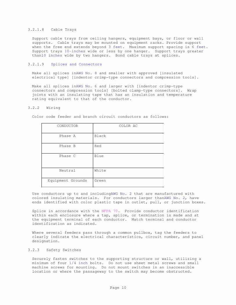
3.2.1.8 Cable Trays
Support cable trays from ceiling hangers, equipment bays, or floor or wall
supports. Cable trays may be mounted on equipment racks. Provide support
when the free end extends beyond 3 feet. Maximum support spacing is 6 feet.
Support trays 10-inches wide or less by one hanger. Support trays greater
than10 inches wide by two hangers. Bond cable trays at splices.
3.2.1.9 Splices and Connectors
Make all splices inAWG No. 8 and smaller with approved [insulated
electrical type] [indentor crimp-type connectors and compression tools].
Make all splices inAWG No. 6 and larger with [indentor crimp-type
connectors and compression tools] [bolted clamp-type connectors]. Wrap
joints with an insulating tape that has an insulation and temperature
rating equivalent to that of the conductor.
3.2.2 Wiring
Color code feeder and branch circuit conductors as follows:
CONDUCTOR COLOR AC
Phase A Black
Phase B Red
Phase C Blue
Neutral White
Equipment Grounds Green
Use conductors up to and includingAWG No. 2 that are manufactured with
colored insulating materials. For conductors larger thanAWG No. 2, have
ends identified with color plastic tape in outlet, pull, or junction boxes.
Splice in accordance with the NFPA 70. Provide conductor identification
within each enclosure where a tap, splice, or termination is made and at
the equipment terminal of each conductor. Match terminal and conductor
identification as indicated.
Where several feeders pass through a common pullbox, tag the feeders to
clearly indicate the electrical characteristics, circuit number, and panel
designation.
3.2.3 Safety Switches
Securely fasten switches to the supporting structure or wall, utilizing a
minimum of four 1/4 inch bolts. Do not use sheet metal screws and small
machine screws for mounting. Do not mount switches in an inaccessible
location or where the passageway to the switch may become obstructed.
Page 10
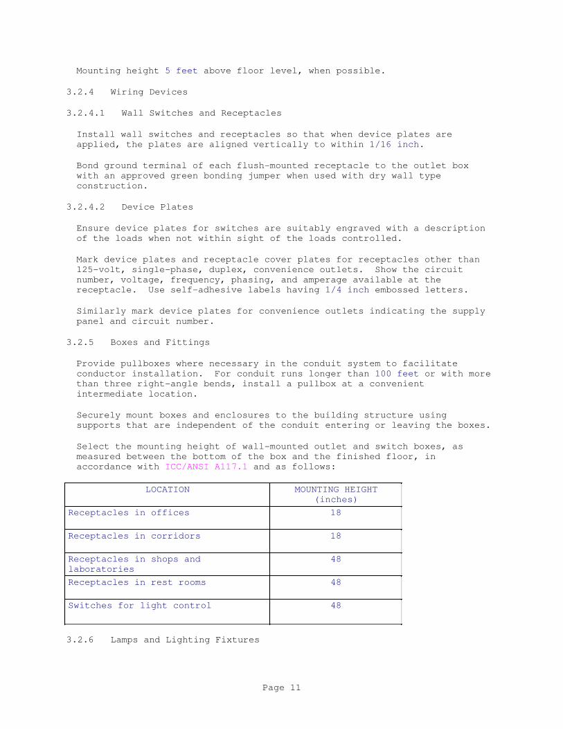
Mounting height 5 feet above floor level, when possible.
3.2.4 Wiring Devices
3.2.4.1 Wall Switches and Receptacles
Install wall switches and receptacles so that when device plates are
applied, the plates are aligned vertically to within 1/16 inch.
Bond ground terminal of each flush-mounted receptacle to the outlet box
with an approved green bonding jumper when used with dry wall type
construction.
3.2.4.2 Device Plates
Ensure device plates for switches are suitably engraved with a description
of the loads when not within sight of the loads controlled.
Mark device plates and receptacle cover plates for receptacles other than
125-volt, single-phase, duplex, convenience outlets. Show the circuit
number, voltage, frequency, phasing, and amperage available at the
receptacle. Use self-adhesive labels having 1/4 inch embossed letters.
Similarly mark device plates for convenience outlets indicating the supply
panel and circuit number.
3.2.5 Boxes and Fittings
Provide pullboxes where necessary in the conduit system to facilitate
conductor installation. For conduit runs longer than 100 feet or with more
than three right-angle bends, install a pullbox at a convenient
intermediate location.
Securely mount boxes and enclosures to the building structure using
supports that are independent of the conduit entering or leaving the boxes.
Select the mounting height of wall-mounted outlet and switch boxes, as
measured between the bottom of the box and the finished floor, in
accordance with ICC/ANSI A117.1 and as follows:
LOCATION MOUNTING HEIGHT
(inches)
Receptacles in offices 18
Receptacles in corridors 18
Receptacles in shops and
laboratories
48
Receptacles in rest rooms 48
Switches for light control 48
3.2.6 Lamps and Lighting Fixtures
Page 11

Install new lamps of the proper type and wattage in each fixture. Securely
fasten fixtures and supports to structural members and install parallel and
perpendicular to major axes of structures.
3.2.7 Panelboards
Securely mount panelboards so that the top operating handle does not exceed
72-inches above the finished floor. Do not mount equipment within36-inches
of the front of the panel. Ensure directory card information is complete
and legible.
3.2.8 Dry-Type Distribution Transformers
Connect dry-type transformers with flexible metallic conduit.
[ Mount all dry-type transformers on vibration isolators in accordance with
Section 23 05 48.00 40 VIBRATION AND SEISMIC CONTROLS FOR HVAC PIPING AND
EQUIPMENT.
]3.2.9 Field Fabricated Nameplates
Ensure nameplates conform to ASTM D709. Provide laminated plastic
nameplates for each equipment enclosure, relay, switch, and device, as
specified or as indicated on the drawings. Each nameplate inscription
identifies the function and, when applicable, the position. Provide
nameplates that are melamine plastic,0.125-inch thick, white with black41
center core and a matte finish surface [ with square corners]. Accurately
align lettering and engrave into the core. Minimum size of nameplates is1
by 2.5 inches. Lettering is a minimum of0.25-inch high normal block style.
3.2.10 Identification Plates and Warnings
Provide identification plates for lighting and power panelboards, motor
control centers, all line voltage heating and ventilating control panels,
fire detector and sprinkler alarms, door bells, pilot lights, disconnect
switches, manual starting switches, and magnetic starters. Attach
identification plates to process control devices and pilot lights.
Install identification plates for all line voltage enclosed circuit
breakers, identifying the equipment served, voltage, phase(s) and power
source. For circuits 480 volts and above, install conspicuously located
warning signs in accordance with OSHA requirements.
3.2.11 Posted Operating Instructions
Print or engrave operating instructions and frame under glass or in
approved laminated plastic. Post instructions where directed. For
operating instructions exposed to the weather, provide weather-resistant
materials or weatherproof enclosures. Ensure operating instructions do not
fade when exposed to sunlight. Secure instructions to prevent easy removal
or peeling.
Ensure each system and principal item of equipment is as specified in the
technical sections for use by operation and maintenance personnel. Include
the following information with the operating instructions:
a. Wiring diagrams, control diagrams, and control sequence for each
Page 12
principal system and item of equipment.
b. Start up, proper adjustment, operating, lubrication, and shutdown
procedures.
c. Safety precautions.
d. The procedure in the event of equipment failure.
e. Other items of instruction as recommended by the manufacturer.
3.3 FIELD QUALITY CONTROL
Perform PT&I tests and provide submittals as specified in Section
01 86 26.07 40 RELIABILITY CENTERED ACCEPTANCE FOR ELECTRICAL SYSTEMS.
After completion of the installation and splicing, and prior to energizing
the conductors, perform wire and cable continuity and insulation tests as
herein specified before the conductors are energized.
Provide all necessary test equipment, labor, and personnel to perform the
tests, as herein specified.
Isolate completely all wire and cable from all extraneous electrical
connections at cable terminations and joints. Use substation and
switchboard feeder breakers, disconnects in combination motor starters,
circuit breakers in panel boards, and other disconnecting devices to
isolate the circuits under test.
Perform insulation-resistance test on each field-installed conductor with
respect to ground and adjacent conductors. Applied potential is 500 volts
dc for 300 volt rated cable and 1000 volts dc for 600 volt rated cable.
Take readings after 1 minute and until the reading is constant for 15
seconds. Minimum insulation-resistance values is not less than 25 Megohms
for 300 volt rated cable and 100 Megohms for 600 volt rated cable. For
circuits with conductor sizesAWG No. 8 and smaller insulation resistance
testing is not required.
Perform continuity test to insure correct cable connection end-to-end (i.e
correct phase conductor, grounded conductor, and grounding conductor
wiring). Repair and verify any damages to existing or new electrical
equipment resulting from mis-wiring. Receive approval for all repairs from
the Contracting Officer prior to commencement of the repair.
Conduct phase-rotation tests on all three-phase circuits using a
phase-rotation indicating instrument. Perform phase rotation of electrical
connections to connected equipment in a clockwise direction, facing the
source.
Submit test reports in accordance with referenced standards in this section.
Page 13

Final acceptance requires the successful performance of wire and cable
under test. Do not energize any conductor until the final test reports are
reviewed and approved by the Contracting Officer.
-- End of Section --
Page 14
SECTION 26 05 19.10 10
INSULATED WIRE AND CABLE
05/16
PART 1 GENERAL
1.1 REFERENCES
The publications listed below form a part of this specification to the
extent referenced. The publications are referred to within the text by the
basic designation only.
INSTITUTE OF ELECTRICAL AND ELECTRONICS ENGINEERS (IEEE)
IEEE 1202 (2006; R 2012; CORR 1 2012)
Flame-Propagation Testing of Wire and Cable
INSULATED CABLE ENGINEERS ASSOCIATION (ICEA)
ICEA S-58-679 (2014) Control, Instrumentation and
Thermocouple Extension Conductor
Identification
ICEA T-30-520 (1986) Conducting Vertical Cable Tray
Flame Tests with Theoretical Heat Input
Rate of 70,000 B.T.U./Hour
NATIONAL ELECTRICAL MANUFACTURERS ASSOCIATION (NEMA)
ANSI/NEMA WC 71/ICEA S-96-659 (2014) Standard for Nonshielded Cables
Rated 2001-5000 Volts for use in the
Distribution of Electric Energy
NEMA WC 26 (2008) Binational Wire and Cable Packaging
Standard
NEMA WC 57 (2014) Standard for Control, Thermocouple
Extension, and Instrumentation Cables
NEMA WC 70 (2009) Power Cable Rated 2000 V or Less
for the Distribution of Electrical
Energy--S95-658
NEMA WC 74/ICEA S-93-639 (2012) 5-46 kV Shielded Power Cable for
Use in the Transmission and Distribution
of Electric Energy
NATIONAL FIRE PROTECTION ASSOCIATION (NFPA)
NFPA 70 (2017) National Electrical Code
UNDERWRITERS LABORATORIES (UL)
UL 1685 (2015) UL Standard for Safety
Page 1
Vertical-Tray Fire-Propagation and
Smoke-Release Test for Electrical and
Optical-Fiber Cables
UL 2556 (2015) UL Standard for Safety Wire and
Cable Test Methods
UL 44 (2014; Reprint Feb 2015)
Thermoset-Insulated Wires and Cables
UL 83 (2014) Thermoplastic-Insulated Wires and
Cables
1.2 SUBMITTALS
Government approval is required for submittals with a "G" designation;
submittals not having a "G" designation are for information only. When
used, a designation following the "G" designation identifies the office
that will review the submittal for the Government. Submittals with an "S"
are for inclusion in the Sustainability Notebook, in conformance to Section
01 33 29 SUSTAINABILITY REPORTING. Submit the following in accordance with
Section 01 33 00 SUBMITTAL PROCEDURES:
SD-03 Product Data
Wire and Cable; G
Conductors; G
Cable Manufacturing Data
SD-06 Test Reports
Test Report(s), Inspection Report(s), and Verification Report(s); G
1.3 DELIVERY, STORAGE, AND HANDLING
Furnish cables on reels or coils. Each cable and the outside of each reel
or coil, must be plainly marked or tagged to indicate the cable length,
voltage rating, conductor size, and manufacturer's lot number and reel
number. Each coil or reel of cable must contain only one continuous cable
without splices. Cables for exclusively dc applications, as specified in
paragraph "High-Voltage Test Source," must be identified as such. Reels
must remain the property of the Contractor.
PART 2 PRODUCTS
2.1 MATERIALS
2.1.1 Wire Table
Furnish wire and cable in accordance with the requirements of the wire
table below, conforming to the detailed requirements specified herein.
2.1.2 Rated Circuit Voltages
All power wire and cable must have minimum rated circuit voltages in
Page 2

accordance with NEMA WC 70, ANSI/NEMA WC 71/ICEA S-96-659, or
NEMA WC 74/ICEA S-93-639 as applicable. Power wire and cable for circuit
voltages rated 0-600 volts must be rated not less than 600 volts. Control
wire and cable must have minimum rated circuit voltages in accordance with
NEMA WC 57, but must be rated 600 volts if routed in raceway with other
conductors that are rated 600 volts.
2.1.3 Conductors
2.1.3.1 Material for Conductors
Conductors must conform to all the applicable requirements of NEMA WC 57,
NEMA WC 70, ANSI/NEMA WC 71/ICEA S-96-659, or NEMA WC 74/ICEA S-93-639 as
applicable. Copper conductors must be annealed copper material and they
may be bare, or tin- or lead-alloy-coated, if required by the type of
insulation used.
2.1.3.2 Size
Minimum wire size must be No. 12 AWG for power and lighting circuits; No.
10 AWG for current transformer secondary circuits; No. 14 AWG for potential
transformer, relaying, and control circuits; No. 16 AWG for annunciator
circuits; and No. 18 AWG for alarm circuits.
2.1.3.3 Stranding
Conductor stranding classes cited herein must be as defined for control
conductors in NEMA WC 57 or as defined for 0-2,000 volts power conductors
in NEMA WC 70, as applicable. Lighting conductors No. 10 AWG and smaller
must be solid or have Class B stranding. Any conductors used between
stationary and moving devices, such as hinged doors or panels, must have
Class H or K stranding. All other conductors must have Class B or C
stranding, except that conductors as shown, or in the schedule, as No. 12
AWG may be 19 strands of No. 25 AWG, and conductors shown as No. 10 AWG may
be 19 strands of No. 22 AWG. Conductor stranding classes for circuit
voltages 2,001 volts and above must be as defined in
ANSI/NEMA WC 71/ICEA S-96-659 and NEMA WC 74/ICEA S-93-639, as applicable.
2.1.3.4 Separator Tape
Where conductor shielding, strand filling, or other special conductor
treatment is not required, a separator tape between conductor and
insulation is permitted.
2.1.4 Insulation
2.1.4.1 Insulation Material
Unless specified otherwise or required by NFPA 70, wires in conduit, other
than service entrance, must be 600-volt, Type THWN/THHN conforming to UL 83
or Type XHHW or RHW conforming to UL 44. Insulation for control wire and
cable must meet the requirements of NEMA WC 57. Insulation requirements
for wire and cable rated less than 2,000 volts must meet the requirements
of NEMA WC 70. Insulation requirements for wire and cable rated
2,001-5,000 volts must meet the requirements of
ANSI/NEMA WC 71/ICEA S-96-659. Insulation requirements for wire and cable
rated 5,001 volts and greater must meet the requirements of
Page 3

NEMA WC 74/ICEA S-93-639.
2.1.4.2 Insulation Thickness
The insulation thickness for each conductor must be based on its rated
circuit voltage.
2.1.4.2.1 Power Cables, 2,000 Volts and Below
The insulation thickness for single-conductor and multiple-conductor power
cables rated 2,000 volts and below must be as required by NEMA WC 70, as
applicable. Some thicknesses of NEMA WC 70 will be permitted only for
single-conductor cross-linked thermosetting polyethylene insulated cables
without a jacket. NEMA WC 70 ethylene-propylene rubber-insulated
conductors must have a jacket.
2.1.4.2.2 Single-Conductor and Multiple-Conductor Control Cables
The insulation thickness of control conductor sizes 22 AWG to 10 AWG used
for control and related purposes must be as required by NEMA WC 57, as
applicable. Control conductors larger than 10 AWG must be as required by
NEMA WC 70.
2.1.5 Jackets
All cables must have jackets meeting the requirements of NEMA WC 57,
NEMA WC 70, ANSI/NEMA WC 71/ICEA S-96-659, and NEMA WC 74/ICEA S-93-639, as
applicable, and as specified herein. Individual conductors of
multiple-conductor cables must be required to have jackets only if they are
necessary for the conductor to meet other specifications herein. Jackets
of single-conductor cables and of individual conductors of
multiple-conductor cables, except for shielded cables, must be in direct
contact and adhere or be vulcanized to the conductor insulation.
Multiple-conductor cables and shielded single-conductor cables must be
provided with a common overall jacket, which must be tightly and
concentrically formed around the core. Repaired jacket defects found and
corrected during manufacturing are permitted if the cable, including
jacket, afterward fully meets these specifications and the requirements of
the applicable standards.
2.1.5.1 Jacket Material
The jacket must be one of the materials listed below. Polyvinyl chloride
compounds will not be permitted. Variations from the materials required
below will be permitted only if approved for each specific use, upon
submittal of sufficient data to prove that they exceed all specified
requirements for the particular application.
2.1.5.1.1 General Use
Heavy-duty black neoprene NEMA WC 70,
ANSI/NEMA WC 71/ICEA S-96-659, or
NEMA WC 74/ICEA S-93-639
Page 4

Heavy-duty chlorosulfonated
polyethylene
NEMA WC 57, NEMA WC 70,
ANSI/NEMA WC 71/ICEA S-96-659, or
NEMA WC 74/ICEA S-93-639
Heavy-duty cross-linked (thermoset)
chlorinated polyethylene
NEMA WC 70,
ANSI/NEMA WC 71/ICEA S-96-659, or
NEMA WC 74/ICEA S-93-639
2.1.5.1.2 Accessible Use Only, 2,000 Volts or Less
Cables installed where they are entirely accessible, such as cable trays
and raceways with removable covers, or where they pass through less than 10
feet of exposed conduit only, must have jackets of one of the materials in
item "a. General Use" or one of the following:
General-purpose neoprene NEMA WC 70,
ANSI/NEMA WC 71/ICEA S-96-659, or
NEMA WC 74/ICEA S-93-639
Black polyethylene (MDPE) NEMA WC 57, NEMA WC 70,
ANSI/NEMA WC 71/ICEA S-96-659, or
NEMA WC 74/ICEA S-93-639
Thermoplastic chlorinated
polyethylene
NEMA WC 70,
ANSI/NEMA WC 71/ICEA S-96-659, or
NEMA WC 74/ICEA S-93-639
2.1.5.2 Jacket Thickness
The minimum thickness of the jackets must be not less than 80 percent of
the respective nominal thicknesses specified below.
2.1.5.2.1 Multiple-Conductor Cables
Thickness of the jackets of the individual conductors of multiple-conductor
cables must be as required by NEMA WC 57, NEMA WC 70,
ANSI/NEMA WC 71/ICEA S-96-659, or NEMA WC 74/ICEA S-93-639 as applicable
and must be in addition to the conductor insulation thickness required by
the applicable respective NEMA publication for the insulation used.
Thickness of the outer jackets and associated coverings of the assembled
multiple-conductor cables must be as required by NEMA WC 57, NEMA WC 70,
ANSI/NEMA WC 71/ICEA S-96-659, or NEMA WC 74/ICEA S-93-639 as applicable.
2.1.5.2.2 Single-Conductor Cables
Single-conductor cables must have a jacket thickness as specified in
NEMA WC 57, NEMA WC 70, ANSI/NEMA WC 71/ICEA S-96-659, or
NEMA WC 74/ICEA S-93-639 as applicable.
Page 5
2.1.6 Metal-Clad Cable
2.1.6.1 General
The metallic covering or sheath must be [interlocked metal tape]
[continuous corrugated metal], conforming to the applicable requirements of
NEMA WC 57, NEMA WC 70, ANSI/NEMA WC 71/ICEA S-96-659, or
NEMA WC 74/ICEA S-93-639. The type of metal for the metallic covering must
be [galvanized steel] [aluminum] [copper] [copper alloy]. If the covering
is of ferrous metal, it must be galvanized. Grounding conductor(s)
conforming to NEMA WC 57, NEMA WC 70, ANSI/NEMA WC 71/ICEA S-96-659, or
NEMA WC 74/ICEA S-93-639 as applicable must be furnished for each
multiple-conductor metal-clad cable. Assembly and cabling must be as
specified in paragraph "Cabling." The metallic covering must be applied
over an inner jacket or filler tape. The cable must be assembled so that
the metallic covering will be tightly bound over a firm core.
2.1.6.2 Jackets
Metal-clad cables may have a jacket under the armor, and must have a jacket
over the armor. Jackets must comply with the requirements of NEMA WC 57,
NEMA WC 70, ANSI/NEMA WC 71/ICEA S-96-659, or NEMA WC 74/ICEA S-93-639 as
applicable. The outer jacket for the metal-clad cable may be of polyvinyl
chloride (PVC) only if specifically approved.
2.1.7 Multiple-Conductor Cables
Grounding conductor(s) conforming to NEMA WC 57, NEMA WC 70,
ANSI/NEMA WC 71/ICEA S-96-659, or NEMA WC 74/ICEA S-93-639 as applicable
must be furnished for each multiple-conductor cable. Assembly and cabling
must be as specified in paragraph CABLING.
2.2 CABLE IDENTIFICATION
2.2.1 Color-Coding
Insulation of individual conductors of multiple-conductor cables must be
color-coded in accordance with ICEA S-58-679, except that colored braids
will not be permitted. Only one color-code method must be used for each
cable construction type. Control cable color-coding must be in accordance
with ICEA S-58-679. Power cable color-coding must be black for Phase A, red
for Phase B, blue for Phase C, white for grounded neutral, and green for an
insulated grounding conductor, if included. [Other individual conductors
must be color-coded as indicated, but such color-coding may be accomplished
by applying colored plastic tapes or colored sleeves at terminations.]
2.2.2 Cabling
Individual conductors of multiple-conductor cables must be assembled with
flame-and moisture-resistant fillers, binders, and a lay conforming to
NEMA WC 57, NEMA WC 70, ANSI/NEMA WC 71/ICEA S-96-659, or
NEMA WC 74/ICEA S-93-639. Flat twin cables are prohibited. Fillers must
be used in the interstices of multiple-conductor round cables with a common
covering where necessary to give the completed cable a substantially
circular cross section. Fillers must be non-hygroscopic material,
compatible with the cable insulation, jacket, and other components of the
cable. The rubber-filled or other approved type of binding tape must
Page 6

consist of a material that is compatible with the other components of the
cable and must be lapped at least 10 percent of its width.
2.2.3 Dimensional Tolerance
The outside diameters of single-conductor cables and of multiple-conductor
cables must not vary more than 5 percent and 10 percent, respectively, from
the manufacturer's published catalog data.
PART 3 EXECUTION
3.1 INSTALLATION INSTRUCTIONS
Submit cable manufacturing data [as requested]. The following information
must be provided by the cable manufacturer for each size, conductor
quantity, and type of cable furnished:
a. Minimum bending radius, in inches - For multiple-conductor cables, this
information must be provided for both the individual conductors and the
multiple-conductor cable.
b. Pulling tension and sidewall pressure limits, inpounds.
c. Instructions for stripping semiconducting insulation shields, if
furnished, with minimum effort without damaging the insulation.
d. Upon request, compatibility of cable materials and construction with
specific materials and hardware manufactured by others must be stated.
Also, if requested, recommendations must be provided for various cable
operations, including installing, splicing, terminating, etc.
3.2 TEST REPORT(S), INSPECTION REPORT(S), AND VERIFICATION REPORT(S)
3.2.1 Cable Data
Do not begin any wire and cable fabrication until materials are submitted
and approved by the Contracting Officer. Submit cable data for approval
including, but not limited to, dimensioned sketches showing cable
construction and sufficient additional data to show that wire and cable
meet the requirements of this Section.
3.2.2 Inspection and Tests
Inspection and tests of wire and cable furnished under these specifications
must be made by and at the plant of the manufacturer, and must be witnessed
by the Contracting Officer, unless waived in writing. and the manufacturer
must provide certification and certification reports of completed
inspections and completed tests. The Government may require or perform
further tests before or after installation. Testing in general must comply
with NEMA WC 57, NEMA WC 70, ANSI/NEMA WC 71/ICEA S-96-659, or
NEMA WC 74/ICEA S-93-639 as applicable. Specific tests required for
particular materials, components, and completed cables must be as specified
in the sections of the above standards applicable to those materials,
components, and cable types. Tests must also be performed in accordance
with the additional requirements specified below. Submit 6 certified
copies of test reports.
Page 7
3.2.2.1 High-Voltage Test Source
Where the applicable standards allow a choice, high-voltage tests for
cables to be used exclusively on dc circuits must be made with dc test
voltages. Cables to be used exclusively on ac circuits must be tested with
ac test voltages. If both ac and dc will be present, on either the same or
separate conductors of the cable, ac test voltages must be used.
3.2.2.2 Flame Tests
All multiple-conductor and single-conductor cable assemblies must pass
either the vertical cable tray flame tests required by ICEA T-30-520
(stated in, but not required by NEMA WC 70), the vertical tray flame
propagation test requirements of UL 1685 and IEEE 1202, the wire and cable
burning characteristics test of the UL 2556 VW-1 Test, or (for control
cables only) the flame test as required by NEMA WC 57. If such tests,
however, have previously been made on identical cables, these tests need
not be repeated. Instead, certified reports of the original qualifying
tests must be submitted. In this case the reports furnished under
paragraph "Reports," must include information, identify critical
information, and verify that all of each cable's materials, construction,
and dimensions are the same as those in the qualifying tests.
3.2.2.3 Independent Tests
The Government may make visual inspections, continuity or resistance
checks, insulation resistance readings, power factor tests, or dc high
potential tests at field test values. A cable's failure to pass these
tests and inspections, or failure to produce readings consistent with
acceptable values for the application, will be grounds for rejection of the
cable.
3.2.2.4 Reports
Furnish results of tests. No wire or cable must be shipped until
authorized. Lot number and reel or coil number of wire and cable tested
must be indicated on the test reports.
Page 8
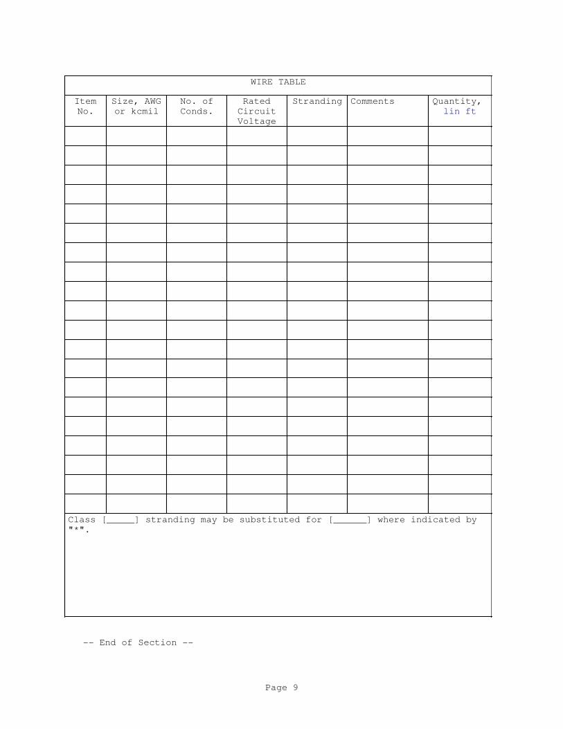
WIRE TABLE
Item
No.
Size, AWG
or kcmil
No. of
Conds.
Rated
Circuit
Voltage
Stranding Comments Quantity,
lin ft
Class [_____] stranding may be substituted for [______] where indicated by
"*".
-- End of Section --
Page 9
SECTION 26 24 16.00 40
PANELBOARDS
08/16
PART 1 GENERAL
Section 26 00 00.00 20 BASIC ELECTRICAL MATERIALS AND METHODS applies to
work specified in this section.
1.1 REFERENCES
The publications listed below form a part of this specification to the
extent referenced. The publications are referred to within the text by the
basic designation only.
ELECTRONIC COMPONENTS INDUSTRY ASSOCIATION (ECIA)
ECIA 416 (1974; R 1981) Filters for Radio
Interference
ECIA/IS 46 (1987) Test Procedure for Resistance to
Soldering (Vapor Phase Technique) for
Surface Mount Devices
NATIONAL AERONAUTICS AND SPACE ADMINISTRATION (NASA)
RCBEA GUIDE (2004) NASA Reliability Centered Building
and Equipment Acceptance Guide
NATIONAL ELECTRICAL MANUFACTURERS ASSOCIATION (NEMA)
NEMA 250 (2014) Enclosures for Electrical Equipment
(1000 Volts Maximum)
NEMA PB 1 (2011) Panelboards
NATIONAL FIRE PROTECTION ASSOCIATION (NFPA)
NFPA 70 (2017) National Electrical Code
U.S. DEPARTMENT OF DEFENSE (DOD)
MIL-HDBK 232 (1987; Rev A; Notice 1 1988; Notice 2
2000; Notice 3 2014) Red/Black Engineering
- Installation Guidelines
U.S. GENERAL SERVICES ADMINISTRATION (GSA)
FED-STD-595 (Rev C; Notice 1) Colors Used in
Government Procurement
UNDERWRITERS LABORATORIES (UL)
UL 489 (2013; Reprint Mar 2014) Molded-Case
Circuit Breakers, Molded-Case Switches,
Page 1

and Circuit-Breaker Enclosures
UL 67 (2009; Reprint Jun 2016) UL Standard for
Safety Panelboards
1.2 SUBMITTALS
Government approval is required for submittals with a "G" designation;
submittals not having a "G" designation are for information only. When
used, a designation following the "G" designation identifies the office
that will review the submittal for the Government. Submittals with an "S"
are for inclusion in the Sustainability Notebook, in conformance to Section
01 33 29 SUSTAINABILITY REPORTING. Submit the following in accordance with
Section 01 33 00 SUBMITTAL PROCEDURES:
SD-02 Shop Drawings
Detail Drawings; G
SD-03 Product Data
Panelboards; G
Directory Card and Holder; G
Filtered Panelboards; G
SD-06 Test Reports
Continuity Tests; G
Insulation Tests; G
SD-07 Certificates
Certification; G
SD-08 Manufacturer's Instructions
Manufacturer's Instructions
1.3 QUALITY CONTROL
1.3.1 Certification
Ensure the manufacturer of the assembly is the manufacturer of the major
components within the assembly and has produced similar electrical
equipment for a minimum period of five years.
Provide certification signed by responsible officials of a manufacturer of
a product, system, or material attesting that the product, system or
material meet specified requirements.[ Ensure statements are dated after
the award of this contract, with the project name, and a list of the
specific requirements which it is intended to address.]
1.3.2 Predictive Testing and Inspection Technology Requirements
Page 2
This section contains systems and equipment components regulated by NASA's
Reliability Centered Building and Equipment Acceptance Program. This
program requires the use of Predictive Testing and Inspection (PT&I)
technologies in conformance with RCBEA GUIDE to ensure building equipment
and systems installed by the Contractor have been installed properly and
contain no identifiable defects that shorten the design life of a system
and its components. Satisfactory completion of all acceptance requirements
is required to obtain Government approval and acceptance of the
Contractor's work.
Perform PT&I tests and provide submittals as specified in Section
01 86 26.07 40 RELIABILITY CENTERED ACCEPTANCE FOR ELECTRICAL SYSTEMS.
PART 2 PRODUCTS
2.1 COMPONENTS
2.1.1 Panelboards
Submit detail drawings for the panelboards consisting of fabrication and
assembly drawings for all parts of the work in sufficient detail to enable
the Government to check conformity with the requirements of the contract
documents. Ensure drawings for panelboards indicate details of bus layout,
overall physical features, dimensions, ratings, service requirements, and
weights of equipment.
Totally enclose power-distribution panelboards and lighting and appliance
branch-circuit panelboards in a steel cabinet, dead-front circuit breaker
type with copper buses, surface- or flush-mounted as indicated. Ensure
panelboards conform to NEMA PB 1 and UL 489. Provide branch circuit panels
with buses fabricated for bolt-on type circuit breakers.
Provide an outer door or cover, hinged on one side, on surface-mounted
panelboards to provide gutter space access. Provide a center door for
circuit breaker switch access only.
Voltage and current rating, number of phases, and number of wires is as
indicated on drawings. Provide four-wire distribution panelboards and
lighting and appliance branch-circuit panelboards with an isolated
full-capacity neutral bus. Ensure panelboards are rated for 120/208-volt,
three-phas,e 277/480-volt, three-phase, 60-hertz current.
Provide three-phase, 4-wire and single-phase, 3-wire distribution lighting
and branch circuit panelboards with an isolated full-capacity bus providing
spaces for single-pole circuit breaker switches and spaces indicated as
spare.
Provide panelboards with a separate grounding bus bonded to the enclosure.
Ensure grounding bus is a solid bus bar of rectangular cross section
equipped with binding screws for the connection of equipment grounding
conductors.
Ensure each panelboard, as a complete unit, has a short-circuit current
rating equal to or greater than the integrated equipment rating shown on
the panelboard schedule.
Ensure panelboards and main lugs or main breaker have current ratings as
Page 3
shown on the panelboard schedule.
Provide bus bar connections to the branch circuit breakers that are the
"distributed phase" or "phase sequence" type. Single-phase, three-wire
panelboard busing is such that when any two adjacent single-pole breakers
are connected to opposite phases, two-pole breakers can be installed in any
location. Three-phase, four-wire busing is such that when any three
adjacent single-pole breakers are individually connected to each of the
three different phases, two- or three-pole breakers can be installed at any
location. Ensure current-carrying parts of the bus assembly are plated.
Mains ratings are as shown on drawings.
For mechanical lugs furnished with panelboards, use cast copper or copper
alloys of sizes suitable for the conductors indicated.
Use boxes with the manufacturer's standard knockouts and are fabricated of
galvanized code-gage sheet steel. Fronts are of code-gage sheet steel
furnished with hinged doors with adjustable trim clamps for securing the
fronts to the boxes.
Ensure panelboard enclosures are NEMA 250, Type 1. Provide enclosures with
hinged fronts and corrosion-resistant steel pin-tumbler cylinder locks.
Ensure locks are identically keyed and properly tagged. Provide two keys
for each enclosure to the Contracting Officer.
Finish panelboards with baked enamel. Finish color is No. 61 gray
conforming to FED-STD-595.
2.1.2 Circuit Breakers
Provide molded-case breakers as specified in Section 26 05 71.00 40 LOW
VOLTAGE OVERCORRECT PROTECTIVE DEVICES. Provide breakers with the
indicated frame and trip ratings.
Interrupting rating of circuit breakers are as indicated on drawings. If
ratings are not shown, the interrupting rating for circuit breakers in
120/208-volt panelboards is not less than 10,000 amperes rms symmetrical,
and that for breakers in 277/480]-volt panelboards is not less than 25,000
amperes rms symmetrical.
Use bolt-on type breakers. Do not use plug-in type breakers.
Provide shunt trips where indicated.
In branch circuit panelboards, ensure branch circuit breakers feeding
convenience outlets have sensitive instantaneous trip settings of not more
than 10 times the trip rating of the breaker to prevent repeated arcing
shorts resulting from frayed appliance cords. Provide UL listed
single-pole 15- and 20-ampere circuit breakers as "Switching Breakers" at
120 volts ac and 277 volts ac. Provide UL Class A (5-milliampere
sensitivity) ground fault circuit protection on 120-volt ac branch circuit
as indicated. Tripping of a branch circuit breaker containing ground fault
circuit interruption is not to disturb the feeder circuit to the panelboard.
Ensure connections to the bus are bolt-on type.
Page 4
When multiple wires per phase are specified, furnish the circuit breakers
with connectors made to accommodate multiple wires.
Ensure circuit breaker spaces called out on the drawings are complete with
mounting hardware to permit ready installation of the circuit breakers.
2.1.3 Directory Card and Holder
Provide a directory card on the inside of hinged fronts and doors [under
glass][ 0.030-inch thick minimum plastic] in a metal frame, with spaces for
circuit numbers, outlets controlled, and room numbers. Where hinged fronts
or doors are not required, provide the directory card 0.030-inch thick
minimum plastic in a metal frame mounted on the left-hand side of the front
trim. Ensure the directory card identifies each branch circuit with its
respective and numbered circuit breaker.
[2.1.4 Filtered Panelboards
2.1.4.1 General
Design panelboards for the distribution, control, and protection of
electrical circuits, providing filtering and shielding performance and,
when specified, conforming to MIL-HDBK 232.
Provide panelboard cabinet with12_]-gage steel minimum,
corrosion-resistant finish and four external mounting brackets welded to
the case. Provide code-gage steel front door and trim, with gray finish,
equipped with directory, holder, adjustable trim clamps, hinges,
self-latching catch, tumbler lock and key and bears the UL label. Provide
a red diagonal strip across the outside surface of door and trim.
2.1.4.2 RF Shielding
Ensure circuit breaker and filter compartments are completely
radio-frequency (RF) shielded and in compliance with specified shielding
requirements with front door open. Ensure case seams are continuous inert
gas welded. Fit removable circuit breaker actuator faceplate and the
filter compartment cover with corrosion-resistant RF gasketing material.
Install in place with suitable fasteners having a maximum spacing of3
inches on center. Mount RF filter units to the internal shield wall with
similar RF gasketing to ensure RF shielding integrity.
2.1.4.3 Circuit Breaker Actuators
Design circuit breaker operating mechanisms to maintain RF shielding
effectiveness without limit to time or number of operations.
2.1.4.4 Terminals
Ensure filter terminals are high-temperature alumina ceramic, continuously
brazed to filter case. Do not use soft solder. Provide ceramic terminals
that incorporate a permanently attached flexible lead, with a suitable
electric lug. Make incoming service connections to the filter lead at a
UL-approved, flame-retardant standoff insulator, mounted in the filter
compartment.
2.1.4.5 Attenuation
Page 5
Ensure each filter provides a minimum insertion loss of 100dB over the
frequency range of 14 kilohertz (kHz) to 10 gigahertz (GHz). Ensure each
filter provides a full rated load insertion loss of 100dB in the frequency
range 14 kHz to 20 megahertz (MHz).
2.1.4.6 Current
Ensure each filter unit is capable of carrying its full rated current
continuously without heat rise exceeding122 degrees F above ambient
temperature. Ensure each filter is capable of withstanding a 100-percent
overload for 30 seconds without damage.
2.1.4.7 Voltage
Ensure each filter unit is capable of continuous operation at its full
rated voltage and withstanding an initial voltage test of twice its rated
voltage without damage.
2.1.4.8 Circuit Breakers
Ensure circuit breakers are rated a minimum 10,000 amperes asymmetrical ac
interrupting capacity, 5,000 amperes dc, and are in accordance with UL 489.
2.1.4.9 RF Filters
Design RF filter units to suppress and reduce the amplitude of undesired RF
energy conducted by power service lines.[ Design RF filter units in
compliance with the applicable requirements of ECIA 416.]
Provide filter cases made of steel,16 1-gage minimum, corrosion-resistant
finish with a blue lacquer over zinc chromate primer. Use conductive
grounding surfaces that are either plated or made of corrosion-resistant
steel. Use continuous inert gas welds for hermetic seams; do not use soft
solder. Firmly mount internal components to withstand applicable shock and
vibration test requirements without damage.
Ensure internal components are fully impregnated and immersed in the fluid
to obtain the full benefit of cooling by convection flow through the liquid
medium to filter case. Completely fill filter case with the fluid. Ensure
fluid conforms to UL nonflammable classification.
2.1.4.10 Filter Discharge Unit
Provide a filter discharge unit for three-filtered circuits on the
panelboard. Install in accordance with NFPA 70.[ Ensure unit meets
applicable requirements of ECIA/IS 46]
]2.1.5 Precautionary Label
To ensure persons are aware of immediate or potential hazard in the
application, installation, use, or maintenance of panelboards,
conspicuously mark each panelboard on the trim or dead front shield with
the text (or equivalent) DANGER symbol. If the panel is supplied with a door, ensure the label is visible when the door is in the open position.
2.2 TESTS, INSPECTIONS, AND VERIFICATIONS
Page 6
Provide panelboards in compliance with UL 67.
PART 3 EXECUTION
3.1 INSTALLATION
Install panelboards in accordance with the manufacturer's instructions.
Fully align and mount panels so that the height of the top operating handle
does not exceed72 inches above the finished floor.
Ensure directory-card information is typewritten in capital letters to
indicate outlets controlled and final room numbers served by each circuit
and is mounted in holders behind protective covering.
3.2 FIELD QUALITY CONTROL
Perform PT&I tests and provide submittals as specified in Section
01 86 26.07 40 RELIABILITY CENTERED ACCEPTANCE FOR ELECTRICAL SYSTEMS.
Do not energize panelboards until the recorded test data has been submitted
to and approved by the Contracting Officer.
Demonstrate each panelboard enclosure key operates the enclosure locks in
the presence of the Contracting Officer.
Provide test equipment, labor, and personnel as required to perform the
tests as specified. Conduct continuity tests using a dc device with
buzzer.
Conduct continuity and insulation tests on the panelboards after the
installation has been completed and before the panelboard is energized.
Conduct insulation tests on 480-volt panelboards using a 1,000-volt
insulation-resistance test set. Record readings every minute until three
equal and consecutive readings have been obtained. Ensure resistance
between phase conductors and between phase conductors and ground is not
less than 50 megohms.
Conduct insulation tests on panelboards rated 300 volts or less using a
500-volt minimum insulation-resistance test set. Record readings after 1
minute and until the reading is constant for 15 seconds. Ensure resistance
between phase conductors and between phase conductors and ground is not
less than 25 megohms.
Record and submit test data. Include the location and identification of
panelboards and megohm readings versus time.
3.3 CLOSEOUT ACTIVITIES
Page 7

Submit manufacturer's instructions for panelboards including special
provisions required to install equipment components and system packages.
Provide special notices details impedances, hazards and safety precautions.
-- End of Section --
Page 8
SECTION 26 51 00
INTERIOR LIGHTING
05/16
PART 1 GENERAL
1.1 REFERENCES
The publications listed below form a part of this specification to the
extent referenced. The publications are referred to in the text by the
basic designation only.
AMERICAN SOCIETY OF HEATING, REFRIGERATING AND AIR-CONDITIONING
ENGINEERS (ASHRAE)
ASHRAE 189.1 (2011) Standard for the Design of
High-Performance Green Buildings Except
Low-Rise Residential Buildings
ASHRAE 90.1 - IP (2010) Energy Standard for Buildings
Except Low-Rise Residential Buildings
ASTM INTERNATIONAL (ASTM)
ASTM A1008/A1008M (2015) Standard Specification for Steel,
Sheet, Cold-Rolled, Carbon, Structural,
High-Strength Low-Alloy and High-Strength
Low-Alloy with Improved Formability,
Solution Hardened, and Bake Hardened
ASTM A580/A580M (2015) Standard Specification for
Stainless Steel Wire
ASTM A641/A641M (2009a; R 2014) Standard Specification for
Zinc-Coated (Galvanized) Carbon Steel Wire
ASTM A653/A653M (2015; E 2016) Standard Specification for
Steel Sheet, Zinc-Coated (Galvanized) or
Zinc-Iron Alloy-Coated (Galvannealed) by
the Hot-Dip Process
ASTM B164 (2003; R 2014) Standard Specification for
Nickel-Copper Alloy Rod, Bar, and Wire
ASTM B633 (2015) Standard Specification for
Electrodeposited Coatings of Zinc on Iron
and Steel
ASTM D4674 REV A (2002; R 2010) Standard Practice for
Accelerated Testing for Color Stability of
Plastics Exposed to Indoor Office
Environments
CALIFORNIA ENERGY COMMISSION (CEC)
Page 1
CEC Title 24 (2008; Effective Jan 2013 California's
Energy Efficiency Standards for
Residential and Nonresidential Buildings
ILLUMINATING ENGINEERING SOCIETY (IES)
IES HB-10 (2011; Errata 2015) IES Lighting Handbook
IES LM-79 (2008) Electrical and Photometric
Measurements of Solid-State Lighting
Products
IES LM-80 (2015) Measuring Lumen Maintenance of LED
Light Sources
IES RP-16 (2010; Addendum A 2008; Addenda B 2009;
Addendum C 2016) Nomenclature and
Definitions for Illuminating Engineering
IES TM-21 (2011; Addendum B 2015) Projecting Long
Term Lumen Maintenance of LED Light Sources
INSTITUTE OF ELECTRICAL AND ELECTRONICS ENGINEERS (IEEE)
IEEE 100 (2000; Archived) The Authoritative
Dictionary of IEEE Standards Terms
IEEE C2 (2012; Errata 1 2012; INT 1-4 2012; Errata
2 2013; INT 5-7 2013; INT 8-10 2014; INT
11 2015; INT 12 2016) National Electrical
Safety Code
IEEE C62.41 (1991; R 1995) Recommended Practice on
Surge Voltages in Low-Voltage AC Power
Circuits
IEEE C62.41.1 (2002; R 2008) Guide on the Surges
Environment in Low-Voltage (1000 V and
Less) AC Power Circuits
IEEE C62.41.2 (2002) Recommended Practice on
Characterization of Surges in Low-Voltage
(1000 V and Less) AC Power Circuits
NATIONAL ELECTRICAL MANUFACTURERS ASSOCIATION (NEMA)
NEMA 250 (2014) Enclosures for Electrical Equipment
(1000 Volts Maximum)
NEMA ANSLG C78.377 (2015) American National Standard for
Electric Lamps— Specifications for the
Chromaticity of Solid State Lighting
Products
NEMA C82.77 (2002) Harmonic Emission Limits - Related
Page 2
Power Quality Requirements for Lighting
Equipment
NEMA ICS 2 (2000; R 2005; Errata 2008) Standard for
Controllers, Contactors, and Overload
Relays Rated 600 V
NEMA ICS 6 (1993; R 2011) Enclosures
NEMA SSL 1 (2010) Electronic Drivers for Led Devices,
Arrays, or Systems
NEMA SSL 3 (2011) High-Power White LED Binning for
General Illumination
NEMA SSL 7A (2015) Phase-Cut Dimming for Solid State
Lighting: Basic Compatibility
NEMA WD 1 (1999; R 2015) Standard for General Color
Requirements for Wiring Devices
NATIONAL FIRE PROTECTION ASSOCIATION (NFPA)
NFPA 101 (2015; ERTA 2015) Life Safety Code
NFPA 70 (2014; AMD 1 2013; Errata 1 2013; AMD 2
2013; Errata 2 2013; AMD 3 2014; Errata
3-4 2014; AMD 4-6 2014) National
Electrical Code
U.S. DEPARTMENT OF DEFENSE (DOD)
DOD 8500.01 (2014) Cybersecurity
DOD 8510.01 (2014) Risk Management Framework (RMF) for
DoD Information Technology (IT)
UNDERWRITERS LABORATORIES (UL)
UL 1472 (2015) UL Standard for Safety Solid-State
Dimming Controls
UL 1598 (2008; Reprint Oct 2012) Luminaires
UL 20 (2010; Reprint Feb 2012) General-Use Snap
Switches
UL 2043 (2013) Fire Test for Heat and Visible
Smoke Release for Discrete Products and
Their Accessories Installed in
Air-Handling Spaces
UL 508 (1999; Reprint Oct 2013) Industrial
Control Equipment
UL 844 (2012) Standard for Luminaires for Use in
Page 3
Hazardous (Classified) Locations
UL 8750 (2009; Reprint May 2014) UL Standard for
Safety Light Emitting Diode (LED)
Equipment for Use in Lighting Products
UL 916 (2007; Reprint Aug 2014) Standard for
Energy Management Equipment
UL 917 (2006; Reprint Aug 2013) UL Standard for
Safety Clock-Operated Switches
UL 924 (2006; Reprint Dec 2015) Standard for
Emergency Lighting and Power Equipment
UL 94 (2013; Reprint Jan 2016) Standard for
Tests for Flammability of Plastic
Materials for Parts in Devices and
Appliances
1.2 RELATED REQUIREMENTS
Materials not considered to be luminaires or luminaire accessories are
specified in Section 26 20 00 INTERIOR DISTRIBUTION SYSTEM.
1.3 DEFINITIONS
a. Unless otherwise specified or indicated, electrical and electronics
terms used in these specifications, and on the drawings, must be as
defined in IEEE 100 and IES RP-16.
b. For LED luminaire light sources, "Useful Life" is the operating hours
before reaching 70 percent of the initial rated lumen output (L70) with
no catastrophic failures under normal operating conditions. This is
also know as 70 percent "Rated Lumen Maintenance Life" as defined in
IES LM-80.
cc. For LED luminaires, "Luminaire Efficacy" (LE) is the appropriate measure
of energy efficiency, measured in lumens/watt. This is gathered from
LM-79 data for the luminaire, in which absolute photometry is used to
measure the lumen output of the luminaire as one entity, not the source
separately and then the source and housing together.
d. Total harmonic distortion (THD) is the root mean square (RMS) of all
the harmonic components divided by the total fundamental current.
1.4 SUBMITTALS
Government approval is required for submittals with a "G" designation;
submittals not having a "G" designation are for information only. When
used, a designation following the "G" designation identifies the office
that will review the submittal for the Government.] Submittals with an "S"
are for inclusion in the Sustainability Notebook, in conformance with
Section 01 33 29 SUSTAINABILITY REPORTING. Data, drawings, and reports
must employ the terminology, classifications and methods prescribed by the
IES HB-10 as applicable, for the lighting system specified. Submit the
following in accordance with Section 01 33 00 SUBMITTAL PROCEDURES:
Page 4

SD-02 Shop Drawings
Luminaire Drawings;
Occupancy/Vacancy Sensor Coverage Layout;
SD-03 Product Data
Luminaires; G
Light Sources; G
Drivers, Ballasts and Generators; G
LED Luminaire Warranty; G
Luminaire Design Data; G
Vacancy Sensors; G
Dimming Controllers (Dimmers); G]
Lighting Contactor; G
Timeswitch; G
Power Hook Luminaire Hangers; G
Exit Signs; G
Emergency Lighting Unit (EBU); G
LED Emergency Drivers; G
Occupancy Sensors; G
Ambient Light Level Sensor ; G
Lighting Control Panel; G
SD-06 Test Reports
LED Luminaire - IES LM-79 Test Report; G
LED Light Source - IES LM-80 Test Report; G
LED Light Source - IES TM-21 Test Report; G
Occupancy/Vacancy Sensor Verification Tests; G
Energy Efficiency; G
SD-07 Certificates
Luminaire Useful Life Certificate; G
Page 5

LED Driver and Dimming Switch Compatibility Certificate; G
1.5 QUALITY CONTROL
1.5.1 Luminaire Drawings
Include dimensions, accessories, and installation and construction
details. Photometric data, including zonal lumen data, average and minimum
ratio, aiming diagram, and computerized candlepower distribution data must
accompany shop drawings.
1.5.2 Occupancy/Vacancy Sensor Coverage Layout
Provide floor plans showing coverage layouts of all devices using
manufacturer's product information.
1.5.3 LED Driver and Dimming Switch Compatibility Certificate
Submit certification from the luminaire, driver, or dimmer switch
manufacturer that ensures compatibility and operability between devices.
1.5.4 Luminaire Design Data
a. Provide safety certification and file number for the luminaire family
that must be listed, labeled, or identified per the NFPA 70 (NEC).
Applicable testing bodies are determined by the US Occupational Safety
Health Administration (OSHA) as Nationally Recognized Testing
Laboratories (NRTL) and include: CSA (Canadian Standards Association),
ETL (Edison Testing Laboratory), and UL (Underwriters Laboratories).
b. Provide long term lumen maintenance projections for each LED luminaire
in accordance with IES TM-21. Data used for projections must be
obtained from testing in accordance with IES LM-80.
1.5.5 LED Luminaire - IES LM-79 Test Report
Submit test report on manufacturer's standard production model luminaire.
Include all applicable and required data as outlined under "14.0 Test
Report" in IES LM-79.
1.5.6 LED Light Source - IES LM-80 Test Report
Submit report on manufacturer's standard production LED light source
(package, array, or module). Include all applicable and required data as
outlined under "8.0 Test Report" in IES LM-80.
1.5.7 LED Light Source - IES TM-21 Test Report
Submit test report on manufacturer's standard production LED light source
(package, array or module). Include all applicable and required data, as
well as required interpolation information as outlined under "7.0 Report"
in IES TM-21.
1.5.8 Occupancy/Vacancy Sensor Verification Tests
Submit test report outlining post-installation coverage and operation of
sensors.
Page 6
1.5.9 Test Laboratories
Test laboratories for the IES LM-79 and IES LM-80 test reports must be one
of the following:
a. National Voluntary Laboratory Accreditation Program (NVLAP) accredited
for solid-state lighting testing as part of the Energy-Efficient
Lighting Products laboratory accreditation program for both LM-79 and
LM-80 testing.
b. One of the qualified labs listed on the Department of Energy - LED
Lighting Facts Approved Testing Laboratories List at for LM-79 testing.
c. One of the EPA-Recognized Laboratories listed at for LM-80 testing.
1.5.10 Regulatory Requirements
In each of the publications referred to herein, consider the advisory
provisions to be mandatory, as though the word "must" had been substituted
for "should" wherever it appears. Interpret references in these
publications to the "authority having jurisdiction," or words of similar
meaning, to mean the Contracting Officer. Equipment, materials,
installation, and workmanship must be in accordance with the mandatory and
advisory provisions of NFPA 70, unless more stringent requirements are
specified or indicated.
1.5.11 Standard Products
Provide materials and equipment that are products of manufacturers
regularly engaged in the production of such products which are of equal
material, design and workmanship. Products must have been in satisfactory
commercial or industrial use for two years prior to bid opening. The
two-year period must include applications of equipment and materials under
similar circumstances and of similar size. The product must have been on
sale on the commercial market through advertisements, manufacturers'
catalogs, or brochures during the two-year period. Where two or more items
of the same class of equipment are required, these items must be products
of a single manufacturer; however, the component parts of the item need not
be the products of the same manufacturer unless stated in this section.
1.5.11.1 Alternative Qualifications
Products having less than a 2-year field service record will be acceptable
if a certified record of satisfactory field operation for not less than
6000 hours, exclusive of the manufacturers' factory or laboratory tests, is
furnished.
1.5.11.2 Material and Equipment Manufacturing Date
Products manufactured more than six months prior to date of delivery to
site must not be used, unless specified otherwise.
1.5.11.3 Energy Efficiency
Submit data indicating lumens per watt efficacy and color rendering index
of light source.
Page 7

1.6 WARRANTY
Support all equipment items by service organizations which are reasonably
convenient to the equipment installation in order to render satisfactory
service to the equipment on a regular and emergency basis during the
warranty period of the contract.
1.6.1 LED Luminaire Warranty
a. Provide a written 10 year on-site replacement warranty for material,
fixture finish, and workmanship. On-site replacement includes
transportation, removal, and installation of new products.
(1) Include finish warranty to include failure and substantial
deterioration such as blistering, cracking, peeling, chalking, or
fading.
(2) Material warranty must include:
(a) All drivers.
(b) Replacement when more than 10 percent of LED sources in any
lightbar or subassembly(s) are defective or non-starting.
b. Warranty period must begin on date of beneficial occupancy. Provide
the Contracting Officer with signed warranty certificates prior to
final payment.
1.6.1.1 Provide Luminaire Useful Life Certificate
Submit certification from the manufacturer indicating the expected useful
life of the luminaires provided. The useful life must be directly
correlated from the IES LM-80 test data using procedures outlined in
IES TM-21. Thermal properties of the specific luminaire and local ambient
operating temperature and conditions must be taken into consideration.
PART 2 PRODUCTS
2.1 PRODUCT COORDINATION
Products and materials not considered to be luminaires, luminaire controls,
or associated equipment are specified in Section 26 20 00 INTERIOR
DISTRIBUTION SYSTEM. Luminaires, luminaire controls, and associated
equipment for exterior applications are specified in Section 26 56 00
EXTERIOR LIGHTING.
2.2 LUMINAIRES
UL 1598, NEMA C82.77, and UL 8750. Provide luminaires as indicated in
luminaire schedule and NL plates or details on project plans. Provide
luminaires complete with light sources of quantity, type, and wattage
indicated. Provide all luminaires of the same type by the same
manufacturer. Luminaires must be specifically designed for use with the
driver, ballast or generator and light source provided.
2.2.1 LED Luminaires
Page 8
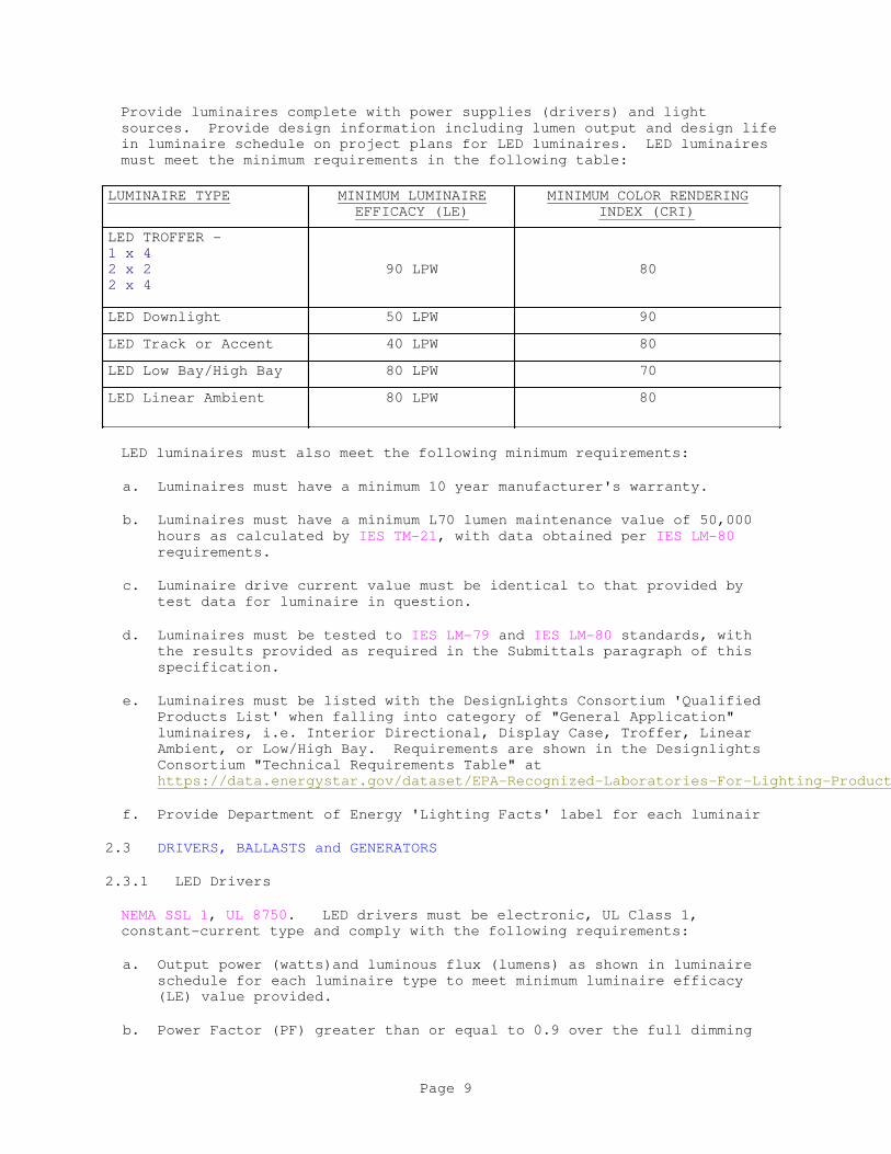
Provide luminaires complete with power supplies (drivers) and light
sources. Provide design information including lumen output and design life
in luminaire schedule on project plans for LED luminaires. LED luminaires
must meet the minimum requirements in the following table:
LUMINAIRE TYPE MINIMUM LUMINAIRE
EFFICACY (LE)
MINIMUM COLOR RENDERING
INDEX (CRI)
LED TROFFER -
1 x 4
2 x 2
2 x 4
90 LPW 80
LED Downlight 50 LPW 90
LED Track or Accent 40 LPW 80
LED Low Bay/High Bay 80 LPW 70
LED Linear Ambient 80 LPW 80
LED luminaires must also meet the following minimum requirements:
a. Luminaires must have a minimum 10 year manufacturer's warranty.
b. Luminaires must have a minimum L70 lumen maintenance value of 50,000
hours as calculated by IES TM-21, with data obtained per IES LM-80
requirements.
c. Luminaire drive current value must be identical to that provided by
test data for luminaire in question.
d. Luminaires must be tested to IES LM-79 and IES LM-80 standards, with
the results provided as required in the Submittals paragraph of this
specification.
e. Luminaires must be listed with the DesignLights Consortium 'Qualified
Products List' when falling into category of "General Application"
luminaires, i.e. Interior Directional, Display Case, Troffer, Linear
Ambient, or Low/High Bay. Requirements are shown in the Designlights
Consortium "Technical Requirements Table" at
https://data.energystar.gov/dataset/EPA-Recognized-Laboratories-For-Lighting-Products/jgwf-7qrr
f. Provide Department of Energy 'Lighting Facts' label for each luminair
2.3 DRIVERS, BALLASTS and GENERATORS
2.3.1 LED Drivers
NEMA SSL 1, UL 8750. LED drivers must be electronic, UL Class 1,
constant-current type and comply with the following requirements:
a. Output power (watts)and luminous flux (lumens) as shown in luminaire
schedule for each luminaire type to meet minimum luminaire efficacy
(LE) value provided.
b. Power Factor (PF) greater than or equal to 0.9 over the full dimming
Page 9
range when provided.
c. Current draw Total Harmonic Distortion (THD) of less than 20 percent.
d. Class A sound rating.
e. Operable at input voltage of 277 volts at 60 hertz.
f. Minimum 10 year manufacturer's warranty.
g. RoHS compliant.
h. Integral thermal protection that reduces or eliminates the output power
if case temperature exceeds a value detrimental to the driver.
i. UL listed for dry or damp locations typical of interior installations.
j. Non-dimmable, step-dimmable to 50 percent output, or fully-dimmable
using 0-10V control as indicated in luminaire schedule.
2.3.2 Induction Generators
Generator must be connected, and operate in conjunction with an inductive
power coupler or coil(s). Provide solid-state, high-frequency (200 kHz -
2.67 MHz) type, with power factor greater than 0.95, Class A sound rating,
maximum input current THD of 15 percent, operating voltage of 120-277V, and
a minimum starting temperature of minus 30 degrees F. Provide generator
dimmable to a minimum of 50 percent light output.
2.4 LIGHT SOURCES
NEMA ANSLG C78.377, NEMA SSL 3. Provide type and wattage as indicated in
luminaire schedule on project plans.
2.4.1 LED Light Sources
a. Correlated Color Temperature (CCT) of 4000 degrees K.
b. Minimum Color Rendering Index (CRI) R9 value of 80.
c. High power, white light output utilizing phosphor conversion (PC)
process[ or mixed system of colored LEDs, typically red, green and blue
(RGB)].
d. RoHS compliant.
e. Provide light source color consistancy by utilizing a binning tolerance
within a 4 step McAdam ellipse.
[]2.5 LIGHTING CONTROLS
ASHRAE 90.1 - IP ASHRAE 189.1. Provide network certification for all
networked lighting control systems and devices per requirements of
DOD 8500.01 and DOD 8510.01.
2.5.1 Toggle Switches
Page 10

Provide line-voltage toggle switches as specified in Section 26 20 00
INTERIOR DISTRIBUTION SYSTEM.
2.5.2 Dimming Controllers (Dimmers)
UL 1472, UL 20, IEEE C62.41, NEMA SSL 7A. 277 V0 dimmers must provide
flicker-free, continuously variable light output throughout the dimming
range. Provide radio frequency interference suppression integral to
device. Provide dimmers utilizing pulse width modulation (PWM)constant
current reduction (CCR) technology. Provide device with a vertical slider,
paddle, rotary button, or toggle (with adjacent vertical slider) type
control, with finish to match switches and outlets in same area. Provide
back box in wall with sufficient depth to accomodate body of switch and
wiring. Devices must be capable of operating at their full rated capacity
regardless of being single or ganged-mounted, and be compatible with
three-way and four-way switching scenarios. Dimmers must be capable of
controlling [two-wire] [three-wire][0-10 volt] fluorescent ballasts or LED
drivers. Ensure compatibility of dimmer with separate power packs when
utilized for lighting control. Dimmers and the ballasts or drivers they
control, must be provided from the same manufacturer, or tested and
certified as compatible for use together. Provide NEMA SSL 7A-compiant
devices.
2.5.3 Sensors for Lighting Control
IEEE C62.41, NEMA WD 1, UL 94, UL 916, UL 508, ASTM D4674 REV A.
2.5.3.1 Occupancy Sensors
Provide occupancy sensors with coverage patterns as indicated on project
plans. Provide no less quantity of sensors as shown on plans, but add
additional sensors when required to fulfill coverage requirement for the
specific model sensor provided. Sensor must be provided with an adaptive
learning function that automaticaly sets sensor in optimum calibration in a
set period of time after installation and a non-volatile memory that saves
settings after a power outage. Provide sensors designed for ceiling, wall
or wall-box installation as indicated. Operating voltage must be 120[277]
volts.[ Operating voltage must be 24V in conjunction with a control system
or separate power pack which interacts with luminare being controllled.]
Provide housing of high-impact, injection-molded thermoplastic with a
multi-segmented lens for PIR and dual technology sensors. Sensor operation
requires movement to activate luminaires controlled, and turns luminaires
off after a set time of inactivity.[ Provide integral photocell mounted in
occupancy sensor housing when indicated.]
2.5.3.1.1 Passive Infrared (PIR) Sensors
Provide ceiling or wall-mounted PIR sensors meeting the following
requirements:
a. Temperature compensated, dual element sensor and a multi-element
fresnel lens (Poly IR4 material).
b. Technology to optimize automatic time delay to fit occupant usage
patterns.
c. No minimum load requirement for line voltage sensors and be capable of
Page 11
switching from zero to 800 W at 120 VAC, 50/60 Hz and from zero to 1200
W at 277 VAC, 50/60 Hz. Control voltage sensors must not exceed a
maximum load requirement of 20 mA at 24VDC.
d. Time delay of five to 30 minutes in increments of five minutes with a
walk through and test mode set by DIP switch.
e. LED indicator that remains active during occupancy.
f. Built-in light level sensor that is operational from 8 to 180
foot-candles.
g. Coverage pattern tested to NEMA WD 7 standards.
h. Standard five year warranty and be UL listed
i. No leakage current to load when in the off mode.
2.5.3.1.2 Ultrasonic Sensors
Provide ceiling-mounted ultrasonic sensors meeting the following
requirements:
a. Operate at an ultrasonic frequency of 40 kHz.
b. LED on exterior of device to indicate occupant detection.
c. Adjustable time delay period of 15 seconds to 30 minutes.
d. UL listed with minimum five year warranty.
e. Provide with isolated relay for integrating control of HVAC or other
automated systems.
2.5.3.1.3 Dual Technology Sensors
Provide dual technology sensors that meet the requirements for PIR sensors
and ultrasonic sensors indicated above. If either the passive infrared or
ultrasonic sensing registers occupancy, the luminaires must remain on.
2.5.3.1.4 Power Packs for Sensors
UL 2043, CEC Title 24, ASHRAE 90.1 - IP. Power packs used to provide power
to one or more lighting control sensors must meet the following
requirements:
a. Input voltage - 277 VAC; output voltage - 24 VDC at 225 mA.
b. Plenum-rated, high-impact thermoplastic enclosure.
c. Utilizes zero-crossing circuitry to prevent damage from inrush current.
d. Maximum load rating of 16 amps for electronic lighting loads.
e. RoHS compliant.
Page 12
2.5.3.2 Vacancy Sensors
Provide vacancy sensors as indicated above under paragraph OCCUPANCY
SENSORS, but with requirement of a manual operation to activate luminaires
controlled. Provide automatic operation to turn luminaires off after a set
period of inactivity.
2.5.4 Lighting Contactor
NEMA ICS 2. Provide an electrically mechanically-held lighting contactor
housed in a NEMA enclosure conforming to NEMA ICS 6. Provide contactor
with one normally-open(NO)[normally closed(NC)], single[double] pole
contacts, rated 600 volts, 30 amps. Provide coil operating voltage of 277
volts.
2.5.5 Lighting Control Panel
Provide an electronic, programmable lighting control panel, capable of
providing lighting control with input from internal programming, digital
switches, time clocks, and other low-voltage control devices.
Enclose panel hardware in a surface-mounted, NEMA 1, painted, steel
enclosure, with hinged, lockable access door and ventilation openings.
Internal low-voltage compartment must be separated from line-voltage
compartment of enclosure with only low-voltage compartment accessible upon
opening of door. Provide additional remote cabinets that communicate back
to main control panel.
Input voltage - 277 V, 60 Hz, with internal 24 VDC power supply.
Provide 16 single-pole latching[return to close] relays rated at [20][30]
amps, [120][277] volts.[ Provide provision for relays to close upon power
failure that meets UL 924.]
Relay control module must operate at 24 VDC and be rated to control a
minimum of 16 relays.
2.5.6 Local Area Lighting Controller
CEC Title 24 and ASHRAE 90.1 - IP compliant. Provide controller designed
for single area or room with the following requirements:
a. 277 volt input, designed for LED lighting loads.
b. 2 zone, with 2 relays rated 20 amps each.
c. Provide daylight harvesting capabilty with full-range dimming control.
d. Inputs for occupancy sensor, photocell, and low-voltage wall switch.
e. Provide capability for receptacle load control.
f. Provide full 'OFF' function with input from external time clock input.
2.6 EXIT AND EMERGENCY LIGHTING EQUIPMENT
UL 924, NFPA 101, and NFPA 70 compliant.
Page 13
2.6.1 Exit Signs
Provide exit signs consuming a maximum of five watts total.
2.6.1.1 LED Self-Powered Exit Signs
Provide in painted steel housing with UL wet labe using clear polycarbonate
housing, configured for ceiling or wall or end mounting. Provide edge-lit
type with clear acrylic, edge-lit face and aluminum trim having clear
aluminum white finish.] Provide 6 inch high,3/4 inch stroke red lettering
on face of sign. Provide chevrons on either side of lettering to indicate
direction. Provide single[double] face. Equip with automatic power
failure device, test switch, and pilot light, and fully automatic high/low
trickle charger in a self-contained power pack. Battery must be sealed,
maintenance free nickel-cadmium type, and must operate unattended for a
period of not less than five years. Emergency run time must be a minimum
of 1 1/2 hours. LEDs must have a minimum rated life of 10 years. Provide
self-diagnostic circuitry integral to emergency LED driver.
2.6.1.2 LED Remote-Powered Exit Signs
Provide as indicated above for self-powered type, but without battery and
charger. Exit sign must contain provision for 120/277 VAC or 6-48 VDC
input from remote source.
2.6.2 Emergency Lighting Unit (EBU)
Provide in [UV-stable, thermo-plastic][painted, die-cast aluminum][painted
steel] housing with [UL damp label][UL wet label] as indicated. Emergency
lighting units must be rated for 12 volts, except units having no
remote-mounted lamps and having no more than two unit-mounted light sources
may be rated six volts. Equip units with brown-out sensitive circuit to
activate battery when input voltage falls to 75 percent of normal. Equip
with two LED, automatic power failure device, test switch, and pilot
light, and fully automatic high/low trickle charger in a self-contained
power pack. Battery must be sealed, maintenance free
lead-calcium[nickel-cadmium]type, and must operate unattended for a period
of not less than five years. Emergency run time must be a minimum of 1 1/2
hours. LEDs must have a minimum rated life of 10 years.
2.6.3 LED Emergency Drivers
Provide LED emergency driver with automatic power failure detection, test
switch and LED indicator (or combination switch/indicator) located on
luminaire exterior, and fully-automatic solid-state charger, battery and
inverter integral to a self-contained housing. Integral nickel-cadmium or
lead-calcium] battery is required to supply a minimum of 90 minutes of
emergency power at 5 watts, 10-50 VDC[compatible with LED forward voltage
requirements], constant output. Driver must be RoHS compliant, rated for
installation in plenum-rated spaces and damp locations, and be warranted
for a minimum of five years.
2.6.4 Self-Diagnostic Circuitry for LED Emergency Drivers/Ballasts
Provide emergency lighting unit with fully-automatic, integral
self-testing/diagnostic electronic circuitry. Circuitry must provide for a
one minute diagnostic test every 28 days, and a 30 minute diagnostic test
Page 14
every six months, minimum. Any malfunction of the unit must be indicated
by LED(s) visible from the exterior of the luminaire. A manual test switch
must also be provided to perform a diagnostic test at any given time.
2.6.5 Central Emergency Lighting System
2.6.5.1 System Operation
During normal power operation, system charges batteries as needed and
allows normal power to pass through to load. Upon loss of normal power,
system automatically transfers to emergency mode without interruption of
connected loads. Internal batteries provide a minimum of 90 minutes of
emergency power at this time. Upon normal power being restored, system
switches back to normal power mode and fully charges batteries within
UL-approved time period.
2.6.5.2 Battery Charger
Solid state, monitored, three step float charging type, keeping batteries
in a fully charged state. Provide circuitry to prevent deep discharge of
batteries in prolonged power outage conditions.
2.6.5.3 Batteries
Provide sealed, lead calcium type, designed to operated unattended without
maintenance, for a minimum of 10 years.
2.6.5.4 Enclosure
Provide system in NEMA painted steel[aluminum] enclosure with
exterior-mounted "push-to-test" button and LED indicator.
2.6.5.5 Accessories
Provide single pole, 20 ampere output circuit breakers. [Voltmeter and
ampmeter for battery[load].]
2.7 LUMINAIRE SUPPORT HARDWARE
2.7.1 Wire
ASTM A641/A641M; Galvanized, soft tempered steel, minimum 0.11 inches in
diameter, or galvanized, braided steel, minimum 0.08 inches in diameter.
2.7.2 Wire for Humid Spaces
ASTM A580/A580M; Composition 302 or 304, annealed stainless steel, minimum
0.11 inches in diameter.
ASTM B164; UNS NO4400, annealed nickel-copper alloy, minimum 0.11 inches
in diameter.
2.7.3 Threaded Rods
Threaded steel rods, 3/16 inch diameter, zinc or cadmium coated.
2.7.4 Straps
Page 15

Galvanized steel, one by 3/16 inch, conforming to ASTM A653/A653M, with a
light commercial zinc coating or ASTM A1008/A1008M with an electrodeposited
zinc coating conforming to ASTM B633, Type RS.
2.8 POWER HOOK LUMINAIRE HANGERS
UL 1598Provide an assembly consisting of through-wired power hook housing,
interlocking plug and receptacle, power cord, and luminaire support loop.
Power hook housing must be cast aluminum having two 3/4 inch threaded
hubs. Support hook must have safety screw. Fixture support loop must be
cast aluminum with provisions for accepting 3/4 inch threaded stems. Power
cord must include 16 inches of 3 conductor No. 16 Type SO cord. Assembly
must be rated 120 volts or 277 volts, 15 amperes.
2.9 EQUIPMENT IDENTIFICATION
2.9.1 Manufacturer's Namplate
Each item of equipment must have a nameplate bearing the manufacturer's
name, address, model number, and serial number securely affixed in a
conspicuous place; the nameplate of the distributing agent will not be
acceptable.
2.9.2 Labels
Provide labeled luminaires in accordance with UL 1598 requirements. All
luminaires must be clearly marked for operation of specific light sources
and ballasts, generators or drivers. Note the following light source
characteristics in the format "Use Only as a-e below":
a. Light source diameter code (T-4, T-5, T-8), tube configuration (twin,
quad, triple), base type, and nominal wattage for fluorescent and
compact fluorescent luminaires.
b. Light source type, wattage, envelope type (ED17, BD56, etc.) and
coating (clear or coated) for HID luminaires.
c. Start type (programmed start, instant start) for fluorescent and
compact fluorescent luminaires.
d. ANSI ballast type (M98, M57, etc.) for HID luminaires.
e. Correlated color temperature (CCT) and color rendering index (CRI) for
all luminaires.
All markings related to light source type must be clear and located to be
readily visible to service personnel, but unseen from normal viewing angles
when light sources are in place. Ballasts, generators or drivers must have
clear markings indicating multi-level outputs and indicate proper terminals
for the various outputs.
2.10 FACTORY APPLIED FINISH
Provide all luminaires and lighting equipment with factory-applied painting
system that as a minimum, meets requirements of NEMA 250
corrosion-resistance test.
Page 16
2.11 RECESS- AND FLUSH-MOUNTED LUMINAIRES
Provide access to lamp and ballast from bottom of luminaire. Provide trim
[and lenses]for the exposed surface of flush-mounted luminaires as
indicated on project drawings and specifications.
2.12 SUSPENDED LUMINAIRES
Provide hangers capable of supporting twice the combined weight of
luminaires supported by hangers. Provide with swivel hangers to ensure a
plumb installation. Provide cadmium-plated steel with a swivel-ball tapped
for the conduit size indicated. Hangers must allow fixtures to swing
within an angle of 45 degrees. Brace pendants 4 feet or longer to limit
swinging. Single-unit suspended luminaires must have twin-stem hangers.
Multiple-unit or continuous row luminaires must have a tubing or stem for
wiring at one point and a tubing or rod suspension provided for each unit
length of chassis, including one at each end. Provide rodsRods in minimum
0.18 inch diameter.
PART 3 EXECUTION
3.1 INSTALLATION
Electrical installations must conform to IEEE C2, NFPA 70, and to the
requirements specified herein. Install luminaires and lighting controls to
meet the requirements of ASHRAE 90.1 - IP and ASHRAE 189.1. To encourage
consistancy and uniformity, install luminaires of the same manufacture and
model number when residing in the same facility or building.
3.1.1 Light Sources
When light sources are not provided as an integral part of the luminaire,
deliver light sources of the type, wattage, lumen output, color
temperature, color rendering index, and voltage rating indicated to the
project site and install just prior to project completion, if not already
installed in the luminaires from the factory.
3.1.2 Luminaires
Set luminaires plumb, square, and level with ceiling and walls, in
alignment with adjacent luminaires and secure in accordance with
manufacturers' directions and approved drawings. Installation must meet
requirements of NFPA 70. Mounting heights specified or indicated must be
to the bottom of the luminaire for ceiling-mounted luminaires and to center
of luminaire for wall-mounted luminaires. Obtain approval of the exact
mounting height on the job before commencing installation and, where
applicable, after coordinating with the type, style, and pattern of the
ceiling being installed. Recessed and semi-recessed luminaires must be
independently supported from the building structure by a minimum of four
wires, straps or rods per luminaire and located near each corner of the
luminiare. Ceiling grid clips are not allowed as an alternative to
independently supported luminaires. Round luminaires or luminaires smaller
in size than the ceiling grid must be independently supported from the
building structure by a minimum of four wires, straps or rods per
luminaire, spaced approximately equidistant around. Do not support
luminaires by acoustical tile ceiling panels. Where luminaires of sizes
less than the ceiling grid are indicated to be centered in the acoustical
panel, support each independently and provide at least two 3/4 inch metal
Page 17
channels spanning, and secured to, the ceiling tees for centering and
aligning the luminiare. Provide wires, straps, or rods for luminaire
support in this section. Luminaires installed in suspended ceilings must
also comply with the requirements of Section 09 51 00 ACOUSTICAL CEILINGS.
3.1.3 Suspended Luminaires
Provide suspended luminaires with 45 degree swivel hangers so that they
hang plumb and level. Locate so that there are no obstructions within the
45 degree range in all directions. The stem, canopy and luminaire must be
capable of 45 degree swing. Pendants, rods, or chains 4 feet or longer
excluding luminaire must be braced to prevent swaying using three cables at
120 degree separation. Suspended luminaires in continuous rows must have
internal wireway systems for end to end wiring and must be properly aligned
to provide a straight and continuous row without bends, gaps, light leaks
or filler pieces. Utilize aligning splines on extruded aluminum luminaires
to assure minimal hairline joints. Support steel luminaires to prevent
"oil-canning" effects. Luminaire finishes must be free of scratches,
nicks, dents, and warps, and must match the color and gloss specified.
Match supporting pendants with supported luminaire. Aircraft cable must be
stainless steel. Canopies must be finished to match the ceiling and must
be low profile unless otherwise shown. Maximum distance between suspension
points must be 10 feet or as recommended by the manufacturer, whichever is
less.
3.1.4 Ballasts, Generators and Power Supplies
Typically, provide ballasts, generators, and power supplies (drivers)
integral to luminaire as constructed by the manufacturer.
3.1.5 Exit Signs and Emergency Lighting Units
Wire exit signs and emergency lighting units ahead of the local switch, to
the normal lighting circuit located in the same room or area.
[3.1.5.1 Exit Signs
Connect exit signs on separate circuits and serve from [an emergency
panel][a separate circuit breaker][a fused disconnect switch]. Provide
only one source of control, which would be [the circuit breaker in the
emergency panel][the separate circuit breaker][the fused disconnect
switch]. Paint source of control red and provide lockout capability.
][3.1.5.2 Emergency Lighting from Central Emergency System
Connect emergency lighting from a central emergency system as indicated on
the project drawings.
]3.1.6 Photocell Switch Aiming
Aim switch according to manufacturer's recommendations.
3.1.7 Occupancy/Vacancy Sensors
Provide testing od sensor coverage in all spaces where sensors are placed.
This should be done only after all furnishings (carpet, furniture,
workstations, etc.) have been installed. Provide quantity of sensor units
Page 18
indicated as a minimum. Provide additional units to give full coverage
over controlled area. Full coverage must provide hand and arm motion
detection for office and administration type areas and walking motion for
industrial areas, warehouses, storage rooms and hallways. Locate the
sensor(s) as indicated and in accordance with the manufacturer's
recommendations to maximize energy savings and to avoid nuisance activation
and deactivation due to sudden temperature or airflow changes and usage.
3.1.8 Daylight or Ambient Light Level Sensor
Locate sensor as indicated and in accordance with the manufacturer's
recommendations. Adjust sensor for 30 footcandlesor for the indicated
light level measured at the work plane for that particular area.
3.2 FIELD APPLIED PAINTING
Paint lighting equipment as required to match finish of adjacent surfaces
or to meet the indicated or specified safety criteria. Provide painting as
specified in Section 09 90 00 PAINTS AND COATINGS.
-- End of Section --
Page 19
SECTION 27 05 28.36 40
CABLE TRAYS FOR COMMUNICATIONS SYSTEMS
05/17
PART 1 GENERAL
This specification covers the requirements for materials and installation
of communication cable tray systems.
The contract drawings indicate the extent and general arrangement of the
cables, equipment, and distribution systems and should indicate cable tray
supports.
Section 26 00 00.00 20 BASIC ELECTRICAL MATERIALS AND METHODS applies to
work specified in this section.
1.1 REFERENCES
The publications listed below form a part of this specification to the
extent referenced. The publications are referred to within the text by the
basic designation only.
ASTM INTERNATIONAL (ASTM)
ASTM A1008/A1008M (2016) Standard Specification for Steel,
Sheet, Cold-Rolled, Carbon, Structural,
High-Strength Low-Alloy, High-Strength
Low-Alloy with Improved Formability,
Solution Hardened, and Bake Hardenable
ASTM A123/A123M (2015) Standard Specification for Zinc
(Hot-Dip Galvanized) Coatings on Iron and
Steel Products
NATIONAL ELECTRICAL MANUFACTURERS ASSOCIATION (NEMA)
NEMA VE 1 (2017) Metal Cable Tray Systems
NEMA VE 2 (2013; ERTA 2016) Cable Tray Installation
Guidelines
NATIONAL FIRE PROTECTION ASSOCIATION (NFPA)
NFPA 70 (2017; ERTA 1-2 2017; TIA 17-1; TIA 17-2)
National Electrical Code
1.2 ADMINISTRATIVE REQUIREMENTS
1.2.1 Pre-Installation Meetings
The Contracting Officer will schedule a pre-installation meeting within 30
days of contract award. Submit fabrication drawings for review and
approval.
Submit manufacturer's product data for the following items:
Page 1
a. Cable Trays
b. Supports
1.3 SUBMITTALS
Government approval is required for submittals with a "G" designation;
submittals not having a "G" designation are for information only. When
used, a designation following the "G" designation identifies the office
that will review the submittal for the Government. Submittals with an "S"
are for inclusion in the Sustainability eNotebook, in conformance to
Section 01 33 29 SUSTAINABILITY REPORTING. Submit the following in
accordance with Section 01 33 00 SUBMITTAL PROCEDURES:
SD-02 Shop Drawings
Fabrication Drawings; G
Installation Drawings; G
SD-03 Product Data
Cable Trays; G
Supports; G
SD-08 Manufacturer's Instructions
Manufacturer's Instructions
1.4 QUALITY CONTROL
Comply with NEMA VE 1.
Comply with NEC, requirements that apply to the construction and
installation of cable tray and cable channel systems (Article 392 NEC).
Provide products that are UL-classified and labeled with the UL
classification mark.
PART 2 PRODUCTS
2.1 SYSTEM DESCRIPTION
Provide ladder cable trays consisting of two longitudinal side members
connected by individual transverse members.
Provide trough cable trays consisting of continuous one-piece
ventilated-bottom sections contained within longitudinal side members.
Provide channel cable trays consisting of one-piece ventilated channel
sections.
Provide solid bottom trays consisting of two longitudinal side members
connected by a one-piece bottom section.
Page 2
2.2 FABRICATION
Submit fabrication drawings for cable trays. Ensure the drawings contain
details showing the fabrication and assembly details performed in the
factory.
Before assembly, use an antioxidant compound to coat the contact surfaces
of trays. Ensure that the finishes of edges, fittings, and hardware are
free from burrs and sharp edges. Include splice and end plates, dropouts,
and miscellaneous hardware.
2.3 COMPONENTS
2.3.1 Supports
Permit both vertical and horizontal adjustment, where possible on supports
and hangers. Provide an adequate bearing surface for the tray on the
horizontal and vertical tray supports, and ensure that the surface can
accommodate holddown clamps or fasteners. Provide a means, other than
friction, for securely fastening cable trays to supports.
Provide support for cable trays at intervals of no more than6-foot. Place
supports for horizontal-elbow tray fittings with2-feet of each fitting
extremity and as recommended by the cable tray manufacturer.
Ensure that the cable trays can carry at least 150 pounds per linear foot
when supported at 6-foot intervals. Ensure that the tray fittings have a
load-carrying capacity that is equal to or greater than that of straight
tray sections. Ensure that the radius of tray fittings is based on the
minimum bending radius of the cables, as specified by the cable
manufacturer.
2.4 MATERIALS
Provide cable trays constructed of steel in accordance with
ASTM A1008/A1008M and that has a zinc coating which was applied after
fabrication.
Provide hot-dipped galvanized steel trays with a finish in accordance with
ASTM A123/A123M.
PART 3 EXECUTION
Comply with NEMA VE 2 for cable tray installation.
3.1 INSTALLATION
3.1.1 Manufacturer's Instructions
Submit the manufacturer's instructions for cable trays, including special
provisions required to install equipment components and system packages.
Ensure that the instructions specify impedances, hazards and safety
precautions.
3.1.2 Installation Drawings
No later than 15 calendar days before shipment, submit installation drawings
Page 3
to the Contracting Officer for approval. Coordinate drawings with those
being used for all other work in the immediate area to ensure that this
other work does not conflict with the installation. Include the layout of
the cable tray work and details on both horizontal and vertical supports as
specified in the paragraph SUPPORTS.
3.1.3 Grounding
Provide properly grounded cable trays by means that has a low-resistance
conductor of sufficient capacity, and that is no smaller than No. 1/0 AWG
copper. Bond the grounding conductor to cable tray sections and fittings
by compatible bolted connections. Consider cable tray sections in tandem
assembly as having electrical continuity when these sections are bonded
with appropriate high-strength bolts. Provide permanent and continuous
effective grounding with an impedance that is low enough to limit the
potential above ground and to facilitate operation of overcurrent devices
in the circuit. Provide grounding and bonding for cable trays in
accordance with NFPA 70.
-- End of Section --
Page 4

SECTION 28 31 76
INTERIOR FIRE ALARM AND MASS NOTIFICATION SYSTEM08/11
PART 1 GENERAL
1.1 RELATED SECTIONS
Section 26 00 00.00 20 BASIC ELECTRICAL MATERIALS AND METHODS, applies to this section, with the additions and modifications specified herein. In addition, refer to the following sections for related work and coordination:
Section 21 13 13.00 20 WET PIPE SPRINKLER SYSTEM, FIRE PROTECTION
Section 21 13 20.00 20 FOAM FIRE EXTINGUISHING FOR AIRCRAFT HANGARS
1.2 SUMMARY
1.2.1 Scope
a. This work includes completion of design and providing a new, complete, and modifying the existing fire alarm and mass notification system as described herein and on the contract drawings for the Global Vigilance Hangar - Building 1414. Include in the system wiring, raceways, pull boxes, terminal cabinets, outlet and mounting boxes, control equipment, alarm, and supervisory signal initiating devices, alarm notification appliances, supervising station fire alarm system transmitter, and other accessories and miscellaneous items required for a complete operating system even though each item is not specifically mentioned or described. Provide system[s] complete and ready for operation.
b. Provide equipment, materials, installation, workmanship, inspection, and testing in strict accordance with the required provisions of NFPA 72, ISO 7240-16, IEC 60268-16, except as modified herein. The system layout on the drawings show the intent of coverage and are shown in suggested locations. Submit plan view drawing showing device locations, terminal cabinet locations, junction boxes, other related equipment, conduit routing, wire counts, circuit identification in each conduit, and circuit layouts for all floors. Drawings shall comply with the requirements of NFPA 170. Final quantity, system layout, and coordination are the responsibility of the Contractor
1.3 REFERENCES
The publications listed below form a part of this specification to the extent referenced. The publications are referred to within the text by the basic designation only.
ASME INTERNATIONAL (ASME)
ASME A17.1/CSA B44 (2016) Safety Code for Elevators and Escalators
FM GLOBAL (FM)
Page 1
FM APP GUIDE (updated on-line) Approval Guide http://www.approvalguide.com/
INSTITUTE OF ELECTRICAL AND ELECTRONICS ENGINEERS (IEEE)
IEEE C62.41.1 (2002; R 2008) Guide on the Surges Environment in Low-Voltage (1000 V and Less) AC Power Circuits
IEEE C62.41.2 (2002) Recommended Practice on Characterization of Surges in Low-Voltage (1000 V and Less) AC Power Circuits
INTERNATIONAL ELECTROTECHNICAL COMMISSION (IEC)
IEC 60268-16 (2003; ED 4.0) Sound System Equipment - Part 16: Objective Rating Of Speech Intelligibility By Speech Transmission Index
INTERNATIONAL ORGANIZATION FOR STANDARDIZATION (ISO)
ISO 7240-16 (2007) Fire Detection And Alarm Systems — Part 16: Sound System Control And Indicating Equipment
NATIONAL FIRE PROTECTION ASSOCIATION (NFPA)
NFPA 170 (2015) Standard for Fire Safety and Emergency Symbols
NFPA 70 (2017; ERTA 1-2 2017; TIA 17-1; TIA 17-2) National Electrical Code
NFPA 72 (2016) National Fire Alarm and Signaling Code
NFPA 90A (2015) Standard for the Installation of Air Conditioning and Ventilating Systems
U.S. DEPARTMENT OF DEFENSE (DOD)
UFC 3-601-02 (2010) Operations and Maintenance: Inspection, Testing, and Maintenance of Fire Protection Systems
UFC 4-021-01 (2008; with Change 1) Design and O&M: Mass Notification Systems
U.S. NATIONAL ARCHIVES AND RECORDS ADMINISTRATION (NARA)
47 CFR 15 Radio Frequency Devices
47 CFR 90 Private Land Mobile Radio Services
UNDERWRITERS LABORATORIES (UL)
Page 2
UL 1480 (2016) Standard for Speakers for Fire Alarm, Emergency, and Commercial and Professional Use
UL 1638 (2016) Visual Signaling Appliances - Private Mode Emergency and General Utility Signaling
UL 1971 (2002; Reprint Oct 2008) Signaling Devices for the Hearing Impaired
UL 2017 (2008; Reprint Jan 2016) General-Purpose Signaling Devices and Systems
UL 268 (2016; Reprint Jul 2016) UL Standard for Safety Smoke Detectors for Fire Alarm Systems
UL 464 (2016) Standard for Audible Signal Appliances
UL 521 (1999; Reprint Oct 2016) UL Standard for Safety Heat Detectors for Fire Protective Signaling Systems
UL 864 (2014) Standard for Control Units and Accessories for Fire Alarm Systems
UL Electrical Constructn (2012) Electrical Construction Equipment Directory
UL Fire Prot Dir (2012) Fire Protection Equipment Directory
1.4 DEFINITIONS
Wherever mentioned in this specification or on the drawings, the equipment, devices, and functions shall be defined as follows:
1.4.1 Interface Device
An addressable device that interconnects hard wired systems or devices to an analog/addressable system.
1.4.2 Remote Fire Alarm and Mass Notification Control Unit
A control panel, electronically remote from the fire alarm and mass notification control panel, that receives inputs from automatic and manual fire alarm devices; may supply power to detection devices and interface devices; may provide transfer of power to the notification appliances; may provide transfer of condition to relays or devices connected to the control unit; and reports to and receives signals from the fire alarm control panel.
1.4.3 Fire Alarm Control Unit and Mass Notification Autonomous Control Unit (FMCP)
A master control panel having the features of a fire alarm and mass notification control unit and fire alarm and mass notification control
Page 3

units are interconnected. The panel has central processing, memory, input and output terminals, and [LCD, LED Display units].
1.4.4 Local Operating Console (LOC)
A unit designed to allow emergency responders and/or building occupants to operate the MNS including delivery or recorded and/or live messages, initiate strobe and textural visible appliance operation and other relayed functions.
1.4.5 Terminal Cabinet
A steel cabinet with locking, hinge-mounted door that terminal strips are securely mounted.
1.5 SUBMITTALS
Government approval is required for submittals with a "G" designation; submittals not having a "G" designation are for Contractor Quality Control approval. Submit the following in accordance with Section 01 33 00 SUBMITTAL PROCEDURES:
SD-02 Shop Drawings
Nameplates; G
Instructions; G
Wiring Diagrams; G
System Layout; G
System Operation; G
Notification Appliances; G
Amplifiers; G
SD-03 Product Data
Technical Data And Computer Software; G
Fire Alarm Control Unit and Mass Notification Control Unit (FMCP); G
LCD, LED Display Unit (VDU); G
Terminal Cabinets; G
Manual Stations; G
Transmitters (including housing); G
Batteries; G
Battery Chargers; G
Page 4

Smoke Sensors; G
Heat Detectors; G
Notification Appliances; G
Addressable Interface Devices; G
Amplifiers; G
Tone Generators; G
Digitalized Voice Generators; G
Remote Fire Alarm/Mass Notification Control Units; G
Radio Transmitter and Interface Panels; G
Local Operating Console (LOC); G
SD-05 Design Data
Battery Power; G
Battery Chargers; G
SD-06 Test Reports
Field Quality Control
Testing Procedures; G
Smoke Sensor Testing Procedures; G
SD-07 Certificates
Installer
Formal Inspection and Tests
Final Testing
SD-09 Manufacturer's Field Reports
System Operation; G
Fire Alarm/Mass Notification System
SD-10 Operation and Maintenance Data
Operation and Maintenance (O&M) Instructions; G
Instruction of Government Employees; G
SD-11 Closeout Submittals
Page 5
As-Built Drawings
1.6 TECHNICAL DATA AND COMPUTER SOFTWARE
Technical data and computer software (meaning technical data that relates to computer software) that are specifically identified in this project, and may be defined/required in other specifications, shall be delivered, strictly in accordance with the CONTRACT CLAUSES. Identify data delivered by reference to the particular specification paragraph against which it is furnished. Data to be submitted shall include complete system, equipment, and software descriptions. Descriptions shall show how the equipment will operate as a system to meet the performance requirements of this contract. The data package shall also include the following:
a. Identification of programmable portions of system equipment and capabilities.
b. Description of system revision and expansion capabilities and methods of implementation detailing both equipment and software requirements.
c. Provision of operational software data on all modes of programmable portions of the fire alarm and detection system.
d. Description of Fire Alarm and Mass Notification Control Panel equipment operation.
e. Description of auxiliary and remote equipment operations.
f. Library of application software.
g. Operation and maintenance manuals.
1.7 QUALITY ASSURANCE
Equipment and devices shall be compatible and operable with existing station fire alarm system and shall not impair reliability or operational functions of existing supervising station fire alarm system.
a. Interpret reference to "authority having jurisdiction" to mean the Air Force Civil Engineer Support Agency, Fire Protection Engineering Subject Matter Expert.
b. The recommended practices stated in the manufacturer's literature or documentation shall be considered as mandatory requirements.
c. Devices and equipment for fire alarm service must be listed by UL Fire Prot Dir or approved by FM APP GUIDE.
1.7.1 Qualifications
1.7.1.1 Design Services
Installations requiring completion of installation drawings and specification or modifications of fire detection, fire alarm, mass notification system, fire suppression systems or mass notification systems shall require the services and review of a qualified engineer. For the purposes of meeting this requirement, a qualified engineer is defined as an
Page 6

individual meeting one of the following conditions:
b. A registered professional engineer (P.E.) in fire protection engineering.
c. Registered Professional Engineer with verification of experience and at least five years of current experience in the design of the fire protection and detection systems.
1.7.1.2 Supervisor
The Fire Alarm technicians supervising the installation of equipment shall be factory trained in the installation, adjustment, testing, and operation of the equipment specified herein and on the drawings.
1.7.1.3 Technician
Fire Alarm Technicians with a minimum of four years of experience utilized to install and terminate fire alarm/mass notification devices, cabinets and panels. The Fire Alarm technicians installing the equipment shall be factory trained in the installation, adjustment, testing, and operation of the equipment specified herein and on the drawings.
1.7.1.4 Installer
Fire Alarm installer with a minimum of two years of experience utilized to assist in the installation of fire alarm/mass notification devices, cabinets and panels An electrician shall be allowed to install wire, cable, conduit and backboxes for the fire alarm system/mass notification system. The Fire Alarm installer shall be factory trained in the installation, adjustment, testing, and operation of the equipment specified herein and on the drawings.
1.7.1.5 Test Personnel
Fire Alarm Technicians with a minimum of eight years of experience (NICET Level III)utilized to test and certify the installation of the fire alarm/mass notification devices, cabinets and panels. The Fire Alarm technicians testing the equipment shall be factory trained in the installation, adjustment, testing, and operation of the equipment specified herein and on the drawings.
1.7.1.6 Manufacturer's Representative
The fire alarm and mass notification equipment manufacturer's representative shall be present for the connection of wiring to the control panel. The Manufacturer's Representative shall be an employee of the manufacturer with necessary technical training (NICET Level III)on the system being installed.
1.7.1.7 Manufacturer
Components shall be of current design and shall be in regular and recurrent production at the time of installation. Provide design, materials, and devices for a protected premises fire alarm system, complete, conforming to NFPA 72, except as otherwise or additionally specified herein.
Page 7
1.7.2 Regulatory Requirements
1.7.2.1 Requirements for Fire Protection Service
Equipment and material shall have been tested by UL and listed in UL Fire Prot Dir or approved by FM and listed in FM APP GUIDE. Where the terms "listed" or "approved" appear in this specification, they shall mean listed in UL Fire Prot Dir or FM APP GUIDE. The omission of these terms under the description of any item of equipment described shall not be construed as waiving this requirement. All listings or approval by testing laboratories shall be from an existing ANSI or UL published standard.
1.7.2.2 Fire Alarm/Mass Notification System
Furnish equipment that is compatible and is UL listed, FM approved, or listed by a nationally recognized testing laboratory for the intended use. All listings by testing laboratories shall be from an existing ANSI or UL published standard. Submit a unique identifier for each device, including the control panel and initiating and indicating devices, with an indication of test results, and signature of the factory-trained technician of the control panel manufacturer and equipment installer. With reports on preliminary tests, include printer information. Include the NFPA 72 Record of Completion and NFPA 72 Inspection and Testing Form, with the appropriate test reports.
1.7.2.3 Fire alarm Testing Services or Laboratories
Fire alarm and fire detection equipment shall be constructed in accordance with UL Fire Prot Dir, UL Electrical Constructn, or FM APP GUIDE.
1.8 DELIVERY, STORAGE, AND HANDLING
Protect equipment delivered and placed in storage from the weather, humidity, and temperature variation, dirt and dust, and other contaminants.
PART 2 PRODUCTS
2.1 MATERIALS AND EQUIPMENT
Submit annotated catalog data as required in the paragraph SUBMITTAL, in table format on the drawings, showing manufacturer's name, model, voltage, and catalog numbers for equipment and components. Submitted shop drawings shall not be smaller than ISO A1. Also provide UL or FM listing cards for equipment provided.
2.1.1 Standard Products
Provide materials, equipment, and devices that have been tested by a nationally recognized testing laboratory, such as UL or FM Approvals, LLC (FM), and listed or approved for fire protection service when so required by NFPA 72 or this specification. Select material from one manufacturer, where possible, and not a combination of manufacturers, for any particular classification of materials. Material and equipment shall be the standard products of a manufacturer regularly engaged in the manufacture of the products for at least two years prior to bid opening.
2.1.2 Nameplates
Page 8

Major components of equipment shall have the manufacturer's name, address, type or style, model or serial number, catalog number, date of installation, installing Contractor's name and address, and the contract number provided on a new plate permanently affixed to the item or equipment. Major components include, but are not limited to, the following:
a. FMCPs
b. Automatic transmitter/transceiver
c. Terminal Cabinet
Furnish nameplate illustrations and data to obtain approval by the Contracting Officer before installation. Obtain approval by the Contracting Officer for installation locations. Nameplates shall be etched metal or plastic, permanently attached by screws to panels or adjacent walls.
2.1.3 Keys
Keys and locks for equipment shall be identical. Provide not less than six keys of each type required. Master all keys and locks to a single key as required by the Installation Fire Department.
LOC is not permitted to be locked or lockable.
2.2 GENERAL PRODUCT REQUIREMENT
All fire alarm and mass notification equipment shall be listed for use under the applicable reference standards. Interfacing of Listed UL 864 or similar approved industry listing with Mass Notification Panels listed to UL 2017 shall be done in a laboratory listed configuration, if the software programming features cannot provide a listed interface control. If a field modification is needed, such as adding equipment like relays, the manufacturer of the panels being same or different brand from manufacturer shall provide the installing contractor for review and confirmation by the installing contractor. As part of the submittal documents, provide this information.
2.3 SYSTEM OPERATION
The Addressable Interior Fire Alarm and Mass Notification System shall be a complete, supervised, noncoded, analog/addressable fire alarm and mass notification system conforming to NFPA 72, UL 864 , and UL 2017. The system shall be activated into the alarm mode by actuation of any alarm initiating device. The system shall remain in the alarm mode until the initiating device is reset and the control panel is reset and restored to normal. The system may be placed in the alarm mode by local microphones, LOC, or remotely from authorized locations/users.
Submit data on each circuit to indicate that there is at least 25 percent spare capacity for notification appliances, 25 percent spare capacity for initiating devices. Annotate data for each circuit on the drawings. Submit a complete description of the system operation in matrix format on the drawings. Submit a complete list of device addresses and corresponding messages.
Page 9
2.3.1 Alarm Initiating Devices and Notification Appliances (Visual, Voice, Textural)
a. Connect alarm initiating devices to initiating device circuits (IDC) Class "A" and installed in accordance with NFPA 72.
b. Connect alarm notification appliances and speakers to notification appliance circuits (NAC) Class "A.
c. The system shall operate in the alarm mode upon actuation of any alarm initiating device or a mass notification signal. The system shall remain in the alarm mode until initiating device(s) or mass notification signal is/are reset and the control panel is manually reset and restored to normal. Audible, and visual appliances and systems shall comply with NFPA 72 and as specified herein. Fire alarm system/mass notification system components requiring power, except for the control panel power supply, shall operate on 24 Volts dc.
2.3.2 Functions and Operating Features
The system shall provide the following functions and operating features:
a. The FACP/FMCP and fire alarm and mass notification control units,if used, shall provide power, annunciation, supervision, and control for the system. Addressable systems shall be microcomputer (microprocessor or microcontroller) based with a minimum word size of eight bits with sufficient memory to perform as specified.
b. For Class "A" or "X" circuits with conductor lengths of 3m (10 feet) or less, the conductors shall be permitted to be installed in the same raceway in accordance with NFPA 72.
c. Provide notification appliance circuits. The visual alarm notification appliances shall have the flash rates synchronized as required by NFPA 72.
d. Provide electrical supervision of the primary power (AC) supply, presence of the battery, battery voltage, and placement of system modules within the control panel.
e. Provide an audible and visual trouble signal to activate upon a single break or open condition, or ground fault (or short circuit for Class "X"). The trouble signal shall also operate upon loss of primary power (AC) supply, absence of a battery supply, low battery voltage, or removal of alarm or supervisory panel modules. Provide a trouble alarm silence feature that shall silence the audible trouble signal, without affecting the visual indicator. After the system returns to normal operating conditions, the trouble signal shall again sound until the trouble is acknowledged. A smoke sensor in the process of being verified for the actual presence of smoke shall not initiate a trouble condition.
f. Provide program capability via switches in a locked portion of the FACP to bypass the automatic notification appliance circuits, fire reporting system features. Operation of this programming shall indicate this action on the FACP display and printer output.
g. Alarm, supervisory, and/or trouble signals shall be automatically
Page 10
transmitted to the fire department..
h. Alarm functions shall override trouble or supervisory functions. Supervisory functions shall override trouble functions.
i. The system shall be capable of being programmed from the panels keyboard. Programmed information shall be stored in non-volatile memory.
j. The system shall be capable of operating, supervising, and/or monitoring both addressable and non-addressable alarm and supervisory devices.
k. There shall be no limit, other than maximum system capacity, as to the number of addressable devices, that may be in alarm simultaneously.
l. Where the fire alarm/mass notification system is responsible for initiating an action in another emergency control device or system, such as an HVAC system, the addressable fire alarm relay shall be in the vicinity of the emergency control device.
m. An alarm signal shall automatically initiate the following functions:
(1) Transmission of an alarm signal to the fire department.
(2) Visual indication of the device operated on the control panel (FACP/MNCP), . Indication on the graphic annunciator shall be by floor, zone or circuit, and type of device.
(3) Continuous actuation of all alarm notification appliances.
(4) Recording of the event via electronically in the history log of the fire control system unit.
(5) Release of doors held open by electromagnetic devices.
(6) Operation of the smoke control system.
(7) Release of power to electric locks (delayed egress locks) on doors that are part of the means of egress.
(8) Operation of a duct smoke sensor shall shut down the appropriate air handler in accordance with NFPA 90A in addition to other requirements of this paragraph and as allowed by NFPA 72.
n. A supervisory signal shall automatically initiate the following functions:
(1) Visual indication of the device operated on the FACP, and on the graphic annunciator, and sound the audible alarm at the respective panel.
(2) Transmission of a supervisory signal to the fire department.
(3) Recording of the event electronically in the history log of the control unit.
Page 11

o . A trouble condition shall automatically initiate the following functions:
(1) Visual indication of the system trouble on the FACP, and on the graphic annunciator, and sound the audible alarm at the respective panel.
(2) Transmission of a trouble signal to the fire department.
(3) Recording of the event in the history log of the control unit.
p. The maximum permissible elapsed time between the actuation of an initiating device and its indication at the FACP is 10 seconds.
q. The maximum elapsed time between the occurrence of the trouble condition and its indication at the FACP is 200 seconds.
2.4 SYSTEM MONITORING
2.4.1 Valves
Each valve affecting the proper operation of a fire protection system, including automatic sprinkler control valves, standpipe control valves, sprinkler service entrance valve, valves at fire pumps, isolating valves for pressure type waterflow or supervision switches, and valves at backflow preventers, whether supplied under this contract or existing, shall be electrically monitored to ensure its proper position. Provide each tamper switch with a separate address.
2.5 MASS NOTIFICATION SYSTEM FUNCTIONS
2.5.1 Notification Appliance Network
The audible notification appliance network consists of speakers located to provide intelligible instructions at all locations in the buildingareas as indicated on the drawings. The Mass Notification System announcements shall take priority over all other audible announcements of the system including the output of the fire alarm system in a normal or alarm state. When a mass notification announcement is activated during a fire alarm, all fire alarm system functions shall continue in an alarm state except for the output signals of the fire alarm audible and visual notification appliances.
2.5.2 Strobes
Provide strobes to alert hearing-impaired occupants.
2.5.3 Text Displays
LED text displays (textural visible appliances) for hearing impaired occupants. The textual displays shall be programmable and shall display the same content of the voice message being played. The signs shall be able to provide a minimum of100 mm 4 inch high letters and be located in high traffic areas easily seen by building occupants. The system shall interface with the Programmable sign controller to activate the proper message.
2.5.4 Voice Notification
Page 12
An autonomous voice notification control unit is used to monitor and control the notification appliance network and provide consoles for local operation. Using a console, personnel in the building can initiate delivery of pre-recorded voice messages, provide live voice messages and instructions, and initiate visual strobe and optional textual message notification appliances. The autonomous voice notification control unit will temporarily override audible fire alarm notification while delivering Mass Notification messages to ensure they are intelligible.
2.6 OVERVOLTAGE AND SURGE PROTECTION
2.6.1 Signaling Line Circuit Surge Protection
For systems having circuits located outdoors, communications equipment shall be protected against surges induced on any signaling line circuit and shall comply with the applicable requirements of IEEE C62.41.1 and IEEE C62.41.2. Cables and conductors, that serve as communications links, shall have surge protection circuits installed at each end that meet the following waveform(s):
a. A 10 microsecond by 1000 microsecond waveform with a peak voltage of 1500 volts and a peak current of 60 amperes.
b. An 8 microsecond by 20 microsecond waveform with a peak voltage of 1000 volts and a peak current of 500 amperes. Protection shall be provided at the equipment. Additional triple electrode gas surge protectors, rated for the application, shall be installed on each wireline circuit within 3 feet of the building cable entrance. Fuses shall not be used for surge protection.
2.6.2 Sensor Wiring Surge Protection
Digital and analog inputs and outputs shall be protected against surges induced by sensor wiring installed outdoors and as shown. The inputs and outputs shall be tested with the following waveform[s]:
a. A 10 by 1000 microsecond waveform with a peak voltage of 1500 volts and a peak current of 60 amperes.
b. An 8 by 20 microsecond waveform with a peak voltage of 1000 volts and a peak current of 500 amperes. Fuses shall not be used for surge protection.
2.7 ADDRESSABLE INTERFACE DEVICES
The initiating device being monitored shall be configured as a Class "A" initiating device circuits. The system shall be capable of defining any module as an alarm module and report alarm trouble, loss of polling, or as a supervisory module, and reporting supervisory short, supervisory open or loss of polling such as waterflow switches, valve supervisory switches, fire pump monitoring, independent smoke detection systems, relays for output function actuation, etc. The module shall be UL or FM listed as compatible with the control panel. The monitor module shall provide address setting means compatible with the control panel's SLC supervision and store an internal identifying code. Monitor module shall contain an integral LED that flashes each time the monitor module is polled and is visible through the device cover plate. Pull stations with a monitor
Page 13

module in a common backbox are not required to have an LED.
2.8 ADDRESSABLE CONTROL MODULE
The control module shall be capable of operating as a relay (dry contact form C) for interfacing the control panel with other systems, and to control door holders or initiate elevator fire service. The module shall be UL or FM listed as compatible with the control panel. The indicating device or the external load being controlled shall be configured as a Class "B" notification appliance circuits. The system shall be capable of supervising, audible, visual and dry contact circuits. The control module shall have both an input and output address. The supervision shall detect a short on the supervised circuit and shall prevent power from being applied to the circuit. The control model shall provide address setting means compatible with the control panel's SLC supervision and store an internal identifying code. The control module shall contain an integral LED that flashes each time the control module is polled and is visible through the device cover plate. Control Modules shall be located in environmental areas that reflect the conditions to which they were listed.
2.9 ISOLATION MODULES
Provide isolation modules to subdivide each signaling line circuit into groups of not more than 20 addressable devices between adjacent isolation modules.
2.10 SMOKE SENSORS
2.10.1 Photoelectric Smoke Sensors
Provide addressable photoelectric smoke sensors as follows:
a. Provide analog/addressable photoelectric smoke sensors utilizing the photoelectric light scattering principle for operation in accordance with UL 268. Smoke sensors shall be listed for use with the fire alarm control panel.
b. Provide self-restoring type sensors that do not require any readjustment after actuation at the FACP to restore them to normal operation. Sensors shall be UL listed as smoke-automatic fire sensors.
c. Components shall be rust and corrosion resistant. Vibration shall have no effect on the sensor's operation. Protect the detection chamber with a fine mesh metallic screen that prevents the entrance of insects or airborne materials. The screen shall not inhibit the movement of smoke particles into the chamber.
d. Provide twist lock bases [with sounder that produces a minimum of 90 dBA at 10 feet] for the sensors. The sensors shall maintain contact with their bases without the use of springs. Provide companion mounting base with screw terminals for each conductor. Terminate field wiring on the screw terminals. The sensor shall have a visual indicator to show actuation.
e. The sensor address shall identify the particular unit, its location within the system, and its sensitivity setting. Sensors shall be of the low voltage type rated for use on a 24 VDC system.
Page 14
f. An operator at the control panel, having a proper access level, shall have the capability to manually access the following information for each initiating device.
(1) Primary status
(2) Device type
(3) Present average value
(4) Present sensitivity selected
(5) Sensor range (normal, dirty, etc.)
2.10.2 Duct Smoke Sensors
Duct-mounted photoelectric smoke detectors shall be furnished and installed where indicated and in accordance with NFPA 90A. Units shall consist of a smoke detector as specified in paragraph Photoelectric Detectors, mounted in a special housing fitted with duct sampling tubes. Detector circuitry shall be mounted in a metallic enclosure exterior to the duct. (It is not permitted to cut the duct insulation to install the duct detector directly on the duct). Detectors shall have a manual reset. Detectors shall be rated for air velocities that include air flows between 500 and 4000 fpm. Detectors shall be powered from the fire alarm panel.
a. Sampling tubes shall run the full width of the duct. The duct detector package shall conform to the requirements of NFPA 90A, UL 268A, and shall be UL listed for use in air-handling systems. The control functions, operation, reset, and bypass shall be controlled from the fire alarm control panel.
b. Lights to indicate the operation and alarm condition; and the test and reset buttons shall be visible and accessible with the unit installed and the cover in place. Remote indicators shall be provided where required by NFPA 72 and these shall be provided with test and reset switches.
c. Remote lamps and switches as well as the affected fan units shall be properly identified in etched plastic placards. Detectors shall provide for control of auxiliary contacts that provide control, interlock, and shutdown functions specified in Section 23 09 00 to INSTRUMENTATION AND CONTROL FOR HVAC. Auxiliary contacts provide for this function shall be located within 3 feet of the controlled circuit or appliance. The detectors shall be supplied by the fire alarm system manufacturer to ensure complete system compatibility.
]2.10.3 Smoke Sensor Testing
Smoke sensors shall be tested in accordance with NFPA 72 and manufacturer's recommended calibrated test method. Submit smoke sensor testing procedures for approval. In addition to the NFPA 72 requirements, smoke detector sensitivity shall be tested during the preliminary tests.
2.11 HEAT DETECTORS
2.11.1 Heat Detectors
Page 15
Heat detectors shall be designed for detection of fire by fixed temperature. The alarm condition shall be determined by comparing sensor valve with the stored values. Heat detector spacing shall be rated in accordance with UL 521. Detectors located in areas subject to moisture, exterior atmospheric conditions, or hazardous locations as defined by NFPA 70, shall be types approved for such locations.
2.11.1.1 Fixed Temperature Detectors
Detectors shall be designed for surface outlet box mounting and supported independently of wiring connections. Detectors shall be designed to detect high heat. The detectors shall have a specific temperature setting of135 degrees F. The UL 521 test rating for the fixed temperature detectors shall be rated for 50 by 50 feet.
2.11.2 Self-Test Routines
Automatic self-test routines shall be performed on each sensor that will functionally check sensor sensitivity electronics and ensure the accuracy of the value being transmitted. Any sensor that fails this test shall indicate a trouble condition with the sensor location at the control panel.
2.11.3 Operator Access
An operator at the control panel, having the proper access level, shall have the capability to manually access the following information for each heat sensor:
a. Primary status
b. Device type
c. Present average value
d. Sensor range
2.11.4 Operator Control
An operator at the control panel, having the proper access level, shall have the capability to manually control the following information for each heat sensor:
a. Alarm detection sensitivity values
b. Enable or disable the point/device
c. Control sensors relay driver output
2.12 ELECTRIC POWER
2.12.1 Primary Power
Power shall be 120 VAC service for the FMCP from the AC service to the building in accordance with NFPA 72.
2.13 SECONDARY POWER SUPPLY
Page 16
Provide for system operation in the event of primary power source failure. Transfer from normal to auxiliary (secondary) power or restoration from auxiliary to normal power shall be automatic and shall not cause transmission of a false alarm.
2.13.1 Batteries
Provide sealed, maintenance-free, sealed lead acid orgel cell batteries as the source for emergency power to the FMCP. Batteries shall contain suspended electrolyte. The battery system shall be maintained in a fully charged condition by means of a solid state battery charger. Provide an automatic transfer switch to transfer the load to the batteries in the event of the failure of primary power.
2.13.1.1 Capacity
Battery size shall be the greater of the following two capacities.
a. Sufficient capacity to operate the fire alarm system under supervisory and trouble conditions, including audible trouble signal devices for 48 hours and audible and visual signal devices under alarm conditions for an additional 60 minutes.
b. Sufficient capacity to operate the mass notification for 60 minutes after loss of AC power.
2.13.1.2 Battery Power Calculations
a. Verify that battery capacity exceeds supervisory and alarm power requirements.
(1) Substantiate the battery calculations for alarm, alert, and supervisory power requirements. Include ampere-hour requirements for each system component and each panel component, and compliance with UL 864.
(2) Provide complete battery calculations for both the alarm, alert, and supervisory power requirements. Submit ampere-hour requirements for each system component with the calculations.
(3) A voltage drop calculation to indicate that sufficient voltage is available for proper operation of the system and all components, at the minimum rated voltage of the system operating on batteries.
b. For battery calculations use the following assumptions: Assume a starting voltage of 24 VDC for starting the calculations to size the batteries. Calculate the required Amp-Hours for the specified standby time, and then calculate the required Amp-Hours for the specified alarm time. Calculate the nominal battery voltage after operation on batteries for the specified time period. Using this voltage perform a voltage drop calculation for circuit containing device and/or appliances remote from the power sources.
2.13.2 Battery Chargers
Provide a solid state, fully automatic, variable charging rate battery charger. The charger shall be capable of providing 120 percent of the
Page 17

connected system load and shall maintain the batteries at full charge. In the event the batteries are fully discharged (20.4 Volts dc), the charger shall recharge the batteries back to 95 percent of full charge within 48 hours after a single discharge cycle as described in paragraph CAPACITY above. Provide pilot light to indicate when batteries are manually placed on a high rate of charge as part of the unit assembly if a high rate switch is provided.
2.14 FIRE ALARM CONTROL UNIT AND MASS NOTIFICATION CONTROL UNIT (FMCP)
Provide a complete control panel fully enclosed in a lockable steel cabinet as specified herein. Operations required for testing or for normal care and maintenance of the systems shall be performed from the front of the enclosure. If more than a single unit is required at a location to form a complete control panel, the unit cabinets shall match exactly. If more than a single unit is required, and is located in the lobby/entrance, notify the Contracting Offices Designated Representative (COR), prior to installing the equipment.
a. Each control unit shall provide power, supervision, control, and logic for the entire system, utilizing solid state, modular components, internally mounted and arranged for easy access. Each control unit shall be suitable for operation on a 120 volt, 60 hertz, normal building power supply. Provide each panel with supervisory functions for power failure, internal component placement, and operation.
b. Visual indication of alarm, supervisory, or trouble initiation on the fire alarm control panel shall be by liquid crystal display or similar means with a minimum of 80 characters. The mass notification control unit shall have the capability of temporarily deactivate the fire alarm audible notification appliances while delivering voice messages.
c. Provide secure operator console for initiating recorded messages, strobes and displays; and for delivering live voice messages. Provide capacity for at least eight pre-recorded messages. Provide the ability to automatically repeat pre-recorded messages. Provide a secure microphone for delivering live messages. Provide adequate discrete outputs to temporarily deactivate fire alarm audible notification, and initiate/synchronize strobes. Provide a complete set of self-diagnostics for controller and appliance network. Provide local diagnostic information display and local diagnostic information and system event log file.
2.14.1 Cabinet
Install control panel components in cabinets large enough to accommodate all components and also to allow ample gutter space for interconnection of panels as well as field wiring. The enclosure shall be identified by an engraved laminated phenolic resin nameplate. Lettering on the nameplate shall say "Fire Alarm and Mass Notification Control Panel" and shall not be less than 1 inch high. Provide prominent rigid plastic or metal identification plates for lamps, circuits, meters, fuses, and switches. The cabinet shall be provided in a sturdy steel housing, complete with back box, hinged steel door with cylinder lock, and surface mounting provisions.
2.14.2 Control Modules
Provide power and control modules to perform all functions of the FACP.
Page 18
Provide audible signals to indicate any alarm, supervisory, or trouble condition. The alarm signals shall be different from the trouble signal. Connect circuit conductors entering or leaving the panel to screw-type terminals with each terminal marked for identification. Locate diodes and resistors, if any, on screw terminals in the FACP. Circuits operating at 24 VDC shall not operate at less than the UL listed voltage at the sensor or appliance connected. Circuits operating at any other voltage shall not have a voltage drop exceeding 10 percent of nominal voltage
2.14.3 Silencing Switches
2.14.3.1 Alarm Silencing Switch
Provide an alarm silencing switch at the FMCP that shall silence the audible and visual. This switch shall be overridden upon activation of a subsequent alarm.
2.14.3.2 Supervisory/Trouble Silencing Switch
Provide supervisory and trouble silencing switch that shall silence the audible trouble and supervisory signal, but not extinguish the visual indicator. This switch shall be overridden upon activation of a subsequent alarm, supervision, or trouble condition. Audible trouble indication must resound automatically every 24 hours after the silencing feature has been operated.
2.14.4 Non-Interfering
Power and supervise each circuit such that a signal from one device does not prevent the receipt of signals from any other device. Circuits shall be manually reset by switch from the FACP after the initiating device or devices have been restored to normal.
2.14.5 Audible Notification System
The Audible Notification System shall comply with the requirements of NFPA 72 for Emergency Voice/Alarm Communications System requirements ISO 7240-16, IEC 60268-16, except as specified herein. The system shall be a one-way multi-channel voice notification system incorporating user selectability of a minimum eight distinct sounds for tone signaling, and the incorporation of a voice module for delivery of prerecorded messages. Audible appliances shall produce a temporal code 3 tone for three cycles followed by a voice message that is repeated until the control panel is reset or silenced. Automatic messages shall be broadcast through speakers throughout the building/facility but not in stairs or elevator cabs. A live voice message shall override the automatic audible output through use of a microphone input at the control panel or the LOC.
a. When using the microphone, live messages shall be broadcast throughout a selected floor or floors or all call The system shall be capable of operating all speakers at the same time. The microprocessor shall actively interrogate circuitry, field wiring, and digital coding necessary for the immediate and accurate rebroadcasting of the stored voice data into the appropriate amplifier input. Loss of operating power, supervisory power, or any other malfunction that could render the digitalized voice module inoperative shall automatically cause the code 3 temporal tone to take over all functions assigned to the failed unit in the event an alarm is activated.
Page 19
b. The Mass Notification functions shall override the manual or automatic fire alarm notification or Public Address (PA) functions. Other fire alarm functions including transmission of a signal(s) to the fire department shall remain operational. The system shall have the capability of utilizing LOC with redundant controls of the notification system control panel. Notification Appliance Circuits (NAC) shall be provided for the activation of strobe appliances. The activation of the NAC Circuits shall follow the operation of the speaker NAC circuits. Audio output shall be selectable for line level. Amplifier outputs shall be not greater than 100 watts RMS output. The strobe NAC Circuits shall provide at least 2 amps of 24 VDC power to operate strobes and have the ability to synchronize all strobes. A hand held microphone shall be provided and, upon activation, shall take priority over any tone signal, recorded message or PA microphone operation in progress, while maintaining the strobe NAC Circuits activation.
2.14.5.1 Outputs and Operational Modules
All outputs and operational modules shall be fully supervised with on-board diagnostics and trouble reporting circuits. Provide form "C" contacts for system alarm and trouble conditions. Provide circuits for operation of auxiliary appliance during trouble conditions. During a Mass Notification event the panel shall not generate nor cause any trouble alarms to be generated with the Fire Alarm system.
2.14.5.2 Mass Notification
a. Mass Notification functions shall take precedence over all other function performed by the Audible Notification System. Messages shall utilize a female voice and shall be as shown on the design drawings.:
(1) 1000 Hz tones (as required in 18.4.2.1 of NFPA 72)
b. The LOC shall incorporate a Push-To-Talk (PTT) microphone, redundant controls and system status indicators of/for the system. The unit shall incorporate microphone override of any tone generation or prerecorded messages. The unit shall be fully supervised from the control panel. The housing shall contain a latch (not lock).
c. Auxiliary Input Module shall be designed to be an outboard expansion module to either expand the number of optional LOC's, or allow a telephone interface.
d. LOC shall incorporate a Push-To-Talk (PTT) microphone, and controls to allow Public Address paging in the facility. The Public Address paging function shall not override any alarm or notification functions and shall be disabled by such signals. The microphone shall be handheld style. All wiring to the LOC shall be supervised in accordance with UFC 4-021-01. Systems that require field modification or are not supervised for multiple LOC's shall not be approved.
e. When an installation has more than one LOC, the LOC's shall be programmed to allow only one LOC to be available for page or messaging at a time. Once one LOC becomes active, all other LOC's will have an indication that the system is busy (Amber Busy Light)and cannot be used at that time. This is to avoid two messages being given at the same time. Also, it must be possible to override or lockout the LOC's from the Master Command Panel (in accordance with NFPA 72.)
Page 20
2.14.6 Memory
Provide each control unit with non-volatile memory and logic for all functions. The use of long life batteries, capacitors, or other age-dependent devices shall not be considered as equal to non-volatile processors, PROMS, or EPROMS.
2.14.7 Field Programmability
Provide control units and control panels that are fully field programmable for control, initiation, notification, supervisory, and trouble functions of both input and output. The system program configuration shall be menu driven. System changes shall be password protected and shall be accomplished using personal computer based equipment. Any proprietary equipment and proprietary software needed by qualified technicians to implement future changes to the fire alarm system shall be provided as part of this contract.
2.14.8 Input/Output Modifications
The FMCP shall contain features that allow the bypassing of input devices from the system or the modification of system outputs. These control features shall consist of a panel mounted keypad[ and a keyboard]. Any bypass or modification to the system shall indicate a trouble condition on the FMCP.
2.14.9 Resetting
Provide the necessary controls to prevent the resetting of any alarm, supervisory, or trouble signal while the alarm, supervisory or trouble condition on the system still exists.
2.14.10 Instructions
Provide a typeset printed or typewritten instruction card mounted behind a Lexan plastic or glass cover in a stainless steel or aluminum frame. Install the frame in a conspicuous location observable from the FACP. The card shall show those steps to be taken by an operator when a signal is received as well as the functional operation of the system under all conditions, normal, alarm, supervisory, and trouble. The instructions shall be approved by the Contracting Officer before being posted.
2.14.11 Walk Test
The FACP shall have a walk test feature. When using this feature, operation of initiating devices shall result in limited system outputs, so that the notification appliances operate for only a few seconds and the event is indicated on the system printer, but no other outputs occur.
2.14.12 History Logging
In addition to the required printer output, the control panel shall have the ability to store a minimum of 400 events in a log. These events shall be stored in a battery-protected memory and shall remain in the memory until the memory is downloaded or cleared manually. Resetting of the control panel shall not clear the memory.
Page 21
2.14.13 Remote LCD Text Display
An LCD text display shall be provided at locations as shown on the drawings. The size shall not exceed 16 inches length by 3 inches deep with a height necessary to meet the requirements of Chapter 24 of NFPA 72). The text display shall as a minimum meet the following requirements:
a. Two lines of information for high priority messaging.
b. Minimum of 20 characters per line (40 total) displayed.
c. Text shall be no less than height requirements in Table 24.4.2.20.14.5 of NFPA 72 and color/contrast requirements of 24.4.2.20 of NFPA 72.
d. 32K character memory.
e. Display shall be wall or ceiling mounted.
f. Mounting brackets for a convenient wall/cubicle mount.
g. During non-emergency periods, display date and time.
h. All programming shall be accomplished from the Mass Notification network. No user programming shall be required.
An LCD text display shall be provided at locations as shown on the drawings. The LCD text display shall spell out the words "EVACUATE" and "ANNOUNCEMENT" and the remainder of the emergency instructions. The design of LCD text display shall be such that it cannot be read when not illuminated.
2.15 AMPLIFIERS, PREAMPLIFIERS, TONE GENERATORS
Any amplifiers, preamplifiers, tone generators, digitalized voice generators, and other hardware necessary for a complete, operational, textual audible circuit conforming to NFPA 72 shall be housed in a remote FMCP, terminal cabinet, or in the FMCP. Submit data to indicate that the amplifiers have sufficient capacity to simultaneously drive all notification speakers at the maximum rating plus 50 percent spare capacity. Annotate data for each circuit on the drawings.
2.15.1 Operation
The system shall automatically operate and control all building speakers except those installed in the stairs and within elevator cabs. The speakers in the stairs and elevator cabs shall operate only when the microphone is used to deliver live messages.
2.15.2 Construction
Amplifiers shall utilize computer grade solid state components and shall be provided with output protection devices sufficient to protect the amplifier against any transient up to 10 times the highest rated voltage in the system.
2.15.3 Inputs
Page 22

Equip each system with separate inputs for the tone generator, digitalized voice driver and panel mounted microphone [Public Address Paging Function (where allowed)]. Microphone inputs shall be of the low impedance, balanced line type. Both microphone and tone generator input shall be operational on any amplifier.
2.15.4 Tone Generator
The tone generator shall be of the modular, plug-in type with securely attached labels to identify the component as a tone generator and to identify the specific tone it produces. The tone generator shall produce a code 3 temporal tone and shall be constantly repeated until interrupted by either the digitalized voice message, the microphone input, or the alarm silence mode as specified. The tone generator shall be single channel with an automatic backup generator per channel such that failure of the primary tone generator causes the backup generator to automatically take over the functions of the failed unit and also causes transfer of the common trouble relay.
2.15.5 Protection Circuits
Each amplifier shall be constantly supervised for any condition that could render the amplifier inoperable at its maximum output. Failure of any component shall cause automatic transfer to a designated backup amplifier, illumination of a visual "amplifier trouble" indicator on the control panel, appropriate logging of the condition on the system printer, and other actions for trouble conditions as specified.
2.16 ANNUNCIATOR
2.16.1 Annunciator Panel
Provide an annunciator that includes an LCD display. The display shall indicate the device in trouble/alarm or any supervisory device. Display the device name, address[, and actual building location].
A building floor plan shall be provided mounted (behind plexiglass or similar protective material) at the annunciator location. The floor plan shall indicate all rooms by name and number including the locations of stairs and elevators. The floor plan shall show all devices and their programmed address to facilitate their physical location from the LCD display information.
2.16.2 Programming
Where programming for the operation of the annunciator is accomplished by a separate software program than the software for the FMCP, the software program shall not require reprogramming after loss of power. The software shall be reprogrammable in the field.
2.17 MANUAL STATIONS
Provide metal or plastic, semi-flush mounted, double action, addressable manual stations, that are not subject to operation by jarring or vibration. Stations shall be equipped with screw terminals for each conductor. Stations that require the replacement of any portion of the device after activation are not permitted. Stations shall be finished in
Page 23
fire-engine red with molded raised lettering operating instructions of contrasting color. The use of a key or wrench shall be required to reset the station. Manual stations shall be mounted at _48____ inches. Stations shall have a separate screw terminal for each conductor.
2.18 NOTIFICATION APPLIANCES
2.18.1 Fire Alarm/Mass Notification Speakers
Audible appliances shall conform to the applicable requirements of UL 464. Appliances shall be connected into notification appliance circuits. Surface mounted audible appliances shall be painted red. Recessed audible appliances shall be installed with a grill that is painted red.
a. Speakers shall conform to the applicable requirements of UL 1480. Speakers shall have six different sound output levels and operate with audio line input levels of 70.7 VRMs and 25 VRMs, by means of selectable tap settings. Tap settings shall include taps of 1/8, 1/4, 1/2, 1, and 2 watt. Speakers shall incorporate a high efficiency speaker for maximum output at minimum power across a frequency range of 150 Hz to 10,000 Hz, and shall have a sealed back construction. Speakers shall be capable of installation on standard 4 inch square electrical boxes. Where speakers and strobes are provided in the same location, they may be combined into a single [wall mounted] unit. All inputs shall be polarized for compatibility with standard reverse polarity supervision of circuit wiring via the FMCP.
b. Provide speaker mounting plates constructed of cold rolled steel having a minimum thickness of 16 gauge or molded high impact plastic and equipped with mounting holes and other openings as needed for a complete installation. Fabrication marks and holes shall be ground and finished to provide a smooth and neat appearance for each plate. Each plate shall be primed and painted.
c. Speakers shall utilize screw terminals for termination of all field wiring.
2.18.2 Visual Notification Appliances
Visual notification appliances shall conform to the applicable requirements of UL 1971 and conform to the Architectural Barriers Act (ABA). Colored lens, such as amber, shall comply with UL 1638. The manufacturer shall have the color lens tested to the full UL 1971 polar plotting criteria, voltage drop, and temperature rise as stated in 1971. The light pattern shall be disbursed so that it is visible above and below the strobe and from a 90 degree angle on both sides of the strobe. Strobe flash rate shall be 1 flash per second and a minimum of 15 candela (actual output after derating for tinted lens) based on the UL 1971 test. Strobe shall be surface mounted. Where more than two appliances are located in the same room or corridor or field of view, provide synchronized operation. Devices shall use screw terminals for all field wiring.
2.19 ENVIRONMENTAL ENCLOSURES OR GUARDS
Environmental enclosures shall be provided to permit Fire Alarm or Mass Notification components to be used in areas that exceed the environmental limits of the listing. The enclosure shall be listed for the device or appliance as either a manufactured part number or as a listed compatible
Page 24
accessory for the UL category that the component is currently listed. Guards required to deter mechanical damage shall be either a listed manufactured part or a listed accessory for the category of the initiating device or notification appliance.
2.20 AUTOMATIC FIRE TRANSMITTERS
2.20.1 Radio Transmitter and Interface Panels
Transmitters shall be compatible with proprietary supervising station receiving equipment. Each radio alarm transmitter shall be the manufacturer's recognized commercial product, completely assembled, wired, factory tested, and delivered ready for installation and operation. Transmitters shall be provided in accordance with applicable portions of NFPA 72, Federal Communications Commission (FCC) 47 CFR 90 and Federal Communications Commission (FCC) 47 CFR 15. Transmitter electronics module shall be contained within the physical housing as an integral, removable assembly. The proprietary supervising station receiving equipment is [_____] and the transceiver shall be fully compatible with this equipment. At the contractors option, and if UL or FM listed, the transmitter may be housed in the same panel as the fire alarm control panel. The transmitter shall be Narrowband radio, with FCC certification for narrowband operation and meets the requirements of the NTIA (National Telecommunications and Information Administration) Manual of Regulations and Procedures for Federal Frequency Management.
2.20.1.1 Operation
Operate each transmitter from 120-volt ac power. In the event of 120-volt ac power loss, the transmitter shall automatically switch to battery operation. Switchover shall be accomplished with no interruption of protective service, and shall automatically transmit a trouble message. Upon restoration of ac power, transfer back to normal ac power supply shall also be automatic.
2.20.1.2 Battery Power
Transmitter standby battery capacity shall provide sufficient power to operate the transmitter in a normal standby status for a minimum of 72 hours and be capable of transmitting alarms during that period.
2.20.1.3 Transmitter Housing
Use NEMA Type 1 for housing. The housing shall contain a lock that is keyed [identical to the fire alarm system for the building][identical to radio alarm transmitter housings on the base]. Radio alarm transmitter housing shall be factory painted with a suitable priming coat and not less than two coats of a hard, durable weatherproof enamel.
2.20.1.4 Antenna
Antenna shall be [omnidirectional, coaxial, halfwave dipole antennas][_____] for radio alarm transmitters with a driving point impedance to match transmitter output. The antenna and antenna mounts shall be corrosion resistant and designed to withstand wind velocities of 100 mph. Do not mount antennas to any portion of the building roofing system. Protect the antenna from physical damage.
Page 25

2.20.2 Signals to Be Transmitted to the Base Receiving Station
The following signals shall be sent to the base receiving station:
a. Sprinkler water flow
b. Manual pull stations
c. Smoke detectors
d. Duct smoke detectors
e. Heat detectors
f. Sprinkler valve supervision
2.21 WIRING
Provide wiring materials under this section as specified in Section 26 20 00 INTERIOR DISTRIBUTION SYSTEM with the additions and modifications specified herein. NFPA 70 accepted fire alarm cables that do not require the use of raceways except as modified herein are permitted.
2.21.1 Alarm Wiring
The SLC wiring shall be solid copper cable in accordance with the manufacturers requirements. Copper signaling line circuits and initiating device circuit field wiring shall be No. 16 AWG size twisted and shielded solid conductors at a minimum. Visual notification appliance circuit conductors, that contain audible alarm appliances, shall be solid copper No. 14 AWG size conductors at a minimum. Speaker circuits shall be copper No. 16 AWG size twisted and shielded conductors at a minimum. Wire size shall be sufficient to prevent voltage drop problems. Circuits operating at 24 VDC shall not operate at less than the UL listed voltages for the sensors and/or appliances. Power wiring, operating at 120 VAC minimum, shall be a minimum No. 12 AWG solid copper having similar insulation. Acceptable power-limited cables are FPL, FPLR or FPLP as appropriate with red colored covering. Nonpower-limited cables shall comply with NFPA 70.
PART 3 EXECUTION
3.1 INSTALLATION OF FIRE ALARM INITIATING DEVICES AND NOTIFICATION APPLIANCES
3.1.1 FMCP
Locate the FMCP where indicated on the drawings. Surface mount the enclosure with the top of the cabinet 6 feet above the finished floor or center the cabinet at 5 feet, whichever is lower. Conductor terminations shall be labeled and a drawing containing conductors, their labels, their circuits, and their interconnection shall be permanently mounted in the FMCP.
3.1.2 Manual Stations:
Locate manual stations as required by NFPA 72 and as indicated on the drawings. Mount stations so that their operating handles are 4 feet above
Page 26
the finished floor. Mount stations so they are located no farther than 5 feet from the exit door they serve, measured horizontally.
3.1.3 Notification Appliance Devices
Locate notification appliance devices as shown on the drawings . Mount assemblies on walls as required by NFPA 72 and to meet the intelligibility requirements. Ceiling mounted speakers shall conform to NFPA 72.
3.1.4 Smoke and Heat Sensors
Locate sensors as required by NFPA 72 and their listings on a 4 inch mounting box. Locate smoke and heat sensors on the ceiling. Install heat sensors not less than 4 inches from a side wall to the near edge. Heat sensors located on the wall shall have the top of the sensor at least 4 inches below the ceiling, but not more than 12 inches below the ceiling. Smoke sensors are permitted to be on the wall no lower than 12 inches from the ceiling with no minimum distance from the ceiling. In raised floor spaces, install the smoke sensors to protect 225 square feet per sensor. Install smoke sensors no closer than 5 feet from air handling supply outlets.
3.1.5 Annunciator
Locate the annunciator as shown on the drawings. Surface mount the panel, with the top of the panel 6 feet above the finished floor or center the panel at 5 feet, whichever is lower.
3.1.6 Water Flow Detectors and Tamper Switches
Connect to water flow detectors and tamper switches.
3.1.7 Firefighter Telephones
Locate wall mounted in each stair at each floor landing, in each elevator lobby, and in each elevator cab 4 feet above the finished floor.
3.1.8 Local Operating Console (LOC)
Locate the LOC as required by NFPA 72 and as indicated. Mount the console so that the top message button is no higher than 44 inches above the floor.
3.2 SYSTEM FIELD WIRING
3.2.1 Wiring within Cabinets, Enclosures, and Boxes
Provide wiring installed in a neat and workmanlike manner and installed parallel with or at right angles to the sides and back of any box, enclosure, or cabinet. Conductors that are terminated, spliced, or otherwise interrupted in any enclosure, cabinet, mounting, or junction box shall be connected to screw-type terminal blocks. Mark each terminal in accordance with the wiring diagrams of the system. The use of wire nuts or similar devices is prohibited. Conform wiring to NFPA 70.
Indicate the following in the wiring diagrams.
a. Point-to-point wiring diagrams showing the points of connection and
Page 27

terminals used for electrical field connections in the system, including interconnections between the equipment or systems that are supervised or controlled by the system. Diagrams shall show connections from field devices to the FACP and remote fire alarm control units, initiating circuits, switches, relays and terminals.
b. Complete riser diagrams indicating the wiring sequence of devices and their connections to the control equipment. Include a color code schedule for the wiring. Include floor plans showing the locations of devices and equipment.
3.2.2 Terminal Cabinets
Provide a terminal cabinet at the base of any circuit riser, on each floor at each riser, and where indicated on the drawings. Terminal size shall be appropriate for the size of the wiring to be connected. Conductor terminations shall be labeled and a drawing containing conductors, their labels, their circuits, and their interconnection shall be permanently mounted in the terminal cabinet. Minimum size is 8 inches by 8 inches. Only screw-type terminals are permitted.
3.2.3 Alarm Wiring
Voltages shall not be mixed in any junction box, housing, or device, except those containing power supplies and control relays. [Provide all wiring in electrical metallic conduit. Conceal conduit in finished areas of new construction and wherever practicable in existing construction. The use of flexible conduit not exceeding a 6 foot length shall be permitted in initiating device or notification appliance circuits. Run conduit or tubing (rigid, IMC, EMT, FMC, etc. as permitted by NFPA 72 and NFPA 70) concealed unless specifically indicated otherwise.]
Use of cables that do not require a raceway as stated hereinbefore are permitted; install them in accordance with NFPA 70. Protect any exposed (as defined in NFPA 70) cables against physical damage by the use of magnetic raceways which shall also be red colored. Utilize shielded wiring where recommended by the manufacturer. For shielded wiring, ground the shield at only one point, that is in or adjacent to the FMCP. Pigtail or T-tap connections to signal line circuits, initiating device circuits, supervisory alarm circuits, and notification appliance circuits are prohibited. Color coding is required for circuits and shall be maintained throughout the circuit. Conductors used for the same functions shall be similarly color coded. Conform wiring to NFPA 70.
3.2.4 Conductor Terminations
Labeling of conductors at terminal blocks in terminal cabinets, FMCP, and remote FMCP and the LOC shall be provided at each conductor connection. Each conductor or cable shall have a shrink-wrap label to provide a unique and specific designation. Each terminal cabinet, FMCP, and remote FMCP shall contain a laminated drawing that indicates each conductor, its label, circuit, and terminal. The laminated drawing shall be neat, using 12 point lettering minimum size, and mounted within each cabinet, panel, or unit so that it does not interfere with the wiring or terminals. Maintain existing color code scheme where connecting to existing equipment.
3.3 DISCONNECTION AND REMOVAL OF EXISTING SYSTEM
Page 28
Maintain existing fire alarm equipment fully operational until the new equipment has been tested and accepted by the Contracting Officer. As new equipment is installed, label it "NOT IN SERVICE" until the new equipment is accepted. Once the new system is completed, tested, and accepted by the Government, it shall be placed in service and connected to the station fire alarm system. Remove tags from new equipment and tag the existing equipment "NOT IN SERVICE" until removed from the building.
a. After acceptance of the new system by the Contracting Officer, remove existing equipment not connected to the new system, remove unused exposed conduit, and restore damaged surfaces. Remove the material from the site and dispose.
b. Disconnect and remove the existing fire alarm and smoke detection systems where indicated and elsewhere in the specification.
c. Control panels and fire alarm devices and appliances disconnected and removed shall be turned over to the Contracting Officer.
d. Properly dispose of fire alarm outlet and junction boxes, wiring, conduit, supports, and other such items.
3.4 CONNECTION OF NEW SYSTEM
The following new system connections shall be made during the last phase of construction, at the beginning of the preliminary tests. New system connections shall include:
a. Connection of new system transmitter to existing base fire reporting system.
Once these connections are made, system shall be left energized and new audio/visual devices deactivated. Report immediately to the Contracting Officer, coordination and field problems resulting from the connection of the above components.
3.5 FIRESTOPPING
Provide firestopping for holes at conduit penetrations through floor slabs, fire rated walls, partitions with fire rated doors, corridor walls, and vertical service shafts in accordance with Section 07 84 00 FIRESTOPPING.
3.6 PAINTING
Paint exposed electrical, fire alarm conduit, and surface metal raceway to match adjacent finishes in exposed areas. Paint junction boxes red in unfinished areas and conduits and surface metal raceways shall be painted with a 1-inch wide red band every 10 feet in unfinished areas.. Painting shall comply with Section 09 90 00 PAINTS AND COATINGS.
3.7 FIELD QUALITY CONTROL
3.7.1 Testing Procedures
Submit detailed test procedures, prepared and signed by a Registered Professional Engineer or a NICET Level [3][4] Fire Alarm Technician, and signed by representative of the installing company, for the fire detection
Page 29
and alarm system 60 days prior to performing system tests. Detailed test procedures shall list all components of the installed system such as initiating devices and circuits, notification appliances and circuits, signaling line devices and circuits, control devices/equipment, batteries, transmitting and receiving equipment, power sources/supply, annunciators, special hazard equipment, emergency communication equipment, interface equipment, Guard's Tour equipment, and transient (surge) suppressors. Test procedures shall include sequence of testing, time estimate for each test, and sample test data forms. The test data forms shall be in a check-off format (pass/fail with space to add applicable test data; similar to the forma in NFPA 72) and shall be used for the preliminary testing and the acceptance testing. The test data forms shall record the test results and shall:
a. Identify the NFPA Class of all Initiating Device Circuits (IDC), Notification Appliance Circuits (NAC), Voice Notification System Circuits (NAC Audio), and Signaling Line Circuits (SLC).
b. Identify each test required by NFPA 72 Test Methods and required test herein to be performed on each component, and describe how this test shall be performed.
c. Identify each component and circuit as to type, location within the facility, and unique identity within the installed system. Provide necessary floor plan sheets showing each component location, test location, and alphanumeric identity.
d. Identify all test equipment and personnel required to perform each test (including equipment necessary for testing smoke detectors using real smoke).
e. Provide space to identify the date and time of each test. Provide space to identify the names and signatures of the individuals conducting and witnessing each test.
3.7.2 Tests Stages
3.7.2.1 Preliminary Testing
Conduct preliminary tests to ensure that devices and circuits are functioning properly. Tests shall meet the requirements of paragraph entitled "Minimum System Tests." After preliminary testing is complete, provide a letter certifying that the installation is complete and fully operable. The letter shall state that each initiating and indicating device was tested in place and functioned properly. The letter shall also state that panel functions were tested and operated properly. The letter shall include the names and titles of the witnesses to the preliminary tests. The Contractor and an authorized representative from each supplier of equipment shall be in attendance at the preliminary testing to make necessary adjustments.
3.7.2.2 Request for Formal Inspection and Tests
When tests have been completed and corrections made, submit a signed, dated certificate with a request for formal inspection and tests to the Contracting Offices Designated Representative (COR).
Page 30
3.7.2.3 Final Testing
Notify the Contracting Officer in writing when the system is ready for final acceptance testing. Submit request for test at least 15 calendar days prior to the test date. The tests shall be performed in accordance with the approved test procedures in the presence of the Contracting Officer. Furnish instruments and personnel required for the tests. A final acceptance test will not be scheduled until the following are provided at the job site:
a. The systems manufacturer's technical representative
b. Marked-up red line drawings of the system as actually installed
c. Megger test results
d. Loop resistance test results
e. Complete program printout including input/output addresses
The final tests will be witnessed by the Contracting Offices Designated Representative (COR). At this time, any and all required tests shall be repeated at their discretion.
3.7.2.4 System Acceptance
Following acceptance of the system, as-built drawings and O&M manuals shall be delivered to the Contracting Officer for review and acceptance. Submit six sets of detailed as-built drawings. The drawings shall show the system as installed, including deviations from both the project drawings and the approved shop drawings. These drawings shall be submitted within two weeks after the final acceptance test of the system. At least one set of as-built (marked-up) drawings shall be provided at the time of, or prior to the final acceptance test.
a. Furnish one set of full size paper as-built drawings and schematics. The drawings shall be prepared on uniform sized mylar sheets not less than 30 by 42 inches with 8 by 4 inch title block similar to contract drawings.Furnish one set of CD or DVD discs containing software back-up and CAD based drawings in latest version of AutoCAD and DXF format of as-built drawings and schematics.
b. Include complete wiring diagrams showing connections between devices and equipment, both factory and field wired.
c. Include a riser diagram and drawings showing the as-built location of devices and equipment.
In existing buildings, the transfer of devices from the existing system to the new system and the permission to begin demolition of the old fire alarm system will not be permitted until the as-built drawings and O&M manuals are received.
3.7.3 Minimum System Tests
Test the system in accordance with the procedures outlined in NFPA 72, ISO 7240-16, IEC 60268-16. The required tests are as follows:
Page 31
a. Megger Tests: After wiring has been installed, and prior to making any connections to panels or devices, wiring shall be megger tested for insulation resistance, grounds, and/or shorts. Conductors with 300 volt rated insulation shall be tested at a minimum of 250 VDC. Conductors with 600 volt rated insulation shall be tested at a minimum of 500 VDC. The tests shall be witnessed by the Contracting Officer and test results recorded for use at the final acceptance test.
b. Loop Resistance Tests: Measure and record the resistance of each circuit with each pair of conductors in the circuit short-circuited at the farthest point from the circuit origin. The tests shall be witnessed by the Contracting Officer and test results recorded for use at the final acceptance test.
c. Verify the absence of unwanted voltages between circuit conductors and ground. The tests shall be accomplished at the preliminary test with results available at the final system test.
d. Verify that the control unit is in the normal condition as detailed in the manufacturer's O&M manual.
e. Test each initiating device and notification appliance and circuit for proper operation and response at the control unit. Smoke sensors shall be tested in accordance with manufacturer's recommended calibrated test method. Use of magnets is prohibited. Testing of duct smoke detectors shall comply with the requirements of NFPA 72 except that, for item 12(e) (Supervision) in Table 14.4.2.2, disconnect at least 20 percent of devices. If there is a failure at these devices, then supervision shall be tested at each device.
f. Test the system for specified functions in accordance with the contract drawings and specifications and the manufacturer's O&M manual.
g. Test both primary power and secondary power. Verify, by test, the secondary power system is capable of operating the system for the time period and in the manner specified.
h. Determine that the system is operable under trouble conditions as specified.
i. Visually inspect wiring.
j. Test the battery charger and batteries.
k. Verify that software control and data files have been entered or programmed into the FACP. Hard copy records of the software shall be provided to the Contracting Officer.
l. Verify that red-line drawings are accurate.
m. Measure the current in circuits to ensure there is the calculated spare capacity for the circuits.
n. Measure voltage readings for circuits to ensure that voltage drop is not excessive.
o. Disconnect the verification feature for smoke sensors during tests to
Page 32
minimize the amount of smoke needed to activate the sensor. Testing of smoke sensors shall be conducted using real smoke or the use of canned smoke which is permitted.
p. Measure the voltage drop at the most remote appliance (based on wire length) on each notification appliance circuit.
3.7.3.1 Intelligibility Tests
Intelligibility testing of the System shall be accomplished in accordance with NFPA 72 for Voice Evacuation Systems, IEC 60268-16, and ASA S3.2. Following are the specific requirements for intelligibility tests:
a. Intelligibility Requirements: Verify intelligibility by measurement after installation.
b. Ensure that a CIS value greater than the required minimum value is provided in each area where building occupants typically could be found. The minimum required value for CIS is .8.
c. Areas of the building provided with hard wall and ceiling surfaces (such as metal or concrete) that are found to cause excessive sound reflections may be permitted to have a CIS score less than the minimum required value if approved by the DOD installation, and if building occupants in these areas can determine that a voice signal is being broadcast and they must walk no more than 33 feet to find a location with at least the minimum required CIS value within the same area.
d. Areas of the building where occupants are not expected to be normally present are permitted to have a CIS score less than the minimum required value if personnel can determine that a voice signal is being broadcast and they must walk no more than 50 feet to a location with at least the minimum required CIS value within the same area.
e. Take measurements near the head level applicable for most personnel in the space under normal conditions (e.g., standing, sitting, sleeping, as appropriate).
f. The distance the occupant must walk to the location meeting the minimum required CIS value shall be measured on the floor or other walking surface as follows:
(1) Along the centerline of the natural path of travel, starting from any point subject to occupancy with less than the minimum required CIS value.
(2) Curving around any corners or obstructions, with a 12 inches clearance there from.
(3) Terminating directly below the location where the minimum required CIS value has been obtained.
Use commercially available test instrumentation to measure intelligibility as specified by ISO 7240-19 and ISO 7240-16 as applicable. Use the mean value of at least three readings to compute the intelligibility score at each test location.
Page 33
3.8 INSTRUCTION OF GOVERNMENT EMPLOYEES
3.8.1 Instructor
Include in the project the services of an instructor, who has received specific training from the manufacturer for the training of other persons regarding the inspection, testing, and maintenance of the system provided. The instructor shall train the Government employees designated by the Contracting Officer, in the care, adjustment, maintenance, and operation of the fire alarm [and fire detection] system. Each instructor shall be thoroughly familiar with all parts of this installation. The instructor shall be trained in operating theory as well as in practical O&M work. Submit the instructors information and qualifications including the training history.
3.8.2 Required Instruction Time
Provide 16 hours of instruction after final acceptance of the system. The instruction shall be given during regular working hours on such dates and times as are selected by the Contracting Officer. The instruction may be divided into two or more periods at the discretion of the Contracting Officer. The training shall allow for rescheduling for unforeseen maintenance and/or fire department responses.
3.9 Technical Data and Computer Software
Provide, in manual format, lesson plans, operating instructions, maintenance procedures, and training data for the training courses. The operations training shall familiarize designated government personnel with proper operation of the installed system. The maintenance training course shall provide the designated government personnel adequate knowledge required to diagnose, repair, maintain, and expand functions inherent to the system.
3.10 OPERATION AND MAINTENANCE (O&M) INSTRUCTIONS
Submit 6 copies of the Operation and Maintenance Instructions, indexed and in booklet form. The Operation and Maintenance Instructions shall be a single volume or in separate volumes, and may be submitted as a Technical Data Package. Manuals shall be approved prior to training. The Interior Fire Alarm And Mass Notification System Operation and Maintenance Instructions shall include:
a. "Manufacturer Data Package 5" as specified in Section 01 78 23 OPERATION AND MAINTENANCE DATA.
b. Operating manual outlining step-by-step procedures required for system startup, operation, and shutdown. The manual shall include the manufacturer's name, model number, service manual, parts list, and complete description of equipment and their basic operating features.
c. Maintenance manual listing routine maintenance procedures, possible breakdowns and repairs, and troubleshooting guide. The manuals shall include conduit layout, equipment layout and simplified wiring, and control diagrams of the system as installed.
d. The manuals shall include complete procedures for system revision and
Page 34
expansion, detailing both equipment and software requirements.
e. Software delivered for this project shall be provided, on each type of CD/DVD media utilized.
f. Printouts of configuration settings for all devices.
g. Routine maintenance checklist. The routine maintenance checklist shall be arranged in a columnar format. The first column shall list all installed devices, the second column shall state the maintenance activity or state no maintenance required, the third column shall state the frequency of the maintenance activity, and the fourth column for additional comments or reference. All data (devices, testing frequencies, etc.) shall comply with UFC 3-601-02.
3.11 EXTRA MATERIALS
3.11.1 Repair Service/Replacement Parts
Repair services and replacement parts for the system shall be available for a period of 10 years after the date of final acceptance of this work by the Contracting Officer. During guarantee period, the service technician shall be on-site within 24 hours after notification. All repairs shall be completed within 24 hours of arrival on-site.
3.11.2 Interchangeable Parts
Spare parts furnished shall be directly interchangeable with the corresponding components of the installed system. Spare parts shall be suitably packaged and identified by nameplate, tagging, or stamping. Spare parts shall be delivered to the Contracting Officer at the time of the final acceptance testing.
3.11.3 Spare Parts
Furnish the following spare parts and accessories:
a. Four fuses for each fused circuit
b. Two of each type of notification appliance in the system (e.g. speaker, FA strobe, MNS strobe, etc.)
c. Two of each type of initiating device included in the system (e.g. smoke detector, thermal detector, manual station, etc.)
3.11.4 Special Tools
Software, connecting cables and proprietary equipment, necessary for the maintenance, testing, and reprogramming of the equipment shall be furnished to the Contracting Officer.
-- End of Section --
Page 35