Embed Size (px)
Citation preview
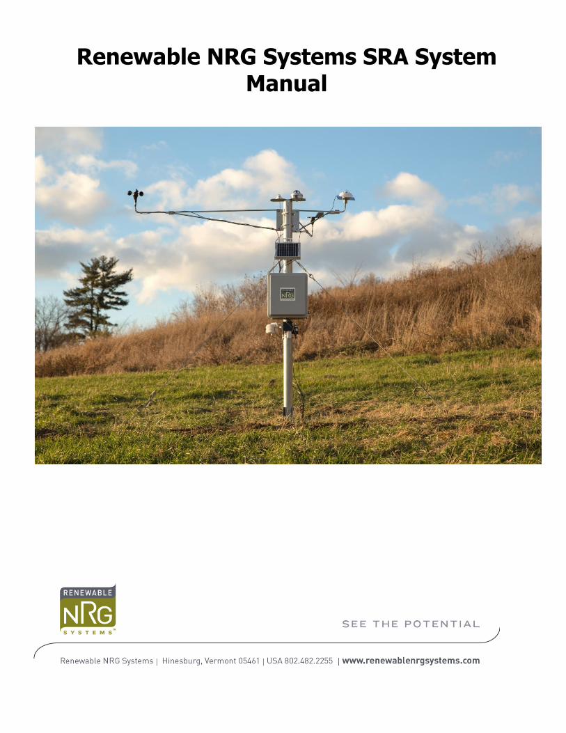
Renewable NRG Systems SRA System Manual

RNRG_SRA_Manual | Rev 9.0 | 7 January 2015 | [email protected] || 2
© Renewable NRG Systems
110 Riggs Road
Hinesburg VT 05461 USA
Tel: 802-482-2255
Fax: 802-482-2272
www.rnrgsystems.com
Specifications are subject to change without notice.
RNRG_SRA_Manual | Rev 9.0 | 7 January 2015 | [email protected] || 3
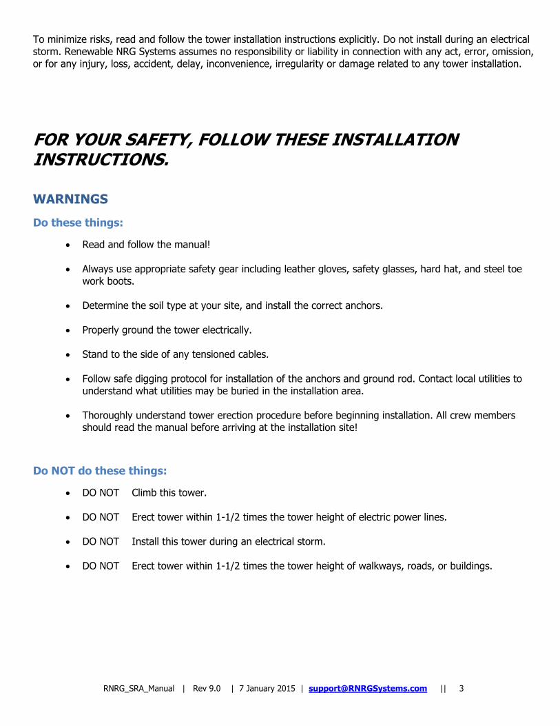
To minimize risks, read and follow the tower installation instructions explicitly. Do not install during an electrical storm. Renewable NRG Systems assumes no responsibility or liability in connection with any act, error, omission, or for any injury, loss, accident, delay, inconvenience, irregularity or damage related to any tower installation.
FOR YOUR SAFETY, FOLLOW THESE INSTALLATION INSTRUCTIONS.
WARNINGS
Do these things:
Read and follow the manual!
Always use appropriate safety gear including leather gloves, safety glasses, hard hat, and steel toe work boots.
Determine the soil type at your site, and install the correct anchors.
Properly ground the tower electrically. Stand to the side of any tensioned cables.
Follow safe digging protocol for installation of the anchors and ground rod. Contact local utilities to understand what utilities may be buried in the installation area.
Thoroughly understand tower erection procedure before beginning installation. All crew members
should read the manual before arriving at the installation site!
Do NOT do these things:
DO NOT Climb this tower. DO NOT Erect tower within 1-1/2 times the tower height of electric power lines. DO NOT Install this tower during an electrical storm. DO NOT Erect tower within 1-1/2 times the tower height of walkways, roads, or buildings.
RNRG_SRA_Manual | Rev 9.0 | 7 January 2015 | [email protected] || 4
Contents
WARNINGS .................................................................................................................................................. 3
Do these things: ....................................................................................................................................... 3
Do NOT do these things: ........................................................................................................................... 3
1.1 Revision History ..................................................................................................................................... 6
1.2 About This Manual .................................................................................................................................. 6
1.3 Typographic Conventions ........................................................................................................................ 6
1.4 Getting Help ........................................................................................................................................... 7
1.5 Overview ............................................................................................................................................... 8
1.5.1 Construction and Assembly ............................................................................................................... 8
1.5.2 Tower Anchoring .............................................................................................................................. 8
1.5.3 Unpacking your tower ...................................................................................................................... 8
1.5.4 Tools recommended for assembly ................................................................................................... 11
Tools included with kit ......................................................................................................................... 11
Personal Protective Equipment ............................................................................................................. 12
1.6 Precautions .......................................................................................................................................... 12
1.6.1 Grounding and ESD ........................................................................................................................ 12
1.6.2 Environmental Considerations ......................................................................................................... 12
1.7 Site Layout ........................................................................................................................................... 12
1.7.1 Pre-Installation Planning .............................................................................................................. 12
1.7.2 Soil Type and Anchors ................................................................................................................. 12
Tip: Wireless Coverage ........................................................................................................................ 12
Tip: Fencing ........................................................................................................................................ 13
1.7.3 Site Layout Map ............................................................................................................................. 14
2.1 Tower Assembly ................................................................................................................................... 15
Assemble the Baseplate ....................................................................................................................... 15
Install the Anchors .............................................................................................................................. 16
Install Tube and Hardware ................................................................................................................... 16
2.2 Guying and Tower Raising .................................................................................................................... 18
Raise Tower Tube to Vertical Position ................................................................................................... 18
RNRG_SRA_Manual | Rev 9.0 | 7 January 2015 | [email protected] || 5
Prepare and Attach Turnbuckles ........................................................................................................... 19
Prepare and attach Guy Wires .............................................................................................................. 20
Attach Sensors and Booms ................................................................................................................... 20
Attach Shelter Box and PV Panel .......................................................................................................... 24
Plumb and Straighten .......................................................................................................................... 26
Pyranometer Leveling .......................................................................................................................... 26
Install Tipping Bucket Rain Gauge ........................................................................................................ 26
Final Inspection and Maintenance of Tipping Bucket Rain Gauge ............................................................ 27
Anchor Loads – Imperial Units ................................................................................................................. 28
Anchor Loads – SI Units .......................................................................................................................... 28
Determine Site Soil and Anchor Type Before You Order Your Tower ........................................................... 29
Anchor Choices and other considerations ................................................................................................. 29
Screw-In Anchor description ................................................................................................................ 30
Arrowhead Anchor description .............................................................................................................. 30
Other Anchor types ............................................................................................................................. 30
Installing Screw-In Anchors ..................................................................................................................... 30
Installing Arrowhead Anchors .................................................................................................................. 31
Site Checklist .......................................................................................................................................... 32
40H Connection Diagram - Bottom View ............................................................................................... 34
Introduction ........................................................................................................................................ 35
Magnetic Declination ........................................................................................................................... 35
Mounting and Aligning Wind Vanes ....................................................................................................... 35
Using Data Analysis Software to Correct for Magnetic Declination ........................................................... 38
Introduction ........................................................................................................................................... 39
Assemble POA Boom ............................................................................................................................... 39
Install POA Boom .................................................................................................................................... 40
Level the Boom and Mount Pyranometer .................................................................................................. 40
Adjust Boom to Desired Angle for POA ..................................................................................................... 41

RNRG_SRA_Manual | Rev 9.0 | 7 January 2015 | [email protected] || 6
Chapter 1 Introduction
1.1 Revision History
Version Date Comment
1 18 January 2012 Initial release.
2 18 January 2012 Fixed typos, no substantive changes.
3 19 March 2012 Updated tools list, updated photos and sensor connection diagram. Added Appendix F: Plane of Array Mounting Boom Installation.
4 23 March 2012 Updated footer only.
5 14 May 2014 Rebranding changes only.
6 17 November 2014 Includes revised tower installation instructions.
7 1 December 2014 New SRA Tower with updated installation instructions.
8 18 December 2014 Updated part quantities on manual that were incorrect.
9 2 January 2015 Updated grounding and sensor connection information.
1.2 About This Manual
Welcome to the Renewable NRG Systems (RNRG) SRA System Installation Manual! This manual is organized to provide a system overview followed by more detailed installation instructions and is intended to be used with the SymphoniePLUS3 data logger manual. Users already familiar with previous generation Symphonie loggers and iPacks will notice similar menus and terminology in the SRA system. We recommend reading the whole manual to take advantage of all of the features and get the most out of your SRA system. All product manuals are available from the Technical Support area of our website at www.renewablenrgsystems.com.
1.3 Typographic Conventions
This type style is used for the general body of this manual.
Caution
This style is used to warn users of a potential danger, either to themselves or to the equipment or data.
Note: This style is used to indicate a tip or an important note.

RNRG_SRA_Manual | Rev 9.0 | 7 January 2015 | [email protected] || 7
1.4 Getting Help
RNRG offers a variety of support options to help you get the most from your RNRG product. If you have questions about your RNRG product, first look in the printed product documentation or the Knowledge Base or Technical Forum in the Tech Support section of the RNRG web site. If you cannot find the answer, contact your salesperson or RNRG Technical Support for assistance using the information below. Customer support is available 8:30 AM to 5:00 PM EST, Monday through Friday.
Renewable NRG Systems 110 Riggs Road Hinesburg, Vermont 05461 U.S.A.
Telephone: 802-482-2255 Fax: 802-482-2272 Email: [email protected]
When you call or email, you should have the appropriate product documentation at hand and be prepared to give the following information:
Customer name Who purchased equipment
Item number or description Serial numbers of loggers and iPack equipment When equipment was purchased Where equipment is installed - terrain conditions Description of the problem with some detail
What events took place leading up to the problem What you have tried while attempting to solve the problem
RNRG maintains an extensive website which includes an in-depth customer support area. If you need assistance at times other than our regular business hours, we suggest visiting our website, www.rnrgsystems.com.
All instruments, sensors, software and towers manufactured by RNRG are designed to be reliable and easy to use. We welcome your comments and appreciate your help in making our products the best available.
RNRG_SRA_Manual | Rev 9.0 | 7 January 2015 | [email protected] || 8
1.5 Overview
The SRA system from RNRG is designed for the professional solar PV developer looking for quick and repeatable deployment, easy and autonomous off-grid operation, and bankable data. The system is comprised of proven products including the RNRG SymphoniePLUS3™ data logger, iPackGPS communications modules (GSM, CDMA, and Satellite), SDR software, meteorological tower components, and reliable sensors. RNRG resource assessment equipment is currently used on all continents and across 145 countries.
1.5.1 Construction and Assembly
The SRA system utilizes a galvanized steel tube stabilized by three guy wires. The tower is tilted up from the ground on a pivot bolt that passes through the base plate assembly and the tube.
1.5.2 Tower Anchoring
The SRA system‟s tower is supplied with 4-inch screw-in anchors. Other anchor types are available. It is your responsibility to determine which type of anchor is appropriate for your specific site.
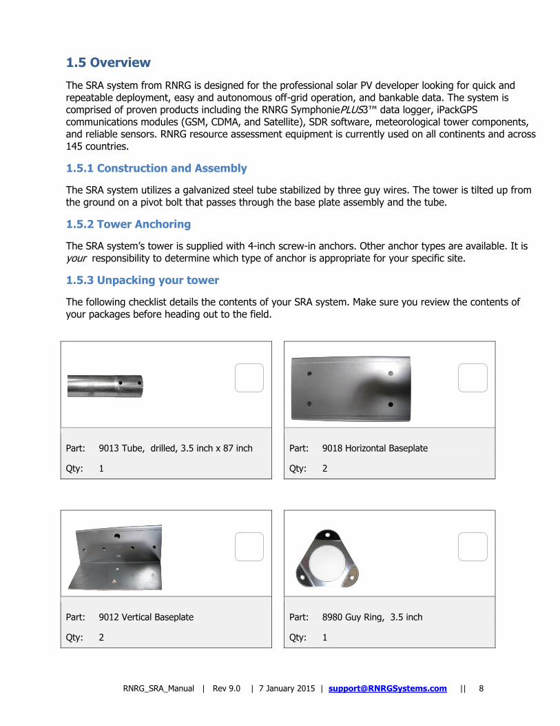
1.5.3 Unpacking your tower
The following checklist details the contents of your SRA system. Make sure you review the contents of your packages before heading out to the field.
Part: 9013 Tube, drilled, 3.5 inch x 87 inch
Qty: 1
Part: 9018 Horizontal Baseplate
Qty: 2
Part: 9012 Vertical Baseplate
Qty: 2
Part: 8980 Guy Ring, 3.5 inch
Qty: 1
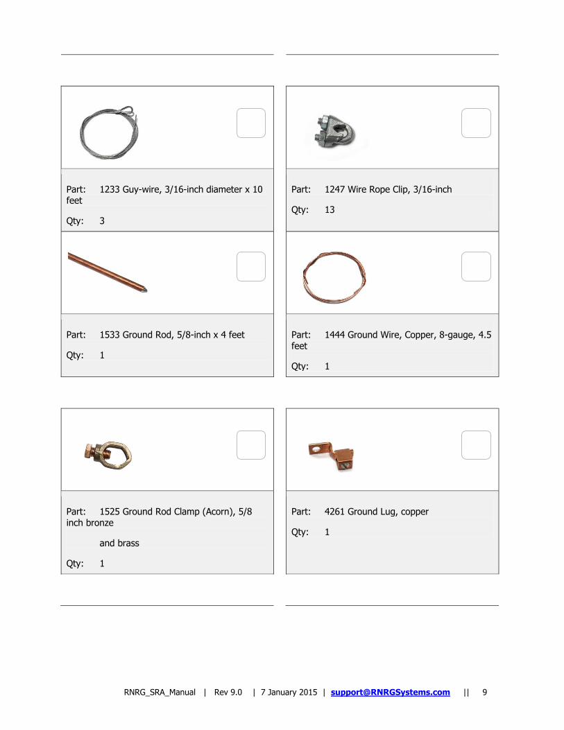
RNRG_SRA_Manual | Rev 9.0 | 7 January 2015 | [email protected] || 9
Part: 1233 Guy-wire, 3/16-inch diameter x 10 feet
Qty: 3
Part: 1247 Wire Rope Clip, 3/16-inch
Qty: 13
Part: 1533 Ground Rod, 5/8-inch x 4 feet
Qty: 1
Part: 1444 Ground Wire, Copper, 8-gauge, 4.5 feet
Qty: 1
Part: 1525 Ground Rod Clamp (Acorn), 5/8 inch bronze
and brass
Qty: 1
Part: 4261 Ground Lug, copper
Qty: 1
RNRG_SRA_Manual | Rev 9.0 | 7 January 2015 | [email protected] || 10
Part: 5270 Turnbuckle, galvanized steel
Qty: 3
Part: 1547 Bolt, 1/2-inch-13 x 5 inch
Qty: 2
Part: 1518 Bolt, 3/8 inch - 16x1 inch
Qty: 4
Part: 1518 W/Nut, 3/8 inch
Qty: 4
Part: 1339 Screw with Washer and Nut, 1/4”
Qty: 1
Part: 6792 Angle Finder / Level
Qty: 1
Part: 5390 Anchor, Screw In, 30-inch length, 4-inch helix Qty: 3
Part: 1524 Screw- ¼”x 3/4” self drilling
Qty: 3
RNRG_SRA_Manual | Rev 9.0 | 7 January 2015 | [email protected] || 11
Part: 5373 Anti-Seize Lubricant
Qty: 1
1.5.4 Tools recommended for assembly
Large adjustable wrench (up to 1 1/8 inch capacity minimum)
Hand sledge (for ground rod) Small adjustable wrench (for opening/closing acorn clamps) Small pliers (for sensor cotter pins) Hex keys for final leveling of pyranometers
Knives (to cut electrical tape) – one per crew member Compass (for aligning direction sensors) Permanent marker (for labeling lower ends of cables) 1.8m (6-feet) stepladder Cordless Drill with 5/15 nutdriver bit (for tightening hose clamps)
*1/4-inch nut driver (for sensor installation) *5/16-inch nut driver (for hose clamps)
*7/16-inch socket wrenches (for wire rope clips) *Small Phillips head (+) screwdriver (for set screws) *Flat (-) screwdriver (grounding lug) *Electrical tape (for cable/wire retention) *Double open-end wrench 1/2 inch and 3/8 inch ends
*Protective installation cap (installing rain gauge pipe)
*Tools indicated included in option SRA ToolKit 5372
Tools included with kit
Magnetic angle finder Anti-Seize Compound
RNRG_SRA_Manual | Rev 9.0 | 7 January 2015 | [email protected] || 12
Personal Protective Equipment
Gloves
Safety Glasses Steel toe boots
1.6 Precautions
1.6.1 Grounding and ESD Failure to ground the logger puts the logger and sensors at risk for electrostatic damage (ESD).
Caution
Whenever coming in contact with the SymphoniePLUS3 logger, either in the field or indoors, it is good practice to first grasp a piece of grounded (earthed) metal before touching the logger to avoid a potentially damaging electrostatic discharge (ESD) to the equipment.
The copper clad ground rod provides an electrical path for static electricity that builds up on the sensors to dissipate to ground. Failure to use proper grounding protection can damage the equipment and will void the warranty.
1.6.2 Environmental Considerations
Sensor cables become less flexible and are more easily damaged at very low temperatures. Make sure that all cables are securely fastened to the tower so they do not flap in the wind. If your site is at high latitude and your logger has many sensors connected, consider using an extra PV panel.
If the equipment will be exposed to high salinity, use protective grease or some other deoxidizing agent on terminals and ground connections.
1.7 Site Layout
1.7.1 Pre-Installation Planning
It is a good idea to visit the site before you order your SRA system as some site preparation may be necessary.
1.7.2 Soil Type and Anchors
Before ordering your system, research the site soil and be sure to know what soil types exist at your site as part of your pre-installation planning process. Depending on the soil type, anchoring can take varying levels of planning, effort, and time. It is your responsibility to determine which type of anchor is appropriate for your specific site. The system ships with 4-inch screw-in anchors.
Tip: Wireless Coverage
This is also a good opportunity to identify what type of wireless service is available at the site (GSM, CDMA, Satellite) for those who will be using an RNRG iPackGPS communications module to transmit data.
RNRG_SRA_Manual | Rev 9.0 | 7 January 2015 | [email protected] || 13
Contact RNRG for more information on iPack communications modules.
Tip: Fencing
It is recommended to consider installing perimeter fencing for your SRA system. This will help prevent vandalism and wildlife interruption.
RNRG_SRA_Manual | Rev 9.0 | 7 January 2015 | [email protected] || 14
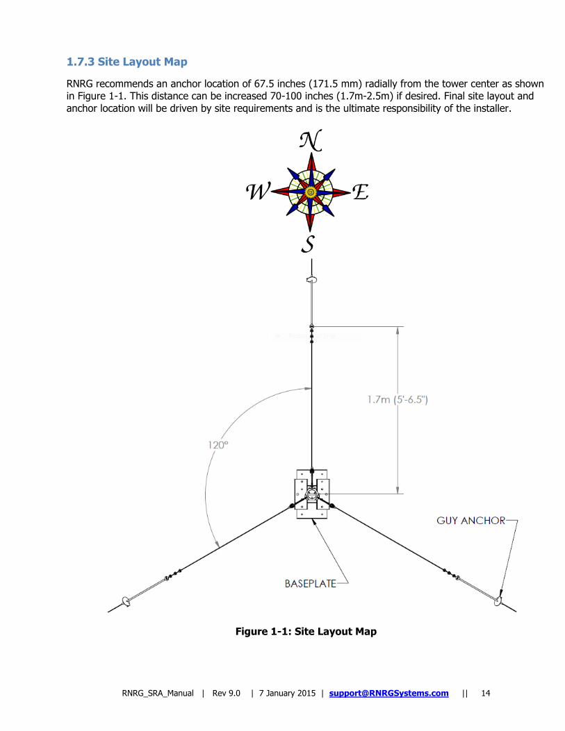
1.7.3 Site Layout Map
RNRG recommends an anchor location of 67.5 inches (171.5 mm) radially from the tower center as shown in Figure 1-1. This distance can be increased 70-100 inches (1.7m-2.5m) if desired. Final site layout and anchor location will be driven by site requirements and is the ultimate responsibility of the installer.
Figure 1-1: Site Layout Map
RNRG_SRA_Manual | Rev 9.0 | 7 January 2015 | [email protected] || 15
Chapter 2 Installation
2.1 Tower Assembly
Assemble the Baseplate
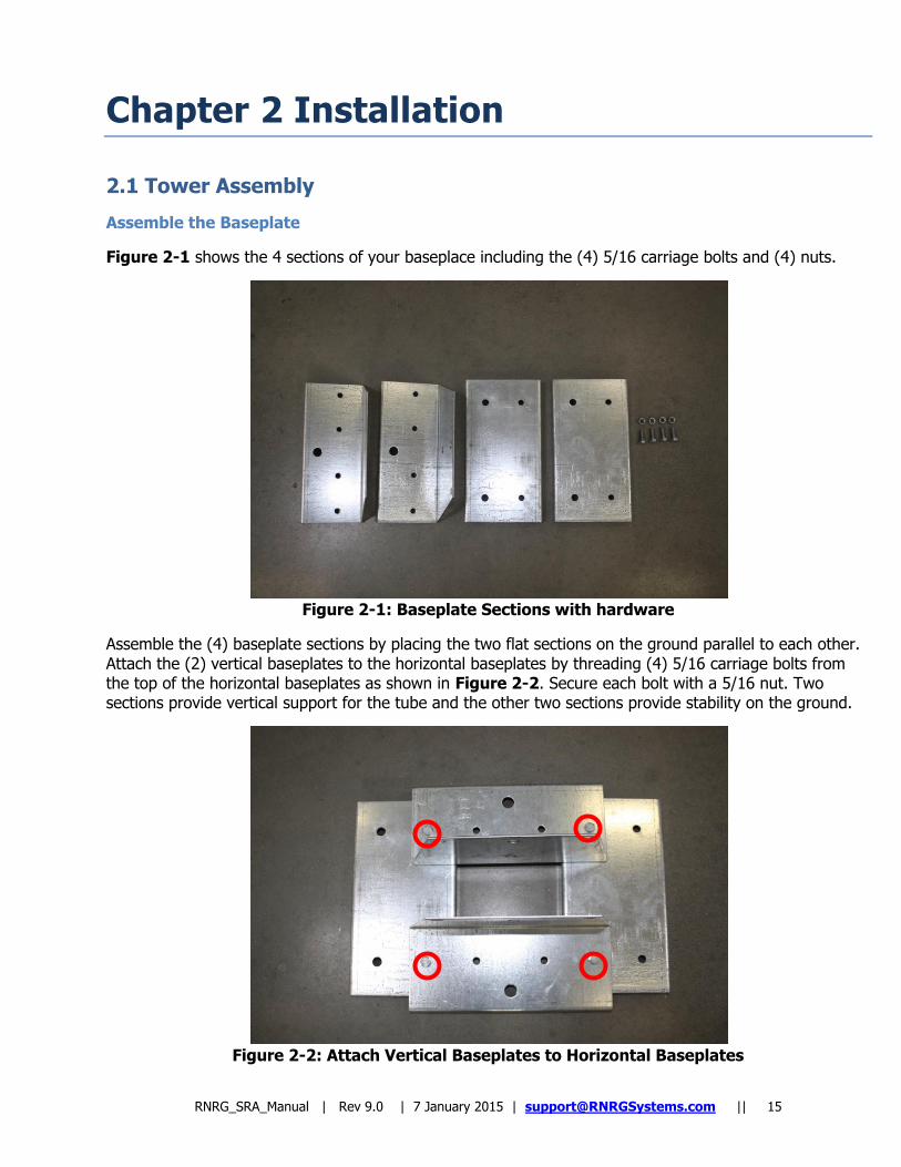
Figure 2-1 shows the 4 sections of your baseplace including the (4) 5/16 carriage bolts and (4) nuts.
Figure 2-1: Baseplate Sections with hardware
Assemble the (4) baseplate sections by placing the two flat sections on the ground parallel to each other. Attach the (2) vertical baseplates to the horizontal baseplates by threading (4) 5/16 carriage bolts from the top of the horizontal baseplates as shown in Figure 2-2. Secure each bolt with a 5/16 nut. Two sections provide vertical support for the tube and the other two sections provide stability on the ground.
Figure 2-2: Attach Vertical Baseplates to Horizontal Baseplates
RNRG_SRA_Manual | Rev 9.0 | 7 January 2015 | [email protected] || 16
Install the Anchors
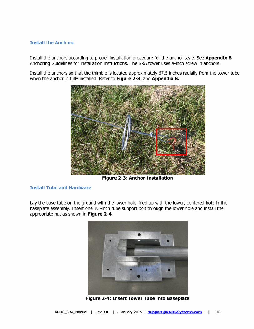
Install the anchors according to proper installation procedure for the anchor style. See Appendix B Anchoring Guidelines for installation instructions. The SRA tower uses 4-inch screw in anchors.
Install the anchors so that the thimble is located approximately 67.5 inches radially from the tower tube when the anchor is fully installed. Refer to Figure 2-3, and Appendix B.
Figure 2-3: Anchor Installation
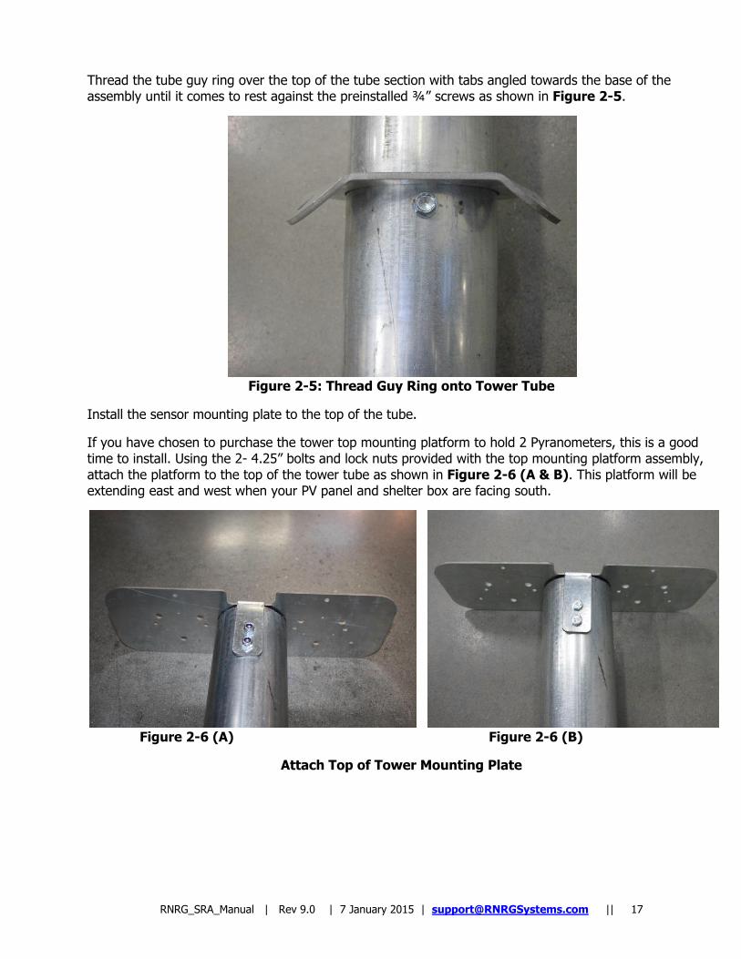
Install Tube and Hardware
Lay the base tube on the ground with the lower hole lined up with the lower, centered hole in the baseplate assembly. Insert one ½ -inch tube support bolt through the lower hole and install the appropriate nut as shown in Figure 2-4.
Figure 2-4: Insert Tower Tube into Baseplate
RNRG_SRA_Manual | Rev 9.0 | 7 January 2015 | [email protected] || 17
Thread the tube guy ring over the top of the tube section with tabs angled towards the base of the assembly until it comes to rest against the preinstalled ¾” screws as shown in Figure 2-5.
Figure 2-5: Thread Guy Ring onto Tower Tube
Install the sensor mounting plate to the top of the tube.
If you have chosen to purchase the tower top mounting platform to hold 2 Pyranometers, this is a good time to install. Using the 2- 4.25” bolts and lock nuts provided with the top mounting platform assembly, attach the platform to the top of the tower tube as shown in Figure 2-6 (A & B). This platform will be extending east and west when your PV panel and shelter box are facing south.
Figure 2-6 (A) Figure 2-6 (B)
Attach Top of Tower Mounting Plate
RNRG_SRA_Manual | Rev 9.0 | 7 January 2015 | [email protected] || 18
2.2 Guying and Tower Raising
Raise Tower Tube to Vertical Position
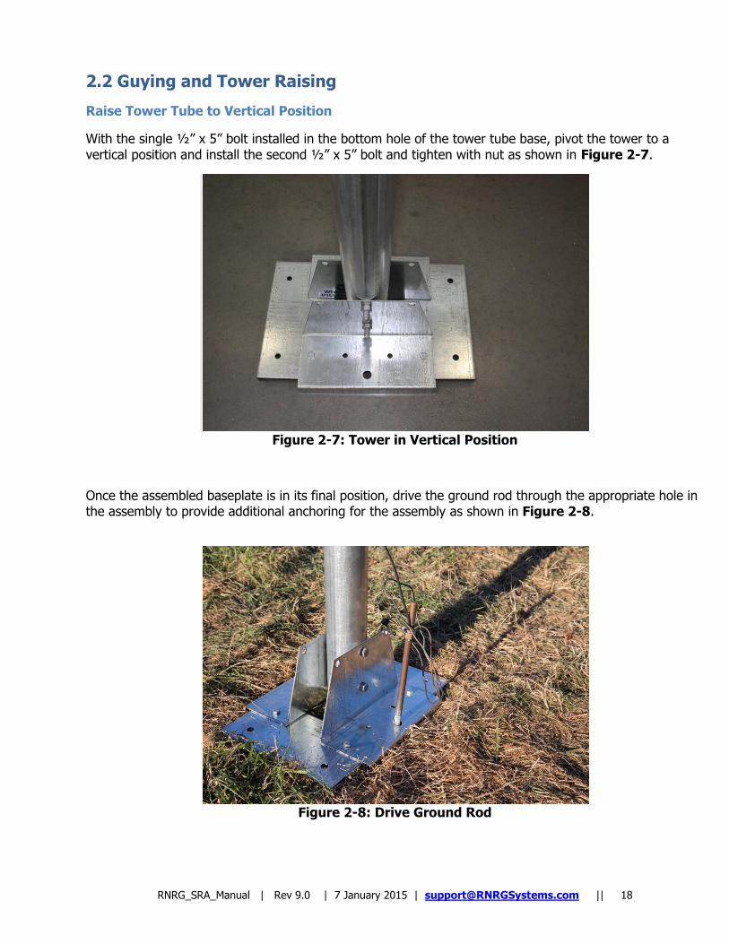
With the single ½” x 5” bolt installed in the bottom hole of the tower tube base, pivot the tower to a vertical position and install the second ½” x 5” bolt and tighten with nut as shown in Figure 2-7.
\ Figure 2-7: Tower in Vertical Position
Once the assembled baseplate is in its final position, drive the ground rod through the appropriate hole in the assembly to provide additional anchoring for the assembly as shown in Figure 2-8.
Figure 2-8: Drive Ground Rod
RNRG_SRA_Manual | Rev 9.0 | 7 January 2015 | [email protected] || 19
Prepare and Attach Turnbuckles
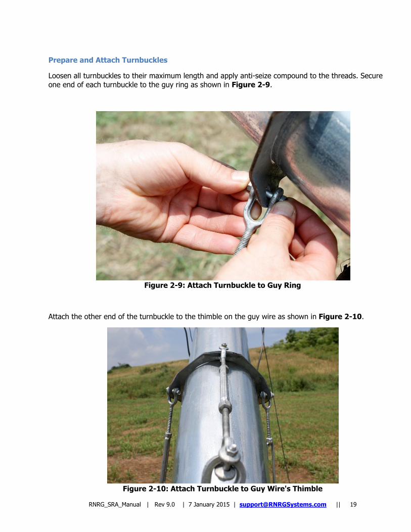
Loosen all turnbuckles to their maximum length and apply anti-seize compound to the threads. Secure one end of each turnbuckle to the guy ring as shown in Figure 2-9.
Figure 2-9: Attach Turnbuckle to Guy Ring
Attach the other end of the turnbuckle to the thimble on the guy wire as shown in Figure 2-10.
Figure 2-10: Attach Turnbuckle to Guy Wire's Thimble
RNRG_SRA_Manual | Rev 9.0 | 7 January 2015 | [email protected] || 20
Prepare and attach Guy Wires
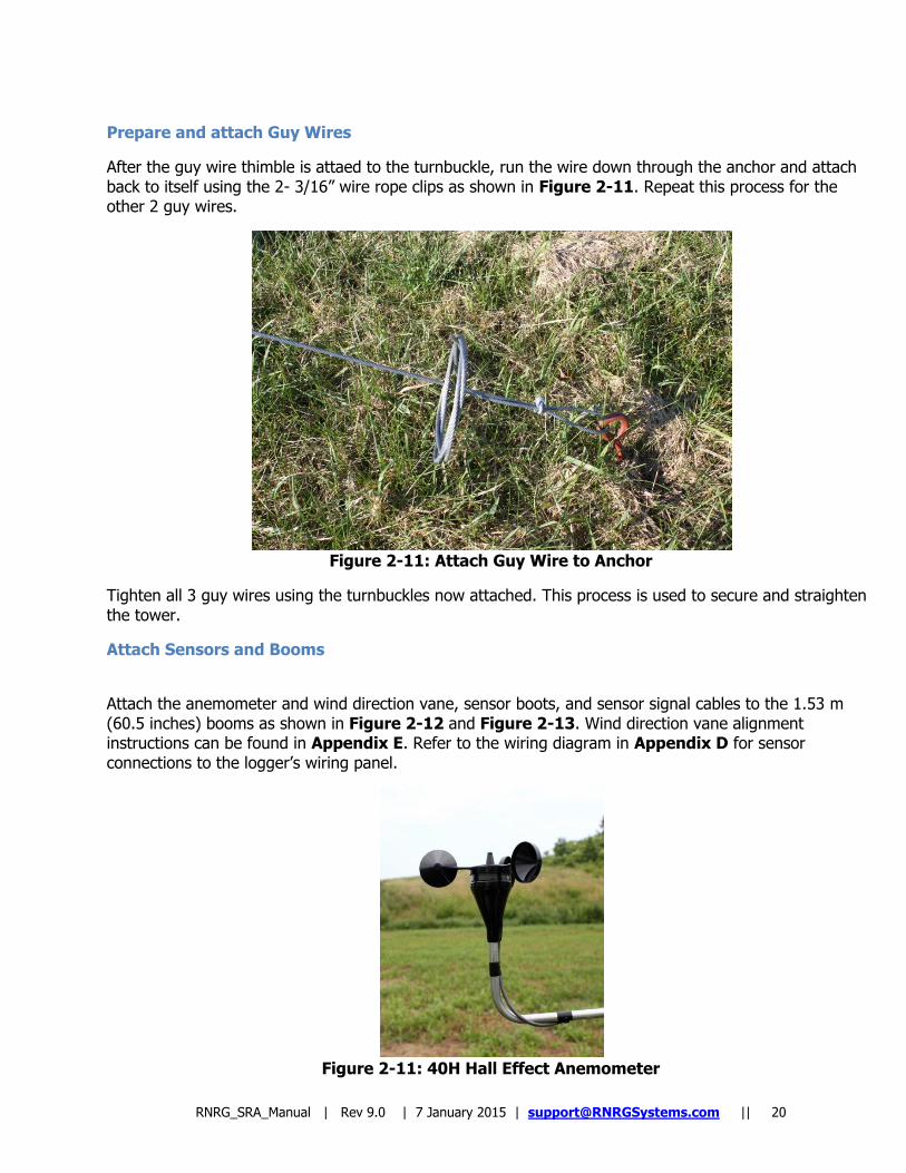
After the guy wire thimble is attaed to the turnbuckle, run the wire down through the anchor and attach back to itself using the 2- 3/16” wire rope clips as shown in Figure 2-11. Repeat this process for the other 2 guy wires.
Figure 2-11: Attach Guy Wire to Anchor
Tighten all 3 guy wires using the turnbuckles now attached. This process is used to secure and straighten the tower.
Attach Sensors and Booms
Attach the anemometer and wind direction vane, sensor boots, and sensor signal cables to the 1.53 m (60.5 inches) booms as shown in Figure 2-12 and Figure 2-13. Wind direction vane alignment instructions can be found in Appendix E. Refer to the wiring diagram in Appendix D for sensor connections to the logger‟s wiring panel.
Figure 2-11: 40H Hall Effect Anemometer
RNRG_SRA_Manual | Rev 9.0 | 7 January 2015 | [email protected] || 21
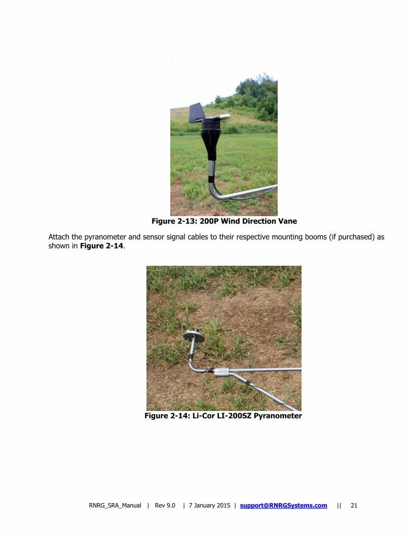
Figure 2-13: 200P Wind Direction Vane
Attach the pyranometer and sensor signal cables to their respective mounting booms (if purchased) as shown in Figure 2-14.
Figure 2-14: Li-Cor LI-200SZ Pyranometer
RNRG_SRA_Manual | Rev 9.0 | 7 January 2015 | [email protected] || 22
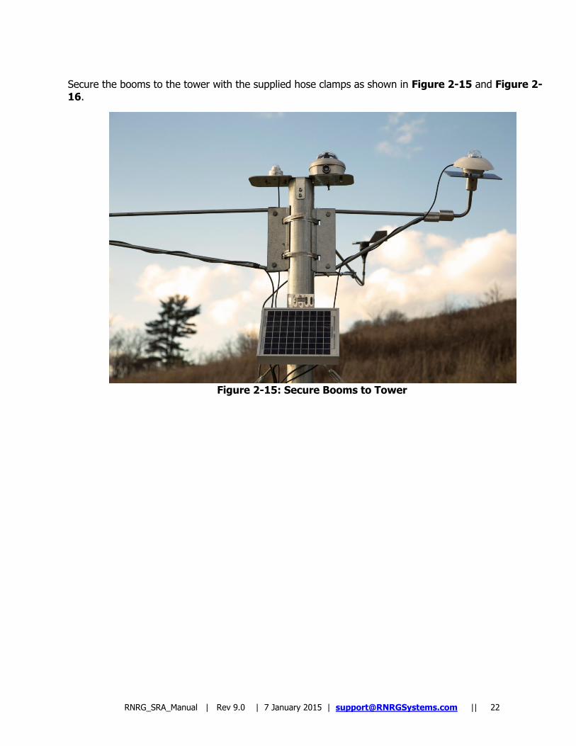
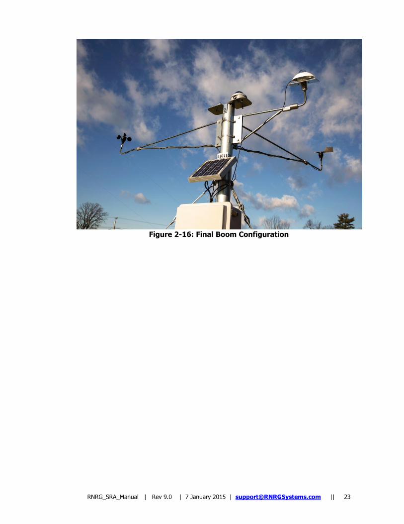
Secure the booms to the tower with the supplied hose clamps as shown in Figure 2-15 and Figure 2-16.
Figure 2-15: Secure Booms to Tower
RNRG_SRA_Manual | Rev 9.0 | 7 January 2015 | [email protected] || 23
Figure 2-16: Final Boom Configuration
RNRG_SRA_Manual | Rev 9.0 | 7 January 2015 | [email protected] || 24
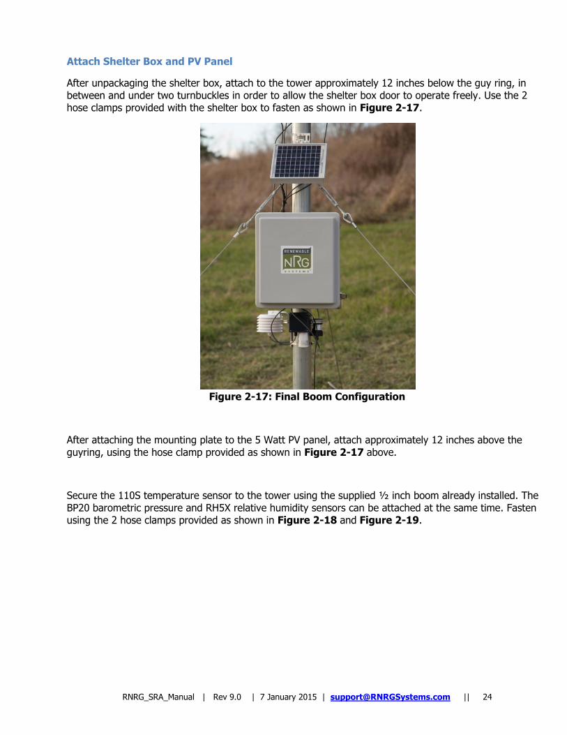
Attach Shelter Box and PV Panel
After unpackaging the shelter box, attach to the tower approximately 12 inches below the guy ring, in between and under two turnbuckles in order to allow the shelter box door to operate freely. Use the 2 hose clamps provided with the shelter box to fasten as shown in Figure 2-17.
Figure 2-17: Final Boom Configuration
After attaching the mounting plate to the 5 Watt PV panel, attach approximately 12 inches above the guyring, using the hose clamp provided as shown in Figure 2-17 above.
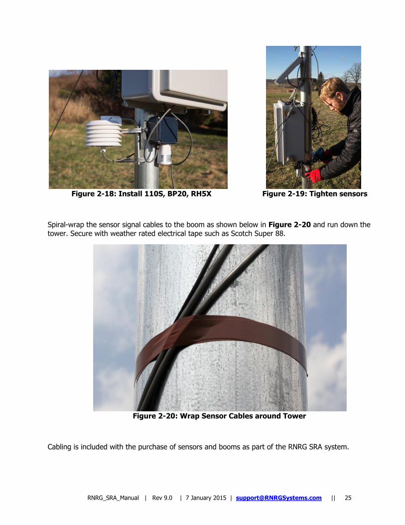
Secure the 110S temperature sensor to the tower using the supplied ½ inch boom already installed. The BP20 barometric pressure and RH5X relative humidity sensors can be attached at the same time. Fasten using the 2 hose clamps provided as shown in Figure 2-18 and Figure 2-19.
RNRG_SRA_Manual | Rev 9.0 | 7 January 2015 | [email protected] || 25
Figure 2-18: Install 110S, BP20, RH5X Figure 2-19: Tighten sensors
Spiral-wrap the sensor signal cables to the boom as shown below in Figure 2-20 and run down the tower. Secure with weather rated electrical tape such as Scotch Super 88.
Figure 2-20: Wrap Sensor Cables around Tower
Cabling is included with the purchase of sensors and booms as part of the RNRG SRA system.
RNRG_SRA_Manual | Rev 9.0 | 7 January 2015 | [email protected] || 26
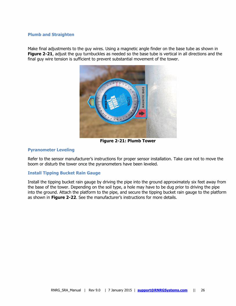
Plumb and Straighten
Make final adjustments to the guy wires. Using a magnetic angle finder on the base tube as shown in Figure 2-21, adjust the guy turnbuckles as needed so the base tube is vertical in all directions and the final guy wire tension is sufficient to prevent substantial movement of the tower.
Figure 2-21: Plumb Tower
Pyranometer Leveling
Refer to the sensor manufacturer‟s instructions for proper sensor installation. Take care not to move the boom or disturb the tower once the pyranometers have been leveled.
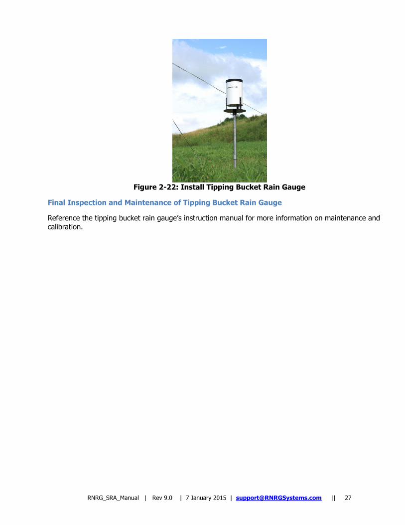
Install Tipping Bucket Rain Gauge
Install the tipping bucket rain gauge by driving the pipe into the ground approximately six feet away from the base of the tower. Depending on the soil type, a hole may have to be dug prior to driving the pipe into the ground. Attach the platform to the pipe, and secure the tipping bucket rain gauge to the platform as shown in Figure 2-22. See the manufacturer‟s instructions for more details.
RNRG_SRA_Manual | Rev 9.0 | 7 January 2015 | [email protected] || 27
Figure 2-22: Install Tipping Bucket Rain Gauge
Final Inspection and Maintenance of Tipping Bucket Rain Gauge
Reference the tipping bucket rain gauge‟s instruction manual for more information on maintenance and calibration.
RNRG_SRA_Manual | Rev 9.0 | 7 January 2015 | [email protected] || 28
Appendix A: SRA Tower Loads and Structural Ratings
Anchor Loads – Imperial Units
90 mph wind speed, max anchor load=71.6 lbf
120mph wind speed, max anchor load=127.3 lbf/ 566 N
Anchor Loads – SI Units
145 kph wind speed, max anchor load = 318 N
193 kph wind speed, max anchor load= 566 N
RNRG_SRA_Manual | Rev 9.0 | 7 January 2015 | [email protected] || 29
Appendix B: Anchoring Guidelines
Determine Site Soil and Anchor Type Before You Order Your Tower
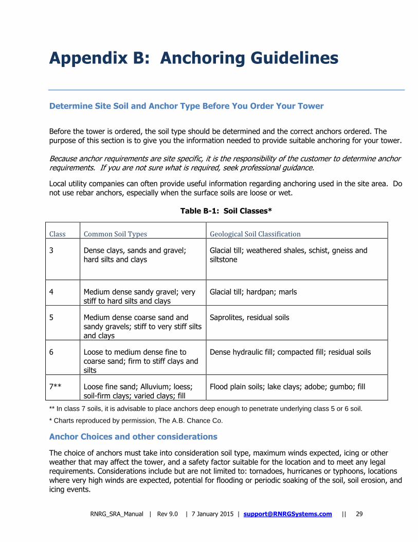
Before the tower is ordered, the soil type should be determined and the correct anchors ordered. The purpose of this section is to give you the information needed to provide suitable anchoring for your tower. Because anchor requirements are site specific, it is the responsibility of the customer to determine anchor requirements. If you are not sure what is required, seek professional guidance.
Local utility companies can often provide useful information regarding anchoring used in the site area. Do not use rebar anchors, especially when the surface soils are loose or wet.
Table B-1: Soil Classes*
Class Common Soil Types Geological Soil Classification
3 Dense clays, sands and gravel; hard silts and clays
Glacial till; weathered shales, schist, gneiss and siltstone
4 Medium dense sandy gravel; very stiff to hard silts and clays
Glacial till; hardpan; marls
5 Medium dense coarse sand and sandy gravels; stiff to very stiff silts and clays
Saprolites, residual soils
6 Loose to medium dense fine to coarse sand; firm to stiff clays and silts
Dense hydraulic fill; compacted fill; residual soils
7** Loose fine sand; Alluvium; loess; soil-firm clays; varied clays; fill
Flood plain soils; lake clays; adobe; gumbo; fill
** In class 7 soils, it is advisable to place anchors deep enough to penetrate underlying class 5 or 6 soil.
* Charts reproduced by permission, The A.B. Chance Co.
Anchor Choices and other considerations
The choice of anchors must take into consideration soil type, maximum winds expected, icing or other weather that may affect the tower, and a safety factor suitable for the location and to meet any legal requirements. Considerations include but are not limited to: tornadoes, hurricanes or typhoons, locations where very high winds are expected, potential for flooding or periodic soaking of the soil, soil erosion, and icing events.
RNRG_SRA_Manual | Rev 9.0 | 7 January 2015 | [email protected] || 30
Screw-In Anchor description
Screw-in anchors are the most commonly used anchors for normal clay soils without rocks and are the standard anchors supplied with the RNRG SRA System. They are installed by hand, using a cross bar to screw them into the earth like a corkscrew.
Arrowhead Anchor description
Arrowhead anchors can penetrate stiff and rocky soils because the unique triangular design threads its way between obstacles such as rocks, which can prevent successful installation of screw-in anchors. Arrowhead anchors are driven into the ground with a hardened steel drive rod. Once in the ground, upward force on the attached cable rotates the anchor perpendicular to the cable for maximum holding power.
Other Anchor types
There are other anchor types such as rock anchors and site-built concrete anchors. These types are not commonly used for a tower this size.
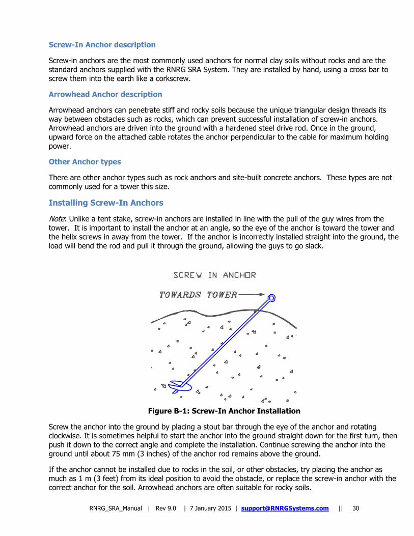
Installing Screw-In Anchors
Note: Unlike a tent stake, screw-in anchors are installed in line with the pull of the guy wires from the tower. It is important to install the anchor at an angle, so the eye of the anchor is toward the tower and the helix screws in away from the tower. If the anchor is incorrectly installed straight into the ground, the load will bend the rod and pull it through the ground, allowing the guys to go slack.
Figure B-1: Screw-In Anchor Installation
Screw the anchor into the ground by placing a stout bar through the eye of the anchor and rotating clockwise. It is sometimes helpful to start the anchor into the ground straight down for the first turn, then push it down to the correct angle and complete the installation. Continue screwing the anchor into the ground until about 75 mm (3 inches) of the anchor rod remains above the ground.
If the anchor cannot be installed due to rocks in the soil, or other obstacles, try placing the anchor as much as 1 m (3 feet) from its ideal position to avoid the obstacle, or replace the screw-in anchor with the correct anchor for the soil. Arrowhead anchors are often suitable for rocky soils.
RNRG_SRA_Manual | Rev 9.0 | 7 January 2015 | [email protected] || 31
If necessary, a hole can be dug for the screw-in anchor to the proper installed depth, the anchor placed in the hole, and the hole back-filled. The earth must be tamped onto the anchor hard while back filling. The holding power of an anchor placed this way will not be as great as an anchor screwed into undisturbed soil. If in doubt, get professional advice on whether this option will work for your site.
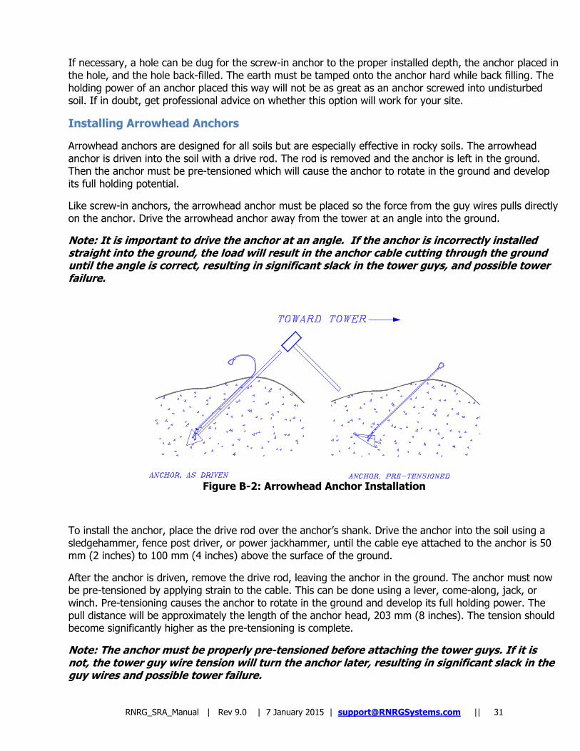
Installing Arrowhead Anchors
Arrowhead anchors are designed for all soils but are especially effective in rocky soils. The arrowhead anchor is driven into the soil with a drive rod. The rod is removed and the anchor is left in the ground. Then the anchor must be pre-tensioned which will cause the anchor to rotate in the ground and develop its full holding potential.
Like screw-in anchors, the arrowhead anchor must be placed so the force from the guy wires pulls directly on the anchor. Drive the arrowhead anchor away from the tower at an angle into the ground.
Note: It is important to drive the anchor at an angle. If the anchor is incorrectly installed straight into the ground, the load will result in the anchor cable cutting through the ground until the angle is correct, resulting in significant slack in the tower guys, and possible tower failure.
Figure B-2: Arrowhead Anchor Installation
To install the anchor, place the drive rod over the anchor‟s shank. Drive the anchor into the soil using a sledgehammer, fence post driver, or power jackhammer, until the cable eye attached to the anchor is 50 mm (2 inches) to 100 mm (4 inches) above the surface of the ground.
After the anchor is driven, remove the drive rod, leaving the anchor in the ground. The anchor must now be pre-tensioned by applying strain to the cable. This can be done using a lever, come-along, jack, or winch. Pre-tensioning causes the anchor to rotate in the ground and develop its full holding power. The pull distance will be approximately the length of the anchor head, 203 mm (8 inches). The tension should become significantly higher as the pre-tensioning is complete.
Note: The anchor must be properly pre-tensioned before attaching the tower guys. If it is not, the tower guy wire tension will turn the anchor later, resulting in significant slack in the guy wires and possible tower failure.
RNRG_SRA_Manual | Rev 9.0 | 7 January 2015 | [email protected] || 32
Appendix C: Site Visit Procedures
Site Checklist When making a site visit, check the following: √ Make sure the tower is straight. Stand at the base of the tower and look up to identify any bowed sections or
curves in the tower that may have developed since the tower installation. Using a magnetic level to verify straightness, carefully adjust guy wires as necessary to straighten the tower.
√ It is recommended that pyranometers are periodically cleaned according to the sensor manufacturer‟s
recommendation. Inspect and adjust the pyranometers for level after each cleaning and whenever visiting the site. Documentation of the site visit with notes are recommended.
√ Check guy wires for excessive slack and adjust as necessary. It is normal for guy wires to stretch over time.
√ Check each anchor for movement or loosening. A loose anchor can also cause excessive slack in guy wires.
√ Check that mounting booms, cellular antennas, temperature sensors, etc. are securely attached.
√ Confirm that all grounding connections on the tower and on the logger are secure and haven‟t corroded.
√ Check instantaneous sensor readings on each channel of your data logger. Any sensor providing erroneous
readings should be disconnected from the logger and tested independently and/or replaced. It is a good idea to always have spare sensors, memory cards, batteries, and a spare data logger.
√ Change the data logger‟s batteries. It is better to change them prematurely rather than risk losing data!
RNRG_SRA_Manual | Rev 9.0 | 7 January 2015 | [email protected] || 33
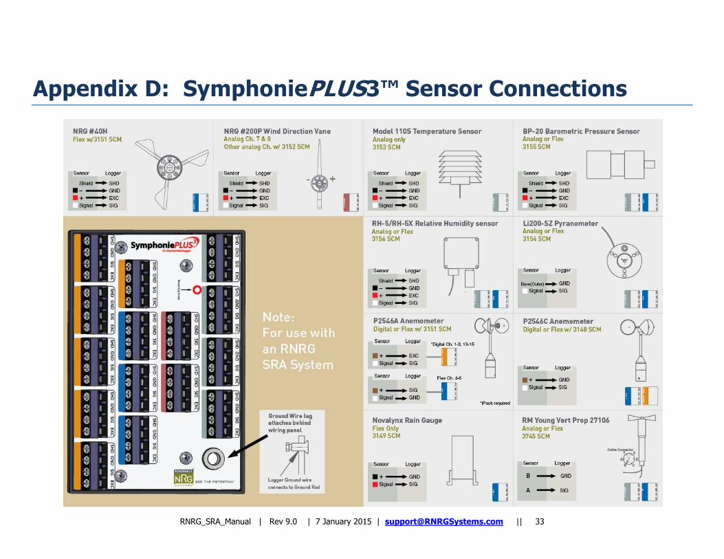
Appendix D: SymphoniePLUS3™ Sensor Connections
RNRG_SRA_Manual | Rev 9.0 | 7 January 2015 | [email protected] || 34
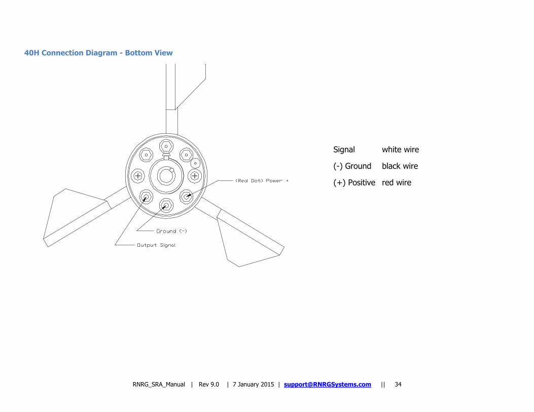
40H Connection Diagram - Bottom View
Signal white wire
(-) Ground black wire
(+) Positive red wire
Appendix E: Aligning Wind Vanes
Introduction
Wind vanes measure wind direction relative to the orientation of the fixed base on the sensor. This Application Note gives you the information you need to orient your wind vanes correctly when they are mounted to the tower. This note also includes information on using offset and magnetic declination corrections when scaling your data to obtain properly scaled and oriented data.
Magnetic Declination
Since the earth‟s magnetic field is not uniform, the magnetic poles do not coincide with the true geographic poles. Moreover, a compass generally doesn‟t point to a true geographic pole; it points to a magnetic pole. This difference between a true geographic bearing and a magnetic bearing varies from location to location and is called magnetic declination. Magnetic declination or “compass variation” is the horizontal angle between true north (also called “geographic north” or “map north”) and the direction the compass points, magnetic north.
Magnetic declination is measured as the number of degrees of error a compass shows at a site. The declination for sites located east of the magnetic north pole is expressed as the number of degrees that magnetic north is west of true north. The declination for sites located west of the magnetic north pole is expressed as the number of degrees that magnetic north is east of true north. For example, Vermont (USA) has a magnetic declination of 15 degrees west. In other words, magnetic north in Vermont is 15 degrees to the west of true north. Magnetic north in Fairbanks, Alaska (USA) is about 27 degrees east of true north; therefore, its magnetic declination is 27 degrees east.
The earth‟s magnetic field varies slightly in position over time. Therefore, the magnetic declination at a site also varies over time. Because of this variation, it is important that you reference an up-to-date map of declination (“isogonic map”) if you choose to orient your wind vanes to magnetic north. Later you can enter a correction for magnetic declination into your wind data analysis software if desired.
Mounting and Aligning Wind Vanes
Since a magnetic compass is the simplest direction reference, it is sometimes convenient to orient wind vanes in the field to magnetic north. Most RNRG customers, however, align their wind vanes to true north. Before installing your RNRG logger, decide whether you want wind direction data to report north when the wind is from the magnetic north or when the wind is from true north. Be sure to make note of your choice and maintain consistency among your sites and projects.
RNRG_SRA_Manual | Rev 9.0 | 7 January 2015 | [email protected] || 36
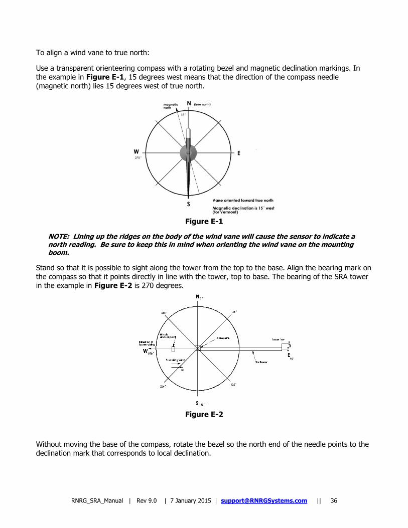
To align a wind vane to true north:
Use a transparent orienteering compass with a rotating bezel and magnetic declination markings. In the example in Figure E-1, 15 degrees west means that the direction of the compass needle (magnetic north) lies 15 degrees west of true north.
Figure E-1
NOTE: Lining up the ridges on the body of the wind vane will cause the sensor to indicate a north reading. Be sure to keep this in mind when orienting the wind vane on the mounting boom.
Stand so that it is possible to sight along the tower from the top to the base. Align the bearing mark on the compass so that it points directly in line with the tower, top to base. The bearing of the SRA tower in the example in Figure E-2 is 270 degrees.
Figure E-2
Without moving the base of the compass, rotate the bezel so the north end of the needle points to the declination mark that corresponds to local declination.
RNRG_SRA_Manual | Rev 9.0 | 7 January 2015 | [email protected] || 37
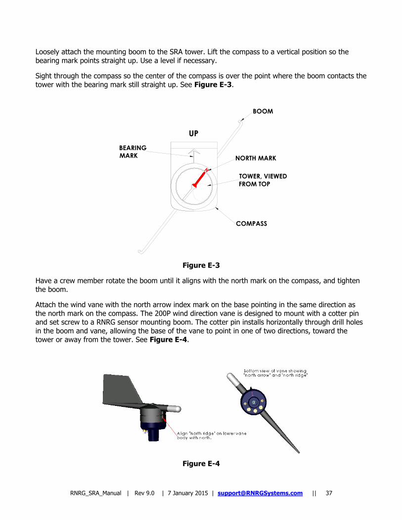
Loosely attach the mounting boom to the SRA tower. Lift the compass to a vertical position so the bearing mark points straight up. Use a level if necessary.
Sight through the compass so the center of the compass is over the point where the boom contacts the tower with the bearing mark still straight up. See Figure E-3.
Figure E-3
Have a crew member rotate the boom until it aligns with the north mark on the compass, and tighten the boom.
Attach the wind vane with the north arrow index mark on the base pointing in the same direction as the north mark on the compass. The 200P wind direction vane is designed to mount with a cotter pin and set screw to a RNRG sensor mounting boom. The cotter pin installs horizontally through drill holes in the boom and vane, allowing the base of the vane to point in one of two directions, toward the tower or away from the tower. See Figure E-4.
Figure E-4
BOOM
NORTH MARK
TOWER, VIEWED
FROM TOP
COMPASS
BEARING
MARK
UP

RNRG_SRA_Manual | Rev 9.0 | 7 January 2015 | [email protected] || 38
When you raise the tower, the north arrow on the base of the wind vane will point to true north.
Use the compass to verify your settings. If necessary, adjust the position of the mounting boom before raising the SRA tower.
Using Data Analysis Software to Correct for Magnetic Declination
If you orient your wind vanes toward magnetic north but want the direction data reported relative to true north, enter the magnetic declination for the site into the offset or magnetic declination field in your wind data analysis software. Declination is not needed if you orient your wind vanes to true north.
Note: Wind direction vanes have a small range centered around the sensor‟s north reading that is called the dead band and produces a zero reading. Although RNRG loggers have an algorithm that interprets north readings correctly, when the prevailing wind is from the north, it may make sense to orient the vane to a direction other than north. If you do this, compensate for the orientation by entering a value in the wind vane „offset‟ field of your data analysis software. For example, if you orient your wind vane to the south (180 degrees), enter an offset of 180 for the vane.
Note: If you orient your wind vane to a magnetic bearing other than magnetic north, you need to enter values for both magnetic declination and offset in your data analysis software. Enter the site‟s magnetic declination so that your software can compensate for the declination; enter an offset to compensate for the orientation of the vane. If just one offset field is available in your software, such as RNRG‟s Symphonie Data Retriever software, you will need to combine the magnetic declination value with the offset value (if wind vanes are not oriented to true north) and enter the net value. For example, if your wind vanes are oriented to the south instead of north, and your site has a magnetic declination of 15 degrees west, you would enter 165 in the offset field. Declinations to the west of true north are subtracted from the magnetic reading, and declinations to the east of true north are added to the magnetic reading.
RNRG_SRA_Manual | Rev 9.0 | 7 January 2015 | [email protected] || 39
Appendix F: Plane of Array Mounting Boom Installation
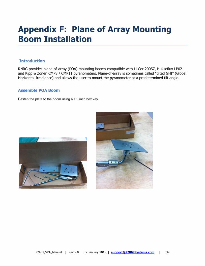
Introduction
RNRG provides plane-of-array (POA) mounting booms compatible with Li-Cor 200SZ, Hukseflux LP02 and Kipp & Zonen CMP3 / CMP11 pyranometers. Plane-of-array is sometimes called “tilted GHI” (Global Horizontal Irradiance) and allows the user to mount the pyranometer at a predetermined tilt angle.
Assemble POA Boom Fasten the plate to the boom using a 1/8 inch hex key.
RNRG_SRA_Manual | Rev 9.0 | 7 January 2015 | [email protected] || 40
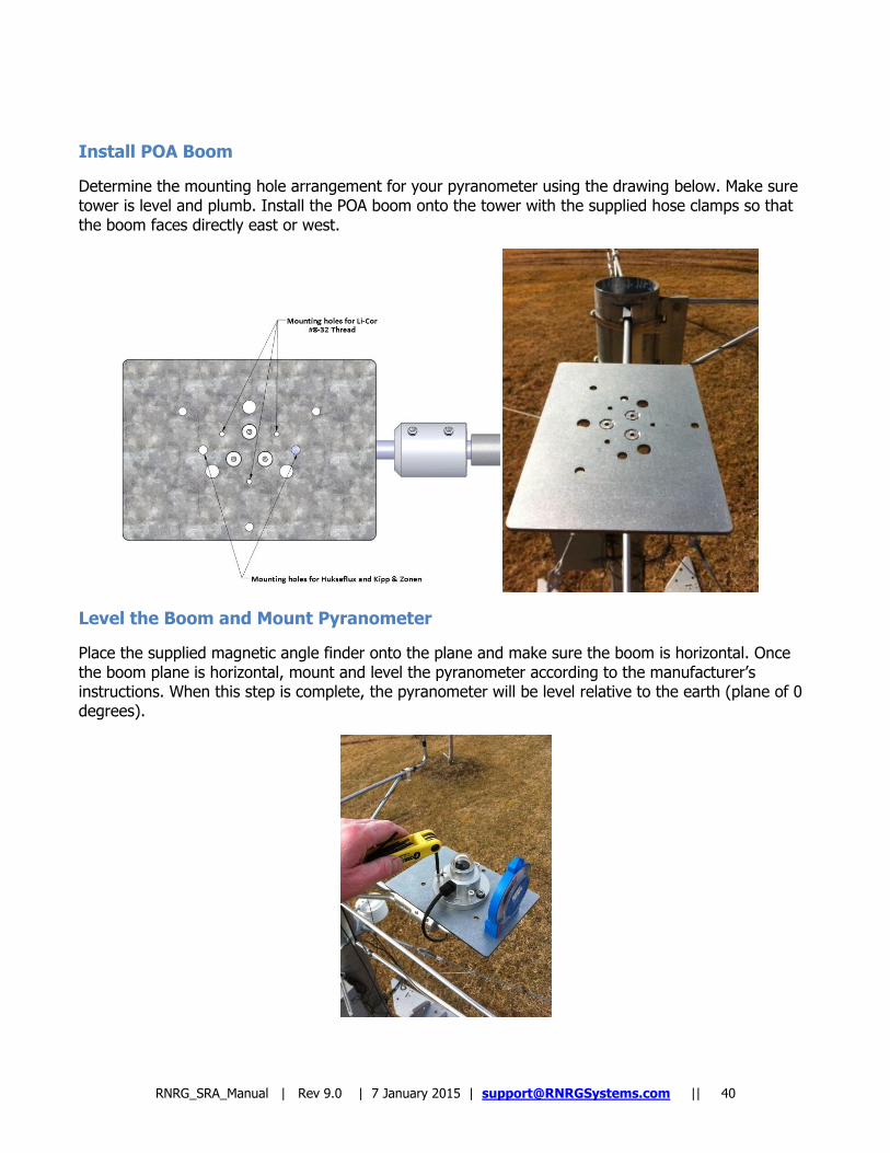
Install POA Boom
Determine the mounting hole arrangement for your pyranometer using the drawing below. Make sure tower is level and plumb. Install the POA boom onto the tower with the supplied hose clamps so that the boom faces directly east or west.
Level the Boom and Mount Pyranometer
Place the supplied magnetic angle finder onto the plane and make sure the boom is horizontal. Once the boom plane is horizontal, mount and level the pyranometer according to the manufacturer‟s instructions. When this step is complete, the pyranometer will be level relative to the earth (plane of 0 degrees).
RNRG_SRA_Manual | Rev 9.0 | 7 January 2015 | [email protected] || 41
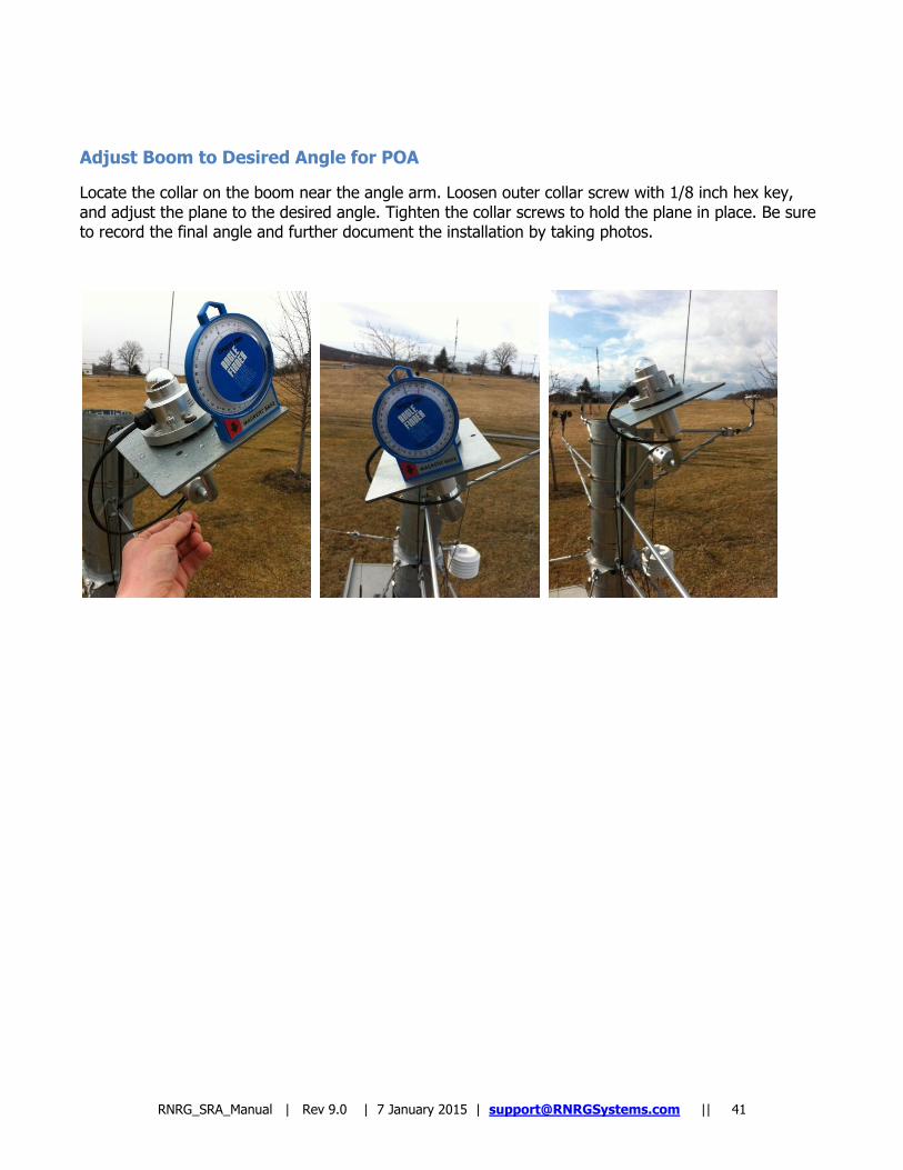
Adjust Boom to Desired Angle for POA
Locate the collar on the boom near the angle arm. Loosen outer collar screw with 1/8 inch hex key, and adjust the plane to the desired angle. Tighten the collar screws to hold the plane in place. Be sure to record the final angle and further document the installation by taking photos.

RNRG_SRA_Manual | Rev 9.0 | 7 January 2015 | [email protected] || 42
Index
anchor ................................................................ 8 anchor requirements .......................................... 29 anchoring ............................................... 29, 31, 32 Anchoring Guidelines .......................................... 29 anchoring the baseplate ..................................... 18 anchors .................................................... 3, 29, 31 Anchors ............................................................ 12 arrowhead anchors ............................................ 31 arrowhead anchors, pre-tensioning...................... 31 batteries ........................................................... 32 guys ........................................................... 26, 31 installing arrowhead anchors............................... 31 Magnetic Declination .......................................... 35 pre-tensioning arrowhead anchors....................... 31
safety ................................................................. 3 site visit procedures ........................................... 32 slack in guy wires ..................................... 31, 32 soil .......................................................... 3, 29, 31 soil type ............................................................ 29 straightening the tower ...................................... 26 tension, guy wire ............................................... 31 tools ................................................................. 11 tube layout ....................................................... 16 WARNINGS ......................................................... 3 winch ............................................................... 31 wind vane alignment .......................................... 35 wire rope clips ................................................... 11