Embed Size (px)
Citation preview

Innovative solutions for the construction industry
Rendalath® Installation guide
2
Table of Contents
03 Getting started
06 Hints for render
application and curing
07 Ensuring continuity of
reinforcement
08 Installation onto
TIMBER FRAME
12 Typical fixing details
for TIMBER FRAME
15 Installation onto
SOLID backgrounds
18 Typical fixing
details for SOLID
BACKGROUNDS
21 Environmental
statement
22 Selecting the right
tools for the job
23 Fixings
Introduction Rendalath® is a unique multi-layered welded wire mesh rein-forced rendering system incorporating sandwich technology. The ‘sandwich’ comprises a welded wire reinforcing mesh, suction control sheet and rear stiffening wires together with an anti-contamination breather membrane all in one easily installed panel.
The Rendalath® panel consists of 4 main components:
1. Welded wire mesh panel providing reinforcement for render to cope with:a. Wind loads when spanning between studs on timber/steel
frame construction. b. Resistance to cracking caused by natural render shrinkage
and movement.
2. Suction control sheet (coloured brown) to provide suction for render adhesion and to avoid the use of a stipple coat (first base-coat). Also assists curing by absorbing and then releasing mois-ture back into the render during hardening.
3. Unique longitudinal stiffening wires provide additional support for timber / steel frame construction and hold chipboard paper in position.
4. Anti-contamination breather membrane (coloured white) to protect against contaminants and to comply with BS5262:1991 Code of Practice for External Rendering for timber frame con-struction.
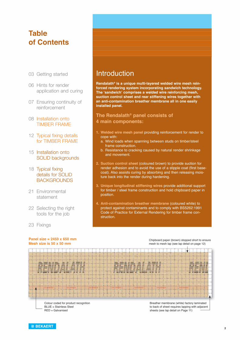
Panel size = 2450 x 650 mmMesh size is 50 x 50 mm
Chipboard paper (brown) stopped short to ensure mesh to mesh lap (see lap detail on page 12)
Colour coded for product recognitionBLUE = Stainless SteelRED = Galvanised
Breather membrane (white) factory laminated to back of sheet requires lapping with adjacent sheets (see lap detail on Page 11)
3
Getting started
All work is to be carried out in accordance with BS8000: Part 10: 1995 Code of Practice for Workmanship on Site.
Preparatory Work
All surfaces should be sound and free from any loose material. When installing onto a solid background all projecting masonry etc., should be cut back and any loose or damaged material removed and filled as nec-essary to produce a firm level surface free from undu-lation. Service pipes, fittings etc., should be removed and re-fixed upon completion and a temporary means to discharge rainwater away from the workings should be sought. Fungicidal wash is not generally necessary as no reliance on background adhesion is required and the anti-contamination breather membrane inhib-its contamination of the new render.
Weather & Fire Protection
If the chipboard paper has become wet, then the render should not be applied until the chipboard paper has completely dried out. It may be necessary to provide sheeting to protect the Rendalath® panels during periods of wet or frosty weather. If in doubt please consult Bekaert for advice on rendering during adverse weather conditions.
The panels must not be exposed to open flame or other ignition sources and stop beads may be required in some of the window / door reveals or where it is necessary to terminate the system to aid fire prevention. Fire regulations require stainless steel fixings to be placed at 1m2 intervals above second floor level. When fixing insulation panels in the UK with the exception of Scotland, firebreaks should be placed at every storey from the ground floor upwards with no restriction on the height of the building. In Scotland firebreaks must also be installed at every storey from the ground floor upwards, but the height of the building is restricted to 18 m and the system must not be on a wall sited one metre or less from a boundary.
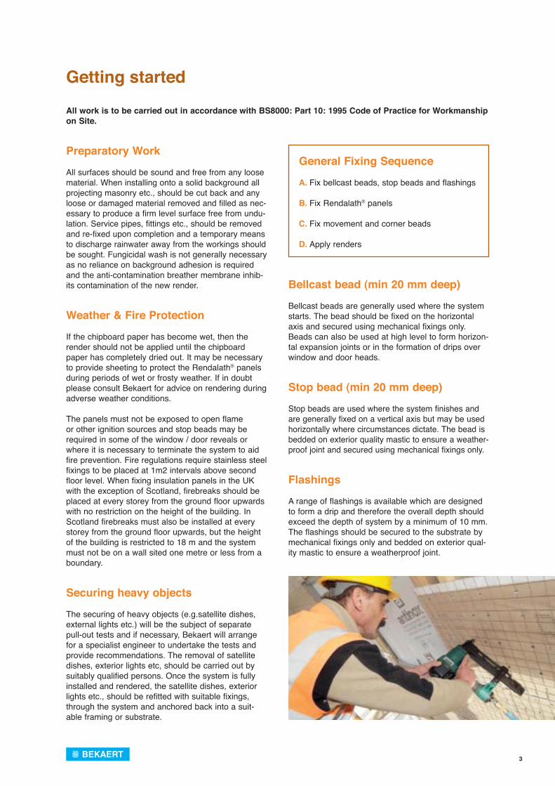
Securing heavy objects
The securing of heavy objects (e.g.satellite dishes, external lights etc.) will be the subject of separatepull-out tests and if necessary, Bekaert will arrange for a specialist engineer to undertake the tests and provide recommendations. The removal of satellite dishes, exterior lights etc, should be carried out by suitably qualified persons. Once the system is fully installed and rendered, the satellite dishes, exterior lights etc., should be refitted with suitable fixings, through the system and anchored back into a suit-able framing or substrate.
General Fixing Sequence
A. Fix bellcast beads, stop beads and flashings
B. Fix Rendalath® panels
C. Fix movement and corner beads
D. Apply renders
Bellcast bead (min 20 mm deep)
Bellcast beads are generally used where the system starts. The bead should be fixed on the horizontal axis and secured using mechanical fixings only. Beads can also be used at high level to form horizon-tal expansion joints or in the formation of drips over window and door heads.
Stop bead (min 20 mm deep)
Stop beads are used where the system finishes and are generally fixed on a vertical axis but may be used horizontally where circumstances dictate. The bead is bedded on exterior quality mastic to ensure a weather-proof joint and secured using mechanical fixings only.
Flashings
A range of flashings is available which are designed to form a drip and therefore the overall depth should exceed the depth of system by a minimum of 10 mm. The flashings should be secured to the substrate by mechanical fixings only and bedded on exterior qual-ity mastic to ensure a weatherproof joint.
4
Fixing of the Rendalath® panel
The fixing of the Rendalath® panels is usually done from right to left, but, once started, is always contin-ued in the same direction along the wall to ensure a continuity of the laps.
The panel should be applied on a horizontal axis and secured at specified fixing positions at spot crimps, using mechanical fixings only, directly onto the fram-ing or substrate. Position the panel at the right hand bottom corner of each wall. (see drawings on pages 11 and 18). The choice and spacing of fixings is determined by pull-out tests.
The panels should be overlapped by one mesh square both horizontally and vertically and wire tied together (see page 9) by snipping the wires of the Rendalath®, or using plastic cable ties, at every 250 mm centres. Laps should be staggered in a brickwork pattern and no laps should occur in line with window / door openings.
If the layout of the elevation is such that there is no fixing within 100 mm of a window or door reveal or where the system ends (e.g. a soffit), then a fixing should be positioned approximately 50 mm from the edge. A floating edge must be avoided. Particular attention should be paid to the overlapping and wire tying. Lapping the breather membrane with the breather membrane (where applicable) and the wire mesh to the wire mesh will ensure continuity of rein-forcement over the lap.
If an insulation panel is to be applied over electric cables then reference should be made to the I.E.E Wiring Regulations, BS7671 or the Electricians Handbook in respect of sizes of cable enclosed within thermal insulation.
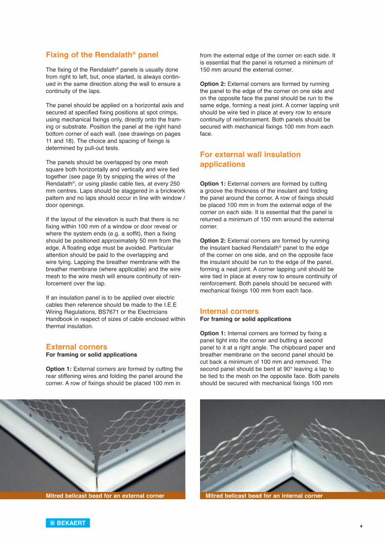
External cornersFor framing or solid applications
Option 1: External corners are formed by cutting the rear stiffening wires and folding the panel around the corner. A row of fixings should be placed 100 mm in
from the external edge of the corner on each side. It is essential that the panel is returned a minimum of 150 mm around the external corner.
Option 2: External corners are formed by running the panel to the edge of the corner on one side and on the opposite face the panel should be run to the same edge, forming a neat joint. A corner lapping unit should be wire tied in place at every row to ensure continuity of reinforcement. Both panels should be secured with mechanical fixings 100 mm from each face.
For external wall insulation applications
Option 1: External corners are formed by cutting a groove the thickness of the insulant and folding the panel around the corner. A row of fixings should be placed 100 mm in from the external edge of the corner on each side. It is essential that the panel is returned a minimum of 150 mm around the external corner.
Option 2: External corners are formed by running the insulant backed Rendalath® panel to the edge of the corner on one side, and on the opposite face the insulant should be run to the edge of the panel, forming a neat joint. A corner lapping unit should be wire tied in place at every row to ensure continuity of reinforcement. Both panels should be secured with mechanical fixings 100 mm from each face.
Internal cornersFor framing or solid applications
Option 1: Internal corners are formed by fixing a panel tight into the corner and butting a second panel to it at a right angle. The chipboard paper and breather membrane on the second panel should be cut back a minimum of 100 mm and removed. The second panel should be bent at 90° leaving a lap to be tied to the mesh on the opposite face. Both panels should be secured with mechanical fixings 100 mm
Mitred bellcast bead for an external corner Mitred bellcast bead for an internal corner
5
from each face. After each coat of render, a ‘V’ notch should be raked out directly below the bead, and then filled with exterior quality mastic after the final coat of render has been applied.Option 2: Internal corners can be formed by fixing a panel tight into the corner and butting a second panel up to it at right angles. A corner lapping unit should be wire tied in place at every row to allow continu-ity of reinforcement. Both panels should be secured with mechanical fixings 100 mm from each face. After each coat of render, a ‘V’ notch should be raked out directly below the bead, and then filled with exterior quality mastic after the final coat of render has been applied.
Internal cornersFor external wall insulation applications
Option 1: Internal corners are formed by fixing a panel tight into the corner and butting a second panel to it at a right angle. The insulant on the second panel should be cut back a minimum of twice the thickness of insulant and removed.
The second panel should be bent at 90° leaving a lap to be tied to the mesh on the opposite face. Both panels should be secured with mechanical fixings 100 mm from each face. After each coat of render, a ‘V’ notch should be raked out directly below the bead, and then filled with exterior quality mastic after the final coat of render has been applied.
Option 2: Internal corners can be formed by fixing a panel tight into the corner and butting a second panel up to it at right angles. A corner lapping unit should be wire tied in place at every row to allow continuity of reinforcement. Both panels should be secured with mechanical fixings 100 mm from each face. After each coat of render, a ‘V’ notch should be raked out directly below the bead, and then filled with exterior quality mastic after the final coat of render has been applied.
Expansion / movement joints
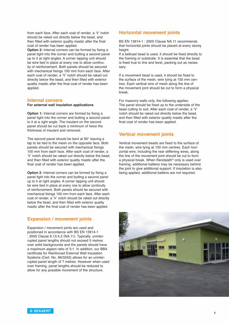
Expansion / movement joints are used andpositioned in accordance with BS EN 13914-1 : 2005 Clause 6.13.4.2 (NA.11). Typically, uninter-rupted panel lengths should not exceed 5 metres over solid backgrounds and the panels should have a maximum aspect ratio of 3:1. In addition, our BBA certificate for Reinforced External Wall Insulation Systems (Cert. No. 96/3242) allows for an uninter-rupted panel length of 7 metres. However when used over framing, panel lengths should be reduced to allow for any possible movement of the structure.
Horizontal movement joints
BS EN 13914-1 : 2005 Clause NA.11 recommends that horizontal joints should be placed at every storey height. If a bellcast bead is used, it should be fixed directly to the framing or substrate. It is essential that the bead is fixed true to line and level, packing out as neces-sary.
If a movement bead is used, it should be fixed to the surface of the mesh, wire tying at 150 mm cen-tres. Each vertical wire of mesh along the line of the movement joint should be cut to form a physical break.
For masonry walls only, the following applies:The panel should be fixed up to the underside of the bead cutting to suit. After each coat of render, a ‘V’ notch should be raked out directly below the bead, and then filled with exterior quality mastic after the final coat of render has been applied.
Vertical movement joints
Vertical movement beads are fixed to the surface of the mesh, wire tying at 150 mm centres. Each hori-zontal wire, including the rear stiffening wires, along the line of the movement joint should be cut to form a physical break. When Rendalath® only is used over framing, additional battens may be necessary behind the joint to give additional support. If insulation is also being applied, additional battens are not required.
6
The fixing of the Rendalath® panels is usually done from right to left, and is always continued in the same direction along the wall (and around the building if appropriate) to ensure a continuity of the laps.
The render is then applied in the opposite direction (usually left to right) so that it flows easily across the laps.
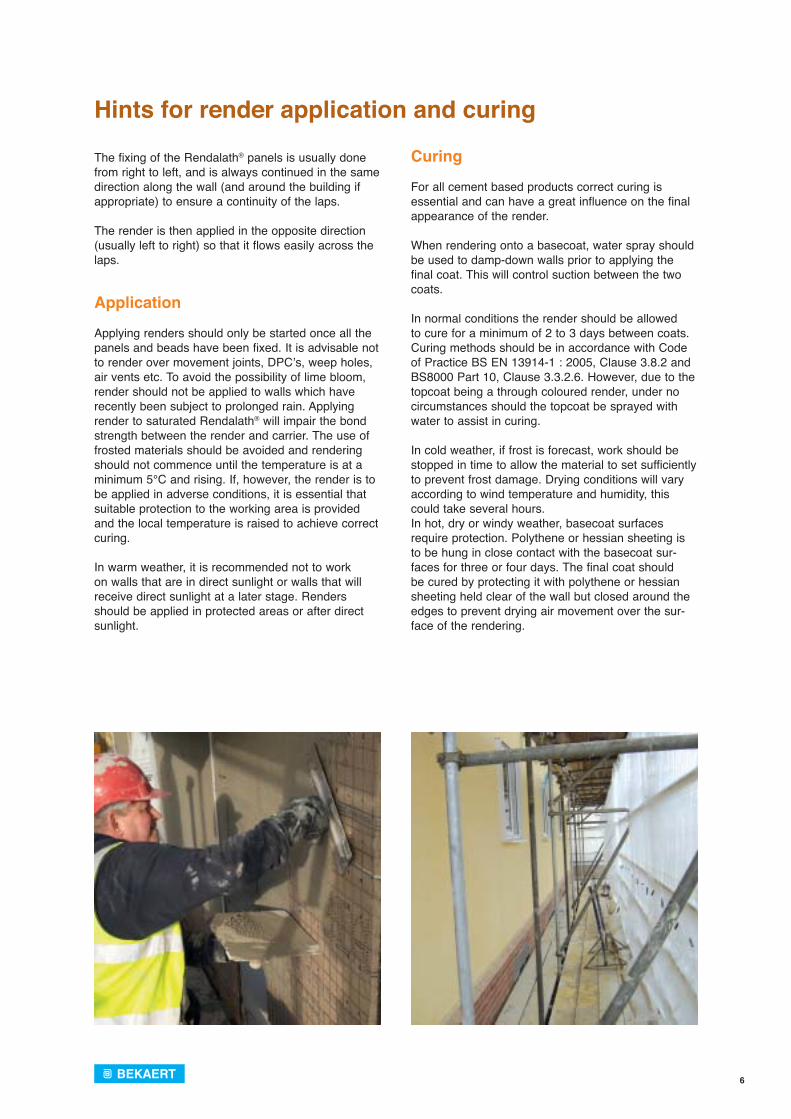
Application
Applying renders should only be started once all the panels and beads have been fixed. It is advisable not to render over movement joints, DPC’s, weep holes, air vents etc. To avoid the possibility of lime bloom, render should not be applied to walls which have recently been subject to prolonged rain. Applying render to saturated Rendalath® will impair the bond strength between the render and carrier. The use of frosted materials should be avoided and rendering should not commence until the temperature is at a minimum 5°C and rising. If, however, the render is to be applied in adverse conditions, it is essential that suitable protection to the working area is provided and the local temperature is raised to achieve correct curing.
In warm weather, it is recommended not to work on walls that are in direct sunlight or walls that will receive direct sunlight at a later stage. Renders should be applied in protected areas or after direct sunlight.
Curing
For all cement based products correct curing is essential and can have a great influence on the final appearance of the render.
When rendering onto a basecoat, water spray should be used to damp-down walls prior to applying the final coat. This will control suction between the two coats.
In normal conditions the render should be allowed to cure for a minimum of 2 to 3 days between coats. Curing methods should be in accordance with Code of Practice BS EN 13914-1 : 2005, Clause 3.8.2 and BS8000 Part 10, Clause 3.3.2.6. However, due to the topcoat being a through coloured render, under no circumstances should the topcoat be sprayed with water to assist in curing.
In cold weather, if frost is forecast, work should be stopped in time to allow the material to set sufficiently to prevent frost damage. Drying conditions will vary according to wind temperature and humidity, this could take several hours.In hot, dry or windy weather, basecoat surfaces require protection. Polythene or hessian sheeting is to be hung in close contact with the basecoat sur-faces for three or four days. The final coat should be cured by protecting it with polythene or hessian sheeting held clear of the wall but closed around the edges to prevent drying air movement over the sur-face of the rendering.
Hints for render application and curing
7
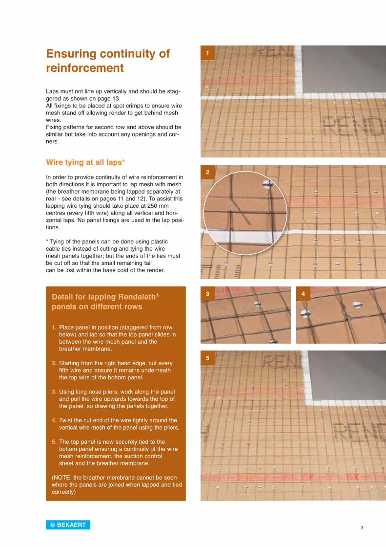
Laps must not line up vertically and should be stag-gered as shown on page 13.All fixings to be placed at spot crimps to ensure wire mesh stand off allowing render to get behind mesh wires. Fixing patterns for second row and above should be similar but take into account any openings and cor-ners.
Wire tying at all laps*
In order to provide continuity of wire reinforcement in both directions it is important to lap mesh with mesh (the breather membrane being lapped separately at rear - see details on pages 11 and 12). To assist this lapping wire tying should take place at 250 mm centres (every fifth wire) along all vertical and hori-zontal laps. No panel fixings are used in the lap posi-tions.
* Tying of the panels can be done using plastic cable ties instead of cutting and tying the wiremesh panels together; but the ends of the ties must be cut off so that the small remaining tail can be lost within the base coat of the render.
Ensuring continuity of reinforcement
Detail for lapping Rendalath® panels on different rows
1. Place panel in position (staggered from row below) and lap so that the top panel slides in between the wire mesh panel and the
breather membrane.
2. Starting from the right hand edge, cut every fifth wire and ensure it remains underneath
the top wire of the bottom panel.
3. Using long nose pliers, work along the panel and pull the wire upwards towards the top of the panel, so drawing the panels together.
4. Twist the cut end of the wire tightly around the vertical wire mesh of the panel using the pliers.
5. The top panel is now securely tied to the bottom panel ensuring a continuity of the wire
mesh reinforcement, the suction control sheet and the breather membrane.
(NOTE: the breather membrane cannot be seen where the panels are joined when lapped and tied correctly)
1
2
3
5
4
8
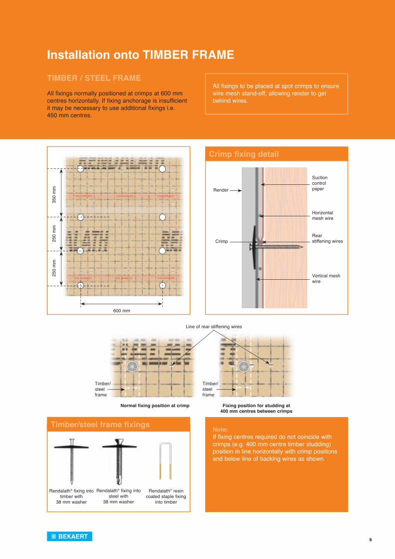
All fixings to be placed at spot crimps to ensure wire mesh stand-off, allowing render to get behind wires.
Note: If fixing centres required do not coincide with crimps (e.g. 400 mm centre timber studding) position in line horizontally with crimp positions and below line of backing wires as shown.
Installation onto TIMBER FRAME
TIMBER / STEEL FRAME
All fixings normally positioned at crimps at 600 mm centres horizontally. If fixing anchorage is insufficient it may be necessary to use additional fixings i.e. 450 mm centres.
Crimp fixing detail
Timber/steel frame fixings
25
0 m
m
250
mm
35
0 m
m
600 mm
Rendalath® fixing into timber with
38 mm washer
Rendalath® fixing into steel with
38 mm washer
Rendalath® resin coated staple fixing
into timber
Timber/steel frame
Line of rear stiffening wires
Timber/steel frame
Normal fixing position at crimp Fixing position for studding at400 mm centres between crimps
Render
CrimpRearstiffening wires
Suctioncontrol paper
Horizontal mesh wire
Vertical mesh wire
9
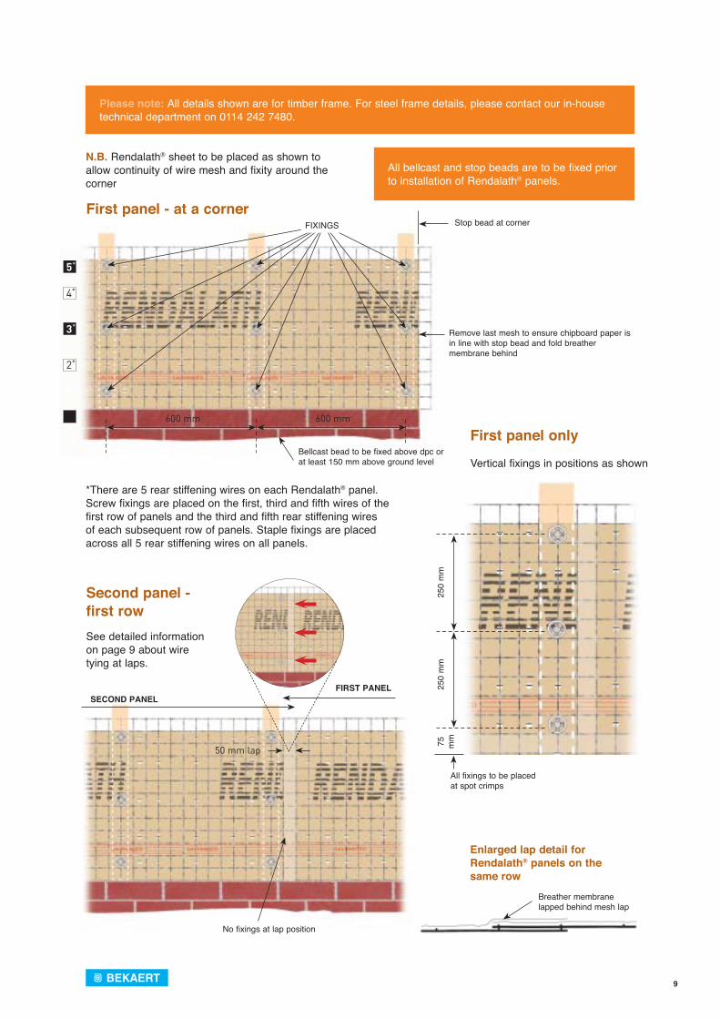
Please note: All details shown are for timber frame. For steel frame details, please contact our in-house technical department on 0114 242 7480.
All bellcast and stop beads are to be fixed prior to installation of Rendalath® panels.
*There are 5 rear stiffening wires on each Rendalath® panel. Screw fixings are placed on the first, third and fifth wires of the first row of panels and the third and fifth rear stiffening wires of each subsequent row of panels. Staple fixings are placed across all 5 rear stiffening wires on all panels.
N.B. Rendalath® sheet to be placed as shown to allow continuity of wire mesh and fixity around the corner
See detailed information on page 9 about wire tying at laps.
Vertical fixings in positions as shown
50 mm lap
No fixings at lap position
SECOND PANELFIRST PANEL
25
0 m
m
250
mm
75
mm
All fixings to be placed at spot crimps
Stop bead at corner
Remove last mesh to ensure chipboard paper is in line with stop bead and fold breather membrane behind
Bellcast bead to be fixed above dpc or at least 150 mm above ground level
FIXINGS
5*
4*
3*
2*
1*
600 mm 600 mm
Breather membranelapped behind mesh lap
Second panel - first row
First panel - at a corner
Enlarged lap detail for Rendalath® panels on the same row
First panel only
10
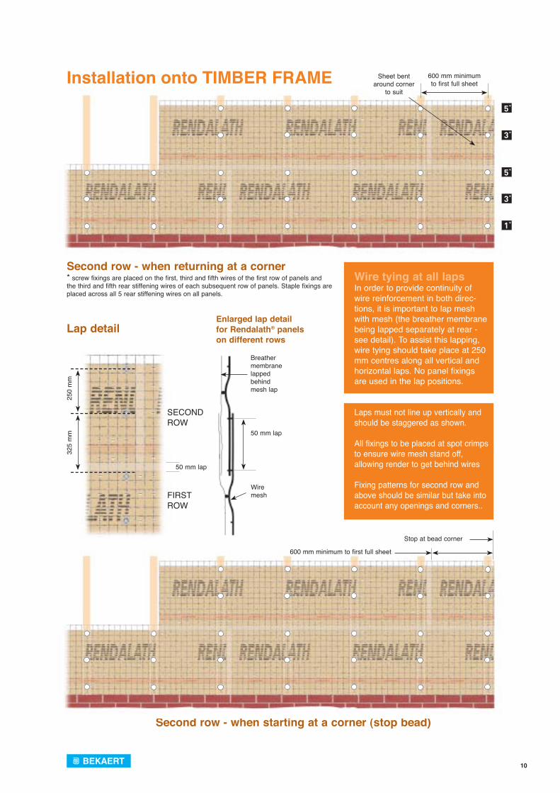
Wire tying at all lapsIn order to provide continuity of wire reinforcement in both direc-tions, it is important to lap mesh with mesh (the breather membrane being lapped separately at rear - see detail). To assist this lapping, wire tying should take place at 250 mm centres along all vertical and horizontal laps. No panel fixings are used in the lap positions.
Laps must not line up vertically and should be staggered as shown.
All fixings to be placed at spot crimps to ensure wire mesh stand off, allowing render to get behind wires
Fixing patterns for second row and above should be similar but take into account any openings and corners..
Second row - when starting at a corner (stop bead)
600 mm minimum to first full sheet
Stop at bead corner
Sheet bentaround corner
to suit
600 mm minimum to first full sheet
5*
3*
5*
3*
1*
Breather membranelapped behind mesh lap
50 mm lap
Wire mesh
32
5 m
m
250
mm
50 mm lap
SECOND ROW
FIRST ROW
Lap detailEnlarged lap detail for Rendalath® panels on different rows
Second row - when returning at a corner* screw fixings are placed on the first, third and fifth wires of the first row of panels and the third and fifth rear stiffening wires of each subsequent row of panels. Staple fixings are placed across all 5 rear stiffening wires on all panels.
Installation onto TIMBER FRAME
11
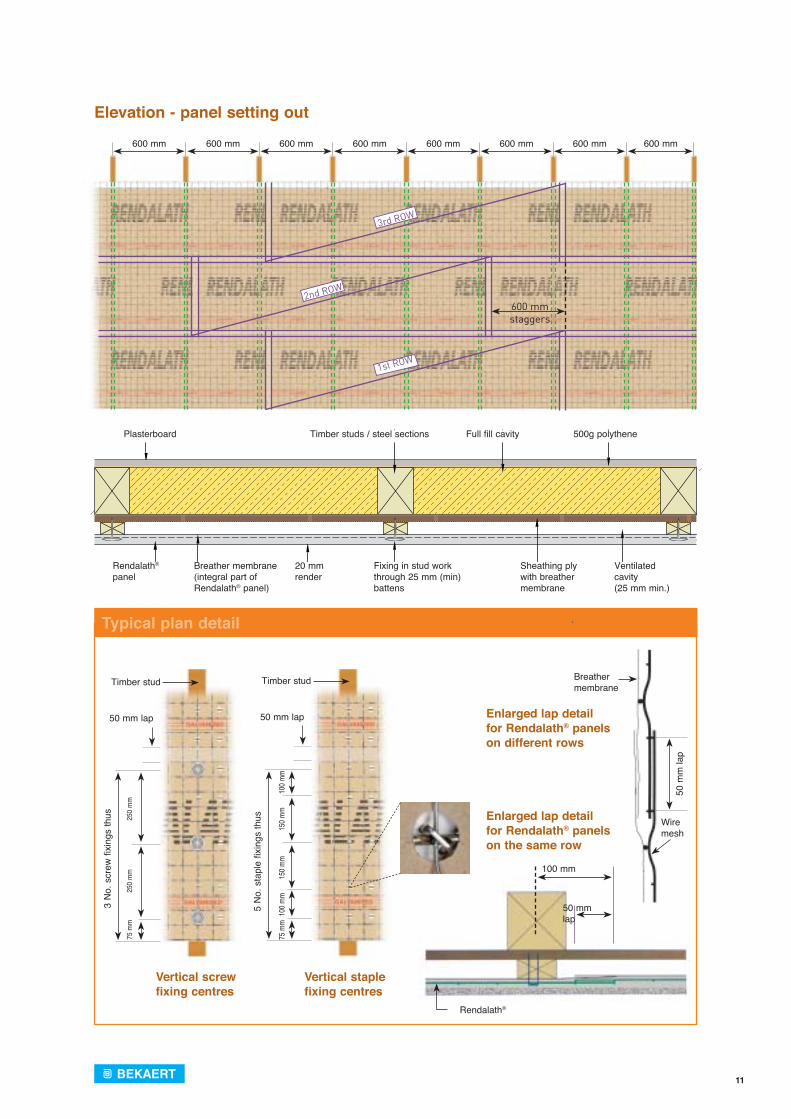
3rd ROW
2nd ROW
1st ROW
600 mm staggers
600 mm 600 mm 600 mm 600 mm 600 mm 600 mm 600 mm 600 mm
Plasterboard Timber studs / steel sections Full fill cavity 500g polythene
Rendalath®
panelBreather membrane(integral part of Rendalath® panel)
20 mmrender
Fixing in stud workthrough 25 mm (min)battens
Sheathing plywith breather membrane
Ventilated cavity(25 mm min.)
Elevation - panel setting out
Typical plan detail
50 mm lap
100 mm
Rendalath®
Vertical screwfixing centres
Vertical staple fixing centres
Timber stud
50 mm lap
3 N
o. s
crew
fixi
ngs
thus
75 m
m
2
50 m
m
2
50 m
m
Timber stud
50 mm lap
5
No.
sta
ple
fixin
gs th
us
75 m
m 10
0 mm
150 m
m
15
0 mm
100 m
m
Breather membrane
50 m
m la
p
Wire mesh
Enlarged lap detail for Rendalath® panels on the same row
Enlarged lap detail for Rendalath® panels on different rows
12
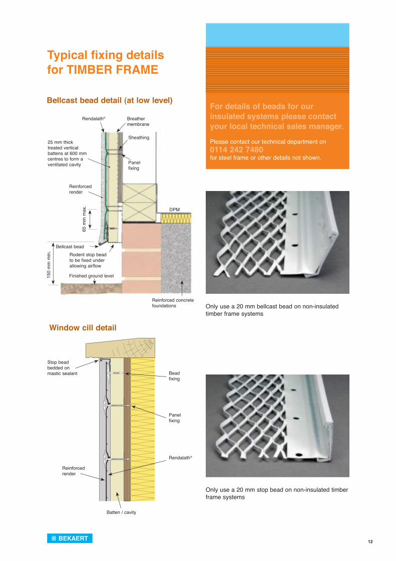
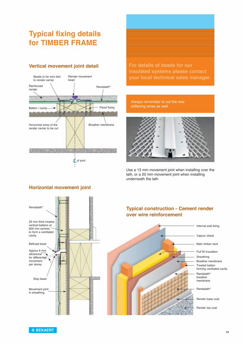
For details of beads for our insulated systems please contact your local technical sales manager.
Please contact our technical department on0114 242 7480 for steel frame or other details not shown.
Typical fi xing detailsfor TIMBER FRAME
65 m
m m
ax.
Rendalath® Breather membrane
Sheathing
Panelfixing
DPM
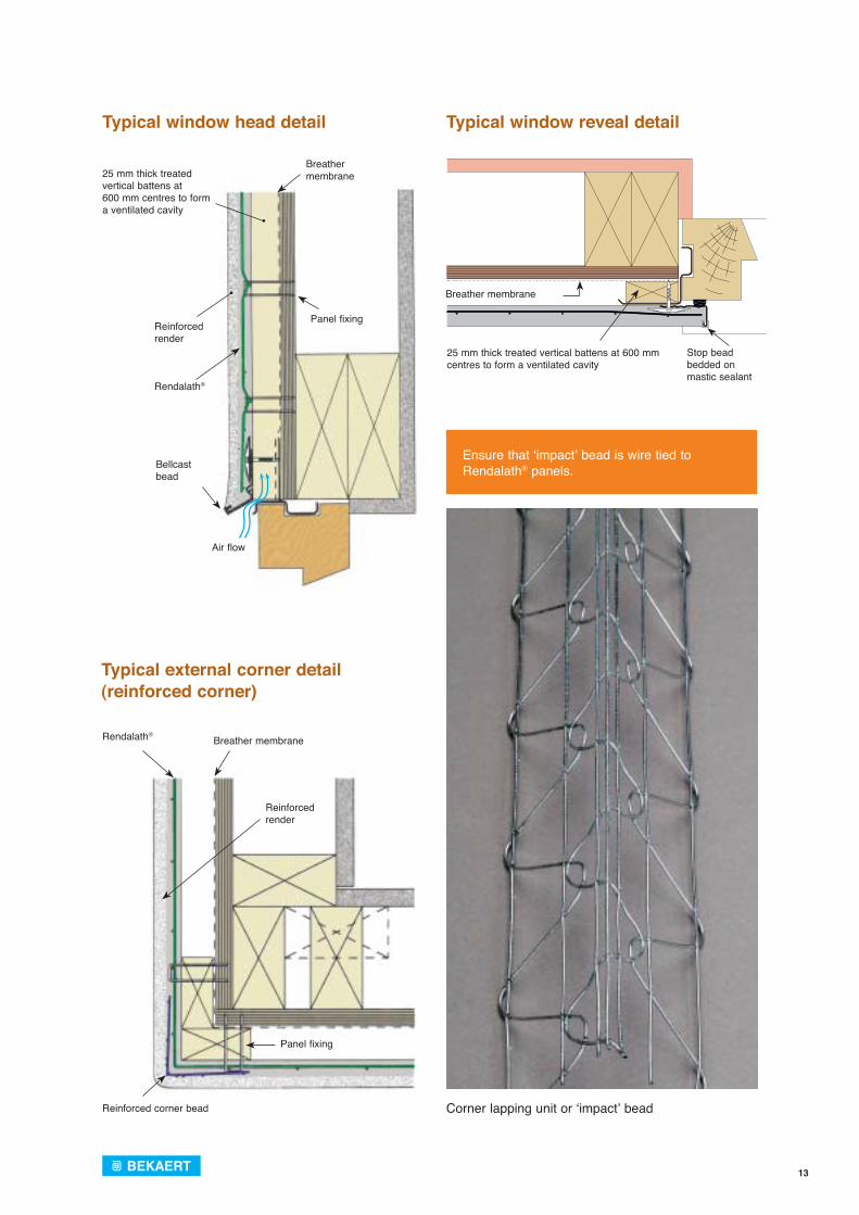
25 mm thicktreated vertical battens at 600 mm centres to form aventilated cavity
Reinforcedrender
Bellcast beadRodent stop beadto be fixed underallowing airflow
Finished ground level150
mm
min
.
Reinforced concretefoundations
Reinforcedrender
Rendalath®
Panel fixing
Batten / cavity
Stop beadbedded onmastic sealant Bead
fixing
Bellcast bead detail (at low level)
Window cill detail
Only use a 20 mm bellcast bead on non-insulated timber frame systems
Only use a 20 mm stop bead on non-insulated timber frame systems
13
Ensure that ‘impact’ bead is wire tied to Rendalath® panels.
25 mm thick treated vertical battens at 600 mm centres to form a ventilated cavity
Breather membrane
Stop beadbedded onmastic sealant
Rendalath®
Panel fixing
Breather membrane25 mm thick treated
vertical battens at 600 mm centres to form a ventilated cavity
Reinforcedrender
Bellcast bead
Air flow
Reinforcedrender
Rendalath®
Panel fixing
Breather membrane
Reinforced corner bead
Typical window head detail
Typical external corner detail (reinforced corner)
Typical window reveal detail
Corner lapping unit or ‘impact’ bead
14
For details of beads for our insulated systems please contact your local technical sales manager.
Always remember to cut the rear stiffening wires as well.
Typical fi xing details for TIMBER FRAME
Vertical movement joint detail
Horizontal movement joint
Use a 13 mm movement joint when installing over the lath, or a 20 mm movement joint when installing underneath the lath
Bellcast bead
Rendalath®
Stop bead
Movement jointin sheathing
25 mm thick treated vertical battens at 600 mm centres to form a ventilated cavity
Approx 6 mmallowance for differentialmovement per storey
Internal wall lining
Vapour check
Rendalath® breather membrane
Treated battenforming ventilated cavity
Rendalath®
Main timber stud
Full fill insulationSheathingBreather membrane
Render base coat
Render top coat
Breather membrane
Rendalath®Reinforcedrender
Beads to be wire tiedto render carrier
Render movement bead
Batten / cavity
Horizontal wires of therender carrier to be cut
Panel fixing
of joint
Typical construction - Cement render over wire reinforcement
15
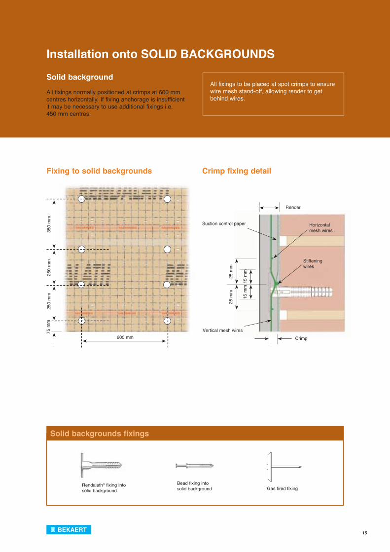
All fixings to be placed at spot crimps to ensure wire mesh stand-off, allowing render to get behind wires.
Installation onto SOLID BACKGROUNDS
Solid backgrounds fixings
Solid background
All fixings normally positioned at crimps at 600 mm centres horizontally. If fixing anchorage is insufficient it may be necessary to use additional fixings i.e. 450 mm centres.
Fixing to solid backgrounds Crimp fixing detail
25
0 m
m
25
0 m
m
3
50 m
m
25
mm
25
mm
15
mm
15
mm
Crimp
Render
Suction control paper
Vertical mesh wires
Horizontalmesh wires
Stiffeningwires
600 mm 75
mm
Rendalath® fixing intosolid background
Bead fixing into solid background Gas fired fixing
16
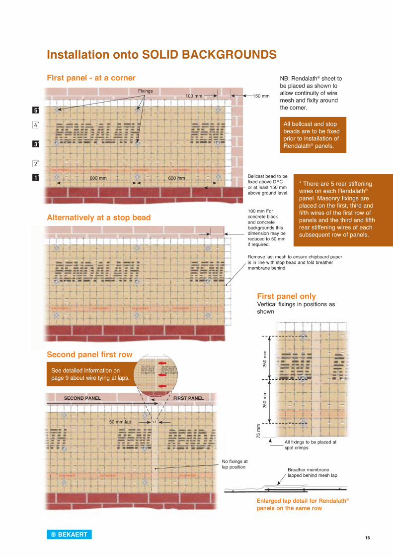
All bellcast and stop beads are to be fixed prior to installation of Rendalath® panels.
* There are 5 rear stiffening wires on each Rendalath® panel. Masonry fixings are placed on the first, third and fifth wires of the first row of panels and the third and fifth rear stiffening wires of each subsequent row of panels.
See detailed information on page 9 about wire tying at laps.
SECOND PANEL FIRST PANEL
No fixings at lap position
50 mm lap
Installation onto SOLID BACKGROUNDS
Bellcast bead to be fixed above DPC or at least 150 mm above ground level.
Fixings100 mm
600 mm
5*
4*
3*
2*
1* 600 mm
150 mm
First panel - at a corner
100 mm For concrete block and concrete backgrounds this dimension may be reduced to 50 mm if required.
Remove last mesh to ensure chipboard paper is in line with stop bead and fold breather membrane behind.
Alternatively at a stop bead
Second panel first row
First panel only
25
0 m
m
250
mm
All fixings to be placed at spot crimps
75
mm
Breather membranelapped behind mesh lap
Enlarged lap detail for Rendalath® panels on the same row
NB: Rendalath® sheet to be placed as shown to allow continuity of wire mesh and fixity around the corner.
Vertical fixings in positions as shown
17
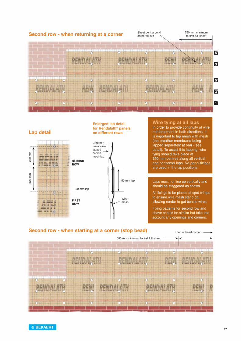
Wire tying at all lapsIn order to provide continuity of wire reinforcement in both directions, it is important to lap mesh with mesh (the breather membrane being lapped separately at rear - see detail). To assist this lapping, wire tying should take place at 250 mm centres along all vertical and horizontal laps. No panel fixings are used in the lap positions.
Laps must not line up vertically and should be staggered as shown.
All fixings to be placed at spot crimps to ensure wire mesh stand off, allowing render to get behind wires.
Fixing patterns for second row and above should be similar but take into account any openings and corners.
Second row - when returning at a corner
Second row - when starting at a corner (stop bead)
Lap detail
Enlarged lap detail for Rendalath® panels on different rows
600 mm minimum to first full sheet
Stop at bead corner
Sheet bent around corner to suit
750 mm minimum to first full sheet
5*
3*
5*
3*
1*
Breather membranelapped behind mesh lap
50 mm lap
Wire mesh
32
5 m
m
2
50 m
m
50 mm lap
SECOND ROW
FIRST ROW
18
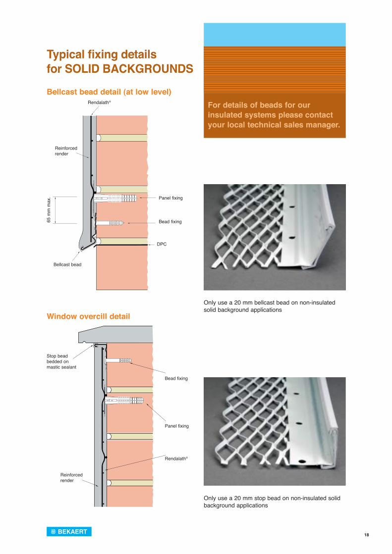
For details of beads for our insulated systems please contact your local technical sales manager.
Typical fi xing details for SOLID BACKGROUNDS
Bellcast bead detail (at low level)
Window overcill detail
Only use a 20 mm bellcast bead on non-insulated solid background applications
Only use a 20 mm stop bead on non-insulated solid background applications
Reinforced render
Panel fixing
Bellcast bead
DPC
65 m
m m
ax.
Rendalath®
Bead fixing
Stop beadbedded on mastic sealant
Reinforced render
Rendalath®
Bead fixing
Panel fixing
19
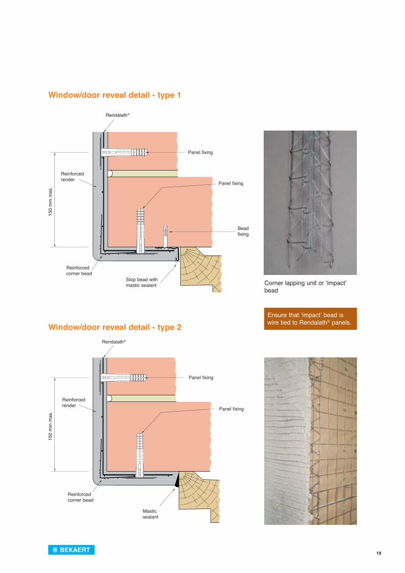
Ensure that ‘impact’ bead is wire tied to Rendalath® panels.
Window/door reveal detail - type 1
Window/door reveal detail - type 2
Corner lapping unit or ‘impact’ bead
Reinforced render
Rendalath®
Reinforced corner bead
Mastic sealant
Reinforced render
Bead fixing
Stop bead with mastic sealant
Rendalath®
Reinforced corner bead
Panel fixing
150
mm
max
.
Panel fixing
150
mm
max
. Panel fixing
Panel fixing
20
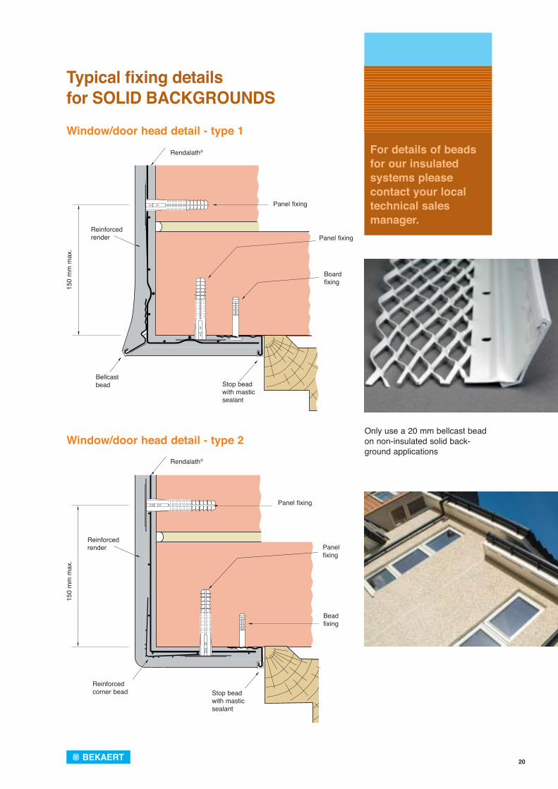
For details of beads for our insulated systems please contact your local technical sales manager.
Typical fi xing details for SOLID BACKGROUNDS
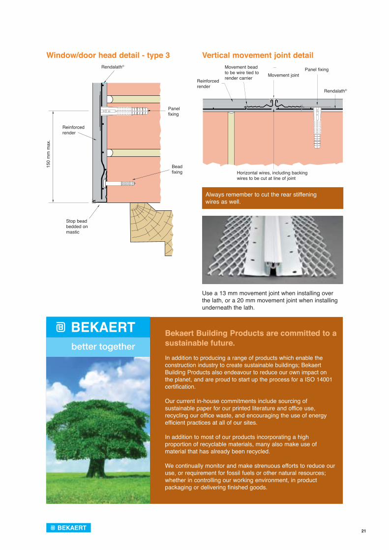
Window/door head detail - type 1
Window/door head detail - type 2Only use a 20 mm bellcast bead on non-insulated solid back-ground applications
Reinforced render
Panel fixing
Bellcast bead
Boardfixing
Stop bead with mastic sealant
Rendalath®
150
mm
max
.
Panel fixing
Reinforced render
Reinforced corner bead
Bead fixing
Stop bead with mastic sealant
Rendalath®
Panel fixing
150
mm
max
.
Panel fixing
21
Always remember to cut the rear stiffening wires as well.
Rendalath®
Reinforced render
Stop bead bedded on mastic
Bead fixing
Panelfixing
150
mm
max
.
Use a 13 mm movement joint when installing over the lath, or a 20 mm movement joint when installing underneath the lath.
Window/door head detail - type 3 Vertical movement joint detail
Reinforced render
Movement jointPanel fixing
Rendalath®
Movement bead to be wire tied to render carrier
Horizontal wires, including backing wires to be cut at line of joint
Bekaert Building Products are committed to a sustainable future.
In addition to producing a range of products which enable the construction industry to create sustainable buildings; Bekaert Building Products also endeavour to reduce our own impact on the planet, and are proud to start up the process for a ISO 14001 certification.
Our current in-house commitments include sourcing of sustainable paper for our printed literature and office use, recycling our office waste, and encouraging the use of energy efficient practices at all of our sites.
In addition to most of our products incorporating a high proportion of recyclable materials, many also make use of material that has already been recycled. We continually monitor and make strenuous efforts to reduce our use, or requirement for fossil fuels or other natural resources; whether in controlling our working environment, in product packaging or delivering finished goods.

22
Selecting the right tools for the job
We would recommend that the following tools are used when installing Rendalath®:
Drill BitsIt is essential that worn, damaged or distorted drill bits are not used in any operation concerning the fixing of the Rendalath® System. The use of a depth gauge on the drill is essential to avoid over drilling.
Health & Safety at Work Act
Gloves to be used when handling and cutting. Suitable clothing to be worn to avoid cuts to limbs. Eye protection should be provided at all times when cutting. Face masks should be worn to avoid breathing metal oxide fumes and parti-cles of dust when cutting using a disc cutter.
Stop beads and bellcast beads must be at least 20 mm deep to accommodate 20 mm of render.
Panel fixings 10 mm diameter
Bead fixings 6 mm diameter
POWER DRILL
CRAFT KNIFE
LONG NOSE PLIERS
WIRE SNIPS
TAPE MEASURE
HACKSAW
HAMMER
MASTIC SEALANT
The Rendalath® Power Tools, associated fixings and accessories can be purchased direct from Bekaert Building Products. For further information, or to arrange a demonstration please contact the Sheffield office on 0114 242 7480 or your local area Sales Manager. Find out more at: www.Rendalath.co.uk
Pneumatic stapler
Our pneumatic powered stapler is available together with purpose designed stainless steel staples for fixing Rendalath® onto timber frame backgrounds. The power stapler represents a major step forward in improving the accuracy and speed of Rendalath® fixing for this application.
The power stapler is of lightweight design and has built in safety features, making it safe and comfortable to use over long periods.
We can also supply a matching compressor and extension cable to power the stapler wherever required on site.
Rendalath® power tools
In order to make the fixing of our Rendalath® reinforced render carrier panels quicker, easier and safer, Bekaert Building Products have developed some automated alternatives to the traditional fixing method. Our experience has shown that considerable savings in man hours can be achieved using these tools.
Gas fired fixing gun
Our gas fired gun, and purpose designed washer, have been developed specifically for securing Rendalath® onto solid wall backgrounds.
The gun also provides the added benefits of not only being lightweight, but has no trailing cables, so eliminating any trip hazards. Being a gas fired fixing, this removes the need for drilling, thus eliminating the possibility of vibration white finger.
23
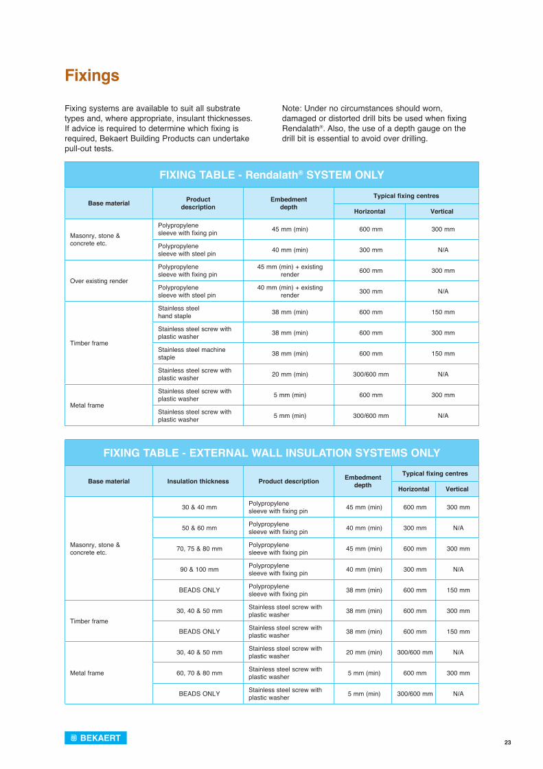
FIXING TABLE - Rendalath® SYSTEM ONLY
Base material Productdescription
Embedmentdepth
Typical fixing centres
Horizontal Vertical
Masonry, stone &concrete etc.
Polypropylenesleeve with fixing pin 45 mm (min) 600 mm 300 mm
Polypropylenesleeve with steel pin 40 mm (min) 300 mm N/A
Over existing render
Polypropylenesleeve with fixing pin
45 mm (min) + existing render 600 mm 300 mm
Polypropylenesleeve with steel pin
40 mm (min) + existing render 300 mm N/A
Timber frame
Stainless steelhand staple 38 mm (min) 600 mm 150 mm
Stainless steel screw with plastic washer 38 mm (min) 600 mm 300 mm
Stainless steel machine staple 38 mm (min) 600 mm 150 mm
Stainless steel screw with plastic washer 20 mm (min) 300/600 mm N/A
Metal frame
Stainless steel screw with plastic washer 5 mm (min) 600 mm 300 mm
Stainless steel screw with plastic washer 5 mm (min) 300/600 mm N/A
FIXING TABLE - EXTERNAL WALL INSULATION SYSTEMS ONLY
Base material Insulation thickness Product description Embedment depth
Typical fixing centres
Horizontal Vertical
Masonry, stone & concrete etc.
30 & 40 mm Polypropylenesleeve with fixing pin 45 mm (min) 600 mm 300 mm
50 & 60 mm Polypropylenesleeve with fixing pin 40 mm (min) 300 mm N/A
70, 75 & 80 mm Polypropylenesleeve with fixing pin 45 mm (min) 600 mm 300 mm
90 & 100 mm Polypropylenesleeve with fixing pin 40 mm (min) 300 mm N/A
BEADS ONLY Polypropylenesleeve with fixing pin 38 mm (min) 600 mm 150 mm
Timber frame30, 40 & 50 mm Stainless steel screw with
plastic washer 38 mm (min) 600 mm 300 mm
BEADS ONLY Stainless steel screw with plastic washer 38 mm (min) 600 mm 150 mm
Metal frame
30, 40 & 50 mm Stainless steel screw with plastic washer 20 mm (min) 300/600 mm N/A
60, 70 & 80 mm Stainless steel screw with plastic washer 5 mm (min) 600 mm 300 mm
BEADS ONLY Stainless steel screw with plastic washer 5 mm (min) 300/600 mm N/A
Fixings
Fixing systems are available to suit all substrate types and, where appropriate, insulant thicknesses. If advice is required to determine which fixing is required, Bekaert Building Products can undertake pull-out tests.
Note: Under no circumstances should worn, damaged or distorted drill bits be used when fixing Rendalath®. Also, the use of a depth gauge on the drill bit is essential to avoid over drilling.

Technical advice serviceOur in-house technical team provides a comprehensive technical advice service for our complete range of products.
Services include:- Free design service- Telephone enquiry service- Office/on-site support and advice- Details and take-offs Sales supportAll products are supported by a national team of sales people who are always available to discuss a particular application or project and provide on-site support as required.
CPD seminarWe offer a range of CPD seminar presentations which are available at lunchtimes or evenings and are suitable for Architects, Clerks of Works, Engineers and colleges/universities.
Development, testing and quality controlOur company quality management system (QMS) has received BS EN ISO9001:2000 certification, and our company environmental
management system (EMS) has received BS EN ISO14001: 2004 certification.
Mad
e b
y A
punta
/ F
eb
ruary
2010 /
54.0
4.0
5
All brands are registered brands of which NV Bekaert SA is the owner.
We reserve the right to amend specifications without prior notice. Whilst the data contained in this brochure is true and accurate to the best of our knowledge, all liability for error and omissions, loss or damage resulting herefrom however so is hereby excluded.
© 2
010
Bek
aert
For full details of all other products offered by Bekaert, please visit: www.bekaert.com/building Bekaert LtdBU Building ProductsThe Gateway Business CentreUnit 7, 5 Leeds RoadGB-Sheffi eld S9 3TYT 0114 242 7480F 0114 242 [email protected]
www.bekaert.com/building