Embed Size (px)
Citation preview
Products Solutions Services
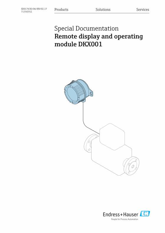
Special DocumentationRemote display and operatingmodule DKX001
SD01763D/06/EN/02.1771350352

Remote display and operating module DKX001 Table of contents
Endress+Hauser 3
Table of contents1 Document information . . . . . . . . . 41.1 Document function . . . . . . . . . . . . . . . . . . . 41.2 Symbols used . . . . . . . . . . . . . . . . . . . . . . . . 41.3 Documentation . . . . . . . . . . . . . . . . . . . . . . 6
2 Basic safety instructions . . . . . . . 72.1 Requirements for personnel . . . . . . . . . . . 72.2 Designated use . . . . . . . . . . . . . . . . . . . . . . 72.3 Operational safety . . . . . . . . . . . . . . . . . . . 82.4 Product safety . . . . . . . . . . . . . . . . . . . . . . . 9
3 Product description . . . . . . . . . . . 103.1 Product design . . . . . . . . . . . . . . . . . . . . . 103.2 Connectable transmitters . . . . . . . . . . . . 103.3 Availability . . . . . . . . . . . . . . . . . . . . . . . . 103.4 Scope of delivery . . . . . . . . . . . . . . . . . . . . 13
4 Incoming acceptance andproduct identification . . . . . . . . . 14
4.1 Incoming acceptance . . . . . . . . . . . . . . . . 144.2 Product identification . . . . . . . . . . . . . . . . 15
5 Storage and transport . . . . . . . . . 175.1 Storage conditions . . . . . . . . . . . . . . . . . . 175.2 Transporting the product . . . . . . . . . . . . . 175.3 Packaging disposal . . . . . . . . . . . . . . . . . . 17
6 Installation . . . . . . . . . . . . . . . . . . . . 176.1 Required tools . . . . . . . . . . . . . . . . . . . . . . 176.2 Wall mounting . . . . . . . . . . . . . . . . . . . . . 176.3 Post mounting . . . . . . . . . . . . . . . . . . . . . . 18
7 Electrical connection . . . . . . . . . . 197.1 Connection conditions . . . . . . . . . . . . . . . 197.2 Connecting the DKX001 . . . . . . . . . . . . . 217.3 Connecting the transmitter . . . . . . . . . . . 227.4 Ensuring potential equalization . . . . . . . 24
8 Operation options . . . . . . . . . . . . . 24
9 Diagnostics andtroubleshooting . . . . . . . . . . . . . . . 25
10 Maintenance . . . . . . . . . . . . . . . . . . 2510.1 Maintenance tasks . . . . . . . . . . . . . . . . . . 2510.2 Replacing seals . . . . . . . . . . . . . . . . . . . . . 25
11 Repairs . . . . . . . . . . . . . . . . . . . . . . . . . 2511.1 General notes . . . . . . . . . . . . . . . . . . . . . . 2511.2 Spare parts . . . . . . . . . . . . . . . . . . . . . . . . 2611.3 Conversion kit . . . . . . . . . . . . . . . . . . . . . . 2611.4 Return . . . . . . . . . . . . . . . . . . . . . . . . . . . . 2811.5 Disposal . . . . . . . . . . . . . . . . . . . . . . . . . . . 29
12 Technical data . . . . . . . . . . . . . . . . . 2912.1 Power supply . . . . . . . . . . . . . . . . . . . . . . . 2912.2 Environment . . . . . . . . . . . . . . . . . . . . . . . 2912.3 Mechanical construction . . . . . . . . . . . . . 3012.4 Certificates and approvals . . . . . . . . . . . . 33
Index . . . . . . . . . . . . . . . . . . . . . . . . . . . . . . . . . 35
Document information Remote display and operating module DKX001
4 Endress+Hauser
1 Document information
1.1 Document functionThis manual constitutes Special Documentation. It describes the installation of the remotedisplay and operating module DKX001 (device).
NOTICEDuring installation:‣ Follow the Operating Instructions for the measuring device (e.g. Promass F 300).
For applications in hazardous areas, follow the "Safety Instructions" documentationassociated with the device. → 6.
1.2 Symbols used
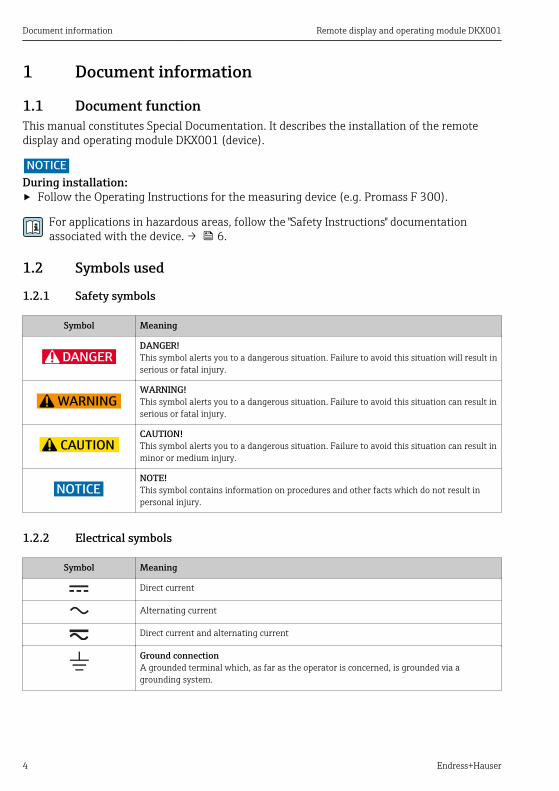
1.2.1 Safety symbols
Symbol Meaning
DANGER
DANGER!This symbol alerts you to a dangerous situation. Failure to avoid this situation will result inserious or fatal injury.
WARNING
WARNING!This symbol alerts you to a dangerous situation. Failure to avoid this situation can result inserious or fatal injury.
CAUTION
CAUTION!This symbol alerts you to a dangerous situation. Failure to avoid this situation can result inminor or medium injury.
NOTICE
NOTE!This symbol contains information on procedures and other facts which do not result inpersonal injury.
1.2.2 Electrical symbols
Symbol Meaning
Direct current
Alternating current
Direct current and alternating current
Ground connectionA grounded terminal which, as far as the operator is concerned, is grounded via agrounding system.
Remote display and operating module DKX001 Document information
Endress+Hauser 5
Symbol Meaning
Protective ground connectionA terminal which must be connected to ground prior to establishing any otherconnections.
Equipotential connectionA connection that has to be connected to the plant grounding system: This may be apotential equalization line or a star grounding system depending on national or companycodes of practice.
1.2.3 Tool symbols
Symbol Meaning
Flat blade screwdriver
Allen key
Open-ended wrench
1.2.4 Symbols for certain types of information
Symbol Meaning
TipIndicates additional information.
Reference to documentation
A Reference to page
Reference to graphic
Notice or individual step to be observed
1. , 2. , 3.… Series of steps
Result of a step
Help in the event of a problem
Visual inspection
Document information Remote display and operating module DKX001
6 Endress+Hauser
1.2.5 Symbols in graphics
Symbol Meaning
1, 2, 3, ... Item numbers
1 →, 2 →, 3 →, etc. Series of steps of individual, consecutive images
1. , 2. , 3. , … Series of steps within an image
A, B, C, ... Views
A-A, B-B, C-C, ... Sections
1.3 DocumentationDetailed information about the measuring device can be found in the Operating Instructionsand other documentation:• On the CD-ROM supplied (not included in the delivery for all device versions).• Available for all device versions via:
– Internet: www.endress.com/deviceviewer– Smart phone/tablet: Endress+Hauser Operations App
1.3.1 Supplementary device-dependent documentation
Safety instructions
Content Documentation code
ATEX/IECEx Ex ia, Ex tb XA01494D
ATEX/IECEx Ex nA XA01498D
CCSAUS IS XA01499D
CCSAUS Ex nA XA01513D
INMETRO Ex ia, Ex tb XA01500D
INMETRO Ex nA XA01501D
NEPSI Ex ia XA01502D
NEPSI Ex nA XA01503D
Control drawing
Content Documentation code
CCSAUS IS/Ex ia/AEx iaCCSAUS Ex nA/AEx nA
FES0245A
Remote display and operating module DKX001 Basic safety instructions
Endress+Hauser 7
Special Documentation
Content Documentation code
Post mounting SD00334FYY
Installation Instructions
Content Documentation code
Display module EA01144D
Cover for remote display, O-ring for cover EA01148D
2 Basic safety instructions
2.1 Requirements for personnelPersonnel involved in mounting, electrical installation, commissioning, diagnostics,maintenance and conversion must meet the following requirements:‣ Trained, qualified specialists must have a relevant qualification for this specific function
and task.‣ Be authorized by the plant owner/operator.‣ Be familiar with federal/national regulations.‣ Be trained in instrument safety.‣ Be familiar with the individual operating conditions of the devices.‣ Before starting work, read and understand the instructions in the manual and
supplementary documentation as well as the certificates (depending on the application).‣ Follow instructions and comply with basic conditions.The operating personnel must fulfill the following requirements:‣ Are instructed and authorized according to the requirements of the task by the facility's
owner-operator.‣ Follow the instructions in this manual.
For Ex-certified devices:‣ Be trained in explosion protection.
2.2 Designated useApplicationThe instrument described in this manual is designed solely for the display and operation ofthe measuring device.To ensure that the measuring device remains in proper condition for the operating time:‣ The measuring device may be used only on condition that the data on the nameplate are
observed and the basic conditions listed in the manual and supplementary documentationare fulfilled.
Basic safety instructions Remote display and operating module DKX001
8 Endress+Hauser
‣ Based on the nameplate, check whether the ordered device is permitted for the intendeduse in the hazardous area (e.g. explosion protection, pressure vessel safety).
‣ If the device is not being operated at atmospheric temperature, it is essential that therelevant basic conditions outlined in the associated device documentation be fulfilled: see"Documentation" section → 6.
Incorrect useNon-designated use can compromise safety. The manufacturer is not liable for damage causedby improper or non-designated use.
Retrofit
NOTICELabeling of explosion-protected electrical apparatus (Ex label).The DKX001 can be supplied with a compatible approval, housing and cable gland or orderedat a later stage as a compatible device using the separate order structure. The DKX001 has itsown approval.‣ There is no requirement to change the nameplate on the measuring device.
2.3 Operational safetyRisk of injury!‣ Operate the device in proper technical condition and fail-safe condition only.‣ The operator is responsible for interference-free operation of the device.Risk of damaging the electronic components!‣ Ensure you have a working environment protected from electrostatic discharge.After removal of the electronics compartment cover: risk of electrical shock due to missingtouch protection!‣ Switch off the measuring device before removing internal covers.Penetration of dust and moisture when opening the housing.‣ Only open housing for a brief period.‣ Avoid the penetration of foreign bodies, moisture or contaminants.If threads are damaged or defective, the measuring device must be repaired.‣ Threads (e.g. of the electronics compartment cover and connection compartment cover)
must be lubricated.‣ If abrasion-proof dry lubrication is not available, use an acid-free, non-hardening grease.For Ex-certified measuring devices:‣ Open the device only when it is in a deenergized state (allow 10 minutes to elapse after
switching off the power supply) or in an environment that does not have a potentiallyexplosive atmosphere.
Modifications to the deviceUnauthorized modifications to the device are not permitted and can lead to unforeseeabledangers:‣ If, despite this, modifications are required, consult with Endress+Hauser.
Remote display and operating module DKX001 Basic safety instructions
Endress+Hauser 9
If, during conversion work, distances are reduced or the dielectric strength of the measuringdevice cannot be guaranteed:‣ Perform a test on completion of the work (e.g. a high-voltage test in accordance with the
manufacturer's instructions).
RepairTo ensure continued operational safety and reliability:‣ Carry out repairs on the device only if they are expressly permitted.‣ Observe federal/national regulations pertaining to repair of an electrical device.‣ Use original spare parts and accessories from Endress+Hauser only.
If you have any questions, please contact your Endress+Hauser service organization.
2.4 Product safetyThis measuring device is designed in accordance with good engineering practice to meet state-of-the-art safety requirements, has been tested, and left the factory in a condition in which itis safe to operate.
Product description Remote display and operating module DKX001
10 Endress+Hauser
3 Product descriptionThe device consists of a housing and a display and operating module.
3.1 Product design
1 2 3 4 5
A0031674
Detailed description of the scope of delivery: → 13
3.2 Connectable transmitters• Promass 300• Cubemass 300• Promag 300
NOTICEFor transmitters with an approval, use of the DKX001 may be restricted.‣ Follow the Safety Instructions for the measuring device.‣ In addition, follow the Safety Instructions (XA) for the DKX001→ 6.
3.3 AvailabilityThe remote display and operating module DKX001 can be ordered with the measuring deviceas an optional extra.
3.3.1 Ordering with measuring device• The measuring device is always supplied with a dummy cover.• Display or operation at the transmitter is not possible in this case.
Remote display and operating module DKX001 Product description
Endress+Hauser 11
Standard versionOrder code for measuring device: Order code 030 for "Display; operation", option O "Remotedisplay 4-line illuminated; 10 m (30 ft)cable; touch control"
Customer-specific version• Order code for measuring device: Order code 030 for "Display; operation", option M "None;
Prepared for remote display"• Order code for DKX001: Customer-specific options are configured in a separate product
structure for the DKX001.
3.3.2 Upgrade without measuring device• The remote display and operating module DKX001 can also be ordered separately and
subsequently as an accessory without a measuring device .• For the customer-specific version or for upgrading the DKX001 for use in hazardous areas:
Use Spare Parts Finding Tool to determine the order code → 26
Dependency between order options for measuring device and DKX001 and the "Approval" ordercode:
Measuring device DKX001
Hazardousareas
Measuring device Orderoption
Approval Orderoption
Approval
n-Ex, Z2, D2 Promass 300Cubemass 300Promag 300
AA Non-hazardous area AA Non-hazardous area
BS ATEX+IECEx; Z2, IIC BS ATEX+IECEx; Z2, Ex nA
CS CSA C/US; Cl.I Div.2, NI CS CSA C/US; Cl.I Div.2, NI, Gr.A-D
MS INMETRO; Z2, IIC MS INMETRO; Z2, Ex nA
NS NEPSI; Z2, IIC NS NEPSI; Z2, Ex nA
Ex d Promass 300Cubemass 300Promag 300
BD ATEX+IECEx; Z1/21, Exd, IIC/IIIC
BE ATEX+IECEx; Z1/Z21,Exia/Ex tb; IIC/IIIC
CD CSA C/US; Cl.I,II,III Div.1, XP, Gr.A-G
CE CSA C/US; Cl.I,II,III Div.1, IS;Gr.A-G
ND NEPSI; Z1/21, Ex d, IIC/IIIC
NE NEPSI; Z1/Z21, Ex ia/DIP;IIC/IIIC
MD INMETRO; Z1/21, Ex d,IIC/IIIC
ME INMETRO; Z1/Z21, Ex ia/Extb; IIC/IIIC
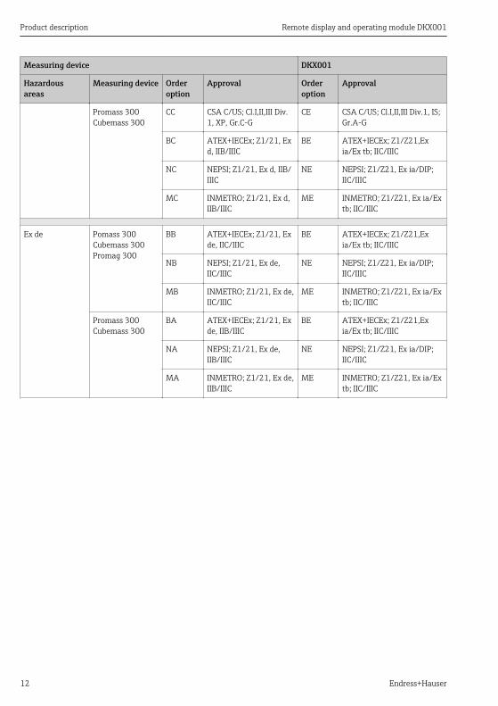
Product description Remote display and operating module DKX001
12 Endress+Hauser
Measuring device DKX001
Hazardousareas
Measuring device Orderoption
Approval Orderoption
Approval
Promass 300Cubemass 300
CC CSA C/US; Cl.I,II,III Div.1, XP, Gr.C-G
CE CSA C/US; Cl.I,II,III Div.1, IS;Gr.A-G
BC ATEX+IECEx; Z1/21, Exd, IIB/IIIC
BE ATEX+IECEx; Z1/Z21,Exia/Ex tb; IIC/IIIC
NC NEPSI; Z1/21, Ex d, IIB/IIIC
NE NEPSI; Z1/Z21, Ex ia/DIP;IIC/IIIC
MC INMETRO; Z1/21, Ex d,IIB/IIIC
ME INMETRO; Z1/Z21, Ex ia/Extb; IIC/IIIC
Ex de Pomass 300Cubemass 300Promag 300
BB ATEX+IECEx; Z1/21, Exde, IIC/IIIC
BE ATEX+IECEx; Z1/Z21,Exia/Ex tb; IIC/IIIC
NB NEPSI; Z1/21, Ex de,IIC/IIIC
NE NEPSI; Z1/Z21, Ex ia/DIP;IIC/IIIC
MB INMETRO; Z1/21, Ex de,IIC/IIIC
ME INMETRO; Z1/Z21, Ex ia/Extb; IIC/IIIC
Promass 300Cubemass 300
BA ATEX+IECEx; Z1/21, Exde, IIB/IIIC
BE ATEX+IECEx; Z1/Z21,Exia/Ex tb; IIC/IIIC
NA NEPSI; Z1/21, Ex de,IIB/IIIC
NE NEPSI; Z1/Z21, Ex ia/DIP;IIC/IIIC
MA INMETRO; Z1/21, Ex de,IIB/IIIC
ME INMETRO; Z1/Z21, Ex ia/Extb; IIC/IIIC
Remote display and operating module DKX001 Product description
Endress+Hauser 13
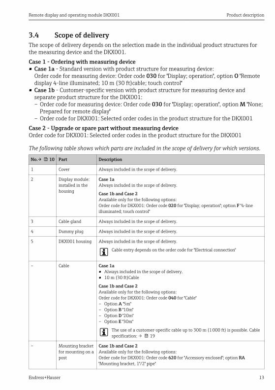
3.4 Scope of deliveryThe scope of delivery depends on the selection made in the individual product structures forthe measuring device and the DKX001.Case 1 - Ordering with measuring device• Case 1a - Standard version with product structure for measuring device:
Order code for measuring device: Order code 030 for "Display; operation", option O "Remotedisplay 4-line illuminated; 10 m (30 ft)cable; touch control"
• Case 1b - Customer-specific version with product structure for measuring device andseparate product structure for the DKX001:– Order code for measuring device: Order code 030 for "Display; operation", option M "None;
Prepared for remote display"– Order code for DKX001: Selected order codes in the product structure for the DKX001
Case 2 - Upgrade or spare part without measuring deviceOrder code for DKX001: Selected order codes in the product structure for the DKX001
The following table shows which parts are included in the scope of delivery for which versions.
No.→ 10 Part Description
1 Cover Always included in the scope of delivery.
2 Display module:installed in thehousing
Case 1aAlways included in the scope of delivery.
Case 1b and Case 2Available only for the following options:Order code for DKX001: Order code 020 for "Display; operation"; option F "4-lineilluminated; touch control"
3 Cable gland Always included in the scope of delivery.
4 Dummy plug Always included in the scope of delivery.
5 DKX001 housing Always included in the scope of delivery.
Cable entry depends on the order code for "Electrical connection"
– Cable Case 1a• Always included in the scope of delivery.• 10 m (30 ft)Cable
Case 1b and Case 2Available only for the following options:Order code for DKX001: Order code 040 for "Cable"– Option A "5m"– Option B "10m"– Option D "20m"– Option E "30m"
The use of a customer-specific cable up to 300 m (1 000 ft) is possible. Cablespecification: → 19
– Mounting bracketfor mounting on apost
Case 1b and Case 2Available only for the following options:Order code for DKX001: Order code 620 for "Accessory enclosed"; option RA"Mounting bracket, 1"/2" pipe"
Incoming acceptance and product identification Remote display and operating module DKX001
14 Endress+Hauser
4 Incoming acceptance and product identification
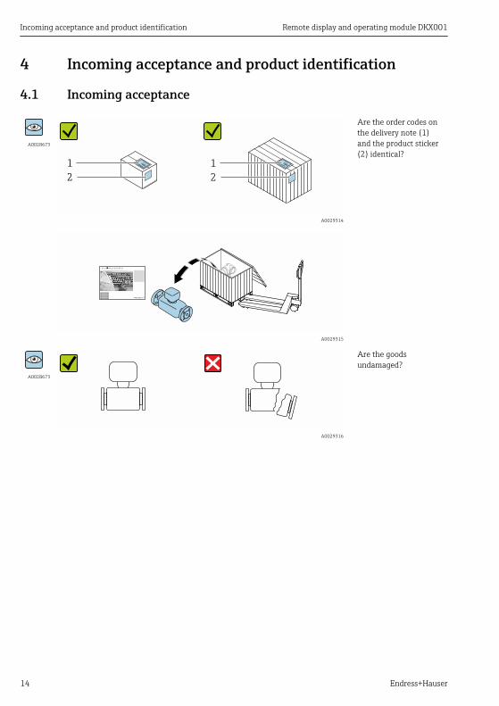
4.1 Incoming acceptance
A0028673
1
2
1
2
A0029314
Are the order codes onthe delivery note (1)and the product sticker(2) identical?
A0029315
A0028673
A0029316
Are the goodsundamaged?
Remote display and operating module DKX001 Incoming acceptance and product identification
Endress+Hauser 15
A0028673Order code:
Ser. no.:
Ext. ord. cd.:
i i
Date:
A0029317
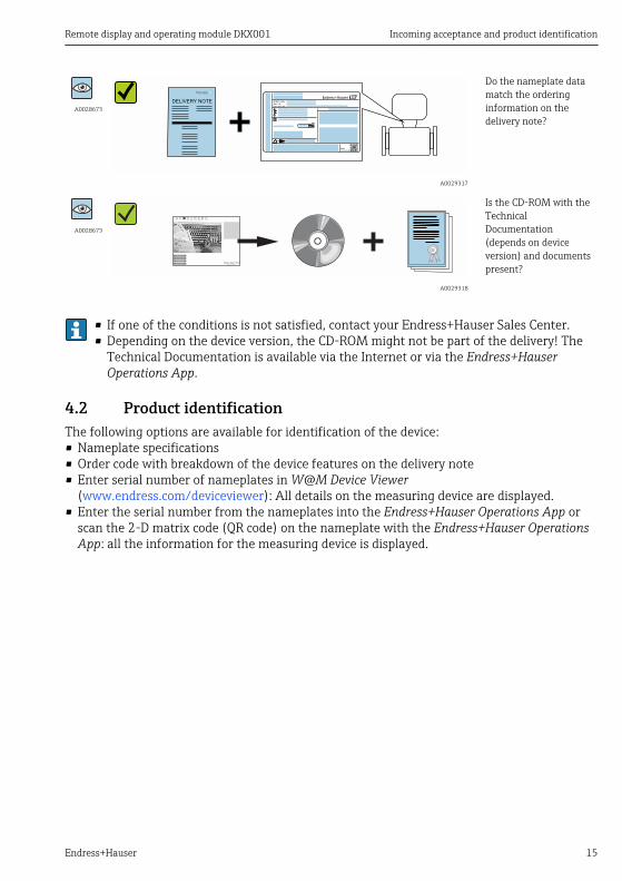
Do the nameplate datamatch the orderinginformation on thedelivery note?
A0028673
A0029318
Is the CD-ROM with theTechnicalDocumentation(depends on deviceversion) and documentspresent?
• If one of the conditions is not satisfied, contact your Endress+Hauser Sales Center.• Depending on the device version, the CD-ROM might not be part of the delivery! The
Technical Documentation is available via the Internet or via the Endress+HauserOperations App.
4.2 Product identificationThe following options are available for identification of the device:• Nameplate specifications• Order code with breakdown of the device features on the delivery note• Enter serial number of nameplates in W@M Device Viewer
(www.endress.com/deviceviewer): All details on the measuring device are displayed.• Enter the serial number from the nameplates into the Endress+Hauser Operations App or
scan the 2-D matrix code (QR code) on the nameplate with the Endress+Hauser OperationsApp: all the information for the measuring device is displayed.
Incoming acceptance and product identification Remote display and operating module DKX001
16 Endress+Hauser
DKX001
Order code:
Ext. ord. cd.:
Ser. no.:
i
Date:
1 2 3 4
5 6 7 8 9
10 11 12 13 14
A0031654
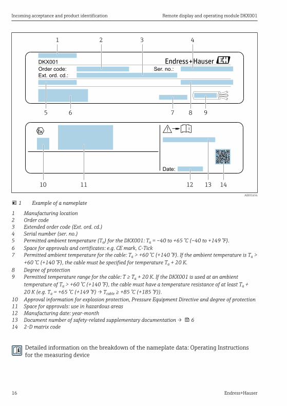
1 Example of a nameplate
1 Manufacturing location2 Order code3 Extended order code (Ext. ord. cd.)4 Serial number (ser. no.)5 Permitted ambient temperature (Ta) for the DKX001: Ta = –40 to +65 °C (–40 to +149 °F).6 Space for approvals and certificates: e.g. CE mark, C-Tick7 Permitted ambient temperature for the cable: Ta > +60 °C (+140 °F). If the ambient temperature is Ta >
+60 °C (+140 °F), the cable must be specified for temperature Ta + 20 K.8 Degree of protection9 Permitted temperature range for the cable: T ≥ Ta + 20 K. If the DKX001 is used at an ambient
temperature of Ta > +60 °C (+140 °F), the cable must have a temperature resistance of at least Ta +20 K (e.g. Ta = +65 °C (+149 °F) → Tcable ≥ +85 °C (+185 °F)).
10 Approval information for explosion protection, Pressure Equipment Directive and degree of protection11 Space for approvals: use in hazardous areas12 Manufacturing date: year-month13 Document number of safety-related supplementary documentation → 614 2-D matrix code
Detailed information on the breakdown of the nameplate data: Operating Instructionsfor the measuring device
Remote display and operating module DKX001 Storage and transport
Endress+Hauser 17
5 Storage and transport
5.1 Storage conditionsFor detailed information on the storage and transportation conditions, see the OperatingInstructions for the device.
Storage temperature: → 29
5.2 Transporting the productFor detailed information on transportation, see the Operating Instructions for the device.
5.3 Packaging disposalFor detailed information on the disposal of packaging, see the Operating Instructions forthe device.
6 InstallationMounting the remote display and operating moduleThe remote display and operating module can be mounted in the following ways:• Wall mounting→ 17• Post mounting→ 18
6.1 Required toolsFor wall mounting:Drill with drill bit 6.0 mmFor mounting on a post:• Mounting the safety claw: Allen key 3 mm• Grounding screws (internal and external): Phillips screwdriver PZ2
6.2 Wall mountingDimensions for wall mounting: → 29
Installation Remote display and operating module DKX001
18 Endress+Hauser
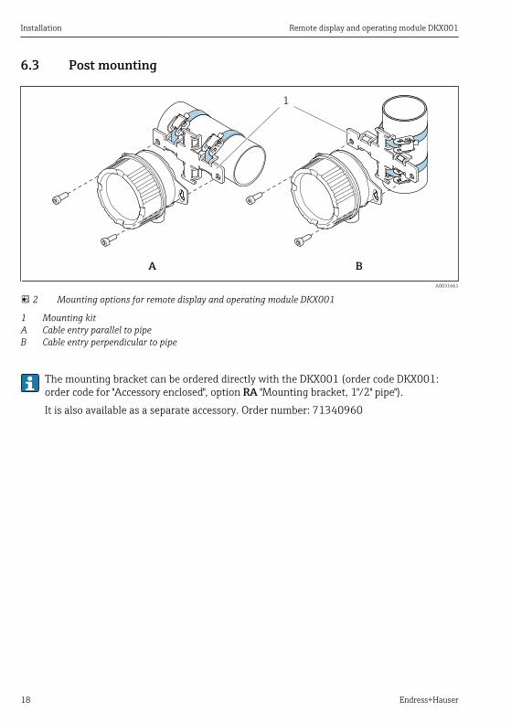
6.3 Post mounting
A B
1
A0031661
2 Mounting options for remote display and operating module DKX001
1 Mounting kitA Cable entry parallel to pipeB Cable entry perpendicular to pipe
The mounting bracket can be ordered directly with the DKX001 (order code DKX001:order code for "Accessory enclosed", option RA "Mounting bracket, 1"/2" pipe").It is also available as a separate accessory. Order number: 71340960
Remote display and operating module DKX001 Electrical connection
Endress+Hauser 19
7 Electrical connection
7.1 Connection conditions
7.1.1 Required tools• Cable gland M16 (cast, stainless): wrench22 mm• Cable gland M16 (aluminum, coated): wrench 24 mm• Clamp for cable shield: Phillips screwdriver PZ1• Terminals: Phillips screwdriver 0.5 × 3.5 mm
7.1.2 Requirements for the connecting cable
Optionally available connecting cableA cable is supplied depending on the order option• Order code for measuring device: Order code 030 for "Display; operation", option O
or• Order code for measuring device: Order code 030 for "Display; operation", option M
and• Order code for DKX001: Order code 040 for "Cable", option A, B, C, D
Standard cable 2 × 2 × 0.34 mm2 (22 AWG) PVC cable with common shield (2 pairs, pair-stranded)
Flame resistance According to DIN EN 60332-1-2
Oil-resistance According to DIN EN 60811-2-1
Shielding Tin-plated copper-braid, optical cover ≥ 85 %
Capacitance: core/shield ≤200 pF/m
L/R ≤24 µH/Ω
Available cable length 5 m (15 ft)/10 m (35 ft)/20 m (65 ft)/30 m (100 ft)
Operating temperature When mounted in a fixed position: –50 to +105 °C (–58 to +221 °F); when cable canmove freely: –25 to +105 °C (–13 to +221 °F)
Standard cable - customer-specific cableNo cable is supplied, and it must be provided by the customer (up to max. 300 m (1 000 ft))for the following order option:Order code for DKX001: Order code 040 for "Cable", option 1 "None, provided by customer, max300 m"A standard cable can be used as the connecting cable.
Standard cable 4 cores (2 pairs); pair-stranded with common shield
Shielding Tin-plated copper-braid, optical cover ≥ 85 %
Capacitance: core/shield Maximum 1 000 nF for Zone 1, Class I, Division 1
Electrical connection Remote display and operating module DKX001
20 Endress+Hauser
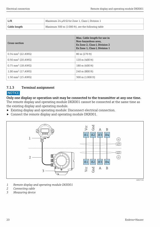
L/R Maximum 24 µH/Ω for Zone 1, Class I, Division 1
Cable length Maximum 300 m (1 000 ft), see the following table
Cross-section
Max. Cable length for use inNon-hazardous area,Ex Zone 2, Class I, Division 2Ex Zone 1, Class I, Division 1
0.34 mm2 (22 AWG) 80 m (270 ft)
0.50 mm2 (20 AWG) 120 m (400 ft)
0.75 mm2 (18 AWG) 180 m (600 ft)
1.00 mm2 (17 AWG) 240 m (800 ft)
1.50 mm2 (15 AWG) 300 m (1 000 ft)
7.1.3 Terminal assignmentNOTICE
Only one display or operation unit may be connected to the transmitter at any one time.The remote display and operating module DKX001 cannot be connected at the same time asthe existing display and operating module.‣ Existing display and operating module: Disconnect electrical connection.‣ Connect the remote display and operating module DKX001.
1
2
3
81
Vcc
82
Gn
d
83
A
84
B
81
Vcc
82
Gn
d
83
A
84
B
A0027518
1 Remote display and operating module DKX0012 Connecting cable3 Measuring device
Remote display and operating module DKX001 Electrical connection
Endress+Hauser 21
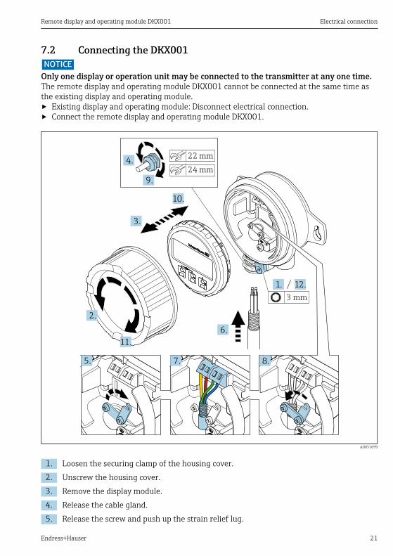
7.2 Connecting the DKX001NOTICE
Only one display or operation unit may be connected to the transmitter at any one time.The remote display and operating module DKX001 cannot be connected at the same time asthe existing display and operating module.‣ Existing display and operating module: Disconnect electrical connection.‣ Connect the remote display and operating module DKX001.
1.
2.
3.
5.
6.
10.
7. 8.
11.
12.
3 mm
22 mm
24 mm
4.
9.
A0031699
1. Loosen the securing clamp of the housing cover.2. Unscrew the housing cover.3. Remove the display module.4. Release the cable gland.5. Release the screw and push up the strain relief lug.
Electrical connection Remote display and operating module DKX001
22 Endress+Hauser
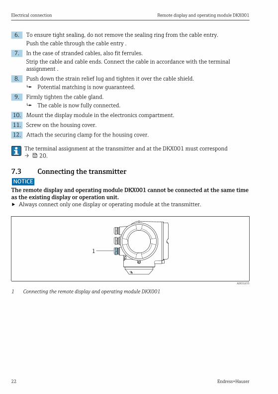
6. To ensure tight sealing, do not remove the sealing ring from the cable entry.Push the cable through the cable entry .
7. In the case of stranded cables, also fit ferrules.Strip the cable and cable ends. Connect the cable in accordance with the terminalassignment .
8. Push down the strain relief lug and tighten it over the cable shield. Potential matching is now guaranteed.
9. Firmly tighten the cable gland. The cable is now fully connected.
10. Mount the display module in the electronics compartment.11. Screw on the housing cover.12. Attach the securing clamp for the housing cover.
The terminal assignment at the transmitter and at the DKX001 must correspond→ 20.
7.3 Connecting the transmitterNOTICE
The remote display and operating module DKX001 cannot be connected at the same timeas the existing display or operation unit.‣ Always connect only one display or operating module at the transmitter.
1
A0031655
1 Connecting the remote display and operating module DKX001
Remote display and operating module DKX001 Electrical connection
Endress+Hauser 23
Nic
ht
unte
r
ar
e
öffn
en
Nicht unter
Spannung öffnen
Do not open when
energizedNe pas ouvrir
sous tension
Power
I/O
1.
2.
4.
9.
3 mm
22 mm
24 mm
3.
5. 6.
7.
8.
10.
A0031703
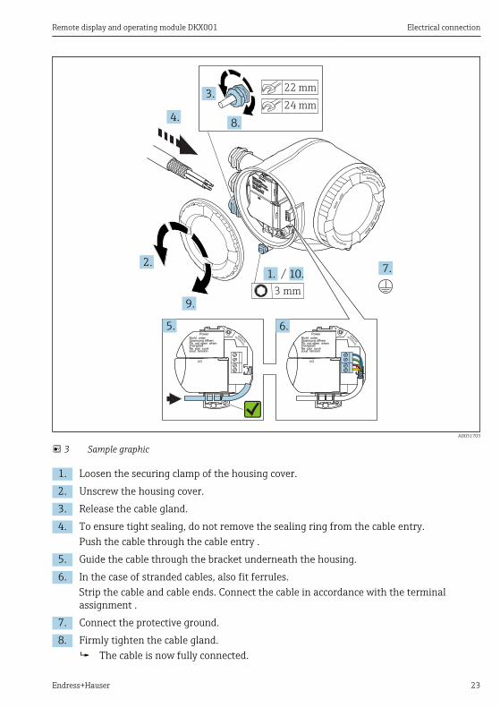
3 Sample graphic
1. Loosen the securing clamp of the housing cover.2. Unscrew the housing cover.3. Release the cable gland.4. To ensure tight sealing, do not remove the sealing ring from the cable entry.
Push the cable through the cable entry .5. Guide the cable through the bracket underneath the housing.6. In the case of stranded cables, also fit ferrules.
Strip the cable and cable ends. Connect the cable in accordance with the terminalassignment .
7. Connect the protective ground.8. Firmly tighten the cable gland.
The cable is now fully connected.
Operation options Remote display and operating module DKX001
24 Endress+Hauser
9. Screw on the housing cover.10. Attach the securing clamp for the housing cover.
7.4 Ensuring potential equalization1. The potential equalization line must be connected at both the transmitter and the
DKX001.2. If potential differences are anticipated, lay the potential equalization conduction
between the DKX001 and the transmitter, if necessary.
For detailed information on guaranteeing potential equalization at the transmitter, seethe Operating Instructions for the measuring device
8 Operation optionsThe display and operating elements correspond to those of the display module .
A0026786
Display elements• 4-line, illuminated, graphic display• White background lighting; switches to red in event of device errors• Format for displaying measured variables and status variables can be individually
configured• Permitted ambient temperature for the display: –20 to +60 °C (–4 to +140 °F)
The readability of the display may be impaired at temperatures outside the temperaturerange.
Operating elements• External operation via touch control (3 optical keys) without opening the housing: , , • Operating elements also accessible in various hazardous areas
Remote display and operating module DKX001 Diagnostics and troubleshooting
Endress+Hauser 25
9 Diagnostics and troubleshootingFor detailed information on diagnostics and troubleshooting, see the OperatingInstructions for the device.
10 Maintenance
10.1 Maintenance tasksNo special maintenance work is required.
10.2 Replacing seals
10.2.1 Replacing housing sealsNOTICE
When using the device in a dusty atmosphere:‣ only use the associated Endress+Hauser housing seals.
1. Replace defect seals only with original seals from Endress+Hauser.2. The housing seals must be clean and undamaged when inserted into their grooves.3. Dry, clean or replace the seals if necessary.
11 Repairs
11.1 General notes
11.1.1 Repair and conversion conceptThe Endress+Hauser repair and conversion concept provides for the following:• The measuring devices have a modular design.• Spare parts are grouped into logical kits with the associated Installation Instructions.• Repairs are carried out by Endress+Hauser Service or by appropriately trained customers.• Certified devices can only be converted to other certified devices by Endress+Hauser Service
or at the factory.
11.1.2 Notes for repair and conversionFor repair and modification of a measuring device, observe the following notes:‣ Use only original Endress+Hauser spare parts.‣ Carry out the repair according to the Installation Instructions.‣ Observe the applicable standards, federal/national regulations, Ex documentation (XA) and
certificates.
Repairs Remote display and operating module DKX001
26 Endress+Hauser
‣ Document every repair and each conversion and enter them into the W@M life cyclemanagement database.
11.2 Spare partsThe SFT (Spare Parts Finding Tool) supports you when searching for the right spare partsfor a specific device.Launch the Endress+Hauser Device Viewer via a web browser:www.endress.com/deviceviewerDetailed information on spare parts: Installation Instructions → 6
11.3 Conversion kit
11.3.1 Alteration with remote display and operating module DKX001Mounting the remote display and operating moduleThe remote display and operating module can be mounted in the following ways:• Wall mounting→ 17• Post mounting→ 18
NOTICEThe remote display and operating module DKX001 cannot be connected at the same timeas the existing display or operation unit.‣ Always connect only one display or operating module at the transmitter.
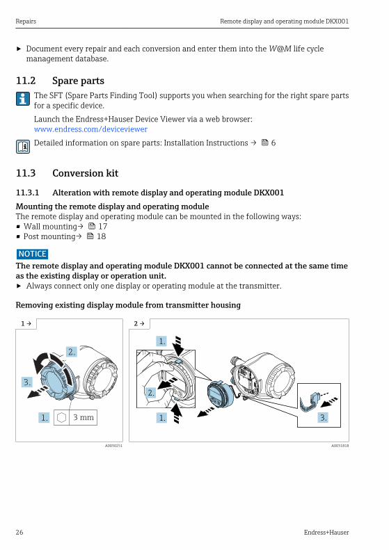
Removing existing display module from transmitter housing
1 → 2 →
3.
Nicht unter
Spannung öffnen
Do not open when
energizedNe pas ouvrir
sous tension
Power
I/O
Nic
ht
unte
r
ar
e
öffn
en
2.
1. 3 mm
Nic
ht
unte
r
ar
e
öffn
en
Nicht unter
Spannung öffnen
Do not open when
energizedNe pas ouvrir
sous tension
Power
I/O
Disp
lay
+
E
ESC
–
+
E
ESC
–
1.
1.
2.
3.
A0030251 A0031818
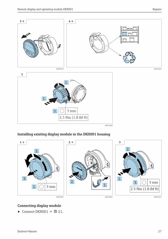
Remote display and operating module DKX001 Repairs
Endress+Hauser 27
3 → 4 →
Disp
lay
Disp
lay
A0030253 A0031819
5
3.
Nicht unter
Spannung öffnen
Do not open when
energizedNe pas ouvrir
sous tension
Power
I/O
Nic
ht
unte
r
ar
e
öffn
en
2.
1.
2.5 Nm (1.8 lbf ft)
3 mm
A0031820
Installing existing display module in the DKX001 housing
1 → 2 → 3
3 mm
3.
1.
2.
1.2.
2.5 Nm (1.8 lbf ft)
3 mm3.1.
2.
A0031821 A0031822 A0031823
Connecting display module‣ Connect DKX001 → 21.
Repairs Remote display and operating module DKX001
28 Endress+Hauser
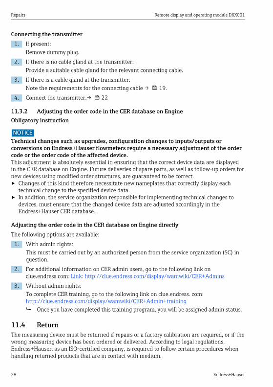
Connecting the transmitter1. If present:
Remove dummy plug.2. If there is no cable gland at the transmitter:
Provide a suitable cable gland for the relevant connecting cable.3. If there is a cable gland at the transmitter:
Note the requirements for the connecting cable → 19.4. Connect the transmitter.→ 22
11.3.2 Adjusting the order code in the CER database on EngineObligatory instruction
NOTICETechnical changes such as upgrades, configuration changes to inputs/outputs orconversions on Endress+Hauser flowmeters require a necessary adjustment of the ordercode or the order code of the affected device.This adjustment is absolutely essential in ensuring that the correct device data are displayedin the CER database on Engine. Future deliveries of spare parts, as well as follow-up orders fornew devices using modified order structures, are guaranteed to be correct.‣ Changes of this kind therefore necessitate new nameplates that correctly display each
technical change to the specified device data.‣ In addition, the service organization responsible for implementing technical changes to
devices, must ensure that the changed device data are adjusted accordingly in theEndress+Hauser CER database.
Adjusting the order code in the CER database on Engine directlyThe following options are available:
1. With admin rights:This must be carried out by an authorized person from the service organization (SC) inquestion.
2. For additional information on CER admin users, go to the following link onclue.endress.com: Link: http://clue.endress.com/display/wamwiki/CER+Admins
3. Without admin rights:To complete CER training, go to the following link on clue.endress. com:http://clue.endress.com/display/wamwiki/CER+Admin+training Once you have completed this training program, you will be assigned admin status.
11.4 ReturnThe measuring device must be returned if repairs or a factory calibration are required, or if thewrong measuring device has been ordered or delivered. According to legal regulations,Endress+Hauser, as an ISO-certified company, is required to follow certain procedures whenhandling returned products that are in contact with medium.
Remote display and operating module DKX001 Technical data
Endress+Hauser 29
To ensure swift, safe and professional device returns, please read the return procedures andconditions on the Endress+Hauser website at www.services.endress.com/return-material
11.5 DisposalObserve the following notes during disposal:• Observe valid federal/national regulations.• Ensure proper separation and reuse of the device components.
12 Technical data
12.1 Power supply→ 19
12.2 Environment
Ambient temperature range –40 to +65 °C (–40 to +149 °F) (for Ex, standard); –50 to +65 °C (–58 to +149) (forEx, order option JN)
Storage temperature –50 to +80 °C (–58 to +176 °F)
Climate class DIN EN 60068-2-38 (test Z/AD)
Degree of protection IP66, NEMA 4X
Vibration resistance DIN EN 60068-2-64/IEC 68-2-64: 20 to 2 000 Hz, 1 (m/s2)2/Hz
Electromagneticcompatibility (EMC)
Electromagnetic compatibility in accordance with all of the relevant requirementsoutlined in the EN 61326 series and NAMUR Recommendation EMC (NE 21). Fordetails, refer to the Declaration of Conformity.
Technical data Remote display and operating module DKX001
30 Endress+Hauser
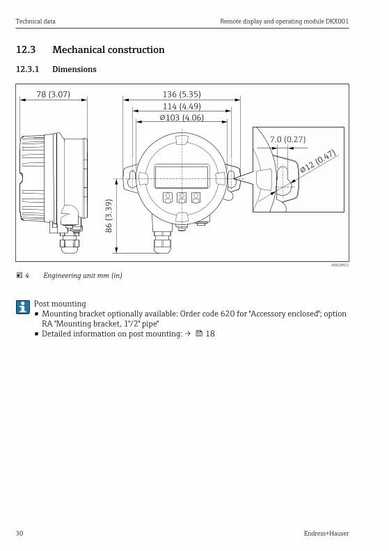
12.3 Mechanical construction
12.3.1 Dimensions
136 (5.35)
114 (4.49)8
6 (
3.3
9)
78 (3.07)
!103 (4.06)
!12 (0.47)
7.0 (0.27)
A0028921
4 Engineering unit mm (in)
Post mounting• Mounting bracket optionally available: Order code 620 for "Accessory enclosed"; option
RA "Mounting bracket, 1"/2" pipe"• Detailed information on post mounting: → 18
Remote display and operating module DKX001 Technical data
Endress+Hauser 31
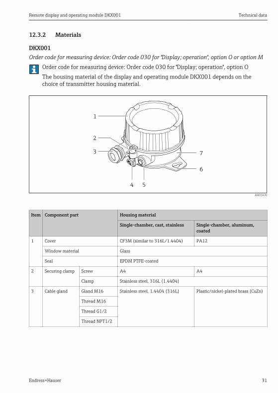
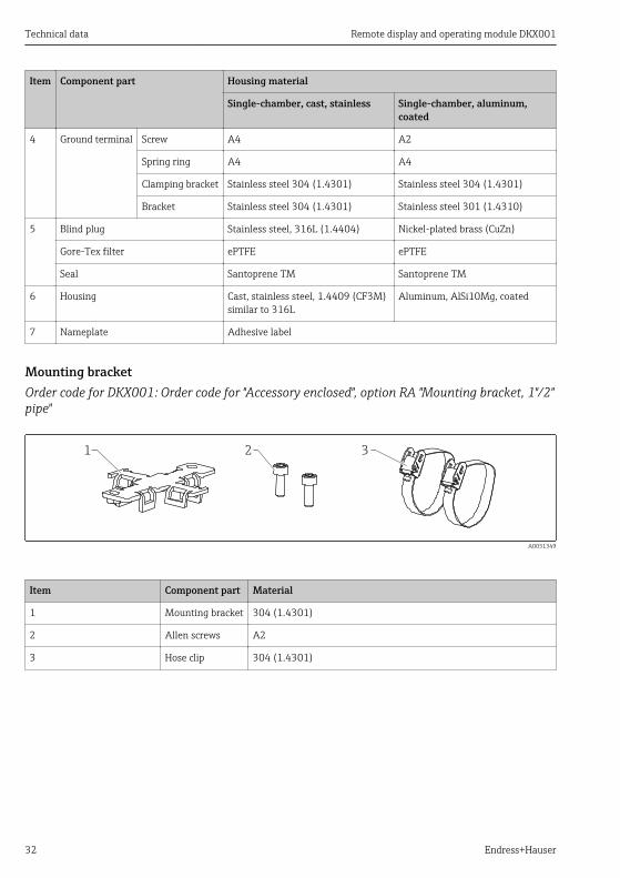
12.3.2 Materials
DKX001Order code for measuring device: Order code 030 for "Display; operation", option O or option M
Order code for measuring device: Order code 030 for "Display; operation", option OThe housing material of the display and operating module DKX001 depends on thechoice of transmitter housing material.
1
2
3
4 5
7
6
A0031670
Item Component part Housing material
Single-chamber, cast, stainless Single-chamber, aluminum,coated
1 Cover CF3M (similar to 316L/1.4404) PA12
Window material Glass
Seal EPDM PTFE-coated
2 Securing clamp Screw A4 A4
Clamp Stainless steel, 316L (1.4404)
3 Cable gland Gland M16 Stainless steel, 1.4404 (316L) Plastic/nickel-plated brass (CuZn)
Thread M16
Thread G1/2
Thread NPT1/2
Technical data Remote display and operating module DKX001
32 Endress+Hauser
Item Component part Housing material
Single-chamber, cast, stainless Single-chamber, aluminum,coated
4 Ground terminal Screw A4 A2
Spring ring A4 A4
Clamping bracket Stainless steel 304 (1.4301) Stainless steel 304 (1.4301)
Bracket Stainless steel 304 (1.4301) Stainless steel 301 (1.4310)
5 Blind plug Stainless steel, 316L (1.4404) Nickel-plated brass (CuZn)
Gore-Tex filter ePTFE ePTFE
Seal Santoprene TM Santoprene TM
6 Housing Cast, stainless steel, 1.4409 (CF3M)similar to 316L
Aluminum, AlSi10Mg, coated
7 Nameplate Adhesive label
Mounting bracketOrder code for DKX001: Order code for "Accessory enclosed", option RA "Mounting bracket, 1"/2"pipe"
1 2 3
A0031349
Item Component part Material
1 Mounting bracket 304 (1.4301)
2 Allen screws A2
3 Hose clip 304 (1.4301)
Remote display and operating module DKX001 Technical data
Endress+Hauser 33
12.4 Certificates and approvals
12.4.1 Ex approvalThe DKX001 is certified for use in hazardous areas.• The safety instructions that must be followed are enclosed in a separate document entitled
"Safety Instructions" (XA) → 6.• The document is referenced on the nameplate → 1, 16.
The approval of the DKX001 depends on the measuring device: → 13
ATEX/IECExCurrently, the following versions for use in hazardous areas are available:
Ex ia, Ex tb
Category Type of protection
II2G/Zone 1 Ex ia IIC T6...T4 Gb
II2D/Zone 21 Ex tb IIIC T115 °C Db
Ex nA
Category Type of protection
II3G/Zone 2 Ex nA IIC T6...T4 Gc
CCSAUS
Currently, the following versions for use in hazardous areas are available:
IS, Ex ia, AEx ia
Category Type of protection
Class I, Division 1, Groups A-D, Class II, Groups E-G, Class III IS
Class I, Zone 1, AEx/Ex ia IIC T6 to T4 GbZone 21, AEx/Ex tb IIIC T115°C Db
Ex ia/AEx ia 1)
1) Entity parameters in accordance with control drawing
NI, Ex nA
Category Type of protection
Class I, Division 2, Groups A-D NI 1)
Class I, Zone 2, AEx/ Ex nA IIC T6 to T4 Gc Ex nA/AEx nA 2)
1) Non-incendive2) Entity parameters in accordance with control drawing
Technical data Remote display and operating module DKX001
34 Endress+Hauser
INMETROCurrently, the following versions for use in hazardous areas are available:
Ex ia, tb
Category Type of protection
Zone 1/Zone21 Ex ia/Ex tb; IIC/IIIC
Ex nA
Category Type of protection
Zone 2 Ex nA
NEPSICurrently, the following versions for use in hazardous areas are available:
Ex i
Category Type of protection
Zone 1/Zone 21 Ex ia IIC T4~T6 GbEx tD A21 IP6X T115°C
Ex nA
Category Type of protection
Zone 2 Ex nA IIC T4~T6
Remote display and operating module DKX001 Index
Endress+Hauser 35
IndexAApproval
ATEX/IECEx . . . . . . . . . . . . . . . . . . 33cCSAus . . . . . . . . . . . . . . . . . . . . . 33INMETRO . . . . . . . . . . . . . . . . . . . 34NEPSI . . . . . . . . . . . . . . . . . . . . . 34
Approvals . . . . . . . . . . . . . . . . . . . . . . 33Availability . . . . . . . . . . . . . . . . . . . . . 10
CCE mark . . . . . . . . . . . . . . . . . . . . . . . . 9Certificates . . . . . . . . . . . . . . . . . . . . . 33Cleaning
Replacing housing seals . . . . . . . . . . . 25Replacing seals . . . . . . . . . . . . . . . . 25
Connectable transmitters . . . . . . . . . . . . . 10Connecting cable . . . . . . . . . . . . . . . . . . 19Connecting the DKX001 . . . . . . . . . . . . . . 21Connecting the transmitter . . . . . . . . . . . . 22Connection
see Electrical connectionConnection tools . . . . . . . . . . . . . . . . . . 19
DDeclaration of Conformity . . . . . . . . . . . . . 9Designated use . . . . . . . . . . . . . . . . . . . . 7Device components . . . . . . . . . . . . . . . . 10Device repair . . . . . . . . . . . . . . . . . . . . 25Diagnostics and troubleshooting . . . . . . . . . 25Dimensions . . . . . . . . . . . . . . . . . . . . . 30Display elements . . . . . . . . . . . . . . . . . . 24Disposal . . . . . . . . . . . . . . . . . . . . . . . 29Document
Function . . . . . . . . . . . . . . . . . . . . . 4Symbols used . . . . . . . . . . . . . . . . . . 4
Document function . . . . . . . . . . . . . . . . . 4Documentation . . . . . . . . . . . . . . . . . . . . 6
EElectrical connection
Connection conditions . . . . . . . . . . . . 19Device . . . . . . . . . . . . . . . . . . . . . 19Required tools . . . . . . . . . . . . . . . . 19
EnvironmentAmbient temperature range . . . . . . . . 29Climate class . . . . . . . . . . . . . . . . . 29
Degree of protection . . . . . . . . . . . . . 29Electromagnetic compatibility (EMC) . . . 29Storage temperature . . . . . . . . . . . . . 29Vibration resistance . . . . . . . . . . . . . 29
Ex approval . . . . . . . . . . . . . . . . . . . . . 33
II/O electronics module . . . . . . . . . . . . . . 10Identifying the measuring device . . . . . . . . 15Incoming acceptance . . . . . . . . . . . . . . . . 14Information on the document . . . . . . . . . . . 4Inspection
Received goods . . . . . . . . . . . . . . . . 14Installation . . . . . . . . . . . . . . . . . . . . . 17Installation Instructions . . . . . . . . . . . . . . . 7
MMain electronics module . . . . . . . . . . . . . 10Maintenance . . . . . . . . . . . . . . . . . . . . 25Maintenance tasks . . . . . . . . . . . . . . . . . 25Materials . . . . . . . . . . . . . . . . . . . . . . 31
DKX001 . . . . . . . . . . . . . . . . . . . . 31Mounting bracket . . . . . . . . . . . . . . 32
Measuring deviceConversion . . . . . . . . . . . . . . . . . . 25Repairs . . . . . . . . . . . . . . . . . . . . . 25Structure . . . . . . . . . . . . . . . . . . . . 10
Mechanical construction . . . . . . . . . . . . . 30Mounting tools . . . . . . . . . . . . . . . . . . . 17
OOperating elements . . . . . . . . . . . . . . . . 24Operation options . . . . . . . . . . . . . . . . . 24Operational safety . . . . . . . . . . . . . . . . . . 8Order code . . . . . . . . . . . . . . . . . . . . . . 15
PPackaging disposal . . . . . . . . . . . . . . . . . 17Post mounting . . . . . . . . . . . . . . . . . . . 18Power supply
Connecting cable . . . . . . . . . . . . . . . 24Optionally available connecting cable . . . 29Standard cable - customer-specific cable 29
Product description . . . . . . . . . . . . . . . . 10Product identification . . . . . . . . . . . . . . . 14Product safety . . . . . . . . . . . . . . . . . . . . 9
Index Remote display and operating module DKX001
36 Endress+Hauser
RRepair of a device . . . . . . . . . . . . . . . . . . 25Repairs
Notes . . . . . . . . . . . . . . . . . . . . . . 25Replacement
Device components . . . . . . . . . . . . . 25Replacing seals . . . . . . . . . . . . . . . . . . . 25Requirements for personnel . . . . . . . . . . . . 7Retrofit Device . . . . . . . . . . . . . . . . . . . . 8Returning devices . . . . . . . . . . . . . . . . . 28
SSafety . . . . . . . . . . . . . . . . . . . . . . . . . 7Safety instructions . . . . . . . . . . . . . . . . . . 6Scope of delivery . . . . . . . . . . . . . . . . . . 13Spare part . . . . . . . . . . . . . . . . . . . . . . 25Special Documentation . . . . . . . . . . . . . . . 7Storage . . . . . . . . . . . . . . . . . . . . . . . 17Storage conditions . . . . . . . . . . . . . . . . . 17Storage temperature . . . . . . . . . . . . . . . . 17Structure
Measuring device . . . . . . . . . . . . . . . 10Supplementary device-dependentdocumentation . . . . . . . . . . . . . . . . . . . . 6System design
see Measuring device design
TTechnical data . . . . . . . . . . . . . . . . . . . 29Temperature range
Storage temperature . . . . . . . . . . . . . 17Terminal assignment . . . . . . . . . . . . . . . 20Tools
Installation . . . . . . . . . . . . . . . . . . 17Transportation . . . . . . . . . . . . . . . . 17
Transportation . . . . . . . . . . . . . . . . . . . 17Transporting the measuring device . . . . . . . 17
UUsage Device
Borderline cases . . . . . . . . . . . . . . . . 8Incorrect use . . . . . . . . . . . . . . . . . . 8see Designated use
WW@M . . . . . . . . . . . . . . . . . . . . . . . . 25W@M Device Viewer . . . . . . . . . . . . . . . 15Wall mounting . . . . . . . . . . . . . . . . . . . 17
WeightTransport (notes) . . . . . . . . . . . . . . 17


www.addresses.endress.com