Embed Size (px)
DESCRIPTION
SMA S16 Sunny Island Inverter Manual
Citation preview
7/17/2019 Remote Control SI60H Operating Manual
http://slidepdf.com/reader/full/remote-control-si60h-operating-manual 1/128
SI60H-80H-BE-en-20 | Version 2.0 ENGLISH
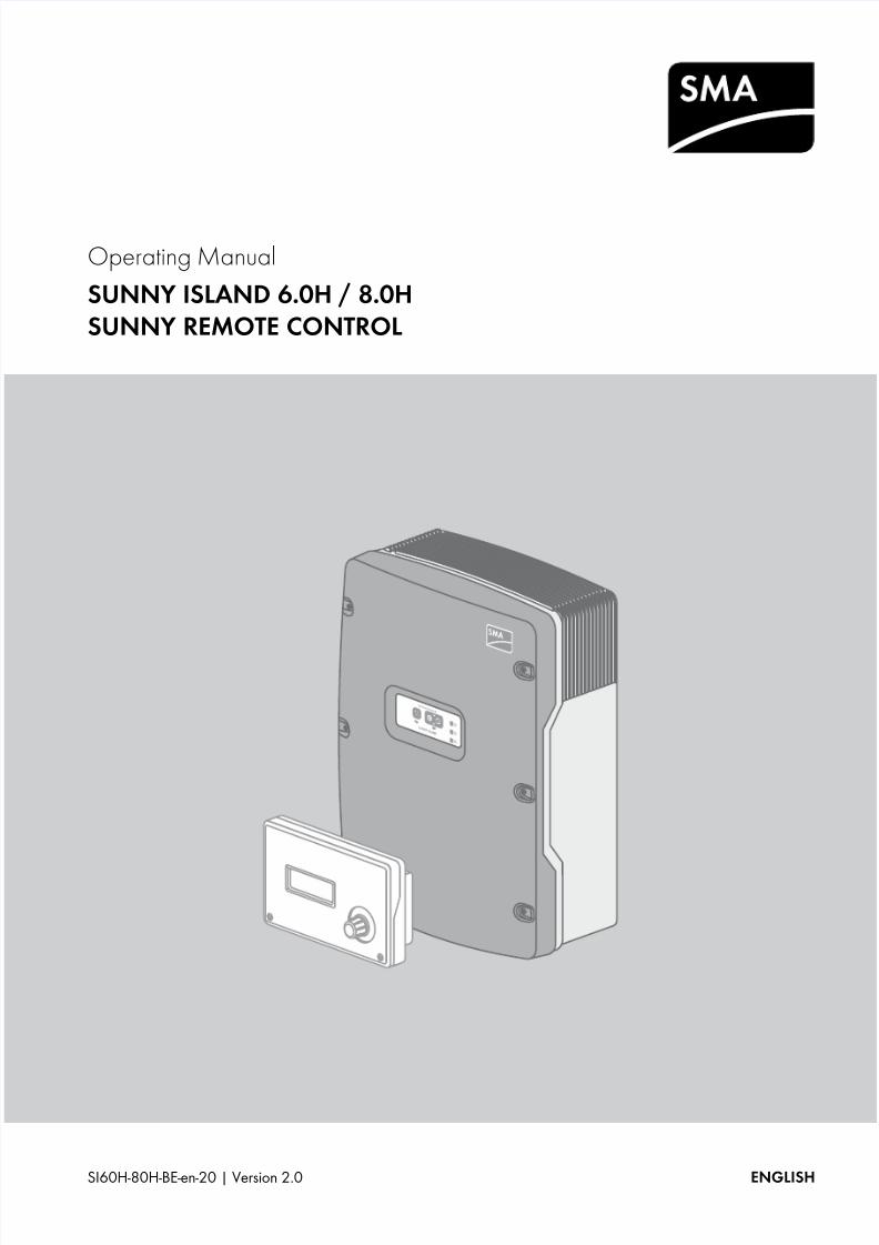
Operating Manual
SUNNY ISLAND 6.0H / 8.0HSUNNY REMOTE CONTROL
7/17/2019 Remote Control SI60H Operating Manual
http://slidepdf.com/reader/full/remote-control-si60h-operating-manual 2/128
Legal Provisions SMA Solar Technology AG
2 SI60H-80H-BE-en-20 Operating Manual
Legal ProvisionsThe information contained in this document is the property of SMA Solar Technology AG. Publishing its content, either partially or in full, requiresthe written permission of SMA Solar Technology AG. Any internal company copying of the document for the purposes of evaluating the product orits correct implementation is allowed and does not require permission.
SMA WarrantyThe current warranty conditions come enclosed with your device. These are also available online at www.SMA-Solar.com and can be downloadedand are available on paper from the usual sales channels if required.
TrademarksAll trademarks are recognized even if these are not marked separately. Missing designations do not mean that a product or brand is not a registeredtrademark.
The Bluetooth® word mark and logos are registered trademarks owned by Bluetooth SIG, Inc. and any use of such marks by
SMA Solar Technology AG is under license.
QR Code® is a registered trademark of DENSO WAVE INCORPORATED.
SMA Solar Technology AG
Sonnenallee 134266 NiestetalGermany
Tel. +49 561 9522-0Fax +49 561 9522-100www.SMA.deE-mail: [email protected]
© 2004 to 2014 SMA Solar Technology AG. All rights reserved.
7/17/2019 Remote Control SI60H Operating Manual
http://slidepdf.com/reader/full/remote-control-si60h-operating-manual 3/128
SMA Solar Technology AG Table of Contents
Operating Manual SI60H-80H-BE-en-20 3
Table of Contents
1 Information on this Document. . . . . . . . . . . . . . . . . . . . . . . . . . . . . . . . . . . . . . . . . . . . . . . . . . . . . 7
2 Safety . . . . . . . . . . . . . . . . . . . . . . . . . . . . . . . . . . . . . . . . . . . . . . . . . . . . . . . . . . . . . . . . . . . . . . . . 9
2.1 Intended Use . . . . . . . . . . . . . . . . . . . . . . . . . . . . . . . . . . . . . . . . . . . . . . . . . . . . . . . . . . . . . . . . . . . . . . . . . 9
2.2 Skills of the Target Group . . . . . . . . . . . . . . . . . . . . . . . . . . . . . . . . . . . . . . . . . . . . . . . . . . . . . . . . . . . . . . . 102.3 Safety Precautions . . . . . . . . . . . . . . . . . . . . . . . . . . . . . . . . . . . . . . . . . . . . . . . . . . . . . . . . . . . . . . . . . . . . 10
3 Product Description . . . . . . . . . . . . . . . . . . . . . . . . . . . . . . . . . . . . . . . . . . . . . . . . . . . . . . . . . . . . 13
3.1 Sunny Island . . . . . . . . . . . . . . . . . . . . . . . . . . . . . . . . . . . . . . . . . . . . . . . . . . . . . . . . . . . . . . . . . . . . . . . . . 13
3.2 Control Panel of the Sunny Island. . . . . . . . . . . . . . . . . . . . . . . . . . . . . . . . . . . . . . . . . . . . . . . . . . . . . . . . . 13
3.3 Type Label . . . . . . . . . . . . . . . . . . . . . . . . . . . . . . . . . . . . . . . . . . . . . . . . . . . . . . . . . . . . . . . . . . . . . . . . . . 14
3.4 Sunny Remote Control . . . . . . . . . . . . . . . . . . . . . . . . . . . . . . . . . . . . . . . . . . . . . . . . . . . . . . . . . . . . . . . . . 16
4 Starting and Stopping the System . . . . . . . . . . . . . . . . . . . . . . . . . . . . . . . . . . . . . . . . . . . . . . . . 17
4.1 Switching on the Sunny Island . . . . . . . . . . . . . . . . . . . . . . . . . . . . . . . . . . . . . . . . . . . . . . . . . . . . . . . . . . . 17
4.2 Starting the System . . . . . . . . . . . . . . . . . . . . . . . . . . . . . . . . . . . . . . . . . . . . . . . . . . . . . . . . . . . . . . . . . . . . 174.3 Stopping the System . . . . . . . . . . . . . . . . . . . . . . . . . . . . . . . . . . . . . . . . . . . . . . . . . . . . . . . . . . . . . . . . . . . 18
4.4 Switching off the Sunny Island . . . . . . . . . . . . . . . . . . . . . . . . . . . . . . . . . . . . . . . . . . . . . . . . . . . . . . . . . . . 18
4.5 Tripping the Emergency Disconnection of the System. . . . . . . . . . . . . . . . . . . . . . . . . . . . . . . . . . . . . . . . . . 19
4.6 Setting Time-Controlled Inverter Operation in Off-Grid Systems. . . . . . . . . . . . . . . . . . . . . . . . . . . . . . . . . . 19
5 Operating the Sunny Island via Sunny Remote Control. . . . . . . . . . . . . . . . . . . . . . . . . . . . . . . 20
5.1 Display Modes . . . . . . . . . . . . . . . . . . . . . . . . . . . . . . . . . . . . . . . . . . . . . . . . . . . . . . . . . . . . . . . . . . . . . . . 20
5.2 Standard Mode . . . . . . . . . . . . . . . . . . . . . . . . . . . . . . . . . . . . . . . . . . . . . . . . . . . . . . . . . . . . . . . . . . . . . . 215.2.1 Display of Operating States . . . . . . . . . . . . . . . . . . . . . . . . . . . . . . . . . . . . . . . . . . . . . . . . . . . . . . . . . . . . . . .21
5.2.2 Information Page in Systems for Increased Self-Consumption and Battery Backup Systems . . . . . . . . . . . . . . .215.2.3 Information Page in Off-Grid Systems . . . . . . . . . . . . . . . . . . . . . . . . . . . . . . . . . . . . . . . . . . . . . . . . . . . . . . . .22
5.3 User Mode . . . . . . . . . . . . . . . . . . . . . . . . . . . . . . . . . . . . . . . . . . . . . . . . . . . . . . . . . . . . . . . . . . . . . . . . . . 265.3.1 Displaying Parameters and Operating and Setting the System. . . . . . . . . . . . . . . . . . . . . . . . . . . . . . . . . . . . .26
5.4 Installer and Expert Mode . . . . . . . . . . . . . . . . . . . . . . . . . . . . . . . . . . . . . . . . . . . . . . . . . . . . . . . . . . . . . . 285.4.1 Switching to Installer Mode or Expert Mode. . . . . . . . . . . . . . . . . . . . . . . . . . . . . . . . . . . . . . . . . . . . . . . . . . .28
5.4.2 Exiting Installer Mode or Expert Mode . . . . . . . . . . . . . . . . . . . . . . . . . . . . . . . . . . . . . . . . . . . . . . . . . . . . . . .28
5.4.3 Menus in Installer and Expert Mode . . . . . . . . . . . . . . . . . . . . . . . . . . . . . . . . . . . . . . . . . . . . . . . . . . . . . . . . .29
5.4.4 Parameter Page in Installer and Expert Mode. . . . . . . . . . . . . . . . . . . . . . . . . . . . . . . . . . . . . . . . . . . . . . . . . .29
5.4.5 Selecting Menus and Parameters . . . . . . . . . . . . . . . . . . . . . . . . . . . . . . . . . . . . . . . . . . . . . . . . . . . . . . . . . . .29
5.4.6 Setting the Parameters . . . . . . . . . . . . . . . . . . . . . . . . . . . . . . . . . . . . . . . . . . . . . . . . . . . . . . . . . . . . . . . . . . . .305.4.7 Directly Accessing the Parameters . . . . . . . . . . . . . . . . . . . . . . . . . . . . . . . . . . . . . . . . . . . . . . . . . . . . . . . . . . .31
6 Data Storage and Firmware Update . . . . . . . . . . . . . . . . . . . . . . . . . . . . . . . . . . . . . . . . . . . . . . 32
6.1 Inserting the SD Memory Card. . . . . . . . . . . . . . . . . . . . . . . . . . . . . . . . . . . . . . . . . . . . . . . . . . . . . . . . . . . 32
6.2 Saving and Loading Parameters. . . . . . . . . . . . . . . . . . . . . . . . . . . . . . . . . . . . . . . . . . . . . . . . . . . . . . . . . . 32
6.3 Saving the Event History and Error History . . . . . . . . . . . . . . . . . . . . . . . . . . . . . . . . . . . . . . . . . . . . . . . . . . 33
6.4 Displaying the SD Memory Card Status Message. . . . . . . . . . . . . . . . . . . . . . . . . . . . . . . . . . . . . . . . . . . . 33
6.5 Removing the SD Memory Card. . . . . . . . . . . . . . . . . . . . . . . . . . . . . . . . . . . . . . . . . . . . . . . . . . . . . . . . . . 33
6.6 Displaying the SD Memory Card Content . . . . . . . . . . . . . . . . . . . . . . . . . . . . . . . . . . . . . . . . . . . . . . . . . . 33

7/17/2019 Remote Control SI60H Operating Manual
http://slidepdf.com/reader/full/remote-control-si60h-operating-manual 4/128
Table of Contents SMA Solar Technology AG
4 SI60H-80H-BE-en-20 Operating Manual
6.7 Updating the Firmware . . . . . . . . . . . . . . . . . . . . . . . . . . . . . . . . . . . . . . . . . . . . . . . . . . . . . . . . . . . . . . . . 356.7.1 Updating the Firmware Using an SD Memory Card . . . . . . . . . . . . . . . . . . . . . . . . . . . . . . . . . . . . . . . . . . . . .35
6.7.2 Updating the Firmware Using Sunny Explorer. . . . . . . . . . . . . . . . . . . . . . . . . . . . . . . . . . . . . . . . . . . . . . . . . .35
6.7.3 Performing a Remote Update Using Sunny Portal . . . . . . . . . . . . . . . . . . . . . . . . . . . . . . . . . . . . . . . . . . . . . . .36
7 Manually Controlling the Generator . . . . . . . . . . . . . . . . . . . . . . . . . . . . . . . . . . . . . . . . . . . . . .37
7.1 Starting the Generator with Sunny Remote Control . . . . . . . . . . . . . . . . . . . . . . . . . . . . . . . . . . . . . . . . . . . 377.2 Stopping the Generator with Sunny Remote Control . . . . . . . . . . . . . . . . . . . . . . . . . . . . . . . . . . . . . . . . . . 37
7.3 Starting the Generator without Autostart Function . . . . . . . . . . . . . . . . . . . . . . . . . . . . . . . . . . . . . . . . . . . . 37
7.4 Stopping the Generator without Autostart Function . . . . . . . . . . . . . . . . . . . . . . . . . . . . . . . . . . . . . . . . . . . 38
8 Disconnecting the Sunny Island from Voltage Sources. . . . . . . . . . . . . . . . . . . . . . . . . . . . . . . .39
9 Troubleshooting . . . . . . . . . . . . . . . . . . . . . . . . . . . . . . . . . . . . . . . . . . . . . . . . . . . . . . . . . . . . . . .40
9.1 Behavior of the Sunny Island under Fault Conditions. . . . . . . . . . . . . . . . . . . . . . . . . . . . . . . . . . . . . . . . . . 40
9.2 Acknowledging Errors . . . . . . . . . . . . . . . . . . . . . . . . . . . . . . . . . . . . . . . . . . . . . . . . . . . . . . . . . . . . . . . . . 41
9.3 Logged Events . . . . . . . . . . . . . . . . . . . . . . . . . . . . . . . . . . . . . . . . . . . . . . . . . . . . . . . . . . . . . . . . . . . . . . . 419.3.1 Sunny Island Category (1xx). . . . . . . . . . . . . . . . . . . . . . . . . . . . . . . . . . . . . . . . . . . . . . . . . . . . . . . . . . . . . . .41
9.3.2 Battery Category (2xx) . . . . . . . . . . . . . . . . . . . . . . . . . . . . . . . . . . . . . . . . . . . . . . . . . . . . . . . . . . . . . . . . . . .42
9.3.3 Generator Category (4xx) . . . . . . . . . . . . . . . . . . . . . . . . . . . . . . . . . . . . . . . . . . . . . . . . . . . . . . . . . . . . . . . .42
9.3.4 Utility Grid Category (5xx) . . . . . . . . . . . . . . . . . . . . . . . . . . . . . . . . . . . . . . . . . . . . . . . . . . . . . . . . . . . . . . . .43
9.3.5 Relay Category (6xx) . . . . . . . . . . . . . . . . . . . . . . . . . . . . . . . . . . . . . . . . . . . . . . . . . . . . . . . . . . . . . . . . . . . .43
9.3.6 System Category (7xx) . . . . . . . . . . . . . . . . . . . . . . . . . . . . . . . . . . . . . . . . . . . . . . . . . . . . . . . . . . . . . . . . . . .44
9.3.7 External Device and Component Category (8xx) . . . . . . . . . . . . . . . . . . . . . . . . . . . . . . . . . . . . . . . . . . . . . . .44
9.4 Logged Warning Messages and Error Messages . . . . . . . . . . . . . . . . . . . . . . . . . . . . . . . . . . . . . . . . . . . . 459.4.1 Sunny Island Category (1xx). . . . . . . . . . . . . . . . . . . . . . . . . . . . . . . . . . . . . . . . . . . . . . . . . . . . . . . . . . . . . . .45
9.4.2 Battery Category (2xx) . . . . . . . . . . . . . . . . . . . . . . . . . . . . . . . . . . . . . . . . . . . . . . . . . . . . . . . . . . . . . . . . . . .48
9.4.3 Generator or Utility Grid Category (3xx) . . . . . . . . . . . . . . . . . . . . . . . . . . . . . . . . . . . . . . . . . . . . . . . . . . . . .50
9.4.4 Generator Category (4xx) . . . . . . . . . . . . . . . . . . . . . . . . . . . . . . . . . . . . . . . . . . . . . . . . . . . . . . . . . . . . . . . .54
9.4.5 Utility Grid Category (5xx) . . . . . . . . . . . . . . . . . . . . . . . . . . . . . . . . . . . . . . . . . . . . . . . . . . . . . . . . . . . . . . . .55
9.4.6 Relay Category (6xx) . . . . . . . . . . . . . . . . . . . . . . . . . . . . . . . . . . . . . . . . . . . . . . . . . . . . . . . . . . . . . . . . . . . .55
9.4.7 System Category (7xx) . . . . . . . . . . . . . . . . . . . . . . . . . . . . . . . . . . . . . . . . . . . . . . . . . . . . . . . . . . . . . . . . . . .55
9.4.8 External Device and Component Category (8xx) . . . . . . . . . . . . . . . . . . . . . . . . . . . . . . . . . . . . . . . . . . . . . . .59
9.4.9 General Category (9xx) . . . . . . . . . . . . . . . . . . . . . . . . . . . . . . . . . . . . . . . . . . . . . . . . . . . . . . . . . . . . . . . . . .65
9.5 Frequently Asked Questions. . . . . . . . . . . . . . . . . . . . . . . . . . . . . . . . . . . . . . . . . . . . . . . . . . . . . . . . . . . . . 659.5.1 Questions regarding the Sunny Island. . . . . . . . . . . . . . . . . . . . . . . . . . . . . . . . . . . . . . . . . . . . . . . . . . . . . . . .65
9.5.2 Questions regarding the Sunny Remote Control . . . . . . . . . . . . . . . . . . . . . . . . . . . . . . . . . . . . . . . . . . . . . . . .669.5.3 Questions regarding the Battery . . . . . . . . . . . . . . . . . . . . . . . . . . . . . . . . . . . . . . . . . . . . . . . . . . . . . . . . . . . .67
9.5.4 Questions regarding the Generator . . . . . . . . . . . . . . . . . . . . . . . . . . . . . . . . . . . . . . . . . . . . . . . . . . . . . . . . .67
9.5.5 Questions regarding Cluster Systems and Multicluster Systems . . . . . . . . . . . . . . . . . . . . . . . . . . . . . . . . . . . .68
9.6 Charging the Battery after Automatic Shutdown in Off-Grid Systems . . . . . . . . . . . . . . . . . . . . . . . . . . . . . 69
9.7 Changing Slave Addresses in a Cluster . . . . . . . . . . . . . . . . . . . . . . . . . . . . . . . . . . . . . . . . . . . . . . . . . . . . 71
10 Cleaning and Maintenance . . . . . . . . . . . . . . . . . . . . . . . . . . . . . . . . . . . . . . . . . . . . . . . . . . . . . .73
10.1 Cleaning and Checking the Sunny Island Enclosure . . . . . . . . . . . . . . . . . . . . . . . . . . . . . . . . . . . . . . . . . . 73
10.2 Cleaning the Sunny Remote Control . . . . . . . . . . . . . . . . . . . . . . . . . . . . . . . . . . . . . . . . . . . . . . . . . . . . . . 73
10.3 Performing a Manual Equalization Charge in the Off-Grid System. . . . . . . . . . . . . . . . . . . . . . . . . . . . . . . 73
10.4 Checking the Function . . . . . . . . . . . . . . . . . . . . . . . . . . . . . . . . . . . . . . . . . . . . . . . . . . . . . . . . . . . . . . . . . 73
10.5 Checking the Terminals . . . . . . . . . . . . . . . . . . . . . . . . . . . . . . . . . . . . . . . . . . . . . . . . . . . . . . . . . . . . . . . . 73

7/17/2019 Remote Control SI60H Operating Manual
http://slidepdf.com/reader/full/remote-control-si60h-operating-manual 5/128
SMA Solar Technology AG Table of Contents
Operating Manual SI60H-80H-BE-en-20 5
10.6 Checking and Maintaining the Battery . . . . . . . . . . . . . . . . . . . . . . . . . . . . . . . . . . . . . . . . . . . . . . . . . . . . . 74
10.7 Cleaning the Fans. . . . . . . . . . . . . . . . . . . . . . . . . . . . . . . . . . . . . . . . . . . . . . . . . . . . . . . . . . . . . . . . . . . . . 75
10.8 Replacing the Battery . . . . . . . . . . . . . . . . . . . . . . . . . . . . . . . . . . . . . . . . . . . . . . . . . . . . . . . . . . . . . . . . . . 77
11 Decommissioning . . . . . . . . . . . . . . . . . . . . . . . . . . . . . . . . . . . . . . . . . . . . . . . . . . . . . . . . . . . . . . 79
11.1 Disassembling the Sunny Island . . . . . . . . . . . . . . . . . . . . . . . . . . . . . . . . . . . . . . . . . . . . . . . . . . . . . . . . . . 79
11.2 Packaging the Sunny Island . . . . . . . . . . . . . . . . . . . . . . . . . . . . . . . . . . . . . . . . . . . . . . . . . . . . . . . . . . . . . 80
11.3 Disposing of the Sunny Island. . . . . . . . . . . . . . . . . . . . . . . . . . . . . . . . . . . . . . . . . . . . . . . . . . . . . . . . . . . . 80
12 Directory of the Parameters in User Mode . . . . . . . . . . . . . . . . . . . . . . . . . . . . . . . . . . . . . . . . . 81
12.1 Inverter Category . . . . . . . . . . . . . . . . . . . . . . . . . . . . . . . . . . . . . . . . . . . . . . . . . . . . . . . . . . . . . . . . . . . . . 81
12.2 Battery Category . . . . . . . . . . . . . . . . . . . . . . . . . . . . . . . . . . . . . . . . . . . . . . . . . . . . . . . . . . . . . . . . . . . . . 82
12.3 Generator Category. . . . . . . . . . . . . . . . . . . . . . . . . . . . . . . . . . . . . . . . . . . . . . . . . . . . . . . . . . . . . . . . . . . 83
12.4 Grid Category . . . . . . . . . . . . . . . . . . . . . . . . . . . . . . . . . . . . . . . . . . . . . . . . . . . . . . . . . . . . . . . . . . . . . . . 83
12.5 SIC50 Category . . . . . . . . . . . . . . . . . . . . . . . . . . . . . . . . . . . . . . . . . . . . . . . . . . . . . . . . . . . . . . . . . . . . . . 84
12.6 Self Cnsmptn Category. . . . . . . . . . . . . . . . . . . . . . . . . . . . . . . . . . . . . . . . . . . . . . . . . . . . . . . . . . . . . . . . . 84
12.7 Grid Cnsmptn Category . . . . . . . . . . . . . . . . . . . . . . . . . . . . . . . . . . . . . . . . . . . . . . . . . . . . . . . . . . . . . . . . 8412.8 Grid Feed Category . . . . . . . . . . . . . . . . . . . . . . . . . . . . . . . . . . . . . . . . . . . . . . . . . . . . . . . . . . . . . . . . . . . 85
12.9 Loads Category . . . . . . . . . . . . . . . . . . . . . . . . . . . . . . . . . . . . . . . . . . . . . . . . . . . . . . . . . . . . . . . . . . . . . . 85
12.10 PV System Category . . . . . . . . . . . . . . . . . . . . . . . . . . . . . . . . . . . . . . . . . . . . . . . . . . . . . . . . . . . . . . . . . . 85
12.11 System Category. . . . . . . . . . . . . . . . . . . . . . . . . . . . . . . . . . . . . . . . . . . . . . . . . . . . . . . . . . . . . . . . . . . . . 85
12.12 Time Category. . . . . . . . . . . . . . . . . . . . . . . . . . . . . . . . . . . . . . . . . . . . . . . . . . . . . . . . . . . . . . . . . . . . . . . 86
12.13 Identity Category . . . . . . . . . . . . . . . . . . . . . . . . . . . . . . . . . . . . . . . . . . . . . . . . . . . . . . . . . . . . . . . . . . . . 86
12.14 Password Category. . . . . . . . . . . . . . . . . . . . . . . . . . . . . . . . . . . . . . . . . . . . . . . . . . . . . . . . . . . . . . . . . . . 86
13 Directory of the Parameters in Installer Mode and Expert Mode . . . . . . . . . . . . . . . . . . . . . . . 87
13.1 Display Values . . . . . . . . . . . . . . . . . . . . . . . . . . . . . . . . . . . . . . . . . . . . . . . . . . . . . . . . . . . . . . . . . . . . . . . 8713.1.1 Inverter (110#) . . . . . . . . . . . . . . . . . . . . . . . . . . . . . . . . . . . . . . . . . . . . . . . . . . . . . . . . . . . . . . . . . . . . . . . . .87
13.1.2 Battery (120#). . . . . . . . . . . . . . . . . . . . . . . . . . . . . . . . . . . . . . . . . . . . . . . . . . . . . . . . . . . . . . . . . . . . . . . . . .89
13.1.3 External (130#). . . . . . . . . . . . . . . . . . . . . . . . . . . . . . . . . . . . . . . . . . . . . . . . . . . . . . . . . . . . . . . . . . . . . . . . .90
13.1.4 Charge Controller (140#). . . . . . . . . . . . . . . . . . . . . . . . . . . . . . . . . . . . . . . . . . . . . . . . . . . . . . . . . . . . . . . . .92
13.1.5 Compact (150#) . . . . . . . . . . . . . . . . . . . . . . . . . . . . . . . . . . . . . . . . . . . . . . . . . . . . . . . . . . . . . . . . . . . . . . . .93
13.1.6 SlfCsmp (160#). . . . . . . . . . . . . . . . . . . . . . . . . . . . . . . . . . . . . . . . . . . . . . . . . . . . . . . . . . . . . . . . . . . . . . . . .95
13.2 Adjustable Parameters . . . . . . . . . . . . . . . . . . . . . . . . . . . . . . . . . . . . . . . . . . . . . . . . . . . . . . . . . . . . . . . . . 9713.2.1 Inverter (210#) . . . . . . . . . . . . . . . . . . . . . . . . . . . . . . . . . . . . . . . . . . . . . . . . . . . . . . . . . . . . . . . . . . . . . . . . .97
13.2.2 Battery (220#). . . . . . . . . . . . . . . . . . . . . . . . . . . . . . . . . . . . . . . . . . . . . . . . . . . . . . . . . . . . . . . . . . . . . . . . . .97
13.2.3 External/Backup (230#). . . . . . . . . . . . . . . . . . . . . . . . . . . . . . . . . . . . . . . . . . . . . . . . . . . . . . . . . . . . . . . . 100
13.2.4 Relay (240#). . . . . . . . . . . . . . . . . . . . . . . . . . . . . . . . . . . . . . . . . . . . . . . . . . . . . . . . . . . . . . . . . . . . . . . . . 108
13.2.5 System (250#). . . . . . . . . . . . . . . . . . . . . . . . . . . . . . . . . . . . . . . . . . . . . . . . . . . . . . . . . . . . . . . . . . . . . . . . 112
13.2.6 SlfCsmpBackup (#260). . . . . . . . . . . . . . . . . . . . . . . . . . . . . . . . . . . . . . . . . . . . . . . . . . . . . . . . . . . . . . . . . 114
13.2.7 Authent (270#) . . . . . . . . . . . . . . . . . . . . . . . . . . . . . . . . . . . . . . . . . . . . . . . . . . . . . . . . . . . . . . . . . . . . . . . 115
13.3 Information (300#). . . . . . . . . . . . . . . . . . . . . . . . . . . . . . . . . . . . . . . . . . . . . . . . . . . . . . . . . . . . . . . . . . . 11513.3.1 Inverter (310#) . . . . . . . . . . . . . . . . . . . . . . . . . . . . . . . . . . . . . . . . . . . . . . . . . . . . . . . . . . . . . . . . . . . . . . . 115
13.3.2 Battery (320#). . . . . . . . . . . . . . . . . . . . . . . . . . . . . . . . . . . . . . . . . . . . . . . . . . . . . . . . . . . . . . . . . . . . . . . . 117
13.3.3 External (330#). . . . . . . . . . . . . . . . . . . . . . . . . . . . . . . . . . . . . . . . . . . . . . . . . . . . . . . . . . . . . . . . . . . . . . . 119
13.4 Report (400#) . . . . . . . . . . . . . . . . . . . . . . . . . . . . . . . . . . . . . . . . . . . . . . . . . . . . . . . . . . . . . . . . . . . . . . 119

7/17/2019 Remote Control SI60H Operating Manual
http://slidepdf.com/reader/full/remote-control-si60h-operating-manual 6/128
Table of Contents SMA Solar Technology AG
6 SI60H-80H-BE-en-20 Operating Manual
13.5 Operation (500#) . . . . . . . . . . . . . . . . . . . . . . . . . . . . . . . . . . . . . . . . . . . . . . . . . . . . . . . . . . . . . . . . . . . 12013.5.1 Inverter (510#) . . . . . . . . . . . . . . . . . . . . . . . . . . . . . . . . . . . . . . . . . . . . . . . . . . . . . . . . . . . . . . . . . . . . . . . .120
13.5.2 Battery (520#) . . . . . . . . . . . . . . . . . . . . . . . . . . . . . . . . . . . . . . . . . . . . . . . . . . . . . . . . . . . . . . . . . . . . . . . .121
13.5.3 Generator (540#). . . . . . . . . . . . . . . . . . . . . . . . . . . . . . . . . . . . . . . . . . . . . . . . . . . . . . . . . . . . . . . . . . . . . .121
13.5.4 MMC-Card (550#). . . . . . . . . . . . . . . . . . . . . . . . . . . . . . . . . . . . . . . . . . . . . . . . . . . . . . . . . . . . . . . . . . . . .121
13.5.5 Grid (560#) . . . . . . . . . . . . . . . . . . . . . . . . . . . . . . . . . . . . . . . . . . . . . . . . . . . . . . . . . . . . . . . . . . . . . . . . . .12114 Menu Structure . . . . . . . . . . . . . . . . . . . . . . . . . . . . . . . . . . . . . . . . . . . . . . . . . . . . . . . . . . . . . . 122
14.1 User Mode. . . . . . . . . . . . . . . . . . . . . . . . . . . . . . . . . . . . . . . . . . . . . . . . . . . . . . . . . . . . . . . . . . . . . . . . . 122
14.2 Installer Mode and Expert Mode. . . . . . . . . . . . . . . . . . . . . . . . . . . . . . . . . . . . . . . . . . . . . . . . . . . . . . . . 123
15 Contact. . . . . . . . . . . . . . . . . . . . . . . . . . . . . . . . . . . . . . . . . . . . . . . . . . . . . . . . . . . . . . . . . . . . . 124

7/17/2019 Remote Control SI60H Operating Manual
http://slidepdf.com/reader/full/remote-control-si60h-operating-manual 7/128
SMA Solar Technology AG 1 Information on this Document
Operating Manual SI60H-80H-BE-en-20 7
1 Information on this Document
Validity
This document is valid for the following device types:
• SI8.0H-11 (Sunny Island 8.0H) from firmware version 3.0
• SI6.0H-11 (Sunny Island 6.0H) from firmware version 3.0
• SRC-20 (Sunny Remote Control)
Target Group
This document is intended for qualified persons and operators. Only persons with the appropriate skills are allowed toperform the tasks described in this document (see Section 2.2 "Skills of the Target Group", page 10). Some tasks mayonly be performed by qualified persons and are labeled with a warning symbol and the designation "Qualified Person".Tasks that can be performed by operators and qualified persons are not labeled and may also be performed byoperators.
Symbols
Typographies
Symbol Explanation
Indicates a hazardous situation which, if not avoided, will result in death or serious injury
Indicates a hazardous situation which, if not avoided, can result in death or serious injury
Indicates a hazardous situation which, if not avoided, can result in minor or moderate injury
Indicates a situation which, if not avoided, can result in property damage
Indicates that the following section contains tasks that may only be performed by qualifiedpersons
Information that is important for a specific topic or goal, but is not safety-relevant
Indicates a requirement for meeting a specific goal
Desired result
A problem that might occur
Typography Usage Example
bold • Display messages
• Parameters
• Terminals
• Slots
• Elements to be selected orentered
• Connect PE to AC2Gen/Grid.
• Select the parameter 235.01 GnAutoEna and set to Off.
> • Connects several elements to beselected
• Select 600# Direct Access > SelectNumber.

7/17/2019 Remote Control SI60H Operating Manual
http://slidepdf.com/reader/full/remote-control-si60h-operating-manual 8/128
1 Information on this Document SMA Solar Technology AG
8 SI60H-80H-BE-en-20 Operating Manual
Nomenclature
Menus are presented as follows: menu number, pound and menu name (e.g. 150# Compact Meters).
Parameters are presented as follows: menu number, period, parameter number and parameter name (e.g. 150.01GdRmgTm). The term parameter includes parameters with configurable values as well as parameters for displayingvalues.
Abbreviations
Complete designation Designation in this Document
Off-grid system, battery backup system, system forincreased self-consumption
System
Sunny Boy, Sunny Mini Central, Sunny Tripower PV inverter
Abbreviation Designation Explanation
AC Alternating Current ‒
DC Direct Current ‒FLA Flooded Lead Acid Batteries ‒
LED Light-Emitting Diode ‒
QCG Quick Configuration Guide ‒
SOC State of Charge State of charge of the battery
VRLA Valve Regulated Lead-Acid ‒

7/17/2019 Remote Control SI60H Operating Manual
http://slidepdf.com/reader/full/remote-control-si60h-operating-manual 9/128
SMA Solar Technology AG 2 Safety
Operating Manual SI60H-80H-BE-en-20 9
2 Safety
2.1 Intended Use
Sunny Island
The Sunny Island is a battery inverter which controls the electrical energy balance in an off-grid system, in a batterybackup system or in a system for increased self-consumption. In addition, you can use the Sunny Island in a batterybackup system for increased self-consumption.
Only use this product in accordance with the enclosed documentation and with the local standards and directives. Anyother application may cause personal injury or property damage. Every change to the electrical installation must be madein accordance with the Sunny Island installation manual.
The Sunny Island is not suitable for supplying life-sustaining medical devices. A power outage must not lead to personalinjury.
The Sunny Island uses batteries for the storage of energy. The battery room must be ventilated complying with therequirements of the battery manufacturer and with the locally applicable standards and directives (see documentation of
the battery manufacturer).Alterations to the product, e.g. changes or modifications, are only permitted with the express written permission of SMASolar Technology AG. Making unauthorized changes will void the warranty and warranty claims and will normally resultin invalidation of the operating permit. SMA Solar Technology AG shall not be held liable for damages caused by suchchanges.
Any use of the product other than that described in the Intended Use section does not qualify as appropriate.
The enclosed documentation is an integral part of this product. This documentation must be read, followed and stored ina convenient place for future reference.
The type label must remain permanently attached to the product.
Sunny Remote Control
You can configure and control the system from a central location using the Sunny Remote Control display.
Only use the product in accordance with the information provided in the enclosed documentation. Alterations to theproduct, e.g. changes or modifications, are only permitted with the express written permission of SMA Solar TechnologyAG. Making unauthorized changes will void the warranty and warranty claims and will normally result in invalidation ofthe operating permit. SMA Solar Technology AG shall not be held liable for damages caused by such changes.
Any use of the product other than that described in the Intended Use section does not qualify as appropriate.
The enclosed documentation is an integral part of this product. This documentation must be read, followed and stored ina convenient place for future reference.
The type label must remain permanently attached to the product.

7/17/2019 Remote Control SI60H Operating Manual
http://slidepdf.com/reader/full/remote-control-si60h-operating-manual 10/128
2 Safety SMA Solar Technology AG
10 SI60H-80H-BE-en-20 Operating Manual
2.2 Skills of the Target Group
Operators
Operators must be given training on the following subjects by qualified persons:
• Training on the dangers involved when handling electrical devices
• Training on the operation of the Sunny Island• Training on the safe handling of batteries
• Training on the secure disconnecting of the Sunny Island under fault conditions
• Training on how to secure a system against unintentional reactivation
• Training on the maintenance and cleaning of the Sunny Island
• Knowledge of and adherence to this document and all safety precautions
Qualified Persons
Only qualified persons are allowed to perform the activities labeled in this document with a warning symbol and the
caption "Qualified person". Qualified persons must have the following qualifications:• Training in how to deal with the dangers and risks associated with installing and using electrical devices and batteries
• Vocational training in the installation and commissioning of electrical devices
• Knowledge of and adherence to the local standards and directives
• Knowledge of and adherence to the Sunny Island documentation and all safety precautions
2.3 Safety PrecautionsThis section contains safety precautions that must be observed at all times when working on or with the product.
To prevent personal injury or property damage and to ensure long-term operation of the product, read this sectioncarefully and follow all safety precautions at all times.
Danger to life from electric shock due to live voltage
High voltages are present inside the Sunny Island. When the enclosure lid is removed, live components can be touchedwhich can result in death or serious injury due to electric shock.
• When carrying out any work on the electrical installation, wear suitable personal protective equipment.
• Turn off or disconnect the following components from voltage sources in the given order:
– Sunny Island
– The control and measurement voltages in the distribution board of the Sunny Island circuit breakers
– Load-break switch of the battery• Ensure that the system cannot be reconnected.
• Open the enclosure lid of the Sunny Island and ensure that no voltage is present.
• Ground and short-circuit the AC conductors outside the Sunny Island.
• Cover or shield any adjacent live components.

7/17/2019 Remote Control SI60H Operating Manual
http://slidepdf.com/reader/full/remote-control-si60h-operating-manual 11/128
SMA Solar Technology AG 2 Safety
Operating Manual SI60H-80H-BE-en-20 11
Danger to life from electric shock due to damaged Sunny Island
Operating a damaged Sunny Island can lead to hazardous situations that result in death or serious injuries due toelectric shock.
• Only operate the Sunny Island when it is technically faultless and in an operationally safe state.• Regularly check the Sunny Island for visible damage.
• Make sure that all external safety equipment is freely accessible at all times.
• Make sure that all safety equipment is in good working order.
Danger to life due to explosive gases
Explosive gases may escape from the battery and cause an explosion. This can result in death or serious injury.
• Protect the battery environment from open flames, embers or sparks.
• Install, operate and maintain the battery according to the manufacturer's specifications.
• Do not heat or burn the battery above the temperature permitted.
• Ensure that the battery room is sufficiently ventilated.
Chemical burns and poisoning caused by battery electrolytes
If handled inappropriately, battery electrolytes can cause chemical burns to eyes, respiratory system and skin, and bepoisonous. This may result in blindness and serious chemical burns.
• Protect the battery enclosure against destruction.
• Do not open or deform the battery.
• Whenever working on the battery, wear suitable personal protective equipment such as rubber gloves, apron,rubber boots and goggles.
• Rinse acid splashes thoroughly with clear water for a long time and consult a doctor.
• Install, operate, maintain and dispose of the battery according to the manufacturer's specifications.
Risk of injury due to short-circuit currents
Short-circuit currents in the battery can cause heat build-up and electric arcs. Burns and eye injury due to flashes mayresult.
• Remove watches, rings and other metal objects.
• Use insulated tools.
• Do not place tools or metal parts on the battery.
Risk of crushing injuries due to movable generator parts
Moving parts in the generator can crush or sever body parts. A generator can be started automatically by the SunnyIsland.
• Only operate the generator with the safety equipment.
• Install, maintain, and operate the generator according to the manufacturer standards.
Risk of burns due to hot components
Some components of the Sunny Island can become very hot during operation. Touching these components can resultin burn injuries.
• Do not touch any parts other than the Sunny Island enclosure lid during operation.
• When the Sunny Island is open, do not touch hot surfaces.
7/17/2019 Remote Control SI60H Operating Manual
http://slidepdf.com/reader/full/remote-control-si60h-operating-manual 12/128
2 Safety SMA Solar Technology AG
12 SI60H-80H-BE-en-20 Operating Manual
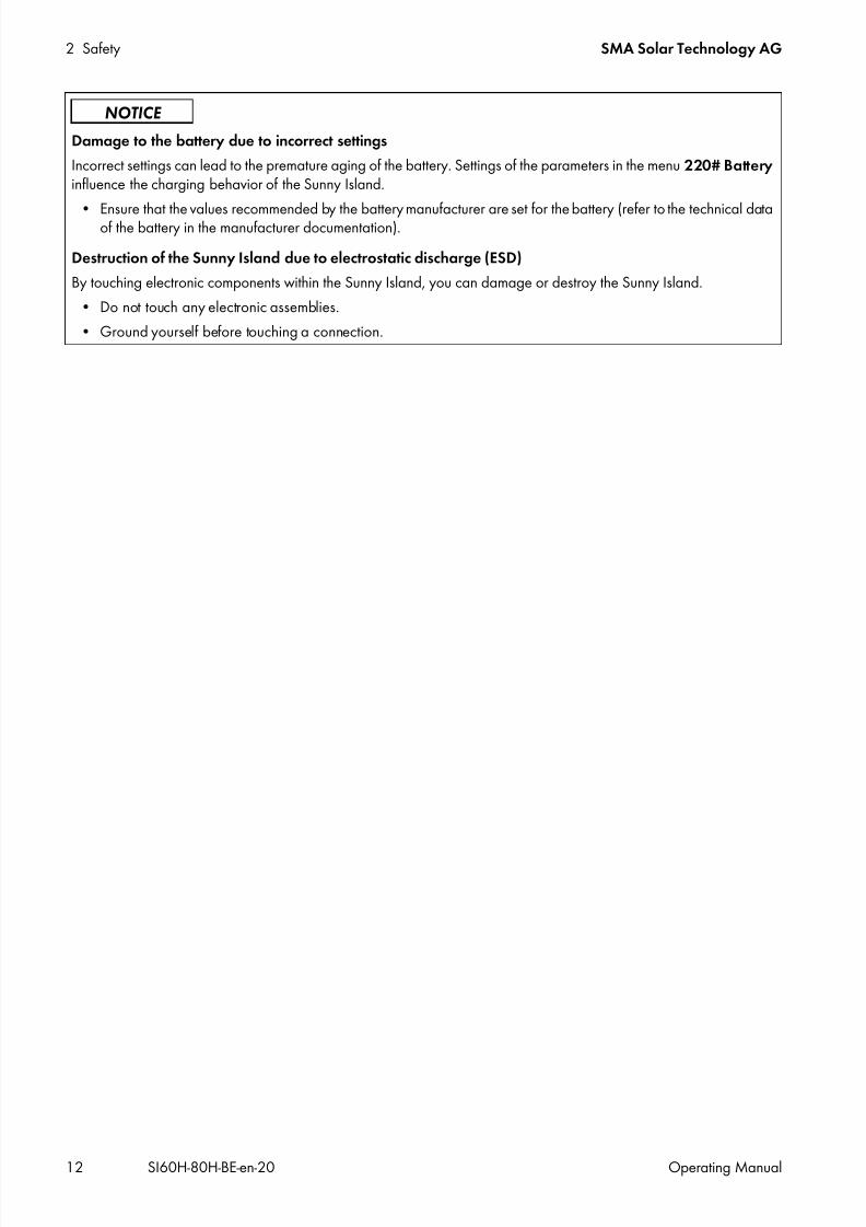
Damage to the battery due to incorrect settings
Incorrect settings can lead to the premature aging of the battery. Settings of the parameters in the menu 220# Battery influence the charging behavior of the Sunny Island.
• Ensure that the values recommended by the battery manufacturer are set for the battery (refer to the technical dataof the battery in the manufacturer documentation).
Destruction of the Sunny Island due to electrostatic discharge (ESD)
By touching electronic components within the Sunny Island, you can damage or destroy the Sunny Island.
• Do not touch any electronic assemblies.
• Ground yourself before touching a connection.

7/17/2019 Remote Control SI60H Operating Manual
http://slidepdf.com/reader/full/remote-control-si60h-operating-manual 13/128
SMA Solar Technology AG 3 Product Description
Operating Manual SI60H-80H-BE-en-20 13
3 Product Description
3.1 Sunny IslandThe Sunny Island is a battery inverter and controls the electrical energy balance in off-grid systems, in battery backupsystems or in systems for increased self-consumption. In addition, you can use the Sunny Island in a battery backup system
for increased self-consumption.
Figure 1: Layout of the Sunny Island
The Sunny Island supplies AC loads in the system from a battery or charges the battery with the energy provided by ACsources (e.g. PV inverter). AC sources supply loads and are used by the Sunny Island to recharge the battery.
3.2 Control Panel of the Sunny Island
Figure 2: Layout of the control panel
Position Designation
A Ventilation grid
B Type label
C Control panel
D Enclosure lid
Position Symbol Designation Status Explanation
A Start-stop buttonTSS
‒ By pressing the start-stop button, you can start or stopthe system. In display messages on the Sunny RemoteControl, the start-stop button is referred to as TSS.

7/17/2019 Remote Control SI60H Operating Manual
http://slidepdf.com/reader/full/remote-control-si60h-operating-manual 14/128
3 Product Description SMA Solar Technology AG
14 SI60H-80H-BE-en-20 Operating Manual
3.3 Type LabelThe type label clearly identifies the product. The type label is located on the right-hand side of the enclosure. You will find
the following information on the type label:• Address of SMA Solar Technology AG
• Device type (Model)
• Serial number (Serial No.)
• Device-specific characteristics
You will require the information on the type label to use the product safely and when seeking customer support from theSMA Service Line.
B "On" button ‒ Pressing the "On" button will switch the Sunny Islandon. The Sunny Island is in standby mode after beingswitched on.
C "Off" button ‒ Pressing the "Off" button will switch off the Sunny
Island.
D Inverter LED not glowing The Sunny Island is switched off.
glowing green The Sunny Island is in operation.
glowing orange The Sunny Island is in standby mode.
glowing red The Sunny Island switched off due to an error.
flashing quickly* The Sunny Island is not configured.
flashingslowly**
The Sunny Island is in overnight shutdown.
E Grid LED not glowing There is no voltage present from the generator or theutility grid.
glowing green Generator or utility grid is connected.
glowing orange The Sunny Island is synchronizing the stand-alonegrid with the generator or the utility grid.
glowing red Fault at the connection of the generator or the utilitygrid.
F Battery LED glowing green The state of charge is more than 50%.
glowing orange The state of charge is between 50% and 20%.
glowing red The state of charge is less than 20%.
G Standby ‒ Position of the buttons for switching on and off
H AC operation ‒ Position of the button for starting and stoppingoperation
* Flashing at intervals of 0.5 s to 1 s** Flashing at intervals of 1.5 s to 2 s
Position Symbol Designation Status Explanation

7/17/2019 Remote Control SI60H Operating Manual
http://slidepdf.com/reader/full/remote-control-si60h-operating-manual 15/128
SMA Solar Technology AG 3 Product Description
Operating Manual SI60H-80H-BE-en-20 15
Symbols on the Type Label
Symbol Explanation
Danger to life due to high voltages
The product operates at high voltages. All work on the product must be carried out by qualifiedpersons only.
Risk of burns due to hot surfaces
The product can get hot during operation. Avoid contact during operation. Allow the product to cooldown sufficiently before carrying out any work. Wear personal protective equipment such as safetygloves.
Observe the documentation.
Observe all the documentation supplied with the product.
AC
Alternating current
DCDirect current
Transformer
The product has a transformer.
WEEE designation
Do not dispose of the product together with the household waste but in accordance with the locallyapplicable disposal regulations for electronic waste.
CE marking
The product complies with the requirements of the applicable EU directives.
Protection class I
All electrical equipment is connected to the protective conductor system of the product.
Degree of protection
The product is protected against interior dust deposits and splashing water from all angles.
Certified safety
The product is VDE-tested and complies with the requirements of the German Equipment and ProductSafety Act.
C-Tick
The product complies with the requirements of the applicable Australian EMC standards.
VD E
7/17/2019 Remote Control SI60H Operating Manual
http://slidepdf.com/reader/full/remote-control-si60h-operating-manual 16/128
3 Product Description SMA Solar Technology AG
16 SI60H-80H-BE-en-20 Operating Manual
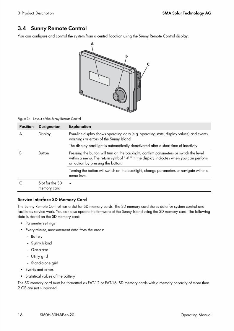
3.4 Sunny Remote ControlYou can configure and control the system from a central location using the Sunny Remote Control display.
Figure 3: Layout of the Sunny Remote Control
Service Interface SD Memory Card
The Sunny Remote Control has a slot for SD memory cards. The SD memory card stores data for system control andfacilitates service work. You can also update the firmware of the Sunny Island using the SD memory card. The followingdata is stored on the SD memory card:
• Parameter settings
• Every minute, measurement data from the areas:– Battery
– Sunny Island
– Generator
– Utility grid
– Stand-alone grid
• Events and errors
• Statistical values of the battery
The SD memory card must be formatted as FAT-12 or FAT-16. SD memory cards with a memory capacity of more than
2 GB are not supported.
Position Designation Explanation
A Display Four-line display shows operating data (e.g. operating state, display values) and events,warnings or errors of the Sunny Island.
The display backlight is automatically deactivated after a short time of inactivity.
B Button Pressing the button will turn on the backlight, confirm parameters or switch the levelwithin a menu. The return symbol " " in the display indicates when you can performan action by pressing the button.
Turning the button will switch on the backlight, change parameters or navigate within amenu level.
C Slot for the SDmemory card
‒
7/17/2019 Remote Control SI60H Operating Manual
http://slidepdf.com/reader/full/remote-control-si60h-operating-manual 17/128
SMA Solar Technology AG 4 Starting and Stopping the System
Operating Manual SI60H-80H-BE-en-20 17
4 Starting and Stopping the System
4.1 Switching on the Sunny Island
Requirements:
The load-break switch in the DC cable must be closed. The Sunny Island must not have switched itself off (see Section 9.6 "Charging the Battery after Automatic Shutdown
in Off-Grid Systems", page 69).
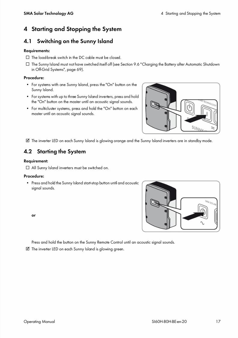
Procedure:
• For systems with one Sunny Island, press the "On" button on theSunny Island.
• For systems with up to three Sunny Island inverters, press and holdthe "On" button on the master until an acoustic signal sounds.
• For multicluster systems, press and hold the "On" button on eachmaster until an acoustic signal sounds.
The inverter LED on each Sunny Island is glowing orange and the Sunny Island inverters are in standby mode.
4.2 Starting the System
Requirement:
All Sunny Island inverters must be switched on.
Procedure:• Press and hold the Sunny Island start-stop button until and acoustic
signal sounds.
or
Press and hold the button on the Sunny Remote Control until an acoustic signal sounds.
The inverter LED on each Sunny Island is glowing green.
7/17/2019 Remote Control SI60H Operating Manual
http://slidepdf.com/reader/full/remote-control-si60h-operating-manual 18/128
4 Starting and Stopping the System SMA Solar Technology AG
18 SI60H-80H-BE-en-20 Operating Manual
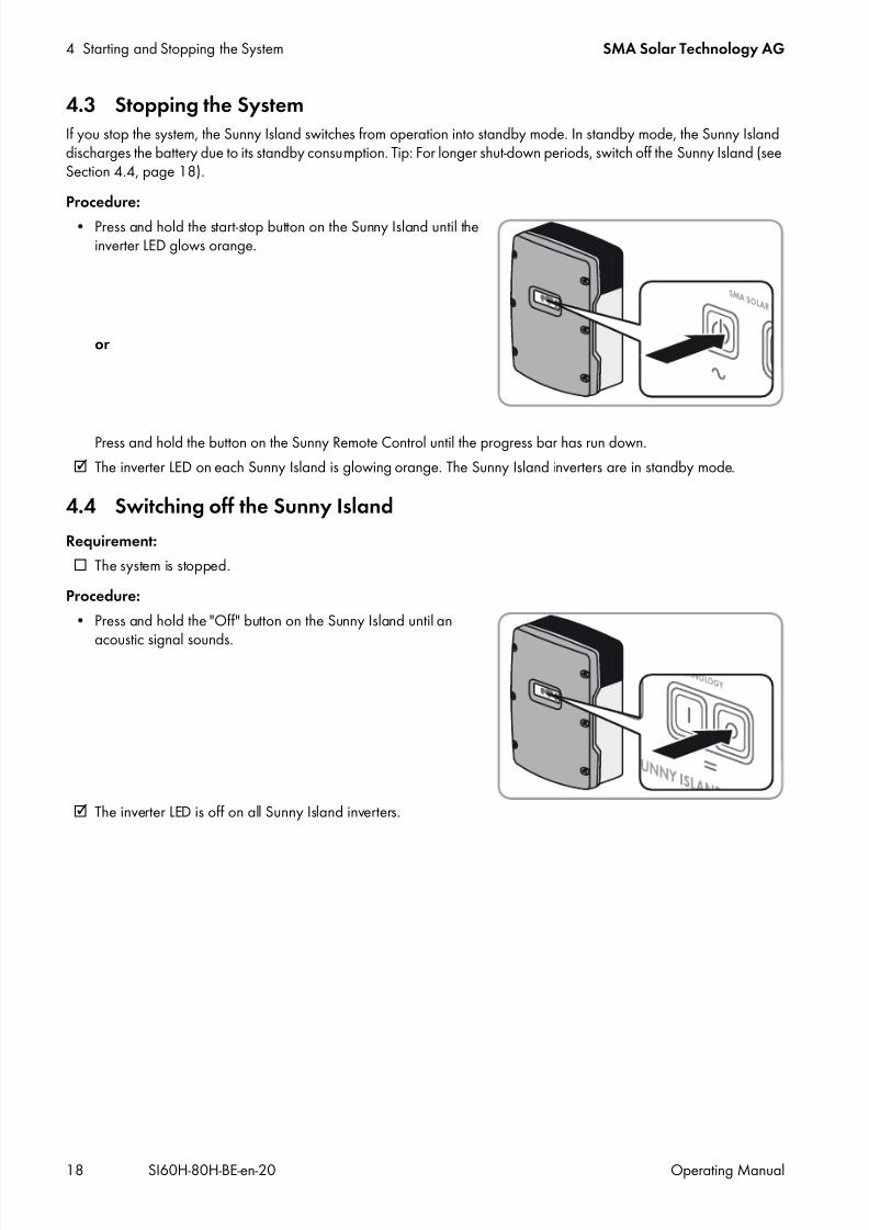
4.3 Stopping the SystemIf you stop the system, the Sunny Island switches from operation into standby mode. In standby mode, the Sunny Islanddischarges the battery due to its standby consumption. Tip: For longer shut-down periods, switch off the Sunny Island (seeSection 4.4, page 18).
Procedure:
• Press and hold the start-stop button on the Sunny Island until theinverter LED glows orange.
or
Press and hold the button on the Sunny Remote Control until the progress bar has run down.
The inverter LED on each Sunny Island is glowing orange. The Sunny Island inverters are in standby mode.
4.4 Switching off the Sunny Island
Requirement:
The system is stopped.
Procedure:
• Press and hold the "Off" button on the Sunny Island until an
acoustic signal sounds.
The inverter LED is off on all Sunny Island inverters.
7/17/2019 Remote Control SI60H Operating Manual
http://slidepdf.com/reader/full/remote-control-si60h-operating-manual 19/128
SMA Solar Technology AG 4 Starting and Stopping the System
Operating Manual SI60H-80H-BE-en-20 19
4.5 Tripping the Emergency Disconnection of the System
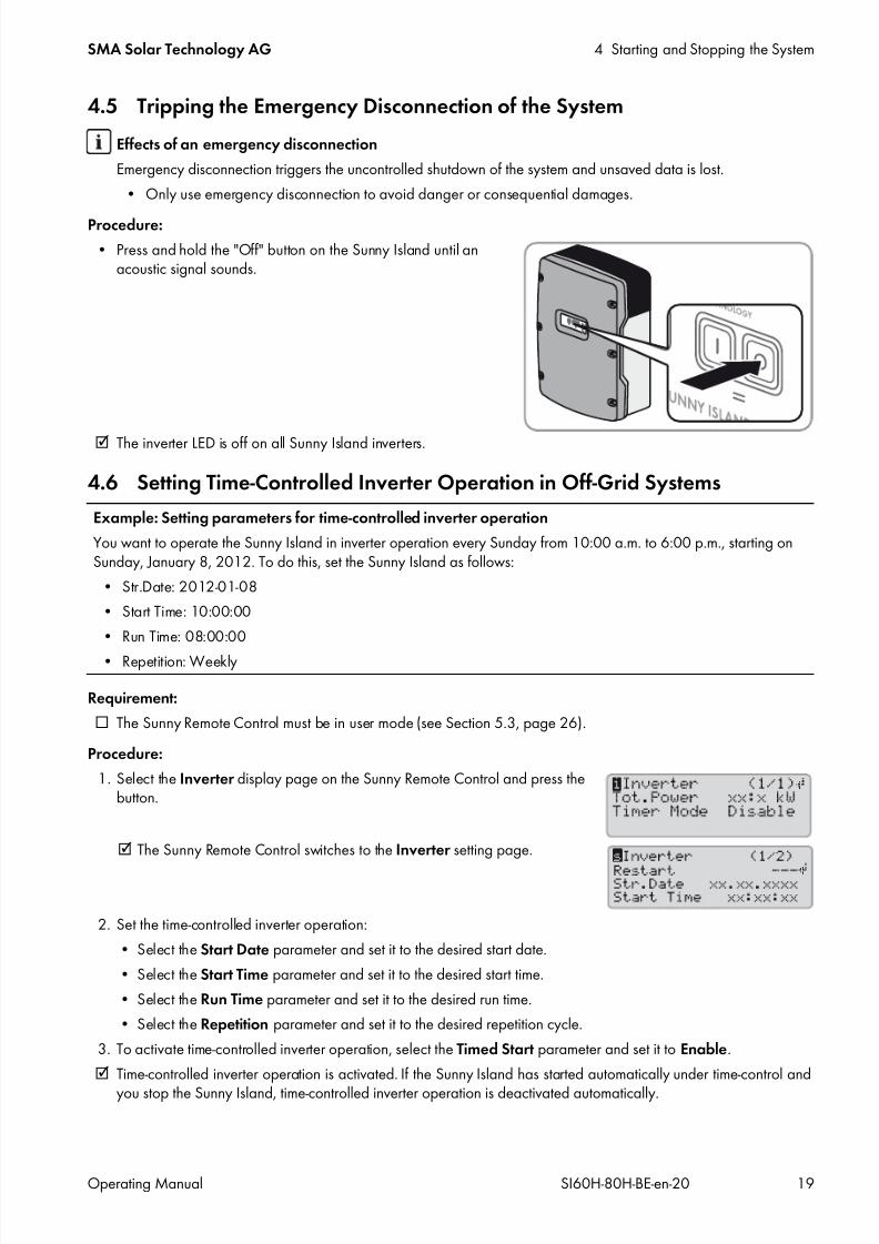
Procedure:
• Press and hold the "Off" button on the Sunny Island until anacoustic signal sounds.
The inverter LED is off on all Sunny Island inverters.
4.6 Setting Time-Controlled Inverter Operation in Off-Grid Systems
Requirement:
The Sunny Remote Control must be in user mode (see Section 5.3, page 26).
Procedure:
1. Select the Inverter display page on the Sunny Remote Control and press thebutton.
The Sunny Remote Control switches to the Inverter setting page.
2. Set the time-controlled inverter operation:
• Select the Start Date parameter and set it to the desired start date.
• Select the Start Time parameter and set it to the desired start time.
• Select the Run Time parameter and set it to the desired run time.
• Select the Repetition parameter and set it to the desired repetition cycle.
3. To activate time-controlled inverter operation, select the Timed Start parameter and set it to Enable.
Time-controlled inverter operation is activated. If the Sunny Island has started automatically under time-control and
you stop the Sunny Island, time-controlled inverter operation is deactivated automatically.
Effects of an emergency disconnection
Emergency disconnection triggers the uncontrolled shutdown of the system and unsaved data is lost.
• Only use emergency disconnection to avoid danger or consequential damages.
Example: Setting parameters for time-controlled inverter operation
You want to operate the Sunny Island in inverter operation every Sunday from 10:00 a.m. to 6:00 p.m., starting onSunday, January 8, 2012. To do this, set the Sunny Island as follows:
• Str.Date: 2012-01-08
• Start Time: 10:00:00
• Run Time: 08:00:00
• Repetition: Weekly
7/17/2019 Remote Control SI60H Operating Manual
http://slidepdf.com/reader/full/remote-control-si60h-operating-manual 20/128
5 Operating the Sunny Island via Sunny Remote Control SMA Solar Technology AG
20 SI60H-80H-BE-en-20 Operating Manual
5 Operating the Sunny Island via Sunny Remote Control
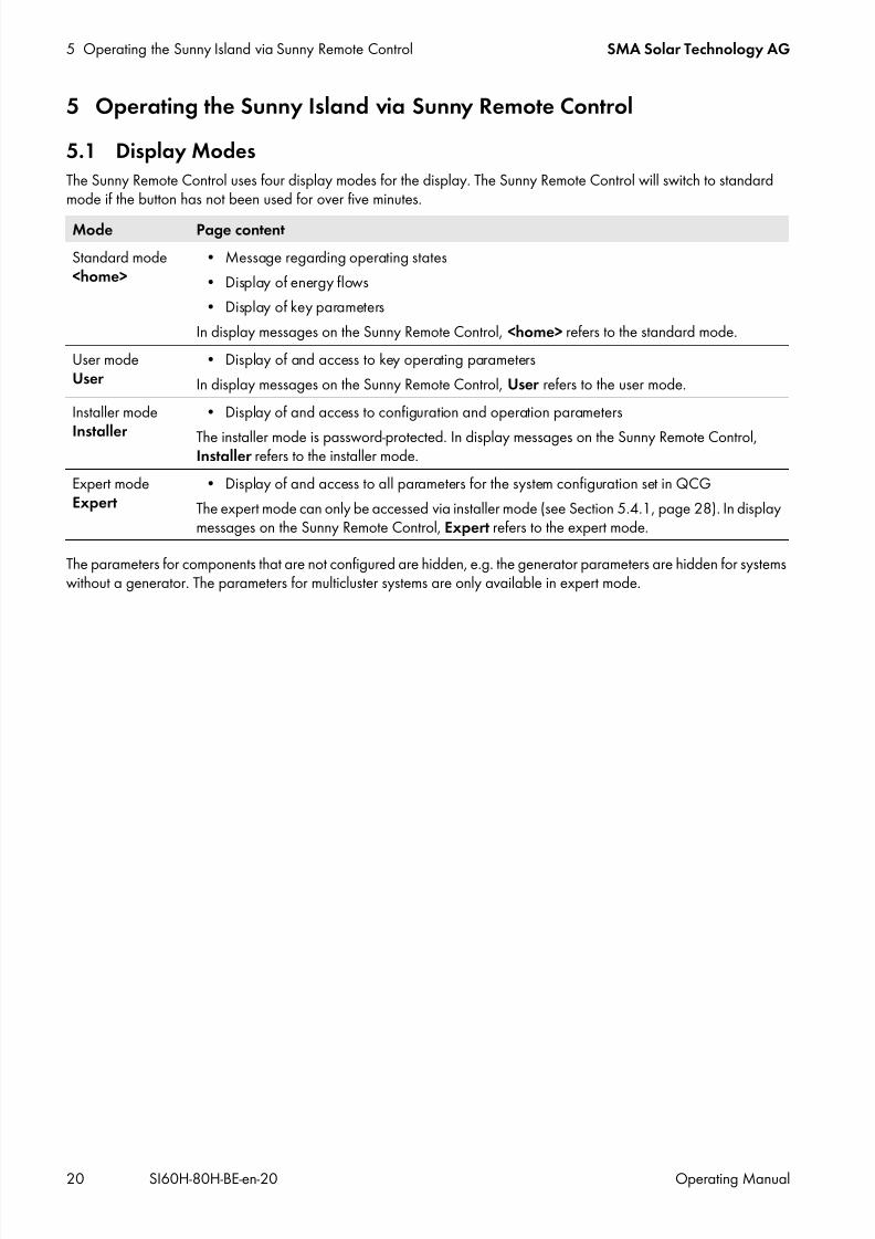
5.1 Display ModesThe Sunny Remote Control uses four display modes for the display. The Sunny Remote Control will switch to standardmode if the button has not been used for over five minutes.
The parameters for components that are not configured are hidden, e.g. the generator parameters are hidden for systemswithout a generator. The parameters for multicluster systems are only available in expert mode.
Mode Page content
Standard mode<home>
• Message regarding operating states
• Display of energy flows
• Display of key parameters
In display messages on the Sunny Remote Control, <home> refers to the standard mode.
User modeUser
• Display of and access to key operating parameters
In display messages on the Sunny Remote Control, User refers to the user mode.
Installer mode
Installer
• Display of and access to configuration and operation parameters
The installer mode is password-protected. In display messages on the Sunny Remote Control,Installer refers to the installer mode.
Expert modeExpert
• Display of and access to all parameters for the system configuration set in QCG
The expert mode can only be accessed via installer mode (see Section 5.4.1, page 28). In displaymessages on the Sunny Remote Control, Expert refers to the expert mode.
7/17/2019 Remote Control SI60H Operating Manual
http://slidepdf.com/reader/full/remote-control-si60h-operating-manual 21/128
SMA Solar Technology AG 5 Operating the Sunny Island via Sunny Remote Control
Operating Manual SI60H-80H-BE-en-20 21
5.2 Standard Mode
5.2.1 Display of Operating States
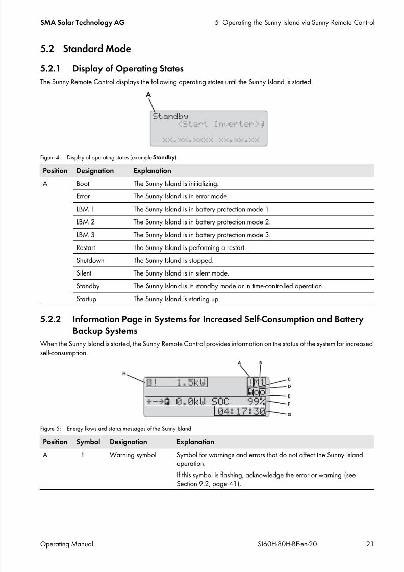
The Sunny Remote Control displays the following operating states until the Sunny Island is started.
Figure 4: Display of operating states (example Standby)
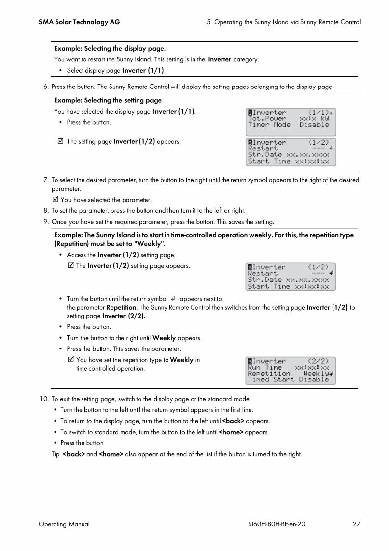
5.2.2 Information Page in Systems for Increased Self-Consumption and BatteryBackup Systems
When the Sunny Island is started, the Sunny Remote Control provides information on the status of the system for increasedself-consumption.
Figure 5: Energy flows and status messages of the Sunny Island
Position Designation Explanation
A Boot The Sunny Island is initializing.
Error The Sunny Island is in error mode.LBM 1 The Sunny Island is in battery protection mode 1.
LBM 2 The Sunny Island is in battery protection mode 2.
LBM 3 The Sunny Island is in battery protection mode 3.
Restart The Sunny Island is performing a restart.
Shutdown The Sunny Island is stopped.
Silent The Sunny Island is in silent mode.
Standby The Sunny Island is in standby mode or in time-controlled operation.
Startup The Sunny Island is starting up.
Position Symbol Designation Explanation
A Warning symbol Symbol for warnings and errors that do not affect the Sunny Islandoperation.
If this symbol is flashing, acknowledge the error or warning (seeSection 9.2, page 41).

7/17/2019 Remote Control SI60H Operating Manual
http://slidepdf.com/reader/full/remote-control-si60h-operating-manual 22/128
5 Operating the Sunny Island via Sunny Remote Control SMA Solar Technology AG
22 SI60H-80H-BE-en-20 Operating Manual
5.2.3 Information Page in Off-Grid Systems
Figure 6: Energy flows and status messages of the Sunny Island (example).
B Device assignment The Sunny Island connected to the Sunny Remote Control is the master.
The Sunny Island connected to the Sunny Remote Control is slave 1.
The Sunny Island connected to the Sunny Remote Control is slave 2.
C SD memory card The SD memory card is inserted.
Symbolflashing
The Sunny Island is accessing the SD memory card.
Nosymbol
The SD memory card is not inserted.
D Multifunction relay 1 Multifunction relay 1 is deactivated.
Multifunction relay 1 is activated.
E Multifunction relay 2 Multifunction relay 2 is deactivated.
Multifunction relay 2 is activated.
F Battery power andstate of charge
The battery is being charged.
The battery is discharging.
Battery power in kW, state of charge (SOC) in %
G hh:mm:ss Time System time
H Power and status ofthe utility grid
Power in kW
The utility grid voltage and frequency are within the configured limits.
The maximum reverse power in the utility grid has been exceeded.
Position Designation
A Graphical representation of the energy flows
B Status of the stand-alone grid
C Status of the Sunny Island
D State of charge of the battery
E Status of the generator
Position Symbol Designation Explanation

7/17/2019 Remote Control SI60H Operating Manual
http://slidepdf.com/reader/full/remote-control-si60h-operating-manual 23/128
SMA Solar Technology AG 5 Operating the Sunny Island via Sunny Remote Control
Operating Manual SI60H-80H-BE-en-20 23
Graphical Representation of the Energy Flows
Figure 7: Energy flow diagram in standard mode (example)
Status of the Stand-Alone Grid
Figure 8: Status of the stand-alone grid (example)
Position Symbol Designation Explanation
A Battery Battery symbol
B Direction of energy flow The battery is supplying the loads.
The battery is being charged.
C Generator Generator symbol
D Internal transfer relay The generator is disconnected from the stand-alone grid.
The stand-alone grid is synchronized with the generator. Thegenerator is supplying the loads and charging the battery.
E Direction of energy flow Loads are being supplied.
AC sources in the stand-alone grid are supplying more energy thanis being consumed by the stand-alone grid.
F Loads in the stand-alonegrid
Symbol for loads in the stand-alone grid
Position Designation Explanation
A Output power Output power of the Sunny Island in kW
B Loads in the stand-alonegrid
Symbol for loads in the stand-alone grid

7/17/2019 Remote Control SI60H Operating Manual
http://slidepdf.com/reader/full/remote-control-si60h-operating-manual 24/128
5 Operating the Sunny Island via Sunny Remote Control SMA Solar Technology AG
24 SI60H-80H-BE-en-20 Operating Manual
Status of the Sunny Island
Figure 9: Status of the Sunny Island (example)
State of charge of the battery
Figure 10: State of charge of the battery in standard mode (example)
Position Symbol Designation Explanation
A Warning symbol Symbol for warnings and errors that do not affect the Sunny Islandoperation.
If this symbol is flashing, acknowledge the error or warning (seeSection 9.2, page 41).
B Device assignment The Sunny Island connected to the Sunny Remote Control is themaster.
The Sunny Island connected to the Sunny Remote Control is slave 1.The Sunny Island connected to the Sunny Remote Control is slave 2.
C SD memory card The SD memory card is inserted.
Symbolflashing
The Sunny Island is accessing the SD memory card.
Nosymbol
The SD memory card is not inserted.
D Multifunction relay 1 Multifunction relay 1 is deactivated.
Multifunction relay 1 is activated.
E Multifunction relay 2 Multifunction relay 2 is deactivated.
Multifunction relay 2 is activated.
F hh:mm:ss Time Off-grid system time
Position Designation Explanation
A Battery Battery symbol
B State of charge State of charge of the battery in percent

7/17/2019 Remote Control SI60H Operating Manual
http://slidepdf.com/reader/full/remote-control-si60h-operating-manual 25/128
SMA Solar Technology AG 5 Operating the Sunny Island via Sunny Remote Control
Operating Manual SI60H-80H-BE-en-20 25
Status of the external energy source
Figure 11: Status of the external energy source in standard mode (example)
Position Symbol Designation Explanation
A Active limiting values Electrical limiting values for the utility grid are active.
Electrical limits for the generator are active.
B Status of the generator Voltage and frequency of the generator are within the limitingvalues set.
Voltage and frequency of the generator are outside of the limitingvalues set.
The maximum reverse power in the generator has been exceeded.
Battery
Generator was requested due to state of charge.
Cycle
Generator was requested via time control.
Extern
Generator was requested by an extension cluster.
Load
Generator was requested due to load.
Start
You have manually started the generator via Sunny Remote Controlor a generator was requested via the DigIn input.
Time
You have started the generator for one hour via Sunny RemoteControl.
C ‒ Power of the generator orthe utility grid
Power in kW
D Generator Generator symbol
E Internal transfer relay The generator is disconnected from the stand-alone grid.
The stand-alone grid is synchronized with the generator. Thegenerator is supplying the loads and charging the battery.

7/17/2019 Remote Control SI60H Operating Manual
http://slidepdf.com/reader/full/remote-control-si60h-operating-manual 26/128
5 Operating the Sunny Island via Sunny Remote Control SMA Solar Technology AG
26 SI60H-80H-BE-en-20 Operating Manual
5.3 User Mode
5.3.1 Displaying Parameters and Operating and Setting the System
User mode displays all important information for the system sorted by category. User mode enables the manual controlof the Sunny Island or system components, e.g starting the generator.
User mode distinguishes between display pages and setting pages. Display pages show the parameters of a category.Setting pages enable the operation and setting of the system.
Figure 12: Layout of a page in user mode (example)
Procedure:
1. Press the button to activate the display illumination of the Sunny Remote Control.
2. Turn the button to the right. The Sunny Remote Control switches from standard mode touser mode.
3. To scroll through the display pages, continue to turn the button to the right.
4. To go back to a previous page, turn the button to the left.
5. To select a setting page, scroll to the display page for the category of the desired setting (see Section 12 "Directoryof the Parameters in User Mode", page 81).
Position Designation Symbol ormessage Explanation
A Page type Information
This symbol indicates display pages.
Set
This symbol indicates setting pages.
B Category − Category name (see Section 12 "Directory of the Parameters in UserMode", page 81)
C Page and number
of pages
‒ Page and number of pages of the selected category
D Return symbol On display pages, this symbol means that setting pages areavailable for this category.
On setting pages, this symbol points to the selected parameter.
no symbol No setting pages are available for this category.
E Parameters ‒ Parameters with the current values
7/17/2019 Remote Control SI60H Operating Manual
http://slidepdf.com/reader/full/remote-control-si60h-operating-manual 27/128
SMA Solar Technology AG 5 Operating the Sunny Island via Sunny Remote Control
Operating Manual SI60H-80H-BE-en-20 27
6. Press the button. The Sunny Remote Control will display the setting pages belonging to the display page.
7. To select the desired parameter, turn the button to the right until the return symbol appears to the right of the desiredparameter.
You have selected the parameter.
8. To set the parameter, press the button and then turn it to the left or right.
9. Once you have set the required parameter, press the button. This saves the setting.
10. To exit the setting page, switch to the display page or the standard mode:
• Turn the button to the left until the return symbol appears in the first line.
• To return to the display page, turn the button to the left until <back> appears.
• To switch to standard mode, turn the button to the left until <home> appears.
• Press the button.
Tip: <back> and <home> also appear at the end of the list if the button is turned to the right.
Example: Selecting the display page.
You want to restart the Sunny Island. This setting is in the Inverter category.
• Select display page Inverter (1/1).
Example: Selecting the setting page
You have selected the display page Inverter (1/1).
• Press the button.
The setting page Inverter (1/2) appears.
Example: The Sunny Island is to start in time-controlled operation weekly. For this, the repetition type(Repetition) must be set to "Weekly".
• Access the Inverter (1/2) setting page.
The Inverter (1/2) setting page appears.
• Turn the button until the return symbol appears next tothe parameter Repetition. The Sunny Remote Control then switches from the setting page Inverter (1/2) tosetting page Inverter (2/2).
• Press the button.
• Turn the button to the right until Weekly appears.
• Press the button. This saves the parameter.
You have set the repetition type to Weekly intime-controlled operation.
7/17/2019 Remote Control SI60H Operating Manual
http://slidepdf.com/reader/full/remote-control-si60h-operating-manual 28/128
5 Operating the Sunny Island via Sunny Remote Control SMA Solar Technology AG
28 SI60H-80H-BE-en-20 Operating Manual
5.4 Installer and Expert Mode
5.4.1 Switching to Installer Mode or Expert Mode
The installer mode is protected via an installer password. The installer password changes constantly and must bere-calculated every time. Expert mode can only be accessed via installer mode.
Procedure:
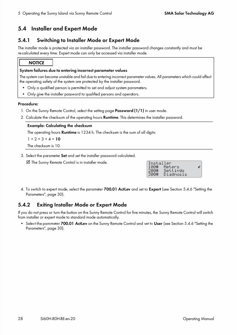
1. On the Sunny Remote Control, select the setting page Password (1/1) in user mode.
2. Calculate the checksum of the operating hours Runtime. This determines the installer password.
3. Select the parameter Set and set the installer password calculated.
The Sunny Remote Control is in installer mode.
4. To switch to expert mode, select the parameter 700.01 ActLev and set to Expert (see Section 5.4.6 "Setting theParameters", page 30).
5.4.2 Exiting Installer Mode or Expert Mode
If you do not press or turn the button on the Sunny Remote Control for five minutes, the Sunny Remote Control will switchfrom installer or expert mode to standard mode automatically.
• Select the parameter 700.01 ActLev on the Sunny Remote Control and set to User (see Section 5.4.6 "Setting theParameters", page 30).
System failures due to entering incorrect parameter values
The system can become unstable and fail due to entering incorrect parameter values. All parameters which could affectthe operating safety of the system are protected by the installer password.
• Only a qualified person is permitted to set and adjust system parameters.
• Only give the installer password to qualified persons and operators.
Example: Calculating the checksum
The operating hours Runtime is 1234 h. The checksum is the sum of all digits:
1 + 2 + 3 + 4 = 10
The checksum is 10.

7/17/2019 Remote Control SI60H Operating Manual
http://slidepdf.com/reader/full/remote-control-si60h-operating-manual 29/128
SMA Solar Technology AG 5 Operating the Sunny Island via Sunny Remote Control
Operating Manual SI60H-80H-BE-en-20 29
5.4.3 Menus in Installer and Expert Mode
Figure 13: Layout of the menu page in installer mode (example)
5.4.4 Parameter Page in Installer and Expert Mode
Figure 14: Layout of the parameter page in installer mode (example)
5.4.5 Selecting Menus and Parameters1. Switch to installer mode on the Sunny Remote Control (see Section 5.4.1, page 28).
2. Turn the button to the right until the return symbol appears to the right of the desired menu. The Sunny Remote Controlscrolls through the menu items on the display line by line.
3. Press the button. This accesses the sub-menu level.
The Sunny Remote Control displays the sub-menu level. The selected menu level is shown in the first line.
4. Repeat steps 2 and 3 until the Sunny Remote Control displays the first parameter page.
5. Turn the button to the right until the Sunny Remote Control displays the desired parameter.
6. Set the parameter (see Section 5.4.6, page 30).
Position Designation Explanation
A Menu path The two previously selected menu levels
If you are in the top menu level, the display will show Installer in installer modeand Expert in expert mode.
B Return symbol Return symbol for selecting a menu
C Menu ‒
Position Designation Explanation
A Menu number and parameter number ‒
B Menu path The two previously selected menu levels
C Return symbol Return symbol for setting the parameter
If no return symbol is displayed, the parameter cannot be set.
D Name of the parameter ‒
E Value and unit of the parameter ‒

7/17/2019 Remote Control SI60H Operating Manual
http://slidepdf.com/reader/full/remote-control-si60h-operating-manual 30/128
5 Operating the Sunny Island via Sunny Remote Control SMA Solar Technology AG
30 SI60H-80H-BE-en-20 Operating Manual
7. To exit the parameter page, switch to the higher level or switch to standard mode:
• Turn the button to the left until the return symbol appears in the first line.
• To switch to a higher menu level, turn the button to the left until <back> appears.
• To switch to standard mode, turn the button to the left until <home> appears.
• Press the button.
Tip: <back> and <home> also appear at the end of the list if the button is turned to the right.
5.4.6 Setting the Parameters
1. Switch to installer mode on the Sunny Remote Control (see Section 5.4.1, page 28).
2. Select the desired parameter. You can only set the parameters forwhich < Set > is shown in the second line in the display.
3. Press the button.
The return symbol flashes next to the value.
Stop device to change the value? appears in the display.
The parameter can only be changed in standby mode.• Stop the system (see Section 4.3, page 18).
No permission to change the value appears in the display.
You are not allowed to change the parameter in installer mode.
• If you want to change the parameters for the battery, select the menu New Battery in the QCG (seeSection 10.8 "Replacing the Battery", page 77).
• For all other settings in the QCG, select the menu New System (see the installation manual of the SunnyIsland).
4. To set the parameter, turn the button to the left or right.
5. Press the button. The Sunny Remote Control requests a confirmation of the set
parameter.
6. To confirm the value, turn the button to the right until Y flashes andthen press the button.
7. To discard the value, turn the button to the right until N flashes and then press the button.
7/17/2019 Remote Control SI60H Operating Manual
http://slidepdf.com/reader/full/remote-control-si60h-operating-manual 31/128
SMA Solar Technology AG 5 Operating the Sunny Island via Sunny Remote Control
Operating Manual SI60H-80H-BE-en-20 31
5.4.7 Directly Accessing the Parameters
Any parameter can be accessed directly by entering a five-digit number. The five-digit number is composed as follows:
• The first three digits are the menu number.
• The last two digits are the parameter number.
Procedure:
1. Switch to installer mode on the Sunny Remote Control (see Section 5.4.1, page 28).
2. Select the parameter 600.02 Select Number and set the five-digit number.
The parameter is displayed.
The display shows Item not Found?
You cannot access the parameter in installer mode.
• Press the button and switch to expert mode (see Section 5.4.1, page 28).
The number set is incorrect.
• Press the button and enter the number again.
Example: Five-digit number for direct parameter access.You want to use parameter 111.01 TotInvPwrAt to show the entire active power of the Sunny Island in a cluster. Thefive-digit number for direct access is 11101.

7/17/2019 Remote Control SI60H Operating Manual
http://slidepdf.com/reader/full/remote-control-si60h-operating-manual 32/128
6 Data Storage and Firmware Update SMA Solar Technology AG
32 SI60H-80H-BE-en-20 Operating Manual
6 Data Storage and Firmware Update
6.1 Inserting the SD Memory Card
Requirements:
The SD memory card must be formatted as FAT-12 or FAT-16. The storage capacity of the SD memory card must not exceed 2 GB.
The SD memory card must only be used as a data medium for the system.
Procedure:
• Insert the SD memory card, with the slanted corner facingupwards, into the SD memory card slot in the Sunny RemoteControl.
6.2 Saving and Loading ParametersYou can load and save the current parameter settings in two different parameter sets on the SD memory card. The twoparameter sets are distinguished by the Sunny Remote Control in Set1 and Set2. Each parameter set saves all settings.This makes it possible to test the settings of a new parameter set without having to delete the old parameter set. Tip: Assoon as you have adjusted the system to your requirements, save the parameter settings to the SD memory card. Aftersaving, you can make further adjustments to the system. If the adjustment does not lead to the desired results, reload thesaved parameter set.
Requirement:
The SD memory card must be inserted.Procedure:
1. Switch to installer mode on the Sunny Remote Control (see Section 5.4.1, page 28).
2. To save a parameter set, select the parameter 550.01 ParaSto and set the parameter:
3. Proceed as follows to load a parameter set:
• Switch to expert mode on the Sunny Remote Control (see Section 5.4.1, page 28).
• Select the parameter 550.02 ParaLod and set the parameter:
Value Explanation
Set1 Save the settings in the first parameter set.
Set2 Save the settings in the second parameter set.
Value Explanation
Set1 Loads the settings from the first parameter set.
Set2 Loads the settings from the second parameter set.
Factory Loads the default settings.
7/17/2019 Remote Control SI60H Operating Manual
http://slidepdf.com/reader/full/remote-control-si60h-operating-manual 33/128
SMA Solar Technology AG 6 Data Storage and Firmware Update
Operating Manual SI60H-80H-BE-en-20 33
6.3 Saving the Event History and Error History
Requirement:
The SD memory card must be inserted.
Procedure:
1. Switch to installer mode on the Sunny Remote Control (see Section 5.4.1, page 28).2. To save the event history, select the parameter 550.03 CardFunc and set to StoEvtHis.
3. To save the error history, select the parameter 550.03 CardFunc and set to StoFailHis.
4. To save the error history and the event history, select the parameter 550.03 CardFunc and set to StoHis.
6.4 Displaying the SD Memory Card Status MessageThe Sunny Remote Control determines the SD memory card status (see Section 13.3.1 "Inverter (310#)", page 115).
1. Switch to installer mode on the Sunny Remote Control (see Section 5.4.1, page 28).
2. Select the parameter 312.11 CardStt and read off the value.
6.5 Removing the SD Memory CardIf the SD memory card is removed without preparation, the removal will cause data loss. Data loss comprises the log dataof the last 15 minutes at most.
Procedure:
1. Switch to installer mode on the Sunny Remote Control (see Section 5.4.1, page 28).
2. Select the parameter 550.03 CardFunc and set to ForcedWrite. Unsaved data will now be saved to the SDmemory card.
3. Remove the SD memory card.
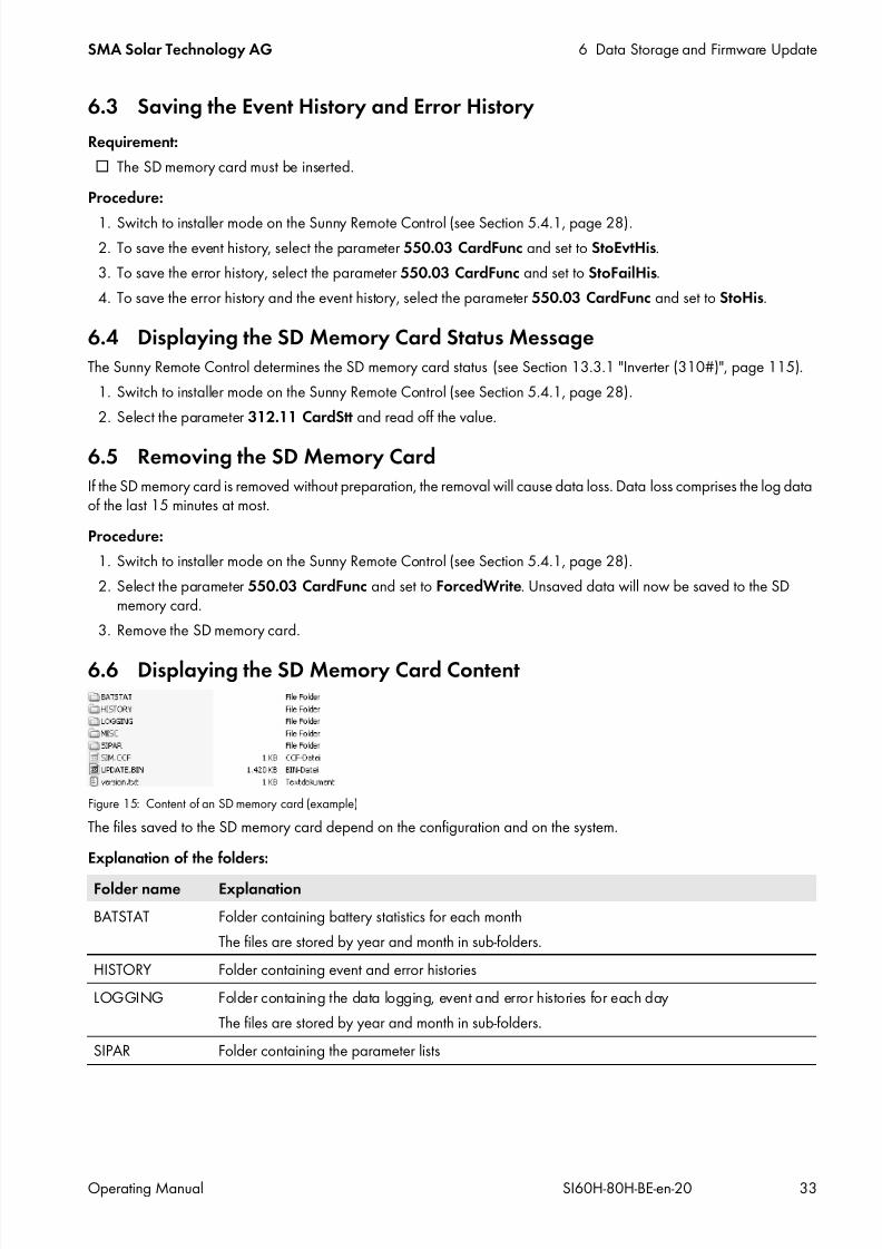
6.6 Displaying the SD Memory Card Content
Figure 15: Content of an SD memory card (example)
The files saved to the SD memory card depend on the configuration and on the system.
Explanation of the folders:
Folder name Explanation
BATSTAT Folder containing battery statistics for each month
The files are stored by year and month in sub-folders.
HISTORY Folder containing event and error histories
LOGGING Folder containing the data logging, event and error histories for each day
The files are stored by year and month in sub-folders.
SIPAR Folder containing the parameter lists

7/17/2019 Remote Control SI60H Operating Manual
http://slidepdf.com/reader/full/remote-control-si60h-operating-manual 34/128
6 Data Storage and Firmware Update SMA Solar Technology AG
34 SI60H-80H-BE-en-20 Operating Manual
Explanation of the files within the folders:
Structure of the files:
The files are CSV files, which means that the data is saved as ASCII text. The files are structured as follows:
• The first lines in the file are used for information. Information lines start and end with the character #.
• The data in the following lines is separated by semicolons.• Decimal places are separated by periods.
• The date format is dd.mm.yyyy.
• The time format is hh:mm:ss.
• Some of the parameter values are saved with plain text numbers (see Section 13 "Directory of the Parameters inInstaller Mode and Expert Mode", page 87).
Requirements:
A computer with installed spreadsheet software must be available.
The spreadsheet software must be able to read CSV files.
Procedure:
1. Insert the SD memory card into the card reader and display the content.
2. Start the spreadsheet software and import the required file. When importing, set the import filter in accordance withthe file structure (see spreadsheet software manual).
File name Explanation
evthis.log Event history
errhis.log Error history
si010112.evt Event and error histories for one dayThe date (ddmmyy) is part of the file name.
si010112.log Data logging for the day
The date (ddmmyy) is part of the file name.
sipar1.lst Parameter set 1
sipar2.lst Parameter set 2
update.bin Firmware of the Sunny Island
batstat.txt Statistical values of the battery
These values are saved every night at 10:00 p.m.batstat.sma Statistical values of the battery for evaluation by SMA Solar Technology AG
sim.ccf System information of the Sunny Island
bootex.log File generated by the operating system of the computer
This file is not generated by every operating system.

7/17/2019 Remote Control SI60H Operating Manual
http://slidepdf.com/reader/full/remote-control-si60h-operating-manual 35/128
SMA Solar Technology AG 6 Data Storage and Firmware Update
Operating Manual SI60H-80H-BE-en-20 35
6.7 Updating the Firmware
6.7.1 Updating the Firmware Using an SD Memory Card
Requirements:
The storage capacity of the SD memory card must not exceed 2 GB.
SD memory card with the firmware update in the main directory must be available.
The SD memory card must only be used as a data medium for the system.
A computer must be able to read from and write to the SD memory card.
The Sunny Remote Control must be connected to the master.
Procedure:
1. Insert the SD memory card into the SD memory card slot (see Section 6.1, page 32).2. Wait until the message UPDATE AVAILABLE appears. This can take up to two minutes.
3. Confirm the question UPDATE AVAILABLE Start update now ? with YES.
The Sunny Island switches to standby and updates the firmware.
6.7.2 Updating the Firmware Using Sunny Explorer
Using Sunny Explorer, transfer the firmware update to the SMA Speedwire data module Sunny Island. Then, theSMA Speedwire data module Sunny Island automatically transfers the firmware update to the SD memory card in theSunny Remote Control. This transfer takes some time.
Requirements:
The SMA Speedwire data module Sunny Island of the type SWDMSI-NR10 with firmware version 1.01.06.R orhigher must be installed in the system.
A computer with Sunny Explorer and the firmware update must be available.
The Sunny Remote Control must be connected to the master.
Procedure:
1. Ensure that a writable SD memory card is inserted in the Sunny Remote Control and remains inserted throughout theentire update.
2. Switch to installer mode on the Sunny Remote Control (see Section 5.4.1, page 28).
3. Set the parameter 250.33 UpdMode to Auto.
4. Set the parameter 250.34 UpdAutoTime to the desired firmware update time.
5. Transfer the firmware update from the computer to the Sunny Island using Sunny Explorer (see the Sunny Exploreruser manual).
6. Once the transfer is complete, close Sunny Explorer.
Once the transfer to the SD memory card is complete, the Sunny Island updates automatically at the specified time.
The Sunny Island switches to standby mode and updates the firmware.
Automatic start of the Sunny Island
If the Sunny Island was in operation before the firmware update, the Sunny Island restarts automatically uponcompletion of the firmware update.
Automatic start of the Sunny Island
If the Sunny Island was in operation before the firmware update, the Sunny Island restarts automatically uponcompletion of the firmware update.

7/17/2019 Remote Control SI60H Operating Manual
http://slidepdf.com/reader/full/remote-control-si60h-operating-manual 36/128
6 Data Storage and Firmware Update SMA Solar Technology AG
36 SI60H-80H-BE-en-20 Operating Manual
6.7.3 Performing a Remote Update Using Sunny Portal
Sunny Portal can make the current firmware available automatically. For this, Sunny Portal first transfers the firmwareupdate to the SMA Speedwire data module Sunny Island. Then, the SMA Speedwire data module Sunny Islandautomatically transfers the firmware update to the SD memory card in the Sunny Remote Control. This transfer takes sometime.
Requirements:
The Sunny Island must be registered in Sunny Portal.
The SMA Speedwire data module Sunny Island of the type SWDMSI-NR10 must be installed in the system.
Sunny Home Manager must be integrated in the system.
The Sunny Remote Control must be connected to the master.
Procedure:
1. Ensure that a writable SD memory card is inserted in the Sunny Remote Control and remains inserted.
2. Switch to installer mode on the Sunny Remote Control (see Section 5.4.1, page 28).
3. Set the parameter 250.33 UpdMode to Auto.
4. Set the parameter 250.34 UpdAutoTime to the desired firmware update time.
5. Activate the automatic update of the PV system in Sunny Portal (see the Sunny Home Manager user manual).
Once the transfer to the SD memory card is complete, the Sunny Island updates automatically at the specified time.The Sunny Island switches to standby mode and updates the firmware.
Automatic start of the Sunny Island
If the Sunny Island was in operation before the firmware update, the Sunny Island restarts automatically uponcompletion of the firmware update.
Firmware for SMA Speedwire data module Sunny Island
The required firmware for the SMA Speedwire data module Sunny Island will be available as of week 12/
2014.

7/17/2019 Remote Control SI60H Operating Manual
http://slidepdf.com/reader/full/remote-control-si60h-operating-manual 37/128
SMA Solar Technology AG 7 Manually Controlling the Generator
Operating Manual SI60H-80H-BE-en-20 37
7 Manually Controlling the Generator
7.1 Starting the Generator with Sunny Remote Control
Requirements:
The Sunny Island must be able to control the generator via a control cable. The Sunny Remote Control must be in standard mode or user mode.
Procedure:
1. Select the Generator display page on the Sunny Remote Control and press the button (see Section 5.3.1"Displaying Parameters and Operating and Setting the System", page 26).
2. To start the generator and run it permanently, select the parameter Mode and set to Start.
The generator starts and runs until you stop it again.
3. To start the generator and run it for one hour, select the parameter Mode and set to Run1h.
The generator starts. If there is no generator request after one hour, the Sunny Island stops the generator.
7.2 Stopping the Generator with Sunny Remote Control
Requirements:
The Sunny Island must be able to control the generator via a control cable.
The Sunny Remote Control must be in standard mode or user mode.
Procedure:
1. Select the Generator display page on the Sunny Remote Control and press the button (see Section 5.3.1"Displaying Parameters and Operating and Setting the System", page 26).
2. Select the parameter Mode and set to Stop.
The generator is stopped temporarily. The generator restarts when a generator request is issued in automaticgenerator mode and the minimum stop time elapses.
3. To permanently stop the generator, deactivate the automatic generator mode:
• Switch to installer mode on the Sunny Remote Control (see Section 5.4.1, page 28).
• Select the parameter 235.01 GnAutoEna and set to Disable.
The generator is permanently stopped.
7.3 Starting the Generator without Autostart Function1. Start the generator (see manufacturer's manual).
2. Close the load-break switch between the generator and Sunny Island.
After the warm-up period, the Sunny Island connects the stand-alone grid to the generator.
Risk of crushing injuries due to movable generator parts
Moving parts in the generator can crush or sever body parts. A generator can be started automatically by theSunny Island.
• Before performing work on the generator, permanently stop the generator and secure it against inadvertentrestarting.
• Work on the generator in accordance with the manufacturer's specifications.

7/17/2019 Remote Control SI60H Operating Manual
http://slidepdf.com/reader/full/remote-control-si60h-operating-manual 38/128
7 Manually Controlling the Generator SMA Solar Technology AG
38 SI60H-80H-BE-en-20 Operating Manual
7.4 Stopping the Generator without Autostart Function
1. Stop the generator on the Sunny Remote Control (see Section 7.2, page 37). By doing so the Sunny Islanddisconnects the stand-alone grid from the generator.
2. Open the load-break switch between the generator and Sunny Island.
3. Stop the generator (see manufacturer's manual).
The generator is stopped. After the power-down time and the minimum stop time, you can use the generator again.

7/17/2019 Remote Control SI60H Operating Manual
http://slidepdf.com/reader/full/remote-control-si60h-operating-manual 39/128
SMA Solar Technology AG 8 Disconnecting the Sunny Island from Voltage Sources
Operating Manual SI60H-80H-BE-en-20 39
8 Disconnecting the Sunny Island from Voltage Sources
1. Switch the system off (see Section 4.4, page 18).
2. Disconnect the circuit breakers and the load-break switches in the sub-distributions and secure against reconnection.
3. Open the load-break switch in the DC cable and secure against reconnection.
5. Loosen all screws of the enclosure lid and remove the enclosure lid.
6. Ensure that the DC terminal is disconnected from voltage sources.
7. Ensure that the terminals AC1 Loads/SunnyBoys, AC2 Gen/Grid and ExtVtg (position A) are disconnected from voltagesources.
8. Ensure that the terminals Relay1 and Relay2 (position A) aredisconnected from voltage sources.
9. Ground and short-circuit the AC power cables outside the Sunny Island.
10. Cover or shield any adjacent live components.
4.
Destruction of the Sunny Island due to electrostatic discharge (ESD)
By touching electronic components within the Sunny Island, you can damage or destroy the Sunny Island.
• Do not touch any electronic assemblies.
• Ground yourself before touching a connection.

7/17/2019 Remote Control SI60H Operating Manual
http://slidepdf.com/reader/full/remote-control-si60h-operating-manual 40/128
9 Troubleshooting SMA Solar Technology AG
40 SI60H-80H-BE-en-20 Operating Manual
9 Troubleshooting
9.1 Behavior of the Sunny Island under Fault Conditions
Display of Errors, Warnings and Events
Pending warnings and errors are shown automatically on the display of the Sunny Remote Control until the cause of thewarning or error is no longer logged by the Sunny Island or has been acknowledged. Events are logged by theSunny Island. The following menus log warnings, errors and events:
• 410# Error active - display of currently pending warnings and errors
• 420# Error history - error and warning history
• 430# Event history - events history
• In systems for increased self-consumption and battery backup systems: 440# Error Grid - history of the last five utilitygrid errors
Structure of Display Numbers
Each error and each event has a unique three-digit display number that is determined based on the parameter ormeasurement value assignment. Events and errors use the same number range:
• 1xx - Sunny Island
• 2xx - Battery
• 3xx - Generator or utility grid
• 4xx - Generator
• 5xx - Utility grid
• 6xx - Relay
• 7xx - System
• 8xx - External devices and components• 9xx - General
Error Levels
The Sunny Island distinguishes between five different levels of errors, each requiring different user interaction.
Meaning of abbreviations
F indicates an error, W a warning, and E an event.
In the event of an error, the display shows whether the error has come or gone using ! for "Set" and C for "Clear".
Level Designation Display onthe SunnyRemoteControl
Explanation
1 Warning Warning Warning, the Sunny Island continues to run. Information in standard modeindicating that a warning has been generated.
2 Malfunction 1 Malfunction Malfunction that is only detectable during operation. The Sunny Islandshuts down. Restart can be initiated immediately (e.g. via autostart).
3 Malfunction 2 Malfunction Malfunction that is also detectable in standby mode. The Sunny Islandshuts down. Restart is blocked until the malfunction is no longer detectedby the Sunny Island.

7/17/2019 Remote Control SI60H Operating Manual
http://slidepdf.com/reader/full/remote-control-si60h-operating-manual 41/128
SMA Solar Technology AG 9 Troubleshooting
Operating Manual SI60H-80H-BE-en-20 41
Treatment of Pending Errors upon Activation
During the activation procedure, all pending errors are acknowledged without the error being logged in the list 420#Error history. Errors which are still pending are entered again after activation. Errors which were detected by the SunnyIsland before activation and are no longer detected after activation are shown in the list 420# Error history.
Autostart
The autostart function allows automatic restarts in the event of malfunctions. If the autostart function fails in the event of amalfunction, the Sunny Island attempts to carry out the next autostart immediately. The number of autostarts is restricted.If the Sunny Island is in operation without malfunctions for ten minutes, it resets the autostart counter.
When the maximum number of autostarts has been reached, the Sunny Island reacts as follows:
• The Sunny Island waits ten minutes.
• The autostart counter is reset.
• The Sunny Island attempts to perform an autostart.
• When the maximum number of autostarts has been reached, the Sunny Island waits again for ten minutes.
9.2 Acknowledging Errors
If a malfunction or failure occurs, the Sunny Island switches to standby mode. Once you have remedied the cause of themalfunction, you can enable a restart of the Sunny Island by acknowledging the error.
Procedure:
1. Eliminate the cause.
2. Press the button on the Sunny Remote Control. This acknowledges the error.
3. Start the system (see Section 4.2, page 17).
9.3 Logged Events
9.3.1 Sunny Island Category (1xx)
4 Failure Failure Device failure, the Sunny Island switches off. Troubleshooting,
acknowledgment of the error and manual restart necessary.5 Device defect Defect The Sunny Island is defective and switches itself off. The Sunny Island must
be replaced.
No. Name Description
E101 Standby Waiting mode
E102 Startup Startup process
E103 Run Operation
E104 RunExtGn Operation with a generator
E105 RunExtGd Operation on the utility grid
E106 RunGdFeed Feed-in grid operation
E108 Silent Silent mode
E110 ErrShutdown Shutdown due to error
Level Designation Display onthe SunnyRemoteControl
Explanation

7/17/2019 Remote Control SI60H Operating Manual
http://slidepdf.com/reader/full/remote-control-si60h-operating-manual 42/128
9 Troubleshooting SMA Solar Technology AG
42 SI60H-80H-BE-en-20 Operating Manual
9.3.2 Battery Category (2xx)
9.3.3 Generator Category (4xx)
E115 EmgCharge Emergency charging
E118 AutoStart Automatic start
E119 ManStart Manual start
E120 ManStop Manual stopE121 PwrSaveStart Start of energy saving mode
E122 PwrSaveStop End of energy saving mode
E129 Ext.Start Start with external generator request
E130 Ext.Stop Stop with external generator request
E131 AfraStart Automatic frequency synchronization control is activated.
E132 AfraStop Automatic frequency synchronization control is not activated.
E133 SlfCsmpStart Start of increased self-consumption
E134 SlfCsmpStop Stop of increased self-consumption
E135 SlfCsmpChrgOnly Battery is charged only when increased self-consumption is active
E136 SLfCsmpBatMnt Full charge or equalization charge when increased self-consumption active
E137 SlfCsmpNormal Switch back to increased self-consumption after completion of full or equalization charge
E138 InvShutdown The Sunny Island shuts down.
E140 FedInOn Setpoint activated
E141 FedInOff Setpoint deactivated
No. Name Description
E202 BmsNewBat (Partial) reset of battery management due to new battery
E203 BmsFloat Battery charge algorithm switches to float charge
E204 BmsBoost Battery charge algorithm switches to boost charge
E205 BmsFull Battery charge algorithm switches to full charge
E206 BmsSilent Battery charge algorithm switches to silent mode
E207 BmsEqual Battery charge algorithm switches to equalization charge
E224 BMS20PReCal 20% recalibration being performed.
No. Name Description
E401 GnAutoStart Automatic generator start (e.g. via state-of-charge-dependent generator request)
E402 GnAutoStop Automatic generator stop
E403 GnManStart Manual generator start
E404 GnManStop Manual generator stop
E405 GnManAck Manual error acknowldgement of generator error
No. Name Description

7/17/2019 Remote Control SI60H Operating Manual
http://slidepdf.com/reader/full/remote-control-si60h-operating-manual 43/128
SMA Solar Technology AG 9 Troubleshooting
Operating Manual SI60H-80H-BE-en-20 43
9.3.4 Utility Grid Category (5xx)
9.3.5 Relay Category (6xx)
E406 GnDmdSrc Generator request
E407 GnCurCtlStr Current-controlled generator operation started.
E408 GnCurCtlStp Current-controlled generator operation stopped.
No. Name Description
E501 GdSocOn Grid request due to low battery state of charge
E502 GdSocOff Grid release due to adequate battery state of charge
E503 GdPwrOn Grid request due to power limit being exceeded
E504 GdPwrOff Grid release due to power falling below the limit
E505 GdManOn Manual grid request
E506 GdManOff Manual grid release
No. Name Description
E601 Rly1Off Multifunction relay 1 is deactivated.
E602 Rly1On Multifunction relay 1 is activated.
E603 Rly1Slv1Off Multifunction relay 1 of slave 1 is deactivated.
E604 Rly1Slv1On Multifunction relay 1 of slave 1 is activated.
E605 Rly1Slv2Off Multifunction relay 1 of slave 2 is deactivated.E606 Rly1Slv2On Multifunction relay 1 of slave 2 is activated.
E609 TransferOff Internal transfer relay is open.
E610 TransferOn Internal transfer relay is closed.
E611 TransferSlv1Off Internal transfer relay of slave 1 is open.
E612 TransferSlv1On Internal transfer relay of slave 1 is closed.
E613 TransferSlv2Off Internal transfer relay of slave 2 is open.
E614 TransferSlv2On Internal transfer relay of slave 2 is closed.
E617 Rly2Off Multifunction relay 2 is deactivated.
E618 Rly2On Multifunction relay 2 is activated.
E619 Rly2Slv1Off Multifunction relay 2 of slave 1 is deactivated.
E620 Rly2Slv1On Multifunction relay 2 of slave 1 is activated.
E621 Rly2Slv2Off Multifunction relay 2 of slave 2 is deactivated.
E622 Rly2Slv2On Multifunction relay 2 of slave 2 is activated.
E625 DigInOff No voltage at input DigIn (Low).
E626 DigInOn Voltage present at input DigIn (High).
No. Name Description

7/17/2019 Remote Control SI60H Operating Manual
http://slidepdf.com/reader/full/remote-control-si60h-operating-manual 44/128
9 Troubleshooting SMA Solar Technology AG
44 SI60H-80H-BE-en-20 Operating Manual
9.3.6 System Category (7xx)
9.3.7 External Device and Component Category (8xx)
No. Name Description
E705 PwrOn Device start
E706 DateSet Date or time has been changed.
E707 NewSys New system configured in the QCG.
E708 Fw1Update Part 1 of the firmware updated.
E709 Fw2Update Part 2 of the firmware updated.
E710 ClstUpdate Cluster firmware updated.
E711 CardInsert The SD memory card is inserted.
E712 ParaUpdate Parameter set has been loaded from SD memory card.
E715 SRCOn Sunny Remote Control is activated.
E716 PvDiscon Disconnection from non-controllable inverters
E718 NoComMod1 Communication interface 1 is incorrectly plugged or missing.
E719 NoComMod2 Communication interface 2 is incorrectly plugged or missing.
No. Name Description
E807 StartBox Multicluster Box ready for operation.
E808 StopBox Multicluster Box disabled.
E824 UpdFileComplete File for firmware update transferred.
E825 UpdFileCrcOK File for firmware update is OK.
E826 UpdFileCrcNOK File for firmware update is damaged.
E851 Sic1Detect Sunny Island Charger 1 has been detected.
E852 Sic2Detect Sunny Island Charger 2 has been detected.
E853 Sic3Detect Sunny Island Charger 3 has been detected.
E854 Sic4Detect Sunny Island Charger 4 has been detected.

7/17/2019 Remote Control SI60H Operating Manual
http://slidepdf.com/reader/full/remote-control-si60h-operating-manual 45/128
SMA Solar Technology AG 9 Troubleshooting
Operating Manual SI60H-80H-BE-en-20 45
9.4 Logged Warning Messages and Error Messages
9.4.1 Sunny Island Category (1xx)
No. Name Level Cause Corrective measures
F 109 InvTmpHi 3 Temperature of the transformer inthe master is too high due tooverload or ambient temperature.
• Ensure that the Sunny Island isfunctional. For this, wait until theSunny Island has cooled downand then restart it.
• Clean the fans (see Section 10.7"Cleaning the Fans", page 75).
• Reduce the total power of theloads, e.g. by staggering their useover time.
W 110 InvTmpHiSlv1 1 Temperature of the transformer inslave 1 is too high due to overloador ambient temperature.
W 111 InvTmpHiSlv2 1 Temperature of the transformer inslave 2 is too high due to overloador ambient temperature.
F 113 InvTmpHi 3 Temperature of the heat sink in the
master is too high due to overloador ambient temperature.
• Ensure that the Sunny Island is
functional. For this, wait until theSunny Island has cooled downand then restart it.
• Reduce the total power of theloads, e.g. by staggering their useover time.
W 114 InvTmpHiSlv1 1 Temperature of the heat sink inslave 1 is too high due to overloador ambient temperature.
W 115 InvTmpHiSlv2 1 Temperature of the heat sink inslave 2 is too high due to overloador ambient temperature.
F 117 AcCurLim 2 The power of the loads is too highfor the master.
• Ensure that the Sunny Island isfunctional. For this, clean the fans
and restart the Sunny Island (seeSection 10.7 "Cleaning the Fans",page 75).
•Ensure that there are no shortcircuits in the system and that thepower of the loads is not greaterthan the power of the SunnyIsland.
•Use a star delta electronic circuit
to start three-phase loads with ahigh start-up electricity demand(e.g. engines).
•Connect the loads with very highpower directly to the generatorwhenever possible. Ensure that thegenerator is not overloaded.
W 118 AcCurLimSlv1 1 The power of the loads is too highfor slave 1.
W 119 AcCurLimSlv2 1 The power of the loads is too highfor slave 2.

7/17/2019 Remote Control SI60H Operating Manual
http://slidepdf.com/reader/full/remote-control-si60h-operating-manual 46/128
9 Troubleshooting SMA Solar Technology AG
46 SI60H-80H-BE-en-20 Operating Manual
F 121 InvVtgHi 3 An overvoltage has occurred atterminal AC1 of the master.
•Ensure that the Sunny Island isfunctional. For this, disconnect allAC sources and loads from the
Sunny Island and restart theSunny Island.
•Find the cause of the overvoltagethrough measurement andstep-for-step connection of the ACsources and loads.
W 122 InvVtgHiSlv1 1 An overvoltage has occurred atterminal AC1 of slave 1.
W 123 InvVtgHiSlv2 1 An overvoltage has occurred atterminal AC1 of slave 2.
F 129 InvFrqHi 3 An overfrequency has occurred atterminal AC1 of the master.
•Ensure that the Sunny Island isfunctional. For this, disconnect allAC sources and loads from the
Sunny Island and restart theSunny Island.
•Find the cause of theoverfrequency throughmeasurement and step-by-stepconnection of the AC sources andloads.
W 130 InvFrqHiSlv1 1 An overfrequency has occurred at
terminal AC1 of slave 1.W 131 InvFrqHiSlv2 1 An overfrequency has occurred at
terminal AC1 of slave 2.
F 133 InvFrqLo 3 An underfrequency has occurredat terminal AC1 of the master.
•Ensure that the Sunny Island isfunctional. For this, disconnect allAC sources and loads from theSunny Island and restart theSunny Island.
•Find the cause of theunderfrequency throughmeasurement and step-by-stepconnection of the AC sources andloads.
W 134 InvFrqLoSlv1 1 An underfrequency has occurredat terminal AC1 of slave 1.
W 135 InvFrqLoSlv2 1 An underfrequency has occurredat terminal AC1 of slave 2.
W 137 Derate 1 The master has reduced the battery
charging current due toovertemperature in the SunnyIsland.
• Clean the fans (see Section 10.7
"Cleaning the Fans", page 75).• Reduce the total power of the
loads, e.g. by staggering their useover time.
•If the Sunny Island frequentlyreduces its power, increase powerby replacing the Sunny Island witha higher-powered version or byinstalling additional Sunny Islandinverters.
W 138 DerateSlv1 1 Slave 1 has reduced the batterycharging current due toovertemperature in the SunnyIsland.
W 139 DerateSlv2 1 Slave 2 has reduced the batterycharging current due toovertemperature in the SunnyIsland.
No. Name Level Cause Corrective measures

7/17/2019 Remote Control SI60H Operating Manual
http://slidepdf.com/reader/full/remote-control-si60h-operating-manual 47/128
SMA Solar Technology AG 9 Troubleshooting
Operating Manual SI60H-80H-BE-en-20 47
F 141 InvVtgLo 2 The voltage at terminal AC1 of themaster is too low due to ACsources in the system.
•Ensure that the Sunny Island isfunctional. For this, disconnect allAC sources and loads from the
Sunny Island and restart theSunny Island.
•Find the cause of the undervoltagethrough measurement andstep-by-step connection of the ACsources and loads.
W 142 InvVtgLoSlv1 1 The voltage at terminal AC1 of
slave 1 is too low due to ACsources in the system.
W 143 InvVtgLoSlv2 1 The voltage at terminal AC1 ofslave 2 is too low due to ACsources in the system.
F 158 VtgOnAC1Det 2 The master has measured anundesired voltage at terminalAC1.
A bypass switch may have bridged theinternal transfer relay.
• Ensure that the bypass switch is inthe position for operation with theSunny Island.
•Ensure that the Sunny Island isfunctional. For this, disconnect allAC sources and loads from theSunny Island and restart theSunny Island.
A voltage source (e.g. generator) mayhave been connected to the terminalAC1.
• Disconnect the voltage sourcefrom terminal AC1 and connect toterminal AC2 (see the SunnyIsland installation manual).
W 159 VtgOnAC1DetSlv1 1 Slave 1 has measured anundesired voltage at terminalAC1.
W 160 VtgOnAC1DetSlv2 1 Slave 2 has measured anundesired voltage at terminalAC1.
F 162 OvrCurDet 2 Too much current is flowingthrough the DC terminal of themaster.
• Reduce the power of the loads.
W 163 OvrCurDetSlv1 1 Too much current is flowingthrough the DC terminal of slave 1.
W 164 OvrCurDetSlv2 1 Too much current is flowingthrough the DC terminal of slave 2.
F 166 Overload5min 3 The five minute overload capacityof the master has been exceeded.
• Reduce the power of the loads.
W 167 Overload5minSlv1 1 The five minute overload capacityof slave 1 has been exceeded.
W 168 Overload5minSlv2 1 The five minute overload capacityof slave 2 has been exceeded.
No. Name Level Cause Corrective measures

7/17/2019 Remote Control SI60H Operating Manual
http://slidepdf.com/reader/full/remote-control-si60h-operating-manual 48/128
9 Troubleshooting SMA Solar Technology AG
48 SI60H-80H-BE-en-20 Operating Manual
9.4.2 Battery Category (2xx)
F 169 Overload30min 3 The 30 minute overload capacityof the master has been exceeded.
• Reduce the power of the loads.
W 170 Overload30minSlv1 1 The 30 minute overload capacityof slave 1 has been exceeded.
W 171 Overload30minSlv2 1 The 30 minute overload capacityof slave 2 has been exceeded.
F 172 Overload 3 The overload capacity of themaster has been exceeded.
• Reduce the power of the loads.
W 173 OverloadSlv1 1 The overload capacity of slave 1has been exceeded.
W 174 OverloadSlv2 1 The overload capacity of slave 2has been exceeded.
F 175 StopSlvError 2 A slave has disconnected. • Contact the SMA Service Line.
No. Name Level Cause Corrective measures
F 201 VBATMAX 2 Battery voltage on the master isabove the permissiblemeasurement range.
• Check whether the value of theparameter 120.02 BatVtg is above65.0 V. If the value is above 65.0 V,check the settings of the DC sources andensure that the battery capacity issufficient. Observe the technical data ofthe battery at the DC terminal (see the
Sunny Island installation manual).•
Ensure that the DC sources are correctlyconnected and configured.
W 202 VBATMAXSL1 1 Battery voltage on slave 1 isabove the permissiblemeasurement range.
W 203 VBATMAXSL2 1 Battery voltage at slave 2 isabove the permissiblemeasurement range.
F 206 BatTmpHi 3 The battery temperature is toohigh.
• Wait for the battery to cool down. Tip:Protect the battery against temperaturesabove 25°C. This helps preventpremature aging of the battery.
•Check whether the electrical resistance of
the battery temperature sensor is approx.2,000 Ω at 20°C to 25°C. If theresistance deviates strongly from thisvalue, replace the sensor.
F 208 BatVtgHi 3 The battery voltage is greaterthan the target charge voltage.
•Ensure that all DC sources are correctlyconfigured.
•Ensure that all SMA inverters areconfigured to the country data set forstand-alone grid operation.
No. Name Level Cause Corrective measures

7/17/2019 Remote Control SI60H Operating Manual
http://slidepdf.com/reader/full/remote-control-si60h-operating-manual 49/128
SMA Solar Technology AG 9 Troubleshooting
Operating Manual SI60H-80H-BE-en-20 49
W 209 BatVtgWrnHi 1 The battery voltage is too highand has not been generated bythe Sunny Island.
•Ensure that all DC sources are correctlyconfigured.
•
Ensure that all SMA inverters areconfigured to the country data set forstand-alone grid operation.
W 210 BatVtgHiWarn 1 Battery voltage is temporarilytoo high.
•Ensure that all DC sources are correctlyconfigured.
•Ensure that all SMA inverters areconfigured to the country data set forstand-alone grid operation.
W 211 BatTmpLoWarn 1 The battery temperature is toolow. • Ensure that the battery room is sufficientlywarm.
W 212 BatTmpHiWarn 1 The battery temperature is toohigh.
• Wait for the battery to cool down. Tip:Protect the battery against temperaturesabove 25°C. This helps preventpremature aging of the battery.
F 213 BatVtgLow 3 Battery voltage is too low. •Charge the battery in emergency chargeoperation or using an external batterycharger (see Section 9.6 "Charging theBattery after Automatic Shutdown inOff-Grid Systems", page 69).
•Ensure that DC loads are shed via aload-shedding contactor when thebattery state of charge is low.
W 220 BatSOH70Warn 1 Available battery capacity isbelow 70%.
•Verify the plausibility of the error messageand replace the battery if necessary.
F 221 InvalidBatType 4 External battery managementdetected although no external
energy management isconfigured.
•Start QCG and configure a new system
with external energy management (e.g.system with lithium-ion battery).
W 222 CheckBat 1 The 20% recalibration resultedin a jump of more than 10%.
• Check the battery.
No. Name Level Cause Corrective measures

7/17/2019 Remote Control SI60H Operating Manual
http://slidepdf.com/reader/full/remote-control-si60h-operating-manual 50/128
9 Troubleshooting SMA Solar Technology AG
50 SI60H-80H-BE-en-20 Operating Manual
9.4.3 Generator or Utility Grid Category (3xx)
No. Name Level Cause Corrective measures
W 309 RlyProtect 1 Excessive current has beenapplied to the internaltransfer relay of the master.
• Reduce the total power of the loads, e.g.by staggering their use over time.
• Connect the loads with very high powerdirectly to the generator wheneverpossible or connect the utility grid. Ensurethat the generator is not overloaded.
•In off-grid systems, ensure that the countrydata sets of the SMA inverters are set tostand-alone grid operation(see the installation manuals of the SMAinverters).
W 310 RlyProtectSlv1 1 Excessive current has beenapplied to the internaltransfer relay of slave 1.
W 311 RlyProtectSlv2 1 Excessive current has beenapplied to the internaltransfer relay of slave 2.
F 314 ExtVtgLoss 2 Voltage and/or frequency ofthe generator or the batterybackup grid are outside ofthe limiting values set.
Corrective measures for a generator:•
Adjust the limiting values for frequencyand/or voltage of the generator on theSunny Island (see installation manual ofthe Sunny Island). Observe and analyzethe measured values 134.02 ExtVtg and 134.04 ExtFrq during operation.
•Adjust the generator voltage and/orgenerator frequency.
Corrective measures for a batterybackup grid:
• Contact the SMA Service Line if required.
W 315 ExtVtgLo 1 Voltage at terminal AC2 ofthe master is too low.
Corrective measures for a generator:
•Adjust the limiting values for voltage ofthe generator on the Sunny Island (seeinstallation manual of the Sunny Island).Observe and analyze the measuredvalues 134.02 ExtVtg during operation.
•If possible, adjust the generator voltage.
Corrective measures for a batterybackup grid:
• Contact the SMA Service Line if required.
W 316 ExtVtgLoSlv1 1 Voltage at terminal AC2 ofslave 1 is too low.
W 317 ExtVtgLoSlv2 1 Voltage at terminal AC2 ofslave 2 is too low.
W 319 ExtVtgHi 1 Voltage at terminal AC2 ofthe master is too high.
W 320 ExtVtgHiSlv1 1 Voltage at terminal AC2 ofslave 1 is too high.
W 321 ExtVtgHiSlv2 1 Voltage at terminal AC2 ofslave 2 is too high.
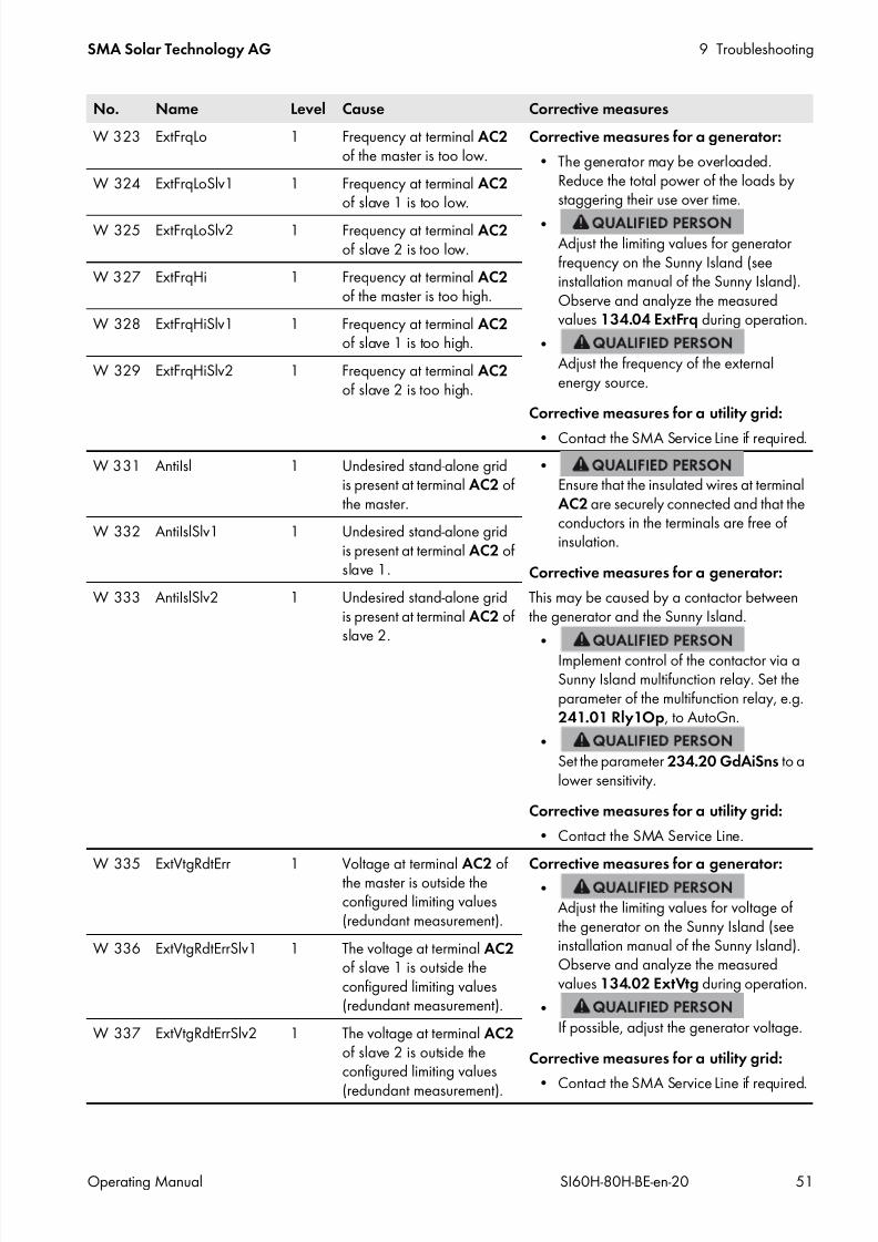
7/17/2019 Remote Control SI60H Operating Manual
http://slidepdf.com/reader/full/remote-control-si60h-operating-manual 51/128
SMA Solar Technology AG 9 Troubleshooting
Operating Manual SI60H-80H-BE-en-20 51
W 323 ExtFrqLo 1 Frequency at terminal AC2 of the master is too low.
Corrective measures for a generator:
• The generator may be overloaded.Reduce the total power of the loads bystaggering their use over time.
•Adjust the limiting values for generatorfrequency on the Sunny Island (seeinstallation manual of the Sunny Island).Observe and analyze the measuredvalues 134.04 ExtFrq during operation.
•Adjust the frequency of the externalenergy source.
Corrective measures for a utility grid:
• Contact the SMA Service Line if required.
W 324 ExtFrqLoSlv1 1 Frequency at terminal AC2 of slave 1 is too low.
W 325 ExtFrqLoSlv2 1 Frequency at terminal AC2 of slave 2 is too low.
W 327 ExtFrqHi 1 Frequency at terminal AC2 of the master is too high.
W 328 ExtFrqHiSlv1 1 Frequency at terminal AC2 of slave 1 is too high.
W 329 ExtFrqHiSlv2 1 Frequency at terminal AC2 of slave 2 is too high.
W 331 AntiIsl 1 Undesired stand-alone gridis present at terminal AC2 ofthe master.
•Ensure that the insulated wires at terminalAC2 are securely connected and that theconductors in the terminals are free ofinsulation.
Corrective measures for a generator:
This may be caused by a contactor betweenthe generator and the Sunny Island.
•Implement control of the contactor via aSunny Island multifunction relay. Set theparameter of the multifunction relay, e.g.241.01 Rly1Op, to AutoGn.
•Set the parameter 234.20 GdAiSns to alower sensitivity.
Corrective measures for a utility grid:
• Contact the SMA Service Line.
W 332 AntiIslSlv1 1 Undesired stand-alone gridis present at terminal AC2 ofslave 1.
W 333 AntiIslSlv2 1 Undesired stand-alone gridis present at terminal AC2 ofslave 2.
W 335 ExtVtgRdtErr 1 Voltage at terminal AC2 ofthe master is outside theconfigured limiting values(redundant measurement).
Corrective measures for a generator:•
Adjust the limiting values for voltage ofthe generator on the Sunny Island (seeinstallation manual of the Sunny Island).Observe and analyze the measuredvalues 134.02 ExtVtg during operation.
•If possible, adjust the generator voltage.
Corrective measures for a utility grid:
• Contact the SMA Service Line if required.
W 336 ExtVtgRdtErrSlv1 1 The voltage at terminal AC2 of slave 1 is outside theconfigured limiting values(redundant measurement).
W 337 ExtVtgRdtErrSlv2 1 The voltage at terminal AC2 of slave 2 is outside theconfigured limiting values
(redundant measurement).
No. Name Level Cause Corrective measures

7/17/2019 Remote Control SI60H Operating Manual
http://slidepdf.com/reader/full/remote-control-si60h-operating-manual 52/128
9 Troubleshooting SMA Solar Technology AG
52 SI60H-80H-BE-en-20 Operating Manual
W 339 ExtVtgIncPro 1 Voltage rise protection •Ensure that the conductor cross-section ofthe AC cables is correctly sized.
W 340 ExtVtgIncProSlv1 1
W 341 ExtVtgIncProSlv2 1
W 343 AcVtglim 1 The master disconnects fromthe external energy sourcebecause the voltage atterminal AC2 is too high orthe battery voltage too low.
• Contact the SMA Service Line if required.
W 344 AcVtglimSlv1 1 Slave 1 disconnects from theexternal energy sourcebecause the voltage atterminal AC2 is too high orthe battery voltage too low.
W 345 AcVtglimSlv2 1 Slave 2 disconnects from theexternal energy sourcebecause the voltage atterminal AC2 is too high orthe battery voltage too low.
W 347 ExtOverload 1 The master disconnects fromthe utility grid due to lineconductor failure/overloadat terminal AC2.
• Reduce the total power of the loads, e.g.by staggering their use over time.
•Ensure that there is not a short circuitpresent at terminal AC2.W 348 ExtOverloadSlv1 1 Slave 1 disconnects from the
utility grid due to line
conductor failure/overloadat terminal AC2.
W 349 ExtOverloadSlv2 1 Slave 2 disconnects from theutility grid due to lineconductor failure/overloadat terminal AC2.
W 351 ExtScirDet 1 There is a short circuitpresent at terminal AC2 ofthe master.
•Eliminate the short circuit.
W 352 ExtScirDetSlv1 1 There is a short circuit
present at terminal AC2 ofslave 1.
W 353 ExtScirDetSlv2 1 There is a short circuitpresent at terminal AC2 ofslave 2.
W 355 PhsAngErr 1 Assignment of the lineconductors of the externalenergy source to the AC2 terminals of the Sunny Islanddoes not result in a
right-rotating magnetic field.
•Ensure that the master is connected to L1,slave 1 to L2, and slave 2 to L3.
No. Name Level Cause Corrective measures

7/17/2019 Remote Control SI60H Operating Manual
http://slidepdf.com/reader/full/remote-control-si60h-operating-manual 53/128
SMA Solar Technology AG 9 Troubleshooting
Operating Manual SI60H-80H-BE-en-20 53
F 365 VAcExtPhsFail 3 The line conductors of themeasured AC voltage atterminals VExt and AC2 donot match.
• Ensure that the neutral conductor and lineconductor are correctly connected to theterminal ExtVtg.
• Ensure that the neutral conductor and lineconductor are correctly connected toterminal AC2.
• Ensure that the terminals ExtVtg andAC2 are connected to the same lineconductor.
F 366 HotAcBus 3 When the tie switch is open,AC voltage from anunknown source is present atterminal AC2.
• Ensure that the triggering of the tie switchis correct.
• Ensure that the tie switch is correctlywired.
F 367 ExtCtcNotOpen 3 Tie switch does not open.
• Ensure that the triggering of the tie switchis correct.
• Ensure that the tie switch is correctlywired.
• Ensure that the feedback contact iscorrectly connected.
F 368 NRelNotOpen 3 Neutral conductor relay of
the master does not open.
• Contact the SMA Service Line.
W 369 NRelNotOpenSlv1 1 Neutral conductor relay ofslave 1 does not open.
W 370 NRelNotOpenSlv2 1 Neutral conductor relay ofslave 2 does not open.
W 372 VtgFrqRatio 1 Disconnection from the utilitygrid or generator due tononcompliance with thevoltage-frequency ratio atthe master.
• Contact the SMA Service Line if required.
W 373 VtgFrqRatioSlv1 1 Disconnection from the utilitygrid or generator due tononcompliance with thevoltage-frequency ratio atslave 1.
W 374 VtgFrqRatioSlv2 1 Disconnection from the utilitygrid or generator due tononcompliance with thevoltage-frequency ratio atslave 2.
No. Name Level Cause Corrective measures
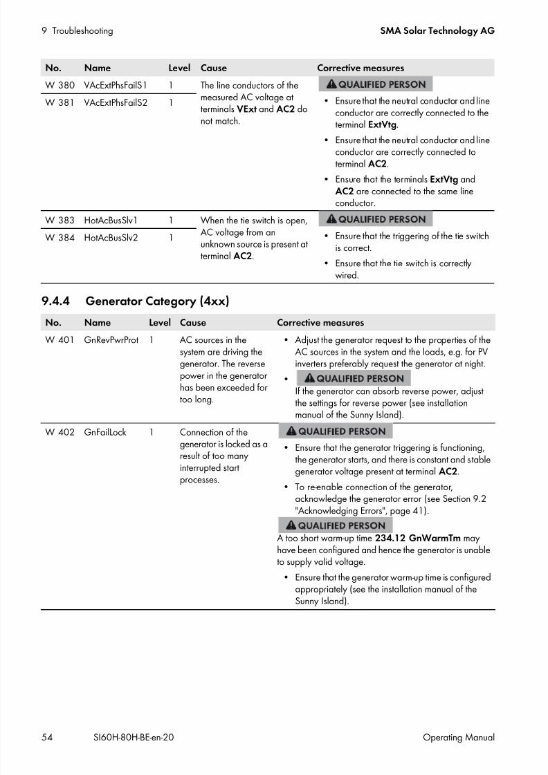
7/17/2019 Remote Control SI60H Operating Manual
http://slidepdf.com/reader/full/remote-control-si60h-operating-manual 54/128
9 Troubleshooting SMA Solar Technology AG
54 SI60H-80H-BE-en-20 Operating Manual
9.4.4 Generator Category (4xx)
W 380 VAcExtPhsFailS1 1 The line conductors of themeasured AC voltage atterminals VExt and AC2 donot match.
• Ensure that the neutral conductor and lineconductor are correctly connected to theterminal ExtVtg.
• Ensure that the neutral conductor and lineconductor are correctly connected toterminal AC2.
• Ensure that the terminals ExtVtg andAC2 are connected to the same lineconductor.
W 381 VAcExtPhsFailS2 1
W 383 HotAcBusSlv1 1 When the tie switch is open,AC voltage from anunknown source is present atterminal AC2.
• Ensure that the triggering of the tie switchis correct.
• Ensure that the tie switch is correctlywired.
W 384 HotAcBusSlv2 1
No. Name Level Cause Corrective measures
W 401 GnRevPwrProt 1 AC sources in thesystem are driving thegenerator. The reversepower in the generatorhas been exceeded fortoo long.
• Adjust the generator request to the properties of theAC sources in the system and the loads, e.g. for PVinverters preferably request the generator at night.
•If the generator can absorb reverse power, adjust
the settings for reverse power (see installationmanual of the Sunny Island).
W 402 GnFailLock 1 Connection of thegenerator is locked as aresult of too manyinterrupted startprocesses.
• Ensure that the generator triggering is functioning,the generator starts, and there is constant and stablegenerator voltage present at terminal AC2.
• To re-enable connection of the generator,acknowledge the generator error (see Section 9.2"Acknowledging Errors", page 41).
A too short warm-up time 234.12 GnWarmTm mayhave been configured and hence the generator is unableto supply valid voltage.
• Ensure that the generator warm-up time is configuredappropriately (see the installation manual of theSunny Island).
No. Name Level Cause Corrective measures

7/17/2019 Remote Control SI60H Operating Manual
http://slidepdf.com/reader/full/remote-control-si60h-operating-manual 55/128
SMA Solar Technology AG 9 Troubleshooting
Operating Manual SI60H-80H-BE-en-20 55
9.4.5 Utility Grid Category (5xx)
9.4.6 Relay Category (6xx)
9.4.7 System Category (7xx)
No. Name Level Cause Corrective measures
W 505 GdCurNomExceed 1 The feed-in current of the master is greaterthan 232.04 GdCurNom.
• Contact the SMA ServiceLine if required.
W 506 GdCurNomExcSlv1 1 The feed-in current of slave 1 is greater than232.04 GdCurNom.
W 507 GdCurNomExcSlv2 1 The feed-in current of slave 2 is greater than232.04 GdCurNom.
No. Name Level Cause Corrective measures
F 605 TransfNotOpn 4 Internal transfer relay in themaster does not open.
A bypass switch may have bridged the internaltransfer relay.
• Ensure that the bypass switch is in theposition for operation with the SunnyIsland.
•Ensure that the terminals AC1 and AC2 are not bridged.
W 606 TransfNotOpnSL1 1 Internal transfer relay inslave 1 does not open.
W 607 TransfNotOpnSL2 1 Internal transfer relay inslave 2 does not open.
No. Name Level Cause Corrective measures
F 702 RsDsp 5 Signal processor has performed a
reset.
• Contact the SMA Service Line.
F 703 TimeOut 2 Time for performing a particular taskhas been exceeded.
• Contact the SMA Service Line.
F 704 Calib 4 The system has not calibrated. • Contact the SMA Service Line.
W 705 TimeOut 1 The watchdog of the signal processorof the master has tripped.
• Contact the SMA Service Line ifrequired.
F 706 TimeOut 4 The watchdog of the signal processorof the master has tripped severaltimes.
• Contact the SMA Service Line.
W 707 TimeOutSlv1 1 The watchdog of the signal processorof slave 1 has tripped several times.
W 708 TimeOutSlv2 1 The watchdog of the signal processorof slave 2 has tripped several times.
F 710 AutoStrCnt 4 Autostart meter has expired severaltimes in succession.
•Read off the pending and loggedwarnings and errors and eliminatethe causes.
• Ensure that the parameter 250.01AutoStr is set to 3.
W 713 TimeOut 1 The watchdog of the operationcontrol unit has tripped.
• Contact the SMA Service Line ifrequired.

7/17/2019 Remote Control SI60H Operating Manual
http://slidepdf.com/reader/full/remote-control-si60h-operating-manual 56/128
9 Troubleshooting SMA Solar Technology AG
56 SI60H-80H-BE-en-20 Operating Manual
F 716 VBATMIN 2 The measured battery voltage of themaster is below the permissiblemeasurement range.
• Disconnect the DC loads andcharge the battery.
The usable battery capacity may be toosmall, e.g. due to aging. If a load with
high power connects, the batteryvoltage collapses.
•If DC loads are installed in thesystem, install load shedding forDC loads.
•Ensure that all battery cells arefunctional.
W 717 VBATMINSL1 1 The measured battery voltage of
slave 1 is below the permissiblemeasurement range.
W 718 VBATMINSL2 1 The measured battery voltage ofslave 2 is below the permissiblemeasurement range.
F 720 InvTmpSns 4 The temperature sensor on the
transformer of the master is defective.
• Contact the SMA Service Line.
F 721 InvTmpSns 4 The temperature sensor on the heatsink of the master is defective.
• Contact the SMA Service Line.
W 722 BatTmpSnsShort 1 Short circuit of the batterytemperature sensor
•Ensure that the battery temperaturesensor is correctly connected (seeinstallation manual of theSunny Island).
• Contact the SMA Service Line.
W 723 BatTmpSnsOpn 1 Cable break in battery temperaturesensor
W 724 AutoStrCntSlv1 1 Maximum number of autostarts for
slave 1 has been reached.
•
Read off the pending and loggedwarnings and errors and eliminatethe causes.
• Ensure that the parameter 250.01AutoStr is set to 3.
W 725 AutoStrCntSlv2 1 The maximum number of autostartsfor slave 2 has been reached.
F 731 ClstConfig 4 Configuration of the cluster isincorrect.
•Change the addresses of theslaves in the cluster (seeSection 9.7, page 71)
F 732 ClstAdress 4 Error in the address assignment of the
Sunny Island in the cluster.
•
Ensure that undamaged CAT5ecables are used for communicationand that the cables are plugged incorrectly.
•Ensure that the communication busis equipped with a terminator atboth ends.
•Reset the address of the SunnyIsland inverters in the cluster (see
Section 9.7, page 71).
No. Name Level Cause Corrective measures

7/17/2019 Remote Control SI60H Operating Manual
http://slidepdf.com/reader/full/remote-control-si60h-operating-manual 57/128
SMA Solar Technology AG 9 Troubleshooting
Operating Manual SI60H-80H-BE-en-20 57
F 733 MstrLoss 4 Communication to the master isinterrupted.
•Ensure that undamaged CAT5ecables are used for communicationand that the cables are plugged in
correctly.•
Ensure that the communication busis equipped with a terminator atboth ends.
W 734 Slv1Loss 1 Communication from the master toslave 1 is interrupted.
W 735 Slv2Loss 1 Communication from the master toslave 2 is interrupted.
W 738 GnSynLoss 1 Synchronization with the generator orbattery backup grid not successful.
• Ensure that the generator can bestarted. It may be that the fuel levelis too low.
•Ensure that a constant and stablevoltage is present at terminal AC2.
•Ensure that the limiting values forthe voltage of the external energysources are correctly configured.
F 739 SPICom 3 Internal device communication of themaster is disturbed.
• Contact the SMA Service Line.
W 740 SPIComSlv1 1 Internal device communication ofslave 1 is disturbed.
W 741 SPIComSlv2 1 Internal device communication of
slave 2 is disturbed.F 743 CANCom 3 Internal device CAN communication
of the master is disturbed.•
Ensure that the terminators in thecommunication bus are attached.
•Ensure that undamaged CAT5ecables are used for communicationand that the cables are plugged incorrectly.
• Contact the SMA Service Line.
W 744 CANComSlv1 1 Internal device CAN communicationof slave 1 is disturbed.
W 745 CANComSlv2 1 Internal device CAN communicationof slave 2 is disturbed.
W 747 InvTmpSnsSlv1 1 Temperature sensor on thetransformer of slave 1 is defective. • Contact the SMA Service Line.
W 748 InvTmpSnsSlv2 1 Temperature sensor on thetransformer of slave 2 is defective.
W 750 InvTmpSnsSlv1 1 Temperature sensor on the heat sinkof slave 1 is defective.
• Contact the SMA Service Line.
W 751 InvTmpSnsSlv2 1 Temperature sensor on the heat sinkof slave 2 is defective.
W 753 DateInvalid 1 System time is invalid. • Select the parameter 250.02 Dt and set the date. Select the
parameter 250.03 Tm and set thetime.
No. Name Level Cause Corrective measures
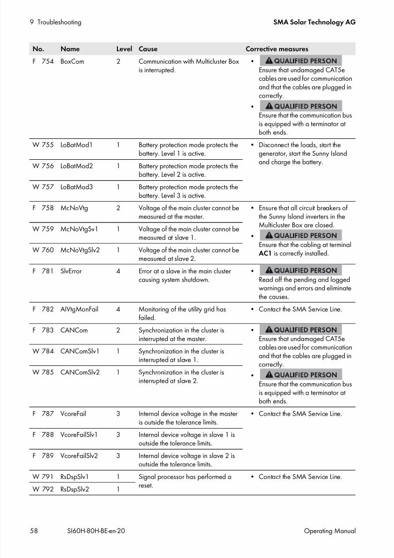
7/17/2019 Remote Control SI60H Operating Manual
http://slidepdf.com/reader/full/remote-control-si60h-operating-manual 58/128
9 Troubleshooting SMA Solar Technology AG
58 SI60H-80H-BE-en-20 Operating Manual
F 754 BoxCom 2 Communication with Multicluster Boxis interrupted.
•Ensure that undamaged CAT5ecables are used for communicationand that the cables are plugged in
correctly.•
Ensure that the communication busis equipped with a terminator atboth ends.
W 755 LoBatMod1 1 Battery protection mode protects thebattery. Level 1 is active.
• Disconnect the loads, start thegenerator, start the Sunny Islandand charge the battery.W 756 LoBatMod2 1 Battery protection mode protects the
battery. Level 2 is active.
W 757 LoBatMod3 1 Battery protection mode protects the
battery. Level 3 is active.F 758 McNoVtg 2 Voltage of the main cluster cannot be
measured at the master.• Ensure that all circuit breakers of
the Sunny Island inverters in theMulticluster Box are closed.
•Ensure that the cabling at terminalAC1 is correctly installed.
W 759 McNoVtgSv1 1 Voltage of the main cluster cannot bemeasured at slave 1.
W 760 McNoVtgSlv2 1 Voltage of the main cluster cannot bemeasured at slave 2.
F 781 SlvError 4 Error at a slave in the main clustercausing system shutdown.
•Read off the pending and loggedwarnings and errors and eliminatethe causes.
F 782 AIVtgMonFail 4 Monitoring of the utility grid hasfailed.
• Contact the SMA Service Line.
F 783 CANCom 2 Synchronization in the cluster isinterrupted at the master.
•Ensure that undamaged CAT5ecables are used for communicationand that the cables are plugged incorrectly.
•Ensure that the communication bus
is equipped with a terminator atboth ends.
W 784 CANComSlv1 1 Synchronization in the cluster isinterrupted at slave 1.
W 785 CANComSlv2 1 Synchronization in the cluster isinterrupted at slave 2.
F 787 VcoreFail 3 Internal device voltage in the masteris outside the tolerance limits.
• Contact the SMA Service Line.
F 788 VcoreFailSlv1 3 Internal device voltage in slave 1 isoutside the tolerance limits.
F 789 VcoreFailSlv2 3 Internal device voltage in slave 2 isoutside the tolerance limits.
W 791 RsDspSlv1 1 Signal processor has performed a
reset.
• Contact the SMA Service Line.
W 792 RsDspSlv2 1
No. Name Level Cause Corrective measures
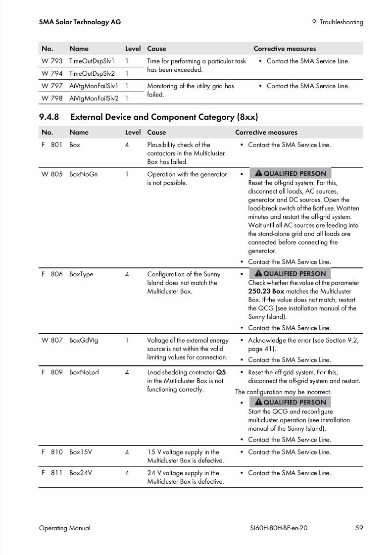
7/17/2019 Remote Control SI60H Operating Manual
http://slidepdf.com/reader/full/remote-control-si60h-operating-manual 59/128
SMA Solar Technology AG 9 Troubleshooting
Operating Manual SI60H-80H-BE-en-20 59
9.4.8 External Device and Component Category (8xx)
W 793 TimeOutDspSlv1 1 Time for performing a particular taskhas been exceeded.
• Contact the SMA Service Line.
W 794 TimeOutDspSlv2 1
W 797 AiVtgMonFailSlv1 1 Monitoring of the utility grid has
failed.
• Contact the SMA Service Line.
W 798 AiVtgMonFailSlv2 1
No. Name Level Cause Corrective measures
F 801 Box 4 Plausibility check of thecontactors in the MulticlusterBox has failed.
• Contact the SMA Service Line.
W 805 BoxNoGn 1 Operation with the generatoris not possible.
•Reset the off-grid system. For this,
disconnect all loads, AC sources,generator and DC sources. Open theload-break switch of the BatFuse. Wait tenminutes and restart the off-grid system.Wait until all AC sources are feeding intothe stand-alone grid and all loads areconnected before connecting thegenerator.
• Contact the SMA Service Line.
F 806 BoxType 4 Configuration of the SunnyIsland does not match the
Multicluster Box.
•Check whether the value of the parameter
250.23 Box matches the MulticlusterBox. If the value does not match, restartthe QCG (see installation manual of theSunny Island).
• Contact the SMA Service Line.
W 807 BoxGdVtg 1 Voltage of the external energysource is not within the validlimiting values for connection.
• Acknowledge the error (see Section 9.2,page 41).
• Contact the SMA Service Line.
F 809 BoxNoLod 4 Load-shedding contactor Q5 in the Multicluster Box is not
functioning correctly.
• Reset the off-grid system. For this,disconnect the off-grid system and restart.
The configuration may be incorrect.
•Start the QCG and reconfiguremulticluster operation (see installationmanual of the Sunny Island).
• Contact the SMA Service Line.
F 810 Box15V 4 15 V voltage supply in theMulticluster Box is defective.
• Contact the SMA Service Line.
F 811 Box24V 4 24 V voltage supply in theMulticluster Box is defective.
• Contact the SMA Service Line.
No. Name Level Cause Corrective measures

7/17/2019 Remote Control SI60H Operating Manual
http://slidepdf.com/reader/full/remote-control-si60h-operating-manual 60/128
9 Troubleshooting SMA Solar Technology AG
60 SI60H-80H-BE-en-20 Operating Manual
W 815 BoxQ5 1 Contactor Q5 in theMulticluster Box is notfunctioning correctly.
• Reset the off-grid system. For this,disconnect the off-grid system and restart.
The configuration may be incorrect.
•Start the QCG and reconfiguremulticluster operation (see installationmanual of the Sunny Island).
• Contact the SMA Service Line.
F 816 BoxQ7 2 Contactor Q7 in the
Multicluster Box is notfunctioning correctly.
F 818 BoxPhsFail 4 One line conductor of a SunnyIsland is missing.
• Ensure that all circuit breakers of theSunny Island inverters in the MulticlusterBox are closed.
• Reset the off-grid system. For this,disconnect the off-grid system and restart.
•Search for the missing line conductor andeliminate the error. For this, with loadsconnected, measure the AC voltagebetween each line conductor andbetween the line conductors and theneutral conductors. If an AC voltagedeviates from the nominal voltage by±10%, the corresponding line conductoris missing.
W 824 BoxQ4Overload 1 Multicluster Box signals anerror at contactor Q4.
• Contact the SMA Service Line.
W 840 eHZ1ComFail 1 Faulty communicationbetween the Meter Box andthe feed-in meter andpurchased electricity meter.
• Ensure that the optical probe is correctlymounted.
• Ensure that the optical probe is correctlyconnected.
W 841 eHZ2ComFail 1 Faulty communicationbetween the Meter Box andthe PV production meter.
W 842 ComBoxFail 1 Faulty communicationbetween the Sunny Island andthe Meter Box.
•Ensure that the data cables are correctlyinstalled.
W 843 ComBoxWD 1 The Meter Box watchdog hastriggered.
• Contact the SMA Service Line.
W 844 eHZ1ProtFail 1 Data protocol of the feed-inand purchased electricitymeter is unknown.
• Contact the SMA Service Line.
W 845 eHZ2ProtFail 1 Data protocol of the PVproduction meter is unknown.
W 846 eHzInFail 1 Optical probes have beenswapped.
• Swap the optical probe connections.
No. Name Level Cause Corrective measures
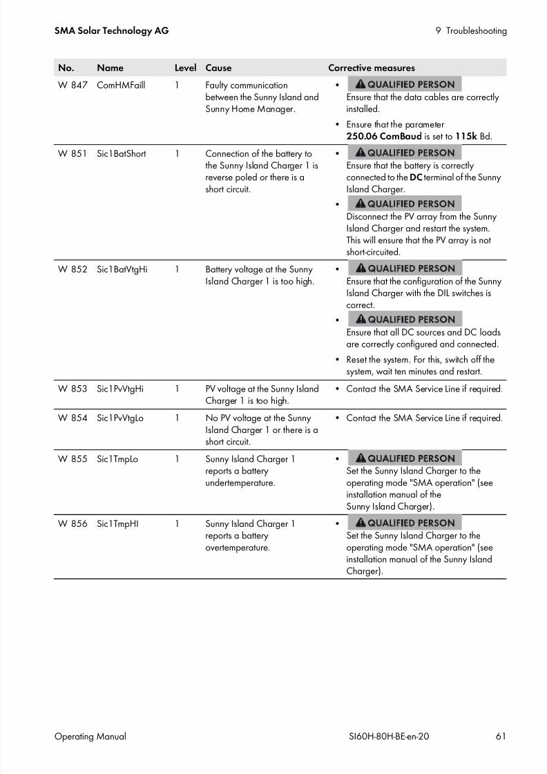
7/17/2019 Remote Control SI60H Operating Manual
http://slidepdf.com/reader/full/remote-control-si60h-operating-manual 61/128
SMA Solar Technology AG 9 Troubleshooting
Operating Manual SI60H-80H-BE-en-20 61
W 847 ComHMFaill 1 Faulty communicationbetween the Sunny Island andSunny Home Manager.
•Ensure that the data cables are correctlyinstalled.
• Ensure that the parameter
250.06 ComBaud is set to 115k Bd.W 851 Sic1BatShort 1 Connection of the battery to
the Sunny Island Charger 1 isreverse poled or there is ashort circuit.
•Ensure that the battery is correctlyconnected to the DC terminal of the SunnyIsland Charger.
•Disconnect the PV array from the SunnyIsland Charger and restart the system.This will ensure that the PV array is notshort-circuited.
W 852 Sic1BatVtgHi 1 Battery voltage at the SunnyIsland Charger 1 is too high. • Ensure that the configuration of the SunnyIsland Charger with the DIL switches iscorrect.
•Ensure that all DC sources and DC loadsare correctly configured and connected.
• Reset the system. For this, switch off thesystem, wait ten minutes and restart.
W 853 Sic1PvVtgHi 1 PV voltage at the Sunny IslandCharger 1 is too high.
• Contact the SMA Service Line if required.
W 854 Sic1PvVtgLo 1 No PV voltage at the SunnyIsland Charger 1 or there is ashort circuit.
• Contact the SMA Service Line if required.
W 855 Sic1TmpLo 1 Sunny Island Charger 1reports a batteryundertemperature.
•Set the Sunny Island Charger to theoperating mode "SMA operation" (seeinstallation manual of theSunny Island Charger).
W 856 Sic1TmpHI 1 Sunny Island Charger 1reports a batteryovertemperature.
•Set the Sunny Island Charger to theoperating mode "SMA operation" (seeinstallation manual of the Sunny IslandCharger).
No. Name Level Cause Corrective measures

7/17/2019 Remote Control SI60H Operating Manual
http://slidepdf.com/reader/full/remote-control-si60h-operating-manual 62/128
9 Troubleshooting SMA Solar Technology AG
62 SI60H-80H-BE-en-20 Operating Manual
W 857 Sic1ComLoss 1 Last communication with theSunny Island Charger 1 wasmore than 24 hours ago.
•Ensure that undamaged CAT5e cablesare used for communication and that thecables are plugged in correctly.
•Ensure that the configuration of the SunnyIsland Charger with the DIL switches iscorrect.
•Ensure that the communication interfacesare correctly inserted in the Sunny Island.
W 861 Sic2BatShort 1 Connection of the battery tothe Sunny Island Charger 2 isreverse poled or there is ashort circuit.
•Ensure that the battery is correctlyconnected to the DC terminal of the SunnyIsland Charger.
•Disconnect the PV array from the SunnyIsland Charger and restart the system.This will ensure that the PV array is notshort-circuited.
W 862 Sic2BatVtgHi 1 Battery voltage at the SunnyIsland Charger 2 is too high.
•Ensure that the configuration of the SunnyIsland Charger with the DIL switches iscorrect.
•
Ensure that all DC sources and DC loadsare correctly configured and connected.
• Reset the system. For this, switch off thesystem, wait ten minutes and restart.
W 863 Sic2PvVtgHi 1 PV voltage at the Sunny IslandCharger 2 is too high.
• Contact the SMA Service Line if required.
W 864 Sic2PvVtgLo 1 No PV voltage at the SunnyIsland Charger 2 or there is ashort circuit.
• Contact the SMA Service Line if required.
W 865 Sic2TmpLo 1 Sunny Island Charger 2reports a batteryundertemperature.
•Set the Sunny Island Charger to theoperating mode "SMA operation" (seeinstallation manual of the Sunny IslandCharger).
W 866 Sic2TmpHI 1 Sunny Island Charger 2reports a batteryovertemperature.
•Set the Sunny Island Charger to theoperating mode "SMA operation" (seeinstallation manual of the Sunny IslandCharger).
No. Name Level Cause Corrective measures

7/17/2019 Remote Control SI60H Operating Manual
http://slidepdf.com/reader/full/remote-control-si60h-operating-manual 63/128
SMA Solar Technology AG 9 Troubleshooting
Operating Manual SI60H-80H-BE-en-20 63
W 867 Sic2ComLoss 1 Last communication with theSunny Island Charger 2 wasmore than 24 hours ago.
•Ensure that undamaged CAT5e cablesare used for communication and that thecables are plugged in correctly.
•Ensure that the configuration of the SunnyIsland Charger with the DIL switches iscorrect.
•Ensure that the communication interfacesare correctly inserted in the Sunny Island.
W 871 Sic2BatShort 1 Connection of the battery tothe Sunny Island Charger 2 isreverse poled or there is ashort circuit.
•Ensure that the battery is correctlyconnected to the DC terminal of the SunnyIsland Charger.
•Disconnect the PV array from the SunnyIsland Charger and restart the system.This will ensure that the PV array is notshort-circuited.
W 872 Sic3BatVtgHi 1 Battery voltage at the SunnyIsland Charger 3 is too high.
•Ensure that the configuration of the SunnyIsland Charger with the DIL switches iscorrect.
•
Ensure that all DC sources and DC loadsare correctly configured and connected.
• Reset the system. For this, switch off thesystem, wait ten minutes and restart.
W 873 Sic3PvVtgHi 1 PV voltage at the Sunny IslandCharger 3 is too high.
• Contact the SMA Service Line if required.
W 874 Sic3PvVtgLo 1 No PV voltage at the SunnyIsland Charger 3 or there is ashort circuit.
• Contact the SMA Service Line if required.
W 875 Sic3TmpLo 1 Sunny Island Charger 3reports a batteryundertemperature.
•Set the Sunny Island Charger to theoperating mode "SMA operation" (seeinstallation manual of the Sunny IslandCharger).
W 876 Sic3TmpHI 1 Sunny Island Charger 3reports a batteryovertemperature.
•Set the Sunny Island Charger to theoperating mode "SMA operation" (seeinstallation manual of the Sunny IslandCharger).
No. Name Level Cause Corrective measures

7/17/2019 Remote Control SI60H Operating Manual
http://slidepdf.com/reader/full/remote-control-si60h-operating-manual 64/128
9 Troubleshooting SMA Solar Technology AG
64 SI60H-80H-BE-en-20 Operating Manual
W 877 Sic3ComLoss 1 Last communication with theSunny Island Charger 3 wasmore than 24 hours ago.
•Ensure that undamaged CAT5e cablesare used for communication and that thecables are plugged in correctly.
•Ensure that the configuration of the SunnyIsland Charger with the DIL switches iscorrect.
•Ensure that the communication interfacesare correctly inserted in the Sunny Island.
W 881 Sic4BatShort 1 Connection of the battery tothe Sunny Island Charger 4 isreverse poled or there is ashort circuit.
•Ensure that the battery is correctlyconnected to the DC terminal of the SunnyIsland Charger.
•Disconnect the PV array from the SunnyIsland Charger and restart the system.This will ensure that the PV array is notshort-circuited.
W 882 Sic4BatVtgHi 1 Battery voltage at theSunny Island Charger 4 is toohigh.
•Ensure that the configuration of the SunnyIsland Charger with the DIL switches iscorrect.
•
Ensure that all DC sources and DC loadsare correctly configured and connected.
• Reset the system. For this, switch off thesystem, wait ten minutes and restart.
W 883 Sic4PvVtgHi 1 PV voltage at the Sunny IslandCharger 4 is too high.
• Contact the SMA Service Line if required.
W 884 Sic4PvVtgLo 1 No PV voltage at the SunnyIsland Charger 4 or there is ashort circuit.
• Contact the SMA Service Line if required.
W 885 Sic4TmpLo 1 Sunny Island Charger 4reports a batteryundertemperature.
•Set the Sunny Island Charger to theoperating mode "SMA operation" (seeinstallation manual of the Sunny IslandCharger).
W 886 Sic4TmpHI 1 Sunny Island Charger 4reports a batteryovertemperature.
•Set the Sunny Island Charger to theoperating mode "SMA operation" (seeinstallation manual of the Sunny IslandCharger).
No. Name Level Cause Corrective measures

7/17/2019 Remote Control SI60H Operating Manual
http://slidepdf.com/reader/full/remote-control-si60h-operating-manual 65/128
SMA Solar Technology AG 9 Troubleshooting
Operating Manual SI60H-80H-BE-en-20 65
9.4.9 General Category (9xx)
9.5 Frequently Asked Questions
9.5.1 Questions regarding the Sunny Island
The Sunny Island does not switch off even though you have opened the load-break switch of theBatFuse?
The Sunny Island may still be supplied from the AC side.
•Switch off all AC sources and disconnect them from the Sunny Island.
The Sunny Island does not switch to silent mode?
Another function might have a higher priority than silent mode, e.g. equalization charge or full charge.
W 887 Sic4ComLoss 1 Last communication with theSunny Island Charger 4 wasmore than 24 hours ago.
•Ensure that undamaged CAT5e cablesare used for communication and that thecables are plugged in correctly.
•Ensure that the configuration of the SunnyIsland Charger with the DIL switches iscorrect.
•Ensure that the communication interfacesare correctly inserted in the Sunny Island.
W 890 BoxMeas 2 Disturbance in voltage orcurrent measurement at themeasurement point of theMulticluster Box for the master.
•Ensure that the control and measuringcable between the Multicluster Box andthe corresponding Sunny Island of themain cluster is correctly inserted. Whendoing so, observe the correct sequence ofthe Multicluster Box terminals to the SunnyIsland inverters (see installation manual ofthe Sunny Island and the Multicluster Boxdocumentation).
W 891 BoxMeasSlv1 2 Disturbance in voltage orcurrent measurement at themeasurement point of theMulticluster Box for slave 1.
W 892 BoxMeasSlv2 2 Disturbance in voltage orcurrent measurement at themeasurement point of theMulticluster Box for slave 2.
No. Name Level Cause
W 915 Timeout 1 An error has occurred in the program run sequence.
F 952 ExtBMSTimeout 3 Time for communication with the external battery management has beenexceeded.
W 953 WrnExtBMSTmOut 1 Time for communication with the external battery management has beenexceeded.
No. Name Level Cause Corrective measures

7/17/2019 Remote Control SI60H Operating Manual
http://slidepdf.com/reader/full/remote-control-si60h-operating-manual 66/128
9 Troubleshooting SMA Solar Technology AG
66 SI60H-80H-BE-en-20 Operating Manual
After automatic disconnection in battery protection mode, the Sunny Island can no longer bestarted?
•Only charge the battery when the Sunny Island cannot be switched on(see Section 9.6 "Charging the Battery after Automatic Shutdown in Off-Grid Systems", page 69) .
• Switch off all loads.• If there is a generator in the system, start the generator manually. When doing so, observe the warm-up time of
the generator. Five minutes without charging current may result in disconnection of the Sunny Island.
• If sufficient power is available from the generator or the AC sources in the stand-alone grid, e.g. sufficient solarirradiation for PV inverters, switch the Sunny Island on. AC sources in the stand-alone grid can only start feedingin electric current once the Sunny Island has been started and is in operation.
9.5.2 Questions regarding the Sunny Remote Control
The display of the Sunny Remote Control is dark and nothing is displayed?
The Sunny Island might not be switched on.
• Switch the Sunny Island on (see Section 4.1, page 17).
The Sunny Island does not switch on?
•Ensure that the fuse in the BatFuse is not defective.
The Sunny Remote Control might not be connected to the Sunny Island.
•Ensure that the Sunny Remote Control is connected to the Sunny Island.
The RJ45 data cable might be damaged.
•
Replace the RJ45 data cable between the Sunny Remote Control and the Sunny Island.
Parameters cannot be changed?
The parameter might only be displayed in expert mode.
• Switch to expert mode on the Sunny Remote Control (see Section 5.4.1, page 28).
The parameter might only be changeable in standby mode or in the QCG.
• Observe the messages in the display (see Section 5.4.6 "Setting the Parameters", page 30).
The parameter might be hidden as it is not required in the configuration set for the system.
• Ensure that the configuration does not deactivate any functions which are required.
"MMC/SD operation failed !" is shown in the display?
An action with the SD memory card has failed.
• Use a computer to ensure that the SD memory card is free of errors.
•Ensure that the data cable between the Sunny Remote Control and the Sunny Island is undamaged and that theplugs are firmly inserted into the pin connectors.
The display shows "WRONG FILE SYSTEM"?
The SD memory card is not formatted with the FAT-12 or FAT-16 file system.
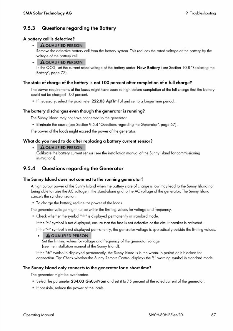
7/17/2019 Remote Control SI60H Operating Manual
http://slidepdf.com/reader/full/remote-control-si60h-operating-manual 67/128
SMA Solar Technology AG 9 Troubleshooting
Operating Manual SI60H-80H-BE-en-20 67
9.5.3 Questions regarding the Battery
A battery cell is defective?
•Remove the defective battery cell from the battery system. This reduces the rated voltage of the battery by the
voltage of the battery cell.•In the QCG, set the current rated voltage of the battery under New Battery (see Section 10.8 "Replacing theBattery", page 77).
The state of charge of the battery is not 100 percent after completion of a full charge?
The power requirements of the loads might have been so high before completion of the full charge that the batterycould not be charged 100 percent.
• If necessary, select the parameter 222.03 AptTmFul and set to a longer time period.
The battery discharges even though the generator is running?
The Sunny Island may not have connected to the generator.
• Eliminate the cause (see Section 9.5.4 "Questions regarding the Generator", page 67).
The power of the loads might exceed the power of the generator.
What do you need to do after replacing a battery current sensor?
•Calibrate the battery current sensor (see the installation manual of the Sunny Island for commissioninginstructions).
9.5.4 Questions regarding the Generator
The Sunny Island does not connect to the running generator?
A high output power of the Sunny Island when the battery state of charge is low may lead to the Sunny Island notbeing able to raise the AC voltage in the stand-alone grid to the AC voltage of the generator. The Sunny Islandcancels the synchronization.
• To charge the battery, reduce the power of the loads.
The generator voltage might not be within the limiting values for voltage and frequency.
• Check whether the symbol " " is displayed permanently in standard mode.
If the " " symbol is not displayed, ensure that the fuse is not defective or the circuit breaker is activated.
If the " " symbol is not displayed permanently, the generator voltage is sporadically outside the limiting values.
•Set the limiting values for voltage and frequency of the generator voltage(see the installation manual of the Sunny Island).
If the " " symbol is displayed permanently, the Sunny Island is in the warm-up period or is blocked forconnection. Tip: Check whether the Sunny Remote Control displays the " " warning symbol in standard mode.
The Sunny Island only connects to the generator for a short time?
The generator might be overloaded.
• Select the parameter 234.03 GnCurNom and set it to 75 percent of the rated current of the generator.
• If possible, reduce the power of the loads.

7/17/2019 Remote Control SI60H Operating Manual
http://slidepdf.com/reader/full/remote-control-si60h-operating-manual 68/128
9 Troubleshooting SMA Solar Technology AG
68 SI60H-80H-BE-en-20 Operating Manual
The set maximum permissible generator voltage might be too low.
•Select the parameter 234.02 GNVtgMax and set to the maximum generator voltage.
The minimum frequency set for the generator voltage might be too high.
•
Select the parameter 234.05 GnFrqMin and set to the minimum frequency of the generator voltage.The permitted time 234.14 GnRvTm for reverse power might have been exceeded.
• Check whether warning W401 is registered in the menu 420# Error history. Tip: If a warning was registered,the warning symbol " " is shown in the standard mode of the Sunny Remote Control.
• Select the 540.02 GnAck parameter and set to Ackn. This acknowledges the generator error.
The Sunny Island does not reconnect to the generator after a disconnection from the generator dueto noncompliance with the limiting values for voltage and frequency?
The Sunny Island is switched with a hysteresis, i.e. the limiting values for connection do not correspond to the limitingvalues for disconnection.
• To unload the generator, disconnect unnecessary loads.• Wait until the voltage and frequency have reached the nominal values.
9.5.5 Questions regarding Cluster Systems and Multicluster Systems
Extension clusters remain in standby mode even though the main cluster is in inverter mode?
The data cable between the masters of the individual clusters might not be connected. The master of the main clustercannot forward the "Start" command to the masters of the extension clusters.
The multicluster system is not supplying full power?
An extension cluster or individual Sunny Island inverters of an extension cluster might have failed.
High levels of energy is transferred between the clusters in the multicluster system?
The state of charge of the batteries might differ temporarily. The off-grid system equalizes different states of chargeautomatically.
The nominal frequencies and nominal voltages might be defined differently.
• Set the frequencies and voltages in the 210# Inverter Settings menu to the same values for all masters.
The battery capacities might differ significantly.
•Distribute the battery capacities to the clusters as evenly as possible.
Individual battery cells of a battery might have failed.•
Disconnect defective battery cells and set the new rated voltage and capacity(see Section 10.8 "Replacing the Battery", page 77).

7/17/2019 Remote Control SI60H Operating Manual
http://slidepdf.com/reader/full/remote-control-si60h-operating-manual 69/128
SMA Solar Technology AG 9 Troubleshooting
Operating Manual SI60H-80H-BE-en-20 69
9.6 Charging the Battery after Automatic Shutdown in Off-Grid Systems
When a battery undergoes a deep discharge, the Sunny Island shuts down automatically and you cannot restart theSunny Island. In order to start the Sunny Island again after an automatic shutdown, you must charge the battery inemergency charge mode.
In emergency charge mode, the Sunny Island does not form a separate stand-alone grid, and you can charge the batteryusing a generator. Battery management is active in emergency charge mode and the Sunny Island charges the batteryin accordance with the parameter settings. In standby mode or in the QCG, you can adjust the parameters for the battery,e.g. the battery nominal voltage, if a battery cell fails.
Requirement:
The Sunny Remote Control must be connected to the master. The system must be an off-grid system.
Procedure:
• Connect the generator to terminal AC1.
• Charge the battery.
• Disconnect the generator from terminal AC1.
• Start the off-grid system.
Connecting the Generator to Terminal AC1
2. If a generator is installed permanently in the off-grid system, bridge the terminals AC1 and AC2.
3. If a mobile generator is used, connect the generator to terminal AC1 (see the installation manual of theSunny Island).
4. Close the Sunny Island (see Commissioning in the installation manual of the Sunny Island).
Charging the Battery
1. Switch off all loads.
2. Connect or close all circuit breakers and fuse switch-disconnectors for energy sources.
3. Quickly connect the load-break switch of the BatFuse and close the BatFuse (see the installation manual of theBatFuse).
4. Start the generator.
5. Switch the Sunny Island on (see Section 4.1, page 17).
Restricted management functions in emergency charge mode
In emergency charge mode, the generator management is not active. The limits for voltage, current and frequencyare not monitored. Set the maximum current consumption of the Sunny Island for charging the battery in emergencycharge mode. The Sunny Island does not record additional strain on the generator due to loads.
1.
Danger to life from electric shock due to high voltages
High voltages are present on the AC power cables and on the control cables. Touching live parts can result in deathor serious injury due to electric shock.
• Disconnect the Sunny Island from voltage sources (see Section 8, page 39).

7/17/2019 Remote Control SI60H Operating Manual
http://slidepdf.com/reader/full/remote-control-si60h-operating-manual 70/128
9 Troubleshooting SMA Solar Technology AG
70 SI60H-80H-BE-en-20 Operating Manual
6. If the Sunny Remote Control displays <Init System> , press and hold the button.
The Sunny Remote Control displays the QCG.
7. Select the menu Emerg Charge and press the button.
8. Confirm with Y .
The Sunny Remote Control shows the ExtCurMax parameter.
9. Set the AC current of the connected generator and press the button.
10. Confirm the AC current with Y .
11. Turn the button to the right and confirm the message Emerg.Confirm ChargMode Start?.
Disconnecting the Generator from Terminal AC1
1. Switch the Sunny Island off (see Section 4.4, page 18).
2. Ensure that the generator is stopped permanently.
4. If the terminals AC1 and AC2 are bridged, remove the bridge.
5. If a mobile generator is used, disconnect the generator from terminal AC1.
6. Close the Sunny Island (see Commissioning in the installation manual of the Sunny Island).
Starting the Off-Grid System
1. Connect or close all circuit breakers and fuse switch-disconnectors.
2. Start the off-grid system (see Section 4.2, page 17).
Interrupting the Emergency Charge Mode
You can interrupt the emergency charge mode, e.g. to add diesel to a generator.
• Press and hold the button.
Emergency charge mode is stopped.• Press and hold the button.
Emergency charge mode is in operation.
3.
Danger to life from electric shock due to high voltages
High voltages are present on the AC power cables and on the control cables. Touching live parts can result in deathor serious injury due to electric shock.
• Disconnect the Sunny Island from voltage sources (see Section 8, page 39).

7/17/2019 Remote Control SI60H Operating Manual
http://slidepdf.com/reader/full/remote-control-si60h-operating-manual 71/128
SMA Solar Technology AG 9 Troubleshooting
Operating Manual SI60H-80H-BE-en-20 71
9.7 Changing Slave Addresses in a Cluster
If you want to change slave addresses (e.g. after replacing a Sunny Island) you can assign the slaves a new addressusing the Quick Configuration Guide (QCG). Only the address is changed, all other configurations remain as they were,e.g. assignment of the clusters in a multicluster system. When replacing a master, you must reconfigure the cluster (seethe Quick Reference Guide "Off-Grid Systems" for configuring single-cluster operation or multicluster operation).
You can change the slave addresses in two ways:
• Change the slave addresses with a Sunny Remote Control.
• Change the slave addresses without Sunny Remote Control.
Changing Slave Addresses with a Sunny Remote Control
Requirements:
All Sunny Island inverters must be switched off.
A Sunny Remote Control is connected to the master only.
Procedure:
1. Switch the slave on.
2. Turn on the master and then press and hold the button on the Sunny Remote Control.
An acoustic signal sounds three times and the QCG starts.
3. Select the NewClstCfg menu on the Sunny Remote Control and confirm with Y .
4. For a single-phase system, set 1Phs and press the button.
5. For a three-phase system, set 3Phs and press the button.
6. Confirm the question Setup new cluster ? with Y .
7. Wait until the inverter LED of slave 1 flashes and the Sunny Remote Control shows the message To identify Slave1press Tss on the Slv.
8. Press the start-stop button on slave 1.
The QCG configures slave 1.
9. To configure slave 2, wait until the inverter LED of slave 2 flashes and the Sunny Remote Control shows the messageTo identify Slave2 press Tss on the Slv.
10. Press the start-stop button on slave 2.
An acoustic signal sounds and the QCG configures slave 2.
11. Press the button on the Sunny Remote Control. This closes the QCG.
The Sunny Remote Control switches from display mode to standard mode.

7/17/2019 Remote Control SI60H Operating Manual
http://slidepdf.com/reader/full/remote-control-si60h-operating-manual 72/128
9 Troubleshooting SMA Solar Technology AG
72 SI60H-80H-BE-en-20 Operating Manual
Changing the Slave Addresses Without a Sunny Remote Control
Only use this method if a Sunny Remote Control cannot be connected.
Requirement:
There is no Sunny Remote Control connected to the cluster.
Procedure:1. Switch the system on.
The Sunny Island inverters are in standby mode.
2. Press and hold the activation button on the master until an acousticsignal sounds three times.
The cluster restarts and the LEDs on the Sunny Island inverters inthe cluster are flashing.
3. In a single-phase system, press the activation button on the master repeatedly until one LED is flashing.
4. In a three-phase system, press the activation button on the master repeatedly until all three LEDs are flashing.
5. Wait until the LED/LEDs on all Sunny Island inverters are flashing.
6. Press the start-stop button on slave 1.
The master configures slave 1.
7. In order to configure slave 2, press the start-stop button on slave 2.
The master configures slave 2.
8. Press the start-stop button on the master. This completes the configuration.
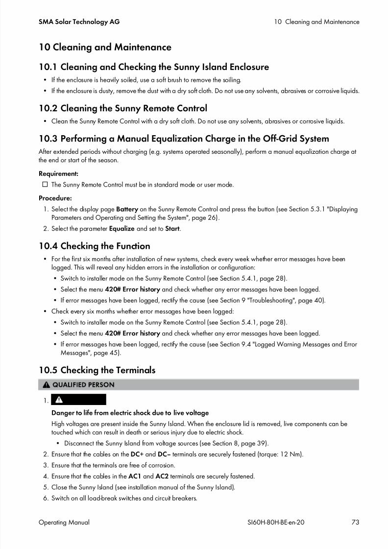
7/17/2019 Remote Control SI60H Operating Manual
http://slidepdf.com/reader/full/remote-control-si60h-operating-manual 73/128
SMA Solar Technology AG 10 Cleaning and Maintenance
Operating Manual SI60H-80H-BE-en-20 73
10 Cleaning and Maintenance
10.1 Cleaning and Checking the Sunny Island Enclosure• If the enclosure is heavily soiled, use a soft brush to remove the soiling.
• If the enclosure is dusty, remove the dust with a dry soft cloth. Do not use any solvents, abrasives or corrosive liquids.
10.2 Cleaning the Sunny Remote Control• Clean the Sunny Remote Control with a dry soft cloth. Do not use any solvents, abrasives or corrosive liquids.
10.3 Performing a Manual Equalization Charge in the Off-Grid SystemAfter extended periods without charging (e.g. systems operated seasonally), perform a manual equalization charge atthe end or start of the season.
Requirement:
The Sunny Remote Control must be in standard mode or user mode.
Procedure:
1. Select the display page Battery on the Sunny Remote Control and press the button (see Section 5.3.1 "DisplayingParameters and Operating and Setting the System", page 26).
2. Select the parameter Equalize and set to Start.
10.4 Checking the Function• For the first six months after installation of new systems, check every week whether error messages have been
logged. This will reveal any hidden errors in the installation or configuration:
• Switch to installer mode on the Sunny Remote Control (see Section 5.4.1, page 28).
• Select the menu 420# Error history and check whether any error messages have been logged.• If error messages have been logged, rectify the cause (see Section 9 "Troubleshooting", page 40).
• Check every six months whether error messages have been logged:
• Switch to installer mode on the Sunny Remote Control (see Section 5.4.1, page 28).
• Select the menu 420# Error history and check whether any error messages have been logged.
• If error messages have been logged, rectify the cause (see Section 9.4 "Logged Warning Messages and ErrorMessages", page 45).
10.5 Checking the Terminals
2. Ensure that the cables on the DC+ and DC‒ terminals are securely fastened (torque: 12 Nm).
3. Ensure that the terminals are free of corrosion.
4. Ensure that the cables in the AC1 and AC2 terminals are securely fastened.
5. Close the Sunny Island (see installation manual of the Sunny Island).
6. Switch on all load-break switches and circuit breakers.
1.
Danger to life from electric shock due to live voltage
High voltages are present inside the Sunny Island. When the enclosure lid is removed, live components can betouched which can result in death or serious injury due to electric shock.
• Disconnect the Sunny Island from voltage sources (see Section 8, page 39).
7/17/2019 Remote Control SI60H Operating Manual
http://slidepdf.com/reader/full/remote-control-si60h-operating-manual 74/128
10 Cleaning and Maintenance SMA Solar Technology AG
74 SI60H-80H-BE-en-20 Operating Manual
10.6 Checking and Maintaining the Battery
Requirement:
The Sunny Remote Control is in user mode.Procedure:
1. Check whether the current state of the battery corresponds with the expected state:
• Select the display page Battery on the Sunny Remote Control.
• Select the parameter Cycle and compare the value with the expected nominal energy throughputs.
• Select the parameter Health (SOH) and compare with the expected usable battery capacity.
If the current state of the battery does not correspond with the expected state, carry out the following steps:
• Ensure that the requirements for the ambient temperature of the battery are met (see documentation of the batterymanufacturer).
• Check and optimize the battery management settings.• If you cannot determine the cause for the deviation, contact the SMA Service Line.
2. Stop the system and switch off the Sunny Island (see Section 6, page 32).
3. Open the load-break switch of the BatFuse and secure against reconnection.
4. Check and maintain the battery (see documentation of the battery manufacturer).
5. Quickly connect the load-break switch of the BatFuse and close the BatFuse (see the installation manual of theBatFuse).
6. Start the system.
Chemical burns and poisoning caused by battery electrolytes
If handled inappropriately, battery electrolytes can cause chemical burns to eyes, respiratory system and skin, and bepoisonous. This may result in blindness and serious chemical burns.
• Protect the battery enclosure against destruction.
• Do not open or deform the battery.
• Whenever working on the battery, wear suitable personal protective equipment such as rubber gloves, apron,rubber boots and goggles.
• Rinse acid splashes thoroughly with clear water for a long time and consult a doctor.
• Install, operate, maintain and dispose of the battery according to the manufacturer's specifications.
Risk of injury due to short-circuit currents
Short-circuit currents in the battery can cause heat build-up and electric arcs. Burns and eye injury due to flashes mayresult.
• Remove watches, rings and other metal objects.
• Use insulated tools.
• Do not place tools or metal parts on the battery.

7/17/2019 Remote Control SI60H Operating Manual
http://slidepdf.com/reader/full/remote-control-si60h-operating-manual 75/128
SMA Solar Technology AG 10 Cleaning and Maintenance
Operating Manual SI60H-80H-BE-en-20 75
10.7 Cleaning the Fans
If the Sunny Remote Control shows the warning W137 Derate exceptionally often, one of the fans is probably defectiveor blocked.
Procedure:
2. Wait for the fans to stop rotating.
3. Check whether the fan guard is dusty or badly clogged.
If the fan guard is dusty, clean the fan guard with a vacuum cleaner or a soft brush.
If the fan guard is badly clogged, remove and clean the fan guard:
• Use a screwdriver to push the two locking tabs at the right-handedge of the fan guard to the right and remove them from theretainer.
• Carefully remove the fan guard.
• Clean the fan guard with a soft brush, a paint brush, a cloth or compressed air.
4. Check whether the fan is soiled.
If the fan is soiled, remove the fan:
• Use a screwdriver to push the two locking tabs at the right-handedge of the fan guard to the right and remove them from theretainer.
• Carefully remove the fan guard.
1.
Danger to life from electric shock due to live voltage
High voltages are present inside the Sunny Island. When the enclosure lid is removed, live components can betouched which can result in death or serious injury due to electric shock.
• Disconnect the Sunny Island from voltage sources (see Section 8, page 39).

7/17/2019 Remote Control SI60H Operating Manual
http://slidepdf.com/reader/full/remote-control-si60h-operating-manual 76/128
10 Cleaning and Maintenance SMA Solar Technology AG
76 SI60H-80H-BE-en-20 Operating Manual
• Push the front locking tabs of the fan backwards and the rearlocking tabs of the fan forwards.
• Slowly remove the fan from the Sunny Island.
• Release and remove the fan plug.
6. Insert the fan plug into the pin connector until it snaps into place.7. Insert the fan into the Sunny Island until the fan audibly snaps into place.
8. Press the fan guard into the bracket until it audibly snaps into place.
5.
Damage to the fan due to compressed air
• Clean the fan with a soft brush, a paint brush, or a damp cloth.
7/17/2019 Remote Control SI60H Operating Manual
http://slidepdf.com/reader/full/remote-control-si60h-operating-manual 77/128
SMA Solar Technology AG 10 Cleaning and Maintenance
Operating Manual SI60H-80H-BE-en-20 77
10.8 Replacing the Battery
Risk of injury due to short-circuit currents
Short-circuit currents in the battery can cause heat build-up and electric arcs. Burns and eye injury due to flashes mayresult.
• Remove watches, rings and other metal objects.
• Use insulated tools.
• Do not place tools or metal parts on the battery.
Danger to life due to incompatible lithium ion-battery
An incompatible lithium-ion battery can lead to a fire or an explosion. With incompatible lithium-ion batteries, it is notensured that the battery management will protect the battery.
• Ensure that the battery is from one of the following manufacturers and has been approved for Sunny Island by themanufacturer:
– Akasol
– Dispatch Energy
– LG Chem
– Leclanché
– SAFT
– Samsung
– Sony
This list is updated regularly (see Planning Guidelines "SMA Smart Home" at www.SMA-Solar.com).
Chemical burns and poisoning caused by battery electrolytes
If handled inappropriately, battery electrolytes can cause chemical burns to eyes, respiratory system and skin, and bepoisonous. This may result in blindness and serious chemical burns.
• Protect the battery enclosure against destruction.
• Do not open or deform the battery.
• Whenever working on the battery, wear suitable personal protective equipment such as rubber gloves, apron,rubber boots and goggles.
• Rinse acid splashes thoroughly with clear water for a long time and consult a doctor.
• Install, operate, maintain and dispose of the battery according to the manufacturer's specifications.
Damage to the battery due to incorrect settings
The battery parameters influence the charging behavior of the Sunny Island. The battery will be damaged by incorrectsettings of the parameters for battery type, nominal voltage and capacity.
• Ensure that the values recommended by the battery manufacturer are set for the battery (refer to the technical dataof the battery in the manufacturer documentation).
7/17/2019 Remote Control SI60H Operating Manual
http://slidepdf.com/reader/full/remote-control-si60h-operating-manual 78/128
10 Cleaning and Maintenance SMA Solar Technology AG
78 SI60H-80H-BE-en-20 Operating Manual
Procedure:
1. Stop the system and switch off the Sunny Island (see Section 6, page 32).
2. Open the load-break switch of the BatFuse and secure against reconnection.
3. Remove the battery to be replaced (see battery manufacturer's instructions).
4. Mount and connect the new battery (see manuals of the battery manufacturer). The battery must comply with the
technical requirements of the Sunny Island (refer to the Sunny Island installation manual for technical data of the DC terminal).
5. Quickly connect the load-break switch of the BatFuse and close the BatFuse (see the installation manual of theBatFuse).
6. Switch the Sunny Island on (see Section 4.1, page 17).
7. If the Sunny Remote Control displays <Init System> , press and hold the button until the Sunny Remote Controldisplays the QCG.
8. Select the menu New Battery and press the button.
9. Confirm with Y .
10. Select the parameter BatTyp, set the battery type as follows and confirm with Y .
11. Make the following settings for lead-acid batteries.
• Select the parameter BatVtgLst, set the battery voltage and confirm with Y .
• Select the parameter BatCpyNom, set the C10 capacity of the battery (see the installation manual of the
Sunny Island on how to calculate the battery capacity) and confirm the battery capacity with Y .12. Make the following settings for lithium-ion batteries.
• Select the parameter BatCpyNom, set the C10 capacity of the battery (see the installation manual of theSunny Island on how to calculate the battery capacity) and confirm the battery capacity with Y .
13. Select the last page and confirm the question Setup New Battery with Y .
Value Explanation
VRLA Lead-acid battery with immobilized electrolyte in AGM (Absorbent Glass Mat Separator) or gel
FLA Lead-acid battery with liquid electrolyte
LiIon_Ext-BMS Lithium-ion battery
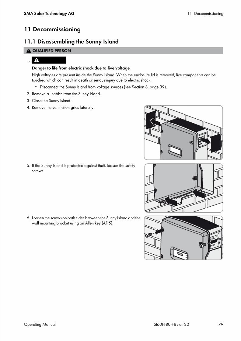
7/17/2019 Remote Control SI60H Operating Manual
http://slidepdf.com/reader/full/remote-control-si60h-operating-manual 79/128
SMA Solar Technology AG 11 Decommissioning
Operating Manual SI60H-80H-BE-en-20 79
11 Decommissioning
11.1 Disassembling the Sunny Island
2. Remove all cables from the Sunny Island.
3. Close the Sunny Island.
4. Remove the ventilation grids laterally.
5. If the Sunny Island is protected against theft, loosen the safetyscrews.
6. Loosen the screws on both sides between the Sunny Island and thewall mounting bracket using an Allen key (AF 5).
1.
Danger to life from electric shock due to live voltage
High voltages are present inside the Sunny Island. When the enclosure lid is removed, live components can betouched which can result in death or serious injury due to electric shock.
• Disconnect the Sunny Island from voltage sources (see Section 8, page 39).
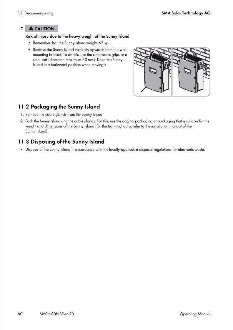
7/17/2019 Remote Control SI60H Operating Manual
http://slidepdf.com/reader/full/remote-control-si60h-operating-manual 80/128
11 Decommissioning SMA Solar Technology AG
80 SI60H-80H-BE-en-20 Operating Manual
11.2 Packaging the Sunny Island
1. Remove the cable glands from the Sunny Island.2. Pack the Sunny Island and the cable glands. For this, use the original packaging or packaging that is suitable for the
weight and dimensions of the Sunny Island (for the technical data, refer to the installation manual of theSunny Island).
11.3 Disposing of the Sunny Island• Dispose of the Sunny Island in accordance with the locally applicable disposal regulations for electronic waste.
7.
Risk of injury due to the heavy weight of the Sunny Island
• Remember that the Sunny Island weighs 63 kg.
• Remove the Sunny Island vertically upwards from the wallmounting bracket. To do this, use the side recess grips or asteel rod (diameter: maximum 30 mm). Keep the SunnyIsland in a horizontal position when moving it.
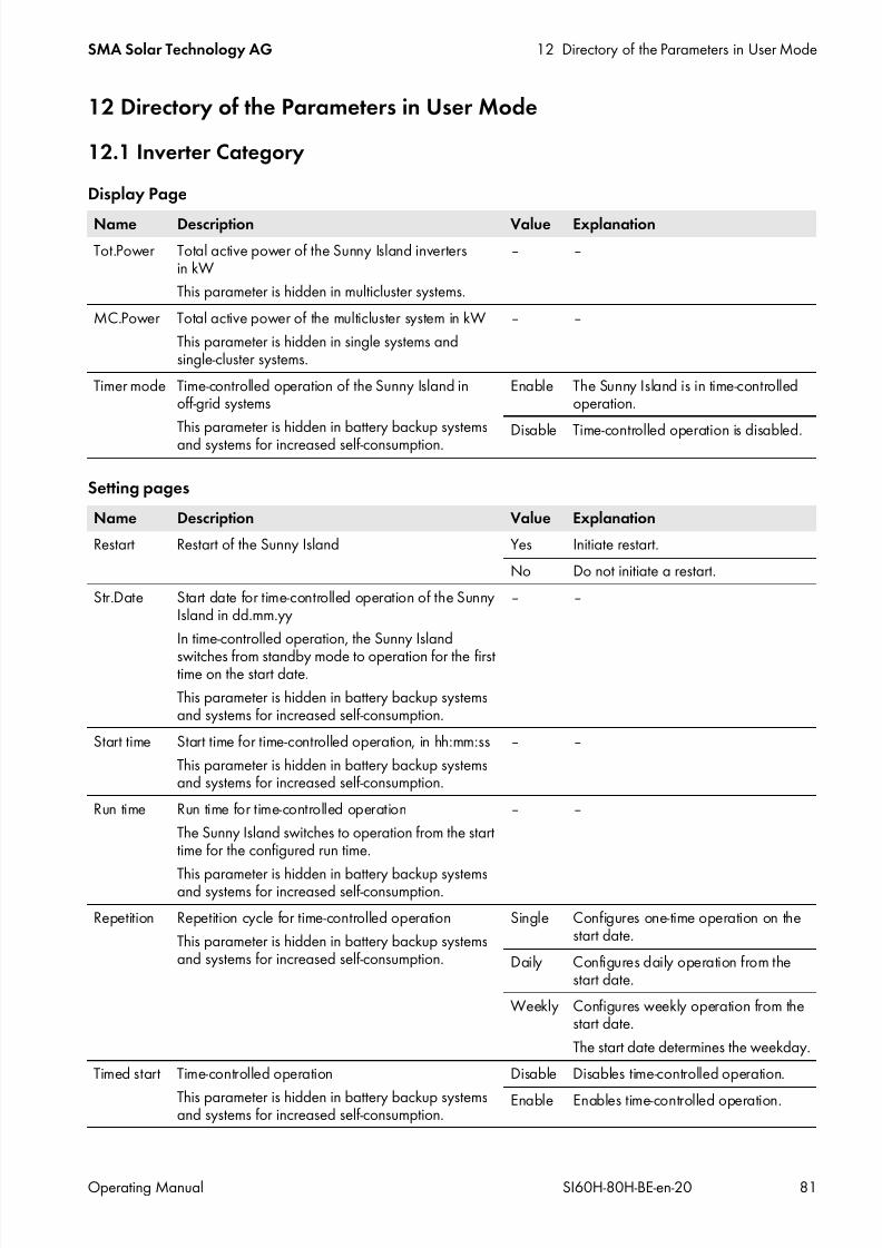
7/17/2019 Remote Control SI60H Operating Manual
http://slidepdf.com/reader/full/remote-control-si60h-operating-manual 81/128
SMA Solar Technology AG 12 Directory of the Parameters in User Mode
Operating Manual SI60H-80H-BE-en-20 81
12 Directory of the Parameters in User Mode
12.1 Inverter Category
Display Page
Setting pages
Name Description Value Explanation
Tot.Power Total active power of the Sunny Island invertersin kW
This parameter is hidden in multicluster systems.
‒ ‒
MC.Power Total active power of the multicluster system in kW
This parameter is hidden in single systems andsingle-cluster systems.
‒ ‒
Timer mode Time-controlled operation of the Sunny Island inoff-grid systems
This parameter is hidden in battery backup systemsand systems for increased self-consumption.
Enable The Sunny Island is in time-controlledoperation.
Disable Time-controlled operation is disabled.
Name Description Value Explanation
Restart Restart of the Sunny Island Yes Initiate restart.
No Do not initiate a restart.
Str.Date Start date for time-controlled operation of the SunnyIsland in dd.mm.yy
In time-controlled operation, the Sunny Island
switches from standby mode to operation for the firsttime on the start date.
This parameter is hidden in battery backup systemsand systems for increased self-consumption.
‒ ‒
Start time Start time for time-controlled operation, in hh:mm:ss
This parameter is hidden in battery backup systemsand systems for increased self-consumption.
‒ ‒
Run time Run time for time-controlled operation
The Sunny Island switches to operation from the starttime for the configured run time.
This parameter is hidden in battery backup systemsand systems for increased self-consumption.
‒ ‒
Repetition Repetition cycle for time-controlled operation
This parameter is hidden in battery backup systemsand systems for increased self-consumption.
Single Configures one-time operation on thestart date.
Daily Configures daily operation from thestart date.
Weekly Configures weekly operation from thestart date.
The start date determines the weekday.
Timed start Time-controlled operation
This parameter is hidden in battery backup systemsand systems for increased self-consumption.
Disable Disables time-controlled operation.
Enable Enables time-controlled operation.

7/17/2019 Remote Control SI60H Operating Manual
http://slidepdf.com/reader/full/remote-control-si60h-operating-manual 82/128
12 Directory of the Parameters in User Mode SMA Solar Technology AG
82 SI60H-80H-BE-en-20 Operating Manual
12.2 Battery Category
Display Pages
Setting Page
Name Description Value Explanation
StateOfCharge Current battery state of charge in % ‒ ‒
Voltage Battery voltage in V ‒ ‒
PowerOut Current discharge power of the battery in kW ‒ If the value is positive, the battery isdischarging. If the value is negative, thebattery is charging.
Mode Current charging process Boost Boost charge is enabled.
Full Full charge is enabled.
Float Float charge is enabled.
Equalize Equalization charge is enabled.
Silent In the silent mode, the Sunny Islandswitches to standby to save energywhen the battery is fully charged.
Remain time Remaining time of current charging processin hh:mm:ss
‒ ‒
Next equal Remaining time until next equalization chargein days
‒ ‒
Health (SOH) Ratio of currently usable capacity to nominalcapacity, in %
‒ ‒
Cycle Nominal energy throughputs of the batteryA nominal energy throughput is the calculatedresult of one full charge and discharge of thebattery.
‒ ‒
Name Description Value Explanation
Equalize Manual equalization charge Start Starts the equalization charge.
Stop Stops the equalization charge.
Idle Remains idle until the requirements foran equalization charge are met.
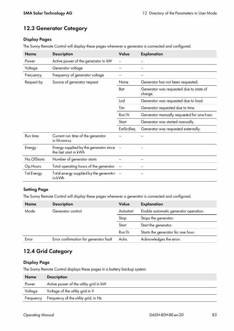
7/17/2019 Remote Control SI60H Operating Manual
http://slidepdf.com/reader/full/remote-control-si60h-operating-manual 83/128
SMA Solar Technology AG 12 Directory of the Parameters in User Mode
Operating Manual SI60H-80H-BE-en-20 83
12.3 Generator Category
Display Pages
The Sunny Remote Control will display these pages whenever a generator is connected and configured.
Setting Page
The Sunny Remote Control will display these pages whenever a generator is connected and configured.
12.4 Grid Category
Display Page
The Sunny Remote Control displays these pages in a battery backup system.
Name Description Value Explanation
Power Active power of the generator in kW ‒ ‒
Voltage Generator voltage ‒ ‒
Frequency Frequency of generator voltage ‒ ‒
Request by Source of generator request None Generator has not been requested.
Bat Generator was requested due to state ofcharge.
Lod Generator was requested due to load.
Tim Generator requested due to time.
Run1h Generator manually requested for one hour.Start Generator was started manually.
ExtSrcReq Generator was requested externally.
Run time Current run time of the generatorin hh:mm:ss
‒ ‒
Energy Energy supplied by the generator sincethe last start in kWh
‒ ‒
No.OfStarts Number of generator starts ‒ ‒
Op.Hours Total operating hours of the generator ‒ ‒
Tot.Energy Total energy supplied by the generatorin kWh ‒ ‒
Name Description Value Explanation
Mode Generator control Autostart Enable automatic generator operation.
Stop Stops the generator.
Start Start the generator.
Run1h Starts the generator for one hour.Error Error confirmation for generator fault Ackn. Acknowledges the error.
Name Description
Power Active power of the utility grid in kW
Voltage Voltage of the utility grid in VFrequency Frequency of the utility grid, in Hz
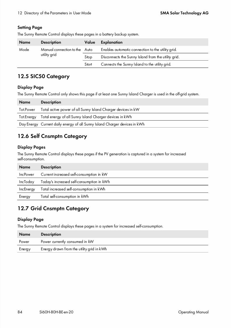
7/17/2019 Remote Control SI60H Operating Manual
http://slidepdf.com/reader/full/remote-control-si60h-operating-manual 84/128
12 Directory of the Parameters in User Mode SMA Solar Technology AG
84 SI60H-80H-BE-en-20 Operating Manual
Setting Page
The Sunny Remote Control displays these pages in a battery backup system.
12.5 SIC50 Category
Display Page
The Sunny Remote Control only shows this page if at least one Sunny Island Charger is used in the off-grid system.
12.6 Self Cnsmptn Category
Display Pages
The Sunny Remote Control displays these pages if the PV generation is captured in a system for increasedself-consumption.
12.7 Grid Cnsmptn Category
Display Page
The Sunny Remote Control displays these pages in a system for increased self-consumption.
Name Description Value Explanation
Mode Manual connection to theutility grid
Auto Enables automatic connection to the utility grid.
Stop Disconnects the Sunny Island from the utility grid.Start Connects the Sunny Island to the utility grid.
Name Description
Tot.Power Total active power of all Sunny Island Charger devices in kW
Tot.Energy Total energy of all Sunny Island Charger devices in kWh
Day Energy Current daily energy of all Sunny Island Charger devices in kWh
Name Description
IncPower Current increased self-consumption in kW
IncToday Today's increased self-consumption in kWh
IncEnergy Total increased self-consumption in kWh
Energy Total self-consumption in kWh
Name Description
Power Power currently consumed in kW
Energy Energy drawn from the utility grid in kWh

7/17/2019 Remote Control SI60H Operating Manual
http://slidepdf.com/reader/full/remote-control-si60h-operating-manual 85/128
SMA Solar Technology AG 12 Directory of the Parameters in User Mode
Operating Manual SI60H-80H-BE-en-20 85
12.8 Grid Feed Category
Display Page
The Sunny Remote Control displays these pages in a system for increased self-consumption.
12.9 Loads Category
Display Page
The Sunny Remote Control displays these pages if the PV generation is captured in a system for increasedself-consumption.
12.10 PV System Category
Display Page
The Sunny Remote Control displays these pages if the PV generation is captured in a system for increasedself-consumption.
12.11 System Category
Display Page
Name Description
Power Current feed-in power in kW
Energy Energy fed in in kWh
Name Description
Power Current power of the loads in kW
Energy Power consumed by the loads in kWh
ConState Reserved for future applications
Name Description
Power Current power of the PV system in kW
Energy Power fed in by the PV system in kWh
ConState Reserved for future applications
Name Description Value ExplanationType Configuration of the system 1Phase1 Single-phase system with 1 Sunny Island
1Phase2 Single-phase system with 2 Sunny Islandinverters
1Phase3 Single-phase system with 3 Sunny Islandinverters
3Phase Three-phase system
MC-Box Multicluster system
Box Type Type of connected Multicluster Box
This parameter is only shown in multiclustersystems.
MC-Box-6 Multicluster Box 6
MC-Box-12 Multicluster Box 12MC-Box-36 Multicluster Box 36

7/17/2019 Remote Control SI60H Operating Manual
http://slidepdf.com/reader/full/remote-control-si60h-operating-manual 86/128
12 Directory of the Parameters in User Mode SMA Solar Technology AG
86 SI60H-80H-BE-en-20 Operating Manual
12.12 Time Category
Display Page
Setting Page
12.13 Identity Category
Display Page
12.14 Password Category
Display Page
Setting Page
Device Type of cluster
This parameter is only shown in multiclustersystems.
MainClst Sunny Remote Control is connected to themain cluster.
ExtnClst The Sunny Remote Control is connected to theextension cluster.
Name Description
Date Date in dd.mm.yyyy
Time Time in hh:mm:ss
Name Description ExplanationDate Date in dd.mm.yyyy Set the date.
Time Time in hh:mm:ss Set the time.
Name Description
Serial No. Serial number
Firmware Firmware version
Name Description Value Explanation
Level Current password level User Sunny Remote Control is in user mode.
Name Description
Set Enter the installer password.
Runtime Displays the operating hours
Name Description Value Explanation

7/17/2019 Remote Control SI60H Operating Manual
http://slidepdf.com/reader/full/remote-control-si60h-operating-manual 87/128
SMA Solar Technology AG 13 Directory of the Parameters in Installer Mode and Expert Mode
Operating Manual SI60H-80H-BE-en-20 87
13 Directory of the Parameters in Installer Mode and Expert Mode
13.1 Display Values
13.1.1 Inverter (110#)
111# Total
112# Device
No. Name Description
111.01 TotInvPwrAt Total active power of the Sunny Island inverters in a cluster in kW
111.02 TotInvCur Total current of the Sunny Island inverters in a cluster in A
111.03 TotInvPwrRt Total reactive power of the Sunny Island inverters in a cluster in kvar (expert mode)
111.05 TotLodPwr Total current active power of the loads in a cluster in kW
111.06 TotMccLodPwr Total current active power of the loads in a multicluster system in kW
No. Name Description Value (plain textno.)
Explanation
112.01 InvOpStt Operating state of the Sunny Island Init (1) Initialization
Startup (2) Switch from standbyto operation
Standby (3) Standby
Run (4) Operation
I-Loop (5) Current-controlledgenerator operation
Error (6) Error status
112.02 InvPwrAt Active power of the Sunny Island in kW ‒ ‒
112.03 InvVtg Voltage of the Sunny Island in V ‒ ‒
112.04 InvCur Current of the Sunny Island in A ‒ ‒
112.05 InvFrq Voltage frequency of the Sunny Island in Hz ‒ ‒
112.06 InvPwrRt Reactive power of the Sunny Island in kvar (expert
mode)
‒ ‒
112.07 Rly1Stt Status of multifunction relay 1 Off Multifunction relay isdeactivated.
On Multifunction relay isactivated.
112.08 Rly2Stt State of multifunction relay 2 Off Multifunction relay isdeactivated.
On Multifunction relay isactivated.
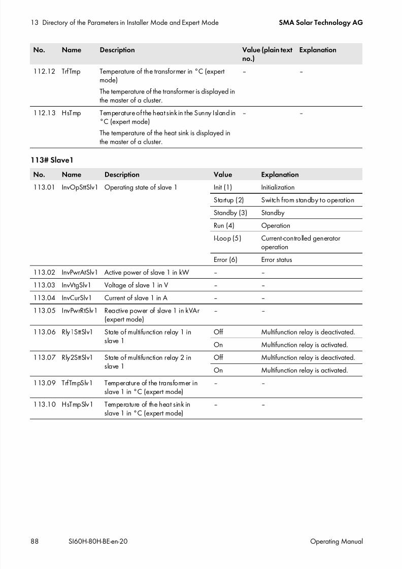
7/17/2019 Remote Control SI60H Operating Manual
http://slidepdf.com/reader/full/remote-control-si60h-operating-manual 88/128
13 Directory of the Parameters in Installer Mode and Expert Mode SMA Solar Technology AG
88 SI60H-80H-BE-en-20 Operating Manual
113# Slave1
112.12 TrfTmp Temperature of the transformer in °C (expertmode)
The temperature of the transformer is displayed in
the master of a cluster.
‒ ‒
112.13 HsTmp Temperature of the heat sink in the Sunny Island in°C (expert mode)
The temperature of the heat sink is displayed inthe master of a cluster.
‒ ‒
No. Name Description Value Explanation
113.01 InvOpSttSlv1 Operating state of slave 1 Init (1) Initialization
Startup (2) Switch from standby to operationStandby (3) Standby
Run (4) Operation
I-Loop (5) Current-controlled generatoroperation
Error (6) Error status
113.02 InvPwrAtSlv1 Active power of slave 1 in kW ‒ ‒
113.03 InvVtgSlv1 Voltage of slave 1 in V ‒ ‒
113.04 InvCurSlv1 Current of slave 1 in A ‒ ‒113.05 InvPwrRtSlv1 Reactive power of slave 1 in kVAr
(expert mode)‒ ‒
113.06 Rly1SttSlv1 State of multifunction relay 1 inslave 1
Off Multifunction relay is deactivated.
On Multifunction relay is activated.
113.07 Rly2SttSlv1 State of multifunction relay 2 inslave 1
Off Multifunction relay is deactivated.
On Multifunction relay is activated.
113.09 TrfTmpSlv1 Temperature of the transformer inslave 1 in °C (expert mode)
‒ ‒
113.10 HsTmpSlv1 Temperature of the heat sink inslave 1 in °C (expert mode)
‒ ‒
No. Name Description Value (plain textno.)
Explanation

7/17/2019 Remote Control SI60H Operating Manual
http://slidepdf.com/reader/full/remote-control-si60h-operating-manual 89/128
SMA Solar Technology AG 13 Directory of the Parameters in Installer Mode and Expert Mode
Operating Manual SI60H-80H-BE-en-20 89
114# Slave2
13.1.2 Battery (120#)
No. Name Description Value Explanation
114.01 InvOpSttSlv2 Operating state of slave 2 Init (1) Initialization
Startup (2) Switch from standby to operation
Standby (3) StandbyRun (4) Operation
I-Loop (5) Current-controlled generatoroperation
Error (6) Error status
114.02 InvPwrAtSlv2 Active power of slave 2 in kW ‒ ‒
114.03 InvVtgSlv2 Voltage of slave 2 in V ‒ ‒
114.04 InvCurSlv2 Current of slave 2 in A ‒ ‒
114.05 InvPwrRtSlv2 Reactive power of slave 2 in kVAr(expert mode) ‒ ‒
114.06 Rly1SttSlv2 State of multifunction relay 1 inslave 2
Off Multifunction relay is deactivated.
On Multifunction relay is activated.
114.07 Rly2SttSlv2 State of multifunction relay 2 inslave 2
Off Multifunction relay is deactivated.
On Multifunction relay is activated.
114.09 TrfTmpSlv2 Temperature of the transformer inslave 2 in °C (expert mode)
‒ ‒
114.10 HsTmpSlv2 Temperature of the heat sink in
slave 2 in °C (expert mode)
‒ ‒
No. Name Description Value (plaintext no.)
Explanation
120.01 BatSoc State of charge of the battery (SOC) based on thenominal battery capacity in %
0% to 100% ‒
120.02 BatVtg Battery voltage in V ‒ ‒
120.03 BatChrgVtg Charging voltage setpoint in V ‒ ‒
120.04 AptTmRmg Remaining absorption time upon completion ofthe active charging process 120.05 BatChrgOp in hh:mm:ss
‒ ‒
120.05 BatChrgOp Active charging process Boost (1) Fast charge
Full (2) Full charge
Float (3;7) Float charge
Equalize (4;5) Equalization charge
Silent (6;8) Silent mode active
120.06 TotBatCur Total battery current of the cluster in A ‒ ‒120.07 BatTmp Battery temperature in °C ‒ ‒
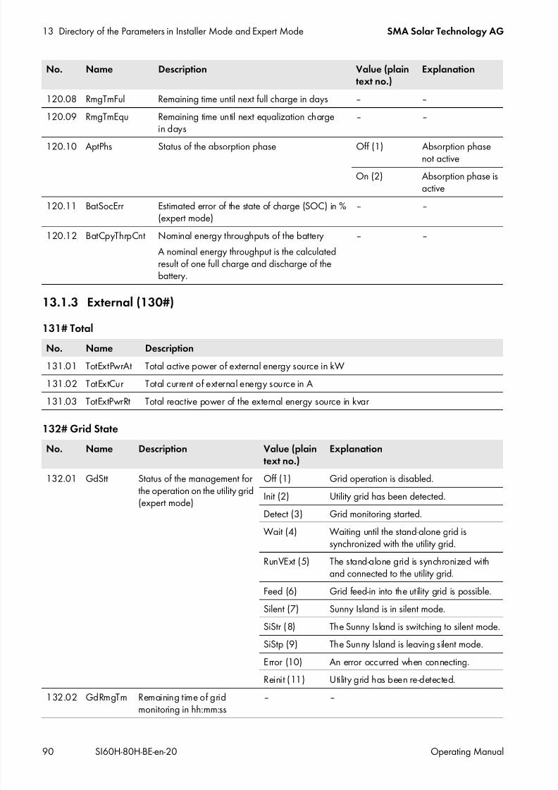
7/17/2019 Remote Control SI60H Operating Manual
http://slidepdf.com/reader/full/remote-control-si60h-operating-manual 90/128
13 Directory of the Parameters in Installer Mode and Expert Mode SMA Solar Technology AG
90 SI60H-80H-BE-en-20 Operating Manual
13.1.3 External (130#)
131# Total
132# Grid State
120.08 RmgTmFul Remaining time until next full charge in days ‒ ‒
120.09 RmgTmEqu Remaining time until next equalization chargein days
‒ ‒
120.10 AptPhs Status of the absorption phase Off (1) Absorption phasenot active
On (2) Absorption phase isactive
120.11 BatSocErr Estimated error of the state of charge (SOC) in %(expert mode)
‒ ‒
120.12 BatCpyThrpCnt Nominal energy throughputs of the battery
A nominal energy throughput is the calculatedresult of one full charge and discharge of the
battery.
‒ ‒
No. Name Description
131.01 TotExtPwrAt Total active power of external energy source in kW
131.02 TotExtCur Total current of external energy source in A
131.03 TotExtPwrRt Total reactive power of the external energy source in kvar
No. Name Description Value (plaintext no.)
Explanation
132.01 GdStt Status of the management forthe operation on the utility grid(expert mode)
Off (1) Grid operation is disabled.
Init (2) Utility grid has been detected.
Detect (3) Grid monitoring started.
Wait (4) Waiting until the stand-alone grid issynchronized with the utility grid.
RunVExt (5) The stand-alone grid is synchronized withand connected to the utility grid.
Feed (6) Grid feed-in into the utility grid is possible.
Silent (7) Sunny Island is in silent mode.
SiStr (8) The Sunny Island is switching to silent mode.
SiStp (9) The Sunny Island is leaving silent mode.
Error (10) An error occurred when connecting.
Reinit (11) Utility grid has been re-detected.
132.02 GdRmgTm Remaining time of gridmonitoring in hh:mm:ss
‒ ‒
No. Name Description Value (plaintext no.)
Explanation

7/17/2019 Remote Control SI60H Operating Manual
http://slidepdf.com/reader/full/remote-control-si60h-operating-manual 91/128
SMA Solar Technology AG 13 Directory of the Parameters in Installer Mode and Expert Mode
Operating Manual SI60H-80H-BE-en-20 91
133# Gen State
134# Device
No. Name Description Value (plaintext no.)
Explanation
133.01 GnDmdSrc Source of generator request None (1) No request
Bat (2) State-of-charge-dependent requestLod (3) Load-dependent request
Tim (4) Time-controlled request
Run1h (5) Requested for 1 hour
Start (6) Manually started
ExtSrcReq (7) External generator request
133.02 GnStt Status of the generatormanagement
Off (1) Deactivated generator operation
Init (2) Detecting generator
Ready (3) Waiting for request (ready)Warm (4) Warming up
Connect (5) Connecting
Run (6) Operation
Retry (7) Restarting
Disconnect (8) Disconnecting
Cool (9) Cooling down
Lock (10) Locked after operation
Fail (11) FailureFailLock (12) Locked after error
Reinit (13) Re-detection of the generator
133.03 GnRmgTm Remaining minimum run time of thegenerator in hh:mm:ss
‒ ‒
133.04 GnRnStt Status of generator feedback(expert mode)
Off (1) Off
On (2) On
No. Name Description
134.01 ExtPwrAt Active power of external energy source in kW
134.02 ExtVtg Voltage of external energy source in V
134.03 ExtCur Current of external energy source in A
134.04 ExtFrq Frequency of external energy source in Hz
134.05 ExtPwrRt Reactive power of external energy source in kVAr (expert mode)
134.07 ExtLkRmgTm Minimum stop time in hh:mm:ss

7/17/2019 Remote Control SI60H Operating Manual
http://slidepdf.com/reader/full/remote-control-si60h-operating-manual 92/128
13 Directory of the Parameters in Installer Mode and Expert Mode SMA Solar Technology AG
92 SI60H-80H-BE-en-20 Operating Manual
135# Slave1
136# Slave2
13.1.4 Charge Controller (140#)
141# SIC50 Total
142# SIC50 1
143# SIC50 2
No. Name Description
135.01 ExtPwrAtSlv1 Active power of external energy source slave 1 in kW
135.02 ExtVtgSlv1 Voltage of external energy source slave 1 in V
135.03 ExtCurSlv1 Current of external energy source slave 1 in A135.04 ExtPwrRtSlv1 Reactive power of external energy source slave 1 in kVAr (expert mode)
No. Name Description
136.01 ExtPwrAtSlv2 Active power of external energy source slave 2 in kW
136.02 ExtVtgSlv2 Voltage of external energy source slave 2 in V
136.03 ExtCurSlv2 Current of external energy source slave 2 in A
136.04 ExtPwrRtSlv2 Reactive power of external energy source slave 2 in kVAr (expert mode)
No. Name Description
141.01 TotSicEgyCntIn Total energy of all Sunny Island Charger devices in kWh
141.02 TotSicDyEgyCntIn Total daily energy of all Sunny Island Charger devices in kWh
141.03 TotSicPvPwr Total PV power of all Sunny Island Charger devices in W
141.04 TotSicBatCur Total battery current of all Sunny Island Charger devices in A
No. Name Description
142.01 Sic1EgyCntIn Total energy of Sunny Island Charger 1 in kWh
142.02 Sic1TdyEgyCntIn Daily energy of Sunny Island Charger 1 in kWh
142.03 Sic1PvPwr PV power of Sunny Island Charger 1 in W
142.04 Sic1PvVtg PV voltage of Sunny Island Charger 1 in V
142.05 Sic1BatVtg Battery voltage of Sunny Island Charger 1 in V (expert mode)
142.06 Sic1BatCur Battery current of Sunny Island Charger 1 in A (expert mode)
142.07 Sic1HsTmp Heat sink temperature of Sunny Island Charger 1 in °C (expert mode)
No. Name Description
143.01 Sic2EgyCntIn Total energy of Sunny Island Charger 2 in kWh
143.02 Sic2TdyEgyCntIn Daily energy of Sunny Island Charger 2 in kWh
143.03 Sic2PvPwr PV power of Sunny Island Charger 2 in W143.04 Sic2PvVtg PV voltage of Sunny Island Charger 2 in V

7/17/2019 Remote Control SI60H Operating Manual
http://slidepdf.com/reader/full/remote-control-si60h-operating-manual 93/128
SMA Solar Technology AG 13 Directory of the Parameters in Installer Mode and Expert Mode
Operating Manual SI60H-80H-BE-en-20 93
144# SIC50 3
145# SIC50 4
13.1.5 Compact (150#)
The menu 150# Compact displays multiple parameters from the following areas at a glance:
• Battery
• AC measured values of the Sunny Island
• Generator or battery backup grid• Status of the Sunny Island
Battery (Bat)
Figure 16: Overview of the menu Meters Compact for the battery
143.05 Sic2BatVtg Battery voltage of Sunny Island Charger 2 in V (expert mode)
143.06 Sic2BatCur Battery current of Sunny Island Charger 2 in A (expert mode)
143.07 Sic2HsTmp Heat sink temperature of Sunny Island Charger 2 in °C (expert mode)
No. Name Description
144.01 Sic3EgyCntIn Total energy of Sunny Island Charger 3 in kWh
144.02 Sic3TdyEgyCntIn Daily energy of Sunny Island Charger 3 in kWh
144.03 Sic3PvPwr PV power of Sunny Island Charger 3 in W
144.04 Sic3PvVtg PV voltage of Sunny Island Charger 3 in V
144.05 Sic3BatVtg Battery voltage of Sunny Island Charger 3 in V (expert mode)
144.06 Sic3BatCur Battery current of Sunny Island Charger 3 in A (expert mode)144.07 Sic3HsTmp Heat sink temperature of Sunny Island Charger 3 in °C (expert mode)
No. Name Description
145.01 Sic4EgyCntIn Total energy of Sunny Island Charger 4 in kWh
145.02 Sic4TdyEgyCntIn Daily energy of Sunny Island Charger 4 in kWh
145.03 Sic4PvPwr PV power of Sunny Island Charger 4 in W
145.04 Sic4PvVtg PV voltage of Sunny Island Charger 4 in V145.05 Sic4BatVtg Battery voltage of Sunny Island Charger 4 in V (expert mode)
145.06 Sic4BatCur Battery current of Sunny Island Charger 4 in A (expert mode)
145.07 Sic4HsTmp Heat sink temperature of Sunny Island Charger 4 in °C (expert mode)
No. Name Description

7/17/2019 Remote Control SI60H Operating Manual
http://slidepdf.com/reader/full/remote-control-si60h-operating-manual 94/128
13 Directory of the Parameters in Installer Mode and Expert Mode SMA Solar Technology AG
94 SI60H-80H-BE-en-20 Operating Manual
Measured AC Values of the Sunny Island (Inv)
Figure 17: Overview of the menu Meters Compact for the AC measured values of the Sunny Island
Generator or Battery Backup Grid (Ext)
Figure 18: Overview of the menu Meters Compact for the generator or the battery backup grid
Position Description Parameter
A State of charge of the battery (SOC) in % 120.01 BatSoc
B Estimated error of the state of charge in % 120.11 BatSocErr
C Battery temperature in °C 120.07 BatTmp
D Setpoint of the charge voltage in V 120.03 BatChrgVtgE Battery voltage in V 120.02 BatVtg
F Total battery current of the cluster in A 120.06 TotBatCur
Position Description Parameter
A Voltage of the Sunny Island in V 112.03 InvVtg
B Voltage frequency of the Sunny Island in Hz 112.05 InvFrq
C Reactive power of the inverter in kvar 112.06 InvPwrRt
D Active power of the inverter in kW 112.02 InvPwrAt
Position Description Parameter
A Voltage of the generator or the battery backup grid in V 134.02 ExtVtg
B Frequency of the generator or the battery backup grid in Hz 134.04 ExtFrq
C Reactive power of the generator or the battery backup grid in kvar 134.05 ExtPwrRt
D Active power of the generator or the battery backup grid in kW 134.01 ExtPwrAt
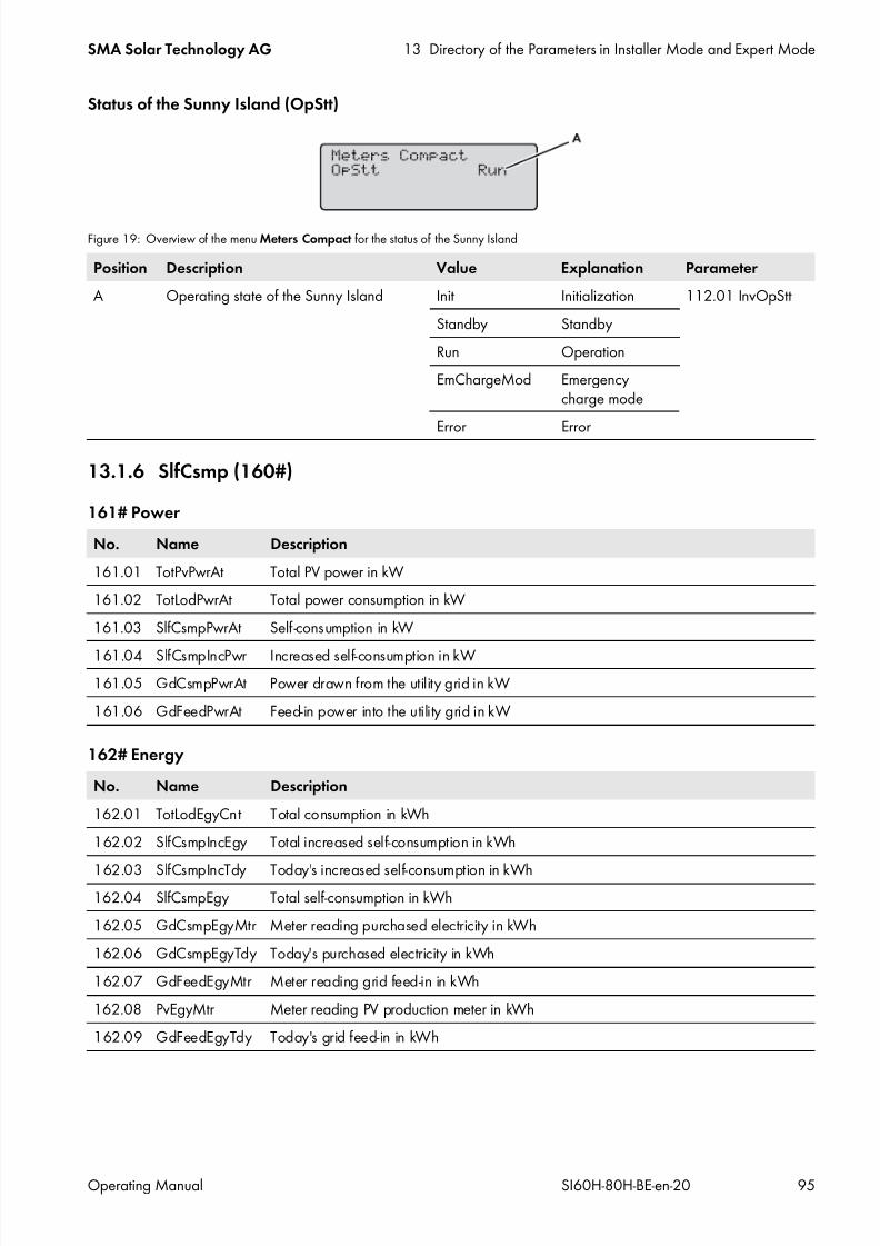
7/17/2019 Remote Control SI60H Operating Manual
http://slidepdf.com/reader/full/remote-control-si60h-operating-manual 95/128
SMA Solar Technology AG 13 Directory of the Parameters in Installer Mode and Expert Mode
Operating Manual SI60H-80H-BE-en-20 95
Status of the Sunny Island (OpStt)
Figure 19: Overview of the menu Meters Compact for the status of the Sunny Island
13.1.6 SlfCsmp (160#)
161# Power
162# Energy
Position Description Value Explanation Parameter
A Operating state of the Sunny Island Init Initialization 112.01 InvOpStt
Standby Standby
Run Operation
EmChargeMod Emergencycharge mode
Error Error
No. Name Description
161.01 TotPvPwrAt Total PV power in kW
161.02 TotLodPwrAt Total power consumption in kW
161.03 SlfCsmpPwrAt Self -consumption in kW
161.04 SlfCsmpIncPwr Increased self-consumption in kW161.05 GdCsmpPwrAt Power drawn from the utility grid in kW
161.06 GdFeedPwrAt Feed-in power into the utility grid in kW
No. Name Description
162.01 TotLodEgyCnt Total consumption in kWh
162.02 SlfCsmpIncEgy Total increased self-consumption in kWh
162.03 SlfCsmpIncTdy Today's increased self-consumption in kWh162.04 SlfCsmpEgy Total self-consumption in kWh
162.05 GdCsmpEgyMtr Meter reading purchased electricity in kWh
162.06 GdCsmpEgyTdy Today's purchased electricity in kWh
162.07 GdFeedEgyMtr Meter reading grid feed-in in kWh
162.08 PvEgyMtr Meter reading PV production meter in kWh
162.09 GdFeedEgyTdy Today's grid feed-in in kWh
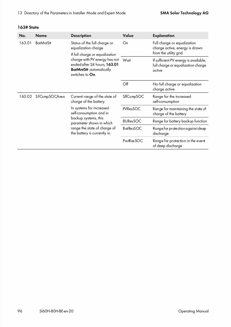
7/17/2019 Remote Control SI60H Operating Manual
http://slidepdf.com/reader/full/remote-control-si60h-operating-manual 96/128
13 Directory of the Parameters in Installer Mode and Expert Mode SMA Solar Technology AG
96 SI60H-80H-BE-en-20 Operating Manual
163# State
No. Name Description Value Explanation
163.01 BatMntStt Status of the full charge orequalization charge
If full charge or equalizationcharge with PV energy has notended after 24 hours, 163.01BatMntStt automaticallyswitches to On.
On Full charge or equalizationcharge active, energy is drawnfrom the utility grid
Wait If sufficient PV energy is available,full charge or equalization chargeactive
Off No full charge or equalizationcharge active
163.02 SlfCsmpSOCArea Current range of the state ofcharge of the battery
In systems for increased
self-consumption and inbackup systems, thisparameter shows in whichrange the state of charge ofthe battery is currently in.
SlfCsmpSOC Range for the increasedself-consumption
PVResSOC Range for maintaining the state of
charge of the batteryBUResSOC Range for battery backup function
BatResSOC Range for protection against deepdischarge
ProtResSOC Range for protection in the eventof deep discharge

7/17/2019 Remote Control SI60H Operating Manual
http://slidepdf.com/reader/full/remote-control-si60h-operating-manual 97/128
SMA Solar Technology AG 13 Directory of the Parameters in Installer Mode and Expert Mode
Operating Manual SI60H-80H-BE-en-20 97
13.2 Adjustable Parameters
13.2.1 Inverter (210#)
13.2.2 Battery (220#)
221# Property
No. Name Description Value Explanation Defaultvalue
210.01 InvVtgNom Nominal voltage of the Sunny Island inV
172.5 V to264.5 V
230 V / 50 Hz 230.0 V
220 V / 60 Hz 220.0 V
210.02 InvFrqNom Nominal frequency of the Sunny Islandin Hz (expert mode)
40 Hz to70 Hz
230 V / 50 Hz 50 Hz
220 V / 60 Hz 60 Hz
210.03 InvChrgCurMax Maximum AC charging current in A(expert mode)
0 A to 26.1 A SI 8.0H 26.1 A
0 A to 20.0 A SI 6.0H 20.0 A
Damage to the battery due to incorrect settings
Settings of the parameters in the menu 220# Battery influence the charging behavior of the Sunny Island. Incorrectsettings lead to premature aging of the battery.
• Ensure that the values recommended by the battery manufacturer are set (refer to the technical data of the batteryin the manufacturer documentation).
No. Name Description Value Explanation Defaultvalue
221.01 BatTyp Battery type VRLA Valve-regulatedlead–acidbattery withimmobilizedelectrolyte in gelor glass mat
‒
FLA Valve-regulatedlead–acidbattery with
liquid electrolyteLiIon Lithium-ion
battery
221.02 BatCpyNom Nominal battery capacity C10 in Ah 100 Ah to 10,000 Ah VRLA, FLA 166 Ah
50 Ah to 10,000 Ah Lithium-ion
221.03 BatVtgNom Battery nominal voltage in V 40.0 V to 48.0 V ‒ ‒
221.04 BatTmpMax Maximum battery temperature in °C(expert mode)
221.05 BatTmpStrto 50°C
‒ 40°C
221.05 BatTmpStr Start temperature after exceedingthe maximum battery temperaturein °C (expert mode)
0°C to221.04 BatTmpMax
‒ 35°C

7/17/2019 Remote Control SI60H Operating Manual
http://slidepdf.com/reader/full/remote-control-si60h-operating-manual 98/128
13 Directory of the Parameters in Installer Mode and Expert Mode SMA Solar Technology AG
98 SI60H-80H-BE-en-20 Operating Manual
222# Chargemode
221.06 BatWirRes Resistance of the battery cable in mΩ(expert mode)
0 m Ω to 100 m Ω ‒ 0 m Ω
221.07 BatFanTmpStr Start temperature for the BatFan
function of the multifunction relayin °C
20°C to
221.04 BatTmpMax
‒ 40°C
No. Name Description Value Explanation Defaultvalue
222.01 BatChrgCurMax Maximum battery charging current in A 10 A to900 A
‒ 900 A
222.02 AptTmBoost Absorption time of the boost charge inminutes (expert mode)
1 min to600 min
For VRLA 180 min
For FLA 90 min222.03 AptTmFul Absorption time for full charge in hours
(expert mode)1.0 h to 20.0h
‒ 6.0 h
222.04 AptTmEqu Absorption time for equalization chargein hours (expert mode)
1.0 h to 48.0h
‒ 12.0 h
222.05 CycTmFul Cycle time of full charge in days (expertmode)
1 d to 180 d ‒ 14 d
222.06 CycTmEqu Cycle time of equalization charge in days(expert mode)
7 d to 365 d ‒ 90 d
222.07 ChrgVtgBoost Setpoint of the cell voltage at boost chargein V (expert mode) 2.20 V to2.70 V VRLA 2.40 VFLA, Off-Grid 2.40 V
FLA, On-Grid 2.55 V
222.08 ChrgVtgFul Cell voltage setpoint for full charge in V(expert mode)
2.30 V to2.70 V
Off-Grid 2.45 V
On-Grid 2.50 V
222.09 ChrgVtgEqu Cell voltage setpoint for equalizationcharge in V (expert mode)
2.30 V to2.70 V
Off-Grid 2.45 V
VRLA,On-Grid
2.55 V
FLA, On-Grid 2.50 V222.10 ChrgVtgFlo Cell voltage setpoint for float charge in V
(expert mode)2.20 V to2.40 V
‒ 2.25 V
222.11 BatTmpCps Battery temperature compensation in mV ⁄ °C (expert mode)
0.0 mV ⁄ °C to10.0 mV ⁄ °C
‒ 4.0 mV ⁄ °C
222.12 AutoEquChrgEna Automatic equalization charge (expertmode)
Disable Disable Enable
Enable Enable
222.13 BatChrgVtgMan Manual setpoint of the battery chargingvoltage with disabled battery managementin V (expert mode)
41.0 V to63.0 V
‒ 54.0 V
No. Name Description Value Explanation Defaultvalue

7/17/2019 Remote Control SI60H Operating Manual
http://slidepdf.com/reader/full/remote-control-si60h-operating-manual 99/128
SMA Solar Technology AG 13 Directory of the Parameters in Installer Mode and Expert Mode
Operating Manual SI60H-80H-BE-en-20 99
223# Protection
224# BatSilentmode
225# Current Sensor
No. Name Description Value Defaultvalue
223.01 BatPro1TmStr Start time of the battery protection mode level 1 in hh:mm:ss(expert mode)
00:00:00 to23:59:59
22:00:00
223.02 BatPro1TmStp Stop time of the battery protection mode level 1 in hh:mm:ss(expert mode)
00:00:00 to23:59:59
06:00:00
223.03 BatPro2TmStr Start time of the battery protection mode level 2 in hh:mm:ss(expert mode)
00:00:00 to23:59:59
17:00:00
223.04 BatPro2TmStp Stop time of the battery protection mode level 2 in hh:mm:ss(expert mode)
00:00:00 to23:59:59
09:00:00
223.05 BatPro1Soc SOC for battery protection mode level 1 in % (expert mode) 0% to 70% 20%
223.06 BatPro2Soc SOC for battery protection mode level 2 in % (expert mode) 0% to 70% 15%
223.07 BatPro3Soc SOC for battery protection mode level 3 in % (expert mode) 0% to 70% 10%
No. Name Description Value Explanation Defaultvalue
224.01 BatSilentEna Silent mode on utility grid (expert mode) Disable Disable Disable
Enable Enable
224.02 BatSilentTmFlo Maximum time for float charge until switch tosilent mode in hours (expert mode)
1 h to 48 h ‒ 3 h
224.03 BatSilentTmMax Maximum time for standby in silent modeuntil switch to float charge in hours (expertmode)
1 h to 168 h ‒ 12 h
No. Name Description Value Explanation Default value
225.01 BatCurSnsTyp Type of battery currentsensor
None No sensor isconnected
None
60 mV 60 mV type
50 mV 50 mV type225.02 BatCurGain60 60 mV type in A ⁄ 60 mV 0 A ⁄ 60 mV to
1,800 A ⁄ 60 mV
‒ 100 A ⁄ 60 mV
225.03 BatCurGain50 50 mV type in A ⁄ 50 mV 0 A ⁄ 50 mV to1,800 A ⁄ 50 mV
‒ 100 A ⁄ 50 mV
225.04 BatCurAutoCal Automatic calibration ofexternal battery currentsensor
Start Start automaticcalibration
‒

7/17/2019 Remote Control SI60H Operating Manual
http://slidepdf.com/reader/full/remote-control-si60h-operating-manual 100/128
13 Directory of the Parameters in Installer Mode and Expert Mode SMA Solar Technology AG
100 SI60H-80H-BE-en-20 Operating Manual
13.2.3 External/Backup (230#)
231# General
232# Grid Control
No. Name Description Value Explanation Defaultvalue
231.01 PvFeedTmStr Start time for PV grid feed-inin hh:mm:ss (expert mode)
00:00:00to23:59:59
‒ 04:00:00
231.02 PvFeedTmStp Stop time for PV grid feed-inin hh:mm:ss (expert mode)
00:00:00to23:59:59
‒ 22:00:00
231.03 ExtLkTm Lock time after reversepower or relay protectionin minutes (expert mode)
0 min to60 min
‒ 20 min
231.06 ExtSrc Generator and gridoperating mode
PvOnly Only AC sources in thestand-alone grid, no generatorin the off-grid system
‒
Gen Generator
Grid Utility grid
GenGrid Generator or util ity grid
231.14 AC2NSel Terminal at which the neutralconductor is connected toAC2.
N The neutral conductor isconnected to terminal N.
‒
NTT The neutral conductor isconnected to terminal NTT.
No. Name Description Value Explanation Defaultvalue
232.01 Country Country data set(protected bySMA Grid Guard)
Other Individual setting ‒
VDE-AR-4105 Code of PracticeVDE-AR-N 4105
−
AS4777 Standard AS4777
232.02 GdVtgMin Minimum line voltagein V (expert mode,protected bySMA Grid Guard)
172.50 V to210.01 InvVtgNom
230 V / 50 Hz 184.00 V
220 V / 60 Hz 194.00 V
232.03 GdVtgMax Maximum line voltagein V (expert mode,protected bySMA Grid Guard)
210.01 InvVtgNomto 264.50 V
230 V / 50 Hz 264.50 V
220 V / 60 Hz 242.00 V

7/17/2019 Remote Control SI60H Operating Manual
http://slidepdf.com/reader/full/remote-control-si60h-operating-manual 101/128
SMA Solar Technology AG 13 Directory of the Parameters in Installer Mode and Expert Mode
Operating Manual SI60H-80H-BE-en-20 101
232.04 GdCurNom Utility grid nominalcurrent in A
0.0 A to 50.0 A 1 Sunny Island 16.0 A
0.0 A to 100.0 A 2 Sunny Island invertersparalle
0.0 A to 150.0 A 3 Sunny Island invertersparallel
0.0 A to 50.0 A Three-phase
232.05 GdFrqNom Utility grid nominalfrequency in Hz (expertmode)
232.05 GdFrqMinto232.06 GdFrqMax
230 V / 50 Hz 50.00 Hz
220 V / 60 Hz 60.00 Hz
232.06 GdFrqMin Minimum powerfrequency in Hz (expertmode, protected by
SMA Grid Guard)
40.00 Hz to232.04 GdFrqNom
230 V / 50 Hz 47.50 Hz
220 V / 60 Hz 59.30 Hz
232.07 GdFrqMax Maximum powerfrequency in Hz (expertmode, protected bySMA Grid Guard)
232.05 GdFrqNomto 70.00 Hz
230 V / 50 Hz 51.50 Hz
220 V / 60 Hz 60.50 Hz
232.08 GdVldTm Minimum observationtime for line voltage andfrequency in thepermissible range forconnection in s (expertmode, protected by SMA
Grid Guard)
5 s to 900 s VDE-AR-N 4105AS4777
60 s
220 V / 60 Hz 300 s
232.09 GdMod Grid interface (expertmode)
GridCharge Charge on utility grid GridCharge
GridFeed Charge and feedbackon utility grid
232.10 GdRvPwr Permissible active powerof grid reverse powerin W (expert mode)
0 W to 5,000 W 1 Sunny Island orsingle-cluster system
100 W
0 W to 20,000 W Multicluster system 100 W
232.11 GdRvTm Permissible time for gridreverse power in s
(expert mode)
0 s to 60 s ‒ 5 s
232.16 GdAlSns Sensitivity of theanti-islanding detection(expert mode, protectedby SMA Grid Guard)
Low Low Normal
Medium Medium
Normal Normal
High High
232.38 GdVtgIncProEna Voltage increaseprotection (protected bySMA Grid Guard)
Enable Enable ‒
Disable Disable
No. Name Description Value Explanation Defaultvalue

7/17/2019 Remote Control SI60H Operating Manual
http://slidepdf.com/reader/full/remote-control-si60h-operating-manual 102/128
13 Directory of the Parameters in Installer Mode and Expert Mode SMA Solar Technology AG
102 SI60H-80H-BE-en-20 Operating Manual
232.39 GdVtgIncPro Limiting value for the tenminute average value ofthe voltage increase
protection (protected bySMA Grid Guard)
253.0 V to 264.5 V 230 V / 50 Hz 253.0 V
242.0 V to 253.0 V 220 V / 60 Hz 242.0 V
232.41 P-WCtlHzMod Frequency-dependentactive power limitation(expert mode, protectedby SMA Grid Guard)
Off Disable
WCtlHz Enable
232.42 P-HzStr Start frequency of theactive power limitation inHz (expert mode,
protected bySMA Grid Guard)
0.0 Hz to 5.0 Hz This values defines howmany Hz above210.02 InvFrqNom
the active powerlimitation starts.
0.2 Hz
232.43 P-HzStop End frequency of theactive power limitationin Hz (expert mode,protected bySMA Grid Guard)
0.0 Hz to 5.0 Hz This values defines howmany Hz above210.02 InvFrqNom the active powerlimitation stops.
0.2 Hz
232.44 P-WGra Increase of the activepower limitation in % /Hz (expert mode, protectedby SMA Grid Guard)
10% ⁄ Hz to 130% ⁄ Hz ‒ 40% ⁄ Hz
232.48 Q-VArMod Setpoint of thedisplacement powerfactor cos φ
(expert mode, protectedby SMA Grid Guard)
Off Disable
PFCnst Constant displacementpower factor cos φ
PFCtlW Automatic adjustmentof the displacementpower factordepending on thecurrent active power
232.49 PF-PF Setpoint of thedisplacement powerfactor cos φ at PFCnst (expert mode, protectedby SMA Grid Guard)
0.8 to 1 Code of PracticeVDE-AR-N 4105
0.9
Standard AS-4777 1
232.50 PF-PFExt Type of excitation of thedisplacement powerfactor cos φ at PFCnst (expert mode, protectedby SMA Grid Guard)
OvExt Overexcited UnExt
UnExt Underexcited
No. Name Description Value Explanation Defaultvalue

7/17/2019 Remote Control SI60H Operating Manual
http://slidepdf.com/reader/full/remote-control-si60h-operating-manual 103/128
SMA Solar Technology AG 13 Directory of the Parameters in Installer Mode and Expert Mode
Operating Manual SI60H-80H-BE-en-20 103
233# Grid Start
232.51 PF-PFStr Displacement powerfactor cos φ at the startpoint at PFCtlW (expert
mode, protected bySMA Grid Guard)
0.8 to 1 ‒ 1
232.52 PF-PFExtStr Excitation type at the startpoint at PFCtlW (expertmode, protected bySMA Grid Guard)
OvExt Overexcited OvExt
UnExt Underexcited
232.53 PF-WNomStr Proportion of themaximum active powerat the start point in % atPFCtlW (expert mode,protected by
SMA Grid Guard)
0% to 232.56PF-WNomStop
‒ 50%
232.54 PF-PFStop Displacement powerfactor cos φ at the endpoint at PFCtlW (expertmode, protected bySMA Grid Guard)
0.8 to 1.0 ‒ 0.9
232.55 PF-PFExtStop Excitation type at the endpoint at PFCtlW (expertmode, protected bySMA Grid Guard)
OvExt Overexcited UnExt
UnExt Underexcited
232.56 PF-WNomStop Proportion of themaximum active powerat the end point in % atPFCtlW (expert mode,protected bySMA Grid Guard)
232.52PF-WNomStr to100%
‒ 100%
No. Name Description Value Explanation Defaultvalue
233.01 GdSocEna Enable grid request basedon SOC (expert mode)
Disable Disable DisableEnable Enable
233.02 GdSocTm1Str SOC limiting value forconnection to the utility gridin interval 1 in % (expertmode)
Interval 1 begins at time233.06 GdTm1Str.
1% to233.03 GdSocTm1Stp
‒ 40%
No. Name Description Value Explanation Defaultvalue

7/17/2019 Remote Control SI60H Operating Manual
http://slidepdf.com/reader/full/remote-control-si60h-operating-manual 104/128
13 Directory of the Parameters in Installer Mode and Expert Mode SMA Solar Technology AG
104 SI60H-80H-BE-en-20 Operating Manual
233.03 GdSocTm1Stp SOC limiting value fordisconnection from the utilitygrid in interval 1 in % (expert
mode)Interval 1 begins at time233.06 GdTm1Str.
233.02 GdSocTm1Str to 95%
‒ 80%
233.04 GdSocTm2Str SOC limiting value forconnection to the utility gridin interval 2 in % (expertmode)
Interval 2 begins at time233.07 GdTm2Str.
1% to233.05 GdSocTm2Stp
‒ 40%
233.05 GdSocTm2Stp SOC limiting value for
disconnection from the utilitygrid in interval 2 in % (expertmode)
Interval 2 begins at time233.07 GdTm2Str.
233.04 GdSocTm2Str
to 95%
‒ 80%
233.06 GdTm1Str Start of interval 1 for gridrequest in hh:mm:ss (expertmode)
00:00:00 to 23:59:59 ‒ ‒
233.07 GdTm2Str Start of interval 2 for gridrequest in hh:mm:ss (expert
mode)
00:00:00 to 23:59:59 ‒ ‒
233.08 GdPwrEna Grid request based onpower (expert mode)
Disable Disable Disable
Enable Enable
233.09 GdPwrStr Grid request connectionpower limit in kW (expertmode)
233.10 GdPwrStp to300 kW
‒ 4.0 kW
233.10 GdPwrStp Grid request disconnectionpower limit in kW (expertmode)
0 kW to233.09 GdPwrStr
‒ 2.0 kW
233.11 GdStrChrgMod Connection to utility grid inconfigured charge mode(expert mode)
Off Off Equal
Full Full charge
Equal Equalizationcharge
Both Full andequalizationcharge
No. Name Description Value Explanation Defaultvalue
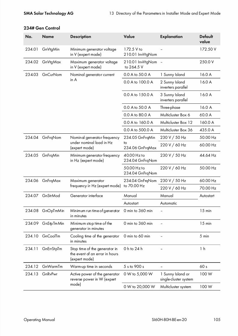
7/17/2019 Remote Control SI60H Operating Manual
http://slidepdf.com/reader/full/remote-control-si60h-operating-manual 105/128
SMA Solar Technology AG 13 Directory of the Parameters in Installer Mode and Expert Mode
Operating Manual SI60H-80H-BE-en-20 105
234# Gen Control
No. Name Description Value Explanation Defaultvalue
234.01 GnVtgMin Minimum generator voltagein V (expert mode)
172.5 V to210.01 InvVtgNom
‒ 172.50 V
234.02 GnVtgMax Maximum generator voltagein V (expert mode)
210.01 InvVtgNomto 264.5 V
‒ 250.0 V
234.03 GnCurNom Nominal generator currentin A
0.0 A to 50.0 A 1 Sunny Island 16.0 A
0.0 A to 100.0 A 2 Sunny Islandinverters parallel
16.0 A
0.0 A to 150.0 A 3 Sunny Islandinverters parallel
16.0 A
0.0 A to 50.0 A Three-phase 16.0 A
0.0 A to 80.0 A Multicluster Box 6 60.0 A
0.0 A to 160.0 A Multicluster Box 12 160.0 A
0.0 A to 500.0 A Multicluster Box 36 435.0 A
234.04 GnFrqNom Nominal generator frequencyunder nominal load in Hz(expert mode)
234.05 GnFrqMinto234.06 GnFrqMax
230 V / 50 Hz 50.00 Hz
220 V / 60 Hz 60.00 Hz
234.05 GnFrqMin Minimum generator frequencyin Hz (expert mode)
40.00 Hz to234.04 GnFrqNom
230 V / 50 Hz 44.64 Hz
50.00 Hz to234.04 GnFrqNom
220 V / 60 Hz 50.00 Hz
234.06 GnFrqMax Maximum generatorfrequency in Hz (expert mode)
234.04 GnFrqNomto 70.00 Hz
230 V / 50 Hz 60.00 Hz
220 V / 60 Hz 70.00 Hz
234.07 GnStrMod Generator interface Manual Manual Autostart
Autostart Automatic
234.08 GnOpTmMin Minimum run time of generatorin minutes
0 min to 360 min ‒ 15 min
234.09 GnStpTmMin Minimum stop time of thegenerator in minutes
0 min to 360 min ‒ 15 min
234.10 GnCoolTm Cooling time of the generatorin minutes
0 min to 60 min ‒ 5 min
234.11 GnErrStpTm Stop time of the generator inthe event of an error in hours(expert mode)
0 h to 24 h ‒ 1 h
234.12 GnWarmTm Warm-up time in seconds 5 s to 900 s ‒ 60 s
234.13 GnRvPwr Active power of the generatorreverse power in W (expertmode)
0 W to 5,000 W 1 Sunny Island orsingle-cluster system
100 W
0 W to 20,000 W Multicluster system 100 W

7/17/2019 Remote Control SI60H Operating Manual
http://slidepdf.com/reader/full/remote-control-si60h-operating-manual 106/128
13 Directory of the Parameters in Installer Mode and Expert Mode SMA Solar Technology AG
106 SI60H-80H-BE-en-20 Operating Manual
235# Gen Start
234.14 GnRvTm Permissible time for reversepower or reverse current, in s(expert mode)
0 s to 900 s ‒ 30 s
234.15 GnCtlMod Generator control (expertmode)
The generator control limits theconsumption of generatorcurrent.
Cur Fixed limiting valuefor current limitation
Cur
CurFrq Frequency-dependentcurrent limitation
234.20 GnAlSns Anti-islanding sensitivity(expert mode)
Low Low Normal
Medium Medium
Normal Normal
High High
234.41 GnCurCtlMod Enable I-Loop in generatormode (expert mode)
I-Loop enables generators withinadequate voltage regulationto be used in the system.
Droop Standard generatoroperation withoutI-Loop
Droop
CurCtl Current-controlledgenerator operationwith I-Loop
No. Name Description Value Explanation Defaultvalue
235.01 GnAutoEna Automatic restart of generator inthe event of disturbance
Off Disable On
On Enable
235.02 GnAutoStr Number of attempts to carry outautomatic restart of generator(expert mode)
0 to 10 ‒ 3
235.03 GnSocTm1Str SOC limiting value for generatorrequest in interval 1 in %
Interval 1 begins at time235.07 GnTm1Str
1% to 235.04GnSocTm1Stp
‒ 40%
235.04 GnSocTm1Stp SOC limiting value for end ofgenerator request in interval 1in %
Interval 1 begins at time235.07 GnTm1Str.
235.03GnSocTm1Str to95%
‒ 80%
235.05 GnSocTm2Str SOC limiting value for generatorrequest in interval 2 in %
Interval 2 begins at time235.08 GnTm2Str.
1% to 235.06GnSocTm2Stp
‒ 40%
No. Name Description Value Explanation Defaultvalue

7/17/2019 Remote Control SI60H Operating Manual
http://slidepdf.com/reader/full/remote-control-si60h-operating-manual 107/128
SMA Solar Technology AG 13 Directory of the Parameters in Installer Mode and Expert Mode
Operating Manual SI60H-80H-BE-en-20 107
235.06 GnSocTm2Stp SOC limiting value for end ofgenerator request in interval 2in %
Interval 2 begins at time235.08 GnTm2Str.
235.05 GnSocTm2Str to 95%
‒ 80%
235.07 GnTm1Str Start of interval 1 for grid requestin hh:mm:ss
00:00:00 to23:59:59
‒ 00:00:00
235.08 GnTm2Str Start of interval 2 for grid requestin hh:mm:ss
00:00:00 to23:59:59
‒ 00:00:00
235.09 GnPwrEna Load-dependent generatorrequest (expert mode)
Disable Disable Enable
Enable Enable
235.10 GnPwrStr Limiting value for load-dependent
generator request in kW (expertmode)
235.11 GnPwrStp
to 300.0 kW
‒ 4.0 kW
235.11 GnPwrStp Limiting value for end ofload-dependent generatorrequest, in kW (expert mode)
0.0 kW to235.10 GnPwrStr
‒ 2.0 kW
235.12 GnPwrAvgTm Averaging time forload-dependent generatorrequest in s (expert mode)
1 s to 900 s ‒ 60 s
235.13 GnTmOpEna Time-controlled generatoroperation
Disable Disable Disable
Enable Enable
235.14 GnTmOpStrDt Start date for time-controlledgenerator operationin dd.mm.yyyy
‒ ‒ 01.01.2011
235.15 GnTmOpStrTm Time at the start of time-controlledgenerator mode in hh:mm:ss
00:00:00 to23:59:59
‒ 00:00:00
235.16 GnTmOpRnDur Run time for time-controlledgenerator operation in hh:mm:ss
00:00:00 to99:59:00
‒ 00:00:00
235.17 GnTmOpCyc Repeat cycle for time-controlledgenerator operation
Single Once Single
Daily Daily
Weekly Weekly
235.18 GnStrChrgMod Generator request in configuredcharge mode (expert mode)
Off Off Both
Full Full charge
Equal Equalizationcharge
Both Full andequalizationcharge
235.19 GnStrDigIn Generator request in response tosignal on activated digital input(expert mode)
Disable Disable DisableEnable Enable
No. Name Description Value Explanation Defaultvalue
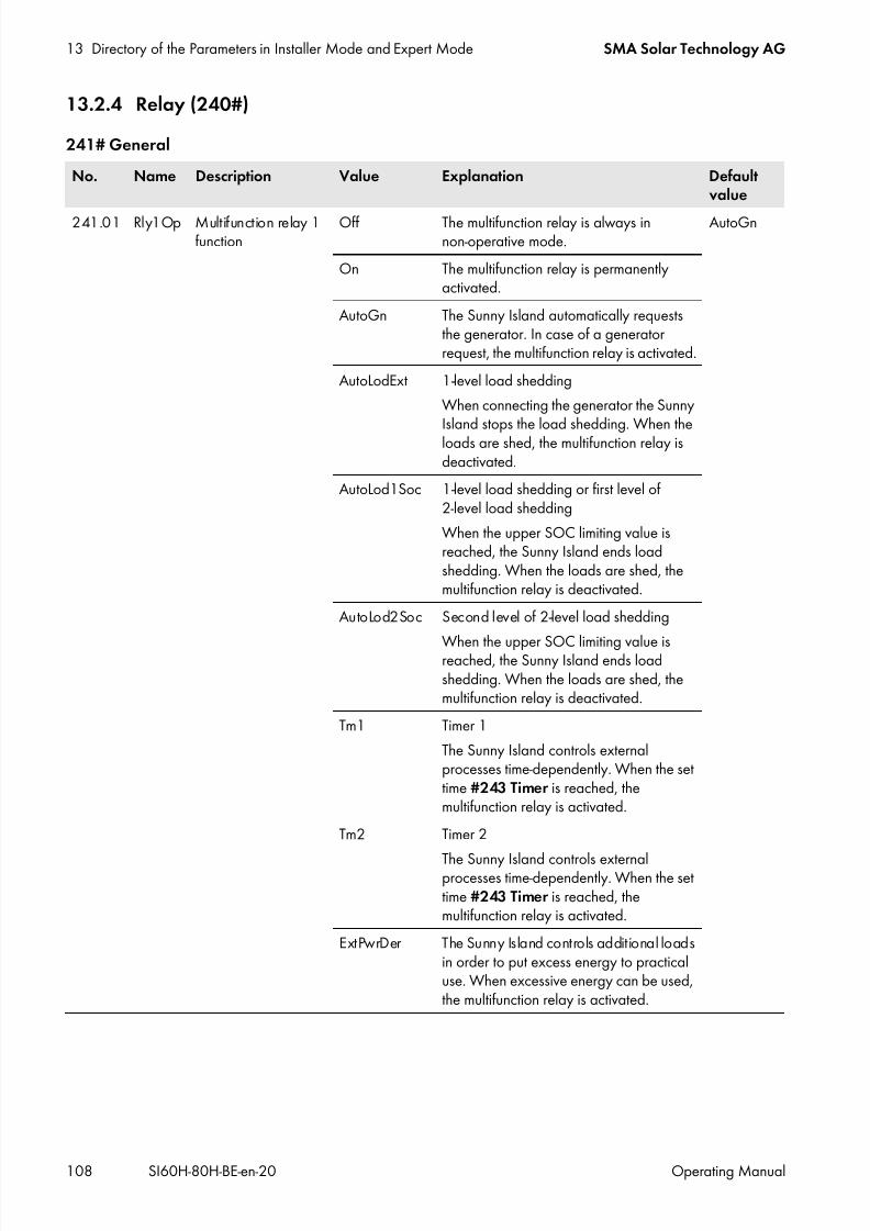
7/17/2019 Remote Control SI60H Operating Manual
http://slidepdf.com/reader/full/remote-control-si60h-operating-manual 108/128
13 Directory of the Parameters in Installer Mode and Expert Mode SMA Solar Technology AG
108 SI60H-80H-BE-en-20 Operating Manual
13.2.4 Relay (240#)
241# General
No. Name Description Value Explanation Defaultvalue
241.01 Rly1Op Multifunction relay 1function
Off The multifunction relay is always innon-operative mode.
AutoGn
On The multifunction relay is permanentlyactivated.
AutoGn The Sunny Island automatically requeststhe generator. In case of a generatorrequest, the multifunction relay is activated.
AutoLodExt 1-level load shedding
When connecting the generator the Sunny
Island stops the load shedding. When theloads are shed, the multifunction relay isdeactivated.
AutoLod1Soc 1-level load shedding or first level of2-level load shedding
When the upper SOC limiting value isreached, the Sunny Island ends loadshedding. When the loads are shed, themultifunction relay is deactivated.
AutoLod2Soc Second level of 2-level load shedding
When the upper SOC limiting value isreached, the Sunny Island ends loadshedding. When the loads are shed, themultifunction relay is deactivated.
Tm1 Timer 1
The Sunny Island controls externalprocesses time-dependently. When the settime #243 Timer is reached, themultifunction relay is activated.
Tm2 Timer 2
The Sunny Island controls externalprocesses time-dependently. When the settime #243 Timer is reached, themultifunction relay is activated.
ExtPwrDer The Sunny Island controls additional loadsin order to put excess energy to practicaluse. When excessive energy can be used,the multifunction relay is activated.

7/17/2019 Remote Control SI60H Operating Manual
http://slidepdf.com/reader/full/remote-control-si60h-operating-manual 109/128
SMA Solar Technology AG 13 Directory of the Parameters in Installer Mode and Expert Mode
Operating Manual SI60H-80H-BE-en-20 109
241.01 Rly1Op Function ofmultifunction relay 1function (continued)
GnRn When the generator is running andconnected, the multifunction relayactivates.
AutoGn
ExtVfOk When the voltage and frequency of theexternal energy source are within the validrange for the connection, the multifunctionrelay activates.
GdOn When the utility grid is connected, themultifunction relay activates.
Error When an error message is pending, themultifunction relay deactivates.
Warn When a warning is pending, themultifunction relay activates.
Run When the Sunny Island or the cluster is inoperation, the multifunction relay isactivated.
BatFan The Sunny Island controls the battery roomfan. When the battery room is to beventilated, the multifunction relay isactivated.
AcdCir The Sunny Island controls the electrolytepump of the battery. When the electrolyteis to be circulated, the multifunction relay is
activated.MccBatFan The Sunny Island controls the battery room
fan for all clusters together. When thebattery room is to be ventilated, themultifunction relay is activated.
MccAutoLod 1-level load shedding
When all batteries have reached the upperSOC limiting value, the Sunny Island endsload shedding. When the loads are shed,the multifunction relay is deactivated.
CHPReq No function
CHPAdd No function
SiComRemote Multifunction relay is controlled viaComSync.
Overload When the Sunny Island limits its power, themultifunction relay is deactivated.
GriSwt Triggering of contactors for griddisconnection in the battery backup system
No. Name Description Value Explanation Defaultvalue

7/17/2019 Remote Control SI60H Operating Manual
http://slidepdf.com/reader/full/remote-control-si60h-operating-manual 110/128
13 Directory of the Parameters in Installer Mode and Expert Mode SMA Solar Technology AG
110 SI60H-80H-BE-en-20 Operating Manual
242# Load
241.01 Rly1Op Function ofmultifunction relay 1(continued)
GndSwt Triggering of the grounding in the batterybackup system
AutoGn
241.02 Rly2Op Multifunction relay 2function
See 241.01 Rly1Op, page 108 for value and explanation AutoLodExt
No. Name Description Value Defaultvalue
241.07 ExtPwrDerMinTm Minimum time for the ExtPwrDer function of the multifunctionrelay in minutes
0 min to600 min
10 min
241.08 ExtPwrDerDltVtg Voltage difference for the ExtPwrDer function of themultifunction relay in V
The voltage difference corresponds to the cell voltage of the
battery.
0 V t o0.40 V
0.15 V
No. Name Description Value Defaultvalue
242.01 Lod1SocTm1Str SOC limiting value for starting loadshedding 1 in interval 1 in %
Interval 1 begins at time242.05 Lod1Tm1Str.
1% to 242.02Lod1SocTm1Stp
30%
242.02 Lod1SocTm1Stp SOC limiting value for stopping loadshedding 1 in interval 1 in %
Interval 1 begins at time242.05 Lod1Tm1Str.
242.01 Lod1SocTm1Str to 90% 50%
242.03 Lod1SocTm2Str SOC limiting value for starting loadshedding 1 in interval 2 in %
Interval 2 begins at time242.06 Lod1Tm2Str.
1% to 242.04Lod1SocTm2Stp
30%
242.04 Lod1SocTm2Stp SOC limiting value for stopping loadshedding 1 in interval 2 in %
Interval 2 begins at time242.06 Lod1Tm2Str.
242.03 Lod1SocTm2Str to 90%
50%
242.05 Lod1Tm1Str Start of interval 1 for load shedding 1,in hh:mm:ss
00:00:00 to 23:59:59 ‒
242.06 Lod1Tm2Str Start of interval 2 for load shedding 1,in hh:mm:ss
00:00:00 to 23:59:59 ‒
242.07 Lod2SocTm1Str SOC limiting value for starting loadshedding 2 in interval 1 in %
Interval 1 begins at time242.11 Lod2Tm1Str.
1% to242.08 Lod2SocTm1Stp
30%
No. Name Description Value Explanation Defaultvalue

7/17/2019 Remote Control SI60H Operating Manual
http://slidepdf.com/reader/full/remote-control-si60h-operating-manual 111/128
SMA Solar Technology AG 13 Directory of the Parameters in Installer Mode and Expert Mode
Operating Manual SI60H-80H-BE-en-20 111
243# Timer
242.08 Lod2SocTm1Stp SOC limiting value for stopping loadshedding 2 in interval 1 in %
Interval 1 begins at time
242.11 Lod2Tm1Str.
242.07 Lod2SocTm1Str to 90%
50%
242.09 Lod2SocTm2Str SOC limiting value for starting loadshedding 2 in interval 2 in %
Interval 2 begins at time242.12 Lod2Tm2Str.
1% to242.10 Lod2SocTm2Stp
30%
242.10 Lod2SocTm2Stp SOC limiting value for stopping loadshedding 2 in interval 2 in %
Interval 2 begins at time242.12 Lod2Tm2Str.
242.09 Lod2SocTm2Str to 90 %
50%
242.11 Lod2Tm1Str Start of interval 1 for load shedding 2in hh:mm:ss 00:00:00 to 23:59:59 00:00:00
242.12 Lod2Tm2Str Start of interval 2 for load shedding 2in hh:mm:ss
00:00:00 to 23:59:59 00:00:00
No. Name Description Value Explanation Defaultvalue
243.01 RlyTmr1StrDt Start date for timer 1 in dd.mm.yyyy ‒ ‒ 01.01.2011
243.02 RlyTmr1StrTm Start time at which the multifunctionrelay activates for timer 1 in hh:mm:ss
00:00:00 to23:59:59
‒ ‒
243.03 RlyTmr1Dur Duration for which the multifunctionrelay remains activated for timer 1in hh:mm:ss
00:00:00 to99:59:00
‒ ‒
243.04 RlyTmr1Cyc Repetition cycle time for timer 1 Single Once Single
Daily Daily
Weekly Weekly
243.05 RlyTmr2StrDt Start date for timer 2 in dd.mm.yyyy ‒ ‒ 01.01.2011
243.06 RlyTmr2StrTm Start time at which the multifunctionrelay activates for timer 2 in hh:mm:ss 00:00:00 to23:59:59 ‒ ‒
243.07 RlyTmr2Dur Duration for which the multifunctionrelay remains activated for timer 2in hh:mm:ss
00:00:00 to99:59:00
‒ ‒
243.08 RlyTmr2Cyc Repetition cycle time for timer 2 Single Once Single
Daily Daily
Weekly Weekly
No. Name Description Value Defaultvalue
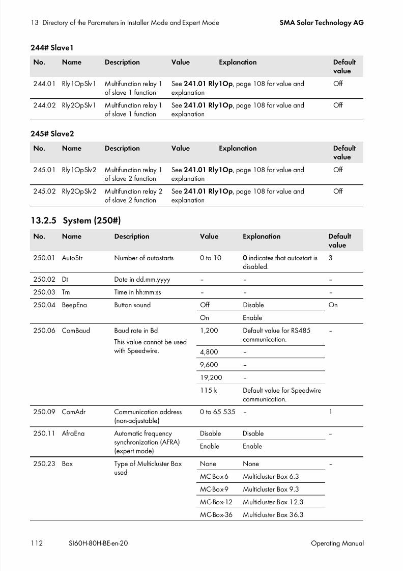
7/17/2019 Remote Control SI60H Operating Manual
http://slidepdf.com/reader/full/remote-control-si60h-operating-manual 112/128
13 Directory of the Parameters in Installer Mode and Expert Mode SMA Solar Technology AG
112 SI60H-80H-BE-en-20 Operating Manual
244# Slave1
245# Slave2
13.2.5 System (250#)
No. Name Description Value Explanation Defaultvalue
244.01 Rly1OpSlv1 Multifunction relay 1of slave 1 function
See 241.01 Rly1Op, page 108 for value andexplanation
Off
244.02 Rly2OpSlv1 Multifunction relay 1of slave 1 function
See 241.01 Rly1Op, page 108 for value andexplanation
Off
No. Name Description Value Explanation Defaultvalue
245.01 Rly1OpSlv2 Multifunction relay 1of slave 2 function
See 241.01 Rly1Op, page 108 for value andexplanation
Off
245.02 Rly2OpSlv2 Multifunction relay 2
of slave 2 function
See 241.01 Rly1Op, page 108 for value and
explanation
Off
No. Name Description Value Explanation Defaultvalue
250.01 AutoStr Number of autostarts 0 to 10 0 indicates that autostart isdisabled.
3
250.02 Dt Date in dd.mm.yyyy ‒ ‒ ‒
250.03 Tm Time in hh:mm:ss ‒ ‒ ‒
250.04 BeepEna Button sound Off Disable On
On Enable
250.06 ComBaud Baud rate in Bd
This value cannot be usedwith Speedwire.
1,200 Default value for RS485communication.
‒
4,800 ‒
9,600 ‒
19,200 ‒
115 k Default value for Speedwire
communication.250.09 ComAdr Communication address
(non-adjustable)0 to 65 535 ‒ 1
250.11 AfraEna Automatic frequencysynchronization (AFRA)(expert mode)
Disable Disable ‒
Enable Enable
250.23 Box Type of Multicluster Boxused
None None ‒
MC-Box-6 Multicluster Box 6.3
MC-Box-9 Multicluster Box 9.3
MC-Box-12 Multicluster Box 12.3
MC-Box-36 Multicluster Box 36.3
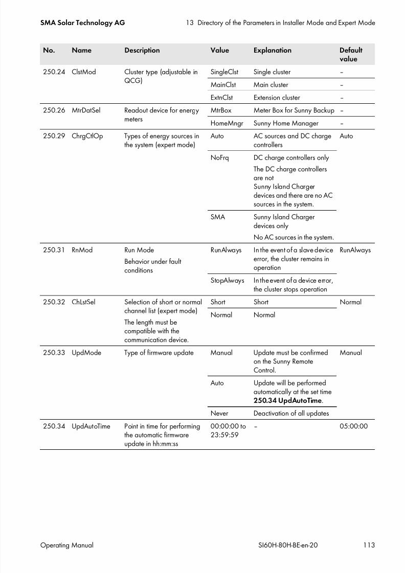
7/17/2019 Remote Control SI60H Operating Manual
http://slidepdf.com/reader/full/remote-control-si60h-operating-manual 113/128
SMA Solar Technology AG 13 Directory of the Parameters in Installer Mode and Expert Mode
Operating Manual SI60H-80H-BE-en-20 113
250.24 ClstMod Cluster type (adjustable inQCG)
SingleClst Single cluster ‒
MainClst Main cluster ‒
ExtnClst Extension cluster ‒250.26 MtrDatSel Readout device for energy
metersMtrBox Meter Box for Sunny Backup ‒
HomeMngr Sunny Home Manager ‒
250.29 ChrgCtlOp Types of energy sources inthe system (expert mode)
Auto AC sources and DC chargecontrollers
Auto
NoFrq DC charge controllers only
The DC charge controllersare notSunny Island Chargerdevices and there are no ACsources in the system.
SMA Sunny Island Chargerdevices only
No AC sources in the system.
250.31 RnMod Run Mode
Behavior under faultconditions
RunAlways In the event of a slave deviceerror, the cluster remains inoperation
RunAlways
StopAlways In the event of a device error,the cluster stops operation
250.32 ChLstSel Selection of short or normalchannel list (expert mode)
The length must becompatible with thecommunication device.
Short Short NormalNormal Normal
250.33 UpdMode Type of firmware update Manual Update must be confirmedon the Sunny RemoteControl.
Manual
Auto Update will be performedautomatically at the set time
250.34 UpdAutoTime.Never Deactivation of all updates
250.34 UpdAutoTime Point in time for performingthe automatic firmwareupdate in hh:mm:ss
00:00:00 to23:59:59
‒ 05:00:00
No. Name Description Value Explanation Defaultvalue

7/17/2019 Remote Control SI60H Operating Manual
http://slidepdf.com/reader/full/remote-control-si60h-operating-manual 114/128
13 Directory of the Parameters in Installer Mode and Expert Mode SMA Solar Technology AG
114 SI60H-80H-BE-en-20 Operating Manual
13.2.6 SlfCsmpBackup (#260)
261# General
262# BatUsage
No. Name Description Value(plain text
no.)
Explanation Defaultvalue
261.01 SlfCsmpIncEna Increased self-consumption Disable Disable −
Enable Enable
261.02 SlfCsmpPosSel System location (expert mode) North Northern hemisphere −
South Southern hemisphere
261.03 Saisonenable Automatic alignment of thebattery depth of discharge(expert mode)
In seasons with fewer hours of
sunlight the battery will undergodeep electric discharges less.
No Disable Yes
Yes Enable
No. Name Description Value(plain textno.)
Explanation Defaultvalue
262.01 ProtResSOC Range for protection in the eventof deep discharge as apercentage of the battery
capacity (expert mode)
10% to 20% Lead-acid batteries 10%
3% to 20% Lithium-ion batteries 3%
262.02 BatResSOC Range for protection againstdeep discharge as a percentageof the battery capacity (expertmode)
2% to 50% Lithium-ion battery,self-consumption only
2%
Lithium-ion batterybattery backup system
10%
Lead-acid battery,self-consumption only
30%
Lead-acid battery,battery backup system
5%
262.03 BUResSOC Range for the battery backupfunction on the longest day ofthe year as a percentage of thebattery capacity (expert mode)
0% to 100% ‒ 0%
262.04 PVResSOC Range for maintaining the stateof charge of the battery as apercentage of the nominalcapacity (expert mode)
4% to 20% ‒ 5%
262.05 MinSlfCsmpSOC Range for increasedself-consumption on the shortestday of the year as a percentageof the battery capacity (expertmode)
0% to 100% Lithium-ion battery 70%
Lead-acid battery 35%

7/17/2019 Remote Control SI60H Operating Manual
http://slidepdf.com/reader/full/remote-control-si60h-operating-manual 115/128
SMA Solar Technology AG 13 Directory of the Parameters in Installer Mode and Expert Mode
Operating Manual SI60H-80H-BE-en-20 115
13.2.7 Authent (270#)
13.3 Information (300#)
13.3.1 Inverter (310#)
311# Total
312# Device
No. Name Description
270.01 Auth.Code Entry of the SMA Grid Guard code
No. Name Description
311.01 EgyCntIn Energy consumed by the Sunny Island in kWh
311.02 EgyCntOut Energy supplied by the Sunny Island in kWh
311.03 EgyCntTm Run time of energy metering in hours
No. Name Description Value (plain textno.)
Explanation
312.01 Adr Device address Master (1) Address
Slave1 (2) Address
Slave2 (3) Address
312.03 AppSel Operating mode of the Sunny Island(expert mode)
Offgrid Sunny Island is operating inthe stand-alone grid.
OnGrid Sunny Island is connected tothe utility grid.
312.05 SysFncSel Selection of the on-grid system SelfConsOnly Increased self-consumptiononly
BackupOnly Battery backup only
SelfConsBackup Battery backup with increasedself-consumption
312.06 FwVer Firmware version of master ‒ ‒
312.07 SN Serial number of master ‒ ‒
312.08 OnTmh Operating hours ‒ ‒
312.09 ClstCfgAt Set configuration of cluster 1Phase1 Single-phase, 1 Sunny Island
1Phase2 Single-phase, 2 Sunny Islandinverters
1Phase3 Single-phase, 3 Sunny Islandinverters
3Phase Three-phase, 3 Sunny Islandinverters

7/17/2019 Remote Control SI60H Operating Manual
http://slidepdf.com/reader/full/remote-control-si60h-operating-manual 116/128
13 Directory of the Parameters in Installer Mode and Expert Mode SMA Solar Technology AG
116 SI60H-80H-BE-en-20 Operating Manual
313# Slave1
312.10 OpStt Operating state of the Sunny Island Operating (1) Operation
Warning (2) Warning
Failure (3) Failure312.11 CardStt SD memory card status message Off (1) No SD memory card inserted
Operational (2) Ready for operation
Mount (3) Initialization
OutOfSpace (4) No storage space available
BadFileSys (5) No file system detected
Incomp (6) File system incompatible
Parameter (7) Parameter set write access
ParamFailed (8) Parameter set write accessfailed
WriteLogData (9) Log data write access
312.12 FwVer2 Firmware version of the digital signalprocessor
‒ ‒
312.13 FwVer3 Boot loader of the operation controlunit
‒ ‒
312.14 FwVer4 Boot loader of the digital signalprocessor
‒ ‒
312.18 ComMod1 Type of interface in the interface slotSISysCan ‒‒‒ No interface insertedSI-SysCan SI-SYSCAN.BGx inserted
(multicluster system)
312.19 ComMod2 Type of interface in the interface slotSiComSma
‒‒‒ No interface inserted
SI-ComSma SI-COMSMA.BGx inserted(RS485)
SI-SW-DM SWDMSI-NR inserted(Speedwire)
No. Name Description Value Explanation
313.01 FwVerSlv1 Firmware version of slave 1 ‒ ‒
313.02 SNSlv1 Serial number of slave 1 ‒ ‒
313.03 OnTmhSlv1 Operating hours of slave 1 in hours ‒ ‒
313.04 PhSlv1 Line conductor assignment of slave 1 L1 Line conductorL1
L2 Line conductorL2
L3 Line conductorL3
No. Name Description Value (plain textno.)
Explanation
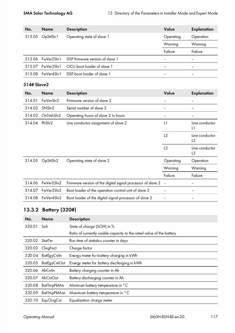
7/17/2019 Remote Control SI60H Operating Manual
http://slidepdf.com/reader/full/remote-control-si60h-operating-manual 117/128
SMA Solar Technology AG 13 Directory of the Parameters in Installer Mode and Expert Mode
Operating Manual SI60H-80H-BE-en-20 117
314# Slave2
13.3.2 Battery (320#)
313.05 OpSttSlv1 Operating state of slave 1 Operating Operation
Warning Warning
Failure Failure
313.06 FwVer2Slv1 DSP firmware version of slave 1 ‒ ‒313.07 FwVer3Slv1 OCU boot loader of slave 1 ‒ ‒
313.08 FwVer4Slv1 DSP boot loader of slave 1 ‒ ‒
No. Name Description Value Explanation
314.01 FwVerSlv2 Firmware version of slave 2 ‒ ‒
314.02 SNSlv2 Serial number of slave 2 ‒ ‒
314.03 OnTmhSlv2 Operating hours of slave 2 in hours ‒ ‒314.04 PhSlv2 Line conductor assignment of slave 2 L1 Line conductor
L1
L2 Line conductorL2
L3 Line conductorL3
314.05 OpSttSlv2 Operating state of slave 2 Operating Operation
Warning Warning
Failure Failure314.06 FwVer2Slv2 Firmware version of the digital signal processor of slave 2 ‒ ‒
314.07 FwVer3Slv2 Boot loader of the operation control unit of slave 2 ‒ ‒
314.08 FwVer4Slv2 Boot loader of the digital signal processor of slave 2 ‒ ‒
No. Name Description
320.01 Soh State of charge (SOH) in %
Ratio of currently usable capacity to the rated value of the battery320.02 StatTm Run time of statistics counter in days
320.03 ChrgFact Charge factor
320.04 BatEgyCntIn Energy meter for battery charging in kWh
320.05 BatEgyCntOut Energy meter for battery discharging in kWh
320.06 AhCntIn Battery charging counter in Ah
320.07 AhCntOut Battery discharging counter in Ah
320.08 BatTmpPkMin Minimum battery temperature in °C
320.09 BatTmpPkMax Maximum battery temperature in °C
320.10 EquChrgCnt Equalization charge meter
No. Name Description Value Explanation

7/17/2019 Remote Control SI60H Operating Manual
http://slidepdf.com/reader/full/remote-control-si60h-operating-manual 118/128
13 Directory of the Parameters in Installer Mode and Expert Mode SMA Solar Technology AG
118 SI60H-80H-BE-en-20 Operating Manual
320.11 FulChrgCnt Full charge counter
320.12 BatCurOfsErr Estimated offset error of battery current in A (expert mode)
320.13 OcvPointCnt Counter for open-circuit voltage points (expert mode)
320.15 AhCntFul Ampere-hour meter for battery discharging since the last full charge in Ah ⁄ 100 Ah
320.16 AhCntEqu Ampere-hour meter for battery discharging since the last equalization charge in Ah ⁄ 100 Ah
320.17 BatVtgPk Maximum battery voltage reached since the last start in V
320.18 BatCurPkIn Maximum battery current reached since the last start in charge direction in A
320.19 BatCurPkOut Maximum battery current reached since the last start in discharge direction in A
320.20 SocHgm100 Percentage frequency distribution of state of charge (SOC) when SOC is in the range of100% to and including 90%, based on time in % (expert mode)
320.21 SocHgm090 Percentage frequency distribution of state of charge (SOC) when SOC is in the range of90% to and including 80%, based on time in % (expert mode)
320.22 SocHgm080 Percentage frequency distribution of state of charge (SOC) when SOC is in the range of80% to and including 70%, based on time in % (expert mode)
320.23 SocHgm070 Percentage frequency distribution of state of charge (SOC) when SOC is in the range of70% to and including 60%, based on time in % (expert mode)
320.24 SocHgm060 Percentage frequency distribution of state of charge (SOC) when SOC is in the range of60% to and including 50%, based on time in % (expert mode)
320.25 SocHgm050 Percentage frequency distribution of state of charge (SOC) when SOC is in the range of50% to and including 40%, based on time in % (expert mode)
320.26 SocHgm040 Percentage frequency distribution of state of charge (SOC) when SOC is in the range of40% to and including 30%, based on time in % (expert mode)
320.27 SocHgm030 Percentage frequency distribution of state of charge (SOC) when SOC is in the range of30% to and including 20%, based on time in % (expert mode)
320.28 SocHgm020 Percentage frequency distribution of state of charge (SOC) when SOC is in the range of20% to and including 10%, based on time in % (expert mode)
320.29 SocHgm010 Percentage frequency distribution of state of charge (SOC) when SOC is in the range of10 % to and including 0 %, based on time in % (expert mode)
320.30 SocHgm000 Frequency distribution of SOC in relation to time, when SOC is equal to 0% in % (expertmode)
320.31 SocVtgCal Recalibration of SOC based on open-circuit voltage only in % (expert mode)
320.32 ErrSocVtgCal Estimated error of the voltage-calibrated state of charge in % (expert mode)
320.33 SocChrgCal Recalibration of SOC based on full charge only in % (expert mode)
320.34 ErrSocChrgCal Estimated error of the full-charge-calibrated state of charge in % (expert mode)
320.35 OcvGra Gradient of the open-circuit voltage characteristic curve in Ah ⁄ V (expert mode)
320.36 OcvMax Maximum open-circuit voltage in V (expert mode)
No. Name Description

7/17/2019 Remote Control SI60H Operating Manual
http://slidepdf.com/reader/full/remote-control-si60h-operating-manual 119/128
SMA Solar Technology AG 13 Directory of the Parameters in Installer Mode and Expert Mode
Operating Manual SI60H-80H-BE-en-20 119
13.3.3 External (330#)
331# Grid
332# Generator
13.4 Report (400#)
410# Error activeDisplay of currently pending warnings and errors (see Section 9 "Troubleshooting", page 40).
420# Error history
History of warnings and errors (see Section 9 "Troubleshooting", page 40).
430# Event history
History of events (see Section 9 "Troubleshooting", page 40).
440# Error Grid
History of the last five grid errors (see Section 9 "Troubleshooting", page 40).
No. Name Description
331.01 GdEgyCntIn Energy meter for grid feed-in in kWh
331.02 GdEgyCntOut Energy meter for purchased electricity in kWh
331.03 GdEgyTmh Duration in which an energy exchange is possible with the utility grid in hours
331.04 GdOpTmh Operating hours counter for grid operation in hours
331.05 GdCtcCnt Number of grid connections
331.06 TotTmh Feed-in hours
331.07 GdFailTms Duration of the grid failure in s
No. Name Description
332.01 GnEgyCnt Energy meter for generator in kWh
332.02 GnEgyTm Duration of the energy measuring for the generator in hours
332.03 GnOpTmh Operating hours counter for generator in hours
332.04 GnStrCnt Number of generator starts

7/17/2019 Remote Control SI60H Operating Manual
http://slidepdf.com/reader/full/remote-control-si60h-operating-manual 120/128
13 Directory of the Parameters in Installer Mode and Expert Mode SMA Solar Technology AG
120 SI60H-80H-BE-en-20 Operating Manual
13.5 Operation (500#)
13.5.1 Inverter (510#)
No. Name Description Value Explanation Default value
510.01 InvRs Trips a restart of the Sunny Island No Do not restart ‒Yes Restart
510.02 InvTmOpEna Time-controlled operation Disable Disable Disable
Enable Enable
510.03 InvTmOpStrDt Start date for time-controlledoperation in dd.mm.yyyy
‒ ‒ ‒
510.04 InvTmOpStrTm Time for the start of time-controlledoperation in hh:mm:ss
00:00:00 to23:59:59
‒ ‒
510.05 InvTmOpRnDur Run time for time-controlled
operation in hh:mm:ss
00:00:00 to
99:59:00
‒ ‒
510.06 InvTmOpCyc Repetition cycle for time-controlledoperation
Single Once Single
Daily Daily
Weekly Weekly
510.07 CntRs Delete energy meter
The value indicates which energymeter is to be deleted.
Inv Sunny Island ‒
Bat Battery
Gn Generator
Gd Utility grid
All All energymeters
Sic1 Sunny IslandCharger 1
Sic2 Sunny IslandCharger 2
Sic3 Sunny IslandCharger 3
Sic4 Sunny Island
Charger 4SicAll All Sunny Island
Charger devices
510.08 TstClstCom Activation of communication testbetween individual clusters (expertmode)
Off Off ‒
Transmit Enable
510.09 ClstComStt Status of communication test (expertmode)
Wait Wait ‒
OK Completed

7/17/2019 Remote Control SI60H Operating Manual
http://slidepdf.com/reader/full/remote-control-si60h-operating-manual 121/128
SMA Solar Technology AG 13 Directory of the Parameters in Installer Mode and Expert Mode
Operating Manual SI60H-80H-BE-en-20 121
13.5.2 Battery (520#)
13.5.3 Generator (540#)
13.5.4 MMC-Card (550#)
13.5.5 Grid (560#)
No. Name Description Value Explanation Default value
520.01 ChrgSelMan Manual equalizationcharge
Idle Waiting until conditions are met Idle
Start Start
Stop Stop
No. Name Description Value Explanation Default value
540.01 GnManStr Manual generator start Auto Automatic Auto
Stop Stop
Start Start
Run1h Start for 1 hour
540.02 GnAck Acknowldgement of generatorerrors
Ackn Acknowledge ‒
No. Name Description Value Explanation
550.01 ParaSto Save parameter settings Set1 Parameter set 1
Set2 Parameter set 2
550.02 ParaLod Load parameter settings (expertmode)
Set1 Parameter set 1
Set2 Parameter set 2Factory Load default settings
550.03 CardFunc Functions of the SD memorycard
ForcedWrite Forced write
StoEvtHis Storing event memory
StoFailHis Storing fault memory
StoHis Storing event and fault memory
No. Name Description Value Explanation Default value560.01 GdManStr Manual connection to the utility grid Auto Automatic Auto
Stop Stop
Start Start

7/17/2019 Remote Control SI60H Operating Manual
http://slidepdf.com/reader/full/remote-control-si60h-operating-manual 122/128
14 Menu Structure SMA Solar Technology AG
122 SI60H-80H-BE-en-20 Operating Manual
14 Menu Structure
14.1 User Mode
Figure 20: Menu structure: user mode
Inverter
attery
Grid
Self
Cnsmptn
Grid
Cnsmptn
Grid
Feed
Loads
PV System
System
Time
Identity
Password
Tot. Power
MC Power
Timer
Mode
State Of Charge
Voltage
Power
Out
Mode
Remain Time
Next
equal
Health SOH)
Cyde
Power
Voltage
Freqeuncy
Inc Power
Inc
Today
Inc
Energy
Energy
Power
Energy
Power
Energy
Power
Energy
ConState
Power
Energy
ConS ate
Type
Box
Type
Device
Date
Time
Serial Na
Firmware
Level
Restart
Str.
Dote
Start Time
Run
Time
Repetition
Timed Start
Equalize
Mode
Date
Time
Set
Runtime

7/17/2019 Remote Control SI60H Operating Manual
http://slidepdf.com/reader/full/remote-control-si60h-operating-manual 123/128
SMA Solar Technology AG 14 Menu Structure
Operating Manual SI60H-80H-BE-en-20 123
14.2 Installer Mode and Expert Mode
Figure 21: Menu structure: installer mode and expert mode
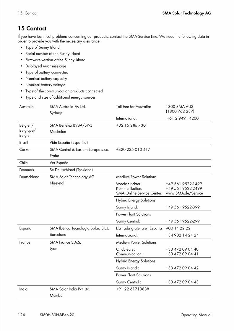
7/17/2019 Remote Control SI60H Operating Manual
http://slidepdf.com/reader/full/remote-control-si60h-operating-manual 124/128
15 Contact SMA Solar Technology AG
124 SI60H-80H-BE-en-20 Operating Manual
15 ContactIf you have technical problems concerning our products, contact the SMA Service Line. We need the following data inorder to provide you with the necessary assistance:
• Type of Sunny Island
• Serial number of the Sunny Island
• Firmware version of the Sunny Island• Displayed error message
• Type of battery connected
• Nominal battery capacity
• Nominal battery voltage
• Type of the communication products connected
• Type and size of additional energy sources
Australia SMA Australia Pty Ltd.
Sydney
Toll free for Australia: 1800 SMA AUS(1800 762 287)
International: +61 2 9491 4200
Belgien/Belgique/België
SMA Benelux BVBA/SPRL
Mechelen
+32 15 286 730
Brasil Vide España (Espanha)
Česko SMA Central & Eastern Europe s.r.o.
Praha
+420 235 010 417
Chile Ver España
Danmark Se Deutschland (Tyskland)
Deutschland SMA Solar Technology AG
Niestetal
Medium Power Solutions
Wechselrichter:Kommunikation:SMA Online Service Center:
+49 561 9522-1499+49 561 9522-2499www.SMA.de/Service
Hybrid Energy Solutions
Sunny Island: +49 561 9522-399
Power Plant Solutions
Sunny Central: +49 561 9522-299
España SMA Ibérica Tecnología Solar, S.L.U.
Barcelona
Llamada gratuita en España: 900 14 22 22
Internacional: +34 902 14 24 24
France SMA France S.A.S.
Lyon
Medium Power Solutions
Onduleurs :Communication :
+33 472 09 04 40+33 472 09 04 41
Hybrid Energy Solutions
Sunny Island : +33 472 09 04 42
Power Plant Solutions
Sunny Central : +33 472 09 04 43
India SMA Solar India Pvt. Ltd.Mumbai
+91 22 61713888

7/17/2019 Remote Control SI60H Operating Manual
http://slidepdf.com/reader/full/remote-control-si60h-operating-manual 125/128
SMA Solar Technology AG 15 Contact
Operating Manual SI60H-80H-BE-en-20 125
Italia SMA Italia S.r.l.
Milano
+39 02 8934-7299
Κύπρος/Kıbrıs
Βλέπε Ελλάδα/Bkz. Ελλάδα (Yunanistan)
Luxemburg/
Luxembourg
Siehe Belgien/
Voir Belgien (Belgique)Magyarország lásd Česko (Csehország)
Nederland zie Belgien (België)
Österreich Siehe Deutschland
Perú Ver España
Polska Patrz Česko (Czechy)
Portugal SMA Solar Technology Portugal,Unipessoal Lda
Lisboa
Isento de taxas em Portugal: 800 20 89 87
Internacional: +351 2 12 37 78 60
România Vezi Česko (Cehia)
Schweiz Siehe Deutschland
Slovensko pozri Česko (Česká republika)
South Africa SMA Solar TechnologySouth Africa Pty Ltd.
Centurion (Pretoria)
08600 SUNNY(08600 78669)
International: +27 (12) 643 1785
United Kingdom SMA Solar UK Ltd.
Milton Keynes
+44 1908 304899
Ελλάδα SMA Hellas AEΑθήνα
801 222 9 222International: +30 212 222 9 222
България Вижте Ελλάδα (Гърция)
SMA Solar (Thailand) Co., Ltd. +66 2 670 6999
대한민국 SMA Technology Korea Co., Ltd.
서울
+82 2 508-8599
中国 SMA Beijing Commercial CompanyLtd.
北京
+86 10 5670 1350
SMA Japan K.K. +81 3 3451 9530
+971 2 698-5080 SMA Middle East LLC
Other countries International SMA Service Line
Niestetal
Toll free worldwide: 00800 SMA SERVICE(+800 762 7378423)

7/17/2019 Remote Control SI60H Operating Manual
http://slidepdf.com/reader/full/remote-control-si60h-operating-manual 126/128

7/17/2019 Remote Control SI60H Operating Manual
http://slidepdf.com/reader/full/remote-control-si60h-operating-manual 127/128

7/17/2019 Remote Control SI60H Operating Manual
http://slidepdf.com/reader/full/remote-control-si60h-operating-manual 128/128
www.SMA-Solar.comSMA Solar Technology