Embed Size (px)
Citation preview
SUNNY REMOTE CONTROL
Warning
LoadMemory Card
Grid / Generator
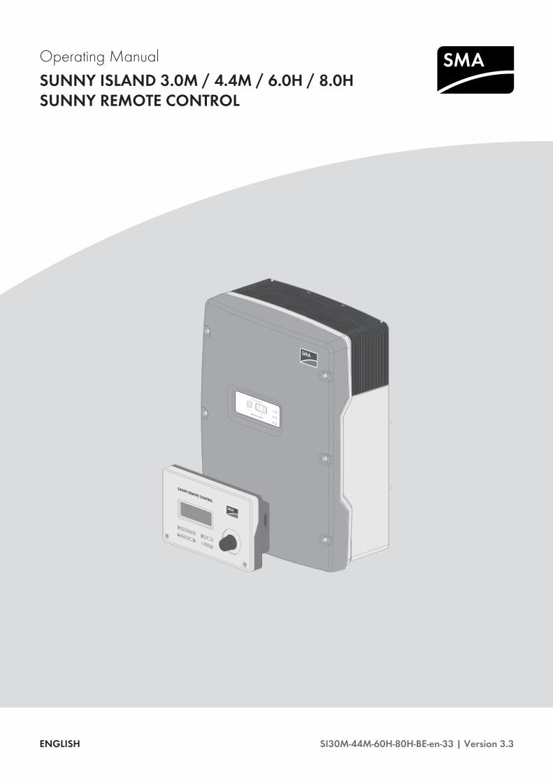
Operating ManualSUNNY ISLAND 3.0M / 4.4M / 6.0H / 8.0HSUNNY REMOTE CONTROL
SI30M-44M-60H-80H-BE-en-33 | Version 3.3ENGLISH
Legal ProvisionsThe information contained in these documents is property of SMA Solar Technology AG. Any publication, whether inwhole or in part, requires prior written approval by SMA Solar Technology AG. Internal reproduction used solely forthe purpose of product evaluation or other proper use is allowed and does not require prior approval.
SMA WarrantyYou can download the current warranty conditions from the Internet at www.SMA-Solar.com.
TrademarksAll trademarks are recognized, even if not explicitly identified as such. Missing designations do not mean that aproduct or brand is not a registered trademark.Modbus® is a registered trademark of Schneider Electric and is licensed by the Modbus Organization, Inc.QR Code is a registered trademark of DENSO WAVE INCORPORATED.Phillips® and Pozidriv® are registered trademarks of Phillips Screw Company.Torx® is a registered trademark of Acument Global Technologies, Inc.
SMA Solar Technology AGSonnenallee 134266 NiestetalGermanyTel. +49 561 9522-0Fax +49 561 9522-100www.SMA.deEmail: [email protected] © 2016 SMA Solar Technology AG. All rights reserved.
Legal Provisions SMA Solar Technology AG
Operating ManualSI30M-44M-60H-80H-BE-en-332
Table of Contents1 Information on this Document ..................................................................................................... 71.1 Validity .............................................................................................................................................................. 71.2 Target group ..................................................................................................................................................... 71.3 Symbols............................................................................................................................................................. 71.4 Typographies .................................................................................................................................................... 81.5 Nomenclature ................................................................................................................................................... 8
2 Safety............................................................................................................................................. 102.1 Intended Use..................................................................................................................................................... 102.2 Safety Information ............................................................................................................................................ 102.3 Information on Handling Batteries................................................................................................................... 12
3 Product Description....................................................................................................................... 153.1 Sunny Island...................................................................................................................................................... 153.2 Control Panel of the Sunny Island Inverter...................................................................................................... 163.3 Type Label......................................................................................................................................................... 173.4 Sunny Remote Control...................................................................................................................................... 18
4 Starting and Stopping the System............................................................................................... 204.1 Switching on the Sunny Island......................................................................................................................... 204.2 Starting the System ........................................................................................................................................... 204.3 Stopping the System......................................................................................................................................... 204.4 Switching Off the Sunny Island........................................................................................................................ 214.5 Tripping the Emergency Disconnection of the System.................................................................................... 214.6 Setting Time-Controlled Inverter Operation in Off-Grid Systems................................................................... 22
5 Operation of the Sunny Island Inverter with the Sunny Remote Control ................................ 235.1 Display Modes ................................................................................................................................................. 235.2 Standard Mode ................................................................................................................................................ 24
5.2.1 Display of Operating States ............................................................................................................................ 245.2.2 Information Page in Systems for Increased Self-Consumption and Battery Backup Systems ...................... 255.2.3 Information Page in Off-Grid Systems ............................................................................................................ 26
5.3 User Mode........................................................................................................................................................ 295.3.1 Pages in the User Mode .................................................................................................................................. 295.3.2 Displaying Parameters and Operating and Setting the System.................................................................... 30
5.4 Installer Mode and Expert Mode.................................................................................................................... 325.4.1 Switching to Installer Mode or Expert Mode ................................................................................................. 325.4.2 Exiting Installer Mode or Expert Mode .......................................................................................................... 325.4.3 Menus in Installer and Expert Mode .............................................................................................................. 335.4.4 Parameter Page in Installer and Expert Mode ............................................................................................... 335.4.5 Selecting Menus and Parameters.................................................................................................................... 335.4.6 Setting Parameters ........................................................................................................................................... 345.4.7 Directly Accessing the Parameters .................................................................................................................. 34
6 Operation of the Sunny Island Inverter with a Communication Product................................. 36
7 Data Storage and Firmware Update .......................................................................................... 377.1 Data Storage on the Computer ....................................................................................................................... 377.2 Data Storage on SD Memory Card................................................................................................................ 37
7.2.1 Insert the SD Memory Card ............................................................................................................................ 37
Table of ContentsSMA Solar Technology AG
Operating Manual 3SI30M-44M-60H-80H-BE-en-33
7.2.2 Loading and Saving Parameters ..................................................................................................................... 377.2.3 Saving the Event History and Error History .................................................................................................... 387.2.4 Displaying the SD Memory Card Status Message ........................................................................................ 387.2.5 Removing the SD Memory Card ..................................................................................................................... 387.2.6 Displaying the SD Memory Card Content...................................................................................................... 38
7.3 Firmware Update.............................................................................................................................................. 407.3.1 Display of the Firmware Version ..................................................................................................................... 407.3.2 Updating the Firmware Using an SD Memory Card ..................................................................................... 407.3.3 Updating the Firmware Using Sunny Explorer ............................................................................................... 417.3.4 Performing a Remote Update Using the Sunny Home Manager.................................................................. 41
8 Manually Controlling the Generator .......................................................................................... 438.1 Starting the Generator with Sunny Remote Control ....................................................................................... 438.2 Stopping the Generator with Sunny Remote Control ..................................................................................... 438.3 Starting the Generator without Autostart Function ......................................................................................... 438.4 Stopping the Generator without Autostart Function ....................................................................................... 44
9 Disconnecting the Sunny Island from Voltage Sources............................................................. 45
10 Troubleshooting ............................................................................................................................ 4610.1 Display of Errors ............................................................................................................................................... 46
10.1.1 Display of Errors on the Sunny Remote Control ............................................................................................. 4610.1.2 Display of Errors on the Communication Product (Example) ........................................................................ 46
10.2 Sunny Island Inverter Behavior Under Fault Conditions................................................................................. 4710.3 Acknowledge Errors ......................................................................................................................................... 4710.4 Logged Events................................................................................................................................................... 48
10.4.1 Sunny Island Category (1xx) .......................................................................................................................... 4810.4.2 Battery Category (2xx) .................................................................................................................................... 4810.4.3 Generator Category (4xx) .............................................................................................................................. 4910.4.4 Utility Grid Category (5xx).............................................................................................................................. 4910.4.5 Relay Category (6xx) ...................................................................................................................................... 4910.4.6 System Category (7xx) .................................................................................................................................... 5010.4.7 External Device and Component Category (8xx) ......................................................................................... 5110.4.8 Category External Events (9xx)....................................................................................................................... 51
10.5 Logged Warning Messages and Error Messages ......................................................................................... 5210.5.1 Sunny Island Category (1xx) .......................................................................................................................... 5210.5.2 Battery Category (2xx) .................................................................................................................................... 5710.5.3 Generator or Utility Grid Category (3xx) ...................................................................................................... 5910.5.4 Generator Category (4xx) .............................................................................................................................. 6710.5.5 Utility Grid Category (5xx).............................................................................................................................. 6810.5.6 Relay Category (6xx) ...................................................................................................................................... 6810.5.7 System Category (7xx) .................................................................................................................................... 6810.5.8 External Device and Component Category (8xx) ......................................................................................... 7310.5.9 General Category (9xx).................................................................................................................................. 83
10.6 Frequently Asked Questions (FAQs) ............................................................................................................... 8610.6.1 Questions Regarding the Sunny Island........................................................................................................... 8610.6.2 Questions Regarding the Sunny Remote Control........................................................................................... 8610.6.3 Questions Regarding the Battery .................................................................................................................... 8710.6.4 Questions Regarding the Generator............................................................................................................... 8710.6.5 Questions Regarding Multicluster Systems..................................................................................................... 88
10.7 Charging the Battery After Automatic Shutdown in Off-Grid Systems (Emergency Charge Mode) .......... 89
Table of Contents SMA Solar Technology AG
Operating ManualSI30M-44M-60H-80H-BE-en-334

10.8 Changing Slave Addresses in a Cluster.......................................................................................................... 91
11 Cleaning and Maintenance.......................................................................................................... 9311.1 Cleaning and Checking the Sunny Island Inverter Enclosure ........................................................................ 9311.2 Cleaning the Sunny Remote Control ............................................................................................................... 9311.3 Performing a Manual Equalization Charge in the Off-Grid System.............................................................. 9311.4 Checking the Function ...................................................................................................................................... 9311.5 Checking the Connections ............................................................................................................................... 9411.6 Checking and Maintaining the Battery ........................................................................................................... 9411.7 Cleaning the Fans............................................................................................................................................. 9511.8 Replacing the Battery ....................................................................................................................................... 97
12 Decommissioning the Sunny Island ............................................................................................100
13 Parameters in Sunny Remote Control.........................................................................................10213.1 Directory of the Parameters in User Mode .....................................................................................................102
13.1.1 Inverter Category .............................................................................................................................................10213.1.2 Battery Category ..............................................................................................................................................10313.1.3 Generator Category ........................................................................................................................................10413.1.4 Grid Category ..................................................................................................................................................10513.1.5 SI Charger Category .......................................................................................................................................10513.1.6 Self Cnsmptn Category....................................................................................................................................10613.1.7 Grid Cnsmptn Category ..................................................................................................................................10613.1.8 Grid Feed Category.........................................................................................................................................10613.1.9 Loads Category................................................................................................................................................10613.1.10 PV System Category.........................................................................................................................................10713.1.11 System Category ..............................................................................................................................................10713.1.12 Time Category ..................................................................................................................................................10713.1.13 Identity Category..............................................................................................................................................10813.1.14 Password Category..........................................................................................................................................108
13.2 Directory of the Parameters in Installer Mode and Expert Mode .................................................................10813.2.1 Display Values..................................................................................................................................................108
13.2.1.1 Inverter (110#) ................................................................................................................................................ 10813.2.1.2 Battery (120#)................................................................................................................................................. 11213.2.1.3 External (130#) ............................................................................................................................................... 11313.2.1.4 Charge Controller (140#) .............................................................................................................................. 11613.2.1.5 Compact (150#) ............................................................................................................................................. 11813.2.1.6 SlfCsmp (160#)............................................................................................................................................... 12013.2.1.7 Multicluster (170#).......................................................................................................................................... 122
13.2.2 Adjustable Parameters .....................................................................................................................................12413.2.2.1 Inverter (210#) ................................................................................................................................................ 12413.2.2.2 Battery (220#)................................................................................................................................................. 12513.2.2.3 External/Backup (230#)................................................................................................................................. 12913.2.2.4 Relay (240#) ................................................................................................................................................... 14113.2.2.5 System (250#)................................................................................................................................................. 14513.2.2.6 SlfCsmpBackup (#260) .................................................................................................................................. 14713.2.2.7 Authent (270#)................................................................................................................................................ 149
13.2.3 Information (300#) ..........................................................................................................................................14913.2.3.1 Inverter (310#) ................................................................................................................................................ 14913.2.3.2 Battery (320#)................................................................................................................................................. 15213.2.3.3 External (330#) ............................................................................................................................................... 154
13.2.4 Report (400#) ..................................................................................................................................................15513.2.5 Operation (500#)............................................................................................................................................155
Table of ContentsSMA Solar Technology AG
Operating Manual 5SI30M-44M-60H-80H-BE-en-33
13.2.5.1 Inverter (510#) ................................................................................................................................................ 15513.2.5.2 Battery (520#)................................................................................................................................................. 15613.2.5.3 Generator (540#) ........................................................................................................................................... 15713.2.5.4 MMC Card (550#)......................................................................................................................................... 15713.2.5.5 Grid (560#) ..................................................................................................................................................... 157
14 Parameters in the Communication Product ................................................................................158
15 Menu Structure..............................................................................................................................15915.1 User Mode........................................................................................................................................................15915.2 Installer Mode and Expert Mode....................................................................................................................160
16 Contact...........................................................................................................................................161
Table of Contents SMA Solar Technology AG
Operating ManualSI30M-44M-60H-80H-BE-en-336
1 Information on this Document
1.1 ValidityThis document is valid for the following device types:• SI3.0M-11 (Sunny Island 3.0M) from firmware version 3.2• SI4.4M-11 (Sunny Island 4.4M) from firmware version 3.2• SI6.0H-11 (Sunny Island 6.0H) from firmware version 3.1• SI8.0H-11 (Sunny Island 8.0H) from firmware version 3.1• SRC-20 (Sunny Remote Control)
1.2 Target groupThis document is intended for qualified persons and operators. Only qualified persons are allowed to perform theactivities marked in this document with a warning symbol and the caption "Qualified person". Activities that may alsobe performed by operators are not marked and may be performed by operators.
OperatorOperators must be given training on the following subjects by qualified persons:• Training on the dangers involved in handling electrical devices• Training on operation of the Sunny Island• Training on the safe handling of batteries• Training on secure disconnection of the Sunny Island under fault conditions• Training on how to secure a system against unintentional reactivation• Training on the maintenance and cleaning of the Sunny Island inverter• Knowledge of and compliance with this document and all safety information
Qualified Persons• Training in how to deal with the dangers and risks associated with installing and using electrical devices andbatteries
• Training in the installation and commissioning of electrical devices• Knowledge of and adherence to the local standards and directives• Knowledge of and compliance with the documentation of the Sunny Island inverter with all safety information
1.3 SymbolsSymbol Explanation
Indicates a hazardous situation which, if not avoided, will result in death or serious injury
Indicates a hazardous situation which, if not avoided, can result in death or serious injury
Indicates a hazardous situation which, if not avoided, can result in minor or moderate injury
Indicates a situation which, if not avoided, can result in property damage
Information advising that the following section contains activities that may be performed onlyby qualified persons.
1 Information on this DocumentSMA Solar Technology AG
Operating Manual 7SI30M-44M-60H-80H-BE-en-33
Symbol Explanation
This information is relevant for systems which are to be operated in parallel with utility grid.(e.g. SMA Flexible Storage System).
Content is relevant for off-grid systems.
Information that is important for a specific topic or goal, but is not safety-relevant
Indicates a requirement for meeting a specific goal
Desired result
A problem that might occur
1.4 TypographiesTypography Use Example
bold • Display messages• Parameter• Terminals• Slots• Elements to be selected• Elements to be entered
• Connect the groundingconductor to AC2 Gen/Grid.
• Select the parameter235.01 GnAutoEna andset to Off.
> • Several elements that are to be selected • Select 600# Direct Access> Select Number.
[Button][Key]
• Button that is to be selected or clicked on • Select [Enter].
1.5 NomenclatureComplete designation Designation in this document
Off-grid system, battery-backup system, system for in-creased self-consumption
System
Sunny Boy, Sunny Mini Central, Sunny Tripower PV inverter
Sunny Explorer, Sunny Portal, Sunny Home Manager Communication product
Grid failure or deviation from the country-specific thresh-olds for voltage and frequency
Grid failure
Automatic transfer switch with battery-backup function Automatic transfer switch
Grid-forming generators such as electric generators orutility grids
External energy sources
1 Information on this Document SMA Solar Technology AG
Operating ManualSI30M-44M-60H-80H-BE-en-338
Menus are presented as follows: menu number, pound sign and menu name (e.g., 150# Compact Meters).Parameters are presented as follows: menu number, period, parameter number and parameter name (e.g., 150.01GdRmgTm). The term "parameter" includes parameters with configurable values as well as parameters for displayingvalues.
1 Information on this DocumentSMA Solar Technology AG
Operating Manual 9SI30M-44M-60H-80H-BE-en-33
2 Safety
2.1 Intended Use
Sunny IslandThe Sunny Island is a battery inverter that controls the electrical energy balance in an off-grid system, in a battery-backup system or in a system for increased self-consumption. In a battery-backup system, you can also use theSunny Island for increased self-consumption.The product is suitable for indoor and outdoor use.The Sunny Island is not suitable for supplying life-sustaining medical devices. A power outage must not lead topersonal injury.The Sunny Island uses batteries for energy storage. The nominal voltage of the battery must correspond to the inputvoltage on the DC connection. A fuse switch-disconnector (e.g., BatFuse) must be installed between the battery and theSunny Island. With lead-acid batteries, the battery room must be ventilated in accordance with the requirements of thebattery manufacturer and with the locally applicable standards and directives (see documentation of the batterymanufacturer).If connecting a lithium-ion battery, the following must be observed:• The lithium-ion battery must comply with the locally applicable standards and directives and be intrinsically safe.• The battery management of the lithium-ion battery is compatible with the Sunny Island (see the technicalinformation at "List of Approved Lithium-Ion Batteries").
Use this product only in accordance with the information provided in the enclosed documentation and with the locallyapplicable standards and directives. Any other application may cause personal injury or property damage.Alterations to the product, e.g. changes or modifications, are only permitted with the express written permission ofSMA Solar Technology AG. Unauthorized alterations will void guarantee and warranty claims and in most casesterminate the operating license. SMA Solar Technology AG shall not be held liable for any damage caused by suchchanges.Any use of the product other than that described in the Intended Use section does not qualify as appropriate.The enclosed documentation is an integral part of this product. Keep the documentation in a convenient place forfuture reference and observe all instructions contained therein.The type label must remain permanently attached to the product.
Sunny Remote ControlYou can configure and control the system from a central location using the Sunny Remote Control display.Use this product only in accordance with the information provided in the enclosed documentation and with the locallyapplicable standards and directives. Any other application may cause personal injury or property damage.Alterations to the product, e.g. changes or modifications, are only permitted with the express written permission ofSMA Solar Technology AG. Unauthorized alterations will void guarantee and warranty claims and in most casesterminate the operating license. SMA Solar Technology AG shall not be held liable for any damage caused by suchchanges.Any use of the product other than that described in the Intended Use section does not qualify as appropriate.The enclosed documentation is an integral part of this product. Keep the documentation in a convenient place forfuture reference and observe all instructions contained therein.The type label must remain permanently attached to the product.
2.2 Safety InformationThis section contains safety information that must be observed at all times when working on or with the product.
2 Safety SMA Solar Technology AG
Operating ManualSI30M-44M-60H-80H-BE-en-3310
To prevent personal injury and property damage and to ensure long-term operation of the product, read this sectioncarefully and observe all safety information at all times.
Danger to life from electric shocks due to live voltage and risk of injury from short-circuit currentsHigh voltages are present inside the Sunny Island inverter. When the enclosure lid is removed, live components canbe touched that can result in death or serious injury due to electric shock. Short-circuit currents in the battery cancause heat build-up and electric arcs. Burns or eye injuries due to flashes may result.• When carrying out any work on the electrical installation, wear suitable personal protective equipment.• Switch off or disconnect the following components in the following order:– Sunny Island– The control and measurement voltages in the distribution board of the Sunny Island circuit breakers– Load-break switch of the battery
• Ensure that the system cannot be reconnected.• Open the enclosure lid of the Sunny Island and ensure that no voltage is present.• Ground and short-circuit the AC conductors outside the Sunny Island inverter.• Cover or isolate any adjacent live components.
Danger to life from electric shock due to damaged inverterOperating a damaged inverter can lead to hazardous situations that can result in death or serious injuries due toelectric shock.• Only use inverter when it is technically faultless and in an operationally safe state.• Check the inverter regularly for visible damage.• Make sure that all external safety equipment is freely accessible at all times.• Make sure that all safety equipment is in good working order.
Risk of crushing injuries due to moving PV array partsMoving parts in the PV array can crush or sever body parts. A generator can be started automatically by theSunny Island.• Operate the generator only with the safety equipment.• Carry out work on the generator in accordance with the manufacturer's specifications.
Risk of burns due to short-circuit currents on the disconnected Sunny IslandThe capacitors in the DC connection input area store energy. After the battery is isolated from the Sunny Island,battery voltage is still temporarily present at the DC connection. A short circuit at the DC terminal can lead to burnsand may damage the Sunny Island inverter.• Wait 15 minutes before performing any work at the DC terminal or on the DC cables. This allows the capacitorsto discharge.
2 SafetySMA Solar Technology AG
Operating Manual 11SI30M-44M-60H-80H-BE-en-33
Risk of burns due to hot componentsSome components of the inverter can become very hot during operation. Touching these components can causeburns. Heat build-up can cause burns.• During operation, do not touch any parts other than the enclosure lid of the inverter.• After opening the inverter, wait until the component parts have cooled down.
Damage to the inverter due to electrostatic dischargeTouching electronic components can cause damage to or destroy the inverter through electrostatic discharge.• Ground yourself before touching any component.
2.3 Information on Handling BatteriesThis section contains safety information that must be observed at all times when working on or with batteries.To prevent personal injury or property damage and to ensure long-term operation of the batteries, read this sectioncarefully and observe all safety information at all times.
Danger to life due to explosive gasesExplosive gases may escape from the battery and cause an explosion. This can result in death or serious injury.• Protect the battery environment from open flames, embers and sparks.• Install, operate and maintain the battery in accordance with the manufacturer’s specifications.• Do not heat the battery above the temperature permitted or burn the battery.• Ensure that the battery room is sufficiently ventilated.
Chemical burns and poisoning due to battery electrolyteIf handled inappropriately, battery electrolyte can cause irritation to the eyes, respiratory system and skin, and it canbe toxic. This may result in blindness or serious chemical burns.• Protect the battery enclosure against destruction.• Do not open or deform the battery.• Whenever working on the battery, wear suitable personal protective equipment such as rubber gloves, apron,rubber boots and goggles.
• Rinse acid splashes thoroughly for a long time with clear water, and consult a doctor.• If acid fumes have been inhaled, consult a doctor.• Install, operate, maintain and dispose of the battery according to the manufacturer’s specifications.
2 Safety SMA Solar Technology AG
Operating ManualSI30M-44M-60H-80H-BE-en-3312
Danger to life due to incompatible lithium-ion batteryAn incompatible lithium-ion battery can lead to a fire or an explosion. With incompatible lithium-ion batteries, it is notensured that battery management is intrinsically safe and will protect the battery.• Verify that the battery complies with locally applicable standards and directives and is intrinsically safe.• Ensure that the lithium-ion batteries are approved for use with the Sunny Island. The list of lithium-ion batteriesapproved for the Sunny Island is updated regularly (see the technical information "List of Approved Lithium-IonBatteries" at www.SMA-Solar.com).
• If no lithium-ion batteries approved for the Sunny Island can be used, lead-acid batteries can be used.
Risk of injury due to short-circuit currentsShort-circuit currents in the battery can cause heat build-up and electric arcs. Burns or eye injuries due to flashes mayresult.• Remove watches, rings and other metal objects.• Use insulated tools.• Do not place tools or metal parts on the battery.
Risk of burns due to hot battery componentsImproper battery connection may result in excessively high transition resistances. Excessive transition resistances giverise to localized heat build-up.• Ensure that all pole connectors are connected with the connecting torque specified by the battery manufacturer.• Ensure that all DC cables are connected with the connecting torque specified by the battery manufacturer.
Damage to the battery due to incorrect settingsThe set battery parameters influence the charging behavior of the Sunny Island inverter. The battery can bedamaged by incorrect settings of the battery type, nominal voltage and capacity parameters.• Ensure that the values recommended by the manufacturer are set for the battery (refer to the technical data ofthe battery in the manufacturer documentation). Note that the battery charging behavior names used bySMA Solar Technology AG and the battery manufacturer may, in some cases, differ in meaning (for the batterycharging behavior of the Sunny Island inverter, see technical information "List of Approved Lithium-Ion Batteries").
• Set the battery capacity for a ten-hour electric discharge (C10). The battery manufacturer specifies the batterycapacity in relation to discharge time.
2 SafetySMA Solar Technology AG
Operating Manual 13SI30M-44M-60H-80H-BE-en-33
Permanent damage to the battery due to improper handlingImproper set-up and maintenance of the battery can cause it to become permanently damaged. Logs can help todetermine the cause.• Comply with all requirements of the battery manufacturer with regard to mounting location.• Check and log the status of the battery before performing maintenance work. Useful hint: Many battery manufacturers provide suitable logs.– Check the battery for visible damage and log.– Measure and log the fill level and acid density of FLA batteries.– In the case of lead-acid batteries, measure and log the voltages of the individual cells.– Perform and log the test routines required by the battery manufacturer.
Prior damage to batteriesBatteries may have suffered prior damage due to production defects. Logs can help to determine the cause.• Check and log the status of the battery before performing maintenance work.
Check and log the status of the battery before performing maintenance work.Transition resistances can impair the performance of the batteries.• Ensure that the torques at the battery connections are correct each time that maintenance is performed.
2 Safety SMA Solar Technology AG
Operating ManualSI30M-44M-60H-80H-BE-en-3314
3 Product Description
3.1 Sunny IslandThe Sunny Island is a battery inverter that controls the electrical energy balance in an off-grid system, in a battery-backup system or in a system for increased self-consumption. In a battery-backup system, you can also use theSunny Island for increased self-consumption.
A
B
C
D
Figure 1: Design of the Sunny Island inverter
Position Designation
A Ventilation grid
B Type label
C Control panel
D Enclosure lid
The Sunny Island supplies AC loads in the system from a battery or charges the battery with the energy provided byAC sources (e.g., PV inverter). AC sources supply loads and are used by the Sunny Island to recharge the battery. Inorder to be able to increase the availability of the off-grid system and reduce the battery capacity, the Sunny Islandcan use and control a generator as an energy reserve.The loads may temporarily overload the Sunny Island. If there is a short circuit, the Sunny Island briefly feeds short-circuit currents into the utility grid. As a result, the Sunny Island may trip certain circuit breakers (for technical data seeinstallation manual of the Sunny Island inverter).
Type labelThe type label clearly identifies the product. The type label is located on the right-hand side of the enclosure (for adescription of the type label, see the Sunny Island inverter operating manual).You will require the information on the type label to use the product safely and when seeking customer support fromService (see Section 16 "Contact", page 161).
3 Product DescriptionSMA Solar Technology AG
Operating Manual 15SI30M-44M-60H-80H-BE-en-33
3.2 Control Panel of the Sunny Island Inverter
=
A B
D
E
F
H G
C
Figure 2: Layout of the control panel
Position Symbol Designation Status Explanation
A Start-stop buttonTSS
− By pressing the start-stop button, you can start orstop the system. In display messages on the Sun-ny Remote Control, the start-stop button is re-ferred to as TSS.
B "On" button − Pressing the "On" button will switch the Sunny Is-land on. The Sunny Island is in standby mode af-ter being switched on.
C "Off" button − Pressing the "Off" button will switch off the Sun-ny Island.
D Inverter LED Not glowing The Sunny Island is switched off.
Glowing green The Sunny Island is in operation.
Glowing orange The Sunny Island is in standby mode.
Glowing red The Sunny Island switched off due to an error.
Flashing quickly* The Sunny Island is not configured.
Flashing slowly** The Sunny Island is in overnight shutdown.
E Grid LED Not glowing There is no voltage present from the generator orthe utility grid.
Glowing green Generator or utility grid is connected.
Glowing orange The Sunny Island is synchronizing the stand-alone grid with the generator or the utility grid.
Glowing red Error at the connection of the generator or theutility grid.
F Battery LED Glowing green The state of charge is more than 50%.
Glowing orange The state of charge is between 50% and 20%.
Glowing red The state of charge is less than 20%.
3 Product Description SMA Solar Technology AG
Operating ManualSI30M-44M-60H-80H-BE-en-3316
Position Symbol Designation Status Explanation
G Standby − Position of the buttons for switching on and off
H AC operation − Position of the button for starting and stoppingoperation
* Flashing at intervals of 0.5 s to 1 s** Flashing at intervals of 1.5 s to 2 s
3.3 Type LabelThe type label clearly identifies the product. The type label is located on the right-hand side of the enclosure. You willfind the following information on the type label:• Address of SMA Solar Technology AG• Device type (Model)• Serial number (Serial No.)• Device-specific characteristicsYou will require the information on the type label to use the product safely and when seeking customer support fromService (see Section 16 "Contact", page 161).
Symbols on the inverter, the ESS and the type label
Symbol Explanation
Danger to life due to electric shockThe product operates at high voltages. All work on the product must be carried out by qualifiedpersons only.
Risk of burns due to hot surfacesThe product can get hot during operation. Avoid contact during operation. Prior to performing anywork on the product, allow the product to cool down sufficiently.
Observe the documentationObserve all documentation supplied with the product.
Alternating current
Direct current
TransformerThe product has a transformer.
WEEE designationDo not dispose of the product together with the household waste but in accordance with the dis-posal regulations for electronic waste applicable at the installation site.
CE markingThe product complies with the requirements of the applicable EU directives.
Protection class IAll electrical equipment is connected to the grounding conductor system of the product.
3 Product DescriptionSMA Solar Technology AG
Operating Manual 17SI30M-44M-60H-80H-BE-en-33
Symbol Explanation
IP54
Degree of protection IP54The product is protected against interior dust deposits and splashing water from all angles.
Certified safetyThe product is VDE-tested and complies with the requirements of the German Equipment and Prod-uct Safety Act.
RCM (Regulatory Compliance Mark)The product complies with the requirements of the applicable Australian standards.
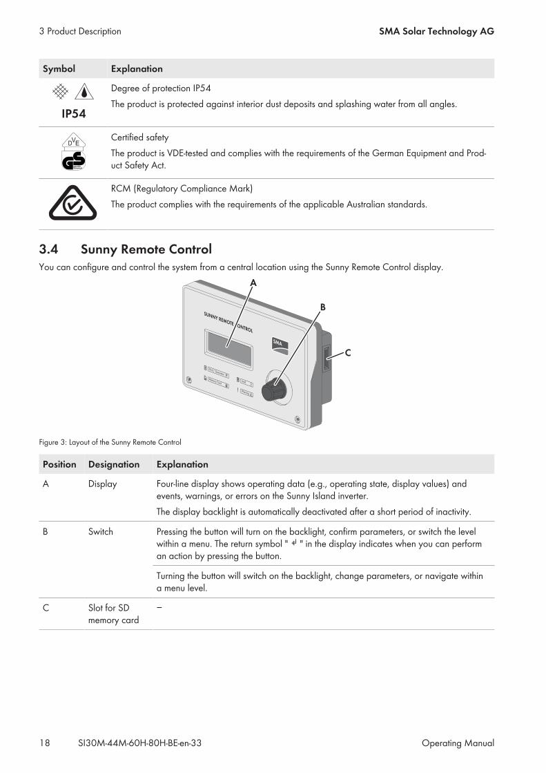
3.4 Sunny Remote ControlYou can configure and control the system from a central location using the Sunny Remote Control display.
SUNNY REMOTE CONTROL
Warning
LoadMemory Card
Grid / Generator
A
B
C
Figure 3: Layout of the Sunny Remote Control
Position Designation Explanation
A Display Four-line display shows operating data (e.g., operating state, display values) andevents, warnings, or errors on the Sunny Island inverter.The display backlight is automatically deactivated after a short period of inactivity.
B Switch Pressing the button will turn on the backlight, confirm parameters, or switch the levelwithin a menu. The return symbol " " in the display indicates when you can performan action by pressing the button.
Turning the button will switch on the backlight, change parameters, or navigate withina menu level.
C Slot for SDmemory card
−
3 Product Description SMA Solar Technology AG
Operating ManualSI30M-44M-60H-80H-BE-en-3318
Service Interface, SD Memory CardThe Sunny Remote Control has a slot for SD memory cards. The SD memory card stores data for system control andfacilitates service work. The SD memory card also allows you to update the firmware on the Sunny Island inverter. Thefollowing data is stored on the SD memory card:• Parameter Settings• Every minute, measurement data from the areas:– Battery– Sunny Island– Generator– Utility grid– Stand-alone grid
• Events and errors• Statistical values of the batteryThe SD memory card must be formatted as FAT-16 or FAT-32.
3 Product DescriptionSMA Solar Technology AG
Operating Manual 19SI30M-44M-60H-80H-BE-en-33
4 Starting and Stopping the System
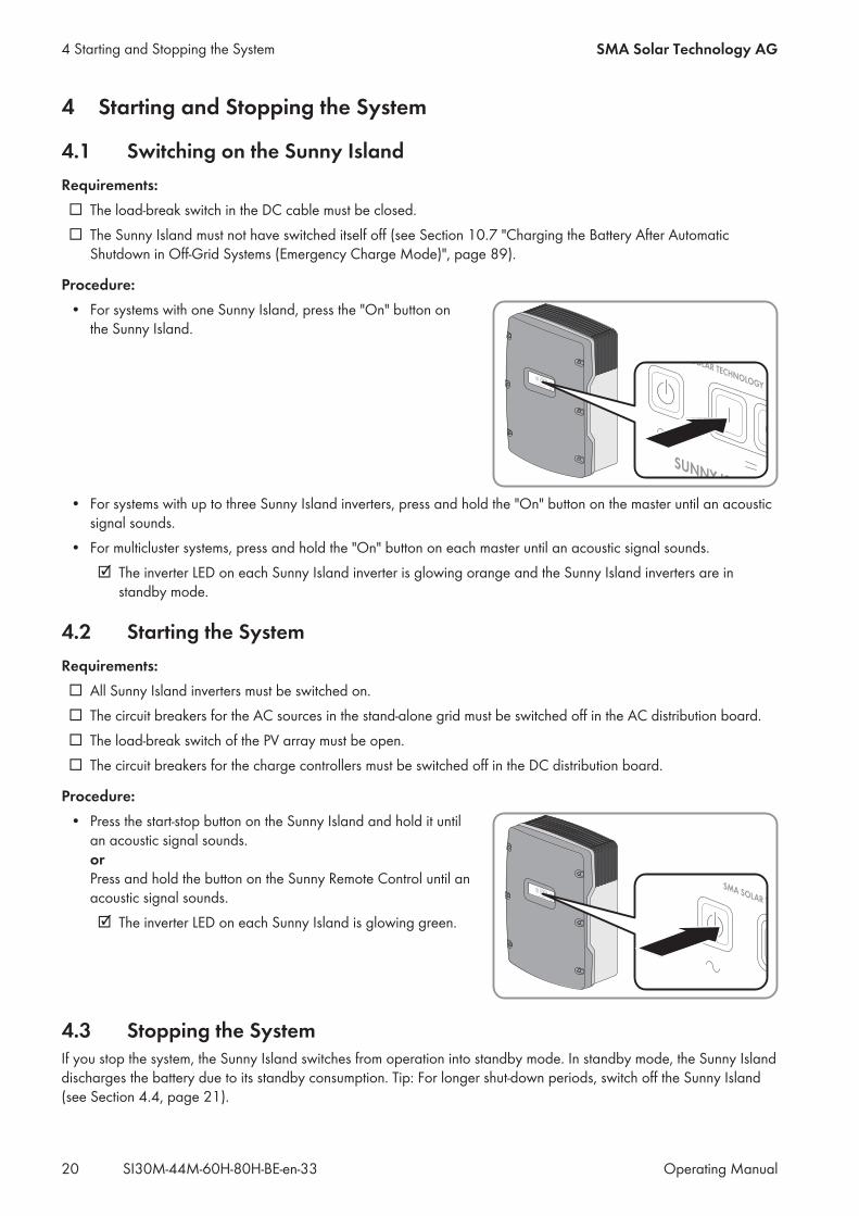
4.1 Switching on the Sunny IslandRequirements: The load-break switch in the DC cable must be closed. The Sunny Island must not have switched itself off (see Section 10.7 "Charging the Battery After AutomaticShutdown in Off-Grid Systems (Emergency Charge Mode)", page 89).
Procedure:• For systems with one Sunny Island, press the "On" button onthe Sunny Island.
• For systems with up to three Sunny Island inverters, press and hold the "On" button on the master until an acousticsignal sounds.
• For multicluster systems, press and hold the "On" button on each master until an acoustic signal sounds. The inverter LED on each Sunny Island inverter is glowing orange and the Sunny Island inverters are instandby mode.
4.2 Starting the SystemRequirements: All Sunny Island inverters must be switched on. The circuit breakers for the AC sources in the stand-alone grid must be switched off in the AC distribution board. The load-break switch of the PV array must be open. The circuit breakers for the charge controllers must be switched off in the DC distribution board.
Procedure:• Press the start-stop button on the Sunny Island and hold it untilan acoustic signal sounds.orPress and hold the button on the Sunny Remote Control until anacoustic signal sounds. The inverter LED on each Sunny Island is glowing green.
4.3 Stopping the SystemIf you stop the system, the Sunny Island switches from operation into standby mode. In standby mode, the Sunny Islanddischarges the battery due to its standby consumption. Tip: For longer shut-down periods, switch off the Sunny Island(see Section 4.4, page 21).
4 Starting and Stopping the System SMA Solar Technology AG
Operating ManualSI30M-44M-60H-80H-BE-en-3320
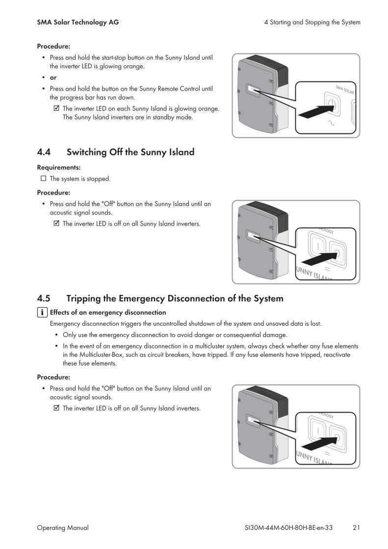
Procedure:• Press and hold the start-stop button on the Sunny Island untilthe inverter LED is glowing orange.
• or• Press and hold the button on the Sunny Remote Control untilthe progress bar has run down. The inverter LED on each Sunny Island is glowing orange.The Sunny Island inverters are in standby mode.
4.4 Switching Off the Sunny IslandRequirements: The system is stopped.
Procedure:• Press and hold the "Off" button on the Sunny Island until anacoustic signal sounds. The inverter LED is off on all Sunny Island inverters.
4.5 Tripping the Emergency Disconnection of the SystemEffects of an emergency disconnectionEmergency disconnection triggers the uncontrolled shutdown of the system and unsaved data is lost.• Only use the emergency disconnection to avoid danger or consequential damage.• In the event of an emergency disconnection in a multicluster system, always check whether any fuse elementsin the Multicluster-Box, such as circuit breakers, have tripped. If any fuse elements have tripped, reactivatethese fuse elements.
Procedure:• Press and hold the "Off" button on the Sunny Island until anacoustic signal sounds. The inverter LED is off on all Sunny Island inverters.
4 Starting and Stopping the SystemSMA Solar Technology AG
Operating Manual 21SI30M-44M-60H-80H-BE-en-33
4.6 Setting Time-Controlled Inverter Operation in Off-Grid Systems
Example: Parameter settings for time-controlled inverter operationYou want to operate the Sunny Island in inverter operation every Sunday from 10:00 a.m. to 6:00 p.m., starting onSunday, January 8, 2012. To do this, set the Sunny Island as follows:• Str.Date: 08.01.2012• Start Time: 10:00:00• Run Time: 08:00:00• Repetition: Weekly
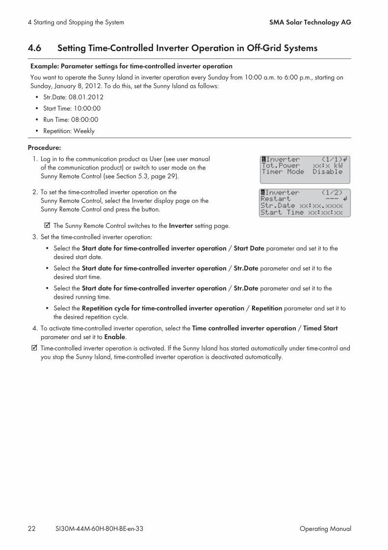
Procedure:1. Log in to the communication product as User (see user manualof the communication product) or switch to user mode on theSunny Remote Control (see Section 5.3, page 29).
iInverter (1/1)
Tot.Power xx:x kW
Timer Mode Disable
Ã
2. To set the time-controlled inverter operation on theSunny Remote Control, select the Inverter display page on theSunny Remote Control and press the button.
sInverter (1/2)
Restart ---
Str.Date xx:xx.xxxx
Start Time xx:xx:xx
Ã
The Sunny Remote Control switches to the Inverter setting page.3. Set the time-controlled inverter operation:• Select the Start date for time-controlled inverter operation / Start Date parameter and set it to thedesired start date.
• Select the Start date for time-controlled inverter operation / Str.Date parameter and set it to thedesired start time.
• Select the Start date for time-controlled inverter operation / Str.Date parameter and set it to thedesired running time.
• Select the Repetition cycle for time-controlled inverter operation / Repetition parameter and set it tothe desired repetition cycle.
4. To activate time-controlled inverter operation, select the Time controlled inverter operation / Timed Startparameter and set it to Enable.
Time-controlled inverter operation is activated. If the Sunny Island has started automatically under time-control andyou stop the Sunny Island, time-controlled inverter operation is deactivated automatically.
4 Starting and Stopping the System SMA Solar Technology AG
Operating ManualSI30M-44M-60H-80H-BE-en-3322
5 Operation of the Sunny Island Inverter with theSunny Remote Control
5.1 Display ModesThe Sunny Remote Control uses four display modes for the display. The Sunny Remote Control will switch to standardmode if the button has not been used for over five minutes.
State Page contents
Standard mode <home> • Message regarding operating states• Display of energy flows• Display of key parametersIn display messages on the Sunny Remote Control, <home> refers to the standardmode.
User mode User • Display of and access to key operating parametersIn display messages on the Sunny Remote Control, User refers to the user mode.
Installer mode Installer • Display of and access to configuration and operation parametersThe installer mode is protected with an installer password. In display messages on theSunny Remote Control, Installer refers to the installer mode.
Expert mode Expert • Display of and access to all parameters for the system configuration set in QCGThe expert mode can be accessed only via installer mode (see Section 5.4.1, page 32). In display messages on the Sunny Remote Control, Expert refers to the expert mode.
The parameters for devices that are not configured are hidden, e.g., the generator parameters are hidden for systemswithout a generator. The parameters for multicluster systems are available only in expert mode.
5 Operation of the Sunny Island Inverter with the Sunny Remote ControlSMA Solar Technology AG
Operating Manual 23SI30M-44M-60H-80H-BE-en-33
5.2 Standard Mode
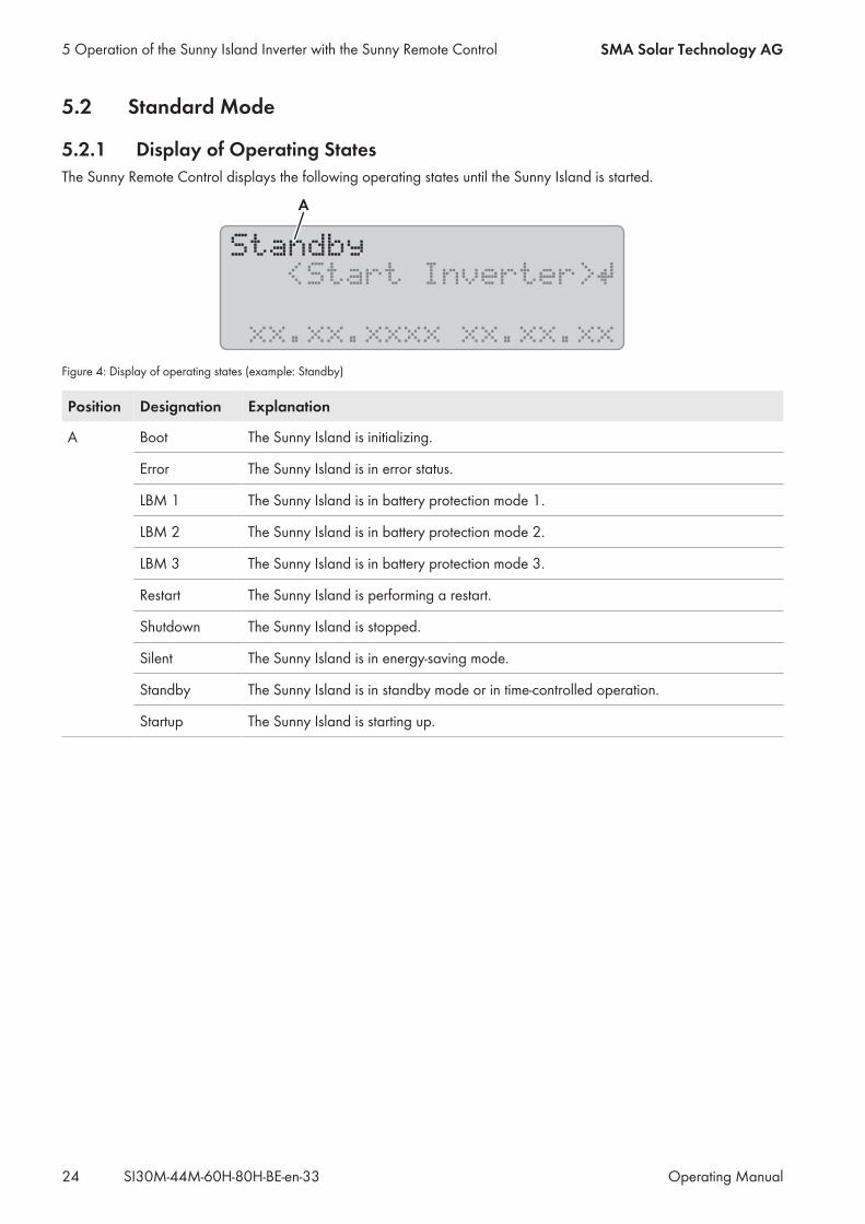
5.2.1 Display of Operating StatesThe Sunny Remote Control displays the following operating states until the Sunny Island is started.
<Start Inverter>
xx.xx.xxxx xx.xx.xx
Ã
Standby
A
Figure 4: Display of operating states (example: Standby)
Position Designation Explanation
A Boot The Sunny Island is initializing.
Error The Sunny Island is in error status.
LBM 1 The Sunny Island is in battery protection mode 1.
LBM 2 The Sunny Island is in battery protection mode 2.
LBM 3 The Sunny Island is in battery protection mode 3.
Restart The Sunny Island is performing a restart.
Shutdown The Sunny Island is stopped.
Silent The Sunny Island is in energy-saving mode.
Standby The Sunny Island is in standby mode or in time-controlled operation.
Startup The Sunny Island is starting up.
5 Operation of the Sunny Island Inverter with the Sunny Remote Control SMA Solar Technology AG
Operating ManualSI30M-44M-60H-80H-BE-en-3324

5.2.2 Information Page in Systems for Increased Self-Consumption and BatteryBackup Systems
When the Sunny Island is started, the Sunny Remote Control provides information on the status of the system forincreased self-consumption.
HCD
F
G
À 1.5kW !M1
oo
!
+-Á 0.0kW SOC 99%
04:17:30
A B
E
Figure 5: Energy flows and status messages of the Sunny Island
Position Symbol Designation Explanation
A Warning symbol Symbol for warnings and errors that do not affect the Sunny Islandoperation.If this symbol is flashing, acknowledge the error or warning (see Sec-tion 10.3, page 47).
B Device assignment The Sunny Island connected to the Sunny Remote Control is the mas-ter.
The Sunny Island connected to the Sunny Remote Control is slave 1.
The Sunny Island connected to the Sunny Remote Control is slave 2.
C SD Memory Card SD memory card is inserted.
Symbolflashing
The Sunny Island is accessing the SD memory card.
NoneSymbol
SD memory card not inserted.
D Multifunction relay 1 Multifunction relay 1 is deactivated.
Multifunction relay 1 is activated.
E Multifunction relay 2 Multifunction relay 2 is deactivated.
Multifunction relay 2 is activated.
F Battery power andstate of charge*
The battery is being charged.
The battery is being discharged.
Battery power in kW, state of charge (SOC) in %
G hh:mm:ss Time System time
5 Operation of the Sunny Island Inverter with the Sunny Remote ControlSMA Solar Technology AG
Operating Manual 25SI30M-44M-60H-80H-BE-en-33
Position Symbol Designation Explanation
H Power and status ofthe utility grid*
Power in kW
The utility grid voltage and frequency are within the configured limits.
The maximum reverse power in the utility grid has been exceeded.
* If a PV production meter is installed, load power and PV production are additionally shown in kW on the left side of the display. Loadpower is marked with L and PV production with P.
5.2.3 Information Page in Off-Grid Systems
0.0kW 1.1kW oo
*
67% xx:xx:xx
--- ------- ! M1
BA C
D
E
Figure 6: Energy flows and status of the Sunny Island inverter (example)
Position Designation
A Graphical Representation of the Energy Flows
B Status of the stand-alone grid
C Status of the Sunny Island Inverter
D State of charge of the battery
E Status of the generator
Graphical Representation of the Energy Flows
0.0kW 1.1kW oo
*
67% xx:xx:xx
--- ------- ! M1B
A
C D E F
Figure 7: Energy flow diagram in standard mode (example)
Position Symbol Designation Explanation
A Battery Battery symbolIf this symbol is flashing, acknowledge the error or warning
B Direction ofenergy flow
The battery is supplying the loads.
The battery is being charged.
C Generator Generator symbol
5 Operation of the Sunny Island Inverter with the Sunny Remote Control SMA Solar Technology AG
Operating ManualSI30M-44M-60H-80H-BE-en-3326
Position Symbol Designation Explanation
D Internal transfer relay The generator is disconnected from the stand-alone grid.
The stand-alone grid is synchronized with the generator. The genera-tor is supplying the loads and charging the battery.
E Direction ofenergy flow
Loads are being supplied.
AC sources in the stand-alone grid are supplying more energy than isbeing consumed by the stand-alone grid.
F Loads in theStand-alone grid
Symbol for loads in the stand-alone grid
Status of the Sunny Island Inverter
0.0kW 1.1kW
*
67%
oo
xx:xx:xx
--- ------- ! M1
BA
C
D
E
F
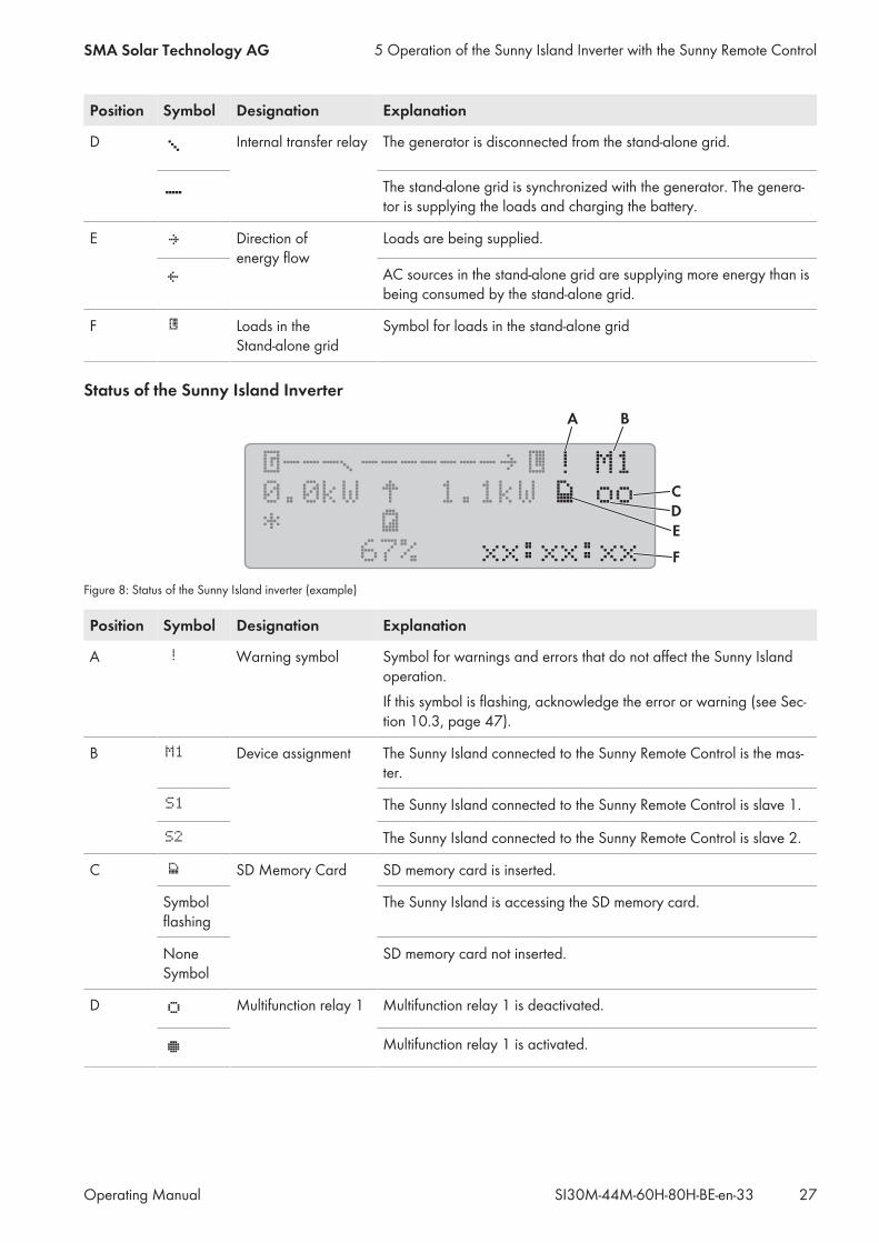
Figure 8: Status of the Sunny Island inverter (example)
Position Symbol Designation Explanation
A Warning symbol Symbol for warnings and errors that do not affect the Sunny Islandoperation.If this symbol is flashing, acknowledge the error or warning (see Sec-tion 10.3, page 47).
B Device assignment The Sunny Island connected to the Sunny Remote Control is the mas-ter.
The Sunny Island connected to the Sunny Remote Control is slave 1.
The Sunny Island connected to the Sunny Remote Control is slave 2.
C SD Memory Card SD memory card is inserted.
Symbolflashing
The Sunny Island is accessing the SD memory card.
NoneSymbol
SD memory card not inserted.
D Multifunction relay 1 Multifunction relay 1 is deactivated.
Multifunction relay 1 is activated.
5 Operation of the Sunny Island Inverter with the Sunny Remote ControlSMA Solar Technology AG
Operating Manual 27SI30M-44M-60H-80H-BE-en-33
Position Symbol Designation Explanation
E Multifunction relay 2 Multifunction relay 2 is deactivated.
Multifunction relay 2 is activated.
G hh:mm:ss Time System time
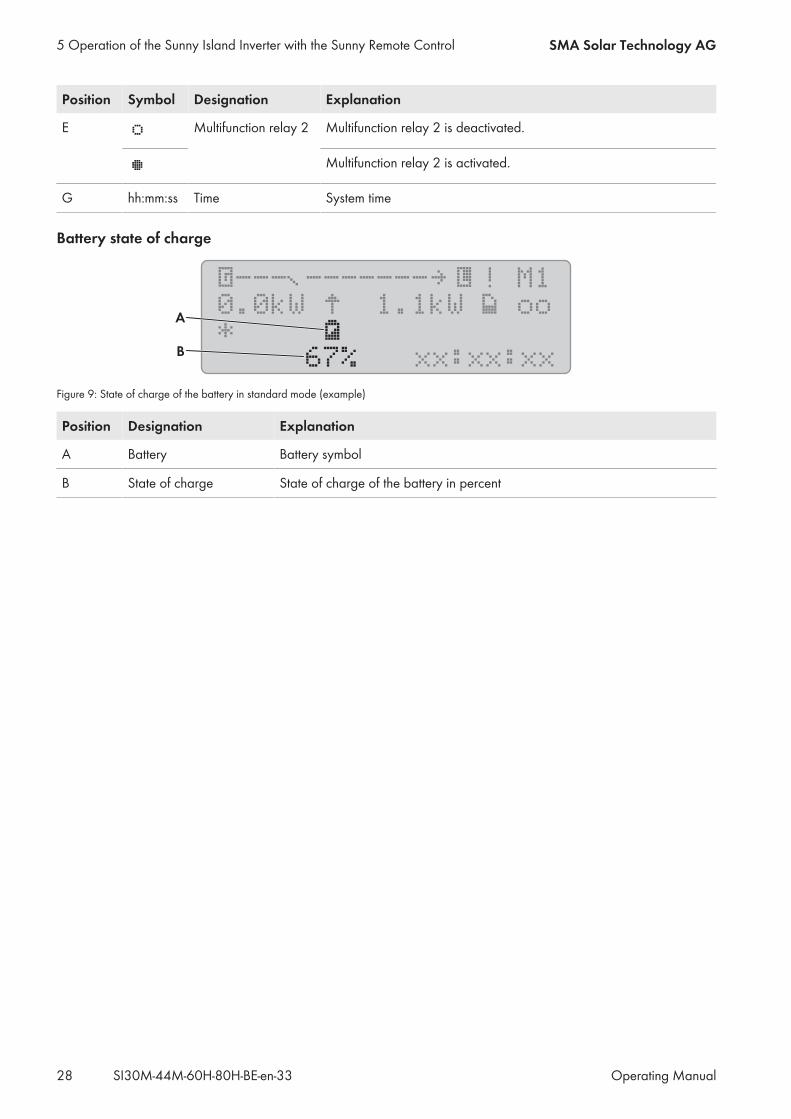
Battery state of charge
0.0kW 1.1kW oo
*
67% xx:xx:xx
--- ------- ! M1
B
A
Figure 9: State of charge of the battery in standard mode (example)
Position Designation Explanation
A Battery Battery symbol
B State of charge State of charge of the battery in percent
5 Operation of the Sunny Island Inverter with the Sunny Remote Control SMA Solar Technology AG
Operating ManualSI30M-44M-60H-80H-BE-en-3328
Status of the External Energy Source
0.0kW
*
1.1kW oo
67% xx:xx:xx
------ ! M1--- -C
D
B
A
Figure 10: Status of the external energy source in standard mode (example)
Position Symbol Designation Explanation
A Status of the generator Voltage and frequency of the generator are within the thresholdsset.
The maximum reverse power in the generator has been exceeded.
BatteryElectricity generator was requested due to state of charge.
CycleGenerator was requested via time control.
ExternalGenerator was requested by an extension cluster.
LoadElectricity generator was requested due to load.
StartYou have manually started the generator via Sunny Remote Con-trol or a generator was requested via the DigIn input.
TimeYou have started the generator for one hour via Sunny Re-mote Control.
B − Power of the generatoror the utility grid
Power in kW
C Generator Generator symbol
D Internal transfer relay The generator is disconnected from the stand-alone grid.
The stand-alone grid is synchronized with the generator. The gener-ator is supplying the loads and charging the battery.
5.3 User Mode
5.3.1 Pages in the User ModeUser mode displays all important information for the system sorted by category. User mode enables manual control ofthe Sunny Island inverter or system devices, e.g., generator start.
5 Operation of the Sunny Island Inverter with the Sunny Remote ControlSMA Solar Technology AG
Operating Manual 29SI30M-44M-60H-80H-BE-en-33
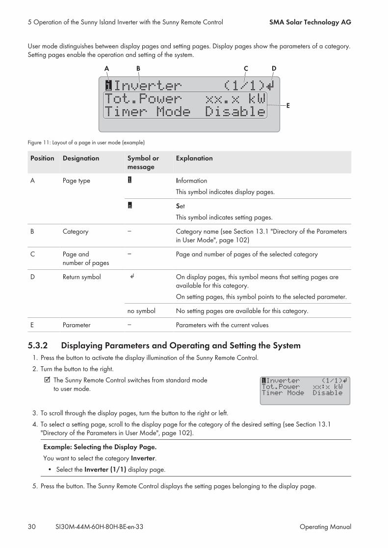
User mode distinguishes between display pages and setting pages. Display pages show the parameters of a category.Setting pages enable the operation and setting of the system.
xx.x kW
Disable
iInverter
Tot.Power
Timer Mode
(1/1)
B CA
E
D
Figure 11: Layout of a page in user mode (example)
Position Designation Symbol ormessage
Explanation
A Page type InformationThis symbol indicates display pages.
SetThis symbol indicates setting pages.
B Category − Category name (see Section 13.1 "Directory of the Parametersin User Mode", page 102)
C Page andnumber of pages
− Page and number of pages of the selected category
D Return symbol On display pages, this symbol means that setting pages areavailable for this category.On setting pages, this symbol points to the selected parameter.
no symbol No setting pages are available for this category.
E Parameter − Parameters with the current values
5.3.2 Displaying Parameters and Operating and Setting the System1. Press the button to activate the display illumination of the Sunny Remote Control.2. Turn the button to the right. The Sunny Remote Control switches from standard modeto user mode.
iInverter (1/1)
Tot.Power xx:x kW
Timer Mode Disable
Ã
3. To scroll through the display pages, turn the button to the right or left.4. To select a setting page, scroll to the display page for the category of the desired setting (see Section 13.1"Directory of the Parameters in User Mode", page 102).
Example: Selecting the Display Page.You want to select the category Inverter.• Select the Inverter (1/1) display page.
5. Press the button. The Sunny Remote Control displays the setting pages belonging to the display page.
5 Operation of the Sunny Island Inverter with the Sunny Remote Control SMA Solar Technology AG
Operating ManualSI30M-44M-60H-80H-BE-en-3330
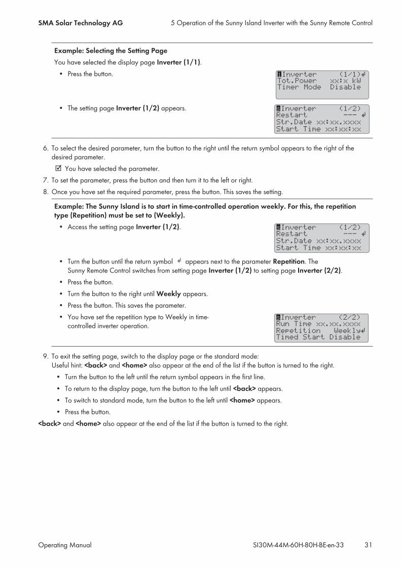
Example: Selecting the Setting PageYou have selected the display page Inverter (1/1).• Press the button. iInverter (1/1)
Tot.Power xx:x kW
Timer Mode Disable
Ã
• The setting page Inverter (1/2) appears. sInverter (1/2)
Restart ---
Str.Date xx:xx.xxxx
Start Time xx:xx:xx
Ã
6. To select the desired parameter, turn the button to the right until the return symbol appears to the right of thedesired parameter. You have selected the parameter.
7. To set the parameter, press the button and then turn it to the left or right.8. Once you have set the required parameter, press the button. This saves the setting.
Example: The Sunny Island is to start in time-controlled operation weekly. For this, the repetitiontype (Repetition) must be set to (Weekly).• Access the setting page Inverter (1/2). sInverter (1/2)
Restart ---
Str.Date xx:xx.xxxx
Start Time xx:xx:xx
Ã
• Turn the button until the return symbol appears next to the parameter Repetition. TheSunny Remote Control switches from setting page Inverter (1/2) to setting page Inverter (2/2).
• Press the button.• Turn the button to the right until Weekly appears.• Press the button. This saves the parameter.• You have set the repetition type to Weekly in time-controlled inverter operation.
sInverter (2/2)
Run Time
Repetition Weekly
Timed Start Disable
Ã
xx.xx.xxxx
9. To exit the setting page, switch to the display page or the standard mode:Useful hint: <back> and <home> also appear at the end of the list if the button is turned to the right.• Turn the button to the left until the return symbol appears in the first line.• To return to the display page, turn the button to the left until <back> appears.• To switch to standard mode, turn the button to the left until <home> appears.• Press the button.
<back> and <home> also appear at the end of the list if the button is turned to the right.
5 Operation of the Sunny Island Inverter with the Sunny Remote ControlSMA Solar Technology AG
Operating Manual 31SI30M-44M-60H-80H-BE-en-33
5.4 Installer Mode and Expert Mode
5.4.1 Switching to Installer Mode or Expert ModeThe installer mode is protected with an installer password. The installer password changes constantly and must berecalculated every time. Expert mode can be accessed only via installer mode.
System failures due to entry of incorrect parameter valuesThe system can become unstable and fail due to entry of incorrect parameter values. All parameters that could affectthe operational safety of the system are protected by the installer password.• Only a qualified person is permitted to set and adjust system parameters.• Give the installer password only to qualified persons and operators.
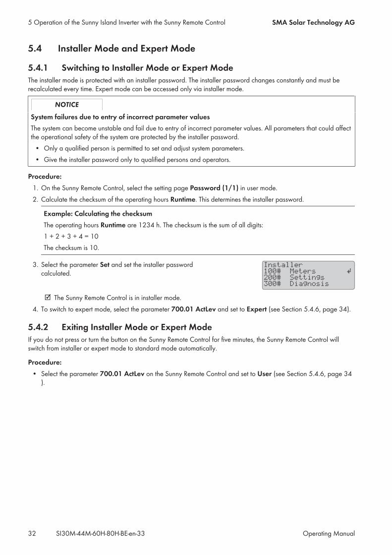
Procedure:1. On the Sunny Remote Control, select the setting page Password (1/1) in user mode.2. Calculate the checksum of the operating hours Runtime. This determines the installer password.
Example: Calculating the checksumThe operating hours Runtime are 1234 h. The checksum is the sum of all digits:1 + 2 + 3 + 4 = 10The checksum is 10.
3. Select the parameter Set and set the installer passwordcalculated.
Installer
100# Meters
200# Settings
300# Diagnosis
Ã
The Sunny Remote Control is in installer mode.4. To switch to expert mode, select the parameter 700.01 ActLev and set to Expert (see Section 5.4.6, page 34).
5.4.2 Exiting Installer Mode or Expert ModeIf you do not press or turn the button on the Sunny Remote Control for five minutes, the Sunny Remote Control willswitch from installer or expert mode to standard mode automatically.
Procedure:• Select the parameter 700.01 ActLev on the Sunny Remote Control and set to User (see Section 5.4.6, page 34).
5 Operation of the Sunny Island Inverter with the Sunny Remote Control SMA Solar Technology AG
Operating ManualSI30M-44M-60H-80H-BE-en-3332
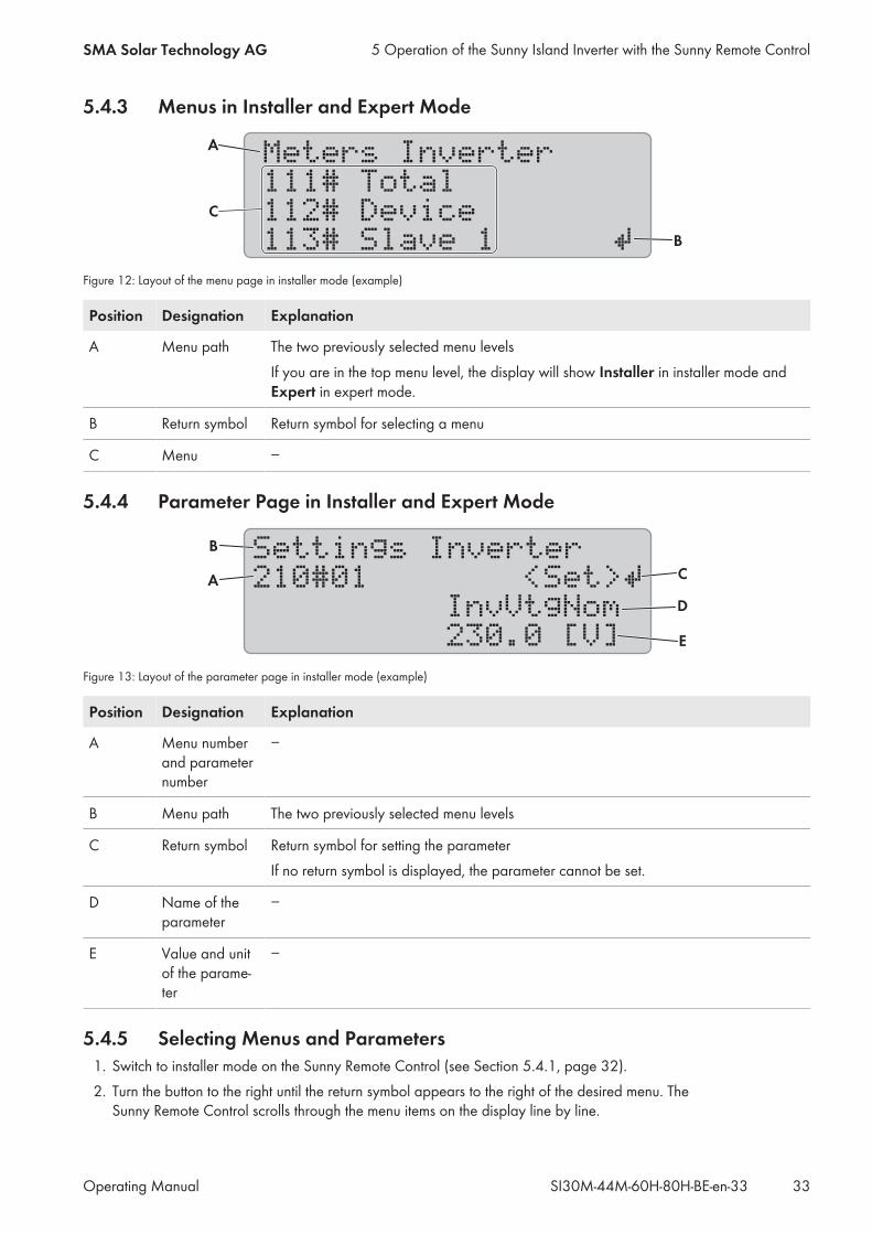
5.4.3 Menus in Installer and Expert Mode
Meters Inverter
111# Total
112# Device
113# Slave 1 B
A
C
Figure 12: Layout of the menu page in installer mode (example)
Position Designation Explanation
A Menu path The two previously selected menu levelsIf you are in the top menu level, the display will show Installer in installer mode andExpert in expert mode.
B Return symbol Return symbol for selecting a menu
C Menu −
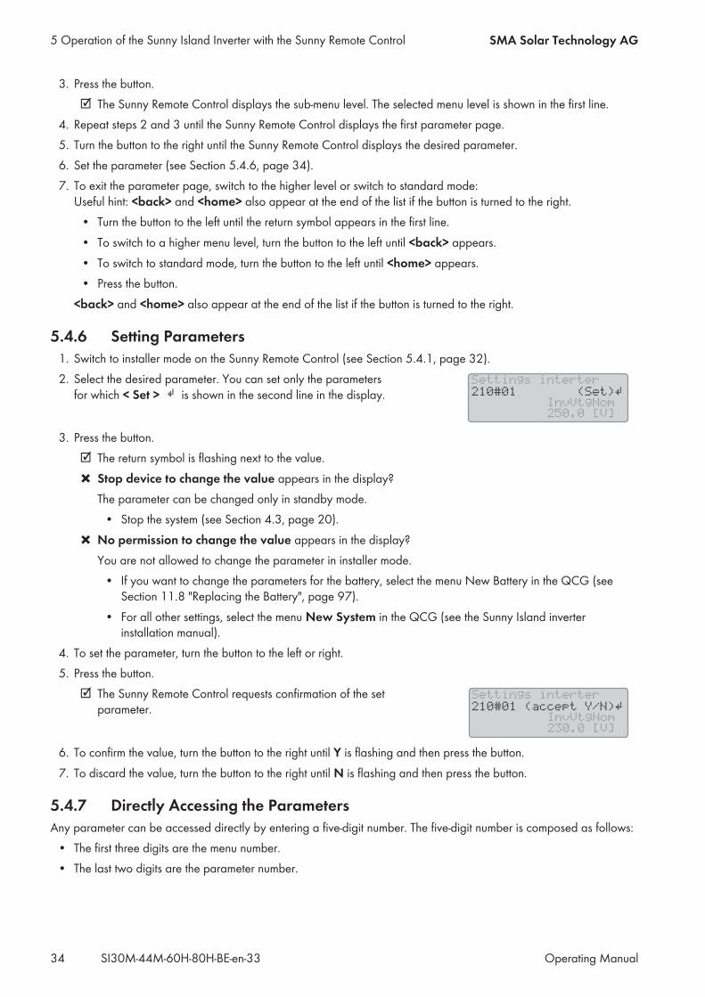
5.4.4 Parameter Page in Installer and Expert Mode
Settings Inverter
210#01 <Set>
InvVtgNom
230.0 [V]
A
D
C
B
E
Figure 13: Layout of the parameter page in installer mode (example)
Position Designation Explanation
A Menu numberand parameternumber
−
B Menu path The two previously selected menu levels
C Return symbol Return symbol for setting the parameterIf no return symbol is displayed, the parameter cannot be set.
D Name of theparameter
−
E Value and unitof the parame-ter
−
5.4.5 Selecting Menus and Parameters1. Switch to installer mode on the Sunny Remote Control (see Section 5.4.1, page 32).2. Turn the button to the right until the return symbol appears to the right of the desired menu. TheSunny Remote Control scrolls through the menu items on the display line by line.
5 Operation of the Sunny Island Inverter with the Sunny Remote ControlSMA Solar Technology AG
Operating Manual 33SI30M-44M-60H-80H-BE-en-33
3. Press the button. The Sunny Remote Control displays the sub-menu level. The selected menu level is shown in the first line.
4. Repeat steps 2 and 3 until the Sunny Remote Control displays the first parameter page.5. Turn the button to the right until the Sunny Remote Control displays the desired parameter.6. Set the parameter (see Section 5.4.6, page 34).7. To exit the parameter page, switch to the higher level or switch to standard mode:Useful hint: <back> and <home> also appear at the end of the list if the button is turned to the right.• Turn the button to the left until the return symbol appears in the first line.• To switch to a higher menu level, turn the button to the left until <back> appears.• To switch to standard mode, turn the button to the left until <home> appears.• Press the button.
<back> and <home> also appear at the end of the list if the button is turned to the right.
5.4.6 Setting Parameters1. Switch to installer mode on the Sunny Remote Control (see Section 5.4.1, page 32).2. Select the desired parameter. You can set only the parametersfor which < Set > is shown in the second line in the display.
Settings interter
InvVtgNom
250.0 [V]
210#01 (Set)
3. Press the button. The return symbol is flashing next to the value. Stop device to change the value appears in the display?The parameter can be changed only in standby mode.• Stop the system (see Section 4.3, page 20).
No permission to change the value appears in the display?You are not allowed to change the parameter in installer mode.• If you want to change the parameters for the battery, select the menu New Battery in the QCG (seeSection 11.8 "Replacing the Battery", page 97).
• For all other settings, select the menu New System in the QCG (see the Sunny Island inverterinstallation manual).
4. To set the parameter, turn the button to the left or right.5. Press the button. The Sunny Remote Control requests confirmation of the setparameter.
Settings interter
InvVtgNom
230.0 [V]
210#01 (accept Y/N)
6. To confirm the value, turn the button to the right until Y is flashing and then press the button.7. To discard the value, turn the button to the right until N is flashing and then press the button.
5.4.7 Directly Accessing the ParametersAny parameter can be accessed directly by entering a five-digit number. The five-digit number is composed as follows:• The first three digits are the menu number.• The last two digits are the parameter number.
5 Operation of the Sunny Island Inverter with the Sunny Remote Control SMA Solar Technology AG
Operating ManualSI30M-44M-60H-80H-BE-en-3334
Example: Five-digit number for direct parameter access.The parameter 111.01 TotInvPwrAt allows you to display the complete active power of the Sunny Island invertersin a cluster. The five-digit number for direct access is 11101.
Procedure:1. Switch to installer mode on the Sunny Remote Control (see Section 5.4.1, page 32).2. Select the parameter 600.02 Select Number and set the five-digit number. The parameter is displayed. The display shows Item not Found?You are still in the installer mode or entered the wrong number.• Switch to expert mode (see Section 5.4.1, page 32) or repeat the entry.
5 Operation of the Sunny Island Inverter with the Sunny Remote ControlSMA Solar Technology AG
Operating Manual 35SI30M-44M-60H-80H-BE-en-33
6 Operation of the Sunny Island Inverter with a CommunicationProduct
When operating a Sunny Island inverter with a communication product, observe the following differences comparedwith operation via Sunny Remote Control:• When the parameters and messages of the Sunny Island inverter are accessed via the communication product, thedefined access rights of the communication product apply (see user manual of the communication product).
• The inverter messages are displayed on the screen of the communication product as clear-text names (seetechnical information "SUNNY ISLAND – Message of the same event for Speedwire (e. g. Sunny Explorer) andRS485 / Sunny Remote Control").
Example:The Sunny Remote Control displays the following message when the Sunny Island inverter is warning of highoperating temperatures: W212 BatTmpHiWarn.The same warning message appears as clear text on the screen of the communication product:Overtemperature fault in battery.
• The inverter parameters are displayed on the screen of the communication product as clear-text names (seetechnical information "SUNNY ISLAND – Comparison of the same parameters forSpeedwire (e. g. Sunny Explorer) and RS485 / Sunny Remote Control").
Example:Example: The information regarding the reason for the generator request sent by the Sunny Island is displayedon the screen of the Sunny Remote Control as parameter number and parameter name: 133.01 GnDmdSrc.The same information appears as clear text on the screen of the communication product: Reason forrequesting generator.
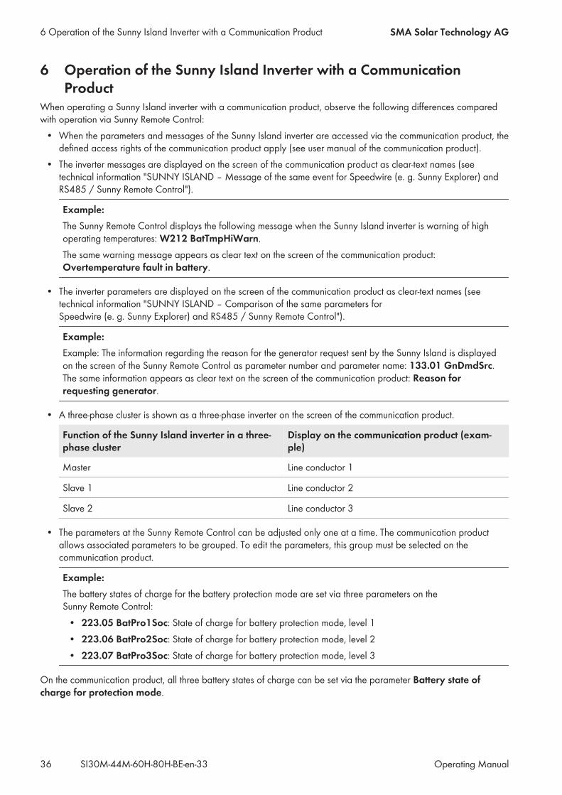
• A three-phase cluster is shown as a three-phase inverter on the screen of the communication product.
Function of the Sunny Island inverter in a three-phase cluster
Display on the communication product (exam-ple)
Master Line conductor 1
Slave 1 Line conductor 2
Slave 2 Line conductor 3
• The parameters at the Sunny Remote Control can be adjusted only one at a time. The communication productallows associated parameters to be grouped. To edit the parameters, this group must be selected on thecommunication product.
Example:The battery states of charge for the battery protection mode are set via three parameters on theSunny Remote Control:• 223.05 BatPro1Soc: State of charge for battery protection mode, level 1• 223.06 BatPro2Soc: State of charge for battery protection mode, level 2• 223.07 BatPro3Soc: State of charge for battery protection mode, level 3
On the communication product, all three battery states of charge can be set via the parameter Battery state ofcharge for protection mode.
6 Operation of the Sunny Island Inverter with a Communication Product SMA Solar Technology AG
Operating ManualSI30M-44M-60H-80H-BE-en-3336

7 Data Storage and Firmware Update
7.1 Data Storage on the ComputerWith Sunny Explorer, you can save system yields and events as CSV files on your computer (see user manual ofSunny Explorer). The CSV files can be opened in Microsoft Excel and the data can be used e.g. to create diagrams.
7.2 Data Storage on SD Memory Card
7.2.1 Insert the SD Memory CardRequirements: The SD memory card must be formatted as FAT-16 or FAT-32. The SD memory card must be used exclusively as a data medium for the system.
Procedure:• Insert the SD memory card, with the slanted corner facingupwards, into the SD memory card slot in theSunny Remote Control.
SUNNY REMOTE CONTROL
Warning
LoadMemory Card
Grid / Generator
7.2.2 Loading and Saving ParametersYou can load and save the current parameter settings in two different parameter sets on the SD memory card. TheSunny Remote Control calls the two parameter sets Set1 and Set2. Each parameter set saves all settings. This makes itpossible to test the settings of a new parameter set without having to delete the old parameter set. Useful hint: As soon as you have adjusted the system to your requirements, save the parameter settings to the SDmemory card. After saving, you can make further adjustments to the system. If the adjustment does not lead to thedesired results, reload the saved parameter set.
Requirement: The SD memory card must be inserted.
Procedure:1. Switch to installer mode on the Sunny Remote Control (see Section 5.4.1, page 32).2. To save a parameter set, select the parameter 550.01 ParaSto and set the parameter:
Value Explanation
Set1 Save the settings in the first parameter set.
Set2 Save the settings in the second parameter set.
3. Proceed as follows to load a parameter set:• Switch to expert mode on the Sunny Remote Control (see Section 5.4.1, page 32).• Select the parameter 550.02 ParaLod and set the parameter:
Value Explanation
Set1 Save the settings in the first parameter set.
7 Data Storage and Firmware UpdateSMA Solar Technology AG
Operating Manual 37SI30M-44M-60H-80H-BE-en-33
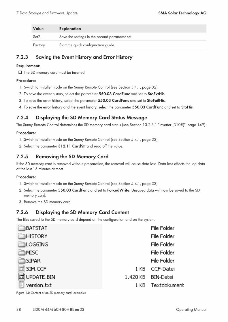
Value Explanation
Set2 Save the settings in the second parameter set.
Factory Start the quick configuration guide.
7.2.3 Saving the Event History and Error HistoryRequirement: The SD memory card must be inserted.
Procedure:1. Switch to installer mode on the Sunny Remote Control (see Section 5.4.1, page 32).2. To save the event history, select the parameter 550.03 CardFunc and set to StoEvtHis.3. To save the error history, select the parameter 550.03 CardFunc and set to StoFailHis.4. To save the error history and the event history, select the parameter 550.03 CardFunc and set to StoHis.
7.2.4 Displaying the SD Memory Card Status MessageThe Sunny Remote Control determines the SD memory card status (see Section 13.2.3.1 "Inverter (310#)", page 149).
Procedure:1. Switch to installer mode on the Sunny Remote Control (see Section 5.4.1, page 32).2. Select the parameter 312.11 CardStt and read off the value.
7.2.5 Removing the SD Memory CardIf the SD memory card is removed without preparation, the removal will cause data loss. Data loss affects the log dataof the last 15 minutes at most.
Procedure:1. Switch to installer mode on the Sunny Remote Control (see Section 5.4.1, page 32).2. Select the parameter 550.03 CardFunc and set to ForcedWrite. Unsaved data will now be saved to the SDmemory card.
3. Remove the SD memory card.
7.2.6 Displaying the SD Memory Card ContentThe files saved to the SD memory card depend on the configuration and on the system.
Figure 14: Content of an SD memory card (example)
7 Data Storage and Firmware Update SMA Solar Technology AG
Operating ManualSI30M-44M-60H-80H-BE-en-3338
Explanation of the folders:
Folder name Explanation
BATSTAT Folder containing battery statistics for each monthThe files are stored by year and month in sub-folders.
HISTORY Folder containing event and error histories
LOGGING Folder containing the data logging, event and error histories for each dayThe files are stored by year and month in sub-folders.
SIPAR Folder containing the parameter lists
Explanation of the files within the folders:
File name Explanation
evthis.log Event history
errhis.log Error history
si010112.evt Event and error histories for one dayThe date (ddmmyy) is part of the file name.
si010112.log Data logging for the dayThe date (ddmmyy) is part of the file name.
sipar.lst Current parameter set
sipar1.lst Parameter set 1
sipar2.lst Parameter set 2
update.bin Sunny Island inverter firmware
batstat.txt Statistical values of the batteryThese values are saved every night at 10:00 p.m.
batstat.sma Statistical values of the battery for evaluation by SMA Solar Technology AG
sim.ccf System information of the Sunny Island inverter
bootex.log File generated by the operating system of the computerThis file is not generated by every operating system.
Structure of the files:The files are CSV files, which means that the data is saved as ASCII text. The files are structured as follows:• The first lines in the file are used for information. Information lines start and end with the character #.• The data in the following lines is separated by semicolons.• Decimal places are separated by periods.• The date format is dd.mm.yyyy.• The time format is hh:mm:ss.• Some of the parameter values are saved with plain text numbers (see Section 13.2 "Directory of the Parameters inInstaller Mode and Expert Mode", page 108).
7 Data Storage and Firmware UpdateSMA Solar Technology AG
Operating Manual 39SI30M-44M-60H-80H-BE-en-33
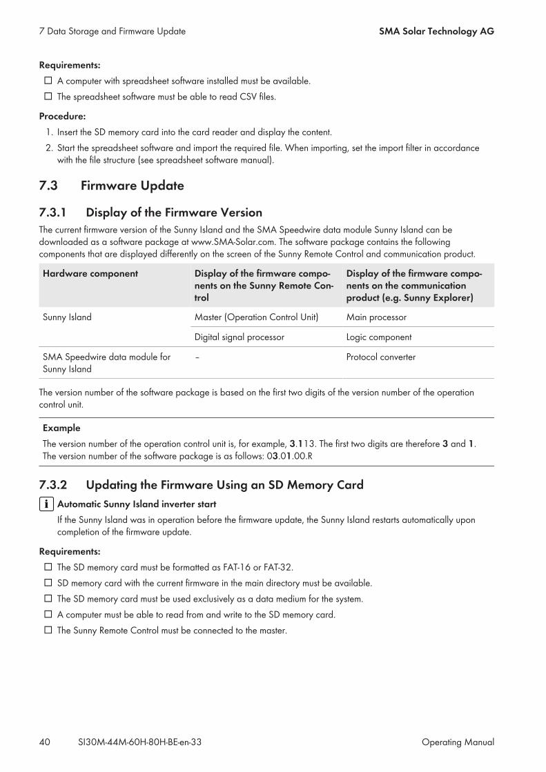
Requirements: A computer with spreadsheet software installed must be available. The spreadsheet software must be able to read CSV files.
Procedure:1. Insert the SD memory card into the card reader and display the content.2. Start the spreadsheet software and import the required file. When importing, set the import filter in accordancewith the file structure (see spreadsheet software manual).
7.3 Firmware Update
7.3.1 Display of the Firmware VersionThe current firmware version of the Sunny Island and the SMA Speedwire data module Sunny Island can bedownloaded as a software package at www.SMA-Solar.com. The software package contains the followingcomponents that are displayed differently on the screen of the Sunny Remote Control and communication product.
Hardware component Display of the firmware compo-nents on the Sunny Remote Con-trol
Display of the firmware compo-nents on the communicationproduct (e.g. Sunny Explorer)
Sunny Island Master (Operation Control Unit) Main processor
Digital signal processor Logic component
SMA Speedwire data module forSunny Island
– Protocol converter
The version number of the software package is based on the first two digits of the version number of the operationcontrol unit.
ExampleThe version number of the operation control unit is, for example, 3.113. The first two digits are therefore 3 and 1.The version number of the software package is as follows: 03.01.00.R
7.3.2 Updating the Firmware Using an SD Memory CardAutomatic Sunny Island inverter startIf the Sunny Island was in operation before the firmware update, the Sunny Island restarts automatically uponcompletion of the firmware update.
Requirements: The SD memory card must be formatted as FAT-16 or FAT-32. SD memory card with the current firmware in the main directory must be available. The SD memory card must be used exclusively as a data medium for the system. A computer must be able to read from and write to the SD memory card. The Sunny Remote Control must be connected to the master.
7 Data Storage and Firmware Update SMA Solar Technology AG
Operating ManualSI30M-44M-60H-80H-BE-en-3340
Procedure:1. Insert the SD memory card into the SD memory card slot (see Section 7.2.1, page 37).2. Wait until the message UPDATE AVAILABLE appears. This can take up to two minutes.3. Confirm the question UPDATE AVAILABLE Start update now ? with YES. The Sunny Island switches to standby and updates the firmware.
7.3.3 Updating the Firmware Using Sunny ExplorerAutomatic Sunny Island inverter startIf the Sunny Island was in operation before the firmware update, the Sunny Island restarts automatically uponcompletion of the firmware update.
Using Sunny Explorer, transfer the firmware update to the SMA Speedwire data module Sunny Island. Then, the SMASpeedwire data module Sunny Island automatically transfers the firmware update to the SD memory card in theSunny Remote Control. This transfer takes some time.
Requirements: The SMA Speedwire data module Sunny Island of the type SWDMSI-NR10 with firmware version 1.01.06.R orhigher must be installed in the system.
A computer with Sunny Explorer and the current firmware must be available. The Sunny Remote Control must be connected to the master.
Procedure:1. Ensure that a writable SD memory card is inserted in the Sunny Remote Control and remains inserted throughoutthe entire update.
2. Switch to installer mode on the Sunny Remote Control (see Section 5.4.1, page 32).3. Set the parameter 250.32 UpdMode to Auto.4. Set the parameter 250.33 UpdAutoTime to the desired firmware update time.5. Transfer the firmware update from the computer to the Sunny Island using Sunny Explorer (see the Sunny Exploreruser manual).
6. Once the transfer is complete, close Sunny Explorer. Once the transfer to the SD memory card is complete, the Sunny Island updates automatically at the specifiedtime. The Sunny Island switches to standby mode and updates the firmware.
7.3.4 Performing a Remote Update Using the Sunny Home ManagerAutomatic Sunny Island inverter startIf the Sunny Island was in operation before the firmware update, the Sunny Island restarts automatically uponcompletion of the firmware update.
The Sunny Home Manager can automatically make the current firmware available via Sunny Portal. For this, theSunny Home Manager first transfers the firmware update to the SMA Speedwire data module Sunny Island. Then, theSMA Speedwire data module Sunny Island automatically transfers the firmware update to the SD memory card in theSunny Remote Control. This transfer takes some time.
Requirements: The Sunny Island must be registered in Sunny Portal. The SMA Speedwire data module Sunny Island of the type SWDMSI-NR10 must be installed in the system. The Sunny Home Manager must be integrated in the system. The Sunny Remote Control must be connected to the master.
7 Data Storage and Firmware UpdateSMA Solar Technology AG
Operating Manual 41SI30M-44M-60H-80H-BE-en-33

Procedure:1. Ensure that a writable SD memory card is inserted in the Sunny Remote Control and remains inserted.2. Switch to installer mode on the Sunny Remote Control (see Section 5.4.1, page 32).3. Set the parameter 250.32 UpdMode to Auto.4. Set the parameter 250.33 UpdAutoTime to the desired firmware update time.5. Activate the automatic software update in the Sunny Home Manager (see user manual of theSunny Home Manager).
Once the transfer to the SD memory card is complete, the Sunny Island updates automatically at the specifiedtime. The Sunny Island switches to standby mode and updates the firmware.
7 Data Storage and Firmware Update SMA Solar Technology AG
Operating ManualSI30M-44M-60H-80H-BE-en-3342
8 Manually Controlling the Generator
8.1 Starting the Generator with Sunny Remote ControlRequirements: The Sunny Island must be able to control the generator via a control cable. The Sunny Remote Control must be in standard mode or user mode.
Procedure:1. Select the Generator display page on the Sunny Remote Control and press the button (see Section 5.3.2"Displaying Parameters and Operating and Setting the System", page 30).
2. To start the generator and run it permanently, select the parameter Mode and set to Start. The electricity generator starts and runs until you stop it again.
3. To start the generator and run it for one hour, select the parameter Mode and set to Run1h. The generator starts. If there is no generator request after one hour, the Sunny Island stops the generator.
8.2 Stopping the Generator with Sunny Remote Control
Risk of crushing injuries due to moving PV array partsMoving parts in the PV array can crush or sever body parts. A generator can be started automatically by theSunny Island.• Operate the generator only with the safety equipment.• Carry out work on the generator in accordance with the manufacturer's specifications.
Requirements: The Sunny Island must be able to control the generator via a control cable. The Sunny Remote Control must be in standard mode or user mode.
Procedure:1. Select the Generator display page on the Sunny Remote Control and press the button (see Section 5.3.2"Displaying Parameters and Operating and Setting the System", page 30).
2. Select the parameter Mode and set to Stop. The generator is stopped temporarily. The generator restarts when a generator request is issued in automaticgenerator mode and the minimum stop time has elapsed.
3. To stop the generator permanently, deactivate the automatic generator mode:• Switch to installer mode on the Sunny Remote Control (see Section 5.4.1, page 32).• Select the parameter 235.01 GnAutoEna and set to Disable. The generator is permanently stopped.
8.3 Starting the Generator without Autostart Function1. Start the generator (see manufacturer's manual).2. Close the load-break switch between the generator and Sunny Island. After the warm-up period, the Sunny Island connects the stand-alone grid to the generator.
8 Manually Controlling the GeneratorSMA Solar Technology AG
Operating Manual 43SI30M-44M-60H-80H-BE-en-33
8.4 Stopping the Generator without Autostart Function1. Stop the generator on the Sunny Remote Control (see Section 8.2, page 43). When you do this, the Sunny Islanddisconnects the stand-alone grid from the generator.
2. Open the load-break switch between the generator and the Sunny Island.3. Stop the generator (see manufacturer's manual). The generator is stopped. After the power-down time and the minimum stop time, you can use the generatoragain.
8 Manually Controlling the Generator SMA Solar Technology AG
Operating ManualSI30M-44M-60H-80H-BE-en-3344
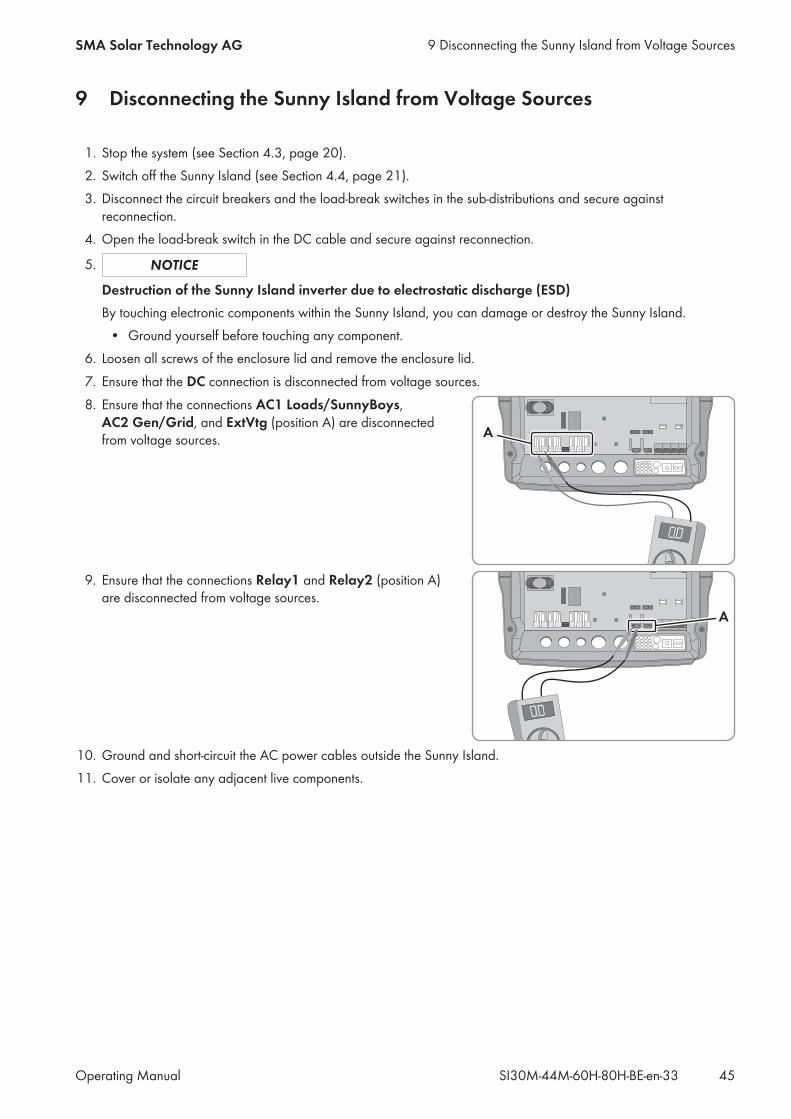
9 Disconnecting the Sunny Island from Voltage Sources
1. Stop the system (see Section 4.3, page 20).2. Switch off the Sunny Island (see Section 4.4, page 21).3. Disconnect the circuit breakers and the load-break switches in the sub-distributions and secure againstreconnection.
4. Open the load-break switch in the DC cable and secure against reconnection.
5.
Destruction of the Sunny Island inverter due to electrostatic discharge (ESD)By touching electronic components within the Sunny Island, you can damage or destroy the Sunny Island.• Ground yourself before touching any component.
6. Loosen all screws of the enclosure lid and remove the enclosure lid.7. Ensure that the DC connection is disconnected from voltage sources.8. Ensure that the connections AC1 Loads/SunnyBoys,
AC2 Gen/Grid, and ExtVtg (position A) are disconnectedfrom voltage sources.
9. Ensure that the connections Relay1 and Relay2 (position A)are disconnected from voltage sources.
10. Ground and short-circuit the AC power cables outside the Sunny Island.11. Cover or isolate any adjacent live components.
9 Disconnecting the Sunny Island from Voltage SourcesSMA Solar Technology AG
Operating Manual 45SI30M-44M-60H-80H-BE-en-33
10 Troubleshooting
10.1 Display of Errors
10.1.1 Display of Errors on the Sunny Remote Control
Display of Errors, Warnings, and EventsPending warnings and errors are shown automatically on the display of the Sunny Remote Control until the cause ofthe warning or error is no longer logged by the Sunny Island or has been acknowledged. Events are logged by theSunny Island. The following menus log warnings, errors and events:• 410# Error active - display of currently pending warnings and errors• 420# Error history - warning and error history• 430# Event history - events history• In systems for increased self-consumption and battery backup systems: 440# Error Grid - history of the last fiveutility grid errors
Structure of Display NumbersEach error and each event has a unique three-digit display number that is determined based on the parameter ormeasurement value assignment. Events and errors use the same number range:• 1xx - Sunny Island• 2xx - Battery• 3xx - Generator or utility grid• 4xx - Generator• 5xx - Utility grid• 6xx - Relay• 7xx - System• 8xx - External devices and components• 9xx - General
Meaning of abbreviationsF indicates an error, W a warning, and E an event.In the event of an error, the display shows whether the error has come or gone using ! for "Set" and C for "Clear".
10.1.2 Display of Errors on the Communication Product (Example)Most warnings, errors and events of the Sunny Island inverter can be called up and set on the communication product(e.g. Sunny Explorer or Sunny Portal). Links to additional information can be found at www.SMA‑Solar.com.
Document title and content Document type
SUNNY EXPLORERCall up and set the parameters in Sunny Portal
User Manual
SUNNY HOME MANAGER in SUNNY PORTALCall up and set the parameters in Sunny Portal
User Manual
SUNNY ISLAND – Comparison of the same parameters for Speedwire (e.g. Sun-ny Explorer) and RS485 (e.g. Sunny Remote Control)
Technical Information
10 Troubleshooting SMA Solar Technology AG
Operating ManualSI30M-44M-60H-80H-BE-en-3346
10.2 Sunny Island Inverter Behavior Under Fault Conditions
Error LevelsThe Sunny Island distinguishes between five different levels of errors, each requiring different user interaction.
Level Designation Display on theSunny Re-mote Control
Explanation
1 Warning Warning Warning; the Sunny Island continues to run. Information in standardmode indicating that a warning has been generated.
2 Malfunction 1 Malfunction Malfunction that is detectable only during operation. The Sunny Islandshuts down. Restart can be initiated immediately (e.g. via autostart).
3 Malfunction 2 Malfunction Malfunction that is also detectable in standby mode. The Sunny Islandshuts down. Restart is blocked until the malfunction is no longer de-tected by the Sunny Island.
4 Failure Failure Device failure; the Sunny Island switches off. Troubleshooting, acknowl-edgment of the error and manual restart necessary.
5 Device defect Defect The Sunny Island is defective and switches itself off. The Sunny Islandmust be replaced.
Handling of Pending Errors upon ActivationDuring the activation procedure, all pending errors are acknowledged without the error being logged in the list 420#Error history. Errors that are still pending are entered again after activation. Errors that were detected by theSunny Island before activation and are no longer detected after activation are shown in the list 420# Error history.
AutostartThe autostart function allows automatic restarts in the event of malfunctions. If the autostart function fails in the event ofa malfunction, the Sunny Island attempts to carry out the next autostart immediately. The number of autostarts isrestricted. If the Sunny Island is in operation without malfunctions for ten minutes, it resets the autostart counter.When the maximum number of autostarts has been reached, the Sunny Island reacts as follows:• The Sunny Island waits ten minutes.• The autostart counter is reset.• The Sunny Island attempts to perform an autostart.• When the maximum number of autostarts has been reached, the Sunny Island waits again for ten minutes.
10.3 Acknowledge ErrorsIf a malfunction or failure occurs, the Sunny Island switches to standby mode. Once you have eliminated the cause ofthe error, you can enable a restart of the Sunny Island inverter by acknowledging the error.
Procedure:1. Eliminate the cause.2. Press the button on the Sunny Remote Control. This acknowledges the error.3. Start the system (see Section 4.2, page 20).
10 TroubleshootingSMA Solar Technology AG
Operating Manual 47SI30M-44M-60H-80H-BE-en-33
10.4 Logged Events
10.4.1 Sunny Island Category (1xx)No. Name Description
E101 Standby Waiting mode
E102 Startup Startup process
E103 Run Operation
E104 RunExtGn Operation with a generator
E105 RunExtGd Operation with the utility grid
E106 RunGdFeed Feed-in grid operation
E108 Silent Energy-saving mode
E110 ErrShutdown Shutdown due to error
E115 EmgCharge Emergency charging
E118 AutoStart Automatic start
E119 ManStart Manual start
E120 ManStop Manual stop
E121 PwrSaveStart Start of energy-saving mode
E122 PwrSaveStop End of energy-saving mode
E129 Ext.Start External start
E130 Ext.Stop External stop
E133 SlfCsmpStart Start of increased self-consumption
E134 SlfCsmpStop Stop of increased self-consumption
E135 SlfCsmpChrgOnly The battery is charged only when increased self-consumption is active.
E136 SLfCsmpBatMnt Full or equalization charge with active increased self-consumption
E137 SlfCsmpNormal Switch back to increased self-consumption after completion of full or equalizationcharge
E138 InvShutdown The Sunny Island shuts down.
E140 FedInOn Setpoint activated
E141 FedInOff Setpoint deactivated
10.4.2 Battery Category (2xx)No. Name Description
E202 BmsNewBat (Partial) reset of battery management due to new battery
E203 BmsFloat Battery charge algorithm switches to float charge
10 Troubleshooting SMA Solar Technology AG
Operating ManualSI30M-44M-60H-80H-BE-en-3348

No. Name Description
E204 BmsBoost Battery charge algorithm switches to boost charge
E205 BmsFull Battery charge algorithm switches to full charge
E206 BmsSilent Switches to energy-saving mode
E207 BmsEqual Status change to equalization charge of the battery
E224 BMS20PReCal 20% recalibration being performed.
10.4.3 Generator Category (4xx)No. Name Description
E401 GnAutoStart Automatic generator start (e.g., via state-of-charge-dependent generator request)
E402 GnAutoStop Automatic generator stop
E403 GnManStart Manual generator start
E404 GnManStop Manual generator stop
E405 GnManAck Manual error acknowledgment of generator error
E406 GnDmdSrc Generator request
E407 GnCurCtlStr Current-controlled generator operation started
E408 GnCurCtlStp Current-controlled generator operation stopped
10.4.4 Utility Grid Category (5xx)No. Name Description
E501 GdSocOn Grid request due to low battery state of charge
E502 GdSocOff Grid release due to adequate battery state of charge
E503 GdPwrOn Grid request due to power limit being exceeded
E504 GdPwrOff Grid approval due to falling below the power limit
E505 GdManOn Manual grid request
E506 GdManOff Manual grid release
10.4.5 Relay Category (6xx)No. Name Description
E601 Rly1Off Multifunction relay 1 is deactivated.
E602 Rly1On Multifunction relay 1 is activated.
E603 Rly1Slv1Off Multifunction relay 1 of slave 1 is deactivated.
E604 Rly1Slv1On Multifunction relay 1 of slave 1 is activated.
E605 Rly1Slv2Off Multifunction relay 1 of slave 2 is deactivated.
10 TroubleshootingSMA Solar Technology AG
Operating Manual 49SI30M-44M-60H-80H-BE-en-33
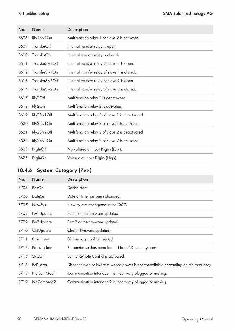
No. Name Description
E606 Rly1Slv2On Multifunction relay 1 of slave 2 is activated.
E609 TransferOff Internal transfer relay is open.
E610 TransferOn Internal transfer relay is closed.
E611 TransferSlv1Off Internal transfer relay of slave 1 is open.
E612 TransferSlv1On Internal transfer relay of slave 1 is closed.
E613 TransferSlv2Off Internal transfer relay of slave 2 is open.
E614 TransferSlv2On Internal transfer relay of slave 2 is closed.
E617 Rly2Off Multifunction relay 2 is deactivated.
E618 Rly2On Multifunction relay 2 is activated.
E619 Rly2Slv1Off Multifunction relay 2 of slave 1 is deactivated.
E620 Rly2Slv1On Multifunction relay 2 of slave 1 is activated.
E621 Rly2Slv2Off Multifunction relay 2 of slave 2 is deactivated.
E622 Rly2Slv2On Multifunction relay 2 of slave 2 is activated.
E625 DigInOff No voltage at input DigIn (Low).
E626 DigInOn Voltage at input DigIn (High).
10.4.6 System Category (7xx)No. Name Description
E705 PwrOn Device start
E706 DateSet Date or time has been changed.
E707 NewSys New system configured in the QCG.
E708 Fw1Update Part 1 of the firmware updated.
E709 Fw2Update Part 2 of the firmware updated.
E710 ClstUpdate Cluster firmware updated.
E711 CardInsert SD memory card is inserted.
E712 ParaUpdate Parameter set has been loaded from SD memory card.
E715 SRCOn Sunny Remote Control is activated.
E716 PvDiscon Disconnection of inverters whose power is not controllable depending on the frequency
E718 NoComMod1 Communication interface 1 is incorrectly plugged or missing.
E719 NoComMod2 Communication interface 2 is incorrectly plugged or missing.
10 Troubleshooting SMA Solar Technology AG
Operating ManualSI30M-44M-60H-80H-BE-en-3350
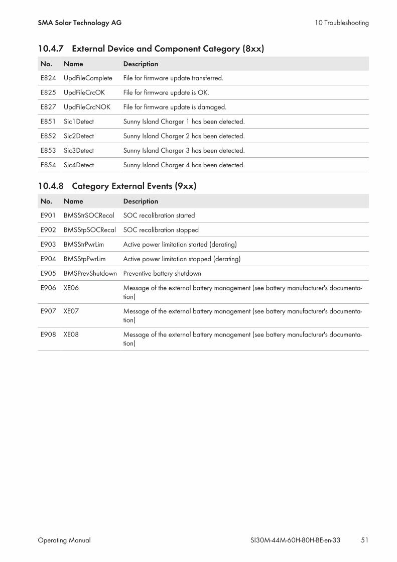
10.4.7 External Device and Component Category (8xx)No. Name Description
E824 UpdFileComplete File for firmware update transferred.
E825 UpdFileCrcOK File for firmware update is OK.
E827 UpdFileCrcNOK File for firmware update is damaged.
E851 Sic1Detect Sunny Island Charger 1 has been detected.
E852 Sic2Detect Sunny Island Charger 2 has been detected.
E853 Sic3Detect Sunny Island Charger 3 has been detected.
E854 Sic4Detect Sunny Island Charger 4 has been detected.
10.4.8 Category External Events (9xx)No. Name Description
E901 BMSStrSOCRecal SOC recalibration started
E902 BMSStpSOCRecal SOC recalibration stopped
E903 BMSStrPwrLim Active power limitation started (derating)
E904 BMSStpPwrLim Active power limitation stopped (derating)
E905 BMSPrevShutdown Preventive battery shutdown
E906 XE06 Message of the external battery management (see battery manufacturer's documenta-tion)
E907 XE07 Message of the external battery management (see battery manufacturer's documenta-tion)
E908 XE08 Message of the external battery management (see battery manufacturer's documenta-tion)
10 TroubleshootingSMA Solar Technology AG
Operating Manual 51SI30M-44M-60H-80H-BE-en-33
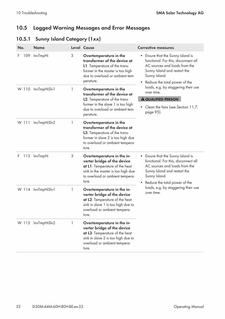
10.5 Logged Warning Messages and Error Messages
10.5.1 Sunny Island Category (1xx)No. Name Level Cause Corrective measures
F 109 InvTmpHi 3 Overtemperature in thetransformer of the device atL1: Temperature of the trans-former in the master is too highdue to overload or ambient tem-perature.
• Ensure that the Sunny Island isfunctional. For this, disconnect allAC sources and loads from theSunny Island and restart theSunny Island.
• Reduce the total power of theloads, e.g. by staggering their useover time.
• Clean the fans (see Section 11.7,page 95).
W 110 InvTmpHiSlv1 1 Overtemperature in thetransformer of the device atL2: Temperature of the trans-former in the slave 1 is too highdue to overload or ambient tem-perature.
W 111 InvTmpHiSlv2 1 Overtemperature in thetransformer of the device atL3: Temperature of the trans-former in slave 2 is too high dueto overload or ambient tempera-ture.
F 113 InvTmpHi 3 Overtemperature in the in-verter bridge of the deviceat L1: Temperature of the heatsink in the master is too high dueto overload or ambient tempera-ture.
• Ensure that the Sunny Island isfunctional. For this, disconnect allAC sources and loads from theSunny Island and restart theSunny Island.
• Reduce the total power of theloads, e.g. by staggering their useover time.
W 114 InvTmpHiSlv1 1 Overtemperature in the in-verter bridge of the deviceat L2: Temperature of the heatsink in slave 1 is too high due tooverload or ambient tempera-ture.
W 115 InvTmpHiSlv2 1 Overtemperature in the in-verter bridge of the deviceat L3: Temperature of the heatsink in slave 2 is too high due tooverload or ambient tempera-ture.
10 Troubleshooting SMA Solar Technology AG
Operating ManualSI30M-44M-60H-80H-BE-en-3352
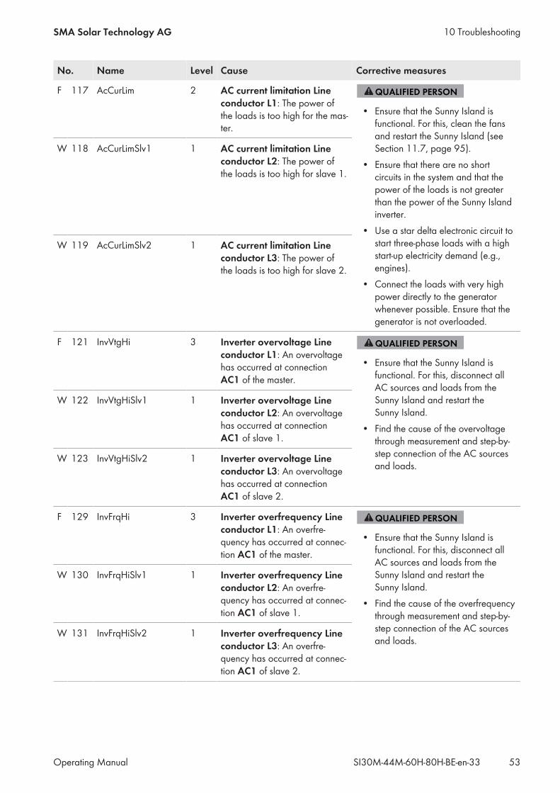
No. Name Level Cause Corrective measures
F 117 AcCurLim 2 AC current limitation Lineconductor L1: The power ofthe loads is too high for the mas-ter.
• Ensure that the Sunny Island isfunctional. For this, clean the fansand restart the Sunny Island (seeSection 11.7, page 95).
• Ensure that there are no shortcircuits in the system and that thepower of the loads is not greaterthan the power of the Sunny Islandinverter.
• Use a star delta electronic circuit tostart three-phase loads with a highstart-up electricity demand (e.g.,engines).
• Connect the loads with very highpower directly to the generatorwhenever possible. Ensure that thegenerator is not overloaded.
W 118 AcCurLimSlv1 1 AC current limitation Lineconductor L2: The power ofthe loads is too high for slave 1.
W 119 AcCurLimSlv2 1 AC current limitation Lineconductor L3: The power ofthe loads is too high for slave 2.
F 121 InvVtgHi 3 Inverter overvoltage Lineconductor L1: An overvoltagehas occurred at connectionAC1 of the master.
• Ensure that the Sunny Island isfunctional. For this, disconnect allAC sources and loads from theSunny Island and restart theSunny Island.
• Find the cause of the overvoltagethrough measurement and step-by-step connection of the AC sourcesand loads.
W 122 InvVtgHiSlv1 1 Inverter overvoltage Lineconductor L2: An overvoltagehas occurred at connectionAC1 of slave 1.
W 123 InvVtgHiSlv2 1 Inverter overvoltage Lineconductor L3: An overvoltagehas occurred at connectionAC1 of slave 2.
F 129 InvFrqHi 3 Inverter overfrequency Lineconductor L1: An overfre-quency has occurred at connec-tion AC1 of the master.
• Ensure that the Sunny Island isfunctional. For this, disconnect allAC sources and loads from theSunny Island and restart theSunny Island.
• Find the cause of the overfrequencythrough measurement and step-by-step connection of the AC sourcesand loads.
W 130 InvFrqHiSlv1 1 Inverter overfrequency Lineconductor L2: An overfre-quency has occurred at connec-tion AC1 of slave 1.
W 131 InvFrqHiSlv2 1 Inverter overfrequency Lineconductor L3: An overfre-quency has occurred at connec-tion AC1 of slave 2.
10 TroubleshootingSMA Solar Technology AG
Operating Manual 53SI30M-44M-60H-80H-BE-en-33
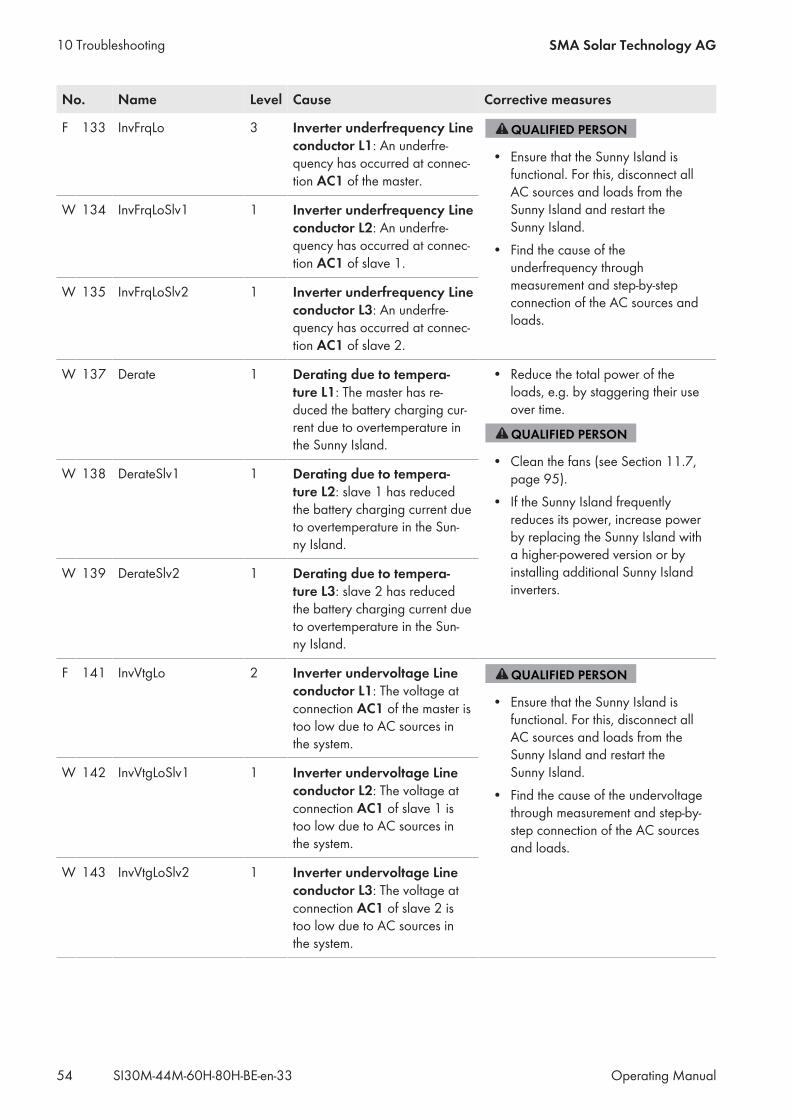
No. Name Level Cause Corrective measures
F 133 InvFrqLo 3 Inverter underfrequency Lineconductor L1: An underfre-quency has occurred at connec-tion AC1 of the master.
• Ensure that the Sunny Island isfunctional. For this, disconnect allAC sources and loads from theSunny Island and restart theSunny Island.
• Find the cause of theunderfrequency throughmeasurement and step-by-stepconnection of the AC sources andloads.
W 134 InvFrqLoSlv1 1 Inverter underfrequency Lineconductor L2: An underfre-quency has occurred at connec-tion AC1 of slave 1.
W 135 InvFrqLoSlv2 1 Inverter underfrequency Lineconductor L3: An underfre-quency has occurred at connec-tion AC1 of slave 2.
W 137 Derate 1 Derating due to tempera-ture L1: The master has re-duced the battery charging cur-rent due to overtemperature inthe Sunny Island.
• Reduce the total power of theloads, e.g. by staggering their useover time.
• Clean the fans (see Section 11.7,page 95).
• If the Sunny Island frequentlyreduces its power, increase powerby replacing the Sunny Island witha higher-powered version or byinstalling additional Sunny Islandinverters.
W 138 DerateSlv1 1 Derating due to tempera-ture L2: slave 1 has reducedthe battery charging current dueto overtemperature in the Sun-ny Island.
W 139 DerateSlv2 1 Derating due to tempera-ture L3: slave 2 has reducedthe battery charging current dueto overtemperature in the Sun-ny Island.
F 141 InvVtgLo 2 Inverter undervoltage Lineconductor L1: The voltage atconnection AC1 of the master istoo low due to AC sources inthe system.
• Ensure that the Sunny Island isfunctional. For this, disconnect allAC sources and loads from theSunny Island and restart theSunny Island.
• Find the cause of the undervoltagethrough measurement and step-by-step connection of the AC sourcesand loads.
W 142 InvVtgLoSlv1 1 Inverter undervoltage Lineconductor L2: The voltage atconnection AC1 of slave 1 istoo low due to AC sources inthe system.
W 143 InvVtgLoSlv2 1 Inverter undervoltage Lineconductor L3: The voltage atconnection AC1 of slave 2 istoo low due to AC sources inthe system.
10 Troubleshooting SMA Solar Technology AG
Operating ManualSI30M-44M-60H-80H-BE-en-3354
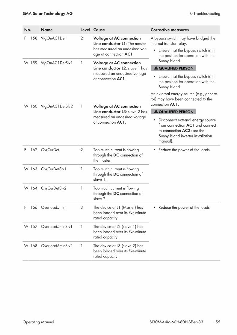
No. Name Level Cause Corrective measures
F 158 VtgOnAC1Det 2 Voltage at AC connectionLine conductor L1: The masterhas measured an undesired volt-age at connection AC1.
A bypass switch may have bridged theinternal transfer relay.• Ensure that the bypass switch is inthe position for operation with theSunny Island.
• Ensure that the bypass switch is inthe position for operation with theSunny Island.
An external energy source (e.g., genera-tor) may have been connected to theconnection AC1.
• Disconnect external energy sourcefrom connection AC1 and connectto connection AC2 (see theSunny Island inverter installationmanual).
W 159 VtgOnAC1DetSlv1 1 Voltage at AC connectionLine conductor L2: slave 1 hasmeasured an undesired voltageat connection AC1.
W 160 VtgOnAC1DetSlv2 1 Voltage at AC connectionLine conductor L3: slave 2 hasmeasured an undesired voltageat connection AC1.
F 162 OvrCurDet 2 Too much current is flowingthrough the DC connection ofthe master.
• Reduce the power of the loads.
W 163 OvrCurDetSlv1 1 Too much current is flowingthrough the DC connection ofslave 1.
W 164 OvrCurDetSlv2 1 Too much current is flowingthrough the DC connection ofslave 2.
F 166 Overload5min 3 The device at L1 (Master) hasbeen loaded over its five-minuterated capacity.
• Reduce the power of the loads.
W 167 Overload5minSlv1 1 The device at L2 (slave 1) hasbeen loaded over its five-minuterated capacity.
W 168 Overload5minSlv2 1 The device at L3 (slave 2) hasbeen loaded over its five-minuterated capacity.
10 TroubleshootingSMA Solar Technology AG
Operating Manual 55SI30M-44M-60H-80H-BE-en-33
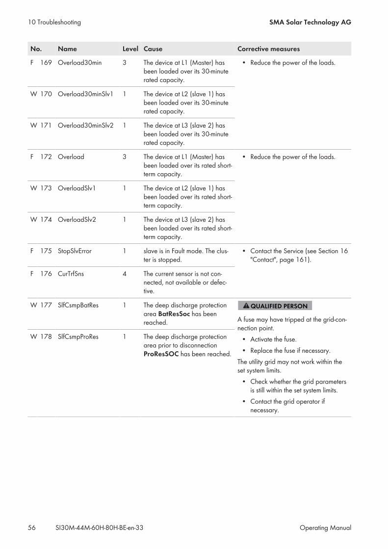
No. Name Level Cause Corrective measures
F 169 Overload30min 3 The device at L1 (Master) hasbeen loaded over its 30-minuterated capacity.
• Reduce the power of the loads.
W 170 Overload30minSlv1 1 The device at L2 (slave 1) hasbeen loaded over its 30-minuterated capacity.
W 171 Overload30minSlv2 1 The device at L3 (slave 2) hasbeen loaded over its 30-minuterated capacity.
F 172 Overload 3 The device at L1 (Master) hasbeen loaded over its rated short-term capacity.
• Reduce the power of the loads.
W 173 OverloadSlv1 1 The device at L2 (slave 1) hasbeen loaded over its rated short-term capacity.
W 174 OverloadSlv2 1 The device at L3 (slave 2) hasbeen loaded over its rated short-term capacity.
F 175 StopSlvError 1 slave is in Fault mode. The clus-ter is stopped.
• Contact the Service (see Section 16"Contact", page 161).
F 176 CurTrfSns 4 The current sensor is not con-nected, not available or defec-tive.
W 177 SlfCsmpBatRes 1 The deep discharge protectionarea BatResSoc has beenreached. A fuse may have tripped at the grid-con-
nection point.• Activate the fuse.• Replace the fuse if necessary.The utility grid may not work within theset system limits.• Check whether the grid parametersis still within the set system limits.
• Contact the grid operator ifnecessary.
W 178 SlfCsmpProRes 1 The deep discharge protectionarea prior to disconnectionProResSOC has been reached.
10 Troubleshooting SMA Solar Technology AG
Operating ManualSI30M-44M-60H-80H-BE-en-3356
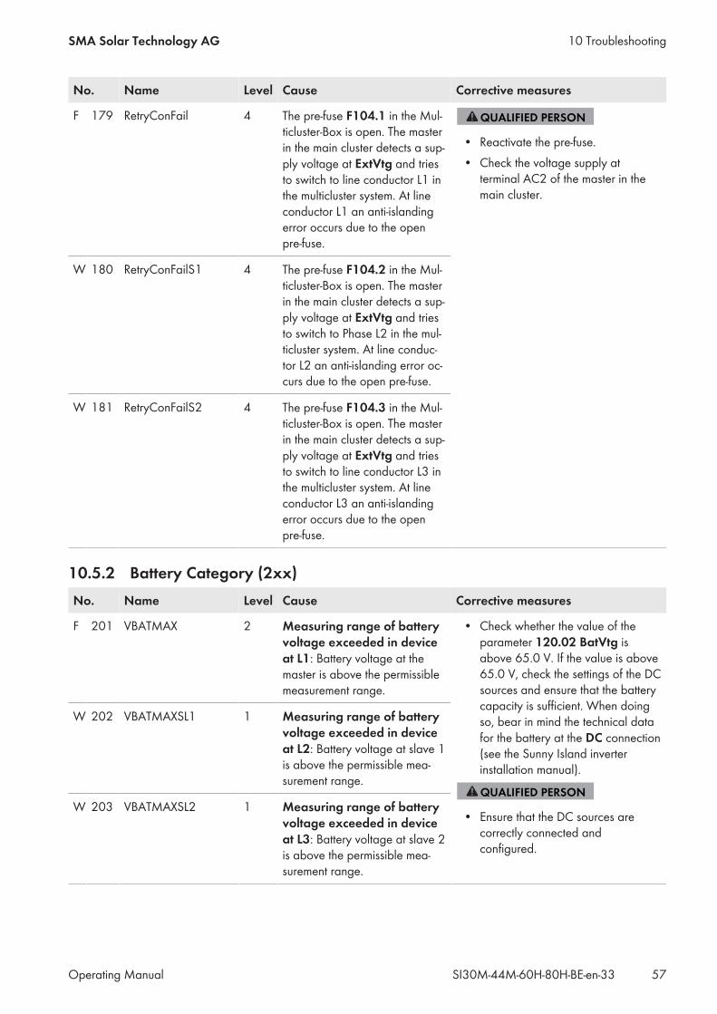
No. Name Level Cause Corrective measures
F 179 RetryConFail 4 The pre-fuse F104.1 in the Mul-ticluster-Box is open. The masterin the main cluster detects a sup-ply voltage at ExtVtg and triesto switch to line conductor L1 inthe multicluster system. At lineconductor L1 an anti-islandingerror occurs due to the openpre-fuse.
• Reactivate the pre-fuse.• Check the voltage supply atterminal AC2 of the master in themain cluster.
W 180 RetryConFailS1 4 The pre-fuse F104.2 in the Mul-ticluster-Box is open. The masterin the main cluster detects a sup-ply voltage at ExtVtg and triesto switch to Phase L2 in the mul-ticluster system. At line conduc-tor L2 an anti-islanding error oc-curs due to the open pre-fuse.
W 181 RetryConFailS2 4 The pre-fuse F104.3 in the Mul-ticluster-Box is open. The masterin the main cluster detects a sup-ply voltage at ExtVtg and triesto switch to line conductor L3 inthe multicluster system. At lineconductor L3 an anti-islandingerror occurs due to the openpre-fuse.
10.5.2 Battery Category (2xx)No. Name Level Cause Corrective measures
F 201 VBATMAX 2 Measuring range of batteryvoltage exceeded in deviceat L1: Battery voltage at themaster is above the permissiblemeasurement range.
• Check whether the value of theparameter 120.02 BatVtg isabove 65.0 V. If the value is above65.0 V, check the settings of the DCsources and ensure that the batterycapacity is sufficient. When doingso, bear in mind the technical datafor the battery at the DC connection(see the Sunny Island inverterinstallation manual).
• Ensure that the DC sources arecorrectly connected andconfigured.
W 202 VBATMAXSL1 1 Measuring range of batteryvoltage exceeded in deviceat L2: Battery voltage at slave 1is above the permissible mea-surement range.
W 203 VBATMAXSL2 1 Measuring range of batteryvoltage exceeded in deviceat L3: Battery voltage at slave 2is above the permissible mea-surement range.
10 TroubleshootingSMA Solar Technology AG
Operating Manual 57SI30M-44M-60H-80H-BE-en-33
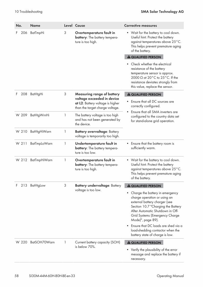
No. Name Level Cause Corrective measures
F 206 BatTmpHi 3 Overtemperature fault inbattery: The battery tempera-ture is too high.
• Wait for the battery to cool down.Useful hint: Protect the batteryagainst temperatures above 25°C.This helps prevent premature agingof the battery.
• Check whether the electricalresistance of the batterytemperature sensor is approx.2000 Ω at 20°C to 25°C. If theresistance deviates strongly fromthis value, replace the sensor.
F 208 BatVtgHi 3 Measuring range of batteryvoltage exceeded in deviceat L2: Battery voltage is higherthan the target charge voltage.
• Ensure that all DC sources arecorrectly configured.
• Ensure that all SMA inverters areconfigured to the country data setfor stand-alone grid operation.
W 209 BatVtgWrnHi 1 The battery voltage is too highand has not been generated bythe device.
W 210 BatVtgHiWarn 1 Battery overvoltage: Batteryvoltage is temporarily too high.
W 211 BatTmpLoWarn 1 Undertemperature fault inbattery: The battery tempera-ture is too low.
• Ensure that the battery room issufficiently warm.
W 212 BatTmpHiWarn 1 Overtemperature fault inbattery: The battery tempera-ture is too high.
• Wait for the battery to cool down.Useful hint: Protect the batteryagainst temperatures above 25°C.This helps prevent premature agingof the battery.
F 213 BatVtgLow 3 Battery undervoltage: Batteryvoltage is too low.
• Charge the battery in emergencycharge operation or using anexternal battery charger (seeSection 10.7 "Charging the BatteryAfter Automatic Shutdown in Off-Grid Systems (Emergency ChargeMode)", page 89).
• Ensure that DC loads are shed via aload-shedding contactor when thebattery state of charge is low.
W 220 BatSOH70Warn 1 Current battery capacity (SOH)is below 70%.
• Verify the plausibility of the errormessage and replace the battery ifnecessary.
10 Troubleshooting SMA Solar Technology AG
Operating ManualSI30M-44M-60H-80H-BE-en-3358
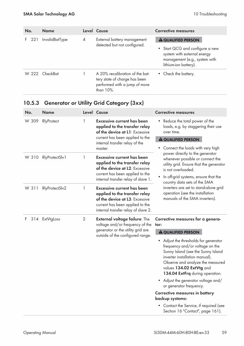
No. Name Level Cause Corrective measures
F 221 InvalidBatType 4 External battery managementdetected but not configured.
• Start QCG and configure a newsystem with external energymanagement (e.g., system withlithium-ion battery).
W 222 CheckBat 1 A 20% recalibration of the bat-tery state of charge has beenperformed with a jump of morethan 10%.
• Check the battery.
10.5.3 Generator or Utility Grid Category (3xx)No. Name Level Cause Corrective measures
W 309 RlyProtect 1 Excessive current has beenapplied to the transfer relayof the device at L1: Excessivecurrent has been applied to theinternal transfer relay of themaster.
• Reduce the total power of theloads, e.g. by staggering their useover time.
• Connect the loads with very highpower directly to the generatorwhenever possible or connect theutility grid. Ensure that the generatoris not overloaded.
• In off-grid systems, ensure that thecountry data sets of the SMAinverters are set to stand-alone gridoperation (see the installationmanuals of the SMA inverters).
W 310 RlyProtectSlv1 1 Excessive current has beenapplied to the transfer relayof the device at L2: Excessivecurrent has been applied to theinternal transfer relay of slave 1.
W 311 RlyProtectSlv2 1 Excessive current has beenapplied to the transfer relayof the device at L3: Excessivecurrent has been applied to theinternal transfer relay of slave 2.
F 314 ExtVtgLoss 2 External voltage failure: Thevoltage and/or frequency of thegenerator or the utility grid areoutside of the configured range.
Corrective measures for a genera-tor:
• Adjust the thresholds for generatorfrequency and/or voltage on theSunny Island (see the Sunny Islandinverter installation manual).Observe and analyze the measuredvalues 134.02 ExtVtg and134.04 ExtFrq during operation.
• Adjust the generator voltage and/or generator frequency.
Corrective measures in batterybackup systems:• Contact the Service, if required (seeSection 16 "Contact", page 161).
10 TroubleshootingSMA Solar Technology AG
Operating Manual 59SI30M-44M-60H-80H-BE-en-33

No. Name Level Cause Corrective measures
W 315 ExtVtgLo 1 Disconnection from the ex-ternal grid due to undervolt-age at line conductor L1: Thevoltage of the generator or theutility grid at the master is toolow.
Corrective measures for a genera-tor:
• Adjust the thresholds for generatorvoltage on the Sunny Island (seethe Sunny Island inverter installationmanual). Observe and analyze themeasured values 134.02 ExtVtgduring operation.
• Adjust the generator voltage and/or generator frequency.
Corrective measures in batterybackup systems:• Contact the Service, if required (seeSection 16 "Contact", page 161).
W 316 ExtVtgLoSlv1 1 Disconnection from the ex-ternal grid due to undervolt-age at line conductor L2: Thevoltage of the generator or theutility grid at slave 1 is too low.
W 317 ExtVtgLoSlv2 1 Disconnection from the ex-ternal grid due to undervolt-age at line conductor L3: Thevoltage of the generator or theutility grid at slave 2 is too low.
W 319 ExtVtgHi 1 Disconnection from the ex-ternal grid due to overvolt-age at line conductor L1: Thevoltage of the generator or theutility grid at the master is toohigh.
Corrective measures for a genera-tor:
• Adjust the thresholds for generatorvoltage on the Sunny Island (seethe Sunny Island inverter installationmanual). Observe and analyze themeasured values 134.02 ExtVtgduring operation.
• Adjust the generator voltage and/or generator frequency.
Corrective measures in batterybackup systems:• Contact the Service, if required (seeSection 16 "Contact", page 161).
W 320 ExtVtgHiSlv1 1 Disconnection from the ex-ternal grid due to overvolt-age at line conductor L2: Thevoltage of the generator or theutility grid at slave 1 is too high.
W 321 ExtVtgHiSlv2 1 Disconnection from the ex-ternal grid due to overvolt-age at line conductor L3: Thevoltage of the generator or theutility grid at slave 2 is too high.
10 Troubleshooting SMA Solar Technology AG
Operating ManualSI30M-44M-60H-80H-BE-en-3360
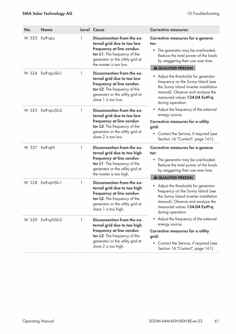
No. Name Level Cause Corrective measures
W 323 ExtFrqLo 1 Disconnection from the ex-ternal grid due to too lowfrequency at line conduc-tor L1: The frequency of thegenerator or the utility grid atthe master is too low.
Corrective measures for a genera-tor:• The generator may be overloaded.Reduce the total power of the loadsby staggering their use over time.
• Adjust the thresholds for generatorfrequency on the Sunny Island (seethe Sunny Island inverter installationmanual). Observe and analyze themeasured values 134.04 ExtFrqduring operation.
• Adjust the frequency of the externalenergy source.
Corrective measures for a utilitygrid:• Contact the Service, if required (seeSection 16 "Contact", page 161).
W 324 ExtFrqLoSlv1 1 Disconnection from the ex-ternal grid due to too lowfrequency at line conduc-tor L2: The frequency of thegenerator or the utility grid atslave 1 is too low.
W 325 ExtFrqLoSlv2 1 Disconnection from the ex-ternal grid due to too lowfrequency at line conduc-tor L3: The frequency of thegenerator or the utility grid atslave 2 is too low.
W 327 ExtFrqHi 1 Disconnection from the ex-ternal grid due to too highfrequency at line conduc-tor L1: The frequency of thegenerator or the utility grid atthe master is too high.
Corrective measures for a genera-tor:• The generator may be overloaded.Reduce the total power of the loadsby staggering their use over time.
• Adjust the thresholds for generatorfrequency on the Sunny Island (seethe Sunny Island inverter installationmanual). Observe and analyze themeasured values 134.04 ExtFrqduring operation.
• Adjust the frequency of the externalenergy source.
Corrective measures for a utilitygrid:• Contact the Service, if required (seeSection 16 "Contact", page 161).
W 328 ExtFrqHiSlv1 1 Disconnection from the ex-ternal grid due to too highfrequency at line conduc-tor L2: The frequency of thegenerator or the utility grid atslave 1 is too high.
W 329 ExtFrqHiSlv2 1 Disconnection from the ex-ternal grid due to too highfrequency at line conduc-tor L3: The frequency of thegenerator or the utility grid atslave 2 is too high.
10 TroubleshootingSMA Solar Technology AG
Operating Manual 61SI30M-44M-60H-80H-BE-en-33
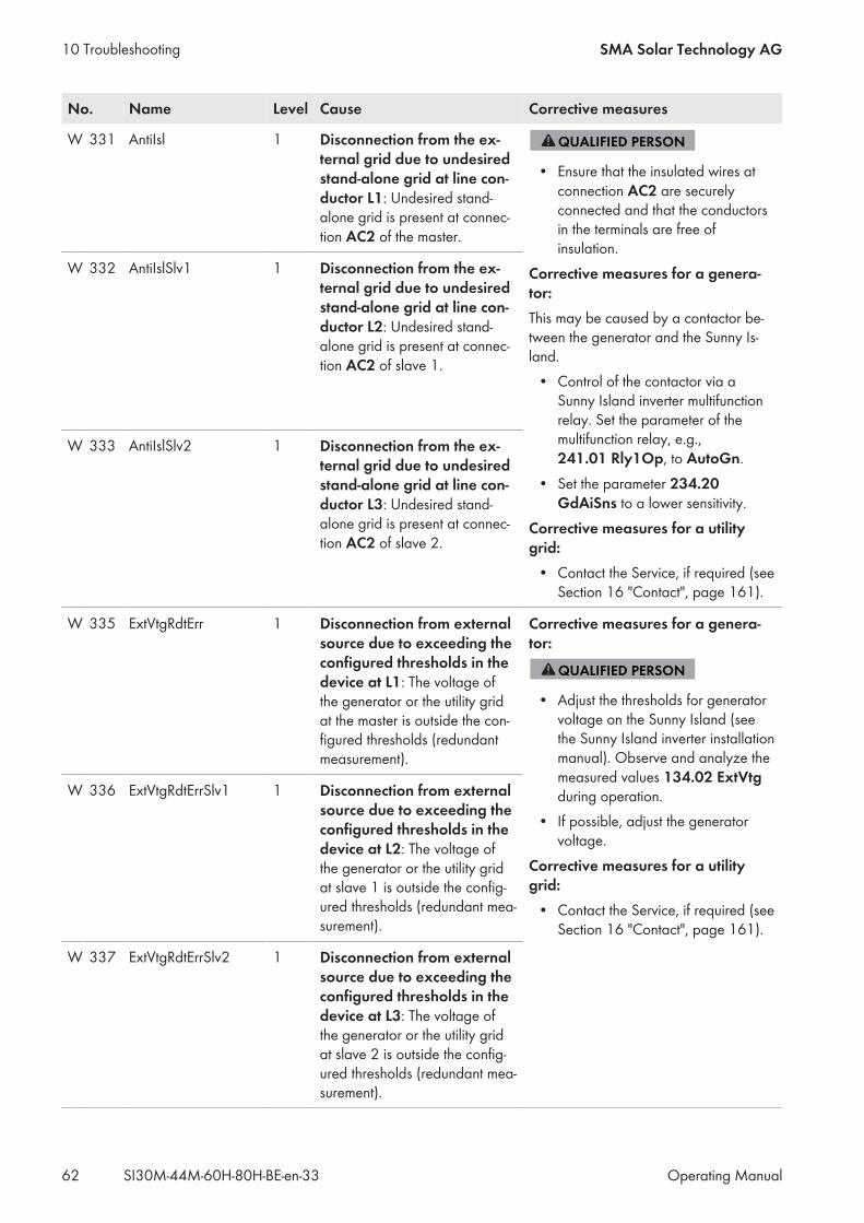
No. Name Level Cause Corrective measures
W 331 AntiIsl 1 Disconnection from the ex-ternal grid due to undesiredstand-alone grid at line con-ductor L1: Undesired stand-alone grid is present at connec-tion AC2 of the master.
• Ensure that the insulated wires atconnection AC2 are securelyconnected and that the conductorsin the terminals are free ofinsulation.
Corrective measures for a genera-tor:This may be caused by a contactor be-tween the generator and the Sunny Is-land.• Control of the contactor via aSunny Island inverter multifunctionrelay. Set the parameter of themultifunction relay, e.g.,241.01 Rly1Op, to AutoGn.
• Set the parameter 234.20GdAiSns to a lower sensitivity.
Corrective measures for a utilitygrid:• Contact the Service, if required (seeSection 16 "Contact", page 161).
W 332 AntiIslSlv1 1 Disconnection from the ex-ternal grid due to undesiredstand-alone grid at line con-ductor L2: Undesired stand-alone grid is present at connec-tion AC2 of slave 1.
W 333 AntiIslSlv2 1 Disconnection from the ex-ternal grid due to undesiredstand-alone grid at line con-ductor L3: Undesired stand-alone grid is present at connec-tion AC2 of slave 2.
W 335 ExtVtgRdtErr 1 Disconnection from externalsource due to exceeding theconfigured thresholds in thedevice at L1: The voltage ofthe generator or the utility gridat the master is outside the con-figured thresholds (redundantmeasurement).
Corrective measures for a genera-tor:
• Adjust the thresholds for generatorvoltage on the Sunny Island (seethe Sunny Island inverter installationmanual). Observe and analyze themeasured values 134.02 ExtVtgduring operation.
• If possible, adjust the generatorvoltage.
Corrective measures for a utilitygrid:• Contact the Service, if required (seeSection 16 "Contact", page 161).
W 336 ExtVtgRdtErrSlv1 1 Disconnection from externalsource due to exceeding theconfigured thresholds in thedevice at L2: The voltage ofthe generator or the utility gridat slave 1 is outside the config-ured thresholds (redundant mea-surement).
W 337 ExtVtgRdtErrSlv2 1 Disconnection from externalsource due to exceeding theconfigured thresholds in thedevice at L3: The voltage ofthe generator or the utility gridat slave 2 is outside the config-ured thresholds (redundant mea-surement).
10 Troubleshooting SMA Solar Technology AG
Operating ManualSI30M-44M-60H-80H-BE-en-3362
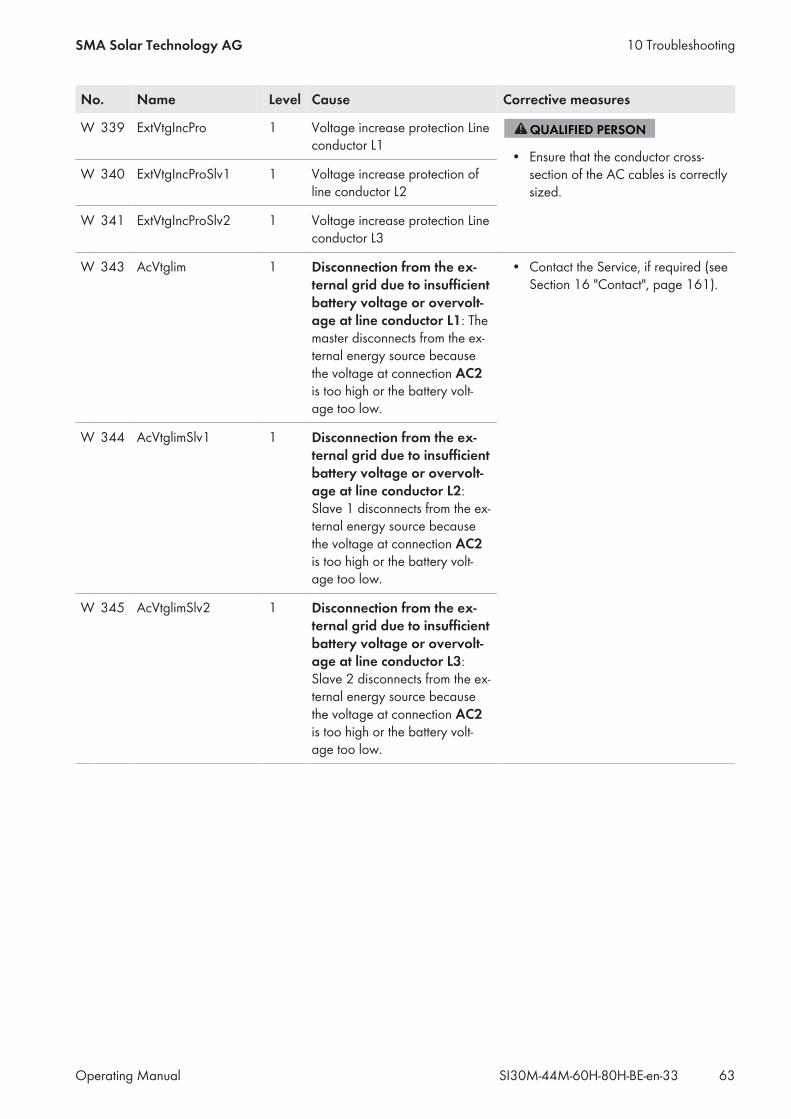
No. Name Level Cause Corrective measures
W 339 ExtVtgIncPro 1 Voltage increase protection Lineconductor L1
• Ensure that the conductor cross-section of the AC cables is correctlysized.
W 340 ExtVtgIncProSlv1 1 Voltage increase protection ofline conductor L2
W 341 ExtVtgIncProSlv2 1 Voltage increase protection Lineconductor L3
W 343 AcVtglim 1 Disconnection from the ex-ternal grid due to insufficientbattery voltage or overvolt-age at line conductor L1: Themaster disconnects from the ex-ternal energy source becausethe voltage at connection AC2is too high or the battery volt-age too low.
• Contact the Service, if required (seeSection 16 "Contact", page 161).
W 344 AcVtglimSlv1 1 Disconnection from the ex-ternal grid due to insufficientbattery voltage or overvolt-age at line conductor L2:Slave 1 disconnects from the ex-ternal energy source becausethe voltage at connection AC2is too high or the battery volt-age too low.
W 345 AcVtglimSlv2 1 Disconnection from the ex-ternal grid due to insufficientbattery voltage or overvolt-age at line conductor L3:Slave 2 disconnects from the ex-ternal energy source becausethe voltage at connection AC2is too high or the battery volt-age too low.
10 TroubleshootingSMA Solar Technology AG
Operating Manual 63SI30M-44M-60H-80H-BE-en-33

No. Name Level Cause Corrective measures
W 347 ExtOverload 1 Disconnection from the ex-ternal grid due to line con-ductor failure or overload atline conductor 1: The masterdisconnects from the utility griddue to line conductor failure/overload at connection AC2.
• Reduce the total power of theloads, e.g. by staggering their useover time.
• Ensure that there is not a shortcircuit present at connection AC2.
W 348 ExtOverloadSlv1 1 Disconnection from the ex-ternal grid due to line con-ductor failure or overload atline conductor 2: Slave 1 dis-connects from the utility grid dueto line conductor failure/over-load at connection AC2.
W 349 ExtOverloadSlv2 1 Disconnection from the ex-ternal grid due to line con-ductor failure or overload atline conductor 3: Slave 2 dis-connects from the utility grid dueto line conductor failure/over-load at connection AC2.
W 351 ExtScirDet 1 Disconnection from the ex-ternal grid due to externalshort circuit at line conduc-tor L1: Short circuit is present atconnection AC2 of the master.
• Eliminate the short circuit.
W 352 ExtScirDetSlv1 1 Disconnection from the ex-ternal grid due to externalshort circuit at line conduc-tor L2: Short circuit is present atconnection AC2 of slave 1.
W 353 ExtScirDetSlv2 1 Disconnection from the ex-ternal grid due to externalshort circuit at line conduc-tor L3: Short circuit is present atconnection AC2 of slave 2.
W 355 PhsAngErr 1 External grid does not havea correct rotating magneticfield: Assignment of the lineconductors of the external en-ergy source to the AC2 connec-tions of the Sunny Island doesnot result in a right-rotating mag-netic field.
• Ensure that the master is connectedto L1, slave 1 to L2, and slave 2 toL3.
10 Troubleshooting SMA Solar Technology AG
Operating ManualSI30M-44M-60H-80H-BE-en-3364
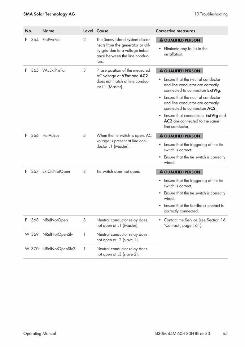
No. Name Level Cause Corrective measures
F 364 PhsPwrFail 2 The Sunny Island system discon-nects from the generator or util-ity grid due to a voltage imbal-ance between the line conduc-tors.
• Eliminate any faults in theinstallation.
F 365 VAcExtPhsFail 3 Phase position of the measuredAC voltage at VExt and AC2does not match at line conduc-tor L1 (Master).
• Ensure that the neutral conductorand line conductor are correctlyconnected to connection ExtVtg.
• Ensure that the neutral conductorand line conductor are correctlyconnected to connection AC2.
• Ensure that connections ExtVtg andAC2 are connected to the sameline conductor.
F 366 HotAcBus 3 When the tie switch is open, ACvoltage is present at line con-ductor L1 (Master). • Ensure that the triggering of the tie
switch is correct.• Ensure that the tie switch is correctlywired.
F 367 ExtCtcNotOpen 3 Tie switch does not open.
• Ensure that the triggering of the tieswitch is correct.
• Ensure that the tie switch is correctlywired.
• Ensure that the feedback contact iscorrectly connected.
F 368 NRelNotOpen 3 Neutral conductor relay doesnot open at L1 (Master).
• Contact the Service (see Section 16"Contact", page 161).
W 369 NRelNotOpenSlv1 1 Neutral conductor relay doesnot open at L2 (slave 1).
W 370 NRelNotOpenSlv2 1 Neutral conductor relay doesnot open at L3 (slave 2).
10 TroubleshootingSMA Solar Technology AG
Operating Manual 65SI30M-44M-60H-80H-BE-en-33
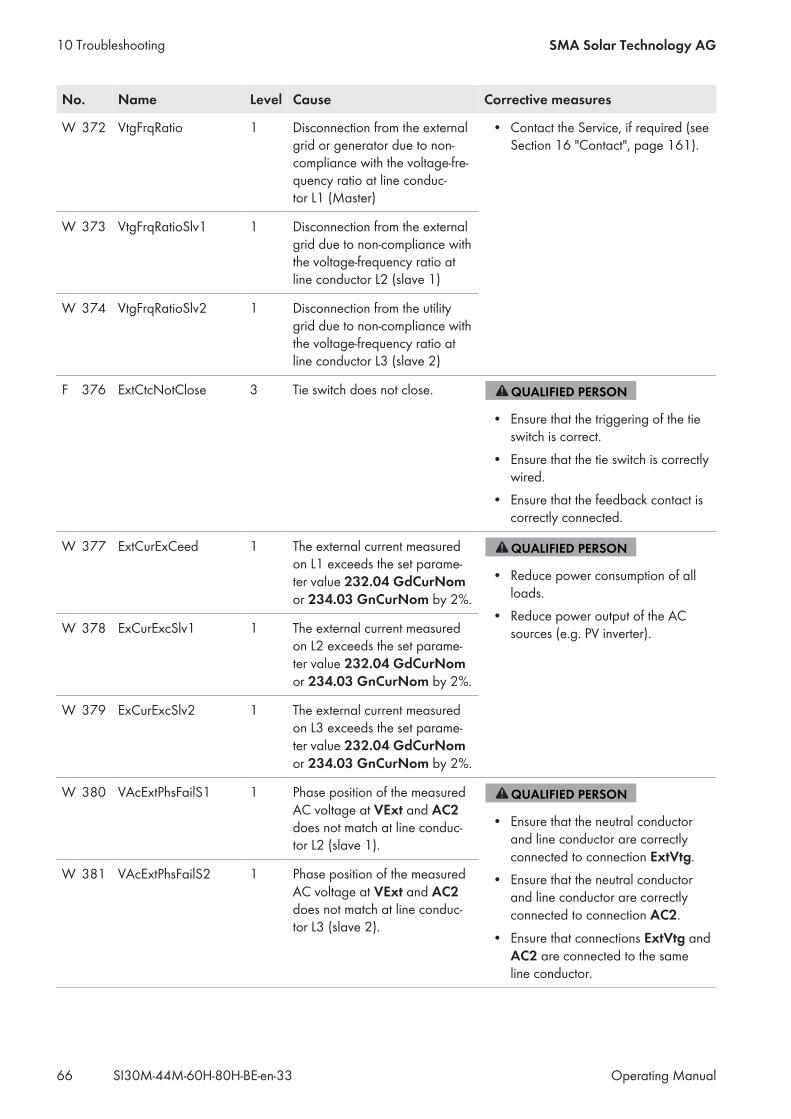
No. Name Level Cause Corrective measures
W 372 VtgFrqRatio 1 Disconnection from the externalgrid or generator due to non-compliance with the voltage-fre-quency ratio at line conduc-tor L1 (Master)
• Contact the Service, if required (seeSection 16 "Contact", page 161).
W 373 VtgFrqRatioSlv1 1 Disconnection from the externalgrid due to non-compliance withthe voltage-frequency ratio atline conductor L2 (slave 1)
W 374 VtgFrqRatioSlv2 1 Disconnection from the utilitygrid due to non-compliance withthe voltage-frequency ratio atline conductor L3 (slave 2)
F 376 ExtCtcNotClose 3 Tie switch does not close.
• Ensure that the triggering of the tieswitch is correct.
• Ensure that the tie switch is correctlywired.
• Ensure that the feedback contact iscorrectly connected.
W 377 ExtCurExCeed 1 The external current measuredon L1 exceeds the set parame-ter value 232.04 GdCurNomor 234.03 GnCurNom by 2%.
• Reduce power consumption of allloads.
• Reduce power output of the ACsources (e.g. PV inverter).W 378 ExCurExcSlv1 1 The external current measured
on L2 exceeds the set parame-ter value 232.04 GdCurNomor 234.03 GnCurNom by 2%.
W 379 ExCurExcSlv2 1 The external current measuredon L3 exceeds the set parame-ter value 232.04 GdCurNomor 234.03 GnCurNom by 2%.
W 380 VAcExtPhsFailS1 1 Phase position of the measuredAC voltage at VExt and AC2does not match at line conduc-tor L2 (slave 1).
• Ensure that the neutral conductorand line conductor are correctlyconnected to connection ExtVtg.
• Ensure that the neutral conductorand line conductor are correctlyconnected to connection AC2.
• Ensure that connections ExtVtg andAC2 are connected to the sameline conductor.
W 381 VAcExtPhsFailS2 1 Phase position of the measuredAC voltage at VExt and AC2does not match at line conduc-tor L3 (slave 2).
10 Troubleshooting SMA Solar Technology AG
Operating ManualSI30M-44M-60H-80H-BE-en-3366
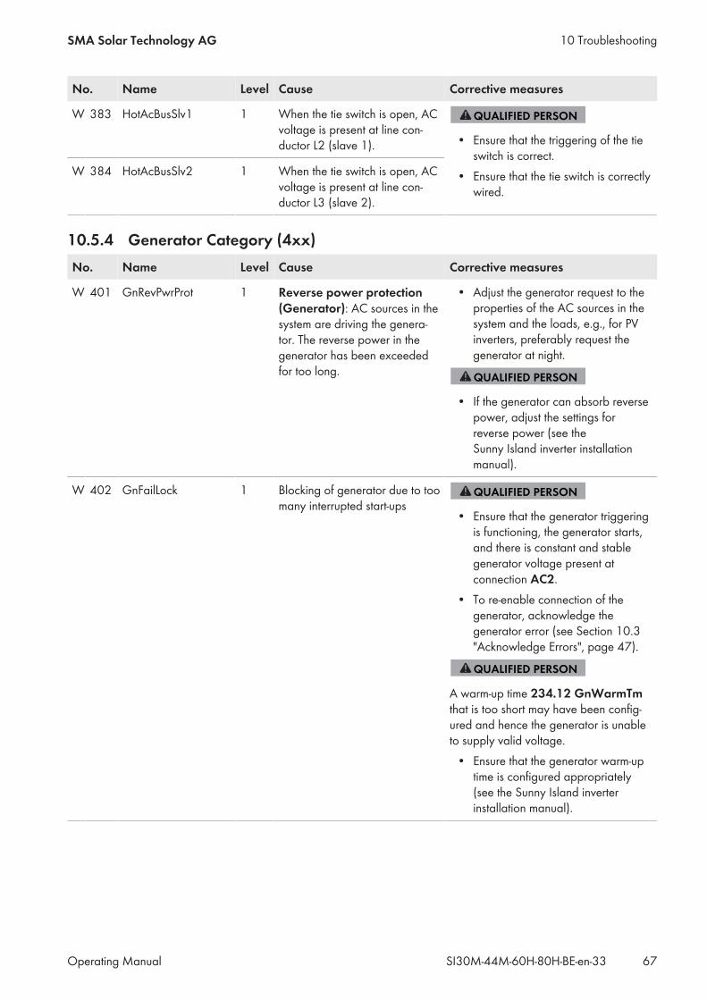
No. Name Level Cause Corrective measures
W 383 HotAcBusSlv1 1 When the tie switch is open, ACvoltage is present at line con-ductor L2 (slave 1). • Ensure that the triggering of the tie
switch is correct.• Ensure that the tie switch is correctlywired.
W 384 HotAcBusSlv2 1 When the tie switch is open, ACvoltage is present at line con-ductor L3 (slave 2).
10.5.4 Generator Category (4xx)No. Name Level Cause Corrective measures
W 401 GnRevPwrProt 1 Reverse power protection(Generator): AC sources in thesystem are driving the genera-tor. The reverse power in thegenerator has been exceededfor too long.
• Adjust the generator request to theproperties of the AC sources in thesystem and the loads, e.g., for PVinverters, preferably request thegenerator at night.
• If the generator can absorb reversepower, adjust the settings forreverse power (see theSunny Island inverter installationmanual).
W 402 GnFailLock 1 Blocking of generator due to toomany interrupted start-ups
• Ensure that the generator triggeringis functioning, the generator starts,and there is constant and stablegenerator voltage present atconnection AC2.
• To re-enable connection of thegenerator, acknowledge thegenerator error (see Section 10.3"Acknowledge Errors", page 47).
A warm-up time 234.12 GnWarmTmthat is too short may have been config-ured and hence the generator is unableto supply valid voltage.• Ensure that the generator warm-uptime is configured appropriately(see the Sunny Island inverterinstallation manual).
10 TroubleshootingSMA Solar Technology AG
Operating Manual 67SI30M-44M-60H-80H-BE-en-33
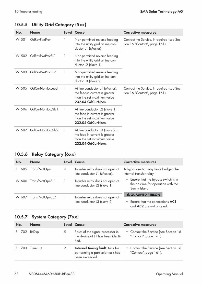
10.5.5 Utility Grid Category (5xx)No. Name Level Cause Corrective measures
W 501 GdRevPwrProt 1 Non-permitted reverse feedinginto the utility grid at line con-ductor L1 (Master)
Contact the Service, if required (see Sec-tion 16 "Contact", page 161).
W 502 GdRevPwrProtSL1 1 Non-permitted reverse feedinginto the utility grid at line con-ductor L2 (slave 1)
W 503 GdRevPwrProtSL2 1 Non-permitted reverse feedinginto the utility grid at line con-ductor L3 (slave 2)
W 505 GdCurNomExceed 1 At line conductor L1 (Master),the feed-in current is greaterthan the set maximum value232.04 GdCurNom.
Contact the Service, if required (see Sec-tion 16 "Contact", page 161).
W 506 GdCurNomExcSlv1 1 At line conductor L2 (slave 1),the feed-in current is greaterthan the set maximum value232.04 GdCurNom.
W 507 GdCurNomExcSlv2 1 At line conductor L3 (slave 2),the feed-in current is greaterthan the set maximum value232.04 GdCurNom.
10.5.6 Relay Category (6xx)No. Name Level Cause Corrective measures
F 605 TransfNotOpn 4 Transfer relay does not open atline conductor L1 (Master).
A bypass switch may have bridged theinternal transfer relay.• Ensure that the bypass switch is inthe position for operation with theSunny Island.
• Ensure that the connections AC1and AC2 are not bridged.
W 606 TransfNotOpnSL1 1 Transfer relay does not open atline conductor L2 (slave 1).
W 607 TransfNotOpnSL2 1 Transfer relay does not open atline conductor L3 (slave 2).
10.5.7 System Category (7xx)No. Name Level Cause Corrective measures
F 702 RsDsp 5 Reset of the signal processor inthe device at L1 has been identi-fied.
• Contact the Service (see Section 16"Contact", page 161).
F 703 TimeOut 2 Internal timing fault: Time forperforming a particular task hasbeen exceeded.
• Contact the Service (see Section 16"Contact", page 161).
10 Troubleshooting SMA Solar Technology AG
Operating ManualSI30M-44M-60H-80H-BE-en-3368
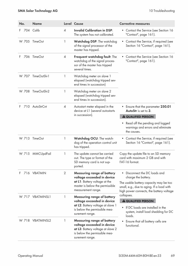
No. Name Level Cause Corrective measures
F 704 Calib 4 Invalid Calibration in DSP:The system has not calibrated.
• Contact the Service (see Section 16"Contact", page 161).
W 705 TimeOut 1 Watchdog DSP: The watchdogof the signal processor of themaster has tripped.
• Contact the Service, if required (seeSection 16 "Contact", page 161).
F 706 TimeOut 4 Frequent watchdog fault: Thewatchdog of the signal proces-sor of the master has trippedseveral times.
• Contact the Service (see Section 16"Contact", page 161).
W 707 TimeOutSlv1 1 Watchdog meter on slave 1elapsed (watchdog tripped sev-eral times in succession)
W 708 TimeOutSlv2 1 Watchdog meter on slave 2elapsed (watchdog tripped sev-eral times in succession).
F 710 AutoStrCnt 4 Autostart meter elapsed in thedevice at L1 (several autostartsin succession).
• Ensure that the parameter 250.01AutoStr is set to 3.
• Read off the pending and loggedwarnings and errors and eliminatethe causes.
W 713 TimeOut 1 Watchdog OCU: The watch-dog of the operation control unithas tripped.
• Contact the Service, if required (seeSection 16 "Contact", page 161).
W 715 MMCUpdFail 1 The update cannot be carriedout. The type or format of theSD memory card is not sup-ported.
Copy the update file to an SD memorycard with maximum 2 GB and withFAT-16 format.
F 716 VBATMIN 2 Measuring range of batteryvoltage exceeded in deviceat L1: Battery voltage at themaster is below the permissiblemeasurement range.
• Disconnect the DC loads andcharge the battery.
The usable battery capacity may be toosmall, e.g., due to aging. If a load withhigh power connects, the battery voltagecollapses.
• If DC loads are installed in thesystem, install load shedding for DCloads.
• Ensure that all battery cells arefunctional.
W 717 VBATMINSL1 1 Measuring range of batteryvoltage exceeded in deviceat L2: Battery voltage at slave 1is below the permissible mea-surement range.
W 718 VBATMINSL2 1 Measuring range of batteryvoltage exceeded in deviceat L3: Battery voltage at slave 2is below the permissible mea-surement range.
10 TroubleshootingSMA Solar Technology AG
Operating Manual 69SI30M-44M-60H-80H-BE-en-33
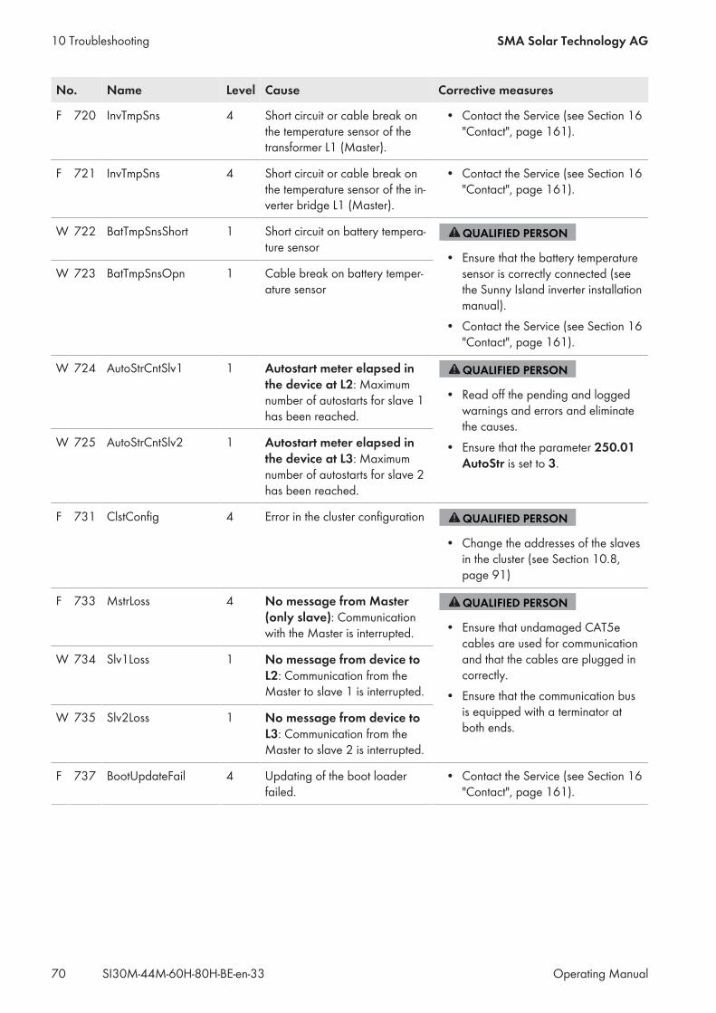
No. Name Level Cause Corrective measures
F 720 InvTmpSns 4 Short circuit or cable break onthe temperature sensor of thetransformer L1 (Master).
• Contact the Service (see Section 16"Contact", page 161).
F 721 InvTmpSns 4 Short circuit or cable break onthe temperature sensor of the in-verter bridge L1 (Master).
• Contact the Service (see Section 16"Contact", page 161).
W 722 BatTmpSnsShort 1 Short circuit on battery tempera-ture sensor
• Ensure that the battery temperaturesensor is correctly connected (seethe Sunny Island inverter installationmanual).
• Contact the Service (see Section 16"Contact", page 161).
W 723 BatTmpSnsOpn 1 Cable break on battery temper-ature sensor
W 724 AutoStrCntSlv1 1 Autostart meter elapsed inthe device at L2: Maximumnumber of autostarts for slave 1has been reached.
• Read off the pending and loggedwarnings and errors and eliminatethe causes.
• Ensure that the parameter 250.01AutoStr is set to 3.
W 725 AutoStrCntSlv2 1 Autostart meter elapsed inthe device at L3: Maximumnumber of autostarts for slave 2has been reached.
F 731 ClstConfig 4 Error in the cluster configuration
• Change the addresses of the slavesin the cluster (see Section 10.8,page 91)
F 733 MstrLoss 4 No message from Master(only slave): Communicationwith the Master is interrupted. • Ensure that undamaged CAT5e
cables are used for communicationand that the cables are plugged incorrectly.
• Ensure that the communication busis equipped with a terminator atboth ends.
W 734 Slv1Loss 1 No message from device toL2: Communication from theMaster to slave 1 is interrupted.
W 735 Slv2Loss 1 No message from device toL3: Communication from theMaster to slave 2 is interrupted.
F 737 BootUpdateFail 4 Updating of the boot loaderfailed.
• Contact the Service (see Section 16"Contact", page 161).
10 Troubleshooting SMA Solar Technology AG
Operating ManualSI30M-44M-60H-80H-BE-en-3370
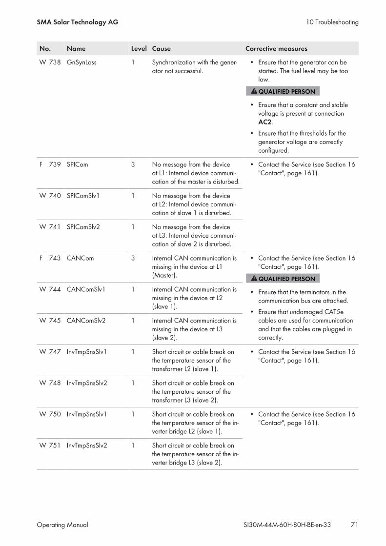
No. Name Level Cause Corrective measures
W 738 GnSynLoss 1 Synchronization with the gener-ator not successful.
• Ensure that the generator can bestarted. The fuel level may be toolow.
• Ensure that a constant and stablevoltage is present at connectionAC2.
• Ensure that the thresholds for thegenerator voltage are correctlyconfigured.
F 739 SPICom 3 No message from the deviceat L1: Internal device communi-cation of the master is disturbed.
• Contact the Service (see Section 16"Contact", page 161).
W 740 SPIComSlv1 1 No message from the deviceat L2: Internal device communi-cation of slave 1 is disturbed.
W 741 SPIComSlv2 1 No message from the deviceat L3: Internal device communi-cation of slave 2 is disturbed.
F 743 CANCom 3 Internal CAN communication ismissing in the device at L1(Master).
• Contact the Service (see Section 16"Contact", page 161).
• Ensure that the terminators in thecommunication bus are attached.
• Ensure that undamaged CAT5ecables are used for communicationand that the cables are plugged incorrectly.
W 744 CANComSlv1 1 Internal CAN communication ismissing in the device at L2(slave 1).
W 745 CANComSlv2 1 Internal CAN communication ismissing in the device at L3(slave 2).
W 747 InvTmpSnsSlv1 1 Short circuit or cable break onthe temperature sensor of thetransformer L2 (slave 1).
• Contact the Service (see Section 16"Contact", page 161).
W 748 InvTmpSnsSlv2 1 Short circuit or cable break onthe temperature sensor of thetransformer L3 (slave 2).
W 750 InvTmpSnsSlv1 1 Short circuit or cable break onthe temperature sensor of the in-verter bridge L2 (slave 1).
• Contact the Service (see Section 16"Contact", page 161).
W 751 InvTmpSnsSlv2 1 Short circuit or cable break onthe temperature sensor of the in-verter bridge L3 (slave 2).
10 TroubleshootingSMA Solar Technology AG
Operating Manual 71SI30M-44M-60H-80H-BE-en-33
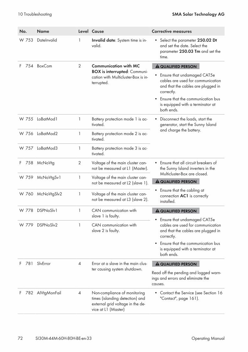
No. Name Level Cause Corrective measures
W 753 DateInvalid 1 Invalid date: System time is in-valid.
• Select the parameter 250.02 Dtand set the date. Select theparameter 250.03 Tm and set thetime.
F 754 BoxCom 2 Communication with MCBOX is interrupted: Communi-cation with Multicluster-Box is in-terrupted.
• Ensure that undamaged CAT5ecables are used for communicationand that the cables are plugged incorrectly.
• Ensure that the communication busis equipped with a terminator atboth ends.
W 755 LoBatMod1 1 Battery protection mode 1 is ac-tivated.
• Disconnect the loads, start thegenerator, start the Sunny Islandand charge the battery.
W 756 LoBatMod2 1 Battery protection mode 2 is ac-tivated.
W 757 LoBatMod3 1 Battery protection mode 3 is ac-tivated.
F 758 McNoVtg 2 Voltage of the main cluster can-not be measured at L1 (Master).
• Ensure that all circuit breakers ofthe Sunny Island inverters in theMulticluster-Box are closed.
• Ensure that the cabling atconnection AC1 is correctlyinstalled.
W 759 McNoVtgSv1 1 Voltage of the main cluster can-not be measured at L2 (slave 1).
W 760 McNoVtgSlv2 1 Voltage of the main cluster can-not be measured at L3 (slave 2).
W 778 DSPNoSlv1 1 CAN communication withslave 1 is faulty.
• Ensure that undamaged CAT5ecables are used for communicationand that the cables are plugged incorrectly.
• Ensure that the communication busis equipped with a terminator atboth ends.
W 779 DSPNoSlv2 1 CAN communication withslave 2 is faulty.
F 781 SlvError 4 Error at a slave in the main clus-ter causing system shutdown.
Read off the pending and logged warn-ings and errors and eliminate thecauses.
F 782 AIVtgMonFail 4 Non-compliance of monitoringtimes (islanding detection) andexternal grid voltage in the de-vice at L1 (Master)
• Contact the Service (see Section 16"Contact", page 161).
10 Troubleshooting SMA Solar Technology AG
Operating ManualSI30M-44M-60H-80H-BE-en-3372
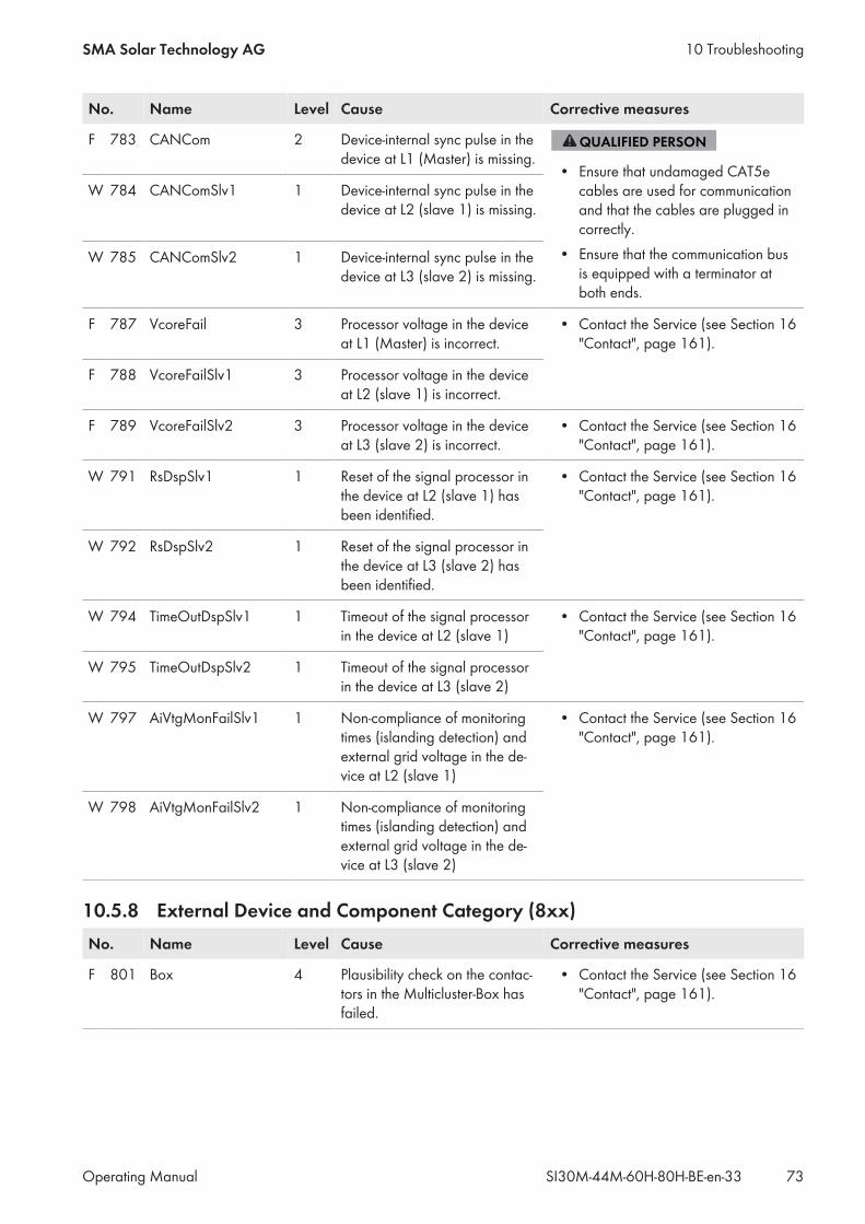
No. Name Level Cause Corrective measures
F 783 CANCom 2 Device-internal sync pulse in thedevice at L1 (Master) is missing.
• Ensure that undamaged CAT5ecables are used for communicationand that the cables are plugged incorrectly.
• Ensure that the communication busis equipped with a terminator atboth ends.
W 784 CANComSlv1 1 Device-internal sync pulse in thedevice at L2 (slave 1) is missing.
W 785 CANComSlv2 1 Device-internal sync pulse in thedevice at L3 (slave 2) is missing.
F 787 VcoreFail 3 Processor voltage in the deviceat L1 (Master) is incorrect.
• Contact the Service (see Section 16"Contact", page 161).
F 788 VcoreFailSlv1 3 Processor voltage in the deviceat L2 (slave 1) is incorrect.
F 789 VcoreFailSlv2 3 Processor voltage in the deviceat L3 (slave 2) is incorrect.
• Contact the Service (see Section 16"Contact", page 161).
W 791 RsDspSlv1 1 Reset of the signal processor inthe device at L2 (slave 1) hasbeen identified.
• Contact the Service (see Section 16"Contact", page 161).
W 792 RsDspSlv2 1 Reset of the signal processor inthe device at L3 (slave 2) hasbeen identified.
W 794 TimeOutDspSlv1 1 Timeout of the signal processorin the device at L2 (slave 1)
• Contact the Service (see Section 16"Contact", page 161).
W 795 TimeOutDspSlv2 1 Timeout of the signal processorin the device at L3 (slave 2)
W 797 AiVtgMonFailSlv1 1 Non-compliance of monitoringtimes (islanding detection) andexternal grid voltage in the de-vice at L2 (slave 1)
• Contact the Service (see Section 16"Contact", page 161).
W 798 AiVtgMonFailSlv2 1 Non-compliance of monitoringtimes (islanding detection) andexternal grid voltage in the de-vice at L3 (slave 2)
10.5.8 External Device and Component Category (8xx)No. Name Level Cause Corrective measures
F 801 Box 4 Plausibility check on the contac-tors in the Multicluster-Box hasfailed.
• Contact the Service (see Section 16"Contact", page 161).
10 TroubleshootingSMA Solar Technology AG
Operating Manual 73SI30M-44M-60H-80H-BE-en-33
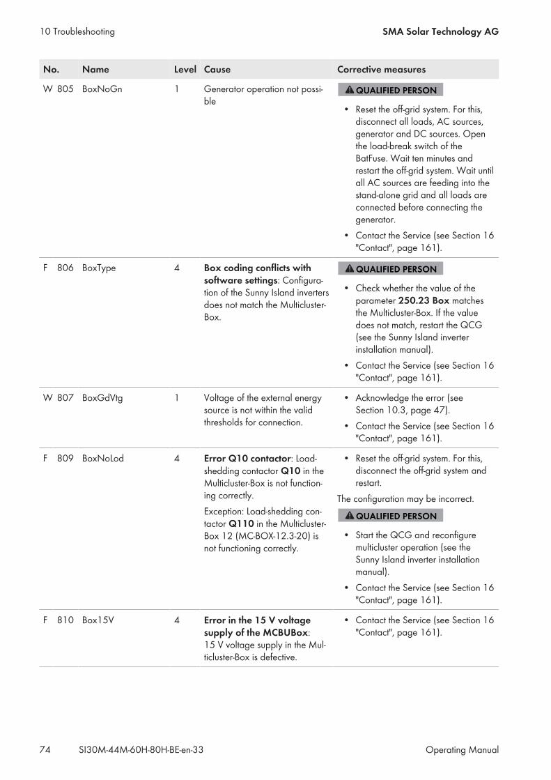
No. Name Level Cause Corrective measures
W 805 BoxNoGn 1 Generator operation not possi-ble
• Reset the off-grid system. For this,disconnect all loads, AC sources,generator and DC sources. Openthe load-break switch of theBatFuse. Wait ten minutes andrestart the off-grid system. Wait untilall AC sources are feeding into thestand-alone grid and all loads areconnected before connecting thegenerator.
• Contact the Service (see Section 16"Contact", page 161).
F 806 BoxType 4 Box coding conflicts withsoftware settings: Configura-tion of the Sunny Island invertersdoes not match the Multicluster-Box.
• Check whether the value of theparameter 250.23 Box matchesthe Multicluster-Box. If the valuedoes not match, restart the QCG(see the Sunny Island inverterinstallation manual).
• Contact the Service (see Section 16"Contact", page 161).
W 807 BoxGdVtg 1 Voltage of the external energysource is not within the validthresholds for connection.
• Acknowledge the error (seeSection 10.3, page 47).
• Contact the Service (see Section 16"Contact", page 161).
F 809 BoxNoLod 4 Error Q10 contactor: Load-shedding contactor Q10 in theMulticluster-Box is not function-ing correctly.Exception: Load-shedding con-tactor Q110 in the Multicluster-Box 12 (MC-BOX-12.3-20) isnot functioning correctly.
• Reset the off-grid system. For this,disconnect the off-grid system andrestart.
The configuration may be incorrect.
• Start the QCG and reconfiguremulticluster operation (see theSunny Island inverter installationmanual).
• Contact the Service (see Section 16"Contact", page 161).
F 810 Box15V 4 Error in the 15 V voltagesupply of the MCBUBox:15 V voltage supply in the Mul-ticluster-Box is defective.
• Contact the Service (see Section 16"Contact", page 161).
10 Troubleshooting SMA Solar Technology AG
Operating ManualSI30M-44M-60H-80H-BE-en-3374
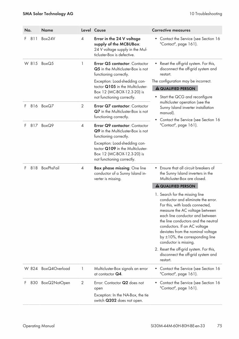
No. Name Level Cause Corrective measures
F 811 Box24V 4 Error in the 24 V voltagesupply of the MCBUBox:24 V voltage supply in the Mul-ticluster-Box is defective.
• Contact the Service (see Section 16"Contact", page 161).
W 815 BoxQ5 1 Error Q5 contactor: ContactorQ5 in the Multicluster-Box is notfunctioning correctly.Exception: Load-shedding con-tactor Q105 in the Multicluster-Box 12 (MC-BOX-12.3-20) isnot functioning correctly.
• Reset the off-grid system. For this,disconnect the off-grid system andrestart.
The configuration may be incorrect.
• Start the QCG and reconfiguremulticluster operation (see theSunny Island inverter installationmanual).
• Contact the Service (see Section 16"Contact", page 161).
F 816 BoxQ7 2 Error Q7 contactor: ContactorQ7 in the Multicluster-Box is notfunctioning correctly.
F 817 BoxQ9 4 Error Q9 contactor: ContactorQ9 in the Multicluster-Box is notfunctioning correctly.Exception: Load-shedding con-tactor Q109 in the Multicluster-Box 12 (MC-BOX-12.3-20) isnot functioning correctly.
F 818 BoxPhsFail 4 Box phase missing: One lineconductor of a Sunny Island in-verter is missing.
• Ensure that all circuit breakers ofthe Sunny Island inverters in theMulticluster-Box are closed.
1. Search for the missing lineconductor and eliminate the error.For this, with loads connected,measure the AC voltage betweeneach line conductor and betweenthe line conductors and the neutralconductors. If an AC voltagedeviates from the nominal voltageby ±10%, the corresponding lineconductor is missing.
2. Reset the off-grid system. For this,disconnect the off-grid system andrestart.
W 824 BoxQ4Overload 1 Multicluster-Box signals an errorat contactor Q4.
• Contact the Service (see Section 16"Contact", page 161).
F 830 BoxQ2NotOpen 2 Error: Contactor Q2 does notopenException: In the NA-Box, the tieswitch Q202 does not open.
• Contact the Service (see Section 16"Contact", page 161).
10 TroubleshootingSMA Solar Technology AG
Operating Manual 75SI30M-44M-60H-80H-BE-en-33
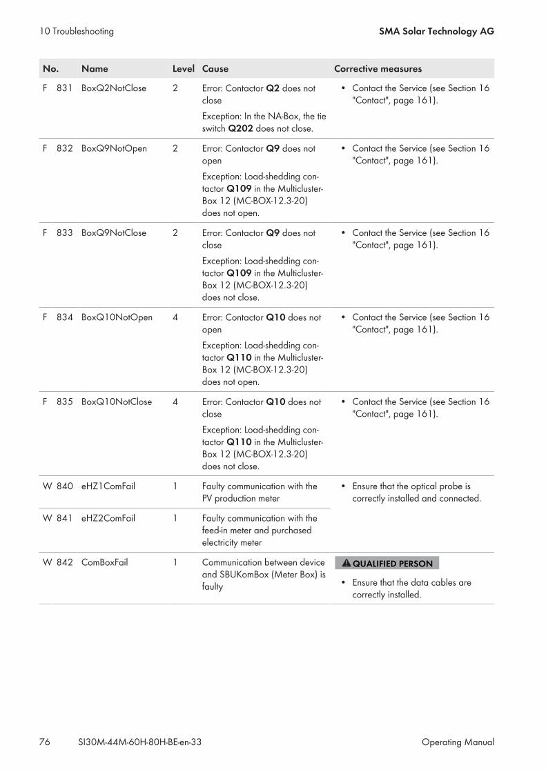
No. Name Level Cause Corrective measures
F 831 BoxQ2NotClose 2 Error: Contactor Q2 does notcloseException: In the NA-Box, the tieswitch Q202 does not close.
• Contact the Service (see Section 16"Contact", page 161).
F 832 BoxQ9NotOpen 2 Error: Contactor Q9 does notopenException: Load-shedding con-tactor Q109 in the Multicluster-Box 12 (MC-BOX-12.3-20)does not open.
• Contact the Service (see Section 16"Contact", page 161).
F 833 BoxQ9NotClose 2 Error: Contactor Q9 does notcloseException: Load-shedding con-tactor Q109 in the Multicluster-Box 12 (MC-BOX-12.3-20)does not close.
• Contact the Service (see Section 16"Contact", page 161).
F 834 BoxQ10NotOpen 4 Error: Contactor Q10 does notopenException: Load-shedding con-tactor Q110 in the Multicluster-Box 12 (MC-BOX-12.3-20)does not open.
• Contact the Service (see Section 16"Contact", page 161).
F 835 BoxQ10NotClose 4 Error: Contactor Q10 does notcloseException: Load-shedding con-tactor Q110 in the Multicluster-Box 12 (MC-BOX-12.3-20)does not close.
• Contact the Service (see Section 16"Contact", page 161).
W 840 eHZ1ComFail 1 Faulty communication with thePV production meter
• Ensure that the optical probe iscorrectly installed and connected.
W 841 eHZ2ComFail 1 Faulty communication with thefeed-in meter and purchasedelectricity meter
W 842 ComBoxFail 1 Communication between deviceand SBUKomBox (Meter Box) isfaulty • Ensure that the data cables are
correctly installed.
10 Troubleshooting SMA Solar Technology AG
Operating ManualSI30M-44M-60H-80H-BE-en-3376
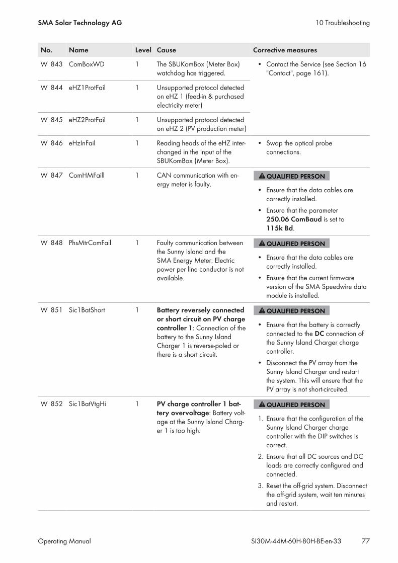
No. Name Level Cause Corrective measures
W 843 ComBoxWD 1 The SBUKomBox (Meter Box)watchdog has triggered.
• Contact the Service (see Section 16"Contact", page 161).
W 844 eHZ1ProtFail 1 Unsupported protocol detectedon eHZ 1 (feed-in & purchasedelectricity meter)
W 845 eHZ2ProtFail 1 Unsupported protocol detectedon eHZ 2 (PV production meter)
W 846 eHzInFail 1 Reading heads of the eHZ inter-changed in the input of theSBUKomBox (Meter Box).
• Swap the optical probeconnections.
W 847 ComHMFaill 1 CAN communication with en-ergy meter is faulty.
• Ensure that the data cables arecorrectly installed.
• Ensure that the parameter250.06 ComBaud is set to115k Bd.
W 848 PhsMtrComFail 1 Faulty communication betweenthe Sunny Island and theSMA Energy Meter: Electricpower per line conductor is notavailable.
• Ensure that the data cables arecorrectly installed.
• Ensure that the current firmwareversion of the SMA Speedwire datamodule is installed.
W 851 Sic1BatShort 1 Battery reversely connectedor short circuit on PV chargecontroller 1: Connection of thebattery to the Sunny IslandCharger 1 is reverse-poled orthere is a short circuit.
• Ensure that the battery is correctlyconnected to the DC connection ofthe Sunny Island Charger chargecontroller.
• Disconnect the PV array from theSunny Island Charger and restartthe system. This will ensure that thePV array is not short-circuited.
W 852 Sic1BatVtgHi 1 PV charge controller 1 bat-tery overvoltage: Battery volt-age at the Sunny Island Charg-er 1 is too high.
1. Ensure that the configuration of theSunny Island Charger chargecontroller with the DIP switches iscorrect.
2. Ensure that all DC sources and DCloads are correctly configured andconnected.
3. Reset the off-grid system. Disconnectthe off-grid system, wait ten minutesand restart.
10 TroubleshootingSMA Solar Technology AG
Operating Manual 77SI30M-44M-60H-80H-BE-en-33
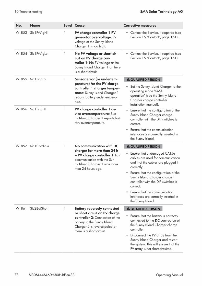
No. Name Level Cause Corrective measures
W 853 Sic1PvVtgHi 1 PV charge controller 1 PVgenerator overvoltage: PVvoltage at the Sunny IslandCharger 1 is too high.
• Contact the Service, if required (seeSection 16 "Contact", page 161).
W 854 Sic1PvVtgLo 1 No PV voltage or short cir-cuit on PV charge con-troller 1: No PV voltage at theSunny Island Charger 1 or thereis a short circuit.
• Contact the Service, if required (seeSection 16 "Contact", page 161).
W 855 Sic1TmpLo 1 Sensor error (or undertem-perature) for the PV chargecontroller 1 charger temper-ature: Sunny Island Charger 1reports battery undertempera-ture.
• Set the Sunny Island Charger to theoperating mode "SMAoperation" (see the Sunny IslandCharger charge controllerinstallation manual).
• Ensure that the configuration of theSunny Island Charger chargecontroller with the DIP switches iscorrect.
• Ensure that the communicationinterfaces are correctly inserted inthe Sunny Island.
W 856 Sic1TmpHI 1 PV charge controller 1 de-vice overtemperature: Sun-ny Island Charger 1 reports bat-tery overtemperature.
W 857 Sic1ComLoss 1 No communication with DCcharger for more than 24 h– PV charge controller 1: Lastcommunication with the Sun-ny Island Charger 1 was morethan 24 hours ago.
• Ensure that undamaged CAT5ecables are used for communicationand that the cables are plugged incorrectly.
• Ensure that the configuration of theSunny Island Charger chargecontroller with the DIP switches iscorrect.
• Ensure that the communicationinterfaces are correctly inserted inthe Sunny Island.
W 861 Sic2BatShort 1 Battery reversely connectedor short circuit on PV chargecontroller 2: Connection of thebattery to the Sunny IslandCharger 2 is reverse-poled orthere is a short circuit.
• Ensure that the battery is correctlyconnected to the DC connection ofthe Sunny Island Charger chargecontroller.
• Disconnect the PV array from theSunny Island Charger and restartthe system. This will ensure that thePV array is not short-circuited.
10 Troubleshooting SMA Solar Technology AG
Operating ManualSI30M-44M-60H-80H-BE-en-3378
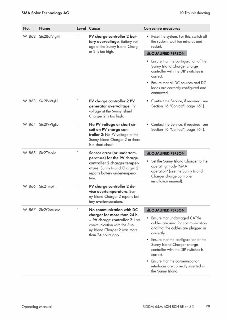
No. Name Level Cause Corrective measures
W 862 Sic2BatVtgHi 1 PV charge controller 2 bat-tery overvoltage: Battery volt-age at the Sunny Island Charg-er 2 is too high.
• Reset the system. For this, switch offthe system, wait ten minutes andrestart.
• Ensure that the configuration of theSunny Island Charger chargecontroller with the DIP switches iscorrect.
• Ensure that all DC sources and DCloads are correctly configured andconnected.
W 863 Sic2PvVtgHi 1 PV charge controller 2 PVgenerator overvoltage: PVvoltage at the Sunny IslandCharger 2 is too high.
• Contact the Service, if required (seeSection 16 "Contact", page 161).
W 864 Sic2PvVtgLo 1 No PV voltage or short cir-cuit on PV charge con-troller 2: No PV voltage at theSunny Island Charger 2 or thereis a short circuit.
• Contact the Service, if required (seeSection 16 "Contact", page 161).
W 865 Sic2TmpLo 1 Sensor error (or undertem-perature) for the PV chargecontroller 2 charger temper-ature: Sunny Island Charger 2reports battery undertempera-ture.
• Set the Sunny Island Charger to theoperating mode "SMAoperation" (see the Sunny IslandCharger charge controllerinstallation manual).
W 866 Sic2TmpHI 1 PV charge controller 2 de-vice overtemperature: Sun-ny Island Charger 2 reports bat-tery overtemperature.
W 867 Sic2ComLoss 1 No communication with DCcharger for more than 24 h– PV charge controller 2: Lastcommunication with the Sun-ny Island Charger 2 was morethan 24 hours ago.
• Ensure that undamaged CAT5ecables are used for communicationand that the cables are plugged incorrectly.
• Ensure that the configuration of theSunny Island Charger chargecontroller with the DIP switches iscorrect.
• Ensure that the communicationinterfaces are correctly inserted inthe Sunny Island.
10 TroubleshootingSMA Solar Technology AG
Operating Manual 79SI30M-44M-60H-80H-BE-en-33
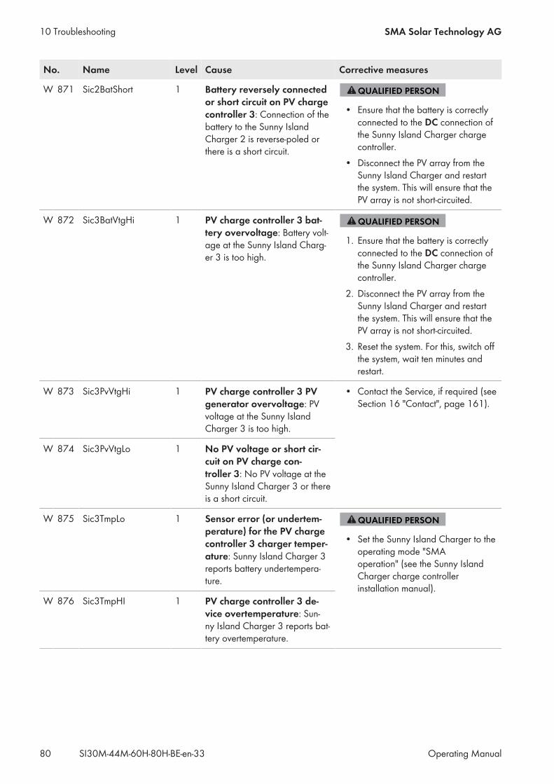
No. Name Level Cause Corrective measures
W 871 Sic2BatShort 1 Battery reversely connectedor short circuit on PV chargecontroller 3: Connection of thebattery to the Sunny IslandCharger 2 is reverse-poled orthere is a short circuit.
• Ensure that the battery is correctlyconnected to the DC connection ofthe Sunny Island Charger chargecontroller.
• Disconnect the PV array from theSunny Island Charger and restartthe system. This will ensure that thePV array is not short-circuited.
W 872 Sic3BatVtgHi 1 PV charge controller 3 bat-tery overvoltage: Battery volt-age at the Sunny Island Charg-er 3 is too high.
1. Ensure that the battery is correctlyconnected to the DC connection ofthe Sunny Island Charger chargecontroller.
2. Disconnect the PV array from theSunny Island Charger and restartthe system. This will ensure that thePV array is not short-circuited.
3. Reset the system. For this, switch offthe system, wait ten minutes andrestart.
W 873 Sic3PvVtgHi 1 PV charge controller 3 PVgenerator overvoltage: PVvoltage at the Sunny IslandCharger 3 is too high.
• Contact the Service, if required (seeSection 16 "Contact", page 161).
W 874 Sic3PvVtgLo 1 No PV voltage or short cir-cuit on PV charge con-troller 3: No PV voltage at theSunny Island Charger 3 or thereis a short circuit.
W 875 Sic3TmpLo 1 Sensor error (or undertem-perature) for the PV chargecontroller 3 charger temper-ature: Sunny Island Charger 3reports battery undertempera-ture.
• Set the Sunny Island Charger to theoperating mode "SMAoperation" (see the Sunny IslandCharger charge controllerinstallation manual).
W 876 Sic3TmpHI 1 PV charge controller 3 de-vice overtemperature: Sun-ny Island Charger 3 reports bat-tery overtemperature.
10 Troubleshooting SMA Solar Technology AG
Operating ManualSI30M-44M-60H-80H-BE-en-3380
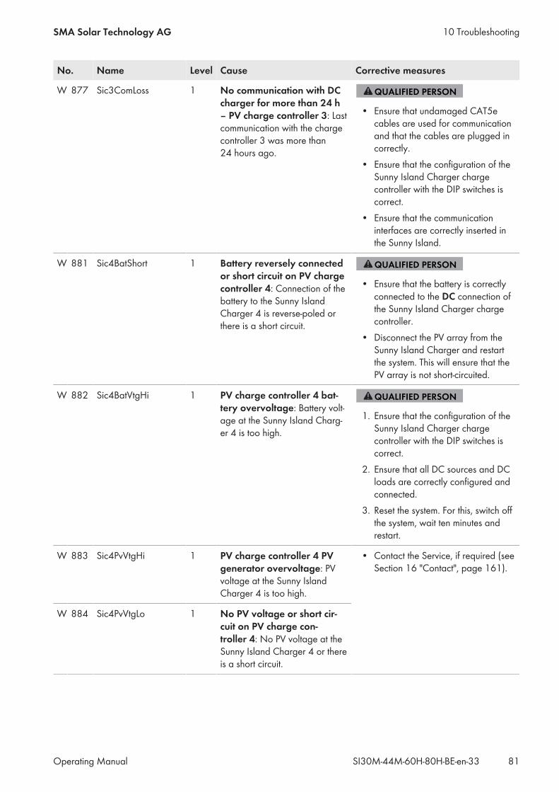
No. Name Level Cause Corrective measures
W 877 Sic3ComLoss 1 No communication with DCcharger for more than 24 h– PV charge controller 3: Lastcommunication with the chargecontroller 3 was more than24 hours ago.
• Ensure that undamaged CAT5ecables are used for communicationand that the cables are plugged incorrectly.
• Ensure that the configuration of theSunny Island Charger chargecontroller with the DIP switches iscorrect.
• Ensure that the communicationinterfaces are correctly inserted inthe Sunny Island.
W 881 Sic4BatShort 1 Battery reversely connectedor short circuit on PV chargecontroller 4: Connection of thebattery to the Sunny IslandCharger 4 is reverse-poled orthere is a short circuit.
• Ensure that the battery is correctlyconnected to the DC connection ofthe Sunny Island Charger chargecontroller.
• Disconnect the PV array from theSunny Island Charger and restartthe system. This will ensure that thePV array is not short-circuited.
W 882 Sic4BatVtgHi 1 PV charge controller 4 bat-tery overvoltage: Battery volt-age at the Sunny Island Charg-er 4 is too high.
1. Ensure that the configuration of theSunny Island Charger chargecontroller with the DIP switches iscorrect.
2. Ensure that all DC sources and DCloads are correctly configured andconnected.
3. Reset the system. For this, switch offthe system, wait ten minutes andrestart.
W 883 Sic4PvVtgHi 1 PV charge controller 4 PVgenerator overvoltage: PVvoltage at the Sunny IslandCharger 4 is too high.
• Contact the Service, if required (seeSection 16 "Contact", page 161).
W 884 Sic4PvVtgLo 1 No PV voltage or short cir-cuit on PV charge con-troller 4: No PV voltage at theSunny Island Charger 4 or thereis a short circuit.
10 TroubleshootingSMA Solar Technology AG
Operating Manual 81SI30M-44M-60H-80H-BE-en-33
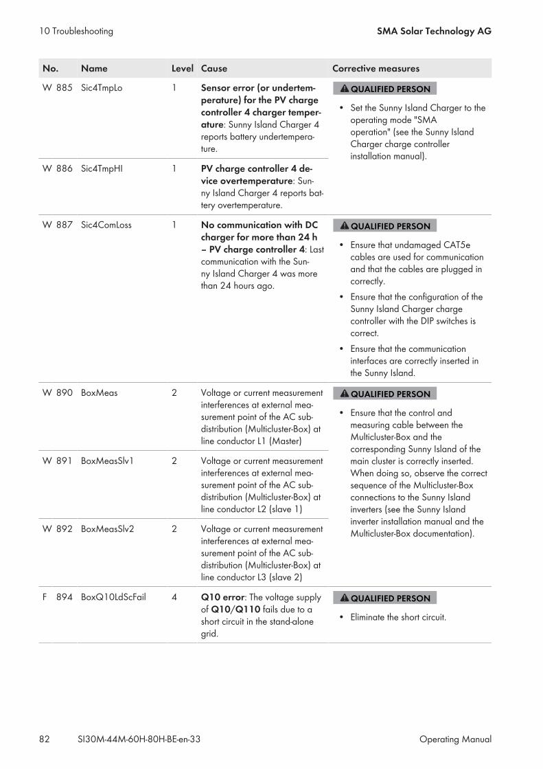
No. Name Level Cause Corrective measures
W 885 Sic4TmpLo 1 Sensor error (or undertem-perature) for the PV chargecontroller 4 charger temper-ature: Sunny Island Charger 4reports battery undertempera-ture.
• Set the Sunny Island Charger to theoperating mode "SMAoperation" (see the Sunny IslandCharger charge controllerinstallation manual).
W 886 Sic4TmpHI 1 PV charge controller 4 de-vice overtemperature: Sun-ny Island Charger 4 reports bat-tery overtemperature.
W 887 Sic4ComLoss 1 No communication with DCcharger for more than 24 h– PV charge controller 4: Lastcommunication with the Sun-ny Island Charger 4 was morethan 24 hours ago.
• Ensure that undamaged CAT5ecables are used for communicationand that the cables are plugged incorrectly.
• Ensure that the configuration of theSunny Island Charger chargecontroller with the DIP switches iscorrect.
• Ensure that the communicationinterfaces are correctly inserted inthe Sunny Island.
W 890 BoxMeas 2 Voltage or current measurementinterferences at external mea-surement point of the AC sub-distribution (Multicluster-Box) atline conductor L1 (Master)
• Ensure that the control andmeasuring cable between theMulticluster-Box and thecorresponding Sunny Island of themain cluster is correctly inserted.When doing so, observe the correctsequence of the Multicluster-Boxconnections to the Sunny Islandinverters (see the Sunny Islandinverter installation manual and theMulticluster-Box documentation).
W 891 BoxMeasSlv1 2 Voltage or current measurementinterferences at external mea-surement point of the AC sub-distribution (Multicluster-Box) atline conductor L2 (slave 1)
W 892 BoxMeasSlv2 2 Voltage or current measurementinterferences at external mea-surement point of the AC sub-distribution (Multicluster-Box) atline conductor L3 (slave 2)
F 894 BoxQ10LdScFail 4 Q10 error: The voltage supplyof Q10/Q110 fails due to ashort circuit in the stand-alonegrid.
• Eliminate the short circuit.
10 Troubleshooting SMA Solar Technology AG
Operating ManualSI30M-44M-60H-80H-BE-en-3382
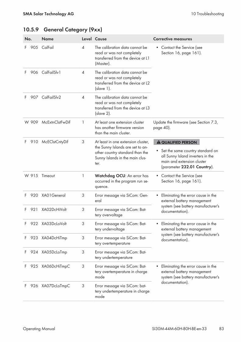
10.5.9 General Category (9xx)No. Name Level Cause Corrective measures
F 905 CalFail 4 The calibration data cannot beread or was not completelytransferred from the device at L1(Master).
• Contact the Service (seeSection 16, page 161).
F 906 CalFailSlv1 4 The calibration data cannot beread or was not completelytransferred from the device at L2(slave 1).
F 907 CalFailSlv2 4 The calibration data cannot beread or was not completelytransferred from the device at L3(slave 2).
W 909 McExtnClstFwDif 1 At least one extension clusterhas another firmware versionthan the main cluster.
Update the firmware (see Section 7.3,page 40).
F 910 McEClstCntyDif 3 At least in one extension cluster,the Sunny Islands are set to an-other country standard than theSunny Islands in the main clus-ter.
• Set the same country standard onall Sunny Island inverters in themain and extension cluster(parameter 232.01 Country).
W 915 Timeout 1 Watchdog OCU: An error hasoccurred in the program run se-quence.
• Contact the Service (seeSection 16, page 161).
F 920 XA01General 3 Error message via SiCom: Gen-eral
• Eliminating the error cause in theexternal battery managementsystem (see battery manufacturer'sdocumentation).F 921 XA02DcHiVolt 3 Error message via SiCom: Bat-
tery overvoltage
F 922 XA03DcLoVolt 3 Error message via SiCom: Bat-tery undervoltage
• Eliminating the error cause in theexternal battery managementsystem (see battery manufacturer'sdocumentation).F 923 XA04DcHiTmp 3 Error message via SiCom: Bat-
tery overtemperature
F 924 XA05DcLoTmp 3 Error message via SiCom: Bat-tery undertemperature
F 925 XA06DcHiTmpC 3 Error message via SiCom: Bat-tery overtemperature in chargemode
• Eliminating the error cause in theexternal battery managementsystem (see battery manufacturer'sdocumentation).
F 926 XA07DcLoTmpC 3 Error message via SiCom: bat-tery undertemperature in chargemode
10 TroubleshootingSMA Solar Technology AG
Operating Manual 83SI30M-44M-60H-80H-BE-en-33
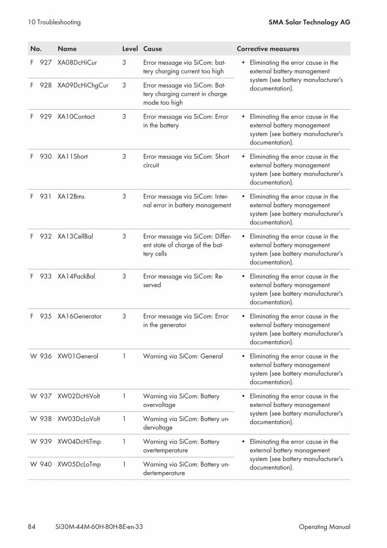
No. Name Level Cause Corrective measures
F 927 XA08DcHiCur 3 Error message via SiCom: bat-tery charging current too high
• Eliminating the error cause in theexternal battery managementsystem (see battery manufacturer'sdocumentation).F 928 XA09DcHiChgCur 3 Error message via SiCom: Bat-
tery charging current in chargemode too high
F 929 XA10Contact 3 Error message via SiCom: Errorin the battery
• Eliminating the error cause in theexternal battery managementsystem (see battery manufacturer'sdocumentation).
F 930 XA11Short 3 Error message via SiCom: Shortcircuit
• Eliminating the error cause in theexternal battery managementsystem (see battery manufacturer'sdocumentation).
F 931 XA12Bms 3 Error message via SiCom: Inter-nal error in battery management
• Eliminating the error cause in theexternal battery managementsystem (see battery manufacturer'sdocumentation).
F 932 XA13CellBal 3 Error message via SiCom: Differ-ent state of charge of the bat-tery cells
• Eliminating the error cause in theexternal battery managementsystem (see battery manufacturer'sdocumentation).
F 933 XA14PackBal 3 Error message via SiCom: Re-served
• Eliminating the error cause in theexternal battery managementsystem (see battery manufacturer'sdocumentation).
F 935 XA16Generator 3 Error message via SiCom: Errorin the generator
• Eliminating the error cause in theexternal battery managementsystem (see battery manufacturer'sdocumentation).
W 936 XW01General 1 Warning via SiCom: General • Eliminating the error cause in theexternal battery managementsystem (see battery manufacturer'sdocumentation).
W 937 XW02DcHiVolt 1 Warning via SiCom: Batteryovervoltage
• Eliminating the error cause in theexternal battery managementsystem (see battery manufacturer'sdocumentation).W 938 XW03DcLoVolt 1 Warning via SiCom: Battery un-
dervoltage
W 939 XW04DcHiTmp 1 Warning via SiCom: Batteryovertemperature
• Eliminating the error cause in theexternal battery managementsystem (see battery manufacturer'sdocumentation).W 940 XW05DcLoTmp 1 Warning via SiCom: Battery un-
dertemperature
10 Troubleshooting SMA Solar Technology AG
Operating ManualSI30M-44M-60H-80H-BE-en-3384

No. Name Level Cause Corrective measures
W 941 XW06DcHiTmpC 1 Warning via SiCom: Batteryovertemperature in chargemode
• Eliminating the error cause in theexternal battery managementsystem (see battery manufacturer'sdocumentation).
W 942 XA07DcLoTmpC 1 Warning via SiCom: Battery un-dertemperature in charge mode
W 943 XW08DcHiCur 1 Warning via SiCom: batterycharging current too high
• Eliminating the error cause in theexternal battery managementsystem (see battery manufacturer'sdocumentation).W 944 Warning via SiCom:
battery charging cur-rent in charge modetoo high
1 Warning via SiCom: batterycharging current in chargemode too high
W 945 XW10Contact 1 Warning via SiCom: error in thebattery
• Eliminating the error cause in theexternal battery managementsystem (see battery manufacturer'sdocumentation).
W 946 XW11Short 1 Warning via SiCom: short circuit • Eliminating the error cause in theexternal battery managementsystem (see battery manufacturer'sdocumentation).
W 947 XW12Bms 1 Warning via SiCom: internal er-ror in battery management
• Eliminating the error cause in theexternal battery managementsystem (see battery manufacturer'sdocumentation).
W 948 XW13CellBal 1 Warning via SiCom: differentstate of charge of the batterycells
• Eliminating the error cause in theexternal battery managementsystem (see battery manufacturer'sdocumentation).
w 949 XW14PackBal 1 Warning via SiCom: Reserved • Eliminating the error cause in theexternal battery managementsystem (see battery manufacturer'sdocumentation).
W 951 XW16Generator 1 Warning via SiCom: Error in thegenerator
• Eliminating the error cause in theexternal battery managementsystem (see battery manufacturer'sdocumentation).
F 952 ExtBMSTimeout 3 The timeout monitoring systemof the battery management hastriggered
• Ensure that the data cable of theexternal lithium-ion battery isconnected correctly.
• Ensure that the terminators of theCAN bus in the communication busare attached.
W 953 WrnExtBMSTmOut 1 The timeout monitoring systemof the battery management hastriggered
10 TroubleshootingSMA Solar Technology AG
Operating Manual 85SI30M-44M-60H-80H-BE-en-33
10.6 Frequently Asked Questions (FAQs)
10.6.1 Questions Regarding the Sunny Island
Why is the Sunny Island not switching off even though I have opened the load-break switch ofthe BatFuse?The Sunny Island may still be supplied from the AC side.
• Switch off all AC sources and disconnect them from the Sunny Island.
Why is the Sunny Island not switching to energy-saving mode?Another function might have a higher priority than energy saving mode, e.g., equalization charge or full charge.
After automatic disconnection in battery protection mode, the Sunny Island can no longer bestarted?
• Charge the battery only when the Sunny Island cannot be switched on (see Section 10.7 "Charging the BatteryAfter Automatic Shutdown in Off-Grid Systems (Emergency Charge Mode)", page 89).– Switch off all loads.– If there is a generator in the system, start the generator manually. When doing so, observe the warm-up timeof the generator. Five minutes without charge current can result in disconnection of the Sunny Island inverter.
– If sufficient power is available from the generator or the AC sources in the stand-alone grid, e.g., sufficientsolar irradiation for PV inverters, switch the Sunny Island on. AC sources in the stand-alone grid can startfeeding in electric current only once the Sunny Island has been started and is in operation.
10.6.2 Questions Regarding the Sunny Remote Control
The display of the Sunny Remote Control is dark and nothing is displayed – why?The Sunny Island might not be switched on.• Ensure that the fuse in the BatFuse is not defective and switch on the Sunny Island(see Section 4.1, page 20) .The Sunny Remote Control might not be connected to the Sunny Island.
• Ensure that the Sunny Remote Control is connected to the Sunny Island.The RJ45 data cable may be damaged.
• Replace the RJ45 data cable between the Sunny Remote Control and the Sunny Island.
Why can parameters not be changed?It is possible that the parameter is displayed only in expert mode.• Switch to expert mode on the Sunny Remote Control (see Section 5.4.1, page 32).It might be possible to change the parameter only in standby mode or in the QCG.• Observe the messages in the display (see Section 5.4.6, page 34).The parameter may be hidden as it is not required in the configuration set for the system.• Ensure that the configuration does not deactivate any functions which are required.
10 Troubleshooting SMA Solar Technology AG
Operating ManualSI30M-44M-60H-80H-BE-en-3386
Why is "MMC/SD operation failed!" shown on the display?An action with the SD memory card has failed.• Use a computer to ensure that the SD memory card is free of errors.
• Ensure that the data cable between the Sunny Remote Control and the Sunny Island is undamaged and that theplugs are firmly inserted into the pin connectors.
Why is the display showing "WRONG FILE SYSTEM"?The SD memory card is not formatted with the FAT-16 or FAT-32 file system.
10.6.3 Questions Regarding the Battery
What happens if a battery is defective?
• Remove the defective battery cell from the battery system. This reduces the rated voltage of the battery by thevoltage of the battery cell.
• In the QCG, set the current rated voltage of the battery under New Battery (see Section 11.8 "Replacing theBattery", page 97).
Why is the SOC of the battery not 100% after completion of full charge?The power requirements of the loads might have been so high before completion of the full charge that the batterycould not be charged to 100 percent.• If necessary, select the parameter 222.03 AptTmFul and set to a longer time period.
Why is the battery discharging even though the generator is running?The Sunny Island may not have connected to the generator.• Eliminate the cause (see Section 10.6.4 "Questions Regarding the Generator", page 87).The power of the loads might exceed the power of the generator.
What do you need to do after replacing a battery current sensor?
• Calibrate the battery current sensor (see the Commissioning section in the Sunny Island inverter installationmanual).
10.6.4 Questions Regarding the Generator
Why is the Sunny Island not connecting to the running generator?A high output power of the Sunny Island inverter when the battery state of charge is low may lead to the Sunny Islandnot being able to raise the AC voltage in the stand-alone grid to the AC voltage of the generator. The Sunny Islandcancels the synchronization.• To charge the battery, reduce the power of the loads.The generator voltage might not be within the thresholds for voltage and frequency.• Check whether the symbol is displayed permanently in standard mode.If the symbol is not displayed, ensure that the fuse is not defective or the circuit breaker is activated.If the symbol is not displayed permanently, the generator voltage is sporadically outside the thresholds.
10 TroubleshootingSMA Solar Technology AG
Operating Manual 87SI30M-44M-60H-80H-BE-en-33
– Set the thresholds for voltage and frequency of the generator voltage (see the Sunny Island inverterinstallation manual).
If the symbol is displayed permanently, the Sunny Island is in the warm-up period or is blocked for connection. Useful hint: Tip: Check whether the Sunny Remote Control displays the " ! " warning symbol in standard mode.
Why does the Sunny Island connect to the generator for only a short time?The generator may be overloaded.• Select the parameter 234.03 GnCurNom and set it to 75% of the rated current of the generator.• If possible, reduce the power of the loads.The maximum permissible generator voltage may be set too low.
• Select the parameter 234.02 GnVtgMax and set to the maximum generator voltage.The minimum frequency for the generator voltage may be set too high.
• Select the parameter 234.05 GnFrqMin and set to the minimum frequency of the generator voltage.The permitted time 234.14 GnRvTm for reverse power might have been exceeded.• Check whether warning W401 is registered in the menu 420# Error history.Useful hint: Tip: If a warning was registered, the warning symbol " ! " is shown in the standard mode of theSunny Remote Control.
• Select the 540.02 GnAck parameter and set to Ackn. This acknowledges the generator error.
The Sunny Island does not reconnect to the generator after disconnection from the generator dueto non-compliance with the thresholds for voltage and frequency – why?The Sunny Island is switched with a hysteresis, i.e., the thresholds for connection do not correspond to the thresholdsfor disconnection.• To unload the generator, disconnect unnecessary loads.• Wait until the voltage and frequency have reached the nominal values.
10.6.5 Questions Regarding Multicluster Systems
Extension clusters remain in standby mode even though the main cluster is in inverter mode?The data cable between the masters of the individual clusters might not be connected. The master of the main clustercannot forward the "Start" command to the masters of the extension clusters.
Why is the multicluster system not supplying full power?An extension cluster or individual Sunny Island inverters of an extension cluster might have failed.
Why are high levels of energy being transferred between the clusters in the multicluster system?The state of charge of the batteries might differ temporarily. The off-grid system equalizes different states of chargeautomatically.The nominal frequencies and nominal voltages may be defined differently.• Set the frequencies and voltages in the 210# Inverter Settings menu to the same values for all masters.The battery capacities might differ significantly.
• Distribute the battery capacities to the clusters as evenly as possible.
10 Troubleshooting SMA Solar Technology AG
Operating ManualSI30M-44M-60H-80H-BE-en-3388

Individual battery cells of a battery might have failed.
• Disconnect defective battery cells and set the new rated voltage and capacity (see Section 11.8 "Replacing theBattery", page 97).
10.7 Charging the Battery After Automatic Shutdown in Off-Grid Systems(Emergency Charge Mode)
When a battery undergoes deep discharge, the Sunny Island shuts down automatically and you cannot restart theSunny Island. In order to start the Sunny Island again after an automatic shutdown, you must charge the battery inemergency charge mode.In emergency charge mode, the Sunny Island does not form a separate stand-alone grid, and you can charge thebattery using a generator. Battery management is active in emergency charge mode and the Sunny Island charges thebattery in accordance with the parameter settings. In standby mode or in the QCG, you can adjust the parameters forthe battery, e.g., the battery nominal voltage, if a battery cell fails.
Danger to life due to fire or explosion when charging a deep discharged lithium-ion battery.The charging of a deep discharged lithium-ion battery can lead to its destruction. Death or lethal injuries can result.• Verify that the lithium-ion battery is not deep discharged (see manual of the lithium-ion battery)• Charging is performed in accordance with the specifications of the battery manufacturer (see manual of thelithium-ion battery).
• Only run the emergency charge mode with Sunny Island after approval by the battery manufacturer.
Danger to life from electric shock due to high voltagesHigh voltages are present inside the Sunny Island. When the enclosure lid is removed, live components can betouched that can result in death or serious injury due to electric shock.• Disconnect the Sunny Island from voltage sources (see Section 9, page 45).
Restricted management functions in emergency charge modeIn emergency charge mode, the generator management is not active. The limits for voltage, current and frequencyare not monitored. Set the maximum current consumption of the Sunny Island inverter for charging the battery inemergency charge mode. The Sunny Island does not record additional strain on the generator due to loads.
Requirements: The Sunny Remote Control must be connected to the master. The system must be an off-grid system. The system must be a single system (single-phase system with Sunny Island). Lead-acid batteries must be connected (for emergency charge mode of a lithium-ion battery see documentation ofthe battery manufacturer).
Procedure:• Connect the generator to connection AC1.• Charge the battery.• Disconnect the generator from connection AC1.• Start the off-grid system.
10 TroubleshootingSMA Solar Technology AG
Operating Manual 89SI30M-44M-60H-80H-BE-en-33
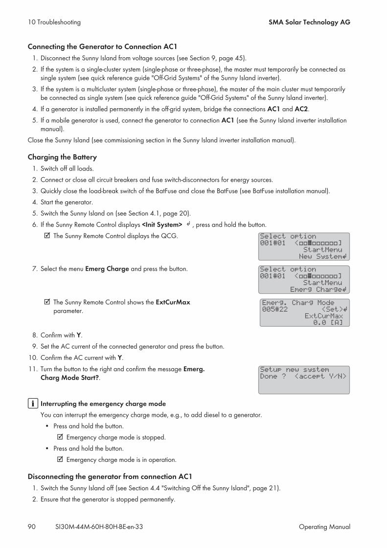
Connecting the Generator to Connection AC11. Disconnect the Sunny Island from voltage sources (see Section 9, page 45).2. If the system is a single-cluster system (single-phase or three-phase), the master must temporarily be connected assingle system (see quick reference guide "Off-Grid Systems" of the Sunny Island inverter).
3. If the system is a multicluster system (single-phase or three-phase), the master of the main cluster must temporarilybe connected as single system (see quick reference guide "Off-Grid Systems" of the Sunny Island inverter).
4. If a generator is installed permanently in the off-grid system, bridge the connections AC1 and AC2.5. If a mobile generator is used, connect the generator to connection AC1 (see the Sunny Island inverter installationmanual).
Close the Sunny Island (see commissioning section in the Sunny Island inverter installation manual).
Charging the Battery1. Switch off all loads.2. Connect or close all circuit breakers and fuse switch-disconnectors for energy sources.3. Quickly close the load-break switch of the BatFuse and close the BatFuse (see BatFuse installation manual).4. Start the generator.5. Switch the Sunny Island on (see Section 4.1, page 20).6. If the Sunny Remote Control displays <Init System> , press and hold the button. The Sunny Remote Control displays the QCG. Select option
001#01 ´ ´´´´ ´]<´ ¿ ´
StartMenu
New SystemÃ
7. Select the menu Emerg Charge and press the button. Select option
001#01 <´´¿´´´´´´]
StartMenu
Emerg ChargeÃ
The Sunny Remote Control shows the ExtCurMaxparameter.
Emerg. Charg Mode
005#22 <Set>Ã
ExtCurMax
0.0 [A]
8. Confirm with Y.9. Set the AC current of the connected generator and press the button.10. Confirm the AC current with Y.11. Turn the button to the right and confirm the message Emerg.
Charg Mode Start?.Setup new system
Done ? <accept Y/N>
Interrupting the emergency charge modeYou can interrupt the emergency charge mode, e.g., to add diesel to a generator.• Press and hold the button. Emergency charge mode is stopped.
• Press and hold the button. Emergency charge mode is in operation.
Disconnecting the generator from connection AC11. Switch the Sunny Island off (see Section 4.4 "Switching Off the Sunny Island", page 21).2. Ensure that the generator is stopped permanently.
10 Troubleshooting SMA Solar Technology AG
Operating ManualSI30M-44M-60H-80H-BE-en-3390
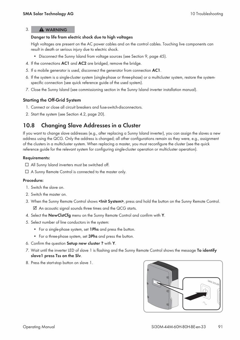
3.
Danger to life from electric shock due to high voltagesHigh voltages are present on the AC power cables and on the control cables. Touching live components canresult in death or serious injury due to electric shock.• Disconnect the Sunny Island from voltage sources (see Section 9, page 45).
4. If the connections AC1 and AC2 are bridged, remove the bridge.5. If a mobile generator is used, disconnect the generator from connection AC1.6. If the system is a single-cluster system (single-phase or three-phase) or a multicluster system, restore the system-specific connection (see quick reference guide of the used system).
7. Close the Sunny Island (see commissioning section in the Sunny Island inverter installation manual).
Starting the Off-Grid System1. Connect or close all circuit breakers and fuse-switch-disconnectors.2. Start the system (see Section 4.2, page 20).
10.8 Changing Slave Addresses in a ClusterIf you want to change slave addresses (e.g., after replacing a Sunny Island inverter), you can assign the slaves a newaddress using the QCG. Only the address is changed; all other configurations remain as they were, e.g., assignmentof the clusters in a multicluster system. When replacing a master, you must reconfigure the cluster (see the quickreference guide for the relevant system for configuring single-cluster operation or multicluster operation).
Requirements: All Sunny Island inverters must be switched off. A Sunny Remote Control is connected to the master only.
Procedure:1. Switch the slave on.2. Switch the master on.3. When the Sunny Remote Control shows <Init System>, press and hold the button on the Sunny Remote Control. An acoustic signal sounds three times and the QCG starts.
4. Select the NewClstCfg menu on the Sunny Remote Control and confirm with Y.5. Select number of line conductors in the system:• For a single-phase system, set 1Phs and press the button.• For a three-phase system, set 3Phs and press the button.
6. Confirm the question Setup new cluster ? with Y.7. Wait until the inverter LED of slave 1 is flashing and the Sunny Remote Control shows the message To identify
slave1 press Tss on the Slv.8. Press the start-stop button on slave 1.
10 TroubleshootingSMA Solar Technology AG
Operating Manual 91SI30M-44M-60H-80H-BE-en-33
The QCG configures slave 1.9. To configure slave 2, wait until the inverter LED of slave 2 is flashing and the Sunny Remote Control shows themessage To identify slave2 press Tss on the Slv.
10. Press the start-stop button on slave 2. An acoustic signal sounds and the QCG configures slave 2.
11. Press the button on the Sunny Remote Control. This closes the QCG. The Sunny Remote Control switches from display mode to standard mode.
10 Troubleshooting SMA Solar Technology AG
Operating ManualSI30M-44M-60H-80H-BE-en-3392
11 Cleaning and Maintenance
11.1 Cleaning and Checking the Sunny Island Inverter Enclosure
Damage to the inverter due to the use of cleaning agents• If the inverter is dirty, clean the enclosure, the enclosure lid, the type label and the LEDs using only clean waterand a cloth.
• Ensure that the inverter is free of dust, foliage and other dirt. Carefully remove heavy dirt with a soft brush.
11.2 Cleaning the Sunny Remote Control
Damage to the Sunny Remote Control due to the use of cleaning agents• If the Sunny Remote Control is dirty, clean the enclosure, type label, button, and display with a damp cloth only.
• Ensure that the Sunny Remote Control is free of dust, foliage and other dirt.
11.3 Performing a Manual Equalization Charge in the Off-Grid SystemAfter extended periods without charging (e.g., systems operated seasonally), perform a manual equalization charge atthe end or start of the season.
Requirement: The Sunny Remote Control must be in standard mode or user mode.
Procedure:1. Select the Battery display page on the Sunny Remote Control and press the button (see Section 5.3.2"Displaying Parameters and Operating and Setting the System", page 30).
2. Select the parameter Equalize and set to Start.
11.4 Checking the Function• For the first six months after installation of new systems, check every week whether error messages have beenlogged. This will reveal any hidden errors in the installation or configuration:– Switch to installer mode on the Sunny Remote Control (see Section 5.4.1, page 32).– Select the menu 420# Error history and check whether any error messages have been logged.– If error messages have been logged, eliminate the cause (see Section 10 "Troubleshooting", page 46).
• Check every six months whether error messages have been logged:– Switch to installer mode on the Sunny Remote Control (see Section 5.4.1, page 32).– Select the menu 420# Error history and check whether any error messages have been logged.– If error messages have been logged, eliminate the cause (see Section 10.5 "Logged Warning Messages andError Messages", page 52).
11 Cleaning and MaintenanceSMA Solar Technology AG
Operating Manual 93SI30M-44M-60H-80H-BE-en-33
11.5 Checking the Connections
Danger to life from electric shock due to high voltagesHigh voltages are present inside the Sunny Island. When the enclosure lid is removed, live components can betouched that can result in death or serious injury due to electric shock.• Disconnect the Sunny Island from voltage sources (see Section 9, page 45).
1. Make sure the Sunny Island is dead. (see Section 9, page 45).2. Ensure that the cables on the DC+ and DC‒ connections are securely fastened (torque: 12 Nm).3. Ensure that the connections are free of corrosion.4. Ensure that the cables in the AC1 and AC2 connections are securely fastened.5. Close the Sunny Island (see the Sunny Island inverter installation manual).6. Switch on all load-break switches and circuit breakers.
11.6 Checking and Maintaining the Battery
Chemical burns and poisoning due to battery electrolyteIf handled inappropriately, battery electrolyte can cause irritation to the eyes, respiratory system and skin, and it canbe toxic. This may result in blindness or serious chemical burns.• Protect the battery enclosure against destruction.• Do not open or deform the battery.• Do not throw batteries into fire. Batteries may explode in fire.• Whenever working on the battery, wear suitable personal protective equipment such as rubber gloves, anapron, rubber boots and goggles.
• Rinse acid splashes thoroughly for a long time with clear water, and consult a doctor.• Install, operate, maintain and dispose of the battery according to the manufacturer’s specifications.
Risk of injury due to short-circuit currentsShort-circuit currents in the battery can cause heat build-up and electric arcs. Burns or eye injuries due to flashes mayresult.• Remove watches, rings and other metal objects.• Use insulated tools.• Do not place tools or metal parts on the battery.
Requirement: The Sunny Remote Control is in user mode.
Procedure:1. Check whether the current state of the battery corresponds to the expected state:• Select the Battery display page on the Sunny Remote Control.• Select the parameter Cycle and compare the value with the expected nominal energy throughputs.
11 Cleaning and Maintenance SMA Solar Technology AG
Operating ManualSI30M-44M-60H-80H-BE-en-3394
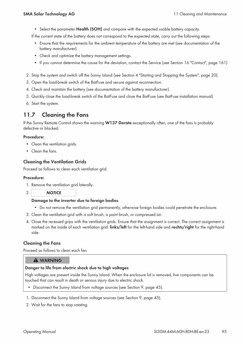
• Select the parameter Health (SOH) and compare with the expected usable battery capacity.If the current state of the battery does not correspond to the expected state, carry out the following steps:• Ensure that the requirements for the ambient temperature of the battery are met (see documentation of thebattery manufacturer).
• Check and optimize the battery management settings.• If you cannot determine the cause for the deviation, contact the Service (see Section 16 "Contact", page 161).
2. Stop the system and switch off the Sunny Island (see Section 4 "Starting and Stopping the System", page 20).3. Open the load-break switch of the BatFuse and secure against reconnection.4. Check and maintain the battery (see documentation of the battery manufacturer).5. Quickly close the load-break switch of the BatFuse and close the BatFuse (see BatFuse installation manual).6. Start the system.
11.7 Cleaning the FansIf the Sunny Remote Control shows the warning W137 Derate exceptionally often, one of the fans is probablydefective or blocked.
Procedure:• Clean the ventilation grids.• Clean the fans.
Cleaning the Ventilation GridsProceed as follows to clean each ventilation grid.
Procedure:1. Remove the ventilation grid laterally.
2.
Damage to the inverter due to foreign bodies• Do not remove the ventilation grid permanently, otherwise foreign bodies could penetrate the enclosure.
3. Clean the ventilation grid with a soft brush, a paint brush, or compressed air.4. Close the recessed grips with the ventilation grids. Ensure that the assignment is correct. The correct assignment ismarked on the inside of each ventilation grid: links/left for the left-hand side and rechts/right for the right-handside.
Cleaning the FansProceed as follows to clean each fan.
Danger to life from electric shock due to high voltagesHigh voltages are present inside the Sunny Island. When the enclosure lid is removed, live components can betouched that can result in death or serious injury due to electric shock.• Disconnect the Sunny Island from voltage sources (see Section 9, page 45).
1. Disconnect the Sunny Island from voltage sources (see Section 9, page 45).2. Wait for the fans to stop rotating.
11 Cleaning and MaintenanceSMA Solar Technology AG
Operating Manual 95SI30M-44M-60H-80H-BE-en-33

3. Check whether the fan guard is dusty or badly clogged.If the fan guard is dusty, clean it with a vacuum cleaner or a soft brush.If the fan guard is heavily soiled, remove it and clean it:• Use a screwdriver to push the two locking tabs at theright-hand edge of the fan guard to the right-hand sideand remove them from the retainer.
• Carefully remove the fan guard.• Clean the fan guard with a soft brush, a paint brush, a cloth or compressed air.
4. Check whether the fan is soiled.If the fan is soiled, remove the fan:• Use a screwdriver to push the two locking tabs at theright-hand edge of the fan guard to the right-hand sideand remove them from the retainer.
• Carefully remove the fan guard.• Push the front locking tabs of the fan backwards and therear locking tabs of the fan forwards.
• Slowly remove the fan from the Sunny Island.
11 Cleaning and Maintenance SMA Solar Technology AG
Operating ManualSI30M-44M-60H-80H-BE-en-3396
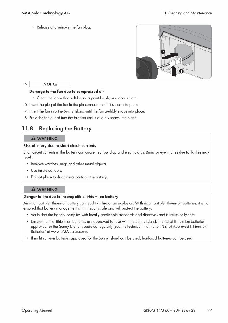
• Release and remove the fan plug.
5.
Damage to the fan due to compressed air• Clean the fan with a soft brush, a paint brush, or a damp cloth.
6. Insert the plug of the fan in the pin connector until it snaps into place.7. Insert the fan into the Sunny Island until the fan audibly snaps into place.8. Press the fan guard into the bracket until it audibly snaps into place.
11.8 Replacing the Battery
Risk of injury due to short-circuit currentsShort-circuit currents in the battery can cause heat build-up and electric arcs. Burns or eye injuries due to flashes mayresult.• Remove watches, rings and other metal objects.• Use insulated tools.• Do not place tools or metal parts on the battery.
Danger to life due to incompatible lithium-ion batteryAn incompatible lithium-ion battery can lead to a fire or an explosion. With incompatible lithium-ion batteries, it is notensured that battery management is intrinsically safe and will protect the battery.• Verify that the battery complies with locally applicable standards and directives and is intrinsically safe.• Ensure that the lithium-ion batteries are approved for use with the Sunny Island. The list of lithium-ion batteriesapproved for the Sunny Island is updated regularly (see the technical information "List of Approved Lithium-IonBatteries" at www.SMA-Solar.com).
• If no lithium-ion batteries approved for the Sunny Island can be used, lead-acid batteries can be used.
11 Cleaning and MaintenanceSMA Solar Technology AG
Operating Manual 97SI30M-44M-60H-80H-BE-en-33
Chemical burns and poisoning due to battery electrolyteIf handled inappropriately, battery electrolyte can cause irritation to the eyes, respiratory system and skin, and it canbe toxic. This may result in blindness or serious chemical burns.• Protect the battery enclosure against destruction.• Do not open or deform the battery.• Do not throw batteries into fire. Batteries may explode in fire.• Whenever working on the battery, wear suitable personal protective equipment such as rubber gloves, anapron, rubber boots and goggles.
• Rinse acid splashes thoroughly for a long time with clear water, and consult a doctor.• Install, operate, maintain and dispose of the battery according to the manufacturer’s specifications.
Damage to the battery due to incorrect settingsThe set battery parameters influence the charging behavior of the Sunny Island inverter. The battery can bedamaged by incorrect settings of the battery type, nominal voltage and capacity parameters.• Ensure that the values recommended by the manufacturer are set for the battery (refer to the technical data ofthe battery in the manufacturer documentation). Note that the battery charging behavior names used bySMA Solar Technology AG and the battery manufacturer may, in some cases, differ in meaning (for the batterycharging behavior of the Sunny Island inverter, see technical information "List of Approved Lithium-Ion Batteries").
• Set the battery capacity for a ten-hour electric discharge (C10). The battery manufacturer specifies the batterycapacity in relation to discharge time.
Procedure:1. Stop the system and switch off the Sunny Island (see Section 4, page 20).2. Ensure that the battery is not grounded unintentionally.If the battery is unintentionally grounded, identify the connection between the battery and ground potential andremove the unintentional connection. This helps to prevent electric shock caused by malfunction of other systemdevices.
3. Open the load-break switch of the BatFuse and secure against reconnection.4. Remove the battery to be replaced (see battery manufacturer's manuals).5. Mount and connect the new battery (see manuals of the battery manufacturer). The battery must comply with thetechnical requirements of the Sunny Island inverter (refer to the Sunny Island inverter installation manual fortechnical data of the DC connection).
6. Quickly close the load-break switch of the BatFuse and close the BatFuse (see BatFuse installation manual).7. Switch the Sunny Island on (see Section 4.1, page 20).8. If the Sunny Remote Control displays <Init System> , press and hold the button until the Sunny Remote Controldisplays the QCG.
9. Select the menu New Battery and press the button.10. Confirm with Y.
11 Cleaning and Maintenance SMA Solar Technology AG
Operating ManualSI30M-44M-60H-80H-BE-en-3398
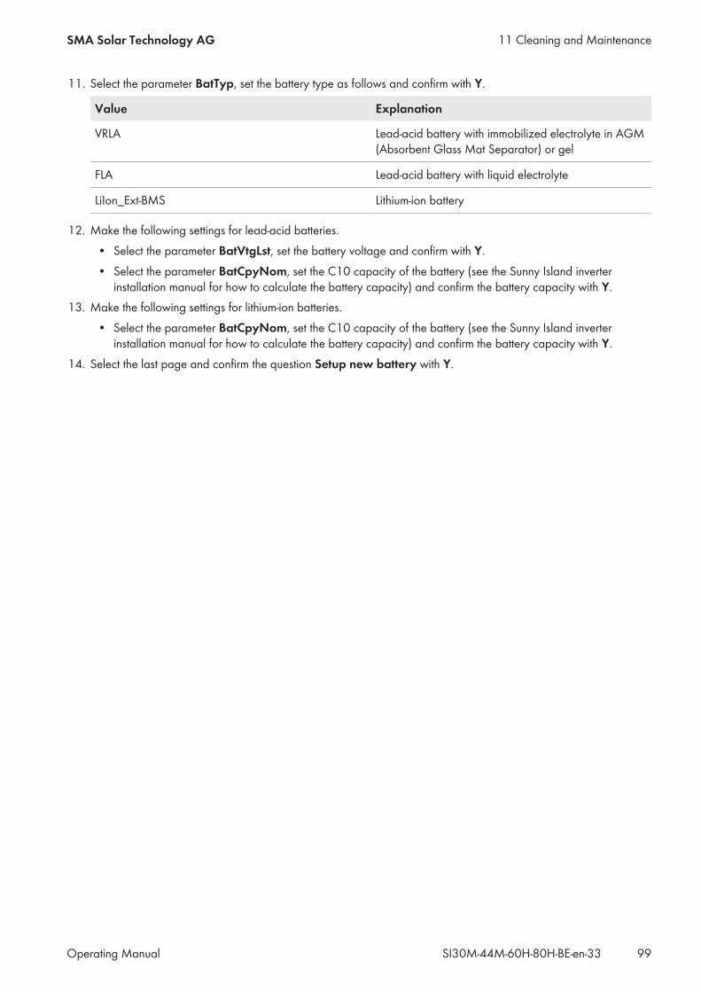
11. Select the parameter BatTyp, set the battery type as follows and confirm with Y.
Value Explanation
VRLA Lead-acid battery with immobilized electrolyte in AGM(Absorbent Glass Mat Separator) or gel
FLA Lead-acid battery with liquid electrolyte
LiIon_Ext-BMS Lithium-ion battery
12. Make the following settings for lead-acid batteries.• Select the parameter BatVtgLst, set the battery voltage and confirm with Y.• Select the parameter BatCpyNom, set the C10 capacity of the battery (see the Sunny Island inverterinstallation manual for how to calculate the battery capacity) and confirm the battery capacity with Y.
13. Make the following settings for lithium-ion batteries.• Select the parameter BatCpyNom, set the C10 capacity of the battery (see the Sunny Island inverterinstallation manual for how to calculate the battery capacity) and confirm the battery capacity with Y.
14. Select the last page and confirm the question Setup new battery with Y.
11 Cleaning and MaintenanceSMA Solar Technology AG
Operating Manual 99SI30M-44M-60H-80H-BE-en-33
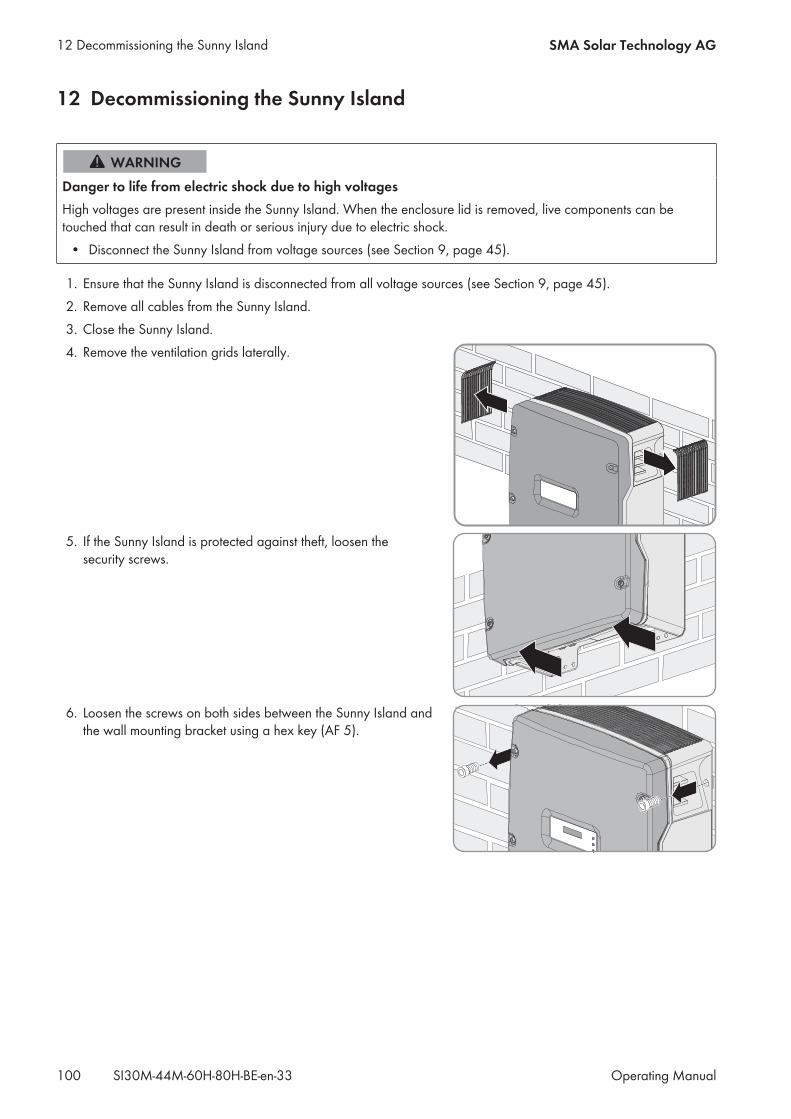
12 Decommissioning the Sunny Island
Danger to life from electric shock due to high voltagesHigh voltages are present inside the Sunny Island. When the enclosure lid is removed, live components can betouched that can result in death or serious injury due to electric shock.• Disconnect the Sunny Island from voltage sources (see Section 9, page 45).
1. Ensure that the Sunny Island is disconnected from all voltage sources (see Section 9, page 45).2. Remove all cables from the Sunny Island.3. Close the Sunny Island.4. Remove the ventilation grids laterally.
5. If the Sunny Island is protected against theft, loosen thesecurity screws.
6. Loosen the screws on both sides between the Sunny Island andthe wall mounting bracket using a hex key (AF 5).
12 Decommissioning the Sunny Island SMA Solar Technology AG
Operating ManualSI30M-44M-60H-80H-BE-en-33100
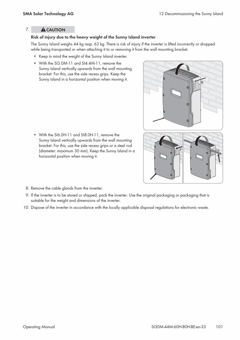
7.
Risk of injury due to the heavy weight of the Sunny Island inverterThe Sunny Island weighs 44 kg resp. 63 kg. There is risk of injury if the inverter is lifted incorrectly or droppedwhile being transported or when attaching it to or removing it from the wall mounting bracket.• Keep in mind the weight of the Sunny Island inverter.• With the SI3.0M-11 and SI4.4M-11, remove theSunny Island vertically upwards from the wall mountingbracket. For this, use the side recess grips. Keep theSunny Island in a horizontal position when moving it.
• With the SI6.0H-11 and SI8.0H-11, remove theSunny Island vertically upwards from the wall mountingbracket. For this, use the side recess grips or a steel rod(diameter: maximum 30 mm). Keep the Sunny Island in ahorizontal position when moving it.
8. Remove the cable glands from the inverter.9. If the inverter is to be stored or shipped, pack the inverter. Use the original packaging or packaging that issuitable for the weight and dimensions of the inverter.
10. Dispose of the inverter in accordance with the locally applicable disposal regulations for electronic waste.
12 Decommissioning the Sunny IslandSMA Solar Technology AG
Operating Manual 101SI30M-44M-60H-80H-BE-en-33
13 Parameters in Sunny Remote Control
13.1 Directory of the Parameters in User Mode
13.1.1 Inverter Category
Display Page
Name Description Value Explanation
Tot.Power Total active power of the Sunny Island inverters in- kWThis parameter is hidden in multicluster systems.
– –
MC.Power Total active power of the multicluster system in kWThis parameter is hidden in single systems and sin-gle-cluster systems.
– –
Timer mode Time-controlled operation of the Sunny Island in off-grid systems
Enable The Sunny Island is in time-controlled operation.
Disable Time-controlled operation isdisabled.
Setting Page
Name Description Value Explanation
Restart Restart of the Sunny Island inverter Yes Initiate restart.
No Do not initiate restart.
Str.Date Start date for time-controlled operation of the Sun-ny Island in dd.mm.yyIn time-controlled operation, the Sunny Islandswitches from standby mode to operation for thefirst time on the start date.
– –
Start time Start time for time-controlled operation, in hh:mm:ss – –
Run Time Run time for time-controlled operationThe Sunny Island switches to operation from thestart time for the configured run time.
– –
Repetition Repetition cycle for time-controlled operation Single Configures one-time opera-tion on the start date.
Daily Configures daily operationfrom the start date.
Weekly Configures weekly opera-tion from the start date.The start date determinesthe weekday.
13 Parameters in Sunny Remote Control SMA Solar Technology AG
Operating ManualSI30M-44M-60H-80H-BE-en-33102
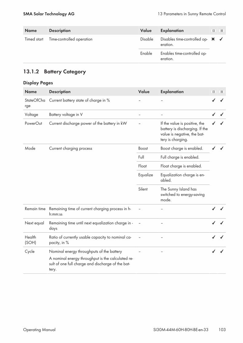
Name Description Value Explanation
Timed start Time-controlled operation Disable Disables time-controlled op-eration.
Enable Enables time-controlled op-eration.
13.1.2 Battery Category
Display Pages
Name Description Value Explanation
StateOfCharge
Current battery state of charge in % – –
Voltage Battery voltage in V – –
PowerOut Current discharge power of the battery in kW – If the value is positive, thebattery is discharging. If thevalue is negative, the bat-tery is charging.
Mode Current charging process Boost Boost charge is enabled.
Full Full charge is enabled.
Float Float charge is enabled.
Equalize Equalization charge is en-abled.
Silent The Sunny Island hasswitched to energy-savingmode.
Remain time Remaining time of current charging process in h-h:mm:ss
– –
Next equal Remaining time until next equalization charge in -days
– –
Health(SOH)
Ratio of currently usable capacity to nominal ca-pacity, in %
– –
Cycle Nominal energy throughputs of the batteryA nominal energy throughput is the calculated re-sult of one full charge and discharge of the bat-tery.
– –
13 Parameters in Sunny Remote ControlSMA Solar Technology AG
Operating Manual 103SI30M-44M-60H-80H-BE-en-33
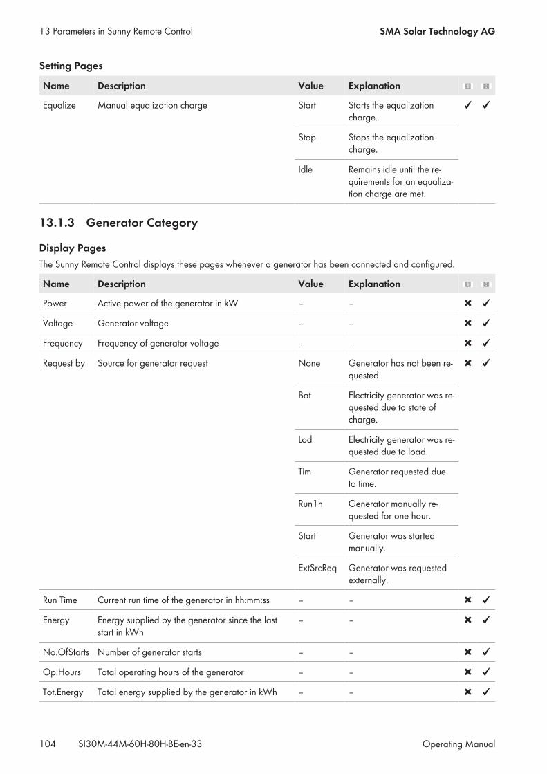
Setting Pages
Name Description Value Explanation
Equalize Manual equalization charge Start Starts the equalizationcharge.
Stop Stops the equalizationcharge.
Idle Remains idle until the re-quirements for an equaliza-tion charge are met.
13.1.3 Generator Category
Display PagesThe Sunny Remote Control displays these pages whenever a generator has been connected and configured.
Name Description Value Explanation
Power Active power of the generator in kW – –
Voltage Generator voltage – –
Frequency Frequency of generator voltage – –
Request by Source for generator request None Generator has not been re-quested.
Bat Electricity generator was re-quested due to state ofcharge.
Lod Electricity generator was re-quested due to load.
Tim Generator requested dueto time.
Run1h Generator manually re-quested for one hour.
Start Generator was startedmanually.
ExtSrcReq Generator was requestedexternally.
Run Time Current run time of the generator in hh:mm:ss – –
Energy Energy supplied by the generator since the laststart in kWh
– –
No.OfStarts Number of generator starts – –
Op.Hours Total operating hours of the generator – –
Tot.Energy Total energy supplied by the generator in kWh – –
13 Parameters in Sunny Remote Control SMA Solar Technology AG
Operating ManualSI30M-44M-60H-80H-BE-en-33104
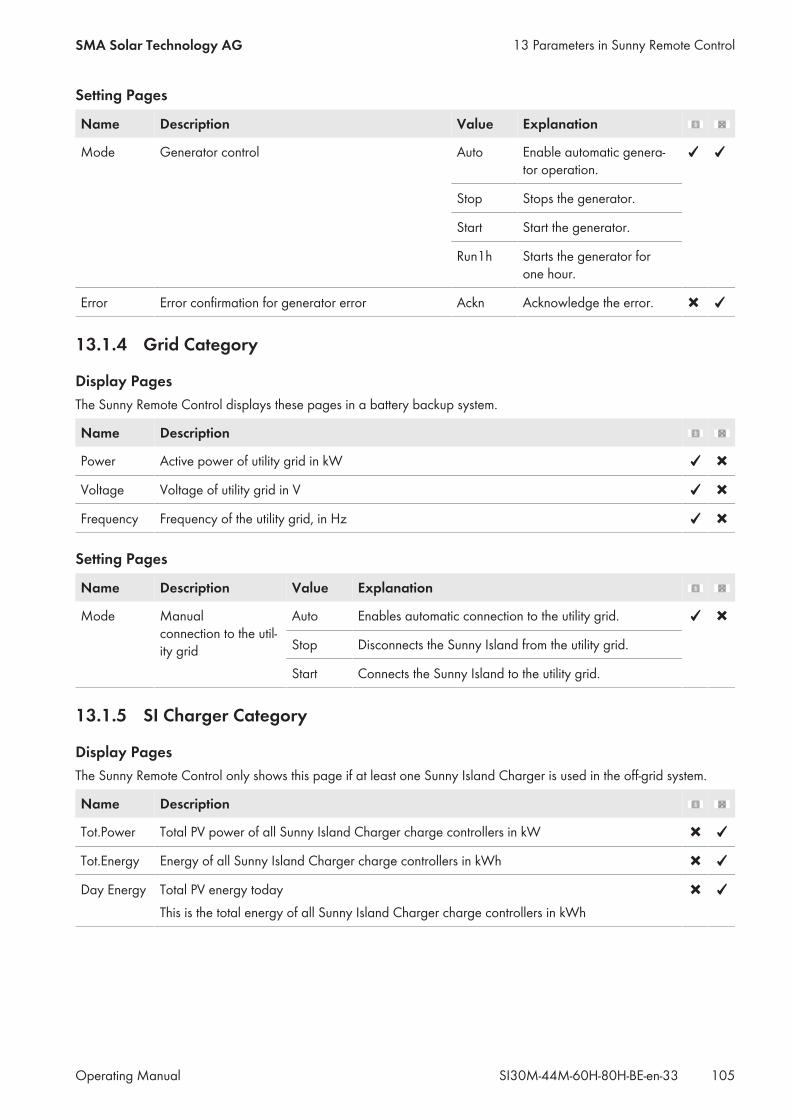
Setting Pages
Name Description Value Explanation
Mode Generator control Auto Enable automatic genera-tor operation.
Stop Stops the generator.
Start Start the generator.
Run1h Starts the generator forone hour.
Error Error confirmation for generator error Ackn Acknowledge the error.
13.1.4 Grid Category
Display PagesThe Sunny Remote Control displays these pages in a battery backup system.
Name Description
Power Active power of utility grid in kW
Voltage Voltage of utility grid in V
Frequency Frequency of the utility grid, in Hz
Setting Pages
Name Description Value Explanation
Mode Manualconnection to the util-ity grid
Auto Enables automatic connection to the utility grid.
Stop Disconnects the Sunny Island from the utility grid.
Start Connects the Sunny Island to the utility grid.
13.1.5 SI Charger Category
Display PagesThe Sunny Remote Control only shows this page if at least one Sunny Island Charger is used in the off-grid system.
Name Description
Tot.Power Total PV power of all Sunny Island Charger charge controllers in kW
Tot.Energy Energy of all Sunny Island Charger charge controllers in kWh
Day Energy Total PV energy todayThis is the total energy of all Sunny Island Charger charge controllers in kWh
13 Parameters in Sunny Remote ControlSMA Solar Technology AG
Operating Manual 105SI30M-44M-60H-80H-BE-en-33
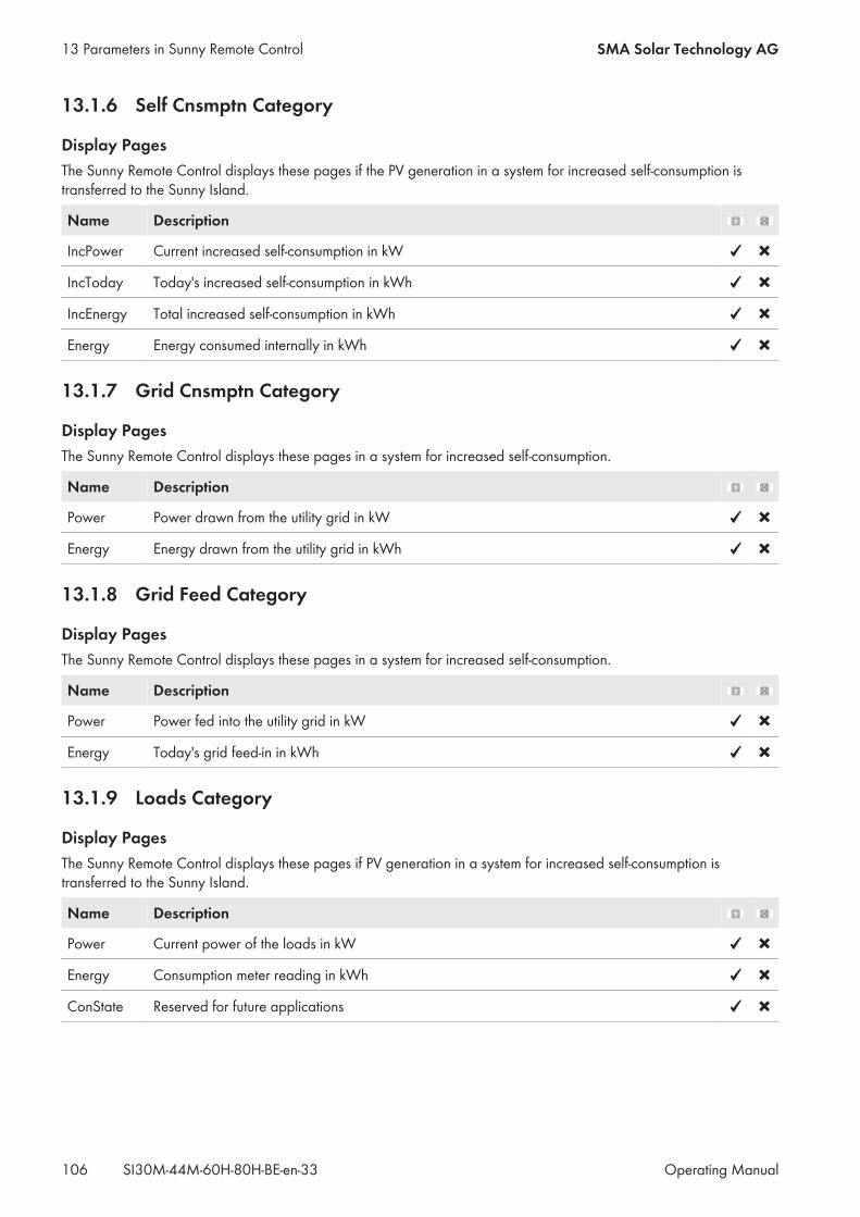
13.1.6 Self Cnsmptn Category
Display PagesThe Sunny Remote Control displays these pages if the PV generation in a system for increased self-consumption istransferred to the Sunny Island.
Name Description
IncPower Current increased self-consumption in kW
IncToday Today's increased self-consumption in kWh
IncEnergy Total increased self-consumption in kWh
Energy Energy consumed internally in kWh
13.1.7 Grid Cnsmptn Category
Display PagesThe Sunny Remote Control displays these pages in a system for increased self-consumption.
Name Description
Power Power drawn from the utility grid in kW
Energy Energy drawn from the utility grid in kWh
13.1.8 Grid Feed Category
Display PagesThe Sunny Remote Control displays these pages in a system for increased self-consumption.
Name Description
Power Power fed into the utility grid in kW
Energy Today's grid feed-in in kWh
13.1.9 Loads Category
Display PagesThe Sunny Remote Control displays these pages if PV generation in a system for increased self-consumption istransferred to the Sunny Island.
Name Description
Power Current power of the loads in kW
Energy Consumption meter reading in kWh
ConState Reserved for future applications
13 Parameters in Sunny Remote Control SMA Solar Technology AG
Operating ManualSI30M-44M-60H-80H-BE-en-33106

13.1.10 PV System Category
Display PagesThe Sunny Remote Control displays these pages if PV generation in a system for increased self-consumption istransferred to the Sunny Island.
Name Description
Power Power PV generation in kW
Energy PV production meter reading in kWh
ConState Reserved for future applications
13.1.11 System Category
Display Pages
Name Description Value Explanation
Type Configuration of the system 1Phase1 Single-phase system with oneSunny Island
1Phase2 Single-phase system with twoSunny Island inverters
1Phase3 Single-phase system with threeSunny Island inverters
3Phase Three-phase system
Box Type Type of connected Multicluster-BoxThis parameter is shown only in multiclus-ter systems.
MC-Box-6 Multicluster-Box 6
MC-Box-12 Multicluster-Box 12 (MC-BOX-12.3)
MC-Box-12-2x*
Multicluster-Box 12 (MC-BOX-12.3-20)
MC-Box-36 Multicluster-Box 36
Device Type of clusterThis parameter is shown only in multiclus-ter systems.
MainClst Sunny Remote Control is con-nected to the main cluster.
ExtnClst The Sunny Remote Control is con-nected to the extension cluster.
* Value is visible until firmware version 3.5 of the Sunny Island
13.1.12 Time Category
Display Pages
Name Description
Date Date in dd.mm.yyyy
Time Time in hh:mm:ss
13 Parameters in Sunny Remote ControlSMA Solar Technology AG
Operating Manual 107SI30M-44M-60H-80H-BE-en-33
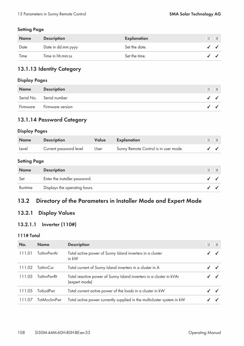
Setting Page
Name Description Explanation
Date Date in dd.mm.yyyy Set the date.
Time Time in hh:mm:ss Set the time.
13.1.13 Identity Category
Display Pages
Name Description
Serial No. Serial number
Firmware Firmware version
13.1.14 Password Category
Display Pages
Name Description Value Explanation
Level Current password level User Sunny Remote Control is in user mode.
Setting Page
Name Description
Set Enter the installer password.
Runtime Displays the operating hours
13.2 Directory of the Parameters in Installer Mode and Expert Mode
13.2.1 Display Values
13.2.1.1 Inverter (110#)
111# Total
No. Name Description
111.01 TotInvPwrAt Total active power of Sunny Island inverters in a clusterin kW
111.02 TotInvCur Total current of Sunny Island inverters in a cluster in A
111.03 TotInvPwrRt Total reactive power of Sunny Island inverters in a cluster in kVAr(expert mode)
111.05 TotLodPwr Total current active power of the loads in a cluster in kW
111.07 TotMccInvPwr Total active power currently supplied in the multicluster system in kW
13 Parameters in Sunny Remote Control SMA Solar Technology AG
Operating ManualSI30M-44M-60H-80H-BE-en-33108
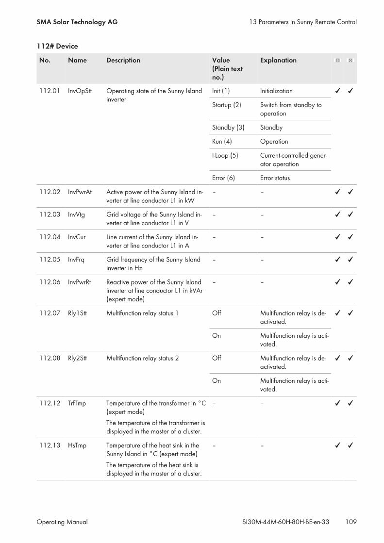
112# Device
No. Name Description Value(Plain textno.)
Explanation
112.01 InvOpStt Operating state of the Sunny Islandinverter
Init (1) Initialization
Startup (2) Switch from standby tooperation
Standby (3) Standby
Run (4) Operation
I-Loop (5) Current-controlled gener-ator operation
Error (6) Error status
112.02 InvPwrAt Active power of the Sunny Island in-verter at line conductor L1 in kW
– –
112.03 InvVtg Grid voltage of the Sunny Island in-verter at line conductor L1 in V
– –
112.04 InvCur Line current of the Sunny Island in-verter at line conductor L1 in A
– –
112.05 InvFrq Grid frequency of the Sunny Islandinverter in Hz
– –
112.06 InvPwrRt Reactive power of the Sunny Islandinverter at line conductor L1 in kVAr(expert mode)
– –
112.07 Rly1Stt Multifunction relay status 1 Off Multifunction relay is de-activated.
On Multifunction relay is acti-vated.
112.08 Rly2Stt Multifunction relay status 2 Off Multifunction relay is de-activated.
On Multifunction relay is acti-vated.
112.12 TrfTmp Temperature of the transformer in °C(expert mode)The temperature of the transformer isdisplayed in the master of a cluster.
– –
112.13 HsTmp Temperature of the heat sink in theSunny Island in °C (expert mode)The temperature of the heat sink isdisplayed in the master of a cluster.
– –
13 Parameters in Sunny Remote ControlSMA Solar Technology AG
Operating Manual 109SI30M-44M-60H-80H-BE-en-33
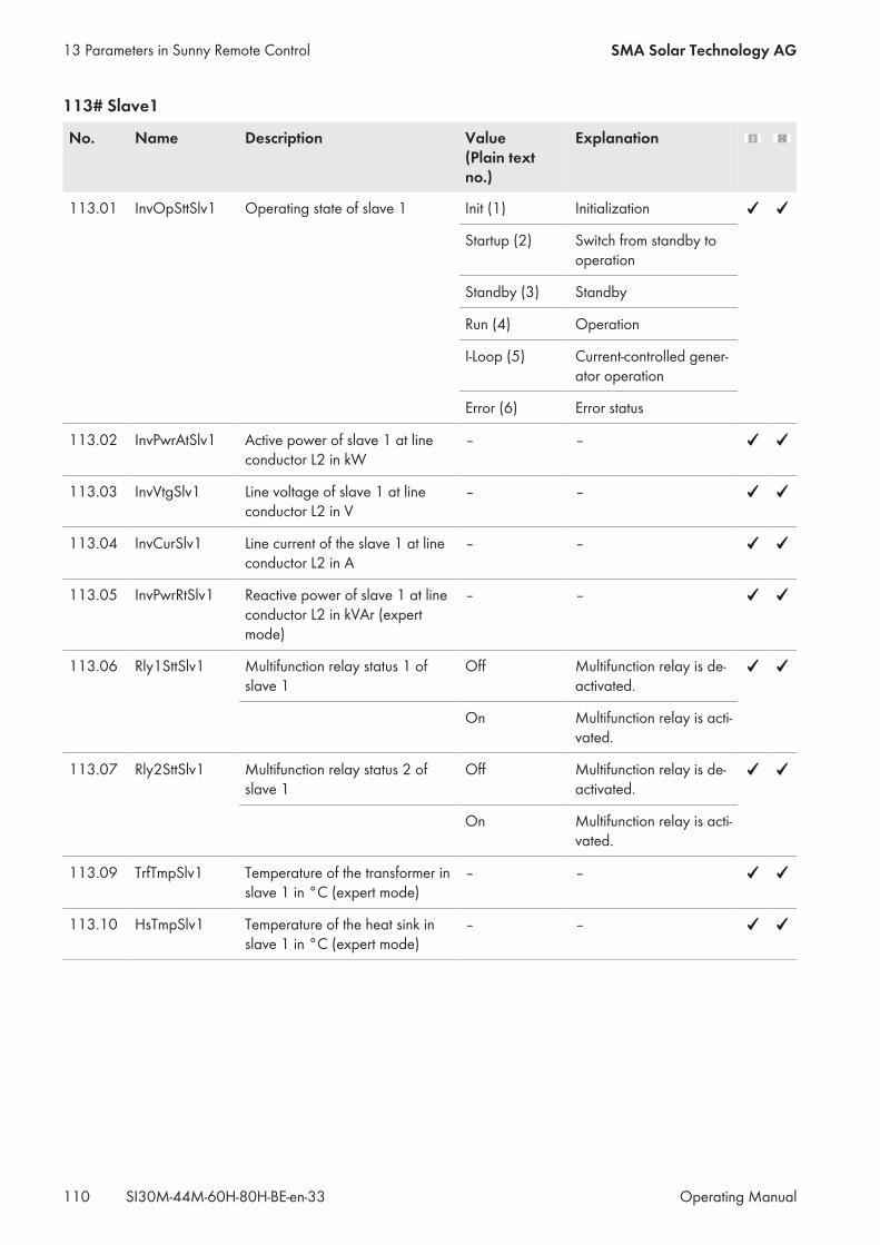
113# Slave1
No. Name Description Value(Plain textno.)
Explanation
113.01 InvOpSttSlv1 Operating state of slave 1 Init (1) Initialization
Startup (2) Switch from standby tooperation
Standby (3) Standby
Run (4) Operation
I-Loop (5) Current-controlled gener-ator operation
Error (6) Error status
113.02 InvPwrAtSlv1 Active power of slave 1 at lineconductor L2 in kW
– –
113.03 InvVtgSlv1 Line voltage of slave 1 at lineconductor L2 in V
– –
113.04 InvCurSlv1 Line current of the slave 1 at lineconductor L2 in A
– –
113.05 InvPwrRtSlv1 Reactive power of slave 1 at lineconductor L2 in kVAr (expertmode)
– –
113.06 Rly1SttSlv1 Multifunction relay status 1 ofslave 1
Off Multifunction relay is de-activated.
On Multifunction relay is acti-vated.
113.07 Rly2SttSlv1 Multifunction relay status 2 ofslave 1
Off Multifunction relay is de-activated.
On Multifunction relay is acti-vated.
113.09 TrfTmpSlv1 Temperature of the transformer inslave 1 in °C (expert mode)
– –
113.10 HsTmpSlv1 Temperature of the heat sink inslave 1 in °C (expert mode)
– –
13 Parameters in Sunny Remote Control SMA Solar Technology AG
Operating ManualSI30M-44M-60H-80H-BE-en-33110
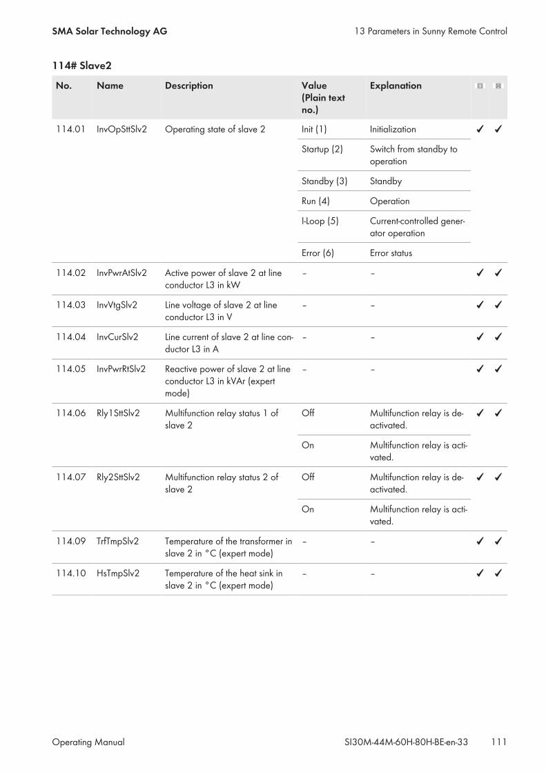
114# Slave2
No. Name Description Value(Plain textno.)
Explanation
114.01 InvOpSttSlv2 Operating state of slave 2 Init (1) Initialization
Startup (2) Switch from standby tooperation
Standby (3) Standby
Run (4) Operation
I-Loop (5) Current-controlled gener-ator operation
Error (6) Error status
114.02 InvPwrAtSlv2 Active power of slave 2 at lineconductor L3 in kW
– –
114.03 InvVtgSlv2 Line voltage of slave 2 at lineconductor L3 in V
– –
114.04 InvCurSlv2 Line current of slave 2 at line con-ductor L3 in A
– –
114.05 InvPwrRtSlv2 Reactive power of slave 2 at lineconductor L3 in kVAr (expertmode)
– –
114.06 Rly1SttSlv2 Multifunction relay status 1 ofslave 2
Off Multifunction relay is de-activated.
On Multifunction relay is acti-vated.
114.07 Rly2SttSlv2 Multifunction relay status 2 ofslave 2
Off Multifunction relay is de-activated.
On Multifunction relay is acti-vated.
114.09 TrfTmpSlv2 Temperature of the transformer inslave 2 in °C (expert mode)
– –
114.10 HsTmpSlv2 Temperature of the heat sink inslave 2 in °C (expert mode)
– –
13 Parameters in Sunny Remote ControlSMA Solar Technology AG
Operating Manual 111SI30M-44M-60H-80H-BE-en-33
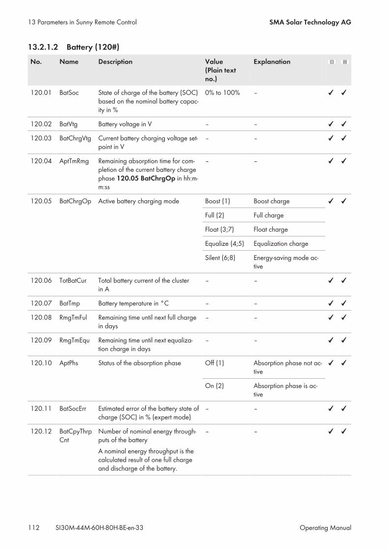
13.2.1.2 Battery (120#)
No. Name Description Value(Plain textno.)
Explanation
120.01 BatSoc State of charge of the battery (SOC)based on the nominal battery capac-ity in %
0% to 100% –
120.02 BatVtg Battery voltage in V – –
120.03 BatChrgVtg Current battery charging voltage set-point in V
– –
120.04 AptTmRmg Remaining absorption time for com-pletion of the current battery chargephase 120.05 BatChrgOp in hh:m-m:ss
– –
120.05 BatChrgOp Active battery charging mode Boost (1) Boost charge
Full (2) Full charge
Float (3;7) Float charge
Equalize (4;5) Equalization charge
Silent (6;8) Energy-saving mode ac-tive
120.06 TotBatCur Total battery current of the clusterin A
– –
120.07 BatTmp Battery temperature in °C – –
120.08 RmgTmFul Remaining time until next full chargein days
– –
120.09 RmgTmEqu Remaining time until next equaliza-tion charge in days
– –
120.10 AptPhs Status of the absorption phase Off (1) Absorption phase not ac-tive
On (2) Absorption phase is ac-tive
120.11 BatSocErr Estimated error of the battery state ofcharge (SOC) in % (expert mode)
– –
120.12 BatCpyThrpCnt
Number of nominal energy through-puts of the batteryA nominal energy throughput is thecalculated result of one full chargeand discharge of the battery.
– –
13 Parameters in Sunny Remote Control SMA Solar Technology AG
Operating ManualSI30M-44M-60H-80H-BE-en-33112
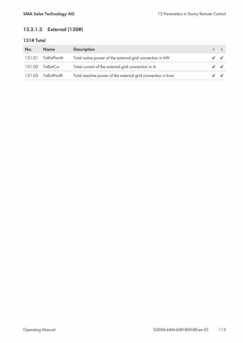
13.2.1.3 External (130#)
131# Total
No. Name Description
131.01 TotExtPwrAt Total active power of the external grid connection in kW
131.02 TotExtCur Total current of the external grid connection in A
131.03 TotExtPwrRt Total reactive power of the external grid connection in kvar
13 Parameters in Sunny Remote ControlSMA Solar Technology AG
Operating Manual 113SI30M-44M-60H-80H-BE-en-33
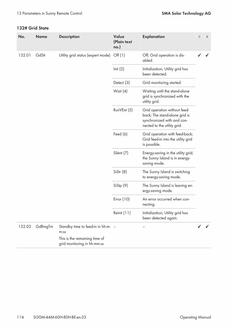
132# Grid State
No. Name Description Value(Plain textno.)
Explanation
132.01 GdStt Utility grid status (expert mode) Off (1) Off; Grid operation is dis-abled.
Init (2) Initialization; Utility grid hasbeen detected.
Detect (3) Grid monitoring started.
Wait (4) Waiting until the stand-alonegrid is synchronized with theutility grid.
RunVExt (5) Grid operation without feed-back; The stand-alone grid issynchronized with and con-nected to the utility grid.
Feed (6) Grid operation with feed-back;Grid feed-in into the utility gridis possible.
Silent (7) Energy-saving in the utility grid;the Sunny Island is in energy-saving mode.
SiStr (8) The Sunny Island is switchingto energy-saving mode.
SiStp (9) The Sunny Island is leaving en-ergy-saving mode.
Error (10) An error occurred when con-necting.
Reinit (11) Initialization; Utility grid hasbeen detected again.
132.02 GdRmgTm Standby time to feed-in in hh:m-m:ssThis is the remaining time ofgrid monitoring in hh:mm:ss
– –
13 Parameters in Sunny Remote Control SMA Solar Technology AG
Operating ManualSI30M-44M-60H-80H-BE-en-33114
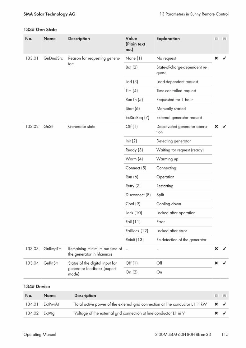
133# Gen State
No. Name Description Value(Plain textno.)
Explanation
133.01 GnDmdSrc Reason for requesting genera-tor:
None (1) No request
Bat (2) State-of-charge-dependent re-quest
Lod (3) Load-dependent request
Tim (4) Time-controlled request
Run1h (5) Requested for 1 hour
Start (6) Manually started
ExtSrcReq (7) External generator request
133.02 GnStt Generator state Off (1) Deactivated generator opera-tion
Init (2) Detecting generator
Ready (3) Waiting for request (ready)
Warm (4) Warming up
Connect (5) Connecting
Run (6) Operation
Retry (7) Restarting
Disconnect (8) Split
Cool (9) Cooling down
Lock (10) Locked after operation
Fail (11) Error
FailLock (12) Locked after error
Reinit (13) Re-detection of the generator
133.03 GnRmgTm Remaining minimum run time ofthe generator in hh:mm:ss
– –
133.04 GnRnStt Status of the digital input forgenerator feedback (expertmode)
Off (1) Off
On (2) On
134# Device
No. Name Description
134.01 ExtPwrAt Total active power of the external grid connection at line conductor L1 in kW
134.02 ExtVtg Voltage of the external grid connection at line conductor L1 in V
13 Parameters in Sunny Remote ControlSMA Solar Technology AG
Operating Manual 115SI30M-44M-60H-80H-BE-en-33
No. Name Description
134.03 ExtCur Current of the external grid connection at line conductor L1 in A
134.04 ExtFrq Frequency of external energy source in Hz
134.05 ExtPwrRt Reactive power of the external grid connection at line conductor L1 in kVAr(expert mode)
134.07 ExtLkRmgTm Minimum stop time in hh:mm:ss
135# Slave1
No. Name Description
135.01 ExtPwrAtSlv1 Total active power of the external grid connection at slave 1 / line conduc-tor L2 in kW
135.02 ExtVtgSlv1 Voltage of the external grid connection at slave 1 / line conductor L2 in V
135.03 ExtCurSlv1 Current of the external grid connection at slave 1 / line conductor L2 in A
135.04 ExtPwrRtSlv1 Reactive power of the external grid connection at slave 1 line conductor L2 in- kVAr (expert mode)
136# Slave2
No. Name Description
136.01 ExtPwrAtSlv2 Total active power of the external grid connection at slave 2 / line conduc-tor L3 in kW
136.02 ExtVtgSlv2 Voltage of the external grid connection at slave 2 / line conductor L3 in V
136.03 ExtCurSlv2 Current of the external grid connection at slave 2 / line conductor L3 in A
136.04 ExtPwrRtSlv2 Reactive power of the external grid connection at slave 2 line conductor L3 in- kVAr (expert mode)
13.2.1.4 Charge Controller (140#)
141# SIC50 Total
No. Name Description
141.01 TotSicEgyCntIn Total PV energy: This is the total energy of all Sunny Island Charger chargecontrollers in kWh
141.02 TSicDyEgyCntIn Total PV energy today: This is the total energy of all Sunny Island Chargercharge controllers in kWh
141.03 TotSicPvPwr Total PV power of all Sunny Island Charger charge controllers in W
141.04 TotSicBatCur Total output current of all Sunny Island Charger charge controllers in A
13 Parameters in Sunny Remote Control SMA Solar Technology AG
Operating ManualSI30M-44M-60H-80H-BE-en-33116
142# SIC50 1
No. Name Description
142.01 Sic1EgyCntIn Total PV energy of Sunny Island Charger charge controller 1 in kWh
142.02 Sic1TdyEgyCntIn Daily energy of Sunny Island Charger charge controller 1 in kWh
142.03 Sic1PvPwr PV power of Sunny Island Charger charge controller 1 in W
142.04 Sic1PvVtg PV voltage of Sunny Island Charger charge controller 1 in V
142.05 Sic1BatVtg Battery voltage of Sunny Island Charger charge controller 1 in V (expertmode)
142.06 Sic1BatCur Battery current of Sunny Island Charger charge controller 1 in A (expertmode)
142.07 Sic1HsTmp Heat sink temperature of Sunny Island Charger charge controller 1 in °C(expert mode)
143# SIC50 2
No. Name Description
143.01 Sic2EgyCntIn Total PV energy of Sunny Island Charger charge controller 2 in kWh
143.02 Sic2TdyEgyCntIn Daily energy of Sunny Island Charger charge controller 2 in kWh
143.03 Sic2PvPwr PV power of Sunny Island Charger charge controller 2 in W
143.04 Sic2PvVtg PV voltage of Sunny Island Charger charge controller 2 in V
143.05 Sic2BatVtg Battery voltage of Sunny Island Charger charge controller 2 in V (expertmode)
143.06 Sic2BatCur Battery current of Sunny Island Charger charge controller 2 in A (expertmode)
143.07 Sic2HsTmp Heat sink temperature of Sunny Island Charger charge controller 2 in °C(expert mode)
144# SIC50 3
No. Name Description
144.01 Sic3EgyCntIn Total PV energy of Sunny Island Charger charge controller 3 in kWh
144.02 Sic3TdyEgyCntIn Daily energy of Sunny Island Charger charge controller 3 in kWh
144.03 Sic3PvPwr PV power of Sunny Island Charger charge controller 3 in W
144.04 Sic3PvVtg PV voltage of Sunny Island Charger charge controller 3 in V
144.05 Sic3BatVtg Battery voltage of Sunny Island Charger charge controller 3 in V (expertmode)
13 Parameters in Sunny Remote ControlSMA Solar Technology AG
Operating Manual 117SI30M-44M-60H-80H-BE-en-33
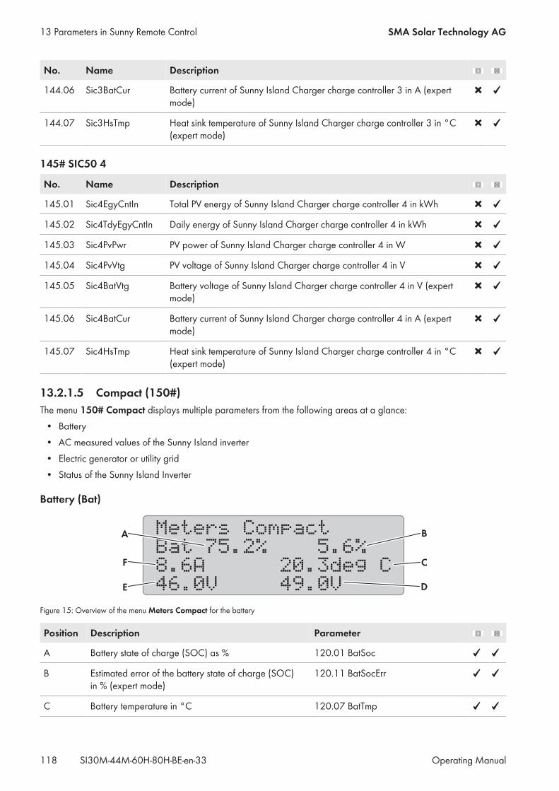
No. Name Description
144.06 Sic3BatCur Battery current of Sunny Island Charger charge controller 3 in A (expertmode)
144.07 Sic3HsTmp Heat sink temperature of Sunny Island Charger charge controller 3 in °C(expert mode)
145# SIC50 4
No. Name Description
145.01 Sic4EgyCntIn Total PV energy of Sunny Island Charger charge controller 4 in kWh
145.02 Sic4TdyEgyCntIn Daily energy of Sunny Island Charger charge controller 4 in kWh
145.03 Sic4PvPwr PV power of Sunny Island Charger charge controller 4 in W
145.04 Sic4PvVtg PV voltage of Sunny Island Charger charge controller 4 in V
145.05 Sic4BatVtg Battery voltage of Sunny Island Charger charge controller 4 in V (expertmode)
145.06 Sic4BatCur Battery current of Sunny Island Charger charge controller 4 in A (expertmode)
145.07 Sic4HsTmp Heat sink temperature of Sunny Island Charger charge controller 4 in °C(expert mode)
13.2.1.5 Compact (150#)The menu 150# Compact displays multiple parameters from the following areas at a glance:• Battery• AC measured values of the Sunny Island inverter• Electric generator or utility grid• Status of the Sunny Island Inverter
Battery (Bat)
Meters Compact
Bat 75.2% 5.6%
8.6A 20.3deg C
46.0V 49.0V
A
F
E
B
C
D
Figure 15: Overview of the menu Meters Compact for the battery
Position Description Parameter
A Battery state of charge (SOC) as % 120.01 BatSoc
B Estimated error of the battery state of charge (SOC)in % (expert mode)
120.11 BatSocErr
C Battery temperature in °C 120.07 BatTmp
13 Parameters in Sunny Remote Control SMA Solar Technology AG
Operating ManualSI30M-44M-60H-80H-BE-en-33118

Position Description Parameter
D Charging voltage setpoint in V 120.03 BatChrgVtg
E Battery voltage in V 120.02 BatVtg
F Total battery current of the cluster in A 120.06 TotBatCur
AC Measured Values of the Sunny Island Inverter (Inv)
Meters Compact
Inv 230V 50.3Hz
-0.6kW 0.1kVArDC
BA
Figure 16: Overview of the menu Meters Compact for the AC measured values of the Sunny Island inverter
Position Description Parameter
A Voltage of the Sunny Island inverter in V 112.03 InvVtg
B Voltage frequency of the Sunny Island inverter in Hz 112.05 InvFrq
C Reactive power of the inverter in kVAr 112.06 InvPwrRt
D Active power of the inverter in kW 112.02 InvPwrAt
Generator or Utility Grid (Ext)
Meters Compact
Ext 230V 50.0Hz
-0.6kW 0.1kVArDC
BA
Figure 17: Overview of the menu Meters Compact for the generator or the battery backup grid
Position Description Parameter
A Voltage of generator or utility grid in V 134.02 ExtVtg
B Frequency of generator or utility grid in Hz 134.04 ExtFrq
C Reactive power of generator or utility grid in kVAr 134.05 ExtPwrRt
D Active power of generator or utility grid in kW 134.01 ExtPwrAt
13 Parameters in Sunny Remote ControlSMA Solar Technology AG
Operating Manual 119SI30M-44M-60H-80H-BE-en-33
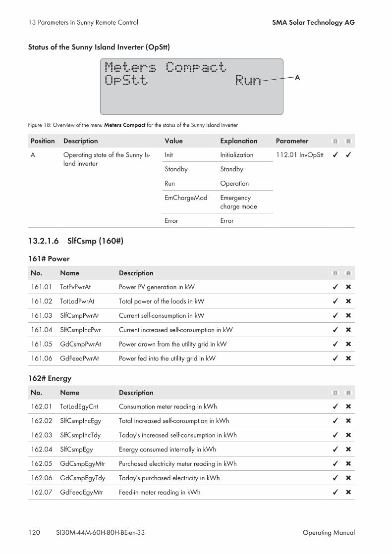
Status of the Sunny Island Inverter (OpStt)
Meters Compact
OpStt RunA
Figure 18: Overview of the menu Meters Compact for the status of the Sunny Island inverter
Position Description Value Explanation Parameter
A Operating state of the Sunny Is-land inverter
Init Initialization 112.01 InvOpStt
Standby Standby
Run Operation
EmChargeMod Emergencycharge mode
Error Error
13.2.1.6 SlfCsmp (160#)
161# Power
No. Name Description
161.01 TotPvPwrAt Power PV generation in kW
161.02 TotLodPwrAt Total power of the loads in kW
161.03 SlfCsmpPwrAt Current self-consumption in kW
161.04 SlfCsmpIncPwr Current increased self-consumption in kW
161.05 GdCsmpPwrAt Power drawn from the utility grid in kW
161.06 GdFeedPwrAt Power fed into the utility grid in kW
162# Energy
No. Name Description
162.01 TotLodEgyCnt Consumption meter reading in kWh
162.02 SlfCsmpIncEgy Total increased self-consumption in kWh
162.03 SlfCsmpIncTdy Today's increased self-consumption in kWh
162.04 SlfCsmpEgy Energy consumed internally in kWh
162.05 GdCsmpEgyMtr Purchased electricity meter reading in kWh
162.06 GdCsmpEgyTdy Today's purchased electricity in kWh
162.07 GdFeedEgyMtr Feed-in meter reading in kWh
13 Parameters in Sunny Remote Control SMA Solar Technology AG
Operating ManualSI30M-44M-60H-80H-BE-en-33120

No. Name Description
162.08 PvEgyMtr PV production meter reading in kWh
162.09 GdFeedEgyTdy Today's grid feed-in in kWh
163# State
No. Name Description Value Explanation
163.01 BatMntStt Battery maintenance chargestatus: If full charge or equal-ization charge with PV energyhas not ended after 24 hours,163.01 BatMntStt automati-cally switches to On.
On Charge with solarpower: Full charge orequalization charge ac-tive; energy is drawnfrom the utility grid
Wait Charge with solarpower: If sufficient PVenergy is available, fullcharge or equalizationcharge active
Off Inactive: No fullcharge or equalizationcharge active
163.02 SlfCsmpSOCArea Status of the battery utilizationrangeIn systems for increased self-consumption and in battery-backup systems, this parametershows in which range the stateof charge of the battery is cur-rently in (export mode).
SlfCsmpSOC Range for increasedself-consumption
PVResSOC Range for maintenanceof the battery state ofcharge
BUResSOC Range for the batterybackup system function
BatResSOC Range for protectionagainst deep discharge
ProtResSOC Range for protection inthe event of deep dis-charge
163.03 SlfCsmpSOCLim Lower discharge limit for self-consumption range as %:With this updated displayvalue, the Sunny Island inverterinforms of the state of chargeup to which the battery for in-creased self-consumption is dis-charged (expert mode).
5% to 90% –
13 Parameters in Sunny Remote ControlSMA Solar Technology AG
Operating Manual 121SI30M-44M-60H-80H-BE-en-33
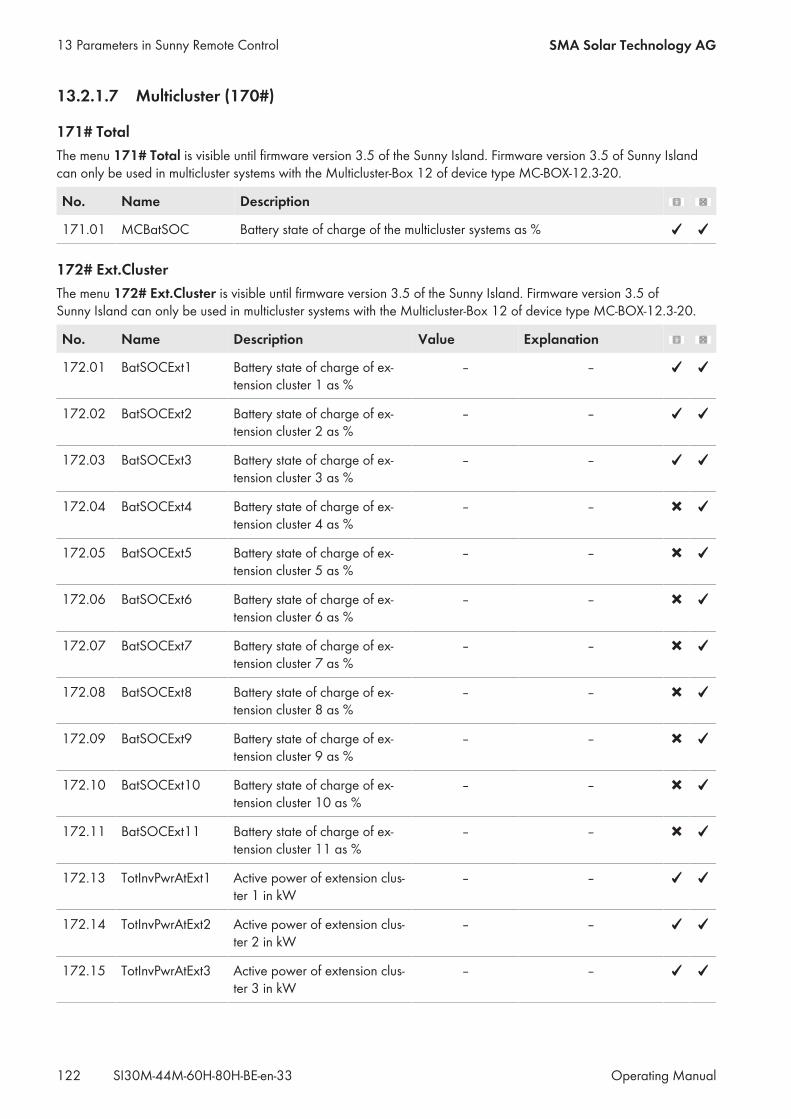
13.2.1.7 Multicluster (170#)
171# TotalThe menu 171# Total is visible until firmware version 3.5 of the Sunny Island. Firmware version 3.5 of Sunny Islandcan only be used in multicluster systems with the Multicluster-Box 12 of device type MC-BOX-12.3-20.
No. Name Description
171.01 MCBatSOC Battery state of charge of the multicluster systems as %
172# Ext.ClusterThe menu 172# Ext.Cluster is visible until firmware version 3.5 of the Sunny Island. Firmware version 3.5 ofSunny Island can only be used in multicluster systems with the Multicluster-Box 12 of device type MC-BOX-12.3-20.
No. Name Description Value Explanation
172.01 BatSOCExt1 Battery state of charge of ex-tension cluster 1 as %
– –
172.02 BatSOCExt2 Battery state of charge of ex-tension cluster 2 as %
– –
172.03 BatSOCExt3 Battery state of charge of ex-tension cluster 3 as %
– –
172.04 BatSOCExt4 Battery state of charge of ex-tension cluster 4 as %
– –
172.05 BatSOCExt5 Battery state of charge of ex-tension cluster 5 as %
– –
172.06 BatSOCExt6 Battery state of charge of ex-tension cluster 6 as %
– –
172.07 BatSOCExt7 Battery state of charge of ex-tension cluster 7 as %
– –
172.08 BatSOCExt8 Battery state of charge of ex-tension cluster 8 as %
– –
172.09 BatSOCExt9 Battery state of charge of ex-tension cluster 9 as %
– –
172.10 BatSOCExt10 Battery state of charge of ex-tension cluster 10 as %
– –
172.11 BatSOCExt11 Battery state of charge of ex-tension cluster 11 as %
– –
172.13 TotInvPwrAtExt1 Active power of extension clus-ter 1 in kW
– –
172.14 TotInvPwrAtExt2 Active power of extension clus-ter 2 in kW
– –
172.15 TotInvPwrAtExt3 Active power of extension clus-ter 3 in kW
– –
13 Parameters in Sunny Remote Control SMA Solar Technology AG
Operating ManualSI30M-44M-60H-80H-BE-en-33122
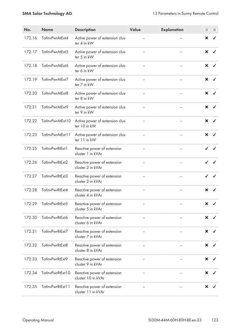
No. Name Description Value Explanation
172.16 TotInvPwrAtExt4 Active power of extension clus-ter 4 in kW
– –
172.17 TotInvPwrAtExt5 Active power of extension clus-ter 5 in kW
– –
172.18 TotInvPwrAtExt6 Active power of extension clus-ter 6 in kW
– –
172.19 TotInvPwrAtExt7 Active power of extension clus-ter 7 in kW
– –
172.20 TotInvPwrAtExt8 Active power of extension clus-ter 8 in kW
– –
172.21 TotInvPwrAtExt9 Active power of extension clus-ter 9 in kW
– –
172.22 TotInvPwrAtExt10 Active power of extension clus-ter 10 in kW
– –
172.23 TotInvPwrAtExt11 Active power of extension clus-ter 11 in kW
– –
172.25 TotInvPwrRtExt1 Reactive power of extensioncluster 1 in kVAr
– –
172.26 TotInvPwrRtExt2 Reactive power of extensioncluster 2 in kVAr
– –
172.27 TotInvPwrRtExt3 Reactive power of extensioncluster 3 in kVAr
– –
172.28 TotInvPwrRtExt4 Reactive power of extensioncluster 4 in kVAr
– –
172.29 TotInvPwrRtExt5 Reactive power of extensioncluster 5 in kVAr
– –
172.30 TotInvPwrRtExt6 Reactive power of extensioncluster 6 in kVAr
– –
172.31 TotInvPwrRtExt7 Reactive power of extensioncluster 7 in kVAr
– –
172.32 TotInvPwrRtExt8 Reactive power of extensioncluster 8 in kVAr
– –
172.33 TotInvPwrRtExt9 Reactive power of extensioncluster 9 in kVAr
– –
172.34 TotInvPwrRtExt10 Reactive power of extensioncluster 10 in kVAr
– –
172.35 TotInvPwrRtExt11 Reactive power of extensioncluster 11 in kVAr
– –
13 Parameters in Sunny Remote ControlSMA Solar Technology AG
Operating Manual 123SI30M-44M-60H-80H-BE-en-33
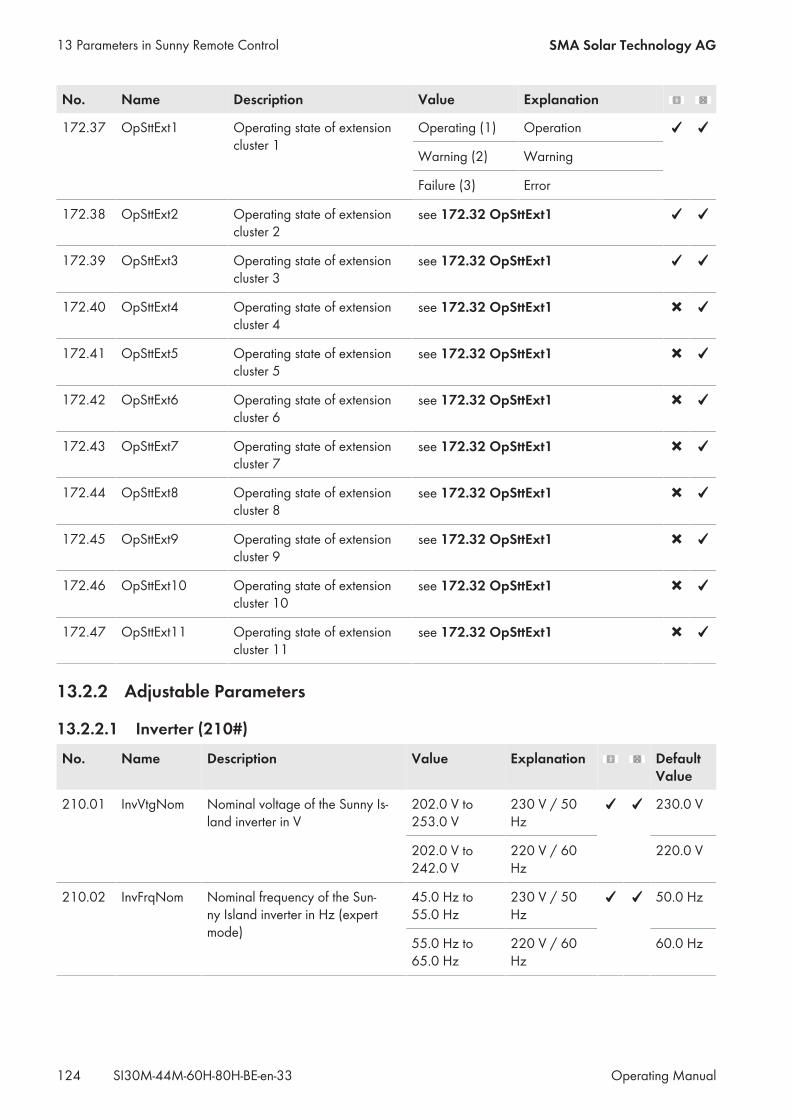
No. Name Description Value Explanation
172.37 OpSttExt1 Operating state of extensioncluster 1
Operating (1) Operation
Warning (2) Warning
Failure (3) Error
172.38 OpSttExt2 Operating state of extensioncluster 2
see 172.32 OpSttExt1
172.39 OpSttExt3 Operating state of extensioncluster 3
see 172.32 OpSttExt1
172.40 OpSttExt4 Operating state of extensioncluster 4
see 172.32 OpSttExt1
172.41 OpSttExt5 Operating state of extensioncluster 5
see 172.32 OpSttExt1
172.42 OpSttExt6 Operating state of extensioncluster 6
see 172.32 OpSttExt1
172.43 OpSttExt7 Operating state of extensioncluster 7
see 172.32 OpSttExt1
172.44 OpSttExt8 Operating state of extensioncluster 8
see 172.32 OpSttExt1
172.45 OpSttExt9 Operating state of extensioncluster 9
see 172.32 OpSttExt1
172.46 OpSttExt10 Operating state of extensioncluster 10
see 172.32 OpSttExt1
172.47 OpSttExt11 Operating state of extensioncluster 11
see 172.32 OpSttExt1
13.2.2 Adjustable Parameters
13.2.2.1 Inverter (210#)
No. Name Description Value Explanation DefaultValue
210.01 InvVtgNom Nominal voltage of the Sunny Is-land inverter in V
202.0 V to253.0 V
230 V / 50Hz
230.0 V
202.0 V to242.0 V
220 V / 60Hz
220.0 V
210.02 InvFrqNom Nominal frequency of the Sun-ny Island inverter in Hz (expertmode)
45.0 Hz to55.0 Hz
230 V / 50Hz
50.0 Hz
55.0 Hz to65.0 Hz
220 V / 60Hz
60.0 Hz
13 Parameters in Sunny Remote Control SMA Solar Technology AG
Operating ManualSI30M-44M-60H-80H-BE-en-33124
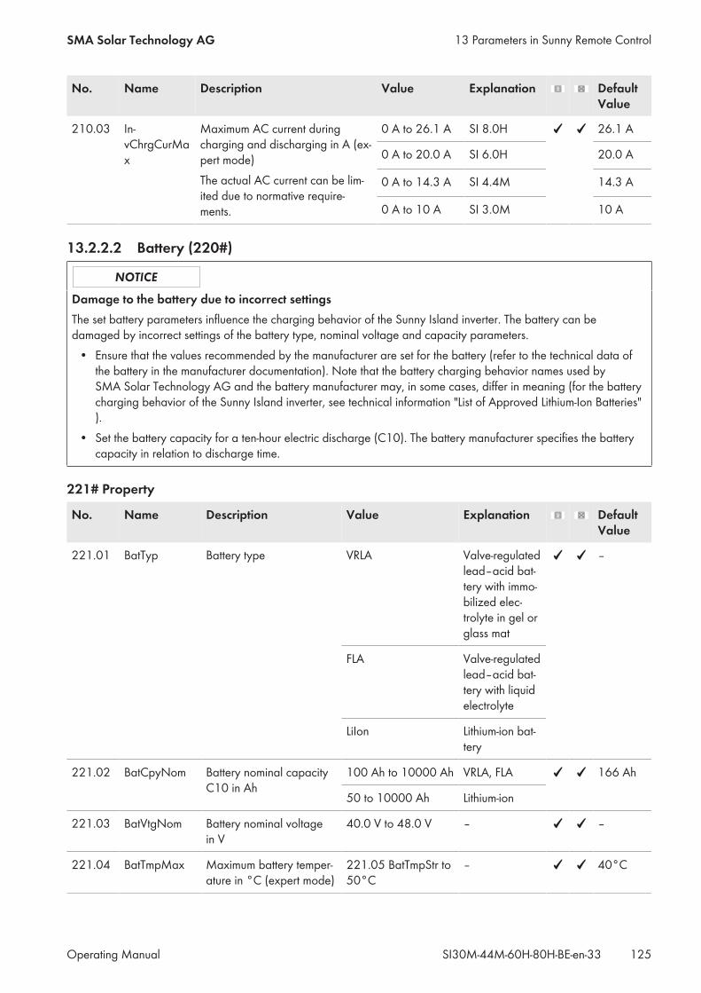
No. Name Description Value Explanation DefaultValue
210.03 In-vChrgCurMax
Maximum AC current duringcharging and discharging in A (ex-pert mode)The actual AC current can be lim-ited due to normative require-ments.
0 A to 26.1 A SI 8.0H 26.1 A
0 A to 20.0 A SI 6.0H 20.0 A
0 A to 14.3 A SI 4.4M 14.3 A
0 A to 10 A SI 3.0M 10 A
13.2.2.2 Battery (220#)
Damage to the battery due to incorrect settingsThe set battery parameters influence the charging behavior of the Sunny Island inverter. The battery can bedamaged by incorrect settings of the battery type, nominal voltage and capacity parameters.• Ensure that the values recommended by the manufacturer are set for the battery (refer to the technical data ofthe battery in the manufacturer documentation). Note that the battery charging behavior names used bySMA Solar Technology AG and the battery manufacturer may, in some cases, differ in meaning (for the batterycharging behavior of the Sunny Island inverter, see technical information "List of Approved Lithium-Ion Batteries").
• Set the battery capacity for a ten-hour electric discharge (C10). The battery manufacturer specifies the batterycapacity in relation to discharge time.
221# Property
No. Name Description Value Explanation DefaultValue
221.01 BatTyp Battery type VRLA Valve-regulatedlead–acid bat-tery with immo-bilized elec-trolyte in gel orglass mat
–
FLA Valve-regulatedlead–acid bat-tery with liquidelectrolyte
LiIon Lithium-ion bat-tery
221.02 BatCpyNom Battery nominal capacityC10 in Ah
100 Ah to 10000 Ah VRLA, FLA 166 Ah
50 to 10000 Ah Lithium-ion
221.03 BatVtgNom Battery nominal voltagein V
40.0 V to 48.0 V – –
221.04 BatTmpMax Maximum battery temper-ature in °C (expert mode)
221.05 BatTmpStr to50°C
– 40°C
13 Parameters in Sunny Remote ControlSMA Solar Technology AG
Operating Manual 125SI30M-44M-60H-80H-BE-en-33
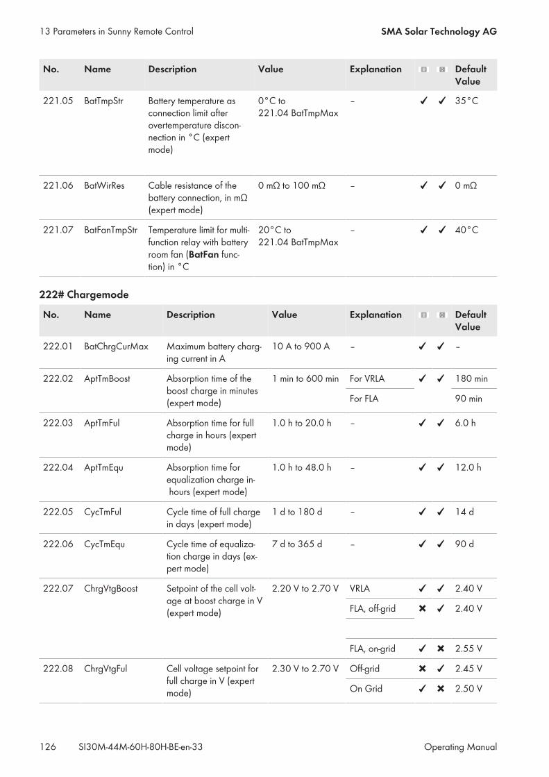
No. Name Description Value Explanation DefaultValue
221.05 BatTmpStr Battery temperature asconnection limit afterovertemperature discon-nection in °C (expertmode)
0°C to221.04 BatTmpMax
– 35°C
221.06 BatWirRes Cable resistance of thebattery connection, in mΩ(expert mode)
0 mΩ to 100 mΩ – 0 mΩ
221.07 BatFanTmpStr Temperature limit for multi-function relay with batteryroom fan (BatFan func-tion) in °C
20°C to221.04 BatTmpMax
– 40°C
222# Chargemode
No. Name Description Value Explanation DefaultValue
222.01 BatChrgCurMax Maximum battery charg-ing current in A
10 A to 900 A – –
222.02 AptTmBoost Absorption time of theboost charge in minutes(expert mode)
1 min to 600 min For VRLA 180 min
For FLA 90 min
222.03 AptTmFul Absorption time for fullcharge in hours (expertmode)
1.0 h to 20.0 h – 6.0 h
222.04 AptTmEqu Absorption time forequalization charge in- hours (expert mode)
1.0 h to 48.0 h – 12.0 h
222.05 CycTmFul Cycle time of full chargein days (expert mode)
1 d to 180 d – 14 d
222.06 CycTmEqu Cycle time of equaliza-tion charge in days (ex-pert mode)
7 d to 365 d – 90 d
222.07 ChrgVtgBoost Setpoint of the cell volt-age at boost charge in V(expert mode)
2.20 V to 2.70 V VRLA 2.40 V
FLA, off-grid 2.40 V
FLA, on-grid 2.55 V
222.08 ChrgVtgFul Cell voltage setpoint forfull charge in V (expertmode)
2.30 V to 2.70 V Off-grid 2.45 V
On Grid 2.50 V
13 Parameters in Sunny Remote Control SMA Solar Technology AG
Operating ManualSI30M-44M-60H-80H-BE-en-33126
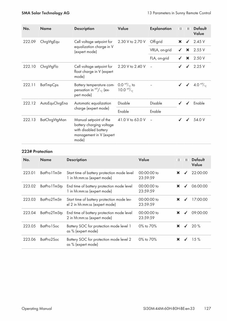
No. Name Description Value Explanation DefaultValue
222.09 ChrgVtgEqu Cell voltage setpoint forequalization charge in V(expert mode)
2.30 V to 2.70 V Off-grid 2.45 V
VRLA, on-grid 2.55 V
FLA, on-grid 2.50 V
222.10 ChrgVtgFlo Cell voltage setpoint forfloat charge in V (expertmode)
2.20 V to 2.40 V – 2.25 V
222.11 BatTmpCps Battery temperature com-pensation in mV/°C (ex-pert mode)
0.0 mV⁄°C to10.0 mV⁄°C
– 4.0 mV⁄°C
222.12 AutoEquChrgEna Automatic equalizationcharge (expert mode)
Disable Disable Enable
Enable Enable
222.13 BatChrgVtgMan Manual setpoint of thebattery charging voltagewith disabled batterymanagement in V (expertmode)
41.0 V to 63.0 V – 54.0 V
223# Protection
No. Name Description Value DefaultValue
223.01 BatPro1TmStr Start time of battery protection mode level1 in hh:mm:ss (expert mode)
00:00:00 to23:59:59
22:00:00
223.02 BatPro1TmStp End time of battery protection mode level1 in hh:mm:ss (expert mode)
00:00:00 to23:59:59
06:00:00
223.03 BatPro2TmStr Start time of battery protection mode lev-el 2 in hh:mm:ss (expert mode)
00:00:00 to23:59:59
17:00:00
223.04 BatPro2TmStp End time of battery protection mode level2 in hh:mm:ss (expert mode)
00:00:00 to23:59:59
09:00:00
223.05 BatPro1Soc Battery SOC for protection mode level 1as % (expert mode)
0% to 70% 20 %
223.06 BatPro2Soc Battery SOC for protection mode level 2as % (expert mode)
0% to 70% 15 %
13 Parameters in Sunny Remote ControlSMA Solar Technology AG
Operating Manual 127SI30M-44M-60H-80H-BE-en-33
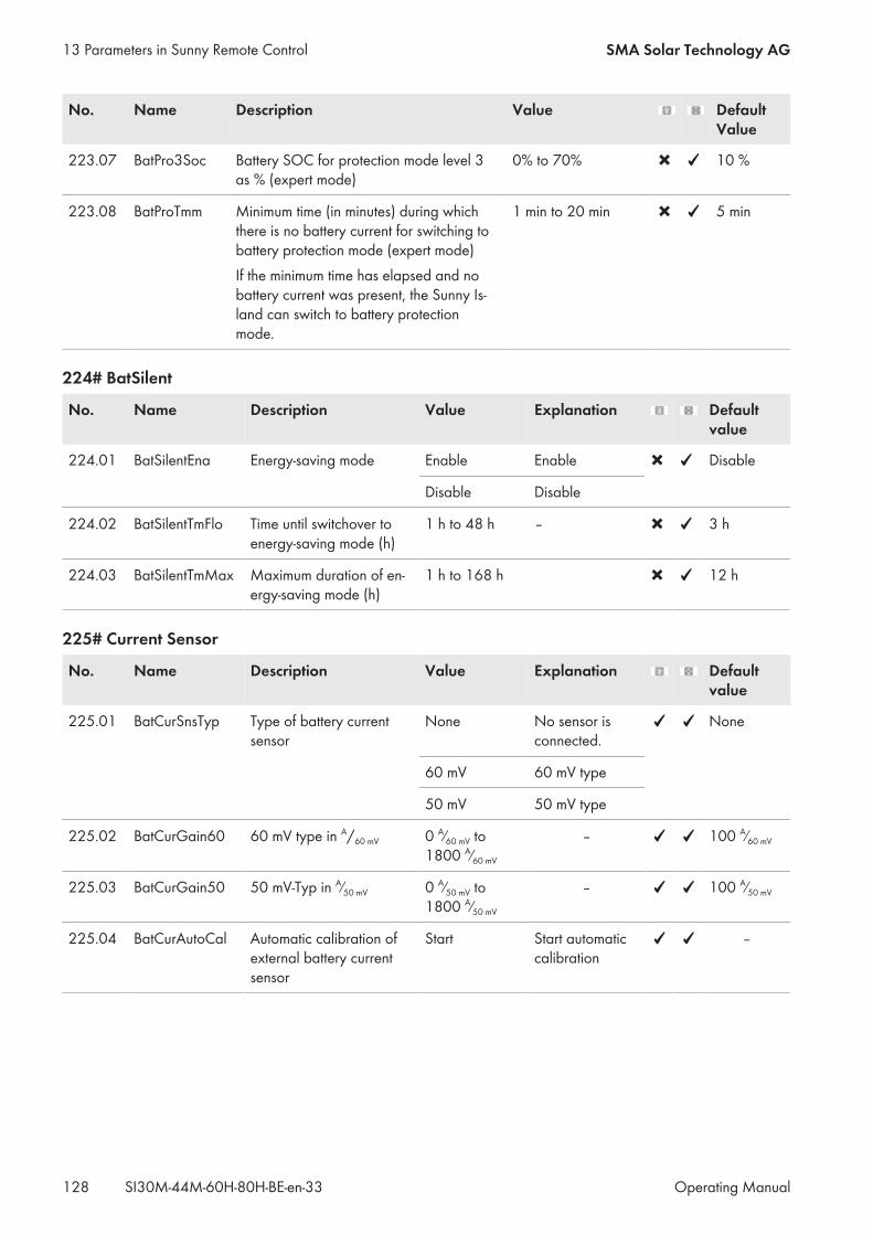
No. Name Description Value DefaultValue
223.07 BatPro3Soc Battery SOC for protection mode level 3as % (expert mode)
0% to 70% 10 %
223.08 BatProTmm Minimum time (in minutes) during whichthere is no battery current for switching tobattery protection mode (expert mode)If the minimum time has elapsed and nobattery current was present, the Sunny Is-land can switch to battery protectionmode.
1 min to 20 min 5 min
224# BatSilent
No. Name Description Value Explanation Defaultvalue
224.01 BatSilentEna Energy-saving mode Enable Enable Disable
Disable Disable
224.02 BatSilentTmFlo Time until switchover toenergy-saving mode (h)
1 h to 48 h – 3 h
224.03 BatSilentTmMax Maximum duration of en-ergy-saving mode (h)
1 h to 168 h 12 h
225# Current Sensor
No. Name Description Value Explanation Defaultvalue
225.01 BatCurSnsTyp Type of battery currentsensor
None No sensor isconnected.
None
60 mV 60 mV type
50 mV 50 mV type
225.02 BatCurGain60 60 mV type in A/60 mV 0 A⁄60 mV to1800 A⁄60 mV
– 100 A⁄60 mV
225.03 BatCurGain50 50 mV-Typ in A⁄50 mV 0 A⁄50 mV to1800 A⁄50 mV
– 100 A⁄50 mV
225.04 BatCurAutoCal Automatic calibration ofexternal battery currentsensor
Start Start automaticcalibration
–
13 Parameters in Sunny Remote Control SMA Solar Technology AG
Operating ManualSI30M-44M-60H-80H-BE-en-33128
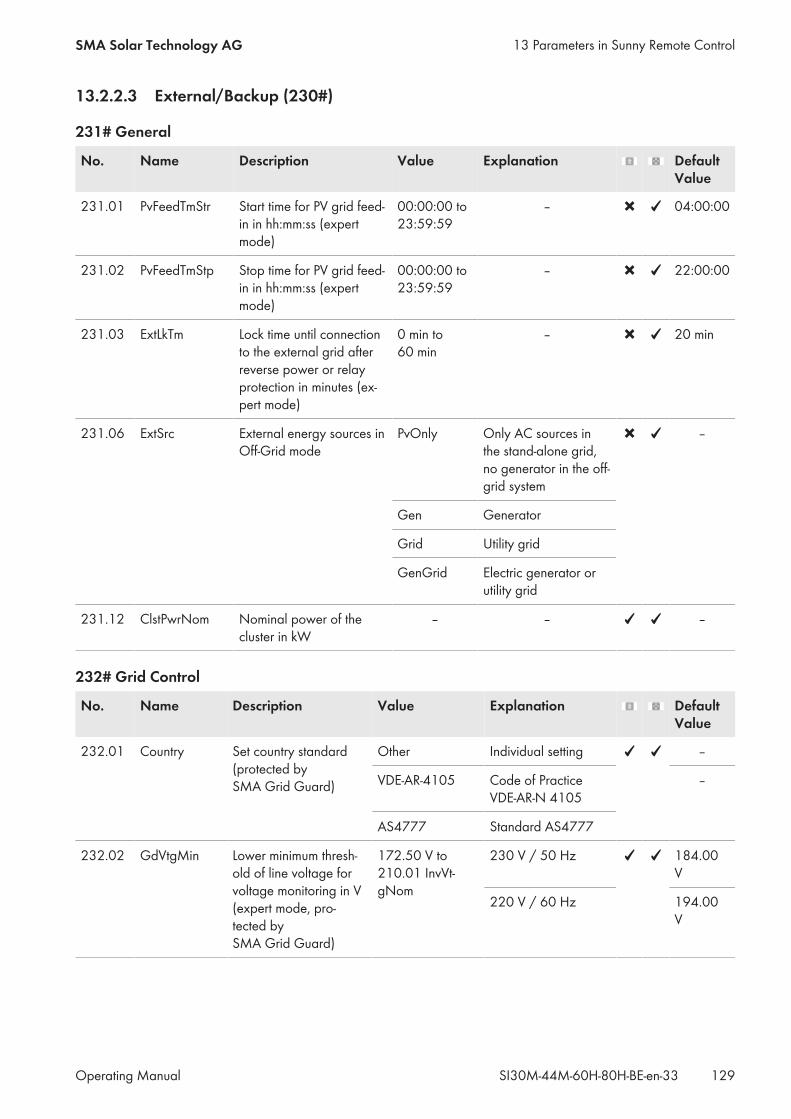
13.2.2.3 External/Backup (230#)
231# General
No. Name Description Value Explanation DefaultValue
231.01 PvFeedTmStr Start time for PV grid feed-in in hh:mm:ss (expertmode)
00:00:00 to23:59:59
– 04:00:00
231.02 PvFeedTmStp Stop time for PV grid feed-in in hh:mm:ss (expertmode)
00:00:00 to23:59:59
– 22:00:00
231.03 ExtLkTm Lock time until connectionto the external grid afterreverse power or relayprotection in minutes (ex-pert mode)
0 min to60 min
– 20 min
231.06 ExtSrc External energy sources inOff-Grid mode
PvOnly Only AC sources inthe stand-alone grid,no generator in the off-grid system
–
Gen Generator
Grid Utility grid
GenGrid Electric generator orutility grid
231.12 ClstPwrNom Nominal power of thecluster in kW
– – –
232# Grid Control
No. Name Description Value Explanation DefaultValue
232.01 Country Set country standard(protected bySMA Grid Guard)
Other Individual setting –
VDE-AR-4105 Code of PracticeVDE-AR-N 4105
–
AS4777 Standard AS4777
232.02 GdVtgMin Lower minimum thresh-old of line voltage forvoltage monitoring in V(expert mode, pro-tected bySMA Grid Guard)
172.50 V to210.01 InvVt-gNom
230 V / 50 Hz 184.00V
220 V / 60 Hz 194.00V
13 Parameters in Sunny Remote ControlSMA Solar Technology AG
Operating Manual 129SI30M-44M-60H-80H-BE-en-33
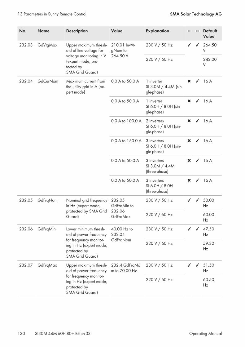
No. Name Description Value Explanation DefaultValue
232.03 GdVtgMax Upper maximum thresh-old of line voltage forvoltage monitoring in V(expert mode, pro-tected bySMA Grid Guard)
210.01 InvVt-gNom to264.50 V
230 V / 50 Hz 264.50V
220 V / 60 Hz 242.00V
232.04 GdCurNom Maximum current fromthe utility grid in A (ex-pert mode)
0.0 A to 50.0 A 1 inverterSI 3.0M / 4.4M (sin-gle-phase)
16 A
0.0 A to 50.0 A 1 inverterSI 6.0H / 8.0H (sin-gle-phase)
16 A
0.0 A to 100.0 A 2 invertersSI 6.0H / 8.0H (sin-gle-phase)
16 A
0.0 A to 150.0 A 3 invertersSI 6.0H / 8.0H (sin-gle-phase)
16 A
0.0 A to 50.0 A 3 invertersSI 3.0M / 4.4M(three-phase)
16 A
0.0 A to 50.0 A 3 invertersSI 6.0H / 8.0H(three-phase)
16 A
232.05 GdFrqNom Nominal grid frequencyin Hz (expert mode,protected by SMA GridGuard)
232.05GdFrqMin to232.06GdFrqMax
230 V / 50 Hz 50.00Hz
220 V / 60 Hz 60.00Hz
232.06 GdFrqMin Lower minimum thresh-old of power frequencyfor frequency monitor-ing in Hz (expert mode,protected bySMA Grid Guard)
40.00 Hz to232.04GdFrqNom
230 V / 50 Hz 47.50Hz
220 V / 60 Hz 59.30Hz
232.07 GdFrqMax Upper maximum thresh-old of power frequencyfor frequency monitor-ing in Hz (expert mode,protected bySMA Grid Guard)
232.4 GdFrqNom to 70.00 Hz
230 V / 50 Hz 51.50Hz
220 V / 60 Hz 60.50Hz
13 Parameters in Sunny Remote Control SMA Solar Technology AG
Operating ManualSI30M-44M-60H-80H-BE-en-33130
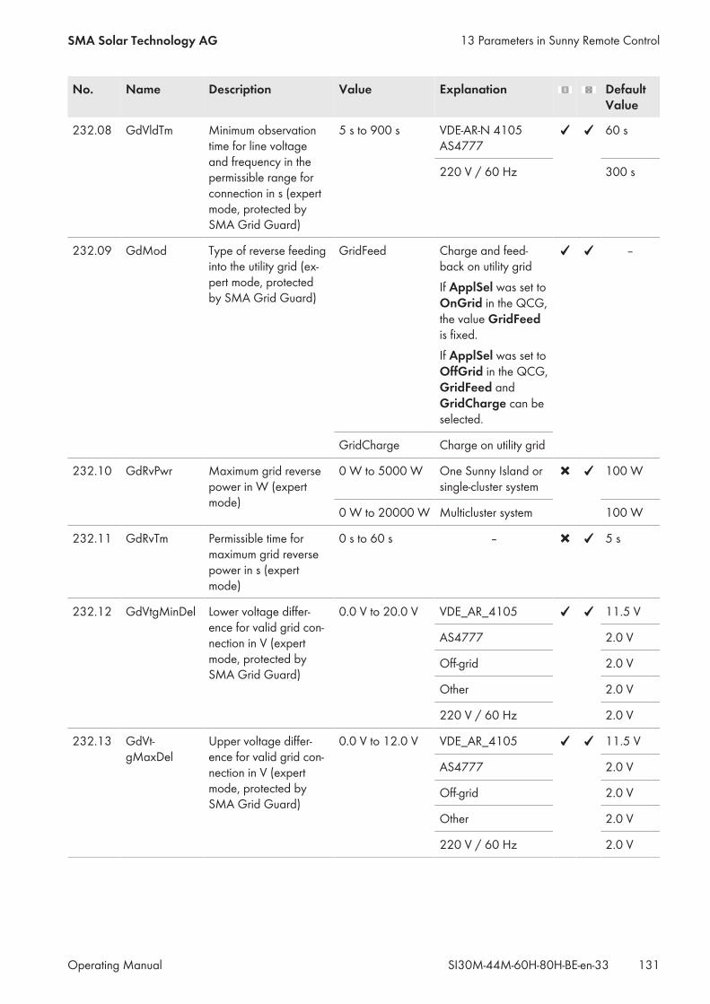
No. Name Description Value Explanation DefaultValue
232.08 GdVldTm Minimum observationtime for line voltageand frequency in thepermissible range forconnection in s (expertmode, protected bySMA Grid Guard)
5 s to 900 s VDE-AR-N 4105AS4777
60 s
220 V / 60 Hz 300 s
232.09 GdMod Type of reverse feedinginto the utility grid (ex-pert mode, protectedby SMA Grid Guard)
GridFeed Charge and feed-back on utility gridIf ApplSel was set toOnGrid in the QCG,the value GridFeedis fixed.If ApplSel was set toOffGrid in the QCG,GridFeed andGridCharge can beselected.
–
GridCharge Charge on utility grid
232.10 GdRvPwr Maximum grid reversepower in W (expertmode)
0 W to 5000 W One Sunny Island orsingle-cluster system
100 W
0 W to 20000 W Multicluster system 100 W
232.11 GdRvTm Permissible time formaximum grid reversepower in s (expertmode)
0 s to 60 s – 5 s
232.12 GdVtgMinDel Lower voltage differ-ence for valid grid con-nection in V (expertmode, protected bySMA Grid Guard)
0.0 V to 20.0 V VDE_AR_4105 11.5 V
AS4777 2.0 V
Off-grid 2.0 V
Other 2.0 V
220 V / 60 Hz 2.0 V
232.13 GdVt-gMaxDel
Upper voltage differ-ence for valid grid con-nection in V (expertmode, protected bySMA Grid Guard)
0.0 V to 12.0 V VDE_AR_4105 11.5 V
AS4777 2.0 V
Off-grid 2.0 V
Other 2.0 V
220 V / 60 Hz 2.0 V
13 Parameters in Sunny Remote ControlSMA Solar Technology AG
Operating Manual 131SI30M-44M-60H-80H-BE-en-33
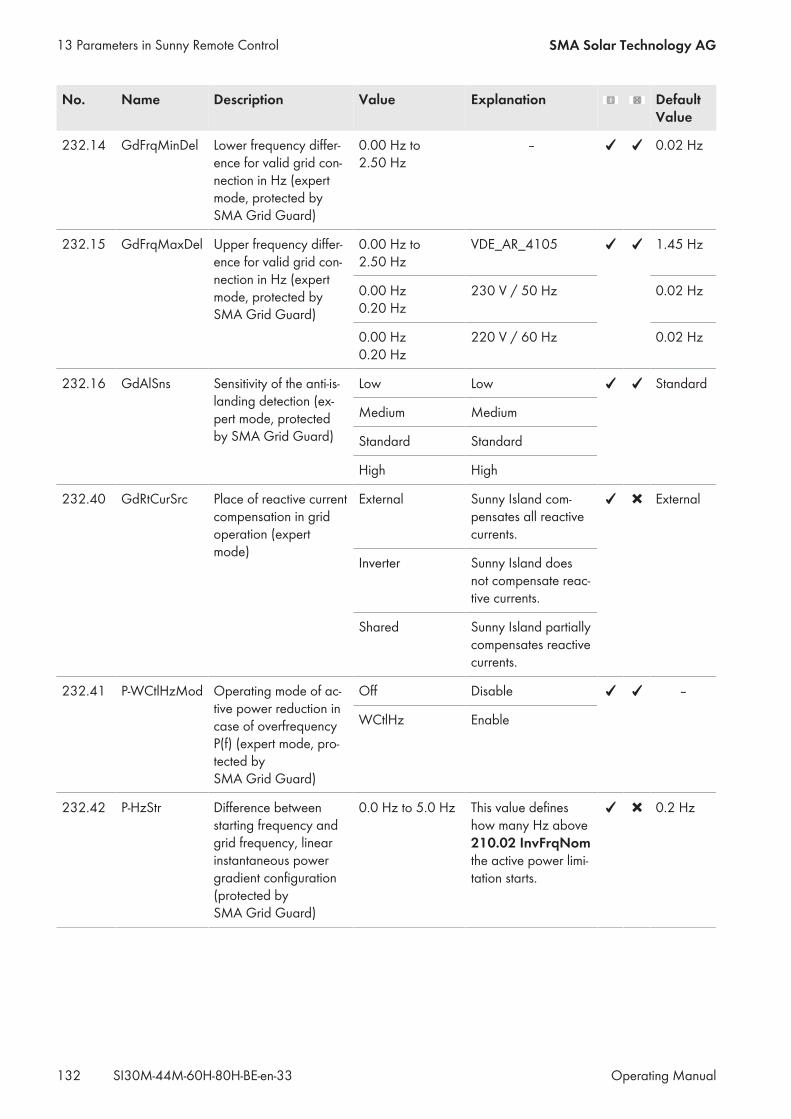
No. Name Description Value Explanation DefaultValue
232.14 GdFrqMinDel Lower frequency differ-ence for valid grid con-nection in Hz (expertmode, protected bySMA Grid Guard)
0.00 Hz to2.50 Hz
‒ 0.02 Hz
232.15 GdFrqMaxDel Upper frequency differ-ence for valid grid con-nection in Hz (expertmode, protected bySMA Grid Guard)
0.00 Hz to2.50 Hz
VDE_AR_4105 1.45 Hz
0.00 Hz 0.20 Hz
230 V / 50 Hz 0.02 Hz
0.00 Hz 0.20 Hz
220 V / 60 Hz 0.02 Hz
232.16 GdAlSns Sensitivity of the anti-is-landing detection (ex-pert mode, protectedby SMA Grid Guard)
Low Low Standard
Medium Medium
Standard Standard
High High
232.40 GdRtCurSrc Place of reactive currentcompensation in gridoperation (expertmode)
External Sunny Island com-pensates all reactivecurrents.
External
Inverter Sunny Island doesnot compensate reac-tive currents.
Shared Sunny Island partiallycompensates reactivecurrents.
232.41 P-WCtlHzMod Operating mode of ac-tive power reduction incase of overfrequencyP(f) (expert mode, pro-tected bySMA Grid Guard)
Off Disable –
WCtlHz Enable
232.42 P-HzStr Difference betweenstarting frequency andgrid frequency, linearinstantaneous powergradient configuration(protected bySMA Grid Guard)
0.0 Hz to 5.0 Hz This value defineshow many Hz above210.02 InvFrqNomthe active power limi-tation starts.
0.2 Hz
13 Parameters in Sunny Remote Control SMA Solar Technology AG
Operating ManualSI30M-44M-60H-80H-BE-en-33132
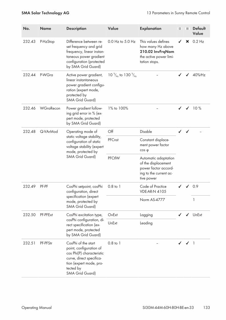
No. Name Description Value Explanation DefaultValue
232.43 P-HzStop Difference between re-set frequency and gridfrequency, linear instan-taneous power gradientconfiguration (protectedby SMA Grid Guard)
0.0 Hz to 5.0 Hz This values defineshow many Hz above210.02 InvFrqNomthe active power limi-tation stops.
0.2 Hz
232.44 P-WGra Active power gradient,linear instantaneouspower gradient configu-ration (expert mode,protected bySMA Grid Guard)
10 %⁄Hz to 130 %⁄Hz – 40%⁄Hz
232.46 WGraRecon Power gradient follow-ing grid error in % (ex-pert mode, protectedby SMA Grid Guard)
1% to 100% ‒ 10 %
232.48 Q-VArMod Operating mode ofstatic voltage stability,configuration of staticvoltage stability (expertmode, protected bySMA Grid Guard)
Off Disable –
PFCnst Constant displace-ment power factorcos φ
PFCtlW Automatic adaptationof the displacementpower factor accord-ing to the current ac-tive power
232.49 PF-PF CosPhi setpoint, cosPhiconfiguration, directspecification (expertmode, protected bySMA Grid Guard)
0.8 to 1 Code of PracticeVDE-AR-N 4105
0.9
Norm AS-4777 1
232.50 PF-PFExt CosPhi excitation type,cosPhi configuration, di-rect specification (ex-pert mode, protectedby SMA Grid Guard)
OvExt Lagging UnExt
UnExt Leading
232.51 PF-PFStr CosPhi of the startpoint, configuration ofcos Phi(P) characteristiccurve, direct specifica-tion (expert mode, pro-tected bySMA Grid Guard)
0.8 to 1 – 1
13 Parameters in Sunny Remote ControlSMA Solar Technology AG
Operating Manual 133SI30M-44M-60H-80H-BE-en-33
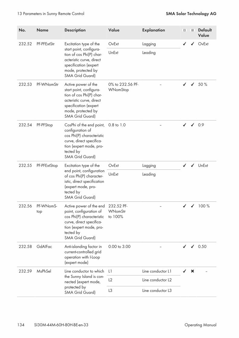
No. Name Description Value Explanation DefaultValue
232.52 PF-PFExtStr Excitation type of thestart point, configura-tion of cos Phi(P) char-acteristic curve, directspecification (expertmode, protected bySMA Grid Guard)
OvExt Lagging OvExt
UnExt Leading
232.53 PF-WNomStr Active power of thestart point, configura-tion of cos Phi(P) char-acteristic curve, directspecification (expertmode, protected bySMA Grid Guard)
0% to 232.56 PF-WNomStop
– 50 %
232.54 PF-PFStop CosPhi of the end point,configuration ofcos Phi(P) characteristiccurve, direct specifica-tion (expert mode, pro-tected bySMA Grid Guard)
0.8 to 1.0 – 0.9
232.55 PF-PFExtStop Excitation type of theend point, configurationof cos Phi(P) character-istic, direct specification(expert mode, pro-tected bySMA Grid Guard)
OvExt Lagging UnExt
UnExt Leading
232.56 PF-WNomS-top
Active power of the endpoint, configuration ofcos Phi(P) characteristiccurve, direct specifica-tion (expert mode, pro-tected bySMA Grid Guard)
232.52 PF-WNomStrto 100%
– 100 %
232.58 GdAIFac Anti-islanding factor incurrent-controlled gridoperation with I-Loop(expert mode)
0.00 to 3.00 – 0.50
232.59 MsPhSel Line conductor to whichthe Sunny Island is con-nected (expert mode,protected bySMA Grid Guard)
L1 Line conductor L1 –
L2 Line conductor L2
L3 Line conductor L3
13 Parameters in Sunny Remote Control SMA Solar Technology AG
Operating ManualSI30M-44M-60H-80H-BE-en-33134
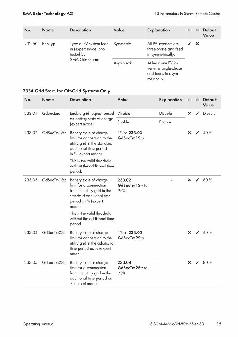
No. Name Description Value Explanation DefaultValue
232.60 EZATyp Type of PV system feed-in (expert mode, pro-tected bySMA Grid Guard)
Symmetric All PV inverters arethree-phase and feedin symmetrically.
–
Asymmetric At least one PV in-verter is single-phaseand feeds in asym-metrically.
233# Grid Start, for Off-Grid Systems Only
No. Name Description Value Explanation DefaultValue
233.01 GdSocEna Enable grid request basedon battery state of charge(expert mode)
Disable Disable Disable
Enable Enable
233.02 GdSocTm1Str Battery state of chargelimit for connection to theutility grid in the standardadditional time periodin % (expert mode)This is the valid thresholdwithout the additional timeperiod.
1% to 233.03 GdSocTm1Stp
– 40 %
233.03 GdSocTm1Stp Battery state of chargelimit for disconnectionfrom the utility grid in thestandard additional timeperiod as % (expertmode)This is the valid thresholdwithout the additional timeperiod.
233.02 GdSocTm1Str to95%
– 80 %
233.04 GdSocTm2Str Battery state of chargelimit for connection to theutility grid in the additionaltime period as % (expertmode)
1% to 233.05 GdSocTm2Stp
‒ 40 %
233.05 GdSocTm2Stp Battery state of chargelimit for disconnectionfrom the utility grid in theadditional time period as% (expert mode)
233.04 GdSocTm2Str to95%
‒ 80 %
13 Parameters in Sunny Remote ControlSMA Solar Technology AG
Operating Manual 135SI30M-44M-60H-80H-BE-en-33
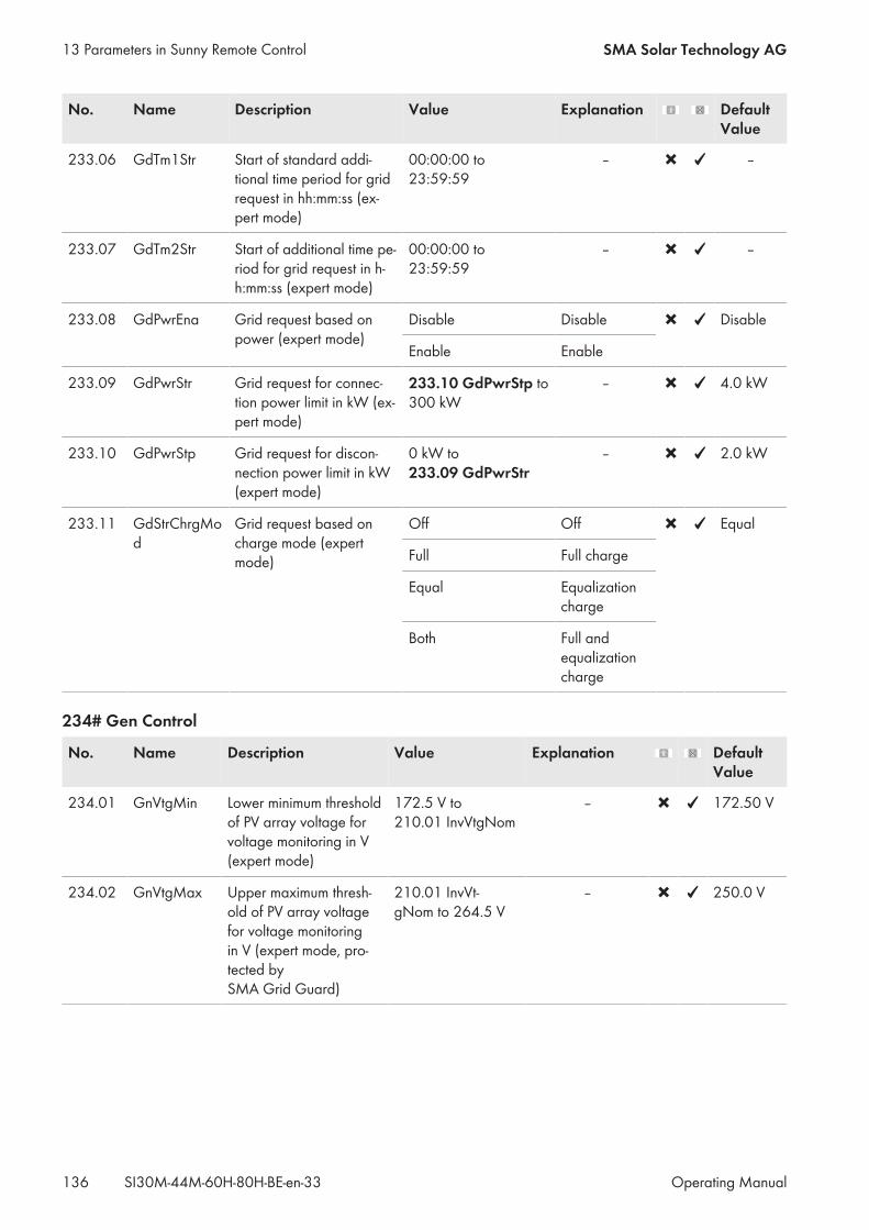
No. Name Description Value Explanation DefaultValue
233.06 GdTm1Str Start of standard addi-tional time period for gridrequest in hh:mm:ss (ex-pert mode)
00:00:00 to23:59:59
‒ ‒
233.07 GdTm2Str Start of additional time pe-riod for grid request in h-h:mm:ss (expert mode)
00:00:00 to23:59:59
– –
233.08 GdPwrEna Grid request based onpower (expert mode)
Disable Disable Disable
Enable Enable
233.09 GdPwrStr Grid request for connec-tion power limit in kW (ex-pert mode)
233.10 GdPwrStp to300 kW
‒ 4.0 kW
233.10 GdPwrStp Grid request for discon-nection power limit in kW(expert mode)
0 kW to233.09 GdPwrStr
– 2.0 kW
233.11 GdStrChrgMod
Grid request based oncharge mode (expertmode)
Off Off Equal
Full Full charge
Equal Equalizationcharge
Both Full andequalizationcharge
234# Gen Control
No. Name Description Value Explanation DefaultValue
234.01 GnVtgMin Lower minimum thresholdof PV array voltage forvoltage monitoring in V(expert mode)
172.5 V to210.01 InvVtgNom
– 172.50 V
234.02 GnVtgMax Upper maximum thresh-old of PV array voltagefor voltage monitoringin V (expert mode, pro-tected bySMA Grid Guard)
210.01 InvVt-gNom to 264.5 V
‒ 250.0 V
13 Parameters in Sunny Remote Control SMA Solar Technology AG
Operating ManualSI30M-44M-60H-80H-BE-en-33136
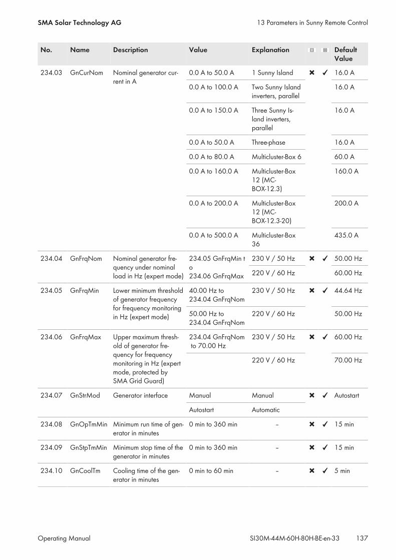
No. Name Description Value Explanation DefaultValue
234.03 GnCurNom Nominal generator cur-rent in A
0.0 A to 50.0 A 1 Sunny Island 16.0 A
0.0 A to 100.0 A Two Sunny Islandinverters, parallel
16.0 A
0.0 A to 150.0 A Three Sunny Is-land inverters,parallel
16.0 A
0.0 A to 50.0 A Three-phase 16.0 A
0.0 A to 80.0 A Multicluster-Box 6 60.0 A
0.0 A to 160.0 A Multicluster-Box12 (MC-BOX-12.3)
160.0 A
0.0 A to 200.0 A Multicluster-Box12 (MC-BOX-12.3-20)
200.0 A
0.0 A to 500.0 A Multicluster-Box36
435.0 A
234.04 GnFrqNom Nominal generator fre-quency under nominalload in Hz (expert mode)
234.05 GnFrqMin to234.06 GnFrqMax
230 V / 50 Hz 50.00 Hz
220 V / 60 Hz 60.00 Hz
234.05 GnFrqMin Lower minimum thresholdof generator frequencyfor frequency monitoringin Hz (expert mode)
40.00 Hz to234.04 GnFrqNom
230 V / 50 Hz 44.64 Hz
50.00 Hz to234.04 GnFrqNom
220 V / 60 Hz 50.00 Hz
234.06 GnFrqMax Upper maximum thresh-old of generator fre-quency for frequencymonitoring in Hz (expertmode, protected bySMA Grid Guard)
234.04 GnFrqNom to 70.00 Hz
230 V / 50 Hz 60.00 Hz
220 V / 60 Hz 70.00 Hz
234.07 GnStrMod Generator interface Manual Manual Autostart
Autostart Automatic
234.08 GnOpTmMin Minimum run time of gen-erator in minutes
0 min to 360 min ‒ 15 min
234.09 GnStpTmMin Minimum stop time of thegenerator in minutes
0 min to 360 min ‒ 15 min
234.10 GnCoolTm Cooling time of the gen-erator in minutes
0 min to 60 min ‒ 5 min
13 Parameters in Sunny Remote ControlSMA Solar Technology AG
Operating Manual 137SI30M-44M-60H-80H-BE-en-33

No. Name Description Value Explanation DefaultValue
234.11 GnErrStpTm Idle time after generatorerror in hours (expertmode)
0 h to 24 h ‒ 1 h
234.12 GnWarmTm Warm-up time in seconds 5 s to 900 s ‒ 60 s
234.13 GnRvPwr Maximum reverse powerfor voltage monitoring ofgenerator in W (expertmode)
0 W to 5000 W One Sunny Islandor single-clustersystem
100 W
0 W to 20000 W Multicluster sys-tem
100 W
234.14 GnRvTm Time for reverse poweror reverse current forvoltage monitoring ofgenerator in s (expertmode)
0 s to 900 s ‒ 30 s
234.15 GnCtlMod Type of generator cur-rent limitation (expertmode)The generator controllimits the consumption ofgenerator current.
Cur Fixed thresholdfor current limita-tion
Cur
CurFrq Frequency-depen-dent current limi-tation
234.20 GnAlSns Anti-islanding Sensitivityof the generator faultrecognition (expertmode)
Low Low Standard
Medium Medium
Standard Standard
High High
234.41 GnCurCtlMod
Enable I‑Loop in genera-tor operation (expertmode, only withSI6.0H-11 andSI8.0H-11)I‑Loop enables genera-tors with inadequate volt-age regulation to beused in the system.
Droop Standard genera-tor operation with-out I‑Loop
Droop
CurCtl Current-controlledgenerator opera-tion with I‑Loop
234.42 GnAIFac Anti-islanding factor incurrent-controlled gener-ator operation with I-Loop (expert mode)
0.00 to 1.00 – 0.10
13 Parameters in Sunny Remote Control SMA Solar Technology AG
Operating ManualSI30M-44M-60H-80H-BE-en-33138
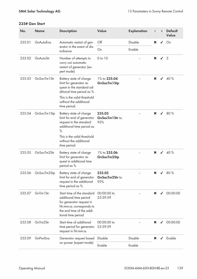
235# Gen Start
No. Name Description Value Explanation DefaultValue
235.01 GnAutoEna Automatic restart of gen-erator in the event of dis-turbance
Off Disable On
On Enable
235.02 GnAutoStr Number of attempts tocarry out automaticrestart of generator (ex-pert mode)
0 to 10 ‒ 3
235.03 GnSocTm1Str Battery state of chargelimit for generator re-quest in the standard ad-ditional time period as %This is the valid thresholdwithout the additionaltime period.
1% to 235.04 GnSocTm1Stp
‒ 40 %
235.04 GnSocTm1Stp Battery state of chargelimit for end of generatorrequest in the standardadditional time period as%This is the valid thresholdwithout the additionaltime period.
235.03 GnSocTm1Str to95%
‒ 80 %
235.05 GnSocTm2Str Battery state of chargelimit for generator re-quest in additional timeperiod as %
1% to 235.06 GnSocTm2Stp
‒ 40 %
235.06 GnSocTm2Stp Battery state of chargelimit for end of generatorrequest in the additionaltime period as %
235.05 GnSocTm2Str to95%
‒ 80 %
235.07 GnTm1Str Start time of the standardadditional time periodfor generator request inhh:mm:ss; corresponds tothe end time of the addi-tional time period
00:00:00 to23:59:59
‒ 00:00:00
235.08 GnTm2Str Start time of additionaltime period for generatorrequest in hh:mm:ss
00:00:00 to23:59:59
‒ 00:00:00
235.09 GnPwrEna Generator request basedon power (expert mode)
Disable Disable Enable
Enable Enable
13 Parameters in Sunny Remote ControlSMA Solar Technology AG
Operating Manual 139SI30M-44M-60H-80H-BE-en-33

No. Name Description Value Explanation DefaultValue
235.10 GnPwrStr Load limit: Generatorstart for generator re-quest based on power in- kW (expert mode)
235.11 GnPwrStp to300.0 kW
– 4.0 kW
235.11 GnPwrStp Load limit: Generatorshutdown for end of gen-erator request based onpower in kW (expertmode)
0.0 kW to 235.10 GnPwrStr
– 2.0 kW
235.12 GnPwrAvgTm Averaging time for load-dependent generator re-quest based on powerin s (expert mode)
1 s to 900 s ‒ 60 s
235.13 GnTmOpEna Time-controlled genera-tor operation
Disable Disable Disable
Enable Enable
235.14 GnTmOpStrDt Start date for time-con-trolled generator opera-tion in dd.mm.yyyy
‒ ‒ 2011-01-01
235.15 GnTmOpStrTm Time at the start of time-controlled generator op-eration in hh:mm:ss
00:00:00 to23:59:59
‒ 00:00:00
235.16 GnTmOpRnDur Run time for time-con-trolled generator opera-tion in hh:mm:ss
00:00:00 to99:59:00
‒ 00:00:00
235.17 GnTmOpCyc Repeat cycle for time-controlled generator op-eration
Single Once Single
Daily Daily
Weekly Weekly
235.18 GnStrChrgMod Generator request inconfigured charge mode(expert mode)
Off Off Both
Full Full charge
Equal Equalizationcharge
Both Full and equal-ization charge
235.19 GnStrDigIn Generator request in re-sponse to signal on acti-vated digital input (ex-pert mode)
Disable Disable Disable
Enable Enable
13 Parameters in Sunny Remote Control SMA Solar Technology AG
Operating ManualSI30M-44M-60H-80H-BE-en-33140

13.2.2.4 Relay (240#)
241# General
No. Name Description Value Explanation DefaultValue
241.01 Rly1Op Operating mode of the multifunc-tion relay 1
Value and description see fol-lowing table 241.01 Rly1Op:Operating mode of the multi-function relay 1
AutoGn
241.02 Rly2Op Multifunction relay 2 function Value and description see fol-lowing table 241.01 Rly1Op:Operating mode of the multi-function relay 1
AutoLodExt
241.07 Ex-tPwrDerMinTm
Minimum time for ExtPwrDer of the multifunctionrelays in minutes
0 min to 600 min 10 min
241.08 Ex-tPwrDerDltVtg
Voltage difference for the ExtPwrDer function of the multi-function relay in VThe voltage difference corre-sponds to the cell voltage of thebattery.
0 V to 0.40 V 0.15 V
241.01 Rly1Op: Operating mode of the multifunction relay 1
Value Explanation
Off Off; the multifunction relay is always in idle mode.
On On; the multifunction relay is permanently activated.
AutoGn Automatic generator request: the Sunny Island automatically requests the generator. In theevent of a generator request, the multifunction relay is activated.
AutoLodExt 1‑level load sheddingWhen the generator is connected, the Sunny Island stops the load shedding. When the loadsare to be shed, the multifunction relay is deactivated.
AutoLod1Soc 1‑level load shedding or first level of 2-level load sheddingWhen the upper SOC threshold is reached, the Sunny Island ends load shedding. When theloads are to be shed, the multifunction relay is deactivated.
AutoLod2Soc Second level of 2‑level load sheddingWhen the upper SOC threshold is reached, the Sunny Island ends load shedding. When theloads are to be shed, the multifunction relay is deactivated.
Tm1 Timer 1The Sunny Island controls external processes time-dependently. When the set time#243 Timer is reached, the multifunction relay is activated.
13 Parameters in Sunny Remote ControlSMA Solar Technology AG
Operating Manual 141SI30M-44M-60H-80H-BE-en-33
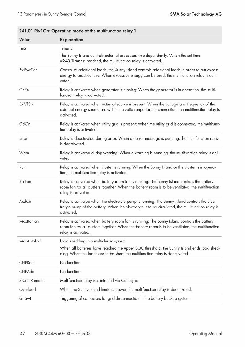
241.01 Rly1Op: Operating mode of the multifunction relay 1
Value Explanation
Tm2 Timer 2The Sunny Island controls external processes time-dependently. When the set time#243 Timer is reached, the multifunction relay is activated.
ExtPwrDer Control of additional loads: the Sunny Island controls additional loads in order to put excessenergy to practical use. When excessive energy can be used, the multifunction relay is acti-vated.
GnRn Relay is activated when generator is running: When the generator is in operation, the multi-function relay is activated.
ExtVfOk Relay is activated when external source is present: When the voltage and frequency of theexternal energy source are within the valid range for the connection, the multifunction relay isactivated.
GdOn Relay is activated when utility grid is present: When the utility grid is connected, the multifunc-tion relay is activated.
Error Relay is deactivated during error: When an error message is pending, the multifunction relayis deactivated.
Warn Relay is activated during warning: When a warning is pending, the multifunction relay is acti-vated.
Run Relay is activated when cluster is running: When the Sunny Island or the cluster is in opera-tion, the multifunction relay is activated.
BatFan Relay is activated when battery room fan is running: The Sunny Island controls the batteryroom fan for all clusters together. When the battery room is to be ventilated, the multifunctionrelay is activated.
AcdCir Relay is activated when the electrolyte pump is running: The Sunny Island controls the elec-trolyte pump of the battery. When the electrolyte is to be circulated, the multifunction relay isactivated.
MccBatFan Relay is activated when battery room fan is running: The Sunny Island controls the batteryroom fan for all clusters together. When the battery room is to be ventilated, the multifunctionrelay is activated.
MccAutoLod Load shedding in a multicluster systemWhen all batteries have reached the upper SOC threshold, the Sunny Island ends load shed-ding. When the loads are to be shed, the multifunction relay is deactivated.
CHPReq No function
CHPAdd No function
SiComRemote Multifunction relay is controlled via ComSync.
Overload When the Sunny Island limits its power, the multifunction relay is deactivated.
GriSwt Triggering of contactors for grid disconnection in the battery backup system
13 Parameters in Sunny Remote Control SMA Solar Technology AG
Operating ManualSI30M-44M-60H-80H-BE-en-33142
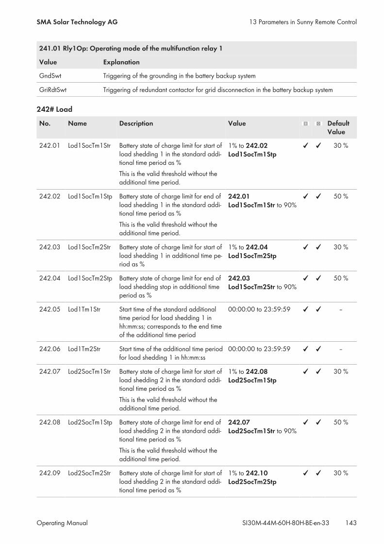
241.01 Rly1Op: Operating mode of the multifunction relay 1
Value Explanation
GndSwt Triggering of the grounding in the battery backup system
GriRdtSwt Triggering of redundant contactor for grid disconnection in the battery backup system
242# Load
No. Name Description Value DefaultValue
242.01 Lod1SocTm1Str Battery state of charge limit for start ofload shedding 1 in the standard addi-tional time period as %This is the valid threshold without theadditional time period.
1% to 242.02 Lod1SocTm1Stp
30 %
242.02 Lod1SocTm1Stp Battery state of charge limit for end ofload shedding 1 in the standard addi-tional time period as %This is the valid threshold without theadditional time period.
242.01 Lod1SocTm1Str to 90%
50 %
242.03 Lod1SocTm2Str Battery state of charge limit for start ofload shedding 1 in additional time pe-riod as %
1% to 242.04 Lod1SocTm2Stp
30 %
242.04 Lod1SocTm2Stp Battery state of charge limit for end ofload shedding stop in additional timeperiod as %
242.03 Lod1SocTm2Str to 90%
50 %
242.05 Lod1Tm1Str Start time of the standard additionaltime period for load shedding 1 inhh:mm:ss; corresponds to the end timeof the additional time period
00:00:00 to 23:59:59 –
242.06 Lod1Tm2Str Start time of the additional time periodfor load shedding 1 in hh:mm:ss
00:00:00 to 23:59:59 –
242.07 Lod2SocTm1Str Battery state of charge limit for start ofload shedding 2 in the standard addi-tional time period as %This is the valid threshold without theadditional time period.
1% to 242.08 Lod2SocTm1Stp
30 %
242.08 Lod2SocTm1Stp Battery state of charge limit for end ofload shedding 2 in the standard addi-tional time period as %This is the valid threshold without theadditional time period.
242.07 Lod2SocTm1Str to 90%
50 %
242.09 Lod2SocTm2Str Battery state of charge limit for start ofload shedding 2 in the standard addi-tional time period as %
1% to 242.10 Lod2SocTm2Stp
30 %
13 Parameters in Sunny Remote ControlSMA Solar Technology AG
Operating Manual 143SI30M-44M-60H-80H-BE-en-33
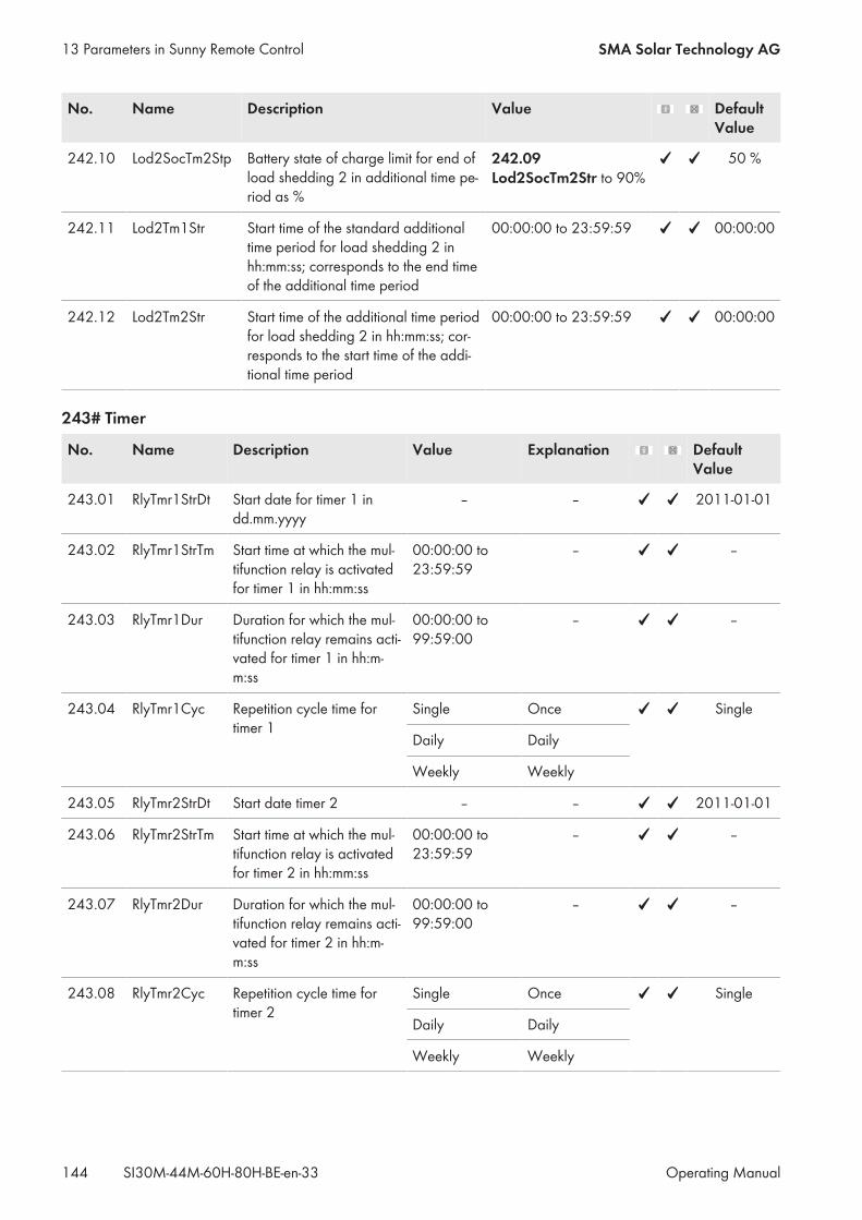
No. Name Description Value DefaultValue
242.10 Lod2SocTm2Stp Battery state of charge limit for end ofload shedding 2 in additional time pe-riod as %
242.09 Lod2SocTm2Str to 90%
50 %
242.11 Lod2Tm1Str Start time of the standard additionaltime period for load shedding 2 inhh:mm:ss; corresponds to the end timeof the additional time period
00:00:00 to 23:59:59 00:00:00
242.12 Lod2Tm2Str Start time of the additional time periodfor load shedding 2 in hh:mm:ss; cor-responds to the start time of the addi-tional time period
00:00:00 to 23:59:59 00:00:00
243# Timer
No. Name Description Value Explanation DefaultValue
243.01 RlyTmr1StrDt Start date for timer 1 indd.mm.yyyy
– – 2011-01-01
243.02 RlyTmr1StrTm Start time at which the mul-tifunction relay is activatedfor timer 1 in hh:mm:ss
00:00:00 to23:59:59
– –
243.03 RlyTmr1Dur Duration for which the mul-tifunction relay remains acti-vated for timer 1 in hh:m-m:ss
00:00:00 to99:59:00
– –
243.04 RlyTmr1Cyc Repetition cycle time fortimer 1
Single Once Single
Daily Daily
Weekly Weekly
243.05 RlyTmr2StrDt Start date timer 2 – – 2011-01-01
243.06 RlyTmr2StrTm Start time at which the mul-tifunction relay is activatedfor timer 2 in hh:mm:ss
00:00:00 to23:59:59
– –
243.07 RlyTmr2Dur Duration for which the mul-tifunction relay remains acti-vated for timer 2 in hh:m-m:ss
00:00:00 to99:59:00
– –
243.08 RlyTmr2Cyc Repetition cycle time fortimer 2
Single Once Single
Daily Daily
Weekly Weekly
13 Parameters in Sunny Remote Control SMA Solar Technology AG
Operating ManualSI30M-44M-60H-80H-BE-en-33144

244# Slave1
No. Name Description Value Explanation DefaultValue
244.01 Rly1OpSlv1
Operatingmode of themultifunction re-lay 1 of slave 1
Value and explanation see 241.01 Rly1Op Off
244.02 Rly2OpSlv1
Operatingmode of themultifunction re-lay 2 of slave 1
Value and explanation see 241.01 Rly1Op Off
245# slave2
No. Name Description Value Explanation DefaultValue
245.01 Rly1OpSlv2
Operatingmode of themultifunction re-lay 1 of slave 2
Value and explanation see 241.01 Rly1Op Off
245.02 Rly2OpSlv2
Operatingmode of themultifunction re-lay 2 of slave 2
Value and explanation see 241.01 Rly1Op Off
13.2.2.5 System (250#)
No. Name Description Value Explanation DefaultValue
250.01 AutoStr Number of au-tostarts
0 to 10 0 indicates that autostart isdisabled.
3
250.02 Dt Date in dd.mm.yyyy – – –
250.03 Tm Time in hh:mm:ss – – –
250.04 BeepEna Button sound Off Disable On
On Enable
250.06 ComBaud Baud rate in BdThis value cannot bechanged withSpeedwire.
1200 Default value for RS485communication.
–
4800 –
9600 –
19200 –
115k Default value for Speedwirecommunication.
13 Parameters in Sunny Remote ControlSMA Solar Technology AG
Operating Manual 145SI30M-44M-60H-80H-BE-en-33
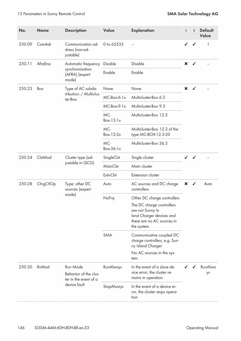
No. Name Description Value Explanation DefaultValue
250.09 ComAdr Communication ad-dress (non-ad-justable)
0 to 65535 – 1
250.11 AfraEna Automatic frequencysynchronization(AFRA) (expertmode)
Disable Disable –
Enable Enable
250.23 Box Type of AC subdis-tribution: / Multiclus-ter-Box
None None –
MC-Box-6-1x Multicluster-Box 6.3
MC-Box-9-1x Multicluster-Box 9.3
MC-Box-12-1x
Multicluster-Box 12.3
MC-Box-12-2x
Multicluster-Box 12.3 of thetype MC-BOX-12.3-20
MC-Box-36-1x
Multicluster-Box 36.3
250.24 ClstMod Cluster type (ad-justable in QCG)
SingleClst Single cluster –
MainClst Main cluster
ExtnClst Extension cluster
250.28 ChrgCtlOp Type: other DCsources (expertmode)
Auto AC sources and DC chargecontrollers
Auto
NoFrq Other DC charge controllersThe DC charge controllersare not Sunny Is-land Charger devices andthere are no AC sources inthe system.
SMA Communicative coupled DCcharge controllers, e.g. Sun-ny Island ChargerNo AC sources in the sys-tem.
250.30 RnMod Run ModeBehavior of the clus-ter in the event of adevice fault
RunAlways In the event of a slave de-vice error, the cluster re-mains in operation
RunAlways
StopAlways In the event of a device er-ror, the cluster stops opera-tion
13 Parameters in Sunny Remote Control SMA Solar Technology AG
Operating ManualSI30M-44M-60H-80H-BE-en-33146

No. Name Description Value Explanation DefaultValue
250.31 ChLstSel Selection of short ornormal channel list(expert mode)The length must becompatible with thecommunication de-vice.
Short Short Standard
Standard Standard
250.32 UpdMode Type of firmware up-date
Manual Update must be confirmedon the Sunny Remote Con-trol.
Manual
Auto Update will be performedautomatically at the set time250.33 UpdAutoTime.
Never Deactivation of all updates
250.33 UpdAutoTime Point in time for per-forming the auto-matic firmware up-date in hh:mm:ss
00:00:00 to23:59:59
– 05:00:00
13.2.2.6 SlfCsmpBackup (#260)
261# General
No. Name Description Value Explanation DefaultValue
261.01 SlfCsm-pIncEna
Increased self-con-sumption
Disable Disable –
Enable Enable
261.02 SlfCsmpPosSel Highest-yieldingmonth for battery uti-lization range:
North Highest PV yield in June –
South Highest PV yield in Decem-ber
261.03 Saisonenable Seasonal operation(expert mode)Automatic adjust-ment of the batterydepth of discharge:In seasons withfewer hours of sun-light, the electric dis-charge of the bat-tery will be lower.
No Disable Yes
Yes Enable
13 Parameters in Sunny Remote ControlSMA Solar Technology AG
Operating Manual 147SI30M-44M-60H-80H-BE-en-33
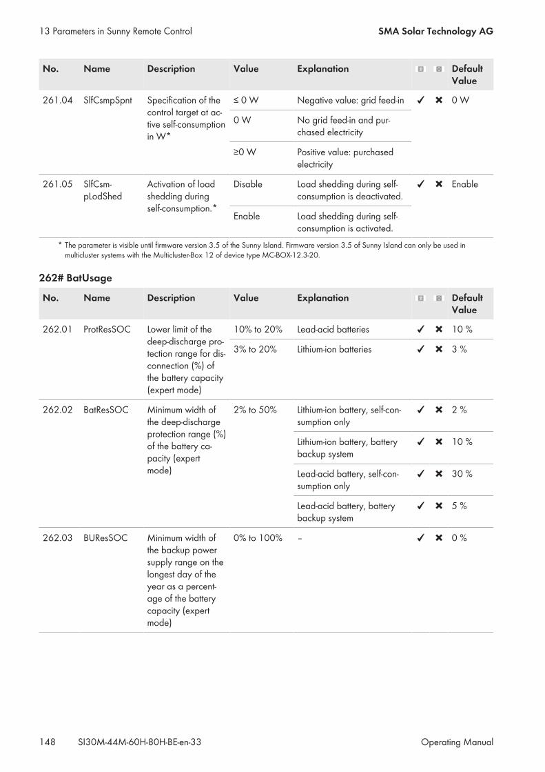
No. Name Description Value Explanation DefaultValue
261.04 SlfCsmpSpnt Specification of thecontrol target at ac-tive self-consumptionin W*
≤ 0 W Negative value: grid feed-in 0 W
0 W No grid feed-in and pur-chased electricity
≥0 W Positive value: purchasedelectricity
261.05 SlfCsm-pLodShed
Activation of loadshedding duringself-consumption.*
Disable Load shedding during self-consumption is deactivated.
Enable
Enable Load shedding during self-consumption is activated.
* The parameter is visible until firmware version 3.5 of the Sunny Island. Firmware version 3.5 of Sunny Island can only be used inmulticluster systems with the Multicluster-Box 12 of device type MC-BOX-12.3-20.
262# BatUsage
No. Name Description Value Explanation DefaultValue
262.01 ProtResSOC Lower limit of thedeep-discharge pro-tection range for dis-connection (%) ofthe battery capacity(expert mode)
10% to 20% Lead-acid batteries 10 %
3% to 20% Lithium-ion batteries 3 %
262.02 BatResSOC Minimum width ofthe deep-dischargeprotection range (%)of the battery ca-pacity (expertmode)
2% to 50% Lithium-ion battery, self-con-sumption only
2 %
Lithium-ion battery, batterybackup system
10 %
Lead-acid battery, self-con-sumption only
30 %
Lead-acid battery, batterybackup system
5 %
262.03 BUResSOC Minimum width ofthe backup powersupply range on thelongest day of theyear as a percent-age of the batterycapacity (expertmode)
0% to 100% – 0 %
13 Parameters in Sunny Remote Control SMA Solar Technology AG
Operating ManualSI30M-44M-60H-80H-BE-en-33148
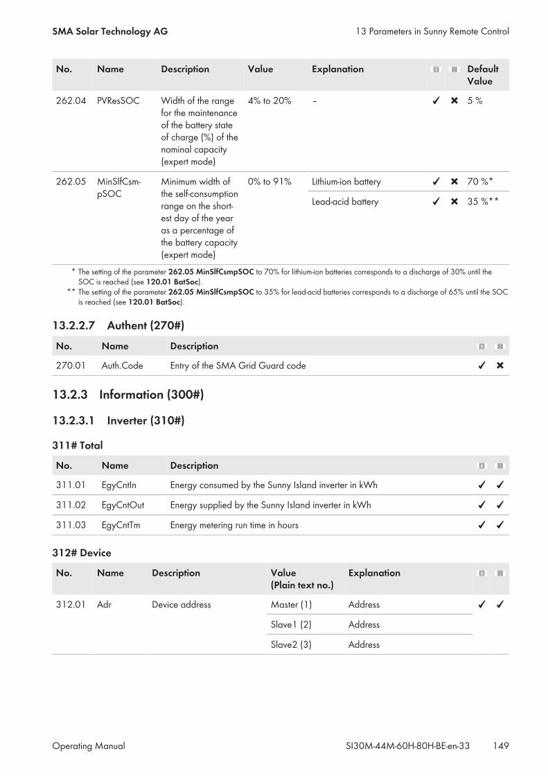
No. Name Description Value Explanation DefaultValue
262.04 PVResSOC Width of the rangefor the maintenanceof the battery stateof charge (%) of thenominal capacity(expert mode)
4% to 20% – 5 %
262.05 MinSlfCsm-pSOC
Minimum width ofthe self-consumptionrange on the short-est day of the yearas a percentage ofthe battery capacity(expert mode)
0% to 91% Lithium-ion battery 70 %*
Lead-acid battery 35 %**
* The setting of the parameter 262.05 MinSlfCsmpSOC to 70% for lithium-ion batteries corresponds to a discharge of 30% until theSOC is reached (see 120.01 BatSoc).
** The setting of the parameter 262.05 MinSlfCsmpSOC to 35% for lead-acid batteries corresponds to a discharge of 65% until the SOCis reached (see 120.01 BatSoc).
13.2.2.7 Authent (270#)
No. Name Description
270.01 Auth.Code Entry of the SMA Grid Guard code
13.2.3 Information (300#)
13.2.3.1 Inverter (310#)
311# Total
No. Name Description
311.01 EgyCntIn Energy consumed by the Sunny Island inverter in kWh
311.02 EgyCntOut Energy supplied by the Sunny Island inverter in kWh
311.03 EgyCntTm Energy metering run time in hours
312# Device
No. Name Description Value(Plain text no.)
Explanation
312.01 Adr Device address Master (1) Address
Slave1 (2) Address
Slave2 (3) Address
13 Parameters in Sunny Remote ControlSMA Solar Technology AG
Operating Manual 149SI30M-44M-60H-80H-BE-en-33
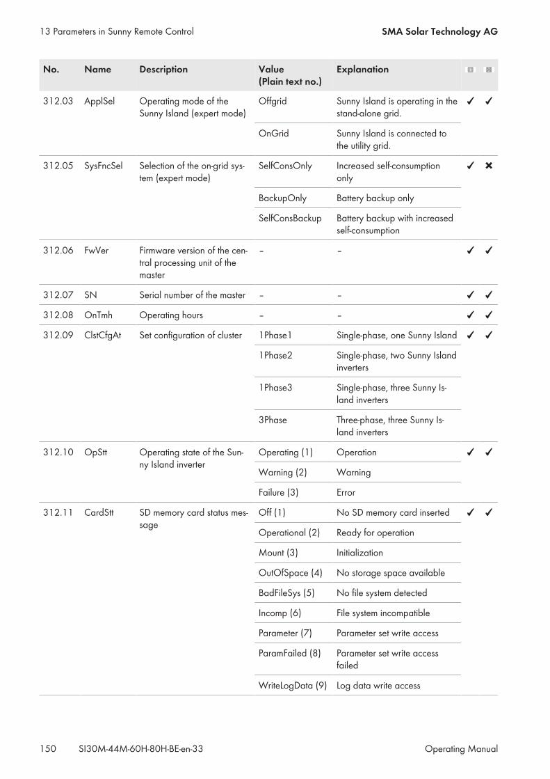
No. Name Description Value(Plain text no.)
Explanation
312.03 ApplSel Operating mode of theSunny Island (expert mode)
Offgrid Sunny Island is operating in thestand-alone grid.
OnGrid Sunny Island is connected tothe utility grid.
312.05 SysFncSel Selection of the on-grid sys-tem (expert mode)
SelfConsOnly Increased self-consumptiononly
BackupOnly Battery backup only
SelfConsBackup Battery backup with increasedself-consumption
312.06 FwVer Firmware version of the cen-tral processing unit of themaster
– –
312.07 SN Serial number of the master – –
312.08 OnTmh Operating hours – –
312.09 ClstCfgAt Set configuration of cluster 1Phase1 Single-phase, one Sunny Island
1Phase2 Single-phase, two Sunny Islandinverters
1Phase3 Single-phase, three Sunny Is-land inverters
3Phase Three-phase, three Sunny Is-land inverters
312.10 OpStt Operating state of the Sun-ny Island inverter
Operating (1) Operation
Warning (2) Warning
Failure (3) Error
312.11 CardStt SD memory card status mes-sage
Off (1) No SD memory card inserted
Operational (2) Ready for operation
Mount (3) Initialization
OutOfSpace (4) No storage space available
BadFileSys (5) No file system detected
Incomp (6) File system incompatible
Parameter (7) Parameter set write access
ParamFailed (8) Parameter set write accessfailed
WriteLogData (9) Log data write access
13 Parameters in Sunny Remote Control SMA Solar Technology AG
Operating ManualSI30M-44M-60H-80H-BE-en-33150
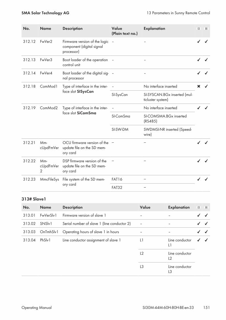
No. Name Description Value(Plain text no.)
Explanation
312.12 FwVer2 Firmware version of the logiccomponent (digital signalprocessor)
– –
312.13 FwVer3 Boot loader of the operationcontrol unit
– –
312.14 FwVer4 Boot loader of the digital sig-nal processor
– –
312.18 ComMod1 Type of interface in the inter-face slot SISysCan
– No interface inserted
SI-SysCan SI‑SYSCAN.BGx inserted (mul-ticluster system)
312.19 ComMod2 Type of interface in the inter-face slot SiComSma
– No interface inserted
SI-ComSma SI‑COMSMA.BGx inserted(RS485)
SI-SW-DM SWDMSI-NR inserted (Speed-wire)
312.21 Mm-cUpdFmVer
OCU firmware version of theupdate file on the SD mem-ory card
− −
312.22 Mm-cUpdFmVer2
DSP firmware version of theupdate file on the SD mem-ory card
− −
312.23 MmcFileSys File system of the SD mem-ory card
FAT16 −
FAT32 −
313# Slave1
No. Name Description Value Explanation
313.01 FwVerSlv1 Firmware version of slave 1 – –
313.02 SNSlv1 Serial number of slave 1 (line conductor 2) – –
313.03 OnTmhSlv1 Operating hours of slave 1 in hours – –
313.04 PhSlv1 Line conductor assignment of slave 1 L1 Line conductorL1
L2 Line conductorL2
L3 Line conductorL3
13 Parameters in Sunny Remote ControlSMA Solar Technology AG
Operating Manual 151SI30M-44M-60H-80H-BE-en-33
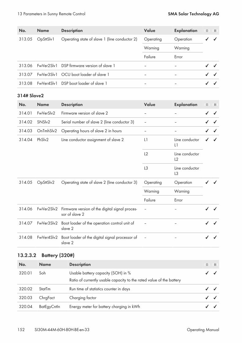
No. Name Description Value Explanation
313.05 OpSttSlv1 Operating state of slave 1 (line conductor 2) Operating Operation
Warning Warning
Failure Error
313.06 FwVer2Slv1 DSP firmware version of slave 1 – –
313.07 FwVer3Slv1 OCU boot loader of slave 1 – –
313.08 FwVer4Slv1 DSP boot loader of slave 1 – –
314# Slave2
No. Name Description Value Explanation
314.01 FwVerSlv2 Firmware version of slave 2 – –
314.02 SNSlv2 Serial number of slave 2 (line conductor 3) – –
314.03 OnTmhSlv2 Operating hours of slave 2 in hours – –
314.04 PhSlv2 Line conductor assignment of slave 2 L1 Line conductorL1
L2 Line conductorL2
L3 Line conductorL3
314.05 OpSttSlv2 Operating state of slave 2 (line conductor 3) Operating Operation
Warning Warning
Failure Error
314.06 FwVer2Slv2 Firmware version of the digital signal proces-sor of slave 2
– –
314.07 FwVer3Slv2 Boot loader of the operation control unit ofslave 2
– –
314.08 FwVer4Slv2 Boot loader of the digital signal processor ofslave 2
– –
13.2.3.2 Battery (320#)
No. Name Description
320.01 Soh Usable battery capacity (SOH) in %Ratio of currently usable capacity to the rated value of the battery
320.02 StatTm Run time of statistics counter in days
320.03 ChrgFact Charging factor
320.04 BatEgyCntIn Energy meter for battery charging in kWh
13 Parameters in Sunny Remote Control SMA Solar Technology AG
Operating ManualSI30M-44M-60H-80H-BE-en-33152
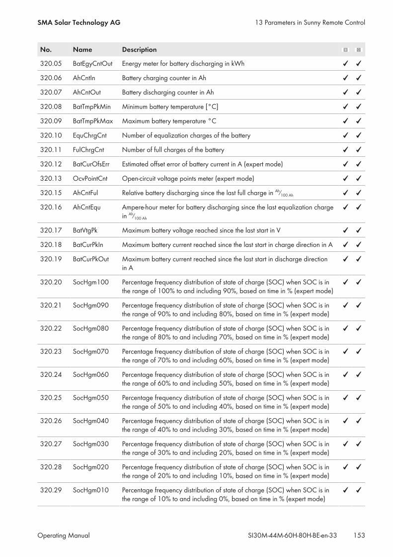
No. Name Description
320.05 BatEgyCntOut Energy meter for battery discharging in kWh
320.06 AhCntIn Battery charging counter in Ah
320.07 AhCntOut Battery discharging counter in Ah
320.08 BatTmpPkMin Minimum battery temperature [°C]
320.09 BatTmpPkMax Maximum battery temperature °C
320.10 EquChrgCnt Number of equalization charges of the battery
320.11 FulChrgCnt Number of full charges of the battery
320.12 BatCurOfsErr Estimated offset error of battery current in A (expert mode)
320.13 OcvPointCnt Open-circuit voltage points meter (expert mode)
320.15 AhCntFul Relative battery discharging since the last full charge in Ah⁄100 Ah
320.16 AhCntEqu Ampere-hour meter for battery discharging since the last equalization chargein Ah⁄100 Ah
320.17 BatVtgPk Maximum battery voltage reached since the last start in V
320.18 BatCurPkIn Maximum battery current reached since the last start in charge direction in A
320.19 BatCurPkOut Maximum battery current reached since the last start in discharge directionin A
320.20 SocHgm100 Percentage frequency distribution of state of charge (SOC) when SOC is inthe range of 100% to and including 90%, based on time in % (expert mode)
320.21 SocHgm090 Percentage frequency distribution of state of charge (SOC) when SOC is inthe range of 90% to and including 80%, based on time in % (expert mode)
320.22 SocHgm080 Percentage frequency distribution of state of charge (SOC) when SOC is inthe range of 80% to and including 70%, based on time in % (expert mode)
320.23 SocHgm070 Percentage frequency distribution of state of charge (SOC) when SOC is inthe range of 70% to and including 60%, based on time in % (expert mode)
320.24 SocHgm060 Percentage frequency distribution of state of charge (SOC) when SOC is inthe range of 60% to and including 50%, based on time in % (expert mode)
320.25 SocHgm050 Percentage frequency distribution of state of charge (SOC) when SOC is inthe range of 50% to and including 40%, based on time in % (expert mode)
320.26 SocHgm040 Percentage frequency distribution of state of charge (SOC) when SOC is inthe range of 40% to and including 30%, based on time in % (expert mode)
320.27 SocHgm030 Percentage frequency distribution of state of charge (SOC) when SOC is inthe range of 30% to and including 20%, based on time in % (expert mode)
320.28 SocHgm020 Percentage frequency distribution of state of charge (SOC) when SOC is inthe range of 20% to and including 10%, based on time in % (expert mode)
320.29 SocHgm010 Percentage frequency distribution of state of charge (SOC) when SOC is inthe range of 10% to and including 0%, based on time in % (expert mode)
13 Parameters in Sunny Remote ControlSMA Solar Technology AG
Operating Manual 153SI30M-44M-60H-80H-BE-en-33
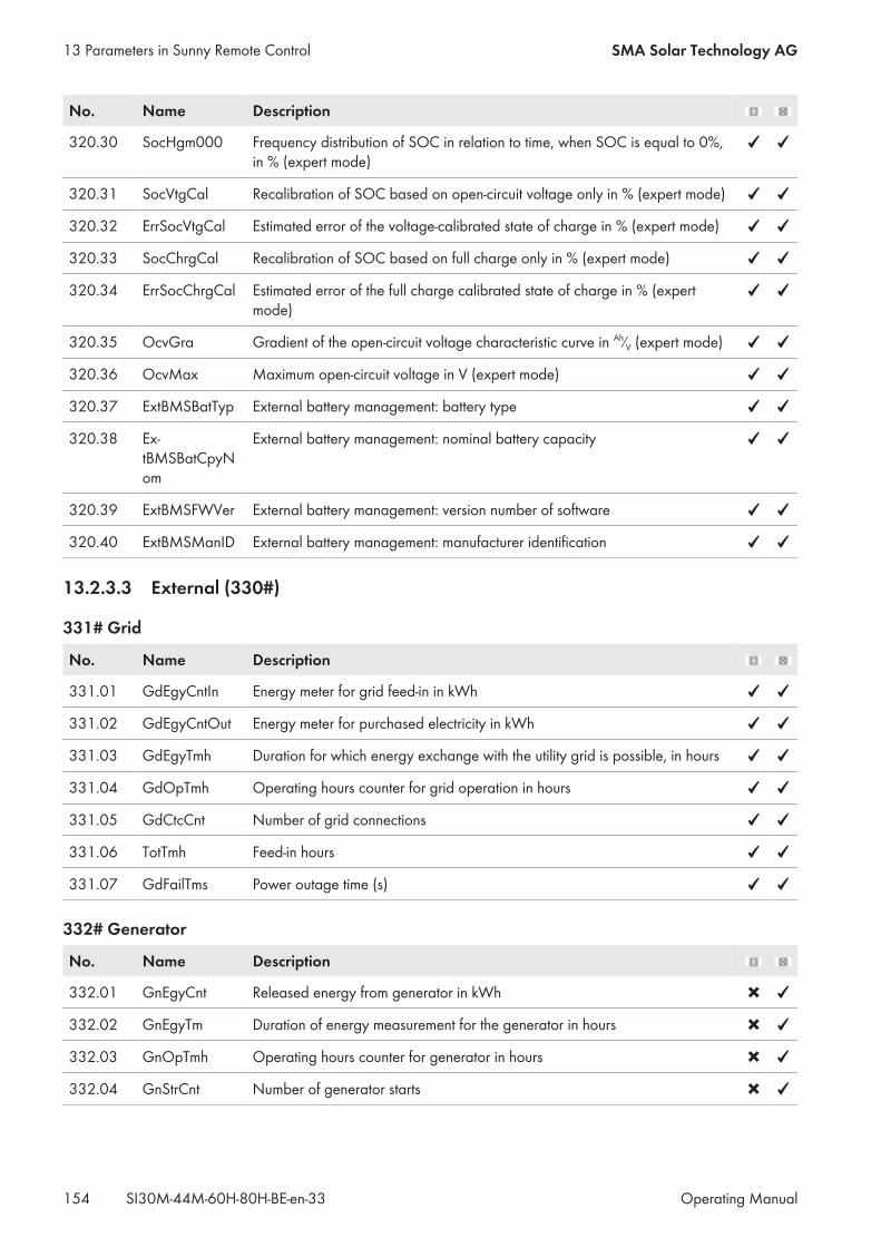
No. Name Description
320.30 SocHgm000 Frequency distribution of SOC in relation to time, when SOC is equal to 0%,in % (expert mode)
320.31 SocVtgCal Recalibration of SOC based on open-circuit voltage only in % (expert mode)
320.32 ErrSocVtgCal Estimated error of the voltage-calibrated state of charge in % (expert mode)
320.33 SocChrgCal Recalibration of SOC based on full charge only in % (expert mode)
320.34 ErrSocChrgCal Estimated error of the full charge calibrated state of charge in % (expertmode)
320.35 OcvGra Gradient of the open-circuit voltage characteristic curve in Ah⁄V (expert mode)
320.36 OcvMax Maximum open-circuit voltage in V (expert mode)
320.37 ExtBMSBatTyp External battery management: battery type
320.38 Ex-tBMSBatCpyNom
External battery management: nominal battery capacity
320.39 ExtBMSFWVer External battery management: version number of software
320.40 ExtBMSManID External battery management: manufacturer identification
13.2.3.3 External (330#)
331# Grid
No. Name Description
331.01 GdEgyCntIn Energy meter for grid feed-in in kWh
331.02 GdEgyCntOut Energy meter for purchased electricity in kWh
331.03 GdEgyTmh Duration for which energy exchange with the utility grid is possible, in hours
331.04 GdOpTmh Operating hours counter for grid operation in hours
331.05 GdCtcCnt Number of grid connections
331.06 TotTmh Feed-in hours
331.07 GdFailTms Power outage time (s)
332# Generator
No. Name Description
332.01 GnEgyCnt Released energy from generator in kWh
332.02 GnEgyTm Duration of energy measurement for the generator in hours
332.03 GnOpTmh Operating hours counter for generator in hours
332.04 GnStrCnt Number of generator starts
13 Parameters in Sunny Remote Control SMA Solar Technology AG
Operating ManualSI30M-44M-60H-80H-BE-en-33154
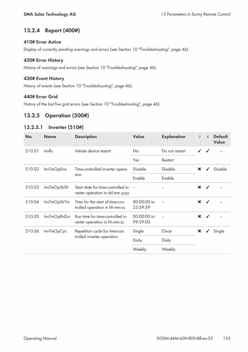
13.2.4 Report (400#)
410# Error ActiveDisplay of currently pending warnings and errors (see Section 10 "Troubleshooting", page 46).
420# Error HistoryHistory of warnings and errors (see Section 10 "Troubleshooting", page 46).
430# Event HistoryHistory of events (see Section 10 "Troubleshooting", page 46).
440# Error GridHistory of the last five grid errors (see Section 10 "Troubleshooting", page 46).
13.2.5 Operation (500#)
13.2.5.1 Inverter (510#)
No. Name Description Value Explanation DefaultValue
510.01 InvRs Initiate device restart No Do not restart –
Yes Restart
510.02 InvTmOpEna Time-controlled inverter opera-tion:
Disable Disable Disable
Enable Enable
510.03 InvTmOpStrDt Start date for time-controlled in-verter operation in dd.mm.yyyy
– – –
510.04 InvTmOpStrTm Time for the start of time-con-trolled operation in hh:mm:ss
00:00:00 to23:59:59
– –
510.05 InvTmOpRnDur Run time for time-controlled in-verter operation in hh:mm:ss
00:00:00 to99:59:00
– –
510.06 InvTmOpCyc Repetition cycle for time-con-trolled inverter operation
Single Once Single
Daily Daily
Weekly Weekly
13 Parameters in Sunny Remote ControlSMA Solar Technology AG
Operating Manual 155SI30M-44M-60H-80H-BE-en-33
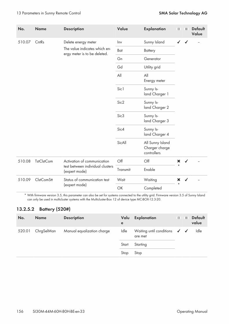
No. Name Description Value Explanation DefaultValue
510.07 CntRs Delete energy meterThe value indicates which en-ergy meter is to be deleted.
Inv Sunny Island –
Bat Battery
Gn Generator
Gd Utility grid
All AllEnergy meter
Sic1 Sunny Is-land Charger 1
Sic2 Sunny Is-land Charger 2
Sic3 Sunny Is-land Charger 3
Sic4 Sunny Is-land Charger 4
SicAll All Sunny IslandCharger chargecontrollers
510.08 TstClstCom Activation of communicationtest between individual clusters(expert mode)
Off Off * –
Transmit Enable
510.09 ClstComStt Status of communication test(expert mode)
Wait Waiting * –
OK Completed* With firmware version 3.5, this parameter can also be set for systems connected to the utility grid. Firmware version 3.5 of Sunny Islandcan only be used in multicluster systems with the Multicluster-Box 12 of device type MC-BOX-12.3-20.
13.2.5.2 Battery (520#)
No. Name Description Value
Explanation Defaultvalue
520.01 ChrgSelMan Manual equalization charge Idle Waiting until conditionsare met
Idle
Start Starting
Stop Stop
13 Parameters in Sunny Remote Control SMA Solar Technology AG
Operating ManualSI30M-44M-60H-80H-BE-en-33156
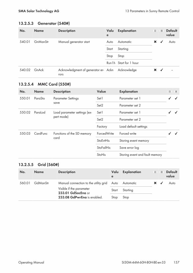
13.2.5.3 Generator (540#)
No. Name Description Value
Explanation Defaultvalue
540.01 GnManStr Manual generator start Auto Automatic Auto
Start Starting
Stop Stop
Run1h Start for 1 hour
540.02 GnAck Acknowledgment of generator er-rors
Ackn Acknowledge –
13.2.5.4 MMC Card (550#)
No. Name Description Value Explanation
550.01 ParaSto Parameter Settingssave
Set1 Parameter set 1
Set2 Parameter set 2
550.02 ParaLod Load parameter settings (ex-pert mode)
Set1 Parameter set 1
Set2 Parameter set 2
Factory Load default settings
550.03 CardFunc Functions of the SD memorycard
ForcedWrite Forced write
StoEvtHis Storing event memory
StoFailHis Save error log
StoHis Storing event and fault memory
13.2.5.5 Grid (560#)
No. Name Description Value
Explanation Defaultvalue
560.01 GdManStr Manual connection to the utility gridVisible if the parameter233.01 GdSocEna or233.08 GdPwrEna is enabled.
Auto Automatic Auto
Start Starting
Stop Stop
13 Parameters in Sunny Remote ControlSMA Solar Technology AG
Operating Manual 157SI30M-44M-60H-80H-BE-en-33
14 Parameters in the Communication ProductMost parameters of the Sunny Island inverter can be called up and set on the communication product (e.g.Sunny Explorer or Sunny Portal). Links to additional information can be found at www.SMA‑Solar.com.
Document title and content Document type
SUNNY EXPLORERCall up and set the parameters in Sunny Portal
User Manual
SUNNY HOME MANAGER in SUNNY PORTALCall up and set the parameters in Sunny Portal
User Manual
SUNNY ISLAND – Comparison of the same parameters for Speedwire (e.g. Sun-ny Explorer) and RS485 (e.g. Sunny Remote Control)
Technical Information
14 Parameters in the Communication Product SMA Solar Technology AG
Operating ManualSI30M-44M-60H-80H-BE-en-33158
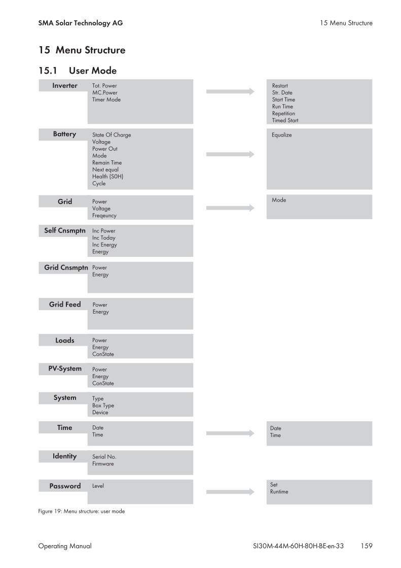
15 Menu Structure
15.1 User Mode
Figure 19: Menu structure: user mode
15 Menu StructureSMA Solar Technology AG
Operating Manual 159SI30M-44M-60H-80H-BE-en-33
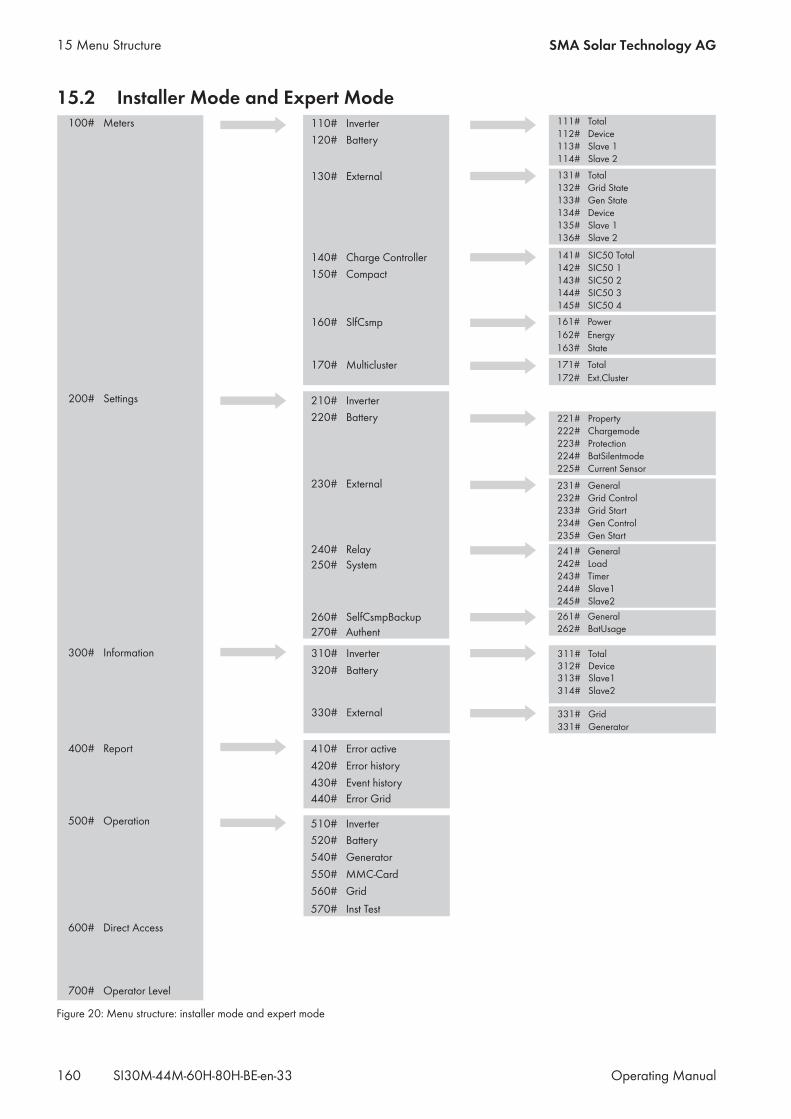
15.2 Installer Mode and Expert Mode
Figure 20: Menu structure: installer mode and expert mode
15 Menu Structure SMA Solar Technology AG
Operating ManualSI30M-44M-60H-80H-BE-en-33160
16 ContactIf you have technical problems with our products, please contact the SMA Service Line. We require the followinginformation in order to provide you with the necessary assistance:• Sunny Island inverter type• Sunny Island inverter serial number• Sunny Island inverter firmware version• Error message displayed• Type of battery connected• Nominal battery capacity• Nominal battery voltage• Type of the communication products connected• Type and size of additional energy sourcesIn order to receive service assignments for the Sunny Island system, all system data must be recorded in the informationsheet for Sunny Island systems during commissioning and made available to Service (for information sheet seewww.SMA-Solar.com).
DanmarkDeutschlandÖsterreichSchweiz
SMA Solar Technology AGNiestetalSMA Online Service Center:www.SMA-Service.comSunny Boy, Sunny Mini Central,Sunny Tripower: +49 561 9522‑1499Monitoring Systems (Kommunikation-sprodukte): +49 561 9522‑2499Fuel Save Controller (PV-Diesel-Hy-bridsysteme): +49 561 9522-3199Sunny Island, Sunny Backup, HydroBoy: +49 561 9522-399Sunny Central: +49 561 9522-299
BelgienBelgiqueBelgiëLuxemburgLuxembourgNederland
SMA Benelux BVBA/SPRLMechelen+32 15 286 730
ČeskoMagyarországSlovensko
SMA Service Partner TERMS a.s.+420 387 6 85 111
Polska SMA Polska+48 12 283 06 66
France SMA France S.A.S.Lyon+33 472 22 97 00
ΕλλάδαΚύπρος
SMA Hellas AEΑθήνα+30 210 9856666
EspañaPortugal
SMA Ibérica Tecnología Solar, S.L.U.Barcelona+34 935 63 50 99
United Kingdom SMA Solar UK Ltd.Milton Keynes+44 1908 304899
BulgariaItaliaRomânia
SMA Italia S.r.l.Milano+39 02 8934-7299
United ArabEmirates
SMA Middle East LLCAbu Dhabi+971 2234 6177
India SMA Solar India Pvt. Ltd.Mumbai+91 22 61713888
16 ContactSMA Solar Technology AG
Operating Manual 161SI30M-44M-60H-80H-BE-en-33

SMA Solar (Thailand) Co., Ltd.
+66 2 670 6999
대한민국 SMA Technology Korea Co., Ltd.서울+82-2-520-2666
South Africa SMA Solar Technology South AfricaPty Ltd.Cape Town08600SUNNY (08600 78669)International: +27 (0)21 826 0600
ArgentinaBrasilChilePerú
SMA South America SPASantiago+562 2820 2101
Australia SMA Australia Pty Ltd.SydneyToll free for Australia: 1800 SMA AUS(1800 762 287)International: +61 2 9491 4200
Other countries International SMA Service LineNiestetalToll free worldwide:00800 SMA SERVICE(+800 762 7378423)
16 Contact SMA Solar Technology AG
Operating ManualSI30M-44M-60H-80H-BE-en-33162

www.SMA-Solar.com