Embed Size (px)
Citation preview
Remote control of the AiboTM camera fromWebotsTM
Raphaël Haberer-Proust
February 20, 2006
Semester project, winter 2005-2006School of Computer & Communication Sciences
Swiss Federal Institute of Technology Lausanne (EPFL)Supervisor: Olivier Michel, Cyberbotics Ltd.
Responsible Professor: Auke Jan Ijspeert, BIRG EPFL
AbstractThis is the report of a semester project done with the Biologically InspiredRobotics Group (BIRG) at the Swiss Federal Institute of Technology Lau-sanne (EPFL) during the winter semester 2005/2006. The goal of this projectwas to extend existing software in order to be able to access the images ofthe Aibo robot's camera.
Contents
Acknowledgment 6About trademarks 71 Introduction 8
1.1 Aibo . . . . . . . . . . . . . . . . . . . . . . . . . . . . . . . . 81.2 Webots . . . . . . . . . . . . . . . . . . . . . . . . . . . . . . 91.3 RCServer . . . . . . . . . . . . . . . . . . . . . . . . . . . . . 101.4 Project objectives . . . . . . . . . . . . . . . . . . . . . . . . . 11
2 System Overview 122.1 Aibo . . . . . . . . . . . . . . . . . . . . . . . . . . . . . . . . 12
2.1.1 OPEN-R . . . . . . . . . . . . . . . . . . . . . . . . . 122.1.2 Aibo's camera . . . . . . . . . . . . . . . . . . . . . . . 17
2.2 Webots . . . . . . . . . . . . . . . . . . . . . . . . . . . . . . 182.3 Protocol . . . . . . . . . . . . . . . . . . . . . . . . . . . . . . 18
3 Implementation 193.1 Image taking functions . . . . . . . . . . . . . . . . . . . . . . 193.2 Inclusions . . . . . . . . . . . . . . . . . . . . . . . . . . . . . 20
3.2.1 stub.cfg . . . . . . . . . . . . . . . . . . . . . . . . . 203.2.2 connect.cfg . . . . . . . . . . . . . . . . . . . . . . . 20
3.3 Image taking and sending . . . . . . . . . . . . . . . . . . . . 203.3.1 The Notify() function . . . . . . . . . . . . . . . . . . 203.3.2 State variable . . . . . . . . . . . . . . . . . . . . . . . 213.3.3 Image size . . . . . . . . . . . . . . . . . . . . . . . . . 223.3.4 Sending of the image . . . . . . . . . . . . . . . . . . . 223.3.5 Image compression . . . . . . . . . . . . . . . . . . . . 233.3.6 JPEG compression quality . . . . . . . . . . . . . . . . 24
3.4 Extension of the existing protocol . . . . . . . . . . . . . . . . 243.4.1 Image header . . . . . . . . . . . . . . . . . . . . . . . 25
4 Conclusion 264.1 Possible extensions . . . . . . . . . . . . . . . . . . . . . . . . 26
2
List of Figures
1.1 Aibo ERS-7 robot . . . . . . . . . . . . . . . . . . . . . . . . 81.2 Webots with the aibo_ers7.wbt world . . . . . . . . . . . . . 91.3 Webots' Aibo ERS-7 remote control, control tab . . . . . . . 102.1 Inter-object communication . . . . . . . . . . . . . . . . . . . 153.1 FSM representing the possible states of the camera . . . . . . 213.2 Example of an image taken by Aibo . . . . . . . . . . . . . . 23
3

List of Tables
3.1 Time needed for image taking and sending . . . . . . . . . . . 233.2 Extension of the protocol for camera support . . . . . . . . . 243.3 Format of an answer on an image taking command . . . . . . 25
4
Listings
Example of a stub con�guration �le . . . . . . . . . . . . . . . . . 15BasicGetCommand . . . . . . . . . . . . . . . . . . . . . . . . . . . 18Entry in the stub con�guration �le . . . . . . . . . . . . . . . . . . 20Entry in the connection con�guration �le . . . . . . . . . . . . . . 20Implementation of the camera's state variable . . . . . . . . . . . . 21
5
Acknowledgment
First of all, I would like to thank Olivier Michel for always have been avail-able, his transmission of technical skills and for showing me the way to go.Then, I would also like to thank Ricardo A. Téllez for his encouragementand his immediate readiness to share his knowledge of OPEN-R. Specialthanks go to Alessandro Crespi and Fabrice Haberer-Proust for their helpin programming. Last but not least, I would like to express my gratitudeto Professor Auke Jan Ijspeert for letting me work for the Biologically In-spired Robotics Group (BIRG) and for providing me an introduction to allthe interesting projects and kind people there.
6
About trademarks
• AiboTM is a registered trademark of SONY Corporation.• �Memory Stick�TM is a trademark of SONY Corporation.• WebotsTM is a registered trademark of Cyberbotics Ltd.• MatlabTM is a registered trademark of The MathWorks, Inc.• Mac OS XTM is registered trademark of Apple Computer, Inc. in theUnited States and/or other countries.
• UNIXTM is a registered trademark of The Open Group in the UnitedStates and/or other countries.
• LinuxTM is a registered trademark of Linus Torvalds.• WindowsTM is registered trademark of Microsoft Corporation in theUnited States and/or other countries.
• MIPSTM is a registered trademark of MIPS Technologies, Inc. in theUnited States and/or other countries.
• Other system names, product names, service names and �rm namescontained in this document are generally trademarks or registeredtrademarks of respective makers.
7
Chapter 1
Introduction
1.1 Aibo
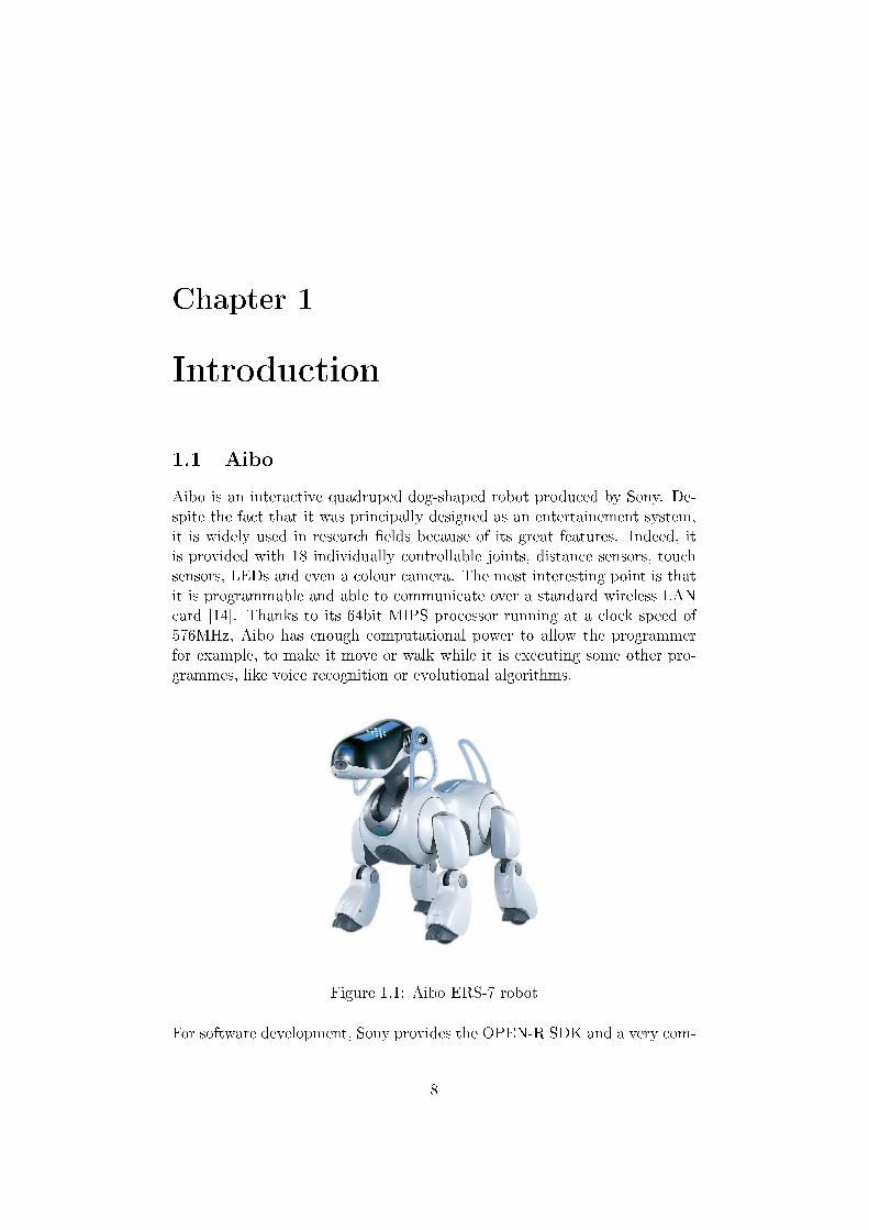
Aibo is an interactive quadruped dog-shaped robot produced by Sony. De-spite the fact that it was principally designed as an entertainement system,it is widely used in research �elds because of its great features. Indeed, itis provided with 18 individually controllable joints, distance sensors, touchsensors, LEDs and even a colour camera. The most interesting point is thatit is programmable and able to communicate over a standard wireless LANcard [14]. Thanks to its 64bit MIPS processor running at a clock speed of576MHz, Aibo has enough computational power to allow the programmerfor example, to make it move or walk while it is executing some other pro-grammes, like voice recognition or evolutional algorithms.
Figure 1.1: Aibo ERS-7 robotFor software development, Sony provides the OPEN-R SDK and a very com-
8
plete documentation [8] including sample programmes [10].
1.2 Webots
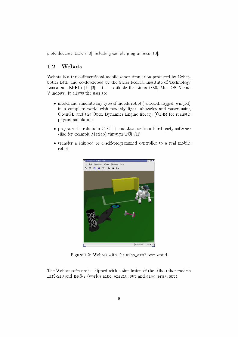
Webots is a three-dimensional mobile robot simulation produced by Cyber-botics Ltd. and co-developed by the Swiss Federal Institute of TechnologyLausanne (EPFL) [1] [2]. It is available for Linux i386, Mac OS X andWindows. It allows the user to:
• model and simulate any type of mobile robot (wheeled, legged, winged)in a complete world with possibly light, obstacles and water usingOpenGL and the Open Dynamics Engine library (ODE) for realisticphysics simulation
• program the robots in C, C++ and Java or from third party software(like for example Matlab) through TCP/IP
• transfer a shipped or a self-programmed controller to a real mobilerobot
Figure 1.2: Webots with the aibo_ers7.wbt world
The Webots software is shipped with a simulation of the Aibo robot modelsERS-210 and ERS-7 (worlds aibo_ers210.wbt and aibo_ers7.wbt).
9
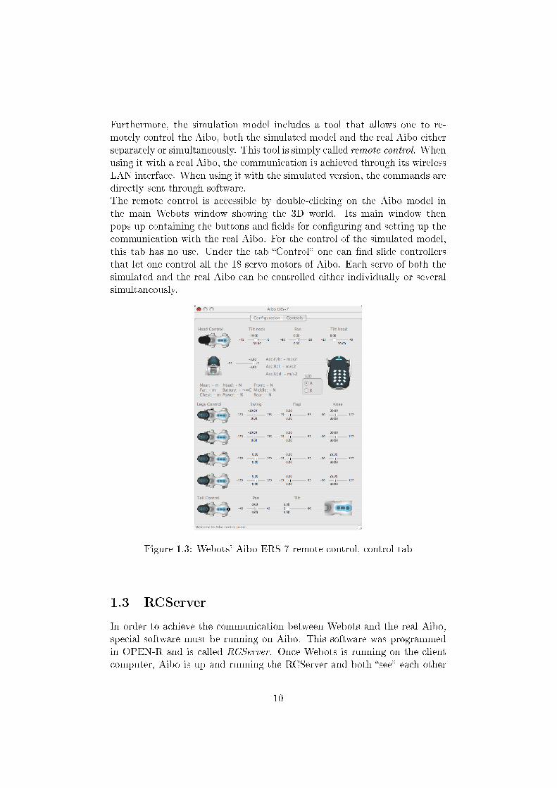
Furthermore, the simulation model includes a tool that allows one to re-motely control the Aibo, both the simulated model and the real Aibo eitherseparately or simultaneously. This tool is simply called remote control. Whenusing it with a real Aibo, the communication is achieved through its wirelessLAN interface. When using it with the simulated version, the commands aredirectly sent through software.The remote control is accessible by double-clicking on the Aibo model inthe main Webots window showing the 3D world. Its main window thenpops up containing the buttons and �elds for con�guring and setting up thecommunication with the real Aibo. For the control of the simulated model,this tab has no use. Under the tab �Control� one can �nd slide controllersthat let one control all the 18 servo motors of Aibo. Each servo of both thesimulated and the real Aibo can be controlled either individually or severalsimultaneously.
Figure 1.3: Webots' Aibo ERS-7 remote control, control tab
1.3 RCServer
In order to achieve the communication between Webots and the real Aibo,special software must be running on Aibo. This software was programmedin OPEN-R and is called RCServer. Once Webots is running on the clientcomputer, Aibo is up and running the RCServer and both �see� each other
10
on the network, a connection can be established in order to remotly controlthe real Aibo robot.
1.4 Project objectives
The goal of this project was to integrate camera support into Webots' remotecontrol for Aibo. This means that the user should be able to either take apicture of what Aibo's camera sees when the user presses the �take a picture�button in the remote control window, or to view in real time a video streamthat Aibo's camera captures.
11
Chapter 2
System Overview
This section describes the elements of the system that are important to knowbefore trying to understand how the camera support was implemented. Itdoes not treat how to set up the programming environment, or how to runa program on Aibo. These information can be found under [11] and [16].Details about the implementation itself are discussed in the next chapter,chapter 3.
2.1 Aibo
For the development and the tests, the lab's Aibo ERS-7 (Figure 1.1) wasavailable. However, the RCServer code was designed to work on other Aibomodels like the ERS-210. The functionality of the camera support shouldalso work with few or even no modi�cations on other Aibo models, but thiswas not tested since no other models were available.
2.1.1 OPEN-R
�OPEN-R� is the interface promoted by Sony for the entertainment robotsystems to expand their capabilities. The �OPEN-R SDK� discloses thespeci�cations of the interface between the `system layer' and the `applica-tion layer'.Features of OPEN-R:
• Modularized software and inter-object communicationOPEN-R software is object-oriented and modular. Software modulesare called �objects� (speci�cally, �OPEN-R objects�).Processing is performed by multiple objects with various functionalitiesrunning concurrently and communicating via inter-object communica-tion.Connections between objects are de�ned in an external description �le
12
(called stub.cfg, see the paragraph about it later). When the sys-tem software boots, the description �le is loaded and used to allocateand con�gure the communication paths for inter-object communica-tion. Connection ports in objects are identi�ed by the service name,which enables objects to be highly modular and easily replaceable assoftware components.
• Layered structure of the software and services provided by the systemlayerThe OPEN-R system layer provides a set of services ( input of sounddata, output of sound data, input of image data, output of controldata to joints, and input of data from various sensors) as the interfaceto the application layer. This interface is also implemented by inter-object communication.OPEN-R services enable application objects to use the robot's under-lying functionalities, without requiring detailed knowledge of the robothardware.The system layer also provides the interface to the TCP/IP protocolstack, which enables programmers to create networking applicationsutilizing the wireless LAN. The IPStack is an OPEN-R system layerobject. Objects can use the network services o�ered by the IPv4 pro-tocol stack by communicating with the protocol stack through normalmessage passing, i.e. by sending special messages to and receiving spe-cial messages from the IPStack.
ObjectOPEN-R application software consists of several OPEN-R objects. Theseare not objects in the object-oriented sense of the word. The concept ofan object is similar to one of a process in the UNIX or Windows operatingsystems with regard to the following points of view. Characteristics speci�cto objects:
• An object corresponds to one executable �le.An object is a concept that only exists at run-time. Each object has acounterpart in the form of an executable �le, created at compile-time.Source code is compiled and linked to create this executable �le. Then,the �le is put on an Aibo Programming Memory Stick. When Aiboboots, the system software loads the �le from the Memory Stick andexecutes it as an object. An executable �le usually has a �lename witha .bin extension.
• Each object runs concurrently with other objects.Each object has its own thread of execution and runs concurrently withother objects in the system.
13
• Objects exchange information using message passing.An object can send messages to other objects. When an object receivesa message, the method corresponding to the message is invoked, withthe data in the message as its argument.An important feature of objects is that they are single-threaded. Thismeans that an object can process only one message at a time. If anobject receives a message while it is processing another message, thesecond message is put into the message queue and processed later. Thetypical life cycle of an object:1. Loaded by the system2. Waits for a message3. When a message arrives, executes the corresponding method. Pos-
sibly sends some messages to other objects.4. When the method �nishes execution, goes to step 2.
Note that this is an in�nite-loop: an object cannot terminate itself. Itpersists until the system is deactivated.
• An object has multiple entry points.Unlike an ordinary programming environment in which a program hasa single entry point main(), OPEN-R allows an object to have multipleentry points. Each entry point corresponds to a method. Some entrypoints are common to all objects and have purposes that are deter-mined by the system, e.g. initialization and termination. Other entrypoints are speci�c to a certain object.
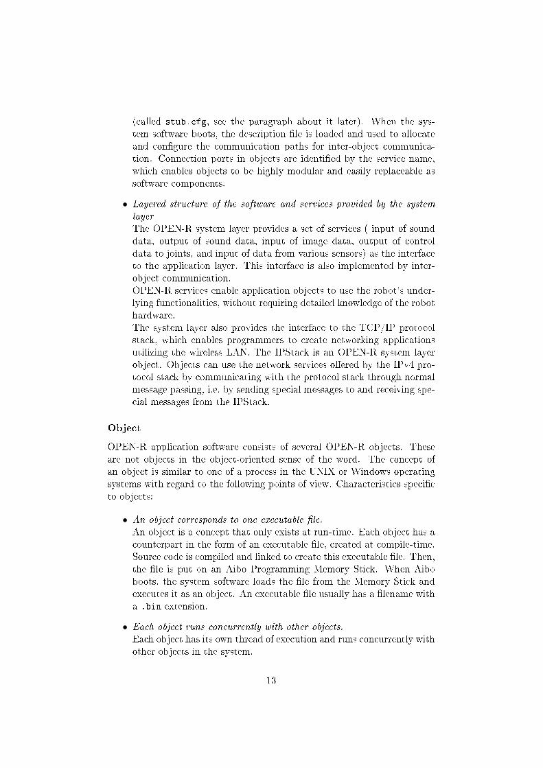
Inter-object communicationThe use of inter-object communication enables each object to be createdseparately and later be connected to other objects. When two objects com-municate, the side that sends data is called the �subject� and the side thatreceives data is called the �observer�. The subject sends a `NotifyEvent'to the observer. NotifyEvent includes the data that the subject wants tosend to the observer. The observer sends a �ReadyEvent� to the subject.The purpose of ReadyEvent is to inform the subject whether the observer isready to receive data or not (see Figure 2.1). If the observer is not ready toreceive data, the subject should not send any data to the observer, otherwisemessages might be ignored[15].In the OPEN-R SDK terminology, subjects and observers are called services.
The virtual objects OVirtualRobotComm and OVirtualAudioCommThe OPEN-R SDK provides two special objects (virtual objects) that providean interface to Aibo's hardware:
14
Subject
Object A Object B
Observer
Ready
Data
gate
Figure 2.1: Inter-object communication
OVirtualRobotComm interfaces with the dog's joints, sensors, LEDs and cam-era.
OVirtualRobotAudioComm interfaces with the robot audio devicesThe use of those objects in the programmes is the same as the use of pro-grammer de�ned objects. The gates in those objects are already de�ned tosend messages to and receive messages from them [16].
Description of the �le stub.cfgThe connection between the entry points (where the message is received)and the actual member functions of the core class is described with speci�edform in a �le called stub.cfg (stub con�guration �le). It is also in that �lethat the services that send and receive data to/from other objects must bedescribed [15].Every object has its own stub.cfg �le. The information from this �le willbe used by the compiler when building the binaries. The �le must be placedin the same directory as the C++ object program.The stub con�guration �le begins by a line describing the name of the object.The next two lines declare how many subjects and observers the object has.Then, each service is described on a line. A service has a unique name inorder to distinguish that service from other services in the system. One canconnect the subject's service to the observer's service of another object bydescribing both service names in the �le connect.cfg (see next paragraph).Here is an example of an stub.cfg �le:ObjectName : SampleObjectNumOfOSubject : 1NumOfOObserver : 2
15
Service : "SampleObject.Func1.char.S", null , Ready ()Service : "SampleObject.Func2.int.O", Connect (), Notify ()Service : "SampleObject.Func3.Data.O", null , Control ()Extra : UpdatePowerStatus ()
Lines starting by Service are the ones that describe the information of thegates. For example, in the lineService : "SampleObject.Func1.char.S", null, Ready()SampleClass is the name of the current object, Func1 is the name of the gatethe message will go through, char is the type of message been interchanged,and S means it is a subject (i.e. an outgoing gate); O would have meant itis an observer. The last two �elds are the name of two functions: the �rstone is called when a connection result is received (in almost every cases thisfunction is not usefull so it is set to null) and the second one is called whenan AssertReady or a message is received [16] [6].
Description of the connect.cfg �leNow, in order to interconnect the objects, each subject must be assigned toone observer and each observer to a subject. The con�g �le doing this is theconnect.cfg �le which has to be in the OPEN-R/MW/CONF/ directory of theAibo programming Memory Stick. When Aibo boots up, the system loadsthe objects and interconnects them according to the information in that �le.There is only one connect.cfg �le per program.Each line of connect.cfg begins by the name a subject, for example:NameOfObject.NameOfSubject.MessageType.Sand ends by the corresponding observer, like:NameOfObject.NameOfObserver.MessageType.O.Of course, the type of messages exchanged by the subject and the observermust be the same at each side. For bi-directional connections, the con�gu-ration �le must contain two lines, one for each direction of the connection.The de�nition of each part of the line follows the same speci�cation as forthe stub.cfg �le described before [6] [15] [16].
The Notify() functionThe Notify(const ONotifyEvent& event) is a special function that is cal-led when a message arrives in the gate of the object where it is in. It is theonly way to retrieve the message that was sent to the object. So, it is theentry point that one must use in order to get the data from a sensor or from
16
an input device like the camera. The message in question is passed in thefunction's argument each time that such a message is ready. Its content canbe retrieved by casting the variable in which it was copied in (in our case itis the variable event):DataType* dt = (DataType*)event.Data(0);
The member functions receiving a message have to be described in stub.cfg,but it is not necessary to describe the member functions sending a messagein stub.cfg. At the end of the Notify() function, an AssertReady must besent to the subject that sent the message with:observer[event.ObsIndex()]->AssertReady();
[6] [15]
Aibo's time measurementTime in Aibo's hardware is divided in discrete timesteps called frames. Aframe is the smallest possible unit of time and represents 8 milliseconds [16].So, there are 125 time steps in one second.
2.1.2 Aibo's camera
Accessing the cameraSensors and joints are called primitives in Sony's o�cial documentation. InAibo's design, each primitive can be referred to by using a primitive locatorsupplied in the Sony's model information document [14]. The primitive loca-tor provides the �address� of the primitive and the OPENR::OpenPrimitivestatic function convert this adress to an ID. In OPEN-R SDK the typeOprimitiveID holds ID information. This design was chosen by Sony's de-velopers in order to make objects portable between di�erent Aibo modelssince the same sensor can have a di�erent index within two di�erent models[6].
Format type of the data sent by the cameraOFbkImageVectorData is the data structure that holds image data. It is thetype of the data sent from the camera, i.e. the type of the messages sentfrom the outgoing gate named FbkImageSensor of OVirtualRobotComm [13].Actually, a OFbkImageVectorData message contains the same picture in dif-ferent resolutions but all in colour that are stored in di�erent layers accessibleby their indices. The index of the layer can be one of the following prede-�ned constants: ofbkimageLAYER_H (high resolution), ofbkimageLAYER_M(medium resolution), ofbkimageLAYER_L (low resolution).
17

colour images are in the YCrCb format, which means they are coded using 3bands: Y luminance, Cr (red component - Y) and Cb (blue component - Y)[6].The OPEN-R SDK provides a C++ class that handles image data calledOFbkImage.
2.2 Webots
Even if the typical client for which the communication with the RCServerwas designed is the remote control provided by the Aibo ERS-7 model inWebots, any other client can be used. The communication just uses port54321 over TCP/IP. So that the RCServer understands the sent commands,they must respect the rules of the de�ned protocol as mentioned in section3.4.Only one connection is possible at one time. This does not include thewireless console which can always be used to see what Aibo prints out (thewireless console is accessible by connecting via telnet to the port 59000).Actually, at the end of the development, a new version of Webots was notavailable. Hence, a small TCP/IP client was used for testing the new func-tionalities.
2.3 Protocol
For their interaction, the RCServer software runing on Aibo and the remotecontrol in Webots on the client computer use a protocol explained in LukasHohls semester project report [4]. The messages used for sending commandsto the RCServer are of a type called BasicGetCommand declared in the �lecommand_structure.h. A BasicGetCommand is a simple structure containingtwo �elds, a single character representing the command and another singlecharacter that can be used for example to identify a joint.struct BasicGetCommand {
char command;unsigned char identifier;
};
Actually, when a BasicGetCommand is sent to the RCServer, it arrives thereas just two consecutive characters. So, in a simpler client, it is enough tojust send two characters.
18
Chapter 3
Implementation
3.1 Image taking functions
The program code for the picture taking functionalities to the RCServer wasinspired by the W3AIBO example of the samples provided by Sony [10].The �les write_jpeg.c, write_jpeg.h and jpeg_mem_dest.c were takenfrom this sample and directly included in the RCServer's source code di-rectory and dependency list without applying any changes to them. Theprogram write_jpeg.c contains two functions; �rst, write_jpeg_mem thatas its name suggests, writes a JPEG picture to the random access mem-ory (RAM) and returns the �le size and secondly, write_jpeg_file thatwrites a JPEG picture to a �le. Actually, for this project, only the functionfor writing the picture to the RAM was used since no function for writinga picture to a �le on the Memory Stick was implemented. But the functionwrite_jpeg_file was not removed on purpose since the RCServer couldeasily be extended in order to have such functionalities as proposed in sec-tion 4.1.In order to be able to use these functionalities, three functions that wereadapted from the JPEGEncoder.c program of the W3AIBO example wereincluded in the RCServer: GetJPEG, ConvertYCbCr and SaveJPEG. Here is adescription of what these functions do:GetJPEG puts a JPEG �le into the RAM. For this purposes, it uses the
function ConvertYCbCr.ConvertYCbCr combines the separated bands to a raw image and converts it
to the JPEG �le format. The pointer that was passed to the functionas argument will then point to the beginning of the newly created �le.
SaveJPEG can be used as a replacement for GetJPEG. This function savesa JPEG �le to a �le on the Memory Stick. It also uses the functionConvertYCbCr for this purpose.
19
3.2 Inclusions
In order to be able to compress the images to the JPEG �le format, thejpeglib had to be included. Actually, an archive including the whole librarywas added to the program's directory. This is the same archive as the oneprovided on the OPEN-R homepage in the download section [9]. As itscontent must be compiled into the RCServer, the jpeglib had to be addedto the dependency list of its Make�le, as well as the write_jpeg and thejpeg_mem functions described in section 3.1.
3.2.1 stub.cfg
In order to be able to get messages from the camera, a supplementary in-coming gate had to be added in the RCServer's stub con�guration �le:Service :
"RCServer.Image.OFbkImageVectorData.O" , null , Notify ()
This means that we de�ne an incoming gate (i.e. the RCServer object isan observer because of the.O) called Image that accepts messages of thetype OFbkImageVectorData (the data type sent by the camera). Further-more, the Notify() function is called each time this gate becomes a message(see section 2.1.1 for details about the stub.cfg �le and for an explana-tion about the Notify() function and section 2.1.2 for details about theOFbkImageVectorData �le format).
3.2.2 connect.cfg
An entry had to be added to the connect.cfg �le in order to get data fromthe camera:OVirtualRobotComm.FbkImageSensor.OFbkImageVectorData.SRCServer.Image.OFbkImageVectorData.O
That means that messages of the type OFbkImageVectorData (the data typesent by the camera) are sent from the virtual object OVirtualRobotCommthat is the hardware interface for the sensors, including the camera, throughits FbkImageSensor gate to the RCServer object through its Image gate.
3.3 Image taking and sending
3.3.1 The Notify() function
Actually, the part of the RCServer where the most important part of codefor image taking lies in the Notify() function. As explained in section 2.1.1,this function is called each time a message from the subject to which the ob-ject is connected to, is ready. This message is passed to the object through
20
the parameter of the Notify() function.For the camera, a picture is ready all 4 frames, i.e. every 32ms. It is in thisfunction that all the work for the camera support is done: an image is taken,converted to JPEG and then saved into the RAM. If that part is successfull,the header of the �le is composed (see section 3.4.1), the image is copied tothe shared memory bu�er (see section 3.3.4) and �nally the header and theimage itself are sent at once to the connected client.Since this function is called each time an image is ready, it is not possible toexecute all the code for image taking every time because images are certainlynot needed all the time and this would use the robot's resources unneces-sarily. That's why all the code of the Notify() function is embedded ina conditional test checking the state of the camera. The camera's state isrepresented by a state variable explained in section 3.3.2
3.3.2 State variable
The state variable was implemented in the RCServer's header �le as a simpleenumeration structure called ImageObserverState. This was done in orderto allow only speci�c values:// states in which the camera exists
enum ImageObserverState {IOS_IDLE , // do nothing
IOS_PICTURE , // take a picture
IOS_CONTINUOUS , // send stream
IOS_STOPSEND // stop sending stream
};
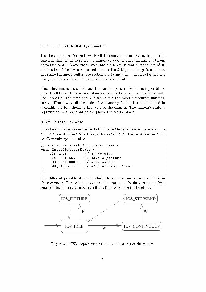
The di�erent possible states in which the camera can be are explained inthe comments. Figure 3.1 contains an illustration of the �nite state machinerepresenting the states and transitions from one state to the other.
IOS_PICTURE IOS_STOPSEND
IOS_CONTINUOUS
WF
WIOS_IDLE
Figure 3.1: FSM representing the possible states of the camera
21
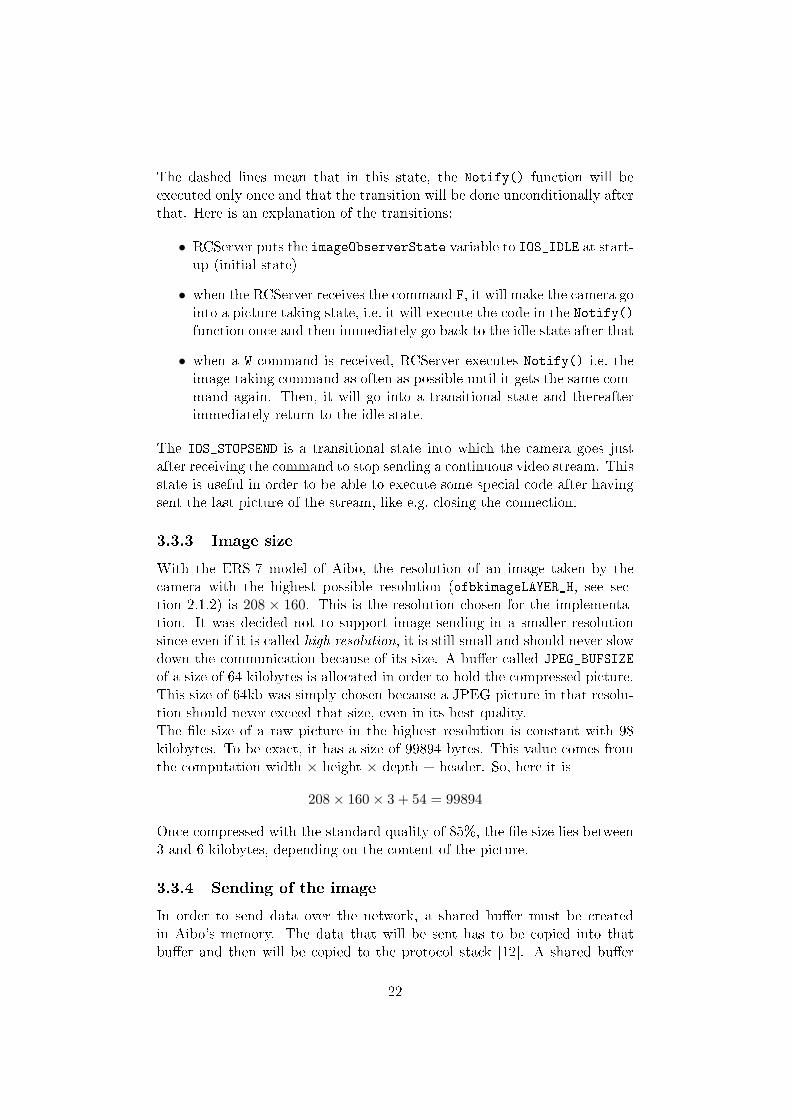
The dashed lines mean that in this state, the Notify() function will beexecuted only once and that the transition will be done unconditionally afterthat. Here is an explanation of the transitions:
• RCServer puts the imageObserverState variable to IOS_IDLE at start-up (initial state)
• when the RCServer receives the command F, it will make the camera gointo a picture taking state, i.e. it will execute the code in the Notify()function once and then immediately go back to the idle state after that
• when a W command is received, RCServer executes Notify() i.e. theimage-taking command as often as possible until it gets the same com-mand again. Then, it will go into a transitional state and thereafterimmediately return to the idle state.
The IOS_STOPSEND is a transitional state into which the camera goes justafter receiving the command to stop sending a continuous video stream. Thisstate is useful in order to be able to execute some special code after havingsent the last picture of the stream, like e.g. closing the connection.
3.3.3 Image size
With the ERS-7 model of Aibo, the resolution of an image taken by thecamera with the highest possible resolution (ofbkimageLAYER_H, see sec-tion 2.1.2) is 208 × 160. This is the resolution chosen for the implementa-tion. It was decided not to support image sending in a smaller resolutionsince even if it is called high resolution, it is still small and should never slowdown the communication because of its size. A bu�er called JPEG_BUFSIZEof a size of 64 kilobytes is allocated in order to hold the compressed picture.This size of 64kb was simply chosen because a JPEG picture in that resolu-tion should never exceed that size, even in its best quality.The �le size of a raw picture in the highest resolution is constant with 98kilobytes. To be exact, it has a size of 99894 bytes. This value comes fromthe computation width × height × depth + header. So, here it is
208× 160× 3 + 54 = 99894
Once compressed with the standard quality of 85%, the �le size lies between3 and 6 kilobytes, depending on the content of the picture.
3.3.4 Sending of the image
In order to send data over the network, a shared bu�er must be createdin Aibo's memory. The data that will be sent has to be copied into thatbu�er and then will be copied to the protocol stack [12]. A shared bu�er
22
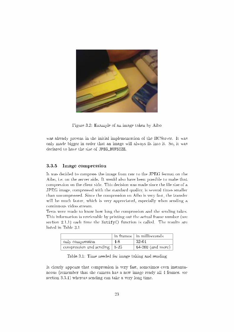
Figure 3.2: Example of an image taken by Aibo
was already present in the initial implementation of the RCServer. It wasonly made bigger in order that an image will always �t into it. So, it wasdeclared to have the size of JPEG_BUFSIZE.
3.3.5 Image compression
It was decided to compress the image from raw to the JPEG format on theAibo, i.e. on the server side. It would also have been possible to make thatcompression on the client side. This decision was made since the �le size of aJPEG image, compressed with the standard quality, is several times smallerthan uncompressed. Since the compression on Aibo is very fast, the transferwill be much faster, which is very appreciated, especially when sending acontinuous video stream.Tests were made to know how long the compression and the sending takes.This information is retrievable by printing out the actual frame number (seesection 2.1.1) each time the Notify() function is called. The results arelisted in Table 3.1
in frames in millisecondsonly compression 4-8 32-64compression and sending 8-25 64-200 (and more)Table 3.1: Time needed for image taking and sending
It clearly appears that compression is very fast, sometimes even instanta-neous (remember that the camera has a new image ready all 4 frames, seesection 3.3.1) whereas sending can take a very long time.
23
3.3.6 JPEG compression quality
The JPEG �le format provides several compression levels. A higher compres-sion rate will produce a �le of a smaller size but with more information losses.Conversely, a lower compression rate will produce a bigger �le with less infor-mation loss. The di�erent possible compression rates are called quality andvary from 0% to 100%, where the default is 85%. A quality of 0% shows themost artefacts and a quality of 100% represents the highest reachable qual-ity of a JPEG �le and does not mean that the image is not compressed at all.The compression rate which the RCServer uses for the image it sends canbe de�ned by the client using the identi�er �eld of the BasicGetCommand itsends. Even if the type of that �eld is unsigned char, it is just interpretedas a number between 0 and 100. If it is over 100, it will be interpreted as100 anyhow.
3.4 Extension of the existing protocol
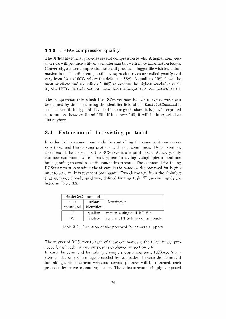
In order to have some commands for controlling the camera, it was neces-sary to extend the existing protocol with new commands. By convention,a command that is sent to the RCServer is a capital letter. Actually, onlytwo new commands were necessary; one for taking a single picture and onefor beginning to send a continuous video stream. The command for tellingRCServer to stop sending the stream is the same as the one used for begin-ning to send it. It is just sent once again. Two characters from the alphabetthat were not already used were de�ned for that task. These commands arelisted in Table 3.2.
BasicGetCommandchar uchar Description
command identi�erF quality return a single JPEG �leW quality return JPEG �les continuously
Table 3.2: Extension of the protocol for camera support
The answer of RCServer to each of these commands is the taken image pre-ceded by a header whose purpose is explained in section 3.4.1.In case the command for taking a single picture was sent, RCServer's an-swer will be only one image preceded by its header. In case the commandfor taking a video stream was sent, several pictures will be returned, eachpreceded by its corresponding header. The video stream is simply composed
24
of consecutively sent pictures. The frequency of images sent is the best thatis technically possible. In application, a frequency of about 15 pictures persecond is achievable. This can vary a lot as it mainly depends on Aibo's avail-able resources and on the quality of the network communication. If Aibo isrunning objects that require a lot of computational power or if the networkis saturated, the number of pictures sent per time unit will decrease. If thishappens, the video stream will be more jerky than under ideal conditionsand the stream can even be frozen temporarily.
3.4.1 Image header
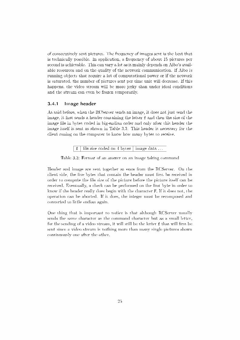
As said before, when the RCServer sends an image, it does not just send theimage, it �rst sends a header containing the letter f and then the size of theimage �le in bytes coded in big-endian order and only after this header theimage itself is sent as shown in Table 3.3. This header is necessery for theclient runing on the computer to know how many bytes to receive.
f �le size coded on 4 bytes image data . . .Table 3.3: Format of an answer on an image taking command
Header and image are sent together at once from the RCServer. On theclient side, the �ve bytes that contain the header must �rst be received inorder to compute the �le size of the picture before the picture itself can bereceived. Eventually, a check can be performed on the �rst byte in order toknow if the header really does begin with the character F. If it does not, theoperation can be aborted. If it does, the integer must be recomposed andconverted to little-endian again.One thing that is important to notice is that although RCServer usuallysends the same character as the command character but as a small letter,for the sending of a video stream, it will still be the letter f that will �rst besent since a video stream is nothing more than many single pictures showncontinuously one after the other.
25
Chapter 4
Conclusion
4.1 Possible extensions
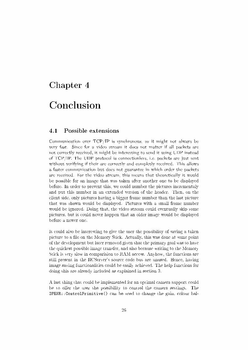
Communication over TCP/IP is synchronous, so it might not always bevery fast. Since for a video stream it does not matter if all packets arenot correctly received, it might be interesting to send it using UDP insteadof TCP/IP. The UDP protocol is connectionless, i.e. packets are just sentwithout verifying if their are correctly and completly received. This allowsa faster communication but does not guarantee in which order the packetsare received. For the video stream, this means that theoretically it wouldbe possible for an image that was taken after another one to be displayedbefore. In order to prevent this, we could number the pictures incrementalyand put this number in an extended version of the header. Then, on theclient side, only pictures having a bigger frame number than the last picturethat was shown would be displayed. Pictures with a small frame numberwould be ignored. Doing that, the video stream could eventually skip somepictures, but it could never happen that an older image would be displayedbefore a newer one.It could also be interesting to give the user the possibility of saving a takenpicture to a �le on the Memory Stick. Actually, this was done at some pointof the development but later removed given that the primary goal was to havethe quickest possible image transfer, and also because writing to the MemoryStick is very slow in comparision to RAM access. Anyhow, the functions arestill present in the RCServer's source code but are unused. Hence, havingimage saving functionalities could be easily achieved. The help functions fordoing this are already included as explained in section 3.A last thing that could be implemented for an optimal camera support couldbe to o�er the user the possibility to control the camera settings. TheOPENR::ControlPrimitive() can be used to change the gain, colour bal-
26
ance and shutter speed of the camera [6].As the icing on the cake, one could imagine providing the with the possibilityof seeing if the robot has detected a given colour since Aibo has a colourdetection algorithm built in. This algorithm works very fast because it isencoded in hardware.
27
Bibliography
[1] Cyberbotics Ltd. Webots Reference Manual.[2] Cyberbotics Ltd. Webots User Guide.[3] Lukas Hohl. Aibo simulation in webots and controller transfer to aibo
robot, June 2004.[4] Lukas Hohl. Wireless remote control and monitoring of an aibo robot,
February 2004.[5] Sergei Poskriakov. Sony Aibo ERS-series robots support in Webots,
2004.[6] François Serra and Jean-Christophe Baillie. Aibo programming using
OPEN-R SDK tutorial, 2003.[7] Sony Corporation. O�cial Sony OPEN-R internet page. http://openr.
aibo.com.[8] Sony Corporation. OPEN-R SDK documentation English. File
OPEN_R_SDK-docE-XXX.tar.gz.[9] Sony Corporation. Source of the JPEG library, �le
jpegsrc.v6b.tar.gz.[10] Sony Corporation. OPEN-R sample programs, 2004.[11] Sony Corporation. OPEN-R SDK Installation Guide, 2004.[12] Sony Corporation. OPEN-R SDK Internet Protocol Version4, 2004.[13] Sony Corporation. OPEN-R SDK Level2 Reference Guide, 2004.[14] Sony Corporation. OPEN-R SDK Model Information for ERS-7, 2004.[15] Sony Corporation. OPEN-R SDK Programmer'sGuide, 2004.[16] Ricardo A. Téllez. Introduction to the aibo programming environment,
2005.
28