Embed Size (px)
Citation preview
Remediation of Oil Refinery Sludge Basin
Wayne S. Adaska, P.E.' Wayne Ten 6ruin2
Steven R. ~ a y ~
Abstract
Work was completed in early 1992 to clean up a 5.5 acre (2.2 ha) stormwater sludge basin for an oil refinery company. The basin, which had served as a stormwater collection and settling pond for over 40 years, contained oily sludges with high concentrations of certain metals and volatile organic compounds. The closure plan included a combination cement-bentonite slurry wall and jet grouting along the perimeter of the basin. The sludge and contaminated soil beneath the basin were solidified in place using a specially developed soil mixing technique.
Keywords
Cement-bentonite slurry wall, jet grouting, Shallow Soil Mixing, slurry wall, soilcrete, solidification, stabilization.
Introduction
Located along the southern shore of Lake Michigan is one of the oldest refineries in North America. For more than 40 years a 5.5 acre (2.2 ha) stormwater sludge basin had served as the plant's stormwater collection and settling pond. Oil sludges 'and other contaminants including certain hazardous metals and organic compounds would be carried with the
Progam Manager, Water and Waste Facilities, Portland Cement Association, 5420 Old Orchard Road, Skokie, IL, 60077.
*~onstruction Manager, Geo-Con Inc., 4075 Monroeville Blvd., Suite 400, Monroeville, PA, 15146. 3~istrict Manager, Geo-Con Inc.

stormwater and deposited in the basin. A series of baffles and weirs within the basin helped direct the flow and regulate storage. Surface skimmers were used to remove oil and the basin was periodically cleaned with backhoe and clamshell equipment to remove settled contaminants.
The 1984 Hazardous and Solid Waste Amendments (HSWA) to the Resource Conservation and Recovery Act (RCRA) of 1976 established strict standards for the handling, storage and disposal of hazardous wastes. As part of the regulations, all surface impounds which treat or store hazardous wastes must either be double lined or taken out of service. In addition hazardous materials within surface impoundments and contaminated soil beneath the impoundments must be removed and disposed of in secure landfills or treated and properly disposed of on-site.
The remediation method chosen for this project consisted of in place stabilization of the sludge and contaminated underlying soil. To prevent the migration of any contaminants into the groundwater, a seepage barrier was installed along the perimeter of the basin and keyed into the underlying clay layer. A geomembrane and clay soil cap were placed over the entire basin.
Site Evaluation
A site investigation was conducted to determine the chemical composition of sludges within the basin and depth of contaminated soil below. The program consisted of proportioning the basin into five zones. Soil borings were taken to determine the depth of the sludge and contaminated soil. A total of five sludge cores were taken from each zone using a grid system and radom number selection process. The samples from each zone were mixed together to form a composite sample representing the particular zone. Testing protocol was performed in accordance with EPA-SW-846' procedures. The average wet weight of the sludge was about 72 pcf (1 153 kg/m3). Table 1 gives the results of the chemical analysis of the sludges in zones 1 and 5. From the sampling program it was determined the depth of the contaminated soil extended approximately three feet below the bottom of the unlined basin.
C!osure Plan
Following the site investigation program an evaluation was made on the most suitable method of disposal. Closure plans involving in-place remediation as well as contaminant removed and off-site disposal were studied. Costs were compared between on-site versus off-site disposal. It was estimated off-site disposal and site cleanup, including backfill and groundwater treatment, would 'cost approximately $40 million. An in-place closure was estimated to be about $8 million. In addition, in-place closure provided the owner complete control over the remediation method and long-term performance of the closure.
The principal component of the closure plan was in-place treatment of the sludge and contaminated underlying soil. Also included in the overall remediation was the use of jet grouting and a cement-bentonite slurry wall along the perimeter of the basin shown in Figure 1. A final cap consisting of clay and geomembrane liner was used to cover the basin. Figure 2 provides a schematic cross sectional view of the final cover design.
Preconstruction Testing Programs
The critical natural of the project and regulatory performance specifications made it imperative that preconstruction testing programs be completed for each specialty geotechnical construction technique. The objective of the testing programs was two-fold; I ) demonstrate
the feasibility of the selected materials to achieve performance specifications, and 2) provide material usage estimates for pricing the construction. Representative samples of the site soils, sludges, and groundwater were obtained and local sources sampled for evaluation as construction materials. The most critical items tested were the slurry wall, jet grout curtain, and sludge solidification.
Slurry Wall
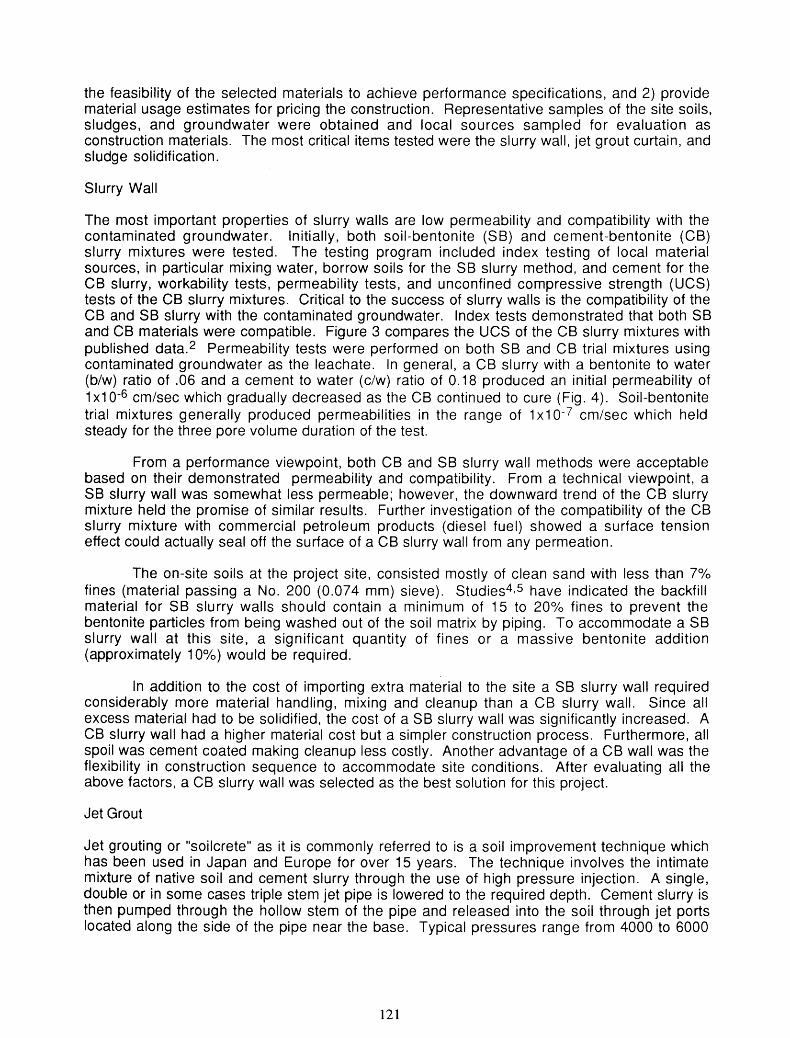
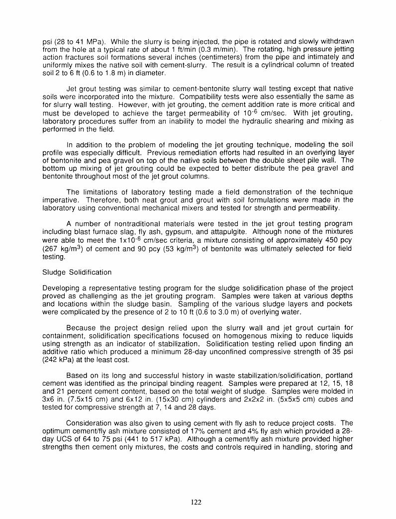
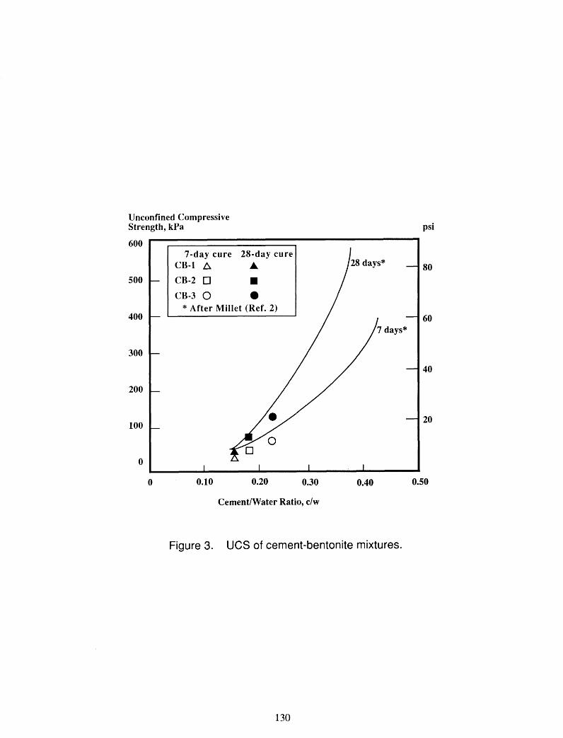
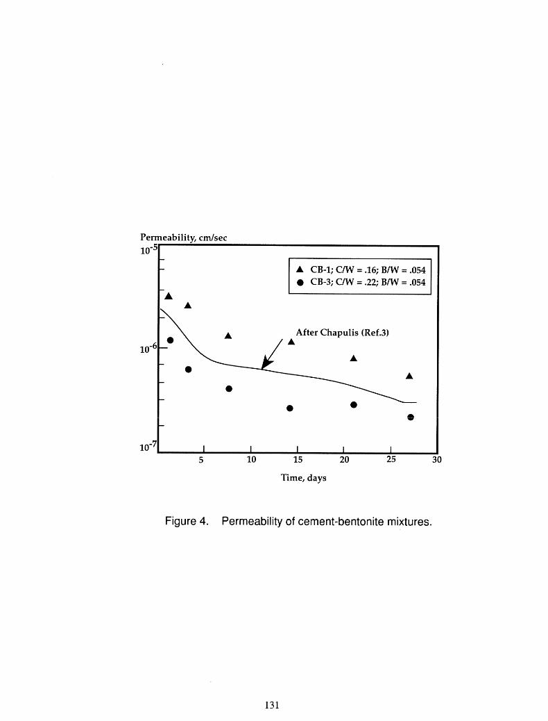
The most important properties of slurry walls are low permeability and compatibility with the contaminated groundwater. Initially, both soil-bentonite (SB) and cement-bentonite (CB) slurry mixtures were tested. The testing program included index testing of local material sources, in particular mixing water, borrow soils for the SB slurry method, and cement for the CB slurry, workability tests, permeability tests, and unconfined compressive strength (UCS) tests of the CB slurry mixtures. Critical to the success of slurry walls is the compatibility of the CB and SB slurry with the contaminated groundwater. Index tests demonstrated that both SB and CB materials were compatible. Figure 3 compares the UCS of the CB slurry mixtures with published data.* Permeability tests were performed on both SB and CB trial mixtures using contaminated groundwater as the leachate. In general, a CB slurry with a bentonite to water (b/w) ratio of .06 and a cement to water (c/w) ratio of 0.18 produced an initial permeability of 1x1 o - ~ cm/sec which gradually decreased as the CB continued to cure (Fig. 4). Soil-bentonite trial mixtures generally produced permeabilities in the range of 1x10⁻⁷ cmisec which held steady for the three pore volume duration of the test.
From a performance viewpoint, both CB and SB slurry wall methods were acceptable based on their demonstrated permeability and compatibility. From a technical viewpoint, a SB slurry wall was somewhat less permeable; however, the downward trend of the CB slurry mixture held the promise of similar results. Further investigation of the compatibility of the CB slurry mixture with commercial petroleum products (diesel fuel) showed a surface tension effect could actually seal off the surface of a CB slurry wall from any permeation.
The on-site soils at the project site, consisted mostly of clean sand with less than 7% fines (material passing a No. 200 (0.074 mm) sieve). Studies4y5 have indicated the backfill material for SB slurry walls should contain a minimum of 15 to 2O0lO fines to prevent the bentonite particles from being washed out of the soil matrix by piping. To accommodate a SB slurry wall at this site, a significant quantity of fines or a massive bentonite addition (approximately 10%) would be required.
In addition to the cost of importing extra material to the site a SB slurry wall required considerably more material handling, mixing and cleanup than a CB slurry wall. Since all excess material had to be solidified, the cost of a SB slurry wall was significantly increased. A CB slurry wall had a higher material cost but a simpler construction process. Furthermore, all spoil was cement coated making cleanup less costly. Another advantage of a CB wall was the flexibility in construction sequence to accommodate site conditions. After evaluating all the above factors, a CB slurry wall was selected as the best solution for this project.
Jet Grout
Jet grouting or "soilcrete" as it is commonly referred to is a soil improvement technique which has been used in Japan and Europe for over 15 years. The technique involves the intimate mixture of native soil and cement slurry through the use of high pressure injection. A single, double or in some cases triple stem jet pipe is lowered to the required depth. Cement slurry is then pumped through the hollow stem of the pipe and released into the soil through jet ports located along the side of the pipe near the base. Typical pressures range from 4000 to 6000
psi (28 to 41 MPa). While the slurry is being injected, the pipe is rotated and slowly withdrawn from the hole at a typical rate of about 1 ftlmin (0.3 m/min). The rotating, high pressure jetting action fractures soil formations several inches (centimeters) from the pipe and intimately and uniformly mixes the native soil with cement-slurry. The result is a cylindrical column of treated soil 2 to 6 ft (0.6 to 1.8 m) in diameter.
Jet grout testing was similar to cement-bentonite slurry wall testing except that native soils were incorporated into the mixture. Compatibility tests were also essentially the same as for slurry wall testing. However, with jet grouting, the cement addition rate is more critical and must be developed to achieve the target permeability of cm/sec. With jet grouting, laboratory procedures suffer from an inability to model the hydraulic shearing and mixing as performed in the field.
In addition to the problem of modeling the jet grouting technique, modeling the soil profile was especially difficult. Previous remediation efforts had resulted in an overlying layer of bentonite and pea gravel on top of the native soils between the double sheet pile wall. The bottom up mixing of jet grouting could be expected to better distribute the pea gravel and bentonite throughout most of the jet grout columns.
The limitations of laboratory testing made a field demonstration of the technique imperative. Therefore, both neat grout and grout with soil formulations were made in the laboratory using conventional mechanical mixers and tested for strength and permeability.
A number of nontraditional materials were tested in the jet grout testing program including blast furnace slag, fly ash, gypsum, and attapulgite. Although none of the mixtures were able to meet the 1 XI o - ~ cm/sec criteria, a mixture consisting of approximately 450 pcy (267 kg/m3) of cement and 90 pcy (53 kg/m3) of bentonite was ultimately selected for field testing.
Sludge Solidification
Developing a representative testing program for the sludge solidification phase of the project proved as challenging as the jet grouting program. Samples were taken at various depths and locations within the sludge basin. Sampling of the various sludge layers and pockets were complicated by the presence of 2 to 10 ft (0.6 to 3.0 m) of overlying water.
Because the project design relied upon the slurry wall and jet grout curtain for containment, solidification specifications focused on homogenous mixing to reduce liquids using strength as an indicator of stabilization. Solidification testing relied upon finding an additive ratio which produced a minimum 28-day unconfined compressive strength of 35 psi (242 kPa) at the least cost.
Based on its long and successful history in waste stabilization/solidification, portland cement was identified as the principal binding reagent. Samples were prepared at 12, 15, 18 and 21 percent cement content, based on the total weight of sludge. Samples were molded in 3x6 in. (7'5x15 cm) and 6x12 in. (15x30 cm) cylinders and 2 x 2 ~ 2 in. ( 5 x 5 ~ 5 cm) cubes and tested for compressive strength at 7, 14 and 28 days.
Consideration was also given to using cement with fly ash to reduce project costs. The optimum cement/fly ash mixture consisted of 17°/o cement and 4% fly ash which provided a 28- day UCS of 64 to 75 psi (441 to 51 7 kPa). Although a cemenVfly ash mixture provided higher strengths then cement only mixtures, the costs and controls required in handling, storing and
mixing two reagents versus one out-weighed the potential savings in material costs alone. It was decided, therefore, to use cement only for the sludge solidification.
Field Testing and Construction
The laboratory testing programs provided the basic guidance for planning the project but full scale field tests were also performed on the slurry wall, clay liner, jet grout curtain and the sludge solidification to confirm the laboratory results, fine tune construction procedures, and to verify the methods and materials selected for the work. These tests involved actually performing the work with production scale equipment on areas of the project which latter became part of the final work.
Slurry Wall
The first phase of the testing program began with the installation of the CB slurry wall. From the initial site investigation it was determined the soil beneath the sludge basin consisted of fine to medium sand underlain by a relatively impervious silty clay at a depth of approximately 40 ft (12 m). The slurry wall was designed to key into the silty clay layer. The slurry wall extends along the perimeter of the sludge basin and ties into the double row of sheet piling.
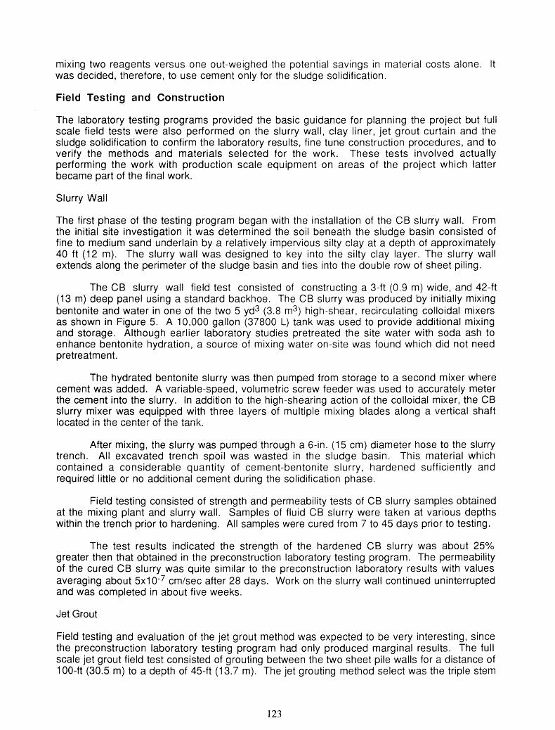
The CB slurry wall field test consisted of constructing a 3-ft (0.9 m) wide, and 42-ft (13 m) deep panel using a standard backhoe. The CB slurry was produced by initially mixing bentonite and water in one of the two 5 yd3 (3.8 m3) high-shear, recirculating colloidal mixers as shown in Figure 5. A 10,000 gallon (37800 L) tank was used to provide additional mixing and storage. Although earlier laboratory studies pretreated the site water with soda ash to enhance bentonite hydration, a source of mixing water on-site was found which did not need pretreatment.
The hydrated bentonite slurry was then pumped from storage to a second mixer where cement was added. A variable-speed, volumetric screw feeder was used to accurately meter the cement into the slurry. In addition to the high-shearing action of the colloidal mixer, the CB slurry mixer was equipped with three layers of multiple mixing blades along a vertical shaft located in the center of the tank.
After mixing, the slurry was pumped through a 6-in. (15 cm) diameter hose to the slurry trench. All excavated trench spoil was wasted in the sludge basin. This material which contained a considerable quantity of cement-bentonite slurry, hardened sufficiently and required little or no additional cement during the solidification phase.
Field testing consisted of strength and permeability tests of CB slurry samples obtained at the mixing plant and slurry wall. Samples of fluid CB slurry were taken at various depths within the trench prior to hardening. All samples were cured from 7 to 45 days prior to testing.
The test results indicated the strength of the hardened CB slurry was about 25% greater then that obtained in the preconstruction laboratory testing program. The permeability of the cured CB slurry was quite similar to the preconstruction laboratory results with values averaging about 5x10⁻⁷ cmlsec after 28 days. Work on the slurry wall continued uninterrupted and was completed in about five weeks.
Jet Grout
Field testing and evaluation of the jet grout method was expected to be very interesting, since the preconstruction laboratory testing program had only produced marginal results. The full scale jet grout field test consisted of grouting between the two sheet pile walls for a distance of 100-ft (30.5 m) to a depth of 45-ft (13.7 m). The jet grouting method select was the triple stem
method which uses an air and water jet to cut and displace the soil while the grout is tremied into place. Initial grouting parameters included grout pressures of 5800 psi (40,000 kPa) with an injection rate of 150 Umin using a grout with a c/w = .25 and a b/w = .05.
The presence of the sheet piling and previously placed bentonite mixture created unanticipated problems. The sheet piling confined the slurry and the bentonite reacted with the cement releasing bond water from the bentonite. These two conditions along with the use of water as a shearing agent prior to grouting significantly diluted the slurry mixture resulting in undesirable strength and permeability values. To correct the situation the cement content of the grout was doubled to 900 pcy (534 kg/m3) and the grouting pressure was reduced. A second test section was constructed using the new mixture and procedures.
Field testing and sampling consisted of strength and permeability tests on both fluid samples and cored samples obtained after the grout curtain had cured approximately 60 days. The specified minimum unconfined compressive strength of 50 psi (345 kPa) was easily obtained. Samples of the soilcrete generally gave UCS of 80 to 600 psi (0.55 to 4.1 MPa) in 14 to 28 days.
Permeability results tended to vary with the test method. Coring the soilcrete was difficult and prone to producing poor samples due to the presence of the pea gravel throughout the soilcrete. Cored samples which were obtained typically resulted in permeability values in the range of 1x1 o - ~ cm/sec. Fluid samples of the soilcrete obtained from within the grout curtain during construction and molded into samples gave much better results and eliminated the problems of coring. These samples gave more consistant results which approached 5x1 0-7 cm/sec after about 60 days of curing. Rising and falling head bore hole permeability tests6 installed in the jet grout wall produced the lowest permeabilities. Piezometers were installed about every 50-ft (15 m) and monitored for up to 50 days. The results from these tests gave results in the range of 2~1O-~cm/sec.
The results indicated the permeability values from the field piezometers and fluid samples met the project's maximum permeability requirements of I x l ~ - ~ c m / s e c . The core samples gave permeability results 10 to 100 times greater than either the field piezometers or fluid samples. Due to the problems encountered in obtaining and testing core samples, it was decided to accept the jet grout wall based on the field piezometer and fluid sample test results.
Sludge Solidification
Treatment of the sludge was principally accomplished by a method referred to as Shallow Soil Mixing (SSM). SSM utilizes a crane mounted mixing system to uniformly mix-in-place the waste with the solidifying reagent. The single mixing auger, 12 ft (3.7 m) in diameter is driven by a high-torque turntable. The mixing auger is enclosed in a specially designed cylindrical hood, as shown in Figure 6, which allows for the capture of organic vapors and dusts emanating from the mixing operation. The solidifying reagent is pneumatically conveyed to the hood as the mixing auger proceeds downward through the waste. Once the auger reaches the specified depth it is raised and often reinserted to provide the necessary blending.
The construction method normally consists of creating alternating primary columns which are allowed to set. Secondary columns are then installed which overlap the primary columns resulting in a continuous treatment of the waste impoundment. Figure 7 shows the overlapping pattern used for this project.
The field test for the SSM system required the treatment of 10,000 ft2 (930 m2) of sludge in zone 1 to a depth of 20 ft (6 m). The lOOxlOO ft (30.5x30.5 m) area was divided

equally to test four cement contents - 12, 15, 18, 21 percent by weight. Each section included 40 treated columns or a total of 160 columns for the entire field test.
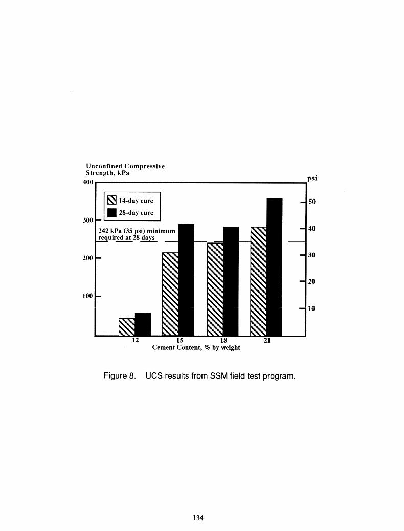
Samples were collected immediately after mixing for 14 and 28 day unconfined compressive strength (UCS) tests. Figure 10 shows the results of UCS tests for the field test program. The completed columns were also tested using standard penetration tests (SPT) and cone penetrometer tests (CPT). Based on the results of the testing program, a 21 percent cement content was recommended to achieve the minimum required 28-day UCS of 35 psi (242 kPa).
Following the test program full scale production began using a presurveyed grid system to mark the exact location of each insertion point. As the solidification progressed a bulldozer was used to grade the solidified sludge to the required level. Approximately 110,000 yd3 (84,000) of sludge was solidified. It was estimated that the total volume of treated sludge increased only about three percent over the volume of untreated sludge in the basin prior to treatment.
In addition to the SSM system, the backhoe mixing method was used initially along the center dike in zone 1 to allow access for the SSM equipment. The backhoe method was also used in confined areas such as underneath the catwalks and along the sheet pile wall where the SSM system could not reach. The cement content for the backhoe method was increased from 2 up to 10 percent to allow for variations in mixing and sludge composition.
Quality control testing consisted of depth measurements, cone penetrometer and unconfined compressive strength tests. Depth measurements were recorded for each treated column. Cone penetrometer and unconfined compressive strength tests were performed a minimum of one per 1000 yd3 (765 m3) of treated sludge. Results indicated the solidified sludge satisfied the minimum UCS requirement of 35 psi.
The final steps in the remediation was placement of the cover which is shown schematically in Figure 2 and installation of a dewatering system within the solidified sludge. The dewatering system isolates the sludge basin by maintaining a phreatic surface below the natural groundwater level resulting in a positive flow into the treated area. Water withdrawn from the treated area is processed through the plant's on-site wastewater treatment facility. Eventually the site will accommodate several above ground storage tanks.
Conclusions
1. Use of on-site remediation using insitu solidification, underground seepage cutoff walls and an impermeable cover was approximately one-fifth the cost of off-site disposal and site cleanup.
2. Both the soil-bentonite and cement-bentonite slurry wall methods exhibited a low permeability and acceptable compatibility with the sludge. However, the CB slurry wall was the preferred method due to the need to import borrow material and the extra material handling, mixing and cleanup associated with the SF3 slurry method.
3. It was difficult to evaluate the jet grout method based on sampling techniques used. Strength and permeability values from fluid samples differed greatly from core samples. Also the use of water as a shearing agent significantly diluted the slurry mixture causing a doubling of the cement content in order to satisfy the permeability requirements.

4. The Shallow Soil Mixing method worked well. The total volume of treated sludge increased only about three percent over the volume of untreated sludge in the basin prior to treatment.
References
1. "Test Methods for Evaluating Solid Waste, PhysicalIChemical Methods," US EPA. SW- 846, 3rd Edition, September 1986.
2. Millet, R.A., and Perez, J.Y., "Current USA Practices: Slurry Wall Specifications," Journal of the Geotechnical Enaineerina Division, ASCE, Vol. 107, No. GT8, August 1981.
3. Chapuis, R.P., Pare, J.J., and Loisell, A.A., "Laboratory Test Results on Self-Hardening Grouts for Flexible Cutoffs," Canadian Geotechnical Journal, Vol. 21, 1984.
4. Ryan, C.R., "Vertical Barriers in Soil for Pollution Containment," ASCE Geotechnical i I n f r n n Geotechnical Practice for Waste D i s ~ o a I, Ann Arbor, MI, June S ~ e c a tv Co e e ce o
1987.
5. D'Appolonia, D.J., "Soil-Bentonite Slurry Trench Cutoffs," Journal of the Geotechnical Enaineerina Division, Proceedings of ASCE, Vol. 106, No. GT4, 1980.
6. Tecter, R.M., and Clemence, S.P., "In-Place Permeability Measurements of Slurry Trench Cutoffs Walls, " Use of lnsitu Tests in Biotechnical Enaineering, ASCE Biotechnical Special Publication No. 6, 1986.
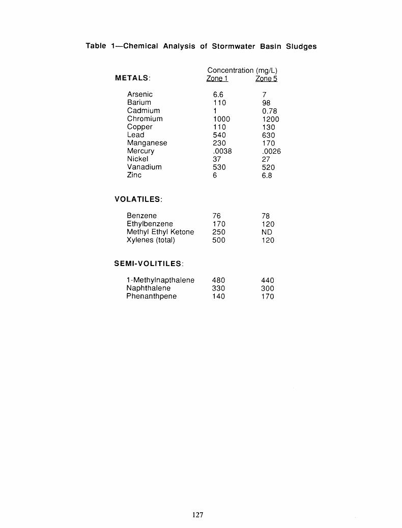
Table 1-Chemical Analysis of Stormwater Basin Sludges
METALS:
Arsenic Barium Cadmium Chromium Copper Lead Manganese Mercury Nickel Vanadium Zinc
VOLATILES:
Concentration (mg/L) Zone 1 zQ!xS
Benzene 76 Ethylbenzene 170 Methyl Ethyl Ketone 250 Xylenes (total) 500
SEMI-VOLITILES:
1 -Methylnapthalene 480 Naphthalene 330 Phenanthpene 140
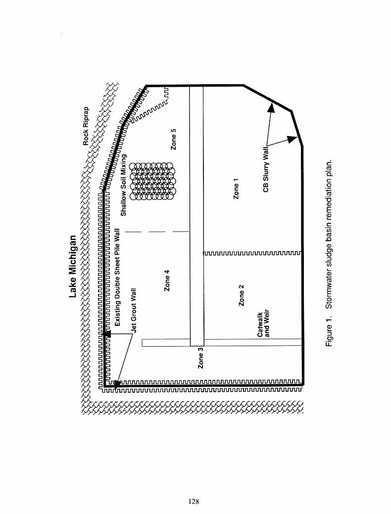
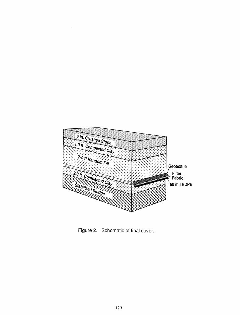
Figure 2. Schematic of final cover.
Unconfined Compressive Strength, kPa psi
0 0.10 0.20 0.30 0.40 0.50
CementlWater Ratio, clw
-
-
Figure 3. UCS of cement-bentonite mixtures.
7-day cure 28-day cure CB-1 A CB-2
CB-3 0 * After Millet (Ref. 2)
- -
-
- -
I I I I
Time, days
Permeability, c d s e c
Figure 4. Permeability of cement-bentonite mixtures.
lom5 - -
CB-3; CIW = .22; BMl = .054 - A
A
After Chapulis (Ref.3)
- * -
10-7 I I I I I 5 10 15 20 25 30
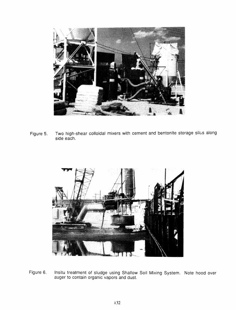
Figure 5. Two high-shear colloidal mixers with cement and bentonite storage s i l ~ s along side each.
Figure 6. lnsitu treatment of sludge using Shallow Soil Mixing System. Note hood over auger to contain organic vapors and dust.

Unconfined Compressive Strength, kPa
400 psi I
14-day cure
Cement Content, % by weight
Figure 8. UCS results from SSM field test program.