Embed Size (px)
Citation preview
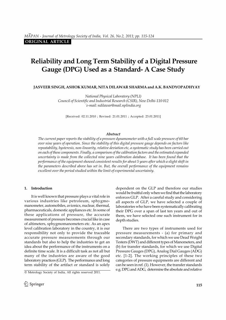
Reliability and Long Term Stability of a Digital Pressure Gauge (DPG) Used as a Standard- A Case Study
115
Reliability and Long Term Stability of a Digital PressureGauge (DPG) Used as a Standard- A Case Study
JASVEER SINGH, ASHOK KUMAR, NITA DILAWAR SHARMA and A.K. BANDYOPADHYAY
National Physical Laboratory (NPLI)Council of Scientific and Industrial Research (CSIR), New Delhi-110 012
*e-mail: [email protected]
[Received: 02.11.2010 ; Revised: 21.01.2011 ; Accepted: 23.01.2011]
AbstractThe current paper reports the stability of a pressure dynamometer with a full scale pressure of 60 barover nine years of operation. Since the stability of this digital pressure gauge depends on factors likerepeatability, hysteresis, non-linearity, relative deviation etc, a systematic study has been carried outon each of these components. Finally, a comparison of the calibration factors and the estimated expandeduncertainty is made from the collected nine years calibration database. It has been found that theperformance of the equipment showed consistent results for about 5 years after which a slight shift inthe parameters described above has set in. But, the overall performance of the equipment remainsexcellent over the period studied within the limit of experimental uncertainty.
© Metrology Society of India, All rights reserved 2011.
1. Introduction
It is well known that pressure plays a vital role invarious industries like petroleum, sphygmo-manometer, automobiles, avionics, nuclear, thermal,pharmaceuticals, domestic appliances etc. In some ofthese applications of pressure, the accuratemeasurement of pressure becomes crucial like in caseof altimeters, sphygmomanometers etc. As an apexlevel calibration laboratory in the country, it is ourresponsibility not only to provide the traceableaccurate pressure measurements through ourstandards but also to help the industries to get anidea about the performance of the instruments on adefinite time scale. It is a difficult task as not all butmany of the industries are aware of the goodlaboratory practices (GLP). The performance and longterm stability of the artifact or standard is solely
dependent on the GLP and therefore our studieswould be fruitful only when we find that the laboratoryenforces GLP. After a careful study and consideringall aspects of GLP, we have selected a couple oflaboratories who have been systematically calibratingtheir DPG over a span of last ten years and out ofthem, we have selected one such instrument for indepth studies.
There are two types of instruments used forpressure measurements - (a) for primary andsecondary standards, for which we use Dead WeightTesters (DWT) and different types of Manometers, and(b) for transfer standards, for which we use DigitalPressure Gauges (DPG), Analog Dial Gauges (ADG)etc. [1-2]. The working principles of these twocategories of pressure equipments are different andcan be seen in ref. (1). However, the transfer standardse.g. DPG and ADG, determine the absolute and relative
MAPAN - Journal of Metrology Society of India, Vol. 26, No.2, 2011; pp. 115-124ORIGINAL ARTICLE
Jasveer Singh, Ashok Kumar, Nita Dilawar Sharma and A.K. Bandyopadhyay
116
value of pressure through the measurement ofphysical properties of materials like strain underpressure, electronic properties under pressure etc.Thus the conversion of pressure data from thesephysical measurements requires a calibration orconversion factor which is dependent on hysteresis,repeatability & reproducibility etc. Each of thesecomponents contribute to the uncertainty inmeasurement. A wide variety of pressure measuringinstruments are available at present in the market withlesser uncertainty but the long term stability is a bigissue. Due to the vital role of pressure in variousindustries, a continuous research is taking place soas to improve the stability, measurement capabilitiesand uncertainty of pressure measuring instruments
A measuring instrument is said to be stable, whenits metrological properties more or less behave withinthe limit of experimental uncertainty. In the recent pastthe usage of digital gauges has increased profoundlydue to its various advantages such as better accuracy,easy to read and its convenient use. Digital pressuregauges have number of advantages over the otherpressure measuring instruments like easy to operateand handle, digital read-out, no manipulation ofmasses required, requires less skill of the operator andlow cost as compared to the dead weight testers.However, piston gauges are best esteemed becausethey can have low uncertainties over wide range andare very stable over time. Even though the digitalgauges are easy to handle, easily read-out but still thestability of the instrument over time is of primeconcern.
In recent times, the introduction ofmicroprocessors has led to better accountability oflinearity problems as well as repeatability. Theprogress in digital electronics as well as incorporationof these microprocessors has led to the production ofdynamometers whose linearity and repeatability areexpected to be better than 1×10⁻⁵ of the full scale. Adynamometer is a combination of the piston-cylinderassembly with electronics and microprocessors toconvert the measurement to a direct pressure display.These dynamometers are convenient, provide quickermeasurements and their output can be interfaced todata handling and control systems.
Considering the advantages of thesedynamometers, we have made an attempt to take aquick look at the stability of one of such electronicdynamometers with the accumulated calibration
database over a number of years. The present paperreports a brief analysis of the data taken for apneumatic digital pressure gauge from year 2001 to2009 and derives the behaviour and the stability ofthe equipment with use as well as the passage of time.The uncertainty estimations in the current paper arecarried out as per NABL 141 guidelines [3] and ISOGuide to the Expression of Uncertainty inmeasurement-1995 [4].
2. Description of Standard Used (NPLI-8A)
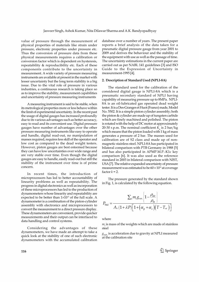
The standard used for the calibration of theconsidered digital gauge is NPLI-8A which is apneumatic secondary standard of NPLI havingcapability of measuring pressure up to 8MPa. NPLI-8A is an oil-lubricated gas operated dead weighttester. It is a Des-Granges et Huot (France) made, ModelNo. 5502. It is a simple piston cylinder assembly; boththe piston & cylinder are made up of tungsten carbidewhich are finely machined and polished. The pistonis rotated with the help of DC motor at approximately20-30 r.p.m. The nominal coefficient Kn is 2 bar/kgwhich means that the piston loaded with 1 kg of massgenerates a pressure of 2 bar. The masses used forcalibration are of S2 class and made up of non-magnetic stainless steel. NPLI-8A has participated inbilateral comparison with PTB Germany in 1988 [5]and has also participated in APMP.M.P.-K1c keycomparison [6]. It was also used as the referencestandard in 2003 in bilateral comparison with NIST,USA [7]. The relative expanded uncertainty of pressuremeasurement was estimated to be 60 × 10-6 at coveragefactor k = 2.
The pressure generated by the standard shownin Fig. 1, is calculated by the following equation.
( ) ( )( )NPL
0 ref
airii
mStd
p c
1
1 1
m gP
A P T T
⎛ ⎞⎜ ⎟⎜ ⎟⎜ ⎟⎜ ⎟⎜ ⎟⎜ ⎟⎝ ⎠
−=
⎡ ⎤+ + + −⎣ ⎦
∑ρρ
λ α α
wheremi is mass of the weights which are made of stainlesssteelgNPL is acceleration due to gravity at NPLI measuredat the calibration site
Reliability and Long Term Stability of a Digital Pressure Gauge (DPG) Used as a Standard- A Case Study
117
ρair & ρm are densities of air and the dead weightscomputed as per specified normsA0 is the effective area of piston-cylinder assembly atzero pressureλ is the pressure distortion coefficient of the piston-cylinder assemblyαp & αc are the thermal expansion coefficients ofpiston & cylinderT is the temperature of piston-cylinder assemblymeasured with a platinum resistance thermometerTref is the temperature at which A0 is specified
3. Description of Test Gauge Under Study
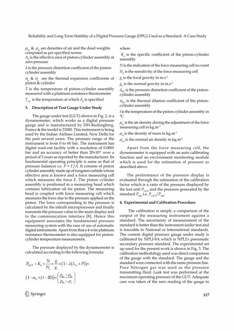
The gauge under test (GUT) shown in Fig. 2, is adynamometer, which works as a digital pressuregauge and is manufactured by DH-Budengberg,France & the model is 21000. This instrument is beingused by the Indian Airlines Limited, New Delhi forthe past several years. The pressure range of theinstrument is from 0 to 60 bar. The instrument hasdigital read-out facility with a resolution of 0.0001bar and an accuracy of better than 20×10-6 over aperiod of 3 years as reported by the manufacturer. Itsfundamental operating principle is same as that ofpressure balances i.e. P = F/A. It consists of pistoncylinder assembly made up of tungsten carbide whoseeffective area is known and a force measuring cellwhich measures the force F. The piston cylinderassembly is positioned in a measuring head whichcontains lubrication oil for piston. The measuringhead is coupled with force measuring cell whichmeasures the force due to the pressure applied on thepiston. The force corresponding to the pressure iscalculated by the inbuilt microprocessor and finallytransmits the pressure value to the main display andto the communication interface [8]. Hence thisequipment associates the fundamental pressuremeasuring system with the ease of use of automaticdigital instruments. Apart from that a 4-wire platinumresistance thermometer is also equipped for piston-cylinder temperature measurement.
The pressure displayed by the dynamometer iscalculated according to the following formula:
where Kn is the specific coefficient of the piston-cylinderassemblyN is the indication of the force measuring cell in countNk is the sensitivity of the force measuring cellgl is the local gravity in m.s-2
gn is the normal gravity in m.s-2
λPC is the pressure distortion coefficient of the piston-cylinder assemblyαPC is the thermal dilation coefficient of the piston-cylinder assemblyt is the temperature of the piston-cylinder assembly in°Cρac is the air density during the adjustment of the forcemeasuring cell in kg.m-3
ρm is the density of mass in kg.m-3
ρan is the normal air density in kg.m-3
Apart from the force measuring cell, thedynamometer is equipped with an auto calibratingfunction and an environment monitoring modulewhich is used for the estimation of pressure asdescribed above.
The performance of the pressure display isevaluated through the estimation of the calibrationfactor which is a ratio of the pressure displayed bythe test unit PGUT and the pressure generated by thestandard PStd i.e. PGUT/PStd.
4. Experimental and Calibration Procedure
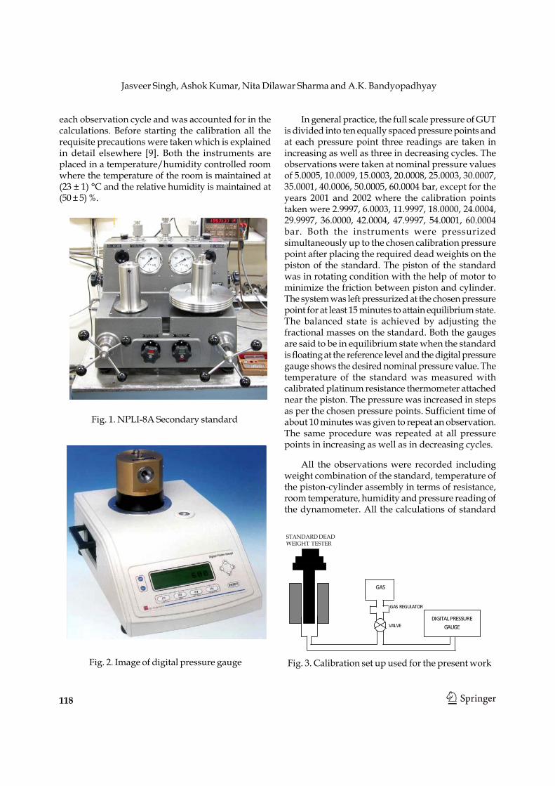
The calibration is simply a comparison of theoutput of the measuring instrument against astandard. The uncertainty of measurement of thestandard is better than the instrument under test andis traceable to National or International standards.The current digital pressure gauge under study iscalibrated by NPLI-8A which is NPLI's pneumaticsecondary pressure standard. The experimental setup used for the present work is shown in Fig. 3. Thecalibration methodology used was direct comparisonof the gauge with the standard. The gauge and thestandard were connected with the same pressure line.Pure Nitrogen gas was used as the pressuretransmitting fluid. Leak test was performed at themaximum operating pressure of the GUT. Adequatecare was taken of the zero reading of the gauge in
( )( )
( )( )
lPC
k n
PC
m
GUT n
ac m
an
1
1 20
gNP K PN g
t
= × × × − λ × ×
⎛ ⎞−− × − ×⎜ ⎟−⎝ ⎠
λ
ρ ρα
ρ ρ
Jasveer Singh, Ashok Kumar, Nita Dilawar Sharma and A.K. Bandyopadhyay
118
Fig. 1. NPLI-8A Secondary standard
Fig. 2. Image of digital pressure gauge
each observation cycle and was accounted for in thecalculations. Before starting the calibration all therequisite precautions were taken which is explainedin detail elsewhere [9]. Both the instruments areplaced in a temperature/humidity controlled roomwhere the temperature of the room is maintained at(23 ± 1) °C and the relative humidity is maintained at(50 ± 5) %.
In general practice, the full scale pressure of GUTis divided into ten equally spaced pressure points andat each pressure point three readings are taken inincreasing as well as three in decreasing cycles. Theobservations were taken at nominal pressure valuesof 5.0005, 10.0009, 15.0003, 20.0008, 25.0003, 30.0007,35.0001, 40.0006, 50.0005, 60.0004 bar, except for theyears 2001 and 2002 where the calibration pointstaken were 2.9997, 6.0003, 11.9997, 18.0000, 24.0004,29.9997, 36.0000, 42.0004, 47.9997, 54.0001, 60.0004bar. Both the instruments were pressurizedsimultaneously up to the chosen calibration pressurepoint after placing the required dead weights on thepiston of the standard. The piston of the standardwas in rotating condition with the help of motor tominimize the friction between piston and cylinder.The system was left pressurized at the chosen pressurepoint for at least 15 minutes to attain equilibrium state.The balanced state is achieved by adjusting thefractional masses on the standard. Both the gaugesare said to be in equilibrium state when the standardis floating at the reference level and the digital pressuregauge shows the desired nominal pressure value. Thetemperature of the standard was measured withcalibrated platinum resistance thermometer attachednear the piston. The pressure was increased in stepsas per the chosen pressure points. Sufficient time ofabout 10 minutes was given to repeat an observation.The same procedure was repeated at all pressurepoints in increasing as well as in decreasing cycles.
All the observations were recorded includingweight combination of the standard, temperature ofthe piston-cylinder assembly in terms of resistance,room temperature, humidity and pressure reading ofthe dynamometer. All the calculations of standard
Fig. 3. Calibration set up used for the present work
DIGITAL PRESSURE GAUGE
GAS
GAS REGULATOR
VALVE
STANDARD DEAD WEIGHTTESTER
STANDARD DEADWEIGHT TESTER
Reliability and Long Term Stability of a Digital Pressure Gauge (DPG) Used as a Standard- A Case Study
119
generated pressure, the regression analysis andestimation of uncertainty were carried out using thein-house software developed in Quick basic. Theuncertainty estimation was carried out as per NABL141 guidelines and ISO Guide to the Expression ofUncertainty in measurement-1995 [3-4]. Themeasurements of all the secondary/transferstandards are traceable to the National Primarystandard. Therefore, the measurements of the testgauge in turn are also traceable to the standardsmaintained at NPLI.
5. Results and Discussion
The pneumatic pressure standards of NPLIregularly receive various types of gauges from differentindustries for calibration and characterization but inthe current context a study is made on a digitalpressure gauge used by the Indian Airlines Limited.The collected nine years calibration data from 2001 to2009 has been analyzed in the present study. Asmentioned earlier, to check the stability of the gauge,the repeatability, uncertainty, hysteresis, nonlinearityand the relative deviation of GUT pressure from thestandard pressure are discussed here.
In recent years, Arun et al. [10] reported shortterm & long term stability of various pressuremeasuring equipments from 100 mbar to 5000 bar andfound that reproducibility changes with time and theuncertainty of all other instruments except deadweight testers increases with time. Yadav et al. [11]also studied several pressure instruments in hydraulic
region for their short term and long term stability andobserved small change in short term stability withtime but the change was prominent in case of longterm stability. However, L. Dargent [12] reported thevarious aspects of digital piston gauges i.e. thecombination of piston-cylinder and electronicdynamometers and demonstrated that these can beused as reliable transfer standards which havediminished degradations in accuracy with use.
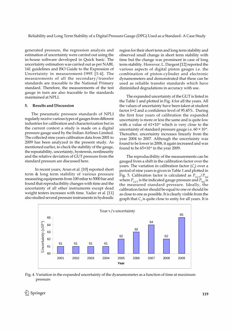
The expanded uncertainty of the GUT is listed inthe Table 1 and plotted in Fig. 4 for all the years. Allthe values of uncertainty have been taken at studentfactor k=2 and a confidence level of 95.45%. Duringthe first four years of calibration the expandeduncertainty is more or less the same and is quite lowwith a value of 61×10-6 which is very close to theuncertainty of standard pressure gauge i.e. 60 × 10-6.Thereafter, uncertainty increases linearly from theyear 2004 to 2007. Although the uncertainty wasfound to be lower in 2008, it again increased and wasfound to be 65×10-6 in the year 2009.
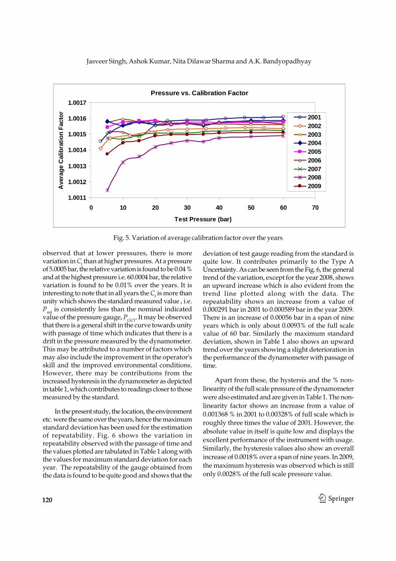
The reproducibility of the measurements can begauged from a shift in the calibration factor over theyears. The variation in calibration factor (Cf) over aperiod of nine years is given in Table 1 and plotted inFig. 5. Calibration factor is calculated as PGUT/PStdwhere PGUT is the indicated gauge pressure and PStd isthe measured standard pressure. Ideally, thecalibration factor should be equal to one or should beas close to one as possible. It is clearly visible from thegraph that Cf is quite close to unity for all years. It is
Year V/S Uncertainity
61 61 61 61
62
63
64
62
65
60
61
62
63
64
65
2001 2002 2003 2004 2005 2006 2007 2008 2009Year
Unc
erta
inity
(x10
-6)
Fig. 4. Variation in the expanded uncertainty of the dyanamometer as a function of time at maximumpressure
Year v/s uncertainty
Unc
erta
inty
(x10
-6)
Jasveer Singh, Ashok Kumar, Nita Dilawar Sharma and A.K. Bandyopadhyay
120
Pressure vs. Calibration Factor
1.0011
1.0012
1.0013
1.0014
1.0015
1.0016
1.0017
0 10 20 30 40 50 60 70
Test Pressure (bar)
Ave
rage
Cal
ibra
tion
Fact
or 200120022003200420052006200720082009
Fig. 5. Variation of average calibration factor over the years
observed that at lower pressures, there is morevariation in Cf than at higher pressures. At a pressureof 5.0005 bar, the relative variation is found to be 0.04 %and at the highest pressure i.e. 60.0004 bar, the relativevariation is found to be 0.01% over the years. It isinteresting to note that in all years the Cf is more thanunity which shows the standard measured value , i.e.Pstd is consistently less than the nominal indicatedvalue of the pressure gauge, PGUT. It may be observedthat there is a general shift in the curve towards unitywith passage of time which indicates that there is adrift in the pressure measured by the dynamometer.This may be attributed to a number of factors whichmay also include the improvement in the operator'sskill and the improved environmental conditions.However, there may be contributions from theincreased hysteresis in the dynamometer as depictedin table 1, which contributes to readings closer to thosemeasured by the standard.
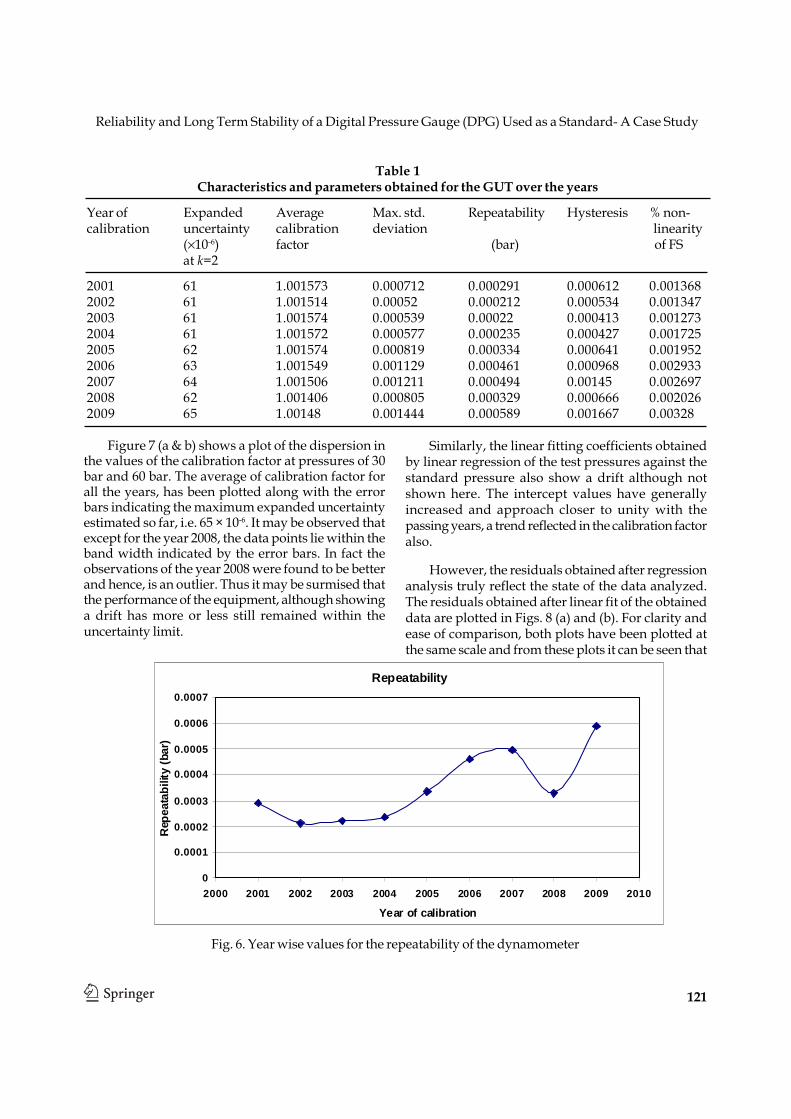
In the present study, the location, the environmentetc. were the same over the years, hence the maximumstandard deviation has been used for the estimationof repeatability. Fig. 6 shows the variation inrepeatability observed with the passage of time andthe values plotted are tabulated in Table 1 along withthe values for maximum standard deviation for eachyear. The repeatability of the gauge obtained fromthe data is found to be quite good and shows that the
deviation of test gauge reading from the standard isquite low. It contributes primarily to the Type AUncertainty. As can be seen from the Fig. 6, the generaltrend of the variation, except for the year 2008, showsan upward increase which is also evident from thetrend line plotted along with the data. Therepeatability shows an increase from a value of0.000291 bar in 2001 to 0.000589 bar in the year 2009.There is an increase of 0.00056 bar in a span of nineyears which is only about 0.0093% of the full scalevalue of 60 bar. Similarly the maximum standarddeviation, shown in Table 1 also shows an upwardtrend over the years showing a slight deterioration inthe performance of the dynamometer with passage oftime.
Apart from these, the hystersis and the % non-linearity of the full scale pressure of the dynamometerwere also estimated and are given in Table 1. The non-linearity factor shows an increase from a value of0.001368 % in 2001 to 0.00328% of full scale which isroughly three times the value of 2001. However, theabsolute value in itself is quite low and displays theexcellent performance of the instrument with usage.Similarly, the hysteresis values also show an overallincrease of 0.0018% over a span of nine years. In 2009,the maximum hysteresis was observed which is stillonly 0.0028% of the full scale pressure value.
Reliability and Long Term Stability of a Digital Pressure Gauge (DPG) Used as a Standard- A Case Study
121
Figure 7 (a & b) shows a plot of the dispersion inthe values of the calibration factor at pressures of 30bar and 60 bar. The average of calibration factor forall the years, has been plotted along with the errorbars indicating the maximum expanded uncertaintyestimated so far, i.e. 65 × 10-6. It may be observed thatexcept for the year 2008, the data points lie within theband width indicated by the error bars. In fact theobservations of the year 2008 were found to be betterand hence, is an outlier. Thus it may be surmised thatthe performance of the equipment, although showinga drift has more or less still remained within theuncertainty limit.
Similarly, the linear fitting coefficients obtainedby linear regression of the test pressures against thestandard pressure also show a drift although notshown here. The intercept values have generallyincreased and approach closer to unity with thepassing years, a trend reflected in the calibration factoralso.
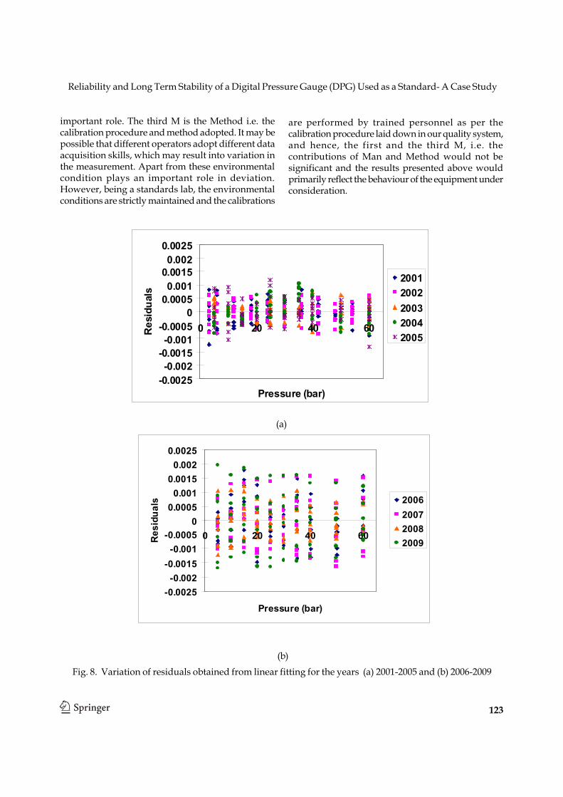
However, the residuals obtained after regressionanalysis truly reflect the state of the data analyzed.The residuals obtained after linear fit of the obtaineddata are plotted in Figs. 8 (a) and (b). For clarity andease of comparison, both plots have been plotted atthe same scale and from these plots it can be seen that
Repeatability
0
0.0001
0.0002
0.0003
0.0004
0.0005
0.0006
0.0007
2000 2001 2002 2003 2004 2005 2006 2007 2008 2009 2010
Year of calibration
Rep
eata
bilit
y (b
ar)
Fig. 6. Year wise values for the repeatability of the dynamometer
Table 1Characteristics and parameters obtained for the GUT over the years
Year of Expanded Average Max. std. Repeatability Hysteresis % non-calibration uncertainty calibration deviation linearity
(×10-6) factor (bar) of FSat k=2
2001 61 1.001573 0.000712 0.000291 0.000612 0.0013682002 61 1.001514 0.00052 0.000212 0.000534 0.0013472003 61 1.001574 0.000539 0.00022 0.000413 0.0012732004 61 1.001572 0.000577 0.000235 0.000427 0.0017252005 62 1.001574 0.000819 0.000334 0.000641 0.0019522006 63 1.001549 0.001129 0.000461 0.000968 0.0029332007 64 1.001506 0.001211 0.000494 0.00145 0.0026972008 62 1.001406 0.000805 0.000329 0.000666 0.0020262009 65 1.00148 0.001444 0.000589 0.001667 0.00328

Jasveer Singh, Ashok Kumar, Nita Dilawar Sharma and A.K. Bandyopadhyay
122
the residuals have increased in magnitude as the yearsgo by. In Fig. 8(a), depicting residuals from years 2001-2005, most of the points are seen to lie between -0.001and + 0.001. But for the years 2006 onwards, themagnitude of residuals of fitting have increased. It isconventionally agreed that there are mainly 3 factorswhich could contribute to the deviation/error and
could be ascribed to 3M's i.e. Man, Machine andMethod. We have already discussed in detail thefactors contributing to the machine aspect. The othertwo factors, i.e. Man and Method could also contributeto these. First M i.e. Man, the person who isperforming calibration affects the calibration in themost significant way. Operator's skill plays an
Fig. 7. The dispersion in the values of calibration factor observed as a function of time at pressures of (a) 30bar nominal and (b) 60 bar nominal. The error bars indicate the expanded uncertainty for the averagecalibration factor. The triangles indicate the value of average calibration factor of nine years
(a)
(b)
30 bar
1.00144
1.00148
1.00152
1.00156
1.0016
1.00164
2000 2001 2002 2003 2004 2005 2006 2007 2008 2009 2010
Calibration year
Calib
ratio
n fa
ctor
60 bar
1.00144
1.00148
1.00152
1.00156
1.0016
1.00164
2000 2001 2002 2003 2004 2005 2006 2007 2008 2009 2010
Calibration year
Cal
ibra
tion
fact
or
Reliability and Long Term Stability of a Digital Pressure Gauge (DPG) Used as a Standard- A Case Study
123
important role. The third M is the Method i.e. thecalibration procedure and method adopted. It may bepossible that different operators adopt different dataacquisition skills, which may result into variation inthe measurement. Apart from these environmentalcondition plays an important role in deviation.However, being a standards lab, the environmentalconditions are strictly maintained and the calibrations
are performed by trained personnel as per thecalibration procedure laid down in our quality system,and hence, the first and the third M, i.e. thecontributions of Man and Method would not besignificant and the results presented above wouldprimarily reflect the behaviour of the equipment underconsideration.
Fig. 8. Variation of residuals obtained from linear fitting for the years (a) 2001-2005 and (b) 2006-2009
(a)
(b)
-0.0025-0.002
-0.0015-0.001
-0.00050
0.00050.001
0.00150.002
0.0025
0 20 40 60
Pressure (bar)
Res
idua
ls
20012002200320042005
-0.0025-0.002
-0.0015-0.001
-0.00050
0.00050.001
0.00150.002
0.0025
0 20 40 60
Pressure (bar)
Res
idua
ls 2006200720082009
Jasveer Singh, Ashok Kumar, Nita Dilawar Sharma and A.K. Bandyopadhyay
124
6. Conclusion
With the help of collected calibration database anattempt has been made to study the stability of adynamometer, i.e. digital pressure gauge having apressure range from 0 to 60 bar. The repeatability orthe short term stability of the gauge is found to bequite low but shows a small increase with time. Theoverall expanded uncertainty increases marginallyover a nine year period. The hysteresis and the non-linearity also show a marginal increase which leadsto increased residuals in the regression of the dataobtained. However, the overall performance of theequipment remains excellent over the period studiedand it may be concluded that the digital gauges withthe arrangement of piston-cylinder assembly and theelectronic dynamometer make digital gauges moretrustworthy.
Acknowledgement
The authors are grateful to Director NPL forconstant encouragement.
References
[1] R.S. Dadson, S.L. Lewis and G.N. Peggs, ThePressure Balance: Theory and Practice, NationalPhysical Laboratory, Department of Industry,Published by her Majesty's Stationary Office,London, (1982).
[2] F. Pavese and G.F. Molinar, Modern Gas-BasedTemperature and Pressure Measurement, Editedby K.D. Timmerhaus, A.F. Clark and C. Rizzuto(Plenum Press, New York) (1992) pp. 337-343.
[3] Guidelines for Estimation and Expression ofUncertainty in Measurement. NABL 141, (2000).
[4] Expression of Uncertainty in Measurement, ISODocument-1995.
[5] J.K.N. Sharma, K.K. Jain, A.K. Bandyopadhyayand J. Jager, International Intercomparison ofPressure Standards in the Pneumatic PressureRegion 0.4-4 MPa between NPL (India) and PTB(FRG) J. Phys. E:Sci Instrum., 21 (1988) p. 635.
[6] A.K. Bandyopadhyay, S.Y. Woo, M. Fitzgerald,J. Man, A. Ooiwa, M. Jescheck, W. Jian, C.S. Fatt,T.K. Chan, K. Moore and A.A.E. Al-Tawil,Results of APMP Pressure Key ComparisonAPMP.M.P.-Klc in Gas Media and Gauge Modefrom 0.4 MPa to 4.0 MPa, Metrologia Tech.Suppl., 40 (2003) 07002.
[7] R.G. Driver, D.B. Olson, N. Dilawar and A.K.Bandyopadhyay, Final Report on KeyComparison APMP.SIM.M.P.-Klc: BilateralComparison between NIST (USA) and NPL(India) in the Pneumatic Pressure Region 0.4MPa to 4.0 MPa, Metrologia Tech. Suppl., 44(2004) 7002.
[8] Manual DH-Budenberg, DH21000, (1985).[9] Document Manual Pressure Standards, NPLI -
DP#1.06/Doc.3/CP#2, (2009)[10] D.A. Vijayakumar, S. Yadav, R.K. Sharma and
A.C. Gupta, Studies on Pressure MeasuringEquipments from 100 mbar to 5000 bar: BothAbsolute and Gauge Pressures, J. Instrum. Soc.India, 27 (1998) 269-277.
[11] S. Yadav, O. Prakash, V.K. Gupta and A.K.Bandyopadhyay, Studies on the Stabilities ofVarious Types of Industrial PressureMeasuring Devices. J. of Scientific & IndustrialResearch, 65 (2006) 721-724.
[12] L. Dargent., Digital Piston Manometers: Arethey Primary or Transfer Standards? Metrologia30 (1993/94) 659-663.