Embed Size (px)
Citation preview

DESIGN OF CIVIL STRUCTURESI n t e g r a t e d S o l u t i o n S y s t e m f o r B r i d g e a n d C i v i l E n g i n e e r i n g
Release NoteRelease Date : July 2018
Product Ver. : Civil 2019 (v1.1)

Enhancements
1. Traffic Load Models for Turkey
2. Moving Load Optimization for Australia
3. India IRS Bridge Rules: Railway Loads
4. Nonlinear Elastic Links for Pushover Analysis
5. GSD - Crack Width Calculation as per IRC 112: 2011
6. AASHTO LRFD 2016 update
7. Shell Design
3
5
6
7
8
9
11
Analysis & Design
Pre & Post-Processing
1. Energy Result Graph for Time History Analysis
2. Strain Output for Material Nonlinear Analysis
3. Multi-linear force-deformation function for Point Spring Support and Elastic Link
4. Rail Track Analysis Report with the US Unit Setting
5. Data Interface with GTS NX
6. Tekla Structure 2018 Interface
24
28
30
31
32
33

3
Civil 2019 (v1.1) Release NoteCivil 2019 Analysis & Design
1. Traffic Load Models for Turkey
Five Turkish live load models are implemented in midas Civil. KGM-45, H30-S24, H30-S24L, H20-S16, H20-S16L
These vehicles can be found from the AASHTO LRFD / AASHTO Standard code.
Load/Moving Load Analysis Data > Vehicles
Standard Vehicular Load, KGM-45 Moving Load Tracer, KGM-45

4
Civil 2019 (v1.1) Release NoteCivil 2019 Analysis & Design
1. Traffic Load Models for Turkey
Load/Moving Load Analysis Data > Vehicles
Standard Vehicular Load, H30-S24
Standard Vehicular Load, H30-S24L Standard Vehicular Load, H20-S16L
Standard Vehicular Load, H20-S16

5
Civil 2019 (v1.1) Release NoteCivil 2019 Analysis & Design
2. Moving Load Optimization for Australia
Now, the moving load optimization function can be applied with the Australia code as
well.
Moving Load Optimization extends the capabilities of moving load analysis and helps
to significantly simplify the evaluation of critical vehicle locations. The critical
locations of vehicles can be identified in the transverse direction as well as
longitudinal direction according to the code provision.
Load > Moving Load > Traffic Line/Surface Lane > Moving Load Optimization
Load > Moving Load > Moving Load Cases
Traffic Line Lane Optimization Moving Load CaseOptimized Results for Exterior Girder by S1600

6
Civil 2019 (v1.1) Release NoteCivil 2019 Analysis & Design
3. India IRS Bridge Rules: Railway Loads
All the applicable railway loads could now directly be applied to any structure. The tractive and braking load of locomotive as well as wagon would be automatically
considered.
Loads> Moving Load> India> Vehicles> IRS Bridge Rules
Analysis> Moving Load Analysis Control > Railway Bridge Information

7
Civil 2019 (v1.1) Release NoteCivil 2019 Analysis & Design
4. Nonlinear Elastic Links for Pushover Analysis
Nonlinear behavior of the elastic links, i.e. comp.-only, tens.-only, multi-linear can be taken into account in the pushover analysis.
Link forces imported from static analysis or construction stage analysis cannot be specified as initial loads for pushover analysis.
Pushover > Control > Global Control
Bi-linear
Elastic Links
representing
soil resistance
Pushover Global ControlPushover Analysis for the Pier and Shaft

8
Civil 2019 (v1.1) Release NoteCivil 2019 Analysis & Design
5. GSD - Crack Width Calculation as per IRC 112: 2011
For any irregular section, both elastic and cracked-elastic crack width can be computed as per IRC 112: 2011 code.
Excel report of the stress and crack width calculation can be obtained.
GSD > Design Section > Crack width > Report

9
Civil 2019 (v1.1) Release NoteCivil 2019 Analysis & Design
6. AASHTO LRFD 2016 update
Load Combination
Load factors of WS for Strength III, Strength V, Service I, Service IV are changed from 1.4 to 1.0, 0.4 to 1.0, 0.3 to 1.0, 0.7 to 1.0, respectively.
Load factor of permanent effects for Extreme Event I is changed from γp to 1.0. AASHTO-LRFD 2012 used a value for γp greater than 1.0.
Load Combinations Dialog

10
Civil 2019 (v1.1) Release NoteCivil 2019 Analysis & Design
6. AASHTO LRFD 2016 update
Resistance Factor
εcl : compression-controlled strain limit in the extreme tension steel
εtl : tension-controlled strain limit in the extreme tension steel
AASHTO 2012 AASHTO 2016

11
Civil 2019 (v1.1) Release NoteCivil 2019 Analysis & Design
7. Shell Design
The design of reinforcement concrete shells as per Annex LL of EN 1992-2 is implemented.
Shell design considers three membrane forces, two flexural moments, twisting moment and two transverse shear forces.
This design feature can be applied to concrete shell structure, abutment walls / wing walls, under ground structures.
Membrane Axial Forces Membrane Shear Forces
Required Rebar AreaPrincipal Compressive Stresses
12
Civil 2019 (v1.1) Release NoteCivil 2019 Analysis & Design
7. Shell Design
Step 1. Define as a shell member Step 2. Define Rebar Data and Layer Thickness Step 3. Run Shell Design and Checking
Shell Design

13
Civil 2019 (v1.1) Release NoteCivil 2019 Analysis & Design
Shell Flexural Design/Checking
The followings can be displayed.
1. Membrane Axial Force2. Membrane Shear Force3. Rebar Stress4. As_req
(Required reinforcement area)5. Rho_req
(Required reinforcement ratio)6. Rebar Arrangement
Result for Rebar
Results Table
Result for Concrete
The followings can be displayed.
1. Membrane Axial Force2. Membrane Shear Force3. Principal Compressive Stress of
Concrete
7. Shell Design

14
Civil 2019 (v1.1) Release NoteCivil 2019 Analysis & Design
Shell Shear Checking
The followings can be displayed.
1. V_Edo2. Shear Resistance for Concrete3. Resistance Ratio
Result for Shear
Results Table
7. Shell Design

15
Civil 2019 (v1.1) Release NoteCivil 2019 Analysis & Design
Design Concept of Shell Design
Transverse shear forces
Plate components
Slab components
Outer layers resistbending moments
+ membrane forces
Inner layer resistthe transverse shear
• Shell or plate element subjected to membrane forces Nx,Ny,Nxy + flexural forces Mx,My,Mxy
• Resisted by resultant tensile forces of reinforcement + resultant compressive forces of concrete
7. Shell Design
16
Civil 2019 (v1.1) Release NoteCivil 2019 Analysis & Design
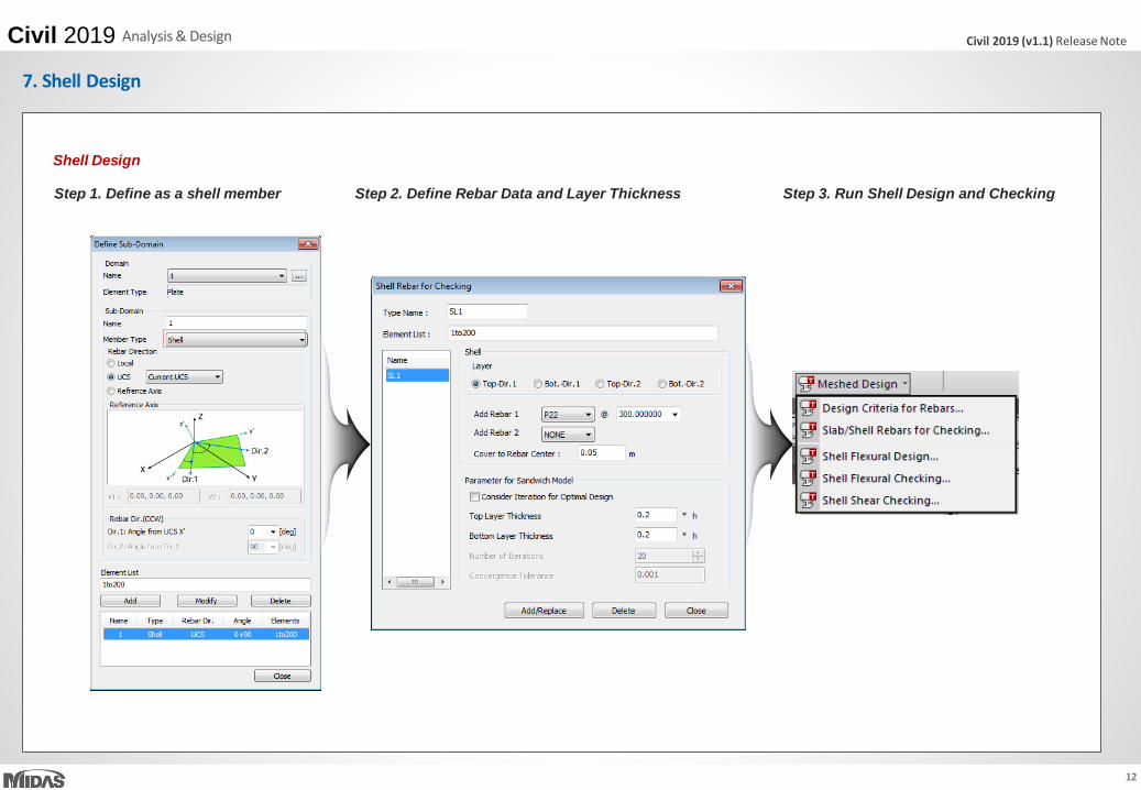
Procedure of Shell Design
Max. Compression stress < Strength O.K.Uncracked
Check plate force by analysis
Crack Checking
Define Sandwich model
Cracked
Calculate Membrane Force
Calculate stress of reinforcement and concrete
Define Rebar Arrangement
Calculate strength of reinforcement and concrete
Stress < Strength O.K.
: Get from ‘Plate force(UL:UCS)’ tap of Plate Stress Table
7. Shell Design

17
Civil 2019 (v1.1) Release NoteCivil 2019 Analysis & Design
Procedure of Shell Design
Crack Checking
Uncracked, If Φ>0.0, Cracked
σ1 = Max. [σx, σy] = Max. [Fxx, Fyy]
σ2 = Min. [σx, σy] = Min. [Fxx, Fyy]
σ3 = 0
σ3
Plate Stress (UL : UCS) Table
7. Shell Design

18
Civil 2019 (v1.1) Release NoteCivil 2019 Analysis & Design
Procedure of Shell Design
Define Sandwich model
• Use ‘ 0.2*h’ as default value.
• If check on “ Consider Iteration for optimal design”, layer thickness will be calculated automatically.
Sandwich Thickness
Calculate Membrane Force
• The geometry of sandwich element has to be known to compute the membrane forces (Nxk, Nyk, Nxyk).
7. Shell Design

19
Civil 2019 (v1.1) Release NoteCivil 2019 Analysis & Design
Procedure of Shell Design
Calculation of Sandwich Thickness for Optimal Design - 1
k=compression layer
j = tension layer
ck0 : 1st estimation of ck
ck : the depth of the compression block
Check main moment
Define Comp. / Tens. by sign of moment
Cal. of Resultant moment, Ma
Cal ck0 by Equations
0,20.1max1
,2 2
jk
cj
akjcka
dc
fd
Mput
cdfcM
Ma = M – Nej ej= dj – h/2
7. Shell Design

20
Civil 2019 (v1.1) Release NoteCivil 2019 Analysis & Design
Procedure of Shell Design
k=compression layer
j = tension layer
Membrane force in compression layer.
a
M
a
aNN
a
M
a
aNN
a
M
a
aNN
aaach
ac
da
xyj
xyxyk
yj
yyk
xj
xxk
kjk
kk
j
,2
,2
Calculation of Sandwich Thickness for Optimal Design - 2
When
When excluding
Compression Force of Concrete .
7. Shell Design

21
Civil 2019 (v1.1) Release NoteCivil 2019 Analysis & Design
Procedure of Shell Design
Calculation of Membrane Force in tension layer and Required Rebar Area
Calculate membrane force in tensioned layer.
Calculate Comp. forces in reinforcement in compressed layer.
In Gen, Ignore Comp. forces in reinforcement (Required rebar Area by comp. is 0)
Calculate tension forces in reinforcement in tension layer.
Areq,x = Nxaj / fyd
Areq,y = Nyaj / fyd
Calculate required Rebar Area in tension layer.
7. Shell Design

22
Civil 2019 (v1.1) Release NoteCivil 2019 Analysis & Design
Procedure of Shell Design
Calculate Force of reinforcement(Tension Layer) and concrete(Compression Layer)
Nxk
Nyk
-|Nxyk|
-|Nxyk|
kkxykck
kxykykyak
xk
xyk
k
xak
xkyykxykxk
NN
NNN
N
N
N
NNNN
cottan
tan
arctan
0
,
224
2
1
2
1
0
,
xykykxkykxkck
yakxak
xykykxykxk
NNNNNN
NN
NNNN
kkxykck
kxykxkxak
xyk
yk
k
yak
xkyxkxykyk
NN
NNN
N
N
N
NNNN
cottan
cot
arctan
0
,
xykkkxykck
xykykkxykykyak
xykxkkxykxkxak
k
xkyxkxykyk
NNN
NNNNN
NNNNN
NNNN
2cottan
tan
cot
45
,
Nxak, Nyak : tension forces in reinforcement placed in x and y direction in layer k
Nck : Concrete compression force in layer k
7. Shell Design

23
Civil 2019 (v1.1) Release NoteCivil 2019 Analysis & Design
Procedure of Shell Design
Modification of Tension force by considering the location of rebar
Distance from center section to center of outerRebar
Distance from center section to center of sandwich thickness
7. Shell Design

24
Civil 2019 (v1.1) Release NoteCivil 2019 Pre & Post-Processing
The shear span value is user input.If it is less than 0, it is treated as an error.
A S HE E ES
E HE
A S HE E E
HE
SE
1. Energy Result Graph for Time History Analysis
Print out energy results graph for isolator and vibration control devices in the nonlinear time history analysis.
Result > T.H. Graph/Text > Time History Energy Graph

25
Civil 2019 (v1.1) Release NoteCivil 2019 Pre & Post-Processing
1. Energy Result Graph for Time History Analysis
The shear span value is user input.If it is less than 0, it is treated as an error.
Result > T.H. Graph/Text > Time History Energy Graph

26
Civil 2019 (v1.1) Release NoteCivil 2019 Pre & Post-Processing
1. Energy Result Graph for Time History Analysis
The shear span value is user input.If it is less than 0, it is treated as an error.
Result > T.H. Graph/Text > Time History Energy Graph
< Text result of the each energy ratio >

27
Civil 2019 (v1.1) Release NoteCivil 2019 Pre & Post-Processing
1. Energy Result Graph for Time History Analysis
The shear span value is user input.If it is less than 0, it is treated as an error.
Result > T.H. Graph/Text > Time History Energy Graph
StrtGrp 1F StrtGrp 2F StrtGrp 3F
BndrGrp 1 BndrGrp 2 BndrGrp 3
< Result output of group distribution for each energy item >
28
Civil 2019 (v1.1) Release NoteCivil 2019 Pre & Post-Processing
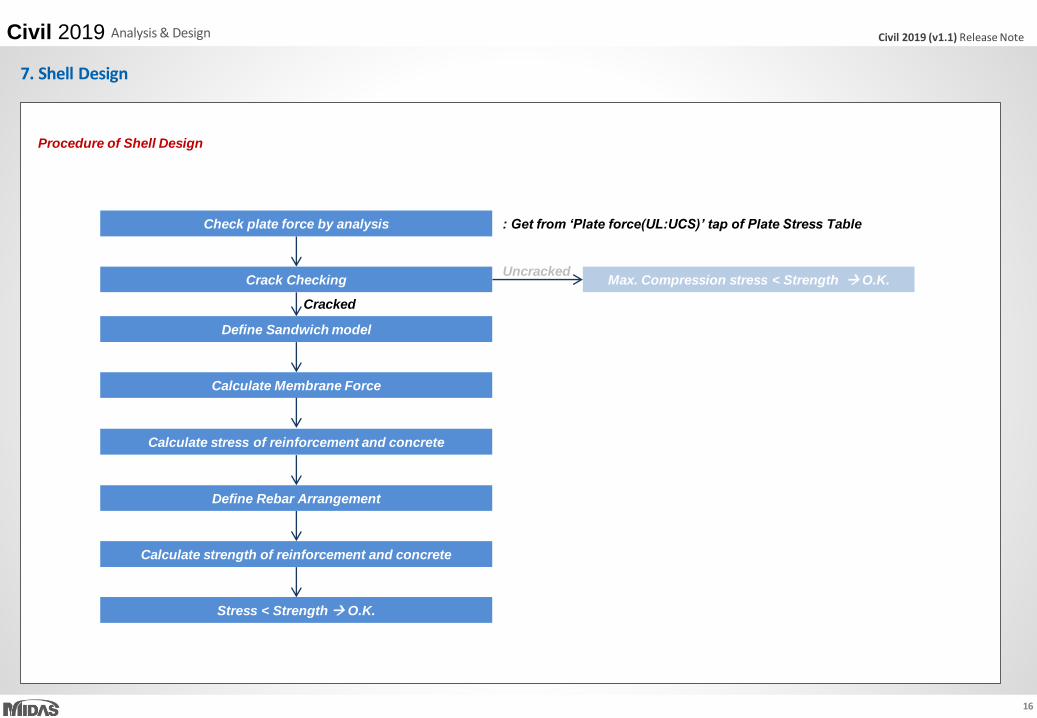
Strain results are provided for plastic materials, i.e. Tresca, Von Mises, Mohr-Coulomb, Drucker-Prager, and Concrete Damage.
Damage ratios for compression and tension are provided for the ‘Concrete Damage’ model.
Results > Results > Strains > Plate Strains/ Solid Strains
2. Strain Output for Material Nonlinear Analysis

29
Civil 2019 (v1.1) Release NoteCivil 2019 Pre & Post-Processing
2. Strain Output for Material Nonlinear Analysis
Results > Tables > Results Tables > Plate/ Solid > Strain(local)/ Strain(Global)
<Plate Strain (local) menu> <Solid Strain (local) menu>Plate Strain Table

30
Civil 2019 (v1.1) Release NoteCivil 2019 Pre & Post-Processing
3. Multi-linear force-deformation function for Point Spring Support and Elastic Link
Multi-linear curve for Point Spring Support and Elastic Link can be defined as a function without limitation in terms of number of data.
< Previous version > < Civil 2019 (v1.1) >
Multi-linear is defined as 6 points in the previous version.

31
Civil 2019 (v1.1) Release NoteCivil 2019 Pre & Post-Processing
4. Rail Track Analysis Report with the US Unit Setting
Rail Track Analysis report supports the US unit system as well as SI unit system.
Structure > Wizard > Rail Track Analysis Model > Rail Track Analysis Report
Report Setting to the US unit Rail Track Analysis Report

32
Civil 2019 (v1.1) Release NoteCivil 2019 Pre & Post-Processing
5. Data Interface with GTS NX
Reactions from Point Spring Support can be exported to GTS NX.
Force-displacement results of soil can be imported from GTS NX into midas Civil, and the input data of the multi-linear Point Spring Supports are updated.
File > Export > Nodal Results for GTS File > Import > Nodal Results for GTS

33
Civil 2019 (v1.1) Release NoteCivil 2019 Pre & Post-Processing
6. Tekla Structure 2018 Interface
Tekla Structures interface is a tool provided to speed up the entire modeling, analysis, and design procedure of a structure by direct data transfer with midas Civil.
Data transfer is limited to structural elements.
Tekla Structure interface enables us to directly transfer a Tekla model data to midas Civil, and delivery back to the Tekla model file. midas Civil text file (*.mct) is used
for the roundtrip.
Category Features Tekla <> Gen
MATERIAL
concrete <>
steel <>
pre cast - wood and other types <>
Material user defined <>
ELEMENT TYPE/
ROTATIONS
vertical column <>
inclined column <>
straight beam <>
curved beam >
Slab <>
vertical panel >
2D ELEMENTS Concrete panels and slab <>
BOUNDARY CONDITIONS
support >
beam end release <>
section offset >
STATIC LOAD
self weigth >
linear load
(uniform or trapezoidal)<>
MERGE OPTION
new element <>
new element that
divide other elements<>
topology changes <>
Tekla Structure 2018
Civil 2019
File > Import > midas Civil MCT File File > Export > midas Civil MCT File