Embed Size (px)
Citation preview
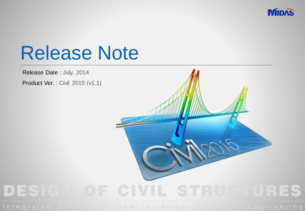
DESIGN OF CIVIL STRUCTURES
I n t e g r a t e d S o l u t i o n S y s t e m f o r B r i d g e a n d C i v i l E n g i n e e r i n g
Release NoteRelease Date : July. 2014
Product Ver. : Civil 2015 (v1.1)
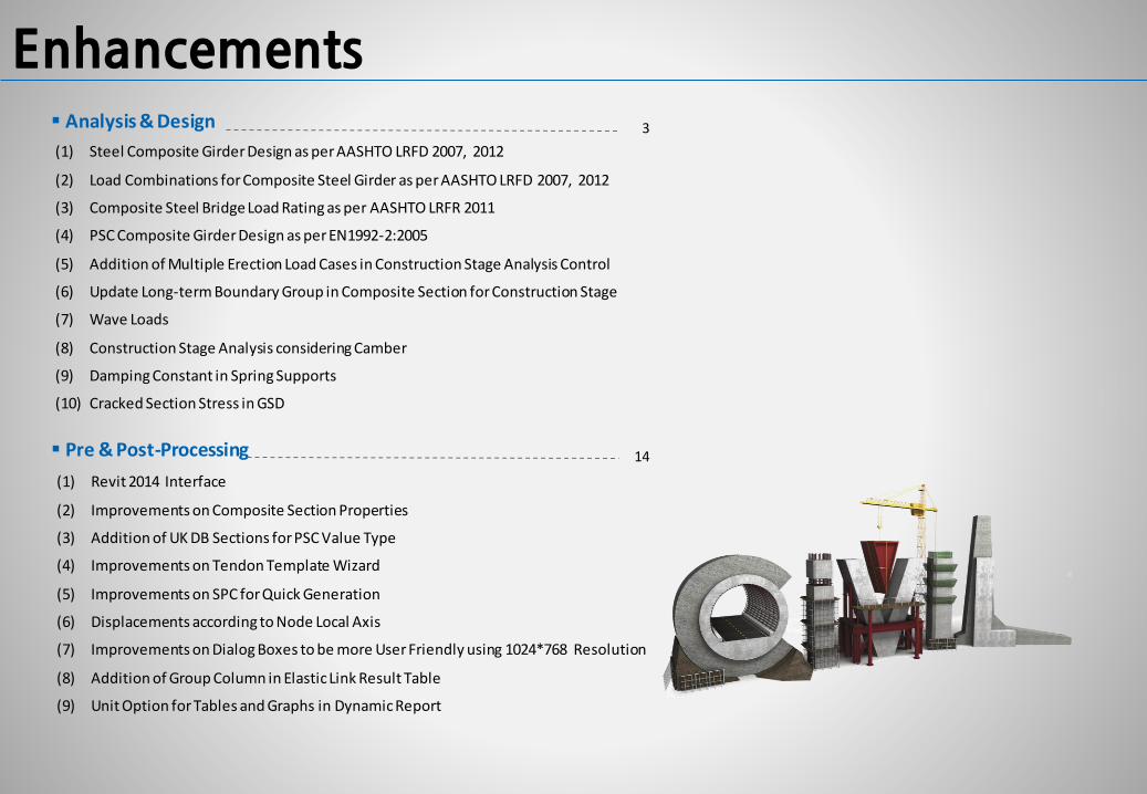
Enhancements
(1) Steel Composite Girder Design as per AASHTO LRFD 2007, 2012
(2) Load Combinations for Composite Steel Girder as per AASHTO LRFD 2007, 2012
(3) Composite Steel Bridge Load Rating as per AASHTO LRFR 2011
(4) PSC Composite Girder Design as per EN1992-2:2005
(5) Addition of Multiple Erection Load Cases in Construction Stage Analysis Control
(6) Update Long-term Boundary Group in Composite Section for Construction Stage
(7) Wave Loads
(8) Construction Stage Analysis considering Camber
(9) Damping Constant in Spring Supports
(10) Cracked Section Stress in GSD
Analysis & Design 3
Pre & Post-Processing
(1) Revit 2014 Interface
(2) Improvements on Composite Section Properties
(3) Addition of UK DB Sections for PSC Value Type
(4) Improvements on Tendon Template Wizard
(5) Improvements on SPC for Quick Generation
(6) Displacements according to Node Local Axis
(7) Improvements on Dialog Boxes to be more User Friendly using 1024*768 Resolution
(8) Addition of Group Column in Elastic Link Result Table
(9) Unit Option for Tables and Graphs in Dynamic Report
14
3 / 21
Civil 2015 V1.1 Release NoteCivil 2015 Analysis & Design
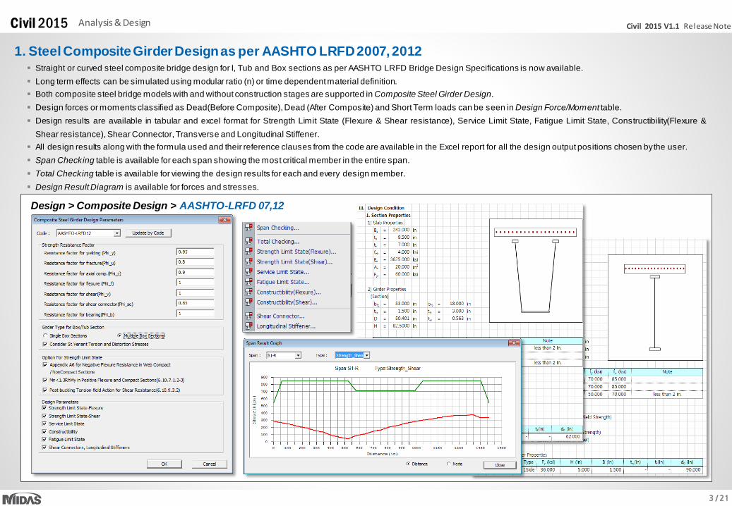
Straight or curved steel composite bridge design for I, Tub and Box sections as per AASHTO LRFD Bridge Design Specifications is now available.
Long term effects can be simulated using modular ratio (n) or time dependent material definition.
Both composite steel bridge models with and without construction stages are supported in Composite Steel Girder Design.
Design forces or moments classified as Dead(Before Composite), Dead (After Composite) and Short Term loads can be seen in Design Force/Moment table.
Design results are available in tabular and excel format for Strength Limit State (Flexure & Shear resistance), Service Limit State, Fatigue Limit State, Constructibility(Flexure &
Shear resistance), Shear Connector, Transverse and Longitudinal Stiffener.
All design results along with the formula used and their reference clauses from the code are available in the Excel report for all the design output positions chosen bythe user.
Span Checking table is available for each span showing the most critical member in the entire span.
Total Checking table is available for viewing the design results for each and every design member.
Design Result Diagram is available for forces and stresses.
Design > Composite Design > AASHTO-LRFD 07,12
1. Steel Composite Girder Design as per AASHTO LRFD 2007, 2012
4 / 21
Civil 2015 V1.1 Release NoteCivil 2015 Analysis & Design
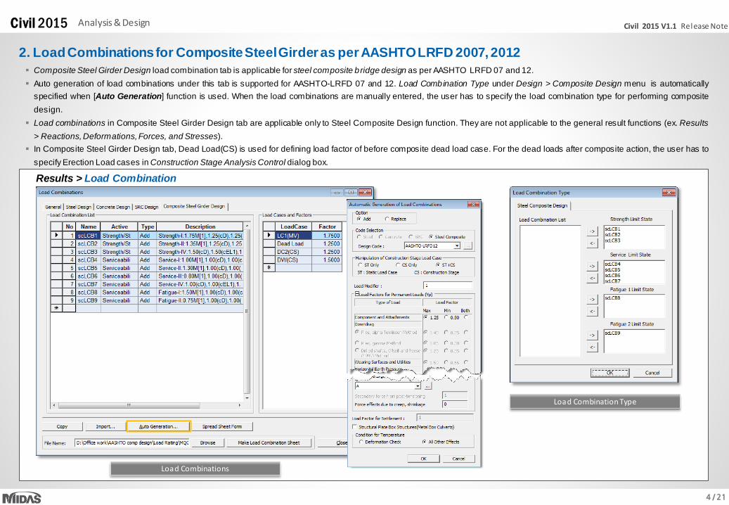
2. Load Combinations for Composite Steel Girder as per AASHTO LRFD 2007, 2012
Composite Steel Girder Design load combination tab is applicable for steel composite bridge design as per AASHTO LRFD 07 and 12.
Auto generation of load combinations under this tab is supported for AASHTO-LRFD 07 and 12. Load Combination Type under Design > Composite Design menu is automatically
specified when [Auto Generation] function is used. When the load combinations are manually entered, the user has to specify the load combination type for performing composite
design.
Load combinations in Composite Steel Girder Design tab are applicable only to Steel Composite Design function. They are not applicable to the general result functions (ex. Results
> Reactions, Deformations,Forces, and Stresses).
In Composite Steel Girder Design tab, Dead Load(CS) is used for defining load factor of before composite dead load case. For the dead loads after composite action, the user has to
specify Erection Load cases in Construction Stage Analysis Control dialog box.
Results > Load Combination
Load Combinations
Load Combination Type
5 / 21
Civil 2015 V1.1 Release NoteCivil 2015 Analysis & Design
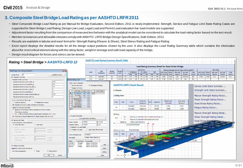
3. Composite Steel Bridge Load Rating as per AASHTO LRFR 2011
Rating > Steel Bridge > AASHTO-LRFD 12
Steel Composite Bridge Load Rating as per Manual for Bridge Evaluation, Second Edition, 2011 is newly implemented. Strength, Service and Fatigue Limit State Rating Cases are
supported for Steel Bridge Load Rating.Design Live Load, Legal Load and Permit Load evaluation live load models are supported.
Adjustment factor resulting from the comparison ofmeasured test behavior with the analytical model can be considered to calculate the load-rating factor based on the test result.
Member resistances and allowable stresses complywith AASHTO LRFD Bridge Design Specifications, Sixth Edition, 2012.
Results are available in tabular and excel format for Strength Rating (Flexure & Shear), Steel Stress Rating and Fatigue Rating.
Excel report displays the detailed results for all the design output positions chosen by the user. It also displays the Load Rating Summary table which contains the information
about the most critical element along with the rating factor, weight in tonnage and safe load capacity of the bridge.
Design result diagram for forces and stress can be viewed.
6 / 21
Civil 2015 V1.1 Release NoteCivil 2015 Analysis & Design
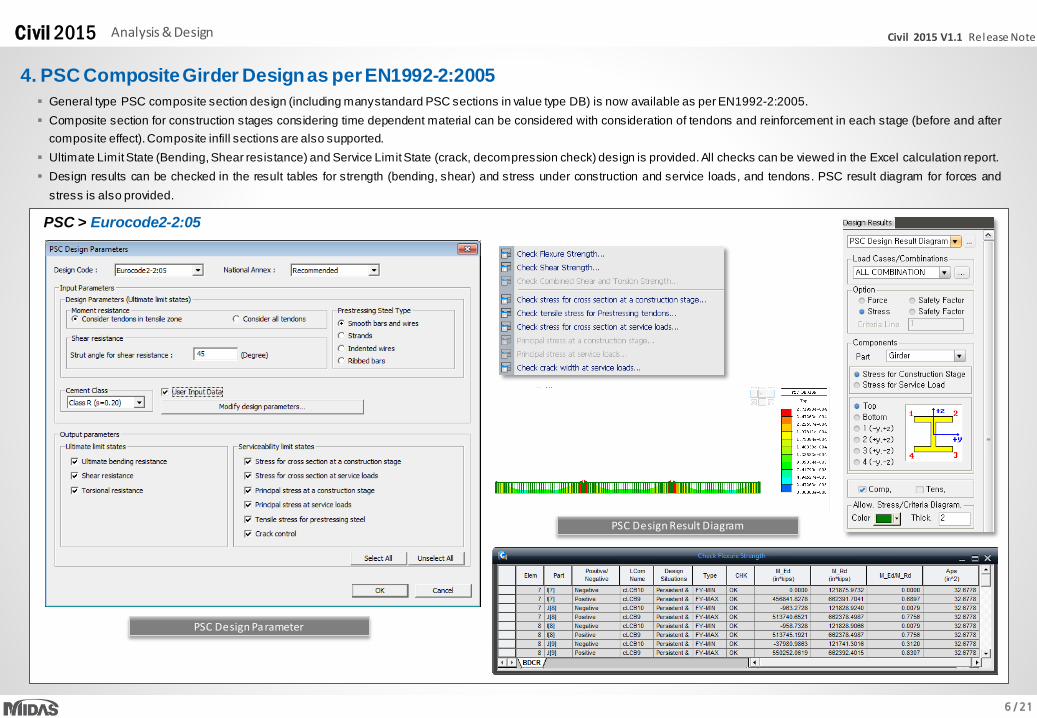
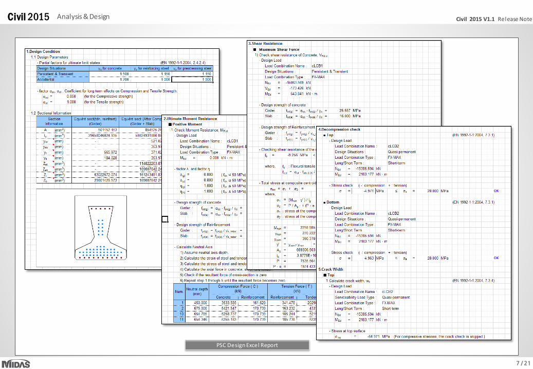
General type PSC composite section design (including manystandard PSC sections in value type DB) is now available as per EN1992-2:2005.
Composite section for construction stages considering time dependent material can be considered with consideration of tendons and reinforcement in each stage (before and after
composite effect).Composite infill sections are also supported.
Ultimate Limit State (Bending, Shear resistance) and Service Limit State (crack, decompression check) design is provided. All checks can be viewed in the Excel calculation report.
Design results can be checked in the result tables for strength (bending, shear) and stress under construction and service loads, and tendons. PSC result diagram for forces and
stress is also provided.
PSC > Eurocode2-2:05
4. PSC Composite Girder Design as per EN1992-2:2005
PSC Design Result Diagram
PSC Design Parameter
7 / 21
Civil 2015 V1.1 Release NoteCivil 2015 Analysis & Design
PSC Design Excel Report
8 / 21
Civil 2015 V1.1 Release NoteCivil 2015 Analysis & Design
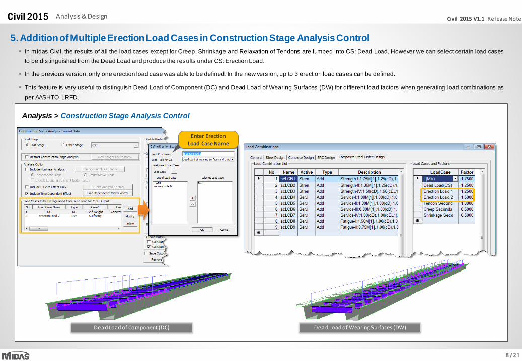
5. Addition of Multiple Erection Load Cases in Construction Stage Analysis Control
In midas Civil, the results of all the load cases except for Creep, Shrinkage and Relaxation of Tendons are lumped into CS: Dead Load. However we can select certain load cases
to be distinguished from the Dead Load and produce the results under CS:Erection Load.
In the previous version,only one erection load case was able to be defined. In the new version, up to 3 erection load cases can be defined.
This feature is very useful to distinguish Dead Load of Component (DC) and Dead Load of Wearing Surfaces (DW) for different load factors when generating load combinations as
per AASHTO LRFD.
Dead Load of Wearing Surfaces (DW)
Analysis > Construction Stage Analysis Control
Dead Load of Component (DC)
Enter Erection Load Case Name
9 / 21
Civil 2015 V1.1 Release NoteCivil 2015 Analysis & Design
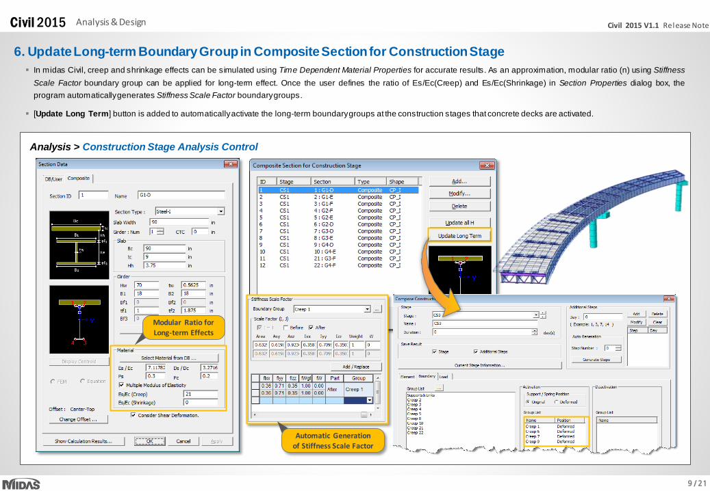
6. Update Long-term Boundary Group in Composite Section for Construction Stage
In midas Civil, creep and shrinkage effects can be simulated using Time Dependent Material Properties for accurate results. As an approximation, modular ratio (n) using Stiffness
Scale Factor boundary group can be applied for long-term effect. Once the user defines the ratio of Es/Ec(Creep) and Es/Ec(Shrinkage) in Section Properties dialog box, the
program automaticallygenerates Stiffness Scale Factor boundarygroups.
[Update Long Term] button is added to automaticallyactivate the long-term boundarygroups at the construction stages that concrete decks are activated.
Analysis > Construction Stage Analysis Control
Modular Ratio for Long-term Effects
Automatic Generation of Stiffness Scale Factor
10 / 21
Civil 2015 V1.1 Release NoteCivil 2015 Analysis & Design
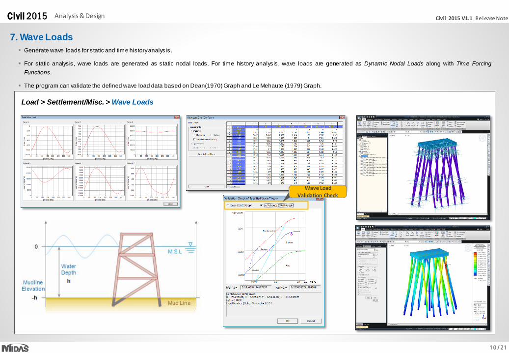
7. Wave Loads
Generate wave loads for static and time historyanalysis.
For static analysis, wave loads are generated as static nodal loads. For time history analysis, wave loads are generated as Dynamic Nodal Loads along with Time Forcing
Functions.
The program can validate the defined wave load data based on Dean(1970) Graph and Le Mehaute (1979) Graph.
Load > Settlement/Misc. > Wave Loads
Wave Load Validation Check
11 / 21
Civil 2015 V1.1 Release NoteCivil 2015 Analysis & Design
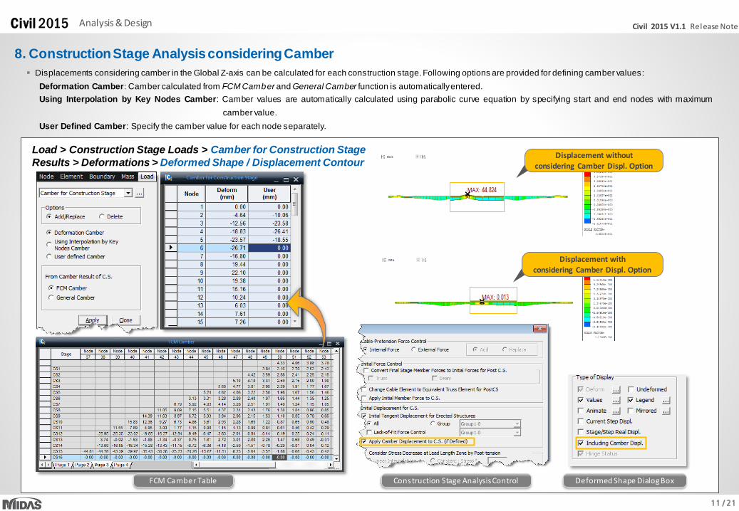
8. Construction Stage Analysis considering Camber
Displacements considering camber in the Global Z-axis can be calculated for each construction stage. Following options are provided for defining camber values:
Deformation Camber: Camber calculated from FCM Camber and General Camber function is automaticallyentered.
Using Interpolation by Key Nodes Camber: Camber values are automatically calculated using parabolic curve equation by specifying start and end nodes with maximum
camber value.
User Defined Camber: Specify the camber value for each node separately.
Displacement without considering Camber Displ. Option
Displacement with considering Camber Displ. Option
FCM Camber Table Construction Stage Analysis Control Deformed Shape Dialog Box
Load > Construction Stage Loads > Camber for Construction Stage
Results > Deformations > Deformed Shape / Displacement Contour
12 / 21
Civil 2015 V1.1 Release NoteCivil 2015 Analysis & Design
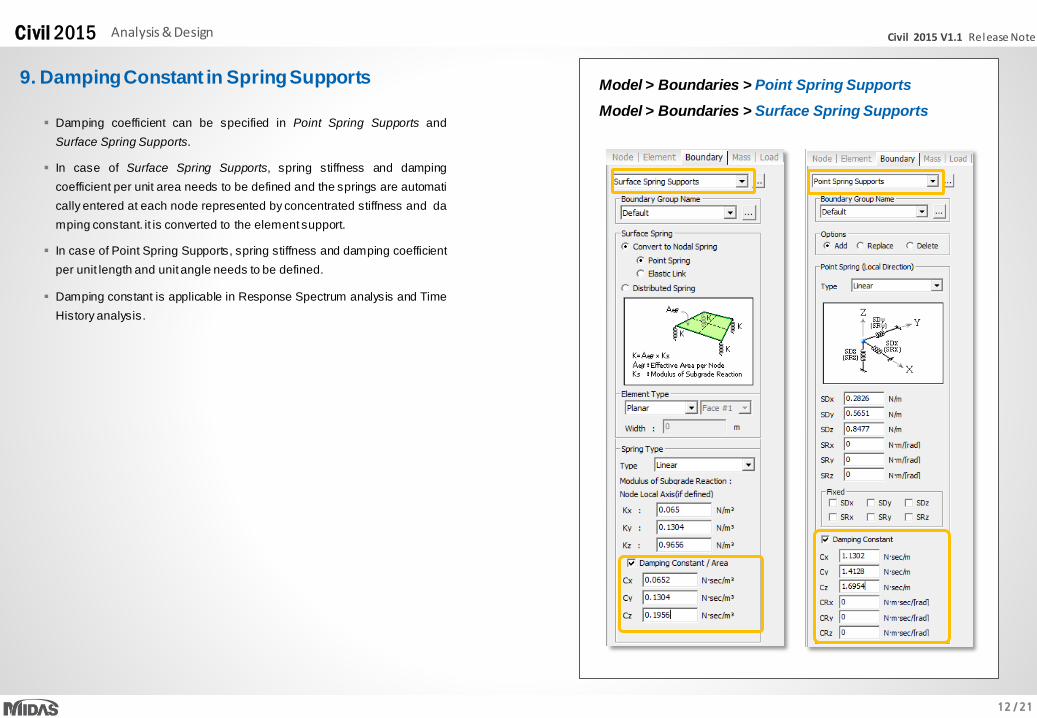
9. Damping Constant in Spring Supports
Damping coefficient can be specified in Point Spring Supports and
Surface Spring Supports.
In case of Surface Spring Supports, spring stiffness and damping
coefficient per unit area needs to be defined and the springs are automati
cally entered at each node represented by concentrated stiffness and da
mping constant. it is converted to the element support.
In case of Point Spring Supports, spring stiffness and damping coefficient
per unit length and unit angle needs to be defined.
Damping constant is applicable in Response Spectrum analysis and Time
History analysis.
Model > Boundaries > Surface Spring Supports
Model > Boundaries > Point Spring Supports
13 / 21
Civil 2015 V1.1 Release NoteCivil 2015 Analysis & Design
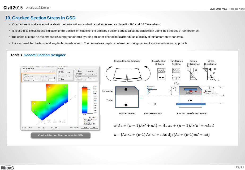
10. Cracked Section Stress in GSD
Cracked section stresses in the elastic behavior without and with axial force are calculated for RC and SRC members.
It is useful to check stress limitation under service limit state for the arbitrary sections and to calculate crack width using the stresses of reinforcement.
The effect of creep on the stresses is simplyconsidered byusing the user-defined ratio ofmodulus elasticityof reinforcement to concrete.
It is assumed that the tensile strength of concrete is zero. The neutral axis depth is determined using cracked transformed section approach.
Tools > General Section Designer
Cracked Section Stresses in midas GSD
Cross Sectionat Crack
TransformedSection
Strain Distribution
StressDistribution
Cracked Elastic Behavior
14 / 21
Civil 2015 V1.1 Release NoteCivil 2015 Pre & Post-Processing
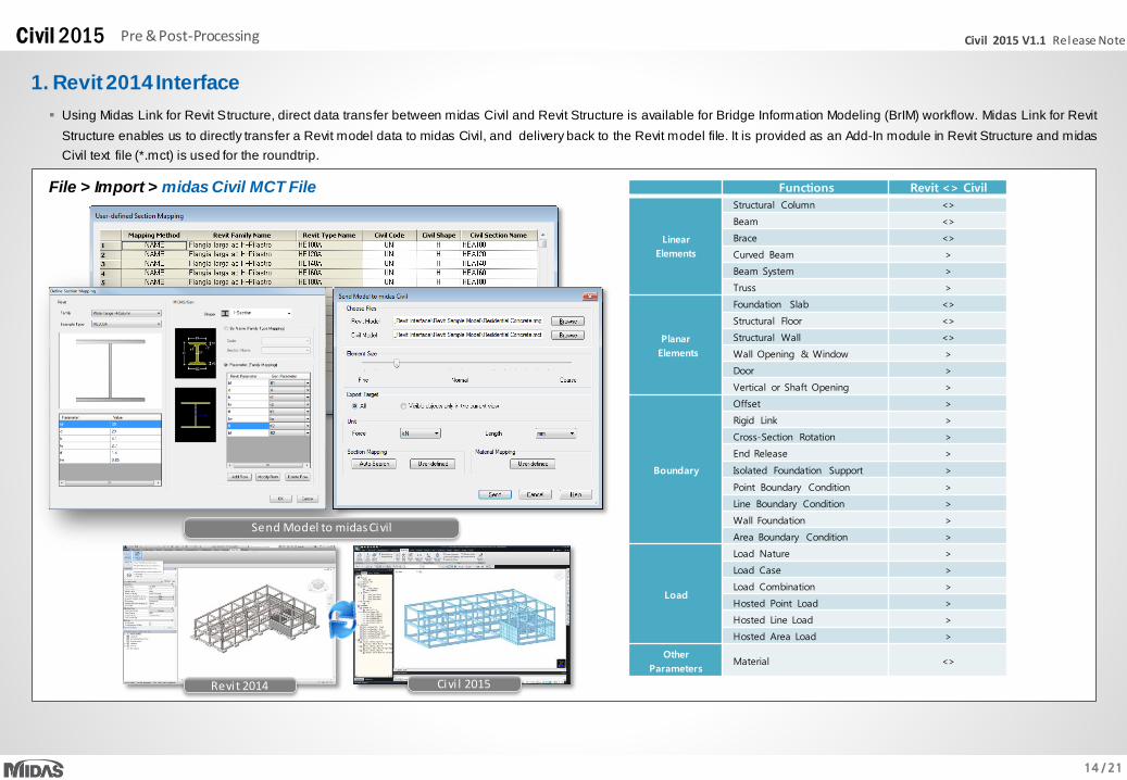
1. Revit 2014 Interface
File > Import > midas Civil MCT File
Using Midas Link for Revit Structure, direct data transfer between midas Civil and Revit Structure is available for Bridge Information Modeling (BrIM) workflow. Midas Link for Revit
Structure enables us to directly transfer a Revit model data to midas Civil, and delivery back to the Revit model file. It is provided as an Add-In module in Revit Structure and midas
Civil text file (*.mct) is used for the roundtrip.
Functions Revit <> Civil
Linear
Elements
Structural Column <>
Beam <>
Brace <>
Curved Beam >
Beam System >
Truss >
Planar
Elements
Foundation Slab <>
Structural Floor <>
Structural Wall <>
Wall Opening & Window >
Door >
Vertical or Shaft Opening >
Boundary
Offset >
Rigid Link >
Cross-Section Rotation >
End Release >
Isolated Foundation Support >
Point Boundary Condition >
Line Boundary Condition >
Wall Foundation >
Area Boundary Condition >
Load
Load Nature >
Load Case >
Load Combination >
Hosted Point Load >
Hosted Line Load >
Hosted Area Load >
Other
ParametersMaterial <>
Send Model to midas Civil
Revit 2014 Civi l 2015
15 / 21
Civil 2015 V1.1 Release NoteCivil 2015 Pre & Post-Processing
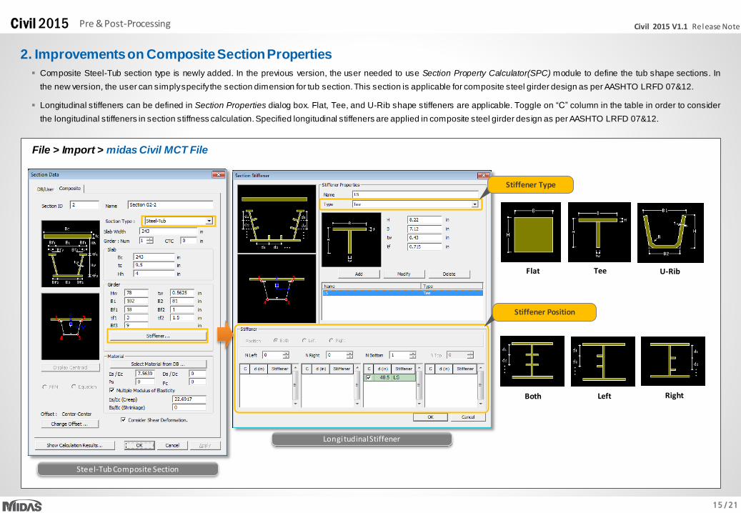
Composite Steel-Tub section type is newly added. In the previous version, the user needed to use Section Property Calculator(SPC) module to define the tub shape sections. In
the new version, the user can simplyspecifythe section dimension for tub section. This section is applicable for composite steel girder design as per AASHTO LRFD 07&12.
Longitudinal stiffeners can be defined in Section Properties dialog box. Flat, Tee, and U-Rib shape stiffeners are applicable. Toggle on “C” column in the table in order to consider
the longitudinal stiffeners in section stiffness calculation.Specified longitudinal stiffeners are applied in composite steel girder design as per AASHTO LRFD 07&12.
Stiffener Type
Flat Tee U-Rib
Stiffener Position
Both Left Right
2. Improvements on Composite Section Properties
File > Import > midas Civil MCT File
Longitudinal Stiffener
Steel-Tub Composite Section
16 / 21
Civil 2015 V1.1 Release NoteCivil 2015 Pre & Post-Processing
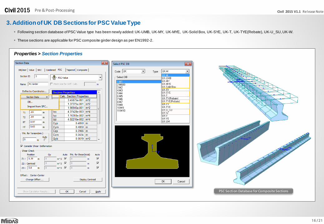
Following section database ofPSC Value type has been newly added:UK-UMB, UK-MY, UK-MYE, UK-Solid Box, UK-SYE, UK-T, UK-TYE(Rebate), UK-U_SU, UK-W.
These sections are applicable for PSC composite girder design as per EN1992-2.
3. Addition of UK DB Sections for PSC Value Type
Properties > Section Properties
PSC Section Database for Composite Sections
17 / 21
Civil 2015 V1.1 Release NoteCivil 2015 Pre & Post-Processing
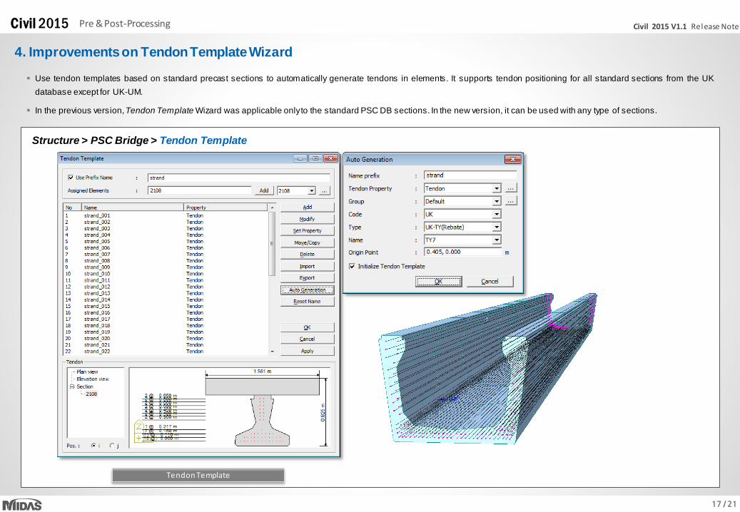
4. Improvements on Tendon Template Wizard
Use tendon templates based on standard precast sections to automatically generate tendons in elements. It supports tendon positioning for all standard sections from the UK
database except for UK-UM.
In the previous version,Tendon Template Wizard was applicable onlyto the standard PSC DB sections. In the new version, it can be used with any type of sections.
Structure > PSC Bridge > Tendon Template
Tendon Template
18 / 21
Civil 2015 V1.1 Release NoteCivil 2015 Pre & Post-Processing
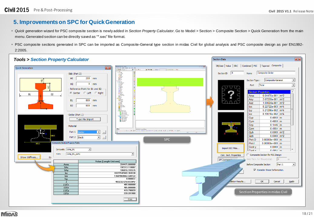
5. Improvements on SPC for Quick Generation
Quick generation wizard for PSC composite section is newly added in Section Property Calculator. Go to Model > Section > Composite Section > Quick Generation from the main
menu.Generated section can be directly saved as “*.sec” file format.
PSC composite sections generated in SPC can be imported as Composite-General type section in midas Civil for global analysis and PSC composite design as per EN1992-
2:2005.
Tools > Section Property Calculator
SPC
Section Properties in midas Civil
19 / 21
Civil 2015 V1.1 Release NoteCivil 2015 Pre & Post-Processing
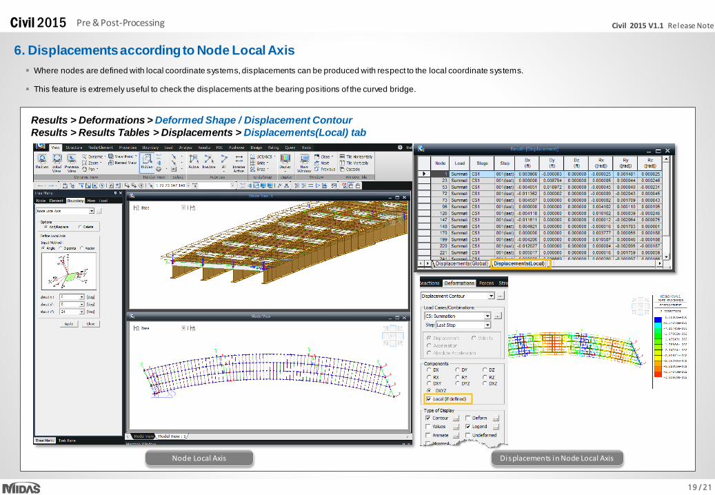
6. Displacements according to Node Local Axis
Results > Deformations > Deformed Shape / Displacement Contour
Results > Results Tables > Displacements > Displacements(Local) tab
Where nodes are defined with local coordinate systems, displacements can be produced with respect to the local coordinate systems.
This feature is extremely useful to check the displacements at the bearing positions of the curved bridge.
Node Local Axis Displacements in Node Local Axis
20 / 21
Civil 2015 V1.1 Release NoteCivil 2015 Pre & Post-Processing
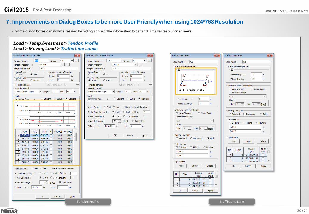
7. Improvements on Dialog Boxes to be more User Friendly when using 1024*768 Resolution
Load > Temp./Prestress > Tendon Profile
Load > Moving Load > Traffic Line Lanes
Tendon Profile Traffic Line Lane
Some dialog boxes can now be resized by hiding some of the information to better fit smaller resolution screens.
21 / 21
Civil 2015 V1.1 Release NoteCivil 2015 Pre & Post-Processing
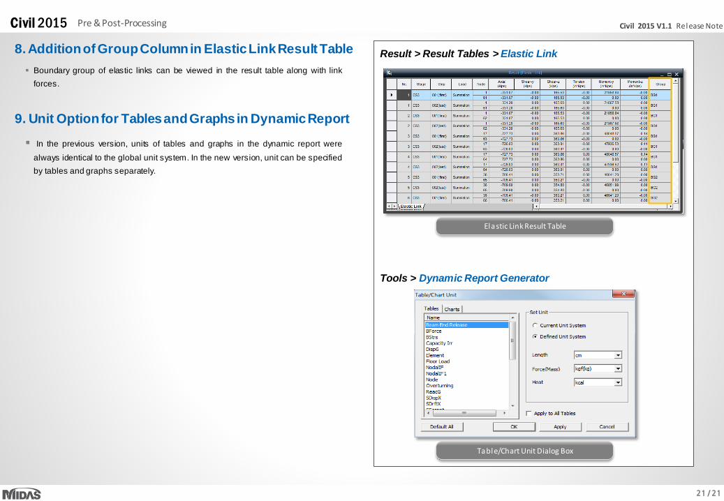
8. Addition of Group Column in Elastic Link Result Table
Boundary group of elastic links can be viewed in the result table along with link
forces.
Result > Result Tables > Elastic Link
Elastic Link Result Table
9. Unit Option for Tables and Graphs in Dynamic Report
In the previous version, units of tables and graphs in the dynamic report were
always identical to the global unit system. In the new version, unit can be specified
by tables and graphs separately.
Tools > Dynamic Report Generator
Table/Chart Unit Dialog Box