Embed Size (px)
Citation preview

313-CD-600-001
EOSDIS Core System Project
Release 6A ECS Internal Interface Control Document
for the ECS Project
Final
March 2001
Raytheon Company Upper Marlboro, Maryland

This page intentionally left blank.
313-CD-600-001

Release 6A ECS Internal Interface Control Document
for the ECS Project
Final
March 2001
Prepared Under Contract NAS5-60000 CDRL Item #051
RESPONSIBLE ENGINEER
Alton Davis for David Johnston /s/ 2/21/01 David D. Johnston Date EOSDIS Core System Project
SUBMITTED BY
William Knauss /s/ 2/21/01 Will Knauss, Director of Development Date EOSDIS Core System Project
Raytheon Company Upper Marlboro, Maryland
313-CD-600-001

This page intentionally left blank.
313-CD-600-001

Preface
This document is a final version of a formal contract deliverable with an approval code 3. Thisdocument has NOT been reviewed by the configuration control board and supports the as builtRelease 6A System. Any questions or proposed changes should be addressed to:
Data Management OfficeThe ECS Project OfficeRaytheon Systems Company1616 McCormick DriveUpper Marlboro, MD 20774-5301
iii 313-CD-600-001

This page intentionally left blank.
iv 313-CD-600-001

Abstract
This document provides a set of interface scenarios that describe how the Release 6A ECS interacts to execute end-to-end system threads. For each scenario a domain (or end user) view and a component interaction view is presented. This document is intended to be used by application developers, system developers and system maintenance engineers to understand how CSMS/SDPS components interact to perform key system functions. For detailed internal interface information, online output provided by automatic software tools such as Discover and ABC++ should be used.
The scenarios in this document reflect the capabilities and functions of the as built design for Drop 6A.
Keywords: external interface, internal interface, public class, private class, class category, system-level scenario, scenario primitive, interface class, distributed object
v 313-CD-600-001

This page intentionally left blank.
vi 313-CD-600-001
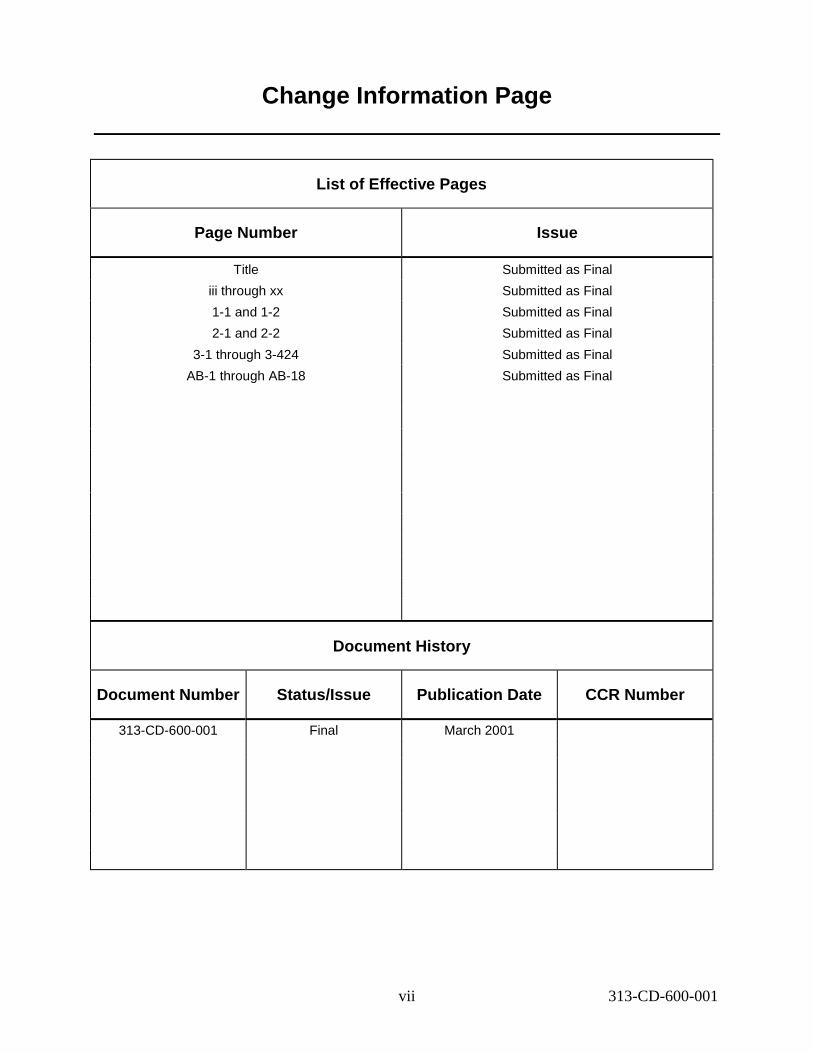
Change Information Page
List of Effective Pages
Page Number Issue
Title iii through xx 1-1 and 1-2 2-1 and 2-2
3-1 through 3-424 AB-1 through AB-18
Submitted as Final Submitted as Final Submitted as Final Submitted as Final Submitted as Final Submitted as Final
Document History
Document Number Status/Issue Publication Date CCR Number
313-CD-600-001 Final March 2001
vii 313-CD-600-001

This page intentionally left blank.
viii 313-CD-600-001

Contents
Preface
Abstract
Change Information Page
1. Introduction
1.1 Identification .................................................................................................................. 1-1
1.2 Scope ............................................................................................................................ 1-1
1.3 Document Organization ................................................................................................ 1-2
2. Related Documentation
2.1 Parent Documents .......................................................................................................... 2-1
2.2 Applicable Documents................................................................................................... 2-1
2.3 Information Documents Not Referenced ....................................................................... 2-1
3. Interface Scenarios
3.1 Overview ....................................................................................................................... 3-1
3.2 Scenario Approach ........................................................................................................ 3-4
3.2.1 Scenario Presentation Approach ....................................................................... 3-5
3.2.2 Scenario Process Flow ........................................................................................ 3-7
3.3 ESDT Handling Scenario .............................................................................................. 3-9
3.3.1 Scenario Description ......................................................................................... 3-9
3.3.2 Scenario Preconditions ...................................................................................... 3-9
3.3.3 Scenario Partitions ............................................................................................ 3-9
3.3.4 Install ESDT Thread ......................................................................................... 3-9
ix 313-CD-600-001

3.3.5 Update ESDT Thread ....................................................................................... 3-14
3.3.6 (Deleted) .......................................................................................................... 3-18
3.3.7 (Deleted) .......................................................................................................... 3-18
3.3.8 Import ESDTs Thread ...................................................................................... 3-19
3.3.9 Export ESDT Thread ....................................................................................... 3-21
3.4 System Start-up/Shutdown ........................................................................................... 3-26
3.5 MODIS Scenario .......................................................................................................... 3-27
3.5.1 MODIS Scenario Description .......................................................................... 3-27
3.5.2 MODIS Scenario Preconditions ....................................................................... 3-28
3.5.3 MODIS Scenario Partitions ............................................................................. 3-29
3.5.4 MODIS Standing Order Submittal Thread ...................................................... 3-30
3.5.5 MODIS Standing Order Support Thread ......................................................... 3-32
3.5.6 MODIS Standard Production Thread ............................................................... 3-39
3.5.7 MODIS Failed PGE Handling Thread ............................................................. 3-74
3.5.8 MODIS Data Access Thread ........................................................................... 3-80
3.5.9 Data Compression on Distribution Thread – Deferred until Release 6B.......... 3-89
3.5.10 Reactivation/Replan ......................................................................................... 3-89
3.6 Landsat-7 Scenario........................................................................................................ 3-99
3.6.1 Landsat-7 Scenario Description........................................................................ 3-99
3.6.2 Landsat-7 Scenario Preconditions.................................................................... 3-100
3.6.3 Landsat-7 Scenario Partitions .......................................................................... 3-101
3.6.4 Landsat-7 User Registration Thread ................................................................ 3-101
3.6.5 Landsat-7 LPS Data Insertion Thread.............................................................. 3-109
3.6.6 Landsat-7 IGS Tape Insertion Thread - Deferred to Release 6B..................... 3-117
3.6.7 Landsat-7 IAS Data Insertion Thread .............................................................. 3-117
3.6.8 Landsat-7 Search and Browse Thread ............................................................. 3-121
3.6.9 Landsat-7 Ordering WRS Scenes Thread ........................................................ 3-131
3.6.10 Landsat-7 MOC Interface Thread - Deleted .................................................... 3-154
3.6.11 Landsat-7 Ordering L70R Floating Scenes Thread ......................................... 3-154
3.6.12 L-7 Floating Scene Price Estimation Thread ................................................... 3-177
3.6.13 Landsat-7 Error Handling ................................................................................. 3-180
3.7 ASTER Scenario.......................................................................................................... 3-183
3.7.1 ASTER Scenario Description .......................................................................... 3-183
3.7.2 ASTER Scenario Preconditions....................................................................... 3-184
x 313-CD-600-001

3.7.3 ASTER Scenario Partitions.............................................................................. 3-185
3.7.4 ASTER DAR Submission Thread ................................................................... 3-186
3.7.5 ASTER GDS Tape Insertion Thread ............................................................... 3-190
3.7.6 ASTER Backward Chaining Thread................................................................ 3-195
3.7.7 ASTER QA Metadata Update Thread ............................................................. 3-221
3.7.8 ASTER On-Demand High Level Production Thread ...................................... 3-224
3.7.9 ASTER On-Demand Non-Standard L1B Production Thread.......................... 3-240
3.7.10 ASTER On-Demand DEM Production Thread ............................................... 3-246
3.7.11 ASTER Simplified Expedited Data Support Thread ...................................... 3-252
3.7.12 ASTER Routine Processing Planning Data Start/Stop Time Thread .............. 3-261
3.7.13 ASTER Routine Processing Planning Insertion Time Thread.......................... 3-266
3.7.14 ASTER Spatial Query Thread ......................................................................... 3-270
3.7.15 ASTER View ECS Data Holdings Thread ...................................................... 3-274
3.7.16 ASTER Price & Order Data Thread ................................................................ 3-283
3.7.17 User View And Order ASTER GDS Data Thread........................................... 3-291
3.7.18 ASTER Attached DPRs (Standing Orders) Thread ......................................... 3-298
3.8 Planning Scenario ....................................................................................................... 3-305
3.8.1 Planning Scenario Description .......................................................................... 3-305
3.8.2 Planning Scenario Preconditions ...................................................................... 3-305
3.8.3 Planning Scenario Partitions ............................................................................. 3-305
3.8.4 Ground Events Jobs Thread (Thread A) ........................................................... 3-306
3.8.5 Resource Planning Thread (Thread B) ............................................................. 3-309
3.8.6 Science Software Archive Package Thread - SSAP Insertion (Thread A) ....... 3-313
3.8.7 SSAP Update Thread (Thread B) ..................................................................... 3-318
3.8.8 Archive PGE Executable TAR File Thread (Thread C) ................................... 3-322
3.8.9 Metadata Query for Current Dynamic Input Granules (Thread A) .................. 3-325
3.8.10 Dynamic Granule Available in the Future Thread (Thread B) ....................... 3-327
3.8.11 Metadata Based Activation Thread ................................................................. 3-329
3.8.12a DPR Regeneration Thread ............................................................................. 3-332
3.8.12b Reprocessing Thread ...................................................................................... 3-336
3.8.13 Delete DPR Thread ......................................................................................... 3-341
3.8.14 Closest Granule Thread ................................................................................... 3-344
3.9 EDOS/FDD Interfaces Scenario ....................................................................................... 3-348
3.9.1 EDOS/FDD Interfaces Scenario Description ..................................................... 3-348
3.9.2 EDOS/FDD/EMOS Interfaces Scenario Preconditions ..................................... 3-348
xi 313-CD-600-001

3.9.3 EDOS/FDD Interfaces Scenario Partitions ........................................................ 3-349
3.9.4 EDOS Level 0 Ancillary Data Thread .............................................................. 3-350
3.9.5 Definitive Attitude Data Thread ........................................................................ 3-355
3.9.6 FDD Repaired Ephemeris Data Thread ............................................................. 3-362
3.9.7 EDOS Backup Level 0 Data Insertion Thread – Deferred until Release 6B ..... 3-369
3.9.8 Aqua FDS Ephemeris Data Thread ................................................................... 3-369
3.9.9 Aqua Predictive/Definitive Attitude Data Thread ............................................. 3-374
3.10 Cross Mode / DAAC Scenario ....................................................................................... 3-381
3.10.1 Cross Mode / DAAC Scenario Description ..................................................... 3-381
3.10.2 Cross Mode / DAAC Scenario Preconditions .................................................. 3-381
3.10.3 Cross Mode / DAAC Scenario Partitions ........................................................ 3-381
3.10.4 Cross Mode / DAAC Insertion Thread ............................................................ 3-381
3.11 Science Investigator-Led Processing Systems (SIPS) Scenario .................................... 3-388
3.11.1 SIPS Scenario Description ............................................................................... 3-388
3.11.2 SIPS Scenario Preconditions ........................................................................... 3-388
3.11.3 SIPS Scenario Partitions ................................................................................. 3-388
3.11.4 SIPS Data Insertion Thread ............................................................................ 3-389
3.11.5 Inventory Search – SIPS Data Reprocessing (Thread B) ............................... 3-393
3.11.6 Product Order – SIPS Data reprocessing (Thread C) ..................................... 3-396
3.11.7 Integrated Search and Order – SIPS Data reprocessing (Thread D) ............... 3-402
3.12 Fault Recovery ............................................................................................................... 3-407
List of Figures
Figure 3.2.2-1. Scenario Process Flow ..................................................................................... 3-7
Figure 3.3.4.1-1. Install ESDT Interaction Diagram ............................................................... 3-10
Figure 3.3.5.1-1. Update ESDT Interaction Diagram.............................................................. 3-15
Figure 3.3.8.1-1. Import ESDT Interaction Diagram............................................................... 3-19
Figure 3.3.9.1-1. Export ESDT Interaction Diagram............................................................... 3-22
Figure 3.5.1-1. MODIS Scenario PGE/Data Relationship Diagram ....................................... 3-27
Figure 3.5.4.1-1. MODIS Standing Order Submittal Interaction Diagram ............................. 3-30
Figure 3.5.5.1-1. MODIS Standing Order Support Interaction Diagram ................................ 3-33
Figure 3.5.6.1-1. MODIS Standard Production Interaction Diagram...................................... 3-39
xii 313-CD-600-001

Figure 3.5.7.1-1. MODIS Failed PGE Handling Interaction Diagram .................................... 3-74
Figure 3.5.8.1-1. MODIS Data Access Interaction Diagram................................................... 3-81
Figure 3.5.10.4.1-1. DPR in New Plan but Not in Old Plan Interaction Diagram - Domain View........................................................................................................................... 3-91
Figure 3.5.10.5.1-1. DPR in Old Plan but Not in New Plan Interaction Diagram - Domain View........................................................................................................................... 3-93
Figure 3.5.10.6.1-1. DPR in Both Old Plan and New Plan Interaction Diagram - Domain View........................................................................................................................... 3-96
Figure 3.6.4.1-1. L-7 User Registration Interaction Diagram................................................. 3-102
Figure 3.6.5.1-1. L-7 LPS Data Insertion Interaction Diagram.............................................. 3-109
Figure 3.6.7.1-1. Landsat-7 IAS Data Insertion Interaction Diagram .................................... 3-117
Figure 3.6.8.1-1. L-7 Search and Browse Interaction Diagram.............................................. 3-122
Figure 3.6.9.1-1. L-7 Ordering WRS Scenes Interaction Diagram ........................................ 3-131
Figure 3.6.11.1-1. L-7 Ordering L70R Floating Scenes Interaction Diagram........................ 3-155
Figure 3.6.12.1-1. L-7 Floating Scenes Price Estimation Interaction Diagram...................... 3-177
Figure 3.6.13.1-1. L-7 Error Handling Interaction Diagram .................................................. 3-181
Figure 3.7.1-1. ASTER Scenario PGE/Data Relationships Diagram ..................................... 3-184
Figure 3.7.4.1-1. ASTER DAR Submission Interaction Diagram.......................................... 3-187
Figure 3.7.5.1-1. ASTER GDS Tape Insertion Interaction Diagram...................................... 3-191
Figure 3.7.6.1-1. ASTER Backward Chaining Interaction Diagram...................................... 3-196
Figure 3.7.7.1-1. ASTER QA Metadata Update Interaction Diagram.................................... 3-221
Figure 3.7.8.1-1. ASTER On-Demand High Level Production Interaction Diagram ............ 3-224
Figure 3.7.9.1-1. ASTER On-Demand Non-Standard L1B Interaction Diagram .................. 3-241
Figure 3.7.10.1-1. ASTER On-Demand DEM Interaction Diagram ...................................... 3-246
Figure 3.7.11.1-1. ASTER Simplified Expedited Data Support Interaction Diagram ........... 3-252
Figure 3.7.12.1-1. ASTER Routine Processing Planning Data Start/Stop Time InteractionDiagram............................................................................................................ 3-262
Figure 3.7.13.1-1. Routine Processing Planning Insertion Time Thread InteractionDiagram............................................................................................................ 3-267
Figure 3.7.14.1-1. ASTER Spatial Query Interaction Diagram.............................................. 3-271
Figure 3.7.15.1-1. ASTER View ECS Data Holdings Interaction Diagram........................... 3-275
xiii 313-CD-600-001

Figure 3.7.16.1-1. ASTER Price & Order Data Interaction Diagram...................................... 3-282
Figure 3.7.17.1-1. User View And Order ASTER GDS Data Interaction Diagram................ 3-291
Figure 3.7.18.1-1. ASTER Attached DPRs (Standing Orders) Interaction Diagram ............. 3-299
Figure 3.8.4.1-1. Ground Events Jobs Thread Interaction Diagram - Domain View ............. 3-307
Figure 3.8.5.1-1. Resource Planning Interaction Diagram - Domain View ........................... 3-310
Figure 3.8.6.1-1. SSAP Diagram - Domain View .................................................................. 3-314
Figure 3.8.7.1-1. SSAP Update Interaction Diagram - Domain View ................................... 3-318
Figure 3.8.8.1-1. Archive PGE Executable TAR File Interaction Diagram -Domain View................................................................................................... 3-322
Figure 3.8.9.1-1. Metadata Query for Current Dynamic Granule Interaction Diagram - DomainView................................................................................................................. 3-325
Figure 3.8.10.1-1. Future Dynamic Granule Interaction - Domain View............................... 3-327
Figure 3.8.11.1-1. Metadata Based Activation Interaction Diagram - Domain View ............ 3-330
Figure 3.8.12a.1-1. DPR Regeneration Interaction Diagram - Domain View......................... 3-333
Figure 3.8.12b.1-1. Reprocessing Interaction Diagram - Domain View ................................ 3-337
Figure 3.8.13.1-1. Delete DPR Interaction Diagram - Domain View .................................... 3-341
Figure 3.8.14.1-1. Closest Granule Interaction Diagram – Domain View ............................. 3-344
Figure 3.9.4.1-1. EDOS Level 0 Ancillary Data Interaction - Domain View ........................ 3-350
Figure 3.9.5.1-1. Definitive Attitude Data Diagram................................................................ 3-356
Figure 3.9.6.1-1. FDD Repaired Ephemeris Data Diagram.................................................... 3-363
Figure 3.9.8.1-1. Aqua FDS Ephemeris Processing Data Interaction - Domain View........... 3-370
Figure 3.9.9.1-1. Definitive Attitude Data Diagram................................................................ 3-375
Figure 3.10.4.1-1. Cross Mode / DAAC Insertion Interaction Diagram ................................ 3-382
Figure 3.11.4.1-1. SIPS Data Insertion Interaction Diagram.................................................. 3-389
Figure 3.11.5.1-1. Inventory Search Diagram – Domain View............................................... 3-393
Figure 3.11.6.1-1. Product Order Diagram – Domain View ................................................... 3-397
Figure 3.11.7.1-1. Integrated Search and Order Diagram – Domain View ............................. 3-402
xiv 313-CD-600-001

List of Tables
Table 3.1-1. ECS Subsystem and Component Design Overviews ........................................... 3-2
Table 3.3.4.2-1. Interaction Table - Domain View: ESDT Installation................................... 3-11
Table 3.3.4.3-1. Component Interaction Table: ESDT Installation......................................... 3-12
Table 3.3.5.2-1. Interaction Table - Domain View: ESDT Update ......................................... 3-15
Table 3.3.5.3-1. Component Interaction Table: ESDT Update ............................................... 3-17
Table 3.3.8.2-1. Interaction Table - Domain View: ESDT Import.......................................... 3-20
Table 3.3.8.3-1. Component Interaction Table: ESDT Installation......................................... 3-21
Table 3.3.9.2-1. Interaction Table - Domain View: ESDT Export.......................................... 3-23
Table 3.3.9.3-1. Component Interaction Table: ESDT Export ................................................ 3-24
Table 3.5.4.2-1. Interaction Table - Domain View: MODIS Standing Order Submittal........ 3-31
Table 3.5.4.3-1. Component Interaction Table: MODIS Standing Order Submittal ............... 3-31
Table 3.5.5.2-1. Interaction Table - Domain View: MODIS Standing Order Support............ 3-33
Table 3.5.5.3-1. Component Interaction Table: MODIS Standing Order Support.................. 3-35
Table 3.5.6.2-1. Interaction Table - Domain View: MODIS Standard Production ................. 3-40
Table 3.5.6.3-1. Component Interaction Table: MODIS Standard Production ....................... 3-44
Table 3.5.7.2-1. Interaction Table - Domain View: MODIS Failed PGE Handling ............... 3-75
Table 3.5.7.3-1. Component Interaction Table: MODIS Failed PGE Handling...................... 3-76
Table 3.5.8.2-1. Interaction Table - Domain View: MODIS Data Access .............................. 3-82
Table 3.5.8.3-1. Component Interaction Table: MODIS Data Access .................................... 3-84
Table 3.5.9.2-1. Interaction Table - Domain View: Data Compression on Distribution......... 3-90
Table 3.5.9.3-1. Component Interaction Table: Data Compression on Distribution............... 3-94
Table 3.5.10.4.2-1. Interaction Table - Domain View: DPR in New Plan butNot in Old Plan ................................................................................................ 3-101
Table 3.5.10.4.3-1. Component Interaction Table: DPR in New Plan butNot in Old Plan ............................................................................................... 3-101
Table 3.5.10.5.2-1. Interaction Table - Domain View: DPR in Old Plan butNot in New Plan............................................................................................... 3-103
Table 3.5.10.5.3-1. Component Interaction Table: DPR in Old Plan butNot in New Plan.............................................................................................. 3-104
xv 313-CD-600-001

Table 3.5.10.6.2-1. Interaction Table - Domain View: DPR in Both Old Planand New Plan ................................................................................................... 3-106
Table 3.5.10.6.3-1. Component Interaction Table: DPR in Both Old Plan andNew Plan ........................................................................................................ 3-107
Table 3.6.4.2-1. Interaction Table - Domain View: L7 User Registration ............................. 3-113
Table 3.6.4.3-1. Component Interaction Table: L7 User Registration ................................... 3-115
Table 3.6.5.2-1. Interaction Table - Domain View: L-7 LPS Data Insertion ......................... 3-119
Table 3.6.5.3-1. Component Interaction Table: L-7 LPS Data Insertion ............................... 3-121
Table 3.6.6.2-1. Interaction Table - Domain View: Landsat-7 IGS Tape Insertion ............... 3-127
Table 3.6.6.3-1. Component Interaction Table: Landsat-7 IGS Tape Insertion ..................... 3-129
Table 3.6.7.2-1. Interaction Table - Domain View: L-7 IAS Data Insertion.......................... 3-134
Table 3.6.7.3-1. Component Interaction Table: L-7 IAS Data Insertion................................ 3-135
Table 3.6.8.2-1. Interaction Table - Domain View: L-7 Search and Browse ......................... 3-138
Table 3.6.8.3-1. Component Interaction Table: L-7 Search and Browse ............................... 3-139
Table 3.6.9.2-1. Interaction Table - Domain View: L-7 Ordering WRS Scenes.................... 3-147
Table 3.6.9.3-1. Component Interaction Table: L-7 Ordering WRS Scenes.......................... 3-152
Table 3.6.10.2-1. Interaction Table - Domain View: L-7 MOC Interface.............................. 3-171
Table 3.6.10.3-1. Component Interaction Table: L-7 MOC Interface.................................... 3-172
Table 3.6.11.2-1. Interaction Table - Domain View: L-7 Ordering L70R Floating Scenes... 3-176
Table 3.6.11.3-1. Component Interaction Table: L-7 Ordering L70R Floating Scenes ......... 3-181
Table 3.6.12.2-1. Interaction Table - Domain View: L-7 Floating Scenes Price Estimation 3-197
Table 3.6.12.3-1. Component Interaction Table: L-7 Floating Scene Price Estimate ............ 3-198
Table 3.6.13.2-1. Interaction Table - Domain View: L-7 Error Handling.............................. 3-200
Table 3.6.13.3-1. Component Interaction Table: L-7 Error Handling.................................... 3-201
Table 3.7.4.2-1. Interaction Table - Domain View: ASTER DAR Submission..................... 3-187
Table 3.7.4.3-1. Component Interaction Table: ASTER DAR Submission ........................... 3-189
Table 3.7.5.2-1. Interaction Table - Domain View: ASTER GDS Tape Insertion................. 3-191
Table 3.7.5.3-1. Component Interaction Table: ASTER GDS Tape Insertion ....................... 3-193
Table 3.7.6.2-1. Interaction Table - Domain View: ASTER Backward Chaining ................. 3-197
xvi 313-CD-600-001
Table 3.7.6.3-1. Component Interaction Table: ASTER Backward Chaining ....................... 3-200
Table 3.7.7.2-1. Interaction Table - Domain View: ASTER QA Metadata Update............... 3-221
Table 3.7.7.3-1. Component Interaction Table: ASTER QA Metadata Update ..................... 3-222
Table 3.7.8.2-1. Interaction Table - Domain View: ASTER On-Demand HighLevel Production.............................................................................................. 3-225
Table 3.7.8.3-1. Component Interaction Table: ASTER On-Demand HighLevel Production.............................................................................................. 3-228
Table 3.7.9.2-1. Interaction Table - Domain View: ASTER On-Demand Non-Standard L1BProduction ........................................................................................................ 3-242
Table 3.7.9.3-1. Component Interaction Table: ASTER On-Demand Non-Standard L1BProduction ........................................................................................................ 3-244
Table 3.7.10.2-1. Interaction Table - Domain View: ASTER On-DemandDEM Production ............................................................................................. 3-247
Table 3.7.10.3-1. Component Interaction Table: ASTER On-DemandDEM Production .............................................................................................. 3-249
Table 3.7.11.2-1. Interaction Table - Domain View: ASTER Simplified Expedited Data .. 3-253
Table 3.7.11.3-1. Component Interaction Table: ASTER Simplified Expedited Data........... 3-254
Table 3.7.12.2-1. Interaction Table - Domain View: ASTER Routine Processing Planning DataStart/Stop Time ................................................................................................ 3-263
Table 3.7.12.3-1. Component Interaction Table: ASTER Routine Processing Planning DataStart/Stop Time ................................................................................................ 3-264
Table 3.7.13.2-1. Interaction Table - Domain View: ASTER Routine Processing PlanningInsertion Time.................................................................................................. 3-268
Table 3.7.13.3-1. Component Interaction Table: ASTER Routine Processing Planning InsertionTime ................................................................................................................. 3-269
Table 3.7.14.2-1. Interaction Table - Domain View: ASTER Spatial Query......................... 3-272
Table 3.7.14.3-1. Component Interaction Table: ASTER Spatial Query ............................... 3-273
Table 3.7.15.2-1. Interaction Table - Domain View: ASTER View ECS Data Holdings...... 3-276
Table 3.7.15.3-1. Component Interaction Table: ASTER View ECS Data Holdings ............ 3-278
Table 3.7.16.2-1. Interaction Table - Domain View: ASTER Price & Order Data................ 3-285
Table 3.7.16.3-1. Component Interaction Table: ASTER Price & Order Data Thread.......... 3-287
Table 3.7.17.2-1. Interaction Table - Domain View: User View And OrderASTER GDS Data ........................................................................................... 3-292
xvii 313-CD-600-001

Table 3.7.17.3-1. Component Interaction Table: User View And OrderASTER GDS Data ........................................................................................... 3-295
Table 3.7.18.2-1. Interaction Table - Domain View: ASTER Attached DPRs(Standing Orders)............................................................................................. 3-300
Table 3.7.18.3-1. Component Interaction Table: ASTER Attached DPRs(Standing Orders)............................................................................................. 3-302
Table 3.8.4.2-1. Interaction Table - Domain View: Ground Events Jobs .............................. 3-308
Table 3.8.4.3-1. Component Interaction Table: Ground Events Jobs..................................... 3-308
Table 3.8.5.2-1. Interaction Table - Domain View: Resource Planning................................. 3-310
Table 3.8.5.3-1. Component Interaction Table: Resource Planning....................................... 3-311
Table 3.8.6.2-1. Interaction Table - Domain View: SSAP Insertion...................................... 3-315
Table 3.8.6.3-1. Component Interaction Table: SSAP Insertion ............................................ 3-316
Table 3.8.7.2-1. Interaction Table - Domain View: SSAP Update......................................... 3-319
Table 3.8.7.3-1. Component Interaction Table: SSAP Update............................................... 3-320
Table 3.8.8.2-1. Interaction Table - Domain View: Archive PGE ExecutableTar File............................................................................................................. 3-323
Table 3.8.8.3-1. Component Interaction Table: Archive PGE Executable Tar File ............... 3-324
Table 3.8.9.2-1. Interaction Table - Domain View: Current Dynamic Granule..................... 3-326
Table 3.8.9.3-1. Component Interaction Table: Current Dynamic Granule ........................... 3-327
Table 3.8.10.2-1. Interaction Table - Domain View: Dynamic GranuleAvailable in the FuturE.................................................................................... 3-328
Table 3.8.10.3-1. Component Interaction Table: Dynamic GranuleAvailable in the Future..................................................................................... 3-329
Table 3.8.11.2-1. Interaction Table - Domain View: Metadata Based Activation ................. 3-331
Table 3.8.11.3-1. Component Interaction Table: Metadata Based Activation ....................... 3-331
Table 3.8.12a.2-1. Interaction Table - Domain View: DPR Regeneration............................. 3-333
Table 3.8.12a.3-1. Component Interaction Table: DPR Regeneration ................................... 3-335
Table 3.8.12b.2-1. Interaction Table - Domain View: Reprocessing ..................................... 3-338
Table 3.8.12b.3-1. Component Interaction Table: Reprocessing ........................................... 3-339
Table 3.8.13.2-1. Interaction Table - Domain View: Delete DPR ......................................... 3-342
Table 3.8.13.3-1. Component Interaction Table: Delete DPR................................................ 3-343
xviii 313-CD-600-001

Table 3.8.14.2-1. Interaction Table - Domain View: Closest Granule ................................... 3-345
Table 3.8.14.3-1. Component Interaction Table: Closest Granule ......................................... 3-346
Table 3.9.4.2-1. Interaction Table - Domain View: EDOS L0 Ancillary Data .................... 3-351
Table 3.9.4.3-1. Component Interaction Table: EDOS L0 Ancillary Data ............................ 3-353
Table 3.9.5.2-1. Interaction Table - Domain View: Definitive Attitude Data........................ 3-356
Table 3.9.5.3-1. Component Interaction Table: Definitive Attitude Data .............................. 3-359
Table 3.9.6.2-1. Interaction Table - Domain View: FDD Repaired Ephemeris Data............. 3-364
Table 3.9.6.3-1. Component Interaction Table: FDD Repaired Ephemeris Data................... 3-366
Table 3.9.8.2-1. Interaction Table - Domain View: FDS Ephemeris Data........................... 3-371
Table 3.9.8.3-1. Component Interaction Table: Aqua Ephemeris Processing........................ 3-372
Table 3.9.9.2-1. Interaction Table - Domain View: Aqua Predicitve/DefinitiveAttitude Data.................................................................................................... 3-376
Table 3.9.9.3-1. Component Interaction Table: Aqua Predictive/DefinitiveAttitude Data.................................................................................................... 3-378
Table 3.10.4.2-1. Interaction Table – Domain View: Cross Mode / DAAC Insertion........... 3-382
Table 3.10.4.3-1. Component Interaction Table: Cross Mode / DAAC Insertion.................. 3-384
Table 3.11.4.2-1. Interaction Table – Domain View: SIPS Data Insertion ............................ 3-389
Table 3.11.4.3-1. Component Interaction Table: SIPS Data Insertion ................................... 3-391
Table 3.11.5.2-1. Interaction Table – Domain View: Inventory Search.................................. 3-394
Table 3.11.5.3-1. Component Interaction Table: Inventory Search ........................................ 3-395
Table 3.11.6.2-1. Interaction Table – Domain View: Product Order ...................................... 3-397
Table 3.11.6.3-1. Component Interaction Table: Product Order ............................................. 3-399
Table 3.11.7.2-1. Interaction Table – Domain View: Integrated Search and Order................ 3-403
Table 3.11.7.3-1 Component Interaction Table: Integrated Search and Order........................ 3-405
Table 3.12-1. Fault Recovery CIs ........................................................................................... 3-408
Table 3.12-2. Checkpointed Servers ....................................................................................... 3-409
Table 3.12-3. Fault Recovery Client/Server Interfaces .......................................................... 3-410
Table 3.12-4. Fault Handling Policies .................................................................................... 3-413
Table 3.12-5. Server Responses to Client Failures ................................................................. 3-415
xix 313-CD-600-001

Table 3.12-6. Client Restart Notification Exceptions............................................................. 3-416
Table 3.12-7. Server Responses to Client Notification........................................................... 3-417
Table 3.12-8. Server Response vs Restart Temperature ......................................................... 3-418
Table 3.12-9. Server Response for Request Re-submission ................................................... 3-422
Abbreviations and Acronyms
xx 313-CD-600-001

1. Introduction
1.1 Identification This Release 6A ECS Internal Interface Control Document (ICD) for the ECS Project, Contract Data Requirement List (CDRL) item 051, with requirements specified in Data Item Description (DID) 313/DV3, is a required deliverable in its final form under the Earth Observing System (EOS) Data and Information System (EOSDIS) Core System (ECS), Contract (NAS5-60000), Revision C, October, 1999 (423-41-03).
1.2 Scope The Release 6A Internal ICD specifies software interfaces internal to the CSMS/SDPS software architecture. It defines Release 6A services in the context of system level scenarios. The relationships and interactions between the Release 6A CSCIs are presented. This document also describes how ECS infrastructure services are used by the ECS internal applications.
This document addresses all interface classes from SDPS and CSMS CSCIs, which are linked to create a desired scenario. External interfaces are mapped to the internal ECS object(s) that provide the service.
This document is not intended to include hardware interface information between subsystems or hardware descriptions. Subsystem hardware is described in CDRL 305. Any reference to hardware processes in this document is meant to portray functional activity relative to software processes and not specific hardware functions.
This document describes the ECS system in terms of its support of several primary scenarios. These scenarios, based on the normal support of EOS instruments, are listed below and are described in Section 3.
• ESDTs (Earth Science Data Types) • System Startup/Shutdown • MODIS (an instrument on the Terra spacecraft which provides data to three DAACs) • Landsat-7 • ASTER (an instrument on the Terra spacecraft which provides data to Japan (GDS)). • Planning Scenarios • EDOS/ FDD/EMOS Interfaces • Cross Mode/DAAC Scenario • Science Investigator-Led Processing Systems (SIPS) Scenario • Fault Recovery
1-1 313-CD-600-001

1.3 Document Organization The document is organized to describe the Release 6A internal interfaces.
Section 1 provides information regarding the identification, scope, status, and organization of this document.
Section 2 provides a listing of the related documents, which were used as source information for this document.
Section 3 contains the system level scenarios that illustrate the interactions between the ECS CSCIs. This section also provides an overview of the interface modeling approach to document the internal interfaces.
1-2 313-CD-600-001

2. Related Documentation
2.1 Parent Documents 194-207-SEI System Design Specification for the ECS Project
313/DV3 ECS Internal Interface Control Documents
2.2 Applicable Documents 305-CD-600 Release 6A Segment/Design Specification for the ECS Project
311-CD-606 Subscription Server Database Design and Schema Specifications for the ECS Project
611-CD-600 Mission Operation Procedures – Drop 6A
625-CD-504 ECS Project Training Manual, Volume 4: System Administration
505-41-32 ESDIS Document, Interface Control Document between the EOSDIS Core System (ECS) and the Landsat-7 System
2.3 Information Documents Not Referenced The documents listed below, while not directly applicable, do help in the maintenance of the delivered software.
423-41-02 Goddard Space Flight Center, Functional and Performance Requirements Specification for the Earth Observing System Data and Information System Core System
423-41-57 ICD between ECS and the Science Investigator - Lead Processing Systems (SIPS)
423-41-63 ICD between EMOS and SDPS
505-41-40 ICD between ECS and GSFC DAAC
540-022 Goddard Space Flight Center, Earth Observing System Communications System Design Specification Interface Requirements Document
560-EDOS-0211.0001 Goddard Space Flight Center, Interface Requirements Document Between EDOS and the EOS Ground System Operational Agreement between the Landsat 7 Data Handling Facility and the Distributed Active Archive Center (DAAC) at the EROS Data Center (EDC)
2-1 313-CD-600-001

This page intentionally left blank.
2-2 313-CD-600-001
3. Interface Scenarios
3.1 Overview The purpose of this section is to document how ECS works to fulfill its mission. The ECS mission is, in its essence, to manage Earth Science-related data in the following ways:
• to receive data from external sources,
• to save that data in either long-term or permanent storage,
• to produce higher level data products from the received data, and
• to support access to the data by Earth Scientists as well as other registered clients.
ECS is a complex software system that comprises nine subsystems. Each of those subsystems comprises a set of software programs (COTS and custom built) that work together to exchange information and control the management of Earth Science-related data.
A preferred method to document how a complex system such as ECS works is to follow a specific thread of functionality, or scenario, tracing how the ECS Clients (both human and software) and internal ECS components interact in support of that scenario. The interaction between the ECS components can be understood by focusing on how the interfaces offered by the ECS components are used in support of the system functionality required to support the given scenario.
This section documents one facet of a multi-faceted problem. In order to get a more complete view of precisely how each ECS component performs its role, the reader should also reference the design material presented by each of the ECS components. This material can be found in CDRL-3051. Table 3.1-1 maps the subsystems and their components to their appropriate interface process. Only major interface processes utilized in the scenarios are shown in this table. Indeed, this document and CDRL 305 should be used in conjunction with each other. CDRL 305 provides a general description of the processes and a statement of what the components are providing and how they provide it. This section documents how those components work together in specific applications to provide a complete system.
It should be noted that many of the scenarios involve a software component / Operations interface with a human operator. The intent of the descriptions of these interfaces is to show the involvement of a human operator to the extent necessary to effect the correct component function and not to show operator procedures. These procedures are detailed in the 611 document.
1 CDRL-305 refers to ECS Document: 305-CD-600-001, Release 6A Segment/Design Specification for the ECS Project.
3-1 313-CD-600-001

Table 3.1-1. ECS Subsystem and Component Design Overviews (1 of 3)•Subsystem
(CI) CSCI/Component Major Interface Process
CLS EOS Data Gateway (EDG) User Profile Gateway Java DARTool EOSView Java Earth Science Server process User Log in On-Demand Form Request Manager
Netscape EcClDtUserProfileGateway EcClWbJdt EOSView jess EcClOdUserLogin EcClOdRequest
CSS Subscription Server Subscription Server GUI Ftp Server Configuration Registry Server (CRS) L7 Gateway ASTER DAR Comm Gateway ASTER EmailParser Gateway MOJO Gateway Machine to Machine Gateway
EcSbSubServer EcSbGui ftp_popen EcCsRegistryServer EcCsLandsat7Gateway EcGwDARServer EcCsEMailParser EcCsMojoGateway EcCsMtMGateway
Sybase (COTS for SBSRV) N/A DMS V0 Gateway
ASTER Gateway
Maintenance Tool - Mtool (DDICT) LIMGR Data Dictionary Sybase (COTS for DDICT)
EcDmV0ToEcsGateway EcDmEcsToV0Gateway EcDmEcsToAsterGateway EcDmAsterToEcsGateway EcDmDdMaintenanceTool EcDmLimServer EcDmDictServer N/A
DPS AutoSys (COTS) Job Management DPR Execution DPREP
Ground Event QA Monitor AITTL
Deletion
event_daemon EcDpPrJobMgmt EcDpPrEM, EcDpPrRunPGE EcDpPrAm1FddAttitudeDPREP EcDpPrAm1EdosEphAttDPREP_PGE EcDpPrAm1FddEphemerisDPREP_PGE EcDpPrPM1AttitudeDPREP EcDpPrGE EcDpPrQaMonitorGUI EcDpAtMgr, EcDpAtSSAPGui, EcDpAtInsertExeTarFile EcDpPrDeletion
3-2 313-CD-600-001

Table 3.1-1. ECS Subsystem and Component Design Overviews (2 of 3)•DSS (SDSRV)
Science Data Server HDF EOS Server Science Data Server Operator GUI Granule Deletion Administration Tool
EcDsScienceDataServer EcDsHdfEosServer EcDsSdSrvGui EcDsGranuleDelete
Sybase/SQS (COTS for SDSRV) N/A DSS (DDIST)
Data Distribution Server Data Distribution Operator GUI Sybase (COTS for DDIST)
EcDsDistributionServer EcDsDdistGui N/A
DSS (STMGT)
Archive RequestManager Staging Disk Cache Manager Storage Management Operator GUI Ftp Server 8mm Tape D3 Tape CD-ROM Digital Linear Tape (DLT) Operator GUI Pull Monitor FTP Daemon System Daemon Sybase (COTS for STMGT)
EcDsStArchiveServer EcDsStRequestManagerServer EcDsStStagingDiskServer EcDsStCacheManager EcDsStmgtGui EcDsStFtpServer EcDsSt8MMServer EcDsStD3Server EcDsStCDROMServer EcDsStDLTServer EcDsStmgtGui EcDsStPullMonitorServer EcDsStFTPClientDaemon EcDsStSystemDaemon N/A
INS Auto Ingest Polling Ingest Ingest GUI Request Manager Granule Server Ingest E-mail Gateway Server Sybase (COTS for configuration and state)
EcInAuto EcInPolling EcInGUI EcInReqMgr EcInGran EcInEmailGWServer N/A
IOS Advertising Server Sybase (COTS for ADSRV)
EcIoAdServer N/A
MSS User Registration Server (Home DAAC) User Registration Server (SMC) User Registration Server GUI Order Tracking Server Order Tracking GUI
Use Profile Database (Sybase COTS) HPOV (COTS)
EcMsAcDAACRegUserSrvr
EcMsAcSMCRegUserSrvr EcMsAcRegUserGUI EcMsAcOrderSrvr EcMsAcOrderGUI
N/A N/A
3-3 313-CD-600-001

Table 3.1-1. ECS Subsystem and Component Design Overviews (3 of 3)•PLS Subscription Editor
Production Request Editor Subscription Manager Production Planning Workbench Resource Planning Workbench Editor Resource Planning Workbench Reservation Editor Resource Planning Workbench Timeline Workbench Timeline Tool Sybase (COTS for PDPS database) On-Demand Production Request Mgr.
EcPlSubsEdit EcPlPREditor_IF EcPlSubMgr EcPlWb EcPlRpRe EcPlRpSi
EcPlRpTl
EcPlTl N/A EcPlOdMgr
3.2 Scenario Approach Section 3.3 describes the steps required prior to the start of usage of the EOSDIS system. The steps taken to install, update, import and export ESDTs are defined in this section.
Section 3.4 This scenario is described in the Mission Operations Procedures document, 611-CD-600-001, Section 3.2. Also, in the ECS Project Training Material document, Volume 4: System Administration, 625-CD-504-003, in the section titled System Startup and Shutdown, the process for start up and shutdown is described.
Sections 3.5 - 3.7 document the ECS system in terms of its support of three primary scenarios using the following primary EOS instruments. (Note other instruments use the same interfaces and are not shown).
• MODIS
• Landsat-7
• ASTER
Section 3.8 describes the Production Planning scenario. This scenario applies to processing common to MODIS and ASTER scenarios.
Section 3.9 describes the EDOS/FDD/EMOS Interfaces Scenario.
Section 3.10 describes threads utilized for cross Mode and cross DAAC data transfers.
Section 3.11 describes the support for SIPS
Section 3.12 describes the fault recovery procedures.
Sub-sections describe how ECS supports each of these scenarios in the above sections from two perspectives: The domain view and the component view. The domain view breaks the scenario into a sequence of activities that are based on what happens from the Operational or Science Data perspective. This view presents how ECS-external users and systems interact with ECS as
3-4 313-CD-600-001

well as looking at how the science data is managed within ECS. This view does not present the details of specific process interactions. The component view shows a more detailed set of interactions that describe the interface usage between ECS components. Each interaction between components is documented, in terms of how and why. Each of the scenarios documented here has been partitioned into primary threads of activity. Each thread of the scenario is documented independently in order to simplify the scenarios.
Section 3.12 outlines client and server failure recovery policies and processes.
3.2.1 Scenario Presentation Approach This section describes how the ECS support of each scenario is presented. As mentioned above, each Scenario is partitioned into a sequence of threads of activity. Each of those threads is documented in the same manner. The following paragraphs define this documentation approach.
Scenario Description: First, each scenario is described from the science mission perspective. The primary system functions that are being exercised are identified.
Scenario Preconditions: All activities that must have been performed prior to the execution of the scenario are identified.
Scenario Partitions: The scenario threads are identified and described.
Scenario Thread Interaction Diagram: A diagram is presented for each Scenario Thread. This diagram shows external system, ECS User, DAAC Operator and ECS-internal subsystem interactions. The notation of the diagram allows for the interactions to be labeled with numbers and short terms. The arrow numbering uses the convention of a letter, representing the Thread within the Scenario, and a sequence number (e.g., A.1, A.2, B.2, B.3). The mechanism of the interactions (e.g. Distributed Object, HMI, ftp, and e-mail or as noted) is identified by the interaction line presentation style. The arrow direction indicates process flow direction for the event named. Note that request events show the direction of the request, and, as in the 305 Document, the return answering the request is assumed and not necessarily shown as a separate interface direction.
Interaction Table - Domain View: Each Scenario Thread is documented in a table which describes the interactions presented in the Scenario Thread Interaction Diagram. These interactions are not the detailed definitions of how the interactions are fulfilled, but rather that they need to occur. This table further specifies the interactions as each row represents an interaction event. The columns in the table delimit how each interaction is defined. The Interaction Table - Domain View includes the following columns:
Step: An identifier of the step within the Scenario Thread. Each step is identified by a “x.y” label, where x is a letter referring to the Thread within the scenario, and y is a sequence number.
Event: The name of an interaction occurrence between major parts of the system (i.e., Subsystem to Subsystem).
3-5 313-CD-600-001

Interface Client: The Client of the interaction. This can be viewed as who is asking the question, or who is stimulating the action. Included in this column are Users, Operators, External Systems and usually ECS subsystems rather than components.
Interface Provider: All Interactions are described in terms of exercising well-defined interfaces. Those interfaces are offered by some entity in the system and are similar to those identified as Interface Clients. The Interface Provider is not only responsible for offering the interface, but for ensuring that the interface is met. The provider is doing the action required, perhaps collaborating with other system entities.
Data Issues: This column describes any special Data related issues. This description includes the data types, volumes and frequencies, as well as the current source of the data used in the system. The word “None” indicates there are no data issues.
Step Preconditions: Any special preconditions that must have been met for the interaction to be successful are called out here. The word “None” indicates there are no special preconditions for this particular step. It is assumed that all baseline subsystems (DSS, INS, CLS, DMS, IOS, PLS, DPS, CSS and MSS) are up and running for each thread.
Description: A description is given of what generally occurs during the interaction, as well as its application in this scenario step.
Component Interaction Table: Each Scenario Thread is further documented in the Component Interaction Table. This table specifies each ECS component-level interaction that is required to support the steps in the Scenario Thread.
Each of these interactions is numbered in a way that is consistent with the Scenario Thread that it is supporting. Specifically, each Component Interaction step is numbered with a “sub”step number in a sequence within that Scenario Thread step. For example, if there are three component interactions required to fulfill Scenario Thread step A.3, those three steps are numbered A.3.1, A.3.2 and A.3.3. Please note that if no component interaction is required to fulfill a Scenario Thread Step (i.e. - only human-to-human interaction), there are no component interaction steps. Therefore, in the Component Interaction steps, a Scenario Thread Step might be skipped.
Each row in the Component Interaction Table defines a step in how the system supports the capability. The columns in the Component Interaction Table are:
Step: An identifier, as described above, of the step within the Scenario Thread.
Event: The name of an interaction occurrence between components.
Interface Client: The Client of the interaction. This can be viewed as who is asking the question, or who is stimulating the action. Included in this column are Users, Operators, External Systems and ECS components. Where ECS components are the Interface Clients, the specific component process is identified.
3-6 313-CD-600-001

Interface Provider: This identifies the entity in the system that is providing the interface used to perform some capability. Interface Providers are primarily ECS Components, which are identified by the component process name.
Interface Mechanism: This column identifies how the interface is accomplished. It defines the low level (normally software) mechanism used by the Interface Client and Provider to exchange necessary information. This is also shown in the scenario diagrams for only the particular component interaction between subsystems – consult the key.
Description: This column contains text describing what is occurring during this step. It describes what is occurring in the context of this scenario thread. It describes not only what is happening, but also how it happens and how the client knows how to ask for it.
3.2.2 Scenario Process Flow The ECS Science Data System is a complex collection of subsystems. There is no single path through the many features of the system. However, there is a general logical flow through the various capabilities. Figure 3.2.2-1 describes the key elements of this flow. Each of the elements identified is described in more detail in the individual scenario threads.
Install ESDT
Data Reprocessing
Data Distribution
Data Processing
SSI&T Data Ingest
Data Ordering
Figure 3.2.2-1. Scenario Process Flow
Install ESDT All data interactions within the ECS are performed against Earth Science Data Types (ESDTs). An ESDT is the logical object that describes both the inventory holdings for particular data, and the services (insert, acquire etc.) that can be applied to that data. Before a user (including DAAC operations) can perform any data services against a data set in the ECS, the ESDT for that data type must be installed. Installation includes defining the collection level and granule level metadata in the inventory (Science Data Server), Advertising the data type and it’s services, defining metadata attribute valids in the Data Dictionary, and defining Subscribable data events.
SSI&T Science Software Integration & Test (SSI&T) is the process by which Instrument Team developed algorithms get qualified for use in the ECS production environment. Much of this process is algorithm specific and/or manual or semi-automatic. These aspects are not dealt with in this document. However, the reception of the original algorithm package (Delivered Algorithm Package - DAP) and the qualified algorithm package (Science Software Archive Package - SSAP) are automated tasks, and are covered in detail in the scenarios.
3-7 313-CD-600-001

Data Ingest Once the ESDT is defined, and any production algorithms have been integrated, then the ECS is ready to accept data and generate higher level products. This document covers a number of different data ingest scenarios that occur with ECS data.
Data Ordering There are a number of ways in which data can be requested in the ECS. If the product exists in the archive, then a user can simply request it for distribution. If the product doesn’t exist, but the algorithms for producing the product have been integrated, then the user can request production. Alternatively if the product exists, but has been generated with a set of run-time parameters different from those desired, then the user can request that the product is reprocessed.
Data Processing Many products are produced automatically upon the availability of the necessary input data. But in addition to this ‘standard’ production, the ECS also has the capability to produce products on-demand in response to a user request. Both types of production, together with QA processing and algorithm failure handling are described in detail in the scenarios.
Data Reprocessing An important feature of the ECS is the ability to reprocess data when either the original production data or algorithm were faulty, or if another user needs different execution parameters.
Data Distribution
Once data is generated or ingested into the ECS, it is made available to other users. The distribution system provides for a flexible data delivery system that can provide data either automatically based on pre-established event triggers, or by direct request.
3-8 313-CD-600-001

--
--
3.3 ESDT Handling Scenario
3.3.1 Scenario Description This scenario shows how Earth Science Data Types (ESDTs) are handled in the ECS system. This scenario is divided into a thread for the installation process, a thread for the update process, and threads for the Import and Export of ESDTs. A detailed description of these threads is provided below.
3.3.2 Scenario Preconditions The preconditions for each thread are shown in the thread sections for this scenario.
3.3.3 Scenario Partitions The ESDT Handling Scenario has been partitioned into the following threads:
• Install ESDT (Thread A) This thread shows how the ESDTs are installed in the ECS system (see Section 3.3.4).
• Update ESDT (Thread B) This thread shows how the ESDTs are updated in the ECS system (see Section 3.3.5).
• Install Reference Descriptor (Thread C) – (Deleted).
• Update Reference Descriptor (Thread D) –(Deleted).
• Import ESDTs (Thread E) – This thread shows how ESDTs are imported into the ECS system from other protocols, namely ASTER GDS (see section 3.3.8).
• Export ESDTs Thread F) – This thread shows how ESDTs are exported from the ECS system to other protocols, namely V0-IMS and ASTER GDS (see section 3.3.9).
3.3.4 Install ESDT Thread This thread shows how Earth Science Data Types (ESDTs) are installed in the ECS system. The purpose is to have ESDT data available in various applications for utilization with advertising, archiving, and subscribing to designated events. The installation of the ESDT requires a descriptor file, and a Dynamic Link Library file (DLL). The ESDT descriptor file contains Collection level and Inventory level metadata and data services information. The Dynamic Link Library file contains the services that are available for the ESDT.
3-9 313-CD-600-001

To accomplishthe install, the DAAC operator first identifies the ESDT. The DSS Science Data Server (SDSRV) sends applicable parts of the ESDT to the Data Dictionary Server (DDICT), the Advertising Server (ADSRV) and the Subscription Server (SBSRV). The SDSRV also stores the ESDT information in its own database.
The ESDTs include data for specific instruments on each mission, external ancillary data, and System data which includes FDD (orbit and attitude) data.
Install ESDT Thread Preconditions
• The ESDT is approved for installation.
• The DAAC Operator knows where the descriptor and the Dynamic Link Library (DLL) for the ESDT are located.
• Any file space needed for the ESDT or handling the ESDT is not provided for explicitly in this scenario. File space is handled as needed by the data servers working with the ESDTs.
3.3.4.1 Install ESDT Interaction Diagram - Domain View
Figure 3.3.4.1-1 depicts the Install ESDT Interaction - Domain View
SDSRV A.1 Activate GUI SDSRV
GUI
A.1 Request ESDT Install
A.3 Send Collection Level Metadata
DDICT SBSRV ADSRV
A.2 Store ESDT info
A.4 Send Inventory & Collection Level Metadata
A.5 Advertise ESDT Services
A.8 Advertise ESDT Events
DAAC Ops
A.6 Register ESDT Events
A.7 Event IDs
Distributed Object (rpc, CtLib) HMI (GUI, Xterm, command) ftp email (or other as noted) Double line - Synchronous email (or other as noted) Dashed - Asynchronous
SDSRV DB
(CSS) (DMS) (IOS)
(DSS)
Figure 3.3.4.1-1. Install ESDT Interaction Diagram
3-10 313-CD-600-001

3.3.4.2 Install ESDT Interaction Table - Domain View
Table 3.3.4.2-1 provides the Interaction - Domain View: ESDT Installation.
Table 3.3.4.2-1. Interaction Table - Domain View: ESDT Installation Step Event Interface
Client Interface Provider
Data Issues
Step Preconditions Description
A.1 Activate GUI /Request ESDT Install
DAAC Operator
DSS None DAAC Operator knows where the descriptor file is located (and therefore the DLL location) for the ESDT.
DAAC Operator brings up the Science Data Server GUI to install the ESDT. The Science Data Server GUI submits a request to the Science Data Server.
A.2 Store ESDT info
DSS DSS None None Collection level metadata and configuration information are stored in the Science Data Server’s database. Also, DLLs are associated for the ESDT.
A.3 Send Collection Level Metadata
DSS IOS None None Science Data Server sends collection level metadata to the Advertising Server.
A.4 Send Inventory and Collection Level Metadata
DSS DMS None None Science Data Server sends collection level and inventory level metadata to the Data Dictionary Server.
A.5 Advertise ESDT Services.
DSS IOS None None Science Data Server sends the ESDT services to the Advertising Server.
A.6 Register ESDT events.
DSS CSS None None SDSRV registers the ESDT events with the Subscription Server.
A.7 Event IDs CSS DSS None None Subscription Server sends Event Identification to the SDSRV.
A.8 Advertise ESDT events.
CSS IOS None None Subscription Server sends the ESDT events to the Advertising Server.
3-11 313-CD-600-001

3.3.4.3 Install ESDT Component Interaction Table Table 3.3.4.3-1 provides the Component Interaction: ESDT Installation.
Table 3.3.4.3-1. Component Interaction Table: ESDT Installation (1 of 2) Step Event Interface
Client Interface Provider
Interface Mech.
Description
A.1.1 Startup SDSRV GUI
DAAC Operator
EcDsSdSrvGui Xterm DAAC Operator invokes the Science Data Server GUI.
A.1.2 Select Add Data Types
DAAC Operator
EcDsSdSrvGui Xterm DAAC Operator selects the Data Types tab and clicks the Add button.
A.1.3 Input ESDT Information
DAAC Operator
EcDsSdSrvGui Xterm DAAC Operator fills in Descriptor Filename, Archive ID, Backup ID, and Offsite ID. The backup Archive and the Offsite DAAC ID are optional.
A.1.4 Submit Add ESDT
EcDsSdSr vGui
EcDsScienceD ataServer
Distribute d Object
DAAC Operator hits the OK button to submit the request to the Science Data Server. The correct Science Data Server is determined via a Server UR, declared in the GUI configuration file.
A.2.1 Descriptor Validation
EcDsScie nceDataS erver
EcDsScienceD ataServer
Internal The Science Data Server validates the descriptor.
A.2.2 Descriptor and DLL Installation
EcDsScie nceDataS erver
EcDsScienceD ataServer
Internal The Science Data Server installs the descriptor and DLL in the directories specified in its configuration file.
A.2.3 Store ESDT configuration information
EcDsScie nceDataS erver
Sybase/SQS CtLib The Configuration information about the ESDT is stored in the Science Data Server’s database.
A.2.4 Store ESDT Collection Level Metadata.
EcDsScie nceDataS erver
Sybase/SQS CtLib The Collection Level Metadata is stored in the Science Data Server’s database.
A.3.1 IOS receives Collection Level Metadata
EcDsScie nceDataS erver
EcIoAdServer Distribute d Object
The Science Data Server sends the ESDT’s Collection Level Metadata to the Advertising Server.
A.3.2 Store Collection Level Metadata in IOS
EcIoAdSe rver
Sybase CtLib The Advertising Server stores the Collection Level Metadata in its database.
3-12 313-CD-600-001

Table 3.3.4.3-1. Component Interaction Table: ESDT Installation (2 of 2) Step Event Interface
Client Interface Provider
Interface Mech.
Description
A.4.1 DDICT receives Collection and Inventory Metadata
EcDsScie nceDataS erver
EcDmDictServ er
Distribute d Object
The Science Data Server sends Collection and Inventory Metadata to the Data Dictionary Server.
A.4.2 Store Collection and Inventory Metadata
EcDmDict Server
Sybase CtLib The Data Dictionary server stores the collection and inventory metadata in its database.
A.5.1 IOS receives ESDT services
EcDsScie nceDataS erver
EcIoAdServer Distribute d Object
The Science Data Server sends the ESDT’s services to the Advertising Server.
A.5.2 Store services in IOS
EcIoAdSe rver
Sybase CtLib The Advertising Server stores the ESDT services in its database.
A.6.1 Register Events with SBSRV
EcDsScie nceDataS erver
EcSbSubServ er
Distribute d Object
The Science Data Server registers the ESDT’s events with the Subscription Server as ESDT qualifiers.
A.6.2 Store events in SBSRV
EcSbSub Server
Sybase CtLib The Subscription Server stores the ESDT’s events in its database.
A.7.1 Send event IDs to Science Data Server
EcSbSub Server
EcDsScience DataServer
Distribute d Object
The Subscription Server sends the Event IDs to the Science Data Server.
A.7.2 Store event IDs in SDSRV
EcDsScie nceDataS erver
Sybase CtLib The Science Data Server stores the Event IDs in its database.
A.8.1 Send events to IOS
EcSbSub Server
EcIoAdServer Distribute d Object
The Subscription Server sends the ESDT’s events to the Advertising Server.
A.8.2 Store events in IOS
EcIoAdSe rver
Sybase CtLib The Advertising Server stores the ESDT’s events in its database.
3-13 313-CD-600-001

3.3.5 Update ESDT Thread This thread shows how Earth Science Data Types (ESDTs) are updated in the ECS system. The purpose is to have updated ESDT data available in various applications for utilization with advertising, archiving, and subscribing to designated events updated. The update of the ESDT requires an updated descriptor file, an updated Dynamic Link Library file (DLL), if needed, and updated valids, if needed. The updated ESDT descriptor file could contain updated Collection level metadata, Inventory level metadata, updated data services information, or updated data event information. The updated Dynamic Link Library file contains the new services that are available for the ESDT. The updated valids contain new rules for the attributes.
To accomplish this, the DAAC operator loads updated valids and identifies the updated ESDT. The DSS Science Data Server (SDSRV) sends applicable parts of the updated ESDT to the Data Dictionary Server (DDICT), the Advertising Server (ADSRV) and the Subscription Server (SBSRV). The SDSRV also stores the updated ESDT information in its own database and copies the updated ESDT descriptor files and DLL to the target directory.
The ESDTs include data for specific instruments on each mission, external ancillary data, and System data which includes FDD (orbit and attitude) data.
Update ESDT Thread Preconditions
• The updated ESDT is approved for installation.
• The updated valids are pre-loaded.
• The DAAC Operator knows where the updated descriptor and the updated Dynamic Link Library (DLL) for the ESDT are located.
• Any file space needed for the ESDT or handling the ESDT is not provided for explicitly in this scenario. File space is handled as needed by the data servers working with the ESDTs.
• The SDSRV is placed in the maintenance mode.
3.3.5.1 Update ESDT Interaction Diagram - Domain View Figure 3.3.5.1-1 depicts the Update ESDT Interaction - Domain View
3-14 313-CD-600-001

SDSRV B.1.1 Activate GUI SDSRV
GUI
B.1.2 Update Request
DDICTSBSRV ADSRV
DAAC Ops
B.8 Event Ids or Status
Distributed Object (rpc, CtLib) HMI (GUI, Xterm, command) ftp email (or other as noted) Double line - Synchronous email (or other as noted) Dashed - Asynchronous
B.3 Replace Collection Level Metadata
B.5 Advertise new ESDT Services or replace the updated Services
B.4 Replace Inventory and Collection Level
Metadata
B.6 Register new ESDT Events or replace the updated Event
B.9 Store Updated ESDT information
B.7 Advertise new ESDT Events or replace updated ESDT Events
SBSRV DB
DDICT DB
ADSRV DB
SDSRV DB
B.2 Validate Descriptor & Identify Changes
Figure 3.3.5.1-1. Update ESDT Interaction Diagram
3.3.5.2 Update ESDT Interaction Table - Domain View Table 3.3.5.2-1 provides the Interaction - Domain View: ESDT Update.
Step Table 3.3.5.2-1. Interaction Table - Domain View: ESDT Update (1 of 2) Event Interface
Client Interface Provider
Data Issues
Step Preconditions Description
B.1 Activate GUI / Update Request
DAAC Operator
DSS None DAAC Operator knows where the updated descriptor file is located (and therefore the DLL location) for the ESDT.
DAAC Operator brings up the Science Data Server GUI to update the ESDT. The Science Data Server GUI submits a request to the Science Data Server.
B.2 Validate Descriptor and Identify Changes
DSS DSS DB
None None The Science Data Server validates the descriptor and identifies changes.
3-15 313-CD-600-001

Step Table 3.3.5.2-1. Interaction Table - Domain View: ESDT Update (2 of 2) Event Interface
Client Interface Provider
Data Issues
Step Preconditions Description
B.3 Replace Collection Level Metadata
DSS IOS None None Science Data Server sends a command to the Advertising Server to replace collection level metadata Server.
B.4 Replace Inventory and Collection Level Metadata
DSS DMS None None Science Data Server sends a command to the Data Dictionary Server to replace collection level and inventory level metadata.
B.5 Advertise new or replace updated ESDT Services.
DSS IOS None None Science Data Server sends the new or updated ESDT services to the Advertising Server. Updated services are replaced.
B.6 Register new or replace updated ESDT events.
DSS CSS None None SDSRV registers the new events or sends a command to replace updated ESDT events with the Subscription Server.
B.7 Advertise new ESDT events or updated events
CSS IOS None None Subscription Server sends the new or updated ESDT events to the Advertising Server.
B.8 Event Ids Or Status
CSS DSS None None Subscription Server sends Event Identification for new events to the SDSRV.
B.9 Store Updated ESDT info
DSS DSS None None Updated Collection level metadata and new PSAs are stored in the Science Data Server’s database. Also, DLLs and descriptor files are copied to the target directories.
3-16 313-CD-600-001

3.3.5.3 Update ESDT Component Interaction Table Table 3.3.5.3-1 provides the Component Interaction: ESDT Update.
Table 3.3.5.3-1. Component Interaction Table: ESDT Update (1 of 2) Step Event Interface
Client Interface Provider
Interface Mech.
Description
B.1.1.1 Startup SDSRV GUI
DAAC Operator
EcDsSdSrvGui Xterm DAAC Operator invokes the Science Data Server GUI.
B.1.1.2 Select Update Data Types
DAAC Operator
EcDsSdSrvGui Xterm DAAC Operator selects the Data Types tab and clicks the Update button.
B.1.1.3 Input ESDT Information
DAAC Operator
EcDsSdSrvGui Xterm DAAC Operator fills in Descriptor Filename.
B.1.2 Submit Update ESDT
EcDsSdSr vGui
EcDsScienceD ataServer
Distribute d Object
DAAC Operator hits the OK button to submit the request to the Science Data Server. The correct Science Data Server is determined via a Server UR, declared in the GUI configuration file.
B.2.1 Descriptor Validation and Identify Changes
EcDsScie nceDataS erver
EcDsScienceD ataServer
Internal The Science Data Server validates the descriptor and identifies changes.
B.3.1 IOS receives Collection Level Metadata
EcDsScie nceDataS erver
EcIoAdServer Distribute d Object
The Science Data Server replaces ESDT’s Collection Level Metadata to the Advertising Server.
B.3.2 Collection Level Metadata replaced in IOS
EcIoAdSe rver
Sybase CtLib The Advertising Server replaces the Collection Level Metadata in its database.
B.4.1 DDICT receives Collection and Inventory Metadata information
EcDsScie nceDataS erver
EcDmDictServ er
Distribute d Object
The Science Data Server sends a command to the Data Dictionary Server to replace updated Collection and Inventory Metadata information.
B.4.2 Updated Collection and Inventory Metadata replaced in DDICT
EcDmDict Server
Sybase CtLib The Data Dictionary server replaces the collection and inventory metadata in its database.
3-17 313-CD-600-001

Table 3.3.5.3-1. Component Interaction Table: ESDT Update (2 of 2) Step Event Interface
Client Interface Provider
Interface Mech.
Description
B.5.1 IOS receives new or updated ESDT services
EcDsScie nceDataS erver
EcIoAdServer Distribute d Object
The Science Data Server sends the new or updated ESDT’s services to the Advertising Server.
B.5.2 Store services in IOS
EcIoAdSe rver
Sybase CtLib The Advertising Server stores the ESDT services in its database.
B.6.1 Register new events or replace updated vents with SBSRV
EcDsScie nceDataS erver
EcSbSubServe r
Distribute d Object
The Science Data Server registers the ESDT’s new events including ESDT qualifiers or replaces updated events with the Subscription Server.
B.6.2 Store events in SBSRV
EcSbSub Server
Sybase CtLib The Subscription Server stores the ESDT’s events in its database.
B.7.1 Send events to IOS
EcSbSub Server
EcIoAdServer Distribute d Object
The Subscription Server sends the ESDT’s events to the Advertising Server.
B.7.2 Store events in IOS
EcIoAdSe rver
Sybase CtLib The Advertising Server stores the ESDT’s events in its database.
B.8.1 Send event IDs to Science Data Server
EcSbSub Server
EcDsScienceD ataServer
Distribute d Object
The Subscription Server sends the Event IDs to the Science Data Server.
B.8.2 Store event Ids in SDSRV
EcDsScie nceDataS erver
Sybase CtLib The Science Data Server stores the Event IDS in its database.
B.9.1 Descriptor and DLL Installation
EcDsScie nceDataS erver
EcDsScienceD ataServer
Internal The Science Data Server installs the descriptor and DLL in the target directories specified in its configuration file.
B.9.2 Store ESDT Collection Level Metadata.
EcDsScie nceDataS erver
Sybase/SQS CtLib The Collection Level Metadata is stored in the Science Data Server’s database.
3.3.6 (Deleted)
3.3.7 (Deleted)
3-18 313-CD-600-001

3.3.8 Import ESDTs Thread This Thread shows how Earth Science Data Types (ESDTs) are imported into the ECS system from other protocols, namely ASTER GDS. The purpose is to have non-ECS ESDT metadata available to ECS clients so they may have access to services relating to those ESDTs. The import of an ESDT requires the existence of a valids file from an external protocol. The valids file contains Collection level and Inventory level metadata and data services information, written in ODL obeying a format specified by the external protocol.
To accomplish this, the DAAC operator supplies the Maintenance Tool with a valids file for import. The Data Dictionary Server (DDICT) is then supplied with metadata pertaining to that ESDT.
Import ESDT Preconditions
• The valids file has been acquired from the external protocol.
3.3.8.1 Import ESDT Interaction Diagram - Domain View
Figure 3.3.8.1-1 depicts the Import ESDT Interaction - Domain View
Mtool GUI
DDICTDAAC
Ops
Distributed Object (rpc, CtLib) HMI (GUI, Xterm, command) ftp email (or other as noted) Double line - Synchronous email (or other as noted) Dashed - Asynchronous
E.6 Insert collection
Valids File
DDICT DB
E.7 Insert collection E.8 Display import results ASTER
GDS
Non EDC DAAC
E.1.2 Import Valids
E.1.1 ftp ECS valids file
E.5 Parse valids file
E.4 Retrieve Import Valids File
(DMS)
(DMS)
(DDICT)
E.2 Request Import Valids E.3 Select file for import
Figure 3.3.8.1-1. Import ESDT Interaction Diagram
3-19 313-CD-600-001

3.3.8.2 Import ESDT Interaction Table - Domain View
Table 3.3.8.2-1 provides the Interaction - Domain View: ESDT Import.
Step Table 3.3.8.2-1. Interaction Table - Domain View: ESDT Import
Event Interface Client
Interface Provider
Data Issues
Step Preconditions Description
E.1 ftp ECS valids file / Import Valids
Non EDC DAAC / ASTER GDS
DDICT Valids File
None Remote Operator has transferred a valids file.
A Remote DAAC operator transfers a valids file.
E.2 Request Import Valids
DAAC Operator
DMS Mtool GUI
None DAAC Operator knows how to run the Data Dictionary Maintenance Tool.
DAAC Operator brings up the Data Dictionary Maintenance Tool and selects the import valids tab.
E.3 Select file for import
DAAC operator
DMS Mtool GUI
None DAAC Operator has a valids file to import.
DAAC operator selects appropriate filename for import.
E.4 Retrieve Import Valids file
DMS Mtool GUI
DDICT Valids File
None None Access and read selected file.
E.5 Parse valids file
DMS Mtool GUI
DMS Mtool GUI
None File is accessible. Read in and create internal representation of the valids file.
E.6 Insert collection
DMS Mtool GUI
DDICT (DMS)
None Valids file is correct. Send insert collection to DDICT.
E.7 Insert collection
DDICT (DMS)
DDICT DB (DMS)
None None Insert the valids into the DDICT database.
E.8 Display import results
DMS Mtool GUI
DAAC operator
None None Show DAAC Operator the results of the import.
3-20 313-CD-600-001

3.3.8.3 Import ESDT Component Interaction Table Table 3.3.8.3-1 provides the Component Interaction: ESDT Import.
Table 3.3.8.3-1. Component Interaction Table: ESDT Installation Step Event Interface
Client Interface Provider
Interface Mech.
Description
E.1.1 Receive a valids file from a Non-EDC DAAC
Non EDC DAAC Operator
Valids File ftp A Non-EDC DAAC operator transfers a valids file to EDC via ftp.
E.1.2 Receive a valids file from ASTER GDS.
ASTER GDS
Valids File e-mail A valids file is transferred to EDC from ASTER GDS via e-mail.
E.2.1 Startup Data Dictionary Maintenance Tool GUI
DAAC Operator
EcDmDdMaint enanceTool
Xterm DAAC Operator invokes the Data Dictionary Maintenance Tool GUI.
E.2.2 Select ‘Import Valids File’ tab
DAAC Operator
EcDmDdMaint enanceTool
Xterm DAAC Operator selects the ‘Import Valids File’ tab.
E.3.1 Supply import filename
DAAC Operator
EcDmDdMaint enanceTool
Xterm DAAC Operator types in filename.
E.4.1 Retrieve Import Valids File
EcDmDd Maintenan ceTool
Valids File (Sybase)
Xterm Access and read selected file.
E.5.1 Click on check button
DAAC operator
EcDmDdMaint enanceTool
Xterm DAAC Operator clicks on Check button, the tool then checks the file contents for syntactic and semantic errors.
E.6.1 Send ESDT metadata to DDICT
EcDmDd Maintenan ceTool
EcDmDictServ er
Distribute d object
Schema update sent to DDICT relating to ESDT. This generates a new collection entity within the schema.
E.7.1 Send ESDT services to ADSRV
EcDmDict Server
DDICT DB (SQS Sybase)
Distribute d object
Update database.
E.8.1 View results EcDmDd Maintenan ceTool
DAAC Operator
Xterm Display the results of the import to the DAAC operator.
3.3.9 Export ESDT Thread This scenario shows how Earth Science Data Types (ESDTs) are exported in the ECS system to other protocols, namely V0-IMS and ASTER GDS. The purpose is to have ECS ESDT metadata available to other protocols so that their clients may have access to ECS services relating to those ESDTs. The export of an ESDT requires the successful install of that ESDT, the creation of a valids file and the sending of that file to the external protocol. The valids file contains Collection
3-21 313-CD-600-001

level and Inventory level metadata and data services information, written in ODL obeying a format specified by the destination protocol.
To accomplish this, the DAAC operator identifies the ESDT(s) to be exported and instructs the Maintenance Tool to generate a valids file for them based on the protocol determined by the operator. The Data Dictionary Server (DDICT) is queried for metadata. The result of this query is then placed within operator-supplied valids file in a format compliant with the specified protocol. This file is then sent via ftp to the external protocol.
Export ESDT Thread Preconditions
• The ESDT has been installed by SDSRV.
• The DAAC Operator knows which ESDTs to export.
3.3.9.1 Export ESDT Interaction Diagram - Domain View Figure 3.3.9.1-1 depicts the Export ESDT Interaction - Domain View
F.1 DAAC Op Search Request F.7 Request Export Valids
Mtool GUI DDICT
DAAC Ops
Distributed Object (rpc, CtLib) HMI (GUI, Xterm, command) ftp email (or other as noted) Double line - Synchronous email (or other as noted) Dashed - Asynchronous
F.2 Request List of Collections F.8 Extract collection for export
F.12 Generate Valids File
Valids File
DDICT DB
F.3 Retrieve collection information request F.9 Extract collection request
F.4 Retrieve collection information F.10 Retrieve collection data sets
F.5 Retrieved collection data set information F.11 Retrieved collection data sets
F.6 Display collection information F.13 Display export results
F.14 Create New Attribute Definitions File
(DMS)
(DMS)
(DDICT)
Figure 3.3.9.1-1. Export ESDT Interaction Diagram
3-22 313-CD-600-001

3.3.9.2 Export ESDT Interaction Table - Domain View
Table 3.3.9.2-1 provides the Interaction - Domain View: ESDT Export.
Step Table 3.3.9.2-1. Interaction Table - Domain View: ESDT Export (1 of 2) Event Interface
Client Interface Provider
Data Issues
Step Preconditions Description
F.1 DAAC Op Search request
DAAC Operator
Mtool GUI (DMS)
None DAAC Operator knows how to run the Data Dictionary Maintenance Tool.
DAAC Operator brings up the Data Dictionary Maintenance Tool and selects the export valids tab. DAAC Operator requests the list of available collections.
F.2 Request list of collections
Mtool GUI (DMS)
DDICT (DMS)
None Data Dictionary Maintenance Tool is up.
The Maintenance tool sends a query to the DDICT server for metadata pertaining to each ESDT.
F.3 Retrieve collection information request
DDICT DDICT DB
None None Request list of collections.
F.4 Retrieve collection information
DDICT DB
DDICT None None Retrieve collection information.
F.5 Retrieved data set collection information
DDICT Mtool GUI
None None Retrieve data set collection information.
F.6 Display collection information
Mtool GUI
DAAC Operator
None None Display collection information.
F.7 Request Export Valids
DAAC Operator
Mtool GUI
None None Select collection(s) for export.
F.8 Extract collection for export
Mtool GUI
DDICT None None Request collection(s) for export.
F.9 Extract collection request
DDICT DDICT DB
None None Retrieve collection(s).
F.10 Retrieve collection data sets
DDICT DB
DDICT None None Retrieve collection(s).
3-23 313-CD-600-001

Step Table 3.3.9.2-1. Interaction Table - Domain View: ESDT Export (2 of 2) Event Interface
Client Interface Provider
Data Issues
Step Preconditions Description
F.11 Retrieved collection data sets
DDICT Mtool GUI
None None Retrieve collection(s).
F.12 Generate Valids File
Mtool GUI
Valids File (DMS)
None None Construct valids structure for export.
F.13 Display Export results
Mtool GUI
DAAC Operator
None None DAAC Operator can view the export results.
F.14 Create new attribute definitions file
DAAC Operator
Valids File (DMS)
None None DAAC Operator selects the filename for the results.
3.3.9.3 Export ESDT Component Interaction Table Table 3.3.9.3-1 provides the Component Interaction: ESDT Export.
Table 3.3.9.3-1. Component Interaction Table: ESDT Export (1 of 2) Step Event Interface
Client Interface Provider
Interface Mech.
Description
F.1.1 Startup Data Dictionary Maintenance Tool GUI
DAAC Operator
EcDmDdMaint enanceTool
Xterm DAAC Operator invokes the Data Dictionary Maintenance Tool GUI.
F.1.2 Select ‘Export Valids File’ tab
DAAC Operator
EcDmDdMaint enanceTool
Xterm DAAC Operator selects the ‘Export Valids File’ tab.
F.1.3 Select export protocol
DAAC Operator
EcDmDdMaint enanceTool
Xterm DAAC Operator uses pick list to determine the export protocol.
F.1.4 Click on ESDT ‘selection criteria’ button
DAAC Operator
EcDmDdMaint enanceTool
Xterm DAAC Operator clicks on button.
F.1.5 Select ESDT search constraints
DAAC operator
EcDmDdMaint enanceTool
Xterm DAAC Operator selects search constraints.
F.2.1 ESDT metadata requested from DDICT
EcDmDd Maintenan ceTool
EcDmDictServ er
Distribute d object
The Maintenance tool sends a query to the DDICT server for metadata pertaining to each ESDT.
3-24 313-CD-600-001

Table 3.3.9.3-1. Component Interaction Table: ESDT Export (2 of 2) Step Event Interface
Client Interface Provider
Interface Mech.
Description
F.3.1 DDICT queries database.
EcDmDict Server
DDICT DB Distribute d object
The DDICT server queries the database for metadata.
F.4.1 DDICT receives metadata
DDICT DB EcDmDictServ er
Distribute d object
The DDICT server retrieves the results of the query.
F.5.1 Return ESDT metadata
EcDmDict Server
EcDmDdMaint enanceTool
Distribute d object
The DDICT server sends the results of the query to the Maintenance tool.
F.6.1 Display the list of collections.
EcDmDd Maintenan ceTool
DAAC Operator
Xterm DAAC Operator can view the results of the query.
F.7.1 Select ESDTs to export
DAAC Operator
EcDmDdMaint enanceTool
Xterm DAAC Operator selects the ESDTs he/she wishes to export.
F.8.1 ESDT metadata requested from DDICT
EcDmDd Maintenan ceTool
EcDmDictServ er
Distribute d object
The Maintenance tool sends a query to the DDICT server for metadata pertaining to each ESDT.
F.9.1 DDICT queries database.
EcDmDict Server
DDICT DB Distribute d object
The DDICT server queries the database for metadata.
F.10.1 DDICT receives metadata
DDICT DB EcDmDictServ er
Distribute d object
The DDICT server retrieves the results of the query.
F.11.1 Return ESDT metadata
EcDmDict Server
EcDmDdMaint enanceTool
Distribute d object
The DDICT server sends the results of the query to the Maintenance tool.
F.12.1 Select file for export target
EcDmDd Maintenan ceTool
EcDmDdMaint enanceTool Valids File (SQS Sybase)
Distribute d object
DAAC Operator provides tool with filename of export file.
F.12.2 Form File DAAC Operator
EcDmDdMaint enanceTool
Xterm The maintenance tool forms a file containing the ESDT metadata and services in a protocol determined by the DAAC operator.
F.13.1 Display the export results
EcDmDd Maintenan ceTool
EcDmDdMaint enanceTool DAAC Operator
Xterm DAAC Operator can view the results of the export request.
F.14.1 Save Export file DAAC Operator
EcDmDdMaint enanceTool
Xterm DAAC Operator clicks a button to save the export file.
3-25 313-CD-600-001

3.4 System Start-up/Shutdown The procedures for start up and shutdown are described in the Mission Operations Procedures document, 611-CD-600-001, Section 3.2, System Startup and Shutdown. In the ECS Project Training Material document, 625-CD-504, Volume 4: System Administration in the section titled System Startup and Shutdown, the process for starting and shutting down the system is also described.
3-26 313-CD-600-001

3.5 MODIS Scenario
3.5.1 MODIS Scenario Description This scenario shows how the ECS supports standard MODIS processing. Generally, MODIS Level 0 data is made available to ECS when MODIS files are placed into a predetermined directory on a predetermined host that ECS polls for periodically. ECS detects the availability of new Level 0 MODIS data via a PDR (Product Delivery Record) file. ECS then ingests and archives the new Level 0 granule, and a sequence of standard production algorithms is run based on that new data.
The PGE01 processes previously archived MOD000 data into MOD01 and MOD03 granules. These MOD01 and MOD03 granules, along with ancillary data, are automatically input to PGE02 to produce MOD02OBC, MOD021KM, MOD02HKM, and MOD02QKM data (all part of “MOD02” data). MOD03 data and selected MOD02 data are input to the PGE03, which produces MOD35_L2, MOD07_L2 and MODVOLC granules.
The threads in this scenario show Terra data utilization. These same threads also apply for the Aqua satellite utilizing similar ESDT data for that satellite.
Figure 3.5.1-1 illustrates the relationships between the data types and PGEs used in the MODIS Scenario.
Processing Level 1B
PGE02
Cloud Mask, Atmos. Prod., Volcano Alert
Processing
PGE03
MOD021KM, MOD02QKM Rad. Prod. 1KM, 250M
262,168 MB 2 files
Cloud Mask MOD35_L2
48 MB 1 file
MOD01 Level 1A
355 MB 1 file
MOD03 Geolocation
61 MB 1 file
Level 1A Processing
PGE01
(static Inputs)
Atmos. Prod. MOD07_L2
28 MB 1 file
Volcano Alert MODVOLC
sizing not available 1 file
357 KB
MOD02LUT
2 file
AM1EPHNO, AM1ATTNF Or
PM1EPHND, PM1ATTNR (Dynamic Inputs)
From DPREP 2 files
MOD35ANC, MOD07LUT (Static Inputs)
3, 2 files
SEA_ICE, OZ_DAILY, GDAS_0ZF, REYNSST
(Ancillary Inputs) 4 files
MOD02OBC, MOD02HKM Calibration, Rad. Prod. 500M
2 files 57, 168 MB
MOD000 MOD01LUT, MOD03LUT Level 0 (static Inputs)
6.5 GB 357 KB 1 file 2 files
Figure 3.5.1-1. MODIS Scenario PGE/Data Relationship Diagram
3-27 313-CD-600-001
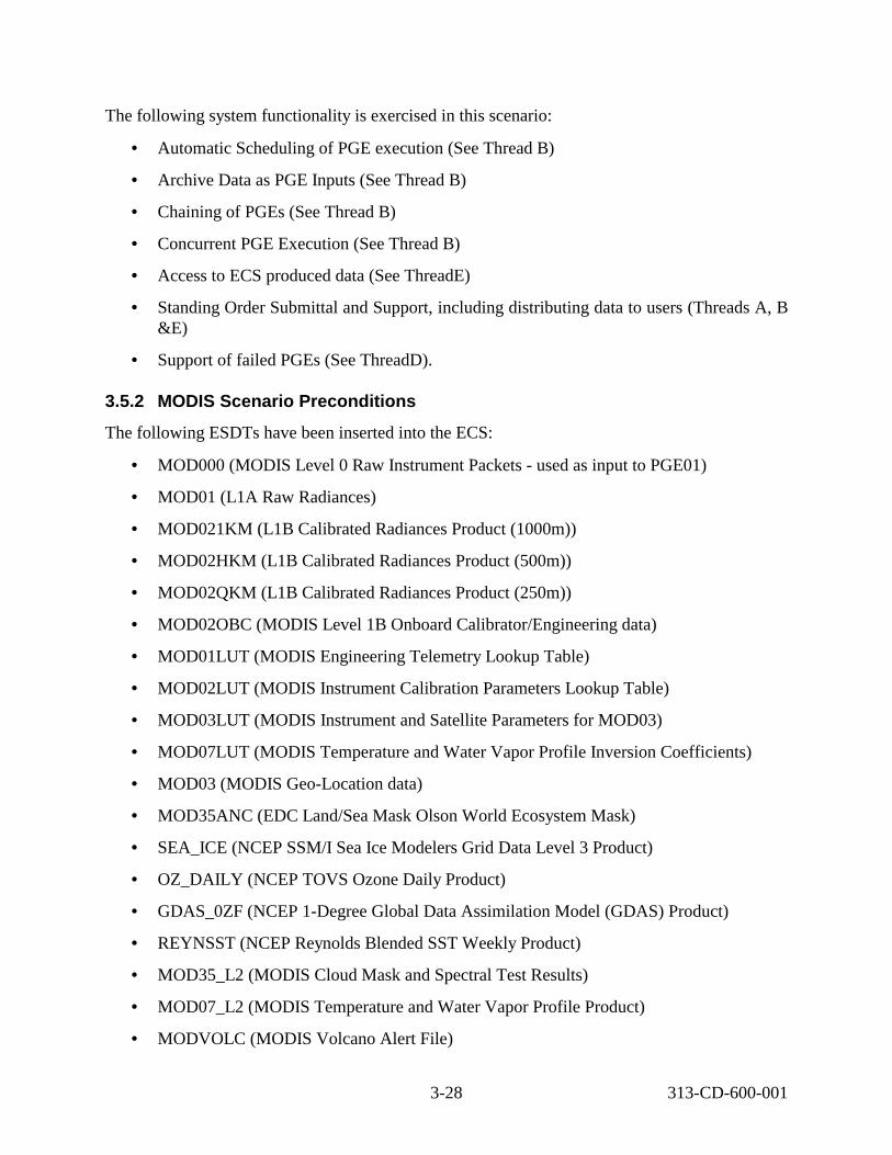
The following system functionality is exercised in this scenario:
• Automatic Scheduling of PGE execution (See Thread B)
• Archive Data as PGE Inputs (See Thread B)
• Chaining of PGEs (See Thread B)
• Concurrent PGE Execution (See Thread B)
• Access to ECS produced data (See ThreadE)
• Standing Order Submittal and Support, including distributing data to users (Threads A, B &E)
• Support of failed PGEs (See ThreadD).
3.5.2 MODIS Scenario Preconditions
The following ESDTs have been inserted into the ECS:
• MOD000 (MODIS Level 0 Raw Instrument Packets - used as input to PGE01)
• MOD01 (L1A Raw Radiances)
• MOD021KM (L1B Calibrated Radiances Product (1000m))
• MOD02HKM (L1B Calibrated Radiances Product (500m))
• MOD02QKM (L1B Calibrated Radiances Product (250m))
• MOD02OBC (MODIS Level 1B Onboard Calibrator/Engineering data)
• MOD01LUT (MODIS Engineering Telemetry Lookup Table)
• MOD02LUT (MODIS Instrument Calibration Parameters Lookup Table)
• MOD03LUT (MODIS Instrument and Satellite Parameters for MOD03)
• MOD07LUT (MODIS Temperature and Water Vapor Profile Inversion Coefficients)
• MOD03 (MODIS Geo-Location data)
• MOD35ANC (EDC Land/Sea Mask Olson World Ecosystem Mask)
• SEA_ICE (NCEP SSM/I Sea Ice Modelers Grid Data Level 3 Product)
• OZ_DAILY (NCEP TOVS Ozone Daily Product)
• GDAS_0ZF (NCEP 1-Degree Global Data Assimilation Model (GDAS) Product)
• REYNSST (NCEP Reynolds Blended SST Weekly Product)
• MOD35_L2 (MODIS Cloud Mask and Spectral Test Results)
• MOD07_L2 (MODIS Temperature and Water Vapor Profile Product)
• MODVOLC (MODIS Volcano Alert File)
3-28 313-CD-600-001

• AM1EPHN0 (Preprocessed Terra Platform Ephemeris Data from L0 in Native format)
• AM1ATTNF (Preprocessed Terra Platform Attitude Data from L0 in Native format)
• PM1EPHND (Preprocessed Definitive Aqua Platform Ephemeris Data from FDD in Native format)
• PM1ATTNR (Aqua Platform Definitive Attitude Data in Native format) (NOTE: It is assumed that this could be either PM1ATTNQ (Quick Attitude) or PM1ATTNR (Refined Attitude)).
• PGEEXE (PGE Execution Granule)
• FAILPGE (Failed PGE History)
• PH (Product History)
The following PGEs have successfully been through the SSI&T process:
• PGE01
• PGE02
• PGE03
Ancillary and static data granules have been inserted into Data Server.
MOD000 granules have been inserted into Data Server (via Ingest Polling from EDOS).
Subscription for MODIS failed PGE has been entered on behalf of Instrument Team.
A Resource Plan has been created for resources needed for MODIS production.
A Production Plan has been created using the Production Planning Workbench. This Production Plan includes Production Requests for the PGE01, PGE02 and PGE03. Available inputs will trigger the PGEs. The DPR for PGE01 job in the plan includes references to the appropriate MOD000 granules. The DPRs for PGE02 and PGE03 have submitted subscriptions for the Insert events for appropriate input data.
3.5.3 MODIS Scenario Partitions
The MODIS scenario has been partitioned into the following threads:
• MODIS Standing Order Submittal (Thread A) - This thread simply shows how the DAAC User Services submits a standing order for MOD35_L2 granules to be distributed via ftp Push to a science user (see Section 3.5.4).
• MODIS Standing Order Support (Thread B) - This thread shows how the system supports standing orders for data granules (see section 3.5.5).
• MODIS Standard Production (Thread C) - This thread shows how the sequence of PGEs (PGE01, PGE02, PGE03) execute in a chained fashion, with the output of one PGE being used as the input of the next (see Section 3.5.6).
3-29 313-CD-600-001

• MODIS Failed PGE Handling (Thread D) - This thread shows how the artifacts from a failed PGE are collected and sent to the Instrument Team (see Section 3.5.7).
• MODIS Data Access (Thread E) - This thread shows how the generated data products are available for user access. Also in this thread, the MODIS Standing Order, submitted in Thread A, is fulfilled (see Section 3.5.8).
• Data Compression on Distribution (Thread F) – Deferred until 6B: This thread shows how data is compressed to fit a desired media in the distribution process (see Section 3.5.9).
• Reactivation/Replan (Threads A, B, C) – This series of threads shows the three different types of reactivation/replanning and applies to MODIS or ASTER (see section 3.5.10).
3.5.4 MODIS Standing Order Submittal Thread This thread simply shows how the DAAC User Services submits a standing order for MOD35_L2, MOD07_L2 and MODVOLC granules to be distributed via ftp Push to a science user.
3.5.4.1 MODIS Standing Order Submittal Thread Interaction Diagram - Domain View Figure 3.5.4.1-1 depicts the MODIS Standing Order Submittal Interaction.
Ops DAAC Ops
A.1 Call DAAC
(via telephone) UserScience User A.2 Subscribe
SBSRVSBSRV Distributed Object (rpc, CtLib) HMI (GUI, Xterm, command) ftp email (or other as noted) Double line - Synchronous email (or other as noted) Dashed - Asynchronous
Figure 3.5.4.1-1. MODIS Standing Order Submittal Interaction Diagram
3.5.4.2 MODIS Standing Order Submittal Thread Interaction Table - Domain View Table 3.5.4.2-1 provides the Interaction - Domain View: MODIS Standing Order Submittal.
3-30 313-CD-600-001

Table 3.5.4.2-1. Interaction Table - Domain View:
Step Event Interface Client
MODIS Standing Order Submittal Interface Provider
Data Issues
Step Preconditions
Description
A.1 Call DAAC User Service s
Science User
DAAC None DAAC User Services Advertises Phone number. Email address available.
The Science User calls the DAAC User Services staff, requesting all MOD35_L2, MOD07_L2, and MODVOLC granules to be sent to his/her workstation, via ftpPush. The Science User provides host name and address, directory for data placement, and user name/password for ECS to use when placing data. Note: This could be performed via e-mail as well as telephone.
A.2 Subscri be
DAAC User Services Represen tative
SBSRV None MOD35_L2, MOD07_L2, and MODVOLC ESDT, with Insert Events
The DAAC User Services Representative submits a Standing Order subscription for MOD35_L2, MOD07_L2, and MODVOLC: Insert events. The action is to electronically push the product to the science user’s machine.
3.5.4.3 MODIS Standing Order Submittal Thread Component Interaction Table Table 3.5.4.3-1 provides the Component Interaction - Domain View: MODIS Standing Order Submittal.
Table 3.5.4.3-1. Component Interaction Table: MODIS Standing Order Submittal
Step Event Interface Client
Interface Provider
(1 of 2) Interface
Mech. Description
A.2.1 Startup SBSRV GUI
DAAC User Services Representa tive
EcSbGui Xterm The DAAC User Services Representative invokes SBSRV GUI application.
3-31 313-CD-600-001

Table 3.5.4.3-1. Component Interaction Table: MODIS Standing Order Submittal
Step Event Interface Client
Interface Provider
(2 of 2) Interface
Mech. Description
A.2.2 Create & Submit Subscript ion from GUI
DAAC User Services Representa tive
EcSbGui Xterm The DAAC User Services Representative represents him/herself as the Science User. The DAAC Operator brings up the GUI and clicks the button to create a new subscription. A list of events is displayed, from which the operator can choose to subscribe. The DAAC Operator selects the MOD35_L2, MOD07_L2, and MODVOLC: Insert events for the subscription. Two actions (besides notification), are available from the SBSRV at this time. Ftp Push as a distribution mechanism is selected via a GUI button. Other parameters required for ftpPush, including the Science User’s host name, target directory, ftp user name, and ftp password, are input via the GUI. The other option is a Ftp Pull, also selected via a GUI button. There are no other parameters required for this option.
A.2.3 Retrieve Distributi on Options
EcSbGui Configura tion Registry Server
Distributed Object
The Subscription Server GUI retrieves distribution options from the ECS Configuration Registry (ftp push, ftp pull).
A.2.4 Submit Subscript ion
EcSbGui EcSbSub Server
Distributed Object
Submit the subscription to the Subscription Server. This is accomplished with the EcClSubscription interface class. The correct SBSRV is determined via a Server UR, declared in configuration.
A.2.5 Store a Subscript ion
EcSbSubS erver
Sybase CtLib The subscription is stored in the Sybase Database.
3.5.5 MODIS Standing Order Support Thread This thread shows how the system supports standing orders for data granules. The granules utilized are MOD35_L2, MOD07_L2, and MODVOLC.
3.5.5.1 MODIS Standing Order Support Thread Interaction Diagram - Domain View Figure 3.5.5.1-1 depicts the MODIS Standing Order Support Interaction.
3-32 313-CD-600-001

B.5 Ship Media to User
Distributed Object (rpc, CtLib) HMI (GUI, Xterm, command) ftp email (or other as noted) Double line - Synchronous email (or other as noted) Dashed - Asynchronous
DSSDSS
Science User
Science User
CSS (SBSRV)
B.1 Trigger Event
B.3 email Notification
B.2 Acquire Data
B.7 Distribution Notice
(via DAAC shipper)
DAAC Ops
DAAC Ops
B.6 Update Order
B.4 Store Data on Media
Figure 3.5.5.1-1. MODIS Standing Order Support Interaction Diagram
3.5.5.2 MODIS Standing Order Support Thread Interaction Table - Domain View
Table 3.5.5.2-1 provides the Interaction - Domain View: MODIS Standing Order Support.
Table 3.5.5.2-1. Interaction Table - Domain View: MODIS Standing Order Support
Step Event Interface Client
Interface Provider
(1 of 2) Data
Issues Step
Precondi tions
Description
B.1 Trigge r Event
DSS (SDSRV)
CSS (SBSRV)
None None This thread picks up with fulfilling the standing order for MODIS data. The SDSRV sends an event trigger to the SBSRV when a subscription event has occurred on one of the MOD35_L2, MOD07_L2, or MODVOLC data types.
B.2 Acquir e Data
CSS (SBSRV)
DSS (SDSRV)
None None The SBSRV assists with fulfilling the standing order by the Science User for MODIS granules. The SBSRV sends a Request to Acquire data from the SDSRV, via one of the hard media, for the Science User.
3-33 313-CD-600-001

Table 3.5.5.2-1. Interaction Table - Domain View: MODIS Standing Order Support
Step Event Interface Client
Interface Provider
(2 of 2) Data
Issues Step
Precondi tions
Description
B.3 E-mail Notific ation
CSS (SBSRV)
Science User
None None Send email notification to the Science User, notifying him/her there is a newly inserted MODIS granule, which meets the specified constraints of interest. The notification message includes the UR of the granule as well as the qualification criteria that it matched.
B.4 Store Data on Media
DSS (DDIST)
DSS (STMGT)
None None The Data Server copies the MODIS granule’s files to one of the hard media types and marks the order as “Ready to Ship.”
B.5 Ship Media to User
DAAC Ingest/Di stribution Technicia n
Science User
None None A DAAC Ingest/Distribution Technician collects tape, media label shipping label and packing list. He/She label tape, enclose tape and packing list in shipping container and label shipping container. The DAAC uses a commercial shipping vendor for delivery to the Science User.
B.6 Updat e Order
DAAC Ingest/Di stribution Tech.
DSS None None A DAAC Ingest/Distribution Technician marks the order as “Shipped”.
B.7 Distrib ution Notice
DSS Science User
None None Send an e-mail notification to the Science User, notifying him/her the newly inserted MODIS data of interest has been shipped to their shipping address.
3.5.5.3 MODIS Standing Order Support Thread Component Interaction Table Table 3.5.5.3-1 provides the Component Interaction: MODIS Standing Order Support.
.
3-34 313-CD-600-001

Table 3.5.5.3-1. Component Interaction Table: MODIS Standing Order Support
Step Event Interface Client
Interface Provider
(1 of 5) Interface
Mech. Description
B.1.1 Insert Event
EcDsScie nceDataS erver
EcSbSub Server
Distributed Object
Upon successful insertion of MODIS granules, an Insert event is triggered for each granule. These are qualified events. Along with the trigger are criteria metadata qualifiers. The correct EcSbSubServer is determined from the EcDsScienceDataServer configuration. The correct event to trigger is determined from the events file, which was populated during ESDT installation. The UR of the inserted granule is provided when the event is triggered.
B.1.2 Retrieve Subscriptio ns
EcSbSub Server
Sybase CtLib The EcSbSubServer queries the Sybase database determining which subscriptions need to be activated, or fired. Each query “hit” is an activated subscription and executes independently. Currently, all the subscriptions on this qualified event are not qualified, so all subscriptions are “hits.”
B.2.1 Connect to SDSRV
EcSbSub Server
EcDsScie nceDataS erver
Distributed Object
In order to fulfill a standing order for MODIS data, the EcSbSubServer begins a session with the EcDsScienceDataServer, on behalf of the subscription user. The appropriate EcDsScienceDataServer is selected by the Granule UR provided when the event was triggered. This is pertinent if there are multi-SDSRVs in use at one DAAC in one mode.
B.2.2 Add PGE granule’s UR to Session
EcSbSub Server
EcDsScie nceDataS erver
Distributed Object
The EcSbSubServer establishes the data context of the session with the SDSRV by adding the input granules to the session. The Granule UR of each input granule is added to the ESDT ReferenceCollector.
3-35 313-CD-600-001

Table 3.5.5.3-1. Component Interaction Table: MODIS Standing Order Support
Step Event Interface Client
Interface Provider
(2 of 5) Interface
Mech. Description
B.2.3 Retrieve Granule Metadata from Inventory
EcDsScie nceDataS erver
Sybase/S QS
CtLib The EcDsScienceDataServer completes establishing the data context by retrieving the metadata for the requested granules from the Sybase/SQS database. The metadata for each granule is passed back to the reference objects for each granule.
B.2.4 Acquire Data
EcSbSub Server
EcDsScie nceDataS erver
Distributed Object
The EcSbSubServer fulfills the standing order for a MODIS granule by submitting an Acquire request for the granule. The Acquire request is for an 8mm, D3, or DLT tape or CD-ROM of all granules in the ESDT ReferenceCollector. This request is asynchronous, meaning the return of the submit call of the request only contains the status of the request’s submittal. The request asks for an email notification for the user. The Acquire request structure is hard-coded within the EcSbSubServer. For the granule referenced in the Acquire request, the EcDsScienceDataServer creates a file containing the granule’s metadata before passing the data to be distributed.
B.2.5 Create Staging Disk
EcDsScie nceDataS erver
EcDsStR equestMa nagerSer ver
Distributed Object
The EcDsDistributionServer sends requests to the EcDsStRequestManagerServer to allocate space on staging disks for the granule files in the archive. The amount of staging disk to request is calculated from the file sizes in the information passed in the Distribution Request. The amount of space on a staging disk to request is determined by the size of the metadata file.
B.2.6 STMGT Retrieve
EcDsScie nceDataS erver
EcDsStR equestMa nagerSer ver
Distributed Object
The EcDsScienceDataServer requests the EcDsStRequestManagerServer to retrieve the granule files. This results in the files being staged to the working staging disk area. The appropriate archive object to request is obtained based upon the information provided by the EcDsScienceDataServer in the distribution request.
3-36 313-CD-600-001

Table 3.5.5.3-1. Component Interaction Table: MODIS Standing Order Support
Step Event Interface Client
Interface Provider
(3 of 5) Interface
Mech. Description
B.2.7 Distribute Granules, Synchrono us
EcDsScie nceDataS erver
EcDsDistr ibutionSe rver
Distributed Object
The EcDsScienceDataServer submits a request to EcDsDistributionServer. The request includes a reference to the metadata files. Other parameters from the Acquire request are passed to the EcDsDistributionServer including media types (8mm, D3, DLT or CD-ROM). At this point all necessary data has been pulled from the archive or the DB.
B.2.8 Create Staging Disk
EcDsDistr ibutionSe rver
EcDsStR equestMa nagerSer ver
Distributed Object
The EcDsDistributionServer sends requests to the EcDsStRequestManagerServer to allocate space on staging disks for the granule files in the archive. The amount of staging disk to request is calculated from the file sizes in the information passed in the Distribution Request. (Note: A packing list is created in step B.4.2)
B.2.9 STMGT Retrieve
EcDsDistr ibutionSe rver
EcDsStR equestMa nagerSer ver
Distributed Object
The EcDsDistributionServer sends requests to the EcDsStRequestManagerServer to retrieve data from the archive. The EcDsStCacheManagerServer moves the files from the archive to the read only cache tables in the Sybase Server.
B.2.1 0
Link data files to Staging Disk
EcDsDistr ibutionSe rver
EcDsStR equestMa nagerSer ver
Distributed Object
The EcDsDistributionServer links the data files in the read-only cache to the staging disk area.
B.2.1 1
Link metadata files to Staging Disk
EcDsDistr ibutionSe rver
EcDsStR equestMa nagerSer ver
Distributed Object
The EcDsDistributionServer sends requests to the EcDsStRequestManagerServer to link the metadata files. The metadata files are provided on staging areas initially allocated for SDSRV.
B.3.1 Send Notification
EcSbSub Server
Science User
e-mail The EcSbSubServer builds an e-mail notification that the user’s subscription on the MODIS data insert event has been fired. This notification identifies the Event, the subscription ID, the UR that was inserted and the previously supplied User String.
3-37 313-CD-600-001

Table 3.5.5.3-1. Component Interaction Table: MODIS Standing Order Support
Step Event Interface Client
Interface Provider
(4 of 5) Interface
Mech. Description
B.4.1 Allocate Media Resource
EcDsDistr ibutionSe rver
EcDsStR equestMa nagerSer ver
Distributed Object
The EcDsDistributionServer sends requests to the EcDsStRequestManagerServer to relay to the Resource manager to prepare the requested hard media type via a Resource Manager Factory. The correct resource manager is determined from the Media Type handed to the resource factory. The correct requested hard media type resource is determined by the configuration within the resource factory.
B.4.2 Write files to 8mm tape
EcDsDistr ibutionSe rver
EcDsStR equestMa nagerSer ver
Distributed Object
The EcDsDistributionServer sends requests to the EcDsStRequestManagerServer to copy the files held on the staging disk to the requested hard media device. Upon completion of the files being copied, the state of the distribution request is marked as “Ready for Shipment,” which is displayed on the operator GUI. A packing list is generated and automatically printed using the STMGTresource manager.
B.5.1 Determine request is ready for shipping
DAAC Ops -Distributio n Technicia n
EcDsDdis tGui
GUI Operator notes the request is ready for shipping on the EcDsDdistGui and the order includes the requested hard media just produced. The slot and stacker ID are included on the logs accessible to the operator for 8mm, D3, or DLT tape or CD writer ID for the CD-ROM, so the operator knows which tapes to ship.
B.5.2 Ship Tapes DAAC Ops -Data Technicia n
DAAC Ops -Data Technicia n
Internal The labels for all media, as well as a shipping label for the package, are created manually. Using commercial shipping vendors (determined by DAAC policy), the DAAC Data Technician labels the tape, packages the tape(s) and packing list, labels the package, and ships the order to the address provided within the request.
B.6.1 Mark as Shipped
DAAC Ops -Data Tech.
EcDsDdis tGui
GUI Using the EcDsDdistGui, the Data Technician marks the request as “Shipped.”
B.6.2 Update Distribution Request
EcDsDdis tGui
EcDsDistr ibutionSe rver
Distributed Object
The Data Technician uses the EcDsDistributionServer to update the state of the request to “Shipped.”
3-38 313-CD-600-001

PLS
DP
DS
DAAC Ops
Table 3.5.5.3-1. Component Interaction Table: MODIS Standing Order Support
Step Event Interface Client
Interface Provider
(5 of 5) Interface
Mech. Description
B.7.1 Build Distribution Notice
EcDsDistr ibutionSe rver
EcDsDistr ibutionSe rver
Internal The EcDsDistributionServer builds an e-mail notification stating the user’s order has been fulfilled. This notification includes the media ID, type and format of the request, UR, type and file names and sizes for each granule as well as a DAAC configurable preamble.
B.7.2 Send E-mail
EcDsDistr ibutionSe rver
Science User
email The EcDsDistributionServer sends the distribution notice (e-mail) to the user. If the subscription is input by or for a registered user, the e-mail goes directly to the user – no interpretation is needed.
3.5.6 MODIS Standard Production Thread This thread shows how the sequence of PGEs (PGE01, PGE02, PGE03) execute in a chained fashion, with the output of one PGE being used as the input of the next.
3.5.6.1 MODIS Standard Production Thread Interaction Diagram Figure 3.5.6.1-1 depicts the MODIS Standard Production Thread Interaction.
C.1 Activate Production Plan C.2 Submit DPRs DAAC PLS C.5 Release Job (PGE01)
Ops C.12 Release Job (PGE02) C.19 Release Job (PGE03) C.8 Request DSS UR
C.15 Request DSS UR
C.4 Notification (MOD00) C.7 Run PGE (PGE01) C.23 Request DSS UR
C.11 Notification(MOD01, MOD03) C.14 Run PGE (PGE02) DPSS IOS C.18 Notification (MOD02) C.21 Run PGE (PGE03)
C.22 PGE Fails C.6 Acquire Data (PGE01 input)
CSS C.9 Insert Data (PGE01 output) (SBSRV) C.13 Acquire Data(PGE02 ancillary)
C.16 Insert Data (PGE02 output) C.3 Trigger Event (MOD00) C.20 Acquire Data (PGE03 static and ancillary inputs)
C.10 Trigger Event (MOD01, MOD03) C.24 Insert Data (PGE03 output)
C.17 Trigger Event (MOD02) Distributed Object (rpc, CtLib)
C.25 Trigger Event HMI (GUI, Xterm, command)
(MOD35_L2, MOD07_L2, MODVOLC) DSSS ftp email (or other as noted) Double line - Synchronous email (or other as noted) Dashed - Asynchronous
Figure 3.5.6.1-1. MODIS Standard Production Interaction Diagram
3-39 313-CD-600-001

3.5.6.2 MODIS Standard Production Thread Interaction Table - Domain View Table 3.5.6.2-1 provides the Interaction - Domain View: MODIS Standard Production.
Table 3.5.6.2-1. Interaction Table - Domain View: MODIS Standard Production (1 of 4)
Step Event Interface Client
Interface Provider
Data Issues
Step Preconditions
Description
C.1 Activat e Produ ction Plan
DAAC Productio n Planner
PLS None PGEs passed SSI&T. already created.
The DAAC Production Planner activates a plan, which includes a DPR for PGE01. Plan created for PGE01, PGE02, and PGE03, with input granules IDs obtained for PGE01, and subscriptions submitted for input data for PGE02 and PGE03.
C.2 Submi t DPRs
PLS DPS None None DPRs for PGE01 are submitted by the PLS “Offhold” (standby state) to the DPS. PGE02 and PGE03 are placed in the jobMgt queue “On Hold.”PGE02 and PGE03 have dependencies on the previous DPRs (PGE02 needs PGE01 DPR, PGE03 needs PGE01 and PGE02 DPRs).
C.3 Insert Event
DSS CSS (SBSRV)
None The MOD000 has been inserted to DSS by Ingest.
The DSS triggers MOD000: Insert event to the CSS.
C.4 Notific ation
CSS (SBSRV)
PLS None PLS Subscriptions for MOD000:Insert event
The CSS sends direct notification to the PLS, notifying there are newly inserted MOD000 granules. Notifications include the UR of the granules produced.
C.5 Relea se Job
PLS DPS None None The PLS sends a request to the DPS releasing the job containing PGE01.
C.6 Acquir e Data
DPS DSS One MOD000 @ 6.2GB every 2 hours.
None The DPS submits an Acquire Request for MOD000, MOD01LUT and MOD03LUT via ftpPush to the DSS, for input to PGE01.
Plan
3-40 313-CD-600-001

Table 3.5.6.2-1. Interaction Table - Domain View: MODIS Standard Production (2 of 4)
Step Event Interface Client
Interface Provider
Data Issues
Step Preconditions
Description
C.7 Run PGE
DPS DPS PGE01 creates 24 MOD01 granules/2 hours @355MB/g ranule and 24 MOD03 granules/2 hours @61MB/gr anule
None The DPS runs PGE01, creating MOD01 and MOD03 granules.
C.8 Reque st DSS UR
DPS IOS None None The DPS gets the DSS UR from the IOS Advertising Server.
C.9 Insert Data
DPS DSS None MOD01 and MOD03 ESDTs.
The DPS sends requests for the archiving of the newly created MOD01 and MOD03 granules into the SDSRV archive within the DSS.
C.10 Insert Event
DSS CSS (SBSRV; Subscript ion Server)
None None The DSS notifies the CSS of the MOD01: Insert and MOD03: Insert events. Note: these are actually two different events, so there are two independent events triggered by the CSS (SBSRV).
C.11 Notific ation
CSS (SBSRV)
PLS None PLS Subscriptions for MOD01:Insert and MOD03:Insert events
The CSS sends direct notification to the PLS, notifying there are ly inserted MOD01 and MOD03 granules. Notifications include the UR of the granules produced.
C.12 Relea se Job
PLS DPS None None The PLS sends a request to the DPS releasing the job containing PGE02.
C.13 Acquir e Data
DPS DSS MOD02LU T @357KB, from MODIS IT
MOD02LUT ESDT.
The DPS submits an Acquire Request to the DSS for the ancillary product, MOD02LUT, via ftpPush, for input to PGE02. input to PGE02 is the MOD01 granule that was created in step C.7.
new
the otherNote:
3-41 313-CD-600-001

Table 3.5.6.2-1. Interaction Table - Domain View: MODIS Standard Production
Step Event Interface Client
Interface Provider
(3 of 4) Data
Issues Step
Preconditions Description
C.14 Run PGE
DPS DPS One MOD02OB C, MOD021K M, MOD02HK M, and MOD02QK M@ 655 MB produced
None The DPS runs PGE02, creating the MOD02OBC, MOD021KM, MOD02HKM, and MOD02QKM granules.
C.15 Reque st DSS UR
DPS IOS None None The DPS gets the DSS UR from the IOS Advertising Server.
C.16 Insert Data
DPS DSS None MOD02OBC, MOD021KM, MOD02HKM, AND MOD02QKM ESDTs.
The DPS requests archiving of the newly created MOD02OBC, MOD021KM, MOD02HKM, and MOD02QKM granules into the SDSRV archive within the DSS.
C.17 Insert Event
DSS CSS (SBSRV)
None None The DSS notifies the CSS of the MOD02OBC, MOD021KM, MOD02HKM, and MOD02QKM: Insert events.
C.18 Notific ation
CSS (SBSRV)
PLS None PLS Subscription for MOD02OBC, MOD021KM, MOD02HKM, AND MOD02QKM: Insert events.
The DSS sends direct notification to the PLS, notifying there are newly inserted MOD02OBC, MOD021KM, MOD02HKM, and MOD02QKM granules. The notification message includes the UR of the granule.
C.19 Relea se Job
PLS DPS None None The PLS sends a request to the DPS releasing the job containing PGE03.
C.20 Acquir e Data
DPS DSS New Static and Ancillary Inputs
Static Inputs: MOD35ANC, MOD07LUT Ancillary Inputs: SEA_ICE, OZ_DAILY, GDAS_0ZF, REYNSST
The DPS submits an Acquire Request to the DSS for PGE03 Products, via ftpPush, for input to PGE03. Note: The other inputs to PGE03 were created with PGE01 and PGE02 outputs and are still on the DPS disk resources, so no Acquires are necessary for those inputs.
3-42 313-CD-600-001

Table 3.5.6.2-1. Interaction Table - Domain View: MODIS Standard Production
Step Event Interface Client
Interface Provider
(4 of 4) Data
Issues Step
Preconditions Description
C.21 Run PGE
DPS DPS 1MOD35_L 2, 1MOD07_L 2, and 1MODVOL C @76+MB produced
None The DPS runs PGE03, creating MOD35_L2, MOD07_L2, and MODVOLC granules.
C.22 PGE Fails
DPS DPS None None One instance of the DPS running PGE03 fails, due to the need for night data, but all input data is during the daylight. This is a planned PGE failure. Please pick up processing of this Failed PGE in Thread D of this MODIS scenario.
C.23 Reque st DSS UR
DPS IOS None None The DPS gets the DSS UR from the IOS Advertising Server.
C.24 Insert Data
DPS DSS None MOD35_L2, MOD07_L2, and MODVOLC ESDTs.
The DPS sends a request for the archiving of the newly created MOD35_L2, MOD07_L2, and MODVOLC granules into the SDSRV archive within the DSS.
C.25 Trigge r Event
DSS CSS (SBSRV)
None None The DSS notifies the CSS of the MOD35_L2, MOD07_L2, and MODVOLC: Insert events. Completion of the support for a Standing order is shown in Thread E of this MODIS scenario.
3.5.6.3 MODIS Standard Production Thread Component Interaction Table Table 3.5.6.3-1 provides the Component Interaction: MODIS Standard Production.
3-43 313-CD-600-001

Table 3.5.6.3-1. Component Interaction Table: MODIS Standard Production
Step Event Interface Client
(1 of 30) Interface Provider Interface
Mech. Description
C.1.1 Startup Planning Workbe nch
DAAC Operator -Planner
EcPlWb GUI The DAAC Planner invokes the Planning workbench (EcPlWb) by double clicking on the Planning Workbench icon.
C.1.2 Select Plan to Activate, Modify and Activate
DAAC Operator -Planner
EcPlWb GUI The Planner interacts with the EcPlWb GUI to select a plan to activate (it was already created) and modify it with DPRs for chaining PGE01, PGE02 and PGE03. Input granules for PGE01 are identified in the Production Plan. (Note: scenario preconditions are stated above.)
C.1.3 Create DPR
EcPlWb EcDpPrJobMgmt rpc The EcPlWb sends the DPRID to the EcDpPrJobMgmt, a list of predecessor DPRs, and whether the DPR is waiting for external data.
C.2.1 Submit DPRs
EcDpPrJo bMgmt
AutoSys JIL The DPRs in the updated plan are submitted to the AutoSys by the EcDpPrJobMgmt for dependent execution. MOD000 covers 2 hours and MOD02 and MOD03 cover 5 minutes each. Therefore, the number of DPRs is one for PGE01 and between 22 and 24 each for PGE02 and PGE03 for a total of 45 to 49 for 2 hours depending on the data. The PGE01 job is automatically released, because all inputs are available and the production rules have been met, because input granules were referenced in DPR.
C.2.2 Initiate Job Processi ng
event_dae mon
EcDpPrEM command line
Theevent daemon initiates the EcDpPrEM containing the PGE01.
3-44 313-CD-600-001

Table 3.5.6.3-1. Component Interaction Table: MODIS Standard Production (2 of 30)
Step Event Interface Client
Interface Provider Interface Mech.
Description
C.2.3 Connect to SDSRV
EcDpPrE M
EcDsScienceData Server
Distributed Object
The EcDpPrEM begins a session with the EcDsScienceDataServer by connecting, in order to acquire the PGE01. he appropriate EcDsScienceDataServer is selected by using the Granule UR of the PGE granule, which is defined in the Production plan and is part of the DPR. This is pertinent if there are multi-SDSRVs in use at one DAAC in one mode.
C.2.4 Add PGE granule’ s UR to Session
EcDpPrE M
EcDsScienceData Server
Distributed Object
The EcDpPrEM tablishes the data context of the session with the EcDsScienceDataServer by adding the PGE granule’s UR to the ESDT ReferenceCollector.
C.2.5 Retrieve Granule Metadat a from Inventor y
EcDsScie nceDataS erver
Sybase/SQS CtLib The EcDsScienceDataServer completes establishing the data context by retrieving the metadata for the requested PGE granule from the Sybase/SQS database. he metadata for the PGE granule is passed back to the reference objects for each granule.
C.2.6 Acquire Data
EcDpPrE M
EcDsScienceData Server
Distributed Object
The EcDpPrEM sends requests for PGE Tar Files to the EcDsScienceDataServer by submitting an Acquire request. he Acquire request is for a ftpPush of all granules in the ESDT ReferenceCollector. his request is synchronous, meaning the return of the submit call of the request contains the results of the request. This means the response is not sent until the PGE granule files have been ftp’ed to the DPS disks. This request asks for no distribution notice to be sent. he Acquire request structure is hard-coded.
T
es
T
T
T
T
3-45 313-CD-600-001

Table 3.5.6.3-1. Component Interaction Table: MODIS Standard Production
Step Event Interface Client
(3 of 30) Interface Provider
Interface Mech.
Description
C.2.7 Create Staging Disk
EcDsScie nceDataS erver
EcDsStRequestM anagerServer
Distributed Object
The EcDsDistributionServer sends requests to the EcDsStRequestManagerServer to allocate space on staging disks for the granule files in the archive. The amount of staging disk to request is calculated from the file sizes in the information passed in the Distribution Request. The amount of staging disk area to request is determined by the size of the metadata file.
C.2.8 Create Metadat a file
EcDsScie nceDataS erver
EcDsScienceData Server
Distributed Object
The EcDsScienceDataServer creates a file containing the PGE granule’s metadata before passing the data to the EcDsDistributionServer.
C.2.9 Distribut e Granule s, Synchro nous
EcDsScie nceDataS erver
EcDsDistributionS erver
Distributed Object
The EcDsScienceDataServer submits a request to the EcDsDistributionServer. The request includes, for each granule, a reference to the metadata file as well as all data files. Other parameters from the Acquire request are passed to the EcDsDistributionServer.
C.2.10 Claim Owners hip
EcDsDistri butionServ er
EcDsStRequestM anagerServer
Distributed Object
The EcDsDistributionServer sends requests to the EcDsStRequestManagerServer to be passed on to the Staging Disk Server to claim ownership of the staging disk area created by the Staging Disk Server.
C.2.11 Compre ss Disk
EcDsDistri butionServ er
EcDsStRequestM anagerServer
Distributed Object
The EcDsDistributionServer sends requests to the EcDsStRequestManagerServer to be passed on to the Staging Disk Server to compress the staging disk area.
3-46 313-CD-600-001

Table 3.5.6.3-1. Component Interaction Table: MODIS Standard Production (4 of 30)
Step Event Interface Client
Interface Provider
Interface Mech.
Description
C.2.12 Create Staging Disk
EcDsDistri butionServ er
EcDsStRequestM anagerServer
Distributed Object
The EcDsDistributionServer sends requests to the EcDsStRequestManagerServer to be forwarded to the Staging Disk Server to allocate space on staging disks for the granule files in the archive. The amount of staging disk to request is calculated from the file sizes in the information passed in the Distribution Request .
C.2.13 STMGT Retrieve
EcDsDistri butionServ er
EcDsStRequestM anagerServer
Distributed Object
The EcDsDistributionServer sends requests to the EcDsStRequestManagerServer to be forwarded to the Archive Server to retrieve the archived PGE granule file. The files are compressed after they are retrieved using the compression type specified. This results in the file being staged to read-only cache disks. This means all files needed to fulfill the distribution request are on disk, and ready to belinked. he correct archive object to request is determined from the information provided by the SDSRV in the distribution request. his returns references to the files in the read-only cache.
C.2.14 Link files to Staging Disk
EcDsDistri butionServ er
EcDsStRequestM anagerServer
Distributed Object
The EcDsDistributionServer sends requests to the EcDsStRequestManagerServer be forwarded to the Staging Disk Server to link to the data files in the read-only cache.
C.2.15 Copy files to Staging Disk
EcDsDistri butionServ er
EcDsStRequestM anagerServer
Distributed Object
The EcDsDistributionServer sends requests to the EcDsStRequestManagerServer to be forwarded to the Staging Disk Server to copy the metadata files from the archive to the staging disk area within the Sybase Server.
T
T
3-47 313-CD-600-001

Table 3.5.6.3-1. Component Interaction Table: MODIS Standard Production (5 of 30)
Step Event Interface Client
Interface Provider
Interface Mech.
Description
C.2.16 ftpPush Files
EcDsDistri butionServ er
EcDsStRequestM anagerServer
Distributed Object
The EcDsDistributionServer sends requests to the EcDsStRequestManagerServer for ftp Pushes via a Resource Manager Factory. The appropriate resource manager is selected by the media type provided to the resource factory (ftpPush, in this case). The files, host, compression type and location are all determined from the information provided in the original Acquire request. er name and password are generated from configuration values if none are given.
C.2.17 ftp Files EcDsStFtp Server
Operating System ftp daemon (EcDpPrEM)
ftp The EcDsStFtpServer performs the actual ftp of the PGE files to the EcDpPrEM host omputer.
C.3.1 Trigger Event (MOD00 0)
EcDsScie nceDataS erver
EcSbSubServer Distributed Object
Upon successful insertion of the MOD000 granules, the MOD000: Insert event is triggered by the EcSbSubServer, one per granule. The appropriate EcSbSubServer is obtained from the SDSRV configuration. The correct events to trigger are determined from the events file, where they were stored when the ESDT was installed in the EcDsScienceDataServer. Provided with the event triggering is the UR of the inserted granule.
C.3.2 Retrieve Subscrip tions
EcSbSub Server
Sybase CtLib The EcSbSubServer queries the Sybase database determining which subscriptions need to be activated, or fired. h query “hit” is an activated subscription and executes independently.
Us
c
Eac
3-48 313-CD-600-001

Table 3.5.6.3-1. Component Interaction Table: MODIS Standard Production (6 of 30)
Step Event Interface Client
Interface Provider
Interface Mech.
Description
C.4.1 Asynchr onous Direct Notificati on
EcSbSub Server
EcPlSubMgr Message Passing Mechanis m
The EcSbSubServer notifies the EcPlSubMgrthere are new MOD000 granules available. he granule UR is passed in the notification to the user, along with a reference to the subscription that is being fulfilled. Direct Notification is to a Queue name (a Message Passing Mechanism) the PlSubMgr provided when the subscription was submitted.
C.4.2 Connect to SDSRV
EcPlSubM gr
EcDsScienceData Server
Distributed Object
The EcPlSubMgr begins a session with the EcDsScienceDataServer to determine the use of the new granule. he appropriate EcDsScienceDataServer is selected by using the Granule UR in the notification message. his is pertinent if there are multi-SDSRVs in use at one DAAC in one mode.
C.4.3 Add PGE granule’ s UR to Session
EcPlSubM gr
EcDsScienceData Server
Distributed Object
The EcPlSubMgr establishes the data context of the session with the EcDsScienceDataServer by adding the new granule’s UR of the PGE granule to the ESDT ReferenceCollector.
C.4.4 Retrieve Granule Metadat a from Inventor y
EcDsScie nceDataS erver
Sybase/SQS CtLib The EcDsScienceDataServer completes establishing the data context by retrieving the metadata for the requested PGE granule from the Sybase/SQS database. he metadata for the PGE granule is passed back to the reference objects for each granule.
C.4.5 Inspect Granule Value Paramet ers
EcPlSubM gr
EcDsScienceData Server
Distributed Object
The EcPlSubMgr checks the new granule’s metadata attributes (type, version, file size and temporal range), to determine which, if any, jobs can use it as input.
C.4.6 Match Granule s
EcPlSubM gr
Sybase CtLib The EcPlSubMgr queries the PDPS database to determine if any PGEs are waiting for this granule. so, the size and granule UR are written.
C.5.1 Release Job Request
EcPlSubM gr
EcDpPrJobMgmt rpc The EcPlSubMgr sends a request to the EcDpPrJobMgmt to release the job containing PGE01.
T
Ec
T
T
T
If
3-49 313-CD-600-001

Table 3.5.6.3-1. Component Interaction Table: MODIS Standard Production (7 of 30)
Step Event Interface Client
Interface Provider
Interface Mech.
Description
C.5.2 Force Start Job
EcDpPrJo bMgmt
event_daemon rpc The DpPrJobMgmt sends a request to the event daemon to release the job containing PGE01.
C.5.3 Initiate Job Processi ng
event_dae mon
EcDpPrEM command line
The event daemon initiates the EcDpPrEM.
C.6.1 Connect to SDSRV
EcDpPrE M
EcDsScienceData Server
Distributed Object
The EcDpPrEM invokes the Data Manager which begins a session with the EcDsScienceDataServer by connecting. he appropriate EcDsScienceDataServer is selected by using the Granule UR of the input granule. his is pertinent if there are multi-SDSRVs in use at one DAAC in one mode.
C.6.2 Add PGE granule’ s UR to Session
EcDpPrE M
EcDsScienceData Server
Distributed Object
The Data Manager invoked by EcDpPrEM establishes the data context of the session with the EcDsScienceDataServer by adding the input granule (MOD000) to the session. The Granule UR of the input granule is added to the ESDT ReferenceCollector. sequence is performed for each input granule, one at a time.
C.6.3 Retrieve Granule Metadat a from Inventor y
EcDsScie nceDataS erver
Sybase/SQS CtLib The EcDsScienceDataServer completes establishing the data context by retrieving the metadata for the requested granule from the Sybase/SQS database. he metadata for each granule is passed back to the reference objects for each granule.
Ec
T
T
Note that this
T
3-50 313-CD-600-001

Table 3.5.6.3-1. Component Interaction Table: MODIS Standard Production (8 of 30)
Step Event Interface Client
Interface Provider
Interface Mech.
Description
C.6.4 Acquire Data
EcDpPrE M
EcDsScienceData Server
Distributed Object
The DPS Data Manager invoked by EcDpPrEM requests granules by submitting an Acquire request for those granules. he Acquire request is for a ftpPush of all granules in the ESDT ReferenceCollector. his request is synchronous, meaning that the return of the submit call of the request contains the results of the request. his means that the response is not sent until the granule files have been ftp’ed to the DPS disks. This request asks for no distribution notice to be sent. The Acquire command structure is hard-coded.
C.6.5 Create Staging Disk
EcDsScie nceDataS erver
EcDsStRequestM anagerServer
Distributed Object
The EcDsDistributionServer sends requests to the EcDsStRequestManagerServer to allocate space on staging disks for the granule files in the archive. The amount of staging disk to request is calculated from the file sizes in the information passed in the Distribution Request. The amount of staging disk area to request is determined by the size of the metadata file.
C.6.6 Create Metadat a file
EcDsScie nceDataS erver
EcDsScienceData Server
Distributed Object
For each granule referenced in the Acquirerequest, the EcDsScienceDataServer creates a file containing the granule’s metadata before passing the data tothe EcDsDistributionServer.
C.6.7 Distribut e Granule s, Synchro nous
EcDsScie nceDataS erver
EcDsDistributionS erver
Distributed Object
The EcDsScienceDataServer submits a request tothe EcDsDistributionServer. The request includes, for each granule, a reference to the metadata file as well as all data files. Other parameters from the Acquire request are passed tothe EcDsDistributionServer.
T
T
T
3-51 313-CD-600-001

Table 3.5.6.3-1. Component Interaction Table: MODIS Standard Production (9 of 30)
Step Event Interface Client
Interface Provider
Interface Mech.
Description
C.6.8 Claim Owners hip
EcDsDistri butionServ er
EcDsStRequestM anagerServer
Distributed Object
The EcDsDistributionServer sends requests to the EcDsStRequestManagerServer to be relayed to the Staging Disk Server which will claim ownership of the staging disk area created by the Staging Disk Server.
C.6.9 Compre ss Disk
EcDsDistri butionServ er
EcDsStRequestM anagerServer
Distributed Object
The EcDsDistributionServer sends requests to the EcDsStRequestManagerServer to be forwared to the Staging Disk Server to compress the staging disk area.
C.6.10 Create Staging Disk
EcDsDistri butionServ er
EcDsStRequestM anagerServer
Distributed Object
The EcDsDistributionServer sends requests to the EcDsStRequestManagerServer which is forwarded to the Staging Disk Server to allocate space on staging disks for the granule files in the archive. The amount of staging disk to request is calculated from the file sizes in the information passed in the Distribution Request.
C.6.11 STMGT Retrieve
EcDsDistri butionServ er
EcDsStRequestM anagerServer
Distributed Object
The EcDsDistributionServer sends requests to the EcDsStRequestManagerServer which is forwarded to the Archive Server to retrieve data from the archive. The EcDsStCacheManagerServer moves the files from the archive to the read only cache tables in the Sybase Server. he files are compressed after they are retrieved using the compression type specified. his results in the file being staged to read-only cache disks. This means all the files needed to fulfill the distribution request are on disk, and ready to be copied. he correct archive object to request is determined from the information provided by the SDSRV in the distribution request. his returns references to the files in the read-only cache.
T
T
T
T
3-52 313-CD-600-001

Table 3.5.6.3-1. Component Interaction Table: MODIS Standard Production (10 of 30)
Step Event Interface Client
Interface Provider
Interface Mech.
Description
C.6.12 Link files to Staging Disk
EcDsDistri butionServ er
EcDsStRequestM anagerServer
Distributed Object
DDIST links the files from the read-only cache into the staging disk with a request sent to the STMGT Request Manger which is forwarded to the Staging Disk Server.
C.6.13 Copy files to Staging Disk
EcDsDistri butionServ er
EcDsStRequestM anagerServer
Distributed Object
The EcDsDistributionServer sends requests to the EcDsStRequestManagerServer to be forwarded to the Staging Disk Server to copy the metadata files from the archive to the staging disk area within the Sybase Server.
C.6.14 ftpPush Files
EcDsDistri butionServ er
EcDsStRequestM anager then to EcDsStFtpServer
Distributed Object
DDIST now creates the Resource manager for ftp Pushes via a Resource Manager Factory. The correct resource manager is determined from the Media Type handed to the resource factory (ftpPush, in this case). he correct ftp Server is determined from configuration within the resource factory. The files, host, and location are all determined from the information provided in the original Acquire request. er name and password are generated from configuration values if none are given.
C.6.15 ftp Files EcDsStFtp Server
Operating System ftp daemon (EcDpPrEM)
ftp The EcDsStFtpServer requests the actual ftp of the files to the EcDpPrEM host computer via the Operating System ftp daemon.
C.7.1 Get Metadat a Configur ation File
EcDpPrE M
EcDsScienceData Server
Distributed Object
The process invoked by EcDpPrEM gets the metadata configuration file of the output data’s ESDT (MOD01 and MOD03) from the EcDsScienceDataServer. The data type and version are obtained from the PDPS database; the appropriate client name is obtained from the configuration file.
T
Us
DPS Data Manager
3-53 313-CD-600-001

Table 3.5.6.3-1. Component Interaction Table: MODIS Standard Production (11 of 30)
Step Event Interface Client
Interface Provider
Interface Mech.
Description
C.7.2 Run PGE
EcDpPrRu nPGE
PGE<PGE01> command line
The EcDpPrRunPGE executes PGE01. output files are placed in the output directory. The directory path is established by using a root, which was established by configuration, and the specific directory by the job ID. his disk root is cross-mounted by DPS, SDSRV and STMGT. This is to ensure they are directly available to the DSS to be archived.
C.8.1 Request DSS UR
EcDpPrE M
EcIoAdServer Distributed Object
If the DSS UR for this output data type is not already known in the PDPS database, The Manager process invoked by EcDpPrEM searches the EcIoAdServer for a “GetQueryableParameters” service for the desired output data type. This is accomplished via the IoAdApprovedSearchCommand class. Since the EcIoAdServer is based on a replicated database, no specification is required to select the appropriate IoAdServer. he local one is used.
C.9.1 Connect to SDSRV
EcDpPrE M
EcDsScienceData Server
Distributed Object
The EcDpPrEM es a Data Manager process which begins a session with the SDSRV by connecting.
C.9.2 Insert Data
EcDpPrE M
EcDsScienceData Server
Distributed Object
The Data Manager invoked by EcDpPrEM sends requests to the EcDsScienceDataServer to insert the newly created files for the MOD01 and MOD03 granules. Insert request, containing the names of the files comprising the granule, is created for each granule. The structure of the Insert Request is hard-coded. The EcDsScienceDataServer validates metadata and determines the archived names of the files. Note: These inserts occur one granule at a time.
Any
T
DPS Data
Ec T
invok
An
3-54 313-CD-600-001

Table 3.5.6.3-1. Component Interaction Table: MODIS Standard Production (12 of 30)
Step Event Interface Client
Interface Provider
Interface Mech.
Description
C.9.3 STMGT Store
EcDsScie nceDataS erver
EcDsStRequestM anagerServer
Distributed Object
The DsScienceDataServer sends requests to the EcDsStRequestManagerServer that will be forwarded to the Archive Server for the files to be archived. The archive server must be able to read the inserted files directly from the DPS disks they are residing on. The appropriate archive object to request is determined by the Archive ID input during ESDT installation. or files having backup archive IDs and/or offsite IDs in the collection level metadata, backup copies are made in locations determined by the values of the backup archive ID and offsite ID.
C.9.4 Add a Granule to Inventor y
EcDsScie nceDataS erver
Sybase/SQS CtLib The validated metadata is parsed and added to the inventory of the EcDsScienceDataServer.
C.10.1 Trigger Event
EcDsScie nceDataS erver
EcSbSubServer Distributed Object
Upon successful insertion of the MOD01 and MOD03 granules, the MOD01: Insert and the MOD03: Insert, events are triggered, one per granule. he appropriate EcSbSubServer is selected from the EcDsScienceDataServer configuration. he appropriate events to trigger are obtained from the events file, where they were stored when the ESDT was installed in the Data Server. The inserted granule UR is provided when the event is triggered.
C.10.2 Retrieve Subscrip tions
EcSbSub Server
Sybase CtLib The EcSbSubServer queries the Sybase database determining which subscriptions need to be activated, or fired. h query “hit” is an activated subscription and executes independently.
Ec
F
T
T
Eac
3-55 313-CD-600-001

Table 3.5.6.3-1. Component Interaction Table: MODIS Standard Production (13 of 30)
Step Event Interface Client
Interface Provider
Interface Mech.
Description
C.11.1 Asynchr onous Direct Notificati on
EcSbSub Server
EcPlSubMgr Message Passing Mechanis m
The EcSbSubServer notifies the EcPlSubMgr there are new MOD01 and MOD03 granules available. The granule UR is passed in the notification to the user, along with a reference to the subscription being fulfilled. t Notification is to a Queuename (a Message Passing Mechanism) the EcPlSubMgr is provided when the subscription was submitted.
C.11.2 Connect to SDSRV
EcPlSubM gr
EcDsScienceData Server
Distributed Object
The EcPlSubMgr begins a session with the EcDsScienceDataServer to determine the use of the new granule. he appropriate EcDsScienceDataServer is determined by using the Granule UR in the notification message. This is pertinent if there are multi-SDSRVs in use at one DAAC in one mode.
C.11.3 Add PGE granule’ s UR to Session
EcPlSubM gr
EcDsScienceData Server
Distributed Object
The EcPlSubMgr establishes the data context of the session with the EcDsScienceDataServer by adding the new granule’s UR of the PGE granule to the ESDT ReferenceCollector.
C.11.4 Retrieve Granule Metadat a from Inventor y
EcDsScie nceDataS erver
Sybase/SQS CtLib The EcDsScienceDataServer completes establishing the data context by retrieving the metadata for the requested PGE granule from the Sybase/SQS database. he metadata for the PGE granule is passed back to the reference objects for each granule.
C.11.5 Inspect Granule Value Paramet ers
EcPlSubM gr
EcDsScienceData Server
Distributed Object
The EcPlSubMgr checks the new granule’s metadata attributes (type, version, file size and temporal range), to determine which, if any, jobs can use it as input.
C.11.6 Match Granule s
EcPlSubM gr
Sybase CtLib The EcPlSubMgr queries the PDPS database to determine if any PGEs are waiting for these granules. so, the size and granule URs are written.
Direc
T
T
If
3-56 313-CD-600-001

Table 3.5.6.3-1. Component Interaction Table: MODIS Standard Production (14 of 30)
Step Event Interface Client
Interface Provider
Interface Mech.
Description
C.12.1 Release Job Request
EcPlSubM gr
EcDpPrJobMgmt Rpc The EcPlSubMgr tells the EcDpPrJobMgmt to release the job containing PGE02.
C.12.2 Force Start Job
EcDpPrJo bMgmt
event_daemon Rpc The EcDpPrJobMgmt calls the event daemon to releases the job containing PGE02.
C.12.3 Initiate Job Processi ng
event_dae mon
EcDpPrEM Command line
The event daemon initiates the EcDpPrEM to begin processing of the job containing the PGE02.
C.13.1 Connect to SDSRV
EcDpPrE M
EcDsScienceData Server
Distributed Object
The EcDpPrEM invokes the Data Manager which begins a session with the EcDsScienceDataServer by connecting. he appropriate EcDsScienceDataServer is selected by using the Granule UR of the input granule or from the EcSbSubServer (SBSRV) notification. his is pertinent if there are multi-SDSRVs in use at one DAAC in one mode.
C.13.2 Add PGE granule’ s UR to Session
EcDpPrE M
EcDsScienceData Server
Distributed Object
The Data Manager invoked by EcDpPrEM establishes the data context of the session with the EcDsScienceDataServer by adding the input granule (MOD02LUT) to the session. The Granule UR of each input granule is added to the ESDT ReferenceCollector. Note: This sequence is performed for each input granule, one at a time.
C.13.3 Retrieve Granule Metadat a from Inventor y
EcDsScie nceDataS erver
Sybase/SQS CtLib The EcDsScienceDataServer completes establishing the data context by retrieving the metadata for the requested granules from the Sybase/SQS database. he metadata for each granule is passed back to the reference objects for each granule.
T
T
T
3-57 313-CD-600-001

Table 3.5.6.3-1. Component Interaction Table: MODIS Standard Production (15 of 30)
Step Event Interface Client
Interface Provider
Interface Mech.
Description
C.13.4 Acquire Data
EcDpPrE M
EcDsScienceData Server
Distributed Object
The Data Manager invoked by EcDpPrEM requests MOD02LUT ancillary granules from the EcDsScienceDataServer by submitting an Acquire request for those granules. he Acquire request is for a ftpPush of all granules in the ESDT ReferenceCollector. his request is synchronous, meaning that the return of the submit call of the request contains the results of the request. his means that the response is not sent until the granule files have been ftp’ed to the DPS disks. This request asks for no distribution notice to be sent. The Acquire request structure is hard-coded.
C.13.5 Create Staging Disk
EcDsScie nceDataS erver
EcDsStRequestM anagerServer
Distributed Object
The EcDsDistributionServer sends requests to the EcDsStRequestManagerServer to be forwarded to the Staging Disk Server which will allocate space on staging disks for the granule files in the archive. The amount of staging disk to request is calculated from the file sizes in the information passed in the Distribution Request. The amount of staging disk to request is determined by the size of the metadata file.
C.13.6 Create Metadat a file
EcDsScie nceDataS erver
EcDsScienceData Server
Distributed Object
For each granule referenced in the Acquirerequest, the EcDsScienceDataServer creates a file containing the granule’s metadata before passing the data to the EcDsDistributionServer.
C.13.7 Distribut e Granule s, Synchro nous
EcDsScie nceDataS erver
EcDsDistributionS erver
Distributed Object
The EcDsScienceDataServer submits a request to the EcDsDistributionServer. The request includes, for each granule, a reference to the metadata file as well as all data files. Other parameters from the Acquire request are passed to the EcDsDistributionServer.
T
T
T
3-58 313-CD-600-001

Table 3.5.6.3-1. Component Interaction Table: MODIS Standard Production (16 of 30)
Step Event Interface Client
Interface Provider
Interface Mech.
Description
C.13.8 Claim Owners hip
EcDsDistri butionServ er
EcDsStRequestM anagerServer
Distributed Object
The EcDsDistributionServer sends requests to the EcDsStRequestManagerServer to be forwarded to the Staging Disk Server to claim ownership of the staging disk area created by the Staging Disk Server.
C.13.9 Compre ss Disk
EcDsDistri butionServ er
EcDsStRequestM anagerServer
Distributed Object
The EcDsDistributionServer sends requests to the EcDsStRequestManagerServer to be forwarded to the Staging Disk Server to ompress the staging disk area.
C.13.1 0
Create Staging Disk
EcDsDistri butionServ er
EcDsStRequestM anagerServer
Distributed Object
The EcDsDistributionServer sends requests to the EcDsStRequestManagerServer to be forwarded to the Staging Disk Server to allocate space on staging disks for the granule files in the archive. The amount of staging disk to request is calculated from the file sizes in the information passed in the Distribution Request.
C.13.1 0
STMGT Retrieve
EcDsDistri butionServ er
EcDsStRequestM anagerServer
Distributed Object
The EcDsDistributionServer sends requests to the EcDsStRequestManagerServer to be forwarded to the Archive Server to retrieve the granule file archived. The files are compressed after they are retrieved using the compression type specified. his results in the file being staged to read-only cache disks. This means all files needed to fulfill the distribution request are on disk, and ready to be copied. The correct archive object to request is determined from the information provided by the SDSRV in the distribution request. his returns references to the files in the read-only cache.
C.13.1 1
Link files to Staging Disk
EcDsDistri butionServ er
EcDsStRequestM anagerServer
Distributed Object
DDIST links the files from the read-only cache into the staging disk by sending a request to the EcDsSt Request ManagerServer which forwards the request to the Staging Disk Server.
c
T
T
3-59 313-CD-600-001

Table 3.5.6.3-1. Component Interaction Table: MODIS Standard Production (17 of 30)
Step Event Interface Client
Interface Provider
Interface Mech.
Description
C.13.1 2
Copy files to Staging Disk
EcDsDistri butionServ er
EcDsStRequestM anagerServer then to EcDsStStagingDis kServer
Distributed Object
The EcDsDistributionServer sends requests to the EcDsStRequestManagerServer which forwards the request the Staging Disk Server to copy the metadata files from the archive to the staging disk area within the Sybase Server.
C.13.1 4
ftpPush Files
EcDsDistri butionServ er
EcDsStFtpServer Distributed Object
DDIST now creates the Resource manager for ftp Pushes via a Resource Manager Factory. The correct resource manager is determined from the Media Type handed to the resource factory (ftpPush, in this case). he correct ftp Server is determined from the configuration within the resource factory. The files, host, and location are all determined from the information provided in the original Acquire command. er name and password are generated from configuration values if none are given.
C.13.1 5
ftp Files EcDsStFtp Server
Operating System ftp daemon (EcDpPrEM)
ftp The EcDsStFtpServer requests the actual ftp of the files via the Op System ftp daemon to theEcDpPrEM host computer.
C.14.1 Get Metadat a Configur ation File
EcDpPrE M
EcDsScienceData Server
Distributed Object
The DpPrEM gets the metadata configuration file of the output data’s ESDTs (MOD02OBC, MOD021KM, MOD02HKM, and MOD02QKM). Data type and version are from the PDPS database; the appropriate client name is from the configuration file.
C.14.2 Run PGE
EcDpPrRu nPGE
PGE<PGE02> command line
PGE02 is executed. utput MOD02OBC, MOD021KM, MOD02HKM, and MOD02QKM files are placed in the output directory on the Science Hardware disks. The directory path is established by using a root, which was established by configuration and the specific directory by the job ID. his disk root is cross-mounted by the DPS, SDSRV and STMGT.
T
Us
Ec
O
T
3-60 313-CD-600-001

Table 3.5.6.3-1. Component Interaction Table: MODIS Standard Production (18 of 30)
Step Event Interface Client
Interface Provider
Interface Mech.
Description
C.15.1 Request DSS UR
EcDpPrE M
EcIoAdServer Distributed Object
If the DSS UR for this output data type is not already known in the PDPS database, the Data Manager invoked by EcDpPrEM searches the EcIoAdServer for a “GetQueryableParameters” service for the desired output data type. This is accomplished via the IoAdApprovedSearchCommand class. Since the EcIoAdServer is based on a replicated database, no specification is required to select the proper EcIoAdServer. he local one is used.
C.16.1 Connect to SDSRV
EcDpPrE M
EcDsScienceData Server
Distributed Object
The EcDpPrEM begins a session with the EcDsScienceDataServer by connecting.
C.16.2 Insert Data
EcDpPrE M
EcDsScienceData Server
Distributed Object
The EcDpPrEM invokes the Data Manager which requests the insertion of the newly created files for the MOD02OBC, MOD021KM, MOD02HKM, and MOD02QKM granules into the EcDsScienceDataServer. An Insert request, containing the names of the files comprising the granule, is created for each granule. he structure of the Insert Request is hard-coded. he EcDsScienceDataServer validates metadata and determines the archived names of the files.
T
T
T
3-61 313-CD-600-001

Table 3.5.6.3-1. Component Interaction Table: MODIS Standard Production (19 of 30)
Step Event Interface Client
Interface Provider
Interface Mech.
Description
C.16.3 STMGT Store
EcDsScie nceDataS erver
EcDsStRequestM anagerServer
Distributed Object
The EcDsScienceDataServer sends requests to the EcDsStRequestManagerServer to archive the files. The EcDsRequestManagerServer forwards the archive request to the EcDsStArchiveServer. The EcDsStArchiveServer must be able to read the inserted files directly from the DPS disks that they are residing on. The correct archive object to request is determined by the Archive ID input during ESDT installation. For files having backup archive IDs and/or offsite IDs in the collection level metadata, backup copies are made in locations determined by the values of the backup archive ID and offsite ID.
C.16.4 Add a Granule to Inventory
EcDsScie nceDataS erver
Sybase/SQS CtLib The validated metadata is parsed and added to the inventory of the EcDsScienceDataServer.
C.17.1 Trigger Event
EcDsScie nceDataS erver
EcSbSubServer Distributed Object
Upon successful insertion of MOD02OBC, MOD021KM, MOD02HKM, and MOD02QKM granules, the MOD02OBC, MOD021KM, MOD02HKM, and MOD02QKM: Inserts, events are triggered for each granule. he appropriate EcSbSubServer is determined from the EcDsScienceDataServer configuration. he appropriate event to trigger is obtained from the events file where the event ID was stored during the ESDT installation. The inserted granule UR is provided when the event is triggered.
C.17.2 Retrieve Subscrip tions
EcSbSub Server
Sybase CtLib The EcSbSubServer queries the Sybase database determining which subscriptions need to be activated, or fired. h query “hit” is an activated subscription and executes independently.
T
T
Eac
3-62 313-CD-600-001

Table 3.5.6.3-1. Component Interaction Table: MODIS Standard Production (20 of 30)
Step Event Interface Client
Interface Provider
Interface Mech.
Description
C.18.1 Asynchr onous Direct Notificati on
EcSbSub Server
EcPlSubMgr Message Passing Mechanis m
The EcSbSubServer notifies the EcPlSubMgr there are new MOD02OBC, MOD021KM, MOD02HKM, and MOD02QKM granules available. he granule UR is passed in the notification to the user, along with a reference to the subscription being fulfilled. ect Notification is to a Queuename (a Message Passing Mechanism) the EcPlSubMgr provided when the subscription was submitted.
C.18.2 Connect to SDSRV
EcPlSubM gr
EcDsScienceData Server
Distributed Object
The EcPlSubMgr begins a session with the EcDsScienceDataServer by connecting, in order to determine the use of the new granule. he appropriate EcDsScienceDataServer is determined by using the Granule UR in the notification message. This is pertinent if there are multi-SDSRVs in use at one DAAC in one mode.
C.18.3 Add PGE granule’ s UR to Session
EcPlSubM gr
EcDsScienceData Server
Distributed Object
The EcPlSubMgr establishes the data context of the session with the EcDsScienceDataServer by adding the new granule’s UR of the PGE granule to the ESDT ReferenceCollector.
C.18.4 Retrieve Granule Metadat a from Inventor y
EcDsScie nceDataS erver
Sybase/SQS CtLib The EcDsScienceDataServer completes establishing the data context by retrieving the metadata for the requested PGE granule from the Sybase/SQS database. he metadata for the PGE granule is passed back to the reference objects for each granule.
C.18.5 Inspect Granule Value Paramet ers
EcPlSubM gr
EcDsScienceData Server
Distributed Object
The EcPlSubMgr checks the new granule’s metadata attributes (type, version, file size and temporal range), to determine which, if any, jobs can use it as input.
T
Dir
T
T
3-63 313-CD-600-001

Table 3.5.6.3-1. Component Interaction Table: MODIS Standard Production (21 of 30)
Step Event Interface Client
Interface Provider
Interface Mech.
Description
C.18.6 Match Granule s
EcPlSubM gr
Sybase CtLib The EcPlSubMgr queries the PDPS database to determine if any PGEs are waiting for this granule. so, the size and granule UR are written.
C.19.1 Release Job Request
EcPlSubM gr
EcDpPrJobMgmt Rpc The EcPlSubMgr tells the EcDpPrJobMgmt to release the job containing PGE03.
C.19.2 Force Start Job
EcDpPrJo bMgmt
event_daemon rpc The EcDpPrJobMgmt calls the event daemon to release the job containing PGE03.
C.19.3 Initiate Job Processi ng
event_dae mon
EcDpPrEM command line
The event daemon initiates the EcDpPrEM to begin processing the job containing the PGE03.
C.19.4 Connect to SDSRV
EcDpPrE M
EcDsScienceData Server
Distributed Object
The EcDpPrEM begins a session with the EcDsScienceDataServer by connecting, in order to acquire the PGE03 PGE. he correct EcDsScienceDataServer is selected by using the Granule UR of the PGE granule, which is defined in the Production plan and is part of the DPR. This is pertinent if there are multi-SDSRVs in use at one DAAC in one mode.
C.19.5 Add PGE granule’ s UR to Session
EcDpPrE M
EcDsScienceData Server
Distributed Object
The EcDpPrEM establishes the data context of the session with the EcDsScienceDataServer by adding the PGE granule’s UR to the ESDT ReferenceCollector.
C.19.6 Retrieve Granule Metadat a from Inventor y
EcDsScie nceDataS erver
Sybase/SQS CtLib The EcDsScienceDataServer completes establishing the data context by retrieving the metadata for the requested PGE granule from the Sybase/SQS database. he metadata for the PGE granule is passed back to the reference objects for each granule.
If
T
T
3-64 313-CD-600-001

Table 3.5.6.3-1. Component Interaction Table: MODIS Standard Production (22 of 30)
Step Event Interface Client
Interface Provider
Interface Mech.
Description
C.19.7 Acquire Data
EcDpPrE M
EcDsScienceData Server
Distributed Object
The EcDpPrEM requests granules from the EcDsScienceDataServer by submitting an Acquire request for the PGE granule. he Acquire request is for an ftpPush of all granules in the ESDT ReferenceCollector. his request is synchronous, meaning that the return of the submit call of the request contains the results of the request. his means that the response is not sent until the PGE granule files have been transferred to the DPS disks. This request asks for no distribution notice to besent. he Acquire request structure is hard-coded.
C.19.8 Create Staging Disk
EcDsScie nceDataS erver
EcDsStRequestM anagerServer
Distributed Object
The EcDsDistributionServer sends requests to the EcDsStRequestManagerServer which is forwarded to the Staging Disk Server to allocate space on staging disks for the granule files in the archive. The amount of staging disk to request is calculated from the file sizes in the information passed in the Distribution Request. The amount of staging disk to request is determined by the size of the metadata file.
C.19.9 Create Metadat a file
EcDsScie nceDataS erver
EcDsScienceData Server
Distributed Object
The EcDsScienceDataServer creates a file containing the PGE granule’s metadata before passing to Distribution.
C.19.1 0
Distribut e Granule s, Synchro nous
EcDsScie nceDataS erver
EcDsDistributionS erver
Distributed Object
The EcDsScienceDataServer submits a request to the EcDsDistributionServer. The request includes, for each granule, a reference to the metadata file as well as all data files. Other parameters from the Acquire request are passed tothe EcDsDistributionServer.
T
T
T
T
3-65 313-CD-600-001

Table 3.5.6.3-1. Component Interaction Table: MODIS Standard Production (23 of 30)
Step Event Interface Client
Interface Provider
Interface Mech.
Description
C.19.1 1
Claim Owners hip
EcDsDistri butionServ er
EcDsStRequestM anagerServer
Distributed Object
The EcDsDistributionServer sends requests to the EcDsStRequestManagerServer which are forwarded to the Staging Disk Server to claim ownership of the staging disk area created by the Staging Disk Server.
C.19.1 2
Compre ss Disk
EcDsDistri butionServ er
EcDsStRequestM anagerServer
Distributed Object
The EcDsDistributionServer sends requests to the EcDsStRequestManagerServer which are forwarded to the Staging Disk Server to compress the staging disk area.
C.19.1 3
Create Staging Disk
EcDsDistri butionServ er
EcDsStRequestM anagerServer
Distributed Object
The EcDsDistributionServer sends requests to the EcDsStRequestManagerServer which are forwarded to the Staging Disk Server to allocate space on staging disks for the granule files in the archive. The amount of staging disk to request is calculated from the file sizes in the information passed in the Distribution Request.
C.19.1 4
STMGT Retrieve
EcDsDistri butionServ er
EcDsStRequestM anagerServer
Distributed Object
The EcDsDistributionServer sends requests to the EcDsStRequestManagerServer which are forwarded to the Staging Disk Server to retrieve the PGE granule file that is archived. he files are compressed after they are being retrieved using the compression type specified. his results in the file being staged to read-only cache disks. This means that all files needed to fulfill the distribution request are on disk, and ready to be copied. he appropriate archive object to request is determined from the information provided by the EcDsScienceDataServer in the distribution request. his returns references to the files in the read-only cache.
T
T
T
T
3-66 313-CD-600-001

Table 3.5.6.3-1. Component Interaction Table: MODIS Standard Production (24 of 30)
Step Event Interface Client
Interface Provider
Interface Mech.
Description
C.19.1 5
Link files to Staging Disk
EcDsDistri butionServ er
EcDsStRequestM anagerServer
Distributed Object
The EcDsDistributionServer links the files from the read-only cache into the staging disk via a request sent by DDIST to be relayed to the Staging Disk Server by the EcDsStRequestManagerServer.
C.19.1 6
Copy files to Staging Disk
EcDsDistri butionServ er
EcDsStRequestM anagerServer
Distributed Object
The EcDsDistributionServer sends requests to the EcDsStRequestManagerServer which are forwarded to the Staging Disk Server to copy the metadata files from the archive to the staging disk area within the Sybase Server.
C.19.1 7
ftpPush Files
EcDsDistri butionServ er
EcDsStResource ManagerServer
Distributed Object
The EcDsDistributionServer sends requests to the EcDsStResourceManagerServer which are forwarded to the Ftp Server for ftp Pushes via a Resource Manager Factory. The correct resource manager is determined from the Media Type handed to the resource factory (ftpPush, in this case). The files, host, and location are all determined from the information provided in the original Acquire request. User name and password are generated from configuration values if none are given.
C.19.1 8
ftp Files EcDsStFtp Server
Operating System ftp daemon (EcDpPrEM)
ftp The EcDsStFtpServer requests the actual transfer, via the ftp service, of the PGE files via the Operating System ftp daemon to the DPS.
C.20.1 Connect to SDSRV
EcDpPrE M
EcDsScienceData Server
Distributed Object
The EcDpPrEM invokes the Data Manager which begins a session with the EcDsScienceDataServer by connecting. he appropriate EcDsScienceDataServer is selected by using the Granule UR of the granule from the SBSRV Notification. This is pertinent if there are multi-SDSRVs in use at one DAAC in one mode.
T
3-67 313-CD-600-001

Table 3.5.6.3-1. Component Interaction Table: MODIS Standard Production (25 of 30)
Step Event Interface Client
Interface Provider
Interface Mech.
Description
C.20.2 Add PGE granule’ s UR to Session
EcDpPrE M
EcDsScienceData Server
Distributed Object
The EcDpPrEM invokes the Data Manager which establishes the data context of the session with the EcDsScienceDataServer by adding the input granules (MOD35ANC, MOD07LUT, SEA_ICE, OZ_DAILY, GDAS_0ZF, and REYNSST) to the session. The Granule UR of each input granule is added to the ESDT ReferenceCollector. Note that this sequence is performed for each input granule, one at a time.
C.20.3 Retrieve Granule Metadat a from Inventor y
EcDsScie nceDataS erver
Sybase/SQS CtLib The EcDsScienceDataServer completes establishing the data context by retrieving the metadata for the requested granules from the Sybase/SQS database. he metadata for each granule is passed back to the reference objects for each granule.
C.20.4 Acquire Data
EcDpPrE M
EcDsScienceData Server
Distributed Object
The EcDpPrEM invokes the Data Manager which requests the MOD35ANC, MOD07LUT, SEA_ICE, OZ_DAILY, GDAS_0ZF, REYNSST granules by submitting an Acquire request for those granules to the EcDsScienceDataServer. The Acquire request is for a ftpPush of all granules in the ESDT ReferenceCollector. his request is synchronous, meaning that the return of the submit call of the request contains the results of the request. his means that the response is not sent until the granule files have been transferred to the DPS disks. This request asks for no distribution notice to be emailed. The Acquire request structure is hard-coded.
T
T
T
3-68 313-CD-600-001

Table 3.5.6.3-1. Component Interaction Table: MODIS Standard Production (26 of 30)
Step Event Interface Client
Interface Provider
Interface Mech.
Description
C.20.5 Create Staging Disk
EcDsScie nceDataS erver
EcDsStRequestM anagerServer
Distributed Object
The EcDsDistributionServer sends requests to the EcDsStRequestManagerServer which are forwarded to the Staging Disk Server to allocate space on staging disks for the granule files in the archive. The amount of staging disk to request is calculated from the file sizes in the information passed in the Distribution Request.
C.20.6 Create Metadat a file
EcDsScie nceDataS erver
EcDsScienceData Server
Distributed Object
For each granule referenced in the Acquire request, the EcDsScienceDataServer creates a file containing the granule’s metadata before passing to Distribution.
C.20.7 Distribut e Granule s, Synchro nous
EcDsScie nceDataS erver
EcDsDistributionS erver
Distributed Object
The EcDsScienceDataServer submits a request tothe EcDsDistributionServer. The request includes, for each granule, a reference to the metadata file as well as all data files. Other parameters from the Acquire request are passed to the EcDsDistributionServer.
C.20.8 Claim Owners hip
EcDsDistri butionServ er
EcDsStRequestM anagerServer
Distributed Object
The EcDsDistributionServer sends requests to the EcDsStRequestManagerServer which are forwarded to the Staging Disk Server to claim ownership of the staging disk area created by the Staging Disk Server.
C.20.9 Compre ss Disk
EcDsDistri butionServ er
EcDsStRequestM anagerServer
Distributed Object
The EcDsDistributionServer sends requests to the EcDsStRequestManagerServer which are forwarded to the Staging Disk Server to compress the staging disk area.
3-69 313-CD-600-001

Table 3.5.6.3-1. Component Interaction Table: MODIS Standard Production (27 of 30)
Step Event Interface Client
Interface Provider
Interface Mech.
Description
C.20.1 0
Create Staging Disk
EcDsDistri butionServ er
EcDsStRequestM anagerServer
Distributed Object
The EcDsDistributionServer sends requests to the EcDsStRequestManagerServer which are forwarded to the Staging Disk Server to allocate space on staging disks for the granule files in the archive. The amount of staging disk to request is calculated from the file sizes in the information passed in the Distribution Request.
C.20.1 1
STMGT Retrieve
EcDsDistri butionServ er
EcDsStRequestM anagerServer
Distributed Object
The EcDsDistributionServer sends requests to the EcDsStRequestManagerServer which are forwarded to the Archive Server to retrieve the granule file that is archived. he files are compressed after they are retrieved using the compression type specified. his results in the file being staged to read-only cache disks. This means all files needed to fulfill the distribution request are on disk, and ready to be copied. The appropriate archive object to request is determined from the information provided by the EcDsScienceDataServer in the distribution request. his returns references to the files in the read-only cache.
C.20.1 2
Link files to Staging Disk
EcDsDistri butionServ er
EcDsStRequestM anagerServer
Distributed Object
The EcDsDistributionServer links the files from the read-only cache into the staging disk via requests sent to the EcDsStRequestManagerServer which are then routed to the Staging Disk Server.
C.20.1 3
Copy files to Staging Disk
EcDsDistri butionServ er
EcDsStRequestM anagerServer
Distributed Object
The EcDsDistributionServer sends requests to the EcDsStRequestManagerServer which are forwarded to the Staging Disk Server to copy the metadata files from the archive to the staging disk area within the Sybase Server.
T
T
T
3-70 313-CD-600-001
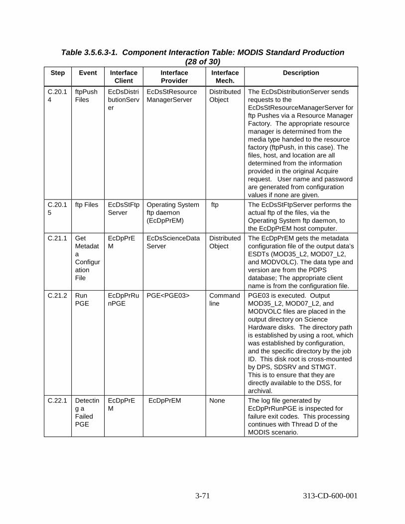
Table 3.5.6.3-1. Component Interaction Table: MODIS Standard Production (28 of 30)
Step Event Interface Client
Interface Provider
Interface Mech.
Description
C.20.1 4
ftpPush Files
EcDsDistri butionServ er
EcDsStResource ManagerServer
Distributed Object
The EcDsDistributionServer sends requests to the EcDsStResourceManagerServer for ftp Pushes via a Resource Manager Factory. The appropriate resource manager is determined from the media type handed to the resource factory (ftpPush, in this case). The files, host, and location are all determined from the information provided in the original Acquire request. er name and password are generated from configuration values if none are given.
C.20.1 5
ftp Files EcDsStFtp Server
Operating System ftp daemon (EcDpPrEM)
ftp The EcDsStFtpServer performs the actual ftp of the files, via the Operating System ftp daemon, to the EcDpPrEM host computer.
C.21.1 Get Metadat a Configur ation File
EcDpPrE M
EcDsScienceData Server
Distributed Object
The EcDpPrEM gets the metadata configuration file of the output data’s ESDTs (MOD35_L2, MOD07_L2, and MODVOLC). The data type and version are from the PDPS database; The appropriate client name is from the configuration file.
C.21.2 Run PGE
EcDpPrRu nPGE
PGE<PGE03> Command line
PGE03 is executed. utput MOD35_L2, MOD07_L2, and MODVOLC files are placed in the output directory on Science Hardware disks. The directory path is established by using a root, which was established by configuration, and the specific directory by the job ID. his disk root is cross-mounted by DPS, SDSRV and STMGT. This is to ensure that they are directly available to the DSS, for archival.
C.22.1 Detectin g a Failed PGE
EcDpPrE M
EcDpPrEM None The log file generated by EcDpPrRunPGE is inspected for failure exit codes. his processing continues with Thread D of the MODIS scenario.
Us
O
T
T
3-71 313-CD-600-001

Table 3.5.6.3-1. Component Interaction Table: MODIS Standard Production (29 of 30)
Step Event Interface Client
Interface Provider
Interface Mech.
Description
C.23.1 Request DSS UR
EcDpPrE M
EcIoAdServer Distributed Object
If the DSS UR for this output data type is not already known in the PDPS database, the EcDpPrEM invokes the Data Manager which searches the EcIoAdServer for a “GetQueryableParameters” service for the desired output data type. This is accomplished via the IoAdApprovedSearchCommand class. Since the IoAdServer r is based on a replicated database, no specification is required to select the proper EcIoAdServer. he local one is used.
C.24.1 Connect to SDSRV
EcDpPrE M
EcDsScienceData Server
Distributed Object
The EcDpPrEM invokes the Data Manager which begins a session with the EcDsScienceDataServer by connecting.
C.24.2 Insert Data
EcDpPrE M
EcDsScienceData Server
Distributed Object
The EcDpPrEM invokes the Data Manager which sends requests to the EcDsScienceDataServer for the insertion of the newly created files for the MOD35_L2, MOD07_L2, and MODVOLC granules into the Data Server. ert request, containing the names of the files comprising the granule, is created for each granule. The structure of the Insert Request is hard-coded. The EcDsScienceDataServer validates the metadata and determines the archived names of the files.
Ec
T
An Ins
3-72 313-CD-600-001

Table 3.5.6.3-1. Component Interaction Table: MODIS Standard Production (30 of 30)
Step Event Interface Client
Interface Provider
Interface Mech.
Description
C.24.3 STMGT Store
EcDsScie nceDataS erver
EcDsStRequestM anagerServer
Distributed Object
The EcDsScienceDataServer sends requests to the EcDsStRequestManagerServer which are forwarded to the Archive Server for the files to be archived. The EcDsStArchiveServer must be able to read the inserted files directly from the DPS disks that they are residing on. The appropriate archive object to request is determined by the Archive ID input during ESDT installation. For files that have backup archive IDs and/or offsite IDs in the collection level metadata, backup copies are made in locations determined by the values of the backup archive ID and offsite ID.
C.24.4 Adding a Granule to Inventor y
EcDsScie nceDataS erver
Sybase/SQS CtLib The validated metadata is parsed and added to the inventory of the EcDsScienceDataServer.
C.25.1 Trigger Event
EcDsScie nceDataS erver
EcSbSubServer Distributed Object
Upon successful insertion of MOD35_L2, MOD07_L2, and MODVOLC granules, the MOD35_L2, MOD07_L2, and MODVOLC, Insert events are triggered. he appropriate EcSbSubServer is determined from the EcDsScienceDataServer configuration. he appropriate events to trigger are obtained from the events file, where the event ID was stored during ESDT installation. The inserted granule UR is provided when the event is triggered.
C.25.2 Retrieve Subscrip tions
EcSbSub Server
Sybase CtLib The EcSbSubServer queries the Sybase database determining which subscriptions need to be activated, or fired. h query “hit” is an activated subscription and executes independently.
T
T
Eac
3-73 313-CD-600-001

3.5.7 MODIS Failed PGE Handling Thread This thread shows how the artifacts from a failed PGE are collected and sent to the Instrument Team.
3.5.7.1 MODIS Failed PGE Handling Thread Interaction Diagram - Domain View Figure 3.5.7.1-1 depicts the MODIS Failed PGE Handling Interaction - Domain View.
DPSDPS DPS
DSS DSS
MODIS IT
MODISIT
D.3 Archive Data (PGEFail)
D.1 PGE Fails
SBSRVSBSRV
D.4 Trigger Event
D.6 Acquire Data (PGEFail)
D.8 email Notice D.7 ftp Data
IOS D.2 Get DSS UR
D.5 email Notification
Distributed Object (rpc, CtLib)
HMI (GUI, Xterm, command) ftp email (or other as noted) Double line - Synchronous email (or other as noted) Dashed - Asynchronous
Figure 3.5.7.1-1. MODIS Failed PGE Handling Interaction Diagram
3-74 313-CD-600-001

3.5.7.2 MODIS Failed PGE Handling Thread Interaction Table - Domain View Table 3.5.7.2-1 provides the Interaction - Domain View: MODIS Failed PGE Handling.
Table 3.5.7.2-1. Interaction Table - Domain View: MODIS Failed PGE Handling
Step Event Interface Client
Interface Provider
Data Issues
Step Preconditions
Description
D.1 PGE Fails DPS DPS None None One instance of the PGE03 running fails, due to the need for all daylight data, but some input data is night data. This step is the same step as C.22 in the previous Thread.
D.2 Get DSS UR
DPS IOS None None DPS gets the DSS UR from Advertiser.
D.3 Archive Data
DPS DSS 1 FailPGE @30K
FailPGE DPS collects the artifacts from the failed PGE, tar’s and inserts them into the Data Server.
D.4 Trigger Event
DSS SBSRV None None Trigger FailPGE:Insert event upon successful insertion of the FailPGE granule.
D.5 Notificatio n
SBSRV MODIS Instrume nt Team
None MODIS IT Subscription for FailPGE:Insert event, qualified for MODIS PGEs.
Send e-mail notification to MODIS IT, notifying that there is a newly inserted FailPGE granule, from a MODIS PGE. Notification message includes the UR of the FailPGE granule.
D.6 Acquire Data
SBSRV DSS None None SBSRV fulfills the standing order by the MODIS IT, for Failed MODIS PGEs. Request to Acquire data, via ftpPush, to the MODIS IT host.
D.7 ftp Data DSS MODIS Instrume nt Team
None None Data Server ftp’s the FailPGE tar file to the MODIS IT, placing it in the specified directory on the specified host.
D.8 Distributio n Notice
DSS MODIS Instrume nt Team
None None Send e-mail notification to MODIS IT, notifying that the newly inserted FailPGE has been successfully ftp’ed to their machine.
3-75 313-CD-600-001

3.5.7.3 Failed PGE Handling Thread Component Interaction Table Table 3.5.7.3-1 provides the Component Interaction: MODIS Failed PGE Handling
Table 3.5.7.3-1. Component Interaction Table: MODIS Failed PGE Handling
Step Event Interface Client
Interface Provider
(1 of 5) Interface
Mech. Description
D.1.1 Detecting a Failed PGE
DPRExec ution
PGE File containing exit code
One instance of the PGE03 has failed, due to incorrect input data. This is detected by examining the exit code of the PGE, which is stored in a file named <DPRID>.log (in this case, MODPGE03#1.0#01<time>.log). DPS pulls together core file, along with any other files marked in the PCF, and tar’s them together. Metadata for the FailPGE is built by EcDpPrEM process.
D.2.1 Get DSS UR
EcDpPrE M
EcIoAdS erver
Distributed Object
If the DSS UR for this output data type is not already known in the PDPS database, EcDpPrEM invokes the Data Manager which searches the Advertiser for a “GetQueryableParameters” service for the desired output data type. This is accomplished via the IoAdApprovedSearchCommand class. Since the Advertiser is based on a replicated database, no specification is required to select the proper Advertiser. The local one is used.
D.3.1 Connect to SDSRV
DPRExec ution
EcDsScie nceData Server
Distributed Object
DPRExecution begins a session with the SDSRV by connecting.
D.3.2 Insert Data
DPRExec ution
EcDsScie nceData Server
Distributed Object
PRONG requests that the newly created tar file for the FailPGE granule are inserted into the Data Server. An Insert request, containing the names of the file comprising the granule, is created for the granule. The structure of the Insert Request is hard-coded. SDSRV validates metadata and determines the archived names of the files.
D.3.3 STMGT Store
EcDsScie nceDataS erver
EcDsStR equestM anagerSe rver
Distributed Object
SDSRV requests that the files be archived. The Archive Server receives the SDSRV requests from the EcDsStRequestManagerServer. The Archive Server must be able to read the inserted files directly from the DPS disks that they are residing on. The correct archive object to request is determined from collection level metadata for the FailPGE ESDT, defined in the ESDT’s descriptor.
3-76 313-CD-600-001

Table 3.5.7.3-1. Component Interaction Table: MODIS Failed PGE Handling (2 of 5)
Step Event Interface Client
Interface Provider
Interface Mech.
Description
D.3.4 Adding a Granule to Inventory
EcDsScie nceDataS erver
Sybase/S QS
CtLib The validated metadata is parsed and added to the inventory of the SDSRV.
D.4.1 Trigger Event
EcDsScie nceDataS erver
EcSbSub Server
Distributed Object
Upon successful insertion of FailPGE granule, the FailPGE:Insert event is triggered. he correct subscription server is determined from SDSRV configuration. he correct events to trigger are determined from the events file which was populated during ESDT installation. ovided with the event triggering is the UR of the inserted granule.
D.4.2 Retrieve Subscripti ons
EcSbSub Server
Sybase CtLib SBSRV queries the Sybase database determining which subscriptions need to be activated, or fired. h query “hit” is an activated subscription and executes independently.
D.5.1 Send Notificatio n
EcSbSub Server
MODIS IT
e-mail The SBSRV builds an e-mail notification that the user’s subscription on the FailPGE event has been fired. his notification identifies the Event, the subscription ID, the granule UR that was inserted and the previously supplied User String.
D.6.1 Connect to SDSRV
EcSbSub Server
EcDsScie nceData Server
Distributed Object
In order to fulfill a standing order for MODIS data, the EcSbSubServer begins a session with the EcDsScienceDataServer, on behalf of the subscription user. he appropriate EcDsScienceDataServer is selected by the Granule UR provided when the event was triggered. This is pertinent if there are multi-SDSRVs in use at one DAAC in one mode.
D.6.2 Add PGE granule’s UR to Session
EcSbSub Server
EcDsScie nceData Server
Distributed Object
The SBSRV establishes the data context of the session with the SDSRV by adding the input granules to the session. The Granule UR of each input granule is added to the ESDT ReferenceCollector.
D.6.3 Retrieve Granule Metadata from Inventory
EcDsScie nceDataS erver
Sybase/S QS
CtLib SDSRV completes establishing the data context by retrieving the metadata for the requested granules from the Sybase/SQS database. he metadata for each granule is passed back to the reference objects for each granule.
TT
Pr
Eac
T
T
T
3-77 313-CD-600-001

Table 3.5.7.3-1. Component Interaction Table: MODIS Failed PGE Handling (3 of 5)
Step Event Interface Client
Interface Provider
Interface Mech.
Description
D.6.4 Acquire Data
EcSbSub Server
EcDsScie nceData Server
Distributed Object
SBSRV fulfills the standing order for the FailPGE granule by submitting an Acquire request for the granule. he Acquire request is for a ftpPush of all granules in the ESDT ReferenceCollector. his request is asynchronous, meaning that the return of the submit call of the request only contains the status of the request’s submittal. This request asks for a distribution notice to be emailed to the client. he Acquire request structure was hard-coded within the subscription server.
D.6.5 Create Staging Disk
EcDsScie nceDataS erver
EcDsStR equestM anagerSe rver
Distributed Object
The EcDsDistributionServer sends requests to the EcDsStRequestManagerServer which are forwarded to the Staging Disk Server to allocate space on staging disks for the granule files in the archive. The amount of staging disk to request is calculated from the file sizes in the information passed in the Distribution Request. The amount of staging disk to request is determined by the size of the metadata file.
D.6.6 Create Metadata file
EcDsScie nceDataS erver
EcDsScie nceData Server
Distributed Object
For each granule referenced in the Acquire request, the SDSRV creates a file containing the granule’s metadata before passing to Distribution.
D.6.7 Distribute Granules, Synchrono us
EcDsScie nceDataS erver
EcDsDist ributionS erver
Distributed Object
SDSRV submits a request to Data Distribution. he request includes, for the granule, a reference to the metadata file as well as the data file. ther parameters from the Acquire request are passed to DDIST.
D.6.8 Claim Ownership
EcDsDistri butionServ er
EcDsStR equestM anagerSe rver
Distributed Object
The EcDsDistributionServer sends requests to the EcDsStRequestManagerServer which are forwarded to the Staging Disk Server to claim ownership of the staging disk area created by the Staging Disk Server.
D.6.9 Compress Disk
EcDsDistri butionServ er
EcDsStR equestM anagerSe rver
Distributed Object
The EcDsDistributionServer sends requests to the EcDsStRequestManagerServer which are forwarded to the Staging Disk Server to compress the staging disk area.
T
T
T
T
O
3-78 313-CD-600-001

Table 3.5.7.3-1. Component Interaction Table: MODIS Failed PGE Handling (4 of 5)
Step Event Interface Client
Interface Provider
Interface Mech.
Description
D.6.1 0
Create Staging Disk
EcDsDistri butionServ er
EcDsStR equestM anagerSe rver
Distributed Object
The EcDsDistributionServer sends requests to the EcDsStRequestManagerServer which are forwarded to the Staging Disk Server to allocate space on staging disks for the granule files in the archive. The amount of staging disk to request is calculated from the file sizes in the information passed in the Distribution Request.
D.6.1 1
STMGT Retrieve
EcDsDistri butionServ er
EcDsStR equestM anagerSe rver
Distributed Object
DDIST requests that STMGT retrieve the granule file that is archived. The request is sent to the EcDsStRequestManagerServer which then orwards the request to the Staging Disk Server. The files will be compressed as they are being retrieved using the compression type specified. his results in the file being staged to read-only cache disks. This means that all files needed to fulfill the distribution request are on disk, and ready to be copied. he correct archive object to request is determined from the information provided by the SDSRV in the distribution request. his returns references to the files in the read-only cache.
D.6.1 2
Link files to Staging Disk
EcDsDistri butionServ er
EcDsStR equestM anagerSe rver
Distributed Object
DDIST links the files from the read-only cache into the staging disk by sending a request to the EcDsStRequestManager Server which then orwards the request to the Staging Disk Server.
D.6.1 3
Copy files to Staging Disk
EcDsDistri butionServ er
EcDsStR equestM anagerSe rver
Distributed Object
The EcDsDistributionServer sends requests to the EcDsStRequestManagerServer, which are forwarded to the Staging Disk Server to copy the metadata files from the archive to the staging disk area within the Sybase Server.
f
T
T
T
f
3-79 313-CD-600-001

Table 3.5.7.3-1. Component Interaction Table: MODIS Failed PGE Handling (5 of 5)
Step Event Interface Client
Interface Provider
Interface Mech.
Description
D.6.1 4
ftpPush Files
EcDsDistri butionServ er
EcDsStFt pServer
Distributed Object
DDIST now creates the Resource manager for ftp Pushes via a Resource Manager Factory. The correct resource manager is determined from the Media Type handed to the resource factory (ftpPush, in this case). The correct ftp Server is determined from configuration within the resource factory. The files, host, location, user name and password are all determined from the information provided in the original Acquire request.
D.7.1 ftp Files EcDsStFtp Server
Operatin g System ftp daemon (MODIS IT)
ftp The EcDsStFtpServer performs the actual ftp of the files to the MODIS IT.
D.8.1 Build Distributio n Notice
EcDsDistri butionServ er
EcDsDist ributionS erver
Internal The DDIST builds an e-mail notification that the user’s order has been fulfilled. his notification includes the media ID, type and format of the request, UR, type, compression type and file names and sizes for each granule as well as a DAAC configurable preamble.
D.8.2 Send E-mail
EcDsDistri butionServ er
MODIS IT
e-mail DDIST sends the distribution notice to the user as determined from the Order via e-mail. If this distribution notice fails, the notice is sent to a pre-configured default Email address for DAAC Distribution Technician parsing and forwarding.
T
3.5.8 MODIS Data Access Thread This thread shows how the generated data products are available for user access. Also in this thread, the MODIS Standing Order, submitted in Thread A, is fulfilled.
3.5.8.1 MODIS Data Access Thread Interaction Diagram - Domain View
Figure 3.5.8.1-1 depicts the MODIS Data Access Interaction - Domain View
3-80 313-CD-600-001

Distributed Object (rpc, CtLib) HMI (GUI, Xterm, command) ftp email (or other as noted) Double line - Synchronous email (or other as noted) Dashed - Asynchronous
E.3 Acquire Data
(MOD35_L2 MOD07_L2 MODVOLC)
E.4 equest User Profile info
CSS
E.12 Retrieve Media
EDG
GTWAYV0GWY
DSSDSS
Science User
Science User
SBSRVSBSRV
E.1 Trigger Event (MOD029:Insert)
E.2 e-mail Notification E.7 ftp Pull (MOD35_L2 MOD07_L2 MODVOLC)
DAAC Ops
DAAC Ops
E.10 Search (socket level interface)
E.9 Inventory Search
E.11 Search
MSS
E.5 Move to Pull Cache Host
E.6 Distribution Notice
E.8 Request info on files Pulled
R
Figure 3.5.8.1-1. MODIS Data Access Interaction Diagram
3.5.8.2 MODIS Data Access Thread Interaction Table - Domain View Table 3.5.8.2-1 provides the Interaction - Domain View: MODIS Data Access.
3-81 313-CD-600-001

Table 3.5.8.2-1. Interaction Table - Domain View: MODIS Data Access (1 of 2) Step Event Interface
Client Interface Provider
Data Issues
Step Precondi
tions
Description
E.1 Trigge r Event
DSS SBSRV None None This thread picks up with fulfilling the standing order for MOD35_L2, MOD07_L2, and MODVOLC data. This is the same step as C.25 of this MODIS scenario.
E.2 Notific ation
SBSRV Science User
None None Send e-mail notification to Science User, notifying that there are newly inserted MOD35_L2, MOD07_L2, and MODVOLC granules. Notification message includes the UR of the MOD35_L2, MOD07_L2, and MODVOLC granules.
E.3 Acquir e Data
SBSRV DSS None None SBSRV fulfills the standing order by the Science User, for MOD35_L2, MOD07_L2, and MODVOLC granules. Request to Acquire data, via ftp Pull from the Pull Cache host.
E.4 Reque st User Profile info
DSS (SDSRV)
MSS (MCI)
None None Upon receiving a request from an authorized user, the SDSRV obtains user profile access privilege level data from the MCI.
E.5 Move to Pull Cache Host
DSS DSS None Account and password for the ftp push to the pull cache have to be set up
Data Server moves the files requested to the Pull Cache area. This is internal to DSS
E.6 Distrib ution Notice
DSS Science User
None None Send e-mail notification to Science User, notifying that the newly inserted MOD35_L2, MOD07_L2, and MODVOLC granules are available via ftp pull on a specified host and directory.
E.7 ftp Pull
Science User
ftp daemon on ftp Pull Area Host
None ftp daemon
Data Requestor logs into the host specified in the mail notification either through an individual account or via anonymous ftp. The Data Requestor performs an ftp get or mget command to move the files (MOD35_L2, MOD07_L2, and MODVOLC) from the directory specified in the mail notification to his/her home node.
3-82 313-CD-600-001

Table 3.5.8.2-1. Interaction Table - Domain View: MODIS Data Access
Step Event Interface Client
Interface Provider
Data Issues
(2 of 2) Step
Precondi tions
Description
E.8 Reque st info on files pulled
DSS CSS None None The Pull Monitor requests information from IDG (CSS) of the files pulled over the last configurable time period.
E.9 Invent ory Searc h
DAAC Operator
EDG None None In order to verify that the newly created data is available, a DAAC Operator will perform an inventory search for all MODIS data created in the last day.
E.10 Searc h
EDG V0GWY None None EDG submits the DAAC Operator’s search criteria to the V0 Gateway in ODL format, via a specific socket.
E.11 Searc h
V0GWY DSS None None The V0 gateway translates the Search criteria from ODL to a query object (using GlParameters), and submits that query to the Search service. The results of this Search are returned synchronously, and are passed back to EDG, which displays them to the Science User.
E.12 Retrie ve Media
V0GWY Registry (CSS)
None None The results of this Search are returned synchronously. The media options are returned from the CSS Registry Server and the results are passed back to the EDG, which displays them to the Science User.
3.5.8.3 MODIS Data Access Thread Component Interaction Table Table 3.5.8.3-1 provides the Component Interaction: MODIS Data Access.
3-83 313-CD-600-001

Table 3.5.8.3-1. Component Interaction Table: MODIS Data Access
Step Event Interface Client
Interface Provider
(1 of 6) Interface
Mech. Description
E.1.1 Trigger Event
EcDsScie nceData Server
EcSbSub Server
Distributed Object
Upon successful insertion of MOD35_L2, MOD07_L2, and MODVOLC granules, the MOD35_L2, MOD07_L2, and MODVOLC:Insert events are triggered, for each granule. The correct subscription server is determined from SDSRV configuration. The correct events to trigger are determined from the events file, which was populated during ESDT installation. Provided with the event triggering is the UR of the inserted granule.
E.1.2 Retrieve Subscript ions
EcSbSub Server
Sybase CtLib SBSRV queries the Sybase database determining which subscriptions need to be activated, or fired. Each query “hit” is an activated subscription and will execute independently.
E.2.1 Send Notificati on
EcSbSub Server
Science User
e-mail The SBSRV builds an e-mail notification that the user’s subscription on the MOD35_L2, MOD07_L2, and MODVOLC:Insert events have been fired. This notification will identify the Event, the subscription ID, the Granule UR that was inserted and the previously supplied User String.
E.3.1 Connect to SDSRV
EcSbSub Server
EcDsScie nceDataS erver
Distributed Object
In order to fulfill a standing order for the MOD35_L2, MOD07_L2, and MODVOLC data, the SBSRV begins a session with the SDSRV, on behalf of the subscription user. The appropriate EcDsScienceDataServer is selected by the Granule UR provided with the event triggering. This is pertinent if there are multi-SDSRVs in use at one DAAC in one mode.
E.3.2 Add PGE granule’s UR to Session
EcSbSub Server
EcDsScie nceDataS erver
Distributed Object
The SBSRV establishes the data context of the session with the SDSRV by adding the input granules to the session. The Granule UR of each input granule is added to the ESDT ReferenceCollector.
E.3.3 Retrieve Granule Metadata from Inventory
EcDsScie nceData Server
Sybase/S QS
CtLib SDSRV completes establishing the data context by retrieving the metadata for the requested granules from the Sybase/SQS database. The metadata for each granule is passed back to the reference objects for each granule.
3-84 313-CD-600-001

Table 3.5.8.3-1. Component Interaction Table: MODIS Data Access
Step Event Interface Client
Interface Provider
(2 of 6) Interface
Mech. Description
E.3.4 Acquire Data
EcSbSub Server
EcDsScie nceDataS erver
Distributed Object
SBSRV fulfills the standing order for the MOD35_L2, MOD07_L2, and MODVOLC granules by submitting an Acquire request for the granule. The Acquire request is for an ftp Pull of all granules in the ESDT ReferenceCollector. This request is asynchronous, meaning that the return of the submit call of the request will only contain the status of the request’s submittal. This request asks for a distribution notice to be emailed to the client. The Acquire request structure was determined from the Action submitted with the standing order method.
E.3.5 Create Staging Disk
EcDsScie nceData Server
EcDsStRe questMan agerServe r
Distributed Object
The EcDsDistributionServer sends requests to the EcDsStRequestManagerServer which are forwarded to the Staging Disk Server to allocate space on staging disks for the granule files in the archive. The amount of staging disk to request is calculated from the file sizes in the information passed in the Distribution Request. The amount of staging disk to request is determined by the size of the metadata file.
E.3.6 Create Metadata file
EcDsScie nceData Server
EcDsScie nceDataS erver
Distributed Object
For each granule referenced in the Acquire request, the SDSRV creates a file containing the granule’s metadata before passing to Distribution.
E.3.7 Distribute Granules, Synchron ous
EcDsScie nceData Server
EcDsDistri butionServ er
Distributed Object
SDSRV submits a request to Data Distribution. The request includes, for the granule, a reference to the metadata file as well as the data file. Other parameters from the Acquire request are passed to DDIST including Archive ID, Backup Archive ID, and off-site ID.
E.3.8 Claim Ownershi p
EcDsDist ributionS erver
EcDsStRe questMan agerServe r
Distributed Object
The EcDsDistributionServer sends requests to the EcDsStRequestManagerServer which are forwarded to the Staging Disk Server to claim ownership of the staging disk area created by the Staging Disk Server.
E.3.9 Compres s Disk
EcDsDist ributionS erver
EcDsStRe questMan agerServe r
Distributed Object
The EcDsDistributionServer sends requests to the EcDsStRequestManagerServer which are forwarded to the Staging Disk Server to compress the staging disk area.
3-85 313-CD-600-001

Table 3.5.8.3-1. Component Interaction Table: MODIS Data Access
Step Event Interface Client
Interface Provider
(3 of 6) Interface
Mech. Description
E.3.1 0
Create Staging Disk
EcDsDist ributionS erver
EcDsStRe questMan agerServe r
Distributed Object
The EcDsDistributionServer sends requests to the EcDsStRequestManagerServer which are forwarded to the Staging Disk Server to allocate space on staging disks for the granule files in the archive. The amount of staging disk to request is calculated from the file sizes in the information passed in the Distribution Request. A Backup Archive ID and an off-site ID are also passed to DDIST from SDSRV metadata for each file.
E.3.1 1
STMGT Retrieve
EcDsDist ributionS erver
EcDsStRe questMan agerServe r
Distributed Object
DDIST sends requests to the EcDsStRequestManager which are forwarded to Archive Server to retrieve the granule file that is archived. The files will be compressed as they are retrieved using the compression type specified. This will result in the file being staged to read-only cache disks. This means that all files needed to fulfill the distribution request are on disk, and ready to be copied. The correct archive object to request is determined from the information provided by the SDSRV in the distribution request. This returns references to the files in the read-only cache. DDIST passes in a backup archive ID and an off-site ID as well. The backup archive ID and off-site ID can be empty strings.
E.3.1 1.1
STMGT Retrieve Failure from Primary Archive ID
EcDsStAr chiveSer ver
EcDsStAr chiveServ er
Internal method call
Failure of the STMGT retrieval of a file initiates an attempt to retrieve the file from the primary archive location (passed in by DDIST as the archive ID) if the backup archive ID is empty or attempts to retrieve the file from the backup archive ID if it is not empty. Operator is notified of the failure of the retrieve from the primary archive ID.
E.3.1 1.2
STMGT Retrieve Failure from Backup Archive ID
EcDsStAr chiveSer ver
EcDsStAr chiveServ er at remote site
Distributed Object
If the retrieve attempt fails a second time (either from backup or from primary archive IDs), then a third attempt is made. If the off-site ID is empty, the primary archive ID is used for the third attempt. If the off-site ID is not empty, It is used to determine the location of the file on tape which may have been exported from the archive. The operator is notified of the failure to retrieve from the backup archive ID.
3-86 313-CD-600-001

Table 3.5.8.3-1. Component Interaction Table: MODIS Data Access
Step Event Interface Client
Interface Provider
(4 of 6) Interface
Mech. Description
E.3.1 2
Link files to Staging Disk
EcDsDist ributionS erver
EcDsStRe questMan agerServe r
Distributed Object
DDIST links the files from the read-only cache into the staging disk by sending a request to the EcDsStRequest ManagerServer which then forwards such requests to the Staging Disk Server.
E.3.1 3
Copy files to Staging Disk
EcDsDist ributionS erver
EcDsStRe questMan agerServe r
Distributed Object
The EcDsDistributionServer sends requests to the EcDsStRequestManagerServer which are forwarded to the Staging Disk Server to copy the metadata files from the archive to the staging disk area within the Sybase Server.
E.3.1 4
ftp Push Files
EcDsStC acheMan agerServ er
EcDsStFtp Server
Distributed Object
DDIST now creates the Resource manager for ftp Pulls via a Resource Manager Factory. The correct resource manager is determined from the Media Type handed to the resource factory (ftp Pull, in this case). The correct ftp Server is determined from configuration within the resource factory. The files are determined from the information provided in the original Acquire request.
E.4.1 Request User Profile info
EcDsScie nceData Server
EcMsAcR egUserSrv r
Distributed Object
Upon receiving a request from an authorized user, the EcDsScienceDataServer obtains user profile access privilege level data from the EcMsAcRegUserSrvr.
E.5.1 Insert files
EcDsStFt pServer
EcDsStCa cheManag erServer
Distributed Object
The EcDsStFtpServer sends the name of a file to the Pull Monitor server. If the Pull Monitor has the file in the pull cache area, then the file is linked to the directory, which was created in the user pull area for servicing this request. If the file is not found in the cache, the EcDsStFtpDisServer pushes the file to the cache area.
E.6.1 Build Distributi on Notice
EcDsDist ributionS erver
EcDsDistri butionServ er
e-mail The DDIST builds an e-mail notification that the user’s order has been fulfilled. This notification will include the media ID, type and format of the request, UR, compression format type and file names and sizes for each granule as well as a DAAC configurable preamble.
E.6.2 Send E-mail
EcDsDist ributionS erver
Science User
e-mail DDIST sends the distribution notice to the user as determined from the Order via e-mail. If this distribution notice fails, the notice is sent to a pre-configured default Email address for DAAC Distribution Technician parsing and forwarding.
3-87 313-CD-600-001

Table 3.5.8.3-1. Component Interaction Table: MODIS Data Access
Step Event Interface Client
Interface Provider
(5 of 6) Interface
Mech. Description
E.7.1 ftp Pull Science User
ftp Daemon on Host for ftp Pull
Operating System command
Science user opens an ftp session on the host designated in the e-mail received after data has been retrieved. Anonymous ftp services are supported. The user sets the directory to the directory specified in the e-mail notification and either does a single get on a per file basis or a multiple get (mget) to copy everything in the directory to his/her own node. Once the copies are completed, the science user quits out of ftp.
E.8.1 Request info on files pulled
EcDsStC acheMan agerServ er
CsFtFTPN otify (Library)
CtLib Syslog is read. All entries pertaining to ftp gets are read and the directory and path are returned. The pull monitor server removes the links for files that have been pulled and updates database tables to maintain consistency. Reading of the syslog is timer based. The timer length can be configured via the STMGT GUI.
E.9.1 Startup EDG
DAAC Science Data Specialist
Netscape Command DAAC Science Data Specialist invokes a Netscape browser and navigates to the EOS Data Gateway (EDG) homepage.
E.9.2 Select Inventory Search, Provide Query constraint s, Submit Query
DAAC Ops
Netscape GUI The operator provides search constraints and the products desired. When query constraints are completed, the query is submitted.
E.10. 1
V0 Gateway Inventory Search
Netscape EcDmV0T oEcsGate way
ODL, over sockets
EDG submits a search to the V0 Gateway, by converting the search criteria into an ODL structure and passing that structure to a socket provided by the Gateway. The correct socket is determined from configuration information contained in the Valids file.
E.11. 1
Establish ECS User
EcDmV0 ToEcsGa teway
EcMsAcR egUserSrv r
Distributed Object
V0 Gateway retrieves the User Profile using ECS Authenticator from ODL message, which includes an encrypted User ID and Password. The User Registration database is replicated across DAACs, so the connection is made to the local User Registration Server.
E.11. 2
Request Attribute Mapping
EcDmV0 ToEcsGa teway
EcDmDict Server
CtLib (RWDBTo ol)
Gateway translates the V0 terms from ODL into ECS names for query submittal. Interface is directly to Data Dictionary database. Database name is retrieved from configuration file.
3-88 313-CD-600-001

Table 3.5.8.3-1. Component Interaction Table: MODIS Data Access
Step Event Interface Client
Interface Provider
(6 of 6) Interface
Mech. Description
E.11. 3
Connect to SDSRV
EcDmV0 ToEcsGa teway
EcDsScie nceDataS erver
Distributed Object
The Gateway first connects to the SDSRV. The appropriate EcDsScienceDataServer is determined by configuration information. This is pertinent if there are multi-SDSRVs in use at one DAAC in one mode.
E.11. 4
SDSRV Query
EcDmV0 ToEcsGa teway
EcDsScie nceDataS erver
Distributed Object
The Gateway translates the query into a DsClQuery object. This object is handed to the Search interface of the DsClESDTReferenceCollector. This Search method is synchronous, so the results of the search will be returned to the calling function. After the search the Gateway receives a list of URs. Then it does an “Inspect” to the SDSRV to get the metadata. It first performs a GetQueryableParameter to determine all attributes associated with each granule.
E.11. 5
Request Metadata
EcDsScie nceData Server
Sybase/S QS
CtLib The SDSRV breaks down the Query object and translates it into a sequence of calls to the inventory database. Resultant rows are converted into data granules, each with their metadata extracted from the database. These results are packaged and returned to the Query client.
E.11. 6
Result Retrieval
Netscape EcDmV0T oEcsGate way
ODL, over Sockets
When the Gateway gets the results, they are translated into ODL, and passed back to the EDG tool. The correct socket for sending results to EDG is the one used to submit the query. EDG then displays the results of the query to the user.
E.12. 1
Retrieve Media
EcDmV0 ToEcsGa teway
EcCsRegi stryServer
Distributed Object
V0 Gateway retrieves the Media from Registry Server. The media are translated into ODL, and the ODL is put into the search result.
3.5.9 Data Compression on Distribution Thread - Deferred until Release 6B
3.5.10 Reactivation/Replan
3.5.10.1 Reactivation/Replan Description
This scenario shows the three different types of reactivation/replanning. This scenario modifies either ASTER or MODIS.
3-89 313-CD-600-001

The following system functionality is exercised in this scenario:
• Ability to activate a new current plan on top of a current plan already being exercised
• Account for discrepancies in Data Processing Requests (DPRs) between those two plans
3.5.10.2 Reactivation/Replan Preconditions Production Requests (PRs) have already been generated from the Production Request Editor. The Subscription Manager is running. The Job Management Server is running. AutoSys is running. The Planning Workbench and its background processes are running.
There must be a current plan. This current plan can be either active or inactive, and either with or without Data Processing Requests. Also, ESDTs must be installed, SSI&T must be completed on the PGE, the PRs must have been entered, and the input granules must be available.
3.5.10.3 Reactivation/Replan Partitions
This scenario has been partitioned into the following threads:
• DPR in New Plan but Not in Old Plan (Thread A) - This thread illustrates how a current active plan without DPRs can be re-planned/reactivated as a new plan with DPRs (see section 3.5.9.4).
• DPR in Old Plan but Not in New Plan (Thread B) - This thread illustrates how a current active plan with DPRs in the queue can be re-planned/reactivated as a new plan without DPRs (see section 3.5.9.5).
• DPR in Both Old Plan and New Plan (Thread C) - This thread illustrates how a current active plan with DPRs can be re-planned/reactivated as a new plan with those same DPRs (see section 3.5.9.6).
3.5.10.4 DPR in New Plan but Not in Old Plan Thread This thread illustrates how a current active plan without DPRs can be re-planned/reactivated as a new plan with DPRs.
3.5.10.4.1 DPR in New Plan but Not in Old Plan Interaction Diagram - Domain View
Figure 3.5.10.4.1-1 depicts the DPR in New Plan but Not in Old Plan Interaction - Domain View.
3-90 313-CD-600-001

SBSRVPLSOps
DAAC Ops DPS
A.2 Activate new plan
A.3 Verify new DPRs created
A.1 Create new plan with new DPRs
Distributed Object (rpc, CtLib)
HMI (GUI, Xterm, command) ftp email (or other as noted) Double line - Synchronous email (or other as noted) Dashed - Asynchronous
Figure 3.5.10.4.1-1. DPR in New Plan but Not in Old Plan Interaction Diagram -Domain View
3.5.10.4.2 DPR in New Plan but Not in Old Plan Interaction Table -Domain View
Table 3.5.10.4.2-1 provides the Interaction - Domain View: DPR in New Plan but Not in Old Plan.
Table 3.5.10.4.2-1. Interaction Table - Domain View: DPR in New Plan but Not in Old Plan
Step Event Interface Client
Interface Provider
Data Issues Step Preconditions Description
A.1 Create new plan with new DPRs
DAAC Ops -Productio n Planner (Operator)
PLS PRs have already been generated. ESDTs must have been installed. Input granules must be available.
There must be a current plan. SSI&T must have been completed on the PGE. The Planning Workbench must be up and running.
The Production Planner creates a new plan with new DPRs.
A.2 Activate new plan
PLS DPS None Planning Workbench must be up and running.
The new plan is activated.
A.3 Verify new DPRs created
DAAC Ops -Productio n Planner
DPS None The Job Management Server and AutoSys must be up and running.
The Production Planner verifies the newly created DPRs.
3-91 313-CD-600-001

3.5.10.4.3DPR in New Plan but Not in Old Plan Component Interaction Table Table 3.5.10.4.3-1 provides the Component Interaction: DPR in New Plan but Not in Old Plan.
Table 3.5.10.4.3-1. Component Interaction Table: DPR in New Plan but Not in Old Plan
Step Event Interface Client
Interface Provider
Interface Mech.
Description
A.1.1 Operator clicks on “new” plan button
DAAC Ops -Production Planner
EcPlWb GUI The Production Planner clicks on the new plan button. The new plan uses the new DPRs.
A.1.2 Operator enters new plan name
DAAC Ops -Production Planner
EcPlWb GUI The Production Planner enters the new plan name.
A.1.3 Operator selects the PRs to be included
DAAC Ops -Production Planner
EcPlWb GUI The Production Planner selects the PRs to be included.
A.1.4 Operator schedules PRs to activate
DAAC Ops -Production Planner
EcPlWb GUI The Production Planner schedules the PRs to activate.
A.1.5 Operator saves the new plan
DAAC Ops -Production Planner
EcPlWb GUI The Production Planner saves the new plan.
A.2.1 Activate new plan
EcPlWb EcDpPrJo bMgmt
Distributed Object
The new plan is activated and the new DPRs are ready to run.
A.3.1 Operator checks on DPS AutoSys to verify state
DAAC Ops -Production Planner
AutoSys GUI The Production Planner checks on the state of the job in AutoSys. The new DPRs are in AutoSys and begin to run.
3.5.10.5 DPR in Old Plan but Not in New Plan Thread This thread illustrates how a current active plan with DPRs in the queue can be replanned or reactivated as a new plan without DPRs.
3.5.10.5.1DPR in Old Plan but Not in New Plan Thread Interaction Diagram -Domain View
Figure 3.5.10.5.1-1 depicts the DPR in Old Plan but Not in New Plan Interaction - Domain View.
3-92 313-CD-600-001

SBSRVPLS
B.2 Create new plan without DPRs
DPS Ops DAAC
Ops
B.4 erify old DPR jobs cancelled
B.1 rify existing DPRs active
B.3 ctivate new plan
Distributed Object (rpc, CtLib)
HMI (GUI, Xterm, command) ftp email (or other as noted) Double line - Synchronous email (or other as noted) Dashed - Asynchronous
V
Ve
A
Figure 3.5.10.5.1-1. DPR in Old Plan but Not in New Plan Interaction Diagram -Domain View
3.5.10.5.2DPR in Old Plan but Not in New Plan Thread Interaction Table -Domain View
Table 3.5.10.5.2-1 provides the Interaction - Domain View: DPR in Old Plan but Not in New Plan.
Table 3.5.10.5.2-1. Interaction Table - Domain View: DPR in Old Plan but
Step Event Interface Client
Not in New Plan (1 of 2) Interface Provider
Data Issues Step Preconditions
Description
B.1 Verify status of current DPRs
DAAC Ops -Production Planner
DPS PRs have already been generated. ESDTs must have been installed. Input granules must be available.
The current plan (with DPRs) must have already been activated.
Current DPRs should be in the JobMgmt queue and can be viewed by the Production Planner by pressing the “Jobs Waiting” button in the Ops Console of the AutoSys GUI.
B.2 Create new plan without DPRs
DAAC Ops -Production Planner
PLS The new plan must not have any DPRs.
The Planning Workbench must be up and running.
The Production Planner creates a new plan (without DPRs) to replace the old plan (with DPRs).
3-93 313-CD-600-001

Table 3.5.10.5.2-1. Interaction Table - Domain View: DPR in Old Plan but
Step Event Interface Client
Not in New Plan (2 of 2) Interface Provider
Data Issues Step Preconditions
Description
B.3 Activate new plan
PLS DPS None The Planning Workbench must be up and running.
The new plan is activated.
B.4 Verify old (current, existing) DPR jobs canceled
DAAC Ops -Production Planner
DPS None Job Management and AutoSys must be up and running.
The Production Planner uses the “Jobs Waiting” button to verify the priority of the new plan and the cancellation of old priority DPR jobs.
3.5.10.5.3DPR in Old Plan but Not in New Plan Thread Component Interaction Table
Table 3.5.10.5.3-1 provides the Component Interaction: DPR in Old Plan but Not in New Plan.
3-94 313-CD-600-001

Table 3.5.10.5.3-1. Component Interaction Table: DPR in Old Plan but Not in New Plan
Step Event Interface Client
Interface Provider
Interface Mech.
Description
B.1.1 Operator verifies DPRs on active plan are in the queue
DAAC Ops – Productio n Planner
AutoSys GUI The current DPRs should be in the queue and can be viewed by the Production Planner by pressing the “Jobs Waiting” button.
B.2.1 Operator creates a new plan
DAAC Ops – Productio n Planner
EcPlWb GUI The Production Planner creates a new plan (without DPRs) to replace the old plan (with DPRs).
B.3.1 Activate new plan
EcPlWb EcDpPrJ obMgmt
Distributed Object
The new plan is activated.
B.4.1 Verify state of new plan’s DPRs
DAAC Ops – Productio n Planner
AutoSys GUI The Production Planner uses AutoSys Jobscape to verify the priority of the new jobs.
B.4.2 Verify state of old (existing) plan’s DPRs
DAAC Ops – Productio n Planner
AutoSys GUI The Production Planner uses the “Jobs Waiting” button to verify the cancellation of old priority DPR jobs. Note – In this case, any jobs that have gotten into AutoSys will not be deleted during a replan. Only jobs that are in the JobMgmt queue will be cancelled.
3.5.10.6 DPR in Both Old Plan and New Plan Thread This thread illustrates how a current active plan with DPRs can be re-planned/reactivated as a new plan with those same DPRs.
3.5.10.6.1DPR in Both Old Plan and New Plan Thread Interaction Diagram -Domain View
Figure 3.5.10.6.1-1 depicts the DPR in Both Old Plan and New Plan Interaction - Domain View.
3-95 313-CD-600-001

SBSRVPLS DPS Ops
DAAC Ops
C.1 rify existing DPRs active
C.4 erify DPR priorities in new plan,
C.2 Create new plan and schedule with existing DPRs
C.3 ctivate new plan
Ve
V
A
Distributed Object (rpc, CtLib)
HMI (GUI, Xterm, command) ftp email (or other as noted) Double line - Synchronous email (or other as noted) Dashed - Asynchronous
cancellation of old priority DPR jobs
Figure 3.5.10.6.1-1. DPR in Both Old Plan and New Plan Interaction Diagram -Domain View
3.5.10.6.2DPR in Both Old Plan and New Plan Thread Interaction Table -Domain View
Table 3.5.10.6.2-1 provides the Interaction - Domain View: DPR in Both Old Plan and New Plan.
3-96 313-CD-600-001

Table 3.5.10.6.2-1. Interaction Table - Domain View: DPR in Both Old Plan and New Plan
Step Event Interface Client
Interface Provider
Data Issues Step Preconditions
Description
C.1 Operator verifies DPRs of active plan are in the AutoSys queue
DAAC Ops -Production Planner
DPS PRs have already been generated. ESDTs must have been installed. Input granules must be available.
The current plan (with DPRs) must have already been activated. Job Management must be up and running. AutoSys Jobscape must be up and running.
The current DPRs should be in the JobMgmt queue and can be viewed by the Production Planner by pressing the “Jobs Waiting” button in the Ops console of the AutoSys GUI.
C.2 Create new plan and schedule with existing DPRs
DAAC Ops -Production Planner
PLS None The Planning Workbench must be up and running.
The Production Planner creates a new plan and schedule using the existing DPRs, adjusting the DPR priorities as necessary.
C.3 Activate new plan
PLS DPS None The Planning Workbench must be up and running.
The new plan is activated.
C.4 Verify DPR priorities in new plan, cancellation of old priority DPR jobs
DAAC Ops -Production Planner
DPS None The Planning Workbench must be up and running. The Planning Workbench ALOG file must exist. AutoSys Jobscape must be up and running.
The Production Planner verifies the DPR priorities in the new plan and the cancellation of the old priority DPR jobs.
3.5.10.6.3DPR in Both Old Plan and New Plan Thread Component Interaction Table
Table 3.5.10.6.3-1 provides the Component Interaction: DPR in Both Old Plan and New Plan.
3-97 313-CD-600-001

Table 3.5.10.6.3-1. Component Interaction Table: DPR in Both Old Plan and New Plan
Step Event Interface Client
Interface Provider
Interface Mech.
Description
C.1.1 Operator verifies that DPRs on active plan are in the queue
DAAC Ops -Productio n Planner
AutoSys GUI The current DPRs should be in the JobMgmt queue and can be viewed by the Production Planner by pressing the “Jobs Waiting” button.
C.2.1 Operator creates a new plan
DAAC Ops -Productio n Planner
EcPlWb GUI The Production Planner creates a new plan.
C.2.2 Select PRs used by the old plan (see step C.2)
DAAC Ops -Productio n Planner
EcPlWb GUI The Production Planner selects PRs, with DPRs in the JobMgmt queue he wishes to re-prioritize.
C.2.3 Schedule these PRs
DAAC Ops -Productio n Planner
EcPlWb GUI The Production Planner creates a new plan using the re-prioritized DPRs.
C.3.1 Activate plan EcPlWb EcDpPrJ obMgmt
Distributed Object
The new plan is activated.
C.4.1 Verify priorities of plan’s DPRs
DAAC Ops -Productio n Planner
AutoSys GUI The Production Planner verifies the new DPR priorities are in the JobMgmt queue.
C.4.2 Priority changes
DAAC Ops -Productio n Planner
AutoSys GUI The new DPR job must be in the JobMgmt queue. The old DPR must be cancelled. If priorities differ between the old DPR and the new DPR, the old DPR job should be cancelled and a new DPR created. Note – Only jobs in the JobMgmt queue have their priorities changed. If the jobs are already in AutoSys, their priorities are meaningless and are not changed.
3-98 313-CD-600-001
3.6 Landsat-7 Scenario
3.6.1 Landsat-7 Scenario Description This scenario shows how ECS supports the archival and retrieval of Landsat-7 data. Landsat-7 data is provided to ECS from one of two primary sources: Landsat Processing System (LPS), and Image Assessment System (IAS). LPS provides Landsat-7 L0R (Level 0 Reformatted) subinterval data and Metadata Browse to ECS. IAS provides the Landsat-7 Calibration Parameter files and Reports to ECS. The dialogue between LPS and ECS is managed by the Landsat-7 Gateway. The interface between IAS and ECS is through a standard polling mechanism managed by Ingest. The dialogue and polling mechanism are documented in the ECS-Landsat-7 ICD. ECS does not process Landsat-7 data.
There are some notable data issues related to the Landsat-7 L0R subintervals. Actually, the Landsat-7 L0R data is produced by LPS in two independent parts, Format 1 and Format 2. While both parts are required to make a complete Landsat-7 L0R granule, these parts are provided to ECS independent from each other. Additionally, there is no guarantee of the delivery order of the parts: Format 1 could precede or follow the delivery of its corresponding Format 2. The deliveries might be separated by delivery of parts of other granules. This requires ECS to determine if each received part’s corresponding part has already been delivered. If so, further internal processing is performed to match the parts and to create the complete Landsat-7 L0R subinterval granule.
Another point of interest is that while LPS provides ECS with all Landsat-7 L0R data, which is subinterval data, ECS provides access to standard L70R WRS Scenes* and Floating Scenes* within the subinterval data. When LPS provides a subinterval, all L70R WRS Scene data is embedded in the subinterval and metadata is provided to derive those scenes. The current ECS approach to storing and accessing subintervals and scenes is to store all subinterval data, and to derive scenes from the subinterval when ECS users request the scenes. To support this two things occur: First when subinterval data is entered into the Data Server, references to all scenes that are available within that subinterval are also created. These scenes are “virtual granules”, insofar as they are referenced as granules, and are searchable, but the granule itself is not archived, per se. Rather it is created upon access. Secondly, upon access the scenes are derived from their “parent” subinterval by using internal subinterval subsetting services. Effectively, each scene knows which subinterval it is part of, and it knows what to ask its subinterval to do in order to complete creation of itself.
(*Note: Standard L70R WRS Scenes are defined by specific ground distances from a center point defined by the intersection of an orbit path and a latitude (row) in a set latitude grid. This scene is “fixed” and it would include overlap scans, meaning a length max of 375 scans (335 plus 20 scans top and 20 scans bottom). A Floating Scene, a subtype of subinterval, desired by user is a scene with the center not on one of these “fixed” scene centers. )
3-99 313-CD-600-001

The following system functionality is exercised in this scenario:
• User Profile Registration (see Thread A)
• LPS-driven data ingest (see Thread B)
• IAS-driven data ingest (see Thread D)
• Access to WRS Scenes (see Thread F)
• EDG browse of granules (see Thread E)
• 8mm, CD-ROM and DLT data distribution (see Threads, F &H)
• Access to Floating Scenes and Floating Scene Price Estimation (see Threads H & I)
• Operator ability to status an order (see Threads, F, G & H)
• Landsat-7 Error Handling (see Thread J)
3.6.2 Landsat-7 Scenario Preconditions
The following ESDTs have been inserted into the ECS:
• L70R (Complete L70R subinterval)
• L70RF1 (Format 1 of a L70R subinterval)
• L70RF2 (Format 2 of a L70R subinterval)
• L70RWRS (Complete L7 WRS Scene)
• L70RWRS1 (Format 1 part of a L70R WRS Scene)
• L70RWRS2 (Format 2 part of a L70R WRS Scene)
• L7CPF (Landsat-7 Calibration Parameter File)
• Browse (Generic Browse file)
Other Preconditions are as follows:
• Subscription for Landsat-7 subintervals entered on behalf of Instrument Team.
• Standing order for L70R WRS Scene, to be delivered on 8mm, D3 and DLT tapes and CD-ROMs.
3-100 313-CD-600-001

3.6.3 Landsat-7 Scenario Partitions The Landsat-7 scenario has been partitioned into the following threads:
• L-7 User Registration (Thread A) - This thread shows the processing required for registering as a new ECS User (see section 3.6.4).
• L-7 LPS Data Insertion (Thread B) - This thread shows how the ECS inserts data provided by LPS (see section 3.6.5).
• L-7 IGS Tape Insertion (Thread C) - This thread shows how the ECS inserts data provided by IGS via 8mm tape (see section 3.6.6). This capability has been deferred until Release 6B.L-7 IAS Data Insertion (Thread D) - This thread shows how the ECS inserts data provided by IAS (see section 3.6.7).
• L-7 Search and Browse (Thread E) - This thread shows how the ECS supports users searching for and browsing data holdings (see section 3.6.8).
• L-7 Ordering WRS Scene (Thread F) - This thread shows how the ECS supports user orders for L70R WRS scene (see section 3.6.9).
• L-7 MOC Interface Thread (Thread G) – This thread shows the interface between the ECS and the MOC for Cloud Cover Assessment (CCA) data (see section 3.6.10).
• L-7 Ordering Floating Scene (Thread H) – This thread shows how the ECS supports user orders for L70R Floating Scene (see section 3.6.11).
• L-7 Floating Scene Price Estimation (Thread I) – This thread shows how the ECS supports price estimation for orders of L70R Floating Scene (see section 3.6.12).
• L-7 Error Handling (Thread J) – This thread shows how the ECS supports operator requests for Merging/De-Merging/Delete of L-7 granules in the SDSRV database. (see section 3.6.13)
3.6.4 Landsat-7 User Registration Thread This thread shows the processing required for registering as a new ECS User.
3.6.4.1 Landsat-7 User Registration Interaction Diagram - Domain View Figure 3.6.4.1-1 depicts the L-7 User Registration Interaction - Domain View.
3-101 313-CD-600-001

stration Done A.8 Privileges Granted A.20 Reset Password
A.6 Reque Privilege
A.16 Retrieve Profile
A.15 Profile Retrieval
Any DAAC
A.7 Update Privileges
Ops DAAC Ops
Distributed Object (rpc, CtLib) HMI (GUI, Xterm, command) ftp email (or other as noted) Double line - Synchronous email (or other as noted) Dashed - Asynchronous
A.1 Submit New User Request A.10 Submit Profile Update A.14 Request User Profile A.17 Change Password
A.3 Create Profile A.12 Update Profile
A.19 Change Password DSSMSS
MSS
SMC
All DAACs
User’s Home DAAC
CLS
EDG
DAAC USER
CLS
MSS A.5 Replicate Profile
A.9 Replicate Profile A.13 Replicate Profile
A.2 User Registration A.11 Profile Update A.18 Password Change
Figure 3.6.4.1-1. L-7 User Registration Interaction Diagram
3.6.4.2 Landsat-7 User Registration Interaction Table - Domain View Table 3.6.4.2-1 provides the Interaction - Domain View: L-7 User Registration.
3-102 313-CD-600-001

Table 3.6.4.2-1. Interaction Table - Domain View: L7 User Registration (1 of 3) Step Event Interface
Client Interface Provider
Data Issues
Step Precondi
tions
Description
A.1 Submi t New User Reque st
Science User
EOS Data Gateway (EDG)
None None The Science user goes to the User Registration form for the first time from the EOS Data Gateway, via its URL, from their favorite Web Browser. The Science user fills in the form with initial registration information.
A.2 User Regist ration
EDG CLS User Profile Gateway
None None The EDG submits the new user’s registration request to the CLS User Profile Gateway in ODL format, via a specific socket.
A.3 Creat e Profile
CLS User Profile Gateway
MSS User Registrati on Server
None None The CLS User Profile Gateway translates the profile request to a profile object and submits the request to the MSS User Registration Server. The results of this request are returned synchronously, and are passed back to the EDG, which displays them to the Science User.
A.4 Regist ration Done
MSS User Registrati on Server
Science User
None None When MSS inserts the new profile into its profile database, an e-mail message is triggered to notify the user the registration is complete.
A.5 Replic ate Profile
SMC MSS
All remote MSS
None None The new profile is replicated at each remote DAAC.
A.6 Reque st Privile ge Updat es
Science User
DAAC Ops
None None The Science User needs access to restricted granules or ASTER L1B on-demand privilege, so the user telephones user services at his home DAAC to request the privileges.
A.7 Updat e privile ges
DAAC Ops
SMC MSS
None None The user services at the home DAAC uses the SMC GUI for updating the MSS User Profile to grant the requested privileges.
A.8 Privile ges Grant ed
SMC MSS
Science User
None None When MSS updates the privileges in its profile database an e-mail message is triggered to notify the user that the privileges have been granted.
A.9 Replic ate Profile
SMC MSS
Remote MSS
None None The updated profile is replicated at each remote DAAC.
3-103 313-CD-600-001

Table 3.6.4.2-1. Interaction Table - Domain View: L7 User Registration (2 of 3) Step Event Interface
Client Interface Provider
Data Issues
Step Precondi
tions
Description
A.10 Submi t Profile Updat e
Science User
EDG None None A Science user goes to the User Registration Update Form through the EDG, via its URL, using their favorite Web Browser. The Science user fills in the form with updated registration information.
A.11 Profile Updat e
EDG CLS User Profile Gateway
None None The EDG submits the updated user’s registration request to the CLS User Profile Gateway in ODL format, via a specific socket.
A.12 Updat e Profile
CLS User Profile Gateway
MSS User Registrati on Server
None None The CLS User Profile Gateway translates the Profile Update Request to a profile object and submits the request to the MSS User Registration Server. The results of this request are returned synchronously and are passed back to the EDG, which displays them to the Science User.
A.13 Replic ate Profile
SMC MSS
Remote MSS
None None The updated profile is replicated at each remote DAAC.
A.14 Login Science User
EDG None None A Science user goes to the User Profile Retrieval Form through the EDG, via its URL, using their favorite Web Browser. The Science user fills in the form with userid and password information.
A.15 Profile Retrie val
EDG CLS User Profile Gateway
None None The EDG submits the profile retrieval request to the CLS User Profile Gateway in ODL format, via a specific socket.
A.16 Retrie ve Profile
CLS User Profile Gateway
MSS User Registrati on Server
None None The CLS User Profile Gateway submits the request to the MSS User Registration Server. The results of this request are returned synchronously and are passed back to the EDG, which displays them to the Science User.
A.17 Chang e Passw ord
Science User
EDG None None A Science user goes to the User Profile Password Change Form through the EDG, via its URL, using their favorite Web Browser. The Science user fills in the form with userid, old password and new password information.
A.18 Passw ord Chang e
EDG CLI User Profile Gateway
None None The EDG submits the password change request to the CLS User Profile Gateway in ODL format, via a specific socket.
3-104 313-CD-600-001

Table 3.6.4.2-1. Interaction Table - Domain View: L7 User Registration (3 of 3) Step Event Interface
Client Interface Provider
Data Issues
Step Precondi
tions
Description
A.19 Chang e Passw ord
CLS User Profile Gateway
MSS User Registrati on Server
None None The CLS User Profile Gateway submits the request to the MSS User Registration Server. The results of this request are returned synchronously and are passed back to the EDG, which displays them to the Science User.
A.20 Reset Passw ord
MSS DAAC User
None None The MSS changes the password in its profile database, if the change was a password reset. An e-mail message is triggered to notify the user the password has been reset.
3.6.4.3 Landsat-7 User Registration Component Interaction Table Table 3.6.4.3-1 provides the Component Interaction: L7 User Registration.
Table 3.6.4.3-1. Component Interaction Table: L7 User Registration (1 of 4) Step Event Interface
Client Interface Provider
Interface Mech.
Description
A.1.1 Web Browser
Science User
EDG Web Browser
A Science user goes to the User Registration Form through the EDG, via its URL, using their favorite Web Browser.
A.1.2 Input User Registratio n Information
Science User
EDG Web Browser
he Science User populates the User Registration Form with the required ECS registration information. The user submits this information to the EDG.
A.2.1 Create User Registratio n Request
Netscape EDG CGI The EDG generates the authenticator from the User ID and Password and creates the user registration message containing the profile information plus the User ID and authenticator (but not the password).
A.2.2 Submit User Registratio n Request
EDG EcClDtUs erProfile Gateway
V0 protocols via SSL
The EDG sends the user registration message to the CLS User Profile Gateway at the SMC. Upon receipt of the successful registration response, the EDG updates its local profiles file with the new ECS User ID, authenticator and other profile information. This information is used on subsequent access to the ECS requiring a user profile.
3-105 313-CD-600-001

Table 3.6.4.3-1. Component Interaction Table: L7 User Registration (2 of 4) Step Event Interface
Client Interface Provider
Interface Mech.
Description
A.3.1 Validate User Registratio n Request
EcClDtU serProfile Gateway
EcClDtUs erProfile Gateway
Internal The CLS User Profile Gateway converts the User Registration Request to an MSS Profile object and validates that required information is present.
A.3.2 Create Profile EcClDtU
serProfile Gateway
EcMsAcR egUserSr vr
Distribut ed Object
The CLS User Profile Gateway sends the User Registration Request to the MSS User Profile Server for approval. The response to the Registration Request is transmitted to the EDG to be displayed to the user.
A.4.1 Validate User Registratio n Request
EcMsAc RegUser Srvr
EcMsAcR egUserSr vr
Internal The MSS User Profile server begins new account creation. The MSS User Profile server checks for duplicate User Ids. If the User ID already exists, the MSS returns an error to the DMS, which constructs and sends a message to the EDG client asking the user to submit another User ID in their request.
A.4.2 Process a User Registratio n Request
EcMsAc RegUser Srvr
EcMsAcR egUserSr vr
Internal If the User ID is unique, the MSS generates a new user profile using the information from the DMS. A default set of information is used for the rest of the users profiles, withholding any special data access or request privileges.
A.4.3 Complete a User Registratio n Request
EcMsAc RegUser Srvr
CsEmMai lRelA (to Science User)
e-mail The MSS inserts the profile into its profile database, triggering the transmittal of an e-mail message to the user indicating their request for registration has been successfully completed. The MSS returns the profile to the CLS User Profile Gateway.
A.5.1 Replicate User Profile
Sybase Sybase EcMsRs Db
The insert of the user profile into the MSS profile database triggers its replication to each remote site via the Sybase Replication Server.
A.6.1 Request Privilege Updates
Science User
DAAC Ops -User Services
Telephon e
If the user requires access to restricted granules or ASTER L1B on-demand privileges, the user calls user services at their Home DAAC, and makes the request for privileges.
A.7.1 Update Privileges
DAAC Ops -User Services
SMC gui Xterm The user services at the Home DAAC uses the SMC GUI for updating the privileges in the MSS user Profiles to perform the update.
A.8.1 Privileges Granted
EcMsAc RegUser Srvr
CsEmMai lRelA (to Science User)
e-mail The update of the profile triggers an e-mail message to notify the user the privileges have been granted.
A.9.1 Replicate User Profile
Sybase Sybase EcMsRs Db
The update of the profile also triggers its replication to each remote site via the Sybase Replication Server.
3-106 313-CD-600-001

Table 3.6.4.3-1. Component Interaction Table: L7 User Registration (3 of 4) Step Event Interface
Client Interface Provider
Interface Mech.
Description
A.10. 1
Startup Web Browser
Science User
EcClDtUs erProfile Gateway
Web Browser
A Science user goes to the User Registration Update Form through the EDG, via its URL, using their favorite Web Browser.
A.10. 2
Input User Registratio n Information
Science User
EcClDtUs erProfile Gateway
Web Browser
The Science User populates the forms with updated ECS registration information. The user submits this information to the EDG.
A.11. 1
Create User Profile Update Request
Netscape EDG CGI The EDG generates the authenticator from the User ID and Password. The EDG creates a user registration update message containing the updated profile information plus the User ID and authenticator (but not the password).
A.11. 2
Submit User Profile Update Request
EDG EcClDtUs erProfile Gateway
V0 protocols via SSL
The EDG sends the user profile update message to the CLS User Profile Gateway at the SMC. Upon receipt of the successful update response, the EDG updates its local profiles file with the updated profile information.
A.12. 1
Validate User Registratio n Request
EcClDtU serProfile Gateway
EcClDtUs erProfile Gateway
Internal The CLS User Profile Gateway converts the User Registration Request to an MSS Profile object, populating updated information.
A.12. 2
Create Profile
EcClDtU serProfile Gateway
EcMsAcR egUserSr vr
Distribut ed Object
The CLS User Profile Gateway sends the User Profile Update Request to the MSS User Profile Server for approval. The response to the Registration Request is transmitted to the EDG to be displayed to the user.
A.12. 3
Validate User Registratio n Request
EcMsAc RegUser Srvr
Sybase Sybase The MSS User Registration Server inserts updated user profile information into its database.
A.12. 4
Process a User Registratio n Request
EcMsAc RegUser Srvr
EcClDtUs erProfile Gateway
Distribut ed Object
The MSS returns the status to the CLS User Profile Gateway.
A.13. 1
Replicate User Profile
Sybase Sybase EcMsRs Db
The update of the user profile in the MSS profile database triggers its replication to each remote site via the Sybase Replication Server.
A.14. 1
Load Profile Retrieval Form
Science User
EcClDtUs erProfile Gateway
Web Browser
A Science user goes to the Profile Retrieval Form through the EDG, via its URL, using their favorite Web Browser.
A.14. 2
Submit Retrieve Profile
Science User
EcClDtUs erProfile Gateway
Web Browser
The Science User populates the Profile Retrieval Form with User ID and password.
3-107 313-CD-600-001

Table 3.6.4.3-1. Component Interaction Table: L7 User Registration (4 of 4) Step Event Interface
Client Interface Provider
Interface Mech.
Description
A.15. 1
Create Profile Retrieval Request
Netscape EDG CGI The EDG generates the authenticator from the User ID and Password. The EDG creates a profile retrieval message containing the User ID and authenticator (but not the password).
A.15. 2
Submit User Profile Retrieval Request
EDG EcClDtUs erProfile Gateway
V0 protocols via SSL
The EDG sends the profile retrieval message to the CLS User Profile Gateway at the SMC. Upon receipt of the successful retrieval response, the EDG updates its local profiles file with the retrieved profile information.
A.16. 1
Retrieve Profile
EcClDtU serProfile Gateway
EcMsAcR egUserSr vr
Distribut ed Object
The CLS User Profile Gateway sends the User Profile Retrieve Request to the MSS User Profile Server for processing. The profile received from the MSS is transmitted to the EDG to be displayed to the user.
A.17. 1
Load Password Change Form
Science User
EcClDtUs erProfile Gateway
Web Browser
A Science user goes to the Password Change Form through the EDG, via its URL, using their favorite Web Browser.
A.17. 2
Submit Password Change
Science User
EcClDtUs erProfile Gateway
Web Browser
The Science User populates the Password Change Form with User ID and old and new passwords.
A.18. 1
Create Password Change Request
EDG Netscape CGI The EDG generates the old and new authenticators from the User ID and Passwords. The EDG creates a password change message containing the User ID and authenticators (but not the password).
A.18. 2
Submit Password Change Request
Netscape EcClDtUs erProfile Gateway
V0 protocols via SSL
The EDG sends the change password message to the CLS User Profile Gateway at the SMC. Upon receipt of the successful password change response, the EDG notifies the user of the success of the request.
A.19. 1
Change Password
EcClDtU serProfile Gateway
EcMsAcR egUserSr vr
Distribut ed Object
The CLS User Profile Gateway sends the Password Change Request to the MSS User Profile Server for approval. The status received from the MSS is transmitted to the EDG to be displayed to the user.
A.20. 1
Reset Password
EcMsAc RegUser Srvr
CsEmMai lRelA (to Science User
E-mail The reset of the user password triggers an e-mail message to notify the user the password has been reset.
3-108 313-CD-600-001

3.6.5 Landsat-7 LPS Data Insertion Thread This thread shows how the ECS inserts data provided by LPS.
3.6.5.1 Landsat-7 LPS Data Insertion Thread Interaction Diagram - Domain View
Figure 3.6.5.1-1 depicts the L-7 LPS Data Insertion Interaction - Domain View.
CSS (SBSRV)
LPSLPS B.2 Create Session
B.3 Data Transfer Messages
CSS (L7GWY)
INSINS
DSSDSS
B.4 Data Transfer Messages
B.8 Trigger Event (subinterval) B.10 Trigger Event (scene)
B.11 Data Delivery Status
B.12 Data Delivery Notice
INSIOS B.1 Get SDSRV URs
B.7 Archive Backup on Insert (subinterval)
Distributed Object (rpc, CtLib) HMI (GUI, Xterm, command) ftp email (or other as noted) Double line - Synchronous email (or other as noted) Dashed - Asynchronous
B.6 Request Data Insert (subinterval) B.9 Request Data Insert (scene – includes Browse)
B.5 Create Staging Disk & Transfer Files (to Disk)
Figure 3.6.5.1-1. L-7 LPS Data Insertion Interaction Diagram
3.6.5.2 Landsat-7 LPS Data Insertion Thread Interaction Table - Domain View Table 3.6.5.2-1 provides the Interaction - Domain View: L-7 LPS Data Insertion.
Table 3.6.5.2-1. Interaction Table - Domain View: L-7 LPS Data Insertion (1 of 3) Step Event Interf
ace Client
Interface Provider
Data Issues
Step Preconditions
Description
B.1 Get SDSRV URs
INS IOS None None Upon startup, the INS gets the SDSRV URs for each data type in its database from the IOS.
3-109 313-CD-600-001

Table 3.6.5.2-1. Interaction Table - Domain View: L-7 LPS Data Insertion (2 of 3) Step Event Interf
ace Client
Interface Provider
Data Issues
Step Preconditions
Description
B.2 Create Session
LPS CSS (L7GWY)
None All required binding information is provided to LPS.
In order to transfer L7 subinterval data, the LPS initiates a session with the ECS. This is accomplished by sending a series of control messages to the CSS (L7GWY).
B.3 Data Transfer Message s
LPS CSS (L7GWY)
None None A Data Availability Notice (DAN) is sent to indicate the LPS transfer of L7 data has begun.
B.4 Data Transfer Message s
CSS (L7G WY)
INS None None The CSS (L7GWY) passes all Data Transfer messages to the INS.
B.5 Create Staging Disk & Transfer Files
INS DSS None None The INS interfaces with the DSS to request staging disk space within the DSS and transfers the files to this staging disk area.
B.6 Request Data Insert (subinter val)
INS DSS For 3 scenes: 13 L70RF1 files @ 732MB, or 7 L70RF2 @ 387MB, from Landsat -7 Team
L70RF1, L70RF2 and L70R ESDTs.
When complete L70R data is transferred to Ithe DSS staging disk areas, Ingest validates information (preprocessing) and sends a request for the data to be read by the DSS for archival. The DSS reads the data from the designated staging disk area. Note the number of files depends on the number of scenes. L70RF1 files = 10 +1 browse file per scene. L70RF2 files = 7 to 9 depending whether Band 8 is processed with 1, 2, or 3 files.
B.7 Archive Backup on Insert
DSS DSS None None The DSS (SDSRV) tells the DSS (STMGT) to store the files in the archive. A list of files is passed with the location of each file.
B.8 Trigger Event
DSS CSS (SBSRV)
None None Upon successful completion of insertion of L70RF1, L70RF2, or complete L70R subinterval in the DSS, the appropriate Insert event is triggered in the CSS (SBSRV).
3-110 313-CD-600-001

Table 3.6.5.2-1. Interaction Table - Domain View: L-7 LPS Data Insertion (3 of 3) Step Event Interf
ace Client
Interface Provider
Data Issues
Step Preconditions
Description
B.9 Request Data Insert (scene – one at a time)
INS DSS 3 L70RW RS(F1/F 2) virtual granules , Browse granules (F1)
None The INS derives L70R WRS scene information from the subinterval metadata. Virtual scene granules (metadata only) are inserted into theDSS, and Browse data are inserted into the DSS archive. Each scene is done separately. After combining L70RF1 & L70RF2 to form L70R data and combining L70RWRS1 & L70RWRS2 to form L70RWRS data, the L70RF1, L70RF2, L70RWRS1 and L70RWRS2 metadata are deleted from the DSS (SDSRV) DB.
B.10 Trigger Event
DSS CSS (SBSRV)
None None The DSS triggers the scene’s Insert event when the scene and Browse data are successfully saved.
B.11 Data Delivery Status
INS CSS (L7GWY)
None None The INS creates a status acknowledgment message to return to the LPS via the CSS (L7GWY).
B.12 Data Delivery Notice
CSS (L7G WY)
LPS None None The CSS (L7GWY) passes the Data Delivery Notice to the LPS.
3.6.5.3 Landsat-7 LPS Data Component Interaction Table Table 3.6.5.3-1 provides the Component Interaction: L-7 LPS Data Insertion.
Table 3.6.5.3-1. Component Interaction Table: L-7 LPS Data Insertion (1 of 7) Step Event Interface
Client Interface Provider
Interface Mech.
Description
B.1.1 Get SDSRV URs from IOS
EcInReq Mgr
EcIoAdSe rver
Distributed Object
Upon startup, Ingest Request Manager (EcInReqMgr) requests the SDSRV URs for each data type in its database from the Advertising Server (EcIoAdServer).
3-111 313-CD-600-001

Table 3.6.5.3-1. Component Interaction Table: L-7 LPS Data Insertion (2 of 7) Step Event Interface
Client Interface Provider
Interface Mech.
Description
B.2.1 LPS Create Session
LPS EcCsLand sat7Gate way
rpc The LPS and the Landsat-7 Gateway server (EcCsLandsat7Gateway) exchange messages to begin a session. The Session messages include Authentication Request and Authentication Response, which are documented in the ECS - Landsat-7 ICD.
B.3.1 Begin LPS Data transfer
LPS EcCsLand sat7Gate way
rpc The LPS first sends a DAN, letting the ECS know data is available, what data it is and where it is. The ECS responds with a data availability acknowledgment (DAA). After insertion, the ECS provides a DDN, which is acknowledged by the LPS with a DDA.
B.4.1 Data Transfer Messages
EcCsLan dsat7Gat eway
EcInAuto Distributed Object
The EcCsLandsat7Gateway transfers the LPS data exchange messages to the INS (EcInAuto). The EcInAuto provides responses in accordance with the L7 -ECS ICD.
B.4.2 Send Request
EcInAuto EcInReq Mgr
Distributed Object
The EcInAuto process packages the Data Transfer messages into the appropriate Ingest Requests. The data source (LPS), defined on startup, is passed to theEcInReqMgr.
B.4.3 Granule Process Request
EcInReq Mgr
EcInGran Distributed Object
The EcInReqMgr packages the request into granules and sends them to theEcInGran.
B.5.1 Create Staging Disk
EcInGran EcDsStRe questMan agerServe r
Distributed Object
The EcInGran sends requests to the EcDsStRequestManagerServer which are forwarded to the Staging Disk Server to obtain a staging disk area, which allocates space and passes back a reference to that disk space. The appropriate staging disk is obtained from the Ingest database, based on data type. The amount of staging disk to request is determined from the DAN.
B.5.2 Allocate Media Resource
EcInGran EcDsStRe questMan agerServe r
Distributed Object
The EcInGran sends requests to the EcDsStRequestManagerServer which are forwarded to the Ftp Server for its ftp server via a STMGT Resource Manager Factory. The EcInGran knows this request is via ftp from a database lookup, keyed on the data provider. The appropriate resource manager is determined from the media type handed to the resource factory.
3-112 313-CD-600-001

Table 3.6.5.3-1. Component Interaction Table: L-7 LPS Data Insertion (3 of 7) Step Event Interface
Client Interface Provider
Interface Mech.
Description
B.5.3 Ftp Get files
EcInGran EcDsStRe questMan agerServe r
Distributed Object
The EcInGran sends requests to the EcDsStRequestManagerServer, via the ftp server, to transfer the files from the LPS host and location, as indicated in the DAN, placing them in the staging disk area.
B.6.1 Connect to SDSRV
EcInGran EcDsScie nceDataS erver
Distributed Object
The EcInGran begins a session with the EcDsScienceDataServer by connecting. The appropriate EcDsScienceDataServer is determined during EcInReqMgr startup, from Advertising, based on the data type. This is pertinent if there are multi-SDSRVs in use at one DAAC in one mode.
B.6.2 Request Metadata Configurati on File
EcInGran EcDsScie nceDataS erver
Distributed Object
The EcInGran requests the metadata configuration file (MCF) for the data being inserted from the EcDsScienceDataServer. The data types being inserted are derived from the DAN messages sent by the LPS. The EcInGran performs preprocessing (current number of files for data type, extraction of metadata, etc.).
B.6.3 Validate Metadata
EcInGran EcDsScie nceDataS erver
Distributed Object
After building the granule’s metadata file, the EcInGran asks the EcDsScienceDataServer to validate the metadata, based on the granule’s data type.
B.6.4 Request Data Insert
EcInGran EcDsScie nceDataS erver
Distributed Object
The EcInGran sends an insert request for the LPS Landsat-7 L0R Subinterval to be inserted into the EcDsScienceDataServer. An Insert request, containing the names of the files comprising the subinterval, is created. The EcDsScienceDataServer validates metadata and determines the archived names of the files. (Note this validation is on a different level than the Ingest validation.)
B.6.5 Request STMGT Store
EcDsSci enceData Server
EcDsStRe questMan agerServe r
Distributed Object
The EcDsScienceDataServer sends requests to the EcDsStRequestManagerServer for the files to be archived.
3-113 313-CD-600-001

Table 3.6.5.3-1. Component Interaction Table: L-7 LPS Data Insertion (4 of 7) Step Event Interface
Client Interface Provider
Interface Mech.
Description
B.6.6 STMGT Store EcDsStR
equestM anagerS erver
EcDsStAr chiveServ er
Distributed Object
TheEcDsStRequestManagerServer receives the request for the files to be archived and routes the request to the EcDsStArchiveServer. The EcDsStArchiveServer copies the inserted files directly from the Ingest staging disks they are residing on. The appropriate archive object to request is obtained from the Archive ID input during ESDT installation.
B.7.1 Establish backup files IDs
EcDsSci enceData Server
EcDsStAr chiveServ er
Distributed Object
When the EcDsScienceDataServer indirectly requests the EcDsStArchiveServer to store the files in the archive, a list of files is passed with the location of each file. Backups are performed on an ESDT basis. The checksum, file size, and status for each file are returned to the EcDsScienceDataServer along with a status for the request.
B.7.2 Move to Primary
EcDsStA rchiveSer ver
EcUtCopy Exec
CtLib File is copied by EcUtCopyExec (an IDG provided executable) from where Ingest placed it originally to the AMASS cacheby the EcDsStArchiveServer. The archive ID indicates which archive server is used and which directory path is used within the archive. If the Backup Archive ID is blank, the next file in the request is processed.
B.7.3 Move to Backup
EcDsStA rchiveSer ver
EcUtCopy Exec
CtLib File is copied by EcUtCopyExec from where Ingest placed it originally to the AMASS cache for the backup archive server. The Backup Archive ID indicates which EcDsStArchiveServer is used for backup and the directory path within that archive. This is done only if the Backup Archive ID is not empty. The operator is notified of an archive failure and is able to see the file and its backup status. The operator can reinitiate the backup of the file at a later time.
3-114 313-CD-600-001

Table 3.6.5.3-1. Component Interaction Table: L-7 LPS Data Insertion (5 of 7) Step Event Interface
Client Interface Provider
Interface Mech.
Description
B.7.4 Move to Offsite
EcDsStA rchiveSer ver
EcUtCopy Exec
CtLib File is copied by EcUtCopyExec from where Ingest placed it originally to the AMASS cache for the off-site EcDsStArchiveServer. The off-site EcDsStArchiveServer is determined by the value for the Offsite Archive ID. This is done only if the Offsite Archive ID is not empty. The operator is notified of an archive failure and is able to see the file and its backup status. The operator can reinitiate the backup of the file at a later time.
B.7.5 Adding a Granule to Inventory
EcDsSci enceData Server
Sybase/S QS
CtLib The validated metadata is parsed and added to the inventory of the EcDsScienceDataServer. The EcDsScienceDataServer queries the DB for L70RF1 and L70RF2 and creates L70R data. After combining L70RF1 and L70RF2, it deletes the metadata for L70RF1 and L70RF2.
B.8.1 Trigger Event
EcDsSci enceData Server
EcSbSub Server
Distributed Object
Upon successful insertion of the Landsat-7 L0R subinterval granule, the L70R Insert event is triggered. The appropriate EcSbSubServer is determined from the EcDsScienceDataServer configuration. The correct event to trigger is determined from the events file which was populated during ESDT installation. The inserted granule's UR is provided when the event is triggered.
B.8.2 Retrieve Subscriptio ns
EcSbSub Server
Sybase CtLib The EcSbSubServer queries the Sybase database determining which subscriptions need to be activated, or fired. Each query “hit” is an activated subscription and executes independently.
B.9.1 Derive Scenes
EcInGran EcInGran Internal The EcInGran component is hard-coded to derive and insert scene data whenever an LPS subinterval is inserted.
B.9.2 Request Metadata Configurati on File
EcInGran EcDsScie nceDataS erver
Distributed Object
The EcInGran requests the metadata configuration files (MCF) for the scene and Browse data being inserted from the EcDsScienceDataServer.
3-115 313-CD-600-001

Table 3.6.5.3-1. Component Interaction Table: L-7 LPS Data Insertion (6 of 7) Step Event Interface
Client Interface Provider
Interface Mech.
Description
B.9.3 Validate Metadata
EcInGran EcDsScie nceDataS erver
Distributed Object
After building a metadata file for each virtual scene and Browse granule, the EcInGran asks the EcDsScienceDataServer to validate the metadata, based on the granule’s data type.
B.9.4 Request Data Insert
EcInGran EcDsScie nceDataS erver
Distributed Object
The EcInGran sends requests to the EcDsScienceDataServer to insert the virtual scene and Browse granules. An Insert request, containing the names of the metadata files is created. The EcDsScienceDataServer validates the metadata file.
B.9.5 Adding a Granule to Inventory
EcDsSci enceData Server
Sybase/S QS
CtLib The validated metadata is parsed and added to the inventory of the EcDsScienceDataServer. The EcDsScienceDataServer queries the DB for L70RWRS1 and L70RWRS2 and creates L70RWRS data. After combining L70RWRS1 and L70RWRS2, it then deletes the metadata for L70RWRS1 and L70RWRS2.
B.9.6 Completion Callback
EcInReq Mgr
EcInGran rpc The EcInGran sends a completion callback to the EcInReqMgr when the processing of the granule is complete.
B.10. 1
Trigger Event
EcDsSci enceData Server
EcSbSub Server
Distributed Object
Upon successful insertion of each Landsat-7 scene virtual granule, the L70R WRS Insert event is triggered. This is a qualified event. The scene’s spatial metadata is passed along with the trigger. The correct subscription server is determined from SDSRV configuration. The correct events to trigger are determined from the events file which was populated when the ESDT was installed. The inserted granule's UR is provided when the event is triggered.
B.10. 2
Retrieve Subscriptio ns
EcSbSub Server
Sybase CtLib The EcSbSubServer queries the Sybase database determining which subscriptions need to be activated, or fired. Each query “hit” is an activated subscription and executes independently.
B.11. 1
Data Delivery status
EcInReq Mgr
EcCsLand sat7Gate way
rpc The EcInReqMgr creates a Data Delivery Notice indicating successful insertion of the LPS data.
3-116 313-CD-600-001

IA
IN
DS
IN
Table 3.6.5.3-1. Component Interaction Table: L-7 LPS Data Insertion (7 of 7) Step Event Interface
Client Interface Provider
Interface Mech.
Description
B.12. 1
Data Delivery Notice
EcCsLan dsat7Gat eway
LPS rpc The EcCsLandsat7Gateway sends the Data Delivery Notice to the LPS. The LPS responds with a Data Delivery Acknowledgment (DDA).
3.6.6 Landsat-7 IGS Tape Insertion Thread - Deferred to Release 6B
3.6.7 Landsat-7 IAS Data Insertion Thread This thread shows how the ECS inserts data provided by IAS.
3.6.7.1 Landsat-7 IAS Data Insertion Thread Interaction Diagram - Domain View Figure 3.6.7.1-1 depicts the Landsat-7 IAS Data Insertion Interaction.
D.3 IAS Copies Files IASS
CSS D.2 Directory Polling D.4 Detect and Read Data(SBSRV) D.1 Get URs
INSS IOSS
D.7 Trigger Event (L7CPF) D.5 Create_Allocate & Transfer Files (to Disk) D.6 Request Data Insert (L7CPF)
DSSS Distributed Object (rpc, CtLib)HMI (GUI, Xterm, command)ftpemail (or other as noted)Double line - Synchronous email (or other as noted) Dashed - Asynchronous
Figure 3.6.7.1-1. Landsat-7 IAS Data Insertion Interaction Diagram
3.6.7.2 Landsat-7 IAS Data Insertion Thread Interaction Table - Domain View Table 3.6.7.2-1 provides the Interaction - Domain View: L-7 IAS Data Insertion.
3-117 313-CD-600-001

Table 3.6.7.2-1. Interaction Table - Domain View: L-7 IAS Data Insertion Step Event Interface
Client Interface Provider
Data Issues
Step Preconditions
Description
D.1 Get URs
INS IOS None None Upon startup, the INS gets the SDSRV URs for each data type in its database from the IOS.
D.2 Polling INS directory None Entire step is really a precondition.
When the system is started, the INS begins polling a directory, looking for files that meet the following standard: *.PDR, in the pre-configured directory.
D.3 Copy Files
IAS directory None IAS knows the host and directory to place files.
IAS copies the CPF, PDR and metadata files to the directory, which the INS is polling.
D.4 Detect & Read Data
INS Directory None None The INS Polling detects data in the directory and reads the data.
D.5 Create _ Allocat e & Transf er Files
INS DSS None None The INS interfaces with the DSS to allocate an INS staging disk area and transfers the files to this staging disk area.
D.6 Reque st Data Insert
INS DSS 1 L7CPF @ 127MB
L7CPF ESDT The INS inserts the new CPF granule into the DSS Data Server archive.
D.7 Trigger Event
DSS CSS (SBSRV)
None None Upon successful completion of insertion of L7CPF into the DSS, the L7CPF: Insert event is triggered and sent to the CSS.
3.6.7.3 Landsat-7 IAS Data Insertion Thread Component Interaction Table Table 3.6.7.3-1 provides the Component Interaction: L-7 IAS Data Insertion.
3-118 313-CD-600-001

Table 3.6.7.3-1. Component Interaction Table: L-7 IAS Data Insertion (1 of 3) Step Event Interface
Client Interface Provider
Interface Mech.
Description
D.1.1 Get URs from IOS
EcInReq Mgr
EcIoAdS erver
Distributed Object
Upon startup, EcInReqMgr requests the URs for each data type in its database from the EcIoAdServer.
D.2.1 Ingest Polling
EcInPolli ng
Polling Directory
ftp The EcInPolling process begins polling the configured directory. It periodically looks for files named *.PDR. The polling periodicity is determined from a configuration file. The mask of the file to look for is determined by the Notify Type of the data provider in the Ingest database.
D.3.1 IAS Copies Files
IAS Polling Directory
ftp IAS ftp’s the Calibration Parameter File to the predetermined directory. Location, directory, user name and password are as per the L7-Operations Agreement.
D.4.1 Polling Detects Files
EcInPolli ng
Polling Directory
ftp The EcInPolling detects files matching the *.PDR mask.
D.4.2 Send Request
EcInPolli ng
EcInReq Mgr
Distributed Object
The EcInPolling process copies the PDR file to the Ingest remote directory and sends a Create Request rpc to theEcInReqMgr. The data source (IAS), defined on startup, is passed to the Ingest Request Manager.
D.4.3 Granule Process Request
EcInReq Mgr
EcInGran Distributed Object
The EcInReqMgr packages the request into granules and sends them to theEcInGran.
D.5.1 Create Staging Disk
EcInGran EcDsStR equestM anagerS erver
Distributed Object
The EcInGran sends a request to the EcDsStRequestManagerServer to allocate staging disk space. The appropriate Staging Disk Server is determined from the Ingest Database. The amount of staging disk space to request is determined from the *.PDR file.
D.5.2 Allocate Media Resource
EcInGran EcDsStR equestM anagerS erver
Distributed Object
The EcInGran sends requests to the EcDsStRequestManagerServer to transfer files via the FTP service. Ingest knows that this request is via ftp from a database lookup, keyed on the data provider. The appropriate resource manager is determined from the media type handed to the resource factory. The appropriate Ftp Server resource is determined from the configuration within the Ingest Database.
3-119 313-CD-600-001

Table 3.6.7.3-1. Component Interaction Table: L-7 IAS Data Insertion (2 of 3) Step Event Interface
Client Interface Provider
Interface Mech.
Description
D.5.3 Ftp Get files EcInGran EcDsStR equest Manager Server
Distributed Object
The EcInGran directs the ftp server (EcDsStFtpServer) through the EcDsStRequestManagerServer to get the files from the host and location, as indicated in the *.PDR file, placing them on the staging disk.
D.6.1 Connect to SDSRV
EcInGran EcDsScie nceDataS erver
Distributed Object
The EcInGran begins a session with the EcDsScienceDataServer by connecting. The appropriate EcDsScienceDataServer is selected during the EcInReqMgr startup, from Advertising, based on the data type. This is pertinent if there are multi-SDSRVs in use at one DAAC in one mode.
D.6.2 Request Metadata Configuratio n File
EcInGran EcDsScie nceDataS erver
Distributed Object
The EcInGran requests the metadata configuration file (MCF) for the data being inserted. The data types being inserted are derived from the *.PDR file sent by the IAS. Ingest performs preprocessing (current number of files for data type, metadata extraction, etc.).
D.6.3 Validate Metadata
EcInGran EcDsScie nceDataS erver
Distributed Object
After building a metadata file for the CPF granule, the EcInGran sends a request to the EcDsScienceDataServer to validate the metadata, based on the granule’s data type.
D.6.4 Request Data Insert
EcInGran EcDsScie nceDataS erver
Distributed Object
The EcInGran requests that the received files for the L7CPF are inserted into the Data Server inventory. An Insert request, containing the names of the files comprising the CPF granule, is created. The EcDsScienceDataServer validates metadata and determines the archived names of the files.
D.6.5 Request STMGT Store
EcDsSci enceDat aServer
EcDsStR equestMa nagerSer ver
Distributed Object
The EcDsScienceDataServer sends a request that the CPF be archived to the EcDsStRequestManager.
D.6.6 STMGT Store
EcDsStR equestM anagerS erver
EcDsStAr chiveServ er
Distributed Object
The EcDsScienceDataServer sends the request that the CPF be archived to the EcDsStArchiveServer. The EcDsStArchiveServer copies the files directly from the Ingest staging disks that they are residing on.
D.6.7 Adding a Granule to Inventory
EcDsSci enceDat aServer
Sybase/S QS
CtLib The validated metadata is parsed and added to the inventory of the EcDsScienceDataServer.
3-120 313-CD-600-001

Table 3.6.7.3-1. Component Interaction Table: L-7 IAS Data Insertion (3 of 3) Step Event Interface
Client Interface Provider
Interface Mech.
Description
D.6.8 Completion Callback
EcInReq Mgr
EcInGran Rpc The EcInGran sends a completion notice to EcInReqMgr.
D.6.9 IAS Data Response
EcInReq Mgr
IAS File The EcInReqMgr places the completion status in a Production Acceptance Notification (PAN) file, which is placed in a directory accessible to the IAS.
D.7.1 Trigger Event
EcDsSci enceDat aServer
EcSbSub Server
Distributed Object
Upon successful insertion of L7 CPF granule, the L7CPF Insert event is triggered. The appropriate EcSbSubServer is determined from the EcDsScienceDataServer configuration. The appropriate events to trigger are determined from the events file, which was populated during the ESDT installation. The inserted granule UR is provided when the event is triggered.
D.7.2 Retrieve Subscription s
EcSbSub Server
Sybase CtLib The EcSbSubServer queries the Sybase database determining which subscriptions need to be activated, or fired. Each query “hit” is an activated subscription and executes independently.
3.6.8 Landsat-7 Search and Browse Thread
This thread shows how the ECS supports users searching for and browsing data holdings.
3.6.8.1 Landsat-7 Search and Browse Thread Interaction Diagram - Domain View Figure 3.6.8.1-1 depicts the L-7 Search and Browse Interaction.
3-121 313-CD-600-001

DMS (V0GWY)
DSSDSS
Science User
Science User
E.2 Search E.6 Order (browse) (socket level interface)
E.1 Inventory Search E.5 Browse Granule
E.3 Search
E.7 Acquire (browse, via ftpPull)
Notice
EOSviewEOSview
E.11 View Data
E.10 Data Request
E.9 Distribution
DAAC Ops
DAAC Ops
E.8 Delete Expired Files
Distributed Object (rpc, CtLib) HMI (GUI, Xterm, command) ftp email (or other as noted) Double line - Synchronous email (or other as noted) Dashed - Asynchronous
EDG
CSS
E.4 Retrieve Media
Figure 3.6.8.1-1. L-7 Search and Browse Interaction Diagram
3.6.8.2 Landsat-7 Search and Browse Thread Interaction Table - Domain View
Table 3.6.8.2-1 provides the Interaction - Domain View: L-7 Search and Browse.
Table 3.6.8.2-1. Interaction Table - Domain View: L-7 Search and Browse (1 of 2) Step Event Interface
Client Interface Provider
Data Issues
Step Precond
itions
Description
E.1 Invent ory Searc h
Science User
EDG None None Upon notification from Subscription Server (SBSRV) via an e-mail that a subscription for a particular ESDT is now available and that there are new scenes available, the Science User decides to look for additional scenes of interest. First, the user invokes Netscape, navigates to the EOS Data Gateway (EDG) and searches for scenes over another area of interest.
3-122 313-CD-600-001

Table 3.6.8.2-1. Interaction Table - Domain View: L-7 Search and Browse (2 of 2) Step Event Interface
Client Interface Provider
Data Issues
Step Precond
itions
Description
E.2 Searc h
EDG DMS (V0GWY)
None None The EDG submits the Science User’s search criteria to the DMS (V0 Gateway) in ODL format, via a specific socket.
E.3 Searc h
DMS (V0GWY)
DSS (SDSRV)
None None The DMS (V0 Gateway) translates the Search criteria from ODL to a query object (using GIParameters), and submits that query to the Search service.
E.4 Retrie ve Media
DMS (V0GWY)
CSS (Registry Server)
None None The results of this Search are returned synchronously. The media options are returned from the CSS Registry Server and the results are passed back to the EDG, which displays them to the Science User.
E.5 Brows e Granu le
Science User
EDG None None The User decides some of these granules might be of interest, so before ordering them he/she decides to get a browse image of one to verify.
E.6 Order EDG DMS (V0GWY)
None None The EDG submits an FTP Browse Request to the V0 Gateway in ODL format via a specific socket-level interface.
E.7 Acquir e Data
DMS (V0GWY)
DSS (SDSRV)
None None The DMS (V0GWY) submits an Acquire request for the browse granule, via an FTP Pull to the DSS (SDSRV).
E.8 Delete Expire d Files
Operator DSS None None The Operator is notified when expired files have to be removed from the Pull Cache. The Operator views and sorts a file display, and deletes files based on expiration status.
E.9 Distrib ution Notice
DSS Science User
None None The DSS sends an e-mail notification to the Science User, to notify him/her the browse granule is now available for ftp access.
E.10 Data Reque st
Science User
DSS 1 browse granule @ 1MB
None The Scientist transfers the browse granule (via the FTP service) from the DSS to their workstation via a request.
E.11 View Data
Science User
EOSView None None The Science User invokes EOSView, and views the selected scene’s browse image.
3-123 313-CD-600-001

3.6.8.3 Landsat-7 Search and Browse Thread Component Interaction Table Table 3.6.8.3-1 provides the Component Interaction: L-7 Search and Browse.
Table 3.6.8.3-1. Component Interaction Table: L-7 Search and Browse (1 of 7) Step Event Interface
Client Interface Provider
Interface Mech.
Description
E.1.1 Startup EDG Science User
Netscape Comman d
A Science User invokes a Netscape browser and navigates to the EOS Data Gateway home page.
E.1.2 Select Inventory Search, Provide Query constraints, Submit Query
Science User
Netscape GUI The Science User provides search constraints and the products desired. When query constraints are completed, the query is submitted via the Netscape browser.
E.2.1 V0 Gateway Inventory Search
Netscape EcDmV0 ToEcsGa teway
ODL, over sockets
The EDG submits a search to the V0 Gateway, by converting the search criteria into an ODL structure and passing that structure to a socket provided by the Gateway. The correct socket is determined from configuration information in the Valids file.
E.3.1 Establish ECS User
EcDmV0 ToEcsGa teway
EcMsAc RegUser Srvr
Distribut ed Object
The V0 Gateway retrieves the User Profile using ECS Authenticator from ODL message, which includes an encrypted User ID and Password. The User Registration database is replicated across DAACs, so the connection is made to the local User Registration Server.
3-124 313-CD-600-001

Table 3.6.8.3-1. Component Interaction Table: L-7 Search and Browse (2 of 7) Step Event Interface
Client Interface Provider
Interface Mech.
Description
E.3.2 Translate Query
EcDmV0 ToEcsGa teway
EcDmDic tServer
CtLib (RWDBTo ol)
The Gateway translates the V0 terms from ODL into ECS names for query submittal using the DDICT database. The interface currently is directly to the Data Dictionary database. The database name is retrieved from the configuration file.
E.3.3 Connect to SDSRV
EcDmV0 ToEcsGa teway
EcDsScie nceData Server
Distributed Object
The Gateway first connects to the SDSRV. The correct SDSRV is determined by configuration file.
E.3.4 SDSRV Query
EcDmV0 ToEcsGa teway
EcDsScie nceData Server
Distributed Object
The Gateway translates the query into a DsClQuery object. This object is handed to the Search interface of the DsCl ESDT ReferenceCollector. This Search method is synchronous, so the results of the search are returned to the calling function. After the search the Gateway receives a list of URs. Then it does an “Inspect” to the SDSRV to get the metadata. It first performs a GetQueryableParamerter to determine all attributes associated with each granule.
E.3.5 Request Metadata
EcDsScie nceData Server
Sybase/S QS
CtLib The SDSRV breaks down the Query object and translates it into a sequence of calls to the inventory database. Resultant rows are converted into data granules, each with their metadata extracted from the database. These results are packaged and returned to the Query client.
E.3.6 Result Retrieval
Netscape EcDmV0 ToEcsGa teway
ODL, over Sockets
When the Gateway gets the results, they are translated into ODL, and passed back to the EDG tool. The correct socket for sending results to the EDG is the one used to submit the query. The EDG displays the results of the query to the user.
E.4.1 Retrieve Media
EcDmV0 ToEcsGa teway
EcCsReg istryServ er
Distributed Object
The V0 Gateway retrieves the Media from the Registry Server. The media are translated into ODL, and the ODL is put into the search result
E.5.1 EDG ftp Browse
Science User
Netscape GUI A Science User decides to browse a specified granule. They click the Browse field, then “Go To Browse”.
E.6.1 V0 ftp Browse
Netscape EcDmV0 ToEcsGa teway
ODL, over sockets
The EDG submits an ftp Pull Request for the browse to the V0 Gateway. The correct socket is determined from Valids file.
3-125 313-CD-600-001

Table 3.6.8.3-1. Component Interaction Table: L-7 Search and Browse (3 of 7) Step Event Interface
Client Interface Provider
Interface Mech.
Description
E.6.2 Establish ECS User
EcDmV0 ToEcsGa teway
EcMsAc RegUser Srvr
Distributed Object
The V0 Gateway retrieves the User Profile using ECS Authenticator from ODL message, which includes an encrypted User ID and Password. The User Registration database is replicated across DAACs, so the connection is made to the local User Registration Server.
E.6.3 Connect to SDSRV
EcDmV0 ToEcsGa teway
EcDsScie nceData Server
Distributed Object
The V0 Gateway begins a session with the SDSRV, on behalf of the science user. The correct SDSRV is determined by the UR of the granule whose browse is being requested. This is pertinent if there are multi-SDSRVs in use at one DAAC in one mode.
E.6.4 Add PGE granule’s UR to Session
EcDmV0 ToEcsGa teway
EcDsScie nceData Server
Distributed Object
The V0 Gateway establishes the data context of the session with the SDSRV by adding granules to the session. The Granule UR of the granule to be browsed is added to the ESDT ReferenceCollector.
E.6.5 Retrieve Granule Metadata from Inventory
EcDsScie nceData Server
Sybase/S QS
CtLib The SDSRV completes establishing the data context by retrieving the metadata for the requested granules from the Sybase/SQS database. The metadata for each granule is passed back to the reference objects for each granule.
E.6.6 Inspect Granule Value Parameters
EcDmV0 ToEcsGa teway
EcDsScie nceData Server
Distributed Object
The V0 Gateway determines the UR of the Browse granule to acquire by inspecting the “browsed” metadata attribute of the granule to be browsed.
E.6.7 Add PGE granule’s UR to Session
EcDmV0 ToEcsGa teway
EcDsScie nceData Server
Distributed Object
The V0 Gateway adds the Browse granule to the data context of the session with the SDSRV by adding its UR to the session.
E.6.8 Retrieve Granule Metadata from Inventory
EcDsScie nceData Server
Sybase/S QS
CtLib SDSRV completes adding the browse granule to the session by retrieving the metadata for the requested granules from the Sybase/SQS database. The metadata for each granule is passed back to the reference objects for each granule.
3-126 313-CD-600-001

Table 3.6.8.3-1. Component Interaction Table: L-7 Search and Browse (4 of 7) Step Event Interface
Client Interface Provider
Interface Mech.
Description
E.7.1 Acquire Data
EcDmV0 ToEcsGa teway
EcDsScie nceData Server
Distributed Object
The V0 Gateway submits an Acquire request for the granule. The Acquire request is for an ftp Pull of the browse granule in the ESDT ReferenceCollector. This request is asynchronous, meaning that the return of the submit call of the request only contains the status of the request’s submittal. This request asks for a distribution notice to be emailed. The e-mail address is obtained from the User Profile. The Acquire request structure is hard coded using the constants in the DDIST provided header file.
E.7.2 Create Staging Disk
EcDsScie nceData Server
EcDsStSt agingDis kServer
Distributed Object
SDSRV requests STMGT to create a Staging Disk for the browse granule’s metadata file, which allocates space and passes back a reference to that disk space. The reference to the Staging Disk is determined from the SDSRV configuration. The amount of staging disk to request is determined by the size of the metadata file.
E.7.3 Create Metadata file
EcDsScie nceData Server
EcDsScie nceData Server
Distributed Object
For the browse granule referenced in the Acquire request, the SDSRV creates a file containing the granule’s metadata before passing to Distribution and placing the file in the staging disk.
E.7.4 Distribute Granules, Asynchrono us
EcDsScie nceData Server
EcDsDist ributionS erver
Distributed Object
SDSRV submits a request to Data Distribution. The request includes, for the granule, a reference to the metadata file as well as the data file. Other parameters from the Acquire request are passed to DDIST.
3-127 313-CD-600-001

Table 3.6.8.3-1. Component Interaction Table: L-7 Search and Browse (5 of 7) Step Event Interface
Client Interface Provider
Interface Mech.
Description
E.7.5 Request Create Staging Disk
EcDsDist ributionS erver
EcDsStR equestM anagerSe rver
Distribut ed Object
EcDsDistributionServer sends a request to the EcDsStRequestManagerServer to create a Staging Disk for the granule files in the archive.
E.7.6 Create Staging Disk
EcDsStR equestM anagerSe rver
EcDsStSt agingDis kServer
Distribut ed Object
EcDsStRequestManagerServer sends a request to the EcDsStStagingDiskServer to create a Staging Disk. This allocates space and passes back a reference to that disk space. The reference to the Staging Disk is determined from the information passed by the SDSRV in the distribution request, which was the SDSRV configuration. The amount of staging disk to request is determined by the size of the metadata file.
E.7.7 Request STMGT Retrieve
EcDsDist ributionS erver
EcDsStR equestM anagerSe rver
Distribut ed Object
EcDsDistributionServer sends a request to the EcDsStRequestManagerServer for EcDsStArchiveServer to retrieve the browse granule file that is archived.
E.7.8 STMGT Retrieve
EcDsStR equestMa nagerSer ver
EcDsStA rchiveSer ver
Distribut ed Object
The EcDsStArchiveServer receives a request to retrieve the browse granule file that is archived. The EcDsStArchiveServer compresses the files in the format specified. This results in the file being staged to read-only cache disks. The EcDsStArchiveServer informs the EcDsDistributionServe through the EcDsStRequestManagerServer of the compressed file sizes. This means that all files needed to fulfill the distribution request are on disk, and ready to belinked. The correct archive object to request is determined from the information provided by the SDSRV in the distribution request. This returns references to the files in the read-only cache.
E.7.9 Request Claim Ownership
EcDsDistr ibutionSe rver
EcDsStR equestM angerSer ver
Distribut ed Object
The EcDsDistributionServer sends a request to the EcDsStRequestMangerServer to ask the EcDsStStagingDiskServer to claim ownership of the staging disk created by SDSRV.
E.7.1 0
Claim Ownership
EcDsStR equestMa ngerServ er
EcDsStSt agingDis kServer
Distribut ed Object
EcDsStStagingDiskServer receives the request from the EcDsStRequestMangerServer to claim ownership of the staging disk created by SDSRV. This is done by inserting appropriate data in the data base table
3-128 313-CD-600-001

Table 3.6.8.3-1. Component Interaction Table: L-7 Search and Browse (6 of 7) Step Event Interface
Client Interface Provider
Interface Mech.
Description
E.7.1 1
Request Compress Disk
EcDsDist ributionS erver
EcDsStR equestMa ngerServ er
Distributed Object
EcDsDistributionServer asks the Staging Disk Server via a request to the EcDsStRequestMangerServer to compress the staging disk.
E.12 Compress Disk
EcDsStR equestM angerSer ver
EcDsStSt agingDis kServer
Distributed Object
EcDsStStagingDiskServer receives the request from the EcDsStRequestMangerServer to compress the staging disk.
E.13 Request Link files to Staging Disk
EcDsDist ributionS erver
EcDsStR equestM angerSer ver
Distributed Object
EcDsDistributionServer sends a request to the EcDsStRequestMangerServer to have the EcDsStStagingDiskServer link the browse file from the read-only cache into the staging disk.
E.7.1 4
Link files to Staging Disk
EcDsStR equestM angerSer ver
EcDsStSt agingDis kServer
Distributed Object
EcDsStStagingDiskServer receives a request from the EcDsStRequestMangerServer sent by EcDsDistributionServer to link the browse file from the read-only cache into the staging disk.
E.15 Request Files Copied to Staging Disk
EcDsDist ributionS erver
EcDsStR equestM angerSer ver
Distributed Object
EcDsDistributionServer sends a request to the EcDsStRequestMangerServer to the EcDsStStagingDiskServer to link browse metadate file from SDSRV staging disk into the staging disk.
E.7.1 6
Copy files to Staging Disk EcDsStR
equestM angerSer ver
EcDsStSt agingDis kServer
Distributed Object
EcDsStStagingDiskServer receives the request from the EcDsStRequestMangerServer to links the browse metadata file from the SDSRV’s Staging Disk into the staging disk.
E.17 Request Distribution Pull – No Tar
EcDsDist ributionS erver
EcDsStR equestM angerSer ver
Distributed Object
The EcDsDistributionServer sends a request to the EcDsStRequestMangerServer to perform an ftp Pull, with a No Tar option.
E.7.1 8
DDIST Pull No Tar EcDsStR
equestM angerSer ver
EcDsStFt pServer
Distributed Object
The EcDsStFtpServer receives a request from the EcDsStRequestMangerServer to perform an Ftp Pull. EcDsDistributionServer now creates the Resource manager for ftp Pull via a STMGT Resource Manager Factory. The correct resource manager is determined from the Media Type handed to the resource factory (ftp Pull, in this case). The correct ftp Server is determined from configuration within the resource factory.
3-129 313-CD-600-001

Table 3.6.8.3-1. Component Interaction Table: L-7 Search and Browse (7 of 7) Step Event Interface
Client Interface Provider
Interface Mech.
Description
E.8.1 Operator Notification of Expired files
Operator EcDsStm gtGui
GUI Message is sent to the operator when expired files have to be removed from the Pull Cache. The notification can either be a warning, the cache is getting full or an indication of imminent failure. Notification comes to the message screen that is part of the EcDsStmgtGui. There is a configuration parameter, which will allow the software to automatically delete expired files.
E.8.2 View Expired Files
Operator EcDsStm gtGui
GUI Operator selects to view the EcDsStPullMonitorServer at the Cache Stats tab. The display will contain all of the files currently in the pull cache. The operator can sort the display based on expiration status so that all of the expired files are in the same place on the screen. The operator can then select the files to be deleted and hits the mark delete button. When the operator has marked all of the files for deletion that he/she wants to delete at that time, the operator hits the purge button. This will cause the files to be deleted from the cache and entries will be removed from the database tables CacheFile and FileLocation. Any remaining links will also be cleaned up.
E.9.1 Build Distribution Notice
EcDsDist ributionS erver
EcDsDist ributionS erver
Internal The EcDsDistributionServer builds a distribution notice indicating that the browse data is now available. The notice includes the UR of the browse granule, name of the browse file, the compression type, the host and directory names where it is available and how long it is available.
E.9.2 Send E-mail EcDsDist ributionS erver
Science User
e-mail The distribution notice is emailed to the Science User.
E.10. 1
User Ftp’s Data
Scientist’ s ftp utility
ftp_pope n
ftp The scientist uses ftp to get the browse file.
E.11. 1
Invoke EOSView
Science User
EOSView Comman d
Science User begins the EOSView application by double clicking the EOSView icon.
E.11. 2
Display Browse File
Science User
EOSView GUI The Science User specifies which file to display and sets visualization parameters. The browse file is now displayed for the user.
3-130 313-CD-600-001

3.6.9 Landsat-7 Ordering WRS Scenes Thread This thread shows how the ECS supports user orders for L70R WRS Scenes. This utilizes an exclusive EDC Distributed Ordering, Reporting, Researching, and Accounting Network (DORRAN) process.
3.6.9.1 Landsat-7 Ordering WRS Scenes Thread Interaction Diagram - Domain View Figure 3.6.9.1-1 depicts the L-7 Ordering WRS Scenes Interaction, where hard media (HM) denotes 8mm, D3, DLT and CD-ROM.
F3, F.18, F30 Send L7 Acquire
F.27 Delete Expired Files
Distributed Object (rpc, CtLib) HMI (GUI, Xterm, command) ftp email (or other as noted) Double line - Synchronous email (or other as noted)Dashed - Asynchronous
DMS (V0ECSGwy)
F.2 Order(HM) F.17 Order (ftpPull) F.29 Order (f h)
F.5 Acquire (HM)
F.20 Acquire (ftpPull) F.32 Acquire (f h)
F.13 Ship Tape to User (via DAAC Shipper)
DAAC Ops
DAAC Ops
F.12 Create Hard Media (HM)
B0SOT DORRAN
CLS (EDG)
F.14 Update d
DSS (DDIST)
DSS (STMGT)
DSS (SDSRV)
F.8, F.23, F.35 L70RWRSSubsetting
DSS (HDFEOS Server)
DSS (Archive Server)
F.4, F.19, F.31 Acquire
F.9, F.24, F.36 Distribute
F.10, F.25, F.37 Stage
F.6, F.21, F.33 F.7, F.22, F.34 Stage
Retrieve
F.15 Distribution Notice (HM shipped) F.26 Distribution Notice ((ftpPull available) F.38 Distribution Notice (ftpPush available)
F.11 Transfer
User
F.1 Order Data (HM) F.16 Order Data (ftpPull) F.28 Order Data(ftpPush)
Science i
Figure 3.6.9.1-1. L-7 Ordering WRS Scenes Interaction Diagram
3.6.9.2 Landsat-7 Ordering WRS Scenes Thread Interaction Table - Domain View
Table 3.6.9.2-1 provides the Interaction - Domain View: Landsat L-7 Ordering WRS Scenes.
3-131 313-CD-600-001

Table 3.6.9.2-1. Interaction Table - Domain View: L-7 Ordering WRS Scenes
Step Event Interface Client
Interface Provider
(1 of 5) Data
Issues Step
Precon ditions
Description
F.1 Order Data
Science User
EDG None None Scientist decides to order a number of L70R WRS scenes. Using EDG, scientist selects the scenes of interest and selects order via one of the hard media.
F.2 Order EDG V0ECSG WY
None None EDG submits the Science User’s order to the V0 Gateway in ODL format, via a specific socket.
F.3 Order V0ECSG WY
DORRAN None None The V0ECSGWY sends the Product request to the DORRAN system.
F.4 Order DORRA N
V0ECSG WY
None None The Operator validates the order and DORRAN sends back all the remaining granules to the V0ECSGWY over a specific socket. The DORRAN System performs a Billing & Accounting verification.
F.5 Acquir e
V0ECSG WY
SDSRV (DSS)
1 L7WRS granules @ 812 MB
None The V0 gateway translates the order into an Acquire request. The request is for a set of L70R WRS scenes, via one of the hard media. To fulfill the acquire of L70R WRS scenes, which are virtual granules, the Data Server derives the scenes from their parent subinterval, using internally available subsetting services.
F.6 Stage SDSRV STMGT 1 L70R granule between 406MB to the whole subinterval
None SDSRV requests STMGT to create a Staging Disk for working space.
F.7 Retrie ve
SDSRV Archive Server
1 L70R granule between 406MB to the whole subinterval
None SDSRV requests that STMGT retrieve the subinterval granule files that are to be subsetted.
F.8 L70R Subse tting
SDSRV HDFEOS Server
1 L70R granule between 406MB to the whole subinterval
None Data Server requests HDFEOS Server to subset L70R files according to standard WRS scene information as well as reformat the output files from HDFEOS to HDF.
3-132 313-CD-600-001

Table 3.6.9.2-1. Interaction Table - Domain View: L-7 Ordering WRS Scenes
Step Event Interface Client
Interface Provider
(2 of 5) Data
Issues Step
Precon ditions
Description
F.9 Distrib ute
SDSRV DDIST 1 L70R granule between 406MB to the whole subinterval
None SDSRV requests Data Distribution to distribute subsetted granules.
F.10 Stage DDIST STMGT 1 L70R granule between 406MB to the whole subinterval
None DDIST creates Staging Disk for the subsetted files and links the subsetted files from SDSRV’s Staging Disk to the one which is newly created.
F.11 Transf er
DDIST STMGT 1 L70R granule between 406 MB to the whole interval
None DDIST sends a request to STMGT to copy the files from the Staging Disk to the selected hard media and marks the order as “Waiting for Shipment”.
F.12 Creat e HM
DSS Tape Device
None None STMGT copies the L70R WRS Scene granule’s files to the selected hard media.
F.13 Ship HM to User
DAAC Ingest/ Distributi on Technicia n
Science User
None None DAAC Ingest/Distribution Technician collects the HM and the packing list, and generates a media-shipping label. He labels the HM, encloses the Hm and packing list in shipping container and labels shipping container. DAAC uses commercial shipping vendor for delivery to Science User.
F.14 Updat e Order
DAAC Ops (Distributi on Tech.)
DSS (DDIST GUI)
None None Data Technician marks order as “Shipped” in the DDIST GUI.
F.15 Distrib ution Notice
DDIST Science User
None None Send email notification to Science User, notifying that the ordered L70R WRS scenes have been shipped to their shipping address.
3-133 313-CD-600-001

Table 3.6.9.2-1. Interaction Table - Domain View: L-7 Ordering WRS Scenes
Step Event Interface Client
Interface Provider
(3 of 5) Data
Issues Step
Precon ditions
Description
F.16 Order Data
Science User
EDG None None Scientist decides to order a particular scene of high interest, via ftp Pull.
F.17 Order EDG V0GWY None None EDG submits the Science User’s order to the V0 Gateway in ODL format, via a specific socket.
F.18 Order V0ECSG WY
DORRAN None None The V0ECSGWY sends the Product request to the DORRAN.
F.19 Order DORRA N
V0ECSG WY
None None The Operator validates the order and DORRAN sends back all the remaining granules to the V0ECSGWY over a specific socket. The DORRAN System performs a Billing & Accounting verification.
F.20 Acquir e
V0GWY DSS 1 L70R WRS scene @812MB (nominally)
None The V0 gateway (V0ECSGWY) translates the order into an Acquire request. The request is for a set of L70R WRS scenes, via ftp Pull. To fulfill the acquire of L70R WRS scenes, which are virtual granules, the Data Server derives the scenes from their parent subinterval, using internally available subsetting services.
F.21 Stage SDSRV STMGT 1 L70R granule between 406MB to the whole subinterval
None SDSRV requests STMGT to create a Staging Disk for working space.
F.22 Retrie ve
SDSRV Archive Server
1 L70R granule between 406MB to the whole subinterval
None SDSRV requests that STMGT retrieve the subinterval granule files that are to be subsetted.
F.23 L70R Subse tting
SDSRV HDFEOS Server
1 L70R granule between 406MB to the whole subinterval
None Data Server requests HDFEOS Server to subset L70R files according to standard WRS scene information as well as reformat the output files from HDFEOS to HDF.
3-134 313-CD-600-001

Table 3.6.9.2-1. Interaction Table - Domain View: L-7 Ordering WRS Scenes
Step Event Interface Client
Interface Provider
(4 of 5) Data
Issues Step
Precon ditions
Description
F.24 Distrib ute
SDSRV DDIST 1 L70R granule between 406MB to the whole subinterval
None SDSRV requests Data Distribution to distribute subsetted granules.
F.25 Stage DDIST STMGT 1 L70R granule between 406MB to the whole subinterval
None DDIST requests STMGT to create Staging Disk for the subsetted files. DDIST links the subsetted files from SDSRV’s Staging Disk to the one which is newly created.
F.26 Distrib ution Notice
DDIST Science User
None None Send email notification to Science User, notifying them that the requested scene is now available for ftp access.
F.27 Delete Expire d Files
Operator STMGT None None The Operator is notified when expired files have to be removed from the Pull Cache. The Operator views and sorts a file display, and deletes files based on expiration status.
F.28 Order Data
Science User
EDG None None Scientist decides to order a particular scene of high interest, via ftp Push.
F.29 Order EDG V0GWY None None EDG submits the Science User’s order to the V0 Gateway in ODL format, via a specific socket.
F.30 Order V0ECSG WY
DORRA N
None None The V0ECSGWY sends the Product request to the DORRAN.
F.31 Order DORRA N
V0ECSG WY
None None The Operator validates the order and DORRAN sends back all the remaining granules to the V0ECSGWY over a specific socket. The DORRAN System performs a Billing & Accounting verification.
3-135 313-CD-600-001
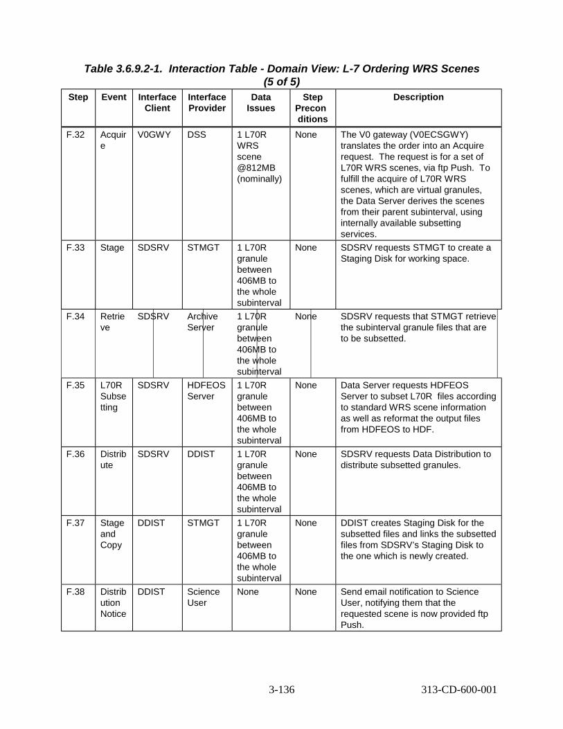
Table 3.6.9.2-1. Interaction Table - Domain View: L-7 Ordering WRS Scenes (5 of 5)
Step Event Interface Client
Interface Provider
Data Issues
Step Precon ditions
Description
F.32 Acquir e
V0GWY DSS 1 L70R WRS scene @812MB (nominally)
None The V0 gateway (V0ECSGWY) translates the order into an Acquire request. he request is for a set of L70R WRS scenes, via ftp Push. o fulfill the acquire of L70R WRS scenes, which are virtual granules, the Data Server derives the scenes from their parent subinterval, using internally available subsetting services.
F.33 Stage SDSRV STMGT 1 L70R granule between 406MB to the whole subinterval
None SDSRV requests STMGT to create a Staging Disk for working space.
F.34 Retrie ve
SDSRV Archive Server
1 L70R granule between 406MB to the whole subinterval
None SDSRV requests that STMGT retrieve the subinterval granule files that are to be subsetted.
F.35 L70R Subse tting
SDSRV HDFEOS Server
1 L70R granule between 406MB to the whole subinterval
None Data Server requests HDFEOS Server to subset L70R files according to standard WRS scene information as well as reformat the output files from HDFEOS to HDF.
F.36 Distrib ute
SDSRV DDIST 1 L70R granule between 406MB to the whole subinterval
None SDSRV requests Data Distribution to distribute subsetted granules.
F.37 Stage and Copy
DDIST STMGT 1 L70R granule between 406MB to the whole subinterval
None DDIST creates Staging Disk for the subsetted files and links the subsetted files from SDSRV’s Staging Disk to the one which is newly created.
F.38 Distrib ution Notice
DDIST Science User
None None Send email notification to Science User, notifying them that the requested scene is now provided ftp Push.
TT
3-136 313-CD-600-001

3.6.9.3 Landsat-7 Ordering WRS Scenes Thread Component Interaction Table Table 3.6.9.3-1 provides the Component Interaction: L-7 Ordering WRS Scenes.
Note that for distribution via one of the hard media (HM) means either 8mm tape, DLT, D3 or CD-ROM. As an example the interface provider is shown for 8mm tape. However for other media the corresponding interface provider would replace EcDsSt8MMServer as follows: EcDsStDLTServer for DLT EcDsStD3Server for D3 tape EcDsStCDROMServer for CD-ROM
For distributions with compression see steps F.8.1 through F.29.1 of Table 3.5.9.3-1 (Component Interaction Table: Data Compression on Distribution) instead of steps F.12 through F.17 of the following Table 3.6.9.3-1.
Table 3.6.9.3-1. Component Interaction Table: L-7 Ordering WRS Scenes (1 of 18) Step Event Interface
Client Interface Provider
Interface Mech.
Description
F.1.1 Select data to be ordered via hard media(HM)
Science User
Netscape GUI The Science User selects a set of L70R WRS scenes to order for delivery via one of the hard media (HM). When the order is complete it is submitted to the V0 Gateway.
F.2.1 V0 Gateway Order
Netscape EcDmV0 ToEcsGa teway
ODL, over sockets
EDG submits an order to the V0 Gateway, by converting the order into an ODL structure and passing that structure to a socket provided by the Gateway. The correct socket is determined from configuration information in the Valids file. The order contains billing information including billing ID.
F.2.2 Establish ECS User
EcDmV0 ToEcsGa teway
EcMsAc RegUser Srvr
Distributed Object
V0 Gateway retrieves the User Profile using ECS Authenticator from ODL message, which is an encrypted User ID and Password. The User Registration database is replicated across DAACs, so the connection is made to the local User Registration Server.
F.2.3 Request Attribute Mapping
EcDmV0 ToEcsGa teway
EcDmDic tServer
CtLib (RWDBTo ol)
Gateway translates the V0 terms from ODL into ECS names for request submittal using the DDICT database. Interface is directly to Data Dictionary database. Database name is retrieved from configuration file.
F.3.1 Request L7 Product
EcDmV0 ToEcsGa teway
EcDmLim Server
Distributed Object
V0ECSGWY sends the request to the DORRAN because the order is for L70R WRS data and there is no order ID in the message.
3-137 313-CD-600-001

Table 3.6.9.3-1. Component Interaction Table: L-7 Ordering WRS Scenes (2 of 18) Step Event Interface
Client Interface Provider
Interface Mech.
Description
F.3.2 B & A Verification
EcDmEc sToV0Ga teway
DORRAN Distributed Object
DORRAN validates the request by checking the account level of the requester and the required funding level of the request.
F.4.1 Acquire Return
DORRAN EcDmV0 ToEcsGa teway
Distributed Object
The Operator validates the order and DORRAN sends back all the remaining granules to the V0ECSGWY over a specific socket.
F.2.2 Create Tracked Order
EcDmV0 ToEcsGa teway
EcMsAc OrderSrv r
Distributed Object
Create an order to be tracked within ECS. Initial status set to “Pending”.
F.4.3 Store Tracked Order
EcMsAc OrderSrv r
Sybase CtLib Save the tracked order to the order database.
F.4.4 Create Tracked Request
EcDmV0 ToEcsGa teway
EcMsAc OrderSrv r
Distributed Object
Create the Tracked Request within the Order. Initial status set to “Pending”.
F.4.5 Store Tracked Request
EcMsAc OrderSrv r
Sybase CtLib Save the tracked request to the order database.
F.5.1 Connect to SDSRV
EcDmV0 ToEcsGa teway
EcDsScie nceData Server
Distributed Object
The Gateway first connects to the SDSRV. The correct SDSRV is determined by the UR of a granule that is being ordered. This is pertinent if there are multi-SDSRVs in use at one DAAC in one mode.
F.5.2 Add granules to Session
EcDmV0 ToEcsGa teway
EcDsScie nceData Server
Distributed Object
The V0 Gateway establishes the data context of the session with the SDSRV by adding granules to the session. The Granule UR of the L70R WRS Scene granules to be ordered is added to the ESDT ReferenceCollector.
F.5.3 Retrieve Granule Metadata from Inventory
EcDsScie nceData Server
Sybase/S QS
CtLib SDSRV completes establishing the data context by retrieving the metadata for the requested granules from the Sybase/SQS database. The metadata for each granule is passed back to the reference objects for each granule.
3-138 313-CD-600-001

Table 3.6.9.3-1. Component Interaction Table: L-7 Ordering WRS Scenes (3 of 18) Step Event Interface
Client Interface Provider
Interface Mech.
Description
F.5.4 Acquire Data
EcDmV0 ToEcsGa teway
EcDsScie nceData Server
Distributed Object
V0Gateway submits the order for L70R WRS Scene granules by submitting an Acquire request for the granules. The Acquire request is for one of the hard media of all granules in the ESDT ReferenceCollector. This request is asynchronous, meaning that the return of the submit call of the request only contains the status of the request’s submittal. The request asks for an email notification to be emailed to the user.
F.6.1 Create Staging Disk
EcDsScie nceData Server
EcDsStSt agingDis kServer
Distributed Object
SDSRV verifies access privileges for the granule and requests STMGT to create a Staging Disk (if local Staging Disk is available, use local one) for working space, scene files and metadata files, which allocates space and passes back a reference to that disk space. The reference to the Staging Disk is determined from the SDSRV configuration. The amount of staging disk to request is determined by the size of the metadata file. The availability of local Staging Disk is determined by the SDSRV configuration.
F.7.1 STMGT Retrieve
EcDsScie nceData Server
EcDsStAr chiveSer ver
Distributed Object
SDSRV requests that STMGT retrieve the subinterval granule files that are to be subset. For a L70R WRS Scene, these files include Band files, MSCD, Calibration File, MTA, PCD, and CPF files. This results in the files being staged to the working staging disk area. The correct archive object to request is determined from the information provided by the SDSRV in the distribution request.
3-139 313-CD-600-001

Table 3.6.9.3-1. Component Interaction Table: L-7 Ordering WRS Scenes (4 of 18) Step Event Interface
Client Interface Provider
Interface Mech.
Description
F.8.1 L7 Scene creation
EcDsScie nceData Server
EcDsHdf EosServe r
Distributed Object
Since L70R WRS Scenes are virtual granules (i.e. the granules are represented in the inventory with their metadata, but the files which contain the data don’t actually exist), the scene files must be extracted from the scene’s parent subinterval. The scene files are created using internal subinterval subsetting methods. The subset files include Band files, MSCD, Calibration File, MTA and PCD files. Metadata files for each L70R WRS Scene granule are created. Also the SDSRV searches the database for a comparable L7CPF file before performing reformatting. It keys the complete MTP file and creates a Format 1 / Format 2 file. Then the subsetted data is reformatted before passing the request to DDIST.
F.9.1 Distribute Granules, Synchrono us
EcDsScie nceData Server
EcDsDist ributionS erver
Distributed Object
SDSRV submits a request to Data Distribution. The request includes, for each L70R WRS Scene, a reference to the subset and metadata files. Other parameters from the Acquire request are passed to DDIST.
F.9.2 Request Claim Ownership
EcDsDist ributionS erver
EcDsStR equestM anager
Distributed Object
The Distribution server claims ownership of the staging disk created by SDSRV by sending a request to the EcDsStRequestManager to insert appropriate data in the data base table.
F9.3 Claim Ownership
EcDsStR equestMa nager
EcDsStSt agingDis kServer
Distributed Object
The EcDsStRequestManager passes on the request to the EcDsStStagingDiskServer to insert appropriate data in the data base table. This is done with the STMGT Request Manager.
F.9.4 Request Compress Disk
EcDsDist ributionS erver
EcDsStR equestM anager
Distributed Object
The Distribution Server sends a request to the Request Manager to ask the Staging Disk Server to compress the staging disk.
F.9.5 Compres Disk
EcDsStR equestM anager
EcDsStSt agingDis kServer
Distributed Object
The Request Manager passes a request to the Staging Disk Server to compress the staging disk. This is done with the STMGT Request Manager.
F.9.6 Update Tracked Request Status
EcDsDist ributionS erver
EcMsAc OrderSrv r
Distributed Object
Update the status of the tracked request to “Active”.
3-140 313-CD-600-001

Table 3.6.9.3-1. Component Interaction Table: L-7 Ordering WRS Scenes (5 of 18) Step Event Interface
Client Interface Provider
Interface Mech.
Description
F.9.7 Update Tracked Status
EcMsAc OrderSrv r
Sybase CtLib Update the Order Tracking Database with new status.
F.10.1 Request Create Staging Disk
EcDsDist ributionS erver
EcDsStR equestM anager
Distributed Object
DDIST sends a request to the Request Manager to create Staging Disk for the granule files in the archive.
F.10.2 Create Staging Disk
EcDsStR equestM anager
EcDsStSt agingDis kServer
Distributed Object
The Request Manager sends the DDIST create staging disk request to the StagingDisk server to create a staging disk for the granule files in the archive. This allocates space and passes back a reference to that disk space. The reference to the Staging Disk is determined from the information passed by the SDSRV in the distribution request, which was the SDSRV configuration. The amount of staging disk to request is determined by the size of the metadata file. DDIST copies the reformatted data to the new staging disk. (Note: A packing list is generated in the next series of steps).
F.10.3 Update Tracked Request Status
EcDsDist ributionS erver
EcMsAc OrderSrv r
Distributed Object
Update the status of the tracked request to “Staging”.
F.10.3 Update Tracked Status
EcMsAc OrderSrv r
Sybase CtLib Update the Order Tracking Database with new status.
F.10.4 Request Link files to Staging Disk
EcDsDist ributionS erver
EcDsStSt agingDis kServer
Distributed Object
DDIST sends a request to the RequestManager to have the Staging Disk server to link the subset and metadata files from the SDSRV’s Staging Disk to the staging disk.
F.10.5 Link files to Staging Disk
EcDsStR equestM anager
EcDsStSt agingDis kServer
Distributed Object
The RequestManager relays DDIST’s request to Staging Disk server to link the subset and metadata files from the SDSRV’s Staging Disk to the staging disk.
F.11.1 Allocate Media Resource
EcDsDist ributionS erver
DsSt Resource Provider
Distributed Object
DDIST now creates the Resource manager for the requested hard media via a STMGT Resource Manager Factory. The correct resource manager is determined from the Media Type handed to the resource factory. The correct hard media resource is determined from configuration within the resource factory.
3-141 313-CD-600-001

Table 3.6.9.3-1. Component Interaction Table: L-7 Ordering WRS Scenes (6 of 18) Step Event Interface
Client Interface Provider
Interface Mech.
Description
F.11.2 Update Tracked Request Status
EcDsDist ributionS erver
EcMsAc OrderSrv r
Distributed Object
Update the status of the tracked request to “Transferring”.
F.11.3 Update Tracked Status
EcMsAc OrderSrv r
Sybase CtLib Update the Order Tracking Database with new status.
F.11.4 Transfer EcDsDist ributionS erver
DsSt Resource Provider
Distributed Object
DDIST requests that the files held in staging disk be copied to therequested hard media.
F.12.1 Write Files to the requested hard media
EcDsSt8 MMServe r
Tape Device
Tar The files in staging disk are copied to the requested hard media.
F.12.2 Update Tracked Request Status
EcDsDist ributionS erver
EcMsAc OrderSrv r
Distributed Object
Upon completion of the files being copied, the state of the distribution request is marked as “Ready for Shipment”, which is displayed on the operator GUI. A packing list is generated. Update the status of the tracked request to “Waiting for Shipment”. Update the media quantity.
F.12.3 Update Tracked Status
EcMsAc OrderSrv r
Sybase CtLib Update the Order Tracking Database with the media quantity and new status.
F.13.1 Determine request is ready for shipping
DAAC Ops -Distributi on Technicia n
EcDsDdi stGui
GUI Operator notes that the request is ready for shipping and that it includes the requested hard media just produced. The slot and stacker ID are included in the logs for the 8mm, DLT, D3 tape, so that the operator knows which tapes to ship. For CD-ROM the CD-Writer ID is included in the logs.
F.13.2 Ship HM DAAC Ops -Data Technicia n
DAAC Ops -Data Technicia n
Internal Labels for all media, as well as a shipping label for the package are created manually. Using commercial shipping vendors (determined by DAAC policy), the DAAC Data Technician labels the HM, packages the HM and packing list, labels the package and ships to address provided with the request.
F.14.1 Mark as Shipped
DAAC Ops -Data Technicia n
EcDsDdi stGui
GUI Using the DDIST GUI, the Data Technician marks the request as “Shipped”.
3-142 313-CD-600-001

Table 3.6.9.3-1. Component Interaction Table: L-7 Ordering WRS Scenes (7 of 18) Step Event Interface
Client Interface Provider
Interface Mech.
Description
F.14.2 Update Distribution Request
EcDsDdi stGui
EcDsDist ributionS erver
Distributed Object
DDIST updates the state of the request to “Shipped”.
F.14.3 Update Tracked Request Status
EcDsDist ributionS erver
EcMsAc OrderSrv r
Distributed Object
Update the status of the tracked request to “Shipped”.
F.14.4 Update Tracked Status
EcMsAc OrderSrv r
Sybase CtLib Update the Order Tracking Database with new status.
F.15.1 Build Distribution Notice
EcDsDist ributionS erver
EcDsDist ributionS erver
Internal The DDIST builds an email notification that the user’s order has been fulfilled. This notification includes the media ID, type and format of the request, UR, type and file names and sizes for each granule as well as a DAAC configurable preamble.
F.15.2 Send E-mail
EcDsDist ributionS erver
Science User
email Message is emailed to the Science User’s email address, as determined from the User Profile.
F.16.1 Select data to be ordered via ftp Pull
Science User
Netscape GUI The Science User selects a specific L70R WRS scene to order for delivery via ftp Pull while the tape order is being processed. When the order is complete it is submitted to the V0 Gateway.
F.17.1 V0 Gateway Order
Netscape EcDmV0 ToEcsGa teway
ODL, over sockets
EDG submits an order to the V0 Gateway, by converting the order into an ODL structure and passing that structure to a socket provided by the Gateway. The correct socket is determined from configuration information in the Valids file. The order contains billing information including billing ID.
F.17.2 Establish ECS User
EcDmV0 ToEcsGa teway
EcMsAc RegUser Srvr
Distributed Object
V0 Gateway retrieves the User Profile using ECS Authenticator from ODL message, which includes an encrypted User ID and Password. The User Registration database is replicated across DAACs, so the connection is made to the local User Registration Server.
F.17.3 Request Attribute Mapping
EcDmV0 ToEcsGa teway
EcDmDic tServer
CtLib (RWDBTo ol)
Gateway translates the V0 terms from ODL into ECS names for request submittal using the DDICT database. Interface is directly to Data Dictionary database. Database name is retrieved from configuration file.
3-143 313-CD-600-001

Table 3.6.9.3-1. Component Interaction Table: L-7 Ordering WRS Scenes (8 of 18) Step Event Interface
Client Interface Provider
Interface Mech.
Description
F.18.1 Send L7 Acquire
EcDmV0 ToEcsGa teway
DORRAN Distributed Object
V0ECSGWY sends the request to the DORRAN because the order is for L70R WRS data and there is no order ID in the message.
F.18.2 B & A Verification
EcDmEc sToV0Ga teway
DORRAN Comp.
Distributed Object
DORRAN validates the request by checking the account level of the requester and the required funding level of the request.
F.19.1 DORRAN Return
DORRAN EcDmV0 ToEcsGa teway
Distributed Object
The Operator validates the order and DORRAN sends back all the remaining granules to the V0ECSGWY over a specific socket.
F.19.2 Create Tracked Order
EcDmV0 ToEcsGa teway
EcMsAc OrderSrv r
Distributed Object
Create an order to be tracked within ECS. Initial status set to “Pending”.
F.19.3 Store Tracked Order
EcMsAc OrderSrv r
Sybase CtLib Create a tracked order in the database.
F.19.4 Create Tracked Request
EcDmV0 ToEcsGa teway
EcMsAc OrderSrv r
Distributed Object
Create the Tracked Request within the Order. Initial status set to “Pending”.
F.19.5 Store Tracked Request
EcMsAc OrderSrv r
Sybase CtLib Create a tracked request in the order database.
F.20.1 Connect to SDSRV
EcDmV0 ToEcsGa teway
EcDsScie nceData Server
Distributed Object
The Gateway first connects to the SDSRV. The correct SDSRV is determined by the UR of a granule that is being ordered. This is pertinent if there are multi-SDSRVs in use at one DAAC in one mode.
F.20.2 Add granules to Session
EcDmV0 ToEcsGa teway
EcDsScie nceData Server
Distributed Object
The V0 Gateway establishes the data context of the session with the SDSRV by adding granules to the session. The Granule UR of the L70R WRS Scene granules to be ordered is added to the ESDT ReferenceCollector.
F.20.3 Retrieve Granule Metadata from Inventory
EcDsScie nceData Server
Sybase/S QS
CtLib SDSRV completes establishing the data context by retrieving the metadata for the requested granules from the Sybase/SQS database. The metadata for each granule is passed back to the reference objects for each granule.
3-144 313-CD-600-001

Table 3.6.9.3-1. Component Interaction Table: L-7 Ordering WRS Scenes
Step Event Interface Client
Interface Provider
(9 of 18) Interface
Mech. Description
F.20.4 Acquire Data
EcDmV0 ToEcsGa teway
EcDsScie nceData Server
Distributed Object
V0Gateway submits the order for L70R WRS Scene granules by submitting an Acquire request for the granules. The Acquire request is for an ftp Pull of a specified granule in the ESDT ReferenceCollector. This request is asynchronous, meaning that the return of the submit call of the request only contains the status of the request’s submittal.
F.21.1 Request Create Staging Disk
EcDsScie nceData Server
Distributed Object
SDSRV verifies access privileges for the granule and sends a request to the Request Manager to create a Staging Disk for working space, scene files and metadata files, which allocates space and passes back a reference to that disk space.
F21.2 Create Staging Disk
EcDsStR equestM anager
EcDsStSt agingDis kServer
Distributed Object
The Request Manager sends a request to the Staging Disk server to create a Staging Disk for working space, scene files and metadata files, which allocates space and passes back a reference to that disk space. The reference to the Staging Disk is determined from the SDSRV configuration. The amount of staging disk to request is determined on a band-by-band basis. The SDSRV requests twice the size of the first band, from metadata in the database, and requests more as needed in order to subset the subsequent files. Each request is for twice the size of the file to be subsetted.
F.22.1 Request STMGT Retrieve
EcDsScie nceData Server
EcDsStAr chiveSer ver
Distributed Object
SDSRV sends a request to the Request Manager so that STMGT can retrieve the subinterval granule files that are to be subsetted.
3-145 313-CD-600-001

Table 3.6.9.3-1. Component Interaction Table: L-7 Ordering WRS Scenes
Step Event Interface Client
(10 of 18) Interface Provider
Interface Mech.
Description
F.22.2 STMGT Retrieve
EcDsStR equestM anager
EcDsStAr chiveSer ver
Distributed Object
Request Manager passes on a request from SDSRV to the Archive Server so that STMGT can retrieve the subinterval granule files that are to be subsetted. For a L70R WRS Scene, these files include band files, calibration files, MTA, MSCD and PCD files. This results in the files being staged to the working staging disk area. The correct archive object to request is determined from the information provided by the SDSRV in the distribution request.
F.23.1 L7 Scene creation
EcDsScie nceData Server
EcDsHdf EosServe r
Distributed Object
Since L7 WRS Scenes are virtual granules (i.e. the granules are represented in the inventory with their metadata, but the files which contain the data don’t actually exist), the scene files must be extracted from the scene’s parent subinterval. The scenes files are created using internal subinterval subsetting methods. The subsetted files include band files, calibration files, MTA, MSCD, PCD, and CPF files. A metadata file for the L70R WRS Scene is created. Also the SDSRV searches the database for a comparable L7CPF file before performing reformatting. It keys the complete MTP file and creates a Format 1 / Format 2 file. Then the subsetted data is reformatted before passing it to DDIST.
F.24.1 Distribute Granules, Synchrono us
EcDsScie nceData Server
EcDsDist ributionS erver
Distributed Object
SDSRV submits a request to Data Distribution. The request includes, for the granule, a reference to the metadata file. Other parameters from the Acquire request are passed to DDIST.
F.24.2 Update Tracked Request Status
EcDsDist ributionS erver
EcMsAc OrderSrv r
Distributed Object
Update the status of the tracked request to “Active”.
F.24.3 Update Tracked Status
EcMsAc OrderSrv r
Sybase CtLib Update the Order Tracking Database with new status.
F.24.4 Request Claim Ownership
EcDsDist ributionS erver
EcDsStR equestM anager
Distributed Object
The Distribution server sends a request to the STMGT Request Manager for the STMGT Distribution server to claim ownership of the staging disk created by SDSRV.
3-146 313-CD-600-001

Table 3.6.9.3-1. Component Interaction Table: L-7 Ordering WRS Scenes
Step Event Interface Client
(11 of 18) Interface Provider
Interface Mech.
Description
F.24.5 Claim Ownership
EcDsStR equestMa nager
EcDsStSt agingDis kServer
Distributed Object
The STMGT Request Manager passes on the Distribution server’s request to the STMGT Staging Disk server to claim ownership of the staging disk created by SDSRV by inserting appropriate data in the data base table.
F.24.6 Request Compress Disk
EcDsDist ributionS erver
EcDsStR equestM anager
Distributed Object
The Distribution Server sends a request to the STMGT Request Manager to asks the Staging Disk Server to compress the staging disk.
F24.7 Compress Disk
EcDsStR equestM anager
EcDsStSt agingDis kServer
Distributed Object
The Request Manager passes on the Distribution Server’s request to asks the Staging Disk Server to compress the staging disk.
F.25.1 Create Staging Disk
EcDs Distributi onServer
EcDsStR equestM anager
Distributed Object
Data Distribution sends a request to the STMGT Request Manager to create a Staging Disk for the granule files in the archive.
F.25.2 Create Staging Disk
EcDsStR equestM anager
EcDsStSt agingDis kServer
Distributed Object
The STMGT Request Manager passes on the Distribution Server’s request to create a Staging Disk for the granule files in the archive. This allocates space and passes back a reference to that disk space. The reference to the Staging Disk is determined from the information passed by the SDSRV in the distribution request, which was the SDSRV configuration. The amount of staging disk to request is determined by the size of the subsetted/reformatted data.
F.25.3 Update Tracked Request Status
EcDsDist ributionS erver
EcMsAc OrderSrv r
Distributed Object
Update the status of the tracked request to “Staging”.
F.25.4 Update Tracked Status
EcMsAc OrderSrv r
Sybase CtLib Update the Order Tracking Database with new status.
F.25.5 Request Link files to Staging Disk
EcDsDist ributionS erver
EcDsStR equestM anager
Distributed Object
DDIST sends a request to the RequestManager to ask the Staging Disk server to link the subsetted and metadata files from the SDSRV’s Staging Disk into the staging disk.
3-147 313-CD-600-001

Table 3.6.9.3-1. Component Interaction Table: L-7 Ordering WRS Scenes
Step Event Interface Client
(12 of 18) Interface Provider
Interface Mech.
Description
F.25.6 Link files to Staging Disk
EcDsStR equestM anager
EcDsStSt agingDis kServer
Distributed Object
Staging Disk server receives the request forwarded by the Request Manager from DDIST to links the subsetted and metadata files from the SDSRV’s Staging Disk into the staging disk.
F.25.6 Update Tracked Request Status
EcDsDist ributionS erver
EcMsAc OrderSrv r
Distributed Object
Update the status of the tracked request to “Transferring”.
F.25.7 Update Tracked Status
EcMsAc OrderSrv r
Sybase CtLib Update the Order Tracking Database with new status.
F.25.8 Update Tracked Request Status
EcDsDist ributionS erver
EcMsAc OrderSrv r
Distributed Object
Update the status of the tracked request to “Shipped”. Update the media quantity.
F.25.9 Update Tracked Status
EcMsAc OrderSrv r
Sybase CtLib Update the Order Tracking Database with the media quantity and the new status.
F.26.1 Build Distribution Notice
EcDsDist ributionS erver
EcDsDist ributionS erver
Internal DDIST builds a distribution notice indicating that the L70R WRS Scene data is now available. The notice includes the UR of the Scene granule, name of the Scene’s files, size of files, the host and directory names where it is available and how long it is available.
F.26.2 Send E-mail
EcDsDist ributionS erver
Science User
E-mail The distribution notice is emailed to the Science User. The e-mail address is obtained from the User Profile.
F.27.1 Operator Notification of Expired files
EcDsStm gtGui
Operator GUI Message is sent to the operator when expired files have to be removed from the Pull Cache. The notification can either be a warning, the cache is getting full or an indication of imminent failure. Notification comes to the message screen that is part of the STMGT GUI. There is a configuration parameter, which will allow the software to automatically delete expired files.
3-148 313-CD-600-001

Table 3.6.9.3-1. Component Interaction Table: L-7 Ordering WRS Scenes
Step Event Interface Client
(13 of 18) Interface Provider
Interface Mech.
Description
F.27.2 View Expired Files
Operator EcDsStm gtGui
GUI Operator selects to view the Pull Monitor Server at the Cache Stats tab. The display will contain all of the files currently in the pull cache. The operator can sort the display based on expiration status so that all of the expired files are in the same place on the screen. The operator can then select the files to be deleted and hits the mark delete button. When the operator has marked all of the files for deletion that he/she wants to delete at that time, the operator hits the purge button. This will cause the files to be deleted from the cache and entries will be removed from the database tables CacheFile and FileLocation. Any remaining links will also be cleaned up.
F.28.1 Select data to be ordered via ftp Push
Science User
Netscape GUI The Science User selects a specific L70R WRS scene to order for delivery via ftp Push while the tape order is being processed. When the order is complete it is submitted to the V0 Gateway.
F.29.1 V0 Gateway Order
Netscape EcDmV0 ToEcsGa teway
ODL, over sockets
EDG submits an order to the V0 Gateway, by converting the order into an ODL structure and passing that structure to a socket provided by the Gateway. The correct socket is determined from configuration information in the Valids file. The order contains billing information including billing ID.
F.29.2 Establish ECS User
EcDmV0 ToEcsGa teway
EcMsAc RegUser Srvr
Distributed Object
V0 Gateway retrieves the User Profile using ECS Authenticator from ODL message, which includes an encrypted User ID and Password. The User Registration database is replicated across DAACs, so the connection is made to the local User Registration Server.
F.29.3 Request Attribute Mapping
EcDmV0 ToEcsGa teway
EcDmDic tServer
CtLib (RWDBTool)
Gateway translates the V0 terms from ODL into ECS names for request submittal using the DDICT database. Interface is directly to Data Dictionary database. Database name is retrieved from configuration file.
3-149 313-CD-600-001

Table 3.6.9.3-1. Component Interaction Table: L-7 Ordering WRS Scenes
Step Event Interface Client
(14 of 18) Interface Provider
Interface Mech.
Description
F.30.1 Send L7 Acquire
EcDmV0 ToEcsGa teway
EcDmLim Server
Distributed Object
V0ECSGWY sends the request to the DORRAN system because the order is for L70R WRS data and there is no order ID in the message.
F.30.2 B & A Verification
EcDmEc sToV0Ga teway
DORRAN Comp.
Distributed Object
DORRAN validates the request by checking the account level of the requester and the required funding level of the request.
F.31.1 DORRAN Return
DORRAN EcDmV0 ToEcsGa teway
Distributed Object
The Operator validates the order and DORRAN sends back all the remaining granules to the V0ECSGWY over a specific socket.
F.31.2 Create Tracked Order
EcDmV0 ToEcsGa teway
EcMsAc OrderSrv r
Distributed Object
Create an order to be tracked within ECS. Initial status set to “Pending”.
F.31.3 Store Tracked Order
EcMsAc OrderSrv r
Sybase CtLib Create a tracked order in the database.
F.31.4 Create Tracked Request
EcDmV0 ToEcsGa teway
EcMsAc OrderSrv r
Distributed Object
Create the Tracked Request within the Order. Initial status set to “Pending”.
F.31.5 Store Tracked Request
EcMsAc OrderSrv r
Sybase CtLib Create a tracked request in the order database.
F.32.1 Connect to SDSRV
EcDmV0 ToEcsGa teway
EcDsScie nceData Server
Distributed Object
The Gateway first connects to the SDSRV. The correct SDSRV is determined by the UR of a granule that is being ordered. This is pertinent if there are multi-SDSRVs in use at one DAAC in one mode.
F.32.2 Add granules to Session
EcDmV0 ToEcsGa teway
EcDsScie nceData Server
Distributed Object
The V0 Gateway establishes the data context of the session with the SDSRV by adding granules to the session. The Granule UR of the L70R WRS Scene granules to be ordered is added to the ESDT ReferenceCollector.
F.32.3 Retrieve Granule Metadata from Inventory
EcDsScie nceData Server
Sybase/S QS
CtLib SDSRV completes establishing the data context by retrieving the metadata for the requested granules from the Sybase/SQS database. The metadata for each granule is passed back to the reference objects for each granule.
3-150 313-CD-600-001

Table 3.6.9.3-1. Component Interaction Table: L-7 Ordering WRS Scenes
Step Event Interface Client
(15 of 18) Interface Provider
Interface Mech.
Description
F.32.4 Acquire Data
EcDmV0 ToEcsGa teway
EcDsScie nceData Server
Distributed Object
V0Gateway submits the order for L70R WRS Scene granules by submitting an Acquire request for the granules. The Acquire request is for an ftp Push of a specified granule in the ESDT ReferenceCollector. This request is asynchronous, meaning that the return of the submit call of the request only contains the status of the request’s submittal.
F.33.1 Request Create Staging Disk
EcDsScie nceData Server
EcDsStR equestM anager
Distributed Object
SDSRV sends a request to the STMGT Request Manager to ask the Staging Disk to create a Staging Disk for working space, scene files and metadata files, which allocates space and passes back a reference to that disk space.
F33.2 Create Staging Disk
EcDsStR equestM anager
EcDsStSt agingDis kServer
Distributed Object
The STMGT Request Manager forwards a SDSRV request to the Staging Disk server which verifies access privileges for the granule and creates a Staging Disk for working space, scene files and metadata files, which allocates space and passes back a reference to that disk space. The reference to the Staging Disk is determined from the SDSRV configuration. The amount of staging disk to request is determined on a band-by-band basis. The SDSRV requests twice the size of the first band, from metadata in the database, and requests more as needed in order to subset the subsequent files. Each request is for twice the size of the file to be subsetted.
F.34.1 Request STMGT Retrieve
EcDsScie nceData Server
EcDsStR equestM anager
Distributed Object
SDSRV sends a request to the STMGT Request Manager to be forwarded to the Archive Server so that STMGT can retrieve the subinterval granule files that are to be subsetted.
3-151 313-CD-600-001

Table 3.6.9.3-1. Component Interaction Table: L-7 Ordering WRS Scenes
Step Event Interface Client
(16 of 18) Interface Provider
Interface Mech.
Description
F34.2 STMGT Retrieve
EcDsStR equestM anager
EcDsStAr chiveSer ver
Distributed Object
The SDSRV request is forwarded by the STMGT Request Manager to the Archive Server so that STMGT can retrieve the subinterval granule files that are to be subsetted. For a L70R WRS Scene, these files include band files, calibration files, MTA, MSCD and PCD files. This results in the files being staged to the working staging disk area. The correct archive object to request is determined from the information provided by the SDSRV in the distribution request.
F.35.1 L7 Scene creation
EcDsScie nceData Server
EcDsHdf EosServe r
Distributed Object
Since L7 WRS Scenes are virtual granules (i.e. the granules are represented in the inventory with their metadata, but the files which contain the data don’t actually exist), the scene files must be extracted from the scene’s parent subinterval. The scenes files are created using internal subinterval subsetting methods. The subsetted files include band files, calibration files, MTA, MSCD, PCD, and CPF files. A metadata file for the L70R WRS Scene is created. Also the SDSRV searches the database for a comparable L7CPF file before performing reformatting. It keys the complete MTP file and creates a Format 1 / Format 2 file. Then the subsetted data is reformatted before passing it to DDIST.
F.36.1 Distribute Granules, Synchrono us
EcDsScie nceData Server
EcDsDist ributionS erver
Distributed Object
SDSRV submits a request to Data Distribution. The request includes, for the granule, a reference to the metadata file. Other parameters such as FtpPushUserId, FtpPushPassword, FtpPushHostName, FtpPushDestination from the Acquire request are passed to DDIST.
F.36.2 Update Tracked Request Status
EcDsDist ributionS erver
EcMsAc OrderSrv r
Distributed Object
Update the status of the tracked request to “Active”.
F.36.3 Update Tracked Status
EcMsAc OrderSrv r
Sybase CtLib Update the Order Tracking Database with new status.
3-152 313-CD-600-001

Table 3.6.9.3-1. Component Interaction Table: L-7 Ordering WRS Scenes
Step Event Interface Client
(17 of 18) Interface Provider
Interface Mech.
Description
F.36.4 Request Claim Ownership
EcDsDist ributionS erver
EcDsStR equestM anagerSe rver
Distributed Object
The Distribution server sends request to the STMGT Request Manager for the Staging Disk server to create a staging disk.
F.36.5 Claim Ownership
EcDsStR equestMa nagerSer ver
EcDsStSt agingDis kServer
Distributed Object
The STMGT Request Manager forwards the Distribution server’s request to the Staging Disk server to claims ownership of the staging disk created by SDSRV by inserting appropriate data in the data base table.
F.36.5 Request Compress Disk
EcDsDist ributionS erver
EcDsStR equestM anagerSe rver
Distributed Object
The Distribution server sends a request to the Request Manager to have the Staging Disk server compress the staging disk.
F.36.6 Compress Disk
EcDsStR equestMa nager
EcDsStSt agingDis kServer
Distributed Object
The STMGT Request Manager forwards the Distribution Server’s request to the Staging Disk Server to compress the staging disk.
F.37.1 Request Create Staging Disk
EcDsDist ributionS erver
EcDsStR equestM anager
Distributed Object
Data Distribution sends a request to the STMGT Request Manger to for the Staging Disk server to create Staging Disk for the granule files in the archive.
F37.2 Create Staging Disk
EcDsStR equestM anager
EcDsStSt agingDis kServer
Distributed Object
The STMGT Request Manager forwards the Distribution Server’s request to the Staging Disk server to create a Staging Disk for the granule files in the archive. This allocates space and passes back a reference to that disk space. The reference to the Staging Disk is determined from the information passed by the SDSRV in the distribution request, which was the SDSRV configuration. The amount of staging disk to request is determined by the size of the subsetted/reformatted data.
F.37.3 Update Tracked Request Status
EcDsDist ributionS erver
EcMsAc OrderSrv r
Distributed Object
Update the status of the tracked request to “Staging”. Update the media quantity.
F.37.4 Update Tracked Status
EcMsAc OrderSrv r
Sybase CtLib Update the Order Tracking Database with the media quantity and the new status.
3-153 313-CD-600-001

Table 3.6.9.3-1. Component Interaction Table: L-7 Ordering WRS Scenes
Step Event Interface Client
(18 of 18) Interface Provider
Interface Mech.
Description
F.37.5 Link files to Staging Disk
EcDsDist ributionS erver
EcDsStR equestM anager
Distributed Object
DDIST sends a request to the STMGT Request Manager for the Staging Disk server to link the subsetted and metadata files from the SDSRV’s Staging Disk into the staging disk.
F37.6 Link files to Staging Disk
EcDsStR equestM anager
EcDsStSt agingDis kServer
Distributed Object
The STMGT Request Manager forwards DDIST’s request to the Staging Disk Server to link the subsetted and metadata files from the SDSRV’s Staging Disk into the staging disk.
F.37.7 Update Tracked Request Status
EcDsDist ributionS erver
EcMsAc OrderSrv r
Distributed Object
Update the status of the tracked request to “Transferring”.
F.37.8 Update Tracked Status
EcMsAc OrderSrv r
Sybase CtLib Update the Order Tracking Database with new status.
F.37.9 Update Tracked Request Status
EcDsDist ributionS erver
EcMsAc OrderSrv r
Distributed Object
Update the status of the tracked request to “Shipped”.
F.37.1 9
Update Tracked Status
EcMsAc OrderSrv r
Sybase CtLib Update the Order Tracking Database with new status.
F.38.1 Build Distribution Notice
EcDsDist ributionS erver
EcDsDist ributionS erver
Internal DDIST builds a distribution notice indicating that the L70R WRS Scene data has been pushed up to user-specified host machine. The notice includes the order ID, the UR of the Scene granule, name of the Scene’s files, size of files, compression type the host and directory names.
F.38.2 Send E-mail
EcDsDist ributionS erver
Science User
E-mail The distribution notice is emailed to the Science User. The e-mail address is obtained from the User Profile.
3.6.10 Landsat-7 MOC Interface Thread - Deleted
3.6.11 Landsat-7 Ordering L70R Floating Scenes Thread This thread shows how the ECS supports user orders for L70R floating scenes where hard media (HM) denotes 8mm, D3, DLT and CD-ROM.
3-154 313-CD-600-001

3.6.11.1 Landsat-7 Ordering L70R Floating Scenes Thread Interaction Diagram - Domain View Figure 3.6.11.1-1 depicts the L-7 Ordering L70R Floating Scenes Interaction
H.27 Delete Expired Files
Distributed Object (rpc, CtLib) HMI (GUI, Xterm, command) ftp email (or other as noted) Double line - Synchronous email (or other as noted) Dashed - Asynchronous
H.1 Order Data (HM)
DMS (V0ECSGwy)
Science User
Science User
H.2 Order(HM) H.17 Order (ftpPull)H.29 Order (ftpPush)
H.5 Acquire(HM)
H.20 Acquire (ftpPull) H.32 Acquire(ftpPush)
H.13 Ship Tape to User(via DAAC Shipper)
DAAC Ops
DAAC Ops
H.12 Prepare Hard Media
B0SOTDORRAN
CLS (EDG)
H.14 Update Order
DSS (DDIST)
DSS (STMGT)
DSS (SDSRV)
H.8, H.23, H.35 L70R Subsetting(floating, band, non-imagery)
DSS (HDFEOS
Server)
DSS (Archive
Server)
H.16 Order Data (
ftpPull) H.28 Order Data (ftpPush)
H.4, H.19, H.31 Acquire
Return
H.9, H.24, H.36 Distribute
H.10, H.25, H.37 Stage
H.6, H.21, H.33 H.7, H.22, H.34Stage
Retrieve
H.15 Distribution Notice (HM shipped)H.26 Distribution Notice (ftpPull) H.38 Distribution Notice(ftpPush) )))))available)
H.11 Transfer
H3, H18, H30 Send L7 Acquire
Figure 3.6.11.1-1. L-7 Ordering L70R Floating Scenes Interaction Diagram
3.6.11.2 Landsat-7 Ordering L70R Floating Scenes Thread Interaction Table -Domain View Table 3.6.11.2-1 provides the Interaction – Domain View: Landsat L-7 Ordering L70R Floating Scenes.
3-155 313-CD-600-001

Table 3.6.11.2-1. Interaction Table - Domain View: L-7 Ordering L70R Floating
Step Event Interface Client
Interface Provider
Scenes (1 of 5) Data
Issues Step
Precon ditions
Description
H.1 Order Data
Science User
EDG None None Scientist decides to order a number of L70R Floating Scenes. Using the EDG, a scientist selects the scenes of interest and selects order via one of the hard media.
H.2 Order EDG V0ECSG WY
None None EDG submits the Science User’s order to DORRAN system in ODL format, via a specific socket.
H.4 Order DORRA N
V0ECSG WY
None None The Operator validates the order and DORRAN sends back all the remaining granules to the V0ECSGWY over a specific socket. The DORRAN System performs a Billing & Accounting verification.
H.5 Acquir e
V0ECSG WY
SDSRV (DSS)
1 L70R granule between 406MB to the whole subinterval
None The V0 gateway (V0ECSGWY) translates the order into an Acquire request. The spatial and band subsetting parameters are part of the request order. The request is for a set of L70R Floating Scenes, via one of the hard media. To fulfill the acquire of floating scenes, which are virtual granules, the Data Server derives the scenes from their parent subinterval, using internally available subsetting services.
H.6 Stage SDSRV STMGT 1 L70R granule between 406MB to the whole subinterval
None SDSRV requests STMGT to create a Staging Disk for working space.
H.7 Retrie ve
SDSRV Archive Server
1 L70R granule between 406MB to the whole subinterval
None SDSRV requests that STMGT retrieve the subinterval granule files that are to be subsetted.
H.8 L70R Subse tting
SDSRV HDFEOS Server
1 L70R granule between 406MB to the whole subinterval
None Data Server requests HDFEOS Server to subset L70R files according to user defined floating scene spatial and band constraints as well as reformat the output files from HDFEOS to HDF. The HDFEOS Server will accept and pass on scanline delimited subsetting requests.
3-156 313-CD-600-001

Table 3.6.11.2-1. Interaction Table - Domain View: L-7 Ordering L70R Floating
Step Event Interface Client
Interface Provider
Scenes (2 of 5) Data
Issues Step
Precon ditions
Description
H.9 Distrib ute
SDSRV DDIST 1 L70R granule between 406MB to the whole subinterval
None SDSRV requests Data Distribution to distribute subsetted granules.
H.10 Stage DDIST STMGT 1 L70R granule between 406MB to the whole subinterval
None DDIST creates Staging Disk for the subsetted files and links the subsetted files from SDSRV’s Staging Disk to the one which is newly created.
H.11 Transf er
DDIST STMGT 1 L70R granule between 406MB to the whole subinterval
None DDIST sends a request to STMGT to copy the files from the Staging Disk to the requested hard media and marks the order as “Waiting for Shipment”.
H.12 Prepa re Hard Media (HM)
STMGT HM Device
None None STMGT copies the L70R Floating Scenes granule’s files to the requested hard media.
H.13 Ship HM to User
DAAC Ingest Distributi on Technicia n
Science User
None None DAAC Ingest/Distribution Technician collects the HM and the packing list, and generates a media shipping label. He labels the HM, encloses the HM and packing list in shipping container and labels shipping container. DAAC uses commercial shipping vendor for delivery to Science User.
H.14 Updat e Order
DAAC Ops (Distributi on Tech.)
DSS (DDIST GUI)
None None Data Technician marks order as “Shipped” in the DDIST GUI.
H.15 Distrib ution Notice
DDIST Science User
None None Send email notification to Science User, notifying that the ordered L70R WRS scenes have been shipped to their shipping address.
3-157 313-CD-600-001
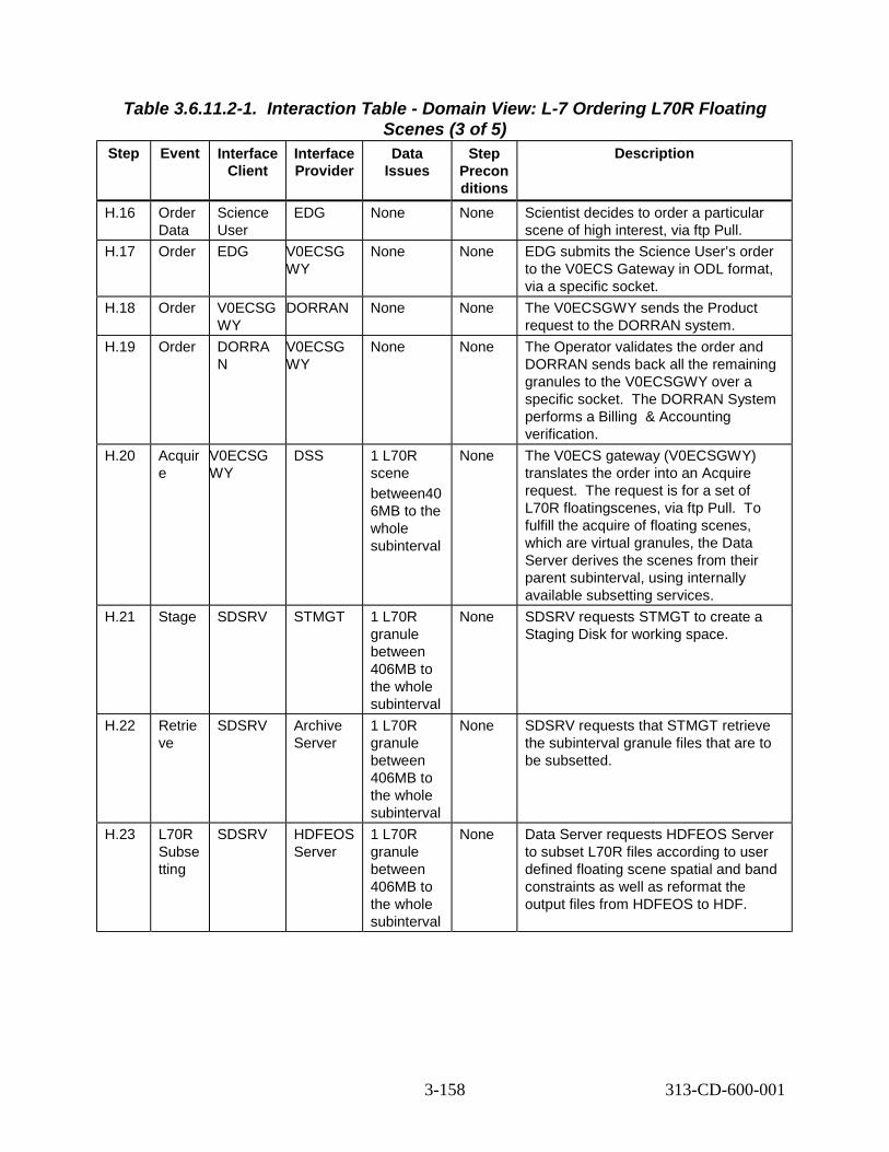
Table 3.6.11.2-1. Interaction Table - Domain View: L-7 Ordering L70R Floating
Step Event Interface Client
Interface Provider
Scenes (3 of 5) Data
Issues Step
Precon ditions
Description
H.16 Order Data
Science User
EDG None None Scientist decides to order a particular scene of high interest, via ftp Pull.
H.17 Order EDG V0ECSG WY
None None EDG submits the Science User’s order to the V0ECS Gateway in ODL format, via a specific socket.
H.18 Order V0ECSG WY
DORRAN None None The V0ECSGWY sends the Product request to the DORRAN system.
H.19 Order DORRA N
V0ECSG WY
None None The Operator validates the order and DORRAN sends back all the remaining granules to the V0ECSGWY over a specific socket. The DORRAN System performs a Billing & Accounting verification.
H.20 Acquir e
V0ECSG WY
DSS 1 L70R scene between40 6MB to the whole subinterval
None The V0ECS gateway (V0ECSGWY) translates the order into an Acquire request. The request is for a set of L70R floatingscenes, via ftp Pull. To fulfill the acquire of floating scenes, which are virtual granules, the Data Server derives the scenes from their parent subinterval, using internally available subsetting services.
H.21 Stage SDSRV STMGT 1 L70R granule between 406MB to the whole subinterval
None SDSRV requests STMGT to create a Staging Disk for working space.
H.22 Retrie ve
SDSRV Archive Server
1 L70R granule between 406MB to the whole subinterval
None SDSRV requests that STMGT retrieve the subinterval granule files that are to be subsetted.
H.23 L70R Subse tting
SDSRV HDFEOS Server
1 L70R granule between 406MB to the whole subinterval
None Data Server requests HDFEOS Server to subset L70R files according to user defined floating scene spatial and band constraints as well as reformat the output files from HDFEOS to HDF.
3-158 313-CD-600-001

Table 3.6.11.2-1. Interaction Table - Domain View: L-7 Ordering L70R Floating
Step Event Interface Client
Interface Provider
Scenes (4 of 5) Data
Issues Step
Precon ditions
Description
H.24 Distrib ute
SDSRV DDIST 1 L70R granule between 406MB to the whole subinterval
None SDSRV requests Data Distribution to distribute subsetted granules.
H.25 Stage SDSRV STMGT 1 L70R granule between 406MB to the whole subinterval
None DDIST requests STMGT to create Staging Disk for the subsetted files. DDIST links the subsetted files from SDSRV’s Staging Disk to the one which is newly created.
H.26 Distrib ution Notice
DDIST Science User
None None Send email notification to Science User, notifying them that the requested scene is now available for ftp access.
H.27 Delete Expire d Files
Operator STMGT None None The Operator is notified when expired files have to be removed from the Pull Cache. The Operator views and sorts a file display, and deletes files based on expiration status.
H.28 Order Data
Science User
EDG None None Scientist decides to order a particular scene of high interest, via ftp Push.
H.29 Order EDG V0GWY None None EDG submits the Science User’s order to the V0 Gateway in ODL format, via a specific socket.
H.30 Order V0ECSG WY
DORRA N
None None The V0ECSGWY sends the Product request to the DORRAN.
H.31 Order DORRA N
V0ECSG WY
None None The Operator validates the order and DORRAN sends back all the remaining granules to the V0ECSGWY over a specific socket. The DORRAN System performs a Billing & Accounting verification.
H.32 Acquir e
V0GWY DSS 1 WRS scene @812MB (nominally)
None The V0 gateway (V0ECSGWY) translates the order into an Acquire request. The request is for a set of L70R floating scenes, via ftp Push. To fulfill the acquire of L70R floating scenes, which are virtual granules, the Data Server derives the scenes from their parent subinterval, using internally available subsetting services.
3-159 313-CD-600-001

Table 3.6.11.2-1. Interaction Table - Domain View: L-7 Ordering L70R Floating
Step Event Interface Client
Interface Provider
Scenes (5 of 5) Data
Issues Step
Precon ditions
Description
H.33 Stage SDSRV STMGT 1 L70R granule between 406MB to the whole subinterval
None SDSRV requests STMGT to create a Staging Disk for working space.
H.34 Retrie ve
SDSRV Archive Server
1 L70R granule between 406MB to the whole subinterval
None SDSRV requests that STMGT retrieve the subinterval granule files that are to be subsetted.
H.35 L70R Subse tting
SDSRV HDFEOS Server
1 L70R granule between 406MB to the whole subinterval
None Data Server requests HDFEOS Server to subset L70R files according to user defined floating scene spatial and band constraints as well as reformat the output files from HDFEOS toHDF.
H.36 Distrib ute
SDSRV DDIST 1 L70R granule between 406MB to the whole subinterval
None SDSRV requests Data Distribution to distribute subsetted granules.
H.37 Stage and Copy
DDIST STMGT 1 L70R granule between 406MB to the whole subinterval
None DDIST creates Staging Disk for the subsetted files and links the subsetted files from SDSRV’s Staging Disk to the one, which is newly created.
H.38 Distrib ution Notice
DDIST Science User
None None Send email notification to Science User, notifying them that the requested scene is now available for ftp push access.
3.6.11.3 Landsat-7 Ordering L70R Floating Scenes Thread ComponentInteraction Table Table 3.6.11.3-1 provides the Component Interaction: L-7 Ordering L70R Floating Scenes.
Note that for distribution via one of the hard media means either 8mm tape, DLT, D3 or CD-ROM. As an example the interface provider is shown for 8mm tape. However for other media the corresponding interface provider would replace EcDsSt8MMServer as follows:
3-160 313-CD-600-001

EcDsStDLTServer for DLT EcDsStD3Server for D3 tape EcDsStCDROMServer for CD-ROM
For distributions with compression see Section 3.5.9.3, Table 3.5.9.3.1, steps F.8.1 through F.29.1 which has been deferred until Release 6B.
Table 3.6.11.3-1. Component Interaction Table: L-7 Ordering L70R Floating
Step Event Interface Client
Scenes (1 of 17) Interface Provider
Interface Mech.
Description
H.1.1 Select data to be ordered via hard media
Science User
Netscape GUI The Science User selects a set of floating scenes to order for delivery via hard media. When the order is completed, it is submitted to the V0 Gateway.
H.2.1 V0 Gateway Order
Netscape EcDmV0 ToEcsGa teway
ODL, over sockets
EDG submits an order to the V0 Gateway, by converting the order into an ODL structure and passing that structure to a socket provided by the Gateway. The correct socket is determined from configuration information in the Valids file.
H.2.2 Establish ECS User
EcDmV0 ToEcsGa teway
EcMsAc RegUser Srvr
Distributed Object
V0 Gateway retrieves the User Profile using ECS Authenticator from ODL message, which is an encrypted User ID and Password. The User Registration database is replicated across DAACs, so the connection is made to the local User Registration Server.
H.2.3 Request Attribute Mapping
EcDmV0 ToEcsGa teway
EcDmDic tServer
CtLib (RWDBTo ol)
Gateway translates the V0 terms from ODL into ECS names for request submittal using the DDICT database. Interface is directly to Data Dictionary database. Database name is retrieved from configuration file.
H.3.1 Request L7 Product
EcDmV0 ToEcsGa teway
EcDmLim Server
Distributed Object
V0ECSGWY sends the request to the DORRAN system because the order is for L70R WRS data and there is no order ID in the message.
H.3.2 B & A Verification
EcDmEc sToV0Ga teway
DORRAN Distributed Object
DORRAN validates the request by checking the account level of the requester and the required funding level of the request.
H.4.1 Acquire Return
DORRAN EcDmV0 ToEcsGa teway
Distributed Object
The Operator validates the order and DORRAN sends back all the remaining granules to the V0ECSGWY over a specific socket.
3-161 313-CD-600-001

Table 3.6.11.3-1. Component Interaction Table: L-7 Ordering L70R Floating
Step Event Interface Client
Scenes (2 of 17) Interface Provider
Interface Mech.
Description
H.4.2 Create Tracked Order
EcDmV0 ToEcsGa teway
EcMsAc OrderSrv r
Distributed Object
Create an order to be tracked within ECS. Initial status set to “Pending”.
H.4.3 Store Tracked Order
EcMsAc OrderSrv r
Sybase CtLib Save the tracked order to the order database.
H.4.4 Create Tracked Request
EcDmV0 ToEcsGa teway
EcMsAc OrderSrv r
Distributed Object
Create the Tracked Request within the Order. Initial status set to “Pending”.
H.4.5 Store Tracked Request
EcMsAc OrderSrv r
Sybase CtLib Save the tracked request to the order database.
H.5.1 Connect to SDSRV
EcDmV0 ToEcsGa teway
EcDsScie nceData Server
Distributed Object
The Gateway first connects to the SDSRV. The correct SDSRV is determined by the UR of a granule that is being ordered. This is pertinent if there are multi-SDSRVs in use at one DAAC in one mode.
H.5.2 Add granules to Session
EcDmV0 ToEcsGa teway
EcDsScie nceData Server
Distributed Object
The V0 Gateway establishes the data context of the session with the SDSRV by adding granules to the session. The Granule UR of the Floating Scene granules to be ordered is added to the ESDT ReferenceCollector.
H.5.3 Retrieve Granule Metadata from Inventory
EcDsScie nceData Server
Sybase/S QS
CtLib SDSRV completes establishing the data context by retrieving the metadata for the requested granules from the Sybase/SQS database. The metadata for each granule is passed back to the reference objects for each granule.
H.5.4 Acquire Data
EcDmV0 ToEcsGa teway
EcDsScie nceData Server
Distributed Object
V0Gateway submits the order for Floating Scene granules by submitting an Acquire request for the granules which consist of GlPolygon and band files to be included in the acquire. The Acquire request is for one of the hard media of all granules in the ESDT ReferenceCollector. This request is asynchronous, meaning that the return of the submit call of the request only contains the status of the request’s submittal. The request asks for an email notification to be emailed to the user.
3-162 313-CD-600-001

Table 3.6.11.3-1. Component Interaction Table: L-7 Ordering L70R Floating
Step Event Interface Client
Scenes (3 of 17) Interface Provider
Interface Mech.
Description
H.6.1 Request Creation of Staging Disk
EcDsScie nceData Server
EcDsStR equestM anagerSe rver
Distributed Object
EcDsScienceData Server sends a request to the EcDsStRequestManagerServer to create a Staging Disk.
H.6.2 Create Staging Disk
EcDsStR equestM anagerSe rver
EcDsStSt agingDis kServer
Distributed Object
The EcDsStRequestMangerServer sends the request to the EcDsStStagingDiskServer. The EcDsStStagingDiskServer will create a Staging Disk (if local Staging Disk is available, use local one) for working space, scene files and metadata files, which allocates space and passes back a reference to that disk space. The reference to the Staging Disk is determined from the SDSRV configuration. The amount of staging disk to request is determined by the size of the metadata file. The availability of local Staging Disk is determined by the SDSRV configuration.
H.7.1 Request STMGT Retrieve
EcDsScie nceData Server
EcDsStR equestM anagerSe rver
Distributed Object
EcDsScienceDataServer sends a request to the EcDsStRequestManagerServer so that the STMGT server, EcDsStArchiveServer, can retrieve the subinterval granule files that are to be subsetted.
H.7.2 STMGT Retrieve
EcDsStR equestM anagerSe rver
EcDsStAr chiveSer ver
Distributed Object
EcDsStRequestManger passes the request onto the EcDsStArdchiveServer to retrieve the subinterval granule files that are to be subsetted. For a Floating Scene, these files include Band files, MSCD, Calibration File, MTA, PCD, and CPF files. This results in the files being staged to the working staging disk area. The correct archive object to request is determined from the information provided by the SDSRV in the distribution request.
3-163 313-CD-600-001

Table 3.6.11.3-1. Component Interaction Table: L-7 Ordering L70R Floating
Step Event Interface Client
Scenes (4 of 17) Interface Provider
Interface Mech.
Description
H.8.1 L7 Scene creation
EcDsScie nceData Server
EcDsHdf EosServe r
Distributed Object
Since L7 Floating Scenes are virtual granules (i.e. the granules are represented in the inventory with their metadata, but the files which contain the data don’t actually exist), the scene files must be extracted from the scene’s parent subinterval. The SDSRV calculates the start and stop scan lines for floating scene subsets. The SDSRV HDFEOS Server accepts and passes on scan lines delimited subsetting requests from the L70R Acquire DLL service. The scenes files are created using internal subinterval subsetting methods. The subset files include Band files and between a minimum 0.5 & maximum of 37 scenes, MSCD, Calibration File, MTA and PCD files. Metadata files for each L70R Floating Scene granule are created. Also the SDSRV searches the database for a comparable L7CPF file before performing reformatting. Then the subsetted data is reformatted before passing the request to DDIST.
H.9.1 Distribute Granules, Synchrono us
EcDsScie nceData Server
EcDsDist ributionS erver
Distributed Object
SDSRV submits a request to Data Distribution. The request includes, for each floating scene, a reference to the subset and metadata files. Other parameters from the Acquire request are passed to DDIST.
H.9.2 Update Tracked Request Status
EcDsDist ributionS erver
EcMsAc OrderSrv r
Distributed Object
Update the status of the tracked request to “Active”.
H.10.3 Update Tracked Status
EcMsAc OrderSrv r
Sybase CtLib Update the Order Tracking Database with new status.
3-164 313-CD-600-001

Table 3.6.11.3-1. Component Interaction Table: L-7 Ordering L70R Floating
Step Event Interface Client
Scenes (5 of 17) Interface Provider
Interface Mech.
Description
H.10.1 Create Staging Disk
EcDsDist ributionS erver
EcDsStSt agingDis kServer
Distributed Object
DDIST creates via a request sent by the EcDsStRequest ManagerServer to the Staging Disk for the granule files in the archive. This allocates space and passes back a reference to that disk space. The reference to the Staging Disk is determined from the information passed by the SDSRV in the distribution request, which was the SDSRV configuration. The amount of staging disk to request is determined by the size of the metadata file. DDIST copies the reformatted data to the new staging disk. (Note: A packing list is generated in the next series of steps).
H.10.2 Update Tracked Request Status
EcDsDist ributionS erver
EcMsAc OrderSrv r
Distributed Object
Update the status of the tracked request to “Staging”.
H.10.3 Update Tracked Status
EcMsAc OrderSrv r
Sybase CtLib Update the Order Tracking Database with new status.
H.10.4 Link files to Staging Disk
EcDsDist ributionS erver
EcDsStSt agingDis kServer
Distributed Object
DDIST links via a request to the EcDsStRequest ManagerServer forwarded to the Staging Disk Server to subset and metadata files from the SDSRV’s Staging Disk into the staging disk.
H.11.1 Allocate Media Resource
EcDsDist ributionS erver
DsSt Resource Provider
Distributed Object
DDIST now creates the Resource manager for the selected hard media via a STMGT Resource Manager Factory. The correct resource manager is determined from the Media Type handed to the resource factory. The correct hard media resource is determined from configuration within the resource factory.
H.11.2 Update Tracked Request Status
EcDsDist ributionS erver
EcMsAc OrderSrv r
Distributed Object
Update the status of the tracked request to “Transferring”.
H.11.3 Update Tracked Status
EcMsAc OrderSrv r
Sybase CtLib Update the Order Tracking Database with new status.
H.11.4 Transfer EcDsDist ributionS erver
DsSt resource Provider
Distributed Object
DDIST requests that the files held in staging disk be copied to theselected hard media.
3-165 313-CD-600-001

Table 3.6.11.3-1. Component Interaction Table: L-7 Ordering L70R Floating
Step Event Interface Client
Scenes (6 of 17) Interface Provider
Interface Mech.
Description
H.12.1 Write files to hard media
EcDsSt 8mm Tape Server
Tape Device
Tar The files in the Staging Disk are copied to the selected hard media.
H.12.2 Update Tracked Request Status
EcDsDist ributionS erver
EcMsAc OrderSrv r
Distributed Object
Upon completion of the files being copied, the state of the distribution request is marked as “Waiting for Shipment”, which is displayed on the operator GUI. A packing list is generated. Operator Updates the status of the tracked request to "Shipped"
H.12.3 Update Tracked Status
EcMsAc OrderSrv r
Sybase CtLib Update the Order Tracking Database with the media quantity and the new status.
H.13.1 Determine request is ready for shipping
DAAC Ops -Distributi on Technicia n
EcDsDdi stGui
GUI Operator notes that the request is ready for shipping and that it includes the hard media just produced. The slot and stacker ID are included in the logs for 8mm, D3 and DLT tape and the CD Writer ID for CD-ROM. The operator then knows which tapes to ship.
H.13.2 Ship HM DAAC Ops -Data Technicia n
DAAC Ops -Data Technicia n
Internal Labels for all media, as well as a shipping label for the package are created manually. Using commercial shipping vendors (determined by DAAC policy), the DAAC Data Technician labels the HM, packages the HM and packing list, labels the package and ships to address provided with the request.
H.14.1 Mark as Shipped
DAAC Ops -Data Technicia n
EcDsDdi stGui
GUI Using the DDIST GUI, the Data Technician marks the request as “Shipped”.
H.14.2 Update Distribution Request
EcDsDdi stGui
EcDsDist ributionS erver
Distributed Object
DDIST updates the state of the request to “Shipped”.
H.14.3 Update Tracked Request Status
EcDsDist ributionS erver
EcMsAc OrderSrv r
Distributed Object
Update the status of the tracked request to “Shipped”.
H.14.4 Update Tracked Status
EcMsAc OrderSrv r
Sybase CtLib Update the Order Tracking Database with new status.
3-166 313-CD-600-001

Table 3.6.11.3-1. Component Interaction Table: L-7 Ordering L70R Floating
Step Event Interface Client
Scenes (7 of 17) Interface Provider
Interface Mech.
Description
H.15.1 Build Distribution Notice
EcDsDist ributionS erver
EcDsDist ributionS erver
Internal The DDIST builds an email notification that the user’s order has been fulfilled. This notification includes the type and format, as well as UR, type and file names and sizes for each granule.
H.15.2 Send E-mail
EcDsDist ributionS erver
Science User
email Message is emailed to the Science User’s email address, as determined from the User Profile.
H.16.1 Select data to be ordered via ftp Pull
Science User
Netscape GUI The Science User selects a specific floating scene to order for delivery via ftp Pull while the tape order is being processed. When the order is complete it is submitted to the V0 Gateway.
H.17.1 V0 Gateway Order
Netscape EcDmV0 ToEcsGa teway
ODL, over sockets
EDG submits an order to the V0 Gateway, by converting the order into an ODL structure and passing that structure to a socket provided by the Gateway. The correct socket is determined from configuration information in the Valids file.
H.17.2 Establish ECS User
EcDmV0 ToEcsGa teway
EcMsAc RegUser Srvr
Distributed Object
V0 Gateway retrieves the User Profile using ECS Authenticator from ODL message, which includes an encrypted User ID and Password. The User Registration database is replicated across DAACs, so the connection is made to the local User Registration Server.
H.17.3 Request Attribute Mapping
EcDmV0 ToEcsGa teway
EcDmDic tServer
CtLib (RWDBTo ol)
Gateway translates the V0 terms from ODL into ECS names for request submittal using the DDICT database. Interface is directly to Data Dictionary database. Database name is retrieved from configuration file.
H.18.1 Send L7 Acquire
EcDmV0 ToEcsGa teway
EcDmLim Server
Distributed Object
V0ECSGWY sends the request to the DORRAN system because the order is for L70R WRS data and there is no order ID in the message.
H.18.2 B & A Verification
EcDmEc sToV0Ga teway
DORRAN Comp.
Distributed Object
DORRAN validates the request by checking the account level of the requester and the required funding level of the request.
H.19.1 DORRAN Return
DORRAN EcDmV0 ToEcsGa teway
Distributed Object
The Operator validates the order and DORRAN sends back all the remaining granules to the V0ECSGWY over a specific socket.
3-167 313-CD-600-001

Table 3.6.11.3-1. Component Interaction Table: L-7 Ordering L70R Floating
Step Event Interface Client
Scenes (8 of 17) Interface Provider
Interface Mech.
Description
H.19.2 Create Tracked Order
EcDmV0 ToEcsGa teway
EcMsAc OrderSrv r
Distributed Object
Create an order to be tracked within ECS. Initial status set to “Pending”.
H.19.3 Store Tracked Order
EcMsAc OrderSrv r
Sybase CtLib Create a tracked order in the database.
H.19.4 Create Tracked Request
EcDmV0 ToEcsGa teway
EcMsAc OrderSrv r
Distributed Object
Create the Tracked Request within the Order. Initial status set to “Pending”.
H.19.5 Store Tracked Request
EcMsAc OrderSrv r
Sybase CtLib Create a tracked request in the order database.
H.20.1 Connect to SDSRV
EcDmV0 ToEcsGa teway
EcDsScie nceData Server
Distributed Object
The Gateway first connects to the SDSRV. The correct SDSRV is determined by the UR of a granule that is being ordered. This is pertinent if there are multi-SDSRVs in use at one DAAC in one mode.
H.20.2 Add granules to Session
EcDmV0 ToEcsGa teway
EcDsScie nceData Server
Distributed Object
The V0 Gateway establishes the data context of the session with the SDSRV by adding granules to the session. The Granule UR of the L70R Floating Scene granules to be ordered is added to the ESDT ReferenceCollector.
H.20.3 Retrieve Granule Metadata from Inventory
EcDsScie nceData Server
Sybase/S QS
CtLib SDSRV completes establishing the data context by retrieving the metadata for the requested granules from the Sybase/SQS database. The metadata for each granule is passed back to the reference objects for each granule.
H.20.4 Acquire Data
EcDmV0 ToEcsGa teway
EcDsScie nceData Server
Distributed Object
V0Gateway submits the order for Floating Scene granules by submitting an Acquire request for the granules which consist of GlPolygon and band files to be included in the acquire. The Acquire request is for an ftp Pull of a specified granule in the ESDT ReferenceCollector. This request is asynchronous, meaning that the return of the submit call of the request only contains the status of the request’s submittal.
3-168 313-CD-600-001

Table 3.6.11.3-1. Component Interaction Table: L-7 Ordering L70R Floating
Step Event Interface Client
Scenes (9 of 17) Interface Provider
Interface Mech.
Description
H.21.1 Create Staging Disk
EcDsScie nceData Server
EcDsStSt agingDis kServer
Distributed Object
SDSRV creates via a request to the EcDsStRequest ManagerServerforwarded to the Staging Disk server a Staging Disk (if local Staging Disk is available, use local one) for working space, scene files and metadata files, which allocates space and passes back a reference to that disk space. The reference to the Staging Disk is determined from the SDSRV configuration. The amount of staging disk to request is determined on a band-by-band basis. The SDSRV requests twice the size of the first band, from metadata in the database, and requests more as needed in order to subset the subsequent files. Each request is for twice the size of the file to be subsetted. The availability of local Staging Disk is determined by the SDSRV configuration.
H.22.1 STMGT Retrieve
EcDsScie nceData Server
EcDsStAr chiveSer ver
Distributed Object
SDSRV requests via the EcDsStRequest ManagerServer that the EcDsStArchiveServer retrieve the subinterval granule files that are to be subsetted. For a Floating Scene, these files include band files, calibration files, MTA, MSCD and PCD files. This results in the files being staged to the working staging disk area. The correct archive object to request is determined from the information provided by the SDSRV in the distribution request.
3-169 313-CD-600-001

Table 3.6.11.3-1. Component Interaction Table: L-7 Ordering L70R Floating
Step Event Interface Client
Scenes (10 of 17) Interface Provider
Interface Mech.
Description
H.23.1 L7 Scene creation
EcDsScie nceData Server
EcDsHdf EosServe r
Distributed Object
Since L7 Floating Scenes are virtual granules (i.e. the granules are represented in the inventory with their metadata, but the files which contain the data don’t actually exist), the scene files must be extracted from the scene’s parent subinterval. The scenes files are created using internal subinterval subsetting methods. The SDSRV calculates the start and stop scan lines for floating scene subsets. The SDSRV HDFEOS Server accepts and passes on scan lines delimited subsetting requests from L70R Acquire DLL service. The subsetted files include band files and between 0.5 & 37 scenes, calibration files, MTA, MSCD, PCD, and CPF files. A metadata file for the L70R Floating Scene is created. Also the SDSRV searches the database for a comparable L7CPF file before performing reformatting. Then the subsetted data is reformatted before passing it to DDIST.
H.24.1 Distribute Granules, Synchrono us
EcDsScie nceData Server
EcDsDist ributionS erver
Distributed Object
SDSRV submits a request to Data Distribution. The request includes, for the granule, a reference to the metadata file. Other parameters from the Acquire request are passed to DDIST.
H.24.2 Update Tracked Request Status
EcDsDist ributionS erver
EcMsAc OrderSrv r
Distributed Object
Update the status of the tracked request to “Active”.
H.2.3 Update Tracked Status
EcMsAc OrderSrv r
Sybase CtLib Update the Order Tracking Database with new status.
H.24.4 Claim Ownership
EcDsDist ributionS erver
EcDsStSt agingDis kServer
Distributed Object
The EcDsDistributionServer claims ownership of the staging disk via a request sent to the EcDsStRequestManagerServer, forwarded to the EcDsStStaging DiskServer, created by SDSRV by inserting appropriate data in the data base table.
H.24.5 Compress Disk
EcDsDist ributionS erver
EcDsStSt agingDis kServer
Distributed Object
The EcDsDistributionServer asks the EcDsStStagingDiskServer to compress the staging disk. This is done with the EcDsStRequestManagerServer.
3-170 313-CD-600-001

Table 3.6.11.3-1. Component Interaction Table: L-7 Ordering L70R Floating
Step Event Interface Client
Scenes (11 of 17) Interface Provider
Interface Mech.
Description
H.25.1 Create Staging Disk
EcDsDist ributionS erver
EcDsStSt agingDis kServer
Distributed Object
The EcDsDataDistribution server via a request to the EcDsStRequestManagerServer, creates a Staging Disk for the granule files in the archive. This allocates space and passes back a reference to that disk space. The reference to the Staging Disk is determined from the information passed by the SDSRV in the distribution request, which was the SDSRV configuration. The amount of staging disk to request is determined by the size of the subsetted/reformatted data.
H.25.2 Update Tracked Request Status
EcDsDist ributionS erver
EcMsAc OrderSrv r
Distributed Object
Update the status of the tracked request to “Staging”.
H.25.3 Update Tracked Status
EcMsAc OrderSrv r
Sybase CtLib Update the Order Tracking Database with new status.
H.25.4 Copy files to Staging Disk
EcDsDist ributionS erver
EcDsStSt agingDis kServer
Distributed Object
DDIST links the subsetted and metadata files from the SDSRV’s Staging Disk into the staging disk.
H.25.5 Update Tracked Request Status
EcDsDist ributionS erver
EcMsAc OrderSrv r
Distributed Object
Update the status of the tracked request to “Transferring”.
H.25.6 Update Tracked Status
EcMsAc OrderSrv r
Sybase CtLib Update the Order Tracking Database with new status.
H.25.7 Update Tracked Request Status
EcDsDist ributionS erver
EcMsAc OrderSrv r
Distributed Object
Update the status of the tracked request to “Shipped”. Update the media quantity.
H.25.8 Update Tracked Status
EcMsAc OrderSrv r
Sybase CtLib Update the Order Tracking Database with the media quantity and the new status.
H.26.1 Build Distribution Notice
EcDsDist ributionS erver
EcDsDist ributionS erver
Internal DDIST builds a distribution notice indicating that the Floating Scene data is now available. The notice includes the UR of the Scene granule, name of the Scene’s files, size of files, compression type the host and directory names where it is available and how long it is available.
3-171 313-CD-600-001
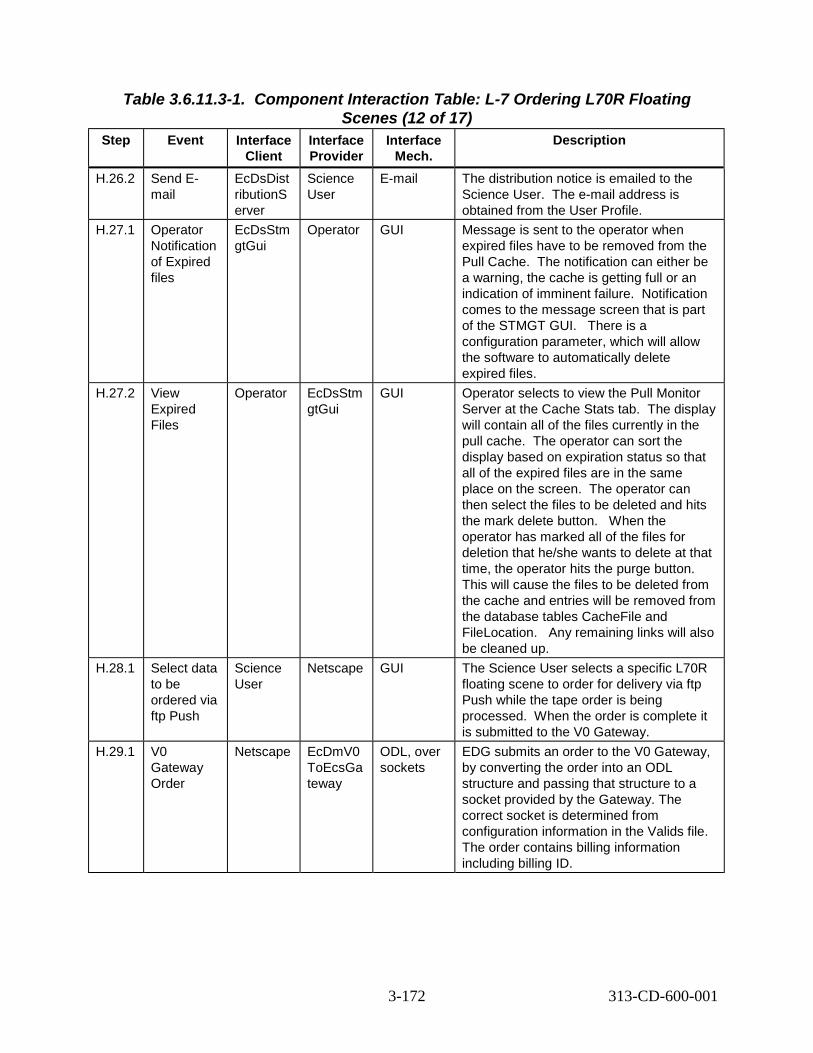
Table 3.6.11.3-1. Component Interaction Table: L-7 Ordering L70R Floating
Step Event Interface Client
Scenes (12 of 17) Interface Provider
Interface Mech.
Description
H.26.2 Send E-mail
EcDsDist ributionS erver
Science User
E-mail The distribution notice is emailed to the Science User. The e-mail address is obtained from the User Profile.
H.27.1 Operator Notification of Expired files
EcDsStm gtGui
Operator GUI Message is sent to the operator when expired files have to be removed from the Pull Cache. The notification can either be a warning, the cache is getting full or an indication of imminent failure. Notification comes to the message screen that is part of the STMGT GUI. There is a configuration parameter, which will allow the software to automatically delete expired files.
H.27.2 View Expired Files
Operator EcDsStm gtGui
GUI Operator selects to view the Pull Monitor Server at the Cache Stats tab. The display will contain all of the files currently in the pull cache. The operator can sort the display based on expiration status so that all of the expired files are in the same place on the screen. The operator can then select the files to be deleted and hits the mark delete button. When the operator has marked all of the files for deletion that he/she wants to delete at that time, the operator hits the purge button. This will cause the files to be deleted from the cache and entries will be removed from the database tables CacheFile and FileLocation. Any remaining links will also be cleaned up.
H.28.1 Select data to be ordered via ftp Push
Science User
Netscape GUI The Science User selects a specific L70R floating scene to order for delivery via ftp Push while the tape order is being processed. When the order is complete it is submitted to the V0 Gateway.
H.29.1 V0 Gateway Order
Netscape EcDmV0 ToEcsGa teway
ODL, over sockets
EDG submits an order to the V0 Gateway, by converting the order into an ODL structure and passing that structure to a socket provided by the Gateway. The correct socket is determined from configuration information in the Valids file. The order contains billing information including billing ID.
3-172 313-CD-600-001

Table 3.6.11.3-1. Component Interaction Table: L-7 Ordering L70R Floating
Step Event Interface Client
Scenes (13 of 17) Interface Provider
Interface Mech.
Description
H.29.2 Establish ECS User
EcDmV0 ToEcsGa teway
EcMsAc RegUser Srvr
Distributed Object
V0 Gateway retrieves the User Profile using ECS Authenticator from ODL message, which includes an encrypted User ID and Password. The User Registration database is replicated across DAACs, so the connection is made to the local User Registration Server.
H.29.3 Request Attribute Mapping
EcDmV0 ToEcsGa teway
EcDmDic tServer
CtLib (RWDBTo ol)
Gateway translates the V0 terms from ODL into ECS names for request submittal using the DDICT database. Interface is directly to Data Dictionary database. Database name is retrieved from configuration file.
H.30.1 Send L7 Acquire
EcDmV0 ToEcsGa teway
EcDmLim Server
Distributed Object
V0ECSGWY sends the request to the DORRAN system because the order is for L70R floating scene data and there is no order ID in the message.
H.30.2 B & A Verification
EcDmEc sToV0Ga teway
DORRAN Comp.
Distributed Object
DORRAN validates the request by checking the account level of the requester and the required funding level of the request.
H.31.1 DORRAN Return
DORRAN EcDmV0 ToEcsGa teway
Distributed Object
The Operator validates the order and DORRAN sends back all the remaining granules to the V0ECSGWY over a specific socket.
H.31.2 Create Tracked Order
EcDmV0 ToEcsGa teway
EcMsAc OrderSrv r
Distributed Object
Create an order to be tracked within ECS. Initial status set to “Pending”.
H.31.3 Store Tracked Order
EcMsAc OrderSrv r
Sybase CtLib Create a tracked order in the database.
H.31.4 Create Tracked Request
EcDmV0 ToEcsGa teway
EcMsAc OrderSrv r
Distributed Object
Create the Tracked Request within the Order. Initial status set to “Pending”.
H.31.5 Store Tracked Request
EcMsAc OrderSrv r
Sybase CtLib Create a tracked request in the order database.
H.32.1 Connect to SDSRV
EcDmV0 ToEcsGa teway
EcDsScie nceData Server
Distributed Object
The Gateway first connects to the SDSRV. The correct SDSRV is determined by the UR of a granule that is being ordered. This is pertinent if there are multi-SDSRVs in use at one DAAC in one mode.
3-173 313-CD-600-001

Table 3.6.11.3-1. Component Interaction Table: L-7 Ordering L70R Floating
Step Event Interface Client
Scenes (14 of 17) Interface Provider
Interface Mech.
Description
H.32.2 Add granules to Session
EcDmV0 ToEcsGa teway
EcDsScie nceData Server
Distributed Object
The V0 Gateway establishes the data context of the session with the SDSRV by adding granules to the session. The Granule UR of the L70R floating Scene granules to be ordered is added to the ESDT ReferenceCollector.
H.32.3 Retrieve Granule Metadata from Inventory
EcDsScie nceData Server
Sybase/S QS
CtLib SDSRV completes establishing the data context by retrieving the metadata for the requested granules from the Sybase/SQS database. The metadata for each granule is passed back to the reference objects for each granule.
H.32.4 Acquire Data
EcDmV0 ToEcsGa teway
EcDsScie nceData Server
Distributed Object
V0Gateway submits the order for L70R floating Scene granules by submitting an Acquire request for the granules. The Acquire request is for an ftp Push of a specified granule in the ESDT ReferenceCollector. This request is asynchronous, meaning that the return of the submit call of the request only contains the status of the request’s submittal.
H.33.1 Create Staging Disk
EcDsScie nceData Server
EcDsStSt agingDis kServer
Distributed Object
SDSRV verifies access privileges for the granule and requests via the EcDsStRequest ManagerServer for the EcDsStStagingDiskServer to create a Staging Disk for working space, scene files and metadata files, which allocates space and passes back a reference to that disk space. The reference to the Staging Disk is determined from the SDSRV configuration. The amount of staging disk to request is determined on a band-by-band basis. The SDSRV requests twice the size of the first band, from metadata in the database, and requests more as needed in order to subset the subsequent files. Each request is for twice the size of the file to be subsetted.
3-174 313-CD-600-001

Table 3.6.11.3-1. Component Interaction Table: L-7 Ordering L70R Floating
Step Event Interface Client
Scenes (15 of 17) Interface Provider
Interface Mech.
Description
H.34.1 STMGT Retrieve
EcDsScie nceData Server
EcDsStAr chiveSer ver
Distributed Object
SDSRV requests via the EcDsStRequestManagerServer for the Archive Server to retrieve the subinterval granule files that are to be subsetted. For a L70R floating Scene, these files include band files, calibration files, MTA, MSCD and PCD files. This results in the files being staged to the working staging disk area. The correct archive object to request is determined from the information provided by the SDSRV in the distribution request.
H.35.1 L7 Scene creation
EcDsScie nceData Server
EcDsHdf EosServe r
Distributed Object
Since L70R Floating Scenes are virtual granules (i.e. the granules are represented in the inventory with their metadata, but the files which contain the data don’t actually exist), the scene files must be extracted from the scene’s parent subinterval. The scene files are created using internal subinterval subsetting methods. The subsetted files include band files, calibration files, MTA, MSCD, PCD, and CPF files. A metadata file for the L70R Floating Scene is created. Also the SDSRV searches the database for a comparable L7CPF file before performing reformatting. It keys the complete MTP file and creates a Format 1 / Format 2 file. Then the subsetted data is reformatted before passing it to DDIST.
H.36.1 Distribute Granules, Synchrono us
EcDsScie nceData Server
EcDsDist ributionS erver
Distributed Object
SDSRV submits a request to Data Distribution. The request includes, for the granule, a reference to the metadata file. Other parameters such as FtpPushUserID, FtpPushPassword, FtpPushHostName, FtpPushDestination from the Acquire request are passed to DDIST.
H.36.2 Update Tracked Request Status
EcDsDist ributionS erver
EcMsAc OrderSrv r
Distributed Object
Update the status of the tracked request to “Active”.
H.36.3 Update Tracked Status
EcMsAc OrderSrv r
Sybase CtLib Update the Order Tracking Database with new status.
3-175 313-CD-600-001

Table 3.6.11.3-1. Component Interaction Table: L-7 Ordering L70R Floating
Step Event Interface Client
Scenes (16 of 17) Interface Provider
Interface Mech.
Description
H.36.4 Claim Ownership
EcDsDist ributionS erver
EcDsStSt agingDis kServer
Distributed Object
The EcDsStDistributionServer claims ownership of the staging disk created via a request via the EcDsStRequest ManagerServer sent to the EcDsStStagingDiskServer by SDSRV by inserting appropriate data in the data base table.
H.36.5 Compress Disk
EcDsDist ributionS erver
EcDsStSt agingDis kServer
Distributed Object
The EcDsStDistributionServer asks the EcDsStStagingDiskServer via a request to the EcDsStRequestManagerServer to compress the staging disk.
H.37.1 Create Staging Disk
EcDsDist ribution
EcDsStSt agingDis kServer
Distributed Object
EcDsStDataDistributionServer via a request to the EcDsStRequestManagerServer, creates Staging Disk for the granule files in the archive. This allocates space and passes back a reference to that disk space. The reference to the Staging Disk is determined from the information passed by the SDSRV in the distribution request, which was the SDSRV configuration. The amount of staging disk to request is determined by the size of the subsetted/reformatted data.
H.37.2 Update Tracked Request Status
EcDsDist ributionS erver
EcMsAc OrderSrv r
Distributed Object
Update the status of the tracked request to “Staging”.
H.37.3 Update Tracked Status
EcMsAc OrderSrv r
Sybase CtLib Update the Order Tracking Database with new status.
H.37.4 Copy files to Staging Disk
EcDsDist ributionS erver
EcDsStSt agingDis kServer
Distributed Object
DDIST links the subsetted and metadata files from the SDSRV’s Staging Disk into the staging disk. This is accomplished with a request sent to the EcDsStRequest ManagerServer forwarded to the EcDsStStagingDiskServer.
H.37.5 Update Tracked Request Status
EcDsDist ributionS erver
EcMsAc OrderSrv r
Distributed Object
Update the status of the tracked request to “Transferring”.
H.37.6 Update Tracked Status
EcMsAc OrderSrv r
Sybase CtLib Update the Order Tracking Database with new status.
3-176 313-CD-600-001

iUse
Table 3.6.11.3-1. Component Interaction Table: L-7 Ordering L70R Floating
Step Event Interface Client
Scenes (17 of 17) Interface Provider
Interface Mech.
Description
H.37.7 Update Tracked Request Status
EcDsDist ributionS erver
EcMsAc OrderSrv r
Distributed Object
Update the status of the tracked request to “Shipped”. Update the media quantity.
H.37.8 Update Tracked Status
EcMsAc OrderSrv r
Sybase CtLib Update the Order Tracking Database with the media quantity and the new status.
H.38.1 Build Distribution Notice
EcDsDist ributionS erver
EcDsDist ributionS erver
Internal The EcDsDistributionServer builds a distribution notice indicating that the L70R Floating Scene data has been pushed up to user-specified host machine. The notice includes the order ID, the UR of the Scene granule, name of the Scene’s files, size of files, compression type, the host and directory names.
H.38.2 Send E-mail
EcDsDist ributionS erver
Science User
E-mail The distribution notice is emailed to the Science User. The e-mail address is obtained from the User Profile.
3.6.12 L-7 Floating Scene Price Estimation Thread This thread shows how the ECS supports price estimation of L-7 floating scenes.
3.6.12.1 L-7 Floating Scene Price Estimation Interaction Diagram - Domain View Figure 3.6.12.1-1 depicts the L-7 floating scene price estimation interaction.
CLS (EDG)
I.1 Submit price estimate request I.2 Price estimate request
I.6 Estimated cost for subset granules
ScienceSc ence DMS Userr (V0GWY)
I.5 Calculate theI.4 Granule metadata estimated cost for
each granule I.3 Inspect request
Distributed Object (rpc, CtLib) DSS HMI (GUI, Xterm, command) DSS ftp
(SDSRV)
email (or other as noted) Double line - Synchronous email (or other as noted) Dashed - Asynchronous
Figure 3.6.12.1-1. L-7 Floating Scenes Price Estimation Interaction Diagram
3-177 313-CD-600-001

3.6.12.2 L-7 Floating Scenes Price Estimation – Domain View Table 3.6.12.2-1 provides the Interaction – Domain View: L-7 Floating Scenes Price Estimation.
Table 3.6.12.2-1. Interaction Table - Domain View: L-7 Floating Scenes Price Estimation
Step Event Interface Client
Interface Provider
Data Issues
Step Precondit
ions
Description
I.1 Submit price estimate request
Science User
EDG None Some L70R granules are selected
Scientist selects the L70R granules of interest to get a price estimate. Scientist clicks “Price Estimate” button on EDG’s results screen.
I.2 Price estimate request
EDG V0GWY None None EDG submits the Science user’s price estimate request in ODL form to V0GWY.
I.3 Inspection request
V0GWY SDSRV None None For each granule that Science user selected, V0GWY sends an inspect request to SDSRV to get granule metadata.
I.4 Granule metadata
SDSRV V0GWY None None SDSRV sends granule metadata to V0GWY.
I.5 Estimated cost for each granule
V0GWY V0GWY None Granule meta data is provided
V0GWY calculates the estimated cost for each granule that has been subset by passing the granule’s spatial extent and user provided spatial and band constraints to the pricing algorithm.
I.6 Estimated cost for all the granules in the request
V0GWY EDG None All the estimated costs have been calculated
V0GWY sends the Price Estimate result back to EDG.
3-178 313-CD-600-001

3.6.12.3 L-7 Floating Scenes Price Estimation Component Interaction Table
Table 3.6.12.3-1 provides the Component Interaction: L-7 Floating Scene Price Estimate
Table 3.6.12.3-1. Component Interaction Table: L-7 Floating Scene Price Estimate
Step Event Interface Client
Interface Provider
(1 of 2) Interface
Mech. Description
I.1.1 Startup EDG Science User
Netscape Command The Science User invokes a Netscape browser and navigates to the EOS Data Gateway (EDG) home page.
I.1.2 Provide Query constraints. Submit Query, and Select Order
Science User
Netscape GUI The Science User formulates and submits the query, waits for results and then select the granules, their spatial and band sub-settings and then places a price estimate request though the EDG.
I.2.1 V0 Gateway Price Estimate Request
Netscape EcDmV0 ToEcsGa teway
ODL, over sockets
EDG submits a price estimate request to the V0 Gateway, by converting the request criteria into an ODL structure and passing that structure to a socket provided by the Gateway. The correct socket is determined from configuration information in the Valids file.
I.2.2 Establish ECS User
EcDmV0 ToEcsGa teway
EcMsAc RegUser Srvr
Distributed Object
V0 Gateway retrieves the User Profile using ECS Authenticator from the ODL message, which includes an encrypted User ID and Password. The User Registration database is replicated across DAACs, so the connection is made to the local User Registration Server.
I.3.1 Connect to SDSRV
EcDmV0 ToEcsGa teway
EcDsScie nceData Server
Distributed Object
The Gateway first connects to the SDSRV. The correct SDSRV is determined by configuration file.
I.3.2 SDSRV Query
EcDmV0 ToEcsGa teway
EcDsScie nceData Server
Distributed Object
The Gateway translates the query into a DsShESDTUR object. This object is handed to the Search interface of the DsCl ESDT ReferenceCollector. This Search method is synchronous, so the results of the search are returned to the calling function. It does an “Inspect” to the SDSRV to get the spatial metadata. . It first performs a GetQueryableParamerter to determine all attributes associated with each granule.
3-179 313-CD-600-001

Table 3.6.12.3-1. Component Interaction Table: L-7 Floating Scene Price Estimate
Step Event Interface Client
Interface Provider
(2 of 2) Interface
Mech. Description
I.3.3 Request Metadata
EcDsScie nceData Server
Sybase/S QS
CtLib The SDSRV breaks down the Query object and translates it into a sequence of calls to the inventory database. The Resultant row is converted into a data granule, with its metadata extracted from the database. This result is packaged and returned to the Query client.
I.4.1 Metadata Retrieval
EcDsScie nceData Server
EcDmV0 ToEcsGa teway
Distributed Object
The Gateway gets the Granule Spatial Extent for the granule.
I.5.1 Price Estimate
EcDmV0 ToEcsGa teway
EcDmV0 ToEcsGa teway
Distributed Object
The Gateway passes the Granule Spatial extent and the User specified spatial constraint to the scanline size algorithm to calculate scanline size. Once the scanline size is calculated its price is calculated from the table look up out of the configuration file.
I.6.1 Price Estimate Result
EcDmV0 ToEcsGa teway
Netscape ODL, over Sockets
When the Gateway calculates the price, it is translated into ODL and passed back to the EDG tool. The correct socket for sending results to EDG is the one used to submit the query. EDG then displays the results of the query to the user.
3.6.13 Landsat-7 Error Handling In Landsat operations, the system merges Format 1 data sets with Format 2 data sets. Since these data sets can be delivered at different times, the merge activity may or may not be completed correctly during an operational period of time. This capability allows the Operator to invoke various commands to handle database merge “Errors”.
3-180 313-CD-600-001

3.6.13.1 Landsat-7 Error Handling Thread Interaction Diagram - Domain View Figure 3.6.13.1-1 depicts the L-7 Error Handling Interaction - Domain View.
D A A C O p s
D istribu ted O b ject (rp c , C tL ib ) H M I (G U I, X term , co m m a n d ) ftp em ail (o r o the r a s no ted ) D o uble lin e - S y nc h r on ous em ail (o r o the r a s no ted ) D a sh e d - A sy n c hr onous
SD SR V D /B
J.1 Q u e ry D a ta ba se
J .2 M e r g e /D e m e rg e /D e le te
J.3 P h ysc ia lD e le te
Figure 3.6.13.1-1. L-7 Error Handling Interaction Diagram
3.6.13.2 Landsat-7 Error Handling Thread Interaction Table - Domain View Table 3.6.13.2-1 provides the Interaction – Domain View: L-7 Error Handling.
3-181 313-CD-600-001
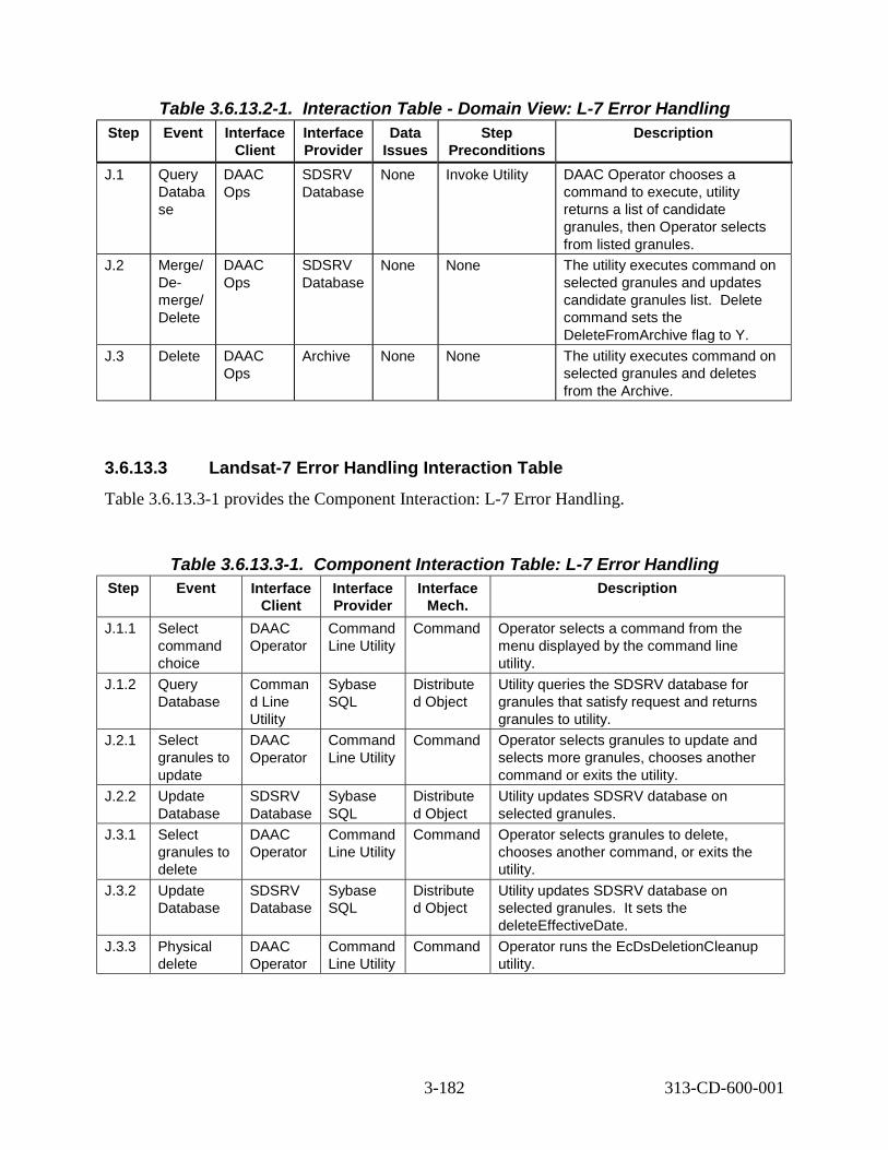
Table 3.6.13.2-1. Interaction Table - Domain View: L-7 Error Handling Step Event Interface Interface Data Step Description
Client Provider Issues Preconditions J.1 Query
Databa se
DAAC Ops
SDSRV Database
None Invoke Utility DAAC Operator chooses a command to execute, utility returns a list of candidate granules, then Operator selects from listed granules.
J.2 Merge/ De-merge/ Delete
DAAC Ops
SDSRV Database
None None The utility executes command on selected granules and updates candidate granules list. Delete command sets the DeleteFromArchive flag to Y.
J.3 Delete DAAC Ops
Archive None None The utility executes command on selected granules and deletes from the Archive.
3.6.13.3 Landsat-7 Error Handling Interaction Table Table 3.6.13.3-1 provides the Component Interaction: L-7 Error Handling.
Step Table 3.6.13.3-1. Component Interaction Table: L-7 Error Handling Event Interface
Client Interface Provider
Interface Mech.
Description
J.1.1 Select command choice
DAAC Operator
Command Line Utility
Command Operator selects a command from the menu displayed by the command line utility.
J.1.2 Query Database
Comman d Line Utility
Sybase SQL
Distribute d Object
Utility queries the SDSRV database for granules that satisfy request and returns granules to utility.
J.2.1 Select granules to update
DAAC Operator
Command Line Utility
Command Operator selects granules to update and selects more granules, chooses another command or exits the utility.
J.2.2 Update Database
SDSRV Database
Sybase SQL
Distribute d Object
Utility updates SDSRV database on selected granules.
J.3.1 Select granules to delete
DAAC Operator
Command Line Utility
Command Operator selects granules to delete, chooses another command, or exits the utility.
J.3.2 Update Database
SDSRV Database
Sybase SQL
Distribute d Object
Utility updates SDSRV database on selected granules. It sets the deleteEffectiveDate.
J.3.3 Physical delete
DAAC Operator
Command Line Utility
Command Operator runs the EcDsDeletionCleanup utility.
3-182 313-CD-600-001

3.7 ASTER Scenario
3.7.1 ASTER Scenario Description This scenario shows how the ECS supports the ASTER mission.
ECS provides a mechanism for ECS Users to submit Data Acquisition Requests (DARs). ECS notifies the ECS User when that DAR has been fulfilled. ECS receives ASTER data via tape, from ASTER GDS. These tapes contain L1A and L1B data. This data is provided to ECS regardless of whether or not ECS Users had previously submitted DARs.
ECS provides support for users to request processing of the L1A and L1B data to higher information levels, via requests for On-Demand Processing. A request for On-Demand Processing may require a sequence of algorithms to be run on the specified data. Granules produced by On-Demand Processing are not permanently archived.
ECS supports the insertion of ASTER Expedited Data Set (EDS) from EOS Data and Operations System (EDOS) and its immediate availability to selected ASTER Scientists.
ECS provides support for interoperability with ASTER GDS so that an EOSDIS user or an ASTER GDS user will be able to view the data holdings and order production data of the other system.
The following system functionality is exercised in this scenario:
• Java DARTool usage for DAR submittal (Thread A)
• Data Tape Ingest (Threads B & I)
• Backward Chaining (Thread C)
• Science User metadata update (Thread D)
• On-Demand Production (Thread E, F & G)
• Simplified ASTER Expedited Data Support (Thread H)
• Routine Processing Planning for Start/Stop and Insertion time (ThreadsI & J)
• Spatial Query/Padding (Thread K)
• View EDC data holdings and order production data (Threads L & M)
• View ASTER GDS data holdings and order production data (Thread N)
• Support of attached standing on-demand processing orders to a DAR (Thread O)
Figure 3.7.1-1 is a dataflow diagram that illustrates the relationships between the data types and PGEs used in the ASTER scenario.
3-183 313-CD-600-001

AST_08 ACT ETS 2.3 MB
(multiple)
AST_L1B 5MB
AST_ANC 772 KB
Brightness Temperature
BTS
AST_04 4.6 MB
Figure 3.7.1-1. ASTER Scenario PGE/Data Relationships Diagram
3.7.2 ASTER Scenario Preconditions The following ESDTs have been inserted into the ECS:
• AST_ANC (ASTER Ancillary data)
• AST_EXP (ASTER Expedited L0 data)
• AST_L1A (ASTER L1A data)
• AST_L1B (ASTER L1B data)
• AST_L1BT (ASTER L1B data – Thermal IR Channels)
• AST_04 (L2 Brightness Temperature)
• AST_05 (L2 Surface Emissivity)
• AST_08 (L2 Surface Temperature)
• AST_09T (L2 Surface Radiance)
• ASTER14DEM (ASTER DEM Product)
• GDAS0ZFH (NCEP provided ancillary data)
• PH (Product History)
• PGEEXE (PGE Execution Granule)
Atmos. Correction
TIR
GDAS0ZFH 34 MB
AST_ANC 4 MB
AST_09T 9.7 MB
Emiss/TempSeparation
AST_05 6.6 MB
3-184 313-CD-600-001

--
--
--
The following ASTER PGEs have passed SSI&T and have been inserted into the ECS:
• ACT Atmospheric Correction – TIR (Thermal Infrared)
• ETS Emissivity/Temperature Separation
• BTS Brightness Temperature at Sensor
Ancillary granules (AST_ANC and GDAS0ZFH) have been inserted into the ECS.
The Science User must be a registered ECS User whose profile reflects a user authorized to submit a DAR.
3.7.3 ASTER Scenario Partitions The ASTER scenario has been partitioned into the following threads:
• ASTER DAR Submission (Thread A) - This thread shows the usage of the CLS Java DARTool, and its interaction with GDS and other ECS components (section 3.7.4).
• ASTER GDS Tape Insertion (Thread B) - This thread shows how the ECS inserts data provided by GDS on D3 tape (see section 3.7.5).
• ASTER Backward Chaining (Thread C) - This thread shows how the system supports requests from ECS users to produce data requiring a sequence of algorithms to be run (see section 3.7.6).
• ASTER QA Metadata Update (Thread D) - This thread shows how the ECS supports updating the QA metadata of a specified granule (see section 3.7.7).
• ASTER On-Demand High Level Production (Thread E) - This thread shows how the ECS supports users request for On-Demand production (see section 3.7.8).
• ASTER On-Demand Non-Standard L1B Production Thread (Thread F) - This thread shows how the ECS supports users request for On-Demand production of non-standard L1B data products (see section 3.7.9).
• ASTER On-Demand DEM Production Thread (Thread G) -- This thread shows how the ECS supports users request for On-Demand production of the DEM data product (see section 3.7.10).
• ASTER Simplified Expedited Data Support (ThreadH) - This thread shows how the ECS supports a simplified version of Expedited data support (see section 3.7.11).
• ASTER Routine Processing Planning Data Start/Stop Time (Thread I) – This thread shows how planning is done to create data processing jobs for ASTER routine processing (see section 3.7.12).
• ASTER Routine Processing Planning Insertion Time (Thread J) – This thread shows how to perform ASTER BTS (Brightness Temperature at Sensor) PGEs (see section 3.7.13).
3-185 313-CD-600-001
• ASTER Spatial Query (Thread K) -- This thread illustrates how to perform ASTER processing for a predefined geographic area. This area can be expanded (padded) by a predefined number of kilometers. (See section 3.7.14).
• ASTER View ECS Data Holdings (Thread L) – This thread shows how an ASTER GDS user can obtain information about the location and other attributes of specified data sets, and browse specified data sets. (See section 3.7.15).
• ASTER Price & Order Data (Thread M) – This thread shows how an ASTER GDS user can obtain a price estimate for ECS products, place an order for ECS products stored at any DAAC and obtain the status of a previously placed order. (See section 3.7.16).
• User View And Order ASTER GDS Data (Thread N) – This thread shows how an ECS user can obtain information on the attributes of specified data sets, browse specified data sets and place an order for ASTER products stored at GDS. (See section 3.7.17).
• ASTER Attached DPRs (Standing Orders) (Thread O) -- This thread shows how the ECS supports user requests for attaching standing, on-demand processing orders to a Data Acquisition Request (DAR). The processing and distribution of the on-demand requests that result from these orders is identical to standard on-demand production discussed in Section 3.7.8. This new capability is an extension of that existing on-demand capability. (See section 3.7.18).
3.7.4 ASTER DAR Submission Thread This thread shows the usage of the CLS Java DARTool, and its interaction with GDS and other ECS components.
3.7.4.1 ASTER DAR Submission Thread Interaction Diagram - Domain View
Figure 3.7.4.1-1 depicts the ASTER DAR Submission Thread Interaction - Domain View.
3-186 313-CD-600-001
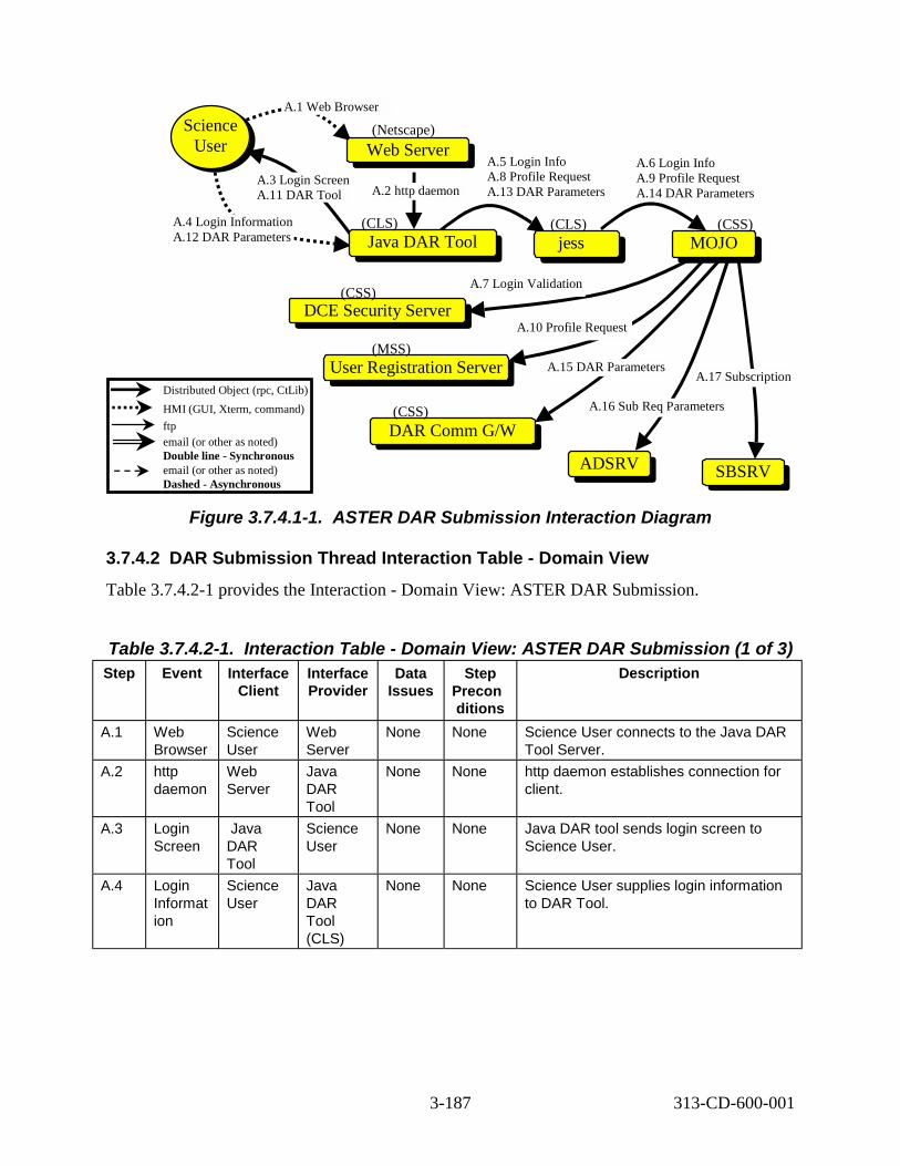
Distributed Object (rpc, CtLib) HMI (GUI, Xterm, command) ftp email (or other as noted) Double line - Synchronous email (or other as noted) Dashed - Asynchronous
A.5 Login Info A.8 Profile Request A.13 DAR Parameters
A.7 Login Validation
A.15 DAR Parameters
A.16 Sub Req Parameters
DCE Security Server
Science User
A.1 Web Browser
A.2 http daemon
A.17 Subscription
A.4 Login Information A.12 DAR Parameters
A.3 Login Screen A.11 DAR Tool
A.6 Login Info A.9 Profile Request A.14 DAR Parameters
Web Server
Java DAR Tool jess MOJO
User Registration Server
DAR Comm G/W
ADSRV SBSRV
A.10 Profile Request
(CSS)
(CLS) (CLS) (CSS)
(Netscape)
(MSS)
(CSS)
Figure 3.7.4.1-1. ASTER DAR Submission Interaction Diagram
3.7.4.2 DAR Submission Thread Interaction Table - Domain View Table 3.7.4.2-1 provides the Interaction - Domain View: ASTER DAR Submission.
Table 3.7.4.2-1. Step Event
Interaction Table - Domain View: ASTER DAR Submission (1 of 3) Interface
Client Interface Provider
Data Issues
Step Precon ditions
Description
A.1 Web Browser
Science User
Web Server
None None Science User connects to the Java DAR Tool Server.
A.2 http daemon
Web Server
Java DAR Tool
None None http daemon establishes connection for client.
A.3 Login Screen
Java DAR Tool
Science User
None None Java DAR tool sends login screen to Science User.
A.4 Login Informat ion
Science User
Java DAR Tool (CLS)
None None Science User supplies login information to DAR Tool.
3-187 313-CD-600-001

Table 3.7.4.2-1. Step Event
Interaction Table - Domain View: ASTER DAR Submission (2 of 3) Interface
Client Interface Provider
Data Issues
Step Precon ditions
Description
A.5 Login Info
Java DAR Tool
jess (CLS)
None None Java DAR Tool relays login information to jess.
A.6 Login Validatio n
jess MOJO (CSS)
None None Jess passes Log in information to MOJO for translation into a form usable by CSS DCE Security Server (COTS).
A.7 Login Validatio n
MOJO DCE Security Server
None Science User should be a register ed ECS user
DCE Security Server (CSS) validates (or doesn’t validate) login information.
A.8 Profile Request
Java DAR Tool
jess None None Once the user is authenticated, the Java DAR Tool requests the user’s profile.
A.9 Profile Request (cont’d)
jess MOJO None None Profile Request is translated into the appropriate format and sent to MOJO.
A.10 Profile Request (cont’d)
MOJO User Profile Server (MSS)
None None MOJO formats and submits request to MSS User Registration Server.
A.11 DAR Tool
Java DAR Tool
Science User
None None Java DAR Tool is instantiated on Science User’s platform.
A.12 DAR Paramet ers
Science User
Java DAR Tool
None None User creates or modifies a request, and submits it.
A.13 DAR Paramet ers
Java DAR Tool
jess None None Java DAR Tool relays parameters to jess.
A.14 DAR Paramet ers
jess MOJO None None Parameters are passed to MOJO for translation.
A.15 DAR Paramet ers
MOJO DAR/Co mm Gateway
None None Parameters are passed for submission to GDS API.
3-188 313-CD-600-001

Table 3.7.4.2-1. Step Event
Interaction Table - Domain View: ASTER DAR Submission (3 of 3) Interface
Client Interface Provider
Data Issues
Step Precon ditions
Description
A.16 Subscri ption Request Paramet ers
MOJO Advertisi ng Server
None None Request for information needed to enter subscription.
A.17 Subscri ption
MOJO Subscript ion Server
None None Subscription is entered for this submission.
3.7.4.3 ASTER DAR Submission Thread Component Interaction Table Table 3.7.4.3-1 provides the Component Interaction: ASTER DAR Submission.
Table 3.7.4.3-1. Step Event
Component Interaction Table: ASTER DAR Submission (1 of 2) Interface
Client Interface Provider
Interface Mech.
Description
A.1.1 Startup Java DAR Tool
Science User
World Wide Web
HMI From browser, user starts the Java DAR Tool.
A.2.1 Web Server downloads Java DAR Tool
Web Server
EcClWbJdt Distribute d Object
Java DAR Tool starts on client platform.
A.3.1 Login Screen Instantiated
EcClWbJdt Science User
Distribute d Object
Login Screen is drawn on user’s screen.
A.4.1 Login Information
Science User
EcClWbJdt HMI Login information is sent by user.
A.5.1 Login Information
EcClWbJdt jess socket Log in information sent from Java DAR Tool to jess.
A.6.1 Login Information
jess EcCsMojo Gateway
socket Login information sent from jess to MOJO.
A.7.1 Login Information
EcCsMojo Gateway
DCE Security (COTS)
rpc Log in information validated through Management Subsystem.
A.8.1 Profile Request
EcClWbJdt jess socket Once the user is authenticated, the user profile request is passed from Java DAR Tool to jess.
A.9.1 Profile Request
jess EcCsMojo Gateway
socket Profile request is formatted and passed from jess to MOJO.
3-189 313-CD-600-001

Table 3.7.4.3-1. Step Event
Component Interaction Table: ASTER DAR Submission (2 of 2) Interface
Client Interface Provider
Interface Mech.
Description
A.10. 1
Profile Request
EcCsMojo Gateway
EcMsAcRe gUserSrvr
rpc MOJO sends the profile request to the MSS User Profile Server.
A.11. 1
DAR Tool downloaded
EcClWbJdt Science User
Distribute d Object
Java DAR Tool screen(s) are downloaded to user’s machine.
A.12. 1
DAR Parameters
Science User
EcClWbJdt HMI DAR Parameters are entered into Java DAR Tool.
A.13. 1
DAR Parameters
EcClWbJdt jess socket DAR parameters go from Java DAR Tool to jess.
A.14. 1
DAR Parameters
jess EcCsMojo Gateway
socket DAR parameters relayed from jess to MOJO.
A.15. 1
DAR Parameters
EcCsMojo Gateway
EcGwDAR Server
rpc DAR Parameters relayed from MOJO to DAR/Comm Gateway.
A.16. 1
Subscription Request Parameters
EcCsMojo Gateway
EcIoAdSer ver
rpc Request for information needed to enter subscription.
A.17. 1
Subscription EcCsMojo Gateway
EcSbSubS erver
rpc Entering subscription so that user will know when request is filled.
3.7.5 ASTER GDS Tape Insertion Thread
This thread shows how the ECS inserts data provided by GDS on D3 tape. This data is either AST_L1A or AST_L1B data.
3.7.5.1 ASTER GDS Tape Insertion Thread Interaction Diagram - Domain View Figure 3.7.5.1-1 depicts the ASTER GDS Tape Insertion Interaction.
3-190 313-CD-600-001

SBSRV
GDS
IN
DS
DAAC Ops
Science User
IN
B.1 GDS Ships D3
Science GDS (commercial shipping)
DAAC B.3 Load Media
STMGT
User Ops Gui
B.8 Send Notification B.4 Ingest from D3
B.2 Get SDSRV URsSBSRV
INSS IOSS
B.7 Trigger Event (AST_L1A or AST_L1B) B.5 Create Staging Disk & Read D3 Tape B.6 Request Data Insert (AST_L1A or AST_L1B)
DSSS Distributed Object (rpc, CtLib) HMI (GUI, Xterm, command) ftp email (or other as noted) Double line - Synchronous email (or other as noted) Dashed - Asynchronous
Figure 3.7.5.1-1. ASTER GDS Tape Insertion Interaction Diagram
3.7.5.2 ASTER GDS Tape Insertion Thread Interaction Table - Domain View Table 3.7.5.2-1 provides the Interaction - Domain View: ASTER GDS Tape Insertion.
Table 3.7.5.2-1. Interaction Table - Domain View: ASTER GDS Tape Insertion
Step Event Interface Client
Interface Provider
(1 of 2) Data
Issues Step
Precondi tions
Description
B.1 GDS Ships D3 Tape
GDS DAAC Ops
None None GDS uses commercial shipping vendor, sends a D3 tapes containing AST_L1A or AST_L1B data. Tape contains data takes that are both due to ECS DARs as well as data that wasn’t requested via ECS.
3-191 313-CD-600-001

Table 3.7.5.2-1. Interaction Table - Domain View: ASTER GDS Tape Insertion
Step Event Interface Client
Interface Provider
(2 of 2) Data
Issues Step
Precondi tions
Description
B.2 Get SDSR V URs
INS IOS None None Upon startup, Ingest gets the SDSRV URs for each data type in its database.
B.3 Load Media
DAAC Ingest/Di stribution Technicia n
DSS None D3 Tape is loaded into Device
DAAC Ingest/Distribution Technician loads the D3 tape using the STMGT Gui.
B.4 Ingest from D3
DAAC Ingest/Di stribution Technicia n
INS None Get Media Id from STMGT Gui
DAAC Ingest/Distribution Technician loads the D3 tape and, using an Ingest GUI, prepares to read the tape.
B.5 Create Staging Disk & Read D3 Tape
INS DSS None None Ingest interfaces with the DSS to create an Ingest staging disk and reads the D3 tape into this staging disk.
B.6 Reque st Data Insert
INS DSS 2 granules @ 5 MB
AST_L1A AST_L1B ESDTs
Ingest inserts the new ASTER granules into the Data Server.
B.7 Trigger Event
DSS SBSRV None None Upon successful completion of insertion of each AST_L1A or AST_L1B granule, the AST_L1A:Insert or AST_L1B:Insert event is triggered, with the qualifiers including all the XARids attached to that data.
B.8 Send Notifica tion
SBSRV Science User
None None Send notification to Science User that AST_L1A or AST_L1B granules for their DAR have been inserted. Notification message includes the UR of the granule, as well as the DAR IDs that have been matched.
3-192 313-CD-600-001

3.7.5.3 ASTER GDS Tape Insertion Thread Component Interaction Table Table 3.7.5.3-1 provides the Component Interaction: ASTER GDS Tape Insertion.
Table 3.7.5.3-1. Component Interaction Table: ASTER GDS Tape Insertion (1 of 3) Step Event Interface
Client Interface Provider
Interface Mech.
Description
B.2. 1
Get SDSRV URs from IOS
EcInReq Mgr
EcIoAdSe rver
Distribute d Object
Upon startup, Ingest Request Manager requests the SDSRV URs for each data type in its database.
B.3.1 Startup STMGT Gui
DAAC Ingest Technicia n
EcDsStmg tGui
Command DAAC Ingest Technician invokes the STMGT Gui using the start script. The DAAC Ingest Technician selects the Resource Mgmt Tab on the STMGT Gui.
B.3.2 Select Media Type
DAAC Ingest Technicia n
EcDsStmg tGui
GUI DAAC Ingest Technician selects D3 from the Media Type Pulldown menu. The DAAC Ingest Technician clicks the Server Id and selects the Manage Hardware Button.
B.3.3 Select Load Media
DAAC Ingest Technicia n
EcDsStmg tGui
GUI DAAC Ingest Technician clicks the Drive Name and selects Load Media from the Media Operations pulldown menu.
B.3.4 Enter Media ID
DAAC Ingest Technicia n
EcDsStmg tGui
GUI DAAC Ingest Technician fills in the Media Id on the Load Media window. DAAC Ingest Technician also selects the OK button.
B.4.1 Startup Ingest GUI
DAAC Ingest Technicia n
EcInGUI Command DAAC Ingest Technician invokes the Ingest GUI using the start script. The DAAC Ingest Technician selects the Media Ingest tab on the Ingest GUI.
B.4.2 Select Ingest Device
DAAC Ingest Technicia n
EcInGUI GUI DAAC Ingest Technician selects the media device (D3) to read data from and selects the data provider. The DAAC Ingest Technician also selects the location of the DDR as embedded in the media and enters the DDR name. The Technician gets the Media Id from the STMGT Gui.
B.5.1 Allocate Media Resource
EcInGUI EcDsStD3 Server
Distribute d Object
Ingest now creates the Resource manager for D3 via a Resource Manager Factory. The correct D3 resource is determined from configuration within the resource factory.
B.5.2 Create Staging Disk
EcInGUI EcDsStSt agingDisk Server
Distribute d Object
Ingest creates a Staging Disk for the delivery record file.
3-193 313-CD-600-001

Table 3.7.5.3-1. Component Interaction Table: ASTER GDS Tape Insertion (2 of 3) Step Event Interface
Client Interface Provider
Interface Mech.
Description
B.5.3 Read D3 Tape
EcInGUI EcDsStD3 Server
Distribute d Object
Ingest reads the delivery record file. From this file the type and amount of data to be read is determined. The delivery record file is in the first tar set on the tape.
B.5.4 Create Staging Disk
EcInGUI EcDsStSt agingDisk Server
Distribute d Object
Ingest creates Staging Disk. The correct staging disk server is determined from the Ingest Database. The amount of staging disk to request is determined from the delivery record file.
B.5.5 Read D3 Tape
EcInGUI EcDsStD3 Server
Distribute d Object
Ingest reads data files from the D3 tape.
B.5.6 Send Request
EcInGUI EcInReqM gr
Distribute d Object
Ingest GUI process copies the DDR file read into the remote directory and sends an Ingest Request to the Request Manager. The data provider is passed to the Ingest Request Manager.
B.5.7 Granule Process Request
EcInReq Mgr
EcInGran Distribute d Object
Request Manager packages the request into granules and sends them to the Ingest Granule Server.
B.6.1 Connect to SDSRV
EcInGran EcDsScie nceDataS erver
Distribute d Object
Ingest begins a session with the SDSRV by connecting. The correct SDSRV is determined during EcInReqMgr startup, from Advertising, based on the data type. This is pertinent if there are multi-SDSRVs in use at one DAAC in one mode. The data type is determined from the delivery record file.
B.6.2 Request MCF
EcInGran EcDsScie nceDataS erver
Distribute d Object
Ingest requests the metadata configuration file (MCF) for the data being inserted.
B.6.3 Validate Metadata
EcInGran EcDsScie nceDataS erver
Distribute d Object
After building a metadata file for the input data granule, Ingest asks SDSRV to validate the metadata, based on the granule’s data type.
B.6.4 Request Data Insert
EcInGran EcDsScie nceDataS erver
Distribute d Object
Ingest requests that the received files for the data granule are inserted into the Data Server. An Insert request, containing the names of the files comprising the granule, is created. The structure of the Insert Request is hard-coded in the granule server. SDSRV validates metadata and determines the archived names of the files. Upon completion of the insert, the status is asynchronously reflected on the GUI monitor and control screen.
3-194 313-CD-600-001

Table 3.7.5.3-1. Component Interaction Table: ASTER GDS Tape Insertion (3 of 3) Step Event Interface
Client Interface Provider
Interface Mech.
Description
B.6.5 STMGT Store
EcDsSci enceData Server
EcDsStAr chiveServ er
Distribute d Object
SDSRV requests that the granule’s files be archived. The archive server reads the inserted files directly from the Ingest staging disk on which they are residing. The correct archive object to request is determined by the Archive ID input during ESDT installation.
B.6.6 Adding a Granule to Inventory
EcDsSci enceData Server
Sybase/S QS
CtLib The validated metadata is parsed and added to the inventory of the SDSRV.
B.7.1 Trigger Event
EcDsSci enceData Server
EcSbSub Server
Distribute d Object
Upon successful insertion of data granule, the AST_L1A:Insert or the AST_L1B:Insert event is triggered. The correct subscription server is determined from SDSRV configuration. The correct events to trigger are determined from the events file, which was populated during ESDT installation. Provided with the event triggering is the UR of the inserted granule.
B.7.2 Retrieve Subscription s
EcSbSub Server
Sybase CtLib SBSRV queries the Sybase database determining which subscriptions need to be activated, or fired. Each query “hit” is an activated subscription and executes independently.
B.8.1 Build E-mail EcSbSub Server
EcSbSub Server
Internal The SBSRV builds an email notification that the user’s subscription on the AST_L1A:Insert or AST_L1B:Insert event has been fired. This notification identifies the event, the subscription ID, the Granule UR that was inserted and the previously supplied User String.
B.8.2 Send Notification
EcSbSub Server
Science User
E-mail The notice is e-mailed to the Science User. The e-mail address is obtained from the User Profile.
3.7.6 ASTER Backward Chaining Thread This thread shows how the system supports requests from ECS users to produce data requiring a sequence of algorithms to be run.
3.7.6.1 ASTER Backward Chaining Thread Interaction Diagram - Domain View Figure 3.7.6.1-1 depicts the ASTER Backward Chaining Interaction.
3-195 313-CD-600-001

Distributed Object (rpc, CtLib) HMI (GUI, Xterm, command) ftp email (or other as noted) Double line - Synchronous email (or other as noted) Dashed - Asynchronous
EDG
C.12 Acquire Data (ACT input) C.15 Insert Data (AST_09T) C.19 Acquire Data (anc.) C.22 Insert Data (AST_08)
DAAC Ops
DAAC Ops
C.1 Inventory Search
C.5 Call DAAC (via telephone)Science
User Science
User
V0GWYV0GWY
SBSRVSBSRV
DSSDSS
DPSDPS
PLSPLS
C.2 Search C.26 ftp Data
C.24 Notification
C.6 Lookup Algorithms
C.8 Create Production Request C.9 Activate Production Plan
C.11 Release Job (ACT) C.18 Release Job (ETS)
C.13 Run PGE (ACT) C.20 Run PGE (ETS)
C.17 Notification
C.25 Acquire Data
C.16 Trigger Event C.23 Trigger Event
C.27
Notice Distribution
C.10 Submit DPRs
IOS
C.14 Get DSS UR C.21 Get DSS UR
C.7 Subscribe (AST_08, ftPush)
C.3 Search
DSSCSS
C.4 Retrieve Media
Figure 3.7.6.1-1. ASTER Backward Chaining Interaction Diagram
3.7.6.2 ASTER Backward Chaining Thread Interaction Table - Domain View Table 3.7.6.2-1 depicts the Interaction - Domain View: ASTER Backward Chaining.
3-196 313-CD-600-001

Table 3.7.6.2-1. Interaction Table - Domain View: ASTER Backward Chaining
Step Event Interface Client
Interface Provider
(1 of 3) Data
Issues Step
Preconditi ons
Description
C.1 Inventory Search
Science User
EDG (CLS)
None None Upon notification of data resulting from the DAR, the Science User looks up the data granule in order to determine it’s metadata characteristics.
C.2 Search EDG V0GWY (DMS)
None None EDG submits the Science User’s search criteria to the V0 Gateway in ODL format, via a specific socket.
C.3 Search V0GWY SDSRV (DSS)
None None The V0 gateway translates the Search criteria from ODL to a query object (using GlParameters), and submits that query to the Search service.
C.4 Retrieve Media
V0GWY Registry (CSS)
None None The results of this Search are returned synchronously. The media options are returned from the CSS Registry Server and the results are passed back to the EDG, which displays them to the Science User.
C.5 Call DAAC
Science User
DAAC User Services Represent ative
None None Upon determining that the data take resulted in useful data, the Scientist decides to call the DAAC, requesting that a L2 Surface Temperature (AST_08) granule is produced from the AST_L1B data. The Scientist request that the AST_08 data be shipped electronically to his/her workstation.
C.6 Lookup Algorithm s
DAAC Productio n Planner
Technical Baseline
None None The DAAC Production Planner determines the process to take the AST_L1B data into AST_08 data. The process is a two-stage algorithm sequence: chaining the ACT and ETS algorithms.
C.7 Subscrib e
DAAC Productio n Planner
SBSRV (CSS)
None None The DAAC Production Planner places a subscription for the Science User to receive the resultant AST_08 granule, via a ftpPush.
3-197 313-CD-600-001

Table 3.7.6.2-1. Interaction Table - Domain View: ASTER Backward Chaining
Step Event Interface Client
Interface Provider
(2 of 3) Data
Issues Step
Preconditi ons
Description
C.8 Create Productio n Request
DAAC Productio n Planner
PLS None None DAAC Production Planner creates DPRs for ACT and ETS PGEs.
C.9 Activate Productio n Plan
DAAC Productio n Planner
PLS None PGEs passed SSI&T-Plan already created.
DAAC Production Planner activates a plan, which includes DPRs for ACT and ETS PGEs.
C.10 Submit DPRs
PLS DPS None None DPRs for ACT and ETS are submitted to DPS.
C.11 Release Job
PLS DPS None None Since all inputs are available to run the ACT PGE, references to those input granules are passed to DPS, and the ACT job is released.
C.12 Acquire Data
DPS DSS 24 AST_A NC @4MB, 1 GDAS0 ZFH @4MB, 1 AST_L1 B @5 MB
AST_ANC & GDAS0ZF H data already inserted
DPS submits Acquire Request for input granules, via ftpPush, for input to ACT.
C.13 Run PGE DPS DPS AST_09 T @9.7 MB
None ACT runs, creating AST_09T granules.
C.14 Get DSS UR
DPS IOS None None DPS gets the DSS UR from Advertiser.
C.15 Request Data Insert
DPS DSS None AST_09T ESDT
Archive newly created AST_09T granule.
C.16 Trigger Event
SDSRV SBSRV None None Trigger AST_09T:Insert event.
C.17 Notificati on
SBSRV PLS None PLS Subscriptio ns for AST_09T:I nsert event
Send direct notification to PLS, notifying that there is a newly inserted AST_09T granule. Notification message includes the UR of the AST_09T granule.
3-198 313-CD-600-001

Table 3.7.6.2-1. Interaction Table - Domain View: ASTER Backward Chaining
Step Event Interface Client
Interface Provider
(3 of 3) Data
Issues Step
Preconditi ons
Description
C.18 Release Job
PLS DPS None None PLS releases job containing ETS.
C.19 Acquire Data
DPS DSS 1 AST_AN C @722M B
AST_ANC data already inserted
DPS submits Acquire Request for the ancillary product, AST_ANC, via ftpPush, for input to ETS. Note that other input to ETS, AST_09T. is already available on DPS resources.
C.20 Run PGE DPS DPS 1 AST_08 @2.3 MB, 1 AST_09 T @6.6MB
None ETS runs, creating both AST_08 and AST_05 data granules.
C.21 Get DSS UR
DPS IOS None None DPS gets the DSS UR from Advertiser.
C.22 Request Data Insert
DPS SDSRV None AST_08 and AST_05 ESDTs
Archive newly created AST_08 and AST_05 granules.
C.23 Trigger Event
SDSRV SBSRV None None Trigger AST_08:Insert and AST_05:Insert events.
C.24 Notificati on
SBSRV Science User
None None Send email notification to Science User, notifying that the AST_08 granule has been inserted. Notification message includes the UR of the AST_08 granule.
C.25 Acquire Data
SBSRV SDSRV None None SBSRV submits an Acquire Request, on behalf of the Science User, to have the AST_08 granule shipped, via ftpPush, to the Scientists workstation.
C.26 ftp Data DSS Science User
1 AST_08 @ 2.3 MB
None DSS ftp’s the AST_08 data to the Scientist’s workstation.
C.27 Distributi on Notice
DSS Science User
None None DSS emails notification to the Science User, notifying the presence of the AST_08 data on their workstation.
3-199 313-CD-600-001

3.7.6.3 ASTER Backward Chaining Thread Component Interaction Table Table 3.7.6.3-1 provides the Component Interaction: ASTER Backward Chaining.
Table 3.7.6.3-1. Component Interaction Table: ASTER Backward Chaining
Step Event Interface Client
Interface Provider
(1 of 21) Interface
Mech. Description
C.1.1 Startup EDG
Science User
Netscape Command Science User invokes a Netscape browser and navigates to the EOS Data Gateway home page.
C.1.2 Select Inventory Search, Provide Query constraints , Submit Query
Science User
Netscape GUI The Science User provides search constraints for the AST_L1B granules desired. When query constraints are completed, the query is submitted.
C.2.1 V0 Gateway Inventory Search
Netscape Internet Site
EcDmV0 ToEcsGat eway
ODL, over sockets
EDG submits a search to the V0 Gateway, by converting the search criteria into an ODL structure and passing that structure to a socket provided by the Gateway. The correct socket is determined from configuration information contained in the Valids file.
C.3.1 Establish ECS User
EcDmV0 ToEcsGat eway
EcMsAcR egUserSr vr
Distributed Object
V0 Gateway retrieves the User Profile using ECS Authenticator from ODL message, which includes an encrypted User ID and Password. The User Registration Server is replicated across DAACs, so the connection is made to the local User Registration Server.
C.3.2 Request Attribute Mapping
EcDmV0 ToEcsGat eway
EcDmDict Server
CtLib (RWDBToo l)
Gateway translates the V0 terms from ODL into ECS names for query submittal. Interface is directly to Data Dictionary database. Database name is retrieved from configuration file.
C.3.3 Connect to SDSRV
EcDmV0 ToEcsGat eway
EcDsScie nceDataS erver
Distributed Object
The Gateway first connects to the SDSRV. The correct SDSRV is determined from configuration information.
3-200 313-CD-600-001

Table 3.7.6.3-1. Component Interaction Table: ASTER Backward Chaining
Step Event Interface Client
Interface Provider
(2 of 21) Interface
Mech. Description
C.3.4 SDSRV Query
EcDmV0 ToEcsGa teway
EcDsScie nceDataS erver
Distributed Object
The Gateway translates the query into a DsClQuery object. This object is handed to the Search interface of the DsCl ESDT ReferenceCollector. This Search method is synchronous, so the results of the search are returned to the calling function. After the search the Gateway receives a list of URs. Then it does an “Inspect” to the SDSRV to get the metadata. . It first performs a GetQueryableParamerter to determine all attributes associated with each granule.
C.3.5 Request Metadata
EcDsSci enceData Server
Sybase/S QS
CtLib The SDSRV breaks down the Query object and translates it into a sequence of calls to the inventory database. Resultant rows are converted into data granules, each with their metadata extracted from the database. These results are packaged and returned to the Query client.
C.3.6 Result Retrieval
Netscape EcDmV0T oEcsGate way
ODL, over Sockets
When the Gateway gets the results, they are translated into ODL, and passed back to the EDG tool. The correct socket for sending results to EDG is the one used to submit the query. EDG then displays the results of the query to the user.
C.4.1 Retrieve Media
EcDmV0 ToEcsGa teway
EcCsRegi stryServer
Distributed Object
V0 Gateway retrieves the Media from Registry Server. The media are translated into ODL, and the ODL is put into the search result.
C.7.1 Startup SBSRV GUI
DAAC User Services Represe ntative
EcSbGui Xterm After receiving a call from the user for AST_08 data made from the AST_L1B granules, User Services Representative then calls DAAC Production Planner, communicating the need for the AST_08 product. DAAC Production Planner determines the sequence of algorithms required. The algorithms needed are determined from the Technical Baseline and a series of queries on the PDPS database. DAAC User Services Representative invokes SBSRV GUI application.
3-201 313-CD-600-001

Table 3.7.6.3-1. Component Interaction Table: ASTER Backward Chaining
Step Event Interface Client
Interface Provider
(3 of 21) Interface
Mech. Description
C.7.2 Create & Submit Subscripti on from GUI
DAAC User Services Represe ntative
EcSbGui Xterm DAAC User Services Representative represents him/herself as the Science User. The DAAC Operator brings up the GUI and clicks button to create new subscription. A list of events is then displayed from which the op can choose to subscribe. DAAC Operator selects the AST_08:Insert Event for subscription. Two actions (besides notification), are available from the SBSRV at this time. FtpPush as a distribution mechanism is input via a GUI button. Other parameters required for FtpPush, includingthe Science User’s host name, target directory, ftp user name, and ftp password, are input via the GUI. The other option is an Ftp Pull, also selected via a GUI button. There are no other parameters required for this option.
C.7.3 Retrieve Distributio n Options
EcSbGui Configurat ion Registry Server
Distributed Object
The Subscription Server GUI will retrieve distribution options from the ECS Configuration Registry (ftp push, ftp pull).
C.7.4 Submit Subscripti on
EcSbGui EcSbSub Server
Distributed Object
Submit the subscription to the Subscription Server. This is accomplished with the EcSbSubscription interface class in the EcSbSr library. The correct SBSRV is determined via a Server UR, declared in configuration.
C.7.5 Persist a Subscripti on
EcSbSub Server
Sybase CtLib Subscription is stored in the Sybase Database.
C.8.1 Startup Productio n Request Editor
DAAC Productio n Planner
EcPlPREd itor_IF
GUI DAAC Planner invokes the Production Request Editor. The planner double clicks on the Planning Workbench icon.
C.8.2 Build Productio n Requests
DAAC Productio n Planner
EcPlPREd itor_IF
GUI DAAC Planner creates Production Requests for the ACT and ETS algorithms. Algorithm (ACT and ETS) is selected, along with the time domain of the output (and input) data. Dependency of ETS on ACT, based on ACT output, is established.
3-202 313-CD-600-001

Table 3.7.6.3-1. Component Interaction Table: ASTER Backward Chaining
Step Event Interface Client
Interface Provider
(4 of 21) Interface
Mech. Description
C.8.3 Search for Service Advertise ments
EcPlPRE ditor_IF
EcIoAdSe rver
Distributed Object
In order to ensure that the correct input data is used for the ACT algorithm, the Editor searches Advertiser for the service to Subscribe to AST_L1B:Insert event. This is accomplished via the IoAdApprovedSearchCommand class. Since the Advertiser is based on a replicated database, no specification is required to select the proper Advertiser. The local one is used. Note: This (and the following SBSRV steps) only occurs if Planning does not already have a subscription for the AST_L1B:Insert event.
C.8.4 Connect to SBSRV
EcPlPRE ditor_IF
EcSbSub Server
Distributed Object
The Editor connects to the subscription server in order to subscribe for notification of new AST_L1B granules. The correct Subscription server is determined from the Subscribe Advertisement.
C.8.5 Submit Subscripti on
EcPlPRE ditor_IF
EcSbSub Server
Distributed Object
Submit the subscription to the Subscription Server. This is accomplished with the EcClSubscription interface class.
C.8.6 Store a Subscripti on
EcSbSub Server
Sybase CtLib Subscription is stored in the Sybase Database.
C.8.7 Search for Service Advertise ments
EcPlPRE ditor_IF
EcIoAdSe rver
Distributed Object
In order to determine where (which SDSRV) the input data (AST_L1B) is located the Editor searches the Advertiser for a “GetQueryableParameters” service for the desired input data type. This is in lieu of searching for Product Advertisements. This is accomplished via the IoAdApprovedSearchCommand class. Since the Advertiser is based on a replicated database, no specification is required to select the proper Advertiser. The local one is used. Note: AST_ANC and GDAS0ZFH are considered “static” data, and have references stored after SSI&T.
C.8.8 Connect to SDSRV
EcPlPRE ditor_IF
EcDsScie nceDataS erver
Distributed Object
Looking for input granules for the ACT PGE, the Production Request Editor first connects to the SDSRV. The correct SDSRV is determined from the service provider on the GetQueryableParameters Advertisement. This is pertinent if there are multi-SDSRVs in use at one DAAC in one mode. (Note this detail is not shown in the figure.)
3-203 313-CD-600-001

Table 3.7.6.3-1. Component Interaction Table: ASTER Backward Chaining
Step Event Interface Client
Interface Provider
(5 of 21) Interface
Mech. Description
C.8.9 SDSRV Query
DpPrDssI F (Library function)
EcDsScie nceDataS erver
Distributed Object
The DpPrDssIF creates an IF object to connect with the Science Data Server and performs the query.
C.8.1 0
Request Metadata
EcDsSci enceData Server
Sybase/S QS
CtLib The SDSRV breaks down the Query object and translates it into a sequence of calls to the inventory database. Resultant rows are converted into data granules, each with their metadata extracted from the database. These results are packaged and returned to the Query client. Results are packaged in the ACT DPR.
C.8.1 1
Inspect Granule Value Parameter s
EcPlPRE ditor_IF
EcDsScie nceDataS erver
Distributed Object
Editor checks the granule’s metadata attributes (type, version, file size and temporal range) to establish job dependencies.
C.8.1 2
Search for Service Advertise ments
EcPlPRE ditor_IF
EcIoAdSe rver
Distributed Object
In order to ensure that the correct input data is used for the ETS algorithm, the Editor searches Advertiser for the service to Subscribe to AST_09:Insert event. This is accomplished via the IoAdApprovedSearchCommand class. Since the Advertiser is based on a replicated database, no specification is required to select the proper Advertiser. The local one is used. Note: This (and the following SBSRV steps) only occurs if Planning does not already have a subscription for the AST_09:Insert event.
C.8.1 3
Connect to SBSRV
EcPlPRE ditor_IF
EcSbSub Server
Distributed Object
The Editor connects to the subscription server in order to subscribe for notification of new AST_09 granules. The correct Subscription server is determined from the Subscribe Advertisement.
C.8.1 4
Submit Subscripti on
EcPlPRE ditor_IF
EcSbSub Server
Distributed Object
Submit the subscription to the Subscription Server. This is accomplished with the EcClSubscription interface class.
C.8.1 5
Store a Subscripti on
EcSbSub Server
Sybase CtLib Subscription is stored in the Sybase Database.
C.9.1 Startup Planning Workbenc h
DAAC Operator - Planner
EcPlWb GUI DAAC Planner invokes the Planning workbench. The planner double clicks on the Planning Workbench icon.
3-204 313-CD-600-001

Table 3.7.6.3-1. Component Interaction Table: ASTER Backward Chaining (6 of 21)
Step Event Interface Client
Interface Provider
Interface Mech.
Description
C.9.2 Create a Plan
DAAC Operator - Planner
EcPlWb GUI Planner interacts with Planning Workbench GUI to create a plan with DPRs for the ACT and ETS PGEs.
C.9.3 Create DPR
EcPlWb EcDpPrJo bMgmt
rpc The Production Planning Workbench sends to DPS the DPRID, a list of predecessor DPRs, and whether the DPR is waiting for external data.
C.10. 1
Submit DPRs (Create Job Box)
EcDpPrJ obMgmt
AutoSys JIL The DPRs (one at a time - one for ACT and a dependent one for ETS PGE) in plan are submitted to AutoSys by DPS for dependent execution. hese jobs are dependent on input data.
C.11. 1
Release Job Request (Start Job Box)
EcDpPrJ obMgmt
event_dae mon
rpc Job containing ACT is released.
C.11. 2
Initiate Job Processin g
event_da emon
EcDpPrE M
command line
The job containing the ACT begins processing.
C.11. 3
Connect to SDSRV
EcDpPrE M
EcDsScie nceDataS erver
Distributed Object
Processing begins a session with the SDSRV by connecting, in order to acquire the ACT PGE. he correct SDSRV is determined by using the Granule UR of the PGE granule, which is defined in the Production plan and is part of the DPR. This is pertinent if there are multi-SDSRVs in use at one DAAC in one mode.
C.11. 4
Add PGE granule’s UR to Session
EcDpPrE M
EcDsScie nceDataS erver
Distributed Object
PRONG establishes the data context of the session with the SDSRV by adding the PGE granule’s UR of the PGE granule to the ESDT ReferenceCollector.
C.11. 5
Retrieve Granule Metadata from Inventory
EcDsSci enceData Server
Sybase/S QS
CtLib SDSRV completes establishing the data context by retrieving the metadata for the requested PGE granule from the Sybase/SQS database. The metadata for the PGE granule is passed back to the reference objects for each granule.
T
T
3-205 313-CD-600-001

Table 3.7.6.3-1. Component Interaction Table: ASTER Backward Chaining
Step Event Interface Client
Interface Provider
(7 of 21) Interface
Mech. Description
C.11. 6
Acquire Data
EcDpPrE M
EcDsScie nceDataS erver
Distributed Object
DPS requests granules by submitting an Acquire request for the PGE granule. The Acquire request is for an ftpPush of all granules in the ESDT ReferenceCollector. This request is synchronous, meaning that the return of the submit call of the request contains the results of the request. This means that the response is not sent until the PGE granule files have been ftp’ed to the DPS disks. This request asks for no distribution notice to be emailed. The Acquire request structure is hard-coded.
C.11. 7
Create Staging Disk
EcDsSci enceData Server
EcDsStSt agingDisk Server
Distributed Object
SDSRV verifies access privileges for the granule and creates a Staging Disk for the metadata file, which allocates space and passes back a reference to that disk space. The correct staging disk server is determined from the SDSRV configuration. The amount of staging disk to request is determined by the size of the metadata file.
C.11. 8
Create Metadata file
EcDsSci enceData Server
EcDsScie nceDataS erver
Distributed Object
The SDSRV creates a file containing the PGE granule’s metadata before passing to Distribution.
C.11. 9
Distribute Granules, Synchron ous
EcDsSci enceData Server
EcDsDistri butionSer ver
Distributed Object
SDSRV submits a request to Data Distribution. The request includes, for each granule, a reference to the metadata file as well as all data files. Other parameters from the Acquire request are passed to DDIST.
C.11. 10
Create Staging Disk
EcDsDist ributionS erver
EcDsStSt agingDisk Server
Distributed Object
DDIST creates Staging Disk for the granule files in the archive. This allocates space and passes back a reference to that disk space. The correct staging disk server is determined from the information passed by the SDSRV in the distribution request, which was the SDSRV configuration. The amount of staging disk to request is determined by the size of the metadata file.
3-206 313-CD-600-001

Table 3.7.6.3-1. Component Interaction Table: ASTER Backward Chaining
Step Event Interface Client
Interface Provider
(8 of 21) Interface
Mech. Description
C.11. 11
STMGT Retrieve
EcDsDist ributionS erver
EcDsStAr chiveServ er
Distributed Object
DDIST requests that STMGT retrieve the PGE granule file that is archived. This results in the file being staged to read-only cache disks. This means that all files needed to fulfill the distribution request are on disk, and ready to be copied. The correct archive object to request is determined from the information provided by the SDSRV in the distribution request. This returns references to the files in the read-only cache.
C.11. 12
Link files to Staging Disk
EcDsDist ributionS erver
EcDsStSt agingDisk Server
Distributed Object
DDIST links the files from the read-only cache into the staging disk.
C.11. 13
Copy files to Staging Disk
EcDsDist ributionS erver
EcDsStSt agingDisk Server
Distributed Object
DDIST copies the metadata files from the SDSRV’s Staging Disk into the staging disk.
C.11. 14
ftpPush Files
EcDsDist ributionS erver
EcDsStFt pDisServe r
Distributed Object
DDIST now creates the Resource manager for ftp Pushes via a Resource Manager Factory. The correct resource manager is determined from the Media Type handed to the resource factory (ftpPush, in this case). The correct ftp Server is determined from configuration within the resource factory. The files, host, location, user name and password are all determined from the information provided in the original Acquire request.
C.11. 15
ftp Files EcDsStFt pDisServ er
Operating System ftp daemon (EcDpPrE M)
ftp The EcDsStFtpDisServer performs the actual ftp of the PGE files to the DPS.
C.12. 1
Connect to SDSRV
EcDpPrD M
EcDsScie nceDataS erver
Distributed Object
PRONG begins a session with the SDSRV by connecting. The correct SDSRV is determined by using the Granule UR of the input granule. This is pertinent if there are multi-SDSRVs in use at one DAAC in one mode.
3-207 313-CD-600-001

Table 3.7.6.3-1. Component Interaction Table: ASTER Backward Chaining (9 of 21)
Step Event Interface Client
Interface Provider
Interface Mech.
Description
C.12. 2
Add PGE granule’s UR to Session
EcDpPrD M
EcDsScie nceDataS erver
Distributed Object
PRONG establishes the data context of the session with the SDSRV by adding the input granules (1 AST_L1B, 1 GDAS0ZFH and 24 AST_ANC) to the session. The Granule UR of the input granule is added to the ESDT ReferenceCollector. ote that this sequence is performed for each input granule, one at a time.
C.12. 3
Retrieve Granule Metadata from Inventory
EcDsSci enceData Server
Sybase/S QS
CtLib SDSRV completes establishing the data context by retrieving the metadata for the requested granule from the Sybase/SQS database. he metadata for each granule is passed back to the reference objects for each granule.
C.12. 4
Acquire Data
EcDpPrD M
EcDsScie nceDataS erver
Distributed Object
DPS requests granules by submitting an Acquire request for those granules. The Acquire request is for a ftpPush of all granules in the ESDT ReferenceCollector. This request is synchronous, meaning that the return of the submit call of the request contains the results of the request. his means that the response is not sent until the granule files have been ftp’ed to the DPS disks. This request asks for no distribution notice to be emailed. The Acquire request structure is hard-coded.
C.12. 5
Create Staging Disk
EcDsSci enceData Server
EcDsStSt agingDisk Server
Distributed Object
SDSRV verifies access privileges for the granule and creates a Staging Disk for metadata files, which allocates space and passes back a reference to that disk space. The correct staging disk server is determined from the SDSRV configuration. The amount of staging disk to request is determined by the size of the metadata file.
C.12. 6
Create Metadata file
EcDsSci enceData Server
EcDsScie nceDataS erver
Distributed Object
For each granule referenced in the Acquire request, the SDSRV creates a file containing the granule’s metadata before passing to Distribution.
C.12. 7
Distribute Granules, Synchron ous
EcDsSci enceData Server
EcDsDistri butionSer ver
Distributed Object
SDSRV submits a request to Data Distribution. he request includes, for each granule, a reference to the metadata file as well as all data files. Other parameters from the Acquire request are passed to DDIST.
N
T
T
T
3-208 313-CD-600-001

Table 3.7.6.3-1. Component Interaction Table: ASTER Backward Chaining
Step Event Interface Client
Interface Provider
(10 of 21) Interface
Mech. Description
C.12. 8
Create Staging Disk
EcDsDistri butionSer ver
EcDsStSt agingDis kServer
Distributed Object
DDIST creates Staging Disk for the granule files in the archive. This allocates space and passes back a reference to that disk space. The correct staging disk server is determined from the information passed by the SDSRV in the distribution request, which was the SDSRV configuration. The amount of staging disk to request is determined by the size of the metadata file.
C.12. 9
STMGT Retrieve
EcDsDistri butionSer ver
EcDsStA rchiveSer ver
Distributed Object
DDIST requests that STMGT retrieve the granule file that is archived. This results in the file being staged to read-only cache disks. This means that all files needed to fulfill the distribution request are on disk, and ready to be copied. The correct archive object to request is determined from the information provided by the SDSRV in the distribution request. This returns references to the files in the read-only cache.
C.12. 10
Link files to Staging Disk
EcDsDistri butionSer ver
EcDsStSt agingDis kServer
Distributed Object
DDIST links the files from the read-only cache into the staging disk.
C.12. 11
Copy files to Staging Disk
EcDsDistri butionSer ver
EcDsStSt agingDis kServer
Distributed Object
DDIST copies the metadata files from the SDSRV’s Staging Disk into the staging disk.
C.12. 12
ftpPush Files
EcDsDistri butionSer ver
EcDsStFt pDisServ er
Distributed Object
DDIST now creates the Resource manager for ftp Pushes via a Resource Manager Factory. The correct resource manager is determined from the Media Type handed to the resource factory (ftpPush, in this case). The correct ftp Server is determined from configuration within the resource factory. The files, host, location, user name and password are all determined from the information provided in the original Acquire request.
C.12. 13
ftp Files EcDsStFt pDisServe r
Operatin g System ftp daemon (EcDpPr DM)
ftp The EcDsStFtpDisServer performs the actual ftp of the files to the DPS via the Operating System ftp daemon.
3-209 313-CD-600-001

Table 3.7.6.3-1. Component Interaction Table: ASTER Backward Chaining (11 of 21)
Step Event Interface Client
Interface Provider
Interface Mech.
Description
C.13. 1
Request Metadata Configurat ion File
EcDpPrE M
EcDsSci enceData Server
Distributed Object
DPS gets the metadata configuration file of the output data’s ESDT (AST_09T). Data type and version are from PDPS database; correct client name is from configuration file.
C.13. 2
Run PGE EcDpPrR unPGE
PGE<AC T>
Command line
ACT is executed. utput files are placed in the output directory. The directory path is established by using a root, which was established by configuration, and the specific directory by the job ID. his disk root is cross-mounted by DPS, SDSRV and STMGT. This is to ensure that they are directly available to the DSS, for archival.
C.13. 1
Get DSS UR
EcDpPrD M
EcIoAdS erver
Distributed Object
If the DSS UR for this output data type is not already known in the PDPS database, DM searches the Advertiser for a “GetQueryableParameters” service for the desired output data type. This is accomplished via the IoAdApprovedSearchCommand class. Since the Advertiser is based on a replicated database, no specification is required to select the proper Advertiser. The local one is used.
C.15. 1
Connect to SDSRV
EcDpPrD M
EcDsSci enceData Server
Distributed Object
PRONG begins a session with the SDSRV by connecting.
C.15. 2
Request Data Insert
EcDpPrD M
EcDsSci enceData Server
Distributed Object
PRONG requests that the newly created files for the AST_09T granule is inserted into the Data Server. An Insert request, containing the names of the files comprising the granule, is created for each granule. The structure of the Insert Request is hard-coded. SDSRV validates metadata and determines the archived names of the files.
C.15. 3
STMGT Store
EcDsSci enceData Server
EcDsStA rchiveSer ver
Distributed Object
SDSRV requests that the files be archived. The archive server must be able to read the inserted files directly from the DPS disks that they are residing on. The correct archive object to request is determined by the Archive ID input during ESDT installation.
C.15. 4
Adding a Granule to Inventory
EcDsSci enceData Server
Sybase/S QS
CtLib The validated metadata is parsed and added to the inventory of the SDSRV.
O
T
3-210 313-CD-600-001

Table 3.7.6.3-1. Component Interaction Table: ASTER Backward Chaining (12 of 21)
Step Event Interface Client
Interface Provider
Interface Mech.
Description
C.16. 1
Trigger Event
EcDsSci enceData Server
EcSbSub Server
Distributed Object
Upon successful insertion of AST_09T the AST_09T:Insert event is triggered. The correct subscription server is determined from the SDSRV configuration. The correct events to trigger are determined from the events file, where they were stored when the ESDT was installed in the Data Server. Provided with the event triggering is the UR of the inserted granule.
C.16. 2
Retrieve Subscripti ons
EcSbSub Server
Sybase CtLib SBSRV queries the Sybase database determining which subscriptions need to be activated, or fired. Each query “hit” is an activated subscription and executes independently.
C.17. 1
Asynchron ous Direct Notificatio n
EcSbSub Server
EcPlSub Mgr
Message Passing Mechanism
The SBSRV notifies PLS that there is a new AST_09T granule available. The UR of the granule is passed in the notification to the user, along with a reference to the subscription that is being fulfilled. irect Notification is to a Queuename (a Message Passing Mechanism) that PLS- Subscription Manager, provided when the subscription was submitted.
C.17. 2
Connect to SDSRV
EcPlSub Mgr
EcDsSci enceData Server
Distributed Object
Subscription Manager begins a session with the SDSRV by connecting, in order to determine the use of the new granule. he correct SDSRV is determined by using the Granule UR in the notification message. This is pertinent if there are multi-SDSRVs in use at one DAAC in one mode.
C.17. 3
Add PGE granule’s UR to Session
EcPlSub Mgr
EcDsSci enceData Server
Distributed Object
Subscription Manager establishes the data context of the session with the SDSRV by adding AST_09 granule’s UR to the ESDT ReferenceCollector.
C.17. 4
Retrieve Granule Metadata from Inventory
EcDsSci enceData Server
Sybase/S QS
CtLib SDSRV completes establishing the data context by retrieving the metadata for the requested PGE granule from the Sybase/SQS database. The metadata for the PGE granule is passed back to the reference objects for each granule.
C.17. 5
Inspect Granule Value Parameter s
EcPlSub Mgr
EcDsSci enceData Server
Distributed Object
Subscription Manager checks the new granule’s metadata attributes (type, version, file size and temporal range), to determine which, if any, jobs can use it as input.
D
T
3-211 313-CD-600-001

Table 3.7.6.3-1. Component Interaction Table: ASTER Backward Chaining (13 of 21)
Step Event Interface Client
Interface Provider
Interface Mech.
Description
C.18. 1
Release Job Request
EcPlSub Mgr
EcDpPrJ obMgmt
rpc Once it ensures that the input granule is to be used to run the job containing ETS from the PDPS database, Planning tells the Job Manager to release the job containing ETS, using the appropriate input granules.
C.18. 2
Force Start Job
EcDpPrJ obMgmt
event_da emon
rpc Job containing ETS is released.
C.18. 3
Initiate Job Processin g
event_da emon
EcDpPrE M
command line
The job containing the ETS begins processing.
C.18. 4
Connect to SDSRV
EcDpPrE M
EcDsSci enceData Server
Distributed Object
Processing begins a session with the SDSRV by connecting, in order to acquire the ETS PGE. The correct SDSRV is determined by using the Granule UR of the PGE granule, which is defined in the Production plan and is part of the DPR. This is pertinent if there are multi-SDSRVs in use at one DAAC in one mode.
C.18. 5
Add PGE granule’s UR to Session
EcDpPrE M
EcDsSci enceData Server
Distributed Object
PRONG establishes the data context of the session with the SDSRV by adding the PGE granule’s UR to the ESDT ReferenceCollector.
C.18. 6
Retrieve Granule Metadata from Inventory
EcDsSci enceData Server
Sybase/S QS
CtLib SDSRV completes establishing the data context by retrieving the metadata for the requested PGE granule from the Sybase/SQS database. The metadata for the PGE granule is passed back to the reference objects for each granule.
C.18. 7
Acquire Data
EcDpPrE M
EcDsSci enceData Server
Distributed Object
DPS requests granules by submitting an Acquire request for the PGE granule. The Acquire request is for a ftpPush of all granules in the ESDT ReferenceCollector. This request is synchronous, meaning that the return of the submit call of the request contains the results of the request. his means that the response is not sent until the PGE granule files have been ftp’ed to the DPS disks. This request asks for no distribution notice to be emailed. The Acquire request structure is hard-coded.
T
3-212 313-CD-600-001

Table 3.7.6.3-1. Component Interaction Table: ASTER Backward Chaining (14 of 21)
Step Event Interface Client
Interface Provider
Interface Mech.
Description
C.18. 8
Create Staging Disk
EcDsSci enceData Server
EcDsStSt agingDis kServer
Distributed Object
SDSRV verifies access privileges for the granule and creates a Staging Disk for the metadata file, which allocates space and passes back a reference to that disk space. The correct staging disk server is determined from the SDSRV configuration. The amount of staging disk to request is determined by the size of the metadata file.
C.18. 9
Create Metadata file
EcDsSci enceData Server
EcDsSci enceData Server
Distributed Object
The SDSRV creates a file containing the PGE granule’s metadata before passing to Distribution.
C.18. 10
Distribute Granules, Synchron ous
EcDsSci enceData Server
EcDsDist ributionS erver
Distributed Object
SDSRV submits a request to Data Distribution. he request includes, for each granule, a reference to the metadata file as well as all data files. Other parameters from the Acquire request are passed to DDIST.
C.18. 11
Create Staging Disk
EcDsDist ributionS erver
EcDsStSt agingDis kServer
Distributed Object
DDIST creates Staging Disk for the granule files in the archive. This allocates space and passes back a reference to that disk space. The correct staging disk server is determined from the information passed by the SDSRV in the distribution request, which was the SDSRV configuration. The amount of staging disk to request is determined by the size of the metadata file.
C.18. 12
STMGT Retrieve
EcDsDist ributionS erver
EcDsStA rchiveSer ver
Distributed Object
DDIST requests that STMGT retrieve the PGE granule file that is archived. his results in the file being staged to read-only cache disks. This means that all files needed to fulfill the distribution request are on disk, and ready to be copied. The correct archive object to request is determined from the information provided by the SDSRV in the distribution request. This returns references to the files in the read-only cache.
C.18. 13
Link files to Staging Disk
EcDsDist ributionS erver
EcDsStSt agingDis kServer
Distributed Object
DDIST links the files from the read-only cache into the staging disk.
C.18. 14
Copy files to Staging Disk
EcDsDist ributionS erver
EcDsStSt agingDis kServer
Distributed Object
DDIST copies the metadata files from the SDSRV’s Staging Disk into the staging disk.
T
T
3-213 313-CD-600-001
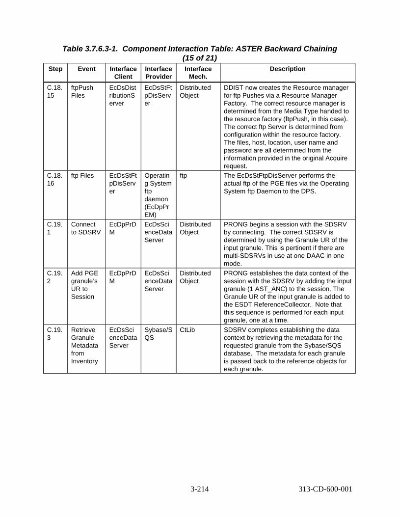
Table 3.7.6.3-1. Component Interaction Table: ASTER Backward Chaining (15 of 21)
Step Event Interface Client
Interface Provider
Interface Mech.
Description
C.18. 15
ftpPush Files
EcDsDist ributionS erver
EcDsStFt pDisServ er
Distributed Object
DDIST now creates the Resource manager for ftp Pushes via a Resource Manager Factory. The correct resource manager is determined from the Media Type handed to the resource factory (ftpPush, in this case). The correct ftp Server is determined from configuration within the resource factory. The files, host, location, user name and password are all determined from the information provided in the original Acquire request.
C.18. 16
ftp Files EcDsStFt pDisServ er
Operatin g System ftp daemon (EcDpPr EM)
ftp The EcDsStFtpDisServer performs the actual ftp of the PGE files via the Operating System ftp Daemon to the DPS.
C.19. 1
Connect to SDSRV
EcDpPrD M
EcDsSci enceData Server
Distributed Object
PRONG begins a session with the SDSRV by connecting. The correct SDSRV is determined by using the Granule UR of the input granule. This is pertinent if there are multi-SDSRVs in use at one DAAC in one mode.
C.19. 2
Add PGE granule’s UR to Session
EcDpPrD M
EcDsSci enceData Server
Distributed Object
PRONG establishes the data context of the session with the SDSRV by adding the input granule (1 AST_ANC) to the session. The Granule UR of the input granule is added to the ESDT ReferenceCollector. ote that this sequence is performed for each input granule, one at a time.
C.19. 3
Retrieve Granule Metadata from Inventory
EcDsSci enceData Server
Sybase/S QS
CtLib SDSRV completes establishing the data context by retrieving the metadata for the requested granule from the Sybase/SQS database. he metadata for each granule is passed back to the reference objects for each granule.
N
T
3-214 313-CD-600-001

Table 3.7.6.3-1. Component Interaction Table: ASTER Backward Chaining (16 of 21)
Step Event Interface Client
Interface Provider
Interface Mech.
Description
C.19. 4
Acquire Data
EcDpPrD M
EcDsSci enceData Server
Distributed Object
DPS requests granules by submitting an Acquire request for those granules. The Acquire request is for a ftpPush of all granules in the ESDT ReferenceCollector. This request is synchronous, meaning that the return of the submit call of the request contains the results of the request. his means that the response is not sent until the granule files have been ftp’ed to the DPS disks. This request asks for no distribution notice to be emailed. The Acquire request structure is hard-coded.
C.19. 5
Create Staging Disk
EcDsSci enceDat aServer
EcDsStSt agingDis kServer
Distributed Object
SDSRV verifies access privileges for the granule and creates a Staging Disk for metadata files, which allocates space and passes back a reference to that disk space. The correct staging disk server is determined from the SDSRV configuration. The amount of staging disk to request is determined by the size of the metadata file.
C.19. 6
Create Metadata file
EcDsSci enceDat aServer
EcDsSci enceData Server
Distributed Object
For each granule referenced in the Acquire request, the SDSRV creates a file containing the granule’s metadata before passing to Distribution.
C.19. 7
Distribute Granules, Synchrono us
EcDsSci enceDat aServer
EcDsDist ributionS erver
Distributed Object
SDSRV submits a request to Data Distribution. he request includes, for each granule, a reference to the metadata file as well as all data files. Other parameters from the Acquire request are passed to DDIST.
C.19. 8
Create Staging Disk
EcDsDist ributionS erver
EcDsStSt agingDis kServer
Distributed Object
DDIST creates Staging Disk for the granule files in the archive. This allocates space and passes back a reference to that disk space. The correct staging disk server is determined from the information passed by the SDSRV in the distribution request, which was the SDSRV configuration. The amount of staging disk to request is determined by the size of the metadata file.
T
T
3-215 313-CD-600-001

Table 3.7.6.3-1. Component Interaction Table: ASTER Backward Chaining
Step Event Interfac e Client
Interface Provider
(17 of 21) Interface
Mech. Description
C.19. 9
STMGT Retrieve
EcDsDis tribution Server
EcDsStAr chiveServ er
Distributed Object
DDIST requests that STMGT retrieve the granule file that is archived. This results in the file being staged to read-only cache disks. This means that all files needed to fulfill the distribution request are on disk, and ready to be copied. The correct archive object to request is determined from the information provided by the SDSRV in the distribution request. This returns references to the files in the read-only cache.
C.19. 10
Link files to Staging Disk
EcDsDis tribution Server
EcDsStSt agingDisk Server
Distributed Object
DDIST links the files from the read-only cache into the staging disk.
C.19. 11
Copy files to Staging Disk
EcDsDis tribution Server
EcDsStSt agingDisk Server
Distributed Object
DDIST copies the metadata files from the SDSRV’s Staging Disk into the staging disk.
C.19. 12
ftpPush Files
EcDsDis tribution Server
EcDsStFt pDisServe r
Distributed Object
DDIST now creates the Resource manager for ftp Pushes via a Resource Manager Factory. The correct resource manager is determined from the Media Type handed to the resource factory (ftpPush, in this case). The correct ftp Server is determined from configuration within the resource factory. The files, host, location, user name and password are all determined from the information provided in the original Acquire request.
C.19. 13
ftp Files EcDsSt FtpDisS erver
Operating System ftp daemon (EcDpPrD M)
ftp The EcDsStFtpDisServer performs the ftp of the files via the Operating System ftp Daemon to the DPS.
C.20. 1
Request Metadata Configurat ion File
EcDpPr EM
EcDsScie nceDataS erver
Distributed Object
DPS gets the metadata configuration file of the output data’s ESDT (AST_08 and AST_05). Data type and version are from PDPS database; correct client name is from configuration file.
3-216 313-CD-600-001

Table 3.7.6.3-1. Component Interaction Table: ASTER Backward Chaining
Step Event Interface Client
Interface Provider
(18 of 21) Interface
Mech. Description
C.20. 2
Run PGE EcDpPrR unPGE
PGE<ET S>
command line
ETS is executed. Output files are placed in the output directory. The directory path is established by using a root, which was established by configuration, and the specific directory by the job ID. This disk root is cross-mounted by DPS, SDSRV and STMGT. This is to ensure that they are directly available to the DSS, for archival.
C.21. 1
Get DSS UR
EcDpPrD M
EcIoAdS erver
Distributed Object
If the DSS UR for this output data type is not already known in the PDPS database, DM searches the Advertiser for a “GetQueryableParameters” service for the desired output data type. This is accomplished via the IoAdApprovedSearchCommand class. Since the Advertiser is based on a replicated database, no specification is required to select the proper Advertiser. The local one is used.
C.22. 1
Connect to SDSRV
EcDpPrD M
EcDsSci enceData Server
Distributed Object
PRONG begins a session with the SDSRV by connecting.
C.22. 2
Request Data Insert
EcDpPrD M
EcDsSci enceData Server
Distributed Object
PRONG requests that the newly created files for the AST_08 and AST_05 granules are inserted into the Data Server. An Insert request, containing the names of the files comprising the granule, is created for each granule. The structure of the Insert Request is hard-coded. SDSRV validates metadata and determines the archived names of the files. Note that these inserts occur one granule at a time.
C.22. 3
STMGT Store
EcDsSci enceData Server
EcDsStA rchiveSer ver
Distributed Object
SDSRV requests that the files are archived. The archive server must be able to read the inserted files directly from the DPS disks that they are residing on. The correct archive object to request is determined by the Archive ID input during ESDT installation.
C.22. 4
Adding a Granule to Inventory
EcDsSci enceData Server
Sybase/S QS
CtLib The validated metadata is parsed and added to the inventory of the SDSRV.
3-217 313-CD-600-001

Table 3.7.6.3-1. Component Interaction Table: ASTER Backward Chaining
Step Event Interface Client
Interface Provider
(19 of 21) Interface
Mech. Description
C.23. 1
Trigger Event
EcDsSci enceData Server
EcSbSub Server
Distributed Object
Upon successful insertion of AST_08 the AST_08:Insert event is triggered. The correct subscription server is determined from the SDSRV configuration. The correct events to trigger are determined from the events file, where they were stored when the ESDT was installed in the Data Server. Provided with the event triggering is the UR of the inserted granule.
C.23. 2
Retrieve Subscripti ons
EcSbSub Server
Sybase CtLib SBSRV queries the Sybase database determining which subscriptions need to be activated, or fired. Each query “hit” is an activated subscription and executes independently.
C.24. 1
Send Notificatio n
EcSbSub Server
Science User
e-mail The SBSRV builds an email notification that the user’s subscription on the AST_08:Insert event has been fired. This notification identifies the event, the subscription ID, the Granule UR that was inserted and the previously supplied User String. The e-mail is sent to the Science User.
C.25. 1
Connect to SDSRV
EcSbSub Server
EcDsSci enceData Server
Distributed Object
In order to fulfill a standing order, the SBSRV begins a session with the SDSRV, on behalf of the subscription user. The correct SDSRV is determined by the Granule UR provided with the event triggering. This is pertinent if there are multi-SDSRVs in use at one DAAC in one mode.
C.25. 2
Add PGE granule’s UR to Session
EcSbSub Server
EcDsSci enceData Server
Distributed Object
The SBSRV establishes the data context of the session with the SDSRV by adding the input granules to the session. The Granule UR of each input granule is added to the ESDT ReferenceCollector.
C.25. 3
Retrieve Granule Metadata from Inventory
EcDsSci enceData Server
Sybase/S QS
CtLib SDSRV completes establishing the data context by retrieving the metadata for the requested granules from the Sybase/SQS database. The metadata for each granule is passed back to the reference objects for each granule.
3-218 313-CD-600-001

Table 3.7.6.3-1. Component Interaction Table: ASTER Backward Chaining
Step Event Interface Client
Interface Provider
(20 of 21) Interface
Mech. Description
C.25. 4
Acquire Data
EcSbSub Server
EcDsSci enceData Server
Distributed Object
SBSRV fulfills the standing order for the AST_08 granule by submitting an Acquire request for the granule. The Acquire request is for a ftpPush of all granules in the ESDT ReferenceCollector. This request is asynchronous, meaning that the return of the submit call of the request only contains the status of the request’s submittal. This request asks for a distribution notice to be emailed to the client. The Acquire request structure was hard-coded within the subscription server.
C.25. 5
Create Staging Disk
EcDsSci enceData Server
EcDsStSt agingDis kServer
Distributed Object
SDSRV verifies access privileges for the granule and creates a Staging Disk for the metadata files, which allocates space and passes back a reference to that disk space. The correct staging disk server is determined from the SDSRV configuration. The amount of staging disk to request is determined by the size of the metadata file.
C.25. 6
Create Metadata file
EcDsSci enceData Server
EcDsSci enceData Server
Distributed Object
For each granule referenced in the Acquire request, the SDSRV creates a file containing the granule’s metadata before passing to Distribution.
C.25. 7
Distribute Granules, Synchron ous
EcDsSci enceData Server
EcDsDist ributionS erver
Distributed Object
SDSRV submits a request to Data Distribution. The request includes, for the granule, a reference to the metadata file as well as the data file. Other parameters from the Acquire request are passed to DDIST.
C.25. 8
Create Staging Disk
EcDsDist ributionS erver
EcDsStSt agingDis kServer
Distributed Object
DDIST creates Staging Disk for the granule files in the archive. This allocates space and passes back a reference to that disk space. The correct staging disk server is determined from the information passed by the SDSRV in the distribution request, which was the SDSRV configuration. The amount of staging disk to request is determined by the size of the metadata file.
3-219 313-CD-600-001
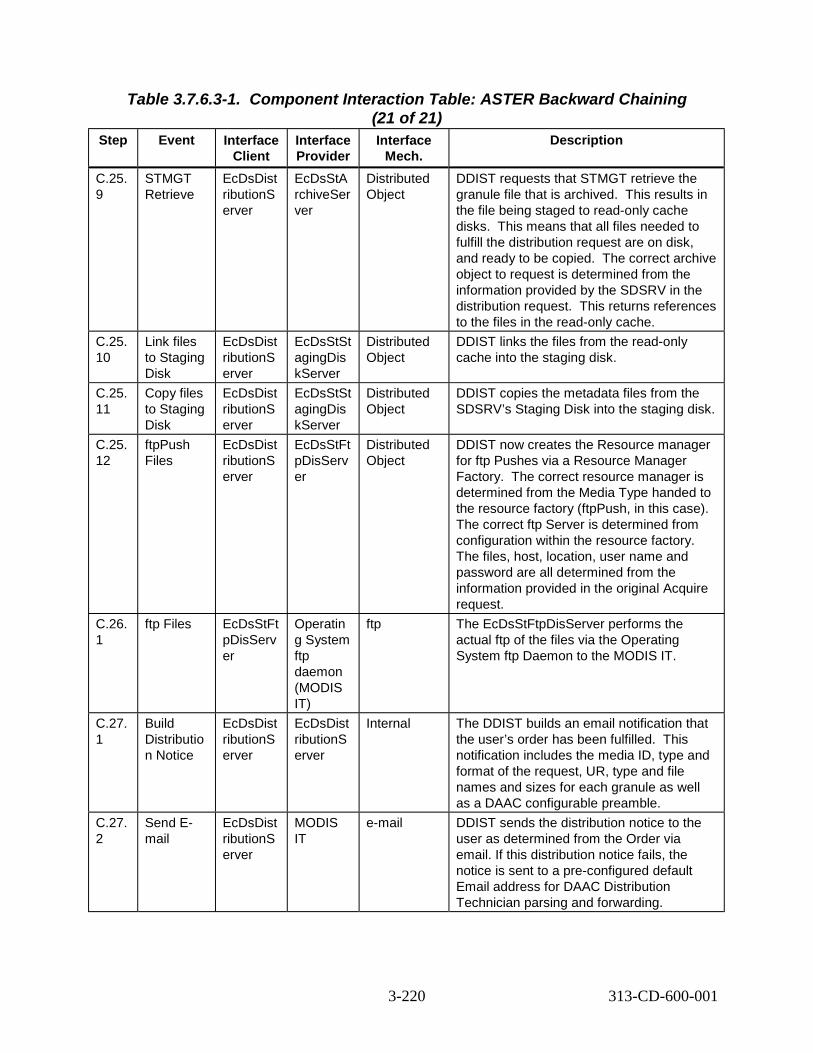
Table 3.7.6.3-1. Component Interaction Table: ASTER Backward Chaining
Step Event Interface Client
Interface Provider
(21 of 21) Interface
Mech. Description
C.25. 9
STMGT Retrieve
EcDsDist ributionS erver
EcDsStA rchiveSer ver
Distributed Object
DDIST requests that STMGT retrieve the granule file that is archived. This results in the file being staged to read-only cache disks. This means that all files needed to fulfill the distribution request are on disk, and ready to be copied. The correct archive object to request is determined from the information provided by the SDSRV in the distribution request. This returns references to the files in the read-only cache.
C.25. 10
Link files to Staging Disk
EcDsDist ributionS erver
EcDsStSt agingDis kServer
Distributed Object
DDIST links the files from the read-only cache into the staging disk.
C.25. 11
Copy files to Staging Disk
EcDsDist ributionS erver
EcDsStSt agingDis kServer
Distributed Object
DDIST copies the metadata files from the SDSRV’s Staging Disk into the staging disk.
C.25. 12
ftpPush Files
EcDsDist ributionS erver
EcDsStFt pDisServ er
Distributed Object
DDIST now creates the Resource manager for ftp Pushes via a Resource Manager Factory. The correct resource manager is determined from the Media Type handed to the resource factory (ftpPush, in this case). The correct ftp Server is determined from configuration within the resource factory. The files, host, location, user name and password are all determined from the information provided in the original Acquire request.
C.26. 1
ftp Files EcDsStFt pDisServ er
Operatin g System ftp daemon (MODIS IT)
ftp The EcDsStFtpDisServer performs the actual ftp of the files via the Operating System ftp Daemon to the MODIS IT.
C.27. 1
Build Distributio n Notice
EcDsDist ributionS erver
EcDsDist ributionS erver
Internal The DDIST builds an email notification that the user’s order has been fulfilled. This notification includes the media ID, type and format of the request, UR, type and file names and sizes for each granule as well as a DAAC configurable preamble.
C.27. 2
Send E-mail
EcDsDist ributionS erver
MODIS IT
e-mail DDIST sends the distribution notice to the user as determined from the Order via email. If this distribution notice fails, the notice is sent to a pre-configured default Email address for DAAC Distribution Technician parsing and forwarding.
3-220 313-CD-600-001

EOSView
DAAOps
SciUse
DSS
QA Moni
3.7.7 ASTER QA Metadata Update Thread This thread shows how the ECS supports updating the QA metadata of a specified granule.
3.7.7.1 ASTER QA Metadata Update Thread Interaction Diagram - Domain View Figure 3.7.7.1-1 depicts the ASTER QA Metadata Update Interaction.
Scieennccee D.2 Call DAAC DAACC Userr Ops
D.1 View Data D.3 Update QA metadata
EOSView QA Monittoorr
D.4 Update
Distributed Object (rpc, CtLib) DSS HMI (GUI, Xterm, command)ftp email (or other as noted) Double line - Synchronous email (or other as noted) Dashed - Asynchronous
(via telephone, e-mail, or FAX)
Figure 3.7.7.1-1. ASTER QA Metadata Update Interaction Diagram
3.7.7.2 ASTER QA Metadata Update Thread Interaction Table - Domain View Table 3.7.7.2-1 provides the Interaction - Domain View: ASTER QA Metadata Update.
Table 3.7.7.2-1. Interaction Table - Domain View: ASTER QA Metadata Update
Step Event Interface Client
Interface Provider
(1 of 2) Data
Issues Step
Precond itions
Description
D.1 View Data
Science User
EOSView None None Upon notification that the AST_08 has been placed on their workstation, the Scientist views the AST_08 data with EOSView.
3-221 313-CD-600-001

Table 3.7.7.2-1. Interaction Table - Domain View: ASTER QA Metadata Update
Step Event Interface Client
Interface Provider
(2 of 2) Data
Issues Step
Precond itions
Description
D.2 Call DAAC
Science User
DAAC Science Data Specialist
None None The Scientist QA’s the produced data. S/he notifies the DAAC, informing the DAAC Science Data Specialist that the granule’s QA flags should be updated.
D.3 Update QA Metada ta
DAAC Science Data Specialist
QA Monitor
None None DAAC Science Data Specialist uses the QA Monitor tool to update the Science QA metadata of the granule.
D.4 Update QA Monitor
DSS None None QA Monitor invokes the Update service offered by the Data Server on the granule. The QA Monitor passes the Scientists requested QA values to the DSS for permanent updating of the granule’s metadata.
3.7.7.3 ASTER QA Metadata Update Thread Component Interaction Table Table 3.7.7.3-1 provides the Component Interaction: ASTER QA Metadata Update.
Table 3.7.7.3-1. Component Interaction Table: ASTER QA Metadata Update
Step Event Interface Client
Interface Provider
(1 of 2) Interface
Mech. Description
D.1.1 Invoke EOSView
Science User
EOSView Command Science User begins the EOSView application. The user double clicks the EOSView icon.
D.1.2 Display AST_08 Data
Science User
EOSView GUI The Science User specifies which file to display and sets visualization parameters. The data file is now displayed for the user.
D.3.1 Invoke DAAC QA Monitor
DAAC Science Data Specialist
EcDpPrQ aMonitor GUI
Command DAAC Science Data Specialist begins the QA Monitor application.
D.3.2 Establish QA values
DAAC Science Data Specialist
EcDpPrQ aMonitor GUI
GUI DAAC Science Data Specialist establishes the updated values for selected metadata fields, for the selected granules. Granules are select by selecting data type and temporal range. Fields to update are hard wired.
3-222 313-CD-600-001

Table 3.7.7.3-1. Component Interaction Table: ASTER QA Metadata Update
Step Event Interface Client
Interface Provider
(2 of 2) Interface
Mech. Description
D.3.3 Connect to SDSRV
EcDpPrQ aMonitor GUI
EcDsSci enceData Server
Distributed Object
QA Monitor begins a session with the SDSRV by connecting, in order to find granules to be updated. The correct SDSRV is determined by using the Server UR indicated in configuration, based on data type. This is pertinent if there are multi-SDSRVs in use at one DAAC in one mode.
D.3.4 SDSRV Query
EcDpPrQ aMonitor GUI
EcDsSci enceData Server
Distributed Object
The QA Monitor builds a DsClQuery object. This object is handed to the Search interface of the DsCl ESDT ReferenceCollector. This Search method is synchronous, so the results of the search are returned to the calling function. After the search the QA Monitor receives a list of URs. Then it does an “Inspect” to the SDSRV to get the metadata. It first performs a GetQueryableParamerter to determine all attributes associated with each granule.
D.3.5 Request Metadata
EcDsSci enceData Server
Sybase/S QS
CtLib The SDSRV breaks down the Query object and translates it into a sequence of calls to the inventory database. Resultant rows are converted into data granules, each with their metadata extracted from the database. These results are packaged and returned to the Query client.
D.3.6 Inspect Granule Value Paramete rs
EcDpPrQ aMonitor GUI
EcDsSci enceData Server
Distributed Object
QA Monitor inspects each resultant granule for the values of displayed metadata fields.
D.3.7 Select granules to update
DAAC Science Data Specialist
EcDpPrQ aMonitor GUI
GUI DAAC Science Data Specialist selects granules for updating.
D.4.1 Update Granule metadata
EcDpPrQ aMonitor GUI
EcDsSci enceData Server
Distributed Object
QA Monitor submits an update request for the granules to be updated (one granule at a time). The structure of the Update request is hard-coded.
D.4.2 Update a metadata inventory
EcDsSci enceData Server
Sybase/S QS
CtLib SDSRV updates the metadata inventory attributes for the granules that are being updated.
3-223 313-CD-600-001

3.7.8 ASTER On-Demand High Level Production Thread This thread shows how the ECS supports users request for On-Demand High Level production.
The ASTER On Demand High Level Processing scenario occurs every time a user places a request for one of the pre-defined set of ASTER High Level Products. The user may want to produce a high level product with a different set of parameters or use a Non-Standard L1B granule as starting input. In either case, the user selects the granule to be used and/or the additional non-standard parameters to generate the High Level product. Then the user submits a request for the system to create this High Level product.
3.7.8.1 ASTER On-Demand High Level Production Thread Interaction Diagram -Domain View
Figure 3.7.8.1-1 depicts the ASTER On-Demand High Level Production Interaction.
EDG
ODFRM
MSS E.14 Subscription
Notification E.16 Update Status (to “Being Processed”)
E.24 User Data Distribution
E.11 Update Status (to “Waiting for Data”)
E.22 Subscription Notification
E.23 User Acquire
E.6 On-Demand Order E.13 Order Confirmation
E.12 Order ID Returned Science
User Science
User
SBSRVSBSRV
DSSSDSRV
DPS DPS
PLSPLS E.9 Subscribe
E.10 Submit DPRs E.15 Release Job
E.18 Run PGE
E.21 Trigger Event
E.17 Acquire DataE.20 Request Data Insert
V0GWYV0GWY
E.1 Inventory Search
E.2 Search
E.3 Search
E.7 Create MSS Order Tracking Elements
E.8 Initialize Status (to “Queued”)
IOS
E.19 Get DSS UR
(socket level interface)
E.5 Submit On-Demand Request
E.25 Completion Notice
CSS
E.4 Retrieve Media
Distributed Object (rpc, CtLib) HMI (GUI, Xterm, command) ftp email (or other as noted) Double line - Synchronous email (or other as noted) Dashed - Asynchronous
Figure 3.7.8.1-1. ASTER On-Demand High Level Production Interaction Diagram
3-224 313-CD-600-001

3.7.8.2 ASTER On-Demand High Level Production Thread Interaction Table -Domain View
Table 3.7.8.2-1 provides the Interaction - Domain View: ASTER On-Demand High Level Production.
Table 3.7.8.2-1. Interaction Table - Domain View: ASTER On-Demand High Level
Step Event Interface Client
Production (1 of 4) Interface Provider
Data Issues Step Preconditions
Description
E.1 Inventory Search
Science User
EDG None None Scientist searches ECS holdings for ASTER images that are over his/her area of study.
E.2 Search EDG V0GWY None None EDG submits the Science User’s search criteria to the V0 Gateway in ODL format, via a specific socket.
E.3 Search V0GWY SDSRV (DSS)
None None The V0 gateway translates the Search criteria from ODL to a query object (using GlParameters), and submits that query to the Search service.
E.4 Retrieve Media
V0GWY Registry (CSS)
None None The results of this Search are returned synchronously. The media options are returned from the CSS Registry Server and the results are passed back to the EDG, which displays them to the Science User.
E.5 Submit On-demand Request
Science User
ODFRM GUI
None The scientist must have found (via EDG) the URs of the input products to be used in the On-demand request.
The scientist desires a product that does not exist in the archive. He/she picks the URs of the inputs and creates an On-demand Production Request via the ODFRM GUI.
3-225 313-CD-600-001

Table 3.7.8.2-1. Interaction Table - Domain View: ASTER On-Demand High Level
Step Event Interface Client
Production (2 of 4) Interface Provider
Data Issues Step Preconditions
Description
E.6 On-demand Order
ODFRM PLS (ODPRM)
This interface is actually accomplishe d via a synchronous rpc call.
None All the users selections for the On-demand Production Request are stored in a Gl Parameter List which is passed to an ODPRM (a PLS server). An Order ID generated by ODPRM will be returned to ODFRM.
E.7 Create MSS Order Tracking Elements
PLS MSS None None PLS creates order-tracking elements.
E.8 Initialize Status (to “Queued”)
PLS MSS None None The status of the On-demand request is initialized to “Queued”.
E.9 Subscrib e
PLS SBSRV None None PLS places subscriptions on those inputs that have not been archived. PLS also places a subscription on the output products desired by the user.
E.10 Submit DPRs
PLS (ODPRM)
DPS None None DPR(s) for PGEs to produce the requested products are created and submitted to DPS.
E.11 Update Status (to “Waiting for Data”)
PLS MSS None None PLS sets the status of the On-demand request to “Waiting for Data”).
E.12 Order ID Returned
PLS ODFRM None None The order ID is returned to the On Demand Form.
E.13 Order Confirma tion
ODFRM Science User
None None The ODFRM notifies the science user that the request has been submitted.
E.14 Subscript ion Notificati on
SBSRV PLS None None SBSRV notifies PLS when data is available in the archive by a subscription notification.
3-226 313-CD-600-001

Table 3.7.8.2-1. Interaction Table - Domain View: ASTER On-Demand High Level
Step Event Interface Client
Production (3 of 4) Interface Provider
Data Issues Step Preconditions
Description
E.15 Release Job
PLS DPS None None Once all inputs are available to run the PGE, references to those input granules are passed to DPS, and the jobs that make up the On-demand Production Request are released.
E.16 Update Status (to “Being Processe d”)
DPS MSS None None DPS updates the status of the On-demand request as it marches through the various stages of processing.
E.17 Acquire Data
DPS DSS (SDSRV)
None None DPS submits Acquire Request for input granules, via ftpPush, for input to PGEs.
E.18 Run PGE DPS DPS None None PGEs run, creating desired products.
E.19 Get DSS UR
DPS IOS None None DPS gets the DSS UR from Advertiser.
E.20 Request Data Insert
DPS DSS (SDSRV)
None None Archive newly created product granules. Note that if the PGE run was a precursor PGE (meaning a PGE that has to be run for the inputs of the PGE that will actually produce the desired product) then DPS will insert the granule such that it will be deleted in an configurable time period.
E.21 Trigger Event
SDSRV SBSRV None None Trigger insert of desired product data. Since PLS placed the subscription for the desired product, then PLS will receive the Subscription Notification (as in step E.13).
E.22 Subscript ion Notificati on
SBSRV PLS None None SBSRV notifies PLS when data is available in the archive by a subscription notification.
3-227 313-CD-600-001

Table 3.7.8.2-1. Interaction Table - Domain View: ASTER On-Demand High Level
Step Event Interface Client
Production (4 of 4) Interface Provider
Data Issues Step Preconditions
Description
E.23 User Acquire
PLS SDSRV None None PLS submits a “user acquire” request, to request that DSS transfer the product(s) to the user who made the On-demand request.
E.24 User Data Distributi on
SDSRV Science User
None None SDSRV acquires the data for the user. It is sent via ftp or placed on requested media.
E.25 Completi on Notice
PLS Science User
None None Send email notification to Science User, notifying that the requested product(s) has been produced.
3.7.8.3 ASTER On-Demand Production High Level Thread Component InteractionTable Table 3.7.8.3-1 provides the Component Interaction: ASTER On-Demand High Level Production.
Table 3.7.8.3-1. Component Interaction Table: ASTER On-Demand High Level
Step Event Interface Client
Production (1 of 13) Interface Provider
Interface Mech.
Description
E.1.1 Startup EDG Science User
Netscape Command Science User invokes a Netscape browser and navigates to the EOS Data Gateway home page.
E.1.2 Select Inventory Search, Provide Query constraints, Submit Query
Science User
Netscape GUI The Science User provides search constraints and the products desired. When query constraints are completed, the query is submitted.
3-228 313-CD-600-001

Table 3.7.8.3-1. Component Interaction Table: ASTER On-Demand High Level
Step Event Interface Client
Production (2 of 13) Interface Provider
Interface Mech.
Description
E.2.1 V0 Gateway Inventory Search
Netscape EcDmV0 ToEcsGa teway
ODL, over sockets
EDG submits a search to the V0 Gateway, by converting the search criteria into an ODL structure and passing that structure to a socket provided by the Gateway. The correct socket is determined from configuration information contained in the Valids file.
E.3.1 Establish ECS User
EcDmV0 ToEcsGa teway
EcMsAc RegUser Srvr
Distributed Object
V0 Gateway retrieves the User Profile using ECS Authenticator from ODL message, which includes an encrypted User ID and Password. The User Registration database is replicated across DAACs, so the connection is made to the local User Registration Server.
E.3.2 Request Attribute Mapping
EcDmV0 ToEcsGa teway
EcDmDic tServer
CtLib (RWDBToo l)
Gateway translates the V0 terms from ODL into ECS names for query submittal. Interface is directly to Data Dictionary database. Database name is retrieved from configuration file.
E.3.3 Connect to SDSRV
EcDmV0 ToEcsGa teway
EcDsSci enceData Server
Distributed Object
The Gateway first connects to the SDSRV. The correct SDSRV is determined from configuration information.
E.3.4 SDSRV Query
EcDmV0 ToEcsGa teway
EcDsSci enceData Server
Distributed Object
The Gateway translates the query into a DsClQuery object. This object is handed to the Search interface of the DsCl ESDT ReferenceCollector. This Search method is synchronous, so the results of the search are returned to the calling function. After the search the Gateway receives a list of URs. Then it does an “Inspect” to the SDSRV to get the metadata. It first performs a GetQueryableParamerter to determine all attributes associated with each granule.
E.3.5 Request Metadata
EcDsSci enceData Server
Sybase/S QS
CtLib The SDSRV breaks down the Query object and translates it into a sequence of calls to the inventory database. Resultant rows are converted into data granules, each with their metadata extracted from the database. These results are packaged and returned to the Query client.
3-229 313-CD-600-001
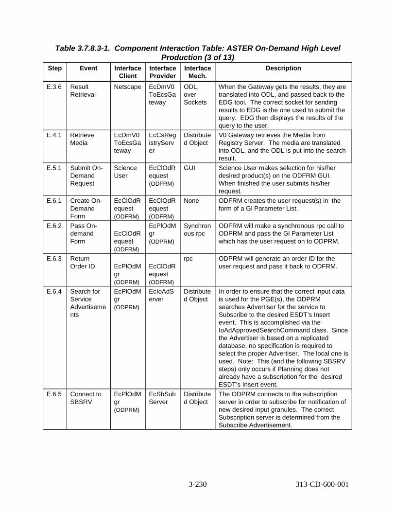
Table 3.7.8.3-1. Component Interaction Table: ASTER On-Demand High Level
Step Event Interface Client
Production (3 of 13) Interface Provider
Interface Mech.
Description
E.3.6 Result Retrieval
Netscape EcDmV0 ToEcsGa teway
ODL, over Sockets
When the Gateway gets the results, they are translated into ODL, and passed back to the EDG tool. The correct socket for sending results to EDG is the one used to submit the query. EDG then displays the results of the query to the user.
E.4.1 Retrieve Media
EcDmV0 ToEcsGa teway
EcCsReg istryServ er
Distribute d Object
V0 Gateway retrieves the Media from Registry Server. The media are translated into ODL, and the ODL is put into the search result.
E.5.1 Submit On-Demand Request
Science User
EcClOdR equest (ODFRM)
GUI Science User makes selection for his/her desired product(s) on the ODFRM GUI. When finished the user submits his/her request.
E.6.1 Create On-Demand Form
EcClOdR equest (ODFRM)
EcClOdR equest (ODFRM)
None ODFRM creates the user request(s) in the form of a Gl Parameter List.
E.6.2 Pass On-demand Form
EcClOdR equest (ODFRM)
EcPlOdM gr (ODPRM)
Synchron ous rpc
ODFRM will make a synchronous rpc call to ODPRM and pass the Gl Parameter List which has the user request on to ODPRM.
E.6.3 Return Order ID EcPlOdM
gr (ODPRM)
EcClOdR equest (ODFRM)
rpc ODPRM will generate an order ID for the user request and pass it back to ODFRM.
E.6.4 Search for Service Advertiseme nts
EcPlOdM gr (ODPRM)
EcIoAdS erver
Distribute d Object
In order to ensure that the correct input data is used for the PGE(s), the ODPRM searches Advertiser for the service to Subscribe to the desired ESDT’s Insert event. This is accomplished via the IoAdApprovedSearchCommand class. Since the Advertiser is based on a replicated database, no specification is required to select the proper Advertiser. The local one is used. Note: This (and the following SBSRV steps) only occurs if Planning does not already have a subscription for the desired ESDT’s Insert event.
E.6.5 Connect to SBSRV
EcPlOdM gr (ODPRM)
EcSbSub Server
Distribute d Object
The ODPRM connects to the subscription server in order to subscribe for notification of new desired input granules. The correct Subscription server is determined from the Subscribe Advertisement.
3-230 313-CD-600-001

Table 3.7.8.3-1. Component Interaction Table: ASTER On-Demand High Level
Step Event Interface Client
Production (4 of 13) Interface Provider
Interface Mech.
Description
E.6.6 Submit Subscription
EcPlOdM gr (ODPRM)
EcSbSub Server
Distributed Object
Submit the subscription to the Subscription Server. This is accomplished with the EcClSubscription interface class.
E.6.7 Store a Subscription
EcSbSub Server
Sybase CtLib Subscription is stored in the Sybase Database.
E.6.8 Search for Service Advertiseme nts
EcPlOdM gr (ODPRM)
EcIoAdS erver
Distributed Object
In order to determine where (which SDSRV) the input data is located the ODPRM searches the Advertiser for a “GetQueryableParameters” service for the desired input data type. This is in lieu of searching for Product Advertisements. This is accomplished via the IoAdApprovedSearchCommand class. Since the Advertiser is based on a replicated database, no specification is required to select the proper Advertiser. The local one is used.
E.6.9 Connect to SDSRV
EcPlOdM gr (ODPRM)
EcDsSci enceData Server
Distributed Object
Looking for input granules for the PGE, the Editor first connects to the SDSRV. The correct SDSRV is determined from the service provider on the GetQueryableParameters Advertisement. This is pertinent if there are multi-SDSRVs in use at one DAAC in one mode.
E.6.1 0
SDSRV Query
DpPrDssI F (Library Function)
EcDsSci enceData Server
Distributed Object
The DpPrDssIF creates an IF object to connect with the Science Data Server and performs the query.
E.6.1 1
Request Metadata
EcDsSci enceData Server
Sybase/S QS
CtLib The SDSRV breaks down the Query object and translates it into a sequence of calls to the inventory database. Resultant rows are converted into data granules, each with their metadata extracted from the database. These results are packaged and returned to the Query client.
E.6.1 2
Inspect Granule Value Parameters
EcPlOdM gr (ODPRM)
EcDsSci enceData Server
Distributed Object
ODPRM checks the granule’s metadata attributes (type, version, file size and temporal range), to establish job dependencies. References to desired granules are packaged in the DPRs.
E.7.1 Create MSS Order Tracking Elements
EcPlOdM gr (ODPRM)
AutoSys Distributed Object
The MSS order tracking elements are created.
3-231 313-CD-600-001

Table 3.7.8.3-1. Component Interaction Table: ASTER On-Demand High Level
Step Event Interface Client
Production (5 of 13) Interface Provider
Interface Mech.
Description
E.8.1 Initialize Status (to “Queued”)
EcPlOdM gr (ODPRM)
AutoSys Distributed Object
The status of the On-demand request is initialized to “Queued”.
E.9.1 Search for Service Advertiseme nts
EcPlOdM gr (ODPRM)
EcIoAdS erver
Distributed Object
In order to ensure that the correct output data is triggered, the ODPRM searches Advertiser for the service to Subscribe to the desired output ESDT’s Insert event. This is accomplished via the IoAdApprovedSearchCommand class. Since the Advertiser is based on a replicated database, no specification is required to select the proper Advertiser.
E.9.2 Connect to SBSRV
EcPlOdM gr (ODPRM)
EcSbSub Server
Distributed Object
The ODPRM connects to the subscription server in order to subscribe for notification of new desired output granules. The correct Subscription server is determined from the Subscribe Advertisement.
E.9.3 Submit Subscription
EcPlOdM gr (ODPRM)
EcSbSub Server
Distributed Object
Submit the subscription to the Subscription Server. This is accomplished with the EcClSubscription interface class.
E.9.4 Store a Subscription
EcSbSub Server
Sybase Ctlib Subscription is stored in the Sybase Database.
E.10. 1
Create DPR EcPlOdM gr
EcDpPrJ obMgmt
rpc The On-Demand Manager sends to DPS the DPRID, a list of predecessor DPRs, and whether the DPR is waiting for external data.
E.11. 1
Update Status (to “Waiting for Data”)
EcPlOdM gr (ODPRM)
AutoSys Distributed Object
The status of the On-demand request is updated to “Waiting for Data”.
E.12. 1
Order ID Returned EcPlOdM
gr (ODPRM)
EcClOdR equest (ODFRM)
Distributed Object
The order ID is returned to the On-demand Form from the PLS.
E.13. 1
Order Confirmation
EcClOdR equest (ODFRM)
Science User
GUI An order confirmation is sent by the ODFRM to the science user.
E.14. 1
Subscription Notification
EcSbSub Server
EcPlSub Mgr
Distributed Object
The subscriptions are submitted for each data type individually.
3-232 313-CD-600-001

Table 3.7.8.3-1. Component Interaction Table: ASTER On-Demand High Level
Step Event Interface Client
Production (6 of 13) Interface Provider
Interface Mech.
Description
E.15. 1
Release Job EcPlOdM gr
EcDpPrJ obMgmt
Rpc Planning tells the Job Manager to release the On-demand job, using the appropriate input granules.
E.15. 2
Submit DPRs
EcDpPrJ obMgmt
AutoSys JIL The DPR (containing BTS PGE) in updated plan are submitted, to AutoSys.
E.15. 3
Force Start Job
EcDpPrJ obMgmt
event_da emon
rpc On-demand Job is released.
E.15. 4
Initiate Job Processing
event_da emon
EcDpPrE M
command line
The On-demand job begins processing.
E.15. 5
Connect to SDSRV
EcDpPrE M
EcDsSci enceData Server
Distributed Object
Processing begins a session with the SDSRV by connecting, in order to acquire the On-demand PGE. The correct SDSRV is determined by using the Granule UR of the PGE granule, which is defined in the Production plan and is part of the DPR. This is pertinent if there are multi-SDSRVs in use at one DAAC in one mode.
E.15. 6
Add PGE granule’s UR to Session
EcDpPrE M
EcDsSci enceData Server
Distributed Object
PRONG establishes the data context of the session with the SDSRV by adding the PGE granule’s UR to the ESDT ReferenceCollector.
E.15. 7
Retrieve Granule Metadata from Inventory
EcDsSci enceData Server
Sybase/S QS
CtLib SDSRV completes establishing the data context by retrieving the metadata for the requested PGE granule from the Sybase/SQS database. The metadata for the PGE granule is passed back to the reference objects for each granule.
E.15. 8
Acquire Data
EcDpPrE M
EcDsSci enceData Server
Distributed Object
DPS requests granules by submitting an Acquire request for the PGE granule. The Acquire request is for a ftpPush of all granules in the ESDT ReferenceCollector. This request is synchronous, meaning that the return of the submit call of the request contains the results of the request. This means that the response is not sent until the PGE granule files have been ftp’ed to the DPS disks. This request asks for no distribution notice to be emailed. The Acquire request structure is hard-coded.
3-233 313-CD-600-001

Table 3.7.8.3-1. Component Interaction Table: ASTER On-Demand High Level
Step Event Interface Client
Production (7 of 13) Interface Provider
Interface Mech.
Description
E.15. 9
Create Staging Disk
EcDsSci enceData Server
EcDsStSt agingDis kServer
Distributed Object
SDSRV verifies access privileges for the granule and creates a Staging Disk for the metadata file, which allocates space and passes back a reference to that disk space. The correct staging disk server is determined from the SDSRV configuration. The amount of staging disk to request is determined by the size of the metadata file.
E.15. 10
Create Metadata file
EcDsSci enceData Server
EcDsSci enceData Server
Distributed Object
The SDSRV creates a file containing the PGE granule’s metadata before passing to Distribution.
E.15. 11
Distribute Granules, Synchronou s
EcDsSci enceData Server
EcDsDist ributionS erver
Distributed Object
SDSRV submits a request to Data Distribution. The request includes, for each granule, a reference to the metadata file as well as all data files. Other parameters from the Acquire request are passed to DDIST.
E.15. 12
Create Staging Disk
EcDsDist ributionS erver
EcDsStSt agingDis kServer
Distributed Object
DDIST creates Staging Disk for the granule files in the archive. This allocates space and passes back a reference to that disk space. The correct staging disk server is determined from the information passed by the SDSRV in the distribution request, which was the SDSRV configuration. The amount of staging disk to request is determined by the size of the metadata file.
E.15. 13
STMGT Retrieve
EcDsDist ributionS erver
EcDsStA rchiveSer ver
Distributed Object
DDIST requests that STMGT retrieve the PGE granule file that is archived. STMGT compresses the files in the format specified. This results in the file being staged to read-only cache disks. STMGT informs DDIST of the compressed file sizes. This means that all files needed to fulfill the distribution request are in read only cache, and ready to be linked. The correct archive object to request is determined from the information provided by the SDSRV in the distribution request. This returns references to the files in the read-only cache.
E.15. 14
Link files to Staging Disk
EcDsDist ributionS erver
EcDsStSt agingDis kServer
Distributed Object
DDIST links the files from the read-only cache into the staging disk.
3-234 313-CD-600-001

Table 3.7.8.3-1. Component Interaction Table: ASTER On-Demand High Level
Step Event Interface Client
Production (8 of 13) Interface Provider
Interface Mech.
Description
E.15. 15
Claim Ownership
EcDsDist ributionS erver
EcDsStR equestM anager then EcDsStSt agingDis kServer
Distributed Object
The Distribution server claims ownership of the staging disk created by SDSRV by sending a request to the STMGT Request Manager. The Request Manager then forwards the request to the Staging Disk Server to insert appropriate data in the data base table.
E.15. 16
Compress Disk
EcDsDist ributionS erver
EcDsStR equestM anager then EcDsStSt agingDis kServer
Distributed Object
The Distribution Server asks the Staging Disk Server via the STMGT Request Manager to compress the staging disk.
E.15. 17
Link files to Staging Disk
EcDsDist ributionS erver
EcDsStSt agingDis kServer
Distributed Object
DDIST links the metadata files from the SDSRV’s Staging Disk into the staging disk.
E.15. 18
ftpPush Files
EcDsDist ributionS erver
EcDsStFt pDisServ er
Distributed Object
DDIST now creates the Resource manager for ftp Pushes via a Resource Manager Factory. The correct resource manager is determined from the Media Type handed to the resource factory (ftpPush, in this case). The correct ftp Server is determined from configuration within the resource factory. The files, host, location, user name and password are all determined from the information provided in the original Acquire request.
E.15. 19
ftp Files EcDsStFt pDisServ er
Operating System ftp daemon (EcDpPrE M)
ftp The EcDsStFtpDisServer performs the actual ftp of the PGE files via the Operating System ftp Daemon to the DPS.
E.16. 1
Update Status
EcDpPrE M and EcDpPrD M
EcMsAc OrderSrv r
Distributed Object
DPS updates the status as the PGE(s) go through the various states. The status of each On-demand PGE goes from “Waiting for Data”, to “Waiting for Processing Resources” to “Started Processing” to “Completed”.
E.17. 1
Connect to SDSRV
EcDpPrD M
EcDsSci enceData Server
Distributed Object
PRONG begins a session with the SDSRV by connecting. The correct SDSRV is determined by using the Granule UR of the input granule. This is pertinent if there are multi-SDSRVs in use at one DAAC in one mode.
3-235 313-CD-600-001

Table 3.7.8.3-1. Component Interaction Table: ASTER On-Demand High Level
Step Event Interface Client
Production (9 of 13) Interface Provider
Interface Mech.
Description
E.17. 2
Add PGE granule’s UR to Session
EcDpPrD M
EcDsSci enceData Server
Distributed Object
PRONG establishes the data context of the session with the SDSRV by adding the input granules to the session. The Granule UR of the input granule is added to the ESDT ReferenceCollector. Note that this sequence is performed for each input granule, one at a time.
E.17. 3
Retrieve Granule Metadata from Inventory
EcDsSci enceData Server
Sybase/S QS
CtLib SDSRV completes establishing the data context by retrieving the metadata for the requested granule from the Sybase/SQS database. The metadata for each granule is passed back to the reference objects for each granule.
E.17. 4
Acquire Data
EcDpPrD M
EcDsSci enceData Server
Distributed Object
DPS requests granules by submitting an Acquire request for those granules. The Acquire request is for an ftpPush of all granules in the ESDT ReferenceCollector. This request is synchronous, meaning that the return of the submit call of the request contains the results of the request. This means that the response is not sent until the granule files have been ftp’ed to the DPS disks. This request asks for no distribution notice to be emailed. The Acquire request structure is hard-coded.
E.17. 5
Create Staging Disk
EcDsSci enceData Server
EcDsStSt agingDis kServer
Distributed Object
SDSRV verifies access privileges for the granule and creates a Staging Disk for metadata files, which allocates space and passes back a reference to that disk space. The correct staging disk server is determined from the SDSRV configuration. The amount of staging disk to request is determined by the size of the metadata file.
E.17. 6
Create Metadata file
EcDsSci enceData Server
EcDsSci enceData Server
Distributed Object
For each granule referenced in the Acquire request, the SDSRV creates a file containing the granule’s metadata before passing to Distribution.
E.17. 7
Distribute Granules, Synchronou s
EcDsSci enceData Server
EcDsDist ributionS erver
Distributed Object
SDSRV submits a request to Data Distribution. The request includes, for each granule, a reference to the metadata file as well as all data files. Other parameters from the Acquire request are passed to DDIST.
3-236 313-CD-600-001

Table 3.7.8.3-1. Component Interaction Table: ASTER On-Demand High Level
Step Event Interface Client
Production (10 of 13) Interface Provider
Interface Mech.
Description
E.17. 8
Create Staging Disk
EcDsDist ributionS erver
EcDsStSt agingDis kServer
Distributed Object
DDIST creates Staging Disk for the granule files in the archive. This allocates space and passes back a reference to that disk space. The correct staging disk server is determined from the information passed by the SDSRV in the distribution request, which was the SDSRV configuration. The amount of staging disk to request is determined by the size of the metadata file.
E.17. 9
STMGT Retrieve
EcDsDist ributionS erver
EcDsStA rchiveSer ver
Distributed Object
DDIST requests that STMGT retrieve the granule file that is archived. STMGT compresses the files in the format specified. STMGT informs DDIST of the compressed file sizes. This results in the file being staged to read-only cache disks. This means that all files needed to fulfill the distribution request are on disk, and ready to be linked. The correct archive object to request is determined from the information provided by the SDSRV in the distribution request. This returns references to the files in the read-only cache.
E.17. 10
Link files to Staging Disk
EcDsDist ributionS erver
EcDsStSt agingDis kServer
Distributed Object
DDIST links the files from the read-only cache into the staging disk.
E.17. 11
Claim Ownership
EcDsDist ributionS erver
EcDsStR equest Manager, then to EcDsStSt agingDis kServer
Distributed Object
The Distribution server claims ownership of the staging disk created by SDSRV by sending a request to the STMGT Request manager which is forwarded to the Staging Disk Server which will insert appropriate data in the data base table.
E.17. 12
Compress Disk
EcDsDist ributionS erver
EcDsStR equest Manager, then to EcDsStSt agingDis kServer
Distributed Object
The Distribution Server asks the Staging Disk Server to compress the staging disk. This is done via a relayed request sent to the STMGT Request Manager by the Distribution Server.
E.17. 13
Link files to Staging Disk
EcDsDist ributionS erver
EcDsStSt agingDis kServer
Distributed Object
DDIST links the metadata files from the SDSRV’s Staging Disk into the staging disk.
3-237 313-CD-600-001

Table 3.7.8.3-1. Component Interaction Table: ASTER On-Demand High Level
Step Event Interface Client
Production (11 of 13) Interface Provider
Interface Mech.
Description
E.17. 14
ftpPush Files
EcDsDist ributionS erver
EcDsStFt pDisServ er
Distributed Object
DDIST now creates the Resource manager for ftp Pushes via a Resource Manager Factory. The correct resource manager is determined from the Media Type handed to the resource factory (ftpPush, in this case). The correct ftp Server is determined from configuration within the resource factory. The files, host, location, username and password are all determined from the information provided in the original Acquire request.
E.17. 15
ftp Files EcDsStFt pDisServ er
Operatin g System ftp daemon (EcDpPr DM)
ftp The EcDsStFtpDisServer performs the actual ftp of the files via the Operating System ftp daemon to the DPS.
E.18. 1
Request Metadata Configuratio n File
EcDpPrE M
EcDsSci enceData Server
Distributed Object
DPS gets the metadata configuration file of the output data’s ESDT. Data type and version are from PDPS database, correct client name is from configuration file.
E.18. 2
Run PGE EcDpPrR unPGE
PGE command line
PGE is executed. Output files are placed in the output directory. The directory path is established by using a root, which was established by configuration, and the specific directory by the job ID. This disk root is cross-mounted by DPS, SDSRV and STMGT. This is to ensure that they are directly available to the DSS, for archival.
E.19. 1
Get DSS UR EcDpPrD M
EcIoAdS erver
Distributed Object
If the DSS UR for this output data type is not already known in the PDPS database, DM searches the Advertiser for a “GetQueryableParameters” service for the desired output data type. This is accomplished via the IoAdApprovedSearchCommand class. Since the Advertiser is based on a replicated database, no specification is required to select the proper Advertiser. The local one is used.
E.20. 1
Connect to SDSRV
EcDpPrD M
EcDsSci enceData Server
Distributed Object
PRONG begins a session with the SDSRV by connecting.
3-238 313-CD-600-001

Table 3.7.8.3-1. Component Interaction Table: ASTER On-Demand High Level
Step Event Interface Client
Production (12 of 13) Interface Provider
Interface Mech.
Description
E.20. 2
Request Data Insert
EcDpPrD M
EcDsSci enceData Server
Distributed Object
PRONG requests that the newly created files for the output granule are inserted into the Data Server. An Insert request, containing the names of the files comprising the granule, is created for each granule. The structure of the Insert Request is hard-coded. SDSRV validates metadata and determines the archived names of the files. Note that these inserts occur one granule at a time.
E.20. 3
STMGT Store
EcDsSci enceData Server
EcDsStA rchiveSer ver
Distributed Object
SDSRV requests that the files are archived. The archive server must be able to read the inserted files directly from the DPS disks that they are residing on. The correct archive object to request is determined by the Archive ID input during ESDT installation.
E.20. 4
Adding a Granule to Inventory
EcDsSci enceData Server
Sybase/S QS
CtLib The validated metadata is parsed and added to the inventory of the SDSRV.
E.21. 1
Trigger Event
EcDsSci enceData Server
EcSbSub Server
Distributed Object
Upon successful insertion of AST_04 the AST_04:Insert event is triggered. The correct subscription server is determined from the SDSRV configuration. The correct events to trigger are determined from the events file, where they were stored when the ESDT was installed in the Data Server. Provided with the event triggering is the UR of the inserted granule.
E.21. 2
Retrieve Subscription s
EcSbSub Server
Sybase CtLib SBSRV queries the Sybase database determining which subscriptions need to be activated, or fired. Each query “hit” is an activated subscription and executes independently.
E.22. 1
Subscription Notification
EcSbSub Server
EcPlSub Mgr
Message Passing Mechanism
The subscriptions are submitted for each data type individually.
E.23. 1
User Acquire
EcPlOdM gr (ODPRM)
EcDsSci enceData Server
Distributed Object
ODPRM receives the subscription notification and sends a request to Science Data Server to distribute the On-demand product to the requester.
3-239 313-CD-600-001

Table 3.7.8.3-1. Component Interaction Table: ASTER On-Demand High Level
Step Event Interface Client
Production (13 of 13) Interface Provider
Interface Mech.
Description
E.24. 1
User Data Distribution
EcDsSci enceData Server
Science User
ftp Data is sent to the user on requested media. This may be via FTP or it may be on tape.
E.25. 1
Completion Email
EcPlOdM gr (ODPRM)
Science User
e-mail Email is sent from ODPRM to the user indicating (after all On-demand DPRs for this request have completed) that his/her On-demand request has been satisfied.
3.7.9 ASTER On-Demand Non-Standard L1B Production Thread This thread shows how the ECS supports users request for On-Demand production of non-standard L1B data products. ASTER non-standard L1B processing allows the user to request an L1B data product to be generated using nonstandard input parameters. The processing of a non-standard L1B product is conducted at the GDS in Japan. The user submits an ECS request by making use of the ODFRM On-Demand Form web page, which is supported by the CLS. This web page enables the user to choose from a list of non-standard parameters, and ECS will parse the information and send the request to GDS via the ASTER gateway. The final product is delivered on tape to the ECS from the GDS in Japan. The final product is archived at the ECS, and the user is notified regarding the final product availability.
3.7.9.1 ASTER On-Demand Non-Standard L1B Thread Interaction Diagram -Domain View
Figure 3.7.9.1-1 depicts the ASTER On-Demand Non-Standard L1B Interaction.
3-240 313-CD-600-001

ODFRM
MSS
Science User
ASTER GDS
F.15 Create Non-Standard L1B
F.7 Create MSS Order Tracking Elements
F.8 Initialize Status (to “Queued”)
F.19 Update Status (to “L1B Received”)
EDG F.11 Send Request
F.3 Search (Results returned) F.9 Subscribe F.2 Search (Results returned)
F.6 On-Demand Order
F.13 Return Order ID
F.5 Check User Authorization (Results returned)
F.18 Subscription Notification
Distributed Object (rpc, CtLib) HMI (GUI, Xterm, command) ftp email (or other as noted) Double line - Synchronous email (or other as noted) Dashed - Asynchronous
Science User
Science User
SBSRVSBSRVDPSSDSRV
PLSPLS
F.17 Insert Event
ECS GDS GW F.10 Send Request
F.16 Insert L1B via Ingest (D3 Tape)
F.4 Submit Non Standard L1B Request
F.14 Order Confirmation
F.20 Completion Notice F.1 Search
(Results returned)
F.12 Update Status (to “Waiting for L1B”)
(CLS)
(DSS) (CSS)
(CLS)
(DMS)
Figure 3.7.9.1-1. ASTER On-Demand Non-Standard L1B Interaction Diagram
3.7.9.2 ASTER On-Demand Non-Standard L1B Thread Interaction Table - Domain View Table 3.7.9.2-1 provides the Interaction - Domain View: ASTER On-Demand Non-Standard L1B.
3-241 313-CD-600-001

Table 3.7.9.2-1. Interaction Table - Domain View: ASTER On-Demand Non-
Step Event Standard L1B Production (1 of 2)
Interface Client
Interface Provider
Data Issues
Step Precondi
tions
Description
F.1 Search (Results returned)
Science User
EDG (CLS)
Results Returned
None The science user initiates a check to see if the non-standard L1B data is available.
F.2 Search (Results returned)
EDG ECS GDS Gateway
Results Returned
None The EDG forwards the data availability search to the ECS GDS Gateway.
F.3 Search (Results returned)
ECS GDS Gateway
ASTER GDS
Results Returned
None The ECS GDS Gateway forwards the data availability search to the ASTER GDS.
F.4 Submit non-standard L1B Request
Science User
ODFRM (CLS)
The non-standard data is not already available.
None If the non-standard L1B data is not already available, the scientist submits a non-standard L1B request through ODFRM.
F.5 Check User Authorizati on (Results returned)
ODFRM MSS Results Returned
None The user’s authorization is checked.
F.6 On-Demand Order
ODFRM PLS (ODPRM)
This interface is done via the synchrono us rpc call.
None All the user selections for the On-demand Production Request are sent over to PLS/ODPRM via a synchronous rpc call. A request ID generated by ODPRM will be sent back to ODFRM.
F.7 Create MSS Order Tracking Elements
PLS MSS None None MSS order elements are created.
F.8 Initialize Status to “Queued”
PLS MSS None None PLS updates the order status in the order tracking database in MSS and sets the status to “Queued”.
F.9 Subscribe PLS SBSRV None None A subscription is placed for the non-standard L1B data.
F.10 Send Request
PLS ECS GDS Gateway
None None An order for a non-standard L1B order is received. The message should contain all relevant information for a L1B order.
3-242 313-CD-600-001

Table 3.7.9.2-1. Interaction Table - Domain View: ASTER On-Demand Non-
Step Event Standard L1B Production (2 of 2)
Interface Client
Interface Provider
Data Issues
Step Precondi
tions
Description
F.11 Send Request
ECS GDS Gateway
ASTER GDS
None None The order is passed on to ASTER GDS by ECS GDS Gateway.
F.12 Update Status (to “Waiting for L1B”)
PLS MSS None None The PLS ODPRM updates the MSS order tracking database to “Waiting for L1B”.
F.13 Return Order ID
PLS ODFRM None None PLS returns the order ID to ODFRM.
F.14 Order Confirmati on
ODFRM Science User
None None The order confirmation is sent to the science user.
F.15 Create Non-Standard L1B
ASTER GDS
ASTER GDS
None None ASTER GDS will generate a non-standard L1B product according to the order e-mail received from PLS through ECS GDS.
F.16 Insert L1B via Ingest (D3 Tape)
ASTER GDS
SDSRV D3 Tape is used
None The completed non-standard AST_L1B product is inserted into the SDSRV via Ingest utilizing the D3 Tape after it is sent via commercial shipping to the DAAC Ops.
F.17 Insert event
SDSRV SBSRV None None SDSRV notifies SBSRV of the insert.
F.18 Subscripti on Notificatio n
SBSRV PLS None None Subscription Manager receives arrival notification for the L1B product and updates the PDPS internal status for the order. ODPRM will poll PDPS DB for the order status.
F.19 Update Status (to “L1B Received” )
PLS MSS None None The PLS ODPRM updates the MSS order tracking database with a “L1B Received” status.
F.20 Completio n notice
PLS Science User
None None User receives email that the processing is completed.
3.7.9.3 ASTER On-Demand Non-Standard L1B Thread Component Interaction Table Table 3.7.9.3-1 provides the Component Interaction: ASTER On-Demand Non-Standard L1B Production.
3-243 313-CD-600-001

Table 3.7.9.3-1. Component Interaction Table: ASTER On-Demand Non-Standard
Step Event Interface Client
L1B Production (1 of 2) Interface Provider
Interface Mech.
Description
F.1.1 Startup EDG
Science User
Netscape Command The Science User invokes a Netscape browser and navigates to the EOS Data Gateway home page.
F.1.2 Select inventory search, provide query constraint s, submit query
Science User
Netscape GUI The Science User provides search constraints and the products desired. When query constraints are completed, the query is submitted.
F.2.1 Search (Results returned)
Netscape EcDmV0 ToEcsGa teway
ODL, over sockets
EDG submits a search to the V0 Gateway, by converting the search criteria into an ODL structure and passing that structure to a socket provided by the Gateway. The correct socket is determined from configuration information contained in the Valids file.
F.3.1 Search EcDmV0 ToEcsGa teway
EcDmEc sToAster Gateway
Distributed Object
A search request is sent to the ASTER Gateway.
F.3.2 Search Performed
ASTER ASTER None A search for the requested data is performed.
F.3.3 Results returned
EcDmEc sToAster Gateway
EcDmV0 ToEcsGa teway
Distributed Object
The results of the search are returned to the V0 Gateway.
F.4.1 Submit Non-Standard L1B Request
Science User
EcClOdR equest (ODFRM)
GUI Science User makes selection for the desired product(s) on the ODFRM GUI. When finished the user submits his/her request.
F.5.1 Check user authorizati on (Results returned)
EcClOdU serLogin
EcAcProf ileMgr
Distributed Object
The user’s authorization is verified.
F.6.1 On-Demand Order
EcClOdR equest (ODFRM)
EcPlOdM gr (ODPRM)
Distributed Object
The sub-steps of this process are listed in detail as Steps E.5.1-E.5.12 of the ASTER On-Demand High Level Production thread.
F.7.1 Create MSS Order Tracking Elements
EcPlOdM gr (ODPRM)
AutoSys Distributed Object
The MSS order tracking elements are created.
3-244 313-CD-600-001

Table 3.7.9.3-1. Component Interaction Table: ASTER On-Demand Non-Standard
Step Event Interface Client
L1B Production (2 of 2) Interface Provider
Interface Mech.
Description
F.8.1 Initialize Status (to “Queued”)
EcPlOdM gr (ODPRM)
AutoSys Distributed Object
The status of the On-demand request is initialized to “Queued”.
F.9.1 Subscribe EcPlOdM gr (ODPRM)
EcSbSub Server
Distributed Object
The sub steps of this process are the same as Steps E.8.1-E.8.4 of the ASTER On-Demand High Level Production thread.
F.10.1 Send request
EcPlOdM gr
EcDmV0 ToEcsGa teway
Distributed Object
An order for a non-standard L1B order is received. The message should contain all relevant information for a L1B order.
F.11.1 Send request
EcDmV0 ToEcsGa teway
EcDmEc sToAster Gateway
Distributed Object
The order is passed on to ASTER GDS by ECS GDS Gateway.
F.12.1 Update status (to “Waiting for L1B”)
EcPlOdM gr (ODPRM )
EcMsAc OrderSrv r
Distributed Object
PLS updates the status to “Waiting for L1B”.
F.13.1 Order ID Returned
EcPlOdM gr (ODPRM)
EcClOdR equest (ODFRM)
Distributed Object
The order ID is returned to the On-demand Form from the PLS.
F.14.1 Order Confirmati on
EcClOdR equest (ODFRM)
Science User
GUI An order confirmation is sent by the ODFRM to the science user.
F.15.1 Create Non-Standard L1B
ASTER ASTER None The requested non-standard L1B data is generated at the ASTER facility in Japan.
F.16.1 Insert L1B via Ingest (D3 Tape)
EcDmAst erToEcs Gateway
EcDsSci enceData Server
Command The D3 tape scenario, Section 3.7.5, documents the interactions for ingesting data into the Science Data Server using D3 tape.
F.17.1 Insert Event
EcDsSci enceData Server
EcSbSub Server
Distributed Object
The subscription(s) are submitted for L1B.
F.18.1 Subscripti on Notificatio n
EcSbSub Server
EcPlSub Mgr
Message Passing Mechanism
The subscriptions are submitted for L1B.
F.19.1 Update Status (to “L1B Received”)
EcPlOdM gr
EcMsAc OrderSrv r
Distributed Object
PLS updates the status to “L1B Received”.
F.20.1 Completio n notice
EcPlOdM gr
Science User
email The completion notice is sent to the user via email.
3-245 313-CD-600-001

3.7.10 ASTER On-Demand DEM Production Thread This thread shows how the ECS supports user’s request for On-Demand production of the Digital Elevation Model (DEM) data product. This type of processing requires the operator to produce the DEM manually at the DAAC. The user will submit a request to ECS through the On Demand Form (ODFRM). ECS will parse the request information and send the request to the DAAC operator. After the operator finishes producing the DEM, the operator informs the ECS. DEMs are archived in SDSRV/STMGT once they are inserted by the DAAC operator via Ingest. The User will get notified about the availability of the DEM product after the product is archived.
3.7.10.1 ASTER On-Demand DEM Thread Interaction Diagram - Domain View
Figure 3.7.10.1-1 depicts the ASTER On-Demand DEM Interaction.
CSS
G.4 Retrieve Media
ODFRM
DAAC Op
EDG
V0GWY G.9 Subscribe
G.20 User Data Distribution
G.2 Search
G.1 Search (Results Returned) MSS
G.6 On-Demand Order
G.13 Create DEM
G.7 Create MSS Order Tracking Elements
G.8 Initialize Status (to “Queued”)
G.18 Update Status (to “Processing Complete”)
G.19 User Acquire
Distributed Object (rpc, CtLib) HMI (GUI, Xterm, command) ftp email (or other as noted) Double line - Synchronous email (or other as noted) Dashed - Asynchronous
G.5 Submit DEM Request Science User
Science User
SBSRVSBSRV DPS SDSRV
PLS PLS
G.16 Insert Event
G.17 Subscription Notification
G.10 Order ID Returned
G.15 Insert DEM via Ingest (SIPS)
G.12 Order Confirmation
G.11 Send Request
G.14 Update PSA
G.3 Search
Figure 3.7.10.1-1. ASTER On-Demand DEM Interaction Diagram
3.7.10.2 ASTER On-Demand DEM Thread Interaction Table - Domain View
Table 3.7.10.2-1 provides the Interaction - Domain View: ASTER On-Demand DEM.
3-246 313-CD-600-001

Table 3.7.10.2-1. Interaction Table - Domain View: ASTER On-Demand DEM
Step Event Interface Client
Production (1 of 3) Interface Provider
Data Issues
Step Precon ditions
Description
G.1 Search Science User
EDG Results returned
None Prior to placing a new order, a search is conducted at the EDG to determine if that data is already available.
G.2 Search EDG V0GWY Results returned
None If the search does not locate the requested data at the EDG prior to placing a new order, a search is conducted at the Version 0 Gateway to determine if that data is already available.
G.3 Search V0GWY SDSRV Results returned
None If the search does not locate the requested data at the V0 Gateway prior to placing a new order, a search is conducted by the Science Data Server to determine if that data is already available.
G.4 Retrieve Media
V0GWY Registry (CSS)
None None The results of this Search are returned synchronously. The media options are returned from the CSS Registry Server and the results are passed back to the EDG, which displays them to the Science User.
G.5 Submit DEM Request
Science User
ODFRM (CLS)
The requested data has not already been generated
None The Scientist submits a DEM request via the ODFRM.
G.6 On-Demand Order
ODFRM (CLS)
ODPRM (PLS )
This interface is done via a synchrono us rpc call
None All the user’s selections for the On-demand Production Request are stored in a GlParameter list. This list is sent over to ODPRM via a synchronous rpc call.
3-247 313-CD-600-001

Table 3.7.10.2-1. Interaction Table - Domain View: ASTER On-Demand DEM
Step Event Interface Client
Production (2 of 3) Interface Provider
Data Issues
Step Precon ditions
Description
G.7 Create MSS order tracking elements
PLS MSS None None The order status elements in the MSS order tracking database are created.
G.8 Initialize Status (to “Queued”)
PLS MSS None None The order status element in the MSS order tracking database is initialized to “Queued”.
G.9 Subscrib e
PLS SBSRV None None A subscription for the requested data is placed with the Subscription Server.
G.10 Order ID Returned
PLS ODFRM None None The Order ID is returned to the On Demand Form.
G.11 Send Request
ODFRM DAAC Op None None Notification of the order is sent to the DAAC operator via e-mail.
G.12 Order Confirma tion
ODFRM Science User
None None The ODFRM notifies the science user that the request has been submitted after the rpc call has been returned.
G.13 Create DEM
DAAC Op
DAAC Op None None The DAAC operator generates a DEM product according to the order email received from the ODFRM (CLS).
G.14 Update Metadata
DAAC Op
DAAC Op None None The metadata production specific attribute (PSA) is updated by the DAAC operator.
G.15 Insert DEM via Ingest (SIPS)
DAAC Op
SDSRV via Ingest (SIPS)
None None The DAAC operator inserts the DEM product to the SDSRV through Ingest. This is done via a “SIPS” scenario – see Section 3.11.
G.16 Insert Event
SDSRV SBSRV None None The DEM insert event is sent to the subscription server.
G.17 Subscript ion Notificati on
SBSRV PLS None None The DEM subscription notification is sent to the PLS (subscription manager). The Subscription Manager updates the PDPS database according to the notification. The ODPRM polls the database to obtain the DEM availability.
3-248 313-CD-600-001

Table 3.7.10.2-1. Interaction Table - Domain View: ASTER On-Demand DEM
Step Event Interface Client
Production (3 of 3) Interface Provider
Data Issues
Step Precon ditions
Description
G.18 Update Status (to “Processi ng Complete ”)
PLS MSS None None The order status element in the MSS order tracking database is updated to “Processing Complete”.
G.19 User Acquire
PLS SDSRB None None PLS submits a “user acquire” request for the DSS to transfer the product(s) to the user who made the On-demand request.
G.20 User Data Distributi on
SDSRV Science User
None None The requested DEM data is sent to the user.
3.7.10.3 ASTER On-Demand DEM Thread Component Interaction Table
Table 3.7.10.3-1 provides the Component Interaction: ASTER On-Demand DEM Production.
Table 3.7.10.3-1. Component Interaction Table: ASTER On-Demand DEM
Step Event Interface Client
Production (1 of 3) Interface Provider
Interface Mech.
Description
G.1.1 Startup EDG
Science User
Netscape Command The Science User invokes a Netscape browser and navigates to the EOS Data Gateway home page.
G.1.2 Select Inventory Search, Provide Query constraint s, Submit Query
Science User
Netscape GUI The Science User provides search constraints and the products desired. When query constraints are completed, the query is submitted.
G.2.1 V0 Gateway Inventory Search
Netscape EcDmV0 ToEcsGa teway
ODL, over sockets
EDG submits a search to the V0 Gateway, by converting the search criteria into an ODL structure and passing that structure to a socket provided by the Gateway. The correct socket is determined from configuration information contained in the Valids file.
3-249 313-CD-600-001

Table 3.7.10.3-1. Component Interaction Table: ASTER On-Demand DEM
Step Event Interface Client
Production (2 of 3) Interface Provider
Interface Mech.
Description
G.3.1 Establish ECS User
EcDmV0 ToEcsGa teway
EcDsSci enceData Server
Distributed Object
The sub-steps of this process are listed in detail as Steps E.3.1-E.3.6 of the ASTER On-Demand High Level Production thread.
G.4.1 Retrieve Media
EcDmV0 ToEcsGa teway
EcCsReg istryServ er
Distributed Object
V0 Gateway retrieves the Media from Registry Server. The media are translated into ODL, and the ODL is put into the search result.
G.5.1 Submit DEM Request
Science User
EcClOdR equest (ODFRM)
GUI Science User makes selection for his/her desired product(s) on the ODFRM GUI. When finished the user submits his/her request.
G.6.1 Create On-Demand Order
EcClOdR equest (ODFRM)
EcPlOdM gr
Distributed Object
The sub steps of this process are listed in detail as Steps E.5.1-E.5.12 of the ASTER On-Demand High Level Production thread.
G.7.1 Create MSS Order Tracking Elements
EcPlOdM gr (ODPRM)
AutoSys Distributed Object
The MSS order tracking elements are created.
G.8.1 Initialize Status (to “Queued”)
EcPlOdM gr (ODPRM)
AutoSys Distributed Object
The status of the On-demand request is initialized to “Queued”.
G.9.1 Subscribe EcPlOdM gr (ODPRM)
EcSbSub Server
Distributed Object
The sub steps of this process are the same as Steps E.8.1-E.8.4 of the ASTER On-Demand High Level Production thread.
G.10.1 Order ID Returned
EcPlOdM gr (ODPRM)
EcClOdR equest (ODFRM)
Distributed Object
The order ID is returned to the On-demand Form from the PLS.
G.11.1 Send Request
EcClOdR equest (ODFRM )
DAAC Op
e-mail Notification of the order is sent to the DAAC Operator via e-mail.
G.12.1 Order Confirmati on
EcClOdR equest (ODFRM)
Science User
GUI An order confirmation is sent by the ODFRM to the science user.
G.13.1 Create DEM
DAAC Op
DAAC Op
GUI The DAAC Op generates the DEM product according to the e-mail request.
G.14.1 Update Metadata
DAAC Op
DAAC Op
editor The DAAC Op updates the DEM product’s metadata file.
3-250 313-CD-600-001

Table 3.7.10.3-1. Component Interaction Table: ASTER On-Demand DEM
Step Event Interface Client
Production (3 of 3) Interface Provider
Interface Mech.
Description
G.15.1 Insert DEM via Ingest (SIPS)
DAAC Op
EcDsSci enceData Server
Distributed Object
The DAAC Op inserts the DEM product into the Science Data Server using Ingest. The SIPS scenario, Section 3.11, documents the standard way of ingesting data into the Science Data Server.
G.16.1 Trigger Event
EcDsSci enceData Server
EcSbSub Server
Distributed Object
Upon successful insertion of the ESDT AST14DEM, the AST14DEM:Insert event is triggered. The correct subscription server is determined from the SDSRV configuration. The correct events to trigger are determined from the events file, where they were stored when the ESDT was installed in the Data Server. Provided with the event triggering is the UR of the inserted granule.
G.16.2 Retrieve Subscripti ons
EcSbSub Server
Sybase CtLib SBSRV queries the Sybase database determining which subscriptions need to be activated, or fired. Each query “hit” is an activated subscription and executes independently.
G.17.1 Subscriptio n Notification
EcSbSub Server
EcPlSub Mgr
Message Passing Mech.
The subscriptions are submitted for each data type individually.
G.18.1 Update Status
EcPlOdM gr (ODPRM)
AutoSys Distributed Object
The status of the On-demand request is updated to “Processing Complete”.
G.19.1 User Acquire
EcPlOdM gr (ODPRM)
EcDsSci enceData Server
Distributed Object
ODPRM receives the subscription notification and sends a request to Science Data Server to distribute the On-demand product to the requester.
G.20.1 User Data Distributio n
EcDsSci enceData Server
Science User
ftp Data is sent to the user on requested media. This may be via FTP or it may be on tape.
3-251 313-CD-600-001

3.7.11 ASTER Simplified Expedited Data Support Thread This thread shows how the ECS supports a simplified version of Expedited data support.
3.7.11.1 ASTER Simplified Expedited Data Support Thread Interaction Diagram -Domain View
Figure 3.7.11.1-1 depicts the ASTER Simplified Expedited Data Support Interaction.
DSS
SBSRV
EDOS
INS
H.5 Request Data Insert (AST_EXP)
H.6 Trigger Event (AST_EXP)
H.3 Directory Polling
DAAC Ops
IOS H.1 Get SDSRV URs
Email Parser Gateway
MSS Notification Service (ASTER Email Handler)
ASTER GDS
H.14 ftp/push data
H.2 Subscribe
H.12 Forward EDR H.7 Notification
H.13 Acquire
H.10 Forward EDN
H.11 Send EDR
Copies Files H.4 EDOS
H.9 Send EDN H.8 Inspect
Distributed Object (rpc, CtLib) HMI (GUI, Xterm, command) ftp email (or other as noted) Double line - Synchronous email (or other as noted) Dashed - Asynchronous
Figure 3.7.11.1-1. ASTER Simplified Expedited Data Support Interaction Diagram
3.7.11.2 ASTER Simplified Expedited Data Support Thread Interaction Table -Domain View
Table 3.7.11.2-1 provides the Interaction - Domain View: ASTER Simplified Expedited Data.
3-252 313-CD-600-001

Table 3.7.11.2-1. Interaction Table - Domain View:
Step Event ASTER Simplified Expedited Data (1 of 2)
Interface Client
Interface Provider
Data Issues
Step Precondi-
tions
Description
H.1 Get SDSRV URs
INS IOS None None Upon startup, Ingest gets the SDSRV URs for each data type in its database.
H.2 Subscri be
DAAC User Services Represe ntative
SBSRV None None The DAAC User Services Representative places a subscription for the Science User to be notified when the AST_EXP is available.
H.3 Polling INS directory None Entire step is really a preconditio n.
When system is started, Ingest begins polling a directory, looking for files that meet the following standard: *.EDR.XFR, in the pre-configured directory.
H.4 Copy Files
EDOS directory None EDOS knows the host and directory to place files.
EDOS copies the Expedited Data and metadata files to the directory which Ingest is polling.
H.5 Request Data Insert
INS DSS 1 AST_E XP @ 16.6MB
AST_EXP ESDT
Ingest inserts the new ASTER Expedited granule into the Data Server.
H.6 Trigger Event
DSS SBSRV None None Upon successful completion of insertion of ASTER Expedited Data, the AST_EXP:Insert event is triggered.
H.7 Notificat ion
SBSRV Email Parser Gateway
None The Email Parser has a valid email address.
Email Parser is notified, via email, that new ASTER Expedited Data is available. The notification contains the UR of the new AST_EXP granule.
H.8 Inspect Email Parser Gateway
DSS None None Search archives based on UR to obtain metadata information.
H.9 Send EDN
Email Parser Gateway
MSS Notificati on Service
None None Send Expedited Data Set Notice to the MSS notification service (ASTER Email Header Handler) for inclusion of the header information.
H.10 Forward EDN
MSS Notificati on Service
ASTER GDS
None None MSS sends the EDN to the ASTER GDS.
3-253 313-CD-600-001

Table 3.7.11.2-1. Interaction Table - Domain View:
Step Event ASTER Simplified Expedited Data (2 of 2)
Interface Client
Interface Provider
Data Issues
Step Precondi-
tions
Description
H.11 Send EDR
ASTER GDS
MSS Notificati on Service
None None The ASTER GDS sends a request to retrieve Expedited Data.
H.12 Forward EDR
MSS Notificati on Service
Email Parser Gateway
None None MSS forwards the Expedited Data Request to the Email Parser Gateway after stripping the header information.
H.13 Acquire Email Parser Gateway
DSS None None The Email Parser Gateway makes an acquire request on behalf of the ASTER GDS to obtain the necessary data granules from DSS. The acquire can be for an ftp push.
H.14 ftp/push data
DSS ASTER GDS
None None The data granules are transferred to the ASTER GDS via ftp Push.
3.7.11.3 ASTER Simplified Expedited Data Support Thread ComponentInteraction Table Table 3.7.11.3-1 provides the Component Interaction: ASTER Simplified Expedited Data.
Table 3.7.11.3-1. Component Interaction Table: ASTER Simplified Expedited Data
Step Event Interface Client
Interface Provider
(1 of 8) Interface
Mech. Description
H.1.1 Get SDSRV URs from IOS
EcInReq Mgr
EcIoAdS erver
Distributed Object
Upon startup, Ingest Request Manager requests the SDSRV URs for each data type in its database.
H.2.1 Startup SBSRV GUI
DAAC User Services Represen tative
EcSbGui Xterm DAAC User Services Representative invokes SBSRV GUI application.
3-254 313-CD-600-001
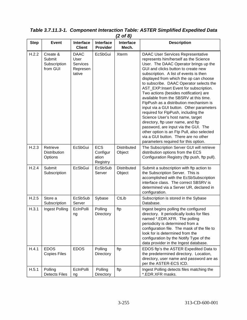
Table 3.7.11.3-1. Component Interaction Table: ASTER Simplified Expedited Data
Step Event Interface Client
Interface Provider
(2 of 8) Interface
Mech. Description
H.2.2 Create & Submit Subscription from GUI
DAAC User Services Represen tative
EcSbGui Xterm DAAC User Services Representative represents him/herself as the Science User. The DAAC Operator brings up the GUI and clicks button to create new subscription. A list of events is then displayed from which the op can choose to subscribe. DAAC Operator selects the AST_EXP:Insert Event for subscription. Two actions (besides notification) are available from the SBSRV at this time. FtpPush as a distribution mechanism is input via a GUI button. Other parameters required for FtpPush, including the Science User’s host name, target directory, ftp user name, and ftp password, are input via the GUI. The other option is an Ftp Pull, also selected via a GUI button. There are no other parameters required for this option.
H.2.3 Retrieve Distribution Options
EcSbGui ECS Configur ation Registry
Distributed Object
The Subscription Server GUI will retrieve distribution options from the ECS Configuration Registry (ftp push, ftp pull).
H.2.4 Submit Subscription
EcSbGui EcSbSub Server
Distributed Object
Submit a subscription with ftp action to the Subscription Server. This is accomplished with the EcSbSubscription interface class. The correct SBSRV is determined via a Server UR, declared in configuration.
H.2.5 Store a Subscription
EcSbSub Server
Sybase CtLib Subscription is stored in the Sybase Database.
H.3.1 Ingest Polling EcInPolli ng
Polling Directory
ftp Ingest begins polling the configured directory. It periodically looks for files named *.EDR.XFR. The polling periodicity is determined from a configuration file. The mask of the file to look for is determined from the configuration by the Notify Type of the data provider in the Ingest database.
H.4.1 EDOS Copies Files
EDOS Polling Directory
ftp EDOS ftp’s the ASTER Expedited Data to the predetermined directory. Location, directory, user name and password are as per the ASTER-ECS ICD.
H.5.1 Polling Detects Files
EcInPolli ng
Polling Directory
ftp Ingest Polling detects files matching the *.EDR.XFR masks.
3-255 313-CD-600-001

Table 3.7.11.3-1. Component Interaction Table: ASTER Simplified Expedited Data
Step Event Interface Client
Interface Provider
(3 of 8) Interface
Mech. Description
H.5.2 Send Request
EcInPolli ng
EcInReq Mgr
Distributed Object
Polling Ingest process copies the .EDR file into the Ingest remote directory and sends a Create Request rpc to the Request Manger. The data source (EDOS), defined on startup, is passed to the Ingest Request Manager.
H.5.3 Granule Process Request
EcInReq Mgr
EcInGran Distributed Object
Ingest Request Manager packages the request into granules and sends them to the Ingest Granule Server.
H.5.4 Connect to SDSRV
EcInGran EcDsSci enceData Server
Distributed Object
Upon detecting an ASTER Expedited data file, Ingest begins a session with the SDSRV by connecting. The correct SDSRV is determined during EcInReqMgr startup, from Advertising, based on the data type.
H.5.5 Request Metadata Configuration File
EcInGran EcDsSci enceData Server
Distributed Object
Ingest requests the metadata configuration file (MCF) for the data being inserted. The data types being inserted are derived from the Ingest Request messages sent by the Polling server.
H.5.6 Validate Metadata
EcInGran EcDsSci enceData Server
Distributed Object
After building a metadata file for the AST_EXP granule, Ingest asks SDSRV to validate the metadata, based on the granule’s data type.
H.5.7 Request Data Insert
EcInGran EcDsSci enceData Server
Distributed Object
Ingest requests that the received files for the AST_EXP are inserted into the Data Server. An Insert request, containing the names of the files comprising the Expedited Data granule, is created. The structure of the Insert Request is hard-coded in the granule server process. SDSRV validates metadata and determines the archived names of the files.
H.5.8 STMGT Store
EcDsScie nceData Server
EcDsStA rchiveSer ver
Distributed Object
SDSRV requests that the Expedited Data is archived. The archive server reads the inserted files directly from the Ingest polling directory. The correct archive object to request is determined by the Archive ID input during ESDT installation.
3-256 313-CD-600-001

Table 3.7.11.3-1. Component Interaction Table: ASTER Simplified Expedited Data
Step Event Interface Client
Interface Provider
(4 of 8) Interface
Mech. Description
H.5.9 Adding a Granule to Inventory
EcDsScie nceData Server
Sybase/S QS
CtLib The validated metadata is parsed and added to the inventory of the SDSRV.
H.6.1 Trigger Event EcDsScie nceData Server
EcSbSub Server
Distributed Object
Upon successful insertion of AST_EXP granule, the AST_EXP:Insert event is triggered. The correct subscription server is determined from SDSRV configuration. The correct events to trigger are determined from the events file, which was populated during ESDT installation. Provided with the event triggering is the UR of the inserted granule.
H.6.2 Retrieve Subscriptions
EcSbSub Server
Sybase CtLib SBSRV queries the Sybase database determining which subscriptions need to be activated, or fired. Each query “hit” is an activated subscription and executes independently.
H.7.1 Send Notification
EcSbSub Server
Email Service
e-mail The SBSRV notifies the Email Service that an AST_EXP granule and associated signal file is available. The UR of the granule is passed in the notification to the user, along with a reference to the subscription that is being fulfilled.
H.7.2 Store the Email notification
EcCsEM ailParser
Email Service
Sendmail script
The ASTER Email Parser Gateway stores the notification as a text file in a configurable directory location using a Sendmail script. A reference to this script is available in the /etc/mail/aliases file.
H.8.1 Parse notification
EcCsEM ailParser
Unix File System
System calls
The ASTER Email Parser Gateway uses the EDN packager functionality to open the notification text file and reads the contents. It then parses the contents and recovers the Granule UR included in the notification.
H.8.2 Connect to SDSRV
EcCsEM ailParser
EcDsSci enceData Server
Distributed Object
The Email Parser Gateway then begins a session with the SDSRV by connecting. The correct SDSRV is determined by using the Server UR embedded in the Granule UR.
H.8.3 Inspect Granule Information
EcCsEM ailParser
EcDsSci enceData Server
Distributed Object
The Email Parser Gateway queries the SDSRV for the metadata related to the granule specified in the notification received from the SBSRV using the inspect interface provided by the SDSRV client library. Using this information the Gateway composes an EDN.
3-257 313-CD-600-001
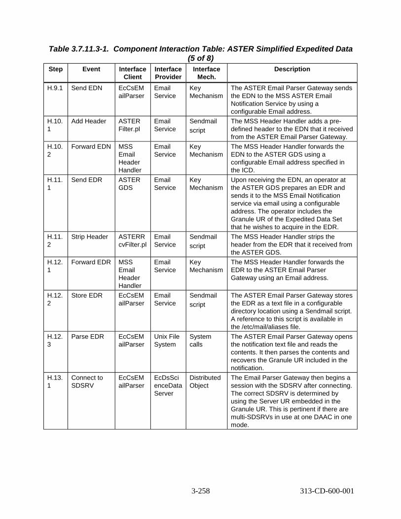
Table 3.7.11.3-1. Component Interaction Table: ASTER Simplified Expedited Data
Step Event Interface Client
Interface Provider
(5 of 8) Interface
Mech. Description
H.9.1 Send EDN EcCsEM ailParser
Email Service
Key Mechanism
The ASTER Email Parser Gateway sends the EDN to the MSS ASTER Email Notification Service by using a configurable Email address.
H.10. 1
Add Header ASTER Filter.pl
Email Service
Sendmail script
The MSS Header Handler adds a pre-defined header to the EDN that it received from the ASTER Email Parser Gateway.
H.10. 2
Forward EDN MSS Email Header Handler
Email Service
Key Mechanism
The MSS Header Handler forwards the EDN to the ASTER GDS using a configurable Email address specified in the ICD.
H.11. 1
Send EDR ASTER GDS
Email Service
Key Mechanism
Upon receiving the EDN, an operator at the ASTER GDS prepares an EDR and sends it to the MSS Email Notification service via email using a configurable address. The operator includes the Granule UR of the Expedited Data Set that he wishes to acquire in the EDR.
H.11. 2
Strip Header ASTERR cvFilter.pl
Email Service
Sendmail script
The MSS Header Handler strips the header from the EDR that it received from the ASTER GDS.
H.12. 1
Forward EDR MSS Email Header Handler
Email Service
Key Mechanism
The MSS Header Handler forwards the EDR to the ASTER Email Parser Gateway using an Email address.
H.12. 2
Store EDR EcCsEM ailParser
Email Service
Sendmail script
The ASTER Email Parser Gateway stores the EDR as a text file in a configurable directory location using a Sendmail script. A reference to this script is available in the /etc/mail/aliases file.
H.12. 3
Parse EDR EcCsEM ailParser
Unix File System
System calls
The ASTER Email Parser Gateway opens the notification text file and reads the contents. It then parses the contents and recovers the Granule UR included in the notification.
H.13. 1
Connect to SDSRV
EcCsEM ailParser
EcDsSci enceData Server
Distributed Object
The Email Parser Gateway then begins a session with the SDSRV after connecting. The correct SDSRV is determined by using the Server UR embedded in the Granule UR. This is pertinent if there are multi-SDSRVs in use at one DAAC in one mode.
3-258 313-CD-600-001

Table 3.7.11.3-1. Component Interaction Table: ASTER Simplified Expedited Data
Step Event Interface Client
Interface Provider
(6 of 8) Interface
Mech. Description
H.13. 2
Acquire EcCsEM ailParser
EcDsSci enceData Server
Distributed Object
The Email Parser submits an Acquire request for the granule. The Acquire request is an FTP Pull of all granules in the ESDT Reference Collection.
H.14. 1
Create Staging Disk
EcDsScie nceData Server
EcDsStSt agingDis kServer
Distributed Object
SDSRV verifies access privileges for the granule and creates a Staging Disk for metadata files, which allocates space and passes back a reference to that disk space. The correct staging disk server is determined from the SDSRV configuration. The amount of staging disk to request is determined by the size of the metadata file.
H.14. 2
Create Metadata file
EcDsScie nceData Server
EcDsSci enceData Server
Distributed Object
For each granule referenced in the Acquire request, the SDSRV creates a file containing the granule’s metadata before passing to Distribution.
H.14. 3
Distribute Granules, Synchronous
EcDsScie nceData Server
EcDsDist ributionS erver
Distributed Object
SDSRV submits a request to Data Distribution. The request includes, for each granule, a reference to the metadata file as well as all data files. Other parameters from the Acquire request are passed to DDIST.
H.14. 4
Create Staging Disk
EcDsDist ributionS erver
EcDsStR equestM anger then to EcDsStSt agingDis kServer
Distributed Object
DDIST creates Staging Disk for the granule files in the archive. This allocates space and passes back a reference to that disk space. The correct staging disk server is determined from the information passed by the SDSRV in the distribution request, which was the SDSRV configuration. The amount of staging disk to request is determined by the size of the metadata file.
3-259 313-CD-600-001

Table 3.7.11.3-1. Component Interaction Table: ASTER Simplified Expedited Data
Step Event Interface Client
Interface Provider
(7 of 8) Interface
Mech. Description
H.14. 5
STMGT Retrieve
EcDsDist ributionS erver
EcDsStR equestM anger then to EcDsStA rchiveSer ver
Distributed Object
DDIST requests that STMGT retrieve the granule file that is archived. STMGT compresses the files in the format specified. This results in the file being staged to read-only cache disks. STMGT informs DDIST of the compressed file sizes. This means that all files needed to fulfill the distribution request are in the read only cache, and ready to be linked. The correct archive object to request is determined from the information provided by the SDSRV in the distribution request. This returns references to the files in the read-only cache.
H.14. 6
Claim Ownership
EcDsDist ributionS erver
EcDsStR equestM anger then to EcDsStSt agingDis kServer
Distributed Object
The Distribution server claims ownership of the staging disk created by SDSRV by inserting appropriate data in the data base table. This is done with the STMGT Request Manager.
H.14. 7
Compress Disk
EcDsDist ributionS erver
EcDsStR equestM anger then to EcDsStSt agingDis kServer
Distributed Object
The Distribution Server asks the Staging Disk Server to compress the staging disk. This is done with the STMGT Request Manager.
H.14. 8
Link files to Staging Disk
EcDsDist ributionS erver
EcDsStSt agingDis kServer
Distributed Object
DDIST links the files from the read-only cache into the staging disk.
H.14. 9
Link files to Staging Disk
EcDsDist ributionS erver
EcDsStSt agingDis kServer
Distributed Object
DDIST links the metadata files from the SDSRV’s Staging Disk into the staging disk.
3-260 313-CD-600-001

Table 3.7.11.3-1. Component Interaction Table: ASTER Simplified Expedited Data
Step Event Interface Client
Interface Provider
(8 of 8) Interface
Mech. Description
H.14. 10
ftpPush Files EcDsDist ributionS erver
EcDsStFt pDisServ er
Distributed Object
DDIST now creates the Resource manager for ftp Pushes via a Resource Manager Factory. The correct resource manager is determined from the Media Type handed to the resource factory (ftpPush, in this case). The correct ftp Server is determined from configuration within the resource factory. The files, host, location, user name and password are all determined from the information provided in the original Acquire request.
H.14. 11
ftp/push data EcDsStFt pDisServ er
Operatin g System ftp daemon
ftp The EcDsStFtpDisServer performs the actual ftp of the files via the Operating System ftp daemon to the ASTER GDS.
3.7.12 ASTER Routine Processing Planning Data Start/Stop Time Thread
Thread Description This thread illustrates how to perform ASTER processing for ACT, BTS, and ETS PGEs.
The following system functionality is exercised in this thread:
• The capability to routinely process ASTER data. Thread Preconditions The PDPS database, the Science Data Server, the Subscription Server, the Production Request Editor, the Job Management Server, AutoSys, and the Planning Workbench must be up and running. Input granules must be available on the Science Data Server. The original Production Request must already be present in the PDPS DB. SSI&T must have set up the ASTER ACT PGE as a data scheduled PGE. The data type of AST_L1B must be set up as non-routine.
3.7.12.1 ASTER Routine Processing Planning Data Start/Stop Time Thread Interaction Diagram
Figure 3.7.12.1-1 depicts the ASTER Routine Processing Planning Data Start/Stop Time Interaction.
3-261 313-CD-600-001

SDSRV DB
PLSPLS
DPSDPS
SBSRV
I.13 Create DPR job for each job
I.4 Initiate ASTER processing I.12 Create & activate plan
DAAC Ops
DAAC Ops
SDSRV
I.7 termine data to be predicted I.9 Prepare granules & generate DPR
PDPS DB
I.14 Place jobs in Autosys
I.6 Read data type granules I.11 Write DPRs
I.5 Submit subscription
I.8 Query for each input data type
I.10 Query for PGE outputs
INS
I.1 ngest ASTER tape
I.2 un script
I.3 Return times
Distributed Object (rpc, CtLib) HMI (GUI, Xterm, command) ftp email (or other as noted) Double line - Synchronous email (or other as noted) Dashed - Asynchronous
De
I
R
Figure 3.7.12.1-1. ASTER Routine Processing Planning Data Start/Stop Time Interaction Diagram
3.7.12.2 ASTER Routine Processing Planning Data Start/Stop Time Interaction Table - Domain View Table 3.7.12.2-1 provides the interaction Domain View: ASTER Routine Processing Planning Data Start/Stop Time.
3-262 313-CD-600-001

Table 3.7.12.2-1. Interaction Table - Domain View:
Step ASTER Routine Processing Planning Data Start/Stop Time (1 of 2) Event Interface
Client Interface Provider
Data Issues Step Preconditions
Description
I.1 Ingest ASTER tape
DAAC Ops -
INS ASTER Level 1 processing is not performed at ECS.
The ASTER PGE must be set up as a data scheduled PGE. The data type AST_L1B must be set up as non-routine.
The tape is provided by the ASTER instrument team.
I.2 Run script DAAC Ops-
SDSRV DB
Data provided by ASTER tape.
Tape must be successfully ingested.
Script queries for time range needed for Production Request.
I.3 Return times
SDSRV DB
DAAC Ops -
Data provided by ASTER tape.
Tape must be successfully ingested.
This start and stop time range is needed by the PLS Production Request Editor.
I.4 Initiate ASTER processing
DAAC Ops -Productio n Planner
PLS The original Production Request must be known and accessible.
The Production Request Editor must be up and running.
Reprocessing is initiated by the Production Planner.
I.5 Submit subscriptio n
PLS SBSRV Input granules must be available.
None Subscriptions must be submitted individually for each data type.
I.6 Read data type granules
PLS PDPS DB
The original Production Request must be present in the DB.
The DB must be up and running.
All the data type granules for the selected input data and time range must be read.
I.7 Determine data to be predicted
PLS PLS The original Production Request must be missing data.
None Data is predicted to substitute for data that is missing from the PDPS DB.
I.8 Query for each input data type
PLS SDSRV None None Each query is based on a time range.
3-263 313-CD-600-001

Table 3.7.12.2-1. Interaction Table - Domain View: ASTER Routine Processing
Step Event Planning Data Start/Stop Time (2 of 2)
Interface Client
Interface Provider
Data Issues
Step Preconditions
Description
I.9 Prepare granules and generate DPR
PLS PLS None DCE must be up and running.
Match each SDSRV granule with a PDPS DB granule and then resume normal processing.
I.10 Query for PGE output
PLS SDSRV None DCE must be up and running.
If these outputs are there, skip generating the current DPR to avoid re-generating output products.
I.11 Write DPR(s)
PLS PDPS DB
None The DB must be up and running.
The DPR(s) is written to the DB normally.
I.12 Create and activate plan
DAAC Ops -Productio n Planner
PLS None The Production Request Editor and the Planning Workbench must be up and running.
The plan is created and activated normally.
I.13 Create a DPR job for each DPR
PLS DPS None DCE must be up and running.
The DPR job for each DPR is created normally.
I.14 Place jobs in AutoSys
DPS DPS None AutoSys must be up and running.
The jobs are placed in AutoSys normally.
3.7.12.3 ASTER Routine Processing Planning Data Start/Stop Time Component Interaction Table Table 3.7.12.3-1 provides the Component Interaction: ASTER Routine Processing Planning Data Start/Stop Time.
Table 3.7.12.3-1. Component Interaction Table:
Step ASTER Routine Processing Planning Data Start/Stop Time (1 of 3)
Event Interface Client
Interface Provider
Interface Mech.
Description
I.1.1 Ingest ASTER tape
DAAC Ops
EcInGUI GUI The tape is provided by the ASTER instrument team.
I.2.1 Run script DAAC Ops
SDSRV DB shell script (currently unnamed)
Script queries for time range needed for Production Request.
I.3.1 Return times
SDSRV DB
DAAC Ops shell script (currently unnamed)
This start and stop time range is needed by the PLS Production Request Editor.
3-264 313-CD-600-001

Table 3.7.12.3-1. Component Interaction Table:
Step ASTER Routine Processing Planning Data Start/Stop Time (2 of 3)
Event Interface Client
Interface Provider
Interface Mech.
Description
I.4.1 Start Production Request Editor
DAAC Ops – Productio n Planner
EcPlPREdit or_IF
GUI The Production Request Editor is started normally.
I.4.2 Initiate request for Production Request to be reprocessed
DAAC Ops – Productio n Planner
EcPlPREdit or_IF
GUI The Production Planner initiates the reprocessing request.
I.4.3 Change PR type
DAAC Ops – Productio n Planner
EcPlPREdit or_IF
GUI The Production Planner changes the PR type from Routine to Reprocessing.
I.4.4 Save Production Request
DAAC Ops – Productio n Planner
EcPlPREdit or_IF
GUI The Production Planner saves the Production Request under a new, unique name.
I.5.1 Submit subscriptio n
EcPlSubM gr
EcSbSubS erver
Distributed Object
The subscriptions are submitted for each data type individually.
I.6.1 Read data type granules
EcPlPREd itor_IF
PDPS DB CtLib All of the data type granules for input data and time range are read.
I.7.1 Determine data to be predicted
EcPlPREd itor_IF
PDPS DB CtLib This determination is based on the data missing in the PDPS DB.
I.8.1 Query for each input data type
EcPlPREd itor_IF
EcDsScien ceDataServ er
CtLib These queries are based on a time range.
I.9.1 Inspect and match granules
EcPlPREd itor_IF
EcPlPREdit or_IF
CtLib Each SDSRV granule is matched with a PDPS DB granule.
I.9.2 Generate DPR(s)
EcPlPREd itor_IF
EcPlPREdit or_IF
CtLib The DPS(s) are generated.
I.10.1 Query for PGE output
EcPlPREd itor_IF
EcDsScien ceDataServ er
Distributed Object
If these outputs are there, skip generating the current DPR to avoid re-generating output products.
I.11.1 Write DPR(s) to DB
EcPlPREd itor_IF
PDPS DB CtLib The DPR(s) are written to the DB.
3-265 313-CD-600-001

Table 3.7.12.3-1. Component Interaction Table:
Step ASTER Routine Processing Planning Data Start/Stop Time (3 of 3)
Event Interface Client
Interface Provider
Interface Mech.
Description
I.12.1 Shut down Production Request Editor
DAAC Ops – Productio n Planner
EcPlPREdit or_IF
GUI The Production Planner shuts down the Production Request Editor.
I.12.2 Start up Planning Workbench
DAAC Ops – Productio n Planner
EcPlWb GUI The Production Planner starts up the Planning Workbench.
I.12.3 Select Production Request and create a plan
DAAC Ops -Productio n Planner
EcPlWb GUI The Production Planner selects a Production Request and creates a plan.
I.12.4 Activate the plan
DAAC Ops -Productio n Planner
EcPlWb GUI The Production Planner activates the plan.
I.13.1 Create a DPR job for each DPR
EcPlWb EcDpPrJob Mgmt
Distributed Object
A DPR job is created for each DPR.
I.14.1 Jobs placed in AutoSys
EcDpPrJo bMgmt
AutoSys rpc (COTS) The job can now be run in AutoSys.
3.7.13 ASTER Routine Processing Planning Insertion Time Thread This thread illustrates how to perform ASTER processing using the tar file insertion time insteadof the usual data start and stop times for ASTER BTS (Brightness Temperature at Sensor) PGEs.Note that this option is not available for ASTER ACT (Atmospheric Correction – TIR) and ETS(Emissivity/Temperature Separation) PGEs.The following system functionality is exercised in this scenario:
• The capability to routinely process ASTER data using the time that the tar file was inserted.
Thread Preconditions The PDPS database, the Science Data Server, the Subscription Server, the Production Request Editor, the Job Management Server, AutoSys, and the Planning Workbench must be up and running. Input granules must be available on the Science Data Server. The original Production Request must already be present in the PDPS DB. SSI&T must have set up the ASTER ACT PGE as a data scheduled PGE – see the ASTER Routine Processing Planning Data Start/Stop Time Thread. The data type of AST_L1BT must be set up as non-routine.
3-266 313-CD-600-001

3.7.13.1 ASTER Routine Processing Planning Insertion Time Thread Interaction Diagram – Domain View Figure 3.7.13.1-1 depicts the ASTER Routine Processing Planning Insertion Time Thread Interaction.
PLSPLS
DPSDPS
SBSRV
J.10 Create DPR job for each job
J.2 nitiate ASTER processing J.9 Create & activate plan
DAAC Ops
DAAC Ops
SDSRV
J.7 Prepare granules & generate DPR
PDPS DB
J.11 Place jobs in Autosys
J.4 ead data type granules J.5 etermine gaps for queryJ.8 rite DPRs INS
J.1 Ingest ASTER tape
J.3 ubmit subscription
J.6 Query for each input data type (using insertion time)
Distributed Object (rpc, CtLib) HMI (GUI, Xterm, command) ftp email (or other as noted) Double line - Synchronous email (or other as noted) Dashed - Asynchronous
I
RDW
S
Figure 3.7.13.1-1. Routine Processing Planning Insertion Time Thread Interaction Diagram
3.7.13.2 Routine Processing Planning Insertion Time Interaction Table - Domain View
Table 3.7.13.2-1 provides the Interaction – Domain View: Routine Processing Planning Insertion Time Interaction.
3-267 313-CD-600-001

Table 3.7.13.2-1. Interaction Table - Domain View: ASTER Routine Processing
Step Interaction Planning Insertion Time (1 of 2)
Interface Client
Interface Provider
Data Issues Preconditions Description
J.1 Ingest ASTER tape
DAAC Ops -
Ingest ASTER Level 1 processing is not performed at ECS.
The ASTER PGE must be set up as a data scheduled PGE. The data type AST_L1BT must be set up as non-routine.
Tape is provided by the ASTER instrument team.
J.2 Initialize ASTER processing
DAAC Ops -Productio n Planner
PLS The original Production Request must be known and accessible.
The Production Request Editor must be up and running.
Ad hoc reprocessing is initiated by the Production Planner using tar file insertion time.
J.3 Submit subscriptio n
PLS SBSRV Input granules must be available.
None Subscriptions must be submitted individually for each data type.
J.4 Read data type granules
PLS PDPS DB
The original Production Request must be present in the DB.
The DB must be up and running.
All the data type granules for the selected input data and time range must be read.
J.5 Determine gaps for query
PLS PDPS DB
None None The Production Request Editor determines the time ranges for upcoming SDSRV query.
J.6 Query for each input data type
PLS SDSRV None None Each query is based on a time range and uses a tar file insertion time.
J.7 Prepare granules and generate DPR
PLS PLS None DCE must be up and running.
Match each SDSRV granule with a PDPS DB granule and then resume normal processing.
J.8 Write DPR(s)
PLS PDPS DB
None The DB must be up and running.
The DPR(s) is written to the DB normally.
J.9 Create and activate plan
DAAC Ops -Productio n Planner
PLS None The Production Request Editor and the Planning Workbench must be up and running.
The plan is created and activated normally.
3-268 313-CD-600-001

Table 3.7.13.2-1. Interaction Table - Domain View: ASTER Routine Processing
Step Interaction Planning Insertion Time (2 of 2)
Interface Client
Interface Provider
Data Issues Preconditions Description
J.10 Create a DPR job for each DPR
PLS DPS None DCE must be up and running.
The DPR job for each DPR is created normally.
J.11 Place jobs in AutoSys
DPS None AutoSys must be up and running.
The jobs are placed in AutoSys normally.
3.7.13.3 Routine Processing Planning Insertion Time Thread ComponentInteraction Table
Table 3.7.13.3-1 provides the Component Interaction: Routine Processing Planning Insertion Time Thread.
Table 3.7.13.3-1. Component Interaction Table: ASTER Routine Processing
Step Event Planning Insertion Time (1 of 2)
Interface Client
Interface Provider
Interface Mech.
Description
J.1.1 Ingest ASTER tape
DAAC Ops EcInGUI GUI Tape is provided by the ASTER instrument team.
J.2.1 Start Production Request Editor
DAAC Ops -Production Planner
EcPlPREd itor_IF
GUI The Production Request Editor is started normally.
J.2.2 Initiate request for Production Request to be reprocessed
DAAC Ops -Production Planner
EcPlPREd itor_IF
GUI The Production Planner initiates the reprocessing request.
J.2.3 Change PR type
DAAC Ops -Production Planner
EcPlPREd itor_IF
GUI The Production Planner changes the PR type from Routine to Reprocessing.
J.2.4 Save Production Request
DAAC Ops -Production Planner
EcPlPREd itor_IF
GUI The Production Planner saves the Production Request under a new, unique name.
J.3.1 Submit subscription
EcPlSubM gr
EcSbSub Server
Distribute d Object
The subscriptions are submitted for each data type individually.
J.4.1 Read data type granules
EcPlPREdi tor_IF
PDPS DB CtLib All of the data type granules for input data and time range are read.
3-269 313-CD-600-001

Table 3.7.13.3-1. Component Interaction Table: ASTER Routine Processing
Step Event Planning Insertion Time (2 of 2)
Interface Client
Interface Provider
Interfac e Mech.
Description
J.5.1 Determine gaps for query
EcPlPRE ditor_IF
PDPS DB
CtLib Determine time ranges for upcoming SDSRV query.
J.6.1 Query for each input data type
EcPlPRE ditor_IF
EcDsSci enceData Server
CtLib These queries are based on a time range.
J.7.1 Inspect and match granules
EcPlPRE ditor_IF
EcPlPRE ditor_IF
CtLib Each SDSRV granule is matched with a PDPS DB granule.
J.7.2 Generate DPR(s)
EcPlPRE ditor_IF
EcPlPRE ditor_IF
CtLib The DPS(s) are generated.
J.8.1 Write DPR(s) to DB
EcPlPRE ditor_IF
PDPS DB
CtLib The DPR(s) are written to the DB.
J.9.1 Shut down Production Request Editor
DAAC Ops -Productio n Planner
EcPlPRE ditor_IF
GUI The Production Planner shuts down the Production Request Editor.
J.9.2 Start up Planning Workbench
DAAC Ops -Productio n Planner
EcPlWb GUI The Production Planner starts up the Planning Workbench.
J.9.3 Select Production Request and create a plan
DAAC Ops -Productio n Planner
EcPlWb GUI The Production Planner selects a Production Request and creates a plan.
J.9.4 Activate the plan
DAAC Ops -Productio n Planner
EcPlWb GUI The Production Planner activates the plan.
J.10.1 Create a DPR job for each DPR
EcPlWb EcDpPrJ obMgmt
Distribut ed Object
A DPR job is created for each DPR.
J.11.1 Jobs placed in AutoSys
EcDpPrJ obMgmt
AutoSys rpc (COTS)
The job can now be run in AutoSys.
3.7.14 ASTER Spatial Query Thread
Thread Description This thread illustrates how to perform ASTER processing for a predefined geographic area. This area can be expanded (padded) by a predefined number of kilometers. Currently, this capability is being utilized for ACT (Atmospheric Correction – TIR) and ACVS (Atmospheric Correction – VNIR, SWIR) PGEs. The set of points describing the polygon which represent the geographic area along with the number of kilometers of the “pad” are defined in the key input granules. If the “pad” is not required, the kilometer value of the “pad” is set to zero.
3-270 313-CD-600-001

The following system functionality is exercised in this thread:
• The capability to routinely process ASTER data for an existing or for an expanded (or padded), predefined geographic area.
Thread Preconditions The PDPS database, the Science Data Server, the Subscription Server, the Production Request Editor, the Subscription Manager, the Job Management Server, AutoSys, and the Planning Workbench must be up and running. Input granules must be available on the Science Data Server. The data type has been defined as spatial pad during the SSIT process. The size of the pad in kilometers is controlled by the instrument team. Conceptually, however, the size of the pad should probably be less than that of the instrument’s photograph, so it can be thought of as a way to obtain portions of the neighboring photographs which border on the original (or central) photograph.
Note: Due to limitations in the current version of the SQS COTS package, the spatial region defined (i.e., the original size of the polygon combined with the size of the pad) must not exceed 60 degrees in latitude or longitude. Since this is a huge area, this limitation should not impact the user.
3.7.14.1 ASTER Spatial Query Thread Interaction Diagram Figure 3.7.14.1-1 depicts the ASTER Spatial Query Interaction.
PLSPLS
DPS DPS
SDSRV
K.10 Create DPR job for each job
K.1 nter Production Request K.9 Create & activate l
DAAC Ops
DAAC Ops
K.3 uery for each key input data type K.6 Query for each target data type
K.2 Prepare for query K.4 Extract polygon info from granules K.5 dd poylgon expan info to query K.7 Prepare granules & generate DPR
PDPS DB
K.8 Write DPR
Distributed Object (rpc, CtLib) HMI (GUI, Xterm, command) ftp email (or other as noted) Double line - Synchronous email (or other as noted) Dashed - Asynchronous
E
Q
A
K.11 Place jobs in Autosys
Figure 3.7.14.1-1. ASTER Spatial Query Interaction Diagram
3-271 313-CD-600-001

3.7.14.2 ASTER Spatial Interaction Table - Domain View Table 3.7.14.2-1 provides the interaction Domain View: ASTER Spatial Query.
Table 3.7.14.2-1. Interaction Table - Domain View: ASTER Spatial Query (1 of 2) Step Event Interface
Client Interface Provider
Data Issues Step Preconditions
Description
K.1 Enter Production Request
DAAC Ops -Productio n Planner
PLS Input data must already be available on the Science Data Server.
None A spatial query is initiated by the Production Planner.
K.2 Prepare for query
PLS PLS The constraints are based on time information
None The query is prepared using the time range.
K.3 Query for each key input data type
PLS SDSRV None None Each query is based on a time range.
K.4 Extract polygon information from granules
PLS PLS Extracts information from GlParameterLi st
None This pulls information from GlParameterList.
K.5 Add polygon expansion information to query
PLS PLS A spatial pad data type was selected.
SSIT was performed for a spatial pad data type.
The query was padded by the number of kilometers.
K.6 Query for each target data type
PLS SDSRV None None Uses spatial information extracted in the previous step.
K.7 Prepare granules and generate DPR
PLS PLS None None Prepare the granules using the data returned from the SDSRV.
K.8 Write DPR(s)
PLS PDPS DB
None None The DPR(s) are written to the PDPS DB.
K.9 Create and activate plan
DAAC Ops – Productio n Planner
PLS None None The plan is created and activated normally.
3-272 313-CD-600-001

Table 3.7.14.2-1. Interaction Table - Domain View: ASTER Spatial Query (2 of 2) Step Event Interface
Client Interface Provider
Data Issues Step Preconditions
Description
K.10 Create DPR job for each DPR
PLS DPS None None The DPR job for each DPR is created normally.
K.11 Place jobs in AutoSys
DPS DPS None None The jobs are placed in AutoSys normally.
3.7.14.3 ASTER Spatial Query Component Interaction Table Table 3.7.14.3-1 provides the Component Interaction: ASTER Spatial Query.
Table 3.7.14.3-1. Component Interaction Table: ASTER Spatial Query (1 of 2) Step Event Interface
Client Interface Provider
Interface Mech.
Description
K.1.1 Start Production Request Editor
DAAC Ops – Productio n Planner
EcPlPREdit or_IF
GUI The Production Request Editor is started normally.
K.1.2 Initiate request for PR to be processed
DAAC Ops – Productio n Planner
EcPlPREdit or_IF
GUI The Production Planner initiates the processing request.
K.1.3 Save PR DAAC Ops – Productio n Planner
EcPlPREdit or_IF
GUI The Production Planner saves the PR under a new, unique name.
K.2.1 Prepare for query
EcPlPREd itor_IF
EcPlPREdit or_IF
GUI Use the time range as constraints.
K.3.1 Query for each key input data type
EcPlPREd itor_IF
EcSbSubS erver
Distributed Object
Each query is based on a time range.
K.4.1 Extract polygon information from granules
EcPlPREd itor_IF
EcPlPREdit or_IF
libGl This pulls information from the GlParameterList.
K.5.1 Add polygon expansion information to query
EcPlPREd itor_IF
EcPlPREdit or_IF
CtLib The query is padded by the designated number of kilometers.
K.6.1 Query for each target data type
EcPlPREd itor_IF
EcSbSubS erver
Distributed Object
A query is needed for each target data type.
3-273 313-CD-600-001

Table 3.7.14.3-1. Component Interaction Table: ASTER Spatial Query (2 of 2) Step Event Interface
Client Interface Provider
Interface Mech.
Description
K.7.1 Inspect granules
EcPlPREd itor_IF
PDPS DB CtLib Each SDSRV granule is stored in the PDPS DB.
K.7.2 Generate DPR(s)
EcPlPREd itor_IF
EcPlPREdit or_IF
CtLib The DPR(s) are generated.
K.8.1 Write DPR(s) to DB
EcPlPREd itor_IF
PDPS DB CtLib The DPR(s) are written to the PDPS DB.
K.9.1 Shut down Production Request Editor
DAAC Ops – Productio n Planner
EcPlPREdit or_IF
GUI The Production Planner shuts down the Production Request Editor.
K.9.2 Start up the Planning Workbench
DAAC Ops – Productio n Planner
EcPlWb GUI The Production Planner starts up the Planning Workbench.
K.9.3 Select the PR(s) and create a plan
DAAC Ops – Productio n Planner
EcPlWb GUI The Production Planner selects a Production Request and creates a plan.
K.9.4 Activate the plan
DAAC Ops – Productio n Planner
EcPlWb GUI The Production Planner activates the plan.
K.10.1 Create a DPR job for each DPR
EcPlSubM gr
EcDpPrJob Mgmt
Distributed Object
A DPR job is created for each DPR.
K.11.1 Jobs placed in AutoSys
EcDpPrJo bMgmt
AutoSys rpc (COTS) The job can now be run in AutoSys.
3.7.15 ASTER View ECS Data Holdings Thread
This thread shows how an ASTER GDS user can obtain information about the location and other attributes of specified data sets, and browse specified data sets.
3.7.15.1 ASTER View ECS Data Holdings Thread Interaction Diagram – Domain View Figure 3.7.15.1-1 depicts the ASTER View ECS Data Holdings Interaction.
3-274 313-CD-600-001

Distributed Object (rpc, CtLib) HMI (GUI, Xterm, command) ftp email (or other as noted) Double line - Synchronous email (or other as noted) Dashed - Asynchronous
ASTER Client (GDS)
DDICT
L.2 Directory Search Request L.6 Inventory Search Request Mapping L.12 Inventory Search Results Mapping
L.3 Directory Search Result L.7 Inventory Search Request Mapping L.13 Inventory Search Result Mapping
ASTGW
L.11 Inventory Search Result L.19 Browse Result
L.8 Inventory Search Request L.16 Browse Request
DSS
L.9 Inventory Search L.17 Browse Request
L.10 Inventory Search Result L.18 Browse Result
Remote DAAC
SMC
(DMS)
L.4 Directory Search Result L.14 Inventory Search Result L.20 Browse Result (socket level interface)
V0GWY L.1 Directory Search Request L.5 Inventory Search Request L.15 Browse Request (socket level interface)
Figure 3.7.15.1-1. ASTER View ECS Data Holdings Interaction Diagram
3.7.15.2 ASTER View ECS Data Holdings Thread Interaction Table – Domain View
Table 3.7.15.2-1 provides the interaction Domain View: ASTER View ECS Data Holdings.
3-275 313-CD-600-001

Table 3.7.15.2-1. Interaction Table - Domain View: ASTER View ECS Data
Step Event Interface Client
Holdings (1 of 2) Interface Provider
Data issues
Step Precon ditions
Description
L.1 Directory Search Request
ASTER Client (GDS)
ASTGW None None ASTER client submits the ASTER user’s Directory search request to ASTER-ECS gateway via a specific socket.
L.2 Directory Search Request
ASTGW DDICT None None The ASTGW queries the DDICT, using the parameters specified in the request ODL, for the Directory Search Results.
L.3 Directory Search Result
DDICT ASTGW None None DDICT sends results to ASTGW.
L.4 Directory Search Result
ASTGW ASTER Client (GDS)
None None ASTGW sends back the Directory Search Results to ASTER Client which displays them to the ASTER user.
L.5 Inventory Search Request
ASTER Client (GDS)
ASTGW None None ASTER client submits the ASTER user’s Inventory Search Request to ASTER-ECS gateway in ASTER ODL format via a specific socket.
L.6 Inventory Search Request Mapping
ASTGW DDICT None None ASTGW queries DDICT for the equivalent ECS mappings for the ASTER attributes/values specified in the request.
L.7 Inventory Search Request Mapping
DDICT ASTGW None None DDICT returns ECS equivalents of the specified ASTER attributes/values to ASTGW.
L.8 Inventory Search Request
ASTGW V0GWY None None The ASTGW submits the request to the remote V0-ECS Gateway.
L.9 Inventory Search Result
V0GWY DSS None None The V0 gateway translates the Search criteria from ODL to a query object (using GIParameters), and submits that query to the Search service.
L.10 Inventory Search Results Mapping
DSS DDICT None None The results of this Search are processed synchronously, and passed back to V0-ECS Gateway.
L.11 Inventory Search Result
V0GWY ASTGW None None V0-ECS Gateway returns the results to ASTGW in V0 ODL form.
3-276 313-CD-600-001

Table 3.7.15.2-1. Interaction Table - Domain View: ASTER View ECS Data
Step Event Interface Client
Holdings (2 of 2) Interface Provider
Data issues
Step Precon ditions
Description
L.12 Inventory Search Results Mapping
ASTGW DDICT None None ASTGW queries DDICT for the equivalent ASTER attributes/values for V0 attributes/values it received from the remote V0-ECS Gateway.
L.13 Inventory Search Results Mapping
DDICT ASTGW None None DDICT returns the ASTER equivalents of the V0 attributes/values to ASTGW.
L.14 Inventory Search Result
ASTGW ASTER Client (GDS)
None None The ASTGW sends back the results to ASTER Client, which displays them to the ASTER User.
L.15 Browse Request
ASTER Client (GDS)
ASTGW None None ASTER Client submits Integrated Browse Request to the ASTGW via specific socket interface.
L.16 Acquire Browse
ASTGW V0GWY None None The ASTGW sends the Browse request to remote V0-ECS Gateway.
L.17 Browse Request
V0GWY SDSRV (DSS)
None None V0-ECS Gateway submits an Browse request for the browse granule.
L.18 Browse Result
SDSRV (DSS)
V0GWY None None The results of this Browse request are returned synchronously, and are passed back to V0-ECS Gateway.
L.19 Browse Result
V0GWY ASTGW None None V0-ECS Gateway sends the Browse results to the ASTGW.
L.20 Browse Result
ASTGW ASTER Client (GDS)
None None The ASTGW sends the results to ASTER Client.
3-277 313-CD-600-001

3.7.15.3 ASTER View ECS Data Holdings Thread Component Interaction Table
Table 3.7.15.3-1 provides the Component Interaction: ASTER View ECS Data Holdings.
Table 3.7.15.3-1. Component Interaction Table: ASTER View ECS Data Holdings
Step Event Interface Client
(1 of 6) Interface Provider
Interface Mechanism
Description
L.1.1 Submit a Directory Search
ASTER User ASTER Client Command The ASTER user invokes an ASTER client at the ASTER GDS and sends a directory search request to the ASTER Gateway.
L.1.2 Receive a Directory Search Request
ASTER Client EcDmAsterTo EcsGateway
ODL, over sockets
The ASTGW receives the request on a specific port and socket on which it is listening. The request is an ODL structure.
L.1.3 User Profile EcDmAsterTo EcsGateway
EcMsAcRegU serSrvr
Distributed Object
Upon receiving the request, ASTGW retrieves the User Profile using the ECS authenticator from ODL message. The User Registration database is replicated across DAACs, so connection is made to the local User Registration Server.
L.2.1 Connect to DDICT
EcDmAsterTo EcsGateway
Sybase CtLib ASTGW connects to DDICT database to run a SQL, based on the criteria in the request ODL.
L.2.2 Run Query against DDICT
EcDmAsterTo EcsGateway
Sybase CtLib The SQL query is run against the DDICT database which returns the metadata of all the granules that satisfies the search criteria.
L.3.1 Retrieve results
Sybase EcDmAsterTo EcsGateway
Distributes Object
ASTGW retrieves the results of the database query and puts them in an ODL structure to be sent to the ASTER client.
L.3.2 Create ODL EcDmAsterTo EcsGateway
EcDmAsterTo EcsGateway
internal ASTGW formats granule metadata into an ODL structure.
L.4.1 Send Results EcDmEcsToA sterGateway
ASTER Client ODL, Over Sockets
The results in ODL, are sent to the ASTER client via the same socket on which it originally received the request.
3-278 313-CD-600-001

Table 3.7.15.3-1. Component Interaction Table: ASTER View ECS Data Holdings
Step Event Interface Client
(2 of 6) Interface Provider
Interface Mechanism
Description
L.5.1 Submit an Inventory Search Request
ASTER GDS ASTGW ODL, Over Sockets
The ASTER user invokes an ASTER client and sends an Inventory Search Request.
L.5.2 Receive an Inventory Search Request
ASTER Client EcDmAsterTo EcsGateway
Distributed Object
The ASTGW receives the request on a specific port and socket on which it is listening. The request is an ODL structure.
L.5.3 Convert to internal format
EcDmAsterTo EcsGateway
EcDmAsterTo EcsGateway
internal The ASTGW converts the ODL structure to a GlParameterList.
L.6.1 Formulate attribute list EcDmAsterTo
EcsGateway
EcDmAsterTo EcsGateway
internal The ASTGW formulates an attribute list to be converted to ECS format.
L.6.2 Submit Inventory Search Mapping Request
EcDmAsterTo EcsGateway
Sybase CtLib The ASTGW submits a query for equivalent attributes to the DDICT.
L.7.1 Retrieve equivalent attributes
Sybase EcDmAsterTo EcsGateway
CtLib The ASTGW retrieves the equivalent attribute results from the DDICT.
L.7.2 Submit data server request
EcDmAsterTo EcsGateway
Sybase CtLib The ASTGW submits a query to determine which ECS servers archive the requested data.
L.7.3 Retrieve data server results
Sybase EcDmAsterTo EcsGateway
CtLib The ASTGW retrieves the data server results from the DDICT.
L.8.1 Arrange requests by server
EcDmAsterTo EcsGateway
EcDmAsterTo EcsGateway
internal The ASTGW arranges request according to the server which can handle them.
L.8.2 Convert requests to ODL
EcDmAsterTo EcsGateway
EcDmAsterTo EcsGateway
internal The ASTGW converts requests for each server to V0 ODL.
L.8.3 Submit requests to servers
EcDmAsterTo EcsGateway
EcDmV0ToEc sGateway
ODL, Over Sockets
The ASTGW concurrently sends the request ODL to the V0 Gateway at each server required to handle a request.
3-279 313-CD-600-001

Table 3.7.15.3-1. Component Interaction Table: ASTER View ECS Data Holdings (3 of 6)
Step Event Interface Client
Interface Provider
Interface Mechanism
Description
L.9.1 Establish ECS User
EcDmV0ToE csGateway
EcMsAcReg UserSrvr
Distributed Object
V0 Gateway retrieves the User Profile using ECS Authenticator from ODL message, which includes an encrypted User ID and Password. The User Registration database is replicated across DAACs, so the connection is made to the local User Registration Server.
L.9.2 Translate Query
EcDmV0ToE csGateway
EcDmDictSer ver
CtLib V0 Gateway translates the V0 terms from ODL into ECS names for query submittal using the DDICT database. Interface currently is directly to Data Dictionary database. Database name is retrieved from configuration file.
L.9.3 Connect to SDSRV
EcDmV0ToE csGateway
EcDsScience DataServer
Distributed Object
The Gateway first connects to the SDSRV. The correct SDSRV is determined by configuration file.
L.9.4 SDSRV Query
EcDmV0ToE csGateway
EcDsScience DataServer
Distributed Object
The Gateway translates the query into a DsClQuery object. This object is handed to the Search interface of the DsCl ESDT ReferenceCollector. After the search the Gateway receives a list of URs. hen it does an “Inspect” to the SDSRV to get the metadata. It first performs a GetQueryableParamerter to determine all attributes associated with each granule.
L.10.1 Request Metadata
EcDsScience DataServer
Sybase/SQS CtLib The SDSRV breaks down the Query object and translates it into a sequence of calls to the inventory database. Resultant rows are converted into data granules, each with their metadata extracted from the database. hese results are packaged and returned to the Query client.
T
T
3-280 313-CD-600-001

Table 3.7.15.3-1. Component Interaction Table: ASTER View ECS Data Holdings
Step Event Interface Client
(4 of 6) Interface Provider
Interface Mechanism
Description
L.10.2 Return Results
EcDsScience DataServer
EcDmV0ToE csGateway
Distributed Object
The Search method is synchronous, so the results of the search are returned to the calling function. After the search the Gateway receives a list of URs. Then it does an “Inspect” to the SDSRV to get the metadata.
L.11.1 Retrieve Result s
EcDmV0ToE csGateway
EcDmAsterT oEcsGatewa y
ODL, over Sockets
When the V0 Gateway gets the results, they are translated into ODL, and passed back to the ASTGW. The correct socket for sending results to ASTGW is the one used to submit the query.
L.11.2 Combine Results
EcDmAsterTo EcsGateway
EcDmV0ToEc sGateway
internal The individual result sets from each DAAC are combined into a single result set.
L.11.3 Formulate attribute list
EcDmAsterTo EcsGateway
EcDmAsterTo EcsGateway
internal The ASTGW formulates an attribute list to be converted to ASTER format.
L.12.1 Submit Inventory Search Mapping Request
EcDmAsterTo EcsGateway
Sybase CtLib The ASTGW submits a query for equivalent attributes to the DDICT.
L.12.2 Retrieve equivalent attributes
Sybase EcDmAsterTo EcsGateway
CtLib The ASTGW retrieves the equivalent attribute results from the DDICT.
L.13.1 Retrieve data server results
Sybase EcDmAsterTo EcsGateway
CtLib The ASTGW retrieves the data server results from the DDICT.
L.14.1 Translate Inventory Search Result
EcDmEcsToA sterGateway
ASTER GDS ODL, over Sockets
When the Gateway gets the results from each DAAC, they are translated into ASTER ODL.
L.14.2 Return Results
EcDmEcsToA sterGateway
ASTER GDS ODL, over Sockets
The combined results set is returned in chunks to the ASTER GDS.
L.15.1 Submit an Browse Request
ASTER GDS EcDmAsterTo EcsGateway
Command The ASTER user invokes an ASTER client and sends a Browse Request.
L.15.2 Receive Browse Request
ASTER Client EcDmAsterTo EcsGateway
ODL, Over Sockets
The ASTGW receives the request on a specific port and socket on which it is listening. The request is an ODL structure.
3-281 313-CD-600-001

Table 3.7.15.3-1. Component Interaction Table: ASTER View ECS Data Holdings
Step Event Interface Client
(5 of 6) Interface Provider
Interface Mechanism
Description
L.15.3 Convert to internal format
EcDmAsterTo EcsGateway
EcDmAsterTo EcsGateway
internal The ASTGW converts the ODL structure to a GlParameterList.
L.16.1 Arrange requests by server
EcDmAsterTo EcsGateway
EcDmAsterTo EcsGateway
intenal The ASTGW arranges request according to the server which can handle them.
L.16.2 Convert requests to ODL
EcDmAsterTo EcsGateway
EcDmAsterTo EcsGateway
internal The ASTGW converts requests for each server to V0 ODL.
L.16.3 Submit requests to servers
EcDmAsterTo EcsGateway
EcDmV0ToEc sGateway
ODL, Over Sockets
The ASTGW concurrently sends the request ODL to the V0 Gateway at each server required to handle a request.
L.17.1 Establish ECS User
EcDmV0ToE csGateway
EcDsScience DataServer
Distributed Object
V0GWY submits an Acquire request for the browse granule.
L.17.2 Translate Query
EcDmV0ToE csGateway
EcDmDictSer ver
CtLib Gateway translates the V0 terms from ODL into ECS names for query submittal using the DDICT database. Interface currently is directly to Data Dictionary database. Database name is retrieved from configuration file.
L.17.3 Connect to SDSRV
EcDmV0ToE csGateway
EcDsScience DataServer
Distributed Object
The Gateway first connects to the SDSRV. The correct SDSRV is determined by configuration file.
L.17.4 SDSRV Query
EcDmV0ToE csGateway
EcDsScience DataServer
Distributed Object
The Gateway translates the query into a DsClQuery object. This object is handed to the Search interface of the DsCl ESDT ReferenceCollector. After the search the Gateway receives a list of URs. Then it does an “Inspect” to the SDSRV to get the metadata. It first performs a GetQueryableParamerter to determine all attributes associated with each granule.
L.18.1 Request Metadata
EcDsScience DataServer
Sybase/SQS CtLib The SDSRV retrieves browse image. This result is packaged and returned to the Query client.
3-282 313-CD-600-001

Table 3.7.15.3-1. Component Interaction Table: ASTER View ECS Data Holdings (6 of 6)
Step Event Interface Client
Interface Provider
Interface Mechanism
Description
L18.2 Return Results
EcDsScience DataServer
EcDmV0ToE csGateway
Distributed Object
The Search method is synchronous, so the resulting browse image is returned to the calling function.
L.19.1 Retrieve Result s
EcDmV0ToE csGateway
EcDmEcsTo AsterGatewa y
ODL, over Sockets
When the Gateway gets the results, they are translated into ODL, and passed back to the ASTGW in chunks. The correct socket for sending results to ASTGW is the one used to submit the query.
L.20.1 Return Results
EcDmEcsToA sterGateway
ASTER GDS ODL, over Sockets
The combined results set is returned in chunks to the Aster GDS.
3.7.16 ASTER Price & Order Data Thread
This thread shows how an ASTER GDS user can obtain a price estimate for ECS products, place an order for ECS products stored at any DAAC and obtain the status of a previously placed order.
3.7.16.1 ASTER Price & Order Data Thread Interaction Diagram – Domain View Figure 3.7.16.1-1 depicts the ASTER Price & Order Data Interaction.
3-283 313-CD-600-001

3-284 313-CD-600-001
Figure 3.7.16.1-1. ASTER Price & Order Data Interaction Diagram
3.7.16.2 ASTER Price & Order Data Thread Interaction Table – Domain View
Table 3.7.16.2-1 provides the Domain View: ASTER Price & Order Data.
Remote Site
M.6 Create OrderM.20 Get Product Status
M.11 Create Order
M.9 Product Request
V0GWY(V0-ECS)
MSS
MSS
M.13 Maintain Order Status
M.3 Price Est ResultM.21 Product Status Result(socket level interface)
DAACOps
M.15 CreateData Tape
ASTERClient (GDS)
AsterUser
ASTGW(GDS-ECS)
DSS
M.2 Price Estimate ReqM.5 Product RequestM.19 Product Status Req(socket level interface)
Distributed Object (rpc, CtLib)HMI (GUI, Xterm, command)ftpemail (or other as noted)Double line - Synchronousemail (or other as noted)Dashed - Asynchronous
DORRAN
M.17 Ship Tapeto User
(via DAAC shipper)
M.16 DistributionNotice (8mm shipped)
M.1 Price Estimate ReqM.4 Product RequestM.18 Product Status Req
M.12 Acquire (8mm)
M.7 Product Request (Non L7)
M.10 Product Request (L7 B&A)
SMC
M.14 Update Order Status
M.8 Product Request (L7 B&A)
(L7 B&A)

Table 3.7.16.2-1. Interaction Table - Domain View: ASTER Price & Order Data
Step Event Interface Client
Interface Provider
(1 of 2) Data
issues Step
Precondi tions
Description
M.1 Price Estimate Request
Aster User
ASTER Client (GDS)
None None Aster User decides to request a Price Estimate and invokes ASTER Client at the GDS to send a Price Estimate Request.
M.2 Price Estimate Request
ASTER Client (GDS)
ASTGW None None ASTER Client submits the Aster user’s Price Estimate Request to the GDS-ECS gateway in GDS ODL format via a specific socket.
M.3 Price Estimate Result
ASTGW ASTER Client (GDS)
None None The ASTGW sends back the Price Estimate result to GDS.
M.4 Product Request
Aster User
ASTER Client (GDS)
None None Aster User decides to request a Product Request and invokes ASTER Client to send a Product Request.
M.5 Product Request
ASTER Client (GDS)
ASTGW None None ASTER Client submits the Aster user’s Product Request to GDS-ECS gateway in GDS ODL format via a INITIATOR_REQUEST_ID and specific socket.
M.6 Create Order ASTGW MSS (SMC)
None None The ASTGW requests MSS on the SMC to Create Order and stores INITIATOR-REQUEST_ID in MSS order tracking database.
M.7 Product Request
ASTGW V0GWY (Remote )
None None The ASTGW sends the product request for the granule stored at the remote DAAC to the V0GWY, via orderID:requestID ODL form.
M.8 Product Request
ASTGW V0GWY None None The ASTGW sends the Product Request for Landsat 7 products to the V0-ECS Gateway.
M. 9 Product Request
V0GWY DORRAN None None The V0-ECS Gateway sends the Product Request to the DORRAN Billing and Accounting System.
3-285 313-CD-600-001

Table 3.7.16.2-1. Interaction Table - Domain View: ASTER Price & Order Data
Step Event Interface Client
Interface Provider
(2 of 2) Data
issues Step
Precondi tions
Description
M.10 Product Request
DORRAN V0GWY (Remote)
None None The DORRAN approves and sends the Product Request to the V0-ECS Gateway at a Remote Site.
M.11 Create Order V0GWY MSS (Remote)
None None The V0-ECS Gateway sends a Create Order to the MSS in the tracking database.
M.12 Acquire V0GWY DSS (Remote)
None None The V0-ECS gateway translates the order into an Acquire request.
M.13 Maintain Order Status
DSS (Remote)
MSS (Remote)
None None DSS updates the order status in the order tracking database.
M.14 Update Order Status
MSS (Remote)
MSS (SMC)
None None MSS updates the order status in the order tracking replicate database.
M.15 Create Data Tape
DSS (Remote)
DAAC Ops (Remote)
None None The Data Server copies the file to an 8mm tape and marks the order as “Ready to Ship”.
M.16 Distribution Notice
DSS (Remote)
Aster User
None None Send email notification to Aster User.
M.17 Ship Tape to User
DAAC Ops (Remote)
Aster User
None None DAAC shipper collects the tape and the packing list, and generates a media shipping label for delivery to the Aster User.
M.18 Product Status Request
Aster User
ASTER Client (GDS)
None None Aster User decides to request a Product Request Status and invokes ASTER Client to send a Product Request Status.
M.19 Product Status Request
ASTER Client (GDS)
ASTGW None None The ASTER Client submits the Aster user’s Product Status Request to the GDS-ECS Gateway in GDS ODL format via an INITIATOR_REQUEST_ID and specific socket.
M.20 Get Product Status
ASTGW MSS (SMC)
None None The ASTGW requests MSS to Get Product Status which includes Order status and request status.
M.21 Product Status Result
ASTGW ASTER Client (GDS)
None None The ASTGW sends back Product Status Result to ASTER Client.
3-286 313-CD-600-001

3.7.16.3 ASTER Price & Order Data Thread Component Interaction Table
Table 3.7.16.3-1 provides the Component Interaction: ASTER Price & Order Data.
Table 3.7.16.3-1. Component Interaction Table: ASTER Price & Order Data Thread
Step Event Interface Client
Interface Provider
(1 of 5) Interface
Mech. Description
M.1.1 Startup Aster GUI
Aster User
ASTER Client (GDS)
Command The Aster User invokes the Aster Client GUI.
M.1.2 Submit Price Estimate Request
Aster User
ASTER Client (GDS)
GUI The Aster User selects Price Estimate Request. After selecting granules, the query is submitted to the ASTER Gateway.
M.2.1 ASTGW Price Estimate Request
ASTER Client (GDS)
EcDmAst erToEcs Gateway
ODL over socket
Upon receiving the Price Estimate Request, the GDS-ECS Gateway computes price estimate using cost of L7 product from configuration files. The price of all other products is zero.
M.2.2 Compute predicted completion date.
EcDmAst erToEcs Gateway
EcDmAst erToEcs Gateway
None The predicted completion date is computed as the number of days to complete order from the configuration file.
M.3.1 Price Estimate Result
EcDmAst erToEcs Gateway
ASTER GDS (Client)
ODL over socket
Once the results are computed, it is translated into ODL and passed back to the ASTER Client. ASTER Client then displays the results of the query to the user.
M.4.1 Select Product Request
Aster User
ASTER Client (GDS)
GUI The Aster User selects a set of data granules to order by media such as 8mm. When this is complete it is submitted to the ASTER Gateway.
M.5.1 Aster Gateway order
ASTER Client (GDS)
EcDmAst erToEcs Gateway
ODL over socket
GDS submits an order to the Aster Gateway by converting the order into an ODL structure and passing that structure to a socket provided by the gateway. The correct socket is determined from configuration information in the valids file. The order contains contact, shipping information together with authenticator and initial request ID.
3-287 313-CD-600-001

Table 3.7.16.3-1. Component Interaction Table: ASTER Price & Order Data Thread
Step Event Interface Client
Interface Provider
(2 of 5) Interface
Mech. Description
M.6.1 Establish ECS user
EcDmAst erToEcs Gateway
EcMsAc RegUser Srvr
Distributed object
Aster Gateway retrieves the user Profile using ECS authenticator from ODL message, which is an encrypted User ID and Password. The User Registration database is replicated across DAACs, so the connection is made to the local User Registration Server that is at the SMC.
M.6.2 Request Attribute Mapping
EcDmAst erToEcs Gateway
EcDmDic tServer
CtLib Aster Gateway translates the ASTER terms from ODL into ECS names for request submittal using the DDICT database. Interface is directly to Data Dictionary database. Database name is retrieved from configuration file.
M.6.3 Create Tracked Order
EcDmAst erToEcs Gateway
EcMsAc OrderSrv r
Distributed object
ASTER Gateway creates an order object through a local (SMC) Order Tracking Server, records the initial request ID into the Order Tracking database. The initial status is set to “Pending”.
M.6.4 Store Tracked Order
EcMsAc OrderSrv r
Sybase CtLib The order is saved to the order database at SMC.
M.6.5 Create Tracked Request
EcDmAst erToEcs Gateway
EcMsAc OrderSrv r
Distributed Object
ASTER Gateway creates each individual request object through a local (SMC) Order Tracking Server by linking it to the order object for order tracking purpose.
M.6.6 Store Tracked Request
EcMsAc OrderSrv r
Sybase CtLib The tracked request is saved to the order database at SMC.
M.7.1 Request Non-L7 Product
EcDmAst erToEcs Gateway
EcDmV0 ToEcsGa teway
ODL over socket
ASTER gateway will send non-L7 data granule order to remote DAAC by a socket connection to V0-ECS gateway where the requested data is archived. The correct V0-ECS gateway to be connected is determined by the Aster Gateway.
M.8.1 Request L7 Product
EcDmAst erToEcs Gateway
EcDmV0 ToEcsGa teway
Distributed Object
The ASTER Gateway sends the product order request to V0ECSGWY based on the data being L70R WRS.
M.9.1 Acquire to DORRAN
EcDmV0 ToEcsGa teway
DORRAN ODL over socket
The V0ECSGWY sends the acquire to the DORRAN system.
M.9.2 B & A Verification
EcDmV0 ToEcsGa teway
DORRAN Comp.
Operator DORRAN validates the request by checking the account level of the requester and the required funding level of the request.
3-288 313-CD-600-001

Table 3.7.16.3-1. Component Interaction Table: ASTER Price & Order Data Thread
Step Event Interface Client
Interface Provider
(3 of 5) Interface
Mech. Description
M.10.1 Acquire to V0-ECS Gateway
DORRAN EcDmV0 ToEcsGa teway (Remote)
ODL over socket
The Operator validates the order and DORRAN forwards all the remaining granules to the V0ECSGWY over a specific socket to a remote DAAC, such as EDC.
M.11.1 Create Tracked Order
EcDmV0 ToEcsGa teway
EcMsAc OrderSrv r
Distributed object
V0 Gateway creates an order object at the Order Tracking Server, sets the order ID by the one which comes from Aster Gateway or DORRAN.
M.11.2 Store Tracked Order
EcMsAc OrderSrv r
Sybase CtLib The tracked order is saved to the order database at the remote DAAC.
M.11.3 Create Tracked Request
EcDmV0 ToEcsGa teway (Remote)
EcMsAc OrderSrv r
Distributed Object
V0 Gateway creates a request object at the Order Tracking Server, sets the request ID by the one which comes from Aster Gateway or DORRAN.
M.11.4 Store Tracked Request
EcMsAc OrderSrv r
Sybase CtLib The tracked request is saved to the order database at the remote DAAC.
M.12.1 Acquire Data
EcDmV0 ToEcsGa teway (Remote)
EcDsScie nceData Server
Distributed Object
The V0 Gateway submits the order by submitting an Acquire request for the granules. This request is asynchronous, meaning that the return of the submit call of the request only contains the status of the request’s submittal. The request asks for an email notification to be emailed to the user.
M.13.1 Update Tracked Request Status
EcDsDist ributionS erver
EcMsAc OrderSrv r
Distributed Object
Update the status of the tracked request to “Active”, “Transferring”, “Shipped”, etc.
M.13.2 Update Tracked Status
EcMsAc OrderSrv r
Sybase CtLib Update the Order Tracking Database with the new status at the local DAAC, such as EDC.
M.14.1 Remote Update Order status
Sybase Sybase CtLib The Sybase database trigger at the remote DAAC, such as EDC, will be fired upon the update at the step M.13.2. This trigger will update the order status at the SMC Order Tracking database.
3-289 313-CD-600-001

Table 3.7.16.3-1. Component Interaction Table: ASTER Price & Order Data Thread
Step Event Interface Client
Interface Provider
(4 of 5) Interface
Mech. Description
M.14.2 Compress Disk
EcDsDist ributionS erver
EcDsStR equest Manager then EcDsStSt agingDis kServer
Distributed Object
The Distribution Server asks the Staging Disk Server via the STMGT Request Manager to compress the staging disk.
M.15.1 Create requested hard media
EcDsDist ributionS erver
EcDsStR equest Manager then EcDsSt8 MMTape Server
Distributed Object
DDIST requests via the STMGT Request Manager that the files held in staging disk be copiedto the requested hard media. Upon completion of the files being copied, the state of the distribution request is marked as “Ready for Shipment”, which is displayed on the operator GUI. A packing list is generated.
M.16.1 Send E-mail
EcDsDist ributionS erver
Aster User
email Message is emailed to the Aster User’s email address, as determined from the User Profile.
M.17.1 Determine request is ready for shipping
DAAC Ops -Distributi on Technicia n
EcDsDdi stGui
GUI Operator notes that the request is ready for shipping and that it includes the requested hard media just produced. The slot and stacker ID are included in the logs for 8mm, D3 or DLT tapes and the CD-Writer ID for the CD-ROM. The operator then knows which tapes to ship.
M.17.2 Ship Tapes DAAC Ops -Data Technicia n
DAAC Ops -Data Technicia n
Internal Labels for all media, as well as a shipping label for the package are created manually. Using commercial shipping vendors (determined by DAAC policy), the DAAC Data Technician labels the tape, packages the tape(s) and packing list, labels the package and ships to address provided with the request.
M.17.3 Tapes Shipped
DAAC Ops -Data Technicia n
ASTER User
Mail Tapes are physically shipped to the ASTER User.
M.18.1 Select Product Status Request
Aster User
ASTER Client (GDS)
GUI The Aster User selects order status request by specifying an initial request ID and submits it to the ASTER Gateway.
3-290 313-CD-600-001

Table 3.7.16.3-1. Component Interaction Table: ASTER Price & Order Data Thread
Step Event Interface Client
Interface Provider
(5 of 5) Interface
Mech. Description
M.19.1 Status to Aster Gateway
ASTER Client (GDS)
EcDmAst erToEcs Gateway
ODL over socket
GDS submits an order to the Aster Gateway by converting the order into an ODL structure and passing that structure to a socket provided by the gateway. The correct socket is determined from configuration information in the valids file. The product status request contains ASTER user’s authenticator and initial request ID.
M.20.1 Establish ECS user
EcDmAst erToEcs Gateway
EcMsAc RegUser Srvr
Distributed object
Aster Gateway retrieves the user Profile using ECS authenticator from ODL message, which is an encrypted User ID and Password. The User Registration database is replicated across DAACs, so the connection is made to the local User Registration Server, which is at SMC.
M.20.2 Retrieve Tracked Order
EcDmAst erToEcs Gateway
EcMsAc OrderSrv r
Distributed object
Aster Gateway retrieves the order object through a local (SMC) Order Tracking Server, by providing the initial request ID.
M.20.3 Retrieve Tracked Order
EcMsAc OrderSrv r
Sybase CtLib The tracked order is retrieved from the order database at SMC.
M.20.4 Retrieve Tracked Request
EcDmAst erToEcs Gateway
EcMsAc OrderSrv r
Distributed Object
Aster Gateway retrieves each individual request object through a local (SMC) Order Tracking Server.
M.20.5 Retrieve Tracked Request
EcMsAc OrderSrv r
Sybase CtLib The tracked request is retrieved from the order database at SMC.
M.21.1 Return Order Status to Aster User
EcDmAst erToEcs Gateway
ASTER GDS (Client)
ODL over Socket
Aster Gateway first maps the ECS order status code to the GDS product order status code, then converts the order status to an ODL structure and sends the ODL structure to the ASTER Client via socket.
3.7.17 User View And Order ASTER GDS Data Thread
This thread shows how an ECS user can obtain information on attributes of specified data sets, browse specified data sets and place an order for ASTER products stored at GDS.
3.7.17.1 User View And Order ASTER GDS Data Thread Interaction Diagram – Domain View Figure 3.7.17.1-1 depicts the View And Order ASTER GDS Data Interaction.
3-291 313-CD-600-001

EDG Client
ASTER GDS
N.5 Directory Search Result N.14 Inventory Search Result N.19 Browse Result N.26 Product Result (socket level interface)
Science User
N.2 Directory Search Req N.7 Inventory Search Req N.16 Browse Request N.21 Product Request (socket level interface)
N.1 Directory Search Req N.6 Inventory Search Req N.15 Browse Request N.20 Product Request
N.11 Inventory Search Result N.18 Browse Result N.25 Product Result (socket level interface)
ECS-GDS (ASTGW)
N.10 Inventory Search N.17 Browse Request N.24 Product Request (socket level interface)
Distributed Object (rpc, CtLib) HMI (GUI, Xterm, command) ftp email (or other as noted) Double line - Synchronous email (or other as noted) Dashed - Asynchronous
DDICT
N.4 Directory Search Result N.9 Inventory Search Request N.13 Inventory Search Result
N.3 Directory Search Req N.8 Inventory Search req N.12 Inv Search Result
MSS
N.23 Product Request Order Id
N.22 Product Request Order
Figure 3.7.17.1-1. User View And Order ASTER GDS Data Interaction Diagram
3.7.17.2 User View And Order ASTER GDS Data Thread Interaction Table – Domain View
Table 3.7.17.2-1 provides the interaction Domain View: User View And Order ASTER GDS Data.
Table 3.7.17.2-1. Interaction Table - Domain View: User View And Order ASTER
Step Event Interface Client
GDS Data (1 of 3) Interface Provider
Data issues
Step Precondi
tions
Description
N.1 Directory Search Request
Science User
EDG None None Science User decides to request a Directory Search and invokes Netscape Navigator and navigates to EDG and sends a Directory Request.
N.2 Directory Search Request
EDG ASTGW None None EDG submits the Science User’s Directory request to ECS-ASTER gateway in EDG ODL format via a specific socket.
3-292 313-CD-600-001

Table 3.7.17.2-1. Interaction Table - Domain View: User View And Order ASTER
Step Event Interface Client
GDS Data (2 of 3) Interface Provider
Data issues
Step Precondi
tions
Description
N.3 Directory Search Request
ASTGW DDICT None None The ASTGW queries the DDICT, using the parameters specified in the request ODL, for the Directory results.
N.4 Directory Search Result
DDICT ASTGW None None DDICT sends results to the ASTGW.
N.5 Directory Search Result
ASTGW EDG None None The ASTGW sends the results to EDG, which displays them to the Science User.
N.6 Inventory Search
Science User
EDG None None User decides to search for ASTER GDS data. Invokes Netscape Navigator and navigates to EDG and specify search parameters.
N.7 Inventory Search
EDG ASTGW None None EDG submits the Science User’s Search criteria to ECS-ASTER gateway in EDG ODL format via a specific socket.
N.8 Inventory Search
ASTGW DDICT None None ASTGW queries DDICT for the equivalent ASTER mappings for the V0 attributes/values specified in the request.
N.9 Inventory Search
DDICT ASTGW None None DDICT returns ASTER equivalents of the specified V0 attributes/values to ASTGW.
N.10 Inventory Search
ASTGW ASTER GDS
None None The ASTGW submits the request to the ASTER GDS.
N.11 Inventory Search Result
ASTER GDS
ASTGW None None ASTER GDS returns the results to ASTGW in the ASTER ODL form.
N.12 Inventory Search Results
ASTGW DDICT None None ASTGW queries DDICT for the equivalent V0 attributes/values for ASTER attributes/values it received from ASTER GDS.
N.13 Inventory Search Results
DDICT ASTGW None None DDICT returns the V0 equivalents of the ASTER attributes/values to ASTGW.
N.14 Inventory Search Result
ASTGW EDG None None The ASTGW sends back the results to EDG, which displays them to the Science User.
3-293 313-CD-600-001

Table 3.7.17.2-1. Interaction Table - Domain View: User View And Order ASTER
Step Event Interface Client
GDS Data (3 of 3) Interface Provider
Data issues
Step Precondi
tions
Description
N.15 Browse Request
Science User
EDG None None User decides some of these granules might be of interest, so before ordering them he decides to get a browse image of one to verify.
N.16 Browse Request
EDG ASTGW None None EDG submits ftp Browse Request to the ASTGW in V0 ODL format via specific socket interface.
N.17 Acquire Browse
ASTGW ASTER GDS
None None The ASTGW translates the V0 ODL into ASTER ODL and sends it to ASTER server.
N.18 Browse Result
ASTER GDS
ASTGW None None ASTER sends the Browse results in ASTER ODL form to the ASTGW.
N.19 Browse Result
ASTGW EDG None None The ASTGW converts the ASTER ODL into EDG ODL and sends the results to EDG.
N.20 Product Request
Science User
EDG None None User decides to order the Product. Invokes Netscape Navigator and navigates to EDG and orders the Product.
N.21 Product Request
EDG ASTGW None None EDG submits the Science User’s Product Request to ASTGW in ODL format via a specific socket.
N.22 Product Request Order
ASTGW MSS None None ASTGW sends message to MSS to create an order ID.
N.23 Product Request Order Id
MSS ASTGW None None MSS sends ASTGW the order ID for the product request.
N.24 Product Request
ASTGW ASTER GDS
None None The ASTGW translates the Product Request from V0 ODL to ASTER ODL and submits that query to the ASTER GDS.
N.25 Product Result
ASTER GDS
ASTGW None None ASTER GDS sends acknowledgment to ASTGW upon Product Request receipt.
N.26 Product Result
ASTGW EDG None None ASTGW sends a message to the client acknowledging the receipt of the Product Request.
3-294 313-CD-600-001

3.7.17.3 User View And Order ASTER GDS Data Thread Component InteractionTable
Table 3.7.17.3-1 provides the Component Interaction: User View And Order ASTER GDS Data
Table 3.7.17.3-1. Component Interaction Table: User View And Order ASTER GDS
Step Event Interface Client
Data (1 of 4) Interface Provider
Interface Mech.
Description
N.1.1 Submit a Directory Search
EDG User EDG Client Command The EDG user invokes EDG Client in a Netscape session and sends a directory search request to the ASTER Gateway.
N.2.1 Receive a Directory Search Request
EDG Client
EcDmEcsT oAsterGate way
Distributed Object
The ASTGW receives the request on a specific port and socket on which it is listening. The request is an ODL structure.
N.2.2 User Profile
EcDmEcs ToAsterG ateway
EcMsAcRe gUserSrvr
Distributed Object
Upon receiving the request, ASTGW retrieves the User Profile using the ECS authenticator from ODL message. The User Registration Server is replicated across DAACs, so connection is made to the local User Registration Server.
N.3.1 Connect to DDICT
EcDmEcs ToAsterG ateway
Sybase CtLib ASTGW connects to DDICT database to run a SQL, based on the criteria in the request ODL.
N.3.2 Run Query against DDICT
EcDmEcs ToAsterG ateway
Sybase CtLib The SQL query is run against the DDICT database which returns the metadata of all the granules that satisfies the search criteria.
N.4.1 Retrieve results
Sybase EcDmEcsT oAsterGate way
Distributed Object
ASTGW retrieves the results of the database query and puts them in an ODL structure to be sent to ASTER client.
N.4.2 Create ODL
EcDmEcs ToAsterG ateway
EcDmEcsT oAsterGate way
Object Interaction
ASTGW formats granule metadata into an ODL structure.
N.5.1 Send Results
EcDmEcs ToAsterG ateway
EDG Client
ODL, Over Sockets
The results in ODL are sent to the ASTER client via the same socket on which it originally received the request.
N.6.1 Submit an Inventory Search request
Science User
EDG Client Command The EDG user invokes EDG Client in a Netscape session and sends an inventory search request to the ASTER Gateway.
3-295 313-CD-600-001

Table 3.7.17.3-1. Component Interaction Table: User View And Order ASTER GDS
Step Event Interface Client
Data (2 of 4) Interface Provider
Interface Me2h.
Description
N.7.1 Receive a Directory Search Request
EDG Client
EcDmEcsT oAsterGate way
Distributed Object
The ASTGW receives the request on a specific port and socket on which it is listening. The request is an ODL structure.
N.8.1 Connect to DDICT
EcDmEcs ToAsterG ateway
Sybase CtLib ASTGW connects to DDICT database to run a SQL, based on the criteria in the request ODL.
N.8.2 Run Query against DDICT
EcDmEcs ToAsterG ateway
Sybase CtLib The SQL query is run against the DDICT database which returns the mapping of the V0 to ASTER attributes and key words.
N.9.1 Retrieve results
Sybase EcDmEcsT oAsterGate way
Distributed Object
ASTGW retrieves the results of the database query and puts them in an ODL structure to be sent to ASTER server.
N.9.2 Create ODL
EcDmEcs ToAsterG ateway
EcDmEcsT oAsterGate way
Object Interaction
ASTGW formats the request in ODL to be sent to ASTER server.
N.10.1 Send Request
EcDmEcs ToAsterG ateway
ASTER GDS
ODL, Over Sockets
The request ODL is sent to the ASTER server via sockets.
N.11.1 Send Result
ASTER GDS
EcDmEcsT oAsterGate way
Distributed Objects
Aster server sends the result ODL over sockets to gateway
N.11.2 Receive result ODL
EcDmEcs ToAsterG ateway
EcDmEcsT oAsterGate way
Object Interaction
The ASTGW receives the result ODL and analyses it. It extracts the Aster attributes.
N.12.1 Inventory Search Result
EcDmEcs ToAsterG ateway
SYBASE CtLib Aster gateway sends the aster attributes in the received ODL to DDICT database for getting the V0 equivalents.
N.12.2 Connect to DDICT
EcDmEcs ToAsterG ateway
Sybase CtLib ASTGW connects to DDICT database to run a SQL, based on the criteria in the result ODL.
N.12.3 Run Query against DDICT
EcDmEcs ToAsterG ateway
Sybase CtLib The SQL query is run against the DDICT database which returns the V0 equivalents of the ASTER attributes input to it.
N.13.1 Retrieve results
Sybase EcDmEcsT oAsterGate way
CtLib ASTGW retrieves the results of the database query and puts them in an ODL structure to be sent to the client.
N.14.1 Create ODL
EcDmEcs ToAsterG ateway
EcDmEcsT oAsterGate way
Object Interaction
ASTGW formats the result in ODL.
3-296 313-CD-600-001

Table 3.7.17.3-1. Component Interaction Table: User View And Order ASTER GDS
Step Event Interface Client
Data (3 of 4) Interface Provider
Interface Mech.
Description
N.14.2 Send Results
EcDmEcs ToAsterG ateway
EDG Client ODL, Over Sockets
The results in ODL are sent to the client via sockets.
N.15.1 Submit a Browse Request
Science User
EDG Client Command The Science user invokes EDG Client in a Netscape session and sends a browse request to go to the ASTER Gateway.
N.16.1 Receive a Browse Request
EDG Client
EcDmEcsT oAsterGate way
Distributed Object
The ASTGW receives the request on a specific port and socket on which it is listening. The request is an ODL structure.
N.16.2 Format Browse Request
EcDmEcs ToAsterG ateway
EcDmEcsT oAsterGate way
Object Interaction
The ASTGW reformats the request ODL so that it can be sent to ASTER server.
N.17.1 Send Browse request to server
EcDmEcs ToAsterG ateway
ASTER GDS
Distributed Objects
ASTGW sends the browse request to aster server.
N.18.1 Receive Browse results
EcDmEcs ToAsterG ateway
Sybase CtLib ASTGW receives the results from ASTER GDS.
N.19.1 Send Results
EDG Client
EcDmEcsT oAsterGate way
Distributed Object
ASTGW sends the result to the client.
N.20.1 Creates Product Request
Science User
EDG Client Command EDG user decides to order the Product. The user fills out the order form specifying the desired granule(s), and how the order should be fulfilled, and information about the user. The EDG Web Client validates the user’s input and requests a correction if necessary.
N.21.1 Submits Product Request To ASTGW
EDG Client
EcDmEcsT oAsterGate way
Distributed Object
EDG Web Client submits the Science User’s Product Request to ASTGW in ODL format.
N.22.1 ASTGW Validates the request
EcDmEcs ToAsterG ateway
EcDmEcsT oAsterGate way
Internal ASTGW validates the request to ensure that the request is valid before processing it.
N.22.2 ASTGW Creates Order tracking Id
EcDmEcs ToAsterG ateway
Sybase CtLib ASTGW sends order tracking information to MSS to create an order-tracking ID.
3-297 313-CD-600-001

Table 3.7.17.3-1. Component Interaction Table: User View And Order ASTER GDS
Step Event Interface Client
Data (4 of 4) Interface Provider
Interface Mech.
Description
N.23.1 ASTGW Get Product Request Order Id
Sybase EcDmEcsT oAsterGate way
CtLib MSS sends ASTGW the order-tracking ID for the product request.
N.24.1 ASTGW Converts Product Request ODL to Aster format
EcDmEcs ToAsterG ateway
EcDmEcsT oAsterGate way
Internal The ASTGW converts the Product Request in the form V0 ODL to ASTER ODL.
N.24.2 ASTGW sends the product request to ASTER GDS
EcDmEcs ToAsterG ateway
ASTER GDS
Distributed Object
The ASTGW submits the product request to the ASTER GDS.
N.25.1 ASTGW Receives acknowled gment
ASTER GDS
EcDmEcsT oAsterGate way
Distributed Object
ASTER GDS sends acknowledgment to ASTGW upon Product Request receipt.
N.26.1 ASTGW prepares the acknowled gment information
EcDmEcs ToAsterG ateway
EcDmEcsT oAsterGate way
Internal ASTGW creates an acknowledgment in the form of V0 ODL. The acknowledgment contains the result of request processing, and the EDC contact address, and the order tracking ID.
N.26.2 ASTGW Sends acknowled gment to the client
EcDmEcs ToAsterG ateway
EDG Client Distributed Object
ASTGW sends the acknowledgment to EDG client.
3.7.18 ASTER Attached DPRs (Standing Orders) Thread This thread shows how the ECS supports user requests for attaching standing, on-demand processing orders to a Data Acquisition Request (DAR). The processing and distribution of the on-demand requests that result from these orders is identical to standard on-demand production discussed in Section 3.7.8. This new capability is an extension of the existing on-demand capability.
With this new option, users who submit a DAR can specify any higher level processing which they want to be performed on the resulting granules. This request for higher level processing, to be performed on DAR output, can be placed at either DAR submission time, or at a later date.
3-298 313-CD-600-001

Rather than placing an active order for granules that have not yet been generated, the standing order can be considered a template. When the granule(s) of the specified type are received by ECS, the standing order causes an on-demand order to be generated without additional actions by the user. The standing order will continue to be in force for as long as the DAR is active. After the DAR expires, the standing order will eventually be deactivated, and then finally removed from production.
3.7.18.1 ASTER Attached DPRs (Standing Orders) Thread Interaction Diagram - Domain View
Figure 3.7.18.1-1 depicts the ASTER Attached DPRs (Standing Orders) Interaction.
Science User
ODFRM
MSS
O.15 Subscription Notification
O.17 Update Status (to "Awaiting More DAR Results") O.18 Create MSS Order Tracking Elements for High Level Products
O.7 Submit Standing Order
O.12 Order Confirmation
O.11 Return Standing Order ID
Distributed Object (rpc, CtLib) HMI (GUI, Xterm, command) ftp email (or other as noted) Double line - Synchronous email (or other as noted) Dashed - Asynchronous
SBSRVSBSRV
DSS SDSRV
DPS DPS
PLSPLS O.10 Subscribe O.20 Subscribe
O.14 Insert Event
O.16 Process Attached DPRs
JDT
O.2 Request DAR
O.13 Insert L1B (via Ingest)
O.8 Create MSS Tracking Elements O.9 Initialize Request Status (to “Awaiting DAR Results”)
O.6 Submit Attached DPR
O.19 DAR Information O.22 High Level Order Confirmation
ASTER GDS
O.3 Return DAR ID
O.4 Return DAR ID O.1 Request DAR
O.5 Invoke Attached DPR Request
O.21 Submit DPRs
Figure 3.7.18.1-1. ASTER Attached DPRs (Standing Orders) Interaction Diagram
3.7.18.2 ASTER Attached DPRs (Standing Orders) Thread Interaction Table -Domain View Table 3.7.18.2-1 provides the Interaction - Domain View: ASTER Attached DPRs (Standing Orders).
3-299 313-CD-600-001

Table 3.7.18.2-1. Interaction Table - Domain View: ASTER Attached DPRs
Step Event Interface Client
(Standing Orders) (1 of 3) Interface Provider
Data Issues Step Preconditions
Description
O.1 Request DAR
Science User
Java DAR Tool (JDT)
None The requestor must be an authorized user.
The scientist initiates the DAR.
O.2 Request DAR
JDT ASTER GDS (Japan)
None None The DAR is passed to the ASTER GDS in Japan.
O.3 Return DAR ID
ASTER GDS (Japan)
JDT None None The DAR ID is returned to the Java DAR Tool.
O.4 Return DAR ID
JDT Science User
None None The DAR ID is returned to the scientist.
O.5 Invoke Attache d DPR Request
Java DAR Tool
ODFRM None DAR ID, expiration time, and production name must be available.
ODFRM is called from the Java DAR Tool.
O.6 Submit Attache d DPR
Science User
ODFRM None None The user submits a product request via ODFRM.
O.7 Submit Standin g Order
ODFRM (CLS)
PLS (ODPRM )
This interface is actually accomplished via a synchronous rpc call.
None All the users selections for the Attached DPRs Production Request are stored in a Gl Parameter List which is passed to an ODPRM (a PLS server).
O.8 Create MSS Tracking Element
PLS MSS None None A standing order is created in the MSS database.
O.9 Initialize Request Status (to “Awaitin g DAR Results” )
PLS MSS None None The status of the Attached DPRs request is initialized (to “Awaiting DAR Results”).
O.10 Subscri be
PLS SBSRV None None PLS places a subscription on the input products desired by the user.
O.11 Order ID Returne d
PLS ODFRM None None The order ID is returned to ODFRM.
3-300 313-CD-600-001

Table 3.7.18.2-1. Interaction Table - Domain View: ASTER Attached DPRs
Step Event Interface Client
(Standing Orders) (2 of 3) Interface Provider
Data Issues Step Preconditions
Description
O.12 Order Confirm ation
ODFRM Science User
None None The ODFRM notifies the science user that the request has been submitted.
O.13 Insert L1B (via Ingest)
ASTER GDS (Japan)
SDSRV This will be newly received data
Waiting for this data
This data has just been received from Japan.
O.14 Insert Event
SDSRV SBSRV None None Trigger insert of desired product data. Since PLS placed the subscription for the desired product, then PLS will receive the Subscription Notification.
O.15 Subscri ption Notificati on
SBSRV PLS None None SBSRV notifies PLS when data is available in the archive by a subscription notification.
O.16 Submit On Demand Informat ion
PLS PLS The product has arrived from Japan.
Waiting for this product
The order is processed as a standard on-demand order. That is, the fourth On Demand Manager thread wakes up and starts processing on-demand information.
O.17 Update status (to "Awaitin g More DAR Results" )
PLS MSS None None Update the order tracking element (to "Awaiting More DAR Results").
O.18 Create MSS Order Tracking Element s for High Level Product s
PLS MSS None None PLS creates order tracking elements.
3-301 313-CD-600-001
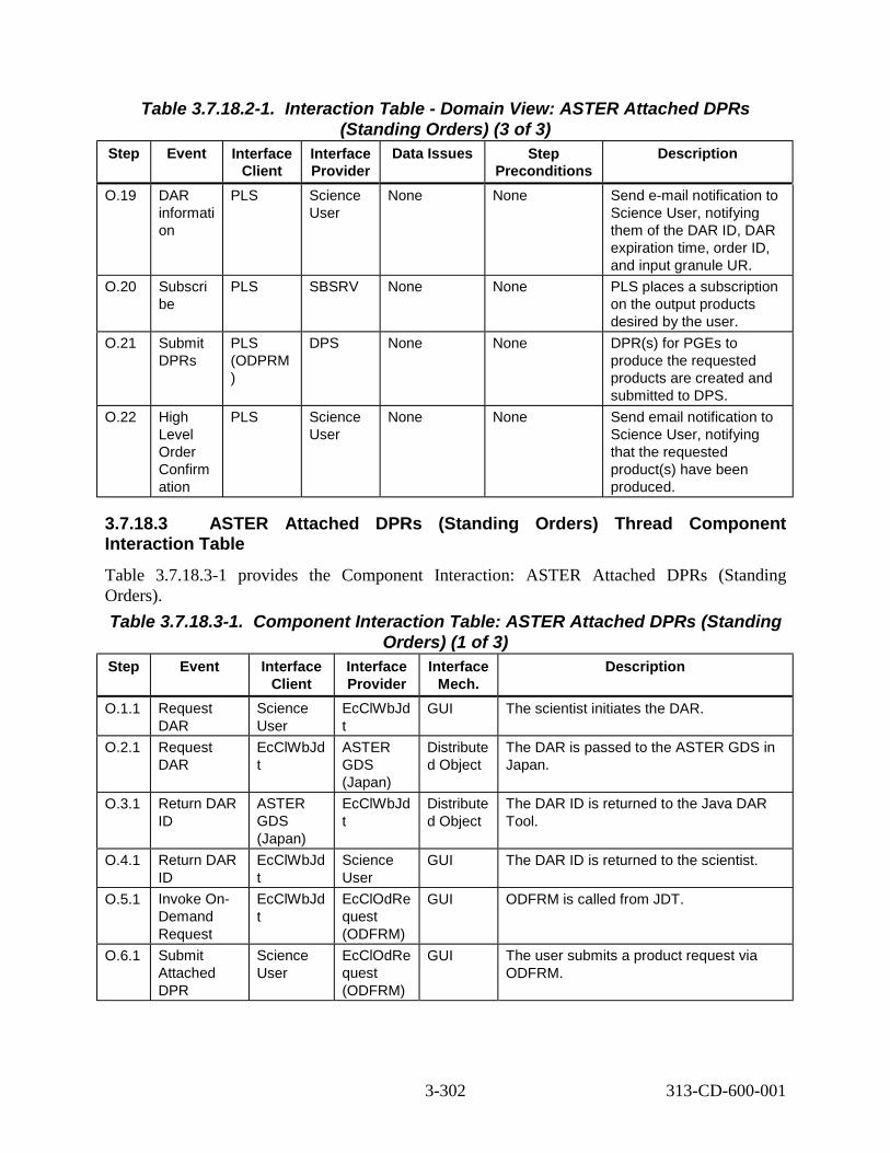
Table 3.7.18.2-1. Interaction Table - Domain View: ASTER Attached DPRs
Step Event Interface Client
(Standing Orders) (3 of 3) Interface Provider
Data Issues Step Preconditions
Description
O.19 DAR informati on
PLS Science User
None None Send e-mail notification to Science User, notifying them of the DAR ID, DAR expiration time, order ID, and input granule UR.
O.20 Subscri be
PLS SBSRV None None PLS places a subscription on the output products desired by the user.
O.21 Submit DPRs
PLS (ODPRM )
DPS None None DPR(s) for PGEs to produce the requested products are created and submitted to DPS.
O.22 High Level Order Confirm ation
PLS Science User
None None Send email notification to Science User, notifying that the requested product(s) have been produced.
3.7.18.3 ASTER Attached DPRs (Standing Orders) Thread ComponentInteraction Table Table 3.7.18.3-1 provides the Component Interaction: ASTER Attached DPRs (Standing Orders). Table 3.7.18.3-1. Component Interaction Table: ASTER Attached DPRs (Standing
Step Event Interface Client
Orders) (1 of 3) Interface Provider
Interface Mech.
Description
O.1.1 Request DAR
Science User
EcClWbJd t
GUI The scientist initiates the DAR.
O.2.1 Request DAR
EcClWbJd t
ASTER GDS (Japan)
Distribute d Object
The DAR is passed to the ASTER GDS in Japan.
O.3.1 Return DAR ID
ASTER GDS (Japan)
EcClWbJd t
Distribute d Object
The DAR ID is returned to the Java DAR Tool.
O.4.1 Return DAR ID
EcClWbJd t
Science User
GUI The DAR ID is returned to the scientist.
O.5.1 Invoke On-Demand Request
EcClWbJd t
EcClOdRe quest (ODFRM)
GUI ODFRM is called from JDT.
O.6.1 Submit Attached DPR
Science User
EcClOdRe quest (ODFRM)
GUI The user submits a product request via ODFRM.
3-302 313-CD-600-001

Table 3.7.18.3-1. Component Interaction Table: ASTER Attached DPRs (Standing
Step Event Interface Client
Orders) (2 of 3) Interface Provider
Interface Mech.
Description
O.7.1 Submit Standing Order
EcClOdRe quest (ODFRM)
EcPlOdM gr (ODPRM)
None The standing order is submitted to ODPRM. This process is identical to that documented in the ASTER On-Demand High Level production thread. Standing Orders is an extension of High Level production. Refer to Section 3.7.8.3 Steps E.5.1 - E.5.12.
O.8.1 Create MSS Standing Order
EcPlOdM gr (ODPRM)
EcMsAcO rderSrvr
Distribute d Object
A standing order is created in the MSS database.
O.8.1 Initialize Status (to “Awaiting DAR Results”)
EcPlOdM gr (ODPRM)
EcMsAcO rderSrvr
Distribute d Object
The status of the On-demand request is initialized (to “Awaiting DAR Results”).
O.10. 1
Subscribe EcPlOdM gr (ODPRM)
EcSbSub Server
Distribute d Object
A subscription is placed with the Subscription Server. This process is identical to that documented in the ASTER On-Demand High Level production thread. Standing Orders is an extension of High Level production. Refer to Section 3.7.8.3 Steps E.8.1 - E.8.4.
O.11. 1
Order ID Returned
EcPlOdM gr (ODPRM)
EcClOdRe quest (ODFRM)
Distribute d Object
The order ID is returned to the On-demand Form from the PLS.
O.12. 1
Order Confirmation
EcClOdRe quest (ODFRM)
Science User
GUI An order confirmation is sent by the ODFRM to the science user.
O.13. 1
Insert L1B (via Ingest)
ASTER GDS (Japan)
EcDsScie nceDataS erver
Distribute d Object
This data has just been received from Japan.
O.14. 1
Insert Event EcDsScie nceDataS erver
EcSbSub Server
Distribute d Object
Upon successful insertion of the DAR output product, the Insert event is triggered. The correct subscription server is determined from the SDSRV configuration. The correct events to trigger are determined from the events file, where they were stored when the ESDT was installed in the Data Server. Provided with the event triggering is the UR of the inserted granule.
3-303 313-CD-600-001

Table 3.7.18.3-1. Component Interaction Table: ASTER Attached DPRs (Standing
Step Event Interface Client
Orders) (3 of 3) Interface Provider
Interface Mech.
Description
O.14. 2
Retrieve Subscription s
EcSbSub Server
Sybase CtLib SBSRV queries the Sybase database determining which subscriptions need to be activated, or fired. Each query “hit” is an activated subscription and executes independently.
O.15. 1
Subscription Notification
EcSbSub Server
EcPlSubM gr
Distribute d Object
The subscriptions are submitted for each data type individually.
O.16. 1
Submit On Demand Information
EcPlOdM gr
EcPlOdM gr
Distribute d Object
The order is processed as a standard on-demand order. That is, the fourth On Demand Manager thread wakes up and starts processing on-demand information.
O.17. 1
Update Status (to "Awaiting More DAR Results")
EcPlOdM gr
EcMsAcO rderSrvr
Distribute d Object
Update the order tracking element (to "Awaiting More DAR Results").
O.18. 1
Create MSS Order Tracking Elements
EcPlOdM gr (ODPRM)
EcMsAcO rderSrvr
Distribute d Object
The MSS order tracking elements are created.
O.19. 1
DAR Information
EcPlOdM gr
Science User
e-mail The user is notified of the DAR ID, expiration time, order ID, and input granule UR.
O.20. 1
Subscribe EcPlOdM gr (ODPRM)
EcSbSub Server
Distribute d Object
A subscription is placed with the Subscription Server. This process is identical to that documented in the ASTER On-Demand High Level production thread. Standing Orders is an extension of High Level production. Refer to Section 3.7.8.3 Steps E.8.1 - E.8.4.
O.21. 1
Create DPR EcPlOdM gr
EcDpPrJo bMgmt
rpc The On-Demand Manager sends to DPS the DPRID, a list of predecessor DPRs, and whether the DPR is waiting for external data.
O.22. 1
Completion Notice
EcPlOdM gr (ODPRM)
Science User
e-mail Email is sent from ODPRM to the user indicating (after all Attached DPRs for this request have completed) that the Attached DPRs request has been satisfied.
3-304 313-CD-600-001

3.8 Planning Scenario
3.8.1 Planning Scenario Description This scenario shows all the planning and any processing threads (including re-processing of a data processing request) that apply to all instrument scenarios which utilize the ECS planning and data processing functions. These threads apply to the MODIS and ASTER scenarios.
3.8.2 Planning Scenario Preconditions There are no overall preconditions, however, applicable preconditions are provided for each thread. The following threads are supplemental to the basic operations of the PDPS which are illustrated in the MODIS and ASTER scenarios. The point of these scenarios is to illustrate different twists in the interactions that were not specified in the MODIS and ASTER scenarios. Each of the following scenarios was developed to highlight a specific part of the overall functionality for the purpose of clarification. Therefore, there is no flow between these individual threads in this document and no thread letters identified with these threads except where thread groups are shown in this section (i.e. the Resource Planning Group, the SSAP group and the Metadata group). Thread descriptions indicate where these threads would logically apply in the MODIS and ASTER scenarios. This thread application would not necessarily be a direct patch into the scenario, but is a representation of the general expansion of that scenario. Some specific modification may be needed for a given specific scenario. Individual thread preconditions are identified with each thread.
3.8.3 Planning Scenario Partitions The Planning Scenario has been partitioned into the following threads:
• Resource Planning Group - This Group consists of the Ground Events Job Thread and the Resource Planning Thread:
• Ground Events Job (Thread A) - This thread illustrates how a ground event marks a resource as unavailable for a specified time (see section 3.8.4).
• Resource Planning (Thread B) - This thread illustrates a means to gather a set of resources to be used by Resource Planning (see section 3.8.5).
• Science Software Archive Package - The Science Software Archive Package (SSAP) is a precondition for the MODIS Scenario (Section 3.5) and the ASTER Scenario (Section 3.7), and has been partitioned into the following threads:
• SSAP Insertion (Thread A) - This thread illustrates how a new SSAP is inserted into the Data Server (see section 3.8.6).
• SSAP Update (Thread B) - This thread illustrates how an existing SSAP in the Data Server can be updated (see section 3.8.7).
• Archive PGE Executable TAR File (Thread C) - This thread illustrates the archiving of a PGE executable tar file, and is implemented at the time of PGE
3-305 313-CD-600-001

registration. This thread would also follow the SSAP Insertion Thread (A) if no update takes place (see section 3.8.8).
• Metadata Query for Dynamic Input Granules - This thread group is needed to determine the inputs to DPRs which use time dependent granules (dynamic) based on a metadata query, and is partitioned into the following threads:
• Dynamic Granule Currently Available (Thread A) - This thread illustrates what happens when a dynamic granule is currently available from the Science Data Server (see section 3.8.9).
• Dynamic Granule Available in the Future (Thread B) - This thread illustrates what happens when a dynamic granule is not currently available but will be available in the future from the Science Data Server (see section 3.8.10).
• Metadata Based Activation - This thread illustrates the activation (run/no run) of a DPR based on a metadata value, and takes place before the MODIS Standard Production Thread (Section 3.5.6) and before the “Activate Plan” step (C.8) of the ASTER Backward Changing Thread (Section 3.7.6). (See section 3.8.11).
• DPR Regeneration - This thread illustrates reprocessing to replace a missing or damaged file. This is necessary when an existing file has been corrupted or deleted. (See section 3.8.12a).
• Reprocessing - This thread illustrates reprocessing to improve an existing file. Reprocessing is performed when the software or static inputs of the PGE have been improved by the instrument team. (See section 3.8.12b).
• Delete DPR - This thread illustrates the deletion of a DPR job, and would apply after the MODIS Failed PGE Handling Thread (Section 3.5.7). (See section 3.8.13).
• Closest Granule – This thread illustrates how a PGE can be processed by using the nearest input granule (either forward or backward) from the time specified in the Data Processing Request. (See section 3.8.14).
3.8.4 Ground Events Jobs Thread (Thread A) This thread illustrates how a ground event marks a resource as unavailable for a specified time. A ground event is composed of a start time, duration, and a resource.
This thread applies to any resource except AutoSys.
The following system functionality is exercised in this thread:
• The capability to recognize already allocated resources identified by a ground event job, and to not schedule additional jobs using resources already covered by an existing ground event job for that ground event duration.
3-306 313-CD-600-001

Thread Preconditions The PDPS database, Resource Planning, AutoSys, and the Job Management Server must all be up and running.
The Planning Workbench cannot be up.
3.8.4.1 Ground Events Jobs Thread Interaction Diagram - Domain View Figure 3.8.4.1-1 depicts the Ground Events Jobs Thread Interaction - Domain View.
A.1 reate ground event C
DAAC Ops
PLSPLS
DPS DPS
A.3 Activate Plan
Distributed Object (rpc, CtLib) HMI (GUI, Xterm, command) ftp email (or other as noted) Double line - Synchronous email (or other as noted) Dashed - Asynchronous
A.2 Perform planning
A.4 Process ground event job
Figure 3.8.4.1-1. Ground Events Jobs Thread Interaction Diagram - Domain View
3.8.4.2 Ground Events Jobs Thread Interaction Table - Domain View Table 3.8.4.2-1 provides the Ground Events Jobs Thread Interaction - Domain View.
3-307 313-CD-600-001

Table 3.8.4.2-1. Interaction Table - Domain View: Ground Events Jobs Step Event Interface
Client Interface Provider
Data Issues Step Preconditions
Description
A.1 Create the ground event
DAAC Ops -Production Planner
PLS The resources to be allocated for the ground event must be known.
Resource Planning must be up and running.
The Production Planner uses Resource Planning to allocate given resources in a ground event. The Planning Workbench is brought up.
A.2 Perform planning
PLS PLS None None The Production Planner performs planning in the normal fashion.
A.3 Activate Plan PLS DPS The ground event message includes a resource ID, a start time, and duration.
The Planning Workbench and the Job Management Server must be up and running.
A ground event message is sent along with the DPRs in the plan.
A.4 Processes ground event job
DPS DPS None The Job Management Server must be up and running.
The ground event job is processed.
3.8.4.3 Ground Events Jobs Thread Component Interaction Table
Table 3.8.4.3-1 provides the Ground Events Jobs Thread Interaction.
Table 3.8.4.3-1. Component Interaction Table: Ground Events Jobs (1 of 2) Step Event Interface
Client Interface Provider
Interface Mech.
Description
A.1.1 Create the ground event
DAAC Ops -Production Planner (Operator)
EcPlRpRe GUI The Production Planner uses Resource Planning to allocate given resources in a ground event.
A.2.1 Create plan DAAC Ops -Production Planner
EcPlWb GUI The Production Planner creates a plan in the normal fashion.
3-308 313-CD-600-001

Table 3.8.4.3-1. Component Interaction Table: Ground Events Jobs (2 of 2) Step Event Interface
Client Interface Provider
Interface Mech.
Description
A.2.2 Submit plan DAAC Ops -Production Planner
EcPlWb GUI The Production Planner submits the plan in the normal manner.
A.3.1 Activate Plan EcPlWb EcDpPrJobM gmt
Distributed Object
A ground event message is sent along with the DPRs in the plan, if any.
A.4.1 Job Appears in AutoSys
EcDpPrJob Mgmt
EcDpPrJobM gmt
Internal This newly created job must have the same name as the ground event job.
A.4.2 Job starts running
EcDpPrGE EcDpPrGE Internal The DPS Ground Event job begins to run.
A.4.3 Job looks up resource
EcDpPrGE Sybase CtLib The DB lookup is accomplished using the primary key.
A.4.4 Set the field onLineState to offLine
EcDpPrGE Sybase CtLib By setting the DB field onLineState to the value offLine, further use of that resource is eliminated until either the job wakes up or is killed.
A.4.5 Job sleeps for the duration time of the ground event
EcDpPrGE EcDpPrGE Internal The resource(s) allocated by the ground event remains allocated for the duration of the ground event.
A.4.6 Set the field onLineState to onLine
EcDpPrGE Sybase CtLib When either the job wakes up, or if the job is killed, the DB field onLineState is reset to onLine.
3.8.5 Resource Planning Thread (Thread B) This thread illustrates a means to gather a set of resources to be used by Resource Planning.
This thread applies to all instruments.
The following system functionality is exercised in this thread:
• The capability to obtain from MSS a baseline configuration file of resources and resource descriptions.
Resource Planning Thread Preconditions A directory must have been created to house the baseline configuration file. The PDPS DB must be up and running. The MSS CM server must be on-line. Tivoli, configured to support the Baseline Manager/Resource Planning interface, must be running on the MSS server, the MSS CM server and the Planning workstation. Resource Planning must be running.
3-309 313-CD-600-001

3.8.5.1 Resource Planning Thread Interaction Diagram - Domain View Figure 3.8.5.1-1 depicts the Resource Planning Interaction Diagram - Domain View.
PLSPLS
DPSMSS
B.1 tch baseline
B.3 nd resource configuration file
B.2 Request resource configuration file
DAAC Ops
DAAC Ops
B.4 y operators
Distributed Object (rpc, CtLib) HMI (GUI, Xterm, command) ftp email (or other as noted) Double line -email (or other as noted)Dashed -
Fe
Se
Notif
Figure 3.8.5.1-1. Resource Planning Interaction Diagram - Domain View
3.8.5.2 Resource Planning Thread Interaction Table - Domain View Table 3.8.5.2-1 provides the - Domain View: Resource Planning.
Table 3.8.5.2-1. Interaction Table - Domain View: Resource Planning (1 of 2) Step Event Interface
Client Interface Provider
Data Issues
Step Precondi-
tions
Description
B.1 Fetch baseline DAAC Ops -Production Planner
PLS The baseline date must be known.
The Resource Editor must be up and running.
The Production Planner performs the baseline fetch steps using the Resource Planner.
3-310 313-CD-600-001

Table 3.8.5.2-1. Interaction Table - Domain View: Resource Planning (2 of 2) Step Event Interface
Client Interface Provider
Data Issues
Step Precondi-
tions
Description
B.2 Request resource configuration file
PLS MSS None Tivoli, configured to support the Baseline Manager/ Resource Planning IF, must be running on the MSS server.
The resource configuration file is provided via Tivoli.
B.3 Send resource configuration file
MSS PLS None None Several Tivoli jobs and an XRP-II script are run.
B.4 Notify operator MSS DAAC Ops -Production Planner
None None A registered Production Planner can browse the Tivoli messages to verify status of the planned resource.
3.8.5.3 Resource Planning Thread Component Interaction Table Table 3.8.5.3-1 provides the Component Interaction: Resource Planning
Table 3.8.5.3-1. Component Interaction Table: Resource Planning (1 of 3) Step Event Interface
Client Interface Provider
Interface Mech.
Description
B.1.1 Bring up the Resource Definition screen
DAAC Ops -Production Planner
EcPlRpRe GUI The Production Planner brings up the Resource Definition screen of the Resource Planner.
B.1.2 Click the Fetch Baseline button
DAAC Ops -Production Planner
EcPlRpRe GUI The Production Planner selects the Fetch Baseline button.
B.1.3 Enter baseline date DAAC Ops -Production Planner
EcPlRpRe GUI The Production Planner enters the baseline date and clicks OK.
B.2.1 Start Tivoli process EcPlRpRe Tivoli command line “tivoli”
Tivoli starts a Tivoli client process.
3-311 313-CD-600-001
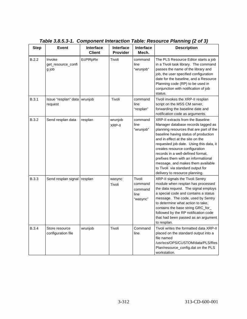
Table 3.8.5.3-1. Component Interaction Table: Resource Planning (2 of 3) Step Event Interface
Client Interface Provider
Interface Mech.
Description
B.2.2 Invoke get_resource_confi g job
EcPlRpRe Tivoli command line “wrunjob”
The PLS Resource Editor starts a job in a Tivoli task library. The command passes the name of the library and job, the user specified configuration date for the baseline, and a Resource Planning code (RP) to be used in conjunction with notification of job status.
B.3.1 Issue “resplan” data request
wrunjob Tivoli command line “resplan”
Tivoli invokes the XRP-II resplan script on the MSS CM server, forwarding the baseline date and notification code as arguments.
B.3.2 Send resplan data resplan wrunjob XRP-II
command line “wrunjob”
XRP-II extracts from the Baseline Manager database records tagged as planning resources that are part of the baseline having status of production and in effect at the site on the requested job date. Using this data, it creates resource configuration records in a well-defined format, prefixes them with an informational message, and makes them available to Tivoli via standard output for delivery to resource planning.
B.3.3 Send resplan signal resplan wasync Tivoli
Tivoli command command line “wasync”
XRP-II signals the Tivoli Sentry module when resplan has processed the data request. The signal employs a special code and contains a status message. The code, used by Sentry to determine what action to take, contains the base string GRC_for_ followed by the RP notification code that had been passed as an argument to resplan.
B.3.4 Store resource configuration file
wrunjob Tivoli Command line
Tivoli writes the formatted data XRP-II placed on the standard output into a file named /usr/ecs/OPS/CUSTOM/data/PLS/Res Plan/resource_config.dat on the PLS workstation.
3-312 313-CD-600-001

Table 3.8.5.3-1. Component Interaction Table: Resource Planning (3 of 3) Step Event Interface
Client Interface Provider
Interface Mech.
Description
B.4.1 Issue notification Tivoli DAAC Ops -Production Planner
Tivoli sentry monitor
In response to a GRC_for_RP signal, a Tivoli Sentry monitor produces a popup window for all users logged onto the PLS workstation who have a Tivoli client process running and are registered to receive GRC_for_RP notices. The window displays the status message from resplan together with some ancillary information. The monitor also writes the status message and ancillary information to the Tivoli Sentry-log notice group.
B.4.2 Browse notices DAAC Ops -Production Planner
Tivoli GUI Planners registered as Tivoli administrators who subscribe to the Sentry-log notice group can view a chronological list of GRC_for_RP messages by clicking on their Tivoli desktop Notices icon and selecting the Sentry-log group.
3.8.6 Science Software Archive Package Thread - SSAP Insertion (Thread A)
This thread illustrates how a new SSAP is inserted into the Data Server.
This thread applies to all instruments.
The following system functionality is exercised in this thread:
• The capability to insert a SSAP into the Data Server
Thread Preconditions The SSAP Editor must be up and running and the added SSAP should appear in the window of the “main” tab.
3.8.6.1 Science Software Archive Package Insertion Thread Interaction Diagram -Domain View
Figure 3.8.6.1-1 depicts the Science Software Archive Package Insertion Interaction - Domain View.
3-313 313-CD-600-001

PLSAITTL
SDSRV
IOS/ADV
A.4 Insert DAP and SSAP
DAAC Ops
DAAC Ops
A.3 UR for Data Server
A.5 eturn UR of SSAP
A.1 r SSAP data
A.6 y insertion message
A.2 Get Data Server UR
Distributed Object (rpc, CtLib) HMI (GUI, Xterm, command) ftp email (or other as noted) Double line - Synchronous email (or other as noted) Dashed - Asynchronous
R
Ente
Displa
Figure 3.8.6.1-1. SSAP Diagram - Domain View
3.8.6.2 Science Software Archive Package Insertion Thread Interaction Table -Domain View
Table 3.8.6.2-1 depicts the Interaction Table - Domain View: SSAP Insertion.
3-314 313-CD-600-001

Table 3.8.6.2-1. Interaction Table - Domain View: SSAP Insertion Step Event Interface
Client Interface Provider
Data Issues
Step Precon-ditions
Description
A.1 Enter SSAP data
DAAC Ops -SSIT Operator
AITTL The SSAP data to be entered must be known.
None The SSIT Operator enters the science software archive package data.
A.2 Get Data Server UR
AITTL IOS/ADV None None The Science Data Server universal reference is requested from the Advertising Server.
A.3 UR for Data Server
IOS/ADV AITTL None None The Science Data Server universal reference is provided by the Advertising Server.
A.4 Insert DAP and SSAP components
AITTL SDSRV None None The DAP and SSAP components are inserted into the appropriate Science Data Server.
A.5 Return UR of SSAP granules
SDSRV AITTL None None The UR of the SSAP granules is returned by the Science Data Server.
A.6 Display insertion message
AITTL DAAC Ops-SSIT Operator
None None The Science Data Server insertion message is displayed to the SSIT Operator.
3.8.6.3 Science Software Archive Package Insertion Thread ComponentInteraction Table Table 3.8.6.3-1 depicts the Science Software Archive Package Component Interaction - SSAP Insertion.
3-315 313-CD-600-001

Table 3.8.6.3-1. Component Interaction Table: SSAP Insertion (1 of 2) Step Event Interface
Client Interface Provider
Interface Mech.
Description
A.1.1 Select SSIT Manager: Tools: Data Server: SSAP Editor
DAAC Ops -SSIT Operator
EcDpAtSS APGui
GUI The SSIT Operator brings up the SSAP Editor.
A.1.2 Click on Create button
DAAC Ops -SSIT Operator
EcDpAtSS APGui
GUI The SSIT Operator clicks on the Create button.
A.1.3 Enter name of the SSAP in the first field
DAAC Ops -SSIT Operator
EcDpAtSS APGui
GUI The SSIT Operator enters the name of the SSAP in the first field.
A.1.4 Enter the SSAP version in the second field
DAAC Ops -SSIT Operator
EcDpAtSS APGui
GUI The SSIT Operator enters the SSAP version in the second field.
A.1.5 Click OK DAAC Ops -SSIT Operator
EcDpAtSS APGui
GUI The SSIT Operator clicks on OK.
A.1.6 Click on File List tab DAAC Ops -SSIT Operator
EcDpAtSS APGui
GUI The SSIT Operator clicks on the File List tab.
A.1.7 Click on File Type button
DAAC Ops -SSIT Operator
EcDpAtSS APGui
GUI The SSIT Operator clicks on the File Type button.
A.1.8 Choose one menu item
DAAC Ops -SSIT Operator
EcDpAtSS APGui
GUI The SSIT Operator chooses one menu item.
A.1.9 Select a file(s) from the left window
DAAC Ops -SSIT Operator
EcDpAtSS APGui
GUI The SSIT Operator selects a file or files from the left window.
A.1.10 Click the Add Arrow DAAC Ops -SSIT Operator
EcDpAtSS APGui
GUI The SSIT Operator clicks on the add arrow.
A.1.11 Click on Metadata tab
DAAC Ops -SSIT Operator
EcDpAtSS APGui
GUI The SSIT Operator clicks on the Metadata tab.
A.1.12 Change values as necessary & click OK
DAAC Ops -SSIT Operator
EcDpAtSS APGui
GUI The SSIT Operator changes the values as necessary and clicks OK.
A.1.13 Click the Edit Assoc Collections button
DAAC Ops -SSIT Operator
EcDpAtSS APGui
GUI The SSIT Operator clicks the Assoc Collections button.
3-316 313-CD-600-001

Step Table 3.8.6.3-1. Component Interaction Table: SSAP Insertion (2 of 2)
Event Interface Client
Interface Provider
Interface Mech.
Description
A.1.14 Enter a short name of an existing ESDT
DAAC Ops -SSIT Operator
EcDpAtSS APGui
GUI The SSIT Operator enters a short name of an existing ESDT.
A.1.15 Enter the version DAAC Ops -SSIT Operator
EcDpAtSS APGui
GUI The SSIT Operator enters the version.
A.1.16 Click OK DAAC Ops -SSIT Operator
EcDpAtSS APGui
GUI The SSIT Operator clicks on OK.
A.1.17 Click Done DAAC Ops -SSIT Operator
EcDpAtSS APGui
GUI The SSIT Operator clicks on Done.
A.1.18 Select Metadata tab: Save
DAAC Ops -SSIT Operator
EcDpAtSS APGui
GUI The SSIT Operator selects the Metasave pulldown Save option.
A.1.19 Select Main tab: Submit
DAAC Ops -SSIT Operator
EcDpAtSS APGui
GUI The SSIT Operator selects the Main tab Submit option.
A.2.1 Get Data Server UR
EcDpAtSSA PGui
EcIoAdSer ver
Distributed Object
The Science Data Server universal reference is requested from the Advertising Server.
A.3.1 Data Server UR EcIoAdServ er
EcDpAtSS APGui
Distributed Object
The Science Data Server universal reference is provided by the Advertising Server.
A.4.1 Insert DAP EcDpAtSSA PGui
EcDsScie nceDataS erver
GUI The DAP is inserted into the appropriate Science Data Server.
A.4.2 Insert SSAP components
EcDpAtSSA PGui
EcDsScie nceDataS erver
Distributed Object
The SSAP components are inserted into the appropriate Science Data Server.
A.5.1 UR of SSAP granules
EcDsScienc eDataServer
EcDpAtSS APGui
Distributed Object
The UR of the SSAP granules is returned by the Science Data Server.
A.6.1 Display insertion message
EcDpAtSSA PGui
DAAC Ops- SSIT Operator
GUI The Science Data Server insertion message is displayed to the SSIT Operator.
3-317 313-CD-600-001

3.8.7 SSAP Update Thread (Thread B) This thread illustrates how an existing SSAP in the Data Server can be updated.
This thread applies to all instruments.
The following system functionality is exercised in this thread:
• The capability to update an existing SSAP in the Data Server
SSAP Update Thread Preconditions
For the SSAP Update thread, an SSAP must have already been inserted into the Data Server.
3.8.7.1 SSAP Update Thread Interaction Diagram - Domain View Figure 3.8.7.1-1 depicts the SSAP Update Thread Interaction - Domain View.
PLSAITTL
SDSRV
IOS/ADV
B.4 t metadata B.6 nsert and update data
DAAC Ops
DAAC Ops
B.5 urrent metadata B.7 R of updated granules
B.1 nter SSAP update data
B.8 isplay insertion message
B.3 Data Server UR
B.2 Get Data Server UR
Distributed Object (rpc, CtLib) HMI (GUI, Xterm, command) ftp email (or other as noted) Double line - Synchronous email (or other as noted) Dashed - Asynchronous
GeI
CU
E
D
Figure 3.8.7.1-1. SSAP Update Interaction Diagram - Domain View
3.8.7.2 SSAP Update Thread Interaction Table - Domain View Table 3.8.7.2-1 provides the SSAP Update Interaction - Domain View.
3-318 313-CD-600-001

Step Table 3.8.7.2-1. Interaction Table - Domain View: SSAP Update
Event Interface Client
Interface Provider
Data Issues
Step Preconditions Description
B.1 Enter SSAP update data
DAAC Ops -SSIT Operator
AITTL The SSAP update data must be known.
A science software archive package (SSAP) must have already been inserted into the Science Data Server. The SSAP editor must be up and running and the inserted SSAP should appear in the window of the Main tab.
The SSIT Operator enters the SSAP update data.
B.2 Get Data Server UR
AITTL IOS/ADV None None The UR of the correct Science Data Server is requested from the Advertising Server.
B.3 Data Server UR
IOS/ADV AITTL None None The UR of the correct Science Data Server is provided by the Advertising Server.
B.4 Get metadata
AITTL SDSRV None None Request the previously inserted (current) SSAP metadata from the Science Data Server.
B.5 Current metadata
SDSRV AITTL None None The Science Data Server provides the previously inserted (current) metadata.
B.6 Insert and update data
AITTL SDSRV None None New data is inserted into the Science Data Server, and existing data is updated in the Science Data Server.
B.7 UR of updated granules
SDSRV AITTL None None The Science Data Server returns the UR of the updated granules.
B.8 Display insertion message
AITTL DAAC Ops -SSIT Operator
None None The Science Data Server insertion message is displayed to the SSIT Operator.
3.8.7.3 SSAP Update Thread Component Interaction Table Table 3.8.7.3-1 provides the SSAP Update Component Interaction.
3-319 313-CD-600-001

Table 3.8.7.3-1. Component Interaction Table: SSAP Update (1 of 2) Step Event Interface
Client Interface Provider
Interface Mech.
Description
B.1.1 Click on existing SSAP in the Main display
DAAC Ops -SSIT Operator
EcDpAtSS APGui
GUI The SSIT Operator clicks on the existing SSAP in the Main display.
B.1.2 Click on the Metadata tab
DAAC Ops -SSIT Operator
EcDpAtSS APGui
GUI The SSIT Operator clicks on the Metadata tab.
B.1.3 Click on the Algorithm Version field & enter a new version
DAAC Ops -SSIT Operator
EcDpAtSS APGui
GUI The SSIT Operator clicks on the Algorithm Version field and enters a new version. This new version must be different from the existing version.
B.1.4 Update any other fields you wish to change
DAAC Ops -SSIT Operator
EcDpAtSS APGui
GUI The SSIT Operator updates any other fields that he wishes to change at this point. A new Associated Collection can be added here by clicking on the Assoc Collection button and following the steps described in Creating an SSAP.
B.1.5 Click Save DAAC Ops -SSIT Operator
EcDpAtSS APGui
GUI The SSIT Operator click on Save before he leaves the Metadata tab.
B.1.6 Click on the File List tab
DAAC Ops -SSIT Operator
EcDpAtSS APGui
GUI The SSIT Operator clicks on the File List tab to set up new SSAP components.
B.1.7 Click on the File Type button
DAAC Ops -SSIT Operator
EcDpAtSS APGui
GUI The SSIT Operator clicks on the file Type button to select the additional SSAP component to manipulate. If the file type already exists, the existing information is acquired from the Science Data Server.
B.1.8 Choose one of the menu items
DAAC Ops -SSIT Operator
EcDpAtSS APGui
GUI The SSIT Operator chooses one of the menu items.
B.1.9 Select file(s) from the left window
DAAC Ops -SSIT Operator
EcDpAtSS APGui
GUI The SSIT Operator selects file(s) from the left window to add to the component.
3-320 313-CD-600-001

Table 3.8.7.3-1. Component Interaction Table: SSAP Update (2 of 2) Step Event Interface
Client Interface Provider
Interface Mech.
Description
B.1.10 Click the Add Arrow button
DAAC Ops -SSIT Operator
EcDpAtSS APGui
GUI The SSIT Operator clicks on the Add Arrow button to add the files. They appear in the right window because they are now part of that SSAP Component.
B.1.11 Click Main DAAC Ops -SSIT Operator
EcDpAtSS APGui
GUI The SSIT Operator clicks on Main to get back to the Main tab.
B.1.12 On the Main tab, click Submit
DAAC Ops -SSIT Operator
EcDpAtSS APGui
GUI The SSIT Operator clicks on Submit to send the new SSAP to the Science Data Server.
B.2.1 Get Data Server UR
EcDpAtSS APGui
EcIoAdSer ver
Distributed Object
The UR of the correct Science Data Server is requested from the Advertising Server.
B.3.1 Data Server UR
EcIoAdSer ver
EcDpAtSS APGui
Distributed Object
The UR of the correct Science Data Server is provided by the Advertising Server.
B.4.1 Get metadata
EcDpAtSS APGui
EcDsScie nceDataS erver
Distributed Object
Request the previously inserted (current) SSAP metadata from the Science Data Server.
B.5.1 Current metadata
EcDsScie nceDataS erver
EcDpAtSS APGui
Distributed Object
The Science Data Server provides the previously inserted (current) metadata.
B.6.1 Insert new Archive Package (DAP)
EcDpAtSS APGui
EcDsScie nceDataS erver
Distributed Object
New data is inserted into the Science Data Server.
B.6.2 Insert SSAP EcDpAtSS APGui
EcDsScie nceDataS erver
Distributed Object
New SSAP components are inserted into the Science Data Server.
B.6.3 Update old components
EcDpAtSS APGui
EcDsScie nceDataS erver
Distributed Object
Existing data is updated in the Science Data Server.
B.7.1 UR of updated granules
EcDsScie nceDataS erver
EcDpAtSS APGui
Distributed Object
The Science Data Server returns the UR of the updated granules.
B.8.1 Display insertion message
EcDpAtSS APGui
DAAC Ops -SSIT Operator
GUI SSAP successfully inserted into the Data Server message is displayed to the SSIT Operator.
3-321 313-CD-600-001

3.8.8 Archive PGE Executable TAR File Thread (Thread C) This thread illustrates the archiving of a PGE executable tar file.
This thread applies to all instruments.
The following system functionality is exercised in this thread:
• The capability to archive a PGE executable tar file.
Thread Preconditions The PGE executable ESDT must have been installed on the Data Server. A PGE executable metadata file must have been created. The PGE must be defined in the PDPS database via the science update tool.
3.8.8.1 Archive PGE Executable TAR File Thread Interaction Diagram - Domain View Figure 3.8.8.1-1 depicts the Archive PGE Executable TAR File Interaction - Domain View.
PLSAITTL
SDSRV
IOS/ADV
C.4 Insert PGE
DAAC Ops
DAAC Ops
C.5 Return UR
C.1 Enter PGE data
C.6 isplay UR
C.3 UR for Data Server
C.2 Get UR for Data Server
Distributed Object (rpc, CtLib) HMI (GUI, Xterm, command) ftp email (or other as noted) Double line - Synchronous email (or other as noted) Dashed - Asynchronous D
Figure 3.8.8.1-1. Archive PGE Executable TAR File Interaction Diagram -Domain View
3.8.8.2 Archive PGE Executable TAR File Thread Interaction Table - Domain View Table 3.8.8.2-1 provides the Archive PGE Executable TAR Interaction - Domain View.
3-322 313-CD-600-001

Table 3.8.8.2-1. Interaction Table - Domain View: Archive PGE Executable Tar File Step Event Interface
Client Interface Provider
Data Issues
Step Preconditions Description
C.1 Enter PGE data
DAAC Op - SSIT Operator
AITTL The PGE tar file information must be known.
The PGE executable must have been installed on the data server. A PGE executable metadata file must have been created. The PGE must be defined in the PDPS DB.
The SSIT Operator enters the PGE data.
C.2 Get UR for Data Server
AITTL IOS/ADV None None This is a request for the specific Science Data Server that is housing the data.
C.3 UR for Data Server
IOS/ADV AITTL None None The object address for the correct Science Data Server is provided by the Advertising Server.
C.4 Insert PGE AITTL SDSRV None None The PGE is inserted into the proper Science Data Server.
C.5 Return UR SDSRV AITTL None None The Universal Reference of the inserted PGE is returned.
C.6 Display UR AITTL DAAC Op -SSIT Operator
None None The Universal Reference of the inserted PGE is displayed to the SSIT Operator.
3.8.8.3 Archive PGE Executable TAR File Thread Component Interaction Table Table 3.8.8.3-1 provides the Archive PGE Executable TAR File Component Interaction -Domain View.
3-323 313-CD-600-001

Table 3.8.8.3-1. Component Interaction Table: Archive PGE Executable Tar File
Step Event Interface Client
(1 of 2) Interface Provider
Interface Mech.
Description
C.1.1 Select Tools: Data Server: Ins EXE TAR
DAAC Ops -SSIT Operator
EcDpAtMg r
GUI The SSIT Operator selects the Insert Executable Tar File option.
C.1.2 Enter for default: /user/ecs/(MO DE)/CUSTO M/cfg/EcDpAt InsertExeTar File.CFG
DAAC Ops -SSIT Operator
EcDpAtIns ertExeTar File
command line
The SSIT Operator enters the configuration file location.
C.1.3 Enter mode DAAC Ops -SSIT Operator
EcDpAtIns ertExeTar File
command line
The SSIT Operator enters the mode.
C.1.4 Enter PGE Name
DAAC Ops - SSIT Operator
EcDpAtInse rtExeTarFil e
command line
The SSIT Operator enters the PGE name.
C.1.5 Enter version DAAC Ops - SSIT Operator
EcDpAtInse rtExeTarFil e
command line
The SSIT Operator enters the version.
C.1.6 Enter tar file location
DAAC Ops-SSIT Operator
ECDpAtIns ertExeTarFi le
command line
The SSIT Operator enters the path/file name of the PGE Executable Tar file
C.1.7 Enter tar file metadata location
DAAC Ops-SSIT Operator
ECDpAtIns ertExeTarFi le
command line
The SSIT Operator enters the path/file name of the PGE Tar file’s metadata file
C.1.8 Enter the Top level shell filename within tar file
DAAC Ops - SSIT Operator
EcDpAtInse rtExeTarFil e
command line
The SSIT Operator enters the top-level shell file name within the tar file.
C.2.1 Get Data Server UR
EcDpAtInse rtExeTarFil e
EcIoAdServ er
Distributed Object
This is a request for the specific Science Data Server that is housing the data.
C.3.1 Data Server UR
EcIoAdServ er
EcDpAtInse rtExeTarFil e
Distributed Object
The object address for the correct Science Data Server is provided by the Advertising Server.
C.4.1 Insert PGE EcDpAtInse rtExeTarFil e
EcDsScien ceDataServ er
Distributed Object
The PGE is inserted into the proper Science Data Server.
3-324 313-CD-600-001

Ops
Table 3.8.8.3-1. Component Interaction Table: Archive PGE Executable Tar File
Step Event Interface Client
(2 of 2) Interface Provider
Interface Mech.
Description
C.5.1 Return PGE UR
EcDsScien ceDataServ er
EcDpAtInse rtExeTarFil e
Distributed Object
The Universal Reference of the inserted PGE is returned.
C.6.1 Display PGE UR
EcDpAtInse rtExeTarFil e
DAAC Ops - SSIT Operator
command line
The Universal Reference of the inserted PGE is displayed to the SSIT Operator.
3.8.9 Metadata Query for Current Dynamic Input Granules (Thread A) This thread illustrates what happens when a dynamic granule is available from the Science Data Server at a current time of operations.
3.8.9.1 Metadata Query for Current Dynamic Input Granules Interaction Diagram - Domain View
Figure 3.8.9.1-1 depicts the Current Dynamic Granule Interaction - Domain View.
Distributed Object (rpc, CtLib)HMI (GUI, Xterm, command) SDSRVftpemail (or other as noted)Double line - Synchronous email (or other as noted) Dashed - Asynchronous A.3 Query for dynamic granule
A.4 Update DB query status A.1 Create
ProductionDAAC Request PLS
(if query status successful)
Ops PDPS DB
A.2 Compare DPR stop time with current time
Figure 3.8.9.1-1. Metadata Query for Current Dynamic Granule Interaction Diagram - Domain View
3-325 313-CD-600-001

3.8.9.2 Metadata Query for Current Dynamic Input Granules Interaction Table -Domain View
Table 3.8.9.2-1 provides the Current Dynamic Granule Interaction - Domain View.
Table 3.8.9.2-1. Interaction Table - Domain View: Current Dynamic Granule Step Event Interface
Client Interface Provider
Data Issues
Step Precon-ditions
Description
A.1 Create a Production Request
DAAC Ops -Production Planner
PLS None None The Production Planner creates a Production Request.
A.2 Compare DPR stop time with current time
PLS PLS None None DPR stop time must be less than or equal to current time to proceed with this scenario. If it is not, this case becomes a Dynamic Granule Available in the Future Thread (see next Thread).
A.3 Query for dynamic granule
PLS SDSRV None None Request the dynamic granule to the Science Data Server is based on metadata conditions.
A.4 Update DB query status
PLS PDPS DB None None The DB is updated only if dynamic granule query was successful. If the dynamic granule query was unsuccessful, the DPR is deleted from the DB and an error message is written to the Production Request Editor ALOG.
3.8.9.3 Metadata Query for Current Dynamic Input Granules ComponentInteraction Table - Domain View
Table 3.8.9.3-1 provides the Current Dynamic Granule Component Interaction.
3-326 313-CD-600-001
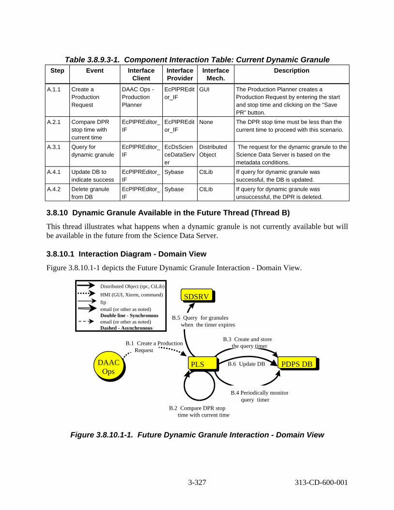
Ops
Table 3.8.9.3-1. Component Interaction Table: Current Dynamic Granule Step Event Interface
Client Interface Provider
Interface Mech.
Description
A.1.1 Create a Production Request
DAAC Ops -Production Planner
EcPlPREdit or_IF
GUI The Production Planner creates a Production Request by entering the start and stop time and clicking on the “Save PR” button.
A.2.1 Compare DPR stop time with current time
EcPlPREditor_ IF
EcPlPREdit or_IF
None The DPR stop time must be less than the current time to proceed with this scenario.
A.3.1 Query for dynamic granule
EcPlPREditor_ IF
EcDsScien ceDataServ er
Distributed Object
The request for the dynamic granule to the Science Data Server is based on the metadata conditions.
A.4.1 Update DB to indicate success
EcPlPREditor_ IF
Sybase CtLib If query for dynamic granule was successful, the DB is updated.
A.4.2 Delete granule from DB
EcPlPREditor_ IF
Sybase CtLib If query for dynamic granule was unsuccessful, the DPR is deleted.
3.8.10 Dynamic Granule Available in the Future Thread (Thread B) This thread illustrates what happens when a dynamic granule is not currently available but will be available in the future from the Science Data Server.
3.8.10.1 Interaction Diagram - Domain View Figure 3.8.10.1-1 depicts the Future Dynamic Granule Interaction - Domain View.
Distributed Object (rpc, CtLib) HMI (GUI, Xterm, command) SDSRV ftp email (or other as noted) Double line - Synchronous B.5 Query for granules email (or other as noted) Dashed - Asynchronous when the timer expires
B.3 Create and storeB.1 Create a Production the query timer
Request
DAAC PLS B.6 Update DB PDPS DB Ops
B.4 Periodically monitor query timer
B.2 Compare DPR stop time with current time
Figure 3.8.10.1-1. Future Dynamic Granule Interaction - Domain View
3-327 313-CD-600-001

3.8.10.2 Future Dynamic Granule Interaction Table - Domain View Table 3.8.10.2-1 provides the Future Dynamic Granule Interaction - Domain View.
Table 3.8.10.2-1. Interaction Table - Domain View: Dynamic Granule Available in the Future
Step Event Interface Client
Interface Provider
Data Issues Step Preconditions
Description
B.1 Create a Production Request
DAAC Ops -Production Planner
PLS ESDTs must be installed. SSI&T must be completed on the PGE. Input granules must be available.
The Production Request Editor must be up and running. The PDPS DB must be up and running.
The Production Planner creates a Production Request.
B.2 Compare DPR stop time with current time
PLS PLS None The Production Request Editor must be up and running. The PDPS DB must be up and running.
The DPR stop time must be greater than the current time to proceed with this scenario.
B.3 Create and store query timer
PLS PDPS DB None The PDPS DB must be up and running.
The query timer is created and stored in the DB timer table.
B.4 Periodically monitor query timer
PLS PDPS DB None The PDPS DB must be up and running.
The query timer in the DB timer table is periodically monitored.
B.5 Query for granule when timer expires
PLS SDSRV None None When the timer expires, query for the granule based on metadata conditions.
B.6 Update DB PLS PDPS DB None The PDPS DB must be up and running.
The DB is updated only if dynamic granule query was successful. If the dynamic granule query was unsuccessful, the DPR is deleted from the DB and an error message is written to the Production Request Editor ALOG.
3.8.10.3 Future Dynamic Granule Interaction Component Interaction Table -Domain View Table 3.8.10.3-1 provides the Future Dynamic Granule Component Interaction.
3-328 313-CD-600-001

Table 3.8.10.3-1. Component Interaction Table: Dynamic Granule Available in the Future
Step Event Interface Client
Interface Provider
Interface Mech.
Description
B.1.1 Create a Production Request
DAAC Ops -Production Planner
EcPlPREdit or_IF
GUI The Production Planner creates a Production Request.
B.2.1 Compare DPR stop time with current time
EcPlPREdit or_IF
EcPlPREdit or_IF
None The DPR stop time must greater than the current time to proceed with this scenario.
B.3.1 Create and store the query timer
EcPlPREdit or_IF
Sybase CtLib The query timer is created and stored in the DB timer table.
B.4.1 Periodically monitor query timer
EcPlSubMg r
Sybase CtLib The query timer in the DB timer table is periodically monitored. Proceed when timer expires.
B.5.1 Query for granules
EcPlSubMg r
EcDsScien ceDataServ er
Distributed Object
When the timer expires, query for the granule based on metadata conditions.
B.6.1 Update DB to indicate success
EcPlPREdit or_IF
Sybase CtLib If dynamic granule query was successful, update the DB with fresh granule information.
B.6.2 Delete granule from DB
EcPlPREdit or_IF
Sybase CtLib If query for dynamic granule was unsuccessful, the granule is deleted from the DB.
B.6.3 Log error message
EcPlPREdit or_IF
EcPlPREdit or_IF
None If query for dynamic granule was unsuccessful, an error message is written to the Production Request Editor ALOG.
3.8.11 Metadata Based Activation Thread This thread illustrates the activation (run/no run) of a PGE job.
This thread applies to all instruments.
The following system functionality is exercised in this thread:
• The capability to make a run/no run decision based on information contained in the granule metadata.
3-329 313-CD-600-001

Thread Preconditions
The following must be present in order to perform this thread: the Subscription Manager must be running, the PDPS database must be up and running, ESDTs must be installed, SSI&T must be completed on the PGE, PRs must have been entered, input granules must be available, and the Planning Workbench must be up and running.
3.8.11.1 Metadata Based Activation Thread Interaction Diagram - Domain View Figure 3.8.11.1-1 depicts the Metadata Based Activation Interaction - Domain View.
PLSPLS
PDPS DB
DPS DPS
3 ore information about data and metadata
4 Perform metadata check (While creating PGE job)
5 Release PGE job (If metadata check succeeded) 1 Data receipt
notification
SBSRV
St
Distributed Object (rpc, CtLib) HMI (GUI, Xterm, command) ftp email (or other as noted) Double line - Synchronous email (or other as noted) Dashed - Asynchronous
2 uery or data and metadata
Q f
SDSRV
Figure 3.8.11.1-1. Metadata Based Activation Interaction Diagram - Domain View
3.8.11.2 Metadata Based Activation Thread Interaction Table Table 3.8.11.2-1 provides the Metadata Based Activation Interaction.
3-330 313-CD-600-001

Table 3.8.11.2-1. Interaction Table - Domain View: Metadata Based Activation Ste p
Event Interface Client
Interface Provider
Data Issues
Step Preconditions Description
1 Data receipt notification
SBSRV PLS The Science Data Server must have received the data in question.
The Science Data Server has notified the Subscription Server with an Event Trigger.
A notification of the data receipt is sent.
2 Query for data and metadata
PLS SDSRV None The data and the accompanying metadata are requested from the Science Data Server.
3 Store information about data and metadata
PLS PDPS DB None The PDPS DB must be up and running.
The information about the data and the accompanying metadata is stored in the PDPS DB.
4 Perform metadata values check
PLS PLS None None While creating the PGE job, a check is performed on the metadata values.
5 Release PGE job
PLS DPS None The PGE job is released only if the metadata values check succeeded.
The PGE job is released.
3.8.11.3 Metadata Based Activation Thread Component Interaction Table Table 3.8.11.3-1 provides the Metadata Based Activation Component Interaction.
Table 3.8.11.3-1. Component Interaction Table: Metadata Based Activation (1 of 2) Step Event Interface
Client Interface Provider
Interface Mech.
Description
1.1 Data receipt notification
EcSbSub Server
EcPlSubM gr
Distributed Object
A notification of the data receipt is sent.
2.1 Query for data and metadata
EcPlSubM gr
EcDsScie nceDataS erver
Distributed Object
The data and the accompanying metadata are requested from the Science Data Server.
3-331 313-CD-600-001

Table 3.8.11.3-1. Component Interaction Table: Metadata Based Activation (2 of 2) Step Event Interface
Client Interface Provider
Interface Mech.
Description
3.1 Store information about data and metadata
EcPlSubM gr
Sybase CtLib The information about the data and the accompanying metadata is stored in the PDPS DB.
4.1 Perform metadata check
EcPlSubM gr
EcPlSubM gr
None While creating the PGE job, a check is performed on the metadata values. If the check identifies errors, the job is not released and error messages are logged.
5.1 Release PGE job
EcPlSubM gr
EcDpPrJo bMgmt
Distributed Object
The PGE job is released.
3.8.12a DPR Regeneration Thread This thread illustrates reprocessing to replace a missing or damaged file. This is necessary when
an existing file has been corrupted or deleted. If that file is needed for shipping or as input for additional processing, it must be recreated. This reprocessed file will be created using the same input, the same processing parameters, and the same algorithm as the original file.
This thread applies to all instruments.
Thread Preconditions
The PDPS database, the Production Request Editor, the Job Management Server, and AutoSys must be up and running. Input granules must be available on the Science Data Server. The Planning Workbench must be down.
3.8.12a.1 DPR Regeneration Thread Interaction Diagram - Domain View Figure 3.8.12a.1-1 depicts the DPR Regeneration Interaction - Domain View.
3-332 313-CD-600-001

SDSRV
PLSPLS
DPSDPS
SBSRV
10 Create DPR job for each DPR in "reprocessing queue"
1 nitiate reprocessing 9 Create & activate plan
DAAC Ops
DAAC Ops 6 uery for up to date
input data as necessary
4 termine data to be predicted 7 Prepare new version of output data granules & generate DPRs
PDPS DB
3 trieve input data granules 5 rite predicted data 8 rite output granules and DPRs
2 ubmit subscription
Distributed Object (rpc, CtLib) HMI (GUI, Xterm, command) ftp email (or other as noted) Double line - Synchronous email (or other as noted) Dashed - Asynchronous
I
Q
De
ReWW
S
11 Place jobs in Autosys
Figure 3.8.12a.1-1. DPR Regeneration Interaction Diagram - Domain View
3.8.12a.2 DPR Regeneration Thread Interaction Table - Domain View
Table 3.8.12a.2-1 provides the Interaction - Domain View: DPR Regeneration.
Table 3.8.12a.2-1. Interaction Table - Domain View: DPR Regeneration (1 of 2) Step Event Interface
Client Interface Provider
Data Issues Step Preconditions
Description
1 Initialize Regeneration
DAAC Ops -Productio n Planner
PLS None The Production Request Editor must be up and running.
The Production Planner initiates Regeneration.
2 Submit subscription
PLS SBSRV None None Subscriptions must be submitted are submitted only when necessary.
3 Retrieve input data granules
PLS PDPS DB
None The DB must be up and running.
All the data type granules for the selected input data and time range must be read.
3-333 313-CD-600-001

Table 3.8.12a.2-1. Interaction Table - Domain View: DPR Regeneration (2 of 2) Step Event Interface
Client Interface Provider
Data Issues Step Preconditions
Description
4 Determine data to be predicted
PLS PLS The original Production Request must be missing data or have updated input data.
None Data is predicted to substitute for data that is missing from the PDPS DB. This step does not normally apply if a routine PR has been entered.
5 Write predicted data
PLS PDPS DB
None The DB must be up and running.
Write missing predicted data to the DB, thus filling in the blank.
6 Query for up to date input data as necessary
PLS SDSRV None None Each query is based on a time range.
7 Prepare new version of output data granules and generate DPRs
PLS PLS None The DB must be up and running.
The predicted output data is written to the DB.
8 Write DPR(s) PLS PDPS DB
None The DB must be up and running.
The DPR(s) is written to the DB normally.
9 Create and activate plan
DAAC Ops -Productio n Planner
PLS The Planning Workbench must be brought up.
None The plan is created and activated normally.
10 Create a DPR job for each DPR in the “reprocessing queue”
PLS DPS None DCE must be up and running.
The DPR job for each DPR is created normally for those jobs in the independent “reprocessing queue”.
11 Place jobs in AutoSys
DPS DPS None AutoSys must be up and running.
The jobs are placed in AutoSys normally.
3.8.12a.3 DPR Regeneration Thread Component Interaction Table Table 3.8.12a.3-1 provides the Component Interaction: DPR Regeneration.
3-334 313-CD-600-001

Table 3.8.12a.3-1. Component Interaction Table: DPR Regeneration (1 of 2) Step Event Interface
Client Interface Provider
Interface Mech.
Description
1.1 Start Production Request Editor
DAAC Ops -Production Planner
EcPlPREdito r_IF
GUI The Production Request Editor is started normally.
1.2 Initiate request for Production Request to be reprocessed
DAAC Ops -Production Planner
EcPlPREdito r_IF
GUI The Production Planner initiates the reprocessing request.
1.3 Change PR type DAAC Ops -Production Planner
EcPlPREdito r_IF
GUI The Production Planner changes the PR type from Routine to Regeneration.
1.4 Save Production Request
DAAC Ops -Production Planner
EcPlPREdito r_IF
GUI The Production Planner saves the Production Request under a new, unique name.
2.1 Submit subscription
EcPlPREditor _IF
EcSbSubSer ver
Distributed Object
Subscriptions are submitted only when necessary.
3.1 Retrieve input data granules
EcPlPREditor _IF
Sybase CtLib All of the data type granules for input data and time range are read.
4.1 Determine data to be predicted
EcPlPREditor _IF
Sybase CtLib This determination is based on the data missing from or updated in the PDPS DB.
5.1 Write predicted data
EcPlPREditor _IF
Sybase CtLib The missing data is filled in with predicted data.
6.1 Query for up to date input data as necessary
EcPlPREditor _IF
EcDsScienc eDataServer
CtLib These queries are based on a time range.
7.1 Inspect and match granules
EcPlPREditor _IF
EcPlPREdito r_IF
CtLib Each SDSRV granule is matched with a PDPS DB granule.
7.2 Generate DPR(s) EcPlPREditor _IF
EcPlPREdito r_IF
CtLib The DPR(s) are generated.
8.1 Write output granules and generate DPR(s)
EcPlPREditor _IF
Sybase CtLib The DPR(s) are written to the DB.
9.1 Shut down Production Request Editor
DAAC Ops -Production Planner
EcPlPREdito r_IF
GUI The Production Planner shuts down the Production Request Editor.
9.2 Start up Planning Workbench
DAAC Ops -Production Planner
EcPlWb GUI The Production Planner starts up the Planning Workbench.
3-335 313-CD-600-001

Table 3.8.12a.3-1. Component Interaction Table: DPR Regeneration (2 of 2) Step Event Interface
Client Interface Provider
Interface Mech.
Description
9.3 Select Production Request and create a plan
DAAC Ops -Production Planner
EcPlWb GUI The Production Planner selects a Production Request and creates a plan.
9.4 Activate the plan DAAC Ops -Production Planner
EcPlWb GUI The Production Planner activates the plan.
10.1 Create a DPR job for each DPR in “reprocessing queue”
EcPlWb EcDpPrJob Mgmt
DCE A DPR job is created for each DPR in the independent “reprocessing queue”.
11.1 Jobs placed in AutoSys
EcDpPrJobM gmt
AutoSys rpc (COTS) The job can now be run in AutoSys.
3.8.12b Reprocessing Thread This thread illustrates reprocessing to improve an existing file. Reprocessing is performed when the software or static inputs of the PGE have been improved by the instrument team. Then, this new PGE is run over the same time periods and data sets as it previously had been run. There are a number of reasons why a change in a PGE would require reprocessing to occur. These are some examples:
- An error is discovered in the software that must be corrected.
- An improved algorithm is found based on an improved understanding of the instrument or physical phenomena.
- Static files, such as calibration data, need to be updated for several reasons including compensation for instrument degradation.
- Changes to software design that incorporate new or different ancillary data files are required.
- Changes to production rules are needed.
- Changes to or additions of run time parameters are needed.
- Changes to a lower level product necessitate the reprocessing of its higher level products.
This thread applies to all instruments.
3-336 313-CD-600-001

Thread Preconditions
The PDPS database, the Production Request Editor, the Job Management Server, and AutoSys must be up and running. Input granules must be available on the Science Data Server.
The Planning Workbench must be down.
3.8.12b.1 Reprocessing Thread Interaction Diagram - Domain View Figure 3.8.12b.1-1 depicts the Reprocessing Interaction - Domain View.
SDSRV
PLSPLS
DPSDPS
SBSRV
11 Create DPR job for each DPR in an independent queue
3 nitiate reprocessing 10 Create & activate plan
DAAC Ops
6 uery for up to date data as necessary
8 Prepare I/O data and generate DPR
PDPS DB
5 trieve input data granules 7 rite predicted output data as new
version 9 rite DPRs
4 ubmit subscription
Distributed Object (rpc, CtLib) HMI (GUI, Xterm, command) ftp email (or other as noted) Double line - Synchronous email (or other as noted) Dashed - Asynchronous
SSIT
2 pdate DB for PGE 1 egister updated PGE
IQ
ReW
W
S
UR
12 Place jobs in Autosys
Figure 3.8.12b.1-1. Reprocessing Interaction Diagram - Domain View
3-337 313-CD-600-001

3.8.12b.2 Reprocessing Thread Interaction Table - Domain View Table 3.8.12b.2-1 provides the Interaction - Domain View: Reprocessing.
Table 3.8.12b.2-1. Step Event
Interaction Table - Domain View: Reprocessing (1 of 2) Interface
Client Interface Provider
Data Issues Step Preconditions
Description
1 Register Updated PGE
DAAC Ops -Production Planner
SSIT None The IT identifies an improvement and implements it.
An improved PGE is received from the Instrument Team and is registered at the DAAC.
2 Update DB for PGE
SSIT PDPS DB None None Information regarding the improved PGE is stored in the database.
3 Initiate Reprocessing
DAAC Ops -Production Planner
PLS None The Production Request Editor must be up and running.
The Production Planner initiates reprocessing.
4 Submit subscription
PLS SBSRV None None Subscriptions are submitted only when necessary.
5 Retrieve input data granules
PLS PDPS DB None The DB must be up and running.
All the data type granules for the selected input data and time range must be read.
6 Query for up to date data as necessary
PLS SDSRV None None Each query is based on a time range.
7 Write predicted output data as a new version
PLS PDPS DB None The DB must be up and running.
The predicted output data is written to the DB.
8 Prepare I/O data and generate DPR
PLS PLS None None The I/O data is prepared and the DPR(s) are generated.
9 Write DPR(s) PLS PDPS DB None The DB must be up and running.
The DPR(s) are written to the DB normally.
3-338 313-CD-600-001

Table 3.8.12b.2-1. Step Event
Interaction Table - Domain View: Reprocessing (2 of 2) Interface
Client Interface Provider
Data Issues
Step Preconditions
Description
10 Create and activate plan
DAAC Ops -Production Planner
PLS The Planning Workbench must be brought up.
None The plan is created and activated normally.
11 Create a DPR job for each DPR in an independent queue
PLS DPS None None The DPR job for each DPR is created normally for those jobs in the independent "reprocessing" queue.
12 Place jobs in AutoSys
DPS DPS None AutoSys must be up and running.
The jobs are placed in AutoSys normally.
3.8.12b.3 Reprocessing Thread Component Interaction Table Table 3.8.12b.3-1 provides the Component Interaction: Reprocessing.
Table 3.8.12b.3-1. Step Event
Component Interaction Table: Reprocessing (1 of 2) Interface
Client Interface Provider
Interface Mech.
Description
1.1 Register updated PGE
DAAC Ops -Production Planner
EcDpAtMgr GUI An improved PGE is registered at the DAAC.
2.1 Update database for PGE
EcDpAtMgr Sybase GUI The new information concerning the improved PGE is stored in the database.
3.1 Start Production Request Editor
DAAC Ops -Production Planner
EcPlPREdito r_IF
GUI The Production Request Editor is started normally.
3.2 Initiate request for Production Request to be reprocessed
DAAC Ops -Production Planner
EcPlPREdito r_IF
GUI The Production Planner initiates the reprocessing request.
3.3 Change PR type DAAC Ops -Production Planner
EcPlPREdito r_IF
GUI The Production Planner changes the PR type from Routine to Reprocessing.
3.4 Save Production Request
DAAC Ops -Production Planner
EcPlPREdito r_IF
GUI The Production Planner saves the Production Request under a new, unique name.
4.1 Submit subscription
EcPlPREditor _IF
EcSbSubSer ver
Distributed Object
Subscriptions are submitted only when necessary.
3-339 313-CD-600-001

Table 3.8.12b.3-1. Step Event
Component Interaction Table: Reprocessing (2 of 2) Interface
Client Interface Provider
Interface Mech.
Description
5.1 Retrieve input data granules
EcPlPREditor_ IF
Sybase CtLib All of the data type granules for input data and time range are read.
6.1 Query for up to date data as necessary
EcPlPREditor_ IF
EcDsScienc eDataServer
CtLib These queries are based on a time range.
7.1 Write predicted output data as new version
EcPlPREditor_ IF
Sybase CtLib The missing data is filled in with predicted data.
8.1 Prepare I/O data EcPlPREditor_ IF
EcPlPREdito r_IF
CtLib The I/O data is prepared.
9.1 Write DPR(s) EcPlPREditor_ IF
Sybase CtLib The DPR(s) are written to the DB.
9.2 Generate DPR(s) EcPlPREditor_ IF
EcPlPREdito r_IF
CtLib The DPR(s) are generated.
10.1 Shut down Production Request Editor
DAAC Ops -Production Planner
EcPlPREdito r_IF
GUI The Production Planner shuts down the Production Request Editor.
10.2 Start up Planning Workbench
DAAC Ops -Production Planner
EcPlWb GUI The Production Planner starts up the Planning Workbench.
10.3 Select Production Request and create a plan
DAAC Ops -Production Planner
EcPlWb GUI The Production Planner selects a Production Request and creates a plan.
10.4 Activate the plan DAAC Ops -Production Planner
EcPlWb GUI The Production Planner activates the plan.
11.1 Create a DPR job for each DPR in an independent queue
EcPlWb EcDpPrJob Mgmt
DCE A DPR job is created for each DPR in the independent "reprocessing" queue.
12.1 Place jobs in AutoSys
EcDpPrJobMg mt
AutoSys rpc (COTS) The job can now be run in AutoSys.
3-340 313-CD-600-001

3.8.13 Delete DPR Thread
This thread illustrates the deletion of a DPR job.
This thread applies to all instruments.
The following system functionality is exercised in this thread:
• The capability to delete an existing DPR from either AutoSys or the PDPS database.
Thread Preconditions
The following must be present in order to perform this thread: the Production Request Editor must be running, the PDPS database must be up and running, and the Job Management Server must be up and running.
3.8.13.1 Delete DPR Thread Interaction Diagram - Domain View Figure 3.8.13.1-1 depicts the Delete DPR Interaction - Domain View.
PDPS DB
2 t list of available PRs 4 t list of DPRs 6 Get current state of selected DPR 8 Delete DPR from DB
GeGe
PLSPLS
DPS DPS
7 lete DPR from Autosys
1 nitiate DPR deletion process 3 lect a Production Request 5 lect a DPR to be deleted
DAAC Ops
DAAC Ops
De
ISeSe
Distributed Object (rpc, CtLib) HMI (GUI, Xterm, command) ftp email (or other as noted) Double line - Synchronous email (or other as noted) Dashed - Asynchronous
Figure 3.8.13.1-1. Delete DPR Interaction Diagram - Domain View
3.8.13.2 Delete DPR Thread Interaction Table - Domain View Table 3.8.13.2-1 provides the Interaction - Domain View: Delete DPR.
3-341 313-CD-600-001

Table 3.8.13.2-1. Interaction Table - Domain View: Delete DPR Step Event Interface
Client Interface Provider
Data Issues
Step Preconditions
Description
1 Initiate DPR deletion process
DAAC Ops -Production Planner
PLS None The Production Request Editor must be up and running.
The Production Planner initiates the deletion process.
2 Get list of available PRs
PLS PDPS DB None The DB must be up and running.
The list of available PRs is obtained from the DB.
3 Select a Production Request
DAAC Ops -Production Planner
PLS The affected Productio n Request must be known.
The Production Request Editor must be up and running.
The Production Planner selects a specific Production Request.
4 Get list of DPRs PLS PDPS DB None The DB must be up and running.
The list of DPRs for the PR is obtained from the DB.
5 Select DPR to be deleted
DAAC Ops -Production Planner
PLS The DPR to be deleted must be known.
The Production Request Editor must be up and running.
Each DPR to be deleted must be selected individually.
6 Get current state of selected DPR
PLS PDPS DB None The DB must be up and running.
The current state of each DPR to be deleted must be retrieved from the DB.
7 Delete DPR from AutoSys
PLS DPS None AutoSys must be up and running.
If selected DPR is also in AutoSys, then the DPR must be deleted from AutoSys.
8 Delete DPR from PDPS DB
PLS PDPS DB None The DB must be up and running.
The selected DPR is deleted from the DB.
3.8.13.3 Delete DPR Thread Component Interaction Table Table 3.8.13.3-1 provides the Component Interaction: Delete DPR.
3-342 313-CD-600-001

Step Table 3.8.13.3-1. Component Interaction Table: Delete DPR
Event Interface Client
Interface Provider
Interface Mech.
Description
1.1 Select DPR list DAAC Ops -Production Planner
EcPlPREdit or_IF
GUI The Production Planner selects the DPR list tab from Production Request Editor main screen.
1.2 Select Production Request pull-down
DAAC Ops -Production Planner
EcPlPREdit or_IF
GUI The Production Planner clicks on the Production Request box arrow.
2.1 Get list of available PRs
EcPlPREd itor_IF
Sybase CtLib The list of available Production Requests is retrieved from the DB.
3.1 Click on chosen Production Request
DAAC Ops -Production Planner
EcPlPREdit or_IF
GUI The Production Planner selects a Production Request from those presented on the scrollable list.
3.2 Click on Filter DAAC Ops -Production Planner
EcPlPREdit or_IF
GUI The Production Planner clicks on the Filter button.
4.1 Get list of DPRs
EcPlPREd itor_IF
Sybase CtLib The list of DPRs related to the chosen PR is retrieved from the DB.
5.1 Click on a Data Processing Request from the list presented
DAAC Ops -Production Planner
EcPlPREdit or_IF
GUI The Production Planner selects a Data Processing Request from the list presented.
5.2 Select Edit: Delete
DAAC Ops -Production Planner
EcPlPREdit or_IF
GUI The Production Planner selects the Delete option from the Edit pulldown menu.
6.1 Get current state of DPR
EcPlPREd itor_IF
Sybase CtLib The current state of the selected DPR is retrieved from the DB.
7.1 Delete DPR from AutoSys
EcPlPREd itor_IF
EcDpPrJob Mgmt
rpc (COTS) If the DPR is in AutoSys, the DPR is deleted from AutoSys.
8.1 Delete DPR from PDPS DB
EcPlPREd itor_IF
Sybase CtLib The DPR is deleted from the DB.
3.8.14 Closest Granule Thread
3.8.14.1 Scenario Description The Closest Granule Production Rule allows a PGE to request the nearest input granule from the time specified in the Data Processing Request. PDPS will search either forward or backward in
3-343 313-CD-600-001

time until it finds a granule that matches the request. Note that there is a limit to the number ofqueries that will be performed. This information (along with the period length of the query) isset by the user during SSIT.
This scenario applies to all instruments.The following system functionality is exercised in this scenario:
• The capability to process a DPR by searching for the data closest in time.
Scenario Preconditions
The PDPS database, the Production Request Editor, the Job Management Server, AutoSys, and the Planning Workbench must be up and running. Input granules must be available on the Science Data Server.
Figure 3.8.14.1-1 shows the Closest Granule Interaction – Domain View.
SDSRV
PLS PLS
DPS DPS
SBSRV
10 Create DPR job for each DPR
1 Initiate PR generation 9 Create & activate plan
DAAC Ops
DAAC Ops 3 uery for each input data type
6 Query for data using new time range
5 Extend query time range using query time delta
7 Prepare granules & generate DPR
PDPS DB
8 rite DPRs
2 ubmit subscription
Distributed Object (rpc, CtLib) HMI (GUI, Xterm, command) ftp email (or other as noted) Double line - Synchronous email (or other as noted) Dashed - Asynchronous
4 ead closest granule direction, query time delta and max number of tries
Q
W
S
R
11 Place jobs in Autosys
Figure 3.8.14.1-1. Closest Granule Interaction Diagram - Domain View
3.8.14.2 Interaction Table - Domain View Table 3.8.14.2-1 provides the Interaction – Domain View: Closest Granule.
3-344 313-CD-600-001

Table 3.8.14.2-1. Interaction Table - Domain View: Closest Granule (1 of 2) Step Interaction Interface
Client Interface Provider
Data Issues Preconditions Description
1 Initialize PR generation
DAAC Ops -Productio n Planner
PLS The original Production Request must be known and accessible.
The Production Request Editor must be up and running.
PR generation is initiated by the Production Planner.
2 Submit subscription
PLS SBSRV Input granules must be available.
None Subscriptions must be submitted individually for each data type.
3 Query for each input data type
PLS SDSRV None None Each query is based on a time range.
4 Read closest granule query direction, time delta and maximum number of tries
PLS PDPS DB
None The DB must be up and running
Read the closest granule direction, time delta (length of each search time) and the maximum number of searches.
5 Extend time query range using query time delta
PLS PLS None The Production Request Editor must be up and running
Prepare the query for the closest granule.
6 Query for data using new time range
PLS SDSRV None None Repeat steps 6 and 7 if no data is returned until the maximum number of queries has been performed. Stop here if no data is found after the maximum number of tries has been met.
7 Prepare granules and generate DPR
PLS PLS None DCE must be up and running.
Match each SDSRV granule with a PDPS DB granule and then resume normal processing.
8 Write DPR(s) PLS PDPS DB
None The DB must be up and running.
The DPR(s) is written to the DB normally.
3-345 313-CD-600-001

Table 3.8.14.2-1. Interaction Table - Domain View: Closest Granule (2 of 2) Step Interaction Interface
Client Interface Provider
Data Issues Preconditions Description
9 Create and activate plan
DAAC Ops -Productio n Planner
PLS None The Planning Workbench must be up and running.
The plan is created and activated normally.
10 Create a DPR job for each DPR
PLS DPS None DCE must be up and running.
The Job Management creates DPR jobs.
11 Place jobs in AutoSys
DPS DPS None AutoSys must be up and running.
The jobs are released into AutoSys and appear in the AutoSys Jobscape GUI.
3.8.14.3 Closest Granule Component Interaction Table Table 3.8.14.3-1 provides the Component Interaction: Closest Granule
Table 3.8.14.3-1. Component Interaction Table: Closest Granule (1 of 2) Step Event Interface
Client Interface Provider
Interface Mech.
Description
1.1 Start Production Request Editor
DAAC Ops – Production Planner
EcPlPREditor _IF
GUI The Production Request Editor is started normally.
1.2 Initiate request for Production Request to be reprocessed
DAAC Ops – Production Planner
EcPlPREditor _IF
GUI The Production Planner initiates the processing request.
1.3 Save Production Request
DAAC Ops – Production Planner
EcPlPREditor _IF
GUI The Production Planner saves the Production Request under a new, unique name.
2.1 Submit subscription
EcPlPREditor _IF
EcSbSubSer ver
Distribute d Object
The subscriptions are submitted for each data type individually.
3.1 Query for each input data type
EcPlPREditor _IF
EcDsScience DataServer
CtLib Each query is based on a time range.
4.1 Read closest granule direction, query time delta and maximum number of tries
EcPlPREditor _IF
Sybase CtLib Read the closest granule direction, time delta (the length of time that the search goes back each try) and the maximum number of searches.
5.1 Extend time query range using query time delta
EcPlPREditor _IF
EcPlPREditor _IF
CtLib Prepare the query for the closest granule.
3-346 313-CD-600-001

Table 3.8.14.3-1. Component Interaction Table: Closest Granule (2 of 2) Step Event Interface
Client Interface Provider
Interface Mech.
Description
6.1 Query for data using new time range
EcPlPREditor _IF
EcDsScience DataServer
CtLib Repeat steps 6.1 and 7.1 if no data is returned until the maximum number of queries has been performed. Stop here if no data is found after the maximum number of tries has been met.
7.1 Inspect and match granules
EcPlPREditor _IF
EcPlPREditor _IF
CtLib Each SDSRV granule is matched with a PDPS DB granule.
7.2 Generate DPR(s) EcPlPREditor _IF
EcPlPREditor _IF
CtLib The DPR(s) are generated.
8.1 Write DPR(s) to DB
EcPlPREditor _IF
Sybase CtLib The DPR(s) are written to the DB.
9.1 Shut down Production Request Editor
DAAC Ops – Production Planner
EcPlPREditor _IF
GUI The Production Planner shuts down the Production Request Editor.
9.2 Start up Planning Workbench
DAAC Ops -Production Planner
EcPlWb GUI The Production Planner starts up the Planning Workbench.
9.3 Select Production Request and create a plan
DAAC Ops -Production Planner
EcPlWb GUI The Production Planner selects a Production Request and creates a plan.
9.4 Activate the plan DAAC Ops -Production Planner
EcPlWb GUI The Production Planner activates the plan.
10.1 Create a DPR job for each DPR
EcPlWb EcDpPrJobM gmt
DCE A DPR job is created for each DPR.
11.1 Jobs placed in AutoSys
EcDpPrJobM gmt
AutoSys rpc (COTS)
The job can now be run in AutoSys.
3-347 313-CD-600-001

3.9 EDOS/FDD Interfaces Scenario
3.9.1 EDOS/FDD Interfaces Scenario Description This scenario illustrates the ability to process orbit, attitude, and ephemeris data into toolkit native format and HDF.
This scenario applies to all instruments.
The following system functionality is exercised in this scenario:
• Ability to process Terra EDOS Level 0 ancillary data (thread A).
• Ability to process Aqua FDD Definitive and Predictive Ephemeris data (thread E).
• Ability to process FDD (Flight Dynamics Division) Terra attitude data and Aqua attitude data (thread B).
• Ability to produce data to fill significant gap(s) in ECS processed EDOS Level 0 ancillary data (thread C). Note this is done for the Terra satellite data and not for the Aqua satellite data.
• Ability to process EMOS supplied Aqua GBAD (Ground –Based Attitude Determination Data) in the form of carry-out files (thread F).
3.9.2 EDOS/FDD/EMOS Interfaces Scenario Preconditions The input data must be available for EDOS to transfer to a disk area for Ingest to read in the corresponding form. The following ESDTs have been inserted into the ECS:
• AM1ANC (Terra Ancillary APIDx4)
• AM1ATTN0 (Preprocessed Terra Platform Attitude Data from L0 in Native format)
• AM1ATTH0 (Preprocessed Terra Platform Attitude Data from L0 in HDF format)
• AM1EPHN0 (Preprocessed Terra Platform Ephemeris Data from L0 in Native format)
• AM1EPHH0 (Preprocessed Terra Platform Ephemeris Data from L0 in HDF format)
• AM1ATTF (Definitive Attitude Data from Terra ingested from the FDF)
• AM1ATTNF (Preprocessed Terra Platform Attitude Data from FDF in Native format)
• AM1ATTHF (Preprocessed Terra Platform Attitude Data from FDF in HDF format)
• AM1EPHF (Repaired Ephemeris Data from FDF)
• PM1EPHD (Aqua Ancillary data – FDD Definitive Ephemeris Data for EOS Aqua)
• PM1EPHND (Preprocessed Aqua Platform Definitive Ephemeris Data from FDD in Native Format)
3-348 313-CD-600-001

• PM1EPHHD (Preprocessed Aqua Platform Definitive Ephemeris Data from FDD in HDF Format)
• PM1ATTNR (Preprocessed Aqua Platform Refined Attitude Data in Native format)
• PM1ATTHR (Preprocessed Aqua Platform Refined Attitude Data in HDF format)
• PMCOGBAD (Aqua GBAD attitude data in carry-out file format)
3.9.3 EDOS/FDD Interfaces Scenario Partitions
This scenario has been partitioned into the following threads:
Terra Threads:
• EDOS Level 0 Ancillary Data (Thread A) - This thread illustrates the acquisition and processing of EDOS supplied Level 0 Ancillary data to toolkit native format and HDF. Gaps up to 60 seconds in ephemeris data are filled in using the interpolation algorithms provided by the FDD (see Section 3.9.4).
• Definitive Attitude Data (Thread B) - This thread illustrates the acquisition and processing of FDD supplied definitive attitude data to toolkit native format and (see Section 3.9.5).
• FDD Repaired Ephemeris Data (Thread C) – This thread illustrates the request, acquisition, and processing of FDD repaired ephemeris data to fill an existing gap of > 60 seconds in the EDOS Terra ephemeris data (AM1EPHN0 and AM1EPHH0) produced in Thread A. See Section 3.9.6 for Thread C.
Aqua Threads:
• Aqua FDD Ephemeris Data Processing (Thread E) – This thread illustrates the acquisition and processing of FDS supplied definitive ephemeris data to toolkit native format and HDF. Data is provided as files with one day of definitive data. Definitive orbit data is expected to arrive 8 to 10 hours after the day in the file. There is no data repair done for the Aqua mission. No requests for replacement data are made for Aqua. See Section 3.9.8 for Thread E.
• Aqua Refined Attitude Processing (Thread F) – This thread illustrates the acquisition and processing of EMOS supplied definitive attitude data (in carry-out file format) to toolkit native format and HDF. The Aqua Attitude PGE uses the same EMOS-supplied attitude carry-out file and the definitive ephemeris data produced by the Aqua FDD Ephemeris Data Processing sequence to produce refined (definitive) attitude data. Each carry-out file contains 2 hours of data. The first 2 hour file of the day is expected to arrive 8 to 10 hours after the start of the current day. See section 3.9.9 for Thread F.
3-349 313-CD-600-001
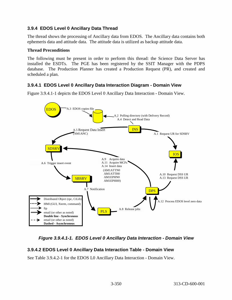
3.9.4 EDOS Level 0 Ancillary Data Thread The thread shows the processing of Ancillary data from EDOS. The Ancillary data contains both ephemeris data and attitude data. The attitude data is utilized as backup attitude data.
Thread Preconditions
The following must be present in order to perform this thread: the Science Data Server has installed the ESDTs. The PGE has been registered by the SSIT Manager with the PDPS database. The Production Planner has created a Production Request (PR), and created and scheduled a plan.
3.9.4.1 EDOS Level 0 Ancillary Data Interaction Diagram - Domain View Figure 3.9.4.1-1 depicts the EDOS Level 0 Ancillary Data Interaction - Domain View.
A.3 EDOS copies file
A.2 Polling directory (with Delivery Record)
DAAC Ops
EDOS
A.4 Detect and Read Data
PLS PLS
SBSRV
SDSRV
A.12 Process EDOS level zero data
DPSDPS
INS
IOS
A.1 Request UR for SDSRV A.5 Request Data Insert (AM1ANC)
A.6 Trigger insert event
A.7 Notification
A.10 Request DSS UR A.13 Request DSS UR
A.9 Acquire data A.11 Acquire MCFs A.14 Insert data
A.8 Release jobs
Distributed Object (rpc, CtLib) HMI (GUI, Xterm, command) ftp email (or other as noted) Double line - Synchronous email (or other as noted) Dashed - Asynchronous
(AM1ATTN0 AM1ATTH0 AM1EPHN0 AM1EPHH0)
Figure 3.9.4.1-1. EDOS Level 0 Ancillary Data Interaction - Domain View
3.9.4.2 EDOS Level 0 Ancillary Data Interaction Table - Domain View See Table 3.9.4.2-1 for the EDOS L0 Ancillary Data Interaction - Domain View.
3-350 313-CD-600-001

Table 3.9.4.2-1. Interaction Table - Domain View: EDOS L0 Ancillary Data (1 of 2) Step Event Interface
Client Interface Provider
Data Issues
Step Preconditio
ns
Description
A.1 Request UR for SDSRV
INS IOS/ADV None None Upon startup, Ingest obtains the SDSRV URs for each data type in its database.
A.2 Polling directory INS Ingest directory
None Entire step is a precondition
When the system is started, Ingest begins polling a directory, looking for files that meet the following standard: *.PDR.XFR in the pre-configured directory.
A.3 EDOS copies file EDOS Ingest directory
None EDOS knows the host and directory for file placement
EDOS copies Ancillary Packets to a local disk on the Ingest host for Ingest access.
A.4 Detect and Read Data
INS Directory None None Ingest Polling detects data in the directory and reads the data.
A.5 Request Data Insert
INS SDSRV None EDOS level 0 ephemeris data
Archive newly received EDOS Ancillary Packets for ESDTAM1ANC..
A.6 Trigger insert event SDSRV SBSRV None None Trigger EDOS Ancillary Packets insert event.
A.7 Notification SBSRV PLS None PLS subscription for EDOS level 0 ephemeris data
Send direct notification to PLS to inform that there are newly inserted Ancillary Packets.
A.8 Release job PLS DPS None None PLS releases job to process EDOS level 0 data.
A.9 Acquire data DPS SDSRV The input data must have been received.
None DPS submits an acquire request for the EDOS Ancillary Packets that were inserted in step A.4.
A.10 Request DSS UR DPS IOS/ADV None None These URs will be used to acquire the metadata control files, one for each data type to be produced.
A.11 Acquire MCFs DPS SDSRV None None Metadata Control Files, one for each data type to be produced, are acquired from the SDSRV.
3-351 313-CD-600-001

Table 3.9.4.2-1. Interaction Table - Domain View: EDOS L0 Ancillary Data (2 of 2) Step Event Interface
Client Interface Provider
Data Issues
Step Preconditio
ns
Description
A.12 Process EDOS Level 0 data
DPS DPS None None Toolkit native format and HDF Level 0 ephemeris data and metadata files are generated. Gaps up to 60 seconds are filled in using an interpolation algorithm provided by the FDD
A.13 Request DSS UR DPS IOS/ADV None None URs to be used by the Data Server for the storage of the generated files are obtained from the Advertising Server.
A.14 Request Data Insert
DPS SDSRV None None The toolkit native format and HDF output files are archived. These cover ESDTs AM1ATTN0, AM1ATTH0, AM1EPHN0, andAM1EPHH0. .
3.9.4.3 EDOS Level 0 Ancillary Data Component Interaction Table See Table 3.9.4.3-1 for the EDOS L0 Ancillary Data Component Interaction.
3-352 313-CD-600-001

Table 3.9.4.3-1. Component Interaction Table: EDOS L0 Ancillary Data (1 of 3) Step Event Interface
Client Interface Provider
Interface Mech.
Description
A.1.1 Request UR for SDSRV
EcInReqM gr
EcIoAdServ er
Distributed Object
Upon startup, Ingest obtains the SDSRV URs for each data type in its database.
A.2.1 Polling directory
EcInPollin g
Directory ftp When the system is started, Ingest begins polling a directory, looking for files that meet the following standard: *.PDR.XFR in the pre-configured directory. The polling periodicity is determined from a configuration file. The mask of the file to look for is determined from the Notify Type of the data provider in the Ingest database.
A.3.1 EDOS copies file
EDOS EcInPolling ftp EDOS copies Ancillary Packets to a local disk on the Ingest host for Ingest access.
A.4.1 Polling Detects Files
EcInPollin g
Directory ftp Ingest Polling detects files matching the *.PDR mask.
A.4.2 Ingest Request
EcInPollin g
EcInReqMgr Distributed Object
Polling Ingest process packages the PDR information into an Ingest Request. The originating system is passed to the Ingest Request Manager.
A.4.3 Ingest Granules
EcInReqM gr
EcInGran Distributed Object
Ingest Request Manager packages the request into granules and sends them to the appropriate Ingest Granule Server.
A.5.1 Connect to SDSRV
EcInGran EcDsScienc eDataServer
Distributed Object
Ingest begins a session with the SDSRV by connecting. The correct SDSRV is determined during EcInReqMgr startup, from Advertising, based on the data type. This is pertinent if there are multi-SDSRVs in use at one DAAC in one mode.
A.5.2 Request Metadata Configuratio n File
EcInGran EcDsScienc eDataServer
Distributed Object
Ingest requests the metadata configuration file (MCF) for the data being inserted. The data types being inserted are derived from the *.PDR file. Ingest performs preprocessing (current number of files for data type, metadata extraction, etc.).
A.5.3 Validate Metadata
EcInGran EcDsScienc eDataServer
Distributed Object
After building a metadata file for the granule, Ingest asks SDSRV to validate the metadata, based on the granule’s data type.
A.5.4 Request Data Insert
EcInGran EcDsScienc eDataServer
Distributed Object
Archive newly received EDOS Ancillary Packets for ESDTAM1ANC. .
3-353 313-CD-600-001
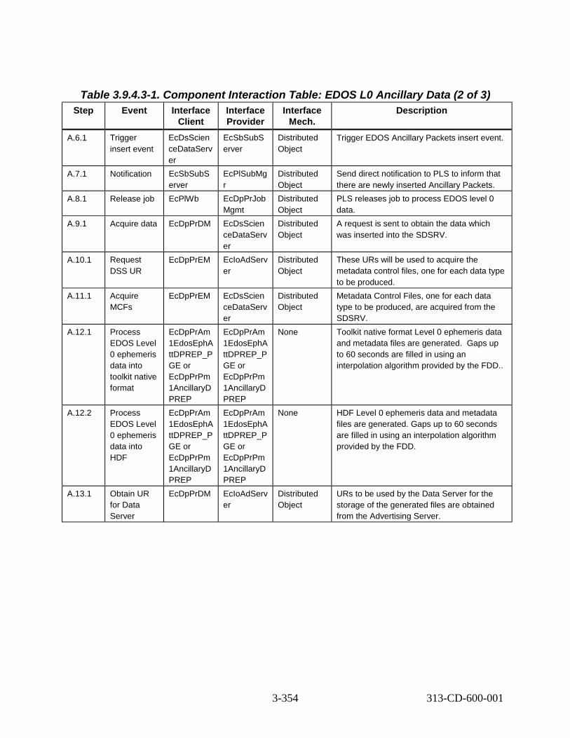
Table 3.9.4.3-1. Component Interaction Table: EDOS L0 Ancillary Data (2 of 3) Step Event Interface
Client Interface Provider
Interface Mech.
Description
A.6.1 Trigger insert event
EcDsScien ceDataServ er
EcSbSubS erver
Distributed Object
Trigger EDOS Ancillary Packets insert event.
A.7.1 Notification EcSbSubS erver
EcPlSubMg r
Distributed Object
Send direct notification to PLS to inform that there are newly inserted Ancillary Packets.
A.8.1 Release job EcPlWb EcDpPrJob Mgmt
Distributed Object
PLS releases job to process EDOS level 0 data.
A.9.1 Acquire data EcDpPrDM EcDsScien ceDataServ er
Distributed Object
A request is sent to obtain the data which was inserted into the SDSRV.
A.10.1 Request DSS UR
EcDpPrEM EcIoAdServ er
Distributed Object
These URs will be used to acquire the metadata control files, one for each data type to be produced.
A.11.1 Acquire MCFs
EcDpPrEM EcDsScien ceDataServ er
Distributed Object
Metadata Control Files, one for each data type to be produced, are acquired from the SDSRV.
A.12.1 Process EDOS Level 0 ephemeris data into toolkit native format
EcDpPrAm 1EdosEphA ttDPREP_P GE or EcDpPrPm 1AncillaryD PREP
EcDpPrAm 1EdosEphA ttDPREP_P GE or EcDpPrPm 1AncillaryD PREP
None Toolkit native format Level 0 ephemeris data and metadata files are generated. Gaps up to 60 seconds are filled in using an interpolation algorithm provided by the FDD..
A.12.2 Process EDOS Level 0 ephemeris data into HDF
EcDpPrAm 1EdosEphA ttDPREP_P GE or EcDpPrPm 1AncillaryD PREP
EcDpPrAm 1EdosEphA ttDPREP_P GE or EcDpPrPm 1AncillaryD PREP
None HDF Level 0 ephemeris data and metadata files are generated. Gaps up to 60 seconds are filled in using an interpolation algorithm provided by the FDD.
A.13.1 Obtain UR for Data Server
EcDpPrDM EcIoAdServ er
Distributed Object
URs to be used by the Data Server for the storage of the generated files are obtained from the Advertising Server.
3-354 313-CD-600-001

Table 3.9.4.3-1. Component Interaction Table: EDOS L0 Ancillary Data (3 of 3) Step Event Interface
Client Interface Provider
Interface Mech.
Description
A.14.1 Insert toolkit native format EDOS Level 0 ephemeris data
EcDpPrDM EcDsScien ceDataServ er
Distributed Object
The toolkit native format output files are stored – ESDTs AM1ATTN0 and AM1EPHN0.
A.14.2 Insert HDF EDOS Level 0 ephemeris data
EcDpPrDM EcDsScien ceDataServ er
Distributed Object
The HDF output files are stored – ESDTs AM1ATTH0 andAM1EPHH0.
3.9.5 Definitive Attitude Data Thread This thread illustrates the acquisition and processing of definitive attitude data to toolkit native format and HDF. The definitive attitude data is supplied by FDD for Terra.
Thread Preconditions
The following must be present in order to perform this thread: the Science Data Server has installed the ESDTs. The PGE has been registered by the SSIT Manager with the PDPS database. The Production Planner has created a Production Request (PR), and created and scheduled a plan.
3.9.5.1 Definitive Attitude Data Thread - Domain View See Figure 3.9.5.1-1 for the Definitive Attitude Data diagram.
3-355 313-CD-600-001

PLSPLS
SBSRV
SDSRV
B.13 Process definitive attitude data
DPSDPS
INS
IOS
B.3 Copy file
B.2 olling directory
B.1 Request UR for SDSRVB.6 Request Data Insert (AM1ATTF or Aqua data)
B.7 rigger insert event
B.8 Notification
B.11 Request DSS UR B.14 Request DSS UR
B.10 Acquire data B.12 Acquire MCFs B.15 Insert data
B.9 Release jobs
DAAC OpsFDF
Distributed Object (rpc, CtLib) HMI (GUI, Xterm, command) ftp email (or other as noted) Double line - Synchronous email (or other as noted) Dashed - Asynchronous
(AM1ATTNF, AM1ATTHF
Polling directory w/o Delivery Record for FDF
B.4 Detect and Read Data
B.5* Create Staging Disk and Transfer files to Disk
* Note: Step B.5 is not done for EDOS applications of this Thread.
P
T
Figure 3.9.5.1-1. Definitive Attitude Data Diagram
3.9.5.2 Definitive Attitude Data Thread Interaction Table - Domain View See Table 3.9.5.2-1 for the Definitive Attitude Data Interaction.
Table 3.9.5.2-1. Interaction Table - Domain View: Definitive Attitude Data (1 of 3)
Step Event Interface Client
Interface Provider
Data Issues
Step Precon-ditions
Description
B.1 Request UR for SDSRV
INS IOS/ADV None None Upon startup, Ingest obtains the SDSRV URs for each data type in its database.
B.2 Polling directory
INS Ingest directory
None Entire step is a precondit ion
When the system is started, Ingest begins polling a directory at a given location and name for Definitive Attitude data. This is polling without Delivery Record, thus, Ingest formulates a Delivery Record internally.
3-356 313-CD-600-001

Table 3.9.5.2-1. Interaction Table - Domain View: Definitive Attitude Data (2 of 3) Step Event Interface
Client Interface Provider
Data Issues
Step Precon ditions
Description
B.3 Copy file (FDF for Terra)
FDD Ingest directory
None FDD knows the host and directory for file placeme nt
FDD copies Definitive Attitude files every 2 hours to a local disk on the FDD host for Ingest access. The source of the FDD data is EDOS via the EDOS Operations Center (EOC).
B.4 Detect and Read Data
INS Directory None None Ingest Polling detects data in the directory and reads the data.
B.5* Create Staging Disk & Transfer Files (FDF data only)
INS DSS None None After Ingest detects files and packages into granules, Ingest interfaces with the DSS to create an Ingest staging disk and transfers the files to this staging disk. (*Note: This step is not done for EDOS).
B.6 Request Data Insert
INS SDSRV None Definitive Attitude data
Ingest inserts the Definitive Attitude data into the Science Data Server for ESDT AM1ATTF.
B.7 Trigger insert event
SDSRV SBSRV None None Trigger Definitive Attitude data insert event.
B.8 Notification SBSRV PLS None PLS subscripti on for Definitive Attitude data
Send direct notification to PLS to inform that there is newly inserted Definitive Attitude data.
B.9 Release job PLS DPS None None PLS releases job to process Definitive Attitude data.
B.10 Acquire data DPS SDSRV The input data must have been received.
None DPS submits an acquire request for the Definitive Attitude data that was inserted in step B.4.
3-357 313-CD-600-001

Table 3.9.5.2-1. Interaction Table - Domain View: Definitive Attitude Data (3 of 3) Step Event Interface
Client Interface Provider
Data Issues
Step Precon ditions
Description
B.11 Request DSS UR
DPS IOS/ADV None None These URs will be used to acquire the metadata control files, one for each data type to be produced.
B.12 Acquire MCFs
DPS SDSRV None None Metadata Control Files, one for each data type to be produced, are acquired from the SDSRV.
B.13 Process Definitive Attitude data
DPS DPS None None Toolkit native format and HDF Definitive Attitude data and metadata files are generated.
B.14 Request DSS UR
DPS IOS/ADV None None URs to be used by the Data Server for the storage of the generated files are obtained from the Advertising Server.
B.15 Insert Data DPS SDSRV None None The toolkit native format and HDF output files are archived for ESDTs AM1ATTNF and AM1ATTHF.
3.9.5.3 Definitive Attitude Data Thread Component Interaction Table See Table 3.9.5.3-1 for the Definitive Attitude Data Component Interaction.
3-358 313-CD-600-001

Table 3.9.5.3-1. Component Interaction Table: Definitive Attitude Data (1 of 4) Step Event Interface
Client Interface Provider
Interface Mech.
Description
B.1.1 Request UR for SDSRV
EcInReqMgr EcIoAdSer ver
Distributed Object
Upon startup, Ingest obtains the SDSRV URs for each data type in its database.
B.2.1 Polling directory EcInPolling Polling Directory
ftp When the system is started, Ingest begins polling a directory at a given location and name for Definitive Attitude data. This is polling without Delivery Record, thus, Ingest formulates a Delivery Record internally.
B.3.1 Copy file FDD EcInPollin g
ftp FDD copies their Definitive Attitude files every 2 hours to a local disk on the FDD host for Ingest access. The source of the FDD data is EDOS via the EOS Operations Center (EOC).
B.4.1 Polling Detects Files EcInPolling Directory ftp Ingest Polling detects files matching the *.PDR mask.
B.4.2 Ingest Request EcInPolling EcInReqM gr
Distributed Object
Polling Ingest process packages the PDR information into an Ingest Request. The originating system is passed to the Ingest Request Manager.
B.4.3 Ingest Granules EcInReqMgr EcInGran Distributed Object
Ingest Request Manager packages the request into granules and sends them to the appropriate Ingest Granule Server.
B.5.1 Create Staging Disk EcInGran EcDsStSt agingDisk Server
Distributed Object
Ingest creates Staging Disk. The correct Staging Disk is determined from the Ingest Database. The amount of staging disk to request is determined from the *.PDR file.
3-359 313-CD-600-001

Table 3.9.5.3-1. Component Interaction Table: Definitive Attitude Data (2 of 4) Step Event Interface
Client Interface Provider
Interface Mech.
Description
B.5.2 Allocate Media Resource
EcInGran EcDsStIng estFtpSer ver
Distributed Object
Ingest now creates the Resource manager for its ftp server via a Resource Manager Factory. Ingest knows that this request is via ftp from a database lookup, keyed on the data provider. The correct resource manager is determined from the Media Type handed to the resource factory (IngestFtp, in this case). The correct IngestFtp Server resource is determined from configuration within the Ingest Database.
B.5.3 Ftp Get files EcInGran EcDsStIng estFtpSer ver
Distributed Object
Ingest directs the ftp server to get the files from the host and location, as indicated in the *.PDR file, placing them on the staging disk.
B.6.1 Connect to SDSRV EcInGran EcDsScie nceDataS erver
Distributed Object
Ingest begins a session with the SDSRV by connecting. The correct SDSRV is determined during EcInReqMgr startup, from Advertising, based on the data type. This is pertinent if there are multi-SDSRVs in use at one DAAC in one mode.
B.6.2 Request Metadata Configuration File
EcInGran EcDsScie nceDataS erver
Distributed Object
Ingest requests the metadata configuration file (MCF) for the data being inserted. The data types being inserted are derived from the *.PDR file. Ingest performs preprocessing (current number of files for data type, metadata extraction, etc.).
B.6.3 Validate Metadata EcInGran EcDsScie nceDataS erver
Distributed Object
After building a metadata file for the granule, Ingest asks SDSRV to validate the metadata, based on the granule’s data type.
3-360 313-CD-600-001

Table 3.9.5.3-1. Component Interaction Table: Definitive Attitude Data (3 of 4) Step Event Interface
Client Interface Provider
Interface Mech.
Description
B.6.4 Request Data Insert EcInGran EcDsScie nceDataS erver
Distributed Object
Archive newly received Definitive Attitude data for ESDT AM1ATTF for Terra.
B.7.1 Trigger insert event EcDsScienc eDataServer
EcSbSub Server
Distributed Object
Trigger Definitive Attitude data insert event.
B.8.1 Notification EcSbSubSer ver
EcPlSubM gr
Distributed Object
Send direct notification to PLS to inform that there is newly received Definitive Attitude data.
B.9.1 Release job EcPlWb EcDpPrJo bMgmt
Distributed Object
PLS releases job to process Definitive Attitude data.
B.10.1 Acquire data EcDpPrDM EcDsScie nceDataS erver
Distributed Object
A request is sent to obtain the data which was inserted into the SDSRV.
B.11.1 Request DSS UR EcDpPrEM EcIoAdSer ver
Distributed Object
These URs will be used to acquire the metadata control files, one for each data type to be produced.
B.12.1 Acquire MCFs EcDpPrEM EcDsScie nceDataS erver
Distributed Object
Metadata Control Files, one for each data type to be produced, are acquired from the SDSRV.
B.13.1 Process Definitive Attitude data into toolkit native format
EcDpPrAm1 FddAttitude DPREP or EcDpPrPm1 FddAttitude DPREP
EcDpPrA m1FddAtti tudeDPRE P or EcDpPrP m1FddAtti tudeDPRE P
None Toolkit native format Definitive Attitude data and metadata files are generated.
B.13.2 Process Definitive Attitude data into HDF
EcDpPrAm1 FddAttitude DPREP or EcDpPrPm1 AttitudeDPR EP
EcDpPrA m1FddAtti tudeDPRE P or EcDpPrP m1Attitude DPREP
None HDF Definitive Attitude data and metadata files are generated.
B.14.1 Obtain UR for Data Server
EcDpPrDM EcIoAdSer ver
Distributed Object
URs to be used by the Data Server for the storage of the generated files are obtained from the Advertising Server.
3-361 313-CD-600-001
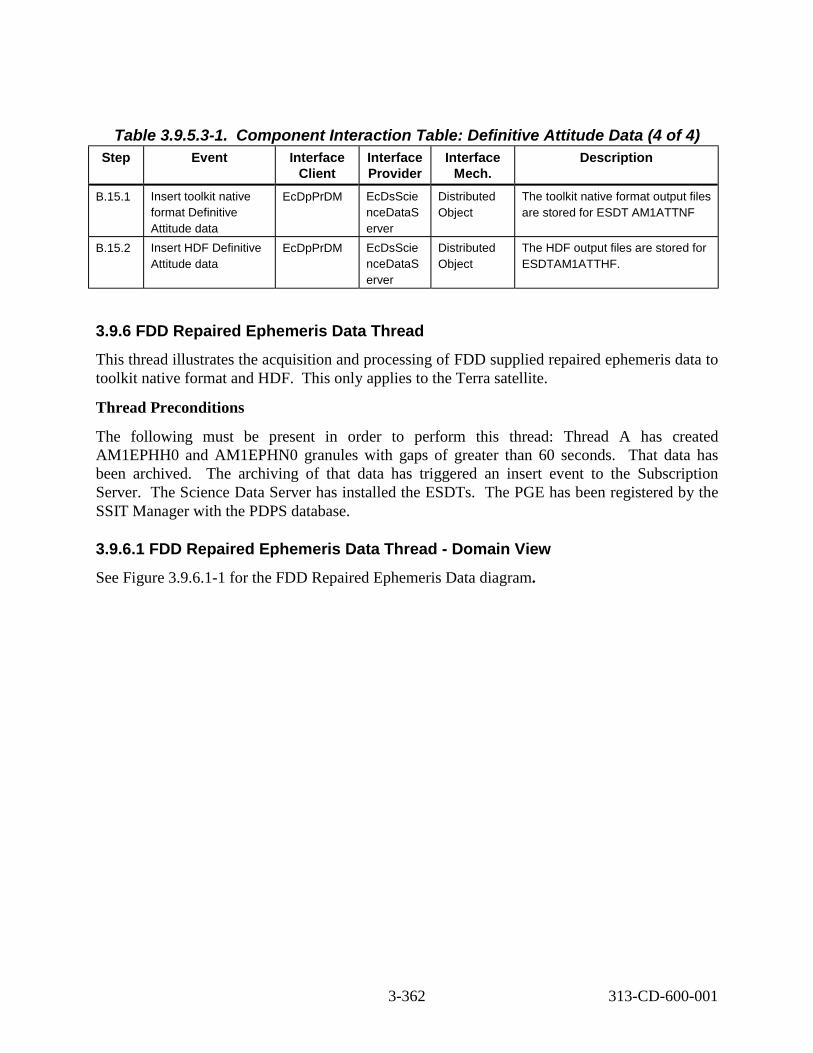
Table 3.9.5.3-1. Component Interaction Table: Definitive Attitude Data (4 of 4) Step Event Interface
Client Interface Provider
Interface Mech.
Description
B.15.1 Insert toolkit native format Definitive Attitude data
EcDpPrDM EcDsScie nceDataS erver
Distributed Object
The toolkit native format output files are stored for ESDT AM1ATTNF
B.15.2 Insert HDF Definitive Attitude data
EcDpPrDM EcDsScie nceDataS erver
Distributed Object
The HDF output files are stored for ESDTAM1ATTHF.
3.9.6 FDD Repaired Ephemeris Data Thread This thread illustrates the acquisition and processing of FDD supplied repaired ephemeris data to toolkit native format and HDF. This only applies to the Terra satellite.
Thread Preconditions
The following must be present in order to perform this thread: Thread A has created AM1EPHH0 and AM1EPHN0 granules with gaps of greater than 60 seconds. That data has been archived. The archiving of that data has triggered an insert event to the Subscription Server. The Science Data Server has installed the ESDTs. The PGE has been registered by the SSIT Manager with the PDPS database.
3.9.6.1 FDD Repaired Ephemeris Data Thread - Domain View See Figure 3.9.6.1-1 for the FDD Repaired Ephemeris Data diagram.
3-362 313-CD-600-001

PLSPLS
SBSRV
SDSRV
C.17 Process FDF AM-1 repaired ephemeris data
DPSDPS
INS
IOS
C.7 FDF copies file
C.6 olling directory (w/o Delivery Record)
C.5 Request UR for SDSRVC.10 Request Data Insert (AM1EPHF)
C.11 Trigger insert event
C.12 Notification
C.15 Request DSS UR C.18 Request DSS UR
C.14 Acquire data C.16 Acquire MCFs C.19 Insert data (AM1EPHH0, AM1EPHN0)
C.13 Release jobs
DAAC Ops FDF
Distributed Object (rpc, CtLib) HMI (GUI, Xterm, command) ftp email (or other as noted) Double line - Synchronous email (or other as noted) Dashed - Asynchronous
DAAC Ops OPS
C.1 E-mail
C.3 Creates a PR C.4 Activate plan
C.2 Phone call
C.8 Detect and Read Data
C.9 Create Staging Disk & Transfer Files to Disk
P
Figure 3.9.6.1-1. FDD Repaired Ephemeris Data Diagram
3.9.6.2 FDD Repaired Ephemeris Data Thread Interaction Table - Domain View See Table 3.9.6.2-1 for the FDD Repaired Ephemeris Data Interaction.
3-363 313-CD-600-001

Table 3.9.6.2-1. Interaction Table - Domain View: FDD Repaired Ephemeris Data (1 of 3)
Step Event Interface Client
Interface Provider
Data Issues
Step Preconditions
Description
C.1 E-mail SBSRV DAAC Ops – Productio n Planner
A gap greater than 60 seconds has occurred in the AM1EPH N0 and AM1EPH H0 files.
The EDOS Level 0 Ancillary Data in question has already been processed.
An e-mail message is sent to the Production Planner, alerting him to the > 60 second gap in the processed EDOS Terra Ephemeris Data file.
C.2 Call FDD (via telephone)
DAAC Ops – Production Planner
FDD Missing data is > 60 seconds.
The gap has been identified.
The Production Planner contacts the FDD and requests repaired ephemeris data for the time span of the granule that has the gap. The whole dataset will replaced, not just the gap.
C.3 Create a PR DAAC Ops – Production Planner
PLS None In preparation for the receipt of the repaired ephemeris data from the FDD
The Operator creates a production request.
C.4 Activate Plan DAAC Ops – Production Planner
PLS None In preparation for the receipt of the repaired ephemeris data from the FDD
The Operator activates a plan.
C.5 Request UR for SDSRV
INS IOS/ADV None None Upon startup, Ingest obtains the SDSRV URs for each data type in its database.
C.6 Polling directory
INS Ingest directory
None Entire step is a precondition
When the system is started, Ingest begins polling a directory at a given location and name for FDD Repaired Ephemeris data.
C.7 FDD copies file
FDD Ingest directory
None FDD knows the host and directory for file placement
FDD copies Repaired Ephemeris file to a local disk on the FDD host for Ingest access.
C.8 Detect and Read Data
INS Directory None None Ingest Polling detects data in the directory and reads the data.
3-364 313-CD-600-001

Table 3.9.6.2-1. Interaction Table - Domain View: FDD Repaired Ephemeris Data (2 of 3)
Step Event Interface Client
Interface Provider
Data Issues
Step Preconditions
Description
C.9 Create Staging Disk & Transfer Files
INS DSS None None After Ingest detects files and packages into granules, Ingest interfaces with the DSS to create an Ingest staging disk and transfers the files to this staging disk.
C.10 Request Data Insert
INS SDSRV None FDD Repaired Ephemeris data
Ingest inserts the FDD Repaired Ephemeris data into the Science Data Server for ESDT AM1EPHF.
C.11 Trigger insert event
SDSRV SBSRV None None Trigger FDD Repaired Ephemeris data insert event.
C.12 Notification SBSRV PLS None PLS subscription for FDD Repaired Ephemeris data
Send direct notification to PLS to inform that there is newly inserted FDD Repaired Ephemeris data.
C.13 Release job PLS DPS None None PLS releases job to process FDD Repaired Ephemeris data
C.14 Acquire data DPS SDSRV The input data must have been received.
None DPS submits an acquire request for the FDD Repaired Ephemeris data that was inserted in step C.8.
C.15 Request DSS UR
DPS IOS/ADV None None These URs will be used to acquire the metadata control files, one for each data type to be produced.
C.16 Acquire MCFs
DPS SDSRV None None Metadata Control Files, one for each data type to be produced, are acquired from the SDSRV.
C.17 Process FDD Terra repaired ephemeris data
DPS DPS The gap is > 60 seconds
FDD has supplied Repaired Ephemeris Data for the gap.
Toolkit native format and HDF EDOS Terra Ephemeris with gaps > 60 seconds are repaired using FDD Repaired Ephemeris data.
3-365 313-CD-600-001

Table 3.9.6.2-1. Interaction Table - Domain View: FDD Repaired Ephemeris Data (3 of 3)
Step Event Interface Client
Interface Provider
Data Issues
Step Preconditions
Description
C.18 Request DSS UR
DPS IOS/ADV None None URs to be used by the Data Server for the storage of the generated files are obtained from the Advertising Server.
C.19 Insert data DPS SDSRV None None The toolkit native format and HDF repaired output files are archived for ESDTs AM1EPHH0 and AM1EPHN0.
3.9.6.3 FDD Repaired Ephemeris Data Thread Component Interaction Table See Table 3.9.6.3-1 for the FDD Repaired Ephemeris Data Component Interaction.
Table 3.9.6.3-1. Component Interaction Table: FDD Repaired Ephemeris Data (1 of 4)
Step Event Interface Client Interface Provider
Interface Mech.
Description
C.1.1 E-mail EcSbSubServer EcSbSub Server
e-mail An e-mail message is sent to the Production Planner, alerting him to the > 60 second gap in the processed EDOS Terra Ephemeris Data file.
C.2.1 Call FDD (via telephone)
DAAC Ops – Production Planner
FDD e-mail The Production Planner contacts the FDD and requests repaired ephemeris data for the time span of the granule that has the gap
C.3.1 Create production request
DAAC Ops – Production Planner
EcPlPREd itor_IF
GUI The Operator creates a production request.
C.4.1 Activate plan DAAC Ops – Production Planner
EcPlPREd itor_IF
GUI The Operator activates a plan.
C.5.1 Request UR for SDSRV
EcInReqMgr EcIoAdSer ver
Distributed Object
Upon startup, Ingest obtains the SDSRV URs for each data type in its database.
C.6.1 Polling directory
EcInPolling Polling Directory
ftp When the system is started, Ingest begins polling a directory at a given location and name for FDD Repaired Ephemeris data.
3-366 313-CD-600-001

Table 3.9.6.3-1. Component Interaction Table: FDD Repaired Ephemeris Data (2 of 4)
Step Event Interface Client Interface Provider
Interface Mech.
Description
C.7.1 FDD copies file
FDD EcInPollin g
ftp FDD copies their Repaired Ephemeris files every 2 hours to a local disk on the FDD host for Ingest access. The source of the FDD data is EDOS via the EOS Operations Center (EOC).
C.8.1 Polling Detects Files
EcInPolling Directory ftp Ingest Polling detects files matching the *.PDR mask.
C.8.2 Ingest Request
EcInPolling EcInReqM gr
Distributed Object
Polling Ingest process packages the PDR information into an Ingest Request. The originating system is passed to the Ingest Request Manager.
C.8.3 Ingest Granules
EcInReqMgr EcInGran Distributed Object
Ingest Request Manager packages the request into granules and sends them to the appropriate Ingest Granule Server.
C.9.1 Create Staging Disk
EcInGran EcDsStSt agingDisk Server
Distributed Object
Ingest creates Staging Disk. The correct Staging Disk is determined from the Ingest Database. The amount of staging disk to request is determined from the *.PDR file.
C.9.2 Allocate Media Resource
EcInGran EcDsStIng estFtpSer ver
Distributed Object
Ingest now creates the Resource manager for its ftp server via a Resource Manager Factory. Ingest knows that this request is via ftp from a database lookup, keyed on the data provider. The correct resource manager is determined from the Media Type handed to the resource factory (IngestFtp, in this case). The correct IngestFtp Server resource is determined from configuration within the Ingest Database.
C.9.3 Ftp Get files EcInGran EcDsStIng estFtpSer ver
Distributed Object
Ingest directs the ftp server to get the files from the host and location, as indicated in the *.PDR file, placing them on the staging disk.
3-367 313-CD-600-001

Table 3.9.6.3-1. Component Interaction Table: FDD Repaired Ephemeris Data (3 of 4)
Step Event Interface Client Interface Provider
Interface Mech.
Description
C.10.1 Connect to SDSRV
EcInGran EcDsScie nceDataS erver
Distributed Object
Ingest begins a session with the SDSRV by connecting. The correct SDSRV is determined during EcInReqMgr startup, from Advertising, based on the data type. This is pertinent if there are multi-SDSRVs in use at one DAAC in one mode.
C.10.2 Request Metadata Configuration File
EcInGran EcDsScie nceDataS erver
Distributed Object
Ingest requests the metadata configuration file (MCF) for the data being inserted. The data types being inserted are derived from the *.PDR file. Ingest performs preprocessing (current number of files for data type, metadata extraction, etc.).
C.10.3 Validate Metadata
EcInGran EcDsScie nceDataS erver
Distributed Object
After building a metadata file for the granule, Ingest asks SDSRV to validate the metadata, based on the granule’s data type.
C.10.4 Request Data Insert
EcInGran EcDsScie nceDataS erver
Distributed Object
Archive newly received FDD Repaired Ephemeris data for ESDT AM1ATTF.
C.11.1 Trigger insert event
EcDsScienceDataS erver
EcSbSub Server
Distributed Object
Trigger FDD Repaired Ephemeris data insert event.
C.12.1 Notification EcSbSubServer EcPlSubM gr
Distributed Object
Send direct notification to PLS to inform that there is newly received FDD Repaired Ephemeris data.
C.13.1 Release job EcPlWb EcDpPrJo bMgmt
Distributed Object
PLS releases job to process FDD Repaired Ephemeris data.
C.14.1 Acquire data EcDpPrEM EcDsScie nceDataS erver
Distributed Object
A request is sent to obtain the data which was inserted into the SDSRV.
C.15.1 Request DSS UR
EcDpPrEM EcIoAdSer ver
Distributed Object
These URs will be used to acquire the metadata control files, one for each data type to be produced.
C.16.1 Acquire MCFs
EcDpPrEM EcDsScie nceDataS erver
Distributed Object
Metadata Control Files, one for each data type to be produced, are acquired from the SDSRV.
3-368 313-CD-600-001

Table 3.9.6.3-1. Component Interaction Table: FDD Repaired Ephemeris Data (4 of 4)
Step Event Interface Client Interface Provider
Interface Mech.
Description
C.17.1 Process FDD Repaired Ephemeris data into toolkit native format
EcDpPrAm1FddAtti tudeDPREP
EcDpPrA m1FddAtti tudeDPRE P
None Toolkit native format FDD Repaired Ephemeris data and metadata files are generated.
C.17.2 Process FDD Repaired Ephemeris data into HDF
EcDpPrAm1FddAtti tudeDPREP
EcDpPrA m1FddAtti tudeDPRE P
None HDF FDD Repaired Ephemeris data and metadata files are generated.
C.18.1 Obtain UR for Data Server
EcDpPrEM EcIoAdSer ver
Distributed Object
URs to be used by the Data Server for the storage of the generated files are obtained from the Advertising Server.
C.19.1 Insert toolkit native format FDD Repaired Ephemeris data
EcDpPrEM EcDsScie nceDataS erver
Distributed Object
The toolkit native format output files are stored for ESDT AM1EPHN0.
C.19.2 Insert HDF FDD Repaired Ephemeris data
EcDpPrDM EcDsScie nceDataS erver
Distributed Object
The HDF output files are stored for ESDT AM1EHPH0.
3.9.7 EDOS Backup Level 0 Data Insertion Thread - Deferred to Release 6B
3.9.8 Aqua FDS Ephemeris Data Thread The thread shows the processing of Aqua FDD Definitive Ephemeris data.
3-369 313-CD-600-001

Thread Preconditions
The following must be present in order to perform this thread: the Science Data Server has installed the ESDTs. The PGE has been registered by the SSIT Manager with the PDPS database. The Production Planner has created a Production Request (PR), and created and scheduled a plan.
3.9.8.1 Aqua FDD Ephemeris Processing Data Interaction Diagram - Domain View Figure 3.9.8.1-1 depicts the Aqua FDD Ephemeris data processing Data Interaction - Domain View.
E.2 olling directory (with Delivery Record) E.4 Detect and Read Data
P
E.3 opies file DAAC Ops FDS FDS c
PLS PLS
SBSRV
SDSRV
E.12 Process FDD Ephemeris data
DPSDPS
INS
IOS
E.1 equest UR for SDSRV E.5 Request Data Insert (PM1EPHD)
E.6 Trigger insert event
A.7 Notification
E.10 Request DSS UR E.13 Request DSS UR
E.9 Acquire data E.11 Acquire MCFs E.14 Insert data
E.8 Release jobs
Distributed Object (rpc, CtLib) HMI (GUI, Xterm, command) ftp email (or other as noted) Double line - Synchronous email (or other as noted) Dashed - Asynchronous
(PM1EPHHD PM1EPHND)
R
Figure 3.9.8.1-1. Aqua FDS Ephemeris Processing Data Interaction - Domain View
3-370 313-CD-600-001

3.9.8.2 Aqua FDS Ephemeris Processing Data Interaction Table - Domain View See Table 3.9.8.2-1 for the Aqua FDS Ephemeris Processing Data Interaction - Domain View.
Table 3.9.8.2-1. Interaction Table - Domain View: FDS Ephemeris Data (1 of 2) Step Event Interface
Client Interface Provider
Data Issues
Step Preconditio
ns
Description
E.1 Request UR for SDSRV
INS IOS/ADV None None Upon startup, Ingest obtains the SDSRV URs for each data type in its database.
E.2 Polling directory INS Ingest directory
None Entire step is a precondition
When the system is started, Ingest begins polling a directory, looking for files that meet the following standard: *.PDR.XFR in the pre-configured directory.
E.3 FDS copies file FDS Ingest directory
None FDS knows the host and directory for file placement
FDS copies ephemeris data to a local disk on the Ingest host for Ingest access.
E.4 Detect and Read Data
INS Directory None None Ingest Polling detects data in the directory and reads the data.
E.5 Request Data Insert
INS SDSRV None FDS ephemeris data
Archive newly received ephemeris data for ESDT.
E.6 Trigger insert event SDSRV SBSRV None None Trigger ephemeris data insert event.
E.7 Notification SBSRV PLS None PLS subscription for FDS ephemeris data
Send direct notification to PLS to inform that there is newly ephemeris data.
E.8 Release job PLS DPS None None PLS releases job to process FDS data.
E.9 Acquire data DPS SDSRV The input data must have been received.
None DPS submits an acquire request for the ephemeris data that was inserted in step A.4.
E.10 Request DSS UR DPS IOS/ADV None None These URs will be used to acquire the metadata control files, one for each data type to be produced.
E.11 Acquire MCFs DPS SDSRV None None Metadata Control Files, one for each data type to be produced, are acquired from the SDSRV.
3-371 313-CD-600-001

Table 3.9.8.2-1. Interaction Table - Domain View: FDD Ephemeris Data (2 of 2) Step Event Interface
Client Interface Provider
Data Issues
Step Preconditio
ns
Description
E.12 Process FDS Ephemeris data
DPS DPS None None Toolkit native format and HDF FDS ephemeris data and metadata files are generated.
E.13 Request DSS UR DPS IOS/ADV None None URs to be used by the Data Server for the storage of the generated files are obtained from the Advertising Server.
E.14 Request Data Insert
DPS SDSRV None None The toolkit native format and HDF output files are archived. These cover ESDTs PM1EPHHD, and PM1EPHND.
3.9.8.3 Aqua FDS Ephemeris Processing Data Component Interaction Table See Table 3.9.8.3-1 for the Aqua FDS Ephemeris Processing Data Component Interaction.
Table 3.9.8.3-1. Component Interaction Table: Aqua Ephemeris Processing (1 of 3)
Step Event Interface Client
Interface Provider
Interface Mech.
Description
E.1.1 Request UR for SDSRV
EcInReqM gr
EcIoAdServ er
Distributed Object
Upon startup, Ingest obtains the SDSRV URs for each data type in its database.
E.2.1 Polling directory
EcInPollin g
Directory ftp When the system is started, Ingest begins polling a directory, looking for files that meet the following standard: *.PDR.XFR in the pre-configured directory. The polling periodicity is determined from a configuration file. The mask of the file to look for is determined from the Notify Type of the data provider in the Ingest database.
E.3.1 FDS copies file
FDS EcInPolling ftp FDS copies ephemeris files to a local disk on the Ingest host for Ingest access.
E.4.1 Polling Detects Files
EcInPollin g
Directory ftp Ingest Polling detects files matching the *.PDR mask.
E.4.2 Ingest Request
EcInPollin g
EcInReqMgr Distributed Object
Polling Ingest process packages the PDR information into an Ingest Request. The originating system is passed to the Ingest Request Manager.
3-372 313-CD-600-001

Table 3.9.8.3-1. Component Interaction Table: Aqua FDS Ephemeris Data (2 of 3) Step Event Interface
Client Interface Provider
Interface Mech.
Description
E.4.3 Ingest Granules
EcInReqMg r
EcInGran Distributed Object
Ingest Request Manager packages the request into granules and sends them to the appropriate Ingest Granule Server.
E.5.1 Connect to SDSRV
EcInGran EcDsScien ceDataServ er
Distributed Object
Ingest begins a session with the SDSRV by connecting. The correct SDSRV is determined during EcInReqMgr startup, from Advertising, based on the data type. This is pertinent if there are multi-SDSRVs in use at one DAAC in one mode.
E.5.2 Request Metadata Configuratio n File
EcInGran EcDsScien ceDataServ er
Distributed Object
Ingest requests the metadata configuration file (MCF) for the data being inserted. The data types being inserted are derived from the *.PDR file. Ingest performs preprocessing (current number of files for data type, metadata extraction, etc.).
E.5.3 Validate Metadata
EcInGran EcDsScien ceDataServ er
Distributed Object
After building a metadata file for the granule, Ingest asks SDSRV to validate the metadata, based on the granule’s data type.
E5.4 Request Data Insert
EcInGran EcDsScien ceDataServ er
Distributed Object
Archive newly received Ephemeris files for ESDT.
E.6.1 Trigger insert event
EcDsScien ceDataServ er
EcSbSubS erver
Distributed Object
Trigger Aqua Ephemeris files insert event.
E.7.1 Notification EcSbSubS erver
EcPlSubMg r
Distributed Object
Send direct notification to PLS to inform that there are newly inserted Ancillary Packets.
E.8.1 Release job EcPlWb EcDpPrJob Mgmt
Distributed Object
PLS releases job to process FDS Ephemeris data.
E.9.1 Acquire data EcDpPrDM EcDsScien ceDataServ er
Distributed Object
A request is sent to obtain the data which was inserted into the SDSRV.
E.10.1 Request DSS UR
EcDpPrEM EcIoAdServ er
Distributed Object
These URs will be used to acquire the metadata control files, one for each data type to be produced.
E.11.1 Acquire MCFs
EcDpPrEM EcDsScien ceDataServ er
Distributed Object
Metadata Control Files, one for each data type to be produced, are acquired from the SDSRV.
3-373 313-CD-600-001

Table 3.9.8.3-1. Component Interaction Table: Aqua FDS Ephemeris Data (3 of 3) Step Event Interface
Client Interface Provider
Interface Mech.
Description
E.12.1 Process FDS Ephemeris data into toolkit native format
EcDpPrPm 1FddEphe merisDPRE P_PGE
EcDpPrAm 1EdosEphA ttDPREP_P GE or EcDpPrPm 1AncillaryD PREP
None Toolkit native format ephemeris data and metadata files are generated.
E.12.2 Process FDS Ephemeris data into HDF
EcDpPrPm 1FddEphe merisDPRE P_PGE
EcDpPrAm 1EdosEphA ttDPREP_P GE or EcDpPrPm 1AncillaryD PREP
None HDF ephemeris data and metadata files are generated.
E.13.1 Obtain UR for Data Server
EcDpPrDM EcIoAdServ er
Distributed Object
URs to be used by the Data Server for the storage of the generated files are obtained from the Advertising Server.
E.14.1 Insert toolkit native format FDS Ephemeris data
EcDpPrEM EcDsScien ceDataServ er
Distributed Object
The toolkit native format output files are stored – ESDTs PM1EPHND or PM1EPHNP.
E.14.2 Insert HDF FDS Ephemeris data
EcDpPrEM EcDsScien ceDataServ er
Distributed Object
The HDF output files are stored – ESDTs PM1EPHHD or PM1EPHHP.
3.9.9 Aqua Definitive Attitude Data Thread This thread illustrates the acquisition and processing of predictive and definitive attitude data to toolkit native format and HDF. The definitive attitude data is supplied formatted in carry-out files by EMOS for Aqua.
Thread Preconditions
The following must be present in order to perform this thread: the Science Data Server has installed the ESDTs. The PGE has been registered by the SSIT Manager with the PDPS database. The Production Planner has created a Production Request (PR), and created and scheduled a plan.
3.9.9.1 Predictive/Definitive Attitude Data Thread - Domain View See Figure 3.9.9.1-1 for the Predictive/Definitive Attitude Data diagram.
3-374 313-CD-600-001

PLSPLS
SBSRV
SDSRV
F.13 Process attitude data
DPSDPS
INS
IOS
F.3 Copy file
F.2 Polling directory
F.1 Request UR for SDSRVF.6 Request Data Insert (PMCOGBAD)
F.7 Trigger insert event
F.8 Notification
F.11 Request DSS UR F.14 Request DSS UR
F.10 Acquire data F.12 Acquire MCFs F.15 Insert data
F.9 Release jobs
DAAC OpsEMOS
Distributed Object (rpc, CtLib) HMI (GUI, Xterm, command) ftp email (or other as noted) Double line - Synchronous email (or other as noted) Dashed - Asynchronous
(PM1ATTHQ, PM1ATTHR
Polling directory w/o Delivery Record for FDF
F.4 Detect and Read Data
F.5* Create Staging Disk and Transfer files to Disk
PM1ATTNQ PM1ATTNR)
Figure 3.9.9.1-1. Definitive Attitude Data Diagram
3.9.9.2 Aqua Predictive/Definitive Attitude Data Thread Interaction Table - Domain View See Table 3.9.9.2-1 for the Aqua Predictive/Definitive Attitude Data Interaction.
3-375 313-CD-600-001

Table 3.9.9.2-1. Interaction Table - Domain View: Aqua Predicitve/Definitive Attitude Data (1 of 2)
Step Event Interface Client
Interface Provider
Data Issues
Step Precon-ditions
Description
F.1 Request UR for SDSRV
INS IOS/ADV None None Upon startup, Ingest obtains the SDSRV URs for each data type in its database.
F.2 Polling directory
INS Ingest directory
None Entire step is a precondit ion
When the system is started, Ingest begins polling a directory at a given location and name for Attitude data. This is polling without Delivery Record, thus, Ingest formulates a Delivery Record internally.
F.3 Copy file EMOS Ingest directory
None EMOS knows the host and directory for file placeme nt
EMOS copies Attitude files every 2 hours to a local disk on the FDD or EDOS host for Ingest access. The source of the data is EMOS.
F.4 Detect and Read Data
INS Directory None None Ingest Polling detects data in the directory and reads the data.
F.5* Create Staging Disk & Transfer Files (FDF data only)
INS DSS None None After Ingest detects files and packages into granules, Ingest interfaces with the DSS to create an Ingest staging disk and transfers the files to this staging disk. (*Note: This step is not done for EDOS).
F.6 Request Data Insert
INS SDSRV None Definitive Attitude data
Ingest inserts the Definitive Attitude data into the Science Data Server for ESDT PMCOGBAD.
F.7 Trigger insert event
SDSRV SBSRV None None Trigger Attitude data insert event.
F.8 Notification SBSRV PLS None PLS subscripti on for Attitude data
Send direct notification to PLS to inform that there is newly inserted Attitude data.
F.9 Release job PLS DPS None None PLS releases job to process Definitive Attitude data.
3-376 313-CD-600-001

Table 3.9.9.2-1. Interaction Table - Domain View: Aqua Predictive/Definitive Attitude Data (2 of 2)
Step Event Interface Client
Interface Provider
Data Issues
Step Precon ditions
Description
F.10 Acquire data DPS SDSRV The input data must have been received.
None DPS submits an acquire request for the Attitude data that was inserted in step E.4.
F.11 Request DSS UR
DPS IOS/ADV None None These URs will be used to acquire the metadata control files, one for each data type to be produced.
F.12 Acquire MCFs
DPS SDSRV None None Metadata Control Files, one for each data type to be produced, are acquired from the SDSRV.
F.13 Process Attitude data
DPS DPS None None Toolkit native format and HDF Definitive Attitude data and metadata files are generated.
F.14 Request DSS UR
DPS IOS/ADV None None URs to be used by the Data Server for the storage of the generated files are obtained from the Advertising Server.
F.15 Insert Data DPS SDSRV None None The toolkit native format and HDF output files are archived for ESDTs or PM1ATTHR and PM!ATTNR.
3.9.9.3 Aqua Predictive/Definitive Attitude Data Thread Component Interaction Table See Table 3.9.9.3-1 for the Aqua Definitive Attitude Data Component Interaction.
3-377 313-CD-600-001

Table 3.9.9.3-1. Component Interaction Table: Aqua Predictive/Definitive Attitude Data (1 of 4)
Step Event Interface Client
Interface Provider
Interface Mech.
Description
F.1.1 Request UR for SDSRV
EcInReqMgr EcIoAdSer ver
Distributed Object
Upon startup, Ingest obtains the SDSRV URs for each data type in its database.
F.2.1 Polling directory EcInPolling Polling Directory
ftp When the system is started, Ingest begins polling a directory at a given location and name for Attitude data. This is polling without Delivery Record, thus, Ingest formulates a Delivery Record internally.
F.3.1 Copy file EMOS EcInPollin g
ftp EMOS copies their carry-out files every 2 hours to the polling directory for Ingest access.
F.4.1 Polling Detects Files EcInPolling Directory ftp Ingest Polling detects files matching the *.PDR mask.
F.4.2 Ingest Request EcInPolling EcInReqM gr
Distributed Object
Polling Ingest process packages the PDR information into an Ingest Request. The originating system is passed to the Ingest Request Manager.
F.4.3 Ingest Granules EcInReqMgr EcInGran Distributed Object
Ingest Request Manager packages the request into granules and sends them to the appropriate Ingest Granule Server.
F.5.1 Create Staging Disk EcInGran EcDsStSt agingDisk Server
Distributed Object
Ingest creates Staging Disk. The correct Staging Disk is determined from the Ingest Database. The amount of staging disk to request is determined from the *.PDR file.
3-378 313-CD-600-001

Table 3.9.9.3-1. Component Interaction Table: Aqua Predictive/Definitive Attitude Data (2 of 4)
Step Event Interface Client
Interface Provider
Interface Mech.
Description
F.5.2 Allocate Media Resource
EcInGran EcDsStIng estFtpSer ver
Distributed Object
Ingest now creates the Resource manager for its ftp server via a Resource Manager Factory. Ingest knows that this request is via ftp from a database lookup, keyed on the data provider. The correct resource manager is determined from the Media Type handed to the resource factory (IngestFtp, in this case). The correct IngestFtp Server resource is determined from configuration within the Ingest Database.
F.5.3 Ftp Get files EcInGran EcDsStRe questMan ger then EcDsStFtp Server
Distributed Object
Ingest sends a request tot he STMGT Request Manager to forward a request to the Ftp Server to direct the ftp server to get the files from the host and location, as indicated in the *.PDR file, placing them on the staging disk.
F.6.1 Connect to SDSRV EcInGran EcDsScie nceDataS erver
Distributed Object
Ingest begins a session with the SDSRV by connecting. The correct SDSRV is determined during EcInReqMgr startup, from Advertising, based on the data type. This is pertinent if there are multi-SDSRVs in use at one DAAC in one mode.
F.6.2 Request Metadata Configuration File
EcInGran EcDsScie nceDataS erver
Distributed Object
Ingest requests the metadata configuration file (MCF) for the data being inserted. The data types being inserted are derived from the *.PDR file. Ingest performs preprocessing (current number of files for data type, metadata extraction, etc.).
F.6.3 Validate Metadata EcInGran EcDsScie nceDataS erver
Distributed Object
After building a metadata file for the granule, Ingest asks SDSRV to validate the metadata, based on the granule’s data type.
3-379 313-CD-600-001

Table 3.9.9.3-1. Component Interaction Table: Aqua Predictive/Definitive Attitude Data (3 of 4)
Step Event Interface Client
Interface Provider
Interface Mech.
Description
F.6.4 Request Data Insert EcInGran EcDsScie nceDataS erver
Distributed Object
Archive newly received Attitude data for ESDT PMCOGBAD.
F.7.1 Trigger insert event EcDsScienc eDataServer
EcSbSub Server
Distributed Object
Trigger Attitude data insert event.
F.8.1 Notification EcSbSubSer ver
EcPlSubM gr
Distributed Object
Send direct notification to PLS to inform that there is newly received Attitude data.
F.9.1 Release job EcPlWb EcDpPrJo bMgmt
Distributed Object
PLS releases job to process Attitude data.
F.10.1 Acquire data EcDpPrDM EcDsScie nceDataS erver
Distributed Object
A request is sent to obtain the data which was inserted into the SDSRV.
F.11.1 Request DSS UR EcDpPrEM EcIoAdSer ver
Distributed Object
These URs will be used to acquire the metadata control files, one for each data type to be produced.
F.12.1 Acquire MCFs EcDpPrEM EcDsScie nceDataS erver
Distributed Object
Metadata Control Files, one for each data type to be produced, are acquired from the SDSRV.
F.13.1 Process Definitive Attitude data into toolkit native format
EcDpPrPm1 FddEphemer isDPREP_P GE
EcDpPrA m1FddAtti tudeDPRE P or EcDpPrP m1FddAtti tudeDPRE P
None Toolkit native format Attitude data and metadata files are generated.
F.13.2 Process Definitive Attitude data into HDF
EcDpPrPm1 FddEphemer isDPREP_P GE
EcDpPrA m1FddAtti tudeDPRE P or EcDpPrP m1Attitude DPREP
None HDF Attitude data and metadata files are generated.
F.14.1 Obtain UR for Data Server
EcDpPrDM EcIoAdSer ver
Distributed Object
URs to be used by the Data Server for the storage of the generated files are obtained from the Advertising Server.
3-380 313-CD-600-001

Table 3.9.9.3-1. Component Interaction Table: Aqua Preditive/Definitive Attitude Data (4 of 4)
Step Event Interface Client
Interface Provider
Interface Mech.
Description
F.15.1 Insert toolkit native format Definitive Attitude data
EcDpPrDM EcDsScie nceDataS erver
Distributed Object
The toolkit native format output files is stored for ESDT PM1ATTNR for Aqua.
F.15.2 Insert HDF Definitive Attitude data
EcDpPrDM EcDsScie nceDataS erver
Distributed Object
The HDF output file is stored for ESDT PM1ATTHR.
3.10 Cross Mode / DAAC Scenario
3.10.1 Cross Mode / DAAC Scenario Description This scenario shows how ECS supports the interface between one Mode and or DAAC (System A) and a different Mode and or DAAC (System B).
The following system functionality is exercised in this scenario:
• Cross System data ingest
3.10.2 Cross Mode / DAAC Scenario Preconditions • The ESDTs for the data which is to be ingested have been inserted into the ECS.
• The data which is to be distributed has already been generated in the mode/DAAC of ECS from which the distribution is to take place.
3.10.3 Cross Mode / DAAC Scenario Partitions The cross mode / DAAC scenario is contained in the following thread:
• Cross Mode / DAAC Insertion (Thread A) – This thread shows how the ECS inserts data provided from a different mode and or DAAC by Data Distribution.
3.10.4 Cross Mode / DAAC Insertion Thread This scenario shows how ECS supports the archival of data distributed by ECS. The data being distributed by ECS comes from a different mode or DAAC than the mode or DAAC in which the archival is being done. The interface between Data Distribution and Ingest is via e-mail. Ingest receives an e-mail delivery notification from Data Distribution after the delivered files are ftp’d to an Ingest directory. Ingest then uses the information in the delivery notification to create a PDR (product delivery record) and puts the PDR in a polling directory. Then the data is ingested via a standard polling mechanism managed by Ingest.
3-381 313-CD-600-001

3.10.4.1 Cross Mode / DAAC Insertion Thread Interaction Diagram – Domain View Figure 3.10.4.1-1 depicts the Cross Mode / DAAC Insertion Thread – Domain View.
A.9 Get SDSRV URs
Data User or SBSRV in System A
INSINS B INSIOS
INSDSS
INSDSS
Distributed Object (rpc, CtLib) HMI (GUI, Xterm, command) ftp email (or other as noted) Double line - Synchronous email (or other as noted) Dashed - Asynchronous
A.11 Send PAN
A.3 Acquire (ftpPush)
A.5 Distribution Notice
A.10 Insert data
A.4 Ftp Data
A.1 Directory Polling for PDRs A.2 Directory Polling for Distribution Notice Files A.6 Put Distribution Notice In File A.7 Read Distribution Notice A.8 Create PDR and Put in Polling Directory
directory
A
B
Figure 3.10.4.1-1. Cross Mode / DAAC Insertion Interaction Diagram
3.10.4.2 Cross Mode Insertion Thread Interaction Table – Domain View Table 3.10.4.2-1 provides the Interaction – Domain View: Cross Mode / DAAC Insertion.
Table 3.10.4.2-1. Interaction Table – Domain View: Cross Mode / DAAC Insertion (1 of 2)
Step Interaction Interface Client
Interface Provider
Data Issues
Preconditions Description
A.1 Directory Polling for PDRs
INS B directory None Entire step is really a precondition.
When system is started, Ingest begins polling a directory, looking for files that meet the following standard: *.PDR, in the pre-configured directory.
3-382 313-CD-600-001

Table 3.10.4.2-1. Interaction Table – Domain View: Cross Mode / DAAC Insertion
Step Interaction Interface Client
Interface Provider
(2 of 2) Data
Issues Preconditions Description
A.2 Directory Polling for Distribution Notice Files
INS B directory None Entire step is really a precondition.
When system is started, Ingest begins polling a directory, looking for files that meet the following standard: *.notify, in the pre-configured directory.
A.3 Acquire Data Data User DSS A None None The Client or Subscription Server submits an Acquire request for granules, via ftp Push.
A.4 Ftp Data DSS A directory None None DSS ftps the data files to a directory.
A.5 Distribution Notice
DSS A INS B None The Ingest Email Parser has a valid e-mail address.
Send e-mail notification to Ingest on System “B” that the requested granules are now available on System “A”.
A.6 Put Distribution Notice in a File
INS B directory None None Store e-mail notification into a file.
A.7 Read Distribution Notice
INS B directory None None Ingest reads the distribution notice file.
A.8 Create PDR and put it in Polling Directory
INS B directory None None Ingest creates a PDR file from the data in the distribution notice file and puts the PDR file in a polling directory.
A.9 Get SDSRV URS
INS B IOS None None When Ingest receives a request for which it does not already have the SDSRV URs, it gets the SDSRV URs from IOS.
A.10 Insert Data INS B DSS B None DSS must have the appropriate ESDTs installed.
Ingest sends the data to DSS for archival.
A.11 Send PAN INS B Data User A
None The Data User’s e-mail address needs to be in the Ingest database.
When the Ingest request is complete, a Production Acceptance Notification (PAN) is e-mailed to the Data User indicating either success or errors found.
3-383 313-CD-600-001

3.10.4.3 Cross Mode / DAAC Insertion Thread Component Interaction Table Table 3.10.4.3-1 provides the Component Interaction: Cross Mode / DAAC Insertion.
Table 3.10.4.3-1. Component Interaction Table: Cross Mode / DAAC Insertion (1 of 5)
Step Event Interface Client
Interface Provider
Interface Mech.
Description
A.1.1 Ingest Polling for PDRs
EcInPolling Directory ftp Ingest begins polling the configured directory. It periodically looks for files named *.PDR. The polling periodicity is determined from a configuration file.
A.2.1 Ingest Polling for Distribution Notice Files
EcInEmailGW Server
Directory ftp Ingest begins polling the configured directory. It periodically looks for files names *.notify. The polling periodicity is determined from the Ingest database.
A.3.1 Acquire Data EcSbSubServe r or Client
EcDsScience DataServer
Distributed Object
SBSRV or Client submits an Acquire request for granules via ftpPush. This request is asynchronous, meaning that the return of the submit call of the request only contains the status of the request’s submittal. The request asks for an e-mail notification to be e-mailed to the Ingest.
A.3.2 Create Staging Disk
EcDsScienceD ataServer
EcDsStStagin gDiskServer
Distributed Object
SDSRV verifies access privileges for the granule and creates a Staging Disk for metadata files, which allocates space and passes back a reference to that disk space. The correct staging disk server is determined from the ArchiveID metadata of the granules to be distributed. The amount of staging disk to request is determined from collection level metadata from the ESDT’s Descriptor file.
A.3.3 Create Metadata File
EcDsScienceD ataServer
EcDsScience DataServer
Distributed Object
For each granule referenced in the Acquire request, the SDSRV creates a file containing the granule’s metadata before passing to Distribution.
3-384 313-CD-600-001

Table 3.10.4.3-1. Component Interaction Table: Cross Mode / DAAC Insertion (2 of 5)
Step Event Interface Client
Interface Provider
Interface Mech.
Description
A.3.4 Distribute Granules, Synchronous
EcDsScienceD ataServer
EcDsDistribut ionServer
Distributed Object
SDSRV submits a request to Data Distribution. The request includes, for each granule, a reference to the metadata file as well as all data files. Other parameters from the Acquire request are passed to Data Distribution.
A.3.5 Create Staging Disk
EcDsDistributi onServer
EcDsStStagin gDiskServer
Distributed Object
DDIST creates a Staging Disk for the granule files in the archive. This allocates space and passes back a reference to that disk space. The correct staging disk server is determined from the information passed by the SDSRV in the distribution request, which was the ArchiveID metadata parameter of the granule to be staged. The amount of staging disk to request is calculated from the file sizes in the information passed in the Distribution Request.
A.3.6 STMGT Retrieve
EcDsDistributi onServer
EcDsStArchiv eServer
Distributed Object
DDIST requests that STMGT retrieve the granule file that is archived. This results in the file being staged to read-only cache disks. This means that all files needed to fulfill the distribution request are on disk, and ready to be copied. The correct archive object to request is determined from the information provided by the SDSRV in the distribution request. The returns references to the files in the read-only cache.
A.3.7 Link Files to Staging Disk
EcDsDistributi onServer
EcDsStStagin gDiskServer
Distributed Object
DDIST links the files from the read-only cache into the staging disk.
A.3.8 Copy Files to Staging Disk
EcDsDistributi onServer
EcDsStStagin gDiskServer
Distributed Object
DDIST copies the metadata files from the SDSRV’s Staging Disk into the staging disk.
3-385 313-CD-600-001

Table 3.10.4.3-1. Component Interaction Table: Cross Mode / DAAC Insertion
Step Event Interface Client
(3 of 5) Interface Provider
Interface Mech.
Description
A.3.9 ftpPush Files EcDsDistributi onServer
EcDsStFtpDis Server
Distributed Object
DDIST now creates the Resource manager for ftp pushes via a Resource Manager Factory. The correct resource manager is determined from the Media Type handed to the resource factory (ftpPush, in this case). The correct FtpServer is determined from configuration within the resource factory. The files, host location, username and password are all determined from the information provided in the original Acquire request.
A.4.1 ftp Files EcDsStFtpDis Server
ftp daemon ftp CSS performs the actual low level ftp of the files.
A.5.1 Build Distribution Notice
EcDsDistributi onServer
EcDsDistribut ionServer
e-mail DDIST builds an e-mail notification that the user’s order has been fulfilled. This notification includes the media ID, type and format of the request, UR, type and the file names and sizes for each granule as well as a DAAC configurable preamble.
A.5.2 Send E-mail EcDsDistributi onServer
E-mail Service
e-mail DDIST sends the distribution notice to Ingest via e-mail.
A.6.1 Put Distribution Notice in a File
EcInEmailGW Server
E-mail Service
Sendmail script
The Ingest Email Parser stores the distribution notice as a text file in a configurable directory location using a Sendmail script. A reference to this script is available in the /etc/mail/aliases file.
A.7.1 Ingest Email Parser Detects Files
EcInEmailGW Server
EcInEmailGW Server
Distributed Object
Ingest Email Parser detects files matching the *.notify mask.
A.8.1 Create PDR EcInEmailGW Server
EcInEmailGW Server
Distributed Object
Ingest Email Parser parses the distribution notice file and uses the ESDT, FTPHOST, FTPDIR, FILENAME, and FILESIZE fields to generate a PDR file. It will set the ORIGINATING_SYSTEM in the PDR to “DDIST”.
A.8.2 Put PDR in Polling Directory
EcInEmailGW Server
Directory copy function Ingest Email Parser copies the PDR file to the predetermined directory.
3-386 313-CD-600-001

Table 3.10.4.3-1. Component Interaction Table: Cross Mode / DAAC Insertion
Step Event Interface Client
(4 of 5) Interface Provider
Interface Mech.
Description
A.8.3 Polling Detects Files
EcInPolling Directory ftp Ingest Polling detects files matching the *.PDR mask.
A.8.4 Ingest Request EcInPolling EcInReqMgr Distributed Object
Polling Ingest process packages the PDR information into an Ingest Request. The originating system (DDIST) is passed to the Ingest Request Manager.
A.9.1 Get SDSRV URS from IOS
EcInReqMgr EcIoAdServer Distributed Object
When Ingest Request Manager receives a request for which it does not already have the SDSRV URs for each data type in the request, it gets the SDSRV URs from Advertising.
A.10.1 Ingest Granules
EcInReqMgr EcInGran Distributed Object
Ingest Request Manager packages the request into granules and sends them to the appropriate Ingest Granule Server.
A.10.2 Connect to SDSRV
EcInGran EcDsScience DataServer
Distributed Object
Upon receiving the message to ingest a granule, the Ingest Granule Server begins a session with the SDSRV by connecting. The correct SDSRV is determined from the SDSRV UR received from IOS by the Ingest Request Manager, based on the data type.
A.10.3 Insert Data EcInGran EcDsScience DataServer
Distributed Object
Ingest replaces the InputPointers in the .met file with “RE-INGEST FROM DISTRIBUTION – INPUTS UNKNOWN” and then requests that the files in the granule be inserted into the Data Server. An Insert request, containing the names of the files comprising the granule is created. SDSRV validates the metadata and determines the archived names of the files.
A.10.4 STMGT Store EcDsScienceD ataServer
EcDsStArchiv eServer
Distributed Object
SDSRV requests that the granule be archived. The archive server reads the inserted files directly from the disks that they are residing on. The correct archive object to request is determined from collection level metadata for the ESDT, defined in the ESDT’s descriptor.
3-387 313-CD-600-001

Table 3.10.4.3-1. Component Interaction Table: Cross Mode / DAAC Insertion
Step Event Interface Client
(5 of 5) Interface Provider
Interface Mech.
Description
A.10.5 Adding a Granule to Inventory
EcDsScienceD ataServer
Sybase/SQS CtLib The validated metadata is parsed and added to the inventory of the SDSRV.
A.11.1 Send PAN EcInReqMgr E-mail Server e-mail The Ingest Request Manager creates a PAN and sends it to the Data User.
3.11 Science Investigator-Led Processing Systems (SIPS) Scenario
3.11.1 SIPS Scenario Description • This scenario shows how ECS supports the archival of SIPS data, and how ECS
supports reordering for reprocessing and in case of errors by a SIPS. The interface between SIPS and ECS in the data archival thread is through a standard polling (with delivery record) mechanism managed by Ingest. The interface between SIPS and ECS in reordering for reprocessing or failure thread is through a Machine to Machine Gateway Server provided by MTMGW in CSS. The security of the communication between SIPS and Machine to Machine Gateway Server is obtained by introducing ssh (secure shell protocol) mechanism which provides secure remote login and other secure network services over an insecure network.
3.11.2 SIPS Scenario Preconditions • The ESDTs for the SIPS data have been inserted into the ECS.
3.11.3 SIPS Scenario Partitions The SIPS scenario is partitioned into the following threads: • SIPS Data Insertion (Thread A) – This thread shows how the ECS inserts data provided by
SIPS via ECS standard data distribution services including search and order. (See section 3.11.4).
• SIPS Data Reprocessing - The SIPS Data Reprocessing illustrates a means to allow SIPS to reprocess data externally to ECS via Machine to Machine Gateway that provides search and order capabilities. • Inventory Search (Thread B) - This thread shows how inventory search request is
submitted by SIPS and how it is handled by ECS. (See section 3.11.5). • Product Order (Thread C) – This thread shows how product order request is
submitted by SIPS and how it is handled by ECS. (See section 3.11.6). • Integrated Search and Order (Thread D) – This thread shows how the integrated
request gets submitted by SIPS and how it is handled by ECS. (See section 3.11.7).
3-388 313-CD-600-001

3.11.4 SIPS Data Insertion Thread This thread shows how the ECS inserts data provided by SIPS.
The following system functionality is exercised in this scenario:
• SIPS driven data ingest
3.11.4.1 SIPS Data Insertion Thread Interaction Diagram – Domain View Figure 3.11.4.1-1 depicts the SIPS Data Insertion Thread – Domain View.
Distributed Object (rpc, CtLib) HMI (GUI, Xterm, command) ftp email (or other as noted) Double line - Synchronous email (or other as noted) Dashed - Asynchronous
A.3 SIPS Copies Files
IASSIPS
INSINS
DSSDSS
A.5 Create Staging Disk & Transfer Files (to Disk) A.6* Translate Granule Pointers in linkage file into Urs A.7 equest Data Insert
A.2 Directory Polling
INSIOS A.1 Get SDSRV URsA.8 Send PAN
(email or ftp)
*Note: Step A.6 Granule Pointer translation is not performed if there is no linkage file.
A.4 Detect and Read Data
R
Figure 3.11.4.1-1. SIPS Data Insertion Interaction Diagram
3.11.4.2 SIPS Data Insertion Thread Interaction Table – Domain View Table 3.11.4.2-1 provides the Interaction – Domain View: SIPS Data Insertion.
Table 3.11.4.2-1. Interaction Table – Domain View: SIPS Data Insertion (1 of 2) Step Interaction Interface
Client Interface Provider
Data Issues
Step Preconditions
Description
A.1 Get SDSRV Urs
INS IOS None None Upon startup, Ingest gets the SDSRV URs for each data type in its database.
A.2 Directory Polling
INS directory None Entire step is really a precondition.
When system is started, Ingest begins polling a directory, looking for files that meet the following standard: *.PDR, in the preconfigured directory.
3-389 313-CD-600-001

Table 3.11.4.2-1. Interaction Table – Domain View: SIPS Data Insertion (2 of 2) Step Interaction Interface
Client Interface Provider
Data Issues
Step Preconditions
Description
A.3 SIPS copies files
SIPS directory None SIPS knows the host and directory to place files.
SIPS copies the data and metadata files to the directory which Ingest is polling.
A.4 Detect and Read Data
INS Directory None None Ingest Polling detects data in the directory and reads the data.
A.5 Create Staging Disk & Transfer Files
INS DSS None None After Ingest detects files and packages into granules, Ingest interfaces with the DSS to create an Ingest staging disk and transfers the files to this staging disk.
A. 6* Translate Granule Pointers in linkage file into Urs (*Note: Translation is not done if there is no linkage file.)
INS DSS None None Ingest submits a query to DSS to search for the ECS UR for the particular internal identifier, data type and version ID which were extracted from the Granule Pointer in the linkage file.
A.7 Request Data Insert
INS DSS None DSS must have the appropriate ESDTs installed.
Ingest sends the data to DSS for archival.
A.8 Send PAN (email or ftp)
INS SIPS None The SIPS e-mail address and/or ftp information needs to be in the Ingest database.
When the Ingest request is complete, a Production Acceptance Notification (PAN) is e-mailed to the SIPS indicating either success or errors found.
3-390 313-CD-600-001
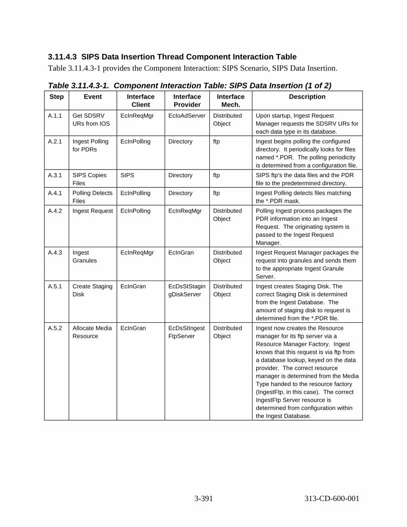
3.11.4.3 SIPS Data Insertion Thread Component Interaction Table Table 3.11.4.3-1 provides the Component Interaction: SIPS Scenario, SIPS Data Insertion.
Table 3.11.4.3-1. Component Interaction Table: SIPS Data Insertion (1 of 2) Step Event Interface
Client Interface Provider
Interface Mech.
Description
A.1.1 Get SDSRV URs from IOS
EcInReqMgr EcIoAdServer Distributed Object
Upon startup, Ingest Request Manager requests the SDSRV URs for each data type in its database.
A.2.1 Ingest Polling for PDRs
EcInPolling Directory ftp Ingest begins polling the configured directory. It periodically looks for files named *.PDR. The polling periodicity is determined from a configuration file.
A.3.1 SIPS Copies Files
SIPS Directory ftp SIPS ftp’s the data files and the PDR file to the predetermined directory.
A.4.1 Polling Detects Files
EcInPolling Directory ftp Ingest Polling detects files matching the *.PDR mask.
A.4.2 Ingest Request EcInPolling EcInReqMgr Distributed Object
Polling Ingest process packages the PDR information into an Ingest Request. The originating system is passed to the Ingest Request Manager.
A.4.3 Ingest Granules
EcInReqMgr EcInGran Distributed Object
Ingest Request Manager packages the request into granules and sends them to the appropriate Ingest Granule Server.
A.5.1 Create Staging Disk
EcInGran EcDsStStagin gDiskServer
Distributed Object
Ingest creates Staging Disk. The correct Staging Disk is determined from the Ingest Database. The amount of staging disk to request is determined from the *.PDR file.
A.5.2 Allocate Media Resource
EcInGran EcDsStIngest FtpServer
Distributed Object
Ingest now creates the Resource manager for its ftp server via a Resource Manager Factory. Ingest knows that this request is via ftp from a database lookup, keyed on the data provider. The correct resource manager is determined from the Media Type handed to the resource factory (IngestFtp, in this case). The correct IngestFtp Server resource is determined from configuration within the Ingest Database.
3-391 313-CD-600-001

Table 3.11.4.3-1. Component Interaction Table: SIPS Data Insertion (2 of 2) Step Event Interface
Client Interface Provider
Interface Mech.
Description
A.5.3 Ftp Get files EcInGran EcDsStIngest FtpServer
Distributed Object
Ingest directs the ftp server to get the files from the host and location, as indicated in the *.PDR file, placing them on the staging disk.
A.6.1 Connect to SDSRV
EcInGran EcDsScience DataServer
Distributed Object
Upon detecting the presence of granule files, the Ingest Granule Server begins a session with the SDSRV by connecting. The correct SDSRV is determined from the SDSRV UR received from IOS by the Ingest Request Manager, based on the data type.
A. 6.2*
Translate Granule Pointers in linkage file into URs
EcInGran EcDsScience DataServer
Distributed Object
The Ingest Granule Server submits a query to SDSRV to search for the ECS UR parameter for the particular internal identifier, data type and version ID found in the Granule Pointer in the linkage file. It then constructs an insert command for the browse, QA, or PH file which is associated with the linkage file. The Granule Server calls the SDSRV Validate method for standard data product granules before doing the insert. (*Note: This step is not performed if there is no linkage file.)
A.7.1 Request Data Insert
EcInGran EcDsScience DataServer
Distributed Object
Ingest requests that the files in the granule are inserted into the Data Server. An Insert request, containing the names of the files comprising the granule is created. SDSRV validates the metadata (only if standard product data granules are being transferred) and determines the archived names of the files.
A.7.2 STMGT Store EcDsScienceD ataServer
EcDsStArchiv eServer
Distributed Object
SDSRV requests that the files be archived. The archive server copies the inserted files directly from the Ingest staging disks that they reside on.
A.8.1 Send PAN (email or ftp)
EcInReqMgr Email Server e-mail or ftp The Ingest Request Manager creates a PAN and sends it to the appropriate SIPS.
3-392 313-CD-600-001

3.11.5 Inventory Search – SIPS Data Reprocessing (Thread B) This thread shows how inventory search request is submitted by SIPS and how it is handled by ECS.
The following system functionality is exercised in this scenario:
• The capability to submit searches to ECS and specify the metadata to be returned.
3.11.5.1 Inventory Search Thread Interaction Diagram – Domain View Figure 3.11.5.1-1 depicts the Inventory Search Interaction Diagram – Domain View.
DDICT (DMS)
MTMGW (CSS)
SIPS
B.1 Inventory search request
B.6 Search
Distributed Object (rpc, CtLib) HMI (GUI, Xterm, command) ftp email (or other as noted) Double line - Synchronous email (or other as noted) Dashed - Asynchronous
sshd
B.3 Search request
B.7 Search response Script (CSS)
REGISTRY (CSS)
B. 5 Get metadata type info
B.4 Get ESDT accessibilityB.2 Invoke
B.8 Search response
B.9 Inventory search result
SDSRV (DSS)
Figure 3.11.5.1-1 Inventory Search Diagram – Domain View
3.11.5.2 Inventory Search Thread Interaction Table – Domain View Table 3.11.5.2-1 depicts the Interaction Table – Domain View: Inventory Search
3-393 313-CD-600-001

Table 3.11.5.2-1. Interaction Table – Domain View: Inventory Search Step Interaction Interface
Client Interface Provider
Data Issues
Step Precon ditions
Description
B.1 Inventory search request
SIPS (Ops) sshd None None SIPS sends inventory search request to sshd (secure shell daemon) process in ECS via ssh remote access method.
B.2 Invoke sshd Script (CSS)
None None Upon receiving the request from SIPS, sshd decrypts the data message and invokes the script whose name is as the remote command SIPS wants to execute.
B.3 Search request
Script (CSS)
MTMGW (CSS)
None None Script turns inventory search request into the message in a format that MTMGW Server recognizes, and sends the message to the configured MTMGW listening on the port that is also specified in the script.
B.4 Get ESDT accessibility
MTMGW (CSS)
REGISTR Y (CSS)
None None Before handling the search request, MTMGW Server gets the ESDT accessibility from REGISTRY Server, and rejects the request if the ESDT in the request is not accessible from MTMGW.
B.5 Get metadata type info
MTMGW (CSS)
DDICT (DMS)
None None MTMGW server gets the qualifying metadata type info from DDICT server.
B.6 Search MTMGW (CSS)
SDSRV (DSS)
None None MTMGW server turns the search message into a Science Data Server search request and calls Science Data Server client interface and gets search results.
B.7 Search response
MTMGW CSS)
Script (CSS)
None None MTMGW converts the structured search result from DSS into a streamed message in XML format and sends this back to sshd.
B.8 Search response
Script (CSS)
sshd None None Script gets the search response message and sends it to sshd.
B.9 Inventory search result
sshd SIPS (Ops)
None None sshd encrypts the data message and returns it back to SIPS.
3.11.5.3 Inventory Search Thread Component Interaction Table Table 3.11.5.3-1 depicts the Component Interaction: Inventory Search
3-394 313-CD-600-001

Table 3.11.5.3-1. Component Interaction Table: Inventory Search (1 of 2) Step Event Interface
Client Interface Provider
Interface Mech.
Description
B.1.1 Inventory search request
SIPS (Ops) sshd ssh remote command
SIPS sends the inventory search request to sshd process in ECS via ssh remote access method.
B.2.1 Invoke sshd Script (CSS)
internal Upon receiving the request from SIPS, sshd invokes the script whose name is as the remote command SIPS wants to execute.
B.3.1 Translate request
Script (CSS)
Script (CSS)
command Script turns the search request into the message in a format that EcCsMtMGateway Server recognizes.
B.3.2 Send request Script (CSS)
EcCsMtMGate way (CSS)
command Script sends search request to the configured MTMGW listening on the port that is also specified in the script.
B.4.1 Check ESDT accessibility
EcCsMtMGatewa y (CSS)
EcCsRegistryS erver (CSS)
Distributed Object
Before handling the search request, EcCsMtMGateway Server gets the ESDT accessibility from EcCsRegistryServer, and rejects the request if the ESDT in the request is not accessible from the EcCsMtMGateway Server.
B.5.1 Get metadata type info
EcCsMtMGatewa y (CSS)
EcDmDictServ er (DMS)
Distributed Object
EcCsMtMGateway Server gets the qualifying metadata type info from EcDmDictServer.
B.6.1 Search request
EcCsMtMGatewa y (CSS)
EcDsScienceD ataServer (DSS)
Distributed Object
EcCsMtMGateway sends the search request to EcDsScienceDataServer and gets qualified search results back.
B.6.2 Inspect search result
EcCsMtMGatewa y (CSS)
EcDsScienceD ataServer (DSS)
Distributed Object
EcCsMtMGateway Server sends an inspect request to EcDsScienceDataServer for each granule in the search results obtained from step B.4.1.
3-395 313-CD-600-001

Table 3.11.5.3-1. Component Interaction Table: Inventory Search (2 of 2) Step Event Interface
Client Interface Provider
Interface Mech.
Description
B.7.1 Search response
EcCsMtMGatewa y (CSS)
Script (CSS)
command EcCsMtMGateway Server converts the structured search results into a streamed message and sends it back to script.
B.8.1 Search response
Script (CSS)
sshd internal Script gets the search response message and sends it to sshd.
B.9.1 Inventory search result
sshd SIPS (Ops) sshd tunnel sshd encrypts the data message and passes it to SIPS.
3.11.6 Product Order – SIPS Data reprocessing (Thread C) This thread shows how Product Order request is submitted by SIPS and how it is handled by ECS.
The following system functionality is exercised in this scenario:
• The capability to order individual ECS data granules based on UR, GranuleID or LocalGranuleID.
3.11.6.1 Product Order Thread Interaction Diagram – Domain View
Figure 3.11.6.1-1 depicts the Product Order Interaction Diagram – Domain View.
3-396 313-CD-600-001

C.3 Order request
SIPS
C.1 Product Order request
sshd
C.9 Order response
Distributed Object (rpc, CtLib) HMI (GUI, Xterm, command) ftp, mail email (or other as noted) Double line - Synchronous email (or other as noted) Dashed - Asynchronous
DSS
C.5 Get distribution priority, shipping info
C.6 Create MSS Order
C.12 eliver granule(s)
MTMGW (CSS)
Script (CSS)
REGISTRY (CSS)
MCI (MSS)
C.2 Invoke C.11 Product
Order result
C.4 Get ESDT accessibility and distribution option
C.14 istribution Notification
C.13 Change Order status to “Submitted”
C.10 Order response
C.7 Acquire Data C.8 Change Order status to “Pending” D
D
Figure 3.11.6.1-1 Product Order Diagram – Domain View
3.11.6.2 Product Order Thread Interaction Table – Domain View Table 3.11.6.2-1 depicts the Interaction Table – Domain View: Product Order
Table 3.11.6.2-1. Interaction Table – Domain View: Product Order (1 of 3) Step Interaction Interface
Client Interface Provider
Data Issues
Step Precon ditions
Description
C.1 Product Order request
SIPS sshd None None SIPS sends a product order request to the sshd process in ECS via ssh remote access method.
3-397 313-CD-600-001

Table 3.11.6.2-1. Interaction Table – Domain View: Product Order (2 of 3) Step Interaction Interface
Client Interface Provider
Data Issues
Step Precon ditions
Description
C.2 Invoke sshd Script (CSS)
None None sshd decrypts the data message and invokes the script whose name is as the remote command SIPS wants to execute.
C.3 Order request
Script (CSS)
MTMGW (CSS)
None None Script turns the order request into the message format that MTMGW Server recognizes, and sends the message to the configured MTMGW Server listening on the port that is also specified in the script.
C.4 Get ESDT accessibility and distribution option
MTMGW (CSS)
REGISTRY (CSS)
None None MTMGW Server gets ESDT accessibility and the distribution option of each ESDT in the request from REGISTRY Server in CSS, and fails the entire request if any ESDT is not accessible by MTMGW or any ESDT whose distribution option provided by SIPS mismatches that in the Registry Server.
C.5 Get distribution priority, shipping info
MTMGW (CSS)
MCI (MSS)
None None MTMGW Server gets the distribution priority and shipping info (if not supplied by SIPS) of a certain user from the User Profile Server in MSS. This user is either provided by SIPS in request or defined in MTMGW by default.
C.6 Create MSS order
MTMGW( CSS)
MCI (MSS)
None None MTMGW Server uses distribution priority, shipping info and External Request ID (optional) as input parameters to request the Order tracking Server to create an order and a request to keep track of the order.
C.7 Acquire Data MTMGW (CSS)
DSS None None MTMGW Server sends an asynchronous acquire request to Science Data Server in DSS.
3-398 313-CD-600-001

Table 3.11.6.2-1. Interaction Table – Domain View: Product Order (3 of 3) Step Interaction Interface
Client Interface Provider
Data Issues
Step Precon ditions
Description
C.8 Change Order status to “Pending”
DSS MCI (MSS)
None None When the Science Data Server gets the acquire request into its DB, it changes the order status to “Pending”.
C.9 Order response
MTMGW (CSS)
Script (MSS)
None None MTMGW server converts the structured response message into a streamed message and sends it back to script.
C.10 Order response
Script (CSS)
sshd None None Script invoked by sshd receives the order response message from MTMGW Server and sends it to sshd.
C.11 Product Order result
sshd SIPS (Ops) None None sshd encrypts the data message and sends it back to SIPS.
C.12 Deliver granules
DSS SIPS (Ops) Granule s
None Storage Management Server in DSS delivers granules acquired according to the media type requested by SIPS.
C.13 Change Order Status to “Submitted”
DSS MCI (MSS)
None None Data Distribution Server in DSS changes Order status to “Submitted” and sends it to MSS once granules acquired are delivered.
C.14 Distribution Notification
DSS SIPS (Ops) None None Data Distribution Server in DSS in the meantime sends the Distribution Notification by email to SIPS Ops.
3.11.6.3 Product Order Thread Component Interaction Table Table 3.11.6.3-1 depicts the Component Interaction: Product Order
Table 3.11.6.3-1. Component Interaction Table: Product Order (1 of 3) Step Event Interface
Client Interface Provider
Interface Mech.
Description
C.1.1 Product Order request
SIPS (Ops) sshd ssh remote command
SIPS sends a Product Order request to the sshd process in ECS via ssh remote access method.
3-399 313-CD-600-001

Table 3.11.6.3-1. Component Interaction Table: Product Order (2 of 3) Step Event Interface
Client Interface Provider
Interface Mech.
Description
C.2.1 Invoke sshd Script (CSS)
Internal sshd decrypts the data message and invokes script whose name is as the remote command SIPS wants to execute.
C.3.1 Translate request
Script (CSS)
Script (CSS)
command Script turns the order request into the message in a format that MTMGW Server recognizes.
C.3.2 Order request
Script (CSS)
EcCsMtMGatew ay (CSS)
command Script sends the message to the configured EcCsMtMGateway Server listening on the port that is also specified in script.
C.4.1 Get ESDT accessibility and distribution option
EcCsMtMGatew ay (CSS)
EcCsRegistrySe rver (CSS)
Distributed Object
EcCsMtMGateway Server gets ESDT accessibility and distribution option of each ESDT from EcCsRegistry Server and checks the “TransferAttribute” field in the order request. It fails the entire request if any ESDT whose distribution option provided by SIPS mismatches that in EcCsRegistryServer or any ESDT is not accessible by EcCsMtMGateway Server.
C.5.1 Get distribution priority, shipping info
EcCsMtMGatew ay (CSS)
EcMsAcRegUser Srvr (MSS)
Distributed Object
EcCsMtMGateway Server gets distribution priority, shipping info (if not supplied by SIPS) of a certain user from the User Profile Server in MSS. The user ID is either provided by SIPS in request or configured in EcCsMtMGateway by default.
C 6.1 Create MSS order
EcCsMtMGatew ay (CSS)
EcMsAcOrderSr vr (MSS)
Distributed Object
EcCsMtMGateway Server uses distribution priority, shipping info, user ID and the external request ID provided SIPS in the order request as input parameters to request the Order tracking Server to create an order.
C.6.2 Create MSS order request
EcCsMtMGatew ay (CSS)
EcMsAcOrderSr vr (MSS)
Distributed Object
EcCsMtMGateway Server requests EcMsAcOrderSrvr Server to create a request for the order created in step C.6.1.
3-400 313-CD-600-001
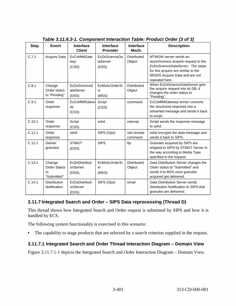
Table 3.11.6.3-1. Component Interaction Table: Product Order (3 of 3) Step Event Interface
Client Interface Provider
Interface Mech.
Description
C.7.1 Acquire Data EcCsMtMGate way (CSS)
EcDsScienceDa taServer (DSS)
Distributed Object
MTMGW server sends an asynchronous acquire request to the EcDsScienceDataServer. The steps for this acquire are similar to the MODIS Acquire Data and are not repeated here.
C.8.1 Change Order status to “Pending”
EcDsScienceD ataServer (DSS)
EcMsAcOrderSr vr (MSS)
Distributed Object
When EcDsScienceDataServer gets the acquire request into its DB, it changes the order status to “Pending”.
C.9.1 Order response
EcCsMtMGatew ay (CSS)
Script (CSS)
command EcCsMtMGateway server converts the structured response into a streamed message and sends it back to script.
C.10.1 Order response
Script (CSS)
sshd internal Script sends the response message to sshd.
C.11.1 Order response
sshd SIPS (Ops) ssh remote command
sshd encrypts the data message and sends it back to SIPS.
C 12.1 Deliver granules
STMGT (DSS)
SIPS ftp Granules acquired by SIPS are shipped to SIPS by STMGT Server in the way according to Media Type specified in the request.
C.13.1 Change Order Status to “Submitted”
EcDsDistributi onServer (DSS)
EcMsAcOrderSr vr (MSS)
Distributed Object
Data Distribution Server changes the Order status to “Submitted” and sends it to MSS once granules acquired get delivered.
C.14.1 Distribution Notification
EcDsDistributi onServer (DSS)
SIPS (Ops) email Data Distribution Server sends Distribution Notification to SIPS that granules are delivered.
3.11.7 Integrated Search and Order – SIPS Data reprocessing (Thread D) This thread shows how Integrated Search and Order request is submitted by SIPS and how it is handled by ECS.
The following system functionality is exercised in this scenario:
• The capability to stage products that are selected by a search criterion supplied in the request.
3.11.7.1 Integrated Search and Order Thread Interaction Diagram – Domain View Figure 3.11.7.1-1 depicts the Integrated Search and Order Interaction Diagram – Domain View.
3-401 313-CD-600-001

D.3 earch & Order request
SIPS
D.1 Integrated Search sshd
D.11 Search & Order response
Distributed Object (rpc, CtLib) HMI (GUI, Xterm, command) ftp, mail email (or other as noted) Double line - Synchronous email (or other as noted) Dashed - Asynchronous
DSS
D.7 Get distribution priority, shipping info
D.8 Create MSS Order
D.14 Deliver granule(s)
MTMGW (CSS)
Script (CSS)
REGISTRY (CSS)
MCI (MSS)
D.2 InvokeSearch & Order result
D.16 Distribution Notification
D.15 Change Order status to “Submitted”
D.12 Search & Order response
D.6 Search D.10 Change Order
status to “Pending”
DDICT (DMS)
D.5 Get metadata type info
and Order request
D.13 Integrated
D.9 Acquire Data
D.4 Get ESDT accessibility and distribution option
S
Figure 3.11.7.1-1 Integrated Search and Order Diagram – Domain View
3.11.7.2 Integrated Search and Order Thread Interaction Table – Domain View Table 3.11.7.2-1 depicts the Interaction Table – Domain View: Integrated Search and Order
3-402 313-CD-600-001

Table 3.11.7.2-1. Interaction Table – Domain View: Integrated Search and Order (1 of 2)
Step Interaction Interface Client
Interface Provider
Data Issues
Step Precon-ditions
Description
D.1 Integrated Search and Order request
SIPS (Ops)
sshd None None SIPS sends an Integrated Search and Order request to the sshd process in ECS via ssh remote access method.
D.2 Invoke sshd Script (CSS)
None None sshd decrypts the data message and invokes the script whose name is as the remote command SIPS wants to execute.
D.3 Search & Order request
Script (CSS)
MTMGW (CSS)
None None Script turns the integrated search and order request into a message in the format MTMGW Server recognizes and sends the message to the configured MTMGW listening on the port which is also specified in script.
D.4 Get ESDT accessibility and distribution option
MTMGW (CSS)
REGISTRY (CSS)
None None MTMGW Server gets ESDT accessibilty and distribution option for each ESDT in the request from REGISTRY Server, and fails if any ESDT is not accessible by MTMGW or any ESDT whose distribution option provided by SIPS doesn’t match that in Registry Server.
D.5 Get metadata type info
MTMGW( CSS)
DDICT (DMS)
None None MTMGW Server gets the qualifying metadata type info from DDICT server.
D 6 Search MTMGW (CSS)
DSS None None MTMGW Server sends a search request to Science Data Server and gets search results back.
D.7 Get distribution priority, shipping info
MTMGW (CSS)
MCI (MSS)
None None MTMGW Server gets distribution priority and shipping info of the user from User Profile Server in MSS. This user is either provided by SIPS in the request or configured in MTMGW by default.
3-403 313-CD-600-001

Table 3.11.7.2-1. Interaction Table – Domain View: Integrated Search and Order (2 of 2)
Step Interaction Interface Client
Interface Provider
Data Issues
Step Precon-ditions
Description
D.8 Create MSS order
MTMGW (CSS)
MCI (MSS)
None None MTMGW server uses distribution priority, shipping info and external user ID and user ID provided by SIPS in the request (optional) as input parameters to request the Order tracking Server to create an order and a request.
D.9 Acquire Data MTMGW (CSS)
DSS None None MTMGW server sends an acquire request to Science Data Server in DSS for each granule in the search results from step D.6.
D.10 Change Order status to “Pending”
DSS MCI (MSS)
None None When the Science Data Server gets the acquire request into its DB, it changes the order status to “Pending”.
D.11 Search & Order response
MTMGW (CSS)
Script (CSS)
None None MTMGW Server converts the structured response message to the streamed message to send it back to Script.
D.12 Search & Order response
Script (CSS)
sshd None None Script receives the search and order response and sends it to sshd.
D.13 Integrated Search and Order result
sshd SIPS Ops None None sshd encrypts the data message and sends it back to SIPS.
D.14 Deliver granules
DSS SIPS Ops Granule s
None Storage Management Server in DSS ships the granules according to the media type requested by SIPS.
D.15 Change Order Status to “Submitted”
DSS MCI (MSS) SIPS Ops
None None Data Distribution Server in DSS changes the Order status to “Submitted” and sends it to MSS once granules acquired gets delivered.
D.16 Distribution Notification
DSS SIPS Ops None None Data Distribution Server in DSS sends a Distribution Notification to SIPS once granules acquired gets delivered.
3.11.7.3 Integrated Search and Order Thread Component Interaction Table Table 3.11.7.3-1 depicts the Component Interaction: Integrated Search and Order
3-404 313-CD-600-001

Table 3.11.7.3-1. Component Interaction Table: Integrated Search and Order (1 of 3)
Step Event Interface Client
Interface Provider
Interface Mech.
Description
D.1.1 Integrated Search and Order request
SIPS Ops sshd ssh remote command
SIPS sends Integrated Search and Order request to the sshd process in ECS via ssh remote access method.
D.2.1 Invoke sshd Script (CSS)
internal sshd decrypts data message and invokes the script whose name is as the remote command SIPS wants to execute.
D.3.1 Translate request
Script (CSS)
Script (CSS)
command Script turns the search request into a message in the format MTMGW recognizes.
D.3.2 Search & Order request
Script (CSS)
EcCsMtMGate way (CSS)
command Script sends the message to the configured MTMGW listening on the port that is also specified in script.
D.4.1 Get ESDT accessibility and distribution option
EcCsMtMGate way (CSS)
EcCsRegistry Server (CSS)
Distributed Object
EcCsMtMGateway Server gets ESDT accessibility and distribution option of each ESDT in the request from EcCsRegistryServer, and fails the granule if any ESDT is not accessible by EcCsMtMGateway Server or its distribution option mismatches that in the Registry Server.
D.5.1 Get metadata type info
EcCsMtMGate way (CSS)
EcDmDictSer ver (DMS)
Distributed Object
EcCsMtMGateway Server gets the qualifying metadata type info from EcDmDictServer.
D.6.1 Search request
EcCsMtMGate way (CSS)
EcDsScience DataServer (DSS)
Distributed Object
EcCsMtMGateway sends the search request to EcDsScienceDataServer and gets the qualified search result back.
D.7.1 Get distribution priority, shipping info
EcCsMtMGate way (CSS)
EcMsAcRegU serSrvr (MSS)
Distributed Object
EcCsMtMGateway Server gets distribution priority and shipping info of the user from EcMsAcRegUserSrvr in MSS. This user is either provided by SIPS in the request or configured in MTMGW by default.
3-405 313-CD-600-001

Table 3.11.7.3-1. Component Interaction Table: Integrated Search and Order (2 of 3)
Step Event Interface Client
Interface Provider
Interface Mech.
Description
D.8.1 Create MSS order
EcCsMtMGate way (CSS)
EcMsAcOrder Srvr (MSS)
Distributed Object
EcCsMtMGateway Server uses distribution priority, shipping info, external user ID and usr ID provided by SIPS in request (optional) as input parameters to request Order tracking Server and creates an order.
D.8.2 Create MSS request
EcCsMtMGate way (CSS)
EcMsAcOrder Srvr (MSS)
Distributed Object
EcCsMtMGateway Server requests EcMsAcOrderSrvr to create an order request.
D.9.1 Acquire Data EcCsMtMGate way (CSS)
EcDsScience DataServer (DSS)
Distributed Object
EcCsMtMGateway Server sends an acquire request to Science Data Server in DSS for each granule in the search result from D.6.1. The steps for this acquire are similar to the MODIS Acquire Data and are not repeated here.
D.10.1 Change Order status to “Pending”
EcDsScienceD ataServer (DSS)
EcMsAcOrder Srvr (MSS)
Distributed Object
When EcDsScienceDataServer gets the acquire request into its DB, it changes the order status to “Pending”.
D.11.1 Search & Order response
EcCsMtMGate way (CSS)
Script (CSS)
command EcCsMtMGateway Server converts the structured message into a streamed message and sends it back to script.
D.12.1 Search & Order response
Script (CSS)
sshd internal Script sends response message to sshd.
D.13.1 Integrated Search and Order response
sshd SIPS (Ops) ssh remote command
sshd encrypts the data message and sends it back to SIPS.
D.14.1 Deliver granules
STMGT (DSS)
SIPS Ops ftp Granules acquired by SIPS are delivered by STMGT in the way according to Media Type specified in the request.
3-406 313-CD-600-001

Table 3.11.7.3-1. Component Interaction Table: Integrated Search and Order (3 of 3)
Step Event Interface Client
Interface Provider
Interface Mech.
Description
D.15.1 Change Order Status to “Submitted”
EcDsDistributi onServer (DSS)
EcMsAcOrder Srvr (MSS)
Distributed Object
EcDsDistributionServer changes Order status to “Submitted” to MSS once granules acquired get delivered.
D.16.1 Distribution Notification
EcDsDistributi onServer (DSS)
SIPS (Ops) email EcDsDistributionServer sends a Distribution Notification to SIPS once granules acquired get delivered.
3.12 Fault Recovery Fault recovery is supported by a number of automated mechanisms that are described in this section. In any scenario, client or server failures could occur which would cause certain recovery events to take place. These events are outlined in this section for specific client or server failures, and these events apply to any operational scenario involving the specified client/server interface. This section does not show a step-by-step scenario as in previous sections, but outlines the recovery steps which are part of any scenario which experiences a fault as outlined below. Note that Operator procedures are detailed in the 611 document.
Integration and testing of the fault recovery capabilities of ECS focused on ASTER and Landsat 7 scenarios which perform inserts (Ingest and PDPS) and acquires (PDPS and SBSRV). All fault recovery capabilities are based on the assumption that the system must recover from a single failure event. The fault recovery mechanisms that are described in this section have been designed to deal with individual failure events. They typically will work if multiple faults occur simultaneously (e.g., failure of several servers because a platform crashes). However, multiple faults can lead to complex interdependencies for recovery. These situations are much more difficult to classify and hence, are not explicitly addressed in this section.
The CIs that provide fault recovery capabilities in ECS are summarized in Table 3.12-1 below. Specific capabilities are detailed in the following sections.
3-407 313-CD-600-001

Table 3.12-1. Fault Recovery CIs CI Server(s) Fault Recovery Support PLANG, PRONG
EcDpPrJobMgmt EcPlSubMgr EcDpPrDeletion
Resumption from last checkpoint
INGST EcInGran Resumption from last checkpoint Start-up options for recovery Client notifies Server it is cold or warm
EcInAuto EcInReqMgr EcInPolling
Resumption from last checkpoint Start-up options for recovery
EcInEmailGWServer Start-up options for recovery EcInGUI None
SBSRV EcSbSubServer Resumption from last checkpoint Start-up options for recovery Client notifies Server it is cold or warm
SDSRV EcDsScienceDataServer Resumption from last checkpoint (partial) Start-up options for recovery Client notifies Server it is cold or warm (client side only)
EcDsHdfEosServer None DDIST EcDsDistributionServer Resumption from last checkpoint
Start-up options for recovery Client notifies Server it is cold or warm
STMGT EcDsStArchiveServer EcDsStStagingDiskServer EcDsStCacheManagerServer EcDsStRequestManager EcDsStPullMonitorServer EcDsStFtpServer EcDsSt8MMServer EcDsStD3Server EcDsStCDROMServer EcDsStDLTServer
Resumption from last checkpoint Start-up options for recovery Client notifies Server it is cold or warm
EcDsStRequestManager None
Other CIs not shown in Table 3.12-1 have been designed to be stateless; where they execute transactions against persistent data, they typically have been designed such that redoing the transaction has no ill effect. The EcDsStRequestManager was designed as a pass though server, passing requests onto to other servers. The fault recovery functions and policies involving these requests should reference the fault recovery procedures of the originating servers who sent the requests. The EcDsStRequestManager was designed to contain no persistent data.
3.12.1 Request Identification and Checkpointing In order to enable fault recovery activities, requests that cross a client/server boundary are assigned a system-unique identifier referred to as an RPC ID. (RPC refers to Remote Procedure Call, the mechanism by which requests are submitted from client to server.) As a request propagates through the system, each associated client/server exchange is assigned a unique RPC ID. However, the RPC ID for each interaction is derived from the previous RPC ID received by
3-408 313-CD-600-001

the client for this request. Thus, all RPC IDs associated with a given request have a common portion that relates the various client/server calls to one another. More importantly, given the previous RPC ID, clients will consistently reproduce the same RPC ID that was submitted to the server on the subsequent event. The concept of reproducible RPC IDs is central to the ECS fault recovery capability. When requests are retried from client to server, they are always submitted with the same RPC ID as was used in the original submission of the request, even if either the client or server has crashed between retries.
RPC IDs are also central to the checkpointing aspect of fault recovery. As requests arrive at fault recovery-enabled servers, they are recorded in a persistent store (typically, a data base), tagged with the RPC ID which identifies the request. As the request is serviced, checkpointing state information may be updated in the persistent store, up to and including the completion status of the request. This allows the servers to resume servicing from the last checkpointed state, particularly upon re-submission from a client.
Table 3.12-2 details what is checkpointed by each fault recovery-enabled server:
Table 3.12-2. Checkpointed Servers CI Server(s) Checkpointed Information PLANG, PRONG
EcDpPrDeletion Interim Delete Requests EcDpPrEM EcDpPrDM
Queued and Activated jobs
EcPlSubMgr Unprocessed subscription notifications INGST EcInGran Granule and granule state information
EcInReqMgr Request state information EcInPolling EcInAuto
Request information
EcInEmailGWServer N/A EcInGUI Media Ingest request information
SBSRV EcSbSubServer Request for triggering subscriptions Triggered actions
SDSRV EcDsScienceDataServer Asynchronous acquire requests that have been accepted for processing, and SBSRV event notifications
EcDsHdfEosServer N/A DDIST EcDsDistributionServer Requests which have been accepted for processing STMGT EcDsStArchiveServer Store and Retrieve request state information
EcDsStStagingDiskServer Resource allocation and ownership for staging disks EcDsStStagingMonitorServer EcDsStFtpServer
Request state information
EcDsStCacheManagerServer EcDsSt8MMServer EcDsStD3Server EcDsStCDROMServer EcDsStDLTServer EcDsStRequestManager
N/A
3-409 313-CD-600-001

3.12.2 Start Temperatures and Restart Notification Fault recovery provides three startup modes – “start temperatures” – for servers: warm start, cold start, and cold restart. The default behavior for all servers is to warm start. These startup modes have the following characteristics:
• Warm Start The server has all knowledge of previously submitted requests, including the last checkpointed state for any request being serviced by the server prior to its crash. Upon re-submission, the server will restore from checkpoint and continue servicing the request. Any resources previously allocated by the server (e.g., staging disks) will be preserved.
• Cold Start The server retains no knowledge of previously submitted requests. Any information in its persistent store that is related to previous requests is flushed as part of the start-up process. All requests appear to be new requests to the server, even if the request is really a re-submission from a client. Any resources previously allocated by the server (e.g., staging disks) are released.
• Cold Restart The server has knowledge of previously submitted requests, but will not perform any further servicing of those requests. All requests in the persistent store are marked as failed due to the server’s cold restart and, if re-submitted, will be failed back to the client with a fatal error. Any resources previously allocated by the server (e.g., staging disks) are released.
Clients that are restarted with a start temperature also notify the servers to which they are clients, except as noted in Table 3.12-6. Clients notify servers that they have come up “cold” or “warm”, and do not differentiate between cold start and cold restart. Detailed client and server behavior on restart is described in subsequent sections.
3.12.3 Client/Server Relationships Fault recovery behavior can vary from interface to interface. Table 3.12-3 summarizes the client/server interfaces relevant to ECS fault recovery.
Table 3.12-3. Fault Recovery Client/Server Interfaces (1 of 3) CI Client Process(es) CI Server Process(es) PLANG, PRONG
EcPlSubMgr SDSRV EcDsScienceDataServer PRONG EcDpPrJobMgmt ADSRV EcIoAdServer
EcPlPREGui SDSRV EcDsScienceDataServer PRONG EcDpPrJobMgmt SBSRV EcSbSubServer ADSRV EcIoAdServer
3-410 313-CD-600-001

Table 3.12-3. Fault Recovery Client/Server Interfaces (2 of 3) CI Client Process(es) CI Server Process(es)
EcPlWb PRONG EcDpPrJobMgmt EcDpAtStageDAP SDSRV EcDsScienceDataServer EcDpAtInsertTestFile SDSRV EcDsScienceDataServer
ADSRV EcIoAdServer EcDpAtInsertStaticFile SDSRV EcDsScienceDataServer
ADSRV EcIoAdServer EcDpAtInsertExeTarFile SDSRV EcDsScienceDataServer
ADSRV EcIoAdServer EcDpAtSSAPGui SDSRV EcDsScienceDataServer
ADSRV EcIoAdServer EcDpAtGetMCF SDSRV EcDsScienceDataServer
ADSRV EcIoAdServer EcDpPrDM SDSRV EcDsScienceDataServer
ADSRV EcIoAdServer EcDpPrEM SDSRV EcDsScienceDataServer
ADSRV EcIoAdServer PRONG EcDpPrJobMgmt
EcDpPrJobMgmt PRONG EcDpPrDeletion EcDpPrDeletion SDSRV EcDsScienceDataServer EcPlOdMgr SDSRV
SBSRV EcDsScienceDataServer EcSbSubServer
INGST EcInGran SDSRV EcDsScienceDataServer STMGT EcDsStStagingDiskServer
EcDsStIngestFtpServer EcInReqMgr INGST EcInGran
STMGT EcDsStStagingDiskServer EcInGUI INGST EcInReqMgr
STMGT EcDsStStagingDiskServer EcDsStD3Server EcDsSt8MMServer
EcInPolling EcInAuto
INGST EcInReqMgr
EcInEmailGWServer N/A N/A SBSRV EcSbSubServer SDSRV EcDsScienceDataServer
PLANG EcPlSubMgr (through Queuename) SDSRV EcDsScienceDataServer SBSRV EcSbSubServer
SDSRV EcDsHdfEosServer DDIST EcDsDistributionServer STMGT EcDsStArchiveServer
EcDsStStagingDiskServer EcDsHdfEosServer STMGT EcDsStStagingDiskServer
3-411 313-CD-600-001

Table 3.12-3. Fault Recovery Client/Server Interfaces (3 of 3) CI Client Process(es) CI Server Process(es) DDIST EcDsDistributionServer STMGT EcDsStArchiveServer
EcDsStStagingDiskServer EcDsStFtpServer EcDsSt8MMServer EcDsStD3Server EcDsStCDROMServer EcDsStDLTServer
STMGT EcDsStArchiveServer STMGT EcDsStArchiveServer EcDsStCacheManagerServer EcDsStStagingDiskServer
EcDsStCacheManagerServer EcDsStPullMonitorServer
N/A N/A
EcDsStStagingDiskServer STMGT EcDsStCacheManagerServer EcDsStStagingDiskServer
EcDsStFtpServer STMGT EcDsStStagingDiskServer EcDsStPullMonitorServer
EcDsStFtpServer EcDsSt8MMServer EcDsStD3Server EcDsStCDROMServer EcDsStDLTServer
STMGT EcDsStStagingDiskServer
3.12.4 Fault Handling Failure events are classified as having any of three severity levels: fatal errors, retryable errors and warnings. Fatal errors are returned when a request cannot be serviced, even with operator intervention. For example, if a request is made to distribute data via FTP to a non-existent host, the request will be failed with a fatal error. Retryable errors can be recovered from, though such errors should be returned back to the client only when the server cannot recover from the error automatically. Retryable errors may also necessitate operator assistance for recovery purposes, such as in the case of a tape that is left in a device and must be manually removed. Warnings are provided where operations will proceed without interruption, but where an unexpected circumstance was detected. For example, if a client requests that a file be removed, and the file does not exist, there is no error per se, but a warning is generated to caution the client that the file to be removed did not exist in the first place.
Transient errors such as network errors are always retryable errors. In general, clients and servers that experience transient, retryable errors will first attempt to recover by retrying the operation automatically. One special case of this is “rebinding.” Rebinding refers to the process by which a client automatically attempts to re-establish communications with a server in the event that communications are disrupted. This disruption may be caused by transient network failure, or by the server being brought down or crashing. In any case, the client will automatically attempt to reconnect to the server for a period of time that is configurable on a client-by-client basis.
3-412 313-CD-600-001

ECS processes that encounter an error or receive an error from a server request may either pass the error back to a higher-level client or present it to the operator for operator intervention. The fault handling policies are detailed in Table 3.12-4:
Table 3.12-4. Fault Handling Policies (1 of 2) CI Client Process(es) Fault Handling Policy PLANG, PRONG
EcPlSubMgr Retryable errors: All Subscription processing errors are retried a configurable number of times and for a configurable time period. After these number of times (or time period) the subscription is lost. Fatal errors: N/A
EcPlPREGui EcPlWb
Retryable errors: Since these are GUI applications, errors are reported to the user and it is his/her responsibility to retry the request. Fatal errors: Errors are reported to the user.
EcDpAtStageDAP EcDpAtInsertTestFile EcDpAtInsertStaticFile EcDpAtInsertExeTarFile EcDpAtSSAPGui EcDpAtGetMCF
Retryable errors: Some automatic retries of requests exist, but in general these are command line tools and as such report any errors to the user and it is his/her responsibility to retry the request. Fatal errors: The User is sent a fatal error message.
EcDpPrDM EcDpPrEM
Retryable errors: Errors are retried a configurable number of times, then the job is failed and it is up to the Production Monitor to restart the job through AutoSys. Fatal errors: A fatal error message is logged.
EcDpPrJobMgmt Retryable errors: Requests are NOT retried to EcDpPrDeletion. This can result in the loss of Interim Granule delete notifications (interim granules may not be deleted from the system). Fatal errors: N/A
EcDpPrDeletion Retryable errors: No retries are implemented. Status from DSS is not checked. Fatal errors: N/A
EcPlOdMgr Retryable errors: Retries errors from the Science Data Server and the Subscription Server. Fatal errors: Logs errors and stops current on demand requests.
INGST EcInGran Retryable errors: Errors are retried a configurable number of times, then the granule is suspended. The operators can then either cancel or resume the suspended granule from the Ingest GUI. Fatal errors: The granule is failed. Granule failures are displayed on the Ingest GUI.
EcInReqMgr Retryable errors: Errors connecting to EcInGran are retried forever. Retryable errors involving staging disks are retried a configurable number of times, then the request is failed. Fatal errors: Errors are failed immediately.
3-413 313-CD-600-001

Table 3.12-4. Fault Handling Policies (2 of 2) CI Client Process(es) Fault Handling Policy
EcInGUI Retryable errors: Any error results in the request failing. Fatal errors: Any error results in the request failing.
EcInPolling EcInAuto
Retryable errors: Errors are retried forever, with a delay between retries. Fatal errors: Errors are failed immediately, and are displayed on the Ingest GUI.
EcInEmailGWServer Retryable errors: N/A Fatal errors: E-mail that cannot be processed is moved to a failed directory, but no operator notification is provided.
SBSRV EcSbSubServer Retryable errors: Errors are retried for a configurable amount of times, then suspended. The operators can then either cancel or resume the suspended acquire requests through system provided scripts. Fatal errors: N/A
SDSRV EcDsScienceDataServer EcDsHdfEosServer
Retryable errors: Errors are retried a configurable number of times, then passed back to the calling client process unchanged. The default retry policy for SDSRV servers is “retry forever.” For async Acquire requests that involve subsetting, retryable errors encountered with the HDF servers are not returned to the client. Instead the request is queued for future execution. Fatal errors: Eerrors are passed back to the calling client process.
Note: Errors associated with asynchronous requests are logged but do not appear on any GUI. HDF servers are restarted manually by the Operator.
DDIST EcDsDistributionServer Errors are presented to the operator via the DDIST GUI. Retryable errors: Errors are presented as “Suspended with Errors” and can be resumed by the operator. Fatal errors: Errors are presented as “Failed.” For synchronous requests, fatal errors are also passed back to the calling client process. For asynchronous requests, fatal errors are sent as part of the e-mail notification.
STMGT EcDsStArchiveServer EcDsStStagingDiskServer EcDsStCacheManagerServer EcDsStPullMonitorServer EcDsStFtpServer
EcDsSt8MMServer EcDsStD3Server EcDsStCDROMServer EcDsStDLTServer
Retryable errors: Errors are passed back to the calling client process. Fatal errors: Errors are passed back to the calling client process.
3-414 313-CD-600-001

3.12.5 Client Crash When a client crashes in the ECS system, fault recovery-enabled servers have several possible responses. Servers may continue to service client requests, independent of the client’s status. Servers may choose to suspend processing of client requests, but permit the requests to be resumed upon client recovery. Or, servers may terminate servicing of the client requests, canceling all work done on the requests. The behavior of each CI is detailed in Table 3.12-5. Note that the behavior of a server in the event of a client crash does not vary from client to client.
Table 3.12-5. Server Responses to Client Failures CI Server(s) Behavior on Client Crash PLANG, PRONG
EcDpPrJobMgmt EcPlSubMgr EcDpPrDeletion
Requests in process are serviced to completion
INGST EcInGran EcInReqMgr EcInAuto
Requests in process are serviced to completion.
EcInGUI EcInPolling EcInEmailGWServer
N/A
SBSRV EcSbSubServer Since its client, SDSRV, is also the action provider of SBSRV, SBSRV will proceed to finish all triggered subscriptions till the point that SDSRV has to be called. By then, all requests are stored for later retry.
SDSRV EcDsScienceDataServer EcDsHdfEosServer
Requests in process are serviced to completion.
DDIST EcDsDistributionServer Requests in process are serviced to completion. STMGT EcDsStArchiveServer
EcDsStRequestManager EcDsStCacheManagerServer EcDsStPullMonitorServer EcDsStFtpServer
EcDsSt8MMServer EcDsStD3Server EcDsStCDROMServer EcDsStDLTServer
Requests in process are cancelled by thread rundown.
EcDsStStagingDiskServer Requests in process are cancelled by thread rundown. Non-persistent staging disks allocated by the client are leaked (NCR 15262 – will be fixed in 6A).
3.12.6 Client Restart When a client restarts in the ECS system, it sends a restart notification to each server with which it interacts. Clients notify servers that they have come up “cold” or “warm”, and do not differentiate between cold start and cold restart. Generally, the notification temperature sent to the server matches the temperature at which the client process is restarted.
3-415 313-CD-600-001

Table 3.12-6 shows exceptions to the general behavior for client submission of restart notification:
Table 3.12-6. Client Restart Notification Exceptions Client Process(es) Server Process(es) Restart Notification PDPS N/A EcInGran EcDsScienceDataServer
EcDsStStagingDiskServer Matches start temperature (Also see Note 1 below)
EcDsStFtpServer N/A (not supported by server) EcInReqMgr EcDsStStagingDiskServer Matches start temperature
(See Note 1 below) EcInGUI EcDsStStagingDiskServer Always sent warm (See Note 1 below)
EcDsStD3Server EcDsSt8MMServer
N/A (not supported by server)
EcInPolling EcInAuto EcInEmailGWServer
N/A N/A
EcSbSubServer EcDsScienceDataServer Match start temperature EcDsScienceDataServer EcDsDistributionServer Always sent warm
EcDsStArchiveServer Always sent warm (Also see Note 1 below)
EcDsStStagingDiskServer Always sent cold (Also see Note 1 below)
EcDsHdfEosServer EcDsStStagingDiskServer Sent cold by default (Also see Note 1 below)
EcDsDistributionServer EcDsStArchiveServer EcDsStStagingDiskServer
Matches start temperature (Also see Note 1 below)
EcDsStFtpDisServer EcDsSt8MMServer EcDsStD3Server EcDsStCDROMServer EcDsStDLTServer
N/A (not supported by server)
EcDsStArchiveServer EcDsStArchiveServer EcDsStCacheManagerServer EcDsStStagingDiskServer
Matches start temperature (Also see Note 1 below)
EcDsStCacheManagerServer EcDsStPullMonitorServer
N/A N/A
EcDsStStagingDiskServer EcDsStCacheManagerServer EcDsStStagingDiskServer
Matches start temperature (Also see Note 1 below)
EcDsStFtpServer EcDsStStagingDiskServer Matches start temperature (Also see Note 1 below)
EcDsStPullMonitorServer N/A (not supported by server) EcDsStFtpServer EcDsSt8MMServer EcDsStD3Server EcDsStCDROMServer EcDsStDLTServer
EcDsStStagingDiskServer Sent cold by default (See Note 1 below)
3-416 313-CD-600-001

Note 1: Restart notifications sent to the EcDsStArchiveServer and EcDsStStagingDiskServer servers are sent as needed. Since multiple server instances exist for each, a restart notification is sent on the first attempt to contact each instance. Note that the restarted client may not connect to a particular server instance (e.g., the WKS Archive Server) for an extended time after restarting. A restart notification will still be sent on the first connection, regardless of how long the client process has been running. Also note that restart notifications to the EcDsStArchiveServer and EcDsStStagingDiskServer servers are sent automatically, even if the client has not explicitly issued a restart notification. Automatically generated notifications are sent as cold restart notifications by default if no explicit restart notification is issued by the client.
The default server behavior in response to a startup notification from a client is as follows:
• Warm Notification Outstanding requests for the restarted client are left available in the persistent store. These requests may be re-submitted by the client, and will be serviced to completion upon re-submission. Associated resources are left allocated until the requests are completed.
• Cold Notification All outstanding requests for the restarted client are cancelled. If the client re-submits any cancelled request using the same RPC ID (e.g., by pressing the Retry button from an operator GUI), it will be failed with a fatal error due to the client cold startup notification. Any resources associated with the cancelled requests are released and reclaimed by the system.
Server behavior upon receipt of a client restart notification are detailed in Table 3.12-7:
Table 3.12-7. Server Responses to Client Notification (1 of 2) CI Server(s) Behavior on Cold
Notification Behavior on Warm Notification
PLANG, PRONG
EcDpPrJobMgmt EcPlSubMgr EcDpPrDeletion
N/A N/A
INGST EcInGran EcInReqMgr EcInPolling EcInAuto EcInGUI EcInEmailGWServer
N/A N/A
SBSRV EcSbSubServer N/A N/A SDSRV EcDsScienceDataServer N/A N/A
EcDsHdfEosServer N/A N/A DDIST EcDsDistributionServer General General STMGT EcDsStArchiveServer For partially completed
Ingest operations, all files stored are removed. (Partial granules are never permitted in the archive.)
General
3-417 313-CD-600-001

Table 3.12-7. Server Responses to Client Notification (2 of 2) CI Server(s) Behavior on Cold
Notification Behavior on Warm Notification
EcDsStCacheManagerServer EcDsStPullMonitorServer EcDsStFtpServer
General General
EcDsStStagingDiskServer All Staging Disks owned by the restarted client are released.
All Staging Disks owned by the restarted client are retained, including temporary staging disks.
EcDsSt8MMServer EcDsStD3Server EcDsStCDROMServer EcDsStDLTServer
N/A N/A
3.12.7 Server Crash When a server crashes, the only impact on the system is that clients cannot continue to submit requests for processing. Synchronous requests that are in progress will result in a DCE exception being thrown back to the client process, which will enter a rebinding failure recovery mode (see Fault Handling section above). Attempts to submit requests while the server is down will result in the client blocking until a communications timeout has been reached.
3.12.8 Server Restart When a server restarts, it may perform various re-synchronization activities in order to recover from an unexpected termination. In the event of a server cold start or cold restart, the server will also cancel all outstanding requests and reclaim all associated resources. Note that the distinction between cold start and cold restart is described in the section above on Start Temperature. Specifics of server startup behavior are detailed in Table 3.12-8. Unless otherwise stated, existing request queues are always retained for warm restarts and cleared for cold starts or cold restarts.
Table 3.12-8. Server Response vs Restart Temperature (1 of 4) CI Server(s) Special Behavior on
Warm Restart Special Behavior on Cold Start or Cold Restart
PLANG, PRONG
EcDpPrJobMgmt Jobs in AutoSys and jobs waiting in the queue are read from the database. Any jobs that are ready are placed into AutoSys from the queue if there are processing slots available.
N/A
3-418 313-CD-600-001

Table 3.12-8. Server Response vs Restart Temperature (2 of 4) CI Server(s) Special Behavior on
Warm Restart Special Behavior on Cold Start or Cold Restart
EcPlSubMgr Any subscriptions that have not been processed are read from checkpoint file and processed.
N/A
EcDpPrDeletion Interim granules marked for deletion are read from the database and will be deleted when time out occurs.
N/A
INGST EcInGran The EcInGran server automatically restarts submitted requests from the beginning. If a file has been FTP’ed, it will not re-do the FTP of that file.
All granule requests are cancelled. Existing request queues are cleared for cold start and retained for cold restart.
EcInReqMgr EcInReqMgr re-synchs requests that are in progress with EcInGran, and resumes processing from the last checkpointed state.
On cold start, all active requests are moved to the summary tables. On cold restart, each granule is re-submitted to the EcInGran where it is failed. EcInReqMgr then re-submits the request to EcInGran, where it is processed as a new request. Existing request queues are cleared for cold start and retained for cold restart.
EcInPolling Re-submit requests that
were in progress at the time of fault. Continue polling for remaining requests in polling directory.
Cleans up files and terminates any requests which had not yet been sent to EcInReqMgr. Requests remaining in the polling directory are sent as new requests.
EcInAuto Re-submit requests that were in progress at the time of fault. The external client may re-submit the request -this can lead to duplicate ingest.
Cleans up files and terminates any requests which had not yet been sent to EcInReqMgr.
EcInGUI EcInEmailGWServer
N/A N/A
3-419 313-CD-600-001

Table 3.12-8. Server Response vs Restart Temperature (3 of 4) CI Server(s) Special Behavior on
Warm Restart Special Behavior on Cold Start or Cold Restart
SBSRV EcSbSubServer SBSRV will perform all unprocessed actions (including re-submissions of ACQUIRE requests to the SDSRV), and resume accepting new event notifications from the SDSRV.
SBSRV will remove all unprocessed requests.
SDSRV EcDsScienceDataServer EcDsHdfEosServer
Restart Async Acquire Requests that were in progress before the crash. (Note that the queue of asynchronous acquire requests is retained. Synchronous requests are assumed to be re-submitted by the respective senior client applications (PRONG, INGST).)
Send event notifications to SBSRV for any services completed before the crash for which a subscribable event is registered and has not been sent to SBSRV.
Purge the queue of Async Acquire Requests. Purge the queue of SBSRV Event Notifications.
DDIST EcDsDistributionServer Request Processing is restarted from the last checkpointed state.
On cold start, STMGT subsystem is informed of a cold start, and the EcDsDistributionServer will delete all (prior) request information from its databases.
STMGT EcDsStArchiveServer Retains existing request queues.
For partially completed Store requests, the files copied into the archive are removed. For partially completed Retrieve requests, the access count is decremented in the Read-Only Cache.
3-420 313-CD-600-001

Table 3.12-8. Server Response vs Restart Temperature (4 of 4) CI Server(s) Special Behavior on
Warm Restart Special Behavior on Cold Start or Cold Restart
EcDsStCacheManagerServer The contents of the Read-Only Cache are synchronized with the database. Discrepancies are logged and removed.
All files are removed from the Read-Only Cache. Links to files in the Read-Only Cache are left dangling.
EcDsStStagingDiskServer The set of staging disks in the staging area is synchronized with the database. Discrepancies are logged and removed. Existing request queues are cleared.
All staging disks are removed.
EcDsStPullMonitorServer The contents of the Pull Area and user request areas are synchronized with the database. Discrepancies are logged and removed.
All files in the Pull Area and all user request areas are removed.
EcDsStFtpServer Existing request queues are retained.
Existing request queues are cleared.
EcDsSt8MMServer EcDsStD3Server EcDsStCDROMServer EcDsStDLTServer
N/A N/A
3.12.9 Request Re-submission Upon restarting a crashed client or server, requests are typically re-submitted. If the restarted process was started warm, the fault recovery capabilities permit the server to resume processing of the request from its last checkpointed state. This prevents needless repetition of potentially time-consuming activities. Specific behavior of servers upon re-submission of a request is detailed in Table 3.12-9. Note that a cell value of N/A means that the server either has no clients or that the clients do not re-submit requests.
3-421 313-CD-600-001

Table 3.12-9. Server Response for Request Re-submission (1 of 2) CI Server(s) Behavior on Request Re-submission PLANG, PRONG
EcDpPrJobMgmt Requests are submitted synchronously. If the entire request is re-submitted by a client then only that part of the re-submitted request that hasn’t been completed will be re-processed.
EcDpPrDeletion Requests are submitted synchronously. If the entire request is re-submitted by a client then only that part of the re-submitted request that hasn’t been completed will be re-processed.
EcInGran EcInReqMgr EcInPolling EcInAuto EcInGUI EcInEmailGWServer
N/A
INGST EcSbSubServer When SDSRV re-submits the same request, if SBSRV received and buffered it successfully, this second request will not be processed. Instead, SBSRV just returns a successful status to the client.
When SBSRV re-submits the same request to its action provider, SDSRV, it will use the same rpc ID for this request. As long as SDSRV returns a successful status, this request will be removed from SBSRV side and will not be re-submited.
SBSRV EcDsScienceDataServer EcDsHdfEosServer
All requests are serviced as if they are new requests. Note that since RPC Ids are generated automatically and reproducibly, SDSRV will typically recreate the same allocation requests on a re-submission. This can trigger special logic to handle requests for which an allocated staging disk has been transferred to DDIST. See the cell below for request re-submission behavior for EcDsStStagingDiskServer.
SDSRV EcDsDistributionServer If previously submitted and completed, the request status is returned based on the checkpointed request status. Otherwise, the client request thread is synchronized with the worker thread that is actually servicing the request.
DDIST EcDsStArchiveServer The request is restored from the last checkpointed state. For Store requests, copies into the archive are resumed from the last file copied. For Retrieve requests, the entire Retrieve request is reprocessed. However, files previously retrieved for the request are, in all likelihood, still in the read-only cache.
3-422 313-CD-600-001

Table 3.12-9. Server Response for Request Re-submission (2 of 2) CI Server(s) Behavior on Request Re-submission STMGT EcDsStCacheManagerServer
EcDsStFtpServer If previously submitted and completed, the request status is returned based on the checkpointed request status. Otherwise, the request is processed anew.
EcDsStStagingDiskServer For staging disk allocation, a warning is returned to the client if the client re-submits the allocation request under which the disk was created, but the staging disk has been transferred to another process and/or destroyed.
Specifically, SDSRV creates staging disks which are subsequently transferred to DDIST (via the Claim Ownership interface) and released by DDIST. If SDSRV attempts to recreate the same staging disk by re-submitted the allocation request with the same RPC ID, no staging disk is returned, and SDSRV is sent the warning that the staging disk has already changed ownership. SDSRV then skips ahead to re-submit its request to DDIST.
EcDsStPullMonitorServer EcDsSt8MMServer EcDsStD3Server EcDsStCDROMServer EcDsStDLTServer
The re-submitted request is processed as if it were a new request.
3-423 313-CD-600-001

This page intentionally left blank
3-424 313-CD-600-001
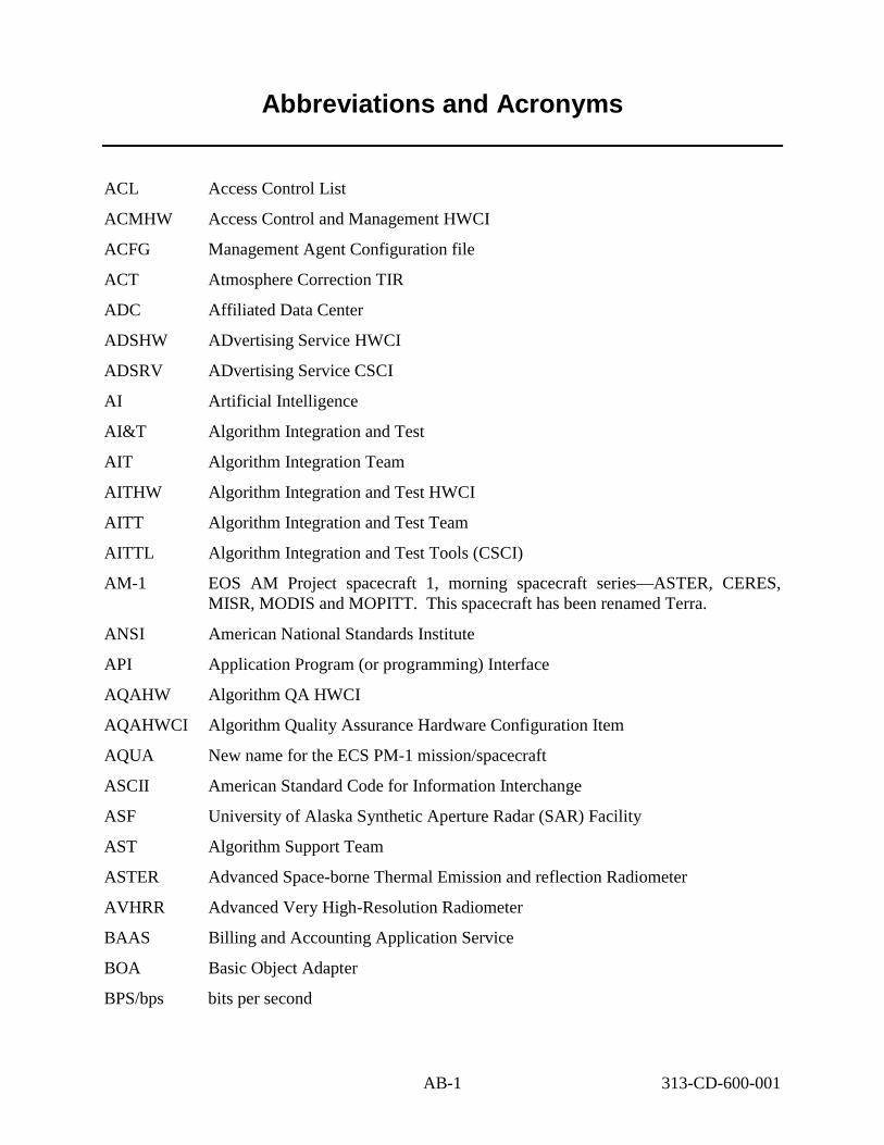
Abbreviations and Acronyms
ACL Access Control List
ACMHW Access Control and Management HWCI
ACFG Management Agent Configuration file
ACT Atmosphere Correction TIR
ADC Affiliated Data Center
ADSHW ADvertising Service HWCI
ADSRV ADvertising Service CSCI
AI Artificial Intelligence
AI&T Algorithm Integration and Test
AIT Algorithm Integration Team
AITHW Algorithm Integration and Test HWCI
AITT Algorithm Integration and Test Team
AITTL Algorithm Integration and Test Tools (CSCI)
AM-1 EOS AM Project spacecraft 1, morning spacecraft series—ASTER, CERES, MISR, MODIS and MOPITT. This spacecraft has been renamed Terra.
ANSI American National Standards Institute
API Application Program (or programming) Interface
AQAHW Algorithm QA HWCI
AQAHWCI Algorithm Quality Assurance Hardware Configuration Item
AQUA New name for the ECS PM-1 mission/spacecraft
ASCII American Standard Code for Information Interchange
ASF University of Alaska Synthetic Aperture Radar (SAR) Facility
AST Algorithm Support Team
ASTER Advanced Space-borne Thermal Emission and reflection Radiometer
AVHRR Advanced Very High-Resolution Radiometer
BAAS Billing and Accounting Application Service
BOA Basic Object Adapter
BPS/bps bits per second
AB-1 313-CD-600-001

Bps/bps bytes per second
BTS Brightness Temperature at Sensor
CASE Computer Aided Software Engineering
CCA Cloud Cover Assessment (Landsat scene information)
CCS CSMS Communications System (CSCI)
CD Compact Disk
CD-ROM Compact Disk - Read Only Memory
CDE Common Desktop Environment
CDHF Central Data Handling Facility
CDR Critical Design Review
CDS Cell Directory Service
CDRL Contract Data Requirements List
CERES Clouds and Earth’s Radiant Energy System
Configuration Item
CIDM Client, Interoperability and Data Management
CLS Client Subsystem
CORBA Common Object Request Broker Architecture
COSS Common Object Services Specifications
COTS Commercial Off-The-Shelf (hardware or software)
CPF Calibration Parameter File
CPU Central Processing Unit
CS Computer Software
CS Client Server
CSC Computer Software Component
CSCI Computer Software Configuration Item
CSDTs Computer Science Data Types
CSMS Communications and Systems Management Segment (ECS)
CSS Communication Subsystem (CSMS)
CtLib Call to Library
AB-2 313-CD-600-001
CI

DAA Data Availability Acknowledgment
DAAC Distributed Active Archive Center
DADS Data Archive and Distribution Service
DAN Data Availability Notice
DAO Data Assimilation Office
DAP Delivered Algorithm Package
DAS Data Assimilation System (at DAO)
DAS Data Availability Schedule
DAS Detailed Activity Schedule
DAR Data Acquisition Request (ASTER)
DB Database (Note: “D/B” and “db” are also utilized)
DBA Database Administrator
DBMS Database Management System
DCCI Distributed Computing software Configuration Item
DCE Distributed Communication Environment
DCE Distributed Computing Environment (OSF)
DCF Data Capture Facility
DCHCI Distributed Communications Hardware Configuration Item
DCHCI Distributed Computing Hardware CI
DDA Data Delivery Acknowledgment
DDICT Data Dictionary CSCI
DDIST Data Distribution services CSCI
DDL Data Definition Language
DDN Data Delivery Notice
DDSRV Document Data Server CSCI in the Data Server Subsystem - SDPS
DEF Data Exchange Format
DEM Digital Elevation Model
DES Data Encryption Standard
DESKT Desktop CI
AB-3 313-CD-600-001

DESKT Desktop CSCI
DFS Distributed File System
DIB Directory Information Base
DID Data Item Description
DIM Distributed Information Manager
DIMGR Distributed Information Manager
DIMGR Distributed Information Manager CSCI
DIPHW Distribution and Ingest Peripheral HWCI
DIPHW Distribution and Ingest Peripheral Management HWCI
DIS Data Information System
DLL Dynamic Link Library (file)
DLPDU Data Link Protocol Data Unit
DM Data Management
DMGHW Data Management HWCI
DMS Data Management Subsystem
DNS Domain Name System
DNS Domain Name Services
DOC Distributed Object Computing
DOF Distributed Object Framework
DORRAN Distributed Ordering, Reporting, Researching, and Accounting Network (EDC)
DPR Data Processing Request
DPREP Data Pre-Processing CSCI
DPS Data Processing Subsystem
DRPHW Data Repository HWCI
DS Data Server
DSS Data Server Subsystem
e-mail electronic mail
email electronic mail
EAS ECS Advertising Service
AB-4 313-CD-600-001

EASI ECS Automatic System Installer (MSS)
ECS EOSDIS Core System
EDC EROS Data Center (DAAC)
EDF ECS Development Facility
EDG EOS Data Gateway (V0 Client – replacement of B0SOT)
EDOS EOS Data and Operations System
EDU EDOS Data Unit
EMC Enterprise Monitoring and Coordination
EMOS Eclipse Mission Operations System
EOC EOS Operations Center
EOS AM EOS AM Project (morning spacecraft series)
EOS Earth Observing System
EOS-AM-1 EOS Morning Crossing (Descending) Mission
EOS-PM EOS Afternoon Crossing (Ascending) Mission (afternoon spacecraft series) (see AIRS, AMSU-A, MHS, MIMR, CERES and MODIS)
EOSDIS Earth Observing System (EOS) Data and Information System (DIS)
ERD Entity Relationship Diagram
EROS Earth Resources Observation System
ESA European Space Agency
ESDD Earth Science Data Directory
ESDIS Earth Science Data and Information System (GSFC Code 505)
ESDT Earth Science Data Types
ESFU Enhanced Standard Format Unit
ESH EDOS Service Header
ESN EOSDIS Science Network (ECS)
ETM+ Enhanced Thematic Mapper Plus
ETS Emissivity/Temperature Separation
FDD Flight Dynamics Division
FDDI Fiber Distributed Data Interface
AB-5 313-CD-600-001

FDF Flight Dynamics Facility
FDS Flight Dynamics System
FOS Flight Operations Segment (ECS)
FOT Flight Operations Team
FSMS File Storage Management System
FTP File Transfer Protocol
ftpd file transfer protocol daemon
G/B Gateway/Bridge
GAC Global Area Coverage (AVHRR)
Gb gigabits (10**9)
Gbps/GBps gigabit/gigabyte per second
GByte gigabyte (10**9)
GCDIS Global Change Data and Information System
GCMD Global Change Master Directory
GCP Ground Control Point
GDAO GSFC Data Assimilation Office
GDS Ground Data System
GFE Government Furnished Equipment
GIS Geographic Information System
GNMP GOSIP Network Management Protocol
GOES Geo-stationary Operational Environmental Satellite
GSFC Goddard Space Flight Center
GTWAY Version 0 Interoperability Gateway CSCI (Also V0GWY)
GUI Graphical User Interface
GV Ground Validation
GV TRMM Ground Validation Data
GV TRMM Ground Verification
H&S Health and Safety
H/K Housekeeping
AB-6 313-CD-600-001

H/W hardware
HCL Hughes Class Library
HDF Hierarchical Data Format
HM Hard Media (e.g. tapes)
HMI Human Machine Interface
HP Hewlett-Packard Corporation
HPOV Hewlett-Packard Open View
HTML Hypertext Markup Language
HTTP Hypertext Transport Protocol
HWCI Hardware Configuration Item
I/F interface
IAS Image Assessment System
I/O input/output
ICD Interface Control Document
ICL Ingest Client
ICLHW Ingest Client HWCI
ICMP Internet Control Management Protocol
ICMP Internet Control Message Protocol
ID Identification
IDD Interface Definition Document
IDL Interactive Data Language
IDL interface definition language
IMS Information Management System
INCI Internetworking CI
INGST Ingest services CI
INHCI Internetworking Hardware CI
INS Ingest Subsystem - SDPS
IOS Interoperability subsystem
IOT Instrument Operations Team
IP Internet Protocol
AB-7 313-CD-600-001

IR-1 Interim Release-1
IRD Interface Requirements Document
IRS Interface Requirements Specification
ISS Internetworking Subsystem - CSMS
JESS Java Earth Science Server
JIL Job I/F Language
JPL Jet Propulsion Laboratory (DAAC)
KB kilobyte (10**3)
KB kilobytes
Kb kilobit (10**3)
KB/SEC kilobyte per second
Kbps kilobits per second
Kbps/KBps kilobit/kilobyte per second
Kerberos security protocol developed by MIT; base for DCE security
Kftp Kerberized file transfer protocol
KM Key Mechanism
KSLOC thousand Single Lines Of Code
Ktelnet Kerberized telnet
Landsat-7 (Landsat-7 for EDHS search)
L7 Landsat-7
L0 Level 0
L0R Level 0 Reformatted data
L0-L4 Level 0 through Level 4 data
L70R Landsat-7 L0 data
LAC Local Area Coverage (AVHRR)
LAN Local Area Network
Landsat Land Remote-Sensing Satellite
LaRC Langley Research Center (DAAC)
LIMGR Local Information Manager CSCI
AB-8 313-CD-600-001
L-7

LIS Lightning Imaging Sensor
LPS Landsat Processing System
M&O Maintenance and Operations
MACI Management Agent Configuration Item (CSCI)
MB megabyte (10**6 bytes)
Mb megabit (10**6)
MBps megabytes per second
Mbps mega bits per second
MBPS/Mbps million bits per second
Mbps/MBps megabit/megabyte per second
Mbyte megabyte
MCF Metadata Configuration File
MCI Management Software CI
med medium
MEM Memory management
MET Metadata
Metadata data about data
MFLOP Million Floating-point Operations per second
MFLOPS Mega (millions of) Floating-point Operations (10**6) per second
MHCI Management Hardware CI
MIB Management Information Base
MIL-STD Military Standard
min minute
MIPS Mega (millions Of) Instructions (10**6) per second
MISR Multi-angle Imaging SpectroRadiometer
MMI Man-Machine Interface
MO&DSD Mission Operations and Data Systems Directorate (GSFC Code 500)
MODIS MODerate resolution Imaging Spectroradiometer
MOJO Message Oriented Jest (Java Earth Science Tool) Orb (Object Request Broker)
AB-9 313-CD-600-001

MOU Memorandum Of Understanding
MSCD Mirror Scan Correction Data (Landsat)
MSS Management Subsystem Service
MSS Multi-Spectral Scanner (Landsat)
MSS System Management Subsystem (of CSMS)
MSSHW MSS Hardware CI
MSU Mass Storage Unit
MSU Microwave Sounding Unit
MTA Message Transfer Agent
MTool Maintenance Tool (DMS)
MTTR Mean Time To Repair
MTTR Mean Time To Restore
MUI Management User Interface
Multicast a point to multi-point data flow
NASA National Aeronautics and Space Administration
Nascom NASA Communications
NCAR National Center for Atmospheric Research
NCEP National Centers for Environmental Prediction
NESDIS National Environmental Satellite, Data, and Information Service (NOAA)
netCDF network Common Data Format
NFS Network File System
NMC National Meteorological Center (NOAA)
NMS Network Management Subsystem (Ecom)
NNTP Network New Transfer Protocol
NNTP Network News Transfer Protocol
NOAA National Oceanic and Atmospheric Administration
NODC National Oceanographic Data Center [NOAA] (also NESDIS/NODC)
NOLAN Nascom Operational Local Area Network
NQS (Network) Queuing System
NRC National Research Council
AB-10 313-CD-600-001

NRDN NOAA Radar Data Network
NREN National Research and Education Network
NRL Naval Research Laboratory
NSF National Science Foundation
NSFNet NSF Network
NSI NASA Science Internet
NSIDC National Snow and Ice Data Center (DAAC - University of Colorado)
NSSDC National Space Science Data Center
NTP Network Transport Protocol
NWCI Networking Configuration Item
O&M Operations and Maintenance
O/A Orbit/Altitude
ODC Other Data Center
ODFRM On-Demand Form Request Manager (CLS)
ODL Object Description Language
ODMS Object Data Management System
ODPRM On-Demand Production Request Manager (PLS)
OES Object Encapsulation Software
OMA Object Management Architecture
OMF Object Management Framework
OMG Object Management Group
OMT Object Modeling Technique
OO object oriented
OOA Object Oriented Analysis
OOD Object Oriented Design
OODBMS Object Oriented Data Base Management System
OODCE Object Oriented Distributed Computing Environment
OORDB Object Oriented Relational Data Base
OPS Operations
AB-11 313-CD-600-001

ORB Object Request Broker
ORDBMS Object Rational Data Base Management System
OS Object Services
OS Operating System
OSF Open Software Foundation
OSI Open Systems Interconnection
OSI-RM OSI Reference Model
OTS Off-The-Shelf
Payload
P/S Planning/Scheduling
PAN Production Acceptance Notification
PAS Planning And Scheduling
PCD Payload Correction Data (Landsat)
PCFG Program Configuration file (Management Agent)
PCL Planning Class Libraries
PDF Publisher’s Display Format
PDF Portable Document Format
PDL Program Design Language
PDPS Planning and Data Processing System
PDR Product Data Request
PDR Product Delivery Record
PDRA Preliminary Design Review release-A
PDS Planetary Data System
PDS Platform Data System
PDS Production Data Set
Perl a UNIX programming language
PF Process Framework
PGE Product Generation Executive (formerly product generation executable)
PGS Product Generation Service
AB-12 313-CD-600-001
P/L

PGS Product Generation System (obsolete ECS element name) (ASTER)
PGSTK Product Generation System Toolkit
PI Primary Investigator
PI Principal Investigator
PI/TL Principal Investigator/Team Leader
PLANG Production Planning CSCI
PLNHW Planning HWCI
PLS Planning Subsystem
PM-1 EOS Project spacecraft 1, evening spacecraft series. This spacecraft has been renamed Aqua.
POSIX Portable Operating System Interface for computer environments
PR Production Request
PR Precipitation Radar (TRMM)
PRONG Processing CSCI
PSA` Product Specific Attributes
PSCN Program Support and Communications Network
PVL Parameter Value Language
QA or Q/A Quality Assurance
QA or Q/A Quality/Accounting
R/W Read/Write
RAID Redundant Array of Inexpensive Disks
RAM Random Access Memory
RCL Resource Class Libraries
RCP Remote Copy
RDA Remote Database Access
RDBMS Relational Data Base Management System
RID Review Item Discrepancy
RMA Reliability, Maintainability, Availability
RMON Remote Monitor (SNMP)
ROC Read Only Cache
AB-13 313-CD-600-001

RPC Remote Procedure Call
RPC Remote Processing Computer
RRR Release Readiness Review
RT or R/T Real Time
RTM Requirements Traceability Model
S/C Spacecraft
S/E Systems Engineering
SAA Satellite Active Archives (NOAA)
SBA Small Business Administration
SBUV Solar Backscatter Ultraviolet
SBUV/2 Solar Backscatter Ultraviolet/version 2
SCDO Science and Communications Development Office (ECS)
SCF Science Computing Facility
SDP Science Data Processing
SDPS Science Data Processing Segment (ECS)
SDPS/W Science Data Processing Software
SDPS/W Science Data Production Software
SDPTK Science Data Processing Toolkit
SDR System Design Review
SDSRV Science Data Server CSCI
SeaWiFS Sea-viewing Wide Field-of-view Sensor
SGI Silicon Graphics Incorporated
SIPS Science Investigator-Led Processing Systems
SMC System Management Center
SMMR Scanning Multi-channel Microwave Radiometer
SMTP Simple Mail Transfer Protocol
SNDCP Sub-Network Dependent Convergence Protocol
SNICP Sub-Network Independent Convergence Protocol
SNMP Simple Network Management Protocol
SP Scenario Primitive
AB-14 313-CD-600-001

SPRHW Science Processing Hardware CI
SQS Spatial Query Servers
SSAP Science Software Archive Package
ssh Secure Shell (Protocol)
sshd Secure Shell Daemon
SSI&T Science Software Integration and Test
SSM/I Special Sensor Microwave/Imager
SSM/T Special Sensor Microwave/Temperature sounder
SST Sea Surface Temperature
STMGT Storage Management software CSCI
StP Software through Pictures
StP/OMT Software through Pictures/Object Modeling Technique
SUN Sun Microsystems
SW Science Workstation
SW or S/W Software
SWCI Software Configuration Item
SWG Science Working Group
TBD To Be Determined, or To Be Defined
TBR To Be Resolved
TBS To Be Supplied
TCP Transmission Control Protocol
TCP/IP Transmission Control Protocol/Internet Protocol
TDRSS Tracking and Data Relay Satellite System
TIR Thermal Infrared
TIROS Television and Infrared Observation Satellite
TL Team Leader
TLCF Team Leader Computing Facility
TM Thematic Mapper (Landsat)
TMI TRMM Microwave Imager
TN TDRSS Network
AB-15 313-CD-600-001

TOMS Total Ozone Mapping Spectrometer
TOPEX Ocean Topography Experiment (joint US-France)
TOVS TIROS Operational Vertical Sounder
TRMM Tropical Rainfall Measuring Mission (joint US-Japan)
TSDIS TRMM Science Data and Information System
TSU TRMM Science User
UARS Upper Atmosphere Research Satellite
UDP User Datagram Protocol
UDP/IP User Datagram Protocol/Internet Protocol
UFS UNIX File System
UID Universal Identifier
UNIX (AT&T Bell Laboratories Operating System) UNiversal Interactive eXecutive
UR Universal Reference
URL Uniform Resource Locator
UserDIS User Data Information System
USGS U.S. Geological Survey
UT Universal Time
UTC Universal Time Code
UTC Universal Time Coordinated
UTCF Universal Time Correlation Factor
UTM Universal Transverse Mercator
UUID Universal Unique Identifier
UX UNIX/X
V&V Verification and Validation
V0 ODL Version 0 Object Description Language
V0 Version 0
V0GWY Version 0 interoperability Gateway CSCI
VAS VISSR Atmospheric Sounder (GOES)
VIMS Virtual IMS
VIRR Visible and Infrared Radiometer
AB-16 313-CD-600-001

VIRS Visible Infrared Scanner (TRMM)
VIS Vendor Information System
VIS-UV Visible/Ultraviolet Spectrometer
VISSR Visible/Infrared Spin-Scan Radiometer (GOES)
VT Virtual Terminal
W/S Workstation
WAIS Wide Area Information Server
WAN Wide Area Network
WKBCH Workbench CSCI
WKSHW Working Storage HWCI
WRKSTN Workstation
WRS Worldwide Reference System (Landsat)
WS Working Storage
WS Workstation
WWW World Wide Web
X protocol
XTE X-ray Timing Explorer
AB-17 313-CD-600-001
X

This page intentionally left blank.
AB-18 313-CD-600-001