Embed Size (px)
Citation preview
313-CD-006-007
EOSDIS Core System Project
Release 4 ECS Internal Interface Control Document
for the ECS Project
Final
February 1999
Raytheon Systems Company Upper Marlboro, Maryland

This page intentionally left blank.
313-CD-006-007
Release 4 ECS Internal Interface Control Document
for the ECS Project
Final
February 1999
Prepared Under Contract NAS5-60000 CDRL Item #051
RESPONSIBLE ENGINEER
Michael R. Helton /s/ 2/24/99
Michael R. Helton Date EOSDIS Core System Project
SUBMITTED BY
Mary S. Armstrong /s/ 2/24/99
Mary S. Armstrong, Director of Development Date EOSDIS Core System Project
Raytheon Systems Company Upper Marlboro, Maryland
313-CD-006-007

This page intentionally left blank.
313-CD-006-007
Preface
This document is a formal contract deliverable with an approval code 3. This document has beenreviewed by the configuration control board and is delivered to NASA in final form, andsupports the Release Readiness Review (RRR). Any questions or proposed changes should beaddressed to:
Data Management OfficeThe ECS Project OfficeRaytheon Systems Company1616 McCormick DriveUpper Marlboro, MD 20774-5301
iii 313-CD-006-007

This page intentionally left blank.
iv 313-CD-006-007
Abstract
This document provides a set of interface scenarios that describe how the Release 4 ECS interacts to execute end-to-end system threads. For each scenario a domain (or end user) view and a component interaction view is presented. This document is intended to be used by application developers, system developers and system maintenance engineers to understand how CSMS/SDPS components interact to perform key system functions. For detailed internal interface information, online output provided by automatic software tools such as Discover and ABC++ should be used.
The scenarios in this document reflect the capabilities and functions of the as built design for Drop 4PX.
Keywords: external interface, internal interface, public class, private class, class category, key mechanism, system-level scenario, scenario primitive, interface class, distributed object
v 313-CD-006-007

This page intentionally left blank.
vi 313-CD-006-007
Change Information Page
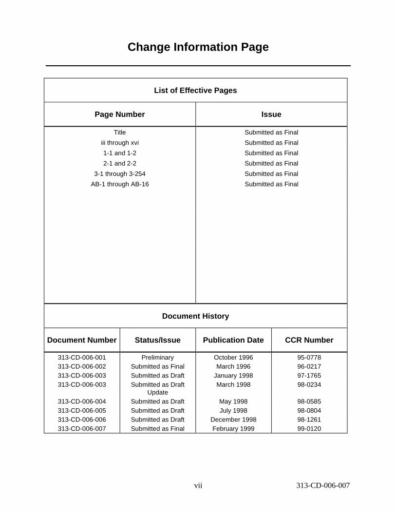
List of Effect ive Pages
Page Number Issue
Title
iii through xvi
1-1 and 1-2
2-1 and 2-2
3-1 through 3-254
AB-1 through AB-16
Submitted as Final
Submitted as Final
Submitted as Final
Submitted as Final
Submitted as Final
Submitted as Final
Document His tory
Document Numbe r Status /Issue Public ation Da te CCR Numbe r
313-CD-006-001 313-CD-006-002 313-CD-006-003 313-CD-006-003
313-CD-006-004 313-CD-006-005 313-CD-006-006 313-CD-006-007
Preliminary Submitted as Final Submitted as Draft Submitted as Draft
Update Submitted as Draft Submitted as Draft Submitted as Draft Submitted as Final
October 1996 March 1996
January 1998 March 1998
May 1998 July 1998
December 1998 February 1999
95-0778 96-0217 97-1765 98-0234
98-0585 98-0804 98-1261 99-0120
vii 313-CD-006-007

This page intentionally left blank.
viii 313-CD-006-007
Contents
Preface
Abstract
1. Introducti on
1.1 Identification ..................................................................................................................1-1
1.2 Scope..............................................................................................................................1-1
1.3 Document Organization .................................................................................................1-1
2. Related Documentation
2.1 Parent Documents ..........................................................................................................2-1
2.2 Applicable Documents...................................................................................................2-1
2.3 Information Documents Not Referenced .......................................................................2-1
3. Inte rfac e Scenarios
3.1 Overview........................................................................................................................3-1
3.2 Scenario Approach.........................................................................................................3-4
3.2.1 Scenario Presentation Approach ........................................................................3-4
3.2.2 Scenario Process Flow .......................................................................................3-6
3.3 Install ESDTs Scenario ..................................................................................................3-8
3.3.1 Scenario Description..........................................................................................3-8
3.3.2 Scenario Preconditions.......................................................................................3-8
3.3.3 Scenario Partitions..............................................................................................3-8
3.3.4 Install ESDT Thread...........................................................................................3-8
3.4 System Start-up/Shutdown Scenario.............................................................................3-13
3.4.1 System Start-up/Shutdown Scenario Description.............................................3-13
ix 313-CD-006-007
3.4.2 System Start-up/Shutdown Scenario Preconditions..........................................3-14
3.4.3 System Start-up/Shutdown Scenario Partitions ................................................3-14
3.4.4 Mode Start-up Thread .......................................................................................3-14
3.4.5 Mode Shutdown Thread....................................................................................3-17
3.4.6 Application Start-up Thread..............................................................................3-20
3.4.7 Application Shutdown Thread ..........................................................................3-23
3.4.8 Program Start-up Thread...................................................................................3-27
3.4.9 Program Shutdown Thread................................................................................3-30
3.4.10 Process Shutdown Thread.................................................................................3-33
3.5 MODIS Scenario...........................................................................................................3-36
3.5.1 MODIS Scenario Description ...........................................................................3-36
3.5.2 MODIS Scenario Preconditions........................................................................3-37
3.5.3 MODIS Scenario Partitions...............................................................................3-38
3.5.4 MODIS Standing Order Submittal Thread........................................................3-39
3.5.5 MODIS Standard Production Thread................................................................3-41
3.5.6 MODIS Failed PGE Handling Thread..............................................................3-71
3.5.7 MODIS Data Access Thread.............................................................................3-77
3.5.8 Reactivation/Replan..........................................................................................3-86
3.6 Landsat-7 Scenario........................................................................................................3-95
3.6.1 Landsat-7 Scenario Description........................................................................3-95
3.6.2 Landsat-7 Scenario Preconditions.....................................................................3-96
3.6.3 Landsat-7 Scenario Partitions............................................................................3-96
3.6.4 Landsat-7 User Registration Thread .................................................................3-96
3.6.5 Landsat-7 LPS Data Insertion Thread..............................................................3-100
3.6.6 Landsat-7 Standing Order Support Thread ......................................................3-107
3.6.7 Landsat-7 IAS Data Insertion Thread ..............................................................3-113
3.6.8 Landsat-7 Search and Browse Thread..............................................................3-116
3.6.9 Landsat-7 Ordering WRS Scenes Thread ........................................................3-124
3.6.10 Landsat-7 MOC Interface Thread....................................................................3-138
3.7 ASTER Scenario..........................................................................................................3-142
3.7.1 ASTER Scenario Description...........................................................................3-142
3.7.2 ASTER Scenario Preconditions.......................................................................3-143
3.7.3 ASTER Scenario Partitions..............................................................................3-143
3.7.4 ASTER DAR Submission Thread....................................................................3-144
x 313-CD-006-007
3.7.5 ASTER GDS Tape Insertion Thread................................................................3-147
3.7.6 ASTER Backward Chaining Thread................................................................3-151
3.7.7 ASTER QA Metadata Update Thread..............................................................3-175
3.7.8 ASTER On-Demand Production Thread..........................................................3-177
3.7.9 ASTER Simplified Expedited Data Support Thread........................................3-190
3.7.10 ASTER Routine Processing Planning Thread..................................................3-197
3.8 Planning Scenario.........................................................................................................3-203
3.8.1 Planning Scenario Description.........................................................................3-203
3.8.2 Planning Scenario Preconditions......................................................................3-203
3.8.3 Planning Scenario Partitions ............................................................................3-203
3.8.4 Ground Events Jobs Thread (Thread A) ..........................................................3-204
3.8.5 Resource Planning Thread (Thread B).............................................................3-207
3.8.6 Science Software Archive Package Thread - SSAP Insertion (Thread A) ......3-211
3.8.7 SSAP Update Thread (Thread B).....................................................................3-215
3.8.8 Archive PGE Executable TAR File Thread (Thread C) ..................................3-220
3.8.9 Metadata Query for Current Dynamic Input Granules (Thread A)..................3-223
3.8.10 Dynamic Granule Available in the Future Thread (Thread B) ........................3-225
3.8.11 Metadata Based Activation Thread..................................................................3-227
3.8.12 Ad Hoc Reprocessing Thread ..........................................................................3-229
3.8.13 Delete DPR Thread ..........................................................................................3-233
3.9 EDOS/FDS Ephemeris/Attitude Data Processing Scenario.........................................3-237
3.9.1 EDOS/FDS Ephemeris/Attitude Data Processing Scenario Description.........3-237
3.9.2 EDOS/FDS Ephemeris/Attitude Data Processing Scenario Preconditions......3-237
3.9.3 EDOS/FDS Ephemeris/Attitude Data Processing Scenario Partitions ............3-237
3.9.4 EDOS Level 0 Ancillary Data Thread .............................................................3-237
3.9.5 FDS Definitive Attitude Data Thread ..............................................................3-242
3.10 Fault Recovery .............................................................................................................3-248
List of Fi gur es
3.2.2-1 Scenario Process Flow .............................................................................................3-6
3.3.4.1-1 Install ESDT Interaction Diagram............................................................................3-9
3.4.1-1 ECS Custom Software Hierarchy Diagram.............................................................3-13
3.4.4.1-1 Mode Start-up Interaction Diagram ........................................................................3-15
xi 313-CD-006-007
3.4.5.1-1 Mode Shutdown Interaction Diagram.....................................................................3-18
3.4.6.1-1 Application Start-up Interaction Diagram...............................................................3-20
3.4.7.1-1 Application Shutdown Interaction Diagram ...........................................................3-23
3.4.8.1-1 Program Start-up Interaction Diagram....................................................................3-27
3.4.9.1-1 Program Shutdown Interaction Diagram.................................................................3-30
3.4.10.1-1 Process Shutdown Interaction Diagram..................................................................3-33
3.5.1-1 MODIS Scenario PGE/Data Relationship Diagram................................................3-36
3.5.4.1-1 MODIS Standing Order Submittal Interaction Diagram.........................................3-39
3.5.5.1-1 MODIS Standard Production Interaction Diagram.................................................3-41
3.5.6.1-1 MODIS Failed PGE Handling Interaction Diagram...............................................3-72
3.5.7.1-1 MODIS Data Access Interaction Diagram..............................................................3-78
3.5.8.4.1-1DPR in New Plan but Not in Old Plan Interaction Diagram - Domain View.........3-87
3.5.8.5.1-1DPR in Old Plan but Not in New Plan Interaction Diagram - Domain View.........3-89
3.5.8.6.1-1DPR in Both Old Plan and New Plan Interaction Diagram - Domain View ..........3-92
3.6.4.1-1 L-7 User Registration Interaction Diagram.............................................................3-97
3.6.5.1-1 L-7 LPS Data Insertion Interaction Diagram.........................................................3-100
3.6.6.1-1 L-7 Standing Order Support Interaction Diagram..................................................3-107
3.6.7.1-1 Landsat-7 IAS Data Insertion Interaction Diagram ...............................................3-113
3.6.8.1-1 L-7 Search and Browse Interaction Diagram.........................................................3-117
3.6.9.1-1 L-7 Ordering WRS Scenes Interaction Diagram....................................................3-124
3.6.10.1-1 L-7 MOC Interface Interaction Diagram ...............................................................3-138
3.7.1-1 ASTER Scenario PGE/Data Relationships Diagram.............................................3-142
3.7.4.1-1 ASTER DAR Submission Interaction Diagram.....................................................3-144
3.7.5.1-1 ASTER GDS Tape Insertion Interaction Diagram.................................................3-147
3.7.6.1-1 ASTER Backward Chaining Interaction Diagram.................................................3-151
3.7.7.1-1 ASTER QA Metadata Update Interaction Diagram...............................................3-175
3.7.8.1-1 ASTER On-Demand Production Interaction Diagram...........................................3-178
3.7.9.1-1 ASTER Simplified Expedited Data Support Interaction Diagram.........................3-191
3.7.10.1-1 ASTER Routine Processing Planning Interaction Diagram...................................3-198
xii 313-CD-006-007
3.8.4.1-1 Ground Events Jobs Thread Interaction Diagram - Domain View........................3-205
3.8.5.1-1 Resource Planning Interaction Diagram - Domain View.......................................3-208
3.8.6.1-1 SSAP Diagram - Domain View .............................................................................3-212
3.8.7.1-1 SSAP Update Interaction Diagram - Domain View...............................................3-216
3.8.8.1-1 Archive PGE Executable TAR File Interaction Diagram -Domain View...........3-220
3.8.9.1-1 Metadata Query for Current Dynamic Granule Interaction Diagram -Domain View .........................................................................................................3-223
3.8.10.1-1 Future Dynamic Granule Interaction -Domain View............................................3-225
3.8.11.1-1 Metadata Based Activation Interaction Diagram - Domain View.........................3-228
3.8.12.1-1 Ad Hoc Reprocessing Interaction Diagram - Domain View..................................3-230
3.8.13.1-1 Delete DPR Interaction Diagram - Domain View .................................................3-234
3.9.4.1-1 EDOS Level 0 Ancillary Data Interaction - Domain View ...................................3-238
3.9.5.1-1 FDS Definitive Attitude Data Diagram..................................................................3-243
List of Tabl es
3.1-1 ECS Subsystem and Component Design Overviews ..............................................3-2
3.3.4.2-1 Interaction Table - Domain View: ESDT Installation ............................................3-10
3.3.4.3-1 Component Interaction Table: ESDT Installation ..................................................3-11
3.4.4.2-1 Interaction Table - Domain View: Mode Start-up .................................................3-15
3.4.4.3-1 Component Interaction Table: Mode Start-up .......................................................3-16
3.4.5.2-1 Interaction Table - Domain View: Mode Shutdown ..............................................3-18
3.4.5.3-1 Mode Shutdown Component Interaction Table .....................................................3-19
3.4.6.2-1 Interaction Table - Domain View Application Start-up..........................................3-21
3.4.6.3-1 Application Start-up Component Interaction Table ...............................................3-22
3.4.7.2-1 Interaction Table - Domain View: Application Shutdown ....................................3-24
3.4.7.3-1 Component Interaction Table: Application Shutdown............................................3-26
3.4.8.2-1 Interaction Table - Domain View: Program Start-up..............................................3-28
3.4.8.3-1 Component Interaction Table: Program Start-up....................................................3-29
3.4.9.2-1 Interaction Table - Domain View: Program Shutdown ..........................................3-31
xiii 313-CD-006-007
3.4.9.3-1 Component Interaction Table: Program Shutdown.................................................3-32
3.4.10.2-1 Interaction Table - Domain View: Process Shutdown............................................3-34
3.4.10.3-1 Component Interaction Table: Process Shutdown..................................................3-35
3.5.4.2-1 Interaction Table - Domain View: MODIS Standing Order Submittal ................3-39
3.5.4.3-1 Component Interaction Table: MODIS Standing Order Submittal.........................3-40
3.5.5.2-1 Interaction Table - Domain View: MODIS Standard Production .........................3-42
3.5.5.3-1 Component Interaction Table: MODIS Standard Production ...............................3-45
3.5.6.2-1 Interaction Table - Domain View: MODIS Failed PGE Handling .......................3-72
3.5.6.3-1 Component Interaction Table: MODIS Failed PGE Handling .............................3-73
3.5.7.2-1 Interaction Table - Domain View: MODIS Data Access ......................................3-79
3.5.7.3-1 Component Interaction Table: MODIS Data Access ............................................3-80
3.5.8.4.2-1Interaction Table - Domain View: DPR in New Plan but Not in Old Plan............3-87
3.5.8.4.3-1Component Interaction Table: DPR in New Plan but Not in Old Plan..................3-88
3.5.8.5.2-1Interaction Table - Domain View: DPR in Old Plan but Not in New Plan............3-90
3.5.8.5.3-1Component Interaction Table: DPR in Old Plan but Not in New Plan..................3-91
3.5.8.6.2-1Interaction Table - Domain View: DPR in Both Old Plan and New Plan ............3-92
3.5.8.6.3-1Component Interaction Table: DPR in Both Old Plan and New Plan ..................3-93
3.6.4.2-1 Interaction Table - Domain View: L7 User Registration .......................................3-97
3.6.4.3-1 Component Interaction Table: L7 User Registration .............................................3-98
3.6.5.2-1 Interaction Table - Domain View: L-7 LPS Data Insertion ..................................3-100
3.6.5.3-1 Component Interaction Table: L-7 LPS Data Insertion ........................................3-102
3.6.6.2-1 Interaction Table - Domain View: L-7 Standing Order Support ...........................3-108
3.6.6.3-1 Component Interaction Table: L-7 Standing Order Support ................................3-109
3.6.7.2-1 Interaction Table - Domain View: L-7 IAS Data Insertion ..................................3-113
3.6.7.3-1 Component Interaction Table: L-7 IAS Data Insertion .........................................3-114
3.6.8.2-1 Interaction Table - Domain View: L-7 Search and Browse ..................................3-117
3.6.8.3-1 Component Interaction Table: L-7 Search and Browse ........................................3-118
3.6.9.2-1 Interaction Table - Domain View: L-7 Ordering WRS Scenes ...........................3-125
3.6.9.3-1 Component Interaction Table: L-7 Ordering WRS Scenes ...................................3-127
xiv 313-CD-006-007
3.6.10.2-1 Interaction Table - Domain View: L-7 MOC Interface .........................................3-139
3.6.10.3-1 Component Interaction Table: L-7 MOC Interface ...............................................3-140
3.7.4.2-1 Interaction Table - Domain View: ASTER DAR Submission...............................3-145
3.7.4.3-1 Component Interaction Table: ASTER DAR Submission ....................................3-146
3.7.5.2-1 Interaction Table - Domain View: ASTER GDS Tape Insertion...........................3-148
3.7.5.3-1 Component Interaction Table: ASTER GDS Tape Insertion ................................3-148
3.7.6.2-1 Interaction Table - Domain View: ASTER Backward Chaining .........................3-152
3.7.6.3-1 Component Interaction Table: ASTER Backward Chaining ...............................3-155
3.7.7.2-1 Interaction Table - Domain View: ASTER QA Metadata Update .......................3-175
3.7.7.3-1 Component Interaction Table: ASTER QA Metadata Update .............................3-176
3.7.8.2-1 Interaction Table - Domain View: ASTER On-Demand Production ...................3-178
3.7.8.3-1 Component Interaction Table: ASTER On-Demand Production .........................3-180
3.7.9.2-1 Interaction Table - Domain View: ASTER Simplified Expedited Data ..............3-191
3.7.9.3-1 Component Interaction Table: ASTER Simplified Expedited Data .....................3-193
3.7.10.2-1 Interaction Table - Domain View: ASTER Routine Processing Planning ...........3-199
3.7.10.3-1 Component Interaction Table: ASTER Routine Processing Planning .................3-200
3.8.4.2-1 Interaction Table - Domain View: Ground Events Jobs .......................................3-205
3.8.4.3-1 Component Interaction Table: Ground Events Jobs .............................................3-206
3.8.5.2-1 Interaction Table - Domain View: Resource Planning ........................................3-208
3.8.5.3-1 Component Interaction Table: Resource Planning ................................................3-209
3.8.6.2-1 Interaction Table - Domain View: SSAP Insertion................................................3-213
3.8.6.3-1 Component Interaction Table: SSAP Insertion .....................................................3-214
3.8.7.2-1 Interaction Table - Domain View: SSAP Update ..................................................3-217
3.8.7.3-1 Component Interaction Table: SSAP Update ........................................................3-218
3.8.8.2-1 Interaction Table - Domain View: Archive PGE Executable Tar File ..................3-221
3.8.8.3-1 Component Interaction Table: Archive PGE Executable Tar File.........................3-222
3.8.9.2-1 Interaction Table - Domain View: Current Dynamic Granule .............................3-223
3.8.9.3-1 Component Interaction Table: Current Dynamic Granule.....................................3-224
3.8.10.2-1 Interaction Table - Domain View: Dynamic Granule Available in the Future ....3-225
xv 313-CD-006-007
3.8.10.3-1 Component Interaction Table: Dynamic Granule Available in the Future...........3-227
3.8.11.2-1 Interaction Table - Domain View: Metadata Based Activation ............................3-228
3.8.11.3-1 Component Interaction Table: Metadata Based Activation...................................3-229
3.8.12.2-1 Interaction Table - Domain View: Ad Hoc Reprocessing ....................................3-231
3.8.12.3-1 Component Interaction Table: Ad Hoc Reprocessing ...........................................3-232
3.8.13.2-1 Interaction Table - Domain View: Delete DPR ....................................................3-234
3.8.13.3-1 Component Interaction Table: Delete DPR ..........................................................3-235
3.9.4.2-1 Interaction Table - Domain View: EDOS L0 Ancillary Data .............................3-239
3.9.4.3-1 Component Interaction Table: EDOS L0 Ancillary Data .....................................3-241
3.9.5.2-1 Interaction Table - Domain View: FDS Definitive Attitude Data .......................3-244
3.9.5.3-1 Component Interaction Table: FDS Definitive Attitude Data .............................3-246
3.10-1 Client Fault Recovery Conditions..........................................................................3-249
3.10-2 Server Fault Recovery Conditions .........................................................................3-252
Abbr eviations and Acr onyms
xvi 313-CD-006-007
1. Intro duction
1.1 Identif icat ion
This Release 4 (Drop 4PX) ECS Internal Interface Control Document (ICD) for the ECS Project, Contract Data Requirement List (CDRL) item 051, with requirements specified in Data Item Description (DID) 313/DV3, is a required deliverable under the Earth Observing System (EOS) Data and Information System (EOSDIS) Core System (ECS), Contract (NAS5-60000).
1.2 Scope
The Drop 4PX Internal ICD specifies software interfaces internal to the CSMS/SDPS software architecture. It defines Drop 4PX services in the context of system level scenarios. The relationships and interactions between the Drop 4PX CSCIs are presented. This document also describes how ECS infrastructure services are used by the ECS internal applications.
This document addresses all interface classes from SDPS and CSMS CSCIs which are linked to create a desired scenario. External interfaces are mapped to the internal ECS object(s) that provide the service.
This document describes the ECS system in terms of its support of several primary scenarios. These scenarios, based on the normal support of EOS instruments, are listed below and are described in section 3.
• Install ESDTs (Earth Science Data Types)• System Startup/Shutdown (ECS Custom Software)• MODIS (an instrument on the AM-1 spacecraft which provides data to three DAACs)• Landsat-7• ASTER (an instrument on the AM-1 spacecraft which provides data to Japan (GDS)).• Planning Scenarios• EDOS/FDS Ephemeris/Attitude Data Processing• Fault Recovery
1.3 Document Or gani zation
The document is organized to describe the Drop 4PX internal interfaces.
Section 1 provides information regarding the identification, scope, status, and organization of this document.
Section 2 provides a listing of the related documents which were used as source information for this document.
Section 3 contains the system level scenarios that illustrate the interactions between the ECS CSCIs. This section also provides an overview of the interface modeling approach to document the internal interfaces.
1-1 313-CD-006-007

This page intentionally left blank.
1-2 313-CD-006-007
2. Related Documentation
2.1 Parent Documents
194-207-SEI System Design Specification for the ECS Project
313/DV3 ECS Internal Interface Control Documents
212-WP-002 Game Plan for the ECS Project
2.2 Applicable Documents
305-CD-100 Release 4 Segment/Design Specification for the ECS Project
311-CD-109 Subscription Server Database Design and Schema Specifications for the ECS Project
611-CD-004 Mission Operation Procedures – Drop 4PX – A Delta Iteration
505-41-32 ESDIS Document, Interface Control Document between the EOSDIS Core System (ECS) and the Landsat-7 System, Revision A, May 1997
2.3 Informat ion Documents Not Refe renced
The documents listed below, while not directly applicable, do help in the maintenance of the delivered software.
423-41-02 Goddard Space Flight Center, Functional and Performance Requirements Specification for the Earth Observing System Data and Information System Core System
540-022 Goddard Space Flight Center, Earth Observing System Communications System Design Specification Interface Requirements Document
560-EDOS-0211.0001 Goddard Space Flight Center, Interface Requirements Document Between EDOS and the EOS Ground System
DRAFT Operational Agreement between the Landsat 7 Data Handling Facility and the Distributed Active Archive Center (DAAC) at the EROS Data Center (EDC)
2-1 313-CD-006-007

This page intentionally left blank.
2-2 313-CD-006-007
3. Interface Scena rios
3.1 Overv iew
The purpose of this section is to document how ECS works to fulfill its mission. The ECS mission is, in its essence, to manage Earth Science-related data in the following ways:
• to receive data from external sources,
• to save that data in either long-term or permanent storage,
• to produce higher level data products from the received data, and
• to support access to the data by Earth Scientists as well as other registered clients.
ECS is a complex software system that comprises nine subsystems. Each of those subsystems comprises a set of software programs (COTS and custom built) that work together to exchange information and control the management of Earth Science-related data.
A preferred method to document how a complex system such as ECS works is to follow a specific thread of functionality, or scenario, tracing how the ECS Clients (both human and software) and internal ECS components interact in support of that scenario. The interaction between the ECS components can be understood by focusing on how the interfaces offered by the ECS components are used in support of the system functionality required to support the given scenario.
This section documents one facet of a multi-faceted problem. In order to get a more complete view of precisely how each ECS component performs its role, the reader should also reference the design material presented by each of the ECS components. This material can be found in CDRL-3051. Table 3.1-1 maps the subsystems and their components to their appropriate interface process. Only major interface processes utilized in the scenarios are shown in this table. Indeed, this document and CDRL 305 should be used in conjunction with each other. CDRL 305 provides a description of the processes and a statement of what the components are providing and how they provide it. This section documents how those components work together to provide a complete system.
It should be noted that many of the scenarios involve a software component / Operations interface with a human operator. The intent of the descriptions of these interfaces is to show the involvement of a human operator to the extent necessary to effect the correct component function and not to show operator procedures. These procedures are detailed in the 611 document.
1 CDRL-305 refers to ECS Document: 305-CD-100-005, Release 4 Segment/Design Specification for the ECS Project.
3-1 313-CD-006-007
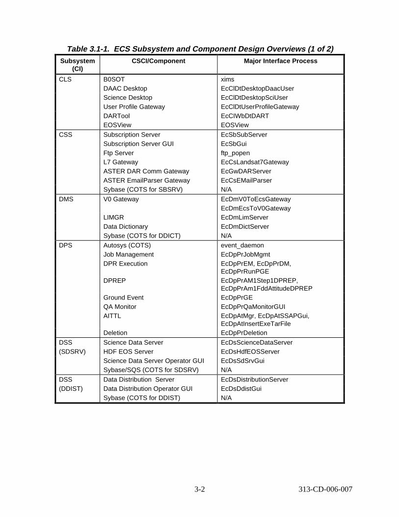
Table 3.1-1. ECS Subsystem and Component Design Overvi ews (1 o f 2) Subsyst em
(CI) CSCI/Compon ent Major Int erface Proc ess
CLS B0SOT DAAC Desktop Science Desktop User Profile Gateway DARTool EOSView
xims EcClDtDesktopDaacUser EcClDtDesktopSciUser EcClDtUserProfileGateway EcCIWbDtDART EOSView
CSS Subscription Server Subscription Server GUI Ftp Server L7 Gateway ASTER DAR Comm Gateway ASTER EmailParser Gateway Sybase (COTS for SBSRV)
EcSbSubServer EcSbGui ftp_popen EcCsLandsat7Gateway EcGwDARServer EcCsEMailParser N/A
DMS V0 Gateway
LIMGR Data Dictionary Sybase (COTS for DDICT)
EcDmV0ToEcsGateway EcDmEcsToV0Gateway EcDmLimServer EcDmDictServer N/A
DPS Autosys (COTS) Job Management DPR Execution
DPREP
Ground Event QA Monitor AITTL
Deletion
event_daemon EcDpPrJobMgmt EcDpPrEM, EcDpPrDM, EcDpPrRunPGE EcDpPrAM1Step1DPREP, EcDpPrAm1FddAttitudeDPREP EcDpPrGE EcDpPrQaMonitorGUI EcDpAtMgr, EcDpAtSSAPGui, EcDpAtInsertExeTarFile EcDpPrDeletion
DSS (SDSRV)
Science Data Server HDF EOS Server Science Data Server Operator GUI Sybase/SQS (COTS for SDSRV)
EcDsScienceDataServer EcDsHdfEOSServer EcDsSdSrvGui N/A
DSS (DDIST)
Data Distribution Server Data Distribution Operator GUI Sybase (COTS for DDIST)
EcDsDistributionServer EcDsDdistGui N/A
3-2 313-CD-006-007
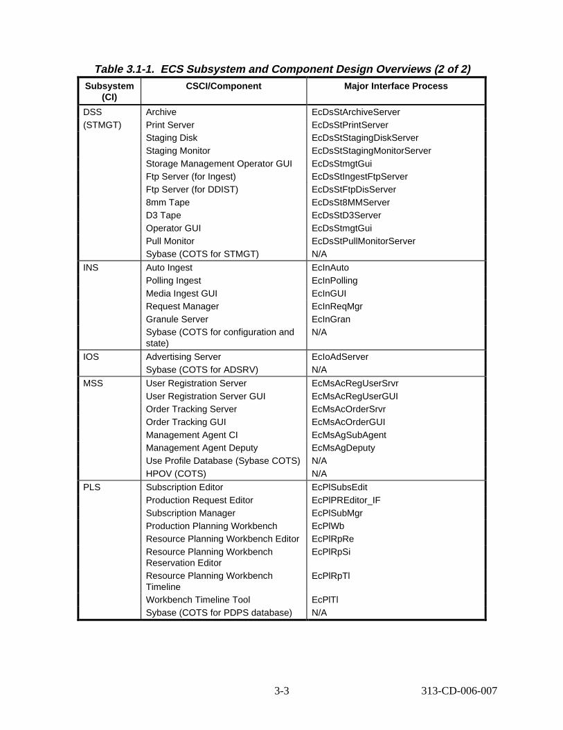
Table 3.1-1. ECS Subsystem and Component Design Overvi ews (2 of 2) Subsyst em
(CI) CSCI/Compon ent Major Int erface Proc ess
DSS (STMGT)
Archive Print Server Staging Disk Staging Monitor Storage Management Operator GUI Ftp Server (for Ingest) Ftp Server (for DDIST) 8mm Tape D3 Tape Operator GUI Pull Monitor Sybase (COTS for STMGT)
EcDsStArchiveServer EcDsStPrintServer EcDsStStagingDiskServer EcDsStStagingMonitorServer EcDsStmgtGui EcDsStIngestFtpServer EcDsStFtpDisServer EcDsSt8MMServer EcDsStD3Server EcDsStmgtGui EcDsStPullMonitorServer N/A
INS Auto Ingest Polling Ingest Media Ingest GUI Request Manager Granule Server Sybase (COTS for configuration and state)
EcInAuto EcInPolling EcInGUI EcInReqMgr EcInGran N/A
IOS Advertising Server Sybase (COTS for ADSRV)
EcIoAdServer N/A
MSS User Registration Server User Registration Server GUI Order Tracking Server Order Tracking GUI Management Agent CI Management Agent Deputy Use Profile Database (Sybase COTS) HPOV (COTS)
EcMsAcRegUserSrvr EcMsAcRegUserGUI EcMsAcOrderSrvr EcMsAcOrderGUI EcMsAgSubAgent EcMsAgDeputy N/A N/A
PLS Subscription Editor Production Request Editor Subscription Manager Production Planning Workbench Resource Planning Workbench Editor Resource Planning Workbench Reservation Editor Resource Planning Workbench Timeline Workbench Timeline Tool Sybase (COTS for PDPS database)
EcPlSubsEdit EcPlPREditor_IF EcPlSubMgr EcPlWb EcPlRpRe EcPlRpSi
EcPlRpTl
EcPlTl N/A
3-3 313-CD-006-007
3.2 Scenar io Appr oach
Section 3.3 describes the steps required prior to the start of usage of the EOSDIS system. The steps taken to install ESDTs are defined in this section.
Section 3.4 describes the processing involved in starting/stopping the EOSDIS system.
Sections 3.5 - 3.7 document the ECS system in terms of its support of three primary scenarios. These scenarios are based on the normal support of three primary EOS instruments:
• MODIS
• Landsat-7
• ASTER
Section 3.8 describes the Production Planning scenario. This scenario applies to processing common to MODIS and ASTER scenarios and one specifically for the MISR instrument.
Section 3.9 describes the EDOS/FDS Ephemeris/Attitude Data Processing Scenario.
Sub-sections describe how ECS supports each of these scenarios in the above sections from two perspectives: The domain view and the component view. The domain view breaks the scenario into a sequence of activities that are based on what happens from the Operational or Science Data perspective. This view presents how ECS-external users and systems interact with ECS as well as looking at how the science data is managed within ECS. This view does not present the details of specific process interactions. The component view shows a more detailed set of interactions that describe the interface usage between ECS components. Each interaction between components is documented, in terms of how and why. Each of the scenarios documented here has been partitioned into primary threads of activity. Each thread of the scenario is documented independently in order to simplify the scenarios.
Section 3.10 documents the processing scenarios that describe the fault detection and recovery schemes included in the system.
3.2.1 Scenar io Pr esent ation A pproa ch
This section describes how the ECS support of each scenario is presented. As mentioned above, each Scenario is partitioned into a sequence of threads of activity. Each of those threads is documented in the same manner. The following paragraphs define this documentation approach.
Scenario Descri ption: First, each scenario is described from the science mission perspective. The primary system functions that are being exercised are identified.
Scenario Preconditions: All activities that must have been performed prior to the execution of the scenario are identified.
Scenario Partitions: The scenario threads are identified and described.
Scenario Thread Interaction Diagram: A diagram is presented for each Scenario Thread. This diagram shows external system, ECS User, DAAC Operator and ECS-internal subsystem
3-4 313-CD-006-007
interactions. The notation of the diagram allows for the interactions to be labeled with numbers and short terms. The arrow numbering uses the convention of a letter, representing the Thread within the Scenario, and a sequence number (e.g. A.1, A.2, B.2, B.3). The mechanism of the interactions (e.g. Distributed Object, HMI, ftp, and e-mail or as noted) is identified by the interaction line presentation style.
In teraction Table - Domain View: Each Scenario Thread is documented in a table which describes the interactions presented in the Scenario Thread Interaction Diagram. These interactions are not the detailed definitions of how the interactions are fulfilled, but rather that they need to occur. This table further specifies the interactions as each row represents an interaction event. The columns in the table delimit how each interaction is defined. The Interaction Table - Domain View includes the following columns:
Step: An identifier of the step within the Scenario Thread. Each step is identified by a “x.y” label, where x is a letter referring to the Thread within the scenario, and y is a sequence number.
Event: The name of an interaction occurrence between major parts of the system (i.e. Subsystem to Subsystem).
Interface Client: The Client of the interaction. This can be viewed as who is asking the question, or who is stimulating the action. Included in this column are Users, Operators, External Systems and usually ECS subsystems rather than components.
Interface Provider: All Interactions are described in terms of exercising well-defined interfaces. Those interfaces are offered by some entity in the system and are similar to those identified as Interface Clients. The Interface Provider is not only responsible for offering the interface, but for ensuring that the interface is met. The provider is doing the action required, perhaps collaborating with other system entities.
Data Issues: This column describes any special Data related issues. This description includes the data types, volumes and frequencies, as well as the current source of the data used in the system. The word “None” i ndicates there are no data issues.
Step Preconditions: Any special preconditions that must have been met for the interaction to be successful are called out here. The word “None” indicates there are no special preconditions for this particular step.
Description: A description is given of what generally occurs during the interaction, as well as its application in this scenario step.
Component In teraction Table: Each Scenario Thread is further documented in the Component Interaction Table. This table specifies each ECS component-level interaction that is required to support the steps in the Scenario Thread.
Each of these interactions is numbered in a way that is consistent with the Scenario Thread that it is supporting. Specifically, each Component Interaction step is numbered with a “sub”step number in a sequence within that Scenario Thread step. For example, if there are three component interactions required to fulfill Scenario Thread step A.3, those three steps are numbered A.3.1, A.3.2 and A.3.3. Please note that if no component interaction is required to
3-5 313-CD-006-007
fulfill a Scenario Thread Step (i.e. - only human-to-human interaction), there are no component interaction steps. Therefore, in the Component Interaction steps, a Scenario Thread Step might be skipped.
Each row in the Component Interaction Table defines a step in how the system supports the capability. The columns in the Component Interaction Table are:
Step: An identifier, as described above, of the step within the Scenario Thread. Event: The name of an interaction occurrence between components.
Interface Client: The Client of the interaction. This can be viewed as who is asking the question, or who is stimulating the action. Included in this column are Users, Operators, External Systems and ECS components. Where ECS components are the Interface Clients, the specific component process is identified.
Interface Provider: This identifies the entity in the system that is providing the interface used to perform some capability. Interface Providers are primarily ECS Components, which are identified by the component process name.
Interface Mechanism: This column identifies how the interface is accomplished. It defines the low level (normally software) mechanism used by the Interface Client and Provider to exchange necessary information. This is also shown in the scenario diagrams for only the particular component interaction between subsystems – consult the key.
Description: This column contains text describing what is occurring during this step. It describes what is occurring in the context of this scenario thread. It describes not only what is happening, but also how it happens and how the client knows how to ask for it.
3.2.2 Scenar io Proc ess Flow
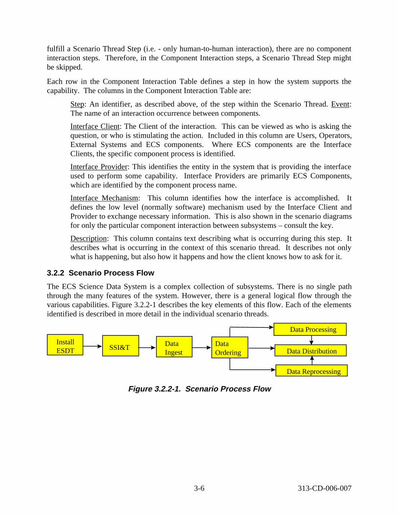
The ECS Science Data System is a complex collection of subsystems. There is no single path through the many features of the system. However, there is a general logical flow through the various capabilities. Figure 3.2.2-1 describes the key elements of this flow. Each of the elements identified is described in more detail in the individual scenario threads.
Install ESDT
Data Reprocessing
Data Distribution
Data Processing
SSI&T Data Ingest
Data Ordering
Figure 3. 2.2-1. Scenar io Proc ess Flow
3-6 313-CD-006-007
Install ESDT
All data interactions within the ECS are performed against Earth Science Data Types (ESDTs). An ESDT is the logical object that describes both the inventory holdings for particular data, and the services (insert, acquire etc.) that can be applied to that data. Before a user (including DAAC operations) can perform any data services against a data set in the ECS, the ESDT for that data type must be installed. Installation includes defining the collection level and granule level metadata in the inventory (Science Data Server), Advertising the data type and it’s services, defining metadata attribute valids in the Data Dictionary, and defining Subscribable data events.
SSI&T
Science Software Integration & Test (SSI&T) is the process by which Instrument Team developed algorithms get qualified for use in the ECS production environment. Much of this process is algorithm specifi c and/or manual or semi-automatic. These aspects are not dealt with in this document. However, the reception of the original algorithm package (DAP) and the qualified algorithm package (SSAP) are automated tasks, and are covered in detail in the scenarios.
Data Ingest
Once the ESDT is defined, and any production algorithms have been integrated, then the ECS is ready to accept data and generate higher level products. This document covers a number of different data ingest scenarios that occur with ECS data.
Data Ordering
There are a number of ways in which data can be requested in the ECS. If the product exists in the archive, then a user can simply request it for distribution. If the product doesn’t exist, but the algorithms for producing the product have been integrated, then the user can request production. Alternatively if the product exists, but has been generated with a set of run-time parameters different from those desired, then the user can request that the product is reprocessed.
Data Processing
Many products are produced automatically upon the availability of the necessary input data. But in addition to this ‘standard’ production, the ECS also has the capability to produce products ondemand in response to a user request. Both types of production, together with QA processing and algorithm failure handling are described in detail in the scenarios.
Data Reprocessing
An important feature of the ECS is the ability to reprocess data when either the original production data or algorithm were faulty, or if another user needs different execution parameters.
Data Distribution
Once data is generated or ingested into the ECS, it is made available to other users. The distribution system provides for a flexible data delivery system that can provide data either automatically based on pre-established event triggers, or by direct request.
3-7 313-CD-006-007
3.3 Install ESDTs Scenario
3.3.1 Scenar io Descript ion
This scenario shows how Earth Science Data Types (ESDTs) are installed in the ECS system. The purpose is to have ESDT data available in various applications for utilization with advertising, archiving, and subscribing to designated events. The installation of the ESDT requires a descriptor file, a Dynamic Linked Library file (DLL), and the identification of archive and backup information for data products of the ESDT. The ESDT descriptor file contains Collection level and Inventory level metadata and data services information. The Dynamic Linked Library file contains the services that are available for the ESDT. The archive and backup information defines where the resulting data products for the ESDT will be archived and backed up.
To accomplish this, the DAAC operator identifies the ESDT along with various IDs associated with storing the data in the Archive. The DSS Science Data Server (SDSRV) sends applicable parts of the ESDT to the Data Dictionary Server (DDICT), the Advertising Server (ADSRV) and the Subscription Server (SBSRV). The SDSRV also stores the ESDT information in its own database.
The ESDTs include data for specific instruments on each mission, external ancillary data, and System data which includes FDS (orbit and attitude) data.
3.3.2 Scenar io Pr econditions
• The ESDT is approved for installation.
• The DAAC Operator knows where the descriptor and the Dynamic Link Library (DLL) for the ESDT are located.
• The DAAC Operator must also know on which Volume Group in the Archive the data will be stored (Archive ID), the Backup Volume Group (Backup ID), and the name of the alternate DAAC where data will be located (Offsite ID). The Backup Volume Group and the Offsite DAAC Identifier are optional.
• Any file space needed for the ESDT or handling the ESDT is not provided for explicitly in this scenario. File space is handled as needed by the data servers working with the ESDTs.
3.3.3 Scenar io Part it ions
The Install ESDT scenario has only one thread (A) which is presented below.
3.3.4 Inst all ESDT Thread
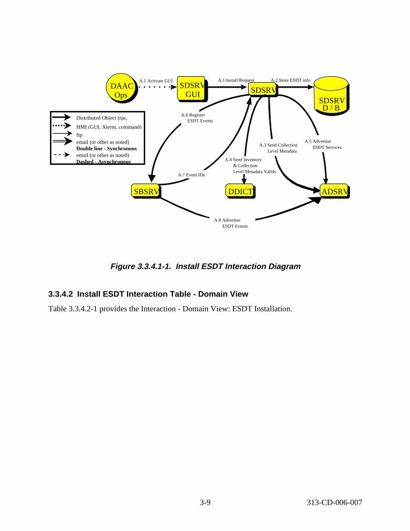
3.3.4.1 Inst all ESDT Interact ion D iagram - Domain V iew Figure 3.3.4.1-1 depicts the Install ESDT Interaction - Domain View
3-8 313-CD-006-007
SDSRV A.1 Activate GUI
SDSRV GUI
A.1 Install Request
A.3 Send Collection Level Metadata
SDSRV D / B
DDICTSBSRV ADSRV
A.2 Store ESDT info
A.4 Send Inventory & Collection Level Metadata Valids
A.5 Advertise ESDT Services
A.8 Advertise ESDT Events
DAAC Ops
A.6 Register ESDT Events
A.7 Event IDs
Distributed Object (rpc,
HMI (GUI, Xterm, command)
ftp email (or other as noted) Double line - Synchronous email (or other as noted) Dashed - Asynchronous
Figure 3. 3.4.1-1. Inst all ESDT Interact ion D iagram
3.3.4.2 Install E SDT Intera ction Table - Domain Vi ew
Table 3.3.4.2-1 provides the Interaction - Domain View: ESDT Installation.
3-9 313-CD-006-007
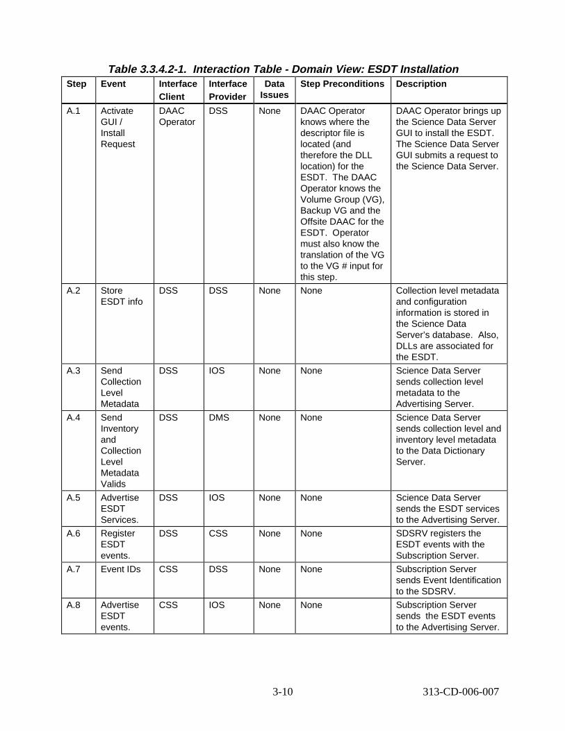
Table 3.3.4.2-1. Interact ion Tabl e - Domain V iew: ESDT Inst allat ion Step Event Interface
Client Interface Provider
Data Issues
Step Preconditions Descript ion
A.1 Activate GUI / Install Request
DAAC Operator
DSS None DAAC Operator knows where the descriptor file is located (and therefore the DLL location) for the ESDT. The DAAC Operator knows the Volume Group (VG), Backup VG and the Offsite DAAC for the ESDT. Operator must also know the translation of the VG to the VG # input for this step.
DAAC Operator brings up the Science Data Server GUI to install the ESDT. The Science Data Server GUI submits a request to the Science Data Server.
A.2 Store ESDT info
DSS DSS None None Collection level metadata and configuration information is stored in the Science Data Server’s database. Also, DLLs are associated for the ESDT.
A.3 Send Collection Level Metadata
DSS IOS None None Science Data Server sends collection level metadata to the Advertising Server.
A.4 Send Inventory and Collection Level Metadata Valids
DSS DMS None None Science Data Server sends collection level and inventory level metadata to the Data Dictionary Server.
A.5 Advertise ESDT Services.
DSS IOS None None Science Data Server sends the ESDT services to the Advertising Server.
A.6 Register ESDT events.
DSS CSS None None SDSRV registers the ESDT events with the Subscription Server.
A.7 Event IDs CSS DSS None None Subscription Server sends Event Identification to the SDSRV.
A.8 Advertise ESDT events.
CSS IOS None None Subscription Server sends the ESDT events to the Advertising Server.
3-10 313-CD-006-007
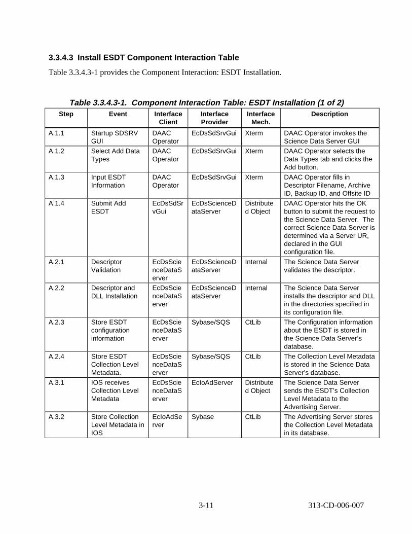
3.3.4.3 Install E SDT Component Interaction T able
Table 3.3.4.3-1 provides the Component Interaction: ESDT Installation.
Table 3.3.4.3-1. Component Interaction Table: E SDT Instal lation (1 of 2) Step Event Interface
Client Interface Provider
Interface Mech.
Descript ion
A.1.1 Startup SDSRV GUI
DAAC Operator
EcDsSdSrvGui Xterm DAAC Operator invokes the Science Data Server GUI
A.1.2 Select Add Data Types
DAAC Operator
EcDsSdSrvGui Xterm DAAC Operator selects the Data Types tab and clicks the Add button.
A.1.3 Input ESDT Information
DAAC Operator
EcDsSdSrvGui Xterm DAAC Operator fills in Descriptor Filename, Archive ID, Backup ID, and Offsite ID
A.1.4 Submit Add ESDT
EcDsSdSr vGui
EcDsScienceD ataServer
Distribute d Object
DAAC Operator hits the OK button to submit the request to the Science Data Server. The correct Science Data Server is determined via a Server UR, declared in the GUI configuration file.
A.2.1 Descriptor Validation
EcDsScie nceDataS erver
EcDsScienceD ataServer
Internal The Science Data Server validates the descriptor.
A.2.2 Descriptor and DLL Installation
EcDsScie nceDataS erver
EcDsScienceD ataServer
Internal The Science Data Server installs the descriptor and DLL in the directories specified in its configuration file.
A.2.3 Store ESDT configuration information
EcDsScie nceDataS erver
Sybase/SQS CtLib The Configuration information about the ESDT is stored in the Science Data Server’s database.
A.2.4 Store ESDT Collection Level Metadata.
EcDsScie nceDataS erver
Sybase/SQS CtLib The Collection Level Metadata is stored in the Science Data Server’s database.
A.3.1 IOS receives Collection Level Metadata
EcDsScie nceDataS erver
EcIoAdServer Distribute d Object
The Science Data Server sends the ESDT’s Collection Level Metadata to the Advertising Server.
A.3.2 Store Collection Level Metadata in IOS
EcIoAdSe rver
Sybase CtLib The Advertising Server stores the Collection Level Metadata in its database.
3-11 313-CD-006-007
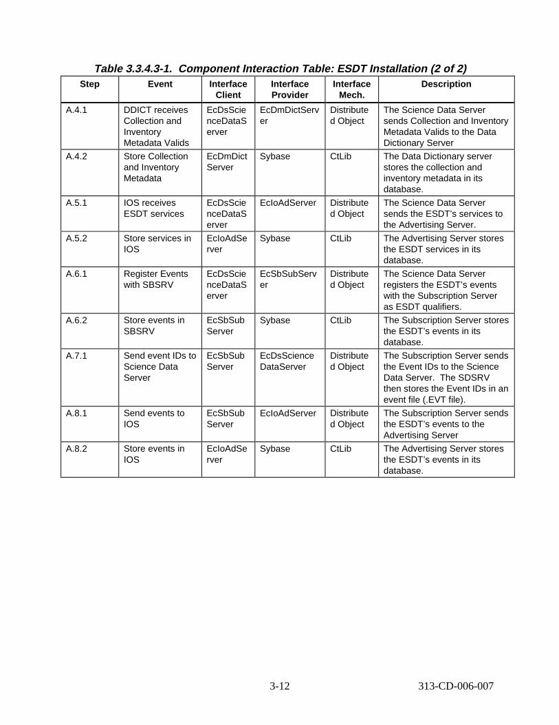
Table 3.3.4.3-1. Component Interaction Table: E SDT Instal lation (2 of 2) Step Event Interface
Client Interface Provider
Interface Mech.
Descript ion
A.4.1 DDICT receives Collection and Inventory Metadata Valids
EcDsScie nceDataS erver
EcDmDictServ er
Distribute d Object
The Science Data Server sends Collection and Inventory Metadata Valids to the Data Dictionary Server
A.4.2 Store Collection and Inventory Metadata
EcDmDict Server
Sybase CtLib The Data Dictionary server stores the collection and inventory metadata in its database.
A.5.1 IOS receives ESDT services
EcDsScie nceDataS erver
EcIoAdServer Distribute d Object
The Science Data Server sends the ESDT’s services to the Advertising Server.
A.5.2 Store services in IOS
EcIoAdSe rver
Sybase CtLib The Advertising Server stores the ESDT services in its database.
A.6.1 Register Events with SBSRV
EcDsScie nceDataS erver
EcSbSubServ er
Distribute d Object
The Science Data Server registers the ESDT’s events with the Subscription Server as ESDT qualifiers.
A.6.2 Store events in SBSRV
EcSbSub Server
Sybase CtLib The Subscription Server stores the ESDT’s events in its database.
A.7.1 Send event IDs to Science Data Server
EcSbSub Server
EcDsScience DataServer
Distribute d Object
The Subscription Server sends the Event IDs to the Science Data Server. The SDSRV then stores the Event IDs in an event file (.EVT file).
A.8.1 Send events to IOS
EcSbSub Server
EcIoAdServer Distribute d Object
The Subscription Server sends the ESDT’s events to the Advertising Server
A.8.2 Store events in IOS
EcIoAdSe rver
Sybase CtLib The Advertising Server stores the ESDT’s events in its database.
3-12 313-CD-006-007
3.4 System Start-up/Shutdown Scenario
3.4.1 Syst em Start -up/Shut down Scen ario D escript ion
This scenario demonstrates the various startup and shutdown capabilities of the ECS Custom Software system. In this Scenario “system” refers to the ECS Custom Software system. ECS operators are presented with a variety of capabilities for starting up and shutting down the system at various levels via the operator GUI provided by HP OpenView.
The following system functionality is exercised in this scenario:
Mode-level start-up
Mode-level shutdown
Application-level start-up
Application-level shutdown
Program-level start-up
Program-level shutdown
Process-level shutdown
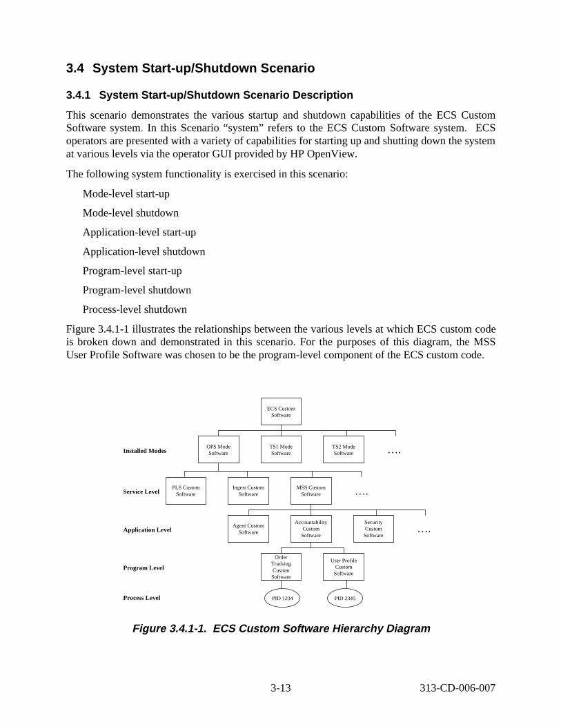
Figure 3.4.1-1 illustrates the relationships between the various levels at which ECS custom code is broken down and demonstrated in this scenario. For the purposes of this diagram, the MSS User Profile Software was chosen to be the program-level component of the ECS custom code.
….
ECS Custom Software
TS2 Mode Software
TS1 Mode Software
OPS Mode Software
…. MSS Custom Software
Ingest Custom Software
PLS Custom Software
…. Security Custom Software
Accountabil ity Custom Software
Agent Custom Software
User Profile Custom Software
Order Tracking Custom Software
PID 1234 PID 2345
Application Level
Installed Modes
Service Level
Program Level
Process Level
Figure 3. 4.1-1. ECS Custom Sof tware Hierarchy D iagram
3-13 313-CD-006-007
3.4.2 System Start-up/Shutdown Scen ario Pr econditions
The MSS custom agent code has been installed and configured to start up at boot time for all hosts on which custom ECS servers are to be managed (i.e., started up, monitored, or shut down). In addition, all MSS agents and HPOV servers are running on the MSS management server and the operator is running the HPOV Windows application.
3.4.3 Syst em Start -up/Shut down Scen ario P art it ions
The System Start-up/Shutdown scenario has been partitioned into the following threads:
• Mode Start-up (Thread A) - This thread shows the start-up of an ECS mode across the various hosts on which the mode has been installed.
• Mode Shutdown (Thread B) - This thread shows the shutdown of an ECS mode across the various hosts on which the mode has been installed and is currently running.
• Application Start-up (Thread C) - This thread shows the start-up of an ECS application on a host on which the application has been installed.
• Application Shutdown (Thread D) - This thread shows the shutdown of an ECS application on a host on which the application has been installed and is currently running.
• Program Star t-up (Thread E) - This thread shows the start-up of an ECS program on a host on which the program has been installed.
• Program Shutdown (Thread F) - This thread shows the shutdown of an ECS program on a host on which the program has been installed and is currently running.
• Process Shutdown (Thread G) - This thread shows the shutdown of an ECS process on a hosts on which the process is currently running.
3.4.4 Mode Start-up Thread This thread shows the start-up of an ECS mode across the various hosts on which the mode has been installed.
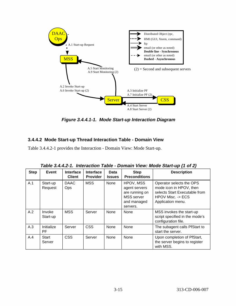
3.4.4.1 Mode St art -up Thread Int eract ion D iagram - Domain V iew
Figure 3.4.4.1-1 illustrates the Mode Start-up Interaction.
3-14 313-CD-006-007
Distributed Object (rpc,
HMI (GUI, Xterm, command)
ftp email (or other as noted) Double line - Synchronous email (or other as noted) Dashed - AsynchronousMSS
A.1 Start-up Request
Science User
DAAC Ops
CSSServer
A.2 Invoke Start-up A.3 Initialize PF
A.4 Start Server
A.6 Invoke Start-up (2) A.7 Initialize PF (2)
(2) = Second and subsequent serversA.5 Start Monitoring A.9 Start Monitoring (2)
A.8 Start Server (2)
Figure 3. 4.4.1-1. Mode Start -up Int eract ion D iagram
3.4.4.2 Mode Start-up Thread Interaction Table - Domain V iew
Table 3.4.4.2-1 provides the Interaction - Domain View: Mode Start-up.
Table 3.4.4.2-1. Interact ion Tabl e - Domain V iew: Mode Start -up (1 of 2) Step Event Interface
Client Interface Provider
Data Issues
Step Preconditions
Descript ion
A.1 Start-up Request
DAAC Ops
MSS None HPOV, MSS agent servers are running on MSS server and managed servers.
Operator selects the OPS mode icon in HPOV, then selects Start Executable from HPOV Misc. -> ECS Application menu.
A.2 Invoke Start-up
MSS Server None None MSS invokes the start-up script specified in the mode’s configuration file.
A.3 Initialize PF
Server CSS None None The subagent calls PfStart to start the server.
A.4 Start Server
CSS Server None None Upon completion of PfStart, the server begins to register with MSS.
3-15 313-CD-006-007
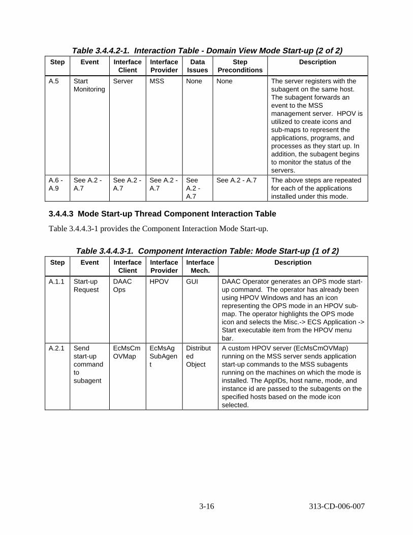
Table 3.4.4.2-1. Interact ion Tabl e - Domain V iew Mode Start -up (2 of 2) Step Event Interface
Client Interface Provider
Data Issues
Step Preconditions
Descript ion
A.5 Start Monitoring
Server MSS None None The server registers with the subagent on the same host. The subagent forwards an event to the MSS management server. HPOV is utilized to create icons and sub-maps to represent the applications, programs, and processes as they start up. In addition, the subagent begins to monitor the status of the servers.
A.6 -A.9
See A.2 -A.7
See A.2 -A.7
See A.2 -A.7
See A.2 -A.7
See A.2 - A.7 The above steps are repeated for each of the applications installed under this mode.
3.4.4.3 Mode Start-up Thread Component Interaction T able
Table 3.4.4.3-1 provides the Component Interaction Mode Start-up.
Table 3.4.4.3-1. Component Interaction Table: Mode Start-up (1 of 2) Step Event Interface
Client Interface Provider
Interface Mech.
Descript ion
A.1.1 Start-up Request
DAAC Ops
HPOV GUI DAAC Operator generates an OPS mode startup command. The operator has already been using HPOV Windows and has an icon representing the OPS mode in an HPOV submap. The operator highlights the OPS mode icon and selects the Misc.-> ECS Application -> Start executable item from the HPOV menu bar.
A.2.1 Send start-up command to subagent
EcMsCm OVMap
EcMsAg SubAgen t
Distribut ed Object
A custom HPOV server (EcMsCmOVMap) running on the MSS server sends application start-up commands to the MSS subagents running on the machines on which the mode is installed. The AppIDs, host name, mode, and instance id are passed to the subagents on the specified hosts based on the mode icon selected.
3-16 313-CD-006-007
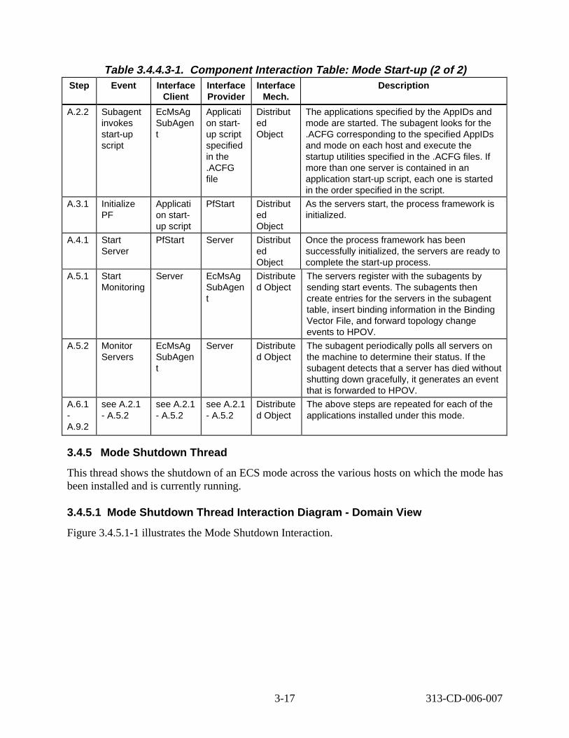
Table 3.4.4.3-1. Component Interaction Table: Mode Start-up (2 of 2) Step Event Interface
Client Interface Provider
Interface Mech.
Descript ion
A.2.2 Subagent invokes start-up script
EcMsAg SubAgen t
Applicati on startup script specified in the .ACFG file
Distribut ed Object
The applications specified by the AppIDs and mode are started. The subagent looks for the .ACFG corresponding to the specified AppIDs and mode on each host and execute the startup utilities specified in the .ACFG files. If more than one server is contained in an application start-up script, each one is started in the order specified in the script.
A.3.1 Initialize PF
Applicati on startup script
PfStart Distribut ed Object
As the servers start, the process framework is initialized.
A.4.1 Start Server
PfStart Server Distribut ed Object
Once the process framework has been successfully initialized, the servers are ready to complete the start-up process.
A.5.1 Start Monitoring
Server EcMsAg SubAgen t
Distribute d Object
The servers register with the subagents by sending start events. The subagents then create entries for the servers in the subagent table, insert binding information in the Binding Vector File, and forward topology change events to HPOV.
A.5.2 Monitor Servers
EcMsAg SubAgen t
Server Distribute d Object
The subagent periodically polls all servers on the machine to determine their status. If the subagent detects that a server has died without shutting down gracefully, it generates an event that is forwarded to HPOV.
A.6.1 -A.9.2
see A.2.1 - A.5.2
see A.2.1 - A.5.2
see A.2.1 - A.5.2
Distribute d Object
The above steps are repeated for each of the applications installed under this mode.
3.4.5 Mode Shutdown Thread
This thread shows the shutdown of an ECS mode across the various hosts on which the mode has been installed and is currently running.
3.4.5.1 Mode Shutdown Thread Interaction Diagram - Domain V iew
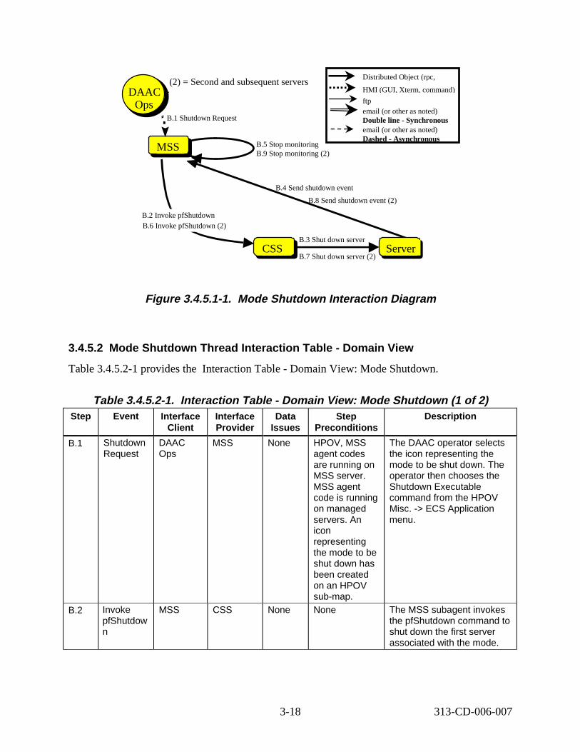
Figure 3.4.5.1-1 illustrates the Mode Shutdown Interaction.
3-17 313-CD-006-007
MSS
B.1 Shutdown Request
Science User
DAAC Ops
B.2 Invoke pfShutdown
B.3 Shut down server CSS
B.5 Stop monitoring
B.4 Send shutdown event
Server
B.6 Invoke pfShutdown (2)
B.7 Shut down server (2)
B.8 Send shutdown event (2)
B.9 Stop monitoring (2)
(2) = Second and subsequent servers Distributed Object (rpc,
HMI (GUI, Xterm, command)
ftp email (or other as noted) Double line - Synchronous email (or other as noted) Dashed - Asynchronous
Figure 3. 4.5.1-1. Mode Shutdown Interaction Di agram
3.4.5.2 Mode Shutdown Thread Interaction Table - Domain V iew
Table 3.4.5.2-1 provides the Interaction Table - Domain View: Mode Shutdown.
Table 3.4.5.2-1. Interaction Tabl e - Domain V iew: Mode Shutdown (1 of 2) Step Event Interface
Client Interface Provider
Data Issues
Step Preconditions
Descript ion
B.1 Shutdown Request
DAAC Ops
MSS None HPOV, MSS agent codes are running on MSS server. MSS agent code is running on managed servers. An icon representing the mode to be shut down has been created on an HPOV sub-map.
The DAAC operator selects the icon representing the mode to be shut down. The operator then chooses the Shutdown Executable command from the HPOV Misc. -> ECS Application menu.
B.2 Invoke pfShutdow n
MSS CSS None None The MSS subagent invokes the pfShutdown command to shut down the first server associated with the mode.
3-18 313-CD-006-007
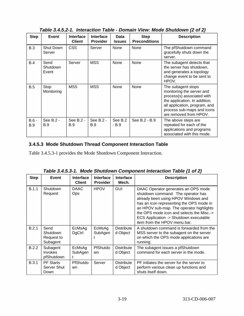
Table 3.4.5.2-1. Interaction Tabl e - Domain V iew: Mode Shutdown (2 of 2) Step Event Interface
Client Interface Provider
Data Issues
Step Preconditions
Descript ion
B.3 Shut Down Server
CSS Server None None The pfShutdown command gracefully shuts down the server.
B.4 Send Shutdown Event
Server MSS None None The subagent detects that the server has shutdown, and generates a topology change event to be sent to HPOV.
B.5 Stop Monitoring
MSS MSS None None The subagent stops monitoring the server and process(s) associated with the application. In addition, all application, program, and process sub-maps and icons are removed from HPOV.
B.6 -B.9
See B.2 -B.9
See B.2 -B.9
See B.2 -B.9
See B.2 - B.9
See B.2 - B.9 The above steps are repeated for each of the applications and programs associated with this mode.
3.4.5.3 Mode Shutdown Thread Component Interaction T able
Table 3.4.5.3-1 provides the Mode Shutdown Component Interaction.
Table 3.4.5.3-1. Mode Shutdown Component Interaction Table ( 1 of 2) Step Event Interface
Client Interface Provider
Interface Mech.
Descript ion
B.1.1 Shutdown Request
DAAC Ops
HPOV GUI DAAC Operator generates an OPS mode shutdown command. The operator has already been using HPOV Windows and has an icon representing the OPS mode in an HPOV sub-map. The operator highlights the OPS mode icon and selects the Misc.-> ECS Application -> Shutdown executable item from the HPOV menu bar.
B.2.1 Send Shutdown Request to Subagent
EcMsAg DgCtrl
EcMsAg SubAgen t
Distribute d Object
A shutdown command is forwarded from the MSS server to the subagent on the server on which the OPS mode applications are running.
B.2.2 Subagent Invokes pfShutdown
EcMsAg SubAgen t
PfShutdo wn
Distribute d Object
The subagent issues a pfShutdown command for each server in the mode.
B.3.1 PF Starts Server Shut Down
PfShutdo wn
Server Distribute d Object
PF initiates the server for the server to perform various clean up functions and shuts itself down.
3-19 313-CD-006-007
Science User
Table 3.4.5.3-1. Mode Shutdown Component Interaction Table ( 2 of 2) Step Event Interface
Client Interface Provider
Interface Mech.
Descript ion
B.4.1 Shutdown Event Sent to Subagent
Server EcMsAg SubAgen t
Distribute d Object
The Subagent detects that the server has shutdown, and generates a topology change event to be sent to HPOV.
B.5.1 SubAgent Sends Shutdown Event to MSS Server
EcMsAg SubAgen t
EcMsAg Deputy
Distribute d Object
The Subagent generates a Shutdown event for each process and forwards it to the deputy agent running on the MSS server.
B.5.2 Shutdown Status Sent to HPOV
EcMsAg Deputy
HPOV Distribute d Object
The deputy logs the shutdown event in the trapd file. HPOV updates its display by removing the icons and sub-maps representing the server and its associated processes. The mode icon remains on the sub-map.
B.6.1 -B.9.2
See B.2.1 -B.5.2
See B.2.1 -B.5.2
See B.2.1 -B.5.2
Distribute d Object
The above steps are repeated for each of the applications and programs associated with this mode.
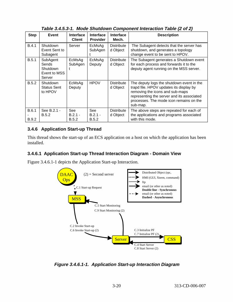
3.4.6 Applicat ion St art -up Thread
This thread shows the start-up of an ECS application on a host on which the application has been installed.
3.4.6.1 Applicat ion St art -up Thread Interact ion D iagram - Domain Vi ew
Figure 3.4.6.1-1 depicts the Application Start-up Interaction.
DAAC (2) = Second server Distributed Object (rpc,
HMI (GUI, Xterm, command)Ops
ftp
C.1 Start-up Request email (or other as noted) Double line - Synchronous email (or other as noted)
MSS Dashed - Asynchronous
C.5 Start Monitoring
C.9 Start Monitoring (2)
C.2 Invoke Start-up
C.6 Invoke Start-up (2) C.3 Initialize PF C.7 Initialize PF (2)
Server CSS C.4 Start Server C.8 Start Server (2)
Figure 3. 4.6.1-1. Appli cat ion St art -up Int eract ion D iagram
3-20 313-CD-006-007
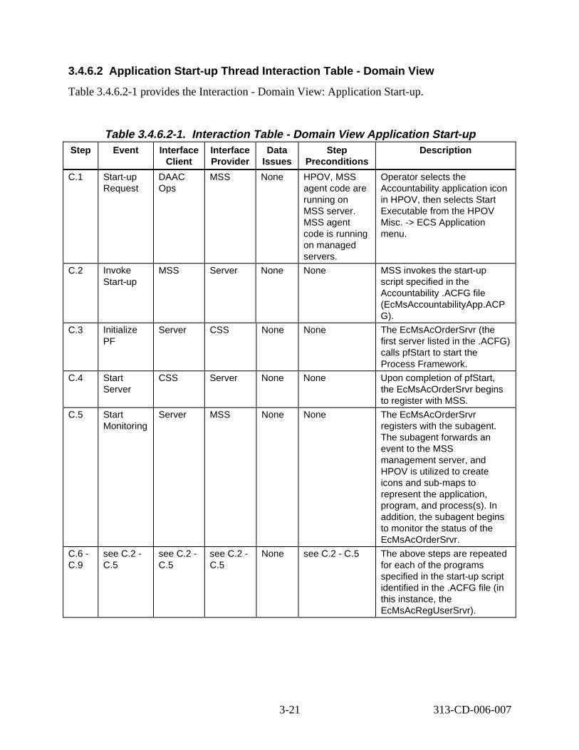
3.4.6.2 Applicat ion St art -up Thread Interact ion T able - Domain Vi ew
Table 3.4.6.2-1 provides the Interaction - Domain View: Application Start-up.
Table 3.4.6.2-1. Interact ion Tabl e - Domain V iew Appli cat ion St art -up Step Event Interface
Client Interface Provider
Data Issues
Step Preconditions
Descript ion
C.1 Start-up Request
DAAC Ops
MSS None HPOV, MSS agent code are running on MSS server. MSS agent code is running on managed servers.
Operator selects the Accountability application icon in HPOV, then selects Start Executable from the HPOV Misc. -> ECS Application menu.
C.2 Invoke Start-up
MSS Server None None MSS invokes the start-up script specified in the Accountability .ACFG file (EcMsAccountabilityApp.ACP G).
C.3 Initialize PF
Server CSS None None The EcMsAcOrderSrvr (the first server listed in the .ACFG) calls pfStart to start the Process Framework.
C.4 Start Server
CSS Server None None Upon completion of pfStart, the EcMsAcOrderSrvr begins to register with MSS.
C.5 Start Monitoring
Server MSS None None The EcMsAcOrderSrvr registers with the subagent. The subagent forwards an event to the MSS management server, and HPOV is utilized to create icons and sub-maps to represent the application, program, and process(s). In addition, the subagent begins to monitor the status of the EcMsAcOrderSrvr.
C.6 -C.9
see C.2 -C.5
see C.2 -C.5
see C.2 -C.5
None see C.2 - C.5 The above steps are repeated for each of the programs specified in the start-up script identified in the .ACFG file (in this instance, the EcMsAcRegUserSrvr).
3-21 313-CD-006-007
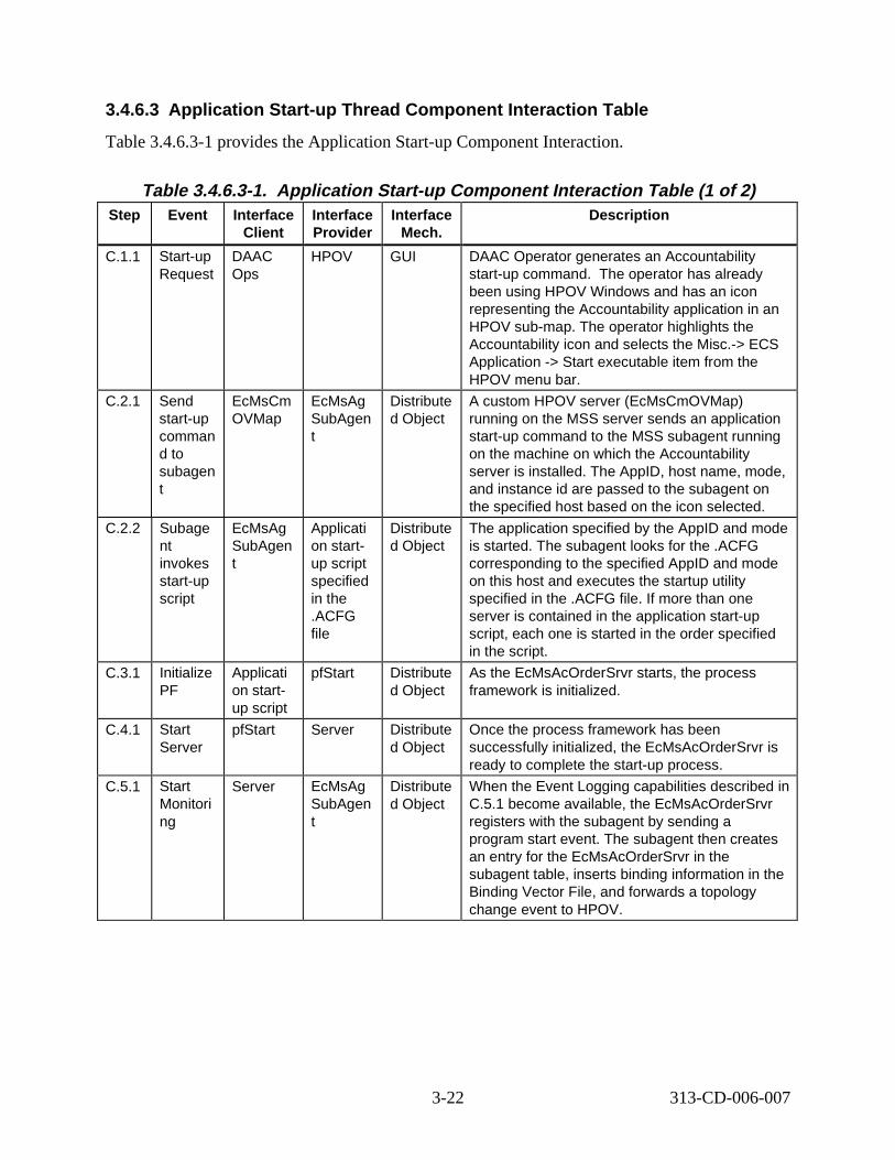
3.4.6.3 Application Start-up Thread Component Inter action Tabl e
Table 3.4.6.3-1 provides the Application Start-up Component Interaction.
Table 3.4.6.3-1. Application Start-up Component Interaction Tabl e (1 of 2) Step Event Interface
Client Interface Provider
Interface Mech.
Descript ion
C.1.1 Start-up Request
DAAC Ops
HPOV GUI DAAC Operator generates an Accountability start-up command. The operator has already been using HPOV Windows and has an icon representing the Accountability application in an HPOV sub-map. The operator highlights the Accountability icon and selects the Misc.-> ECS Application -> Start executable item from the HPOV menu bar.
C.2.1 Send start-up comman d to subagen t
EcMsCm OVMap
EcMsAg SubAgen t
Distribute d Object
A custom HPOV server (EcMsCmOVMap) running on the MSS server sends an application start-up command to the MSS subagent running on the machine on which the Accountability server is installed. The AppID, host name, mode, and instance id are passed to the subagent on the specified host based on the icon selected.
C.2.2 Subage nt invokes start-up script
EcMsAg SubAgen t
Applicati on startup script specified in the .ACFG file
Distribute d Object
The application specified by the AppID and mode is started. The subagent looks for the .ACFG corresponding to the specified AppID and mode on this host and executes the startup utility specified in the .ACFG file. If more than one server is contained in the application start-up script, each one is started in the order specified in the script.
C.3.1 Initialize PF
Applicati on startup script
pfStart Distribute d Object
As the EcMsAcOrderSrvr starts, the process framework is initialized.
C.4.1 Start Server
pfStart Server Distribute d Object
Once the process framework has been successfully initialized, the EcMsAcOrderSrvr is ready to complete the start-up process.
C.5.1 Start Monitori ng
Server EcMsAg SubAgen t
Distribute d Object
When the Event Logging capabilities described in C.5.1 become available, the EcMsAcOrderSrvr registers with the subagent by sending a program start event. The subagent then creates an entry for the EcMsAcOrderSrvr in the subagent table, inserts binding information in the Binding Vector File, and forwards a topology change event to HPOV.
3-22 313-CD-006-007
Science Us
Table 3.4.6.3-1. Application Start-up Component Interaction Table ( 2 of 2) Step Event Interface
Client Interface Provider
Interface Mech.
Descript ion
C.5.2 Monitor Servers
EcMsAg SubAgen t
Server Distribute d Object
The subagent periodically polls the EcMsAcOrderSrvr to determine their status. If the subagent detects that the EcMsAcOrderSrvr has died without shutting down gracefully, it generates an event that is forwarded to HPOV.
C.6.1 -C.9.2
see C.2.1 -C.5.2
see C.2.1 - C.5.2
see C.2.1 - C.5.2
Distribute d Object
The above steps are repeated for each of the programs specified in the start-up script identified in the .ACFG file (in this instance, the EcMsAcRegUserSrvr).
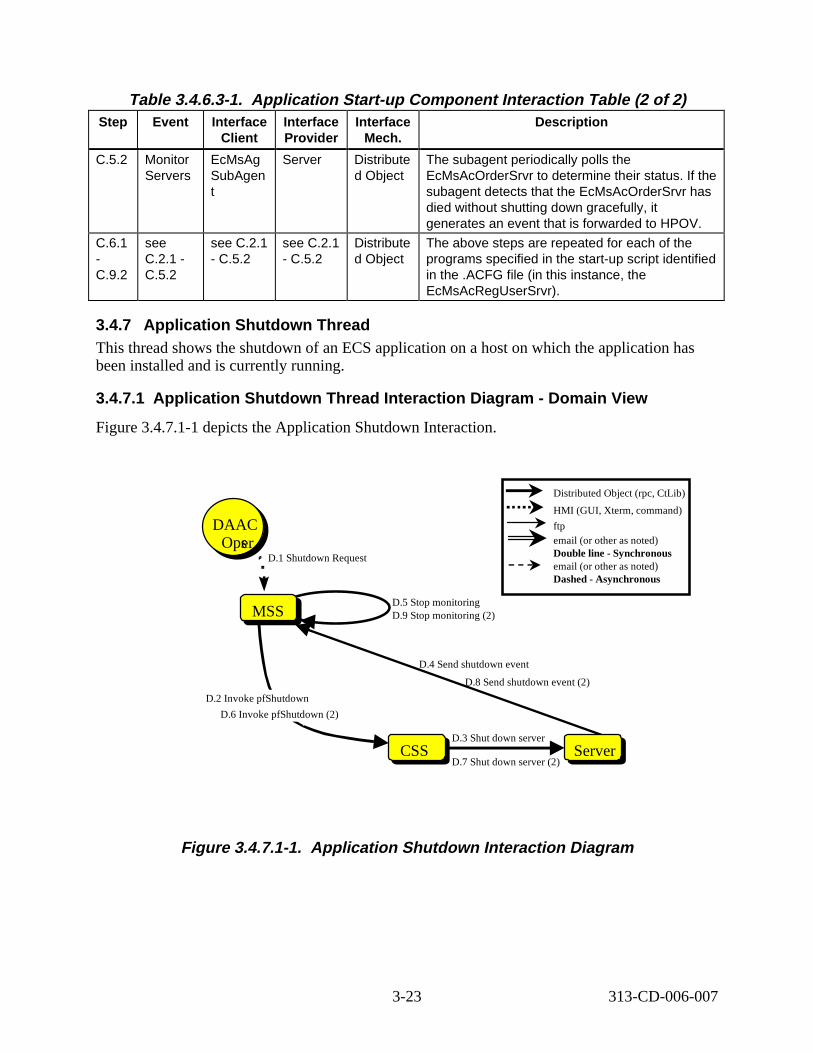
3.4.7 Application Shutdown Thread This thread shows the shutdown of an ECS application on a host on which the application has been installed and is currently running.
3.4.7.1 Application Shutdown Thread Interaction Di agram - Domain Vi ew
Figure 3.4.7.1-1 depicts the Application Shutdown Interaction.
Distributed Object (rpc, CtLib)
HMI (GUI, Xterm, command)
DAAC ftp
Opser email (or other as noted)
D.1 Shutdown Request Double line -Synchronous email (or other as noted) Dashed - Asynchronous
D.5 Stop monitoringMSS D.9 Stop monitoring (2)
D.4 Send shutdown event
D.8 Send shutdown event (2)
D.2 Invoke pfShutdown
D.6 Invoke pfShutdown (2)
D.3 Shut down server CSS Server
D.7 Shut down server (2)
Figure 3. 4.7.1-1. Appli cation Shutdown Inter action Diagr am
3-23 313-CD-006-007
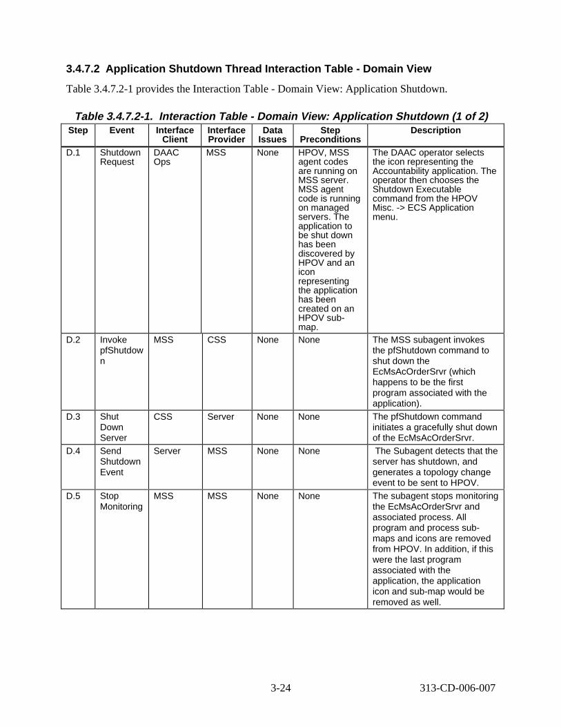
3.4.7.2 Application Shutdown Thread Interaction Tab le - Domain Vi ew
Table 3.4.7.2-1 provides the Interaction Table - Domain View: Application Shutdown.
Table 3.4.7.2-1. Interaction Tabl e - Domain V iew: Appli cation Shutdown (1 of 2) Step Event Interface
Client Interface Provider
Data Issues
Step Preconditions
Descript ion
D.1 Shutdown Request
DAAC Ops
MSS None HPOV, MSS agent codes are running on MSS server. MSS agent code is running on managed servers. The application to be shut down has been discovered by HPOV and an icon representing the application has been created on an HPOV submap.
The DAAC operator selects the icon representing the Accountability application. The operator then chooses the Shutdown Executable command from the HPOV Misc. -> ECS Application menu.
D.2 Invoke pfShutdow n
MSS CSS None None The MSS subagent invokes the pfShutdown command to shut down the EcMsAcOrderSrvr (which happens to be the first program associated with the application).
D.3 Shut Down Server
CSS Server None None The pfShutdown command initiates a gracefully shut down of the EcMsAcOrderSrvr.
D.4 Send Shutdown Event
Server MSS None None The Subagent detects that the server has shutdown, and generates a topology change event to be sent to HPOV.
D.5 Stop Monitoring
MSS MSS None None The subagent stops monitoring the EcMsAcOrderSrvr and associated process. All program and process submaps and icons are removed from HPOV. In addition, if this were the last program associated with the application, the application icon and sub-map would be removed as well.
3-24 313-CD-006-007
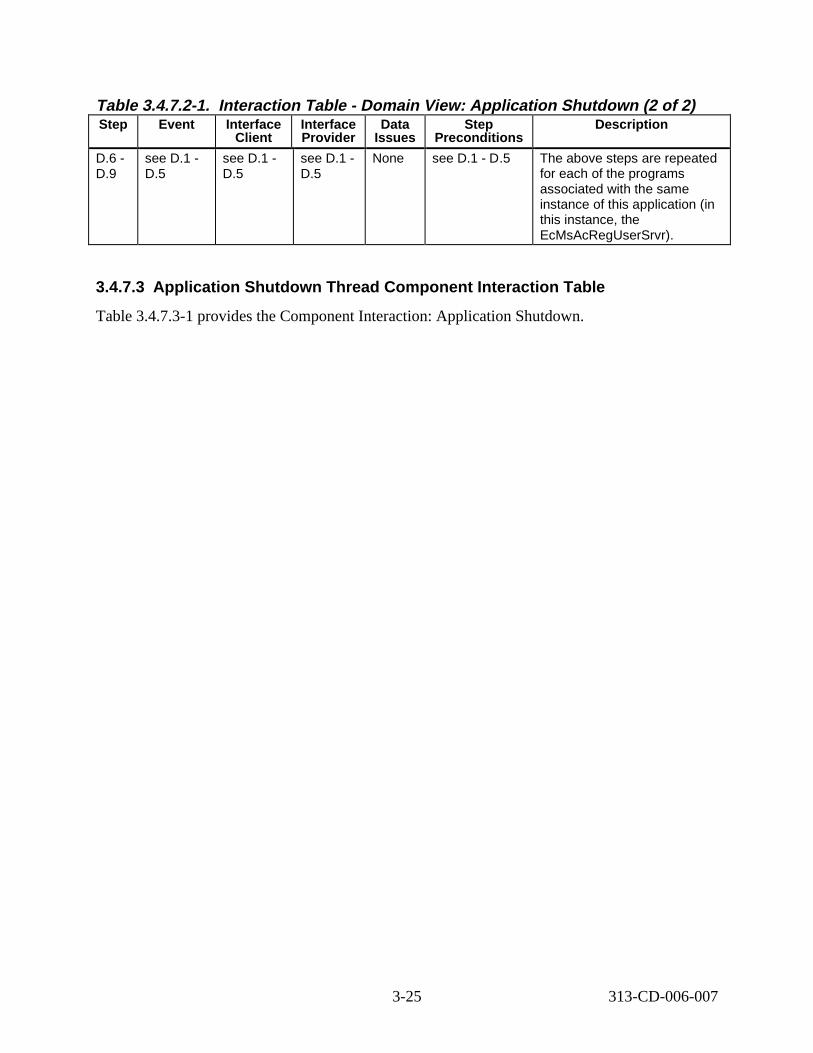
Table 3.4.7.2-1. Interaction Tabl e - Domain V iew: Appli cation Shutdown (2 of 2) Step Event Interface
Client Interface Provider
Data Issues
Step Preconditions
Descript ion
D.6 -D.9
see D.1 -D.5
see D.1 -D.5
see D.1 -D.5
None see D.1 - D.5 The above steps are repeated for each of the programs associated with the same instance of this application (in this instance, the EcMsAcRegUserSrvr).
3.4.7.3 Application Shutdown Thread Component Inter action Tabl e
Table 3.4.7.3-1 provides the Component Interaction: Application Shutdown.
3-25 313-CD-006-007
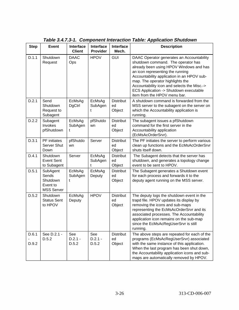
Table 3.4.7.3-1. Component Interaction Table: Appli cation Shutdown Step Event Interface
Client Interface Provider
Interface Mech.
Descript ion
D.1.1 Shutdown Request
DAAC Ops
HPOV GUI DAAC Operator generates an Accountability shutdown command. The operator has already been using HPOV Windows and has an icon representing the running Accountability application in an HPOV submap. The operator highlights the Accountability icon and selects the Misc.-> ECS Application -> Shutdown executable item from the HPOV menu bar.
D.2.1 Send Shutdown Request to Subagent
EcMsAg DgCtrl
EcMsAg SubAgen t
Distribut ed Object
A shutdown command is forwarded from the MSS server to the subagent on the server on which the Accountability application is running.
D.2.2 Subagent Invokes pfShutdown
EcMsAg SubAgen t
pfShutdo wn
Distribut ed Object
The subagent issues a pfShutdown command for the first server in the Accountability application (EcMsAcOrderSrvr).
D.3.1 PF initiates Server Shut Down
pfShutdo wn
Server Distribut ed Object
The PF initiates the server to perform various clean up functions and the EcMsAcOrderSrvr shuts itself down.
D.4.1 Shutdown Event Sent to Subagent
Server EcMsAg SubAgen t
Distribut ed Object
The Subagent detects that the server has shutdown, and generates a topology change event to be sent to HPOV.
D.5.1 SubAgent Sends Shutdown Event to MSS Server
EcMsAg SubAgen t
EcMsAg Deputy
Distribut ed Object
The Subagent generates a Shutdown event for each process and forwards it to the deputy agent running on the MSS server.
D.5.2 Shutdown Status Sent to HPOV
EcMsAg Deputy
HPOV Distribut ed Object
The deputy logs the shutdown event in the trapd file. HPOV updates its display by removing the icons and sub-maps representing the EcMsAcOrderSrvr and its associated processes. The Accountability application icon remains on the sub-map since the EcMsAcRegUserSrvr is still running.
D.6.1 -D.9.2
See D.2.1 -D.5.2
See D.2.1 -D.5.2
See D.2.1 -D.5.2
Distribut ed Object
The above steps are repeated for each of the programs (EcMsAcRegUserSrvr) associated with the same instance of this application. When the last program has been shut down, the Accountability application icons and submaps are automatically removed by HPOV.
3-26 313-CD-006-007
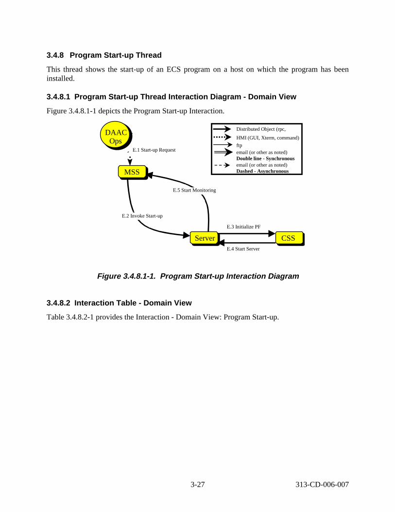
3.4.8 Program Start-up Thread
This thread shows the start-up of an ECS program on a host on which the program has been installed.
3.4.8.1 Program St art -up Thre ad Int eract ion D iagram - Domain V iew
Figure 3.4.8.1-1 depicts the Program Start-up Interaction.
MSS
E.1 Start-up Request
Science User
DAAC Ops
CSS Server
E.2 Invoke Start-up
E.3 Initialize PF
E.5 Start Monitoring
Distributed Object (rpc,
HMI (GUI, Xterm, command)
ftp email (or other as noted) Double line - Synchronous email (or other as noted) Dashed - Asynchronous
E.4 Start Server
Figure 3. 4.8.1-1. Program Start -up Int eract ion D iagram
3.4.8.2 Interact ion Tabl e - Domain View
Table 3.4.8.2-1 provides the Interaction - Domain View: Program Start-up.
3-27 313-CD-006-007
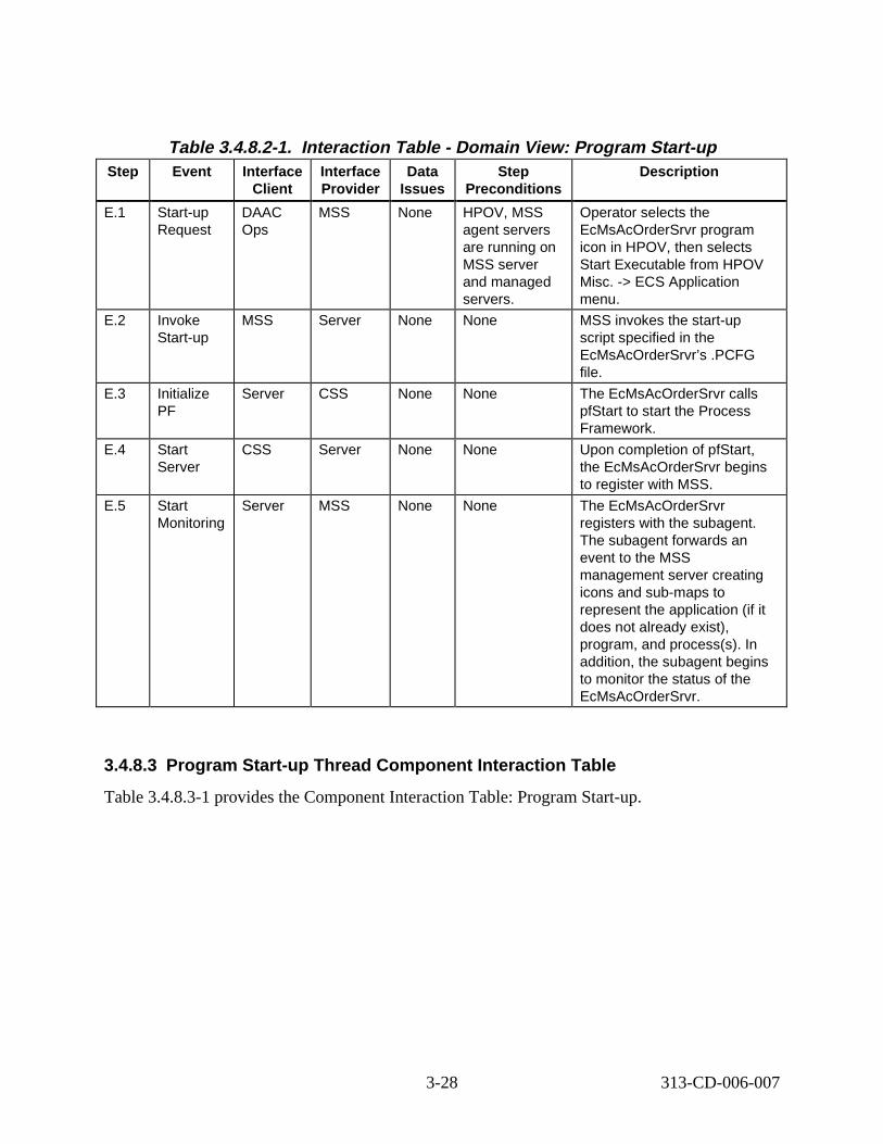
Table 3.4.8.2-1. Interact ion Tabl e - Domain V iew: Program St art -up Step Event Interface
Client Interface Provider
Data Issues
Step Preconditions
Descript ion
E.1 Start-up Request
DAAC Ops
MSS None HPOV, MSS agent servers are running on MSS server and managed servers.
Operator selects the EcMsAcOrderSrvr program icon in HPOV, then selects Start Executable from HPOV Misc. -> ECS Application menu.
E.2 Invoke Start-up
MSS Server None None MSS invokes the start-up script specified in the EcMsAcOrderSrvr’s .PCFG file.
E.3 Initialize PF
Server CSS None None The EcMsAcOrderSrvr calls pfStart to start the Process Framework.
E.4 Start Server
CSS Server None None Upon completion of pfStart, the EcMsAcOrderSrvr begins to register with MSS.
E.5 Start Monitoring
Server MSS None None The EcMsAcOrderSrvr registers with the subagent. The subagent forwards an event to the MSS management server creating icons and sub-maps to represent the application (if it does not already exist), program, and process(s). In addition, the subagent begins to monitor the status of the EcMsAcOrderSrvr.
3.4.8.3 Program Start-up Thread Component Interaction T able
Table 3.4.8.3-1 provides the Component Interaction Table: Program Start-up.
3-28 313-CD-006-007
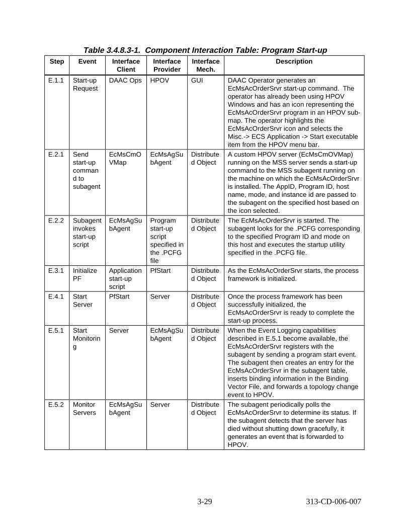
Table 3.4.8.3-1. Component Interaction Table: P rogram St art-up Step Event Interface
Client Interface Provider
Interface Mech.
Descript ion
E.1.1 Start-up Request
DAAC Ops HPOV GUI DAAC Operator generates an EcMsAcOrderSrvr start-up command. The operator has already been using HPOV Windows and has an icon representing the EcMsAcOrderSrvr program in an HPOV submap. The operator highlights the EcMsAcOrderSrvr icon and selects the Misc.-> ECS Application -> Start executable item from the HPOV menu bar.
E.2.1 Send start-up comman d to subagent
EcMsCmO VMap
EcMsAgSu bAgent
Distribute d Object
A custom HPOV server (EcMsCmOVMap) running on the MSS server sends a start-up command to the MSS subagent running on the machine on which the EcMsAcOrderSrvr is installed. The AppID, Program ID, host name, mode, and instance id are passed to the subagent on the specified host based on the icon selected.
E.2.2 Subagent invokes start-up script
EcMsAgSu bAgent
Program start-up script specified in the .PCFG file
Distribute d Object
The EcMsAcOrderSrvr is started. The subagent looks for the .PCFG corresponding to the specified Program ID and mode on this host and executes the startup utility specified in the .PCFG file.
E.3.1 Initialize PF
Application start-up script
PfStart Distribute d Object
As the EcMsAcOrderSrvr starts, the process framework is initialized.
E.4.1 Start Server
PfStart Server Distribute d Object
Once the process framework has been successfully initialized, the EcMsAcOrderSrvr is ready to complete the start-up process.
E.5.1 Start Monitorin g
Server EcMsAgSu bAgent
Distribute d Object
When the Event Logging capabilities described in E.5.1 become available, the EcMsAcOrderSrvr registers with the subagent by sending a program start event. The subagent then creates an entry for the EcMsAcOrderSrvr in the subagent table, inserts binding information in the Binding Vector File, and forwards a topology change event to HPOV.
E.5.2 Monitor Servers
EcMsAgSu bAgent
Server Distribute d Object
The subagent periodically polls the EcMsAcOrderSrvr to determine its status. If the subagent detects that the server has died without shutting down gracefully, it generates an event that is forwarded to HPOV.
3-29 313-CD-006-007
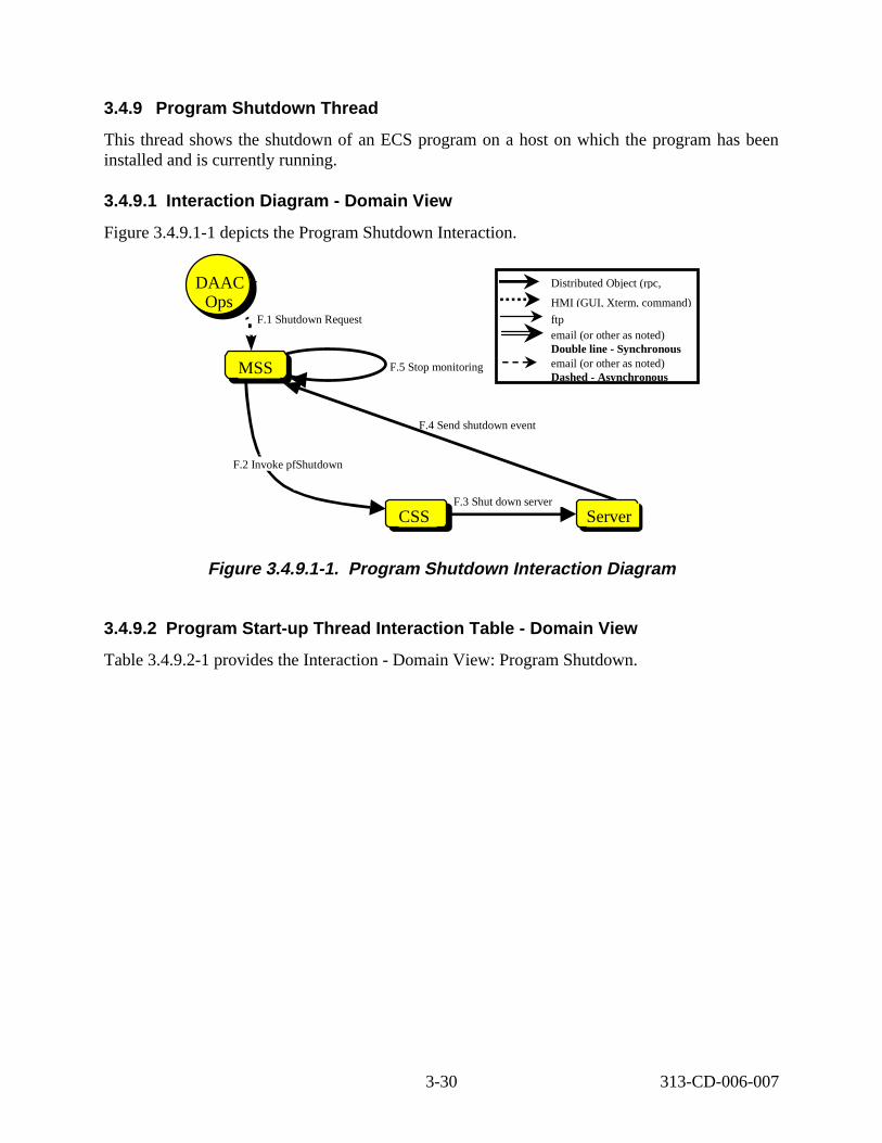
3.4.9 Program Shutdown Thread
This thread shows the shutdown of an ECS program on a host on which the program has been installed and is currently running.
3.4.9.1 Interact ion D iagram - Domain View
Figure 3.4.9.1-1 depicts the Program Shutdown Interaction.
F.1 Shutdown Request
Science User
DAAC Ops
F.2 Invoke pfShutdown
F.3 Shut down server
CSS
MSS F.5 Stop monitoring
F.4 Send shutdown event
Server
Distributed Object (rpc,
HMI (GUI, Xterm, command)
ftp email (or other as noted) Double line - Synchronous email (or other as noted) Dashed - Asynchronous
Figure 3. 4.9.1-1. Program Shutdown Interaction Di agram
3.4.9.2 Program Start-up Thread Interaction Table - Domain Vi ew
Table 3.4.9.2-1 provides the Interaction - Domain View: Program Shutdown.
3-30 313-CD-006-007
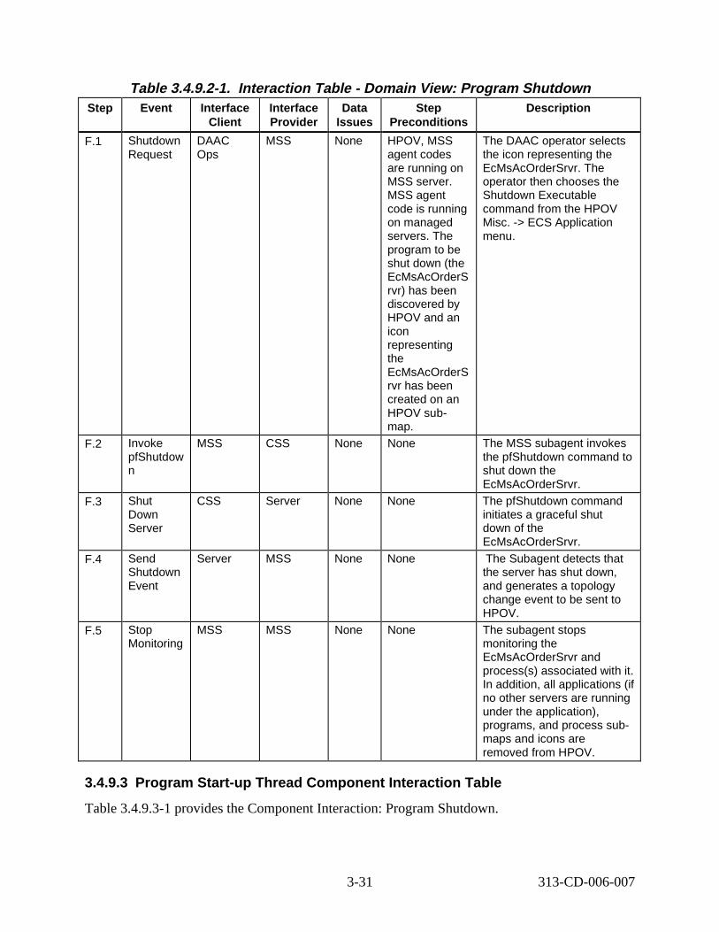
Table 3.4.9.2-1. Interaction Tabl e - Domain V iew: Program Shutdown Step Event Interface
Client Interface Provider
Data Issues
Step Preconditions
Descript ion
F.1 Shutdown Request
DAAC Ops
MSS None HPOV, MSS agent codes are running on MSS server. MSS agent code is running on managed servers. The program to be shut down (the EcMsAcOrderS rvr) has been discovered by HPOV and an icon representing the EcMsAcOrderS rvr has been created on an HPOV submap.
The DAAC operator selects the icon representing the EcMsAcOrderSrvr. The operator then chooses the Shutdown Executable command from the HPOV Misc. -> ECS Application menu.
F.2 Invoke pfShutdow n
MSS CSS None None The MSS subagent invokes the pfShutdown command to shut down the EcMsAcOrderSrvr.
F.3 Shut Down Server
CSS Server None None The pfShutdown command initiates a graceful shut down of the EcMsAcOrderSrvr.
F.4 Send Shutdown Event
Server MSS None None The Subagent detects that the server has shut down, and generates a topology change event to be sent to HPOV.
F.5 Stop Monitoring
MSS MSS None None The subagent stops monitoring the EcMsAcOrderSrvr and process(s) associated with it. In addition, all applications (if no other servers are running under the application), programs, and process submaps and icons are removed from HPOV.
3.4.9.3 Program Start-up Thread Component Interaction T able
Table 3.4.9.3-1 provides the Component Interaction: Program Shutdown.
3-31 313-CD-006-007
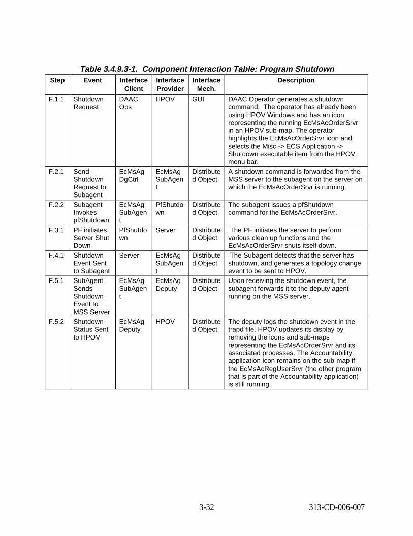
Table 3.4.9.3-1. Component Interaction Table: P rogram Shutdown Step Event Interface
Client Interface Provider
Interface Mech.
Descript ion
F.1.1 Shutdown Request
DAAC Ops
HPOV GUI DAAC Operator generates a shutdown command. The operator has already been using HPOV Windows and has an icon representing the running EcMsAcOrderSrvr in an HPOV sub-map. The operator highlights the EcMsAcOrderSrvr icon and selects the Misc.-> ECS Application -> Shutdown executable item from the HPOV menu bar.
F.2.1 Send Shutdown Request to Subagent
EcMsAg DgCtrl
EcMsAg SubAgen t
Distribute d Object
A shutdown command is forwarded from the MSS server to the subagent on the server on which the EcMsAcOrderSrvr is running.
F.2.2 Subagent Invokes pfShutdown
EcMsAg SubAgen t
PfShutdo wn
Distribute d Object
The subagent issues a pfShutdown command for the EcMsAcOrderSrvr.
F.3.1 PF initiates Server Shut Down
PfShutdo wn
Server Distribute d Object
The PF initiates the server to perform various clean up functions and the EcMsAcOrderSrvr shuts itself down.
F.4.1 Shutdown Event Sent to Subagent
Server EcMsAg SubAgen t
Distribute d Object
The Subagent detects that the server has shutdown, and generates a topology change event to be sent to HPOV.
F.5.1 SubAgent Sends Shutdown Event to MSS Server
EcMsAg SubAgen t
EcMsAg Deputy
Distribute d Object
Upon receiving the shutdown event, the subagent forwards it to the deputy agent running on the MSS server.
F.5.2 Shutdown Status Sent to HPOV
EcMsAg Deputy
HPOV Distribute d Object
The deputy logs the shutdown event in the trapd file. HPOV updates its display by removing the icons and sub-maps representing the EcMsAcOrderSrvr and its associated processes. The Accountability application icon remains on the sub-map if the EcMsAcRegUserSrvr (the other program that is part of the Accountability application) is still running.
3-32 313-CD-006-007

3.4.10 Process Shutdown Thread
This thread shows the shutdown of an ECS process on a host on which the process is currently running.
3.4.10.1 Proces s Shut down Thre ad Int eract ion D iagram - Domain V iew
Figure 3.4.10.1-1 depicts the Process Shutdown Interaction.
G.1 Shutdown Request
Science User
DAAC Ops
G.2 Invoke pfShutdown
G.3 Shut down server
CSS
MSS G.5 Stop monitoring
G.4 Send shutdown event
Server
Distributed Object (rpc,
HMI (GUI, Xterm, command)
ftp email (or other as noted) Double line - Synchronous email (or other as noted) Dashed - Asynchronous
Figure 3. 4.10.1-1. Process Shutdown Interaction Diagr am
3.4.10.2 Process Shutdown Thread Interaction Table - Domain V iew
Table 3.4.10.2-1 provides the Interaction - Domain View: Process Shutdown.
3-33 313-CD-006-007
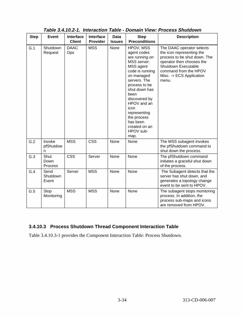
Table 3.4.10.2-1. Interact ion T able - Domain View: Proc ess Shut down Step Event Interface
Client Interface Provider
Data Issues
Step Preconditions
Descript ion
G.1 Shutdown Request
DAAC Ops
MSS None HPOV, MSS agent codes are running on MSS server. MSS agent code is running on managed servers. The process to be shut down has been discovered by HPOV and an icon representing the process has been created on an HPOV submap.
The DAAC operator selects the icon representing the process to be shut down. The operator then chooses the Shutdown Executable command from the HPOV Misc. -> ECS Application menu.
G.2 Invoke pfShutdow n
MSS CSS None None The MSS subagent invokes the pfShutdown command to shut down the process.
G.3 Shut Down Process
CSS Server None None The pfShutdown command initiates a graceful shut down of the process.
G.4 Send Shutdown Event
Server MSS None None The Subagent detects that the server has shut down, and generates a topology change event to be sent to HPOV.
G.5 Stop Monitoring
MSS MSS None None The subagent stops monitoring process. In addition, the process sub-maps and icons are removed from HPOV.
3.4.10.3 Process Shutdown Thread Component Interaction T able
Table 3.4.10.3-1 provides the Component Interaction Table: Process Shutdown.
3-34 313-CD-006-007
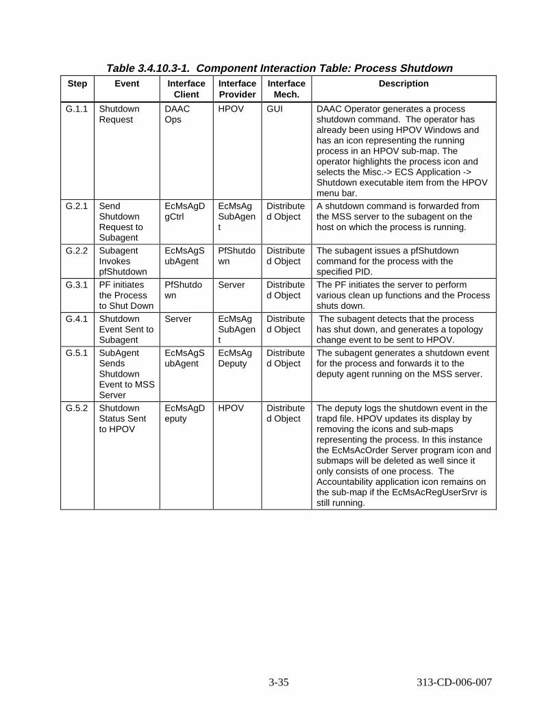
Table 3.4.10.3-1. Component Inter action Tabl e: Process Shutdown Step Event Interface
Client Interface Provider
Interface Mech.
Descript ion
G.1.1 Shutdown Request
DAAC Ops
HPOV GUI DAAC Operator generates a process shutdown command. The operator has already been using HPOV Windows and has an icon representing the running process in an HPOV sub-map. The operator highlights the process icon and selects the Misc.-> ECS Application -> Shutdown executable item from the HPOV menu bar.
G.2.1 Send Shutdown Request to Subagent
EcMsAgD gCtrl
EcMsAg SubAgen t
Distribute d Object
A shutdown command is forwarded from the MSS server to the subagent on the host on which the process is running.
G.2.2 Subagent Invokes pfShutdown
EcMsAgS ubAgent
PfShutdo wn
Distribute d Object
The subagent issues a pfShutdown command for the process with the specified PID.
G.3.1 PF initiates the Process to Shut Down
PfShutdo wn
Server Distribute d Object
The PF initiates the server to perform various clean up functions and the Process shuts down.
G.4.1 Shutdown Event Sent to Subagent
Server EcMsAg SubAgen t
Distribute d Object
The subagent detects that the process has shut down, and generates a topology change event to be sent to HPOV.
G.5.1 SubAgent Sends Shutdown Event to MSS Server
EcMsAgS ubAgent
EcMsAg Deputy
Distribute d Object
The subagent generates a shutdown event for the process and forwards it to the deputy agent running on the MSS server.
G.5.2 Shutdown Status Sent to HPOV
EcMsAgD eputy
HPOV Distribute d Object
The deputy logs the shutdown event in the trapd file. HPOV updates its display by removing the icons and sub-maps representing the process. In this instance the EcMsAcOrder Server program icon and submaps will be deleted as well since it only consists of one process. The Accountability application icon remains on the sub-map if the EcMsAcRegUserSrvr is still running.
3-35 313-CD-006-007
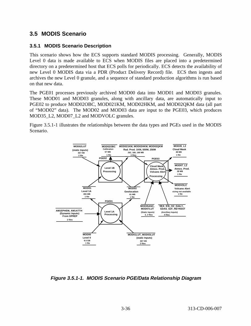
3.5 MODIS Scenario
3.5.1 MODIS Scenario D escript ion
This scenario shows how the ECS supports standard MODIS processing. Generally, MODIS Level 0 data is made available to ECS when MODIS fi les are placed into a predetermined directory on a predetermined host that ECS polls for periodically. ECS detects the availability of new Level 0 MODIS data via a PDR (Product Delivery Record) file. ECS then ingests and archives the new Level 0 granule, and a sequence of standard production algorithms is run based on that new data.
The PGE01 processes previously archived MOD00 data into MOD01 and MOD03 granules. These MOD01 and MOD03 granules, along with ancillary data, are automatically input to PGE02 to produce MOD02OBC, MOD021KM, MOD02HKM, and MOD02QKM data (all part of “MOD02” data). The MOD02 and MOD03 data are input to the PGE03, which produces MOD35_L2, MOD07_L2 and MODVOLC granules.
Figure 3.5.1-1 illustrates the relationships between the data types and PGEs used in the MODIS Scenario.
MOD02LUT MOD02OBC MOD021KM, MOD02HKM, MOD02QKM MOD35_L2
(static Inputs) Cali bration Rad. Prod. 1KM, 500M, 250M Clou d Mask 357 KB 57 MB 262, 168, 168 MB 48 MB
2 file 1 file 3 files 1 file
Processing Level 1B
PGE02
Cloud Mask, Atmos. Prod., Volcano Alert
Processing
PGE03
MOD01 Level 1A
355 MB 1 file
MOD03 Geolo cation
61 MB 1 file
Level 1A Processing
PGE01
Atmo s. Prod. MOD07_L2
28 MB 1 file
Volcano Alert MODVOLC
si zing not avail able 1 file
AM1EPHEM, AM1ATTH (Dynamic Inputs )
From DPREP 2 files
MOD35ANC, MOD07LUT (Static Inputs)
3, 2 fil es
SEA_ICE, OZ_DAILY, GDAS_0ZF, REYNSST
(Ancillary Inputs )4 files
MOD00 MOD01LUT, MOD03LUT Level 0 (static Inputs)
6.5 GB 357 KB 1 file 2 files
Figure 3.5.1- 1. MODIS Scenario PGE/D ata Relat ionship D iagram
3-36 313-CD-006-007
The following system functionality is exercised in this scenario:
• Automatic Scheduling of PGE execution
• Archive Data as PGE Inputs
• Chaining of PGEs
• Concurrent PGE Execution
• Access to ECS produced data
• Standing Order Support, including distributing data to users electronically
• Support of failed PGEs.
3.5.2 MODIS Scenario Preconditions
The following ESDTs have been inserted into the ECS:
• MOD00 (MODIS Level 0 Raw Instrument Packets - used as input to PGE01)
• MOD01 (L1A Raw Radiances)
• MOD021KM (L1B Calibrated Radiances Product (1000m))
• MOD02HKM (L1B Calibrated Radiances Product (500m))
• MOD02QKM (L1B Calibrated Radiances Product (250m))
• MOD02OBC (MODIS Level 1B Onboard Calibrator/Engineering data)
• MOD01LUT (MODIS Engineering Telemetry Lookup Table)
• MOD02LUT (MODIS Instrument Calibration Parameters Lookup Table)
• MOD03LUT (MODIS Instrument and Satellite Parameters for MOD03)
• MOD07LUT (MODIS Temperature and Water Vapor Profile Inversion Coefficients)
• MOD03 (MODIS Geo-Location data)
• MOD35ANC (EDC Land/Sea Mask Olson World Ecosystem Mask)
• SEA_ICE (NCEP SSM/I Sea Ice Modelers Grid Data Level 3 Product)
• OZ_DAILY (NCEP TOVS Ozone Daily Product)
• GDAS_0ZF (NCEP 1-Degree Global Data Assimilation Model (GDAS) Product)
• REYNSST (NCEP Reynolds Blended SST Weekly Product)
• MOD35_L2 (MODIS Cloud Mask and Spectral Test Results)
• MOD07_L2 (MODIS Temperature and Water Vapor Profile Product)
• MODVOLC (MODIS Volcano Alert File)
3-37 313-CD-006-007
• AM1EPHEM (Predicted EOS AM-1 Ephemeris)
• AM1ATTH (Definitive Attitude Data for EOS AM-1 ingested from FDF FDD)
• PGEEXE (PGE Execution Granule)
• FAILPGE (Failed PGE History)
• PH (Product History)
The following PGEs have successfully been through the SSI&T process:
• PGE01
• PGE02
• PGE03
Ancillary and static data granules have been inserted into Data Server.
MOD00 granules have been inserted into Data Server (via Ingest Polling from EDOS).
Subscription for MODIS failed PGE has been entered on behalf of Instrument Team.
A Resource Plan has been created for resources needed for MODIS production.
A Production Plan has been created using the Production Planning Workbench. This Production Plan includes Production Requests for the PGE01, PGE02 and PGE03. Available inputs will trigger the PGEs. The DPR for PGE01 job in the plan includes references to the appropriate MOD00 granules. The DPRs for PGE02 and PGE03 have submitted subscriptions for the Insert events for appropriate input data.
Production Planning Workbench is already running on the DAAC Desktop.
3.5.3 MODIS Scenario Partitions
The MODIS scenario has been partitioned into the following threads:
• MODIS Standing Order Submit tal (Thread A) - This thread simply shows how the DAAC User Services submits a standing order for MOD35_L2 granules to be distributed via ftp Push to a science user.
• MODIS Standard Production (Thread B) - This thread shows how the sequence of PGEs (PGE01, PGE02, PGE03) execute in a chained fashion, with the output of one PGE being used as the input of the next.
• MODIS Failed PGE Handling (Thread C) - This thread shows how the artifacts from a failed PGE are collected and sent to the Instrument Team.
• MODIS Data Access (Thread D) - This thread shows how the generated data products are available for user access. Also in this thread, the MODIS Standing Order, submitted in Thread A, is fulfilled.
3-38 313-CD-006-007
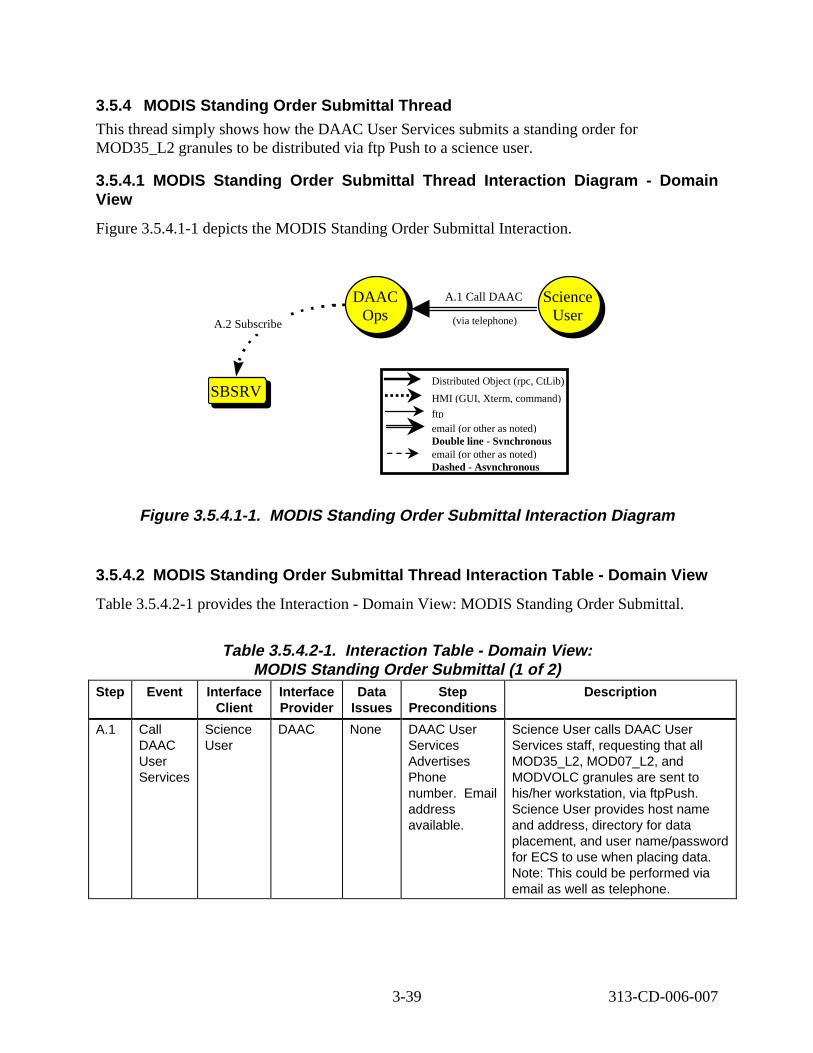
3.5.4 MODIS Standing Order Submittal Thread This thread simply shows how the DAAC User Services submits a standing order for MOD35_L2 granules to be distributed via ftp Push to a science user.
3.5.4.1 MODIS Standing Order Submittal Thread Interaction Diagram - Domain View
Figure 3.5.4.1-1 depicts the MODIS Standing Order Submittal Interaction.
SBSRVSBSRV
DAAC Ops
DAAC Ops
A.2 Subscribe
A.1 Call DAAC
(via telephone)
Science User
Science User
Distributed Object (rpc, CtLib)
HMI (GUI, Xterm, command)
ftp email (or other as noted) Double line - Synchronous email (or other as noted) Dashed - Asynchronous
Figure 3.5.4.1-1. MODIS Standing Order Submittal Interaction Diagram
3.5.4.2 MODIS Standing Order Submittal Thread Interaction Table - Domain View
Table 3.5.4.2-1 provides the Interaction - Domain View: MODIS Standing Order Submittal.
Table 3.5.4.2-1. Interact ion Table - Domain View: MODIS Standing Order Submittal (1 of 2)
Step Event Interface Client
Interface Provider
Data Issues
Step Preconditions
Descript ion
A.1 Call DAAC User Services
Science User
DAAC None DAAC User Services Advertises Phone number. Email address available.
Science User calls DAAC User Services staff, requesting that all MOD35_L2, MOD07_L2, and MODVOLC granules are sent to his/her workstation, via ftpPush. Science User provides host name and address, directory for data placement, and user name/password for ECS to use when placing data. Note: This could be performed via email as well as telephone.
3-39 313-CD-006-007
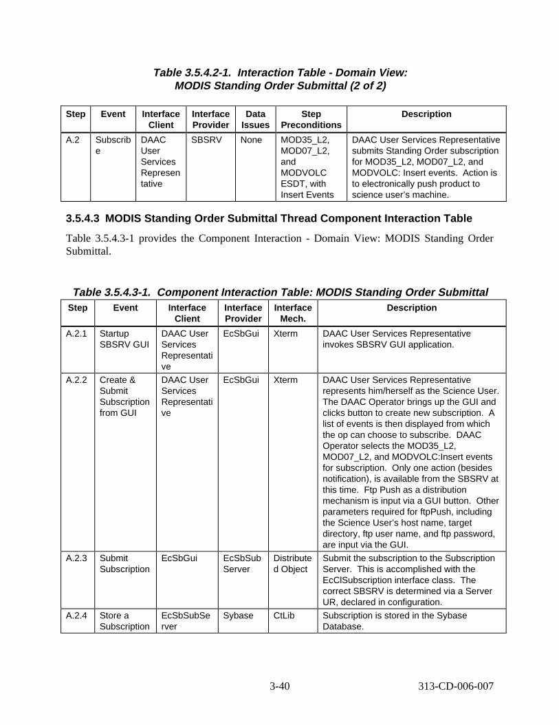
Table 3.5.4.2-1. Interact ion Table - Domain View: MODIS Standing Order Submittal (2 of 2)
Step Event Interface Client
Interface Provider
Data Issues
Step Preconditions
Descript ion
A.2 Subscrib e
DAAC User Services Represen tative
SBSRV None MOD35_L2, MOD07_L2, and MODVOLC ESDT, with Insert Events
DAAC User Services Representative submits Standing Order subscription for MOD35_L2, MOD07_L2, and MODVOLC: Insert events. Action is to electronically push product to science user’s machine.
3.5.4.3 MODIS Standing Order Submittal Thread Component Interaction Table
Table 3.5.4.3-1 provides the Component Interaction - Domain View: MODIS Standing Order Submittal.
Table 3.5.4.3-1. Component Interaction Table: MODIS Standing Order Submittal Step Event Interface
Client Interface Provider
Interface Mech.
Descript ion
A.2.1 Startup SBSRV GUI
DAAC User Services Representati ve
EcSbGui Xterm DAAC User Services Representative invokes SBSRV GUI application.
A.2.2 Create & Submit Subscription from GUI
DAAC User Services Representati ve
EcSbGui Xterm DAAC User Services Representative represents him/herself as the Science User. The DAAC Operator brings up the GUI and clicks button to create new subscription. A list of events is then displayed from which the op can choose to subscribe. DAAC Operator selects the MOD35_L2, MOD07_L2, and MODVOLC:Insert events for subscription. Only one action (besides notification), is available from the SBSRV at this time. Ftp Push as a distribution mechanism is input via a GUI button. Other parameters required for ftpPush, including the Science User’s host name, target directory, ftp user name, and ftp password, are input via the GUI.
A.2.3 Submit Subscription
EcSbGui EcSbSub Server
Distribute d Object
Submit the subscription to the Subscription Server. This is accomplished with the EcClSubscription interface class. The correct SBSRV is determined via a Server UR, declared in configuration.
A.2.4 Store a Subscription
EcSbSubSe rver
Sybase CtLib Subscription is stored in the Sybase Database.
3-40 313-CD-006-007
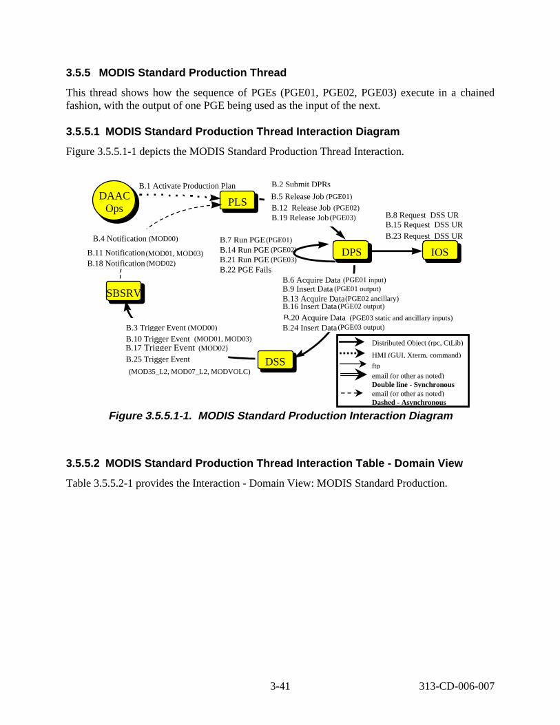
3.5.5 MODIS Standard Production Thread
This thread shows how the sequence of PGEs (PGE01, PGE02, PGE03) execute in a chained fashion, with the output of one PGE being used as the input of the next.
3.5.5.1 MODIS Standard Production Thread Interaction Diagram
Figure 3.5.5.1-1 depicts the MODIS Standard Production Thread Interaction.
PLSPLS
DPS DPSB.14 Run PGE (PGE02) B.21 Run PGE (PGE03)
IOS
B.2 Submit DPRs
B.12 Release Job (PGE02) B.19 Release Job (PGE03)
B.7 Run PGE (PGE01)
B.5 Release Job (PGE01)
DSS DSS
B.6 Acquire Data (PGE01 input) B.9 Insert Data (PGE01 output) B.13 Acquire Data(PGE02 ancillary) B.16 Insert Data (PGE02 output)
B.24 Insert Data (PGE03 output)
B.22 PGE Fails
Distributed Object (rpc, CtLib)
HMI (GUI, Xterm, command)
ftp email (or other as noted) Double line - Synchronous email (or other as noted) Dashed - Asynchronous
B.20 Acquire Data (PGE03 static and ancillary inputs)
B.11 Notification(MOD01, MOD03) B.18 Notification (MOD02)
B.4 Notification (MOD00)
B.1 Activate Production Plan
DAAC Ops
DAAC Ops
B.8 Request DSS UR B.15 Request DSS UR B.23 Request DSS UR
SBSRVSBSRV
B.10 Trigger Event (MOD01, MOD03) B.17 Trigger Event (MOD02)
B.25 Trigger Event
(MOD35_L2, MOD07_L2, MODVOLC)
B.3 Trigger Event (MOD00)
Figure 3.5.5.1-1. MODIS Standard Production Interaction Diagram
3.5.5.2 MODIS Standard Production Thread Interaction Table - Domain View
Table 3.5.5.2-1 provides the Interaction - Domain View: MODIS Standard Production.
3-41 313-CD-006-007
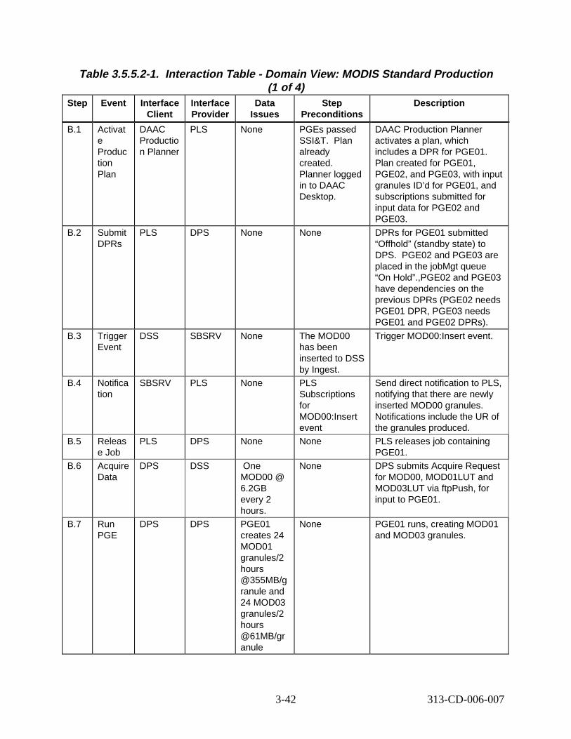
Table 3.5.5.2-1. Interaction Table - Domain View: MODIS Standard Production (1 of 4)
Step Event Interface Client
Interface Provider
Data Issues
Step Preconditions
Descript ion
B.1 Activat e Produc tion Plan
DAAC Productio n Planner
PLS None PGEs passed SSI&T. already created. Planner logged in to DAAC Desktop.
DAAC Production Planner activates a plan, which includes a DPR for PGE01. Plan created for PGE01, PGE02, and PGE03, with input granules ID’d for PGE01, and subscriptions submitted for input data for PGE02 and PGE03.
B.2 Submit DPRs
PLS DPS None None DPRs for PGE01 submitted “Offhold” (standby state) to DPS. E02 and PGE03 are placed in the jobMgt queue “On Hold”.,PGE02 and PGE03 have dependencies on the previous DPRs (PGE02 needs PGE01 DPR, PGE03 needs PGE01 and PGE02 DPRs).
B.3 Trigger Event
DSS SBSRV None The MOD00 has been inserted to DSS by Ingest.
Trigger MOD00:Insert event.
B.4 Notifica tion
SBSRV PLS None PLS Subscriptions for MOD00:Insert event
Send direct notification to PLS, notifying that there are newly inserted MOD00 granules. Notifications include the UR of the granules produced.
B.5 Releas e Job
PLS DPS None None PLS releases job containing PGE01.
B.6 Acquire Data
DPS DSS One MOD00 @ 6.2GB every 2 hours.
None DPS submits Acquire Request for MOD00, MOD01LUT and MOD03LUT via ftpPush, for input to PGE01.
B.7 Run PGE
DPS DPS PGE01 creates 24 MOD01 granules/2 hours @355MB/g ranule and 24 MOD03 granules/2 hours @61MB/gr anule
None PGE01 runs, creating MOD01 and MOD03 granules.
Plan
PG
3-42 313-CD-006-007

Table 3.5.5.2-1. Interaction Table - Domain View: MODIS Standard Production (2 of 4)
Step Event Interface Client
Interface Provider
Data Issues
Step Preconditions
Descript ion
B.8 Reque st DSS UR
DPS IOS None None DPS gets the DSS UR from Advertiser.
B.9 Insert Data
DPS DSS None MOD01 and MOD03 ESDTs.
Archive newly created MOD01 and MOD03 granules.
B.10 Trigger Event
DSS SBSRV None None Trigger MOD01:Insert and MOD03:Insert events. Note that these are actually two different events, so there are two independent events triggered.
B.11 Notifica tion
SBSRV PLS None PLS Subscriptions for MOD01:Insert and MOD03:Insert events
Send direct notification to PLS, notifying that there is a newly inserted MOD01 and MOD03 granules. Notifications include the UR of the granules produced.
B.12 Releas e Job
PLS DPS None None PLS releases job containing PGE02.
B.13 Acquire Data
DPS DSS MOD02LU T @357KB, from MODIS IT
MOD02LUT ESDT.
DPS submits Acquire Request for the ancillary product, MOD02LUT, via ftpPush, for input to PGE02. other input to PGE02 is the MOD01 granule that was created in step B.7.
B.14 Run PGE
DPS DPS One MOD02OB C, MOD021K M, MOD02HK M, and MOD02QK M@ 655 MB produced
None PGE02 runs, creating the MOD02OBC, MOD021KM, MOD02HKM, and MOD02QKM granules.
B.15 Reque st DSS UR
DPS IOS None None DPS gets the DSS UR from Advertiser.
Note that
3-43 313-CD-006-007
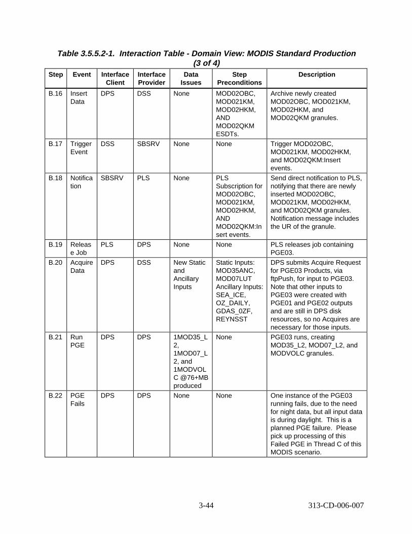
Table 3.5.5.2-1. Interaction Table - Domain View: MODIS Standard Production (3 of 4)
Step Event Interface Client
Interface Provider
Data Issues
Step Preconditions
Descript ion
B.16 Insert Data
DPS DSS None MOD02OBC, MOD021KM, MOD02HKM, AND MOD02QKM ESDTs.
Archive newly created MOD02OBC, MOD021KM, MOD02HKM, and MOD02QKM granules.
B.17 Trigger Event
DSS SBSRV None None Trigger MOD02OBC, MOD021KM, MOD02HKM, and MOD02QKM:Insert events.
B.18 Notifica tion
SBSRV PLS None PLS Subscription for MOD02OBC, MOD021KM, MOD02HKM, AND MOD02QKM:In sert events.
Send direct notification to PLS, notifying that there are newly inserted MOD02OBC, MOD021KM, MOD02HKM, and MOD02QKM granules. Notification message includes the UR of the granule.
B.19 Releas e Job
PLS DPS None None PLS releases job containing PGE03.
B.20 Acquire Data
DPS DSS New Static and Ancillary Inputs
Static Inputs: MOD35ANC, MOD07LUT Ancillary Inputs: SEA_ICE, OZ_DAILY, GDAS_0ZF, REYNSST
DPS submits Acquire Request for PGE03 Products, via ftpPush, for input to PGE03. Note that other inputs to PGE03 were created with PGE01 and PGE02 outputs and are still in DPS disk resources, so no Acquires are necessary for those inputs.
B.21 Run PGE
DPS DPS 1MOD35_L 2, 1MOD07_L 2, and 1MODVOL C @76+MB produced
None PGE03 runs, creating MOD35_L2, MOD07_L2, and MODVOLC granules.
B.22 PGE Fails
DPS DPS None None One instance of the PGE03 running fails, due to the need for night data, but all input data is during daylight. This is a planned PGE failure. Please pick up processing of this Failed PGE in Thread C of this MODIS scenario.
3-44 313-CD-006-007
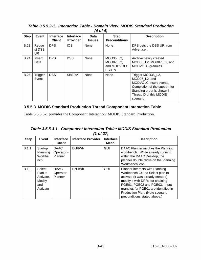
Table 3.5.5.2-1. Interaction Table - Domain View: MODIS Standard Production (4 of 4)
Step Event Interface Client
Interface Provider
Data Issues
Step Preconditions
Descript ion
B.23 Reque st DSS UR
DPS IOS None None DPS gets the DSS UR from Advertiser.
B.24 Insert Data
DPS DSS None MOD35_L2, MOD07_L2, and MODVOLC ESDTs.
Archive newly created MOD35_L2, MOD07_L2, and MODVOLC granules.
B.25 Trigger Event
DSS SBSRV None None Trigger MOD35_L2, MOD07_L2, and MODVOLC:Insert events. Completion of the support for Standing order is shown in Thread D of this MODIS scenario.
3.5.5.3 MODIS Standard Production Thread Component Interaction Table
Table 3.5.5.3-1 provides the Component Interaction: MODIS Standard Production.
Table 3.5.5.3-1. Component Interaction Table: MODIS Standard Production (1 of 27)
Step Event Interface Client
Interface Provider Interface Mech.
Descript ion
B.1.1 Startup Planning Workbe nch
DAAC Operator -Planner
EcPlWb GUI DAAC Planner invokes the Planning workbench. While already running within the DAAC Desktop, the planner double clicks on the Planning Workbench icon.
B.1.2 Select Plan to Activate, Modify and Activate
DAAC Operator -Planner
EcPlWb GUI Planner interacts with Planning Workbench GUI to Select plan to activate (it was already created), modify it with DPRs for chaining PGE01, PGE02 and PGE03. Input granules for PGE01 are identified in Production Plan. (Note scenario preconditions stated above.)
3-45 313-CD-006-007
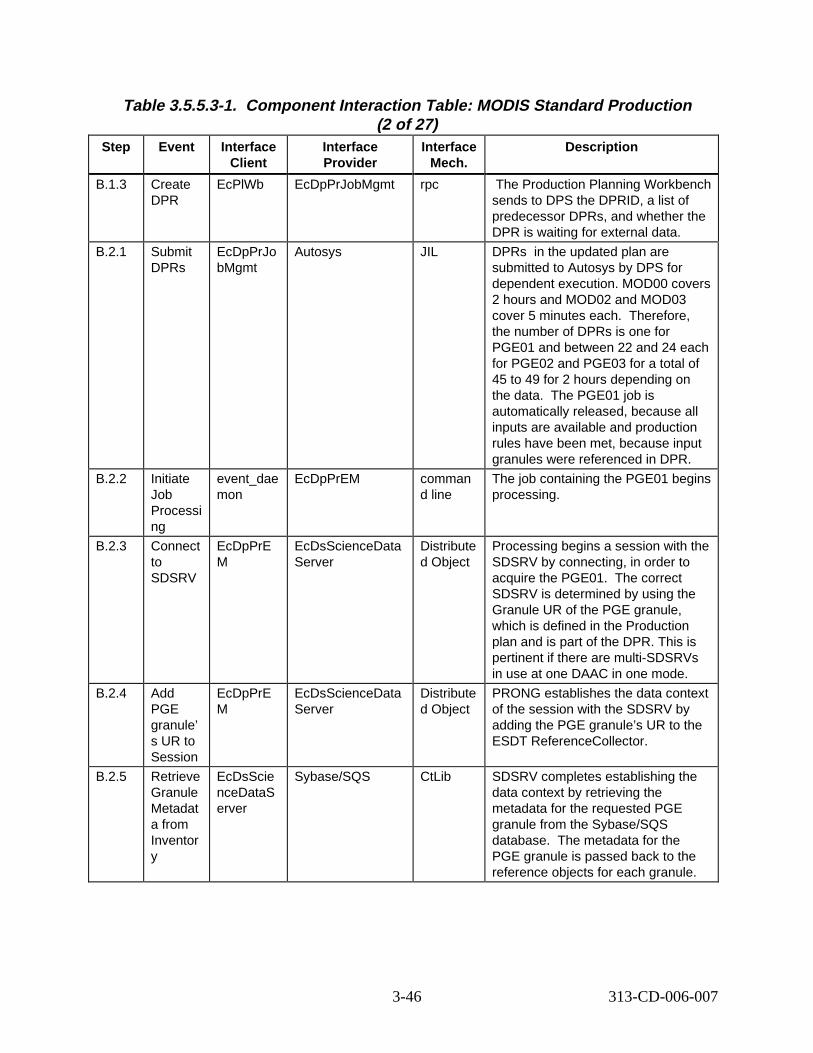
Table 3.5.5.3-1. Component Interaction Table: MODIS Standard Production (2 of 27)
Step Event Interface Client
Interface Provider
Interface Mech.
Descript ion
B.1.3 Create DPR
EcPlWb EcDpPrJobMgmt rpc The Production Planning Workbench sends to DPS the DPRID, a list of predecessor DPRs, and whether the DPR is waiting for external data.
B.2.1 Submit DPRs
EcDpPrJo bMgmt
Autosys JIL DPRs in the updated plan are submitted to Autosys by DPS for dependent execution. MOD00 covers 2 hours and MOD02 and MOD03 cover 5 minutes each. Therefore, the number of DPRs is one for PGE01 and between 22 and 24 each for PGE02 and PGE03 for a total of 45 to 49 for 2 hours depending on the data. The PGE01 job is automatically released, because all inputs are available and production rules have been met, because input granules were referenced in DPR.
B.2.2 Initiate Job Processi ng
event_dae mon
EcDpPrEM comman d line
The job containing the PGE01 begins processing.
B.2.3 Connect to SDSRV
EcDpPrE M
EcDsScienceData Server
Distribute d Object
Processing begins a session with the SDSRV by connecting, in order to acquire the PGE01. The correct SDSRV is determined by using the Granule UR of the PGE granule, which is defined in the Production plan and is part of the DPR. This is pertinent if there are multi-SDSRVs in use at one DAAC in one mode.
B.2.4 Add PGE granule’ s UR to Session
EcDpPrE M
EcDsScienceData Server
Distribute d Object
PRONG establishes the data context of the session with the SDSRV by adding the PGE granule’s UR to the ESDT ReferenceCollector.
B.2.5 Retrieve Granule Metadat a from Inventor y
EcDsScie nceDataS erver
Sybase/SQS CtLib SDSRV completes establishing the data context by retrieving the metadata for the requested PGE granule from the Sybase/SQS database. The metadata for the PGE granule is passed back to the reference objects for each granule.
3-46 313-CD-006-007
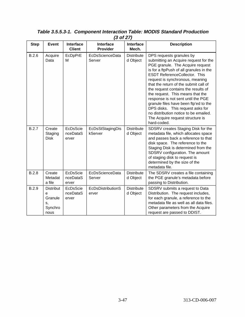
Table 3.5.5.3-1. Component Interaction Table: MODIS Standard Production (3 of 27)
Step Event Interface Client
Interface Provider
Interface Mech.
Descript ion
B.2.6 Acquire Data
EcDpPrE M
EcDsScienceData Server
Distribute d Object
DPS requests granules by submitting an Acquire request for the PGE granule. The Acquire request is for a ftpPush of all granules in the ESDT ReferenceCollector. This request is synchronous, meaning that the return of the submit call of the request contains the results of the request. This means that the response is not sent until the PGE granule files have been ftp’ed to the DPS disks. This request asks for no distribution notice to be emailed. The Acquire request structure is hard-coded.
B.2.7 Create Staging Disk
EcDsScie nceDataS erver
EcDsStStagingDis kServer
Distribute d Object
SDSRV creates Staging Disk for the metadata file, which allocates space and passes back a reference to that disk space. The reference to the Staging Disk is determined from the SDSRV configuration. The amount of staging disk to request is determined by the size of the metadata file.
B.2.8 Create Metadat a file
EcDsScie nceDataS erver
EcDsScienceData Server
Distribute d Object
The SDSRV creates a file containing the PGE granule’s metadata before passing to Distribution.
B.2.9 Distribut e Granule s, Synchro nous
EcDsScie nceDataS erver
EcDsDistributionS erver
Distribute d Object
SDSRV submits a request to Data Distribution. The request includes, for each granule, a reference to the metadata file as well as all data files. Other parameters from the Acquire request are passed to DDIST.
3-47 313-CD-006-007

Table 3.5.5.3-1. Component Interaction Table: MODIS Standard Production (4 of 27)
Step Event Interface Client
Interface Provider
Interface Mech.
Descript ion
B.2.10 Create Staging Disk
EcDsDistri butionServ er
EcDsStStagingDis kServer
Distribute d Object
DDIST creates Staging Disk for the granule files in the archive. This allocates space and passes back a reference to that disk space. reference to the Staging Disk is determined from the information passed by the SDSRV in the distribution request, which was the Archive ID metadata parameter of the granule to be staged. amount of staging disk to request is calculated from the file sizes of archived files, in the information passed in the Distribution Request.
B.2.11 STMGT Retrieve
EcDsDistri butionServ er
EcDsStArchiveSer ver
Distribute d Object
DDIST requests that STMGT retrieve the PGE granule file that is archived. This results in the file being staged to read-only cache disks. s means that all files needed to fulfill the distribution request are on disk, and ready to be copied. orrect archive object to request is determined from the information provided by the SDSRV in the distribution request. returns references to the files in the readonly cache.
B.2.12 Link files to Staging Disk
EcDsDistri butionServ er
EcDsStStagingDis kServer
Distribute d Object
DDIST links the files from the readonly cache into the staging disk.
B.2.13 Copy files to Staging Disk
EcDsDistri butionServ er
EcDsStStagingDis kServer
Distribute d Object
DDIST copies the metadata files from the SDSRV Staging Disk into the staging disk.
The
The
Thi
The c
This
3-48 313-CD-006-007
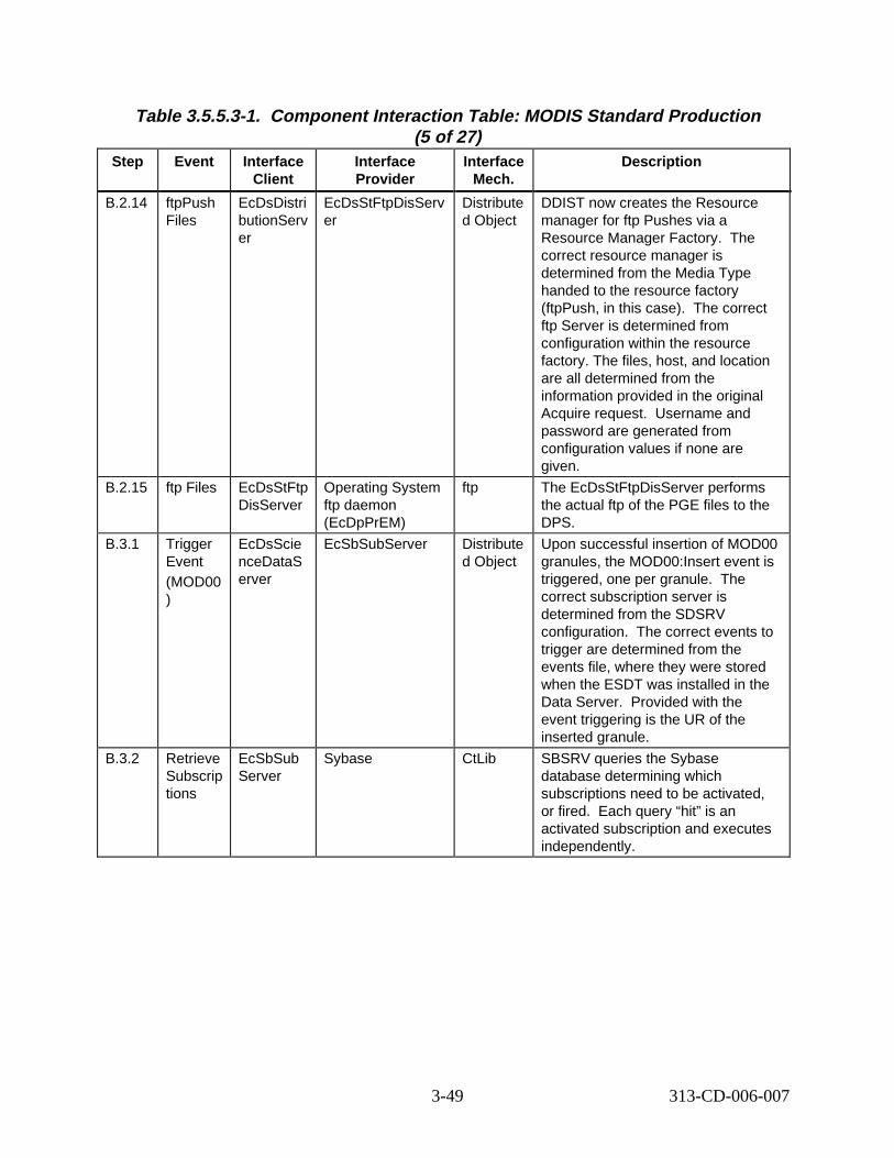
Table 3.5.5.3-1. Component Interaction Table: MODIS Standard Production (5 of 27)
Step Event Interface Client
Interface Provider
Interface Mech.
Descript ion
B.2.14 ftpPush Files
EcDsDistri butionServ er
EcDsStFtpDisServ er
Distribute d Object
DDIST now creates the Resource manager for ftp Pushes via a Resource Manager Factory. The correct resource manager is determined from the Media Type handed to the resource factory (ftpPush, in this case). orrect ftp Server is determined from configuration within the resource factory. The files, host, and location are all determined from the information provided in the original Acquire request. ername and password are generated from configuration values if none are given.
B.2.15 ftp Files EcDsStFtp DisServer
Operating System ftp daemon (EcDpPrEM)
ftp The EcDsStFtpDisServer performs the actual ftp of the PGE files to the DPS.
B.3.1 Trigger Event (MOD00 )
EcDsScie nceDataS erver
EcSbSubServer Distribute d Object
Upon successful insertion of MOD00 granules, the MOD00:Insert event is triggered, one per granule. correct subscription server is determined from the SDSRV configuration. orrect events to trigger are determined from the events file, where they were stored when the ESDT was installed in the Data Server. ovided with the event triggering is the UR of the inserted granule.
B.3.2 Retrieve Subscrip tions
EcSbSub Server
Sybase CtLib SBSRV queries the Sybase database determining which subscriptions need to be activated, or fired. h query “hit” is an activated subscription and executes independently.
The c
Us
The
The c
Pr
Eac
3-49 313-CD-006-007
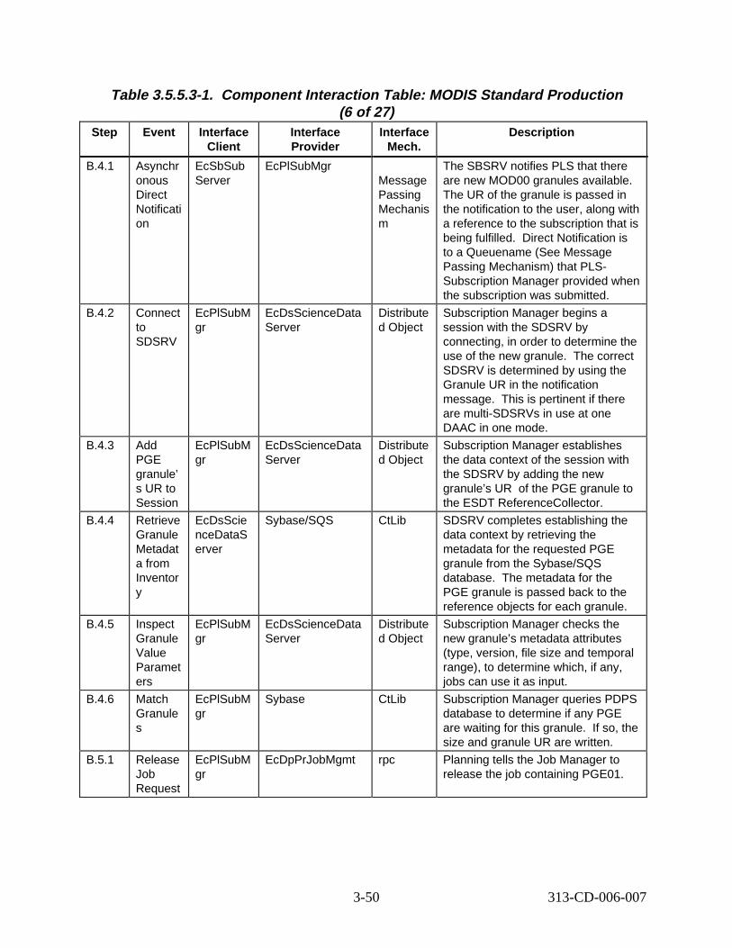
Table 3.5.5.3-1. Component Interaction Table: MODIS Standard Production (6 of 27)
Step Event Interface Client
Interface Provider
Interface Mech.
Descript ion
B.4.1 Asynchr onous Direct Notificati on
EcSbSub Server
EcPlSubMgr Message Passing Mechanis m
The SBSRV notifies PLS that there are new MOD00 granules available. The UR of the granule is passed in the notification to the user, along with a reference to the subscription that is being fulfilled. ect Notification is to a Queuename (See Message Passing Mechanism) that PLS-Subscription Manager provided when the subscription was submitted.
B.4.2 Connect to SDSRV
EcPlSubM gr
EcDsScienceData Server
Distribute d Object
Subscription Manager begins a session with the SDSRV by connecting, in order to determine the use of the new granule. orrect SDSRV is determined by using the Granule UR in the notification message. is pertinent if there are multi-SDSRVs in use at one DAAC in one mode.
B.4.3 Add PGE granule’ s UR to Session
EcPlSubM gr
EcDsScienceData Server
Distribute d Object
Subscription Manager establishes the data context of the session with the SDSRV by adding the new granule’s UR E granule to the ESDT ReferenceCollector.
B.4.4 Retrieve Granule Metadat a from Inventor y
EcDsScie nceDataS erver
Sybase/SQS CtLib SDSRV completes establishing the data context by retrieving the metadata for the requested PGE granule from the Sybase/SQS database. the PGE granule is passed back to the reference objects for each granule.
B.4.5 Inspect Granule Value Paramet ers
EcPlSubM gr
EcDsScienceData Server
Distribute d Object
Subscription Manager checks the new granule’s metadata attributes (type, version, file size and temporal range), to determine which, if any, jobs can use it as input.
B.4.6 Match Granule s
EcPlSubM gr
Sybase CtLib Subscription Manager queries PDPS database to determine if any PGE are waiting for this granule. o, the size and granule UR are written.
B.5.1 Release Job Request
EcPlSubM gr
EcDpPrJobMgmt rpc Planning tells the Job Manager to release the job containing PGE01.
Dir
The c
This
of the PG
The metadata for
If s
3-50 313-CD-006-007
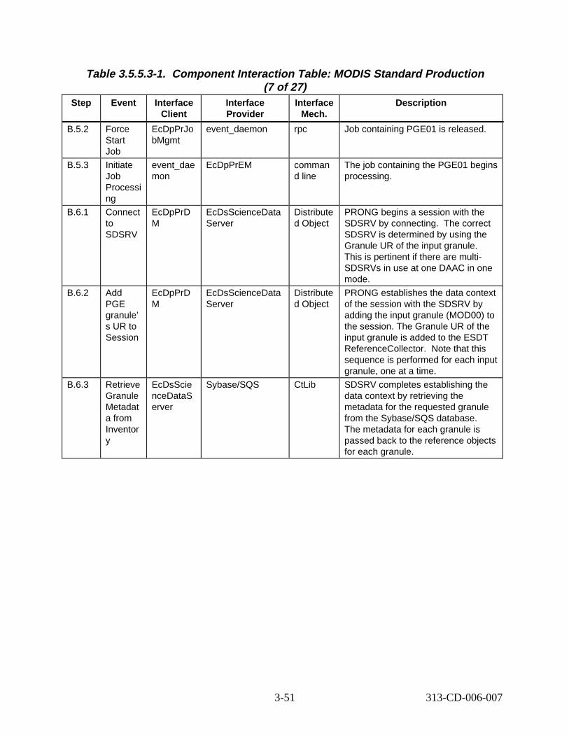
Table 3.5.5.3-1. Component Interaction Table: MODIS Standard Production (7 of 27)
Step Event Interface Client
Interface Provider
Interface Mech.
Descript ion
B.5.2 Force Start Job
EcDpPrJo bMgmt
event_daemon rpc Job containing PGE01 is released.
B.5.3 Initiate Job Processi ng
event_dae mon
EcDpPrEM comman d line
The job containing the PGE01 begins processing.
B.6.1 Connect to SDSRV
EcDpPrD M
EcDsScienceData Server
Distribute d Object
PRONG begins a session with the SDSRV by connecting. orrect SDSRV is determined by using the Granule UR of the input granule. This is pertinent if there are multi-SDSRVs in use at one DAAC in one mode.
B.6.2 Add PGE granule’ s UR to Session
EcDpPrD M
EcDsScienceData Server
Distribute d Object
PRONG establishes the data context of the session with the SDSRV by adding the input granule (MOD00) to the session. The Granule UR of the input granule is added to the ESDT ReferenceCollector. sequence is performed for each input granule, one at a time.
B.6.3 Retrieve Granule Metadat a from Inventor y
EcDsScie nceDataS erver
Sybase/SQS CtLib SDSRV completes establishing the data context by retrieving the metadata for the requested granule from the Sybase/SQS database. The metadata for each granule is passed back to the reference objects for each granule.
The c
Note that this
3-51 313-CD-006-007
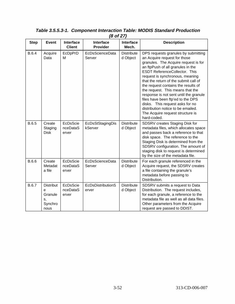
Table 3.5.5.3-1. Component Interaction Table: MODIS Standard Production (8 of 27)
Step Event Interface Client
Interface Provider
Interface Mech.
Descript ion
B.6.4 Acquire Data
EcDpPrD M
EcDsScienceData Server
Distribute d Object
DPS requests granules by submitting an Acquire request for those granules. quire request is for an ftpPush of all granules in the ESDT ReferenceCollector. request is synchronous, meaning that the return of the submit call of the request contains the results of the request. means that the response is not sent until the granule files have been ftp’ed to the DPS disks. s request asks for no distribution notice to be emailed. The Acquire request structure is hard-coded.
B.6.5 Create Staging Disk
EcDsScie nceDataS erver
EcDsStStagingDis kServer
Distribute d Object
SDSRV creates Staging Disk for metadata files, which allocates space and passes back a reference to that disk space. eference to the Staging Disk is determined from the SDSRV configuration. The amount of staging disk to request is determined by the size of the metadata file.
B.6.6 Create Metadat a file
EcDsScie nceDataS erver
EcDsScienceData Server
Distribute d Object
For each granule referenced in the Acquire request, the SDSRV creates a file containing the granule’s metadata before passing to Distribution.
B.6.7 Distribut e Granule s, Synchro nous
EcDsScie nceDataS erver
EcDsDistributionS erver
Distribute d Object
SDSRV submits a request to Data Distribution. equest includes, for each granule, a reference to the metadata file as well as all data files. Other parameters from the Acquire request are passed to DDIST.
The Ac
This
This
Thi
The r
The r
3-52 313-CD-006-007

Table 3.5.5.3-1. Component Interaction Table: MODIS Standard Production (9 of 27)
Step Event Interface Client
Interface Provider
Interface Mech.
Descript ion
B.6.8 Create Staging Disk
EcDsDistri butionServ er
EcDsStStagingDis kServer
Distribute d Object
DDIST creates Staging Disk for the granule files in the archive. This allocates space and passes back a reference to that disk space. reference to the Staging Disk is determined from the information passed by the SDSRV in the distribution request, which was the Archive ID metadata parameter of the granule to be staged. amount of staging disk to request is calculated from the file sizes in the information passed in the Distribution Request.
B.6.9 STMGT Retrieve
EcDsDistri butionServ er
EcDsStArchiveSer ver
Distribute d Object
DDIST requests that STMGT retrieve the granule file that is archived. results in the file being staged to read-only cache disks. s means that all files needed to fulfill the distribution request are on disk, and ready to be copied. orrect archive object to request is determined from the information provided by the SDSRV in the distribution request. returns references to the files in the readonly cache.
B.6.10 Link files to Staging Disk
EcDsDistri butionServ er
EcDsStStagingDis kServer
Distribute d Object
DDIST links the files from the readonly cache into the staging disk.
B.6.11 Copy files to Staging Disk
EcDsDistri butionServ er
EcDsStStagingDis kServer
Distribute d Object
DDIST copies the metadata files from the SDSRV Staging Disk into the staging disk.
The
The
This
Thi
The c
This
3-53 313-CD-006-007
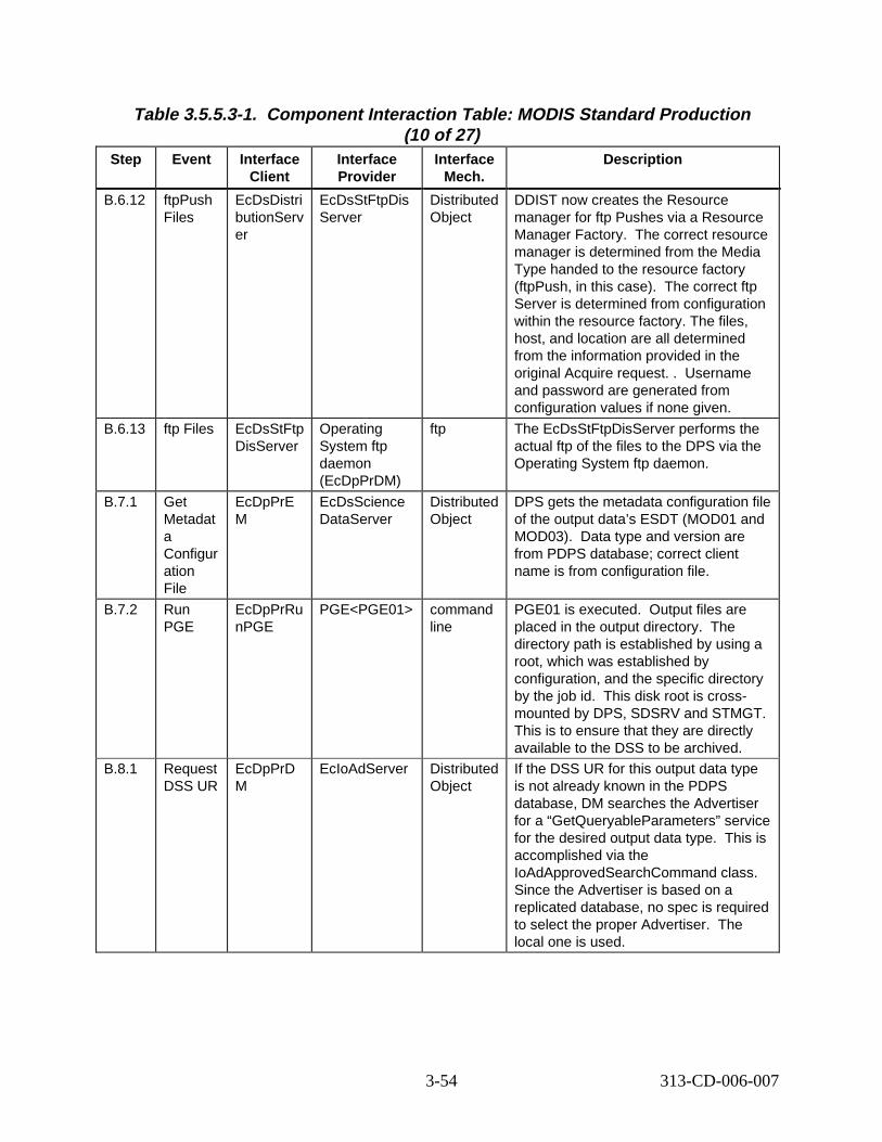
Table 3.5.5.3-1. Component Interaction Table: MODIS Standard Production (10 of 27)
Step Event Interface Client
Interface Provider
Interface Mech.
Descript ion
B.6.12 ftpPush Files
EcDsDistri butionServ er
EcDsStFtpDis Server
Distributed Object
DDIST now creates the Resource manager for ftp Pushes via a Resource Manager Factory. The correct resource manager is determined from the Media Type handed to the resource factory (ftpPush, in this case). orrect ftp Server is determined from configuration within the resource factory. The files, host, and location are all determined from the information provided in the original Acquire request. . ername and password are generated from configuration values if none given.
B.6.13 ftp Files EcDsStFtp DisServer
Operating System ftp daemon (EcDpPrDM)
ftp The EcDsStFtpDisServer performs the actual ftp of the files to the DPS via the Operating System ftp daemon.
B.7.1 Get Metadat a Configur ation File
EcDpPrE M
EcDsScience DataServer
Distributed Object
DPS gets the metadata configuration file of the output data’s ESDT (MOD01 and MOD03). pe and version are from PDPS database; correct client name is from configuration file.
B.7.2 Run PGE
EcDpPrRu nPGE
PGE<PGE01> command line
PGE01 is executed. utput files are placed in the output directory. The directory path is established by using a root, which was established by configuration, and the specific directory by the job id. disk root is crossmounted by DPS, SDSRV and STMGT. This is to ensure that they are directly available to the DSS to be archived.
B.8.1 Request DSS UR
EcDpPrD M
EcIoAdServer Distributed Object
If the DSS UR for this output data type is not already known in the PDPS database, DM searches the Advertiser for a “GetQueryableParameters” service for the desired output data type. is accomplished via the IoAdApprovedSearchCommand class. Since the Advertiser is based on a replicated database, no spec is required to select the proper Advertiser. local one is used.
The c
Us
Data ty
O
This
This
The
3-54 313-CD-006-007
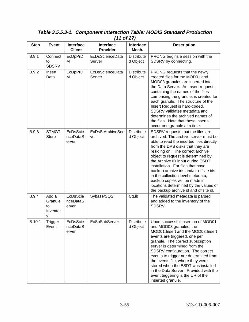
Table 3.5.5.3-1. Component Interaction Table: MODIS Standard Production (11 of 27)
Step Event Interface Client
Interface Provider
Interface Mech.
Descript ion
B.9.1 Connect to SDSRV
EcDpPrD M
EcDsScienceData Server
Distribute d Object
PRONG begins a session with the SDSRV by connecting.
B.9.2 Insert Data
EcDpPrD M
EcDsScienceData Server
Distribute d Object
PRONG requests that the newly created files for the MOD01 and MOD03 granules are inserted into the Data Server. ert request, containing the names of the files comprising the granule, is created for each granule. tructure of the Insert Request is hard-coded. SDSRV validates metadata and determines the archived names of the files. Note that these inserts occur one granule at a time.
B.9.3 STMGT Store
EcDsScie nceDataS erver
EcDsStArchiveSer ver
Distribute d Object
SDSRV requests that the files are archived. The archive server must be able to read the inserted files directly from the DPS disks that they are residing on. orrect archive object to request is determined by the Archive ID input during ESDT installation. files that have backup archive ids and/or offsite ids in the collection level metadata, backup copies will be made in locations determined by the values of the backup archive id and offsite id.
B.9.4 Add a Granule to Inventor y
EcDsScie nceDataS erver
Sybase/SQS CtLib The validated metadata is parsed and added to the inventory of the SDSRV.
B.10.1 Trigger Event
EcDsScie nceDataS erver
EcSbSubServer Distribute d Object
Upon successful insertion of MOD01 and MOD03 granules, the MOD01:Insert and the MOD03:Insert events are triggered, one per granule. orrect subscription server is determined from the SDSRV configuration. orrect events to trigger are determined from the events file, where they were stored when the ESDT was installed in the Data Server. ovided with the event triggering is the UR of the inserted granule.
An Ins
The s
The c
For
The c
The c
Pr
3-55 313-CD-006-007
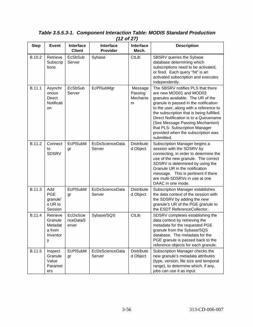
Table 3.5.5.3-1. Component Interaction Table: MODIS Standard Production (12 of 27)
Step Event Interface Client
Interface Provider
Interface Mech.
Descript ion
B.10.2 Retrieve Subscrip tions
EcSbSub Server
Sybase CtLib SBSRV queries the Sybase database determining which subscriptions need to be activated, or fired. h query “hit” is an activated subscription and executes independently.
B.11.1 Asynchr onous Direct Notificati on
EcSbSub Server
EcPlSubMgr Message Passing Mechanis m
The SBSRV notifies PLS that there are new MOD01 and MOD03 granules available. granule is passed in the notification to the user, along with a reference to the subscription that is being fulfilled. Direct Notification is to a Queuename (See Message Passing Mechanism) that PLS- Subscription Manager provided when the subscription was submitted.
B.11.2 Connect to SDSRV
EcPlSubM gr
EcDsScienceData Server
Distribute d Object
Subscription Manager begins a session with the SDSRV by connecting, in order to determine the use of the new granule. orrect SDSRV is determined by using the Granule UR in the notification message. is pertinent if there are multi-SDSRVs in use at one DAAC in one mode.
B.11.3 Add PGE granule’ s UR to Session
EcPlSubM gr
EcDsScienceData Server
Distribute d Object
Subscription Manager establishes the data context of the session with the SDSRV by adding the new granule’s UR of the PGE granule to the ESDT ReferenceCollector.
B.11.4 Retrieve Granule Metadat a from Inventor y
EcDsScie nceDataS erver
Sybase/SQS CtLib SDSRV completes establishing the data context by retrieving the metadata for the requested PGE granule from the Sybase/SQS database. the PGE granule is passed back to the reference objects for each granule.
B.11.5 Inspect Granule Value Paramet ers
EcPlSubM gr
EcDsScienceData Server
Distribute d Object
Subscription Manager checks the new granule’s metadata attributes (type, version, file size and temporal range), to determine which, if any, jobs can use it as input.
Eac
The UR of the
The c
This
The metadata for
3-56 313-CD-006-007
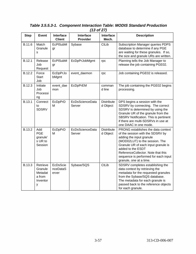
Table 3.5.5.3-1. Component Interaction Table: MODIS Standard Production (13 of 27)
Step Event Interface Client
Interface Provider
Interface Mech.
Descript ion
B.11.6 Match Granule s
EcPlSubM gr
Sybase CtLib Subscription Manager queries PDPS database to determine if any PGE are waiting for these granules. o, the size and granule URs are written.
B.12.1 Release Job Request
EcPlSubM gr
EcDpPrJobMgmt rpc Planning tells the Job Manager to release the job containing PGE02.
B.12.2 Force Start Job
EcDpPrJo bMgmt
event_daemon rpc Job containing PGE02 is released.
B.12.3 Initiate Job Processi ng
event_dae mon
EcDpPrEM comman d line
The job containing the PGE02 begins processing.
B.13.1 Connect to SDSRV
EcDpPrD M
EcDsScienceData Server
Distribute d Object
DPS begins a session with the SDSRV by connecting. orrect SDSRV is determined by using the Granule UR of the granule from the SBSRV Notification. This is pertinent if there are multi-SDSRVs in use at one DAAC in one mode.
B.13.2 Add PGE granule’ s UR to Session
EcDpPrD M
EcDsScienceData Server
Distribute d Object
PRONG establishes the data context of the session with the SDSRV by adding the input granule (MOD02LUT) to the session. The Granule UR of each input granule is added to the ESDT ReferenceCollector. Note that this sequence is performed for each input granule, one at a time.
B.13.3 Retrieve Granule Metadat a from Inventor y
EcDsScie nceDataS erver
Sybase/SQS CtLib SDSRV completes establishing the data context by retrieving the metadata for the requested granules from the Sybase/SQS database. The metadata for each granule is passed back to the reference objects for each granule.
If s
The c
3-57 313-CD-006-007
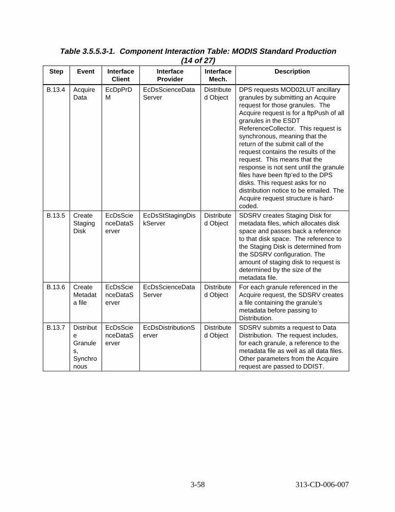
Table 3.5.5.3-1. Component Interaction Table: MODIS Standard Production (14 of 27)
Step Event Interface Client
Interface Provider
Interface Mech.
Descript ion
B.13.4 Acquire Data
EcDpPrD M
EcDsScienceData Server
Distribute d Object
DPS requests MOD02LUT ancillary granules by submitting an Acquire request for those granules. Acquire request is for a ftpPush of all granules in the ESDT ReferenceCollector. request is synchronous, meaning that the return of the submit call of the request contains the results of the request. means that the response is not sent until the granule files have been ftp’ed to the DPS disks. This request asks for no distribution notice to be emailed. The Acquire request structure is hardcoded.
B.13.5 Create Staging Disk
EcDsScie nceDataS erver
EcDsStStagingDis kServer
Distribute d Object
SDSRV creates Staging Disk for metadata files, which allocates disk space and passes back a reference to that disk space. eference to the Staging Disk is determined from the SDSRV configuration. The amount of staging disk to request is determined by the size of the metadata file.
B.13.6 Create Metadat a file
EcDsScie nceDataS erver
EcDsScienceData Server
Distribute d Object
For each granule referenced in the Acquire request, the SDSRV creates a file containing the granule’s metadata before passing to Distribution.
B.13.7 Distribut e Granule s, Synchro nous
EcDsScie nceDataS erver
EcDsDistributionS erver
Distribute d Object
SDSRV submits a request to Data Distribution. equest includes, for each granule, a reference to the metadata file as well as all data files. Other parameters from the Acquire request are passed to DDIST.
The
This
This
The r
The r
3-58 313-CD-006-007

Table 3.5.5.3-1. Component Interaction Table: MODIS Standard Production (15 of 27)
Step Event Interface Client
Interface Provider
Interface Mech.
Descript ion
B.13.8 Create Staging Disk
EcDsDistri butionServ er
EcDsStStagingDis kServer
Distribute d Object
DDIST creates Staging Disk for the granule files in the archive. This allocates space and passes back a reference to that disk space. reference to the Staging Disk is determined from the information passed by the SDSRV in the distribution request, which was the Archive ID metadata parameter of the granule to be staged. amount of staging disk to request is calculated from the file sizes in the information passed in the Distribution Request.
B.13.9 STMGT Retrieve
EcDsDistri butionServ er
EcDsStArchiveSer ver
Distribute d Object
DDIST requests that STMGT retrieve the granule file that is archived. results in the file being staged to read-only cache disks. s means that all files needed to fulfill the distribution request are on disk, and ready to be copied. orrect archive object to request is determined from the information provided by the SDSRV in the distribution request. returns references to the files in the readonly cache.
B.13.1 0
Link files to Staging Disk
EcDsDistri butionServ er
EcDsStStagingDis kServer
Distribute d Object
DDIST links the files from the readonly cache into the staging disk.
B.13.1 1
Copy files to Staging Disk
EcDsDistri butionServ er
EcDsStStagingDis kServer
Distribute d Object
DDIST copies the metadata files from the SDSRV’s Staging Disk into the staging disk.
The
The
This
Thi
The c
This
3-59 313-CD-006-007
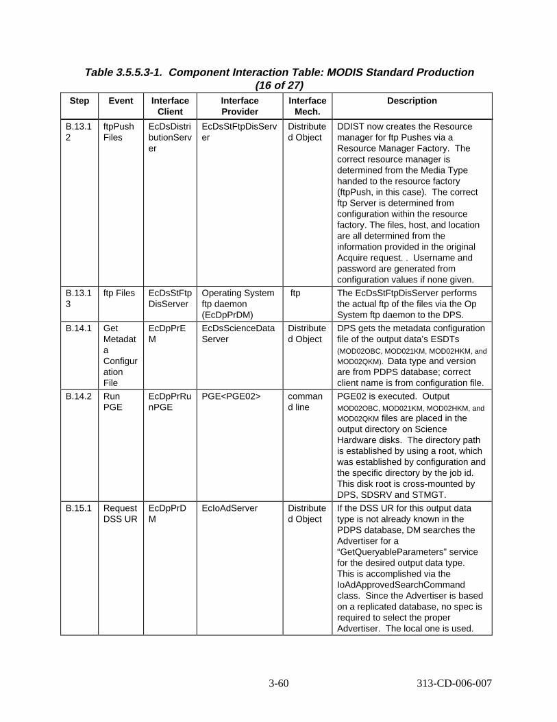
Table 3.5.5.3-1. Component Interaction Table: MODIS Standard Production (16 of 27)
Step Event Interface Client
Interface Provider
Interface Mech.
Descript ion
B.13.1 2
ftpPush Files
EcDsDistri butionServ er
EcDsStFtpDisServ er
Distribute d Object
DDIST now creates the Resource manager for ftp Pushes via a Resource Manager Factory. The correct resource manager is determined from the Media Type handed to the resource factory (ftpPush, in this case). orrect ftp Server is determined from configuration within the resource factory. The files, host, and location are all determined from the information provided in the original Acquire request. . ername and password are generated from configuration values if none given.
B.13.1 3
ftp Files EcDsStFtp DisServer
Operating System ftp daemon (EcDpPrDM)
ftp The EcDsStFtpDisServer performs the actual ftp of the files via the Op System ftp daemon to the DPS.
B.14.1 Get Metadat a Configur ation File
EcDpPrE M
EcDsScienceData Server
Distribute d Object
DPS gets the metadata configuration file of the output data’s ESDTs (MOD02OBC, MOD021KM, MOD02HKM, and MOD02QKM). Data type and version are from PDPS database; correct client name is from configuration file.
B.14.2 Run PGE
EcDpPrRu nPGE
PGE<PGE02> comman d line
PGE02 is executed. utput MOD02OBC, MOD021KM, MOD02HKM, and MOD02QKM files are placed in the output directory on Science Hardware disks. The directory path is established by using a root, which was established by configuration and the specific directory by the job id. This disk root is cross-mounted by DPS, SDSRV and STMGT.
B.15.1 Request DSS UR
EcDpPrD M
EcIoAdServer Distribute d Object
If the DSS UR for this output data type is not already known in the PDPS database, DM searches the Advertiser for a “GetQueryableParameters” service for the desired output data type. This is accomplished via the IoAdApprovedSearchCommand class. Since the Advertiser is based on a replicated database, no spec is required to select the proper Advertiser. al one is used.
The c
Us
O
The loc
3-60 313-CD-006-007
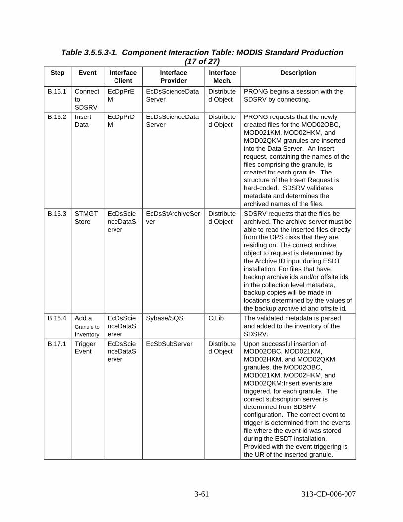
Table 3.5.5.3-1. Component Interaction Table: MODIS Standard Production (17 of 27)
Step Event Interface Client
Interface Provider
Interface Mech.
Descript ion
B.16.1 Connect to SDSRV
EcDpPrE M
EcDsScienceData Server
Distribute d Object
PRONG begins a session with the SDSRV by connecting.
B.16.2 Insert Data
EcDpPrD M
EcDsScienceData Server
Distribute d Object
PRONG requests that the newly created files for the MOD02OBC, MOD021KM, MOD02HKM, and MOD02QKM granules are inserted into the Data Server. ert request, containing the names of the files comprising the granule, is created for each granule. structure of the Insert Request is hard-coded. alidates metadata and determines the archived names of the files.
B.16.3 STMGT Store
EcDsScie nceDataS erver
EcDsStArchiveSer ver
Distribute d Object
SDSRV requests that the files be archived. The archive server must be able to read the inserted files directly from the DPS disks that they are residing on. The correct archive object to request is determined by the Archive ID input during ESDT installation. For files that have backup archive ids and/or offsite ids in the collection level metadata, backup copies will be made in locations determined by the values of the backup archive id and offsite id.
B.16.4 Add a Granule to
Inventory
EcDsScie nceDataS erver
Sybase/SQS CtLib The validated metadata is parsed and added to the inventory of the SDSRV.
B.17.1 Trigger Event
EcDsScie nceDataS erver
EcSbSubServer Distribute d Object
Upon successful insertion of MOD02OBC, MOD021KM, MOD02HKM, and MOD02QKM granules, the MOD02OBC, MOD021KM, MOD02HKM, and MOD02QKM:Insert events are triggered, for each granule. correct subscription server is determined from SDSRV configuration. orrect event to trigger is determined from the events file where the event id was stored during the ESDT installation. Provided with the event triggering is the UR of the inserted granule.
An Ins
The
SDSRV v
The
The c
3-61 313-CD-006-007
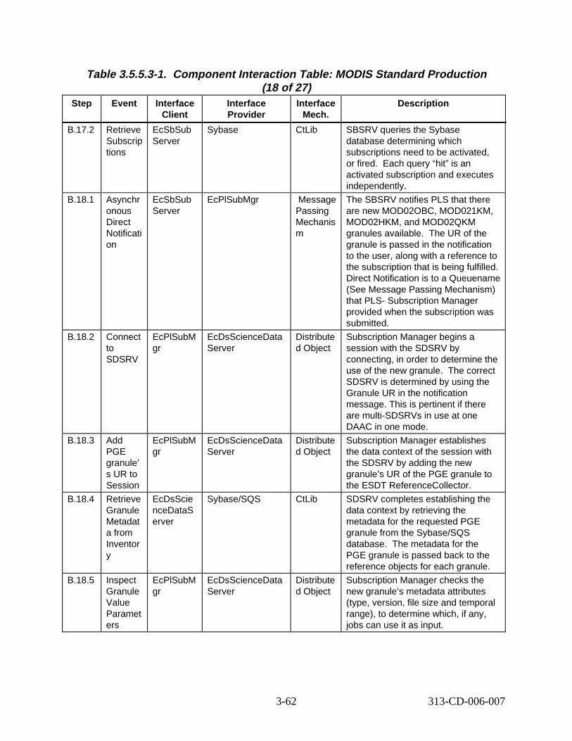
Table 3.5.5.3-1. Component Interaction Table: MODIS Standard Production (18 of 27)
Step Event Interface Client
Interface Provider
Interface Mech.
Descript ion
B.17.2 Retrieve Subscrip tions
EcSbSub Server
Sybase CtLib SBSRV queries the Sybase database determining which subscriptions need to be activated, or fired. h query “hit” is an activated subscription and executes independently.
B.18.1 Asynchr onous Direct Notificati on
EcSbSub Server
EcPlSubMgr Message Passing Mechanis m
The SBSRV notifies PLS that there are new MOD02OBC, MOD021KM, MOD02HKM, and MOD02QKM granules available. granule is passed in the notification to the user, along with a reference to the subscription that is being fulfilled. Direct Notification is to a Queuename (See Message Passing Mechanism) that PLS- Subscription Manager provided when the subscription was submitted.
B.18.2 Connect to SDSRV
EcPlSubM gr
EcDsScienceData Server
Distribute d Object
Subscription Manager begins a session with the SDSRV by connecting, in order to determine the use of the new granule. orrect SDSRV is determined by using the Granule UR in the notification message. This is pertinent if there are multi-SDSRVs in use at one DAAC in one mode.
B.18.3 Add PGE granule’ s UR to Session
EcPlSubM gr
EcDsScienceData Server
Distribute d Object
Subscription Manager establishes the data context of the session with the SDSRV by adding the new granule’s UR of the PGE granule to the ESDT ReferenceCollector.
B.18.4 Retrieve Granule Metadat a from Inventor y
EcDsScie nceDataS erver
Sybase/SQS CtLib SDSRV completes establishing the data context by retrieving the metadata for the requested PGE granule from the Sybase/SQS database. the PGE granule is passed back to the reference objects for each granule.
B.18.5 Inspect Granule Value Paramet ers
EcPlSubM gr
EcDsScienceData Server
Distribute d Object
Subscription Manager checks the new granule’s metadata attributes (type, version, file size and temporal range), to determine which, if any, jobs can use it as input.
Eac
The UR of the
The c
The metadata for
3-62 313-CD-006-007
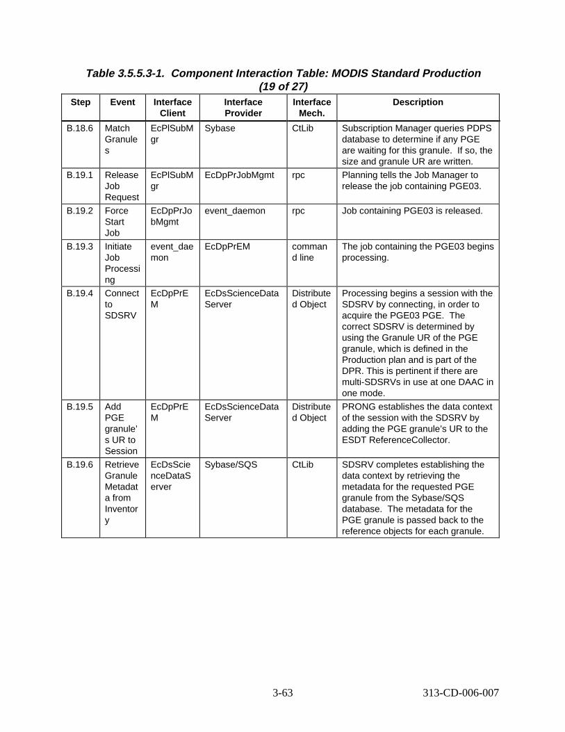
Table 3.5.5.3-1. Component Interaction Table: MODIS Standard Production (19 of 27)
Step Event Interface Client
Interface Provider
Interface Mech.
Descript ion
B.18.6 Match Granule s
EcPlSubM gr
Sybase CtLib Subscription Manager queries PDPS database to determine if any PGE are waiting for this granule. o, the size and granule UR are written.
B.19.1 Release Job Request
EcPlSubM gr
EcDpPrJobMgmt rpc Planning tells the Job Manager to release the job containing PGE03.
B.19.2 Force Start Job
EcDpPrJo bMgmt
event_daemon rpc Job containing PGE03 is released.
B.19.3 Initiate Job Processi ng
event_dae mon
EcDpPrEM comman d line
The job containing the PGE03 begins processing.
B.19.4 Connect to SDSRV
EcDpPrE M
EcDsScienceData Server
Distribute d Object
Processing begins a session with the SDSRV by connecting, in order to acquire the PGE03 PGE. correct SDSRV is determined by using the Granule UR of the PGE granule, which is defined in the Production plan and is part of the DPR. This is pertinent if there are multi-SDSRVs in use at one DAAC in one mode.
B.19.5 Add PGE granule’ s UR to Session
EcDpPrE M
EcDsScienceData Server
Distribute d Object
PRONG establishes the data context of the session with the SDSRV by adding the PGE granule’s UR to the ESDT ReferenceCollector.
B.19.6 Retrieve Granule Metadat a from Inventor y
EcDsScie nceDataS erver
Sybase/SQS CtLib SDSRV completes establishing the data context by retrieving the metadata for the requested PGE granule from the Sybase/SQS database. the PGE granule is passed back to the reference objects for each granule.
If s
The
The metadata for
3-63 313-CD-006-007
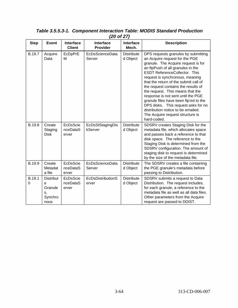
Table 3.5.5.3-1. Component Interaction Table: MODIS Standard Production (20 of 27)
Step Event Interface Client
Interface Provider
Interface Mech.
Descript ion
B.19.7 Acquire Data
EcDpPrE M
EcDsScienceData Server
Distribute d Object
DPS requests granules by submitting an Acquire request for the PGE granule. quire request is for an ftpPush of all granules in the ESDT ReferenceCollector. request is synchronous, meaning that the return of the submit call of the request contains the results of the request. means that the response is not sent until the PGE granule files have been ftp’ed to the DPS disks. s request asks for no distribution notice to be emailed. The Acquire request structure is hard-coded.
B.19.8 Create Staging Disk
EcDsScie nceDataS erver
EcDsStStagingDis kServer
Distribute d Object
SDSRV creates Staging Disk for the metadata file, which allocates space and passes back a reference to that disk space. eference to the Staging Disk is determined from the SDSRV configuration. The amount of staging disk to request is determined by the size of the metadata file.
B.19.9 Create Metadat a file
EcDsScie nceDataS erver
EcDsScienceData Server
Distribute d Object
The SDSRV creates a file containing the PGE granule’s metadata before passing to Distribution.
B.19.1 0
Distribut e Granule s, Synchro nous
EcDsScie nceDataS erver
EcDsDistributionS erver
Distribute d Object
SDSRV submits a request to Data Distribution. equest includes, for each granule, a reference to the metadata file as well as all data files. Other parameters from the Acquire request are passed to DDIST.
The Ac
This
This
Thi
The r
The r
3-64 313-CD-006-007
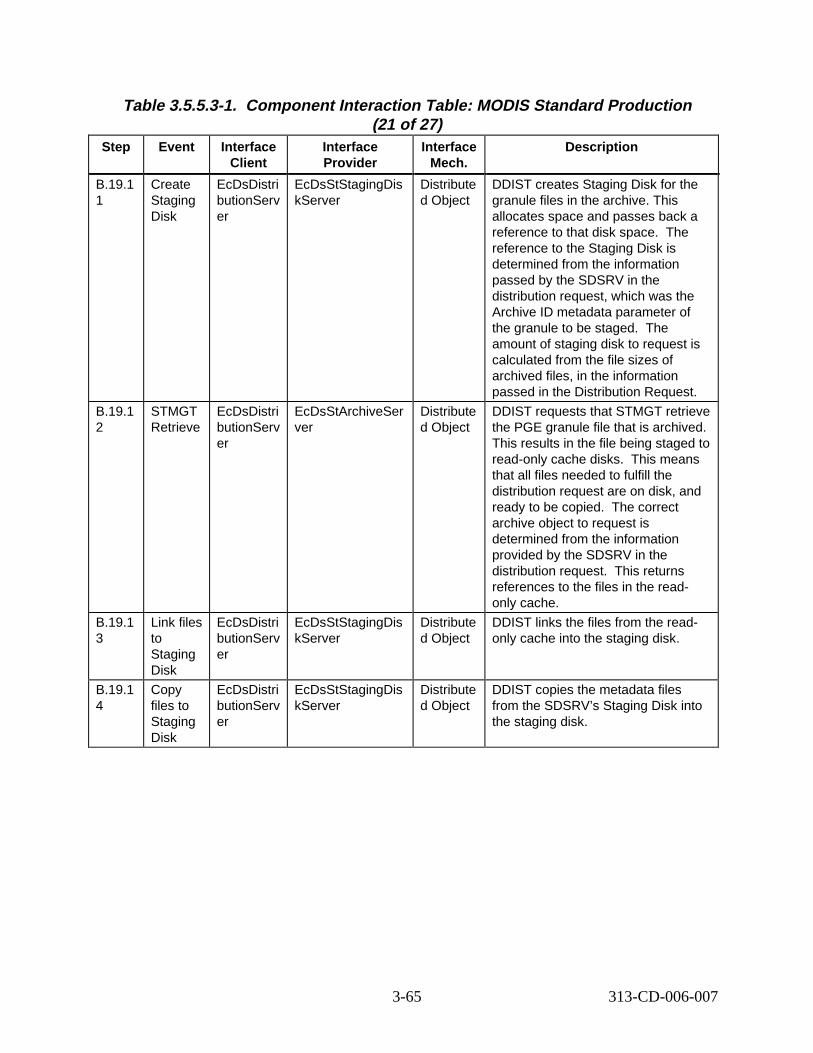
Table 3.5.5.3-1. Component Interaction Table: MODIS Standard Production (21 of 27)
Step Event Interface Client
Interface Provider
Interface Mech.
Descript ion
B.19.1 1
Create Staging Disk
EcDsDistri butionServ er
EcDsStStagingDis kServer
Distribute d Object
DDIST creates Staging Disk for the granule files in the archive. This allocates space and passes back a reference to that disk space. reference to the Staging Disk is determined from the information passed by the SDSRV in the distribution request, which was the Archive ID metadata parameter of the granule to be staged. amount of staging disk to request is calculated from the file sizes of archived files, in the information passed in the Distribution Request.
B.19.1 2
STMGT Retrieve
EcDsDistri butionServ er
EcDsStArchiveSer ver
Distribute d Object
DDIST requests that STMGT retrieve the PGE granule file that is archived. This results in the file being staged to read-only cache disks. s means that all files needed to fulfill the distribution request are on disk, and ready to be copied. orrect archive object to request is determined from the information provided by the SDSRV in the distribution request. returns references to the files in the readonly cache.
B.19.1 3
Link files to Staging Disk
EcDsDistri butionServ er
EcDsStStagingDis kServer
Distribute d Object
DDIST links the files from the readonly cache into the staging disk.
B.19.1 4
Copy files to Staging Disk
EcDsDistri butionServ er
EcDsStStagingDis kServer
Distribute d Object
DDIST copies the metadata files from the SDSRV’s Staging Disk into the staging disk.
The
The
Thi
The c
This
3-65 313-CD-006-007
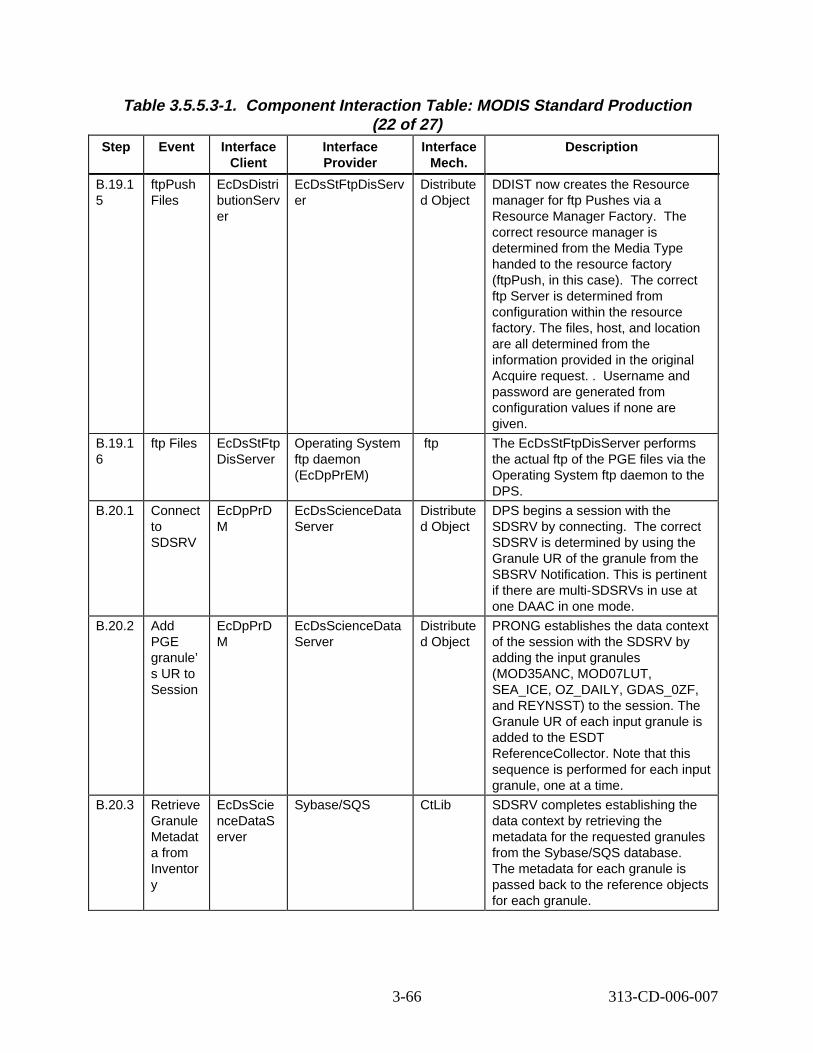
Table 3.5.5.3-1. Component Interaction Table: MODIS Standard Production (22 of 27)
Step Event Interface Client
Interface Provider
Interface Mech.
Descript ion
B.19.1 5
ftpPush Files
EcDsDistri butionServ er
EcDsStFtpDisServ er
Distribute d Object
DDIST now creates the Resource manager for ftp Pushes via a Resource Manager Factory. The correct resource manager is determined from the Media Type handed to the resource factory (ftpPush, in this case). orrect ftp Server is determined from configuration within the resource factory. The files, host, and location are all determined from the information provided in the original Acquire request. . ername and password are generated from configuration values if none are given.
B.19.1 6
ftp Files EcDsStFtp DisServer
Operating System ftp daemon (EcDpPrEM)
ftp The EcDsStFtpDisServer performs the actual ftp of the PGE files via the Operating System ftp daemon to the DPS.
B.20.1 Connect to SDSRV
EcDpPrD M
EcDsScienceData Server
Distribute d Object
DPS begins a session with the SDSRV by connecting. orrect SDSRV is determined by using the Granule UR of the granule from the SBSRV Notification. This is pertinent if there are multi-SDSRVs in use at one DAAC in one mode.
B.20.2 Add PGE granule’ s UR to Session
EcDpPrD M
EcDsScienceData Server
Distribute d Object
PRONG establishes the data context of the session with the SDSRV by adding the input granules (MOD35ANC, MOD07LUT, SEA_ICE, OZ_DAILY, GDAS_0ZF, and REYNSST) to the session. The Granule UR of each input granule is added to the ESDT ReferenceCollector. Note that this sequence is performed for each input granule, one at a time.
B.20.3 Retrieve Granule Metadat a from Inventor y
EcDsScie nceDataS erver
Sybase/SQS CtLib SDSRV completes establishing the data context by retrieving the metadata for the requested granules from the Sybase/SQS database. The metadata for each granule is passed back to the reference objects for each granule.
The c
Us
The c
3-66 313-CD-006-007
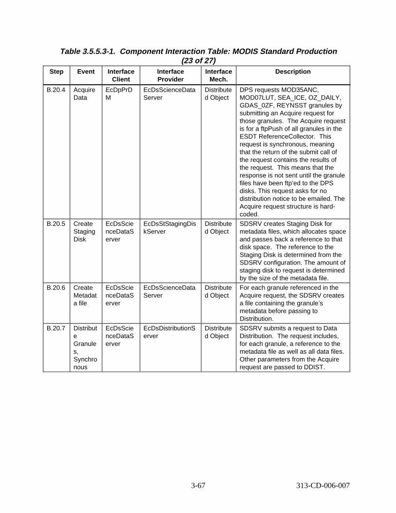
Table 3.5.5.3-1. Component Interaction Table: MODIS Standard Production (23 of 27)
Step Event Interface Client
Interface Provider
Interface Mech.
Descript ion
B.20.4 Acquire Data
EcDpPrD M
EcDsScienceData Server
Distribute d Object
DPS requests MOD35ANC, MOD07LUT, SEA_ICE, OZ_DAILY, GDAS_0ZF, REYNSST granules by submitting an Acquire request for those granules. quire request is for a ftpPush of all granules in the ESDT ReferenceCollector. request is synchronous, meaning that the return of the submit call of the request contains the results of the request. means that the response is not sent until the granule files have been ftp’ed to the DPS disks. This request asks for no distribution notice to be emailed. The Acquire request structure is hardcoded.
B.20.5 Create Staging Disk
EcDsScie nceDataS erver
EcDsStStagingDis kServer
Distribute d Object
SDSRV creates Staging Disk for metadata files, which allocates space and passes back a reference to that disk space. eference to the Staging Disk is determined from the SDSRV configuration. The amount of staging disk to request is determined by the size of the metadata file.
B.20.6 Create Metadat a file
EcDsScie nceDataS erver
EcDsScienceData Server
Distribute d Object
For each granule referenced in the Acquire request, the SDSRV creates a file containing the granule’s metadata before passing to Distribution.
B.20.7 Distribut e Granule s, Synchro nous
EcDsScie nceDataS erver
EcDsDistributionS erver
Distribute d Object
SDSRV submits a request to Data Distribution. equest includes, for each granule, a reference to the metadata file as well as all data files. Other parameters from the Acquire request are passed to DDIST.
The Ac
This
This
The r
The r
3-67 313-CD-006-007
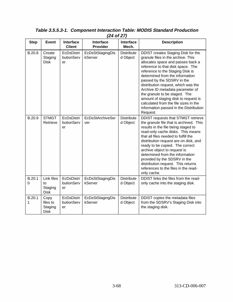
Table 3.5.5.3-1. Component Interaction Table: MODIS Standard Production (24 of 27)
Step Event Interface Client
Interface Provider
Interface Mech.
Descript ion
B.20.8 Create Staging Disk
EcDsDistri butionServ er
EcDsStStagingDis kServer
Distribute d Object
DDIST creates Staging Disk for the granule files in the archive. This allocates space and passes back a reference to that disk space. reference to the Staging Disk is determined from the information passed by the SDSRV in the distribution request, which was the Archive ID metadata parameter of the granule to be staged. amount of staging disk to request is calculated from the file sizes in the information passed in the Distribution Request.
B.20.9 STMGT Retrieve
EcDsDistri butionServ er
EcDsStArchiveSer ver
Distribute d Object
DDIST requests that STMGT retrieve the granule file that is archived. results in the file being staged to read-only cache disks. s means that all files needed to fulfill the distribution request are on disk, and ready to be copied. orrect archive object to request is determined from the information provided by the SDSRV in the distribution request. returns references to the files in the readonly cache.
B.20.1 0
Link files to Staging Disk
EcDsDistri butionServ er
EcDsStStagingDis kServer
Distribute d Object
DDIST links the files from the readonly cache into the staging disk.
B.20.1 1
Copy files to Staging Disk
EcDsDistri butionServ er
EcDsStStagingDis kServer
Distribute d Object
DDIST copies the metadata files from the SDSRV’s Staging Disk into the staging disk.
The
The
This
Thi
The c
This
3-68 313-CD-006-007
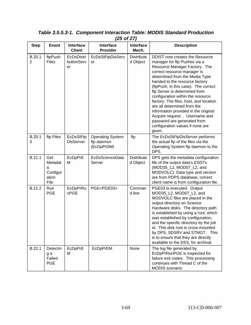
Table 3.5.5.3-1. Component Interaction Table: MODIS Standard Production (25 of 27)
Step Event Interface Client
Interface Provider
Interface Mech.
Descript ion
B.20.1 2
ftpPush Files
EcDsDistri butionServ er
EcDsStFtpDisServ er
Distribute d Object
DDIST now creates the Resource manager for ftp Pushes via a Resource Manager Factory. The correct resource manager is determined from the Media Type handed to the resource factory (ftpPush, in this case). orrect ftp Server is determined from configuration within the resource factory. The files, host, and location are all determined from the information provided in the original Acquire request. . ername and password are generated from configuration values if none are given.
B.20.1 3
ftp Files EcDsStFtp DisServer
Operating System ftp daemon (EcDpPrDM)
ftp The EcDsStFtpDisServer performs the actual ftp of the files via the Operating System ftp daemon to the DPS.
B.21.1 Get Metadat a Configur ation File
EcDpPrE M
EcDsScienceData Server
Distribute d Object
DPS gets the metadata configuration file of the output data’s ESDTs (MOD35_L2, MOD07_L2, and MODVOLC). Data type and version are from PDPS database; correct client name is from configuration file.
B.21.2 Run PGE
EcDpPrRu nPGE
PGE<PGE03> Comman d line
PGE03 is executed. utput MOD35_L2, MOD07_L2, and MODVOLC files are placed in the output directory on Science Hardware disks. The directory path is established by using a root, which was established by configuration, and the specific directory by the job id. disk root is cross-mounted by DPS, SDSRV and STMGT. is to ensure that they are directly available to the DSS, for archival.
B.22.1 Detectin g a Failed PGE
EcDpPrE M
EcDpPrEM None The log file generated by EcDpPrRunPGE is inspected for failure exit codes. processing continues with Thread C of the MODIS scenario.
The c
Us
O
ThisThis
This
3-69 313-CD-006-007
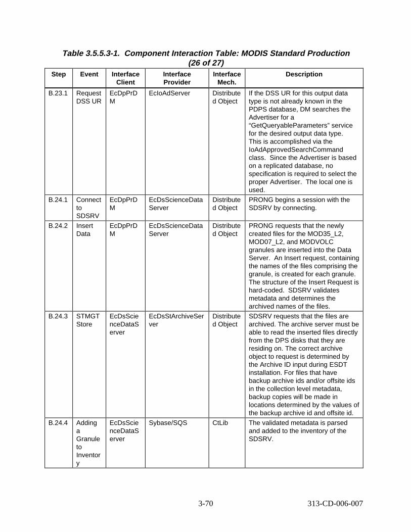
Table 3.5.5.3-1. Component Interaction Table: MODIS Standard Production (26 of 27)
Step Event Interface Client
Interface Provider
Interface Mech.
Descript ion
B.23.1 Request DSS UR
EcDpPrD M
EcIoAdServer Distribute d Object
If the DSS UR for this output data type is not already known in the PDPS database, DM searches the Advertiser for a “GetQueryableParameters” service for the desired output data type. This is accomplished via the IoAdApprovedSearchCommand class. Since the Advertiser is based on a replicated database, no specification is required to select the proper Advertiser. al one is used.
B.24.1 Connect to SDSRV
EcDpPrD M
EcDsScienceData Server
Distribute d Object
PRONG begins a session with the SDSRV by connecting.
B.24.2 Insert Data
EcDpPrD M
EcDsScienceData Server
Distribute d Object
PRONG requests that the newly created files for the MOD35_L2, MOD07_L2, and MODVOLC granules are inserted into the Data Server. ert request, containing the names of the files comprising the granule, is created for each granule. The structure of the Insert Request is hard-coded. alidates metadata and determines the archived names of the files.
B.24.3 STMGT Store
EcDsScie nceDataS erver
EcDsStArchiveSer ver
Distribute d Object
SDSRV requests that the files are archived. The archive server must be able to read the inserted files directly from the DPS disks that they are residing on. The correct archive object to request is determined by the Archive ID input during ESDT installation. For files that have backup archive ids and/or offsite ids in the collection level metadata, backup copies will be made in locations determined by the values of the backup archive id and offsite id.
B.24.4 Adding a Granule to Inventor y
EcDsScie nceDataS erver
Sybase/SQS CtLib The validated metadata is parsed and added to the inventory of the SDSRV.
The loc
An Ins
SDSRV v
3-70 313-CD-006-007
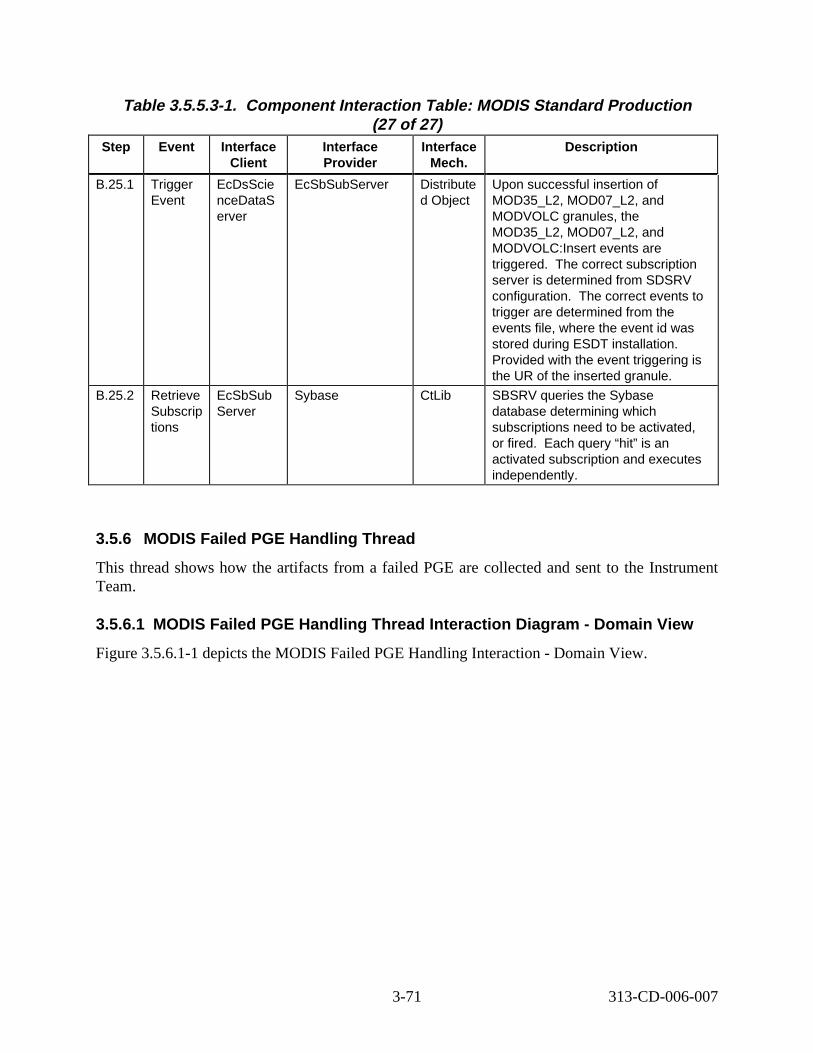
Table 3.5.5.3-1. Component Interaction Table: MODIS Standard Production (27 of 27)
Step Event Interface Client
Interface Provider
Interface Mech.
Descript ion
B.25.1 Trigger Event
EcDsScie nceDataS erver
EcSbSubServer Distribute d Object
Upon successful insertion of MOD35_L2, MOD07_L2, and MODVOLC granules, the MOD35_L2, MOD07_L2, and MODVOLC:Insert events are triggered. orrect subscription server is determined from SDSRV configuration. orrect events to trigger are determined from the events file, where the event id was stored during ESDT installation. Provided with the event triggering is the UR of the inserted granule.
B.25.2 Retrieve Subscrip tions
EcSbSub Server
Sybase CtLib SBSRV queries the Sybase database determining which subscriptions need to be activated, or fired. h query “hit” is an activated subscription and executes independently.
The c
The c
Eac
3.5.6 MODIS Failed PGE Handling Thread
This thread shows how the artifacts from a failed PGE are collected and sent to the Instrument Team.
3.5.6.1 MODIS Failed PGE Handling Thread Interaction Diagram - Domain View
Figure 3.5.6.1-1 depicts the MODIS Failed PGE Handling Interaction - Domain View.
3-71 313-CD-006-007
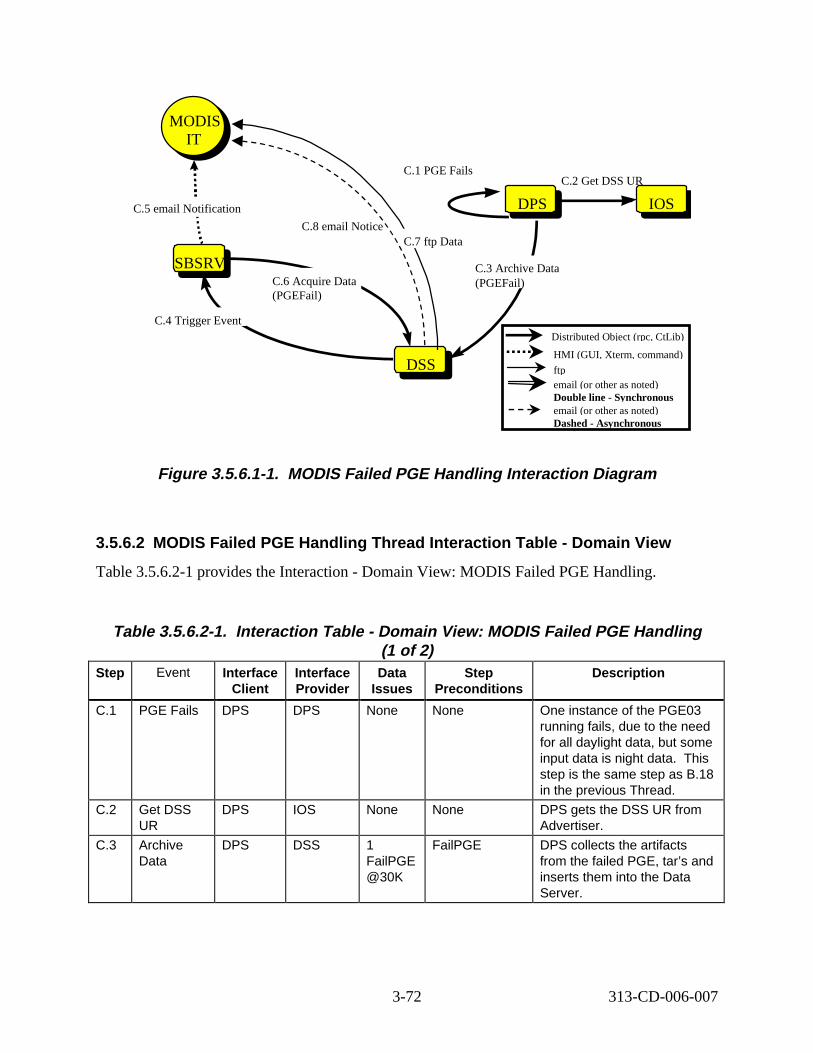
DPSDPSDPS
DSSDSS
MODIS IT
MODIS IT
C.3 Archive Data (PGEFail)
C.1 PGE Fails
SBSRVSBSRV
C.4 Trigger Event
C.6 Acquire Data (PGEFail)
C.8 email Notice C.7 ftp Data
IOS
C.2 Get DSS UR
C.5 email Notification
Distributed Object (rpc, CtLib)
HMI (GUI, Xterm, command)
ftp email (or other as noted) Double line - Synchronous email (or other as noted) Dashed - Asynchronous
Figure 3.5.6.1-1. MODIS Failed PGE Handling Interaction Diagram
3.5.6.2 MODIS Failed PGE Handling Thread Interaction Table - Domain View
Table 3.5.6.2-1 provides the Interaction - Domain View: MODIS Failed PGE Handling.
Table 3.5.6.2-1. Interact ion Table - Domain View: MODIS Failed PGE H andling (1 of 2)
Step Event Interface Client
Interface Provider
Data Issues
Step Preconditions
Descript ion
C.1 PGE Fails DPS DPS None None One instance of the PGE03 running fails, due to the need for all daylight data, but some input data is night data. This step is the same step as B.18 in the previous Thread.
C.2 Get DSS UR
DPS IOS None None DPS gets the DSS UR from Advertiser.
C.3 Archive Data
DPS DSS 1 FailPGE @30K
FailPGE DPS collects the artifacts from the failed PGE, tar’s and inserts them into the Data Server.
3-72 313-CD-006-007
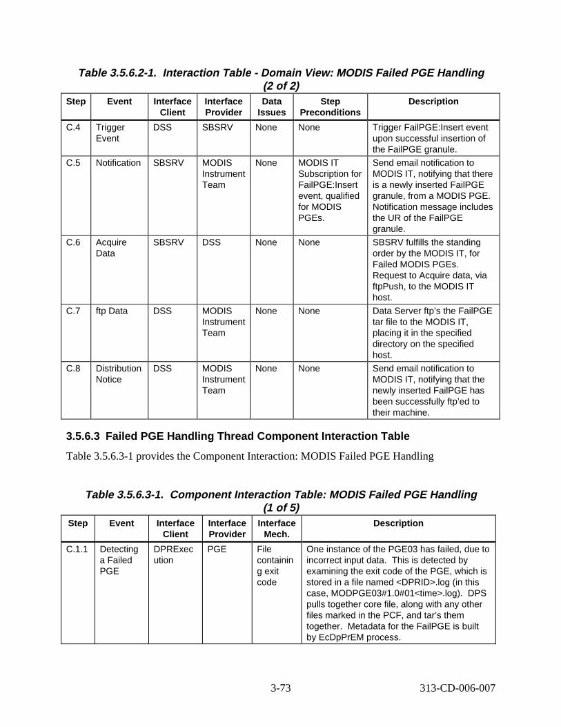
Table 3.5.6.2-1. Interact ion Table - Domain View: MODIS Failed PGE H andling (2 of 2)
Step Event Interface Client
Interface Provider
Data Issues
Step Preconditions
Descript ion
C.4 Trigger Event
DSS SBSRV None None Trigger FailPGE:Insert event upon successful insertion of the FailPGE granule.
C.5 Notification SBSRV MODIS Instrument Team
None MODIS IT Subscription for FailPGE:Insert event, qualified for MODIS PGEs.
Send email notification to MODIS IT, notifying that there is a newly inserted FailPGE granule, from a MODIS PGE. Notification message includes the UR of the FailPGE granule.
C.6 Acquire Data
SBSRV DSS None None SBSRV fulfills the standing order by the MODIS IT, for Failed MODIS PGEs. Request to Acquire data, via ftpPush, to the MODIS IT host.
C.7 ftp Data DSS MODIS Instrument Team
None None Data Server ftp’s the FailPGE tar file to the MODIS IT, placing it in the specified directory on the specified host.
C.8 Distribution Notice
DSS MODIS Instrument Team
None None Send email notification to MODIS IT, notifying that the newly inserted FailPGE has been successfully ftp’ed to their machine.
3.5.6.3 Failed PGE Handling Thread Component Interaction Table
Table 3.5.6.3-1 provides the Component Interaction: MODIS Failed PGE Handling
Table 3.5.6.3-1. Component Interaction Table: MODIS Failed PGE Handling (1 of 5)
Step Event Interface Client
Interface Provider
Interface Mech.
Descript ion
C.1.1 Detecting a Failed PGE
DPRExec ution
PGE File containin g exit code
One instance of the PGE03 has failed, due to incorrect input data. This is detected by examining the exit code of the PGE, which is stored in a file named <DPRID>.log (in this case, MODPGE03#1.0#01<time>.log). DPS pulls together core file, along with any other files marked in the PCF, and tar’s them together. Metadata for the FailPGE is built by EcDpPrEM process.
3-73 313-CD-006-007
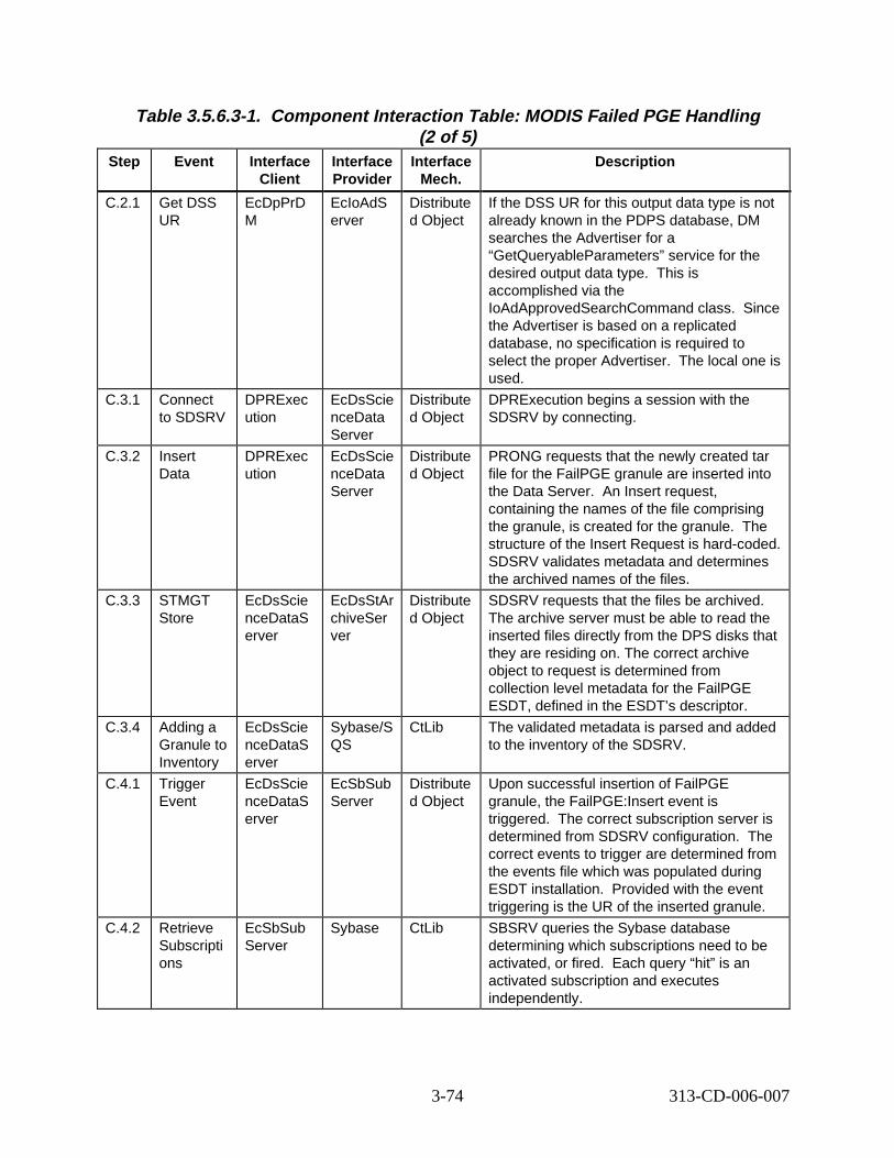
Table 3.5.6.3-1. Component Interaction Table: MODIS Failed PGE Handling (2 of 5)
Step Event Interface Client
Interface Provider
Interface Mech.
Descript ion
C.2.1 Get DSS UR
EcDpPrD M
EcIoAdS erver
Distribute d Object
If the DSS UR for this output data type is not already known in the PDPS database, DM searches the Advertiser for a “GetQueryableParameters” service for the desired output data type. is accomplished via the IoAdApprovedSearchCommand class. Since the Advertiser is based on a replicated database, no specification is required to select the proper Advertiser. al one is used.
C.3.1 Connect to SDSRV
DPRExec ution
EcDsScie nceData Server
Distribute d Object
DPRExecution begins a session with the SDSRV by connecting.
C.3.2 Insert Data
DPRExec ution
EcDsScie nceData Server
Distribute d Object
PRONG requests that the newly created tar file for the FailPGE granule are inserted into the Data Server. ert request, containing the names of the file comprising the granule, is created for the granule. structure of the Insert Request is hard-coded. SDSRV validates metadata and determines the archived names of the files.
C.3.3 STMGT Store
EcDsScie nceDataS erver
EcDsStAr chiveSer ver
Distribute d Object
SDSRV requests that the files be archived. The archive server must be able to read the inserted files directly from the DPS disks that they are residing on. The correct archive object to request is determined from collection level metadata for the FailPGE ESDT, defined in the ESDT’s descriptor.
C.3.4 Adding a Granule to Inventory
EcDsScie nceDataS erver
Sybase/S QS
CtLib The validated metadata is parsed and added to the inventory of the SDSRV.
C.4.1 Trigger Event
EcDsScie nceDataS erver
EcSbSub Server
Distribute d Object
Upon successful insertion of FailPGE granule, the FailPGE:Insert event is triggered. orrect subscription server is determined from SDSRV configuration. correct events to trigger are determined from the events file which was populated during ESDT installation. ovided with the event triggering is the UR of the inserted granule.
C.4.2 Retrieve Subscripti ons
EcSbSub Server
Sybase CtLib SBSRV queries the Sybase database determining which subscriptions need to be activated, or fired. h query “hit” is an activated subscription and executes independently.
This
The loc
An Ins
The
The cThe
Pr
Eac
3-74 313-CD-006-007
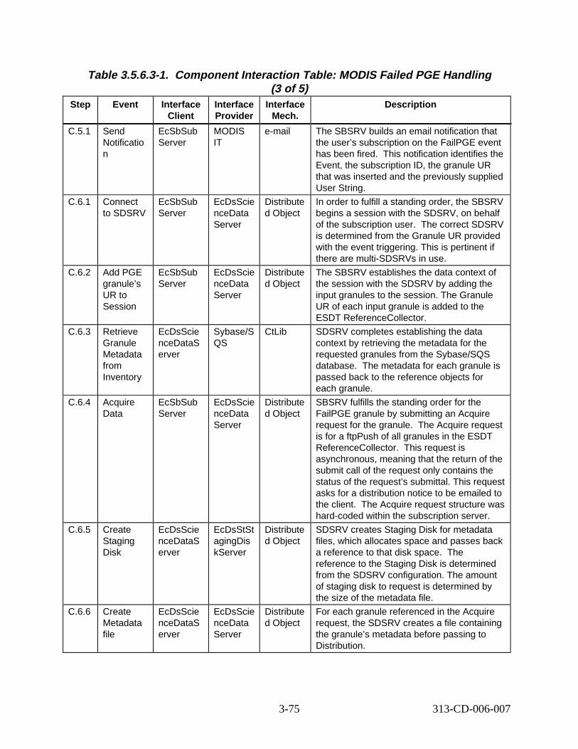
Table 3.5.6.3-1. Component Interaction Table: MODIS Failed PGE Handling (3 of 5)
Step Event Interface Client
Interface Provider
Interface Mech.
Descript ion
C.5.1 Send Notificatio n
EcSbSub Server
MODIS IT
e-mail The SBSRV builds an email notification that the user’s subscription on the FailPGE event has been fired. notification identifies the Event, the subscription ID, the granule UR that was inserted and the previously supplied User String.
C.6.1 Connect to SDSRV
EcSbSub Server
EcDsScie nceData Server
Distribute d Object
In order to fulfill a standing order, the SBSRV begins a session with the SDSRV, on behalf of the subscription user. orrect SDSRV is determined from the Granule UR provided with the event triggering. This is pertinent if there are multi-SDSRVs in use.
C.6.2 Add PGE granule’s UR to Session
EcSbSub Server
EcDsScie nceData Server
Distribute d Object
The SBSRV establishes the data context of the session with the SDSRV by adding the input granules to the session. The Granule UR of each input granule is added to the ESDT ReferenceCollector.
C.6.3 Retrieve Granule Metadata from Inventory
EcDsScie nceDataS erver
Sybase/S QS
CtLib SDSRV completes establishing the data context by retrieving the metadata for the requested granules from the Sybase/SQS database. each granule is passed back to the reference objects for each granule.
C.6.4 Acquire Data
EcSbSub Server
EcDsScie nceData Server
Distribute d Object
SBSRV fulfills the standing order for the FailPGE granule by submitting an Acquire request for the granule. quire request is for a ftpPush of all granules in the ESDT ReferenceCollector. request is asynchronous, meaning that the return of the submit call of the request only contains the status of the request’s submittal. This request asks for a distribution notice to be emailed to the client. quire request structure was hard-coded within the subscription server.
C.6.5 Create Staging Disk
EcDsScie nceDataS erver
EcDsStSt agingDis kServer
Distribute d Object
SDSRV creates Staging Disk for metadata files, which allocates space and passes back a reference to that disk space. reference to the Staging Disk is determined from the SDSRV configuration. The amount of staging disk to request is determined by the size of the metadata file.
C.6.6 Create Metadata file
EcDsScie nceDataS erver
EcDsScie nceData Server
Distribute d Object
For each granule referenced in the Acquire request, the SDSRV creates a file containing the granule’s metadata before passing to Distribution.
This
The c
The metadata for
The Ac
This
The Ac
The
3-75 313-CD-006-007
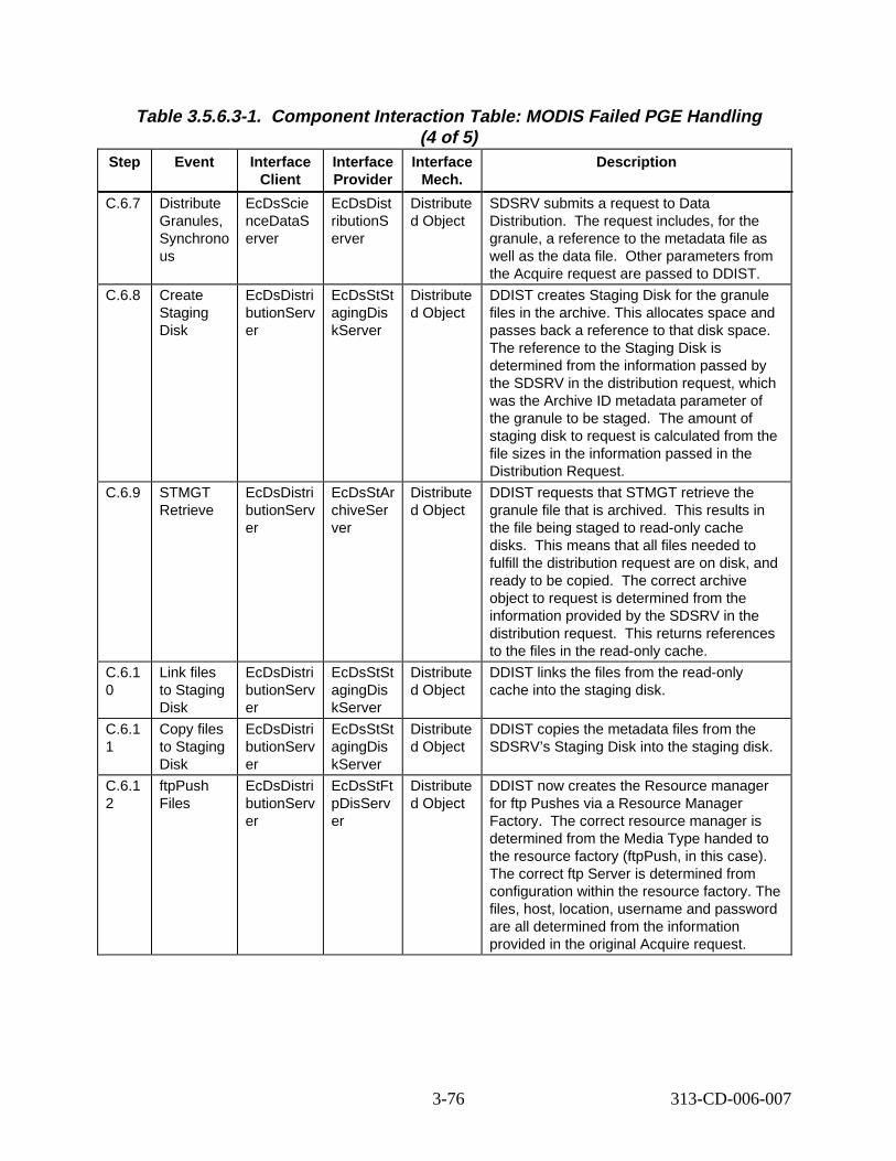
Table 3.5.6.3-1. Component Interaction Table: MODIS Failed PGE Handling (4 of 5)
Step Event Interface Client
Interface Provider
Interface Mech.
Descript ion
C.6.7 Distribute Granules, Synchrono us
EcDsScie nceDataS erver
EcDsDist ributionS erver
Distribute d Object
SDSRV submits a request to Data Distribution. equest includes, for the granule, a reference to the metadata file as well as the data file. ther parameters from the Acquire request are passed to DDIST.
C.6.8 Create Staging Disk
EcDsDistri butionServ er
EcDsStSt agingDis kServer
Distribute d Object
DDIST creates Staging Disk for the granule files in the archive. This allocates space and passes back a reference to that disk space. The reference to the Staging Disk is determined from the information passed by the SDSRV in the distribution request, which was the Archive ID metadata parameter of the granule to be staged. staging disk to request is calculated from the file sizes in the information passed in the Distribution Request.
C.6.9 STMGT Retrieve
EcDsDistri butionServ er
EcDsStAr chiveSer ver
Distribute d Object
DDIST requests that STMGT retrieve the granule file that is archived. results in the file being staged to read-only cache disks. s means that all files needed to fulfill the distribution request are on disk, and ready to be copied. orrect archive object to request is determined from the information provided by the SDSRV in the distribution request. returns references to the files in the read-only cache.
C.6.1 0
Link files to Staging Disk
EcDsDistri butionServ er
EcDsStSt agingDis kServer
Distribute d Object
DDIST links the files from the read-only cache into the staging disk.
C.6.1 1
Copy files to Staging Disk
EcDsDistri butionServ er
EcDsStSt agingDis kServer
Distribute d Object
DDIST copies the metadata files from the SDSRV’s Staging Disk into the staging disk.
C.6.1 2
ftpPush Files
EcDsDistri butionServ er
EcDsStFt pDisServ er
Distribute d Object
DDIST now creates the Resource manager for ftp Pushes via a Resource Manager Factory. The correct resource manager is determined from the Media Type handed to the resource factory (ftpPush, in this case). The correct ftp Server is determined from configuration within the resource factory. The files, host, location, username and password are all determined from the information provided in the original Acquire request.
The r
O
The amount of
This
Thi
The c
This
3-76 313-CD-006-007
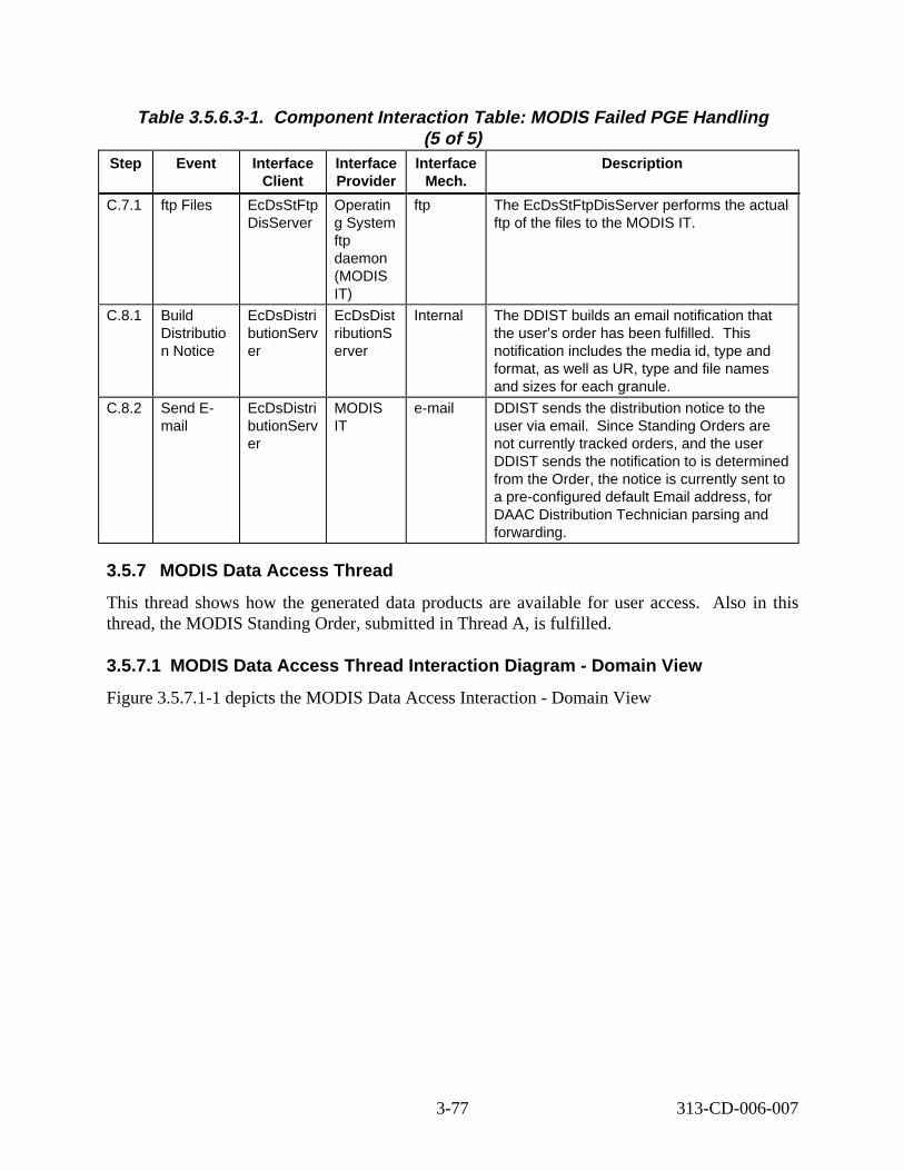
Table 3.5.6.3-1. Component Interaction Table: MODIS Failed PGE Handling (5 of 5)
Step Event Interface Client
Interface Provider
Interface Mech.
Descript ion
C.7.1 ftp Files EcDsStFtp DisServer
Operatin g System ftp daemon (MODIS IT)
ftp The EcDsStFtpDisServer performs the actual ftp of the files to the MODIS IT.
C.8.1 Build Distributio n Notice
EcDsDistri butionServ er
EcDsDist ributionS erver
Internal The DDIST builds an email notification that the user’s order has been fulfilled. his notification includes the media id, type and format, as well as UR, type and file names and sizes for each granule.
C.8.2 Send Email
EcDsDistri butionServ er
MODIS IT
e-mail DDIST sends the distribution notice to the user via email. e Standing Orders are not currently tracked orders, and the user DDIST sends the notification to is determined from the Order, the notice is currently sent to a pre-configured default Email address, for DAAC Distribution Technician parsing and forwarding.
T
Sinc
3.5.7 MODIS Data Access Thread
This thread shows how the generated data products are available for user access. Also in this thread, the MODIS Standing Order, submitted in Thread A, is fulfilled.
3.5.7.1 MODIS Data Access Thread Int eract ion D iagram - Domain View
Figure 3.5.7.1-1 depicts the MODIS Data Access Interaction - Domain View
3-77 313-CD-006-007
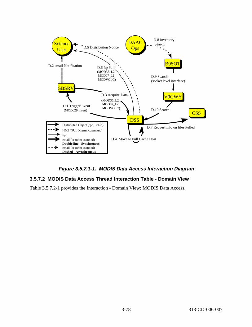
B0SOTB0SOT
GTWAYV0GWY
DSSDSS
Science User
Science User
SBSRVSBSRV
D.1 Trigger Event (MOD029:Insert)
D.2 email Notification
D.3 Acquire Data
D.6 ftp Pull (MOD35_L2 MOD07_L2 MODVOLC)
DAAC Ops
DAAC Ops
D.9 Search (socket level interface)
D.8 Inventory Search
D.10 Search CSS
D.7 Request info on files Pulled
D.4 Move to Pull Cache Host
D.5 Distribution Notice
Distributed Object (rpc, CtLib)
HMI (GUI, Xterm, command)
ftp email (or other as noted) Double line - Synchronous email (or other as noted) Dashed - Asynchronous
(MOD35_L2 MOD07_L2 MODVOLC)
Figure 3.5.7.1- 1. MODIS Data Access Int eract ion D iagram
3.5.7.2 MODIS Data Access Th read Int eract ion Table - Domain View
Table 3.5.7.2-1 provides the Interaction - Domain View: MODIS Data Access.
3-78 313-CD-006-007
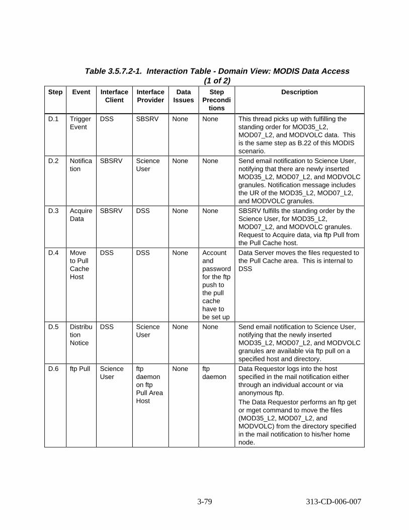
Table 3.5.7.2-1. Interact ion Table - Domain View: MODIS Data Access (1 of 2)
Step Event Interface Client
Interface Provider
Data Issues
Step Precondi
tions
Descript ion
D.1 Trigger Event
DSS SBSRV None None This thread picks up with fulfilling the standing order for MOD35_L2, MOD07_L2, and MODVOLC data. This is the same step as B.22 of this MODIS scenario.
D.2 Notifica tion
SBSRV Science User
None None Send email notification to Science User, notifying that there are newly inserted MOD35_L2, MOD07_L2, and MODVOLC granules. Notification message includes the UR of the MOD35_L2, MOD07_L2, and MODVOLC granules.
D.3 Acquire Data
SBSRV DSS None None SBSRV fulfills the standing order by the Science User, for MOD35_L2, MOD07_L2, and MODVOLC granules. Request to Acquire data, via ftp Pull from the Pull Cache host.
D.4 Move to Pull Cache Host
DSS DSS None Account and password for the ftp push to the pull cache have to be set up
Data Server moves the files requested to the Pull Cache area. This is internal to DSS
D.5 Distribu tion Notice
DSS Science User
None None Send email notification to Science User, notifying that the newly inserted MOD35_L2, MOD07_L2, and MODVOLC granules are available via ftp pull on a specified host and directory.
D.6 ftp Pull Science User
ftp daemon on ftp Pull Area Host
None ftp daemon
Data Requestor logs into the host specified in the mail notification either through an individual account or via anonymous ftp. The Data Requestor performs an ftp get or mget command to move the files (MOD35_L2, MOD07_L2, and MODVOLC) from the directory specified in the mail notification to his/her home node.
3-79 313-CD-006-007
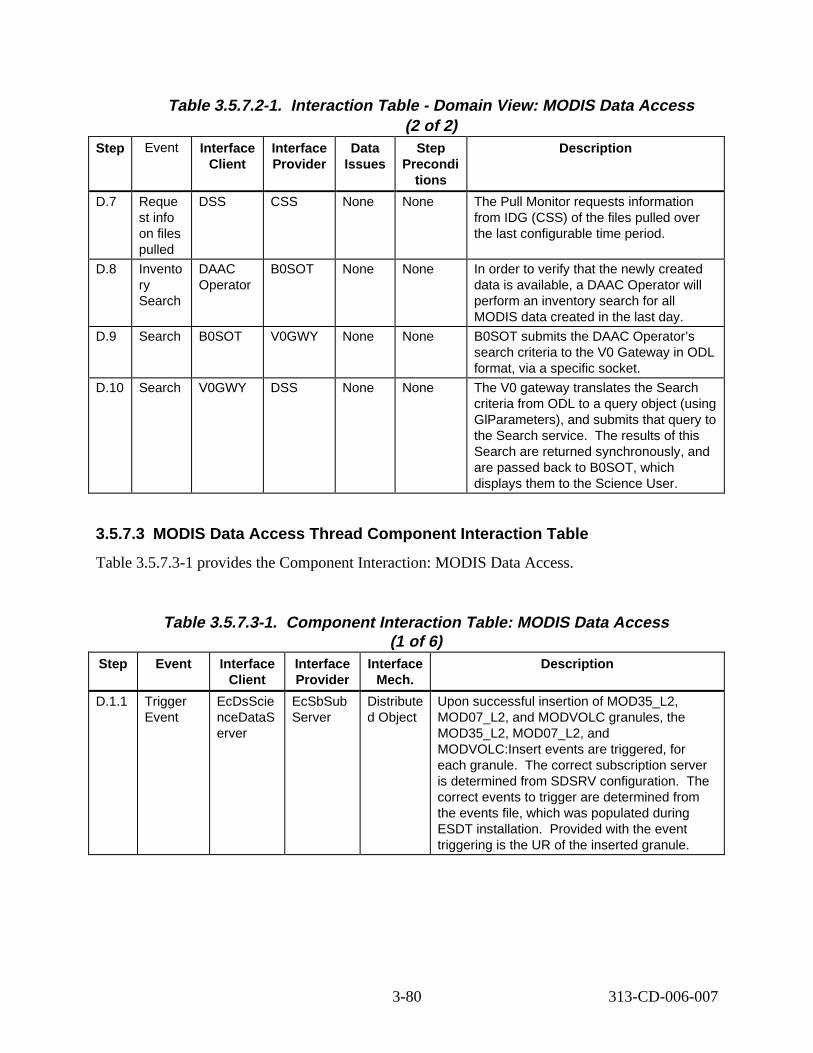
Table 3.5.7.2-1. Interact ion Table - Domain View: MODIS Data Access (2 of 2)
Step Event Interface Client
Interface Provider
Data Issues
Step Precondi
tions
Descript ion
D.7 Reque st info on files pulled
DSS CSS None None The Pull Monitor requests information from IDG (CSS) of the files pulled over the last configurable time period.
D.8 Invento ry Search
DAAC Operator
B0SOT None None In order to verify that the newly created data is available, a DAAC Operator will perform an inventory search for all MODIS data created in the last day.
D.9 Search B0SOT V0GWY None None B0SOT submits the DAAC Operator’s search criteria to the V0 Gateway in ODL format, via a specific socket.
D.10 Search V0GWY DSS None None The V0 gateway translates the Search criteria from ODL to a query object (using GlParameters), and submits that query to the Search service. The results of this Search are returned synchronously, and are passed back to B0SOT, which displays them to the Science User.
3.5.7.3 MODIS Data Access Thread Component Interaction Table
Table 3.5.7.3-1 provides the Component Interaction: MODIS Data Access.
Table 3.5.7.3-1. Component Interaction Table: MODIS Data Access (1 of 6)
Step Event Interface Client
Interface Provider
Interface Mech.
Descript ion
D.1.1 Trigger Event
EcDsScie nceDataS erver
EcSbSub Server
Distribute d Object
Upon successful insertion of MOD35_L2, MOD07_L2, and MODVOLC granules, the MOD35_L2, MOD07_L2, and MODVOLC:Insert events are triggered, for each granule. The correct subscription server is determined from SDSRV configuration. The correct events to trigger are determined from the events file, which was populated during ESDT installation. Provided with the event triggering is the UR of the inserted granule.
3-80 313-CD-006-007
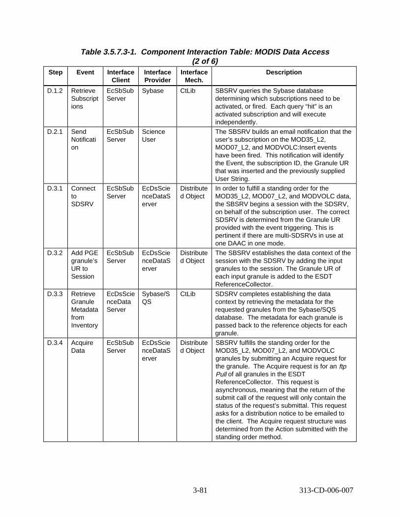
Table 3.5.7.3-1. Component Interaction Table: MODIS Data Access (2 of 6)
Step Event Interface Client
Interface Provider
Interface Mech.
Descript ion
D.1.2 Retrieve Subscript ions
EcSbSub Server
Sybase CtLib SBSRV queries the Sybase database determining which subscriptions need to be activated, or fired. Each query “hit” is an activated subscription and will execute independently.
D.2.1 Send Notificati on
EcSbSub Server
Science User
The SBSRV builds an email notification that the user’s subscription on the MOD35_L2, MOD07_L2, and MODVOLC:Insert events have been fired. This notification will identify the Event, the subscription ID, the Granule UR that was inserted and the previously supplied User String.
D.3.1 Connect to SDSRV
EcSbSub Server
EcDsScie nceDataS erver
Distribute d Object
In order to fulfill a standing order for the MOD35_L2, MOD07_L2, and MODVOLC data, the SBSRV begins a session with the SDSRV, on behalf of the subscription user. The correct SDSRV is determined from the Granule UR provided with the event triggering. This is pertinent if there are multi-SDSRVs in use at one DAAC in one mode.
D.3.2 Add PGE granule’s UR to Session
EcSbSub Server
EcDsScie nceDataS erver
Distribute d Object
The SBSRV establishes the data context of the session with the SDSRV by adding the input granules to the session. The Granule UR of each input granule is added to the ESDT ReferenceCollector.
D.3.3 Retrieve Granule Metadata from Inventory
EcDsScie nceData Server
Sybase/S QS
CtLib SDSRV completes establishing the data context by retrieving the metadata for the requested granules from the Sybase/SQS database. The metadata for each granule is passed back to the reference objects for each granule.
D.3.4 Acquire Data
EcSbSub Server
EcDsScie nceDataS erver
Distribute d Object
SBSRV fulfills the standing order for the MOD35_L2, MOD07_L2, and MODVOLC granules by submitting an Acquire request for the granule. The Acquire request is for an ftp Pull of all granules in the ESDT ReferenceCollector. This request is asynchronous, meaning that the return of the submit call of the request will only contain the status of the request’s submittal. This request asks for a distribution notice to be emailed to the client. The Acquire request structure was determined from the Action submitted with the standing order method.
3-81 313-CD-006-007
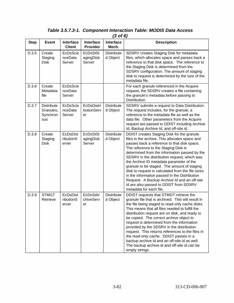
Table 3.5.7.3-1. Component Interaction Table: MODIS Data Access (3 of 6)
Step Event Interface Client
Interface Provider
Interface Mech.
Descript ion
D.3.5 Create Staging Disk
EcDsScie nceData Server
EcDsStSt agingDisk Server
Distribute d Object
SDSRV creates Staging Disk for metadata files, which allocates space and passes back a reference to that disk space. The reference to the Staging Disk is determined from the SDSRV configuration. The amount of staging disk to request is determined by the size of the metadata file.
D.3.6 Create Metadata file
EcDsScie nceData Server
For each granule referenced in the Acquire request, the SDSRV creates a file containing the granule’s metadata before passing to Distribution.
D.3.7 Distribute Granules, Synchron ous
EcDsScie nceData Server
EcDsDistri butionServ er
Distribute d Object
SDSRV submits a request to Data Distribution. The request includes, for the granule, a reference to the metadata file as well as the data file. Other parameters from the Acquire request are passed to DDIST including Archive Id, Backup Archive Id, and off-site id.
D.3.8 Create Staging Disk
EcDsDist ributionS erver
EcDsStSt agingDisk Server
Distribute d Object
DDIST creates Staging Disk for the granule files in the archive. This allocates space and passes back a reference to that disk space. The reference to the Staging Disk is determined from the information passed by the SDSRV in the distribution request, which was the Archive ID metadata parameter of the granule to be staged. The amount of staging disk to request is calculated from the file sizes in the information passed in the Distribution Request. A Backup Archive Id and an off-site id are also passed to DDIST from SDSRV metadata for each file.
D.3.9 STMGT Retrieve
EcDsDist ributionS erver
EcDsStAr chiveServ er
Distribute d Object
DDIST requests that STMGT retrieve the granule file that is archived. This will result in the file being staged to read-only cache disks. This means that all files needed to fulfill the distribution request are on disk, and ready to be copied. The correct archive object to request is determined from the information provided by the SDSRV in the distribution request. This returns references to the files in the read-only cache. DDIST passes in a backup archive id and an off-site id as well. The backup archive id and off-site id can be empty strings.
3-82 313-CD-006-007
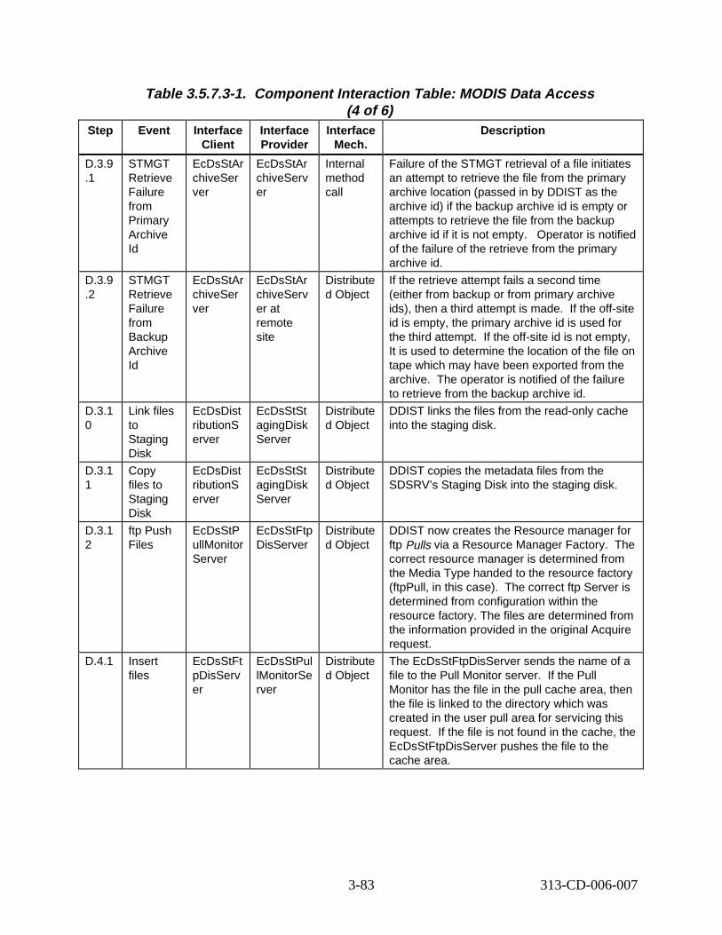
Table 3.5.7.3-1. Component Interaction Table: MODIS Data Access (4 of 6)
Step Event Interface Client
Interface Provider
Interface Mech.
Descript ion
D.3.9 .1
STMGT Retrieve Failure from Primary Archive Id
EcDsStAr chiveSer ver
EcDsStAr chiveServ er
Internal method call
Failure of the STMGT retrieval of a file initiates an attempt to retrieve the file from the primary archive location (passed in by DDIST as the archive id) if the backup archive id is empty or attempts to retrieve the file from the backup archive id if it is not empty. Operator is notified of the failure of the retrieve from the primary archive id.
D.3.9 .2
STMGT Retrieve Failure from Backup Archive Id
EcDsStAr chiveSer ver
EcDsStAr chiveServ er at remote site
Distribute d Object
If the retrieve attempt fails a second time (either from backup or from primary archive ids), then a third attempt is made. If the off-site id is empty, the primary archive id is used for the third attempt. If the off-site id is not empty, It is used to determine the location of the file on tape which may have been exported from the archive. The operator is notified of the failure to retrieve from the backup archive id.
D.3.1 0
Link files to Staging Disk
EcDsDist ributionS erver
EcDsStSt agingDisk Server
Distribute d Object
DDIST links the files from the read-only cache into the staging disk.
D.3.1 1
Copy files to Staging Disk
EcDsDist ributionS erver
EcDsStSt agingDisk Server
Distribute d Object
DDIST copies the metadata files from the SDSRV’s Staging Disk into the staging disk.
D.3.1 2
ftp Push Files
EcDsStP ullMonitor Server
EcDsStFtp DisServer
Distribute d Object
DDIST now creates the Resource manager for ftp Pulls via a Resource Manager Factory. The correct resource manager is determined from the Media Type handed to the resource factory (ftpPull, in this case). The correct ftp Server is determined from configuration within the resource factory. The files are determined from the information provided in the original Acquire request.
D.4.1 Insert files
EcDsStFt pDisServ er
EcDsStPul lMonitorSe rver
Distribute d Object
The EcDsStFtpDisServer sends the name of a file to the Pull Monitor server. If the Pull Monitor has the file in the pull cache area, then the file is linked to the directory which was created in the user pull area for servicing this request. If the file is not found in the cache, the EcDsStFtpDisServer pushes the file to the cache area.
3-83 313-CD-006-007
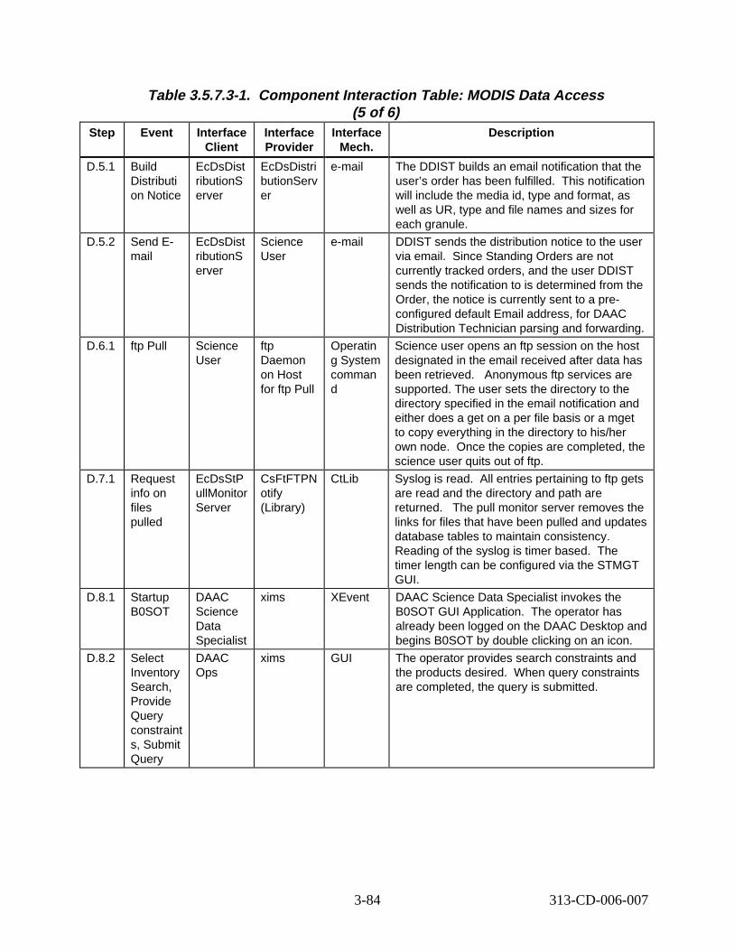
Table 3.5.7.3-1. Component Interaction Table: MODIS Data Access (5 of 6)
Step Event Interface Client
Interface Provider
Interface Mech.
Descript ion
D.5.1 Build Distributi on Notice
EcDsDist ributionS erver
EcDsDistri butionServ er
e-mail The DDIST builds an email notification that the user’s order has been fulfilled. This notification will include the media id, type and format, as well as UR, type and file names and sizes for each granule.
D.5.2 Send Email
EcDsDist ributionS erver
Science User
e-mail DDIST sends the distribution notice to the user via email. Since Standing Orders are not currently tracked orders, and the user DDIST sends the notification to is determined from the Order, the notice is currently sent to a preconfigured default Email address, for DAAC Distribution Technician parsing and forwarding.
D.6.1 ftp Pull Science User
ftp Daemon on Host for ftp Pull
Operatin g System comman d
Science user opens an ftp session on the host designated in the email received after data has been retrieved. Anonymous ftp services are supported. The user sets the directory to the directory specified in the email notification and either does a get on a per file basis or a mget to copy everything in the directory to his/her own node. Once the copies are completed, the science user quits out of ftp.
D.7.1 Request info on files pulled
EcDsStP ullMonitor Server
CsFtFTPN otify (Library)
CtLib Syslog is read. All entries pertaining to ftp gets are read and the directory and path are returned. The pull monitor server removes the links for files that have been pulled and updates database tables to maintain consistency. Reading of the syslog is timer based. The timer length can be configured via the STMGT GUI.
D.8.1 Startup B0SOT
DAAC Science Data Specialist
xims XEvent DAAC Science Data Specialist invokes the B0SOT GUI Application. The operator has already been logged on the DAAC Desktop and begins B0SOT by double clicking on an icon.
D.8.2 Select Inventory Search, Provide Query constraint s, Submit Query
DAAC Ops
xims GUI The operator provides search constraints and the products desired. When query constraints are completed, the query is submitted.
3-84 313-CD-006-007
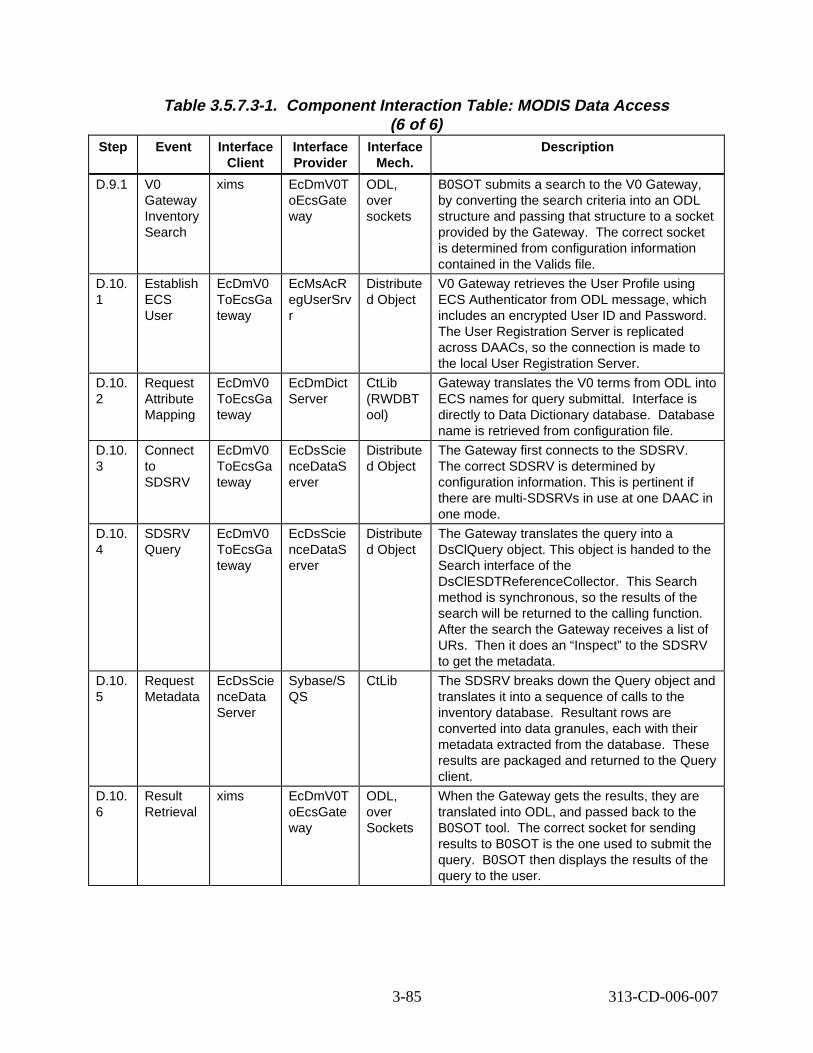
Table 3.5.7.3-1. Component Interaction Table: MODIS Data Access (6 of 6)
Step Event Interface Client
Interface Provider
Interface Mech.
Descript ion
D.9.1 V0 Gateway Inventory Search
xims EcDmV0T oEcsGate way
ODL, over sockets
B0SOT submits a search to the V0 Gateway, by converting the search criteria into an ODL structure and passing that structure to a socket provided by the Gateway. The correct socket is determined from configuration information contained in the Valids file.
D.10. 1
Establish ECS User
EcDmV0 ToEcsGa teway
EcMsAcR egUserSrv r
Distribute d Object
V0 Gateway retrieves the User Profile using ECS Authenticator from ODL message, which includes an encrypted User ID and Password. The User Registration Server is replicated across DAACs, so the connection is made to the local User Registration Server.
D.10. 2
Request Attribute Mapping
EcDmV0 ToEcsGa teway
EcDmDict Server
CtLib (RWDBT ool)
Gateway translates the V0 terms from ODL into ECS names for query submittal. Interface is directly to Data Dictionary database. Database name is retrieved from configuration file.
D.10. 3
Connect to SDSRV
EcDmV0 ToEcsGa teway
EcDsScie nceDataS erver
Distribute d Object
The Gateway first connects to the SDSRV. The correct SDSRV is determined by configuration information. This is pertinent if there are multi-SDSRVs in use at one DAAC in one mode.
D.10. 4
SDSRV Query
EcDmV0 ToEcsGa teway
EcDsScie nceDataS erver
Distribute d Object
The Gateway translates the query into a DsClQuery object. This object is handed to the Search interface of the DsClESDTReferenceCollector. This Search method is synchronous, so the results of the search will be returned to the calling function. After the search the Gateway receives a list of URs. Then it does an “Inspect” to the SDSRV to get the metadata.
D.10. 5
Request Metadata
EcDsScie nceData Server
Sybase/S QS
CtLib The SDSRV breaks down the Query object and translates it into a sequence of calls to the inventory database. Resultant rows are converted into data granules, each with their metadata extracted from the database. These results are packaged and returned to the Query client.
D.10. 6
Result Retrieval
xims EcDmV0T oEcsGate way
ODL, over Sockets
When the Gateway gets the results, they are translated into ODL, and passed back to the B0SOT tool. The correct socket for sending results to B0SOT is the one used to submit the query. B0SOT then displays the results of the query to the user.
3-85 313-CD-006-007
3.5.8 React ivat ion/R eplan
3.5.8.1 React ivat ion/R eplan D escript ion
This scenario shows the three different types of reactivation/replanning. This scenario modifies either ASTER or MODIS.
The following system functionality is exercised in this scenario:
• Ability to activate a new current plan on top of a current plan already being exercised
• Account for discrepancies in Data Processing Requests (DPRs) between those two plans
3.5.8.2 Reactivation/Replan Preconditions
Production Requests (PRs) have already been generated from the Production Request Editor. The Subscription Manager is running. The Job Management Server is running. Autosys is running. The Planning Workbench and its background processes are running.
There must be a current plan. This current plan can be either active or inactive, and either with or without Data Processing Requests. Also, ESDTs must be installed, SSI&T must be completed on the PGE, the PRs must have been entered, and the input granules must be available.
3.5.8.3 React ivat ion/R eplan Part it ions
This thread has been partitioned into the following sub-threads:
• DPR in New Plan but Not in Old Plan (Thread A) - This thread illustrates how a current active plan without DPRs can be re-planned/reactivated as a new plan with DPRs.
• DPR in Old Plan but Not in New Plan (Thread B) - This thread illustrates how a current active plan with DPRs in the queue can be re-planned/reactivated as a new plan without DPRs.
• DPR in Both Old Plan and New Plan (Thread C) - This thread illustrates how a current active plan with DPRs can be re-planned/reactivated as a new plan with those same DPRs.
3.5.8.4 DPR in New Plan but Not in Old Plan Thread This thread illustrates how a current active plan without DPRs can be re-planned/reactivated as a new plan with DPRs.
3.5.8.4.1 DPR in New Plan but Not in Old Plan Interaction Diagram - Domain View
Figure 3.5.8.4.1-1 depicts the DPR in New Plan but Not in Old Plan Interaction - Domain View.
3-86 313-CD-006-007
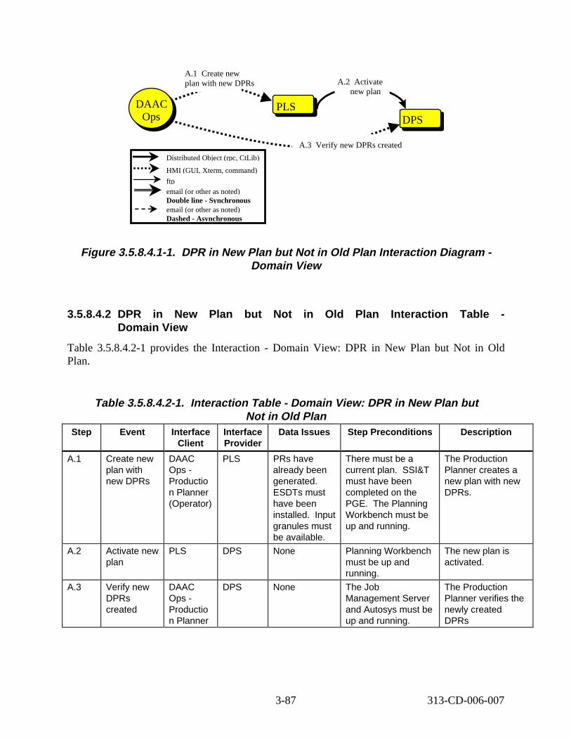
SBSRVPLSOps
DAAC Ops DPS
A.2 Activate new plan
A.3 Verify new DPRs created
A.1 Create new plan with new DPRs
Distributed Object (rpc, CtLib)
HMI (GUI, Xterm, command)
ftp email (or other as noted) Double line - Synchronous email (or other as noted) Dashed - Asynchronous
Figure 3.5.8.4.1- 1. DPR in New Plan but Not in Old Plan Int eract ion D iagram -Domain View
3.5.8.4.2 DPR in New Plan but Not in Old Plan Interact ion Table -Domain View
Table 3.5.8.4.2-1 provides the Interaction - Domain View: DPR in New Plan but Not in Old Plan.
Table 3.5.8.4.2-1. Interact ion Table - Domain View: DPR in New Plan but Not in Old Plan
Step Event Interface Client
Interface Provider
Data Issues Step Preconditions Description
A.1 Create new plan with new DPRs
DAAC Ops -Productio n Planner (Operator)
PLS PRs have already been generated. ESDTs must have been installed. Input granules must be available.
There must be a current plan. SSI&T must have been completed on the PGE. The Planning Workbench must be up and running.
The Production Planner creates a new plan with new DPRs.
A.2 Activate new plan
PLS DPS None Planning Workbench must be up and running.
The new plan is activated.
A.3 Verify new DPRs created
DAAC Ops -Productio n Planner
DPS None The Job Management Server and Autosys must be up and running.
The Production Planner verifies the newly created DPRs
3-87 313-CD-006-007
3.5.8.4.3 DPR in New Plan but Not in Old Plan Component Interaction Table
Table 3.5.8.4.3-1 provides the Component Interaction: DPR in New Plan but Not in Old Plan.
Table 3.5.8.4.3-1. Component Interaction Table: DPR in New Plan but Not in Old Plan
Step Event Interface Client
Interface Provider
Interface Mech.
Descript ion
A.1.1 Operator clicks on “new” plan button
DAAC Ops -Production Planner
EcPlWb GUI The Production Planner clicks on the new plan button. The new plan uses the new DPRs.
A.1.2 Operator enters new plan name
DAAC Ops -Production Planner
EcPlWb GUI The Production Planner enters the new plan name.
A.1.3 Operator selects the PRs to be included
DAAC Ops -Production Planner
EcPlWb GUI The Production Planner selects the PRs to be included.
A.1.4 Operator schedules PRs to activate
DAAC Ops -Production Planner
EcPlWb GUI The Production Planner schedules the PRs to activate.
A.1.5 Operator saves the new plan
DAAC Ops -Production Planner
EcPlWb GUI The Production Planner saves the new plan.
A.2.1 Activate new plan
EcPlWb EcDpPrJo bMgmt
Distributed Object
The new plan is activated and the new DPRs are ready to run.
A.3.1 Operator checks on DPS Autosys to verify state
DAAC Ops -Production Planner
Autosys GUI The Production Planner checks on the state of the job in Autosys. The new DPRs are in Autosys and begin to run.
3.5.8.5 DPR in Old Plan but Not in New Plan Thread
This thread illustrates how a current active plan with DPRs in the queue can be replanned or reactivated as a new plan without DPRs.
3.5.8.5.1 DPR in Old Plan but Not in New Plan Thread Interact ion Diagram -Domain View
Figure 3.5.8.5.1-1 depicts the DPR in Old Plan but Not in New Plan Interaction - Domain View.
3-88 313-CD-006-007
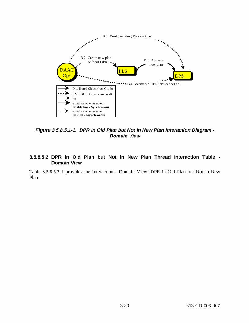
SBSRVPLS
B.2 Create new plan without DPRs
DPS Ops DAAC
Ops
B.4 Verify old DPR jobs cancelled
B.1 Verify existing DPRs active
B.3 ctivate new plan
Distributed Object (rpc, CtLib)
HMI (GUI, Xterm, command)
ftp email (or other as noted) Double line - Synchronous email (or other as noted) Dashed - Asynchronous
A
Figure 3.5.8.5.1- 1. DPR in Old Plan but Not in New Plan Int eract ion D iagram -Domain View
3.5.8.5.2 DPR in Old Plan but Not in New Plan Thread Int eract ion Table -Domain View
Table 3.5.8.5.2-1 provides the Interaction - Domain View: DPR in Old Plan but Not in New Plan.
3-89 313-CD-006-007
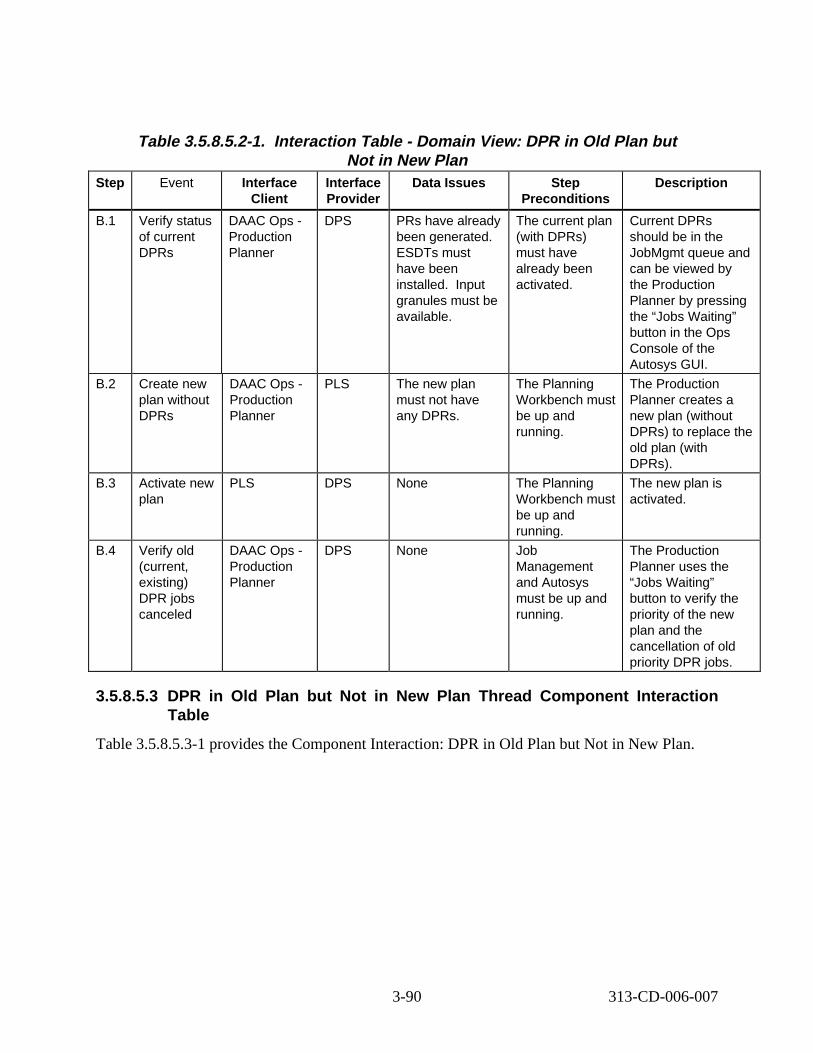
Table 3.5.8.5.2-1. Interact ion Table - Domain View: DPR in Old Plan but Not in New Plan
Step Event Interface Client
Interface Provider
Data Issues Step Preconditions
Descript ion
B.1 Verify status of current DPRs
DAAC Ops -Production Planner
DPS PRs have already been generated. ESDTs must have been installed. Input granules must be available.
The current plan (with DPRs) must have already been activated.
Current DPRs should be in the JobMgmt queue and can be viewed by the Production Planner by pressing the “Jobs Waiting” button in the Ops Console of the Autosys GUI.
B.2 Create new plan without DPRs
DAAC Ops -Production Planner
PLS The new plan must not have any DPRs.
The Planning Workbench must be up and running.
The Production Planner creates a new plan (without DPRs) to replace the old plan (with DPRs).
B.3 Activate new plan
PLS DPS None The Planning Workbench must be up and running.
The new plan is activated.
B.4 Verify old (current, existing) DPR jobs canceled
DAAC Ops -Production Planner
DPS None Job Management and Autosys must be up and running.
The Production Planner uses the “Jobs Waiting” button to verify the priority of the new plan and the cancellation of old priority DPR jobs.
3.5.8.5.3 DPR in Old Plan but Not in New Plan Thread Component Interaction Table
Table 3.5.8.5.3-1 provides the Component Interaction: DPR in Old Plan but Not in New Plan.
3-90 313-CD-006-007
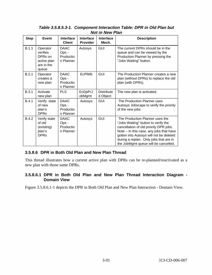
Table 3.5.8.5.3-1. Component Interaction Table: DPR in Old Plan but Not in New Plan
Step Event Interface Client
Interface Provider
Interface Mech.
Descript ion
B.1.1 Operator verifies DPRs on active plan are in the queue
DAAC Ops -Productio n Planner
Autosys GUI The current DPRs should be in the queue and can be viewed by the Production Planner by pressing the “Jobs Waiting” button.
B.2.1 Operator creates a new plan
DAAC Ops -Productio n Planner
EcPlWb GUI The Production Planner creates a new plan (without DPRs) to replace the old plan (with DPRs).
B.3.1 Activate new plan
PLS EcDpPrJ obMgmt
Distribute d Object
The new plan is activated.
B.4.1 Verify state of new plan’s DPRs
DAAC Ops -Productio n Planner
Autosys GUI The Production Planner uses Autosys Jobscape to verify the priority of the new jobs.
B.4.2 Verify state of old (existing) plan’s DPRs
DAAC Ops -Productio n Planner
Autosys GUI The Production Planner uses the “Jobs Waiting” button to verify the cancellation of old priority DPR jobs. Note – In this case, any jobs that have gotten into Autosys will not be deleted during a replan. Only jobs that are in the JobMgmt queue will be cancelled.
3.5.8.6 DPR in Both Old Plan and New Plan Thread
This thread illustrates how a current active plan with DPRs can be re-planned/reactivated as a new plan with those same DPRs.
3.5.8.6.1 DPR in Both Old Plan and N ew Plan Thread Int eract ion D iagram -Domain View
Figure 3.5.8.6.1-1 depicts the DPR in Both Old Plan and New Plan Interaction - Domain View.
3-91 313-CD-006-007
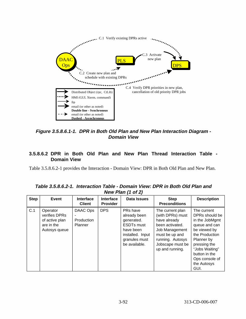
SBSRVPLS DPS Ops
DAAC Ops
C.1 Verify existing DPRs active
C.2 Create new plan and schedule with existing DPRs
C.3 ctivate new plan A
Distributed Object (rpc, CtLib)
HMI (GUI, Xterm, command)
ftp email (or other as noted) Double line - Synchronous email (or other as noted) Dashed - Asynchronous
C.4 Verify DPR priorities in new plan, cancellation of old priority DPR jobs
Figure 3.5.8.6.1- 1. DPR in B oth Old Plan and N ew Plan Int eract ion D iagram -Domain View
3.5.8.6.2 DPR in B oth Old Plan and N ew Plan Thread Interact ion Table -Domain View
Table 3.5.8.6.2-1 provides the Interaction - Domain View: DPR in Both Old Plan and New Plan.
Table 3.5.8.6.2-1. Interact ion Table - Domain View: DPR in B oth Old Plan and New Plan (1 of 2)
Step Event Interface Client
Interface Provider
Data Issues Step Preconditions
Descript ion
C.1 Operator verifies DPRs of active plan are in the Autosys queue
DAAC Ops -Production Planner
DPS PRs have already been generated. ESDTs must have been installed. Input granules must be available.
The current plan (with DPRs) must have already been activated. Job Management must be up and running. Autosys Jobscape must be up and running.
The current DPRs should be in the JobMgmt queue and can be viewed by the Production Planner by pressing the “Jobs Waiting” button in the Ops console of the Autosys GUI.
3-92 313-CD-006-007
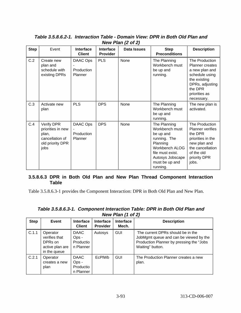
Table 3.5.8.6.2-1. Interact ion Table - Domain View: DPR in B oth Old Plan and New Plan (2 of 2)
Step Event Interface Client
Interface Provider
Data Issues Step Preconditions
Descript ion
C.2 Create new plan and schedule with existing DPRs
DAAC Ops -Production Planner
PLS None The Planning Workbench must be up and running.
The Production Planner creates a new plan and schedule using the existing DPRs, adjusting the DPR priorities as necessary.
C.3 Activate new plan
PLS DPS None The Planning Workbench must be up and running.
The new plan is activated.
C.4 Verify DPR priorities in new plan, cancellation of old priority DPR jobs
DAAC Ops -Production Planner
DPS None The Planning Workbench must be up and running. The Planning Workbench ALOG file must exist. Autosys Jobscape must be up and running.
The Production Planner verifies the DPR priorities in the new plan and the cancellation of the old priority DPR jobs.
3.5.8.6.3 DPR in Both Old Plan and New Plan Thread Component Interaction Table
Table 3.5.8.6.3-1 provides the Component Interaction: DPR in Both Old Plan and New Plan.
Table 3.5.8.6.3-1. Component Interaction Table: DPR in Both Old Plan and New Plan (1 of 2)
Step Event Interface Client
Interface Provider
Interface Mech.
Descript ion
C.1.1 Operator verifies that DPRs on active plan are in the queue
DAAC Ops -Productio n Planner
Autosys GUI The current DPRs should be in the JobMgmt queue and can be viewed by the Production Planner by pressing the “Jobs Waiting” button.
C.2.1 Operator creates a new plan
DAAC Ops -Productio n Planner
EcPlWb GUI The Production Planner creates a new plan.
3-93 313-CD-006-007
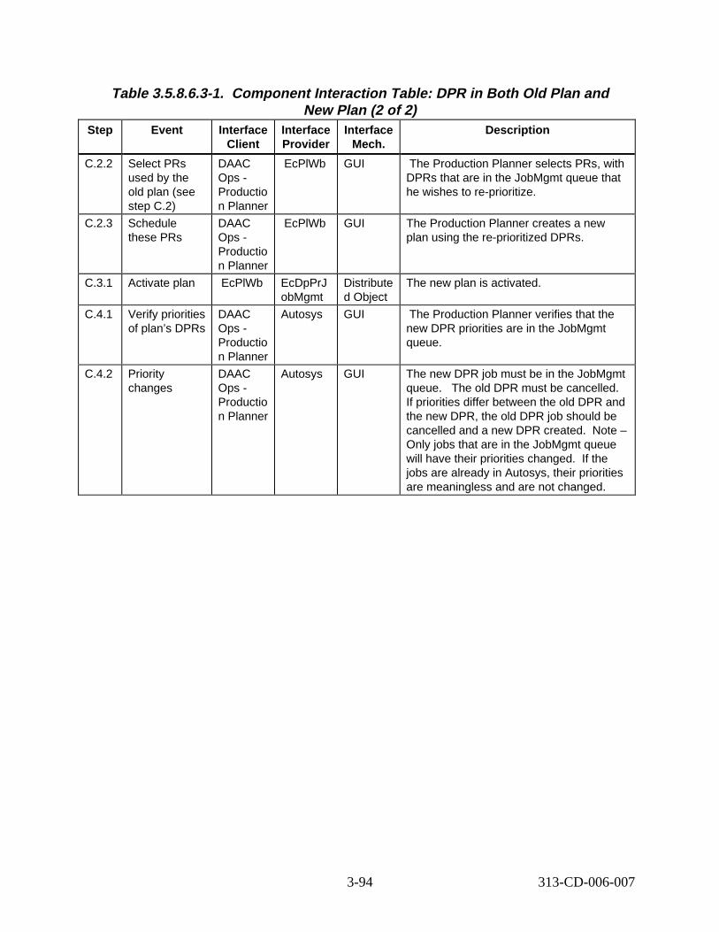
Table 3.5.8.6.3-1. Component Interaction Table: DPR in Both Old Plan and New Plan (2 of 2)
Step Event Interface Client
Interface Provider
Interface Mech.
Descript ion
C.2.2 Select PRs used by the old plan (see step C.2)
DAAC Ops -Productio n Planner
EcPlWb GUI The Production Planner selects PRs, with DPRs that are in the JobMgmt queue that he wishes to re-prioritize.
C.2.3 Schedule these PRs
DAAC Ops -Productio n Planner
EcPlWb GUI The Production Planner creates a new plan using the re-prioritized DPRs.
C.3.1 Activate plan EcPlWb EcDpPrJ obMgmt
Distribute d Object
The new plan is activated.
C.4.1 Verify priorities of plan’s DPRs
DAAC Ops -Productio n Planner
Autosys GUI The Production Planner verifies that the new DPR priorities are in the JobMgmt queue.
C.4.2 Priority changes
DAAC Ops -Productio n Planner
Autosys GUI The new DPR job must be in the JobMgmt queue. The old DPR must be cancelled. If priorities differ between the old DPR and the new DPR, the old DPR job should be cancelled and a new DPR created. Note – Only jobs that are in the JobMgmt queue will have their priorities changed. If the jobs are already in Autosys, their priorities are meaningless and are not changed.
3-94 313-CD-006-007
3.6 Landsat-7 Scenario
3.6.1 Landsat -7 Scenar io Descript ion
This scenario shows how ECS supports the archival and retrieval of Landsat-7 data. Landsat-7 data is provided to ECS from one of two primary sources: LPS and IAS. LPS provides Landsat7 L0R subinterval data and Metadata Browse to ECS. IAS provides the Landsat-7 Calibration Parameter files and Reports to ECS. The dialogue between LPS and ECS is managed by the Landsat-7 Gateway. The interface between IAS and ECS is through a standard polling mechanism managed by Ingest. The dialogue and polling mechanism are documented in the ECS-Landsat-7 ICD. ECS does not process Landsat-7 data.
There are some notable data issues related to the Landsat-7 L0R subintervals. Actually, the L0R data is produced by LPS in two independent parts, Format 1 and Format 2. While both parts are required to make a complete L0R granule, these parts are provided to ECS independent from each other. Additionally, there is no guarantee of the delivery order of the parts: Format 1 could precede or follow the delivery of its corresponding Format 2. The deliveries might be separated by delivery of parts of other granules. This requires ECS to determine if each received part’s corresponding part has already been delivered. If so, further internal processing is performed to match the parts and to create the complete L0R subinterval granule.
Another point of interest is that while LPS provides ECS with all L0R data, which is subinterval data, ECS provides access to standard WRS Scenes within the subinterval data. When LPS provides a subinterval, all WRS scene data is embedded in the subinterval and metadata is provided to derive those scenes. The current ECS approach to storing and accessing subintervals and scenes is to store all subinterval data, and to derive scenes from the subinterval when ECS users request the scenes. To support this two things occur: First when subinterval data is entered into the Data Server, references to all scenes that are available within that subinterval are also created. These scenes are “vi rtual granules”, insofar as they are referenced as granules, and are searchable, but the granule itself is not archived, per se. Rather it is created upon access. Secondly, upon access the scenes are derived from their “parent” subinterval by using internal subinterval subsetting services. Effectively, each scene knows which subinterval it is part of, and it knows what to ask its subinterval to do in order to complete creation of itself.
The following system functionality is exercised in this scenario:
• User Profile Registration
• LPS-driven data ingest
• IAS-driven data ingest
• Access to WRS Scenes
• B0SOT browse of granules
• 8mm data distribution
• Operator ability to status an order.
3-95 313-CD-006-007
3.6.2 Landsat-7 S cenar io Preconditions
The following ESDTs have been inserted into the ECS:
• L70R (Complete L7 L0R subinterval)
• L70RF1 (Format 1 of a L0R subinterval)
• L70RF2 (Format 2 of a L0R subinterval)
• L70RWRS (Complete L7 WRS Scene)
• L70RWRS1 (Format 1 part of a WRS Scene)
• L70RWRS2 (Format 2 part of a WRS Scene)
• L7CPF (Landsat-7 Calibration Parameter File)
• Browse (Generic Browse file)
• Subscription for Landsat-7 subintervals entered on behalf of Instrument Team.
• Standing order for WRS Scene, to be delivered on 8mm tape.
3.6.3 Landsat -7 Scenar io Part it ions
The Landsat-7 scenario has been partitioned into the following threads:
• L-7 User Registration (Thread A) - This thread shows the processing required for registering as a new ECS User.
• L-7 LPS Data Insertion (Thread B) - This thread shows how the ECS inserts data provided by LPS.
• L-7 Standing Order Support (Thread C) - This thread shows how the system supports standing orders for data granules.
• L-7 IAS Data Insertion (Thread D) - This thread shows how the ECS inserts data provided by IAS.
• L-7 Search and Browse (Thread E) - This thread shows how the ECS supports users searching for and browsing data holdings.
• L-7 Ordering WRS Scenes (Thread F) - This thread shows how the ECS supports user orders for WRS scenes.
• L-7 MOC Interface Thread (Thread G) – This thread shows the interface between the ECS and the MOC for Cloud Cover Assessment (CCA) data.
3.6.4 Landsat -7 User Regist ration Thread
This thread shows the processing required for registering as a new ECS User.
3-96 313-CD-006-007
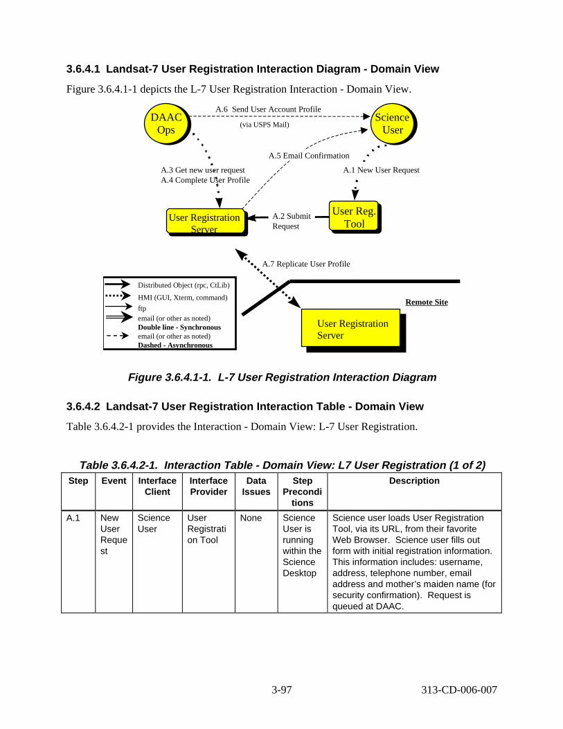
User Reg. Tool
3.6.4.1 Landsat -7 User Regist ration Int eract ion D iagram - Domain Vi ew
Figure 3.6.4.1-1 depicts the L-7 User Registration Interaction - Domain View.
DAAC Ops
DAAC Ops
A.6 nd User Account Profile
(via USPS Mail ) Science User
Science User
A.1 New User Request
A.5 Email Confirmation
Se
A.3 Get new user request A.4 Complete User Profile
User Registration A.2 Submit User Reg.
Server Request Tool
A.7 Replicate User Profi le
Distributed Object (rpc, CtLib)
HMI (GUI, Xterm, command) Remote Site
ftp email (or other as noted)Double line - Synchronous User Registrationemail (or other as noted) ServerDashed - Asynchronous
Figure 3. 6.4.1-1. L-7 User Regist rat ion Int eract ion D iagram
3.6.4.2 Landsat -7 User Regist ration Int eract ion Table - Domain Vi ew
Table 3.6.4.2-1 provides the Interaction - Domain View: L-7 User Registration.
Table 3.6.4.2-1. Interact ion Tabl e - Domain V iew: L7 User Regist rat ion (1 of 2) Step Event Interface
Client Interface Provider
Data Issues
Step Precondi
tions
Descript ion
A.1 New User Reque st
Science User
User Registrati on Tool
None Science User is running within the Science Desktop
Science user loads User Registration Tool, via its URL, from their favorite Web Browser. Science user fills out form with initial registration information. This information includes: username, address, telephone number, email address and mother’s maiden name (for security confirmation). Request is queued at DAAC.
3-97 313-CD-006-007
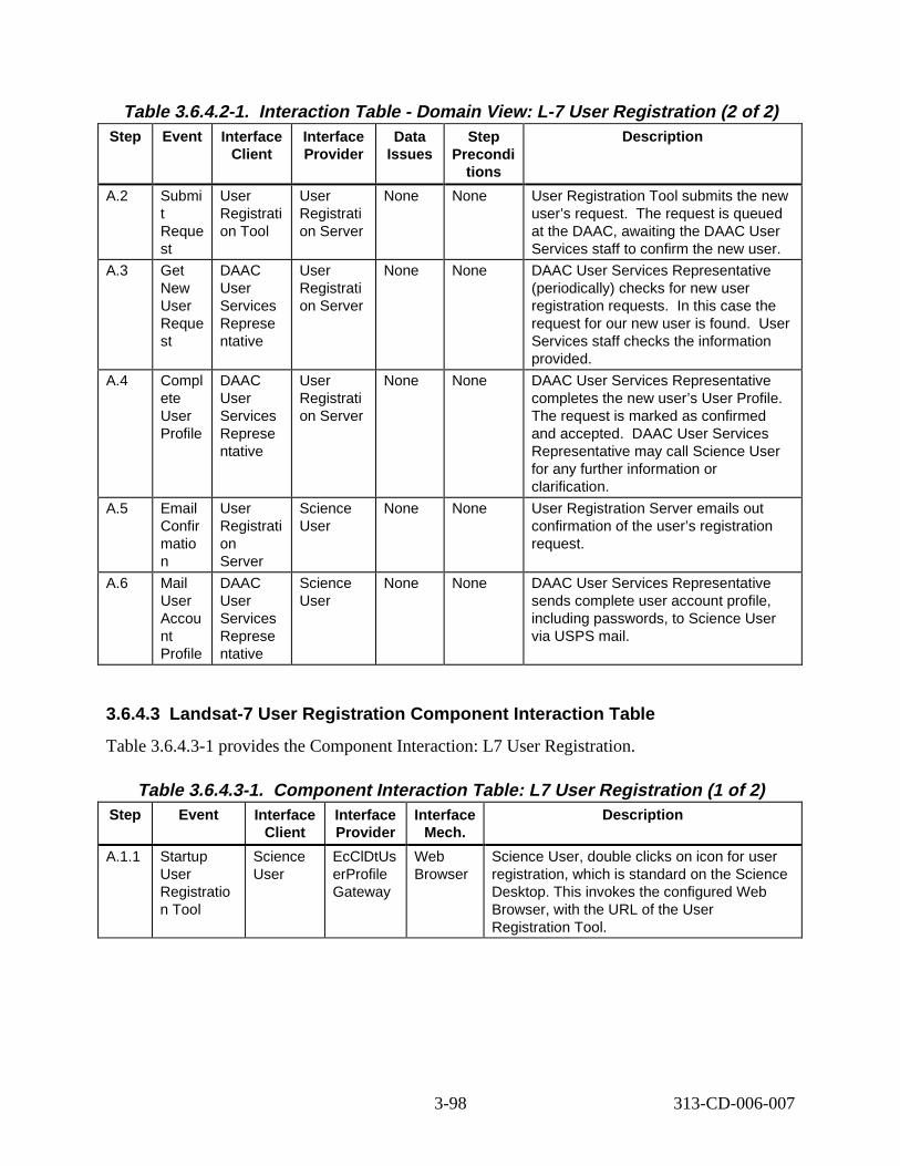
Table 3.6.4.2-1. Interact ion Tabl e - Domain V iew: L-7 User Regist rat ion (2 of 2) Step Event Interface
Client Interface Provider
Data Issues
Step Precondi
tions
Descript ion
A.2 Submi t Reque st
User Registrati on Tool
User Registrati on Server
None None User Registration Tool submits the new user’s request. The request is queued at the DAAC, awaiting the DAAC User Services staff to confirm the new user.
A.3 Get New User Reque st
DAAC User Services Represe ntative
User Registrati on Server
None None DAAC User Services Representative (periodically) checks for new user registration requests. In this case the request for our new user is found. User Services staff checks the information provided.
A.4 Compl ete User Profile
DAAC User Services Represe ntative
User Registrati on Server
None None DAAC User Services Representative completes the new user’s User Profile. The request is marked as confirmed and accepted. DAAC User Services Representative may call Science User for any further information or clarification.
A.5 Email Confir matio n
User Registrati on Server
Science User
None None User Registration Server emails out confirmation of the user’s registration request.
A.6 Mail User Accou nt Profile
DAAC User Services Represe ntative
Science User
None None DAAC User Services Representative sends complete user account profile, including passwords, to Science User via USPS mail.
3.6.4.3 Landsat-7 User Registr ation Component Interaction Tab le
Table 3.6.4.3-1 provides the Component Interaction: L7 User Registration.
Table 3.6.4.3-1. Component Interaction Table: L7 User Registration (1 of 2) Step Event Interface
Client Interface Provider
Interface Mech.
Descript ion
A.1.1 Startup User Registratio n Tool
Science User
EcClDtUs erProfile Gateway
Web Browser
Science User, double clicks on icon for user registration, which is standard on the Science Desktop. This invokes the configured Web Browser, with the URL of the User Registration Tool.
3-98 313-CD-006-007
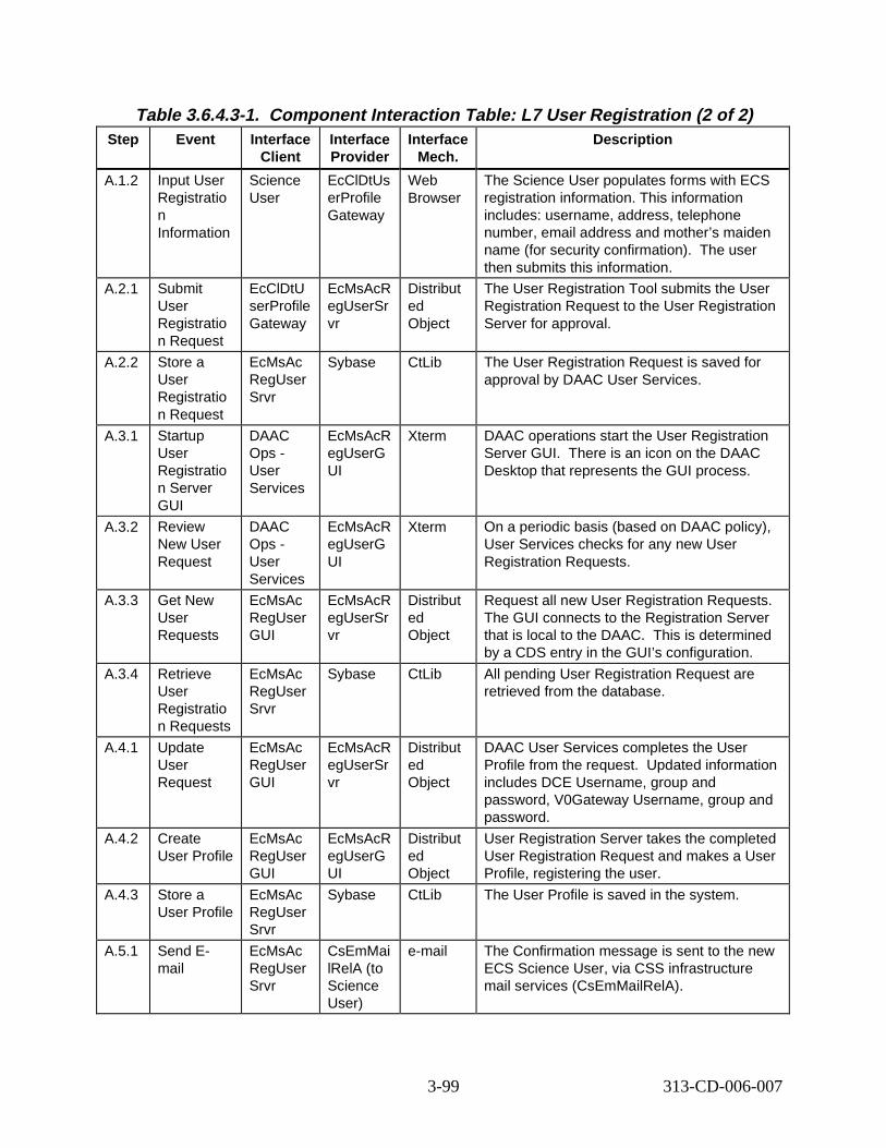
Table 3.6.4.3-1. Component Interaction Table: L7 User Registration (2 of 2) Step Event Interface
Client Interface Provider
Interface Mech.
Descript ion
A.1.2 Input User Registratio n Information
Science User
EcClDtUs erProfile Gateway
Web Browser
The Science User populates forms with ECS registration information. This information includes: username, address, telephone number, email address and mother’s maiden name (for security confirmation). The user then submits this information.
A.2.1 Submit User Registratio n Request
EcClDtU serProfile Gateway
EcMsAcR egUserSr vr
Distribut ed Object
The User Registration Tool submits the User Registration Request to the User Registration Server for approval.
A.2.2 Store a User Registratio n Request
EcMsAc RegUser Srvr
Sybase CtLib The User Registration Request is saved for approval by DAAC User Services.
A.3.1 Startup User Registratio n Server GUI
DAAC Ops -User Services
EcMsAcR egUserG UI
Xterm DAAC operations start the User Registration Server GUI. There is an icon on the DAAC Desktop that represents the GUI process.
A.3.2 Review New User Request
DAAC Ops -User Services
EcMsAcR egUserG UI
Xterm On a periodic basis (based on DAAC policy), User Services checks for any new User Registration Requests.
A.3.3 Get New User Requests
EcMsAc RegUser GUI
EcMsAcR egUserSr vr
Distribut ed Object
Request all new User Registration Requests. The GUI connects to the Registration Server that is local to the DAAC. This is determined by a CDS entry in the GUI’s configuration.
A.3.4 Retrieve User Registratio n Requests
EcMsAc RegUser Srvr
Sybase CtLib All pending User Registration Request are retrieved from the database.
A.4.1 Update User Request
EcMsAc RegUser GUI
EcMsAcR egUserSr vr
Distribut ed Object
DAAC User Services completes the User Profile from the request. Updated information includes DCE Username, group and password, V0Gateway Username, group and password.
A.4.2 Create User Profile
EcMsAc RegUser GUI
EcMsAcR egUserG UI
Distribut ed Object
User Registration Server takes the completed User Registration Request and makes a User Profile, registering the user.
A.4.3 Store a User Profile
EcMsAc RegUser Srvr
Sybase CtLib The User Profile is saved in the system.
A.5.1 Send Email
EcMsAc RegUser Srvr
CsEmMai lRelA (to Science User)
e-mail The Confirmation message is sent to the new ECS Science User, via CSS infrastructure mail services (CsEmMailRelA).
3-99 313-CD-006-007
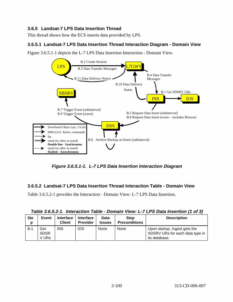
3.6.5 Landsat -7 LPS Data Insert ion Thre ad This thread shows how the ECS inserts data provided by LPS.
3.6.5.1 Landsat -7 LPS Data Insert ion Thre ad Int eract ion D iagram - Domain V iew
Figure 3.6.5.1-1 depicts the L-7 LPS Data Insertion Interaction - Domain View.
SBSRVSBSRV
LPSLPS B.2 Create Session
B.3 Data Transfer Messages L7GWYL7GWY
INSINS
DSSDSS
B.4 Data Transfer Messages
B.5 Request Data Insert (subinterval) B.8 Request Data Insert (scene – includes Browse)
B.7 Trigger Event (subinterval) B.9 Trigger Event (scene)
B.10 Data Delivery
Status
B.11 Data Delivery Notice
INSIOS
B.1 Get SDSRV URs
B.6 Archive Backup on Insert (subinterval)
Distributed Object (rpc, CtLib)
HMI (GUI, Xterm, command)
ftp email (or other as noted) Double line - Synchronous email (or other as noted) Dashed - Asynchronous
Figure 3. 6.5.1-1. L-7 LPS Data Insert ion Int eract ion D iagram
3.6.5.2 Landsat-7 LPS Data Insertion Thread Interaction Table - Domain V iew
Table 3.6.5.2-1 provides the Interaction - Domain View: L-7 LPS Data Insertion.
Table 3.6.5.2-1. Interact ion Tabl e - Domain V iew: L-7 LPS Data Insert ion ( 1 of 3) Ste
p Event Interface
Client Interface Provider
Data Issues
Step Preconditions
Descript ion
B.1 Get SDSR V URs
INS IOS None None Upon startup, Ingest gets the SDSRV URs for each data type in its database.
3-100 313-CD-006-007
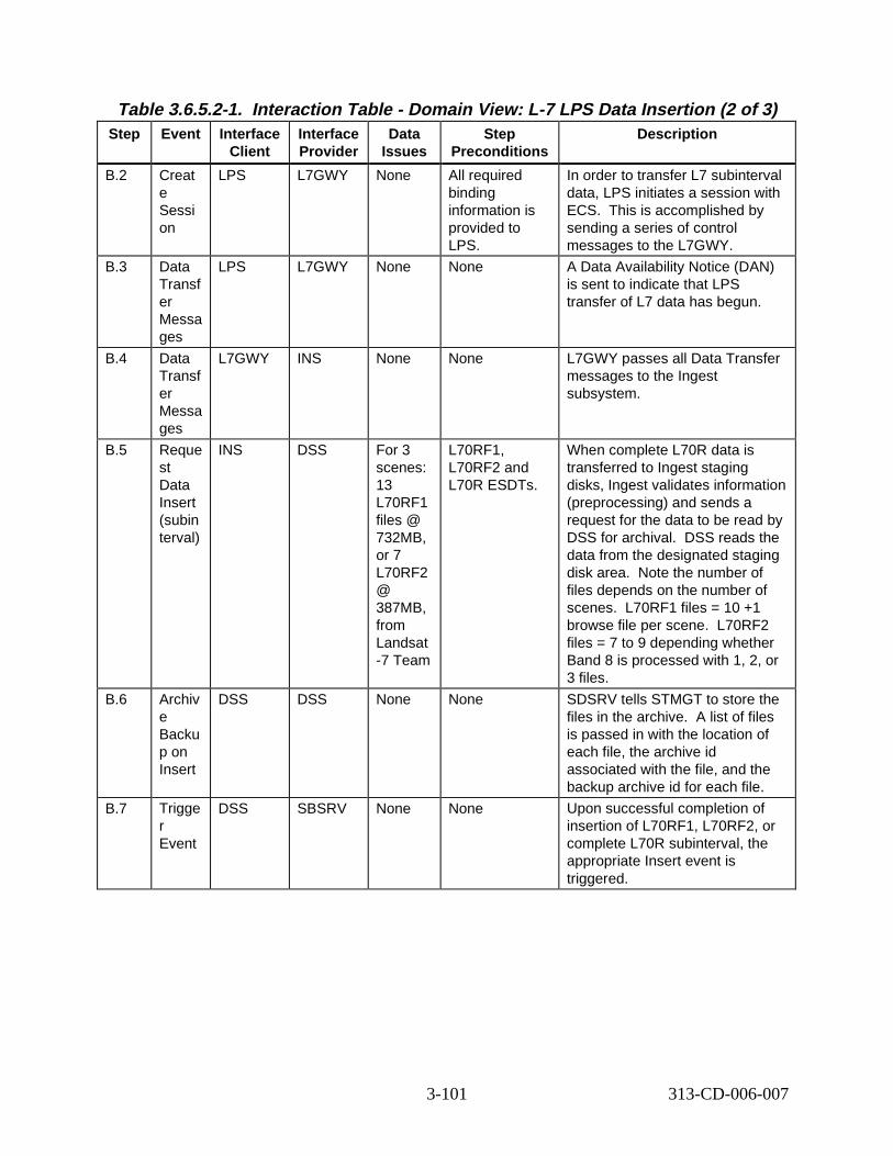
Table 3.6.5.2-1. Interact ion Tabl e - Domain V iew: L-7 LPS Data Insert ion ( 2 of 3) Step Event Interface
Client Interface Provider
Data Issues
Step Preconditions
Descript ion
B.2 Creat e Sessi on
LPS L7GWY None All required binding information is provided to LPS.
In order to transfer L7 subinterval data, LPS initiates a session with ECS. This is accomplished by sending a series of control messages to the L7GWY.
B.3 Data Transf er Messa ges
LPS L7GWY None None A Data Availability Notice (DAN) is sent to indicate that LPS transfer of L7 data has begun.
B.4 Data Transf er Messa ges
L7GWY INS None None L7GWY passes all Data Transfer messages to the Ingest subsystem.
B.5 Reque st Data Insert (subin terval)
INS DSS For 3 scenes: 13 L70RF1 files @ 732MB, or 7 L70RF2 @ 387MB, from Landsat -7 Team
L70RF1, L70RF2 and L70R ESDTs.
When complete L70R data is transferred to Ingest staging disks, Ingest validates information (preprocessing) and sends a request for the data to be read by DSS for archival. DSS reads the data from the designated staging disk area. Note the number of files depends on the number of scenes. L70RF1 files = 10 +1 browse file per scene. L70RF2 files = 7 to 9 depending whether Band 8 is processed with 1, 2, or 3 files.
B.6 Archiv e Backu p on Insert
DSS DSS None None SDSRV tells STMGT to store the files in the archive. A list of files is passed in with the location of each file, the archive id associated with the file, and the backup archive id for each file.
B.7 Trigge r Event
DSS SBSRV None None Upon successful completion of insertion of L70RF1, L70RF2, or complete L70R subinterval, the appropriate Insert event is triggered.
3-101 313-CD-006-007
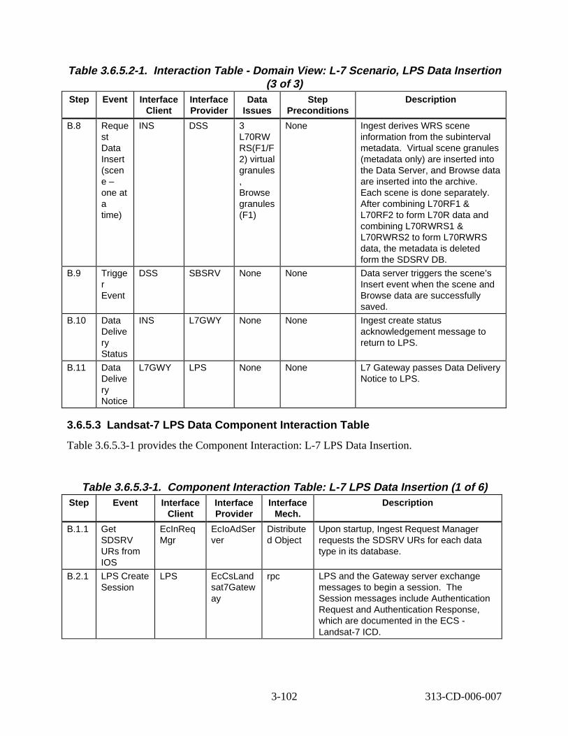
Table 3.6.5.2-1. Interact ion Tabl e - Domain V iew: L-7 Scenario, LP S Data Insert ion (3 of 3)
Step Event Interface Client
Interface Provider
Data Issues
Step Preconditions
Descript ion
B.8 Reque st Data Insert (scen e – one at a time)
INS DSS 3 L70RW RS(F1/F 2) virtual granules , Browse granules (F1)
None Ingest derives WRS scene information from the subinterval metadata. Virtual scene granules (metadata only) are inserted into the Data Server, and Browse data are inserted into the archive. Each scene is done separately. After combining L70RF1 & L70RF2 to form L70R data and combining L70RWRS1 & L70RWRS2 to form L70RWRS data, the metadata is deleted form the SDSRV DB.
B.9 Trigge r Event
DSS SBSRV None None Data server triggers the scene’s Insert event when the scene and Browse data are successfully saved.
B.10 Data Delive ry Status
INS L7GWY None None Ingest create status acknowledgement message to return to LPS.
B.11 Data Delive ry Notice
L7GWY LPS None None L7 Gateway passes Data Delivery Notice to LPS.
3.6.5.3 Landsat-7 LPS Data Component Interaction Table
Table 3.6.5.3-1 provides the Component Interaction: L-7 LPS Data Insertion.
Table 3.6.5.3-1. Component Interaction Table: L-7 L PS Data Insertion ( 1 of 6) Step Event Interface
Client Interface Provider
Interface Mech.
Descript ion
B.1.1 Get SDSRV URs from IOS
EcInReq Mgr
EcIoAdSer ver
Distribute d Object
Upon startup, Ingest Request Manager requests the SDSRV URs for each data type in its database.
B.2.1 LPS Create Session
LPS EcCsLand sat7Gatew ay
rpc LPS and the Gateway server exchange messages to begin a session. The Session messages include Authentication Request and Authentication Response, which are documented in the ECS -Landsat-7 ICD.
3-102 313-CD-006-007
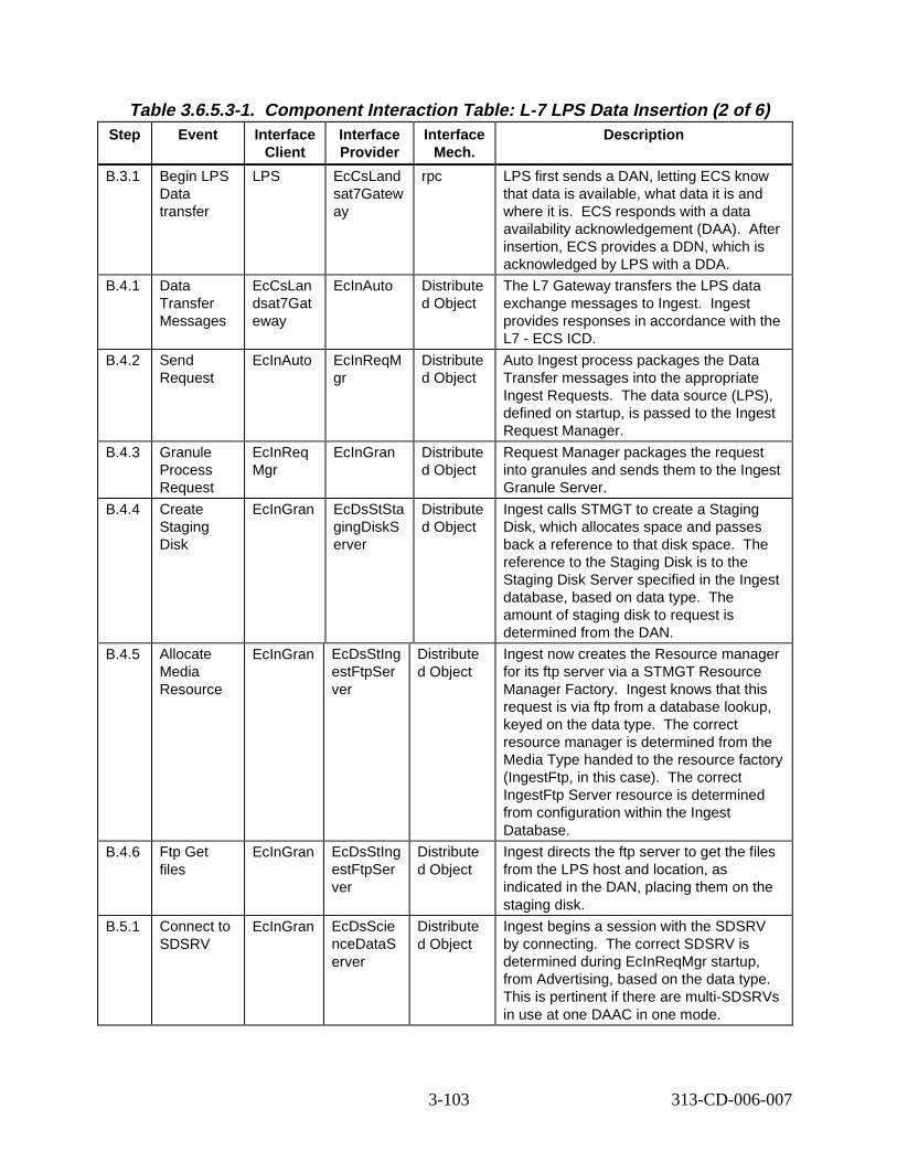
Table 3.6.5.3-1. Component Interaction Table: L-7 L PS Data Insertion ( 2 of 6) Step Event Interface
Client Interface Provider
Interface Mech.
Descript ion
B.3.1 Begin LPS Data transfer
LPS EcCsLand sat7Gatew ay
rpc LPS first sends a DAN, letting ECS know that data is available, what data it is and where it is. ECS responds with a data availability acknowledgement (DAA). After insertion, ECS provides a DDN, which is acknowledged by LPS with a DDA.
B.4.1 Data Transfer Messages
EcCsLan dsat7Gat eway
EcInAuto Distribute d Object
The L7 Gateway transfers the LPS data exchange messages to Ingest. Ingest provides responses in accordance with the L7 - ECS ICD.
B.4.2 Send Request
EcInAuto EcInReqM gr
Distribute d Object
Auto Ingest process packages the Data Transfer messages into the appropriate Ingest Requests. The data source (LPS), defined on startup, is passed to the Ingest Request Manager.
B.4.3 Granule Process Request
EcInReq Mgr
EcInGran Distribute d Object
Request Manager packages the request into granules and sends them to the Ingest Granule Server.
B.4.4 Create Staging Disk
EcInGran EcDsStSta gingDiskS erver
Distribute d Object
Ingest calls STMGT to create a Staging Disk, which allocates space and passes back a reference to that disk space. The reference to the Staging Disk is to the Staging Disk Server specified in the Ingest database, based on data type. The amount of staging disk to request is determined from the DAN.
B.4.5 Allocate Media Resource
EcInGran EcDsStIng estFtpSer ver
Distribute d Object
Ingest now creates the Resource manager for its ftp server via a STMGT Resource Manager Factory. Ingest knows that this request is via ftp from a database lookup, keyed on the data type. The correct resource manager is determined from the Media Type handed to the resource factory (IngestFtp, in this case). The correct IngestFtp Server resource is determined from configuration within the Ingest Database.
B.4.6 Ftp Get files
EcInGran EcDsStIng estFtpSer ver
Distribute d Object
Ingest directs the ftp server to get the files from the LPS host and location, as indicated in the DAN, placing them on the staging disk.
B.5.1 Connect to SDSRV
EcInGran EcDsScie nceDataS erver
Distribute d Object
Ingest begins a session with the SDSRV by connecting. The correct SDSRV is determined during EcInReqMgr startup, from Advertising, based on the data type. This is pertinent if there are multi-SDSRVs in use at one DAAC in one mode.
3-103 313-CD-006-007
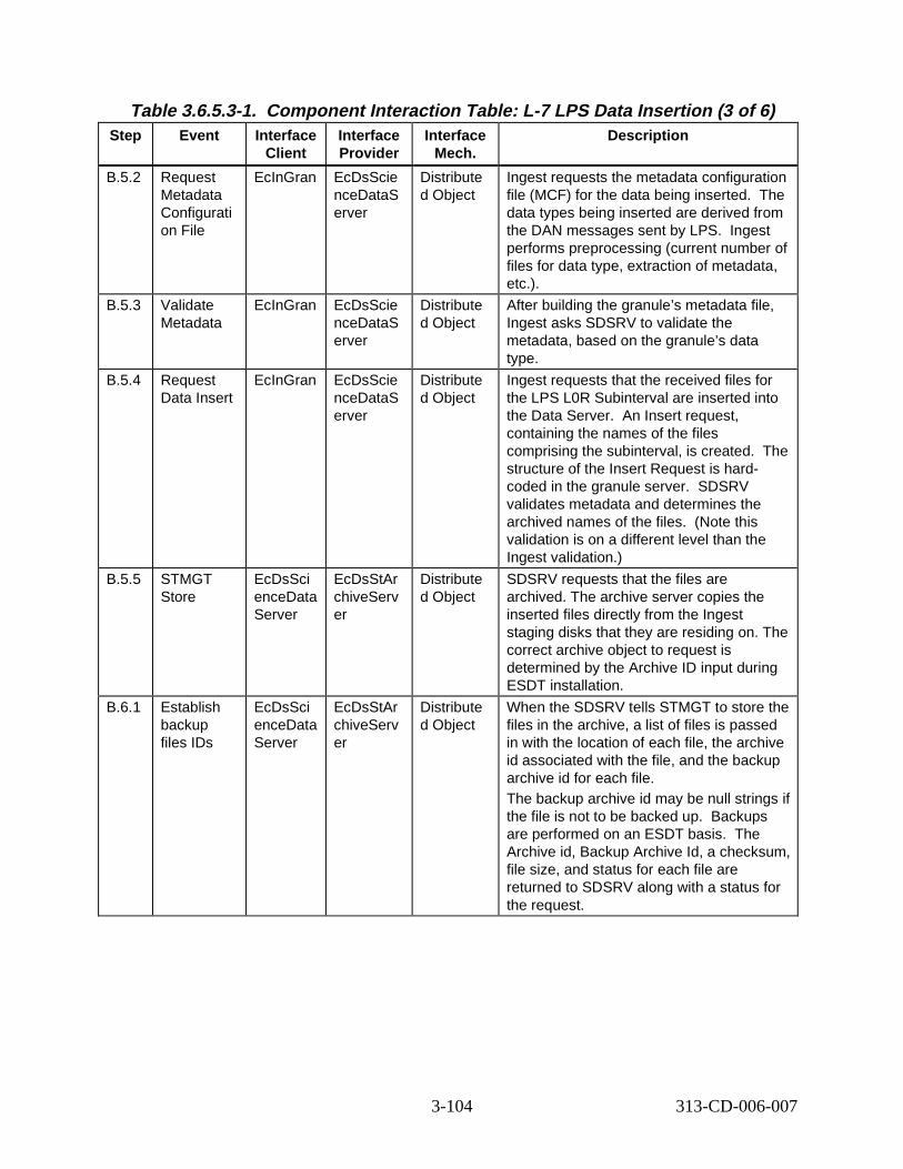
Table 3.6.5.3-1. Component Interaction Table: L-7 L PS Data Insertion ( 3 of 6) Step Event Interface
Client Interface Provider
Interface Mech.
Descript ion
B.5.2 Request Metadata Configurati on File
EcInGran EcDsScie nceDataS erver
Distribute d Object
Ingest requests the metadata configuration file (MCF) for the data being inserted. The data types being inserted are derived from the DAN messages sent by LPS. Ingest performs preprocessing (current number of files for data type, extraction of metadata, etc.).
B.5.3 Validate Metadata
EcInGran EcDsScie nceDataS erver
Distribute d Object
After building the granule’s metadata file, Ingest asks SDSRV to validate the metadata, based on the granule’s data type.
B.5.4 Request Data Insert
EcInGran EcDsScie nceDataS erver
Distribute d Object
Ingest requests that the received files for the LPS L0R Subinterval are inserted into the Data Server. An Insert request, containing the names of the files comprising the subinterval, is created. The structure of the Insert Request is hardcoded in the granule server. SDSRV validates metadata and determines the archived names of the files. (Note this validation is on a different level than the Ingest validation.)
B.5.5 STMGT Store
EcDsSci enceData Server
EcDsStAr chiveServ er
Distribute d Object
SDSRV requests that the files are archived. The archive server copies the inserted files directly from the Ingest staging disks that they are residing on. The correct archive object to request is determined by the Archive ID input during ESDT installation.
B.6.1 Establish backup files IDs
EcDsSci enceData Server
EcDsStAr chiveServ er
Distribute d Object
When the SDSRV tells STMGT to store the files in the archive, a list of files is passed in with the location of each file, the archive id associated with the file, and the backup archive id for each file. The backup archive id may be null strings if the file is not to be backed up. Backups are performed on an ESDT basis. The Archive id, Backup Archive Id, a checksum, file size, and status for each file are returned to SDSRV along with a status for the request.
3-104 313-CD-006-007
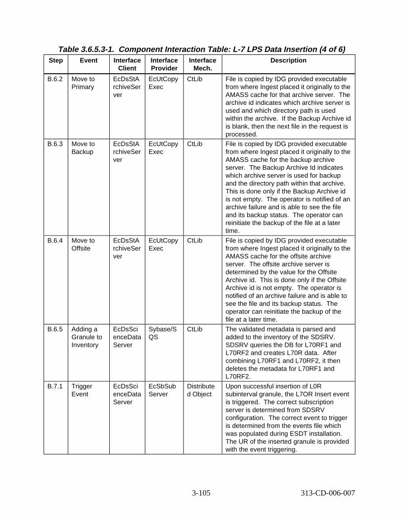
Table 3.6.5.3-1. Component Interaction Table: L-7 L PS Data Insertion ( 4 of 6) Step Event Interface
Client Interface Provider
Interface Mech.
Descript ion
B.6.2 Move to Primary
EcDsStA rchiveSer ver
EcUtCopy Exec
CtLib File is copied by IDG provided executable from where Ingest placed it originally to the AMASS cache for that archive server. The archive id indicates which archive server is used and which directory path is used within the archive. If the Backup Archive id is blank, then the next file in the request is processed.
B.6.3 Move to Backup
EcDsStA rchiveSer ver
EcUtCopy Exec
CtLib File is copied by IDG provided executable from where Ingest placed it originally to the AMASS cache for the backup archive server. The Backup Archive Id indicates which archive server is used for backup and the directory path within that archive. This is done only if the Backup Archive id is not empty. The operator is notified of an archive failure and is able to see the file and its backup status. The operator can reinitiate the backup of the file at a later time.
B.6.4 Move to Offsite
EcDsStA rchiveSer ver
EcUtCopy Exec
CtLib File is copied by IDG provided executable from where Ingest placed it originally to the AMASS cache for the offsite archive server. The offsite archive server is determined by the value for the Offsite Archive id. This is done only if the Offsite Archive id is not empty. The operator is notified of an archive failure and is able to see the file and its backup status. The operator can reinitiate the backup of the file at a later time.
B.6.5 Adding a Granule to Inventory
EcDsSci enceData Server
Sybase/S QS
CtLib The validated metadata is parsed and added to the inventory of the SDSRV. SDSRV queries the DB for L70RF1 and L70RF2 and creates L70R data. After combining L70RF1 and L70RF2, it then deletes the metadata for L70RF1 and L70RF2.
B.7.1 Trigger Event
EcDsSci enceData Server
EcSbSub Server
Distribute d Object
Upon successful insertion of L0R subinterval granule, the L7OR Insert event is triggered. The correct subscription server is determined from SDSRV configuration. The correct event to trigger is determined from the events file which was populated during ESDT installation. The UR of the inserted granule is provided with the event triggering.
3-105 313-CD-006-007
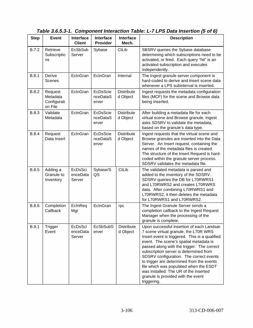
Table 3.6.5.3-1. Component Interaction Table: L-7 L PS Data Insertion ( 5 of 6) Step Event Interface
Client Interface Provider
Interface Mech.
Descript ion
B.7.2 Retrieve Subscriptio ns
EcSbSub Server
Sybase CtLib SBSRV queries the Sybase database determining which subscriptions need to be activated, or fired. Each query “hit” is an activated subscription and executes independently.
B.8.1 Derive Scenes
EcInGran EcInGran Internal The Ingest granule server component is hard-coded to derive and insert scene data whenever a LPS subinterval is inserted.
B.8.2 Request Metadata Configurati on File
EcInGran EcDsScie nceDataS erver
Distribute d Object
Ingest requests the metadata configuration files (MCF) for the scene and Browse data being inserted.
B.8.3 Validate Metadata
EcInGran EcDsScie nceDataS erver
Distribute d Object
After building a metadata file for each virtual scene and Browse granule, Ingest asks SDSRV to validate the metadata, based on the granule’s data type.
B.8.4 Request Data Insert
EcInGran EcDsScie nceDataS erver
Distribute d Object
Ingest requests that the virtual scene and Browse granules are inserted into the Data Server. An Insert request, containing the names of the metadata files is created. The structure of the Insert Request is hardcoded within the granule server process. SDSRV validates the metadata file.
B.8.5 Adding a Granule to Inventory
EcDsSci enceData Server
Sybase/S QS
CtLib The validated metadata is parsed and added to the inventory of the SDSRV. SDSRV queries the DB for L70RWRS1 and L70RWRS2 and creates L70RWRS data. After combining L70RWRS1 and L70RWRS2, it then deletes the metadata for L70RWRS1 and L70RWRS2.
B.8.6 Completion Callback
EcInReq Mgr
EcInGran rpc The Ingest Granule Server sends a completion callback to the Ingest Request Manager when the processing of the granule is complete.
B.9.1 Trigger Event
EcDsSci enceData Server
EcSbSubS erver
Distribute d Object
Upon successful insertion of each Landsat7 scene virtual granule, the L70R WRS Insert event is triggered. This is a qualified event. The scene’s spatial metadata is passed along with the trigger. The correct subscription server is determined from SDSRV configuration. The correct events to trigger are determined from the events file which was populated when the ESDT was installed. The UR of the inserted granule is provided with the event triggering.
3-106 313-CD-006-007
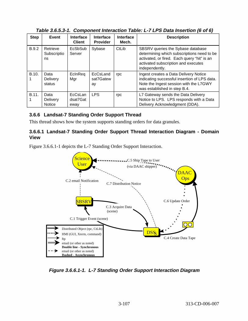
DS
Science User
SBSRV
DAAC Ops
Table 3.6.5.3-1. Component Interaction Table: L-7 L PS Data Insertion ( 6 of 6) Step Event Interface
Client Interface Provider
Interface Mech.
Descript ion
B.9.2 Retrieve Subscriptio ns
EcSbSub Server
Sybase CtLib SBSRV queries the Sybase database determining which subscriptions need to be activated, or fired. Each query “hit” is an activated subscription and executes independently.
B.10. 1
Data Delivery status
EcInReq Mgr
EcCsLand sat7Gatew ay
rpc Ingest creates a Data Delivery Notice indicating successful insertion of LPS data. Note the Ingest session with the L7GWY was established in step B.4.
B.11. 1
Data Delivery Notice
EcCsLan dsat7Gat eway
LPS rpc L7 Gateway sends the Data Delivery Notice to LPS. LPS responds with a Data Delivery Acknowledgment (DDA).
3.6.6 Landsat-7 Standing O rder Support Thread This thread shows how the system supports standing orders for data granules.
3.6.6.1 Landsat-7 Standing O rder Support Thread Interaction Diagr am - Domain View
Figure 3.6.6.1-1 depicts the L-7 Standing Order Support Interaction.
Science C.5 Ship Tape to User User (via DAAC shipper)
DAAC
C.2 email Notification Ops C.7 Distribution Notice
SBSRV C.6 Update Order
C.3 Acquire Data (scene)
C.1 Trigger Event (scene)
Distributed Object (rpc, CtLib)
HMI (GUI, Xterm, command) DSSS ftp C.4 Create Data Tape
email (or other as noted) Double line - Synchronous email (or other as noted) Dashed - Asynchronous
Figure 3. 6.6.1-1. L-7 Standing Ord er Support Interaction Diagr am
3-107 313-CD-006-007
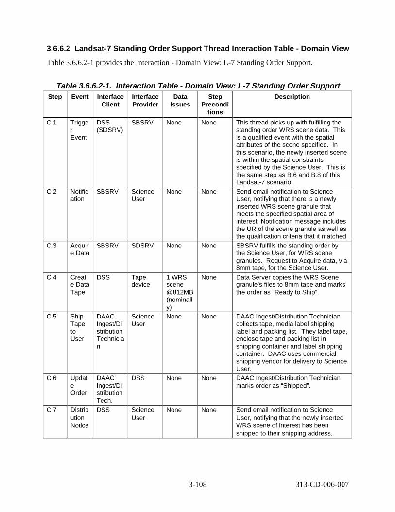
3.6.6.2 Landsat-7 Standing O rder Support Thread Interaction Tabl e - Domain V iew
Table 3.6.6.2-1 provides the Interaction - Domain View: L-7 Standing Order Support.
Table 3.6.6.2-1. Interaction Tabl e - Domain V iew: L-7 Standing Order Support Step Event Interface
Client Interface Provider
Data Issues
Step Precondi
tions
Descript ion
C.1 Trigge r Event
DSS (SDSRV)
SBSRV None None This thread picks up with fulfilling the standing order WRS scene data. This is a qualified event with the spatial attributes of the scene specified. In this scenario, the newly inserted scene is within the spatial constraints specified by the Science User. This is the same step as B.6 and B.8 of this Landsat-7 scenario.
C.2 Notific ation
SBSRV Science User
None None Send email notification to Science User, notifying that there is a newly inserted WRS scene granule that meets the specified spatial area of interest. Notification message includes the UR of the scene granule as well as the qualification criteria that it matched.
C.3 Acquir e Data
SBSRV SDSRV None None SBSRV fulfills the standing order by the Science User, for WRS scene granules. Request to Acquire data, via 8mm tape, for the Science User.
C.4 Creat e Data Tape
DSS Tape device
1 WRS scene @812MB (nominall y)
None Data Server copies the WRS Scene granule’s files to 8mm tape and marks the order as “Ready to Ship”.
C.5 Ship Tape to User
DAAC Ingest/Di stribution Technicia n
Science User
None None DAAC Ingest/Distribution Technician collects tape, media label shipping label and packing list. They label tape, enclose tape and packing list in shipping container and label shipping container. DAAC uses commercial shipping vendor for delivery to Science User.
C.6 Updat e Order
DAAC Ingest/Di stribution Tech.
DSS None None DAAC Ingest/Distribution Technician marks order as “Shipped”.
C.7 Distrib ution Notice
DSS Science User
None None Send email notification to Science User, notifying that the newly inserted WRS scene of interest has been shipped to their shipping address.
3-108 313-CD-006-007
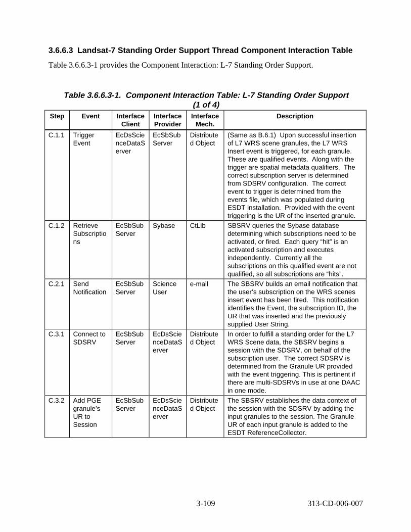
3.6.6.3 Landsat-7 Standing O rder Support Thread Component Interaction Table
Table 3.6.6.3-1 provides the Component Interaction: L-7 Standing Order Support.
Table 3.6.6.3-1. Component Interaction Table: L-7 Standing Order Support (1 of 4)
Step Event Interface Client
Interface Provider
Interface Mech.
Descript ion
C.1.1 Trigger Event
EcDsScie nceDataS erver
EcSbSub Server
Distribute d Object
(Same as B.6.1) Upon successful insertion of L7 WRS scene granules, the L7 WRS Insert event is triggered, for each granule. These are qualified events. Along with the trigger are spatial metadata qualifiers. The correct subscription server is determined from SDSRV configuration. The correct event to trigger is determined from the events file, which was populated during ESDT installation. Provided with the event triggering is the UR of the inserted granule.
C.1.2 Retrieve Subscriptio ns
EcSbSub Server
Sybase CtLib SBSRV queries the Sybase database determining which subscriptions need to be activated, or fired. Each query “hit” is an activated subscription and executes independently. Currently all the subscriptions on this qualified event are not qualified, so all subscriptions are “hits”.
C.2.1 Send Notification
EcSbSub Server
Science User
e-mail The SBSRV builds an email notification that the user’s subscription on the WRS scenes insert event has been fired. This notification identifies the Event, the subscription ID, the UR that was inserted and the previously supplied User String.
C.3.1 Connect to SDSRV
EcSbSub Server
EcDsScie nceDataS erver
Distribute d Object
In order to fulfill a standing order for the L7 WRS Scene data, the SBSRV begins a session with the SDSRV, on behalf of the subscription user. The correct SDSRV is determined from the Granule UR provided with the event triggering. This is pertinent if there are multi-SDSRVs in use at one DAAC in one mode.
C.3.2 Add PGE granule’s UR to Session
EcSbSub Server
EcDsScie nceDataS erver
Distribute d Object
The SBSRV establishes the data context of the session with the SDSRV by adding the input granules to the session. The Granule UR of each input granule is added to the ESDT ReferenceCollector.
3-109 313-CD-006-007
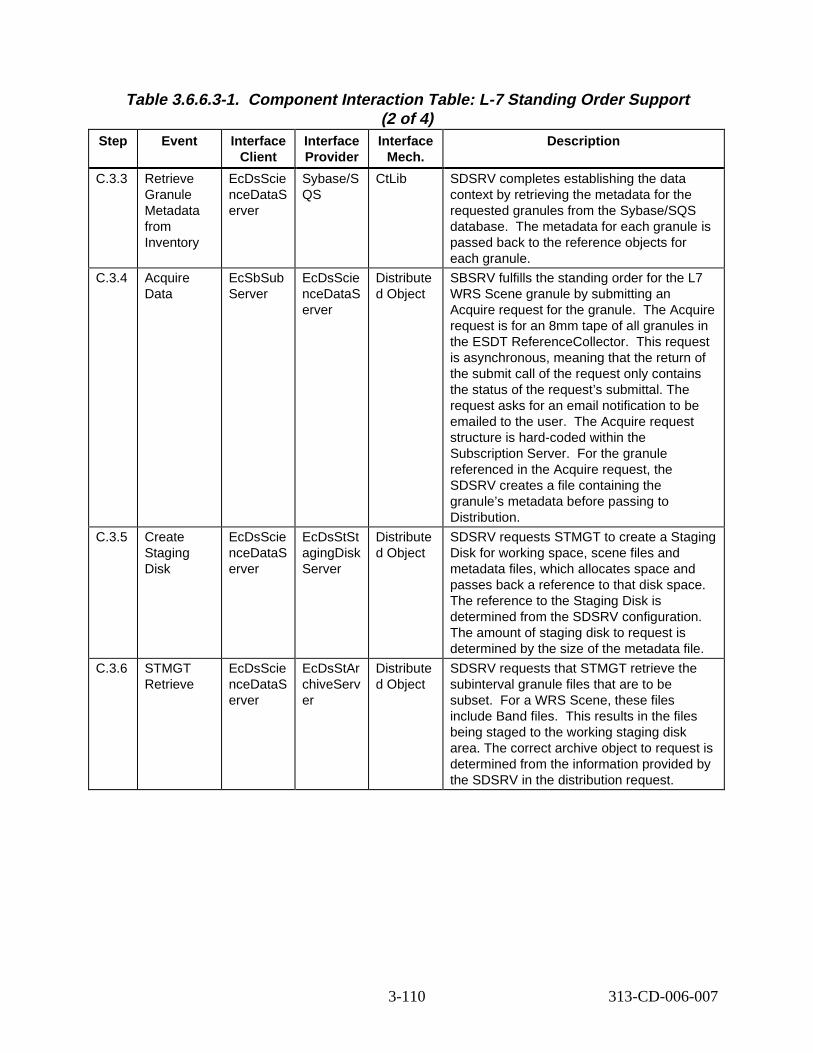
Table 3.6.6.3-1. Component Interaction Table: L-7 Standing Order Support (2 of 4)
Step Event Interface Client
Interface Provider
Interface Mech.
Descript ion
C.3.3 Retrieve Granule Metadata from Inventory
EcDsScie nceDataS erver
Sybase/S QS
CtLib SDSRV completes establishing the data context by retrieving the metadata for the requested granules from the Sybase/SQS database. The metadata for each granule is passed back to the reference objects for each granule.
C.3.4 Acquire Data
EcSbSub Server
EcDsScie nceDataS erver
Distribute d Object
SBSRV fulfills the standing order for the L7 WRS Scene granule by submitting an Acquire request for the granule. The Acquire request is for an 8mm tape of all granules in the ESDT ReferenceCollector. This request is asynchronous, meaning that the return of the submit call of the request only contains the status of the request’s submittal. The request asks for an email notification to be emailed to the user. The Acquire request structure is hard-coded within the Subscription Server. For the granule referenced in the Acquire request, the SDSRV creates a file containing the granule’s metadata before passing to Distribution.
C.3.5 Create Staging Disk
EcDsScie nceDataS erver
EcDsStSt agingDisk Server
Distribute d Object
SDSRV requests STMGT to create a Staging Disk for working space, scene files and metadata files, which allocates space and passes back a reference to that disk space. The reference to the Staging Disk is determined from the SDSRV configuration. The amount of staging disk to request is determined by the size of the metadata file.
C.3.6 STMGT Retrieve
EcDsScie nceDataS erver
EcDsStAr chiveServ er
Distribute d Object
SDSRV requests that STMGT retrieve the subinterval granule files that are to be subset. For a WRS Scene, these files include Band files. This results in the files being staged to the working staging disk area. The correct archive object to request is determined from the information provided by the SDSRV in the distribution request.
3-110 313-CD-006-007
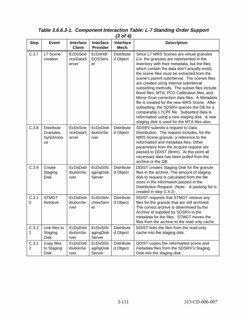
Table 3.6.6.3-1. Component Interaction Table: L-7 Standing Order Support (3 of 4)
Step Event Interface Client
Interface Provider
Interface Mech.
Descript ion
C.3.7 L7 Scene creation
EcDsScie nceDataS erver
EcDsHdf EOSServ er
Distribute d Object
Since L7 WRS Scenes are virtual granules (i.e. the granules are represented in the inventory with their metadata, but the files which contain the data don’t actually exist), the scene files must be extracted from the scene’s parent subinterval. The scenes files are created using internal subinterval subsetting methods. The subset files include Band files, MTA, PCD Calibration files, and Mirror Scan correction data files. A Metadata file is created for the new WRS Scene. After subsetting, the SDSRV queries the DB for a comparable L7CPF file. Subsetted data is reformatted using a new staging disk. A new staging disk is used for the MTA files also.
C.3.8 Distribute Granules, Synchrono us
EcDsScie nceDataS erver
EcDsDistr ibutionSe rver
Distribute d Object
SDSRV submits a request to Data Distribution. The request includes, for the WRS Scene granule, a reference to the reformatted and metadata files. Other parameters from the Acquire request are passed to DDIST (8mm). At this point all necessary data has been pulled from the archive or the DB.
C.3.9 Create Staging Disk
EcDsDistr ibutionSe rver
EcDsStSt agingDisk Server
Distribute d Object
DDIST creates Staging Disk for the granule files in the archive. The amount of staging disk to request is calculated from the file sizes in the information passed in the Distribution Request. (Note: A packing list is created in step C.4.2)
C.3.1 0
STMGT Retrieve
EcDsDistr ibutionSe rver
EcDsStAr chiveServ er
Distribute d Object
DDIST requests that STMGT retrieve any files for the granule that are still archived. The correct archive is determined by the Archive id supplied by SDSRV in the metadata for the files. STMGT moves the files from the archive to the read only cache.
C.3.1 1
Link files to Staging Disk
EcDsDistr ibutionSe rver
EcDsStSt agingDisk Server
Distribute d Object
DDIST links the files from the read-only cache into the staging disk.
C.3.1 2
Copy files to Staging Disk
EcDsDistr ibutionSe rver
EcDsStSt agingDisk Server
Distribute d Object
DDIST copies the reformatted scene and metadata files from the SDSRV’s Staging Disk into the staging disk.
3-111 313-CD-006-007
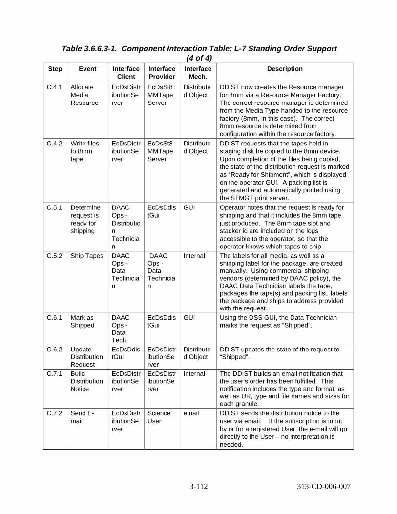
Table 3.6.6.3-1. Component Interaction Table: L-7 Standing Order Support (4 of 4)
Step Event Interface Client
Interface Provider
Interface Mech.
Descript ion
C.4.1 Allocate Media Resource
EcDsDistr ibutionSe rver
EcDsSt8 MMTape Server
Distribute d Object
DDIST now creates the Resource manager for 8mm via a Resource Manager Factory. The correct resource manager is determined from the Media Type handed to the resource factory (8mm, in this case). The correct 8mm resource is determined from configuration within the resource factory.
C.4.2 Write files to 8mm tape
EcDsDistr ibutionSe rver
EcDsSt8 MMTape Server
Distribute d Object
DDIST requests that the tapes held in staging disk be copied to the 8mm device. Upon completion of the files being copied, the state of the distribution request is marked as “Ready for Shipment”, which is displayed on the operator GUI. A packing list is generated and automatically printed using the STMGT print server.
C.5.1 Determine request is ready for shipping
DAAC Ops -Distributio n Technicia n
EcDsDdis tGui
GUI Operator notes that the request is ready for shipping and that it includes the 8mm tape just produced. The 8mm tape slot and stacker id are included on the logs accessible to the operator, so that the operator knows which tapes to ship.
C.5.2 Ship Tapes DAAC Ops -Data Technicia n
DAAC Ops -Data Technicia n
Internal The labels for all media, as well as a shipping label for the package, are created manually. Using commercial shipping vendors (determined by DAAC policy), the DAAC Data Technician labels the tape, packages the tape(s) and packing list, labels the package and ships to address provided with the request.
C.6.1 Mark as Shipped
DAAC Ops -Data Tech.
EcDsDdis tGui
GUI Using the DSS GUI, the Data Technician marks the request as “Shipped”.
C.6.2 Update Distribution Request
EcDsDdis tGui
EcDsDistr ibutionSe rver
Distribute d Object
DDIST updates the state of the request to “Shipped”.
C.7.1 Build Distribution Notice
EcDsDistr ibutionSe rver
EcDsDistr ibutionSe rver
Internal The DDIST builds an email notification that the user’s order has been fulfilled. This notification includes the type and format, as well as UR, type and file names and sizes for each granule.
C.7.2 Send Email
EcDsDistr ibutionSe rver
Science User
email DDIST sends the distribution notice to the user via email. If the subscription is input by or for a registered User, the e-mail will go directly to the User – no interpretation is needed.
3-112 313-CD-006-007
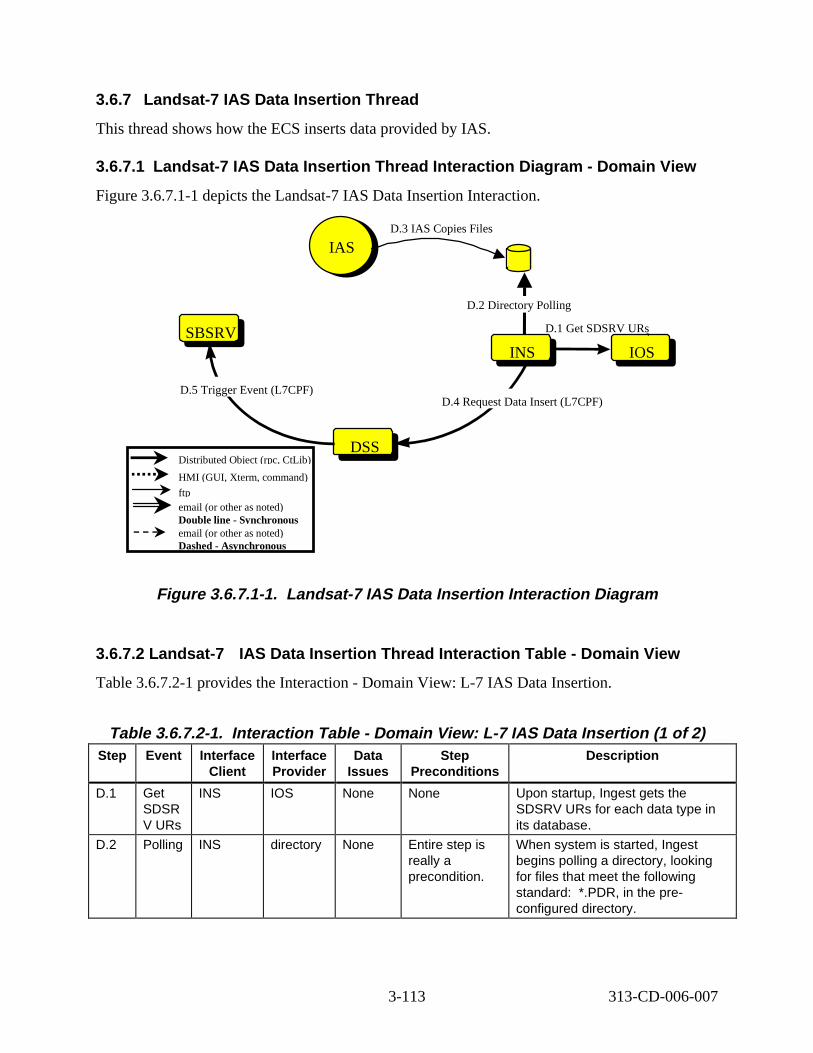
3.6.7 Landsat -7 IAS Data Insert ion Thread
This thread shows how the ECS inserts data provided by IAS.
3.6.7.1 Landsat -7 IAS Data Insert ion Thread Interact ion D iagram - Domain Vi ew
Figure 3.6.7.1-1 depicts the Landsat-7 IAS Data Insertion Interaction.
SBSRVSBSRV
IASIAS
INSINS
DSSDSS
D.3 IAS Copies Files
D.4 Request Data Insert (L7CPF) D.5 Trigger Event (L7CPF)
D.2 Directory Polling
INSIOS
D.1 Get SDSRV URs
Distributed Object (rpc, CtLib)
HMI (GUI, Xterm, command)
ftp email (or other as noted) Double line - Synchronous email (or other as noted) Dashed - Asynchronous
Figure 3. 6.7.1-1. Landsat -7 IAS Data Insert ion Int eract ion D iagram
3.6.7.2 Landsat-7 IAS Data Insertion Thread Interaction Table - Domain Vi ew
Table 3.6.7.2-1 provides the Interaction - Domain View: L-7 IAS Data Insertion.
Table 3.6.7.2-1. Interact ion Tabl e - Domain V iew: L-7 IAS Data Insert ion (1 of 2) Step Event Interface
Client Interface Provider
Data Issues
Step Preconditions
Descript ion
D.1 Get SDSR V URs
INS IOS None None Upon startup, Ingest gets the SDSRV URs for each data type in its database.
D.2 Polling INS directory None Entire step is really a precondition.
When system is started, Ingest begins polling a directory, looking for files that meet the following standard: *.PDR, in the preconfigured directory.
3-113 313-CD-006-007
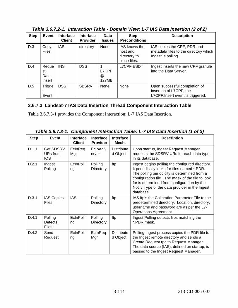
Table 3.6.7.2-1. Interact ion Tabl e - Domain Vi ew: L-7 IAS Data Insert ion (2 of 2) Step Event Interface
Client Interface Provider
Data Issues
Step Preconditions
Descript ion
D.3 Copy Files
IAS directory None IAS knows the host and directory to place files.
IAS copies the CPF, PDR and metadata files to the directory which Ingest is polling.
D.4 Reque st Data Insert
INS DSS 1 L7CPF @ 127MB
L7CPF ESDT Ingest inserts the new CPF granule into the Data Server.
D.5 Trigge r Event
DSS SBSRV None None Upon successful completion of insertion of L7CPF, the L7CPF:Insert event is triggered.
3.6.7.3 Landsat-7 IAS D ata Insertion Thread Component Interaction Tabl e
Table 3.6.7.3-1 provides the Component Interaction: L-7 IAS Data Insertion.
Table 3.6.7.3-1. Component Interaction Table: L-7 IAS Data Insertion (1 of 3) Step Event Interface
Client Interface Provider
Interface Mech.
Descript ion
D.1.1 Get SDSRV URs from IOS
EcInReq Mgr
EcIoAdS erver
Distribute d Object
Upon startup, Ingest Request Manager requests the SDSRV URs for each data type in its database.
D.2.1 Ingest Polling
EcInPolli ng
Polling Directory
ftp Ingest begins polling the configured directory. It periodically looks for files named *.PDR. The polling periodicity is determined from a configuration file. The mask of the file to look for is determined from configuration by the Notify Type of the data provider in the Ingest database.
D.3.1 IAS Copies Files
IAS Polling Directory
ftp IAS ftp’s the Calibration Parameter File to the predetermined directory. Location, directory, username and password are as per the L7-Operations Agreement.
D.4.1 Polling Detects Files
EcInPolli ng
Polling Directory
ftp Ingest Polling detects files matching the *.PDR mask.
D.4.2 Send Request
EcInPolli ng
EcInReq Mgr
Distribute d Object
Polling Ingest process copies the PDR file to the Ingest remote directory and sends a Create Request rpc to Request Manager. The data source (IAS), defined on startup, is passed to the Ingest Request Manager.
3-114 313-CD-006-007
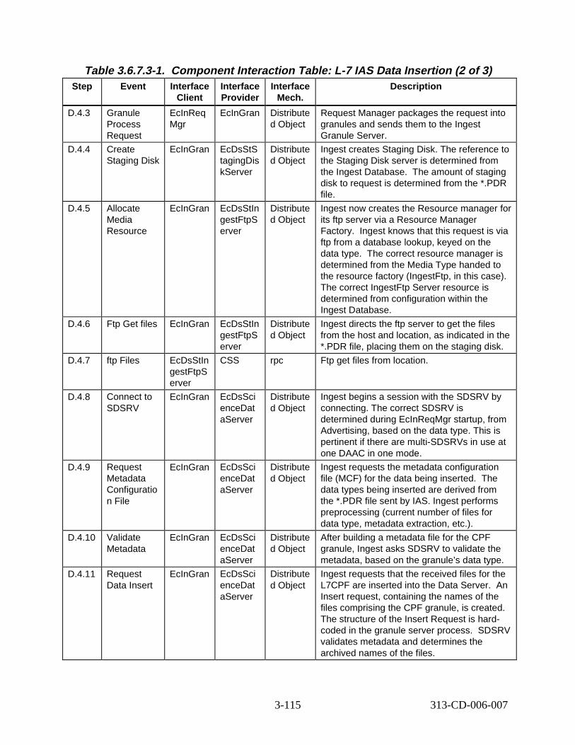
Table 3.6.7.3-1. Component Interaction Table: L-7 IAS Data Insertion (2 of 3) Step Event Interface
Client Interface Provider
Interface Mech.
Descript ion
D.4.3 Granule Process Request
EcInReq Mgr
EcInGran Distribute d Object
Request Manager packages the request into granules and sends them to the Ingest Granule Server.
D.4.4 Create Staging Disk
EcInGran EcDsStS tagingDis kServer
Distribute d Object
Ingest creates Staging Disk. The reference to the Staging Disk server is determined from the Ingest Database. The amount of staging disk to request is determined from the *.PDR file.
D.4.5 Allocate Media Resource
EcInGran EcDsStIn gestFtpS erver
Distribute d Object
Ingest now creates the Resource manager for its ftp server via a Resource Manager Factory. Ingest knows that this request is via ftp from a database lookup, keyed on the data type. The correct resource manager is determined from the Media Type handed to the resource factory (IngestFtp, in this case). The correct IngestFtp Server resource is determined from configuration within the Ingest Database.
D.4.6 Ftp Get files EcInGran EcDsStIn gestFtpS erver
Distribute d Object
Ingest directs the ftp server to get the files from the host and location, as indicated in the *.PDR file, placing them on the staging disk.
D.4.7 ftp Files EcDsStIn gestFtpS erver
CSS rpc Ftp get files from location.
D.4.8 Connect to SDSRV
EcInGran EcDsSci enceDat aServer
Distribute d Object
Ingest begins a session with the SDSRV by connecting. The correct SDSRV is determined during EcInReqMgr startup, from Advertising, based on the data type. This is pertinent if there are multi-SDSRVs in use at one DAAC in one mode.
D.4.9 Request Metadata Configuratio n File
EcInGran EcDsSci enceDat aServer
Distribute d Object
Ingest requests the metadata configuration file (MCF) for the data being inserted. The data types being inserted are derived from the *.PDR file sent by IAS. Ingest performs preprocessing (current number of files for data type, metadata extraction, etc.).
D.4.10 Validate Metadata
EcInGran EcDsSci enceDat aServer
Distribute d Object
After building a metadata file for the CPF granule, Ingest asks SDSRV to validate the metadata, based on the granule’s data type.
D.4.11 Request Data Insert
EcInGran EcDsSci enceDat aServer
Distribute d Object
Ingest requests that the received files for the L7CPF are inserted into the Data Server. An Insert request, containing the names of the files comprising the CPF granule, is created. The structure of the Insert Request is hardcoded in the granule server process. SDSRV validates metadata and determines the archived names of the files.
3-115 313-CD-006-007
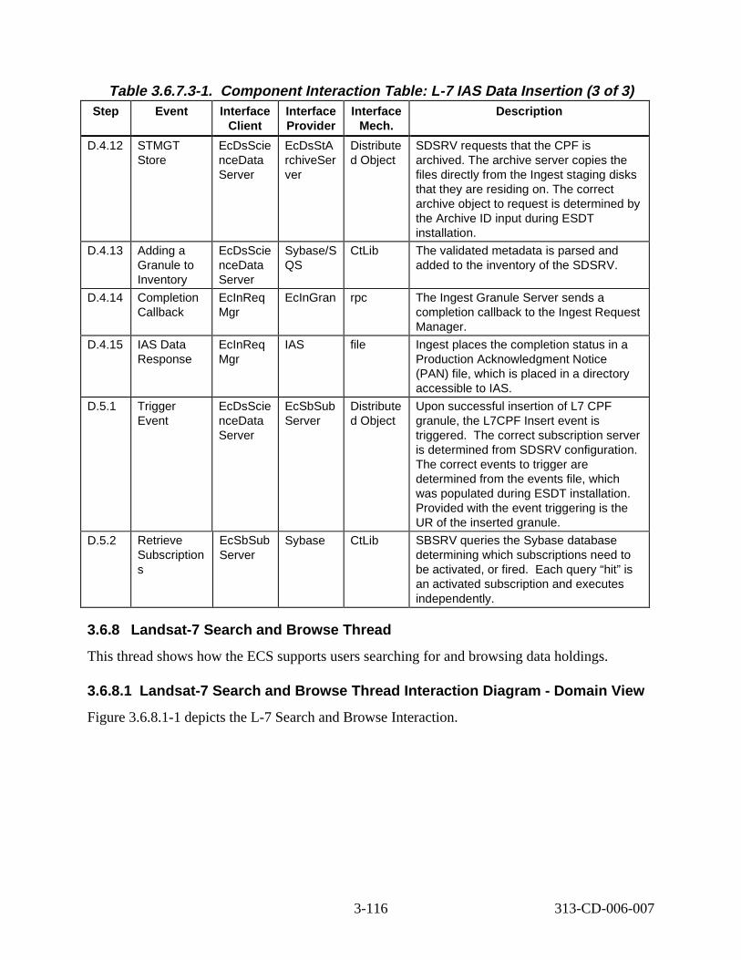
Table 3.6.7.3-1. Component Interaction Table: L-7 IAS Data Insertion (3 of 3) Step Event Interface
Client Interface Provider
Interface Mech.
Descript ion
D.4.12 STMGT Store
EcDsScie nceData Server
EcDsStA rchiveSer ver
Distribute d Object
SDSRV requests that the CPF is archived. The archive server copies the files directly from the Ingest staging disks that they are residing on. The correct archive object to request is determined by the Archive ID input during ESDT installation.
D.4.13 Adding a Granule to Inventory
EcDsScie nceData Server
Sybase/S QS
CtLib The validated metadata is parsed and added to the inventory of the SDSRV.
D.4.14 Completion Callback
EcInReq Mgr
EcInGran rpc The Ingest Granule Server sends a completion callback to the Ingest Request Manager.
D.4.15 IAS Data Response
EcInReq Mgr
IAS file Ingest places the completion status in a Production Acknowledgment Notice (PAN) file, which is placed in a directory accessible to IAS.
D.5.1 Trigger Event
EcDsScie nceData Server
EcSbSub Server
Distribute d Object
Upon successful insertion of L7 CPF granule, the L7CPF Insert event is triggered. The correct subscription server is determined from SDSRV configuration. The correct events to trigger are determined from the events file, which was populated during ESDT installation. Provided with the event triggering is the UR of the inserted granule.
D.5.2 Retrieve Subscription s
EcSbSub Server
Sybase CtLib SBSRV queries the Sybase database determining which subscriptions need to be activated, or fired. Each query “hit” is an activated subscription and executes independently.
3.6.8 Landsat -7 Search and B rows e Thread
This thread shows how the ECS supports users searching for and browsing data holdings.
3.6.8.1 Landsat -7 Search and B rows e Thread Int eract ion D iagram - Domain V iew
Figure 3.6.8.1-1 depicts the L-7 Search and Browse Interaction.
3-116 313-CD-006-007
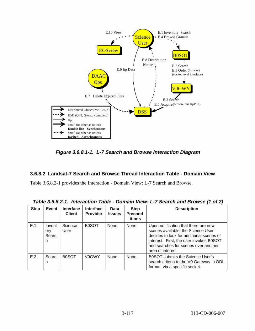
B0SOTB0SOT
GTWAYV0GWY
DSSDSS
Science User
Science User
E.2 Search E.5 Order (browse) (socket level interface)
E.1 Inventory arch E.4 Browse Granule
E.3 Search E.6 Acquire(browse, via ftpPull)
Notice
EOSviewEOSview
E.10 View
E.9 ftp Data
E.8 Distribution
DAAC Ops
DAAC Ops
E.7 Delete Expired Files
Distributed Object (rpc, CtLib)
HMI (GUI, Xterm, command)
ftp email (or other as noted) Double line - Synchronous email (or other as noted) Dashed - Asynchronous
Se
Figure 3. 6.8.1-1. L-7 Search and B rowse Interact ion D iagram
3.6.8.2 Landsat-7 S earch and Browse Thread Interaction Table - Domain V iew
Table 3.6.8.2-1 provides the Interaction - Domain View: L-7 Search and Browse.
Table 3.6.8.2-1. Interact ion Tabl e - Domain V iew: L-7 Search and B rowse (1 of 2) Step Event Interface
Client Interface Provider
Data Issues
Step Precond
itions
Descript ion
E.1 Invent ory Searc h
Science User
B0SOT None None Upon notification that there are new scenes available, the Science User decides to look for additional scenes of interest. First, the user invokes B0SOT and searches for scenes over another area of interest.
E.2 Searc h
B0SOT V0GWY None None B0SOT submits the Science User’s search criteria to the V0 Gateway in ODL format, via a specific socket.
3-117 313-CD-006-007
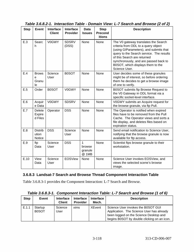
Table 3.6.8.2-1. Interact ion Tabl e - Domain V iew: L-7 Search and B rowse (2 of 2) Step Event Interface
Client Interface Provider
Data Issues
Step Precond
itions
Descript ion
E.3 Searc h
V0GWY SDSRV (DSS)
None None The V0 gateway translates the Search criteria from ODL to a query object (using GIParameters), and submits that query to the Search service. The results of this Search are returned synchronously, and are passed back to B0SOT, which displays them to the Science User.
E.4 Brows e Granu le
Science User
B0SOT None None User decides some of these granules might be of interest, so before ordering them he decides to get a browse image of one to verify.
E.5 Order B0SOT V0GWY None None B0SOT submits ftp Browse Request to the V0 Gateway in ODL format via a specific socket-level interface.
E.6 Acquir e Data
V0GWY SDSRV None None V0GWY submits an Acquire request for the browse granule, via ftp Pull.
E.7 Delete Expire d Files
Operator DSS None None The Operator is notified when expired files have to be removed from the Pull Cache. The Operator views and sorts a file display, and deletes files based on expiration status.
E.8 Distrib ution Notice
DSS Science User
None None Send email notification to Science User, notifying that the browse granule is now available for ftp access.
E.9 ftp Data
Science User
DSS 1 browse granule @ 1MB
None Scientist ftps browse granule to their workstation.
E.10 View Data
Science User
EOSView None None Science User invokes EOSView, and views the selected scene’s browse image.
3.6.8.3 Landsat-7 S earch and Browse Thread Component Interaction T able
Table 3.6.8.3-1 provides the Component Interaction: L-7 Search and Browse.
Table 3.6.8.3-1. Component Interaction Table: L-7 Search and Brow se (1 of 6) Step Event Interface
Client Interface Provider
Interface Mech.
Descript ion
E.1.1 Startup B0SOT
Science User
xims XEvent Science User invokes the B0SOT GUI Application. The Science User has already been logged on the Science Desktop and begins B0SOT by double clicking on an icon.
3-118 313-CD-006-007
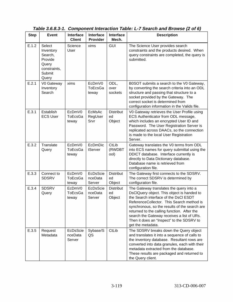
Table 3.6.8.3-1. Component Interaction Table: L-7 Search and Brow se (2 of 6) Step Event Interface
Client Interface Provider
Interface Mech.
Descript ion
E.1.2 Select Inventory Search, Provide Query constraints, Submit Query
Science User
xims GUI The Science User provides search constraints and the products desired. When query constraints are completed, the query is submitted.
E.2.1 V0 Gateway Inventory Search
xims EcDmV0 ToEcsGa teway
ODL, over sockets
B0SOT submits a search to the V0 Gateway, by converting the search criteria into an ODL structure and passing that structure to a socket provided by the Gateway. The correct socket is determined from configuration information in the Valids file.
E.3.1 Establish ECS User
EcDmV0 ToEcsGa teway
EcMsAc RegUser Srvr
Distribut ed Object
V0 Gateway retrieves the User Profile using ECS Authenticator from ODL message, which includes an encrypted User ID and Password. The User Registration Server is replicated across DAACs, so the connection is made to the local User Registration Server.
E.3.2 Translate Query
EcDmV0 ToEcsGa teway
EcDmDic tServer
CtLib (RWDBT ool)
Gateway translates the V0 terms from ODL into ECS names for query submittal using the DDICT database. Interface currently is directly to Data Dictionary database. Database name is retrieved from configuration file.
E.3.3 Connect to SDSRV
EcDmV0 ToEcsGa teway
EcDsScie nceData Server
Distribut ed Object
The Gateway first connects to the SDSRV. The correct SDSRV is determined by configuration file.
E.3.4 SDSRV Query
EcDmV0 ToEcsGa teway
EcDsScie nceData Server
Distribut ed Object
The Gateway translates the query into a DsClQuery object. This object is handed to the Search interface of the DsCl ESDT ReferenceCollector. This Search method is synchronous, so the results of the search are returned to the calling function. After the search the Gateway receives a list of URs. Then it does an “Inspect” to the SDSRV to get the metadata.
E.3.5 Request Metadata
EcDsScie nceData Server
Sybase/S QS
CtLib The SDSRV breaks down the Query object and translates it into a sequence of calls to the inventory database. Resultant rows are converted into data granules, each with their metadata extracted from the database. These results are packaged and returned to the Query client.
3-119 313-CD-006-007
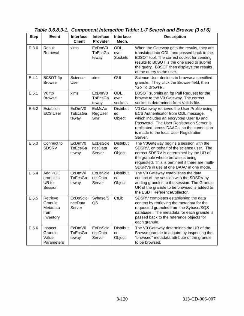
Table 3.6.8.3-1. Component Interaction Table: L-7 Search and Brow se (3 of 6) Step Event Interface
Client Interface Provider
Interface Mech.
Descript ion
E.3.6 Result Retrieval
xims EcDmV0 ToEcsGa teway
ODL, over Sockets
When the Gateway gets the results, they are translated into ODL, and passed back to the B0SOT tool. The correct socket for sending results to B0SOT is the one used to submit the query. B0SOT then displays the results of the query to the user.
E.4.1 B0SOT ftp Browse
Science User
xims GUI Science User decides to browse a specified granule. They click the Browse field, then “Go To Browse”.
E.5.1 V0 ftp Browse
xims EcDmV0 ToEcsGa teway
ODL, over sockets
B0SOT submits an ftp Pull Request for the browse to the V0 Gateway. The correct socket is determined from Valids file.
E.5.2 Establish ECS User
EcDmV0 ToEcsGa teway
EcMsAc RegUser Srvr
Distribut ed Object
V0 Gateway retrieves the User Profile using ECS Authenticator from ODL message, which includes an encrypted User ID and Password. The User Registration Server is replicated across DAACs, so the connection is made to the local User Registration Server.
E.5.3 Connect to SDSRV
EcDmV0 ToEcsGa teway
EcDsScie nceData Server
Distribut ed Object
The V0Gateway begins a session with the SDSRV, on behalf of the science user. The correct SDSRV is determined by the UR of the granule whose browse is being requested. This is pertinent if there are multi-SDSRVs in use at one DAAC in one mode.
E.5.4 Add PGE granule’s UR to Session
EcDmV0 ToEcsGa teway
EcDsScie nceData Server
Distribut ed Object
The V0 Gateway establishes the data context of the session with the SDSRV by adding granules to the session. The Granule UR of the granule to be browsed is added to the ESDT ReferenceCollector.
E.5.5 Retrieve Granule Metadata from Inventory
EcDsScie nceData Server
Sybase/S QS
CtLib SDSRV completes establishing the data context by retrieving the metadata for the requested granules from the Sybase/SQS database. The metadata for each granule is passed back to the reference objects for each granule.
E.5.6 Inspect Granule Value Parameters
EcDmV0 ToEcsGa teway
EcDsScie nceData Server
Distribut ed Object
The V0 Gateway determines the UR of the Browse granule to acquire by inspecting the “browsed” metadata attribute of the granule to be browsed.
3-120 313-CD-006-007
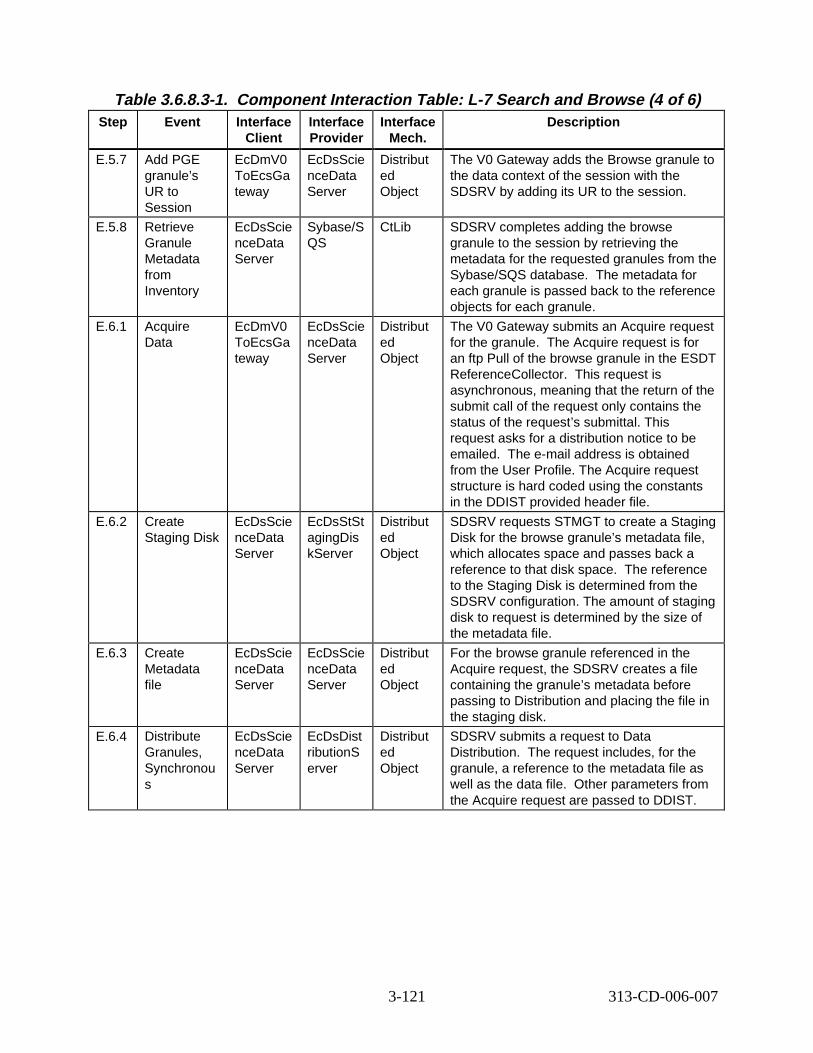
Table 3.6.8.3-1. Component Interaction Table: L-7 Search and Brow se (4 of 6) Step Event Interface
Client Interface Provider
Interface Mech.
Descript ion
E.5.7 Add PGE granule’s UR to Session
EcDmV0 ToEcsGa teway
EcDsScie nceData Server
Distribut ed Object
The V0 Gateway adds the Browse granule to the data context of the session with the SDSRV by adding its UR to the session.
E.5.8 Retrieve Granule Metadata from Inventory
EcDsScie nceData Server
Sybase/S QS
CtLib SDSRV completes adding the browse granule to the session by retrieving the metadata for the requested granules from the Sybase/SQS database. The metadata for each granule is passed back to the reference objects for each granule.
E.6.1 Acquire Data
EcDmV0 ToEcsGa teway
EcDsScie nceData Server
Distribut ed Object
The V0 Gateway submits an Acquire request for the granule. The Acquire request is for an ftp Pull of the browse granule in the ESDT ReferenceCollector. This request is asynchronous, meaning that the return of the submit call of the request only contains the status of the request’s submittal. This request asks for a distribution notice to be emailed. The e-mail address is obtained from the User Profile. The Acquire request structure is hard coded using the constants in the DDIST provided header file.
E.6.2 Create Staging Disk
EcDsScie nceData Server
EcDsStSt agingDis kServer
Distribut ed Object
SDSRV requests STMGT to create a Staging Disk for the browse granule’s metadata file, which allocates space and passes back a reference to that disk space. The reference to the Staging Disk is determined from the SDSRV configuration. The amount of staging disk to request is determined by the size of the metadata file.
E.6.3 Create Metadata file
EcDsScie nceData Server
EcDsScie nceData Server
Distribut ed Object
For the browse granule referenced in the Acquire request, the SDSRV creates a file containing the granule’s metadata before passing to Distribution and placing the file in the staging disk.
E.6.4 Distribute Granules, Synchronou s
EcDsScie nceData Server
EcDsDist ributionS erver
Distribut ed Object
SDSRV submits a request to Data Distribution. The request includes, for the granule, a reference to the metadata file as well as the data file. Other parameters from the Acquire request are passed to DDIST.
3-121 313-CD-006-007
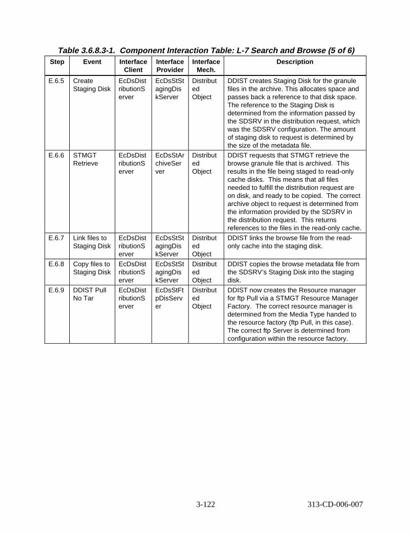
Table 3.6.8.3-1. Component Interaction Table: L-7 Search and Brow se (5 of 6) Step Event Interface
Client Interface Provider
Interface Mech.
Descript ion
E.6.5 Create Staging Disk
EcDsDist ributionS erver
EcDsStSt agingDis kServer
Distribut ed Object
DDIST creates Staging Disk for the granule files in the archive. This allocates space and passes back a reference to that disk space. The reference to the Staging Disk is determined from the information passed by the SDSRV in the distribution request, which was the SDSRV configuration. The amount of staging disk to request is determined by the size of the metadata file.
E.6.6 STMGT Retrieve
EcDsDist ributionS erver
EcDsStAr chiveSer ver
Distribut ed Object
DDIST requests that STMGT retrieve the browse granule file that is archived. This results in the file being staged to read-only cache disks. This means that all files needed to fulfill the distribution request are on disk, and ready to be copied. The correct archive object to request is determined from the information provided by the SDSRV in the distribution request. This returns references to the files in the read-only cache.
E.6.7 Link files to Staging Disk
EcDsDist ributionS erver
EcDsStSt agingDis kServer
Distribut ed Object
DDIST links the browse file from the readonly cache into the staging disk.
E.6.8 Copy files to Staging Disk
EcDsDist ributionS erver
EcDsStSt agingDis kServer
Distribut ed Object
DDIST copies the browse metadata file from the SDSRV’s Staging Disk into the staging disk.
E.6.9 DDIST Pull No Tar
EcDsDist ributionS erver
EcDsStFt pDisServ er
Distribut ed Object
DDIST now creates the Resource manager for ftp Pull via a STMGT Resource Manager Factory. The correct resource manager is determined from the Media Type handed to the resource factory (ftp Pull, in this case). The correct ftp Server is determined from configuration within the resource factory.
3-122 313-CD-006-007
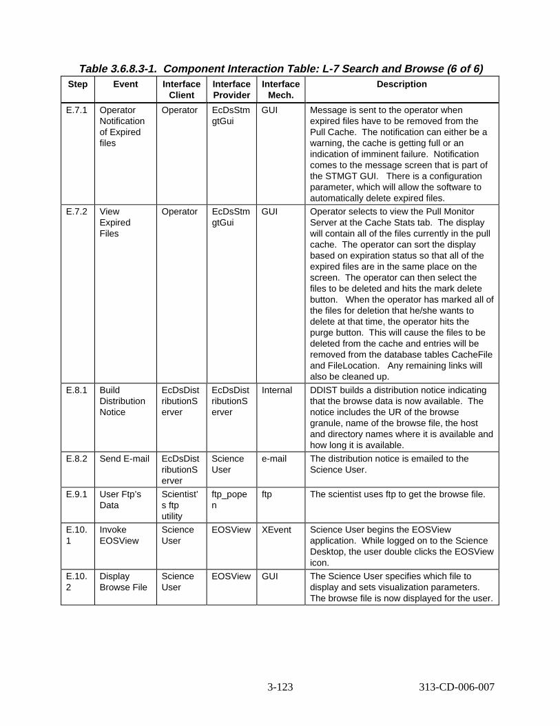
Table 3.6.8.3-1. Component Interaction Table: L-7 Search and Brow se (6 of 6) Step Event Interface
Client Interface Provider
Interface Mech.
Descript ion
E.7.1 Operator Notification of Expired files
Operator EcDsStm gtGui
GUI Message is sent to the operator when expired files have to be removed from the Pull Cache. The notification can either be a warning, the cache is getting full or an indication of imminent failure. Notification comes to the message screen that is part of the STMGT GUI. There is a configuration parameter, which will allow the software to automatically delete expired files.
E.7.2 View Expired Files
Operator EcDsStm gtGui
GUI Operator selects to view the Pull Monitor Server at the Cache Stats tab. The display will contain all of the files currently in the pull cache. The operator can sort the display based on expiration status so that all of the expired files are in the same place on the screen. The operator can then select the files to be deleted and hits the mark delete button. When the operator has marked all of the files for deletion that he/she wants to delete at that time, the operator hits the purge button. This will cause the files to be deleted from the cache and entries will be removed from the database tables CacheFile and FileLocation. Any remaining links will also be cleaned up.
E.8.1 Build Distribution Notice
EcDsDist ributionS erver
EcDsDist ributionS erver
Internal DDIST builds a distribution notice indicating that the browse data is now available. The notice includes the UR of the browse granule, name of the browse file, the host and directory names where it is available and how long it is available.
E.8.2 Send E-mail EcDsDist ributionS erver
Science User
e-mail The distribution notice is emailed to the Science User.
E.9.1 User Ftp’s Data
Scientist’ s ftp utility
ftp_pope n
ftp The scientist uses ftp to get the browse file.
E.10. 1
Invoke EOSView
Science User
EOSView XEvent Science User begins the EOSView application. While logged on to the Science Desktop, the user double clicks the EOSView icon.
E.10. 2
Display Browse File
Science User
EOSView GUI The Science User specifies which file to display and sets visualization parameters. The browse file is now displayed for the user.
3-123 313-CD-006-007
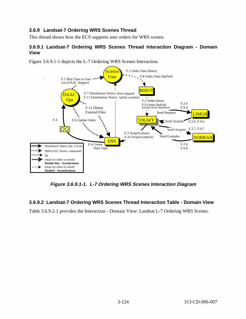
3.6.9 Landsat -7 Ordering W RS Scenes Thread This thread shows how the ECS supports user orders for WRS scenes.
3.6.9.1 Landsat -7 Ordering W RS Scenes Thread Interact ion D iagram - Domain View
Figure 3.6.9.1-1 depicts the L-7 Ordering WRS Scenes Interaction.
F.12 Delete Expired Files
Distributed Object (rpc, CtLib)
HMI (GUI, Xterm, command)
ftp email (or other as noted) Double line -Synchronous email (or other as noted) Dashed -Asynchronous
F.1 Order Data (8mm)
V0GWY
DSSDSS
Science User
Science User
F.2 Order (8mm) F.9 Order (ftpPull) (socket level interface)
F.8 Order Data (ftpPull)
F.3 Acquire (8mm) F.10 Acquire (ftpPull)
F.5 Ship Tape to User (via DAAC shipper)
(8mm shipped) ftpPull available)F.11 Distribution Notice
F.7 Distribution NoticeDAAC
Ops DAAC
Ops
B0SOT B0SOT
F.4 Create Data Tape
F.2.4 F.9.4
F.6 Update Order
B0SOTLIMGR
B0SOT DORRAN
Send Request
Send Acquire
Send Acquire
Send Granules
F.4 F.2.6, F.9.6
F.2.9 F.9.9
F.2.7, F.9.7
Figure 3. 6.9.1-1. L-7 Order ing WRS Scenes Interact ion D iagram
3.6.9.2 Landsat -7 Ordering W RS Scenes Thread Interact ion T able - Domain Vi ew
Table 3.6.9.2-1 provides the Interaction - Domain View: Landsat L-7 Ordering WRS Scenes.
3-124 313-CD-006-007
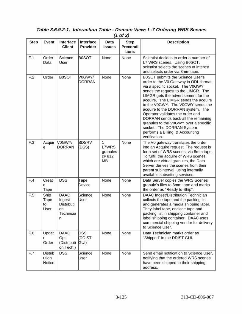
Table 3.6.9.2-1. Interact ion Tabl e - Domain V iew: L-7 Ordering W RS Scenes (1 of 2)
Step Event Interface Client
Interface Provider
Data Issues
Step Precondi
tions
Descript ion
F.1 Order Data
Science User
B0SOT None None Scientist decides to order a number of L7 WRS scenes. Using B0SOT, scientist selects the scenes of interest and selects order via 8mm tape.
F.2 Order B0SOT V0GWY/ DORRAN
None None B0SOT submits the Science User’s order to the V0 Gateway in ODL format, via a specific socket. The V0GWY sends the request to the LIMGR. The LIMGR gets the advertisement for the acquire. The LIMGR sends the acquire to the V0GWY. The V0GWY sends the acquire to the DORRAN system. The Operator validates the order and DORRAN sends back all the remaining granules to the V0GWY over a specific socket. The DORRAN System performs a Billing & Accounting verification.
F.3 Acquir e
V0GWY/ DORRAN
SDSRV (DSS)
1 L7WRS granules @ 812 MB
None The V0 gateway translates the order into an Acquire request. The request is for a set of WRS scenes, via 8mm tape. To fulfill the acquire of WRS scenes, which are virtual granules, the Data Server derives the scenes from their parent subinterval, using internally available subsetting services.
F.4 Creat e Tape
DSS Tape Device
None None Data Server copies the WRS Scenes granule’s files to 8mm tape and marks the order as “Ready to Ship”.
F.5 Ship Tape to User
DAAC Ingest Distributi on Technicia n
Science User
None None DAAC Ingest/Distribution Technician collects the tape and the packing list, and generates a media shipping label. They label tape, enclose tape and packing list in shipping container and label shipping container. DAAC uses commercial shipping vendor for delivery to Science User.
F.6 Updat e Order
DAAC Ops (Distributi on Tech.)
DSS (DDIST GUI)
None None Data Technician marks order as “Shipped” in the DDIST GUI.
F.7 Distrib ution Notice
DSS Science User
None None Send email notification to Science User, notifying that the ordered WRS scenes have been shipped to their shipping address.
3-125 313-CD-006-007
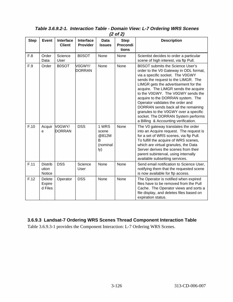
Table 3.6.9.2-1. Interact ion Tabl e - Domain V iew: L-7 Ordering W RS Scenes (2 of 2)
Step Event Interface Client
Interface Provider
Data Issues
Step Precondi
tions
Descript ion
F.8 Order Data
Science User
B0SOT None None Scientist decides to order a particular scene of high interest, via ftp Pull.
F.9 Order B0SOT V0GWY/ DORRAN
None None B0SOT submits the Science User’s order to the V0 Gateway in ODL format, via a specific socket. The V0GWY sends the request to the LIMGR. The LIMGR gets the advertisement for the acquire. The LIMGR sends the acquire to the V0GWY. The V0GWY sends the acquire to the DORRAN system. The Operator validates the order and DORRAN sends back all the remaining granules to the V0GWY over a specific socket. The DORRAN System performs a Billing & Accounting verification.
F.10 Acquir e
V0GWY/ DORRAN
DSS 1 WRS scene @812M B (nominal ly)
None The V0 gateway translates the order into an Acquire request. The request is for a set of WRS scenes, via ftp Pull. To fulfill the acquire of WRS scenes, which are virtual granules, the Data Server derives the scenes from their parent subinterval, using internally available subsetting services.
F.11 Distrib ution Notice
DSS Science User
None None Send email notification to Science User, notifying them that the requested scene is now available for ftp access.
F.12 Delete Expire d Files
Operator DSS None None The Operator is notified when expired files have to be removed from the Pull Cache. The Operator views and sorts a file display, and deletes files based on expiration status.
3.6.9.3 Landsat-7 Ordering WRS Scenes Thread Component Inter action Tabl e Table 3.6.9.3-1 provides the Component Interaction: L-7 Ordering WRS Scenes.
3-126 313-CD-006-007
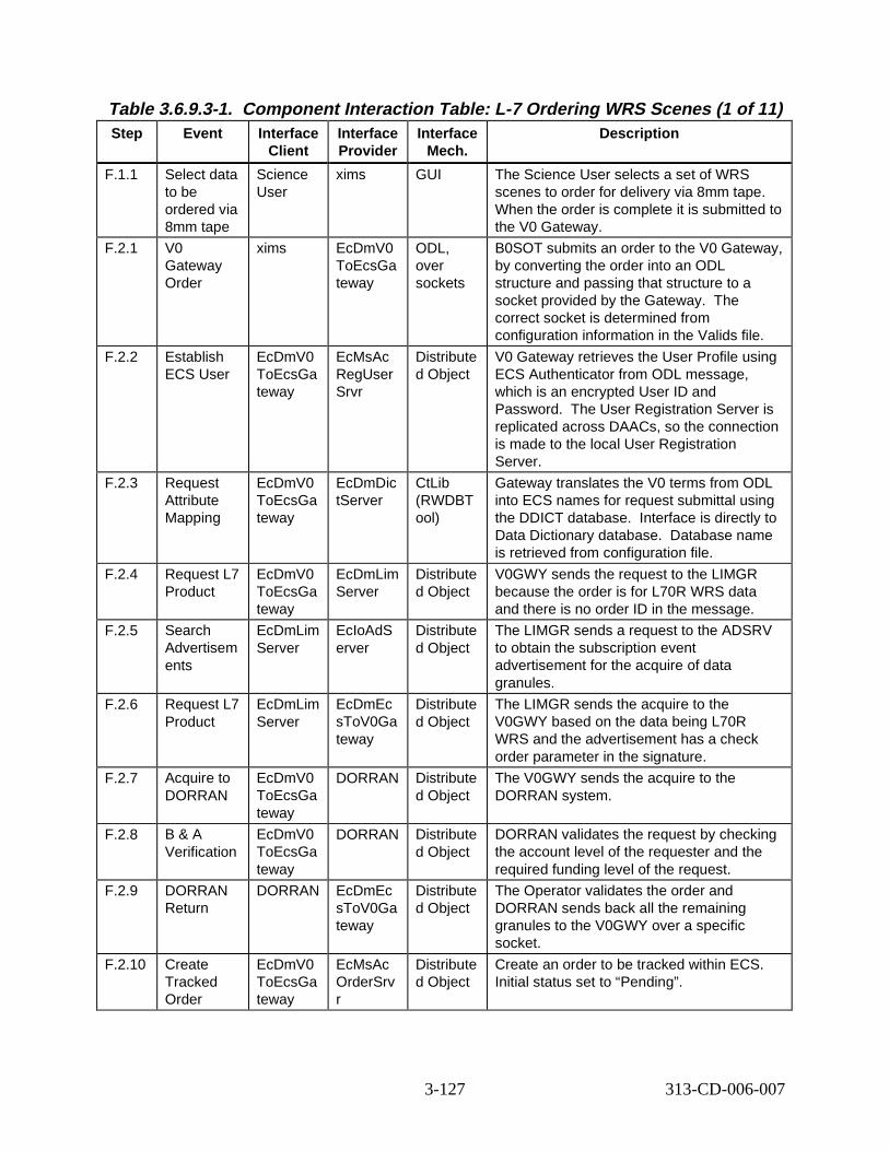
Table 3.6.9.3-1. Component Interaction Table: L-7 Ordering WRS S cenes (1 of 11) Step Event Interface
Client Interface Provider
Interface Mech.
Descript ion
F.1.1 Select data to be ordered via 8mm tape
Science User
xims GUI The Science User selects a set of WRS scenes to order for delivery via 8mm tape. When the order is complete it is submitted to the V0 Gateway.
F.2.1 V0 Gateway Order
xims EcDmV0 ToEcsGa teway
ODL, over sockets
B0SOT submits an order to the V0 Gateway, by converting the order into an ODL structure and passing that structure to a socket provided by the Gateway. The correct socket is determined from configuration information in the Valids file.
F.2.2 Establish ECS User
EcDmV0 ToEcsGa teway
EcMsAc RegUser Srvr
Distribute d Object
V0 Gateway retrieves the User Profile using ECS Authenticator from ODL message, which is an encrypted User ID and Password. The User Registration Server is replicated across DAACs, so the connection is made to the local User Registration Server.
F.2.3 Request Attribute Mapping
EcDmV0 ToEcsGa teway
EcDmDic tServer
CtLib (RWDBT ool)
Gateway translates the V0 terms from ODL into ECS names for request submittal using the DDICT database. Interface is directly to Data Dictionary database. Database name is retrieved from configuration file.
F.2.4 Request L7 Product
EcDmV0 ToEcsGa teway
EcDmLim Server
Distribute d Object
V0GWY sends the request to the LIMGR because the order is for L70R WRS data and there is no order ID in the message.
F.2.5 Search Advertisem ents
EcDmLim Server
EcIoAdS erver
Distribute d Object
The LIMGR sends a request to the ADSRV to obtain the subscription event advertisement for the acquire of data granules.
F.2.6 Request L7 Product
EcDmLim Server
EcDmEc sToV0Ga teway
Distribute d Object
The LIMGR sends the acquire to the V0GWY based on the data being L70R WRS and the advertisement has a check order parameter in the signature.
F.2.7 Acquire to DORRAN
EcDmV0 ToEcsGa teway
DORRAN Distribute d Object
The V0GWY sends the acquire to the DORRAN system.
F.2.8 B & A Verification
EcDmV0 ToEcsGa teway
DORRAN Distribute d Object
DORRAN validates the request by checking the account level of the requester and the required funding level of the request.
F.2.9 DORRAN Return
DORRAN EcDmEc sToV0Ga teway
Distribute d Object
The Operator validates the order and DORRAN sends back all the remaining granules to the V0GWY over a specific socket.
F.2.10 Create Tracked Order
EcDmV0 ToEcsGa teway
EcMsAc OrderSrv r
Distribute d Object
Create an order to be tracked within ECS. Initial status set to “Pending”.
3-127 313-CD-006-007
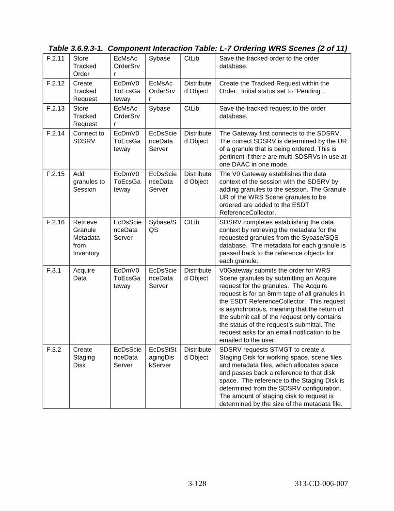
Table 3.6.9.3-1. Component Interaction Table: L-7 Ordering WRS S cenes (2 of 11) F.2.11 Store
Tracked Order
EcMsAc OrderSrv r
Sybase CtLib Save the tracked order to the order database.
F.2.12 Create Tracked Request
EcDmV0 ToEcsGa teway
EcMsAc OrderSrv r
Distribute d Object
Create the Tracked Request within the Order. Initial status set to “Pending”.
F.2.13 Store Tracked Request
EcMsAc OrderSrv r
Sybase CtLib Save the tracked request to the order database.
F.2.14 Connect to SDSRV
EcDmV0 ToEcsGa teway
EcDsScie nceData Server
Distribute d Object
The Gateway first connects to the SDSRV. The correct SDSRV is determined by the UR of a granule that is being ordered. This is pertinent if there are multi-SDSRVs in use at one DAAC in one mode.
F.2.15 Add granules to Session
EcDmV0 ToEcsGa teway
EcDsScie nceData Server
Distribute d Object
The V0 Gateway establishes the data context of the session with the SDSRV by adding granules to the session. The Granule UR of the WRS Scene granules to be ordered are added to the ESDT ReferenceCollector.
F.2.16 Retrieve Granule Metadata from Inventory
EcDsScie nceData Server
Sybase/S QS
CtLib SDSRV completes establishing the data context by retrieving the metadata for the requested granules from the Sybase/SQS database. The metadata for each granule is passed back to the reference objects for each granule.
F.3.1 Acquire Data
EcDmV0 ToEcsGa teway
EcDsScie nceData Server
Distribute d Object
V0Gateway submits the order for WRS Scene granules by submitting an Acquire request for the granules. The Acquire request is for an 8mm tape of all granules in the ESDT ReferenceCollector. This request is asynchronous, meaning that the return of the submit call of the request only contains the status of the request’s submittal. The request asks for an email notification to be emailed to the user.
F.3.2 Create Staging Disk
EcDsScie nceData Server
EcDsStSt agingDis kServer
Distribute d Object
SDSRV requests STMGT to create a Staging Disk for working space, scene files and metadata files, which allocates space and passes back a reference to that disk space. The reference to the Staging Disk is determined from the SDSRV configuration. The amount of staging disk to request is determined by the size of the metadata file.
3-128 313-CD-006-007
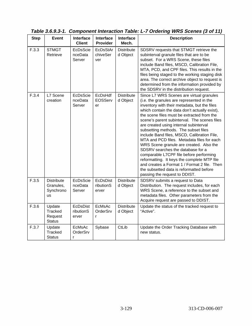
Table 3.6.9.3-1. Component Interaction Table: L-7 Ordering WRS S cenes (3 of 11) Step Event Interface
Client Interface Provider
Interface Mech.
Descript ion
F.3.3 STMGT Retrieve
EcDsScie nceData Server
EcDsStAr chiveSer ver
Distribute d Object
SDSRV requests that STMGT retrieve the subinterval granule files that are to be subset. For a WRS Scene, these files include Band files, MSCD, Calibration File, MTA, PCD, and CPF files. This results in the files being staged to the working staging disk area. The correct archive object to request is determined from the information provided by the SDSRV in the distribution request.
F.3.4 L7 Scene creation
EcDsScie nceData Server
EcDsHdf EOSServ er
Distribute d Object
Since L7 WRS Scenes are virtual granules (i.e. the granules are represented in the inventory with their metadata, but the files which contain the data don’t actually exist), the scene files must be extracted from the scene’s parent subinterval. The scenes files are created using internal subinterval subsetting methods. The subset files include Band files, MSCD, Calibration File, MTA and PCD files. Metadata files for each WRS Scene granule are created. Also the SDSRV searches the database for a comparable L7CPF file before performing reformatting. It keys the complete MTP file and creates a Format 1 / Format 2 file. Then the subsetted data is reformatted before passing the request to DDIST.
F.3.5 Distribute Granules, Synchrono us
EcDsScie nceData Server
EcDsDist ributionS erver
Distribute d Object
SDSRV submits a request to Data Distribution. The request includes, for each WRS Scene, a reference to the subset and metadata files. Other parameters from the Acquire request are passed to DDIST.
F.3.6 Update Tracked Request Status
EcDsDist ributionS erver
EcMsAc OrderSrv r
Distribute d Object
Update the status of the tracked request to “Active”.
F.3.7 Update Tracked Status
EcMsAc OrderSrv r
Sybase CtLib Update the Order Tracking Database with new status.
3-129 313-CD-006-007
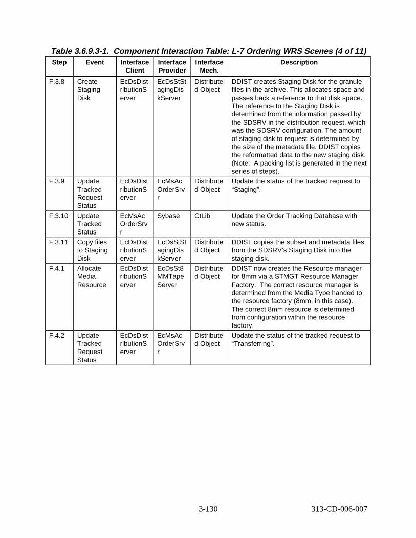
Table 3.6.9.3-1. Component Interaction Table: L-7 Ordering WRS S cenes (4 of 11) Step Event Interface
Client Interface Provider
Interface Mech.
Descript ion
F.3.8 Create Staging Disk
EcDsDist ributionS erver
EcDsStSt agingDis kServer
Distribute d Object
DDIST creates Staging Disk for the granule files in the archive. This allocates space and passes back a reference to that disk space. The reference to the Staging Disk is determined from the information passed by the SDSRV in the distribution request, which was the SDSRV configuration. The amount of staging disk to request is determined by the size of the metadata file. DDIST copies the reformatted data to the new staging disk. (Note: A packing list is generated in the next series of steps).
F.3.9 Update Tracked Request Status
EcDsDist ributionS erver
EcMsAc OrderSrv r
Distribute d Object
Update the status of the tracked request to “Staging”.
F.3.10 Update Tracked Status
EcMsAc OrderSrv r
Sybase CtLib Update the Order Tracking Database with new status.
F.3.11 Copy files to Staging Disk
EcDsDist ributionS erver
EcDsStSt agingDis kServer
Distribute d Object
DDIST copies the subset and metadata files from the SDSRV’s Staging Disk into the staging disk.
F.4.1 Allocate Media Resource
EcDsDist ributionS erver
EcDsSt8 MMTape Server
Distribute d Object
DDIST now creates the Resource manager for 8mm via a STMGT Resource Manager Factory. The correct resource manager is determined from the Media Type handed to the resource factory (8mm, in this case). The correct 8mm resource is determined from configuration within the resource factory.
F.4.2 Update Tracked Request Status
EcDsDist ributionS erver
EcMsAc OrderSrv r
Distribute d Object
Update the status of the tracked request to “Transferring”.
3-130 313-CD-006-007
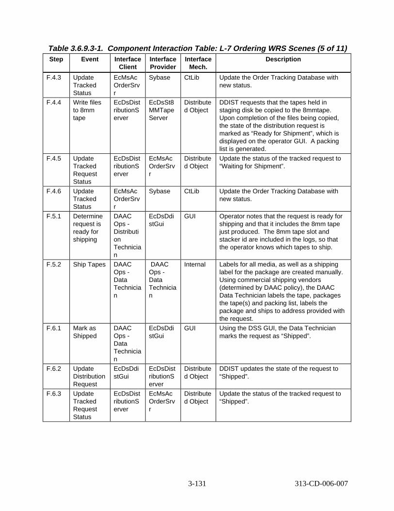
Table 3.6.9.3-1. Component Interaction Table: L-7 Ordering WRS S cenes (5 of 11) Step Event Interface
Client Interface Provider
Interface Mech.
Descript ion
F.4.3 Update Tracked Status
EcMsAc OrderSrv r
Sybase CtLib Update the Order Tracking Database with new status.
F.4.4 Write files to 8mm tape
EcDsDist ributionS erver
EcDsSt8 MMTape Server
Distribute d Object
DDIST requests that the tapes held in staging disk be copied to the 8mmtape. Upon completion of the files being copied, the state of the distribution request is marked as “Ready for Shipment”, which is displayed on the operator GUI. A packing list is generated.
F.4.5 Update Tracked Request Status
EcDsDist ributionS erver
EcMsAc OrderSrv r
Distribute d Object
Update the status of the tracked request to “Waiting for Shipment”.
F.4.6 Update Tracked Status
EcMsAc OrderSrv r
Sybase CtLib Update the Order Tracking Database with new status.
F.5.1 Determine request is ready for shipping
DAAC Ops -Distributi on Technicia n
EcDsDdi stGui
GUI Operator notes that the request is ready for shipping and that it includes the 8mm tape just produced. The 8mm tape slot and stacker id are included in the logs, so that the operator knows which tapes to ship.
F.5.2 Ship Tapes DAAC Ops -Data Technicia n
DAAC Ops -Data Technicia n
Internal Labels for all media, as well as a shipping label for the package are created manually. Using commercial shipping vendors (determined by DAAC policy), the DAAC Data Technician labels the tape, packages the tape(s) and packing list, labels the package and ships to address provided with the request.
F.6.1 Mark as Shipped
DAAC Ops -Data Technicia n
EcDsDdi stGui
GUI Using the DSS GUI, the Data Technician marks the request as “Shipped”.
F.6.2 Update Distribution Request
EcDsDdi stGui
EcDsDist ributionS erver
Distribute d Object
DDIST updates the state of the request to “Shipped”.
F.6.3 Update Tracked Request Status
EcDsDist ributionS erver
EcMsAc OrderSrv r
Distribute d Object
Update the status of the tracked request to “Shipped”.
3-131 313-CD-006-007
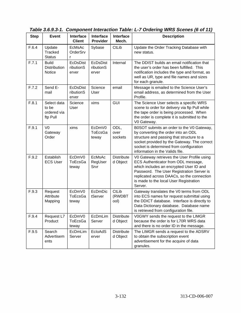
Table 3.6.9.3-1. Component Interaction Table: L-7 Ordering WRS S cenes (6 of 11) Step Event Interface
Client Interface Provider
Interface Mech.
Descript ion
F.6.4 Update Tracked Status
EcMsAc OrderSrv r
Sybase CtLib Update the Order Tracking Database with new status.
F.7.1 Build Distribution Notice
EcDsDist ributionS erver
EcDsDist ributionS erver
Internal The DDIST builds an email notification that the user’s order has been fulfilled. This notification includes the type and format, as well as UR, type and file names and sizes for each granule.
F.7.2 Send Email
EcDsDist ributionS erver
Science User
email Message is emailed to the Science User’s email address, as determined from the User Profile.
F.8.1 Select data to be ordered via ftp Pull
Science User
xims GUI The Science User selects a specific WRS scene to order for delivery via ftp Pull while the tape order is being processed. When the order is complete it is submitted to the V0 Gateway.
F.9.1 V0 Gateway Order
xims EcDmV0 ToEcsGa teway
ODL, over sockets
B0SOT submits an order to the V0 Gateway, by converting the order into an ODL structure and passing that structure to a socket provided by the Gateway. The correct socket is determined from configuration information in the Valids file.
F.9.2 Establish ECS User
EcDmV0 ToEcsGa teway
EcMsAc RegUser Srvr
Distribute d Object
V0 Gateway retrieves the User Profile using ECS Authenticator from ODL message, which includes an encrypted User ID and Password. The User Registration Server is replicated across DAACs, so the connection is made to the local User Registration Server.
F.9.3 Request Attribute Mapping
EcDmV0 ToEcsGa teway
EcDmDic tServer
CtLib (RWDBT ool)
Gateway translates the V0 terms from ODL into ECS names for request submittal using the DDICT database. Interface is directly to Data Dictionary database. Database name is retrieved from configuration file.
F.9.4 Request L7 Product
EcDmV0 ToEcsGa teway
EcDmLim Server
Distribute d Object
V0GWY sends the request to the LIMGR because the order is for L70R WRS data and there is no order ID in the message.
F.9.5 Search Advertisem ents
EcDmLim Server
EcIoAdS erver
Distribute d Object
The LIMGR sends a request to the ADSRV to obtain the subscription event advertisement for the acquire of data granules.
3-132 313-CD-006-007
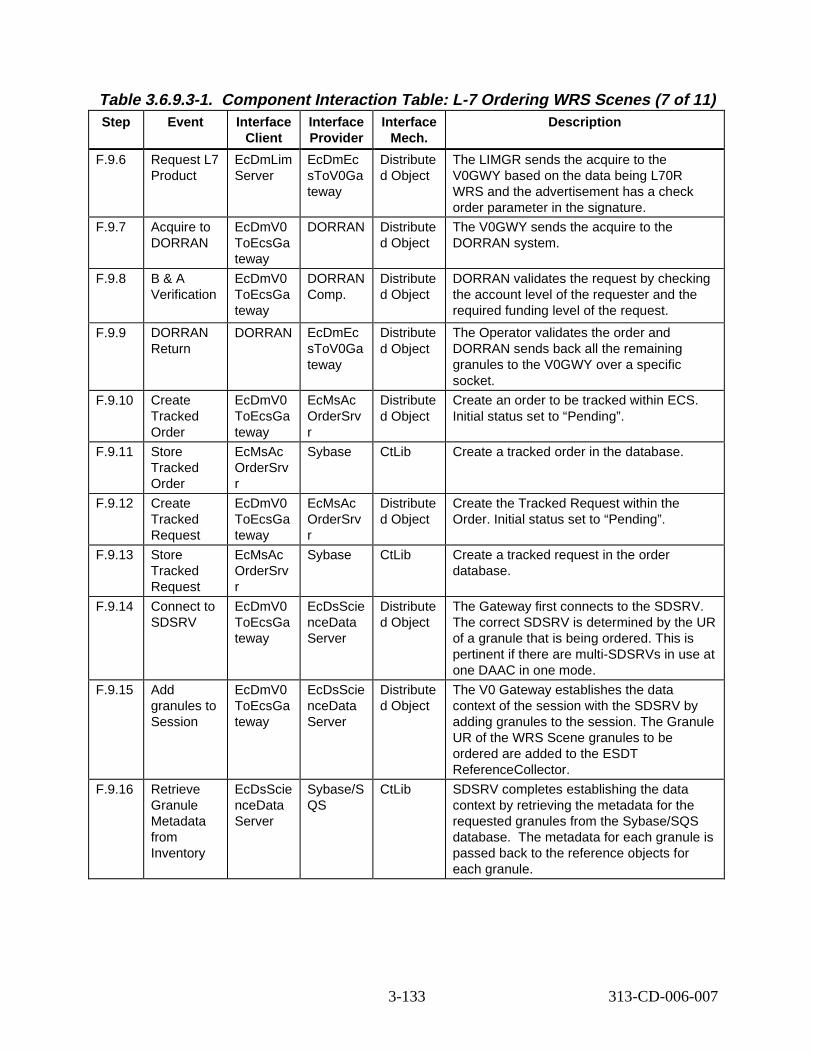
Table 3.6.9.3-1. Component Interaction Table: L-7 Ordering WRS S cenes (7 of 11) Step Event Interface
Client Interface Provider
Interface Mech.
Descript ion
F.9.6 Request L7 Product
EcDmLim Server
EcDmEc sToV0Ga teway
Distribute d Object
The LIMGR sends the acquire to the V0GWY based on the data being L70R WRS and the advertisement has a check order parameter in the signature.
F.9.7 Acquire to DORRAN
EcDmV0 ToEcsGa teway
DORRAN Distribute d Object
The V0GWY sends the acquire to the DORRAN system.
F.9.8 B & A Verification
EcDmV0 ToEcsGa teway
DORRAN Comp.
Distribute d Object
DORRAN validates the request by checking the account level of the requester and the required funding level of the request.
F.9.9 DORRAN Return
DORRAN EcDmEc sToV0Ga teway
Distribute d Object
The Operator validates the order and DORRAN sends back all the remaining granules to the V0GWY over a specific socket.
F.9.10 Create Tracked Order
EcDmV0 ToEcsGa teway
EcMsAc OrderSrv r
Distribute d Object
Create an order to be tracked within ECS. Initial status set to “Pending”.
F.9.11 Store Tracked Order
EcMsAc OrderSrv r
Sybase CtLib Create a tracked order in the database.
F.9.12 Create Tracked Request
EcDmV0 ToEcsGa teway
EcMsAc OrderSrv r
Distribute d Object
Create the Tracked Request within the Order. Initial status set to “Pending”.
F.9.13 Store Tracked Request
EcMsAc OrderSrv r
Sybase CtLib Create a tracked request in the order database.
F.9.14 Connect to SDSRV
EcDmV0 ToEcsGa teway
EcDsScie nceData Server
Distribute d Object
The Gateway first connects to the SDSRV. The correct SDSRV is determined by the UR of a granule that is being ordered. This is pertinent if there are multi-SDSRVs in use at one DAAC in one mode.
F.9.15 Add granules to Session
EcDmV0 ToEcsGa teway
EcDsScie nceData Server
Distribute d Object
The V0 Gateway establishes the data context of the session with the SDSRV by adding granules to the session. The Granule UR of the WRS Scene granules to be ordered are added to the ESDT ReferenceCollector.
F.9.16 Retrieve Granule Metadata from Inventory
EcDsScie nceData Server
Sybase/S QS
CtLib SDSRV completes establishing the data context by retrieving the metadata for the requested granules from the Sybase/SQS database. The metadata for each granule is passed back to the reference objects for each granule.
3-133 313-CD-006-007
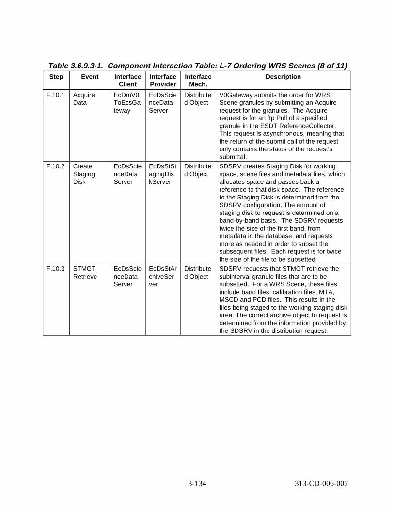
Table 3.6.9.3-1. Component Interaction Table: L-7 Ordering WRS S cenes (8 of 11) Step Event Interface
Client Interface Provider
Interface Mech.
Descript ion
F.10.1 Acquire Data
EcDmV0 ToEcsGa teway
EcDsScie nceData Server
Distribute d Object
V0Gateway submits the order for WRS Scene granules by submitting an Acquire request for the granules. The Acquire request is for an ftp Pull of a specified granule in the ESDT ReferenceCollector. This request is asynchronous, meaning that the return of the submit call of the request only contains the status of the request’s submittal.
F.10.2 Create Staging Disk
EcDsScie nceData Server
EcDsStSt agingDis kServer
Distribute d Object
SDSRV creates Staging Disk for working space, scene files and metadata files, which allocates space and passes back a reference to that disk space. The reference to the Staging Disk is determined from the SDSRV configuration. The amount of staging disk to request is determined on a band-by-band basis. The SDSRV requests twice the size of the first band, from metadata in the database, and requests more as needed in order to subset the subsequent files. Each request is for twice the size of the file to be subsetted.
F.10.3 STMGT Retrieve
EcDsScie nceData Server
EcDsStAr chiveSer ver
Distribute d Object
SDSRV requests that STMGT retrieve the subinterval granule files that are to be subsetted. For a WRS Scene, these files include band files, calibration files, MTA, MSCD and PCD files. This results in the files being staged to the working staging disk area. The correct archive object to request is determined from the information provided by the SDSRV in the distribution request.
3-134 313-CD-006-007
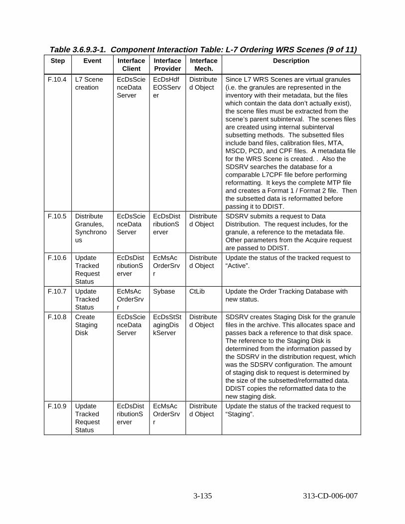
Table 3.6.9.3-1. Component Interaction Table: L-7 Ordering WRS S cenes (9 of 11) Step Event Interface
Client Interface Provider
Interface Mech.
Descript ion
F.10.4 L7 Scene creation
EcDsScie nceData Server
EcDsHdf EOSServ er
Distribute d Object
Since L7 WRS Scenes are virtual granules (i.e. the granules are represented in the inventory with their metadata, but the files which contain the data don’t actually exist), the scene files must be extracted from the scene’s parent subinterval. The scenes files are created using internal subinterval subsetting methods. The subsetted files include band files, calibration files, MTA, MSCD, PCD, and CPF files. A metadata file for the WRS Scene is created. . Also the SDSRV searches the database for a comparable L7CPF file before performing reformatting. It keys the complete MTP file and creates a Format 1 / Format 2 file. Then the subsetted data is reformatted before passing it to DDIST.
F.10.5 Distribute Granules, Synchrono us
EcDsScie nceData Server
EcDsDist ributionS erver
Distribute d Object
SDSRV submits a request to Data Distribution. The request includes, for the granule, a reference to the metadata file. Other parameters from the Acquire request are passed to DDIST.
F.10.6 Update Tracked Request Status
EcDsDist ributionS erver
EcMsAc OrderSrv r
Distribute d Object
Update the status of the tracked request to “Active”.
F.10.7 Update Tracked Status
EcMsAc OrderSrv r
Sybase CtLib Update the Order Tracking Database with new status.
F.10.8 Create Staging Disk
EcDsScie nceData Server
EcDsStSt agingDis kServer
Distribute d Object
SDSRV creates Staging Disk for the granule files in the archive. This allocates space and passes back a reference to that disk space. The reference to the Staging Disk is determined from the information passed by the SDSRV in the distribution request, which was the SDSRV configuration. The amount of staging disk to request is determined by the size of the subsetted/reformatted data. DDIST copies the reformatted data to the new staging disk.
F.10.9 Update Tracked Request Status
EcDsDist ributionS erver
EcMsAc OrderSrv r
Distribute d Object
Update the status of the tracked request to “Staging”.
3-135 313-CD-006-007
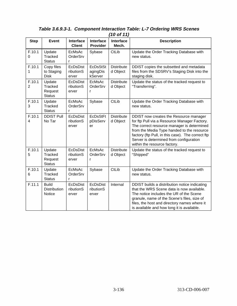
Table 3.6.9.3-1. Component Interaction Table: L-7 Ordering WRS S cenes (10 of 11)
Step Event Interface Client
Interface Provider
Interface Mech.
Descript ion
F.10.1 0
Update Tracked Status
EcMsAc OrderSrv r
Sybase CtLib Update the Order Tracking Database with new status.
F.10.1 1
Copy files to Staging Disk
EcDsDist ributionS erver
EcDsStSt agingDis kServer
Distribute d Object
DDIST copies the subsetted and metadata files from the SDSRV’s Staging Disk into the staging disk.
F.10.1 2
Update Tracked Request Status
EcDsDist ributionS erver
EcMsAc OrderSrv r
Distribute d Object
Update the status of the tracked request to “Transferring”.
F.10.1 3
Update Tracked Status
EcMsAc OrderSrv r
Sybase CtLib Update the Order Tracking Database with new status.
F.10.1 4
DDIST Pull No Tar
EcDsDist ributionS erver
EcDsStFt pDisServ er
Distribute d Object
DDIST now creates the Resource manager for ftp Pull via a Resource Manager Factory. The correct resource manager is determined from the Media Type handed to the resource factory (ftp Pull, in this case). The correct ftp Server is determined from configuration within the resource factory.
F.10.1 5
Update Tracked Request Status
EcDsDist ributionS erver
EcMsAc OrderSrv r
Distribute d Object
Update the status of the tracked request to “Shipped”
F.10.1 6
Update Tracked Status
EcMsAc OrderSrv r
Sybase CtLib Update the Order Tracking Database with new status.
F.11.1 Build Distribution Notice
EcDsDist ributionS erver
EcDsDist ributionS erver
Internal DDIST builds a distribution notice indicating that the WRS Scene data is now available. The notice includes the UR of the Scene granule, name of the Scene’s files, size of files, the host and directory names where it is available and how long it is available.
3-136 313-CD-006-007
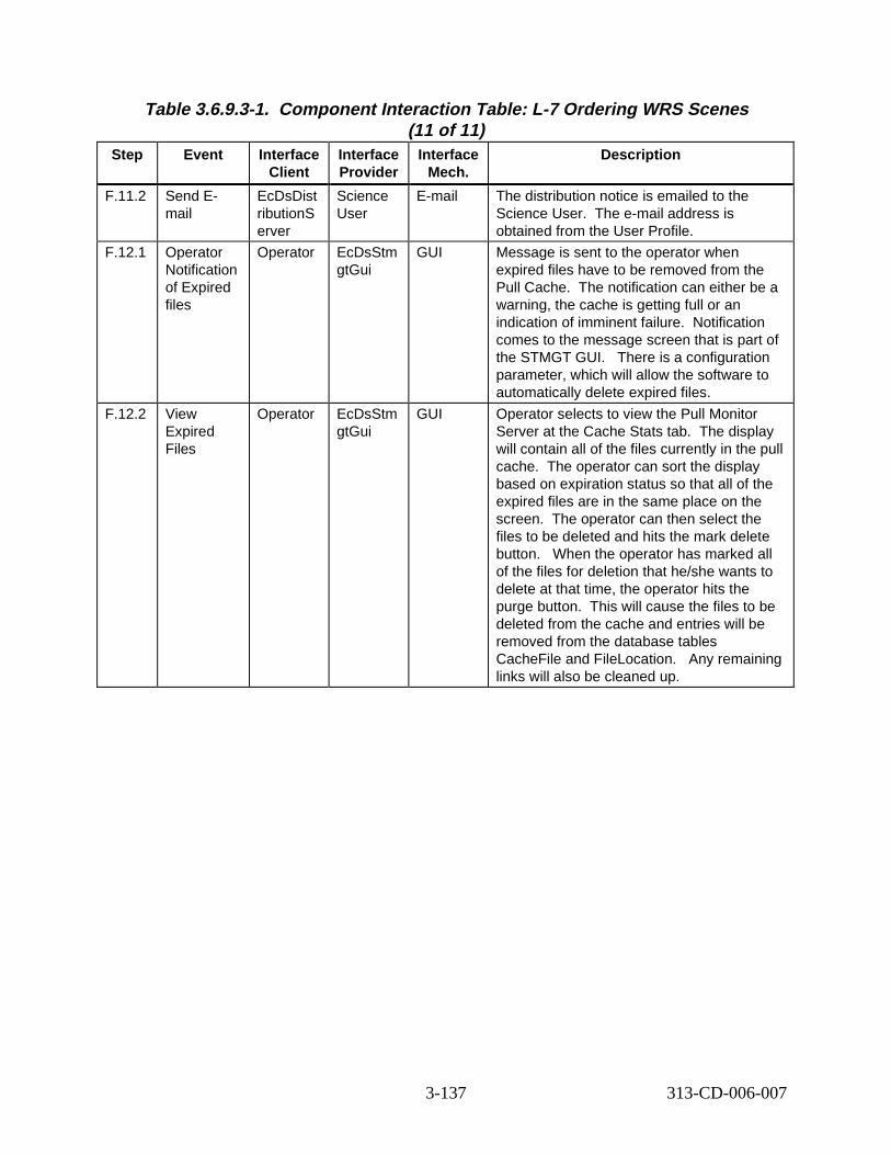
Table 3.6.9.3-1. Component Interaction Table: L-7 Ordering WRS S cenes (11 of 11)
Step Event Interface Client
Interface Provider
Interface Mech.
Descript ion
F.11.2 Send Email
EcDsDist ributionS erver
Science User
E-mail The distribution notice is emailed to the Science User. The e-mail address is obtained from the User Profile.
F.12.1 Operator Notification of Expired files
Operator EcDsStm gtGui
GUI Message is sent to the operator when expired files have to be removed from the Pull Cache. The notification can either be a warning, the cache is getting full or an indication of imminent failure. Notification comes to the message screen that is part of the STMGT GUI. There is a configuration parameter, which will allow the software to automatically delete expired files.
F.12.2 View Expired Files
Operator EcDsStm gtGui
GUI Operator selects to view the Pull Monitor Server at the Cache Stats tab. The display will contain all of the files currently in the pull cache. The operator can sort the display based on expiration status so that all of the expired files are in the same place on the screen. The operator can then select the files to be deleted and hits the mark delete button. When the operator has marked all of the files for deletion that he/she wants to delete at that time, the operator hits the purge button. This will cause the files to be deleted from the cache and entries will be removed from the database tables CacheFile and FileLocation. Any remaining links will also be cleaned up.
3-137 313-CD-006-007
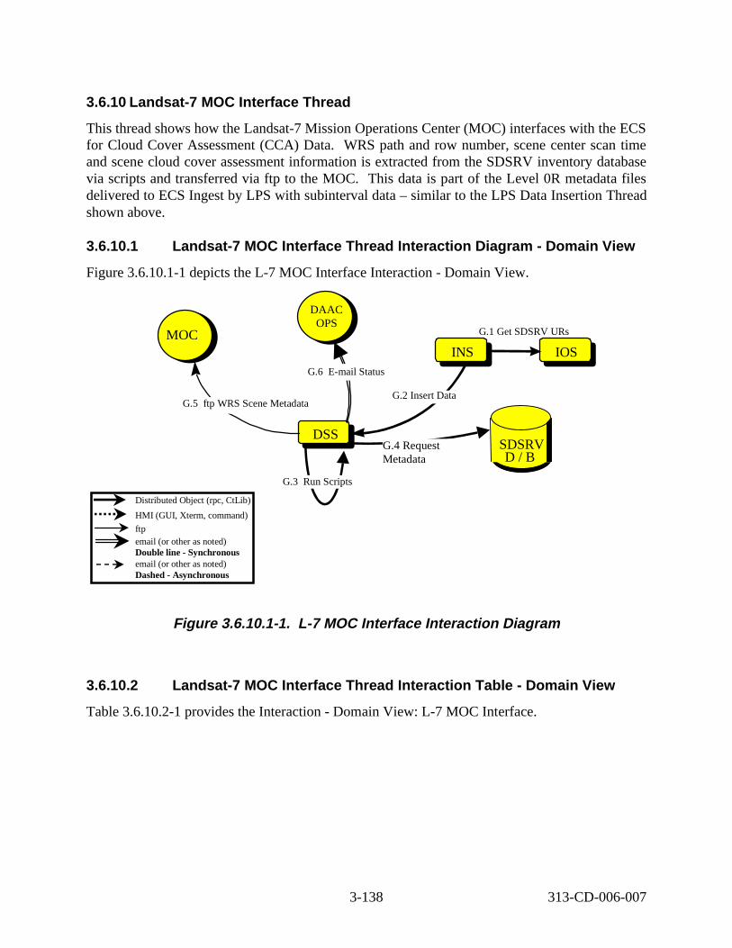
3.6.10 Landsat -7 MOC Interface Thre ad
This thread shows how the Landsat-7 Mission Operations Center (MOC) interfaces with the ECS for Cloud Cover Assessment (CCA) Data. WRS path and row number, scene center scan time and scene cloud cover assessment information is extracted from the SDSRV inventory database via scripts and transferred via ftp to the MOC. This data is part of the Level 0R metadata files delivered to ECS Ingest by LPS with subinterval data – similar to the LPS Data Insertion Thread shown above.
3.6.10.1 Landsat -7 MOC Interface Thre ad Int eract ion D iagram - Domain View
Figure 3.6.10.1-1 depicts the L-7 MOC Interface Interaction - Domain View.
INSINS
DSSDSS
G.2 Insert Data G.5 ftp WRS Scene Metadata
INSIOS
G.1 Get SDSRV URs
G.4 Request Metadata
G.3 Run Scripts
Distributed Object (rpc, CtLib)
HMI (GUI, Xterm, command)
ftp email (or other as noted) Double line - Synchronous email (or other as noted) Dashed -Asynchronous
LPS MOC
SDSRV D / B
LPS DAAC OPS
G.6 E-mail Status
Figure 3. 6.10.1-1. L-7 MOC Interface Int eract ion D iagram
3.6.10.2 Landsat -7 MOC Interface Thre ad Int eract ion Tabl e - Domain View
Table 3.6.10.2-1 provides the Interaction - Domain View: L-7 MOC Interface.
3-138 313-CD-006-007
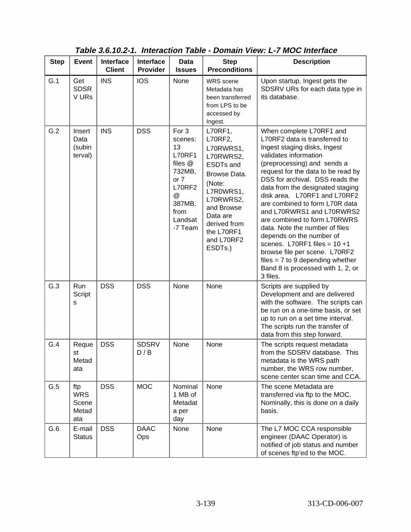
Table 3.6.10.2-1. Interact ion T able - Domain View: L-7 MOC Interface Step Event Interface
Client Interface Provider
Data Issues
Step Preconditions
Descript ion
G.1 Get SDSR V URs
INS IOS None WRS scene Metadata has been transferred from LPS to be accessed by Ingest.
Upon startup, Ingest gets the SDSRV URs for each data type in its database.
G.2 Insert Data (subin terval)
INS DSS For 3 scenes: 13 L70RF1 files @ 732MB, or 7 L70RF2 @ 387MB, from Landsat -7 Team
L70RF1, L70RF2, L70RWRS1, L70RWRS2, ESDTs and Browse Data. (Note: L7R0WRS1, L70RWRS2, and Browse Data are derived from the L70RF1 and L70RF2 ESDTs.)
When complete L70RF1 and L70RF2 data is transferred to Ingest staging disks, Ingest validates information (preprocessing) and ends a request for the data to be read by DSS for archival. DSS reads the data from the designated staging disk area. L70RF1 and L70RF2 are combined to form L70R data and L70RWRS1 and L70RWRS2 are combined to form L70RWRS data. Note the number of files depends on the number of scenes. 0RF1 files = 10 +1 browse file per scene. 70RF2 files = 7 to 9 depending whether Band 8 is processed with 1, 2, or 3 files.
G.3 Run Script s
DSS DSS None None Scripts are supplied by Development and are delivered with the software. The scripts can be run on a one-time basis, or set up to run on a set time interval. The scripts run the transfer of data from this step forward.
G.4 Reque st Metad ata
DSS SDSRV D / B
None None The scripts request metadata from the SDSRV database. his metadata is the WRS path number, the WRS row number, scene center scan time and CCA.
G.5 ftp WRS Scene Metad ata
DSS MOC Nominal 1 MB of Metadat a per day
None The scene Metadata are transferred via ftp to the MOC. Nominally, this is done on a daily basis.
G.6 E-mail Status
DSS DAAC Ops
None None The L7 MOC CCA responsible engineer (DAAC Operator) is notified of job status and number of scenes ftp’ed to the MOC.
s
L7L
T
3-139 313-CD-006-007
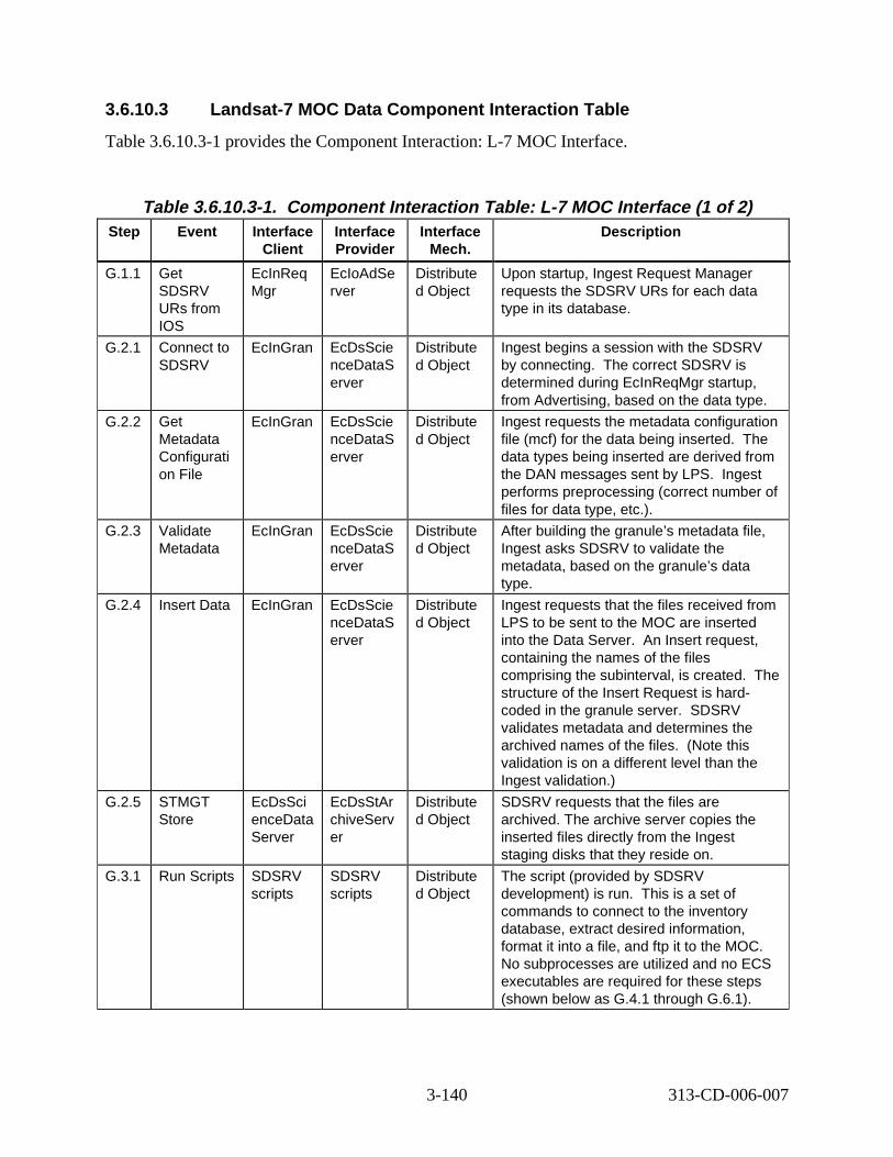
3.6.10.3 Landsat-7 MOC Data Component Inter action Tabl e
Table 3.6.10.3-1 provides the Component Interaction: L-7 MOC Interface.
Table 3.6.10.3-1. Component Inter action Tabl e: L-7 MOC Interface (1 of 2) Step Event Interface
Client Interface Provider
Interface Mech.
Descript ion
G.1.1 Get SDSRV URs from IOS
EcInReq Mgr
EcIoAdSe rver
Distribute d Object
Upon startup, Ingest Request Manager requests the SDSRV URs for each data type in its database.
G.2.1 Connect to SDSRV
EcInGran EcDsScie nceDataS erver
Distribute d Object
Ingest begins a session with the SDSRV by connecting. The correct SDSRV is determined during EcInReqMgr startup, from Advertising, based on the data type.
G.2.2 Get Metadata Configurati on File
EcInGran EcDsScie nceDataS erver
Distribute d Object
Ingest requests the metadata configuration file (mcf) for the data being inserted. he data types being inserted are derived from the DAN messages sent by LPS. Ingest performs preprocessing (correct number of files for data type, etc.).
G.2.3 Validate Metadata
EcInGran EcDsScie nceDataS erver
Distribute d Object
After building the granule’s metadata file, Ingest asks SDSRV to validate the metadata, based on the granule’s data type.
G.2.4 Insert Data EcInGran EcDsScie nceDataS erver
Distribute d Object
Ingest requests that the files received from LPS to be sent to the MOC are inserted into the Data Server. n Insert request, containing the names of the files comprising the subinterval, is created. e structure of the Insert Request is hardcoded in the granule server. SDSRV validates metadata and determines the archived names of the files. (Note this validation is on a different level than the Ingest validation.)
G.2.5 STMGT Store
EcDsSci enceData Server
EcDsStAr chiveServ er
Distribute d Object
SDSRV requests that the files are archived. The archive server copies the inserted files directly from the Ingest staging disks that they reside on.
G.3.1 Run Scripts SDSRV scripts
SDSRV scripts
Distribute d Object
The script (provided by SDSRV development) is run. his is a set of commands to connect to the inventory database, extract desired information, format it into a file, and ftp it to the MOC. No subprocesses are utilized and no ECS executables are required for these steps (shown below as G.4.1 through G.6.1).
T
A
Th
T
3-140 313-CD-006-007
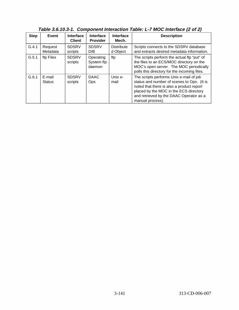
Table 3.6.10.3-1. Component Inter action Tabl e: L-7 MOC Interface (2 of 2) Step Event Interface
Client Interface Provider
Interface Mech.
Descript ion
G.4.1 Request Metadata
SDSRV scripts
SDSRV D/B
Distribute d Object
Scripts connects to the SDSRV database and extracts desired metadata information.
G.5.1 ftp Files SDSRV scripts
Operating System ftp daemon
ftp The scripts perform the actual ftp “put” of the files to an ECS/MOC directory on the MOC’s open server. The MOC periodically polls this directory for the incoming files.
G.6.1 E-mail Status
SDSRV scripts
DAAC Ops
Unix email
The scripts performs Unix e-mail of job status and number of scenes to Ops. (It is noted that there is also a product report placed by the MOC in the ECS directory and retrieved by the DAAC Operator as a manual process).
3-141 313-CD-006-007
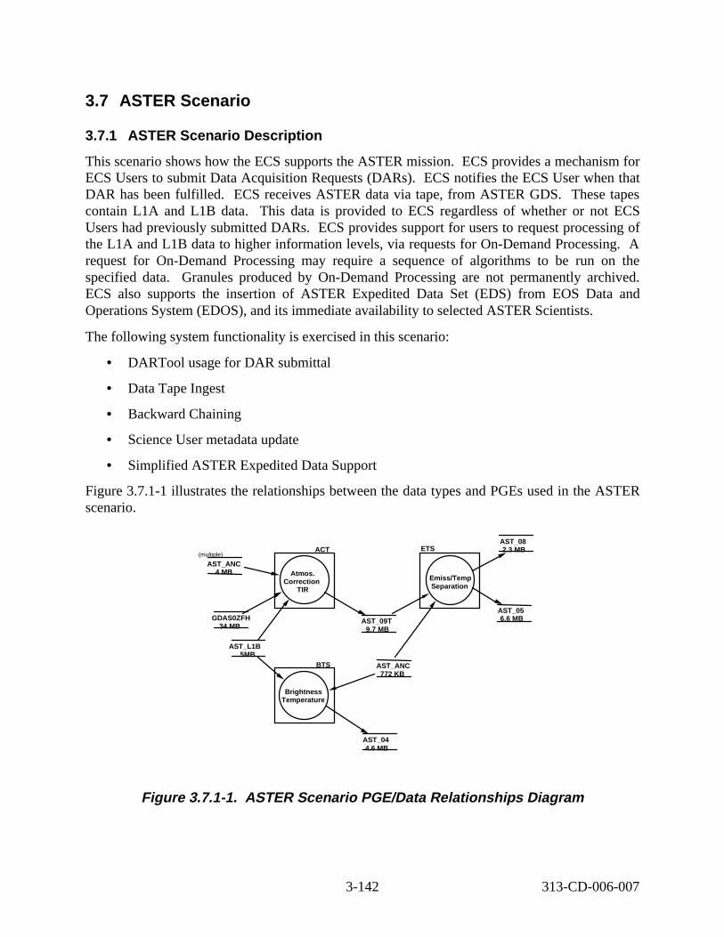
3.7 ASTER Scenario
3.7.1 ASTER Scenario D escript ion
This scenario shows how the ECS supports the ASTER mission. ECS provides a mechanism for ECS Users to submit Data Acquisition Requests (DARs). ECS notifies the ECS User when that DAR has been fulfilled. ECS receives ASTER data via tape, from ASTER GDS. These tapes contain L1A and L1B data. This data is provided to ECS regardless of whether or not ECS Users had previously submitted DARs. ECS provides support for users to request processing of the L1A and L1B data to higher information levels, via requests for On-Demand Processing. A request for On-Demand Processing may require a sequence of algorithms to be run on the specified data. Granules produced by On-Demand Processing are not permanently archived. ECS also supports the insertion of ASTER Expedited Data Set (EDS) from EOS Data and Operations System (EDOS), and its immediate availability to selected ASTER Scientists.
The following system functionality is exercised in this scenario:
• DARTool usage for DAR submittal
• Data Tape Ingest
• Backward Chaining
• Science User metadata update
• Simplified ASTER Expedited Data Support
Figure 3.7.1-1 illustrates the relationships between the data types and PGEs used in the ASTER scenario.
AST_08 ACT ETS 2.3 MB
Brightne ss Temperatur e
BTS
AST_L1B 5MB
AST_ANC 772 KB
Atmos. Correction
TIR
GDAS0ZFH 34 MB
AST_ANC 4 MB
(multiple)
AST_09T 9.7 MB
Emiss/Tem p Separation
AST_05 6.6 MB
AST_04 4.6 MB
Figure 3. 7.1-1. ASTER Scenario PG E/Data Relat ionship s Diagram
3-142 313-CD-006-007
3.7.2 ASTER Scenario Pr econditions
The following ESDTs have been inserted into the ECS:
• AST_ANC (ASTER Ancillary data)
• AST_EXP (ASTER Expedited L0 data)
• AST_L1A (ASTER L1A data)
• AST_L1B (ASTER L1B data)
• AST_04 (L2 Brightness Temperature)
• AST_05 (L2 Surface Emissivity)
• AST_08 (L2 Surface Temperature)
• AST_09T (L2 Surface Radiance)
• GDAS0ZFH (NCEP provided ancillary data)
• PH (Product History)
• PGEEXE (PGE Execution Granule)
The following ASTER PGEs have passed SSI&T and have been inserted into the ECS:
• ACT
• ETS
• BTS
Ancillary granules (AST_ANC and GDAS0ZFH) have been inserted into the ECS.
The Science User must be a registered ECS User whose profile reflects a user authorized to submit a DAR.
3.7.3 ASTER Scenario P art it ions
The ASTER scenario has been partitioned into the following threads:
• ASTER DAR Submission (Thread A) - This thread shows the usage of the CLS DARTool, and its interaction with GDS and other ECS components.
• ASTER GDS Tape Inser tion (Thread B) - This thread shows how the ECS inserts data provided by GDS on D3 tape.
• ASTER Backward Chaining (Thread C) - This thread shows how the system supports requests from ECS users to produce data requiring a sequence of algorithms to be run.
• ASTER QA Metadata Update (Thread D) - This thread shows how the ECS supports updating the QA metadata of a specified granule.
3-143 313-CD-006-007
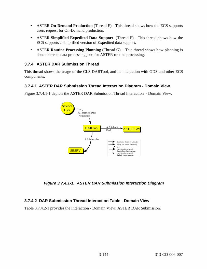
• ASTER On-Demand Production (Thread E) - This thread shows how the ECS supports users request for On-Demand production.
• ASTER Simplif ied Expedited Data Support (Thread F) - This thread shows how the ECS supports a simplified version of Expedited data support.
• ASTER Routine Processing Planning (Thread G) – This thread shows how planning is done to create data processing jobs for ASTER routine processing.
3.7.4 ASTER DAR Submis sion Thr ead
This thread shows the usage of the CLS DARTool, and its interaction with GDS and other ECS components.
3.7.4.1 ASTER DAR Submis sion Thr ead Interaction Dia gram - Doma in View
Figure 3.7.4.1-1 depicts the ASTER DAR Submission Thread Interaction - Domain View.
Sc ience User
Science User
A.1 Request Data Acquisition
ASTER GWASTER GWDARTool DARTool
SBSRV SBSRV
A.3 Subscribe
A.2 Submit DAR
Distributed Object (rpc, CtLib)
HMI (GUI, Xterm, command)
ftp email (or other as noted) Double line - Synchronous email (or other as noted) Dashed - Asynchronous
Figure 3.7.4.1-1. ASTER DAR Submis sion Inte rac tion Dia gram
3.7.4.2 DAR Submis sion Threa d Inte rac tion Ta ble - Doma in Vie w
Table 3.7.4.2-1 provides the Interaction - Domain View: ASTER DAR Submission.
3-144 313-CD-006-007
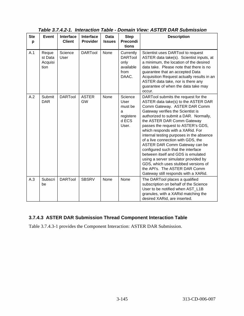
Table 3.7.4.2-1. Interac tion Ta ble - Domain Vie w: ASTER DAR Submi ssion Ste
p Event Interface
Client Interface Provider
Data Issues
Step Precondi
tions
Descript ion
A.1 Reque st Data Acquisi tion
Science User
DARTool None Currently DARTool only available from DAAC.
Scientist uses DARTool to request ASTER data take(s). Scientist inputs, at a minimum, the location of the desired data take. Please note that there is no guarantee that an accepted Data Acquisition Request actually results in an ASTER data take, nor is there any guarantee of when the data take may occur.
A.2 Submit DAR
DARTool ASTER GW
None Science User must be a registere d ECS User.
DARTool submits the request for the ASTER data take(s) to the ASTER DAR Comm Gateway. ASTER DAR Comm Gateway verifies the Scientist is authorized to submit a DAR. Normally, the ASTER DAR Comm Gateway passes the request to ASTER’s GDS, which responds with a XARid. For internal testing purposes in the absence of a live connection with GDS, the ASTER DAR Comm Gateway can be configured such that the interface between itself and GDS is emulated using a server simulator provided by GDS, which uses stubbed versions of the API's. The ASTER DAR Comm Gateway still responds with a XARid.
A.3 Subscri be
DARTool SBSRV None None The DARTool places a qualified subscription on behalf of the Science User to be notified when AST_L1B granules, with a XARid matching the desired XARid, are inserted.
3.7.4.3 ASTER DAR Submis sion Thr ead Compone nt Inte rac tion Ta ble
Table 3.7.4.3-1 provides the Component Interaction: ASTER DAR Submission.
3-145 313-CD-006-007
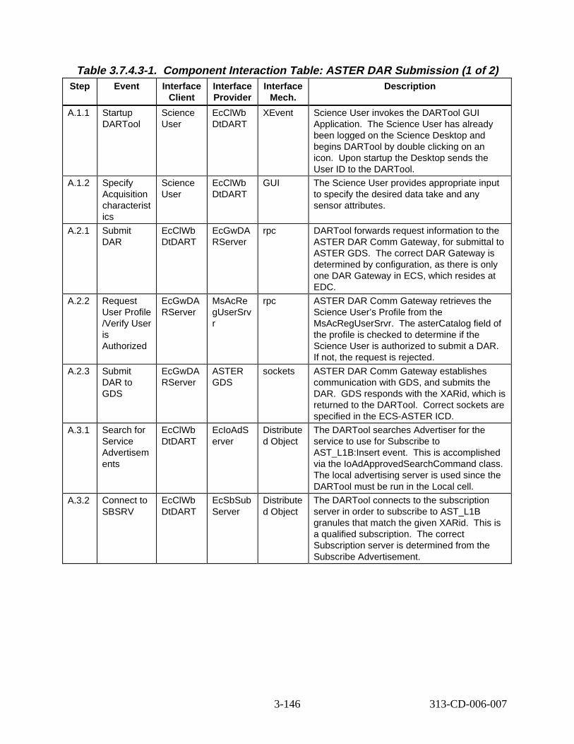
Table 3.7.4.3-1. Compone nt Inte rac tion Ta ble : ASTER DAR Submi ssion (1 of 2) Step Event Interface
Client Interface Provider
Interface Mech.
Descript ion
A.1.1 Startup DARTool
Science User
EcClWb DtDART
XEvent Science User invokes the DARTool GUI Application. The Science User has already been logged on the Science Desktop and begins DARTool by double clicking on an icon. Upon startup the Desktop sends the User ID to the DARTool.
A.1.2 Specify Acquisition characterist ics
Science User
EcClWb DtDART
GUI The Science User provides appropriate input to specify the desired data take and any sensor attributes.
A.2.1 Submit DAR
EcClWb DtDART
EcGwDA RServer
rpc DARTool forwards request information to the ASTER DAR Comm Gateway, for submittal to ASTER GDS. The correct DAR Gateway is determined by configuration, as there is only one DAR Gateway in ECS, which resides at EDC.
A.2.2 Request User Profile /Verify User is Authorized
EcGwDA RServer
MsAcRe gUserSrv r
rpc ASTER DAR Comm Gateway retrieves the Science User’s Profile from the MsAcRegUserSrvr. The asterCatalog field of the profile is checked to determine if the Science User is authorized to submit a DAR. If not, the request is rejected.
A.2.3 Submit DAR to GDS
EcGwDA RServer
ASTER GDS
sockets ASTER DAR Comm Gateway establishes communication with GDS, and submits the DAR. GDS responds with the XARid, which is returned to the DARTool. Correct sockets are specified in the ECS-ASTER ICD.
A.3.1 Search for Service Advertisem ents
EcClWb DtDART
EcIoAdS erver
Distribute d Object
The DARTool searches Advertiser for the service to use for Subscribe to AST_L1B:Insert event. This is accomplished via the IoAdApprovedSearchCommand class. The local advertising server is used since the DARTool must be run in the Local cell.
A.3.2 Connect to SBSRV
EcClWb DtDART
EcSbSub Server
Distribute d Object
The DARTool connects to the subscription server in order to subscribe to AST_L1B granules that match the given XARid. This is a qualified subscription. The correct Subscription server is determined from the Subscribe Advertisement.
3-146 313-CD-006-007
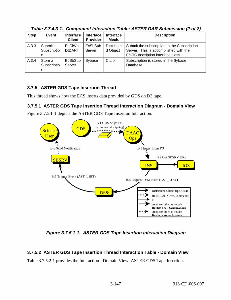
SBSRV
GDS
INS
DS
DAAC Ops
Science User
INS
Table 3.7.4.3-1. Compone nt Inte rac tion Ta ble : ASTER DAR Submi ssion (2 of 2) Step Event Interface
Client Interface Provider
Interface Mech.
Descript ion
A.3.3 Submit Subscriptio n
EcClWb DtDART
EcSbSub Server
Distribute d Object
Submit the subscription to the Subscription Server. This is accomplished with the EcClSubscription interface class.
A.3.4 Store a Subscriptio n
EcSbSub Server
Sybase CtLib Subscription is stored in the Sybase Database.
3.7.5 ASTER GDS Tape Insertion Thread
This thread shows how the ECS inserts data provided by GDS on D3 tape.
3.7.5.1 ASTER GDS Tape Insert ion Thread Int eract ion D iagram - Domain Vi ew
Figure 3.7.5.1-1 depicts the ASTER GDS Tape Insertion Interaction.
B.1 GDS Ships D3
GDS (commercial shipping) Science DAAC
User Ops
B.6 Send Notification B.3 Ingest from D3
B.2 Get SDSRV URs SBSRV
INS IOS
B.5 Trigger Event (AST_L1BT) B.4 Request Data Insert (AST_L1BT)
DSSS Distributed Object (rpc, CtLib)
HMI (GUI, Xterm, command)
ftp email (or other as noted) Double line - Synchronous email (or other as noted) Dashed - Asynchronous
Figure 3. 7.5.1-1. ASTER GDS Tape Ins ert ion Int eract ion D iagram
3.7.5.2 ASTER GDS Tape Insert ion Thread Int eract ion Tab le - Domain View
Table 3.7.5.2-1 provides the Interaction - Domain View: ASTER GDS Tape Insertion.
3-147 313-CD-006-007
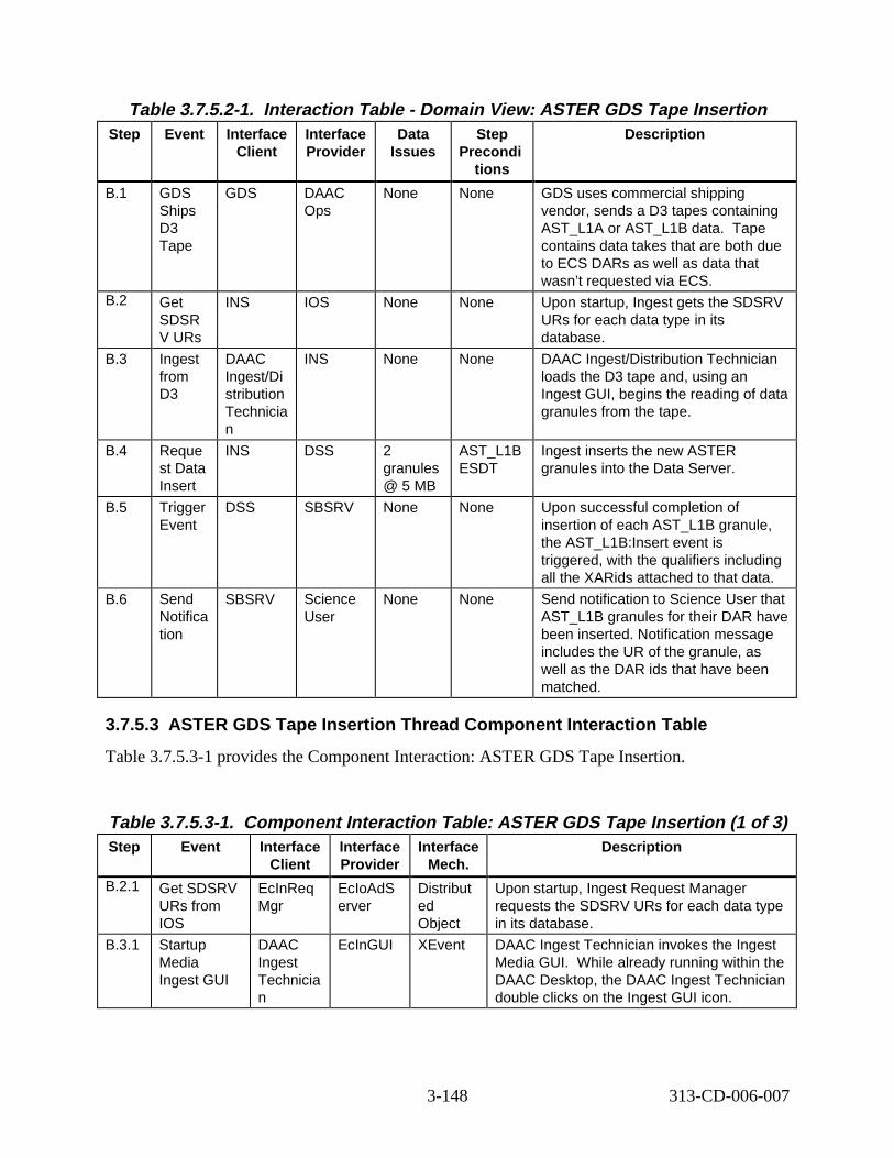
Table 3.7.5.2-1. Interact ion Tabl e - Domain V iew: ASTER GDS Tape Insert ion Step Event Interface
Client Interface Provider
Data Issues
Step Precondi
tions
Descript ion
B.1 GDS Ships D3 Tape
GDS DAAC Ops
None None GDS uses commercial shipping vendor, sends a D3 tapes containing AST_L1A or AST_L1B data. Tape contains data takes that are both due to ECS DARs as well as data that wasn’t requested via ECS.
B.2 Get SDSR V URs
INS IOS None None Upon startup, Ingest gets the SDSRV URs for each data type in its database.
B.3 Ingest from D3
DAAC Ingest/Di stribution Technicia n
INS None None DAAC Ingest/Distribution Technician loads the D3 tape and, using an Ingest GUI, begins the reading of data granules from the tape.
B.4 Reque st Data Insert
INS DSS 2 granules @ 5 MB
AST_L1B ESDT
Ingest inserts the new ASTER granules into the Data Server.
B.5 Trigger Event
DSS SBSRV None None Upon successful completion of insertion of each AST_L1B granule, the AST_L1B:Insert event is triggered, with the qualifiers including all the XARids attached to that data.
B.6 Send Notifica tion
SBSRV Science User
None None Send notification to Science User that AST_L1B granules for their DAR have been inserted. Notification message includes the UR of the granule, as well as the DAR ids that have been matched.
3.7.5.3 ASTER GDS Tape Insertion Thread Component Inter action Tabl e
Table 3.7.5.3-1 provides the Component Interaction: ASTER GDS Tape Insertion.
Table 3.7.5.3-1. Component Interaction Table: ASTER GDS Tape Insertion (1 of 3) Step Event Interface
Client Interface Provider
Interface Mech.
Descript ion
B.2.1 Get SDSRV URs from IOS
EcInReq Mgr
EcIoAdS erver
Distribut ed Object
Upon startup, Ingest Request Manager requests the SDSRV URs for each data type in its database.
B.3.1 Startup Media Ingest GUI
DAAC Ingest Technicia n
EcInGUI XEvent DAAC Ingest Technician invokes the Ingest Media GUI. While already running within the DAAC Desktop, the DAAC Ingest Technician double clicks on the Ingest GUI icon.
3-148 313-CD-006-007
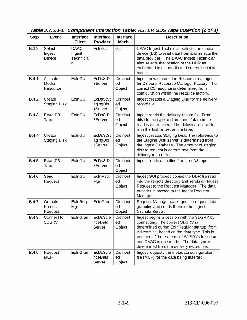
Table 3.7.5.3-1. Component Interaction Table: ASTER GDS Tape Insertion (2 of 3) Step Event Interface
Client Interface Provider
Interface Mech.
Descript ion
B.3.2 Select Ingest Device
DAAC Ingest Technicia n
EcInGUI GUI DAAC Ingest Technician selects the media device (D3) to read data from and selects the data provider. The DAAC Ingest Technician also selects the location of the DDR as embedded in the media and enters the DDR name.
B.4.1 Allocate Media Resource
EcInGUI EcDsStD 3Server
Distribut ed Object
Ingest now creates the Resource manager for D3 via a Resource Manager Factory. The correct D3 resource is determined from configuration within the resource factory.
B.4.2 Create Staging Disk
EcInGUI EcDsStSt agingDis kServer
Distribut ed Object
Ingest creates a Staging Disk for the delivery record file.
B.4.3 Read D3 Tape
EcInGUI EcDsStD 3Server
Distribut ed Object
Ingest reads the delivery record file. From this file the type and amount of data to be read is determined. The delivery record file is in the first tar set on the tape.
B.4.4 Create Staging Disk
EcInGUI EcDsStSt agingDis kServer
Distribut ed Object
Ingest creates Staging Disk. The reference to the Staging Disk server is determined from the Ingest Database. The amount of staging disk to request is determined from the delivery record file.
B.4.5 Read D3 Tape
EcInGUI EcDsStD 3Server
Distribut ed Object
Ingest reads data files from the D3 tape.
B.4.6 Send Request
EcInGUI EcInReq Mgr
Distribut ed Object
Ingest GUI process copies the DDR file read into the remote directory and sends an Ingest Request to the Request Manager. The data provider is passed to the Ingest Request Manager.
B.4.7 Granule Process Request
EcInReq Mgr
EcInGran Distribut ed Object
Request Manager packages the request into granules and sends them to the Ingest Granule Server.
B.4.8 Connect to SDSRV
EcInGran EcDsScie nceData Server
Distribut ed Object
Ingest begins a session with the SDSRV by connecting. The correct SDSRV is determined during EcInReqMgr startup, from Advertising, based on the data type. This is pertinent if there are multi-SDSRVs in use at one DAAC in one mode. The data type is determined from the delivery record file.
B.4.9 Request MCF
EcInGran EcDsScie nceData Server
Distribut ed Object
Ingest requests the metadata configuration file (MCF) for the data being inserted.
3-149 313-CD-006-007
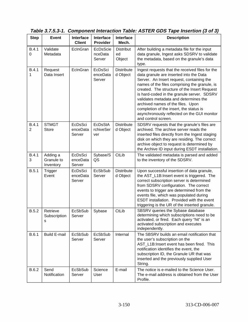
Table 3.7.5.3-1. Component Interaction Table: ASTER GDS Tape Insertion (3 of 3) Step Event Interface
Client Interface Provider
Interface Mech.
Descript ion
B.4.1 0
Validate Metadata
EcInGran EcDsScie nceData Server
Distribut ed Object
After building a metadata file for the input data granule, Ingest asks SDSRV to validate the metadata, based on the granule’s data type.
B.4.1 1
Request Data Insert
EcInGran EcDsSci enceData Server
Distribute d Object
Ingest requests that the received files for the data granule are inserted into the Data Server. An Insert request, containing the names of the files comprising the granule, is created. The structure of the Insert Request is hard-coded in the granule server. SDSRV validates metadata and determines the archived names of the files. Upon completion of the insert, the status is asynchronously reflected on the GUI monitor and control screen.
B.4.1 2
STMGT Store
EcDsSci enceData Server
EcDsStA rchiveSer ver
Distribute d Object
SDSRV requests that the granule’s files are archived. The archive server reads the inserted files directly from the Ingest staging disk on which they are residing. The correct archive object to request is determined by the Archive ID input during ESDT installation.
B.4.1 3
Adding a Granule to Inventory
EcDsSci enceData Server
Sybase/S QS
CtLib The validated metadata is parsed and added to the inventory of the SDSRV.
B.5.1 Trigger Event
EcDsSci enceData Server
EcSbSub Server
Distribute d Object
Upon successful insertion of data granule, the AST_L1B:Insert event is triggered. The correct subscription server is determined from SDSRV configuration. The correct events to trigger are determined from the events file, which was populated during ESDT installation. Provided with the event triggering is the UR of the inserted granule.
B.5.2 Retrieve Subscription s
EcSbSub Server
Sybase CtLib SBSRV queries the Sybase database determining which subscriptions need to be activated, or fired. Each query “hit” is an activated subscription and executes independently.
B.6.1 Build E-mail EcSbSub Server
EcSbSub Server
Internal The SBSRV builds an email notification that the user’s subscription on the AST_L1B:Insert event has been fired. This notification identifies the event, the subscription ID, the Granule UR that was inserted and the previously supplied User String.
B.6.2 Send Notification
EcSbSub Server
Science User
E-mail The notice is e-mailed to the Science User. The e-mail address is obtained from the User Profile.
3-150 313-CD-006-007
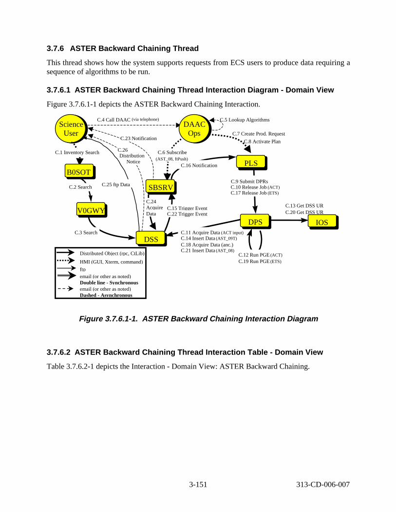
3.7.6 ASTER Backw ard Chaining Thr ead
This thread shows how the system supports requests from ECS users to produce data requiring a sequence of algorithms to be run.
3.7.6.1 ASTER Backw ard Chaining Thr ead Int eract ion D iagram - Domain Vi ew
Figure 3.7.6.1-1 depicts the ASTER Backward Chaining Interaction.
Distributed Object (rpc, CtLib)
HMI (GUI, Xterm, command)
ftp email (or other as noted) Double line - Synchronous email (or other as noted) Dashed - Asynchronous
C.11 Acquire Data (ACT input) C.14 Insert Data (AST_09T)
C.18 Acquire Data (anc.) C.21 Insert Data (AST_08)
B0SOTB0SOT
DAAC Ops
DAAC Ops
C.1 Inventory Search
C.4 Call DAAC (via telephone)
Science User
Science User
V0GWYV0GWY
SBSRVSBSRV
DSS DSS
DPS DPS
PLSPLS
C.2 Search
C.3 Search
C.25 ftp Data
C.23 Notification
C.5 Lookup Algorithms
C.7 Create Prod. Request
C.8 Activate Plan
C.10 Release Job (ACT) C.17 Release Job (ETS)
C.12 Run PGE (ACT)
C.19 Run PGE (ETS)
C.16 Notification
C.24 Acquire Data
C.15 Trigger Event C.22 Trigger Event
C.26
Notice Distribution
C.9 Submit DPRs
IOS
C.13 Get DSS UR C.20 Get DSS UR
C.6 Subscribe (AST_08, ftPush)
Figure 3. 7.6.1-1. ASTER Backward Chaining Int eract ion D iagram
3.7.6.2 ASTER Backw ard Chaining Th read Int eract ion Tab le - Domain View
Table 3.7.6.2-1 depicts the Interaction - Domain View: ASTER Backward Chaining.
3-151 313-CD-006-007
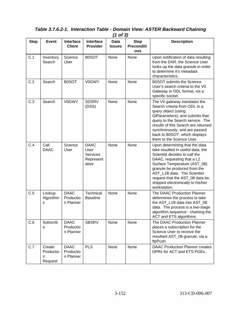
Table 3.7.6.2-1. Interact ion Tabl e - Domain V iew: ASTER Backward C haining (1 of 3)
Step Event Interface Client
Interface Provider
Data Issues
Step Preconditi
ons
Descript ion
C.1 Inventory Search
Science User
B0SOT None None Upon notification of data resulting from the DAR, the Science User looks up the data granule in order to determine it’s metadata characteristics.
C.2 Search B0SOT V0GWY None None B0SOT submits the Science User’s search criteria to the V0 Gateway in ODL format, via a specific socket.
C.3 Search V0GWY SDSRV (DSS)
None None The V0 gateway translates the Search criteria from ODL to a query object (using GlParameters), and submits that query to the Search service. The results of this Search are returned synchronously, and are passed back to B0SOT, which displays them to the Science User.
C.4 Call DAAC
Science User
DAAC User Services Represent ative
None None Upon determining that the data take resulted in useful data, the Scientist decides to call the DAAC, requesting that a L2 Surface Temperature (AST_08) granule be produced from the AST_L1B data. The Scientist request that the AST_08 data be shipped electronically to his/her workstation.
C.5 Lookup Algorithm s
DAAC Productio n Planner
Technical Baseline
None None The DAAC Production Planner determines the process to take the AST_L1B data into AST_08 data. The process is a two-stage algorithm sequence: chaining the ACT and ETS algorithms.
C.6 Subscrib e
DAAC Productio n Planner
SBSRV None None The DAAC Production Planner places a subscription for the Science User to receive the resultant AST_08 granule, via a ftpPush.
C.7 Create Productio n Request
DAAC Productio n Planner
PLS None None DAAC Production Planner creates DPRs for ACT and ETS PGEs.
3-152 313-CD-006-007
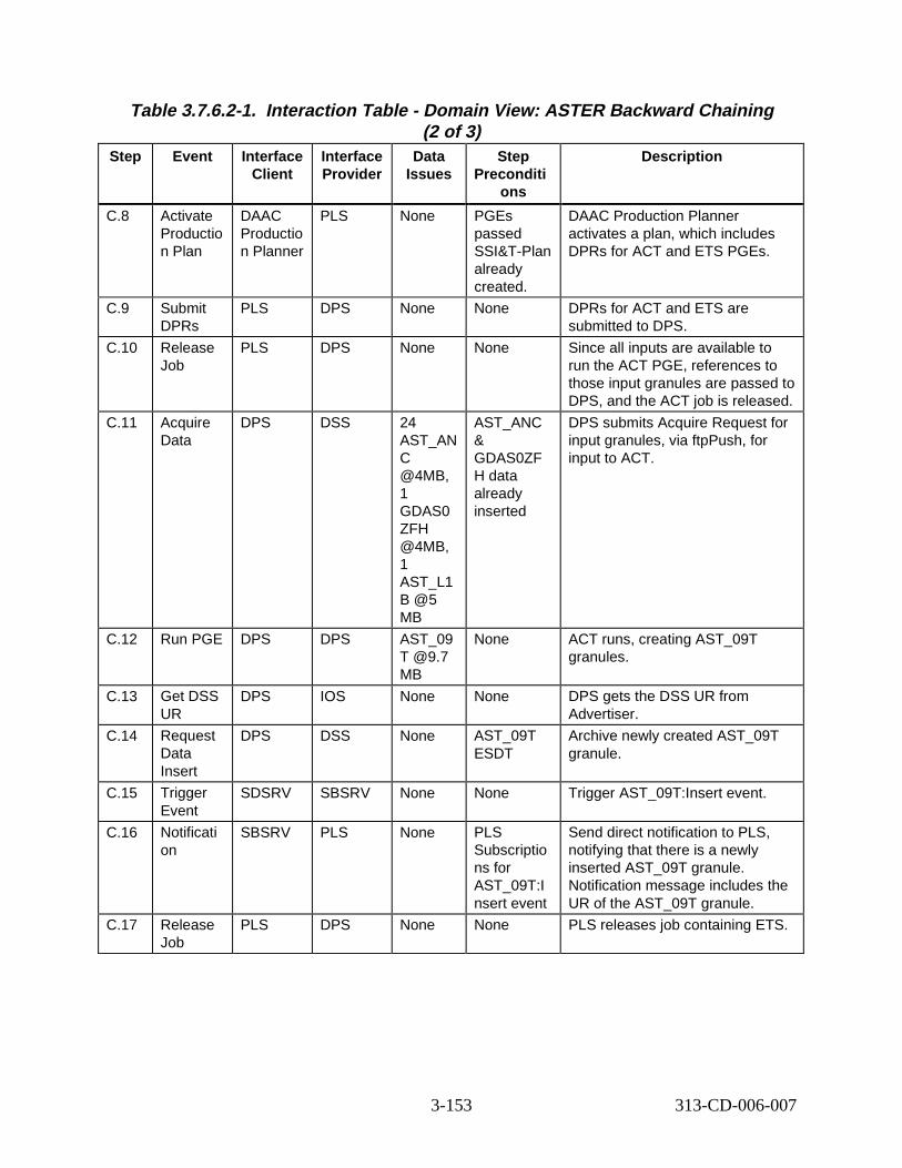
Table 3.7.6.2-1. Interact ion Tabl e - Domain V iew: ASTER Backward C haining (2 of 3)
Step Event Interface Client
Interface Provider
Data Issues
Step Preconditi
ons
Descript ion
C.8 Activate Productio n Plan
DAAC Productio n Planner
PLS None PGEs passed SSI&T-Plan already created.
DAAC Production Planner activates a plan, which includes DPRs for ACT and ETS PGEs.
C.9 Submit DPRs
PLS DPS None None DPRs for ACT and ETS are submitted to DPS.
C.10 Release Job
PLS DPS None None Since all inputs are available to run the ACT PGE, references to those input granules are passed to DPS, and the ACT job is released.
C.11 Acquire Data
DPS DSS 24 AST_AN C @4MB, 1 GDAS0 ZFH @4MB, 1 AST_L1 B @5 MB
AST_ANC & GDAS0ZF H data already inserted
DPS submits Acquire Request for input granules, via ftpPush, for input to ACT.
C.12 Run PGE DPS DPS AST_09 T @9.7 MB
None ACT runs, creating AST_09T granules.
C.13 Get DSS UR
DPS IOS None None DPS gets the DSS UR from Advertiser.
C.14 Request Data Insert
DPS DSS None AST_09T ESDT
Archive newly created AST_09T granule.
C.15 Trigger Event
SDSRV SBSRV None None Trigger AST_09T:Insert event.
C.16 Notificati on
SBSRV PLS None PLS Subscriptio ns for AST_09T:I nsert event
Send direct notification to PLS, notifying that there is a newly inserted AST_09T granule. Notification message includes the UR of the AST_09T granule.
C.17 Release Job
PLS DPS None None PLS releases job containing ETS.
3-153 313-CD-006-007
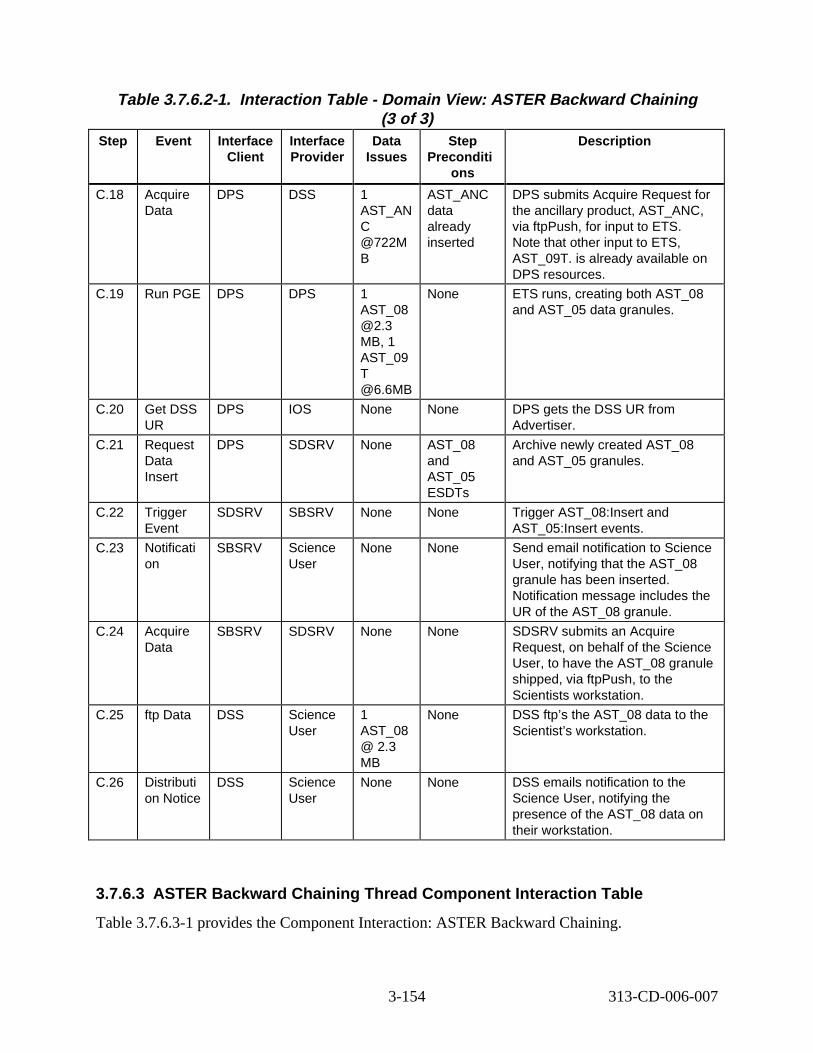
Table 3.7.6.2-1. Interact ion Tabl e - Domain V iew: ASTER Backward C haining (3 of 3)
Step Event Interface Client
Interface Provider
Data Issues
Step Preconditi
ons
Descript ion
C.18 Acquire Data
DPS DSS 1 AST_AN C @722M B
AST_ANC data already inserted
DPS submits Acquire Request for the ancillary product, AST_ANC, via ftpPush, for input to ETS. Note that other input to ETS, AST_09T. is already available on DPS resources.
C.19 Run PGE DPS DPS 1 AST_08 @2.3 MB, 1 AST_09 T @6.6MB
None ETS runs, creating both AST_08 and AST_05 data granules.
C.20 Get DSS UR
DPS IOS None None DPS gets the DSS UR from Advertiser.
C.21 Request Data Insert
DPS SDSRV None AST_08 and AST_05 ESDTs
Archive newly created AST_08 and AST_05 granules.
C.22 Trigger Event
SDSRV SBSRV None None Trigger AST_08:Insert and AST_05:Insert events.
C.23 Notificati on
SBSRV Science User
None None Send email notification to Science User, notifying that the AST_08 granule has been inserted. Notification message includes the UR of the AST_08 granule.
C.24 Acquire Data
SBSRV SDSRV None None SDSRV submits an Acquire Request, on behalf of the Science User, to have the AST_08 granule shipped, via ftpPush, to the Scientists workstation.
C.25 ftp Data DSS Science User
1 AST_08 @ 2.3 MB
None DSS ftp’s the AST_08 data to the Scientist’s workstation.
C.26 Distributi on Notice
DSS Science User
None None DSS emails notification to the Science User, notifying the presence of the AST_08 data on their workstation.
3.7.6.3 ASTER Backw ard Chaining Thr ead Component Inter action Tabl e
Table 3.7.6.3-1 provides the Component Interaction: ASTER Backward Chaining.
3-154 313-CD-006-007
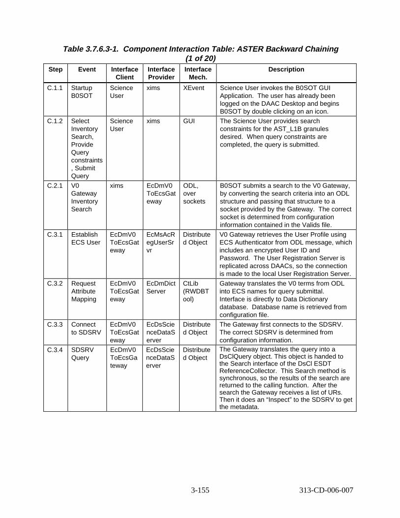
Table 3.7.6.3-1. Component Interaction Table: ASTER B ackward Chaining (1 of 20)
Step Event Interface Client
Interface Provider
Interface Mech.
Descript ion
C.1.1 Startup B0SOT
Science User
xims XEvent Science User invokes the B0SOT GUI Application. The user has already been logged on the DAAC Desktop and begins B0SOT by double clicking on an icon.
C.1.2 Select Inventory Search, Provide Query constraints , Submit Query
Science User
xims GUI The Science User provides search constraints for the AST_L1B granules desired. When query constraints are completed, the query is submitted.
C.2.1 V0 Gateway Inventory Search
xims EcDmV0 ToEcsGat eway
ODL, over sockets
B0SOT submits a search to the V0 Gateway, by converting the search criteria into an ODL structure and passing that structure to a socket provided by the Gateway. The correct socket is determined from configuration information contained in the Valids file.
C.3.1 Establish ECS User
EcDmV0 ToEcsGat eway
EcMsAcR egUserSr vr
Distribute d Object
V0 Gateway retrieves the User Profile using ECS Authenticator from ODL message, which includes an encrypted User ID and Password. The User Registration Server is replicated across DAACs, so the connection is made to the local User Registration Server.
C.3.2 Request Attribute Mapping
EcDmV0 ToEcsGat eway
EcDmDict Server
CtLib (RWDBT ool)
Gateway translates the V0 terms from ODL into ECS names for query submittal. Interface is directly to Data Dictionary database. Database name is retrieved from configuration file.
C.3.3 Connect to SDSRV
EcDmV0 ToEcsGat eway
EcDsScie nceDataS erver
Distribute d Object
The Gateway first connects to the SDSRV. The correct SDSRV is determined from configuration information.
C.3.4 SDSRV Query
EcDmV0 ToEcsGa teway
EcDsScie nceDataS erver
Distribute d Object
The Gateway translates the query into a DsClQuery object. This object is handed to the Search interface of the DsCl ESDT ReferenceCollector. This Search method is synchronous, so the results of the search are returned to the calling function. After the search the Gateway receives a list of URs. Then it does an “Inspect” to the SDSRV to get the metadata.
3-155 313-CD-006-007
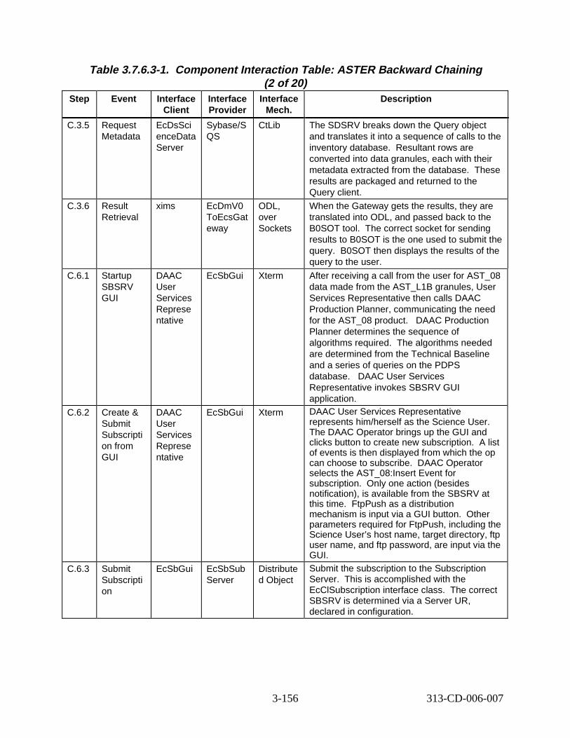
Table 3.7.6.3-1. Component Interaction Table: ASTER B ackward Chaining (2 of 20)
Step Event Interface Client
Interface Provider
Interface Mech.
Descript ion
C.3.5 Request Metadata
EcDsSci enceData Server
Sybase/S QS
CtLib The SDSRV breaks down the Query object and translates it into a sequence of calls to the inventory database. Resultant rows are converted into data granules, each with their metadata extracted from the database. These results are packaged and returned to the Query client.
C.3.6 Result Retrieval
xims EcDmV0 ToEcsGat eway
ODL, over Sockets
When the Gateway gets the results, they are translated into ODL, and passed back to the B0SOT tool. The correct socket for sending results to B0SOT is the one used to submit the query. B0SOT then displays the results of the query to the user.
C.6.1 Startup SBSRV GUI
DAAC User Services Represe ntative
EcSbGui Xterm After receiving a call from the user for AST_08 data made from the AST_L1B granules, User Services Representative then calls DAAC Production Planner, communicating the need for the AST_08 product. AC Production Planner determines the sequence of algorithms required. The algorithms needed are determined from the Technical Baseline and a series of queries on the PDPS database. DAAC User Services Representative invokes SBSRV GUI application.
C.6.2 Create & Submit Subscripti on from GUI
DAAC User Services Represe ntative
EcSbGui Xterm DAAC User Services Representative represents him/herself as the Science User. The DAAC Operator brings up the GUI and clicks button to create new subscription. A list of events is then displayed from which the op can choose to subscribe. AAC Operator selects the AST_08:Insert Event for subscription. nly one action (besides notification), is available from the SBSRV at this time. FtpPush as a distribution mechanism is input via a GUI button. ther parameters required for FtpPush, including the Science User’s host name, target directory, ftp user name, and ftp password, are input via the GUI.
C.6.3 Submit Subscripti on
EcSbGui EcSbSub Server
Distribute d Object
Submit the subscription to the Subscription Server. is is accomplished with the EcClSubscription interface class. The correct SBSRV is determined via a Server UR, declared in configuration.
DA
D
O
O
Th
3-156 313-CD-006-007
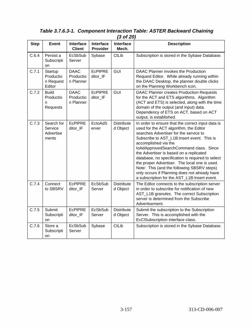
Table 3.7.6.3-1. Component Interaction Table: ASTER B ackward Chaining (3 of 20)
Step Event Interface Client
Interface Provider
Interface Mech.
Descript ion
C.6.4 Persist a Subscripti on
EcSbSub Server
Sybase CtLib Subscription is stored in the Sybase Database.
C.7.1 Startup Productio n Request Editor
DAAC Productio n Planner
EcPlPRE ditor_IF
GUI DAAC Planner invokes the Production Request Editor. While already running within the DAAC Desktop, the planner double clicks on the Planning Workbench icon.
C.7.2 Build Productio n Requests
DAAC Productio n Planner
EcPlPRE ditor_IF
GUI DAAC Planner creates Production Requests for the ACT and ETS algorithms. Algorithm (ACT and ETS) is selected, along with the time domain of the output (and input) data. Dependency of ETS on ACT, based on ACT output, is established.
C.7.3 Search for Service Advertise ments
EcPlPRE ditor_IF
EcIoAdS erver
Distribute d Object
In order to ensure that the correct input data is used for the ACT algorithm, the Editor searches Advertiser for the service to Subscribe to AST_L1B:Insert event. This is accomplished via the IoAdApprovedSearchCommand class. Since the Advertiser is based on a replicated database, no specification is required to select the proper Advertiser. The local one is used. Note: This (and the following SBSRV steps) only occurs if Planning does not already have a subscription for the AST_L1B:Insert event.
C.7.4 Connect to SBSRV
EcPlPRE ditor_IF
EcSbSub Server
Distribute d Object
The Editor connects to the subscription server in order to subscribe for notification of new AST_L1B granules. The correct Subscription server is determined from the Subscribe Advertisement.
C.7.5 Submit Subscripti on
EcPlPRE ditor_IF
EcSbSub Server
Distribute d Object
Submit the subscription to the Subscription Server. This is accomplished with the EcClSubscription interface class.
C.7.6 Store a Subscripti on
EcSbSub Server
Sybase CtLib Subscription is stored in the Sybase Database.
3-157 313-CD-006-007
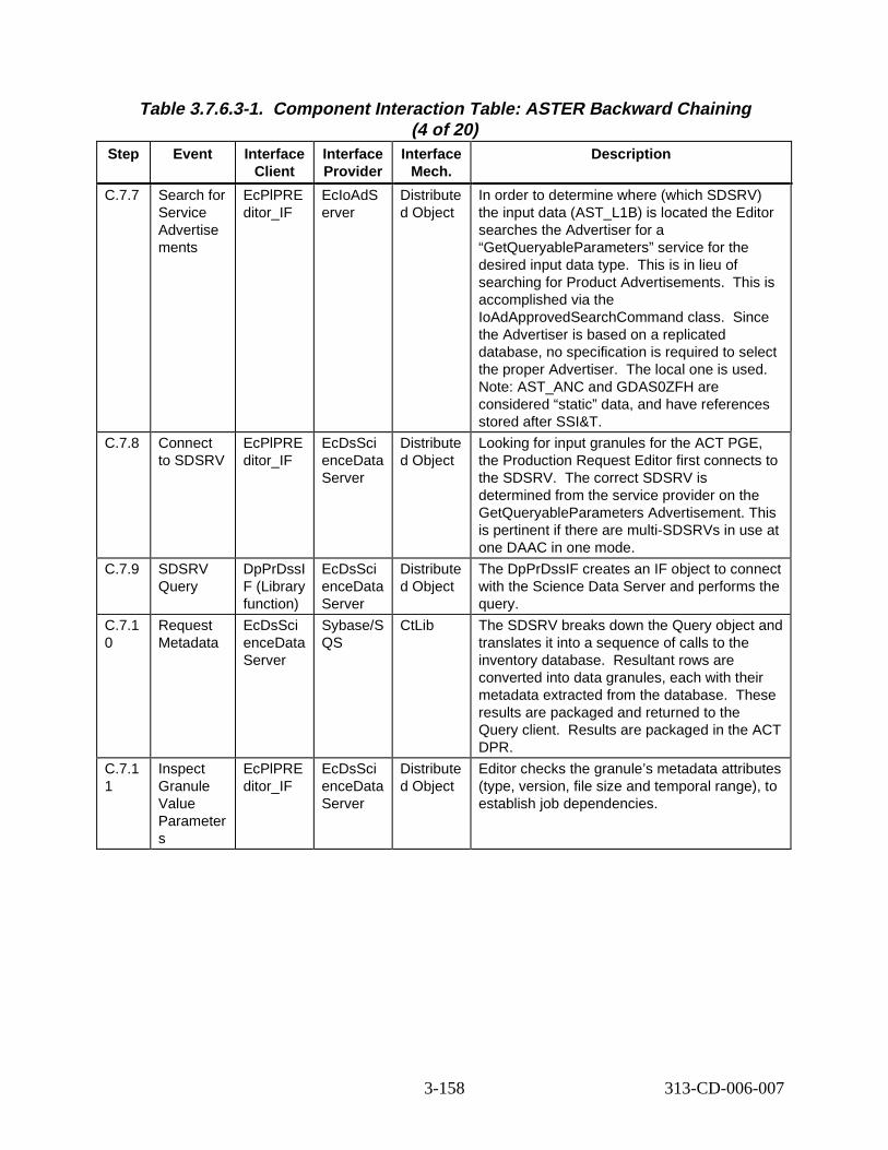
Table 3.7.6.3-1. Component Interaction Table: ASTER B ackward Chaining (4 of 20)
Step Event Interface Client
Interface Provider
Interface Mech.
Descript ion
C.7.7 Search for Service Advertise ments
EcPlPRE ditor_IF
EcIoAdS erver
Distribute d Object
In order to determine where (which SDSRV) the input data (AST_L1B) is located the Editor searches the Advertiser for a “GetQueryableParameters” service for the desired input data type. This is in lieu of searching for Product Advertisements. This is accomplished via the IoAdApprovedSearchCommand class. Since the Advertiser is based on a replicated database, no specification is required to select the proper Advertiser. The local one is used. Note: AST_ANC and GDAS0ZFH are considered “static” data, and have references stored after SSI&T.
C.7.8 Connect to SDSRV
EcPlPRE ditor_IF
EcDsSci enceData Server
Distribute d Object
Looking for input granules for the ACT PGE, the Production Request Editor first connects to the SDSRV. The correct SDSRV is determined from the service provider on the GetQueryableParameters Advertisement. This is pertinent if there are multi-SDSRVs in use at one DAAC in one mode.
C.7.9 SDSRV Query
DpPrDssI F (Library function)
EcDsSci enceData Server
Distribute d Object
The DpPrDssIF creates an IF object to connect with the Science Data Server and performs the query.
C.7.1 0
Request Metadata
EcDsSci enceData Server
Sybase/S QS
CtLib The SDSRV breaks down the Query object and translates it into a sequence of calls to the inventory database. Resultant rows are converted into data granules, each with their metadata extracted from the database. These results are packaged and returned to the Query client. Results are packaged in the ACT DPR.
C.7.1 1
Inspect Granule Value Parameter s
EcPlPRE ditor_IF
EcDsSci enceData Server
Distribute d Object
Editor checks the granule’s metadata attributes (type, version, file size and temporal range), to establish job dependencies.
3-158 313-CD-006-007
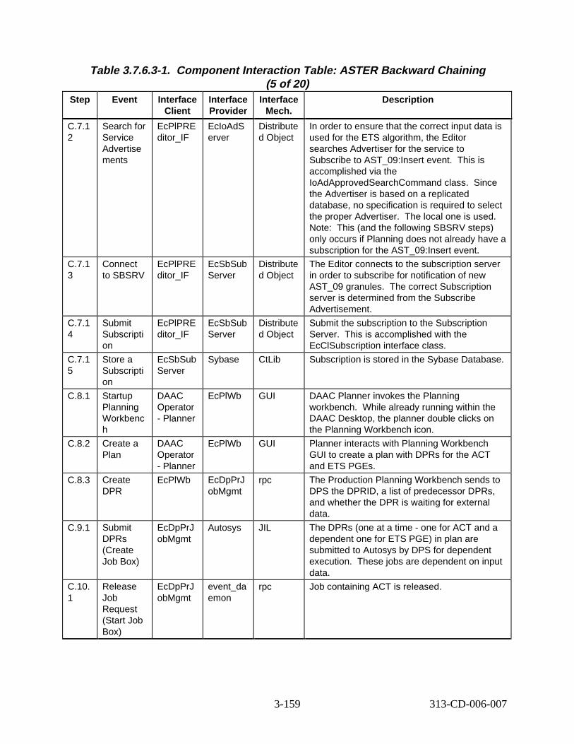
Table 3.7.6.3-1. Component Interaction Table: ASTER B ackward Chaining (5 of 20)
Step Event Interface Client
Interface Provider
Interface Mech.
Descript ion
C.7.1 2
Search for Service Advertise ments
EcPlPRE ditor_IF
EcIoAdS erver
Distribute d Object
In order to ensure that the correct input data is used for the ETS algorithm, the Editor searches Advertiser for the service to Subscribe to AST_09:Insert event. This is accomplished via the IoAdApprovedSearchCommand class. Since the Advertiser is based on a replicated database, no specification is required to select the proper Advertiser. The local one is used. Note: This (and the following SBSRV steps) only occurs if Planning does not already have a subscription for the AST_09:Insert event.
C.7.1 3
Connect to SBSRV
EcPlPRE ditor_IF
EcSbSub Server
Distribute d Object
The Editor connects to the subscription server in order to subscribe for notification of new AST_09 granules. The correct Subscription server is determined from the Subscribe Advertisement.
C.7.1 4
Submit Subscripti on
EcPlPRE ditor_IF
EcSbSub Server
Distribute d Object
Submit the subscription to the Subscription Server. This is accomplished with the EcClSubscription interface class.
C.7.1 5
Store a Subscripti on
EcSbSub Server
Sybase CtLib Subscription is stored in the Sybase Database.
C.8.1 Startup Planning Workbenc h
DAAC Operator - Planner
EcPlWb GUI DAAC Planner invokes the Planning workbench. While already running within the DAAC Desktop, the planner double clicks on the Planning Workbench icon.
C.8.2 Create a Plan
DAAC Operator - Planner
EcPlWb GUI Planner interacts with Planning Workbench GUI to create a plan with DPRs for the ACT and ETS PGEs.
C.8.3 Create DPR
EcPlWb EcDpPrJ obMgmt
rpc The Production Planning Workbench sends to DPS the DPRID, a list of predecessor DPRs, and whether the DPR is waiting for external data.
C.9.1 Submit DPRs (Create Job Box)
EcDpPrJ obMgmt
Autosys JIL The DPRs (one at a time - one for ACT and a dependent one for ETS PGE) in plan are submitted to Autosys by DPS for dependent execution. These jobs are dependent on input data.
C.10. 1
Release Job Request (Start Job Box)
EcDpPrJ obMgmt
event_da emon
rpc Job containing ACT is released.
3-159 313-CD-006-007
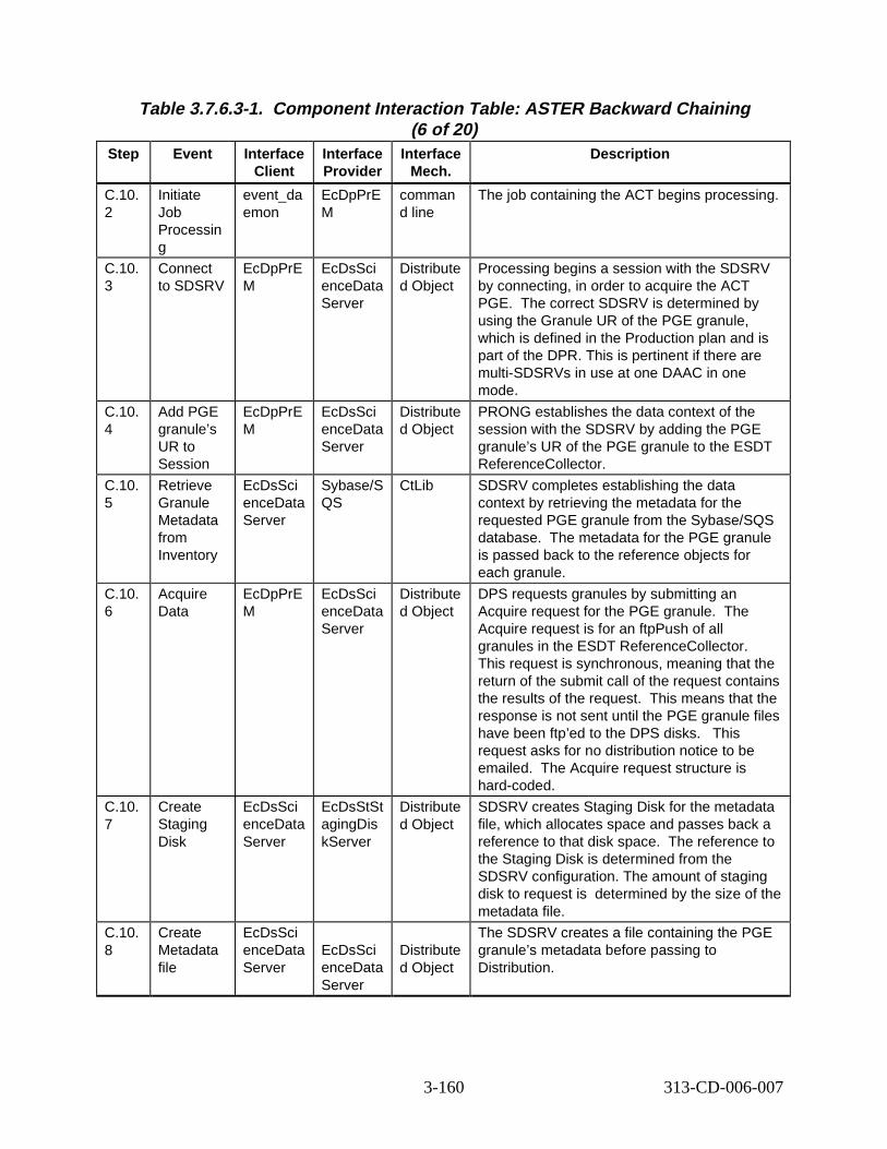
Table 3.7.6.3-1. Component Interaction Table: ASTER B ackward Chaining (6 of 20)
Step Event Interface Client
Interface Provider
Interface Mech.
Descript ion
C.10. 2
Initiate Job Processin g
event_da emon
EcDpPrE M
comman d line
The job containing the ACT begins processing.
C.10. 3
Connect to SDSRV
EcDpPrE M
EcDsSci enceData Server
Distribute d Object
Processing begins a session with the SDSRV by connecting, in order to acquire the ACT PGE. The correct SDSRV is determined by using the Granule UR of the PGE granule, which is defined in the Production plan and is part of the DPR. This is pertinent if there are multi-SDSRVs in use at one DAAC in one mode.
C.10. 4
Add PGE granule’s UR to Session
EcDpPrE M
EcDsSci enceData Server
Distribute d Object
PRONG establishes the data context of the session with the SDSRV by adding the PGE granule’s UR of the PGE granule to the ESDT ReferenceCollector.
C.10. 5
Retrieve Granule Metadata from Inventory
EcDsSci enceData Server
Sybase/S QS
CtLib SDSRV completes establishing the data context by retrieving the metadata for the requested PGE granule from the Sybase/SQS database. The metadata for the PGE granule is passed back to the reference objects for each granule.
C.10. 6
Acquire Data
EcDpPrE M
EcDsSci enceData Server
Distribute d Object
DPS requests granules by submitting an Acquire request for the PGE granule. The Acquire request is for an ftpPush of all granules in the ESDT ReferenceCollector. This request is synchronous, meaning that the return of the submit call of the request contains the results of the request. This means that the response is not sent until the PGE granule files have been ftp’ed to the DPS disks. This request asks for no distribution notice to be emailed. The Acquire request structure is hard-coded.
C.10. 7
Create Staging Disk
EcDsSci enceData Server
EcDsStSt agingDis kServer
Distribute d Object
SDSRV creates Staging Disk for the metadata file, which allocates space and passes back a reference to that disk space. The reference to the Staging Disk is determined from the SDSRV configuration. The amount of staging disk to request is determined by the size of the metadata file.
C.10. 8
Create Metadata file
EcDsSci enceData Server
EcDsSci enceData Server
Distribute d Object
The SDSRV creates a file containing the PGE granule’s metadata before passing to Distribution.
3-160 313-CD-006-007
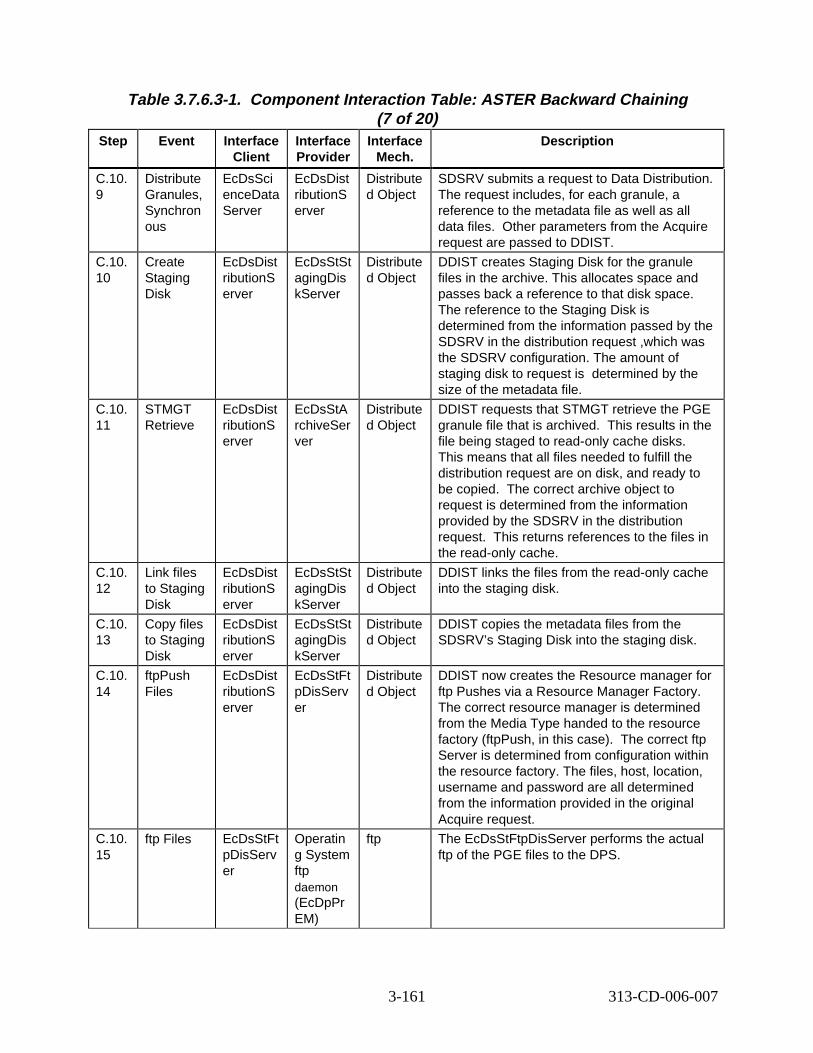
Table 3.7.6.3-1. Component Interaction Table: ASTER B ackward Chaining (7 of 20)
Step Event Interface Client
Interface Provider
Interface Mech.
Descript ion
C.10. 9
Distribute Granules, Synchron ous
EcDsSci enceData Server
EcDsDist ributionS erver
Distribute d Object
SDSRV submits a request to Data Distribution. The request includes, for each granule, a reference to the metadata file as well as all data files. Other parameters from the Acquire request are passed to DDIST.
C.10. 10
Create Staging Disk
EcDsDist ributionS erver
EcDsStSt agingDis kServer
Distribute d Object
DDIST creates Staging Disk for the granule files in the archive. This allocates space and passes back a reference to that disk space. The reference to the Staging Disk is determined from the information passed by the SDSRV in the distribution request ,which was the SDSRV configuration. The amount of staging disk to request is determined by the size of the metadata file.
C.10. 11
STMGT Retrieve
EcDsDist ributionS erver
EcDsStA rchiveSer ver
Distribute d Object
DDIST requests that STMGT retrieve the PGE granule file that is archived. This results in the file being staged to read-only cache disks. This means that all files needed to fulfill the distribution request are on disk, and ready to be copied. correct archive object to request is determined from the information provided by the SDSRV in the distribution request. his returns references to the files in the read-only cache.
C.10. 12
Link files to Staging Disk
EcDsDist ributionS erver
EcDsStSt agingDis kServer
Distribute d Object
DDIST links the files from the read-only cache into the staging disk.
C.10. 13
Copy files to Staging Disk
EcDsDist ributionS erver
EcDsStSt agingDis kServer
Distribute d Object
DDIST copies the metadata files from the SDSRV’s Staging Disk into the staging disk.
C.10. 14
ftpPush Files
EcDsDist ributionS erver
EcDsStFt pDisServ er
Distribute d Object
DDIST now creates the Resource manager for ftp Pushes via a Resource Manager Factory. The correct resource manager is determined from the Media Type handed to the resource factory (ftpPush, in this case). e correct ftp Server is determined from configuration within the resource factory. The files, host, location, username and password are all determined from the information provided in the original Acquire request.
C.10. 15
ftp Files EcDsStFt pDisServ er
Operatin g System ftp daemon (EcDpPr EM)
ftp The EcDsStFtpDisServer performs the actual ftp of the PGE files to the DPS.
The
T
Th
3-161 313-CD-006-007

Table 3.7.6.3-1. Component Interaction Table: ASTER B ackward Chaining (8 of 20)
Step Event Interface Client
Interface Provider
Interface Mech.
Descript ion
C.11. 1
Connect to SDSRV
EcDpPrD M
EcDsSci enceData Server
Distribute d Object
PRONG begins a session with the SDSRV by connecting. The correct SDSRV is determined by using the Granule UR of the input granule. This is pertinent if there are multi-SDSRVs in use at one DAAC in one mode.
C.11. 2
Add PGE granule’s UR to Session
EcDpPrD M
EcDsSci enceData Server
Distribute d Object
PRONG establishes the data context of the session with the SDSRV by adding the input granules (1 AST_L1B, 1 GDAS0ZFH and 24 AST_ANC) to the session. The Granule UR of the input granule is added to the ESDT ReferenceCollector. Note that this sequence is performed for each input granule, one at a time.
C.11. 3
Retrieve Granule Metadata from Inventory
EcDsSci enceData Server
Sybase/S QS
CtLib SDSRV completes establishing the data context by retrieving the metadata for the requested granule from the Sybase/SQS database. he metadata for each granule is passed back to the reference objects for each granule.
C.11. 4
Acquire Data
EcDpPrD M
EcDsSci enceData Server
Distribute d Object
DPS requests granules by submitting an Acquire request for those granules. The Acquire request is for a ftpPush of all granules in the ESDT ReferenceCollector. is request is synchronous, meaning that the return of the submit call of the request contains the results of the request. is means that the response is not sent until the granule files have been ftp’ed to the DPS disks. s request asks for no distribution notice to be emailed. The Acquire request structure is hard-coded.
C.11. 5
Create Staging Disk
EcDsSci enceData Server
EcDsStSt agingDis kServer
Distribute d Object
SDSRV creates Staging Disk for metadata files, which allocates space and passes back a reference to that disk space. e reference to the Staging Disk is determined from the SDSRV configuration. The amount of staging disk to request is determined by the size of the metadata file.
C.11. 6
Create Metadata file
EcDsSci enceData Server
EcDsSci enceData Server
Distribute d Object
For each granule referenced in the Acquire request, the SDSRV creates a file containing the granule’s metadata before passing to Distribution.
C.11. 7
Distribute Granules, Synchron ous
EcDsSci enceData Server
EcDsDist ributionS erver
Distribute d Object
SDSRV submits a request to Data Distribution. The request includes, for each granule, a reference to the metadata file as well as all data files. Other parameters from the Acquire request are passed to DDIST.
T
Th
Th
Thi
Th
3-162 313-CD-006-007
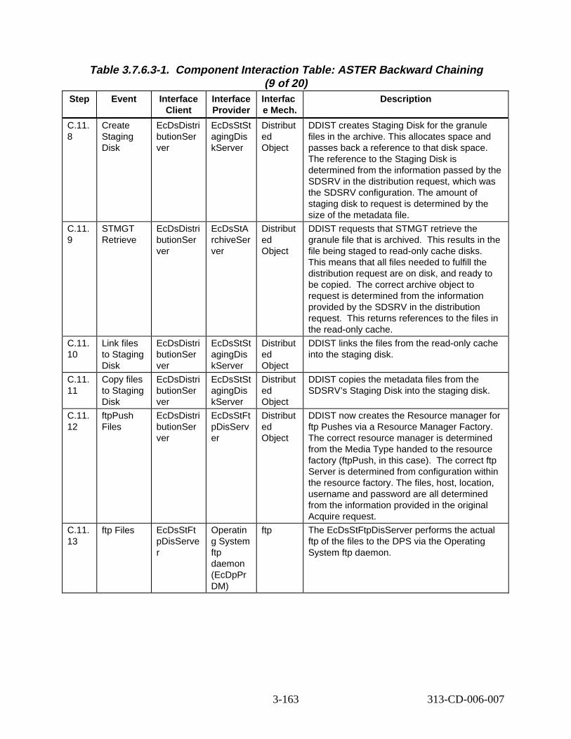
Table 3.7.6.3-1. Component Interaction Table: ASTER B ackward Chaining (9 of 20)
Step Event Interface Client
Interface Provider
Interfac e Mech.
Descript ion
C.11. 8
Create Staging Disk
EcDsDistri butionSer ver
EcDsStSt agingDis kServer
Distribut ed Object
DDIST creates Staging Disk for the granule files in the archive. This allocates space and passes back a reference to that disk space. The reference to the Staging Disk is determined from the information passed by the SDSRV in the distribution request, which was the SDSRV configuration. The amount of staging disk to request is determined by the size of the metadata file.
C.11. 9
STMGT Retrieve
EcDsDistri butionSer ver
EcDsStA rchiveSer ver
Distribut ed Object
DDIST requests that STMGT retrieve the granule file that is archived. This results in the file being staged to read-only cache disks. This means that all files needed to fulfill the distribution request are on disk, and ready to be copied. The correct archive object to request is determined from the information provided by the SDSRV in the distribution request. This returns references to the files in the read-only cache.
C.11. 10
Link files to Staging Disk
EcDsDistri butionSer ver
EcDsStSt agingDis kServer
Distribut ed Object
DDIST links the files from the read-only cache into the staging disk.
C.11. 11
Copy files to Staging Disk
EcDsDistri butionSer ver
EcDsStSt agingDis kServer
Distribut ed Object
DDIST copies the metadata files from the SDSRV’s Staging Disk into the staging disk.
C.11. 12
ftpPush Files
EcDsDistri butionSer ver
EcDsStFt pDisServ er
Distribut ed Object
DDIST now creates the Resource manager for ftp Pushes via a Resource Manager Factory. The correct resource manager is determined from the Media Type handed to the resource factory (ftpPush, in this case). The correct ftp Server is determined from configuration within the resource factory. The files, host, location, username and password are all determined from the information provided in the original Acquire request.
C.11. 13
ftp Files EcDsStFt pDisServe r
Operatin g System ftp daemon (EcDpPr DM)
ftp The EcDsStFtpDisServer performs the actual ftp of the files to the DPS via the Operating System ftp daemon.
3-163 313-CD-006-007
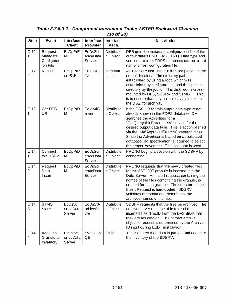
Table 3.7.6.3-1. Component Interaction Table: ASTER B ackward Chaining (10 of 20)
Step Event Interface Client
Interface Provider
Interface Mech.
Descript ion
C.12. 1
Request Metadata Configurat ion File
EcDpPrE M
EcDsSci enceData Server
Distribute d Object
DPS gets the metadata configuration file of the output data’s ESDT (AST_09T). Data type and version are from PDPS database; correct client name is from configuration file.
C.12. 2
Run PGE EcDpPrR unPGE
PGE<AC T>
comman d line
ACT is executed. utput files are placed in the output directory. The directory path is established by using a root, which was established by configuration, and the specific directory by the job id. This disk root is crossmounted by DPS, SDSRV and STMGT. is is to ensure that they are directly available to the DSS, for archival.
C.13. 1
Get DSS UR
EcDpPrD M
EcIoAdS erver
Distribute d Object
If the DSS UR for this output data type is not already known in the PDPS database, DM searches the Advertiser for a “GetQueryableParameters” service for the desired output data type. This is accomplished via the IoAdApprovedSearchCommand class. Since the Advertiser is based on a replicated database, no specification is required to select the proper Advertiser. The local one is used.
C.14. 1
Connect to SDSRV
EcDpPrD M
EcDsSci enceData Server
Distribute d Object
PRONG begins a session with the SDSRV by connecting.
C.14. 2
Request Data Insert
EcDpPrD M
EcDsSci enceData Server
Distribute d Object
PRONG requests that the newly created files for the AST_09T granule is inserted into the Data Server. An Insert request, containing the names of the files comprising the granule, is created for each granule. The structure of the Insert Request is hard-coded. SDSRV validates metadata and determines the archived names of the files.
C.14. 3
STMGT Store
EcDsSci enceData Server
EcDsStA rchiveSer ver
Distribute d Object
SDSRV requests that the files be archived. The archive server must be able to read the inserted files directly from the DPS disks that they are residing on. he correct archive object to request is determined by the Archive ID input during ESDT installation.
C.14. 4
Adding a Granule to Inventory
EcDsSci enceData Server
Sybase/S QS
CtLib The validated metadata is parsed and added to the inventory of the SDSRV.
O
Th
T
3-164 313-CD-006-007
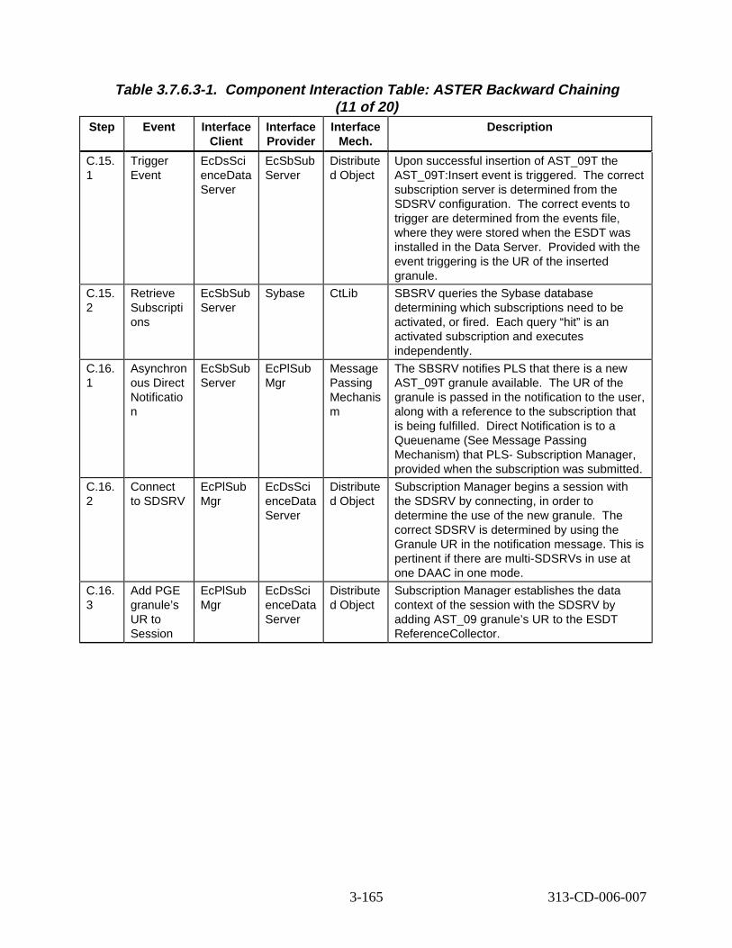
Table 3.7.6.3-1. Component Interaction Table: ASTER B ackward Chaining (11 of 20)
Step Event Interface Client
Interface Provider
Interface Mech.
Descript ion
C.15. 1
Trigger Event
EcDsSci enceData Server
EcSbSub Server
Distribute d Object
Upon successful insertion of AST_09T the AST_09T:Insert event is triggered. he correct subscription server is determined from the SDSRV configuration. The correct events to trigger are determined from the events file, where they were stored when the ESDT was installed in the Data Server. Provided with the event triggering is the UR of the inserted granule.
C.15. 2
Retrieve Subscripti ons
EcSbSub Server
Sybase CtLib SBSRV queries the Sybase database determining which subscriptions need to be activated, or fired. Each query “hit” is an activated subscription and executes independently.
C.16. 1
Asynchron ous Direct Notificatio n
EcSbSub Server
EcPlSub Mgr
Message Passing Mechanis m
The SBSRV notifies PLS that there is a new AST_09T granule available. The UR of the granule is passed in the notification to the user, along with a reference to the subscription that is being fulfilled. irect Notification is to a Queuename (See Message Passing Mechanism) that PLS- Subscription Manager, provided when the subscription was submitted.
C.16. 2
Connect to SDSRV
EcPlSub Mgr
EcDsSci enceData Server
Distribute d Object
Subscription Manager begins a session with the SDSRV by connecting, in order to determine the use of the new granule. he correct SDSRV is determined by using the Granule UR in the notification message. This is pertinent if there are multi-SDSRVs in use at one DAAC in one mode.
C.16. 3
Add PGE granule’s UR to Session
EcPlSub Mgr
EcDsSci enceData Server
Distribute d Object
Subscription Manager establishes the data context of the session with the SDSRV by adding AST_09 granule’s UR to the ESDT ReferenceCollector.
T
D
T
3-165 313-CD-006-007
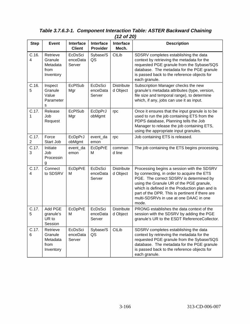
Table 3.7.6.3-1. Component Interaction Table: ASTER B ackward Chaining (12 of 20)
Step Event Interface Client
Interface Provider
Interface Mech.
Descript ion
C.16. 4
Retrieve Granule Metadata from Inventory
EcDsSci enceData Server
Sybase/S QS
CtLib SDSRV completes establishing the data context by retrieving the metadata for the requested PGE granule from the Sybase/SQS database. he metadata for the PGE granule is passed back to the reference objects for each granule.
C.16. 5
Inspect Granule Value Parameter s
EcPlSub Mgr
EcDsSci enceData Server
Distribute d Object
Subscription Manager checks the new granule’s metadata attributes (type, version, file size and temporal range), to determine which, if any, jobs can use it as input.
C.17. 1
Release Job Request
EcPlSub Mgr
EcDpPrJ obMgmt
rpc Once it ensures that the input granule is to be used to run the job containing ETS from the PDPS database, Planning tells the Job Manager to release the job containing ETS, using the appropriate input granules.
C.17. 2
Force Start Job
EcDpPrJ obMgmt
event_da emon
rpc Job containing ETS is released.
C.17. 3
Initiate Job Processin g
event_da emon
EcDpPrE M
comman d line
The job containing the ETS begins processing.
C.17. 4
Connect to SDSRV
EcDpPrE M
EcDsSci enceData Server
Distribute d Object
Processing begins a session with the SDSRV by connecting, in order to acquire the ETS PGE. The correct SDSRV is determined by using the Granule UR of the PGE granule, which is defined in the Production plan and is part of the DPR. This is pertinent if there are multi-SDSRVs in use at one DAAC in one mode.
C.17. 5
Add PGE granule’s UR to Session
EcDpPrE M
EcDsSci enceData Server
Distribute d Object
PRONG establishes the data context of the session with the SDSRV by adding the PGE granule’s UR to the ESDT ReferenceCollector.
C.17. 6
Retrieve Granule Metadata from Inventory
EcDsSci enceData Server
Sybase/S QS
CtLib SDSRV completes establishing the data context by retrieving the metadata for the requested PGE granule from the Sybase/SQS database. he metadata for the PGE granule is passed back to the reference objects for each granule.
T
T
3-166 313-CD-006-007
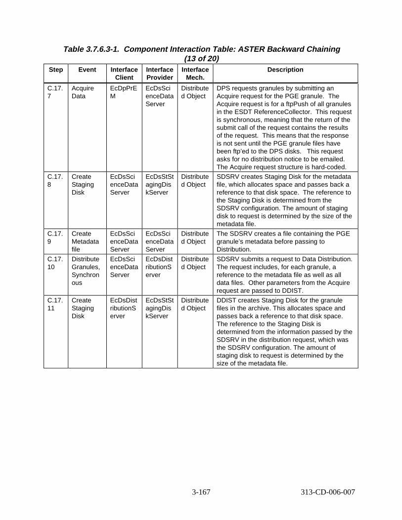
Table 3.7.6.3-1. Component Interaction Table: ASTER B ackward Chaining (13 of 20)
Step Event Interface Client
Interface Provider
Interface Mech.
Descript ion
C.17. 7
Acquire Data
EcDpPrE M
EcDsSci enceData Server
Distribute d Object
DPS requests granules by submitting an Acquire request for the PGE granule. The Acquire request is for a ftpPush of all granules in the ESDT ReferenceCollector. is request is synchronous, meaning that the return of the submit call of the request contains the results of the request. is means that the response is not sent until the PGE granule files have been ftp’ed to the DPS disks. s request asks for no distribution notice to be emailed. The Acquire request structure is hard-coded.
C.17. 8
Create Staging Disk
EcDsSci enceData Server
EcDsStSt agingDis kServer
Distribute d Object
SDSRV creates Staging Disk for the metadata file, which allocates space and passes back a reference to that disk space. e reference to the Staging Disk is determined from the SDSRV configuration. The amount of staging disk to request is determined by the size of the metadata file.
C.17. 9
Create Metadata file
EcDsSci enceData Server
EcDsSci enceData Server
Distribute d Object
The SDSRV creates a file containing the PGE granule’s metadata before passing to Distribution.
C.17. 10
Distribute Granules, Synchron ous
EcDsSci enceData Server
EcDsDist ributionS erver
Distribute d Object
SDSRV submits a request to Data Distribution. The request includes, for each granule, a reference to the metadata file as well as all data files. Other parameters from the Acquire request are passed to DDIST.
C.17. 11
Create Staging Disk
EcDsDist ributionS erver
EcDsStSt agingDis kServer
Distribute d Object
DDIST creates Staging Disk for the granule files in the archive. This allocates space and passes back a reference to that disk space. The reference to the Staging Disk is determined from the information passed by the SDSRV in the distribution request, which was the SDSRV configuration. The amount of staging disk to request is determined by the size of the metadata file.
Th
Th
Thi
Th
3-167 313-CD-006-007
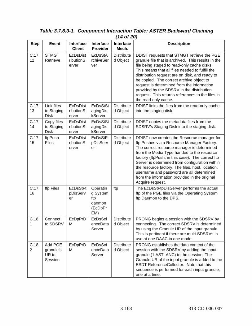
Table 3.7.6.3-1. Component Interaction Table: ASTER B ackward Chaining (14 of 20)
Step Event Interface Client
Interface Provider
Interface Mech.
Descript ion
C.17. 12
STMGT Retrieve
EcDsDist ributionS erver
EcDsStA rchiveSer ver
Distribute d Object
DDIST requests that STMGT retrieve the PGE granule file that is archived. This results in the file being staged to read-only cache disks. This means that all files needed to fulfill the distribution request are on disk, and ready to be copied. The correct archive object to request is determined from the information provided by the SDSRV in the distribution request. This returns references to the files in the read-only cache.
C.17. 13
Link files to Staging Disk
EcDsDist ributionS erver
EcDsStSt agingDis kServer
Distribute d Object
DDIST links the files from the read-only cache into the staging disk.
C.17. 14
Copy files to Staging Disk
EcDsDist ributionS erver
EcDsStSt agingDis kServer
Distribute d Object
DDIST copies the metadata files from the SDSRV’s Staging Disk into the staging disk.
C.17. 15
ftpPush Files
EcDsDist ributionS erver
EcDsStFt pDisServ er
Distribute d Object
DDIST now creates the Resource manager for ftp Pushes via a Resource Manager Factory. The correct resource manager is determined from the Media Type handed to the resource factory (ftpPush, in this case). The correct ftp Server is determined from configuration within the resource factory. The files, host, location, username and password are all determined from the information provided in the original Acquire request.
C.17. 16
ftp Files EcDsStFt pDisServ er
Operatin g System ftp daemon (EcDpPr EM)
ftp The EcDsStFtpDisServer performs the actual ftp of the PGE files via the Operating System ftp Daemon to the DPS.
C.18. 1
Connect to SDSRV
EcDpPrD M
EcDsSci enceData Server
Distribute d Object
PRONG begins a session with the SDSRV by connecting. The correct SDSRV is determined by using the Granule UR of the input granule. This is pertinent if there are multi-SDSRVs in use at one DAAC in one mode.
C.18. 2
Add PGE granule’s UR to Session
EcDpPrD M
EcDsSci enceData Server
Distribute d Object
PRONG establishes the data context of the session with the SDSRV by adding the input granule (1 AST_ANC) to the session. The Granule UR of the input granule is added to the ESDT ReferenceCollector. Note that this sequence is performed for each input granule, one at a time.
3-168 313-CD-006-007
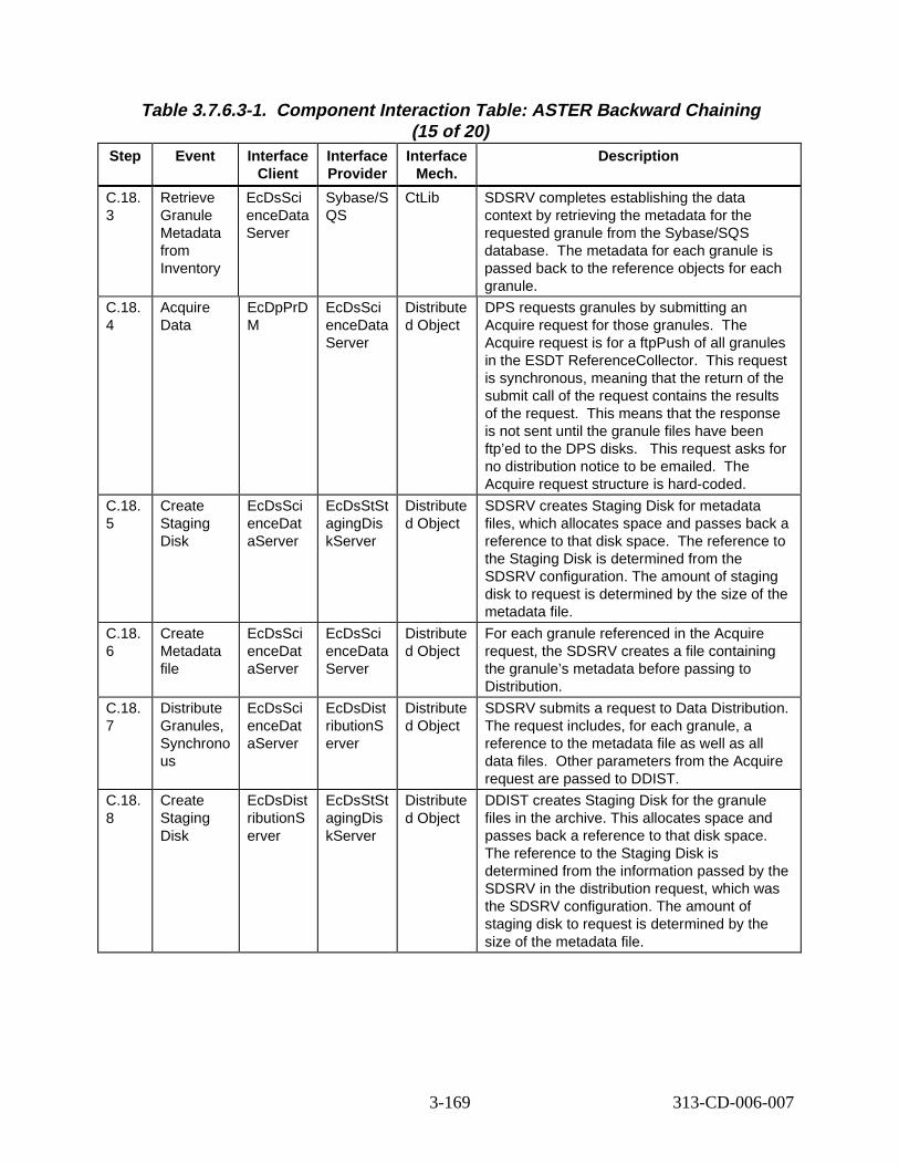
Table 3.7.6.3-1. Component Interaction Table: ASTER B ackward Chaining (15 of 20)
Step Event Interface Client
Interface Provider
Interface Mech.
Descript ion
C.18. 3
Retrieve Granule Metadata from Inventory
EcDsSci enceData Server
Sybase/S QS
CtLib SDSRV completes establishing the data context by retrieving the metadata for the requested granule from the Sybase/SQS database. The metadata for each granule is passed back to the reference objects for each granule.
C.18. 4
Acquire Data
EcDpPrD M
EcDsSci enceData Server
Distribute d Object
DPS requests granules by submitting an Acquire request for those granules. The Acquire request is for a ftpPush of all granules in the ESDT ReferenceCollector. This request is synchronous, meaning that the return of the submit call of the request contains the results of the request. This means that the response is not sent until the granule files have been ftp’ed to the DPS disks. This request asks for no distribution notice to be emailed. The Acquire request structure is hard-coded.
C.18. 5
Create Staging Disk
EcDsSci enceDat aServer
EcDsStSt agingDis kServer
Distribute d Object
SDSRV creates Staging Disk for metadata files, which allocates space and passes back a reference to that disk space. The reference to the Staging Disk is determined from the SDSRV configuration. The amount of staging disk to request is determined by the size of the metadata file.
C.18. 6
Create Metadata file
EcDsSci enceDat aServer
EcDsSci enceData Server
Distribute d Object
For each granule referenced in the Acquire request, the SDSRV creates a file containing the granule’s metadata before passing to Distribution.
C.18. 7
Distribute Granules, Synchrono us
EcDsSci enceDat aServer
EcDsDist ributionS erver
Distribute d Object
SDSRV submits a request to Data Distribution. The request includes, for each granule, a reference to the metadata file as well as all data files. Other parameters from the Acquire request are passed to DDIST.
C.18. 8
Create Staging Disk
EcDsDist ributionS erver
EcDsStSt agingDis kServer
Distribute d Object
DDIST creates Staging Disk for the granule files in the archive. This allocates space and passes back a reference to that disk space. The reference to the Staging Disk is determined from the information passed by the SDSRV in the distribution request, which was the SDSRV configuration. The amount of staging disk to request is determined by the size of the metadata file.
3-169 313-CD-006-007
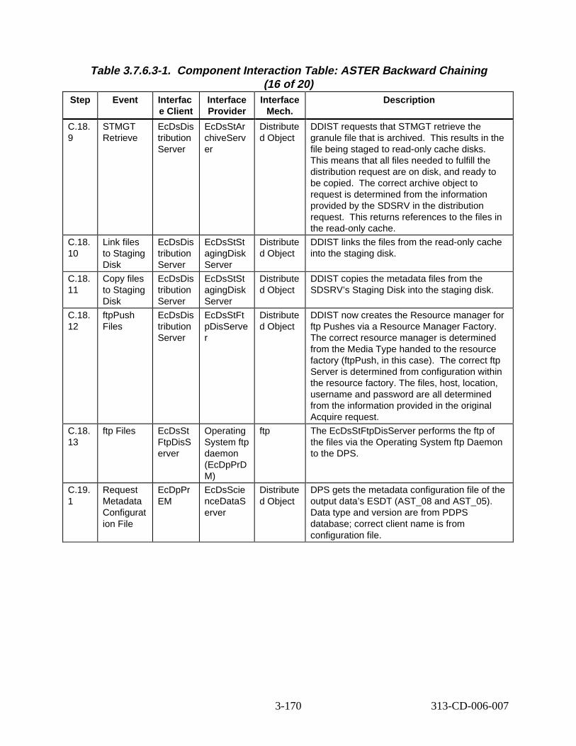
Table 3.7.6.3-1. Component Interaction Table: ASTER B ackward Chaining (16 of 20)
Step Event Interfac e Client
Interface Provider
Interface Mech.
Descript ion
C.18. 9
STMGT Retrieve
EcDsDis tribution Server
EcDsStAr chiveServ er
Distribute d Object
DDIST requests that STMGT retrieve the granule file that is archived. This results in the file being staged to read-only cache disks. This means that all files needed to fulfill the distribution request are on disk, and ready to be copied. The correct archive object to request is determined from the information provided by the SDSRV in the distribution request. This returns references to the files in the read-only cache.
C.18. 10
Link files to Staging Disk
EcDsDis tribution Server
EcDsStSt agingDisk Server
Distribute d Object
DDIST links the files from the read-only cache into the staging disk.
C.18. 11
Copy files to Staging Disk
EcDsDis tribution Server
EcDsStSt agingDisk Server
Distribute d Object
DDIST copies the metadata files from the SDSRV’s Staging Disk into the staging disk.
C.18. 12
ftpPush Files
EcDsDis tribution Server
EcDsStFt pDisServe r
Distribute d Object
DDIST now creates the Resource manager for ftp Pushes via a Resource Manager Factory. The correct resource manager is determined from the Media Type handed to the resource factory (ftpPush, in this case). The correct ftp Server is determined from configuration within the resource factory. The files, host, location, username and password are all determined from the information provided in the original Acquire request.
C.18. 13
ftp Files EcDsSt FtpDisS erver
Operating System ftp daemon (EcDpPrD M)
ftp The EcDsStFtpDisServer performs the ftp of the files via the Operating System ftp Daemon to the DPS.
C.19. 1
Request Metadata Configurat ion File
EcDpPr EM
EcDsScie nceDataS erver
Distribute d Object
DPS gets the metadata configuration file of the output data’s ESDT (AST_08 and AST_05). Data type and version are from PDPS database; correct client name is from configuration file.
3-170 313-CD-006-007
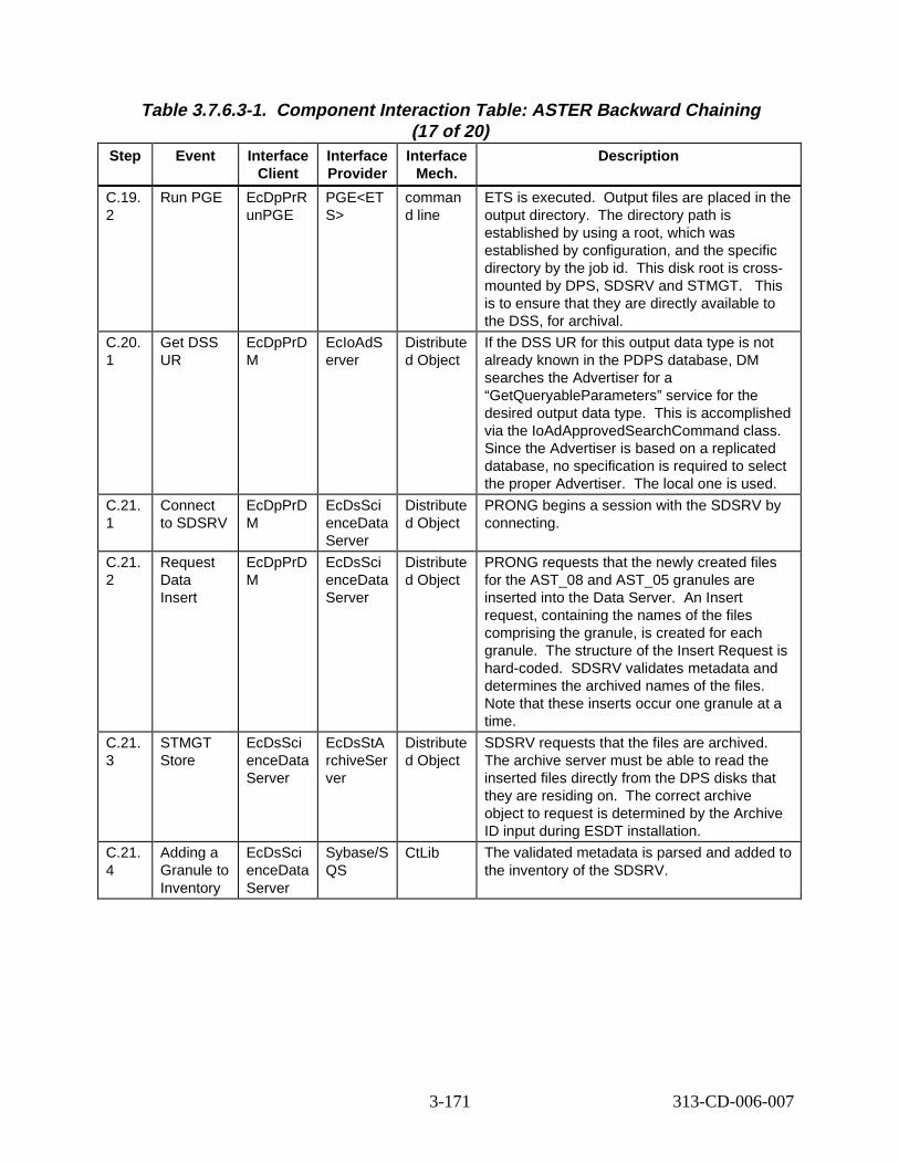
Table 3.7.6.3-1. Component Interaction Table: ASTER B ackward Chaining (17 of 20)
Step Event Interface Client
Interface Provider
Interface Mech.
Descript ion
C.19. 2
Run PGE EcDpPrR unPGE
PGE<ET S>
comman d line
ETS is executed. Output files are placed in the output directory. The directory path is established by using a root, which was established by configuration, and the specific directory by the job id. This disk root is crossmounted by DPS, SDSRV and STMGT. This is to ensure that they are directly available to the DSS, for archival.
C.20. 1
Get DSS UR
EcDpPrD M
EcIoAdS erver
Distribute d Object
If the DSS UR for this output data type is not already known in the PDPS database, DM searches the Advertiser for a “GetQueryableParameters” service for the desired output data type. This is accomplished via the IoAdApprovedSearchCommand class. Since the Advertiser is based on a replicated database, no specification is required to select the proper Advertiser. The local one is used.
C.21. 1
Connect to SDSRV
EcDpPrD M
EcDsSci enceData Server
Distribute d Object
PRONG begins a session with the SDSRV by connecting.
C.21. 2
Request Data Insert
EcDpPrD M
EcDsSci enceData Server
Distribute d Object
PRONG requests that the newly created files for the AST_08 and AST_05 granules are inserted into the Data Server. An Insert request, containing the names of the files comprising the granule, is created for each granule. The structure of the Insert Request is hard-coded. SDSRV validates metadata and determines the archived names of the files. Note that these inserts occur one granule at a time.
C.21. 3
STMGT Store
EcDsSci enceData Server
EcDsStA rchiveSer ver
Distribute d Object
SDSRV requests that the files are archived. The archive server must be able to read the inserted files directly from the DPS disks that they are residing on. The correct archive object to request is determined by the Archive ID input during ESDT installation.
C.21. 4
Adding a Granule to Inventory
EcDsSci enceData Server
Sybase/S QS
CtLib The validated metadata is parsed and added to the inventory of the SDSRV.
3-171 313-CD-006-007
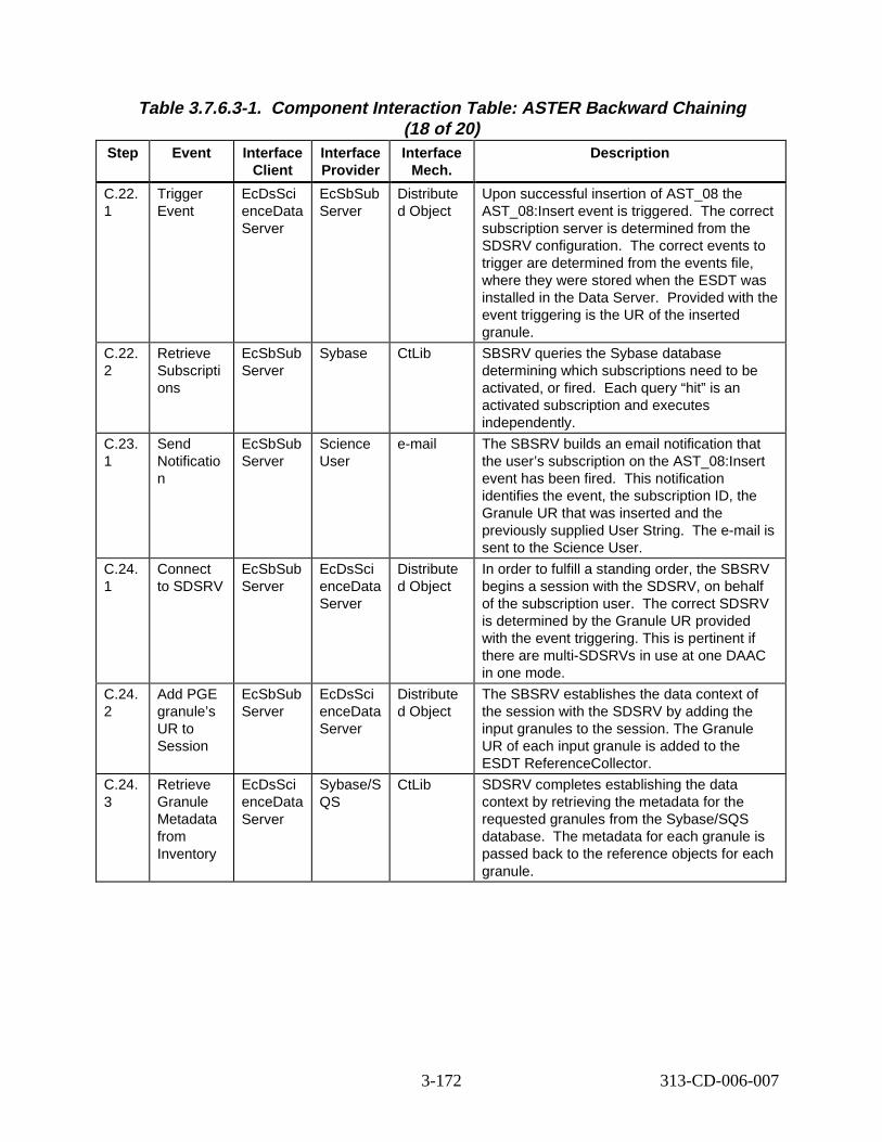
Table 3.7.6.3-1. Component Interaction Table: ASTER B ackward Chaining (18 of 20)
Step Event Interface Client
Interface Provider
Interface Mech.
Descript ion
C.22. 1
Trigger Event
EcDsSci enceData Server
EcSbSub Server
Distribute d Object
Upon successful insertion of AST_08 the AST_08:Insert event is triggered. The correct subscription server is determined from the SDSRV configuration. The correct events to trigger are determined from the events file, where they were stored when the ESDT was installed in the Data Server. Provided with the event triggering is the UR of the inserted granule.
C.22. 2
Retrieve Subscripti ons
EcSbSub Server
Sybase CtLib SBSRV queries the Sybase database determining which subscriptions need to be activated, or fired. Each query “hit” is an activated subscription and executes independently.
C.23. 1
Send Notificatio n
EcSbSub Server
Science User
e-mail The SBSRV builds an email notification that the user’s subscription on the AST_08:Insert event has been fired. This notification identifies the event, the subscription ID, the Granule UR that was inserted and the previously supplied User String. The e-mail is sent to the Science User.
C.24. 1
Connect to SDSRV
EcSbSub Server
EcDsSci enceData Server
Distribute d Object
In order to fulfill a standing order, the SBSRV begins a session with the SDSRV, on behalf of the subscription user. The correct SDSRV is determined by the Granule UR provided with the event triggering. This is pertinent if there are multi-SDSRVs in use at one DAAC in one mode.
C.24. 2
Add PGE granule’s UR to Session
EcSbSub Server
EcDsSci enceData Server
Distribute d Object
The SBSRV establishes the data context of the session with the SDSRV by adding the input granules to the session. The Granule UR of each input granule is added to the ESDT ReferenceCollector.
C.24. 3
Retrieve Granule Metadata from Inventory
EcDsSci enceData Server
Sybase/S QS
CtLib SDSRV completes establishing the data context by retrieving the metadata for the requested granules from the Sybase/SQS database. The metadata for each granule is passed back to the reference objects for each granule.
3-172 313-CD-006-007
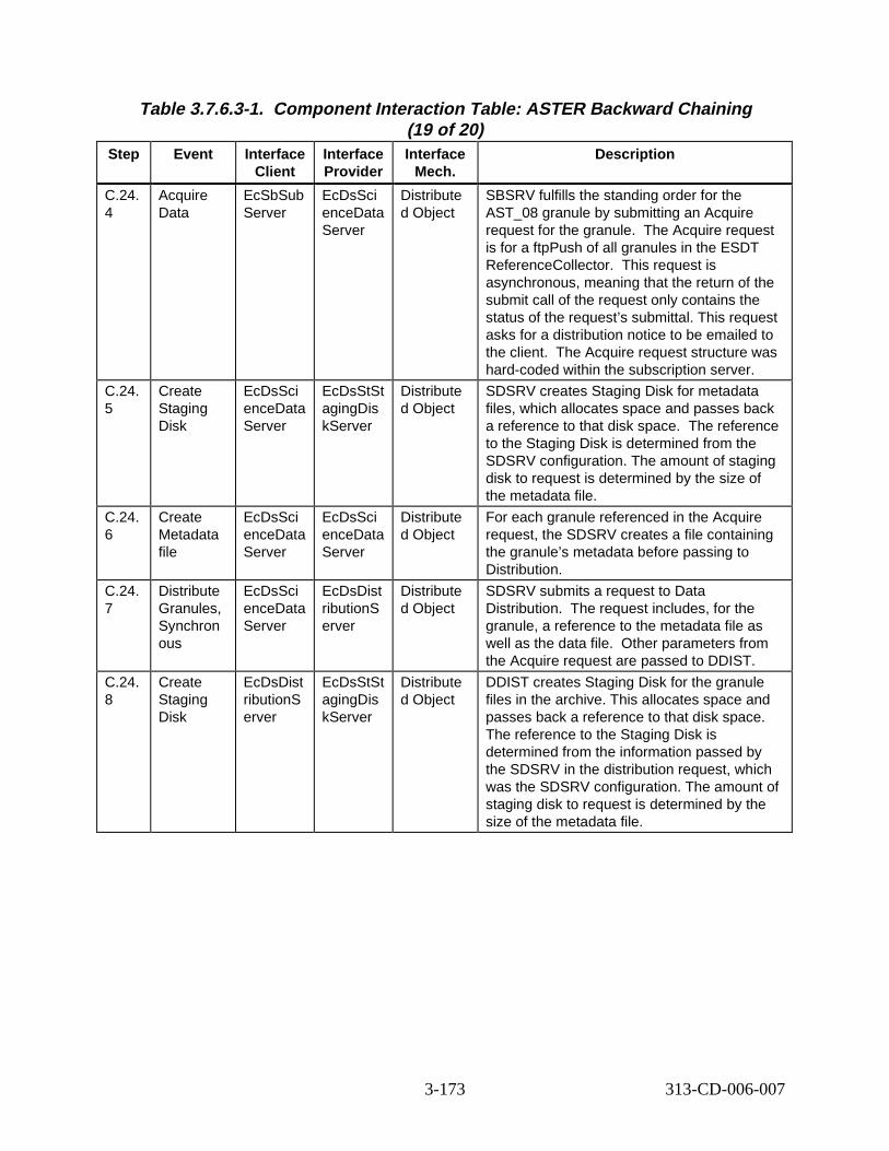
Table 3.7.6.3-1. Component Interaction Table: ASTER B ackward Chaining (19 of 20)
Step Event Interface Client
Interface Provider
Interface Mech.
Descript ion
C.24. 4
Acquire Data
EcSbSub Server
EcDsSci enceData Server
Distribute d Object
SBSRV fulfills the standing order for the AST_08 granule by submitting an Acquire request for the granule. The Acquire request is for a ftpPush of all granules in the ESDT ReferenceCollector. This request is asynchronous, meaning that the return of the submit call of the request only contains the status of the request’s submittal. This request asks for a distribution notice to be emailed to the client. The Acquire request structure was hard-coded within the subscription server.
C.24. 5
Create Staging Disk
EcDsSci enceData Server
EcDsStSt agingDis kServer
Distribute d Object
SDSRV creates Staging Disk for metadata files, which allocates space and passes back a reference to that disk space. The reference to the Staging Disk is determined from the SDSRV configuration. The amount of staging disk to request is determined by the size of the metadata file.
C.24. 6
Create Metadata file
EcDsSci enceData Server
EcDsSci enceData Server
Distribute d Object
For each granule referenced in the Acquire request, the SDSRV creates a file containing the granule’s metadata before passing to Distribution.
C.24. 7
Distribute Granules, Synchron ous
EcDsSci enceData Server
EcDsDist ributionS erver
Distribute d Object
SDSRV submits a request to Data Distribution. The request includes, for the granule, a reference to the metadata file as well as the data file. Other parameters from the Acquire request are passed to DDIST.
C.24. 8
Create Staging Disk
EcDsDist ributionS erver
EcDsStSt agingDis kServer
Distribute d Object
DDIST creates Staging Disk for the granule files in the archive. This allocates space and passes back a reference to that disk space. The reference to the Staging Disk is determined from the information passed by the SDSRV in the distribution request, which was the SDSRV configuration. The amount of staging disk to request is determined by the size of the metadata file.
3-173 313-CD-006-007
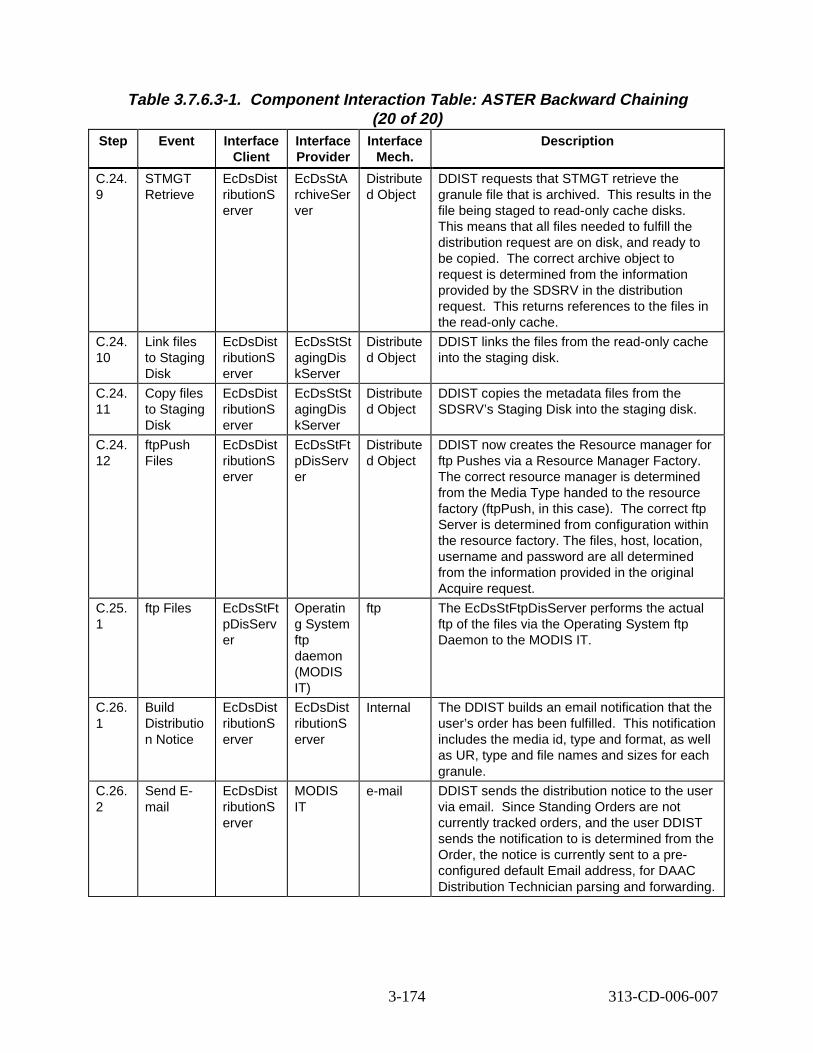
Table 3.7.6.3-1. Component Interaction Table: ASTER B ackward Chaining (20 of 20)
Step Event Interface Client
Interface Provider
Interface Mech.
Descript ion
C.24. 9
STMGT Retrieve
EcDsDist ributionS erver
EcDsStA rchiveSer ver
Distribute d Object
DDIST requests that STMGT retrieve the granule file that is archived. This results in the file being staged to read-only cache disks. This means that all files needed to fulfill the distribution request are on disk, and ready to be copied. The correct archive object to request is determined from the information provided by the SDSRV in the distribution request. This returns references to the files in the read-only cache.
C.24. 10
Link files to Staging Disk
EcDsDist ributionS erver
EcDsStSt agingDis kServer
Distribute d Object
DDIST links the files from the read-only cache into the staging disk.
C.24. 11
Copy files to Staging Disk
EcDsDist ributionS erver
EcDsStSt agingDis kServer
Distribute d Object
DDIST copies the metadata files from the SDSRV’s Staging Disk into the staging disk.
C.24. 12
ftpPush Files
EcDsDist ributionS erver
EcDsStFt pDisServ er
Distribute d Object
DDIST now creates the Resource manager for ftp Pushes via a Resource Manager Factory. The correct resource manager is determined from the Media Type handed to the resource factory (ftpPush, in this case). The correct ftp Server is determined from configuration within the resource factory. The files, host, location, username and password are all determined from the information provided in the original Acquire request.
C.25. 1
ftp Files EcDsStFt pDisServ er
Operatin g System ftp daemon (MODIS IT)
ftp The EcDsStFtpDisServer performs the actual ftp of the files via the Operating System ftp Daemon to the MODIS IT.
C.26. 1
Build Distributio n Notice
EcDsDist ributionS erver
EcDsDist ributionS erver
Internal The DDIST builds an email notification that the user’s order has been fulfilled. This notification includes the media id, type and format, as well as UR, type and file names and sizes for each granule.
C.26. 2
Send Email
EcDsDist ributionS erver
MODIS IT
e-mail DDIST sends the distribution notice to the user via email. Since Standing Orders are not currently tracked orders, and the user DDIST sends the notification to is determined from the Order, the notice is currently sent to a preconfigured default Email address, for DAAC Distribution Technician parsing and forwarding.
3-174 313-CD-006-007
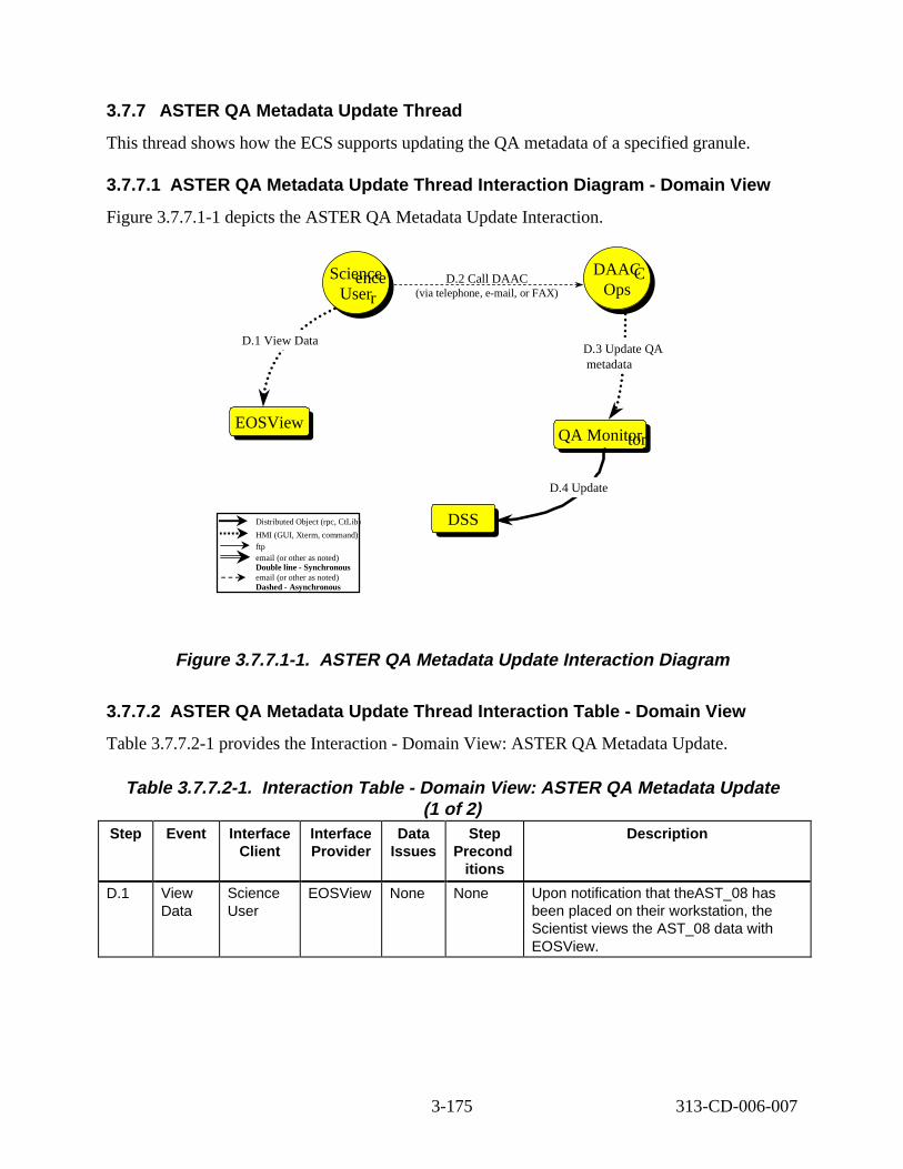
EOSView
DAAOps
SciUse
DSS
QA Moni
3.7.7 ASTER QA Metadata Update Thre ad
This thread shows how the ECS supports updating the QA metadata of a specified granule.
3.7.7.1 ASTER QA Metadata Updat e Thread Int eract ion D iagram - Domain Vi ew
Figure 3.7.7.1-1 depicts the ASTER QA Metadata Update Interaction.
Scieennccee D.2 Call DAAC DAACC
Userr Ops
D.1 View Data D.3 Update QA metadata
EOSView QA Monittoorr
D.4 Update
Distributed Object (rpc, CtLib) DSS HMI (GUI, Xterm, command)ftp email (or other as noted) Double line - Synchronous email (or other as noted) Dashed - Asynchronous
(via telephone, e-mail, or FAX)
Figure 3. 7.7.1-1. ASTER QA Metadata Updat e Interact ion D iagram
3.7.7.2 ASTER QA Metadata Updat e Thread Int eract ion T able - Domain Vi ew
Table 3.7.7.2-1 provides the Interaction - Domain View: ASTER QA Metadata Update.
Table 3.7.7.2-1. Interaction Tabl e - Domain V iew: ASTER QA Metadata Update (1 of 2)
Step Event Interface Client
Interface Provider
Data Issues
Step Precond
itions
Descript ion
D.1 View Data
Science User
EOSView None None Upon notification that theAST_08 has been placed on their workstation, the Scientist views the AST_08 data with EOSView.
3-175 313-CD-006-007
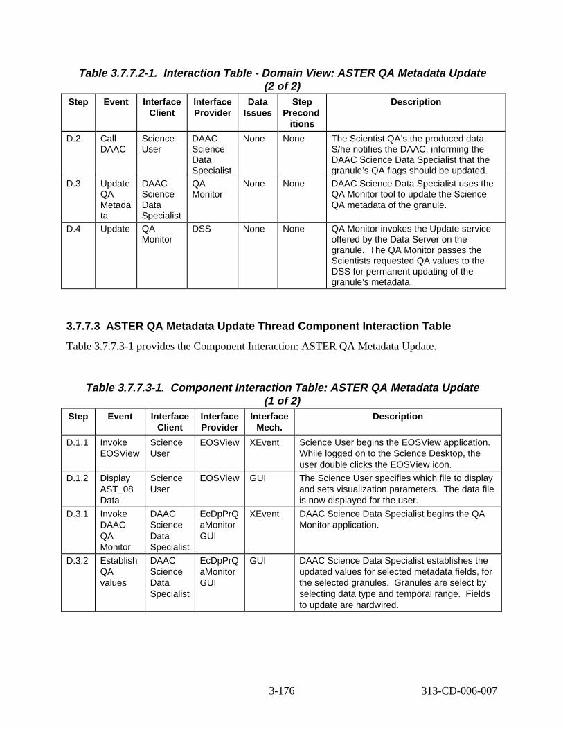
Table 3.7.7.2-1. Interaction Tabl e - Domain V iew: ASTER QA Metadata Update (2 of 2)
Step Event Interface Client
Interface Provider
Data Issues
Step Precond
itions
Descript ion
D.2 Call DAAC
Science User
DAAC Science Data Specialist
None None The Scientist QA’s the produced data. S/he notifies the DAAC, informing the DAAC Science Data Specialist that the granule’s QA flags should be updated.
D.3 Update QA Metada ta
DAAC Science Data Specialist
QA Monitor
None None DAAC Science Data Specialist uses the QA Monitor tool to update the Science QA metadata of the granule.
D.4 Update QA Monitor
DSS None None QA Monitor invokes the Update service offered by the Data Server on the granule. The QA Monitor passes the Scientists requested QA values to the DSS for permanent updating of the granule’s metadata.
3.7.7.3 ASTER QA Metadata Update Thread Component Inter action Table
Table 3.7.7.3-1 provides the Component Interaction: ASTER QA Metadata Update.
Table 3.7.7.3-1. Component Interaction Table: ASTER QA Metadata Update (1 of 2)
Step Event Interface Client
Interface Provider
Interface Mech.
Descript ion
D.1.1 Invoke EOSView
Science User
EOSView XEvent Science User begins the EOSView application. While logged on to the Science Desktop, the user double clicks the EOSView icon.
D.1.2 Display AST_08 Data
Science User
EOSView GUI The Science User specifies which file to display and sets visualization parameters. The data file is now displayed for the user.
D.3.1 Invoke DAAC QA Monitor
DAAC Science Data Specialist
EcDpPrQ aMonitor GUI
XEvent DAAC Science Data Specialist begins the QA Monitor application.
D.3.2 Establish QA values
DAAC Science Data Specialist
EcDpPrQ aMonitor GUI
GUI DAAC Science Data Specialist establishes the updated values for selected metadata fields, for the selected granules. Granules are select by selecting data type and temporal range. Fields to update are hardwired.
3-176 313-CD-006-007
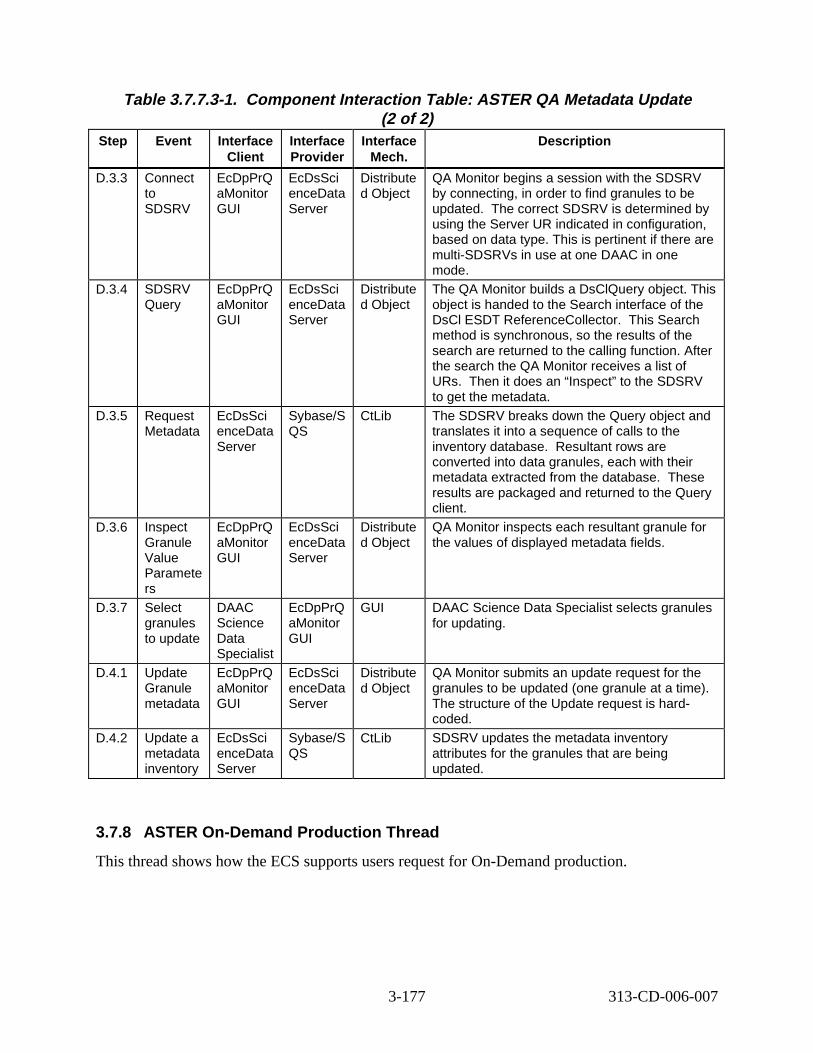
Table 3.7.7.3-1. Component Interaction Table: ASTER QA Metadata Update (2 of 2)
Step Event Interface Client
Interface Provider
Interface Mech.
Descript ion
D.3.3 Connect to SDSRV
EcDpPrQ aMonitor GUI
EcDsSci enceData Server
Distribute d Object
QA Monitor begins a session with the SDSRV by connecting, in order to find granules to be updated. The correct SDSRV is determined by using the Server UR indicated in configuration, based on data type. This is pertinent if there are multi-SDSRVs in use at one DAAC in one mode.
D.3.4 SDSRV Query
EcDpPrQ aMonitor GUI
EcDsSci enceData Server
Distribute d Object
The QA Monitor builds a DsClQuery object. This object is handed to the Search interface of the DsCl ESDT ReferenceCollector. This Search method is synchronous, so the results of the search are returned to the calling function. After the search the QA Monitor receives a list of URs. Then it does an “Inspect” to the SDSRV to get the metadata.
D.3.5 Request Metadata
EcDsSci enceData Server
Sybase/S QS
CtLib The SDSRV breaks down the Query object and translates it into a sequence of calls to the inventory database. Resultant rows are converted into data granules, each with their metadata extracted from the database. These results are packaged and returned to the Query client.
D.3.6 Inspect Granule Value Paramete rs
EcDpPrQ aMonitor GUI
EcDsSci enceData Server
Distribute d Object
QA Monitor inspects each resultant granule for the values of displayed metadata fields.
D.3.7 Select granules to update
DAAC Science Data Specialist
EcDpPrQ aMonitor GUI
GUI DAAC Science Data Specialist selects granules for updating.
D.4.1 Update Granule metadata
EcDpPrQ aMonitor GUI
EcDsSci enceData Server
Distribute d Object
QA Monitor submits an update request for the granules to be updated (one granule at a time). The structure of the Update request is hardcoded.
D.4.2 Update a metadata inventory
EcDsSci enceData Server
Sybase/S QS
CtLib SDSRV updates the metadata inventory attributes for the granules that are being updated.
3.7.8 ASTER On-Demand Production Thread
This thread shows how the ECS supports users request for On-Demand production.
3-177 313-CD-006-007
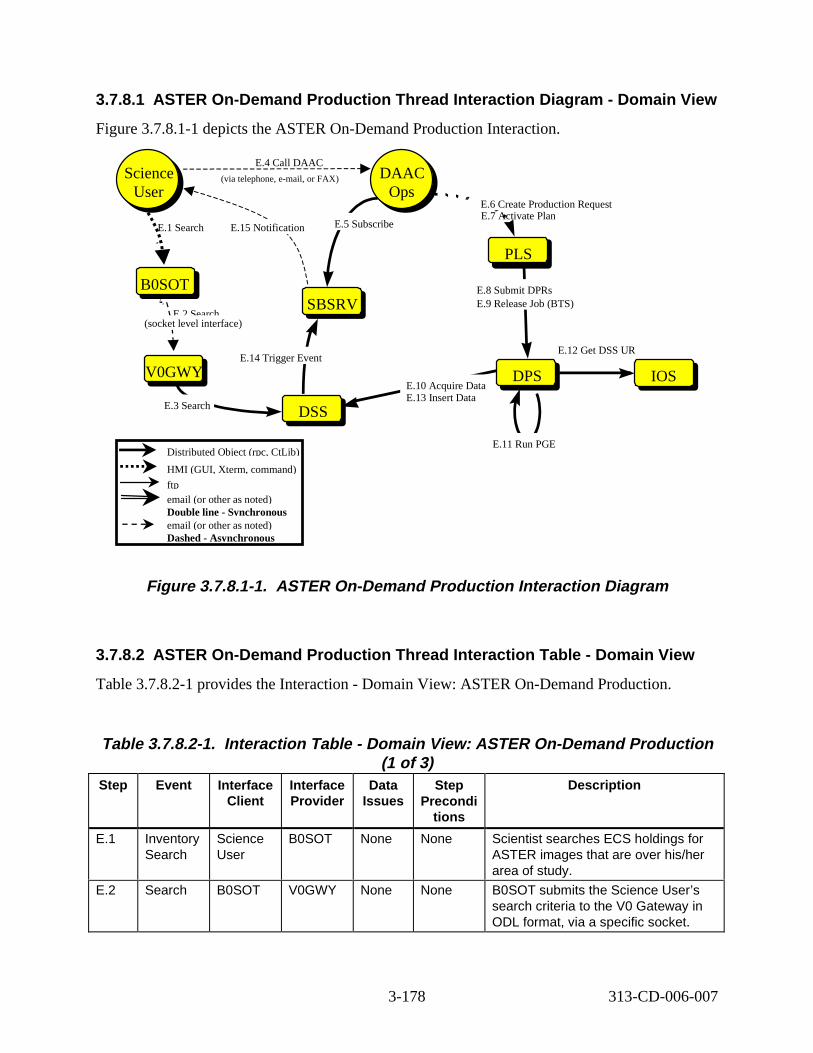
3.7.8.1 ASTER On-Demand Production Thread Inter action Diagr am - Domain View
Figure 3.7.8.1-1 depicts the ASTER On-Demand Production Interaction.
Distributed Object (rpc, CtLib)
HMI (GUI, Xterm, command)
ftp email (or other as noted) Double line - Synchronous email (or other as noted) Dashed - Asynchronous
DAAC Ops
DAAC Ops
E.4 Call DAAC
(via telephone, e-mail, or FAX)Science User
Science User
SBSRVSBSRV
DSSDSS
DPSDPS
PLSPLS
E.15 Notifi cation E.5 Subscribe
E.6 Create Production Request
E.8 Submit DPRs E.9 Release Job (BTS)
E.11 Run PGE
E.14 Trigger Event
E.10 Acquire Data E.13 Insert Data
V0GWYV0GWY
B0SOTB0SOT
E.1 Search
E.2 Search
E.3 Search
E.7 Activate Plan
IOS
E.12 Get DSS UR
(socket level interface)
Figure 3. 7.8.1-1. ASTER On-Demand P roduction Interaction Diagram
3.7.8.2 ASTER On-Demand Production Thread Inter action Tabl e - Domain View
Table 3.7.8.2-1 provides the Interaction - Domain View: ASTER On-Demand Production.
Table 3.7.8.2-1. Interaction Tabl e - Domain V iew: ASTER On-Demand Production (1 of 3)
Step Event Interface Client
Interface Provider
Data Issues
Step Precondi
tions
Descript ion
E.1 Inventory Search
Science User
B0SOT None None Scientist searches ECS holdings for ASTER images that are over his/her area of study.
E.2 Search B0SOT V0GWY None None B0SOT submits the Science User’s search criteria to the V0 Gateway in ODL format, via a specific socket.
3-178 313-CD-006-007
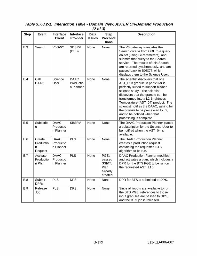
Table 3.7.8.2-1. Interaction Tabl e - Domain V iew: ASTER On-Demand Production (2 of 3)
Step Event Interface Client
Interface Provider
Data Issues
Step Precondi
tions
Descript ion
E.3 Search V0GWY SDSRV (DSS)
None None The V0 gateway translates the Search criteria from ODL to a query object (using GlParameters), and submits that query to the Search service. The results of this Search are returned synchronously, and are passed back to B0SOT, which displays them to the Science User.
E.4 Call DAAC
Science User
DAAC Productio n Planner
None None The scientist discovers that one AST_L1B granule in particular is perfectly suited to support his/her science study. The scientist discovers that the granule can be transformed into a L2 Brightness Temperature (AST_04) product. The scientist notifies the DAAC, asking for the granule to be processed to L2, and to be notified when that processing is complete.
E.5 Subscrib e
DAAC Productio n Planner
SBSRV None None The DAAC Production Planner places a subscription for the Science User to be notified when the AST_04 is available.
E.6 Create Productio n Request
DAAC Productio n Planner
PLS None None The DAAC Production Planner creates a production request containing the requested BTS algorithm to be run.
E.7 Activate Productio n Plan
DAAC Productio n Planner
PLS None PGEs passed SSI&T. Plan already created.
DAAC Production Planner modifies and activates a plan, which includes a DPR for the BTS PGE to be run on the requested AST_L1B.
E.8 Submit DPRs
PLS DPS None None DPR for BTS is submitted to DPS.
E.9 Release Job
PLS DPS None None Since all inputs are available to run the BTS PGE, references to those input granules are passed to DPS, and the BTS job is released.
3-179 313-CD-006-007
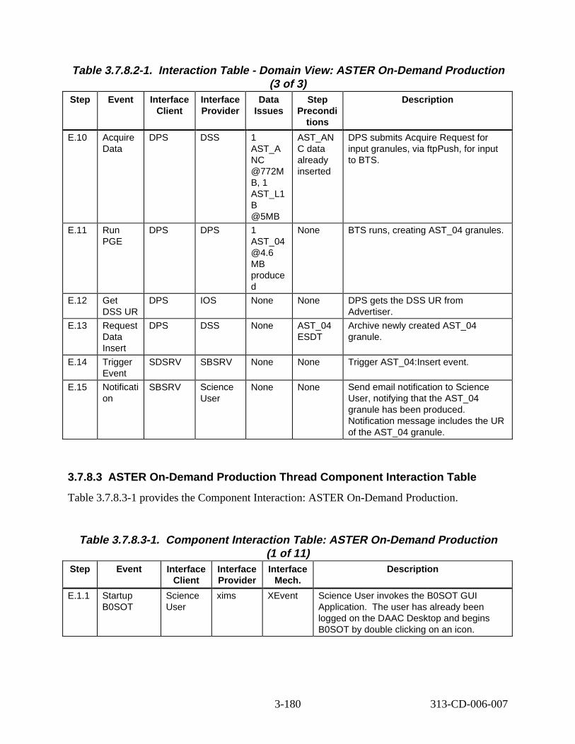
Table 3.7.8.2-1. Interaction Tabl e - Domain V iew: ASTER On-Demand Production (3 of 3)
Step Event Interface Client
Interface Provider
Data Issues
Step Precondi
tions
Descript ion
E.10 Acquire Data
DPS DSS 1 AST_A NC @772M B, 1 AST_L1 B @5MB
AST_AN C data already inserted
DPS submits Acquire Request for input granules, via ftpPush, for input to BTS.
E.11 Run PGE
DPS DPS 1 AST_04 @4.6 MB produce d
None BTS runs, creating AST_04 granules.
E.12 Get DSS UR
DPS IOS None None DPS gets the DSS UR from Advertiser.
E.13 Request Data Insert
DPS DSS None AST_04 ESDT
Archive newly created AST_04 granule.
E.14 Trigger Event
SDSRV SBSRV None None Trigger AST_04:Insert event.
E.15 Notificati on
SBSRV Science User
None None Send email notification to Science User, notifying that the AST_04 granule has been produced. Notification message includes the UR of the AST_04 granule.
3.7.8.3 ASTER On-Demand Production Thread Component Interaction Table
Table 3.7.8.3-1 provides the Component Interaction: ASTER On-Demand Production.
Table 3.7.8.3-1. Component Interaction Table: ASTER On-Demand Production (1 of 11)
Step Event Interface Client
Interface Provider
Interface Mech.
Descript ion
E.1.1 Startup B0SOT
Science User
xims XEvent Science User invokes the B0SOT GUI Application. The user has already been logged on the DAAC Desktop and begins B0SOT by double clicking on an icon.
3-180 313-CD-006-007
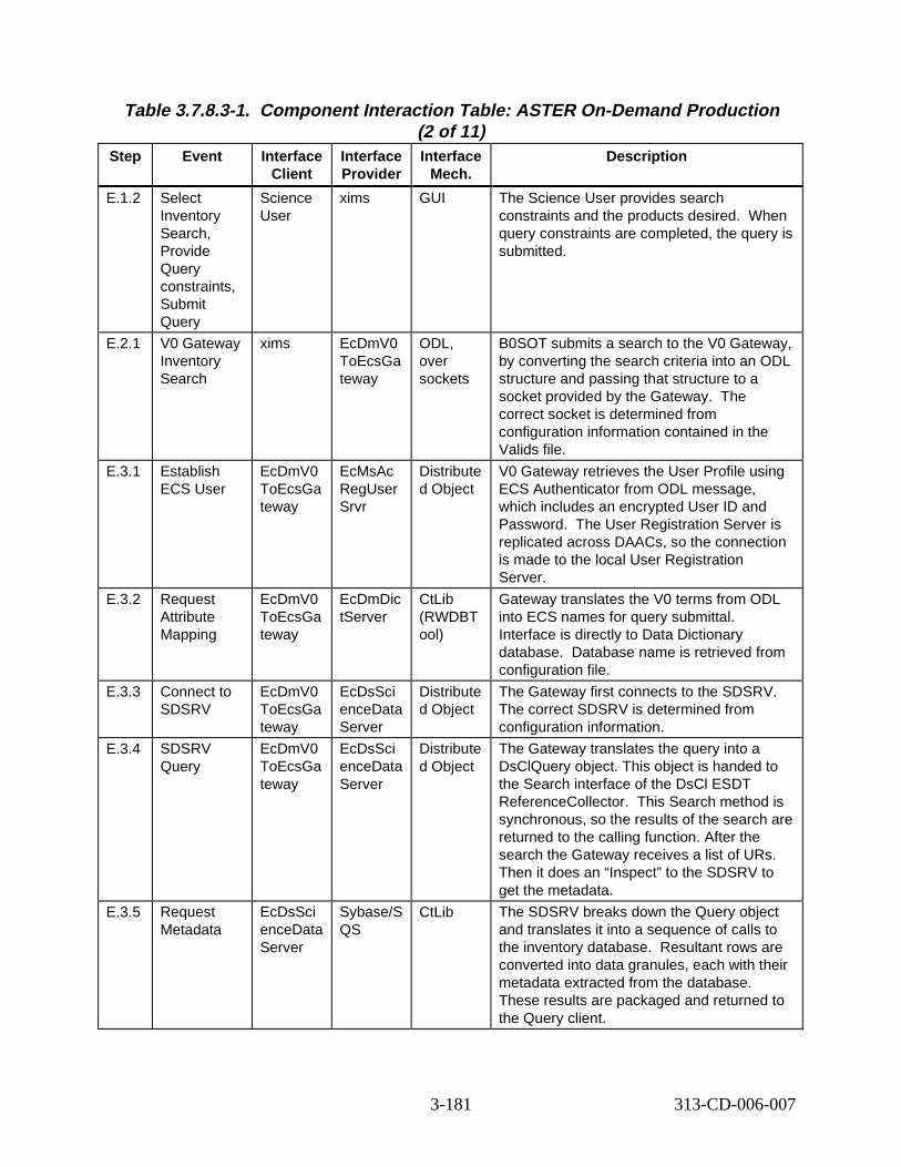
Table 3.7.8.3-1. Component Interaction Table: ASTER On-Demand Production (2 of 11)
Step Event Interface Client
Interface Provider
Interface Mech.
Descript ion
E.1.2 Select Inventory Search, Provide Query constraints, Submit Query
Science User
xims GUI The Science User provides search constraints and the products desired. When query constraints are completed, the query is submitted.
E.2.1 V0 Gateway Inventory Search
xims EcDmV0 ToEcsGa teway
ODL, over sockets
B0SOT submits a search to the V0 Gateway, by converting the search criteria into an ODL structure and passing that structure to a socket provided by the Gateway. The correct socket is determined from configuration information contained in the Valids file.
E.3.1 Establish ECS User
EcDmV0 ToEcsGa teway
EcMsAc RegUser Srvr
Distribute d Object
V0 Gateway retrieves the User Profile using ECS Authenticator from ODL message, which includes an encrypted User ID and Password. The User Registration Server is replicated across DAACs, so the connection is made to the local User Registration Server.
E.3.2 Request Attribute Mapping
EcDmV0 ToEcsGa teway
EcDmDic tServer
CtLib (RWDBT ool)
Gateway translates the V0 terms from ODL into ECS names for query submittal. Interface is directly to Data Dictionary database. Database name is retrieved from configuration file.
E.3.3 Connect to SDSRV
EcDmV0 ToEcsGa teway
EcDsSci enceData Server
Distribute d Object
The Gateway first connects to the SDSRV. The correct SDSRV is determined from configuration information.
E.3.4 SDSRV Query
EcDmV0 ToEcsGa teway
EcDsSci enceData Server
Distribute d Object
The Gateway translates the query into a DsClQuery object. This object is handed to the Search interface of the DsCl ESDT ReferenceCollector. This Search method is synchronous, so the results of the search are returned to the calling function. After the search the Gateway receives a list of URs. Then it does an “Inspect” to the SDSRV to get the metadata.
E.3.5 Request Metadata
EcDsSci enceData Server
Sybase/S QS
CtLib The SDSRV breaks down the Query object and translates it into a sequence of calls to the inventory database. Resultant rows are converted into data granules, each with their metadata extracted from the database. These results are packaged and returned to the Query client.
3-181 313-CD-006-007
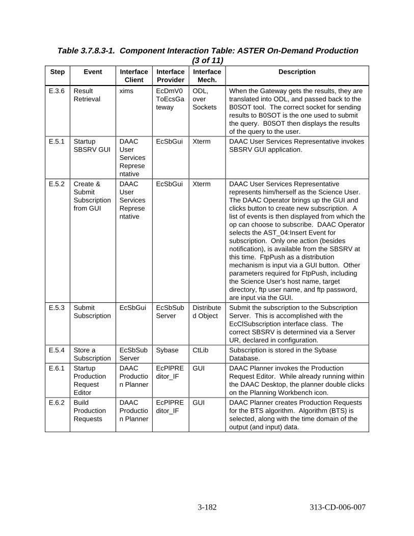
Table 3.7.8.3-1. Component Interaction Table: ASTER On-Demand Production (3 of 11)
Step Event Interface Client
Interface Provider
Interface Mech.
Descript ion
E.3.6 Result Retrieval
xims EcDmV0 ToEcsGa teway
ODL, over Sockets
When the Gateway gets the results, they are translated into ODL, and passed back to the B0SOT tool. The correct socket for sending results to B0SOT is the one used to submit the query. B0SOT then displays the results of the query to the user.
E.5.1 Startup SBSRV GUI
DAAC User Services Represe ntative
EcSbGui Xterm DAAC User Services Representative invokes SBSRV GUI application.
E.5.2 Create & Submit Subscription from GUI
DAAC User Services Represe ntative
EcSbGui Xterm DAAC User Services Representative represents him/herself as the Science User. The DAAC Operator brings up the GUI and clicks button to create new subscription. A list of events is then displayed from which the op can choose to subscribe. DAAC Operator selects the AST_04:Insert Event for subscription. Only one action (besides notification), is available from the SBSRV at this time. FtpPush as a distribution mechanism is input via a GUI button. Other parameters required for FtpPush, including the Science User’s host name, target directory, ftp user name, and ftp password, are input via the GUI.
E.5.3 Submit Subscription
EcSbGui EcSbSub Server
Distribute d Object
Submit the subscription to the Subscription Server. This is accomplished with the EcClSubscription interface class. The correct SBSRV is determined via a Server UR, declared in configuration.
E.5.4 Store a Subscription
EcSbSub Server
Sybase CtLib Subscription is stored in the Sybase Database.
E.6.1 Startup Production Request Editor
DAAC Productio n Planner
EcPlPRE ditor_IF
GUI DAAC Planner invokes the Production Request Editor. While already running within the DAAC Desktop, the planner double clicks on the Planning Workbench icon.
E.6.2 Build Production Requests
DAAC Productio n Planner
EcPlPRE ditor_IF
GUI DAAC Planner creates Production Requests for the BTS algorithm. Algorithm (BTS) is selected, along with the time domain of the output (and input) data.
3-182 313-CD-006-007
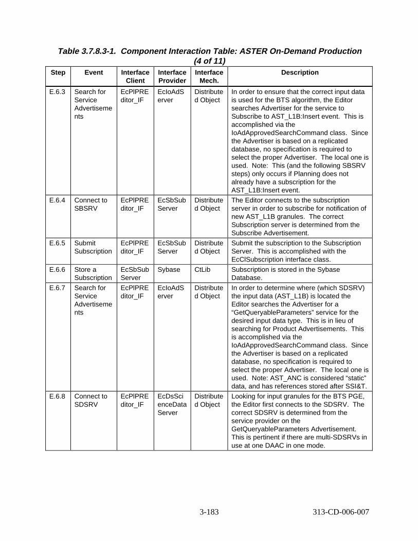
Table 3.7.8.3-1. Component Interaction Table: ASTER On-Demand Production (4 of 11)
Step Event Interface Client
Interface Provider
Interface Mech.
Descript ion
E.6.3 Search for Service Advertiseme nts
EcPlPRE ditor_IF
EcIoAdS erver
Distribute d Object
In order to ensure that the correct input data is used for the BTS algorithm, the Editor searches Advertiser for the service to Subscribe to AST_L1B:Insert event. This is accomplished via the IoAdApprovedSearchCommand class. Since the Advertiser is based on a replicated database, no specification is required to select the proper Advertiser. The local one is used. Note: This (and the following SBSRV steps) only occurs if Planning does not already have a subscription for the AST_L1B:Insert event.
E.6.4 Connect to SBSRV
EcPlPRE ditor_IF
EcSbSub Server
Distribute d Object
The Editor connects to the subscription server in order to subscribe for notification of new AST_L1B granules. The correct Subscription server is determined from the Subscribe Advertisement.
E.6.5 Submit Subscription
EcPlPRE ditor_IF
EcSbSub Server
Distribute d Object
Submit the subscription to the Subscription Server. This is accomplished with the EcClSubscription interface class.
E.6.6 Store a Subscription
EcSbSub Server
Sybase CtLib Subscription is stored in the Sybase Database.
E.6.7 Search for Service Advertiseme nts
EcPlPRE ditor_IF
EcIoAdS erver
Distribute d Object
In order to determine where (which SDSRV) the input data (AST_L1B) is located the Editor searches the Advertiser for a “GetQueryableParameters” service for the desired input data type. This is in lieu of searching for Product Advertisements. This is accomplished via the IoAdApprovedSearchCommand class. Since the Advertiser is based on a replicated database, no specification is required to select the proper Advertiser. The local one is used. Note: AST_ANC is considered “static” data, and has references stored after SSI&T.
E.6.8 Connect to SDSRV
EcPlPRE ditor_IF
EcDsSci enceData Server
Distribute d Object
Looking for input granules for the BTS PGE, the Editor first connects to the SDSRV. The correct SDSRV is determined from the service provider on the GetQueryableParameters Advertisement. This is pertinent if there are multi-SDSRVs in use at one DAAC in one mode.
3-183 313-CD-006-007
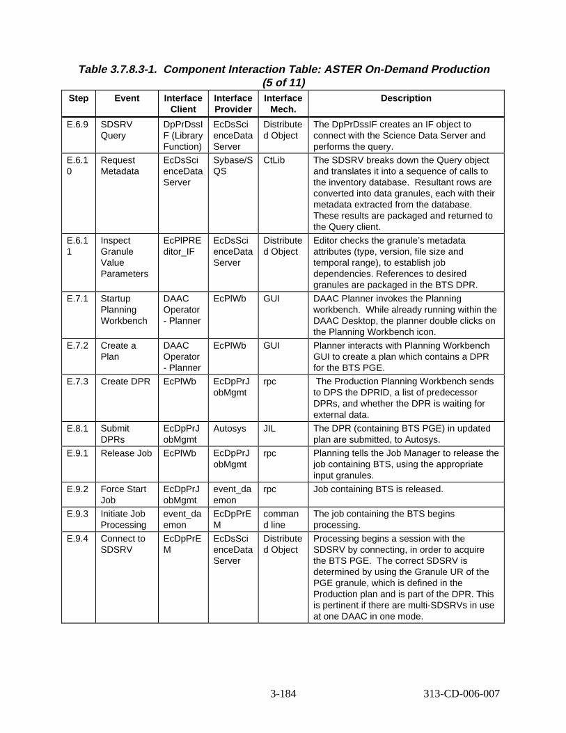
Table 3.7.8.3-1. Component Interaction Table: ASTER On-Demand Production (5 of 11)
Step Event Interface Client
Interface Provider
Interface Mech.
Descript ion
E.6.9 SDSRV Query
DpPrDssI F (Library Function)
EcDsSci enceData Server
Distribute d Object
The DpPrDssIF creates an IF object to connect with the Science Data Server and performs the query.
E.6.1 0
Request Metadata
EcDsSci enceData Server
Sybase/S QS
CtLib The SDSRV breaks down the Query object and translates it into a sequence of calls to the inventory database. Resultant rows are converted into data granules, each with their metadata extracted from the database. These results are packaged and returned to the Query client.
E.6.1 1
Inspect Granule Value Parameters
EcPlPRE ditor_IF
EcDsSci enceData Server
Distribute d Object
Editor checks the granule’s metadata attributes (type, version, file size and temporal range), to establish job dependencies. References to desired granules are packaged in the BTS DPR.
E.7.1 Startup Planning Workbench
DAAC Operator - Planner
EcPlWb GUI DAAC Planner invokes the Planning workbench. While already running within the DAAC Desktop, the planner double clicks on the Planning Workbench icon.
E.7.2 Create a Plan
DAAC Operator - Planner
EcPlWb GUI Planner interacts with Planning Workbench GUI to create a plan which contains a DPR for the BTS PGE.
E.7.3 Create DPR EcPlWb EcDpPrJ obMgmt
rpc The Production Planning Workbench sends to DPS the DPRID, a list of predecessor DPRs, and whether the DPR is waiting for external data.
E.8.1 Submit DPRs
EcDpPrJ obMgmt
Autosys JIL The DPR (containing BTS PGE) in updated plan are submitted, to Autosys.
E.9.1 Release Job EcPlWb EcDpPrJ obMgmt
rpc Planning tells the Job Manager to release the job containing BTS, using the appropriate input granules.
E.9.2 Force Start Job
EcDpPrJ obMgmt
event_da emon
rpc Job containing BTS is released.
E.9.3 Initiate Job Processing
event_da emon
EcDpPrE M
comman d line
The job containing the BTS begins processing.
E.9.4 Connect to SDSRV
EcDpPrE M
EcDsSci enceData Server
Distribute d Object
Processing begins a session with the SDSRV by connecting, in order to acquire the BTS PGE. The correct SDSRV is determined by using the Granule UR of the PGE granule, which is defined in the Production plan and is part of the DPR. This is pertinent if there are multi-SDSRVs in use at one DAAC in one mode.
3-184 313-CD-006-007
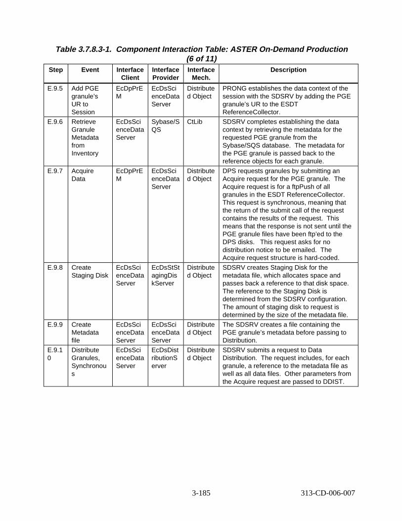
Table 3.7.8.3-1. Component Interaction Table: ASTER On-Demand Production (6 of 11)
Step Event Interface Client
Interface Provider
Interface Mech.
Descript ion
E.9.5 Add PGE granule’s UR to Session
EcDpPrE M
EcDsSci enceData Server
Distribute d Object
PRONG establishes the data context of the session with the SDSRV by adding the PGE granule’s UR to the ESDT ReferenceCollector.
E.9.6 Retrieve Granule Metadata from Inventory
EcDsSci enceData Server
Sybase/S QS
CtLib SDSRV completes establishing the data context by retrieving the metadata for the requested PGE granule from the Sybase/SQS database. The metadata for the PGE granule is passed back to the reference objects for each granule.
E.9.7 Acquire Data
EcDpPrE M
EcDsSci enceData Server
Distribute d Object
DPS requests granules by submitting an Acquire request for the PGE granule. The Acquire request is for a ftpPush of all granules in the ESDT ReferenceCollector. This request is synchronous, meaning that the return of the submit call of the request contains the results of the request. This means that the response is not sent until the PGE granule files have been ftp’ed to the DPS disks. This request asks for no distribution notice to be emailed. The Acquire request structure is hard-coded.
E.9.8 Create Staging Disk
EcDsSci enceData Server
EcDsStSt agingDis kServer
Distribute d Object
SDSRV creates Staging Disk for the metadata file, which allocates space and passes back a reference to that disk space. The reference to the Staging Disk is determined from the SDSRV configuration. The amount of staging disk to request is determined by the size of the metadata file.
E.9.9 Create Metadata file
EcDsSci enceData Server
EcDsSci enceData Server
Distribute d Object
The SDSRV creates a file containing the PGE granule’s metadata before passing to Distribution.
E.9.1 0
Distribute Granules, Synchronou s
EcDsSci enceData Server
EcDsDist ributionS erver
Distribute d Object
SDSRV submits a request to Data Distribution. The request includes, for each granule, a reference to the metadata file as well as all data files. Other parameters from the Acquire request are passed to DDIST.
3-185 313-CD-006-007
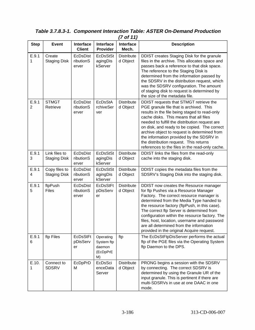
Table 3.7.8.3-1. Component Interaction Table: ASTER On-Demand Production (7 of 11)
Step Event Interface Client
Interface Provider
Interface Mech.
Descript ion
E.9.1 1
Create Staging Disk
EcDsDist ributionS erver
EcDsStSt agingDis kServer
Distribute d Object
DDIST creates Staging Disk for the granule files in the archive. This allocates space and passes back a reference to that disk space. The reference to the Staging Disk is determined from the information passed by the SDSRV in the distribution request, which was the SDSRV configuration. The amount of staging disk to request is determined by the size of the metadata file.
E.9.1 2
STMGT Retrieve
EcDsDist ributionS erver
EcDsStA rchiveSer ver
Distribute d Object
DDIST requests that STMGT retrieve the PGE granule file that is archived. This results in the file being staged to read-only cache disks. This means that all files needed to fulfill the distribution request are on disk, and ready to be copied. The correct archive object to request is determined from the information provided by the SDSRV in the distribution request. This returns references to the files in the read-only cache.
E.9.1 3
Link files to Staging Disk
EcDsDist ributionS erver
EcDsStSt agingDis kServer
Distribute d Object
DDIST links the files from the read-only cache into the staging disk.
E.9.1 4
Copy files to Staging Disk
EcDsDist ributionS erver
EcDsStSt agingDis kServer
Distribute d Object
DDIST copies the metadata files from the SDSRV’s Staging Disk into the staging disk.
E.9.1 5
ftpPush Files
EcDsDist ributionS erver
EcDsStFt pDisServ er
Distribute d Object
DDIST now creates the Resource manager for ftp Pushes via a Resource Manager Factory. The correct resource manager is determined from the Media Type handed to the resource factory (ftpPush, in this case). The correct ftp Server is determined from configuration within the resource factory. The files, host, location, username and password are all determined from the information provided in the original Acquire request.
E.9.1 6
ftp Files EcDsStFt pDisServ er
Operating System ftp daemon (EcDpPrE M)
ftp The EcDsStFtpDisServer performs the actual ftp of the PGE files via the Operating System ftp Daemon to the DPS.
E.10. 1
Connect to SDSRV
EcDpPrD M
EcDsSci enceData Server
Distribute d Object
PRONG begins a session with the SDSRV by connecting. The correct SDSRV is determined by using the Granule UR of the input granule. This is pertinent if there are multi-SDSRVs in use at one DAAC in one mode.
3-186 313-CD-006-007
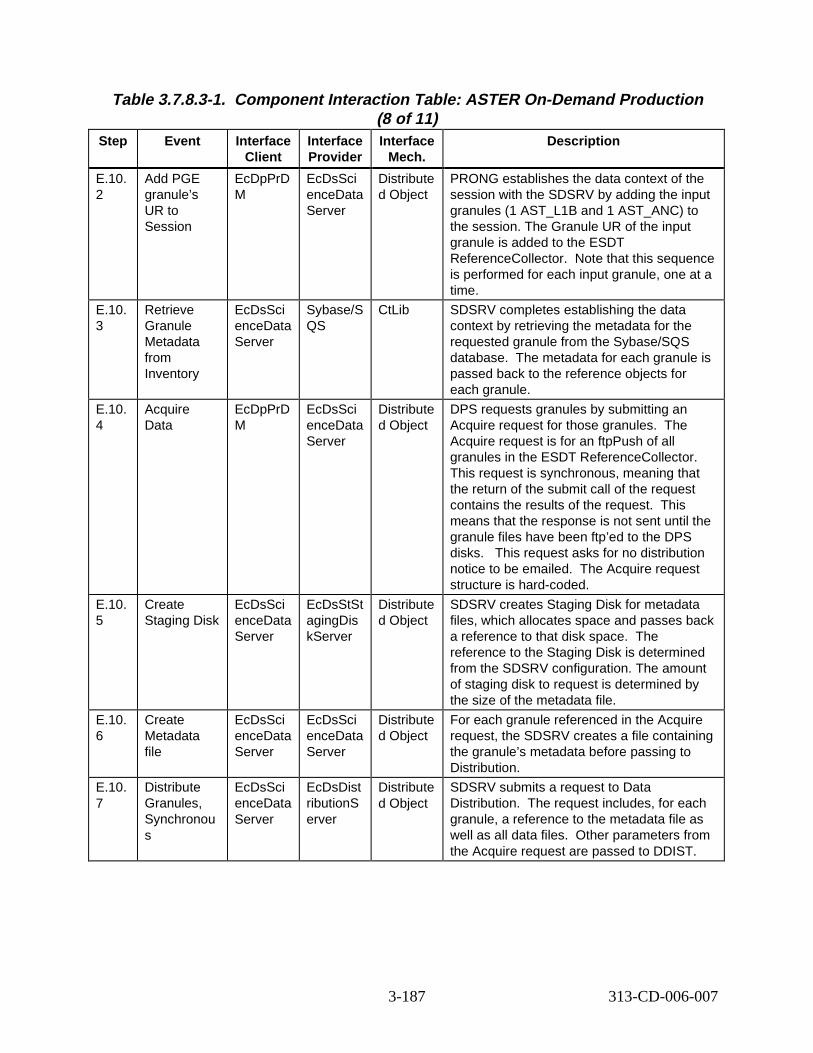
Table 3.7.8.3-1. Component Interaction Table: ASTER On-Demand Production (8 of 11)
Step Event Interface Client
Interface Provider
Interface Mech.
Descript ion
E.10. 2
Add PGE granule’s UR to Session
EcDpPrD M
EcDsSci enceData Server
Distribute d Object
PRONG establishes the data context of the session with the SDSRV by adding the input granules (1 AST_L1B and 1 AST_ANC) to the session. The Granule UR of the input granule is added to the ESDT ReferenceCollector. Note that this sequence is performed for each input granule, one at a time.
E.10. 3
Retrieve Granule Metadata from Inventory
EcDsSci enceData Server
Sybase/S QS
CtLib SDSRV completes establishing the data context by retrieving the metadata for the requested granule from the Sybase/SQS database. The metadata for each granule is passed back to the reference objects for each granule.
E.10. 4
Acquire Data
EcDpPrD M
EcDsSci enceData Server
Distribute d Object
DPS requests granules by submitting an Acquire request for those granules. The Acquire request is for an ftpPush of all granules in the ESDT ReferenceCollector. This request is synchronous, meaning that the return of the submit call of the request contains the results of the request. This means that the response is not sent until the granule files have been ftp’ed to the DPS disks. This request asks for no distribution notice to be emailed. The Acquire request structure is hard-coded.
E.10. 5
Create Staging Disk
EcDsSci enceData Server
EcDsStSt agingDis kServer
Distribute d Object
SDSRV creates Staging Disk for metadata files, which allocates space and passes back a reference to that disk space. The reference to the Staging Disk is determined from the SDSRV configuration. The amount of staging disk to request is determined by the size of the metadata file.
E.10. 6
Create Metadata file
EcDsSci enceData Server
EcDsSci enceData Server
Distribute d Object
For each granule referenced in the Acquire request, the SDSRV creates a file containing the granule’s metadata before passing to Distribution.
E.10. 7
Distribute Granules, Synchronou s
EcDsSci enceData Server
EcDsDist ributionS erver
Distribute d Object
SDSRV submits a request to Data Distribution. The request includes, for each granule, a reference to the metadata file as well as all data files. Other parameters from the Acquire request are passed to DDIST.
3-187 313-CD-006-007
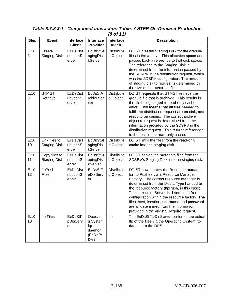
Table 3.7.8.3-1. Component Interaction Table: ASTER On-Demand Production (9 of 11)
Step Event Interface Client
Interface Provider
Interface Mech.
Descript ion
E.10. 8
Create Staging Disk
EcDsDist ributionS erver
EcDsStSt agingDis kServer
Distribute d Object
DDIST creates Staging Disk for the granule files in the archive. This allocates space and passes back a reference to that disk space. The reference to the Staging Disk is determined from the information passed by the SDSRV in the distribution request, which was the SDSRV configuration. The amount of staging disk to request is determined by the size of the metadata file.
E.10. 9
STMGT Retrieve
EcDsDist ributionS erver
EcDsStA rchiveSer ver
Distribute d Object
DDIST requests that STMGT retrieve the granule file that is archived. This results in the file being staged to read-only cache disks. This means that all files needed to fulfill the distribution request are on disk, and ready to be copied. The correct archive object to request is determined from the information provided by the SDSRV in the distribution request. This returns references to the files in the read-only cache.
E.10. 10
Link files to Staging Disk
EcDsDist ributionS erver
EcDsStSt agingDis kServer
Distribute d Object
DDIST links the files from the read-only cache into the staging disk.
E.10. 11
Copy files to Staging Disk
EcDsDist ributionS erver
EcDsStSt agingDis kServer
Distribute d Object
DDIST copies the metadata files from the SDSRV’s Staging Disk into the staging disk.
E.10. 12
ftpPush Files
EcDsDist ributionS erver
EcDsStFt pDisServ er
Distribute d Object
DDIST now creates the Resource manager for ftp Pushes via a Resource Manager Factory. The correct resource manager is determined from the Media Type handed to the resource factory (ftpPush, in this case). The correct ftp Server is determined from configuration within the resource factory. The files, host, location, username and password are all determined from the information provided in the original Acquire request.
E.10. 13
ftp Files EcDsStFt pDisServ er
Operatin g System ftp daemon (EcDpPr DM)
ftp The EcDsStFtpDisServer performs the actual ftp of the files via the Operating System ftp daemon to the DPS.
3-188 313-CD-006-007
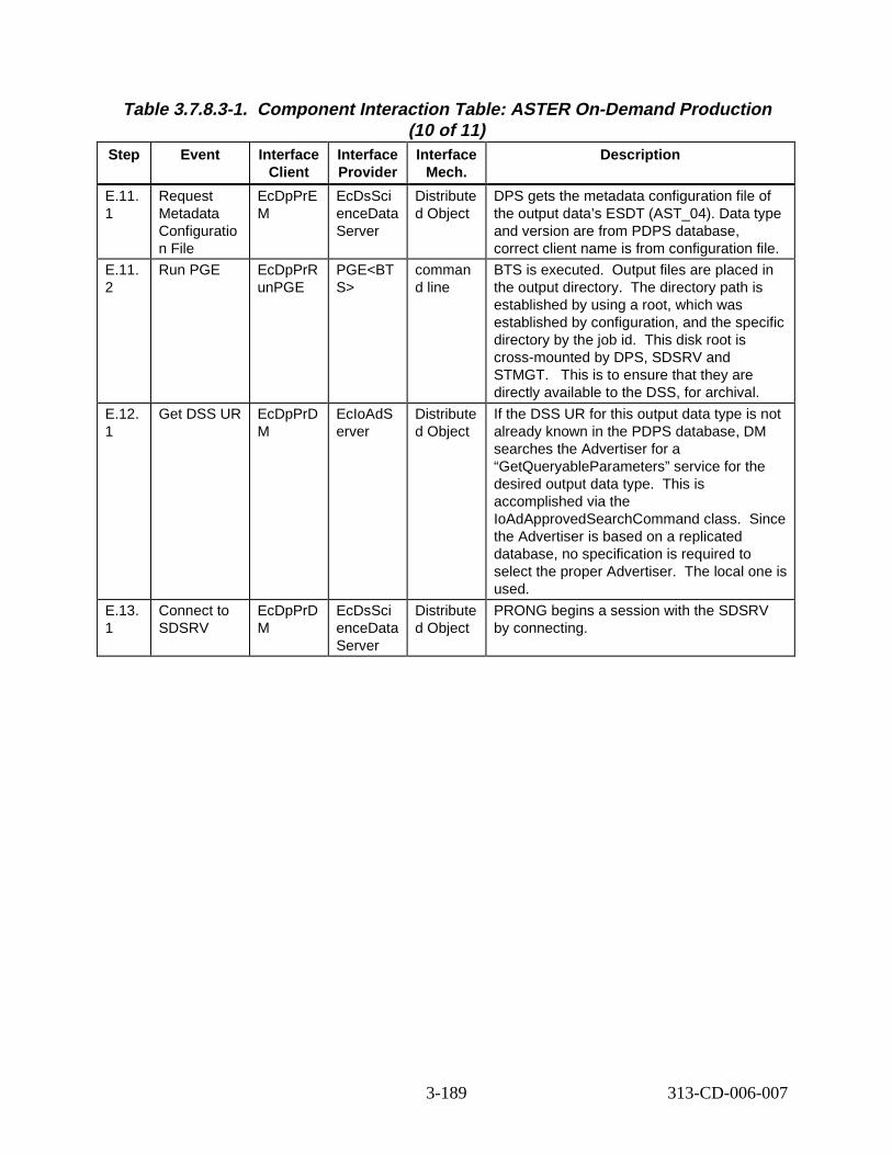
Table 3.7.8.3-1. Component Interaction Table: ASTER On-Demand Production (10 of 11)
Step Event Interface Client
Interface Provider
Interface Mech.
Descript ion
E.11. 1
Request Metadata Configuratio n File
EcDpPrE M
EcDsSci enceData Server
Distribute d Object
DPS gets the metadata configuration file of the output data’s ESDT (AST_04). Data type and version are from PDPS database, correct client name is from configuration file.
E.11. 2
Run PGE EcDpPrR unPGE
PGE<BT S>
comman d line
BTS is executed. Output files are placed in the output directory. The directory path is established by using a root, which was established by configuration, and the specific directory by the job id. This disk root is cross-mounted by DPS, SDSRV and STMGT. This is to ensure that they are directly available to the DSS, for archival.
E.12. 1
Get DSS UR EcDpPrD M
EcIoAdS erver
Distribute d Object
If the DSS UR for this output data type is not already known in the PDPS database, DM searches the Advertiser for a “GetQueryableParameters” service for the desired output data type. This is accomplished via the IoAdApprovedSearchCommand class. Since the Advertiser is based on a replicated database, no specification is required to select the proper Advertiser. The local one is used.
E.13. 1
Connect to SDSRV
EcDpPrD M
EcDsSci enceData Server
Distribute d Object
PRONG begins a session with the SDSRV by connecting.
3-189 313-CD-006-007
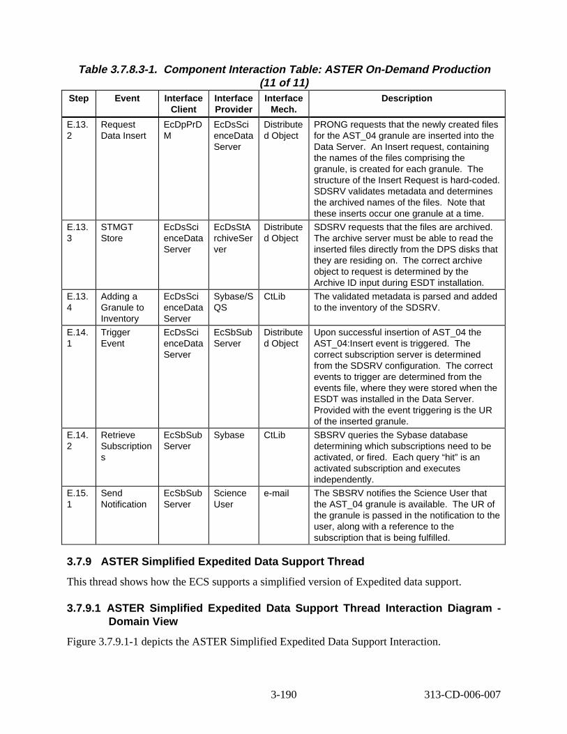
Table 3.7.8.3-1. Component Interaction Table: ASTER On-Demand Production (11 of 11)
Step Event Interface Client
Interface Provider
Interface Mech.
Descript ion
E.13. 2
Request Data Insert
EcDpPrD M
EcDsSci enceData Server
Distribute d Object
PRONG requests that the newly created files for the AST_04 granule are inserted into the Data Server. An Insert request, containing the names of the files comprising the granule, is created for each granule. The structure of the Insert Request is hard-coded. SDSRV validates metadata and determines the archived names of the files. Note that these inserts occur one granule at a time.
E.13. 3
STMGT Store
EcDsSci enceData Server
EcDsStA rchiveSer ver
Distribute d Object
SDSRV requests that the files are archived. The archive server must be able to read the inserted files directly from the DPS disks that they are residing on. The correct archive object to request is determined by the Archive ID input during ESDT installation.
E.13. 4
Adding a Granule to Inventory
EcDsSci enceData Server
Sybase/S QS
CtLib The validated metadata is parsed and added to the inventory of the SDSRV.
E.14. 1
Trigger Event
EcDsSci enceData Server
EcSbSub Server
Distribute d Object
Upon successful insertion of AST_04 the AST_04:Insert event is triggered. The correct subscription server is determined from the SDSRV configuration. The correct events to trigger are determined from the events file, where they were stored when the ESDT was installed in the Data Server. Provided with the event triggering is the UR of the inserted granule.
E.14. 2
Retrieve Subscription s
EcSbSub Server
Sybase CtLib SBSRV queries the Sybase database determining which subscriptions need to be activated, or fired. Each query “hit” is an activated subscription and executes independently.
E.15. 1
Send Notification
EcSbSub Server
Science User
e-mail The SBSRV notifies the Science User that the AST_04 granule is available. The UR of the granule is passed in the notification to the user, along with a reference to the subscription that is being fulfilled.
3.7.9 ASTER Simplifi ed Exp edited Data Support Thread
This thread shows how the ECS supports a simplified version of Expedited data support.
3.7.9.1 ASTER Simplified Expedited Data Support Thread Inter action Diagr am -Domain Vie w
Figure 3.7.9.1-1 depicts the ASTER Simplified Expedited Data Support Interaction.
3-190 313-CD-006-007

DSS
SBSRV
EDOS
INS
F.5 Request Data Insert (AST_EXP)
F.6 Trigger Event (AST_EXP)
F.3 Directory Polling
DAAC Ops
IOS F.1 Get SDSRV URs
Email Parser Gateway
MSS Notification Service (ASTER Email Handler)
ASTER GDS
F.14 ftp/push data
F.2 Subscribe
F.12 Forward EDR F.7 Notifi cation
F.13 Acquire
F.10 Forward EDN
F.11 Send EDR
Copies Files F.4 EDOS
F.9 Send EDN F.8 Inspect
Distributed Object (rpc, CtLib)
HMI (GUI, Xterm, command)
ftp email (or other as noted) Double line - Synchronous email (or other as noted) Dashed - Asynchronous
Figure 3. 7.9.1-1. ASTER Simpl ified E xpedited Dat a Support Interaction Diagram
3.7.9.2 ASTER Simplified Expedited Data Support Thread Inter action Table -Domain Vie w
Table 3.7.9.2-1 provides the Interaction - Domain View: ASTER Simplified Expedited Data.
Table 3.7.9.2-1. Interact ion Tabl e - Domain V iew: ASTER Simplified Expedited Data (1 of 3)
Step Event Interface Client
Interface Provider
Data Issues
Step Precondi
tions
Descript ion
F.1 Get SDSRV URs
INS IOS None None Upon startup, Ingest gets the SDSRV URs for each data type in its database.
3-191 313-CD-006-007
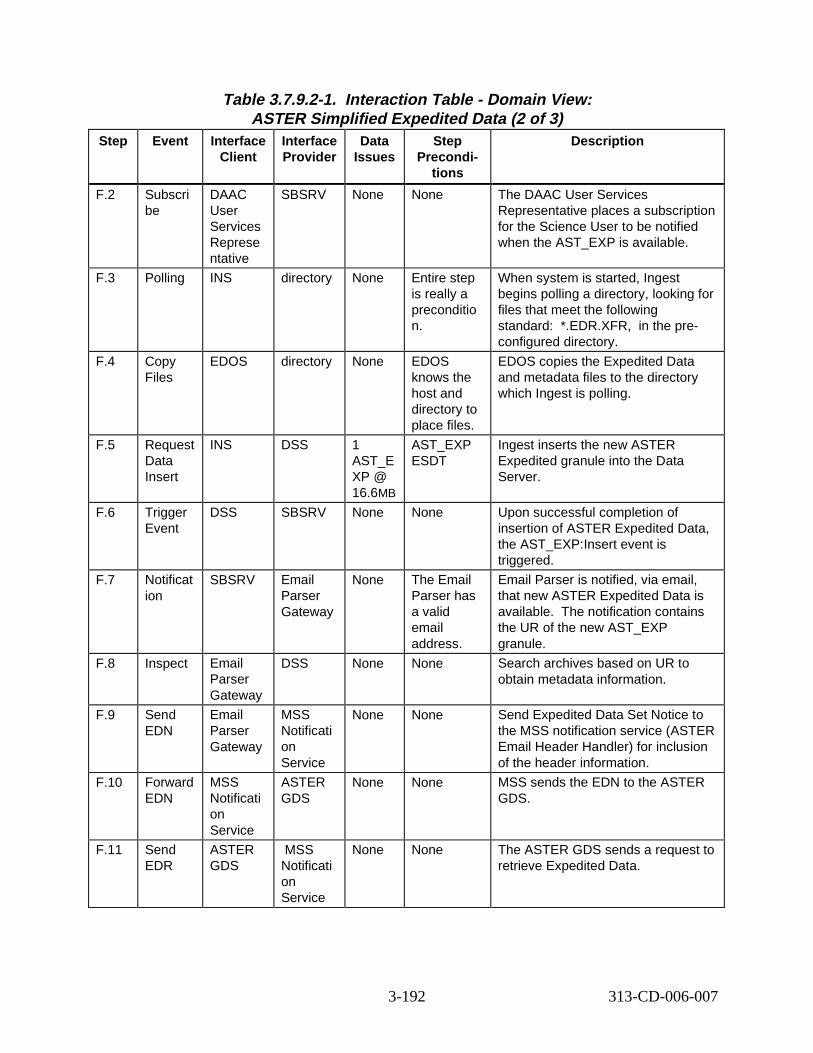
Table 3.7.9.2-1. Interact ion Tabl e - Domain V iew: ASTER Simplified Expedited Data (2 of 3)
Step Event Interface Client
Interface Provider
Data Issues
Step Precondi
tions
Descript ion
F.2 Subscri be
DAAC User Services Represe ntative
SBSRV None None The DAAC User Services Representative places a subscription for the Science User to be notified when the AST_EXP is available.
F.3 Polling INS directory None Entire step is really a preconditio n.
When system is started, Ingest begins polling a directory, looking for files that meet the following standard: *.EDR.XFR, in the preconfigured directory.
F.4 Copy Files
EDOS directory None EDOS knows the host and directory to place files.
EDOS copies the Expedited Data and metadata files to the directory which Ingest is polling.
F.5 Request Data Insert
INS DSS 1 AST_E XP @ 16.6MB
AST_EXP ESDT
Ingest inserts the new ASTER Expedited granule into the Data Server.
F.6 Trigger Event
DSS SBSRV None None Upon successful completion of insertion of ASTER Expedited Data, the AST_EXP:Insert event is triggered.
F.7 Notificat ion
SBSRV Email Parser Gateway
None The Email Parser has a valid email address.
Email Parser is notified, via email, that new ASTER Expedited Data is available. The notification contains the UR of the new AST_EXP granule.
F.8 Inspect Email Parser Gateway
DSS None None Search archives based on UR to obtain metadata information.
F.9 Send EDN
Email Parser Gateway
MSS Notificati on Service
None None Send Expedited Data Set Notice to the MSS notification service (ASTER Email Header Handler) for inclusion of the header information.
F.10 Forward EDN
MSS Notificati on Service
ASTER GDS
None None MSS sends the EDN to the ASTER GDS.
F.11 Send EDR
ASTER GDS
MSS Notificati on Service
None None The ASTER GDS sends a request to retrieve Expedited Data.
3-192 313-CD-006-007

Table 3.7.9.2-1. Interact ion Tabl e - Domain V iew: ASTER Simplified Expedited Data (3 of 3)
Step Event Interface Client
Interface Provider
Data Issues
Step Precondi
tions
Descript ion
F.12 Forward EDR
MSS Notificati on Service
Email Parser Gateway
None None MSS forwards the Expedited Data Request to the Email Parser Gateway after stripping the header information.
F.13 Acquire Email Parser Gateway
DSS None None The Email Parser Gateway makes an acquire request on behalf of the ASTER GDS to obtain the necessary data granules from DSS. The acquire can be for an ftp push.
F.14 ftp/push data
DSS ASTER GDS
None None The data granules are transferred to the ASTER GDS via ftp Push.
3.7.9.3 ASTER Simplified Expedited Data Support Thread Component Interaction Table
Table 3.7.9.3-1 provides the Component Interaction: ASTER Simplified Expedited Data.
Table 3.7.9.3-1. Component Interaction Table: ASTER Simplifi ed Exp edited Data (1 of 5)
Step Event Interface Client
Interface Provider
Interface Mech.
Descript ion
F.1.1 Get SDSRV URs from IOS
EcInReq Mgr
EcIoAdS erver
Distribute d Object
Upon startup, Ingest Request Manager requests the SDSRV URs for each data type in its database.
F.2.1 Startup SBSRV GUI
DAAC User Services Represen tative
EcSbGui Xterm DAAC User Services Representative invokes SBSRV GUI application.
3-193 313-CD-006-007
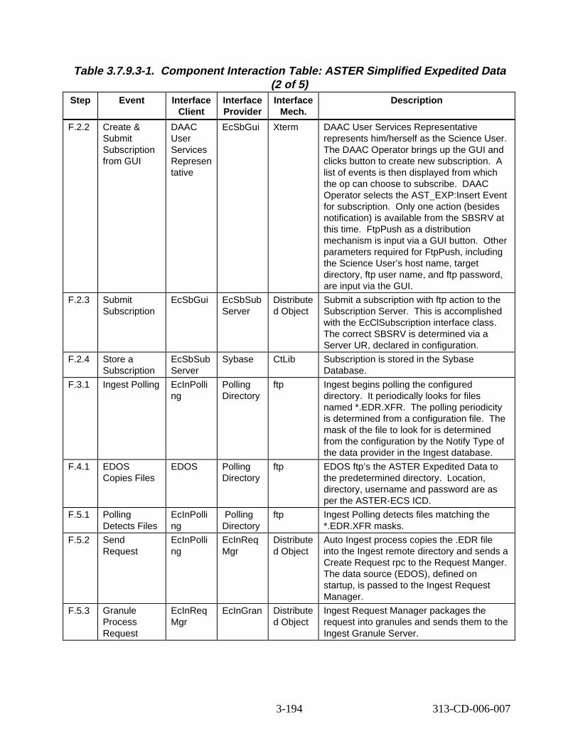
Table 3.7.9.3-1. Component Interaction Table: ASTER Simplifi ed Exp edited Data (2 of 5)
Step Event Interface Client
Interface Provider
Interface Mech.
Descript ion
F.2.2 Create & Submit Subscription from GUI
DAAC User Services Represen tative
EcSbGui Xterm DAAC User Services Representative represents him/herself as the Science User. The DAAC Operator brings up the GUI and clicks button to create new subscription. A list of events is then displayed from which the op can choose to subscribe. DAAC Operator selects the AST_EXP:Insert Event for subscription. Only one action (besides notification) is available from the SBSRV at this time. FtpPush as a distribution mechanism is input via a GUI button. Other parameters required for FtpPush, including the Science User’s host name, target directory, ftp user name, and ftp password, are input via the GUI.
F.2.3 Submit Subscription
EcSbGui EcSbSub Server
Distribute d Object
Submit a subscription with ftp action to the Subscription Server. This is accomplished with the EcClSubscription interface class. The correct SBSRV is determined via a Server UR, declared in configuration.
F.2.4 Store a Subscription
EcSbSub Server
Sybase CtLib Subscription is stored in the Sybase Database.
F.3.1 Ingest Polling EcInPolli ng
Polling Directory
ftp Ingest begins polling the configured directory. It periodically looks for files named *.EDR.XFR. The polling periodicity is determined from a configuration file. The mask of the file to look for is determined from the configuration by the Notify Type of the data provider in the Ingest database.
F.4.1 EDOS Copies Files
EDOS Polling Directory
ftp EDOS ftp’s the ASTER Expedited Data to the predetermined directory. Location, directory, username and password are as per the ASTER-ECS ICD.
F.5.1 Polling Detects Files
EcInPolli ng
Polling Directory
ftp Ingest Polling detects files matching the *.EDR.XFR masks.
F.5.2 Send Request
EcInPolli ng
EcInReq Mgr
Distribute d Object
Auto Ingest process copies the .EDR file into the Ingest remote directory and sends a Create Request rpc to the Request Manger. The data source (EDOS), defined on startup, is passed to the Ingest Request Manager.
F.5.3 Granule Process Request
EcInReq Mgr
EcInGran Distribute d Object
Ingest Request Manager packages the request into granules and sends them to the Ingest Granule Server.
3-194 313-CD-006-007
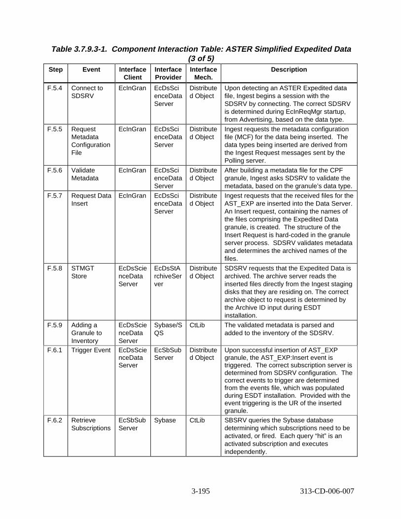
Table 3.7.9.3-1. Component Interaction Table: ASTER Simplifi ed Exp edited Data (3 of 5)
Step Event Interface Client
Interface Provider
Interface Mech.
Descript ion
F.5.4 Connect to SDSRV
EcInGran EcDsSci enceData Server
Distribute d Object
Upon detecting an ASTER Expedited data file, Ingest begins a session with the SDSRV by connecting. The correct SDSRV is determined during EcInReqMgr startup, from Advertising, based on the data type.
F.5.5 Request Metadata Configuration File
EcInGran EcDsSci enceData Server
Distribute d Object
Ingest requests the metadata configuration file (MCF) for the data being inserted. The data types being inserted are derived from the Ingest Request messages sent by the Polling server.
F.5.6 Validate Metadata
EcInGran EcDsSci enceData Server
Distribute d Object
After building a metadata file for the CPF granule, Ingest asks SDSRV to validate the metadata, based on the granule’s data type.
F.5.7 Request Data Insert
EcInGran EcDsSci enceData Server
Distribute d Object
Ingest requests that the received files for the AST_EXP are inserted into the Data Server. An Insert request, containing the names of the files comprising the Expedited Data granule, is created. The structure of the Insert Request is hard-coded in the granule server process. SDSRV validates metadata and determines the archived names of the files.
F.5.8 STMGT Store
EcDsScie nceData Server
EcDsStA rchiveSer ver
Distribute d Object
SDSRV requests that the Expedited Data is archived. The archive server reads the inserted files directly from the Ingest staging disks that they are residing on. The correct archive object to request is determined by the Archive ID input during ESDT installation.
F.5.9 Adding a Granule to Inventory
EcDsScie nceData Server
Sybase/S QS
CtLib The validated metadata is parsed and added to the inventory of the SDSRV.
F.6.1 Trigger Event EcDsScie nceData Server
EcSbSub Server
Distribute d Object
Upon successful insertion of AST_EXP granule, the AST_EXP:Insert event is triggered. The correct subscription server is determined from SDSRV configuration. The correct events to trigger are determined from the events file, which was populated during ESDT installation. Provided with the event triggering is the UR of the inserted granule.
F.6.2 Retrieve Subscriptions
EcSbSub Server
Sybase CtLib SBSRV queries the Sybase database determining which subscriptions need to be activated, or fired. Each query “hit” is an activated subscription and executes independently.
3-195 313-CD-006-007
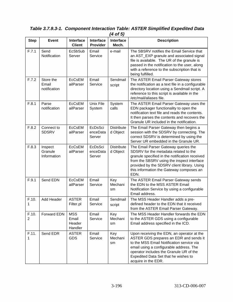
Table 3.7.9.3-1. Component Interaction Table: ASTER Simplifi ed Exp edited Data (4 of 5)
Step Event Interface Client
Interface Provider
Interface Mech.
Descript ion
F.7.1 Send Notification
EcSbSub Server
Email Service
e-mail The SBSRV notifies the Email Service that an AST_EXP granule and associated signal file is available. The UR of the granule is passed in the notification to the user, along with a reference to the subscription that is being fulfilled.
F.7.2 Store the Email notification
EcCsEM ailParser
Email Service
Sendmail script
The ASTER Email Parser Gateway stores the notification as a text file in a configurable directory location using a Sendmail script. A reference to this script is available in the /etc/mail/aliases file.
F.8.1 Parse notification
EcCsEM ailParser
Unix File System
System calls
The ASTER Email Parser Gateway uses the EDN packager functionality to open the notification text file and reads the contents. It then parses the contents and recovers the Granule UR included in the notification.
F.8.2 Connect to SDSRV
EcCsEM ailParser
EcDsSci enceData Server
Distribute d Object
The Email Parser Gateway then begins a session with the SDSRV by connecting. The correct SDSRV is determined by using the Server UR embedded in the Granule UR.
F.8.3 Inspect Granule Information
EcCsEM ailParser
EcDsSci enceData Server
Distribute d Object
The Email Parser Gateway queries the SDSRV for the metadata related to the granule specified in the notification received from the SBSRV using the inspect interface provided by the SDSRV client library. Using this information the Gateway composes an EDN.
F.9.1 Send EDN EcCsEM ailParser
Email Service
Key Mechani sm
The ASTER Email Parser Gateway sends the EDN to the MSS ASTER Email Notification Service by using a configurable Email address.
F.10. 1
Add Header ASTER Filter.pl
Email Service
Sendmail script
The MSS Header Handler adds a predefined header to the EDN that it received from the ASTER Email Parser Gateway.
F.10. 2
Forward EDN MSS Email Header Handler
Email Service
Key Mechani sm
The MSS Header Handler forwards the EDN to the ASTER GDS using a configurable Email address specified in the ICD.
F.11. 1
Send EDR ASTER GDS
Email Service
Key Mechani sm
Upon receiving the EDN, an operator at the ASTER GDS prepares an EDR and sends it to the MSS Email Notification service via email using a configurable address. The operator includes the Granule UR of the Expedited Data Set that he wishes to acquire in the EDR.
3-196 313-CD-006-007
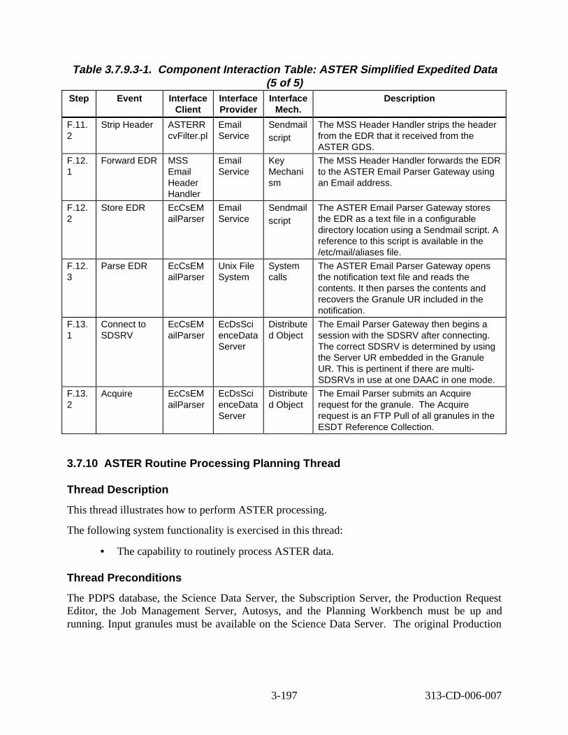
Table 3.7.9.3-1. Component Interaction Table: ASTER Simplifi ed Exp edited Data (5 of 5)
Step Event Interface Client
Interface Provider
Interface Mech.
Descript ion
F.11. 2
Strip Header ASTERR cvFilter.pl
Email Service
Sendmail script
The MSS Header Handler strips the header from the EDR that it received from the ASTER GDS.
F.12. 1
Forward EDR MSS Email Header Handler
Email Service
Key Mechani sm
The MSS Header Handler forwards the EDR to the ASTER Email Parser Gateway using an Email address.
F.12. 2
Store EDR EcCsEM ailParser
Email Service
Sendmail script
The ASTER Email Parser Gateway stores the EDR as a text file in a configurable directory location using a Sendmail script. A reference to this script is available in the /etc/mail/aliases file.
F.12. 3
Parse EDR EcCsEM ailParser
Unix File System
System calls
The ASTER Email Parser Gateway opens the notification text file and reads the contents. It then parses the contents and recovers the Granule UR included in the notification.
F.13. 1
Connect to SDSRV
EcCsEM ailParser
EcDsSci enceData Server
Distribute d Object
The Email Parser Gateway then begins a session with the SDSRV after connecting. The correct SDSRV is determined by using the Server UR embedded in the Granule UR. This is pertinent if there are multi-SDSRVs in use at one DAAC in one mode.
F.13. 2
Acquire EcCsEM ailParser
EcDsSci enceData Server
Distribute d Object
The Email Parser submits an Acquire request for the granule. The Acquire request is an FTP Pull of all granules in the ESDT Reference Collection.
3.7.10 ASTER Routine Processing Pl anning Thread
Thread Description
This thread illustrates how to perform ASTER processing.
The following system functionality is exercised in this thread:
• The capability to routinely process ASTER data.
Thread Pr econditions
The PDPS database, the Science Data Server, the Subscription Server, the Production Request Editor, the Job Management Server, Autosys, and the Planning Workbench must be up and running. Input granules must be available on the Science Data Server. The original Production
3-197 313-CD-006-007
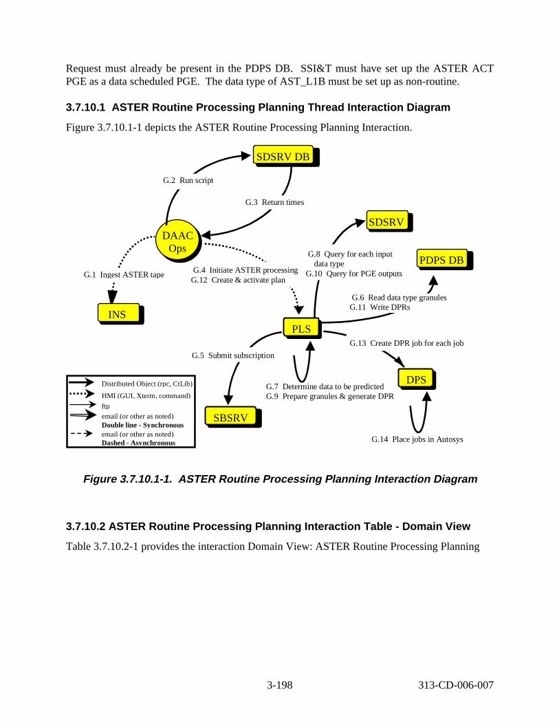
Request must already be present in the PDPS DB. SSI&T must have set up the ASTER ACT PGE as a data scheduled PGE. The data type of AST_L1B must be set up as non-routine.
3.7.10.1 ASTER Routine Processing Planning Thread Inter action Diagr am
Figure 3.7.10.1-1 depicts the ASTER Routine Processing Planning Interaction.
SDSRV DB
PLSPLS
DPS DPS
SBSRV
G.13 Create DPR job for each job
G.4 Initiate ASTER processing G.12 Create & activate plan
DAAC Ops
DAAC Ops
SDSRV
G.7 Determine data to be predicted G.9 Prepare granules & generate DPR
PDPS DB
G.14 Place jobs in Autosys
G.6 Read data type granules G.11 Write DPRs
G.5 Submit subscription
G.8 Query for each input data type
G.10 Query for PGE outputs
INS
G.1 Ingest ASTER tape
G.2 Run script
G.3 Return times
Distributed Object (rpc, CtLib)
HMI (GUI, Xterm, command)
ftp email (or other as noted) Double line - Synchronous email (or other as noted) Dashed - Asynchronous
Figure 3. 7.10.1-1. ASTER Routine P rocessing P lanning Inter action Diagr am
3.7.10.2 ASTER Rout ine Pro cessing P lanning Int eract ion Tabl e - Domain View
Table 3.7.10.2-1 provides the interaction Domain View: ASTER Routine Processing Planning
3-198 313-CD-006-007
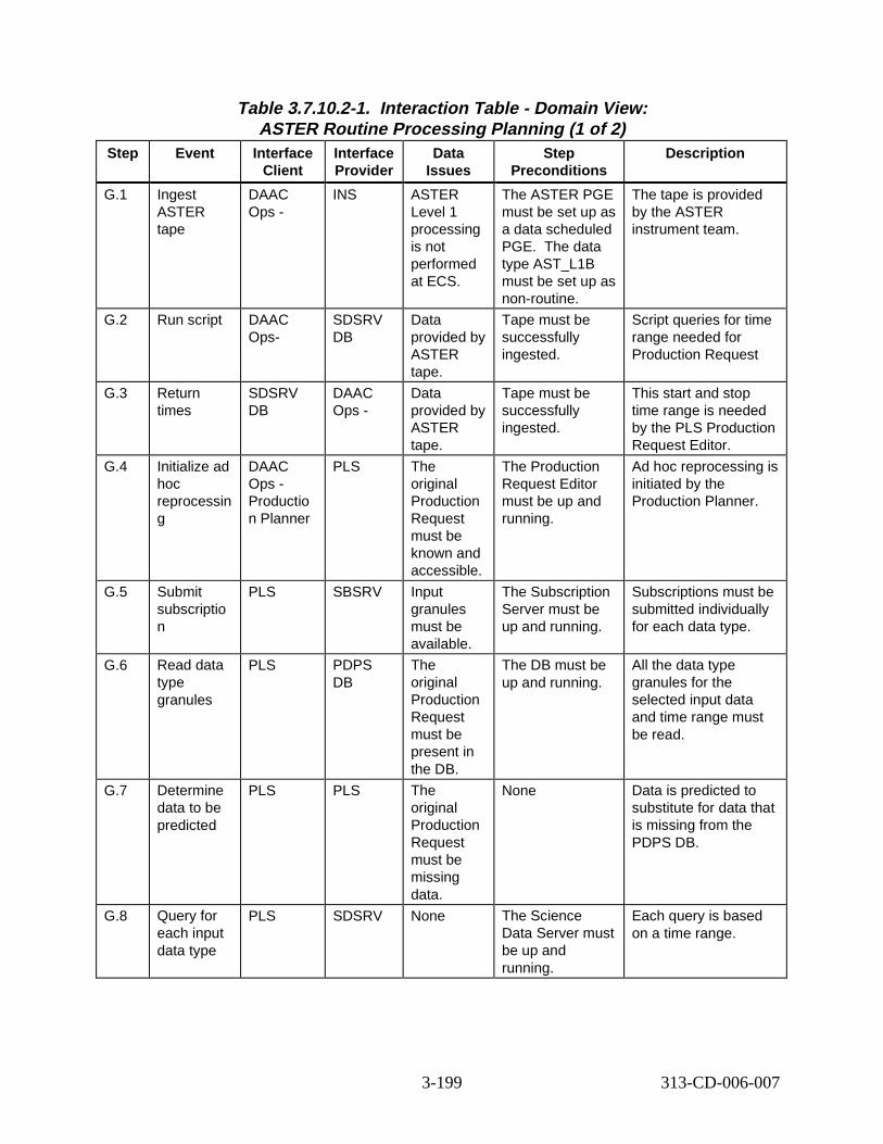
Table 3.7.10.2-1. Interact ion T able - Domain View: ASTER Routine Processing Planning (1 of 2)
Step Event Interface Client
Interface Provider
Data Issues
Step Preconditions
Descript ion
G.1 Ingest ASTER tape
DAAC Ops -
INS ASTER Level 1 processing is not performed at ECS.
The ASTER PGE must be set up as a data scheduled PGE. The data type AST_L1B must be set up as non-routine.
The tape is provided by the ASTER instrument team.
G.2 Run script DAAC Ops-
SDSRV DB
Data provided by ASTER tape.
Tape must be successfully ingested.
Script queries for time range needed for Production Request
G.3 Return times
SDSRV DB
DAAC Ops -
Data provided by ASTER tape.
Tape must be successfully ingested.
This start and stop time range is needed by the PLS Production Request Editor.
G.4 Initialize ad hoc reprocessin g
DAAC Ops -Productio n Planner
PLS The original Production Request must be known and accessible.
The Production Request Editor must be up and running.
Ad hoc reprocessing is initiated by the Production Planner.
G.5 Submit subscriptio n
PLS SBSRV Input granules must be available.
The Subscription Server must be up and running.
Subscriptions must be submitted individually for each data type.
G.6 Read data type granules
PLS PDPS DB
The original Production Request must be present in the DB.
The DB must be up and running.
All the data type granules for the selected input data and time range must be read.
G.7 Determine data to be predicted
PLS PLS The original Production Request must be missing data.
None Data is predicted to substitute for data that is missing from the PDPS DB.
G.8 Query for each input data type
PLS SDSRV None The Science Data Server must be up and running.
Each query is based on a time range.
3-199 313-CD-006-007
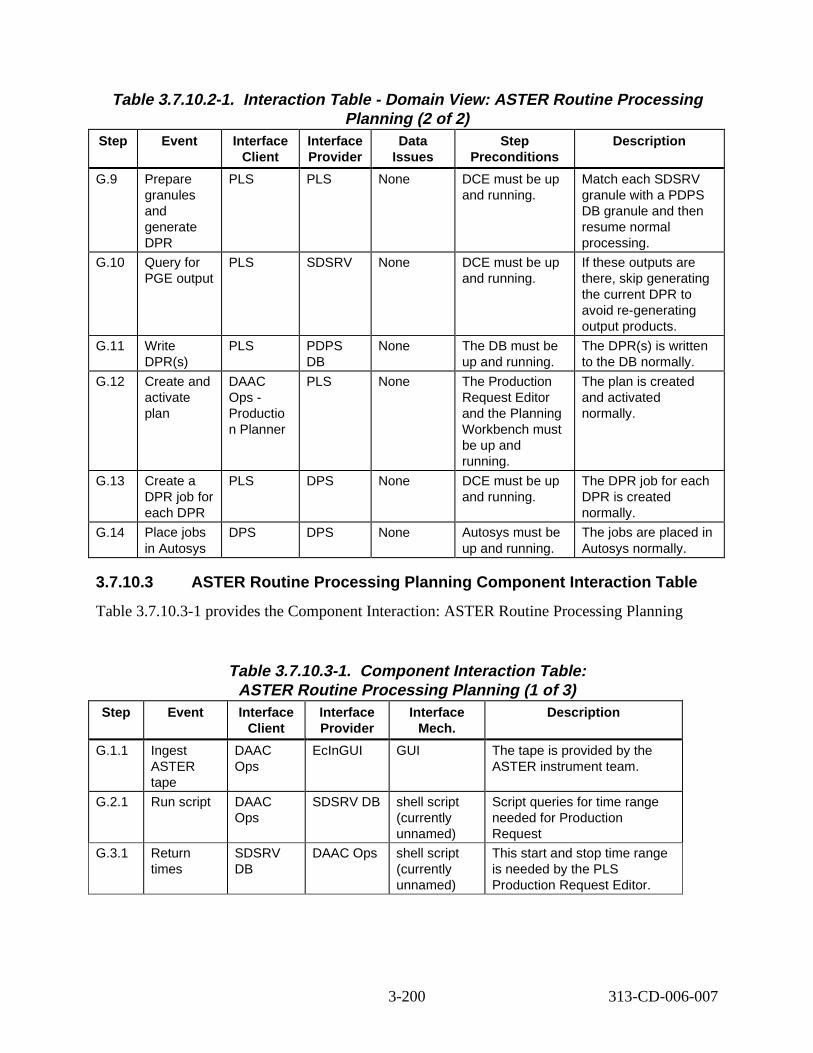
Table 3.7.10.2-1. Interact ion T able - Domain View: ASTER Rout ine Pro cessing Planning (2 of 2)
Step Event Interface Client
Interface Provider
Data Issues
Step Preconditions
Descript ion
G.9 Prepare granules and generate DPR
PLS PLS None DCE must be up and running.
Match each SDSRV granule with a PDPS DB granule and then resume normal processing.
G.10 Query for PGE output
PLS SDSRV None DCE must be up and running.
If these outputs are there, skip generating the current DPR to avoid re-generating output products.
G.11 Write DPR(s)
PLS PDPS DB
None The DB must be up and running.
The DPR(s) is written to the DB normally.
G.12 Create and activate plan
DAAC Ops -Productio n Planner
PLS None The Production Request Editor and the Planning Workbench must be up and running.
The plan is created and activated normally.
G.13 Create a DPR job for each DPR
PLS DPS None DCE must be up and running.
The DPR job for each DPR is created normally.
G.14 Place jobs in Autosys
DPS DPS None Autosys must be up and running.
The jobs are placed in Autosys normally.
3.7.10.3 ASTER Routine Processing Planning Component Inter action Tabl e
Table 3.7.10.3-1 provides the Component Interaction: ASTER Routine Processing Planning
Table 3.7.10.3-1. Component Inter action Tabl e: ASTER Routine Processing Planning (1 of 3)
Step Event Interface Client
Interface Provider
Interface Mech.
Descript ion
G.1.1 Ingest ASTER tape
DAAC Ops
EcInGUI GUI The tape is provided by the ASTER instrument team.
G.2.1 Run script DAAC Ops
SDSRV DB shell script (currently unnamed)
Script queries for time range needed for Production Request
G.3.1 Return times
SDSRV DB
DAAC Ops shell script (currently unnamed)
This start and stop time range is needed by the PLS Production Request Editor.
3-200 313-CD-006-007
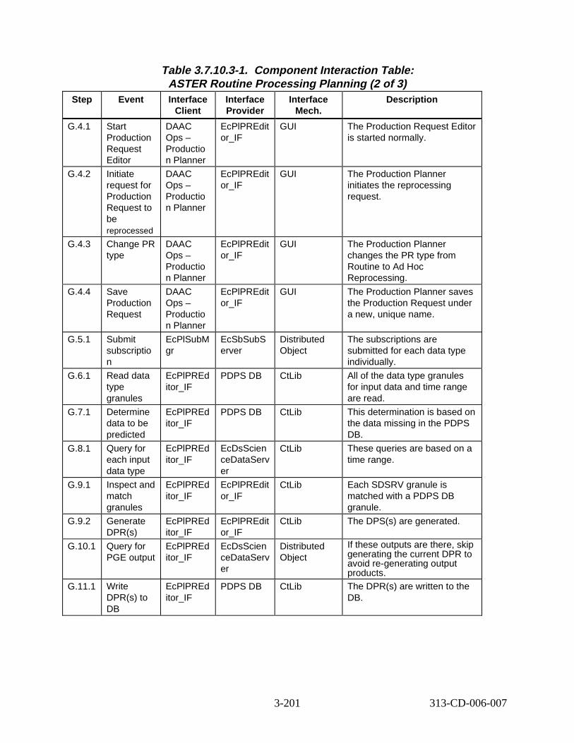
Table 3.7.10.3-1. Component Inter action Tabl e: ASTER Routine Processing Planning (2 of 3)
Step Event Interface Client
Interface Provider
Interface Mech.
Descript ion
G.4.1 Start Production Request Editor
DAAC Ops – Productio n Planner
EcPlPREdit or_IF
GUI The Production Request Editor is started normally.
G.4.2 Initiate request for Production Request to be reprocessed
DAAC Ops – Productio n Planner
EcPlPREdit or_IF
GUI The Production Planner initiates the reprocessing request.
G.4.3 Change PR type
DAAC Ops – Productio n Planner
EcPlPREdit or_IF
GUI The Production Planner changes the PR type from Routine to Ad Hoc Reprocessing.
G.4.4 Save Production Request
DAAC Ops – Productio n Planner
EcPlPREdit or_IF
GUI The Production Planner saves the Production Request under a new, unique name.
G.5.1 Submit subscriptio n
EcPlSubM gr
EcSbSubS erver
Distributed Object
The subscriptions are submitted for each data type individually.
G.6.1 Read data type granules
EcPlPREd itor_IF
PDPS DB CtLib All of the data type granules for input data and time range are read.
G.7.1 Determine data to be predicted
EcPlPREd itor_IF
PDPS DB CtLib This determination is based on the data missing in the PDPS DB.
G.8.1 Query for each input data type
EcPlPREd itor_IF
EcDsScien ceDataServ er
CtLib These queries are based on a time range.
G.9.1 Inspect and match granules
EcPlPREd itor_IF
EcPlPREdit or_IF
CtLib Each SDSRV granule is matched with a PDPS DB granule.
G.9.2 Generate DPR(s)
EcPlPREd itor_IF
EcPlPREdit or_IF
CtLib The DPS(s) are generated.
G.10.1 Query for PGE output
EcPlPREd itor_IF
EcDsScien ceDataServ er
Distributed Object
If these outputs are there, skip generating the current DPR to avoid re-generating output products.
G.11.1 Write DPR(s) to DB
EcPlPREd itor_IF
PDPS DB CtLib The DPR(s) are written to the DB.
3-201 313-CD-006-007

Table 3.7.10.3-1. Component Inter action Tabl e: ASTER Routine Processing Planning (3 of 3)
Step Event Interface Client
Interface Provider
Interface Mech.
Descript ion
G.12.1 Shut down Production Request Editor
DAAC Ops – Productio n Planner
EcPlPREdit or_IF
GUI The Production Planner shuts down the Production Request Editor.
G.12.2 Start up Planning Workbench
DAAC Ops – Productio n Planner
EcPlWb GUI The Production Planner starts up the Planning Workbench.
G.12.3 Select Production Request and create a plan
DAAC Ops -Productio n Planner
EcPlWb GUI The Production Planner selects a Production Request and creates a plan.
G.12.4 Activate the plan
DAAC Ops -Productio n Planner
EcPlWb GUI The Production Planner activates the plan.
G.13.1 Create a DPR job for each DPR
EcPlWb EcDpPrJob Mgmt
Distributed Object
A DPR job is created for each DPR.
G.14.1 Jobs placed in Autosys
EcDpPrJo bMgmt
Autosys rpc (COTS) The job can now be run in Autosys.
3-202 313-CD-006-007
3.8 Planning Scena rio
3.8.1 Planning S cenar io Descript ion
This scenario shows all the planning and any processing threads (including re-processing of a data processing request) that apply to all instrument scenarios which utilize the ECS planning and data processing functions. These threads apply to the MODIS and ASTER scenarios.
3.8.2 Planning S cenar io Preconditions
There are no overall preconditions, however, applicable preconditions are provided for each thread. The following threads are supplemental to the basic operations of the PDPS which are illustrated in the MODIS and ASTER scenarios. The point of these scenarios is to illustrate different twists in the interactions that were not specified in the MODIS and ASTER scenarios. Each of the following scenarios was developed to highlight a specific part of the overall functionality for the purpose of clarification. Therefore, there is no flow between these individual threads in this document and no thread letters identified with these threads except where thread groups are shown in this section (i.e. the Resource Planning Group, the SSAP group and the Metadata group). Thread descriptions indicate where these threads would logically apply in the MODIS and ASTER scenarios. This thread application would not necessarily be a direct patch into the scenario, but is a representation of the general expansion of that scenario. Some specific modification may be needed for a given specific scenario. Individual thread preconditions are identified with each thread.
3.8.3 Planning S cenar io Part it ions
The Planning Scenario has been partitioned into the following threads:
• Resource Planning Group - This Group consists of the Ground Events Job Thread and the Resource Planning Thread:
• Ground Events Job (Thread A) - This thread illustrates how a ground event marks a resource as unavailable for a specified time.
• Resource Planning (Thread B) - This thread illustrates a means to gather a set of resources to be used by Resource Planning.
• Science Software Ar chive Package - The Science Software Archive Package (SSAP) thread is a precondition for the MODIS Scenario (Section 3.5) and the ASTER Scenario (Section 3.7), and has been partitioned into the following sub-threads:
• SSAP Inser tion (Thread A) - This sub-thread illustrates how a new SSAP is inserted into the Data Server.
• SSAP Update (Thread B) - This sub-thread illustrates how an existing SSAP in the Data Server can be updated.
• Arch ive PGE Executable TAR File (Thread C) - This thread illustrates the archiving of a PGE executable tar file, and is implemented at the time of PGE
3-203 313-CD-006-007
registration. This thread would also follow the SSAP Insertion Thread (A) if no update takes place.
• Metadata Query for Dynamic Input Granules - This thread is needed to determine the inputs to DPRs which use time dependent granules (dynamic) based on a metadata query, and is partitioned into the following sub-threads:
• Dynamic Granule Currently Available (Thread A) - This thread illustrates what happens when a dynamic granule is currently available from the Science Data Server.
• Dynamic Granule Available in the Future (Thread B) - This thread illustrates what happens when a dynamic granule is not currently available but will be available in the future from the Science Data Server.
• Metadata Based Activation - This thread illustrates the activation (run/no run) of a DPR based on a metadata value, and takes place before the MODIS Standard Production Thread (Section 3.5.5) and before the “Activate Plan” step (C.8) of the ASTER Backward Changing Thread (Section 3.7.6).
• Ad Hoc Reprocessing - This thread illustrates how to reprocess a DPR without affecting previously processed jobs. This thread would apply after the MODIS Standard Production Thread (Section 3.5.5) or the ASTER On-Demand Production Thread (Section 3.7.8).
• Delete DPR - This thread illustrates the deletion of a DPR job, and would apply after the MODIS Failed PGE Handling Thread (Section 3.5.6).
3.8.4 Ground E vents Jobs Thread (Thread A)
This thread illustrates how a ground event marks a resource as unavailable for a specified time. A ground event is composed of a start time, duration, and a resource.
This thread applies to any resource except Autosys.
The following system functionality is exercised in this thread:
• The capability to recognize already allocated resources identified by a ground event job, and to not schedule additional jobs using resources already covered by an existing ground event job for that ground event duration.
Thread Preconditions
The PDPS database, Resource Planning, Autosys, and the Job Management Server must all be up and running.
The Planning Workbench cannot be up.
3.8.4.1 Ground Events Job s Thread Interaction Di agram - Domain Vi ew
Figure 3.8.4.1-1 depicts the Ground Events Jobs Thread Interaction - Domain View.
3-204 313-CD-006-007
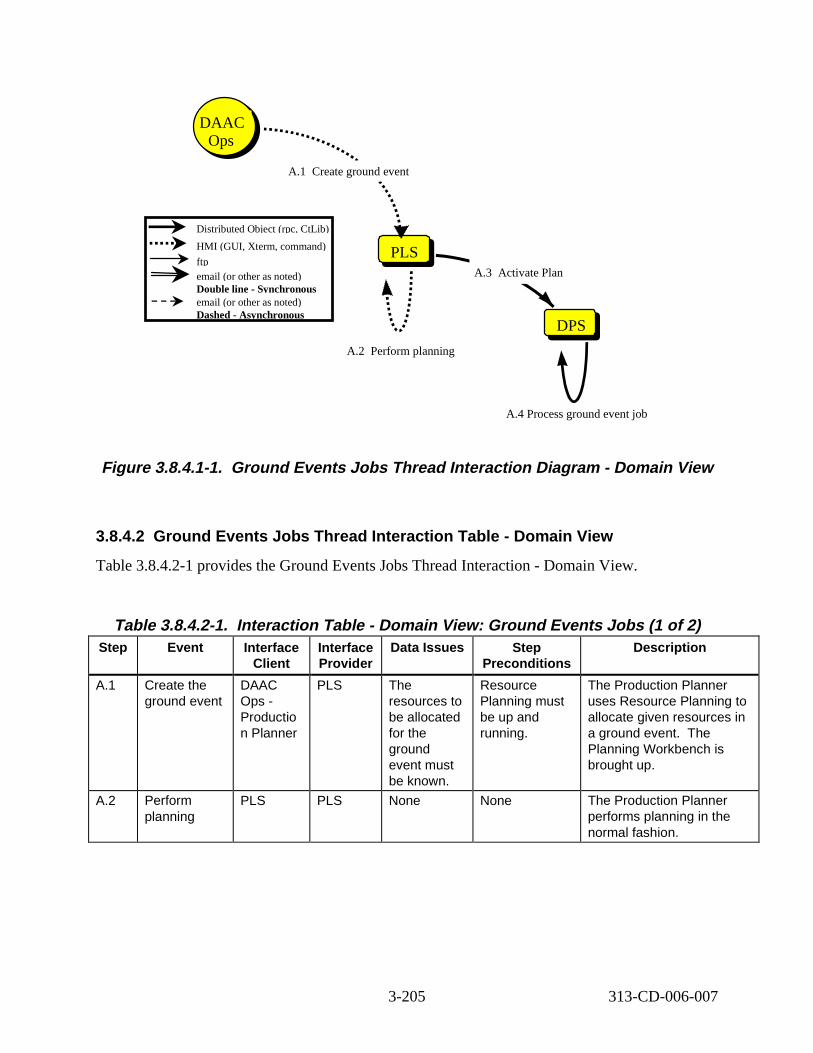
PLSPLS
DPSDPS
A.3 Activate Plan
A.1 reate ground event
DAAC Ops
Distributed Object (rpc, CtLib)
HMI (GUI, Xterm, command)
ftp email (or other as noted) Double line - Synchronous email (or other as noted) Dashed - Asynchronous
C
A.2 Perform planning
A.4 Process ground event job
Figure 3. 8.4.1-1. Ground Events Jobs Thread Interaction Di agram - Dom ain Vi ew
3.8.4.2 Ground Events Job s Thread Interaction T able - Dom ain Vi ew
Table 3.8.4.2-1 provides the Ground Events Jobs Thread Interaction - Domain View.
Table 3.8.4.2-1. Interaction Tabl e - Domain V iew: Ground Events Jobs (1 of 2) Step Event Interface
Client Interface Provider
Data Issues Step Preconditions
Descript ion
A.1 Create the ground event
DAAC Ops -Productio n Planner
PLS The resources to be allocated for the ground event must be known.
Resource Planning must be up and running.
The Production Planner uses Resource Planning to allocate given resources in a ground event. The Planning Workbench is brought up.
A.2 Perform planning
PLS PLS None None The Production Planner performs planning in the normal fashion.
3-205 313-CD-006-007
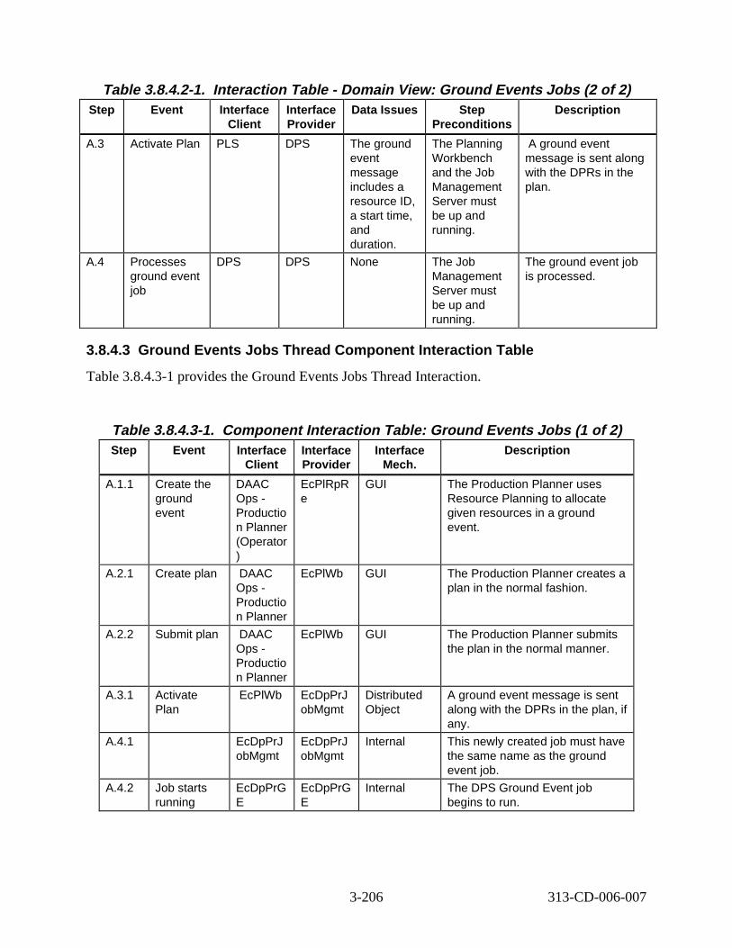
Table 3.8.4.2-1. Interaction Tabl e - Domain V iew: Ground Events Jobs (2 of 2) Step Event Interface
Client Interface Provider
Data Issues Step Preconditions
Descript ion
A.3 Activate Plan PLS DPS The ground event message includes a resource ID, a start time, and duration.
The Planning Workbench and the Job Management Server must be up and running.
A ground event message is sent along with the DPRs in the plan.
A.4 Processes ground event job
DPS DPS None The Job Management Server must be up and running.
The ground event job is processed.
3.8.4.3 Ground Events Job s Thread Component Interaction Tab le
Table 3.8.4.3-1 provides the Ground Events Jobs Thread Interaction.
Table 3.8.4.3-1. Component Interaction Table: Ground Events Jobs (1 of 2) Step Event Interface
Client Interface Provider
Interface Mech.
Descript ion
A.1.1 Create the ground event
DAAC Ops -Productio n Planner (Operator )
EcPlRpR e
GUI The Production Planner uses Resource Planning to allocate given resources in a ground event.
A.2.1 Create plan DAAC Ops -Productio n Planner
EcPlWb GUI The Production Planner creates a plan in the normal fashion.
A.2.2 Submit plan DAAC Ops -Productio n Planner
EcPlWb GUI The Production Planner submits the plan in the normal manner.
A.3.1 Activate Plan
EcPlWb EcDpPrJ obMgmt
Distributed Object
A ground event message is sent along with the DPRs in the plan, if any.
A.4.1 EcDpPrJ obMgmt
EcDpPrJ obMgmt
Internal This newly created job must have the same name as the ground event job.
A.4.2 Job starts running
EcDpPrG E
EcDpPrG E
Internal The DPS Ground Event job begins to run.
3-206 313-CD-006-007
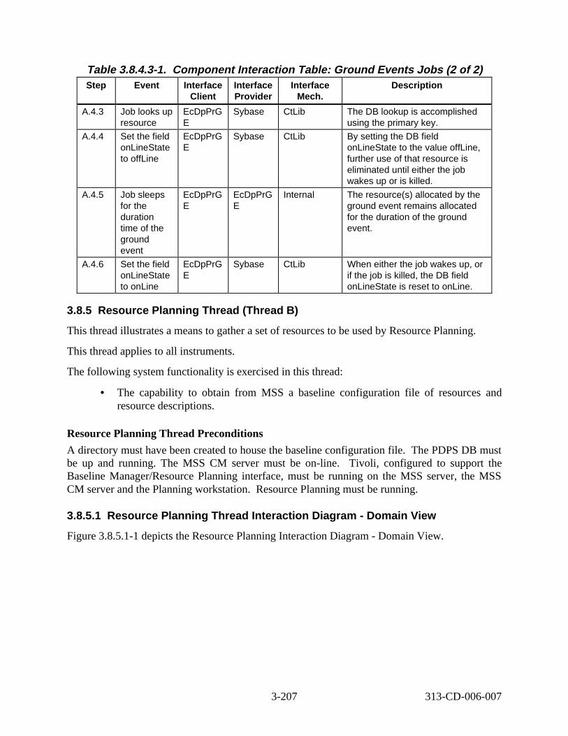
Table 3.8.4.3-1. Component Interaction Table: Ground Events Jobs (2 of 2) Step Event Interface
Client Interface Provider
Interface Mech.
Descript ion
A.4.3 Job looks up resource
EcDpPrG E
Sybase CtLib The DB lookup is accomplished using the primary key.
A.4.4 Set the field onLineState to offLine
EcDpPrG E
Sybase CtLib By setting the DB field onLineState to the value offLine, further use of that resource is eliminated until either the job wakes up or is killed.
A.4.5 Job sleeps for the duration time of the ground event
EcDpPrG E
EcDpPrG E
Internal The resource(s) allocated by the ground event remains allocated for the duration of the ground event.
A.4.6 Set the field onLineState to onLine
EcDpPrG E
Sybase CtLib When either the job wakes up, or if the job is killed, the DB field onLineState is reset to onLine.
3.8.5 Resource Planning Thr ead (Thread B)
This thread illustrates a means to gather a set of resources to be used by Resource Planning.
This thread applies to all instruments.
The following system functionality is exercised in this thread:
• The capability to obtain from MSS a baseline configuration file of resources and resource descriptions.
Resource Planning Thread Preconditions
A directory must have been created to house the baseline configuration file. The PDPS DB must be up and running. The MSS CM server must be on-line. Tivoli, configured to support the Baseline Manager/Resource Planning interface, must be running on the MSS server, the MSS CM server and the Planning workstation. Resource Planning must be running.
3.8.5.1 Resource P lanning Thread Interaction Diagram - Domain V iew
Figure 3.8.5.1-1 depicts the Resource Planning Interaction Diagram - Domain View.
3-207 313-CD-006-007
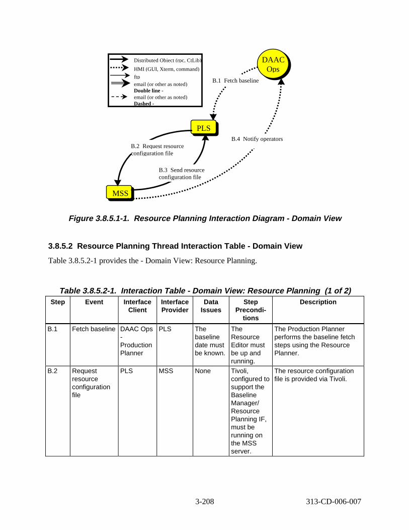
PLSPLS
DPSMSS
B.1 tch baseline
B.3 nd resource configuration file
B.2 Request resource configuration file
DAAC Ops
DAAC Ops
B.4 y operators
Distributed Object (rpc, CtLib)
HMI (GUI, Xterm, command)
ftp email (or other as noted) Double line email (or other as noted) Dashed -
Fe
Se
Notif
Figure 3. 8.5.1-1. Resourc e Planning Int eraction D iagram - Domain View
3.8.5.2 Resource P lanning Thread Interaction Table - Domain V iew
Table 3.8.5.2-1 provides the - Domain View: Resource Planning.
Table 3.8.5.2-1. Interaction Tabl e - Domain V iew: Resource Pl anning (1 of 2) Step Event Interface
Client Interface Provider
Data Issues
Step Precondi
tions
Descript ion
B.1 Fetch baseline DAAC Ops -Production Planner
PLS The baseline date must be known.
The Resource Editor must be up and running.
The Production Planner performs the baseline fetch steps using the Resource Planner.
B.2 Request resource configuration file
PLS MSS None Tivoli, configured to support the Baseline Manager/ Resource Planning IF, must be running on the MSS server.
The resource configuration file is provided via Tivoli.
3-208 313-CD-006-007
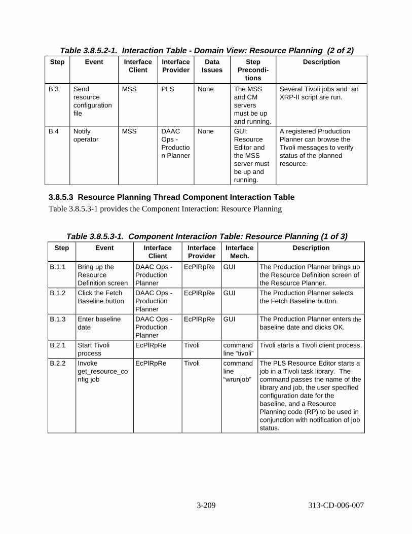
Table 3.8.5.2-1. Interaction Tabl e - Domain V iew: Resource Pl anning (2 of 2) Step Event Interface
Client Interface Provider
Data Issues
Step Precondi
tions
Descript ion
B.3 Send resource configuration file
MSS PLS None The MSS and CM servers must be up and running.
Several Tivoli jobs and an XRP-II script are run.
B.4 Notify operator
MSS DAAC Ops -Productio n Planner
None GUI: Resource Editor and the MSS server must be up and running.
A registered Production Planner can browse the Tivoli messages to verify status of the planned resource.
3.8.5.3 Resource P lanning Thread Component Interaction T able Table 3.8.5.3-1 provides the Component Interaction: Resource Planning
Table 3.8.5.3-1. Component Interaction Table: Resource Pl anning (1 of 3) Step Event Interface
Client Interface Provider
Interface Mech.
Descript ion
B.1.1 Bring up the Resource Definition screen
DAAC Ops -Production Planner
EcPlRpRe GUI The Production Planner brings up the Resource Definition screen of the Resource Planner.
B.1.2 Click the Fetch Baseline button
DAAC Ops -Production Planner
EcPlRpRe GUI The Production Planner selects the Fetch Baseline button.
B.1.3 Enter baseline date
DAAC Ops -Production Planner
EcPlRpRe GUI The Production Planner enters the baseline date and clicks OK.
B.2.1 Start Tivoli process
EcPlRpRe Tivoli command line “tivoli”
Tivoli starts a Tivoli client process.
B.2.2 Invoke get_resource_co nfig job
EcPlRpRe Tivoli command line “wrunjob”
The PLS Resource Editor starts a job in a Tivoli task library. The command passes the name of the library and job, the user specified configuration date for the baseline, and a Resource Planning code (RP) to be used in conjunction with notification of job status.
3-209 313-CD-006-007
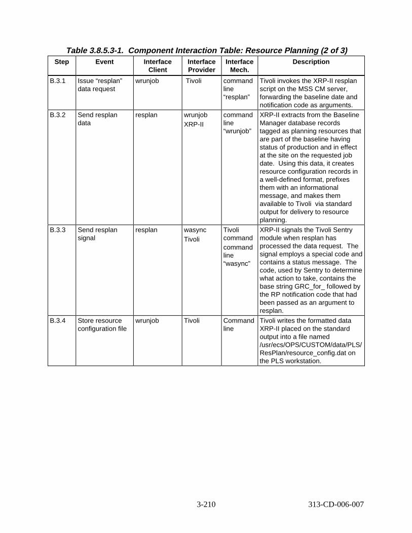
Table 3.8.5.3-1. Component Interaction Table: Resource Pl anning (2 of 3) Step Event Interface
Client Interface Provider
Interface Mech.
Descript ion
B.3.1 Issue “resplan” data request
wrunjob Tivoli command line “resplan”
Tivoli invokes the XRP-II resplan script on the MSS CM server, forwarding the baseline date and notification code as arguments.
B.3.2 Send resplan data
resplan wrunjob XRP-II
command line “wrunjob”
XRP-II extracts from the Baseline Manager database records tagged as planning resources that are part of the baseline having status of production and in effect at the site on the requested job date. Using this data, it creates resource configuration records in a well-defined format, prefixes them with an informational message, and makes them available to Tivoli via standard output for delivery to resource planning.
B.3.3 Send resplan signal
resplan wasync Tivoli
Tivoli command command line “wasync”
XRP-II signals the Tivoli Sentry module when resplan has processed the data request. The signal employs a special code and contains a status message. The code, used by Sentry to determine what action to take, contains the base string GRC_for_ followed by the RP notification code that had been passed as an argument to resplan.
B.3.4 Store resource configuration file
wrunjob Tivoli Command line
Tivoli writes the formatted data XRP-II placed on the standard output into a file named /usr/ecs/OPS/CUSTOM/data/PLS/ ResPlan/resource_config.dat on the PLS workstation.
3-210 313-CD-006-007
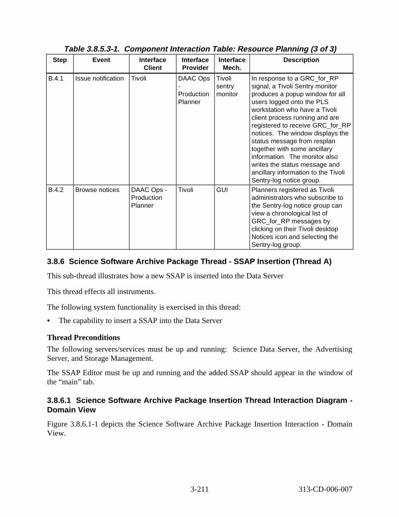
Table 3.8.5.3-1. Component Interaction Table: Resource Pl anning (3 of 3) Step Event Interface
Client Interface Provider
Interface Mech.
Descript ion
B.4.1 Issue notification Tivoli DAAC Ops -Production Planner
Tivoli sentry monitor
In response to a GRC_for_RP signal, a Tivoli Sentry monitor produces a popup window for all users logged onto the PLS workstation who have a Tivoli client process running and are registered to receive GRC_for_RP notices. The window displays the status message from resplan together with some ancillary information. The monitor also writes the status message and ancillary information to the Tivoli Sentry-log notice group.
B.4.2 Browse notices DAAC Ops -Production Planner
Tivoli GUI Planners registered as Tivoli administrators who subscribe to the Sentry-log notice group can view a chronological list of GRC_for_RP messages by clicking on their Tivoli desktop Notices icon and selecting the Sentry-log group.
3.8.6 Science Sof tware Archi ve Package Thread - SSAP Insert ion (Thread A)
This sub-thread illustrates how a new SSAP is inserted into the Data Server
This thread effects all instruments.
The following system functionality is exercised in this thread:
• The capability to insert a SSAP into the Data Server
Thread Preconditions
The following servers/services must be up and running: Science Data Server, the Advertising Server, and Storage Management.
The SSAP Editor must be up and running and the added SSAP should appear in the window of the “main” tab.
3.8.6.1 Science Sof tware Archiv e Package Insert ion Thr ead Int eract ion Diagram -Domain Vie w
Figure 3.8.6.1-1 depicts the Science Software Archive Package Insertion Interaction - Domain View.
3-211 313-CD-006-007
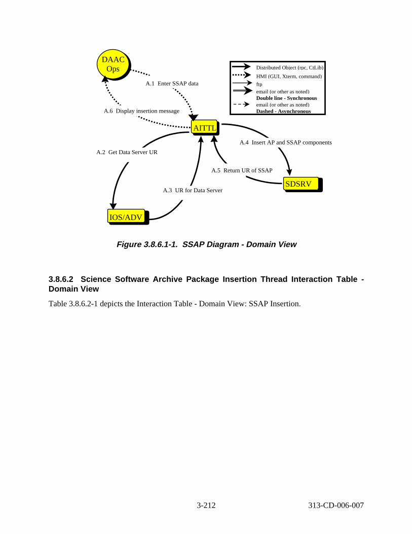
PLSAITTL
SDSRV
IOS/ADV
A.4 nsert AP and SSAP components
DAAC Ops
DAAC Ops
A.3 UR for Data Server
A.5 Return UR of SSAP
A.1 nter SSAP data
A.6 Display insertion message
A.2 Get Data Server UR
Distributed Object (rpc, CtLib)
HMI (GUI, Xterm, command)
ftp email (or other as noted) Double line - Synchronous email (or other as noted) Dashed - Asynchronous
I
E
Figure 3. 8.6.1-1. SSAP Diagram - Domain Vi ew
3.8.6.2 Science Sof tware Archiv e Package Insert ion Thr ead Int eract ion Tabl e -Domain Vie w
Table 3.8.6.2-1 depicts the Interaction Table - Domain View: SSAP Insertion.
3-212 313-CD-006-007
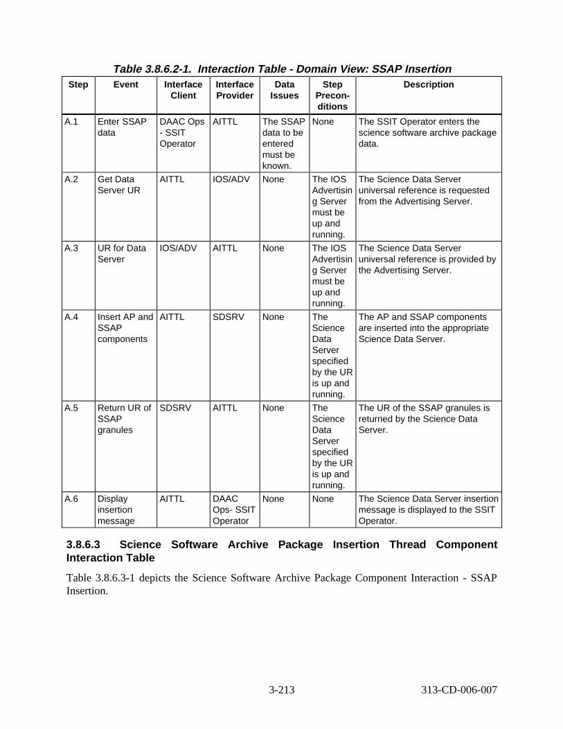
Table 3.8.6.2-1. Interact ion Tabl e - Domain V iew: SSAP Insert ion Step Event Interface
Client Interface Provider
Data Issues
Step Preconditions
Descript ion
A.1 Enter SSAP data
DAAC Ops - SSIT Operator
AITTL The SSAP data to be entered must be known.
None The SSIT Operator enters the science software archive package data.
A.2 Get Data Server UR
AITTL IOS/ADV None The IOS Advertisin g Server must be up and running.
The Science Data Server universal reference is requested from the Advertising Server.
A.3 UR for Data Server
IOS/ADV AITTL None The IOS Advertisin g Server must be up and running.
The Science Data Server universal reference is provided by the Advertising Server.
A.4 Insert AP and SSAP components
AITTL SDSRV None The Science Data Server specified by the UR is up and running.
The AP and SSAP components are inserted into the appropriate Science Data Server.
A.5 Return UR of SSAP granules
SDSRV AITTL None The Science Data Server specified by the UR is up and running.
The UR of the SSAP granules is returned by the Science Data Server.
A.6 Display insertion message
AITTL DAAC Ops- SSIT Operator
None None The Science Data Server insertion message is displayed to the SSIT Operator.
3.8.6.3 Science Software Archive P ackage In sertion Thr ead Component Interaction Tabl e
Table 3.8.6.3-1 depicts the Science Software Archive Package Component Interaction - SSAP Insertion.
3-213 313-CD-006-007
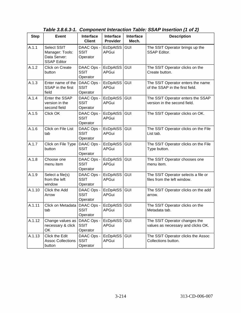
Table 3.8.6.3-1. Component Interaction Table: S SAP Insertion (1 of 2) Step Event Interface
Client Interface Provider
Interface Mech.
Descript ion
A.1.1 Select SSIT Manager: Tools: Data Server: SSAP Editor
DAAC Ops -SSIT Operator
EcDpAtSS APGui
GUI The SSIT Operator brings up the SSAP Editor.
A.1.2 Click on Create button
DAAC Ops -SSIT Operator
EcDpAtSS APGui
GUI The SSIT Operator clicks on the Create button.
A.1.3 Enter name of the SSAP in the first field
DAAC Ops -SSIT Operator
EcDpAtSS APGui
GUI The SSIT Operator enters the name of the SSAP in the first field.
A.1.4 Enter the SSAP version in the second field
DAAC Ops -SSIT Operator
EcDpAtSS APGui
GUI The SSIT Operator enters the SSAP version in the second field.
A.1.5 Click OK DAAC Ops -SSIT Operator
EcDpAtSS APGui
GUI The SSIT Operator clicks on OK.
A.1.6 Click on File List tab
DAAC Ops -SSIT Operator
EcDpAtSS APGui
GUI The SSIT Operator clicks on the File List tab.
A.1.7 Click on File Type button
DAAC Ops -SSIT Operator
EcDpAtSS APGui
GUI The SSIT Operator clicks on the File Type button.
A.1.8 Choose one menu item
DAAC Ops -SSIT Operator
EcDpAtSS APGui
GUI The SSIT Operator chooses one menu item.
A.1.9 Select a file(s) from the left window
DAAC Ops -SSIT Operator
EcDpAtSS APGui
GUI The SSIT Operator selects a file or files from the left window.
A.1.10 Click the Add Arrow
DAAC Ops -SSIT Operator
EcDpAtSS APGui
GUI The SSIT Operator clicks on the add arrow.
A.1.11 Click on Metadata tab
DAAC Ops -SSIT Operator
EcDpAtSS APGui
GUI The SSIT Operator clicks on the Metadata tab.
A.1.12 Change values as necessary & click OK
DAAC Ops -SSIT Operator
EcDpAtSS APGui
GUI The SSIT Operator changes the values as necessary and clicks OK.
A.1.13 Click the Edit Assoc Collections button
DAAC Ops -SSIT Operator
EcDpAtSS APGui
GUI The SSIT Operator clicks the Assoc Collections button.
3-214 313-CD-006-007
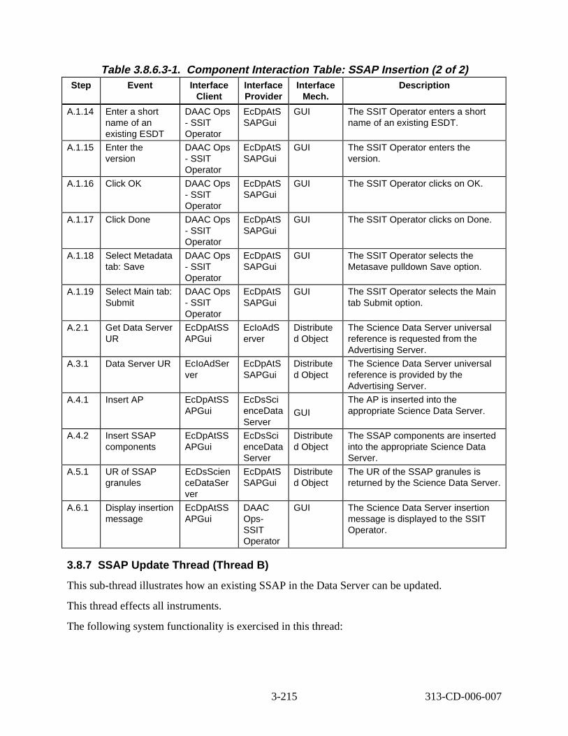
Table 3.8.6.3-1. Component Interaction Table: S SAP Insertion (2 of 2) Step Event Interface
Client Interface Provider
Interface Mech.
Descript ion
A.1.14 Enter a short name of an existing ESDT
DAAC Ops - SSIT Operator
EcDpAtS SAPGui
GUI The SSIT Operator enters a short name of an existing ESDT.
A.1.15 Enter the version
DAAC Ops - SSIT Operator
EcDpAtS SAPGui
GUI The SSIT Operator enters the version.
A.1.16 Click OK DAAC Ops - SSIT Operator
EcDpAtS SAPGui
GUI The SSIT Operator clicks on OK.
A.1.17 Click Done DAAC Ops - SSIT Operator
EcDpAtS SAPGui
GUI The SSIT Operator clicks on Done.
A.1.18 Select Metadata tab: Save
DAAC Ops - SSIT Operator
EcDpAtS SAPGui
GUI The SSIT Operator selects the Metasave pulldown Save option.
A.1.19 Select Main tab: Submit
DAAC Ops - SSIT Operator
EcDpAtS SAPGui
GUI The SSIT Operator selects the Main tab Submit option.
A.2.1 Get Data Server UR
EcDpAtSS APGui
EcIoAdS erver
Distribute d Object
The Science Data Server universal reference is requested from the Advertising Server.
A.3.1 Data Server UR EcIoAdSer ver
EcDpAtS SAPGui
Distribute d Object
The Science Data Server universal reference is provided by the Advertising Server.
A.4.1 Insert AP EcDpAtSS APGui
EcDsSci enceData Server
GUI The AP is inserted into the appropriate Science Data Server.
A.4.2 Insert SSAP components
EcDpAtSS APGui
EcDsSci enceData Server
Distribute d Object
The SSAP components are inserted into the appropriate Science Data Server.
A.5.1 UR of SSAP granules
EcDsScien ceDataSer ver
EcDpAtS SAPGui
Distribute d Object
The UR of the SSAP granules is returned by the Science Data Server.
A.6.1 Display insertion message
EcDpAtSS APGui
DAAC Ops-SSIT Operator
GUI The Science Data Server insertion message is displayed to the SSIT Operator.
3.8.7 SSAP Update Thread (Thread B)
This sub-thread illustrates how an existing SSAP in the Data Server can be updated.
This thread effects all instruments.
The following system functionality is exercised in this thread:
3-215 313-CD-006-007
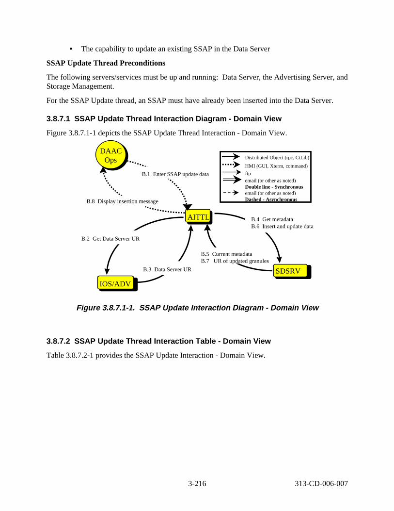
• The capability to update an existing SSAP in the Data Server
SSAP Update Thread Preconditions
The following servers/services must be up and running: Data Server, the Advertising Server, and Storage Management.
For the SSAP Update thread, an SSAP must have already been inserted into the Data Server.
3.8.7.1 SSAP Updat e Thread Interact ion D iagram - Domain Vi ew
Figure 3.8.7.1-1 depicts the SSAP Update Thread Interaction - Domain View.
PLSAITTL
SDSRV
IOS/ADV
B.4 t metadata B.6 nsert and update data
DAAC Ops
DAAC Ops
B.5 urrent metadata B.7 R of updated granules
B.1 nter SSAP update data
B.8 isplay insertion message
B.3 Data Server UR
B.2 Get Data Server UR
Distributed Object (rpc, CtLib)
HMI (GUI, Xterm, command)
ftp email (or other as noted) Double line - Synchronous email (or other as noted) Dashed - Asynchronous
GeI
CU
E
D
Figure 3. 8.7.1-1. SSAP Updat e Interact ion D iagram - Domain V iew
3.8.7.2 SSAP Updat e Thread Interact ion Table - Domain Vi ew
Table 3.8.7.2-1 provides the SSAP Update Interaction - Domain View.
3-216 313-CD-006-007
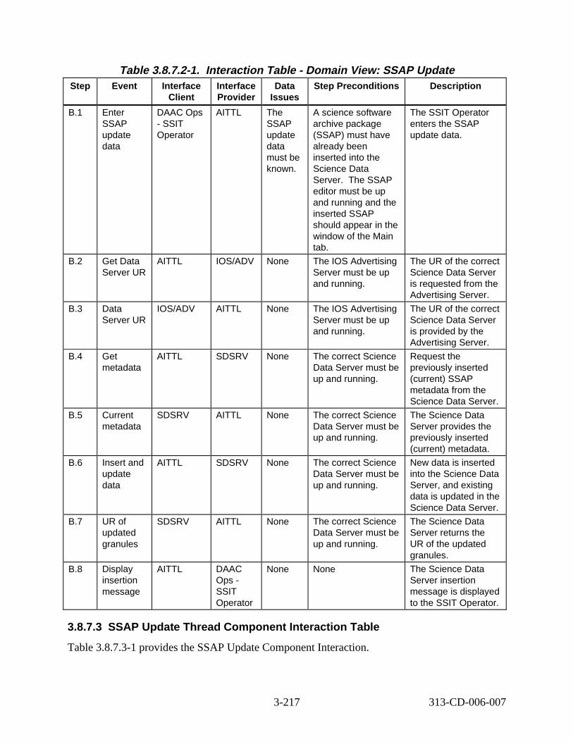
Table 3.8.7.2-1. Interact ion Tabl e - Domain V iew: SSAP Updat e Step Event Interface
Client Interface Provider
Data Issues
Step Preconditions Descript ion
B.1 Enter SSAP update data
DAAC Ops - SSIT Operator
AITTL The SSAP update data must be known.
A science software archive package (SSAP) must have already been inserted into the Science Data Server. The SSAP editor must be up and running and the inserted SSAP should appear in the window of the Main tab.
The SSIT Operator enters the SSAP update data.
B.2 Get Data Server UR
AITTL IOS/ADV None The IOS Advertising Server must be up and running.
The UR of the correct Science Data Server is requested from the Advertising Server.
B.3 Data Server UR
IOS/ADV AITTL None The IOS Advertising Server must be up and running.
The UR of the correct Science Data Server is provided by the Advertising Server.
B.4 Get metadata
AITTL SDSRV None The correct Science Data Server must be up and running.
Request the previously inserted (current) SSAP metadata from the Science Data Server.
B.5 Current metadata
SDSRV AITTL None The correct Science Data Server must be up and running.
The Science Data Server provides the previously inserted (current) metadata.
B.6 Insert and update data
AITTL SDSRV None The correct Science Data Server must be up and running.
New data is inserted into the Science Data Server, and existing data is updated in the Science Data Server.
B.7 UR of updated granules
SDSRV AITTL None The correct Science Data Server must be up and running.
The Science Data Server returns the UR of the updated granules.
B.8 Display insertion message
AITTL DAAC Ops -SSIT Operator
None None The Science Data Server insertion message is displayed to the SSIT Operator.
3.8.7.3 SSAP Updat e Thread Component Interaction Tab le
Table 3.8.7.3-1 provides the SSAP Update Component Interaction.
3-217 313-CD-006-007
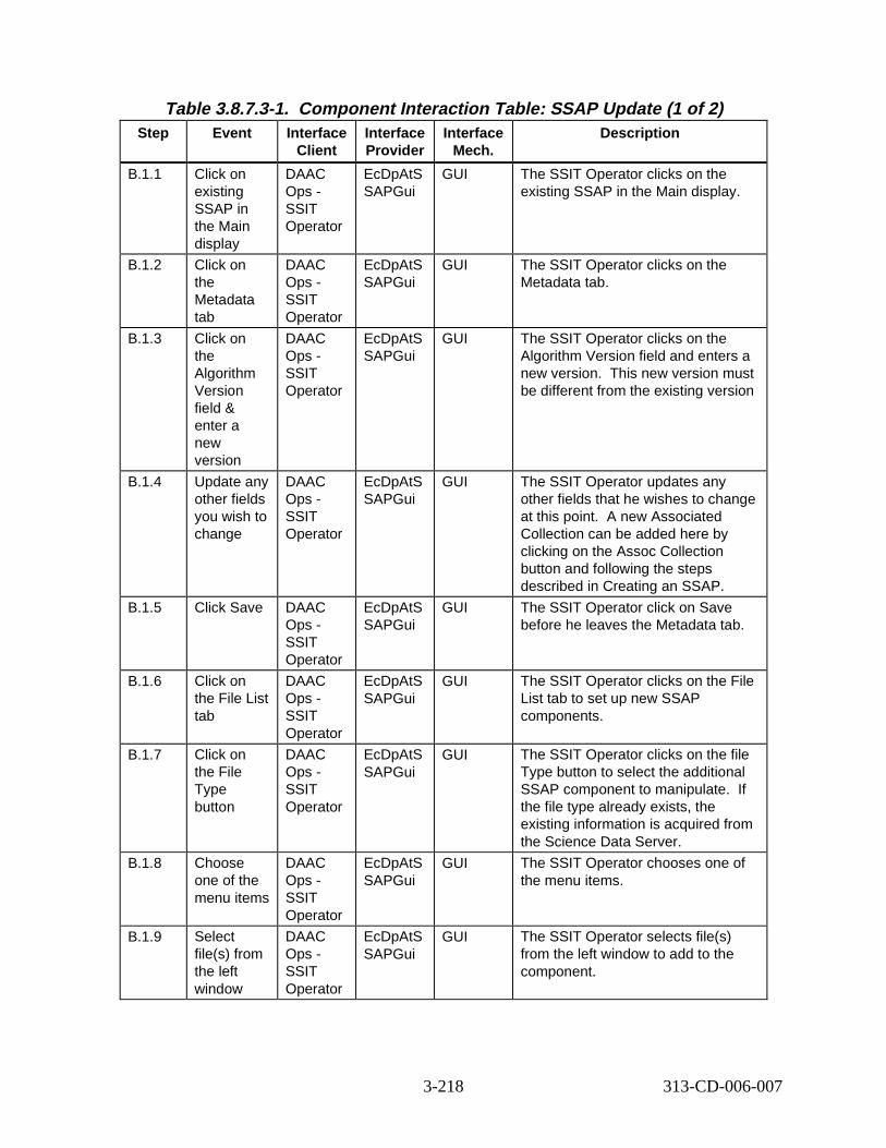
Table 3.8.7.3-1. Component Interaction Table: S SAP Update (1 of 2) Step Event Interface
Client Interface Provider
Interface Mech.
Descript ion
B.1.1 Click on existing SSAP in the Main display
DAAC Ops -SSIT Operator
EcDpAtS SAPGui
GUI The SSIT Operator clicks on the existing SSAP in the Main display.
B.1.2 Click on the Metadata tab
DAAC Ops -SSIT Operator
EcDpAtS SAPGui
GUI The SSIT Operator clicks on the Metadata tab.
B.1.3 Click on the Algorithm Version field & enter a new version
DAAC Ops -SSIT Operator
EcDpAtS SAPGui
GUI The SSIT Operator clicks on the Algorithm Version field and enters a new version. This new version must be different from the existing version
B.1.4 Update any other fields you wish to change
DAAC Ops -SSIT Operator
EcDpAtS SAPGui
GUI The SSIT Operator updates any other fields that he wishes to change at this point. A new Associated Collection can be added here by clicking on the Assoc Collection button and following the steps described in Creating an SSAP.
B.1.5 Click Save DAAC Ops -SSIT Operator
EcDpAtS SAPGui
GUI The SSIT Operator click on Save before he leaves the Metadata tab.
B.1.6 Click on the File List tab
DAAC Ops -SSIT Operator
EcDpAtS SAPGui
GUI The SSIT Operator clicks on the File List tab to set up new SSAP components.
B.1.7 Click on the File Type button
DAAC Ops -SSIT Operator
EcDpAtS SAPGui
GUI The SSIT Operator clicks on the file Type button to select the additional SSAP component to manipulate. If the file type already exists, the existing information is acquired from the Science Data Server.
B.1.8 Choose one of the menu items
DAAC Ops -SSIT Operator
EcDpAtS SAPGui
GUI The SSIT Operator chooses one of the menu items.
B.1.9 Select file(s) from the left window
DAAC Ops -SSIT Operator
EcDpAtS SAPGui
GUI The SSIT Operator selects file(s) from the left window to add to the component.
3-218 313-CD-006-007
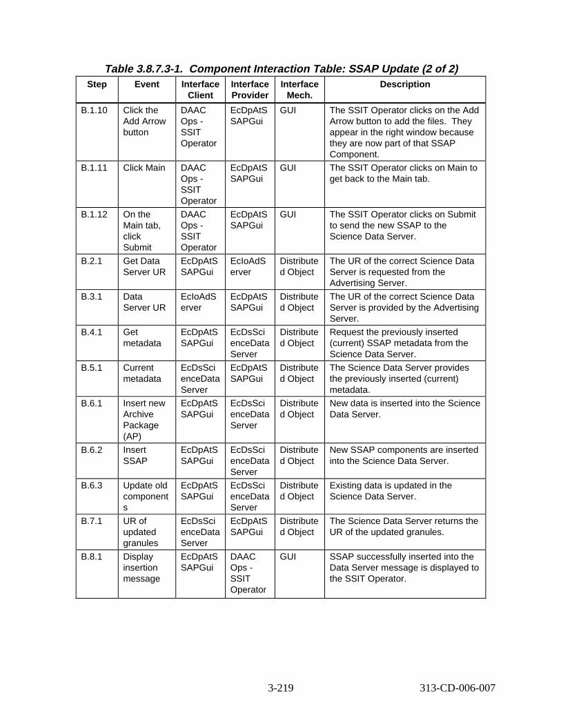
Table 3.8.7.3-1. Component Interaction Table: S SAP Update (2 of 2) Step Event Interface
Client Interface Provider
Interface Mech.
Descript ion
B.1.10 Click the Add Arrow button
DAAC Ops -SSIT Operator
EcDpAtS SAPGui
GUI The SSIT Operator clicks on the Add Arrow button to add the files. They appear in the right window because they are now part of that SSAP Component.
B.1.11 Click Main DAAC Ops -SSIT Operator
EcDpAtS SAPGui
GUI The SSIT Operator clicks on Main to get back to the Main tab.
B.1.12 On the Main tab, click Submit
DAAC Ops -SSIT Operator
EcDpAtS SAPGui
GUI The SSIT Operator clicks on Submit to send the new SSAP to the Science Data Server.
B.2.1 Get Data Server UR
EcDpAtS SAPGui
EcIoAdS erver
Distribute d Object
The UR of the correct Science Data Server is requested from the Advertising Server.
B.3.1 Data Server UR
EcIoAdS erver
EcDpAtS SAPGui
Distribute d Object
The UR of the correct Science Data Server is provided by the Advertising Server.
B.4.1 Get metadata
EcDpAtS SAPGui
EcDsSci enceData Server
Distribute d Object
Request the previously inserted (current) SSAP metadata from the Science Data Server.
B.5.1 Current metadata
EcDsSci enceData Server
EcDpAtS SAPGui
Distribute d Object
The Science Data Server provides the previously inserted (current) metadata.
B.6.1 Insert new Archive Package (AP)
EcDpAtS SAPGui
EcDsSci enceData Server
Distribute d Object
New data is inserted into the Science Data Server.
B.6.2 Insert SSAP
EcDpAtS SAPGui
EcDsSci enceData Server
Distribute d Object
New SSAP components are inserted into the Science Data Server.
B.6.3 Update old component s
EcDpAtS SAPGui
EcDsSci enceData Server
Distribute d Object
Existing data is updated in the Science Data Server.
B.7.1 UR of updated granules
EcDsSci enceData Server
EcDpAtS SAPGui
Distribute d Object
The Science Data Server returns the UR of the updated granules.
B.8.1 Display insertion message
EcDpAtS SAPGui
DAAC Ops -SSIT Operator
GUI SSAP successfully inserted into the Data Server message is displayed to the SSIT Operator.
3-219 313-CD-006-007
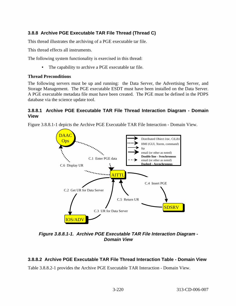
3.8.8 Archi ve PGE Executable TAR File Thre ad (Thread C )
This thread illustrates the archiving of a PGE executable tar file.
This thread effects all instruments.
The following system functionality is exercised in this thread:
• The capability to archive a PGE executable tar file.
Thread Preconditions
The following servers must be up and running: the Data Server, the Advertising Server, and Storage Management. The PGE executable ESDT must have been installed on the Data Server. A PGE executable metadata file must have been created. The PGE must be defined in the PDPS database via the science update tool.
3.8.8.1 Archiv e PGE Execut able TAR File Thread Int eract ion Diagram - Domain View
Figure 3.8.8.1-1 depicts the Archive PGE Executable TAR File Interaction - Domain View.
PLSAITTL
SDSRV
IOS/ADV
C.4 Insert PGE
DAAC Ops
DAAC Ops
C.5 Return UR
C.1 Enter PGE data
C.6 isplay UR
C.3 UR for Data Server
C.2 Get UR for Data Server
Distributed Object (rpc, CtLib)
HMI (GUI, Xterm, command)
ftp email (or other as noted) Double line - Synchronous email (or other as noted) Dashed - Asynchronous D
Figure 3. 8.8.1-1. Archiv e PGE Execut able TAR File Interact ion D iagram -Domain Vie w
3.8.8.2 Archiv e PGE Execut able TAR File Thread Interact ion Table - Domain Vi ew
Table 3.8.8.2-1 provides the Archive PGE Executable TAR Interaction - Domain View.
3-220 313-CD-006-007
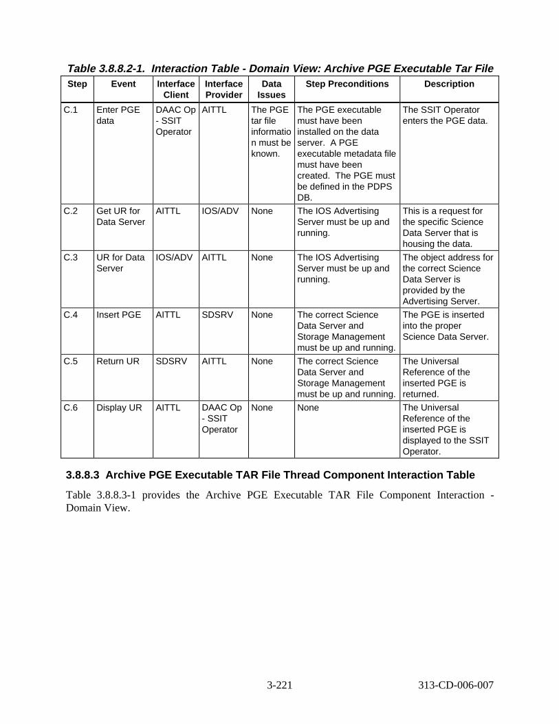
Table 3.8.8.2-1. Interact ion Tabl e - Domain V iew: Archive PGE Execut able Tar Fi le Step Event Interface
Client Interface Provider
Data Issues
Step Preconditions Descript ion
C.1 Enter PGE data
DAAC Op - SSIT Operator
AITTL The PGE tar file informatio n must be known.
The PGE executable must have been installed on the data server. A PGE executable metadata file must have been created. The PGE must be defined in the PDPS DB.
The SSIT Operator enters the PGE data.
C.2 Get UR for Data Server
AITTL IOS/ADV None The IOS Advertising Server must be up and running.
This is a request for the specific Science Data Server that is housing the data.
C.3 UR for Data Server
IOS/ADV AITTL None The IOS Advertising Server must be up and running.
The object address for the correct Science Data Server is provided by the Advertising Server.
C.4 Insert PGE AITTL SDSRV None The correct Science Data Server and Storage Management must be up and running.
The PGE is inserted into the proper Science Data Server.
C.5 Return UR SDSRV AITTL None The correct Science Data Server and Storage Management must be up and running.
The Universal Reference of the inserted PGE is returned.
C.6 Display UR AITTL DAAC Op - SSIT Operator
None None The Universal Reference of the inserted PGE is displayed to the SSIT Operator.
3.8.8.3 Archiv e PGE Executab le TAR File Thread Component Inter action Tabl e
Table 3.8.8.3-1 provides the Archive PGE Executable TAR File Component Interaction -Domain View.
3-221 313-CD-006-007
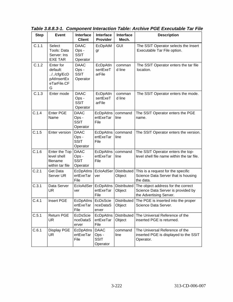
Table 3.8.8.3-1. Component Interaction Table: Arch ive PGE Executabl e Tar Fi le Step Event Interface
Client Interface Provider
Interface Mech.
Descript ion
C.1.1 Select Tools: Data Server: Ins EXE TAR
DAAC Ops -SSIT Operator
EcDpAtM gr
GUI The SSIT Operator selects the Insert Executable Tar File option.
C.1.2 Enter for default: ../../cfg/EcD pAtInsertEx eTarFile.CF G
DAAC Ops -SSIT Operator
EcDpAtIn sertExeT arFile
comman d line
The SSIT Operator enters the tar file location.
C.1.3 Enter mode DAAC Ops -SSIT Operator
EcDpAtIn sertExeT arFile
comman d line
The SSIT Operator enters the mode.
C.1.4 Enter PGE Name
DAAC Ops -SSIT Operator
EcDpAtIns ertExeTar File
command line
The SSIT Operator enters the PGE name.
C.1.5 Enter version DAAC Ops -SSIT Operator
EcDpAtIns ertExeTar File
command line
The SSIT Operator enters the version.
C.1.6 Enter the Top level shell filename within tar file
DAAC Ops -SSIT Operator
EcDpAtIns ertExeTar File
command line
The SSIT Operator enters the toplevel shell file name within the tar file.
C.2.1 Get Data Server UR
EcDpAtIns ertExeTar File
EcIoAdSer ver
Distributed Object
This is a request for the specific Science Data Server that is housing the data.
C.3.1 Data Server UR
EcIoAdSer ver
EcDpAtIns ertExeTar File
Distributed Object
The object address for the correct Science Data Server is provided by the Advertising Server.
C.4.1 Insert PGE EcDpAtIns ertExeTar File
EcDsScie nceDataS erver
Distributed Object
The PGE is inserted into the proper Science Data Server.
C.5.1 Return PGE UR
EcDsScie nceDataS erver
EcDpAtIns ertExeTar File
Distributed Object
The Universal Reference of the inserted PGE is returned.
C.6.1 Display PGE UR
EcDpAtIns ertExeTar File
DAAC Ops -SSIT Operator
command line
The Universal Reference of the inserted PGE is displayed to the SSIT Operator.
3-222 313-CD-006-007
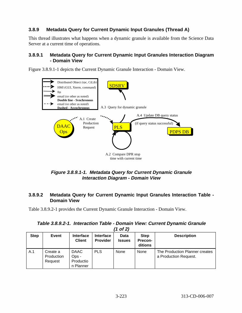
3.8.9 Metadata Quer y for Current Dynamic Input Gr anules (Thread A)
This thread illustrates what happens when a dynamic granule is available from the Science Data Server at a current time of operations.
3.8.9.1 Metadata Quer y for Current Dynamic Input Granules Interaction Diagr am - Domain View
Figure 3.8.9.1-1 depicts the Current Dynamic Granule Interaction - Domain View.
Distributed Object (rpc, CtLib)
HMI (GUI, Xterm, command)
ftp email (or other as noted) Double line - Synchronous email (or other as noted) Dashed - Asynchronous
PLS PDPS DB
SDSRV
A.4 Update DB query status
(if query status successful)
A.3 uery for dynamic granule Q
Ops
DAAC Ops
A.1 Create Production Request
A.2 Compare DPR stop time with current time
Figure 3. 8.9.1-1. Metadata Query f or Current Dynami c Granul e Interact ion D iagram - Domain View
3.8.9.2 Metadata Quer y for Current Dynamic Input Gr anules Interaction Tabl e -Domain Vie w
Table 3.8.9.2-1 provides the Current Dynamic Granule Interaction - Domain View.
Table 3.8.9.2-1. Interact ion Tabl e - Domain V iew: Current Dynamic Granul e (1 of 2)
Step Event Interface Client
Interface Provider
Data Issues
Step Preconditions
Descript ion
A.1 Create a Production Request
DAAC Ops -Productio n Planner
PLS None None The Production Planner creates a Production Request.
3-223 313-CD-006-007
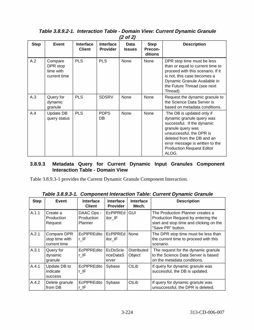
Table 3.8.9.2-1. Interact ion Tabl e - Domain V iew: Current Dynamic G ranul e (2 of 2)
Step Event Interface Client
Interface Provider
Data Issues
Step Preconditions
Descript ion
A.2 Compare DPR stop time with current time
PLS PLS None None DPR stop time must be less than or equal to current time to proceed with this scenario. If it is not, this case becomes a Dynamic Granule Available in the Future Thread (see next Thread).
A.3 Query for dynamic granule
PLS SDSRV None None Request the dynamic granule to the Science Data Server is based on metadata conditions.
A.4 Update DB query status
PLS PDPS DB
None None The DB is updated only if dynamic granule query was successful. If the dynamic granule query was unsuccessful, the DPR is deleted from the DB and an error message is written to the Production Request Editor ALOG.
3.8.9.3 Metadata Quer y for Current Dynamic Input Granules Component Interaction Tabl e - Domain View
Table 3.8.9.3-1 provides the Current Dynamic Granule Component Interaction.
Table 3.8.9.3-1. Component Interaction Table: Current Dyn amic Granul e Step Event Interface
Client Interface Provider
Interface Mech.
Descript ion
A.1.1 Create a Production Request
DAAC Ops -Production Planner
EcPlPREd itor_IF
GUI The Production Planner creates a Production Request by entering the start and stop time and clicking on the “Save PR” button.
A.2.1 Compare DPR stop time with current time
EcPlPREdito r_IF
EcPlPREd itor_IF
None The DPR stop time must be less than the current time to proceed with this scenario.
A.3.1 Query for dynamic granule
EcPlPREdito r_IF
EcDsScie nceDataS erver
Distributed Object
The request for the dynamic granule to the Science Data Server is based on the metadata conditions.
A.4.1 Update DB to indicate success
EcPlPREdito r_IF
Sybase CtLib If query for dynamic granule was successful, the DB is updated.
A.4.2 Delete granule from DB
EcPlPREdito r_IF
Sybase CtLib If query for dynamic granule was unsuccessful, the DPR is deleted.
3-224 313-CD-006-007
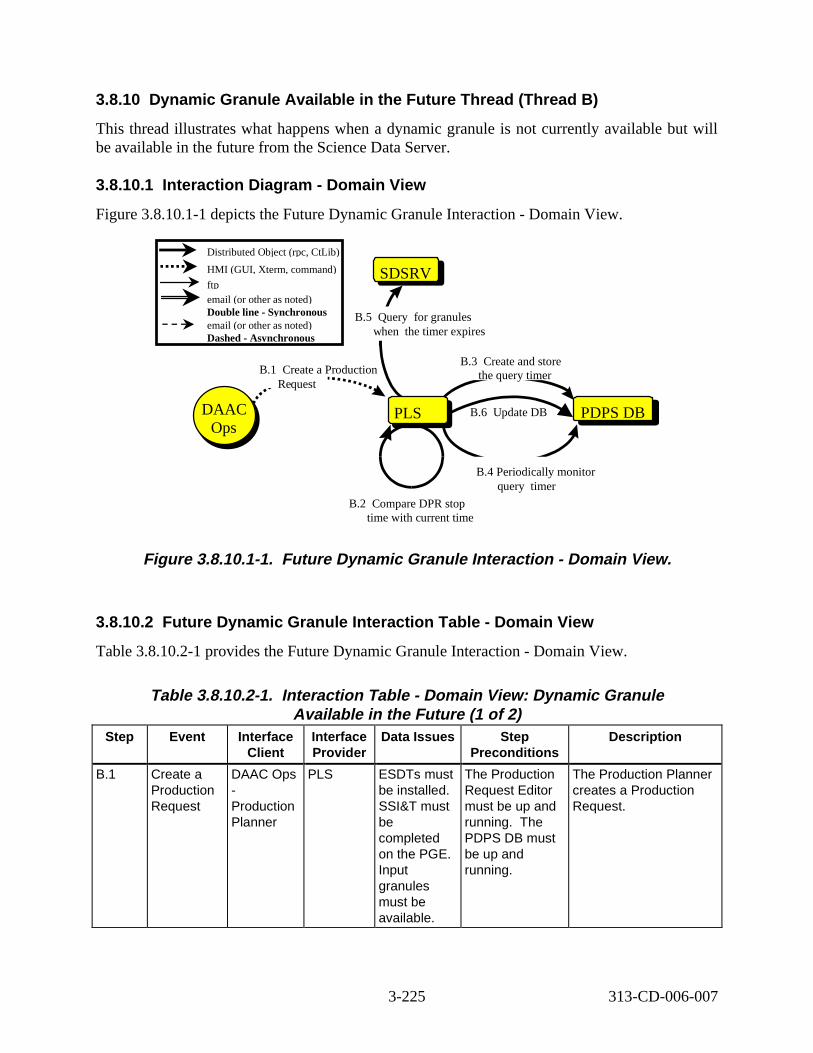
3.8.10 Dynami c Granul e Availab le in t he Future Thread ( Thread B)
This thread illustrates what happens when a dynamic granule is not currently available but will be available in the future from the Science Data Server.
3.8.10.1 Interact ion D iagram - Domain View
Figure 3.8.10.1-1 depicts the Future Dynamic Granule Interaction - Domain View.
PLS PDPS DBOps
DAAC Ops
SDSRV
B.6 pdate DB
B.5 uery or granules when the timer expires
B.4 Periodically monitor query timer
B.3 Create and store the query timer B.1 Create a Production
Request
Distributed Object (rpc, CtLib)
HMI (GUI, Xterm, command)
ftp email (or other as noted) Double line - Synchronous email (or other as noted) Dashed - Asynchronous
U
Q f
B.2 Compare DPR stop time with current time
Figure 3. 8.10.1-1. Future Dynamic G ranule Interaction - Domain Vi ew.
3.8.10.2 Future Dynamic Granul e Interact ion Table - Domain V iew
Table 3.8.10.2-1 provides the Future Dynamic Granule Interaction - Domain View.
Table 3.8.10.2-1. Interact ion T able - Domain View: Dynami c Granule Availabl e in the Future (1 of 2)
Step Event Interface Client
Interface Provider
Data Issues Step Preconditions
Descript ion
B.1 Create a Production Request
DAAC Ops -Production Planner
PLS ESDTs must be installed. SSI&T must be completed on the PGE. Input granules must be available.
The Production Request Editor must be up and running. The PDPS DB must be up and running.
The Production Planner creates a Production Request.
3-225 313-CD-006-007
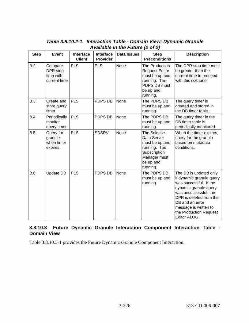
Table 3.8.10.2-1. Interact ion T able - Domain View: Dynami c Granule Availabl e in the Future (2 of 2)
Step Event Interface Client
Interface Provider
Data Issues Step Preconditions
Descript ion
B.2 Compare DPR stop time with current time
PLS PLS None The Production Request Editor must be up and running. The PDPS DB must be up and running.
The DPR stop time must be greater than the current time to proceed with this scenario.
B.3 Create and store query timer
PLS PDPS DB None The PDPS DB must be up and running.
The query timer is created and stored in the DB timer table.
B.4 Periodically monitor query timer
PLS PDPS DB None The PDPS DB must be up and running.
The query timer in the DB timer table is periodically monitored.
B.5 Query for granule when timer expires
PLS SDSRV None The Science Data Server must be up and running. The Subscription Manager must be up and running.
When the timer expires, query for the granule based on metadata conditions.
B.6 Update DB PLS PDPS DB None The PDPS DB must be up and running.
The DB is updated only if dynamic granule query was successful. If the dynamic granule query was unsuccessful, the DPR is deleted from the DB and an error message is written to the Production Request Editor ALOG.
3.8.10.3 Future Dyn amic Granul e Interaction Component Interaction Table -Domain Vie w
Table 3.8.10.3-1 provides the Future Dynamic Granule Component Interaction.
3-226 313-CD-006-007
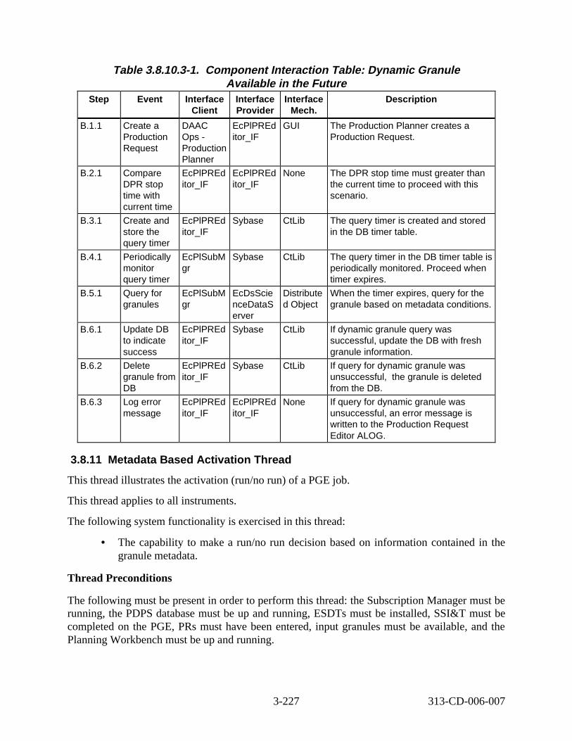
Table 3.8.10.3-1. Component Inter action Tabl e: Dynami c Granule Availabl e in the Future
Step Event Interface Client
Interface Provider
Interface Mech.
Descript ion
B.1.1 Create a Production Request
DAAC Ops -Production Planner
EcPlPREd itor_IF
GUI The Production Planner creates a Production Request.
B.2.1 Compare DPR stop time with current time
EcPlPREd itor_IF
EcPlPREd itor_IF
None The DPR stop time must greater than the current time to proceed with this scenario.
B.3.1 Create and store the query timer
EcPlPREd itor_IF
Sybase CtLib The query timer is created and stored in the DB timer table.
B.4.1 Periodically monitor query timer
EcPlSubM gr
Sybase CtLib The query timer in the DB timer table is periodically monitored. Proceed when timer expires.
B.5.1 Query for granules
EcPlSubM gr
EcDsScie nceDataS erver
Distribute d Object
When the timer expires, query for the granule based on metadata conditions.
B.6.1 Update DB to indicate success
EcPlPREd itor_IF
Sybase CtLib If dynamic granule query was successful, update the DB with fresh granule information.
B.6.2 Delete granule from DB
EcPlPREd itor_IF
Sybase CtLib If query for dynamic granule was unsuccessful, the granule is deleted from the DB.
B.6.3 Log error message
EcPlPREd itor_IF
EcPlPREd itor_IF
None If query for dynamic granule was unsuccessful, an error message is written to the Production Request Editor ALOG.
3.8.11 Metadata Based A ctivat ion Thre ad
This thread illustrates the activation (run/no run) of a PGE job.
This thread applies to all instruments.
The following system functionality is exercised in this thread:
• The capability to make a run/no run decision based on information contained in the granule metadata.
Thread Preconditions
The following must be present in order to perform this thread: the Subscription Manager must be running, the PDPS database must be up and running, ESDTs must be installed, SSI&T must be completed on the PGE, PRs must have been entered, input granules must be available, and the Planning Workbench must be up and running.
3-227 313-CD-006-007
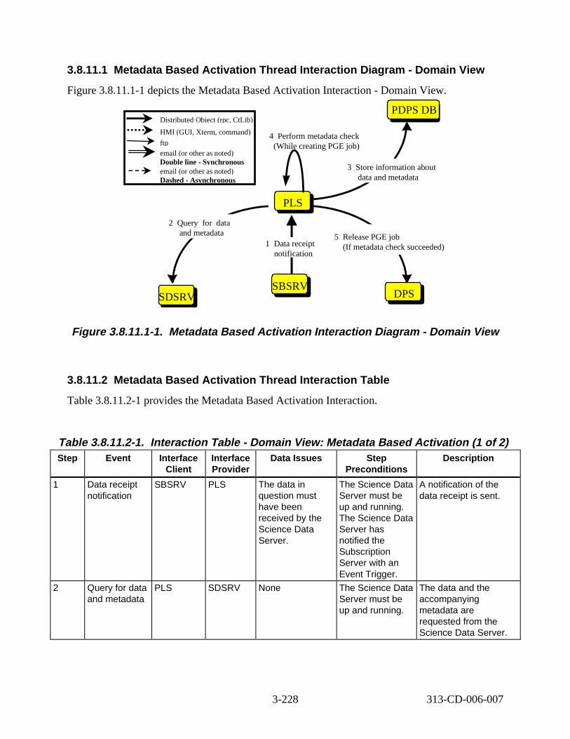
3.8.11.1 Metadata Based Activation Thread Interact ion D iagram - Domain Vi ew
Figure 3.8.11.1-1 depicts the Metadata Based Activation Interaction - Domain View.
PLSPLS
SDSRV
PDPS DB
DPSDPS
3 ore information about data and metadata
4 Perform metadata check (While creating PGE job)
5 Release PGE job (If metadata check succeeded)1 Data receipt
notification
2 uery or data and metadata
Distributed Object (rpc, CtLib)
HMI (GUI, Xterm, command)
ftp email (or other as noted) Double line - Synchronous email (or other as noted) Dashed - Asynchronous
SBSRV
St
Q f
Figure 3.8.11.1-1. Metadata Based Ac tiva tion Inte rac tion Dia gram - Domain V iew
3.8.11.2 Metadata Based Activation Thread Interact ion T able
Table 3.8.11.2-1 provides the Metadata Based Activation Interaction.
Table 3.8.11.2-1. Interact ion T able - Domain View: Metadata Based A ctivat ion ( 1 of 2) Step Event Interface
Client Interface Provider
Data Issues Step Preconditions
Descript ion
1 Data receipt notification
SBSRV PLS The data in question must have been received by the Science Data Server.
The Science Data Server must be up and running. The Science Data Server has notified the Subscription Server with an Event Trigger.
A notification of the data receipt is sent.
2 Query for data and metadata
PLS SDSRV None The Science Data Server must be up and running.
The data and the accompanying metadata are requested from the Science Data Server.
3-228 313-CD-006-007
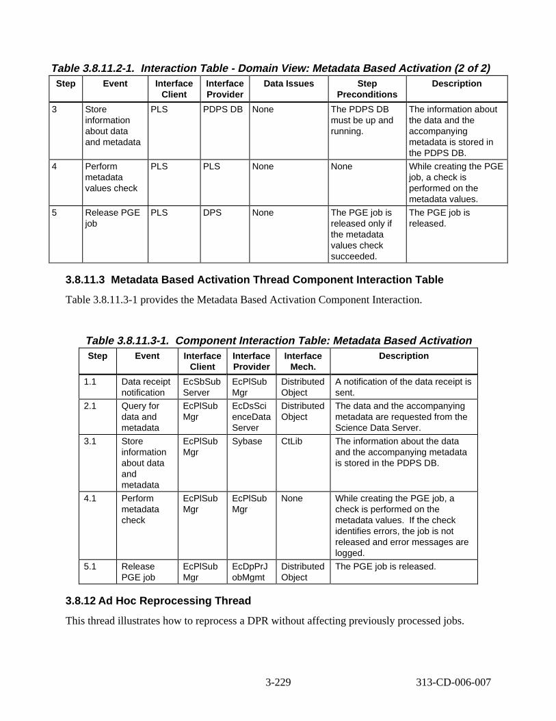
Table 3.8.11.2-1. Interact ion T able - Domain View: Metadata Based A ctivat ion ( 2 of 2) Step Event Interface
Client Interface Provider
Data Issues Step Preconditions
Descript ion
3 Store information about data and metadata
PLS PDPS DB None The PDPS DB must be up and running.
The information about the data and the accompanying metadata is stored in the PDPS DB.
4 Perform metadata values check
PLS PLS None None While creating the PGE job, a check is performed on the metadata values.
5 Release PGE job
PLS DPS None The PGE job is released only if the metadata values check succeeded.
The PGE job is released.
3.8.11.3 Metadat a Based Activation Thread Component Inter action Tabl e
Table 3.8.11.3-1 provides the Metadata Based Activation Component Interaction.
Table 3.8.11.3-1. Component Inter action Tabl e: Metadata B ased A ctivation Step Event Interface
Client Interface Provider
Interface Mech.
Descript ion
1.1 Data receipt notification
EcSbSub Server
EcPlSub Mgr
Distributed Object
A notification of the data receipt is sent.
2.1 Query for data and metadata
EcPlSub Mgr
EcDsSci enceData Server
Distributed Object
The data and the accompanying metadata are requested from the Science Data Server.
3.1 Store information about data and metadata
EcPlSub Mgr
Sybase CtLib The information about the data and the accompanying metadata is stored in the PDPS DB.
4.1 Perform metadata check
EcPlSub Mgr
EcPlSub Mgr
None While creating the PGE job, a check is performed on the metadata values. If the check identifies errors, the job is not released and error messages are logged.
5.1 Release PGE job
EcPlSub Mgr
EcDpPrJ obMgmt
Distributed Object
The PGE job is released.
3.8.12 Ad Hoc Reproces sing Thre ad
This thread illustrates how to reprocess a DPR without affecting previously processed jobs.
3-229 313-CD-006-007
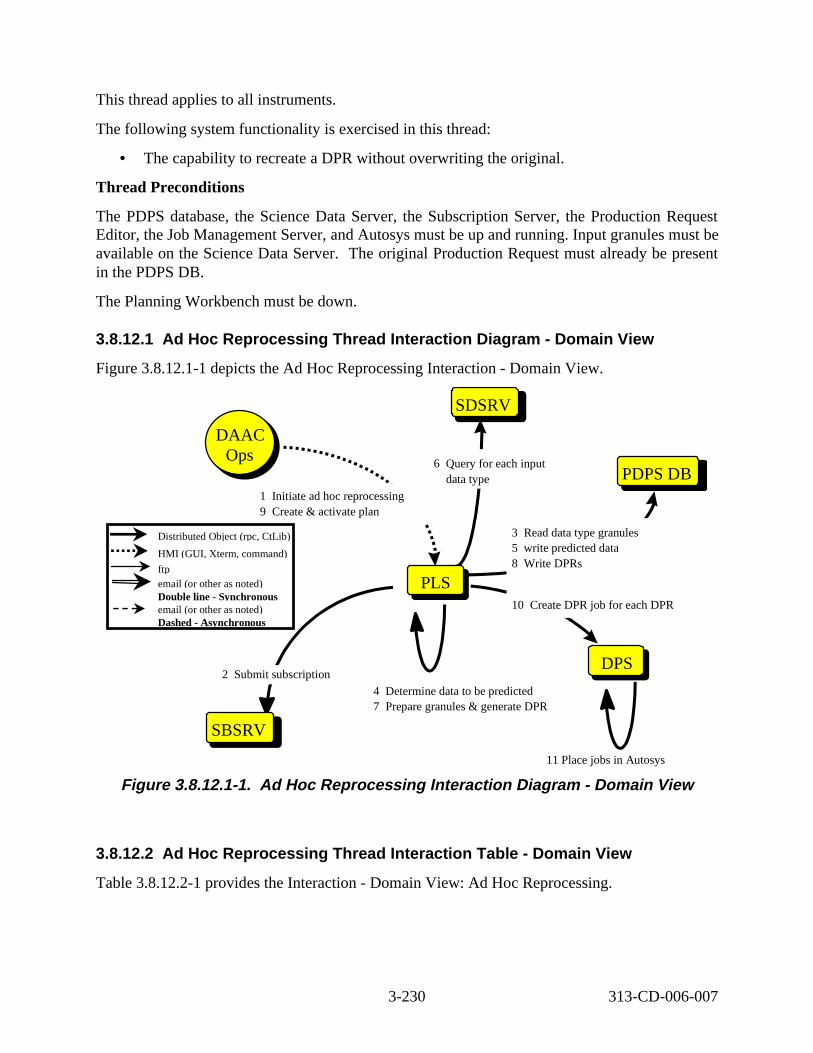
This thread applies to all instruments.
The following system functionality is exercised in this thread:
• The capability to recreate a DPR without overwriting the original.
Thread Preconditions
The PDPS database, the Science Data Server, the Subscription Server, the Production Request Editor, the Job Management Server, and Autosys must be up and running. Input granules must be available on the Science Data Server. The original Production Request must already be present in the PDPS DB.
The Planning Workbench must be down.
3.8.12.1 Ad Hoc Repro cessing Thre ad Int eract ion D iagram - Domain View
Figure 3.8.12.1-1 depicts the Ad Hoc Reprocessing Interaction - Domain View.
SDSRV
PLSPLS
DPSDPS
SBSRV
10 Create DPR job for each DPR
1 nitiate ad hoc reprocessing 9 Create & activate plan
DAAC Ops
DAAC Ops
6 Query for each input data type
4 termine data to be predicted 7 Prepare granules & generate DPR
PDPS DB
3 ead data type granules 5 predicted data 8 te DPRs
2 ubmit subscription
Distributed Object (rpc, CtLib)
HMI (GUI, Xterm, command)
ftp email (or other as noted) Double line - Synchronous email (or other as noted) Dashed - Asynchronous
I
De
Rwrite Wri
S
11 Place jobs in Autosys
Figure 3. 8.12.1-1. Ad Hoc Repro cessing Int eract ion D iagram - Domain View
3.8.12.2 Ad Hoc Repro cessing Thre ad Int eract ion Tabl e - Domain V iew
Table 3.8.12.2-1 provides the Interaction - Domain View: Ad Hoc Reprocessing.
3-230 313-CD-006-007
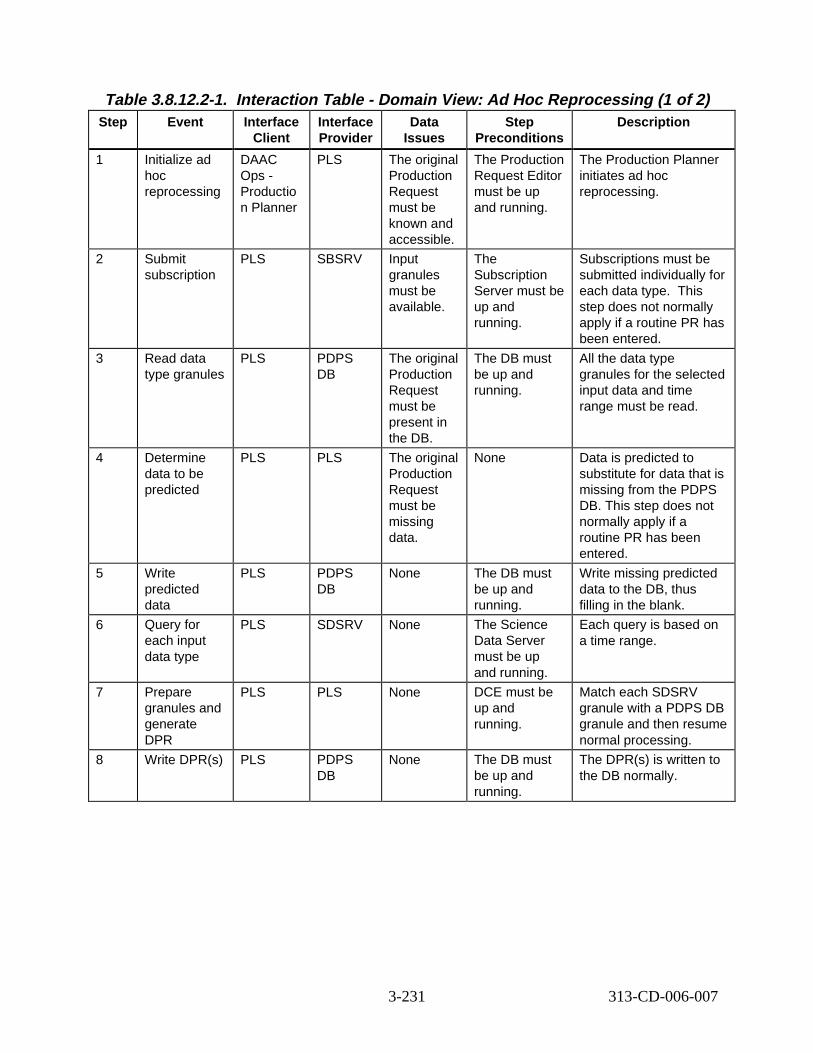
Table 3.8.12.2-1. Interact ion T able - Domain View: Ad Hoc Reproc essing ( 1 of 2) Step Event Interface
Client Interface Provider
Data Issues
Step Preconditions
Descript ion
1 Initialize ad hoc reprocessing
DAAC Ops -Productio n Planner
PLS The original Production Request must be known and accessible.
The Production Request Editor must be up and running.
The Production Planner initiates ad hoc reprocessing.
2 Submit subscription
PLS SBSRV Input granules must be available.
The Subscription Server must be up and running.
Subscriptions must be submitted individually for each data type. This step does not normally apply if a routine PR has been entered.
3 Read data type granules
PLS PDPS DB
The original Production Request must be present in the DB.
The DB must be up and running.
All the data type granules for the selected input data and time range must be read.
4 Determine data to be predicted
PLS PLS The original Production Request must be missing data.
None Data is predicted to substitute for data that is missing from the PDPS DB. This step does not normally apply if a routine PR has been entered.
5 Write predicted data
PLS PDPS DB
None The DB must be up and running.
Write missing predicted data to the DB, thus filling in the blank.
6 Query for each input data type
PLS SDSRV None The Science Data Server must be up and running.
Each query is based on a time range.
7 Prepare granules and generate DPR
PLS PLS None DCE must be up and running.
Match each SDSRV granule with a PDPS DB granule and then resume normal processing.
8 Write DPR(s) PLS PDPS DB
None The DB must be up and running.
The DPR(s) is written to the DB normally.
3-231 313-CD-006-007
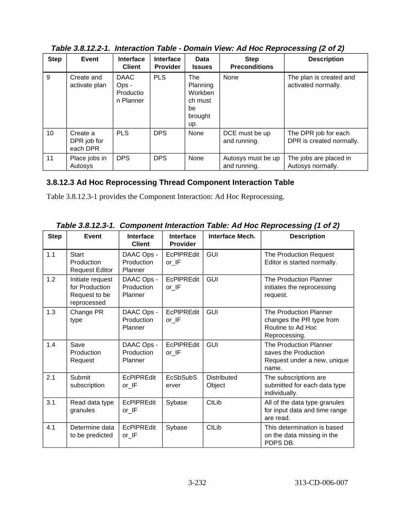
Table 3.8.12.2-1. Interact ion T able - Domain View: Ad Hoc Reproc essing ( 2 of 2) Step Event Interface
Client Interface Provider
Data Issues
Step Preconditions
Descript ion
9 Create and activate plan
DAAC Ops -Productio n Planner
PLS The Planning Workben ch must be brought up.
None The plan is created and activated normally.
10 Create a DPR job for each DPR
PLS DPS None DCE must be up and running.
The DPR job for each DPR is created normally.
11 Place jobs in Autosys
DPS DPS None Autosys must be up and running.
The jobs are placed in Autosys normally.
3.8.12.3 Ad Hoc Reprocessing Thread Component Interaction T able
Table 3.8.12.3-1 provides the Component Interaction: Ad Hoc Reprocessing.
Table 3.8.12.3-1. Component Inter action Tabl e: Ad Hoc Reprocessing (1 of 2) Step Event Interface
Client Interface Provider
Interface Mech. Descript ion
1.1 Start Production Request Editor
DAAC Ops -Production Planner
EcPlPREdit or_IF
GUI The Production Request Editor is started normally.
1.2 Initiate request for Production Request to be reprocessed
DAAC Ops -Production Planner
EcPlPREdit or_IF
GUI The Production Planner initiates the reprocessing request.
1.3 Change PR type
DAAC Ops -Production Planner
EcPlPREdit or_IF
GUI The Production Planner changes the PR type from Routine to Ad Hoc Reprocessing.
1.4 Save Production Request
DAAC Ops -Production Planner
EcPlPREdit or_IF
GUI The Production Planner saves the Production Request under a new, unique name.
2.1 Submit subscription
EcPlPREdit or_IF
EcSbSubS erver
Distributed Object
The subscriptions are submitted for each data type individually.
3.1 Read data type granules
EcPlPREdit or_IF
Sybase CtLib All of the data type granules for input data and time range are read.
4.1 Determine data to be predicted
EcPlPREdit or_IF
Sybase CtLib This determination is based on the data missing in the PDPS DB.
3-232 313-CD-006-007

Table 3.8.12.3-1. Component Inter action Tabl e: Ad Hoc Reprocessing (2 of 2) Step Event Interface
Client Interface Provider
Interface Mech.
Descript ion
5.1 Write predicted data
EcPlPREditor _IF
Sybase CtLib The missing data is filled in with predicted data.
6.1 Query for each input data type
EcPlPREditor _IF
EcDsScien ceDataSer ver
CtLib These queries are based on a time range.
7.1 Inspect and match granules
EcPlPREditor _IF
EcPlPREdit or_IF
CtLib Each SDSRV granule is matched with a PDPS DB granule.
7.2 Generate DPR(s)
EcPlPREditor _IF
EcPlPREdit or_IF
CtLib The DP R(s) are generated.
8.1 Write DPR(s) to DB
EcPlPREditor _IF
Sybase CtLib The DPR(s) are written to the DB.
9.1 Shut down Production Request Editor
DAAC Ops -Production Planner
EcPlPREdit or_IF
GUI The Production Planner shuts down the Production Request Editor.
9.2 Start up Planning Workbench
DAAC Ops -Production Planner
EcPlWb GUI The Production Planner starts up the Planning Workbench.
9.3 Select Production Request and create a plan
DAAC Ops -Production Planner
EcPlWb GUI The Production Planner selects a Production Request and creates a plan.
9.4 Activate the plan
DAAC Ops -Production Planner
EcPlWb GUI The Production Planner activates the plan.
10.1 Create a DPR job for each DPR
EcPlWb EcDpPrJob Mgmt
DCE A DPR job is created for each DPR.
11.1 Jobs placed in Autosys
EcDpPrJobM gmt
Autosys rpc (COTS) The job can now be run in Autosys.
3.8.13 Delete DPR Thread
This thread illustrates the deletion of a DPR job.
This thread applies to all instruments.
The following system functionality is exercised in this thread:
• The capability to delete an existing DPR from either Autosys or the PDPS database.
3-233 313-CD-006-007
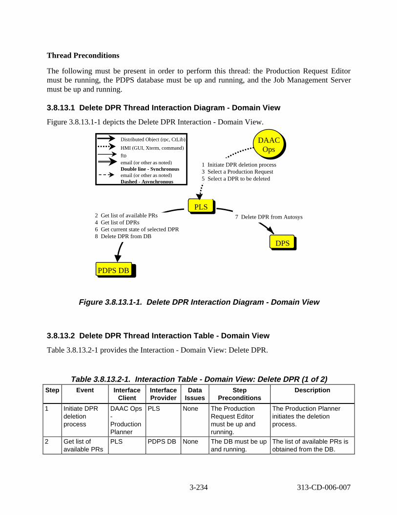
Thread Preconditions
The following must be present in order to perform this thread: the Production Request Editor must be running, the PDPS database must be up and running, and the Job Management Server must be up and running.
3.8.13.1 Delete DPR Thread Int eract ion D iagram - Domain View
Figure 3.8.13.1-1 depicts the Delete DPR Interaction - Domain View.
Distributed Object (rpc, CtLib)
HMI (GUI, Xterm, command)
ftp email (or other as noted) Double line - Synchronous email (or other as noted) Dashed - Asynchronous
PDPS DB
2 t list of available PRs 4 t list of DPRs 6 Get current state of selected DPR 8 Delete DPR from DB
GeGe
PLSPLS
DPSDPS
7 lete DPR from Autosys
1 nitiate DPR deletion process 3 lect a Production Request 5 lect a DPR to be deleted
DAAC Ops
DAAC Ops
De
ISeSe
Figure 3. 8.13.1-1. Delete DPR Interact ion D iagram - Domain View
3.8.13.2 Delete DPR Thread Int eract ion Tabl e - Domain View
Table 3.8.13.2-1 provides the Interaction - Domain View: Delete DPR.
Table 3.8.13.2-1. Interact ion T able - Domain View: Delete DPR (1 of 2) Step Event Interface
Client Interface Provider
Data Issues
Step Preconditions
Descript ion
1 Initiate DPR deletion process
DAAC Ops -Production Planner
PLS None The Production Request Editor must be up and running.
The Production Planner initiates the deletion process.
2 Get list of available PRs
PLS PDPS DB None The DB must be up and running.
The list of available PRs is obtained from the DB.
3-234 313-CD-006-007
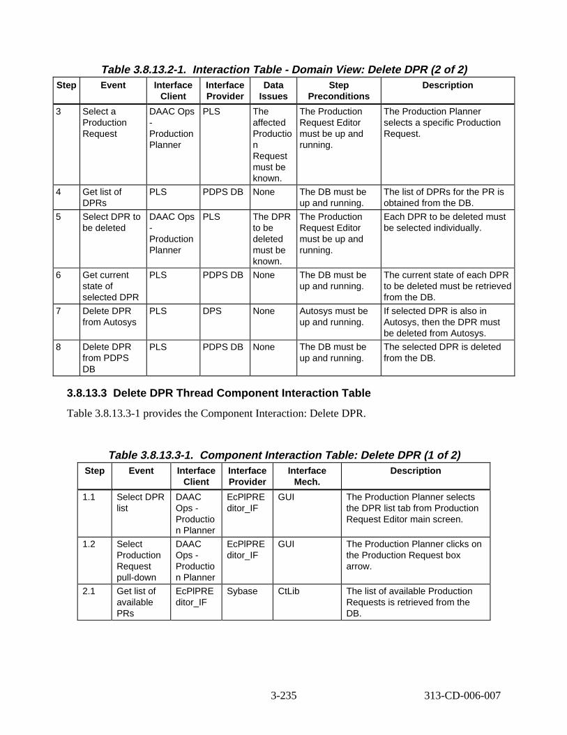
Table 3.8.13.2-1. Interact ion T able - Domain View: Delete DPR (2 of 2) Step Event Interface
Client Interface Provider
Data Issues
Step Preconditions
Descript ion
3 Select a Production Request
DAAC Ops -Production Planner
PLS The affected Productio n Request must be known.
The Production Request Editor must be up and running.
The Production Planner selects a specific Production Request.
4 Get list of DPRs
PLS PDPS DB None The DB must be up and running.
The list of DPRs for the PR is obtained from the DB.
5 Select DPR to be deleted
DAAC Ops -Production Planner
PLS The DPR to be deleted must be known.
The Production Request Editor must be up and running.
Each DPR to be deleted must be selected individually.
6 Get current state of selected DPR
PLS PDPS DB None The DB must be up and running.
The current state of each DPR to be deleted must be retrieved from the DB.
7 Delete DPR from Autosys
PLS DPS None Autosys must be up and running.
If selected DPR is also in Autosys, then the DPR must be deleted from Autosys.
8 Delete DPR from PDPS DB
PLS PDPS DB None The DB must be up and running.
The selected DPR is deleted from the DB.
3.8.13.3 Delete DPR Thread Component Interaction Table
Table 3.8.13.3-1 provides the Component Interaction: Delete DPR.
Table 3.8.13.3-1. Component Inter action Tabl e: Delete DPR (1 of 2) Step Event Interface
Client Interface Provider
Interface Mech.
Descript ion
1.1 Select DPR list
DAAC Ops -Productio n Planner
EcPlPRE ditor_IF
GUI The Production Planner selects the DPR list tab from Production Request Editor main screen.
1.2 Select Production Request pull-down
DAAC Ops -Productio n Planner
EcPlPRE ditor_IF
GUI The Production Planner clicks on the Production Request box arrow.
2.1 Get list of available PRs
EcPlPRE ditor_IF
Sybase CtLib The list of available Production Requests is retrieved from the DB.
3-235 313-CD-006-007
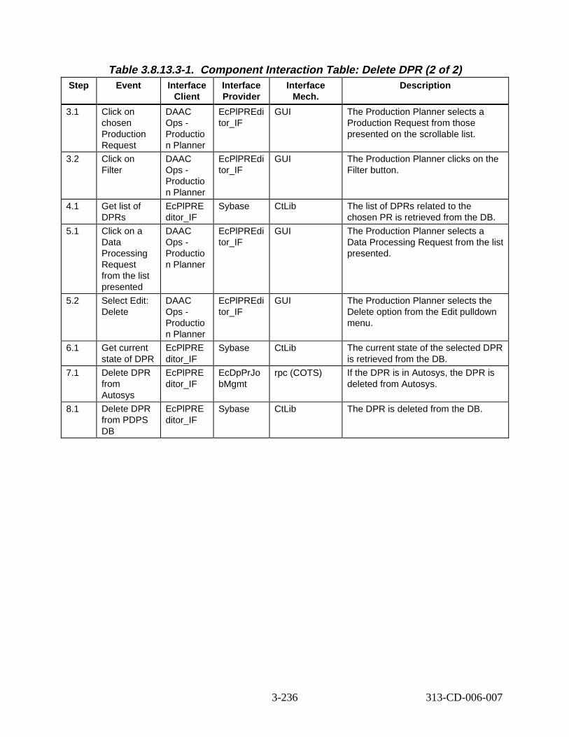
Table 3.8.13.3-1. Component Inter action Tabl e: Delete DPR (2 of 2) Step Event Interface
Client Interface Provider
Interface Mech.
Descript ion
3.1 Click on chosen Production Request
DAAC Ops -Productio n Planner
EcPlPREdi tor_IF
GUI The Production Planner selects a Production Request from those presented on the scrollable list.
3.2 Click on Filter
DAAC Ops -Productio n Planner
EcPlPREdi tor_IF
GUI The Production Planner clicks on the Filter button.
4.1 Get list of DPRs
EcPlPRE ditor_IF
Sybase CtLib The list of DPRs related to the chosen PR is retrieved from the DB.
5.1 Click on a Data Processing Request from the list presented
DAAC Ops -Productio n Planner
EcPlPREdi tor_IF
GUI The Production Planner selects a Data Processing Request from the list presented.
5.2 Select Edit: Delete
DAAC Ops -Productio n Planner
EcPlPREdi tor_IF
GUI The Production Planner selects the Delete option from the Edit pulldown menu.
6.1 Get current state of DPR
EcPlPRE ditor_IF
Sybase CtLib The current state of the selected DPR is retrieved from the DB.
7.1 Delete DPR from Autosys
EcPlPRE ditor_IF
EcDpPrJo bMgmt
rpc (COTS) If the DPR is in Autosys, the DPR is deleted from Autosys.
8.1 Delete DPR from PDPS DB
EcPlPRE ditor_IF
Sybase CtLib The DPR is deleted from the DB.
3-236 313-CD-006-007
3.9. EDOS/FDS Epheme ris/Att itude Data Processing S cenario
3.9.1 EDOS/FDS Ephem eris /Attitude Data Proc essing Sc enario D escript ion
This scenario illustrates the ability to process orbit, attitude, and ephemeris data into toolkit native format and HDF.
This scenario effects all instruments.
The following system functionality is exercised in this scenario:
• Ability to process EDOS Level 0 ancillary data
• Ability to process FDS (Flight Dynamics System) AM-1 attitude data
3.9.2 EDOS/FDS Ephem eris/Attitude Data Processing Scenario Preconditions
The input data must be available for EDOS to transfer to a disk area for Ingest to read in the corresponding form. The following ESDTs have been inserted into the ECS:
• AM1ANC (AM-1 Ancillary APIDx4)
• AM1ATTN0 (Preprocessed AM-1 Platform Attitude Data from L0 in Native format)
• AM1ATTH0 (Preprocessed AM-1 Platform Attitude Data from L0 in HDF format)
• AM1EPHN0 (Preprocessed AM-1 Platform Ephemeris Data from L0 in Native format)
• AM1EPHH0 (Preprocessed AM-1 Platform Ephemeris Data from L0 in HDF format)
• AM1ATTF (Definitive Attitude Data from AM-1 ingested from the FDF)
• AM1ATTNF (Preprocessed AM-1 Platform Attitude Data from FDF in Native format)
• AM1ATTHF (Preprocessed AM-1 Platform Attitude Data from FDF in HDF format)
3.9.3 EDOS/FDS Ephem eris/Attitude Data Processing Scenario Partitions
This scenario has been partitioned into the following threads:
• EDOS Level 0 Ancillar y Data (Thread A) - This thread illustrates the acquisition and processing of EDOS supplied Level 0 Ancillary data to toolkit native format and HDF. Gaps up to 60 seconds in ephemeris data are filled in using the interpolation algorithms provided by the FDS.
• FDS Definitive Attitu de Data (Thread B) - This thread illustrates the acquisition and processing of FDS supplied definitive attitude data to toolkit native format and HDF.
3.9.4 EDOS Level 0 Ancil lary Data Thread
The thread shows the processing of Ancillary data from EDOS. The Ancillary data contains both ephemeris data and attitude data. The attitude data is utilized as backup attitude data.
3-237 313-CD-006-007
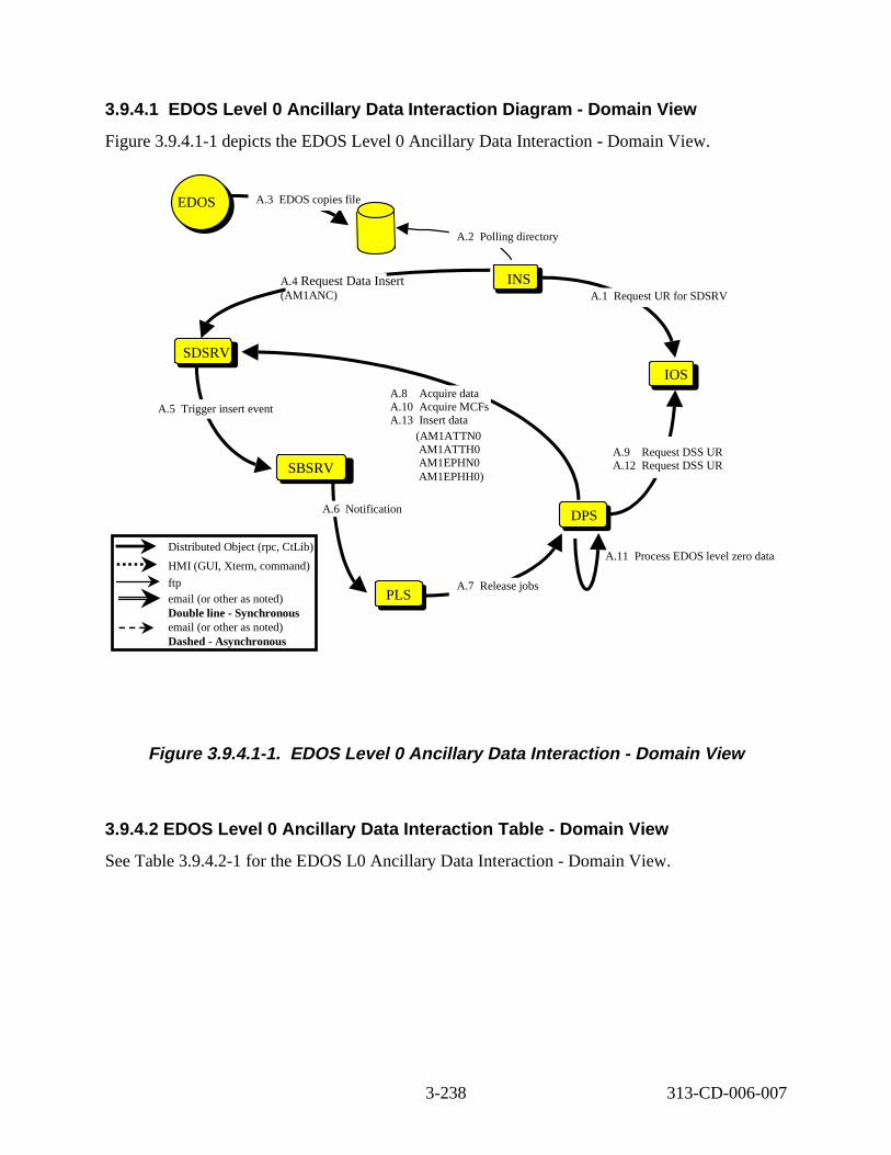
3.9.4.1 EDOS Level 0 Ancill ary Data Interact ion D iagram - Domain Vi ew
Figure 3.9.4.1-1 depicts the EDOS Level 0 Ancillary Data Interaction - Domain View.
PLSPLS
SBSRV
SDSRV
A.11 Process EDOS level zero data
DPSDPS
INS
IOS
A.3 EDOS copies fil e
A.2 Poll ing directory
A.1 Request UR for SDSRV A.4 Request Data Insert (AM1ANC)
A.5 Trigger insert event
A.6 Notification
A.9 Request DSS UR A.12 Request DSS UR
A.8 Acquire data A.10 Acquire MCFs A.13 Insert data
A.7 Release jobs
DAAC Ops
EDOS
Distributed Object (rpc, CtLib)
HMI (GUI, Xterm, command)
ftp email (or other as noted) Double line - Synchronous email (or other as noted) Dashed - Asynchronous
(AM1ATTN0 AM1ATTH0 AM1EPHN0 AM1EPHH0)
Figure 3. 9.4.1-1. EDOS Level 0 Anc illar y Data Intera ction - Domain Vi ew
3.9.4.2 EDOS Level 0 Anc illar y Data Intera ction Table - Dom ain Vi ew
See Table 3.9.4.2-1 for the EDOS L0 Ancillary Data Interaction - Domain View.
3-238 313-CD-006-007
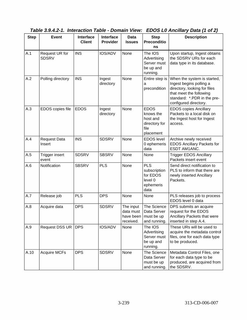
Table 3.9.4.2-1. Interact ion Tabl e - Domain V iew: EDOS L0 Ancil lary Data (1 of 2) Step Event Interface
Client Interface Provider
Data Issues
Step Preconditio
ns
Descript ion
A.1 Request UR for SDSRV
INS IOS/ADV None The IOS Advertising Server must be up and running.
Upon startup, Ingest obtains the SDSRV URs for each data type in its database.
A.2 Polling directory INS Ingest directory
None Entire step is a precondition
When the system is started, Ingest begins polling a directory, looking for files that meet the following standard: *.PDR in the preconfigured directory.
A.3 EDOS copies file EDOS Ingest directory
None EDOS knows the host and directory for file placement
EDOS copies Ancillary Packets to a local disk on the Ingest host for Ingest access.
A.4 Request Data Insert
INS SDSRV None EDOS level 0 ephemeris data
Archive newly received EDOS Ancillary Packets for ESDT AM1ANC.
A.5 Trigger insert event
SDSRV SBSRV None None Trigger EDOS Ancillary Packets insert event
A.6 Notification SBSRV PLS None PLS subscription for EDOS level 0 ephemeris data
Send direct notification to PLS to inform that there are newly inserted Ancillary Packets.
A.7 Release job PLS DPS None None PLS releases job to process EDOS level 0 data
A.8 Acquire data DPS SDSRV The input data must have been received.
The Science Data Server must be up and running.
DPS submits an acquire request for the EDOS Ancillary Packets that were inserted in step A.4.
A.9 Request DSS UR DPS IOS/ADV None The IOS Advertising Server must be up and running.
These URs will be used to acquire the metadata control files, one for each data type to be produced.
A.10 Acquire MCFs DPS SDSRV None The Science Data Server must be up and running.
Metadata Control Files, one for each data type to be produced, are acquired from the SDSRV.
3-239 313-CD-006-007
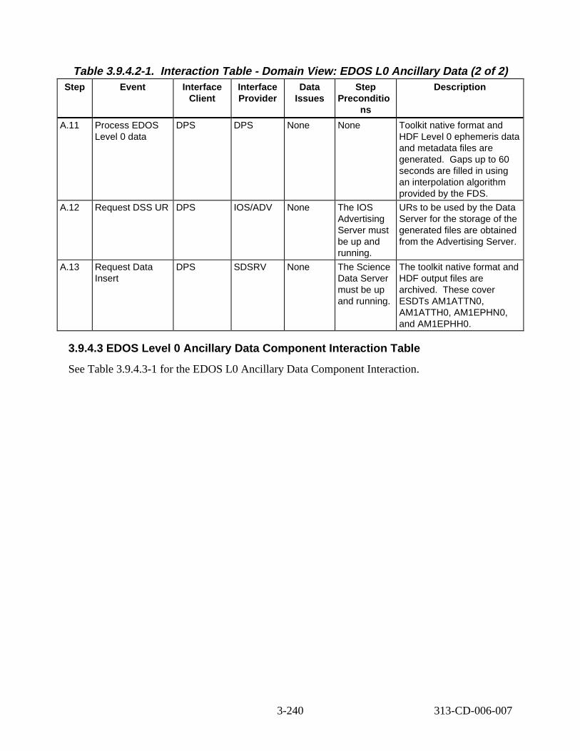
Table 3.9.4.2-1. Intera ction Tabl e - Domain V iew: EDOS L0 An cilla ry Data (2 of 2) Step Event Interface
Client Interface Provider
Data Issues
Step Preconditio
ns
Descript ion
A.11 Process EDOS Level 0 data
DPS DPS None None Toolkit native format and HDF Level 0 ephemeris data and metadata files are generated. Gaps up to 60 seconds are filled in using an interpolation algorithm provided by the FDS.
A.12 Request DSS UR DPS IOS/ADV None The IOS Advertising Server must be up and running.
URs to be used by the Data Server for the storage of the generated files are obtained from the Advertising Server.
A.13 Request Data Insert
DPS SDSRV None The Science Data Server must be up and running.
The toolkit native format and HDF output files are archived. These cover ESDTs AM1ATTN0, AM1ATTH0, AM1EPHN0, and AM1EPHH0.
3.9.4.3 EDOS Level 0 Anc illar y Data Component Inter action Tab le
See Table 3.9.4.3-1 for the EDOS L0 Ancillary Data Component Interaction.
3-240 313-CD-006-007
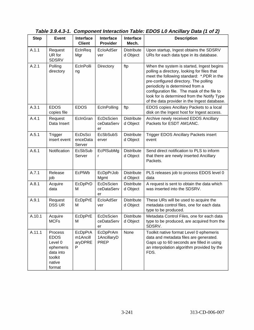
Table 3.9.4.3-1. Component Interaction Table: EDO S L0 An cill ary Dat a (1 of 2) Step Event Interface
Client Interface Provider
Interface Mech.
Descript ion
A.1.1 Request UR for SDSRV
EcInReq Mgr
EcIoAdSer ver
Distribute d Object
Upon startup, Ingest obtains the SDSRV URs for each data type in its database.
A.2.1 Polling directory
EcInPolli ng
Directory ftp When the system is started, Ingest begins polling a directory, looking for files that meet the following standard: *.PDR in the pre-configured directory. The polling periodicity is determined from a configuration file. The mask of the file to look for is determined from the Notify Type of the data provider in the Ingest database.
A.3.1 EDOS copies file
EDOS EcInPolling ftp EDOS copies Ancillary Packets to a local disk on the Ingest host for Ingest access.
A.4.1 Request Data Insert
EcInGran EcDsScien ceDataServ er
Distribute d Object
Archive newly received EDOS Ancillary Packets for ESDT AM1ANC.
A.5.1 Trigger insert event
EcDsSci enceData Server
EcSbSubS erver
Distribute d Object
Trigger EDOS Ancillary Packets insert event
A.6.1 Notification EcSbSub Server
EcPlSubMg r
Distribute d Object
Send direct notification to PLS to inform that there are newly inserted Ancillary Packets.
A.7.1 Release job
EcPlWb EcDpPrJob Mgmt
Distribute d Object
PLS releases job to process EDOS level 0 data
A.8.1 Acquire data
EcDpPrD M
EcDsScien ceDataServ er
Distribute d Object
A request is sent to obtain the data which was inserted into the SDSRV.
A.9.1 Request DSS UR
EcDpPrE M
EcIoAdSer ver
Distribute d Object
These URs will be used to acquire the metadata control files, one for each data type to be produced.
A.10.1 Acquire MCFs
EcDpPrE M
EcDsScien ceDataServ er
Distribute d Object
Metadata Control Files, one for each data type to be produced, are acquired from the SDSRV.
A.11.1 Process EDOS Level 0 ephemeris data into toolkit native format
EcDpPrA m1Ancill aryDPRE P
EcDpPrAm 1AncillaryD PREP
None Toolkit native format Level 0 ephemeris data and metadata files are generated. Gaps up to 60 seconds are filled in using an interpolation algorithm provided by the FDS.
3-241 313-CD-006-007
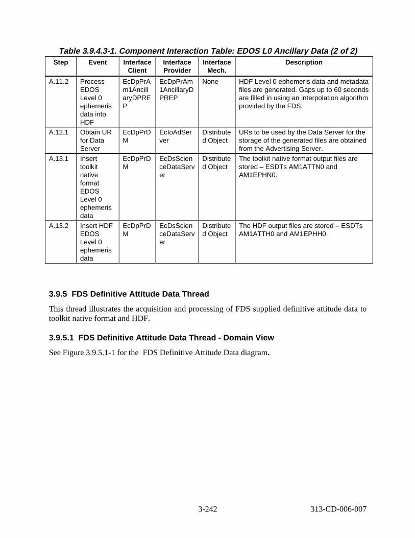
Table 3.9.4.3-1. Component Interaction T able: EDO S L0 Anc illar y Data (2 of 2) Step Event Interface
Client Interface Provider
Interface Mech.
Descript ion
A.11.2 Process EDOS Level 0 ephemeris data into HDF
EcDpPrA m1Ancill aryDPRE P
EcDpPrAm 1AncillaryD PREP
None HDF Level 0 ephemeris data and metadata files are generated. Gaps up to 60 seconds are filled in using an interpolation algorithm provided by the FDS.
A.12.1 Obtain UR for Data Server
EcDpPrD M
EcIoAdSer ver
Distribute d Object
URs to be used by the Data Server for the storage of the generated files are obtained from the Advertising Server.
A.13.1 Insert toolkit native format EDOS Level 0 ephemeris data
EcDpPrD M
EcDsScien ceDataServ er
Distribute d Object
The toolkit native format output files are stored – ESDTs AM1ATTN0 and AM1EPHN0.
A.13.2 Insert HDF EDOS Level 0 ephemeris data
EcDpPrD M
EcDsScien ceDataServ er
Distribute d Object
The HDF output files are stored – ESDTs AM1ATTH0 and AM1EPHH0.
3.9.5 FDS Definitiv e Attitude Data Thread
This thread illustrates the acquisition and processing of FDS supplied definitive attitude data to toolkit native format and HDF.
3.9.5.1 FDS Definitiv e Attitude Data Thread - Domain V iew
See Figure 3.9.5.1-1 for the FDS Definitive Attitude Data diagram.
3-242 313-CD-006-007
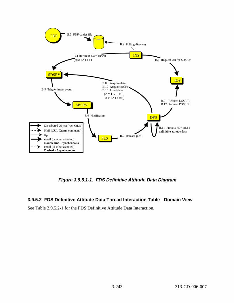
PLSPLS
SBSRV
SDSRV
B.11 Process FDF AM-1 definitive attitude data
DPSDPS
INS
IOS
B.3 DF copies file
B.2 olling directory
B.1 Request UR for SDSRV B.4 Request Data Insert (AM1ATTF)
B.5 rigger insert event
B.6 Notifi cation
B.9 Request DSS UR B.12 Request DSS UR
B.8 Acquire data B.10 Acquire MCFs B.13 Insert data
B.7 Release jobs
DAAC Ops FDF
Distributed Object (rpc, CtLib)
HMI (GUI, Xterm, command)
ftp email (or other as noted) Double line - Synchronous email (or other as noted) Dashed - Asynchronous
(AM1ATTNF, AM1ATTHF)
F
P
T
Figure 3. 9.5.1-1. FDS Definit ive Attitude Data Diagram
3.9.5.2 FDS Definitive Attitude Data Thread Interaction Table - Domain Vi ew
See Table 3.9.5.2-1 for the FDS Definitive Attitude Data Interaction.
3-243 313-CD-006-007
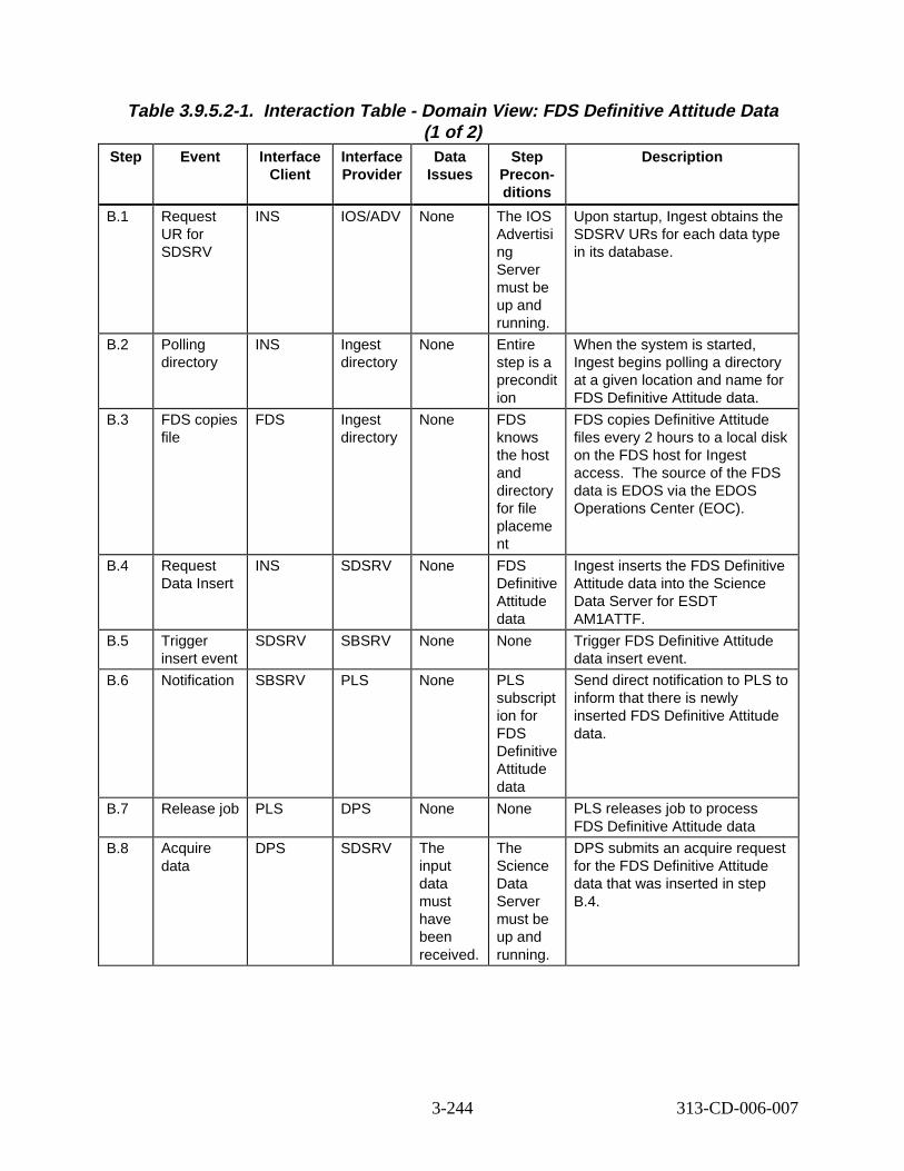
Table 3.9.5.2-1. Interact ion Tabl e - Domain V iew: FDS Definit ive Attitude Data (1 of 2)
Step Event Interface Client
Interface Provider
Data Issues
Step Preconditions
Descript ion
B.1 Request UR for SDSRV
INS IOS/ADV None The IOS Advertisi ng Server must be up and running.
Upon startup, Ingest obtains the SDSRV URs for each data type in its database.
B.2 Polling directory
INS Ingest directory
None Entire step is a precondit ion
When the system is started, Ingest begins polling a directory at a given location and name for FDS Definitive Attitude data.
B.3 FDS copies file
FDS Ingest directory
None FDS knows the host and directory for file placeme nt
FDS copies Definitive Attitude files every 2 hours to a local disk on the FDS host for Ingest access. The source of the FDS data is EDOS via the EDOS Operations Center (EOC).
B.4 Request Data Insert
INS SDSRV None FDS Definitive Attitude data
Ingest inserts the FDS Definitive Attitude data into the Science Data Server for ESDT AM1ATTF.
B.5 Trigger insert event
SDSRV SBSRV None None Trigger FDS Definitive Attitude data insert event.
B.6 Notification SBSRV PLS None PLS subscript ion for FDS Definitive Attitude data
Send direct notification to PLS to inform that there is newly inserted FDS Definitive Attitude data.
B.7 Release job PLS DPS None None PLS releases job to process FDS Definitive Attitude data
B.8 Acquire data
DPS SDSRV The input data must have been received.
The Science Data Server must be up and running.
DPS submits an acquire request for the FDS Definitive Attitude data that was inserted in step B.4.
3-244 313-CD-006-007
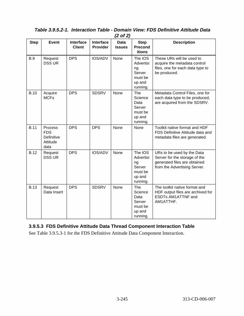
Table 3.9.5.2-1. Interact ion Tabl e - Domain V iew: FDS Definit ive Attitude Data (2 of 2)
Step Event Interface Client
Interface Provider
Data Issues
Step Precond
itions
Descript ion
B.9 Request DSS UR
DPS IOS/ADV None The IOS Advertisi ng Server must be up and running.
These URs will be used to acquire the metadata control files, one for each data type to be produced.
B.10 Acquire MCFs
DPS SDSRV None The Science Data Server must be up and running.
Metadata Control Files, one for each data type to be produced, are acquired from the SDSRV.
B.11 Process FDS Definitive Attitude data
DPS DPS None None Toolkit native format and HDF FDS Definitive Attitude data and metadata files are generated.
B.12 Request DSS UR
DPS IOS/ADV None The IOS Advertisi ng Server must be up and running.
URs to be used by the Data Server for the storage of the generated files are obtained from the Advertising Server.
B.13 Request Data Insert
DPS SDSRV None The Science Data Server must be up and running.
The toolkit native format and HDF output files are archived for ESDTs AM1ATTNF and AM1ATTHF.
3.9.5.3 FDS Definitive Attitude Data Thread Component Interaction T able See Table 3.9.5.3-1 for the FDS Definitive Attitude Data Component Interaction.
3-245 313-CD-006-007
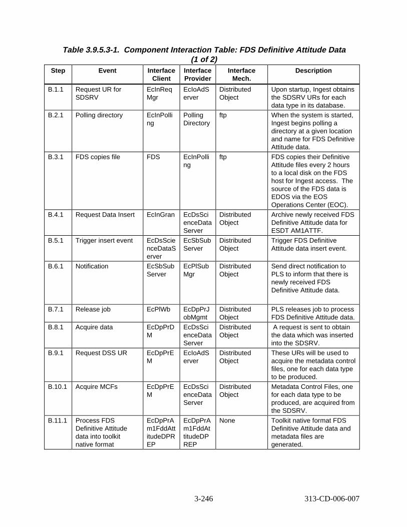
Table 3.9.5.3-1. Component Interaction Table: FDS D efinitive Attitude Data (1 of 2)
Step Event Interface Client
Interface Provider
Interface Mech.
Descript ion
B.1.1 Request UR for SDSRV
EcInReq Mgr
EcIoAdS erver
Distributed Object
Upon startup, Ingest obtains the SDSRV URs for each data type in its database.
B.2.1 Polling directory EcInPolli ng
Polling Directory
ftp When the system is started, Ingest begins polling a directory at a given location and name for FDS Definitive Attitude data.
B.3.1 FDS copies file FDS EcInPolli ng
ftp FDS copies their Definitive Attitude files every 2 hours to a local disk on the FDS host for Ingest access. The source of the FDS data is EDOS via the EOS Operations Center (EOC).
B.4.1 Request Data Insert EcInGran EcDsSci enceData Server
Distributed Object
Archive newly received FDS Definitive Attitude data for ESDT AM1ATTF.
B.5.1 Trigger insert event EcDsScie nceDataS erver
EcSbSub Server
Distributed Object
Trigger FDS Definitive Attitude data insert event.
B.6.1 Notification EcSbSub Server
EcPlSub Mgr
Distributed Object
Send direct notification to PLS to inform that there is newly received FDS Definitive Attitude data.
B.7.1 Release job EcPlWb EcDpPrJ obMgmt
Distributed Object
PLS releases job to process FDS Definitive Attitude data.
B.8.1 Acquire data EcDpPrD M
EcDsSci enceData Server
Distributed Object
A request is sent to obtain the data which was inserted into the SDSRV.
B.9.1 Request DSS UR EcDpPrE M
EcIoAdS erver
Distributed Object
These URs will be used to acquire the metadata control files, one for each data type to be produced.
B.10.1 Acquire MCFs EcDpPrE M
EcDsSci enceData Server
Distributed Object
Metadata Control Files, one for each data type to be produced, are acquired from the SDSRV.
B.11.1 Process FDS Definitive Attitude data into toolkit native format
EcDpPrA m1FddAtt itudeDPR EP
EcDpPrA m1FddAt titudeDP REP
None Toolkit native format FDS Definitive Attitude data and metadata files are generated.
3-246 313-CD-006-007
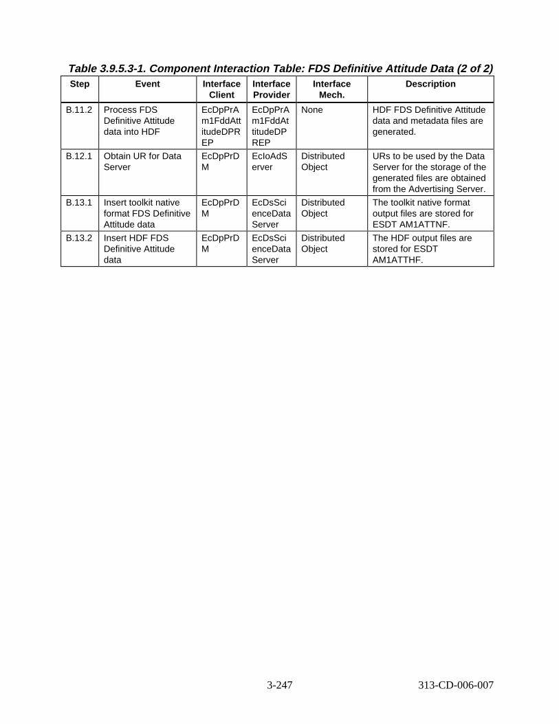
Table 3.9.5.3-1. Component Interaction T able: FDS Definiti ve Attitude Data (2 of 2) Step Event Interface
Client Interface Provider
Interface Mech.
Descript ion
B.11.2 Process FDS Definitive Attitude data into HDF
EcDpPrA m1FddAtt itudeDPR EP
EcDpPrA m1FddAt titudeDP REP
None HDF FDS Definitive Attitude data and metadata files are generated.
B.12.1 Obtain UR for Data Server
EcDpPrD M
EcIoAdS erver
Distributed Object
URs to be used by the Data Server for the storage of the generated files are obtained from the Advertising Server.
B.13.1 Insert toolkit native format FDS Definitive Attitude data
EcDpPrD M
EcDsSci enceData Server
Distributed Object
The toolkit native format output files are stored for ESDT AM1ATTNF.
B.13.2 Insert HDF FDS Definitive Attitude data
EcDpPrD M
EcDsSci enceData Server
Distributed Object
The HDF output files are stored for ESDT AM1ATTHF.
3-247 313-CD-006-007
3.10 Fault Recove ry
Fault recovery is an automated process. In any scenario, client or server failures could occur which would cause certain recovery events to take place. These events are outlined in this section for applicable combinations of single point failures, and these events would apply to any operational scenario. This section does not show a step by step scenario as in previous sections, but outlines the recovery steps which would be part of any scenario which would have a fault as outlined below. Note that Operator procedures are detailed in the 611 document.
Integration and testing focused on ASTER and Landsat 7 performing inserts (Ingest and PDPS) and acquires (PDPS and SBSRV). For Drop 4, it is assumed that the system would only have to recover from a single point of failure - either a client or a server crash. When clients/servers fail to connect, messages identifying the error condition and the time are placed into the message log. The number of retries to connect that a server attempts is a server by server configurable condition.
In general, the crashed server/client may be brought back up in a cold start or a warm restart state. The degree of persistent data available to that client/server will determine which state the crashed object will be brought back up. No knowledge of its condition prior to the crash will mean a cold start. Fault handling and recovery involved the following clients and servers with the identified restart conditions:
CLIENT S IDE
• PDPS No cold start. Warm re-start with reproducible RPC-ID
• INGEST Cold Start - will require all servers in INGEST to be re-started. Warm restart internally with SRF - externally with Reproducible RPC-ID
• SBSRV Cold Start with Reproducible RPC-ID
• SDSRV Cold Start with Reproducible RPC-ID and persistent (warm) Subscription Queues
• DDIST Cold Start with Reproducible RPC-ID. Warm restart with Reproducible RPC-ID
SERVER SIDE
• PDPS NA
• INGEST Checkpointing on all interfaces except Gateways
• SDSRV Loss of context - no checkpointing, except for persistent (warm) Subscription Queues
• STMGT Checkpointing on all interfaces, ownership on all resources, removal of resources on client death (Cold Start), time based removal of resources based on inactivity.
3-248 313-CD-006-007
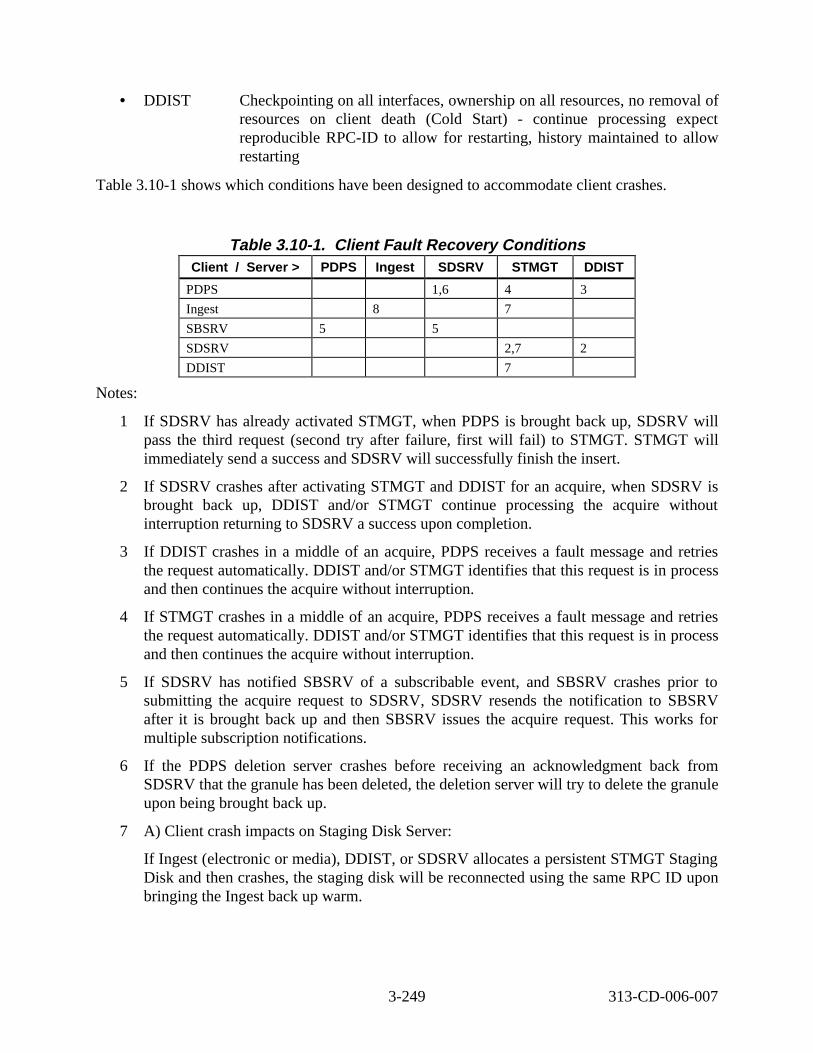
• DDIST Checkpointing on all interfaces, ownership on all resources, no removal of resources on client death (Cold Start) - continue processing expect reproducible RPC-ID to allow for restarting, history maintained to allow restarting
Table 3.10-1 shows which conditions have been designed to accommodate client crashes.
Table 3.10-1. Client Fault Reco very Conditions Client / Server > PDPS Ingest SDSRV STMGT DDIST
PDPS 1,6 4 3
Ingest 8 7
SBSRV 5 5
SDSRV 2,7 2
DDIST 7
Notes:
1 If SDSRV has already activated STMGT, when PDPS is brought back up, SDSRV will pass the third request (second try after failure, first will fail) to STMGT. STMGT will immediately send a success and SDSRV will successfully finish the insert.
2 If SDSRV crashes after activating STMGT and DDIST for an acquire, when SDSRV is brought back up, DDIST and/or STMGT continue processing the acquire without interruption returning to SDSRV a success upon completion.
3 If DDIST crashes in a middle of an acquire, PDPS receives a fault message and retries the request automatically. DDIST and/or STMGT identifies that this request is in process and then continues the acquire without interruption.
4 If STMGT crashes in a middle of an acquire, PDPS receives a fault message and retries the request automatically. DDIST and/or STMGT identifies that this request is in process and then continues the acquire without interruption.
5 If SDSRV has notified SBSRV of a subscribable event, and SBSRV crashes prior to submitting the acquire request to SDSRV, SDSRV resends the notification to SBSRV after it is brought back up and then SBSRV issues the acquire request. This works for multiple subscription notifications.
6 If the PDPS deletion server crashes before receiving an acknowledgment back from SDSRV that the granule has been deleted, the deletion server will try to delete the granule upon being brought back up.
7 A) Client crash impacts on Staging Disk Server:
If Ingest (electronic or media), DDIST, or SDSRV allocates a persistent STMGT Staging Disk and then crashes, the staging disk will be reconnected using the same RPC ID upon bringing the Ingest back up warm.
3-249 313-CD-006-007
If Ingest (electronic or media), DDIST, or SDSRV allocates a persistent or non-persistent STMGT Staging Disk and then crashes, the staging disk will be destroyed and removed upon bringing the Ingest back up cold. If the client tries to reconnect using the same RPC ID, the request will be refused as the disk has been allocated and subsequently destroyed.
If Ingest (electronic or media), DDIST, or SDSRV allocates a STMGT Staging Disk (non-persistent) and then crashes, the staging disk will be destroyed and removed upon bringing the client back up warm. If the client tries to reconnect using the same RPC ID, the request will be refused as the disk has been allocated and subsequently destroyed.
If either Ingest (electronic or media), DDIST, or SDSRV allocates a STMGT Staging Disk (non-persistent), and one of the other clients connects to the same staging disk and makes it persistent, then the original client crashes, the staging disk remains present and populated regardless of whether the crashed client comes up warm or cold.
If either Ingest (electronic or media), DDIST, or SDSRV allocates a STMGT Staging Disk (non-persistent), and one of the other clients connects to the same staging disk and makes it persistent, then the second client crashes, the staging disk remains present and populated if the crashed client comes up warm.
If either Ingest (electronic or media), DDIST, or SDSRV allocates a STMGT Staging Disk (non-persistent), and one of the other clients connects to the same staging disk and makes it persistent, then the second client crashes, the staging disk will be destroyed and removed upon bringing the crashed client back up cold. If the either client tries to reconnect by submitting the same allocation with the same RPC ID, the request is refused.
7 B) Client crash impacts on Archive Server (store procedure):
Either DDIST or SDSRV clients connect to the Archive Server and each submits a multiple-file store request. If either client crashes, its request stops at the crash point while the other request successfully completes. Restarting the crashed client warm will result in the store request picking up from where it was terminated and completing successfully.
Either DDIST or SDSRV clients connect to the Archive Server and each submits a multiple-file store request. If either client crashes, its request stops at the crash point while the other request successfully completes. Restarting the crashed client cold will result in the request being removed from the Archive Checkpoint Table. If the client brought back up cold now resubmits the request, it is treated as a new request by the Archive Server.
7 C) Client crash impacts on Archive Server (retrieve procedure):
Any two of DDIST, or SDSRV clients connect to the Archive Server and each submits a multiple-file retrieve request. If either client crashes, its request stops at the crash point while the other request successfully completes. Files staged by the request from the crashed client remain in the read-only cache with an access count of zero. Restarting the
3-250 313-CD-006-007
crashed client warm and resubmitting the request will result in the request completing successfully.
7 D) Client crash impacts on Distribution FTP Operation:
Any two DDIST or SDSRV clients connect to the Distribution FTP Server and each submits a multiple-file distribution request. If either client crashes, its request stops at the crash point while the other request successfully completes. Restarting the crashed client warm and resubmitting the distribution request will result in the request picking up from where it was terminated and completing successfully.
Any two of DDIST or SDSRV clients connect to the Distribution FTP Server and each submits a multiple-file distribution request. If either client crashes, its request stops at the crash point while the other request successfully completes. Restarting the crashed client cold will result in the request being removed from the FTP Checkpoint Table. If the client brought back up cold now resubmits the request, it is treated as a new request.
7 E) Ingest Client crash impacts on Ingest FTP Operation:
An Ingest Client submits a request to pull a large file and once the FTP has begun, the client crashes. The FTP completes successfully. If the client is restarted and the request is resubmitted, the Ingest FTP server automatically responds to the request with the status from the checkpoint in the database without performing an additional FTP.
8 A) Internal Ingest interactions with warm starts:
A request is sent to Auto and Auto crashes before it can send the request to the Request Manager. Auto restarts warm and the request is sent to Request Manager and Granule Server.
A PDR file is placed in the Polling directory and Polling crashes before it can send the request to the Request Manager. Upon warm restart of Polling, the request gets sent to Request Manager and Granule Server.
An Ingest client sends a request to Request Manager. Granule Server crashes before Request Manager sends it the request. Upon a warm restart of the Granule Server, it receives the request.
8 B) Internal Ingest interactions with cold starts:
A request is sent to Auto and Auto crashes before it can send the request to the Request Manager. Auto restarts cold and the request is set to Terminated.
A PDR file is placed in the Polling directory and Polling crashes before it can send the request to the Request Manager. Upon cold restart of Polling, the request state gets set to Terminated and, if the PDR file is left in the Polling Directory, then polling will resubmit the request.
An Ingest client sends a request to Request Manager. The Request Manager crashes after it sends the request to Granule Server. Upon a cold restart of the Request Manager, the request completes successfully.
3-251 313-CD-006-007
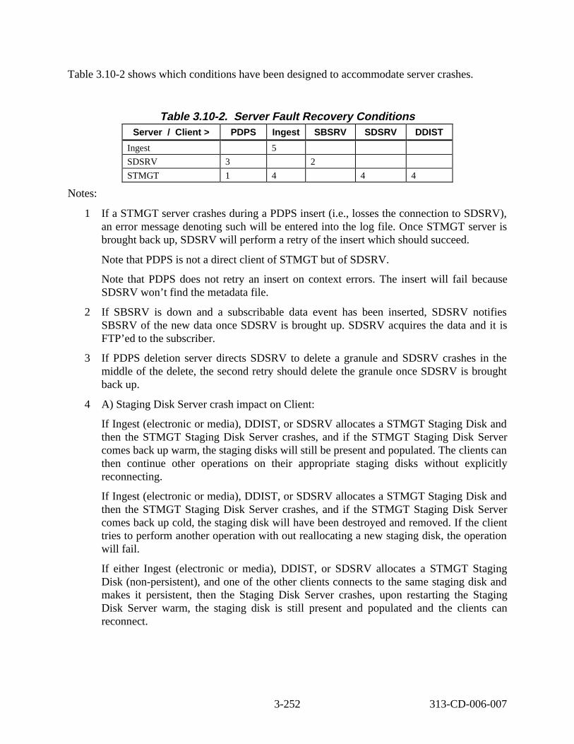
Table 3.10-2 shows which conditions have been designed to accommodate server crashes.
Table 3.10-2. Server Fault Recovery Conditions Server / Client > PDPS Ingest SBSRV SDSRV DDIST
Ingest 5
SDSRV 3 2
STMGT 1 4 4 4
Notes:
1 If a STMGT server crashes during a PDPS insert (i.e., losses the connection to SDSRV), an error message denoting such will be entered into the log file. Once STMGT server is brought back up, SDSRV will perform a retry of the insert which should succeed.
Note that PDPS is not a direct client of STMGT but of SDSRV.
Note that PDPS does not retry an insert on context errors. The insert will fail because SDSRV won’t find the metadata file.
2 If SBSRV is down and a subscribable data event has been inserted, SDSRV notifies SBSRV of the new data once SDSRV is brought up. SDSRV acquires the data and it is FTP’ed to the subscriber.
3 If PDPS deletion server directs SDSRV to delete a granule and SDSRV crashes in the middle of the delete, the second retry should delete the granule once SDSRV is brought back up.
4 A) Staging Disk Server crash impact on Client:
If Ingest (electronic or media), DDIST, or SDSRV allocates a STMGT Staging Disk and then the STMGT Staging Disk Server crashes, and if the STMGT Staging Disk Server comes back up warm, the staging disks will still be present and populated. The clients can then continue other operations on their appropriate staging disks without explicitly reconnecting.
If Ingest (electronic or media), DDIST, or SDSRV allocates a STMGT Staging Disk and then the STMGT Staging Disk Server crashes, and if the STMGT Staging Disk Server comes back up cold, the staging disk will have been destroyed and removed. If the client tries to perform another operation with out reallocating a new staging disk, the operation will fail.
If either Ingest (electronic or media), DDIST, or SDSRV allocates a STMGT Staging Disk (non-persistent), and one of the other clients connects to the same staging disk and makes it persistent, then the Staging Disk Server crashes, upon restarting the Staging Disk Server warm, the staging disk is still present and populated and the clients can reconnect.
3-252 313-CD-006-007
If either Ingest (electronic or media), DDIST, or SDSRV allocates a STMGT Staging Disk (non-persistent), and one of the other clients connects to the same staging disk and makes it persistent, then the Staging Disk Server crashes, upon restarting the Staging Disk Server cold, the staging disk will have been destroyed and removed. If either client tries to reconnect by submitting the same allocation with the same RPC ID, the request is refused.
4 B) Archive Server crash impacts on Client (store procedure):
A DDIST or SDSRV client connects to the Archive Server and submits a multiple-file store request. If the Archive Server crashes and is restarted warm, the request is automatically resubmitted and the Archive Server picks up from where it was terminated and completing successfully.
A DDIST or SDSRV client connects to the Archive Server and submits a multiple-file store request. If the Archive Server crashes and is restarted cold, the request is failed back to the client and is flagged as failed in the database.
4 C) Archive Server crash impacts on Client (retrieve procedure):
A DDIST or SDSRV client connects to the Archive Server and submits a multiple-file retrieve request. If the Archive Server crashes and is restarted warm, the request is automatically resubmitted; the Archive Server picks up from where it was terminated and completed successfully; the retrieve files are left with the proper access counts in the read-only cache.
A DDIST or SDSRV client connects to the Archive Server and submits a multiple-file retrieve request. If the Archive Server crashes and is restarted cold, the request is automatically resubmitted and the request is failed back to the client and is flagged as failed in the database.
4 D) Distribution FTP Server crash impacts on Client:
An DDIST or SDSRV client connects to the Distribution FTP Server and submits a multiple-file retrieve distribution request. If the Distribution FTP Server crashes and is restarted warm, the request is automatically resubmitted and the Archive Server picks up from where it was terminated and completes successfully; the retrieve files are left with the proper access counts in the read-only cache.
An DDIST or SDSRV client connects to the Distribution FTP Server and submits a multiple-file retrieve request. If the Distribution FTP Server crashes and is restarted cold, the request is automatically resubmitted and the request is failed back to the client and is flagged as failed in the database.
5 A) Internal Ingest interactions upon warm restart:
An Ingest client sends a request to Request Manager. The Request Manager crashes before it sends the request to Granule Server. Upon a warm restart of Request Manager, the request gets sent to Granule Server.
3-253 313-CD-006-007

An Ingest client sends a request to Granule Server. Granule Server crashes during, preprocessing, processing, or insertion. Upon a warm restart of the Granule Server, the granule completes.
5 B) Internal Ingest interactions upon cold restart:
An Ingest client sends a request to Request Manager. The Request Manager crashes before it sends the request to Granule Server. Upon a cold restart of Request Manager, the request state is set to Terminated.
Operator considerations
If either EcInGran or EcInReqMgr are cold started, then all of Ingest must be cold started.
3-254 313-CD-006-007
Abbreviations and Acronyms
ACL Access Control List
ACMHW Access Control and Management HWCI
ACFG Management Agent Configuration file
ACT Atmosphere Correction TIR
ADC Affilia ted Data Center
ADSHW ADvertising Service HWCI
ADSRV ADvertising Service CSCI
AI Artific ial Intelligence
AI&T Algorithm Integration and Test
AIT Algorithm Integration Team
AITHW Algorithm Integration and Test HWCI
AITT Algorithm Integration and Test Team
AITTL Algorithm Integration and Test Tools (CSCI)
AM-1 EOS AM Project spacecraft 1, morning spacecraft series—ASTER, CERES, MISR, MODIS and MOPITT
ANSI American National Standards Institute
API Application Program (or programming) Interface
AQAHW Algorithm QA HWCI
AQAHWCI Algorithm Quality Assurance Hardware Configuration Item
ASCII American Standard Code for Information Interchange
ASF University of Alaska Synthetic Aperture Radar (SAR) Facility
AST Algorithm Support Team
ASTER Advanced Space-borne Thermal Emission and reflection Radiometer
AVHRR Advanced Very High-Resolution Radiometer
BAAS Billing and Accounting Application Service
BOA Basic Object Adapter
BPS/bps bits per second
Bps/bps bytes per second
AB-1 313-CD-006-007
CASE Computer Aided Software Engineering
CCA Cloud Cover Assessment (Landsat scene information)
CCS CSMS Communications System (CSCI)
CD Compact Disk
CD-ROM Compact Disk - Read Only Memory
CDHF Central Data Handling Facility
CDR Critical Design Review
CDS Cell Directory Service
CDRL Contract Data Requirements List
CERES Clouds and Earth’s Radiant Energy System
Configuration Item
CIDM Client, Interoperability and Data Management
CLS Client Subsystem
CORBA Common Object Request Broker Architecture
COSS Common Object Services Specifications
COTS Commercial Off-The-Shelf (hardware or software)
CPF Calibration Parameter File
CPU Central Processing Unit
CS Computer Software
CS Client Server
CSC Computer Software Component
CSCI Computer Software Configuration Item
CSDTs Computer Science Data Types
CSMS Communications and Systems Management Segment (ECS)
CSS Communication Subsystem (CSMS)
CtLib Call to Library
DAA Data Availability Acknowledgment
DAAC Distributed Active Archive Center
DADS Data Archive and Distribution Service
DAN Data Availability Notice
AB-2 313-CD-006-007
CI

DAO Data Assimilation Office
DAS Data Assimilation System (at DAO)
DAS Data Availability Schedule
DAR Data Acquisition Request (ASTER)
DB Database
DBA Database Administrator
DBMS Database Management System
DCCI Distributed Computing software Configuration Item
DCE Distributed Communication Environment
DCE Distributed Computing Environment (OSF)
DCF Data Capture Facility
DCHCI Distributed Communications Hardware Configuration Item
DCHCI Distributed Computing Hardware CI
DDA Data Delivery Acknowledgment
DDICT Data Dictionary CSCI
DDIST Data Distribution services CSCI
DDL Data Definition Language
DDN Data Delivery Notice
DDSRV Document Data Server CSCI in the Data Server Subsystem - SDPS
DEF Data Exchange Format
DEM Digital Elevation Model
DES Data Encryption Standard
DESKT Desktop CI
DESKT Desktop CSCI
DFS Distributed File System
DIB Directory Information Base
DID Data Item Description
DIM Distributed Information Manager
DIMGR Distributed Information Manager
DIMGR Distributed Information Manager CSCI
AB-3 313-CD-006-007
DIPHW Distribution and Ingest Peripheral HWCI
DIPHW Distribution and Ingest Peripheral Management HWCI
DIS Data Information System
DLPDU Data Link Protocol Data Unit
DM Data Management
DMGHW Data Management HWCI
DMS Data Management Subsystem
DNS Domain Name System
DNS Domain Name Services
DOC Distributed Object Computing
DOF Distributed Object Framework
DORRAN Distributed Ordering, Reporting, Researching, and Accounting Network (EDC)
DPR Data Processing Request
DPREP Data Pre-Processing CSCI
DPS Data Processing Subsystem
DRPHW Data Repository HWCI
DS Data Server
DSS Data Server Subsystem
e-mail electronic mail
email electronic mail
EAS ECS Advertising Service
ECS EOSDIS Core System
EDC EROS Data Center (DAAC)
EDF ECS Development Facility
EDOS EOS Data and Operations System
EDU EDOS Data Unit
EMC Enterprise Monitoring and Coordination
EOC EOS Operations Center
EOS AM EOS AM Project (morning spacecraft series)
EOS Earth Observing System
AB-4 313-CD-006-007

EOS-AM-1 EOS Morning Crossing (Descending) Mission
EOS-PM EOS Afternoon Crossing (Ascending) Mission (afternoon spacecraft series) (see AIRS, AMSU-A, MHS, MIMR, CERES and MODIS)
EOSDIS Earth Observing System (EOS) Data and Information System (DIS)
ERD Entity Relationship Diagram
EROS Earth Resources Observation System
ESA European Space Agency
ESDD Earth Science Data Directory
ESDIS Earth Science Data and Information System (GSFC Code 505)
ESDT Earth Science Data Types
ESFU Enhanced Standard Format Unit
ESH EDOS Service Header
ESN EOSDIS Science Network (ECS)
ETM+ Enhanced Thematic Mapper Plus
ETS Emission Temperature Separation
FDD Flight Dynamics Division
FDDI Fiber Distributed Data Interface
FDF Flight Dynamics Facility
FDS Flight Dynamics System
FOS Flight Operations Segment (ECS)
FOT Flight Operations Team
FSMS File Storage Management System
FTP File Transfer Protocol
ftpd file transfer protocol daemon
G/B Gateway/Bridge
GAC Global Area Coverage (AVHRR)
Gb gigabits (10**9)
Gbps/GBps gigabit/gigabyte per second
GByte gigabyte (10**9)
GCDIS Global Change Data and Information System
AB-5 313-CD-006-007

GCMD Global Change Master Directory
GCP Ground Control Point
GDAO GSFC Data Assimilation Office
GDS Ground Data System
GFE Government Furnished Equipment
GIS Geographic Information System
GNMP GOSIP Network Management Protocol
GOES Geo-stationary Operational Environmental Satellite
GSFC Goddard Space Flight Center
GTWAY Version 0 Interoperability Gateway CSCI (Also V0GWY)
GUI Graphical User Interface
GV Ground Validation
GV TRMM Ground Validation Data
GV TRMM Ground Verification
H&S Health and Safety
H/K Housekeeping
H/W hardware
HCL Hughes Class Library
HDF Hierarchical Data Format
HMI Human Machine Interface
HP Hewlett-Packard Corporation
HPOV Hewlett-Packard Open View
HTML Hypertext Markup Language
HTTP Hypertext Transport Protocol
HWCI Hardware Configuration Item
I/F interface
I/O input/output
ICD Interface Control Document
ICL Ingest Client
ICLHW Ingest Client HWCI
AB-6 313-CD-006-007
ICMP Internet Control Management Protocol
ICMP Internet Control Message Protocol
IDD Interface Definition Document
IDL Interactive Data Language
IDL interface definition language
IMS Information Management System
INCI Internetworking CI
INGST Ingest services CI
INHCI Internetworking Hardware CI
INS Ingest Subsystem - SDPS
IOS Interoperability subsystem
IOT Instrument Operations Team
IP Internet Protocol
IR-1 Interim Release-1
IRD Interface Requirements Document
IRS Interface Requirements Specifi cation
ISS Internetworking Subsystem - CSMS
JIL Job I/F Language
JPL Jet Propulsion Laboratory (DAAC)
KB kilobyte (10**3)
KB kilobytes
Kb kilobit (10**3)
KB/SEC kilobyte per second
Kbps kilobits per second
Kbps/KBps kilobit/kilobyte per second
Kerberos security protocol developed by MIT; base for DCE security
Kftp Kerberized file transfer protocol
KM Key Mechanism
KSLOC thousand Single Lines Of Code
Ktelnet Kerberized telnet
AB-7 313-CD-006-007
L-7 Landsat-7 (Landsat-7 for EDHS search)
L7 Landsat-7
L0 Level 0
L0R Level 0 Reformatted data
L0-L4 Level 0 through Level 4 data
L70R Landsat-7 L0 data
LAC Local Area Coverage (AVHRR)
LAN Local Area Network
Landsat Land Remote-Sensing Satellite
LaRC Langley Research Center (DAAC)
LIMGR Local Information Manager CSCI
LIS Lightning Imaging Sensor
M& O Maintenance and Operations
MACI Management Agent Configuration Item (CSCI)
MB megabyte (10**6 bytes)
Mb megabit (10**6)
MBps megabytes per second
Mbps mega bits per second
MBPS/Mbps million bits per second
Mbps/MBps megabit/megabyte per second
Mbyte megabyte
MCF Metadata Configuration File
MCI Management Software CI
med medium
MEM Memory management
MET Metadata
Metadata data about data
MFLOP Million Floating-point Operations per second
MFLOPS Mega (millions of) Floating-point Operations (10**6) per second
MHCI Management Hardware CI
AB-8 313-CD-006-007
MIB Management Information Base
MIL-STD Military Standard
min minute
MIPS Mega (millions Of) Instructions (10**6) per second
MISR Multi-angle Imaging SpectroRadiometer
MMI Man-Machine Interface
MO&DSD Mission Operations and Data Systems Directorate (GSFC Code 500)
MODIS MODerate resolution Imaging Spectroradiometer
MOU Memorandum Of Understanding
MSCD Mirror Scan Correction Data (Landsat)
MSS Management Subsystem Service
MSS Multi-Spectral Scanner (Landsat)
MSS System Management Subsystem (of CSMS)
MSSHW MSS Hardware CI
MSU Mass Storage Unit
MSU Microwave Sounding Unit
MTA Message Transfer Agent
MTTR Mean Time To Repair
MTTR Mean Time To Restore
MUI Management User Interface
Multicast a point to multi-point data flow
NASA National Aeronautics and Space Administration
Nascom NASA Communications
NCAR National Center for Atmospheric Research
NCEP National Centers for Environmental Prediction
NESDIS National Environmental Satellite, Data, and Information Service (NOAA)
netCDF network Common Data Format
NFS Network File System
NMC National Meteorological Center (NOAA)
NMS Network Management Subsystem (Ecom)
AB-9 313-CD-006-007

NNTP Network New Transfer Protocol
NNTP Network News Transfer Protocol
NOAA National Oceanic and Atmospheric Administration
NODC National Oceanographic Data Center [NOAA] (also NESDIS/NODC)
NOLAN Nascom Operational Local Area Network
NQS (Network) Queuing System
NRC National Research Council
NRDN NOAA Radar Data Network
NREN National Research and Education Network
NRL Naval Research Laboratory
NSF National Science Foundation
NSFNet NSF Network
NSI NASA Science Internet
NSIDC National Snow and Ice Data Center (DAAC - University of Colorado)
NSSDC National Space Science Data Center
NTP Network Transport Protocol
NWCI Networking Configuration Item
O&M Operations and Maintenance
O/A Orbit/Altitude
ODC Other Data Center
ODL Object Description Language
ODMS Object Data Management System
OES Object Encapsulation Software
OMA Object Management Architecture
OMF Object Management Framework
OMG Object Management Group
OMT Object Modeling Technique
OO object oriented
OOA Object Oriented Analysis
OOD Object Oriented Design
AB-10 313-CD-006-007
OODBMS Object Oriented Data Base Management System
OODCE Object Oriented Distributed Computing Environment
OORDB Object Oriented Relational Data Base
OPS Operations
ORB Object Request Broker
ORDBMS Object Rational Data Base Management System
OS Object Services
OS Operating System
OSF Open Software Foundation
OSI Open Systems Interconnection
OSI-RM OSI Reference Model
OTS Off-The-Shelf
Payload
P/S Planning/Scheduling
PAN Production Acknowledgement Notice
PAS Planning And Scheduling
PCD Payload Correction Data (Landsat)
PCFG Program Configuration file (Management Agent)
PCL Planning Class Libraries
PDF Publisher’s Display Format
PDF Portable Document Format
PDL Program Design Language
PDPS Planning and Data Processing System
PDR Product Data Request
PDR Product Delivery Record
PDRA Preliminary Design Review release-A
PDS Planetary Data System
PDS Platform Data System
PDS Production Data Set
Perl a UNIX programming language
AB-11 313-CD-006-007
P/L

PF Process Framework
PGE Product Generation Executive (formerly product generation executable)
PGS Product Generation Service
PGS Product Generation System (obsolete ECS element name) (ASTER)
PGSTK Product Generation System Toolkit
PI Primary Investigator
PI Principal Investigator
PI/TL Principal Investigator/Team Leader
PLANG Production Planning CSCI
PLNHW Planning HWCI
PLS Planning Subsystem
POSIX Portable Operating System Interface for computer environments
PR Production Request
PR Precipitation Radar (TRMM)
PRONG Processing CSCI
PSCN Program Support and Communications Network
PVL Parameter Value Language
QA or Q/A Quality Assurance
QA or Q/A Quality/Accounting
R/W Read/Write
RAID Redundant Array of Inexpensive Disks
RAM Random Access Memory
RCL Resource Class Libraries
RCP Remote Copy
RDA Remote Database Access
RDBMS Relational Data Base Management System
RID Review Item Discrepancy
RMA Reliability, Maintainability, Availability
RMON Remote Monitor (SNMP)
RPC Remote Procedure Call
AB-12 313-CD-006-007
RPC Remote Processing Computer
RRR Release Readiness Review
RT or R/T Real Time
RTM Requirements Traceability Model
S/C Spacecraft
S/E Systems Engineering
SAA Satellite Active Archives (NOAA)
SBA Small Business Administration
SBUV Solar Backscatter Ultraviolet
SBUV/2 Solar Backscatter Ultraviolet/version 2
SCDO Science and Communications Development Office (ECS)
SCF Science Computing Facility
SDP Science Data Processing
SDPS Science Data Processing Segment (ECS)
SDPS/W Science Data Processing Software
SDPS/W Science Data Production Software
SDPTK Science Data Processing Toolkit
SDR System Design Review
SDSRV Science Data Server CSCI
SeaWiFS Sea-viewing Wide Field-of-view Sensor
SGI Silicon Graphics Incorporated
SMC System Management Center
SMMR Scanning Multi-channel Microwave Radiometer
SMTP Simple Mail Transfer Protocol
SNDCP Sub-Network Dependent Convergence Protocol
SNICP Sub-Network Independent Convergence Protocol
SNMP Simple Network Management Protocol
SP Scenario Primitive
SPRHW Science Processing Hardware CI
SQS Spatial Query Servers
AB-13 313-CD-006-007
SSAP Science Software Archive Package
SSI&T Science Software Integration and Test
SSM/I Special Sensor Microwave/Imager
SSM/T Special Sensor Microwave/Temperature sounder
SST Sea Surface Temperature
STMGT Storage Management software CSCI
StP Software through Pictures
StP/OMT Software through Pictures/Object Modeling Technique
SUN Sun Microsystems
SW Science Workstation
SW or S/W Software
SWCI Software Configuration Item
SWG Science Working Group
TBD To Be Determined, or To Be Defined
TBR To Be Resolved
TBS To Be Supplied
TCP Transmission Control Protocol
TCP/IP Transmission Control Protocol/Internet Protocol
TDRSS Tracking and Data Relay Satellite System
TIR Thermal Infrared
TIROS Television and Infrared Observation Satellite
TL Team Leader
TLCF Team Leader Computing Facility
TM Thematic Mapper (Landsat)
TMI TRMM Mi crowave Imager
TN TDRSS Network
TOMS Total Ozone Mapping Spectrometer
TOPEX Ocean Topography Experiment (joint US-France)
TOVS TIROS Operational Vertical Sounder
TRMM Tropical Rainfall Measuring Mission (joint US-Japan)
AB-14 313-CD-006-007
TSDIS TRMM Science Data and Information System
TSU TRMM Science User
UARS Upper Atmosphere Research Satellite
UDP User Datagram Protocol
UDP/IP User Datagram Protocol/Internet Protocol
UFS UNIX File System
UID Universal Identifier
UNIX (AT&T Bell Laboratories Operating System) UNiversal Interactive eXecutive
UR Universal Reference
URL Uniform Resource Locator
UserDIS User Data Information System
USGS U.S. Geological Survey
UT Universal Time
UTC Universal Time Code
UTC Universal Time Coordinated
UTCF Universal Time Correlation Factor
UTM Universal Transverse Mercator
UUID Universal Unique Identifier
UX UNIX/X
V&V Verification and Validation
V0 ODL Version 0 Object Description Language
V0 Version 0
V0GWY Version 0 interoperability Gateway CSCI
VAS VISSR Atmospheric Sounder (GOES)
VIMS Virtual IMS
VIRR Visible and Infrared Radiometer
VIRS Visible Infrared Scanner (TRMM)
VIS Vendor Information System
VIS-UV Visible/Ultraviolet Spectrometer
VISSR Visible/Infrared Spin-Scan Radiometer (GOES)
AB-15 313-CD-006-007
VT Virtual Terminal
W/S Workstation
WAIS Wide Area Information Server
WAN Wide Area Network
WKBCH Workbench CSCI
WKSHW Working Storage HWCI
WRKSTN Workstation
WRS Worldwide Reference System (Landsat)
WS Working Storage
WS Workstation
WWW World Wide Web
X protocol
XTE X-ray Timing Explorer
AB-16 313-CD-006-007
X