Embed Size (px)
Citation preview
www.magnecraft.com 847-441-2540
SEC
TIO
N 5
5 R e l a y s - T i m e D e l a y & S e n s o r
S e c t i o n
Definition:Time Delay is defined as the controlled period between the functioning of two events. A Time Delay relay is a combination of an electromechanical output relay and a control circuit. The control circuit is comprised of solid state components and timing circuits that control operation of the relay and timing range. Typical time delay functions include On-Delay, Repeat cycle (starting off), Interval, Off-Delay, Retriggerable One Shot, Repeat cycle (starting on), Pulse Generator, One Shot, On/Off Delay, and Memory Latch. Each function is explained in the table below. Time delay relays have a broad choice of timing ranges from less than one second to many days. There are many choices of timing adjustments from calibrated external knobs, DIP switches, thumbwheel switches, or recessed potentiometer. The output contacts on the electromechanical output relay are direct wired to the output terminals. The contact load ratings are specified for each specific type of time delay relay.
Understanding the differences between all the functions available in time delay relays can sometimes be a daunting task. When designing circuits using time delay relays questions such as:
“What initiates a time delay relay?”
“Does the timing start with the application or release of voltage?”
“When does the output relay come on?”
must be asked.
Time delay relays are simply control relays with a time delay built in. Their purpose is to control an event based on time. The difference between relays and time delay relays is when the output contacts open & close: on a control relay, it happens when voltage is applied and removed from the coil; on time delay relays, the contacts will open or close before or after a pre-selected, timed interval.
Typically, time delay relays are initiated or triggered by one of two methods:• application of input voltage (On Delay, Interval On, Flasher, Repeat Cycle, Delayed Interval & Interval/Flasher). • opening or closing of a trigger signal (Off Delay, Single Shot & Watchdog).
These trigger signals can be one of two designs:• a control switch (dry contact), i.e., limit switch, push button, float switch, etc. • voltage (commonly known as a power trigger).
To help understand, some definitions are important:Input Voltage: Control voltage applied to the input terminals (see wiring diagrams below). Depending on the function, input voltage will either initiate the unit or make it ready to initiate when a trigger signal is applied.
Trigger Signal: On certain timing functions, a trigger signal is used to initiate the unit after input voltage has been applied. As noted above, this trigger signal can either be a control switch (dry contact switch) or a power trigger (voltage).
Output (Load): Every time delay relay has an internal relay (usually mechanical) with contacts that open & close to control the load. They are represented by the dotted lines in the wiring diagrams. Note that the user must provide the voltage to power the load being switched by the output contacts of the time delay relay.
The following tables contain both written and visual descriptions on how the common timing functions operate. A Timing Chart shows the relationship between Input Voltage, Trigger Signal (if present) and Output Contacts.
SEC
TIO
N 5
Magnecraf t Solut ion Guide 105A Magnecraf t Solut ion Guide 105A
Time Delay Relays – Application Data
5/2
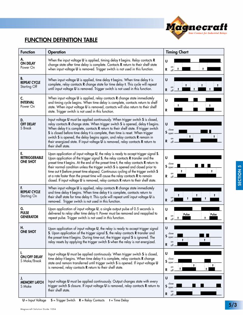
FUNCTION DEFINITION TABLE
Function Operation Timing Chart
When the input voltage U is applied, timing delay t begins. Relay contacts R change state after time delay is complete. Contacts R return to their shelf state when input voltage U is removed. Trigger switch is not used in this function.
When input voltage U is applied, time delay t begins. When time delay t is complete, relay contacts R change state for time delay t. This cycle will repeat until input voltage U is removed. Trigger switch is not used in this function.
t
t t tt t t
When input voltage U is applied, relay contacts R change state immediately and timing cycle begins. When time delay is complete, contacts return to shelf state. When input voltage U is removed, contacts will also return to their shelf state. Trigger switch is not used in this function.
t
Input voltage U must be applied continuously. When trigger switch S is closed, relay contacts R change state. When trigger switch S is opened, delay t begins. When delay t is complete, contacts R return to their shelf state. If trigger switch S is closed before time delay t is complete, then time is reset. When trigger switch S is opened, the delay begins again, and relay contacts R remain in their energized state. If input voltage U is removed, relay contacts R return to their shelf state.
t t
F.REPEAT CYCLEStarting On
When input voltage U is applied, relay contacts R change state immediately and time delay t begins. When time delay t is complete, contacts return to their shelf state for time delay t. This cycle will repeat until input voltage U is removed. Trigger switch is not used in this function.
E.RETRIGGERABLEONE SHOT
Upon application of input voltage U, the relay is ready to accept trigger signal S. Upon application of the trigger signal S, the relay contacts R transfer and the preset time t begins. At the end of the preset time t, the relay contacts R return to their normal condition unless the trigger switch S is opened and closed prior to time out t (before preset time elapses). Continuous cycling of the trigger switch S at a rate faster than the preset time will cause the relay contacts R to remain closed. If input voltage U is removed, relay contacts R return to their shelf state.
t t
G.PULSEGENERATOR
H.ONE SHOT
Upon application of input voltage U, a single output pulse of 0.5 seconds is delivered to relay after time delay t. Power must be removed and reapplied to repeat pulse. Trigger switch is not used in this function.
Upon application of input voltage U, the relay is ready to accept trigger signal S. Upon application of the trigger signal S, the relay contacts R transfer and the preset time t begins. During time-out, the trigger signal S is ignored. The relay resets by applying the trigger switch S when the relay is not energized.
I.ON/OFF DELAYS Make/Break
J.MEMORY LATCHS Make
Input voltage U must be applied continuously. When trigger switch S is closed, time delay t begins. When time delay t is complete, relay contacts R change state and remain transferred until trigger switch S is opened. If input voltage U is removed, relay contacts R return to their shelf state.
Input voltage U must be applied continuously. Output changes state with every trigger switch S closure. If input voltage U is removed, relay contacts R return to their shelf state.
t tt t
t t
U
R
U
R
U
R
U
S
R
U
R
U
S
R
U
S
R
U
S
R
R
U
S
U
R tPulse
tonoff
t
onoff
closeopen
onoff
onoff
onoff
closeopen
onoff t
Pulse
onoff
closeopen
onoff
closeopen
onoff
closeopen
t tt t t
D.OFF DELAYS Break
A.ON DELAYPower On
C.INTERVALPower On
B.REPEAT CYCLEStarting Off
U = Input Voltage S = Trigger Switch R = Relay Contacts t = Time Delay
Magnecraf t Solut ion Guide 105A
SEC
TIO
N 5
Magnecraf t Solut ion Guide 105A5/3
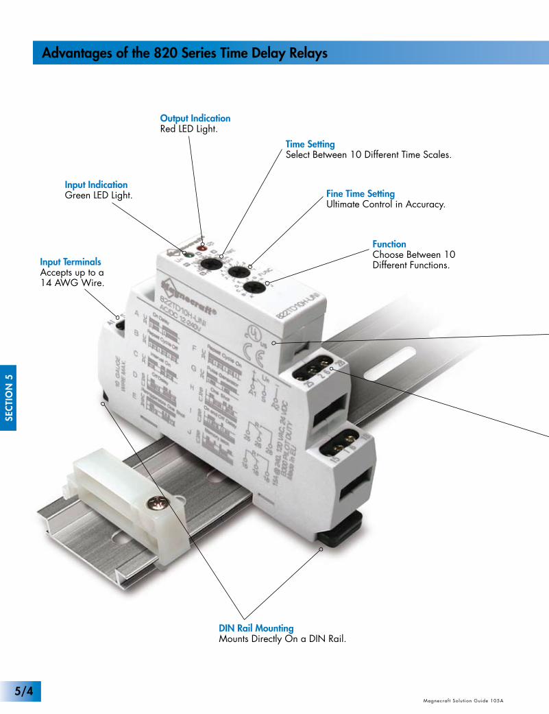
Input TerminalsAccepts up to a 14 AWG Wire.
Output IndicationRed LED Light.
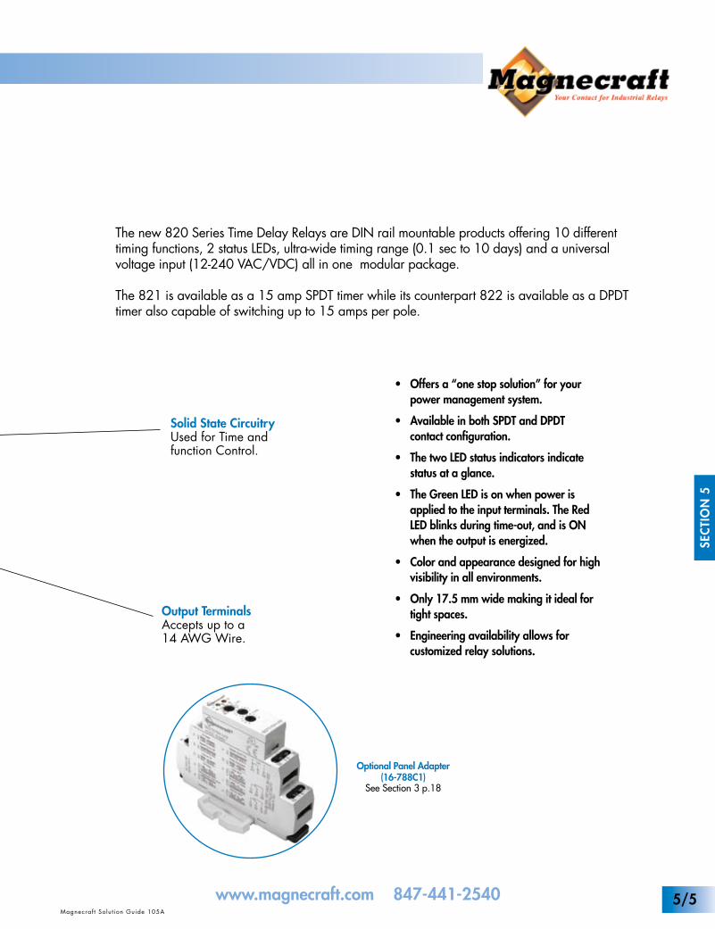
Solid State CircuitryUsed for Time andfunction Control.
DIN Rail MountingMounts Directly On a DIN Rail.
Input IndicationGreen LED Light.
Time SettingSelect Between 10 Different Time Scales.
Fine Time SettingUltimate Control in Accuracy.
FunctionChoose Between 10Different Functions.
Output TerminalsAccepts up to a 14 AWG Wire.
SEC
TIO
N 5
Magnecraf t Solut ion Guide 105A Magnecraf t Solut ion Guide 105A
Advantages of the 820 Series Time Delay Relays
5/4
www.magnecraft.com 847-441-2540
Optional Panel Adapter(16-788C1)
See Section 3 p.18
Input TerminalsAccepts up to a 14 AWG Wire.
Output IndicationRed LED Light.
Solid State CircuitryUsed for Time andfunction Control.
DIN Rail MountingMounts Directly On a DIN Rail.
Input IndicationGreen LED Light.
Time SettingSelect Between 10 Different Time Scales.
Fine Time SettingUltimate Control in Accuracy.
FunctionChoose Between 10Different Functions.
Output TerminalsAccepts up to a 14 AWG Wire.
Magnecraf t Solut ion Guide 105A
SEC
TIO
N 5
Magnecraf t Solut ion Guide 105A
The new 820 Series Time Delay Relays are DIN rail mountable products offering 10 different timing functions, 2 status LEDs, ultra-wide timing range (0.1 sec to 10 days) and a universal voltage input (12-240 VAC/VDC) all in one modular package.
The 821 is available as a 15 amp SPDT timer while its counterpart 822 is available as a DPDT timer also capable of switching up to 15 amps per pole.
• Offers a “one stop solution” for your power management system.
• Available in both SPDT and DPDT contact configuration.
• The two LED status indicators indicate status at a glance.
• The Green LED is on when power is applied to the input terminals. The Red LED blinks during time-out, and is ON when the output is energized.
• Color and appearance designed for high visibility in all environments.
• Only 17.5 mm wide making it ideal for tight spaces.
• Engineering availability allows for customized relay solutions.
5/5
WHITE
UL ListedFile No. E234203
WHITE
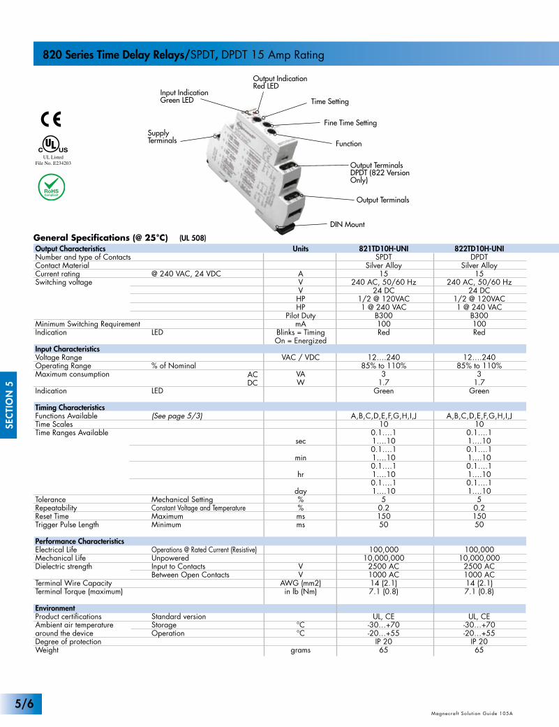
General Specifications (@ 25°C) (UL 508)
ACDC
SEC
TIO
N 5
Magnecraf t Solut ion Guide 105A Magnecraf t Solut ion Guide 105AMagnecraf t Solut ion Guide 105A
820 Series Time Delay Relays/SPDT, DPDT 15 Amp Rating
Units
AVVHPHP
Pilot DutymA
Blinks = TimingOn = Energized
VAC / VDC
VAW
sec
min
hr
day%%msms
VV
AWG (mm2)in lb (Nm)
°C°C
grams
821TD10H-UNISPDT
Silver Alloy15
240 AC, 50/60 Hz24 DC
1/2 @ 120VAC1 @ 240 VAC
B300100Red
12….24085% to 110%
31.7
Green
A,B,C,D,E,F,G,H,I,J10
0.1….11….100.1….11….100.1….11….100.1….11….10
50.215050
100,00010,000,000
2500 AC1000 AC14 (2.1)7.1 (0.8)
UL, CE-30…+70-20…+55
IP 2065
Output IndicationRed LED
Output Terminals
Input IndicationGreen LED Time Setting
Fine Time Setting
FunctionSupplyTerminals
Output Terminals DPDT (822 Version Only)
DIN Mount
Output Characteristics Number and type of ContactsContact MaterialCurrent ratingSwitching voltage
Minimum Switching RequirementIndication
Input CharacteristicsVoltage RangeOperating Range Maximum consumption
Indication
Timing CharacteristicsFunctions AvailableTime ScalesTime Ranges Available
ToleranceRepeatabilityReset TimeTrigger Pulse Length
Performance CharacteristicsElectrical LifeMechanical LifeDielectric strength
Terminal Wire CapacityTerminal Torque (maximum)
EnvironmentProduct certificationsAmbient air temperaturearound the deviceDegree of protectionWeight
@ 240 VAC, 24 VDC
LED
% of Nominal
LED
(See page 5/3)
Mechanical SettingConstant Voltage and TemperatureMaximumMinimum
Operations @ Rated Current (Resistive)UnpoweredInput to ContactsBetween Open Contacts
Standard versionStorageOperation
822TD10H-UNIDPDT
Silver Alloy15
240 AC, 50/60 Hz24 DC
1/2 @ 120VAC1 @ 240 VAC
B300100Red
12….24085% to 110%
31.7
Green
A,B,C,D,E,F,G,H,I,J10
0.1….11….100.1….11….100.1….11….100.1….11….10
50.215050
100,00010,000,000
2500 AC1000 AC14 (2.1)7.1 (0.8)
UL, CE-30…+70-20…+55
IP 2065
5/6
(7.4)0.3
0.7(17.6) 0.6
(14.2)
(5)0.2
(65)
(16)
(45.3)1.8
0.63
(67.5)2.7
(90)3.5
1.4
2.6 MAX
(34.2)1.35
(3.4)0.13
(35)
0.6(16)0.236
(6)
(16.71)0.7
1.3(34)
821 822
Part Number Builder
R
1615 18
U
R
2825 26
+n
-
SA1 A2
R
1615 18
U+
n-
SA1 A2
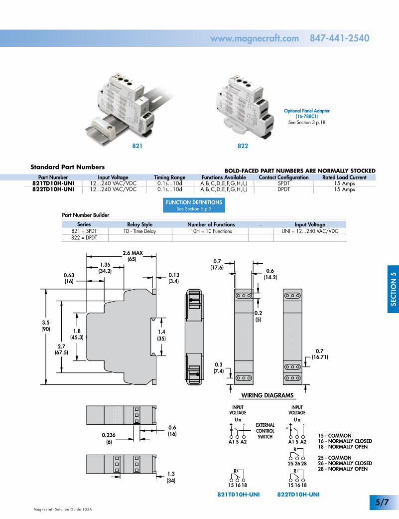
821TD10H-UNI 822TD10H-UNI
INPUTVOLTAGE
EXTERNALCONTROLSWITCH
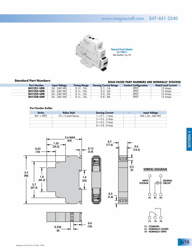
15 - COMMON16 - NORMALLY CLOSED18 - NORMALLY OPEN
26 - NORMALLY CLOSED28 - NORMALLY OPEN
25 - COMMON
INPUTVOLTAGE
WIRING DIAGRAMSR
1615 18
U
R
2825 26
+n
-
SA1 A2
R
1615 18
U+
n-
SA1 A2
821TD10H-UNI 822TD10H-UNI
INPUTVOLTAGE
EXTERNALCONTROLSWITCH
15 - COMMON16 - NORMALLY CLOSED18 - NORMALLY OPEN
26 - NORMALLY CLOSED28 - NORMALLY OPEN
25 - COMMON
INPUTVOLTAGE
Standard Part NumbersBOLD-FACED PART NUMBERS ARE NORMALLY STOCKED
Optional Panel Adapter(16-788C1)
See Section 3 p.18
Magnecraf t Solut ion Guide 105A
SEC
TIO
N 5
Magnecraf t Solut ion Guide 105AMagnecraf t Solut ion Guide 105A
www.magnecraft.com 847-441-2540
Input Voltage12...240 VAC/VDC12...240 VAC/VDC
Timing Range0.1s...10d0.1s...10d
Functions AvailableA,B,C,D,E,F,G,H,I,JA,B,C,D,E,F,G,H,I,J
Contact ConfigurationSPDTDPDT
Part Number821TD10H-UNI822TD10H-UNI
Series821 = SPDT822 = DPDT
Relay StyleTD - Time Delay
Input VoltageUNI = 12...240 VAC/VDC
Number of Functions10H = 10 Functions
Rated Load Current15 Amps15 Amps
–
FUNCTION DEFINITIONSSee Section 5 p.3
5/7
WHITEUL Listed
File No. E234203
WHITE
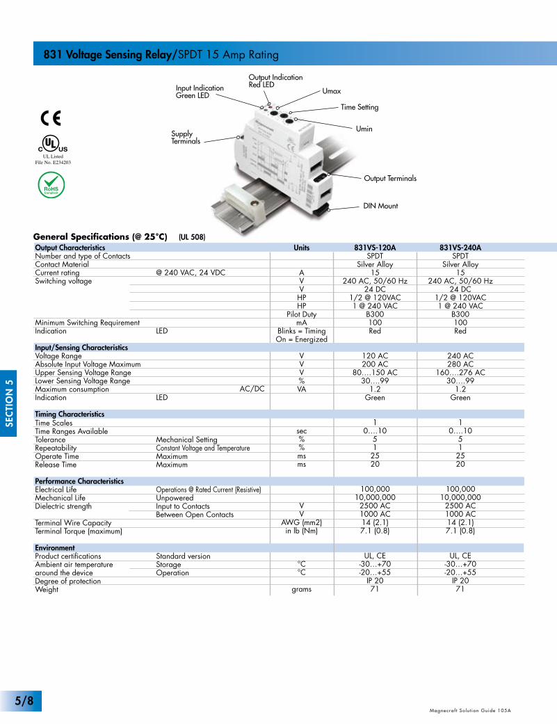
General Specifications (@ 25°C) (UL 508)
SEC
TIO
N 5
Magnecraf t Solut ion Guide 105A Magnecraf t Solut ion Guide 105AMagnecraf t Solut ion Guide 105A
831 Voltage Sensing Relay/SPDT 15 Amp Rating
Output IndicationRed LED
Output Terminals
Input IndicationGreen LED Umax
Time Setting
UminSupplyTerminals
DIN Mount
Units
AVVHPHP
Pilot DutymA
Blinks = TimingOn = Energized
VVV%VA
sec%%msms
VV
AWG (mm2)in lb (Nm)
°C°C
grams
831VS-120ASPDT
Silver Alloy15
240 AC, 50/60 Hz24 DC
1/2 @ 120VAC1 @ 240 VAC
B300100Red
120 AC200 AC
80….150 AC30….99
1.2Green
10….10
512520
100,00010,000,000
2500 AC1000 AC14 (2.1)7.1 (0.8)
UL, CE-30…+70-20…+55
IP 2071
Output CharacteristicsNumber and type of ContactsContact MaterialCurrent ratingSwitching voltage
Minimum Switching RequirementIndication
Input/Sensing CharacteristicsVoltage RangeAbsolute Input Voltage MaximumUpper Sensing Voltage RangeLower Sensing Voltage RangeMaximum consumptionIndication
Timing CharacteristicsTime ScalesTime Ranges AvailableToleranceRepeatabilityOperate TimeRelease Time
Performance CharacteristicsElectrical LifeMechanical LifeDielectric strength
Terminal Wire CapacityTerminal Torque (maximum)
EnvironmentProduct certificationsAmbient air temperaturearound the deviceDegree of protectionWeight
@ 240 VAC, 24 VDC
LED
LED
Mechanical SettingConstant Voltage and TemperatureMaximumMaximum
Operations @ Rated Current (Resistive)UnpoweredInput to ContactsBetween Open Contacts
Standard versionStorageOperation
831VS-240ASPDT
Silver Alloy15
240 AC, 50/60 Hz24 DC
1/2 @ 120VAC1 @ 240 VAC
B300100Red
240 AC280 AC
160….276 AC30….99
1.2Green
10….10
512520
100,00010,000,000
2500 AC1000 AC14 (2.1)7.1 (0.8)
UL, CE-30…+70-20…+55
IP 2071
AC/DC
5/8
(7.4)0.3
0.7(17.6) 0.6
(14.2)
(5)0.2
(65)
(16)
(45.3)1.8
0.63
(67.5)2.7
(90)3.5
1.4
2.6 MAX
(34.2)1.35
(3.4)0.13
(35)
0.6(16)0.236
(6)
Part Number Builder
1615 18
Un
+ –
A1 A2
INPUTVOLTAGE
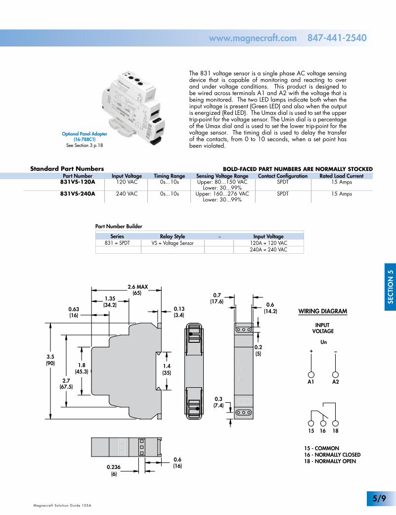
15 - COMMON16 - NORMALLY CLOSED18 - NORMALLY OPEN
Standard Part Numbers BOLD-FACED PART NUMBERS ARE NORMALLY STOCKED
Optional Panel Adapter(16-788C1)
See Section 3 p.18
Magnecraf t Solut ion Guide 105A
SEC
TIO
N 5
Magnecraf t Solut ion Guide 105AMagnecraf t Solut ion Guide 105A
www.magnecraft.com 847-441-2540
Input Voltage120 VAC
240 VAC
Timing Range0s...10s
0s...10s
Sensing Voltage RangeUpper: 80...150 VAC
Lower: 30...99%Upper: 160...276 VAC
Lower: 30...99%
Contact ConfigurationSPDT
SPDT
Part Number831VS-120A
831VS-240A
Rated Load Current15 Amps
15 Amps
Series831 = SPDT
Relay StyleVS = Voltage Sensor
Input Voltage120A = 120 VAC240A = 240 VAC
–
WIRING DIAGRAM
The 831 voltage sensor is a single phase AC voltage sensing device that is capable of monitoring and reacting to over and under voltage conditions. This product is designed to be wired across terminals A1 and A2 with the voltage that is being monitored. The two LED lamps indicate both when the input voltage is present (Green LED) and also when the output is energized (Red LED). The Umax dial is used to set the upper trip-point for the voltage sensor. The Umin dial is a percentage of the Umax dial and is used to set the lower trip-point for the voltage sensor. The timing dial is used to delay the transfer of the contacts, from 0 to 10 seconds, when a set point has been violated.
5/9
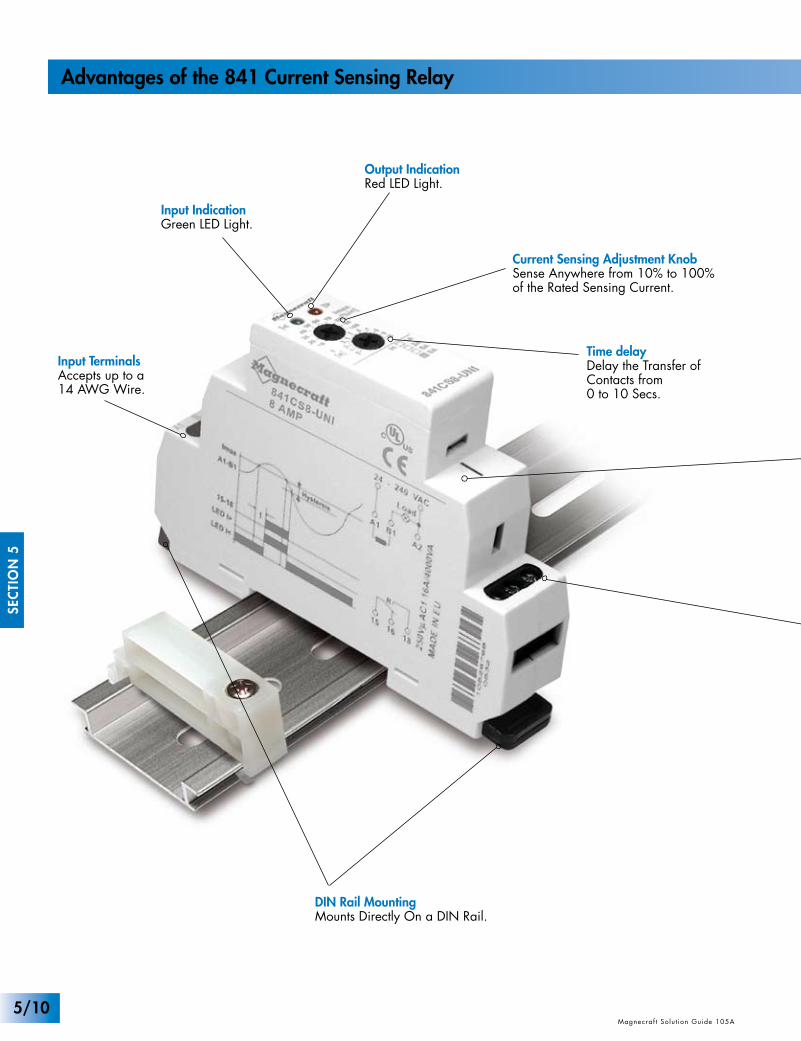
Input TerminalsAccepts up to a14 AWG Wire.
Output IndicationRed LED Light.
Solid State CircuitryUsed for Sensing and Timing Control.
Output TerminalsAccepts up to a 14 AWG wire.
DIN Rail MountingMounts Directly On a DIN Rail.
Input IndicationGreen LED Light.
Current Sensing Adjustment KnobSense Anywhere from 10% to 100%of the Rated Sensing Current.
Time delayDelay the Transfer ofContacts from0 to 10 Secs.
SEC
TIO
N 5
Magnecraf t Solut ion Guide 105A Magnecraf t Solut ion Guide 105A
Advantages of the 841 Current Sensing Relay
5/10
Input TerminalsAccepts up to a14 AWG Wire.
Output IndicationRed LED Light.
Solid State CircuitryUsed for Sensing and Timing Control.
Output TerminalsAccepts up to a 14 AWG wire.
DIN Rail MountingMounts Directly On a DIN Rail.
Input IndicationGreen LED Light.
Current Sensing Adjustment KnobSense Anywhere from 10% to 100%of the Rated Sensing Current.
Time delayDelay the Transfer ofContacts from0 to 10 Secs.
www.magnecraft.com 847-441-2540
Optional Panel Adapter(16-788C1)
See Section 3 p.18
Magnecraf t Solut ion Guide 105A
SEC
TIO
N 5
Magnecraf t Solut ion Guide 105A
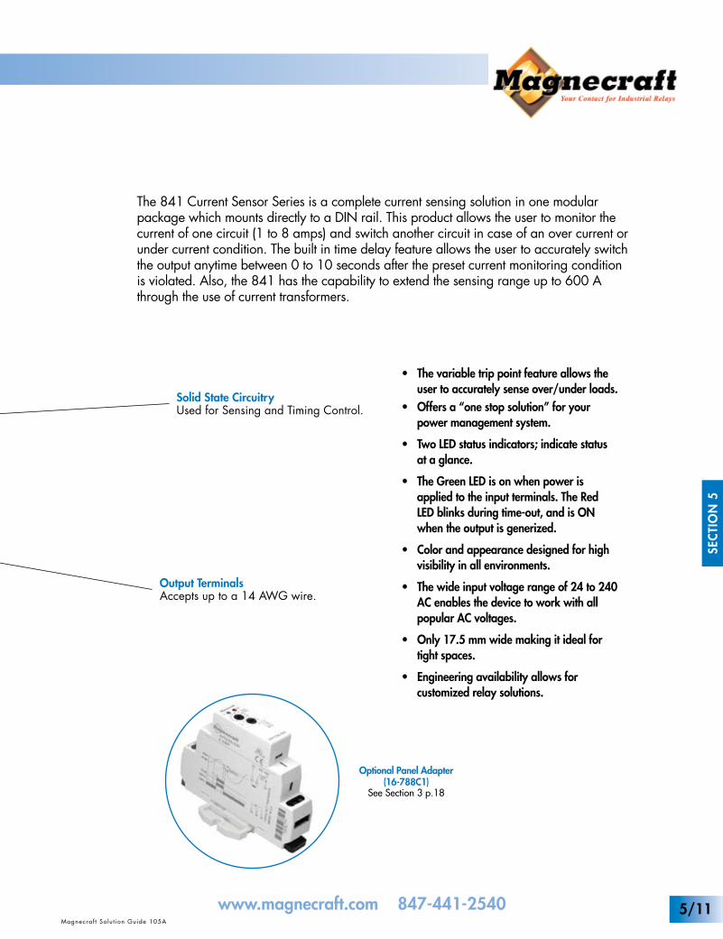
The 841 Current Sensor Series is a complete current sensing solution in one modular package which mounts directly to a DIN rail. This product allows the user to monitor the current of one circuit (1 to 8 amps) and switch another circuit in case of an over current or under current condition. The built in time delay feature allows the user to accurately switch the output anytime between 0 to 10 seconds after the preset current monitoring condition is violated. Also, the 841 has the capability to extend the sensing range up to 600 A through the use of current transformers.
• The variable trip point feature allows the user to accurately sense over/under loads.• Offers a “one stop solution” for your power management system.
• Two LED status indicators; indicate status at a glance.
• The Green LED is on when power is applied to the input terminals. The Red LED blinks during time-out, and is ON when the output is generized.
• Color and appearance designed for high visibility in all environments.
• The wide input voltage range of 24 to 240 AC enables the device to work with all popular AC voltages.
• Only 17.5 mm wide making it ideal for tight spaces.
• Engineering availability allows for customized relay solutions.
5/11
Time Delay
Current SensingAdjustment Knob
Output Terminals
DIN Rail Mounting
WHITEUL Listed
File No. E234203
WHITE
Output IndicationRed LEDInput Indication
Green LED
SupplyTerminals
General Specifications (@ 25°C) (UL 508)
SEC
TIO
N 5
Magnecraf t Solut ion Guide 105A Magnecraf t Solut ion Guide 105AMagnecraf t Solut ion Guide 105A
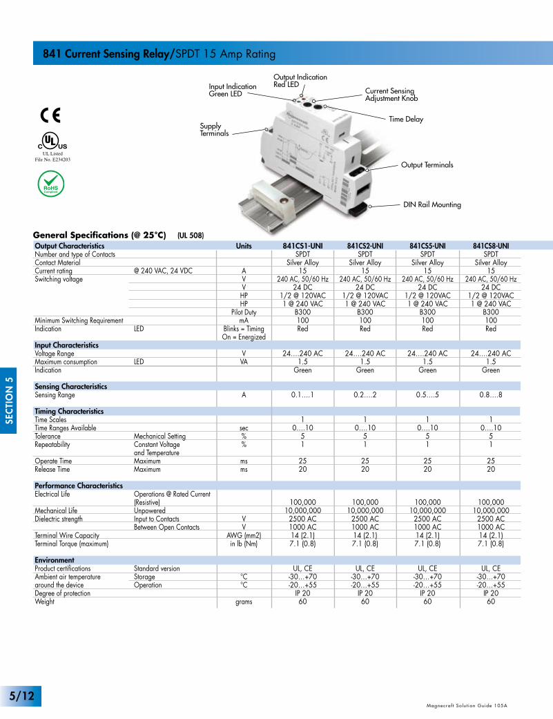
841 Current Sensing Relay/SPDT 15 Amp Rating
Units
AVVHPHP
Pilot DutymA
Blinks = TimingOn = Energized
VVA
A
sec%%
msms
VV
AWG (mm2)in lb (Nm)
°C°C
grams
841CS1-UNISPDT
Silver Alloy15
240 AC, 50/60 Hz24 DC
1/2 @ 120VAC1 @ 240 VAC
B300100Red
24….240 AC1.5
Green
0.1….1
10….10
51
2520
100,00010,000,000
2500 AC1000 AC14 (2.1)7.1 (0.8)
UL, CE-30…+70-20…+55
IP 2060
Output CharacteristicsNumber and type of ContactsContact MaterialCurrent ratingSwitching voltage
Minimum Switching RequirementIndication
Input CharacteristicsVoltage RangeMaximum consumptionIndication
Sensing CharacteristicsSensing Range
Timing CharacteristicsTime ScalesTime Ranges AvailableToleranceRepeatability
Operate TimeRelease Time
Performance CharacteristicsElectrical Life
Mechanical LifeDielectric strength
Terminal Wire CapacityTerminal Torque (maximum)
EnvironmentProduct certificationsAmbient air temperaturearound the deviceDegree of protectionWeight
@ 240 VAC, 24 VDC
LED
LED
Mechanical SettingConstant Voltageand TemperatureMaximumMaximum
Operations @ Rated Current (Resistive)UnpoweredInput to ContactsBetween Open Contacts
Standard versionStorageOperation
841CS2-UNISPDT
Silver Alloy15
240 AC, 50/60 Hz24 DC
1/2 @ 120VAC1 @ 240 VAC
B300100Red
24….240 AC1.5
Green
0.2….2
10….10
51
2520
100,00010,000,000
2500 AC1000 AC14 (2.1)7.1 (0.8)
UL, CE-30…+70-20…+55
IP 2060
841CS5-UNISPDT
Silver Alloy15
240 AC, 50/60 Hz24 DC
1/2 @ 120VAC1 @ 240 VAC
B300100Red
24….240 AC1.5
Green
0.5….5
10….10
51
2520
100,00010,000,000
2500 AC1000 AC14 (2.1)7.1 (0.8)
UL, CE-30…+70-20…+55
IP 2060
841CS8-UNISPDT
Silver Alloy15
240 AC, 50/60 Hz24 DC
1/2 @ 120VAC1 @ 240 VAC
B300100Red
24….240 AC1.5
Green
0.8….8
10….10
51
2520
100,00010,000,000
2500 AC1000 AC14 (2.1)7.1 (0.8)
UL, CE-30…+70-20…+55
IP 2060
5/12
A1 A2
INPUTVOLTAGE
B1
SENSINGCIRCUIT
1615 18
15 - COMMON16 - NORMALLY CLOSED18 - NORMALLY OPEN
Part Number Builder
(7.4)0.3
0.7(17.6) 0.6
(14.2)
(5)0.2
(65)
(16)
(45.3)1.8
0.63
(67.5)2.7
(90)3.5
1.4
2.6 MAX
(34.2)1.35
(3.4)0.13
(35)
0.6(16)0.236
(6)
Standard Part Numbers BOLD-FACED PART NUMBERS ARE NORMALLY STOCKED
Optional Panel Adapter(16-788C1)
See Section 3 p.18
Magnecraf t Solut ion Guide 105A
SEC
TIO
N 5
Magnecraf t Solut ion Guide 105AMagnecraf t Solut ion Guide 105A
www.magnecraft.com 847-441-2540
Input Voltage24...240 VAC24...240 VAC24...240 VAC24...240 VAC
Timing Range0.1s...10s0.1s...10s0.1s...10s0.1s...10s
Sensing Current Range0.1...1A0.2...2A0.5...5A0.8...8A
Contact ConfigurationSPDTSPDTSPDTSPDT
Part Number841CS1-UNI841CS2-UNI841CS5-UNI841CS8-UNI
Rated Load Current15 Amps15 Amps15 Amps15 Amps
Series841 = SPDT
Relay StyleCS = Current Sensor
Input VoltageUNI = 24...240 VAC
Sensing Current1 = 0.1...1 Amp2 = 0.2...2 Amp5 = 0.5...5 Amp8 = 0.8...8 Amp
–
WIRING DIAGRAM
5/13
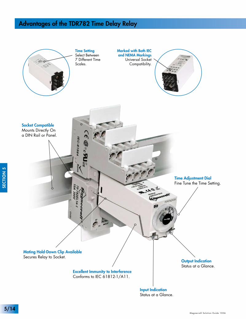
Input IndicationStatus at a Glance.
Output IndicationStatus at a Glance.
Socket CompatibleMounts Directly Ona DIN Rail or Panel.
Time Adjustment DialFine Tune the Time Setting.
Excellent Immunity to InterferenceConforms to IEC 61812-1/A11.
Mating Hold-Down Clip AvailableSecures Relay to Socket.
5/14
SEC
TIO
N 5
Magnecraf t Solut ion Guide 105A Magnecraf t Solut ion Guide 105A
Advantages of the TDR782 Time Delay Relay
Time SettingSelect Between 7 Different Time Scales.
Marked with Both IEC and NEMA Markings
Universal Socket Compatibility.

The Complete System
Solution!
The miniature TDR782 series is a single-function, single-voltage time delay relay with multiple time ranges for the ultimate in packaging the most within the smallest space possible in a panel or on the DIN rail. The TDR782 features a screw driver adjust-able knob which allows the user to choose 1 of 7 timing ranges and a large knob on top for fine tuning the timing setting. This dual adjustment design allows for supreme flexibility and timing accuracy. The dual LEDs allow the user to know when power is present at the coil and when the output is energized. When mat-ed with the Magnecraft sockets and accessories, these ROHS compliant timers provide a complete modular system that will meet all your control relay requirements in a package that is both visually appealing and functionally outstanding.
• Offers a “one stop solution” for your power management system.• Available as a DPDT and 4PDT to meet your individual needs.• Switching capabilities of either 3 or 5 amps.• The two LED status indicators; indicate status at a glance. • Color and appearance designed to high visibility in all environments.• Engineering availability allows for customized control system solutions.
www.magnecraft.com 847-441-2540 5/15Magnecraf t Solut ion Guide 105A
SEC
TIO
N 5
Magnecraf t Solut ion Guide 105A
WHITEUL Recognized
File No. E191122
General Specifications (@ 25°C) (UL 508)
SEC
TIO
N 5
Magnecraf t Solut ion Guide 105A Magnecraf t Solut ion Guide 105AMagnecraf t Solut ion Guide 105A
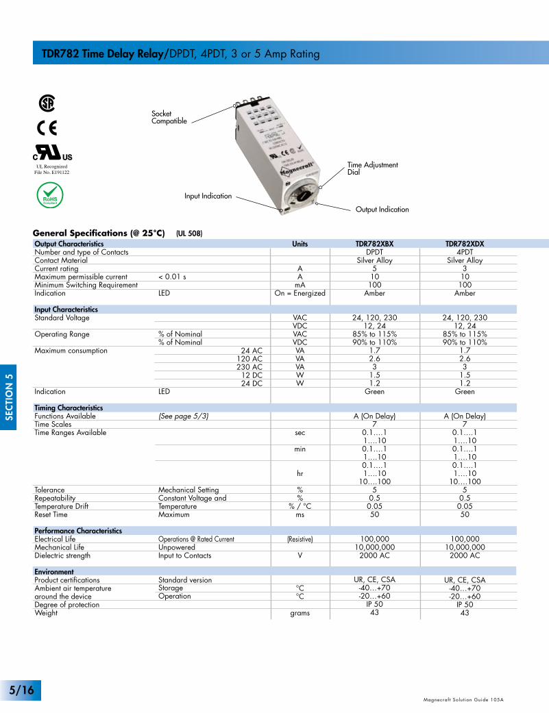
TDR782 Time Delay Relay/DPDT, 4PDT, 3 or 5 Amp Rating
Time AdjustmentDial
SocketCompatible
Output Indication
Input Indication
Units
AA
mAOn = Energized
VACVDCVACVDCVAVAVAWW
sec
min
hr
%%
% / °Cms
(Resistive)
V
°C°C
grams
TDR782XBXDPDT
Silver Alloy510100
Amber
24, 120, 23012, 24
85% to 115%90% to 110%
1.72.63
1.51.2
Green
A (On Delay)7
0.1….11….100.1….11….100.1….11….10
10….1005
0.50.0550
100,00010,000,000
2000 AC
UR, CE, CSA-40…+70-20…+60
IP 5043
Output CharacteristicsNumber and type of ContactsContact MaterialCurrent ratingMaximum permissible current Minimum Switching RequirementIndication
Input CharacteristicsStandard Voltage
Operating Range
Maximum consumption
Indication
Timing CharacteristicsFunctions AvailableTime ScalesTime Ranges Available
ToleranceRepeatabilityTemperature DriftReset Time
Performance CharacteristicsElectrical LifeMechanical LifeDielectric strength
EnvironmentProduct certificationsAmbient air temperaturearound the deviceDegree of protectionWeight
< 0.01 s
LED
% of Nominal% of Nominal
LED
(See page 5/3)
Mechanical SettingConstant Voltage and TemperatureMaximum
Operations @ Rated CurrentUnpoweredInput to Contacts
Standard versionStorageOperation
TDR782XDX4PDT
Silver Alloy310100
Amber
24, 120, 23012, 24
85% to 115%90% to 110%
1.72.63
1.51.2
Green
A (On Delay)7
0.1….11….100.1….11….100.1….11….10
10….1005
0.50.0550
100,00010,000,000
2000 AC
UR, CE, CSA-40…+70-20…+60
IP 5043
24 AC120 AC230 AC
12 DC24 DC
5/16
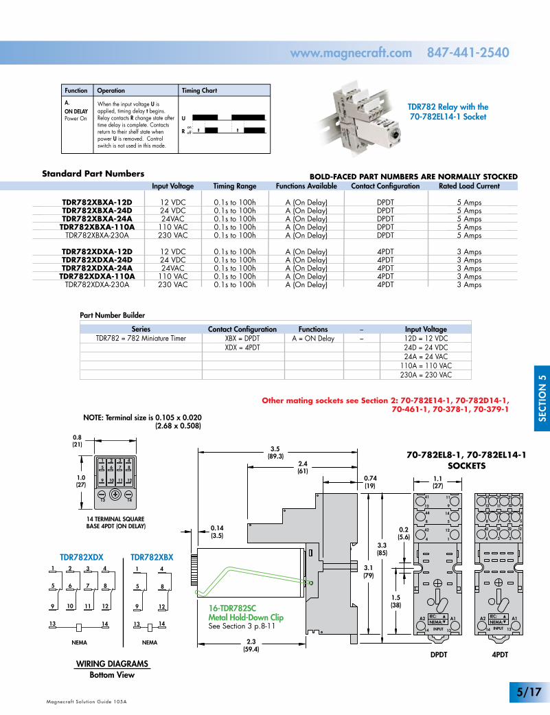
Standard Part Numbers
Part Number Builder
129
13 14
1
5 8
4
129 10 11
13 14
1
5 86 7
42 3
321
4 5
1098
76
14 TERMINAL SQUARE BASE 4PDT (ON DELAY)
8 TERMINAL SQUARE BASE DPDT (ON DELAY)
Un R
0.8(21)
1.0(27)
Other mating sockets see Section 2: 70-782E14-1, 70-782D14-1, 70-461-1, 70-378-1, 70-379-1
(38)1.5
(5.6)0.2
1.1(27)
3.1(79)
(85)3.3
(61)2.4
0.74(19)
(89.3)3.5
A1
INPUT
A2
14 13
12
5
9
11
14
4 1
8
12
42
41
44
0.14 (3.5)
2.3 (59.4)
1
A1
12
5
9
11
14
INPUT
A2
14
34
78
1112
3242
41 31
3444
13
2
6
10
22
21
24
NEMA:IEC:
NEMA:IEC:
1.1(27.9)
.83(21)
1.1(27.9)
.83(21)
1.54(39.1)
2.6(6.5)
.02(0.5)
13
5
9
1
14
6
10
2
87
11 12
3 4
85
13
9
14
12
1 4
865
13
9
14
10 12
1 2 4
1.4(35.5).24
(6.0).24(6.0)
NEMA NEMA NEMA
1.1(27.9)
.83(21)
1.1(27.9)
.83(21)
1.54(39.1)
2.6(6.5)
.02(0.5)
13
5
9
1
14
6
10
2
87
11 12
3 4
85
13
9
14
12
1 4
865
13
9
14
10 12
1 2 4
1.4(35.5).24
(6.0).24(6.0)
NEMA NEMA NEMA
Function
A.ON DELAYPower On
Operation Timing Chart
When the input voltage U is applied, timing delay t begins. Relay contacts R change state after time delay is complete. Contacts return to their shelf state when power U is removed. Control switch is not used in this mode.
t
U
R tonoff
16-TDR782SCMetal Hold-Down ClipSee Section 3 p.8-11
Magnecraf t Solut ion Guide 105A
SEC
TIO
N 5
Magnecraf t Solut ion Guide 105AMagnecraf t Solut ion Guide 105A
www.magnecraft.com 847-441-2540
Input Voltage
12 VDC24 VDC24VAC
110 VAC230 VAC
12 VDC24 VDC24VAC
110 VAC230 VAC
Timing Range
0.1s to 100h0.1s to 100h0.1s to 100h0.1s to 100h0.1s to 100h
0.1s to 100h0.1s to 100h0.1s to 100h0.1s to 100h0.1s to 100h
Functions Available
A (On Delay)A (On Delay)A (On Delay)A (On Delay)A (On Delay)
A (On Delay)A (On Delay)A (On Delay)A (On Delay)A (On Delay)
Contact Configuration
DPDTDPDTDPDTDPDTDPDT
4PDT4PDT4PDT4PDT4PDT
TDR782XBXA-12DTDR782XBXA-24DTDR782XBXA-24A
TDR782XBXA-110ATDR782XBXA-230A
TDR782XDXA-12DTDR782XDXA-24DTDR782XDXA-24A
TDR782XDXA-110ATDR782XDXA-230A
Rated Load Current
5 Amps5 Amps5 Amps5 Amps5 Amps
3 Amps3 Amps3 Amps3 Amps3 Amps
SeriesTDR782 = 782 Miniature Timer
Contact ConfigurationXBX = DPDTXDX = 4PDT
Input Voltage12D = 12 VDC24D = 24 VDC24A = 24 VAC
110A = 110 VAC230A = 230 VAC
FunctionsA = ON Delay
––
NOTE: Terminal size is 0.105 x 0.020 (2.68 x 0.508)
DPDT 4PDT
70-782EL8-1, 70-782EL14-1SOCKETS
TDR782XDX TDR782XBX
WIRING DIAGRAMSBottom View
TDR782 Relay with the 70-782EL14-1 Socket
BOLD-FACED PART NUMBERS ARE NORMALLY STOCKED
5/17
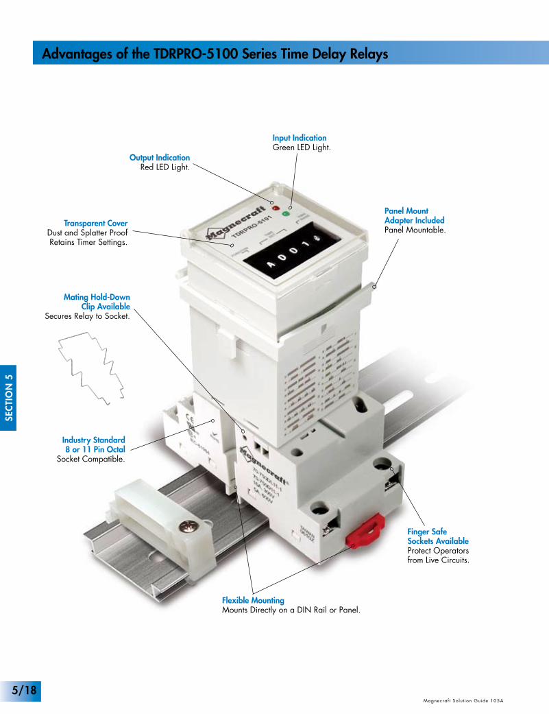
Transparent CoverDust and Splatter ProofRetains Timer Settings.
Output IndicationRed LED Light.
Panel Mount Adapter IncludedPanel Mountable.
Finger Safe Sockets AvailableProtect Operators from Live Circuits.
Flexible MountingMounts Directly on a DIN Rail or Panel.
Input IndicationGreen LED Light.
Industry Standard8 or 11 Pin Octal
Socket Compatible.
Mating Hold-DownClip Available
Secures Relay to Socket.
SEC
TIO
N 5
Magnecraf t Solut ion Guide 105A Magnecraf t Solut ion Guide 105A
Advantages of the TDRPRO-5100 Series Time Delay Relays
5/18
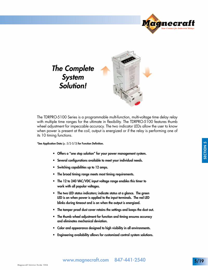
The Complete System
Solution!
The TDRPRO-5100 Series is a programmable multi-function, multi-voltage time delay relay with multiple time ranges for the ultimate in flexibility. The TDRPRO-5100 features thumb wheel adjustment for impeccable accuracy. The two indicator LEDs allow the user to know when power is present at the coil, output is energized or if the relay is performing one of its 10 timing functions.
*See Application Data (p. 5/2-5/3) for Function Definition.
• Offers a “one stop solution” for your power management system.
• Several configurations available to meet your individual needs.
• Switching capabilities up to 12 amps.
• The broad timing range meets most timing requirements.
• The 12 to 240 VAC/VDC input voltage range enables this timer to work with all popular voltages.
• The two LED status indicators; indicate status at a glance. The green LED is on when power is applied to the input terminals. The red LED blinks during timeout and is on when the output is energized.
• The tamper proof dust cover retains the settings and keeps the dust out.
• The thumb wheel adjustment for function and timing ensures accuracy and eliminates mechanical deviation.
• Color and appearance designed to high visibility in all environments.
• Engineering availability allows for customized control system solutions.
www.magnecraft.com 847-441-2540Magnecraf t Solut ion Guide 105A
SEC
TIO
N 5
Magnecraf t Solut ion Guide 105A
5/19
INPUT
3
2
1
6
7
8
4 5
INPUT
2
1
4
3
7
8
5
6
EXTERNALCONTROLSWITCH
32
1
4
910
11
8
65 7
EXTERNALCONTROLSWITCH
INPUT
OFF DELAY ON DELAY
WIRING DIAGRAMS
Output IndicationRed LED
Input IndicationGreen LED
Panel Mount Adapter Included
UL RecognizedFile No. E43641
General Specifications (@ 25°C) (UL 508)
WHITE
SEC
TIO
N 5
Magnecraf t Solut ion Guide 105A Magnecraf t Solut ion Guide 105AMagnecraf t Solut ion Guide 105A
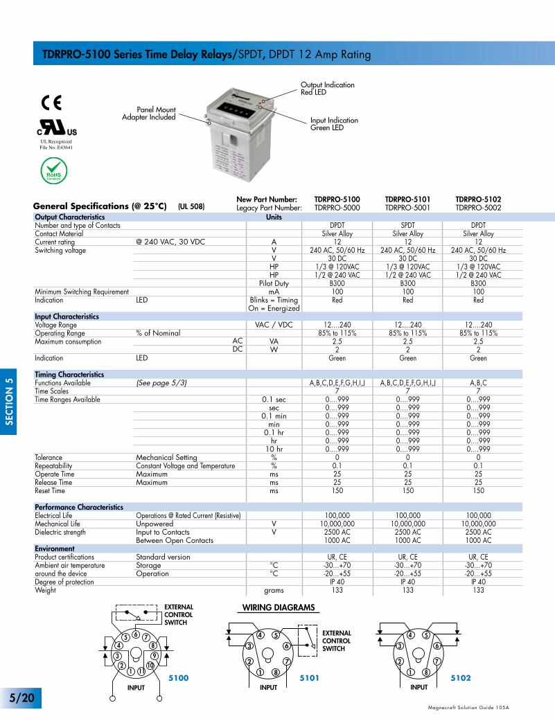
TDRPRO-5100 Series Time Delay Relays/SPDT, DPDT 12 Amp Rating
New Part Number:Legacy Part Number:
Units
AVVHPHP
Pilot DutymA
Blinks = TimingOn = Energized
VAC / VDC
VAW
0.1 secsec
0.1 minmin
0.1 hrhr
10 hr%%msmsms
VV
°C°C
grams
TDRPRO-5100TDRPRO-5000
DPDTSilver Alloy
12240 AC, 50/60 Hz
30 DC1/3 @ 120VAC1/2 @ 240 VAC
B300100Red
12….24085% to 115%
2.52
Green
A,B,C,D,E,F,G,H,I,J7
0….9990….9990….9990….9990….9990….9990….999
00.12525150
100,00010,000,000
2500 AC1000 AC
UR, CE-30…+70-20…+55
IP 40133
Output CharacteristicsNumber and type of ContactsContact MaterialCurrent ratingSwitching voltage
Minimum Switching RequirementIndication
Input CharacteristicsVoltage RangeOperating Range Maximum consumption
Indication
Timing CharacteristicsFunctions AvailableTime ScalesTime Ranges Available
ToleranceRepeatabilityOperate TimeRelease TimeReset Time
Performance CharacteristicsElectrical LifeMechanical LifeDielectric strength
EnvironmentProduct certificationsAmbient air temperaturearound the deviceDegree of protectionWeight
@ 240 VAC, 30 VDC
LED
% of Nominal
LED
(See page 5/3)
Mechanical SettingConstant Voltage and TemperatureMaximumMaximum
Operations @ Rated Current (Resistive)UnpoweredInput to ContactsBetween Open Contacts
Standard versionStorageOperation
ACDC
TDRPRO-5101TDRPRO-5001
SPDTSilver Alloy
12240 AC, 50/60 Hz
30 DC1/3 @ 120VAC1/2 @ 240 VAC
B300100Red
12….24085% to 115%
2.52
Green
A,B,C,D,E,F,G,H,I,J7
0….9990….9990….9990….9990….9990….9990….999
00.12525150
100,00010,000,000
2500 AC1000 AC
UR, CE-30…+70-20…+55
IP 40133
TDRPRO-5102TDRPRO-5002
DPDTSilver Alloy
12240 AC, 50/60 Hz
30 DC1/3 @ 120VAC1/2 @ 240 VAC
B300100Red
12….24085% to 115%
2.52
Green
A,B,C7
0….9990….9990….9990….9990….9990….9990….999
00.12525
150
100,00010,000,000
2500 AC1000 AC
UR, CE-30…+70-20…+55
IP 40133
51015100 5102
5/20
(109.2)4.3
(36)1.4
(5.1)0.2
1.1(28)
11
41
12
14
3
A2
7
5
22
2124
6 8
A1
2
(72)2.9
(37)1.45
INPUTINPUT
(76)3.0
(40)1.6
(30)1.2
NEMA:IEC:
(48)1.9
(48)1.9
(6)0.23
0.06(1.52)
(72)2.8
(6.35)0.25
(38)1.5
(81)3.18
(40)1.6
(34.2)1.35
11
4
1
12
14
3
A2
10
5
22
21
24
6
7
A1
2INPUTINPUT
34
9
3111
32
8
NEMA:IEC:
Part Number Builder
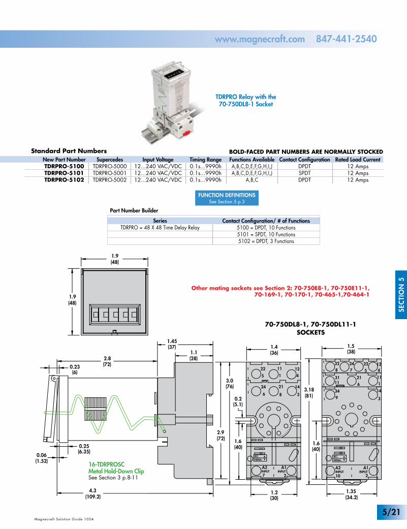
Standard Part Numbers
Other mating sockets see Section 2: 70-750E8-1, 70-750E11-1, 70-169-1, 70-170-1, 70-465-1,70-464-1
70-750DL8-1, 70-750DL11-1SOCKETS
BOLD-FACED PART NUMBERS ARE NORMALLY STOCKED
Magnecraf t Solut ion Guide 105A
SEC
TIO
N 5
Magnecraf t Solut ion Guide 105AMagnecraf t Solut ion Guide 105A
www.magnecraft.com 847-441-2540
Input Voltage12...240 VAC/VDC12...240 VAC/VDC12...240 VAC/VDC
Timing Range0.1s...9990h0.1s...9990h0.1s...9990h
Functions AvailableA,B,C,D,E,F,G,H,I,JA,B,C,D,E,F,G,H,I,J
A,B,C
Contact ConfigurationDPDTSPDTDPDT
New Part NumberTDRPRO-5100TDRPRO-5101TDRPRO-5102
Rated Load Current12 Amps12 Amps12 Amps
SupercedesTDRPRO-5000TDRPRO-5001TDRPRO-5002
SeriesTDRPRO = 48 X 48 Time Delay Relay
Contact Configuration/ # of Functions5100 = DPDT, 10 Functions5101 = SPDT, 10 Functions5102 = DPDT, 3 Functions
TDRPRO Relay with the 70-750DL8-1 Socket
16-TDRPROSCMetal Hold-Down ClipSee Section 3 p.8-11
FUNCTION DEFINITIONSSee Section 5 p.3
5/21
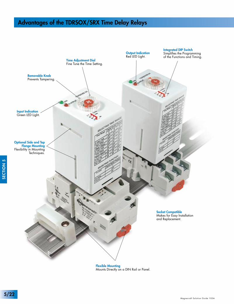
Optional Side and TopFlange Mounting
Flexibility in MountingTechniques.
Output IndicationRed LED Light.
Time Adjustment DialFine Tune the Time Setting.
Socket CompatibleMakes for Easy Installationand Replacement.
Flexible MountingMounts Directly on a DIN Rail or Panel.
Input IndicationGreen LED Light.
Integrated DIP SwitchSimplifies the Programmingof the Functions and Timing.
Removable KnobPrevents Tampering.
SEC
TIO
N 5
Magnecraf t Solut ion Guide 105A Magnecraf t Solut ion Guide 105A
Advantages of the TDRSOX/SRX Time Delay Relays
5/22
www.magnecraft.com 847-441-2540Magnecraf t Solut ion Guide 105A
SEC
TIO
N 5
Magnecraf t Solut ion Guide 105A
The Complete System
Solution!
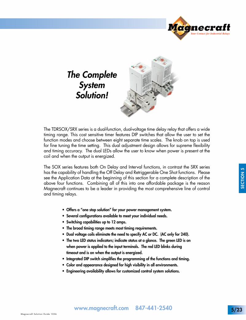
The TDRSOX/SRX series is a dual-function, dual-voltage time delay relay that offers a wide timing range. This cost sensitive timer features DIP switches that allow the user to set the function modes and choose between eight separate time scales. The knob on top is used for fine tuning the time setting. This dual adjustment design allows for supreme flexibility and timing accuracy. The dual LEDs allow the user to know when power is present at the coil and when the output is energized.
The SOX series features both On Delay and Interval functions, in contrast the SRX series has the capability of handling the Off Delay and Retriggerable One Shot functions. Please see the Application Data at the beginning of this section for a complete description of the above four functions. Combining all of this into one affordable package is the reason Magnecraft continues to be a leader in providing the most comprehensive line of control and timing relays.
• Offers a “one stop solution” for your power management system.• Several configurations available to meet your individual needs.• Switching capabilities up to 12 amps.• The broad timing range meets most timing requirements.• Dual voltage coils eliminate the need to specify AC or DC. (AC only for 240).• The two LED status indicators; indicate status at a glance. The green LED is on when power is applied to the input terminals. The red LED blinks during timeout and is on when the output is energized.• Integrated DIP switch simplifies the programming of the functions and timing.• Color and appearance designed for high visibility in all environments.• Engineering availability allows for customized control system solutions.
5/23
General Specifications (@ 25°C) (UL 508)
UL Listed When Used With Magnecraft Sockets.
UL USC
UL RecognizedFile No. E43641
SEC
TIO
N 5
Magnecraf t Solut ion Guide 105A Magnecraf t Solut ion Guide 105AMagnecraf t Solut ion Guide 105A
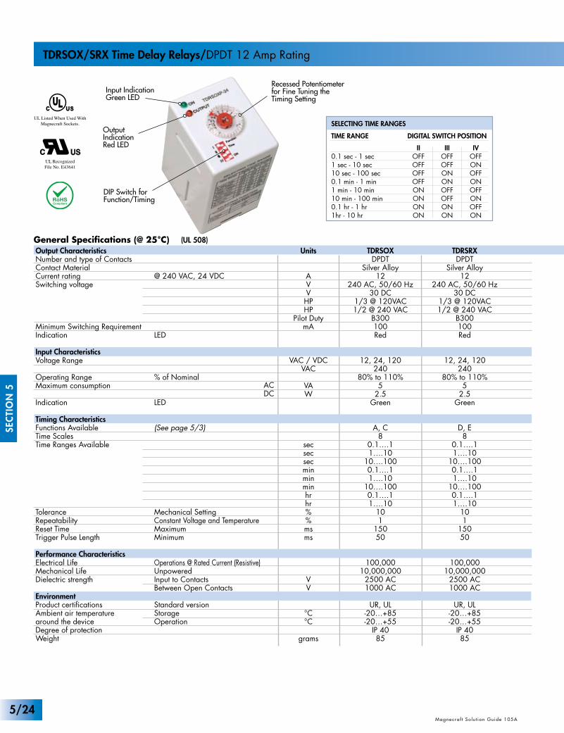
TDRSOX/SRX Time Delay Relays/DPDT 12 Amp Rating
Output IndicationRed LED
Input IndicationGreen LED
Recessed Potentiometerfor Fine Tuning theTiming Setting
DIP Switch for Function/Timing
Units
AVVHPHP
Pilot DutymA
VAC / VDCVAC
VAW
secsecsecminminminhrhr%%msms
VV
°C°C
grams
TDRSOXDPDT
Silver Alloy12
240 AC, 50/60 Hz30 DC
1/3 @ 120VAC1/2 @ 240 VAC
B300100Red
12, 24, 120240
80% to 110%5
2.5Green
A, C8
0.1….11….10
10….1000.1….11….10
10….1000.1….11….10
101
15050
100,00010,000,000
2500 AC1000 AC
UR, UL-20…+85-20…+55
IP 4085
Output CharacteristicsNumber and type of ContactsContact MaterialCurrent ratingSwitching voltage
Minimum Switching RequirementIndication
Input CharacteristicsVoltage Range
Operating Range Maximum consumption
Indication
Timing CharacteristicsFunctions AvailableTime ScalesTime Ranges Available
ToleranceRepeatabilityReset TimeTrigger Pulse Length
Performance CharacteristicsElectrical LifeMechanical LifeDielectric strength
EnvironmentProduct certificationsAmbient air temperaturearound the deviceDegree of protectionWeight
@ 240 VAC, 24 VDC
LED
% of Nominal
LED
(See page 5/3)
Mechanical SettingConstant Voltage and TemperatureMaximumMinimum
Operations @ Rated Current (Resistive)UnpoweredInput to ContactsBetween Open Contacts
Standard versionStorageOperation
ACDC
TDRSRXDPDT
Silver Alloy12
240 AC, 50/60 Hz30 DC
1/3 @ 120VAC1/2 @ 240 VAC
B300100Red
12, 24, 120240
80% to 110%5
2.5Green
D, E8
0.1….11….10
10….1000.1….11….10
10….1000.1….11….10
101
15050
100,00010,000,000
2500 AC1000 AC
UR, UL-20…+85-20…+55
IP 4085
0.1 sec - 1 sec1 sec - 10 sec10 sec - 100 sec0.1 min - 1 min1 min - 10 min10 min - 100 min0.1 hr - 1 hr1hr - 10 hr
SELECTING TIME RANGES
TIME RANGE DIGITAL SWITCH POSITION
IIOFFOFFOFFOFFONONONON
IIIOFFOFFONONOFFOFFONON
IVOFFONOFFONOFFONOFFON
5/24
Part Number Builder
Standard Part Numbers
ON DELAY
1 12 22
14 24
12 22
14
32
34 24
11 21 11 21
3
4 6
97
A B
OFF DELAY
EXTERNAL CONTROL SWITCH
1 2 3
4 5 6
7 9
A1 A2A BA1 A2
IECNEMA
IECNEMA
ON DELAY
1 12 22
14 24
12 22
14
32
34 24
11 21 11 21
3
4 6
97
A B
OFF DELAY
EXTERNAL CONTROL SWITCH
1 2 3
4 5 6
7 9
A1 A2A BA1 A2
IECNEMA
IECNEMA
WIRING DIAGRAMS
INPUT
3
2
1
6
7
8
4 5
INPUT
2
1
4
3
7
8
5
6
EXTERNALCONTROLSWITCH
32
1
4
910
11
8
65 7
EXTERNALCONTROLSWITCH
INPUT
OFF DELAY ON DELAY
INPUT
3
2
1
6
7
8
4 5
INPUT
2
1
4
3
7
8
5
6
EXTERNALCONTROLSWITCH
32
1
4
910
11
8
65 7
EXTERNALCONTROLSWITCH
INPUT
OFF DELAY ON DELAY
BOLD-FACED PART NUMBERS ARE NORMALLY STOCKED
FUNCTION DEFINITIONSSee Section 5 p.3
Magnecraf t Solut ion Guide 105A
SEC
TIO
N 5
Magnecraf t Solut ion Guide 105AMagnecraf t Solut ion Guide 105A
www.magnecraft.com 847-441-2540
Input Voltage
12 VAC/VDC24 VAC/VDC120 VAC/VDC
240 VAC
12 VAC/VDC24 VAC/VDC120 VAC/VDC
240 VAC
12 VAC/VDC24 VAC/VDC120 VAC/VDC
240 VAC
12 VAC/VDC24 VAC/VDC120 VAC/VDC
240 VAC
Timing Range
0.1s...10h0.1s...10h0.1s...10h0.1s...10h
0.1s...10h0.1s...10h0.1s...10h0.1s...10h
0.1s...10h0.1s...10h0.1s...10h0.1s...10h
0.1s...10h0.1s...10h0.1s...10h0.1s...10h
Contact Configuration
DPDTDPDTDPDTDPDT
DPDTDPDTDPDTDPDT
DPDTDPDTDPDTDPDT
DPDTDPDTDPDTDPDT
Rated Load Current
12 Amps12 Amps12 Amps12 Amps
12 Amps12 Amps12 Amps12 Amps
12 Amps12 Amps12 Amps12 Amps
12 Amps12 Amps12 Amps12 Amps
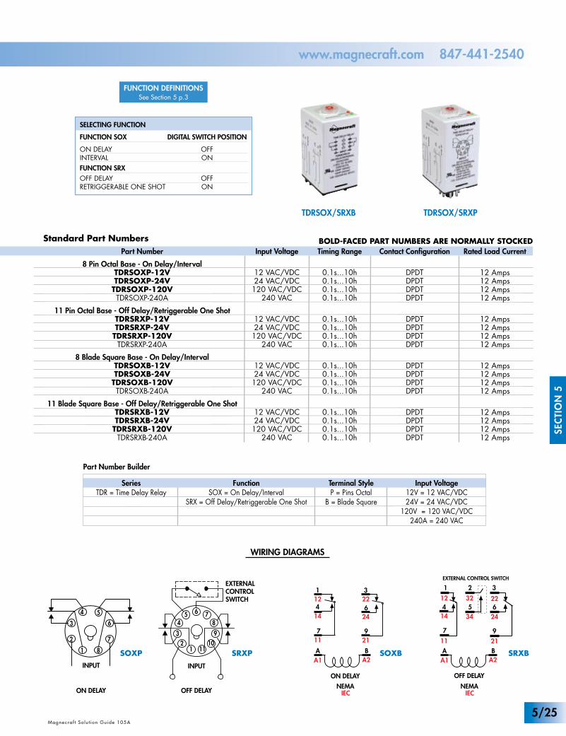
Part Number
8 Pin Octal Base - On Delay/IntervalTDRSOXP-12VTDRSOXP-24V
TDRSOXP-120VTDRSOXP-240A
11 Pin Octal Base - Off Delay/Retriggerable One ShotTDRSRXP-12VTDRSRXP-24V
TDRSRXP-120VTDRSRXP-240A
8 Blade Square Base - On Delay/IntervalTDRSOXB-12VTDRSOXB-24V
TDRSOXB-120VTDRSOXB-240A
11 Blade Square Base - Off Delay/Retriggerable One ShotTDRSRXB-12VTDRSRXB-24V
TDRSRXB-120VTDRSRXB-240A
SeriesTDR = Time Delay Relay
FunctionSOX = On Delay/Interval
SRX = Off Delay/Retriggerable One Shot
Input Voltage12V = 12 VAC/VDC24V = 24 VAC/VDC
120V = 120 VAC/VDC240A = 240 VAC
Terminal StyleP = Pins Octal
B = Blade Square
SELECTING FUNCTION
FUNCTION SOX
ON DELAYINTERVALFUNCTION SRXOFF DELAY RETRIGGERABLE ONE SHOT
DIGITAL SWITCH POSITION
OFFON
OFFON
TDRSOX/SRXB TDRSOX/SRXP
SOXBSOXP SRXP SRXB
5/25
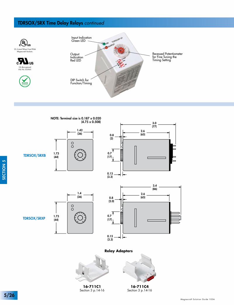
TDRSOX/SRXB
TDRSOX/SRXP1.73(44)
0.13(3.3)
0.7(17)
1.4(36)
(2.0)0.8 (65)
2.6
1.73(44)
1.42(36)
(86)3.4
(77)3.0
0.13(3.3)
0.7(17)
(2)0.8 (65)
2.6
UL Listed When Used With Magnecraft Sockets.
UL USC
UL RecognizedFile No. E43641
SEC
TIO
N 5
Magnecraf t Solut ion Guide 105A Magnecraf t Solut ion Guide 105AMagnecraf t Solut ion Guide 105A
TDRSOX/SRX Time Delay Relays continued
Output IndicationRed LED
Input IndicationGreen LED
Recessed Potentiometerfor Fine Tuning theTiming Setting
DIP Switch for Function/Timing
NOTE: Terminal size is 0.187 x 0.020 (4.75 x 0.508)
16-711C4Section 3 p.14-16
16-711C1Section 3 p.14-16
Relay Adapters
5/26
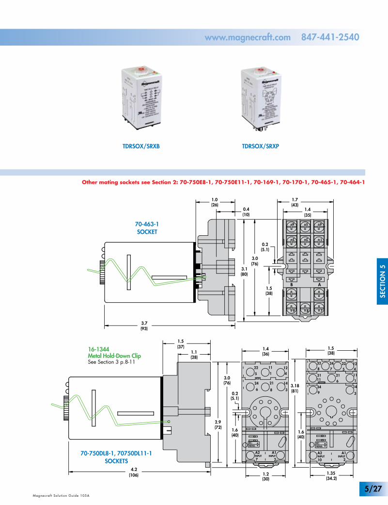
TDRSOX/SRXB TDRSOX/SRXP
1.1(28)
(72)2.9
(37)1.5
(80)3.1
0.2(5.1)
9 8
B
(76)3.0
3 2
7
A
1
6 5
(35)1.4
4
(26)1.0
(38)1.5
(93)3.7
0.4(10)
(106)4.2
1.7(43)
(5.1)0.2
(76)3.0
(40)1.6
(36)1.4
11
41
12
14
3
A2
7
5
22
2124
6 8
A1
2INPUTINPUT
(30)1.2
NEMA:IEC:
(38)1.5
(81)3.18
(40)1.6
(34.2)1.35
11
4
1
12
14
3
A2
10
5
22
21
24
6
7
A1
2INPUTINPUT
34
9
3111
32
8
NEMA:IEC:
Magnecraf t Solut ion Guide 105A
SEC
TIO
N 5
Magnecraf t Solut ion Guide 105AMagnecraf t Solut ion Guide 105A
www.magnecraft.com 847-441-2540
16-1344Metal Hold-Down ClipSee Section 3 p.8-11
70-463-1SOCKET
70-750DL8-1, 70750DL11-1SOCKETS
Other mating sockets see Section 2: 70-750E8-1, 70-750E11-1, 70-169-1, 70-170-1, 70-465-1, 70-464-1
5/27
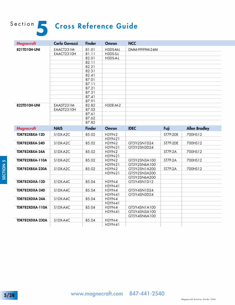
5 Cross Reference GuideS e c t i o n
www.magnecraft.com 847-441-2540Magnecraf t Solut ion Guide 105A
www.magnecraft.com 847-441-2540Magnecraf t Solut ion Guide 105AMagnecraf t Solut ion Guide 105A
SEC
TIO
N 5
NCCDMM-9999M-24M
IDEC
GT5Y-2SN1D24GT5Y-2SN3D24
GT5Y-2SN3A100GT5Y-2SN6A100GT5Y-2SN1A200GT5Y-2SN3A200GT5Y-2SN6A200GT5Y-4SN1D12
GT5Y-4SN1D24GT5Y-4SN3D24
GT5Y-4SN1A100GT5Y-4SN3A100GT5Y-4SN6A100
FujiST7P-2DE
ST7P-2DE
ST7P-2A
ST7P-2A
ST7P-2A
Allen Bradley700HS12
700HS12
700HS12
700HS12
700HS12
Carlo GavazziEAACT231MEAACT2310H
EAADT231MEAADT2310H
NAISS1DX-A2C
S1DX-A2C
S1DX-A2C
S1DX-A2C
S1DX-A2C
S1DX-A4C
S1DX-A4C
S1DX-A4C
S1DX-A4C
S1DX-A4C
Magnecraft821TD10H-UNI
822TD10H-UNI
MagnecraftTDR782XBXA-12D
TDR782XBXA-24D
TDR782XBXA-24A
TDR782XBXA-110A
TDR782XBXA-230A
TDR782XDXA-12D
TDR782XDXA-24D
TDR782XDXA-24A
TDR782XDXA-110A
TDR782XDXA-230A
Finder81.0181.1182.0182.1182.2182.3182.4187.0187.1187.2187.3187.4187.9182.8287.0287.6187.6287.82
Finder85.02
85.02
85.02
85.02
85.02
85.04
85.04
85.04
85.04
85.04
OmronH3DS-M-LH3DS-S-LH3DS-A-L
H3DE-M-2
OmronH3YN-2H3YN-21H3YN-2H3YN-21H3YN-2H3YN-21H3YN-2H3YN-21H3YN-2H3YN-21
H3YN-4H3YN-41H3YN-4H3YN-41H3YN-4H3YN-41H3YN-4H3YN-41
H3YN-4H3YN-41
5/28
www.magnecraft.com 847-441-2540Magnecraf t Solut ion Guide 105A
www.magnecraft.com 847-441-2540Magnecraf t Solut ion Guide 105AMagnecraf t Solut ion Guide 105A
SEC
TIO
N 5
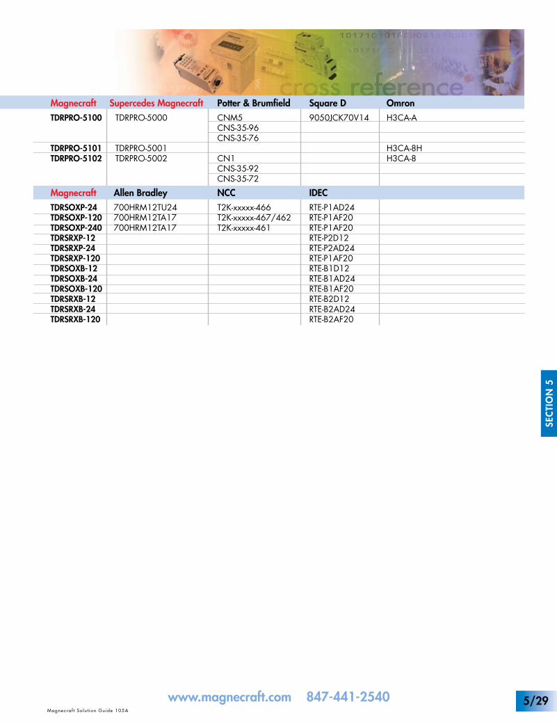
OmronH3CA-A
H3CA-8HH3CA-8
Allen Bradley700HRM12TU24700HRM12TA17700HRM12TA17
Magnecraft Supercedes MagnecraftTDRPRO-5100 TDRPRO-5000
TDRPRO-5101 TDRPRO-5001TDRPRO-5102 TDRPRO-5002
Potter & BrumfieldCNM5CNS-35-96CNS-35-76
CN1CNS-35-92CNS-35-72
NCCT2K-xxxxx-466T2K-xxxxx-467/462T2K-xxxxx-461
Square D9050JCK70V14
IDECRTE-P1AD24RTE-P1AF20RTE-P1AF20RTE-P2D12RTE-P2AD24RTE-P1AF20RTE-B1D12RTE-B1AD24RTE-B1AF20RTE-B2D12RTE-B2AD24RTE-B2AF20
MagnecraftTDRSOXP-24TDRSOXP-120TDRSOXP-240TDRSRXP-12TDRSRXP-24TDRSRXP-120TDRSOXB-12TDRSOXB-24TDRSOXB-120TDRSRXB-12TDRSRXB-24TDRSRXB-120
5/29

Magnecraf t Solut ion Guide 105A
SEC
TIO
N 5
www.magnecraft.com 847-441-2540NOTES:
5/30


![[ 3000 Series Time Delay Relays and Measuring Relays ... · [ 3000 Series Time Delay Relays and Measuring Relays ] ... Measuring Relays ] • Time Delay Relays ... Dear Reader, Dear](https://img.pdfslide.us/doc/110x75/5b85683b7f8b9aec488e43dd/-3000-series-time-delay-relays-and-measuring-relays-3000-series-time.jpg)