Embed Size (px)
Citation preview

8/7/2019 Relay protection and series FACTS
http://slidepdf.com/reader/full/relay-protection-and-series-facts 1/6
DIGITAL PROTECTIONOF POWER TRANSMISSION LINES IN THE
PRESENCE OF SERIES CONNECTED FACTSDEVICES
P.K.Dash, A. K. Pradhan, G. PandaRegionalEngineering College,Rourkela
INDIA
ABSTRACT: The presence of series connected FACTS (flexiblcac transmission system) devices like TCSC (thyristor controlledstria capacitor), TCPST (thyristor controlled phase shiftingtransformer) and UPFC (unified power flow controller) etc. candrastically effect the performance of a distance relay in a two-terminal system connected by a double-circuit transmission line. Thecontrol characteristics of the series connected FACTS devices, theirlocations on the transmission line, the fault resistance especially thehigher ones make this problem more severe and complicated. Thefault location with respect to the position of the FACTS devices alsogreatly influcnccs the trip boundaries of the distance relay. The paperpresents apparent impedance calculations for relaying of double-circuit transmission system with varying parameters of the FACTSdevices and location. The study reveals the adaptive nature of the
protection scheme that necessitaes the use of an ANN basedprocedure for the generation of trip boundaries during faultconditions.Key Words- Digital protection, Distance relay, Adaptive setting,FACTS.
I. INTRODUCTION
The possibility of controlling electric power flow in atransmission system by using controllable solid state deviceslike TCSC and TCPST is well known [l]. These seriesconnected FACTS devices inject a series voltage with the lineand thereby modulate the line reactance or the phase shiftbetween the two end voltages. Recent advances in solid-statepower electronics technology have made it possible toimplement the above devices using power switching voltage
source converters. Another versatile FACTS dev ice like UPFChas provided the necessary functional flexibility for optimalpower flow control. In the UPFC both active and reactivepower flow in the line arc controlled through a series and ashunt reactive compensation [ l- 21.
The presence of a FACTS device in the fault loop affectsboth the steady state and transient components in the voltageand current signals at the relaying point. Therefore, theapparent impedance calculations should take into account thevariable series voltage source and its angle and shunt currentand admittance, if present in the device [3]. However, if theFACTS device is not present in the fault loop, the apparentimpedance calculations are similar to the ordinarytransmission lines. Thus a decision concerning the relative
position of such a device must be considered before thecalculation of apparent impedance. Besides the fault resistance
A. C. LiewNatlonal Universityof Singapore
SINGAPORE
magnitude of the arc and system operating condition theapparent impedance seen by a distance relay is influencedgreatly by the location and parameters of FACTS device incase of a ground fault. If the impedance seen by a relay islower or higher than the actual line impedance, the distancerelay either overreaches or underreaches. Therefore anadaptive relay setting of the distance protection is required to
cope up with the problems of overreach or underreach.Adaptive reach settings of the distance relays for faults
involving high arc resistance have been researched forsometime now [4-91. Methods for on-line corrections of thetrip boundaries are presented in references [S-71. This paperpresents the apparent impedance calculation procedure alo ng
with detailed simulation results for distance relaying schemesin which one of the circuits in a double circuit transmissionline has a series connected FACTS device. The variations ofthe device parameters and the locations are found to influencethe apparent impedance measurements and trip boundaries to agreat extent.
11. APPARENT IMPEDANCE CALCULATION IN THEPRESENCE OF FACTS ELEMENTS
Fig.1. FACTS device at the relaying point in the power system
A double circuit transmission line connecting two sourcespossessing a TCPST or TCSC or UPFC in one of its circuitsat relaying point or midpoint (Fig. 1) is exposed to a single-line-to-ground fault. The apparent impedance as seen by thephase-to-ground relay in such an event taking into accountinfeed and fault resistance is derived in the following sections.
A. The TCPSTon circuit-G
P' P"
0-7803-5935-6/00/$10.00(c) 2000 IEEE 1967

8/7/2019 Relay protection and series FACTS
http://slidepdf.com/reader/full/relay-protection-and-series-facts 2/6
Fig2 (a) Basic circuit arrangementof TCPST (b)TCPST model
The TCPST consists of two transformers; amagnetizing transformer connected in parallel and a boostertransformer in series to the line (Fig. 2). The current throughthe magnetizing transformer induces a voltage on the primaryside of the b ooster transformer which is in quadrature with thephase voltages. The basic equations of TCPST for phase-a are:v, =)eJ'eV&)'
Hence Vqt =CpV'w
whereC p =1/(1+ )e/')
y =an,n = turns ratio of magnetizing transformer
n=-S?-'
(1)
(2)
therangeof Q is - l o o < + < l o o a nd 8 Pf4
Equating the complex power between shunt and seriesbranches
( 3 )
I) TCPST at the relaying point :Considering phase-a to ground fault (Fig. 1) and assigningcurrent between P and P' as I'& the current relations are
Iald = I h d g + Ialdh
&dg = I;ldg + Iash
( 5 )
(6 )
(7)
From the above eq uations we can rewrite
I h g = ccldvclp and 1;ldg = cclddvap
,i#and ccldd =Cdd7
Again from Fig. 1
From the above equations we obtain
vc p = Cvp lo f
Where Cvp = 4 3 9 +ZX)
(zlpJccldd -
Zz =Zb + Zi +Z; (refer equations 11 and 12) and being
zero sequence component of fault current. The magnitudes of
Zb, Zi(Z5 =2;)are obtained from the equivalent sequence
diagrams..
Where ZlSp Z,.,,, Z,, Z , , = positive and zero sequenceimpedances of the sources at the terminals P and Qyrespectively. Z,, = Zero sequence m utual impedance betwee'ncircuitG and circu it H. n= per unit distance of the fault point Ffrom the relaying pointRAlso the currents can be expressedas
I:ldg = clddlo$ (13 )
I h d g = cld'of (14)
lash = CIsh'of (15)
Where cl&= c c l & c v p , c l d E C&&p and = c l d - c l d d
At the relaying point the voltage and current equations ofphase-aare:
VaR = C p ( 3 R f Io$ + I I p ' g f Z I p $ + I 2 p ' g f Z 2 p ~ +lop'gfzopf +
I o h z o m f + I i l d g z l p f )
(16)
(17)laR = I i ldg + lash + lap'g + KOIOp"gf
SubstitutingZl,f by n Z,, the ap parent impedance seen by a-phase to ground re$y is
0-7803-5935-6/00/$10.00(c) 2000 IEEE 1968

8/7/2019 Relay protection and series FACTS
http://slidepdf.com/reader/full/relay-protection-and-series-facts 3/6
From equation 18 it can be observed that if the TCPST isplaced at the relaying point on one of the circuits of thedoub lecircuit transmission line, the apparent impedance seenby the relay for a single-line-to-ground fault is influenced bythe factorC, of the TCPST. Also the impedan ce is influencedby the resistance Rf in the fault path, zero sequence mutualimpedance, TCPST shunt branch current, fault location andprefault system condition.
2) TCPST at midpoint of circuitG:
P Q
The apparent impedance seen by the relay is given by
where Z , = jX,, TCSC reactance
2) TCSC at the mid point of circuitG:
Apparen t impedance for fault beyond the TCSC (refer Fig. 3)
2, =(n-)& +?+z, +A2
PR/ +cm( ( n - ~ ~ o m+2zOm )- CoK,Zc]
Where AZ =Cfd +2c1+cO(l+KO)
(22)For fault within TCSC; at FI
3Rf +CmnZom2, =nz*+ (23)
ICircUit-G c f d+2c 1 f cO(l+KO)TCPST
Fig.3. Th e powersystem withTCPSTat midwintof circuit4
FC. TheUPFC
The UPFC modeled by tw o voltage sources is shownin Fig.5. It consists of two converters, one connected in serieswith the transmission line with a 'series transformer and theother connected in parallel with the line through a shuhttransformer. The series and shunt converters are connectedtogether through a DC capacitor, which also acts as an energy
source of variable magnitude and phase ang le, while the shu ntconverter provides the real power balance between the seriesconverter and the power system.
For fault beyond the TCPST (at Fz) the seen impedance(phase-a-to-ground relay) is
Z , = C p ( n - ~ Z , + - + A z '2,
2
[3~,c,+c.(C,(n-x)zonr+& -cbhc,(.-K)z,] storage device. The series converter introduces a voltage2U'E
cl&/+cbh +zc, +cO(f+KO))(19)
For fault within the TCPST (at F,) the apparent impedanceequation becomes Bus
(20)gR/ + CmZOmf -Q l(c ld -cldd1)
2, =n z ,+c!d + 2 c ] + cO( l+ KO)
B.The E S CThe TCSC as shown in Fig. 4 consists of a fixed
capacitor and a thyristor controlled reactor that circulatescurrent pulses which add in phase with the line current. Thisboosts the capacitor voltage beyond the level that would beobtained by the line current alone. The TCSC can be modeled85 a variable reactance (both capacitive and inductive) where
conductionangleof the thyristors [lo].
1) TCSC at the relaying point:
7
the net "rice offered by TCSG X i , depends on theI:ig. (a)Dasiccircuit a,.,angcmcnt of
(b) iu equivalent voltage representation
For apparent impedance calculations, the UPFC modelequations for the a-phase are
vap*=CpVq1t ( 2 4 )
where Cp=1/(1+ y e"), y =2.Elv IIv.P*I
The magnitude of V,, can be controlled by varying the dc
voltage and firing an gle of the series voltage source converterand 0 varies from 0 to 2n radians. The shunt current is
C
(b) obtained as
Fig.4 (a) TCSC circuit arrangement(b) its equivalent representation
0-7803-5935-6/00/$10.00(c) 2000 IEEE 1969
8/7/2019 Relay protection and series FACTS
http://slidepdf.com/reader/full/relay-protection-and-series-facts 4/6
Where Vmh =shunt converter voltage, C,,==voltage
ratio(Vqp/VaJI) and z,h is its impedance. Assume Ew as th e
equivalent voltage source of the a-phase at the terminal P. Let
the relation between bus voltage at P and ET be
Where h is the amplitude ratio (Vup/ Eup) and S is the angle
between the source voltage and bus voltage at P. The
magnitude of shunt con verter voltage source V, is computed
From the power balance equation ;
For the two location s of the UPFC on circuit-G the eq uationsare similar to the cases of TCPST.
Vq =h e-*&Eq (26)
Re(Vw#lai) = Re(yVw*eJeiidgg* ) (27)
111.SIMULATIONRESULTSThe data of the transmission system used for the simulation
purpose isgiven below:System vo ltage =4OOkV,Length of the line=200km
Positive sequence impedance of each line 4.28 75L 86' zukm
Zero sequence impedance of each line =0.8735L83' NkmZero sequence mutual imp edance of line=0.71L76° NkmParameters for sources at P and Q are:
Z,-5.54L62' Q &,,E 2.77L62' 0Amplitude ratio between sou rce voltages at P and Q= 0.95Load angle between sources =20'
21,~ 1 9 . 5 L 8 5 ~f2, Zilp=9.75L85' 22
A single line to ground fault in phase-a is assumed tooccur at a distance of 95% of the length from the relayingpoint in circuit-G where the FACTS element is placed. For
both the positions of the FACTS element computations werecarried out to evaluate apparent impedance with different faultpath resistance values (0 -2OOn). System conditions remaininLthe same some of the results showing apparent reactance andresistance (the real and imaginary parts of 2,respectively) aretabulated a t Rf=l8n.
A. Inpresence of X P S TTable 1 TCPSTat relayingpoint, Rp l 8R
. ..26.86 I 82.09 I 68.70 I 104.67 I
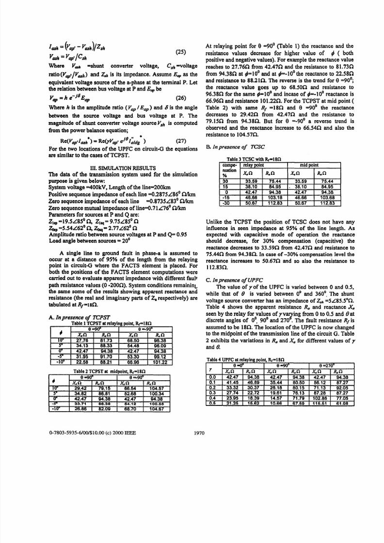
At relaying point for 8 =90° (Table 1) the reactance and the
resistance values decrease for higher value of 4 ( bothpositive and neg ative values). For example the reactance valuereaches to 27. 76 n from 42.4722 and the resistance to 8 1.7322
from 94.3851 at d-10' and at +=-lo' the reactanc e to 22.5851and resistance to 88.2152. The reverse is the trend for 8 -90';the reactance value goes up to 68.5022 and resistance to96.3822 for the sam e 4-10' and incase of #=-lo' reactance is66.9622 and resistance 101.2222. For the TCPST at mid point (
Table 2) with same Rf -180 and 8 -90' the reactancedecreases to 29.42n from 42.47a and the resistance to79.150 from 94.380. But for 8 =-goo a reverse trend isobserved and the reactance increase to 66.54C2 and also theresistance to 104.5752.
B. I n presenceof TCSC
Table 3 TCSC with Rp l8 R* compe- relaypoint mid point
X.Q I %n X. f-2 I R Snsation?4
38.10
-15-30
Unlike the TCPST the position of TCSC does not have anyinfluence in seen impedance at 95% of the line length. Asexpected with capacitive mode of operation the reactanceshould decrease, for 30% compensation (capacitive) thereactance decreases to 33.59n from 42.4722 and resistance to75.44f2 from 94.38Q. In case of -30% compensation level thereactance increases to 50.67n and so also the resistance to112.83R.
C. Inpresenceof UPFCThe value of y of the UPFC is varied between 0 and 0.5,
while that of 0 is varied between 0' and 360'. The shun tvoltage source converter has an impedance of Z s h =5L85.S0Q.
Table 4 shows the apparent resistance R, and reactance Xaseen by the relay for values of y v y i n g from 0 to 0.5 and 0 atdiscrete angles of 0'. 90' and 270 .The fault resistance RJ isassumed to be 1822. The location of the UPFC is now changedto the m idpoint of the transmission line of the circuit G.Table2 exhibits the variations in R, and Xafor different values of y
and 8.
Table4 UPFC at relaying point,&=18n
I I e=ou I e 1
0.3 27.74
0.4 I 23.95 I 18.39 I 14.57 I 71.79 I 102.86 I 77.050.5 1 21.25 I 16.62 I 10.66 I 67.50 1 115.61 1 61.08
0-7803-5935-6/00/$10.00(c) 2000 IEEE 1970

8/7/2019 Relay protection and series FACTS
http://slidepdf.com/reader/full/relay-protection-and-series-facts 5/6
Table5 UPFC et midpoint. &- I 8Cl
With the UPFC at die relaying point (Table 4) and 84'the resistance seen by the phase-a ground relay decreasesconsiderably whereas the reactance increases up to @ . I andthen decreases significantly. For 0 390' the reactancedecreasesfrom 42.478 to 10.66Q and also the resistance fallsto 67.590 fiom 94.388. However at 8 =270° the reactanceincreases drastically, but the resistance shows a complexvariation. Table 5 for mid point location of the UPFC depictsthat at 84'the resistance value decreases considerably butthe reactance varies in a complex manner. At 8 4 0 ' thereactance reaches to 19.0221 fiom 42.4721 and the resistance
also decreases to 60.0921 from 94.3821. In case of 8 =270° theXa increases drastically but R,,shows a complex variation.These observations clearly demonstrate that the presence ofUPFC introduces a capacitive or inductive reactance to thel i e depending on its parameters yand 8 and location.
IV. TRIP CHARACTERISTICSKeeping the system operating condition same trip boundariesare generated considering line-to-ground fault for one of thecircuit by varying fault distance in km from 0 to 95% of thel i e and fault path arc resistance from 0 to 200n. Fig. 6depicts the trip characteristic without the presence of anyFACTS element for line-to-ground fault. However, if any ofthe FACTS elements is located at the midpoint the trip
characteristic exhibits two different trip boundaries. The up perone is for faults between the m idpoint and to 95% of the linelength and the lower characteristic is due to the fault locationlying between the relaying point to the midpoint.
A. In presence of TCPSTFigs. 7 and 8 represent the trip boun dary with the presence oTCPST for the sam e system condition as in UPFC study fordifferent values of and 8 (90' and -904 at 4 =IOo .For +looand 0 -90' (Fig. 7) the trip characteristic for TCPST atrelaying point shifts dow nward and for mid point case the triparea decreases. At both the locations, the R, value isdecreased.. For +lo o and 0 5-90' (Fig. 8) the trip areas areincreased considerably and the X,value goes as high as 160R
and R a reaches 4000. The trip boundaries for TCPSTdemonstrate that they are greatly influenced by the positionand parameters of TCPST.
operations. In the figure, the upper boundaries for TCPST atmid po int and relaying point converge. In Fig. 9 the reactancevalue is decrease d and the low er boundary for relaying point iswell below that of the mid point case. Therefore it can beconcluded that the location and level of compensation ofTCSC influences the trip boundary settings.
C.Inpresenceof UPFCFigs. 10 and 11 represent the trip boundaries for line-to-ground fault with the presence of UPFC either at the relayingpoint or midpoint of circuit G for 0 values of O'and 90"
keeping yunchanged ( ~0 .5 ) .In Fig.10 it is observed that fort+O0 and UPFC at both the locations, the Xavalue decreasesfor smaller Rfand increases for higher Rp However, for theabove cases, the R,, value is decreased significantly. Withsame system conditions with UPFC at the relaying point thetrip area is reduced which is not the case for midpo int locationof UPFC. Fig. 11 demonstrates that for &IOo the upperbound ary decreases with high er RJ fo r both the loca tions ofUPFC. These figures clearly show that the UPFC parametersand position modulate the trip boundary set for line to ground
fault protection.
V. DISCUSSIONSIt is eviden t from the two preceding sections that the presenccof FACTS elements in a transmission system affects the trilboundary set for single-line-to-ground fault considerably. Noonly the param eters of the elem ent, its location on the line alscinfluences the trip characteristics substantially. In case oUPFC the influencing parameters are yand B, that for TCPSIare 4 and U and for the TCSC it is only the compensatiorlevel. In ail the observations only two positions o f the FACT!elements on the line are envisaged and in all cases thlcharacteristics differ with respect to the location of th.element. Therefore in an adap tive protection for a transmissioisystem possessing such a FACTS device the trip boundarneeds to be adapted with the mentioned influencinparameters besides the system operating conditions. Artificirintelligence techniques such as neural network, fuzzy logisystem etc. may dictate a solution to the above amplenrotection problem considering the influencing parameters e
om e of the inputs.
VI.CONCLUSIONSApparent impedance calculations for a double-circutransmission line operating with series connected FACTdevices are presented. The presence of a FACTS device li b
UPFC,TCPST or TCSC on a line can substantially influencthe apparent impedance seen by a distance relay. Thphenomenon has been clearly demonstrated in this paper t
varying the parametbrs of the FACTS element, its locatiofault resistance along with source impedance and 0th
uncertainties for line to ground fault. The ideal trip boundariderived are clearly showing the influence of FACTS devil
B. In presence of TCSC operating parameters. In real-time applications the
necessary trip comm ands to the circuit breakers.circuitare shown in Figs.9 for capacitive ( 30%) mode ofch"2teristics in the presence of T c s c on one of the boundaries need to be generated adaptively for issuing t
0-7803-5935-6/00/$10.00(c)2000 IEEE 1971

8/7/2019 Relay protection and series FACTS
http://slidepdf.com/reader/full/relay-protection-and-series-facts 6/6
VII. REFERENCES[I ] M. Noroozian, LAngquiSt, M.Ghandhari, and G.Anderson,
"Improving Power System Dynamics by series connected FACTS&vices", lEEE Trans. on Pow er Delivery, Vol. 12,No.4, 1997pp.1635-1641
[2] K.R Padiyar and A.M. Kulkaml, "Control. Design and Simulation ofUni&d P o w Flow Controller", IEEE Trans. on Power Dclivery.
[3] A.A. Oi@, A A Sallam and A.K. EI-Din, "An Adaptive ProtectionScheme for Advanced Stria Compensated (ASC)Transmission Lines,IEEE Trans. on Power Delivery, Vol. 13,No. I, 1998,pp. 414420.
[4] AX . Jampala, S.S.Venkata and M.J.Dambotg, "Adaptive transmissionprotection: Concepts and Computational iauca", IEEE Trans. on Power
[5 ] Z Zhtha, and C. Dcshu, "An adaptive approach in Digital Distanceprotection", IEEE T m . on Power Delivery, Vol. 6,No. 1,1991 , pp.135-142.
[a] Y.Q.Xi& K. K.Li and A.K. David, Adaptive relay setting for stand-alone digital d m ce protection, IEEE Trans. on Power Delivery, Vol. 9,No. I, 1993, pp. 480-491.
[7] P.J. Moon,RK.Aggiuwal,H.Jiang and A.T. Johns, "New Approach toDistance Protection for Resistive Double-Phase to Earth Fsults usingAdaptive T&kpea", IEE Proc.-Gener. Transm. Dlstrib., Vo1.141,No.4.1994. pp.369-376.
(81 D.L. Wdkar, S.Elangovan, and A.C. Liew, "Further Enhancements inthe Symmetrical Components based Improved fault ImpedanceEstimation Method Part-I. Mathematical Modeling, Electric Power
[g] G. Jongepier. and L.V.D. Sluis, "Adaptive Distance Protection of aDouble Circuit Line", IEEE Trans. on Power Delivery, Vol. 9, No. 3,1994, pp.1289-1297
[101E. V. Lanen.Kclark,S.A. Miske, and J.Urbanek, "Characteristics andRating Consideration of Thyristor Controlied Series Compensation",
V01.13, NO,4, 1998. pp.1348-1354.
D e l i v ~ y .V01.4.No. 1.1989 . pp. 177-185.
SySteM Rtsesrch, V01.40,1997. pp. 189-194.
lEEE T m . OII Power Delivery, 1994,9, (2), pp.992-999
VU.BIOGRAPHIESP. K. Dash i t a Professor of Electrical Engineering and Chairman of theCentre of ApplW Artificial Intelligence. Regional Engineering College.Rourkela, IndiaA. K. Pndhan is a lecturer In the department of Electrical Engineering,University College of Engineering, Burls, lndia
G. Panda is Professorand Head of the departmentof Applied Electronics andI " m t a t i o n Engineerlng. Regional Engineering College.Rourkela, lndia.A. C.Idcw is with depam nent of Electrical Engineering, National Institute ofSingapore.Singapore.
; for
I* . . . . .
*I nI
/1 4
!I &I
&TohmsrFig. 7. Trip characteristics for TCP ST6-100. woo b l 0 O .woo
t m m a m a
R (ohms)Fig.8. Trip characteristicsfor T. - .
relay point - at mid point- at relay point ~ltmid point
R. (ohms)Fig. 9. Trip characteristics for TCSC with 300 ?compensation at relay point at mld point-
R.(ohms)Fig. 10. Trip characteristics for UPFC
at relay point-atmid point-Fig. 11. Trip characteristics 1
at relay point - atmid poi~r0 . s .e& T+.s. e+$ .
0-7803-5935-6/00/$10.00(c) 2000IEEE 1972