Embed Size (px)
Citation preview
C H A P T E R 1Introduction
1.1 Reinforced Concrete
1.1.1 Definition of Reinforced ConcreteReinforced concrete is concrete in which reinforcing bars or other types of reinforcementhave been integrated to improve one or more properties of the concrete. For many years,it has been utilized as an economical construction material in one form or another inbuildings, bridges, and many other types of structures throughout the world. A largepart of its worldwide appeal is that the basic constituent materials—cement, sand,aggregate, water, and reinforcing bars—are widely available and that it is possible toconstruct a structure using local sources of labor and materials.
In addition to being readily obtainable, reinforced concrete has been universallyaccepted because it can be molded essentially into any shape or form, is inherentlyrigid, and is inherently fire-resistant. With proper protection of the reinforcement, areinforced concrete structure can be very durable and can have a long life even underharsh climatic or environmental conditions. Reinforced concrete structures have alsodemonstrated that they can provide a safe haven from the potentially devastating effectsof earthquakes, hurricanes, floods, and tornadoes.
Based on these and other advantages, it is evident that reinforced concrete canprovide viable and cost-effective solutions in a variety of applications. This book focuseson the design of reinforced concrete members in building structures.
1.1.2 Mechanics of Reinforced ConcreteConcrete is a brittle, composite material that is strong in compression and weak intension. Cracking occurs when the concrete tensile stress in a member reaches thetensile strength due to externally applied loads, temperature changes, or shrinkage.Concrete members that do not have any type of reinforcement in them will typicallyfail very suddenly once the first tension cracks form because there is nothing to preventthe cracks from propagating completely through the member.
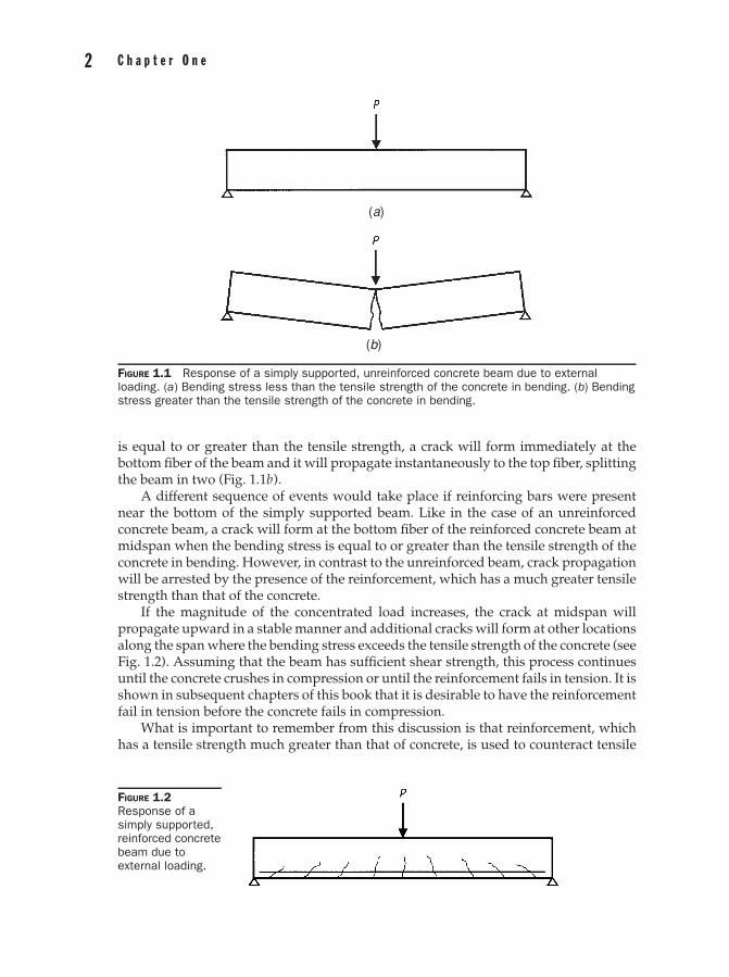
Consider the simply supported, unreinforced concrete beam shown in Fig. 1.1 thatis subjected to a concentrated load P at midspan. From the strength of materials, themaximum tensile bending stress occurs at the bottom fibers of the beam section atmidspan and the maximum compressive bending stress occurs at the top fibers. Becauseconcrete is stronger in compression than in tension, the beam will be able to supportthe concentrated load and its own weight as long as the maximum bending stress isless than the tensile strength of the concrete in bending (Fig. 1.1a ). If the bending stress
1
2 C h a p t e r O n e
(a)
(b)
FIGURE 1.1 Response of a simply supported, unreinforced concrete beam due to externalloading. (a) Bending stress less than the tensile strength of the concrete in bending. (b) Bendingstress greater than the tensile strength of the concrete in bending.
is equal to or greater than the tensile strength, a crack will form immediately at thebottom fiber of the beam and it will propagate instantaneously to the top fiber, splittingthe beam in two (Fig. 1.1b).
A different sequence of events would take place if reinforcing bars were presentnear the bottom of the simply supported beam. Like in the case of an unreinforcedconcrete beam, a crack will form at the bottom fiber of the reinforced concrete beam atmidspan when the bending stress is equal to or greater than the tensile strength of theconcrete in bending. However, in contrast to the unreinforced beam, crack propagationwill be arrested by the presence of the reinforcement, which has a much greater tensilestrength than that of the concrete.
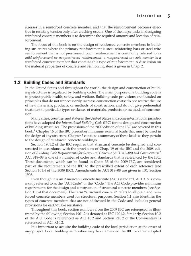
If the magnitude of the concentrated load increases, the crack at midspan willpropagate upward in a stable manner and additional cracks will form at other locationsalong the span where the bending stress exceeds the tensile strength of the concrete (seeFig. 1.2). Assuming that the beam has sufficient shear strength, this process continuesuntil the concrete crushes in compression or until the reinforcement fails in tension. It isshown in subsequent chapters of this book that it is desirable to have the reinforcementfail in tension before the concrete fails in compression.
What is important to remember from this discussion is that reinforcement, whichhas a tensile strength much greater than that of concrete, is used to counteract tensile
FIGURE 1.2Response of asimply supported,reinforced concretebeam due toexternal loading.
3I n t r o d u c t i o n
stresses in a reinforced concrete member, and that the reinforcement becomes effec-tive in resisting tension only after cracking occurs. One of the major tasks in designingreinforced concrete members is to determine the required amount and location of rein-forcement.
The focus of this book is on the design of reinforced concrete members in build-ing structures where the primary reinforcement is steel reinforcing bars or steel wirereinforcement that is not prestressed. Such reinforcement is commonly referred to asmild reinforcement or nonprestressed reinforcement; a nonprestressed concrete member is areinforced concrete member that contains this type of reinforcement. A discussion onthe material properties of concrete and reinforcing steel is given in Chap. 2.
1.2 Building Codes and StandardsIn the United States and throughout the world, the design and construction of build-ing structures is regulated by building codes. The main purpose of a building code isto protect public health, safety, and welfare. Building code provisions are founded onprinciples that do not unnecessarily increase construction costs; do not restrict the useof new materials, products, or methods of construction; and do not give preferentialtreatment to particular types or classes of materials, products, or methods of construc-tion.
Many cities, counties, and states in the United States and some international jurisdic-tions have adopted the International Building Code (IBC) for the design and constructionof building structures. The provisions of the 2009 edition of the IBC are covered in thisbook.1 Chapter 16 of the IBC prescribes minimum nominal loads that must be used inthe design of any structure. Chapter 3 contains a summary of these loads as they pertainto the design of reinforced concrete buildings.
Section 1901.2 of the IBC requires that structural concrete be designed and con-structed in accordance with the provisions of Chap. 19 of the IBC and the 2008 edi-tion of Building Code Requirements for Structural Concrete (ACI 318–08) and Commentary.2
ACI 318–08 is one of a number of codes and standards that is referenced by the IBC.These documents, which can be found in Chap. 35 of the 2009 IBC, are consideredpart of the requirements of the IBC to the prescribed extent of each reference (seeSection 101.4 of the 2009 IBC). Amendments to ACI 318–08 are given in IBC Section1908.
Even though it is an American Concrete Institute (ACI) standard, ACI 318 is com-monly referred to as the “ACI Code” or the “Code.” The ACI Code provides minimumrequirements for the design and construction of structural concrete members (see Sec-tion 1.1 of that document). The term “structural concrete” refers to all plain and rein-forced concrete members used for structural purposes. Section 1.1 also identifies thetypes of concrete members that are not addressed in the Code and includes generalprovisions for earthquake resistance.
Throughout this book, section numbers from the 2009 IBC are referenced as illus-trated by the following: Section 1901.2 is denoted as IBC 1901.2. Similarly, Section 10.2of the ACI Code is referenced as ACI 10.2 and Section R10.2 of the Commentary isreferenced as ACI R10.2.
It is important to acquire the building code of the local jurisdiction at the onset ofany project. Local building authorities may have amended the IBC or other adopted
4 C h a p t e r O n e
codes, and it is the responsibility of the registered design professional to be aware ofsuch amendments before designing the building.
1.3 Strength and ServiceabilityDesign philosophies related to reinforced concrete members have changed over theyears. Until the early 1960s, the primary design method for reinforced concrete wasworking stress design. In this method, members are proportioned so that the maximumelastic stresses due to service loads are less than or equal to allowable stresses prescribedin the Code.
The strength design method was included for the first time in the 1956 edition of theCode, and it became the preferred design method in the 1971 Code. The strength designmethod requires that both strength and serviceability requirements be satisfied in thedesign of any reinforced concrete member. In general, reinforced concrete members areproportioned to resist factored load effects and to satisfy requirements for deflectionand cracking.
An in-depth discussion on the fundamental requirements of strength and service-ability is given in Chap. 4. Presented are the basic concepts of required strength (in-cluding load combinations) and design strength (including strength reduction factors).
Chapter 5 contains the general principles of the strength design method. Thismethod is based on the fundamental conditions of static equilibrium and compatibilityof strains. The information presented in this chapter forms the basis for the design ofreinforced concrete sections subjected to flexure, axial load, or a combination of both.
1.4 Reinforced Concrete Members in Building Structures
1.4.1 OverviewStructural members in any structure must be designed to safely and economically sup-port the weight of the structure and to resist all of the loads superimposed on thestructure. In ordinary buildings, superimposed loads typically consist of live loads dueto the inhabitants, dead loads due to items permanently attached to the building, andlateral loads due to wind or earthquakes. Some types of buildings must also be designedfor extraordinary loads such as explosions or vehicular impact. Chapter 3 provides acomprehensive discussion on loads.
A typical reinforced concrete building is made up of a variety of different reinforcedconcrete members. The members work together to support the applicable loads, whichare transferred through load paths in the structure to the foundation members. Theloads are ultimately supported by the soil or rock adjoining the foundations.
Unlike other typical types of construction commonly used in building structures,such as structural steel and timber, reinforced concrete construction possesses inherentcontinuity. Cast-in-place reinforced concrete structures are essentially monolithic withreinforcement that extends into adjoining members. As such, reinforced concrete mem-bers are analyzed as continuous members in a statically indeterminate structure wherebending moments, shear forces, and axial forces are transferred through the joints. Un-derstanding the behavior and response of a reinforced concrete structure is imperativein the proper analysis, design, and detailing of the members in the structure.
5I n t r o d u c t i o n
Chapters 6 through 10 of this book contain the design and detailing requirementsfor typical reinforced concrete members found in building structures. A summary of thedifferent member types that are addressed in these chapters is given in the followingsections.
It is important to note that the information presented in Chaps. 6 through 10 isapplicable to the design of members in structures that are located in areas of low-to-moderate seismic risk. Seismic risk is related to seismic design category (SDC), whichis defined in IBC 1613.5.6. In general, SDC is determined on the basis of the levelof seismicity and soil type at the site and on the occupancy of the building. Build-ings assigned to SDC A and B are located in areas of low seismic risk, whereas build-ings assigned to SDC C are located in areas of moderate seismic risk. SDC D, E, and Fare assigned to buildings located in areas of high seismic risk.
The provisions in ACI Chap. 21 relate design and detailing requirements to thetype of structural member and the SDC. The provisions of ACI Chaps. 1 through 19and 22 are considered to be adequate for structures assigned to SDC A; no additionalrequirements need to be satisfied (also see IBC 1908.1.2). ACI Table R21.1.1 gives thesections of ACI Chap. 21 that need to be satisfied as a function of SDC.
Table 1.1 contains a summary of the reinforced concrete members addressed inChaps. 6 through 10 of this book. Included in the table is the applicability of the in-formation presented in these chapters related to SDC. For example, the design anddetailing requirements presented in Chap. 6 are applicable to beams and one-way slabsin buildings assigned to SDC A.
The information presented in Chaps. 6 through 10 is not as limited as it first mightappear. In fact, this information forms the basis of design regardless of SDC. For ex-ample, the determination of the nominal moment strength of a beam is required in thedesign of that member no matter what the SDC is for the building. The same is truein regards to the design strength interaction diagram for a column as well as for otherimportant items.
It is also important to point out that satisfying the requirements for SDC B is readilyachievable for beams and columns without any special design or detailing. In particular,beams in structures assigned to SDC B must have at least two bars that are continuous atboth the top and bottom of the section that must be developed at the face of the supports(ACI 21.2.2). This is usually satisfied in typical beams because these bars are neededover the full length to support the stirrups. In regards to columns, column dimensionsin typical buildings are such that the clear height of the column is greater than five timesthe cross-sectional dimension of the column in the direction of analysis; thus, in manycases, the special shear requirements of ACI 21.3.3 need not be satisfied (ACI 21.2.3).
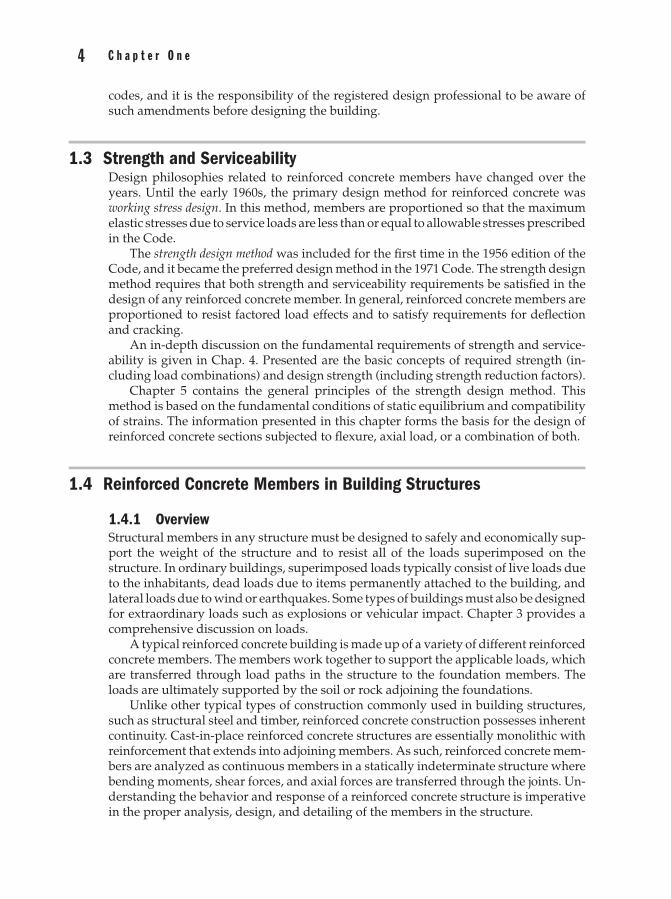
Chapter Reinforced Concrete Member(s) Seismic Design Category (SDC)
6 Beams and one-way slabs A
7 Two-way slabs A, B
8 Columns A
9 Walls A, B, C
10 Foundations A, B, C
TABLE 1.1 Applicability of Design and Detailing Requirements in Chaps. 6 through 10
6 C h a p t e r O n e
Methods to determine the SDC and comprehensive design and detailing proceduresfor reinforced concrete members in all SDCs can be found in Ref. 3.
1.4.2 Floor and Roof Systems
OverviewReinforced concrete structural systems can be formed into virtually any geometry tomeet any requirement. Regardless of the geometry, standardized floor and roof systemsare available that provide cost-effective solutions in typical situations. The most com-mon types are classified as one-way systems and two-way systems. Examined later arethe structural members that make up these types of systems.
It is common for one type of floor or roof system to be specified on one entire levelof building; this is primarily done for cost savings. However, there may be cases thatwarrant a change in framing system. The feasibility of using more than one type of flooror roof system at any given level needs to be investigated carefully.
One-Way SystemsA one-way reinforced concrete floor or roof system consists of members that have themain flexural reinforcement running in one direction. In other words, reactions fromsupported loads are transferred primarily in one direction. Because they are primarilysubjected to the effects from bending (and the accompanying shear), members in one-way systems are commonly referred to as flexural members.
Members in a one-way system are usually horizontal but can be provided at aslope if needed. Sloped members are commonly used at the roof level to accommodatedrainage requirements.
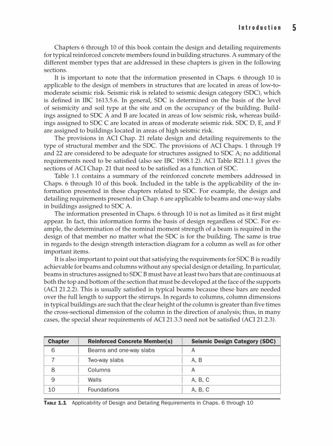
Illustrated in Fig. 1.3 is a one-way slab system. The load that is supported by theslabs is transferred to the beams that span perpendicular to the slabs. The beams, inturn, transfer the loads to the girders, and the girders transfer the loads to the columns.Individual spread footings may carry the column loads to the soil below. It is evidentthat load transfer between the members of this system occurs in one direction.
Main flexural reinforcement for the one-way slabs is placed in the direction parallelto load transfer, which is the short direction. Similarly, the main flexural reinforcementfor the beams and girders is placed parallel to the length of these members. Concrete forthe slabs, beams, and girders is cast at the same time after the forms have been set and
FIGURE 1.3 One-wayslab system.
7I n t r o d u c t i o n
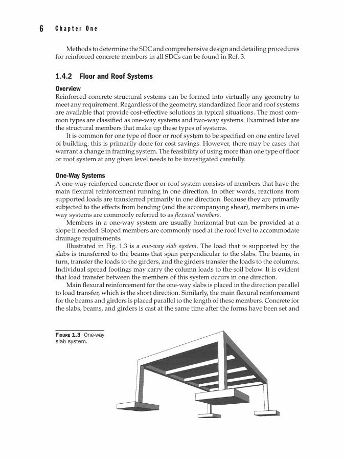
FIGURE 1.4Standard one-wayjoist system.
the reinforcement has been placed in the formwork. This concrete is also integrated withcolumns. In addition, reinforcing bars are extended into adjoining members. Like allcast-in-place systems, this clearly illustrates the monolithic nature of reinforced concretestructural members.
A standard one-way joist system is depicted in Fig. 1.4. The one-way slab transfers theload to the joists, which transfer the loads to the column-line beams (or, girders). Thissystem utilizes standard forms where the clear spacing between the ribs is 30 in. or less.Because of its relatively heavy weight and associated costs, this system is not used asoften as it was in the past.
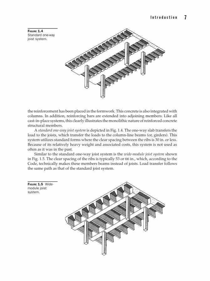
Similar to the standard one-way joist system is the wide-module joist system shownin Fig. 1.5. The clear spacing of the ribs is typically 53 or 66 in., which, according to theCode, technically makes these members beams instead of joists. Load transfer followsthe same path as that of the standard joist system.
FIGURE 1.5 Wide-module joistsystem.
8 C h a p t e r O n e
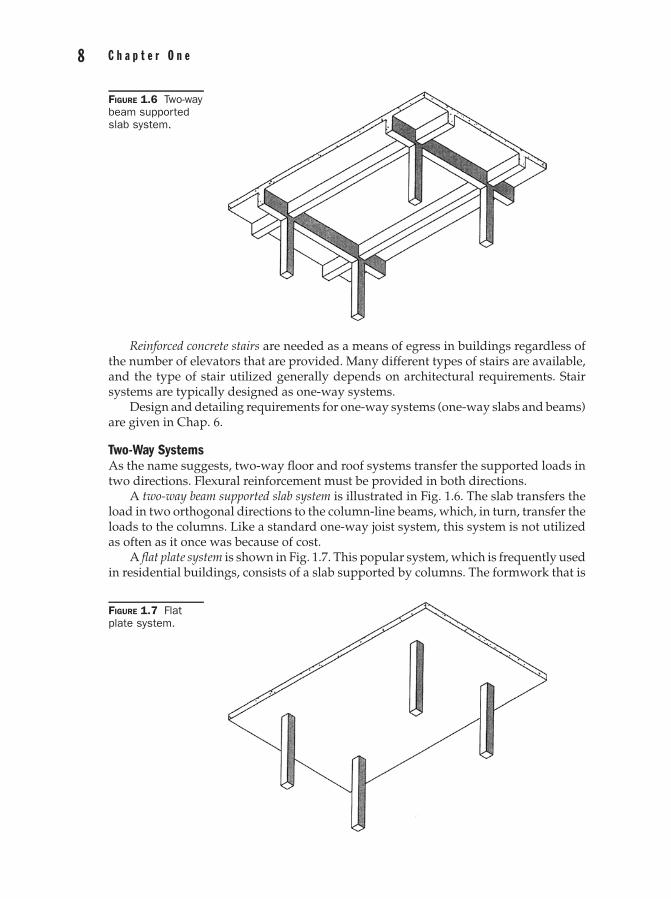
FIGURE 1.6 Two-waybeam supportedslab system.
Reinforced concrete stairs are needed as a means of egress in buildings regardless ofthe number of elevators that are provided. Many different types of stairs are available,and the type of stair utilized generally depends on architectural requirements. Stairsystems are typically designed as one-way systems.
Design and detailing requirements for one-way systems (one-way slabs and beams)are given in Chap. 6.
Two-Way SystemsAs the name suggests, two-way floor and roof systems transfer the supported loads intwo directions. Flexural reinforcement must be provided in both directions.
A two-way beam supported slab system is illustrated in Fig. 1.6. The slab transfers theload in two orthogonal directions to the column-line beams, which, in turn, transfer theloads to the columns. Like a standard one-way joist system, this system is not utilizedas often as it once was because of cost.
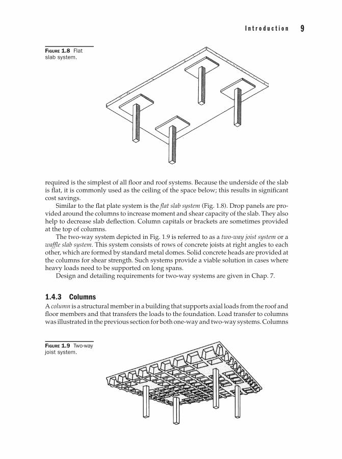
A flat plate system is shown in Fig. 1.7. This popular system, which is frequently usedin residential buildings, consists of a slab supported by columns. The formwork that is
FIGURE 1.7 Flatplate system.
9I n t r o d u c t i o n
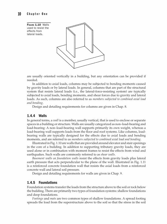
FIGURE 1.8 Flatslab system.
required is the simplest of all floor and roof systems. Because the underside of the slabis flat, it is commonly used as the ceiling of the space below; this results in significantcost savings.
Similar to the flat plate system is the flat slab system (Fig. 1.8). Drop panels are pro-vided around the columns to increase moment and shear capacity of the slab. They alsohelp to decrease slab deflection. Column capitals or brackets are sometimes providedat the top of columns.
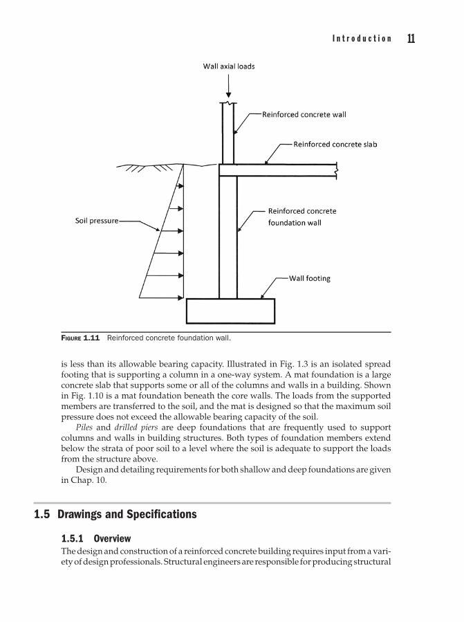
The two-way system depicted in Fig. 1.9 is referred to as a two-way joist system or awaffle slab system. This system consists of rows of concrete joists at right angles to eachother, which are formed by standard metal domes. Solid concrete heads are provided atthe columns for shear strength. Such systems provide a viable solution in cases whereheavy loads need to be supported on long spans.
Design and detailing requirements for two-way systems are given in Chap. 7.
1.4.3 ColumnsA column is a structural member in a building that supports axial loads from the roof andfloor members and that transfers the loads to the foundation. Load transfer to columnswas illustrated in the previous section for both one-way and two-way systems. Columns
FIGURE 1.9 Two-wayjoist system.
10 C h a p t e r O n e
FIGURE 1.10 Wallsused to resist theeffects fromlateral loads.
are usually oriented vertically in a building, but any orientation can be provided ifneeded.
In addition to axial loads, columns may be subjected to bending moments causedby gravity loads or by lateral loads. In general, columns that are part of the structuralsystem that resists lateral loads (i.e., the lateral-force-resisting system) are typicallysubjected to axial loads, bending moments, and shear forces due to gravity and lateralloads. As such, columns are also referred to as members subjected to combined axial loadand bending.
Design and detailing requirements for columns are given in Chap. 8.
1.4.4 WallsIn general terms, a wall is a member, usually vertical, that is used to enclose or separatespaces in a building or structure. Walls are usually categorized as non–load-bearing andload-bearing: A non–load-bearing wall supports primarily its own weight, whereas aload-bearing wall supports loads from the floor and roof systems. Like columns, load-bearing walls are typically designed for the effects due to axial loads and bendingmoments, and are referred to as members subjected to combined axial load and bending.
Illustrated in Fig. 1.10 are walls that are provided around elevator and stair openingsin the core of a building. In addition to supporting tributary gravity loads, they areused alone or in combination with moment frames to resist the effects from wind andearthquakes. Such walls are commonly referred to as shear walls.
Basement walls or foundation walls resist the effects from gravity loads plus lateralearth pressure that acts perpendicular to the plane of the wall. Illustrated in Fig. 1.11is a reinforced concrete foundation wall that resists the axial loads from a reinforcedconcrete wall and lateral soil pressure.
Design and detailing requirements for walls are given in Chap. 9.
1.4.5 FoundationsFoundation systems transfer the loads from the structure above to the soil or rock belowthe building. There are primarily two types of foundation systems: shallow foundationsand deep foundations.
Footings and mats are two common types of shallow foundations. A spread footingspreads the load from the superstructure above to the soil so that the stress in the soil
11I n t r o d u c t i o n
FIGURE 1.11 Reinforced concrete foundation wall.
is less than its allowable bearing capacity. Illustrated in Fig. 1.3 is an isolated spreadfooting that is supporting a column in a one-way system. A mat foundation is a largeconcrete slab that supports some or all of the columns and walls in a building. Shownin Fig. 1.10 is a mat foundation beneath the core walls. The loads from the supportedmembers are transferred to the soil, and the mat is designed so that the maximum soilpressure does not exceed the allowable bearing capacity of the soil.
Piles and drilled piers are deep foundations that are frequently used to supportcolumns and walls in building structures. Both types of foundation members extendbelow the strata of poor soil to a level where the soil is adequate to support the loadsfrom the structure above.
Design and detailing requirements for both shallow and deep foundations are givenin Chap. 10.
1.5 Drawings and Specifications
1.5.1 OverviewThe design and construction of a reinforced concrete building requires input from a vari-ety of design professionals. Structural engineers are responsible for producing structural
12 C h a p t e r O n e
drawings and specifications that are used to eventually build the structure. Drawingsand specifications, as well as other documents, are referred to as construction documentsor contract documents.
Once the construction documents have been reviewed and approved by the localbuilding authority, a number of important processes are set in motion. One of the firstthings to move forward is the production of the reinforcing steel placing drawings by thereinforcing steel supplier. As the name suggests, these drawings are used in the actualconstruction of the structure.
Additional information on construction and placing drawings, as well as otherpertinent information, is covered in the following sections.
1.5.2 Construction DocumentsThe following definition of construction documents is given in IBC 202:
Written, graphic, and pictorial documents prepared or assembled for describing the design,location, and physical characteristics of the elements of a project necessary for obtaining abuilding permit.
Construction documents consist of calculations, drawings, specifications, and anyother data that are needed to indicate compliance with the governing building code.IBC 107 describes the information that must be included in the construction documents,who must prepare them (the registered design professional), and procedures that areused by the building official for approving them.
IBC 1603 and ACI 1.2 contain minimum requirements for construction documents.The following design loads and information must be included in the construction doc-uments (see IBC 1603):
� Floor live load� Roof live load� Roof snow load� Wind design data� Earthquake design data� Geotechnical information� Flood design data� Special loads
These items are typically listed on the General Notes sheet of the structural draw-ings. Chapter 3 of this book provides a summary of loads that are typically required inthe design of building structures.
For reinforced concrete structures, the following information must also be providedin the construction documents (see ACI 1.2.1):
� Specified compressive strength of all concrete mixtures utilized in the structureat the ages or stages of construction for which each part of the structure isdesigned.
13I n t r o d u c t i o n
� Specified strength or grade of all reinforcement utilized in the structure.� Size and location of all structural members, reinforcement, and anchors.� Provisions for dimensional changes resulting from creep, shrinkage, and tem-
perature.� Anchorage length of reinforcement and location and length of lap splices.� Type and location of mechanical and welded splices of reinforcement.
Structural drawings must show the size, section, and relative locations of all ofstructural members in a building. The following items are usually included in a typicalset of drawings:
� Foundation plans� Framing plans for all levels at and above ground� Schedules for the structural members, including foundations, beams, slabs,
columns, and walls� Sections and details
It is important that the structural and architectural drawings be coordinated on aregular basis.
The size of the structural members can be given directly on the plans, or the memberscan be identified by marks on the plan with the sizes given in applicable schedules (thelatter is typically done for beams, columns, walls, and foundations). The same is donefor the size, spacing, and length of reinforcing bars. Either method of identification (orboth) can be utilized in a project.
Typical details are provided for various types of members utilized in the structure.These details, along with sections cut at various locations in the structure, help inillustrating specific information about the structure.
Specifications are documents that supplement the structural drawings and provideadditional information on materials, methods of construction, and quality assurance.Specifications for structural concrete are given in ACI 301.4 This specification may bereferenced or incorporated in its entirety in the construction documents of any rein-forced concrete building project together with additional requirements for the specificproject. Included in ACI 301 is information on the following:
� Formwork and formwork accessories� Reinforcement and reinforcement supports� Concrete mixtures� Handling, placing, and constructing� Architectural concrete� Lightweight concrete� Mass concrete� Prestressed concrete� Shrinkage-compensating concrete
14 C h a p t e r O n e
Mandatory and optional requirements checklists are also provided in ACI 301. Al-though these checklists do not form a part of ACI 301, they assist in selecting and spec-ifying project requirements in the project specifications. The mandatory requirementschecklist includes requirements pertaining to specific qualities, procedures, materials,and performance criteria that are not specifically defined in ACI 301. The optional re-quirements checklist contains a list of actions that are required or available when thespecifications are being developed.
A number of master specifications are available that can be utilized in a reinforcedconcrete building project. One such specification is MasterSpec.5 Section 033000 of thatspecification contains comprehensive specifications for cast-in-place concrete. Masterspecifications can be modified by deleting and inserting text to meet the specific re-quirements of a project.
1.5.3 Placing DrawingsOnce the construction documents have been approved by the local building authority,the documents are used by the reinforcing steel detailer in the preparation of placingdrawings and bar lists. Placing drawings are used by the ironworkers at the job siteto place (or, install) the reinforcing steel in the formwork. Bar lists are used by thereinforcing steel fabricator to fabricate the reinforcing bars.
When preparing the placing drawings for a specific project, the detailer uses thestructural drawings and the specifications to determine the quantity, lengths, bendtypes, and positioning of the reinforcing bars in all of the members in the structure. Theregistered design professional reviews and approves the placing drawings once theyare complete. Additional information on placing drawings and many other importantaspects related to reinforcing steel can be found in Ref. 6.
1.6 Construction of Reinforced Concrete Buildings
1.6.1 OverviewAlthough each reinforced concrete building is unique, the following sequence of eventsoccurs in the construction of any cast-in-place concrete building with mild reinforce-ment:
1. Erect formwork
2. Place reinforcement
3. Place concrete
4. Strip forms and provide reshores
This cycle is repeated for each floor of the building. Numerous activities occurwithin each segment of construction.
It is safe to state that no structure can be built that is perfectly level, plumb, straight,and true. This does not imply that contractors are doing their jobs improperly; rather, itis simply a reality that must be accepted because of the inherent nature of construction.
Fortunately, constructing a “perfect” structure is not necessary. However, somerequirements must be established so that the actual structure performs as originally
15I n t r o d u c t i o n
designed. Construction tolerances provide permissible variations in dimensions and lo-cations of the members in a structure. Tolerances are essentially limits within which thework is to be performed. ACI 117 contains comprehensive specifications for tolerancesin reinforced concrete construction and materials.7 This document can be referenced orused in its entirety in the project specifications.
Details of the construction process are covered in the following sections. Includedis information that can be incorporated in the preliminary design stages to help inachieving an economical structure.
1.6.2 Formwork Installation
OverviewAccording to ACI 347,8 formwork is the total system of support for freshly placedconcrete, including the mold or sheathing that contacts the concrete and all supportingmembers, hardware, and necessary bracing. In essence, formwork is a temporary struc-ture whose main purpose is to support and contain fresh concrete until it can supportitself. Concrete buildings require formwork for vertical members (columns and walls)and horizontal members (slabs, beams, and joists). In addition to the weight of freshconcrete, formwork must be designed to support construction loads (workers, material,and equipment) and to resist the effects from wind.
The cost of formwork usually accounts for approximately 50% to 60% of the totalcost of the concrete frame. Thus, selecting the proper forming system is crucial to thesuccess of any project. Specifying standard form sizes, repeating the size and shape ofconcrete members wherever possible, and striving for simple formwork are mandatoryin achieving a cost-effective structure.
The type of formwork system to be used is dictated primarily by the structuralsystem that will be utilized in the building. Formwork materials are shipped to the jobsite and erected. The process of erecting the formwork includes the following:
1. Lifting, positioning, and assembling the various formwork elements.
2. Installing shoring to support the formwork, the weight of the fresh concrete,and the construction loads.
To help ensure that the concrete does not bond to the forms, a form release agentor coating may be applied to the inside of the formwork at this stage. The coating alsohelps prevent wood formwork from absorbing water from the concrete mixture.
The following is a typical construction sequence in a conventional cast-in-placeconcrete building:
1. Build formwork for vertical elements
2. Place reinforcement for vertical elements
3. Place concrete for vertical elements
4. Strip formwork for vertical elements
5. Build formwork for horizontal elements
6. Place reinforcement for horizontal elements
7. Place concrete for horizontal elements
16 C h a p t e r O n e
The forms for the horizontal elements are stripped after a sufficient amount of time,and the process is repeated in multistory construction. Several levels of reshores aretypically required below the newly constructed level to support the weight of the freshconcrete and the construction loads.
Brief descriptions of various types of vertical and horizontal forming systems thatare commonly used in reinforced concrete building construction follow. Additionalinformation on these and other types of forming systems can be found in Ref. 9.
Vertical Forming SystemsAs noted earlier, the construction of vertical members in the structure (columns andwalls) precedes the construction of horizontal members. The following systems arecommonly used to form vertical members in a concrete building:
1. Conventional column/wall system
2. Ganged system
3. Jump forms
4. Slipforms
5. Self-raising forms
Slipform and self-raising formwork are classified as crane-independent systemswhere formwork panels are moved vertically by mainly proprietary mechanisms. Here,we describe the first three systems.
Conventional Column/Wall System A conventional column forming system consists ofplywood sheathing that is nailed together and stiffened by vertical studs. The sides ofthe forms are held together by clamps that help prevent buckling of the sheathing dueto the horizontal pressure imposed by the fresh concrete. Prior to construction of theformwork, a template is made on the floor slab or foundation to accurately locate theposition of the column. Round columns are typically formed by steel forms.
In a conventional wall forming system, studs and wales support plywood sheath-ing that form the wall. Tie rods resist the pressure exerted by the fresh concrete andhelp maintain the specified thickness of the wall. Wood spreaders can also be used tomaintain wall thickness.
Ganged Systems Ganged systems are large wall form units that consist of aluminumor plywood panels joined together and braced by aluminum or steel frames. Once thesystem has been assembled on the ground, it is raised into place by a crane. Gangedformwork produces smoother concrete walls that have fewer joints than those con-structed with conventional systems.
Jump Forms Jump forms consist of an upper-framed panel form that is used to form theconcrete in a wall member and a supporting structure that is attached to the completedwall below, which carries the entire assembly. Once the concrete in the upper-framedpanel form gains sufficient strength, the jump forms are lifted to the next level and theprocess is repeated.
17I n t r o d u c t i o n
Horizontal Framing SystemsWood System A conventional wood system consists of lumber and/or plywood andis used to form slabs, beams, and foundations. Wood shoring is typically set on woodmudsills. The pieces of this system are made and erected on site.
Metal System A conventional metal system consists of aluminum joists and stringersthat support plywood sheathing. Aluminum or steel scaffolding is commonly used forshoring. Similar to the wood system, this system is also built on site.
Joist-Slab and Dome Forming System One-way and two-way joist systems are formedby pan forms and dome forms, respectively. These forms come in standard sizes andare made of steel and fiberglass. The forms are nailed to plywood sheathing and aresupported by wood or metal shoring.
Flying Form System A flying form system is a crane-set system that is constructed andassembled as one unit and moved from floor to floor. Flying forms typically consist ofsheathing panels that are supported on aluminum joists. These elements, in turn, aresupported by steel or aluminum trusses, which have telescoping legs that are used asshoring.
As the name implies, the formwork assembly is flown to the next level by a craneonce the concrete on that level has cured and attained sufficient strength.
1.6.3 Reinforcement InstallationOnce the formwork has been erected, the required reinforcement is installed in thecolumns and walls using the placing drawings. For columns, the reinforcement consistsof longitudinal bars and transverse reinforcement in the form of either ties or spirals.One or two layers of vertical and horizontal reinforcing bars are provided in walls;in some cases, horizontal ties are required as well. In general, reinforcement is tiedtogether with metal wires into what are commonly referred to as reinforcement cages.
The reinforcement in all of the beams, slabs, and other horizontal structural mem-bers is placed and supported in the formwork according to the placing drawings. Insertsfor mechanical and electrical equipment and openings for ducts and conduits are someof the typical elements that must be positioned at their proper locations in the form-work as well. Beams require longitudinal and transverse reinforcement, whereas slabstypically require only longitudinal reinforcement at the top and bottom of the sectionin one or two directions.
Additional information on reinforcement, including recommended practices forplacing reinforcing bars, can be found in Ref. 6.
1.6.4 Concrete PlacementConcrete is deposited into the forms after the reinforcement and other constructionitems, such as ducts and conduits, have been installed at the proper locations. Priorto placement, the concrete is mixed and transported to the job site. Depending on anumber of factors, on-site ready-mix plants are sometimes used.
Belt conveyors, buckets and cranes, chutes, drop chutes, and pumping are the mostpopular methods of transporting concrete to the point where it is needed in the structure.Project size and site constraints are just two of the many factors that dictate whichmethod is the most effective in a particular project.
18 C h a p t e r O n e
Once placed, the concrete is consolidated by hand or mechanical vibrators to ensurethat the fresh concrete is properly compacted within the forms and around the rein-forcement and other embedded items. Proper consolidation also helps in eliminatinghoneycombs and entrapped air in the mix.
Finishing the exposed concrete surfaces occurs shortly after consolidation. Many at-tributes can be achieved at this stage, including desired appearance, texture, or wearingqualities.
It is very important to ensure that all newly placed and finished concrete be curedand protected from rapid drying, extreme changes in temperature, and damage fromfuture construction activities. Curing should begin as soon as possible after finishingso that hydration of the cement and strength gain of the concrete continues. Columnsand walls are usually cured after the forms are stripped, whereas slabs and beams arecured before and after their formwork is stripped.
Comprehensive information on batching, mixing, transporting, and handling con-crete can be found in Ref. 10.
1.6.5 Formwork RemovalFormwork is typically removed (stripped) after the concrete has gained sufficientstrength to carry its own weight plus any construction loads. Generally, the formworkis not stripped before the concrete has reached at least 70% of its design compressivestrength. Various admixtures are available to accelerate strength development of con-crete at an early age so that forms can be stripped sooner (see Chap. 2).
Temporary vertical support is required for the stripped concrete members thathave not yet acquired their design strength. Reshores and backshores are two typesof shoring that is provided beneath horizontal concrete members after the forms andoriginal shoring has been removed.
Reshores are spaced relatively far apart; this allows the horizontal members todeflect, permitting the forms and original shores to be removed from a large area.Reduced stripping costs are usually realized when using reshores.
Backshores are spaced closer than reshores. The horizontal members are not allowedto deflect, resulting in a small area over which the forms and original shoring can beremoved. This permits stripping to occur sooner than if reshores were used.
Reshores and backshores are removed after the structural members have acquiredsufficient strength to support all of the required loads. More information on shoringand reshoring of concrete buildings can be found in Ref. 11.
References1. International Code Council (ICC). 2009. International Building Code. ICC, Washington, DC.2. American Concrete Institute (ACI), Committee 318. 2008. Building Code Requirements for Struc-
tural Concrete and Commentary, ACI 318–08. ACI, Farmington Hills, MI.3. Fanella, D. A. 2009. Design of Low-Rise Reinforced Concrete Buildings Based on 2009 IBC, ASCE/SEI
7–05, ACI 318–08. International Code Council, Washington, DC.4. American Concrete Institute (ACI), Committee 301. 2005. Specifications for Reinforced Concrete,
ACI 301–05. ACI, Farmington Hills, MI.5. American Institute of Architects (AIA). 2009. MasterSpec. Architectural Computer Services,
Inc., Salt Lake City, UT.
19I n t r o d u c t i o n
6. Concrete Reinforcing Steel Institute (CRSI), CRSI Committee on Manual of Standard Practice.2009. Manual of Standard Practice, 28th ed. CRSI, Schaumburg, IL.
7. American Concrete Institute (ACI), Committee 117. 2006. Specifications for Tolerances for ConcreteConstruction and Materials and Commentary, ACI 117–06. ACI, Farmington Hills, MI.
8. American Concrete Institute (ACI), Committee 347. 2004. Guide to Formwork for Concrete, ACI347–04. ACI, Farmington Hills, MI.
9. Hurd, M. K. 2005. Formwork for Concrete, SP-4, 7th ed. American Concrete Institute, FarmingtonHills, MI.
10. Kosmatka, S., Kerkhoff, B., and Panarese, W. 2002 (rev. 2008). Design and Control of ConcreteMixtures, 14th ed. Portland Cement Association (PCA), Skokie, IL.
11. American Concrete Institute (ACI), Committee 347. 2005. Guide for Shoring/Reshoring of ConcreteMultistory Buildings, ACI 347.2R-05. ACI, Farmington Hills, MI.