Embed Size (px)
Citation preview
Bulletin of the Transilvania University of BraşovCIBv 2015 • Vol. 8 (57) Special Issue No. 1 - 2015
REHABILITATION OF TWO HISTORICALBRIDGES IN BAILE HERCULANE
ROMANIA
I. BADEA1 D. BADEA2
Abstract: The paper presents the history, the present technical conditionand some rehabilitation proposals for two bridges erected in the 19th centuryin the famous Spa from Baile Herculane near to the Danube.The first structure is a steel foot bridge constructed in 1837 made fromwrought iron with the span of 32,2 m. The maintenance of the bridge wasneglected; the present technical condition is very poor.The second structure is a masonry arch bridge with 2 spans of 16,5 m and12,5 m. Some proposals for the rehabilitation of both structures arepresented.
Key words: bridge, arch, iron, stone, rehabilitation.
1 Faculty of Civil Engineering , Polytechnic University of Timisoara.2 Faculty of Civil Engineering , Polytechnic University of Timisoara.
1. Introduction
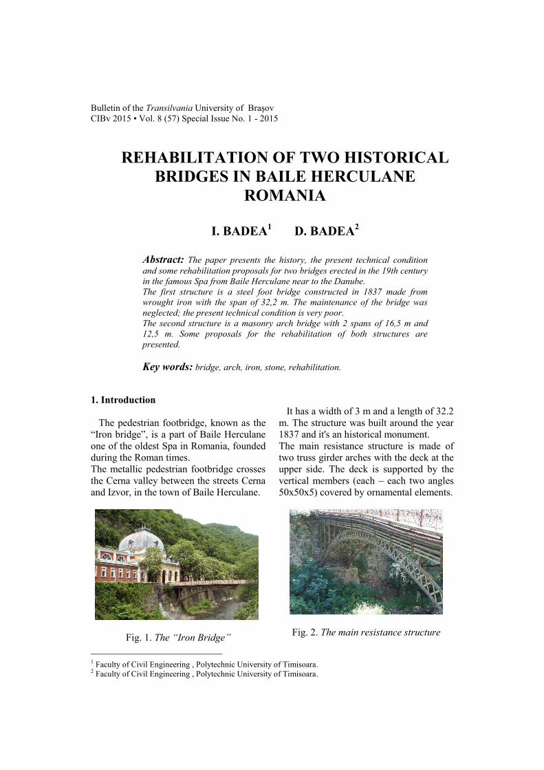
The pedestrian footbridge, known as the“Iron bridge”, is a part of Baile Herculaneone of the oldest Spa in Romania, foundedduring the Roman times.The metallic pedestrian footbridge crossesthe Cerna valley between the streets Cernaand Izvor, in the town of Baile Herculane.
Fig. 1. The “Iron Bridge”
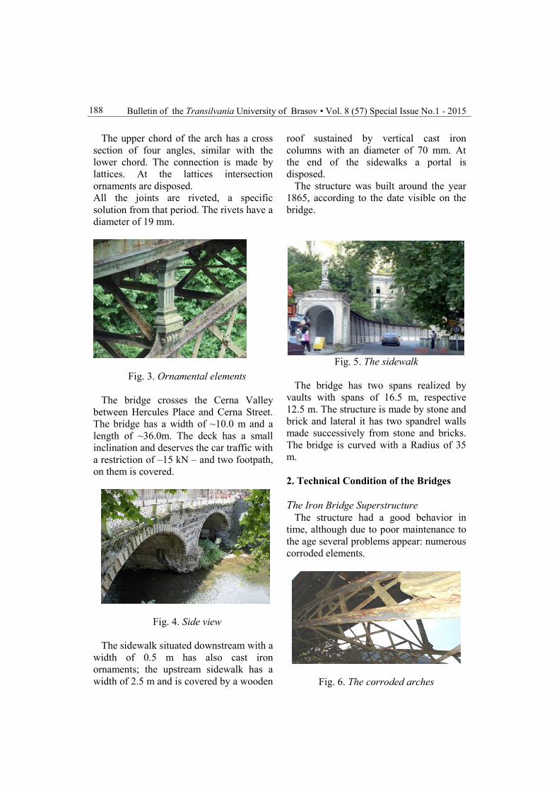
It has a width of 3 m and a length of 32.2m. The structure was built around the year1837 and it's an historical monument.The main resistance structure is made oftwo truss girder arches with the deck at theupper side. The deck is supported by thevertical members (each – each two angles50x50x5) covered by ornamental elements.
Fig. 2. The main resistance structure
Bulletin of the Transilvania University of Brasov • Vol. 8 (57) Special Issue No.1 - 2015188
The upper chord of the arch has a crosssection of four angles, similar with thelower chord. The connection is made bylattices. At the lattices intersectionornaments are disposed.All the joints are riveted, a specificsolution from that period. The rivets have adiameter of 19 mm.
Fig. 3. Ornamental elements
The bridge crosses the Cerna Valleybetween Hercules Place and Cerna Street.The bridge has a width of ~10.0 m and alength of ~36.0m. The deck has a smallinclination and deserves the car traffic witha restriction of –15 kN – and two footpath,on them is covered.
Fig. 4. Side view
The sidewalk situated downstream with awidth of 0.5 m has also cast ironornaments; the upstream sidewalk has awidth of 2.5 m and is covered by a wooden
roof sustained by vertical cast ironcolumns with an diameter of 70 mm. Atthe end of the sidewalks a portal isdisposed.
The structure was built around the year1865, according to the date visible on thebridge.
Fig. 5. The sidewalk
The bridge has two spans realized byvaults with spans of 16.5 m, respective12.5 m. The structure is made by stone andbrick and lateral it has two spandrel wallsmade successively from stone and bricks.The bridge is curved with a Radius of 35m.
2. Technical Condition of the Bridges
The Iron Bridge SuperstructureThe structure had a good behavior in
time, although due to poor maintenance tothe age several problems appear: numerouscorroded elements.
Fig. 6. The corroded arches
BADEA et al.: Rehabilitation of Two Historical Bridges in Baile Herculane Romania 189
At the main elements you can find a lotof areas with destroyed anticorrosiveprotection.
Fig. 7. Corroded joint and vertical member
The distance between the rivet at jointswas find inadequate (dmax= 6d= 6 x 19mm= 120 mm), causing corrosion betweenelements.
The wooden floor was severely damagedand some fixing elements were missing.There are some ornament elementsmissing.
The Iron Bridge InfrastructureThe infrastructure of the footbridge it's
build of soft stone, with a low resistance toerosion.The connection between the infrastructureand the embankment is partially destroyed.Vegetation growth can be observed.
Fig. 8. Vegetation growth
Road bridge SuperstructureThe road bridge had a good behavior in
time. Some degradation due to a badmaintenance can be observed. Also the
impact of the vehicles with the structuredestroyed partially some elements of thestructure.- masonry elements are severely damaged;- water infiltration;- vegetation;- damaged soft stone;- degradations, absence of stone masonry,- deformations, instabilities, inadequaterepairmants and vegetation- ornaments are missing
Fig. 9. Vegetation, damaged masonryelements
Fig.10. Ornaments are missing
Road bridge InfrastructureThe bridge infrastructure it's built up of
stone masonry and it shows the followingproblems: erosion, cracks, scouring, andseparation. Scoring and missing stonemasonry elements can be observed
The riverbed is clogged with differentwaste and wooden scraps in the zone of thefront-breakwaters. The support wallssustaining the riverbed are partiallydestroyed.

Bulletin of the Transilvania University of Brasov • Vol. 8 (57) Special Issue No.1 - 2015190
2.1. The Determination of Stress State inthe Structure
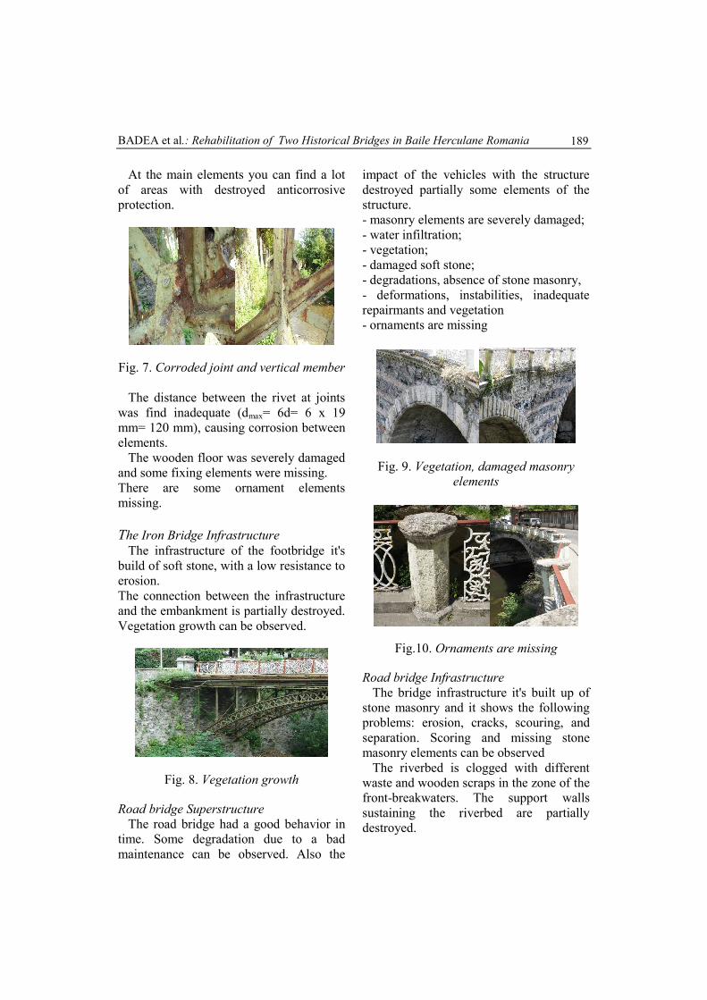
The arch is parabolic shaped, representsline of pressure for uniform distributedloads. The structure is double articulated,this means that the structure is static.
Fig. 11. The bridge infrastructure
determinate. The structure design wasperformed using a automatically computerprogram (Sofistik) and was verified withmanual calculus. The main loads were: selfweight of the structure resistance, pathweight, human load and temperatureaction.
Fig. 12. Structure design in Sofistik
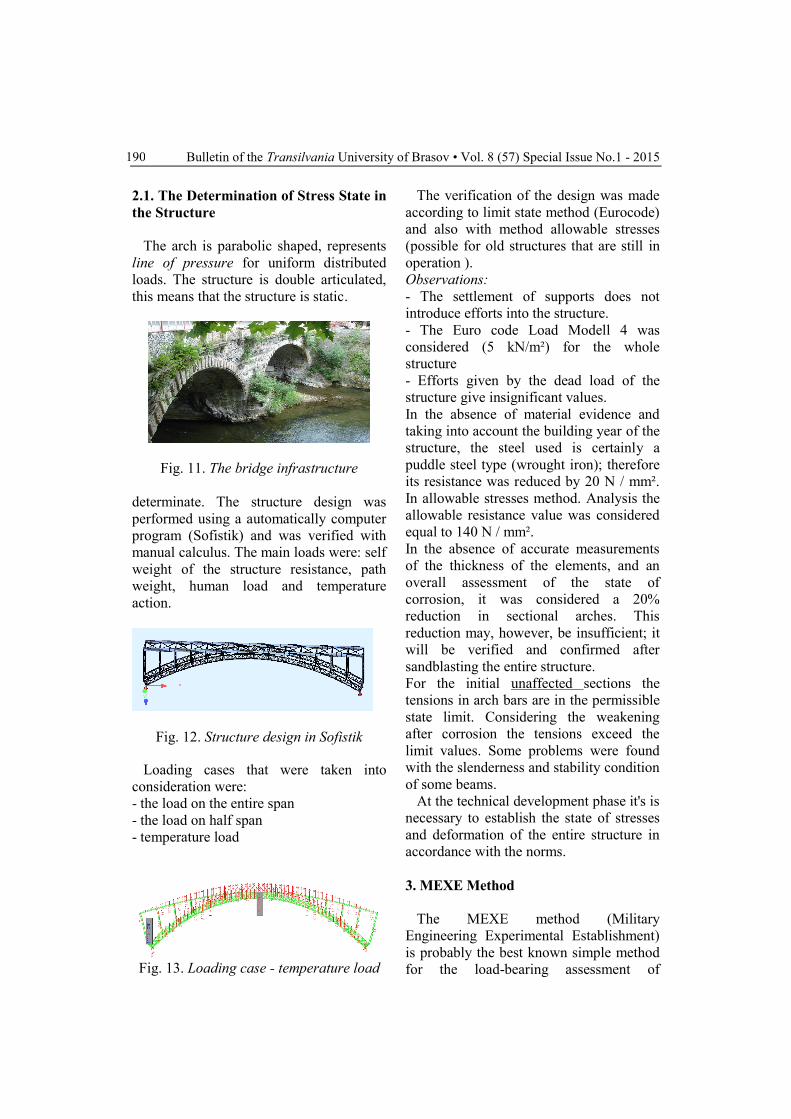
Loading cases that were taken intoconsideration were:- the load on the entire span- the load on half span- temperature load
Fig. 13. Loading case - temperature load
The verification of the design was madeaccording to limit state method (Eurocode)and also with method allowable stresses(possible for old structures that are still inoperation ).Observations:- The settlement of supports does notintroduce efforts into the structure.- The Euro code Load Modell 4 wasconsidered (5 kN/m²) for the wholestructure- Efforts given by the dead load of thestructure give insignificant values.In the absence of material evidence andtaking into account the building year of thestructure, the steel used is certainly apuddle steel type (wrought iron); thereforeits resistance was reduced by 20 N / mm².In allowable stresses method. Analysis theallowable resistance value was consideredequal to 140 N / mm².In the absence of accurate measurementsof the thickness of the elements, and anoverall assessment of the state ofcorrosion, it was considered a 20%reduction in sectional arches. Thisreduction may, however, be insufficient; itwill be verified and confirmed aftersandblasting the entire structure.For the initial unaffected sections thetensions in arch bars are in the permissiblestate limit. Considering the weakeningafter corrosion the tensions exceed thelimit values. Some problems were foundwith the slenderness and stability conditionof some beams.
At the technical development phase it's isnecessary to establish the state of stressesand deformation of the entire structure inaccordance with the norms.
3. MEXE Method
The MEXE method (MilitaryEngineering Experimental Establishment)is probably the best known simple methodfor the load-bearing assessment of
BADEA et al.: Rehabilitation of Two Historical Bridges in Baile Herculane Romania 191
historical arch bridges. The method isheavily applied not only in Great Britain(Huges and Blackler 1997), the country oforigin, but also in many other countriessince it was included in UIC-Codex(1995).
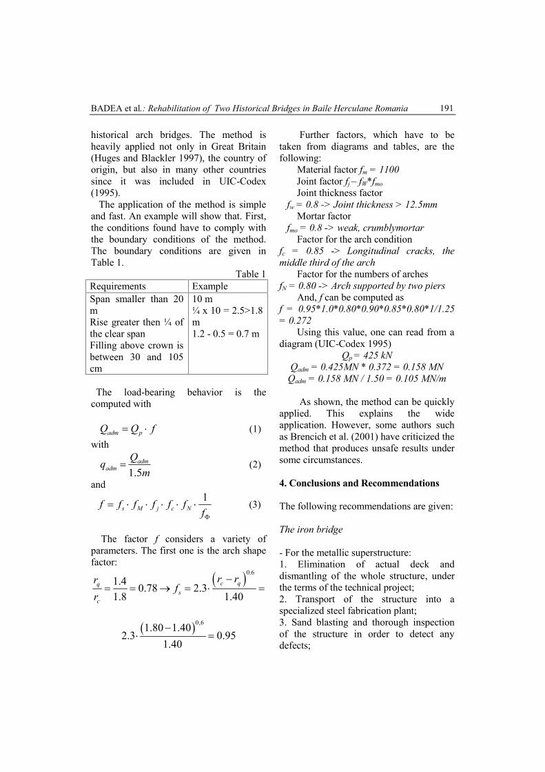
The application of the method is simpleand fast. An example will show that. First,the conditions found have to comply withthe boundary conditions of the method.The boundary conditions are given inTable 1.
Table 1Requirements ExampleSpan smaller than 20mRise greater then ¼ ofthe clear spanFilling above crown isbetween 30 and 105cm
10 m¼ x 10 = 2.5>1.8m1.2 - 0.5 = 0.7 m
The load-bearing behavior is thecomputed with
fQQ padm (1)with
mQq adm
adm 5.1 (2)
and
f
ffffff NcjMs1
(3)
The factor f considers a variety ofparameters. The first one is the arch shapefactor:
0.61.4 0.78 2.31.8 1.40
c qqs
c
r rrf
r
0,61.80 1.402.3 0.95
1.40
Further factors, which have to betaken from diagrams and tables, are thefollowing:
Material factor fm = 1100Joint factor fj – fW*fmoJoint thickness factor
fw = 0.8 -> Joint thickness > 12.5mmMortar factor
fmo = 0.8 -> weak, crumblymortarFactor for the arch condition
fc = 0.85 -> Longitudinal cracks, themiddle third of the arch
Factor for the numbers of archesfN = 0.80 -> Arch supported by two piers
And, f can be computed asf = 0.95*1.0*0.80*0.90*0.85*0.80*1/1.25= 0.272
Using this value, one can read from adiagram (UIC-Codex 1995)
Qp = 425 kNQadm = 0.425MN * 0.372 = 0.158 MN
Qadm = 0.158 MN / 1.50 = 0.105 MN/m
As shown, the method can be quicklyapplied. This explains the wideapplication. However, some authors suchas Brencich et al. (2001) have criticized themethod that produces unsafe results undersome circumstances.
4. Conclusions and Recommendations
The following recommendations are given:
The iron bridge
- For the metallic superstructure:1. Elimination of actual deck anddismantling of the whole structure, underthe terms of the technical project;2. Transport of the structure into aspecialized steel fabrication plant;3. Sand blasting and thorough inspectionof the structure in order to detect anydefects;
Bulletin of the Transilvania University of Brasov • Vol. 8 (57) Special Issue No.1 - 2015192
6. All joints will be executed with rivets tomaintain the original character of thestructure;7. Restoration of the deck in a modern andeasy solution;8. Revision, cleaning and repair ofbearings and spring connection of the arch;9. Remounting of the structure inaccordance with conditions imposed in thetechnical project;10. The final painting of the wholestructure; its illumination is recommendedto restore the original lighting pillars;
Highway Bridge
For the superstructure:Taking into account the considerable ageof 146 years, special attention will begiven to the structure:- elimination of road layers;- a repair, rebuilding the vaults in theiroriginal form and consistency to ensurelateral stability, uniformity and aestheticsof the bridge;- cleaning, filling, repair of the bricks at thespandrel, including their protection;- strengthening the vaults at the extrados orintrados in collaboration with the existingconstruction.These operations will be executed basedonly on the technical rehabilitation project- Construction of a new path by introducingreinforced concrete slabs;- a masonry repair, cleaning degraded stonemasonry all over the bridge;- a repair of the ornaments.
5. Proposed Solutions
Solution 1: Besides the usual repairs arepair of the vault at extrados withreinforced concrete C25 / 30 is proposed.Also the replacing of the filling existingover vaults with simple concrete C8 / 10and the disposal of a plate of reinforcedconcrete C35 / 45 with the runway role,must be adopted
Solution 2: Also in addition to therecommended repairs, instead ofstrengthening the upper surface of thevaults, you can choose the consolidationwith the intrados side at the vaults by aproviding a supplementary reinforcedconcrete wall. On top of the existing fillingwill be replaced on the height of approx.25 cm. Finally a slab of reinforced concreteC35 / 45, similar to the first solution haveto be adopted
Repair sidewalks by restoring andreplacing only a part of the structure (onlyhighly degraded and corroded elements - arate of ca. 60% estimated amount) , andsubsequently the applying of corrosionprotection. In this situation the life of thestructure can prolonged by 50 years, in theconditions of a strict maintenance program.2. Restoring the entire structure whilemaintaining the strict initial form and itshistorical features. In this case life is atleast 100 years, in the conditions of a strictmaintenance program.
References1. Expertiza: SSF-RO2. I.Badea, D.Badea: Lucrare de licenta:Bogenbrücken. Reabilitierungs Problem.