Embed Size (px)
Citation preview
Paper No. 694
REHABILITATION OF LOWER CHENAB CANAL (LCC)
SYSTEM PUNJAB PAKISTAN
Engr. Mazhar Hussain

448 Hussain

Pakistan Engineering Congress, 71st Annual Session Proceedings 449
REHABILITATION OF LOWER CHENAB CANAL (LCC)
SYSTEM PUNJAB PAKISTAN
Engr. Mazhar Hussain1
SYNOPSIS:
The Lower Chenab Canal (L.C.C.) Irrigation System is one of the oldest systems in the Punjab province constructed between the years 1892-1898. The
Command Area of Lower Chenab Canal lies between the rivers Ravi & Chenab i.e.
Rachna Doab. It is bounded by Qadirabad Balloki (Q.B.) Link Canal on the eastern side while it terminates beyond Trimmun-Sidhnai (T.S.) Link Canal on the western
side. The project area covers between latitude 30° - 36' and 32° - 09'N and longitude
72° - 14' and 77° - 44‟E and falls in the districts of Gujranwala, Hafizabad, Sheikhupura, Faisalabad, Jhang, Toba Tek Singh and Nankana Sahib. The Main
Line off-takes at Khanki Head works from left of the river Chenab with a head
discharge of 15,536 cusecs serving an area of 3.031 million acres. A large part of the Lower Chenab Canal system has already passed over a century of its life and has
undergone considerable deterioration. The Government of Punjab through Punjab
Irrigation and Drainage Authority (PIDA) decided to rehabilitate the system and remodel/reconstruct various worn out structures under funding of Japan Bank for
International Construction (JBIC).
The rehabilitation works involved remodeling of about 1640 canal miles length of irrigation channels, 1000 allied structures and 300 canal miles concrete
lining of existing earthen channels. The system was facing many maintenance
problems like deteriorated condition of about 100 years old structures with upstream and downstream erosion, berm-less reaches with eroded banks and
reduced free board. The system was unable to take its authorized discharge safely
and was being run by adopting a rotational programme. Now, the physical rehabilitation has contributed to great extent to increase system efficiency. The
rehabilitated irrigation system network has improved the operational / conveyance
efficiency, reliability and durability of the system as per designed discharges ensuring the safety of the canal systems and delivering equitable assured share of
water to the beneficiaries in a more sustainable and equitable manner in order to
boost up the national economy. The works of the project are in full swing and up to date progress is about 79%. The paper focuses on to present the rehabilitations
techniques / design approaches adopted. The performance of irrigation system for
efficient use of available water resources of Lower Chenab Canal System is also highlighted. The efficient water management practices are discussed in order to
improve system efficiency.
1 Director Design, Rehabilitating Lower Chenab Canal Project, Irrigation and Power Department, Faisalabad.
450 Hussain
1.0 INTRODUCTION
Lower Chenab Canal (L.C.C.) Irrigation System is one of the oldest systems
in the Punjab Province. The Lower Chenab Canal (LCC) off-taking from Khanki Head Works located in Gujranwala District on the River Chenab was constructed in
1892-98 and is supplying irrigation water to about 3.031 million acres of Culturable
Command Area (CCA) of 7 Districts i.e. Gujranwala, Hafizabad, Sheikhupura, Nanakana Sahib, Faisalabad, Jhang and Toba Tek Singh through a network of
Canals, Branches, distributaries and minors. The system has been maintained over
the years with very limited resources, resulting in backlog of various repair/remodelling works. A large part of the system has already lived over a
century of its life and has undergone considerable deterioration. Punjab Irrigation
and Drainage Authority (PIDA) have decided to rehabilitate the system and remodel/reconstruct various worn out structures. The system having vast quantum
of work has been divided into three parts i.e. Parts A, B and C for rehabilitation.
The Part A comprises the (i) L.C.C. Main Line Upper, (ii) L.C.C. Main Line Lower, and (iii) Upper Gugera Branch Canal along with distributaries/minors was
under implementation of rehabilitation/remodeling work since early 2004. It was
completed by June 30, 2007. All works had been completed by the said date except for some works yet under execution particularly in the reach from RD 0+000 to
69+000 of Main Line Upper, where substantial part of the work on a cross regulator
could not be completed. PIDA has now taken up implementation of “Part-B” of the LCC System namely “Rehabilitating Lower Chenab Canal System (Part-B) Project”.
Part B comprises rehabilitation of the canal systems (i) Burala Branch Canal
System, (ii) Mian Ali Branch Canal System, (iv) Lower Gugera Branch Canal System, (v) Rakh Branch Canal System, and two drainage system like (a)
Ahmadpur Kot Nikka (A.K.N.) Drainage System, and (b) Chak Bandi Drainage
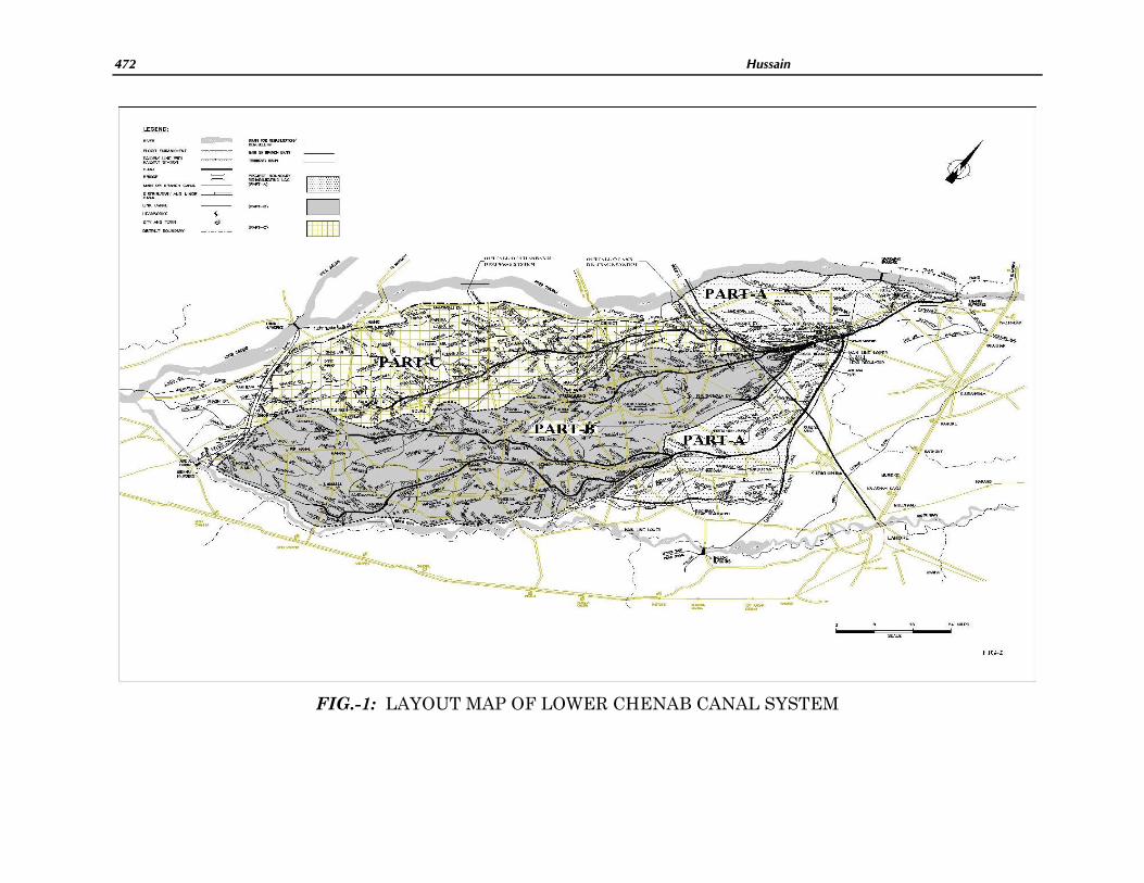
System. The Part –C comprise remodeling of Jhang Branch System. The Gross Area (GA) and Cultivable Command Area (CCA) under this Part-B Project is 1.85 million
Acres and 1.47 million Acres respectively. The entire L.C.C. system and the project
areas are shown in FIG.-1. The line diagram of the system is shown in FIG.-2.
The main object for rehabilitation of the Lower Chenab Canal system is to
improve conveyance efficiency, reliability and durability of the system as per
designed discharges by rehabilitating/remodeling the entire irrigation system, so as to provide irrigation water to the beneficiaries in a more sustainable and equitable
manner. The following describes the system project details and rehabilitations
design approaches. The performance of irrigation system for efficient use of available water resources of Lower Chenab Canal System is also highlighted. The
efficient water management practices are discussed in order to improve system
efficiency.
2.0 POTENTIAL PROBLEMS OF LCC SYSTEM
The L.C.C. system has been facing a number of major/minor problems. There
has been increase in water demand with the increase in the cropping intensity over
the years. The present cropping intensity is 175%. However the system was

Pakistan Engineering Congress, 71st Annual Session Proceedings 451
designed on cropping intensity of 75%. There has been deterioration of canal banks
and berms due to excessive discharges above the safe operational capacities. On the other hand, shortage of irrigation supplies was faced, particularly in tail reaches
due to inefficient conveyance system. There has been decrease in the groundwater
component due to gradual de-commissioning of public sector deep water tube wells. The following categories of works were involved. (a) Raising and strengthening of
canal banks in set-back position, (b) Bank Protection in Segments of excessive
erosion, (c) Rehabilitation/Replacement of old structures, (d) Replacement of worn out bridges, (e) Improving escapes and escape channels, (f) Provision of cattle ghats,
(g) Provision of monitoring facilities etc.
3.0 REHABILITATIONS WORKS IN PART-A
The channels being more than a century old, their banks have become weak and deteriorated, due to deferred maintenance. The Canal System is subject to a
great stress due to problems of (i) erratic behaviour of century old hydraulic
structures (ii) excessive bank erosion due to friable soil (iii) inadequate escape facilities (iv) abnormal fluming at bridges, inclusion of new areas into CCA etc. On
account of these problems, the canal system is unable to safely pass the designed
discharges through the Branch Canals, distributaries and minors.
A project for Rehabilitation of Lower Chenab Canal System (Part-A) was
initiated under National Drainage Programme (NDP) in February 2004 at a cost of
Rs. 2400.00 million for Rehabilitation of distributaries and minors of Khanki Division and Upper Gugera Branch Canal. The civil works were divided into 17
contract packages (12 packages of main canal, 2 packages of distys & minors and 3
packages for new bridges). The works on these packages has been subsentially completed. The area benefitted is about 0.68 million acres.
Overall Progress of this Part is 97%. As a result of its implementation, the
discharge carrying capacity of the Main Canal has been raised from 12,243 cusecs to 15,528 cusecs. This project will overcome the shortfall of 3285 cusecs for irrigating
the existing command area. The old and outdated 100 years old, 138 structures (12
Fall-cum-Bridges, 21 Head Regulators, 8 Cross Regulators, 28 Bridges and 77 Minor structures) have been replaced and raising and strengthening of 97 miles of
Canal Banks and remodeling of 85 Nos. of farmers managed distributaries have
been implemented. This project will increase the agriculture production over an area of 1.47 million acres and enhance the income of the 200,000 Farmers. The
Table-1 below shows the works taken up in Part-A.
Table-1: Rehabilitation/Remodeling details Part-A LCC System
Sr. No. Description of works Length
1 Raising & strengthening of banks of Main & Branch Canal 97 Miles
2 Re-construction of Hydraulic structures i.e. Falls / X-
Regulators
12 Nos.
3 Re-construction of bridges 29 Nos.

452 Hussain
4 Cattle Bath Stations 31 Nos.
5 Head Regulators of off-taking channels 20 Nos.
6 Bank Protection 51 Miles
7 Lining of channels. 12 Miles
8 Outlets 1288
Nos.
9 Rehabilitating of Distributaries and Minors (69 Nos.) 691
Miles
4.0 REHABILITATIONS WORKS IN PART-B
The Project cost amounting Rs. 9,142.248 million is financed from Japan
Bank for International Construction (JBIC) for Rehabilitating Lower Chenab Canal
System Part-B. The Project is expected to be completed by December 2011. Punjab Irrigation and Drainage Authority (PIDA) formulated Project Management Unit
(PMU) for managing, administrating/coordination and supervision of the agencies
involved in implementation of the Project. Project Management Unit is headed by the Chief Engineer Irrigation Faisalabad Zone. The Consultants of the Project are a
joint venture of National Engineering Services Pakistan (Pvt.) Ltd. – NESPAK and
National Development Consultants (Regd.) – NDC jointly called Punjab Irrigation Consultants (PIC).
The quantum of works for rehabilitation/Remodeling of Channels are
depicted in Tables-2, 3 and 4. The project works were divided into two Phases. The Phase –I comprised of Burala Br and Mian Ali Branch Canal system while Phase-II
comprised of Lower Gugera Branch and Rakh Branch Canal System. The details of
all Contract Packages of LCC System Part-B are shown in FIG.-3. The Phase I comprising 22 no contract packages were further divided into two divisions 1A and
IB. The 10 No. (Phase IA) & 12 No. (Phase IB) Contracts were awarded in
September & November 2007 respectively. The Phase-IIA (9 no. Contract Packages) were awarded during September 2008 and the Phase IIB (6 no. Contract Packages)
contracts were awarded in October 2008. The last contract of Phase IIB (PB-35 for
Drainage Works) was awarded in August 2009. The rehabilitation of Drainage System includes the following two systems. (a) AKN Drainage System
(Faisalabad/Samundri Drainage Division) and (b) Chakbandi Drainage System
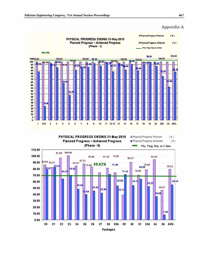
(Samundri Drainage Division). The Package wise physical progress worked out on the basis of weighted progress in each section/sub section of a package and its
graphical presentation for scheduled and achieved targets is shown in the
Appendix-A.
5.0 REHABILITATIONS WORKS IN PART-C
The LCC Part-C System comprises rehabilitation/remodeling Jhang Branch
Canal (Lower & Upper) which is taken under Annual Development Program (ADP),
Pakistan Engineering Congress, 71st Annual Session Proceedings 453
while lining/ rehabilitation/remodeling of distribution system is taken under
“Punjab Irrigation System Improvement Project (PISIP) financed by Japan Bank for International Construction (JBIC). The rehabilitation of Jhang Branch Upper RD
211+852 to 308+426 is divided into two contract packages while Jhang Branch
Lower from RD 0 to RD 189+300 is divided into 3 contract packages. The works involved are (i) raising and strengthening of banks, (ii) Re-sectioning &
improvement of prism by providing stone stud and bamboo bushing (iii) Remodeling
/ reconstruction of structures like falls, head regulators, bridges, outlets, cattle bath stations (iv) side protections. The civil works of distribution system of Jhang
Branch Canal System comprises of concrete lining of about 285 miles length and
rehabilitation of about 400 miles length of total 125 no. channels in Faisalabad Irrigation Zone which are divided into 10 no contract packages. This component of
the LCC System is in initial stage of tendering/award process. The physical works of
Part-C is not yet started.
6.0 BASIS OF DESIGN
The design approach was developed for an existing LCC Canal system which
has been working for the last more than hundred years but required rehabilitation
and remodeling. Capacity Statements and L sections of distributaries and minors were revised for design of structures. The designs produced were based on standard
design procedures and satisfied the requirements of modern construction materials
and methods. Experience and design approach based on standard codes and practices was adopted to minimize operational risks. The technical soundness of the
design was secured through condition surveys, soil exploration, testing programs.
The system design was divided into the different parts such as main (Branch) canals, distributary and minor canals, Hydraulic Structures, Escapes, Drains,
Buildings, Mechanical Works, Bridges etc.
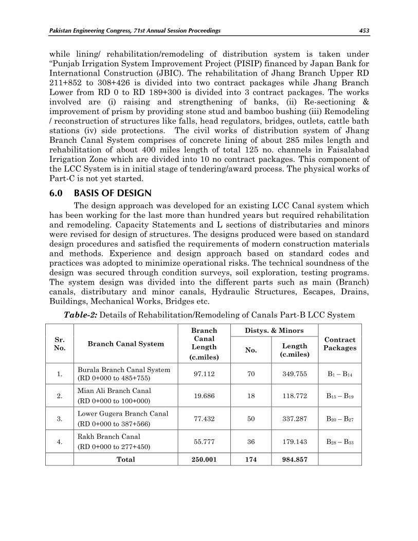
Table-2: Details of Rehabilitation/Remodeling of Canals Part-B LCC System
Sr.
No. Branch Canal System
Branch
Canal
Length
(c.miles)
Distys. & Minors
Contract
Packages No. Length
(c.miles)
1. Burala Branch Canal System
(RD 0+000 to 485+755) 97.112 70 349.755 B1 – B14
2. Mian Ali Branch Canal
(RD 0+000 to 100+000) 19.686 18 118.772 B15 – B19
3. Lower Gugera Branch Canal
(RD 0+000 to 387+566) 77.432 50 337.287 B20 – B27
4. Rakh Branch Canal
(RD 0+000 to 277+450) 55.777 36 179.143 B28 – B33
Total 250.001 174 984.857

454 Hussain
Table-3: Quantum of work in different categories of work in Part-B LCC System
Sr.
No. Description
Estimated Quantities
Branch Canals Distys/Minors
1. Raising and Strengthening of canal Banks 272 Mcft 166 Mcft
2. Remodelling / Reconstruction of Hydraulic
Structures
a) Construction of Diversion Channels 48 nos. -
b) Cross Regulators/Falls 48 nos. 45 nos.
c) Head Regulator 99 nos. 25 nos.
3. Escape channels (Lower Gugera Br: 1 Burala
Br: 4 Mian Ali Br: 1; Rakh Br: 1)
7 nos. -
4. New/Replacement of Structures (Bridges) 58 nos. 165 nos.
5. Bank Protection 50.527 c mi. 53.152 c mi.
6. Cattle Ghats 65 nos. 146 nos.
7. Renovation/replacement of buildings 97 nos. 29 nos.
8. Lining of Channels - 263.792 c.mi.
6.1 Design Discharge
The design discharges of Minor and Distributary canals were based on the
Culturable Command Areas (CCA) of outlets and the sanctioned Water Allowance.
Special water supply sanctioned for gardens, fish ponds etc; was added to make up total discharge of an outlet. The total discharge of the off takes (Channels, outlets
etc;) grouped together in a reach, along with the calculated seepage losses in that
reach, forms the designed discharge at the head of that reach which also was the tail of the next u/s reach. To this discharge was added the discharges of the off takes
of this u/s reach grouped together along with the calculated losses in that reach, to
give design discharge at the head of this reach / tail of the next reach. With cumulative effect of design discharges of the successive reaches u/s, the design
discharge at head of the channel got worked out. The approved L- sections
therefore, showed both Rabi and Kharif FS discharges.
For a Branch canal, the same process as that for the distributary off takes
was repeated. The Rabi design discharge at heads of the off-takes, as computed
along with the seepage losses formed the basis of the discharge at head of a branch. The Branch L sections also showed both the Rabi and Kharif FS discharges. Full
supply levels and the prism parameters based on the Rabi AFS discharges were
shown on longitudinal section of channels. A typical updated /revised longitudinal section of a channel is depicted in FIG-4.
Pakistan Engineering Congress, 71st Annual Session Proceedings 455
6.2 Full Supply Levels and Longitudinal Water Surface Slope
The Full Supply Levels (FSL) of channels provided adequate command. The
FSLs were fixed on the basis of field hydraulic data which was observed by field formations. The existing longitudinal water surface slope of a channel was followed.
The existing slope was determined by observing the existing water levels in the
channel at regular specified intervals, at control points and at u/s and d/s of head regulators of the off-takes. The regime slope related to discharge in the channel, the
silt load and grade defined by the value of „f‟ if designed on Lacey‟s and on „n‟ if
designed on Manning‟s.
6.3 Selection of Manning's "n" or “f”
Some distributary and minor canals were lined wholly or partially. All lined
channels, drain sections and branch canals were designed on Manning's formula.
The value of Manning‟s ‟n‟ was kept constant for a new channel. A channel with a smoother bed section has lower value of „n‟ and has more discharge capacity than
that with a rougher section with the same remaining parameters. The bed surface
of a lined channel deteriorates with age and becomes increasingly rough. Its value of „n‟ increases and its flow capacity gradually decreases. For LCC System, an “n”
value of 0.018 is adopted for brick and 0.016 for newly concrete lined channels. For
the existing channels, the "n" value is computed from their flow measurements. It ranges from 0.018 to 0.020 for existing lined channels and is between 0.021 and
0.025 for unlined sections. However, the large values of “n” represent the unlined
reaches, heavily silted and with berms dented with regular cattle trespass and/ or infested with weed growth.
The existing unlined distributary and minor canals were based on Lacey‟s
Silt factor „f‟. In the laboratory method, percentage of d50 (mm) particles retained is determined by sieve analysis of samples of the existing suspended and bed material
in a given reach for sediment concentration and particle size gradation. The value of
„f‟ is then computed with the following relationship „f‟ = 1.76( d50 )1/2 .The following Lacey‟s equations were used. (a) Q*f^2 = 3.8*V^6 and f = (1844* S* Q^1/6)^3/5 . The
laboratory values of „f‟ in various reaches of the project Branch Canals were also
determined by the Central Material Testing Laboratory (CMTL) WAPDA. The design of the unlined / earthen branch channels were based on Manning‟s equation,
based on the values of „n‟ actually observed in the field.
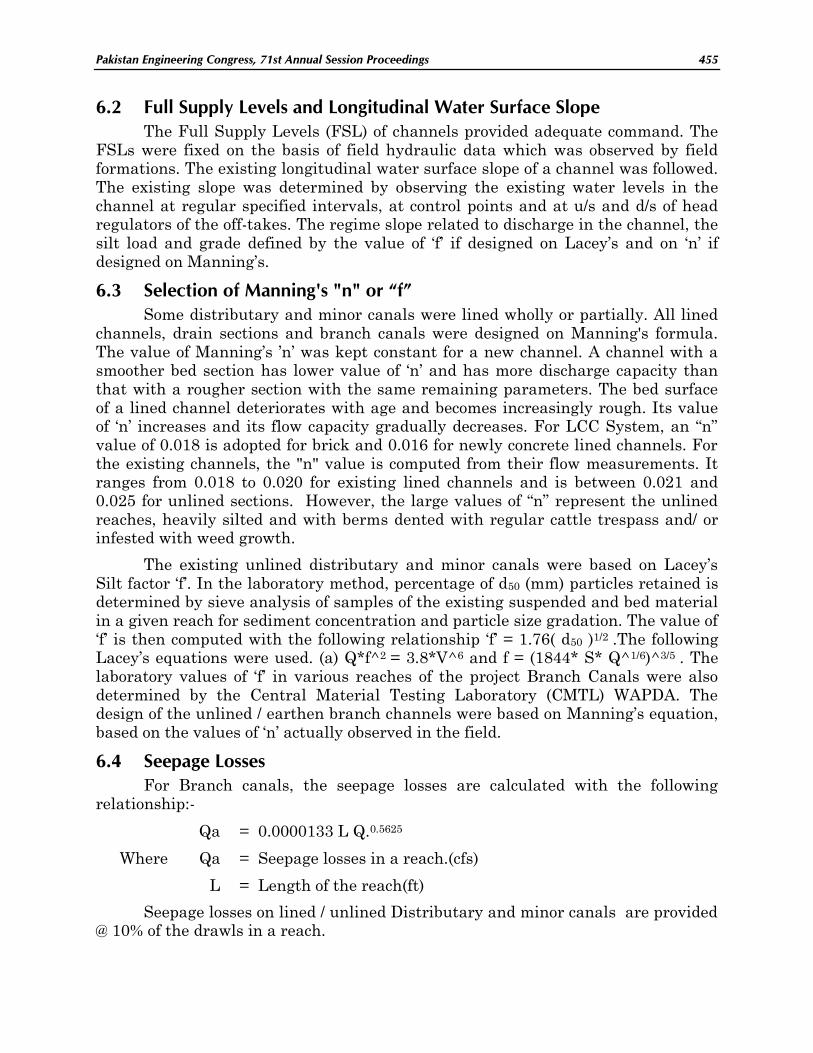
6.4 Seepage Losses
For Branch canals, the seepage losses are calculated with the following relationship:-
Qa = 0.0000133 L Q.0.5625
Where Qa = Seepage losses in a reach.(cfs)
L = Length of the reach(ft)
Seepage losses on lined / unlined Distributary and minor canals are provided @ 10% of the drawls in a reach.

456 Hussain
6.5 Design Velocities
The velocity in a canal reach relates to hydraulic parameters such as bed
slope and shape of its cross section, etc. For a lined channel, the type of lining also matters. Depending on the flow conditions in a given canal reach, the flow velocities
may fall below the design velocities exhibiting the tendency of the channel to silt up.
On the other hand, if the design velocities are exceeded, an excessive bed slope is indicated and the channel bed will tend to scour. The limiting velocity in a channel
depends mainly upon its designed discharge. However, for an unlined channel,
velocity exceeding 3.50 ft/sec is rarely allowed. For a lined channel, it may be up to 6.0 ft/sec if sufficient slope is available. For lining of channels under the LCC
project, the following range of velocities was adopted as shown in Table-5.
Table-5: Range of Velocities adopted for lining of channels
Range of discharges
(cusecs)
Range of velocities
(ft/sec)
71 – 100 1.80 – 2.15
21 – 70 1.40 – 1.80
5 – 20 1.25 – 1.40
Less than 5.0 1.0 – 1.25
6.6 Backwater Curves
To determine the influence of the cross regulators upon the water surface elevations at some specified point‟s u/s in the Branch Canal, backwater effects are
calculated where necessary. The backwater calculations are carried out with the
direct step method of computations for determination of the backwater profile.
6.7 Bank Section Design
Typical earthen bank sections of a branch canal and disty / minor canals are
shown in FIGs. 5 & 6. Width of Patrol banks for Distys above 200 cfs discharge are
kept as 17 ft including 5 ft for a dowel and for a non patrol bank it is 12 ft. For Disty and Minor canals below 200 cfs discharge, the patrol bank width is kept as 12 ft and
the non patrol bank is also kept as 12 ft wide where Right of way permits.
Otherwise it is restricted between non patrol bank width 6.0 ft to 8.0 ft.
6.8 Freeboards
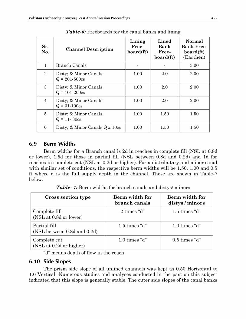
The Table-6 below shows the freeboards for the canal banks and lining above
the normal FS level, freeboards also cater 0.50ft for extra discharge during Kharif
season.
Pakistan Engineering Congress, 71st Annual Session Proceedings 457
Table-6: Freeboards for the canal banks and lining
Sr.
No. Channel Description
Lining
Free-
board(ft)
Lined
Bank
Free-
board(ft)
Normal
Bank Free-
board(ft)
(Earthen)
1 Branch Canals - - 3.00
2 Disty; & Minor Canals
Q = 201-500cs
1.00 2.0 2.00
3 Disty; & Minor Canals
Q = 101-200cs
1.00 2.0 2.00
4 Disty; & Minor Canals
Q = 31-100cs
1.00 2.0 2.00
5 Disty; & Minor Canals
Q = 11- 30cs
1.00 1.50 1.50
6 Disty; & Minor Canals Q 10cs 1.00 1.50 1.50
6.9 Berm Widths
Berm widths for a Branch canal is 2d in reaches in complete fill (NSL at 0.8d or lower), 1.5d for those in partial fill (NSL between 0.8d and 0.2d) and 1d for
reaches in complete cut (NSL at 0.2d or higher). For a distributary and minor canal
with similar set of conditions, the respective berm widths will be 1.50, 1.00 and 0.5 ft where d is the full supply depth in the channel. These are shown in Table-7
below.
Table- 7: Berm widths for branch canals and distys/ minors
Cross section type Berm width for
branch canals
Berm width for
distys / minors
Complete fill
(NSL at 0.8d or lower)
2 times “d” 1.5 times “d”
Partial fill
(NSL between 0.8d and 0.2d)
1.5 times “d” 1.0 times “d”
Complete cut
(NSL at 0.2d or higher)
1.0 times “d” 0.5 times “d”
“d” means depth of flow in the reach
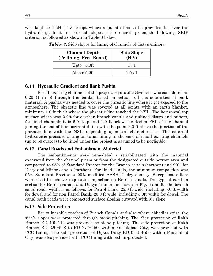
6.10 Side Slopes
The prism side slope of all unlined channels was kept as 0.50 Horizontal to 1.0 Vertical. Numerous studies and analyses conducted in the past on this subject
indicated that this slope is generally stable. The outer side slopes of the canal banks
458 Hussain
was kept as 1.5H : 1V except where a pushta has to be provided to cover the
hydraulic gradient line. For side slopes of the concrete prism, the following ISRIP criterion is followed as shown in Table-8 below.
Table- 8: Side slopes for lining of channels of distys /minors
Channel Depth
(i/c lining Free Board)
Side Slope
(H:V)
Upto 5.0ft 1 : 1
Above 5.0ft 1.5 : 1
6.11 Hydraulic Gradient and Bank Pushta
For all existing channels of the project, Hydraulic Gradient was considered as
0.20 (1 in 5) through the banks, based on actual soil characteristics of bank
material. A pushta was needed to cover the phreatic line where it got exposed to the atmosphere. The phraetic line was covered at all points with an earth blanket,
minimum 1.0 ft thick where the phreatic line touched the NSL. The horizontal top
surface width was 3.0ft for earthen branch canals and unlined distys and minors, for lined channels it is 5.0 ft, placed 1.0 ft below the design FSL of the channel
joining the end of this horizontal line with the point 2.0 ft above the junction of the
phreatic line with the NSL, depending upon soil characteristics. The external hydrostatic pressure acting on canal lining in the case of small existing channels
(up to 50 cusecs) to be lined under the project is assumed to be negligible.
6.12 Canal Roads and Embankment Material
The embankments were remodeled / rehabilitated with the material excavated from the channel prism or from the designated outside borrow area and
compacted to 95% of Standard Proctor for the Branch canals (earthen) and 90% for
Disty and Minor canals (earthen). For lined canals, the minimum compaction was 95% Standard Proctor or 90% modified AASHTO dry density. Sheep foot rollers
were used to achieve requisite compaction on Branch canals. The typical earthen
section for Branch canals and Distys / minors is shown in Fig. 5 and 6. The branch canal roads width is as follows: for Patrol Bank- 25.0 ft wide, including 5.0 ft width
for dowel and for non Patrol Bank, 20.0 ft wide, including 5.0ft width for dowel. The
canal bank roads were compacted surface sloping outward with 3% slope.
6.13 Side Protection
For vulnerable reaches of Branch Canals and also where abbadies exist, the
side‟s slopes were protected through stone pitching. The Side protection of Rakh
Branch RD 100-114 was provided as stone pitching. The side protection of Rakh Branch RD 229+528 to RD 277+450, within Faisalabad City, was provided with
PCC Lining. The side protection of Dijkot Disty RD 0- 31+500 within Faisalabad
City, was also provided with PCC lining with bed un-protected.

Pakistan Engineering Congress, 71st Annual Session Proceedings 459
6.14 Concrete Lining of Channels
Under the LCC System, the channels were selected for concrete lining up to
50 cuseces capacity. Some distributaries and minor canal reaches located in saline zones, have been selected for lining with an idea to save heavy seepage losses which
otherwise occur in unlined channels. Cases of channels located in sweet zones were
evaluated on individual basis and decided as per criteria of ISRIP. Lining also protects the channels from damage to its sections by cattle trespass. The bank top
width was kept as minimum 12.0 ft and Free-board was allowed as indicated. The
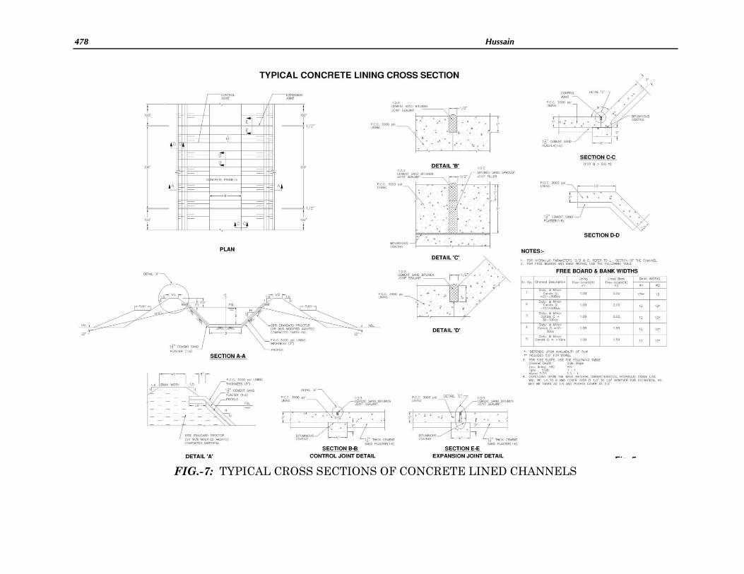
lined sections were redesigned with Manning‟s „n‟ as 0.016 for PCC lining. The canal lining comprised plain 3.0 inches thick concrete over 1½ inch thick 1:6 cement sand
plaster placed on the moistened, compacted grade, as shown in FIG. 7. The 28-day
compressive cylinder strength of the concrete, in the lining, was adopted as 3000 psi, with the maximum aggregate size not exceeding ¾ inches. Shoulder length was
kept as 1.0ft in a channel with discharge up to 100 cfs and 1.50 ft in one up to 250
cfs. The transverse (vertical) and longitudinal joints in the lining were provided with joint filler/sealant. The transverse joints were spaced 10 ft. apart. Two
longitudinal joints were placed one at either end of the bottom slab. The expansion
joint were provided at 100 feet interval.
6.15 Canal Escapes
There were no working escapes on the branch canals of this project, except
the partially working Buchiana escape located at tail Upper Gugera branch. It was
the common instrument of relief for Burala and Lower Gugera branches and its design capacityhas been raised from 1800 cfs to 2500 cfs. Due to lengthy time lag
involved, the relief afforded by this escape was not very effective in case of a
mishap in the lower middle and tail reaches of these branches. Table-9 shows new escapes provided in the LCC System.
Table-9: New escapes provided in Part –B LCC System
Sr.
No. Branch RD of Escape
Discharge
(cfs)
1 Burala 102 + 000/L 800
2 Burala 410 + 000/R 400
3 Lower Gu. 90 + 000/L 800
4 Lower Gu. 358 + 566/R 500
5 Mian Ali 66 + 000/R 400
6 Rakh 80 + 000/R 800
460 Hussain
6.16 Drainage Systems
Under Contract Package 35, rehabilitation of Ahmadpur-Kot Nikka Drainage
System of Faisalabad Drainage Division, and Chakbandi Drainage System of Samundri Drainage Division, Faisalabad, are included for enabling these systems to
drain off excess rain water run off from their catchments within 48 hours, and
maintain salt balance in the soil and a minimum depth of ground water so as to keep it clear below the crop root zone. L-sections of these drainage systems are
revised and updated with their capacities based on the respective catchments areas
and drainage coefficients.
6.17 Buildings
Some of the existing buildings, residential and non residential, were in bad
shape. These have been repaired, rehabilitated and renovated and some of them
have been replaced. Renovation and repairing has been done in respect of the office building of Sub divisional Officer, and other buildings, residential and non
residential, in Drainage colony, Chiniot. A rest house has also been constructed
there.
6.18 Mechanical Works
The head and cross regulator structures were provided with gated
arrangement for regulation. The following types of gate equipment were considered,
(a) Fixed Wheel Gate with counter weight and (b) Slide Gate. Weir type fixed-wheel gates with three side sealing system were provided at cross regulators with manual
hoisting system depending upon other operational requirements. However, sliding
type gates were installed depending upon the size of the clear span and full supply level in the canal. The hoisting systems for cross regulator gates were of drum rope
with counter weight to reduce hoisting effort. The hoisting system was designed to
limit the hand load of the operator to 20 lbs at the crank or hand wheel while maintaining a reasonable opening/ closing speed of the gate. Inspection windows
were provided for fixed wheel gates for inspection and maintenance of the wheels/
wheel pins etc. The head regulator gates at distributaries were of slide type with three/ four side sealing system having manually operated stem rod type hoisting
system. Rubber sealing systems were provided for fixed wheel gates with stainless
steel sealing surfaces. Slide gates have bronze sealing with stainless steel sealing surfaces. Coalter- epoxy paint (C-200) is applied to the gates for protection against
corrosion.
The gate equipment was designed to have useful life of approximately 50 years with minimum of maintenance requirement. The gates were designed to
withstand maximum hydrostatic pressure on the fully closed gates i.e. designed
maximum pond level u/s and nil d/s and with maximum earthquake factor of the area. For gates mechanism, conservative safety factors and friction coefficients were
adopted because of the indeterminate structural and variable operational
characteristics of the gates. Maximum values of friction coefficients were used for determining hoisting capacity. The design of gate equipment was based on
Pakistan Engineering Congress, 71st Annual Session Proceedings 461
guidelines of the U.S. Army Corps of Engineers and U.S Bureau of Reclamation and
ACI codes. The technical details and specifications are based on ASTM Standards.
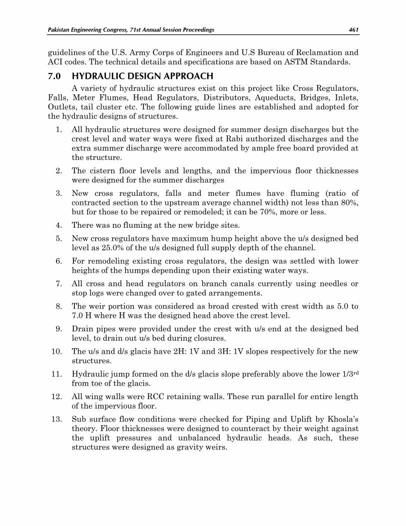
7.0 HYDRAULIC DESIGN APPROACH
A variety of hydraulic structures exist on this project like Cross Regulators,
Falls, Meter Flumes, Head Regulators, Distributors, Aqueducts, Bridges, Inlets,
Outlets, tail cluster etc. The following guide lines are established and adopted for the hydraulic designs of structures.
1. All hydraulic structures were designed for summer design discharges but the
crest level and water ways were fixed at Rabi authorized discharges and the extra summer discharge were accommodated by ample free board provided at
the structure.
2. The cistern floor levels and lengths, and the impervious floor thicknesses were designed for the summer discharges
3. New cross regulators, falls and meter flumes have fluming (ratio of
contracted section to the upstream average channel width) not less than 80%, but for those to be repaired or remodeled; it can be 70%, more or less.
4. There was no fluming at the new bridge sites.
5. New cross regulators have maximum hump height above the u/s designed bed level as 25.0% of the u/s designed full supply depth of the channel.
6. For remodeling existing cross regulators, the design was settled with lower
heights of the humps depending upon their existing water ways.
7. All cross and head regulators on branch canals currently using needles or
stop logs were changed over to gated arrangements.
8. The weir portion was considered as broad crested with crest width as 5.0 to 7.0 H where H was the designed head above the crest level.
9. Drain pipes were provided under the crest with u/s end at the designed bed
level, to drain out u/s bed during closures.
10. The u/s and d/s glacis have 2H: 1V and 3H: 1V slopes respectively for the new
structures.
11. Hydraulic jump formed on the d/s glacis slope preferably above the lower 1/3rd from toe of the glacis.
12. All wing walls were RCC retaining walls. These run parallel for entire length
of the impervious floor.
13. Sub surface flow conditions were checked for Piping and Uplift by Khosla‟s
theory. Floor thicknesses were designed to counteract by their weight against
the uplift pressures and unbalanced hydraulic heads. As such, these structures were designed as gravity weirs.

462 Hussain
14. The minimum Exit Gradient for such new structures was adopted as 0.14 to
0.20.
15. Stilling basins conformed to USBR standards.
16. Stilling basin floor level was placed at 1.25Ef2 below the d/s Total Energy
Line (TEL), or 1.0ft below the designed bed level whichever was lower, where Ef2 was the d/s conjugate depth d2 + d/s Velocity head.
17. Minimum length of the cistern was kept as 4 to 6 Ef2
18. Cut off walls were provided at the u/s and d/s ends of the impervious floor to prevent under mining.
19. These cut off walls have depths higher of the two as under:-
u/s cut off = 1/3d below designed bed level or 1.25R below FSL
d/s cut off = 1/2d below designed bed level or 1.50R below FSL where:
d = u/s or d/s FS depth, as the case may be.
R = Scour depth
Scour depth „R‟ is calculated with Lacey‟s formula R= 0.9(q2/f)1/3
Where
q = Discharge per foot width of the channel section
f = Lacey‟s silt factor
20. MS sheet piles are used as cut off walls where depth is more than 5 ft and
dewatering is involved.
21. The inverted filter have Precast PCC blocks, size 1.5‟x 1.5‟x 1.5‟ or 2‟x2‟x1‟, up
to minimum length 1.5d from the d/s cut off, over graded inverted filter as per
specifications. It is followed by stone apron, having minimum stone size 0.75‟ dia, up to a length of 2.25d, with minimum depth equal to that of the precast
block.
22. All cross regulators and falls on the project branch canals have stone side pitching 1.67 ft thick as specified on the drawings or dry brick side pitching
0.62 ft, up to 200ft on the upstream and 300ft on the downstream.
23. The cross regulators and head regulators were designed with d/s as nil and the u/s pond level as the FSL. The new head regulators were designed as
drowned culverts. The structure water level d/s of which it was never going to
be nil, were designed for the maximum head across expected
24. Escape regulators have crest level setting at 2/3 FS depth (from FSL) of the
canal to prevent excessive silt passing in to the drains in which these are to
outfall.
25. For Bridges with pile abutments, the clear distance between the abutments
was kept as (2d+ b) ft, where „b‟ is the design bed width at the site.

Pakistan Engineering Congress, 71st Annual Session Proceedings 463
7.1 Structures Replacements
Structures which have deteriorated or been damaged for reasons already
explained, beyond reasonable repairs or were not amenable to remodeling, were replaced by constructing them a new. The final decision in this respect was based on
the joint condition surveys carried out by the client‟s and the consultants‟ staff. The
independent diversions were constructed to allow construction of the new structures during the flow seasons. For replacing structures on distributaries and minor
canals, the joint decisions based on site visits and physical condition survey, were
generally respected. All existing bridges not maintained by the Highway Department, National Highway Authority or the District Government was
reconstructed on pile foundations and roadways as per Highway Department
Standards. All village road (VR) bridges were generally at right angles except when combined with other structures having skewed orientation. Arterial road
(AR)/district road (DR) bridges were oriented with the existing alignment. The road
way widths as per highway standards were adopted: The Clear Roadway Width for Arterial Roads (AR) was 28 ft. For District Roads (DR), it was 24 ft while for Village
Roads (VR), it was 14 ft.
7.2 Remodeling Structures
As L-section parameters of the branch canals and their distribution systems were revised, all existing structures were checked for new conditions. The
structures, on which the changes required by the revised parameters were carried
out within the annual closures, were redesigned and remodeled. An effort was made to carry out the required changes without disturbing the main body of the structure.
Majority of existing control structures were made of masonry and or concrete
either plain or reinforced, with protection by stone pitching upstream and downstream. These were remodeled with the use of same material and new
structures were made of plain or reinforced concrete or with combination of these.
The floors were designed to resist full unbalanced hydrostatic pressures (assumed effective on the entire area of section considered) by its own weight. In mass
concrete floors minimum crack control reinforcement were provided where
necessary to economize the weight of vertical members i.e piers columns ,abutment walls, were made use of to enhance the weight of members resisting buoyancy and
flexural moments were resisted by reinforcement. Gated Structures consist of Brick
or Concrete walls and piers and were designed to resist all dead and live loads. The floors were provided with thickness to counter full hydrostatic pressures.
7.3 New Structures
Structures which were required to be introduced new in addition to those
existing already were new structures. This were hydraulic structures needed to improve working or command of a channel at a particular point, a head regulator
for a new channel or for a new escape facility to be provided on a system, or was a
new bridge on public demand. List of new/replacement structures in each package are finalized progressively after assessment. In addition, the new structure
proposed on the two drainage systems covered by this project, were also taken up.

464 Hussain
New lining of reaches/ channels undertaken under the project were also a new
work. Cattle Bath Stations were also new structures and were provided on Branch canals within the canal prism, depending upon their site requirements and public
demand. In case of Distys, some cattle bath stations were also provided as per site
requirements.
The Project contained different types of structures. There were many bridges,
cross drainage structures and cross regulators, intake Structures etc. The procedure
and the criteria for selection of type of foundation and the foundation design were established. Choice of type of foundation depended upon the nature of the sub-
strata and on the arrangement of the super structure. The loads were spread to the
soil in a manner such that its limiting strength was not exceeded and resulting deformations were tolerable. Shallow foundations accomplish this by spreading the
loads laterally whereas deep foundations, although analogous to spread footings,
distribute the load vertically rather than horizontally. The spread footing was considered for box culverts bridges, off-take head regulators structures and crossing
structures of distributaries and minors. The mat foundation was adopted for Intake
Structure, some components of Cross Drainage Structures and Fall Structures. The deep foundation was adopted for in-situ reinforced concrete friction piles for
foundations of AR, DR and VR bridges over mainly Branch Canals.
A factor of safety of 3 against ultimate bearing capacity was adopted under normal loading conditions and a factor of safety of 2 under combined maximum
load. The minimum depth of shallow foundations was adopted as 4.0 ft below the
existing ground level. The evaluation of bearing capacity was carried out by considering both the shear based and settlement based criteria supported by
geotechnical investigation. The bearing capacity analyses were carried out using the
conservative methods. The final recommendations of allowable bearing pressures were based upon these analyses and geotechnical investigation of various sites. For
the L.C.C. Project, FOS of 1.5 was adopted for shaft resistance while FOS of 3 was
used for end bearing. However, FOS based on both end bearing and shaft resistance was taken as 2.5.
7.4 Earthen Channels
On the branch canals, the banks were brought to the designed dimensions as
per revised parameters and as per criteria mentioned above. No earth work was carried out in the prism except where required for rehabilitation of the existing X-
section, through berm cutting/unloading and killa bushing or re-sectioning of the
canal prism. However, brick or stone side protection were provided, where the channel sections tend to widen by side erosion. Earthen sections of distributary and
minor canals were brought to the design sections and some reaches needed side
protection as well. Instead of existing Rakh Branch between RD 0- 38, Jhang Branch Upper RD 0- 38 was remodeled to feed Rakh Branch from RD 38, as it was
considered to be more economical and viable duo to better condition of existing
structures and canal prism.

Pakistan Engineering Congress, 71st Annual Session Proceedings 465
8.0 PERFORMANCE OF LCC IRRIGATION SYSTEM
The conveyance efficiency has been improved by about 40-50 percent by
strengthening and raising of canal banks and lining of channels in the system. Wastage of water has also been reduced to 40-60 percent by providing control gates
for efficient regulation and reconstruction of outlets. It is a matter of fact that the
water allocations to the system are exclusively from river water, groundwater is not considered as a resource, the contribution of rain is not explicitly considered and the
cropping intensities are too high (175%). The design for the full potential of the
system is based on a proper water balance and accounting of all water components. A huge investment is incurred for rehabilitating of Lower Chenab Canal System.
Now it is dire need to save and utilize every drop of water to a maximum extend for
the benefit of the beneficiaries. An efficiency associated with irrigation systems is distribution uniformity, or how evenly water is applied over the system. To
maintain water efficiency in operations and maintenance, a water budget is used as
a performance standard for water consumption. It is also now important to revise the water needs division wise of LCC Irrigation system and plan an irrigation
schedule to meet that needs. It is the need of time to have a full water audit of
irrigation system to verify proper scheduling and to expose growing deficiencies from changes. Over the time, it is also required to check the irrigation schedule is
appropriate for climate, soil conditions, plant materials, grading, and season.
9.0 EFFICIENT WATER MANAGEMENT PRACTICES
The improvements in the performance of LCC System have been significantly completed by redesigning the systems, by rehabilitation /remodeling of channels
and replacement/reconstruction of worn out structures. The level of farmer
knowledge regarding application technology and management practices is generally moderate, and irrigation scheduling is uniformly being used. The water user
association is the basic organizational unit for achieving truly participatory
irrigation management. To improve irrigation service delivery, all Farmers Organizations in Area Water Board, LCC (West) and (East) Circle, Faisalabad are
in operation and are working to solve the problems of farming community regarding
Irrigation water. Technical Managers, Beldars and other staff of Farmers Organizations are working to control water theft, checking and observe the
discharge at Head Regulators of Distributaries. Farmers Organizations are also
checking the outlets on regular basis and repairing tampered or defective outlets. Capacity Building & Training of farmers is underway. Now, farmers are partners in
planning, implementation and management and they have formed their water user
association. The management goals are: assurance of a reliable water supply to the farms; adoption of a system of equitable water distribution, appropriate irrigation
scheduling and efficient irrigation practices; operation and maintenance of the
system by the beneficiary farmers; and creation of community awareness of the activities needed for sustained agricultural production.
466 Hussain
10. CONCLUSIONS AND RECOMMENDATIONS
This is the first historical existing Irrigation System in Pakistan being
rehabilitated / remodeled on a full scale by Irrigation and Power Department, Government of Punjab. The experience gained in design and construction can
successfully be utilized on other Irrigation Systems planned to be rehabilitated in
the country.
11. ACKNOWLEDGEMENT
The author acknowledges the majestically and commendable contribution of
Engr. Qazi Anwar Ali, Chief Engineer (Rtd.) Irrigation Zone Faisalabad,
Government of Punjab, for remodeling / rehabilitation of Lower Chenab Canal (LCC) Project. The author also deeply thanks to Engr. S.M.A Zaidi, former
Secretary Irrigation and Power Department, Government of Punjab for valuable
suggestions and guidance to improve the manuscript of the paper.
12. REFERENCE
1.0 Project PC-1, Rehabilitating Lower Chenab Canal System Part-B, 2005.
2.0 Inception report, Rehabilitating Lower Chenab Canal System Part-B, June
2007.
3.0 Progress Reports, Rehabilitating Lower Chenab Canal System.
4.0 Project Documents and reports Lower Chenab Canals Systems.
5.0 Manuals of Irrigation Practice Government of Punjab, 1964 & USBR Manuals, etc.
Pakistan Engineering Congress, 71st Annual Session Proceedings 467
Appendix-A

468 Hussain
Photo No.1: PB-2: Downstream view of X-Regulator Burala Branch Canal RD 61+000
Photo No.2: PB-10: View of X-Regulator RD 320+000 Burala Branch Canal

Pakistan Engineering Congress, 71st Annual Session Proceedings 469
Photo No.3: PB-3: View of Lining of Nupewala-2 (RD 77/L of Burala Branch Canal)
Photo No.4: View Showing Newly Constructed Cross Regulator at RD 78+000 Burala
Branch Canal

470 Hussain
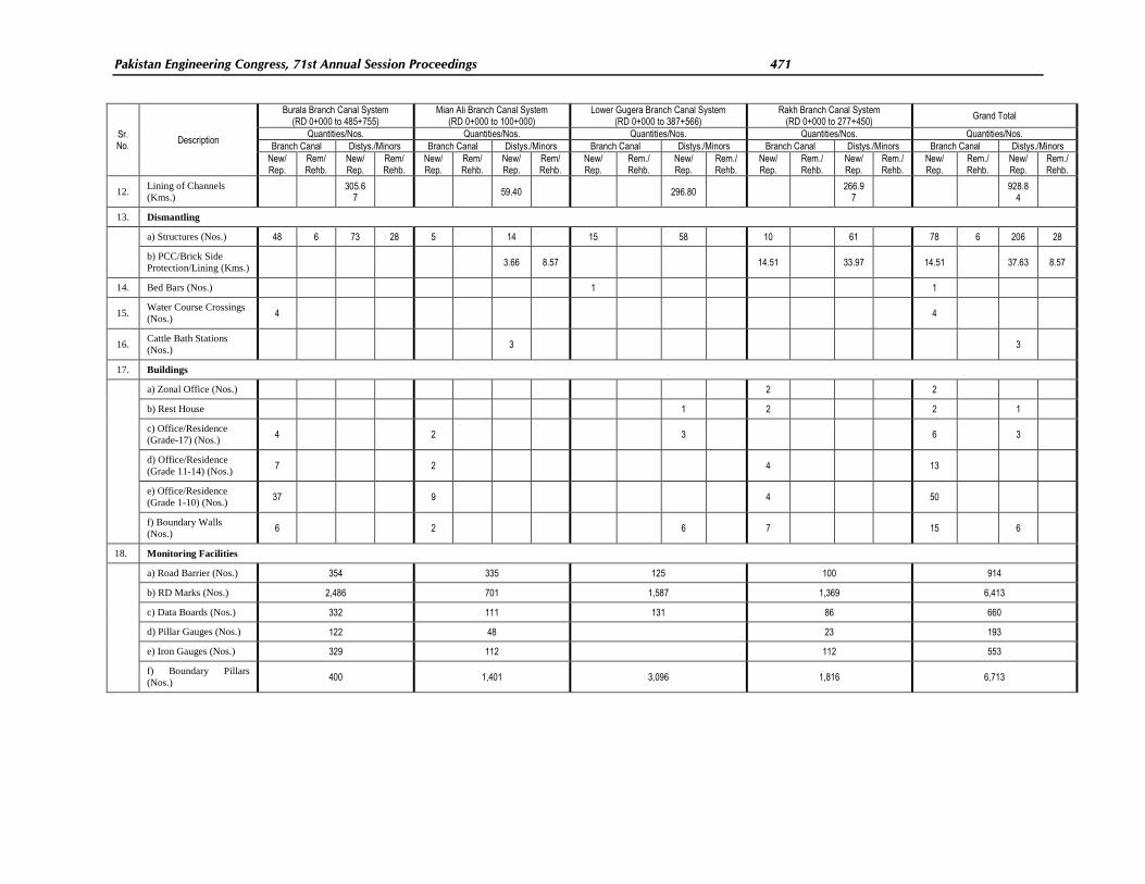
Table-4: Summary of the Rehabilitated Works in Branch Canal Systems of LCC (Part-B) Project
Quantum of work in different categories of work
Sr. No.
Description
Burala Branch Canal System (RD 0+000 to 485+755)
Mian Ali Branch Canal System (RD 0+000 to 100+000)
Lower Gugera Branch Canal System (RD 0+000 to 387+566)
Rakh Branch Canal System (RD 0+000 to 277+450)
Grand Total
Quantities/Nos. Quantities/Nos. Quantities/Nos. Quantities/Nos. Quantities/Nos.
Branch Canal Distys./Minors Branch Canal Distys./Minors Branch Canal Distys./Minors Branch Canal Distys./Minors Branch Canal Distys./Minors
New/ Rep.
Rem/ Rehb.
New/ Rep.
Rem/ Rehb.
New/ Rep.
Rem/ Rehb.
New/ Rep.
Rem/ Rehb.
New/ Rep.
Rem./ Rehb.
New/ Rep.
Rem./ Rehb.
New/ Rep.
Rem./ Rehb.
New/ Rep.
Rem./ Rehb.
New/ Rep.
Rem./ Rehb.
New/ Rep.
Rem./ Rehb.
1. Raising & Strengthening
of Canal Banks (Kms.)
174.87
185.3
9 30.50
101.14
118.28 76.22 80.46 32.31 404.11 395.06
2. Hydraulic Structures
a) Construction of
Diversion Channels
(Nos.) 9 2 4 1 16
b) Cross Regulators /
Falls / Outfalls / Meter
Flumes (Nos.) 12 6 39 45 2 2 3 5 6 20 22 1 10 6 23 20 22 67 93
c) Head Regulators /
Distributors (Nos.) 18 6 6 22 5 2 2 2 2 4 7 33 1 1 1 41 26 13 16 98
d) Water Course
Crossings (Nos.) 4 3 4 3
3. HR-Escape Channels
(Nos.) 2 1 1 1 2 1 4 1 3
4. Structures (Bridges /
Culverts) (Nos.) 35 8 146 68 5 3 14 28 3 6 32 59 7 5 39 125 50 22 231 280
5. Cattle Ghats (Nos.) 50 31 29 13 19 14 28 4 126 62
6. Outlets (Nos.) 32 820 14 379 604 32 569 78 2,372
7. Syphon (Nos.)
8. Aqueduct (Nos.) 1 1 1 1 1 1
9. Bifurcation / Trifurcator
/ Tail Cluster (Nos.) 50 3 39 40 132
10. Dry Brick Pitching
(Kms.)
11. Bank Protection
a) Stone Side Protection
(Kms.) L/R 110.5
7 3.04 19.43 47.75 36.51 0.61 214.26 3.65
b) PCC Side Protection
(Kms.) L/R 23.66 29.37 36.91 28.93 44.65 28.93
134.59
c) Brick Side Protection
(Kms.) L/R 1.24 0.15 1.24 0.15
d) Bamboo Bushing
(Kms.) L/R 16.44 29.25 10.64 12.77 2.44 69.10 2.44
Pakistan Engineering Congress, 71st Annual Session Proceedings 471
Sr. No.
Description
Burala Branch Canal System (RD 0+000 to 485+755)
Mian Ali Branch Canal System (RD 0+000 to 100+000)
Lower Gugera Branch Canal System (RD 0+000 to 387+566)
Rakh Branch Canal System (RD 0+000 to 277+450)
Grand Total
Quantities/Nos. Quantities/Nos. Quantities/Nos. Quantities/Nos. Quantities/Nos.
Branch Canal Distys./Minors Branch Canal Distys./Minors Branch Canal Distys./Minors Branch Canal Distys./Minors Branch Canal Distys./Minors
New/ Rep.
Rem/ Rehb.
New/ Rep.
Rem/ Rehb.
New/ Rep.
Rem/ Rehb.
New/ Rep.
Rem/ Rehb.
New/ Rep.
Rem./ Rehb.
New/ Rep.
Rem./ Rehb.
New/ Rep.
Rem./ Rehb.
New/ Rep.
Rem./ Rehb.
New/ Rep.
Rem./ Rehb.
New/ Rep.
Rem./ Rehb.
12. Lining of Channels
(Kms.)
305.67
59.40 296.80 266.9
7
928.84
13. Dismantling
a) Structures (Nos.) 48 6 73 28 5 14 15 58 10 61 78 6 206 28
b) PCC/Brick Side
Protection/Lining (Kms.) 3.66 8.57 14.51 33.97 14.51 37.63 8.57
14. Bed Bars (Nos.) 1 1
15. Water Course Crossings
(Nos.) 4 4
16. Cattle Bath Stations
(Nos.) 3 3
17. Buildings
a) Zonal Office (Nos.) 2 2
b) Rest House 1 2 2 1
c) Office/Residence
(Grade-17) (Nos.) 4 2 3 6 3
d) Office/Residence
(Grade 11-14) (Nos.) 7 2 4 13
e) Office/Residence
(Grade 1-10) (Nos.) 37 9 4 50
f) Boundary Walls
(Nos.) 6 2 6 7 15 6
18. Monitoring Facilities
a) Road Barrier (Nos.) 354 335 125 100 914
b) RD Marks (Nos.) 2,486 701 1,587 1,369 6,413
c) Data Boards (Nos.) 332 111 131 86 660
d) Pillar Gauges (Nos.) 122 48 23 193
e) Iron Gauges (Nos.) 329 112 112 553
f) Boundary Pillars
(Nos.) 400 1,401 3,096 1,816 6,713
472 Hussain
FIG.-1: LAYOUT MAP OF LOWER CHENAB CANAL SYSTEM

Pakistan Engineering Congress, 71st Annual Session Proceedings 473
FIG.-2: LINE DIAGRAM OF LOWER CHENAB CANAL SYSTEM

474 Hussain
FIG.-3: INDEX MAP OF LOWER CHENAB CANAL SYSTEM SHOWING CONTRACT PACKAGES

Pakistan Engineering Congress, 71st Annual Session Proceedings 475
FIG.-4: AN UPDATED TYPICAL LONGITUDINAL SECTION OF BRANCH CANAL

476 Hussain
FIG.-5: TYPICAL CROSS SECTIONS OF REHABILITATED BRANCH CANALS (EARTHEN)

Pakistan Engineering Congress, 71st Annual Session Proceedings 477
FIG.-6: TYPICAL CROSS SECTIONS OF REHABILITATED DISTYS / MINORS CANALS (EARTHEN)
478 Hussain
FIG.-7: TYPICAL CROSS SECTIONS OF CONCRETE LINED CHANNELS