Embed Size (px)
Citation preview
Founding Members
Preliminary safety assessment and regulatory compliance report
Deliverable ID D3.2 Project Acronym DREAMS Grant: 763671 Call: H2020-SESAR-2016-1 Topic: RPAS-02: Drone information management Consortium coordinator: IDS Edition date: 30 July 2018 Edition: 00.01.010 Template Edition: 02.00.00
EXPLORATORY RESEARCH
EDITION 00.01.010
2
© – 2017 – IDS, TU Delft, EUROUSC, TOPVIEW SRL. All rights reserved. Licensed to the SESAR Joint Undertaking under conditions
Founding Members
Authoring & Approval
Authors of the document Name/Beneficiary Position/Title Date
Filippo Tomasello / EuroUSC Italy Team Leader 01/02/2018
Costantino Senatore / EuroUSC Italy
Safety assessment validator 01/02/2018
Sara Mangoni / EuroUSC Italy Regulatory compliance validator 01/02/2018
Reviewers internal to the project Name/Beneficiary Position/Title Date
Massimo Antonini/IDS
Giuseppe Di Bitonto/ IDS
Team Partner
Team Partner
11/04/2018
11/04/2018
Massimo Antonini/IDS
Giuseppe Di Bitonto/ IDS
Alberto Mennella/Topview
Joost Ellerbroek/TU Deft
Manuel Onate/ EuroUSC Spain
Team Partner
Team Partner
Team Partner
Team Partner
Team Partner
08/05/2018
08/05/2018
08/05/2018
08/05/2018
08/05/2018
Approved for submission to the SJU By - Representatives of beneficiaries involved in the project Name/Beneficiary Position/Title Date
Giuseppe Di Bitonto/IDS Team Coordinator 09/05/2018
Rejected By - Representatives of beneficiaries involved in the project Name/Beneficiary Position/Title Date
Document History
Edition Date Status Author Justification
00.00.01 18 December 2017 Draft Costantino Senatore
00.00.02 30 January 2018 Draft Costantino Senatore
00.00.03 27 February 2018 Draft Costantino Senatore
00.00.04 26 March 2018 Draft Costantino Senatore
00.00.05 10 April 2018 First Review Massimo Antonini, Giuseppe Di Bitonto
Preliminary review of the deliverable
© – 2017 – IDS, TU Delft, EUROUSC, TOPVIEW SRL. All rights reserved. Licensed to the SESAR Joint Undertaking under conditions
3
Founding Members
00.00.06 18 April 2018 Draft post Review Costantino Senatore
00.00.07 27 April 2018 Draft Costantino Senatore
00.01.00 08 May 2018 Final Draft Filippo Tomasello
Costantino Senatore
00.01.01 30 July 2018 Revision after SJU comments
Filippo Tomasello
Costantino Senatore
EDITION 00.01.010
4
© – 2017 – IDS, TU Delft, EUROUSC, TOPVIEW SRL. All rights reserved. Licensed to the SESAR Joint Undertaking under conditions
Founding Members
DREAMS DRone European AIM Study
This study is part of the project under Grant Agreement No 763671, included in European Union’s Horizon 2020 research and innovation programme and that has received funding from the SESAR Joint Undertaking.
Executive summary
This document aims at two objectives, as follows:
1. analysis of specific operational scenarios and producing related risk assessment to serve as requirement for the definition of U-Space system.
2. verification of the regulatory compliance of U-Space services and related service providers, by considering current regulations on ANSPs, expected UAS regulations and highlighting possible gaps.
A subset of scenarios of particular interest for UAS operators in both VLOS and BVLOS conditions was identified in deliverable 3.1 [1] through a defined identification process, considering state-of-the art technologies and available services against the present and envisaged needs of UAS operators. The scenarios shall cover different conditions and situations as real as possible, in order to better match the industry and operator expectations. In particular, the risk assessment shall verify the hazards for other aircraft (manned and unmanned) and for third parties on the ground (or water), including people, goods and infrastructures. It should underline the most critical conditions, identifying and proposing adequate risk mitigations. The risk-assessment is implemented with application of two methodologies:
• SORA (Specific Operations Risk Assessment), the methodology proposed by JARUS, is applied for risk assessment regarding possible influence of RPAS operation for third parties on the ground (Ground Risk) and Mid-Air Collisions (MAC) with other manned aircraft (Air Risk). In particular, SORA version 1.1 [2], released by JARUS for internal consultation on 30/01/2018, is taken as reference.
• EASA Pre-Regulatory Impact Assessment [3], is applied for the evaluation of potential failure conditions within the U-Space services proposed in DREAMS scenarios.
Both risk assessment processes are performed only for a subset of the scenarios identified in D3.1. This point is clarified in Chapter 2. Special focus is given on BVLOS operations with potential other manned/unmanned traffic and obstacles interfering with UAS operations. These are the condition where the UTM service is projected to be more applicable and where it’s expected to be more useful and valuable.
© – 2017 – IDS, TU Delft, EUROUSC, TOPVIEW SRL. All rights reserved. Licensed to the SESAR Joint Undertaking under conditions
5
Founding Members
The regulatory compliance is assessed on the basis of European Regulations and ICAO documents. The EASA NPA 5/2017 [4] was proposed for consultation on 5th May 2017. The document, aimed at providing rules in the European community, is “operation centric” philosophy and it’s focused on “open” and “specific” UAS, generally meaning UAS able to operate without any particular authorization and UAS operating with limited authorization/condition and with a previous risk assessment. This study is structured with the design of some scenarios aimed at replying potential operational situations with UAS involved to perform defined activities. The UAS involved are encompassed in the EASA “specific” category. The identification of relevant scenario in DREAMS starts from the assumption of a suitable architecture and the services coping with all the UAS flight phases, from planning to post-flight. The focus of scenarios is the planning of operations related to the information provided by UTM service in contexts where is expected to have market. The study may facilitate the manufacturing to better develop and create equipment and devices for UAS. In particular, the study should evaluate the UTM service adding value in several situations and conditions, increasing the pilot awareness about the other air traffic operating in the same sector of airspace. Improvements should come also for Air Traffic Management. UTM will rise the information of air traffic in the airspace and, consequently, safety will be increased. In the SESAR programme there are several projects aimed at developing the different aspects of UTM service and a significant coordination process is in progress to better harmonize the different studies and the involved Companies and Enterprises.

EDITION 00.01.010
6
© – 2017 – IDS, TU Delft, EUROUSC, TOPVIEW SRL. All rights reserved. Licensed to the SESAR Joint Undertaking under conditions
Founding Members
TableofContents
1 Introduction .................................................................................................................. 12
2 DREAMS scenarios ........................................................................................................ 19
3 Airspace and Operational environment ........................................................................ 27
4 Risk Assessment methodologies ................................................................................... 37
5 Operational safety assessment for U-Space services .................................................... 60
6 U-Space Information Regulatory compliance ............................................................... 71
7 Conclusions ................................................................................................................. 112
8 References .................................................................................................................. 132
Appendix A – Risk Assessment of Scenario 2: “concurrent operations” ....................... 134
Appendix B – Risk Assessment of Scenario 4: “cooperative geo-tagging” ................... 189
Appendix C Risk Assessment of Scenario 5: “CTR Crossing” ......................................... 212
Appendix D - Risk Assessment of Scenario 8: “Emergency Management” ................... 242 List of Figures Figure 1: Bow-tie Representation of the holistic model .................................................................... 39 Figure 2: The SORA process (credit: JARUS) ...................................................................................... 40 Figure 3: AEC determination process ................................................................................................ 43 Figure 4: Final ARC reduction for Strategic Mitigations by Structures and Rules ................................ 46 Figure 5: Safety risk matrix (ICAO Doc.9859) .................................................................................... 53 Figure 6: Safety risk matrix (EASA Pre-regulatory impact assessment) .............................................. 55 Figure 7: Safety risk matrix (EUROCAE ED 78-A)................................................................................ 59 Figure 8: Safety risk matrix (EASA Pre-Regulatory Risk assessment) .................................................. 62 Figure 9: Risk management .............................................................................................................. 63 Figure 10: DREAMS scenarios typical UML phase diagram and interrelated processes ...................... 68 Figure 11: VMC visibility and distance from cloud minima (Reg. 923/2012 SERA) ............................. 91 Figure 12: Operational area for scenario 2...................................................................................... 135 Figure 13: UAS 1 features (scenario 2) ............................................................................................ 136 Figure 14: UAS 2 features (scenario 2) ............................................................................................ 136 Figure 15: UAS 3 features (scenario 2) ............................................................................................ 137 Figure 16: AEC determination process ............................................................................................ 142 Figure 17: Final ARC reduction for Strategic Mitigations by Structures and Rules ............................ 146 Figure 18: Sequence diagram for phase 1 (scenario 2) .................................................................... 160 Figure 19: Sequence diagram for phase 2 (scenario 2) .................................................................... 173 Figure 20: Sequence diagram for phase 3 (scenario 2) .................................................................... 182 Figure 21: UAS 1 during delivery mission (scenario 4) ..................................................................... 191 Figure 22: UAS 1 after obstacle detection and obstacle geo-tagging (scenario 4) ............................ 191 Figure 23: Obstacle detection sequence diagram (scenario 4) ........................................................ 191 Figure 24: UAS 1 features (scenario 4) ............................................................................................ 192
© – 2017 – IDS, TU Delft, EUROUSC, TOPVIEW SRL. All rights reserved. Licensed to the SESAR Joint Undertaking under conditions
7
Founding Members
Figure 25: UAS 2 features (scenario 4) ............................................................................................ 192 Figure 26: UAS 3 features (scenario 4) ............................................................................................ 193 Figure 27: Obstacle detection sequence diagram (scenario 4) ........................................................ 199 Figure 28: U-Space Hazard notification to Flying Drone User (scenario 4) ....................................... 205 Figure 29: Example of CTR Crossing (scenario 5) ............................................................................. 213 Figure 30: UAS features (scenario 5) ............................................................................................... 214 Figure 31: AEC determination process ............................................................................................ 220 Figure 32: Final ARC reduction for Strategic Mitigations by Structures and Rules ............................ 224 Figure 33: Sequence diagram for phase 1 (scenario 5) .................................................................... 232 Figure 34: Sequence diagram for phase 2 (scenario 5) .................................................................... 235 Figure 35: UAS features for scenario 8............................................................................................ 244 Figure 36: AEC determination process ............................................................................................ 249 Figure 37: Final ARC reduction for Strategic Mitigations by Structures and Rules ............................ 253 Figure 38: Sequence diagram for phase 1 (scenario 8) .................................................................... 262 Figure 39: Sequence diagram for phase 2 (scenario 8) .................................................................... 268 List of Tables Table 1 - General features of DREAMS scenarios ............................................................................. 20 Table 2 - DREAMS scenarios considered for the safety risk assessment ........................................... 26 Table 3: GRC determination ............................................................................................................. 41 Table 4: Harm barriers for GRC adaptation ....................................................................................... 42 Table 5: SAIL determination for Ground Risk .................................................................................... 42 Table 6 : ARC determination............................................................................................................. 44 Table 7: Air SAIL determination ........................................................................................................ 46 Table 8: Uncontained ARC Assignment ............................................................................................. 47 Table 9: TMPR Assignment ............................................................................................................... 49 Table 10: Determination of robustness level .................................................................................... 50 Table 11: ICAO Safety risk probability table ...................................................................................... 52 Table 12: ICAO Safety risk severity table ........................................................................................... 53 Table 13: Safety risk severity classifications (SC-RPAS.1309) ............................................................. 55 Table 14: Relationship among severity and probability (SC-RPAS 1309) ............................................ 56 Table 15: Safety risk severity classifications (EUROCONTROL ESARR 4) ............................................. 57 Table 16: Relationship among severity and probability (EUROCONTROL ESARR 4) ............................ 57 Table 17: Hazard classification matrix (EUROCAE ED 78-A) ............................................................... 58 Table 18 : Failure condition classification ......................................................................................... 62 Table 19: Safety requirements definition.......................................................................................... 63 Table 20: Relationship between EASA severity classification and ICAO aeronautical data categories 69 Table 21: Performance requirements ............................................................................................... 69 Table 22: Assignment of Design Assurance Level .............................................................................. 70 Table 23: EASA form Service Provider Certificate-Service Provision Conditions (Reg.373/2017) ........ 92 Table 24: RCP types (ICAO RCP Doc.9869, first edition 2008) ............................................................ 95 Table 25: RCP types (ICAO PBCS Doc.9869, second edition 2017) ..................................................... 96 Table 26: RSP types (ICAO PBCS Doc.9869, second edition 2017)...................................................... 96 Table 27 : Data Process Assurance Levels ....................................................................................... 101 Table 28: Data Process Assurance Levels in relation to EASA severity classification ........................ 102 Table 29: Data Process Assurance Levels in relation to EUROCAE severity classification ................. 102
EDITION 00.01.010
8
© – 2017 – IDS, TU Delft, EUROUSC, TOPVIEW SRL. All rights reserved. Licensed to the SESAR Joint Undertaking under conditions
Founding Members
Table 30: Most demanding performance requirements for U-Space services.................................. 113 Table 31: U-Space services safety requirements ............................................................................. 114 Table 32: U-Space services mitigation (for the most demanding processes) ................................... 117 Table 33: U-Space services vs traditional ANSP (EU Reg. 549/2004 and EU Reg. 373/2017) ............ 126 Table 34:Elements of discussion for the definition of U-Space service providers ............................. 129 Table 35: Operational details for scenario 2 ................................................................................... 135 Table 36: Intrinsic UAS Ground Risk Class ....................................................................................... 137 Table 37: Intrinsic UAS Ground Risk Class for scenario 2 ................................................................. 138 Table 38: Harm barriers for GRC adaptation ................................................................................... 138 Table 39: GRC adaptation for scenario 2 ......................................................................................... 139 Table 40: Integrity requirements for GRC adaptation in scenario 2 ................................................. 140 Table 41: SAIL determination for Ground Risk ................................................................................ 141 Table 42: SAIL deriving from GRC for UAS of scenario 2 .................................................................. 141 Table 43: AEC for UAS of scenario 2 ............................................................................................... 143 Table 44: Initial ARC determination ................................................................................................ 144 Table 45: Initial ARC for UAS of scenario 2 ...................................................................................... 144 Table 46: Air SAIL determination .................................................................................................... 147 Table 47: Air SAIL for UAS of scenario 2 .......................................................................................... 147 Table 48: Maximum SAIL for UAS of scenario 2 .............................................................................. 147 Table 49: TMPR Assignment for scenario 2 ..................................................................................... 149 Table 50: TMPR Requisite for medium performance (ARC 3) .......................................................... 151 Table 51: TMPR Integrity and Assurance Assignments .................................................................... 152 Table 52: Required robustness for threat barriers (SAIL IV) ............................................................ 157 Table 53: Identification and classification of failure conditions for Flight Plan Submission (FPS) process ...................................................................................................................................................... 163 Table 54: Failure conditions and corresponding requirements for Flight Plan Submission (FPS) process ...................................................................................................................................................... 164 Table 55: RCP Recommended performance requirements for Flight Plan submission (FPS) ............ 164 Table 56: Identification and classification of failure conditions for Check Restricted Area (CRA) process .......................................................................................................................................... 165 Table 57: Failure conditions and corresponding requirements for Check Restricted Area (CRA) process ...................................................................................................................................................... 165 Table 58: RSP Recommended performance requirements for Check Restricted Area (CRA) ............ 166 Table 59: Identification and classification of failure conditions for Check and Deconflict Plan (CDP) process .......................................................................................................................................... 166 Table 60: Failure conditions and corresponding requirements for Check and Deconflict Plan (CDP) process .......................................................................................................................................... 167 Table 61: RSP Recommended performance requirements for Check and Deconflict Plan (CDP) ...... 167 Table 62: Identification and classification of failure conditions for Authorization Request (AR) process ...................................................................................................................................................... 169 Table 63: Failures and requirements for Authorization Request (AR) process ................................. 170 Table 64: RCP Recommended performance requirements for Authorization Request (AR) ............. 170 Table 65: Identification and classification of failure conditions for Flight Plan Approved (FPA) process ...................................................................................................................................................... 171 Table 66: Failures and requirements for Flight Plan Approved (FPA) process .................................. 172 Table 67: RCP Recommended performance requirements for Flight Plan Approved (FPA) .............. 172 Table 68: Identification and classification of failure conditions for Check Restricted Area (CRA) process .......................................................................................................................................... 174
© – 2017 – IDS, TU Delft, EUROUSC, TOPVIEW SRL. All rights reserved. Licensed to the SESAR Joint Undertaking under conditions
9
Founding Members
Table 69: Failure conditions and corresponding requirements for Check Restricted Area (CRA) process ...................................................................................................................................................... 175 Table 70: Recommended performance requirements for Check Restricted Area (CRA) ................... 175 Table 71: Identification and classification of failure conditions for Check and Deconflict Plan (CDP) process .......................................................................................................................................... 176 Table 72: Failure conditions and corresponding requirements for Check and Deconflict Plan (CDP) process .......................................................................................................................................... 176 Table 73: Recommended performance requirements for Check and Deconflict Plan (CDP) ............. 176 Table 74: Identification and classification of failure conditions for Authorization Request (AR) process ...................................................................................................................................................... 178 Table 75: Failures and requirements for Authorization Request (AR) process ................................. 179 Table 76: Recommended performance requirements for Authorization Request (AR) .................... 179 Table 77: Identification and classification of failure conditions for Flight Plan Rejected (FPR) process ...................................................................................................................................................... 181 Table 78: Failures and requirements for Flight Plan Rejected (FPR) process .................................... 181 Table 79: Recommended performance requirements for Flight Plan Rejected (FPR) ....................... 181 Table 80: Identification and classification of failure conditions for Check MET and micro-weather (CMMW) process ........................................................................................................................... 184 Table 81: Failures and requirements for Check MET and micro-weather (CMMW) process ............ 184 Table 82: Recommended performance requirements for Check MET and micro-weather (CMMW) process .......................................................................................................................................... 184 Table 83: Identification and classification of failure conditions for Check Active Flight Plans (CAFP) process .......................................................................................................................................... 185 Table 84: Failures and requirements for Check Active Flight Plans (CAFP) process .......................... 185 Table 85: Recommended performance requirements for Check Active Flight Plans (CAFP) process 186 Table 86: Identification and classification of failure conditions for Land Immediately Notification (LIN) process .......................................................................................................................................... 187 Table 87: Failures and requirements for Land Immediately Notification (LIN) process .................... 187 Table 88: Recommended performance requirements for Immediate Landing Notification (LIN) process .......................................................................................................................................... 187 Table 89: Operational details for scenario 4 ................................................................................... 190 Table 90: Intrinsic UAS Ground Risk Class ....................................................................................... 193 Table 91: Intrinsic UAS Ground Risk Class for scenario 4 ................................................................. 194 Table 92: Harm barriers for GRC adaptation ................................................................................... 194 Table 93: GRC adaptation for scenario 4 ......................................................................................... 195 Table 94: Integrity requirements for GRC adaptation ..................................................................... 196 Table 95: SAIL determination for Ground Risk ................................................................................ 197 Table 96: SAIL deriving from GRC for UAS of scenario 4 .................................................................. 197 Table 97: Identification and classification of failure conditions for Obstacle Detection (OD) process ...................................................................................................................................................... 202 Table 98: Failure conditions and corresponding requirements for Obstacle Detection (OD) process 203 Table 99: Recommended performance requirements for Obstacle Detection (OD) process ............ 203 Table 100: Identification and classification of failure conditions for Update Geofencing process (UG) process .......................................................................................................................................... 204 Table 101: Failure conditions and corresponding requirements for Update Geofencing (UG) ......... 204 Table 102: Recommended performance requirements for Update Geofencing (UG) process .......... 204 Table 103: Identification and classification of failure conditions for Notify Geofence Change process (NGC) process ................................................................................................................................ 207
EDITION 00.01.010
10
© – 2017 – IDS, TU Delft, EUROUSC, TOPVIEW SRL. All rights reserved. Licensed to the SESAR Joint Undertaking under conditions
Founding Members
Table 104: Failure conditions and corresponding requirements for Notify Geofence Change (NGC) process .......................................................................................................................................... 208 Table 105: Recommended performance requirements for Notify Geofence Change (NGC) process 208 Table 106: Identification and classification of failure conditions for Modify Flight Plan (MFP) process ...................................................................................................................................................... 209 Table 107: Failure conditions and corresponding requirements for Modify Flight Plan (MFP) process ...................................................................................................................................................... 210 Table 108: Recommended performance requirements for Modify Flight Plan (MFP) process ......... 210 Table 109: operational details for scenario 5 .................................................................................. 213 Table 110: Intrinsic UAS Ground Risk Class ..................................................................................... 215 Table 111: Intrinsic UAS Ground Risk Class for scenario 5 ............................................................... 215 Table 112: Harm barriers for GRC adaptation ................................................................................. 216 Table 113: GRC adaptation for scenario 5 ....................................................................................... 216 Table 114: Integrity requirements for GRC adaptation ................................................................... 218 Table 115: SAIL determination for Ground Risk .............................................................................. 219 Table 116: SAIL deriving from GRC for scenario 5 ........................................................................... 219 Table 117: AEC determination for scenario 5 .................................................................................. 221 Table 118: Initial ARC determination .............................................................................................. 222 Table 119: Initial ARC for the UAS involved in scenario 5 ................................................................ 222 Table 120: Final ARC for scenario 5 ................................................................................................ 225 Table 121: Air SAIL determination .................................................................................................. 225 Table 122: Air SAIL for scenario 5 ................................................................................................... 225 Table 123: Maximum SAIL for scenario 5 ........................................................................................ 225 Table 124: Uncontained AEC/ARC for scenario 5 ............................................................................ 226 Table 125: Integrity and Assurance Level for Uncontained ARC ...................................................... 226 Table 126: TMPR Assignment for scenario 5 ................................................................................... 228 Table 127: TMPR Requisite for medium performance (ARC 3) ........................................................ 230 Table 128: TMPR Integrity and Assurance Assignments for medium performance .......................... 230 Table 129: Identification and classification of failure conditions for Request to Access Airspace Process (RAA) process .................................................................................................................... 234 Table 130: Failure conditions and corresponding requirements for Request to Access Airspace (RAA) process .......................................................................................................................................... 234 Table 131: RSP Recommended performance requirements for Request to Access Airspace (RAA) .. 234 Table 132: Identification and classification of failure conditions for Authorization Request (AR) process .......................................................................................................................................... 237 Table 133: Failures and requirements for Authorization Request (AR) process ............................... 238 Table 134: RCP Recommended performance requirements for Authorization Request (AR) ........... 238 Table 135: Identification and classification of failure conditions for Procedural Instructions (PI) process .......................................................................................................................................... 240 Table 136: Failures and requirements for Procedural Instructions (PI) process ............................... 240 Table 137: RCP Recommended performance requirements for Procedural Instructions (PI) ........... 240 Table 138: Operational details for scenario 8 ................................................................................. 243 Table 139: Intrinsic UAS Ground Risk Class ..................................................................................... 245 Table 140: Intrinsic UAS Ground Risk Class for scenario 8 ............................................................... 245 Table 141: Harm barriers for GRC adaptation ................................................................................. 245 Table 142: GRC adaptation for scenario 8 ....................................................................................... 246 Table 143: Integrity requirements for GRC adaptation ................................................................... 247 Table 144: SAIL determination for Ground Risk .............................................................................. 248 Table 145: SAIL deriving from GRC for scenario 8 ........................................................................... 248
© – 2017 – IDS, TU Delft, EUROUSC, TOPVIEW SRL. All rights reserved. Licensed to the SESAR Joint Undertaking under conditions
11
Founding Members
Table 146: AEC for scenario 8 ......................................................................................................... 249 Table 147: Initial ARC determination .............................................................................................. 250 Table 148: Initial ARC for scenario 8 ............................................................................................... 251 Table 149: Initial and Intermediate ARC for scenario 8 ................................................................... 252 Table 150: Air SAIL determination .................................................................................................. 254 Table 151: Air SAIL for scenario 8 ................................................................................................... 254 Table 152: Maximum SAIL for scenario 8 ........................................................................................ 254 Table 153: TMPR Assignment for scenario 8 ................................................................................... 256 Table 154: TMPR Requisite for low performance (ARC 2) ............................................................... 257 Table 155: TMPR Integrity and Assurance Assignments .................................................................. 257 Table 156: Required robustness for threat barriers (SAIL II) ............................................................ 261 Table 157: Identification and classification of failure conditions for Battery Low (BL) process ......... 264 Table 158: Failure conditions and corresponding requirements for Battery Low (BL) process ......... 265 Table 159: Recommended performance requirements for Battery Low (BL) process ...................... 265 Table 160: Identification and classification of failure conditions for Location of Landing Pads (LLP) process .......................................................................................................................................... 266 Table 161: Failure conditions and corresponding requirements for Location of Landing Pads (LLP) process .......................................................................................................................................... 267 Table 162: Recommended performance requirements for Location of Landing Pads (LLP) process . 267 Table 163: Identification and classification of failure conditions for Loss of Control (LC-A) process . 270 Table 164: Failure conditions and corresponding requirements for Loss of control (LC) process ..... 271 Table 165: Recommended performance requirements for Loss of control (LC) process .................. 271 Table 166: Identification and classification of failure conditions for Acknowledge (ACK) process .... 272 Table 167: Failure conditions and corresponding requirements for Acknowledge (ACK) process .... 272 Table 168: Recommended performance requirements for Location of Acknowledge (ACK) process 273 Table 169: Identification and classification of failure conditions for Loss of Control (LCB) process .. 274 Table 170: Failure conditions and corresponding requirements for Loss of control (LCB) process ... 275 Table 171: Recommended performance requirements for Loss of control (LC-B) process ............... 275
EDITION 00.01.010
12
© – 2017 – IDS, TU Delft, EUROUSC, TOPVIEW SRL. All rights reserved. Licensed to the SESAR Joint Undertaking under conditions
Founding Members
1 Introduction
1.1 Purpose of the document
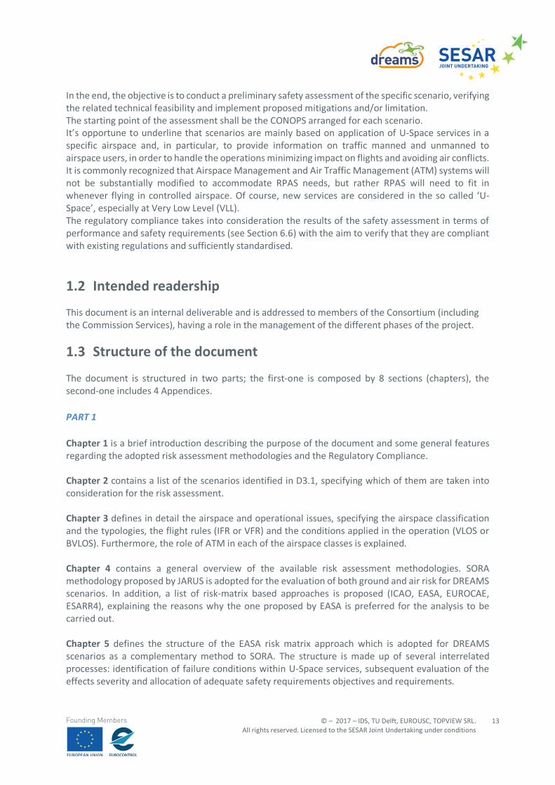
The purpose of DREAMS is to define the European UTM Aeronautical Information Management operational concept. The project is focused on solutions for the drone aeronautical information management. Operational and technical aspects, environmental scenarios, technologies and safety impact are analysed in order to identify possible U-Space data service providers (e.g. airspace structure, terrain, obstacles and weather) and required facilities. The scope of deliverable 3.2 consists on assessing identified scenarios for UAS operations conducted in both VLOS and BVLOS conditions related to safety issues and taking in consideration the services that could be provided to UAS Operators in the U-Space. The purposes of this study are:
- to perform a Preliminary Risk Assessment of the generic CONOPS, which is going to be the basis for the actual demonstration scenarios of the DREAMS project;
- to verify the regulatory compliance of the requirements related to U-Space service providers,
taking into account current and expected future UAS regulations.
This document will therefore serve as a basis for any operation conducted in the framework of the generic CONOPS. Further analyses will be instead required to confirm the applicability of this Risk Assessment to the specific scenario that will be demonstrated as part of the DREAMS project activities. In fact, the aim of a Preliminary Risk assessment is to define general safety requirements for each scenario, without providing evidence that such requirements have been implemented. The scenarios will be referred to UAS and operation encompassed within “specific” category. For “specific” category, EASA intends to refer to a system including a risk assessment conducted by the operator before starting an operation, or the operator complying with a standard scenario, or the operator holding a certificate with privileges. It basically requires the operator to perform a risk assessment that the competent Authority confirms through an authorisation. The EASA document recognizes that standard scenarios are a key to the success of the specific category, mainly for the mutual recognition of authorisations by Authorities of EU community. All scenarios are set in order to reproduce civil “public” and or “commercial”1 operation, taking in consideration the market and the manufacturing involvement. As already explained in the Executive Summary, the Risk Assessment of DREAMS scenarios is performed using two different methodologies: SORA (Specific Operations Risk Assessment) and EASA risk matrix approach defined in the Pre-Regulatory Impact Assessment.
1Commercial operation:
- Definition of “commercial operation” in Part III (International helicopter operations) of Annex 6 [5] to the Chicago Convention (ICAO) - “Commercial air transport operation: an aircraft operation involving the transport of passengers, cargo or mail for remuneration or hire.”
- Definition in Article 3(i) of EU Regulation 216/2008 [6] (EASA Basic Regulation) - “any operation of an aircraft, in return for remuneration or other valuable consideration, which is available to the public or, when not made available to the public, which is performed under a contract between an operator and a customer, where the latter has no control over the operator”.
© – 2017 – IDS, TU Delft, EUROUSC, TOPVIEW SRL. All rights reserved. Licensed to the SESAR Joint Undertaking under conditions
13
Founding Members
In the end, the objective is to conduct a preliminary safety assessment of the specific scenario, verifying the related technical feasibility and implement proposed mitigations and/or limitation. The starting point of the assessment shall be the CONOPS arranged for each scenario. It’s opportune to underline that scenarios are mainly based on application of U-Space services in a specific airspace and, in particular, to provide information on traffic manned and unmanned to airspace users, in order to handle the operations minimizing impact on flights and avoiding air conflicts. It is commonly recognized that Airspace Management and Air Traffic Management (ATM) systems will not be substantially modified to accommodate RPAS needs, but rather RPAS will need to fit in whenever flying in controlled airspace. Of course, new services are considered in the so called ‘U-Space’, especially at Very Low Level (VLL). The regulatory compliance takes into consideration the results of the safety assessment in terms of performance and safety requirements (see Section 6.6) with the aim to verify that they are compliant with existing regulations and sufficiently standardised.
1.2 Intended readership
This document is an internal deliverable and is addressed to members of the Consortium (including the Commission Services), having a role in the management of the different phases of the project.
1.3 Structure of the document
The document is structured in two parts; the first-one is composed by 8 sections (chapters), the second-one includes 4 Appendices. PART 1 Chapter 1 is a brief introduction describing the purpose of the document and some general features regarding the adopted risk assessment methodologies and the Regulatory Compliance. Chapter 2 contains a list of the scenarios identified in D3.1, specifying which of them are taken into consideration for the risk assessment. Chapter 3 defines in detail the airspace and operational issues, specifying the airspace classification and the typologies, the flight rules (IFR or VFR) and the conditions applied in the operation (VLOS or BVLOS). Furthermore, the role of ATM in each of the airspace classes is explained. Chapter 4 contains a general overview of the available risk assessment methodologies. SORA methodology proposed by JARUS is adopted for the evaluation of both ground and air risk for DREAMS scenarios. In addition, a list of risk-matrix based approaches is proposed (ICAO, EASA, EUROCAE, ESARR4), explaining the reasons why the one proposed by EASA is preferred for the analysis to be carried out. Chapter 5 defines the structure of the EASA risk matrix approach which is adopted for DREAMS scenarios as a complementary method to SORA. The structure is made up of several interrelated processes: identification of failure conditions within U-Space services, subsequent evaluation of the effects severity and allocation of adequate safety requirements objectives and requirements.
EDITION 00.01.010
14
© – 2017 – IDS, TU Delft, EUROUSC, TOPVIEW SRL. All rights reserved. Licensed to the SESAR Joint Undertaking under conditions
Founding Members
Chapter 6 defines the aspects taken into consideration for the regulatory compliance related to possible UTM application. Chapter 7 reports the conclusions of the study. Chapter 8 provides the reference documents considered for this document. PART 2 The appendices contain the risk assessment of four scenarios out of eleven identified in D3.1. The risk assessment is performed both with SORA and EASA methodology for the selected scenarios, as follows: Appendix A Scenario 2 Appendix B Scenario 4 Appendix C Scenario 5 Appendix D Scenario 8
1.4 SORA methodology
The SORA methodology has been developed by JARUS (Joint Authorities on Rulemaking on Unmanned Systems), a group of experts gathering regulatory expertise from all around the world, whose objective is to recommend a single set of technical, safety and operational requirements for all aspects linked to the safe operation of the Remotely Piloted Aircraft Systems (RPAS). This group is currently composed by representatives of 52 countries as well as EASA and EUROCONTROL. The purpose of SORA is to propose a methodology for the risk assessment to support the application for an authorization to operate a UAS within the specific category, as envisage by EASA prototype regulation [7]. With this respect, SORA can represent an acceptable mean to evaluate the risks associated with the operation of an UAS within the specific category and to determine its acceptability. The SORA Methodology and the related guidance material are routinely updated and, in this document, version 1.1 (released for internal consultation in January 2018) is adopted. This means that the proposed approach is not in its final shape but can be considered already quite mature. In addition, as mentioned, EASA is one of the member of JARUS and SORA was already mentioned in EASA Technical Opinion A-NPA: 2018-01 [8] as the current preferred methodology to assess the risk for UAS operating in the specific category. In addition, SORA methodology is being applied for other European projects, carried on in the RPAS domain (i.e. REAL project 2)
2 REAL Project foresees the implementation of an EGNOS receiver on UAS performing BVLOS operations. SORA
is being used for the risk assessment analysis on the two scenarios developed in the REAL CONOPS [9].
© – 2017 – IDS, TU Delft, EUROUSC, TOPVIEW SRL. All rights reserved. Licensed to the SESAR Joint Undertaking under conditions
15
Founding Members
In light of this, the use of this approach can give further opportunities to validate on a real case the SORA methodology, thus increasing the potential exploitation of the outcomes of DREAMS project.
1.5 Risk matrix-based approach for UTM failure condition analysis
SORA methodology allows to perform a risk assessment for each scenario, by evaluating both Ground Risk and Air-Risk according to a rigid scheme in which a certain number of pre-define barriers is provided. SORA allows to treat U-Space services as a mitigation (a barrier) which may be implemented to reduce the Air-Risk (Strategic Mitigation) or meet specific requirements imposed by the Air-Risk Class (Tactical Mitigation). Malfunctions of U-Space services are not taken into account in detail within SORA methodology. This leads to the necessity to use a different risk assessment approach to evaluate the risks related to possible failure conditions within UTM architecture (digital services and communications). A risk-matrix approach is chosen for this purpose since it is a more flexible way to cover a wider range of risk areas. In Chapter 4, for the sake of completeness, four possible models are presented:
- ICAO risk matrix [10] - EASA risk matrix, reported in EASA Pre-Regulatory Impact Assessment - ESARR4 risk matrix [11] - EUROCAE risk matrix [12]
Among these, the model proposed by EASA is preferred (see Section 4.4.3) since it provides in output a fully numeric risk index which is a more immediate parameter for hazard evaluation. It is important to underline that in this approach:
- failure conditions are considered as operational hazard. - safety objectives are minimum allowable quantitative probability in relation to a
failure condition (determined with risk matrix). - safety requirements are the mitigation strategies which it is necessary to implement.
1.6 Abbreviation
Acronym Meaning
AEC Airspace Encounter Category
ALRS Alerting Service
AIM Aeronautical Information Management
AMC Acceptable Means of Compliance
ANSP Air Navigation Service Provider
APAC Asia-Pacific
AR Authorization Request
EDITION 00.01.010
16
© – 2017 – IDS, TU Delft, EUROUSC, TOPVIEW SRL. All rights reserved. Licensed to the SESAR Joint Undertaking under conditions
Founding Members
ARC Air Risk Class
ASM Air Space Management
ASOR Allocation of safety objectives and requirements
ATC Air Traffic Control
ATFM Air Traffic Flow Management
ATM Air Traffic Management
ATS Air Traffic Service
ATZ Aerodrome Traffic Zone
BL Battery Low
BVLOS Beyond Visual Line of Sight
CAA Civil Aviation Authority
CAFP Check Active Flight Plans
CDOL Check drone operational limits
CDP Check and Deconflict plan
CMMW Check MET and Micro Weather
CofA Certificate of Airworthiness
CNS Communication and Surveillance Services
CPDLC Controller-Pilot Data Link Communications
CRA Check Restricted Areas
CTR Control Zone
C2 Command and Control data Link
DAA Detect And Avoid
DAL Design Assurance Level
DPAL Data Process Assurance Level
DREAMS DRone European AIM Study
EASA European Aviation Safety Agency
EATMN European Air Traffic Management Network
EFB Electronic Flight Bag
ERP Emergency Response Plan
ESARR EUROCONTROL Safety Regulatory Requirement
ETSO European Technical Standard Order
E-VLOS Extended Visual Line of Sight
FPA Flight Plan Approved
FPR Flight Plan Rejected
FPS Flight Plan Submission
FTS Flight Termination System
© – 2017 – IDS, TU Delft, EUROUSC, TOPVIEW SRL. All rights reserved. Licensed to the SESAR Joint Undertaking under conditions
17
Founding Members
GRC Ground Risk Class
GM Guidance Material
GPS Global Positioning System
GNSS Global Navigation Satellite System
HEMS Helicopter emergency medical service
HRM Holistic Risk Model
ICAO International Civil Aviation Organization
IFR Instrument Flight Rules
ILS Instrument Landing System
IMC Instrumental Meteorological Condition
JARUS Joint Authorities for Rulemaking of Unmanned Systems
LC Loss of control
LCB Loss of control Broadcast
LIN Land Immediately Notification
LUC Light UAS Certificate
MAC Mid Air Collision
MFP Modify Flight Plan
MOE Means of Evidence
MOPS Minimum Operational Performance Standards
MTBF Mean Time Between Failures
MTOM Maximum Take-Off Mass
NAT North-Atlantic
NGC Notify Geofence Change
NOTAM Notice To AirMen
OHA Operational Hazard Analysis
OD Obstacle Detection
PBCS Performance Based Communication and Surveillance
PI Procedural Instructions
QE Qualified Entity
RAA Request to Access Airspace
REAL RPAS EGNOS Assited Landings
RCP Required Communication Performance
RLOS Radio Line of Sight
RPA Remotely Piloted Aircraft
RPAS Remotely Piloted Aircraft System
RSP Required Surveillance Performance
EDITION 00.01.010
18
© – 2017 – IDS, TU Delft, EUROUSC, TOPVIEW SRL. All rights reserved. Licensed to the SESAR Joint Undertaking under conditions
Founding Members
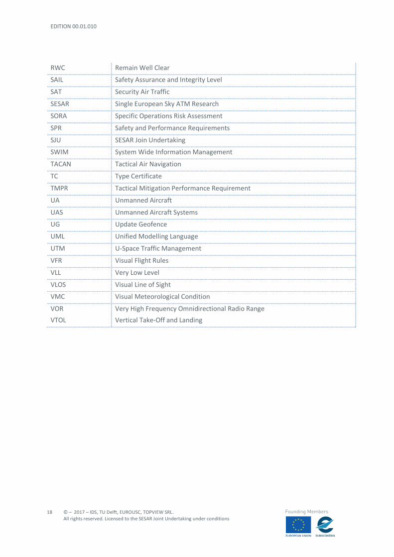
RWC Remain Well Clear
SAIL Safety Assurance and Integrity Level
SAT Security Air Traffic
SESAR Single European Sky ATM Research
SORA Specific Operations Risk Assessment
SPR Safety and Performance Requirements
SJU SESAR Join Undertaking
SWIM System Wide Information Management
TACAN Tactical Air Navigation
TC Type Certificate
TMPR Tactical Mitigation Performance Requirement
UA Unmanned Aircraft
UAS Unmanned Aircraft Systems
UG Update Geofence
UML Unified Modelling Language
UTM U-Space Traffic Management
VFR Visual Flight Rules
VLL Very Low Level
VLOS Visual Line of Sight
VMC Visual Meteorological Condition
VOR Very High Frequency Omnidirectional Radio Range
VTOL Vertical Take-Off and Landing
© – 2017 – IDS, TU Delft, EUROUSC, TOPVIEW SRL. All rights reserved. Licensed to the SESAR Joint Undertaking under conditions
19
Founding Members
2 DREAMS scenarios
2.1 General
The scenario is a high-level container representing a particular environment of relevant importance for U-Space operations, where different actors and airspace users interact though defined logical interfaces. Each scenario can be composed by multiple instances of UAS in different surrounding environment expressed by a number of attributes, both quantitative and qualitative, used to better outline the boundaries for the safety assessment, gap analyses and further tasks. One or more UAS instances can be allocated inside a scenario. Each UAS is controlled by one Ground Control Station (GCS), but multiple UASs can be controlled also by one GCS. Each GCS is supervised by one pilot. The UAS class can be tailored in more specialized Class as Fixed-wing drones or Multi-copter for instance which inheritances all the attributes of the “mother” UAS class but specialize in a more tailored drone with specific attributes (e.g. the attribute stall velocity is typical for fixed wing UAS).
2.2 Scenarios
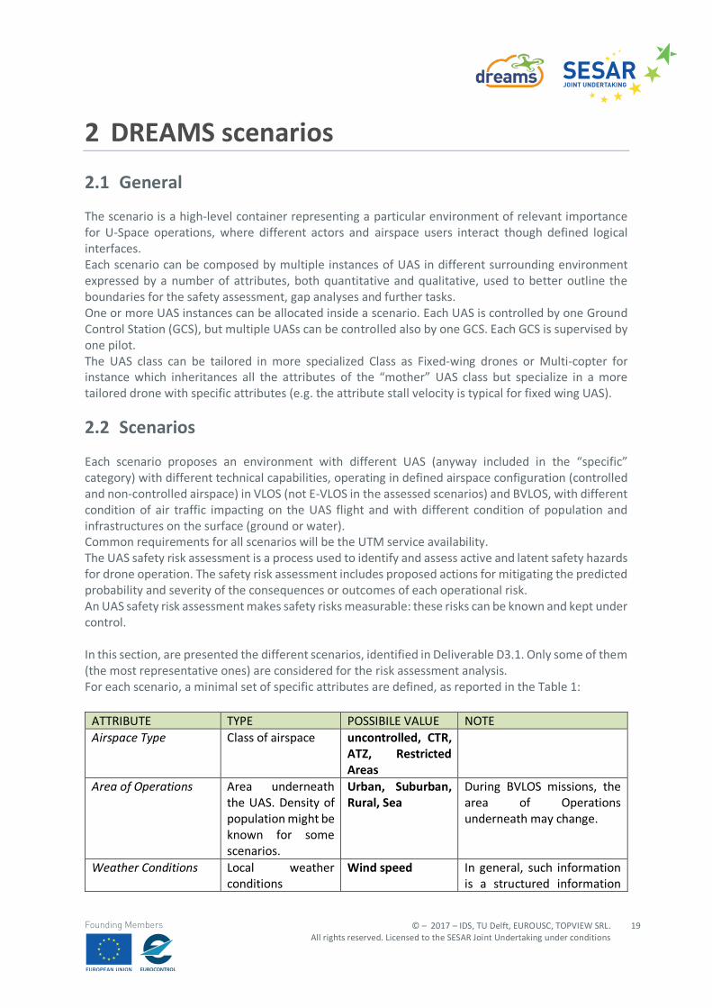
Each scenario proposes an environment with different UAS (anyway included in the “specific” category) with different technical capabilities, operating in defined airspace configuration (controlled and non-controlled airspace) in VLOS (not E-VLOS in the assessed scenarios) and BVLOS, with different condition of air traffic impacting on the UAS flight and with different condition of population and infrastructures on the surface (ground or water). Common requirements for all scenarios will be the UTM service availability. The UAS safety risk assessment is a process used to identify and assess active and latent safety hazards for drone operation. The safety risk assessment includes proposed actions for mitigating the predicted probability and severity of the consequences or outcomes of each operational risk. An UAS safety risk assessment makes safety risks measurable: these risks can be known and kept under control. In this section, are presented the different scenarios, identified in Deliverable D3.1. Only some of them (the most representative ones) are considered for the risk assessment analysis. For each scenario, a minimal set of specific attributes are defined, as reported in the Table 1:
ATTRIBUTE TYPE POSSIBILE VALUE NOTE Airspace Type Class of airspace uncontrolled, CTR,
ATZ, Restricted Areas
Area of Operations Area underneath the UAS. Density of population might be known for some scenarios.
Urban, Suburban, Rural, Sea
During BVLOS missions, the area of Operations underneath may change.
Weather Conditions Local weather conditions
Wind speed In general, such information is a structured information
EDITION 00.01.010
20
© – 2017 – IDS, TU Delft, EUROUSC, TOPVIEW SRL. All rights reserved. Licensed to the SESAR Joint Undertaking under conditions
Founding Members
and does not belong to simple types. However, an overall value can be given for the definition of scenario.
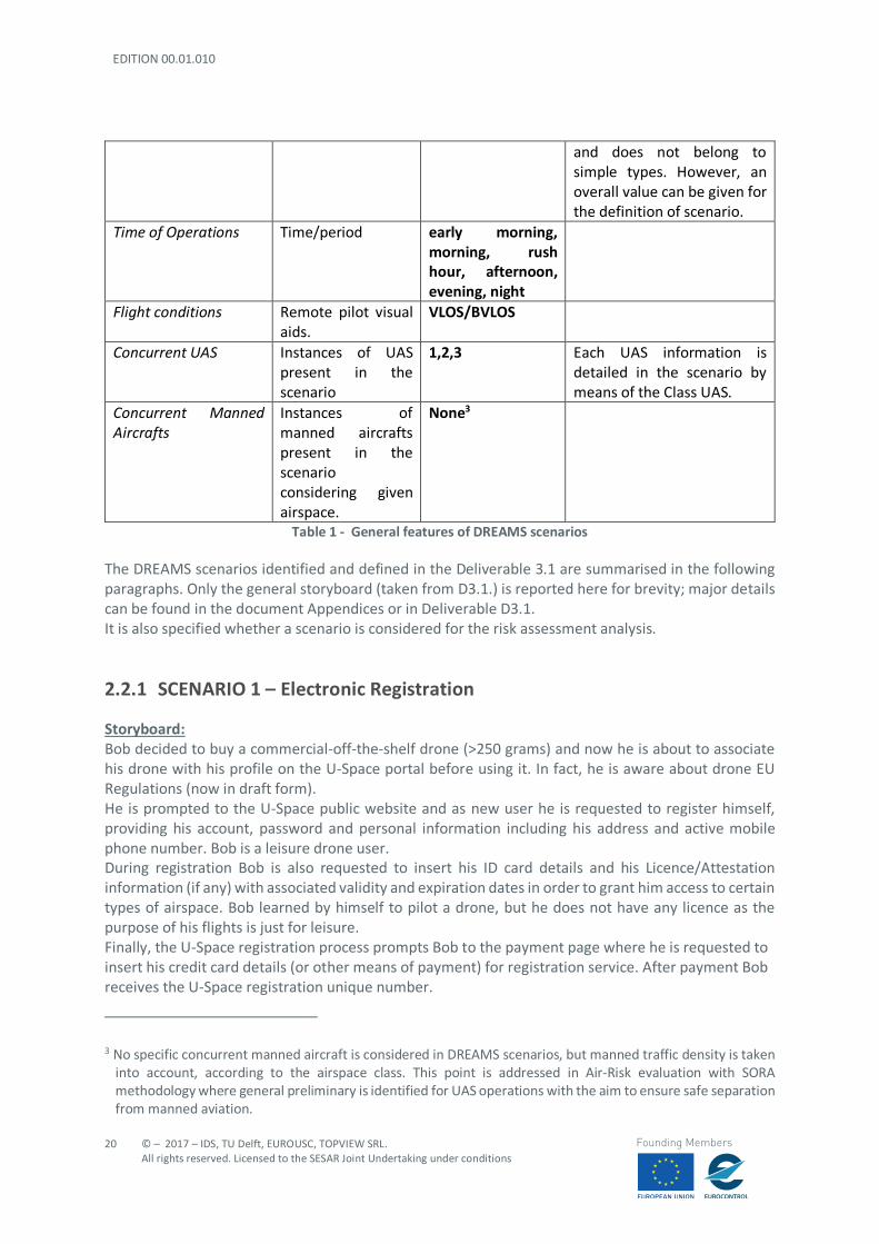
Time of Operations Time/period early morning, morning, rush hour, afternoon, evening, night
Flight conditions Remote pilot visual aids.
VLOS/BVLOS
Concurrent UAS Instances of UAS present in the scenario
1,2,3 Each UAS information is detailed in the scenario by means of the Class UAS.
Concurrent Manned Aircrafts
Instances of manned aircrafts present in the scenario considering given airspace.
None3
Table 1 - General features of DREAMS scenarios
The DREAMS scenarios identified and defined in the Deliverable 3.1 are summarised in the following paragraphs. Only the general storyboard (taken from D3.1.) is reported here for brevity; major details can be found in the document Appendices or in Deliverable D3.1. It is also specified whether a scenario is considered for the risk assessment analysis.
2.2.1 SCENARIO 1 – Electronic Registration
Storyboard: Bob decided to buy a commercial-off-the-shelf drone (>250 grams) and now he is about to associate his drone with his profile on the U-Space portal before using it. In fact, he is aware about drone EU Regulations (now in draft form). He is prompted to the U-Space public website and as new user he is requested to register himself, providing his account, password and personal information including his address and active mobile phone number. Bob is a leisure drone user. During registration Bob is also requested to insert his ID card details and his Licence/Attestation information (if any) with associated validity and expiration dates in order to grant him access to certain types of airspace. Bob learned by himself to pilot a drone, but he does not have any licence as the purpose of his flights is just for leisure. Finally, the U-Space registration process prompts Bob to the payment page where he is requested to insert his credit card details (or other means of payment) for registration service. After payment Bob receives the U-Space registration unique number.
3 No specific concurrent manned aircraft is considered in DREAMS scenarios, but manned traffic density is taken
into account, according to the airspace class. This point is addressed in Air-Risk evaluation with SORA methodology where general preliminary is identified for UAS operations with the aim to ensure safe separation from manned aviation.
© – 2017 – IDS, TU Delft, EUROUSC, TOPVIEW SRL. All rights reserved. Licensed to the SESAR Joint Undertaking under conditions
21
Founding Members
2.2.2 SCENARIO 2 – Concurrent operations
Storyboard: Three UAS are involved in concurrent operations in the same uncontrolled airspace. The first UAS is a rotary wing UAS (quad-copter) involved in one inspection mission over a large rooftop in VLOS condition; the area of operations is at the limits of an urban area. The second UAS is a fixed wing drone involved in a mapping (site scanning) operation for the construction of a new site in a suburban/rural area. The third UAS is a heavy lift aerial filming platform (hex-copter) used for aerial filming production in VLOS conditions in industrial area. The UAS starts at different locations, in particular the heavy lift drone starts from the rooftop of a nearby industrial building for filming production reasons. The flight plan of UAS fixed wing drone has been previously approved by the U-Space Controller (e.g. BOT4) and it is already in the execution phase of its automatic waypoints mission. The other “stand-by” drone users are about to submit their flight plan before take-off. The wind is increasing beyond the capabilities for some UAS so that UTM will provide notification to land immediately to drone users.
2.2.3 SCENARIO 3 – Territory Control
Storyboard: A drone Operator has been accredited by the authorities to fly in a geo-fenced area in urban environment where the most important public cycling event of the year will take place. The starting line of the event will be crowded of cyclists, journalists, authorities (i.e. law enforcement) and citizens are enthusiastic to see the competition. The authorities are monitoring the event also by means of a tethered drone in the proximity of the starting line (about 50 meters AGL, 100 meters horizontally from the unusual gathering of people). The tethered drone payload is operated by the local police station for public security. Moreover, the authorities have installed locally a Ground Surveillance anti drone system, capable to detect incoming drones and neutralize them in case of unauthorized incursion. The authorized Drone Operator is flying in the proximity of the start line of the cycling event without overflying people, inside the geo-fenced area for live video broadcasting activities of the event. The flight is in VLOS conditions and takes place in an uncontrolled airspace. Suddenly before the start of the event a second and a third drone appear in the geo-fenced area with insufficient authorizations or registration to the U-Space services.
2.2.4 SCENARIO 4 – Cooperative Geo-tagging
Storyboard: The scenario is focused on the cooperative mechanism that drones use for geo-tagging new obstacles and how the U-Space could notify information to the other users. Two neighbouring mid-size cities in Europe (about 2500 citizens/Km^2) in uncontrolled airspace have two hospitals, each one with an heliport on the rooftop. Each heliport is equipped with one landing pad for manned helicopters and 5 small landing pads for multi-copter drones. Hospital 1 acts also as 4 The term “BOT” derives from “ROBOT” which means “slave” in Czech language. In the U-Space concept the BOT could be a non-human “controller”.
EDITION 00.01.010
22
© – 2017 – IDS, TU Delft, EUROUSC, TOPVIEW SRL. All rights reserved. Licensed to the SESAR Joint Undertaking under conditions
Founding Members
Drone Operator for medical equipment delivery. Hospital 2 offers only its heliport for landing and take-off operations. There is no prohibited/ restricted zone, nor airport in the proximity of the hospitals. The Hospital 1 is out of a stock of particular medicine drug, needed as soon as possible for a patient, therefore requests to Hospital 2 a fast drone delivery, after checking via telephone the availability of the drug. The Hospital 2 acknowledges the delivery and prepares one of its UASs for the flight mission. As by normal procedures, the flight plan is successfully uploaded by the Drone User appointed personnel by the Hospital 2 to the U-Space, which provides authorization for the mission. The route uploaded for the mission has not been flown for a long time. The UAS 1 used by the Hospital 2 is a quadcopter with ground obstacles detection capability, equipped with parachute and flight termination system with the possibility of 1 Kg payload cargo. During the flight route, the UAS 1 encounters an unpredicted hazard represented by a crane nearby an unreported construction site. The UAS 1 slows down autonomously its velocity while circumnavigating the obstacles, modifying its path. This event is notified to the respective Drone User through ground control station. The estimated position of the crane, obtained through Ground Obstacle Detection capability and UAS positioning information by the Flying drone is “Geo-tagged” (in 4 dimensions) and notified to the U-Space for fencing purposes. In the meanwhile, 2 other U-Space users (1 flying User and 1 Stand-by User) with possible route conflicts with the crane position, are notified by the U-Space for a flight plan or route modification.
2.2.5 SCENARIO 5 – CTR crossing
Storyboard: A VTOL aircraft is involved in a delivery mission between two hubs of an express courier (also Drone Operator). The operation is conducted in BVLOS conditions and the distance between the hubs is about 15 km; the first Hub is located in a village with low density population, the second Hub is located in the industrial suburb of a European city of average dimensions. The second Hub is inside the controlled airspace (e.g., a CTR zone), however it is located at more than 8 km from the city airport. The scenario is focused on the pre-tactical phase of mission preparation and the interfaces from UTM and ATM worlds.
2.2.6 SCENARIO 6 – Long range operations
Storyboard: A Fixed wing drone is involved in a pipeline inspection in BVLOS conditions, in an uncontrolled airspace with prevalence of trees and hills in a rural environment. No villages or cities are supposed to be encountered during the flight. The Mission of the fixed wing drone is aimed at identifying possible oil spilling on a given segment of the pipeline by means of hyper-spectral and thermal sensor payload. In order to maximize the probability of faults detection on the pipeline, the fixed wing drone has to fly at average vertical distance of 50 meters from the pipeline, which stands at ground level following the hills’ slopes. The segment of pipeline to inspect is 25 km long and the longest distance to be flown by the aircraft in this mission is 35 km from the launching point (HOME point) for a total distance of 70 km to be flown. Moreover, considering the typology of mission, the Ground Control station does not always guarantee RLOS conditions to Aircraft, due to the natural obstacles represented by the hills. The Scenario is representative of the tactical stage (Mission planning) considering the data offered by the U-Space services and third-party service providers. General Aviation pilots can benefit of some
© – 2017 – IDS, TU Delft, EUROUSC, TOPVIEW SRL. All rights reserved. Licensed to the SESAR Joint Undertaking under conditions
23
Founding Members
services offered by the U-Space, during flight phase with the aid of portable Electronic Flight Bag (EFB) equipment and allowed U-Space tablet application.
2.2.7 SCENARIO 7 – Deconflict management
Storyboard: One rotary wing UAS (quadcopter) is involved in a delivery mission application inside an uncontrolled airspace in urban environment. The UAS flight-plan has been previously approved and the UAS is in en-route phase. The scenario is focused on modification of the flight route because of a possible conflict during UAS flight. The UAS is flying towards its destination (i.e., the rooftop of a Hospital for the delivery of medical aid). During the mission a potential conflict with another UAS is detected due to a restriction of area requested by law enforcement for a car accident. In fact, law enforcement is going to use their drone for a metric survey of the area of the accident, in order to obtain evidentiary materials also from the sky. The law enforcement has a higher priority for requesting a temporal segregation of the area to allow their drone to take-off, therefore after the obtainment of the authorization for segregation, other flying drone users and other stakeholders in conflict with the fenced area are immediately notified and possible contingency actions are suggested to the drone users.
2.2.8 SCENARIO 8 – Emergency management
Storyboard: St. Michael Hospital uses daily a drone to deliver tubes with blood samples to an external Analysis Centres located in another hospital in a southern Italy city (about 3000 citizens/Km^2 – uncontrolled airspace), and all the procedures works fine since the beginning of the service started two months ago. Today is a cold day of February, with temperatures below 0°C, quite uncommon for Southern Italy areas. The Drone User (Pilot) Luca, as usual, checks and setups the drone of the Hospital used for delivery after loading the tubes in the delivery box, and after obtaining the flight authorization by the U-Space, starts the aircraft for this mission. The expected flight time is about 12 minutes, widely within the limits of drone autonomy; but, just after 5 minutes from take-off, when the drone is at 90 meters AGL, the flight control unit detects an abrupt reduction of battery voltage on different elements for both batteries packs (likely defective cells degraded by low temperature). The Drone User Luca, is alerted on his ground station (Control room of the hospital) of this situation and is notified by Emergency Management service of the U-Space about the closest emergency landing areas. Luca, decided to accept the alternative landing pad suggested by the service due to the contingency situation and uploads the new flight plan proposed by the U-Space on the drone flight controller. The drone changes its trajectory and flies towards the emergency landing pad. The estimated time to reach the pad is about 90 seconds. Unfortunately, during the new trajectory, the voltage on three cells of one battery drops down to zero and few seconds later it happens also to the second battery. The Drone is underpowered. The critical situation is detected autonomously by the Flight control unit which provides to cut-off the engines and open the parachute activated by the Flight termination system. The parachute slows the drone fall up to a vertical descending speed of 4,5 m/s While the drone descends slowly by, the U-Space provides to notify the emergency to Authorities, for a fast intervention on the interested area.
EDITION 00.01.010
24
© – 2017 – IDS, TU Delft, EUROUSC, TOPVIEW SRL. All rights reserved. Licensed to the SESAR Joint Undertaking under conditions
Founding Members
2.2.9 SCENARIO 9 – Capacity management
Storyboard: Two neighbouring mid-size cities in Europe in uncontrolled airspace in 2025 are connected daily with hundreds of drones’ flights mainly for delivery missions. The take-off and landing areas for the drones are placed on new or existing structures equipped with automatic recharging stations for batteries, local weather stations and digital communication services with a minimal presence of human crew. Express couriers and Hospitals for example have different hubs connected with other take-off and landing areas, that serve multiple concurrent drones operations. Every route is predefined, and each related flight plan has validity for more operations (e.g. a route to connect 2 hubs is implemented daily at a given time for one month). With the introduction of U3 services and the increased level of automation, drones are connected directly with U-Space services and are capable of taking conditional decisions. The level of connectivity with 5G network is high and high data rate services are supported. The appointed personnel from Drone Operators’ is in charge to monitor and control drones with hand held devices or by means of control rooms and can take actions in case of contingency situations. In this scenario Drone 1 has an approved flight plan to perform a delivery mission to HUB 1 (and return) every day at 12:00. The Drone has the capability to request access to airspace before take-off to the U-Space Controller (BOT), that can exploit the Dynamic Capacity Management service for monitoring airspace demand. Moreover, during the flight, the Drone is provided with separation management by Tactical De-confliction service and is capable to perform actions to guarantee separation with other unmanned flights (e.g. reduce speed, climb to a different altitude, …).
2.2.10 SCENARIO 10 – Security Service
Storyboard: The authority (law enforcement) is interested to acquire all surveillance videos and evidentiary materials nearby a bank subsidiary in an urban contest, where a bank raid happened the day before. The law enforcement already acquired all possible closed-circuit videos from the bank and nearby surveillance cameras, but they would like to integrate it with more evidentiary materials. The law enforcement however can still interact with the U-Space services in order to ask to the authority (NAA) for the list of all Drone Operators that submitted and executed a valid flight plan overlapping in the proximity of the area of their interest. In case of possible matching flight plan, the NAA could provide directly to the law enforcement, the contacts of Drone Operators involved in operations in the proximities of the event. Though, no guaranty is given to law enforcement about aerial filming capabilities of drone and recording state of payload, used by the drone operator, a potential big impact could be given in terms of security to EU citizens in case of success.
2.2.11 SCENARIO 11 – Personal Mobility
Storyboard: After landing at the airport of a big European city, a business man decides to book a drone taxi service to go downtown. The reservation is made through a dedicated mobile phone app created specifically for this purpose that interfaces directly with the Service Provider (Taxi Drone Operator). The drones
© – 2017 – IDS, TU Delft, EUROUSC, TOPVIEW SRL. All rights reserved. Licensed to the SESAR Joint Undertaking under conditions
25
Founding Members
used for this purpose are "parked" in a reserved area of the airport ("skyport"). These drones (electric jet-powered) have both VTOL and Rapid Horizontal Flight capabilities, and do not need to take-off and land on an airport runway but in pre-established areas, at sufficient distance from the take-off and landing runways. The drone flies in autonomous mode and is equipped with recovery functions (parachutes or auto-landing in case of emergency) and redundancies in the propulsion system. The business man books his taxi drone flight from his mobile phone and receives the acknowledgment from the Taxi Drone Operator after payment with the instructions to reach the taxi drone N°5 in the skyport. Right after the payment the skyport station is warned about the booking and prepares (likely with help of an assistant) the drone for take-off.
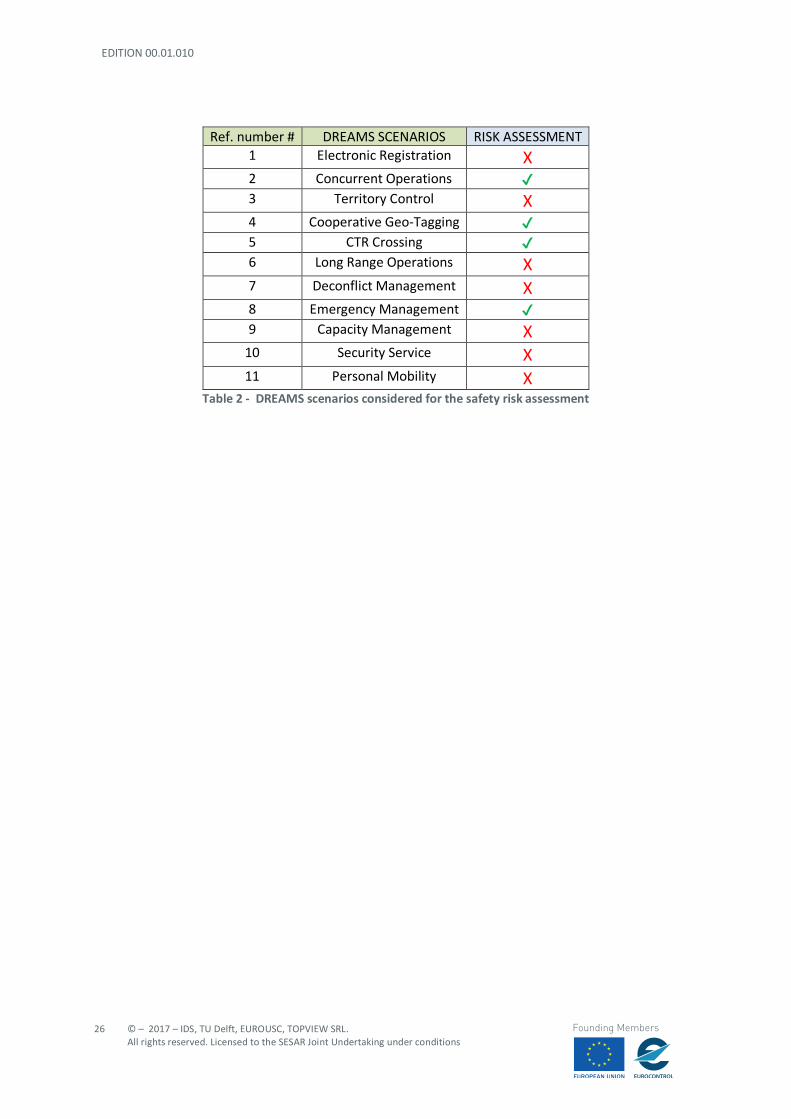
2.2.12 Scenarios included in the Safety Risk Assessment
Only a subset of scenarios identified in D3.1 are considered in this document. In particular, the most relevant scenarios dealing with safety issues are considered for the risk assessment analysis, as follows:
- scenario 2: “Concurrent operations” - scenario 4: “Cooperative Geo-tagging” - scenario 5: “CTR crossing” - scenario 8: “Emergency Management”
Scenarios are selected with the aim to cover a wide range of UAS operations (i.e. VLOS/BVLOS conditions, controlled/uncontrolled airspace, urban/rural environment) and U-Space services. In fact, both VLOS (scenario 2) and BVLOS (scenarios 2,4,5,8) conditions are investigated in different operational environments (rural, urban and suburban). A typical operation in a controlled airspace is analysed in scenario 5; in particular, an airport environment (CTR) where manned traffic density is expected to be high and interface with traditional ATC structures is envisaged. The remaining scenarios are excluded from the safety assessment since:
- scenario 1, scenario 3 and scenario 10 deal with security aspects; - scenario 6 and scenario 9 deal with BVLOS operations in uncontrolled airspace, being these
operational conditions already analysed in scenario 4 and 8. - scenario 7 deals with possible UAS interactions in urban environment, in a perspective
similar to scenario 2. - scenario 11 foresees operations of drones carrying persons on board: such operations cannot
be included in the “specific category” and are not investigated at this level. In conclusion, the operational range of the scenarios included the risk assessment can be considered reasonably exhaustive, allowing to define the most demanding requirements (both performance and safety requirements) for U-Space services.
EDITION 00.01.010
26
© – 2017 – IDS, TU Delft, EUROUSC, TOPVIEW SRL. All rights reserved. Licensed to the SESAR Joint Undertaking under conditions
Founding Members
Ref. number # DREAMS SCENARIOS RISK ASSESSMENT 1 Electronic Registration X 2 Concurrent Operations ✔ 3 Territory Control X 4 Cooperative Geo-Tagging ✔ 5 CTR Crossing ✔ 6 Long Range Operations X 7 Deconflict Management X 8 Emergency Management ✔ 9 Capacity Management X
10 Security Service X 11 Personal Mobility X
Table 2 - DREAMS scenarios considered for the safety risk assessment
© – 2017 – IDS, TU Delft, EUROUSC, TOPVIEW SRL. All rights reserved. Licensed to the SESAR Joint Undertaking under conditions
27
Founding Members
3 Airspace and Operational environment
3.1 General
The States of European Union are under the “jurisdiction” of European Regulation and, for the airspace domain, EASA, the European Aviation Safety Agency, is in charge to provide the regulation for all civil aviation matters. Regarding to UAS sphere, in July 2015, the Agency proposed in consultation the NPA 2015-10 [13] and in December 2015, a Technical Opinion, a ‘Prototype’ regulation drafted for the ‘open’ and ‘specific’ categories. In August 2016 the ‘Prototype’ regulation was published proposing actual rules providing the necessary clarity, notably on what are the responsibilities of the Member States and what is the flexibility offered to them. At this stage, the new proposed Basic Regulation) is under discussion between the Council, the European Commission, and the European Parliament. EASA, in consideration of political and commercial issues, on May 2017, and according to above mentioned NPA 2015-10, proposed another NPA for consultation. The NPA 5/2017 is a proposal for an operation centric, proportionate, risk- and performance-based regulatory framework for all unmanned aircraft (UA), establishing three categories (“open”, “specific” and “certified”) with different safety requirements, proportionate to the operation and the related risk. On 6th February 2018, EASA published the Opinion 1/2018 and, in addition, two draft Regulatory documents (EU Regulation for “laying down rules and procedures for the operation of unmanned aircraft ”[14] and EU delegated Regulation “on making available on the market of unmanned aircraft intended for use in the ‘open’ category and on third-country UAS operators”[15]. Furthermore, the Agency proposes one Annex [16] named “UAS operations in the ‘open’ and ‘specific’ categories [PART-UAS]” and a draft AMC-GM [17] in relation to the EU regulation [14] and the Annex. The above-mentioned documents, expected to be approved in mid-2018, officially issued within the same year and in force in 2019/2020, intend to give “rules” and operational guidance to fly “open” and “specific” unmanned operations in European airspace even if no change are expected, at this stage, for airspace structure. In European airspace, UE Reg. 923/2012 (SERA – Standardised European Rules of the Air) [18] lays down the common rules of the air and operational provisions regarding services and procedures in air navigation that shall be applicable to general air traffic in the Union framework. In this context, unmanned aircraft have to operate in “controlled” or “uncontrolled” airspace and, if the case, in “reserved” portions of airspace. To be more precise, the UAS have to operate in the different classes of airspace (from “A” to “G”) or in “reserved” areas, according to regulation in force for general air traffic ICAO, EU and national rules and procedures. Accordingly, the foreseen services have to be provided to the traffic operating in a specific portion of airspace, in terms of authorizations, instructions or information, on the basis of type of flight, airspace class involved and including separation (if expected), speed limitation, radio communication requirement and specific clearance by ATS.
EDITION 00.01.010
28
© – 2017 – IDS, TU Delft, EUROUSC, TOPVIEW SRL. All rights reserved. Licensed to the SESAR Joint Undertaking under conditions
Founding Members
Obviously, the structure is set up for manned traffic, but at this stage, even if the U-Space is aiming at integrating the drones in all classes of airspace, the UAS operation have to consider this framework. The present study has to take into consideration the different “conditions” of airspace where UAS operate, in particular, it’s important to define for each scenario the airspace involved, the aspects to consider related to rules to follow and services to be provided. Another aspect to underline is the consideration of the surrounding of an operational scenario, the airspace and the territory adjacent to the operational area. We could have an operational area located in a rural unpopulated site, the airspace is classified G and it’s clear of traffic in the period of UAS planned activity. No airfields and no restricted zones. But few miles around the scenario, there could be airports, urban or sub-urban areas and restricted areas. The assessment has to take in consideration these aspects for correct evaluation in case of particular failure. If the drone has a “lost link” it could be uncontrollable, and it could fly outside of the operation area, miles far from it. In the following paragraphs will be reported the basic concept of airspace structure in order to better frame the UAS scenarios, assessed in this study.
3.2 Controlled and uncontrolled airspace
UE Regulation 923/2012 reports as follows:
- “’Controlled airspace’ means an airspace of defined dimensions within which air traffic control service is provided in accordance with the airspace classification.”5
It means that air traffic control services are provided to IFR flights and to VFR flights in accordance with the airspace classification. Controlled Airspace is a generic term which covers ATS airspace classes A, B, C, D, and E. Controlled Airspace includes Control Areas, Terminal Control Areas, Airways and Control Zones. Current EU and ICAO documents don’t report any definition of “uncontrolled airspace”. As a consequence of “controlled airspace” definition we may assume that “uncontrolled airspace” could an airspace of defined dimension within which air traffic control service may be provided in accordance with the airspace classification. It means that in uncontrolled airspace there isn’t supervision by air traffic control, so no clearance is required to operate in uncontrolled airspace. The large majority of light aircraft (included ultra-light machines) and helicopters operate outside or underneath controlled airspace. In uncontrolled airspace, pilots are often not in contact with air traffic control units, but they must still follow visual flight rules or instrument flight rules. In uncontrolled airspace Air Traffic Controllers do not provide separation but provide information (Flight Information Service and Traffic Information Service) to aircraft flying following instrument flight rules and, on request, to aircraft flying on visual flight rules.
5 Reg. UE 923-2012 SERA “Definitions” – ICAO Annex 2 [19] and Annex 11 [20] “Definitions”
© – 2017 – IDS, TU Delft, EUROUSC, TOPVIEW SRL. All rights reserved. Licensed to the SESAR Joint Undertaking under conditions
29
Founding Members
Regarding to airspace classification, uncontrolled airspace is a generic term which covers ATS airspace classified F and G. Having regard to scenarios reported in D3.1, the controlled or uncontrolled airspace may be applied as follows:
- Scenario 1 Electronic Registration – Not applicable - Scenario 2 Concurrent Operations – Uncontrolled - Scenario 3 Territory Control – Undefined - Scenario 4 Cooperative Geo-tagging – Uncontrolled - Scenario 5 CTR Crossing – Controlled and Uncontrolled - Scenario 6 Long Range Operations – Uncontrolled - Scenario 7 Deconflict Management – Uncontrolled and Temporary Restricted Area - Scenario 8 Emergency Management – Uncontrolled - Scenario 9 Capacity Management – Uncontrolled
3.2.1 Airspace classification
Airspace is divided in Controlled and Uncontrolled airspace and it’s classified6 as follows: Controlled airspace
- Class A -.IFR flights only are permitted. All flights are provided with air traffic control service and are separated from each other. Continuous air-ground voice communications are required for all flights. All flights shall be subject to ATC clearance.
- Class B - IFR and VFR flights are permitted. All flights are provided with air traffic control
service and are separated from each other. Continuous air-ground voice communications are required for all flights. All flights shall be subject to ATC clearance.
- Class C - IFR and VFR flights are permitted. All flights are provided with air traffic control
service and IFR flights are separated from other IFR flights and from VFR flights. VFR flights are separated from IFR flights and receive traffic information in respect of other VFR flights and traffic avoidance advice on request. Continuous air-ground voice communications are required for all flights. For VFR flights a speed limitation of 250kts indicated airspeed (IAS) applies below 3 050 m (10 000ft) AMSL, except where approved by the competent authority for aircraft types, which for technical or safety reasons, cannot maintain this speed. All flights shall be subject to ATC clearance.
- Class D - IFR and VFR flights are permitted, and all flights are provided with air traffic control service. IFR flights are separated from other IFR flights, receive traffic information in respect of VFR flights and traffic avoidance advice on request. VFR flights receive traffic information in respect of all other flights and traffic avoidance advice on request. Continuous air-ground voice communications are required for all flights and a speed limitation of 250 kts IAS applies
6 EU Reg. 923/2012 SECTION 6 Airspace classification - SERA.6001 Classification of airspace
EDITION 00.01.010
30
© – 2017 – IDS, TU Delft, EUROUSC, TOPVIEW SRL. All rights reserved. Licensed to the SESAR Joint Undertaking under conditions
Founding Members
to all flights below 3 050 m (10 000 ft) AMSL, except where approved by the competent authority for aircraft types, which for technical or safety reasons, cannot maintain this speed. All flights shall be subject to ATC clearance.
- Class E - IFR and VFR flights are permitted. IFR flights are provided with air traffic control
service and are separated from other IFR flights. All flights receive traffic information, as far as is practical. Continuous air-ground voice communications are required for IFR flights. A speed limitation of 250kts IAS applies to all flights below 3 050 m (10 000ft) AMSL, except where approved by the competent authority for aircraft types, which for technical or safety reasons, cannot maintain this speed. All IFR flights shall be subject to ATC clearance. Class E shall not be used for control zones.
Uncontrolled airspace
- Class F - IFR and VFR flights are permitted. All participating IFR flights receive an air traffic advisory service and all flights receive flight information service if requested. Continuous air-ground voice communications are required for IFR flights participating in the advisory service and all IFR flights shall be capable of establishing air-ground voice communications. A speed limitation of 250kts IAS applies to all flights below 3 050 m (10 000ft) AMSL, except where approved by the competent authority for aircraft types, which for technical or safety reasons, cannot maintain this speed. ATC clearance is not required.
- Class G - IFR and VFR flights are permitted and receive flight information service if requested.
All IFR flights shall be capable of establishing air-ground voice communications. A speed limitation of 250kts IAS applies to all flights below 3 050 m (10 000ft) AMSL, except where approved by the competent authority for aircraft types, which for technical or safety reasons, cannot maintain this speed. ATC clearance is not required.
The above classification reports very different services to be provided. ATC clearance, Traffic separation or traffic information/advisory and traffic/ATS communication are the main key requirements for manned traffic. In this context, the rules that will be followed by drones operating in a common airspace shall have significant impact on manned traffic. Regarding to U-Space, and in particular VLL airspace, specific classification should be anyway “accommodated” (new class of airspace?). Currently, the only unclassified airspaces are the “reserved” areas (Prohibited, Restricted or Dangerous) and the “manageable areas”, when activated.
3.3 Airspace restrictions
Portions of controlled and uncontrolled airspace may assume a different configuration in particular condition and for very specific reasons. Some areas may be “reserved” (or “segregated”) to special activities or to grant protection (safety and/or security) to particular sites and infrastructure. Each area
© – 2017 – IDS, TU Delft, EUROUSC, TOPVIEW SRL. All rights reserved. Licensed to the SESAR Joint Undertaking under conditions
31
Founding Members
may be permanent or temporary, may be never allowed to fly (P - Prohibited areas) or subject to specific permission and conditions (i.e. Restricted areas).7 “Prohibited areas” are portion of airspace where the air traffic is not allowed (usually is permanent and prohibition is for all air operations). ‘Restricted area’ means ‘an airspace of defined dimensions, above the land areas or territorial waters of a State, within which the flight of aircraft is restricted in accordance with certain specified conditions’8. In practical terms, traffic cannot fly through the dimensions of a restricted airspace without getting permission from the “competent” controlling agency. If the airspace is “active,” “open,” or “hot”9 the agency will deny permission and traffic shall go around. Regarding drones, two aspects of restricted areas should be considered:
- the restricted areas assigned and reserved to other special activities and to be avoided intrusions (by drones) because already occupied by other “special activities”, or
- the restricted areas assigned and reserved to drone operations. The aim of U-Space is to integrate the UAS with manned traffic but, for certain specific operations, as for some manned special activities, UAS activities shall be conducted in restricted (segregated) areas. In other cases, UAS shall avoid “reserved” areas similar to manned aircraft behaviour.
3.4 VFR and IFR operations
VFR and IFR are rules not yet well “encompassed” in the UAS domain and in particular in the U-Space and for VLL operations. It’s still hard to link a UAS flight to VFR or IFR terms because of the difficulty to respect the rules and related procedures. Basically, and very simply, VFR is the capability to “see (the other traffic and obstacles) and to be seen (by other traffic) during the flight, in a context of specific weather condition and limits. The VFR traffic is used to “space” itself from the other traffic or obstacles. IFR is the capability to fly using radio aid (i.e. VOR, TACAN and GNSS), following specific routes and maintaining a specific separation (normally assigned by ATC) from other traffic or terrain. For U-Space, VFR and IFR could be “arranged” in order to allow similar typologies of operations.
3.4.1 VFR
EU Regulation reports for VFR definition as follows: - “‘VFR flight’ means a flight conducted in accordance with the visual flight rules.”10
VFR flights shall be conducted so that the aircraft is flown in conditions of visibility and distance from clouds equal to or greater than those defined by Rules (UE Reg. 923/2012 in Europe and ICAO Annex 2 “Rules of the air”). 7 Reg. UE 923-2012 SERA and ICAO Annex 2 - Aircraft shall not be flown in a prohibited area, or in a restricted
area, the particulars of which have been duly published, except in accordance with the conditions of the restrictions or by permission of the Member State over whose territory the areas are established.
8 Reg. UE 923-2012 SERA “Definitions” – ICAO Annex 2, Annex 11 and Annex 15 [21] “Definitions” 9 Different terminology to define an area engaged by activities, included gunnery or other no aircraft operations 10 Reg. UE 923-2012 SERA “Definitions” – ICAO Annex 2 and Annex 11 “Definitions”
EDITION 00.01.010
32
© – 2017 – IDS, TU Delft, EUROUSC, TOPVIEW SRL. All rights reserved. Licensed to the SESAR Joint Undertaking under conditions
Founding Members
VFR stands for Visual Flight Rules and refers to a set of rules created for flights in VMC - Visual Meteorological Conditions. When referring to VFR or VMC, VFR is the type of flight operation or type of flight plan flown by the pilot, and VMC refers to the type of weather conditions. Air traffic controllers aren’t always required to keep VFR aircraft separated from each other like they do for IFR traffic. The responsibility for traffic separation lies solely with the pilot during VFR operations, which means he needs to be able to see in front of and around his aircraft while in the air. For this reason, VFR rules also cover visibility requirements and cloud clearance criteria required to fly with visual reference to the ground and/or horizon. These visibility and cloud clearance requirements vary depending on the type of airspace pilots are flying in, but they exist to ensure that pilots flying VFR don’t get caught up in the clouds and crash into each other. In other words, the main concept of VFR flight is “to see and to be seen”. In the context of UAS, VFR flight seems to be the closest rules to VLOS operation, even if appears easy to achieve only the condition “to see” other traffic (in particular, manned traffic). Many issues are to be considered for the second part of sentence, “to be seen”. A small drone is not easy to be seen by another traffic (in particular, by manned traffic, including Parachute jumpings or other similar aeronautical activities). In order to improve capacity of other traffic “to see” the drones, additionally devices might be placed on board. For instance, the use of navigation “lights” specific for drones may improve the visibility by third airspace users (both manned and unmanned). Such light system could be designed so that:
- Drone presence is highlighted by a universally recognized light colour (e.g. orange lights); - heading is easily recognizable by other users as for manned aircraft (e.g. flashing and fixed
lights to indicate flight direction); In addition, for rotary wing configurations (where four drone heading directions are possible), it could be possible to:
- install a light system which rotates accordingly with the heading of the aircraft; or - design a flight control system could automatically adjust drone heading to non-rotating lights
In addition, a sound alert could be envisaged to prevent collisions with third parties on the ground in case of:
- emergency situations (e.g. flight termination system activated); - situations in which a “forced” landing is prescribed by an unexpected event (e.g. law
enforcement or drone malfunctions).

© – 2017 – IDS, TU Delft, EUROUSC, TOPVIEW SRL. All rights reserved. Licensed to the SESAR Joint Undertaking under conditions
33
Founding Members
3.4.2 IFR
EU Regulation 923/2012 reports definition as follows: - “‘IFR flight’ means a flight conducted in accordance with the instrument flight rules.”11
IFR and IMC are related. IFR stands for Instrument Flight Rules – the set of rules that govern aircraft that fly in IMC, or Instrument Meteorological Conditions. In general terms, IMC means flying in the clouds or in very low visibility (i.e. fog). More specifically, IMC is defined as weather that is “below the minimums prescribed for flight under Visual Flight Rules.” Of course, IFR flight may be also conducted in VMC condition, depending on the weather. It’s called instrument flight because the pilot navigates only by reference to the instruments in the aircraft cockpit. Flying in the clouds (IMC) and in low visibility requires an IFR flight plan and an instrument rating. IFR flight is defined by ICAO as a flight conducted in accordance with the instrument flight rules. An IFR flight shall be flown at a level which is not below the minimum flight altitude established by the State whose territory is overflown, or, where no such minimum flight altitude has been established:
a) over high terrain or in mountainous areas, at a level which is at least 600m (2000ft) above the highest obstacle located within 8km of the estimated position of the aircraft;
b) elsewhere than as specified in a), at a level which is at least 300m (1000ft) above the highest obstacle located within 8km of the estimated position of the aircraft.
Flying by instruments, without any outside references sounds dangerous, but it’s very safe once pilot have received the proper training. The pilot has to use navigational aids like VORs, ADF and GPS and how to fly approaches using an Instrument Landing System (ILS). In the context of UAS, for IFR flights seems to be not possible to use the traditional aids (VOR, TACAN, ILS, …). The GPS (GNSS) should be one of the “aid” usable for UAS operations. Flights operating in IFR are usually “controlled” by ATC and the ATC grant separations from other traffic. In the U-Space context, it isn’t yet clear the IFR drone operations and, consequently, which will be the role of ATC. Probably the IFR will be operated by “medium and long range” drone flights, crossing portions of controlled airspace and with relevant probability to interface with manned traffic.
3.5 VLL – Very Low-Level operations
In Europe, many different rules are in force in the countries for UAS with MTOM below 150Kg. One of non-standard requirements is the maximum height allowed (MTOM – Maximum Take-Off Mass) for drones operating in VLOS. Two upper limits are usually defined by States: 400ft or 500ft Above Ground Level - AGL).
11 Reg. UE 923-2012 SERA “Definitions” – ICAO Annex 2 and Annex 11 “Definitions”
EDITION 00.01.010
34
© – 2017 – IDS, TU Delft, EUROUSC, TOPVIEW SRL. All rights reserved. Licensed to the SESAR Joint Undertaking under conditions
Founding Members
In the last EASA 1/2018 Opinion, 400ft AGL is the maximum upper level allowed for “open” drone operations. In any case, the separation (or spacing or safe distance or “remain well clear”) from other traffic (manned or unmanned) is not granted by the limit. In fact, manned traffic, in particular in G airspace, often operates at 500ft or below. For instance, helicopters or ultra-light aircraft, usually fly below this height and several military operations (fixed wings or rotary wings) are also conducted at or below 500ft AGL. Furthermore, standard VFR traffic over unpopulated areas, is not allowed by ICAO Annex 2 and SERA below 500ft AGL. In the U-Space terminology, VLL – Very Low Level, commonly stands for operations conducted not above 500ft, but this limitation doesn’t mean no manned traffic in this portion of airspace, as highlighted immediately above. In any case, at this stage, no documents (EU or ICAO) reports any official specific definition neither any defined limit for VLL term. In other words, no rules in force to define the 500ft (or other limit) the maximum upper limit for VLL. Presently drone operations occur mainly at VLL in VLOS. In this condition, the UAS remote pilot is generally able to “remain well clear” from other traffic (included manned traffic), because of the reduced operational area and short distance between the remote pilot and the drone. VLOS drone operations may be compared to the capability of a pilot “on board” to “see and avoid” the other traffic and the obstacles and to be able to maintain “safe spacing”. The term separation is more appropriate when specific distances between two or more aircraft are quantitatively defined (e.g. in IFR). For VLOS and VFR operations, specific “distance” between two aircraft are not defined. However, due to small size, it’s very hard to be compliant with the “to be seen” requirement. Therefore, if deviating from the priority rules, the remote pilot has to assume responsibility for avoiding manned traffic. Regarding to BVLOS, flights at VLL could be related to automatic operation and to DAA capability. In absence of DAA systems, even if with the usage of cameras, appears very challenging to fly VLL following VFR. The difficulties come from the scarce awareness of the environment (hard to see other traffic/obstacles) and the low “visibility” of the drone by other air users. IFR seems to be inconsistent with the requirement of separation currently applied from other traffic or from terrain (and ground obstacles). Flying below 500ftAGL, there is very poor vertical space to grant appropriate manoeuvres to avoid other traffic in conflict, even if this traffic is cooperative. In other words, the separation expected to be granted to manned traffic, seems to be very hard to achieve. For time being, BVLOS seems to be practicable only in segregated areas waiting for DAA systems. In the end, VLL has to be defined. To maintain “a strategic spacing” between drones and manned flight, the VLL could be raised not above 400ft. There are only 100ft (30m) but anyway that’s a minimum distance useful to increase safety.
© – 2017 – IDS, TU Delft, EUROUSC, TOPVIEW SRL. All rights reserved. Licensed to the SESAR Joint Undertaking under conditions
35
Founding Members
3.6 ATM in the VLL airspace
The ATM in the U-Space management is an aspect to be assessed, even if no many paragraphs are dedicated to ATM or ATC aspects in the new EASA proposed regulation. It’s a fact that the Opinion 1/2018, issued on 6th February 2018 by the Agency, includes only very few short sentences regarding these aspects. In particular, the document reports that “In the operational authorisation section, a new requirement has been added to ensure that the UAS operator develops a procedure for the coordination with the relevant ATC unit(s) if the entire operation or part of it is to be conducted in controlled airspace.”12 The proposed new EU Regulation “laying down rules and procedures for the operation of unmanned aircraft", published with Opinion 172018, only refers to “airspace restrictions” to be established by “an authority” designated by the Member States13. No any specific reference to ATM or ATC role, responsibilities or any other involvement in the UAS legislation. Similar situation is in the proposed AMC-GM, related to EU draft regulation. No ATC or ATM aspects are included in the draft document and the only reference to airspace aspects is reported in GM1 Article 11 “Airspace restriction related to UAS operations” and GM2 Article 11 “Airspace restrictions”. The paragraphs specify the portion of airspace, defined by Member States, “where UAS operations are limited to commercial or leisure ones or where certain equipment, such as a geo-awareness or an electronic identification system, is mandatory.” In addition, it’s specified that information on restricted areas reserved to UAS has to be published on national AIP. Regarding to the draft Annex “UAS operations in the ‘open’ and ‘specific’ categories [PART-UAS]” the term ATC is reported in UAS.SPEC.040 14 in EASA Opinion 1/2018, in the section of “specific” operation. In particular, is reported as follows:
- “The competent authority shall issue, without undue delay, an authorisation to a UAS operator to conduct an operation in the ‘specific’ category when it concludes that the operation corresponds to a standard scenario issued by EASA that requires an authorisation,
and - “a procedure is in place for the coordination with the relevant ATC unit(s) if the entire operation
or part of it is to be conducted in controlled airspace;”. The term ATM is reported in the section dedicated to risk assessment (UAS.SPEC.020 “Operational risk assessment”15) underlining that the UAS operator, when conducting the operational risk assessment, shall consider (among other requirements) “the class of the airspace and the impact on other air traffic and air traffic management (ATM) in cooperation with the relevant air navigation service provider (ANSP)”.
12 Opinion 1/2018 - 2.4.3.3. ‘Specific’ category 13 Draft EU Regulation laying down rules and procedures for the operation of unmanned aircraft - Article 8
Designation of the competent authority, 1 (c) and Article 11 Airspace conditions for UAS operations - Airspace conditions for UAS operations.
14 UAS.SPEC.040 - Issuing of an operational authorisation 15 UAS.SPEC.020 Operational risk assessment, 2 (b)
EDITION 00.01.010
36
© – 2017 – IDS, TU Delft, EUROUSC, TOPVIEW SRL. All rights reserved. Licensed to the SESAR Joint Undertaking under conditions
Founding Members
In reference to term ATS, it’s mentioned in UAS.SPEC.070 “Responsibilities of the remote pilot”, to specify that the remote Pilot, before starting UAS operation shall “ensure that the information about the operation has been made available to the relevant air traffic service (ATS) unit” -. Taking in consideration the above-mentioned paragraphs, the ATM/ATC/ATS aspect seems to be marginal or anyway not directly related to UAS operation in U-Space. In this context, which will be the role of ATM and ATC in the U-Space? First of all, it’s relevant to define if the ATM in the U-Space will be endorsed for all the “phases” of the flight or only in specific conditions. Interaction among Operators, Pilots and ATM may be realised in the strategic phase (planning the mission), in the pre-tactical phase (preparing to operate the mission), in the tactical phase (operating the mission) and after the conclusion of mission (post operation). Different functions and related responsibilities come from the above mentioned four phases and, for each phase, different “ATM services” may be provided. At this stage, will be the ATM directly involved in the UTM provision or will be only involved in coordination and cooperation activities? In both cases, regulation shall clear which provider will be in charge to manage “all” the traffic (manned and unmanned) in the U-Space or which rules and procedures shall be defined in case of different Service Providers. And another point to evaluate regards the future UAS autonomous flights, where ATM role could be hugely overtaken. In any case, new Regulation (or modified Regulation) shall be issued to harmonise the competence in the U-Space portion in relation of traditional traffic and UAS operations.
© – 2017 – IDS, TU Delft, EUROUSC, TOPVIEW SRL. All rights reserved. Licensed to the SESAR Joint Undertaking under conditions
37
Founding Members
4 Risk Assessment methodologies
4.1 THE HOLISTIC RISK MODEL (HRM)
Both SORA and the other risk matrix-based methodologies (i.e. ICAO and EASA) use the same terminology and definitions of the words “risk”, “harm”, “hazard” and “threat” used in the Holistic Risk Model. So, these methods and terminology are detailed in the following paragraphs. Concerning the term “risk”, SORA takes the definition provided in the SAE ARP 4754A/ EUROCAE ED-79 [22], while EUROCONTROL SAM, takes definition in the ESARR4 document, as follows:
- “’RISK’ is the combination of the frequency (probability) of an occurrence and its associated level of severity”. (EUROCAE),
- “’RISK’ is the combination of the overall probability, or frequency of occurrence of a harmful effect induced by a hazard and the severity of that effect.” (EUROCONTROL).16
The terms related to the Risk are defined as follows:
- “HARM (of some type) is the consequence of every occurrence.” (EUROCAE). HARM is not defined in ESARR 4.
- “HAZARD” is anything with the potential to cause harm (i.e. the “occurrence”). (EUROCAE), “17 - “HAZARD is any condition, event, or circumstance which could induce an accident.”
(EUROCONTROL)
- “THREAT is the issue that can cause the hazard to occur if not kept under control possible causes.” (EUROCAE).
THREAT is not defined in ESARR 4. The philosophy applied in the assessment has the aim to reduce the “risk”. That’s possible acting either on the threats or on the harms by using appropriate barriers that will reduce the likelihood or the severity of the hazard and its consequences.
4.2 SORA Methodology
4.2.1 SORA Holistic Risk Model
The Holistic Risk Model (HRM) is the main framework used in SORA to support the assessment of the risks involved in a UAS operation. This model provides a generic framework to identify the hazards, the threats and the relevant harm and threat barriers applicable to the UAS operation under consideration. In SORA three categories of harm are considered: 16 - ESARR 4 APPENDIX B - Terms and Definitions - Glossary 17 - The EASA NPA 2017 – 05(A) reports following definition: ‘hazard’ means a condition or an object with the
potential to cause injuries, damage, loss of material or a reduction of the ability to perform a prescribed function.
EDITION 00.01.010
38
© – 2017 – IDS, TU Delft, EUROUSC, TOPVIEW SRL. All rights reserved. Licensed to the SESAR Joint Undertaking under conditions
Founding Members
a. Fatal injuries to third parties on the ground; b. Fatal injuries to third parties in the air (Mid-air collision with manned aircraft); c. Damage to critical infrastructure.
This list of harms may be extended, but for the purpose of the DREAMS project is considered comprehensive as it covers all possible relevant categories. However, when this Risk Assessment will be better specified for the demonstration scenarios, the local authorities may want to consider additional categories of harm (e.g. disruption of a community, environmental damage, financial loss, etc.) which could be assessed in the same way using this methodology. Currently, the SORA methodology developed only the analysis of the first two harms. For DREAMS this is considered appropriate for the time being. Further analyses could be required if the actual operation is going to be conducted in proximity of critical infrastructures thus requiring to explicitly address this issue. In SORA the only hazard related to the UAS operation that may lead to any of the three identified harms is “UAS operation out of control”. This is defined as any condition in which the operation being conducted is going outside of the approved Concept of Operations (ConOps). The definition of “out of control” is therefore not considering in any way if the remote pilot is actually controlling the RPA or not. It just refers to any condition which was not envisaged in the ConOps, no matter the reason why this violation happened. Examples of cases of operation “out of control” may include the following:
- Violation of segregated areas or altitude restrictions, issuance of incorrect commands, etc.; - Loss of visual contact with the UA when operating VLOS, even if only temporary and not linked
to failures of the technical system; - Loss of safe separation between the UA and another aircraft.
Lastly, the HRM defines the possible threats which are the issues that can produce a hazard, if not kept under control. The threats identified are divided into the following five categories, all applicable to any UAS operation:
1. Technical issue with the UAS; 2. Human error; 3. Aircraft on collision course; 4. Adverse operating conditions; 5. Deterioration of external systems supporting the UAS operation.
HARM BARRIERS can be identified in order to reduce the likelihood and/or severity of the harms when the hazard occurs. These are all the mitigation strategies that are applicable to a specific harm for a defined hazard. Depending on the nature of the harm, the risk mitigation measures can be implemented using various means. In the case of fatal injuries on ground, for instance, appropriate mitigations might be linked to the use of a parachute to reduce the impact speed of a UAS crashing on ground. In the same way, it is possible to define THREAT BARRIERS to select mitigations applicable to a specific threat for a defined hazard. These barriers will affect only the likelihood that a specific threat can cause the hazard. Figure 1 provides a bow-tie representation of the HRM.
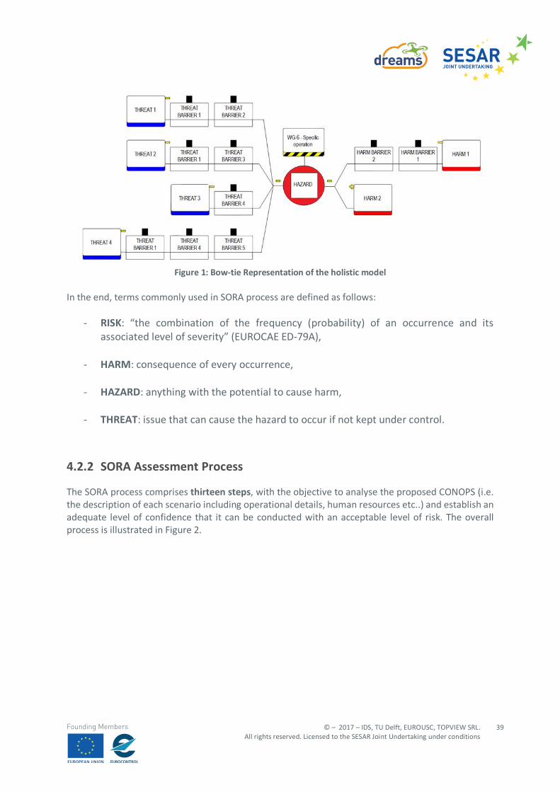
© – 2017 – IDS, TU Delft, EUROUSC, TOPVIEW SRL. All rights reserved. Licensed to the SESAR Joint Undertaking under conditions
39
Founding Members
Figure 1: Bow-tie Representation of the holistic model
In the end, terms commonly used in SORA process are defined as follows:
- RISK: “the combination of the frequency (probability) of an occurrence and its associated level of severity” (EUROCAE ED-79A),
- HARM: consequence of every occurrence,
- HAZARD: anything with the potential to cause harm,
- THREAT: issue that can cause the hazard to occur if not kept under control.
4.2.2 SORA Assessment Process
The SORA process comprises thirteen steps, with the objective to analyse the proposed CONOPS (i.e. the description of each scenario including operational details, human resources etc..) and establish an adequate level of confidence that it can be conducted with an acceptable level of risk. The overall process is illustrated in Figure 2.
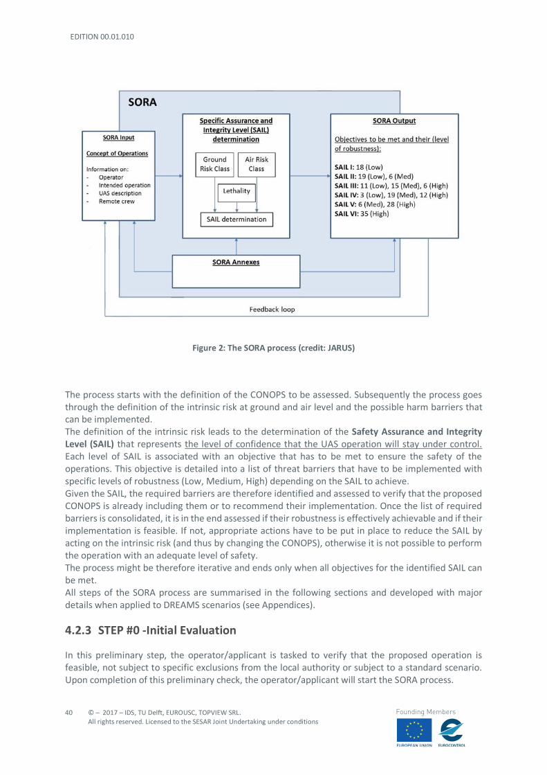
EDITION 00.01.010
40
© – 2017 – IDS, TU Delft, EUROUSC, TOPVIEW SRL. All rights reserved. Licensed to the SESAR Joint Undertaking under conditions
Founding Members
Figure 2: The SORA process (credit: JARUS)
The process starts with the definition of the CONOPS to be assessed. Subsequently the process goes through the definition of the intrinsic risk at ground and air level and the possible harm barriers that can be implemented. The definition of the intrinsic risk leads to the determination of the Safety Assurance and Integrity Level (SAIL) that represents the level of confidence that the UAS operation will stay under control. Each level of SAIL is associated with an objective that has to be met to ensure the safety of the operations. This objective is detailed into a list of threat barriers that have to be implemented with specific levels of robustness (Low, Medium, High) depending on the SAIL to achieve. Given the SAIL, the required barriers are therefore identified and assessed to verify that the proposed CONOPS is already including them or to recommend their implementation. Once the list of required barriers is consolidated, it is in the end assessed if their robustness is effectively achievable and if their implementation is feasible. If not, appropriate actions have to be put in place to reduce the SAIL by acting on the intrinsic risk (and thus by changing the CONOPS), otherwise it is not possible to perform the operation with an adequate level of safety. The process might be therefore iterative and ends only when all objectives for the identified SAIL can be met. All steps of the SORA process are summarised in the following sections and developed with major details when applied to DREAMS scenarios (see Appendices).
4.2.3 STEP #0 -Initial Evaluation
In this preliminary step, the operator/applicant is tasked to verify that the proposed operation is feasible, not subject to specific exclusions from the local authority or subject to a standard scenario. Upon completion of this preliminary check, the operator/applicant will start the SORA process.
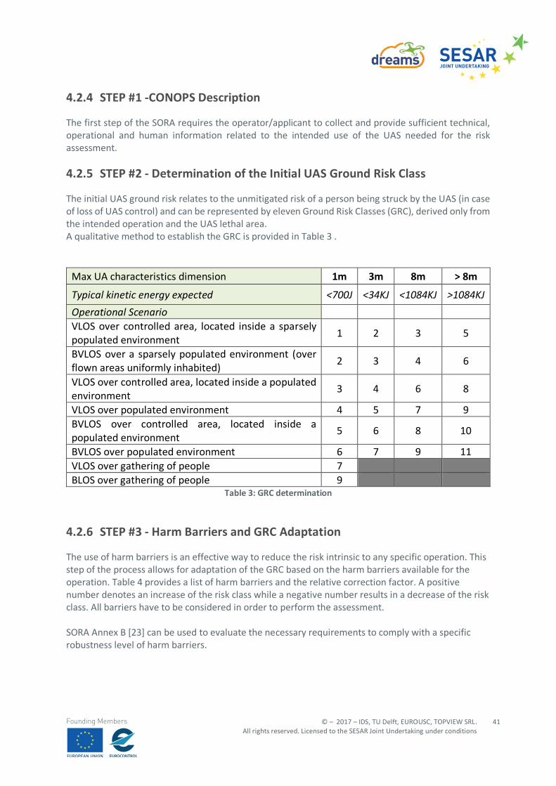
© – 2017 – IDS, TU Delft, EUROUSC, TOPVIEW SRL. All rights reserved. Licensed to the SESAR Joint Undertaking under conditions
41
Founding Members
4.2.4 STEP #1 -CONOPS Description
The first step of the SORA requires the operator/applicant to collect and provide sufficient technical, operational and human information related to the intended use of the UAS needed for the risk assessment.
4.2.5 STEP #2 - Determination of the Initial UAS Ground Risk Class
The initial UAS ground risk relates to the unmitigated risk of a person being struck by the UAS (in case of loss of UAS control) and can be represented by eleven Ground Risk Classes (GRC), derived only from the intended operation and the UAS lethal area. A qualitative method to establish the GRC is provided in Table 3 .
Max UA characteristics dimension 1m 3m 8m > 8m
Typical kinetic energy expected <700J <34KJ <1084KJ >1084KJ Operational Scenario VLOS over controlled area, located inside a sparsely populated environment
1 2 3 5
BVLOS over a sparsely populated environment (over flown areas uniformly inhabited)
2 3 4 6
VLOS over controlled area, located inside a populated environment
3 4 6 8
VLOS over populated environment 4 5 7 9 BVLOS over controlled area, located inside a populated environment
5 6 8 10
BVLOS over populated environment 6 7 9 11 VLOS over gathering of people 7 BLOS over gathering of people 9
Table 3: GRC determination
4.2.6 STEP #3 - Harm Barriers and GRC Adaptation
The use of harm barriers is an effective way to reduce the risk intrinsic to any specific operation. This step of the process allows for adaptation of the GRC based on the harm barriers available for the operation. Table 4 provides a list of harm barriers and the relative correction factor. A positive number denotes an increase of the risk class while a negative number results in a decrease of the risk class. All barriers have to be considered in order to perform the assessment. SORA Annex B [23] can be used to evaluate the necessary requirements to comply with a specific robustness level of harm barriers.
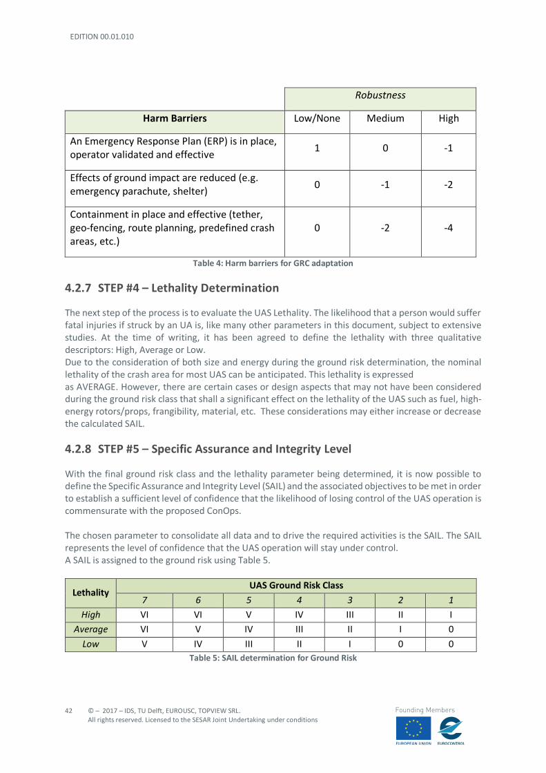
EDITION 00.01.010
42
© – 2017 – IDS, TU Delft, EUROUSC, TOPVIEW SRL. All rights reserved. Licensed to the SESAR Joint Undertaking under conditions
Founding Members
Robustness
Harm Barriers Low/None Medium High
An Emergency Response Plan (ERP) is in place, operator validated and effective
1 0 -1
Effects of ground impact are reduced (e.g. emergency parachute, shelter)
0 -1 -2
Containment in place and effective (tether, geo-fencing, route planning, predefined crash areas, etc.)
0 -2 -4
Table 4: Harm barriers for GRC adaptation
4.2.7 STEP #4 – Lethality Determination
The next step of the process is to evaluate the UAS Lethality. The likelihood that a person would suffer fatal injuries if struck by an UA is, like many other parameters in this document, subject to extensive studies. At the time of writing, it has been agreed to define the lethality with three qualitative descriptors: High, Average or Low. Due to the consideration of both size and energy during the ground risk determination, the nominal lethality of the crash area for most UAS can be anticipated. This lethality is expressed as AVERAGE. However, there are certain cases or design aspects that may not have been considered during the ground risk class that shall a significant effect on the lethality of the UAS such as fuel, high-energy rotors/props, frangibility, material, etc. These considerations may either increase or decrease the calculated SAIL.
4.2.8 STEP #5 – Specific Assurance and Integrity Level
With the final ground risk class and the lethality parameter being determined, it is now possible to define the Specific Assurance and Integrity Level (SAIL) and the associated objectives to be met in order to establish a sufficient level of confidence that the likelihood of losing control of the UAS operation is commensurate with the proposed ConOps. The chosen parameter to consolidate all data and to drive the required activities is the SAIL. The SAIL represents the level of confidence that the UAS operation will stay under control. A SAIL is assigned to the ground risk using Table 5.
Lethality UAS Ground Risk Class
7 6 5 4 3 2 1 High VI VI V IV III II I
Average VI V IV III II I 0
Low V IV III II I 0 0 Table 5: SAIL determination for Ground Risk
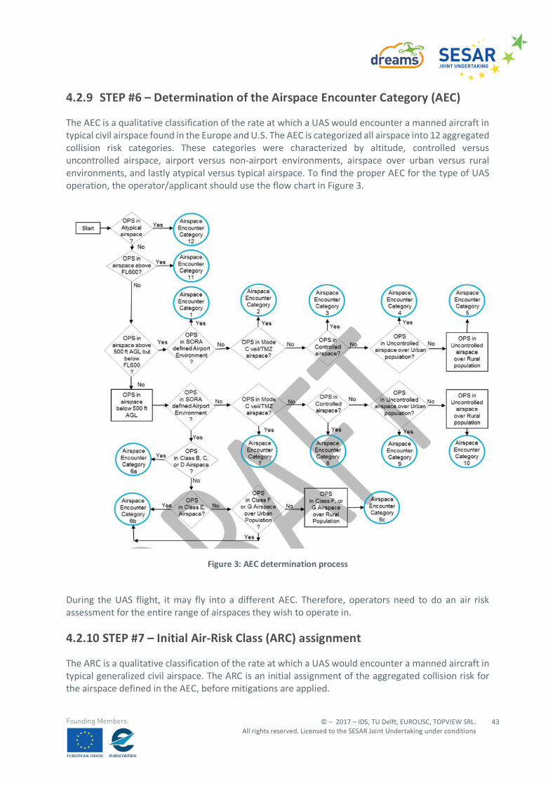
© – 2017 – IDS, TU Delft, EUROUSC, TOPVIEW SRL. All rights reserved. Licensed to the SESAR Joint Undertaking under conditions
43
Founding Members
4.2.9 STEP #6 – Determination of the Airspace Encounter Category (AEC)
The AEC is a qualitative classification of the rate at which a UAS would encounter a manned aircraft in typical civil airspace found in the Europe and U.S. The AEC is categorized all airspace into 12 aggregated collision risk categories. These categories were characterized by altitude, controlled versus uncontrolled airspace, airport versus non-airport environments, airspace over urban versus rural environments, and lastly atypical versus typical airspace. To find the proper AEC for the type of UAS operation, the operator/applicant should use the flow chart in Figure 3.
Figure 3: AEC determination process
During the UAS flight, it may fly into a different AEC. Therefore, operators need to do an air risk assessment for the entire range of airspaces they wish to operate in.
4.2.10 STEP #7 – Initial Air-Risk Class (ARC) assignment
The ARC is a qualitative classification of the rate at which a UAS would encounter a manned aircraft in typical generalized civil airspace. The ARC is an initial assignment of the aggregated collision risk for the airspace defined in the AEC, before mitigations are applied.
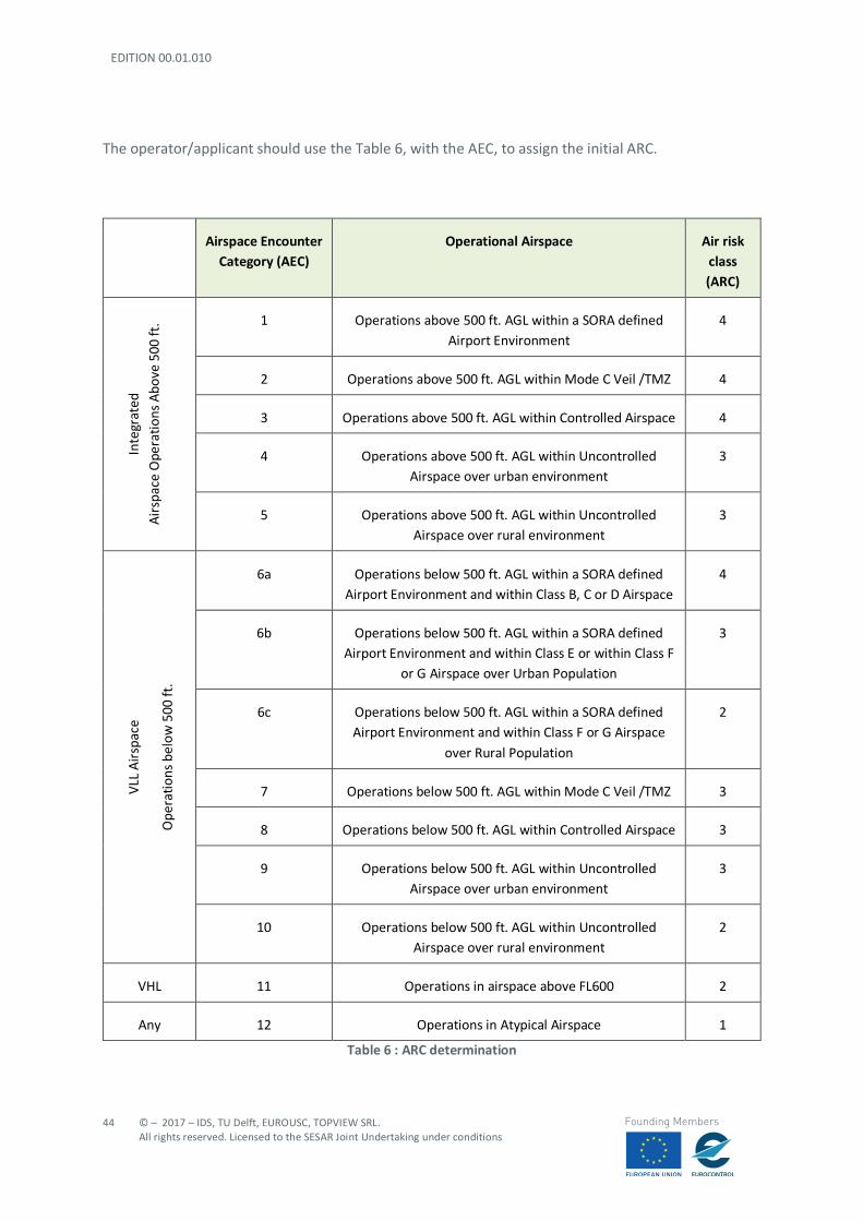
EDITION 00.01.010
44
© – 2017 – IDS, TU Delft, EUROUSC, TOPVIEW SRL. All rights reserved. Licensed to the SESAR Joint Undertaking under conditions
Founding Members
The operator/applicant should use the Table 6, with the AEC, to assign the initial ARC.
Airspace Encounter Category (AEC)
Operational Airspace Air risk class (ARC)
Inte
grat
ed
Air
spac
e O
pera
tions
Abo
ve 5
00 ft
. 1 Operations above 500 ft. AGL within a SORA defined Airport Environment
4
2 Operations above 500 ft. AGL within Mode C Veil /TMZ 4
3 Operations above 500 ft. AGL within Controlled Airspace 4
4 Operations above 500 ft. AGL within Uncontrolled Airspace over urban environment
3
5 Operations above 500 ft. AGL within Uncontrolled Airspace over rural environment
3
VLL
Air
spac
e
Ope
ratio
ns b
elow
500
ft.
6a Operations below 500 ft. AGL within a SORA defined Airport Environment and within Class B, C or D Airspace
4
6b Operations below 500 ft. AGL within a SORA defined Airport Environment and within Class E or within Class F
or G Airspace over Urban Population
3
6c Operations below 500 ft. AGL within a SORA defined Airport Environment and within Class F or G Airspace
over Rural Population
2
7 Operations below 500 ft. AGL within Mode C Veil /TMZ 3
8 Operations below 500 ft. AGL within Controlled Airspace 3
9 Operations below 500 ft. AGL within Uncontrolled Airspace over urban environment
3
10 Operations below 500 ft. AGL within Uncontrolled Airspace over rural environment
2
VHL 11 Operations in airspace above FL600 2
Any 12 Operations in Atypical Airspace 1
Table 6 : ARC determination
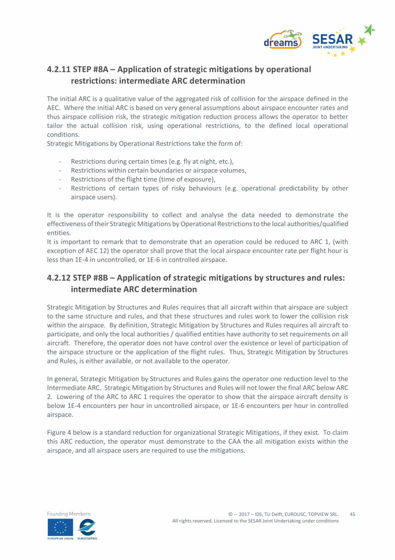
© – 2017 – IDS, TU Delft, EUROUSC, TOPVIEW SRL. All rights reserved. Licensed to the SESAR Joint Undertaking under conditions
45
Founding Members
4.2.11 STEP #8A – Application of strategic mitigations by operational restrictions: intermediate ARC determination
The initial ARC is a qualitative value of the aggregated risk of collision for the airspace defined in the AEC. Where the initial ARC is based on very general assumptions about airspace encounter rates and thus airspace collision risk, the strategic mitigation reduction process allows the operator to better tailor the actual collision risk, using operational restrictions, to the defined local operational conditions. Strategic Mitigations by Operational Restrictions take the form of:
- Restrictions during certain times (e.g. fly at night, etc.), - Restrictions within certain boundaries or airspace volumes, - Restrictions of the flight time (time of exposure), - Restrictions of certain types of risky behaviours (e.g. operational predictability by other
airspace users). It is the operator responsibility to collect and analyse the data needed to demonstrate the effectiveness of their Strategic Mitigations by Operational Restrictions to the local authorities/qualified entities. It is important to remark that to demonstrate that an operation could be reduced to ARC 1, (with exception of AEC 12) the operator shall prove that the local airspace encounter rate per flight hour is less than 1E-4 in uncontrolled, or 1E-6 in controlled airspace.
4.2.12 STEP #8B – Application of strategic mitigations by structures and rules: intermediate ARC determination
Strategic Mitigation by Structures and Rules requires that all aircraft within that airspace are subject to the same structure and rules, and that these structures and rules work to lower the collision risk within the airspace. By definition, Strategic Mitigation by Structures and Rules requires all aircraft to participate, and only the local authorities / qualified entities have authority to set requirements on all aircraft. Therefore, the operator does not have control over the existence or level of participation of the airspace structure or the application of the flight rules. Thus, Strategic Mitigation by Structures and Rules, is either available, or not available to the operator. In general, Strategic Mitigation by Structures and Rules gains the operator one reduction level to the Intermediate ARC. Strategic Mitigation by Structures and Rules will not lower the final ARC below ARC 2. Lowering of the ARC to ARC 1 requires the operator to show that the airspace aircraft density is below 1E-4 encounters per hour in uncontrolled airspace, or 1E-6 encounters per hour in controlled airspace. Figure 4 below is a standard reduction for organizational Strategic Mitigations, if they exist. To claim this ARC reduction, the operator must demonstrate to the CAA the all mitigation exists within the airspace, and all airspace users are required to use the mitigations.
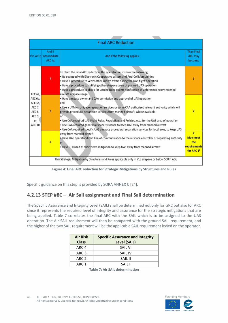
EDITION 00.01.010
46
© – 2017 – IDS, TU Delft, EUROUSC, TOPVIEW SRL. All rights reserved. Licensed to the SESAR Joint Undertaking under conditions
Founding Members
Figure 4: Final ARC reduction for Strategic Mitigations by Structures and Rules
Specific guidance on this step is provided by SORA ANNEX C [24].
4.2.13 STEP #8C – Air Sail assignment and Final Sail determination
The Specific Assurance and Integrity Level (SAIL) shall be determined not only for GRC but also for ARC since it represents the required level of integrity and assurance for the strategic mitigations that are being applied. Table 7 correlates the final ARC with the SAIL which is to be assigned to the UAS operation. The Air-SAIL requirement will then be compared with the ground-SAIL requirement, and the higher of the two SAIL requirement will be the applicable SAIL requirement levied on the operator.
Air Risk Class
Specific Assurance and Integrity Level (SAIL)
ARC 4 SAIL VI ARC 3 SAIL IV ARC 2 SAIL II ARC 1 SAIL I
Table 7: Air SAIL determination
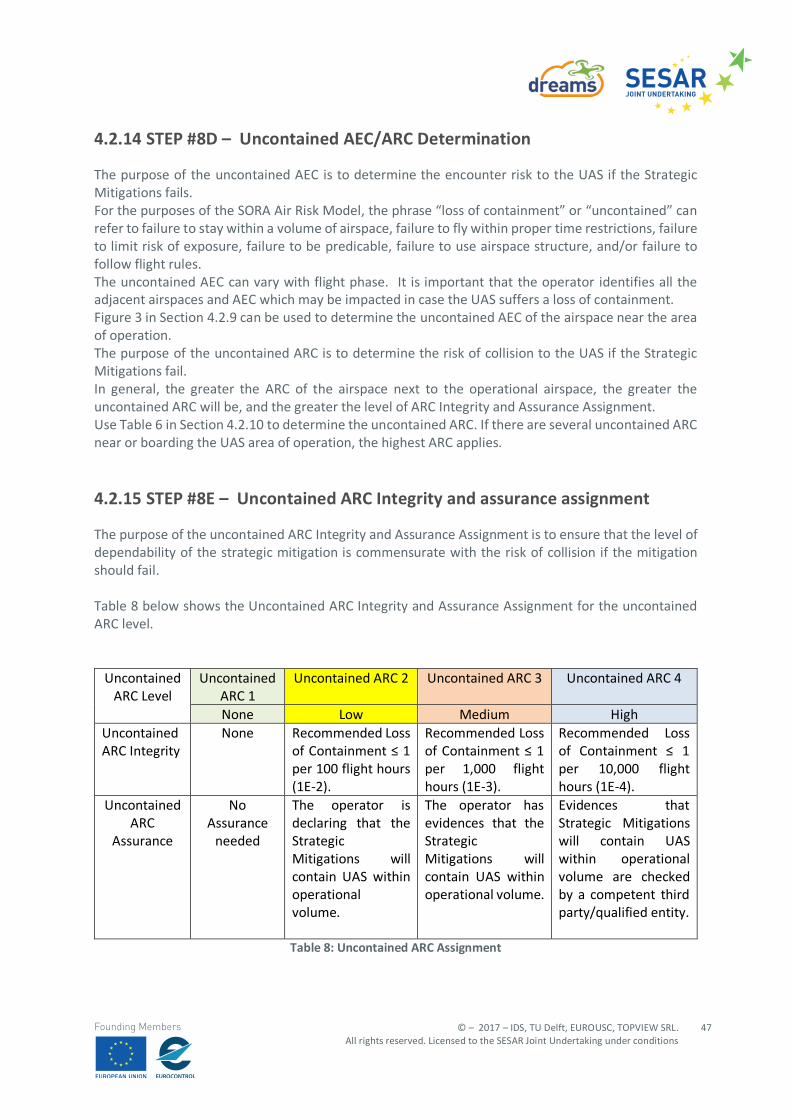
© – 2017 – IDS, TU Delft, EUROUSC, TOPVIEW SRL. All rights reserved. Licensed to the SESAR Joint Undertaking under conditions
47
Founding Members
4.2.14 STEP #8D – Uncontained AEC/ARC Determination
The purpose of the uncontained AEC is to determine the encounter risk to the UAS if the Strategic Mitigations fails. For the purposes of the SORA Air Risk Model, the phrase “loss of containment” or “uncontained” can refer to failure to stay within a volume of airspace, failure to fly within proper time restrictions, failure to limit risk of exposure, failure to be predicable, failure to use airspace structure, and/or failure to follow flight rules. The uncontained AEC can vary with flight phase. It is important that the operator identifies all the adjacent airspaces and AEC which may be impacted in case the UAS suffers a loss of containment. Figure 3 in Section 4.2.9 can be used to determine the uncontained AEC of the airspace near the area of operation. The purpose of the uncontained ARC is to determine the risk of collision to the UAS if the Strategic Mitigations fail. In general, the greater the ARC of the airspace next to the operational airspace, the greater the uncontained ARC will be, and the greater the level of ARC Integrity and Assurance Assignment. Use Table 6 in Section 4.2.10 to determine the uncontained ARC. If there are several uncontained ARC near or boarding the UAS area of operation, the highest ARC applies.
4.2.15 STEP #8E – Uncontained ARC Integrity and assurance assignment
The purpose of the uncontained ARC Integrity and Assurance Assignment is to ensure that the level of dependability of the strategic mitigation is commensurate with the risk of collision if the mitigation should fail. Table 8 below shows the Uncontained ARC Integrity and Assurance Assignment for the uncontained ARC level.
Uncontained
ARC Level Uncontained
ARC 1 Uncontained ARC 2 Uncontained ARC 3 Uncontained ARC 4
None Low Medium High Uncontained ARC Integrity
None Recommended Loss of Containment ≤ 1 per 100 flight hours (1E-2).
Recommended Loss of Containment ≤ 1 per 1,000 flight hours (1E-3).
Recommended Loss of Containment ≤ 1 per 10,000 flight hours (1E-4).
Uncontained ARC
Assurance
No Assurance
needed
The operator is declaring that the Strategic Mitigations will contain UAS within operational volume.
The operator has evidences that the Strategic Mitigations will contain UAS within operational volume.
Evidences that Strategic Mitigations will contain UAS within operational volume are checked by a competent third party/qualified entity.
Table 8: Uncontained ARC Assignment
EDITION 00.01.010
48
© – 2017 – IDS, TU Delft, EUROUSC, TOPVIEW SRL. All rights reserved. Licensed to the SESAR Joint Undertaking under conditions
Founding Members
There are two ways to meet Integrity and Assurance requirement:
• Prevent the loss of containment; or • Reduces the severity of loss of containment
4.2.16 STEP #9 – Tactical Mitigation Performance Requirement (TMPR) Assignment
Tactical Mitigations are applied to meet residual risk of the ARC. Residual risk is the remaining collision risk from the ARC threat needed to achieve the airspace safety objective. For example, a high ARC leaves a large amount of residual risk, whereas a low ARC leaves a small amount of residual risk required to meet the same airspace safety objective. One possible Tactical Mitigation is flying in VLOS/E-VLOS condition since this provides “see and avoid capabilities”. However, the operator shall produce a documented VLOS/EVLOS de-confliction scheme, in which the operator explains which tools or methods will be used for detection and what the criteria are that will be applied for the decision to avoid incoming traffic. In case the remote pilot relies on detection by observers, the use of phraseology shall to be described as well. This document must be provided to the CAA for approval. Beside VLOS/EVLOS, TMPR requirements are describing requirements for tactical mitigations supported by electronic means used to assist the pilot in detecting and avoiding traffic. The Tactical Mitigation Performance Requirement (TMPR) is the amount of Tactical Mitigation which is required by the residual risk. The amount of residual risk is dependent on the ARC. Therefore, the higher the ARC, the greater the residual risk, the greater the TMPR. Table 9 below can be used to determine the TMPR. Four categories are identified, as follows:
- HIGH TMPR (ARC 4): This is airspace where the manned aircraft encounter rate is high and/or the Strategic Mitigations available are Low. As a consequence, the resulting residual collision risk is high, and therefore the TMPR must be high. In this airspace, the UAS is operating in Integrated Airspace and must comply with existing operating rules and procedures for manned aircraft, without reducing existing capacity, decreasing safety, negatively impacting current operators, or increasing the risk to airspace users or persons and property on the ground, any more than the integration of comparable new and novel technologies would. The number of Tactical mitigations, and performance level of those Tactical mitigations is generally higher than for the other ARCs.
- MEDIUM TMPR (ARC 3): A medium TMPR will be required for operations in airspace where there is a reasonable chance to encounter manned aircraft and/or the Strategic Mitigations available are medium. Consequently, the resulting residual collision risk needs to be countered with medium level Tactical Mitigations. This collision risk class requires more Tactical mitigation and higher performance requirements than Class 2 but less than Class 4. Operations with a medium TMPR will likely have to rely be supported by systems currently used in aviation for detection of other (cooperative) aircraft, or on systems designed to support aviation and build to a corresponding level of robustness. Traffic avoidance manoeuvres could be more advanced than for a low TMPR.
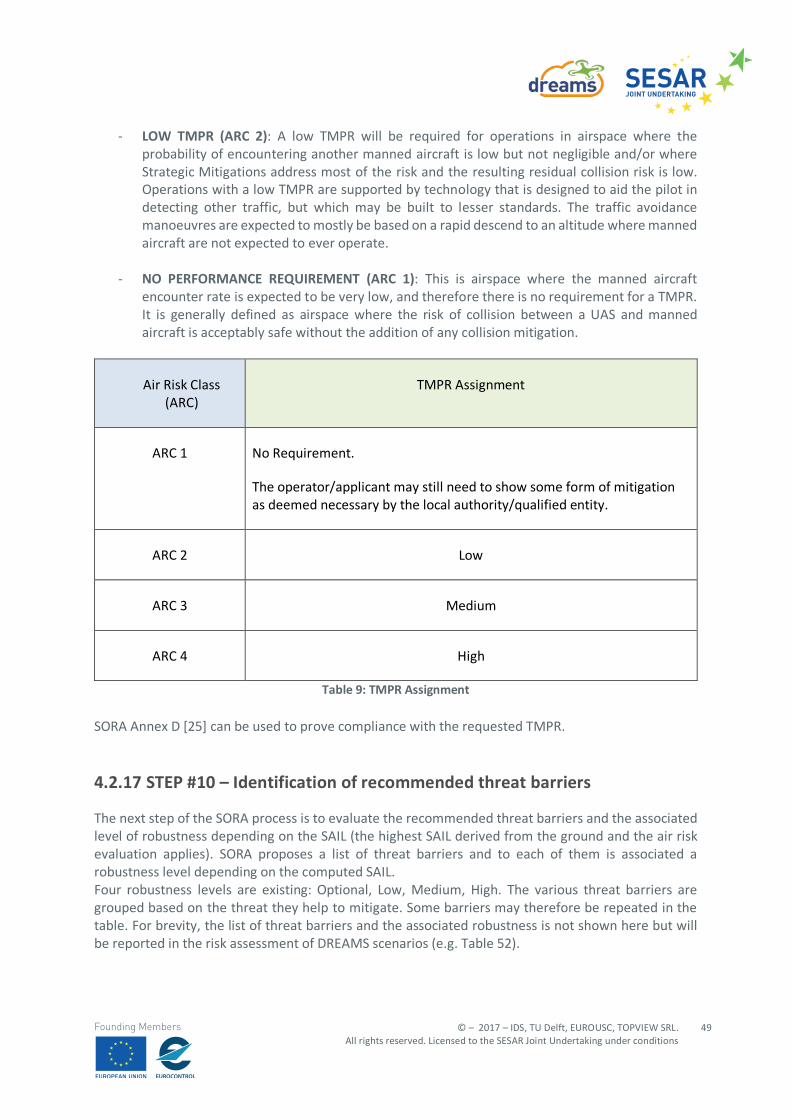
© – 2017 – IDS, TU Delft, EUROUSC, TOPVIEW SRL. All rights reserved. Licensed to the SESAR Joint Undertaking under conditions
49
Founding Members
- LOW TMPR (ARC 2): A low TMPR will be required for operations in airspace where the probability of encountering another manned aircraft is low but not negligible and/or where Strategic Mitigations address most of the risk and the resulting residual collision risk is low. Operations with a low TMPR are supported by technology that is designed to aid the pilot in detecting other traffic, but which may be built to lesser standards. The traffic avoidance manoeuvres are expected to mostly be based on a rapid descend to an altitude where manned aircraft are not expected to ever operate.
- NO PERFORMANCE REQUIREMENT (ARC 1): This is airspace where the manned aircraft encounter rate is expected to be very low, and therefore there is no requirement for a TMPR. It is generally defined as airspace where the risk of collision between a UAS and manned aircraft is acceptably safe without the addition of any collision mitigation.
Air Risk Class (ARC)
TMPR Assignment
ARC 1 No Requirement.
The operator/applicant may still need to show some form of mitigation as deemed necessary by the local authority/qualified entity.
ARC 2 Low
ARC 3 Medium
ARC 4 High
Table 9: TMPR Assignment SORA Annex D [25] can be used to prove compliance with the requested TMPR.
4.2.17 STEP #10 – Identification of recommended threat barriers
The next step of the SORA process is to evaluate the recommended threat barriers and the associated level of robustness depending on the SAIL (the highest SAIL derived from the ground and the air risk evaluation applies). SORA proposes a list of threat barriers and to each of them is associated a robustness level depending on the computed SAIL. Four robustness levels are existing: Optional, Low, Medium, High. The various threat barriers are grouped based on the threat they help to mitigate. Some barriers may therefore be repeated in the table. For brevity, the list of threat barriers and the associated robustness is not shown here but will be reported in the risk assessment of DREAMS scenarios (e.g. Table 52).
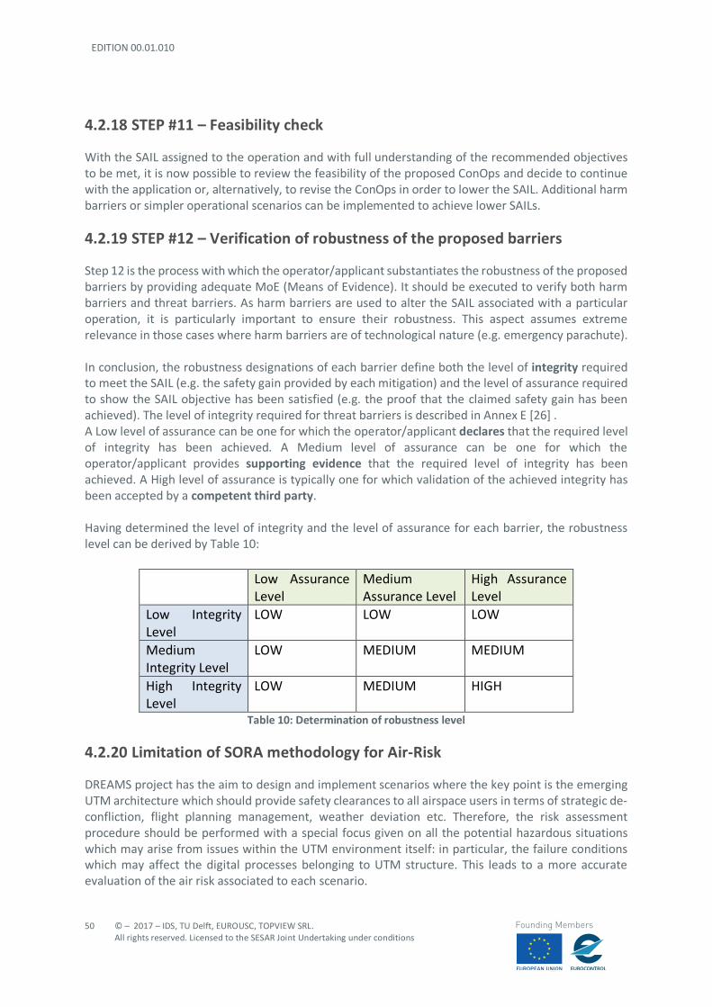
EDITION 00.01.010
50
© – 2017 – IDS, TU Delft, EUROUSC, TOPVIEW SRL. All rights reserved. Licensed to the SESAR Joint Undertaking under conditions
Founding Members
4.2.18 STEP #11 – Feasibility check
With the SAIL assigned to the operation and with full understanding of the recommended objectives to be met, it is now possible to review the feasibility of the proposed ConOps and decide to continue with the application or, alternatively, to revise the ConOps in order to lower the SAIL. Additional harm barriers or simpler operational scenarios can be implemented to achieve lower SAILs.
4.2.19 STEP #12 – Verification of robustness of the proposed barriers
Step 12 is the process with which the operator/applicant substantiates the robustness of the proposed barriers by providing adequate MoE (Means of Evidence). It should be executed to verify both harm barriers and threat barriers. As harm barriers are used to alter the SAIL associated with a particular operation, it is particularly important to ensure their robustness. This aspect assumes extreme relevance in those cases where harm barriers are of technological nature (e.g. emergency parachute). In conclusion, the robustness designations of each barrier define both the level of integrity required to meet the SAIL (e.g. the safety gain provided by each mitigation) and the level of assurance required to show the SAIL objective has been satisfied (e.g. the proof that the claimed safety gain has been achieved). The level of integrity required for threat barriers is described in Annex E [26] . A Low level of assurance can be one for which the operator/applicant declares that the required level of integrity has been achieved. A Medium level of assurance can be one for which the operator/applicant provides supporting evidence that the required level of integrity has been achieved. A High level of assurance is typically one for which validation of the achieved integrity has been accepted by a competent third party. Having determined the level of integrity and the level of assurance for each barrier, the robustness level can be derived by Table 10:
Low Assurance Level
Medium Assurance Level
High Assurance Level
Low Integrity Level
LOW LOW LOW
Medium Integrity Level
LOW MEDIUM MEDIUM
High Integrity Level
LOW MEDIUM HIGH
Table 10: Determination of robustness level
4.2.20 Limitation of SORA methodology for Air-Risk
DREAMS project has the aim to design and implement scenarios where the key point is the emerging UTM architecture which should provide safety clearances to all airspace users in terms of strategic de-confliction, flight planning management, weather deviation etc. Therefore, the risk assessment procedure should be performed with a special focus given on all the potential hazardous situations which may arise from issues within the UTM environment itself: in particular, the failure conditions which may affect the digital processes belonging to UTM structure. This leads to a more accurate evaluation of the air risk associated to each scenario.
© – 2017 – IDS, TU Delft, EUROUSC, TOPVIEW SRL. All rights reserved. Licensed to the SESAR Joint Undertaking under conditions
51
Founding Members
SORA methodology, although providing a method for the evaluation of the air risk (as seen in the previous paragraph), uses Air Risk classifications parameters that are very simplistic. For example, important parameters that are missing include how the airspace is managed (uncontrolled/ controlled) and procedures that are in place within that airspace. These components directly relate to the risk assessment and determine the density of traffic that can be safely managed, controlled or monitored by the UTM structure. In addition, SORA methodology is not capable of representing the risks associated to interactions of different UAS in the same environment (such as concurrent operations). In addition to this SORA does not offer yet a systematic way to evaluate specific safety requirements for digital communications and services, which, for what said above, represent the core of the UTM system that should be validated. U-Space services are proposed as mitigations for air risk but remaining too general. It is however expected that further developments of SORA methodology (also in the form of additional annexes) may include more specific analyses for the air risk evaluation. It is important to keep in mind that the progressive deployment of U-Space is linked to the increasing availability of blocks of services and enabling technologies. Over time, U-Space services will evolve as the level of automation of the drone increases, and advanced forms of interaction with the environment are enabled (including manned and unmanned aircraft) mainly through digital information and data exchange over a cloud-based platform. Hence the necessity to develop a risk assessment methodology (especially for the air-risk evaluation) which is based on a traditional risk-matrix approach. This method, although being less schematic than SORA, provides a flexible way to cover a wider area of potential risks, being this much in line with UTM philosophy. In particular, the severity classification proposed by EASA will be adopted for reason that will be better clarified in the following paragraphs.
4.3 ICAO Risk Assessment Methodology
The ICAO risk assessment methodology (Doc. ICAO 9859) is based on the holistic model as well but the assessment is performed through the definition of a risk matrix for each hazard identified in the current operation. As already seen in paragraph 5.1, the safety risk is defined as the product of risk probability and risk severity.
4.3.1 Safety risk probability
The process of controlling safety risks starts by assessing the probability that the consequences of hazards will materialize during aviation activities performed by the organization. Safety risk probability is defined as the likelihood or frequency that a safety consequence or outcome might occur. The determination of likelihood can be aided by questions such as:
- Is there a history of occurrences similar to the one under consideration or is this an isolated occurrence?
- What other equipment or components of the same type might have similar defects? - How many personnel are following, or are subject too, the procedures in question? - What percentage of the time is the suspect equipment or the questionable procedure in use? - To what extent are there organizational, managerial or regulatory implications that might
reflect larger threats to public safety?
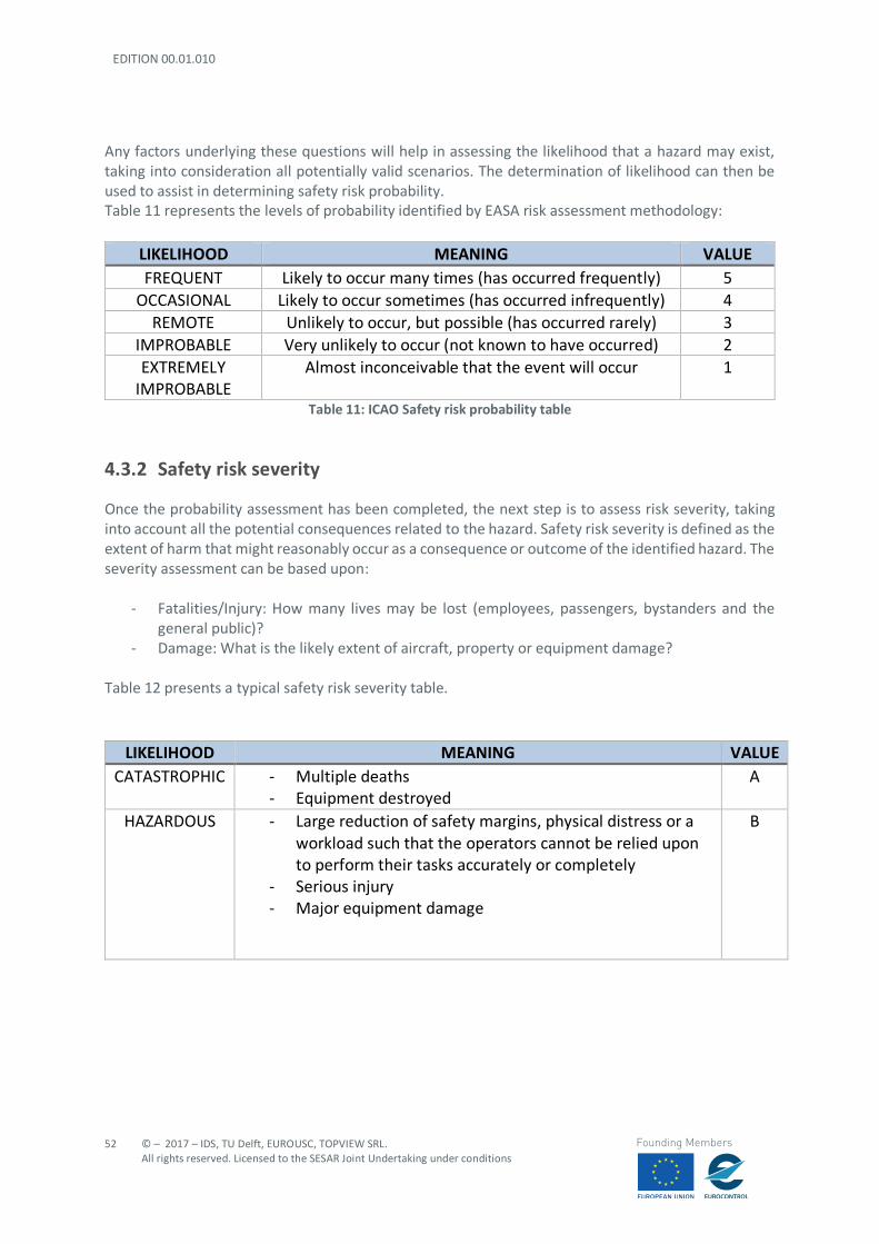
EDITION 00.01.010
52
© – 2017 – IDS, TU Delft, EUROUSC, TOPVIEW SRL. All rights reserved. Licensed to the SESAR Joint Undertaking under conditions
Founding Members
Any factors underlying these questions will help in assessing the likelihood that a hazard may exist, taking into consideration all potentially valid scenarios. The determination of likelihood can then be used to assist in determining safety risk probability. Table 11 represents the levels of probability identified by EASA risk assessment methodology:
LIKELIHOOD MEANING VALUE FREQUENT Likely to occur many times (has occurred frequently) 5
OCCASIONAL Likely to occur sometimes (has occurred infrequently) 4 REMOTE Unlikely to occur, but possible (has occurred rarely) 3
IMPROBABLE Very unlikely to occur (not known to have occurred) 2 EXTREMELY
IMPROBABLE Almost inconceivable that the event will occur 1
Table 11: ICAO Safety risk probability table
4.3.2 Safety risk severity
Once the probability assessment has been completed, the next step is to assess risk severity, taking into account all the potential consequences related to the hazard. Safety risk severity is defined as the extent of harm that might reasonably occur as a consequence or outcome of the identified hazard. The severity assessment can be based upon:
- Fatalities/Injury: How many lives may be lost (employees, passengers, bystanders and the general public)?
- Damage: What is the likely extent of aircraft, property or equipment damage? Table 12 presents a typical safety risk severity table.
LIKELIHOOD MEANING VALUE CATASTROPHIC - Multiple deaths
- Equipment destroyed A
HAZARDOUS - Large reduction of safety margins, physical distress or a workload such that the operators cannot be relied upon to perform their tasks accurately or completely
- Serious injury - Major equipment damage
B
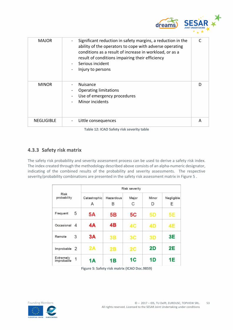
© – 2017 – IDS, TU Delft, EUROUSC, TOPVIEW SRL. All rights reserved. Licensed to the SESAR Joint Undertaking under conditions
53
Founding Members
MAJOR - Significant reduction in safety margins, a reduction in the ability of the operators to cope with adverse operating conditions as a result of increase in workload, or as a result of conditions impairing their efficiency
- Serious incident - Injury to persons
C
MINOR - Nuisance - Operating limitations - Use of emergency procedures - Minor incidents
D
NEGLIGIBLE - Little consequences A
Table 12: ICAO Safety risk severity table
4.3.3 Safety risk matrix
The safety risk probability and severity assessment process can be used to derive a safety risk index. The index created through the methodology described above consists of an alpha-numeric designator, indicating of the combined results of the probability and severity assessments. The respective severity/probability combinations are presented in the safety risk assessment matrix in Figure 5 .
Figure 5: Safety risk matrix (ICAO Doc.9859)
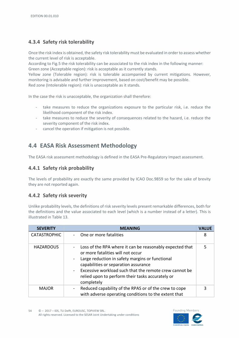
EDITION 00.01.010
54
© – 2017 – IDS, TU Delft, EUROUSC, TOPVIEW SRL. All rights reserved. Licensed to the SESAR Joint Undertaking under conditions
Founding Members
4.3.4 Safety risk tolerability
Once the risk index is obtained, the safety risk tolerability must be evaluated in order to assess whether the current level of risk is acceptable. According to Fig.5 the risk tolerability can be associated to the risk index in the following manner: Green zone (Acceptable region): risk is acceptable as it currently stands. Yellow zone (Tolerable region): risk is tolerable accompanied by current mitigations. However, monitoring is advisable and further improvement, based on cost/benefit may be possible. Red zone (Intolerable region): risk is unacceptable as it stands. In the case the risk is unacceptable, the organization shall therefore:
- take measures to reduce the organizations exposure to the particular risk, i.e. reduce the likelihood component of the risk index.
- take measures to reduce the severity of consequences related to the hazard, i.e. reduce the severity component of the risk index.
- cancel the operation if mitigation is not possible.
4.4 EASA Risk Assessment Methodology
The EASA risk assessment methodology is defined in the EASA Pre-Regulatory Impact assessment.
4.4.1 Safety risk probability
The levels of probability are exactly the same provided by ICAO Doc.9859 so for the sake of brevity they are not reported again.
4.4.2 Safety risk severity
Unlike probability levels, the definitions of risk severity levels present remarkable differences, both for the definitions and the value associated to each level (which is a number instead of a letter). This is illustrated in Table 13.
SEVERITY MEANING VALUE CATASTROPHIC - One or more fatalities 8
HAZARDOUS - Loss of the RPA where it can be reasonably expected that or more fatalities will not occur
- Large reduction in safety margins or functional capabilities or separation assurance
- Excessive workload such that the remote crew cannot be relied upon to perform their tasks accurately or completely
5
MAJOR - Reduced capability of the RPAS or of the crew to cope with adverse operating conditions to the extent that
3

© – 2017 – IDS, TU Delft, EUROUSC, TOPVIEW SRL. All rights reserved. Licensed to the SESAR Joint Undertaking under conditions
55
Founding Members
there would be a significant reduction in safety margins, functional capabilities or separation assurance
- Significant increase in remote crew workload and decrease in crew efficiency
MINOR - Not a significant reduction in RPAS safety - Slight reduction of safety margins or functional
capabilities or separation assurance - Slight increase in crew workload
2
NEGLIGIBLE - No effects on safety 1
Table 13: Safety risk severity classifications (SC-RPAS.1309)
4.4.3 Safety risk matrix
The main difference between ICAO and EASA methodologies is definitely highlighted in the risk matrix (Figure 6).
Figure 6: Safety risk matrix (EASA Pre-regulatory impact assessment)
The risk index is fully numeric, and the severity scale is non-linear so that high risk areas are better differentiated. In other words, the risk index provides a more immediate comprehension of the identified hazardous situations.
4.4.4 SC-RPAS 1309
SC-RPAS 1309 [27] is an EASA special condition issued on aimed at defining a relationship between risk severity and risk probability when evaluating the risks associated to a failure condition related to a UAS. This relationship is shown in Table 14.
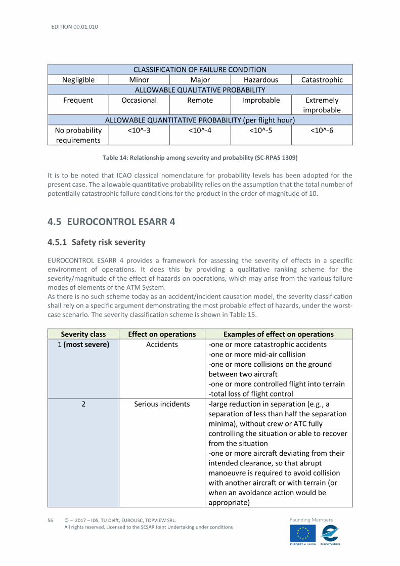
EDITION 00.01.010
56
© – 2017 – IDS, TU Delft, EUROUSC, TOPVIEW SRL. All rights reserved. Licensed to the SESAR Joint Undertaking under conditions
Founding Members
CLASSIFICATION OF FAILURE CONDITION Negligible Minor Major Hazardous Catastrophic
ALLOWABLE QUALITATIVE PROBABILITY Frequent Occasional Remote Improbable Extremely
improbable ALLOWABLE QUANTITATIVE PROBABILITY (per flight hour)
No probability requirements
<10^-3 <10^-4 <10^-5 <10^-6
Table 14: Relationship among severity and probability (SC-RPAS 1309)
It is to be noted that ICAO classical nomenclature for probability levels has been adopted for the present case. The allowable quantitative probability relies on the assumption that the total number of potentially catastrophic failure conditions for the product in the order of magnitude of 10.
4.5 EUROCONTROL ESARR 4
4.5.1 Safety risk severity
EUROCONTROL ESARR 4 provides a framework for assessing the severity of effects in a specific environment of operations. It does this by providing a qualitative ranking scheme for the severity/magnitude of the effect of hazards on operations, which may arise from the various failure modes of elements of the ATM System. As there is no such scheme today as an accident/incident causation model, the severity classification shall rely on a specific argument demonstrating the most probable effect of hazards, under the worst-case scenario. The severity classification scheme is shown in Table 15.
Severity class Effect on operations Examples of effect on operations 1 (most severe) Accidents -one or more catastrophic accidents
-one or more mid-air collision -one or more collisions on the ground between two aircraft -one or more controlled flight into terrain -total loss of flight control
2 Serious incidents -large reduction in separation (e.g., a separation of less than half the separation minima), without crew or ATC fully controlling the situation or able to recover from the situation -one or more aircraft deviating from their intended clearance, so that abrupt manoeuvre is required to avoid collision with another aircraft or with terrain (or when an avoidance action would be appropriate)
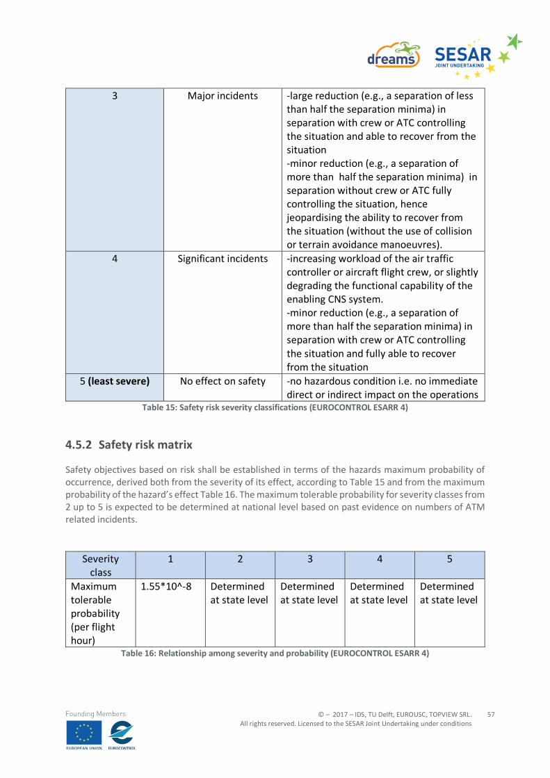
© – 2017 – IDS, TU Delft, EUROUSC, TOPVIEW SRL. All rights reserved. Licensed to the SESAR Joint Undertaking under conditions
57
Founding Members
3 Major incidents -large reduction (e.g., a separation of less than half the separation minima) in separation with crew or ATC controlling the situation and able to recover from the situation -minor reduction (e.g., a separation of more than half the separation minima) in separation without crew or ATC fully controlling the situation, hence jeopardising the ability to recover from the situation (without the use of collision or terrain avoidance manoeuvres).
4 Significant incidents -increasing workload of the air traffic controller or aircraft flight crew, or slightly degrading the functional capability of the enabling CNS system. -minor reduction (e.g., a separation of more than half the separation minima) in separation with crew or ATC controlling the situation and fully able to recover from the situation
5 (least severe) No effect on safety -no hazardous condition i.e. no immediate direct or indirect impact on the operations
Table 15: Safety risk severity classifications (EUROCONTROL ESARR 4)
4.5.2 Safety risk matrix
Safety objectives based on risk shall be established in terms of the hazards maximum probability of occurrence, derived both from the severity of its effect, according to Table 15 and from the maximum probability of the hazard’s effect Table 16. The maximum tolerable probability for severity classes from 2 up to 5 is expected to be determined at national level based on past evidence on numbers of ATM related incidents.
Severity class
1 2 3 4 5
Maximum tolerable probability (per flight hour)
1.55*10^-8 Determined at state level
Determined at state level
Determined at state level
Determined at state level
Table 16: Relationship among severity and probability (EUROCONTROL ESARR 4)
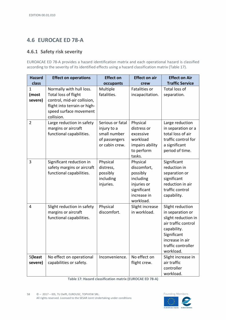
EDITION 00.01.010
58
© – 2017 – IDS, TU Delft, EUROUSC, TOPVIEW SRL. All rights reserved. Licensed to the SESAR Joint Undertaking under conditions
Founding Members
4.6 EUROCAE ED 78-A
4.6.1 Safety risk severity
EUROACAE ED 78-A provides a hazard identification matrix and each operational hazard is classified according to the severity of its identified effects using a hazard classification matrix (Table 17).
Hazard class
Effect on operations Effect on occupants
Effect on air crew
Effect on Air Traffic Service
1 (most severe)
Normally with hull loss. Total loss of flight control, mid-air collision, flight into terrain or high-speed surface movement collision.
Multiple fatalities.
Fatalities or incapacitation.
Total loss of separation.
2 Large reduction in safety margins or aircraft functional capabilities.
Serious or fatal injury to a small number of passengers or cabin crew.
Physical distress or excessive workload impairs ability to perform tasks.
Large reduction in separation or a total loss of air traffic control for a significant period of time.
3 Significant reduction in safety margins or aircraft functional capabilities.
Physical distress, possibly including injuries.
Physical discomfort, possibly including injuries or significant increase in workload.
Significant reduction in separation or significant reduction in air traffic control capability.
4 Slight reduction in safety margins or aircraft functional capabilities.
Physical discomfort.
Slight increase in workload.
Slight reduction in separation or slight reduction in air traffic control capability. Significant increase in air traffic controller workload.
5(least severe)
No effect on operational capabilities or safety.
Inconvenience. No effect on flight crew.
Slight increase in air traffic controller workload.
Table 17: Hazard classification matrix (EUROCAE ED 78-A)
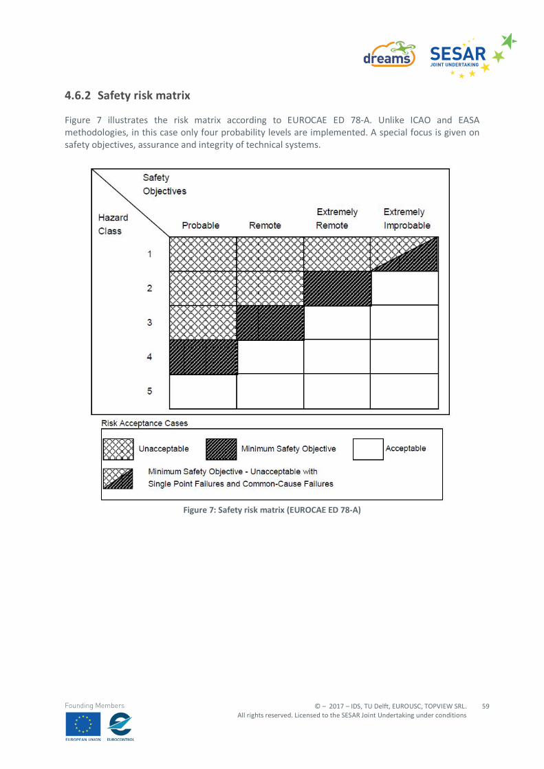
© – 2017 – IDS, TU Delft, EUROUSC, TOPVIEW SRL. All rights reserved. Licensed to the SESAR Joint Undertaking under conditions
59
Founding Members
4.6.2 Safety risk matrix
Figure 7 illustrates the risk matrix according to EUROCAE ED 78-A. Unlike ICAO and EASA methodologies, in this case only four probability levels are implemented. A special focus is given on safety objectives, assurance and integrity of technical systems.
Figure 7: Safety risk matrix (EUROCAE ED 78-A)
EDITION 00.01.010
60
© – 2017 – IDS, TU Delft, EUROUSC, TOPVIEW SRL. All rights reserved. Licensed to the SESAR Joint Undertaking under conditions
Founding Members
5 Operational safety assessment for U-Space services
5.1 Assessment Processes
The safety assessment performed using the risk matrix approach has the aim to evaluate the potential failure conditions associated to U-Space services, in turn necessary to support the scenarios described in Chapter 2. This analysis is divided into two interrelated processes:
- Failure Condition Analysis (FCA) - Allocation of Safety Objectives and Requirements (ASOR)
This approach is described in EUROCAE ED 78A and applied, for data link with manned aircraft, respectively in continental and oceanic environment, in EUROCAE ED 120 [28] and EUROCAE ED 122 [29]. It is however to be noted that:
- in EUROCAE documents the process is named “Operational Hazard Analysis” (OHA), which is equivalent to the term FCA used in this document;
- in this document the term FCA is preferred, since failure condition affecting digital services is considered;
The safety assessment process in EUROCAE documents is carried on based on the risk matrix illustrated in Section 4.6.2. Due to reasons already explained in Section 4.4.3, the model adopted in this document is based on EASA risk matrix instead.
Typical considered failure conditions are presented in Appendices from 1 to 4 for each scenario.
5.2 Failure Condition Analysis
Once all the operational details of DREAMS scenarios have been defined as well as the involved U-Space services, all the potential failure conditions are identified through the FCA. As already pointed out in the introduction and in D3.1, the aim of the DREAMS project is to validate the benefits of U-Space services in providing notifications to the remote pilots about potential airspace conflicts, adverse weather conditions or non-accessible areas. Therefore, the risk assessment is carried out addressing all the risks associated to failure conditions18
or procedural errors in the context of UTM. In other words, the safety of the envisaged operations is
18 A failure condition may be the failure of hardware, but also malfunction of software or corruption of the
information or performances of a network outside the specified limits.
© – 2017 – IDS, TU Delft, EUROUSC, TOPVIEW SRL. All rights reserved. Licensed to the SESAR Joint Undertaking under conditions
61
Founding Members
strictly related not only to airworthiness of the U or competence of the remote pilots, but also to the correct behaviour of the digital and communications services supporting the UTM controller and drone operators. This process of failure identification hence considers:
- Total loss or unavailability of information - Misleading information - Detected/undetected errors
Total loss or unavailability of information: The information is lost, or the service is unavailable (e.g. an UTM controller’s workstation is inoperative or a service provider is unavailable). Misleading information:
- Partial loss - part of the information is lost, or the function is only partially completed. - Corruption - the information is altered from what was intended to be transmitted. - Misdirection - the data has come from the wrong source or received by the wrong destination. - Delay - the data received is out of date or the function is carried out late in relation to
succeeding processes. - Inconsistency - here diverse information paths convey different information.
Any of the above might be either detected or undetected. This consideration may result in two different failures for a given descriptor from the list above, where one is more severe than the other. In addition, the following possible procedural errors, are considered:
- Human failure to respond appropriately to functional failure - Human error or omission during normal use - Human underrating of potential hazardous situation - Transitional failures (those that may result by changing over from an existing operation to a
new operation) - External factors (e.g., outages, weather)
Once all the potential failure conditions have been identified, for each of them the severity of the consequences is determined. Operational effects may include:
- Collision or loss of margin of safety with respect to collision between airborne aircraft. - Collision or loss of margin of safety with respect to collision with terrain or loss of separation
with terrain. - Loss of separation or loss of margin of safety with respect to loss of separation with significant
weather or atmospheric contamination effects (e.g., volcanic ash, birds). - Collision or loss of margin of safety with respect to collision between drones and other aircraft
or vehicles on the ground. When assessing the effects of system failures or operational errors on the margin of safety it is important to consider contributory factors such as:
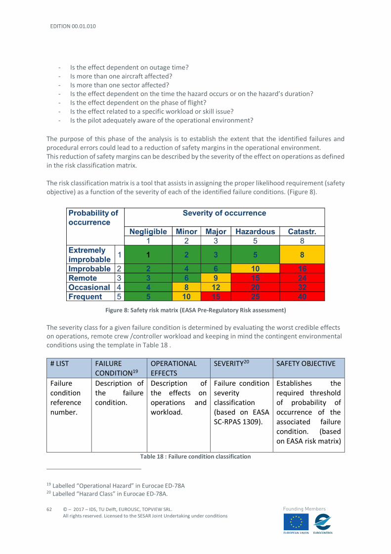
EDITION 00.01.010
62
© – 2017 – IDS, TU Delft, EUROUSC, TOPVIEW SRL. All rights reserved. Licensed to the SESAR Joint Undertaking under conditions
Founding Members
- Is the effect dependent on outage time? - Is more than one aircraft affected? - Is more than one sector affected? - Is the effect dependent on the time the hazard occurs or on the hazard’s duration? - Is the effect dependent on the phase of flight? - Is the effect related to a specific workload or skill issue? - Is the pilot adequately aware of the operational environment?
The purpose of this phase of the analysis is to establish the extent that the identified failures and procedural errors could lead to a reduction of safety margins in the operational environment. This reduction of safety margins can be described by the severity of the effect on operations as defined in the risk classification matrix. The risk classification matrix is a tool that assists in assigning the proper likelihood requirement (safety objective) as a function of the severity of each of the identified failure conditions. (Figure 8).
Figure 8: Safety risk matrix (EASA Pre-Regulatory Risk assessment)
The severity class for a given failure condition is determined by evaluating the worst credible effects on operations, remote crew /controller workload and keeping in mind the contingent environmental conditions using the template in Table 18 .
# LIST FAILURE CONDITION19
OPERATIONAL EFFECTS
SEVERITY20 SAFETY OBJECTIVE
Failure condition reference number.
Description of the failure condition.
Description of the effects on operations and workload.
Failure condition severity classification (based on EASA SC-RPAS 1309).
Establishes the required threshold of probability of occurrence of the associated failure condition. (based on EASA risk matrix)
Table 18 : Failure condition classification
19 Labelled “Operational Hazard” in Eurocae ED-78A 20 Labelled “Hazard Class” in Eurocae ED-78A.
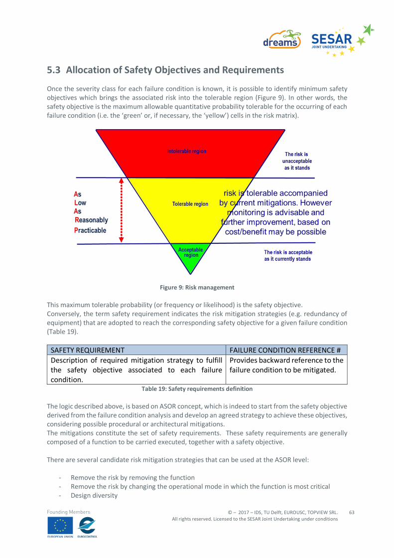
© – 2017 – IDS, TU Delft, EUROUSC, TOPVIEW SRL. All rights reserved. Licensed to the SESAR Joint Undertaking under conditions
63
Founding Members
5.3 Allocation of Safety Objectives and Requirements
Once the severity class for each failure condition is known, it is possible to identify minimum safety objectives which brings the associated risk into the tolerable region (Figure 9). In other words, the safety objective is the maximum allowable quantitative probability tolerable for the occurring of each failure condition (i.e. the ‘green’ or, if necessary, the ‘yellow’) cells in the risk matrix).
Figure 9: Risk management This maximum tolerable probability (or frequency or likelihood) is the safety objective. Conversely, the term safety requirement indicates the risk mitigation strategies (e.g. redundancy of equipment) that are adopted to reach the corresponding safety objective for a given failure condition (Table 19).
SAFETY REQUIREMENT FAILURE CONDITION REFERENCE # Description of required mitigation strategy to fulfill the safety objective associated to each failure condition.
Provides backward reference to the failure condition to be mitigated.
Table 19: Safety requirements definition The logic described above, is based on ASOR concept, which is indeed to start from the safety objective derived from the failure condition analysis and develop an agreed strategy to achieve these objectives, considering possible procedural or architectural mitigations. The mitigations constitute the set of safety requirements. These safety requirements are generally composed of a function to be carried executed, together with a safety objective. There are several candidate risk mitigation strategies that can be used at the ASOR level:
- Remove the risk by removing the function - Remove the risk by changing the operational mode in which the function is most critical - Design diversity
EDITION 00.01.010
64
© – 2017 – IDS, TU Delft, EUROUSC, TOPVIEW SRL. All rights reserved. Licensed to the SESAR Joint Undertaking under conditions
Founding Members
- Isolation - Proven reliability - Failure warning or indication - Check procedures, flight crew/controller - Removal of common cause - Designed failure effect limits - Designed failure path - Margins or factors of safety - Error tolerance - Error avoidance, reduction, or transfer
Whatever risk mitigation strategy is adopted, the resultant allocation/apportionment should be applied and documented, through Means of Evidence (MoE).
5.4 Services in U-SPACE
In the envisaged UTM structure, the following services are expected to be implemented, according with the European ATM Master Plan: roadmap for the safe integration of drones into all classes of airspace [30].
5.4.1 U1 – foundation services
E-registration: The service enables the registration of the operator, drone and pilot with the appropriate information according to regulation. A level of security of the service will be defined. E-identification: The service allows the identification of a drone operator from a drone in operation (in line with the global scope of registry (ICAO) & eIDAS - Regulation (EU) No 910/2014). The identification provides access to the information stored in the registry based on an identifier emitted electronically by the drone. The identification service includes the localisation of the drones (position and time stamp). Pre-tactical geofencing: The service provides the operator with geo-information about predefined restricted areas (prisons, etc.) and available aeronautical information (NOTAM, AIRAC cycle) used during the flight preparation. This service requires the identification of accredited sources and the availability of qualified geoinformation related to restricted areas. This service provides information that allows the drone operator to make use of the geofencing capability of the drone.
5.4.2 U2 – initial services
Tactical geofencing: Compared to U1 pre-tactical geofencing, tactical geofencing brings the possibility to update the operator with geofencing information even during the flight. Tracking: This refers to the service provider using cooperative and non-cooperative surveillance data to maintain track-identity of individual drones. The capability includes ground and air surveillance systems, as well as surveillance data processing systems. The performance requirements of the capability will vary in accordance with the specific requirements for each application.
© – 2017 – IDS, TU Delft, EUROUSC, TOPVIEW SRL. All rights reserved. Licensed to the SESAR Joint Undertaking under conditions
65
Founding Members
Flight planning management: This service covers the receipt of a flight notification or a flight plan and provides the appropriate answer according to the characteristics of the mission and applicable regulations This service will be available for any drone operator/user with different levels of requirements. Strategic deconfliction: The service provides deconfliction assistance to a drone operator at strategic level (when the flight plan is submitted, it is compared to other known flight plans and a deconfliction in time or route could be proposed). This service could be mandatory or optional according to the operating environment. Weather information: The service provides drone operators with forecast and actual weather information either before or during the flight; it can also collect and make available weather information from different stakeholders. Different levels of service provision could be considered; for example:
- MET information for missions in a rural environment (based on existing aeronautical information);
- Enhanced weather information for missions in urban areas; - Micro-weather information for urban areas (urban canyoning/ autonomous vehicles)
Drone aeronautical information management: This service provides the operator with relevant aeronautical information for drone operations. It will connect to the Aeronautical information service (AIS) to guarantee coherent information provision for manned and unmanned operators. Procedural interface with ATC: The service is a set of defined procedures for some mission types where there may be an impact on ATC; for example, crossing certain types of controlled airspace under prescribed conditions. The procedures ensure clear and unambiguous drone operation and provide an appropriate flow of information between the drone operators and ATC. Such procedures will allow drones to fly in controlled airspace and near airports with more flexibility and procedural approval/rejection based on agreed rules. Emergency management: The service receives emergency alerts from operators (e.g. loss of control) and informs relevant actors of the ecosystem. These may include drone operators operating drones nearby, ANSPs, police, airport authorities. The service also provides the drone/operator with assistance information to manage the emergency situation (e.g. location of landing pads). Monitoring: Subject to appropriate data-quality requirements, this service retrieves data from the tracking service and fuses it with information related to non-cooperative obstacles and vehicles in order to create air situation for authorities, service providers, and operators. This service may include conformance monitoring. Traffic information: This service provides the drone operator with traffic information coming from any kind of monitoring services.
EDITION 00.01.010
66
© – 2017 – IDS, TU Delft, EUROUSC, TOPVIEW SRL. All rights reserved. Licensed to the SESAR Joint Undertaking under conditions
Founding Members
5.4.3 U3– advanced services
Dynamic Geofencing: Compared to tactical geofencing in U2, the dynamic geofencing targets the drone itself and then this service requires data-link connectivity to a geofencing system that allows the data to be updated during the flight. Collaborative interface with ATC: The service provides a mechanism to ensure proper effective coordination when drone operations using U-Space services impact ATC. It encompasses shared situational awareness and procedures to enable a two-way dialogue supporting the safe and flexible operation of drones in airspace where ANS are provided. Tactical deconfliction: This service provides information to the operators or the drones to ensure separation management when flying. The differences with the strategic deconfliction described in U2 are twofold: the drone may receive the information and this deconfliction is set for the in-flight phase. It will be necessary to appropriately define the boundaries with the use of Detect & Avoid capabilities. Dynamic capacity management: Upon the definition of drone density thresholds (that can be dynamically modified), the service monitors demand for airspace, and manages access to that airspace as new flight notifications are received. This service may be coupled with the flight planning management service. There should be appropriate set of rules and priorities for slot allocation when a portion of airspace is expected to reach its capacity limits. Apart from the demand and capacity balancing, the service could manage capacity due to non-nominal occurrences, such as weather hazards or emergency situations.
5.4.4 U4 – full services
U4 offers the full integration with manned aviation and air traffic services and supports the full operational capability of U-Space based on a very high level of automation. It is expected that the need for new services will arise during the roll-out of U3. In addition, it is envisaged that manned aircraft could be equipped to take advantage of U-Space services.
5.5 System safety and performance parameters
As a result of the information presented in the previous sections, failure conditions are identified in relation to all the above-mentioned U-Space services. However, services responding to security needs (e.g. E-registration/identification) are excluded from this document because they are served by the same technical enablers as other more demanding services, which instead are herein considered. It is expected that, in analogy to the current ATM, even in the UTM context these services should be designed based on appropriate safety and performance requirements (SPR) in terms of transaction time, continuity, availability and integrity.
© – 2017 – IDS, TU Delft, EUROUSC, TOPVIEW SRL. All rights reserved. Licensed to the SESAR Joint Undertaking under conditions
67
Founding Members
The performance parameters are defined in ICAO Doc.9869 -PBCS [31] for communications (RCP):
- TRANSACTION TIME: The maximum time for the completion of the operational communication transaction after which the initiator should revert to an alternative procedure.
- CONTINUITY: The probability that an operational communication transaction can be completed within the communication transaction time.
- AVAILABILITY: The probability that an operational communication transaction can be initiated when needed.
- INTEGRITY: The probability of one or more undetected errors in a completed communication transaction.
For surveillance (RSP):
- TRANSACTION TIME: The maximum time for the reception of the surveillance data after which the controller should revert to an alternative procedure.
- CONTINUITY: The minimum proportion of surveillance data delivery to be completed within the specified RSP surveillance data delivery time, given that the service was available at the start of the delivery.
- AVAILABILITY: The required probability that surveillance data can be provided. - INTEGRITY: The required probability that surveillance data delivery is completed with no
undetected errors. In the present document the acceptable values for these parameters are determined taking as reference:
- the specifications provided in ICAO documents21 and for the definition of transaction time; - SORA Annex D for the definition of continuity and availability22; - EUROCAE ED 76 [33] for the definition of integrity.
The choice of appropriate values to be assigned to all these parameters is based on the results of safety assessment for each scenario. This is done considering the features of each U-Space service as well as the operational context in which they are being used. For example, the requirement on the availability of a U-Space service provided in a Pre-Tactical phase will be less stringent with respect to a service used while the drone is flying. As it is obvious, in output from the risk assessment, the most stringent requirements are taken. DREAMS scenarios are made up of a certain number phases; each phase is described by an UML sequence diagram in which several processes interconnecting U-Space services are involved (see Figure 10 below): in this document such processes are differentiated in “communication” processes (e.g. when a transaction involves a human actor), “surveillance” processes (e.g. services related to traffic surveillance mainly in terms of aircraft position and E-identification) or “information” processes (e.g. weather information acquisition/processing).
21 ICAO Doc. 9869-PBCS and ICAO Doc. 9869-RCP [32]. 22 SORA Annex D defines three general quantitative levels of performance (low, medium, high) associated to
the robustness of Tactical Mitigations.
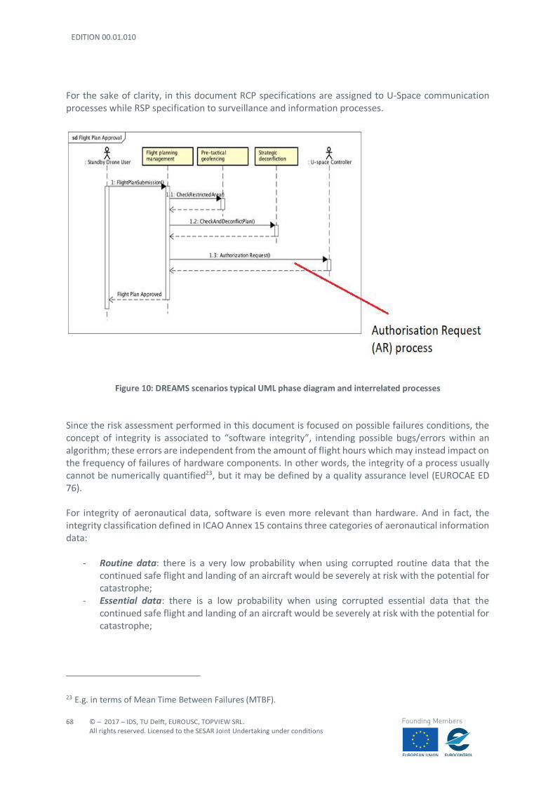
EDITION 00.01.010
68
© – 2017 – IDS, TU Delft, EUROUSC, TOPVIEW SRL. All rights reserved. Licensed to the SESAR Joint Undertaking under conditions
Founding Members
For the sake of clarity, in this document RCP specifications are assigned to U-Space communication processes while RSP specification to surveillance and information processes.
Figure 10: DREAMS scenarios typical UML phase diagram and interrelated processes
Since the risk assessment performed in this document is focused on possible failures conditions, the concept of integrity is associated to “software integrity”, intending possible bugs/errors within an algorithm; these errors are independent from the amount of flight hours which may instead impact on the frequency of failures of hardware components. In other words, the integrity of a process usually cannot be numerically quantified23, but it may be defined by a quality assurance level (EUROCAE ED 76). For integrity of aeronautical data, software is even more relevant than hardware. And in fact, the integrity classification defined in ICAO Annex 15 contains three categories of aeronautical information data:
- Routine data: there is a very low probability when using corrupted routine data that the continued safe flight and landing of an aircraft would be severely at risk with the potential for catastrophe;
- Essential data: there is a low probability when using corrupted essential data that the continued safe flight and landing of an aircraft would be severely at risk with the potential for catastrophe;
23 E.g. in terms of Mean Time Between Failures (MTBF).
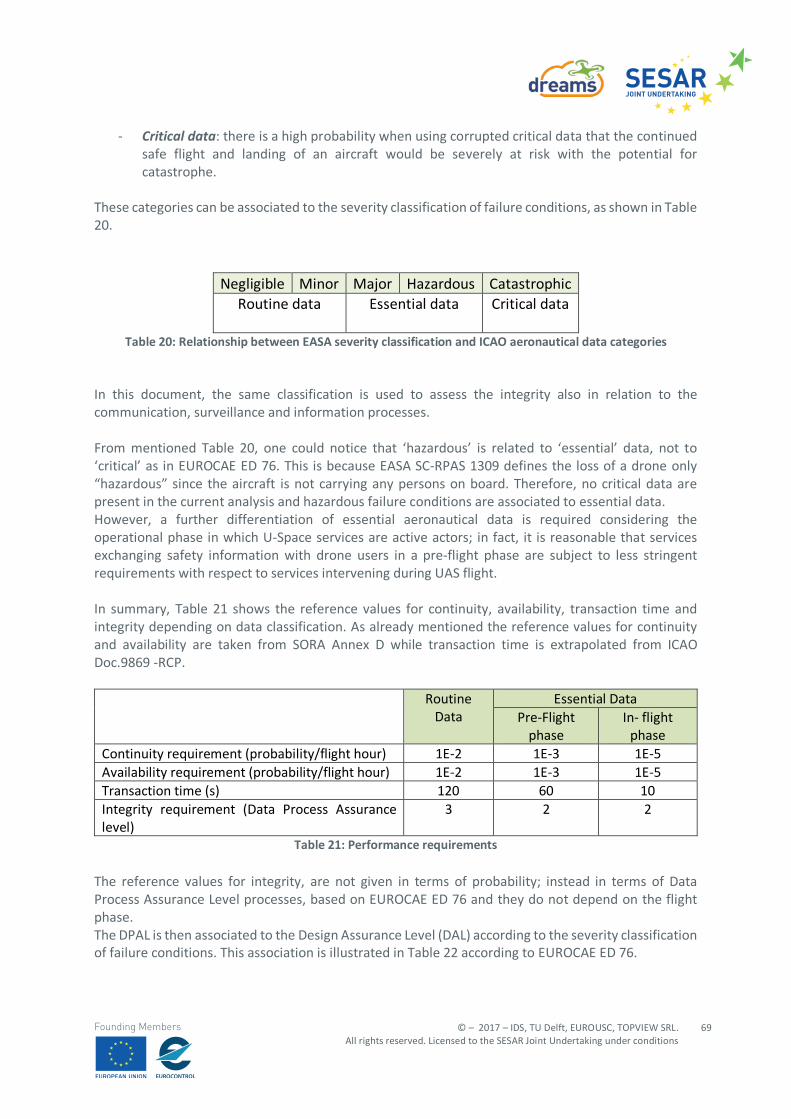
© – 2017 – IDS, TU Delft, EUROUSC, TOPVIEW SRL. All rights reserved. Licensed to the SESAR Joint Undertaking under conditions
69
Founding Members
- Critical data: there is a high probability when using corrupted critical data that the continued safe flight and landing of an aircraft would be severely at risk with the potential for catastrophe.
These categories can be associated to the severity classification of failure conditions, as shown in Table 20.
Negligible Minor Major Hazardous Catastrophic Routine data
Essential data
Critical data
Table 20: Relationship between EASA severity classification and ICAO aeronautical data categories
In this document, the same classification is used to assess the integrity also in relation to the communication, surveillance and information processes. From mentioned Table 20, one could notice that ‘hazardous’ is related to ‘essential’ data, not to ‘critical’ as in EUROCAE ED 76. This is because EASA SC-RPAS 1309 defines the loss of a drone only “hazardous” since the aircraft is not carrying any persons on board. Therefore, no critical data are present in the current analysis and hazardous failure conditions are associated to essential data. However, a further differentiation of essential aeronautical data is required considering the operational phase in which U-Space services are active actors; in fact, it is reasonable that services exchanging safety information with drone users in a pre-flight phase are subject to less stringent requirements with respect to services intervening during UAS flight. In summary, Table 21 shows the reference values for continuity, availability, transaction time and integrity depending on data classification. As already mentioned the reference values for continuity and availability are taken from SORA Annex D while transaction time is extrapolated from ICAO Doc.9869 -RCP.
Routine Data
Essential Data Pre-Flight
phase In- flight
phase Continuity requirement (probability/flight hour) 1E-2 1E-3 1E-5 Availability requirement (probability/flight hour) 1E-2 1E-3 1E-5 Transaction time (s) 120 60 10 Integrity requirement (Data Process Assurance level)
3 2 2
Table 21: Performance requirements The reference values for integrity, are not given in terms of probability; instead in terms of Data Process Assurance Level processes, based on EUROCAE ED 76 and they do not depend on the flight phase. The DPAL is then associated to the Design Assurance Level (DAL) according to the severity classification of failure conditions. This association is illustrated in Table 22 according to EUROCAE ED 76.
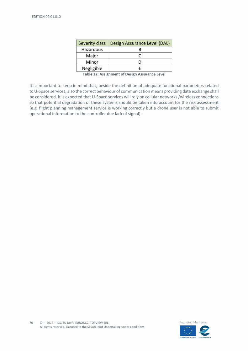
EDITION 00.01.010
70
© – 2017 – IDS, TU Delft, EUROUSC, TOPVIEW SRL. All rights reserved. Licensed to the SESAR Joint Undertaking under conditions
Founding Members
Severity class Design Assurance Level (DAL) Hazardous B
Major C Minor D
Negligible E Table 22: Assignment of Design Assurance Level
It is important to keep in mind that, beside the definition of adequate functional parameters related to U-Space services, also the correct behaviour of communication means providing data exchange shall be considered. It is expected that U-Space services will rely on cellular networks /wireless connections so that potential degradation of these systems should be taken into account for the risk assessment (e.g. flight planning management service is working correctly but a drone user is not able to submit operational information to the controller due lack of signal).
© – 2017 – IDS, TU Delft, EUROUSC, TOPVIEW SRL. All rights reserved. Licensed to the SESAR Joint Undertaking under conditions
71
Founding Members
6 U-Space Information Regulatory compliance
6.1 Introduction
The regulatory compliance takes into consideration the results of the safety assessment in terms of performance and safety requirements (see Section 5.5) with the aim to:
- Verify that such requirements are compliant with existing (and applicable) regulations; - Verify whether adequate supporting standards are in place; and - Propose regulation amendments “ad hoc” for U-Space services in case of gaps.
EU Regulation 549/2004 establishes the framework for the creation of the Single European Sky and defines the EATMN (European Air Traffic Management Network) whose collection of systems is listed in EU Reg.552/2004 [35]; interoperability of such systems shall be ensured according to EU Reg.552/2004. Common requirements for the provision of ANS services are defined in Article 6 of Reg.550/2004 [36], including:
- Technical and operational competence and suitability; - Systems and processes for safety and quality management; - Reporting systems; - Quality of services; - Financial strength; - Liability and insurance cover; - ownership and organisational structure, including the prevention of conflicts of interest; - human resources, including adequate staffing plans; and - security.
It is expected that such framework will be adopted also for UTM, clearly presenting technical and procedural differences in the means for service provision, involved actors and information content of the provided services. For instance, the primary means of communication and coordination between the air navigation services providers (ANSPs), operators and other stakeholders may be through a distributed network of highly automated systems via Application Programming Interfaces (API), rather than the traditional voice/data exchange between pilots and air traffic controllers. The aspects considered in this document are focused on safety and quality of the provided services as well as liability aspects. Other aspects (e.g. organisational structure, human resources, financial issues etc.) are not assessed being UTM still at an early stage of development.
6.2 Definitions Review for U-SPACE Concept
The airspace matter in Europe is regulated by international (i.e. ICAO), European and national documents. In any case, one of the common requirements for these documents is to list and explain
EDITION 00.01.010
72
© – 2017 – IDS, TU Delft, EUROUSC, TOPVIEW SRL. All rights reserved. Licensed to the SESAR Joint Undertaking under conditions
Founding Members
the terms used. The “glossary” has to cover all the terms treated in all arguments and, in order to avoid misleading or ambiguous meaning, the definitions reported in the different documents should be consistent and harmonised. The terminology of U-Space is “still in progress” and many definitions used for manned aviation may make sense also for UAS operation. In this context it’s to verify if the terminology encompassed in the current legislation may be “legally” applied to drones and if terms and definitions, currently aimed at manned aviation and traditional aeronautical framework, are consistent with U-Space and UTM structure. The EU Reg. published in 2004 by EU24 is the basic regulation “laying down the framework for the creation of the Single European Sky”. Obviously, the legislation is focused on “traditional” aviation, manned traffic, service providers, operators, industry, authorities and any other subject involved in the European airspace management. In 2004, UASs were “out of scope” and no specific terminology was appointed in EU Regulations. In this chapter is assessed the “compliance” of some terms, used in the traditional aviation and now encompassed in the U-Space literature. The terms are related to players involved in the different phases of operation and used also in the scenarios reported in Deliverable 3.1. The documents considered for this assessment are EU Reg. 549/2004, 550/2004, 551/2004 [37] and Reg.552/2004. Moreover, we will consider EU Regulations 216/2008, 73/2010 [38],255/2010 [39], 923/2012 and 373/2017 [40]. For ICAO documents, the study refers to ICAO Annexes 2, 3[41], 11, 15, Doc.4444 [42] , Doc.10019 [43] and Doc. 9161[44]. Of course, for this study only some terms are considered “key terms” and submitted to “compliance assessment”. They are:
- Service Provider - ATM - ATFM - AIS - Separation and spacing - Surveillance and identification - Remote Pilots and ATC - Meteorological minima
6.2.1 Service Providers
The U-Space expects to provide “new future services”, so it’s relevant to consider the meaning of “service provider” and if the term is appropriate to apply to drone activities on the basis of definitions reported in the regulatory documents. In the art. 2 of 549/2004, bullet 5, is reported as follows:
- ‘air navigation service providers’ means any public or private entity providing air navigation services for general air traffic” -
24 EU Regulation 549, 550, 551 and 552 issued on 2004
© – 2017 – IDS, TU Delft, EUROUSC, TOPVIEW SRL. All rights reserved. Licensed to the SESAR Joint Undertaking under conditions
73
Founding Members
A similar definition is included in EU Reg. 373/2017, art 2 Definitions:
- “‘service provider’ means any legal or natural person providing functions or services of ATM/ANS as defined in point (q) of Article 3 of Regulation (EC) No 216/2008 or other ATM network functions, either individually or bundled for general air traffic;”
This aspect is connected to bullet 15 which reports:
- “‘certificate’ means a document issued by a national supervisory authority in any form complying with national law, which confirms that an air navigation service provider meets the requirements for providing a specific service;’ “
The two statements define that the Service Provider may provide “specific services” to general air traffic. For this reason, in order to be consistent with the definitions, the drone operation in U-Space has to be encompassed in the “general air traffic”. If not, may need to change or integrate the definitions. On the matter, the definition listed in 549, art 2, bullet 26., reports:
- “‘general air traffic’ means all movements of civil aircraft, as well as all movements of State aircraft (including military, customs and police aircraft) when these movements are carried out in conformity with the procedures of the ICAO;”.
The Regulation 550/2004 art 7 bullet 5, in reference to “service provision”, states:
- “omissis…, Member States may allow the provision of air navigation services in all or part of the airspace under their responsibility without certification in cases where the provider of such services offers them primarily to aircraft movements other than general air traffic. In those cases, the Member State concerned shall inform the Commission and the other Member States of its decision and of the measures taken to ensure maximum compliance with the common requirements.”
It's the case to underline that ICAO Annexes and DOC4444 don’t report any definition for service provider. In the framework of U-Space is transparent that the “service provider concept” has to include the UTM service providers. In particular, the U-Space expects to have a “management airspace” in the layer of VLL - very low level -, where the traffic, manned and unmanned, will be handled by “units/agencies”. In the far future (phase U4), these units/agencies could be “not human” but BOT (an automatic code that performs automatic operations). Furthermore, the Aeronautical Information Services and Meteorological Services should provide information to UAS operators/pilots with same efficiency and effectiveness of manned traffic. This aspect is very sensitive due to responsibilities connected to the service provision, in particular, in case of accident or incident. Another point to be considered is the provision of information related to terrain, in particular, the natural and artificial obstacles and/or the density of population. The UTM service provider in charge to provide the aeronautical information shall disseminate very specific and sharp information to users but, some of this information, could not be originated by
EDITION 00.01.010
74
© – 2017 – IDS, TU Delft, EUROUSC, TOPVIEW SRL. All rights reserved. Licensed to the SESAR Joint Undertaking under conditions
Founding Members
“aviation actors” (e.g. new buildings or temporary obstacles like a crane) and referred to parameters very variable, depending on time, day, season or particular events (e.g. density of population). The Service Providers will represent one of the main actors in the U-Space and in the UAS operation too, but the current definitions seem to be not exhaustive for drone operations because of aimed at “traditional aviation”. Before changing definitions, it’s relevant to define which actors in the U-Space are “Service Providers”. The current definition links “service provider” to ATM, ANS and General Air Traffic. The term ATM includes ATC, ATFM and AIS. These three terms will be assessed in the next paragraph but, in any case, they refer to specific functions and responsibilities aimed at manned aviation. The ICAO DOC 9161 ANS reports:
- “Air Navigation Service – This term includes air traffic management (ATM), communications, navigation and surveillance systems (CNS), meteorological services for air navigation (MET), search and rescue (SAR) and aeronautical information services/aeronautical information management (AIS/AIM). These services are provided to air traffic during all phases of operations (approach, aerodrome and en-route).”,
and, - “ANSP Air navigation services provider - Any entity providing ATM and/or other air navigation
services mentioned above.”
Both definitions are correlated to ATM and other services specifying the provision “in all phases of operations”. General Air Traffic (see above mentioned “definition”) encompasses civil and military flights that operate following rules based on ICAO, but military traffic (and government traffic?) is out of scope of U-Space. In the end, the term “Service Provider” is transparent in the traditional aviation but could be necessary to review the concept and the related definition to better address the U-Space requirements, as much as possible in order to include new actors able to provide information useful for the safety requirements and to minimise the risk for other air traffic or third parties on the ground. Information on density of population, temporary obstacles (e.g. cranes) or modification of the sky-line of a suburb, availability of mobile 4G/5G network, are not Air Navigation Services but anyway are relevant for safe drone operations. The clear definition of U-Space Service Providers and the rules on their specific functions will also enable the liability.
6.2.2 ATM – Air Traffic Management
The terms U-Space and UTM are still under discussion to define the respective meaning and they are often used in the drone literature without difference. At this stage, U-Space is a brand name promoted by the EC in which a set of services (U-Space) is envisaged. No official definition or position on UTM is currently available in the EU. So, U-Space can be
© – 2017 – IDS, TU Delft, EUROUSC, TOPVIEW SRL. All rights reserved. Licensed to the SESAR Joint Undertaking under conditions
75
Founding Members
considered mainly as a set of services, technically enabling airborne traffic. EC intends to distinguish U-Space from UTM, but at the moment the differences are not clear at all. It’s relevant to underline that the EASA Opinion 1/2018, the related draft Regulations, Annex and AMC/GM, don’t report any U-Space definition. Only for this study, we could compare the U-Space with the “airspace” and the term UTM with ATM. In other words, the U-Space should be the airspace mainly dedicated to UAS operations and UTM should be the envisaged services provided to manage the traffic of UAS in the U-Space. The term U-Space is normally used in the scenarios reported in Deliverable 3.1. It’s used for the services provided and for the “actors” involved in this provision. The Blueprint document published by the SESAR JU states:
- “U-Space provides an enabling framework to support routine drone operations, as well as a clear and effective interface to manned aviation, ATM/ANS service providers and authorities”.
This definition looks like a concept but if we would consider the U-Space like the portions of airspace where UAS operations are allowed, it should be possible to define “different classes” (and services) to provide for each-one, likewise the current airspace and manned aviation. The majority of UAS operations will be probably flown in uncontrolled airspace (“G” class), where it’s normally provided the “information service” but, in such conditions, drones might fly in controlled airspace (e.g. close to airports or within a “control zone”25). In both cases, the services provided to UAS in the different airspace classes could be similar (but probably not the same) to the services provided to manned traffic in parallel conditions and environment. U-Space services like “drone aeronautical information management”, “weather information” or “geo-fencing” may be included in “information services”, while “tracking”, “tactical de-confliction” or “collaborative interface with ATC” may be comprised in a “control service”. In reference to UTM no definition is reported in the EU and ICAO documents. The Blueprint document, published by the SESAR JU, foresees a relation between U-Space and ATM and the EASA draft Annex, published with Opinion 1/2018 reports, in the “specific category” chapter that, the Operator when conducting the “Operational risk assessment” has “to consider the class of the airspace and the impact on other air traffic and air traffic management (ATM) in cooperation with the relevant air navigation service provider (ANSP)” As reported by EU Reg. 549/2004 and by ICAO documents, ‘Air Traffic Management (ATM)’ means:
- “the aggregation of the airborne and ground-based functions (air traffic services, airspace management and air traffic flow management) required to ensure the safe and efficient movement of aircraft during all phases of operations”.26
25 EU Reg. 923/2012 - ‘control zone’ means a controlled airspace extending upwards from the surface of the earth
to a specified upper limit 26 EU Reg. 549/2004, Art. 2 “Definitions”, bullet 10
EDITION 00.01.010
76
© – 2017 – IDS, TU Delft, EUROUSC, TOPVIEW SRL. All rights reserved. Licensed to the SESAR Joint Undertaking under conditions
Founding Members
On the other side, a possible UTM definition could be:
- “the aggregation of the airborne (UA), the remote-based functions (RPS27 – Remote Pilot Station) and ground-based functions (U-Space services, U-Space management and UAS flow management) required to ensure the safe and efficient movement of aircraft during all phases of operations in the U-Space”.
In any case, the terms U-Space and UTM need to be well defined in the (EU) Regulation and only the clear understanding of the terms will better address the new drone services and the new (or reviewed) actors involved in the matter. Even in this case, regulation needs to be update.
6.2.3 Aeronautical Information Services
Dissemination of information will be a main topic of U-Space development and evolution. All services might be involved in information exchange process, either in the strategic phase of operations or in pre-tactical and tactical phases. In such cases, information provision will be “urgent”, in other cases could need less fast. In traditional aviation, the aeronautical information service is in charge to provide users with all “aeronautical” data useful for operations. EU Reg. 549 and ICAO Annex 15 report definition as follows:
- “‘aeronautical information service’ means a service established within the defined area of coverage responsible for the provision of aeronautical information and data necessary for the safety, regularity, and efficiency of air navigation;”.
In addition, Annex 15 reports definitions as follows:
- “‘Aeronautical information’ means information resulting from the assembly, analysis and formatting of aeronautical data.”
- “‘Aeronautical data’ means a representation of aeronautical facts, concepts or instructions in a formalized manner suitable for communication, interpretation or processing.”,
- “’Aeronautical information management (AIM)’ means the dynamic, integrated management of aeronautical information through the provision and exchange of quality-assured digital aeronautical data in collaboration with all parties.”
and Reg. 549 reports:
- “‘flight information service’ means a service provided for the purpose of giving advice and information useful for the safe and efficient conduct of flights;”.
27 ICAO Annex 2 definitions: Remote pilot station. The component of the remotely piloted aircraft system
containing the equipment used to pilot the remotely piloted aircraft.
© – 2017 – IDS, TU Delft, EUROUSC, TOPVIEW SRL. All rights reserved. Licensed to the SESAR Joint Undertaking under conditions
77
Founding Members
In other words, the AIS is responsible for the compilation and distribution of all aeronautical information necessary to airspace users, including information on:
- safety, - navigation, - technical, - administrative - or legal matters and their updates.
The information can take the form of maps showing the air routes and air traffic control centres and the areas that they are responsible for; or it can be notices, information circulars or publications. Some of these publications contain orders which must be carried out. Others are simply provided to give useful information - on prevailing weather, for instance: all of them are aimed at promoting the safety, regularity and efficiency of air navigation. The above mentioned final definitions of Annex 15 (AIM) and EU Reg.549 (FIS) may encompass the U-Space aeronautical information. The service might be so added to current service provision, aiming at changing requirements or including supplementary requirements. The Service in U-Space could be provided by “traditional” AIS providers or by new providers, mostly for new typologies of information (e.g. density of population, temporary law enforcement areas, ...). U-Space Information could be provided by same dissemination system (AIP, NOTAM, maps and charts…) for strategic and pre-tactical phases but information and data should be also provided in “real time”, using modern (and future) technology (e.g. mobile 4/5G/ network). In any case the Service Providers shall be certified by the competent national (or EU) Authority or by qualified agencies, previously recognised and approved by the competent Authority. Data and information shall respect defined criteria and requirements (mainly, integrity and accuracy) and shall be verified the coverage of the airspace, taking in consideration that remote pilots (and Operator) are commonly on the ground. This last issue may be even considered a positive factor, because ground to ground network may be developed. In any case, between traditional aviation and unmanned aviation will be mandatory to grant the interoperability of aeronautical information exchange systems. On the matter, Reg. 549 reports:
- “‘interoperability’ means a set of functional, technical and operational properties required of the systems and constituents of the EATMN and of the procedures for its operation, in order to enable its safe, seamless and efficient operation. Interoperability is achieved by making the systems and constituents compliant with the essential requirements;”
EU Reg. 552 reports in Art 1:
- “The objective of this Regulation is to achieve interoperability between the different systems, constituents and associated procedures of the EATMN, taking due account of the relevant international rules. This Regulation aims also at ensuring the coordinated and rapid introduction of new agreed and validated concepts of operations or technology in air traffic management.”
EDITION 00.01.010
78
© – 2017 – IDS, TU Delft, EUROUSC, TOPVIEW SRL. All rights reserved. Licensed to the SESAR Joint Undertaking under conditions
Founding Members
In U-Space aeronautical information are included in Pre-tactical, Tactical geo-fencing, Dynamic geofencing and Drone aeronautical information management service. In particular, Pre-Tactical and Tactical geofencing provide the operator with geo-information about predefined restricted areas (institutional buildings, prisons, etc.) and available aeronautical information (NOTAM, AIRAC cycle) used during the flight preparation and to update the operator with geofencing information even during the flight. These services require the eligibility of accredited sources and the availability of qualified geoinformation related to “reserved areas” (i.e. Prohibited and Restricted) and that allows the drone operator to make use of the geofencing capability of the “drone system”. Dynamin Geofencing, compared to tactical geofencing in U2, targets the drone itself and then this service requires data-link connectivity to a geofencing system that allows the data to be updated during the flight. Drone Information Management service provides the operator with relevant aeronautical information for drone operations. It will connect to the Aeronautical information service (AIS) to guarantee coherent information provision for manned and unmanned operators. In conclusion, interoperability is the key word in the future Aeronautical Information Management and in related AIS provision. Regulation has to be adapted to encompass U-Space Aeronautical Information Service in the traditional AIM. Having defined the new services, the community will need to regulate them. Using a taxonomy already enshrined in EC Regulation 373/2017 could make it easier to integrate therein the new comers. In case of AISP they are currently covered by Annex V to EU Reg.373/2017, which makes mere reference to ICAO Annexes 4 and 15 and, however, EASA Opinion 02/2018 proposes to have a better set of requirements on the matter. Part of current requirements could be applicable also to providers of information in the U-Space and one possibility, in due time, would hence be to amend the Annex to encompass all aeronautical information providers (traditional and in the U-Space). Different solutions might be applied:
- one company may be certified for both sets of (different) services; - a different company only for one set; - a third organisation only for a segment of the service (e.g. this is the case of EUROCONTROL
today, certified by EASA only to manage the Pan-European EAD), similarly to current situation in the domain of NAV (the majority of ATS Providers takes also responsibility of ground beacons, ILS, VOR, while the ENOS SSP takes responsibility only for its satellite navigation signals and all of them are NAV SPs.
In the EU we may regulate beyond Annex 15 and we could use the same principles for the traditional AISP and also for the new U-Space providers, to possibly create a level playing field for competition in the internal EU market. Regarding to the liability of the services, will be significant to define specific requirements like integrity, continuity, transaction time and availability of the information and the AIS Providers shall respect the defined “parameters” of each requirement.
© – 2017 – IDS, TU Delft, EUROUSC, TOPVIEW SRL. All rights reserved. Licensed to the SESAR Joint Undertaking under conditions
79
Founding Members
In particular, geofencing data will be very sensitive data and the “correct” provision will be directly related to the service liability.
6.2.4 Air Traffic Flow Management
The EU Reg. 549, Art 2, bullet 9, reports that ‘air traffic flow management’ means:
- “a function established with the objective of contributing to a safe, orderly and expeditious flow of air traffic by ensuring that ATC capacity is utilised to the maximum extent possible, and that the traffic volume is compatible with the capacities declared by the appropriate air traffic service providers”.
The EU Reg. 255/2010, “laying down common rules on air traffic flow management”, Article 1 “Subject matter and scope” reports:
- " This Regulation shall apply within the airspace referred to in Article 1(3) of Regulation (EC) No 551/2004 to all flights intended to operate or operating as general air traffic and in accordance with the instrument flight rules (hereinafter IFR) in whole or in part.”
The flow management is an activity that is done before flights take place. Any aircraft (IFR) using air traffic control, from a business aeroplane to an airliner, files a flight plan and sends it to a central repository. All flight plans for flight into, out of and around Europe are analysed and computed. For safety reasons, air traffic controllers cannot handle too many flights at once so the number of flights they control at any one time is limited. Sophisticated computers used by Air Traffic Flow Management calculate exactly where an aircraft will be at any given moment and check that the controllers in that airspace can safely cope with the flight. If they cannot, a “slot” is assigned to the flight and the aircraft has to wait on the ground until it is safe to take off. The ATFM definition relates the service to ATC capability. The function is so aimed at managing the IFR traffic in controlled airspace and in order to “make safer” the air traffic controllers activity. The ATFM foresees the presence of routes and, of course, the application of specific separations. In U-Space situation may be quite different. Most of drones traffic will be operated at VLL in “G” airspace, where is normally provided the Flight Information Service and not ATC service. The services of “Flight planning management” (U2 phase) and “Dynamic capacity management” (U3 phase) seem to be similar to ATFM (or ATFCM – Air Traffic Flow and Capacity Management) but probably they could be extended to both VFR and IFR drone operations and adapted to different requirements and needs In the expectation of U-Space the volume of traffic should be managed by a “provider” (U-Space Traffic Management provider), before the flight (Flight Planning phase) and during the flight (Dynamic Capacity management) on the basis of “airspace block volume” (areas or corridors) engaged by the single activity. In other words, the UTM provider should de-conflict drone operation that interfere with each other. In any case, separation (in terms of minimum distance) should be applied to the traffic (manned by ATFM and UAS by U-Space Traffic Management).
EDITION 00.01.010
80
© – 2017 – IDS, TU Delft, EUROUSC, TOPVIEW SRL. All rights reserved. Licensed to the SESAR Joint Undertaking under conditions
Founding Members
The question is:
- which is the “adequate separation” in terms of minimum distance between two drones (lateral and vertical) to apply in the “flow management”?
Another point is the relation between the volume of traffic and the capacity declared by ATS provider for that specific portion of airspace. In U-Space is expected to define a “threshold number” of drones in a defined portion of space. The number should be decided by the U-Space traffic manager but, in this case, probably without any coordination with ATS. In conclusion, service providers, aimed at providing “drone flow management” in U-Space, need to be able to apply specific “distances” among all the traffic. Different volume of space and different typologies of drones may need different vertical/lateral/time-period “distance/interval”.
6.2.5 Separation and spacing
ICAO and EU documents don’t report any definition for the generic terms “separation” and “spacing”. In the traditional aviation, the term “separation” is anyway normally related to vertical, longitudinal and lateral “interval” between two or more aircraft, expressed in terms of “distance” (miles, kilometres and feet) or “time” (in terms of minutes and seconds).28 Lateral separation may be granted also by maintaining aircraft on different routes or in different geographical areas (anyway is assured the principle of “minimum distance”). The term is normally connected to controlled airspace and to “controlled” air traffic (IFR) and it’s one the parameters (probably the most important) related to capacity to ensure safety to flights. Different “interval” may be provided on the basis of airspace involved, type of aircraft, available navigation aids, phases of flight (e.g. cruise, approach and departure, take-off and landing, …). May be also provided a “reduced” separation in specific conditions and situations. The term “separation” is also reported in some situation in which “If requested by pilot, ATC unit may clear a controlled flight, including departing and arriving flights, operating in airspace Classes D and E in visual meteorological conditions during the hours of daylight to fly subject to maintaining own separation to one other aircraft and remaining in visual meteorological conditions” (and applying other specific conditions)29. In the majority, separation is connected to the provision of air traffic control and the pilot is in charge to respect the “assigned” clearance in order to maintain the correct separation. Among VFR traffic the term “separation” is anyway used but no any “minimum distance” is legally defined. The principle is that each traffic has to provide itself an “adequate distance” from other air traffic (“own separation”), on the basis of “to see and to be seen”. But the “adequate distance” doesn’t give specific indication on meters, kilometres or miles between two aircraft flying in VFR. In other words, the pilots are directly responsible to maintain a “safe distance” in order to avoid conflict with other traffic.
28 ICAO Annex 11 and Doc4444, EU Reg. 923/2012 SERA 29 ICAO DOC4444 para 5.9 and EU Reg. 923/2012 SERA .8005 Operation of air traffic control service
© – 2017 – IDS, TU Delft, EUROUSC, TOPVIEW SRL. All rights reserved. Licensed to the SESAR Joint Undertaking under conditions
81
Founding Members
The term “spacing” is even more generic in the regulatory documents. It’s largely used in Doc4444 but even if it’s used also in IFR context (e.g. in approach sequence), no indications are reported in terms of figures (meters, miles or kilometres). Just for example Doc4444 reports in para 6.5.6.1.3:
- “In establishing the approach sequence, the need for increased longitudinal spacing between arriving aircraft due to wake turbulence shall be taken into account.”,
or in 6.7.3.1.2: - “Whenever parallel approaches are carried out, separate controllers should be responsible for
the sequencing and spacing of arriving aircraft to each runway.” The term “spacing” is also mentioned in the ICAO ATS SURVEILLANCE SERVICE PHRASEOLOGIES. In para 12.4.1.5 MANOEUVRES, the phraseology foresees the sentence “for spacing” to specify the reason for vectoring. The documents on RPAS mention very often the term “separation”. ICAO Doc10019 para 9.5.2 reports:
- “For VLOS, the visual contact has to be direct, meaning that the remote pilot or RPA observer must maintain a continuous unobstructed view of the RPA, allowing the remote pilot and/or RPA observer to monitor the RPA’s flight path in relation to other aircraft, persons, obstacles (e.g. vehicles, vessels, structures, terrain), for the purpose of maintaining separation and avoiding collisions.”.
The same document reports at para 10.4.3.2:
- “The separator or agent responsible for separation provision can be: a) the corresponding ATC unit; or b) the airspace user, in which case the separation provision is referred to as RWC.”
Regarding to the INTEGRATION PRINCIPLES para 14.2.3 reports:
- “RPAS operations should conform to the existing airspace requirements. These airspace requirements include, but are not limited to, communication, navigation and surveillance requirements, separation from traffic and distances from clouds.”
The new proposed EU regulation, laying down rules and procedures for the operation of unmanned aircraft, published with Opinion 1/2018, reports the following definition:
- ‘visual line of sight (VLOS)’ means a type of operation in which the remote pilot maintains continuous unobstructed and unaided visual contact with the UA, allowing the remote pilot to monitor the flight path of the UA in relation to other aircraft, persons, and obstacles for the purpose of maintaining separation from them and avoiding collisions.
The related Annex on “UAS operations in the ‘open’ and ‘specific’ categories” doesn’t use the term separation and, only in two cases refers to the term “distance” (…. omissis … “at a safe distance from uninvolved persons” and …. omissis ….” keeping a safe distance from the boundaries of congested areas”) in relation to “OPEN category operations”.
EDITION 00.01.010
82
© – 2017 – IDS, TU Delft, EUROUSC, TOPVIEW SRL. All rights reserved. Licensed to the SESAR Joint Undertaking under conditions
Founding Members
The associated AMC/GM reports:
- “Operations in first-person view (FPV) can be conducted only if the remote pilot is assisted by a UA observer positioned in his or her proximity, able to provide effective directions to the remote pilot in order to maintain the required separation between the UA and any obstacle, including other air traffic. During FPV operations, the remote pilot is still responsible for the safety of the flight.”
In conclusion, the current regulation on aviation gives well defined criteria for separation in the IFR context while the sense of “minimum distance” between two aircraft related to VFR flight is only qualitative (adequate, safe, sufficient, …). No figures at all. The pilots have responsibility to grant safety, maintaining a distance each other sufficient to avoid conflict even if in case of unexpected conditions (e.g. technical failure, sudden bad weather, …). In traditional aviation, liability appears well defined and easy to be appointed. The ATC is responsible to assign and reserve the minimum separation among controlled aircraft, on the basis of rules foreseen for that context; the pilot is responsible to make the correct manoeuvres to respect the instructions provided by the ATC. In uncontrolled airspace, the pilot is responsible to maintain own separation on the basis of information provided by the ATC. The possible future specific regulation on unmanned seems to disregard the issue at the moment, returning to further and mid-long-term documents. The debate is more focused on ATC services provided by human or BOT but, in any case, specific criteria on minimum distance among drones, and drones and manned traffic, have to be appointed. Both if the ATC (human or BOT) will provide separation or the RPA shall have the capability to separate themselves from any aircraft (other drones or manned), the minimum distance shall be defined among all the traffic. VLOS operation could be handled similarly to VFR traffic, with remote pilots able to maintain own separation but for BVLOS specific “interval” shall be defined, in terms of vertical and horizontal “spacing” (or time period). The four U-Space phases envisage services with connection to the concept of “separation” and “spacing”. Tracking, de-confliction and monitoring are directly connected to the concepts. Geofencing, Flight planning management, interface with ATC, emergency management and dynamic management are anyway related. Which will be the minimum distance to apply between 2 drones? And drones and manned traffic or any other aeronautical activity (e.g. parachute jumpings)? Might be envisaged different separation criteria for VLOS and BVLOS? And in the end, is acceptable to have similar distances to manned and unmanned IFR traffic or new spacing/separations need to be defined?
6.2.6 Identification and Surveillance
The U-Space envisages many services for building the four U phases. “Identification”, “tracking” and “monitoring” are part of these services and they seem to be related each other in functions similar to “aircraft surveillance”.
© – 2017 – IDS, TU Delft, EUROUSC, TOPVIEW SRL. All rights reserved. Licensed to the SESAR Joint Undertaking under conditions
83
Founding Members
The definition of “identification” in the EU draft Reg. “laying down rules and procedures for the operation of unmanned aircraft”, published with EASA Opinion 1/2018, reports:
- “‘electronic identification’ means a system that transmits the identity of the UA so that it can be identified without direct physical access to that UA;”.
The associated draft GM1 UAS.OPEN.060(4) and UAS.SPEC.060(5) report:
- “E-identification: the operator should upload the registration number assigned to him or her into the UA. The UA e-identification system will combine the operator’s registration number with the serial number of the UA to create a unique UA identification number. This data will be broadcast by the e-identification system.”
The AMC1 UAS.SPEC.050(5) regarding the identification of the UAS, reports the following note:
- “if the UAS is not subject to registration, the identification of the UAS may be done using the serial number of the UAS.”
Looking at these sentences, the term “identification” in U-Space seems to be related to the capability to “understand who is that drone” and “what’s its position”. It’s not clear if the service is directly related to other services, for instance like tracking or monitoring. Doc4444, basically aimed at manned aviation, reports following definitions:
- “Aircraft identification - A group of letters, figures or a combination thereof which is either identical to, or the coded equivalent of, the aircraft call sign to be used in air-ground communications, and which is used to identify the aircraft in ground-ground air traffic services communications.”,
and - “Identification - The situation which exists when the position indication of a particular aircraft
is seen on a situation display and positively identified.”. The same document, in the chapter dedicated to “Identification of aircraft” (8.6.2.1 ESTABLISHMENT OF IDENTIFICATION), states on bullet 8.6.2.1.1:
- “Before providing an ATS surveillance service to an aircraft, identification shall be established, and the pilot informed. Thereafter, identification shall be maintained until termination of the ATS surveillance service”,
and, - “‘surveillance services’ means those facilities and services used to determine the respective
positions of aircraft to allow safe separation;” -
The sentences in Doc4444 clearly associate the term “identification” to the capability to define the position of an aircraft in relation to the provision of ATS services (surveillance). For safety reasons, parameters like transaction time, accuracy, continuity, are strictly related to the determination of a position of an aircraft and, consequently, to the identification of an aircraft and its surveillance.
EDITION 00.01.010
84
© – 2017 – IDS, TU Delft, EUROUSC, TOPVIEW SRL. All rights reserved. Licensed to the SESAR Joint Undertaking under conditions
Founding Members
As well as the “surveillance” service is connected to the “aircraft identification” and its “sharp” positioning, the “tracking” and “monitoring” services in U-Space will need to localise the drones with reliable and “safe” precision in order to grant drones management. In U-Space “E-identification” allows the identification of a drone operator from a drone in operation. The identification provides access to the information stored in the registry based on an identifier emitted electronically by the drone. The identification service includes the localisation of the drones (position and time stamp). “Tracking” refers to the service provider using cooperative and non-cooperative surveillance data to maintain track identity of individual drones. The capability includes ground and air surveillance systems, as well as surveillance data processing systems. The performance requirements of the capability will vary in accordance with the specific requirements of each application. “Monitoring” is subject to appropriate data-quality requirements and this service retrieves data from the tracking service and fuses it with information related to non-cooperative obstacles and vehicles in order to create air situation for authorities, service providers, and operators. This service may include conformance monitoring. In conclusion, in traditional aviation the terms “identification” and “surveillance” are strictly related to well defined criteria to grant separation among the traffic under control. In controlled airspace may be considered identified even an “unknown traffic”. In any case, the ATC consider its position to maintain minimum separation from other controlled (and known) traffic. In the U-Space, the term “identification” is related to other services like “tracking” and ““monitoring” but, at the moment, no specific criteria are in force to validate the correct identification of a drone (accuracy, tolerance, …). The “tracking” and “monitoring” services, don’t clear which kind of “spacing” will be applied among drones, and drones and manned traffic. Taking in consideration the draft UAS EASA regulation (published with Opinion 1/2018), the U-Space could need more specific definitions and statements for “identification”, connecting the term with the other U-Space services terms, in particular tracking and monitoring.
6.2.7 Remote Pilots and ATC
Pilots and Air Traffic Controllers are two main actors in the aviation world, both of them well involved in safe management of flights. Pilots have responsibility to conduct the aircraft and, depending on flight rules, they have to follow instructions issued by Air Traffic Controllers (i.e. IFR) to ensure separation from other air traffic or to use the information provided by ATCO (Air Traffic Control Operator) to grant themselves adequate “spacing” from the other traffic (i.e. VFR). Doc4444 and EU Reg. 923/2012 - SERA -, report :
- “Pilot-in-command is the pilot designated by the operator, or in the case of general aviation, the owner, as being in command and charged with the safe conduct of a flight.”
SERA.2010 reports on the pilot responsibility as follows:
© – 2017 – IDS, TU Delft, EUROUSC, TOPVIEW SRL. All rights reserved. Licensed to the SESAR Joint Undertaking under conditions
85
Founding Members
- “’Responsibility of the pilot-in-command’ The pilot-in-command of an aircraft shall, whether manipulating the controls or not, be responsible for the operation of the aircraft in accordance with this Regulation, except that the pilot-in-command may depart from these rules in circumstances that render such departure absolutely necessary in the interests of safety.”
No definition for the single term “pilot” are reported in ICAO and EU Regulations. In any case, we could generically define a pilot, “the person who fly an aircraft”. For UAS the Draft UAS EU Regulation30 reports:
- “‘remote pilot’ means a natural person responsible for safely conducting the flight of a UA by operating its flight controls, either by manual use of the remote controls or, when the UA flies automatically, by monitoring its course and remaining able to intervene and change its course at any time;”,
and: - “‘unmanned aircraft (UA) observer’ means a natural person who, by unaided visual observation
of the UA, assists the remote pilot in safely conducting the flight.”
Art. 3 of draft UAS EU Regulation states:
- “The remote pilot is responsible for the safe conduct of each individual UA flight.”
In relation to the liability aspects, the draft UAS EU ANNEX and the AMC/GM define skills requirements and responsibilities for remote pilot. ICAO Doc1001931 reports definitions as follows:
- “Remote pilot is a person charged by the operator with duties essential to the operation of a remotely piloted aircraft and who manipulates the flight controls, as appropriate, during flight time.”
- “Remote pilot-in-command. The remote pilot designated by the operator as being in command and charged with the safe conduct of a flight”
Regarding to the remote pilot responsibility, the draft UAS EU Regulation reports as follows:
- “‘visual line of sight (VLOS)’ means a type of operation in which the remote pilot maintains continuous unobstructed and unaided visual contact with the UA, allowing the remote pilot to monitor the flight path of the UA in relation to other aircraft, persons, and obstacles for the purpose of maintaining separation from them and avoiding collisions;”
Clear responsibilities seem to be addressed to a remote pilot in VLOS operation. Anyway, the remote pilot has to grant “safe flight conditions” in relation to other air traffic.
30 EASA Opinion 1/2018 31 ICAO Doc10019 is a manual addressed to RPAS as one subset of UAS and it’s applicable to any RPAS used for
other than recreational purposes.

EDITION 00.01.010
86
© – 2017 – IDS, TU Delft, EUROUSC, TOPVIEW SRL. All rights reserved. Licensed to the SESAR Joint Undertaking under conditions
Founding Members
For BVLOS operations, ICAO Doc10019 in the chapter on “BVLOS Operation reports the following statements”:32
- “When neither the remote pilot nor RPA observer(s) can maintain direct unaided visual contact with the RPA, the operations are considered BVLOS. Minimum equipment requirements to support BVLOS operations increase significantly as the range and complexity of such operations increase, as does the cost involved in ensuring the robustness of the C2 link. The ability to detect conflicting traffic or obstacles and take appropriate action to avoid them is essential.”,
and - “To conduct flights beyond VLOS of the remote pilot or RPA observer, a means to DAA traffic
and all other hazards such as hazardous meteorological conditions, terrain and obstacles must be available to the remote pilot.”
The same document reports33:
- “BVLOS operations conducted under VFR should only be considered when the following conditions are met:
a) the State of the Operator and the State in whose airspace the operation occurs have approved the operation; b) the RPA remains in VMC throughout the flight; and c) a DAA capability or other mitigation is used to assure the RPA remains well clear of all other traffic; or d) the area is void of other traffic; or e) the operation occurs in specifically delimited or segregated airspace.”
In the end, at this stage, for BVLOS operations, no clear responsibilities seem to be definitively addressed to remote pilots. In the ICAO and EU documents no definitions are inserted for “Air Traffic Control Operator” or “Air Traffic Controller”. All the definitions are connected to terms “unit”, service”, “clearance” (i.e. ATC unit, ATC service, ATC clearance). Even if ICAO Doc10019 reports the acronym “ATCO - air traffic control officer”, no definition is inserted in the same document. Anyway, the functions and responsibilities of Air Traffic Controllers may result by the chapters including the “Unit ATC provision”. The responsibilities derive from airspace classes where the unit is in charge for “traffic management”, both controlled or uncontrolled airspace. ICAO Annex 2 reports:
- “A controlled flight shall be under the control of only one air traffic control unit at any given time.”34
In UAS domain, ICAO Doc10019 reports:
32 ICAO Doc10019 - Chapter 2.3.13 and 9.5.9. 33 ICAO Doc10019 chapter 9.5.15. 34 ICAO Doc10019 – chapter 9.5.10

© – 2017 – IDS, TU Delft, EUROUSC, TOPVIEW SRL. All rights reserved. Licensed to the SESAR Joint Undertaking under conditions
87
Founding Members
- “Prior to conducting a controlled BVLOS operation, coordination should be effected with the ATC unit(s)”35
The draft UAS EU Annex to Regulation36, for specific operation, reports following statement:
- “The competent authority shall issue, without undue delay, an authorisation to a UAS operator to conduct an operation in the ‘specific’ category when it concludes that the operation: i. corresponds to a standard scenario issued by EASA that requires an authorisation, and
that a procedure is in place for the coordination with the relevant ATC unit(s) if the entire operation or part of it is to be conducted in controlled airspace; or
ii. if does not correspond to a standard scenario, a procedure is in place for the coordination with the relevant ATC unit(s) if the entire operation or part of it is to be conducted in controlled airspace.”.
The statements foresee a relationship between UAS Operator (not Pilot) and the ATC for applying coordination procedures. Current ICAO and EU regulation don’t provide any rule where UAS operation are dependent on ATC clearance (or authorisation/approval) and same situation seems to become with early future EU regulation (drafts published with EASA Opinion 1/2018). In the U-Space concept, the “Procedural interface with ATC”37 in U2 phase and the “Collaborative interface with ATC”38 in U3 phase, foresee information exchange and coordination between drone operators and ATC. No involvement by ATC in providing separations. In U3 phase “Tactical de-confliction”39 the information exchange is aimed at providing separation (and avoiding conflict) with other traffic but drones seem to provide themselves (by DAA capabilities) separation, without ATC involvement. In conclusion, in traditional aviation Pilots and Controllers have specific relationship; pilots have to follow instructions of controllers if flying IFR and they have to “use” information of controllers if they fly VFR, aiming anyway to grant minimum separation (well defined for IFR in terms of distance or time)
36 EASA Opinion 1/2018 Annex to Regulation laying down rules and procedures for the operation of unmanned
aircraft - UAS.SPEC.040 Issuing of an operational authorisation, bullet 2. 37 Procedural interface with ATC in U2 is a set of defined procedures for some mission types where there may
be an impact on ATC; for example, crossing certain types of controlled airspace under prescribed conditions. The procedures ensure clear and unambiguous drone operation and provide an appropriate flow of information between the drone operators and ATC. Such procedures will allow drones to fly in controlled airspace and near airports with more flexibility and procedural approval/rejection based on agreed rules.
38 Collaborative interface with ATC provides a mechanism to ensure proper effective coordination when drone operations using U-Space services impact ATC. It encompasses shared situational awareness and procedures to enable a two-way dialogue supporting the safe and flexible operation of drones in airspace where ANS are provided.
39 Tactical Deconfliction provides information to the operators or the drones to ensure separation management when flying. The differences with the strategic deconfliction described in U2 are twofold: the drone may receive the information and this deconfliction is set for the in-flight phase. It will be necessary to appropriately define the boundaries with the use of Detect & Avoid capabilities
EDITION 00.01.010
88
© – 2017 – IDS, TU Delft, EUROUSC, TOPVIEW SRL. All rights reserved. Licensed to the SESAR Joint Undertaking under conditions
Founding Members
or to ensure “adequate spacing” from other traffic (not well defined for VFR). Consequently, pilots and controllers have well defined responsibilities related to their roles. In U-Space, the role of ATC is not well clear and, of course, relation-ship with remote pilots and respective responsibilities are to be defined. In U-Space, drones should be managed by “a drone traffic manager”, human or BOT. But in U-Space other traffic (no drone) will operate and “adequate spacing” will be maintained among all air users. Human or BOT depends on the level of risk of the operations, but artificial intelligence might be introduced being it associated to a pilot decision making capability. Initially a human might be the controller, but, once regime conditions would be reached, the human could be replaced by a BOT and, from the service point of view, the U-Space controller could be seen as a “flow and capacity manager”. In the end, which will be in U-Space the relationship between remote pilots and ATC? and which will be the relation-ship between U-Space and ATM? Is the current regulation adequate to encompass the “new” traffic management provision in U-Space?
6.2.8 Meteorological minima
Weather information is expected to be one of U-Space services developed and provided since U2 phase. Meteorological service is one of the air navigation services and, as reported in EU Reg. 549/2004:
- “‘meteorological services’ means those facilities and services that provide aircraft with meteorological forecasts, briefs and observations as well as any other meteorological information and data provided by States for aeronautical use.”
On the matter, ICAO published the Annex 3 — Meteorological Service for International Air Navigation, dedicated to meteorological service provision, and to prove the importance of the matter, the first edition, was published in 1948. The document specifies that the objective of meteorological service “shall be to contribute towards the safety, regularity and efficiency of international air navigation.” This objective shall be achieved by supplying the operators, flight crew members, air traffic services units, search and rescue services units, airport managements and others concerned with the conduct or development of international air navigation, with the meteorological information necessary for the performance of their respective functions. Each Contracting State shall determine the meteorological service which it will provide to meet the needs of international air navigation and each State shall designate the authority to provide or to arrange for the provision of meteorological service for international air navigation on its behalf. It’s transparent that meteorological information has to be provided by designated Service Provider (State agencies or other “designated” agencies). And meteorological information has to be provided in order to allow flights in two different condition, Visual Meteorological Condition (VMC) and Instrumental Meteorological Condition (IMC). ICAO Doc4444 and EU Reg. 923/2012 define VMC and IMC as follows:
- “Visual meteorological conditions. Meteorological conditions expressed in terms of visibility, distance from cloud, and ceiling, equal to or better than specified minima.”
© – 2017 – IDS, TU Delft, EUROUSC, TOPVIEW SRL. All rights reserved. Licensed to the SESAR Joint Undertaking under conditions
89
Founding Members
- “Instrument meteorological conditions. Meteorological conditions expressed in terms of visibility, distance from cloud, and ceiling, less than the minima specified for visual meteorological conditions.”
Relation-ship between meteorological condition and UAS may be found in ICAO documents. For RPAS, ICAO Doc10019 reports that 40:
- “when operating IFR in visual meteorological conditions (VMC), VFR traffic, possibly having right-of-way, may be encountered. The remote pilot must be able to identify these situations and take appropriate action;”,
and, - “in order to conduct VFR flights, the remote pilot must have a means to comply with the
visibility and distance from cloud minima;”.
The same document underlines the relevance of the meteorological condition to assess the “environment” where the RPAS operation are flown in relation to performance limitations of the same RPAS. The main meteorological information for unmanned operation are visibility, wind (in terms of direction and speed), upper air temperature and any other hazardous meteorological conditions including cumulonimbus, icing and turbulence. Taking into consideration the above mentioned brief statements, meteorological information is to be considered very important for flight operations, whether for manned aviation or for unmanned activities. Of course, similarly to manned aviation, for U-Space and in particular for VLL operations, different data and information should be provided for departing and arrival phases and for “cruising phase”. Furthermore, usually, manned aviation take-off and landing are on an aerodrome41, while drones normally take-off and landing are not executed on an aerodrome. Current meteorological service during departure and arrival phases is aimed at providing information on aerodrome and its surrounding (visibility, wind, clouds, temperature, altimeter, …). In the majority, aerodrome information is sharp, bordered and provided “in real time”. In the portion of flight far from the aerodromes, weather information is generic, the Pilot is the first “weather observer” and he is well aware of the situation. In U-Space, drones will operate in very different context and, probably, in the majority of flights, far from airports. In relation to meteorological aspects, VLOS operation could be compared to very localised manned flights operating in VFR on and in the vicinity of an aerodrome, where ATC is not provided. In this context, operations are in VMC, and with Pilots (or Remote Pilots) responsible to ensure “spacing” each other, on the basis of “to see and to be seen” concept. But VLOS drone operations are mainly conducted within 500m from the Remote Pilot and they are usually small sized (not easy to “be seen”). May we consider, for this specific scenario, same meteorological minima of visibility and distance from clouds for manned and unmanned flights?
40 ICAO Doc10019 chapter 2.3.7 – Flight rules 41 Rotary wings may take-off and land from different location, like helipad, platforms or any adequate surface.
Also, VTOL aircraft may use different sites. Military aircraft (e.g. cargo) may take-off and land from “operational strips”.
EDITION 00.01.010
90
© – 2017 – IDS, TU Delft, EUROUSC, TOPVIEW SRL. All rights reserved. Licensed to the SESAR Joint Undertaking under conditions
Founding Members
BVLOS operations expect to be conducted in VFR and IFR and, in most cases, performing medium-long range flights. Consequently, the flights might be in VMC and IMC. Once again, in relation to U-Space, it’s relevant to define meteorological minima to delineate which will be the conditions during the flight and which will be the situation awareness of the Remote Pilot on the basis of weathers. In particular, flying BVLOS in VFR, Remote Pilots should be aware about visibility and distance from clouds. Cameras or other technological equipment (telemetry?) should provide weather information, similarly to pilots on manned aircraft. The draft EU regulation, issued with EASA Opinion 1-2018, underline the need for Pilot/Operator to get weather information related to all phases of the flight. Draft EU AMC/GM for OPEN operation, in AMC1 UAS.OPEN.070(2)(b) Operating environment (3rd bullet), reports:
- “It should be verified that the weather conditions at the time when the operation starts and those that are expected for the entire period of the operation are compatible with those defined in the manufacturer’s manual.”
Same document, for SPECIFIC operation, in AMC1 UAS.SPEC.070(2)(b) Operating environment (3rd bullet) reports:
- “It should be verified that the weather conditions at the time when the operation starts and those that are expected for the entire period of the operation are compatible with those defined in the manufacturer manual, as well as with the operational authorisation or standard scenario, as applicable.”
For both OPEN and SPECIFIC operation, in AMC1 UAS.OPEN.070(2)(c) and in AMC1 UAS.SPEC.070(2)(c) “Ensuring that the UAS is in a safe condition to complete the intended flight”, reports:
- “The remote pilot should be familiar with the operating environment, should consider the weather conditions (including the forecast) …”.
In absence of any specific indication, at the moment, the weather minima seem to be the same for manned. As reported in SERA.5001, the minima for VMC visibility and distance from clouds are as follows in (Figure 11):

© – 2017 – IDS, TU Delft, EUROUSC, TOPVIEW SRL. All rights reserved. Licensed to the SESAR Joint Undertaking under conditions
91
Founding Members
Figure 11: VMC visibility and distance from cloud minima (Reg. 923/2012 SERA)
But which could be the adequate weather minima for drones in U-Space? And, taking in consideration the “size difference” (and MTOM) of drones, could be necessary to define different weather minima (e.g. similar to “wake turbulence”) related to performance impact? Regarding the “meteorological information” provision, EU Reg. 373/2017, in addition to general requirements for Air Navigation Service Providers, reports specific Annexes for each Service. The Annex V - SPECIFIC REQUIREMENTS FOR PROVIDERS OF METEOROLOGICAL SERVICES – defines the structure for providing meteorological information, including specific sites (i.e. offices, stations), instruments, and dissemination methodology (types of “messages” and frequency of dissemination and time of validity) and tools (e.g. internet) and all the system is based on a huge and well spread network (aerodromes meteorological offices, meteorological station, …). In U-Space, the majority of operations will be flown in different contexts compared to scenarios in which are operated manned aircraft flights; roof of buildings, farms, industries, electrical lines, are places supposedly far from aerodromes and probably far from meteorological stations. Drones will often fly in very delimited and small areas, with particular weather and microclimate conditions and for short time. In this small “operational zones”, weather, and in particular visibility, temperature and wind, may change very rapidly and may be quite different from the “official” values reported in the large “geographical area” (both weather and forecast) or anyway different from other surrounding sites. In other words, might be difficult to realise a prompt and widespread meteorological network with capability to provide weather information in an acceptable capillary way.
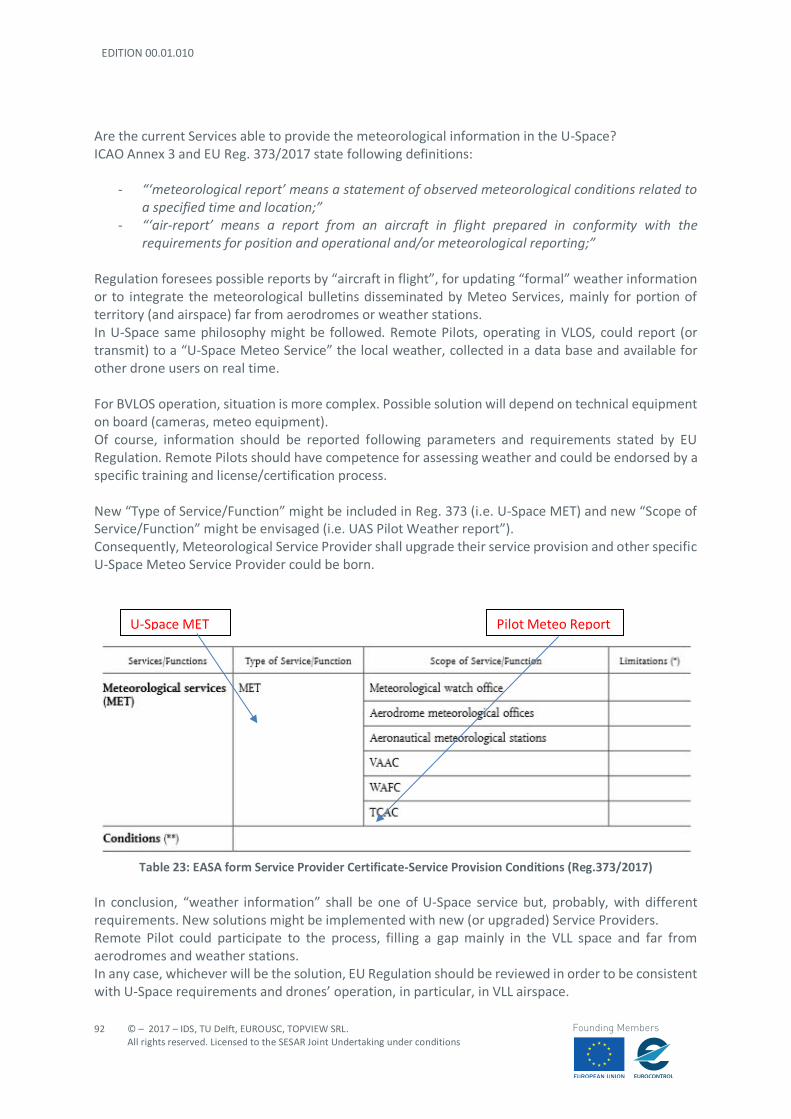
EDITION 00.01.010
92
© – 2017 – IDS, TU Delft, EUROUSC, TOPVIEW SRL. All rights reserved. Licensed to the SESAR Joint Undertaking under conditions
Founding Members
Are the current Services able to provide the meteorological information in the U-Space? ICAO Annex 3 and EU Reg. 373/2017 state following definitions:
- “‘meteorological report’ means a statement of observed meteorological conditions related to a specified time and location;”
- “‘air-report’ means a report from an aircraft in flight prepared in conformity with the requirements for position and operational and/or meteorological reporting;”
Regulation foresees possible reports by “aircraft in flight”, for updating “formal” weather information or to integrate the meteorological bulletins disseminated by Meteo Services, mainly for portion of territory (and airspace) far from aerodromes or weather stations. In U-Space same philosophy might be followed. Remote Pilots, operating in VLOS, could report (or transmit) to a “U-Space Meteo Service” the local weather, collected in a data base and available for other drone users on real time. For BVLOS operation, situation is more complex. Possible solution will depend on technical equipment on board (cameras, meteo equipment). Of course, information should be reported following parameters and requirements stated by EU Regulation. Remote Pilots should have competence for assessing weather and could be endorsed by a specific training and license/certification process. New “Type of Service/Function” might be included in Reg. 373 (i.e. U-Space MET) and new “Scope of Service/Function” might be envisaged (i.e. UAS Pilot Weather report”). Consequently, Meteorological Service Provider shall upgrade their service provision and other specific U-Space Meteo Service Provider could be born.
Table 23: EASA form Service Provider Certificate-Service Provision Conditions (Reg.373/2017)
In conclusion, “weather information” shall be one of U-Space service but, probably, with different requirements. New solutions might be implemented with new (or upgraded) Service Providers. Remote Pilot could participate to the process, filling a gap mainly in the VLL space and far from aerodromes and weather stations. In any case, whichever will be the solution, EU Regulation should be reviewed in order to be consistent with U-Space requirements and drones’ operation, in particular, in VLL airspace.
U-Space MET Pilot Meteo Report
© – 2017 – IDS, TU Delft, EUROUSC, TOPVIEW SRL. All rights reserved. Licensed to the SESAR Joint Undertaking under conditions
93
Founding Members
6.3 Interoperability of U-SPACE Service Providers
EU Regulation 552/2004 establishes essential requirements and implementing rules for interoperability of different systems, constituents and procedures of EATMN. The concept of interoperability should apply also to Air Navigation Services involved in UTM since this facilitates the coordinated and rapid introduction of new concept of operations or technologies in the air traffic management. The introduction of alternative decision-making processes, increasing automation and alternative methods of delegation of separation responsibility, shall be examined taking into account technological developments as well as their safe implementation. As essential requirements, U-Space traffic management systems and constituents shall be designed, built and maintained ensuring:
- seamless operations at all times and for all phases of flight; - safety of operations by defining a harmonised set of safety prescription; - minimum environmental impact according to Community Legislation.
In addition, new systems shall be designed ensuring a harmonised, flexible architecture, respecting the basic engineering principles of modularity, redundancy and interchangeability of the components. U-Space services assimilable to ATFM Systems for U-Space service assimilable to ATFM (e.g. Flight planning management and Strategic Deconfliction) shall provide strategic, pre-tactical and tactical information, with the aim to achieve an optimised (and safe) use of airspace. U-Space services assimilable to ATS Systems for U-Space service assimilable to ATS (e.g. Tactical Geofencing, Procedural Interface with ATC or Emergency Management) shall be interoperable in terms of the timely sharing of the information, and a common operational understanding of that information, to ensure a coherent and consistent planning process and coordination during all phases of flight. For instance, Tactical Geofencing, Emergency Management and Procedural Interface with ATC could be coupled and coordinated with Flight Planning Management. U-Space services assimilable to SUR Independently from the technology used, systems for U-Space service assimilable to SUR (e.g. Tracking) shall ensure the required performance and quality of service within a given environment with the aim to provide traffic information when requested. It is envisaged that Tracking could be also coupled with Tactical Geofencing when associating drone ID and position to an obstacle real time detection. U-Space services assimilable to MET Systems for U-Space service assimilable to MET (e.g. Weather information) information shall ensure the consistency and timeliness of its provision and the quality of its presentation, using an agreed data set (e.g. JPEG images or XML vectors). Such systems shall also ensure the promptness of service availability as well as the required speed with which they may be used.
EDITION 00.01.010
94
© – 2017 – IDS, TU Delft, EUROUSC, TOPVIEW SRL. All rights reserved. Licensed to the SESAR Joint Undertaking under conditions
Founding Members
U-Space services assimilable to AIS Systems for U-Space service assimilable to AIS (e.g. Pre-Tactical Geofencing) shall provide accurate, timely and consistent aeronautical information as well as “non- aeronautical” information, based on a commonly agreed and standardised data set. Increasingly accurate, complete and up-to-date information shall be made available and used in a timely manner in order to support safe operations in urban and rural environment. Non-aeronautical information may be provided by land-use authorities through interoperable interfaces, ensuring the same performance and safety requirements. As a final remark, the increase in automation shall be such as to enable coherent and efficient pre-tactical and tactical processing of flight information in different parts of the U-Space network which must be able to communicate among each other during all phases of flight. This is evident in those DREAMS scenarios where different services are interconnected among each other (e.g. in scenario 4 in which Tactical Geofencing is interfaced with Tracking, Flight planning management and Pre-Tactical Geofencing). Therefore, interoperability shall be ensured also among services belonging to different families (e.g. Tracking and Tactical Geofencing).
6.4 Performance Requirements
6.4.1 Introduction
The starting point is what established in the Commission Implementing Regulation 373/2017 Annex VIII Subpart A regarding to the common requirements of CNS service providers:
- “A communication, navigation or surveillance service shall ensure the availability, continuity, accuracy and integrity of their services”.
Unlike ANS providers for manned aviation, U-Space providers are expected to exchange aeronautical information with drone users through digital processes. Therefore, it is reasonable to extend this approach to the new U-Space services.
6.4.2 ICAO Reference Background
The continuing growth of aviation places increasing demands on airspace capacity and emphasizes the need for the optimum utilization of the available airspace. These factors, allied with the requirement for operational efficiency within acceptable levels of safety, have resulted in the need for a performance-based airspace system. The transition to a performance-based airspace system is a critical aspect of the evolution to a safe and efficient global air traffic management (ATM) environment. As ATM evolves, it will be necessary to ensure acceptable operational performance, taking into account changing technologies. The performance-based communication and surveillance (PBCS) concept provides objective operational criteria to evaluate different and emerging communication and surveillance technologies, intended for evolving air traffic management (ATM) operations (e.g. UTM).
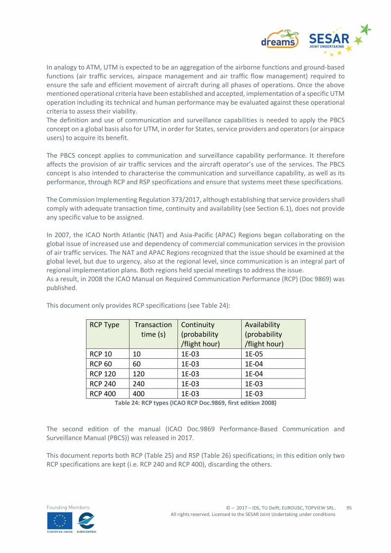
© – 2017 – IDS, TU Delft, EUROUSC, TOPVIEW SRL. All rights reserved. Licensed to the SESAR Joint Undertaking under conditions
95
Founding Members
In analogy to ATM, UTM is expected to be an aggregation of the airborne functions and ground-based functions (air traffic services, airspace management and air traffic flow management) required to ensure the safe and efficient movement of aircraft during all phases of operations. Once the above mentioned operational criteria have been established and accepted, implementation of a specific UTM operation including its technical and human performance may be evaluated against these operational criteria to assess their viability. The definition and use of communication and surveillance capabilities is needed to apply the PBCS concept on a global basis also for UTM, in order for States, service providers and operators (or airspace users) to acquire its benefit. The PBCS concept applies to communication and surveillance capability performance. It therefore affects the provision of air traffic services and the aircraft operator’s use of the services. The PBCS concept is also intended to characterise the communication and surveillance capability, as well as its performance, through RCP and RSP specifications and ensure that systems meet these specifications. The Commission Implementing Regulation 373/2017, although establishing that service providers shall comply with adequate transaction time, continuity and availability (see Section 6.1), does not provide any specific value to be assigned. In 2007, the ICAO North Atlantic (NAT) and Asia-Pacific (APAC) Regions began collaborating on the global issue of increased use and dependency of commercial communication services in the provision of air traffic services. The NAT and APAC Regions recognized that the issue should be examined at the global level, but due to urgency, also at the regional level, since communication is an integral part of regional implementation plans. Both regions held special meetings to address the issue. As a result, in 2008 the ICAO Manual on Required Communication Performance (RCP) (Doc 9869) was published. This document only provides RCP specifications (see Table 24):
RCP Type Transaction time (s)
Continuity (probability /flight hour)
Availability (probability /flight hour)
RCP 10 10 1E-03 1E-05 RCP 60 60 1E-03 1E-04 RCP 120 120 1E-03 1E-04 RCP 240 240 1E-03 1E-03 RCP 400 400 1E-03 1E-03
Table 24: RCP types (ICAO RCP Doc.9869, first edition 2008) The second edition of the manual (ICAO Doc.9869 Performance-Based Communication and Surveillance Manual (PBCS)) was released in 2017. This document reports both RCP (Table 25) and RSP (Table 26) specifications; in this edition only two RCP specifications are kept (i.e. RCP 240 and RCP 400), discarding the others.
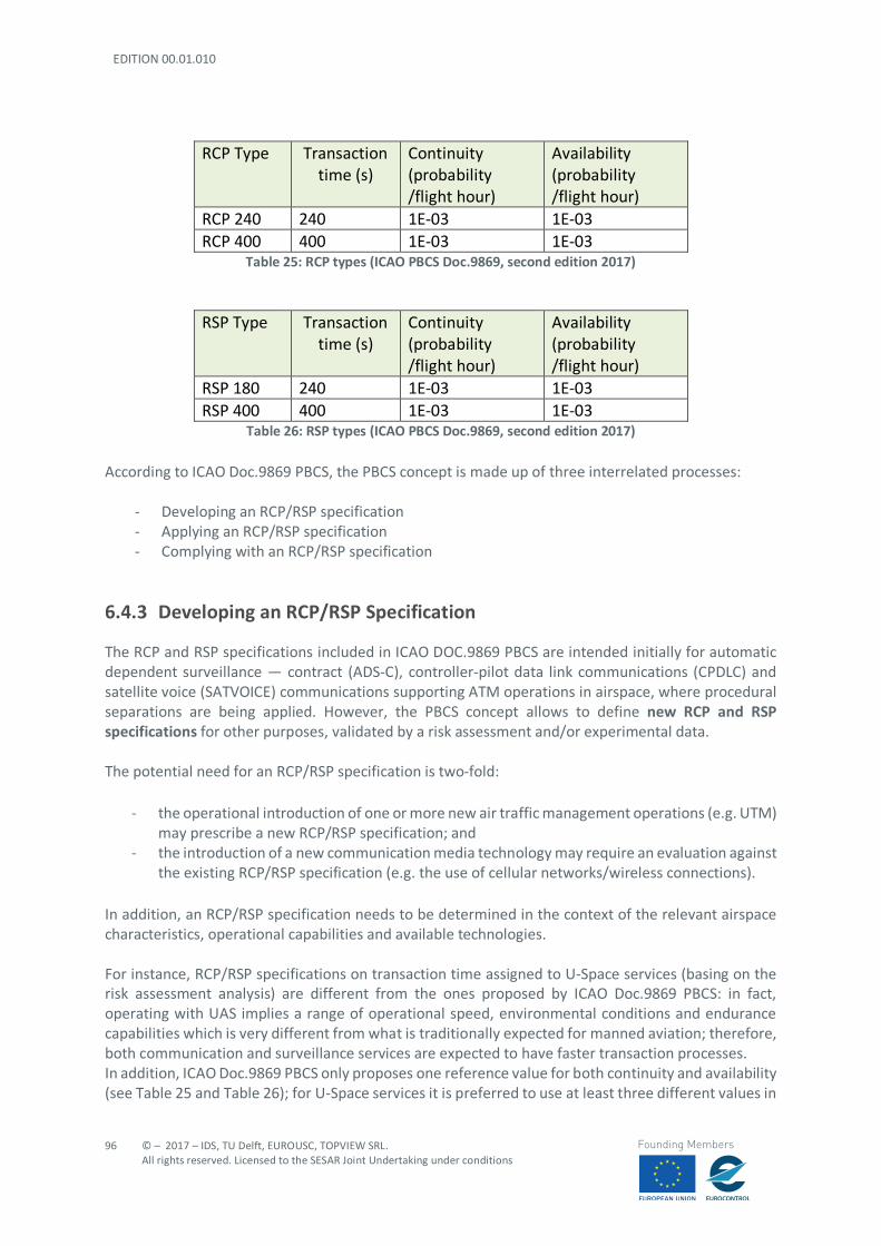
EDITION 00.01.010
96
© – 2017 – IDS, TU Delft, EUROUSC, TOPVIEW SRL. All rights reserved. Licensed to the SESAR Joint Undertaking under conditions
Founding Members
RCP Type Transaction time (s)
Continuity (probability /flight hour)
Availability (probability /flight hour)
RCP 240 240 1E-03 1E-03 RCP 400 400 1E-03 1E-03
Table 25: RCP types (ICAO PBCS Doc.9869, second edition 2017)
RSP Type Transaction
time (s) Continuity (probability /flight hour)
Availability (probability /flight hour)
RSP 180 240 1E-03 1E-03 RSP 400 400 1E-03 1E-03
Table 26: RSP types (ICAO PBCS Doc.9869, second edition 2017)
According to ICAO Doc.9869 PBCS, the PBCS concept is made up of three interrelated processes:
- Developing an RCP/RSP specification - Applying an RCP/RSP specification - Complying with an RCP/RSP specification
6.4.3 Developing an RCP/RSP Specification
The RCP and RSP specifications included in ICAO DOC.9869 PBCS are intended initially for automatic dependent surveillance — contract (ADS-C), controller-pilot data link communications (CPDLC) and satellite voice (SATVOICE) communications supporting ATM operations in airspace, where procedural separations are being applied. However, the PBCS concept allows to define new RCP and RSP specifications for other purposes, validated by a risk assessment and/or experimental data. The potential need for an RCP/RSP specification is two-fold:
- the operational introduction of one or more new air traffic management operations (e.g. UTM) may prescribe a new RCP/RSP specification; and
- the introduction of a new communication media technology may require an evaluation against the existing RCP/RSP specification (e.g. the use of cellular networks/wireless connections).
In addition, an RCP/RSP specification needs to be determined in the context of the relevant airspace characteristics, operational capabilities and available technologies. For instance, RCP/RSP specifications on transaction time assigned to U-Space services (basing on the risk assessment analysis) are different from the ones proposed by ICAO Doc.9869 PBCS: in fact, operating with UAS implies a range of operational speed, environmental conditions and endurance capabilities which is very different from what is traditionally expected for manned aviation; therefore, both communication and surveillance services are expected to have faster transaction processes. In addition, ICAO Doc.9869 PBCS only proposes one reference value for both continuity and availability (see Table 25 and Table 26); for U-Space services it is preferred to use at least three different values in
© – 2017 – IDS, TU Delft, EUROUSC, TOPVIEW SRL. All rights reserved. Licensed to the SESAR Joint Undertaking under conditions
97
Founding Members
order to better differentiate between “routine data”, “essential pre-flight data” and “essential in-flight data”. Finally, COM services (e.g. cellular networks) shall ensure adequate performance parameters to correctly support all U-Space services (both the less and the most demanding ones). The choice of new RCP/RSP specifications assigned to U-Space services (Section 5.5) is supported by a specific risk assessment for each scenario (see document Appendices).
6.4.4 Applying an RCP/RSP Specification
An RCP/RSP specification provides a globally standardised means to prescribe in the Aeronautical Information Publication (AIP) (or equivalent publication) the compliance criteria for communication and surveillance capabilities in the applicable airspace, supporting:
- approval of air navigation services providers (ANSP) for UTM operations that depend on RCP/RSP capabilities, including flight plan provisions and notifications of service;
- operational approval, including the relevant aircraft system to participate in UTM operations that depend on RCP/RSP capabilities;
- performance-based communication and surveillance (PBCS) monitoring programmes.
Applying an RCP/RSP specification to ANSP approval, operational approval and PBCS monitoring programmes provides a globally standardised means to ensure the communication system, within a particular airspace, meets applicable performance requirements initially and in continued operations. The State should prescribe the appropriate RCP/RSP specification for the communication and surveillance capability in the AIP (or equivalent publication) for the applicable airspace, as well as the implementation of:
- a new UTM operation predicated on communication and surveillance performance; or - any significant safety-related change to communication and surveillance capabilities.
When, as in this case, the appropriate RCP/RSP specification does not exist, the State should coordinate with ICAO to develop and publish the appropriate RCP/RSP specification in this manual. When prescribing the RCP/RSP specification in the AIP (or equivalent publication), the State should specify the following:
- applicable airspace or specific routes; - specific UTM operations; - the interoperability standards for communication and surveillance capabilities; - any limitations that may apply as a result of communication and/or surveillance infrastructure
constraints or specific communication and/or surveillance functionality requirements.42 When the State does not prescribe an RCP/RSP specification, the ANSP should apply the appropriate RCP/RSP specification to identify the continuing compliance criteria for PBCS monitoring programmes when employing new technology for communication and surveillance capabilities.
42 Limitations may apply to specific areas of operation (e.g. areas with a bad 4G signal coverage).
EDITION 00.01.010
98
© – 2017 – IDS, TU Delft, EUROUSC, TOPVIEW SRL. All rights reserved. Licensed to the SESAR Joint Undertaking under conditions
Founding Members
6.4.5 Complying with an RCP/RSP Specification
This section is addressed to the appropriate organizations to show initial compliance with RCP/RSP specifications for different system components and continued compliance at the operational level through PBCS monitoring programmes. Initial compliance provides a level of confidence that the system component will perform in accordance with its allocation provided by the RCP/RSP specification and will not compromise the overall performance of the operational system. Since the initial compliance for a system component is not exhaustive, the PBCS monitoring programmes provide a higher level of confidence that the operational system will continue to meet the RCP/RSP specification. Compliance to RCP/RSP specifications is performed as part of different approval types. The different approval types are:
- the ANSP approval, - aircraft operator approval depending on the category of operation; and - aircraft system approval.
These separate and distinct types of approvals collectively may define the conceptual “UTM system approval.”
6.4.5.1 ANSP APPROVAL When an RCP/RSP specification is prescribed, the State should ensure that the service provider establishes means to assess the actual performance of UTM services in an airspace prior to operational implementation of associated UTM operation (concept of “State oversight”). The ANSP should ensure that the following is in place for PBCS operations within UTM:
- an air traffic service system, comprising communication services, procedures, personnel training and qualification (if human), and service provision approval; and
- the establishment of local and regional PBCS monitoring programmes.
The ANSP should also ensure a validation process confirming that the system and its procedures meet capability and performance requirements, in order to support PBCS operations. This process should include:
- a system safety assessment, including a functional hazard analysis, demonstrating that the service provision meets the safety objectives;
- design evaluation, demonstrating that the air traffic system complies with the RCP/RSP specification by providing the necessary functionality, performance, human-machine interface, including controls, displays and alerts;
- integration testing and operational trials of sufficient duration, confirming interoperability, and that performance is acceptable for the UTM operation predicated on the RCP/RSP specification; and
- confirmation that air traffic services operation manuals are compatible with those of adjacent providers, where applicable;
© – 2017 – IDS, TU Delft, EUROUSC, TOPVIEW SRL. All rights reserved. Licensed to the SESAR Joint Undertaking under conditions
99
Founding Members
The ANSP should also ensure that its air traffic controllers (if humans43) receive appropriate training in accordance with ICAO Annex 1 [45]. The ANSP should establish the following, subject to a bilateral, multilateral or regional air navigation agreement, if applicable:
- a local PBCS monitoring programme, to ensure that the communication and surveillance capabilities in the airspace applicable to its air traffic service units continue to meet the RCP/RSP specification, and to coordinate monitored data, analysis and corrective action;
- in cooperation with the other ANSPs within the region, a regional PBCS monitoring programme to assess regional performance and exchange the results of PBCS monitoring programmes regionally and globally.
6.4.5.2 AIRCRAFT OPERATOR APPROVAL In accordance with the regulatory framework being developed by EASA, three categories of UAS operations have been identified:
- “Open” category (low risk) - “Specific” category (medium risk) - “Certified” category (high risk)
Regarding the “Open” category, the EU Draft Commission Delegated Regulation foresees that the UAS manufacturer shall provide a conformity assessment when placing on the market a new aircraft model belonging to one of the five UAS classes (C0-C4). The EU declaration of conformity shall be made according to specific conformity assessment modules provided by the EU. These requirements also apply to importers who intend their UAS to be operated in EU countries in the “open” category. For operations to be conducted in the “specific” class, it is also required that the operator performs a risk assessment unless holding a certificate with privileges (LUC) or complying with a standard scenario requiring only a declaration. Each risk assessment shall be accompanied by the required MoE (Means of Evidence): such evidences shall demonstrate that the aircraft is equipped with components/software which are able to interface with UTM services, ensuring compliance with the required RCP/RSP specifications.
6.4.5.3 AIRCRAFT SYSTEMS APPROVAL Regarding the aircraft approval for operations in “Open” and “Specific”, what already discussed in Section 6.4.5.2 applies. In the “certified” category the single aircraft shall be provided with a CofA (Certificate of Airworthiness). Concerning the aircraft equipment (e.g. systems for Electronic identification), for operations in any category, a European Technical Standard Order (ETSO) authorisation (based on ETSO published by
43 It is possible that U-Space controllers might be “BOT” entities instead of human beings. In this case training and qualification could be replaced by the concept of integrity (i.e. software assurance level, see Section 6.5.3.1).
EDITION 00.01.010
100
© – 2017 – IDS, TU Delft, EUROUSC, TOPVIEW SRL. All rights reserved. Licensed to the SESAR Joint Undertaking under conditions
Founding Members
EASA) could be issued, referring to Minimum Operational Performance Standards (MOPS) developed by a Standard Making Body (e.g. under development by EUROCAE WG 105).
6.5 Data Quality
6.5.1 Definition and General Requirements
The Commission Regulation 73/2010 provides the definition of “data quality”:
- “data quality means a degree or level of confidence that the provided data meets the user's data requirements in terms of accuracy, resolution, integrity (or equivalent assurance level), traceability, timeliness, completeness, and format”.
Article 6 of the same regulation also establishes44 that:
- “Member States shall ensure that air navigation service providers comply with the data quality requirements laid down in Annex IV, Part A”;
- “When providing aeronautical data and/or aeronautical information, the air navigation service providers shall comply with the evidence requirements laid down in Annex IV, Part B”;
In particular, Annex IV Part A defines the following data quality requirement for service providers:
- Accuracy and resolution of the data; - Integrity level of the data; - Ability to determine the origin of the data; - the level of assurance that data is made available to the next intended user prior to its effective
start date/time and not deleted before its effective end date/time. In addition, such data quality requirements shall be developed in accordance with a standardised process describing the methodology for the derivation and validation of these requirements. Part B of Annex IV underlines that evidence shall be generated by service providers in order to prove compliance with data quality requirements. Such requirements refer to traditional ANSP for manned aviation, but it is reasonable to expect their application to U-Space service providers.
6.5.2 Standards for Data Quality
Existing standards for data quality are provided by EUROCAE ED 76 in terms of accuracy, timeliness, traceability, completeness, resolution and format. EUROCAE ED 76 provides a recommended minimum standard for the processing of aeronautical data. This is applicable to all phases of the aeronautical data process, from origination to data exchange with the end-user.
44 Such requirement applies to U-Space service providers which will be included in Reg.373/2017.
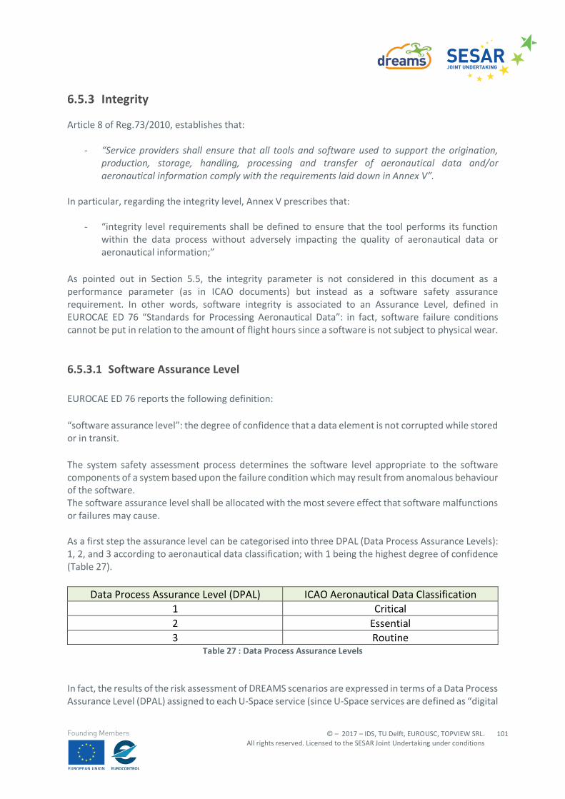
© – 2017 – IDS, TU Delft, EUROUSC, TOPVIEW SRL. All rights reserved. Licensed to the SESAR Joint Undertaking under conditions
101
Founding Members
6.5.3 Integrity
Article 8 of Reg.73/2010, establishes that:
- “Service providers shall ensure that all tools and software used to support the origination, production, storage, handling, processing and transfer of aeronautical data and/or aeronautical information comply with the requirements laid down in Annex V”.
In particular, regarding the integrity level, Annex V prescribes that:
- “integrity level requirements shall be defined to ensure that the tool performs its function within the data process without adversely impacting the quality of aeronautical data or aeronautical information;”
As pointed out in Section 5.5, the integrity parameter is not considered in this document as a performance parameter (as in ICAO documents) but instead as a software safety assurance requirement. In other words, software integrity is associated to an Assurance Level, defined in EUROCAE ED 76 “Standards for Processing Aeronautical Data”: in fact, software failure conditions cannot be put in relation to the amount of flight hours since a software is not subject to physical wear.
6.5.3.1 Software Assurance Level EUROCAE ED 76 reports the following definition: “software assurance level”: the degree of confidence that a data element is not corrupted while stored or in transit. The system safety assessment process determines the software level appropriate to the software components of a system based upon the failure condition which may result from anomalous behaviour of the software. The software assurance level shall be allocated with the most severe effect that software malfunctions or failures may cause. As a first step the assurance level can be categorised into three DPAL (Data Process Assurance Levels): 1, 2, and 3 according to aeronautical data classification; with 1 being the highest degree of confidence (Table 27).
Data Process Assurance Level (DPAL) ICAO Aeronautical Data Classification 1 Critical 2 Essential 3 Routine
Table 27 : Data Process Assurance Levels
In fact, the results of the risk assessment of DREAMS scenarios are expressed in terms of a Data Process Assurance Level (DPAL) assigned to each U-Space service (since U-Space services are defined as “digital
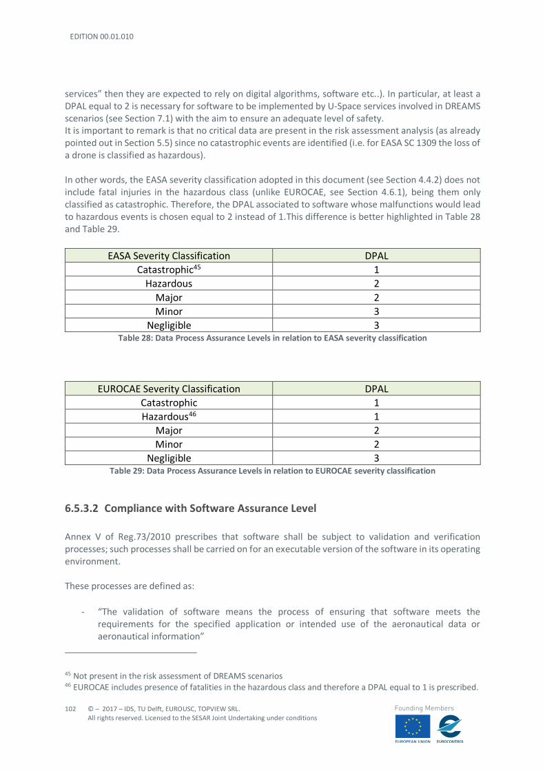
EDITION 00.01.010
102
© – 2017 – IDS, TU Delft, EUROUSC, TOPVIEW SRL. All rights reserved. Licensed to the SESAR Joint Undertaking under conditions
Founding Members
services” then they are expected to rely on digital algorithms, software etc..). In particular, at least a DPAL equal to 2 is necessary for software to be implemented by U-Space services involved in DREAMS scenarios (see Section 7.1) with the aim to ensure an adequate level of safety. It is important to remark is that no critical data are present in the risk assessment analysis (as already pointed out in Section 5.5) since no catastrophic events are identified (i.e. for EASA SC 1309 the loss of a drone is classified as hazardous). In other words, the EASA severity classification adopted in this document (see Section 4.4.2) does not include fatal injuries in the hazardous class (unlike EUROCAE, see Section 4.6.1), being them only classified as catastrophic. Therefore, the DPAL associated to software whose malfunctions would lead to hazardous events is chosen equal to 2 instead of 1.This difference is better highlighted in Table 28 and Table 29.
EASA Severity Classification DPAL Catastrophic45 1
Hazardous 2 Major 2 Minor 3
Negligible 3 Table 28: Data Process Assurance Levels in relation to EASA severity classification
EUROCAE Severity Classification DPAL Catastrophic 1 Hazardous46 1
Major 2 Minor 2
Negligible 3 Table 29: Data Process Assurance Levels in relation to EUROCAE severity classification
6.5.3.2 Compliance with Software Assurance Level Annex V of Reg.73/2010 prescribes that software shall be subject to validation and verification processes; such processes shall be carried on for an executable version of the software in its operating environment. These processes are defined as:
- “The validation of software means the process of ensuring that software meets the requirements for the specified application or intended use of the aeronautical data or aeronautical information”
45 Not present in the risk assessment of DREAMS scenarios 46 EUROCAE includes presence of fatalities in the hazardous class and therefore a DPAL equal to 1 is prescribed.
© – 2017 – IDS, TU Delft, EUROUSC, TOPVIEW SRL. All rights reserved. Licensed to the SESAR Joint Undertaking under conditions
103
Founding Members
- “The verification of software means the evaluation of the output of an aeronautical data and/or aeronautical information software development process to ensure correctness and consistency with respect to the inputs and applicable software standards, rules and conventions used in that process.
EUROCAE ED 76 provides acceptable means of compliance with the assigned assurance level. This can be done by means of:
- Validation techniques (e.g. validation by application, logical consistency, semantic
consistency); - Verification techniques (e.g.: digital error detection techniques, feedback, independent
redundancy, update comparison). Further details on how these techniques are applied can be found in EUROCAE ED 76. For assurance level 2 (assigned to software of U-Space services on the basis of a risk assessment analysis) validation by application is not required but only recommended. Logical and semantic consistency may also be used as components of the overall validation. Validation is typically accomplished by the originator of the data. Once the data is validated, verification techniques shall be used to ensure that the technical content of the data is not modified at any stage of the process.
6.5.4 Accuracy, Resolution and Data Format
EUROCAE ED 76 provides the following definition for accuracy and resolution:
- ‘Accuracy’: “The degree of conformance between the estimated or measured value and its true value”.
- Resolution’: “Means a number of units or digits to which a measured or calculated value is expressed and used”.
The required accuracy and resolution of a particular data element should be based upon its intended use. Accuracy and resolution only apply to data elements that are derived from measured values and are not specified for data elements which have a “defined” value (e.g. obstacle height is a measurable value whereas drone ID identification is a defined value). Since the resolution may also affect the accuracy of the data, it must be considered in relation to the accuracy requirement. Once the resolution is defined, it should be incorporated into the specified data format. The format of the data shall be adequate to ensure that the data, when loaded into the end application, is interpreted in a manner that is consistent with the intent of the data. Specifications in terms of accuracy and resolution are provided by ICAO for typical ANS involved in manned aviation. Specifications “ad hoc” for U-Space services might be developed where existing standards are not adequate. This may be due to:
- Different operational range for drones with respect to manned aviation: (e.g. drones may fly closer to terrain and obstacles and weather information should be provided “locally”); or
- Different technologies employed (e.g. new surveillance techniques, both cooperative and non-cooperative, hyperlocal wind measurements, use of cellular networks for service provision).
EDITION 00.01.010
104
© – 2017 – IDS, TU Delft, EUROUSC, TOPVIEW SRL. All rights reserved. Licensed to the SESAR Joint Undertaking under conditions
Founding Members
Data format should be chosen according to the expected amount of information to be transmitted. For instance, fast processes might require transmission of compressed data.
6.5.4.1 Compliance with Accuracy, Resolution and Data Format Requirements Reg. 73/2010 establishes that evidence shall be generated by service providers to show that they are compliant with accuracy and resolution requirements. These requirements must be in place in data origination process and maintained through to delivery to the next intended user. Guidance provided by EUROCAE ED 76 establishes that analysis of each U-Space service data process should be accomplished; for data originated locally (e.g. location of landing pads for emergency management), the analysis should include the accuracy and resolution of the process that originated and validated the data. For data not originated locally (e.g. weather information), the analysis shall consider the accuracy and resolution delivered from the preceding data supplier. It is to be noted that moving or storing data does not affect accuracy. Regarding the data format, procedures should ensure that the output data will comply with the specified format. Compliance is typically accomplished by qualification of the tool that generates the delivered product.
6.5.5 Completeness
EUROCAE ED 76 provides the following definition for completeness:
- ‘Completeness’: “the degree of confidence that all of the data needed to support the intended use is provided.”
Completeness includes the minimum acceptable set of data to perform the intended function. One set may be defined regarding those data provided by drone users for each specific service (e.g. submission of flight plan); a larger set may be identified for those data stored in a database and extrapolated by U-Space services when needed (e.g. flight plans stored and compared by Strategic Deconfliction algorithms or location of emergency landing pads). In some cases, database size limitations may restrict the total amount of data that can be stored. In this case, selection criteria can be used to reduce the total content. These selection criteria must be consistent with the operational requirements of the end-user (e.g. UAS deconfliction might take into account a “local” database containing only flight plans related to the specific area of operations). The data supplier may be the one who develops these criteria in order to meet system capacity constraints.
6.5.5.1 Compliance with Completeness Requirement Competencies of individuals who assemble data packages to be transmitted shall be assured. Tools or software that assemble or select data shall be qualified for this purpose and ensure that no data is inadvertently discarded.
© – 2017 – IDS, TU Delft, EUROUSC, TOPVIEW SRL. All rights reserved. Licensed to the SESAR Joint Undertaking under conditions
105
Founding Members
6.5.6 Timeliness
EUROCAE ED 76 provides the following definition for timeliness:
- ‘Timeliness’: “The degree of confidence that the data is applicable to the period of its intended use.”
Many data elements have an identified period for which the data is valid; the period of validity may be based upon an update period from the supplier or the underlying characteristics of the data itself. For example, Strategic Deconfliction service relies on a deconfliction algorithm which is based on the known flight plan stored in the database. Therefore, a de-conflict action notified to flight planning management could be valid only for a certain period of time since in the meanwhile other flight plans could be submitted, thus requiring a new de-conflict process.
6.5.6.1 Compliance with Timeliness Requirement Timeliness can be assured by defining a specific period of validity for each category of data. These limits may be associated with individual data elements or data sets. If the effective period is defined for a data set, it should account for the effective dates of all of the individual data elements.
6.5.7 Traceability
EUROCAE ED 76 provides the following definition for traceability:
- ‘Traceability’: “The ability to determine the origin of data”. An essential requirement is the need to validate and verify data. When data does not meet standard quality requirements it is necessary to determine the sources of the error so that corrective actions can be taken. To achieve this, data should be traceable to the supplier and to the end-user, and errors should be traceable to their root causes. In other words, the requirement for traceability extends from data origination to its final use. The aim of such requirement is to ensure that all detected errors can be traced back to their origin. In the U-Space context, it is fundamental that meteorological information (provided to drone users by Weather information service) are gathered from a reliable source. The same consideration is applicable to Pre-Tactical Geofencing service when checking the presence of restricted areas (e.g. by consulting an AIP), obstacles on the way, or events dealing with gathering of people. The latter point is a key point for the development of U-Space since aeronautical information (e.g. the ones provided by AIP) do not include information about concerts, streets demonstrations etc. and therefore sources other than aeronautical shall be taken into account. In addition, the data provision shall be “transparent” in the sense that possible anomalies can be traced back to their origin.
EDITION 00.01.010
106
© – 2017 – IDS, TU Delft, EUROUSC, TOPVIEW SRL. All rights reserved. Licensed to the SESAR Joint Undertaking under conditions
Founding Members
6.5.7.1 Compliance with Traceability Requirement External sources of information shall be qualified and evidence for those U-Space service providers relying on them shall be generated.
6.6 Robustness Requirement (SAIL)
6.6.1 General
The specific assurance and integrity level (SAIL) represents the “confidence” level that the envisaged operation will stay under control. This parameter, obtained in output from SORA, imposes a specific robustness level to be implemented for each proposed mitigation. In output from SORA it is obtained a maximum SAIL equal to IV for the examined scenarios. The mitigation involving safety requirements of U-Space providers is the one named in SORA “External services supporting UAS operations are adequate to the operation”. According to SAIL IV, this mitigation is required to have a high robustness level. This means that integrity of U-Space service providers shall be ensured by a competent third party. It is important to notice that, according to Reg.373/2017 Art. 6, ATM/ANS:
- “Service providers shall be granted a certificate and be entitled to exercise the privileges granted within the scope of that certificate”.
Therefore, it is reasonable to expect that U-Space service providers, although presenting different features with respect to the classical providers for manned aviation, shall be subject to a certification process too. Such certification process is a responsibility of national aviation authorities, but certification tasks could be allocated to qualified entities.
6.6.2 Qualified Entities
A competent third party can be associated to the concept of qualified entity. The definition of a qualified entity is provided in EU Regulation 216/2008:
- “qualified entity”: shall mean a body which may be allocated a specific certification task by, and under the control and the responsibility of, the Agency or a national aviation authority.
Article 13 of Reg.216/2008 establishes that, when allocating a certification task to a QE, the NAA/Agency shall ensure that such entity comply with the criteria defined in Annex V of the same regulation. Although a QE may be allocated with a certification task, in any case this entity shall not issue certificates. It is then evident that QE might be involved in the certification process of U-Space service providers. This trend is followed by the proposal for a regulation of the European parliament and of the Council (COM 613-2015 [46]) repealing the EU Reg.216/2008.
© – 2017 – IDS, TU Delft, EUROUSC, TOPVIEW SRL. All rights reserved. Licensed to the SESAR Joint Undertaking under conditions
107
Founding Members
It is here proposed that qualified entities may be granted a privilege to issue, amend, revoke, and suspend certificates or to receive declarations on behalf of the Agency or national competent authority. In addition, the principle of recognition of accreditations of qualified entities is introduced. Such recognition process does not require further evaluation or technical requirement to be proven. This is without prejudice to the rights of Member States to decide to which qualified entity they wish to allocate certification and oversight tasks. It is also proposed that Member States may accredit a qualified entity jointly. Nevertheless, this proposal does not provide guidance on the accreditation rules. To fill this gap a negotiation was held among EU Parliament, Council and Commission which led to the Political Agreement approved on 11/12/2017 [47]. In particular, Article 58 establishes that the accreditation process shall be carried on in accordance to what prescribed in Article 51 of the same document. As pointed out in Article 51, with regard to the tasks of the Agency related to certification:
- “the Commission is empowered to adopt delegated acts in accordance with Article 117 to lay down detailed rules concerning the conditions and procedures for the accreditation by the Agency of a qualified entity”.
- the Commission shall lay down, by means of implementing acts, adopted in accordance with the procedure referred to in Article 116(3), detailed provisions concerning the rules and procedures for the accreditation by the national competent authority of a qualified entity.
6.6.3 Advantages of using Qualified Entities
This section reports a list of advantages which may derive from the involvement of QEs in a certification task:
- Qualified Entity can take over work under the responsibility of EASA/NAA in case the latter have limited capacity;
- If EASA and/or NAA does not have the expertise to perform the mandatory obligations under EU/ICAO requirements, a Qualified Entity can provide the complementary expertise;
- Qualified Entities can operate close to national parties (NAA and Industry) and reduce language barriers;
- Qualified Entities can operate more efficiently and cost-effective and are therefore more attractive to be contracted by EASA, NAA’s and mainly directly by industry, to reduce the costs for the applicants;
- Qualified Entities with an EASA-certificate can operate throughout the EU and are not bound by national borders within the EU.
In conclusion:
- The burden on authority is reduced, since several assessments can be carried out by the QEs; - Safety is maintained since the QEs are under oversight by the authorities; and - No financial burden on authorities when QEs are contracted directly by the applicant.
EDITION 00.01.010
108
© – 2017 – IDS, TU Delft, EUROUSC, TOPVIEW SRL. All rights reserved. Licensed to the SESAR Joint Undertaking under conditions
Founding Members
6.7 Recommended Mitigations of U-SPACE Service Providers
6.7.1 Safety Management System of Service Providers
In accordance with Article 6 of EU Reg. 373/2017, Annex III establishes common requirements to be met by ANSP. At this level no distinction is made among the different areas of competence (e.g. ATM, CNS, AIS, etc..). Subpart B of Annex III establishes that:
- “a service provider shall ensure that it is able to provide its services in a safe, efficient, continuous and sustainable manner, consistent with any foreseen level of overall demand for a given airspace. To this end, it shall maintain adequate technical and operational capacity and expertise”.
In addition, “a service provider shall implement and maintain a management system”. Such system shall include:
- a description of the overall philosophies and principles of the service provider with regard to safety, quality, and security of its services, collectively constituting a policy, signed by the accountable manager;
- a process to identify changes within the service provider's organisation and the context in which it operates, which may affect established processes, procedures and services and, where necessary, change the management system and/or the functional system to accommodate those changes;
- U-Space service providers that could be assimilated into traditional providers for manned aviation (e.g. AIS, MET etc..) shall comply with Reg. 373/2017 SUBPART B by implementing a safety management policy.
It is important to notice that Regulation 373/2017, although establishing that all service providers shall implement a safety management, does not provide detailed information on specific risk mitigation strategies. The consequence is that each organisation may adopt any kind of mitigation strategies as long as it represents an effective and validated gain in safety. This document (see Section 7.1 or document Appendices) proposes a list of mitigations which could be implemented for each process involving U-Space services. Where necessary, most usual mitigations, once sufficient experience would have been accrued, could be published as Acceptable Means of Compliance/Guidance Material (AMC/GM) by EASA. This is allowed by Reg.373/2017 Annex III SUBPART A:
- “Alternative means of compliance to the AMC adopted by the Agency may be used by the service provider to establish compliance with the requirements of this Regulation”.
As already pointed out in section 6.2.1, it is not to be excluded that U-Space service providers may be designed with different features with respect to the existing providers for manned aviation. This may be due to a different type of “provided services” or to a completely different structure/organisation. It may happen that existing providers will evolve in new forms of providers with the aim to ensure, in a future perspective, safe and complete integration between drones and manned aircraft (this is very much in line with U4 philosophy).

© – 2017 – IDS, TU Delft, EUROUSC, TOPVIEW SRL. All rights reserved. Licensed to the SESAR Joint Undertaking under conditions
109
Founding Members
In this case the requirements laid down in Regulation 373/2017 could not be even suitable or sufficiently exhaustive to characterize the new providers; therefore, new requirements could be evaluated “ad hoc” for U-Space services and included in a new Annex (e.g. Annex XIV) of Reg.373/2017.
6.8 Liability Assessment in Contingency/Emergency Situations
The liability assessment can be performed only in presence of a regulation which prescribes specific privileges and responsibilities of all the actors involved in UAS operations. Traditionally, liability in manned aviation is distributed among:
- Pilot in Command - Aircraft Operator (i.e. the enterprise) - Manufacturers - Air Traffic Control - Others (flying schools; equipment manufacturers; aerodrome operators; maintenance etc...)
Usually damaged third parties almost call in front of the Civil Court the aircraft operator because:
- The operator is easily identifiable; - The operator has greater financial capability; - The operator almost certainly has part of the responsibility.
In the case of operations with unmanned aircraft, the identification of the operator is a key point to assess liability. This can be done by means of the U-Space Service Electronic Identification while the drone is flying; however, a plate on the aircraft identifying the operator should be always envisaged (e.g. immediately after a crash on the ground causing some damages). Regarding UAS operations, damages to third parties may occur due to several factors, for instance:
- Remote pilot negligence in performing adequate pre-flight check lists; - Remote pilot error in performing manoeuvres (including Observer errors in providing
information to Remote pilot); - Operator negligence in performing the envisaged maintenance/training activities; - Component failure (e.g. engine failure or lost C2 link) which may due either to contingencies
or errors in manufacturing process; - Unexpected external events (e.g. a drone struck by lightning or a bird); - Errors of U-Space controller (if human) whose role and liability are still to be clarified also in
relation to the classical air traffic controller for manned aviation. In some cases, UAS could share the airspace with manned aircraft, either in controlled airspace or uncontrolled airspace; in both situations, it would be important to define the liability boundaries between the ATC, the U-Space controller and the remote pilot/operator (and other “actors” involved in the operations) to ensure safe separation or, anyway, to avoid/minimise traffic conflicts. In any case regulation “ad hoc” defining UAS operator liability are still “work in progress”.
EDITION 00.01.010
110
© – 2017 – IDS, TU Delft, EUROUSC, TOPVIEW SRL. All rights reserved. Licensed to the SESAR Joint Undertaking under conditions
Founding Members
On the matter, EU Reg. 785/2004 [48] prescribes a mandatory insurance for aircraft operators defined in Article 3 as follows:
- “aircraft operator’ means the person or entity, not being an air carrier, who has continual effective disposal of the use or operation of the aircraft; the natural or legal person in whose name the aircraft is registered shall be presumed to be the operator, unless that person can prove that another person is the operator”.
Article 4 defines the principles of insurance for aircraft operators:
• Aircraft operators shall be insured in accordance with this Regulation as regards their aviation specific liability in respect of passengers, baggage, cargo and third parties. The insured risks shall include acts of war, terrorism, hijacking, acts of sabotage, unlawful seizure of aircraft and civil commotion.
At this stage, it must be kept in mind that passengers, baggage and cargo may not be relevant issues for operations with unmanned aircraft.47 This regulation does not apply to:
• State aircraft; • Model aircraft with a MTOM less than 20 kg; • Captive balloons, kites, etc...
It is important to underline that the definition of model aircraft is not provided in Regulation 785/2004; this gap is also highlighted in the report for the European parliament “Research for tran committee - safe integration of drones into airspace”[49]; this may represent a problem since operators in the open and specific category might escape the insurance obligation pretending that their drone is a model aircraft. It is recommended to provide a clear definition of model aircraft similar to the one contained in the Standardised European Rules of the Air (SERA):
- “model aircraft” means an unmanned aircraft, other than toy aircraft, having an operating mass not exceeding limits prescribed by the competent aviation authority, that is capable of sustained flight in the atmosphere and that is used exclusively for display or recreational activities;
The definition proposed in [49] is inspired from the previous one but takes into account the EASA prototype rules:
- “model aircraft” means an unmanned aircraft that is capable of sustained flight in the atmosphere and that is used exclusively for leisure flights, air displays, sport or competition activities.
The key point is that UAS are aircraft and, consequently, UAS operator shall rely on an insurance to cover financial risks.
47 Passengers might be relevant for future applications (e.g. taxi drone).In addition, cargo could be taken into account in mission dealing with delivery of goods.
© – 2017 – IDS, TU Delft, EUROUSC, TOPVIEW SRL. All rights reserved. Licensed to the SESAR Joint Undertaking under conditions
111
Founding Members
At the moment there are not sufficient data to demonstrate the actual damage caused by a UA. Therefore, at this stage, no specific rules for UAS are in force but, in the future, situation could probably be as follows:
- Operations in “certified” category with a traditional aviation insurance;
- Operations in “specific” category with an insurance contracted with general liability insurers (e.g. car insurers whose competencies could be extended to unmanned aircraft);
- Operations in “Open” category with a contract with private liability insurers (e.g. home insurers).
In addition, a “compensation fund” (as used in motor insurance) could be considered by the EU Commission. This fund might cover risks associated to drones which are not insured or operated without the consent of the owner. This way a minimum damage compensation could be provided to damaged third parties. Information on occurrences should be improved and made more widely available, including both insurers and operators so that insurance policy would be based on more reliable data and statistics. It is important to remark that Regulation 785/2004 does not prescribe to have an insurance with aviation insurance companies (i.e. implying a very high minimum coverage); consequently, operations in the specific category could be related to car insurers, thus requiring a lower minimum coverage since the risk is distributed over a wider range of third parties. In the U-Space an important role is played by service providers whose aim is to ensure the safe and efficient development of UAS operations. Differences with traditional ANSP may exist but it is reasonable to apply Regulation 373/2017 which prescribes a mandatory insurance for ANSP:
- “Air navigation services and air traffic flow management providers shall have in place arrangements to cover liabilities related to the execution of their tasks in accordance with the applicable law.
And:
- “The method employed to provide the cover shall be appropriate to the potential loss and damage in question, taking into account the legal status of the providers concerned and the level of commercial insurance cover available”
The idea is that insurance coverage of service providers shall be commensurate to the task they perform; in other words, the impact on safety of the provided information. In conclusion, even small unmanned aircraft might represent a risk for third parties either on the ground and in the air and such risks shall be adequately covered. Sooner or later drone “accidents” will happen since the level of risk cannot be reduced to zero. Therefore, the challenge is to find the balance between the appropriate safety level the UAS market growth (i.e. by limiting the number of UAS operations).
EDITION 00.01.010
112
© – 2017 – IDS, TU Delft, EUROUSC, TOPVIEW SRL. All rights reserved. Licensed to the SESAR Joint Undertaking under conditions
Founding Members
7 Conclusions
7.1 Safety assessment report
The SORA methodology (Section 4.2) and EASA risk matrix approach (Section 4.4) are applied to a number of DREAMS scenarios identified in D3.1, selected according to criteria specified in Section 2.2. SORA methodology basically treats the UTM architecture as possible forms of mitigation for Ground and Air risk, but specific possible failure condition affecting one of the several envisaged services in the U-Space are not considered. This gap is filled by the EASA risk matrix approach.
In particular, the risk assessment performed using the risk matrix approach considers as starting point the UML diagrams defining each phase of a scenario. Each phase is made up of several interrelated processes. At the end of the assessment the most demanding processes for each U-Space service are considered for the definition of performance and safety requirements, this way ensuring a conservative approach. In other words, it is obtained a set of performance parameters (i.e. transaction time, continuity, availability) in output from the risk assessment, applicable to each U-Space service and resulting safety requirements (alias mitigations and software design assurance level). The set of performance parameters allows to adopt a PBCS approach including specifications “ad hoc” for the UTM context. The potential need for the adoption of such approach is two-fold:
- the operational introduction of one or more new air traffic management operations (e.g. UTM) may prescribe a new RCP/RSP specification; and
- the introduction of a new communication media technology may require an evaluation against the existing RCP/RSP specification (e.g. the use of cellular networks/wireless connections).
In the future, appropriate validation tests will need to be conducted to evaluate whether the identified performance requirements (i.e. integrity, availability, continuity and transaction time) are consistent with U-Space environment. The results of the risk assessment, in terms of the most demanding performance and safety requirements, are summarised in Table 30and Table 31. The latter also reports the main outcome of SORA which is given in terms of SAIL, that is the level of confidence that the operation will stay under control. The complete analyses with SORA is carried on in Section A1 (scenario 2), Section B1 (scenario 4), Section C1 (scenario 5) and Section D1 (scenario 8). In particular for each analysis it is underlined the contribution of U-Space services in improving safety of operations. In addition, Table 32 reports a list of possible mitigations for each scenario with the aim to reduce the level of risk. Such mitigations are related to the UML processes investigated with the risk matrix approach; consequently, their aim is to mitigate failure conditions of U-Space services. Further details on the entire safety assessment for the selected DREAMS scenarios are presented in Appendices from 1 to 4.
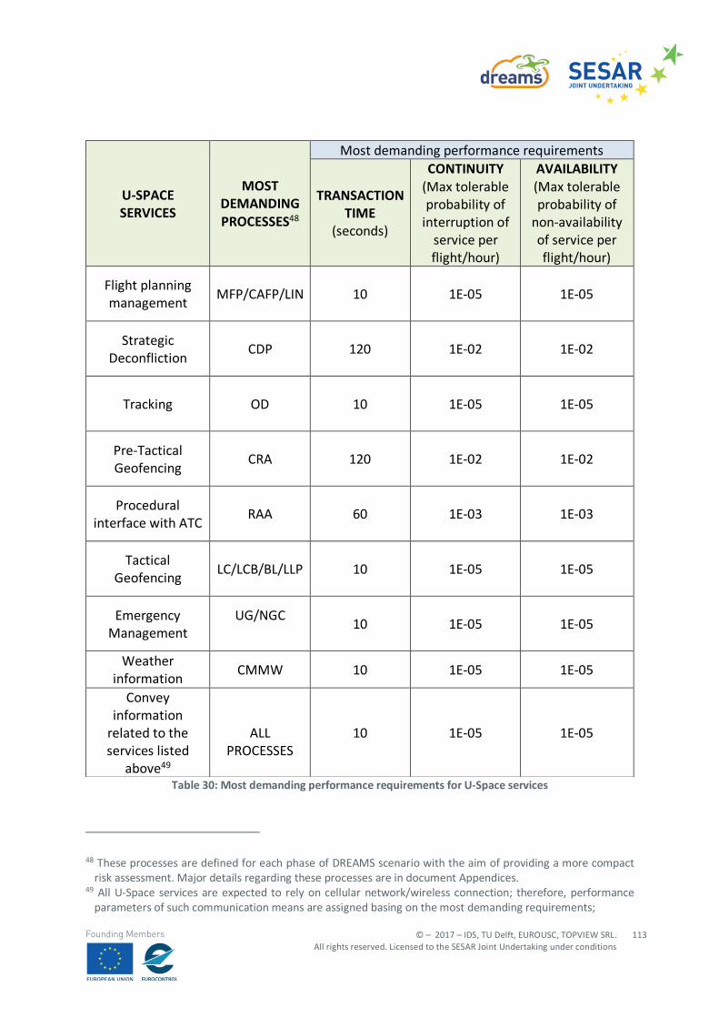
© – 2017 – IDS, TU Delft, EUROUSC, TOPVIEW SRL. All rights reserved. Licensed to the SESAR Joint Undertaking under conditions
113
Founding Members
Table 30: Most demanding performance requirements for U-Space services
48 These processes are defined for each phase of DREAMS scenario with the aim of providing a more compact
risk assessment. Major details regarding these processes are in document Appendices. 49 All U-Space services are expected to rely on cellular network/wireless connection; therefore, performance
parameters of such communication means are assigned basing on the most demanding requirements;
U-SPACE SERVICES
MOST DEMANDING PROCESSES48
Most demanding performance requirements
TRANSACTION TIME
(seconds)
CONTINUITY (Max tolerable probability of
interruption of service per flight/hour)
AVAILABILITY (Max tolerable probability of
non-availability of service per flight/hour)
Flight planning management
MFP/CAFP/LIN 10 1E-05 1E-05
Strategic Deconfliction
CDP 120 1E-02 1E-02
Tracking OD 10 1E-05 1E-05
Pre-Tactical Geofencing
CRA 120 1E-02 1E-02
Procedural interface with ATC
RAA 60 1E-03 1E-03
Tactical Geofencing
LC/LCB/BL/LLP 10 1E-05 1E-05
Emergency Management
UG/NGC
10 1E-05 1E-05
Weather information
CMMW 10 1E-05 1E-05
Convey information
related to the services listed
above49
ALL PROCESSES
10 1E-05 1E-05
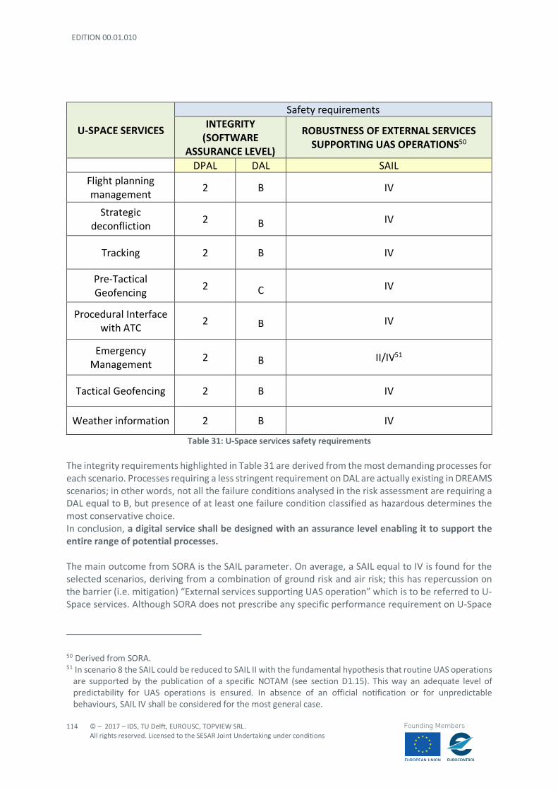
EDITION 00.01.010
114
© – 2017 – IDS, TU Delft, EUROUSC, TOPVIEW SRL. All rights reserved. Licensed to the SESAR Joint Undertaking under conditions
Founding Members
U-SPACE SERVICES
Safety requirements INTEGRITY
(SOFTWARE ASSURANCE LEVEL)
ROBUSTNESS OF EXTERNAL SERVICES SUPPORTING UAS OPERATIONS50
DPAL DAL SAIL Flight planning management
2 B IV
Strategic deconfliction
2
B IV
Tracking 2 B IV
Pre-Tactical Geofencing
2
C IV
Procedural Interface with ATC
2
B IV
Emergency Management
2
B II/IV51
Tactical Geofencing 2 B IV
Weather information 2 B IV
Table 31: U-Space services safety requirements The integrity requirements highlighted in Table 31 are derived from the most demanding processes for each scenario. Processes requiring a less stringent requirement on DAL are actually existing in DREAMS scenarios; in other words, not all the failure conditions analysed in the risk assessment are requiring a DAL equal to B, but presence of at least one failure condition classified as hazardous determines the most conservative choice. In conclusion, a digital service shall be designed with an assurance level enabling it to support the entire range of potential processes. The main outcome from SORA is the SAIL parameter. On average, a SAIL equal to IV is found for the selected scenarios, deriving from a combination of ground risk and air risk; this has repercussion on the barrier (i.e. mitigation) “External services supporting UAS operation” which is to be referred to U-Space services. Although SORA does not prescribe any specific performance requirement on U-Space
50 Derived from SORA. 51 In scenario 8 the SAIL could be reduced to SAIL II with the fundamental hypothesis that routine UAS operations
are supported by the publication of a specific NOTAM (see section D1.15). This way an adequate level of predictability for UAS operations is ensured. In absence of an official notification or for unpredictable behaviours, SAIL IV shall be considered for the most general case.
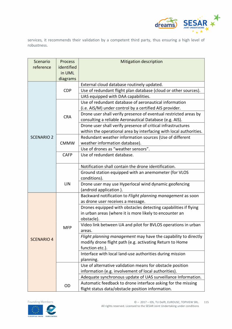
© – 2017 – IDS, TU Delft, EUROUSC, TOPVIEW SRL. All rights reserved. Licensed to the SESAR Joint Undertaking under conditions
115
Founding Members
services, it recommends their validation by a competent third party, thus ensuring a high level of robustness.
Scenario reference
Process identified
in UML diagrams
Mitigation description
SCENARIO 2
CDP External cloud database routinely updated. Use of redundant flight plan database (cloud or other sources). UAS equipped with DAA capabilities.
CRA
Use of redundant database of aeronautical information (i.e. AIS/M) under control by a certified AIS provider. Drone user shall verify presence of eventual restricted areas by consulting a reliable Aeronautical Database (e.g. AIS). Drone user shall verify presence of critical infrastructures within the operational area by interfacing with local authorities.
CMMW Redundant weather information sources (Use of different weather information database). Use of drones as “weather sensors”.
CAFP
Use of redundant database.
LIN
Notification shall contain the drone identification. Ground station equipped with an anemometer (for VLOS conditions). Drone user may use Hyperlocal wind dynamic geofencing (android application ).
SCENARIO 4
MFP
Backward notification to Flight planning management as soon as drone user receives a message. Drones equipped with obstacles detecting capabilities if flying in urban areas (where it is more likely to encounter an obstacle). Video link between UA and pilot for BVLOS operations in urban areas. Flight planning management may have the capability to directly modify drone flight path (e.g. activating Return to Home function etc.). Interface with local land-use authorities during mission planning.
OD
Use of alternative validation means for obstacle position information (e.g. involvement of local authorities). Adequate synchronous update of UAS surveillance Information. Automatic feedback to drone interface asking for the missing flight status data/obstacle position information.
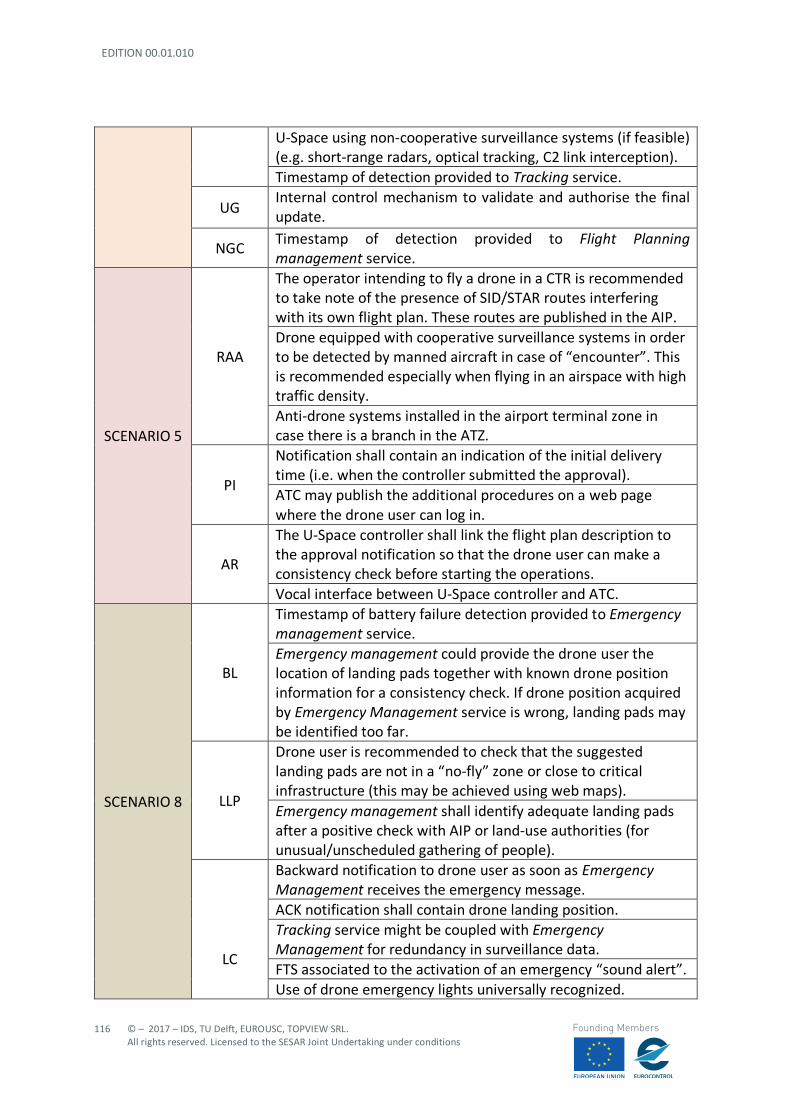
EDITION 00.01.010
116
© – 2017 – IDS, TU Delft, EUROUSC, TOPVIEW SRL. All rights reserved. Licensed to the SESAR Joint Undertaking under conditions
Founding Members
U-Space using non-cooperative surveillance systems (if feasible) (e.g. short-range radars, optical tracking, C2 link interception). Timestamp of detection provided to Tracking service.
UG Internal control mechanism to validate and authorise the final update.
NGC Timestamp of detection provided to Flight Planning management service.
SCENARIO 5
RAA
The operator intending to fly a drone in a CTR is recommended to take note of the presence of SID/STAR routes interfering with its own flight plan. These routes are published in the AIP. Drone equipped with cooperative surveillance systems in order to be detected by manned aircraft in case of “encounter”. This is recommended especially when flying in an airspace with high traffic density. Anti-drone systems installed in the airport terminal zone in case there is a branch in the ATZ.
PI
Notification shall contain an indication of the initial delivery time (i.e. when the controller submitted the approval). ATC may publish the additional procedures on a web page where the drone user can log in.
AR
The U-Space controller shall link the flight plan description to the approval notification so that the drone user can make a consistency check before starting the operations. Vocal interface between U-Space controller and ATC.
SCENARIO 8
BL
Timestamp of battery failure detection provided to Emergency management service. Emergency management could provide the drone user the location of landing pads together with known drone position information for a consistency check. If drone position acquired by Emergency Management service is wrong, landing pads may be identified too far.
LLP
Drone user is recommended to check that the suggested landing pads are not in a “no-fly” zone or close to critical infrastructure (this may be achieved using web maps). Emergency management shall identify adequate landing pads after a positive check with AIP or land-use authorities (for unusual/unscheduled gathering of people).
LC
Backward notification to drone user as soon as Emergency Management receives the emergency message. ACK notification shall contain drone landing position. Tracking service might be coupled with Emergency Management for redundancy in surveillance data. FTS associated to the activation of an emergency “sound alert”. Use of drone emergency lights universally recognized.
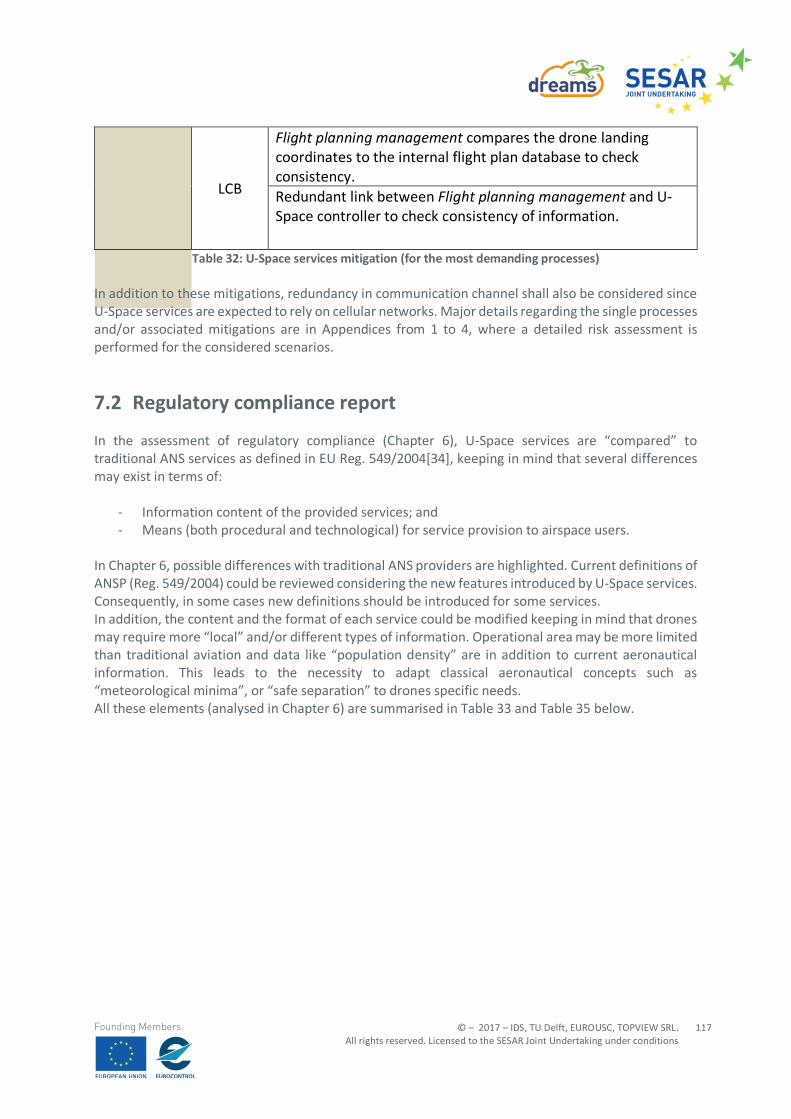
© – 2017 – IDS, TU Delft, EUROUSC, TOPVIEW SRL. All rights reserved. Licensed to the SESAR Joint Undertaking under conditions
117
Founding Members
LCB
Flight planning management compares the drone landing coordinates to the internal flight plan database to check consistency. Redundant link between Flight planning management and U-Space controller to check consistency of information.
Table 32: U-Space services mitigation (for the most demanding processes)
In addition to these mitigations, redundancy in communication channel shall also be considered since U-Space services are expected to rely on cellular networks. Major details regarding the single processes and/or associated mitigations are in Appendices from 1 to 4, where a detailed risk assessment is performed for the considered scenarios.
7.2 Regulatory compliance report
In the assessment of regulatory compliance (Chapter 6), U-Space services are “compared” to traditional ANS services as defined in EU Reg. 549/2004[34], keeping in mind that several differences may exist in terms of:
- Information content of the provided services; and - Means (both procedural and technological) for service provision to airspace users.
In Chapter 6, possible differences with traditional ANS providers are highlighted. Current definitions of ANSP (Reg. 549/2004) could be reviewed considering the new features introduced by U-Space services. Consequently, in some cases new definitions should be introduced for some services. In addition, the content and the format of each service could be modified keeping in mind that drones may require more “local” and/or different types of information. Operational area may be more limited than traditional aviation and data like “population density” are in addition to current aeronautical information. This leads to the necessity to adapt classical aeronautical concepts such as “meteorological minima”, or “safe separation” to drones specific needs. All these elements (analysed in Chapter 6) are summarised in Table 33 and Table 35 below.
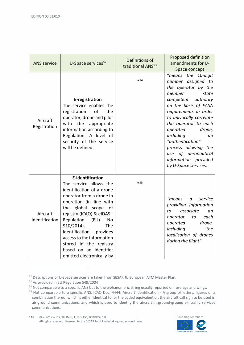
EDITION 00.01.010
118
© – 2017 – IDS, TU Delft, EUROUSC, TOPVIEW SRL. All rights reserved. Licensed to the SESAR Joint Undertaking under conditions
Founding Members
52 Descriptions of U-Space services are taken from SESAR JU European ATM Master Plan. 53 As provided in EU Regulation 549/2004 54 Not comparable to a specific ANS but to the alphanumeric string usually reported on fuselage and wings. 55 Not comparable to a specific ANS. ICAO Doc. 4444: Aircraft identification - A group of letters, figures or a
combination thereof which is either identical to, or the coded equivalent of, the aircraft call sign to be used in air-ground communications, and which is used to identify the aircraft in ground-ground air traffic services communications.
ANS service U-Space services52 Definitions of
traditional ANS53
Proposed definition amendments for U-
Space concept
Aircraft Registration
E-registration The service enables the registration of the operator, drone and pilot with the appropriate information according to Regulation. A level of security of the service will be defined.
*54
“means the 10-digit number assigned to the operator by the member state competent authority on the basis of EASA requirements in order to univocally correlate the operator to each operated drone, including an “authentication” process allowing the use of aeronautical information provided by U-Space services.
Aircraft Identification
E-identification The service allows the identification of a drone operator from a drone in operation (in line with the global scope of registry (ICAO) & eIDAS - Regulation (EU) No 910/2014). The identification provides access to the information stored in the registry based on an identifier emitted electronically by
*55
“means a service providing information to associate an operator to each operated drone, including the localisation of drones during the flight”
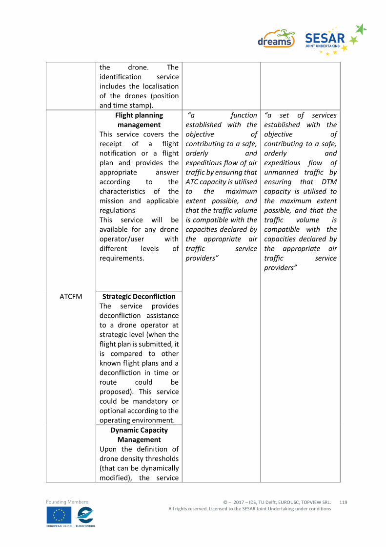
© – 2017 – IDS, TU Delft, EUROUSC, TOPVIEW SRL. All rights reserved. Licensed to the SESAR Joint Undertaking under conditions
119
Founding Members
the drone. The identification service includes the localisation of the drones (position and time stamp).
ATCFM
Flight planning management
This service covers the receipt of a flight notification or a flight plan and provides the appropriate answer according to the characteristics of the mission and applicable regulations This service will be available for any drone operator/user with different levels of requirements.
“a function established with the objective of contributing to a safe, orderly and expeditious flow of air traffic by ensuring that ATC capacity is utilised to the maximum extent possible, and that the traffic volume is compatible with the capacities declared by the appropriate air traffic service providers”
“a set of services established with the objective of contributing to a safe, orderly and expeditious flow of unmanned traffic by ensuring that DTM capacity is utilised to the maximum extent possible, and that the traffic volume is compatible with the capacities declared by the appropriate air traffic service providers”
Strategic Deconfliction The service provides deconfliction assistance to a drone operator at strategic level (when the flight plan is submitted, it is compared to other known flight plans and a deconfliction in time or route could be proposed). This service could be mandatory or optional according to the operating environment.
Dynamic Capacity Management
Upon the definition of drone density thresholds (that can be dynamically modified), the service
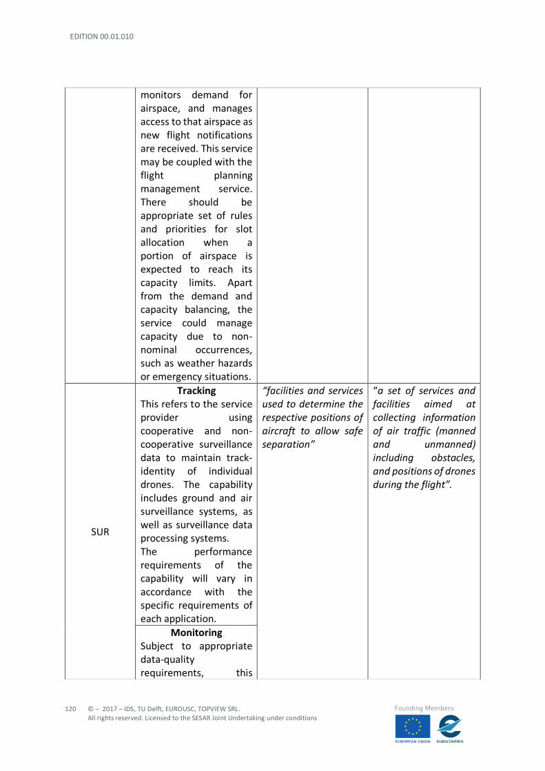
EDITION 00.01.010
120
© – 2017 – IDS, TU Delft, EUROUSC, TOPVIEW SRL. All rights reserved. Licensed to the SESAR Joint Undertaking under conditions
Founding Members
monitors demand for airspace, and manages access to that airspace as new flight notifications are received. This service may be coupled with the flight planning management service. There should be appropriate set of rules and priorities for slot allocation when a portion of airspace is expected to reach its capacity limits. Apart from the demand and capacity balancing, the service could manage capacity due to non-nominal occurrences, such as weather hazards or emergency situations.
SUR
Tracking This refers to the service provider using cooperative and non-cooperative surveillance data to maintain track-identity of individual drones. The capability includes ground and air surveillance systems, as well as surveillance data processing systems. The performance requirements of the capability will vary in accordance with the specific requirements of each application.
“facilities and services used to determine the respective positions of aircraft to allow safe separation”
“a set of services and facilities aimed at collecting information of air traffic (manned and unmanned) including obstacles, and positions of drones during the flight”.
Monitoring Subject to appropriate data-quality requirements, this
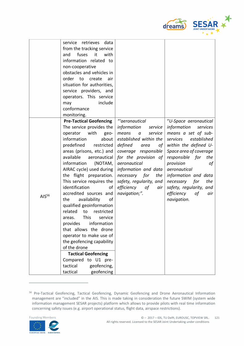
© – 2017 – IDS, TU Delft, EUROUSC, TOPVIEW SRL. All rights reserved. Licensed to the SESAR Joint Undertaking under conditions
121
Founding Members
56 Pre-Tactical Geofencing, Tactical Geofencing, Dynamic Geofencing and Drone Aeronautical Information
management are “included” in the AIS. This is made taking in consideration the future SWIM (system wide information management SESAR projects) platform which allows to provide pilots with real time information concerning safety issues (e.g. airport operational status, flight data, airspace restrictions).
service retrieves data from the tracking service and fuses it with information related to non-cooperative obstacles and vehicles in order to create air situation for authorities, service providers, and operators. This service may include conformance monitoring.
AIS56
Pre-Tactical Geofencing The service provides the operator with geo-information about predefined restricted areas (prisons, etc.) and available aeronautical information (NOTAM, AIRAC cycle) used during the flight preparation. This service requires the identification of accredited sources and the availability of qualified geoinformation related to restricted areas. This service provides information that allows the drone operator to make use of the geofencing capability of the drone
“‘aeronautical information service means a service established within the defined area of coverage responsible for the provision of aeronautical information and data necessary for the safety, regularity, and efficiency of air navigation;”.
“U-Space aeronautical information services means a set of sub-services established within the defined U-Space area of coverage responsible for the provision of aeronautical information and data necessary for the safety, regularity, and efficiency of air navigation.
Tactical Geofencing Compared to U1 pre-tactical geofencing, tactical geofencing
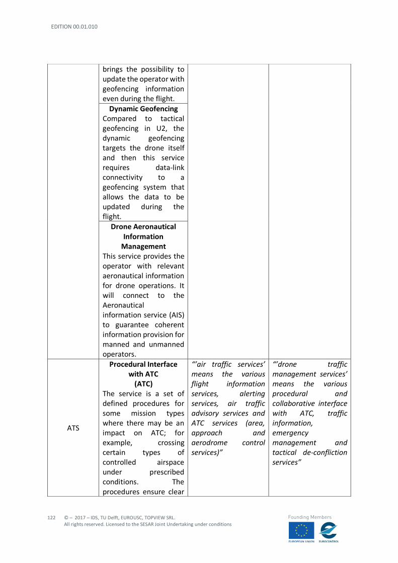
EDITION 00.01.010
122
© – 2017 – IDS, TU Delft, EUROUSC, TOPVIEW SRL. All rights reserved. Licensed to the SESAR Joint Undertaking under conditions
Founding Members
brings the possibility to update the operator with geofencing information even during the flight.
Dynamic Geofencing Compared to tactical geofencing in U2, the dynamic geofencing targets the drone itself and then this service requires data-link connectivity to a geofencing system that allows the data to be updated during the flight.
Drone Aeronautical Information
Management This service provides the operator with relevant aeronautical information for drone operations. It will connect to the Aeronautical information service (AIS) to guarantee coherent information provision for manned and unmanned operators.
ATS
Procedural Interface with ATC
(ATC) The service is a set of defined procedures for some mission types where there may be an impact on ATC; for example, crossing certain types of controlled airspace under prescribed conditions. The procedures ensure clear
“’air traffic services’ means the various flight information services, alerting services, air traffic advisory services and ATC services (area, approach and aerodrome control services)”
“’drone traffic management services’ means the various procedural and collaborative interface with ATC, traffic information, emergency management and tactical de-confliction services”
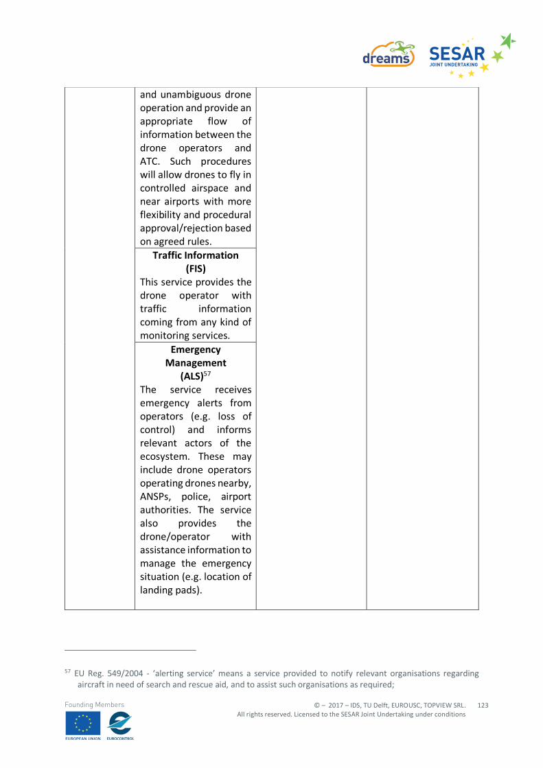
© – 2017 – IDS, TU Delft, EUROUSC, TOPVIEW SRL. All rights reserved. Licensed to the SESAR Joint Undertaking under conditions
123
Founding Members
57 EU Reg. 549/2004 - ‘alerting service’ means a service provided to notify relevant organisations regarding
aircraft in need of search and rescue aid, and to assist such organisations as required;
and unambiguous drone operation and provide an appropriate flow of information between the drone operators and ATC. Such procedures will allow drones to fly in controlled airspace and near airports with more flexibility and procedural approval/rejection based on agreed rules.
Traffic Information (FIS)
This service provides the drone operator with traffic information coming from any kind of monitoring services.
Emergency Management
(ALS)57 The service receives emergency alerts from operators (e.g. loss of control) and informs relevant actors of the ecosystem. These may include drone operators operating drones nearby, ANSPs, police, airport authorities. The service also provides the drone/operator with assistance information to manage the emergency situation (e.g. location of landing pads).
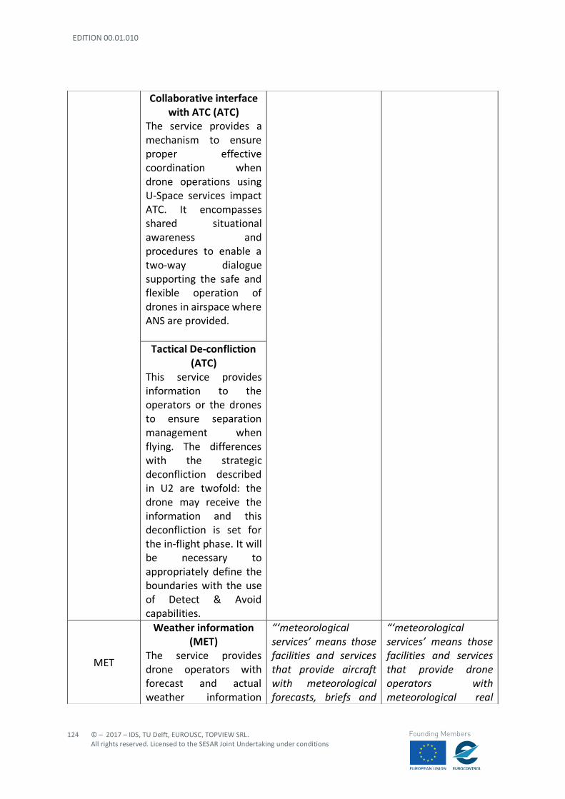
EDITION 00.01.010
124
© – 2017 – IDS, TU Delft, EUROUSC, TOPVIEW SRL. All rights reserved. Licensed to the SESAR Joint Undertaking under conditions
Founding Members
Collaborative interface with ATC (ATC)
The service provides a mechanism to ensure proper effective coordination when drone operations using U-Space services impact ATC. It encompasses shared situational awareness and procedures to enable a two-way dialogue supporting the safe and flexible operation of drones in airspace where ANS are provided.
Tactical De-confliction
(ATC) This service provides information to the operators or the drones to ensure separation management when flying. The differences with the strategic deconfliction described in U2 are twofold: the drone may receive the information and this deconfliction is set for the in-flight phase. It will be necessary to appropriately define the boundaries with the use of Detect & Avoid capabilities.
MET
Weather information (MET)
The service provides drone operators with forecast and actual weather information
“‘meteorological services’ means those facilities and services that provide aircraft with meteorological forecasts, briefs and
“‘meteorological services’ means those facilities and services that provide drone operators with meteorological real
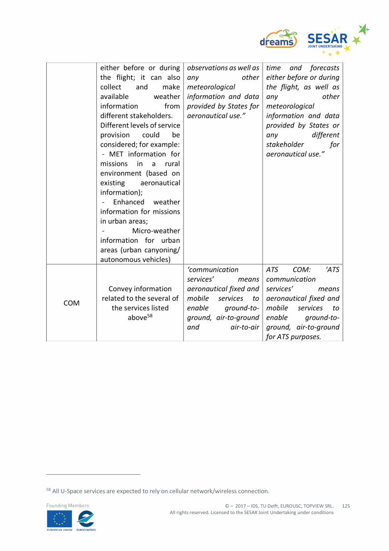
© – 2017 – IDS, TU Delft, EUROUSC, TOPVIEW SRL. All rights reserved. Licensed to the SESAR Joint Undertaking under conditions
125
Founding Members
58 All U-Space services are expected to rely on cellular network/wireless connection.
either before or during the flight; it can also collect and make available weather information from different stakeholders. Different levels of service provision could be considered; for example: - MET information for missions in a rural environment (based on existing aeronautical information); - Enhanced weather information for missions in urban areas; - Micro-weather information for urban areas (urban canyoning/ autonomous vehicles)
observations as well as any other meteorological information and data provided by States for aeronautical use.”
time and forecasts either before or during the flight, as well as any other meteorological information and data provided by States or any different stakeholder for aeronautical use.”
COM
Convey information related to the several of
the services listed above58
‘communication services’ means aeronautical fixed and mobile services to enable ground-to-ground, air-to-ground and air-to-air
ATS COM: ‘ATS communication services’ means aeronautical fixed and mobile services to enable ground-to-ground, air-to-ground for ATS purposes.
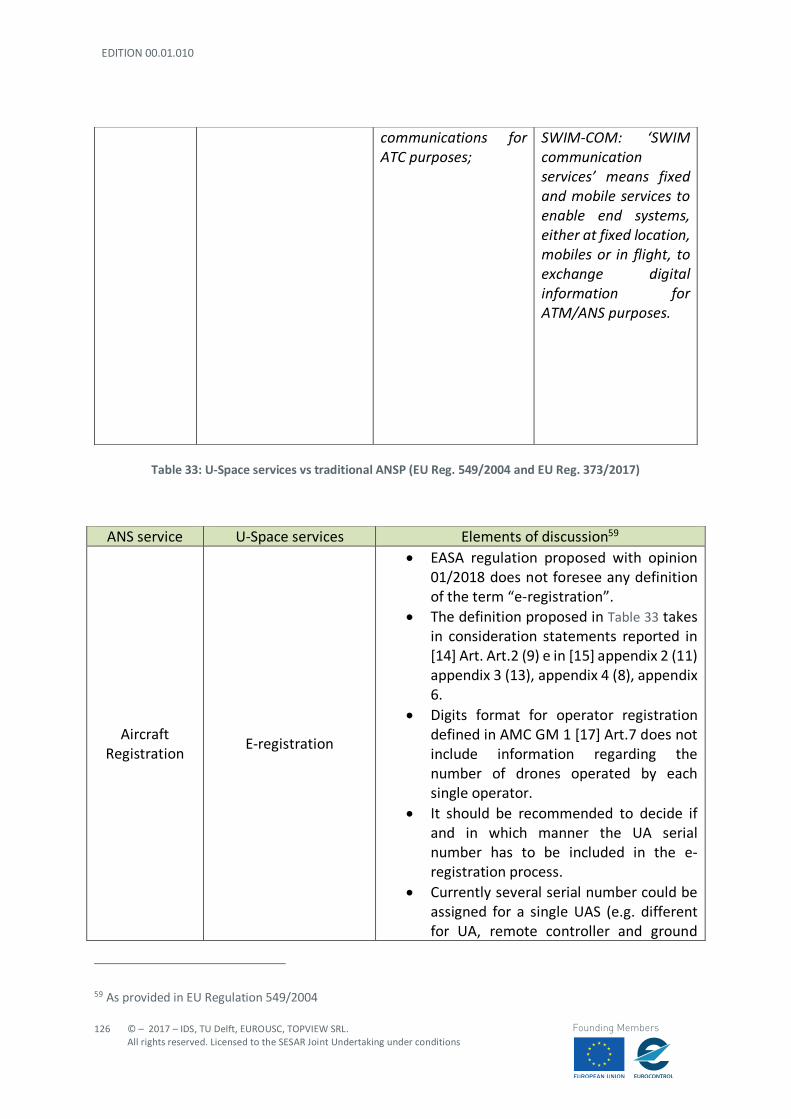
EDITION 00.01.010
126
© – 2017 – IDS, TU Delft, EUROUSC, TOPVIEW SRL. All rights reserved. Licensed to the SESAR Joint Undertaking under conditions
Founding Members
Table 33: U-Space services vs traditional ANSP (EU Reg. 549/2004 and EU Reg. 373/2017)
59 As provided in EU Regulation 549/2004
communications for ATC purposes;
SWIM-COM: ‘SWIM communication services’ means fixed and mobile services to enable end systems, either at fixed location, mobiles or in flight, to exchange digital information for ATM/ANS purposes.
ANS service U-Space services Elements of discussion59
Aircraft Registration
E-registration
• EASA regulation proposed with opinion 01/2018 does not foresee any definition of the term “e-registration”.
• The definition proposed in Table 33 takes in consideration statements reported in [14] Art. Art.2 (9) e in [15] appendix 2 (11) appendix 3 (13), appendix 4 (8), appendix 6.
• Digits format for operator registration defined in AMC GM 1 [17] Art.7 does not include information regarding the number of drones operated by each single operator.
• It should be recommended to decide if and in which manner the UA serial number has to be included in the e-registration process.
• Currently several serial number could be assigned for a single UAS (e.g. different for UA, remote controller and ground
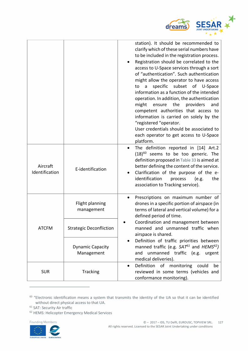
© – 2017 – IDS, TU Delft, EUROUSC, TOPVIEW SRL. All rights reserved. Licensed to the SESAR Joint Undertaking under conditions
127
Founding Members
60 “Electronic identification means a system that transmits the identity of the UA so that it can be identified
without direct physical access to that UA. 61 SAT: Security Air traffic 62 HEMS: Helicopter Emergency Medical Services
station). It should be recommended to clarify which of these serial numbers have to be included in the registration process.
• Registration should be correlated to the access to U-Space services through a sort of “authentication”. Such authentication might allow the operator to have access to a specific subset of U-Space information as a function of the intended operation. In addition, the authentication might ensure the providers and competent authorities that access to information is carried on solely by the “registered “operator. User credentials should be associated to each operator to get access to U-Space platform.
Aircraft Identification
E-identification
• The definition reported in [14] Art.2 (18)60 seems to be too generic. The definition proposed in Table 33 is aimed at better defining the content of the service.
• Clarification of the purpose of the e-identification process (e.g. the association to Tracking service).
ATCFM
Flight planning management
• Prescriptions on maximum number of drones in a specific portion of airspace (in terms of lateral and vertical volume) for a defined period of time.
• Coordination and management between manned and unmanned traffic when airspace is shared.
• Definition of traffic priorities between manned traffic (e.g. SAT61 and HEMS62) and unmanned traffic (e.g. urgent medical deliveries).
Strategic Deconfliction
Dynamic Capacity Management
SUR Tracking • Definition of monitoring could be
reviewed in some terms (vehicles and conformance monitoring).
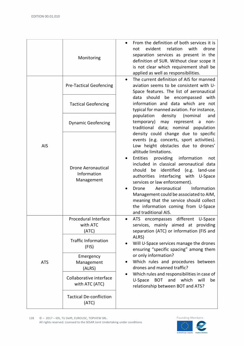
EDITION 00.01.010
128
© – 2017 – IDS, TU Delft, EUROUSC, TOPVIEW SRL. All rights reserved. Licensed to the SESAR Joint Undertaking under conditions
Founding Members
Monitoring
• From the definition of both services it is not evident relation with drone separation services as present in the definition of SUR. Without clear scope it is not clear which requirement shall be applied as well as responsibilities.
AIS
Pre-Tactical Geofencing • The current definition of AIS for manned
aviation seems to be consistent with U-Space features. The list of aeronautical data should be encompassed with information and data which are not typical for manned aviation. For instance, population density (nominal and temporary) may represent a non-traditional data; nominal population density could change due to specific events (e.g. concerts, sport activities). Low height obstacles due to drones’ altitude limitations.
• Entities providing information not included in classical aeronautical data should be identified (e.g. land-use authorities interfacing with U-Space services or law enforcement).
• Drone Aeronautical Information Management could be associated to AIM, meaning that the service should collect the information coming from U-Space and traditional AIS.
Tactical Geofencing
Dynamic Geofencing
Drone Aeronautical Information
Management
ATS
Procedural Interface with ATC
(ATC)
• ATS encompasses different U-Space services, mainly aimed at providing separation (ATC) or information (FIS and ALRS)
• Will U-Space services manage the drones ensuring “specific spacing” among them or only information?
• Which rules and procedures between drones and manned traffic?
• Which rules and responsibilities in case of U-Space BOT and which will be relationship between BOT and ATS?
Traffic Information (FIS)
Emergency Management
(ALRS)
Collaborative interface with ATC (ATC)
Tactical De-confliction (ATC)

© – 2017 – IDS, TU Delft, EUROUSC, TOPVIEW SRL. All rights reserved. Licensed to the SESAR Joint Undertaking under conditions
129
Founding Members
Table 34:Elements of discussion for the definition of U-Space service providers
63 All U-Space services are expected to rely on cellular network/wireless connection.
MET Weather information
(MET)
• More local weather information required for drone operations (e.g. urban canyons)
• Since U-Space foresees different levels of weather information, this might require new definitions, for instance, as follows:
o MET information means… o Enhanced weather information
means… o Micro-weather information
means… • Technologies enabling acquisition of local
meteorological conditions are existing (e.g. hyperlocal wind measurements) but economic effort could be unsustainable for territory capillary diffusion.
• Definition of VMC and IMC minima for VLOS and BVLOS operations. For instance, the current VMC minima (see Figure 11 could not be suitable for drone operations. Different values need to be defined.
• Micro-weather information (i.e. relative to very reduced portions of territory) could be provided by remote pilots operating in VLOS or automatic systems installed on UA in BVLOS (e.g. UAS pilot weather report).
• UAS seen as meteorological “sensors”
COM Convey information
related to the services listed above63
• Use of cellular networks for information exchange in the U-Space.
• Are current networks able to ensure the required level of performance?
• Adequate coverage of cellular network (e.g. urban/rural areas??
• 4G/5G LTE might be used also for C2 link. • Will traditional ANSP be able to provide
cellular networks or new service providers are expected to be involved?
EDITION 00.01.010
130
© – 2017 – IDS, TU Delft, EUROUSC, TOPVIEW SRL. All rights reserved. Licensed to the SESAR Joint Undertaking under conditions
Founding Members
For regulation purposes, different options may be envisaged to define requirements of Service Providers in the U-Space:
- Option A: making of regulations for quality of service but no formal requirement on service providers;
- Option B: inclusion of U-Space service providers in EU Regulation 373/2017; - Option C: making of new specific regulation on U-Space service providers.
However, option A does not seem a sufficiently safe solution due to high SAIL derived from SORA. In fact, SAIL IV requires external service providers to be validated by a competent third party. Option B looks like the more affordable. Inclusion of U-Space service providers in EU Regulation 373/2017 implies that such providers shall be subject to a certification process in which some tasks could be performed by independent Qualified Entities (being this option also supported by SORA). On the other hand, option C is not in line with article 2.2 (c) of regulation 216/200864 “to promote cost-efficiency in the regulatory and certification processes and to avoid duplication at national and European level”; because traditional ANS providers would be subject to a double regime for oversight. In any case Qualified Entities could perform some certification tasks even if new regulations are adopted for the U-Space. Gaps with existing ANSP may be filled by introducing new Annex/Annexes in the current regulation or foreseeing a new “ad hoc” U-Space regulation. Furthermore, Service Providers in the U-Space could be certified by national (or EU) competent Authority and/or “approved” by qualified agencies (i.e. QE – Qualified Entities). Qualified entities may be also involved in auditing /training processes of U-Space service providers. Regarding the liability assessment, the main results of the study are the following:
- In States with a strict liability regime, the party liable for damage is generally the operator. - Since RPAS are aircraft, operators are required by Regulation 785/2004 to have insurance for
third party liability otherwise their assets would be liquidated to compensate the victims; - A definition of model aircraft should be provided in Reg.785/2004 since these aircraft are not
required to be insured. - A “compensation fund" could be considered to cover damages caused by non-insured drones; - Operator insurance might be stipulated with general liability insurers (e.g. car insurers),
leading to a lower minimum coverage with respect to traditional aviation insurance. - Reasonably, U-Space service providers are expected to have an insurance (like traditional
ANSP according to Reg.373/2017) which shall be proportionate to the task they perform (e.g. the impact on safety of the provided information).
The last bullet is a further element of support for the inclusion of U-Space service providers in EU Regulation 373/2017. Another element of discussion is to determine who will provide U-Space services; we could have a specific U-Space service provided by:
64 EU Reg. 216/2008, Art 2, (c)
© – 2017 – IDS, TU Delft, EUROUSC, TOPVIEW SRL. All rights reserved. Licensed to the SESAR Joint Undertaking under conditions
131
Founding Members
- Traditional ANSP only; or - Traditional ANSP and other new providers; or - New service providers only.
From the analysis of DREAMS scenarios, it is evident that most U-Space services are interconnected among each other; in fact, services belonging to different families (e.g. Tactical Geofencing and Flight Planning Management) are expected to share different types of information. In any case all services have necessity to get access to aeronautical information or other data in order to ensure an efficient and safe support to UAS operations. As a result of the study, some U-Space services will require information in addition to classical aeronautical data; the diffusion of all these data might then lead to the introduction of new providers. Furthermore, all the providers involved in the U-Space should be able to interoperate in the same network. In a future perspective, this concept of interoperability should be extended with the aim to integrate U-Space providers and classical providers for manned aviation. This is a key point for the complete integration of UAS and manned traffic in the U-Space. In conclusion, U-Space is rapidly coming. Development and production of new and more performing technology is a key-point of U-Space realisation. But technology needs to be applied by specific Service Providers in a “suitable” regulation framework. New services are coming for U-Space and new Service Providers might be part of the UTM; Authorities could be supported in this process by new “actors” like the Qualified Entities. Finally, current regulation should be updated, and new rules could be implemented.
EDITION 00.01.010
132
© – 2017 – IDS, TU Delft, EUROUSC, TOPVIEW SRL. All rights reserved. Licensed to the SESAR Joint Undertaking under conditions
Founding Members
8 References
[1] ER DREAMS - D3.1 Scenarios identification and requirement analysis [2] JARUS guidelines on SORA v1.1 [3] EASA Pre-Regulatory Impact Assessment [4] EASA NPA 5/2017 [5] ICAO Annex 6 “Operation of Aircraft” [6] EU Regulation 216/2008 “on common rules in the field of civil aviation and establishing a
European Aviation Safety Agency” [7] EASA (2016), Prototype Commission Regulation on Unmanned Aircraft Operations [8] EASA Opinion 01/2018 [9] REAL CONOPS [10]ICAO Doc.9859 Safety Management Manual [11]EUROCONTROL SAFETY REGULATORY REQUIREMENT (ESARR 4) [12]EUROCAE ED 78 A “GUIDELINES FOR APPROVAL OF THE PROVISION AND USE OF AIR TRAFFIC
SERVICES SUPPORTED BY DATA COMMUNICATIONS “ [13]EASA NPA 10/2015 [14]EU Regulation for “laying down rules and procedures for the operation of unmanned aircraft” [15]EU delegated Regulation “on making available on the market of unmanned aircraft intended
for use in the ‘open’ category and on third-country UAS operators” [16]EASA Annex “UAS operations in the ‘open’ and ‘specific’ categories [PART-UAS]” [17]EASA AMC/GM [18]EU Reg, 923/2012 (SERA – Standardised European Rules of the Air) [19]ICAO Annex 2 “Rules of the air” [20]ICAO Annex 11 “Air Traffic Services” [21]ICAO Annex 15 “Aeronautical Information Services” [22]EUROCAE ED-79A “Guidelines for development of civil aircraft and systems “ [23]SORA ANNEX B “Harm Barriers” [24]SORA ANNEX C “Strategic Mitigation Collision Risk Assessment” [25]SORA ANNEX D “Tactical Mitigation Collision Risk Assessment” [26]SORA ANNEX E “Threat Barriers” [27]EASA SC-RPAS 1309 [28]EUROCAE ED 120 “safety and performance requirements standard for air traffic data link
services in continental airspace (continental SPR standard)” [29]EUROCAE ED 122 “safety and performance standard for air traffic datalink services in oceanic
and remote airspace (oceanic SPR standard)” [30]European ATM Master Plan: roadmap for the safe integration of drones into all classes of
airspace [31]ICAO Doc.9869 Performance-Based Communication and Surveillance Manual (PBCS), Second
Edition 2017 [32]ICAO Doc.9869 Manual on Required Communication Performance (RCP) [33]EUROCAE ED 76 “Standards for processing aeronautical data” [34]EU Regulation 549/2004 “laying down the framework for the creation of the single European
sky” [35]EU Regulation 552/2004 “on the interoperability of the European Air Traffic Management
network”
© – 2017 – IDS, TU Delft, EUROUSC, TOPVIEW SRL. All rights reserved. Licensed to the SESAR Joint Undertaking under conditions
133
Founding Members
[36]EU Regulation 550/2004 “on the provision of air navigation services in the single European sky”
[37]EU Regulation 551/2004 “on the organisation and use of the airspace in the single European sky”
[38]EU Regulation 73/2010 “laying down requirements on the quality of aeronautical data and aeronautical information for the single European sky”
[39]EU Regulation 255/2010 “laying down common rules on air traffic flow management” [40]EU Regulation 373/2017 “laying down common requirements for providers of air traffic
management/air navigation services” [41]ICAO Annex 3 “Meteorological Services for Internal Air Navigation” [42]ICAO Doc. 4444 “Air Traffic Management” [43]ICAO Doc. 10019 “Manual on RPAS” [44]ICAO Doc. 9161 “Manual on Air Navigation Services” [45]ICAO Annex 1 “Personnel Licensing” [46]Proposal for a Regulation of the European Parliament and of the Council “on common rules in
the field of civil aviation” [47]Political Agreement 11/12/2017 [48]EU Regulation 785/2004 [49]Research for TRAN committee - safe integration of drones into airspace

EDITION 00.01.010
134
© – 2017 – IDS, TU Delft, EUROUSC, TOPVIEW SRL. All rights reserved. Licensed to the SESAR Joint Undertaking under conditions
Founding Members
Appendix A – Risk Assessment of Scenario 2: “concurrent operations”
A.1 Risk assessment with SORA methodology The SORA methodology (v1.1) is fully applied to this scenario, with the aim to:
- Evaluating both Ground and Air Risk; - Identifying some general requirements in terms of required barriers (mitigations) and
robustness, which are the output of SORA.
However, it should be noted that:
- No Means of Evidence (MoE) are contained in this deliverable, since the assessment is generic for several scenarios;
- Consequently, the operator or service provider using this generic assessment in the future, should complete it (i.e. SORA Step #11 and STEP # 12, see Section 4.2.17 and Section 4.2.18);
- the air risk evaluation based on v1.1 of SORA is not sufficient, as already highlighted in Section 4.2.6, to cover all the potential hazards associated to concurrent UAS operations;
- therefore, in this deliverable, SORA is complemented by the more flexible risk-matrix approach (based on EASA example).
A.1.1 STEP #0 INITIAL EVALUATION In this preliminary step, the operator/applicant is tasked to verify that the proposed operation is feasible, not subject to specific exclusions from the local authority or subject to a standard scenario. Things to verify include:
- If the operation can be covered under a “standard scenario” recognized by the local authority; - If the operation falls under the “open” category; - If the operation is subject to specific NO-GO from local authority; - If the local authority has determined that the UAS is “harmless” for both ground and air risk. -
Upon completion of this preliminary check, the operator/applicant will start the SORA process if none of the previous cases applies. For the present scenario it is assumed that the envisaged operations are compliant with local regulations and that none of the previous point is verified.
A.1.2 STEP #1 CONOPS DESCRIPTION
A1.2.1 INTENDED OPERATIONS
Three UAS are involved in concurrent operations in the same uncontrolled airspace. The first UAS is a rotary wing UAS (quad-copter) involved in one inspection mission over a large rooftop in VLOS condition; the area of operations is at the limits of an urban area. The second UAS is a fixed wing drone involved in a mapping (site scanning) operation for the construction of a new site in a suburban/rural area. The third UAS is a heavy lift aerial filming platform (hex-copter) used for aerial filming production in VLOS conditions in industrial area. The UAS starts at different locations, in particular the heavy lift drone starts from the rooftop of a nearby industrial building for filming production reasons.
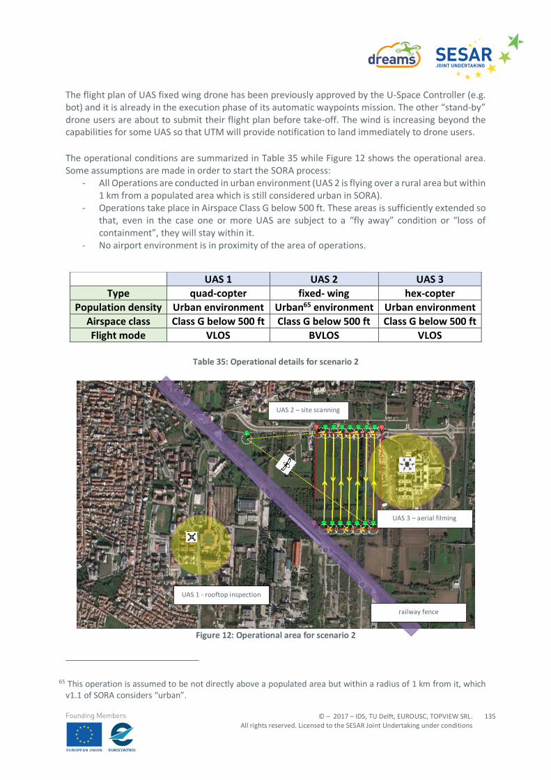
© – 2017 – IDS, TU Delft, EUROUSC, TOPVIEW SRL. All rights reserved. Licensed to the SESAR Joint Undertaking under conditions
135
Founding Members
The flight plan of UAS fixed wing drone has been previously approved by the U-Space Controller (e.g. bot) and it is already in the execution phase of its automatic waypoints mission. The other “stand-by” drone users are about to submit their flight plan before take-off. The wind is increasing beyond the capabilities for some UAS so that UTM will provide notification to land immediately to drone users. The operational conditions are summarized in Table 35 while Figure 12 shows the operational area. Some assumptions are made in order to start the SORA process:
- All Operations are conducted in urban environment (UAS 2 is flying over a rural area but within 1 km from a populated area which is still considered urban in SORA).
- Operations take place in Airspace Class G below 500 ft. These areas is sufficiently extended so that, even in the case one or more UAS are subject to a “fly away” condition or “loss of containment”, they will stay within it.
- No airport environment is in proximity of the area of operations.
Table 35: Operational details for scenario 2
Figure 12: Operational area for scenario 2
65 This operation is assumed to be not directly above a populated area but within a radius of 1 km from it, which v1.1 of SORA considers “urban”.
UAS 1 UAS 2 UAS 3 Type quad-copter fixed- wing hex-copter
Population density Urban environment Urban65 environment Urban environment Airspace class Class G below 500 ft Class G below 500 ft Class G below 500 ft Flight mode VLOS BVLOS VLOS
UAS 2 – site scanning
UAS 1 - rooftop inspection
railway fence
UAS 3 – aerial filming
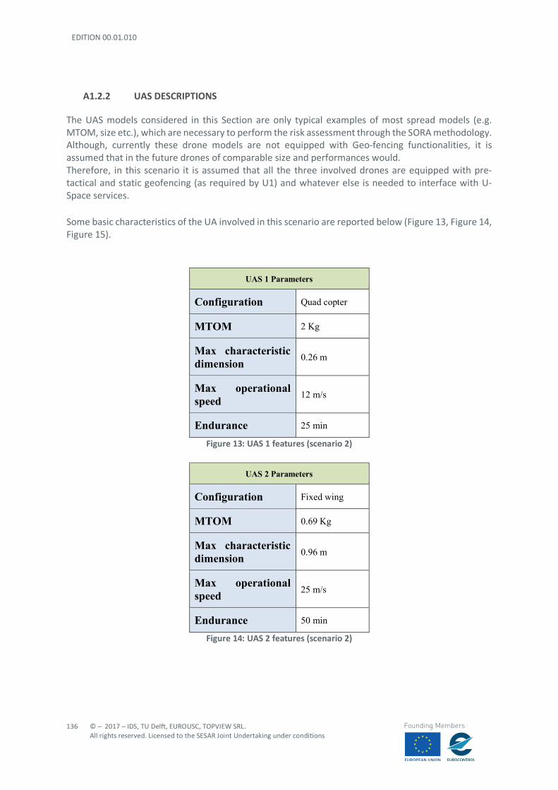
EDITION 00.01.010
136
© – 2017 – IDS, TU Delft, EUROUSC, TOPVIEW SRL. All rights reserved. Licensed to the SESAR Joint Undertaking under conditions
Founding Members
A1.2.2 UAS DESCRIPTIONS
The UAS models considered in this Section are only typical examples of most spread models (e.g. MTOM, size etc.), which are necessary to perform the risk assessment through the SORA methodology. Although, currently these drone models are not equipped with Geo-fencing functionalities, it is assumed that in the future drones of comparable size and performances would. Therefore, in this scenario it is assumed that all the three involved drones are equipped with pre-tactical and static geofencing (as required by U1) and whatever else is needed to interface with U-Space services. Some basic characteristics of the UA involved in this scenario are reported below (Figure 13, Figure 14, Figure 15).
UAS 1 Parameters
Configuration Quad copter
MTOM 2 Kg
Max characteristic dimension 0.26 m
Max operational speed 12 m/s
Endurance 25 min
Figure 13: UAS 1 features (scenario 2)
UAS 2 Parameters
Configuration Fixed wing
MTOM 0.69 Kg
Max characteristic dimension 0.96 m
Max operational speed 25 m/s
Endurance 50 min
Figure 14: UAS 2 features (scenario 2)

© – 2017 – IDS, TU Delft, EUROUSC, TOPVIEW SRL. All rights reserved. Licensed to the SESAR Joint Undertaking under conditions
137
Founding Members
UAS 3 Parameters
Configuration Hex copter
MTOM 15.5 Kg
Max characteristic dimension 1,7 m
Max operational speed 18 m/s
Endurance 30 min
Figure 15: UAS 3 features (scenario 2)
A.1.3 STEP #2 DETERMINATION OF THE INITIAL UAS GROUND RISK CLASS
The initial UAS ground risk relates to the unmitigated risk of a person being struck by the UA (in case of loss of UAS flight control 66 and can be represented by eleven Ground Risk Classes (GRC) (Table 36), derived only from the intended operation and the UAS lethal area, in turn function of the UA dimensions.
Max UA characteristics dimension 1m 3m 8m > 8m
Typical kinetic energy expected <700J <34KJ <1084KJ >1084KJ Operational Scenario VLOS over controlled area, located inside a sparsely populated environment
1 2 3 5
BVLOS over a sparsely populated environment (over flown areas uniformly inhabited)
2 3 4 6
VLOS over controlled area, located inside a populated environment
3 4 6 8
VLOS over populated environment 4 5 7 9 BVLOS over controlled area, located inside a populated environment
5 6 8 10
BVLOS over populated environment 6 7 9 11 VLOS over gathering of people 7 BVLOS over gathering of people 9
Table 36: Intrinsic UAS Ground Risk Class
66 Loss-of-Control In flight (LOC-I), e.g. after a stall, is one of the typical accident/incident categories in the ICAO ADREP taxonomy. This occurrence category should not be confused with loss of C2 Link, after which, is probable that the UA would continue controlled flight, governed by the on-board autopilot.
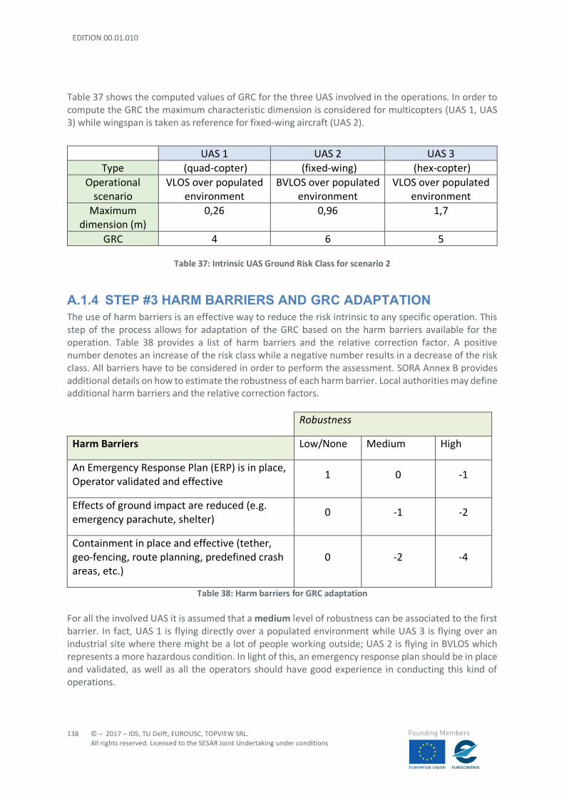
EDITION 00.01.010
138
© – 2017 – IDS, TU Delft, EUROUSC, TOPVIEW SRL. All rights reserved. Licensed to the SESAR Joint Undertaking under conditions
Founding Members
Table 37 shows the computed values of GRC for the three UAS involved in the operations. In order to compute the GRC the maximum characteristic dimension is considered for multicopters (UAS 1, UAS 3) while wingspan is taken as reference for fixed-wing aircraft (UAS 2).
Table 37: Intrinsic UAS Ground Risk Class for scenario 2
A.1.4 STEP #3 HARM BARRIERS AND GRC ADAPTATION The use of harm barriers is an effective way to reduce the risk intrinsic to any specific operation. This step of the process allows for adaptation of the GRC based on the harm barriers available for the operation. Table 38 provides a list of harm barriers and the relative correction factor. A positive number denotes an increase of the risk class while a negative number results in a decrease of the risk class. All barriers have to be considered in order to perform the assessment. SORA Annex B provides additional details on how to estimate the robustness of each harm barrier. Local authorities may define additional harm barriers and the relative correction factors.
Robustness
Harm Barriers Low/None Medium High
An Emergency Response Plan (ERP) is in place, Operator validated and effective
1 0 -1
Effects of ground impact are reduced (e.g. emergency parachute, shelter)
0 -1 -2
Containment in place and effective (tether, geo-fencing, route planning, predefined crash areas, etc.)
0 -2 -4
Table 38: Harm barriers for GRC adaptation For all the involved UAS it is assumed that a medium level of robustness can be associated to the first barrier. In fact, UAS 1 is flying directly over a populated environment while UAS 3 is flying over an industrial site where there might be a lot of people working outside; UAS 2 is flying in BVLOS which represents a more hazardous condition. In light of this, an emergency response plan should be in place and validated, as well as all the operators should have good experience in conducting this kind of operations.
UAS 1 UAS 2 UAS 3 Type (quad-copter) (fixed-wing) (hex-copter)
Operational scenario
VLOS over populated environment
BVLOS over populated environment
VLOS over populated environment
Maximum dimension (m)
0,26 0,96 1,7
GRC 4 6 5
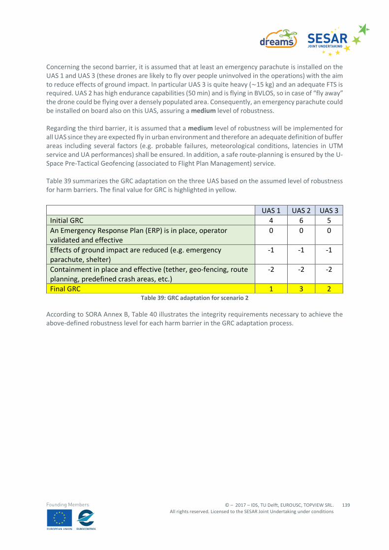
© – 2017 – IDS, TU Delft, EUROUSC, TOPVIEW SRL. All rights reserved. Licensed to the SESAR Joint Undertaking under conditions
139
Founding Members
Concerning the second barrier, it is assumed that at least an emergency parachute is installed on the UAS 1 and UAS 3 (these drones are likely to fly over people uninvolved in the operations) with the aim to reduce effects of ground impact. In particular UAS 3 is quite heavy (~15 kg) and an adequate FTS is required. UAS 2 has high endurance capabilities (50 min) and is flying in BVLOS, so in case of “fly away” the drone could be flying over a densely populated area. Consequently, an emergency parachute could be installed on board also on this UAS, assuring a medium level of robustness. Regarding the third barrier, it is assumed that a medium level of robustness will be implemented for all UAS since they are expected fly in urban environment and therefore an adequate definition of buffer areas including several factors (e.g. probable failures, meteorological conditions, latencies in UTM service and UA performances) shall be ensured. In addition, a safe route-planning is ensured by the U-Space Pre-Tactical Geofencing (associated to Flight Plan Management) service. Table 39 summarizes the GRC adaptation on the three UAS based on the assumed level of robustness for harm barriers. The final value for GRC is highlighted in yellow.
Table 39: GRC adaptation for scenario 2
According to SORA Annex B, Table 40 illustrates the integrity requirements necessary to achieve the above-defined robustness level for each harm barrier in the GRC adaptation process.
UAS 1 UAS 2 UAS 3 Initial GRC 4 6 5 An Emergency Response Plan (ERP) is in place, operator validated and effective
0 0 0
Effects of ground impact are reduced (e.g. emergency parachute, shelter)
-1 -1 -1
Containment in place and effective (tether, geo-fencing, route planning, predefined crash areas, etc.)
-2 -2 -2
Final GRC 1 3 2
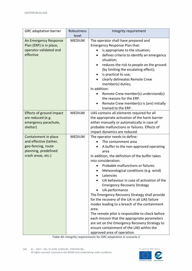
EDITION 00.01.010
140
© – 2017 – IDS, TU Delft, EUROUSC, TOPVIEW SRL. All rights reserved. Licensed to the SESAR Joint Undertaking under conditions
Founding Members
Table 40: Integrity requirements for GRC adaptation in scenario 2
GRC adaptation barrier Robustness level
Integrity requirement
An Emergency Response Plan (ERP) is in place, operator validated and effective
MEDIUM The operator shall have prepared and Emergency Response Plan that:
• is appropriate to the situation; • defines criteria to identify an emergency
situation; • reduces the risk to people on the ground
(by limiting the escalating effect); • is practical to use; • clearly delineates Remote Crew
member(s) duties; In addition:
• Remote Crew member(s) understand(s) the reasons for the ERP.
• Remote Crew member(s) is (are) initially trained to the ERP.
Effects of ground impact are reduced (e.g. emergency parachute, shelter)
MEDIUM UAS contains all elements required for all the appropriate activation of the harm barrier either manually or automatically in case of probable malfunctions or failures. Effects of impact dynamics are reduced.
Containment in place and effective (tether, geo-fencing, route planning, predefined crash areas, etc.)
MEDIUM The operator needs to define: • The containment area • A buffer to the non-approved operating
area In addition, the definition of the buffer takes into consideration:
• Probable malfunctions or failures • Meteorological conditions (e.g. wind) • Latencies • UA behaviour in case of activation of the
Emergency Recovery Strategy • UA performance
The Emergency Recovery Strategy shall provide for the recovery of the UA in all UAS failure modes leading to a breach of the containment area. The remote pilot is responsible to check before each mission that the appropriate parameters are set on the Emergency Recovery Strategy to ensure containment of the UAS within the approved area of operation.
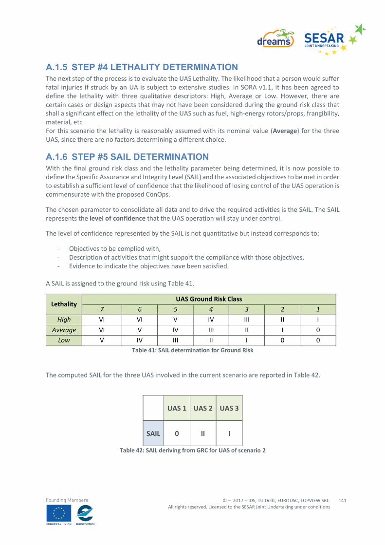
© – 2017 – IDS, TU Delft, EUROUSC, TOPVIEW SRL. All rights reserved. Licensed to the SESAR Joint Undertaking under conditions
141
Founding Members
A.1.5 STEP #4 LETHALITY DETERMINATION The next step of the process is to evaluate the UAS Lethality. The likelihood that a person would suffer fatal injuries if struck by an UA is subject to extensive studies. In SORA v1.1, it has been agreed to define the lethality with three qualitative descriptors: High, Average or Low. However, there are certain cases or design aspects that may not have been considered during the ground risk class that shall a significant effect on the lethality of the UAS such as fuel, high-energy rotors/props, frangibility, material, etc For this scenario the lethality is reasonably assumed with its nominal value (Average) for the three UAS, since there are no factors determining a different choice.
A.1.6 STEP #5 SAIL DETERMINATION With the final ground risk class and the lethality parameter being determined, it is now possible to define the Specific Assurance and Integrity Level (SAIL) and the associated objectives to be met in order to establish a sufficient level of confidence that the likelihood of losing control of the UAS operation is commensurate with the proposed ConOps.
The chosen parameter to consolidate all data and to drive the required activities is the SAIL. The SAIL represents the level of confidence that the UAS operation will stay under control.
The level of confidence represented by the SAIL is not quantitative but instead corresponds to:
- Objectives to be complied with, - Description of activities that might support the compliance with those objectives, - Evidence to indicate the objectives have been satisfied.
A SAIL is assigned to the ground risk using Table 41.
Lethality UAS Ground Risk Class
7 6 5 4 3 2 1 High VI VI V IV III II I
Average VI V IV III II I 0
Low V IV III II I 0 0 Table 41: SAIL determination for Ground Risk
The computed SAIL for the three UAS involved in the current scenario are reported in Table 42.
UAS 1 UAS 2 UAS 3
SAIL 0 II I
Table 42: SAIL deriving from GRC for UAS of scenario 2
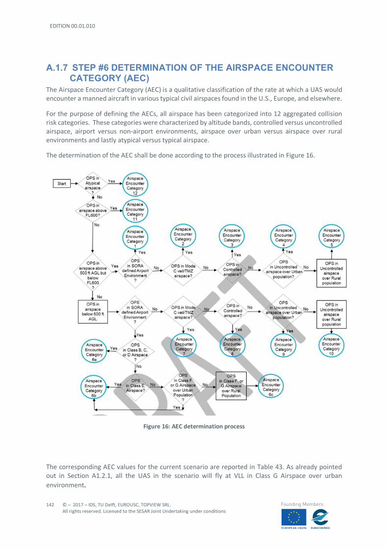
EDITION 00.01.010
142
© – 2017 – IDS, TU Delft, EUROUSC, TOPVIEW SRL. All rights reserved. Licensed to the SESAR Joint Undertaking under conditions
Founding Members
A.1.7 STEP #6 DETERMINATION OF THE AIRSPACE ENCOUNTER CATEGORY (AEC)
The Airspace Encounter Category (AEC) is a qualitative classification of the rate at which a UAS would encounter a manned aircraft in various typical civil airspaces found in the U.S., Europe, and elsewhere.
For the purpose of defining the AECs, all airspace has been categorized into 12 aggregated collision risk categories. These categories were characterized by altitude bands, controlled versus uncontrolled airspace, airport versus non-airport environments, airspace over urban versus airspace over rural environments and lastly atypical versus typical airspace.
The determination of the AEC shall be done according to the process illustrated in Figure 16.
Figure 16: AEC determination process
The corresponding AEC values for the current scenario are reported in Table 43. As already pointed out in Section A1.2.1, all the UAS in the scenario will fly at VLL in Class G Airspace over urban environment.
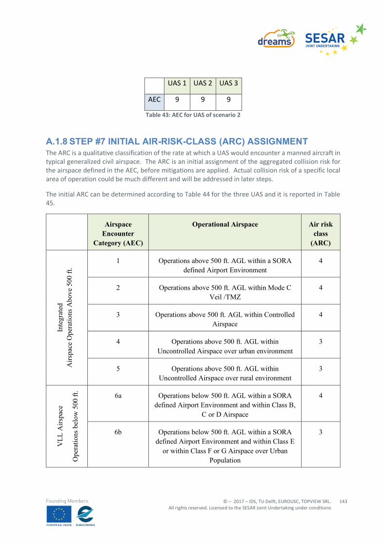
© – 2017 – IDS, TU Delft, EUROUSC, TOPVIEW SRL. All rights reserved. Licensed to the SESAR Joint Undertaking under conditions
143
Founding Members
UAS 1 UAS 2 UAS 3
AEC 9 9 9
Table 43: AEC for UAS of scenario 2
A.1.8 STEP #7 INITIAL AIR-RISK-CLASS (ARC) ASSIGNMENT The ARC is a qualitative classification of the rate at which a UAS would encounter a manned aircraft in typical generalized civil airspace. The ARC is an initial assignment of the aggregated collision risk for the airspace defined in the AEC, before mitigations are applied. Actual collision risk of a specific local area of operation could be much different and will be addressed in later steps.
The initial ARC can be determined according to Table 44 for the three UAS and it is reported in Table 45.
Airspace Encounter
Category (AEC)
Operational Airspace Air risk class
(ARC)
Inte
grat
ed
Airs
pace
Ope
ratio
ns A
bove
500
ft.
1 Operations above 500 ft. AGL within a SORA defined Airport Environment
4
2 Operations above 500 ft. AGL within Mode C Veil /TMZ
4
3 Operations above 500 ft. AGL within Controlled Airspace
4
4 Operations above 500 ft. AGL within Uncontrolled Airspace over urban environment
3
5 Operations above 500 ft. AGL within Uncontrolled Airspace over rural environment
3
VLL
Airs
pace
Ope
ratio
ns b
elow
500
ft.
6a Operations below 500 ft. AGL within a SORA defined Airport Environment and within Class B,
C or D Airspace
4
6b Operations below 500 ft. AGL within a SORA defined Airport Environment and within Class E
or within Class F or G Airspace over Urban Population
3
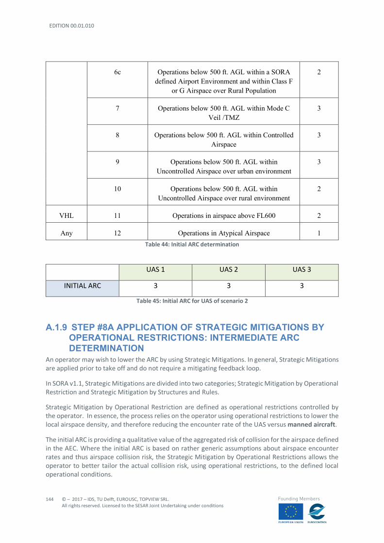
EDITION 00.01.010
144
© – 2017 – IDS, TU Delft, EUROUSC, TOPVIEW SRL. All rights reserved. Licensed to the SESAR Joint Undertaking under conditions
Founding Members
6c Operations below 500 ft. AGL within a SORA defined Airport Environment and within Class F
or G Airspace over Rural Population
2
7 Operations below 500 ft. AGL within Mode C Veil /TMZ
3
8 Operations below 500 ft. AGL within Controlled Airspace
3
9 Operations below 500 ft. AGL within Uncontrolled Airspace over urban environment
3
10 Operations below 500 ft. AGL within Uncontrolled Airspace over rural environment
2
VHL 11 Operations in airspace above FL600 2
Any 12 Operations in Atypical Airspace 1 Table 44: Initial ARC determination
UAS 1 UAS 2 UAS 3
INITIAL ARC 3 3 3
Table 45: Initial ARC for UAS of scenario 2
A.1.9 STEP #8A APPLICATION OF STRATEGIC MITIGATIONS BY OPERATIONAL RESTRICTIONS: INTERMEDIATE ARC DETERMINATION
An operator may wish to lower the ARC by using Strategic Mitigations. In general, Strategic Mitigations are applied prior to take off and do not require a mitigating feedback loop.
In SORA v1.1, Strategic Mitigations are divided into two categories; Strategic Mitigation by Operational Restriction and Strategic Mitigation by Structures and Rules.
Strategic Mitigation by Operational Restriction are defined as operational restrictions controlled by the operator. In essence, the process relies on the operator using operational restrictions to lower the local airspace density, and therefore reducing the encounter rate of the UAS versus manned aircraft.
The initial ARC is providing a qualitative value of the aggregated risk of collision for the airspace defined in the AEC. Where the initial ARC is based on rather generic assumptions about airspace encounter rates and thus airspace collision risk, the Strategic Mitigation by Operational Restrictions allows the operator to better tailor the actual collision risk, using operational restrictions, to the defined local operational conditions.
© – 2017 – IDS, TU Delft, EUROUSC, TOPVIEW SRL. All rights reserved. Licensed to the SESAR Joint Undertaking under conditions
145
Founding Members
The most common Strategic Mitigations by Operational Restriction will take the form of:
- Mitigation by Boundary (restricted to geographical volume where encounter rate might be lower),
- Mitigation by Chronology (restricted to time of day), - Mitigation by Behaviour (restricted by operational predictability by other airspace users), or - Mitigation by Exposure (restricted by time of exposure to risk).
The first two Strategic Mitigations by Operational Restriction, limiting risk by operating during certain times, limiting risk by operating within certain boundaries, are the primary means by which the operator will generally reduce collision risk with strategic mitigation.
The next mitigation, limiting risk by limiting certain types of risky behaviour, is fundamentally about making your UAS operations predictable. Unpredictable behaviours such as acrobatic flights, sudden stops to a hover, excessive climbing and descending, etc. are interpreted as risky behaviours because they can be seen as unpredictable to other airspace users. In order for the operator to take advantage of this mitigation scheme, they would need to have an operation so predictable in nature that all airspace users could predict the behaviour of the aircraft well in advance.
For the current scenario no, strategic mitigations by Operational Restrictions are applied.
In fact, although the operations are conducted in VLL, the presence of manned aircraft (e.g. helicopters flying in urban environment) cannot be neglected a priori so a strategic mitigation by Boundary cannot be implemented.
No restriction by chronology is applicable since the scenario might take place at any time of the day as well as no predictable behaviours are in place (no routine operations).
Finally, no mitigation by exposure can be applied in this context since the three UAS will be flying in the same airspace class for the entire duration of the mission.
In conclusion, no intermediate modifications are applied on the initial ARC evaluated at step #7.
A.1.10 STEP #8B APPLICATION OF STRATEGIC MITIGATIONS BY STRUCTURES AND RULES: FINAL ARC DETERMINATION
Strategic Mitigation by Structures and Rules requires that all aircraft within that airspace are subject to the same structure and rules, and that these structures and rules work to lower the collision risk within the airspace. By definition, Strategic Mitigation by Structures and Rules requires all aircraft to participate, and only the local authorities / qualified entities have authority to set requirements on all aircraft. Therefore, the operator does not have control over the existence or level of participation of the airspace structure or the application of the flight rules. Thus, Strategic Mitigation by Structures and Rules, is either available, or not available to the operator.
Application of Strategic Mitigation by Structures and Rules only applies to operations in AEC 6a, 6b, 6c, 7, 8, 9, and 10, or operations in VLL under 500 ft AGL.
Strategic Mitigation by Structures and Rules (if applied) gains the operator one reduction level to the Intermediate ARC.
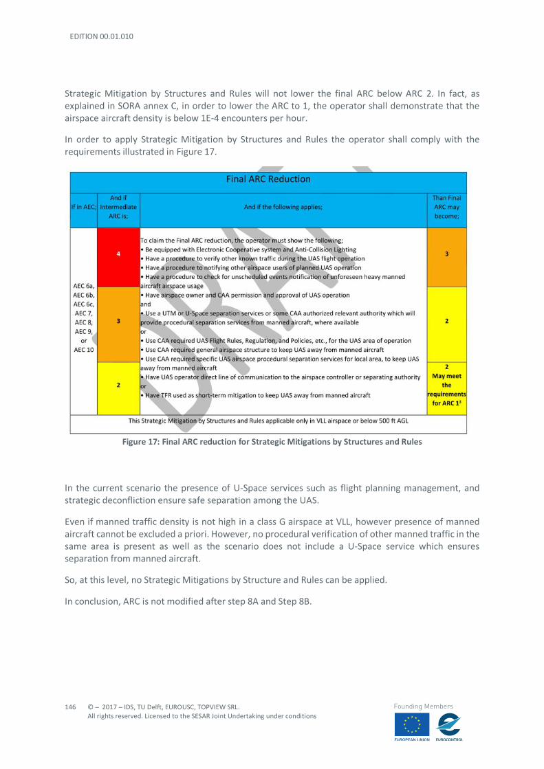
EDITION 00.01.010
146
© – 2017 – IDS, TU Delft, EUROUSC, TOPVIEW SRL. All rights reserved. Licensed to the SESAR Joint Undertaking under conditions
Founding Members
Strategic Mitigation by Structures and Rules will not lower the final ARC below ARC 2. In fact, as explained in SORA annex C, in order to lower the ARC to 1, the operator shall demonstrate that the airspace aircraft density is below 1E-4 encounters per hour.
In order to apply Strategic Mitigation by Structures and Rules the operator shall comply with the requirements illustrated in Figure 17.
Figure 17: Final ARC reduction for Strategic Mitigations by Structures and Rules
In the current scenario the presence of U-Space services such as flight planning management, and strategic deconfliction ensure safe separation among the UAS.
Even if manned traffic density is not high in a class G airspace at VLL, however presence of manned aircraft cannot be excluded a priori. However, no procedural verification of other manned traffic in the same area is present as well as the scenario does not include a U-Space service which ensures separation from manned aircraft.
So, at this level, no Strategic Mitigations by Structure and Rules can be applied.
In conclusion, ARC is not modified after step 8A and Step 8B.
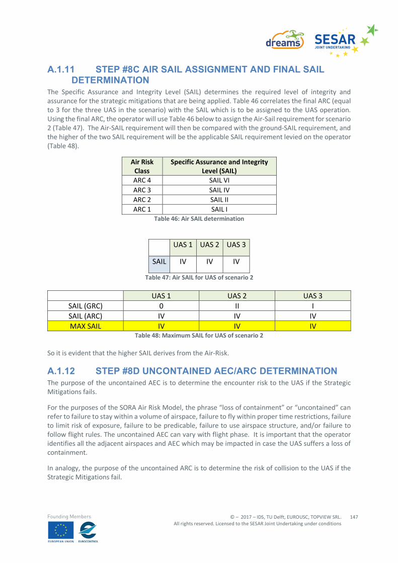
© – 2017 – IDS, TU Delft, EUROUSC, TOPVIEW SRL. All rights reserved. Licensed to the SESAR Joint Undertaking under conditions
147
Founding Members
A.1.11 STEP #8C AIR SAIL ASSIGNMENT AND FINAL SAIL DETERMINATION
The Specific Assurance and Integrity Level (SAIL) determines the required level of integrity and assurance for the strategic mitigations that are being applied. Table 46 correlates the final ARC (equal to 3 for the three UAS in the scenario) with the SAIL which is to be assigned to the UAS operation. Using the final ARC, the operator will use Table 46 below to assign the Air-Sail requirement for scenario 2 (Table 47). The Air-SAIL requirement will then be compared with the ground-SAIL requirement, and the higher of the two SAIL requirement will be the applicable SAIL requirement levied on the operator (Table 48).
Air Risk Class
Specific Assurance and Integrity Level (SAIL)
ARC 4 SAIL VI ARC 3 SAIL IV ARC 2 SAIL II ARC 1 SAIL I
Table 46: Air SAIL determination
UAS 1 UAS 2 UAS 3
SAIL IV IV IV
Table 47: Air SAIL for UAS of scenario 2
UAS 1 UAS 2 UAS 3 SAIL (GRC) 0 II I SAIL (ARC) IV IV IV MAX SAIL IV IV IV
Table 48: Maximum SAIL for UAS of scenario 2 So it is evident that the higher SAIL derives from the Air-Risk.
A.1.12 STEP #8D UNCONTAINED AEC/ARC DETERMINATION The purpose of the uncontained AEC is to determine the encounter risk to the UAS if the Strategic Mitigations fails.
For the purposes of the SORA Air Risk Model, the phrase “loss of containment” or “uncontained” can refer to failure to stay within a volume of airspace, failure to fly within proper time restrictions, failure to limit risk of exposure, failure to be predicable, failure to use airspace structure, and/or failure to follow flight rules. The uncontained AEC can vary with flight phase. It is important that the operator identifies all the adjacent airspaces and AEC which may be impacted in case the UAS suffers a loss of containment.
In analogy, the purpose of the uncontained ARC is to determine the risk of collision to the UAS if the Strategic Mitigations fail.
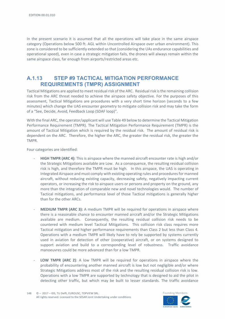
EDITION 00.01.010
148
© – 2017 – IDS, TU Delft, EUROUSC, TOPVIEW SRL. All rights reserved. Licensed to the SESAR Joint Undertaking under conditions
Founding Members
In the present scenario it is assumed that all the operations will take place in the same airspace category (Operations below 500 ft. AGL within Uncontrolled Airspace over urban environment). This zone is considered to be sufficiently extended so that (considering the UAs endurance capabilities and operational speed), even in case a strategic mitigation fails, the drones will always remain within the same airspace class, far enough from airports/restricted areas etc.
A.1.13 STEP #9 TACTICAL MITIGATION PERFORMANCE REQUIREMENTS (TMPR) ASSIGNMENT
Tactical Mitigations are applied to meet residual risk of the ARC. Residual risk is the remaining collision risk from the ARC threat needed to achieve the airspace safety objective. For the purposes of this assessment, Tactical Mitigations are procedures with a very short time horizon (seconds to a few minutes) which change the UAS encounter geometry to mitigate collision risk and may take the form of a “See, Decide, Avoid, Feedback Loop (SDAF loop)”.
With the final ARC, the operator/applicant will use Table 49 below to determine the Tactical Mitigation Performance Requirement (TMPR). The Tactical Mitigation Performance Requirement (TMPR) is the amount of Tactical Mitigation which is required by the residual risk. The amount of residual risk is dependent on the ARC. Therefore, the higher the ARC, the greater the residual risk, the greater the TMPR.
Four categories are identified:
- HIGH TMPR (ARC 4): This is airspace where the manned aircraft encounter rate is high and/or the Strategic Mitigations available are Low. As a consequence, the resulting residual collision risk is high, and therefore the TMPR must be high. In this airspace, the UAS is operating in Integrated Airspace and must comply with existing operating rules and procedures for manned aircraft, without reducing existing capacity, decreasing safety, negatively impacting current operators, or increasing the risk to airspace users or persons and property on the ground, any more than the integration of comparable new and novel technologies would. The number of Tactical mitigations, and performance level of those Tactical mitigations is generally higher than for the other ARCs.
- MEDIUM TMPR (ARC 3): A medium TMPR will be required for operations in airspace where there is a reasonable chance to encounter manned aircraft and/or the Strategic Mitigations available are medium. Consequently, the resulting residual collision risk needs to be countered with medium level Tactical Mitigations. This collision risk class requires more Tactical mitigation and higher performance requirements than Class 2 but less than Class 4. Operations with a medium TMPR will likely have to rely be supported by systems currently used in aviation for detection of other (cooperative) aircraft, or on systems designed to support aviation and build to a corresponding level of robustness. Traffic avoidance manoeuvres could be more advanced than for a low TMPR.
- LOW TMPR (ARC 2): A low TMPR will be required for operations in airspace where the
probability of encountering another manned aircraft is low but not negligible and/or where Strategic Mitigations address most of the risk and the resulting residual collision risk is low. Operations with a low TMPR are supported by technology that is designed to aid the pilot in detecting other traffic, but which may be built to lesser standards. The traffic avoidance
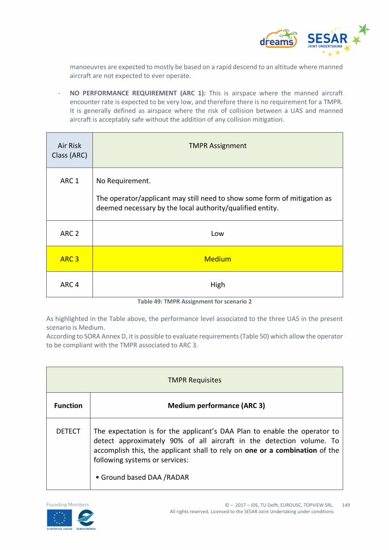
© – 2017 – IDS, TU Delft, EUROUSC, TOPVIEW SRL. All rights reserved. Licensed to the SESAR Joint Undertaking under conditions
149
Founding Members
manoeuvres are expected to mostly be based on a rapid descend to an altitude where manned aircraft are not expected to ever operate.
- NO PERFORMANCE REQUIREMENT (ARC 1): This is airspace where the manned aircraft
encounter rate is expected to be very low, and therefore there is no requirement for a TMPR. It is generally defined as airspace where the risk of collision between a UAS and manned aircraft is acceptably safe without the addition of any collision mitigation.
Air Risk Class (ARC)
TMPR Assignment
ARC 1 No Requirement.
The operator/applicant may still need to show some form of mitigation as deemed necessary by the local authority/qualified entity.
ARC 2 Low
ARC 3 Medium
ARC 4 High
Table 49: TMPR Assignment for scenario 2 As highlighted in the Table above, the performance level associated to the three UAS in the present scenario is Medium. According to SORA Annex D, it is possible to evaluate requirements (Table 50) which allow the operator to be compliant with the TMPR associated to ARC 3.
TMPR Requisites
Function Medium performance (ARC 3)
DETECT The expectation is for the applicant’s DAA Plan to enable the operator to detect approximately 90% of all aircraft in the detection volume. To accomplish this, the applicant shall to rely on one or a combination of the following systems or services:
• Ground based DAA /RADAR
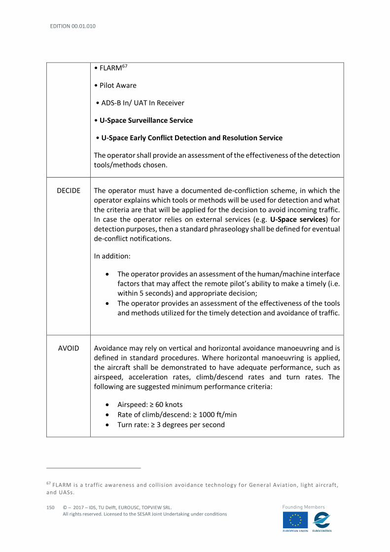
EDITION 00.01.010
150
© – 2017 – IDS, TU Delft, EUROUSC, TOPVIEW SRL. All rights reserved. Licensed to the SESAR Joint Undertaking under conditions
Founding Members
• FLARM67
• Pilot Aware
• ADS-B In/ UAT In Receiver
• U-Space Surveillance Service
• U-Space Early Conflict Detection and Resolution Service
The operator shall provide an assessment of the effectiveness of the detection tools/methods chosen.
DECIDE The operator must have a documented de-confliction scheme, in which the operator explains which tools or methods will be used for detection and what the criteria are that will be applied for the decision to avoid incoming traffic. In case the operator relies on external services (e.g. U-Space services) for detection purposes, then a standard phraseology shall be defined for eventual de-conflict notifications.
In addition:
• The operator provides an assessment of the human/machine interface factors that may affect the remote pilot’s ability to make a timely (i.e. within 5 seconds) and appropriate decision;
• The operator provides an assessment of the effectiveness of the tools and methods utilized for the timely detection and avoidance of traffic.
AVOID Avoidance may rely on vertical and horizontal avoidance manoeuvring and is defined in standard procedures. Where horizontal manoeuvring is applied, the aircraft shall be demonstrated to have adequate performance, such as airspeed, acceleration rates, climb/descend rates and turn rates. The following are suggested minimum performance criteria:
• Airspeed: ≥ 60 knots • Rate of climb/descend: ≥ 1000 ft/min • Turn rate: ≥ 3 degrees per second
67 FLARM is a traffic awareness and coll ision avoidance technology for General Aviation, l ight aircraft, and UASs.
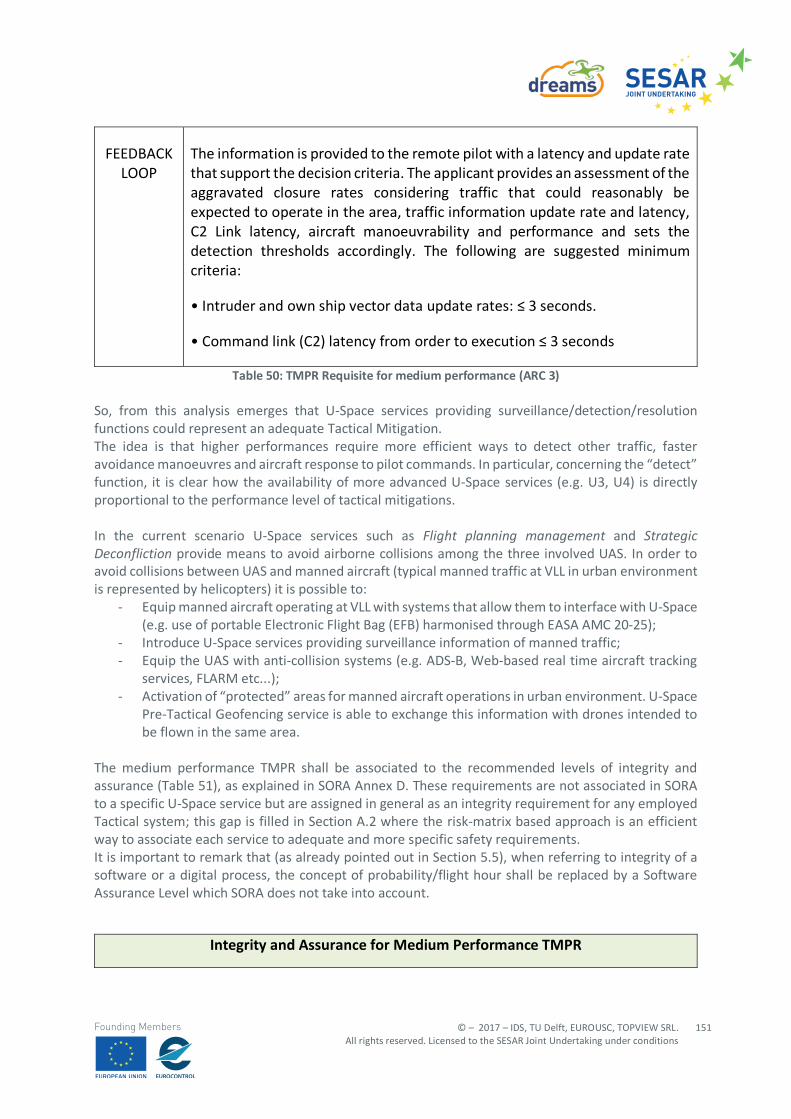
© – 2017 – IDS, TU Delft, EUROUSC, TOPVIEW SRL. All rights reserved. Licensed to the SESAR Joint Undertaking under conditions
151
Founding Members
FEEDBACK LOOP
The information is provided to the remote pilot with a latency and update rate that support the decision criteria. The applicant provides an assessment of the aggravated closure rates considering traffic that could reasonably be expected to operate in the area, traffic information update rate and latency, C2 Link latency, aircraft manoeuvrability and performance and sets the detection thresholds accordingly. The following are suggested minimum criteria:
• Intruder and own ship vector data update rates: ≤ 3 seconds.
• Command link (C2) latency from order to execution ≤ 3 seconds
Table 50: TMPR Requisite for medium performance (ARC 3) So, from this analysis emerges that U-Space services providing surveillance/detection/resolution functions could represent an adequate Tactical Mitigation. The idea is that higher performances require more efficient ways to detect other traffic, faster avoidance manoeuvres and aircraft response to pilot commands. In particular, concerning the “detect” function, it is clear how the availability of more advanced U-Space services (e.g. U3, U4) is directly proportional to the performance level of tactical mitigations. In the current scenario U-Space services such as Flight planning management and Strategic Deconfliction provide means to avoid airborne collisions among the three involved UAS. In order to avoid collisions between UAS and manned aircraft (typical manned traffic at VLL in urban environment is represented by helicopters) it is possible to:
- Equip manned aircraft operating at VLL with systems that allow them to interface with U-Space (e.g. use of portable Electronic Flight Bag (EFB) harmonised through EASA AMC 20-25);
- Introduce U-Space services providing surveillance information of manned traffic; - Equip the UAS with anti-collision systems (e.g. ADS-B, Web-based real time aircraft tracking
services, FLARM etc...); - Activation of “protected” areas for manned aircraft operations in urban environment. U-Space
Pre-Tactical Geofencing service is able to exchange this information with drones intended to be flown in the same area.
The medium performance TMPR shall be associated to the recommended levels of integrity and assurance (Table 51), as explained in SORA Annex D. These requirements are not associated in SORA to a specific U-Space service but are assigned in general as an integrity requirement for any employed Tactical system; this gap is filled in Section A.2 where the risk-matrix based approach is an efficient way to associate each service to adequate and more specific safety requirements. It is important to remark that (as already pointed out in Section 5.5), when referring to integrity of a software or a digital process, the concept of probability/flight hour shall be replaced by a Software Assurance Level which SORA does not take into account.
Integrity and Assurance for Medium Performance TMPR
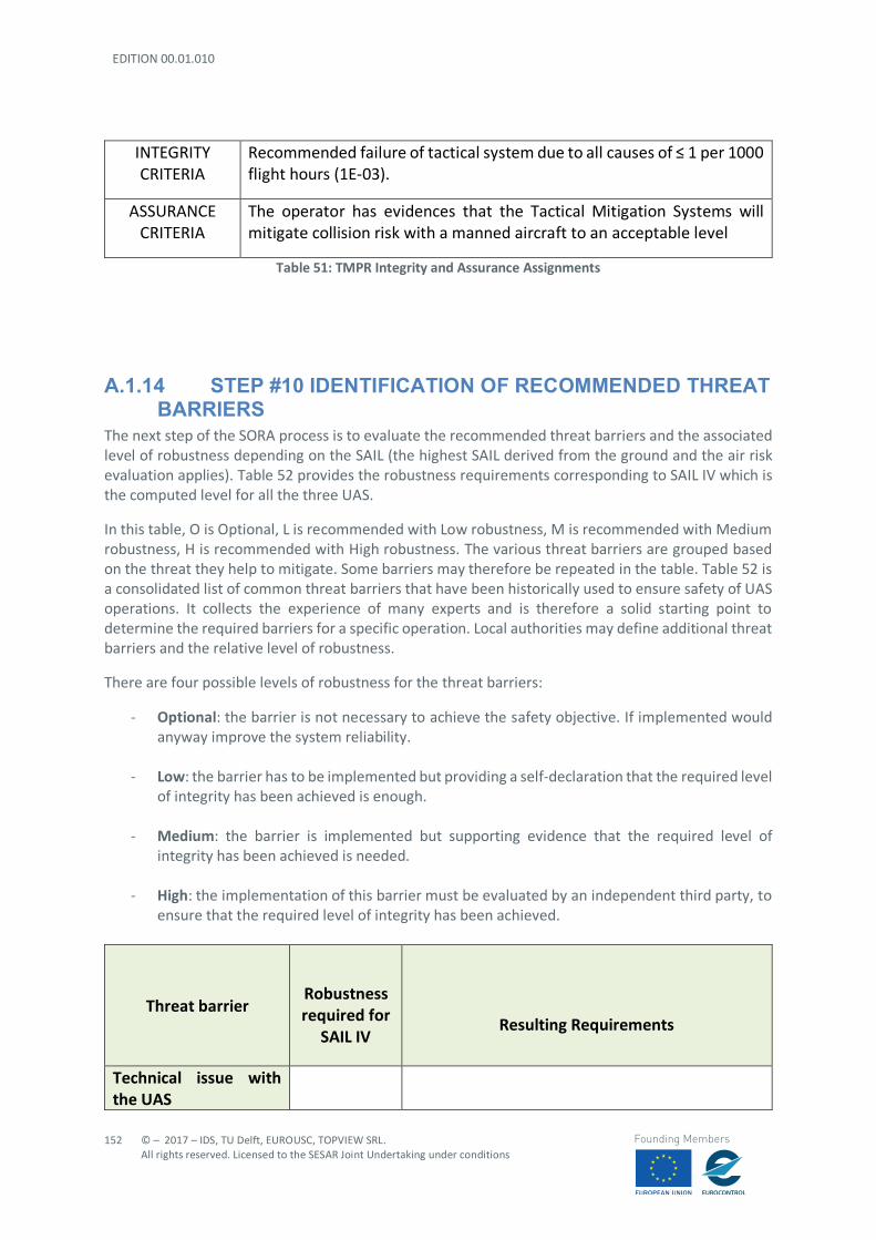
EDITION 00.01.010
152
© – 2017 – IDS, TU Delft, EUROUSC, TOPVIEW SRL. All rights reserved. Licensed to the SESAR Joint Undertaking under conditions
Founding Members
INTEGRITY CRITERIA
Recommended failure of tactical system due to all causes of ≤ 1 per 1000 flight hours (1E-03).
ASSURANCE CRITERIA
The operator has evidences that the Tactical Mitigation Systems will mitigate collision risk with a manned aircraft to an acceptable level
Table 51: TMPR Integrity and Assurance Assignments
A.1.14 STEP #10 IDENTIFICATION OF RECOMMENDED THREAT BARRIERS
The next step of the SORA process is to evaluate the recommended threat barriers and the associated level of robustness depending on the SAIL (the highest SAIL derived from the ground and the air risk evaluation applies). Table 52 provides the robustness requirements corresponding to SAIL IV which is the computed level for all the three UAS.
In this table, O is Optional, L is recommended with Low robustness, M is recommended with Medium robustness, H is recommended with High robustness. The various threat barriers are grouped based on the threat they help to mitigate. Some barriers may therefore be repeated in the table. Table 52 is a consolidated list of common threat barriers that have been historically used to ensure safety of UAS operations. It collects the experience of many experts and is therefore a solid starting point to determine the required barriers for a specific operation. Local authorities may define additional threat barriers and the relative level of robustness.
There are four possible levels of robustness for the threat barriers:
- Optional: the barrier is not necessary to achieve the safety objective. If implemented would anyway improve the system reliability.
- Low: the barrier has to be implemented but providing a self-declaration that the required level of integrity has been achieved is enough.
- Medium: the barrier is implemented but supporting evidence that the required level of
integrity has been achieved is needed.
- High: the implementation of this barrier must be evaluated by an independent third party, to ensure that the required level of integrity has been achieved.
Threat barrier
Robustness required for
SAIL IV
Resulting Requirements
Technical issue with the UAS
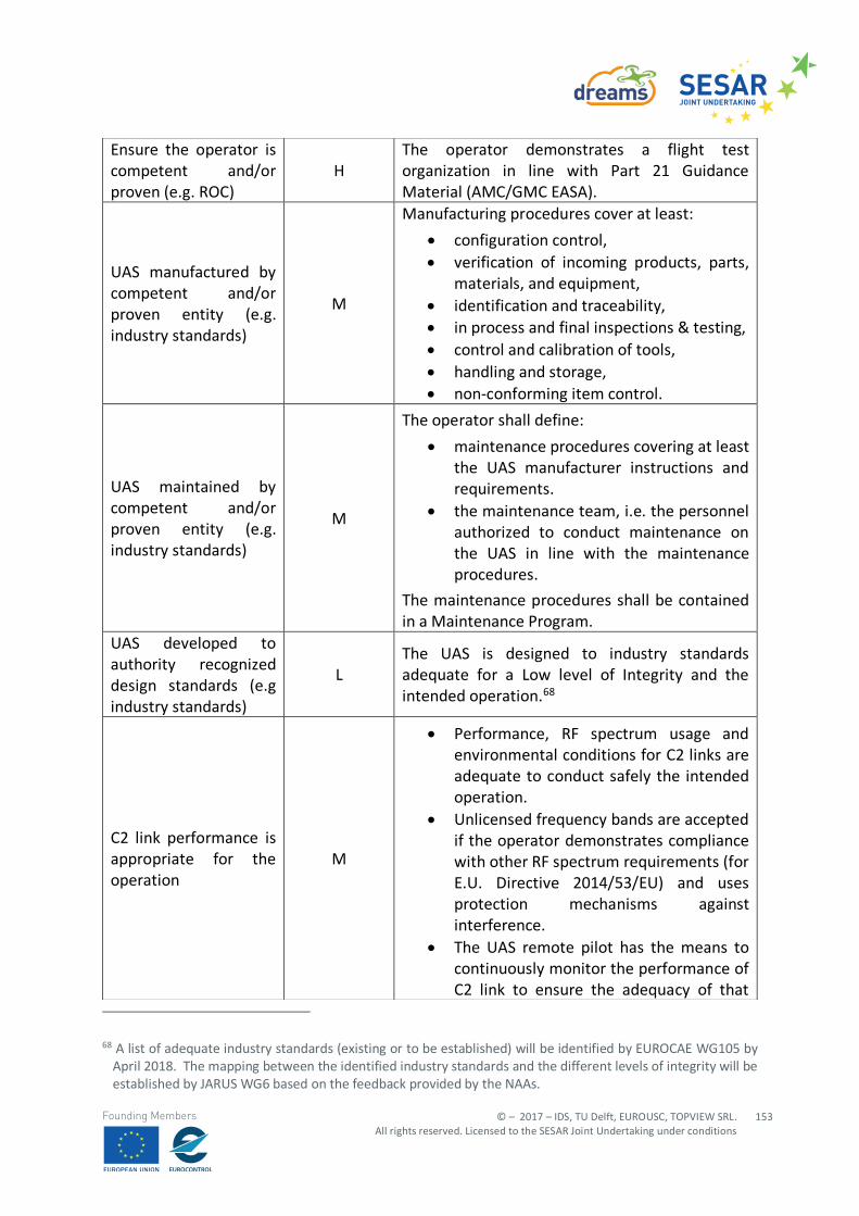
© – 2017 – IDS, TU Delft, EUROUSC, TOPVIEW SRL. All rights reserved. Licensed to the SESAR Joint Undertaking under conditions
153
Founding Members
68 A list of adequate industry standards (existing or to be established) will be identified by EUROCAE WG105 by
April 2018. The mapping between the identified industry standards and the different levels of integrity will be established by JARUS WG6 based on the feedback provided by the NAAs.
Ensure the operator is competent and/or proven (e.g. ROC)
H The operator demonstrates a flight test organization in line with Part 21 Guidance Material (AMC/GMC EASA).
UAS manufactured by competent and/or proven entity (e.g. industry standards)
M
Manufacturing procedures cover at least:
• configuration control, • verification of incoming products, parts,
materials, and equipment, • identification and traceability, • in process and final inspections & testing, • control and calibration of tools, • handling and storage, • non-conforming item control.
UAS maintained by competent and/or proven entity (e.g. industry standards)
M
The operator shall define:
• maintenance procedures covering at least the UAS manufacturer instructions and requirements.
• the maintenance team, i.e. the personnel authorized to conduct maintenance on the UAS in line with the maintenance procedures.
The maintenance procedures shall be contained in a Maintenance Program.
UAS developed to authority recognized design standards (e.g industry standards)
L The UAS is designed to industry standards adequate for a Low level of Integrity and the intended operation.68
C2 link performance is appropriate for the operation
M
• Performance, RF spectrum usage and environmental conditions for C2 links are adequate to conduct safely the intended operation.
• Unlicensed frequency bands are accepted if the operator demonstrates compliance with other RF spectrum requirements (for E.U. Directive 2014/53/EU) and uses protection mechanisms against interference.
• The UAS remote pilot has the means to continuously monitor the performance of C2 link to ensure the adequacy of that
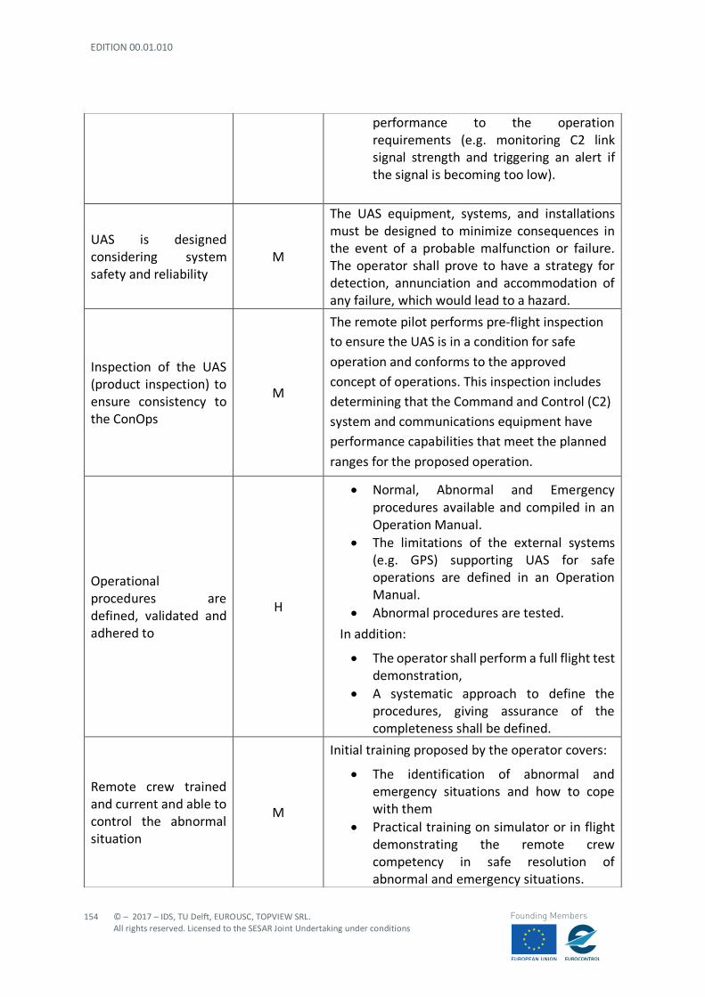
EDITION 00.01.010
154
© – 2017 – IDS, TU Delft, EUROUSC, TOPVIEW SRL. All rights reserved. Licensed to the SESAR Joint Undertaking under conditions
Founding Members
performance to the operation requirements (e.g. monitoring C2 link signal strength and triggering an alert if the signal is becoming too low).
UAS is designed considering system safety and reliability
M
The UAS equipment, systems, and installations must be designed to minimize consequences in the event of a probable malfunction or failure. The operator shall prove to have a strategy for detection, annunciation and accommodation of any failure, which would lead to a hazard.
Inspection of the UAS (product inspection) to ensure consistency to the ConOps
M
The remote pilot performs pre-flight inspection to ensure the UAS is in a condition for safe
operation and conforms to the approved
concept of operations. This inspection includes
determining that the Command and Control (C2)
system and communications equipment have
performance capabilities that meet the planned
ranges for the proposed operation.
Operational procedures are defined, validated and adhered to
H
• Normal, Abnormal and Emergency procedures available and compiled in an Operation Manual.
• The limitations of the external systems (e.g. GPS) supporting UAS for safe operations are defined in an Operation Manual.
• Abnormal procedures are tested.
In addition:
• The operator shall perform a full flight test demonstration,
• A systematic approach to define the procedures, giving assurance of the completeness shall be defined.
Remote crew trained and current and able to control the abnormal situation
M
Initial training proposed by the operator covers:
• The identification of abnormal and emergency situations and how to cope with them
• Practical training on simulator or in flight demonstrating the remote crew competency in safe resolution of abnormal and emergency situations.
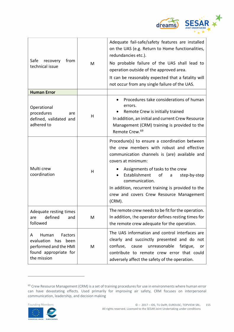
© – 2017 – IDS, TU Delft, EUROUSC, TOPVIEW SRL. All rights reserved. Licensed to the SESAR Joint Undertaking under conditions
155
Founding Members
69 Crew Resource Management (CRM) is a set of training procedures for use in environments where human error can have devastating effects. Used primarily for improving air safety, CRM focuses on interpersonal communication, leadership, and decision making
Safe recovery from technical issue
M
Adequate fail-safe/safety features are installed on the UAS (e.g. Return to Home functionalities,
redundancies etc.).
No probable failure of the UAS shall lead to
operation outside of the approved area.
It can be reasonably expected that a fatality will
not occur from any single failure of the UAS.
Human Error
Operational procedures are defined, validated and adhered to
H
• Procedures take considerations of human errors.
• Remote Crew is initially trained
In addition, an initial and current Crew Resource
Management (CRM) training is provided to the
Remote Crew.69
Multi crew coordination
H
Procedure(s) to ensure a coordination between
the crew members with robust and effective
communication channels is (are) available and
covers at minimum:
• Assignments of tasks to the crew • Establishment of a step-by-step
communication.
In addition, recurrent training is provided to the
crew and covers Crew Resource Management
(CRM).
Adequate resting times are defined and followed
M
The remote crew needs to be fit for the operation. In addition, the operator defines resting times for
the remote crew adequate for the operation.
A Human Factors evaluation has been performed and the HMI found appropriate for the mission
M
The UAS information and control interfaces are
clearly and succinctly presented and do not
confuse, cause unreasonable fatigue, or
contribute to remote crew error that could
adversely affect the safety of the operation.
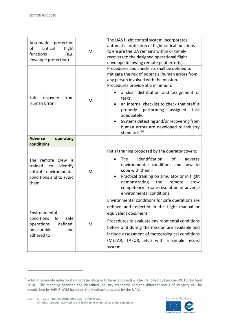
EDITION 00.01.010
156
© – 2017 – IDS, TU Delft, EUROUSC, TOPVIEW SRL. All rights reserved. Licensed to the SESAR Joint Undertaking under conditions
Founding Members
70 A list of adequate industry standards (existing or to be established) will be identified by Eurocae WG105 by April 2018. The mapping between the identified industry standards and the different levels of integrity will be established by JARUS WG6 based on the feedback provided by the NAAs.
Automatic protection of critical flight functions (e.g. envelope protection)
M
The UAS flight control system incorporates automatic protection of flight critical functions to ensure the UA remains within or timely recovers to the designed operational flight envelope following remote pilot error(s).
Safe recovery from Human Error
M
Procedures and checklists shall be defined to mitigate the risk of potential human errors from any person involved with the mission. Procedures provide at a minimum:
• a clear distribution and assignment of tasks,
• an internal checklist to check that staff is properly performing assigned task adequately.
• Systems detecting and/or recovering from human errors are developed to industry standards.70
Adverse operating conditions
The remote crew is trained to identify critical environmental conditions and to avoid them
M
Initial training proposed by the operator covers:
• The identification of adverse environmental conditions and how to cope with them;
• Practical training on simulator or in flight demonstrating the remote crew competency in safe resolution of adverse environmental conditions.
Environmental conditions for safe operations defined, measurable and adhered to
M
Environmental conditions for safe operations are
defined and reflected in the flight manual or
equivalent document.
Procedures to evaluate environmental conditions
before and during the mission are available and
include assessment of meteorological conditions
(METAR, TAFOR, etc.) with a simple record
system.
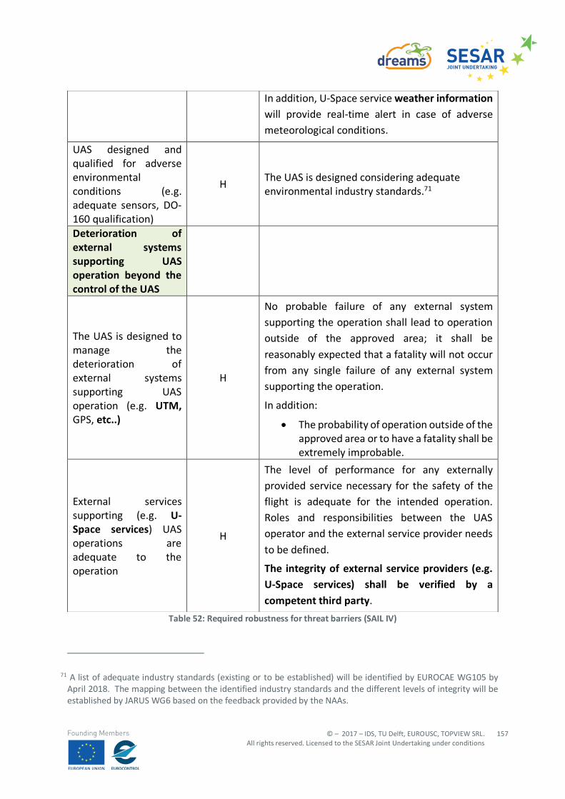
© – 2017 – IDS, TU Delft, EUROUSC, TOPVIEW SRL. All rights reserved. Licensed to the SESAR Joint Undertaking under conditions
157
Founding Members
Table 52: Required robustness for threat barriers (SAIL IV)
71 A list of adequate industry standards (existing or to be established) will be identified by EUROCAE WG105 by April 2018. The mapping between the identified industry standards and the different levels of integrity will be established by JARUS WG6 based on the feedback provided by the NAAs.
In addition, U-Space service weather information will provide real-time alert in case of adverse
meteorological conditions.
UAS designed and qualified for adverse environmental conditions (e.g. adequate sensors, DO-160 qualification)
H The UAS is designed considering adequate environmental industry standards.71
Deterioration of external systems supporting UAS operation beyond the control of the UAS
The UAS is designed to manage the deterioration of external systems supporting UAS operation (e.g. UTM, GPS, etc..)
H
No probable failure of any external system
supporting the operation shall lead to operation
outside of the approved area; it shall be
reasonably expected that a fatality will not occur
from any single failure of any external system
supporting the operation.
In addition:
• The probability of operation outside of the approved area or to have a fatality shall be extremely improbable.
External services supporting (e.g. U-Space services) UAS operations are adequate to the operation
H
The level of performance for any externally
provided service necessary for the safety of the
flight is adequate for the intended operation.
Roles and responsibilities between the UAS
operator and the external service provider needs
to be defined.
The integrity of external service providers (e.g. U-Space services) shall be verified by a
competent third party.
EDITION 00.01.010
158
© – 2017 – IDS, TU Delft, EUROUSC, TOPVIEW SRL. All rights reserved. Licensed to the SESAR Joint Undertaking under conditions
Founding Members
A.1.15 SORA CONCLUSIONS
The analysis carried on with SORA has provided a guidance for determining preliminary requirements which are necessary to conduct operations safely. These requirements include an adequate level of operator competencies (experience, maintenance, emergency plan, operational procedures, etc..) as well as mitigations to be implemented on the drones (failsafe features, anti-collision systems, etc..). To each mitigation (barrier) a robustness level is assigned according to the computed SAIL.
Since UTM/U-Space are in the very early stages of development, UTM/U-Space mitigations have not been factored into the initial air risk assessments (initial ARC) in SORA version 1.1. Nevertheless, SORA v1.1 takes into consideration the availability of U-Space services both as a form of Strategic Mitigation (in order to reduce the ARC) and Tactical Mitigation (with the aim to meet the residual risk level).
As described in Section A1.4 the availability of U-Space services such as Pre-Tactical Geofencing can be taken into account by the operator to avoid possible obstacles on the way. This actually represents a harm barrier.
However, it clearly emerges the necessity to introduce procedures to ensure safe separation from manned traffic in the area (e.g. both in the flight plan approval phase and in-flight phase). This can be achieved with the introduction of a U-Space service which is able to collect surveillance information on manned traffic in the area. An anti-collision system could be installed on the UAS (e.g. FLARM/Pilot Aware etc..) to prevent collision with typical manned aircraft operating at VLL (e.g. helicopters, paragliders etc.).
The basic idea is that drone users should be able to detect and avoid other airspace users but at the same time manned aircraft should be notified about possible planned UAS operations (drones typically have a small size, so visual detection could be very difficult). Therefore, equipping manned aircraft flying at VLL with “U-Space box” could represent a solution of the problem.
In order to improve visibility by other airspace users the introduction of navigation lights specific for drones could be envisaged (as already discussed in Section 3.4.1).
If these actions are implemented, the analysis carried on with SORA shows that the operations described in DREAMS scenario 2 (corresponding to a SAIL IV) can be conducted safely.
As a final remark, SORA methodology does not provide a detailed guidance to investigate the effects of potential failure conditions occurring for one or more U-Space services, providing only a general integrity and assurance requirement: in particular the threat barrier named “External services supporting (e.g. U-Space services) UAS operations are adequate to the operation” is associated to a high level of robustness which implies the intervention of a competent third party for U-Space service providers validation.
The following section provides a detailed failure conditions analysis of the U-Space services involved in the present scenario.
© – 2017 – IDS, TU Delft, EUROUSC, TOPVIEW SRL. All rights reserved. Licensed to the SESAR Joint Undertaking under conditions
159
Founding Members
A.2 Failure Condition Analysis with EASA risk matrix approach As explained in the previous sections, SORA methodology basically treats the UTM architecture as a mitigation for Air-Risk, but specific possible failure condition affecting one of the several envisaged services in the U-Space are not considered. In SORA the risks related to possible malfunctions in digital services, communications or integrity of information are in fact not assessed. Since these possible malfunctions may affect possible interactions among the UAS involved in the scenario, is therefore necessary to use a methodology complementary to SORA.
One of the main advantages of SORA is a structured process, tailored on the UAS risks. However, the methodology is quite rigid and therefore it is not easy to cover topics not already embedded in it.
Conversely a risk-matrix approach, although offering less detailed guidance, is suitable to assess any aspect, being extremely flexible. Therefore, the risks associated to the current scenario, with respect to possible failure conditions in the U-Space services, are used using a risk matrix.
The air risk assessment will be focused on the concurrent flight operations with particular reference to the flight plan submission and authorization. The information exchange between drone users and UTM controller is divided in three phases; in addition, each phase is made up of several sub-processes which take place in a precise time sequence (as reported in the sequence diagrams) and the risk assessment will be focused on each of these.
This section is structured as follows:
- Description of the phase and the related sub-processes - Risk assessment based on the model explained in Chapter 5.
Available U-Space services:
- Pre-tactical geofencing - Strategic deconfliction - Flight planning management - Weather information
PHASE 1: Flight plan approved upon a request from a “stand by drone user “ This first phase (Figure 18) highlights the flight plan submission and approval from the point of view of the stand-by drone user (UAS 1 in Figure 12), waiting for authorization before take-off). The operations for this user are limited to a small area because of the typology of mission (rooftop inspections). The drone will be operated manually by the drone user (no automatic mission) because of limited space of manoeuvres among city buildings which requires good piloting skills. It is assumed that the “Stand-By Drone User” is a registered user. Moreover, the drone is uniquely identified and its unique number and related information (capabilities) are already stored on the authority registry. The stand-by drone user is on the home point waiting for authorization to take-off.
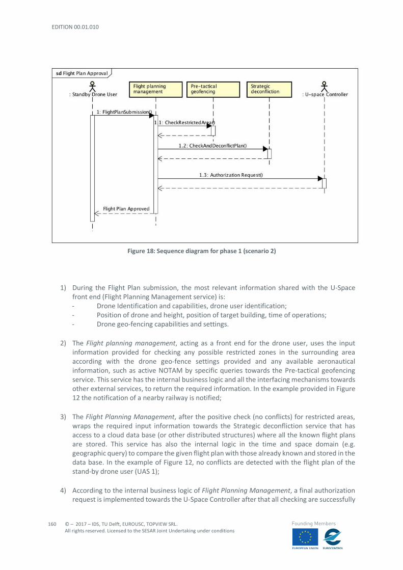
EDITION 00.01.010
160
© – 2017 – IDS, TU Delft, EUROUSC, TOPVIEW SRL. All rights reserved. Licensed to the SESAR Joint Undertaking under conditions
Founding Members
Figure 18: Sequence diagram for phase 1 (scenario 2)
1) During the Flight Plan submission, the most relevant information shared with the U-Space front end (Flight Planning Management service) is: - Drone Identification and capabilities, drone user identification; - Position of drone and height, position of target building, time of operations; - Drone geo-fencing capabilities and settings.
2) The Flight planning management, acting as a front end for the drone user, uses the input
information provided for checking any possible restricted zones in the surrounding area according with the drone geo-fence settings provided and any available aeronautical information, such as active NOTAM by specific queries towards the Pre-tactical geofencing service. This service has the internal business logic and all the interfacing mechanisms towards other external services, to return the required information. In the example provided in Figure 12 the notification of a nearby railway is notified;
3) The Flight Planning Management, after the positive check (no conflicts) for restricted areas,
wraps the required input information towards the Strategic deconfliction service that has access to a cloud data base (or other distributed structures) where all the known flight plans are stored. This service has also the internal logic in the time and space domain (e.g. geographic query) to compare the given flight plan with those already known and stored in the data base. In the example of Figure 12, no conflicts are detected with the flight plan of the stand-by drone user (UAS 1);
4) According to the internal business logic of Flight Planning Management, a final authorization
request is implemented towards the U-Space Controller after that all checking are successfully

© – 2017 – IDS, TU Delft, EUROUSC, TOPVIEW SRL. All rights reserved. Licensed to the SESAR Joint Undertaking under conditions
161
Founding Members
achieved. This actor can be either a human or a “bot” and can operate autonomously or semi-autonomously. The U-Space Controller takes in charge the request by cross checking other sources of information, if required, before final clearance. If the final clearance is given, the notification is forwarded to the stand-by drone user by means of the same interface (or redundantly on two independent channels such as internet and SMS).
The following acronyms are defined for each sub-process identified in the UML diagram with the purpose to provide clear references between failure conditions and safety requirements:
- FPS (Flight plan submission): communication process in which the drone user submits the flight plan containing identification, operational details to the flight planning management block;
- CRA (Check restricted area): information process within the flight planning management block
in which the presence of any restricted areas is checked;
- CDP (Check and deconflict plan): information process within the flight planning management in which the presence of any possible conflict with other UAS is detected;
- AR (Authorization Request): information process in which all the data gathered at previous
steps are forwarded to the controller who can perform a cross-checking;
- FPA (Flight plan approved): communication process in which approval/rejection of flight plan is notified to the drone-user.
Each sub-process is analysed highlighting all the possible failure conditions and subsequent operational effect. The severity of each failure as well as the corresponding safety objective are assessed referring to EASA matrix shown in Section 4.4.3. A preliminary evaluation of system performance parameters (transaction, time, continuity, availability, integrity) is performed according to Section 5.5. It is important to underline that this evaluation is only based on safety considerations: each parameter may appear as a form of mitigation for a certain failure condition or it may be chosen according to qualitative operational considerations. In addition, as already pointed out in Section 5.5, it is important to underline that U-Space services will rely on wireless connections or cellular networks (4G,5G); therefore, a digital service might work correctly but the drone user/controller could not be able to use it. A key aspect to be considered in the risk assessment process is the human factor. It is assumed that human intervention is present in the FPS process (drone user starting the process) and FPA process (flight plan approval forwarded to drone user by the controller). It is important to remark that although this scenario does not include possible flight plan conflicts for UAS 1, the risk assessment is carried on with the assumption that, in general, this cannot be known a priority.
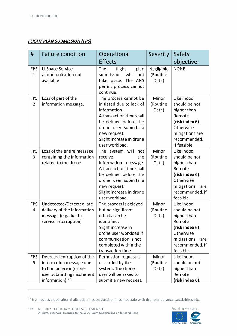
EDITION 00.01.010
162
© – 2017 – IDS, TU Delft, EUROUSC, TOPVIEW SRL. All rights reserved. Licensed to the SESAR Joint Undertaking under conditions
Founding Members
FLIGHT PLAN SUBMISSION (FPS)
# Failure condition Operational Effects
Severity Safety objective
FPS 1
U-Space Service /communication not available
The flight plan submission will not take place. The ANS permit process cannot continue.
Negligible (Routine
Data)
NONE
FPS 2
Loss of part of the information message.
The process cannot be initiated due to lack of information. A transaction time shall be defined before the drone user submits a new request. Slight increase in drone user workload.
Minor (Routine
Data)
Likelihood should be not higher than Remote (risk index 6). Otherwise mitigations are recommended, if feasible.
FPS 3
Loss of the entire message containing the information related to the drone.
The system will not receive the information message. A transaction time shall be defined before the drone user submits a new request. Slight increase in drone user workload.
Minor (Routine
Data)
Likelihood should be not higher than Remote (risk index 6). Otherwise mitigations are recommended, if feasible.
FPS 4
Undetected/Detected late delivery of the information message (e.g. due to service interruption)
The process is delayed but no significant effects can be identified. Slight increase in drone user workload if communication is not completed within the transaction time.
Minor (Routine
Data)
Likelihood should be not higher than Remote (risk index 6). Otherwise mitigations are recommended, if feasible.
FPS 5
Detected corruption of the information message due to human error (drone user submitting incoherent information).72
Permission request is discarded by the system. The drone user will be asked to submit a new request.
Minor (Routine
Data)
Likelihood should be not higher than Remote (risk index 6).
72 E.g. negative operational altitude, mission duration incompatible with drone endurance capabilities etc..
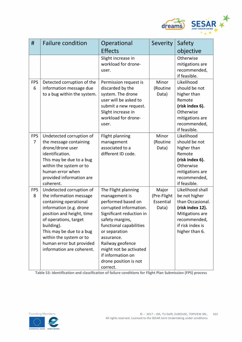
© – 2017 – IDS, TU Delft, EUROUSC, TOPVIEW SRL. All rights reserved. Licensed to the SESAR Joint Undertaking under conditions
163
Founding Members
# Failure condition Operational Effects
Severity Safety objective
Slight increase in workload for drone-user.
Otherwise mitigations are recommended, if feasible.
FPS 6
Detected corruption of the information message due to a bug within the system.
Permission request is discarded by the system. The drone user will be asked to submit a new request. Slight increase in workload for drone-user.
Minor (Routine
Data)
Likelihood should be not higher than Remote (risk index 6). Otherwise mitigations are recommended, if feasible.
FPS 7
Undetected corruption of the message containing drone/drone user identification. This may be due to a bug within the system or to human error when provided information are coherent.
Flight planning management associated to a different ID code.
Minor (Routine
Data)
Likelihood should be not higher than Remote (risk index 6). Otherwise mitigations are recommended, if feasible.
FPS 8
Undetected corruption of the information message containing operational information (e.g. drone position and height, time of operations, target building). This may be due to a bug within the system or to human error but provided information are coherent.
The Flight planning management is performed based on corrupted information. Significant reduction in safety margins, functional capabilities or separation assurance. Railway geofence might not be activated if information on drone position is not correct.
Major (Pre-Flight Essential
Data)
Likelihood shall be not higher than Occasional. (risk index 12). Mitigations are recommended, if risk index is higher than 6.
Table 53: Identification and classification of failure conditions for Flight Plan Submission (FPS) process
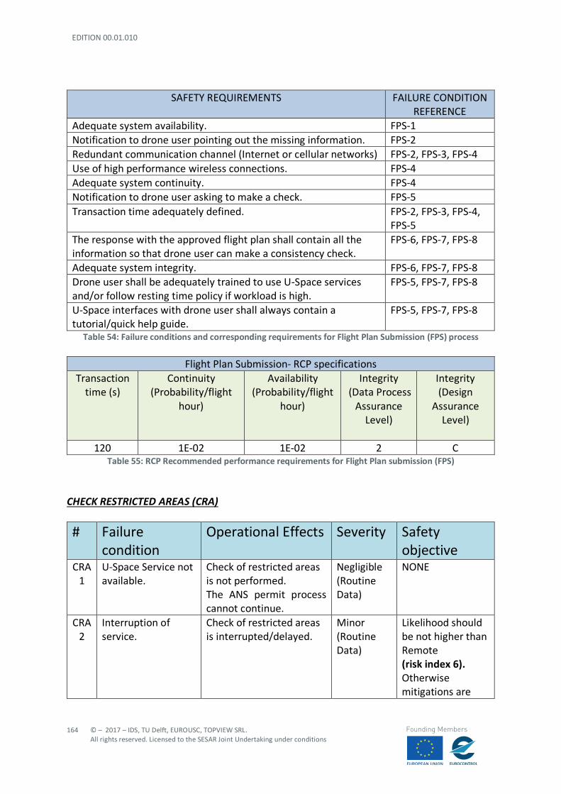
EDITION 00.01.010
164
© – 2017 – IDS, TU Delft, EUROUSC, TOPVIEW SRL. All rights reserved. Licensed to the SESAR Joint Undertaking under conditions
Founding Members
SAFETY REQUIREMENTS FAILURE CONDITION REFERENCE
Adequate system availability. FPS-1 Notification to drone user pointing out the missing information. FPS-2 Redundant communication channel (Internet or cellular networks) FPS-2, FPS-3, FPS-4 Use of high performance wireless connections. FPS-4 Adequate system continuity. FPS-4 Notification to drone user asking to make a check. FPS-5 Transaction time adequately defined. FPS-2, FPS-3, FPS-4,
FPS-5 The response with the approved flight plan shall contain all the information so that drone user can make a consistency check.
FPS-6, FPS-7, FPS-8
Adequate system integrity. FPS-6, FPS-7, FPS-8 Drone user shall be adequately trained to use U-Space services and/or follow resting time policy if workload is high.
FPS-5, FPS-7, FPS-8
U-Space interfaces with drone user shall always contain a tutorial/quick help guide.
FPS-5, FPS-7, FPS-8
Table 54: Failure conditions and corresponding requirements for Flight Plan Submission (FPS) process
Flight Plan Submission- RCP specifications Transaction
time (s) Continuity
(Probability/flight hour)
Availability (Probability/flight
hour)
Integrity (Data Process
Assurance Level)
Integrity (Design
Assurance Level)
120 1E-02 1E-02 2 C Table 55: RCP Recommended performance requirements for Flight Plan submission (FPS)
CHECK RESTRICTED AREAS (CRA)
# Failure condition
Operational Effects Severity Safety objective
CRA 1
U-Space Service not available.
Check of restricted areas is not performed. The ANS permit process cannot continue.
Negligible (Routine Data)
NONE
CRA 2
Interruption of service.
Check of restricted areas is interrupted/delayed.
Minor (Routine Data)
Likelihood should be not higher than Remote (risk index 6). Otherwise mitigations are
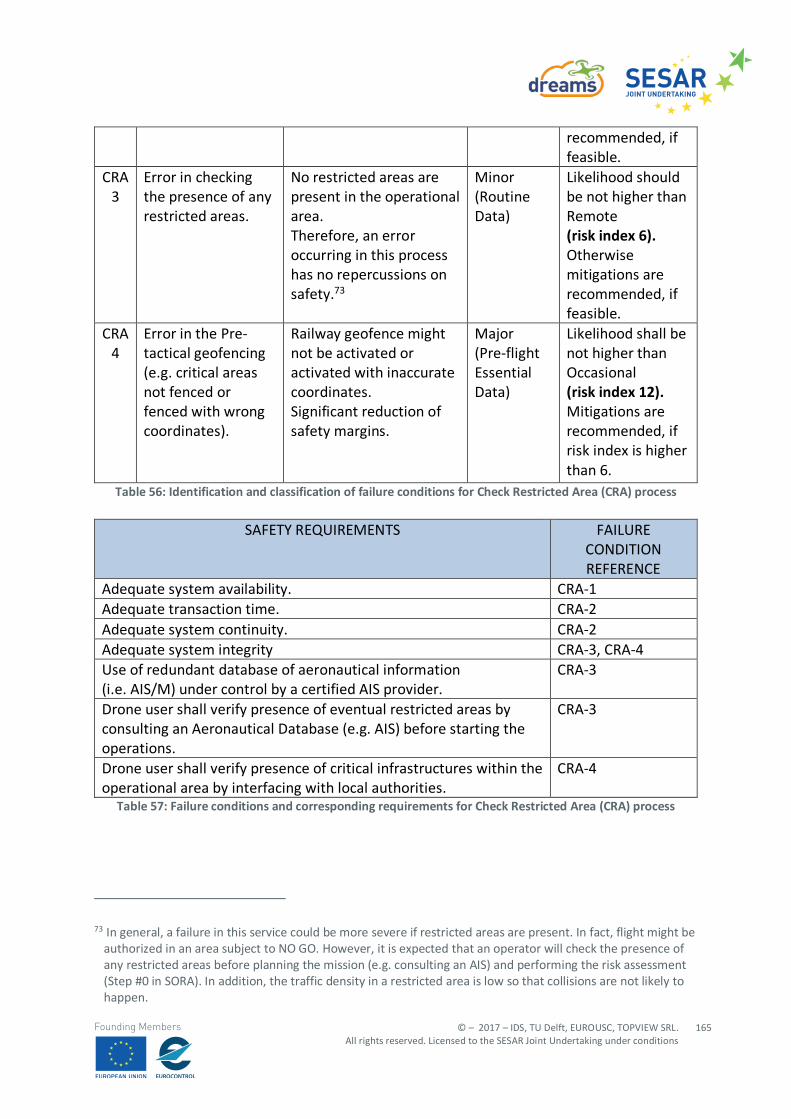
© – 2017 – IDS, TU Delft, EUROUSC, TOPVIEW SRL. All rights reserved. Licensed to the SESAR Joint Undertaking under conditions
165
Founding Members
recommended, if feasible.
CRA 3
Error in checking the presence of any restricted areas.
No restricted areas are present in the operational area. Therefore, an error occurring in this process has no repercussions on safety.73
Minor (Routine Data)
Likelihood should be not higher than Remote (risk index 6). Otherwise mitigations are recommended, if feasible.
CRA 4
Error in the Pre-tactical geofencing (e.g. critical areas not fenced or fenced with wrong coordinates).
Railway geofence might not be activated or activated with inaccurate coordinates. Significant reduction of safety margins.
Major (Pre-flight Essential Data)
Likelihood shall be not higher than Occasional (risk index 12). Mitigations are recommended, if risk index is higher than 6.
Table 56: Identification and classification of failure conditions for Check Restricted Area (CRA) process
SAFETY REQUIREMENTS FAILURE CONDITION REFERENCE
Adequate system availability. CRA-1 Adequate transaction time. CRA-2 Adequate system continuity. CRA-2 Adequate system integrity CRA-3, CRA-4 Use of redundant database of aeronautical information (i.e. AIS/M) under control by a certified AIS provider.
CRA-3
Drone user shall verify presence of eventual restricted areas by consulting an Aeronautical Database (e.g. AIS) before starting the operations.
CRA-3
Drone user shall verify presence of critical infrastructures within the operational area by interfacing with local authorities.
CRA-4
Table 57: Failure conditions and corresponding requirements for Check Restricted Area (CRA) process
73 In general, a failure in this service could be more severe if restricted areas are present. In fact, flight might be
authorized in an area subject to NO GO. However, it is expected that an operator will check the presence of any restricted areas before planning the mission (e.g. consulting an AIS) and performing the risk assessment (Step #0 in SORA). In addition, the traffic density in a restricted area is low so that collisions are not likely to happen.
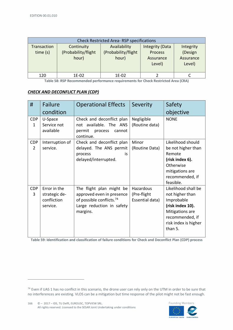
EDITION 00.01.010
166
© – 2017 – IDS, TU Delft, EUROUSC, TOPVIEW SRL. All rights reserved. Licensed to the SESAR Joint Undertaking under conditions
Founding Members
Check Restricted Area- RSP specifications Transaction
time (s) Continuity
(Probability/flight hour)
Availability (Probability/flight
hour)
Integrity (Data Process
Assurance Level)
Integrity (Design
Assurance Level)
120 1E-02 1E-02 2 C Table 58: RSP Recommended performance requirements for Check Restricted Area (CRA)
CHECK AND DECONFLICT PLAN (CDP)
# Failure condition
Operational Effects Severity Safety objective
CDP 1
U-Space Service not available
Check and deconflict plan not available. The ANS permit process cannot continue.
Negligible (Routine data)
NONE
CDP 2
Interruption of service.
Check and deconflict plan delayed. The ANS permit process is delayed/interrupted.
Minor (Routine Data)
Likelihood should be not higher than Remote (risk index 6). Otherwise mitigations are recommended, if feasible.
CDP 3
Error in the strategic de-confliction service.
The flight plan might be approved even in presence of possible conflicts.74 Large reduction in safety margins.
Hazardous (Pre-flight Essential data)
Likelihood shall be not higher than Improbable (risk index 10). Mitigations are recommended, if risk index is higher than 5.
Table 59: Identification and classification of failure conditions for Check and Deconflict Plan (CDP) process
74 Even if UAS 1 has no conflict in this scenario, the drone user can rely only on the UTM in order to be sure that no interferences are existing. VLOS can be a mitigation but time response of the pilot might not be fast enough.
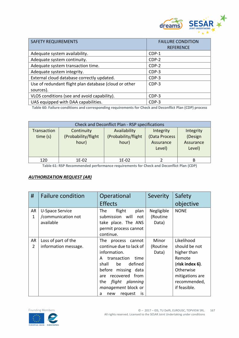
© – 2017 – IDS, TU Delft, EUROUSC, TOPVIEW SRL. All rights reserved. Licensed to the SESAR Joint Undertaking under conditions
167
Founding Members
SAFETY REQUIREMENTS FAILURE CONDITION REFERENCE
Adequate system availability. CDP-1 Adequate system continuity. CDP-2 Adequate system transaction time. CDP-2 Adequate system integrity. CDP-3 External cloud database correctly updated. CDP-3 Use of redundant flight plan database (cloud or other sources).
CDP-3
VLOS conditions (see and avoid capability). CDP-3 UAS equipped with DAA capabilities. CDP-3 Table 60: Failure conditions and corresponding requirements for Check and Deconflict Plan (CDP) process
Check and Deconflict Plan - RSP specifications Transaction
time (s) Continuity
(Probability/flight hour)
Availability (Probability/flight
hour)
Integrity (Data Process
Assurance Level)
Integrity (Design
Assurance Level)
120 1E-02 1E-02 2 B Table 61: RSP Recommended performance requirements for Check and Deconflict Plan (CDP)
AUTHORIZATION REQUEST (AR)
# Failure condition Operational Effects
Severity Safety objective
AR 1
U-Space Service /communication not available
The flight plan submission will not take place. The ANS permit process cannot continue.
Negligible (Routine
Data)
NONE
AR 2
Loss of part of the information message.
The process cannot continue due to lack of information. A transaction time shall be defined before missing data are recovered from the flight planning management block or a new request is
Minor (Routine
Data)
Likelihood should be not higher than Remote (risk index 6). Otherwise mitigations are recommended, if feasible.
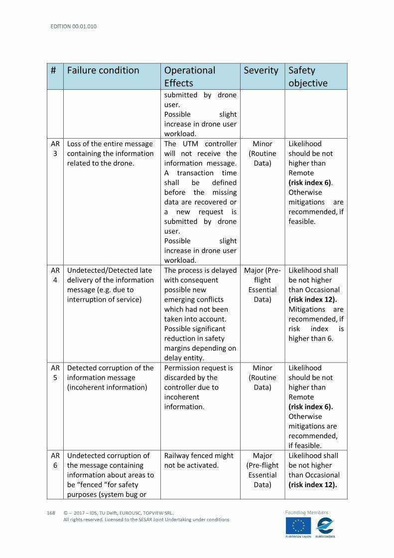
EDITION 00.01.010
168
© – 2017 – IDS, TU Delft, EUROUSC, TOPVIEW SRL. All rights reserved. Licensed to the SESAR Joint Undertaking under conditions
Founding Members
# Failure condition Operational Effects
Severity Safety objective
submitted by drone user. Possible slight increase in drone user workload.
AR 3
Loss of the entire message containing the information related to the drone.
The UTM controller will not receive the information message. A transaction time shall be defined before the missing data are recovered or a new request is submitted by drone user. Possible slight increase in drone user workload.
Minor (Routine
Data)
Likelihood should be not higher than Remote (risk index 6). Otherwise mitigations are recommended, if feasible.
AR 4
Undetected/Detected late delivery of the information message (e.g. due to interruption of service)
The process is delayed with consequent possible new emerging conflicts which had not been taken into account. Possible significant reduction in safety margins depending on delay entity.
Major (Pre-flight
Essential Data)
Likelihood shall be not higher than Occasional (risk index 12). Mitigations are recommended, if risk index is higher than 6.
AR 5
Detected corruption of the information message (incoherent information)
Permission request is discarded by the controller due to incoherent information.
Minor (Routine
Data)
Likelihood should be not higher than Remote (risk index 6). Otherwise mitigations are recommended, if feasible.
AR 6
Undetected corruption of the message containing information about areas to be “fenced “for safety purposes (system bug or
Railway fenced might not be activated.
Major (Pre-flight Essential
Data)
Likelihood shall be not higher than Occasional (risk index 12).
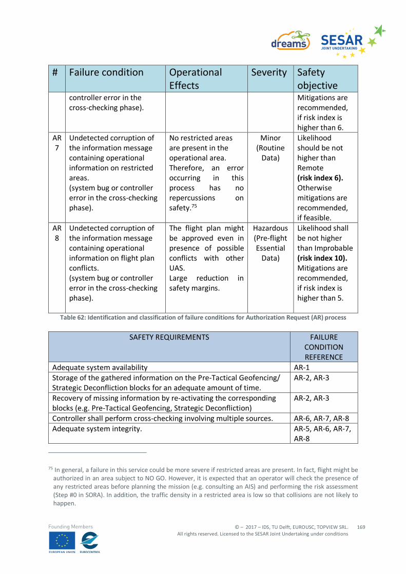
© – 2017 – IDS, TU Delft, EUROUSC, TOPVIEW SRL. All rights reserved. Licensed to the SESAR Joint Undertaking under conditions
169
Founding Members
# Failure condition Operational Effects
Severity Safety objective
controller error in the cross-checking phase).
Mitigations are recommended, if risk index is higher than 6.
AR 7
Undetected corruption of the information message containing operational information on restricted areas. (system bug or controller error in the cross-checking phase).
No restricted areas are present in the operational area. Therefore, an error occurring in this process has no repercussions on safety.75
Minor (Routine
Data)
Likelihood should be not higher than Remote (risk index 6). Otherwise mitigations are recommended, if feasible.
AR 8
Undetected corruption of the information message containing operational information on flight plan conflicts. (system bug or controller error in the cross-checking phase).
The flight plan might be approved even in presence of possible conflicts with other UAS. Large reduction in safety margins.
Hazardous (Pre-flight Essential
Data)
Likelihood shall be not higher than Improbable (risk index 10). Mitigations are recommended, if risk index is higher than 5.
Table 62: Identification and classification of failure conditions for Authorization Request (AR) process
SAFETY REQUIREMENTS FAILURE CONDITION REFERENCE
Adequate system availability AR-1 Storage of the gathered information on the Pre-Tactical Geofencing/ Strategic Deconfliction blocks for an adequate amount of time.
AR-2, AR-3
Recovery of missing information by re-activating the corresponding blocks (e.g. Pre-Tactical Geofencing, Strategic Deconfliction)
AR-2, AR-3
Controller shall perform cross-checking involving multiple sources. AR-6, AR-7, AR-8 Adequate system integrity. AR-5, AR-6, AR-7,
AR-8
75 In general, a failure in this service could be more severe if restricted areas are present. In fact, flight might be
authorized in an area subject to NO GO. However, it is expected that an operator will check the presence of any restricted areas before planning the mission (e.g. consulting an AIS) and performing the risk assessment (Step #0 in SORA). In addition, the traffic density in a restricted area is low so that collisions are not likely to happen.
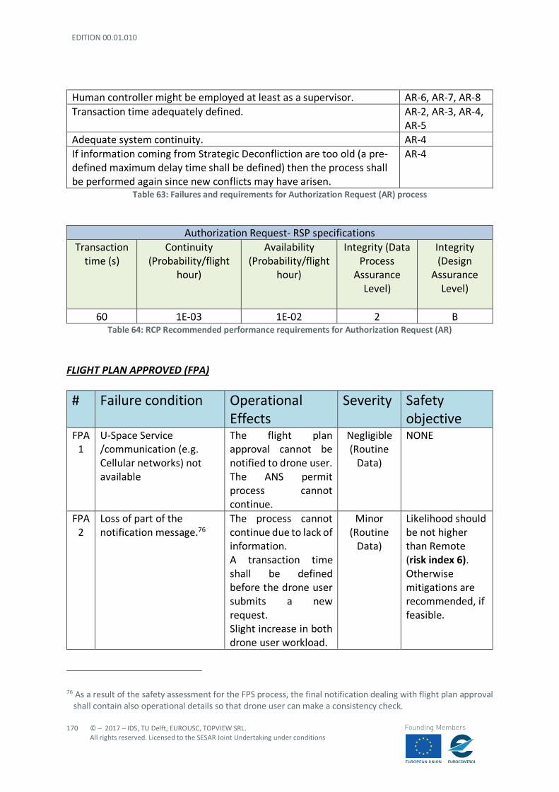
EDITION 00.01.010
170
© – 2017 – IDS, TU Delft, EUROUSC, TOPVIEW SRL. All rights reserved. Licensed to the SESAR Joint Undertaking under conditions
Founding Members
Human controller might be employed at least as a supervisor. AR-6, AR-7, AR-8 Transaction time adequately defined. AR-2, AR-3, AR-4,
AR-5 Adequate system continuity. AR-4 If information coming from Strategic Deconfliction are too old (a pre-defined maximum delay time shall be defined) then the process shall be performed again since new conflicts may have arisen.
AR-4
Table 63: Failures and requirements for Authorization Request (AR) process
Authorization Request- RSP specifications Transaction
time (s) Continuity
(Probability/flight hour)
Availability (Probability/flight
hour)
Integrity (Data Process
Assurance Level)
Integrity (Design
Assurance Level)
60 1E-03 1E-02 2 B
Table 64: RCP Recommended performance requirements for Authorization Request (AR) FLIGHT PLAN APPROVED (FPA) # Failure condition Operational
Effects Severity Safety
objective FPA
1 U-Space Service /communication (e.g. Cellular networks) not available
The flight plan approval cannot be notified to drone user. The ANS permit process cannot continue.
Negligible (Routine
Data)
NONE
FPA 2
Loss of part of the notification message.76
The process cannot continue due to lack of information. A transaction time shall be defined before the drone user submits a new request. Slight increase in both drone user workload.
Minor (Routine
Data)
Likelihood should be not higher than Remote (risk index 6). Otherwise mitigations are recommended, if feasible.
76 As a result of the safety assessment for the FPS process, the final notification dealing with flight plan approval
shall contain also operational details so that drone user can make a consistency check.
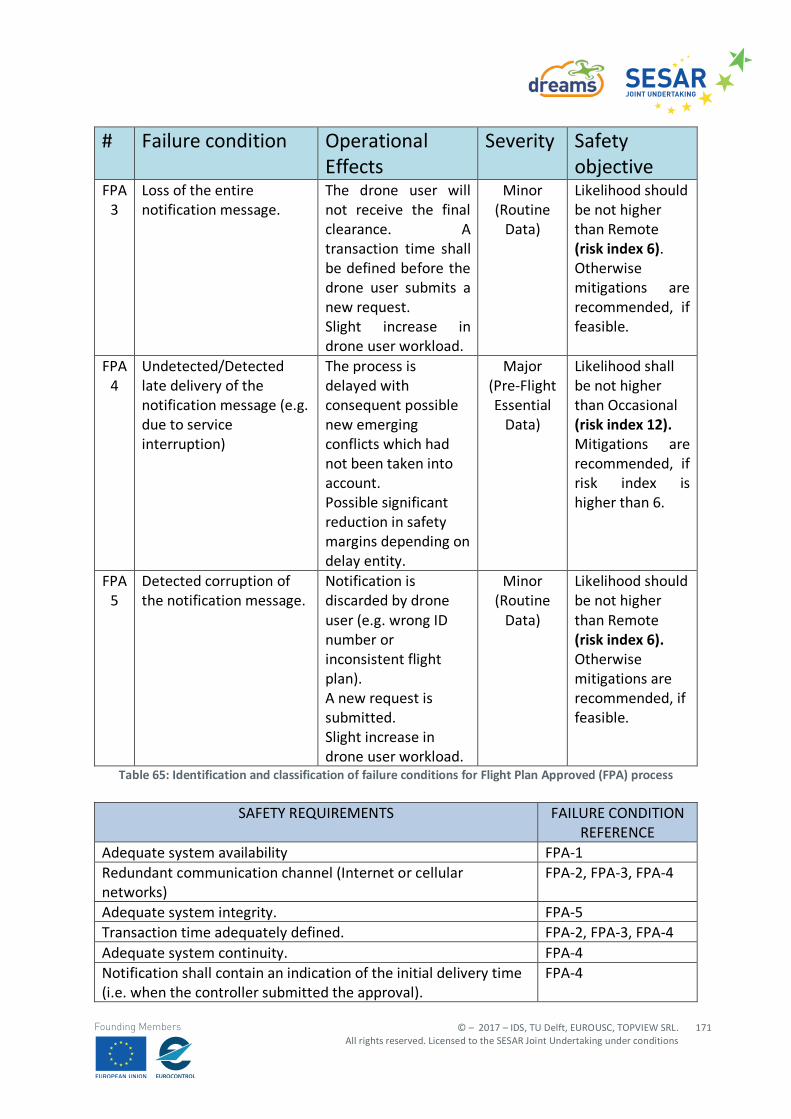
© – 2017 – IDS, TU Delft, EUROUSC, TOPVIEW SRL. All rights reserved. Licensed to the SESAR Joint Undertaking under conditions
171
Founding Members
# Failure condition Operational Effects
Severity Safety objective
FPA 3
Loss of the entire notification message.
The drone user will not receive the final clearance. A transaction time shall be defined before the drone user submits a new request. Slight increase in drone user workload.
Minor (Routine
Data)
Likelihood should be not higher than Remote (risk index 6). Otherwise mitigations are recommended, if feasible.
FPA 4
Undetected/Detected late delivery of the notification message (e.g. due to service interruption)
The process is delayed with consequent possible new emerging conflicts which had not been taken into account. Possible significant reduction in safety margins depending on delay entity.
Major (Pre-Flight Essential
Data)
Likelihood shall be not higher than Occasional (risk index 12). Mitigations are recommended, if risk index is higher than 6.
FPA 5
Detected corruption of the notification message.
Notification is discarded by drone user (e.g. wrong ID number or inconsistent flight plan). A new request is submitted. Slight increase in drone user workload.
Minor (Routine
Data)
Likelihood should be not higher than Remote (risk index 6). Otherwise mitigations are recommended, if feasible.
Table 65: Identification and classification of failure conditions for Flight Plan Approved (FPA) process
SAFETY REQUIREMENTS FAILURE CONDITION REFERENCE
Adequate system availability FPA-1 Redundant communication channel (Internet or cellular networks)
FPA-2, FPA-3, FPA-4
Adequate system integrity. FPA-5 Transaction time adequately defined. FPA-2, FPA-3, FPA-4 Adequate system continuity. FPA-4 Notification shall contain an indication of the initial delivery time (i.e. when the controller submitted the approval).
FPA-4
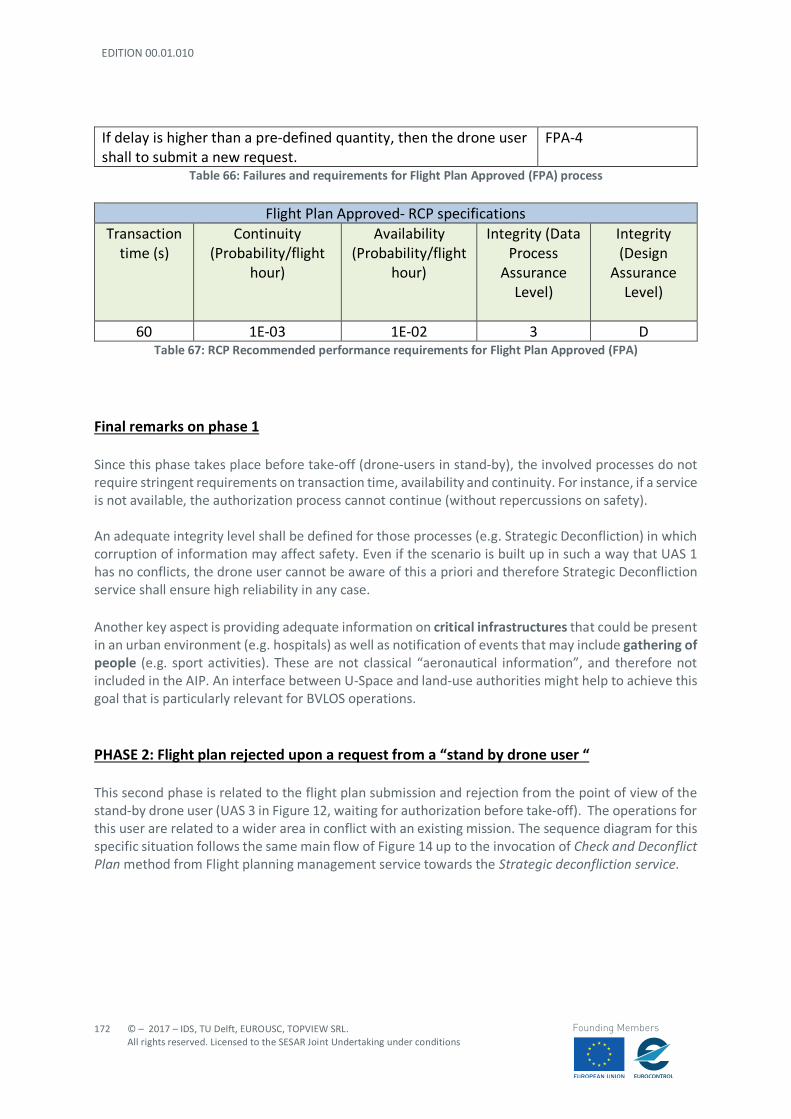
EDITION 00.01.010
172
© – 2017 – IDS, TU Delft, EUROUSC, TOPVIEW SRL. All rights reserved. Licensed to the SESAR Joint Undertaking under conditions
Founding Members
If delay is higher than a pre-defined quantity, then the drone user shall to submit a new request.
FPA-4
Table 66: Failures and requirements for Flight Plan Approved (FPA) process
Flight Plan Approved- RCP specifications Transaction
time (s) Continuity
(Probability/flight hour)
Availability (Probability/flight
hour)
Integrity (Data Process
Assurance Level)
Integrity (Design
Assurance Level)
60 1E-03 1E-02 3 D
Table 67: RCP Recommended performance requirements for Flight Plan Approved (FPA) Final remarks on phase 1 Since this phase takes place before take-off (drone-users in stand-by), the involved processes do not require stringent requirements on transaction time, availability and continuity. For instance, if a service is not available, the authorization process cannot continue (without repercussions on safety). An adequate integrity level shall be defined for those processes (e.g. Strategic Deconfliction) in which corruption of information may affect safety. Even if the scenario is built up in such a way that UAS 1 has no conflicts, the drone user cannot be aware of this a priori and therefore Strategic Deconfliction service shall ensure high reliability in any case. Another key aspect is providing adequate information on critical infrastructures that could be present in an urban environment (e.g. hospitals) as well as notification of events that may include gathering of people (e.g. sport activities). These are not classical “aeronautical information”, and therefore not included in the AIP. An interface between U-Space and land-use authorities might help to achieve this goal that is particularly relevant for BVLOS operations. PHASE 2: Flight plan rejected upon a request from a “stand by drone user “ This second phase is related to the flight plan submission and rejection from the point of view of the stand-by drone user (UAS 3 in Figure 12, waiting for authorization before take-off). The operations for this user are related to a wider area in conflict with an existing mission. The sequence diagram for this specific situation follows the same main flow of Figure 14 up to the invocation of Check and Deconflict Plan method from Flight planning management service towards the Strategic deconfliction service.
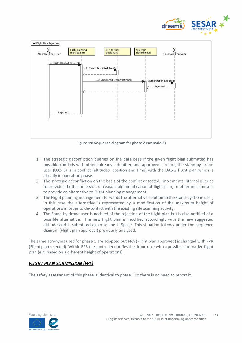
© – 2017 – IDS, TU Delft, EUROUSC, TOPVIEW SRL. All rights reserved. Licensed to the SESAR Joint Undertaking under conditions
173
Founding Members
Figure 19: Sequence diagram for phase 2 (scenario 2)
1) The strategic deconfliction queries on the data base if the given flight plan submitted has possible conflicts with others already submitted and approved. In fact, the stand-by drone user (UAS 3) is in conflict (altitudes, position and time) with the UAS 2 flight plan which is already in operation phase.
2) The strategic deconfliction on the basis of the conflict detected, implements internal queries to provide a better time slot, or reasonable modification of flight plan, or other mechanisms to provide an alternative to Flight planning management.
3) The Flight planning management forwards the alternative solution to the stand-by drone user; in this case the alternative is represented by a modification of the maximum height of operations in order to de-conflict with the existing site scanning activity.
4) The Stand-by drone user is notified of the rejection of the flight plan but is also notified of a possible alternative. The new flight plan is modified accordingly with the new suggested altitude and is submitted again to the U-Space. This situation follows under the sequence diagram (Flight plan approval) previously analysed.
The same acronyms used for phase 1 are adopted but FPA (Flight plan approved) is changed with FPR (Flight plan rejected). Within FPR the controller notifies the drone user with a possible alternative flight plan (e.g. based on a different height of operations). FLIGHT PLAN SUBMISSION (FPS) The safety assessment of this phase is identical to phase 1 so there is no need to report it.
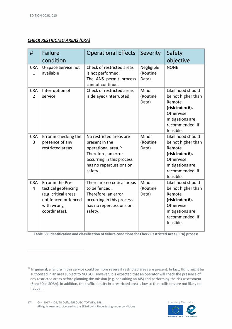
EDITION 00.01.010
174
© – 2017 – IDS, TU Delft, EUROUSC, TOPVIEW SRL. All rights reserved. Licensed to the SESAR Joint Undertaking under conditions
Founding Members
CHECK RESTRICTED AREAS (CRA)
# Failure condition
Operational Effects Severity Safety objective
CRA 1
U-Space Service not available
Check of restricted areas is not performed. The ANS permit process cannot continue.
Negligible (Routine Data)
NONE
CRA 2
Interruption of service.
Check of restricted areas is delayed/interrupted.
Minor (Routine Data)
Likelihood should be not higher than Remote (risk index 6). Otherwise mitigations are recommended, if feasible.
CRA 3
Error in checking the presence of any restricted areas.
No restricted areas are present in the operational area.77 Therefore, an error occurring in this process has no repercussions on safety.
Minor (Routine Data)
Likelihood should be not higher than Remote (risk index 6). Otherwise mitigations are recommended, if feasible.
CRA 4
Error in the Pre-tactical geofencing (e.g. critical areas not fenced or fenced with wrong coordinates).
There are no critical areas to be fenced. Therefore, an error occurring in this process has no repercussions on safety.
Minor (Routine Data)
Likelihood should be not higher than Remote (risk index 6). Otherwise mitigations are recommended, if feasible.
Table 68: Identification and classification of failure conditions for Check Restricted Area (CRA) process
77 In general, a failure in this service could be more severe if restricted areas are present. In fact, flight might be
authorized in an area subject to NO GO. However, it is expected that an operator will check the presence of any restricted areas before planning the mission (e.g. consulting an AIS) and performing the risk assessment (Step #0 in SORA). In addition, the traffic density in a restricted area is low so that collisions are not likely to happen.
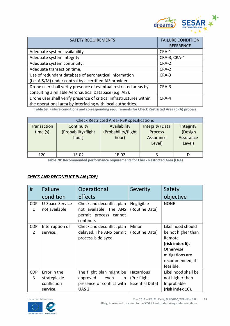
© – 2017 – IDS, TU Delft, EUROUSC, TOPVIEW SRL. All rights reserved. Licensed to the SESAR Joint Undertaking under conditions
175
Founding Members
SAFETY REQUIREMENTS FAILURE CONDITION REFERENCE
Adequate system availability CRA-1 Adequate system integrity CRA-3, CRA-4 Adequate system continuity. CRA-2 Adequate transaction time. CRA-2 Use of redundant database of aeronautical information (i.e. AIS/M) under control by a certified AIS provider.
CRA-3
Drone user shall verify presence of eventual restricted areas by consulting a reliable Aeronautical Database (e.g. AIS).
CRA-3
Drone user shall verify presence of critical infrastructures within the operational area by interfacing with local authorities.
CRA-4
Table 69: Failure conditions and corresponding requirements for Check Restricted Area (CRA) process
Check Restricted Area- RSP specifications Transaction
time (s) Continuity
(Probability/flight hour)
Availability (Probability/flight
hour)
Integrity (Data Process
Assurance Level)
Integrity (Design
Assurance Level)
120 1E-02 1E-02 3 D
Table 70: Recommended performance requirements for Check Restricted Area (CRA) CHECK AND DECONFLICT PLAN (CDP)
# Failure condition
Operational Effects
Severity Safety objective
CDP 1
U-Space Service not available
Check and deconflict plan not available. The ANS permit process cannot continue.
Negligible (Routine Data)
NONE
CDP 2
Interruption of service.
Check and deconflict plan delayed. The ANS permit process is delayed.
Minor (Routine Data)
Likelihood should be not higher than Remote (risk index 6). Otherwise mitigations are recommended, if feasible.
CDP 3
Error in the strategic de-confliction service.
The flight plan might be approved even in presence of conflict with UAS 2.
Hazardous (Pre-flight Essential Data)
Likelihood shall be not higher than Improbable (risk index 10).
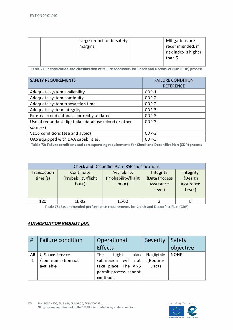
EDITION 00.01.010
176
© – 2017 – IDS, TU Delft, EUROUSC, TOPVIEW SRL. All rights reserved. Licensed to the SESAR Joint Undertaking under conditions
Founding Members
Large reduction in safety margins.
Mitigations are recommended, if risk index is higher than 5.
Table 71: Identification and classification of failure conditions for Check and Deconflict Plan (CDP) process
SAFETY REQUIREMENTS FAILURE CONDITION REFERENCE
Adequate system availability CDP-1 Adequate system continuity CDP-2 Adequate system transaction time. CDP-2 Adequate system integrity CDP-3 External cloud database correctly updated CDP-3 Use of redundant flight plan database (cloud or other sources)
CDP-3
VLOS conditions (see and avoid) CDP-3 UAS equipped with DAA capabilities. CDP-3 Table 72: Failure conditions and corresponding requirements for Check and Deconflict Plan (CDP) process
Check and Deconflict Plan- RSP specifications
Transaction time (s)
Continuity (Probability/flight
hour)
Availability (Probability/flight
hour)
Integrity (Data Process
Assurance Level)
Integrity (Design
Assurance Level)
120 1E-02 1E-02 2 B
Table 73: Recommended performance requirements for Check and Deconflict Plan (CDP) AUTHORIZATION REQUEST (AR)
# Failure condition Operational Effects
Severity Safety objective
AR 1
U-Space Service /communication not available
The flight plan submission will not take place. The ANS permit process cannot continue.
Negligible (Routine
Data)
NONE

© – 2017 – IDS, TU Delft, EUROUSC, TOPVIEW SRL. All rights reserved. Licensed to the SESAR Joint Undertaking under conditions
177
Founding Members
# Failure condition Operational Effects
Severity Safety objective
AR 2
Loss of part of the information message.
The process cannot continue due to lack of information. A transaction time shall be defined after which missing data are recovered from the flight planning management block or a new request is submitted by drone user. Possible slight increase in drone user workload.
Minor (Routine
Data)
Likelihood should be not higher than Remote (risk index 6). Otherwise mitigations are recommended, if feasible.
AR 3
Loss of the entire message containing the information related to the drone.
The UTM controller will not receive the information message. A transaction time shall be defined before the missing data are recovered or a new request is submitted by drone user. Possible slight increase in controller/drone user workload.
Minor (Routine
Data)
Likelihood should be not higher than Remote (risk index 6). Otherwise mitigations are recommended, if feasible.
AR 4
Undetected/Detected late delivery of the information message (e.g. due to interruption of service)
The process is delayed with consequent possible new emerging conflicts which had not been taken into account. Significant reduction in safety margins.
Major (Pre-Flight Essential
Data)
Likelihood shall be not higher than Occasional (risk index 12). Mitigations are recommended, if risk index is higher than 6.
AR 5
Detected corruption of the information message (incoherent information)
Permission request is discarded by the controller due to incoherent information.
Minor (Routine
Data)
Likelihood should be not higher than Remote (risk index 6).
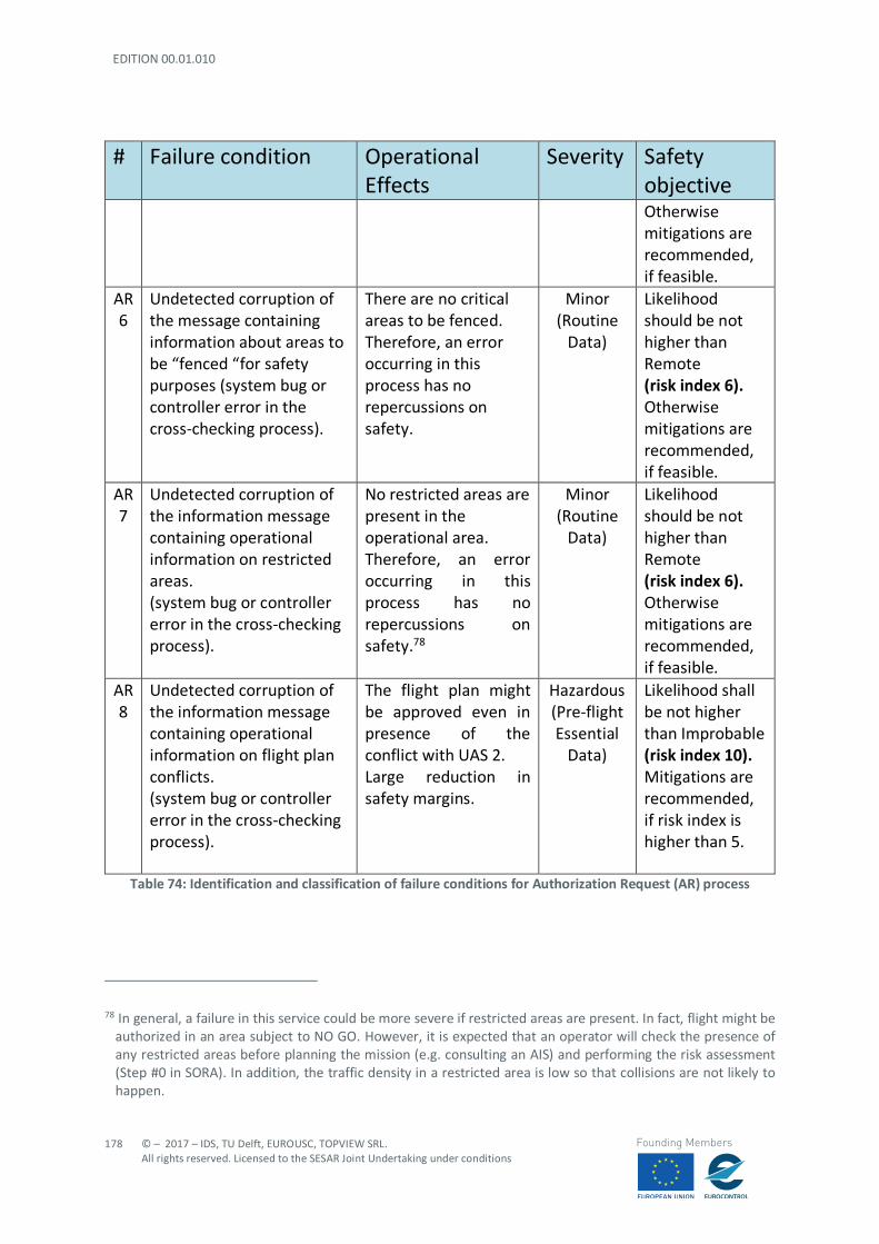
EDITION 00.01.010
178
© – 2017 – IDS, TU Delft, EUROUSC, TOPVIEW SRL. All rights reserved. Licensed to the SESAR Joint Undertaking under conditions
Founding Members
# Failure condition Operational Effects
Severity Safety objective Otherwise mitigations are recommended, if feasible.
AR 6
Undetected corruption of the message containing information about areas to be “fenced “for safety purposes (system bug or controller error in the cross-checking process).
There are no critical areas to be fenced. Therefore, an error occurring in this process has no repercussions on safety.
Minor (Routine
Data)
Likelihood should be not higher than Remote (risk index 6). Otherwise mitigations are recommended, if feasible.
AR 7
Undetected corruption of the information message containing operational information on restricted areas. (system bug or controller error in the cross-checking process).
No restricted areas are present in the operational area. Therefore, an error occurring in this process has no repercussions on safety.78
Minor (Routine
Data)
Likelihood should be not higher than Remote (risk index 6). Otherwise mitigations are recommended, if feasible.
AR 8
Undetected corruption of the information message containing operational information on flight plan conflicts. (system bug or controller error in the cross-checking process).
The flight plan might be approved even in presence of the conflict with UAS 2. Large reduction in safety margins.
Hazardous (Pre-flight Essential
Data)
Likelihood shall be not higher than Improbable (risk index 10). Mitigations are recommended, if risk index is higher than 5.
Table 74: Identification and classification of failure conditions for Authorization Request (AR) process
78 In general, a failure in this service could be more severe if restricted areas are present. In fact, flight might be
authorized in an area subject to NO GO. However, it is expected that an operator will check the presence of any restricted areas before planning the mission (e.g. consulting an AIS) and performing the risk assessment (Step #0 in SORA). In addition, the traffic density in a restricted area is low so that collisions are not likely to happen.
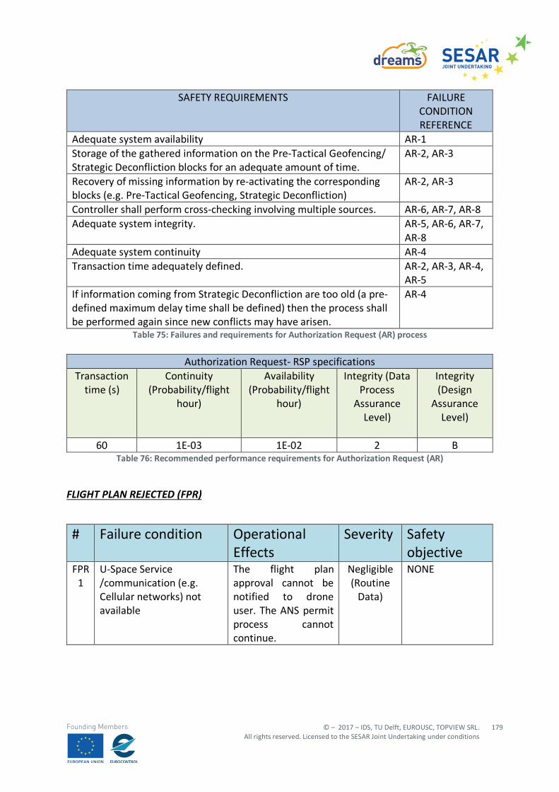
© – 2017 – IDS, TU Delft, EUROUSC, TOPVIEW SRL. All rights reserved. Licensed to the SESAR Joint Undertaking under conditions
179
Founding Members
SAFETY REQUIREMENTS FAILURE CONDITION REFERENCE
Adequate system availability AR-1 Storage of the gathered information on the Pre-Tactical Geofencing/ Strategic Deconfliction blocks for an adequate amount of time.
AR-2, AR-3
Recovery of missing information by re-activating the corresponding blocks (e.g. Pre-Tactical Geofencing, Strategic Deconfliction)
AR-2, AR-3
Controller shall perform cross-checking involving multiple sources. AR-6, AR-7, AR-8 Adequate system integrity. AR-5, AR-6, AR-7,
AR-8 Adequate system continuity AR-4 Transaction time adequately defined. AR-2, AR-3, AR-4,
AR-5 If information coming from Strategic Deconfliction are too old (a pre-defined maximum delay time shall be defined) then the process shall be performed again since new conflicts may have arisen.
AR-4
Table 75: Failures and requirements for Authorization Request (AR) process
Authorization Request- RSP specifications Transaction
time (s) Continuity
(Probability/flight hour)
Availability (Probability/flight
hour)
Integrity (Data Process
Assurance Level)
Integrity (Design
Assurance Level)
60 1E-03 1E-02 2 B Table 76: Recommended performance requirements for Authorization Request (AR)
FLIGHT PLAN REJECTED (FPR)
# Failure condition Operational Effects
Severity Safety objective
FPR 1
U-Space Service /communication (e.g. Cellular networks) not available
The flight plan approval cannot be notified to drone user. The ANS permit process cannot continue.
Negligible (Routine
Data)
NONE
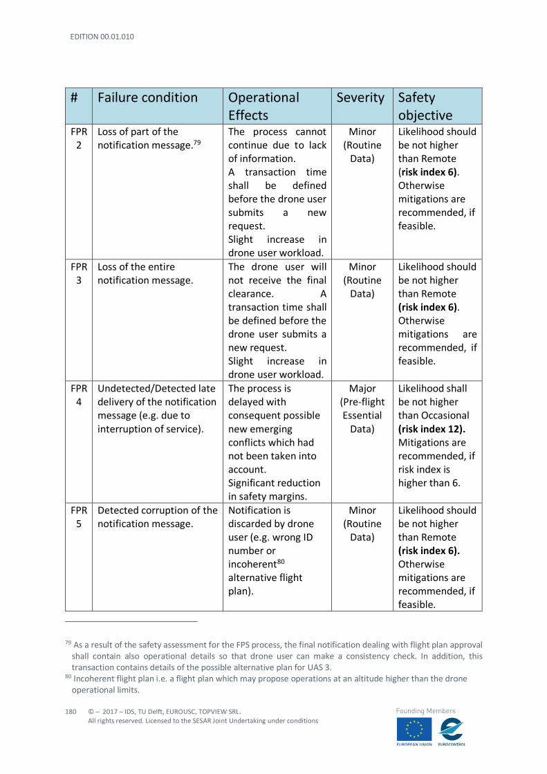
EDITION 00.01.010
180
© – 2017 – IDS, TU Delft, EUROUSC, TOPVIEW SRL. All rights reserved. Licensed to the SESAR Joint Undertaking under conditions
Founding Members
# Failure condition Operational Effects
Severity Safety objective
FPR 2
Loss of part of the notification message.79
The process cannot continue due to lack of information. A transaction time shall be defined before the drone user submits a new request. Slight increase in drone user workload.
Minor (Routine
Data)
Likelihood should be not higher than Remote (risk index 6). Otherwise mitigations are recommended, if feasible.
FPR 3
Loss of the entire notification message.
The drone user will not receive the final clearance. A transaction time shall be defined before the drone user submits a new request. Slight increase in drone user workload.
Minor (Routine
Data)
Likelihood should be not higher than Remote (risk index 6). Otherwise mitigations are recommended, if feasible.
FPR 4
Undetected/Detected late delivery of the notification message (e.g. due to interruption of service).
The process is delayed with consequent possible new emerging conflicts which had not been taken into account. Significant reduction in safety margins.
Major (Pre-flight Essential
Data)
Likelihood shall be not higher than Occasional (risk index 12). Mitigations are recommended, if risk index is higher than 6.
FPR 5
Detected corruption of the notification message.
Notification is discarded by drone user (e.g. wrong ID number or incoherent80 alternative flight plan).
Minor (Routine
Data)
Likelihood should be not higher than Remote (risk index 6). Otherwise mitigations are recommended, if feasible.
79 As a result of the safety assessment for the FPS process, the final notification dealing with flight plan approval
shall contain also operational details so that drone user can make a consistency check. In addition, this transaction contains details of the possible alternative plan for UAS 3.
80 Incoherent flight plan i.e. a flight plan which may propose operations at an altitude higher than the drone operational limits.
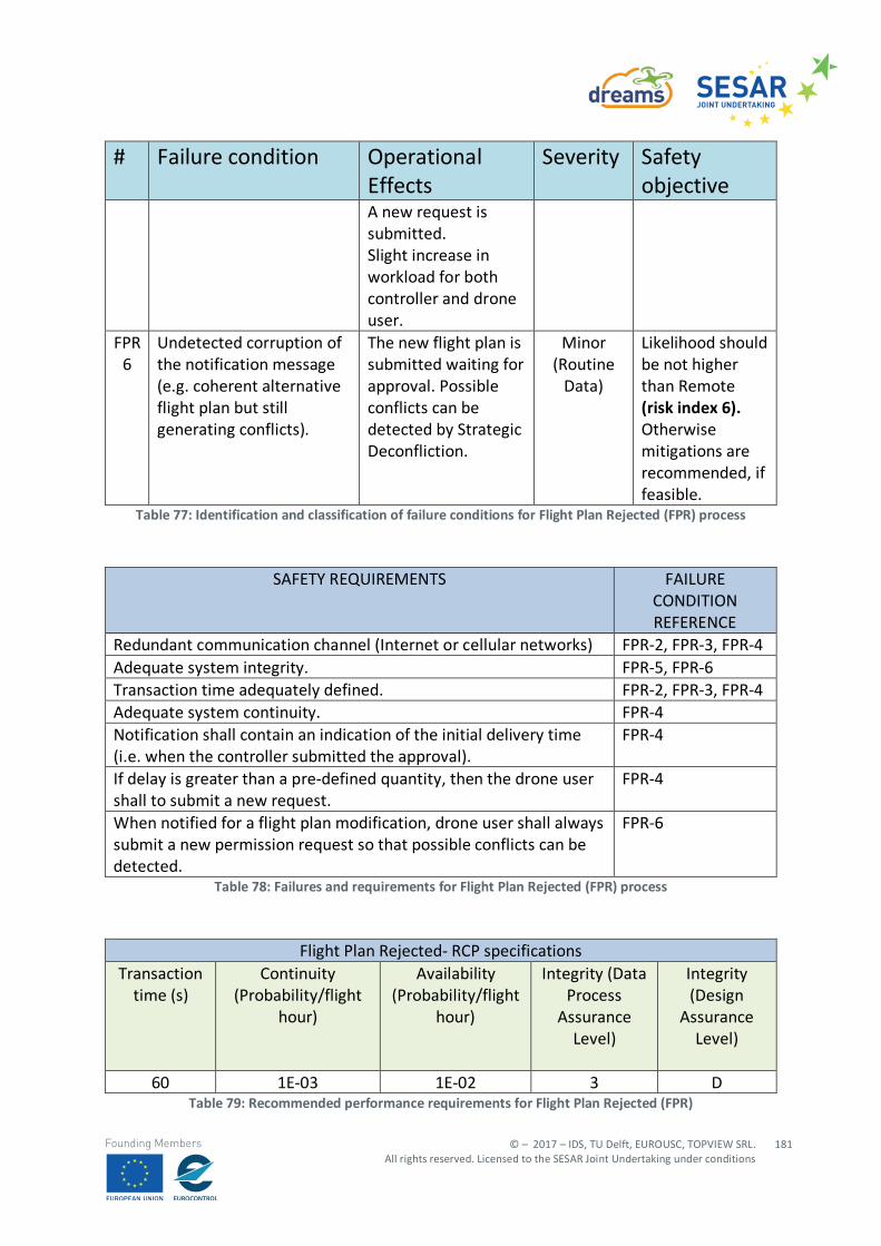
© – 2017 – IDS, TU Delft, EUROUSC, TOPVIEW SRL. All rights reserved. Licensed to the SESAR Joint Undertaking under conditions
181
Founding Members
# Failure condition Operational Effects
Severity Safety objective
A new request is submitted. Slight increase in workload for both controller and drone user.
FPR 6
Undetected corruption of the notification message (e.g. coherent alternative flight plan but still generating conflicts).
The new flight plan is submitted waiting for approval. Possible conflicts can be detected by Strategic Deconfliction.
Minor (Routine
Data)
Likelihood should be not higher than Remote (risk index 6). Otherwise mitigations are recommended, if feasible.
Table 77: Identification and classification of failure conditions for Flight Plan Rejected (FPR) process
SAFETY REQUIREMENTS FAILURE
CONDITION REFERENCE
Redundant communication channel (Internet or cellular networks) FPR-2, FPR-3, FPR-4 Adequate system integrity. FPR-5, FPR-6 Transaction time adequately defined. FPR-2, FPR-3, FPR-4 Adequate system continuity. FPR-4 Notification shall contain an indication of the initial delivery time (i.e. when the controller submitted the approval).
FPR-4
If delay is greater than a pre-defined quantity, then the drone user shall to submit a new request.
FPR-4
When notified for a flight plan modification, drone user shall always submit a new permission request so that possible conflicts can be detected.
FPR-6
Table 78: Failures and requirements for Flight Plan Rejected (FPR) process
Flight Plan Rejected- RCP specifications
Transaction time (s)
Continuity (Probability/flight
hour)
Availability (Probability/flight
hour)
Integrity (Data Process
Assurance Level)
Integrity (Design
Assurance Level)
60 1E-03 1E-02 3 D
Table 79: Recommended performance requirements for Flight Plan Rejected (FPR)
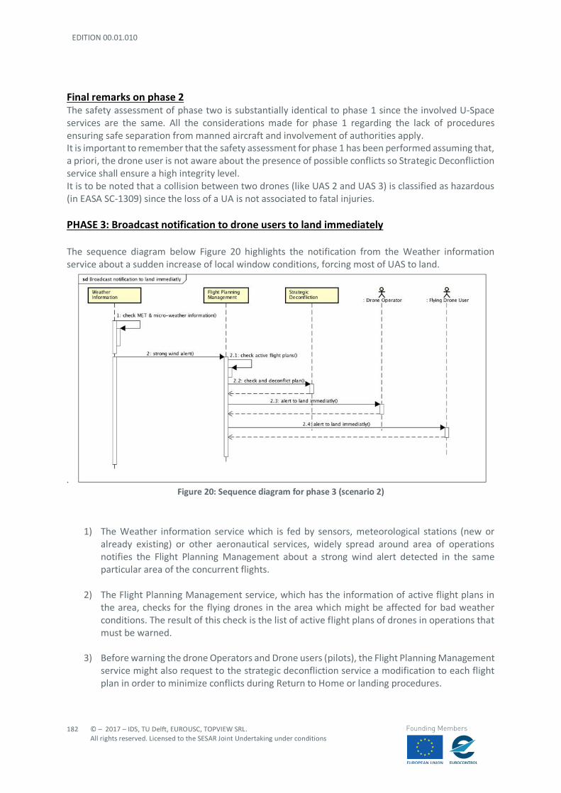
EDITION 00.01.010
182
© – 2017 – IDS, TU Delft, EUROUSC, TOPVIEW SRL. All rights reserved. Licensed to the SESAR Joint Undertaking under conditions
Founding Members
Final remarks on phase 2 The safety assessment of phase two is substantially identical to phase 1 since the involved U-Space services are the same. All the considerations made for phase 1 regarding the lack of procedures ensuring safe separation from manned aircraft and involvement of authorities apply. It is important to remember that the safety assessment for phase 1 has been performed assuming that, a priori, the drone user is not aware about the presence of possible conflicts so Strategic Deconfliction service shall ensure a high integrity level. It is to be noted that a collision between two drones (like UAS 2 and UAS 3) is classified as hazardous (in EASA SC-1309) since the loss of a UA is not associated to fatal injuries. PHASE 3: Broadcast notification to drone users to land immediately The sequence diagram below Figure 20 highlights the notification from the Weather information service about a sudden increase of local window conditions, forcing most of UAS to land.
. Figure 20: Sequence diagram for phase 3 (scenario 2)
1) The Weather information service which is fed by sensors, meteorological stations (new or already existing) or other aeronautical services, widely spread around area of operations notifies the Flight Planning Management about a strong wind alert detected in the same particular area of the concurrent flights.
2) The Flight Planning Management service, which has the information of active flight plans in the area, checks for the flying drones in the area which might be affected for bad weather conditions. The result of this check is the list of active flight plans of drones in operations that must be warned.
3) Before warning the drone Operators and Drone users (pilots), the Flight Planning Management
service might also request to the strategic deconfliction service a modification to each flight plan in order to minimize conflicts during Return to Home or landing procedures.
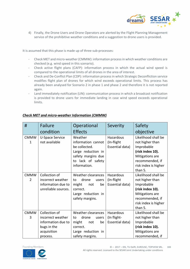
© – 2017 – IDS, TU Delft, EUROUSC, TOPVIEW SRL. All rights reserved. Licensed to the SESAR Joint Undertaking under conditions
183
Founding Members
4) Finally, the Drone Users and Drone Operators are alerted by the Flight Planning Management service of the prohibitive weather conditions and a suggestion to drone users is provided.
It is assumed that this phase is made up of three sub-processes:
- Check MET and micro-weather (CMMW): information process in which weather conditions are checked (e.g. wind speed in this scenario).
- Check active flight plans (CAFP): information process in which the actual wind speed is compared to the operational limits of all drones in the area of interest.
- Check and De-Conflict Plan (CDP): information process in which Strategic Deconfliction service modifies flight plan of drones for which wind exceeds operational limits. This process has already been analysed for Scenario 2 in phase 1 and phase 2 and therefore it is not reported again.
- Land immediately notification (LIN): communication process in which a broadcast notification is provided to drone users for immediate landing in case wind speed exceeds operational limits.
Check MET and micro-weather Information (CMMW) # Failure
condition Operational Effects
Severity Safety objective
CMMW 1
U-Space Service not available
Weather information cannot be collected. Large reduction in safety margins due to lack of safety information.
Hazardous (In-flight Essential data)
Likelihood shall be not higher than Improbable (risk index 10). Mitigations are recommended, if risk index is higher than 5.
CMMW 2
Collection of incorrect weather information due to unreliable sources.
Weather clearances to drone users might not be correct. Large reduction in safety margins.
Hazardous (In-flight Essential data)
Likelihood shall be not higher than Improbable (risk index 10). Mitigations are recommended, if risk index is higher than 5.
CMMW 3
Collection of incorrect weather information due to bugs in the acquisition process.
Weather clearances to drone users might not be correct. Large reduction in safety margins.
Hazardous (In flight-Essential data)
Likelihood shall be not higher than Improbable (risk index 10). Mitigations are recommended, if
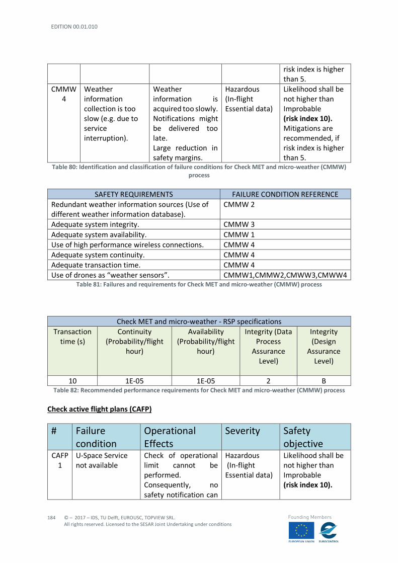
EDITION 00.01.010
184
© – 2017 – IDS, TU Delft, EUROUSC, TOPVIEW SRL. All rights reserved. Licensed to the SESAR Joint Undertaking under conditions
Founding Members
risk index is higher than 5.
CMMW 4
Weather information collection is too slow (e.g. due to service interruption).
Weather information is acquired too slowly. Notifications might be delivered too late. Large reduction in safety margins.
Hazardous (In-flight Essential data)
Likelihood shall be not higher than Improbable (risk index 10). Mitigations are recommended, if risk index is higher than 5.
Table 80: Identification and classification of failure conditions for Check MET and micro-weather (CMMW) process
SAFETY REQUIREMENTS FAILURE CONDITION REFERENCE
Redundant weather information sources (Use of different weather information database).
CMMW 2
Adequate system integrity. CMMW 3 Adequate system availability. CMMW 1 Use of high performance wireless connections. CMMW 4 Adequate system continuity. CMMW 4 Adequate transaction time. CMMW 4 Use of drones as “weather sensors”. CMMW1,CMMW2,CMWW3,CMWW4
Table 81: Failures and requirements for Check MET and micro-weather (CMMW) process
Check MET and micro-weather - RSP specifications Transaction
time (s) Continuity
(Probability/flight hour)
Availability (Probability/flight
hour)
Integrity (Data Process
Assurance Level)
Integrity (Design
Assurance Level)
10 1E-05 1E-05 2 B
Table 82: Recommended performance requirements for Check MET and micro-weather (CMMW) process
Check active flight plans (CAFP) # Failure
condition Operational Effects
Severity Safety objective
CAFP 1
U-Space Service not available
Check of operational limit cannot be performed. Consequently, no safety notification can
Hazardous (In-flight Essential data)
Likelihood shall be not higher than Improbable (risk index 10).
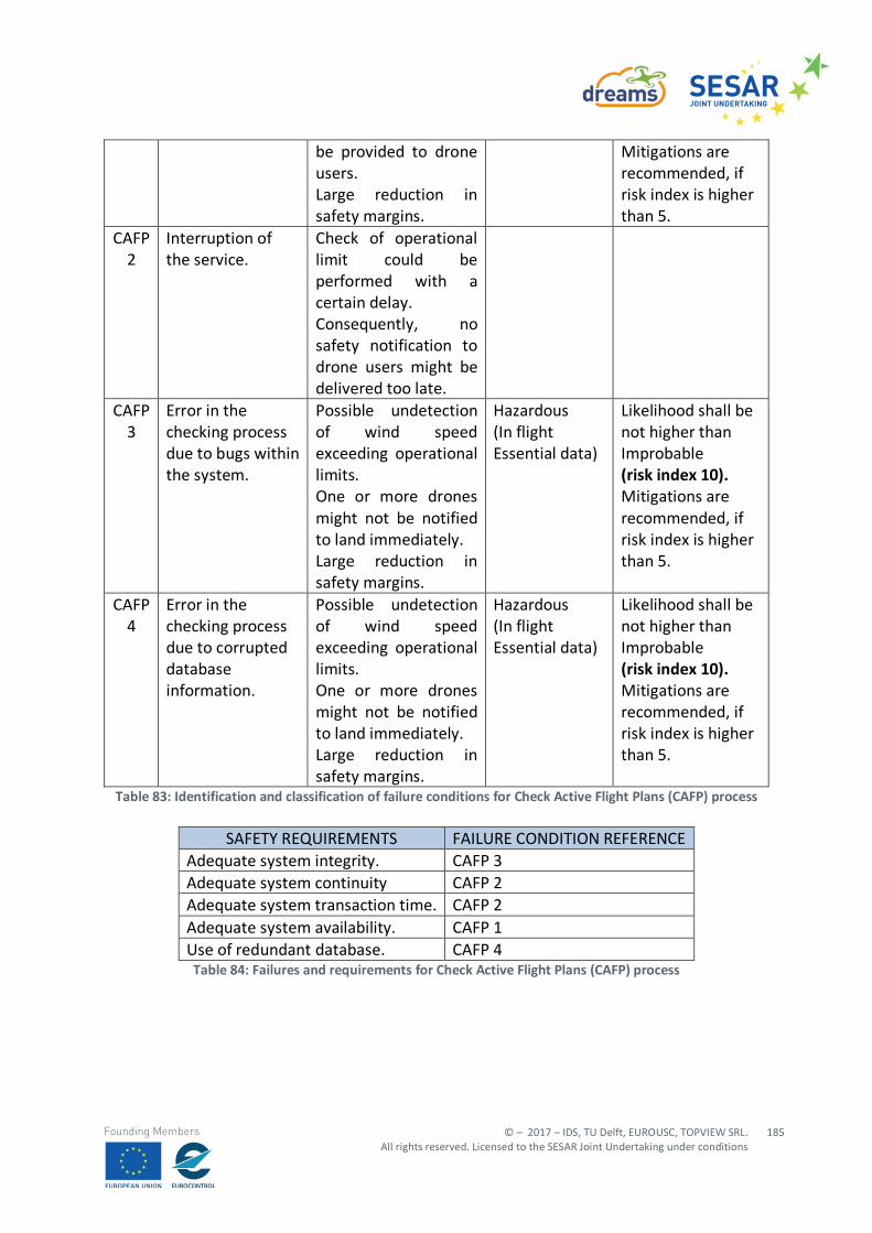
© – 2017 – IDS, TU Delft, EUROUSC, TOPVIEW SRL. All rights reserved. Licensed to the SESAR Joint Undertaking under conditions
185
Founding Members
be provided to drone users. Large reduction in safety margins.
Mitigations are recommended, if risk index is higher than 5.
CAFP 2
Interruption of the service.
Check of operational limit could be performed with a certain delay. Consequently, no safety notification to drone users might be delivered too late.
CAFP 3
Error in the checking process due to bugs within the system.
Possible undetection of wind speed exceeding operational limits. One or more drones might not be notified to land immediately. Large reduction in safety margins.
Hazardous (In flight Essential data)
Likelihood shall be not higher than Improbable (risk index 10). Mitigations are recommended, if risk index is higher than 5.
CAFP 4
Error in the checking process due to corrupted database information.
Possible undetection of wind speed exceeding operational limits. One or more drones might not be notified to land immediately. Large reduction in safety margins.
Hazardous (In flight Essential data)
Likelihood shall be not higher than Improbable (risk index 10). Mitigations are recommended, if risk index is higher than 5.
Table 83: Identification and classification of failure conditions for Check Active Flight Plans (CAFP) process
SAFETY REQUIREMENTS FAILURE CONDITION REFERENCE Adequate system integrity. CAFP 3 Adequate system continuity CAFP 2 Adequate system transaction time. CAFP 2 Adequate system availability. CAFP 1 Use of redundant database. CAFP 4
Table 84: Failures and requirements for Check Active Flight Plans (CAFP) process
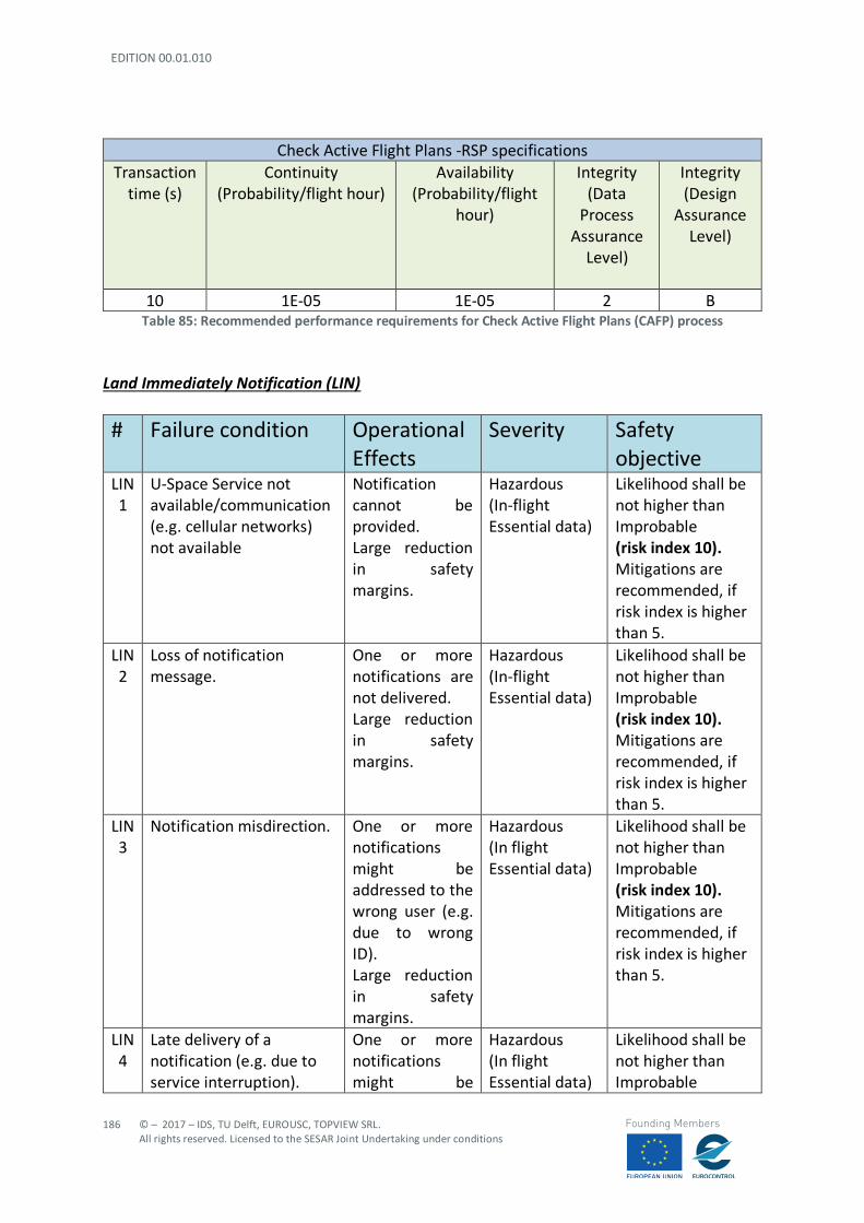
EDITION 00.01.010
186
© – 2017 – IDS, TU Delft, EUROUSC, TOPVIEW SRL. All rights reserved. Licensed to the SESAR Joint Undertaking under conditions
Founding Members
Check Active Flight Plans -RSP specifications Transaction
time (s) Continuity
(Probability/flight hour) Availability
(Probability/flight hour)
Integrity (Data
Process Assurance
Level)
Integrity (Design
Assurance Level)
10 1E-05 1E-05 2 B Table 85: Recommended performance requirements for Check Active Flight Plans (CAFP) process
Land Immediately Notification (LIN) # Failure condition Operational
Effects Severity Safety
objective LIN 1
U-Space Service not available/communication (e.g. cellular networks) not available
Notification cannot be provided. Large reduction in safety margins.
Hazardous (In-flight Essential data)
Likelihood shall be not higher than Improbable (risk index 10). Mitigations are recommended, if risk index is higher than 5.
LIN 2
Loss of notification message.
One or more notifications are not delivered. Large reduction in safety margins.
Hazardous (In-flight Essential data)
Likelihood shall be not higher than Improbable (risk index 10). Mitigations are recommended, if risk index is higher than 5.
LIN 3
Notification misdirection. One or more notifications might be addressed to the wrong user (e.g. due to wrong ID). Large reduction in safety margins.
Hazardous (In flight Essential data)
Likelihood shall be not higher than Improbable (risk index 10). Mitigations are recommended, if risk index is higher than 5.
LIN 4
Late delivery of a notification (e.g. due to service interruption).
One or more notifications might be
Hazardous (In flight Essential data)
Likelihood shall be not higher than Improbable
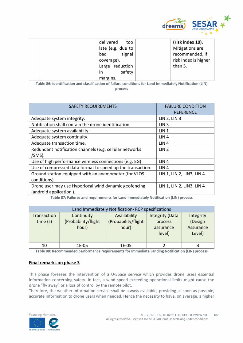
© – 2017 – IDS, TU Delft, EUROUSC, TOPVIEW SRL. All rights reserved. Licensed to the SESAR Joint Undertaking under conditions
187
Founding Members
delivered too late (e.g. due to bad signal coverage). Large reduction in safety margins.
(risk index 10). Mitigations are recommended, if risk index is higher than 5.
Table 86: Identification and classification of failure conditions for Land Immediately Notification (LIN) process
SAFETY REQUIREMENTS FAILURE CONDITION REFERENCE
Adequate system integrity. LIN 2, LIN 3 Notification shall contain the drone identification. LIN 3 Adequate system availability. LIN 1 Adequate system continuity. LIN 4 Adequate transaction time. LIN 4 Redundant notification channels (e.g. cellular networks /SMS).
LIN 2
Use of high performance wireless connections (e.g. 5G) LIN 4 Use of compressed data format to speed up the transaction. LIN 4 Ground station equipped with an anemometer (for VLOS conditions).
LIN 1, LIN 2, LIN3, LIN 4
Drone user may use Hyperlocal wind dynamic geofencing (android application ).
LIN 1, LIN 2, LIN3, LIN 4
Table 87: Failures and requirements for Land Immediately Notification (LIN) process
Land Immediately Notification- RCP specifications Transaction
time (s) Continuity
(Probability/flight hour)
Availability (Probability/flight
hour)
Integrity (Data process
assurance level)
Integrity (Design
Assurance Level)
10 1E-05 1E-05 2 B
Table 88: Recommended performance requirements for Immediate Landing Notification (LIN) process Final remarks on phase 3 This phase foresees the intervention of a U-Space service which provides drone users essential information concerning safety. In fact, a wind speed exceeding operational limits might cause the drone “fly away” or a loss of control by the remote pilot. Therefore, the weather information service shall be always available, providing as soon as possible, accurate information to drone users when needed. Hence the necessity to have, on average, a higher
EDITION 00.01.010
188
© – 2017 – IDS, TU Delft, EUROUSC, TOPVIEW SRL. All rights reserved. Licensed to the SESAR Joint Undertaking under conditions
Founding Members
system performance in terms of transaction time, continuity, availability and integrity with respect to the processes taking place in phase 1 and 2 which take place before take-off. As a mitigation for possible failure conditions occurring to weather information service, for operations in VLOS (UAS 1 and UAS 3 in the current scenario), remote pilot may be able to know wind speed in real time (e.g. using an anemometer) and take precautions subsequently. For BVLOS conditions (UAS 2) the ground station could be far away from the actual position of the drone, making more difficult for the pilot to have perception of adverse operating conditions. In a future perspective, several drones flying in the same area might be used as “weather sensors” to automatically broadcast meteorological information to both U-Space and other users. It is also evident that, since communication between a UTM controller and a drone user relies on cellular networks (4G,5G), the reliability and availability of such means shall be granted before starting the operations. It may happen, for instance, that operations are planned in an area having a bad signal coverage (e.g. rural areas or urban canyons): this may impact on safety even if U-Space service providers are working correctly. In this case an alternative communication means (e.g. Satellite communication) could be considered.
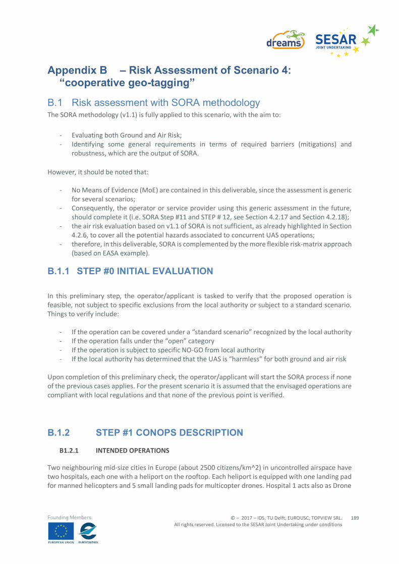
© – 2017 – IDS, TU Delft, EUROUSC, TOPVIEW SRL. All rights reserved. Licensed to the SESAR Joint Undertaking under conditions
189
Founding Members
Appendix B – Risk Assessment of Scenario 4: “cooperative geo-tagging”
B.1 Risk assessment with SORA methodology The SORA methodology (v1.1) is fully applied to this scenario, with the aim to:
- Evaluating both Ground and Air Risk; - Identifying some general requirements in terms of required barriers (mitigations) and
robustness, which are the output of SORA.
However, it should be noted that:
- No Means of Evidence (MoE) are contained in this deliverable, since the assessment is generic for several scenarios;
- Consequently, the operator or service provider using this generic assessment in the future, should complete it (i.e. SORA Step #11 and STEP # 12, see Section 4.2.17 and Section 4.2.18);
- the air risk evaluation based on v1.1 of SORA is not sufficient, as already highlighted in Section 4.2.6, to cover all the potential hazards associated to concurrent UAS operations;
- therefore, in this deliverable, SORA is complemented by the more flexible risk-matrix approach (based on EASA example).
B.1.1 STEP #0 INITIAL EVALUATION
In this preliminary step, the operator/applicant is tasked to verify that the proposed operation is feasible, not subject to specific exclusions from the local authority or subject to a standard scenario. Things to verify include:
- If the operation can be covered under a “standard scenario” recognized by the local authority - If the operation falls under the “open” category - If the operation is subject to specific NO-GO from local authority - If the local authority has determined that the UAS is “harmless” for both ground and air risk
Upon completion of this preliminary check, the operator/applicant will start the SORA process if none of the previous cases applies. For the present scenario it is assumed that the envisaged operations are compliant with local regulations and that none of the previous point is verified.
B.1.2 STEP #1 CONOPS DESCRIPTION
B1.2.1 INTENDED OPERATIONS
Two neighbouring mid-size cities in Europe (about 2500 citizens/km^2) in uncontrolled airspace have two hospitals, each one with a heliport on the rooftop. Each heliport is equipped with one landing pad for manned helicopters and 5 small landing pads for multicopter drones. Hospital 1 acts also as Drone
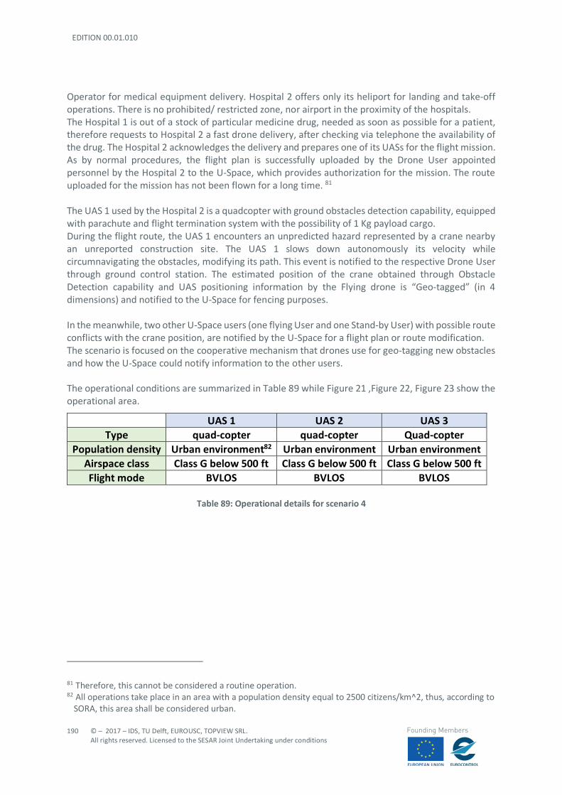
EDITION 00.01.010
190
© – 2017 – IDS, TU Delft, EUROUSC, TOPVIEW SRL. All rights reserved. Licensed to the SESAR Joint Undertaking under conditions
Founding Members
Operator for medical equipment delivery. Hospital 2 offers only its heliport for landing and take-off operations. There is no prohibited/ restricted zone, nor airport in the proximity of the hospitals. The Hospital 1 is out of a stock of particular medicine drug, needed as soon as possible for a patient, therefore requests to Hospital 2 a fast drone delivery, after checking via telephone the availability of the drug. The Hospital 2 acknowledges the delivery and prepares one of its UASs for the flight mission. As by normal procedures, the flight plan is successfully uploaded by the Drone User appointed personnel by the Hospital 2 to the U-Space, which provides authorization for the mission. The route uploaded for the mission has not been flown for a long time. 81 The UAS 1 used by the Hospital 2 is a quadcopter with ground obstacles detection capability, equipped with parachute and flight termination system with the possibility of 1 Kg payload cargo. During the flight route, the UAS 1 encounters an unpredicted hazard represented by a crane nearby an unreported construction site. The UAS 1 slows down autonomously its velocity while circumnavigating the obstacles, modifying its path. This event is notified to the respective Drone User through ground control station. The estimated position of the crane obtained through Obstacle Detection capability and UAS positioning information by the Flying drone is “Geo-tagged” (in 4 dimensions) and notified to the U-Space for fencing purposes. In the meanwhile, two other U-Space users (one flying User and one Stand-by User) with possible route conflicts with the crane position, are notified by the U-Space for a flight plan or route modification. The scenario is focused on the cooperative mechanism that drones use for geo-tagging new obstacles and how the U-Space could notify information to the other users. The operational conditions are summarized in Table 89 while Figure 21 ,Figure 22, Figure 23 show the operational area.
Table 89: Operational details for scenario 4
81 Therefore, this cannot be considered a routine operation. 82 All operations take place in an area with a population density equal to 2500 citizens/km^2, thus, according to
SORA, this area shall be considered urban.
UAS 1 UAS 2 UAS 3 Type quad-copter quad-copter Quad-copter
Population density Urban environment82 Urban environment Urban environment Airspace class Class G below 500 ft Class G below 500 ft Class G below 500 ft Flight mode BVLOS BVLOS BVLOS
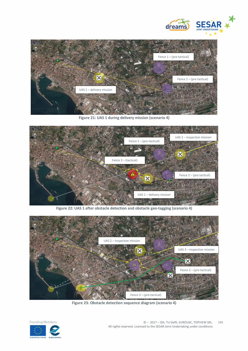
© – 2017 – IDS, TU Delft, EUROUSC, TOPVIEW SRL. All rights reserved. Licensed to the SESAR Joint Undertaking under conditions
191
Founding Members
Figure 21: UAS 1 during delivery mission (scenario 4)
Figure 22: UAS 1 after obstacle detection and obstacle geo-tagging (scenario 4)
Figure 23: Obstacle detection sequence diagram (scenario 4)
UAS 1 – delivery mission
Fence 1 – (pre tactical)
Fence 2 – (pre tactical)
UAS 1 – delivery mission
Fence 1 – (pre tactical)
Fence 2 – (pre tactical)
Fence 3 – (tactical)
UAS 2 – inspection mission
Fence 3 – (pre-tactical)
UAS 2 – inspection mission
UAS 3 – inspection mission
Fence 2 – (pre-tactical)
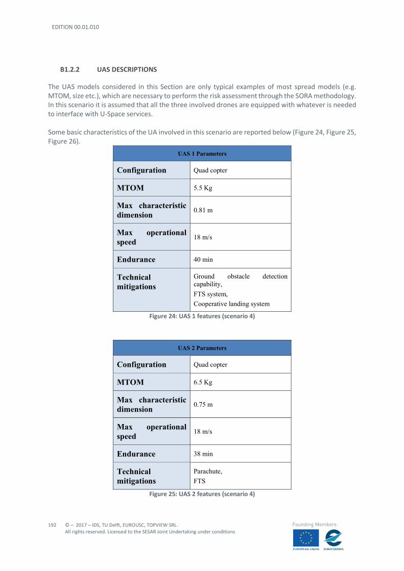
EDITION 00.01.010
192
© – 2017 – IDS, TU Delft, EUROUSC, TOPVIEW SRL. All rights reserved. Licensed to the SESAR Joint Undertaking under conditions
Founding Members
B1.2.2 UAS DESCRIPTIONS
The UAS models considered in this Section are only typical examples of most spread models (e.g. MTOM, size etc.), which are necessary to perform the risk assessment through the SORA methodology. In this scenario it is assumed that all the three involved drones are equipped with whatever is needed to interface with U-Space services. Some basic characteristics of the UA involved in this scenario are reported below (Figure 24, Figure 25, Figure 26).
UAS 1 Parameters
Configuration Quad copter
MTOM 5.5 Kg
Max characteristic dimension 0.81 m
Max operational speed 18 m/s
Endurance 40 min
Technical mitigations
Ground obstacle detection capability, FTS system, Cooperative landing system
Figure 24: UAS 1 features (scenario 4)
UAS 2 Parameters
Configuration Quad copter
MTOM 6.5 Kg
Max characteristic dimension 0.75 m
Max operational speed 18 m/s
Endurance 38 min
Technical mitigations
Parachute, FTS
Figure 25: UAS 2 features (scenario 4)
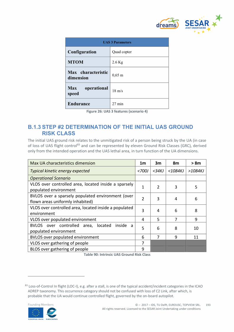
© – 2017 – IDS, TU Delft, EUROUSC, TOPVIEW SRL. All rights reserved. Licensed to the SESAR Joint Undertaking under conditions
193
Founding Members
UAS 3 Parameters
Configuration Quad copter
MTOM 2.6 Kg
Max characteristic dimension 0,65 m
Max operational speed 18 m/s
Endurance 27 min
Figure 26: UAS 3 features (scenario 4)
B.1.3 STEP #2 DETERMINATION OF THE INITIAL UAS GROUND RISK CLASS
The initial UAS ground risk relates to the unmitigated risk of a person being struck by the UA (in case of loss of UAS flight control83 and can be represented by eleven Ground Risk Classes (GRC), derived only from the intended operation and the UAS lethal area, in turn function of the UA dimensions.
Max UA characteristics dimension 1m 3m 8m > 8m
Typical kinetic energy expected <700J <34KJ <1084KJ >1084KJ Operational Scenario VLOS over controlled area, located inside a sparsely populated environment
1 2 3 5
BVLOS over a sparsely populated environment (over flown areas uniformly inhabited)
2 3 4 6
VLOS over controlled area, located inside a populated environment
3 4 6 8
VLOS over populated environment 4 5 7 9 BVLOS over controlled area, located inside a populated environment
5 6 8 10
BVLOS over populated environment 6 7 9 11 VLOS over gathering of people 7 BLOS over gathering of people 9
Table 90: Intrinsic UAS Ground Risk Class
83 Loss-of-Control In flight (LOC-I), e.g. after a stall, is one of the typical accident/incident categories in the ICAO ADREP taxonomy. This occurrence category should not be confused with loss of C2 Link, after which, is probable that the UA would continue controlled flight, governed by the on-board autopilot.
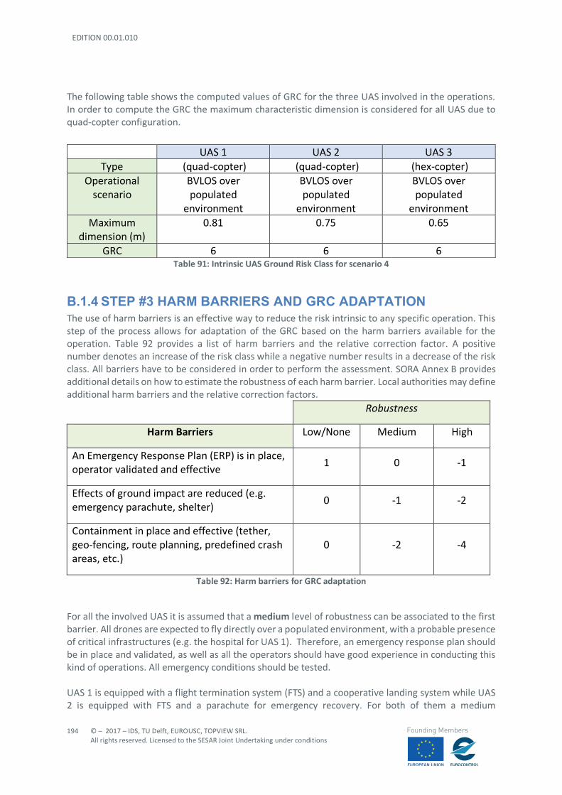
EDITION 00.01.010
194
© – 2017 – IDS, TU Delft, EUROUSC, TOPVIEW SRL. All rights reserved. Licensed to the SESAR Joint Undertaking under conditions
Founding Members
The following table shows the computed values of GRC for the three UAS involved in the operations. In order to compute the GRC the maximum characteristic dimension is considered for all UAS due to quad-copter configuration.
Table 91: Intrinsic UAS Ground Risk Class for scenario 4
B.1.4 STEP #3 HARM BARRIERS AND GRC ADAPTATION The use of harm barriers is an effective way to reduce the risk intrinsic to any specific operation. This step of the process allows for adaptation of the GRC based on the harm barriers available for the operation. Table 92 provides a list of harm barriers and the relative correction factor. A positive number denotes an increase of the risk class while a negative number results in a decrease of the risk class. All barriers have to be considered in order to perform the assessment. SORA Annex B provides additional details on how to estimate the robustness of each harm barrier. Local authorities may define additional harm barriers and the relative correction factors.
Robustness
Harm Barriers Low/None Medium High
An Emergency Response Plan (ERP) is in place, operator validated and effective
1 0 -1
Effects of ground impact are reduced (e.g. emergency parachute, shelter)
0 -1 -2
Containment in place and effective (tether, geo-fencing, route planning, predefined crash areas, etc.)
0 -2 -4
Table 92: Harm barriers for GRC adaptation
For all the involved UAS it is assumed that a medium level of robustness can be associated to the first barrier. All drones are expected to fly directly over a populated environment, with a probable presence of critical infrastructures (e.g. the hospital for UAS 1). Therefore, an emergency response plan should be in place and validated, as well as all the operators should have good experience in conducting this kind of operations. All emergency conditions should be tested. UAS 1 is equipped with a flight termination system (FTS) and a cooperative landing system while UAS 2 is equipped with FTS and a parachute for emergency recovery. For both of them a medium
UAS 1 UAS 2 UAS 3 Type (quad-copter) (quad-copter) (hex-copter)
Operational scenario
BVLOS over populated
environment
BVLOS over populated
environment
BVLOS over populated
environment Maximum
dimension (m) 0.81 0.75 0.65
GRC 6 6 6
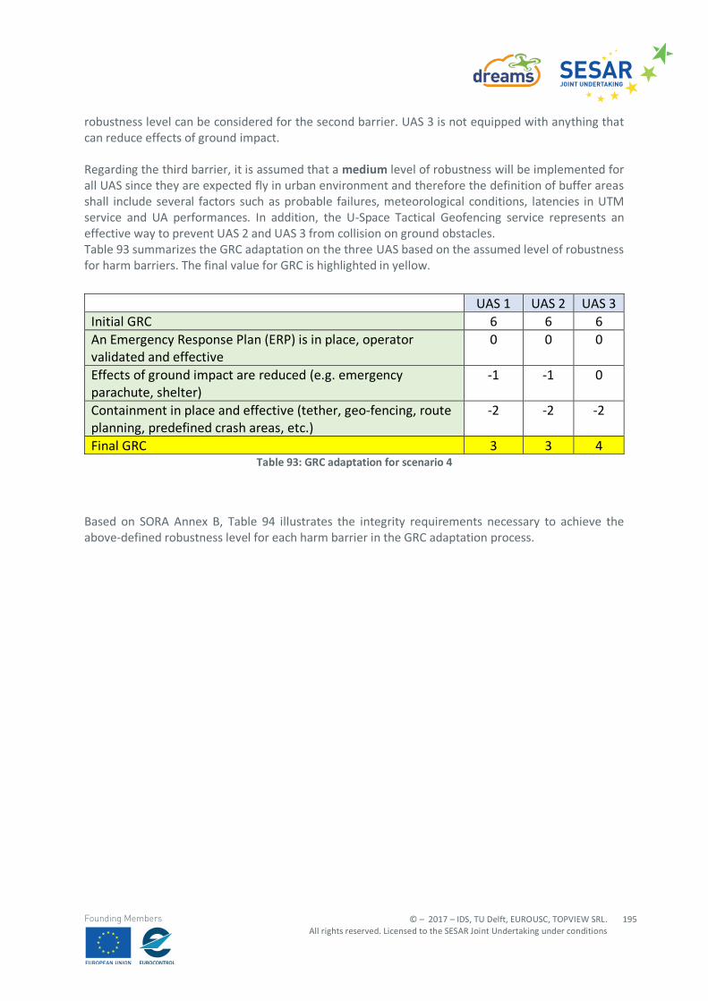
© – 2017 – IDS, TU Delft, EUROUSC, TOPVIEW SRL. All rights reserved. Licensed to the SESAR Joint Undertaking under conditions
195
Founding Members
robustness level can be considered for the second barrier. UAS 3 is not equipped with anything that can reduce effects of ground impact. Regarding the third barrier, it is assumed that a medium level of robustness will be implemented for all UAS since they are expected fly in urban environment and therefore the definition of buffer areas shall include several factors such as probable failures, meteorological conditions, latencies in UTM service and UA performances. In addition, the U-Space Tactical Geofencing service represents an effective way to prevent UAS 2 and UAS 3 from collision on ground obstacles. Table 93 summarizes the GRC adaptation on the three UAS based on the assumed level of robustness for harm barriers. The final value for GRC is highlighted in yellow.
Table 93: GRC adaptation for scenario 4
Based on SORA Annex B, Table 94 illustrates the integrity requirements necessary to achieve the above-defined robustness level for each harm barrier in the GRC adaptation process.
UAS 1 UAS 2 UAS 3 Initial GRC 6 6 6 An Emergency Response Plan (ERP) is in place, operator validated and effective
0 0 0
Effects of ground impact are reduced (e.g. emergency parachute, shelter)
-1 -1 0
Containment in place and effective (tether, geo-fencing, route planning, predefined crash areas, etc.)
-2 -2 -2
Final GRC 3 3 4
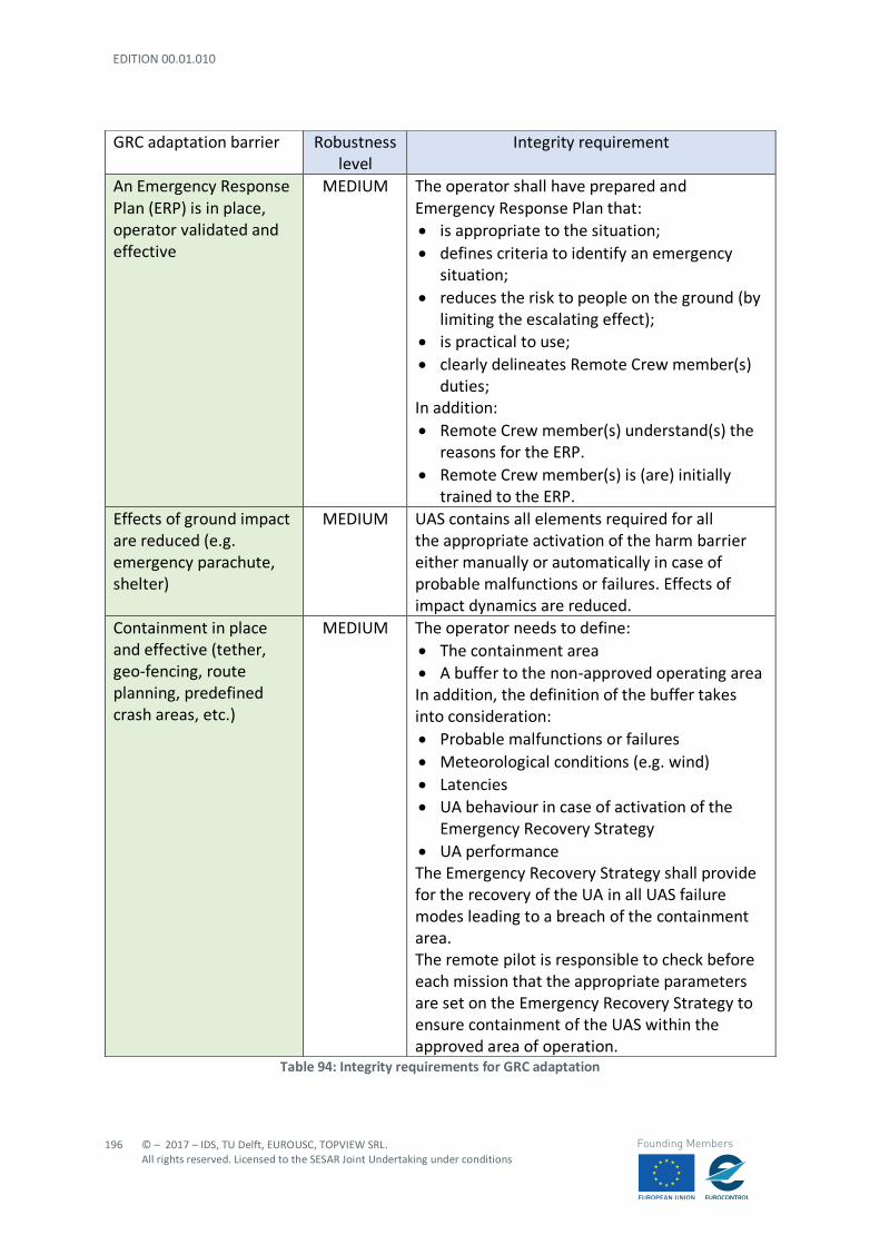
EDITION 00.01.010
196
© – 2017 – IDS, TU Delft, EUROUSC, TOPVIEW SRL. All rights reserved. Licensed to the SESAR Joint Undertaking under conditions
Founding Members
Table 94: Integrity requirements for GRC adaptation
GRC adaptation barrier Robustness level
Integrity requirement
An Emergency Response Plan (ERP) is in place, operator validated and effective
MEDIUM The operator shall have prepared and Emergency Response Plan that: • is appropriate to the situation; • defines criteria to identify an emergency
situation; • reduces the risk to people on the ground (by
limiting the escalating effect); • is practical to use; • clearly delineates Remote Crew member(s)
duties; In addition: • Remote Crew member(s) understand(s) the
reasons for the ERP. • Remote Crew member(s) is (are) initially
trained to the ERP. Effects of ground impact are reduced (e.g. emergency parachute, shelter)
MEDIUM UAS contains all elements required for all the appropriate activation of the harm barrier either manually or automatically in case of probable malfunctions or failures. Effects of impact dynamics are reduced.
Containment in place and effective (tether, geo-fencing, route planning, predefined crash areas, etc.)
MEDIUM The operator needs to define: • The containment area • A buffer to the non-approved operating area In addition, the definition of the buffer takes into consideration: • Probable malfunctions or failures • Meteorological conditions (e.g. wind) • Latencies • UA behaviour in case of activation of the
Emergency Recovery Strategy • UA performance The Emergency Recovery Strategy shall provide for the recovery of the UA in all UAS failure modes leading to a breach of the containment area. The remote pilot is responsible to check before each mission that the appropriate parameters are set on the Emergency Recovery Strategy to ensure containment of the UAS within the approved area of operation.
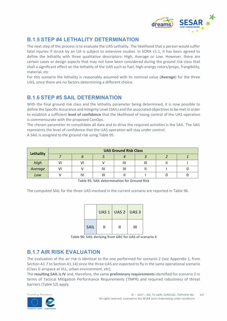
© – 2017 – IDS, TU Delft, EUROUSC, TOPVIEW SRL. All rights reserved. Licensed to the SESAR Joint Undertaking under conditions
197
Founding Members
B.1.5 STEP #4 LETHALITY DETERMINATION The next step of the process is to evaluate the UAS Lethality. The likelihood that a person would suffer fatal injuries if struck by an UA is subject to extensive studies. In SORA v1.1, it has been agreed to define the lethality with three qualitative descriptors: High, Average or Low. However, there are certain cases or design aspects that may not have been considered during the ground risk class that shall a significant effect on the lethality of the UAS such as fuel, high-energy rotors/props, frangibility, material, etc For this scenario the lethality is reasonably assumed with its nominal value (Average) for the three UAS, since there are no factors determining a different choice.
B.1.6 STEP #5 SAIL DETERMINATION With the final ground risk class and the lethality parameter being determined, it is now possible to define the Specific Assurance and Integrity Level (SAIL) and the associated objectives to be met in order to establish a sufficient level of confidence that the likelihood of losing control of the UAS operation is commensurate with the proposed ConOps. The chosen parameter to consolidate all data and to drive the required activities is the SAIL. The SAIL represents the level of confidence that the UAS operation will stay under control. A SAIL is assigned to the ground risk using Table 95.
Lethality UAS Ground Risk Class
7 6 5 4 3 2 1 High VI VI V IV III II I
Average VI V IV III II I 0
Low V IV III II I 0 0 Table 95: SAIL determination for Ground Risk
The computed SAIL for the three UAS involved in the current scenario are reported in Table 96.
UAS 1 UAS 2 UAS 3
SAIL II II III
Table 96: SAIL deriving from GRC for UAS of scenario 4
B.1.7 AIR RISK EVALUATION The evaluation of the air risk is identical to the one performed for scenario 2 (see Appendix 1, from Section A1.7 to Section A1.14) since the three UAS are expected to fly in the same operational scenario (Class G airspace at VLL, urban environment, etc). The resulting SAIL is IV and, therefore, the same preliminary requirements identified for scenario 2 in terms of Tactical Mitigation Performance Requirements (TMPR) and required robustness of threat barriers (Table 52) apply.
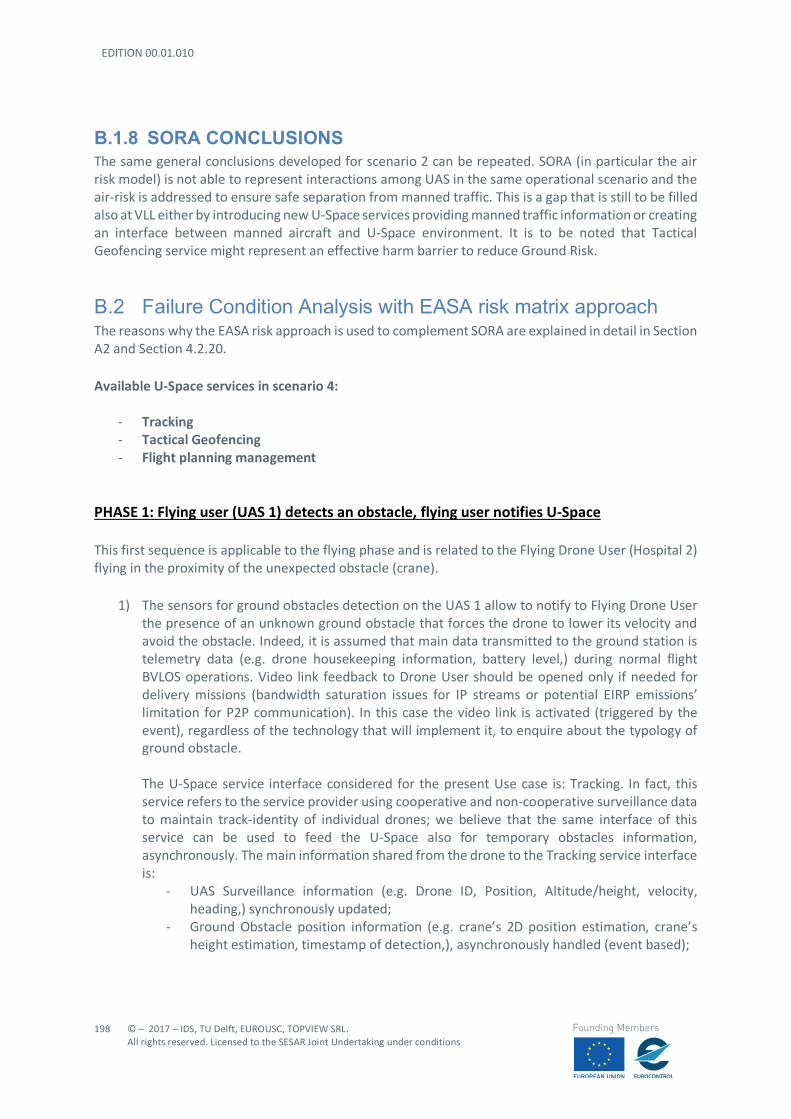
EDITION 00.01.010
198
© – 2017 – IDS, TU Delft, EUROUSC, TOPVIEW SRL. All rights reserved. Licensed to the SESAR Joint Undertaking under conditions
Founding Members
B.1.8 SORA CONCLUSIONS The same general conclusions developed for scenario 2 can be repeated. SORA (in particular the air risk model) is not able to represent interactions among UAS in the same operational scenario and the air-risk is addressed to ensure safe separation from manned traffic. This is a gap that is still to be filled also at VLL either by introducing new U-Space services providing manned traffic information or creating an interface between manned aircraft and U-Space environment. It is to be noted that Tactical Geofencing service might represent an effective harm barrier to reduce Ground Risk.
B.2 Failure Condition Analysis with EASA risk matrix approach The reasons why the EASA risk approach is used to complement SORA are explained in detail in Section A2 and Section 4.2.20. Available U-Space services in scenario 4:
- Tracking - Tactical Geofencing - Flight planning management
PHASE 1: Flying user (UAS 1) detects an obstacle, flying user notifies U-Space This first sequence is applicable to the flying phase and is related to the Flying Drone User (Hospital 2) flying in the proximity of the unexpected obstacle (crane).
1) The sensors for ground obstacles detection on the UAS 1 allow to notify to Flying Drone User the presence of an unknown ground obstacle that forces the drone to lower its velocity and avoid the obstacle. Indeed, it is assumed that main data transmitted to the ground station is telemetry data (e.g. drone housekeeping information, battery level,) during normal flight BVLOS operations. Video link feedback to Drone User should be opened only if needed for delivery missions (bandwidth saturation issues for IP streams or potential EIRP emissions’ limitation for P2P communication). In this case the video link is activated (triggered by the event), regardless of the technology that will implement it, to enquire about the typology of ground obstacle. The U-Space service interface considered for the present Use case is: Tracking. In fact, this service refers to the service provider using cooperative and non-cooperative surveillance data to maintain track-identity of individual drones; we believe that the same interface of this service can be used to feed the U-Space also for temporary obstacles information, asynchronously. The main information shared from the drone to the Tracking service interface is:
- UAS Surveillance information (e.g. Drone ID, Position, Altitude/height, velocity, heading,) synchronously updated;
- Ground Obstacle position information (e.g. crane’s 2D position estimation, crane’s height estimation, timestamp of detection,), asynchronously handled (event based);
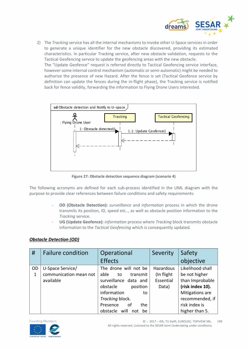
© – 2017 – IDS, TU Delft, EUROUSC, TOPVIEW SRL. All rights reserved. Licensed to the SESAR Joint Undertaking under conditions
199
Founding Members
2) The Tracking service has all the internal mechanisms to invoke other U-Space services in order to generate a unique identifier for the new obstacle discovered, providing its estimated characteristics. In particular Tracking service, after new obstacle validation, requests to the Tactical Geofencing service to update the geofencing areas with the new obstacle. The “Update Geofence” request is referred directly to Tactical Geofencing service interface, however some internal control mechanism (automatic or semi-automatic) might be needed to authorize the presence of new Hazard. After the fence is set (Tactical Geofence service by definition can update the fences during the in-flight phase), the Tracking service is notified back for fence validity, forwarding the information to Flying Drone Users interested.
Figure 27: Obstacle detection sequence diagram (scenario 4)
The following acronyms are defined for each sub-process identified in the UML diagram with the purpose to provide clear references between failure conditions and safety requirements:
- OD (Obstacle Detection): surveillance and information process in which the drone transmits its position, ID, speed etc.., as well as obstacle position information to the Tracking service.
- UG (Update Geofence): information process where Tracking block transmits obstacle information to the Tactical Geofencing which is consequently updated.
Obstacle Detection (OD) # Failure condition Operational
Effects Severity Safety
objective OD 1
U-Space Service/ communication mean not available
The drone will not be able to transmit surveillance data and obstacle position information to Tracking block. Presence of the obstacle will not be
Hazardous (In flight Essential
Data)
Likelihood shall be not higher than Improbable (risk index 10). Mitigations are recommended, if risk index is higher than 5.
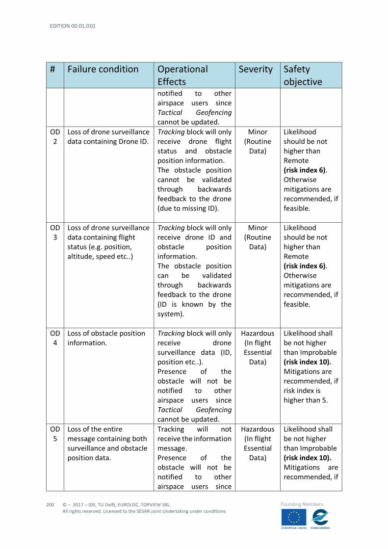
EDITION 00.01.010
200
© – 2017 – IDS, TU Delft, EUROUSC, TOPVIEW SRL. All rights reserved. Licensed to the SESAR Joint Undertaking under conditions
Founding Members
# Failure condition Operational Effects
Severity Safety objective
notified to other airspace users since Tactical Geofencing cannot be updated.
OD 2
Loss of drone surveillance data containing Drone ID.
Tracking block will only receive drone flight status and obstacle position information. The obstacle position cannot be validated through backwards feedback to the drone (due to missing ID).
Minor (Routine
Data)
Likelihood should be not higher than Remote (risk index 6). Otherwise mitigations are recommended, if feasible.
OD 3
Loss of drone surveillance data containing flight status (e.g. position, altitude, speed etc..)
Tracking block will only receive drone ID and obstacle position information. The obstacle position can be validated through backwards feedback to the drone (ID is known by the system).
Minor (Routine
Data)
Likelihood should be not higher than Remote (risk index 6). Otherwise mitigations are recommended, if feasible.
OD 4
Loss of obstacle position information.
Tracking block will only receive drone surveillance data (ID, position etc..). Presence of the obstacle will not be notified to other airspace users since Tactical Geofencing cannot be updated.
Hazardous (In flight Essential
Data)
Likelihood shall be not higher than Improbable (risk index 10). Mitigations are recommended, if risk index is higher than 5.
OD 5
Loss of the entire message containing both surveillance and obstacle position data.
Tracking will not receive the information message. Presence of the obstacle will not be notified to other airspace users since
Hazardous (In flight Essential
Data)
Likelihood shall be not higher than Improbable (risk index 10). Mitigations are recommended, if
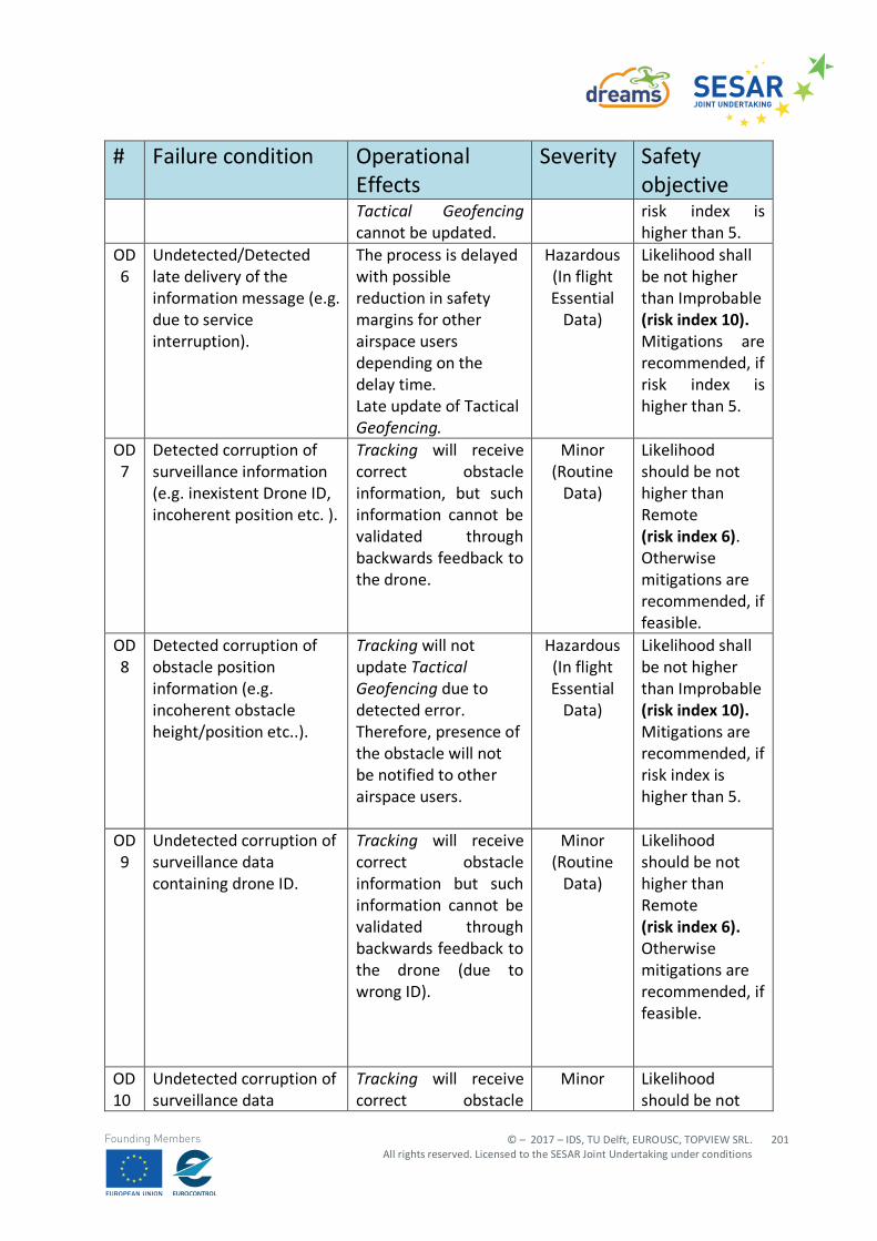
© – 2017 – IDS, TU Delft, EUROUSC, TOPVIEW SRL. All rights reserved. Licensed to the SESAR Joint Undertaking under conditions
201
Founding Members
# Failure condition Operational Effects
Severity Safety objective
Tactical Geofencing cannot be updated.
risk index is higher than 5.
OD 6
Undetected/Detected late delivery of the information message (e.g. due to service interruption).
The process is delayed with possible reduction in safety margins for other airspace users depending on the delay time. Late update of Tactical Geofencing.
Hazardous (In flight Essential
Data)
Likelihood shall be not higher than Improbable (risk index 10). Mitigations are recommended, if risk index is higher than 5.
OD 7
Detected corruption of surveillance information (e.g. inexistent Drone ID, incoherent position etc. ).
Tracking will receive correct obstacle information, but such information cannot be validated through backwards feedback to the drone.
Minor (Routine
Data)
Likelihood should be not higher than Remote (risk index 6). Otherwise mitigations are recommended, if feasible.
OD 8
Detected corruption of obstacle position information (e.g. incoherent obstacle height/position etc..).
Tracking will not update Tactical Geofencing due to detected error. Therefore, presence of the obstacle will not be notified to other airspace users.
Hazardous (In flight Essential
Data)
Likelihood shall be not higher than Improbable (risk index 10). Mitigations are recommended, if risk index is higher than 5.
OD 9
Undetected corruption of surveillance data containing drone ID.
Tracking will receive correct obstacle information but such information cannot be validated through backwards feedback to the drone (due to wrong ID).
Minor (Routine
Data)
Likelihood should be not higher than Remote (risk index 6). Otherwise mitigations are recommended, if feasible.
OD 10
Undetected corruption of surveillance data
Tracking will receive correct obstacle
Minor Likelihood should be not
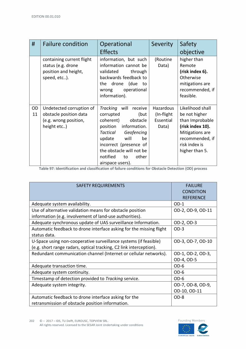
EDITION 00.01.010
202
© – 2017 – IDS, TU Delft, EUROUSC, TOPVIEW SRL. All rights reserved. Licensed to the SESAR Joint Undertaking under conditions
Founding Members
# Failure condition Operational Effects
Severity Safety objective
containing current flight status (e.g. drone position and height, speed, etc..).
information, but such information cannot be validated through backwards feedback to the drone (due to wrong operational information).
(Routine Data)
higher than Remote (risk index 6). Otherwise mitigations are recommended, if feasible.
OD 11
Undetected corruption of obstacle position data (e.g. wrong position, height etc..)
Tracking will receive corrupted (but coherent) obstacle position information. Tactical Geofencing update will be incorrect (presence of the obstacle will not be notified to other airspace users).
Hazardous (In-flight Essential
Data)
Likelihood shall be not higher than Improbable (risk index 10). Mitigations are recommended, if risk index is higher than 5.
Table 97: Identification and classification of failure conditions for Obstacle Detection (OD) process
SAFETY REQUIREMENTS FAILURE CONDITION REFERENCE
Adequate system availability. OD-1 Use of alternative validation means for obstacle position information (e.g. involvement of land-use authorities).
OD-2, OD-9, OD-11
Adequate synchronous update of UAS surveillance Information. OD-2, OD-3 Automatic feedback to drone interface asking for the missing flight status data.
OD-3
U-Space using non-cooperative surveillance systems (if feasible) (e.g. short range radars, optical tracking, C2 link interception).
OD-3, OD-7, OD-10
Redundant communication channel (Internet or cellular networks). OD-1, OD-2, OD-3, OD-4, OD-5
Adequate transaction time. OD-6 Adequate system continuity. OD-6 Timestamp of detection provided to Tracking service. OD-6 Adequate system integrity. OD-7, OD-8, OD-9,
OD-10, OD-11 Automatic feedback to drone interface asking for the retransmission of obstacle position information.
OD-8

© – 2017 – IDS, TU Delft, EUROUSC, TOPVIEW SRL. All rights reserved. Licensed to the SESAR Joint Undertaking under conditions
203
Founding Members
The obstacle validation process (after Tactical Geofencing is updated) will enable the system to correlate obstacle position with drone flight status.
OD-10
Table 98: Failure conditions and corresponding requirements for Obstacle Detection (OD) process
Obstacle Detection- RSP specifications Transaction
time (s) Continuity
(Probability/flight hour)
Availability (Probability/flight
hour)
Integrity (Data Process
Assurance Level)
Integrity (Design
Assurance Level)
10 1E-05 1E-05 2 B
Table 99: Recommended performance requirements for Obstacle Detection (OD) process Update Geofencing (UG)
# Failure condition
Operational Effects Severity Safety objective
UG 1
U-Space Service/ communication mean not available
The Tactical Geo-fencing block will not be updated and therefore the presence of the obstacle cannot be notified to other airspace users.
Hazardous (In-flight Essential
Data)
Likelihood shall be not higher than Improbable (risk index 10). Mitigations are recommended, if risk index is higher than 5.
UG 2
Loss of message containing obstacle position information.
The Tactical Geo-fencing block will not be updated and therefore the presence of the obstacle cannot be notified to other airspace users.
Hazardous (In-flight Essential
Data)
Likelihood shall be not higher than Improbable (risk index 10). Mitigations are recommended, if risk index is higher than 5.
UG 3
Late update of Tactical Geofencing (e.g. due to service interruption)
The process is delayed with possible reduction in safety margins for other airspace users depending on the delay time.
Hazardous (In-flight Essential
Data)
Likelihood shall be not higher than Improbable (risk index 10). Mitigations are recommended, if risk index is higher than 5.

EDITION 00.01.010
204
© – 2017 – IDS, TU Delft, EUROUSC, TOPVIEW SRL. All rights reserved. Licensed to the SESAR Joint Undertaking under conditions
Founding Members
# Failure condition
Operational Effects Severity Safety objective
UG 4
Error in the Tactical Geofencing update process.
Tactical Geofencing not correctly updated. Obstacle not correctly “fenced” with subsequent possible reduction of safety margins.
Hazardous (In-Flight Essential
Data)
Likelihood shall be not higher than Improbable (risk index 10). Mitigations are recommended, if risk index is higher than 5.
Table 100: Identification and classification of failure conditions for Update Geofencing process (UG) process
SAFETY REQUIREMENTS FAILURE CONDITION REFERENCE
Adequate system availability. UG-1 Redundant communication channel (Internet or cellular networks).
UG-1, UG-2
Adequate system continuity. UG-3 Adequate system transaction time. UG-3 Adequate system integrity. UG-4 Internal control mechanism to validate and authorize the final update.
UG-4
Table 101: Failure conditions and corresponding requirements for Update Geofencing (UG) process
Update Geofencing- RSP specifications
Transaction time (s)
Continuity (Probability/flight
hour)
Availability (Probability/flight
hour)
Integrity (Data Process
Assurance Level)
Integrity (Design
Assurance Level)
10 1E-05 1E-05 2 B
Table 102: Recommended performance requirements for Update Geofencing (UG) process Final remarks on phase 1 Phase 1 takes place while UAS 1 is in an in-flight phase and involves the Tactical Geofencing service which is able to provide notifications to flying users by updating its database in real time with new reported obstacles position information. The key point s is that the system should validate the reported position of new obstacles (e.g. using an internal control mechanism that correlates obstacle position with surveillance data of the drone that detected the obstacle).
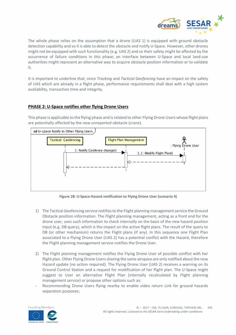
© – 2017 – IDS, TU Delft, EUROUSC, TOPVIEW SRL. All rights reserved. Licensed to the SESAR Joint Undertaking under conditions
205
Founding Members
The whole phase relies on the assumption that a drone (UAS 1) is equipped with ground obstacle detection capability and so it is able to detect the obstacle and notify U-Space. However, other drones might not be equipped with such functionality (e.g. UAS 2) and so their safety might be affected by the occurrence of failure conditions in this phase; an interface between U-Space and local land-use authorities might represent an alternative way to acquire obstacle position information or to validate it. It is important to underline that, since Tracking and Tactical Geofencing have an impact on the safety of UAS which are already in a flight phase, performance requirements shall deal with a high system availability, transaction time and integrity. PHASE 2: U-Space notifies other flying Drone Users This phase is applicable to the flying phase and is related to other Flying Drone Users whose flight plans are potentially affected by the new unreported obstacle (crane).
Figure 28: U-Space Hazard notification to Flying Drone User (scenario 4)
1) The Tactical Geofencing service notifies to the Flight planning management service the Ground Obstacle position information. The Flight planning management, acting as a front end for the drone user, uses such information to check internally on the basis of the new hazard position input (e.g. DB query), which is the impact on the active flight plans. The result of the query to DB (or other mechanism) returns the Flight plans (if any). In this sequence one Flight Plan associated to a Flying Drone User (UAS 2) has a potential conflict with the Hazard, therefore the Flight planning management service notifies the Drone User.
2) The Flight planning management notifies the Flying Drone User of possible conflict with her flight plan. Other Flying Drone Users sharing the same airspace are only notified about the new Hazard update (no action required). The Flying Drone User (UAS 2) receives a warning on its Ground Control Station and a request for modification of her flight plan. The U-Space might suggest to User an alternative Flight Plan (internally recalculated by Flight planning management service) or propose other options such as:
- Recommending Drone Users flying nearby to enable video return Link for ground hazards separation purposes;

EDITION 00.01.010
206
© – 2017 – IDS, TU Delft, EUROUSC, TOPVIEW SRL. All rights reserved. Licensed to the SESAR Joint Undertaking under conditions
Founding Members
- Restricting the flight of that area only to drones with compliant ground obstacle detection capabilities;
- Requesting RTH (Return to home, aborting mission) to drone with insufficient ground obstacle detection capabilities.
In our understanding, the Drone User shall select and accept one of the options proposed by the U-Space services. The following acronyms are defined for each sub-process identified in the UML diagram with the purpose to provide clear references between failure conditions and safety requirements:
- NGC (Notify Geofence Change): information process in which Tactical Management block transmits obstacle position to Flight planning management.
- MFP (Modify Flight Plan): information process where Flight planning management notifies a drone user (whose flight plan has conflicts with the detected obstacle) about the threat and proposes an alternative strategy.
It is assumed that the internal process (in which the Flight planning management checks possible conflicts) is developed without errors (failure conditions associated to this kind of process have already been evaluated in scenario 2). Notify Geofence Change (NGC)
# Failure condition Operational Effects
Severity Safety objective
NGC 1
U-Space Service/ communication mean not available
Tactical Geofencing will not exchange information with Flight Planning Management block. Presence of the obstacle will not be notified to other airspace users.
Hazardous (In flight Essential
Data)
Likelihood shall be not higher than Improbable (risk index 10). Mitigations are recommended, if risk index is higher than 5.
NGC 2
Loss of obstacle position information.
Flight planning management will not be updated. Presence of the obstacle will not be notified to other airspace users.
Hazardous (In flight Essential
Data)
Likelihood shall be not higher than Improbable (risk index 10). Mitigations are recommended, if risk index is higher than 5.
NGC 3
Undetected/Detected late delivery of the obstacle position
The process is delayed with possible reduction in safety
Hazardous Likelihood shall be not higher than Improbable
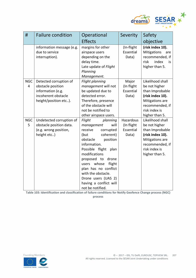
© – 2017 – IDS, TU Delft, EUROUSC, TOPVIEW SRL. All rights reserved. Licensed to the SESAR Joint Undertaking under conditions
207
Founding Members
# Failure condition Operational Effects
Severity Safety objective
information message (e.g. due to service interruption).
margins for other airspace users depending on the delay time. Late update of Flight Planning Management.
(In-flight Essential
Data)
(risk index 10). Mitigations are recommended, if risk index is higher than 5.
NGC 4
Detected corruption of obstacle position information (e.g. incoherent obstacle height/position etc..).
Flight planning management will not be updated due to detected error. Therefore, presence of the obstacle will not be notified to other airspace users.
Major (In flight Essential
Data)
Likelihood shall be not higher than Improbable (risk index 10). Mitigations are recommended, if risk index is higher than 5.
NGC 5
Undetected corruption of obstacle position data. (e.g. wrong position, height etc..)
Flight planning management will receive corrupted (but coherent) obstacle position information. Possible flight plan modifications proposed to drone users whose flight plan has no conflict with the obstacle. Drone users (UAS 2) having a conflict will not be notified.
Hazardous (In flight Essential
Data)
Likelihood shall be not higher than Improbable (risk index 10). Mitigations are recommended, if risk index is higher than 5.
Table 103: Identification and classification of failure conditions for Notify Geofence Change process (NGC) process
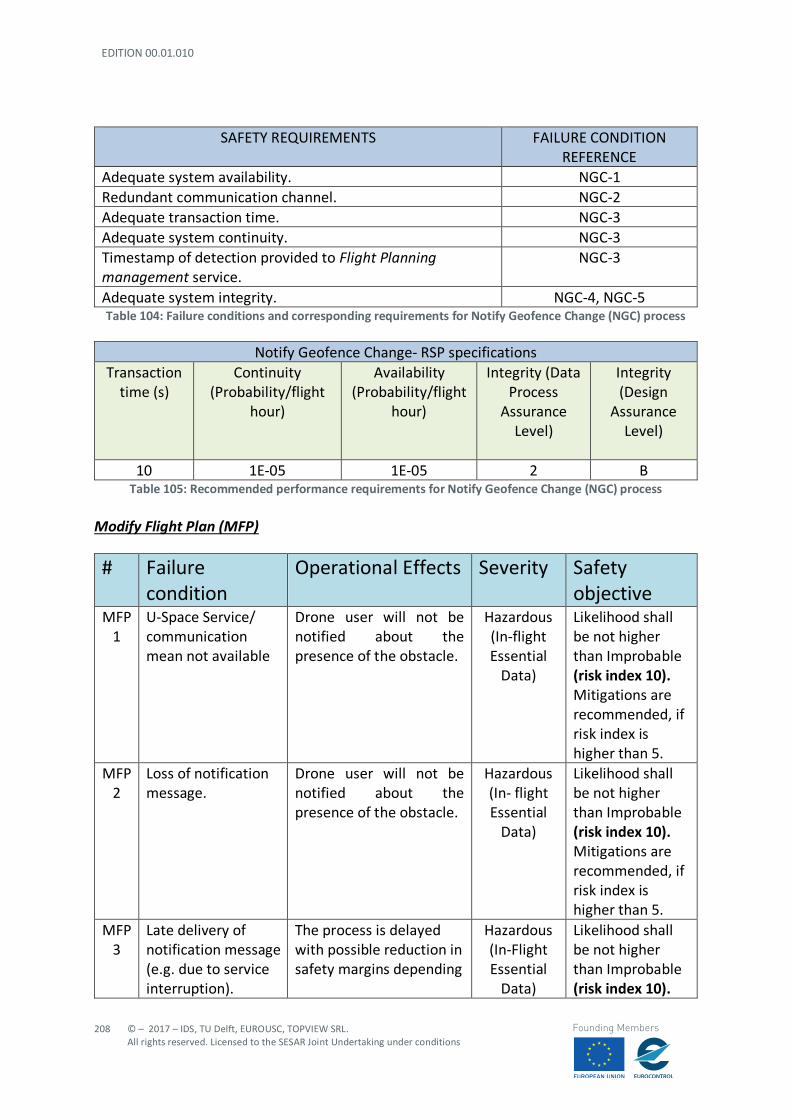
EDITION 00.01.010
208
© – 2017 – IDS, TU Delft, EUROUSC, TOPVIEW SRL. All rights reserved. Licensed to the SESAR Joint Undertaking under conditions
Founding Members
SAFETY REQUIREMENTS FAILURE CONDITION REFERENCE
Adequate system availability. NGC-1 Redundant communication channel. NGC-2 Adequate transaction time. NGC-3 Adequate system continuity. NGC-3 Timestamp of detection provided to Flight Planning management service.
NGC-3
Adequate system integrity. NGC-4, NGC-5 Table 104: Failure conditions and corresponding requirements for Notify Geofence Change (NGC) process
Notify Geofence Change- RSP specifications
Transaction time (s)
Continuity (Probability/flight
hour)
Availability (Probability/flight
hour)
Integrity (Data Process
Assurance Level)
Integrity (Design
Assurance Level)
10 1E-05 1E-05 2 B
Table 105: Recommended performance requirements for Notify Geofence Change (NGC) process Modify Flight Plan (MFP)
# Failure condition
Operational Effects Severity Safety objective
MFP 1
U-Space Service/ communication mean not available
Drone user will not be notified about the presence of the obstacle.
Hazardous (In-flight Essential
Data)
Likelihood shall be not higher than Improbable (risk index 10). Mitigations are recommended, if risk index is higher than 5.
MFP 2
Loss of notification message.
Drone user will not be notified about the presence of the obstacle.
Hazardous (In- flight Essential
Data)
Likelihood shall be not higher than Improbable (risk index 10). Mitigations are recommended, if risk index is higher than 5.
MFP 3
Late delivery of notification message (e.g. due to service interruption).
The process is delayed with possible reduction in safety margins depending
Hazardous (In-Flight Essential
Data)
Likelihood shall be not higher than Improbable (risk index 10).
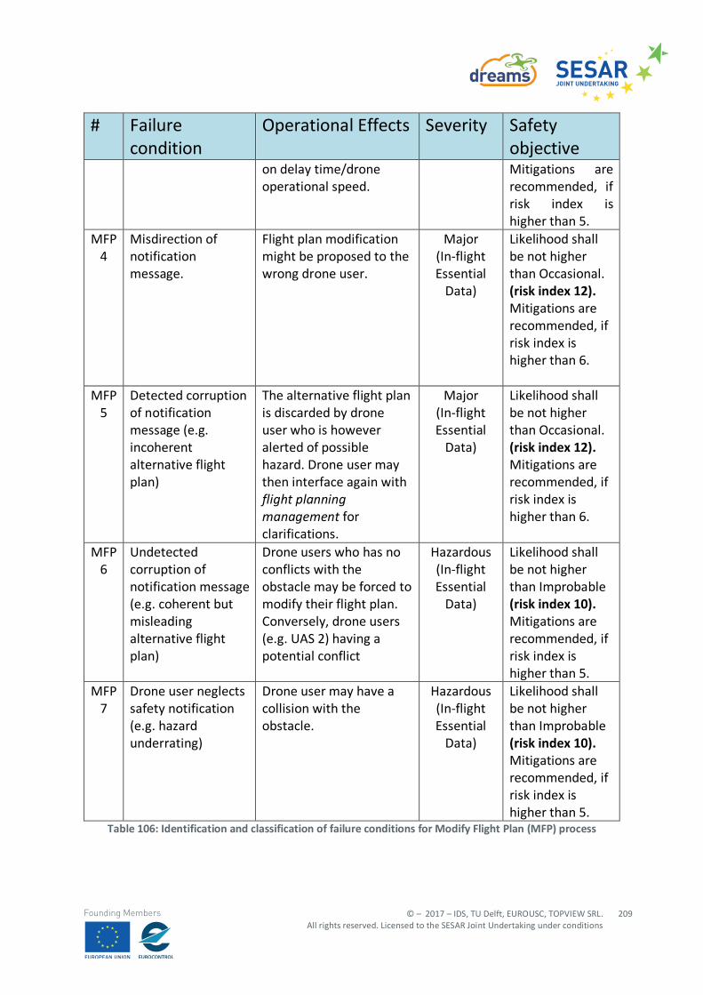
© – 2017 – IDS, TU Delft, EUROUSC, TOPVIEW SRL. All rights reserved. Licensed to the SESAR Joint Undertaking under conditions
209
Founding Members
# Failure condition
Operational Effects Severity Safety objective
on delay time/drone operational speed.
Mitigations are recommended, if risk index is higher than 5.
MFP 4
Misdirection of notification message.
Flight plan modification might be proposed to the wrong drone user.
Major (In-flight Essential
Data)
Likelihood shall be not higher than Occasional. (risk index 12). Mitigations are recommended, if risk index is higher than 6.
MFP 5
Detected corruption of notification message (e.g. incoherent alternative flight plan)
The alternative flight plan is discarded by drone user who is however alerted of possible hazard. Drone user may then interface again with flight planning management for clarifications.
Major (In-flight Essential
Data)
Likelihood shall be not higher than Occasional. (risk index 12). Mitigations are recommended, if risk index is higher than 6.
MFP 6
Undetected corruption of notification message (e.g. coherent but misleading alternative flight plan)
Drone users who has no conflicts with the obstacle may be forced to modify their flight plan. Conversely, drone users (e.g. UAS 2) having a potential conflict
Hazardous (In-flight Essential
Data)
Likelihood shall be not higher than Improbable (risk index 10). Mitigations are recommended, if risk index is higher than 5.
MFP 7
Drone user neglects safety notification (e.g. hazard underrating)
Drone user may have a collision with the obstacle.
Hazardous (In-flight Essential
Data)
Likelihood shall be not higher than Improbable (risk index 10). Mitigations are recommended, if risk index is higher than 5.
Table 106: Identification and classification of failure conditions for Modify Flight Plan (MFP) process
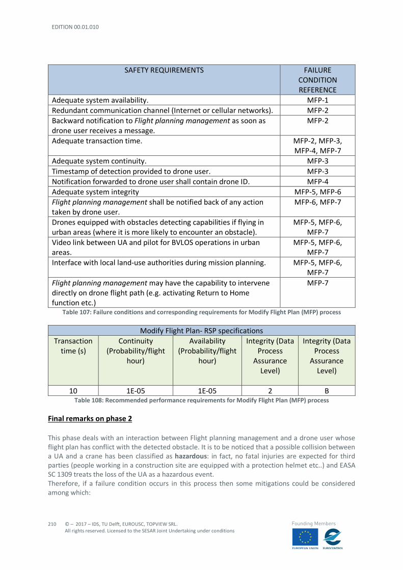
EDITION 00.01.010
210
© – 2017 – IDS, TU Delft, EUROUSC, TOPVIEW SRL. All rights reserved. Licensed to the SESAR Joint Undertaking under conditions
Founding Members
SAFETY REQUIREMENTS FAILURE CONDITION REFERENCE
Adequate system availability. MFP-1 Redundant communication channel (Internet or cellular networks). MFP-2 Backward notification to Flight planning management as soon as drone user receives a message.
MFP-2
Adequate transaction time. MFP-2, MFP-3, MFP-4, MFP-7
Adequate system continuity. MFP-3 Timestamp of detection provided to drone user. MFP-3 Notification forwarded to drone user shall contain drone ID. MFP-4 Adequate system integrity MFP-5, MFP-6 Flight planning management shall be notified back of any action taken by drone user.
MFP-6, MFP-7
Drones equipped with obstacles detecting capabilities if flying in urban areas (where it is more likely to encounter an obstacle).
MFP-5, MFP-6, MFP-7
Video link between UA and pilot for BVLOS operations in urban areas.
MFP-5, MFP-6, MFP-7
Interface with local land-use authorities during mission planning. MFP-5, MFP-6, MFP-7
Flight planning management may have the capability to intervene directly on drone flight path (e.g. activating Return to Home function etc.)
MFP-7
Table 107: Failure conditions and corresponding requirements for Modify Flight Plan (MFP) process
Modify Flight Plan- RSP specifications Transaction
time (s) Continuity
(Probability/flight hour)
Availability (Probability/flight
hour)
Integrity (Data Process
Assurance Level)
Integrity (Data Process
Assurance Level)
10 1E-05 1E-05 2 B
Table 108: Recommended performance requirements for Modify Flight Plan (MFP) process
Final remarks on phase 2 This phase deals with an interaction between Flight planning management and a drone user whose flight plan has conflict with the detected obstacle. It is to be noticed that a possible collision between a UA and a crane has been classified as hazardous: in fact, no fatal injuries are expected for third parties (people working in a construction site are equipped with a protection helmet etc..) and EASA SC 1309 treats the loss of the UA as a hazardous event. Therefore, if a failure condition occurs in this process then some mitigations could be considered among which:
© – 2017 – IDS, TU Delft, EUROUSC, TOPVIEW SRL. All rights reserved. Licensed to the SESAR Joint Undertaking under conditions
211
Founding Members
- video link between GCS and UA; - Equipping the drone with ground obstacle detection capabilities; and - Adequate mission planning involving local land use authorities.
In a future perspective, where several drones might be flying simultaneously in urban environment, high reliability and performance requirements shall be ensured for all those services exchanging information in “tactical” phases. PHASE 3: U-Space notifies other Stand by Drone Users This phase is substantially identical to phase 2 (the U-Space services are the same) but it takes place before flight. The failure condition analysis is not carried for this phase since:
- safety and performance requirements for these services are chosen (conservatively) from phase 2 which takes place during the flight; and
- mitigation strategies to be possibly implemented before take-off have already been identified in the analysis performed for scenario 2 “concurrent operations” (see section A.2 in Appendix 1).
EDITION 00.01.010
212
© – 2017 – IDS, TU Delft, EUROUSC, TOPVIEW SRL. All rights reserved. Licensed to the SESAR Joint Undertaking under conditions
Founding Members
Appendix C Risk Assessment of Scenario 5: “CTR Crossing”
C.1 Risk assessment with SORA methodology The SORA methodology (v1.1) is fully applied to this scenario, with the aim to:
- Evaluating both Ground and Air Risk; - Identifying some general requirements in terms of required barriers (mitigations) and
robustness, which are the output of SORA.
However, it should be noted that:
- No Means of Evidence (MoE) are contained in this deliverable, since the assessment is generic for several scenarios;
- Consequently, the operator or service provider using this generic assessment in the future, should complete it (i.e. SORA Step #11 and STEP # 12, see Section 4.2.17 and Section 4.2.18);
- the air risk evaluation based on v1.1 of SORA is not sufficient, as already highlighted in Section 4.2.6, to cover all the potential hazards associated to concurrent UAS operations;
- therefore, in this deliverable, SORA is complemented by the more flexible risk-matrix approach (based on EASA example).
C.1.1 STEP #0 INITIAL EVALUATION In this preliminary step, the operator/applicant is tasked to verify that the proposed operation is feasible, not subject to specific exclusions from the local authority or subject to a standard scenario. Things to verify include:
- If the operation can be covered under a “standard scenario” recognized by the local authority; - If the operation falls under the “open” category; - If the operation is subject to specific NO-GO from local authority; - If the local authority has determined that the UAS is “harmless” for both ground and air risk.
Upon completion of this preliminary check, the operator/applicant will start the SORA process if none of the previous cases applies. For the present scenario it is assumed that the envisaged operations are compliant with local regulations and that none of the previous point is verified.
C.1.2 STEP #1 CONOPS DESCRIPTION
C.1.2.1 INTENDED OPERATIONS
A VTOL aircraft is involved in a delivery mission between two hubs of an express courier (also Drone Operator). The operation is conducted in BVLOS conditions and the distance between the hubs is about 15 km; the first Hub is located in a village with low density population, the second Hub is located in the industrial suburb of a European city of average dimensions. The second Hub is inside the controlled airspace (e.g., CTR zone 1), however it is located at more than 8 km from the city airport.
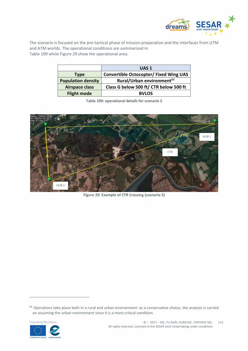
© – 2017 – IDS, TU Delft, EUROUSC, TOPVIEW SRL. All rights reserved. Licensed to the SESAR Joint Undertaking under conditions
213
Founding Members
The scenario is focused on the pre-tactical phase of mission preparation and the interfaces from UTM and ATM worlds. The operational conditions are summarized in Table 109 while Figure 29 show the operational area.
Table 109: operational details for scenario 5
Figure 29: Example of CTR Crossing (scenario 5)
84 Operations take place both in a rural and urban environment: as a conservative choice, the analysis is carried
on assuming the urban environment since it is a more critical condition.
UAS 1 Type Convertible Octocopter/ Fixed Wing UAS
Population density Rural/Urban environment84 Airspace class Class G below 500 ft/ CTR below 500 ft Flight mode BVLOS
HUB 1
CTR
HUB 2
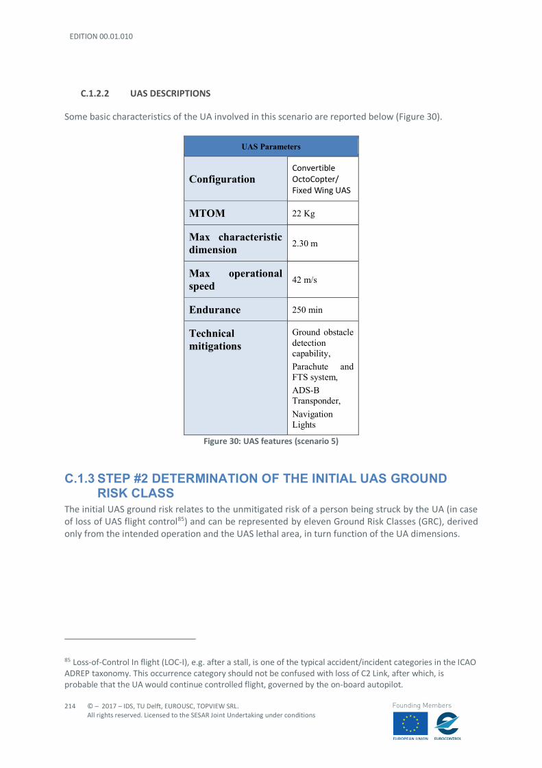
EDITION 00.01.010
214
© – 2017 – IDS, TU Delft, EUROUSC, TOPVIEW SRL. All rights reserved. Licensed to the SESAR Joint Undertaking under conditions
Founding Members
C.1.2.2 UAS DESCRIPTIONS
Some basic characteristics of the UA involved in this scenario are reported below (Figure 30).
UAS Parameters
Configuration Convertible OctoCopter/ Fixed Wing UAS
MTOM 22 Kg
Max characteristic dimension 2.30 m
Max operational speed 42 m/s
Endurance 250 min
Technical mitigations
Ground obstacle detection capability, Parachute and FTS system, ADS-B Transponder, Navigation Lights
Figure 30: UAS features (scenario 5)
C.1.3 STEP #2 DETERMINATION OF THE INITIAL UAS GROUND RISK CLASS
The initial UAS ground risk relates to the unmitigated risk of a person being struck by the UA (in case of loss of UAS flight control85) and can be represented by eleven Ground Risk Classes (GRC), derived only from the intended operation and the UAS lethal area, in turn function of the UA dimensions.
85 Loss-of-Control In flight (LOC-I), e.g. after a stall, is one of the typical accident/incident categories in the ICAO ADREP taxonomy. This occurrence category should not be confused with loss of C2 Link, after which, is probable that the UA would continue controlled flight, governed by the on-board autopilot.
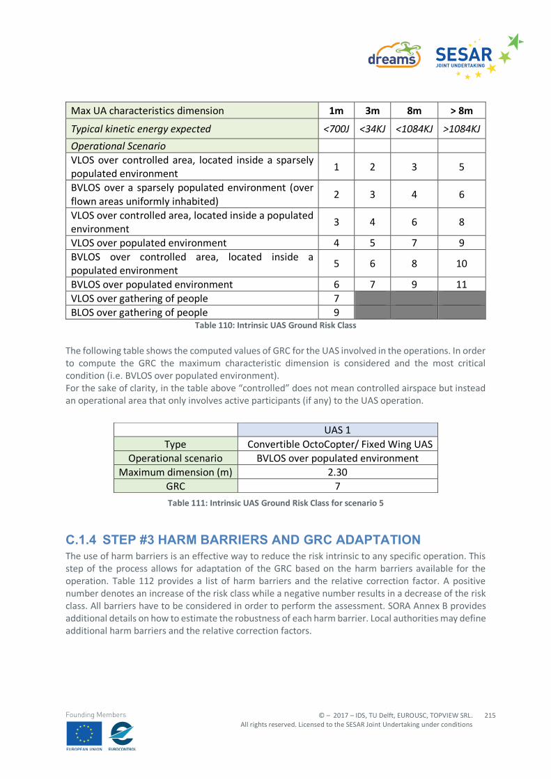
© – 2017 – IDS, TU Delft, EUROUSC, TOPVIEW SRL. All rights reserved. Licensed to the SESAR Joint Undertaking under conditions
215
Founding Members
Max UA characteristics dimension 1m 3m 8m > 8m
Typical kinetic energy expected <700J <34KJ <1084KJ >1084KJ Operational Scenario VLOS over controlled area, located inside a sparsely populated environment
1 2 3 5
BVLOS over a sparsely populated environment (over flown areas uniformly inhabited)
2 3 4 6
VLOS over controlled area, located inside a populated environment
3 4 6 8
VLOS over populated environment 4 5 7 9 BVLOS over controlled area, located inside a populated environment
5 6 8 10
BVLOS over populated environment 6 7 9 11 VLOS over gathering of people 7 BLOS over gathering of people 9
Table 110: Intrinsic UAS Ground Risk Class The following table shows the computed values of GRC for the UAS involved in the operations. In order to compute the GRC the maximum characteristic dimension is considered and the most critical condition (i.e. BVLOS over populated environment). For the sake of clarity, in the table above “controlled” does not mean controlled airspace but instead an operational area that only involves active participants (if any) to the UAS operation.
Table 111: Intrinsic UAS Ground Risk Class for scenario 5
C.1.4 STEP #3 HARM BARRIERS AND GRC ADAPTATION The use of harm barriers is an effective way to reduce the risk intrinsic to any specific operation. This step of the process allows for adaptation of the GRC based on the harm barriers available for the operation. Table 112 provides a list of harm barriers and the relative correction factor. A positive number denotes an increase of the risk class while a negative number results in a decrease of the risk class. All barriers have to be considered in order to perform the assessment. SORA Annex B provides additional details on how to estimate the robustness of each harm barrier. Local authorities may define additional harm barriers and the relative correction factors.
UAS 1 Type Convertible OctoCopter/ Fixed Wing UAS
Operational scenario BVLOS over populated environment Maximum dimension (m) 2.30
GRC 7
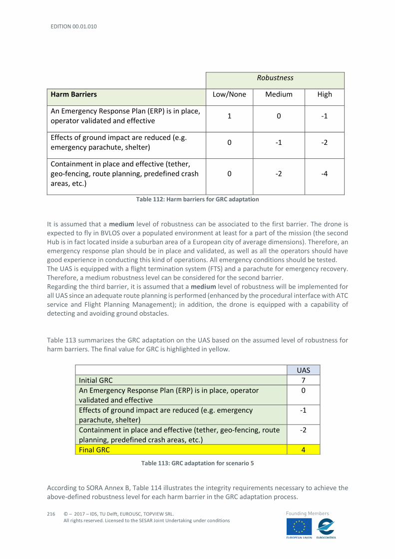
EDITION 00.01.010
216
© – 2017 – IDS, TU Delft, EUROUSC, TOPVIEW SRL. All rights reserved. Licensed to the SESAR Joint Undertaking under conditions
Founding Members
Robustness
Harm Barriers Low/None Medium High
An Emergency Response Plan (ERP) is in place, operator validated and effective
1 0 -1
Effects of ground impact are reduced (e.g. emergency parachute, shelter)
0 -1 -2
Containment in place and effective (tether, geo-fencing, route planning, predefined crash areas, etc.)
0 -2 -4
Table 112: Harm barriers for GRC adaptation
It is assumed that a medium level of robustness can be associated to the first barrier. The drone is expected to fly in BVLOS over a populated environment at least for a part of the mission (the second Hub is in fact located inside a suburban area of a European city of average dimensions). Therefore, an emergency response plan should be in place and validated, as well as all the operators should have good experience in conducting this kind of operations. All emergency conditions should be tested. The UAS is equipped with a flight termination system (FTS) and a parachute for emergency recovery. Therefore, a medium robustness level can be considered for the second barrier. Regarding the third barrier, it is assumed that a medium level of robustness will be implemented for all UAS since an adequate route planning is performed (enhanced by the procedural interface with ATC service and Flight Planning Management); in addition, the drone is equipped with a capability of detecting and avoiding ground obstacles. Table 113 summarizes the GRC adaptation on the UAS based on the assumed level of robustness for harm barriers. The final value for GRC is highlighted in yellow.
Table 113: GRC adaptation for scenario 5
According to SORA Annex B, Table 114 illustrates the integrity requirements necessary to achieve the above-defined robustness level for each harm barrier in the GRC adaptation process.
UAS Initial GRC 7 An Emergency Response Plan (ERP) is in place, operator validated and effective
0
Effects of ground impact are reduced (e.g. emergency parachute, shelter)
-1
Containment in place and effective (tether, geo-fencing, route planning, predefined crash areas, etc.)
-2
Final GRC 4

© – 2017 – IDS, TU Delft, EUROUSC, TOPVIEW SRL. All rights reserved. Licensed to the SESAR Joint Undertaking under conditions
217
Founding Members
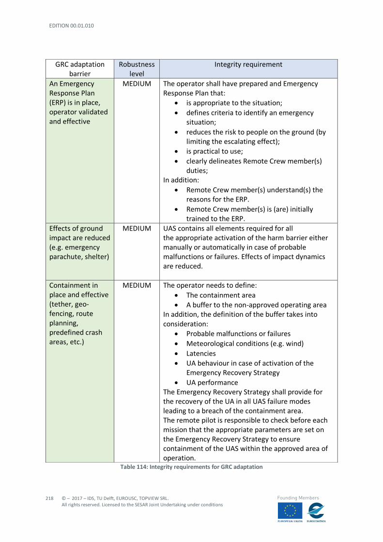
EDITION 00.01.010
218
© – 2017 – IDS, TU Delft, EUROUSC, TOPVIEW SRL. All rights reserved. Licensed to the SESAR Joint Undertaking under conditions
Founding Members
Table 114: Integrity requirements for GRC adaptation
GRC adaptation barrier
Robustness level
Integrity requirement
An Emergency Response Plan (ERP) is in place, operator validated and effective
MEDIUM The operator shall have prepared and Emergency Response Plan that:
• is appropriate to the situation; • defines criteria to identify an emergency
situation; • reduces the risk to people on the ground (by
limiting the escalating effect); • is practical to use; • clearly delineates Remote Crew member(s)
duties; In addition:
• Remote Crew member(s) understand(s) the reasons for the ERP.
• Remote Crew member(s) is (are) initially trained to the ERP.
Effects of ground impact are reduced (e.g. emergency parachute, shelter)
MEDIUM UAS contains all elements required for all the appropriate activation of the harm barrier either manually or automatically in case of probable malfunctions or failures. Effects of impact dynamics are reduced.
Containment in place and effective (tether, geo-fencing, route planning, predefined crash areas, etc.)
MEDIUM The operator needs to define: • The containment area • A buffer to the non-approved operating area
In addition, the definition of the buffer takes into consideration:
• Probable malfunctions or failures • Meteorological conditions (e.g. wind) • Latencies • UA behaviour in case of activation of the
Emergency Recovery Strategy • UA performance
The Emergency Recovery Strategy shall provide for the recovery of the UA in all UAS failure modes leading to a breach of the containment area. The remote pilot is responsible to check before each mission that the appropriate parameters are set on the Emergency Recovery Strategy to ensure containment of the UAS within the approved area of operation.
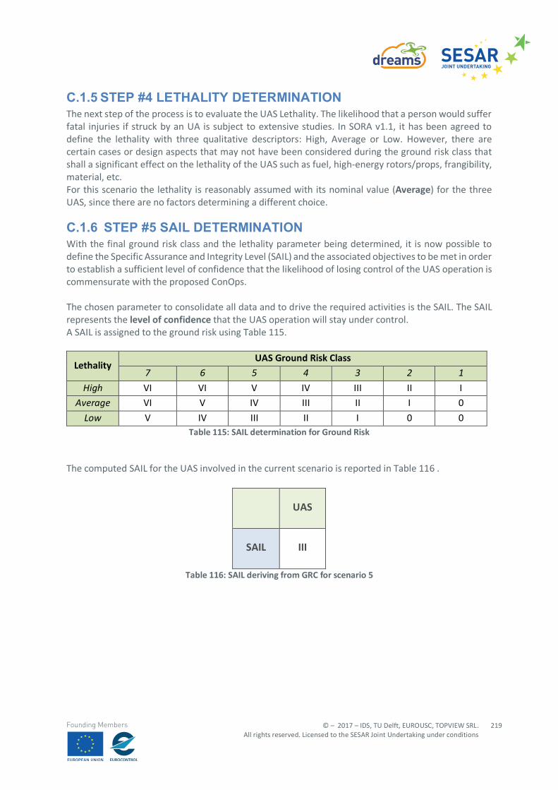
© – 2017 – IDS, TU Delft, EUROUSC, TOPVIEW SRL. All rights reserved. Licensed to the SESAR Joint Undertaking under conditions
219
Founding Members
C.1.5 STEP #4 LETHALITY DETERMINATION The next step of the process is to evaluate the UAS Lethality. The likelihood that a person would suffer fatal injuries if struck by an UA is subject to extensive studies. In SORA v1.1, it has been agreed to define the lethality with three qualitative descriptors: High, Average or Low. However, there are certain cases or design aspects that may not have been considered during the ground risk class that shall a significant effect on the lethality of the UAS such as fuel, high-energy rotors/props, frangibility, material, etc. For this scenario the lethality is reasonably assumed with its nominal value (Average) for the three UAS, since there are no factors determining a different choice.
C.1.6 STEP #5 SAIL DETERMINATION With the final ground risk class and the lethality parameter being determined, it is now possible to define the Specific Assurance and Integrity Level (SAIL) and the associated objectives to be met in order to establish a sufficient level of confidence that the likelihood of losing control of the UAS operation is commensurate with the proposed ConOps. The chosen parameter to consolidate all data and to drive the required activities is the SAIL. The SAIL represents the level of confidence that the UAS operation will stay under control. A SAIL is assigned to the ground risk using Table 115.
Lethality UAS Ground Risk Class
7 6 5 4 3 2 1 High VI VI V IV III II I
Average VI V IV III II I 0
Low V IV III II I 0 0 Table 115: SAIL determination for Ground Risk
The computed SAIL for the UAS involved in the current scenario is reported in Table 116 .
UAS
SAIL III
Table 116: SAIL deriving from GRC for scenario 5

EDITION 00.01.010
220
© – 2017 – IDS, TU Delft, EUROUSC, TOPVIEW SRL. All rights reserved. Licensed to the SESAR Joint Undertaking under conditions
Founding Members
C.1.7 STEP #6 DETERMINATION OF THE AIRSPACE ENCOUNTER CATEGORY (AEC)
The determination of the AEC is done according to the process illustrated in Figure 31. As already pointed out in Section C1.2.1, the UAS in the scenario is expected to fly at VLL in two different airspace classes:
- Class G airspace (uncontrolled) - Control zone (CTR i.e. a controlled airspace C or D)
Since multiple airspace types are present, SORA prescribes to take the most critical one (i.e. flight in a CTR) as a guidance parameter for the Air Risk evaluation. Even if the airport is at 8 km of distance, the UA is expected to fly in a region surrounding an airport where arriving and departing manned aircraft typically fly. Therefore, conservatively the AEC is taken equal to 6a (Table 117)
Figure 31: AEC determination process
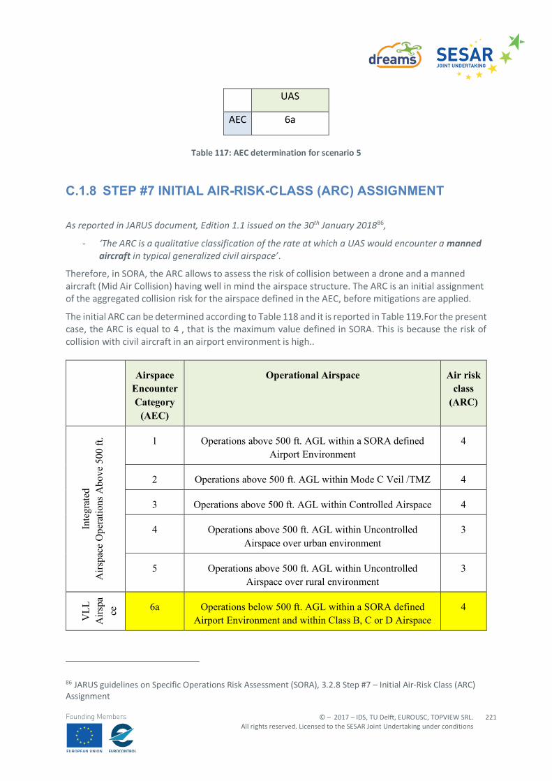
© – 2017 – IDS, TU Delft, EUROUSC, TOPVIEW SRL. All rights reserved. Licensed to the SESAR Joint Undertaking under conditions
221
Founding Members
UAS
AEC 6a
Table 117: AEC determination for scenario 5
C.1.8 STEP #7 INITIAL AIR-RISK-CLASS (ARC) ASSIGNMENT
As reported in JARUS document, Edition 1.1 issued on the 30th January 201886,
- ‘The ARC is a qualitative classification of the rate at which a UAS would encounter a manned aircraft in typical generalized civil airspace’.
Therefore, in SORA, the ARC allows to assess the risk of collision between a drone and a manned aircraft (Mid Air Collision) having well in mind the airspace structure. The ARC is an initial assignment of the aggregated collision risk for the airspace defined in the AEC, before mitigations are applied.
The initial ARC can be determined according to Table 118 and it is reported in Table 119.For the present case, the ARC is equal to 4 , that is the maximum value defined in SORA. This is because the risk of collision with civil aircraft in an airport environment is high..
Airspace Encounter Category
(AEC)
Operational Airspace Air risk class
(ARC)
Inte
grat
ed
Airs
pace
Ope
ratio
ns A
bove
500
ft. 1 Operations above 500 ft. AGL within a SORA defined
Airport Environment 4
2 Operations above 500 ft. AGL within Mode C Veil /TMZ 4
3 Operations above 500 ft. AGL within Controlled Airspace 4
4 Operations above 500 ft. AGL within Uncontrolled Airspace over urban environment
3
5 Operations above 500 ft. AGL within Uncontrolled Airspace over rural environment
3
VLL
A
irspa
ce
Ope
ratio
ns
belo
w
500
ft.
6a Operations below 500 ft. AGL within a SORA defined Airport Environment and within Class B, C or D Airspace
4
86 JARUS guidelines on Specific Operations Risk Assessment (SORA), 3.2.8 Step #7 – Initial Air-Risk Class (ARC) Assignment

EDITION 00.01.010
222
© – 2017 – IDS, TU Delft, EUROUSC, TOPVIEW SRL. All rights reserved. Licensed to the SESAR Joint Undertaking under conditions
Founding Members
6b Operations below 500 ft. AGL within a SORA defined Airport Environment and within Class E or within Class F
or G Airspace over Urban Population
3
6c Operations below 500 ft. AGL within a SORA defined Airport Environment and within Class F or G Airspace over
Rural Population
2
7 Operations below 500 ft. AGL within Mode C Veil /TMZ 3
8 Operations below 500 ft. AGL within Controlled Airspace 3
9 Operations below 500 ft. AGL within Uncontrolled Airspace over urban environment
3
10 Operations below 500 ft. AGL within Uncontrolled Airspace over rural environment
2
VHL 11 Operations in airspace above FL600 2
Any 12 Operations in Atypical Airspace 1 Table 118: Initial ARC determination
UAS 1
INITIAL ARC 4
Table 119: Initial ARC for the UAS involved in scenario 5
C.1.9 STEP #8A APPLICATION OF STRATEGIC MITIGATIONS BY OPERATIONAL RESTRICTIONS: INTERMEDIATE ARC DETERMINATION
An operator may wish to lower the ARC by using Strategic Mitigations. In general, Strategic Mitigations are applied prior to take off and do not require a mitigating feedback loop. In SORA v1.1, Strategic Mitigations are divided into two categories; Strategic Mitigation by Operational Restriction and Strategic Mitigation by Structures and Rules. Strategic Mitigation by Operational Restriction are defined as operational restrictions controlled by the operator. In essence, the process relies on the operator using operational restrictions to lower the local airspace density, and therefore reducing the encounter rate of the UAS versus manned aircraft.
© – 2017 – IDS, TU Delft, EUROUSC, TOPVIEW SRL. All rights reserved. Licensed to the SESAR Joint Undertaking under conditions
223
Founding Members
The initial ARC is providing a qualitative value of the aggregated risk of collision for the airspace defined in the AEC. Where the initial ARC is based on rather generic assumptions about airspace encounter rates and thus airspace collision risk, the Strategic Mitigation by Operational Restrictions allows the operator to better tailor the actual collision risk, using operational restrictions, to the defined local operational conditions. The most common Strategic Mitigations by Operational Restriction will take the form of:
- Mitigation by Boundary (restricted to geographical volume where encounter rate might be lower),
- Mitigation by Chronology (restricted to time of day),
- Mitigation by Behaviour (restricted by operational predictability by other airspace users), or;
- Mitigation by Exposure (restricted by time of exposure to risk). The first two Strategic Mitigations by Operational Restriction, limiting risk by operating during certain times, limiting risk by operating within certain boundaries, are the primary means by which the operator will generally reduce collision risk with strategic mitigation. The next mitigation, limiting risk by limiting certain types of risky behaviour, is fundamentally about making your UAS operations predictable. Unpredictable behaviours such as acrobatic flights, sudden stops to a hover, excessive climbing and descending, etc. are interpreted as risky behaviours because they can be seen as unpredictable to other airspace users. In order for the operator to take advantage of this mitigation scheme, they would need to have an operation so predictable in nature that all airspace users could predict the behaviour of the aircraft well in advance. Although at the outset this may appear to be difficult, over time this may be an acceptable mitigation approach, e.g. the daily launch of a weather sensing balloon at a given time. For the current scenario, thanks to the contribution provided by the U-Space Procedural interface with ATC service, a mitigation by Boundary is applied. In fact, the drone flight plan is modified so that the CTR will be crossed in such a way to minimize possible trajectory interferences with manned aircraft. The effect of this mitigation is taken into account in the following step: in fact, the mitigation is achieved through the U-Space service procedural interface with ATC which also represent a Strategic Mitigation by Structure and Rules. It is very important in SORA not to double count the mitigations that are applied. No other mitigations by operational restrictions are applicable for this scenario.
C.1.10 STEP #8B APPLICATION OF STRATEGIC MITIGATIONS BY STRUCTURES AND RULES: FINAL ARC DETERMINATION
Strategic Mitigation by Structures and Rules requires that all aircraft within that airspace are subject to the same structure and rules, and that these structures and rules work to lower the collision risk within the airspace.
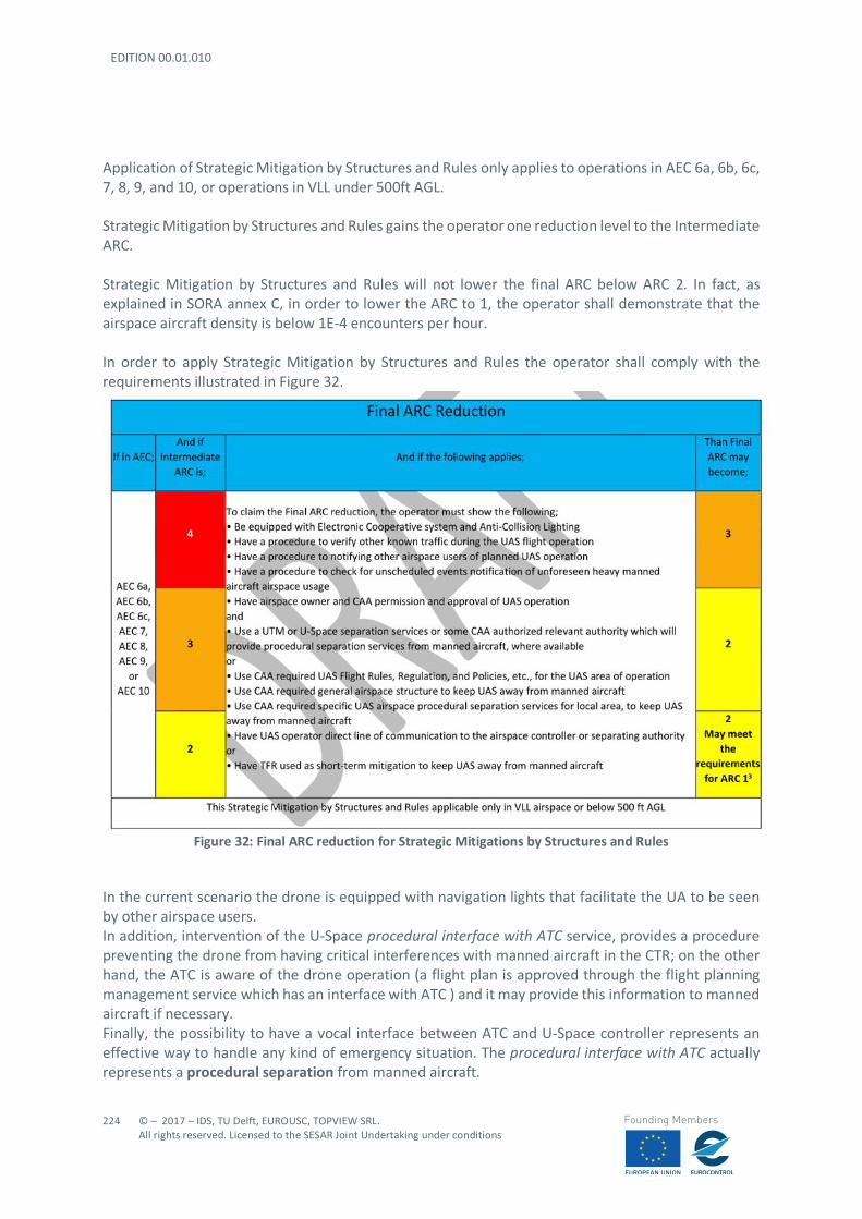
EDITION 00.01.010
224
© – 2017 – IDS, TU Delft, EUROUSC, TOPVIEW SRL. All rights reserved. Licensed to the SESAR Joint Undertaking under conditions
Founding Members
Application of Strategic Mitigation by Structures and Rules only applies to operations in AEC 6a, 6b, 6c, 7, 8, 9, and 10, or operations in VLL under 500ft AGL. Strategic Mitigation by Structures and Rules gains the operator one reduction level to the Intermediate ARC. Strategic Mitigation by Structures and Rules will not lower the final ARC below ARC 2. In fact, as explained in SORA annex C, in order to lower the ARC to 1, the operator shall demonstrate that the airspace aircraft density is below 1E-4 encounters per hour. In order to apply Strategic Mitigation by Structures and Rules the operator shall comply with the requirements illustrated in Figure 32.
Figure 32: Final ARC reduction for Strategic Mitigations by Structures and Rules
In the current scenario the drone is equipped with navigation lights that facilitate the UA to be seen by other airspace users. In addition, intervention of the U-Space procedural interface with ATC service, provides a procedure preventing the drone from having critical interferences with manned aircraft in the CTR; on the other hand, the ATC is aware of the drone operation (a flight plan is approved through the flight planning management service which has an interface with ATC ) and it may provide this information to manned aircraft if necessary. Finally, the possibility to have a vocal interface between ATC and U-Space controller represents an effective way to handle any kind of emergency situation. The procedural interface with ATC actually represents a procedural separation from manned aircraft.
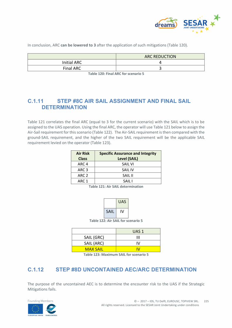
© – 2017 – IDS, TU Delft, EUROUSC, TOPVIEW SRL. All rights reserved. Licensed to the SESAR Joint Undertaking under conditions
225
Founding Members
In conclusion, ARC can be lowered to 3 after the application of such mitigations (Table 120).
ARC REDUCTION Initial ARC 4 Final ARC 3
Table 120: Final ARC for scenario 5
C.1.11 STEP #8C AIR SAIL ASSIGNMENT AND FINAL SAIL DETERMINATION
Table 121 correlates the final ARC (equal to 3 for the current scenario) with the SAIL which is to be assigned to the UAS operation. Using the final ARC, the operator will use Table 121 below to assign the Air-Sail requirement for this scenario (Table 122). The Air-SAIL requirement is then compared with the ground-SAIL requirement, and the higher of the two SAIL requirement will be the applicable SAIL requirement levied on the operator (Table 123).
Air Risk Class
Specific Assurance and Integrity Level (SAIL)
ARC 4 SAIL VI ARC 3 SAIL IV ARC 2 SAIL II ARC 1 SAIL I
Table 121: Air SAIL determination
UAS
SAIL IV
Table 122: Air SAIL for scenario 5
UAS 1 SAIL (GRC) III SAIL (ARC) IV MAX SAIL IV
Table 123: Maximum SAIL for scenario 5
C.1.12 STEP #8D UNCONTAINED AEC/ARC DETERMINATION
The purpose of the uncontained AEC is to determine the encounter risk to the UAS if the Strategic Mitigations fails.
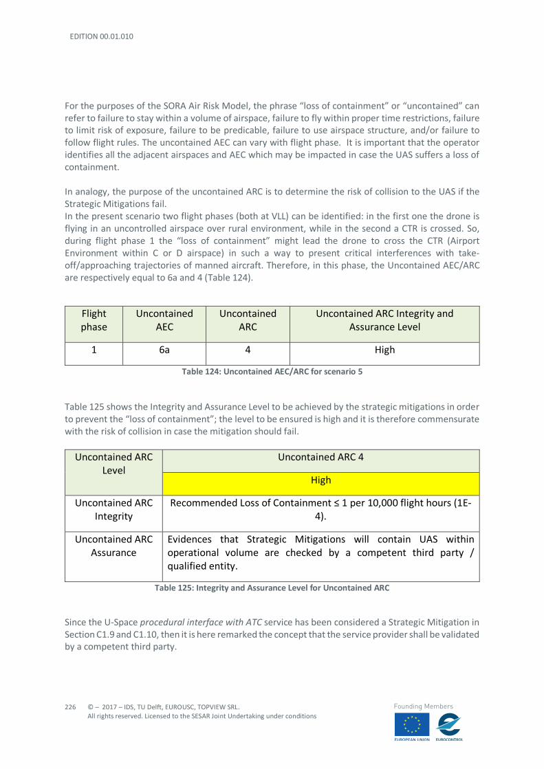
EDITION 00.01.010
226
© – 2017 – IDS, TU Delft, EUROUSC, TOPVIEW SRL. All rights reserved. Licensed to the SESAR Joint Undertaking under conditions
Founding Members
For the purposes of the SORA Air Risk Model, the phrase “loss of containment” or “uncontained” can refer to failure to stay within a volume of airspace, failure to fly within proper time restrictions, failure to limit risk of exposure, failure to be predicable, failure to use airspace structure, and/or failure to follow flight rules. The uncontained AEC can vary with flight phase. It is important that the operator identifies all the adjacent airspaces and AEC which may be impacted in case the UAS suffers a loss of containment. In analogy, the purpose of the uncontained ARC is to determine the risk of collision to the UAS if the Strategic Mitigations fail. In the present scenario two flight phases (both at VLL) can be identified: in the first one the drone is flying in an uncontrolled airspace over rural environment, while in the second a CTR is crossed. So, during flight phase 1 the “loss of containment” might lead the drone to cross the CTR (Airport Environment within C or D airspace) in such a way to present critical interferences with take-off/approaching trajectories of manned aircraft. Therefore, in this phase, the Uncontained AEC/ARC are respectively equal to 6a and 4 (Table 124).
Flight phase
Uncontained AEC
Uncontained ARC
Uncontained ARC Integrity and Assurance Level
1 6a 4 High
Table 124: Uncontained AEC/ARC for scenario 5
Table 125 shows the Integrity and Assurance Level to be achieved by the strategic mitigations in order to prevent the “loss of containment”; the level to be ensured is high and it is therefore commensurate with the risk of collision in case the mitigation should fail.
Uncontained ARC Level
Uncontained ARC 4
High
Uncontained ARC Integrity
Recommended Loss of Containment ≤ 1 per 10,000 flight hours (1E-4).
Uncontained ARC Assurance
Evidences that Strategic Mitigations will contain UAS within operational volume are checked by a competent third party / qualified entity.
Table 125: Integrity and Assurance Level for Uncontained ARC
Since the U-Space procedural interface with ATC service has been considered a Strategic Mitigation in Section C1.9 and C1.10, then it is here remarked the concept that the service provider shall be validated by a competent third party.
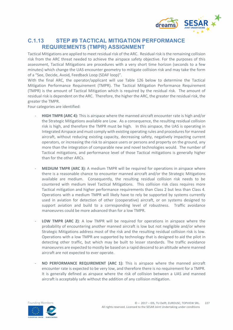
© – 2017 – IDS, TU Delft, EUROUSC, TOPVIEW SRL. All rights reserved. Licensed to the SESAR Joint Undertaking under conditions
227
Founding Members
C.1.13 STEP #9 TACTICAL MITIGATION PERFORMANCE REQUIREMENTS (TMPR) ASSIGNMENT
Tactical Mitigations are applied to meet residual risk of the ARC. Residual risk is the remaining collision risk from the ARC threat needed to achieve the airspace safety objective. For the purposes of this assessment, Tactical Mitigations are procedures with a very short time horizon (seconds to a few minutes) which change the UAS encounter geometry to mitigate collision risk and may take the form of a “See, Decide, Avoid, Feedback Loop (SDAF loop)”. With the final ARC, the operator/applicant will use Table 126 below to determine the Tactical Mitigation Performance Requirement (TMPR). The Tactical Mitigation Performance Requirement (TMPR) is the amount of Tactical Mitigation which is required by the residual risk. The amount of residual risk is dependent on the ARC. Therefore, the higher the ARC, the greater the residual risk, the greater the TMPR. Four categories are identified:
- HIGH TMPR (ARC 4): This is airspace where the manned aircraft encounter rate is high and/or the Strategic Mitigations available are Low. As a consequence, the resulting residual collision risk is high, and therefore the TMPR must be high. In this airspace, the UAS is operating in Integrated Airspace and must comply with existing operating rules and procedures for manned aircraft, without reducing existing capacity, decreasing safety, negatively impacting current operators, or increasing the risk to airspace users or persons and property on the ground, any more than the integration of comparable new and novel technologies would. The number of Tactical mitigations, and performance level of those Tactical mitigations is generally higher than for the other ARCs.
- MEDIUM TMPR (ARC 3): A medium TMPR will be required for operations in airspace where there is a reasonable chance to encounter manned aircraft and/or the Strategic Mitigations available are medium. Consequently, the resulting residual collision risk needs to be countered with medium level Tactical Mitigations. This collision risk class requires more Tactical mitigation and higher performance requirements than Class 2 but less than Class 4. Operations with a medium TMPR will likely have to rely be supported by systems currently used in aviation for detection of other (cooperative) aircraft, or on systems designed to support aviation and build to a corresponding level of robustness. Traffic avoidance manoeuvres could be more advanced than for a low TMPR.
- LOW TMPR (ARC 2): A low TMPR will be required for operations in airspace where the
probability of encountering another manned aircraft is low but not negligible and/or where Strategic Mitigations address most of the risk and the resulting residual collision risk is low. Operations with a low TMPR are supported by technology that is designed to aid the pilot in detecting other traffic, but which may be built to lesser standards. The traffic avoidance manoeuvres are expected to mostly be based on a rapid descend to an altitude where manned aircraft are not expected to ever operate.
- NO PERFORMANCE REQUIREMENT (ARC 1): This is airspace where the manned aircraft
encounter rate is expected to be very low, and therefore there is no requirement for a TMPR. It is generally defined as airspace where the risk of collision between a UAS and manned aircraft is acceptably safe without the addition of any collision mitigation.

EDITION 00.01.010
228
© – 2017 – IDS, TU Delft, EUROUSC, TOPVIEW SRL. All rights reserved. Licensed to the SESAR Joint Undertaking under conditions
Founding Members
Air Risk Class (ARC)
TMPR Assignment
ARC 1 No Requirement.
The operator/applicant may still need to show some form of mitigation as deemed necessary by the local authority/qualified entity.
ARC 2 Low
ARC 3 Medium
ARC 4 High
Table 126: TMPR Assignment for scenario 5 As highlighted in the Table above, the performance level associated to the UAS in the present scenario is Medium. According to SORA Annex D, it is possible to evaluate the requirements (Table 127) that allow the operator to comply with the TMPR associated to ARC 3.
TMPR Requisites
Function Medium performance (ARC 3)
DETECT The expectation is for the applicant’s DAA Plan to enable the operator to detect approximately 90%87 of all manned88 aircraft in the detection volume. To accomplish this, the applicant shall rely on one or a combination of the following systems or services:
• Ground based DAA /RADAR
• FLARM
87 This percentage is proposed by SORA methodology as a function of the Air Risk. The higher the ARC, the higher is the percentage of traffic that should be detected. 88 As already stated in Section C1.8, the Air Risk in SORA (and consequent mitigations) are addressed to prevent collisions with manned aircraft.
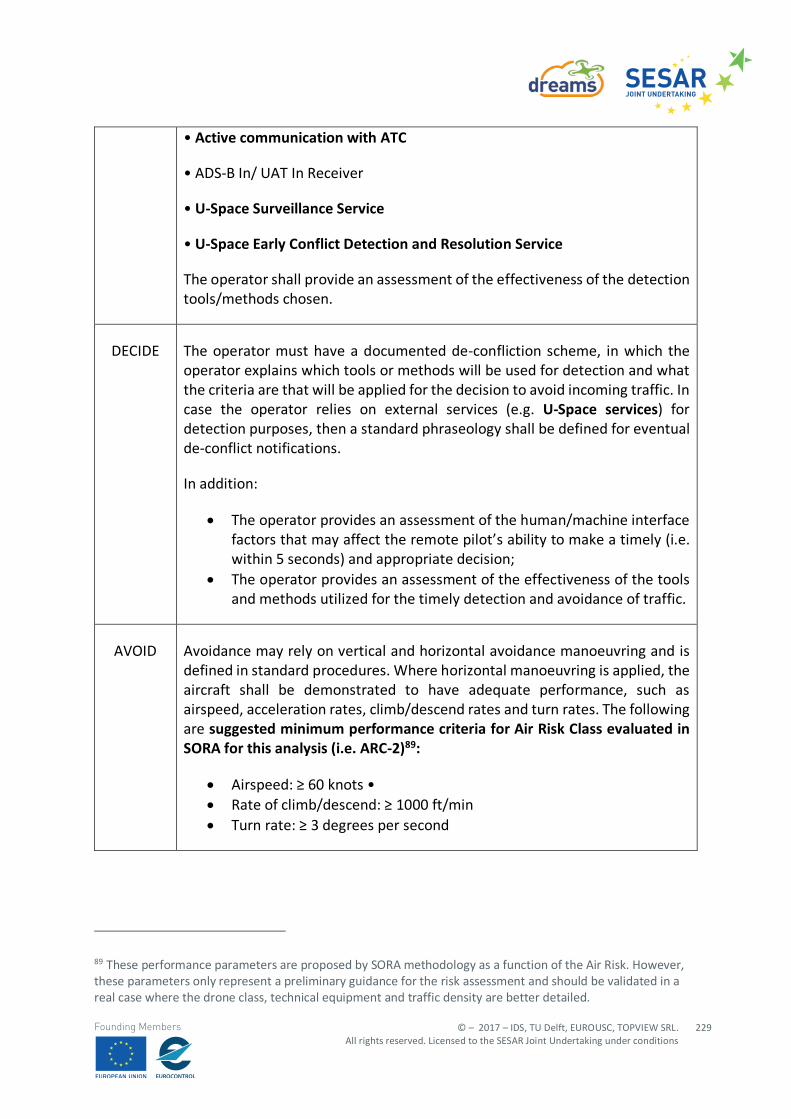
© – 2017 – IDS, TU Delft, EUROUSC, TOPVIEW SRL. All rights reserved. Licensed to the SESAR Joint Undertaking under conditions
229
Founding Members
• Active communication with ATC
• ADS-B In/ UAT In Receiver
• U-Space Surveillance Service
• U-Space Early Conflict Detection and Resolution Service
The operator shall provide an assessment of the effectiveness of the detection tools/methods chosen.
DECIDE The operator must have a documented de-confliction scheme, in which the operator explains which tools or methods will be used for detection and what the criteria are that will be applied for the decision to avoid incoming traffic. In case the operator relies on external services (e.g. U-Space services) for detection purposes, then a standard phraseology shall be defined for eventual de-conflict notifications.
In addition:
• The operator provides an assessment of the human/machine interface factors that may affect the remote pilot’s ability to make a timely (i.e. within 5 seconds) and appropriate decision;
• The operator provides an assessment of the effectiveness of the tools and methods utilized for the timely detection and avoidance of traffic.
AVOID Avoidance may rely on vertical and horizontal avoidance manoeuvring and is defined in standard procedures. Where horizontal manoeuvring is applied, the aircraft shall be demonstrated to have adequate performance, such as airspeed, acceleration rates, climb/descend rates and turn rates. The following are suggested minimum performance criteria for Air Risk Class evaluated in SORA for this analysis (i.e. ARC-2)89:
• Airspeed: ≥ 60 knots • • Rate of climb/descend: ≥ 1000 ft/min • Turn rate: ≥ 3 degrees per second
89 These performance parameters are proposed by SORA methodology as a function of the Air Risk. However, these parameters only represent a preliminary guidance for the risk assessment and should be validated in a real case where the drone class, technical equipment and traffic density are better detailed.
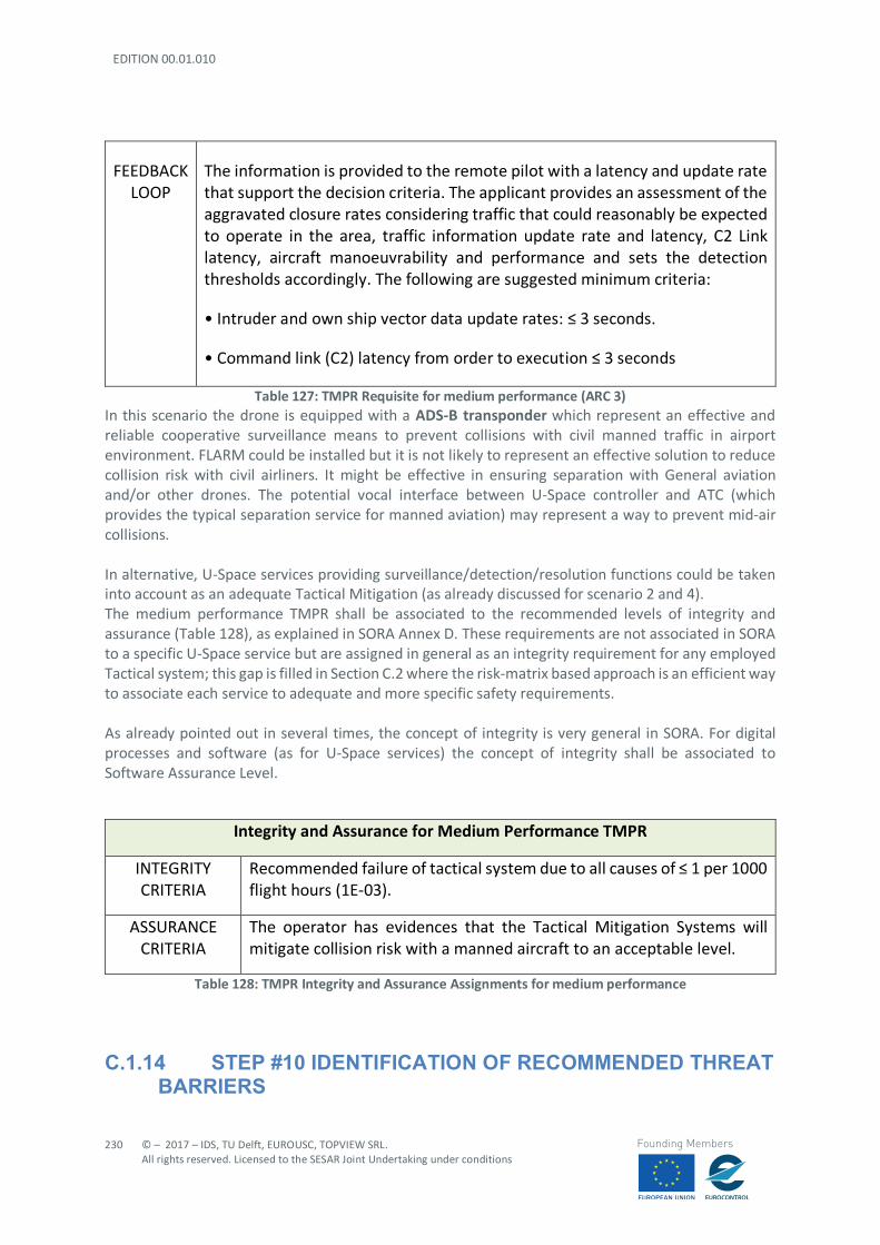
EDITION 00.01.010
230
© – 2017 – IDS, TU Delft, EUROUSC, TOPVIEW SRL. All rights reserved. Licensed to the SESAR Joint Undertaking under conditions
Founding Members
FEEDBACK LOOP
The information is provided to the remote pilot with a latency and update rate that support the decision criteria. The applicant provides an assessment of the aggravated closure rates considering traffic that could reasonably be expected to operate in the area, traffic information update rate and latency, C2 Link latency, aircraft manoeuvrability and performance and sets the detection thresholds accordingly. The following are suggested minimum criteria:
• Intruder and own ship vector data update rates: ≤ 3 seconds.
• Command link (C2) latency from order to execution ≤ 3 seconds
Table 127: TMPR Requisite for medium performance (ARC 3) In this scenario the drone is equipped with a ADS-B transponder which represent an effective and reliable cooperative surveillance means to prevent collisions with civil manned traffic in airport environment. FLARM could be installed but it is not likely to represent an effective solution to reduce collision risk with civil airliners. It might be effective in ensuring separation with General aviation and/or other drones. The potential vocal interface between U-Space controller and ATC (which provides the typical separation service for manned aviation) may represent a way to prevent mid-air collisions. In alternative, U-Space services providing surveillance/detection/resolution functions could be taken into account as an adequate Tactical Mitigation (as already discussed for scenario 2 and 4). The medium performance TMPR shall be associated to the recommended levels of integrity and assurance (Table 128), as explained in SORA Annex D. These requirements are not associated in SORA to a specific U-Space service but are assigned in general as an integrity requirement for any employed Tactical system; this gap is filled in Section C.2 where the risk-matrix based approach is an efficient way to associate each service to adequate and more specific safety requirements. As already pointed out in several times, the concept of integrity is very general in SORA. For digital processes and software (as for U-Space services) the concept of integrity shall be associated to Software Assurance Level.
Integrity and Assurance for Medium Performance TMPR
INTEGRITY CRITERIA
Recommended failure of tactical system due to all causes of ≤ 1 per 1000 flight hours (1E-03).
ASSURANCE CRITERIA
The operator has evidences that the Tactical Mitigation Systems will mitigate collision risk with a manned aircraft to an acceptable level.
Table 128: TMPR Integrity and Assurance Assignments for medium performance
C.1.14 STEP #10 IDENTIFICATION OF RECOMMENDED THREAT BARRIERS
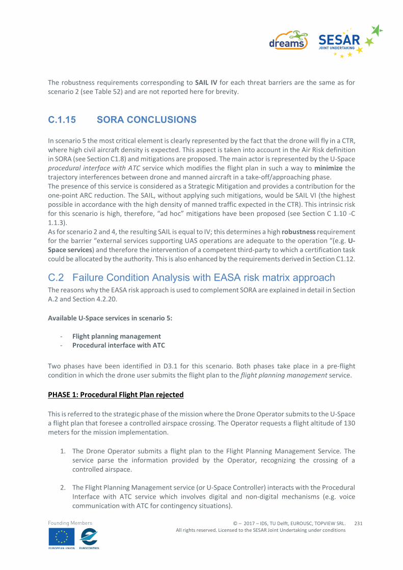
© – 2017 – IDS, TU Delft, EUROUSC, TOPVIEW SRL. All rights reserved. Licensed to the SESAR Joint Undertaking under conditions
231
Founding Members
The robustness requirements corresponding to SAIL IV for each threat barriers are the same as for scenario 2 (see Table 52) and are not reported here for brevity.
C.1.15 SORA CONCLUSIONS In scenario 5 the most critical element is clearly represented by the fact that the drone will fly in a CTR, where high civil aircraft density is expected. This aspect is taken into account in the Air Risk definition in SORA (see Section C1.8) and mitigations are proposed. The main actor is represented by the U-Space procedural interface with ATC service which modifies the flight plan in such a way to minimize the trajectory interferences between drone and manned aircraft in a take-off/approaching phase. The presence of this service is considered as a Strategic Mitigation and provides a contribution for the one-point ARC reduction. The SAIL, without applying such mitigations, would be SAIL VI (the highest possible in accordance with the high density of manned traffic expected in the CTR). This intrinsic risk for this scenario is high, therefore, “ad hoc” mitigations have been proposed (see Section C 1.10 -C 1.1.3). As for scenario 2 and 4, the resulting SAIL is equal to IV; this determines a high robustness requirement for the barrier “external services supporting UAS operations are adequate to the operation “(e.g. U-Space services) and therefore the intervention of a competent third-party to which a certification task could be allocated by the authority. This is also enhanced by the requirements derived in Section C1.12.
C.2 Failure Condition Analysis with EASA risk matrix approach The reasons why the EASA risk approach is used to complement SORA are explained in detail in Section A.2 and Section 4.2.20. Available U-Space services in scenario 5:
- Flight planning management - Procedural interface with ATC
Two phases have been identified in D3.1 for this scenario. Both phases take place in a pre-flight condition in which the drone user submits the flight plan to the flight planning management service. PHASE 1: Procedural Flight Plan rejected This is referred to the strategic phase of the mission where the Drone Operator submits to the U-Space a flight plan that foresee a controlled airspace crossing. The Operator requests a flight altitude of 130 meters for the mission implementation.
1. The Drone Operator submits a flight plan to the Flight Planning Management Service. The service parse the information provided by the Operator, recognizing the crossing of a controlled airspace.
2. The Flight Planning Management service (or U-Space Controller) interacts with the Procedural Interface with ATC service which involves digital and non-digital mechanisms (e.g. voice communication with ATC for contingency situations).
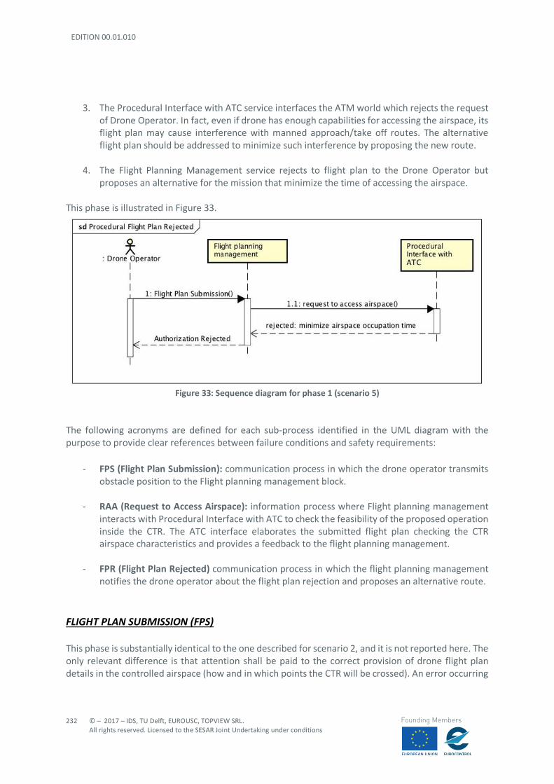
EDITION 00.01.010
232
© – 2017 – IDS, TU Delft, EUROUSC, TOPVIEW SRL. All rights reserved. Licensed to the SESAR Joint Undertaking under conditions
Founding Members
3. The Procedural Interface with ATC service interfaces the ATM world which rejects the request
of Drone Operator. In fact, even if drone has enough capabilities for accessing the airspace, its flight plan may cause interference with manned approach/take off routes. The alternative flight plan should be addressed to minimize such interference by proposing the new route.
4. The Flight Planning Management service rejects to flight plan to the Drone Operator but proposes an alternative for the mission that minimize the time of accessing the airspace.
This phase is illustrated in Figure 33.
Figure 33: Sequence diagram for phase 1 (scenario 5)
The following acronyms are defined for each sub-process identified in the UML diagram with the purpose to provide clear references between failure conditions and safety requirements:
- FPS (Flight Plan Submission): communication process in which the drone operator transmits obstacle position to the Flight planning management block.
- RAA (Request to Access Airspace): information process where Flight planning management interacts with Procedural Interface with ATC to check the feasibility of the proposed operation inside the CTR. The ATC interface elaborates the submitted flight plan checking the CTR airspace characteristics and provides a feedback to the flight planning management.
- FPR (Flight Plan Rejected) communication process in which the flight planning management notifies the drone operator about the flight plan rejection and proposes an alternative route.
FLIGHT PLAN SUBMISSION (FPS) This phase is substantially identical to the one described for scenario 2, and it is not reported here. The only relevant difference is that attention shall be paid to the correct provision of drone flight plan details in the controlled airspace (how and in which points the CTR will be crossed). An error occurring
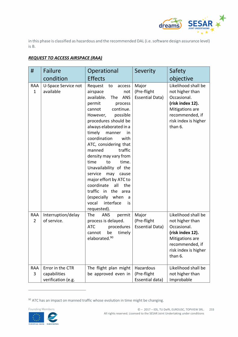
© – 2017 – IDS, TU Delft, EUROUSC, TOPVIEW SRL. All rights reserved. Licensed to the SESAR Joint Undertaking under conditions
233
Founding Members
in this phase is classified as hazardous and the recommended DAL (i.e. software design assurance level) is B.
REQUEST TO ACCESS AIRSPACE (RAA)
# Failure condition
Operational Effects
Severity Safety objective
RAA 1
U-Space Service not available
Request to access airspace not available. The ANS permit process cannot continue. However, possible procedures should be always elaborated in a timely manner in coordination with ATC, considering that manned traffic density may vary from time to time. Unavailability of the service may cause major effort by ATC to coordinate all the traffic in the area (especially when a vocal interface is requested).
Major (Pre-flight Essential Data)
Likelihood shall be not higher than Occasional. (risk index 12). Mitigations are recommended, if risk index is higher than 6.
RAA 2
Interruption/delay of service.
The ANS permit process is delayed. ATC procedures cannot be timely elaborated.90
Major (Pre-flight Essential Data)
Likelihood shall be not higher than Occasional. (risk index 12). Mitigations are recommended, if risk index is higher than 6.
RAA 3
Error in the CTR capabilities verification (e.g.
The flight plan might be approved even in
Hazardous (Pre-flight Essential data)
Likelihood shall be not higher than Improbable
90 ATC has an impact on manned traffic whose evolution in time might be changing.
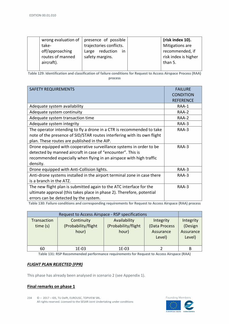
EDITION 00.01.010
234
© – 2017 – IDS, TU Delft, EUROUSC, TOPVIEW SRL. All rights reserved. Licensed to the SESAR Joint Undertaking under conditions
Founding Members
wrong evaluation of take-off/approaching routes of manned aircraft).
presence of possible trajectories conflicts. Large reduction in safety margins.
(risk index 10). Mitigations are recommended, if risk index is higher than 5.
Table 129: Identification and classification of failure conditions for Request to Access Airspace Process (RAA) process
SAFETY REQUIREMENTS FAILURE
CONDITION REFERENCE
Adequate system availability RAA-1 Adequate system continuity RAA-2 Adequate system transaction time RAA-2 Adequate system integrity RAA-3 The operator intending to fly a drone in a CTR is recommended to take note of the presence of SID/STAR routes interfering with its own flight plan. These routes are published in the AIP.
RAA-3
Drone equipped with cooperative surveillance systems in order to be detected by manned aircraft in case of “encounter”. This is recommended especially when flying in an airspace with high traffic density.
RAA-3
Drone equipped with Anti-Collision lights. RAA-3 Anti-drone systems installed in the airport terminal zone in case there is a branch in the ATZ.
RAA-3
The new flight plan is submitted again to the ATC interface for the ultimate approval (this takes place in phase 2). Therefore, potential errors can be detected by the system.
RAA-3
Table 130: Failure conditions and corresponding requirements for Request to Access Airspace (RAA) process
Request to Access Airspace - RSP specifications Transaction
time (s) Continuity
(Probability/flight hour)
Availability (Probability/flight
hour)
Integrity (Data Process
Assurance Level)
Integrity (Design
Assurance Level)
60 1E-03 1E-03 2 B
Table 131: RSP Recommended performance requirements for Request to Access Airspace (RAA) FLIGHT PLAN REJECTED (FPR)
This phase has already been analysed in scenario 2 (see Appendix 1). Final remarks on phase 1
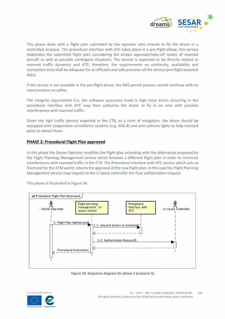
© – 2017 – IDS, TU Delft, EUROUSC, TOPVIEW SRL. All rights reserved. Licensed to the SESAR Joint Undertaking under conditions
235
Founding Members
This phase deals with a flight plan submitted by the operator who intends to fly the drone in a controlled airspace. The procedural interface with ATC takes place in a pre-flight phase; this service elaborates the submitted flight plan considering the known approach/take-off routes of manned aircraft as well as possible contingent situations. The service is expected to be directly related to manned traffic dynamics and ATC; therefore, the requirements on continuity, availability and transaction time shall be adequate for an efficient and safe provision of the service (pre-flight essential data). If the service is not available in the pre-flight phase, the ANS permit process cannot continue with no repercussions on safety. The integrity requirement (i.e. the software assurance level) is high since errors occurring in the procedural interface with ATC may then authorise the drone to fly in an area with possible interferences with manned traffic. Given the high traffic density expected in the CTR, as a form of mitigation, the drone should be equipped with cooperative surveillance systems (e.g. ADS-B) and anti-collision lights to help manned pilots to detect them. PHASE 2: Procedural Flight Plan approved In this phase the Drone Operator modifies the flight plan according with the alternative proposed by the Flight Planning Management service which foresees a different flight plan in order to minimize interferences with manned traffic in the CTR. The Procedural Interface with ATC service which acts as front end for the ATM world, returns the approval of the new flight plan. In this case the Flight Planning Management service may request to the U-Space controller the final authorisation request. This phase is illustrated in Figure 34.
Figure 34: Sequence diagram for phase 2 (scenario 5)
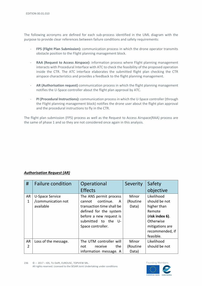
EDITION 00.01.010
236
© – 2017 – IDS, TU Delft, EUROUSC, TOPVIEW SRL. All rights reserved. Licensed to the SESAR Joint Undertaking under conditions
Founding Members
The following acronyms are defined for each sub-process identified in the UML diagram with the purpose to provide clear references between failure conditions and safety requirements:
- FPS (Flight Plan Submission): communication process in which the drone operator transmits obstacle position to the Flight planning management block.
- RAA (Request to Access Airspace): information process where Flight planning management interacts with Procedural Interface with ATC to check the feasibility of the proposed operation inside the CTR. The ATC interface elaborates the submitted flight plan checking the CTR airspace characteristics and provides a feedback to the flight planning management.
- AR (Authorisation request) communication process in which the flight planning management
notifies the U-Space controller about the flight plan approval by ATC.
- PI (Procedural Instructions): communication process in which the U-Space controller (through the Flight planning management block) notifies the drone user about the flight plan approval and the procedural instructions to fly in the CTR.
The flight plan submission (FPS) process as well as the Request to Access Airspace(RAA) process are the same of phase 1 and so they are not considered once again in this analysis. Authorisation Request (AR) # Failure condition Operational
Effects Severity Safety
objective AR 1
U-Space Service /communication not available
The ANS permit process cannot continue. A transaction time shall be defined for the system before a new request is submitted to the U-Space controller.
Minor (Routine
Data)
Likelihood should be not higher than Remote (risk index 6). Otherwise mitigations are recommended, if feasible.
AR 2
Loss of the message. The UTM controller will not receive the information message. A
Minor (Routine
Data)
Likelihood should be not
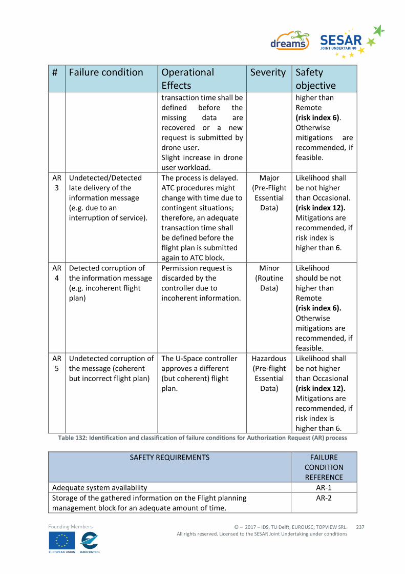
© – 2017 – IDS, TU Delft, EUROUSC, TOPVIEW SRL. All rights reserved. Licensed to the SESAR Joint Undertaking under conditions
237
Founding Members
# Failure condition Operational Effects
Severity Safety objective
transaction time shall be defined before the missing data are recovered or a new request is submitted by drone user. Slight increase in drone user workload.
higher than Remote (risk index 6). Otherwise mitigations are recommended, if feasible.
AR 3
Undetected/Detected late delivery of the information message (e.g. due to an interruption of service).
The process is delayed. ATC procedures might change with time due to contingent situations; therefore, an adequate transaction time shall be defined before the flight plan is submitted again to ATC block.
Major (Pre-Flight Essential
Data)
Likelihood shall be not higher than Occasional. (risk index 12). Mitigations are recommended, if risk index is higher than 6.
AR 4
Detected corruption of the information message (e.g. incoherent flight plan)
Permission request is discarded by the controller due to incoherent information.
Minor (Routine
Data)
Likelihood should be not higher than Remote (risk index 6). Otherwise mitigations are recommended, if feasible.
AR 5
Undetected corruption of the message (coherent but incorrect flight plan)
The U-Space controller approves a different (but coherent) flight plan.
Hazardous (Pre-flight Essential
Data)
Likelihood shall be not higher than Occasional (risk index 12). Mitigations are recommended, if risk index is higher than 6.
Table 132: Identification and classification of failure conditions for Authorization Request (AR) process
SAFETY REQUIREMENTS FAILURE CONDITION REFERENCE
Adequate system availability AR-1 Storage of the gathered information on the Flight planning management block for an adequate amount of time.
AR-2
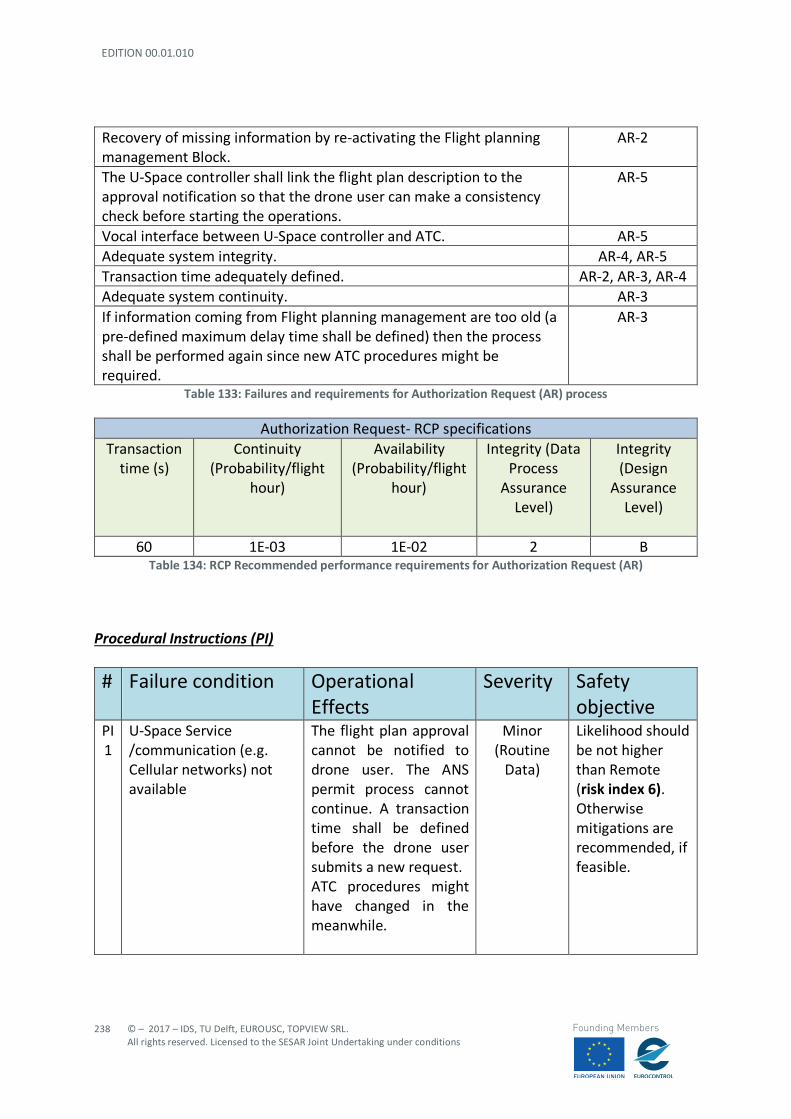
EDITION 00.01.010
238
© – 2017 – IDS, TU Delft, EUROUSC, TOPVIEW SRL. All rights reserved. Licensed to the SESAR Joint Undertaking under conditions
Founding Members
Recovery of missing information by re-activating the Flight planning management Block.
AR-2
The U-Space controller shall link the flight plan description to the approval notification so that the drone user can make a consistency check before starting the operations.
AR-5
Vocal interface between U-Space controller and ATC. AR-5 Adequate system integrity. AR-4, AR-5 Transaction time adequately defined. AR-2, AR-3, AR-4 Adequate system continuity. AR-3 If information coming from Flight planning management are too old (a pre-defined maximum delay time shall be defined) then the process shall be performed again since new ATC procedures might be required.
AR-3
Table 133: Failures and requirements for Authorization Request (AR) process
Authorization Request- RCP specifications Transaction
time (s) Continuity
(Probability/flight hour)
Availability (Probability/flight
hour)
Integrity (Data Process
Assurance Level)
Integrity (Design
Assurance Level)
60 1E-03 1E-02 2 B
Table 134: RCP Recommended performance requirements for Authorization Request (AR) Procedural Instructions (PI)
# Failure condition Operational Effects
Severity Safety objective
PI 1
U-Space Service /communication (e.g. Cellular networks) not available
The flight plan approval cannot be notified to drone user. The ANS permit process cannot continue. A transaction time shall be defined before the drone user submits a new request. ATC procedures might have changed in the meanwhile.
Minor (Routine
Data)
Likelihood should be not higher than Remote (risk index 6). Otherwise mitigations are recommended, if feasible.
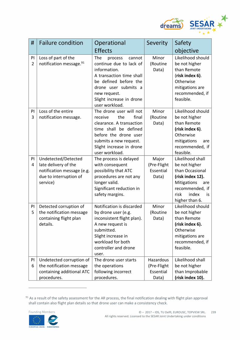
© – 2017 – IDS, TU Delft, EUROUSC, TOPVIEW SRL. All rights reserved. Licensed to the SESAR Joint Undertaking under conditions
239
Founding Members
# Failure condition Operational Effects
Severity Safety objective
PI 2
Loss of part of the notification message.91
The process cannot continue due to lack of information. A transaction time shall be defined before the drone user submits a new request. Slight increase in drone user workload.
Minor (Routine
Data)
Likelihood should be not higher than Remote (risk index 6). Otherwise mitigations are recommended, if feasible.
PI 3
Loss of the entire notification message.
The drone user will not receive the final clearance. A transaction time shall be defined before the drone user submits a new request. Slight increase in drone user workload.
Minor (Routine
Data)
Likelihood should be not higher than Remote (risk index 6). Otherwise mitigations are recommended, if feasible.
PI 4
Undetected/Detected late delivery of the notification message (e.g. due to interruption of service)
The process is delayed with consequent possibility that ATC procedures are not any longer valid. Significant reduction in safety margins.
Major (Pre-Flight Essential
Data)
Likelihood shall be not higher than Occasional (risk index 12). Mitigations are recommended, if risk index is higher than 6.
PI 5
Detected corruption of the notification message containing flight plan details.
Notification is discarded by drone user (e.g. inconsistent flight plan). A new request is submitted. Slight increase in workload for both controller and drone user.
Minor (Routine
Data)
Likelihood should be not higher than Remote (risk index 6). Otherwise mitigations are recommended, if feasible.
PI 6
Undetected corruption of the notification message containing additional ATC procedures.
The drone user starts the operations following incorrect procedures.
Hazardous (Pre-Flight Essential
Data)
Likelihood shall be not higher than Improbable (risk index 10).
91 As a result of the safety assessment for the AR process, the final notification dealing with flight plan approval shall contain also flight plan details so that drone user can make a consistency check.
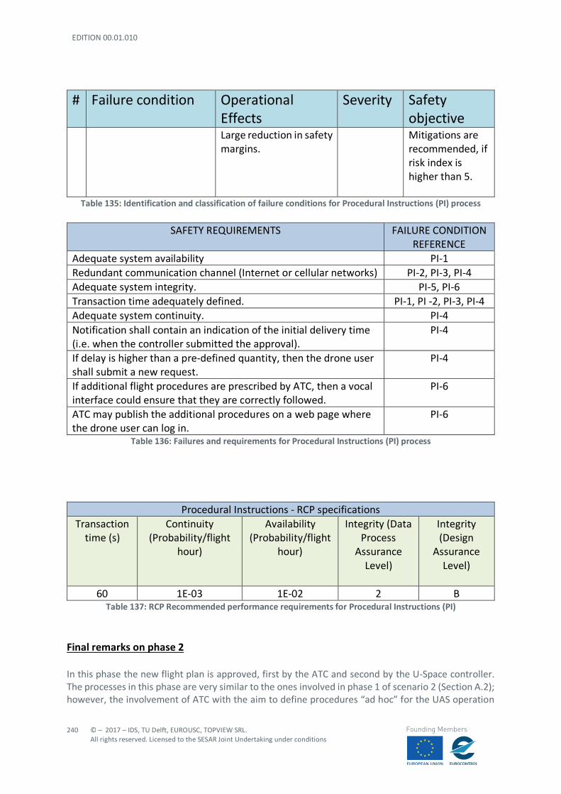
EDITION 00.01.010
240
© – 2017 – IDS, TU Delft, EUROUSC, TOPVIEW SRL. All rights reserved. Licensed to the SESAR Joint Undertaking under conditions
Founding Members
# Failure condition Operational Effects
Severity Safety objective
Large reduction in safety margins.
Mitigations are recommended, if risk index is higher than 5.
Table 135: Identification and classification of failure conditions for Procedural Instructions (PI) process
SAFETY REQUIREMENTS FAILURE CONDITION REFERENCE
Adequate system availability PI-1 Redundant communication channel (Internet or cellular networks) PI-2, PI-3, PI-4 Adequate system integrity. PI-5, PI-6 Transaction time adequately defined. PI-1, PI -2, PI-3, PI-4 Adequate system continuity. PI-4 Notification shall contain an indication of the initial delivery time (i.e. when the controller submitted the approval).
PI-4
If delay is higher than a pre-defined quantity, then the drone user shall submit a new request.
PI-4
If additional flight procedures are prescribed by ATC, then a vocal interface could ensure that they are correctly followed.
PI-6
ATC may publish the additional procedures on a web page where the drone user can log in.
PI-6
Table 136: Failures and requirements for Procedural Instructions (PI) process
Procedural Instructions - RCP specifications
Transaction time (s)
Continuity (Probability/flight
hour)
Availability (Probability/flight
hour)
Integrity (Data Process
Assurance Level)
Integrity (Design
Assurance Level)
60 1E-03 1E-02 2 B
Table 137: RCP Recommended performance requirements for Procedural Instructions (PI)
Final remarks on phase 2
In this phase the new flight plan is approved, first by the ATC and second by the U-Space controller. The processes in this phase are very similar to the ones involved in phase 1 of scenario 2 (Section A.2); however, the involvement of ATC with the aim to define procedures “ad hoc” for the UAS operation
© – 2017 – IDS, TU Delft, EUROUSC, TOPVIEW SRL. All rights reserved. Licensed to the SESAR Joint Undertaking under conditions
241
Founding Members
inside the CTR requires faster processes. In fact, ATC is directly related to manned traffic control and so the period of validity (timeliness) of certain procedures might be influenced by contingency situations occurring in the airport environment. Even if the interface with ATC is completely digital (thus preventing the ATC from experiencing an excessive workload), a vocal channel for communication may be needed to handle potential critical situations.
EDITION 00.01.010
242
© – 2017 – IDS, TU Delft, EUROUSC, TOPVIEW SRL. All rights reserved. Licensed to the SESAR Joint Undertaking under conditions
Founding Members
Appendix D - Risk Assessment of Scenario 8: “Emergency Management”
D.1 Risk assessment with SORA methodology The SORA methodology (v1.1) is fully applied to this scenario, with the aim to:
- Evaluating both Ground and Air Risk; - Identifying some general requirements in terms of required barriers (mitigations) and
robustness, which are the output of SORA.
However, it should be noted that:
- No Means of Evidence (MoE) are contained in this deliverable, since the assessment is generic for several scenarios;
- Consequently, the operator or service provider using this generic assessment in the future, should complete it (i.e. SORA Step #11 and STEP # 12, see Section 4.2.17 and Section 4.2.18);
- the air risk evaluation based on v1.1 of SORA is not sufficient, as already highlighted in Section 4.2.6, to cover all the potential hazards associated to concurrent UAS operations;
- therefore, in this deliverable, SORA is complemented by the more flexible risk-matrix approach (based on EASA example).
D.1.1 STEP #0 INITIAL EVALUATION In this preliminary step, the operator/applicant is tasked to verify that the proposed operation is feasible, not subject to specific exclusions from the local authority or subject to a standard scenario. Things to verify include:
- If the operation can be covered under a “standard scenario” recognized by the local authority; - If the operation falls under the “open” category; - If the operation is subject to specific NO-GO from local authority; - If the local authority has determined that the UAS is “harmless” for both ground and air risk.
Upon completion of this preliminary check, the operator/applicant will start the SORA process if none of the previous cases applies. For the present scenario it is assumed that the envisaged operations are compliant with local regulations and that none of the previous point is verified.
D.1.2 STEP #1 CONOPS DESCRIPTION
D.1.2.1 INTENDED OPERATIONS
St. Michael Hospital uses daily a drone to deliver tubes with blood samples to an external Analysis Centres located in another hospital in a southern Italy city (about 3000 citizens/Km^2 – uncontrolled airspace), and all the procedures works fine since the beginning of the service started two months ago. Today is a cold day of February, with temperatures below 0°C, quite uncommon for Southern Italy areas. The Drone User (Pilot) Luca, as usual, checks and setups the drone of the Hospital used for

© – 2017 – IDS, TU Delft, EUROUSC, TOPVIEW SRL. All rights reserved. Licensed to the SESAR Joint Undertaking under conditions
243
Founding Members
delivery after loading the tubes in the delivery box, and after obtaining the flight authorization by the U-Space, starts the aircraft for this mission. The expected flight time is about 12 minutes, widely within the limits of drone autonomy; but, just after 5 minutes from take-off, when the drone is at 90 meters AGL, the flight control unit detects an abrupt reduction of battery voltage on different elements for both batteries packs (likely defective cells degraded by low temperature). The Drone User Luca, is alerted on his ground station (Control room of the hospital) of this situation and is notified by Emergency Management service of the U-Space about the closest emergency landing areas. Luca, decided to accept the alternative landing pad suggested by the service due to the contingency situation and uploads the new flight plan proposed by the U-Space on the drone flight controller. The drone changes its trajectory and flies towards the emergency landing pad. The estimated time to reach the pad is about 90 seconds. Unfortunately, during the new trajectory, the voltage on three cells of one battery drops down to zero and few seconds later it happens also to the second battery. The Drone is underpowered. The critical situation is detected autonomously by the Flight control unit which provides to cut-off the engines and open the parachute activated by the Flight termination system. The parachute slows the drone fall up to a vertical descending speed of 4,5 m/s. While the drone descends slowly by, the U-Space provides to notify the emergency to Authorities, for a fast intervention on the interested area. The operational conditions are summarized in Table 138.
Table 138: Operational details for scenario 8
D.1.2.2 UAS DESCRIPTIONS
The UAS model considered in this Section is only a typical example of most spread models (e.g. MTOM, size etc.), which are necessary to perform the risk assessment through the SORA methodology. In this scenario it is assumed that the involved drone is equipped with whatever is needed to interface with U-Space services. Some basic characteristics of the UA involved in this scenario are reported below (Figure 35).
92 All operations take place in an area with a population density equal to 3000 citizens/km^2, thus, according to
SORA, this area shall be considered urban.
UAS 1 Type quad-copter
Population density Urban environment92 Airspace class Class G below 500 ft Flight mode BVLOS
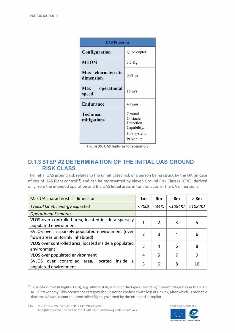
EDITION 00.01.010
244
© – 2017 – IDS, TU Delft, EUROUSC, TOPVIEW SRL. All rights reserved. Licensed to the SESAR Joint Undertaking under conditions
Founding Members
UAS Properties
Configuration Quad copter
MTOM 5.5 Kg
Max characteristic dimension 0.81 m
Max operational speed 18 m/s
Endurance 40 min
Technical mitigations
Ground Obstacle Detection Capability, FTS system, Parachute
Figure 35: UAS features for scenario 8
D.1.3 STEP #2 DETERMINATION OF THE INITIAL UAS GROUND RISK CLASS
The initial UAS ground risk relates to the unmitigated risk of a person being struck by the UA (in case of loss of UAS flight control93) and can be represented by eleven Ground Risk Classes (GRC), derived only from the intended operation and the UAS lethal area, in turn function of the UA dimensions.
Max UA characteristics dimension 1m 3m 8m > 8m
Typical kinetic energy expected <700J <34KJ <1084KJ >1084KJ Operational Scenario VLOS over controlled area, located inside a sparsely populated environment
1 2 3 5
BVLOS over a sparsely populated environment (over flown areas uniformly inhabited)
2 3 4 6
VLOS over controlled area, located inside a populated environment
3 4 6 8
VLOS over populated environment 4 5 7 9 BVLOS over controlled area, located inside a populated environment
5 6 8 10
93 Loss-of-Control In flight (LOC-I), e.g. after a stall, is one of the typical accident/incident categories in the ICAO
ADREP taxonomy. This occurrence category should not be confused with loss of C2 Link, after which, is probable that the UA would continue controlled flight, governed by the on-board autopilot.
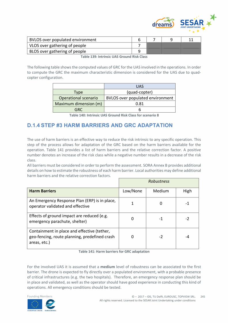
© – 2017 – IDS, TU Delft, EUROUSC, TOPVIEW SRL. All rights reserved. Licensed to the SESAR Joint Undertaking under conditions
245
Founding Members
BVLOS over populated environment 6 7 9 11 VLOS over gathering of people 7 BLOS over gathering of people 9
Table 139: Intrinsic UAS Ground Risk Class The following table shows the computed values of GRC for the UAS involved in the operations. In order to compute the GRC the maximum characteristic dimension is considered for the UAS due to quad-copter configuration.
Table 140: Intrinsic UAS Ground Risk Class for scenario 8
D.1.4 STEP #3 HARM BARRIERS AND GRC ADAPTATION
The use of harm barriers is an effective way to reduce the risk intrinsic to any specific operation. This step of the process allows for adaptation of the GRC based on the harm barriers available for the operation. Table 141 provides a list of harm barriers and the relative correction factor. A positive number denotes an increase of the risk class while a negative number results in a decrease of the risk class. All barriers must be considered in order to perform the assessment. SORA Annex B provides additional details on how to estimate the robustness of each harm barrier. Local authorities may define additional harm barriers and the relative correction factors.
Robustness
Harm Barriers Low/None Medium High
An Emergency Response Plan (ERP) is in place, operator validated and effective
1 0 -1
Effects of ground impact are reduced (e.g. emergency parachute, shelter)
0 -1 -2
Containment in place and effective (tether, geo-fencing, route planning, predefined crash areas, etc.)
0 -2 -4
Table 141: Harm barriers for GRC adaptation For the involved UAS it is assumed that a medium level of robustness can be associated to the first barrier. The drone is expected to fly directly over a populated environment, with a probable presence of critical infrastructures (e.g. the two hospitals). Therefore, an emergency response plan should be in place and validated, as well as the operator should have good experience in conducting this kind of operations. All emergency conditions should be tested.
UAS Type (quad-copter)
Operational scenario BVLOS over populated environment Maximum dimension (m) 0.81
GRC 6
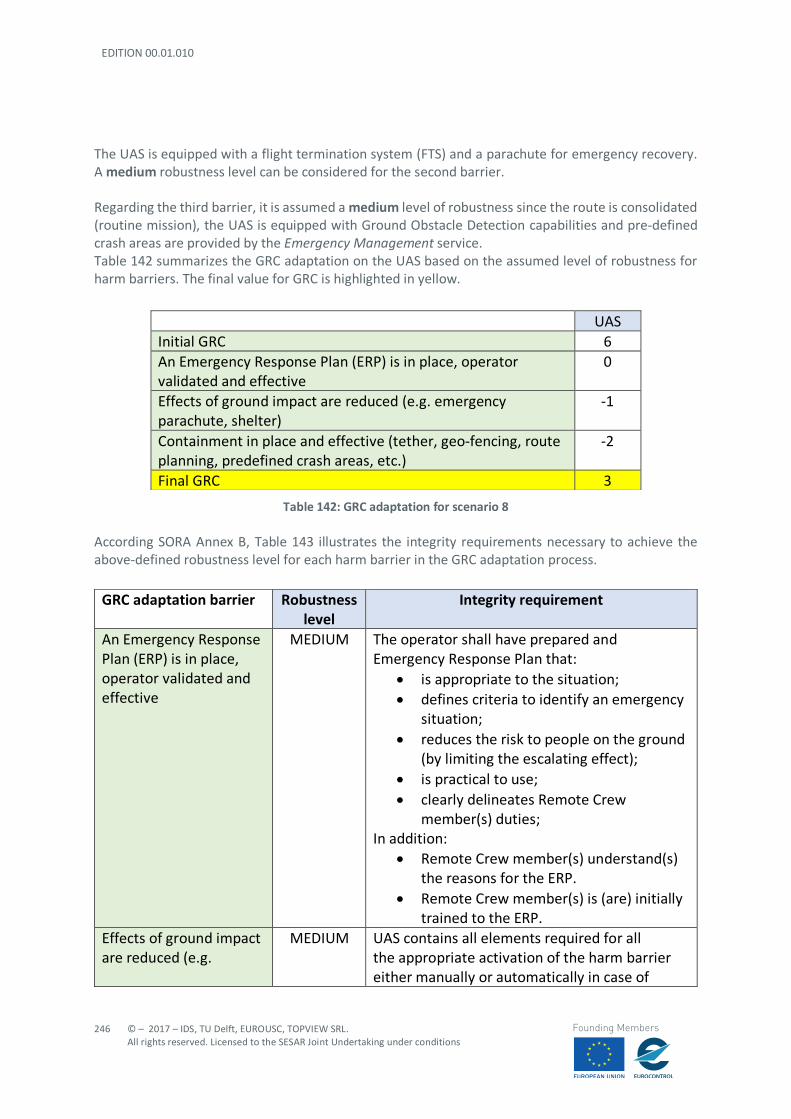
EDITION 00.01.010
246
© – 2017 – IDS, TU Delft, EUROUSC, TOPVIEW SRL. All rights reserved. Licensed to the SESAR Joint Undertaking under conditions
Founding Members
The UAS is equipped with a flight termination system (FTS) and a parachute for emergency recovery. A medium robustness level can be considered for the second barrier. Regarding the third barrier, it is assumed a medium level of robustness since the route is consolidated (routine mission), the UAS is equipped with Ground Obstacle Detection capabilities and pre-defined crash areas are provided by the Emergency Management service. Table 142 summarizes the GRC adaptation on the UAS based on the assumed level of robustness for harm barriers. The final value for GRC is highlighted in yellow.
Table 142: GRC adaptation for scenario 8 According SORA Annex B, Table 143 illustrates the integrity requirements necessary to achieve the above-defined robustness level for each harm barrier in the GRC adaptation process.
UAS Initial GRC 6 An Emergency Response Plan (ERP) is in place, operator validated and effective
0
Effects of ground impact are reduced (e.g. emergency parachute, shelter)
-1
Containment in place and effective (tether, geo-fencing, route planning, predefined crash areas, etc.)
-2
Final GRC 3
GRC adaptation barrier Robustness level
Integrity requirement
An Emergency Response Plan (ERP) is in place, operator validated and effective
MEDIUM The operator shall have prepared and Emergency Response Plan that:
• is appropriate to the situation; • defines criteria to identify an emergency
situation; • reduces the risk to people on the ground
(by limiting the escalating effect); • is practical to use; • clearly delineates Remote Crew
member(s) duties; In addition:
• Remote Crew member(s) understand(s) the reasons for the ERP.
• Remote Crew member(s) is (are) initially trained to the ERP.
Effects of ground impact are reduced (e.g.
MEDIUM UAS contains all elements required for all the appropriate activation of the harm barrier either manually or automatically in case of
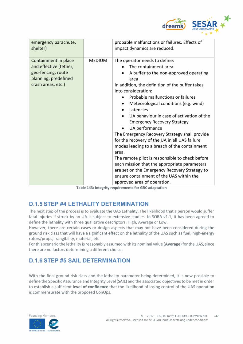
© – 2017 – IDS, TU Delft, EUROUSC, TOPVIEW SRL. All rights reserved. Licensed to the SESAR Joint Undertaking under conditions
247
Founding Members
Table 143: Integrity requirements for GRC adaptation
D.1.5 STEP #4 LETHALITY DETERMINATION The next step of the process is to evaluate the UAS Lethality. The likelihood that a person would suffer fatal injuries if struck by an UA is subject to extensive studies. In SORA v1.1, it has been agreed to define the lethality with three qualitative descriptors: High, Average or Low. However, there are certain cases or design aspects that may not have been considered during the ground risk class that will have a significant effect on the lethality of the UAS such as fuel, high-energy rotors/props, frangibility, material, etc For this scenario the lethality is reasonably assumed with its nominal value (Average) for the UAS, since there are no factors determining a different choice.
D.1.6 STEP #5 SAIL DETERMINATION
With the final ground risk class and the lethality parameter being determined, it is now possible to define the Specific Assurance and Integrity Level (SAIL) and the associated objectives to be met in order to establish a sufficient level of confidence that the likelihood of losing control of the UAS operation is commensurate with the proposed ConOps.
emergency parachute, shelter)
probable malfunctions or failures. Effects of impact dynamics are reduced.
Containment in place and effective (tether, geo-fencing, route planning, predefined crash areas, etc.)
MEDIUM The operator needs to define: • The containment area • A buffer to the non-approved operating
area In addition, the definition of the buffer takes into consideration:
• Probable malfunctions or failures • Meteorological conditions (e.g. wind) • Latencies • UA behaviour in case of activation of the
Emergency Recovery Strategy • UA performance
The Emergency Recovery Strategy shall provide for the recovery of the UA in all UAS failure modes leading to a breach of the containment area. The remote pilot is responsible to check before each mission that the appropriate parameters are set on the Emergency Recovery Strategy to ensure containment of the UAS within the approved area of operation.
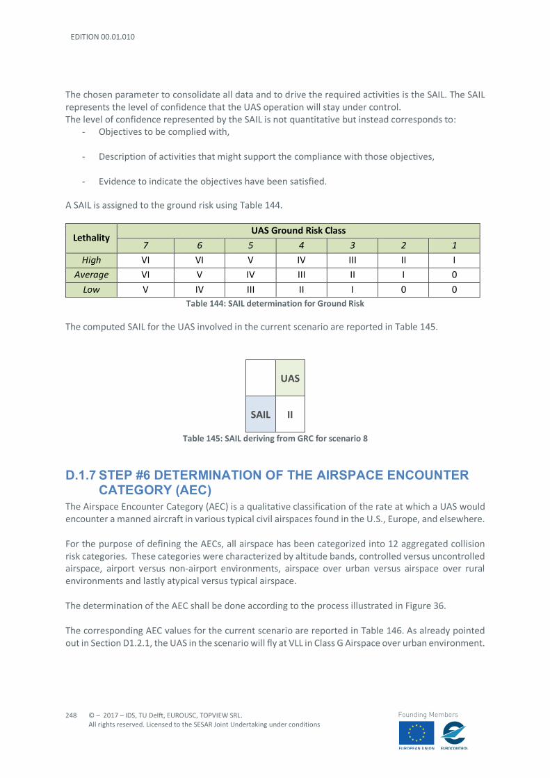
EDITION 00.01.010
248
© – 2017 – IDS, TU Delft, EUROUSC, TOPVIEW SRL. All rights reserved. Licensed to the SESAR Joint Undertaking under conditions
Founding Members
The chosen parameter to consolidate all data and to drive the required activities is the SAIL. The SAIL represents the level of confidence that the UAS operation will stay under control. The level of confidence represented by the SAIL is not quantitative but instead corresponds to:
- Objectives to be complied with,
- Description of activities that might support the compliance with those objectives,
- Evidence to indicate the objectives have been satisfied.
A SAIL is assigned to the ground risk using Table 144.
Lethality UAS Ground Risk Class
7 6 5 4 3 2 1 High VI VI V IV III II I
Average VI V IV III II I 0
Low V IV III II I 0 0 Table 144: SAIL determination for Ground Risk
The computed SAIL for the UAS involved in the current scenario are reported in Table 145.
UAS
SAIL II
Table 145: SAIL deriving from GRC for scenario 8
D.1.7 STEP #6 DETERMINATION OF THE AIRSPACE ENCOUNTER CATEGORY (AEC)
The Airspace Encounter Category (AEC) is a qualitative classification of the rate at which a UAS would encounter a manned aircraft in various typical civil airspaces found in the U.S., Europe, and elsewhere. For the purpose of defining the AECs, all airspace has been categorized into 12 aggregated collision risk categories. These categories were characterized by altitude bands, controlled versus uncontrolled airspace, airport versus non-airport environments, airspace over urban versus airspace over rural environments and lastly atypical versus typical airspace. The determination of the AEC shall be done according to the process illustrated in Figure 36. The corresponding AEC values for the current scenario are reported in Table 146. As already pointed out in Section D1.2.1, the UAS in the scenario will fly at VLL in Class G Airspace over urban environment.
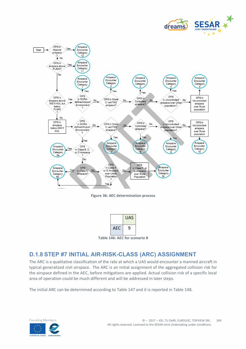
© – 2017 – IDS, TU Delft, EUROUSC, TOPVIEW SRL. All rights reserved. Licensed to the SESAR Joint Undertaking under conditions
249
Founding Members
Figure 36: AEC determination process
UAS
AEC 9
Table 146: AEC for scenario 8
D.1.8 STEP #7 INITIAL AIR-RISK-CLASS (ARC) ASSIGNMENT The ARC is a qualitative classification of the rate at which a UAS would encounter a manned aircraft in typical generalized civil airspace. The ARC is an initial assignment of the aggregated collision risk for the airspace defined in the AEC, before mitigations are applied. Actual collision risk of a specific local area of operation could be much different and will be addressed in later steps. The initial ARC can be determined according to Table 147 and it is reported in Table 148.
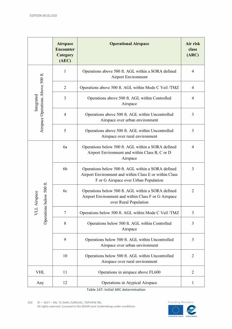
EDITION 00.01.010
250
© – 2017 – IDS, TU Delft, EUROUSC, TOPVIEW SRL. All rights reserved. Licensed to the SESAR Joint Undertaking under conditions
Founding Members
Airspace Encounter Category
(AEC)
Operational Airspace Air risk class
(ARC)
Inte
grat
ed
Airs
pace
Ope
ratio
ns A
bove
500
ft. 1 Operations above 500 ft. AGL within a SORA defined
Airport Environment 4
2 Operations above 500 ft. AGL within Mode C Veil /TMZ 4
3 Operations above 500 ft. AGL within Controlled Airspace
4
4 Operations above 500 ft. AGL within Uncontrolled Airspace over urban environment
3
5 Operations above 500 ft. AGL within Uncontrolled Airspace over rural environment
3
VLL
Airs
pace
Ope
ratio
ns b
elow
500
ft.
6a Operations below 500 ft. AGL within a SORA defined Airport Environment and within Class B, C or D
Airspace
4
6b Operations below 500 ft. AGL within a SORA defined Airport Environment and within Class E or within Class
F or G Airspace over Urban Population
3
6c Operations below 500 ft. AGL within a SORA defined Airport Environment and within Class F or G Airspace
over Rural Population
2
7 Operations below 500 ft. AGL within Mode C Veil /TMZ 3
8 Operations below 500 ft. AGL within Controlled Airspace
3
9 Operations below 500 ft. AGL within Uncontrolled Airspace over urban environment
3
10 Operations below 500 ft. AGL within Uncontrolled Airspace over rural environment
2
VHL 11 Operations in airspace above FL600 2
Any 12 Operations in Atypical Airspace 1 Table 147: Initial ARC determination
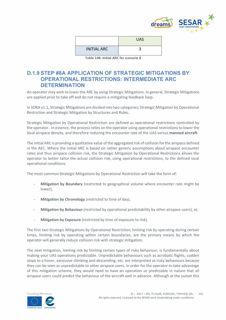
© – 2017 – IDS, TU Delft, EUROUSC, TOPVIEW SRL. All rights reserved. Licensed to the SESAR Joint Undertaking under conditions
251
Founding Members
UAS
INITIAL ARC 3
Table 148: Initial ARC for scenario 8
D.1.9 STEP #8A APPLICATION OF STRATEGIC MITIGATIONS BY OPERATIONAL RESTRICTIONS: INTERMEDIATE ARC DETERMINATION
An operator may wish to lower the ARC by using Strategic Mitigations. In general, Strategic Mitigations are applied prior to take off and do not require a mitigating feedback loop. In SORA v1.1, Strategic Mitigations are divided into two categories; Strategic Mitigation by Operational Restriction and Strategic Mitigation by Structures and Rules. Strategic Mitigation by Operational Restriction are defined as operational restrictions controlled by the operator. In essence, the process relies on the operator using operational restrictions to lower the local airspace density, and therefore reducing the encounter rate of the UAS versus manned aircraft. The initial ARC is providing a qualitative value of the aggregated risk of collision for the airspace defined in the AEC. Where the initial ARC is based on rather generic assumptions about airspace encounter rates and thus airspace collision risk, the Strategic Mitigation by Operational Restrictions allows the operator to better tailor the actual collision risk, using operational restrictions, to the defined local operational conditions. The most common Strategic Mitigations by Operational Restriction will take the form of:
- Mitigation by Boundary (restricted to geographical volume where encounter rate might be lower),
- Mitigation by Chronology (restricted to time of day),
- Mitigation by Behaviour (restricted by operational predictability by other airspace users), or,
- Mitigation by Exposure (restricted by time of exposure to risk). The first two Strategic Mitigations by Operational Restriction, limiting risk by operating during certain times, limiting risk by operating within certain boundaries, are the primary means by which the operator will generally reduce collision risk with strategic mitigation. The next mitigation, limiting risk by limiting certain types of risky behaviour, is fundamentally about making your UAS operations predictable. Unpredictable behaviours such as acrobatic flights, sudden stops to a hover, excessive climbing and descending, etc. are interpreted as risky behaviours because they can be seen as unpredictable to other airspace users. In order for the operator to take advantage of this mitigation scheme, they would need to have an operation so predictable in nature that all airspace users could predict the behaviour of the aircraft well in advance. Although at the outset this
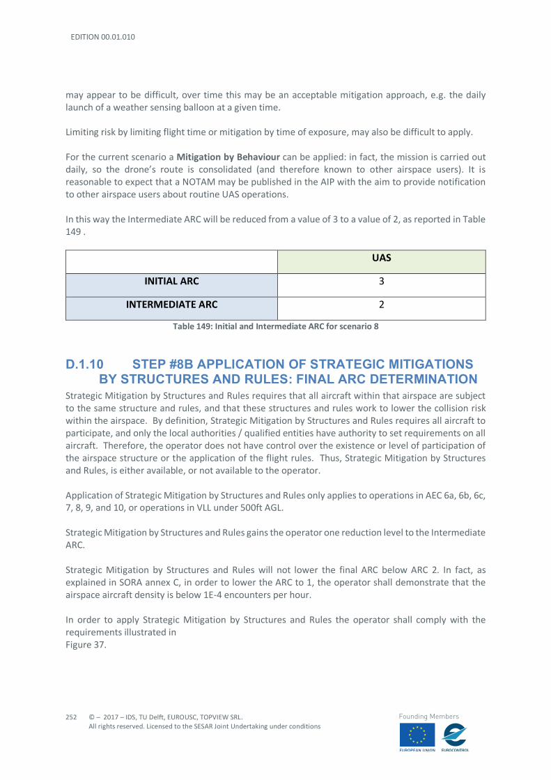
EDITION 00.01.010
252
© – 2017 – IDS, TU Delft, EUROUSC, TOPVIEW SRL. All rights reserved. Licensed to the SESAR Joint Undertaking under conditions
Founding Members
may appear to be difficult, over time this may be an acceptable mitigation approach, e.g. the daily launch of a weather sensing balloon at a given time. Limiting risk by limiting flight time or mitigation by time of exposure, may also be difficult to apply. For the current scenario a Mitigation by Behaviour can be applied: in fact, the mission is carried out daily, so the drone’s route is consolidated (and therefore known to other airspace users). It is reasonable to expect that a NOTAM may be published in the AIP with the aim to provide notification to other airspace users about routine UAS operations. In this way the Intermediate ARC will be reduced from a value of 3 to a value of 2, as reported in Table 149 .
UAS
INITIAL ARC 3
INTERMEDIATE ARC 2
Table 149: Initial and Intermediate ARC for scenario 8
D.1.10 STEP #8B APPLICATION OF STRATEGIC MITIGATIONS BY STRUCTURES AND RULES: FINAL ARC DETERMINATION
Strategic Mitigation by Structures and Rules requires that all aircraft within that airspace are subject to the same structure and rules, and that these structures and rules work to lower the collision risk within the airspace. By definition, Strategic Mitigation by Structures and Rules requires all aircraft to participate, and only the local authorities / qualified entities have authority to set requirements on all aircraft. Therefore, the operator does not have control over the existence or level of participation of the airspace structure or the application of the flight rules. Thus, Strategic Mitigation by Structures and Rules, is either available, or not available to the operator. Application of Strategic Mitigation by Structures and Rules only applies to operations in AEC 6a, 6b, 6c, 7, 8, 9, and 10, or operations in VLL under 500ft AGL. Strategic Mitigation by Structures and Rules gains the operator one reduction level to the Intermediate ARC. Strategic Mitigation by Structures and Rules will not lower the final ARC below ARC 2. In fact, as explained in SORA annex C, in order to lower the ARC to 1, the operator shall demonstrate that the airspace aircraft density is below 1E-4 encounters per hour. In order to apply Strategic Mitigation by Structures and Rules the operator shall comply with the requirements illustrated in Figure 37.
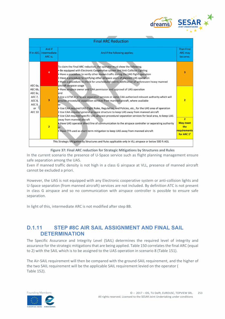
© – 2017 – IDS, TU Delft, EUROUSC, TOPVIEW SRL. All rights reserved. Licensed to the SESAR Joint Undertaking under conditions
253
Founding Members
Figure 37: Final ARC reduction for Strategic Mitigations by Structures and Rules
In the current scenario the presence of U-Space service such as flight planning management ensure safe separation among the UAS. Even if manned traffic density is not high in a class G airspace at VLL, presence of manned aircraft cannot be excluded a priori. However, the UAS is not equipped with any Electronic cooperative system or anti-collision lights and U-Space separation (from manned aircraft) services are not included. By definition ATC is not present in class G airspace and so no communication with airspace controller is possible to ensure safe separation. In light of this, intermediate ARC is not modified after step 8B.
D.1.11 STEP #8C AIR SAIL ASSIGNMENT AND FINAL SAIL DETERMINATION
The Specific Assurance and Integrity Level (SAIL) determines the required level of integrity and assurance for the strategic mitigations that are being applied. Table 150 correlates the final ARC (equal to 2) with the SAIL which is to be assigned to the UAS operation in scenario 8 (Table 151). The Air-SAIL requirement will then be compared with the ground-SAIL requirement, and the higher of the two SAIL requirement will be the applicable SAIL requirement levied on the operator ( Table 152).
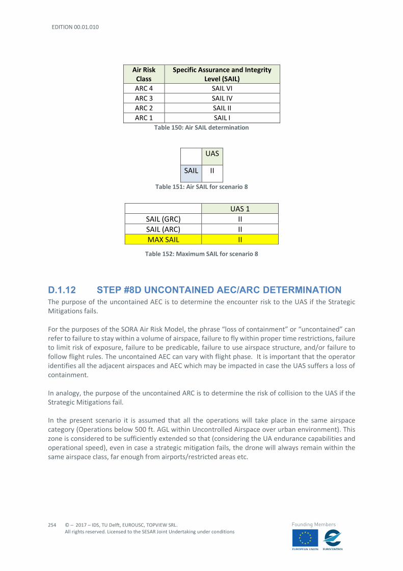
EDITION 00.01.010
254
© – 2017 – IDS, TU Delft, EUROUSC, TOPVIEW SRL. All rights reserved. Licensed to the SESAR Joint Undertaking under conditions
Founding Members
Air Risk Class
Specific Assurance and Integrity Level (SAIL)
ARC 4 SAIL VI ARC 3 SAIL IV ARC 2 SAIL II ARC 1 SAIL I
Table 150: Air SAIL determination
UAS
SAIL II
Table 151: Air SAIL for scenario 8
Table 152: Maximum SAIL for scenario 8
D.1.12 STEP #8D UNCONTAINED AEC/ARC DETERMINATION The purpose of the uncontained AEC is to determine the encounter risk to the UAS if the Strategic Mitigations fails. For the purposes of the SORA Air Risk Model, the phrase “loss of containment” or “uncontained” can refer to failure to stay within a volume of airspace, failure to fly within proper time restrictions, failure to limit risk of exposure, failure to be predicable, failure to use airspace structure, and/or failure to follow flight rules. The uncontained AEC can vary with flight phase. It is important that the operator identifies all the adjacent airspaces and AEC which may be impacted in case the UAS suffers a loss of containment. In analogy, the purpose of the uncontained ARC is to determine the risk of collision to the UAS if the Strategic Mitigations fail. In the present scenario it is assumed that all the operations will take place in the same airspace category (Operations below 500 ft. AGL within Uncontrolled Airspace over urban environment). This zone is considered to be sufficiently extended so that (considering the UA endurance capabilities and operational speed), even in case a strategic mitigation fails, the drone will always remain within the same airspace class, far enough from airports/restricted areas etc.
UAS 1 SAIL (GRC) II SAIL (ARC) II MAX SAIL II
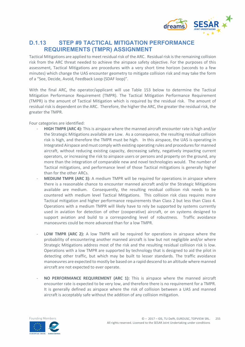
© – 2017 – IDS, TU Delft, EUROUSC, TOPVIEW SRL. All rights reserved. Licensed to the SESAR Joint Undertaking under conditions
255
Founding Members
D.1.13 STEP #9 TACTICAL MITIGATION PERFORMANCE REQUIREMENTS (TMPR) ASSIGNMENT
Tactical Mitigations are applied to meet residual risk of the ARC. Residual risk is the remaining collision risk from the ARC threat needed to achieve the airspace safety objective. For the purposes of this assessment, Tactical Mitigations are procedures with a very short time horizon (seconds to a few minutes) which change the UAS encounter geometry to mitigate collision risk and may take the form of a “See, Decide, Avoid, Feedback Loop (SDAF loop)”. With the final ARC, the operator/applicant will use Table 153 below to determine the Tactical Mitigation Performance Requirement (TMPR). The Tactical Mitigation Performance Requirement (TMPR) is the amount of Tactical Mitigation which is required by the residual risk. The amount of residual risk is dependent on the ARC. Therefore, the higher the ARC, the greater the residual risk, the greater the TMPR. Four categories are identified:
- HIGH TMPR (ARC 4): This is airspace where the manned aircraft encounter rate is high and/or the Strategic Mitigations available are Low. As a consequence, the resulting residual collision risk is high, and therefore the TMPR must be high. In this airspace, the UAS is operating in Integrated Airspace and must comply with existing operating rules and procedures for manned aircraft, without reducing existing capacity, decreasing safety, negatively impacting current operators, or increasing the risk to airspace users or persons and property on the ground, any more than the integration of comparable new and novel technologies would. The number of Tactical mitigations, and performance level of those Tactical mitigations is generally higher than for the other ARCs.
- MEDIUM TMPR (ARC 3): A medium TMPR will be required for operations in airspace where there is a reasonable chance to encounter manned aircraft and/or the Strategic Mitigations available are medium. Consequently, the resulting residual collision risk needs to be countered with medium level Tactical Mitigations. This collision risk class requires more Tactical mitigation and higher performance requirements than Class 2 but less than Class 4. Operations with a medium TMPR will likely have to rely be supported by systems currently used in aviation for detection of other (cooperative) aircraft, or on systems designed to support aviation and build to a corresponding level of robustness. Traffic avoidance manoeuvres could be more advanced than for a low TMPR.
- LOW TMPR (ARC 2): A low TMPR will be required for operations in airspace where the probability of encountering another manned aircraft is low but not negligible and/or where Strategic Mitigations address most of the risk and the resulting residual collision risk is low. Operations with a low TMPR are supported by technology that is designed to aid the pilot in detecting other traffic, but which may be built to lesser standards. The traffic avoidance manoeuvres are expected to mostly be based on a rapid descend to an altitude where manned aircraft are not expected to ever operate.
- NO PERFORMANCE REQUIREMENT (ARC 1): This is airspace where the manned aircraft
encounter rate is expected to be very low, and therefore there is no requirement for a TMPR. It is generally defined as airspace where the risk of collision between a UAS and manned aircraft is acceptably safe without the addition of any collision mitigation.
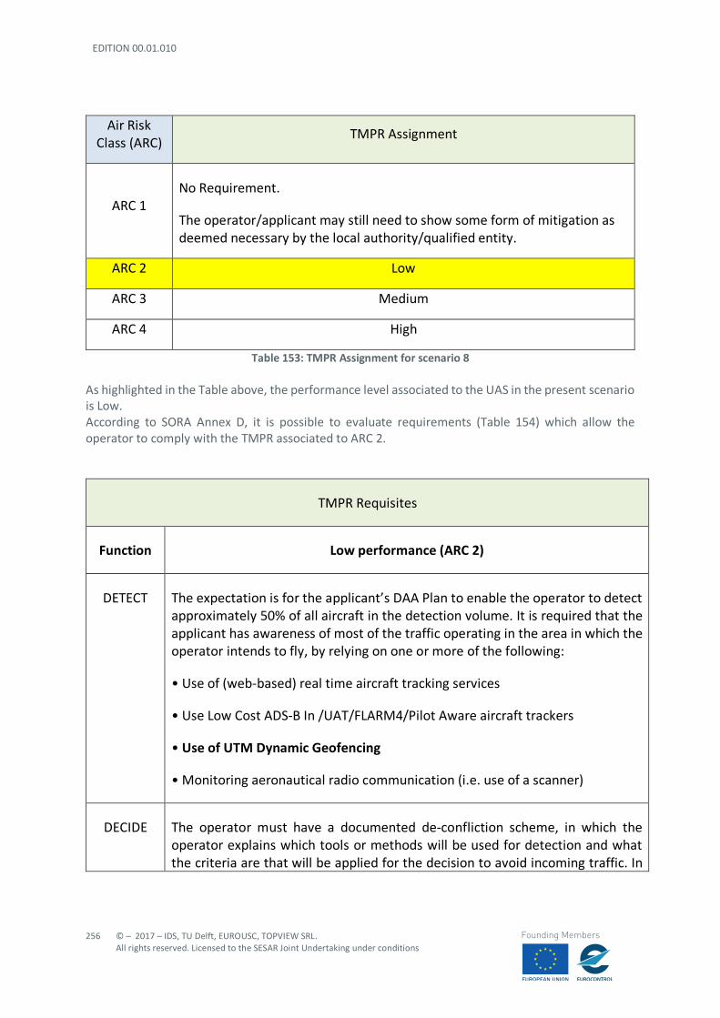
EDITION 00.01.010
256
© – 2017 – IDS, TU Delft, EUROUSC, TOPVIEW SRL. All rights reserved. Licensed to the SESAR Joint Undertaking under conditions
Founding Members
Air Risk Class (ARC) TMPR Assignment
ARC 1 No Requirement.
The operator/applicant may still need to show some form of mitigation as deemed necessary by the local authority/qualified entity.
ARC 2 Low
ARC 3 Medium
ARC 4 High
Table 153: TMPR Assignment for scenario 8 As highlighted in the Table above, the performance level associated to the UAS in the present scenario is Low. According to SORA Annex D, it is possible to evaluate requirements (Table 154) which allow the operator to comply with the TMPR associated to ARC 2.
TMPR Requisites
Function Low performance (ARC 2)
DETECT The expectation is for the applicant’s DAA Plan to enable the operator to detect approximately 50% of all aircraft in the detection volume. It is required that the applicant has awareness of most of the traffic operating in the area in which the operator intends to fly, by relying on one or more of the following:
• Use of (web-based) real time aircraft tracking services
• Use Low Cost ADS-B In /UAT/FLARM4/Pilot Aware aircraft trackers
• Use of UTM Dynamic Geofencing
• Monitoring aeronautical radio communication (i.e. use of a scanner)
DECIDE The operator must have a documented de-confliction scheme, in which the operator explains which tools or methods will be used for detection and what the criteria are that will be applied for the decision to avoid incoming traffic. In
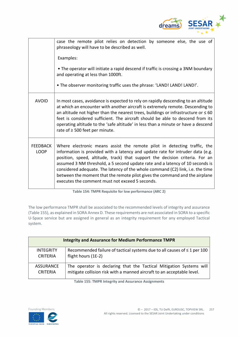
© – 2017 – IDS, TU Delft, EUROUSC, TOPVIEW SRL. All rights reserved. Licensed to the SESAR Joint Undertaking under conditions
257
Founding Members
case the remote pilot relies on detection by someone else, the use of phraseology will have to be described as well.
Examples:
• The operator will initiate a rapid descend if traffic is crossing a 3NM boundary and operating at less than 1000ft.
• The observer monitoring traffic uses the phrase: ‘LAND! LAND! LAND!’.
AVOID In most cases, avoidance is expected to rely on rapidly descending to an altitude at which an encounter with another aircraft is extremely remote. Descending to an altitude not higher than the nearest trees, buildings or infrastructure or ≤ 60 feet is considered sufficient. The aircraft should be able to descend from its operating altitude to the ‘safe altitude’ in less than a minute or have a descend rate of ≥ 500 feet per minute.
FEEDBACK LOOP
Where electronic means assist the remote pilot in detecting traffic, the information is provided with a latency and update rate for intruder data (e.g. position, speed, altitude, track) that support the decision criteria. For an assumed 3 NM threshold, a 5 second update rate and a latency of 10 seconds is considered adequate. The latency of the whole command (C2) link, i.e. the time between the moment that the remote pilot gives the command and the airplane executes the comment must not exceed 5 seconds.
Table 154: TMPR Requisite for low performance (ARC 2) The low performance TMPR shall be associated to the recommended levels of integrity and assurance (Table 155), as explained in SORA Annex D. These requirements are not associated in SORA to a specific U-Space service but are assigned in general as an integrity requirement for any employed Tactical system.
Integrity and Assurance for Medium Performance TMPR
INTEGRITY CRITERIA
Recommended failure of tactical systems due to all causes of ≤ 1 per 100 flight hours (1E-2)
ASSURANCE CRITERIA
The operator is declaring that the Tactical Mitigation Systems will mitigate collision risk with a manned aircraft to an acceptable level.
Table 155: TMPR Integrity and Assurance Assignments
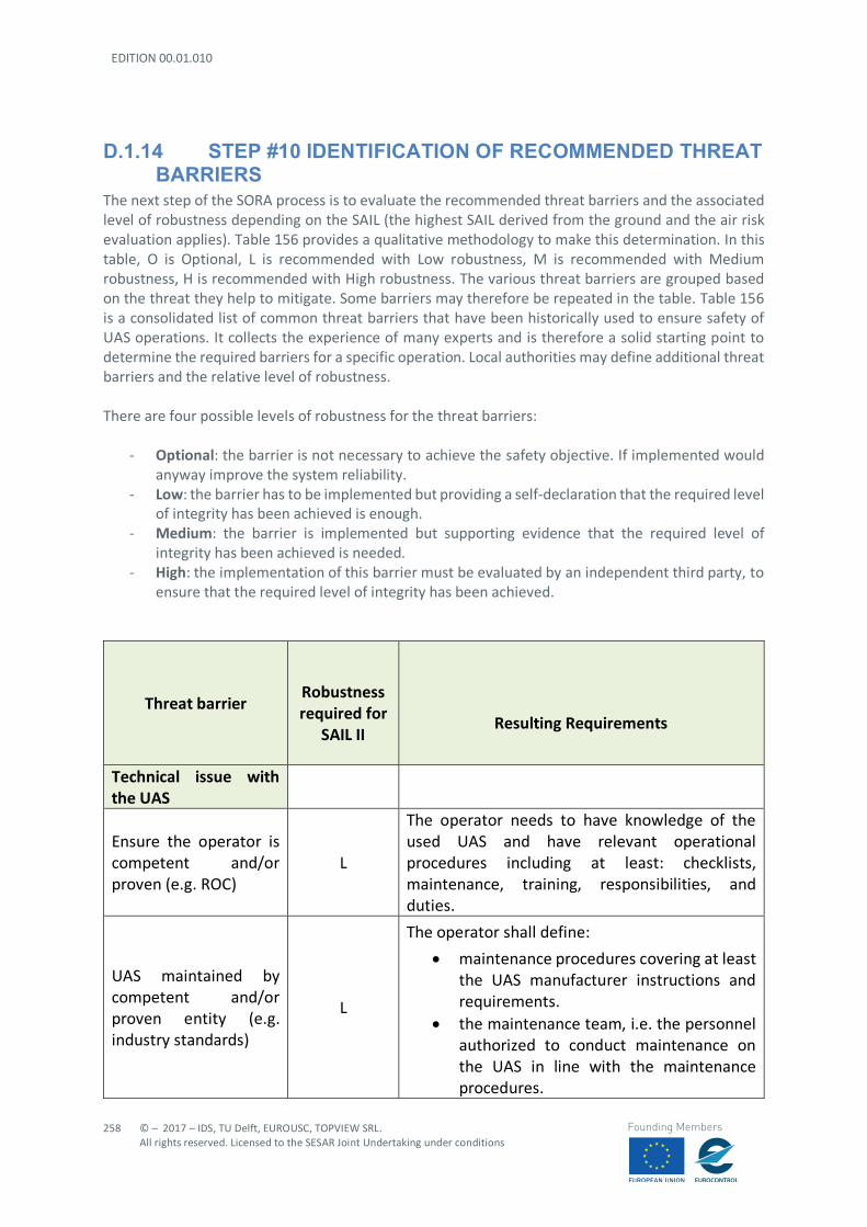
EDITION 00.01.010
258
© – 2017 – IDS, TU Delft, EUROUSC, TOPVIEW SRL. All rights reserved. Licensed to the SESAR Joint Undertaking under conditions
Founding Members
D.1.14 STEP #10 IDENTIFICATION OF RECOMMENDED THREAT BARRIERS
The next step of the SORA process is to evaluate the recommended threat barriers and the associated level of robustness depending on the SAIL (the highest SAIL derived from the ground and the air risk evaluation applies). Table 156 provides a qualitative methodology to make this determination. In this table, O is Optional, L is recommended with Low robustness, M is recommended with Medium robustness, H is recommended with High robustness. The various threat barriers are grouped based on the threat they help to mitigate. Some barriers may therefore be repeated in the table. Table 156 is a consolidated list of common threat barriers that have been historically used to ensure safety of UAS operations. It collects the experience of many experts and is therefore a solid starting point to determine the required barriers for a specific operation. Local authorities may define additional threat barriers and the relative level of robustness. There are four possible levels of robustness for the threat barriers:
- Optional: the barrier is not necessary to achieve the safety objective. If implemented would anyway improve the system reliability.
- Low: the barrier has to be implemented but providing a self-declaration that the required level of integrity has been achieved is enough.
- Medium: the barrier is implemented but supporting evidence that the required level of integrity has been achieved is needed.
- High: the implementation of this barrier must be evaluated by an independent third party, to ensure that the required level of integrity has been achieved.
Threat barrier
Robustness required for
SAIL II
Resulting Requirements
Technical issue with the UAS
Ensure the operator is competent and/or proven (e.g. ROC)
L
The operator needs to have knowledge of the used UAS and have relevant operational procedures including at least: checklists, maintenance, training, responsibilities, and duties.
UAS maintained by competent and/or proven entity (e.g. industry standards)
L
The operator shall define:
• maintenance procedures covering at least the UAS manufacturer instructions and requirements.
• the maintenance team, i.e. the personnel authorized to conduct maintenance on the UAS in line with the maintenance procedures.
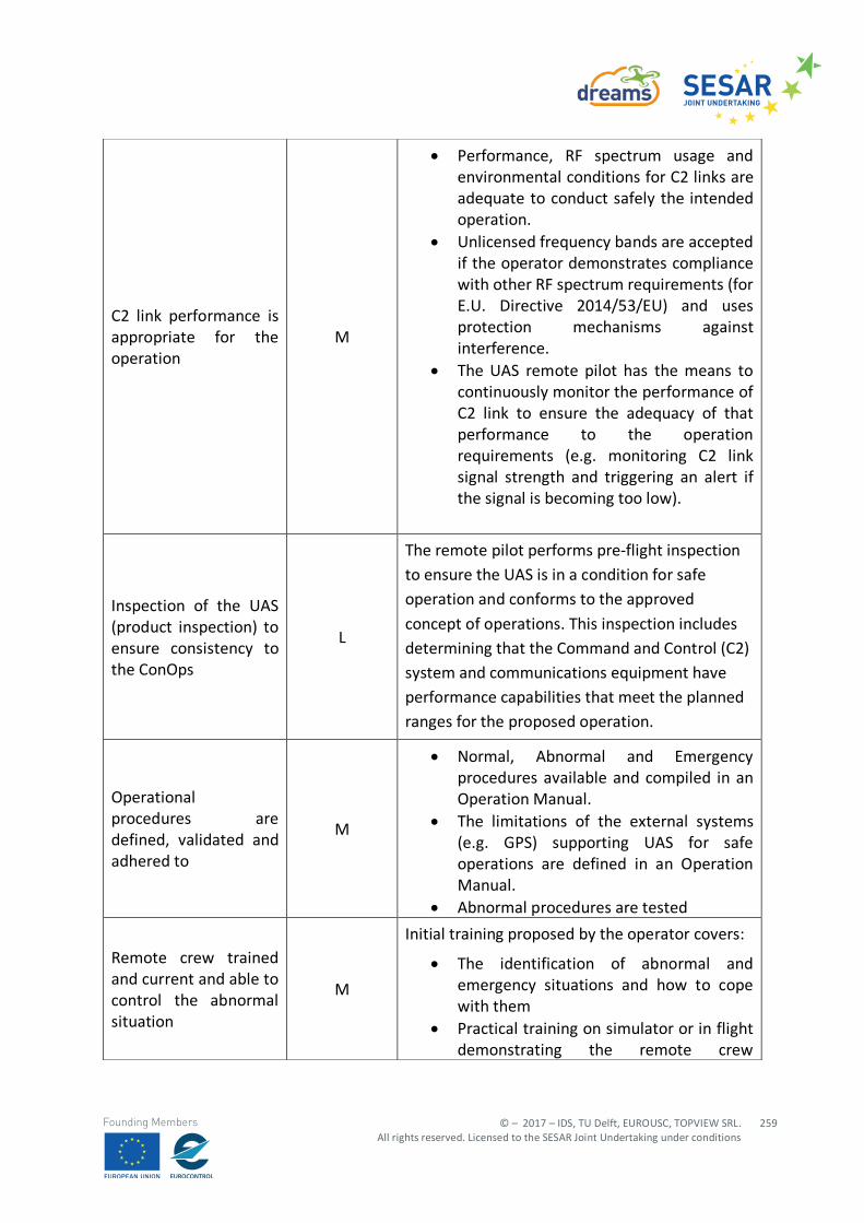
© – 2017 – IDS, TU Delft, EUROUSC, TOPVIEW SRL. All rights reserved. Licensed to the SESAR Joint Undertaking under conditions
259
Founding Members
C2 link performance is appropriate for the operation
M
• Performance, RF spectrum usage and environmental conditions for C2 links are adequate to conduct safely the intended operation.
• Unlicensed frequency bands are accepted if the operator demonstrates compliance with other RF spectrum requirements (for E.U. Directive 2014/53/EU) and uses protection mechanisms against interference.
• The UAS remote pilot has the means to continuously monitor the performance of C2 link to ensure the adequacy of that performance to the operation requirements (e.g. monitoring C2 link signal strength and triggering an alert if the signal is becoming too low).
Inspection of the UAS (product inspection) to ensure consistency to the ConOps
L
The remote pilot performs pre-flight inspection
to ensure the UAS is in a condition for safe
operation and conforms to the approved
concept of operations. This inspection includes
determining that the Command and Control (C2)
system and communications equipment have
performance capabilities that meet the planned
ranges for the proposed operation.
Operational procedures are defined, validated and adhered to
M
• Normal, Abnormal and Emergency procedures available and compiled in an Operation Manual.
• The limitations of the external systems (e.g. GPS) supporting UAS for safe operations are defined in an Operation Manual.
• Abnormal procedures are tested
Remote crew trained and current and able to control the abnormal situation
M
Initial training proposed by the operator covers:
• The identification of abnormal and emergency situations and how to cope with them
• Practical training on simulator or in flight demonstrating the remote crew
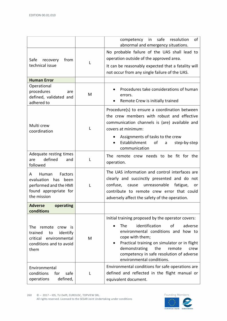
EDITION 00.01.010
260
© – 2017 – IDS, TU Delft, EUROUSC, TOPVIEW SRL. All rights reserved. Licensed to the SESAR Joint Undertaking under conditions
Founding Members
competency in safe resolution of abnormal and emergency situations.
Safe recovery from technical issue
L
No probable failure of the UAS shall lead to
operation outside of the approved area.
It can be reasonably expected that a fatality will
not occur from any single failure of the UAS.
Human Error
Operational procedures are defined, validated and adhered to
M • Procedures take considerations of human
errors. • Remote Crew is initially trained
Multi crew coordination
L
Procedure(s) to ensure a coordination between the crew members with robust and effective
communication channels is (are) available and
covers at minimum:
• Assignments of tasks to the crew • Establishment of a step-by-step
communication Adequate resting times are defined and followed
L The remote crew needs to be fit for the operation.
A Human Factors evaluation has been performed and the HMI found appropriate for the mission
L
The UAS information and control interfaces are
clearly and succinctly presented and do not
confuse, cause unreasonable fatigue, or
contribute to remote crew error that could
adversely affect the safety of the operation.
Adverse operating conditions
The remote crew is trained to identify critical environmental conditions and to avoid them
M
Initial training proposed by the operator covers:
• The identification of adverse environmental conditions and how to cope with them;
• Practical training on simulator or in flight demonstrating the remote crew competency in safe resolution of adverse environmental conditions.
Environmental conditions for safe operations defined,
L
Environmental conditions for safe operations are
defined and reflected in the flight manual or
equivalent document.
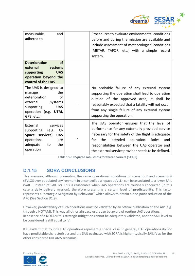
© – 2017 – IDS, TU Delft, EUROUSC, TOPVIEW SRL. All rights reserved. Licensed to the SESAR Joint Undertaking under conditions
261
Founding Members
Table 156: Required robustness for threat barriers (SAIL II)
D.1.15 SORA CONCLUSIONS This scenario, although presenting the same operational conditions of scenario 2 and scenario 4 (BVLOS over populated environment in uncontrolled airspace at VLL), can be associated to a lower SAIL (SAIL II instead of SAIL IV). This is reasonable when UAS operations are routinely conducted (in this case a daily delivery mission), therefore presenting a certain level of predictability. This factor represents a “Strategic Mitigation by Behaviour” which allows to obtain a one-point reduction of the ARC (See Section D1.9). However, predictability of such operations must be validated by an official publication on the AIP (e.g. through a NOTAM). This way all other airspace users can be aware of routine UAS operations. In absence of a NOTAM this strategic mitigation cannot be adequately validated, and the SAIL level to be considered is still equal to IV. It is evident that routine UAS operations represent a special case; in general, UAS operations do not have predictable characteristics and the SAIL evaluated with SORA is higher (typically SAIL IV as for the other considered DREAMS scenarios).
measurable and adhered to
Procedures to evaluate environmental conditions
before and during the mission are available and
include assessment of meteorological conditions
(METAR, TAFOR, etc.) with a simple record
system.
Deterioration of external systems supporting UAS operation beyond the control of the UAS
The UAS is designed to manage the deterioration of external systems supporting UAS operation (e.g. UTM, GPS, etc..)
L
No probable failure of any external system supporting the operation shall lead to operation
outside of the approved area; it shall be
reasonably expected that a fatality will not occur
from any single failure of any external system
supporting the operation.
External services supporting (e.g. U-Space services) UAS operations are adequate to the operation
L
The UAS operator ensures that the level of performance for any externally provided service
necessary for the safety of the flight is adequate
for the intended operation. Roles and
responsibilities between the UAS operator and
the external service provider needs to be defined.
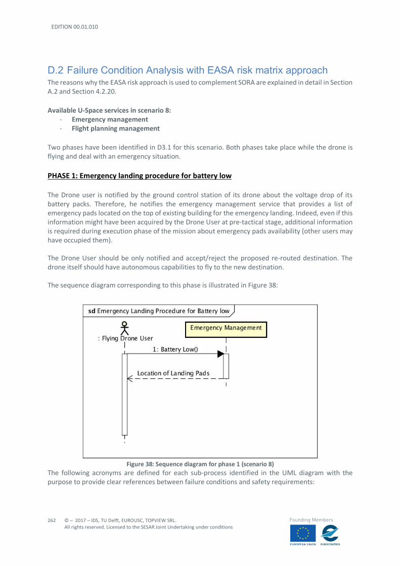
EDITION 00.01.010
262
© – 2017 – IDS, TU Delft, EUROUSC, TOPVIEW SRL. All rights reserved. Licensed to the SESAR Joint Undertaking under conditions
Founding Members
D.2 Failure Condition Analysis with EASA risk matrix approach The reasons why the EASA risk approach is used to complement SORA are explained in detail in Section A.2 and Section 4.2.20. Available U-Space services in scenario 8:
- Emergency management - Flight planning management
Two phases have been identified in D3.1 for this scenario. Both phases take place while the drone is flying and deal with an emergency situation. PHASE 1: Emergency landing procedure for battery low The Drone user is notified by the ground control station of its drone about the voltage drop of its battery packs. Therefore, he notifies the emergency management service that provides a list of emergency pads located on the top of existing building for the emergency landing. Indeed, even if this information might have been acquired by the Drone User at pre-tactical stage, additional information is required during execution phase of the mission about emergency pads availability (other users may have occupied them). The Drone User should be only notified and accept/reject the proposed re-routed destination. The drone itself should have autonomous capabilities to fly to the new destination. The sequence diagram corresponding to this phase is illustrated in Figure 38:
Figure 38: Sequence diagram for phase 1 (scenario 8)
The following acronyms are defined for each sub-process identified in the UML diagram with the purpose to provide clear references between failure conditions and safety requirements:
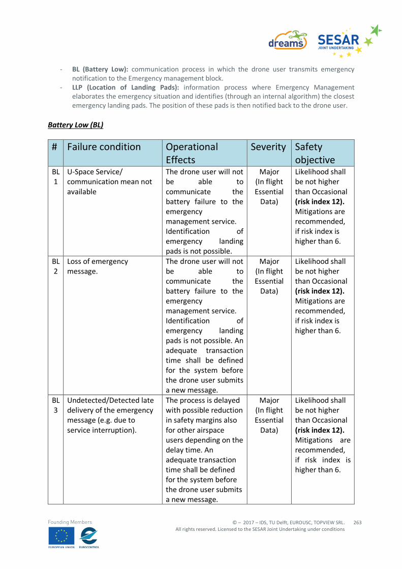
© – 2017 – IDS, TU Delft, EUROUSC, TOPVIEW SRL. All rights reserved. Licensed to the SESAR Joint Undertaking under conditions
263
Founding Members
- BL (Battery Low): communication process in which the drone user transmits emergency notification to the Emergency management block.
- LLP (Location of Landing Pads): information process where Emergency Management elaborates the emergency situation and identifies (through an internal algorithm) the closest emergency landing pads. The position of these pads is then notified back to the drone user.
Battery Low (BL)
# Failure condition Operational Effects
Severity Safety objective
BL 1
U-Space Service/ communication mean not available
The drone user will not be able to communicate the battery failure to the emergency management service. Identification of emergency landing pads is not possible.
Major (In flight Essential
Data)
Likelihood shall be not higher than Occasional (risk index 12). Mitigations are recommended, if risk index is higher than 6.
BL 2
Loss of emergency message.
The drone user will not be able to communicate the battery failure to the emergency management service. Identification of emergency landing pads is not possible. An adequate transaction time shall be defined for the system before the drone user submits a new message.
Major (In flight Essential
Data)
Likelihood shall be not higher than Occasional (risk index 12). Mitigations are recommended, if risk index is higher than 6.
BL 3
Undetected/Detected late delivery of the emergency message (e.g. due to service interruption).
The process is delayed with possible reduction in safety margins also for other airspace users depending on the delay time. An adequate transaction time shall be defined for the system before the drone user submits a new message.
Major (In flight Essential
Data)
Likelihood shall be not higher than Occasional (risk index 12). Mitigations are recommended, if risk index is higher than 6.

EDITION 00.01.010
264
© – 2017 – IDS, TU Delft, EUROUSC, TOPVIEW SRL. All rights reserved. Licensed to the SESAR Joint Undertaking under conditions
Founding Members
# Failure condition Operational Effects
Severity Safety objective
BL 4
Detected corruption of emergency message (e.g. incoherent battery level notification not justifying the emergency status etc.).
Emergency management will discard automatically the message.
Major (In flight Essential
Data)
Likelihood shall be not higher than Occasional (risk index 12). Mitigations are recommended, if risk index is higher than 6.
BL 5
Undetected corruption of the emergency message (e.g. wrong drone current position). This may be due to either a system bug or drone user not correctly using U-Space digital interface.
Emergency management will receive the emergency message, but drone position is wrong. Landing pads may be identified too far from the drone.
Major (In flight Essential
Data)
Likelihood shall be not higher than Occasional (risk index 12). Mitigations are recommended, if risk index is higher than 6.
Table 157: Identification and classification of failure conditions for Battery Low (BL) process
SAFETY REQUIREMENTS FAILURE CONDITION REFERENCE
Adequate system availability. BL -1 Redundant communication channel (Internet or cellular networks). BL-2 Backward notification to drone user as soon as Emergency Management receives the emergency message.
BL-2, BL-3
Adequate transaction time. BL-2, BL-3 Adequate system continuity. BL-3 Timestamp of battery failure detection provided to Emergency management service.
BL-3
Direct interface between drone and Emergency management service to speed up the process.
BL -3
In case of incoherent information, the Emergency management service may ask the drone user for the re-transmission.
BL-4
Adequate system integrity. BL-4, BL-5 Digital U-Space application (used by remote pilot) shall always include a tutorial/quick-help tool.
BL-5
Emergency management shall provide the drone user the location of landing pads together with known drone position information for a
BL-5
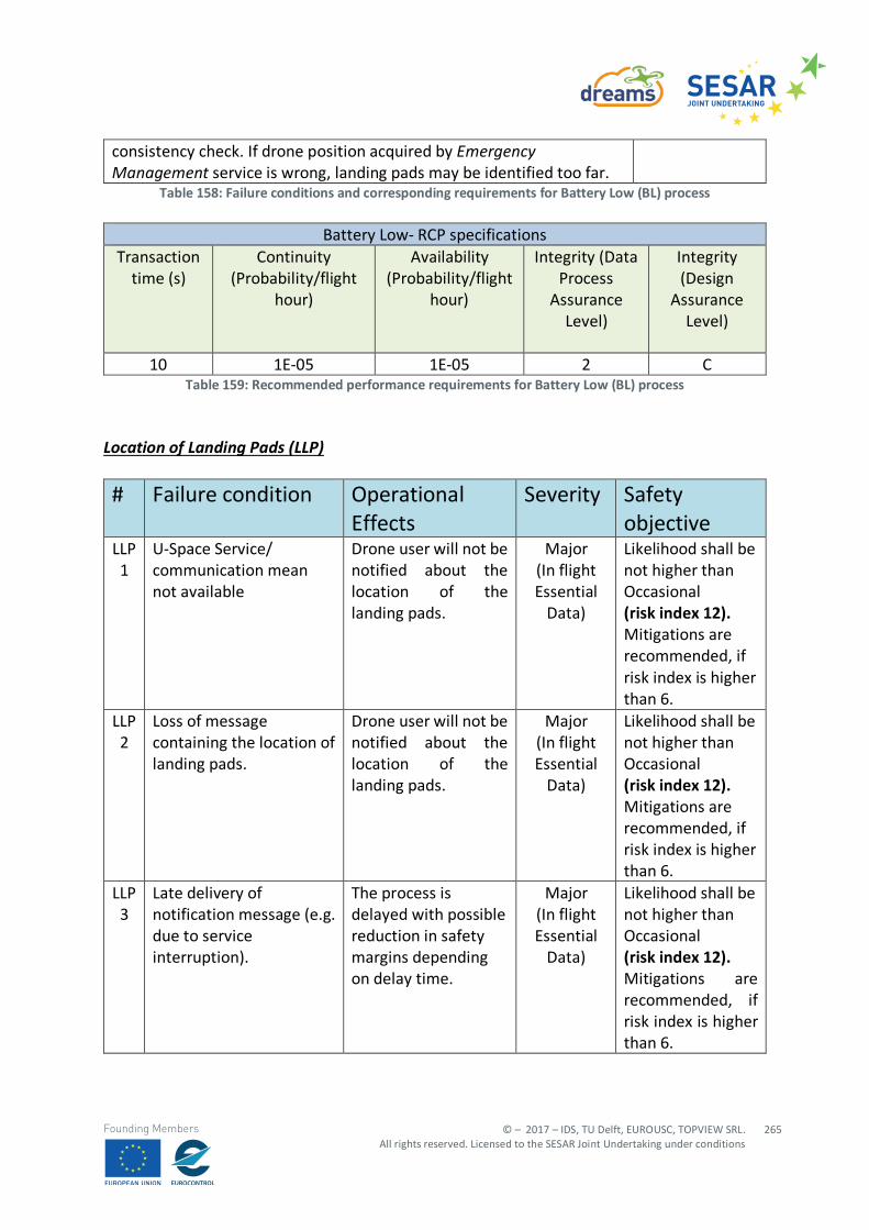
© – 2017 – IDS, TU Delft, EUROUSC, TOPVIEW SRL. All rights reserved. Licensed to the SESAR Joint Undertaking under conditions
265
Founding Members
consistency check. If drone position acquired by Emergency Management service is wrong, landing pads may be identified too far.
Table 158: Failure conditions and corresponding requirements for Battery Low (BL) process
Battery Low- RCP specifications Transaction
time (s) Continuity
(Probability/flight hour)
Availability (Probability/flight
hour)
Integrity (Data Process
Assurance Level)
Integrity (Design
Assurance Level)
10 1E-05 1E-05 2 C
Table 159: Recommended performance requirements for Battery Low (BL) process Location of Landing Pads (LLP)
# Failure condition Operational Effects
Severity Safety objective
LLP 1
U-Space Service/ communication mean not available
Drone user will not be notified about the location of the landing pads.
Major (In flight Essential
Data)
Likelihood shall be not higher than Occasional (risk index 12). Mitigations are recommended, if risk index is higher than 6.
LLP 2
Loss of message containing the location of landing pads.
Drone user will not be notified about the location of the landing pads.
Major (In flight Essential
Data)
Likelihood shall be not higher than Occasional (risk index 12). Mitigations are recommended, if risk index is higher than 6.
LLP 3
Late delivery of notification message (e.g. due to service interruption).
The process is delayed with possible reduction in safety margins depending on delay time.
Major (In flight Essential
Data)
Likelihood shall be not higher than Occasional (risk index 12). Mitigations are recommended, if risk index is higher than 6.
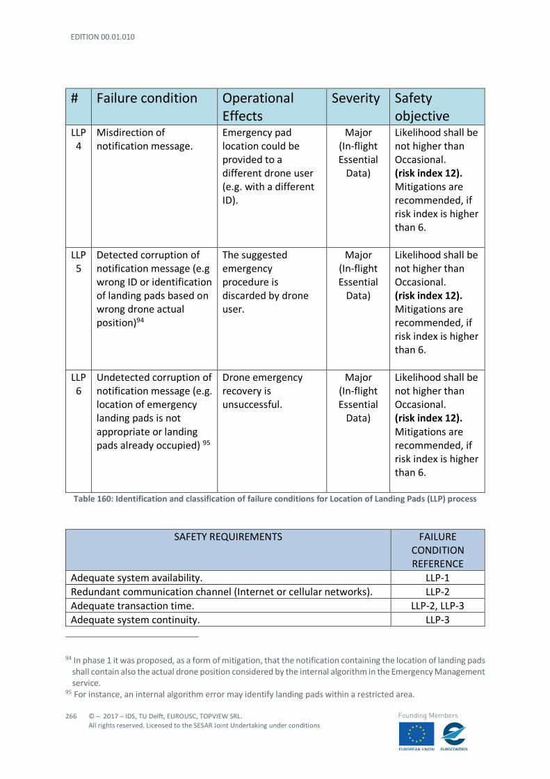
EDITION 00.01.010
266
© – 2017 – IDS, TU Delft, EUROUSC, TOPVIEW SRL. All rights reserved. Licensed to the SESAR Joint Undertaking under conditions
Founding Members
# Failure condition Operational Effects
Severity Safety objective
LLP 4
Misdirection of notification message.
Emergency pad location could be provided to a different drone user (e.g. with a different ID).
Major (In-flight Essential
Data)
Likelihood shall be not higher than Occasional. (risk index 12). Mitigations are recommended, if risk index is higher than 6.
LLP 5
Detected corruption of notification message (e.g wrong ID or identification of landing pads based on wrong drone actual position)94
The suggested emergency procedure is discarded by drone user.
Major (In-flight Essential
Data)
Likelihood shall be not higher than Occasional. (risk index 12). Mitigations are recommended, if risk index is higher than 6.
LLP 6
Undetected corruption of notification message (e.g. location of emergency landing pads is not appropriate or landing pads already occupied) 95
Drone emergency recovery is unsuccessful.
Major (In-flight Essential
Data)
Likelihood shall be not higher than Occasional. (risk index 12). Mitigations are recommended, if risk index is higher than 6.
Table 160: Identification and classification of failure conditions for Location of Landing Pads (LLP) process
SAFETY REQUIREMENTS FAILURE CONDITION REFERENCE
Adequate system availability. LLP-1 Redundant communication channel (Internet or cellular networks). LLP-2 Adequate transaction time. LLP-2, LLP-3 Adequate system continuity. LLP-3
94 In phase 1 it was proposed, as a form of mitigation, that the notification containing the location of landing pads
shall contain also the actual drone position considered by the internal algorithm in the Emergency Management service.
95 For instance, an internal algorithm error may identify landing pads within a restricted area.
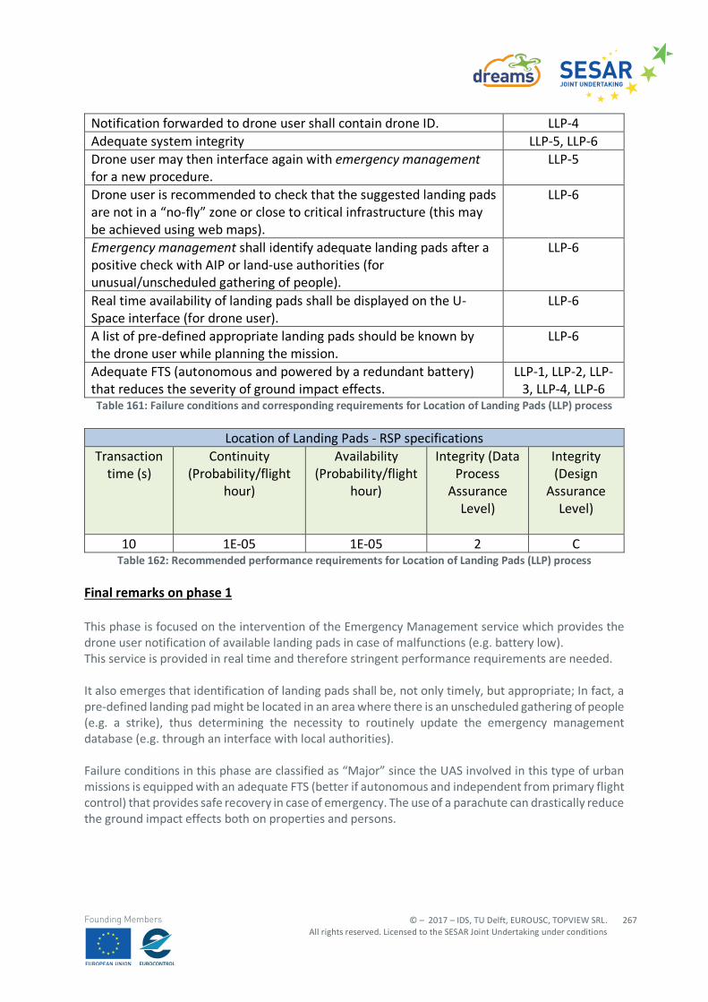
© – 2017 – IDS, TU Delft, EUROUSC, TOPVIEW SRL. All rights reserved. Licensed to the SESAR Joint Undertaking under conditions
267
Founding Members
Notification forwarded to drone user shall contain drone ID. LLP-4 Adequate system integrity LLP-5, LLP-6 Drone user may then interface again with emergency management for a new procedure.
LLP-5
Drone user is recommended to check that the suggested landing pads are not in a “no-fly” zone or close to critical infrastructure (this may be achieved using web maps).
LLP-6
Emergency management shall identify adequate landing pads after a positive check with AIP or land-use authorities (for unusual/unscheduled gathering of people).
LLP-6
Real time availability of landing pads shall be displayed on the U-Space interface (for drone user).
LLP-6
A list of pre-defined appropriate landing pads should be known by the drone user while planning the mission.
LLP-6
Adequate FTS (autonomous and powered by a redundant battery) that reduces the severity of ground impact effects.
LLP-1, LLP-2, LLP-3, LLP-4, LLP-6
Table 161: Failure conditions and corresponding requirements for Location of Landing Pads (LLP) process
Location of Landing Pads - RSP specifications Transaction
time (s) Continuity
(Probability/flight hour)
Availability (Probability/flight
hour)
Integrity (Data Process
Assurance Level)
Integrity (Design
Assurance Level)
10 1E-05 1E-05 2 C
Table 162: Recommended performance requirements for Location of Landing Pads (LLP) process
Final remarks on phase 1 This phase is focused on the intervention of the Emergency Management service which provides the drone user notification of available landing pads in case of malfunctions (e.g. battery low). This service is provided in real time and therefore stringent performance requirements are needed. It also emerges that identification of landing pads shall be, not only timely, but appropriate; In fact, a pre-defined landing pad might be located in an area where there is an unscheduled gathering of people (e.g. a strike), thus determining the necessity to routinely update the emergency management database (e.g. through an interface with local authorities). Failure conditions in this phase are classified as “Major” since the UAS involved in this type of urban missions is equipped with an adequate FTS (better if autonomous and independent from primary flight control) that provides safe recovery in case of emergency. The use of a parachute can drastically reduce the ground impact effects both on properties and persons.
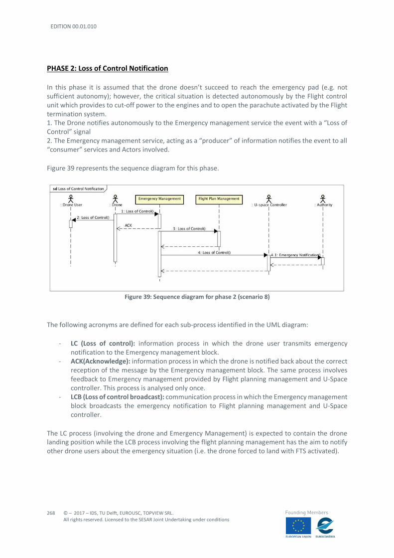
EDITION 00.01.010
268
© – 2017 – IDS, TU Delft, EUROUSC, TOPVIEW SRL. All rights reserved. Licensed to the SESAR Joint Undertaking under conditions
Founding Members
PHASE 2: Loss of Control Notification In this phase it is assumed that the drone doesn’t succeed to reach the emergency pad (e.g. not sufficient autonomy); however, the critical situation is detected autonomously by the Flight control unit which provides to cut-off power to the engines and to open the parachute activated by the Flight termination system. 1. The Drone notifies autonomously to the Emergency management service the event with a “Loss of Control” signal 2. The Emergency management service, acting as a “producer” of information notifies the event to all “consumer” services and Actors involved. Figure 39 represents the sequence diagram for this phase.
Figure 39: Sequence diagram for phase 2 (scenario 8)
The following acronyms are defined for each sub-process identified in the UML diagram:
- LC (Loss of control): information process in which the drone user transmits emergency notification to the Emergency management block.
- ACK(Acknowledge): information process in which the drone is notified back about the correct reception of the message by the Emergency management block. The same process involves feedback to Emergency management provided by Flight planning management and U-Space controller. This process is analysed only once.
- LCB (Loss of control broadcast): communication process in which the Emergency management block broadcasts the emergency notification to Flight planning management and U-Space controller.
The LC process (involving the drone and Emergency Management) is expected to contain the drone landing position while the LCB process involving the flight planning management has the aim to notify other drone users about the emergency situation (i.e. the drone forced to land with FTS activated).
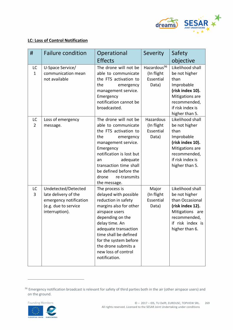
© – 2017 – IDS, TU Delft, EUROUSC, TOPVIEW SRL. All rights reserved. Licensed to the SESAR Joint Undertaking under conditions
269
Founding Members
LC: Loss of Control Notification # Failure condition Operational
Effects Severity Safety
objective LC 1
U-Space Service/ communication mean not available
The drone will not be able to communicate the FTS activation to the emergency management service. Emergency notification cannot be broadcasted.
Hazardous96 (In flight Essential
Data)
Likelihood shall be not higher than Improbable (risk index 10). Mitigations are recommended, if risk index is higher than 5.
LC 2
Loss of emergency message.
The drone will not be able to communicate the FTS activation to the emergency management service. Emergency notification is lost but an adequate transaction time shall be defined before the drone re-transmits the message.
Hazardous (In flight Essential
Data)
Likelihood shall be not higher than Improbable (risk index 10). Mitigations are recommended, if risk index is higher than 5.
LC 3
Undetected/Detected late delivery of the emergency notification (e.g. due to service interruption).
The process is delayed with possible reduction in safety margins also for other airspace users depending on the delay time. An adequate transaction time shall be defined for the system before the drone submits a new loss of control notification.
Major (In flight Essential
Data)
Likelihood shall be not higher than Occasional (risk index 12). Mitigations are recommended, if risk index is higher than 6.
96 Emergency notification broadcast is relevant for safety of third parties both in the air (other airspace users) and on the ground.

EDITION 00.01.010
270
© – 2017 – IDS, TU Delft, EUROUSC, TOPVIEW SRL. All rights reserved. Licensed to the SESAR Joint Undertaking under conditions
Founding Members
# Failure condition Operational Effects
Severity Safety objective
LC 4
Detected corruption of the emergency notification (e.g. incoherent drone current landing position97).
Emergency Management will discard the message and will ask the drone for the re-transmission.
Major (In flight Essential
Data)
Likelihood shall be not higher than Occasional (risk index 12). Mitigations are recommended, if risk index is higher than 6.
LC 5
Undetected corruption of the emergency notification (e.g. wrong but coherent drone current landing position).
Emergency management will receive the emergency message, but drone landing position is wrong. Emergency notification to other stakeholders is incorrect.
Hazardous (In flight Essential
Data)
Likelihood shall be not higher than Improbable (risk index 10). Mitigations are recommended, if risk index is higher than 5.
Table 163: Identification and classification of failure conditions for Loss of Control (LC-A) process
SAFETY REQUIREMENTS FAILURE CONDITION REFERENCE
Adequate system availability. LC-1 Redundant communication channel (Internet or cellular networks).
LC-2
Backward notification to drone user as soon as Emergency Management receives the emergency message.
LC-2, LC-3
Adequate transaction time. LC-2, LC-3 Adequate system continuity. LC-3 Adequate system integrity. LC-4, LC-5 ACK notification shall contain drone landing position. LC-5 Tracking service might be coupled with Emergency Management for redundancy in surveillance data.
LC-4, LC-5
FTS associated to the activation emergency” sound alert”. LC-1, LC-2, LC-3, LC-4, LC-5
97 For instance, a negative altitude or landing coordinates corresponding to an indoor environment.
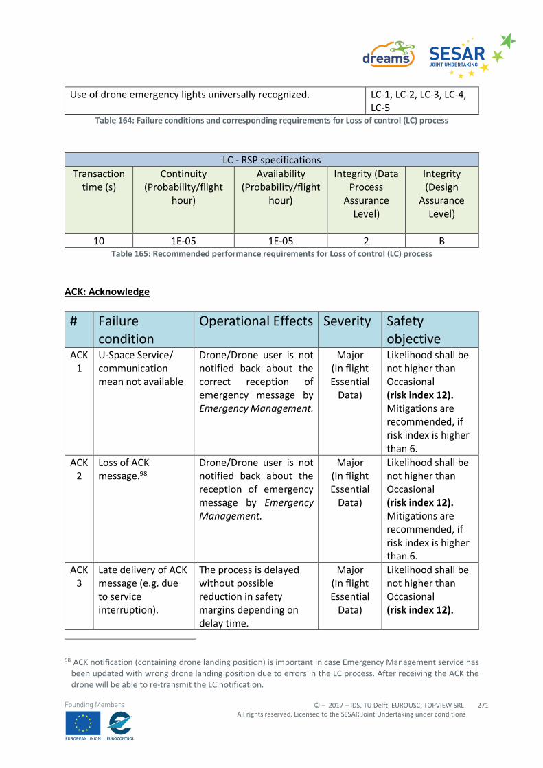
© – 2017 – IDS, TU Delft, EUROUSC, TOPVIEW SRL. All rights reserved. Licensed to the SESAR Joint Undertaking under conditions
271
Founding Members
Use of drone emergency lights universally recognized. LC-1, LC-2, LC-3, LC-4, LC-5
Table 164: Failure conditions and corresponding requirements for Loss of control (LC) process
LC - RSP specifications
Transaction time (s)
Continuity (Probability/flight
hour)
Availability (Probability/flight
hour)
Integrity (Data Process
Assurance Level)
Integrity (Design
Assurance Level)
10 1E-05 1E-05 2 B
Table 165: Recommended performance requirements for Loss of control (LC) process ACK: Acknowledge # Failure
condition Operational Effects Severity Safety
objective ACK
1 U-Space Service/ communication mean not available
Drone/Drone user is not notified back about the correct reception of emergency message by Emergency Management.
Major (In flight Essential
Data)
Likelihood shall be not higher than Occasional (risk index 12). Mitigations are recommended, if risk index is higher than 6.
ACK 2
Loss of ACK message.98
Drone/Drone user is not notified back about the reception of emergency message by Emergency Management.
Major (In flight Essential
Data)
Likelihood shall be not higher than Occasional (risk index 12). Mitigations are recommended, if risk index is higher than 6.
ACK 3
Late delivery of ACK message (e.g. due to service interruption).
The process is delayed without possible reduction in safety margins depending on delay time.
Major (In flight Essential
Data)
Likelihood shall be not higher than Occasional (risk index 12).
98 ACK notification (containing drone landing position) is important in case Emergency Management service has
been updated with wrong drone landing position due to errors in the LC process. After receiving the ACK the drone will be able to re-transmit the LC notification.
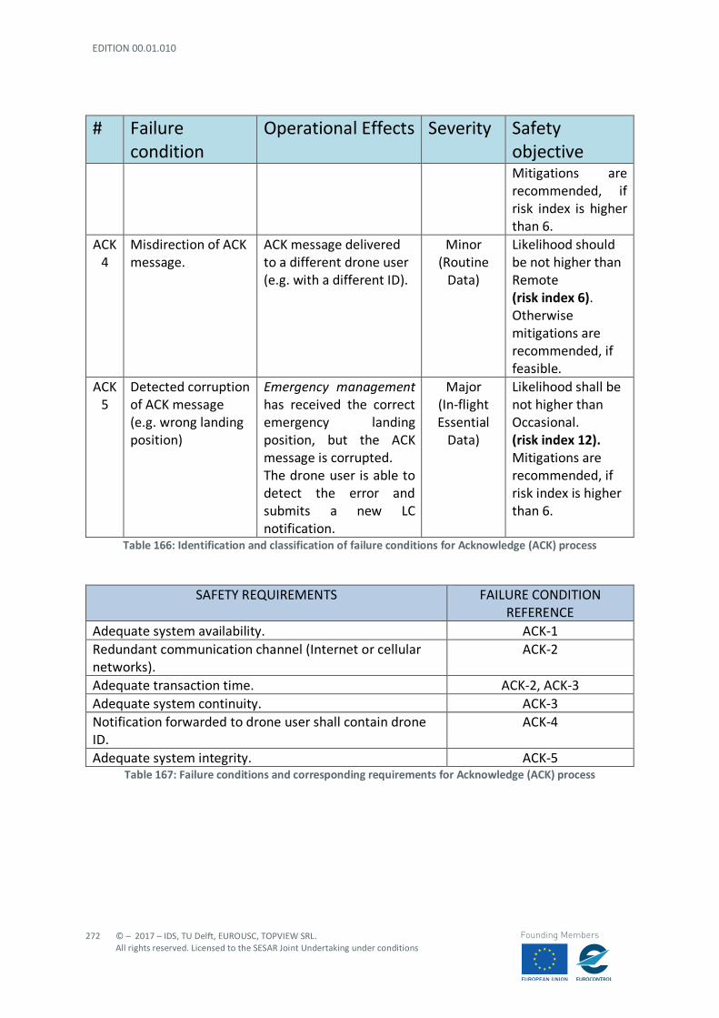
EDITION 00.01.010
272
© – 2017 – IDS, TU Delft, EUROUSC, TOPVIEW SRL. All rights reserved. Licensed to the SESAR Joint Undertaking under conditions
Founding Members
# Failure condition
Operational Effects Severity Safety objective Mitigations are recommended, if risk index is higher than 6.
ACK 4
Misdirection of ACK message.
ACK message delivered to a different drone user (e.g. with a different ID).
Minor (Routine
Data)
Likelihood should be not higher than Remote (risk index 6). Otherwise mitigations are recommended, if feasible.
ACK 5
Detected corruption of ACK message (e.g. wrong landing position)
Emergency management has received the correct emergency landing position, but the ACK message is corrupted. The drone user is able to detect the error and submits a new LC notification.
Major (In-flight Essential
Data)
Likelihood shall be not higher than Occasional. (risk index 12). Mitigations are recommended, if risk index is higher than 6.
Table 166: Identification and classification of failure conditions for Acknowledge (ACK) process
SAFETY REQUIREMENTS FAILURE CONDITION REFERENCE
Adequate system availability. ACK-1 Redundant communication channel (Internet or cellular networks).
ACK-2
Adequate transaction time. ACK-2, ACK-3 Adequate system continuity. ACK-3 Notification forwarded to drone user shall contain drone ID.
ACK-4
Adequate system integrity. ACK-5 Table 167: Failure conditions and corresponding requirements for Acknowledge (ACK) process
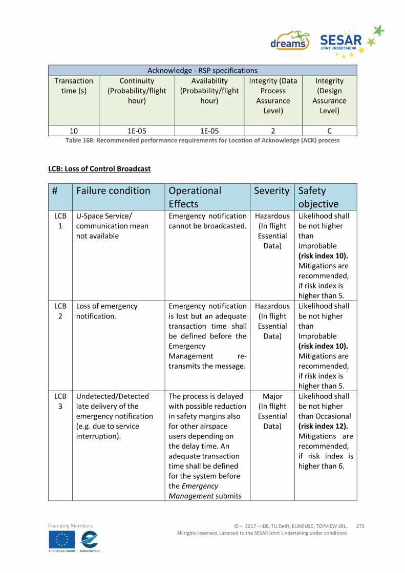
© – 2017 – IDS, TU Delft, EUROUSC, TOPVIEW SRL. All rights reserved. Licensed to the SESAR Joint Undertaking under conditions
273
Founding Members
Acknowledge - RSP specifications Transaction
time (s) Continuity
(Probability/flight hour)
Availability (Probability/flight
hour)
Integrity (Data Process
Assurance Level)
Integrity (Design
Assurance Level)
10 1E-05 1E-05 2 C
Table 168: Recommended performance requirements for Location of Acknowledge (ACK) process
LCB: Loss of Control Broadcast # Failure condition Operational
Effects Severity Safety
objective LCB
1 U-Space Service/ communication mean not available
Emergency notification cannot be broadcasted.
Hazardous (In flight Essential
Data)
Likelihood shall be not higher than Improbable (risk index 10). Mitigations are recommended, if risk index is higher than 5.
LCB 2
Loss of emergency notification.
Emergency notification is lost but an adequate transaction time shall be defined before the Emergency Management re-transmits the message.
Hazardous (In flight Essential
Data)
Likelihood shall be not higher than Improbable (risk index 10). Mitigations are recommended, if risk index is higher than 5.
LCB 3
Undetected/Detected late delivery of the emergency notification (e.g. due to service interruption).
The process is delayed with possible reduction in safety margins also for other airspace users depending on the delay time. An adequate transaction time shall be defined for the system before the Emergency Management submits
Major (In flight Essential
Data)
Likelihood shall be not higher than Occasional (risk index 12). Mitigations are recommended, if risk index is higher than 6.

EDITION 00.01.010
274
© – 2017 – IDS, TU Delft, EUROUSC, TOPVIEW SRL. All rights reserved. Licensed to the SESAR Joint Undertaking under conditions
Founding Members
# Failure condition Operational Effects
Severity Safety objective
a new loss of control notification.
LCB 4
Detected corruption of the emergency notification (e.g. incoherent drone current landing position99).
Flight planning management/U-Space controller will discard the message and will ask the Emergency Management for the message re-transmission.
Major (In flight Essential
Data)
Likelihood shall be not higher than Occasional (risk index 12). Mitigations are recommended, if risk index is higher than 6.
LCB 5
Undetected corruption of the emergency notification (e.g. wrong but coherent drone current landing position).
Flight planning management/U-Space Controller will receive the emergency message, but drone landing position is wrong.
Hazardous (In flight Essential
Data)
Likelihood shall be not higher than Improbable (risk index 10). Mitigations are recommended, if risk index is higher than 5.
Table 169: Identification and classification of failure conditions for Loss of Control (LCB) process
SAFETY REQUIREMENTS FAILURE CONDITION REFERENCE
Adequate system availability. LCB -1 Redundant communication channel (Internet or cellular networks). LCB- 2 Backward notification to Emergency Management as soon as Flight planning management /U-Space controller receives the emergency message.
LCB-2, LCB-3
Adequate transaction time. LCB-2, LCB-3 Adequate system continuity. LCB-3 Adequate system integrity. LCB-4, LCB-5 ACK100 notification shall contain drone landing position. LCB-5
99 For instance, a negative altitude or landing coordinates corresponding to an indoor environment. 100 ACK notification is present also for LC-B processes. In this case it actually represents a feedback for emergency
management service to check that Flight planning management and U-Space controller have correctly received the emergency notification.
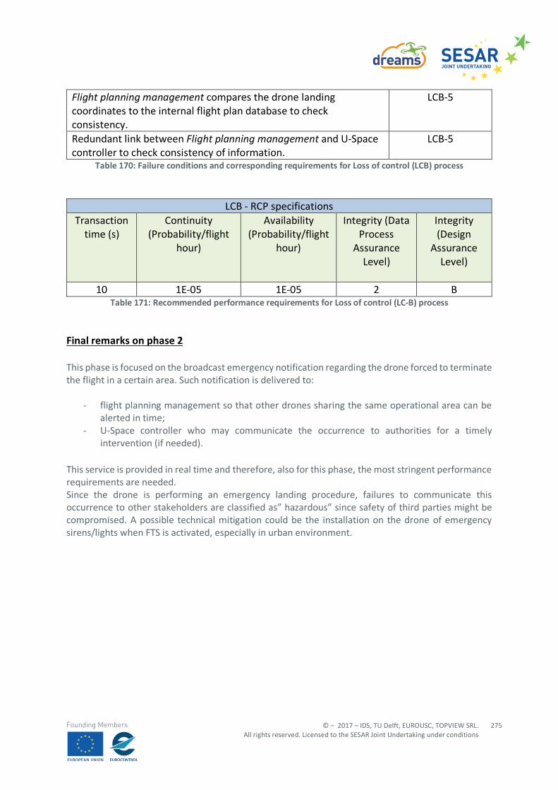
© – 2017 – IDS, TU Delft, EUROUSC, TOPVIEW SRL. All rights reserved. Licensed to the SESAR Joint Undertaking under conditions
275
Founding Members
Flight planning management compares the drone landing coordinates to the internal flight plan database to check consistency.
LCB-5
Redundant link between Flight planning management and U-Space controller to check consistency of information.
LCB-5
Table 170: Failure conditions and corresponding requirements for Loss of control (LCB) process
LCB - RCP specifications Transaction
time (s) Continuity
(Probability/flight hour)
Availability (Probability/flight
hour)
Integrity (Data Process
Assurance Level)
Integrity (Design
Assurance Level)
10 1E-05 1E-05 2 B
Table 171: Recommended performance requirements for Loss of control (LC-B) process
Final remarks on phase 2 This phase is focused on the broadcast emergency notification regarding the drone forced to terminate the flight in a certain area. Such notification is delivered to:
- flight planning management so that other drones sharing the same operational area can be alerted in time;
- U-Space controller who may communicate the occurrence to authorities for a timely intervention (if needed).
This service is provided in real time and therefore, also for this phase, the most stringent performance requirements are needed. Since the drone is performing an emergency landing procedure, failures to communicate this occurrence to other stakeholders are classified as” hazardous” since safety of third parties might be compromised. A possible technical mitigation could be the installation on the drone of emergency sirens/lights when FTS is activated, especially in urban environment.


![Sustainable Regulatory Compliance[1]](https://img.pdfslide.us/doc/110x75/577cdd861a28ab9e78ad346d/sustainable-regulatory-compliance1.jpg)