Embed Size (px)
Citation preview

Region of Waterloo and Area Municipalities
Design Guidelines and Supplemental Specifications
for Municipal Services
January 2018
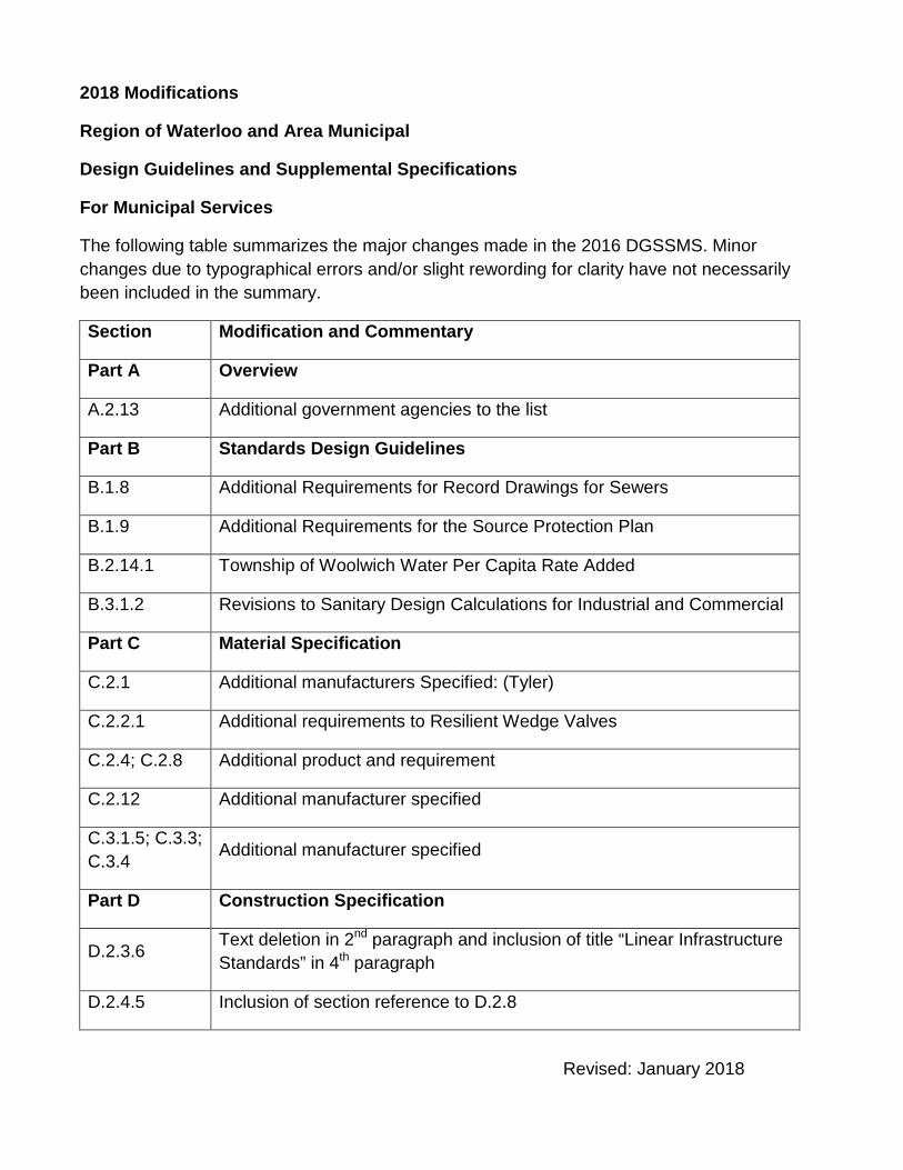
2018 Modifications
Region of Waterloo and Area Municipal
Design Guidelines and Supplemental Specifications
For Municipal Services
The following table summarizes the major changes made in the 2016 DGSSMS. Minor changes due to typographical errors and/or slight rewording for clarity have not necessarily been included in the summary.
Section Modification and Commentary
Part A Overview
A.2.13 Additional government agencies to the list
Part B Standards Design Guidelines
B.1.8 Additional Requirements for Record Drawings for Sewers
B.1.9 Additional Requirements for the Source Protection Plan
B.2.14.1 Township of Woolwich Water Per Capita Rate Added
B.3.1.2 Revisions to Sanitary Design Calculations for Industrial and Commercial
Part C Material Specification
C.2.1 Additional manufacturers Specified: (Tyler)
C.2.2.1 Additional requirements to Resilient Wedge Valves
C.2.4; C.2.8 Additional product and requirement
C.2.12 Additional manufacturer specified
C.3.1.5; C.3.3; C.3.4 Additional manufacturer specified
Part D Construction Specification
D.2.3.6 Text deletion in 2nd paragraph and inclusion of title “Linear Infrastructure Standards” in 4th paragraph
D.2.4.5 Inclusion of section reference to D.2.8
Revised: January 2018
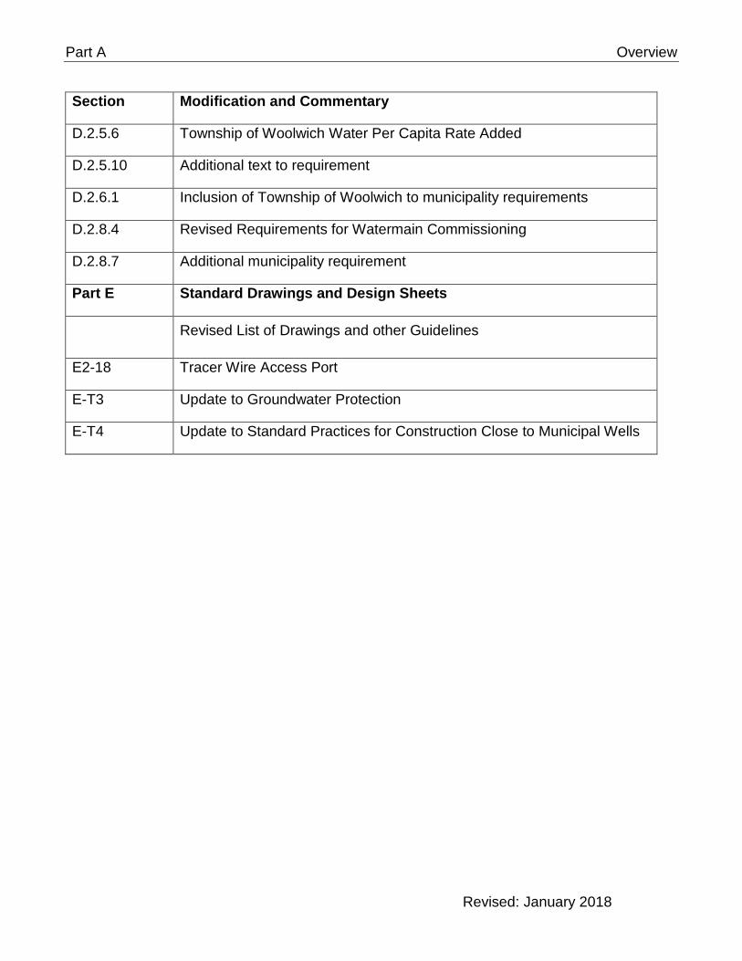
Part A Overview
Section Modification and Commentary
D.2.5.6 Township of Woolwich Water Per Capita Rate Added
D.2.5.10 Additional text to requirement
D.2.6.1 Inclusion of Township of Woolwich to municipality requirements
D.2.8.4 Revised Requirements for Watermain Commissioning
D.2.8.7 Additional municipality requirement
Part E Standard Drawings and Design Sheets
Revised List of Drawings and other Guidelines
E2-18 Tracer Wire Access Port
E-T3 Update to Groundwater Protection
E-T4 Update to Standard Practices for Construction Close to Municipal Wells
Revised: January 2018
Region of Waterloo and Area Municipalities
Design Guidelines and Supplemental Specifications
For Municipal Services
Part A
Overview
Part A Overview
Overview
Table of Contents
A.1 General ................................................................................................................. 1 Introduction ...................................................................................................... 1 A.1.1 Area Municipalities ........................................................................................... 1 A.1.2 Purpose ........................................................................................................... 1 A.1.3 Ontario Provincial Standards ........................................................................... 2 A.1.4 Ontario Building Code ...................................................................................... 2 A.1.5 Municipal Services Considered ........................................................................ 2 A.1.6 Implementation ................................................................................................ 2 A.1.7 Document Structure ......................................................................................... 3 A.1.8 Availability of Specifications ............................................................................. 3 A.1.9 Updates / Notifications ..................................................................................... 3 A.1.10
A.2 Definitions ............................................................................................................ 4
A.2.1. Municipality: ............................................................................................. 4
A.2.2. Region or Region of Waterloo: ................................................................. 4
A.2.3. Chief Municipal Engineer: ........................................................................ 4
A.2.4. Developer: ............................................................................................... 4
A.2.5. Engineer: ................................................................................................. 4
A.2.6. Contract Administrator: ............................................................................ 4
A.2.7. Consultant: ............................................................................................... 4
A.2.8. Initial Acceptance ..................................................................................... 4
A.2.9. Warranty Period: ...................................................................................... 5
A.2.10. Water Distribution Report: ........................................................................ 5
A.2.11. DGSSMS or SSMS: ................................................................................. 5
A.2.12. OPSS: ...................................................................................................... 5
A.2.13. OPSD: ...................................................................................................... 5 A.3 Environment ........................................................................................................ 5 A.4 Chief Municipal Engineer ................................................................................... 5

Part A Overview
A.1 General
Introduction A.1.1
Many engineering consultants and construction contractors work within the municipalities that comprise the Region of Waterloo and surrounding areas. One of the common industry comments was that the design guidelines and contract specifications differ among the various area municipalities.
The Best Management Practices (BMP) Committee, which is comprised of representatives from the Region of Waterloo and area municipalities, has recognized that benefits will be realized for both the construction industry and municipalities if common design guidelines and contract specifications for municipal services are developed. A technical subcommittee of the Best Management Practices Committee was established to develop the Region of Waterloo and Area Municipal Design Guidelines and Supplemental Specifications for Municipal Services (DGSSMS). Key personnel from the area municipalities plus the Region of Waterloo were assigned to the project.
Area Municipalities A.1.2
For the purposes of this document, the area municipalities include:
• City of Cambridge
• City of Guelph
• City of Kitchener
• Township of North Dumfries
• City of Waterloo
• Township of Wellesley
• Township of Wilmot
• Township of Woolwich
For the purposes of these specifications, the Region of Waterloo will also be considered an area municipality.
Purpose A.1.3
The primary purpose and benefit of creating a common set of design guidelines and contract specifications is to facilitate the design and construction of municipal services by consultants and contractors that work in more than one municipality.
Although this document is often referred to as specifications, the design portion (Part B) should be considered as guidelines. This document provides the municipalities’ design preferences under normal circumstances. The Engineer; however, should use their best judgement to find innovative solutions when abnormal design conditions are encountered. The Chief Municipal A-1

Part A Overview
Engineer must approve any design modifications made by the Engineer outside of this document.
This document shall be used in conjunction with the local municipalities’ respective subdivision standards and related documents.
Ontario Provincial Standards A.1.4
The Region of Waterloo and Area Municipal Design Guidelines and Supplemental Specifications for Municipal Services are supplemental to the Ontario Provincial Standards (OPS) and thus take precedence over the related specifications (OPSS) and drawings (OPSD).
The standards to be followed during the design and construction of Joint Services projects will be determined by who owns the proposed infrastructure which is to be installed.
Ontario Building Code A.1.5
The DGSSMS applies to municipally owned services. The installation of privately held services is governed by the Ontario Building Code and associated specifications (which may include DGSSMS).
Municipal Services Considered A.1.6
The municipal services currently considered are:
• Watermains
• Sanitary Sewers
• Storm Sewers
For all other municipal services, the user must refer to that municipality’s specifications.
The water and sanitary guidelines and specifications apply to distribution and collection only and do not apply to supply and/or treatment. Trunk servicing may use other or additional special specifications.
Implementation A.1.7
The Region of Waterloo and Area Municipal Design Guidelines and Supplemental Specifications for Municipal Services is a standalone document (i.e. not bound into Contract Documents) that will be referenced in Engineering Agreements and Contract Documents. The Municipality; however, may issue municipal specific instructions or modifications to the specifications as part of a Special Conditions or Special Provisions Section within Construction Contracts. Similarly, modifications may also be made to address project specific requirements; however, the municipality under whose jurisdiction the work is undertaken must agree to any such modifications.
Check with individual municipalities for additional standards or requirements.
A-2
Part A Overview
These specifications will be used on all municipal service additions and alterations including:
• Subdivisions
• Site Plans (Condominiums / Commercial / Industrial Lands)
• Reconstruction
• Improvements and augmentations
• Operations and maintenance
In the case where the DGSSMS and the individual municipality’s standards (e.g. Development Manual) differ, the individual municipality’s standard(s) will supersede the DGSSMS.
Document Structure A.1.8
The document is structured in the following manner:
• Part A: Overview
• Part B: Design Guidelines
• Part C: Materials Specifications
• Part D: Construction Specifications
• Part E: Standard Drawings and Forms
− Watermain Commissioning Plan Template
− Hydrostatic Pressure Test Template
− Tracer Wire Conductivity Test Template
− Water Services Procedure: Standard Practices for Construction Work Near a Well Field
• Part F: Special Product Approval With Conditions
Availability of Specifications A.1.9
The current specifications are available free of charge via the Region of Waterloo’s website.
Updates / Notifications A.1.10
On a regular basis the Technical Sub-Committee of the Best Management Practices Committee will meet to review the specifications in light of comments received and the introduction of new materials and procedures. For manufactures and suppliers who wish to have their products reviewed please download the product approval form from the Region of Waterloo web site.
Comments are encouraged and may be forwarded to: A-3

Part A Overview
BMP Technical Sub-Committee
c/o Design and Construction Division
Transportation and Environmental Services Department
Regional Municipality of Waterloo
150 Frederick St, 6th Floor
Kitchener, Ontario N2G 4J3
Email: [email protected]
A.2 Definitions
A.2.1. Municipality: Refers to the municipality having jurisdiction over the works and includes, for the purpose of this document, the Regional Municipality of Waterloo.
A.2.2. Region or Region of Waterloo: Regional Municipality of Waterloo will be referred to as a municipality for the purposes of this document
A.2.3. Chief Municipal Engineer: That individual(s) within the Municipality having responsibility for the specification of design, construction and materials. This individual will be specified by the Municipality. The words “Chief Municipal Engineer” is considered to be appended with the words “or their authorized designate”. All approvals, design alterations or other instructions must be issued in writing by the Chief Municipal Engineer or their authorized designate before being considered valid.
A.2.4. Developer: The owner of land upon which municipal services will be located and ultimately owned by the Municipality.
A.2.5. Engineer: The licensed individual or firm responsible for the design of the works or their designate. May also be referred to as the Design Engineer.
A.2.6. Contract Administrator: The individual or firm responsible for overseeing the construction of the works and representing the municipality’s interests.
A.2.7. Consultant: Consulting Engineering firm retained by, or on behalf of the Municipality. This reference may also include municipal staff depending on the context.
A.2.8. Initial Acceptance: This can be either the Initiation of the Maintenance Guarantee Period for subdivision servicing or the Substantial Completion of the Contract for other work. This is typically when the Municipality assumes ownership of the works subject to the Warranty Period.
A-4

Part A Overview
A.2.9. Warranty Period: During this period of time, the Contractor is responsible for all costs related to repairing any defects in materials or workmanship. The Municipality will specify the length of the warranty period.
A.2.10. Water Distribution Report: This report is prepared by the designer to document the analysis completed to determine the layout and sizing of a watermain or water distribution system
A.2.11. DGSSMS or SSMS: The Region of Waterloo and Area Municipal Design Guidelines and Supplemental Specifications for Municipal Services
A.2.12. OPSS: Ontario Provincial Standard Specifications
A.2.13. OPSD: Ontario Provincial Standard Drawings
MOECC: Ministry of Environment and Climate Change
AWWA: American Water Works Association
CSA: Canadian Standards Association
OHSA: The Occupational Health and Safety Act
OTM: Ontario Traffic Manual
CCTV: Closed-Circuit Television
OBC: Ontario Building Code
A.3 Environment
It is the aim of all the area municipalities and the Regional Municipality of Waterloo to be environmentally responsible during all phases of the design, construction and operation of all municipal services.
The users of these guidelines and specifications must be familiar with the environmental protection standards laid out within this document and by the various area municipalities, federal and provincial legislation.
A.4 Chief Municipal Engineer
For the purpose of this document, the Chief Municipal Engineer for each Municipality shall be defined as per Table A1. The Chief Municipal Engineer may designate municipal staff or others to act on their behalf.
A-5

Part A Overview
Table A1: Position of Chief Municipal Engineer
Municipality Chief Municipal Engineer
City of Cambridge City Engineer
City of Guelph City Engineer
City of Kitchener Utilities Engineer
Director of Engineering Services (sanitary and storm)
City of Waterloo Engineering Services Director
Water Services Director
Township of North Dumfries
Township Engineer
see Region of Waterloo for water and sanitary
Township of Wellesley Director of Public Works and Environment for storm see Region of Waterloo for water and sanitary
Township of Wilmot Director of Public Works
Township of Woolwich Manager of Engineering
Region of Waterloo Commissioner of Transportation and Environmental Services
A-6
Region of Waterloo and Area Municipalities
Design Guidelines and Supplemental Specifications
For Municipal Services
Part B
Design Guidelines
Design Guidelines
Table of Contents
B.1 General............................................................................................. 1
B.1.1 Approvals .............................................................................................. 1
B.1.2 Ontario Ministry of the Environment and Climate Change Guidelines ............................................................................................ 1
B.1.3 Definitions ............................................................................................. 1
B.1.4 Alterations to Design Guidelines ........................................................ 1
B.1.5 Impact of Works on Existing System ................................................. 1
B.1.6 Easements ............................................................................................ 1
B.1.7 Constructability .................................................................................... 2
B.1.8 Record Drawings .................................................................................. 2
B.1.9 Construction Near a Regional Well Field ........................................... 3
B.1.10 Sourcewater Protection Requirements .............................................. 3
B.1.10.1 Environmental Compliance Approval for Transfer of Review for Sewage Works ................................................................................. 3
B.2 Watermains ...................................................................................... 5
B.2.1 Watermain Classification – Region of Waterloo ............................... 5
B.2.1.1 General ............................................................................................ 5
B.2.1.2 Regional Watermains ...................................................................... 5
B.2.1.3 Local Watermains ............................................................................ 6
B.2.1.4 Connection to Regional Watermains ............................................... 6
B.2.2 Water Demand ...................................................................................... 6
Definitions ........................................................................................ 6 B.2.2.1
Domestic .......................................................................................... 7 B.2.2.2
Fire Flow .......................................................................................... 7 B.2.2.3
Design Period .................................................................................. 7 B.2.2.4
Peaking Factors ............................................................................... 7 B.2.2.5B.2.3 Hydraulic Analysis ............................................................................... 7
Friction Factors ................................................................................ 7 B.2.3.1
Nominal vs. Actual Diameter ........................................................... 8 B.2.3.2
Capacity ........................................................................................... 8 B.2.3.3
Maximum Velocity ............................................................................ 8 B.2.3.4
Transient Pressure........................................................................... 8 B.2.3.5B.2.4 Pressure ................................................................................................ 8
Pressure Zone Delineation .............................................................. 8 B.2.4.1
Boundary Conditions ....................................................................... 8 B.2.4.2
Preferred Pressure Range ............................................................... 9 B.2.4.3
Minimum Pressure ........................................................................... 9 B.2.4.4
Maximum Pressure .......................................................................... 9 B.2.4.5
In-Line Booster Pumps .................................................................... 9 B.2.4.6
Individual Pressure Reducing Devices .......................................... 10 B.2.4.7
Design Pressure Location .............................................................. 10 B.2.4.8B.2.5 Pipework ............................................................................................. 10
B.2.5.1 Material .......................................................................................... 10
B.2.5.2 Location ......................................................................................... 10
B.2.5.3 Diameter ........................................................................................ 10
B.2.5.3.1 General .......................................................................................... 10
B.2.5.3.2 Minimum ........................................................................................ 10
B.2.5.3.3 Maximum ....................................................................................... 11
B.2.5.4 Depth of Cover ............................................................................... 11
B.2.5.5 Vertical Connection to Existing System ......................................... 11
B.2.5.6 High Points ..................................................................................... 11
B.2.5.7 Minimum Slope .............................................................................. 12
B.2.5.8 Dead-end Mains............................................................................. 12
B.2.5.9 Cul-de-sac Servicing ...................................................................... 12
B.2.5.10 Minimum Clearance to Sewers ...................................................... 12
B.2.5.11 Thrust Restraint ............................................................................. 12
B.2.5.12 Soil Settlement Areas .................................................................... 13
B.2.6 Water Quality ...................................................................................... 13
B.2.6.1 Minimum Chlorine Residual ........................................................... 13
B.2.6.2 Design Considerations ................................................................... 13
B.2.7 Hydrants .............................................................................................. 13
B.2.7.1 Maximum Spacing ......................................................................... 13
B.2.7.2 Lead Size ....................................................................................... 13
B.2.7.3 Location ......................................................................................... 14
B.2.7.4 Bends ............................................................................................. 14
B.2.7.5 Minimum Clearance ....................................................................... 14
B.2.8 Isolation Valving ................................................................................. 15
B.2.8.1 Size ................................................................................................ 15
B.2.8.2 Location ......................................................................................... 15
B.2.8.3 Maximum Spacing ......................................................................... 15
B.2.8.4 Direct Bury ..................................................................................... 15
B.2.8.5 Minimum Clearance ....................................................................... 15
B.2.8.6 Valve Depth ................................................................................... 15
B.2.9 Combination Air & Vacuum Release Valves .................................... 16
B.2.9.1 Utilisation ....................................................................................... 16
B.2.9.2 Watermain Profile .......................................................................... 16
B.2.9.3 Sizing ............................................................................................. 16
B.2.10 Drain Chambers .................................................................................. 16
B.2.10.1 Utilisation ....................................................................................... 16
B.2.10.2 Location ......................................................................................... 16
B.2.11 Flushing and Swabbing Ports ........................................................... 17
B.2.11.1 Utilisation ....................................................................................... 17
B.2.12 Services ............................................................................................... 17
B.2.12.1 Sizing ............................................................................................. 17
B.2.12.2 Location ......................................................................................... 17
B.2.12.3 Number of Services per Property .................................................. 17
B.2.12.4 Restraints ....................................................................................... 17
B.2.12.5 Bends ............................................................................................. 18
B.2.12.6 Valving ........................................................................................... 18
B.2.12.7 Metering ......................................................................................... 18
B.2.12.8 Allowance for Future Servicing ...................................................... 18
B.2.12.9 Electrical Grounding ...................................................................... 18
B.2.13 Geotechnical Report .......................................................................... 18
B.2.13.1 Requirements ................................................................................. 18
B.2.14 Corrosion Protection ......................................................................... 19
B.2.14.1 Non-Metallic Watermain ................................................................ 19
B.2.14.2 Metallic Watermain ........................................................................ 19
B.2.15 Watermain Identification .................................................................... 19
B.3 Sanitary .......................................................................................... 19
B.3.1 Pipework ............................................................................................. 19
B.3.1.1 Design flow .................................................................................... 19
B.3.1.2 Flow Calculations ........................................................................... 20
B.3.1.3 Design Flow Calculations .............................................................. 21
B.3.1.4 Minimum Pipe Size ........................................................................ 21
B.3.1.5 Manning’s “n” ................................................................................. 21
B.3.1.6 Pipe Slope ...................................................................................... 21
B.3.1.7 Flow Velocities ............................................................................... 21
B.3.1.8 Selection of Bedding and Class of Pipe – Rigid Pipe .................... 21
B.3.1.9 Selection of Bedding and Class of Pipe – Flexible Pipe ................ 21
B.3.1.10 Pipe Depth ..................................................................................... 22
B.3.2 Maintenance Holes ............................................................................. 22
B.3.2.1 Structure ........................................................................................ 22
B.3.2.2 Spacing .......................................................................................... 22
B.3.2.3 Size ................................................................................................ 22
B.3.2.4 Drop Inlet Structures ...................................................................... 22
B.3.2.5 Safety Grates ................................................................................. 23
B.3.2.6 Minimum Invert Drop...................................................................... 23
B.3.2.7 Location ......................................................................................... 23
B.3.2.8 Watertight Lids ............................................................................... 23
B.3.2.9 Flow Direction Changes ................................................................. 23
B.3.3 Services ............................................................................................... 23
B.3.3.1 Minimum Diameter ......................................................................... 23
B.3.3.2 Location ......................................................................................... 23
B.3.3.3 Slope .............................................................................................. 23
B.3.3.4 Depth ............................................................................................. 23
B.3.3.5 Connections to Maintenance Holes ............................................... 24
B.3.4 Curvilinear Sewers ............................................................................. 24
B.3.5 Geotechnical Report .......................................................................... 24
B.4 Storm ............................................................................................. 24
B.4.1 General ................................................................................................ 24
B.4.2 Pipework ............................................................................................. 24
B.4.2.1 Design Flow Calculations .............................................................. 24
B.4.2.2 Minimum Pipe Size ........................................................................ 28
B.4.2.3 Manning’s “n” ................................................................................. 28
B.4.2.4 Pipe Slope ...................................................................................... 28
B.4.2.5 Flow Velocities ............................................................................... 28
B.4.2.6 Selection of Bedding and Class of Pipe – Rigid Pipe .................... 28
B.4.2.7 Selection of Bedding and Class of Pipe – Flexible Pipe ................ 28
B.4.2.8 Pipe Depth ..................................................................................... 29
B.4.2.9 Curvilinear Sewers ......................................................................... 29
B.4.2.10 Elliptical Sewers ............................................................................. 29
B.4.2.11 Blind Connections .......................................................................... 29
B.4.2.12 Safety / Rodent Grates .................................................................. 29
B.4.2.13 Head Walls ..................................................................................... 29
B.4.3 Maintenance Holes ..............................................................................30
B.4.3.1 Structure ........................................................................................ 30
B.4.3.2 Spacing .......................................................................................... 30
B.4.3.3 Size ................................................................................................ 30
B.4.3.4 Tee Maintenance Holes ................................................................. 30
B.4.3.5 Drop Inlet Structures ...................................................................... 30
B.4.3.6 Location ......................................................................................... 30
B.4.3.7 Safety Grates ................................................................................. 30
B.4.3.8 Minimum Invert Drop...................................................................... 30
B.4.3.9 Flow Direction Changes ................................................................. 31
B.4.4 Catchbasins ........................................................................................ 31
B.4.4.1 Minimum Lead Size ....................................................................... 31
B.4.4.2 Catchbasin Lead Depth ................................................................. 31
B.4.4.3 Spacing .......................................................................................... 31
B.4.4.4 Intersection Location ...................................................................... 31
B.4.4.5 Flow Direction Changes ................................................................. 32
B.4.4.6 Double Catchbasin......................................................................... 32
B.4.4.7 Side Inlet Catchbasin ..................................................................... 32
B.4.4.8 Double Catchbasin with Curb Inlet Overflow ................................. 32
B.4.4.9 Sub-drains ...................................................................................... 32
B.4.4.10 Slotted Drain Pipe .......................................................................... 32
B.4.4.11 Rear Yard Drainage ....................................................................... 32
B.4.5 Services ................................................................................................33
B.4.5.1 Minimum Diameter ......................................................................... 33
B.4.5.2 Location ......................................................................................... 33
B.4.5.3 Slope .............................................................................................. 33
B.4.5.4 Flow Direction Changes ................................................................. 33
B.4.5.5 Depth ............................................................................................. 33 B.4.6 Geotechnical Report .......................................................................... 33
B.4.7 Open Ditch and Culvert Design ........................................................ 33

Part B Design Guidelines
B.1 General
B.1.1 Approvals
All watermain and sewer projects are subject to the Ministry of the Environment and Climate Change and municipal approval process.
B.1.2 Ontario Ministry of the Environment and Climate Change Guidelines
The Engineer is referred to the Ontario Ministry of the Environment and Climate Change’s latest issue of Guidelines for the Design of Sewage Works and Drinking Water Systems for the minimum standards to be used. The DGSSMS are supplemental to the MOECC Guidelines. Additionally, where watermain additions, modifications, replacements or extensions are being proposed, the Engineer is referred to the MOECC latest issue of Watermain Design Criteria for Future Alterations Authorized under a Drinking Water Works Permit and the Engineer is required to complete a Form 1 Record to be submitted to the respective municipality for approval prior to construction.
B.1.3 Definitions
This section is blank intentionally.
B.1.4 Alterations to Design Guidelines
The Chief Municipal Engineer reserves the right to modify these design guidelines in writing or to provide written direction to the Engineer as it may relate to project specific requirements.
The Engineer may submit a written request to the Chief Municipal Engineer to waive or modify a portion of the Design Guidelines on a project by project basis. The submission must be accompanied by documentation to substantiate the modifications.
B.1.5 Impact of Works on Existing System
The Engineer is responsible to determine and to mitigate the impact of the new works on the existing system and its users both inside and outside of the project limits.
B.1.6 Easements
The minimum easement width shall be the greater of:
a) 2 x depth where the depth is from the proposed final grade to the invert rounded up to the nearest half metre
b) 5.0 m in Guelph, Kitchener, Cambridge, Region of Waterloo, and Waterloo
c) 6.0 m (4.0 m if concrete encased) in the Township of Wilmot and Township of Woolwich
The Engineer shall also consider the soil conditions and constructability and future maintenance when selecting the easement width. In addition, if more than one utility is installed in the easement, the easement width should be increased by the separation distance of the utilities.
B-1
Part B Design Guidelines
B.1.7 Constructability
The Engineer shall consider the constructability and phasing of the proposed works that the works can be constructed in a cost effective manner and that the impact to the adjacent property owners and residents is minimized.
The Engineer shall contact the local operating authorities of the water distribution and sewer collection system to determine if there are possible adverse ramifications within the existing systems, within or outside of the construction limits, due to the construction of the works. The Engineer shall take reasonable measures to minimize any adverse effects outside of the construction limits.
The Engineer shall contact the local operating authorities of all utilities to coordinate the installation of the works.
B.1.8 Record Drawings
In addition to standard drawing information, include the following information on the record drawings for the project.
General:
• “Record Drawing” to be shown in the revision block
• Remove all construction notes
• Show registered plan number on all drawings (if applicable)
Watermains and Forcemains:
• Plan and profiles for all main lines
• Top of watermain elevation shots at a minimum 50m spacing, including every fitting
• Main size and pipe material (including DR rating and IPS/DIPS, product name where applicable)
• Service size and pipe material (including type and rating, product name where applicable) – on private and public side
• Swing ties to appurtenances, services and anode locations
• Thrust restraint (type, locations and/or extents)
• Special features (casings, insulation, trench cut-off walls, special gasket material, etc.)
• Final shop drawings for concrete pressure pipe (CPP) scanned and added to detail sheets
• Heat fusion reports
• Include locations of insulated / heat traced pipe
• Add material list as per Section D
B-2
Part B Design Guidelines
Sewers:
• Plan and profiles
• Surveyed invert elevations
• Re-calculated pipe grades and design sheets
• Measured lengths
• Pipe strength
• MH sizes
• Special features (casings, concrete bedding, trench cut-off walls, etc.)
• Service size and material (private/public side), top of pipe at property line.
• Pipe Material and product name as per Section D
• Subdrains size and material and location
• Swing ties to locations where proposed sewer connects to existing sewer main
• Swing ties to existing sanitary and storm sewer services (building corners)
• Show all abandoned and grout filled pipes/manholes including method of abandonment
All main and service feature locations and inverts/top of pipe levels are to be positioned in the digital drawing files to within 100 mm (at drawing scale) of the actual recorded location on the plan and actual recorded elevation on the profile.
Record drawings shall be provided in both hardcopy and digital formats (latest version of AutoCAD) to the Chief Municipal Engineer within three months following completion of the project.
Check with individual municipalities for additional record drawing requirements (e.g. Kitchener’s requirements are included in the Development Manual, electrical as per OPS).
CCTV videos to be included for storm sewer and sanitary sewers including laterals, all in accordance with the municipality.
B.1.9 Construction Near a Regional Well Field
Construction work planned within 200 m of any Regional Supply Well must follow standard practices and procedures. Refer to Part E for “Water Services Procedure: Standard Practices for Construction Work Near a Well Field”.
B.1.10 Sourcewater Protection Requirements
The Ministry of Environment and Climate Change (MOECC) will accept under the Transfer of Review Program (TOR) Environmental Compliance Approval (ECA) applications proposing sewage works that pose a significant threat to drinking water provided the following are submitted as part of a complete ECA application:
B-3
Part B Design Guidelines
i) Proponent: The proponent must outline how the proposed works will be managed to mitigate the contamination of sources of drinking water through the construction, design and operation of the proposed activity.
ii) Municipality: A letter of recommendation from the municipality confirming that the works have been reviewed in accordance with the Clean Water Act (CWA) and the applicable policies of the local Source Protection Plan (SPP). The review has determined that the activity will no longer pose a significant threat to drinking water as a result of the measures identified by the proponent and with appropriate ECA terms and conditions, if approved.
It is the applicant’s responsibility to know what SPP prescribed instrument policies apply to their activity.
Within the Regional Municipality of Waterloo, the SPP requires that any project within Wellhead Protection Areas A and B use enhanced construction practices for transport pathways to ensure that they do not contribute to the creation of significant drinking water threats. Subsurface excavation within these areas, that may excavate into or through aquitards overlying municipal aquifers, should be planned and carried out with appropriate mitigative measures to ensure that the aquifer intrinsic vulnerability is not increased.
B.1.10.1 Environmental Compliance Approval for Transfer of Review for Sewage Works
If the proposed activity for sewage works is located in a wellhead protection area or intake protection zone with a vulnerability score of 8 or above, it may be considered a significant drinking water threat. In general, this would apply to construction involving any sanitary sewers that are located within a 100m security area around any Regional water supply well. ECA applications for sanitary sewers that pose a significant threat to drinking water may be submitted under the TOR but must comply with the following conditions:
i) Contractors shall provide a Spill Contingency Plan as part of their Health and Safety Plan;
ii) Pipe material shall be HDPE, PVC or PVCO for watermains as per Table C.2.1 of the DGSSMS;
iii) Connections to manholes shall be in accordance with OPSS 407 Construction Specification for New Maintenance Hole, Catch Basin, Ditch Inlet, and Valve Chamber Installation - Section 407.07.13 Installation of Inlet and Outlet Pipes Into Concrete Structures c) Resilient Connector;
iv) Testing of the new sewers only shall be conducted in accordance with OPSS 410 Construction Specification for Pipe Sewer Installation in Open Cut - Section 410.07.16.04.03 Low Pressure Air Testing modified for 0kPa pressure loss; and
v) Closed–circuit television inspections on new sewers only shall be carried out at completion of construction and at the end of the maintenance period in accordance with OPSS 409 Construction Specification for Closed-Circuit Television (CCTV) Inspection of Pipelines. Closed–circuit television inspections on existing sewers shall include an additional inspection six (6) months after completion of construction.
B-4
Part B Design Guidelines B.2 Watermains
B.2.1 Watermain Classification – Region of Waterloo B.2.1.1 General
Watermains within the Region of Waterloo are classified into 2 broad categories:
• Regional
• Local
Regional watermains are furthermore classified into four subcategories:
i) Transmission
ii) Trunk Dual-Purpose
iii) Arterial Dual-Purpose
iv) Non-Potable
The purpose of the classification is to aid in maintaining the reliability, integrity and flexibility of key components in the water supply and distribution system.
Within the Region of Waterloo, the Region, in consultation with the Municipality, will classify new watermains. The watermain is classified by use and not by size.
Dual-Purpose Watermains are those that qualify as Regional Watermains yet allow service connections. Non-potable watermains transfer water not fully treated as defined under provincial regulations.
B.2.1.2 Regional Watermains
Regional Watermains constitute the skeleton (supply lines and related ancillaries) of the distribution system and satisfy one or more of the following cases:
• Watermains which connect water sources, storage or pumping facilities
• Watermains which cross pressure zone boundaries unless these watermains are controlled by special agreements with the Region and relevant area municipalities
• Watermains that include controlling devices (pressure regulating valves, motorized valves, etc.) with the exception of devices that control a local watermain
• Watermains that include bulk water meters used for wholesale water billing
• Watermains that complete or will complete future major loops. A major loop is defined as watermains that branch from Regional watermains and "loop back" to Regional Watermains. The purpose of a major loop is to enhance the pressure and water supply in the looped area rather than to provide a ring distribution main.
• Watermains that include chlorine residual boosting facilities
• Watermains that provide a focal supplying node to development areas B-5
Part B Design Guidelines
B.2.1.3 Local Watermains
Local Watermains are those that do not satisfy the criteria for Regional Watermains. These watermains provide the majority of connections to customers.
B.2.1.4 Connection to Regional Watermains
B.2.1.4.1 Transmission Watermains
Private services and fire hydrants shall not be connected to Transmission Watermains. A parallel watermain, connection to other watermains, individual supply wells, etc. must be installed to service properties adjacent to Transmission Watermains. Only in very exceptional cases will these connections be allowed. Special arrangements must be made with the Region of Waterloo and it must be clearly demonstrated that an alternate supply is not available.
Watermains connecting to Transmission Watermains must utilize a suitable tee, cross fitting or anchor tee. An isolation valve must be installed as near as practical to the Transmission Watermain to minimize the likelihood that damage to the connecting main will interrupt the water supply in the Transmission Watermain. The Region of Waterloo must approve the interconnection locations; however, generally only up to two (2) connections (tee and/or cross) will be allowed per kilometre of Transmission Watermain.
Existing private service and fire hydrant connections made prior to the classification of the watermain will be grandfathered until the time that the roadway and/or the watermain system are reconstructed. At which time, the connection will be removed and suitably connected to another water source. The Region may also undertake to remove connections and will at that time provide an alternate water source.
Although connections may exist on a Transmission Watermain (grandfathered or special conditions), it in no way implies that future connections will be allowed to the watermain.
B.2.1.4.2 Trunk Dual Purpose Watermains
One private service connection is permitted per 30 m of watermain. There is no limitation on the connection of fire hydrants and branch watermains.
B.2.1.4.3 Arterial Dual-Purpose Watermains
There are no connection limitations.
B.2.1.4.4 Non-Potable Watermains
Non-potable watermains are those that transfer water that has not been fully treated to regulated standards. Included in this classification are watermains transferring water from the source (well, river) to the treatment plant and watermains utilized to achieve the minimum chlorine contact time. Connections shall not be made to watermains designated non-potable.
B.2.2 Water Demand Definitions B.2.2.1
B-6
Part B Design Guidelines
B.2.2.1.1 Average Day: The total amount of water demanded within a certain time period, usually one year, divided by the number of days within that time period.
B.2.2.1.2 Maximum Day: The average water demand over the day (midnight to midnight) of highest water demand within any one year.
B.2.2.1.3 Minimum Hour: The smallest short-term (1 hour) demand. Without accurate records, this value can be taken as zero (0) in small systems or as the smallest hourly demand over a typical average day in large systems.
B.2.2.1.4 Peak Hour: The highest short-term (1 hour) demand within a system not including fire flow. The peak hour is normally the highest hourly demand on the maximum day.
B.2.2.1.5 Domestic: Any non-fire water use.
Domestic B.2.2.2
Wherever available, the Engineer shall use historical data, as supplied by the Region of Waterloo and the Municipality, to establish the Peaking Factors and Unit Consumption Rates. Based on historic information, the specific usage rate is 225 L/c/d as outlined in the Region’s “Water Supply and Distribution Optimization Master Plan, 2015” . For the City of Guelph, use the water demands as utilized in the City’s Hydraulic Water Model.
Fire Flow B.2.2.3
The fire flow requirements shall be determined in accordance with the current issue of “Water Supply for Public Fire Protection”, Fire Underwriters Survey.
Design Period B.2.2.4
The Design Period for watermain sizing purposes shall be 40 years, using the ultimate land use as predicted by the Municipality, Planning Department, and as shown in the Region of Waterloo’s and Area Municipality’s Official Plan.
Peaking Factors B.2.2.5
The peaking factors used to calculate minimum hour, maximum day and for peak hour must be based on:
• Historical information
• Water Supply and Distribution Optimization Master Plan
• Ministry of the Environment and Climate Change guidelines
• As directed by the municipality
B.2.3 Hydraulic Analysis Friction Factors B.2.3.1
The following “C” friction factors, which include an allowance for age, shall be used for the following materials:
B-7

Part B Design Guidelines
• PVC/PVCO: 150
• DI: 130
• CPP: 140
• HDPE: 140 If the watermain material has not been determined at the time of watermain sizing, a “C” factor of 130 shall be used.
Nominal vs. Actual Diameter B.2.3.2The nominal diameter can be used for general water distribution system design. The actual inside diameter shall be used though for the design of critical infrastructure (i.e. Regional Watermains).
The actual inside diameter shall be used for the design of HDPE watermains.
Capacity B.2.3.3All watermain distribution systems must be able to transfer the larger of maximum day plus fire or peak hour.
Maximum Velocity B.2.3.4The maximum velocity in the watermain under all flow conditions shall not exceed 5.0 m/s.
For Regional watermains, the maximum velocity under all flow conditions shall not exceed 1.5 m/s.
Transient Pressure B.2.3.5All watermains shall be designed to withstand the maximum operating pressure plus the transient pressures to which the watermain will be subjected. As a minimum, the pipe and joint strength shall be such that it can withstand the pressure surge resulting from an instantaneous stoppage of a water column moving at 0.6 m/s.
The minimum material classes specified for watermains in Part C – Materials tend to be adequate for normally interconnected water distribution systems. A transient pressure analysis however must be conducted for Regional Watermains, long single feed watermains, and those watermains designated by the Chief Municipal Engineer.
B.2.4 Pressure Pressure Zone Delineation B.2.4.1
The Water Services Division of the Region of Waterloo is responsible for general pressure zone delineation and the resultant pressures within the Region of Waterloo. Within the City of Guelph, the Infrastructure Planning Group is similarly responsible.
Boundary Conditions B.2.4.2The boundary conditions (i.e. available pressure and flow) for new watermains and water distribution systems can be obtained by field testing and/or from the Municipality. Field testing the water distribution system shall only be conducted with the approval and assistance of the
B-8
Part B Design Guidelines
Municipality. The Region of Waterloo (Water Services) maintains a hydraulic model of the trunk system for select communities within its borders and the City of Guelph (Infrastructure Planning) maintains a hydraulic model of its system.
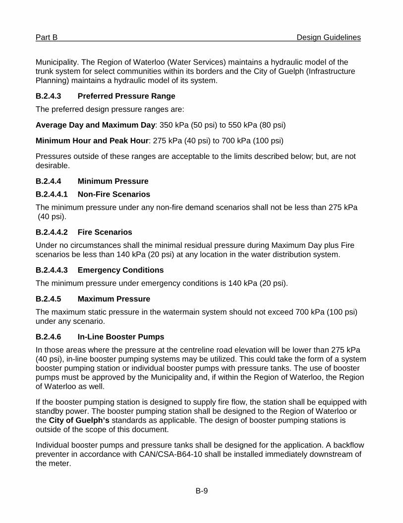
Preferred Pressure Range B.2.4.3The preferred design pressure ranges are:
Average Day and Maximum Day: 350 kPa (50 psi) to 550 kPa (80 psi)
Minimum Hour and Peak Hour: 275 kPa (40 psi) to 700 kPa (100 psi)
Pressures outside of these ranges are acceptable to the limits described below; but, are not desirable.
Minimum Pressure B.2.4.4B.2.4.4.1 Non-Fire Scenarios The minimum pressure under any non-fire demand scenarios shall not be less than 275 kPa (40 psi).
B.2.4.4.2 Fire Scenarios Under no circumstances shall the minimal residual pressure during Maximum Day plus Fire scenarios be less than 140 kPa (20 psi) at any location in the water distribution system.
B.2.4.4.3 Emergency Conditions The minimum pressure under emergency conditions is 140 kPa (20 psi).
Maximum Pressure B.2.4.5The maximum static pressure in the watermain system should not exceed 700 kPa (100 psi) under any scenario.
In-Line Booster Pumps B.2.4.6In those areas where the pressure at the centreline road elevation will be lower than 275 kPa (40 psi), in-line booster pumping systems may be utilized. This could take the form of a system booster pumping station or individual booster pumps with pressure tanks. The use of booster pumps must be approved by the Municipality and, if within the Region of Waterloo, the Region of Waterloo as well.
If the booster pumping station is designed to supply fire flow, the station shall be equipped with standby power. The booster pumping station shall be designed to the Region of Waterloo or the City of Guelph’s standards as applicable. The design of booster pumping stations is outside of the scope of this document.
Individual booster pumps and pressure tanks shall be designed for the application. A backflow preventer in accordance with CAN/CSA-B64-10 shall be installed immediately downstream of the meter.
B-9
Part B Design Guidelines
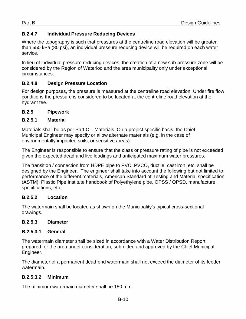
Individual Pressure Reducing Devices B.2.4.7Where the topography is such that pressures at the centreline road elevation will be greater than 550 kPa (80 psi), an individual pressure reducing device will be required on each water service.
In lieu of individual pressure reducing devices, the creation of a new sub-pressure zone will be considered by the Region of Waterloo and the area municipality only under exceptional circumstances.
Design Pressure Location B.2.4.8For design purposes, the pressure is measured at the centreline road elevation. Under fire flow conditions the pressure is considered to be located at the centreline road elevation at the hydrant tee.
B.2.5 Pipework B.2.5.1 Material
Materials shall be as per Part C – Materials. On a project specific basis, the Chief Municipal Engineer may specify or allow alternate materials (e.g. in the case of environmentally impacted soils, or sensitive areas).
The Engineer is responsible to ensure that the class or pressure rating of pipe is not exceeded given the expected dead and live loadings and anticipated maximum water pressures.
The transition / connection from HDPE pipe to PVC, PVCO, ductile, cast iron, etc. shall be designed by the Engineer. The engineer shall take into account the following but not limited to: performance of the different materials, American Standard of Testing and Material specification (ASTM), Plastic Pipe Institute handbook of Polyethylene pipe, OPSS / OPSD, manufacture specifications, etc.
B.2.5.2 Location
The watermain shall be located as shown on the Municipality’s typical cross-sectional drawings.
B.2.5.3 Diameter
B.2.5.3.1 General
The watermain diameter shall be sized in accordance with a Water Distribution Report prepared for the area under consideration, submitted and approved by the Chief Municipal Engineer.
The diameter of a permanent dead-end watermain shall not exceed the diameter of its feeder watermain.
B.2.5.3.2 Minimum
The minimum watermain diameter shall be 150 mm.
B-10
Part B Design Guidelines
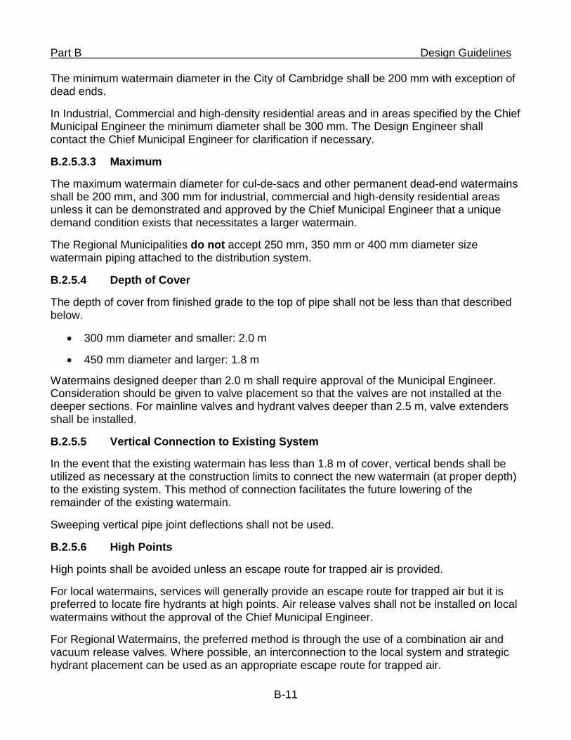
The minimum watermain diameter in the City of Cambridge shall be 200 mm with exception of dead ends.
In Industrial, Commercial and high-density residential areas and in areas specified by the Chief Municipal Engineer the minimum diameter shall be 300 mm. The Design Engineer shall contact the Chief Municipal Engineer for clarification if necessary.
B.2.5.3.3 Maximum
The maximum watermain diameter for cul-de-sacs and other permanent dead-end watermains shall be 200 mm, and 300 mm for industrial, commercial and high-density residential areas unless it can be demonstrated and approved by the Chief Municipal Engineer that a unique demand condition exists that necessitates a larger watermain.
The Regional Municipalities do not accept 250 mm, 350 mm or 400 mm diameter size watermain piping attached to the distribution system.
B.2.5.4 Depth of Cover
The depth of cover from finished grade to the top of pipe shall not be less than that described below.
• 300 mm diameter and smaller: 2.0 m
• 450 mm diameter and larger: 1.8 m
Watermains designed deeper than 2.0 m shall require approval of the Municipal Engineer. Consideration should be given to valve placement so that the valves are not installed at the deeper sections. For mainline valves and hydrant valves deeper than 2.5 m, valve extenders shall be installed.
B.2.5.5 Vertical Connection to Existing System
In the event that the existing watermain has less than 1.8 m of cover, vertical bends shall be utilized as necessary at the construction limits to connect the new watermain (at proper depth) to the existing system. This method of connection facilitates the future lowering of the remainder of the existing watermain.
Sweeping vertical pipe joint deflections shall not be used.
B.2.5.6 High Points
High points shall be avoided unless an escape route for trapped air is provided.
For local watermains, services will generally provide an escape route for trapped air but it is preferred to locate fire hydrants at high points. Air release valves shall not be installed on local watermains without the approval of the Chief Municipal Engineer.
For Regional Watermains, the preferred method is through the use of a combination air and vacuum release valves. Where possible, an interconnection to the local system and strategic hydrant placement can be used as an appropriate escape route for trapped air.
B-11
Part B Design Guidelines
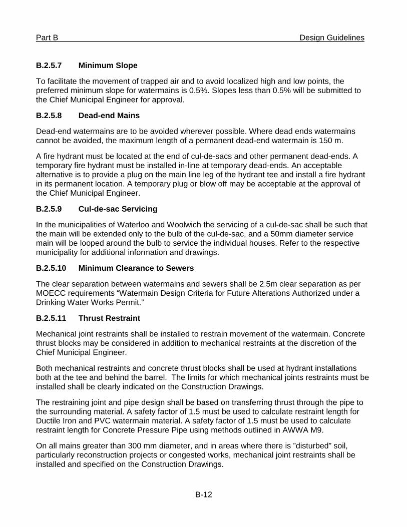
B.2.5.7 Minimum Slope
To facilitate the movement of trapped air and to avoid localized high and low points, the preferred minimum slope for watermains is 0.5%. Slopes less than 0.5% will be submitted to the Chief Municipal Engineer for approval.
B.2.5.8 Dead-end Mains
Dead-end watermains are to be avoided wherever possible. Where dead ends watermains cannot be avoided, the maximum length of a permanent dead-end watermain is 150 m.
A fire hydrant must be located at the end of cul-de-sacs and other permanent dead-ends. A temporary fire hydrant must be installed in-line at temporary dead-ends. An acceptable alternative is to provide a plug on the main line leg of the hydrant tee and install a fire hydrant in its permanent location. A temporary plug or blow off may be acceptable at the approval of the Chief Municipal Engineer.
B.2.5.9 Cul-de-sac Servicing
In the municipalities of Waterloo and Woolwich the servicing of a cul-de-sac shall be such that the main will be extended only to the bulb of the cul-de-sac, and a 50mm diameter service main will be looped around the bulb to service the individual houses. Refer to the respective municipality for additional information and drawings.
B.2.5.10 Minimum Clearance to Sewers
The clear separation between watermains and sewers shall be 2.5m clear separation as per MOECC requirements “Watermain Design Criteria for Future Alterations Authorized under a Drinking Water Works Permit.”
B.2.5.11 Thrust Restraint
Mechanical joint restraints shall be installed to restrain movement of the watermain. Concrete thrust blocks may be considered in addition to mechanical restraints at the discretion of the Chief Municipal Engineer.
Both mechanical restraints and concrete thrust blocks shall be used at hydrant installations both at the tee and behind the barrel. The limits for which mechanical joints restraints must be installed shall be clearly indicated on the Construction Drawings.
The restraining joint and pipe design shall be based on transferring thrust through the pipe to the surrounding material. A safety factor of 1.5 must be used to calculate restraint length for Ductile Iron and PVC watermain material. A safety factor of 1.5 must be used to calculate restraint length for Concrete Pressure Pipe using methods outlined in AWWA M9.
On all mains greater than 300 mm diameter, and in areas where there is ”disturbed” soil, particularly reconstruction projects or congested works, mechanical joint restraints shall be installed and specified on the Construction Drawings.
B-12
Part B Design Guidelines
B.2.5.12 Soil Settlement Areas
On areas subject to possible future soil settlement, the bedding design must minimize pipe movement and mechanical joint restraints must be installed to the limits of the possible settlement area. This requirement may be waived if it can be demonstrated that future settlement will not occur.
B.2.6 Water Quality B.2.6.1 Minimum Chlorine Residual
The minimum chlorine residual as mandated by the Ministry of the Environment and Climate Change is 0.25 mg/L for combined chlorine or 0.05 mg/L for free chlorine at any point in the distribution system. The combined chlorine residual is the total chlorine residual minus the free chlorine residual. For development that is approved under a Subdivision Agreement, the Developer shall provide a Chlorine Residual Maintenance Plan, see sheet E-T2.
B.2.6.2 Design Considerations
Although the Municipality has primary responsibility to ensure that the minimum chlorine residuals are maintained in the distribution system, the distribution system must be designed to mitigate the degradation of chlorine residuals. The Chief Municipal Engineer reserves the right to require watermain looping and/or automatic flushing devices to facilitate the maintenance of chlorine residuals.
B.2.7 Hydrants B.2.7.1 Maximum Spacing
The maximum spacing between fire hydrants as measured along the roadway centreline is as follows:
• Residential 150 m
• Industrial, Commercial & High Density Residential 90 m
• Watermains not fronting lots 300 m
The Chief Municipal Engineer:
• Will determine if fire hydrants are required along watermains not fronting lots
• Reserves the right to request additional fire hydrants
• May waive the requirement to provide fire hydrants fronting vacant properties
B.2.7.2 Lead Size
The minimum hydrants lead size to be 150 mm. On a site specific basis, the Chief Municipal Engineer may request a larger hydrant lead size.
The valve and boot must be the same size as the lead. A reducer shall not be utilized at the hydrant boot.
B-13
Part B Design Guidelines
B.2.7.3 Location
Fire hydrants shall be installed at the end of cul-de-sacs and other permanent dead end watermains. For municipalities that use a 50mm loop at the end of cul-de-sacs, the hydrant shall be located just short of the bulb of the cul-de-sac such that the hydrant coverage can be maintained.
The preferred locations for the fire hydrants are:
• At street intersections
• On the same side of the road as the watermain
• Consistently on the same side of the road as existing and future fire hydrants
• At the dividing property line between adjacent properties
• At high points
• At low points
During road reconstruction projects if an adjacent property has an existing fire hydrant which is located for a specific fire suppression system for a private building then the new fire hydrant that is part of the road reconstruction shall be located within 45m of existing siamese or similar fire suppression connection(s) on buildings in accordance with the latest edition of the Ontario Building Code or approved site plan. Fire hydrant leads must be installed perpendicular to the road and/or the watermain.
At street intersections, the City of Cambridge requires hydrant valves to be located with the watermain valves at the intersection.
B.2.7.4 Bends
Bends in fire hydrant leads will not be allowed unless site conditions warrant and with written approval of the Chief Municipal Engineer.
B.2.7.5 Minimum Clearance
The minimum clearance from above ground obstructions to fire hydrants shall be as follows:
• Behind 0.6 m
• Each Side with a port 2.0 m
• Each Side without a port 1.0 m
• Front no obstructions between the street and the hydrant face
The installation of bollards shall be as directed by the Municipality.
B-14
Part B Design Guidelines B.2.7.6 Restraints
Hydrants leads, including valves and joints shall be fully restrained from the watermain to the property line. The concrete thrust blocks and mechanical restraints shall be as per SSMS E2-01.
B.2.8 Isolation Valving B.2.8.1 Size
The valve shall be the same size as the main.
B.2.8.2 Location
Valving must satisfy the following location criteria:
• 2 valves at tee intersections
• 3 valves at cross intersections
• Valve on each side of a railway crossing a minimum of one pipe length away from casing pipe.
• Valve on each side of any water stream a minimum of one pipe length away from casing pipe or as directed by the Engineer.
• Separating hydrants such that no two adjacent hydrants will be out of service at one time unless otherwise directed by the Municipality. Valving at intersections shall be located in-line with the extension of the property line of the intersecting through street, unless otherwise directed by the Chief Municipal Engineer. Contract Administrator / Contractor to ensure that the valve doesn’t conflict with other utilities and /or infrastructure.
City of Cambridge requires 3 valves at the tee and 4 valves at the cross
B.2.8.3 Maximum Spacing
In addition to the valving requirements outlined above, the maximum spacing for isolation valves shall be as listed for the following watermain diameters:
• 300 mm diameter and smaller spacing = 300 m
• Larger than 300 mm diameter spacing = as directed by the Chief Municipal Engineer
B.2.8.4 Direct Bury
All valves shall be direct buried as per SSMS E2-02, unless the Chief Municipal Engineer specifically requires a chamber to be provided.
B.2.8.5 Minimum Clearance
The minimum clearance from above ground obstructions to valves is 2.0 m.
B.2.8.6 Valve Depth B-15
Part B Design Guidelines
A standard valve key (+/-2.1m) must be able to operate the valve. If the watermain is greater than 1.8m in depth to the top of valve nuts, extensions/ highheads need to be installed on the valve.
B.2.9 Combination Air & Vacuum Release Valves B.2.9.1 Utilisation
Air and Vacuum Release Valves shall be utilized in watermains in situations where it is possible for air to accumulate or a vacuum to develop and an alternate means for release is not available (i.e. services or fire hydrants) to remove the air. The valves shall be located in accordance with best design practices. This generally includes supply watermains with localized high points, long stretches of flat or gently sloping watermain or at changes in grade.
In general terms, Air and Vacuum Release Valves shall be of the combination configuration. The sole use of either an air release or vacuum release valve must be dictated by the situation and approved by the Chief Municipal Engineer.
Watermains servicing adjacent lots generally do not require air and vacuum release valves because air can escape or enter through the services.
A blowoff or fire hydrant is an acceptable alternate means of air or vacuum release in temporary situations with the approval of the Chief Municipal Engineer.
The Region of Waterloo will consider the application of chamberless combination air and vacuum release valves for use on transmission watermains, to be approved on a case by case basis.
B.2.9.2 Watermain Profile
The Engineer, through a cost-benefit analysis, shall consider reducing the number of air and vacuum release valves by altering the profile of the watermain.
B.2.9.3 Sizing
Air Release and Vacuum Release valve and piping to be designed and sealed by a professional engineer in accordance with E02-12.
B.2.10 Drain Chambers B.2.10.1 Utilisation
Drain chambers are required where the normal methodology of watermain dewatering is not appropriate due to the watermain size or location. Watermains smaller than 450 mm will generally not require a drain chamber, however, a long downhill gradient without an isolation valve or fire hydrant for bulk draining may necessitate a drain chamber.
With the written approval of the Chief Municipal Engineer, a fire hydrant may be installed with the intention that the watermain will be drained with a hydrant barrel pump.
B.2.10.2 Location
B-16
Part B Design Guidelines Drain chambers must be located at the low points of the watermain profile. Consideration should be given to locating low points adjacent to appropriate discharge locations (i.e. near catchbasin)
B.2.11 Flushing and Swabbing Ports B.2.11.1 Utilisation
Flushing and swabbing ports shall be considered for watermains over 300 mm. The Engineer shall contact the Chief Municipal Engineer to determine if a swab launching and/or swab retrieval chamber is required or is available nearby.
B.2.12 Services B.2.12.1 Sizing
The minimum nominal service size shall be 25 mm.
The allowable service sizes are 25 mm, 38 mm, 50 mm, 100 mm, 150 mm etc. in 50 mm increments. Multi-block minimum service should be 150 mm (for onsite hydrants). Services larger than the minimum size for the Municipality shall be sized in accordance with AWWA M22 ‘Sizing Water Service Lines and Meters’. The Chief Municipal Engineer must approve services sized larger than 300 mm or alternate service sizing.
The service size shall not exceed the diameter of the watermain.
B.2.12.2 Location
The service shall be located as detailed on the Municipality’s typical servicing and/or road cross-section drawings unless otherwise approved.
Water services must be installed perpendicular to the road and/or the watermain wherever practical and within the lot frontage.
B.2.12.3 Number of Services per Property
No more than one individual property shall be serviced by the same service regardless of ownership.
In situations where a fire service is required due to infilling or site development after the water distribution system has been installed, private hydrants can be supplied by a separate service at the discretion of the municipality as long as it can be demonstrated that the fire line service will not be interconnected now or later with the domestic water system.
In the case of multi-unit blocks, on-site servicing can be arranged to the property owner’s convenience, however, there shall only be one service from the municipal system.
In unique circumstances and with the approval by the Chief Municipal Engineer, more than one service may be allowed to one property. However, a testable backflow preventer in accordance with CAN/CSA-B64-10 shall be installed on each service to eliminate the possibility of system flow through private property.
B.2.12.4 Restraints
B-17

Part B Design Guidelines Services 100 mm and larger, including valves, joints and bends, regardless of size shall be fully restrained from the watermain to the property line.
B.2.12.5 Bends
Bend fittings shall be avoided wherever possible.
B.2.12.6 Valving
For services 50 mm diameter and smaller, all services shall have two isolation valves. One valve shall be installed immediately adjacent to the watermain (main stop) and buried, and another valve shall be installed at the property line or easement limit (curb stop) and a service box provided to finished grade.
For services 100 mm and larger, the Engineer shall contact the Municipality having jurisdiction regarding the number, location and need for valves and valve boxes. Kitchener and Cambridge requires 2 valves for services 100 mm and larger. The main stop or valve, regardless of size, shall be fully restrained to the watermain, preferably through the use of an anchor tee, joint restraint, or bolted connection.
B.2.12.7 Metering
The metering of water use shall be in accordance with the Municipality’s standard.
B.2.12.8 Allowance for Future Servicing
If the location of future servicing is in doubt then the servicing can only be installed with the written approval of the Chief Municipal Engineer.
B.2.12.9 Electrical Grounding
On reconstruction or local improvement projects where existing structures will be serviced by a replacement or new water distribution system, the design Engineer shall determine if the electrical grounding systems are connected to the water service. If so, appropriate measures must be taken to ensure that electrical grounding systems are not compromised. Possible solutions include using copper services or installing new grounding rods or plates (see the Electrical Safety Code).
B.2.13 Geotechnical Report B.2.13.1 Requirements
A geotechnical report must be submitted to the Chief Municipal Engineer as part of the design of the watermain unless otherwise waived by the Chief Municipal Engineer. As a minimum, recommendations must be made regarding the watermain bedding, thrust restraints, trench dewatering and corrosion protection based on soil resistivity testing, including corrosiveness of the soil, and soil stability. The results of the soil resistivity testing must be included in the report with recommendations as to anode type and spacing.
The geotechnical report shall also include test results and recommendations for the use and/or disposal of adversely impacted soils, such as from sodium and petroleum products, in accordance with current regulations.
B-18
Part B Design Guidelines B.2.14 Corrosion Protection B.2.14.1 Non-Metallic Watermain
Non-metallic watermain with metallic valves and fittings and non-metallic service laterals, shall have one zinc Z-24-48 (24 lb) anode attached to the tracer wire and to a metallic valve or fitting whenever possible. Spacing is to be based on soil resistivity results and the corrosiveness of the soil. Maximum spacing between anodes shall not exceed 100 meters along the length of watermain. In the City of Waterloo and City of Guelph anodes are not to be attached to the tracer wire (See Section D.2.5.6). In Township of Woolwich a max. 50m spacing between anodes is required.
The anode spacing shall be clearly shown on the Construction Drawings and Record Drawings. In addition, a tabular listing of the stations at which the anodes are to be installed shall be provided.
Corrosion Protection for CPP shall be considered on a project by project basis. See Section D.2.5.6 for additional information.
B.2.14.2 Metallic Watermain
As part of the geotechnical report, the resistivity and corrosiveness of the soil must be determined.
Where metallic watermains are to be installed, an appraisal must be done to determine if corrosion protection is required. This appraisal shall be performed using the 10-point soil evaluation procedure as described in AWWA C105 Appendix. If the 10-point soil evaluation establishes a need for corrosion protection, the necessary anode spacing shall be clearly shown on the Construction Drawings. Approved methods for corrosion protection of Ductile Iron watermain and fittings are:
• Sacrificial anodes
• Petrolatum tape systems (refer to section D.2.5.10, Wrapping)
• Hyprotec coating
B.2.15 Watermain Identification All non-potable watermains will be identified in the trench with an underground warning tape placed on the top of the pipe bedding along the centreline of the pipe.
B.3 Sanitary
B.3.1 Pipework
B.3.1.1 Design flow
The quantity of sewage flow for residential area shall be calculated on the following basis:
• The design flow of sewage including extraneous flows
• Allowance shall be made in the designed capacity of the sewer to provide for future sewage requirements
B-19
Part B Design Guidelines
• Flow data sheets and plans showing drainage area must accompany plan and profile submission
• In accordance with MOECC approval requirements
B.3.1.2 Flow Calculations
Except in the City of Kitchener and Township of Woolwich, sanitary sewer flows are to be determined using the following design criteria. For Kitchener and Woolwich refer to the Chief Municipal Engineer.
B.3.1.2.1 Residential
• Average flow – 275 L/c/d
• Use actual or projected populations based on information (zoning or otherwise) to be provided by the Municipality
• Peak the average flow using the Harmon Formula
F = 1 + 14 (P = Population/1,000) 4 + √P
• Daily domestic flows to be provided from municipal sanitary sewer master plans.
B.3.1.2.2 Industrial
• Average flow: 0.40 l/s/ha.
• Use higher design flows for point sources known to have significantly greater flows than the average design allowance.
• Use actual flows for large known discharges.
• Use peaking factor as per MOECC guidelines “Typical Industry Sewage Flow Peaking Factors”.
B.3.1.2.3 Commercial
• Average flow – Core =0.95 l/s/ha; Shopping Mall = 0.3 l/s/ha; General = 0.5 l/s/ha. Use higher design flows for point sources known to have significantly greater flows than the average design allowance.
• Use actual flows for large known discharges.
• Peak using a factor of 2.5.
B.3.1.2.4 Institutional
• 0.25 L/s/ha for institutional uses
• 0.015 L/s/bed for hospitals
B.3.1.2.5 Other Miscellaneous Average Flow Rates
B-20
Part B Design Guidelines
In accordance with MOECC Design Guidelines.
B.3.1.2.6 Extraneous Flows
Add an inflow and infiltration allowance of 0.25 l/s/ha to account for wet weather flows, or as directed by the Municipality.
B.3.1.3 Design Flow Calculations
Design flow calculations for sanitary sewer systems shall be completed on Sanitary Sewer Design Sheets in accordance with MOECC Design Guidelines and the MOECC Pipe Data Form.
B.3.1.4 Minimum Pipe Size
In accordance with MOECC Design Guidelines.
B.3.1.5 Manning’s “n”
The value of "n" using the Manning formula shall be 0.013 for all pipe materials.
B.3.1.6 Pipe Slope
The minimum gradient for the first reach of permanent dead end sewers shall be 1%.
For sewers other than the first reach of permanent dead end the minimum slope shall be 0.5%, unless otherwise approved by the Chief Municipal Engineer.
B.3.1.7 Flow Velocities
In accordance with MOECC Design Guidelines.
B.3.1.8 Selection of Bedding and Class of Pipe – Rigid Pipe
Rigid sanitary sewer pipe is to be designed to withstand all earth loads, superimposed loads and hydraulic loads placed on it in accordance with methods provided by manufactures and suppliers such as the “Concrete Pipe Design Manual” produced by the Ontario Concrete Pipe Association (OPCA).
The 0.3 mm crack, three edge bearing strength shall be used as the design criteria as specified in the CSA standards on concrete pipe. For non-reinforced pipe, a factor of safety of 1.5 must be used.
Pipe strength design calculations are to be completed. The class of bedding type and pipe shall be noted on the plans. If transition width is not used for design, the design width of all trenches shall be specified on the construction drawings. In case the actual trench width exceeds the design width, it must be noted that the Contractor shall be responsible for the supply of additional bedding and/or stronger pipe.
B.3.1.9 Selection of Bedding and Class of Pipe – Flexible Pipe
Flexible sanitary sewer pipe shall be designed so as to accommodate external dead and live loading (i.e. Traffic, soil, ground water changes, frost actions, soil settlement, etc.) imposed on
B-21
Part B Design Guidelines
it in accordance with the criteria and methodology as outlined in the current version of the MOECC Design Guidelines.
Pipe strength design calculations shall be completed and provided to the Chief Municipal Engineer for review. Pipe and bedding type class shall be noted on the construction drawings.
B.3.1.10 Pipe Depth
The obvert shall be a minimum of 2.8 metres below the final road grade.
For depths over 5.0 m, a secondary collection system may be required and shall be approved by the Chief Municipal Engineer. A secondary collection system may be installed directly over the deep trunk sewer.
B.3.2 Maintenance Holes
B.3.2.1 Structure
Maintenance holes 3000 mm and smaller shall be precast concrete.
B.3.2.2 Spacing
The maximum spacing for maintenance holes shall be as follows for the sewer diameters indicated:
• 200 mm to 450 mm 90 m
• Larger than 450 mm to 900 mm 120 m
• Larger than 900 mm at approval of Chief Municipal Engineer
B.3.2.3 Size
The maintenance hole shall be sized to receive pipes as per SSMS standard drawing. The minimum maintenance hole size is 1200 mm diameter. See standard drawing E1-02.
B.3.2.4 Drop Inlet Structures
A drop inlet structure shall be provided in accordance with MOECC Design Guidelines and OPSD 1003.01 (external); 1003.031 (internal).
Note: MOECC guideline applies for an invert difference of 0.61 m.
The City of Kitchener only permits external drop inlet structures.
B-22
Part B Design Guidelines
B.3.2.5 Safety Grates
For maintenance hole depths between 5.0 and 10.0 m, a safety grate must be installed at the mid-point. For maintenance hole depths between 10.0 and 15.0 m, a safety grate must be installed at the third points. Refer to OPSD 404.02.
B.3.2.6 Minimum Invert Drop
Where pipes enter and leave inline or at angles between 0° to 45°, the minimum drop from invert to invert across the maintenance hole shall be 0.030 m.
Where pipes enter and leave at angles of 45° to 90°, the minimum drop from invert to invert across the maintenance hole shall be 0.060 m.
B.3.2.7 Location
In accordance with MOECC Design Guidelines.
B.3.2.8 Watertight Lids
Where there is a possibility for flooding, watertight lids shall be installed.
B.3.2.9 Flow Direction Changes
Changes in direction of flow through a maintenance hole greater than 90° will not be permitted.
In pipe sizes 675 mm or greater, a change in direction of flow through a maintenance hole greater than 45° shall not be permitted.
B.3.3 Services
B.3.3.1 Minimum Diameter
The minimum service size is 100 mm for sanitary services.
B.3.3.2 Location
Services shall be installed perpendicular to the main wherever practical.
Sanitary services for single and semi-detached dwellings shall be at locations to the Municipality’s standard.
B.3.3.3 Slope
The minimum service slope is 2%.
The maximum service slope is 8%.
B.3.3.4 Depth
The sanitary service invert at property line shall be 2.5 m below the finished grade.
B-23
Part B Design Guidelines B.3.3.5 Connections to Maintenance Holes
Sanitary service connections to maintenance holes are permitted. If the invert of the service entering the maintenance hole is 0.61 m or more above the lowest invert, a drop pipe must be installed to direct flow to the main channel.
B.3.3.5.1 Drop Structure
If the inlet of the sanitary service is 0.61 m above the lowest invert, a drop (internal or external) shall be provided to direct the flow into the channel in a manner to avoid splashing and the accumulation of debris on the benching. The maintenance hole shall be sized accordingly for internal drop; in particular a minimum internal clearance of 1200 mm is required. The City of Kitchener only permits external drop.
B.3.3.5.2 Main Line Connection
For 100 mm and 150 mm diameter services, factory made tees or wyes shall be used. Service saddles and “inserta-tees” are not permitted.
For services 200 mm and larger, a maintenance hole shall be installed within the road corridor or in the boulevard.
Under special circumstances, on specific road reconstructions, site plan projects (case by case) and intensification projects, service saddles may be used at the discretion of the Chief Municipal Engineer.
B.3.4 Curvilinear Sewers
Curvilinear sewers may be considered for sanitary sewers 600 mm diameter and larger.
B.3.5 Geotechnical Report
A geotechnical report must be submitted to the Chief Municipal Engineer as part of the design of the sanitary sewer unless otherwise waived by the Chief Municipal Engineer. Recommendations must be made regarding the sanitary sewer bedding, trench dewatering, and pipe selection.
The geotechnical report shall also include test results and recommendations for the use and/or disposal of adversely impacted soils, such as from sodium and petroleum products, in accordance with current regulations.
B.4 Storm
B.4.1 General
This section relates to storm sewers only and does not include requirements for storm water management. The Engineer is directed to the municipality’s standard and/or applicable governing conservation authority for design guidelines related to storm water management.
B.4.2 Pipework
B.4.2.1 Design Flow Calculations
B-24
Part B Design Guidelines
Design calculations for storm sewer systems shall be completed on Storm Sewer Design Sheets (see MOECC Design Guidelines for Sewage Works and the MOECC Pipe Data Form).
The quantity of storm flow shall be calculated using the Rational Method as follows:
Q= kAIR, where: Q = flow (l/s) k = 2.78 A = contribution area (ha) I = rainfall intensity (mm/hr) R = runoff coefficient
All storm sewers shall, as a minimum, be designed to a 5 year storm event, unless otherwise indicated.
For design purposes drainage areas shall be allocated to the up-stream end of the pipe run being sized.
B.4.2.1.1 Rainfall Intensity – Pipe Size Design Only
Values of rainfall intensity (I) shall be determined by: I = A / (Tc + B)C, where
For detailed stormwater management design, please contact the local Municipality for rainfall intensity parameters.
B.4.2.1.2 Time of Concentration and Inlet Time
The time of concentration is the time required for flow to reach a particular point in the sewer system from the most remote part of the drainage area. It requires not only the travel time in the sewers, but also the inlet time or time required to flow overland into the sewer system. In addition to overland flow, the inlet time may also include components of open channel flow, gutter flow, and pipe flow, depending on the characteristics of the drainage area.
The MOECC Guidelines state: “Inlet times should be calculated rather than relying upon arbitrary minimum or maximum times. The calculation should be based upon the overland flow route that will exist when the sewer system has been fully developed to the drainage limit. In the case of single-family residential areas, calculations will not be needed if a maximum inlet time of 10 minutes is used”.
As referenced in the MOECC Design Guidelines, Inlet Times may be calculated in accordance with the “MTO Drainage Management Manual” (Ministry of Transportation, 1995-1997), Chapter 8, “Watershed Time of Concentration” where it is stated:
“Several methods are available to determine tc. Two recommended approaches are:
Return Period A B C
5 year 1593 11 0.8789
B-25
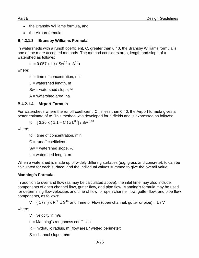
Part B Design Guidelines
• the Bransby Williams formula, and
• the Airport formula.
B.4.2.1.3 Bransby Williams Formula
In watersheds with a runoff coefficient, C, greater than 0.40, the Bransby Williams formula is one of the more accepted methods. The method considers area, length and slope of a watershed as follows:
tc = 0.057 x L / ( Sw0.2 x A0.1) where:
tc = time of concentration, min L = watershed length, m Sw = watershed slope, % A = watershed area, ha
B.4.2.1.4 Airport Formula
For watersheds where the runoff coefficient, C, is less than 0.40, the Airport formula gives a better estimate of tc. This method was developed for airfields and is expressed as follows:
tc = [ 3.26 x ( 1.1 – C ) x L0.5] / Sw 0.33 where:
tc = time of concentration, min C = runoff coefficient Sw = watershed slope, % L = watershed length, m
When a watershed is made up of widely differing surfaces (e.g. grass and concrete), tc can be calculated for each surface, and the individual values summed to give the overall value.
Manning’s Formula
In addition to overland flow (as may be calculated above), the inlet time may also include components of open channel flow, gutter flow, and pipe flow. Manning’s formula may be used for determining flow velocities and time of flow for open channel flow, gutter flow, and pipe flow components, as follows:
V = ( 1 / n ) x R2/3 x S1/2 and Time of Flow (open channel, gutter or pipe) = L / V where:
V = velocity in m/s n = Manning’s roughness coefficient R = hydraulic radius, m (flow area / wetted perimeter) S = channel slope, m/m
B-26
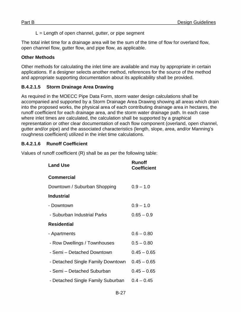
Part B Design Guidelines
L = Length of open channel, gutter, or pipe segment
The total inlet time for a drainage area will be the sum of the time of flow for overland flow, open channel flow, gutter flow, and pipe flow, as applicable.
Other Methods
Other methods for calculating the inlet time are available and may by appropriate in certain applications. If a designer selects another method, references for the source of the method and appropriate supporting documentation about its applicability shall be provided.
B.4.2.1.5 Storm Drainage Area Drawing
As required in the MOECC Pipe Data Form, storm water design calculations shall be accompanied and supported by a Storm Drainage Area Drawing showing all areas which drain into the proposed works, the physical area of each contributing drainage area in hectares, the runoff coefficient for each drainage area, and the storm water drainage path. In each case where inlet times are calculated, the calculation shall be supported by a graphical representation or other clear documentation of each flow component (overland, open channel, gutter and/or pipe) and the associated characteristics (length, slope, area, and/or Manning’s roughness coefficient) utilized in the inlet time calculations.
B.4.2.1.6 Runoff Coefficient
Values of runoff coefficient (R) shall be as per the following table:
Land Use Runoff Coefficient
Commercial
Downtown / Suburban Shopping 0.9 – 1.0
Industrial
- Downtown
- Suburban Industrial Parks
0.9 – 1.0
0.65 – 0.9
Residential
- Apartments
- Row Dwellings / Townhouses
- Semi – Detached Downtown
- Detached Single Family Downtown
- Semi – Detached Suburban
- Detached Single Family Suburban
0.6 – 0.80
0.5 – 0.80
0.45 – 0.65
0.45 – 0.65
0.45 – 0.65
0.4 – 0.45
B-27
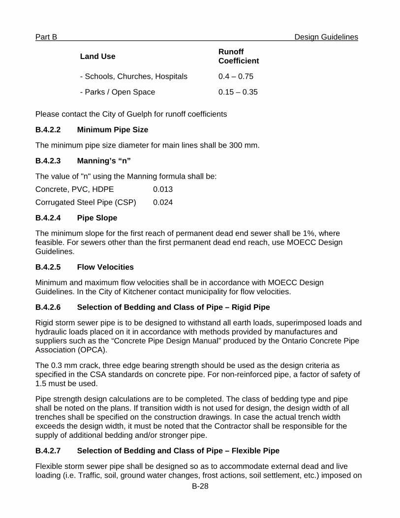
Part B Design Guidelines
Land Use Runoff Coefficient
- Schools, Churches, Hospitals 0.4 – 0.75
- Parks / Open Space 0.15 – 0.35
Please contact the City of Guelph for runoff coefficients
B.4.2.2 Minimum Pipe Size
The minimum pipe size diameter for main lines shall be 300 mm.
B.4.2.3 Manning’s “n”
The value of "n" using the Manning formula shall be: Concrete, PVC, HDPE 0.013 Corrugated Steel Pipe (CSP) 0.024
B.4.2.4 Pipe Slope
The minimum slope for the first reach of permanent dead end sewer shall be 1%, where feasible. For sewers other than the first permanent dead end reach, use MOECC Design Guidelines.
B.4.2.5 Flow Velocities
Minimum and maximum flow velocities shall be in accordance with MOECC Design Guidelines. In the City of Kitchener contact municipality for flow velocities.
B.4.2.6 Selection of Bedding and Class of Pipe – Rigid Pipe
Rigid storm sewer pipe is to be designed to withstand all earth loads, superimposed loads and hydraulic loads placed on it in accordance with methods provided by manufactures and suppliers such as the “Concrete Pipe Design Manual” produced by the Ontario Concrete Pipe Association (OPCA).
The 0.3 mm crack, three edge bearing strength should be used as the design criteria as specified in the CSA standards on concrete pipe. For non-reinforced pipe, a factor of safety of 1.5 must be used.
Pipe strength design calculations are to be completed. The class of bedding type and pipe shall be noted on the plans. If transition width is not used for design, the design width of all trenches shall be specified on the construction drawings. In case the actual trench width exceeds the design width, it must be noted that the Contractor shall be responsible for the supply of additional bedding and/or stronger pipe.
B.4.2.7 Selection of Bedding and Class of Pipe – Flexible Pipe
Flexible storm sewer pipe shall be designed so as to accommodate external dead and live loading (i.e. Traffic, soil, ground water changes, frost actions, soil settlement, etc.) imposed on
B-28
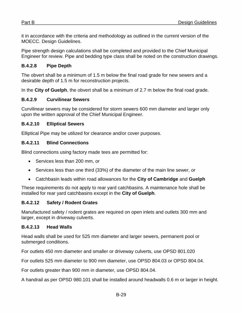
Part B Design Guidelines
it in accordance with the criteria and methodology as outlined in the current version of the MOECC. Design Guidelines.
Pipe strength design calculations shall be completed and provided to the Chief Municipal Engineer for review. Pipe and bedding type class shall be noted on the construction drawings.
B.4.2.8 Pipe Depth
The obvert shall be a minimum of 1.5 m below the final road grade for new sewers and a desirable depth of 1.5 m for reconstruction projects.
In the City of Guelph, the obvert shall be a minimum of 2.7 m below the final road grade.
B.4.2.9 Curvilinear Sewers
Curvilinear sewers may be considered for storm sewers 600 mm diameter and larger only upon the written approval of the Chief Municipal Engineer.
B.4.2.10 Elliptical Sewers
Elliptical Pipe may be utilized for clearance and/or cover purposes.
B.4.2.11 Blind Connections
Blind connections using factory made tees are permitted for:
• Services less than 200 mm, or
• Services less than one third (33%) of the diameter of the main line sewer, or
• Catchbasin leads within road allowances for the City of Cambridge and Guelph
These requirements do not apply to rear yard catchbasins. A maintenance hole shall be installed for rear yard catchbasins except in the City of Guelph.
B.4.2.12 Safety / Rodent Grates
Manufactured safety / rodent grates are required on open inlets and outlets 300 mm and larger, except in driveway culverts.
B.4.2.13 Head Walls
Head walls shall be used for 525 mm diameter and larger sewers, permanent pool or submerged conditions.
For outlets 450 mm diameter and smaller or driveway culverts, use OPSD 801.020
For outlets 525 mm diameter to 900 mm diameter, use OPSD 804.03 or OPSD 804.04.
For outlets greater than 900 mm in diameter, use OPSD 804.04.
A handrail as per OPSD 980.101 shall be installed around headwalls 0.6 m or larger in height.
B-29
Part B Design Guidelines B.4.3 Maintenance Holes
B.4.3.1 Structure
Maintenance holes 3000 mm and smaller shall be precast concrete.
B.4.3.2 Spacing
The maximum spacing for maintenance holes shall be as follows for the sewer diameters indicated:
• 300 mm to 900 mm 90 m
• Larger than 900 mm and smaller than 1350 mm 120 m
• 1350 mm and larger at approval of Chief Municipal Engineer
B.4.3.3 Size
The maintenance hole shall be sized adequately to receive pipes as per SSMS Standard Drawing. The minimum maintenance hole size is 1200 mm diameter.
B.4.3.4 Tee Maintenance Holes
Tee maintenance holes are permitted provided that:
• No change in slope
• No change in direction
• 1200 mm or larger pipe
Fabricated bends, reducers and increasers may be used immediately adjacent to tee maintenance holes.
B.4.3.5 Drop Inlet Structures
A drop structure shall be provided in accordance with MOECC Design Guidelines and OPSD 1003.01 (external); 1003.031 (internal).Note: MOECC requirement applies for a difference of 0.61 m. The City of Kitchener only permits external.
B.4.3.6 Location
Location shall be in accordance with MOECC Design Guidelines.
B.4.3.7 Safety Grates
For maintenance hole depths between 5.0 and 10.0 m, a safety grate must be installed at the mid-point. For maintenance hole depths between 10.0 and 15.0 m, a safety grate must be installed at the third points. Refer to OPSD 404.02.
B.4.3.8 Minimum Invert Drop
Where pipes enter and leave in line, the drop from invert to invert across the maintenance hole shall be a minimum of the slope of the upstream pipe.
B-30
Part B Design Guidelines
Where pipes enter and leave at angles deflected 0° to 45°, the minimum drop from invert to invert across the maintenance hole shall be 0.030 m.
Where pipes enter and leave at angles deflected 45° to 90°, the minimum drop from invert to invert across the maintenance hole shall be 0.060 m.
B.4.3.9 Flow Direction Changes
Changes in direction of flow through a maintenance hole greater than 90° will not be permitted.
In pipe sizes of 675 mm or greater, a change in direction of flow through a maintenance hole shall not be greater than 45°.
B.4.4 Catchbasins
B.4.4.1 Minimum Lead Size
Size of catchbasin leads shall be calculated by the engineer based on the catchment area and it will be greater of the calculated size or:
• Double Catchbasin Lead: 300 mm
• Single Catchbasin Lead: 250 mm (In the City of Guelph the minimum is 200 mm)
Minimum lead size for City of Waterloo for single and double is 300 mm
B.4.4.2 Catchbasin Lead Depth
The catchbasin lead obvert shall be a minimum of 1.2 m below the final road grade for new sewers and a desirable depth of 1.2 m for reconstruction projects.
B.4.4.3 Spacing
The maximum spacing between catchbasins or highpoint to first catchbasin shall be:
Road Type Road Grade
< 3% 3% to 5% >5%
For two (2) lane roads 90m 75m 60m
For four (4) lane roads 75m 60m 60m
The Engineer shall ensure that the catchbasin spacing and casting cover is adequate to collect the storm water.
B.4.4.4 Intersection Location
Catchbasins shall be located on the upstream side of all intersections where the road grade falls towards the intersection
B-31
Part B Design Guidelines B.4.4.5 Flow Direction Changes
Horizontal bends are to be avoided.
B.4.4.6 Double Catchbasin
Double catchbasins are required at all low points, when water is collected from two directions. A single catchbasin may be considered if the total aggregate spacing to the adjacent catchbasins is less than the maximum spacing allowable, as noted above.
B.4.4.7 Side Inlet Catchbasin
Side inlet catchbasins shall be installed on Regional and other major arterial roads, or as directed by the Chief Municipal Engineer. If a side inlet catchbasin (including doubles and manholes) are not feasible to construct on a Regional Road a standard catchbasin (including doubles and manholes) will be fitted with OPSD frame & cover 400.11.
B.4.4.8 Double Catchbasin with Curb Inlet Overflow
Double catchbasin with curb inlet overflow shall be installed in the City of Kitchener and the Township of Wilmot at all low points, when water is collected from two directions, unless the low point is at an intersection. A single catchbasin may be considered if the total aggregate spacing to the adjacent catchbasins is less than the maximum spacing allowable, as noted above. Please see dwg E4-07 and E4-08.
B.4.4.9 Sub-drains
When warranted by a geotechnical investigation, the minimum size is 150 mm. Sub-drain shall be connected to the downstream end of the sub-drain only.
Sub-drains are required 3.0 m on each side of low point catchbasins on Regional roads.
Township of Woolwich, Township of Wilmot, City of Waterloo and City of Kitchener requires continuous 150 mm dia. sub drain along curb on all projects.
B.4.4.10 Slotted Drain Pipe
Slotted drain pipe shall be utilized when:
• Road grade is equal to or larger than 5%
• Problem areas and where additional catchment is needed
• A slotted drain will not be used with a side inlet CB
B.4.4.11 Rear Yard Drainage
A maintenance hole is required on the main line for the connection of a rear yard catchbasin lead, regardless of the lead size. Pipe size is to be designed based on drainage area and shall be included in the storm design sheets.
In the City of Cambridge, requirement for maintenance holes for rear yard catch basins will be subject to the approval of the City.
B-32
Part B Design Guidelines
In the City of Guelph, maintenance holes are not required at the connection to rear yard catchbasins.
In the City of Kitchener, Township of Woolwich, Township of Wilmot sumps are not permitted.
B.4.5 Services
B.4.5.1 Minimum Diameter
The minimum service size is 150 mm for storm services.
B.4.5.2 Location
Services shall be installed perpendicular to the main wherever practical.
Sewer connections for single and semi-detached dwellings shall be made with factory made fittings at locations to the Municipality’s standard.
B.4.5.3 Slope
The minimum service slope is 2%
The maximum service slope is 8%
B.4.5.4 Flow Direction Changes
Horizontal bends are to be avoided.
B.4.5.5 Depth
The storm service obvert at property line shall be 1.2 m below the finished grade except in the City of Guelph where the depth shall be 2.5 m.
B.4.6 Geotechnical Report
A geotechnical report must be submitted to the Chief Municipal Engineer as part of the design of the storm sewer system unless otherwise waived by the Chief Municipal Engineer. Recommendations must be made regarding the storm sewer bedding, trench dewatering, and pipe selection.
The geotechnical report shall also include test results and recommendations for the use and/or disposal of adversely impacted soils, such as from sodium and petroleum products, in accordance with current regulations.
B.4.7 Open Ditch and Culvert Design
Contact applicable Chief Municipal Engineer for design standards.
B-33
Region of Waterloo and Area Municipalities
Design Guidelines and Supplemental Specifications
For Municipal Services
Part C
Material Specifications
Material Specifications
Table of Contents
C.1 General ................................................................................................................. 1 C.1.1 Ontario Provincial Standards ....................................................................... 1 C.1.2 Definitions ...................................................................................................... 1 C.1.3 Standards Council of Canada ....................................................................... 1 C.1.4 Material Conformance ................................................................................... 1
C.2 Watermain ............................................................................................................ 1 Approved Watermain Pipe material.............................................................. 1 C.2.1
C.2.1.1 Ductile Iron Pipe ...................................................................................... 3 C.2.1.1.2 Fittings ............................................................................................................ 3 C.2.1.1.3 Joint Restraint ................................................................................................ 3
C.2.1.2 Concrete Pressure Pipe ........................................................................... 3
C.2.1.3 Polyvinyl Chloride Pipe (PVC) ................................................................. 4
C.2.1.4 Polyvinyl Chlorine Oriented (PVCO) ........................................................ 5
C.2.1.5 High Density Polyethylene Pipe (HDPE) .................................................. 5 Valves ............................................................................................................. 6 C.2.2
C.2.2.1 Gate Valves ............................................................................................. 6
C.2.2.2 Combination Air and Vacuum Release Valves ........................................ 7 Tapping Sleeves ............................................................................................ 7 C.2.3 Valve Chambers ............................................................................................. 7 C.2.4
C.2.4.1 Cast Iron Maintenance Hole Lids ............................................................. 7
C.2.4.2 Adjustment Units ...................................................................................... 7
C.2.4.3 Safety Post .............................................................................................. 8 Line Closure Couplings ................................................................................. 8 C.2.5 Flange Adaptors ............................................................................................ 8 C.2.6 Valve Boxes .................................................................................................... 8 C.2.7 Hydrants ......................................................................................................... 8 C.2.8 50 mm and Smaller Service Connections .................................................... 9 C.2.9
C.2.9.1 Service Pipe ............................................................................................. 9
C.2.9.2 Service Saddles ....................................................................................... 9
C.2.9.3 PVC Tapped Couplings ......................................................................... 10
C.2.9.4 Main Stops ............................................................................................. 10
C.2.9.5 Union Couplings .................................................................................... 10
C.2.9.6 Curb Stops ............................................................................................. 10
C.2.9.7 Service Boxes ........................................................................................ 10 Temporary Watermains ............................................................................... 10 C.2.10 Metal Items ................................................................................................... 11 C.2.11 Petrolatum Tape Systems ........................................................................... 11 C.2.12 Anodes .......................................................................................................... 12 C.2.13 Tracer Wire ................................................................................................... 12 C.2.14 Warning Tape ............................................................................................... 12 C.2.15
C.3 Sewers................................................................................................................ 12 C.3.1 Pipe Materials ............................................................................................... 12
C.3.1.1 Concrete Sewer Pipe and Fittings ......................................................... 12
C.3.1.2 PVC Sewer Pipe and Fittings ................................................................. 13
C.3.1.3 HDPE Sanitary Sewer Pipe and Fittings ................................................ 13
C.3.1.4 HDPE Storm Sewer Pipe and Fittings .................................................... 13
C.3.1.5 Approved Sanitary Sewer Pipe Materials ............................................... 13
C.3.1.6 Sanitary Forcemain Material .................................................................. 14
C.3.1.7 Approved Storm Sewer Pipe Materials .................................................. 14 C.3.2 Cast Iron Maintenance Hole Lids................................................................ 15 C.3.3 Cast Iron Catchbasin Frames and Grates .................................................. 16 C.3.4 Maintenance Hole and Catchbasin Adjustment Units .............................. 16 C.3.5 Slotted Pipe Drain ........................................................................................ 16 C.3.6 Flexible Couplings ....................................................................................... 16 C.3.7 Watertight Connectors ................................................................................ 16
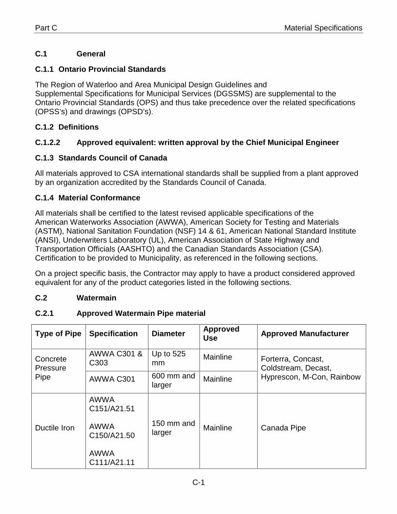
Part C Material Specifications
C.1 General
C.1.1 Ontario Provincial Standards
The Region of Waterloo and Area Municipal Design Guidelines and Supplemental Specifications for Municipal Services (DGSSMS) are supplemental to the Ontario Provincial Standards (OPS) and thus take precedence over the related specifications (OPSS’s) and drawings (OPSD’s).
C.1.2 Definitions
C.1.2.2 Approved equivalent: written approval by the Chief Municipal Engineer
C.1.3 Standards Council of Canada
All materials approved to CSA international standards shall be supplied from a plant approved by an organization accredited by the Standards Council of Canada.
C.1.4 Material Conformance
All materials shall be certified to the latest revised applicable specifications of the American Waterworks Association (AWWA), American Society for Testing and Materials (ASTM), National Sanitation Foundation (NSF) 14 & 61, American National Standard Institute (ANSI), Underwriters Laboratory (UL), American Association of State Highway and Transportation Officials (AASHTO) and the Canadian Standards Association (CSA). Certification to be provided to Municipality, as referenced in the following sections.
On a project specific basis, the Contractor may apply to have a product considered approved equivalent for any of the product categories listed in the following sections.
C.2 Watermain
Approved Watermain Pipe material C.2.1
Type of Pipe Specification Diameter Approved Use Approved Manufacturer
Concrete Pressure Pipe
AWWA C301 & C303
Up to 525 mm
Mainline Forterra, Concast, Coldstream, Decast, Hyprescon, M-Con, Rainbow AWWA C301 600 mm and
larger Mainline
Ductile Iron
AWWA C151/A21.51 AWWA C150/A21.50 AWWA C111/A21.11
150 mm and larger Mainline Canada Pipe
C-1
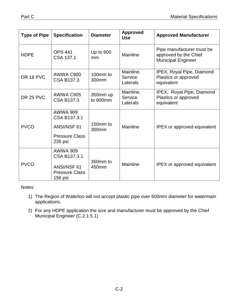
Part C Material Specifications
Type of Pipe Specification Diameter Approved Use Approved Manufacturer
HDPE OPS 441 CSA 137.1
Up to 600 mm Mainline
Pipe manufacturer must be approved by the Chief Municipal Engineer
DR 18 PVC AWWA C900 CSA B137.3
100mm to 300mm
Mainline, Service Laterals
IPEX, Royal Pipe, Diamond Plastics or approved equivalent
DR 25 PVC AWWA C905 CSA B137.3
350mm up to 600mm
Mainline, Service Laterals
IPEX, Royal Pipe, Diamond Plastics or approved equivalent
PVCO
AWWA 909 CSA B137.3.1
ANSI/NSF 61
Pressure Class 235 psi
150mm to 300mm Mainline IPEX or approved equivalent
PVCO
AWWA 909 CSA B137.3.1 ANSI/NSF 61 Pressure Class 156 psi
350mm to 450mm Mainline IPEX or approved equivalent
Notes:
1) The Region of Waterloo will not accept plastic pipe over 600mm diameter for watermain applications.
2) For any HDPE application the size and manufacturer must be approved by the Chief Municipal Engineer (C.2.1.5.1)
C-2
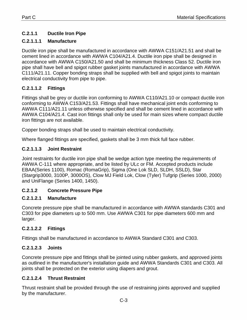
Part C Material Specifications
C.2.1.1 Ductile Iron Pipe C.2.1.1.1 Manufacture
Ductile iron pipe shall be manufactured in accordance with AWWA C151/A21.51 and shall be cement lined in accordance with AWWA C104/A21.4. Ductile iron pipe shall be designed in accordance with AWWA C150/A21.50 and shall be minimum thickness Class 52. Ductile iron pipe shall have bell and spigot rubber gasket joints manufactured in accordance with AWWA C111/A21.11. Copper bonding straps shall be supplied with bell and spigot joints to maintain electrical conductivity from pipe to pipe.
C.2.1.1.2 Fittings
Fittings shall be grey or ductile iron conforming to AWWA C110/A21.10 or compact ductile iron conforming to AWWA C153/A21.53. Fittings shall have mechanical joint ends conforming to AWWA C111/A21.11 unless otherwise specified and shall be cement lined in accordance with AWWA C104/A21.4. Cast iron fittings shall only be used for main sizes where compact ductile iron fittings are not available.
Copper bonding straps shall be used to maintain electrical conductivity.
Where flanged fittings are specified, gaskets shall be 3 mm thick full face rubber.
C.2.1.1.3 Joint Restraint
Joint restraints for ductile iron pipe shall be wedge action type meeting the requirements of AWWA C-111 where appropriate, and be listed by ULc or FM. Accepted products include EBAA(Series 1100), Romac (RomaGrip), Sigma (One Lok SLD, SLDH, SSLD), Star (Stargrip3000, 3100P, 3000OS), Clow MJ Field Lok, Clow (Tyler) Tufgrip (Series 1000, 2000) and UniFlange (Series 1400, 1450).
C.2.1.2 Concrete Pressure Pipe C.2.1.2.1 Manufacture
Concrete pressure pipe shall be manufactured in accordance with AWWA standards C301 and C303 for pipe diameters up to 500 mm. Use AWWA C301 for pipe diameters 600 mm and larger.
C.2.1.2.2 Fittings
Fittings shall be manufactured in accordance to AWWA Standard C301 and C303.
C.2.1.2.3 Joints
Concrete pressure pipe and fittings shall be jointed using rubber gaskets, and approved joints as outlined in the manufacturer's installation guide and AWWA Standards C301 and C303. All joints shall be protected on the exterior using diapers and grout.
C.2.1.2.4 Thrust Restraint
Thrust restraint shall be provided through the use of restraining joints approved and supplied by the manufacturer.
C-3
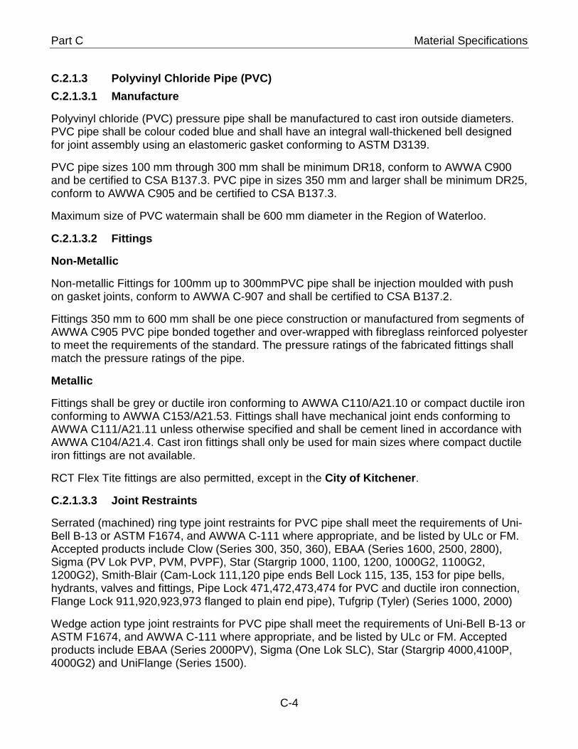
Part C Material Specifications
C.2.1.3 Polyvinyl Chloride Pipe (PVC) C.2.1.3.1 Manufacture
Polyvinyl chloride (PVC) pressure pipe shall be manufactured to cast iron outside diameters. PVC pipe shall be colour coded blue and shall have an integral wall-thickened bell designed for joint assembly using an elastomeric gasket conforming to ASTM D3139.
PVC pipe sizes 100 mm through 300 mm shall be minimum DR18, conform to AWWA C900 and be certified to CSA B137.3. PVC pipe in sizes 350 mm and larger shall be minimum DR25, conform to AWWA C905 and be certified to CSA B137.3.
Maximum size of PVC watermain shall be 600 mm diameter in the Region of Waterloo.
C.2.1.3.2 Fittings
Non-Metallic
Non-metallic Fittings for 100mm up to 300mmPVC pipe shall be injection moulded with push on gasket joints, conform to AWWA C-907 and shall be certified to CSA B137.2.
Fittings 350 mm to 600 mm shall be one piece construction or manufactured from segments of AWWA C905 PVC pipe bonded together and over-wrapped with fibreglass reinforced polyester to meet the requirements of the standard. The pressure ratings of the fabricated fittings shall match the pressure ratings of the pipe.
Metallic
Fittings shall be grey or ductile iron conforming to AWWA C110/A21.10 or compact ductile iron conforming to AWWA C153/A21.53. Fittings shall have mechanical joint ends conforming to AWWA C111/A21.11 unless otherwise specified and shall be cement lined in accordance with AWWA C104/A21.4. Cast iron fittings shall only be used for main sizes where compact ductile iron fittings are not available.
RCT Flex Tite fittings are also permitted, except in the City of Kitchener.
C.2.1.3.3 Joint Restraints
Serrated (machined) ring type joint restraints for PVC pipe shall meet the requirements of Uni-Bell B-13 or ASTM F1674, and AWWA C-111 where appropriate, and be listed by ULc or FM. Accepted products include Clow (Series 300, 350, 360), EBAA (Series 1600, 2500, 2800), Sigma (PV Lok PVP, PVM, PVPF), Star (Stargrip 1000, 1100, 1200, 1000G2, 1100G2, 1200G2), Smith-Blair (Cam-Lock 111,120 pipe ends Bell Lock 115, 135, 153 for pipe bells, hydrants, valves and fittings, Pipe Lock 471,472,473,474 for PVC and ductile iron connection, Flange Lock 911,920,923,973 flanged to plain end pipe), Tufgrip (Tyler) (Series 1000, 2000)
Wedge action type joint restraints for PVC pipe shall meet the requirements of Uni-Bell B-13 or ASTM F1674, and AWWA C-111 where appropriate, and be listed by ULc or FM. Accepted products include EBAA (Series 2000PV), Sigma (One Lok SLC), Star (Stargrip 4000,4100P, 4000G2) and UniFlange (Series 1500).
C-4
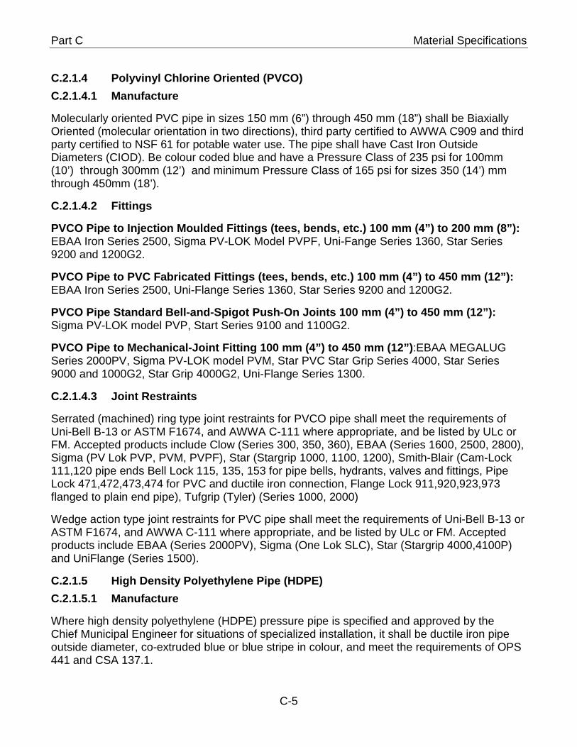
Part C Material Specifications
C.2.1.4 Polyvinyl Chlorine Oriented (PVCO) C.2.1.4.1 Manufacture
Molecularly oriented PVC pipe in sizes 150 mm (6”) through 450 mm (18”) shall be Biaxially Oriented (molecular orientation in two directions), third party certified to AWWA C909 and third party certified to NSF 61 for potable water use. The pipe shall have Cast Iron Outside Diameters (CIOD). Be colour coded blue and have a Pressure Class of 235 psi for 100mm (10’) through 300mm (12’) and minimum Pressure Class of 165 psi for sizes 350 (14’) mm through 450mm (18’).
C.2.1.4.2 Fittings
PVCO Pipe to Injection Moulded Fittings (tees, bends, etc.) 100 mm (4”) to 200 mm (8”): EBAA Iron Series 2500, Sigma PV-LOK Model PVPF, Uni-Fange Series 1360, Star Series 9200 and 1200G2.
PVCO Pipe to PVC Fabricated Fittings (tees, bends, etc.) 100 mm (4”) to 450 mm (12”): EBAA Iron Series 2500, Uni-Flange Series 1360, Star Series 9200 and 1200G2.
PVCO Pipe Standard Bell-and-Spigot Push-On Joints 100 mm (4”) to 450 mm (12”): Sigma PV-LOK model PVP, Start Series 9100 and 1100G2.
PVCO Pipe to Mechanical-Joint Fitting 100 mm (4”) to 450 mm (12”):EBAA MEGALUG Series 2000PV, Sigma PV-LOK model PVM, Star PVC Star Grip Series 4000, Star Series 9000 and 1000G2, Star Grip 4000G2, Uni-Flange Series 1300.
C.2.1.4.3 Joint Restraints
Serrated (machined) ring type joint restraints for PVCO pipe shall meet the requirements of Uni-Bell B-13 or ASTM F1674, and AWWA C-111 where appropriate, and be listed by ULc or FM. Accepted products include Clow (Series 300, 350, 360), EBAA (Series 1600, 2500, 2800), Sigma (PV Lok PVP, PVM, PVPF), Star (Stargrip 1000, 1100, 1200), Smith-Blair (Cam-Lock 111,120 pipe ends Bell Lock 115, 135, 153 for pipe bells, hydrants, valves and fittings, Pipe Lock 471,472,473,474 for PVC and ductile iron connection, Flange Lock 911,920,923,973 flanged to plain end pipe), Tufgrip (Tyler) (Series 1000, 2000)
Wedge action type joint restraints for PVC pipe shall meet the requirements of Uni-Bell B-13 or ASTM F1674, and AWWA C-111 where appropriate, and be listed by ULc or FM. Accepted products include EBAA (Series 2000PV), Sigma (One Lok SLC), Star (Stargrip 4000,4100P) and UniFlange (Series 1500).
C.2.1.5 High Density Polyethylene Pipe (HDPE) C.2.1.5.1 Manufacture
Where high density polyethylene (HDPE) pressure pipe is specified and approved by the Chief Municipal Engineer for situations of specialized installation, it shall be ductile iron pipe outside diameter, co-extruded blue or blue stripe in colour, and meet the requirements of OPS 441 and CSA 137.1.
C-5
Part C Material Specifications
With the use of HDPE pipe post certification is required by the installer and manufacturer to ensure compliance with the manufacturer specifications for the transition connection. Post certification will require a professional engineers stamp.
C.2.1.5.2 Fittings
HDPE pipe fittings shall meet the requirements of OPS 441.
C.2.1.5.3 Joint Restraints
Joints will be restrained in accordance with OPS 441.
Valves C.2.2
C.2.2.1 Gate Valves
Gate valves equal to and less than 300 mm shall be resilient wedge. Gate valves greater than 300 mm can be either resilient wedge or double disk.
Resilient Wedge Valves
Resilient wedge valves equal to and less than 300 mm shall conform to AWWA C509. Resilient wedge valves greater than 300 mm conform to AWWA C509 or AWWA C515.
Resilient wedge valves shall be Mueller, Clow or East Jordan Iron Works for sizes up to and including 300 mm.
Resilient wedge valves shall be Mueller, Clow, East Jordan Iron Works, or AVK for sizes greater than 350mm.
In the City of Guelph only Clow and Mueller are allowed.
Gate valves in sizes 100 mm to 350 mm shall have mechanical joint ends.
All gate valves shall be iron body, bronze mounted with inside screw, non-rising spindle and a 50 mm operating nut that opens by turning counter-clockwise. All gate valves shall be epoxy coated.
Gate valves in sizes 350 mm and larger shall have a minimum 50 mm integral bypass, mechanical joint or flanged ends, waterproof spur gearing and shall be supplied with a shop drawing. The integral bypass must be manufactured as part of the cast body. The integral bypass shall be fabricated with a sufficient offset from the gate valve ensuring that any part of the valve and/or bonnet will not obstruct the operation of the bypass valve.
In the City of Cambridge resilient seat gate valves that include a bypass will not be allowed.
Double Disk Valves
Double disk valves shall conform to AWWA C500.
Double disk valves shall be Clow or Mueller.
C-6
Part C Material Specifications
All gate valves shall be iron body, bronze mounted with inside screw, non-rising spindle and a 50 mm operating nut that opens by turning counter-clockwise. All gate valves shall be epoxy coated.
Double Disk valves shall have mechanical joint ends.
For 400 mm gate valves no spur gearing is required and shall conform to AWWA C515 Ductile Iron. Gate valves in sizes 450 mm and larger shall have an integral bypass, mechanical joint or flanged ends, waterproof spur gearing and shall be supplied with a shop drawing. The integral bypass shall be fabricated with a sufficient offset from the gate valve ensuring that any part of the valve and/or bonnet will not obstruct the operation of the bypass valve.
C.2.2.2 Combination Air and Vacuum Release Valves
Combination air and vacuum release valves shall consist of an air and vacuum valve and an air release valve in single body housing. The body and cover shall be cast iron conforming to ASTM A126 Class B and fusion bonded epoxy coating to meet or exceed C-213. In additional NSF 61 certification is required Combination air and vacuum release valves shall be Golden Anderson Industries (Figure GA945) or ARI D-040 series 1” and 2, D-090 direct bury air valve. The D-040C epoxy cast series shall be used if chambers are required.
Tapping Sleeves C.2.3
Carbon steel tapping sleeves shall be Smith-Blair 622, Mueller H-615, Ford FTSC. Carbon steel tapping sleeves shall have fusion bonded epoxy finish and come equipped with TYPE 304 stainless steel bolts, nuts and washers. In the City of Kitchener, only carbon steel tapping sleeves shall be used.
Stainless steel tapping sleeves shall be Ford FAST, Smith-Blair 663, Mueller H304. Stainless steel tapping sleeves including flanges shall be manufactured from Type 304 stainless steel and shall come equipped with Type 304 stainless steel bolts, nuts and washers.
Valve Chambers C.2.4
C.2.4.1 Cast Iron Maintenance Hole Lids
Cast iron maintenance hole lids shall be as per OPSS 1850 and OPSD 401.010 Type A as manufactured by Bibby, East Jordan and Cedar Infrastructure Products Inc.
C.2.4.2 Adjustment Units
Concrete adjustment units shall be as per OPSS 407 and OPSD 704.01. Precast adjustment units shall be laid in a full bed of mortar with successive units being joined using sealant as recommended by the manufacturer. A minimum of one (1) adjustment unit shall be installed with a minimum height of 75 mm. A maximum of three adjustment units may be installed to a height not in excess of 300 mm.
Concrete brick and mortar shall not be used.
Rubber adjustment units as per OPSS 1853 or HDPE as per OPSS 1854, as manufactured by IPEX under the trade name “Lifesaver”.
C-7
Part C Material Specifications
City of Cambridge, City of Guelph, Township of Wilmot does not permit plastic adjustment units.
C.2.4.3 Safety Post
Safety posts shall be galvanized "Ladder Up" as manufactured by "BILCO", MSU Model 3100.
Line Closure Couplings C.2.5
Line closure coupling shall be Robar Style 1408 (Robar is not accepted in Kitchener), Smith-Blair Style 411, 421, Mueller Viking Johnson Maxifit, Hymax 2000. Line closure coupling will not be allowed in City of Guelph only MJ solid sleeve.
Flange Adaptors C.2.6
Flange adapters shall be Uni-Flange Series 400 or 900, Clow Series 40 and 90, EBAA Iron Megaflange Series 2100, Smith-Blair l Series 913.
Valve Boxes C.2.7
Cast iron valve boxes shall be a screw type box with a No. 6 Base as supplied by Bibby, Mueller or Star. The valve box must be raised to final grade. Road levellers (inside screw type) of any style shall not be installed.
Hydrants C.2.8
Hydrants shall conform to AWWA C502 for Dry Barrel Hydrants and shall open counter clockwise (clockwise in the City of Guelph) by a 32 mm square operating nut. Hydrants shall have tapped drain ports, 150 mm mechanical joint inlet with brass to brass fittings on the main valve seat, two 63.5 mm (2.5 in) hose nozzles spread 180 degrees apart and a 114.3 mm (4.5 in) pumper nozzle with a 100 mm ULC approved Stortz connection. Hydrants shall be connected to the main using 150 mm lead, 150 gate valve, and anchor tee. Hydrants shall be supplied for a minimum 2.3 m depth of trench. A maximum of one hydrant extension (300 mm or less for new development) shall be allowed except in City of Guelph, with authorization of the Chief Municipal Engineer, between the upper and lower hydrant barrels for deeper installations.
Hydrant barrels shall be painted chrome yellow with a high gloss exterior paint over a quick dry oxide primer. Stortz nozzles shall be painted black. The colour(s) of hydrant bonnet and nozzle caps shall be obtained from the Chief Municipal Engineer and painted with a high gloss exterior paint over a quick dry oxide primer. Fire hydrant nozzles shall be greased by manufacturer before coming to site.
All private hydrants must be painted red.
In the City of Kitchener, Township of Wilmot, Township of Woolwich (including Regional projects), and the City of Guelph the watermain diameter in inches to which the hydrant is connected shall be painted in black letters 200 mm high on the face of the hydrant barrel immediately below the pumper nozzle.
C-8
Part C Material Specifications
Hydrants shall be Canada Valve (Century), Mueller (Modern Centurian), or Clow (Brigadier). (City of Cambridge permits East Jordan Watermaster hydrants).
In the Township of Woolwich all hydrants shall be Canada Valve (Century) or Clow Brigadier hydrant.
In the City of Guelph all hydrants shall be McAvity style M-67 or East Jordan Iron Works 5CD250 HYD MJ-2AD WTRMSTR STZ or Mueller Canada Valve Century.
For watermains installed greater than 2 m depth within the City of Kitchener and Township of Wilmot, Canada Valve (Century) hydrants or Clow Brigadier in-line hydrants must be installed.
50 mm and Smaller Service Connections C.2.9
C.2.9.1 Service Pipe
Copper service pipe for services 50 mm and smaller shall be Type “K” soft copper and shall conform to ASTM B88.
Polyethylene service pipe for services 50 mm and smaller shall be certified to CSA B137.1 minimum Series 160, stiffeners shall be used.
Composite pipe for services 25 mm in diameter shall be certified to CSA B137.9 and shall be as manufactured by IPEX under the trade name “Q-Line”.
Blue 904-PEX and Municipex municipal water service tubing for services 50 mm and smaller shall be certified to AWWA C904, CSA B137.5 and NSF 14 and 61. (City of Cambridge only accepts these two products for water services).
All service pipes shall be of new material. Kinked, crushed or distorted tubing will not be accepted.
All service piping in the City of Guelph shall be copper.
C.2.9.2 Service Saddles
Saddles shall be 18 gauge Type 304 stainless steel with AWWA tapered thread. Saddles for PVC pipe shall be double bolted. Saddles shall have a minimum of 50 mm bearing width and shall be fully contoured to the outside of the pipe.
For PVC pipe, service saddles shall be Cambridge Brass (Teck) Series 8405, Ford FS303, Romac, Smith-Blair Series 375 and 373 and come equipped with TYPE 304 stainless steel bolts, nuts and washers.
For metallic pipe, service saddles shall be Smith Blair 313 Epoxy coated and come equipped with TYPE 304 stainless steel bolts, nuts and washers.
City of Cambridge and Township of Wilmot no longer permits the use of service saddles for service connections 50 mm or larger.
C-9
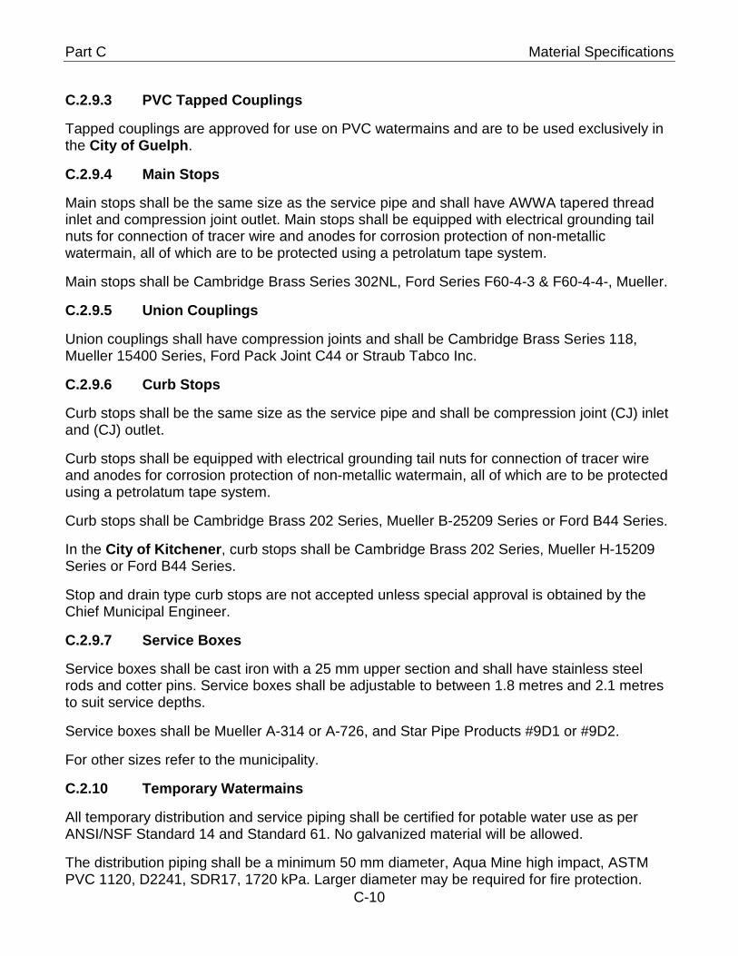
Part C Material Specifications
C.2.9.3 PVC Tapped Couplings
Tapped couplings are approved for use on PVC watermains and are to be used exclusively in the City of Guelph.
C.2.9.4 Main Stops
Main stops shall be the same size as the service pipe and shall have AWWA tapered thread inlet and compression joint outlet. Main stops shall be equipped with electrical grounding tail nuts for connection of tracer wire and anodes for corrosion protection of non-metallic watermain, all of which are to be protected using a petrolatum tape system.
Main stops shall be Cambridge Brass Series 302NL, Ford Series F60-4-3 & F60-4-4-, Mueller.
C.2.9.5 Union Couplings
Union couplings shall have compression joints and shall be Cambridge Brass Series 118, Mueller 15400 Series, Ford Pack Joint C44 or Straub Tabco Inc.
C.2.9.6 Curb Stops
Curb stops shall be the same size as the service pipe and shall be compression joint (CJ) inlet and (CJ) outlet.
Curb stops shall be equipped with electrical grounding tail nuts for connection of tracer wire and anodes for corrosion protection of non-metallic watermain, all of which are to be protected using a petrolatum tape system.
Curb stops shall be Cambridge Brass 202 Series, Mueller B-25209 Series or Ford B44 Series.
In the City of Kitchener, curb stops shall be Cambridge Brass 202 Series, Mueller H-15209 Series or Ford B44 Series.
Stop and drain type curb stops are not accepted unless special approval is obtained by the Chief Municipal Engineer.
C.2.9.7 Service Boxes
Service boxes shall be cast iron with a 25 mm upper section and shall have stainless steel rods and cotter pins. Service boxes shall be adjustable to between 1.8 metres and 2.1 metres to suit service depths.
Service boxes shall be Mueller A-314 or A-726, and Star Pipe Products #9D1 or #9D2.
For other sizes refer to the municipality.
Temporary Watermains C.2.10
All temporary distribution and service piping shall be certified for potable water use as per ANSI/NSF Standard 14 and Standard 61. No galvanized material will be allowed.
The distribution piping shall be a minimum 50 mm diameter, Aqua Mine high impact, ASTM PVC 1120, D2241, SDR17, 1720 kPa. Larger diameter may be required for fire protection.
C-10
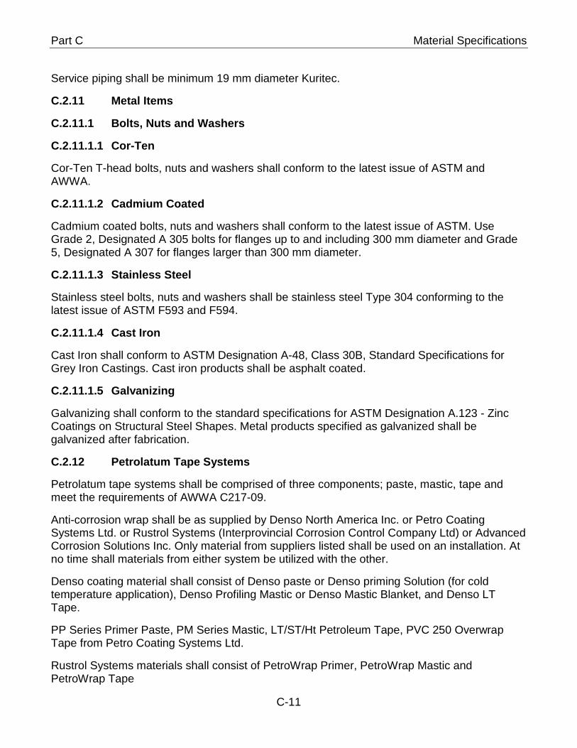
Part C Material Specifications
Service piping shall be minimum 19 mm diameter Kuritec.
Metal Items C.2.11
C.2.11.1 Bolts, Nuts and Washers
C.2.11.1.1 Cor-Ten
Cor-Ten T-head bolts, nuts and washers shall conform to the latest issue of ASTM and AWWA.
C.2.11.1.2 Cadmium Coated
Cadmium coated bolts, nuts and washers shall conform to the latest issue of ASTM. Use Grade 2, Designated A 305 bolts for flanges up to and including 300 mm diameter and Grade 5, Designated A 307 for flanges larger than 300 mm diameter.
C.2.11.1.3 Stainless Steel
Stainless steel bolts, nuts and washers shall be stainless steel Type 304 conforming to the latest issue of ASTM F593 and F594.
C.2.11.1.4 Cast Iron
Cast Iron shall conform to ASTM Designation A-48, Class 30B, Standard Specifications for Grey Iron Castings. Cast iron products shall be asphalt coated.
C.2.11.1.5 Galvanizing
Galvanizing shall conform to the standard specifications for ASTM Designation A.123 - Zinc Coatings on Structural Steel Shapes. Metal products specified as galvanized shall be galvanized after fabrication.
Petrolatum Tape Systems C.2.12
Petrolatum tape systems shall be comprised of three components; paste, mastic, tape and meet the requirements of AWWA C217-09.
Anti-corrosion wrap shall be as supplied by Denso North America Inc. or Petro Coating Systems Ltd. or Rustrol Systems (Interprovincial Corrosion Control Company Ltd) or Advanced Corrosion Solutions Inc. Only material from suppliers listed shall be used on an installation. At no time shall materials from either system be utilized with the other.
Denso coating material shall consist of Denso paste or Denso priming Solution (for cold temperature application), Denso Profiling Mastic or Denso Mastic Blanket, and Denso LT Tape.
PP Series Primer Paste, PM Series Mastic, LT/ST/Ht Petroleum Tape, PVC 250 Overwrap Tape from Petro Coating Systems Ltd.
Rustrol Systems materials shall consist of PetroWrap Primer, PetroWrap Mastic and PetroWrap Tape
C-11
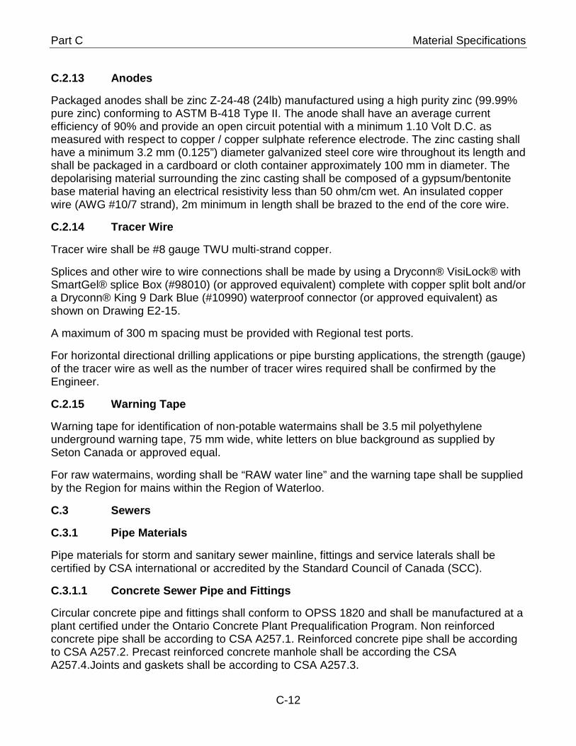
Part C Material Specifications
Anodes C.2.13
Packaged anodes shall be zinc Z-24-48 (24lb) manufactured using a high purity zinc (99.99% pure zinc) conforming to ASTM B-418 Type II. The anode shall have an average current efficiency of 90% and provide an open circuit potential with a minimum 1.10 Volt D.C. as measured with respect to copper / copper sulphate reference electrode. The zinc casting shall have a minimum 3.2 mm (0.125”) diameter galvanized steel core wire throughout its length and shall be packaged in a cardboard or cloth container approximately 100 mm in diameter. The depolarising material surrounding the zinc casting shall be composed of a gypsum/bentonite base material having an electrical resistivity less than 50 ohm/cm wet. An insulated copper wire (AWG #10/7 strand), 2m minimum in length shall be brazed to the end of the core wire.
Tracer Wire C.2.14
Tracer wire shall be #8 gauge TWU multi-strand copper.
Splices and other wire to wire connections shall be made by using a Dryconn® VisiLock® with SmartGel® splice Box (#98010) (or approved equivalent) complete with copper split bolt and/or a Dryconn® King 9 Dark Blue (#10990) waterproof connector (or approved equivalent) as shown on Drawing E2-15.
A maximum of 300 m spacing must be provided with Regional test ports.
For horizontal directional drilling applications or pipe bursting applications, the strength (gauge) of the tracer wire as well as the number of tracer wires required shall be confirmed by the Engineer.
Warning Tape C.2.15
Warning tape for identification of non-potable watermains shall be 3.5 mil polyethylene underground warning tape, 75 mm wide, white letters on blue background as supplied by Seton Canada or approved equal.
For raw watermains, wording shall be “RAW water line” and the warning tape shall be supplied by the Region for mains within the Region of Waterloo.
C.3 Sewers
C.3.1 Pipe Materials
Pipe materials for storm and sanitary sewer mainline, fittings and service laterals shall be certified by CSA international or accredited by the Standard Council of Canada (SCC).
C.3.1.1 Concrete Sewer Pipe and Fittings
Circular concrete pipe and fittings shall conform to OPSS 1820 and shall be manufactured at a plant certified under the Ontario Concrete Plant Prequalification Program. Non reinforced concrete pipe shall be according to CSA A257.1. Reinforced concrete pipe shall be according to CSA A257.2. Precast reinforced concrete manhole shall be according the CSA A257.4.Joints and gaskets shall be according to CSA A257.3.
C-12
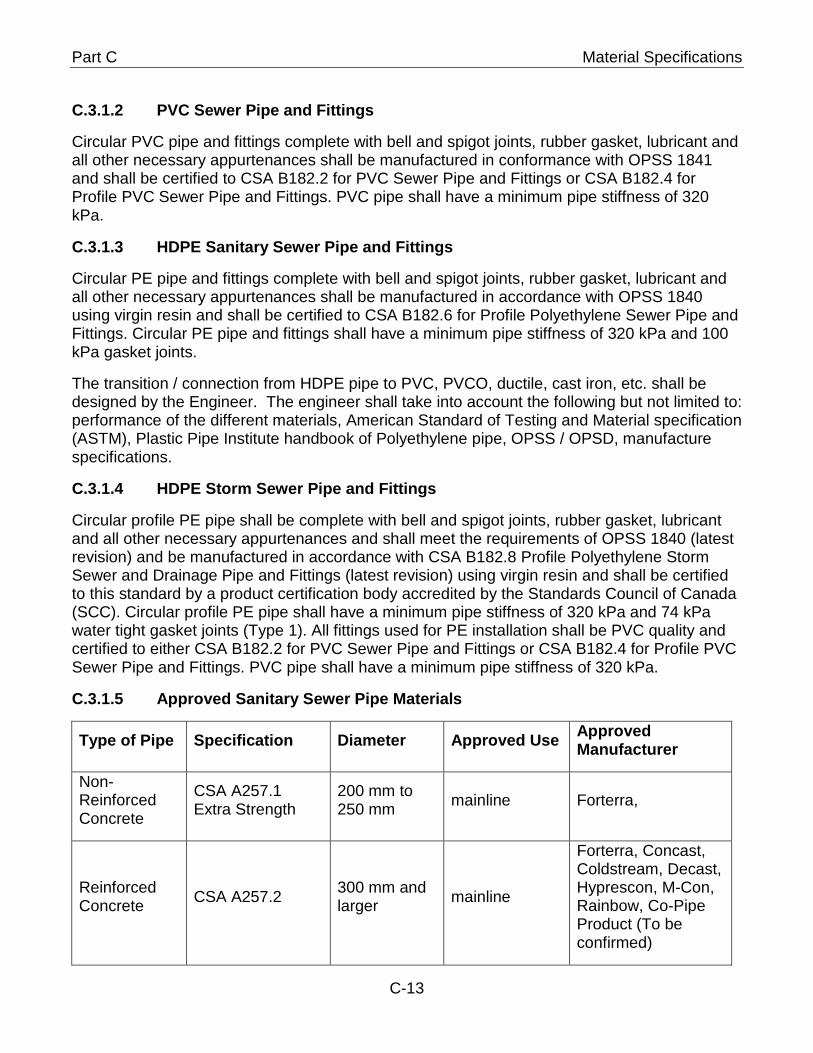
Part C Material Specifications
C.3.1.2 PVC Sewer Pipe and Fittings
Circular PVC pipe and fittings complete with bell and spigot joints, rubber gasket, lubricant and all other necessary appurtenances shall be manufactured in conformance with OPSS 1841 and shall be certified to CSA B182.2 for PVC Sewer Pipe and Fittings or CSA B182.4 for Profile PVC Sewer Pipe and Fittings. PVC pipe shall have a minimum pipe stiffness of 320 kPa.
C.3.1.3 HDPE Sanitary Sewer Pipe and Fittings
Circular PE pipe and fittings complete with bell and spigot joints, rubber gasket, lubricant and all other necessary appurtenances shall be manufactured in accordance with OPSS 1840 using virgin resin and shall be certified to CSA B182.6 for Profile Polyethylene Sewer Pipe and Fittings. Circular PE pipe and fittings shall have a minimum pipe stiffness of 320 kPa and 100 kPa gasket joints.
The transition / connection from HDPE pipe to PVC, PVCO, ductile, cast iron, etc. shall be designed by the Engineer. The engineer shall take into account the following but not limited to: performance of the different materials, American Standard of Testing and Material specification (ASTM), Plastic Pipe Institute handbook of Polyethylene pipe, OPSS / OPSD, manufacture specifications.
C.3.1.4 HDPE Storm Sewer Pipe and Fittings
Circular profile PE pipe shall be complete with bell and spigot joints, rubber gasket, lubricant and all other necessary appurtenances and shall meet the requirements of OPSS 1840 (latest revision) and be manufactured in accordance with CSA B182.8 Profile Polyethylene Storm Sewer and Drainage Pipe and Fittings (latest revision) using virgin resin and shall be certified to this standard by a product certification body accredited by the Standards Council of Canada (SCC). Circular profile PE pipe shall have a minimum pipe stiffness of 320 kPa and 74 kPa water tight gasket joints (Type 1). All fittings used for PE installation shall be PVC quality and certified to either CSA B182.2 for PVC Sewer Pipe and Fittings or CSA B182.4 for Profile PVC Sewer Pipe and Fittings. PVC pipe shall have a minimum pipe stiffness of 320 kPa.
C.3.1.5 Approved Sanitary Sewer Pipe Materials
Type of Pipe Specification Diameter Approved Use Approved Manufacturer
Non-Reinforced Concrete
CSA A257.1 Extra Strength
200 mm to 250 mm mainline Forterra,
Reinforced Concrete CSA A257.2 300 mm and
larger mainline
Forterra, Concast, Coldstream, Decast, Hyprescon, M-Con, Rainbow, Co-Pipe Product (To be confirmed)
C-13
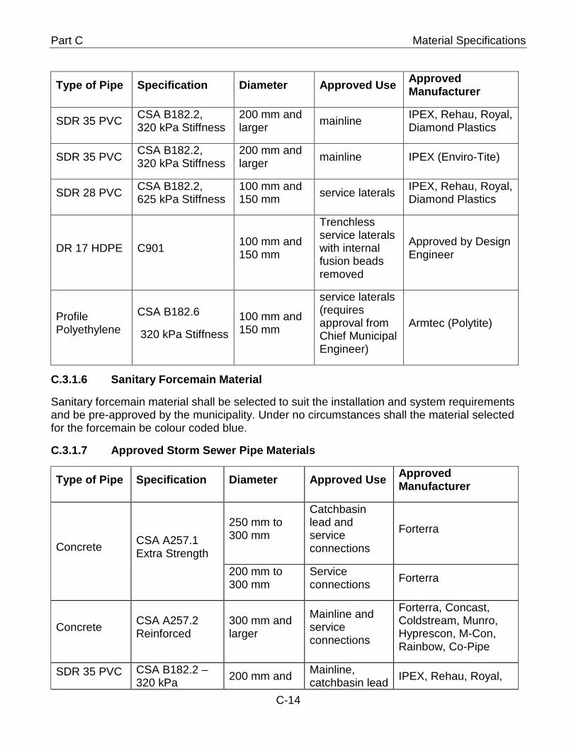
Part C Material Specifications
Type of Pipe Specification Diameter Approved Use Approved Manufacturer
SDR 35 PVC CSA B182.2, 320 kPa Stiffness
200 mm and larger mainline IPEX, Rehau, Royal,
Diamond Plastics
SDR 35 PVC CSA B182.2, 320 kPa Stiffness
200 mm and larger mainline IPEX (Enviro-Tite)
SDR 28 PVC CSA B182.2, 625 kPa Stiffness
100 mm and 150 mm service laterals IPEX, Rehau, Royal,
Diamond Plastics
DR 17 HDPE C901 100 mm and 150 mm
Trenchless service laterals with internal fusion beads removed
Approved by Design Engineer
Profile Polyethylene
CSA B182.6
320 kPa Stiffness 100 mm and 150 mm
service laterals (requires approval from Chief Municipal Engineer)
Armtec (Polytite)
C.3.1.6 Sanitary Forcemain Material
Sanitary forcemain material shall be selected to suit the installation and system requirements and be pre-approved by the municipality. Under no circumstances shall the material selected for the forcemain be colour coded blue.
C.3.1.7 Approved Storm Sewer Pipe Materials
Type of Pipe Specification Diameter Approved Use Approved Manufacturer
Concrete CSA A257.1 Extra Strength
250 mm to 300 mm
Catchbasin lead and service connections
Forterra
200 mm to 300 mm
Service connections Forterra
Concrete CSA A257.2 Reinforced
300 mm and larger
Mainline and service connections
Forterra, Concast, Coldstream, Munro, Hyprescon, M-Con, Rainbow, Co-Pipe
SDR 35 PVC CSA B182.2 – 320 kPa 200 mm and Mainline,
catchbasin lead IPEX, Rehau, Royal,
C-14
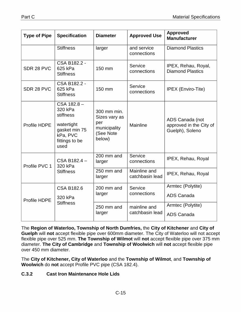
Part C Material Specifications
Type of Pipe Specification Diameter Approved Use Approved Manufacturer
Stiffness larger and service connections
Diamond Plastics
SDR 28 PVC CSA B182.2 - 625 kPa Stiffness
150 mm Service connections
IPEX, Rehau, Royal, Diamond Plastics
SDR 28 PVC CSA B182.2 - 625 kPa Stiffness
150 mm Service connections IPEX (Enviro-Tite)
Profile HDPE
CSA 182.8 – 320 kPa stiffness
watertight gasket min 75 kPa, PVC fittings to be used
300 mm min. Sizes vary as per municipality (See Note below)
Mainline ADS Canada (not approved in the City of Guelph), Soleno
Profile PVC 1 CSA B182.4 – 320 kPa Stiffness
200 mm and larger
Service connections IPEX, Rehau, Royal
250 mm and larger
Mainline and catchbasin lead IPEX, Rehau, Royal
Profile HDPE
CSA B182.6
320 kPa Stiffness
200 mm and larger
Service connections
Armtec (Polytite)
ADS Canada
250 mm and larger
mainline and catchbasin lead
Armtec (Polytite)
ADS Canada
The Region of Waterloo, Township of North Dumfries, the City of Kitchener and City of Guelph will not accept flexible pipe over 600mm diameter. The City of Waterloo will not accept flexible pipe over 525 mm. The Township of Wilmot will not accept flexible pipe over 375 mm diameter. The City of Cambridge and Township of Woolwich will not accept flexible pipe over 450 mm diameter.
The City of Kitchener, City of Waterloo and the Township of Wilmot, and Township of Woolwich do not accept Profile PVC pipe (CSA 182.4).
C.3.2 Cast Iron Maintenance Hole Lids
C-15
Part C Material Specifications
Cast iron maintenance hole lids shall be as per OPSS 1850 and OPSD 401.010 Type “A” Closed Cover as manufactured by Bibby, East Jordan, Domcast or Star Pipe Canada. In the City of Kitchener Type “B” Cover is to be used for storm sewer applications.
All new maintenance holes shall be fitted with self-adjusting manhole frame and cover from East Jordan Iron Works (Product No. 00302201), Bibby-Ste-Croix (Auto Stable C-50M-ONT) or Star Pipe Products MH24SL or Cedar Infratruture Products Inc. or approved equivalent on Region of Waterloo, City of Kitchener, City of Waterloo, and Township of Woolwich roadways. All self-levellers to be supplied with rubber gaskets.
C.3.3 Cast Iron Catchbasin Frames and Grates
Cast iron catchbasin frames and grates shall conform to OPSS 1850 and shall be manufactured by Bibby, East Jordan or Star or Cedar Infrastructure Products Inc. Catchbasin frames and grates shall be as per:
• SSMS E4-03 and E4-041 and E4-042 on all Region of Waterloo roadways; or as directed by the Municipality
• OPSD 400.10 on the City of Cambridge and Waterloo roadways
• OPSD 400.11 on the City of Kitchener roadways
• SSMS E4-01 on the Township of Wilmot and Township of Woolwich roadways
• OPSD 400.010 on the City of Guelph roadways
C.3.4 Maintenance Hole and Catchbasin Adjustment Units
Refer to section D.3.3.2 for adjustment unit installation.
Concrete brick and mortar shall not be used.
The use of rubber adjustment units as per OPSS 1853 or HDPE OPSS 1854, as manufactured by IPEX under the trade name “Lifesaver” is acceptable.
The City of Cambridge will only accept concrete adjustment units conforming to OPSS 407.
C.3.5 Slotted Pipe Drain
Slotted drain pipe shall be fabricated from galvanized steel in accordance with AASHTO M-36 and shall have a minimum wall thickness of 1.6 mm. Slotted drain pipe shall be as manufactured by Armtec.
C.3.6 Flexible Couplings
Flexible couplings shall be as supplied by Fernco, Mission or Preper.
C.3.7 Watertight Connectors
Watertight connectors shall be resilient connectors and applied to flexible pipe for sanitary and storm sewers. Concrete sanitary sewers shall have resilient connectors.
C-16
Part C Material Specifications
All pipe to maintenance hole shall meet and or exceed ASTM C 923, Standard Specification for Resilient Connectors Between Reinforced Concrete Manholes, Structures, Pipes and Laterals. All mechanical devices if employed, including castings, bolt assemblies shall use non-magnetic 300 series stainless steel with no welds or rivets in the sleeve or bolt assembly. Take up clamps shall use non-magnetic 304 series stainless steel. Plastic parts or components aren’t allowed. Connector sizes 700 mm (28”) and above shall employ multiple adjusters to better equalize the rubber and provide a uniform seal. The installation of the connector shall be accomplished at initial install and shall require no additional adjustments or installation at a later time to provide a watertight seal. Catchbasins shall not have factory installed boots but shall have a sand collar fitting.
Sand collars shall be used on flexible pipe when the use of a resilient connector is not possible.
C-17

Region of Waterloo and Area Municipalities
Design Guidelines and Supplemental Specifications
For Municipal Services
Part D
Construction Specifications
Construction Specifications
Table of Contents
D.1 General ................................................................................................................. 1 D.1.1 Ontario Provincial Standards ....................................................................... 1 D.1.2 Special Conditions or Special Provisions ................................................... 1 D.1.3 Definitions ...................................................................................................... 1 D.1.4 Environment ................................................................................................... 1
D.1.4.1 Blasting .................................................................................................... 1
D.1.4.2 Smog Alert ............................................................................................... 1
D.1.4.3 Discharge to Sewers ................................................................................ 2 D.1.5 Traffic Control ................................................................................................ 2 D.1.6 Safety Requirements ..................................................................................... 2 D.1.7 Materials ......................................................................................................... 2 D.1.8 Layout ............................................................................................................. 2 D.1.9 Pre-Condition Survey .................................................................................... 2 D.1.10 Site Preparation ............................................................................................. 2
D.1.10.1 Clearing and Grubbing ............................................................................. 2
D.1.10.2 Removals ................................................................................................. 2
D.1.10.3 Demolition ................................................................................................ 3 D.1.11 Excavation ...................................................................................................... 3
D.1.11.1 Temporary Stockpiling of Material ........................................................... 3
D.1.11.2 Surplus Excavated Material ..................................................................... 3
D.1.11.3 Width of Trenches .................................................................................... 3
D.1.11.4 Open Trenching ....................................................................................... 3
D.1.11.5 Trenchless Installations ........................................................................... 4 D.1.12 Backfilling and Compaction .......................................................................... 4
D.1.12.1 Bedding .................................................................................................... 4
D.1.12.2 Backfill Material ........................................................................................ 4
D.1.12.3 Imported Backfill ...................................................................................... 4
D.1.12.4 Backfill under Utilities ............................................................................... 4 D.2 Watermains .......................................................................................................... 5
D.2.1 Ontario Provincial Standard Specifications ................................................ 5 D.2.2 Project Coordination ..................................................................................... 5
D.2.2.1 Notification of Operating Authority ........................................................... 5
D.2.2.2 Notification of Local Water Users ............................................................. 5
D.2.2.3 Shutting Down or Charging Mains ........................................................... 5
D.2.2.4 Water Interruption .................................................................................... 6
D.2.2.5 Requirements Outside of Contract Limits ................................................ 6 D.2.3 Temporary Water Distribution System ......................................................... 6
D.2.3.1 General .................................................................................................... 6
D.2.3.2 Layout Plan .............................................................................................. 7
D.2.3.3 Minimum Diameter ................................................................................... 8
D.2.3.4 Location ................................................................................................... 8
D.2.3.5 Isolation Valves ........................................................................................ 8
D.2.3.6 Source Water Connection ........................................................................ 8
D.2.3.7 Pressure Testing and Leakage ................................................................ 9
D.2.3.8 Chlorine Residual and Bacteriological Testing ......................................... 9
D.2.3.9 Temporary Sampling Ports and Flushing ............................................... 10
D.2.3.10 Service Connections .............................................................................. 10
D.2.3.11 Operation ............................................................................................... 10
D.2.3.12 Off-hours Corrective Action .................................................................... 11
D.2.3.13 Relocation of the Temporary Distribution System .................................. 11 D.2.4 Source Water Connection For New Water System ................................... 11
D.2.4.1 Connection Plan .................................................................................... 11
D.2.4.2 Physical Separation ............................................................................... 11
D.2.4.3 Use of Fire Hydrants .............................................................................. 11
D.2.4.4 Temporary Connection and Backflow Preventer .................................... 12
D.2.4.5 Connection Point Relocation .................................................................. 12 D.2.5 Watermain Installation ................................................................................. 12
D.2.5.1 Pipeline Layout Drawings ...................................................................... 13
D.2.5.2 Watermain Laying Tolerance ................................................................. 13
D.2.5.3 Joint and Pipe Deflection ....................................................................... 13
D.2.5.4 Joint and Thrust Restraint ...................................................................... 13
D.2.5.5 Tracer Wire ............................................................................................ 14
D.2.5.6 Corrosion Protection .............................................................................. 14
D.2.5.6.1 Metallic Mains ........................................................................................ 15
D.2.5.6.2 Wire Connections................................................................................... 15
D.2.5.6.3 Anode Offset .......................................................................................... 15
D.2.5.7 Bolts, Nuts and Washers ....................................................................... 15
D.2.5.8 Warning Tape ........................................................................................ 16
D.2.5.9 Measurement and Payment ................................................................... 16
D.2.5.10 Wrapping ............................................................................................... 16 D.2.6 Hydrant, Valve and Chamber Installation .................................................. 16
D.2.6.1 Setting of Hydrants ................................................................................ 16
D.2.6.2 Hydrant Valves ...................................................................................... 17
D.2.6.3 Minimum Clearance ............................................................................... 17
D.2.6.4 Chambers .............................................................................................. 17
D.2.6.5 Valve Box and Chamber Lid Adjustment Tolerance .............................. 18
D.2.6.6 Bolts, Nuts and Washers ....................................................................... 18 D.2.7 Service Connections ................................................................................... 18
D.2.7.1 Installation .............................................................................................. 18
D.2.7.2 Live Tapping .......................................................................................... 19
D.2.7.3 Tapping for Connections 100 mm and Larger ........................................ 19
D.2.7.4 Pressure Testing .................................................................................... 19
D.2.7.5 Disinfection ............................................................................................ 20
D.2.7.6 Union Couplings .................................................................................... 20
D.2.7.7 Marker .................................................................................................... 20
D.2.7.8 Thrust Restraint ..................................................................................... 20 D.2.8 Watermain Commissioning ......................................................................... 21
D.2.8.1 General .................................................................................................. 21
D.2.8.2 Swabbing ............................................................................................... 22
D.2.8.3 Hydrostatic Pressure Test ...................................................................... 22
D.2.8.4 Disinfection ............................................................................................ 22
D.2.8.5 De-chlorination ....................................................................................... 23
D.2.8.6 Chlorine Residual & Bacteriological Testing .......................................... 23
D.2.8.7 Final Connection to Existing Water System ........................................... 28
D.2.8.8 Tracer Wire Conductivity Test ................................................................ 29
D.2.8.9 Valve Positioning ................................................................................... 30 D.3 Sewers................................................................................................................ 30
D.3.1 Ontario Provincial Standard Specifications .............................................. 30 D.3.2 Sewer Installation ........................................................................................ 30
D.3.2.1 Laying Tolerance ................................................................................... 30 D.3.3 Maintenance Hole and Catchbasin Installation ......................................... 31
D.3.3.1 Maintenance Hole Lid Adjustment Tolerance ........................................ 31
D.3.3.2 Adjustment Unit Parging ........................................................................ 31
D.3.3.3 Maintenance Holes Connections ........................................................... 31
D.3.3.4 Maintenance Hole Benching .................................................................. 32
D.3.4.1 Installation .............................................................................................. 32
D.3.4.2 Minimum Pipe Length ............................................................................ 32
D.3.4.3 Line and Grade ...................................................................................... 32
D.3.4.4 Mainline Connection .............................................................................. 32
D.3.4.5 Maintenance Hole Connections ............................................................. 33
D.3.4.6 Caps ...................................................................................................... 33
D.3.4.7 Markers .................................................................................................. 33 D.3.4 Commissioning ............................................................................................ 33
D.3.5.1 General .................................................................................................. 33
D.3.5.2 Leakage ................................................................................................. 33
D.3.5.3 Visual Inspection .................................................................................... 34
D.3.5.4 Cleaning and Flushing ........................................................................... 34
D.3.5.5 Deflection ............................................................................................... 35
D.3.5.6 CCTV Inspections .................................................................................. 35
Part D Construction Specifications
D.1 General
D.1.1 Ontario Provincial Standards
All work shall be carried out in accordance with Ontario Provincial Standards (OPS) as referenced herein or in the Contract Documents. The Region of Waterloo and Area Municipal Design Guidelines and Supplemental Specifications for Municipal Services (SSMS or DGSSMS) are supplemental to the Ontario Provincial Standards and thus take precedence over the related specifications (OPSS’s) and drawings (OPSD’s).
D.1.2 Special Conditions or Special Provisions
These specifications may be altered on a project or Municipal specific basis within the Special Conditions or Special Provisions section of the Construction Contract.
D.1.3 Definitions
This section is intentionally left blank.
D.1.4 Environment
D.1.4.1 Blasting
At no time is blasting or tunnelling to be undertaken without the prior written approval of the Chief Municipal Engineer.
D.1.4.2 Smog Alert
In the event of a Smog Alert, the Contractor shall work in accordance with the guidelines as specified below. Only Smog Alerts issued by the Municipality by 3:00 p.m. of the previous day will be applicable. A Smog Day Alert is issued with the Air Quality Index (AQI) as reported by the MOECC is 50 or greater.
The Contractor shall take the following actions:
• Schedule the use of gas powered equipment to the morning hours
• Re-fuel equipment before 8:30 a.m. and after 3:00 p.m.
• Reschedule jobs that require the use of oil based paints, solvents and other organic based compounds. This also includes the use of cleaning solvents during daylight hours
• Avoid unnecessary idling of vehicle engines
• Reschedule any welding activities
• Reduce the use of gas-powered lawn mowers, generators, power washers, hedge trimmers, concrete saws, etc.
If, in the opinion of the Contract Administrator, a Smog Alert day restricts work related to a controlling operation from being completed, an extension of the specified working day allowance may be considered.
D-1
Part D Construction Specifications
D.1.4.3 Discharge to Sewers
The discharge of water to the storm and sanitary sewers regardless of the source of water shall be as per the Municipal by-law.
D.1.5 Traffic Control
The Contractor’s operations shall conform to the Ontario Traffic Manual (OTM) Book 7 (Temporary Conditions).
It will be the Contractor’s responsibility to obtain the latest publication of Occupational Health and Safety Act (OHSA) and OTM Book 7.
D.1.6 Safety Requirements
No excavations regulated under provincial legislation shall commence until the Contractor has notified the Ministry of Labour in accordance with the Provincial Occupational Health and Safety Act and Regulations for Construction Projects, and no excavation shall commence on any existing street (with the exception of the City of Guelph) without a “Road Occupancy Permit” issued by the Municipality having jurisdiction.
D.1.7 Materials
All materials shall be as listed in Part C - Materials of these specifications or the Contract Documents.
A complete list of materials to be installed shall be provided to the Contractor Administrator prior to the start of construction or as specified in the Contract Documents.
D.1.8 Layout
Construction layout will be specified in the Contract Documents.
D.1.9 Pre-Condition Survey
If specified in the Contract Documents, this sub-section provides direction on what pre-construction activities are necessary.
For reconstruction projects, or where existing structures may be impacted, a pre-condition survey shall be completed to the Municipality’s standards.
D.1.10 Site Preparation
This sub-section provides direction on site preparation operations, which may be required prior to initiating any excavation activities necessary for the installation of the works.
D.1.10.1 Clearing and Grubbing
Clearing and grubbing as specified in the Contract Documents and OPSS 201
D.1.10.2 Removals
Removals as specified in the Contract Documents and OPSS 490
D-2
Part D Construction Specifications
D.1.10.3 Demolition
Demolition as specified in the Contract Documents
D.1.11 Excavation
This sub-section provides direction on excavation operations that the Contractor is required to perform to meet the technical requirements of the Contract Documents.
D.1.11.1 Temporary Stockpiling of Material
When insufficient space is available to allow placing of excavated material on the right-of-way, the Contractor shall load, haul and stockpile such excavated material at an offsite location arranged for by and at the sole expense of the Contractor. When the underground work has been installed, the Contractor shall, at the Contractor’s own expense, bring back as much acceptable material so removed as may be required to properly refill the trench.
All surplus materials shall be disposed in accordance with the contract requirements for impacted materials and current regulations.
The Contractor shall provide a letter from the temporary offsite disposal site property owner accepting the material, placement, grading and restoration and releasing the Municipality of any responsibility to the satisfaction of the Municipality and OPSS 180.
D.1.11.2 Surplus Excavated Material
Material excavated during the construction of the works, which is surplus to the requirements for backfilling and which cannot be disposed on Municipal property adjacent to the site, as determined by the Contract Administer, shall be disposed at locations arranged for, by, and at the sole expense of the Contractor.
The Contractor shall provide a letter from the disposal site property owner accepting the material, placement and grading and releasing the Municipality of any responsibility to the satisfaction of the Municipality and OPSS 180.
D.1.11.3 Width of Trenches
Unless otherwise specified, the trench width at the top of the pipe shall be as specified in the SSMS drawings.
Trench side slopes shall conform to the requirements of the Occupational Health and Safety Act.
D.1.11.4 Open Trenching
Unless otherwise authorized in the Contract Documents or on the Construction Drawings, all underground works shall be constructed in open trench. When required or where designated, by the Contract Administrator to minimize surface disturbance, the Contractor shall use close sheeting or a trench box in accordance with the Occupational Health & Safety Act.
The Contractor shall not continue excavation and/or pipe installation where any part of a trench is left open for an unreasonable length of time in the opinion of the Contract Administrator. The Contractor shall, when directed by the Contract Administrator, refill the trench or part thereof,
D-3
Part D Construction Specifications
and temporarily resurface the same, at the Contractor’s own expense, and shall not again open such trench or part thereof until the Contractor is ready to proceed with the construction of the underground works.
D.1.11.5 Trenchless Installations
Trenchless installations shall be conducted in accordance with the Contract Documents and the Construction Drawings.
The Contractor may elect to utilize trenchless techniques; however, written approval shall be obtained from the Contract Administrator and the Chief Municipal Engineer.
D.1.12 Backfilling and Compaction
This sub-section provides direction on the placement, backfilling and compaction operations that the Contractor is required to perform to meet the technical requirements of the Contract Documents. Backfilling and compaction shall be carried out in a manner to not damage or dislodge the pipe, associated appurtenances, or utilities.
D.1.12.1 Bedding
The Contractor shall confirm the specified type of bedding and obtain the Contract Administrator’s approval before any backfilling operations are undertaken. Backfilling and compaction shall be carried out continuously and immediately after the specified bedding material has been placed and approved by the Contract Administrator.
Bedding material shall be Granular “A” compacted to 100% Standard Proctor Maximum Dry Density. Recycled asphalt shall not be used wholly or in any part of the bedding material.
Where conditions warrant, and with the Contractor Administrator’s approval, the Contractor shall sub-excavate to achieve a more stable base and replace with Granular “A’ compacted to 100% Standard Proctor Maximum Dry Density.
D.1.12.2 Backfill Material
The trench above the specified bedding shall be backfilled with approved native material excavated from the trench or obtained elsewhere on the project, and shall be placed in layers not exceeding 300 mm, and shall be compacted to 98% Standard Proctor Maximum Dry Density.
D.1.12.3 Imported Backfill
Where approved native material is not suitable in the sole opinion of the Contract Administrator, and there is no approved native surplus material from other sections of the work, the Contract Administrator may order that the trench be wholly or partially backfilled with imported materials as approved by the Contract Administrator.
D.1.12.4 Backfill under Utilities
Unless otherwise specified in the Contract Documents or by the Utility having justification, backfill the trench under existing utilities using controlled density fill approved by the Contract Administrator. Extend the fill from the bottom of the trench or that level at which full compaction is achieved as specified to the underside of the utility being supported. The controlled density
D-4
Part D Construction Specifications
fill shall in all instances be placed across the entire trench width of the trench and shall extend a minimum of 150 mm on each side of the utility being supported measured along the length of the trench. Wrap the existing utility with a polyethylene bond breaker.
D.2 Watermains
This section provides direction on project coordination and notification requirements and also describes how watermains, service connections and associated appurtenances are to be installed, commissioned and tested to meet the technical requirements of the Contract Documents.
D.2.1 Ontario Provincial Standard Specifications
The watermain works shall be installed in accordance with OPSS 441 and 442 except as amended or extended herein.
D.2.2 Project Coordination
This sub-section defines responsibility with respect to project coordination objectives required prior to, during and following the water system construction.
D.2.2.1 Notification of Operating Authority
The Contractor shall notify the local operating authority of the water distribution system at least 48 hours prior to the commencement of any work that may affect the existing water distribution system.
D.2.2.2 Notification of Local Water Users
The Contractor shall notify all local water users who will be affected by the shutting down of any section of a permanent or temporary watermain system. Arrangements shall be made with the local operating authority regarding the methodology of notification.
The Contractor shall provide written hand delivered notification of the water service interruption at least two (2) full working days prior to the interruption to all affected water users. The notification letter / door hanger shall be to the local operating authority’s standards and approved by the local operating authority prior to distribution.
The notification shall include:
• 24 hr. Contractor contact name(s) and phone number(s)
• Start date and time
• Duration of service interruption
At their discretion, the Municipality may provide door hangers or similar notices to the Contractor for distribution.
D.2.2.3 Shutting Down or Charging Mains
Only authorized operating authority personnel shall operate valves on existing watermains for the purpose of controlling water. No person other than the authorized operating authority
D-5
Part D Construction Specifications
personnel shall shut down or charge any section of existing watermain or operate any valve for the purpose of controlling water from existing watermains.
The Contractor shall provide the local operating authority with at least two (2) full working days advance notice when a change in control of the water is required. All necessary water supply interruptions shall be scheduled in cooperation with the local operating authority during normal working hours. If the Contractor elects to have the operating authority make system changes after normal working hours, the Contractor may be responsible for additional costs.
The Contractor shall operate only those valves, hydrants and curb stops installed in their Contract during the construction period prior to final connection to the existing distribution system. After final connection, only the local operating authority may operate the system.
D.2.2.4 Water Interruption
The Contractor shall take all measures reasonable to ensure that water service is not interrupted before 9:00 a.m. and after 4:00 p.m. The Chief Municipal Engineer reserves the right to require that specified water users not be interrupted at all or that the interruption is limited to a certain time span. The Chief Municipal Engineer also reserves the right to require that any water interruptions be conducted outside of normal working hours.
D.2.2.5 Requirements Outside of Contract Limits
The Contractor shall ensure that construction activities will not unduly affect, in the opinion of the Municipality, the water distribution system outside of the contract limit.
D.2.3 Temporary Water Distribution System
D.2.3.1 General
In the event that existing water users must be taken out of service for a period exceeding eight (8) hours, or at the discretion of the Contract Administrator or the Chief Municipal Engineer, a temporary water distribution system shall be provided to all interrupted users.
This sub-section provides direction on the installation of Temporary Water Distribution System that the Contractor is required to perform to meet the technical requirements of the Contract Documents.
The temporary water system shall remain in service and not be removed until the Chief Municipal Engineer has approved the final connection of the new watermain to the existing system and authorized removal of the temporary water system.
The temporary watermain must run with a low flow once commissioned to maintain the quality of the water. The water is to be dechlorinated and discharged to a storm inlet as per CSA B64.10 (latest version).
Existing fire hydrants removed from service shall be bagged as out of service in accordance with the directions of the municipality.
The ends of the temporary watermain should be capped when arriving on site and kept capped until placed in use.
D-6
Part D Construction Specifications
The watermain commissioning plan template in Part E is to be followed for temporary watermain plans (drawing to be included).
The inspector shall update the contract administrator whenever the following occurs:
• Buildings are placed on temporary water
• Buildings are taken off of temporary water
• Any changes in the sampling plan/ locations for approval prior to the change
• Any changes in the source for approval prior to the change
• Any breaches of the temporary water supply as soon as possible
D.2.3.2 Layout Plan
Prior to installing the temporary water distribution system, a detailed plan of the system shall be provided by the Contractor and approved by the Chief Municipal Engineer. Allow two weeks for review and approval. The plan shall detail:
• Connection points to municipal system
• Backflow preventor size
• Materials for mainline and services
• Mainline and service sizes
• Sampling points
• List of addresses of affected properties including unit, apartment and suite numbers
• Emergency procedures and After Hours contact information
• Fire lines and any dead ends shall be identified and be blown out
• Other related information about the temporary water system
The Contractor shall demonstrate that the level of service to the water users will not be impacted and that the temporary system will supply water demands at pressures normal to the existing system.
The design Engineer shall identify large or exceptional water users and/or fire protection requirements. It is the contractor’s responsibility to incorporate the requirements in their temporary water distribution system. The installation of temporary fire hydrants may be required.
The City of Cambridge and Region of Waterloo require metering of temporary watermains and as such, the layout plan must include the size and location of the water meter. A water meter can be obtained from City of Cambridge Public Works or Region of Waterloo Water Operations. Meter readings must be taken in accordance with contract specifications.
D-7
Part D Construction Specifications
D.2.3.3 Minimum Diameter
The minimum pipe size shall be 50 mm for mainlines and 19 mm for individual service connections.
The temporary water system shall be adequately sized to provide water at pressures normal to the existing water distribution system including the supply to fire suppression systems in serviced buildings. If temporary fire hydrants are required, the required fire flows shall be specified by the Chief Municipal Engineer. The Contractor may be requested to provide confirmation of the supply adequacy of the temporary watermain system by flow and pressure tests or by calculations.
D.2.3.4 Location
The temporary distribution piping shall be installed behind the sidewalk and service piping shall be installed along the edge of existing driveways to avoid grass-cutting conflicts.
All above ground piping shall be installed with appropriate ramping or burial such that the piping will:
• Not to be endangered by equipment or vehicular traffic
• Not pose a hazard for pedestrians (tripping, etc)
• Provide a barrier-free access
• Be constructed to safeguard against vandalism and tampering
D.2.3.5 Isolation Valves
Isolation valves are required at the source water connection, branches (2 on 3 way, 3 on 4 way) and at every service.
D.2.3.6 Source Water Connection
The connection of the temporary water system to the existing distribution system shall be done in a secure location and be vandal and tamper resistant. A backflow preventer is required to separate the two systems as long as the temporary system is in service. The backflow preventer shall be a double check or a reduced pressure type assembly and shall be installed, maintained, and field-tested in accordance with the latest edition of CAN/CSA-B64.10.
At the beginning of the project on the first installation and all subsequent relocations, a certificate of operation shall be completed by an appropriately licensed technician and submitted to the Chief Municipal Engineer prior to the backflow preventer being put into service. Source water connections to fire hydrants are discouraged unless the Contractor can demonstrate that the hydrant has been disinfected and thoroughly flushed. The Municipality assumes no responsibility for the quality of water obtained from a hydrant. After disinfection, the hydrant shall be pressurized at all times that it serves as a source of potable water.
Where meters are required by the municipality they shall be installed upstream of the backflow prevention device.
D-8
Part D Construction Specifications
For the City of Guelph the backflow prevention device (double check valve or reduced pressure type assembly) must be certified by a certified tester and inspected by the Backflow Prevention Officer prior to being placed in service. Proper support of the device similarly as shown in City of Guelph Linear Infrastructure Standards will also be a requirement for approval.
D.2.3.7 Pressure Testing and Leakage
All above ground piping shall be regularly inspected to ensure leak tight connections at the beginning and during the period that the temporary water distribution is in use.
At the discretion of the Contract Administrator or the Chief Municipal Engineer, buried temporary water distribution piping shall satisfy hydrostatic pressure testing.
D.2.3.8 Chlorine Residual and Bacteriological Testing
After the temporary water system is installed (both mainlines and services) in its final location, but before service piping is connected to the water users, the temporary water distribution system shall satisfy the chlorine residual and bacteriological testing standards and protocols for the commissioning of new watermains as outlined in D.2.8.6. Samples must be collected at the end of each branch (individual services under 50 mm exempt unless designated by Contract Administrator) and at maximum 350 m intervals.
All sampler qualification, procedural standards, bacteriological and chlorine residual requirements detailed for commissioning new watermain distribution systems apply to testing the temporary water distribution system, including swabbing.
One week after the temporary water system is placed into operation and bi-weekly thereafter, chlorine residual and bacteriological samples shall be taken until the temporary system is decommissioned. The chlorine residual and bacteriological requirements after the temporary system is installed shall be that associated with the existing distribution system.
The Contract Administrator is to be contacted immediately if there is damage or loss of pressure to the temporary distribution system. This will require the contractor to perform another round of bacteriological testing.
If a water sample is shown adverse in accordance with O.Reg. 170/03 after the temporary water distribution system is in service, the Contract Administrator will notify the Contractor as soon as possible. The severity of the problem will be addressed and corrective action determined by the Chief Municipal Engineer. If a Boil Water or Drinking Water Advisory must be issued, or if the temporary water system must be disconnected, the Contractor shall supply bottled water or an alternate acceptable water supply to the interrupted water users. Before the temporary water system can be placed back into operation, it must satisfy the chlorine residual and bacteriological testing standards and protocols used to initially commission the temporary system and/or the requirements of the Medical Officer of Health, Public Health Department, Regional Municipality of Waterloo. The Contactor shall have forces available at all times during the corrective action and testing periods to conduct necessary work or assist with sampling as necessary and will be responsible for any costs incurred by the Municipality for corrective action and/or testing.
D-9
Part D Construction Specifications
D.2.3.9 Temporary Sampling Ports and Flushing
Sampling ports are to be copper from the temporary main connection to the end (no plastic pipe) with a removable handle for the valve. Refer to detail E2-08. A gooseneck configuration or a tee configuration (both fully copper) are acceptable. A description of the sampling port or reference this section is required for the temporary watermain commissioning plan. Sample locations shall be kept clean and shall be located high enough to minimize any ground splashing back onto the sample port.
Once commissioned, the temporary watermain shall continuously flush at all dead ends to ensure water movement (dechlorinated and directed to the storm sewer, whenever possible). Specific tender requirements regarding sampling ports may be provided by the Municipality.
D.2.3.10 Service Connections
The service connection piping shall be installed and disinfected at the same time as the main line in order that disinfection is accomplished on the service piping. The final connection to the water user shall not be made until the chlorine residual and bacteriological testing requirements have been satisfied. During service connections, the Contractor shall minimize the portion of the system depressurized.
A check valve shall be installed on the service connection between the mainline and the connection to the water user.
Prior to connection to water users, individual service lines shall be thoroughly flushed. The final connectors shall be spray-disinfected and swabbed with a minimum 1% and maximum 5% solution to disinfect the fittings. The Contractor shall arrange for the plumbing system to be flushed to remove any elevated chlorine residuals.
A typical service connection to a private building shall be at an outside hose bib. An individual WYE type connector shall be installed. A vacuum breaker shall be installed on the service connection. In the event that this scenario is not possible, it is the responsibility of the Contractor to determine how to provide temporary water service to the satisfaction of the property owner. Any excavation on private property or internal plumbing modifications shall only be done after written approval is obtained from the property owner and applicable plumbing permits obtained. A copy of any written approvals shall be provided to the Contract Administrator.
The Contractor is responsible to provide an appropriate connection to the water user. The property owner is under no obligation to allow the temporary water system to be connected to their internal system at any location other than on the public side of the curb stop. In the event that a property owner will not permit an above ground connection as typical, it shall be the Contractor’s responsibility to make alternate arrangements to service the property. In lieu of making above-ground temporary servicing, the Contractor has the option to connect the temporary distribution system to the public side of the existing curb stop.
D.2.3.11 Operation
The temporary water distribution system shall be continually pressurized after the bacteriological testing is completed and be capable of supply normal water demands throughout its installation.
D-10
Part D Construction Specifications
In the event of a main or service break, the Contractor shall advise the Chief Municipal Engineer and take immediate steps to minimize water loss and to avoid system contamination. Each end of the broken pipe shall be elevated in a manner to avoid backflow into the pipe. All fittings used in the repair and the pipe ends shall be spray-disinfected and swabbed with a minimum 1% and maximum 5% solution to disinfect the connection. At the discretion of the Contract Administrator or the Municipality, a round of chlorine and bacteriological samples may be taken to ensure the integrity of the system.
D.2.3.12 Off-hours Corrective Action
In the event that corrective action is needed to the temporary water distribution system outside of normal working hours, the Contract Administrator and/or the Municipality will attempt to contact the Contractor to take corrective actions. If, in the sole opinion of the Municipality, the Contractor is unable to make the corrections in a timely manner, the Municipality may direct their own forces to take corrective steps. The Contractor will be responsible for any costs incurred by the Municipality.
D.2.3.13 Relocation of the Temporary Distribution System
The relocation of the temporary water system either in whole or parts by any means without conducting and passing the chlorine residual and bacteriological requirements shall not be permitted. Relocation here is defined as depressurising and moving the pipework in order to service other water users.
D.2.4 Source Water Connection For New Water System
This sub-section provides information on submission requirement and procedures to be followed by the contractor in order to acquire approval to complete the Source Water Connection for the temporary water system and/or the testing and/or commissioning of the watermain system. Where meters are required by the municipality they shall be installed upstream of the backflow prevention device.
D.2.4.1 Connection Plan
Prior to the use of municipal water for testing and/or commissioning the new water system, the Contractor shall submit a plan detailing the source water connection, tapping machine, location via the Contract Administrator to the Chief Municipal Engineer for approval. The Contactor may also include the plan required for chlorine and bacteriological testing with this submission. The Contractor shall allow two (2) weeks for review and approval.
D.2.4.2 Physical Separation
All connection points between the existing water distribution system and new watermains, including temporary water distribution systems, shall be kept physically separated until the watermain has successfully passed commissioning and testing requirements.
D.2.4.3 Use of Fire Hydrants
Source water connections to fire hydrants are discouraged unless the Contractor can demonstrate that the fire hydrant has been disinfected and thoroughly flushed. The Municipality assumes no responsibility for the quality of water obtained from a fire hydrant.
D-11
Part D Construction Specifications
After disinfection, the fire hydrant shall be pressurized at all times that it serves as a source of potable water.
D.2.4.4 Temporary Connection and Backflow Preventer
To facilitate watermain commissioning, a temporary connection to the existing water distribution can be made through the use of a temporary or “jumper” connection equipped with a backflow preventer as detailed in the SSMS standard drawing E2-17. The connection to the existing distribution system shall be done in a secure location and be vandal and tamper resistant and shall be no larger than 50 mm diameter. Multiple jumpers or larger connections are acceptable with the approval of the Chief Municipal Engineer.
The backflow preventer shall be a double check or a reduced pressure type assembly and shall be installed, maintained, and field-tested in accordance with the latest edition of CAN/CSA-B64.10.
At the beginning of the project on the first installation, and all subsequent relocations, a certificate of operation shall be completed by a licensed plumber and submitted to the Chief Municipal Engineer prior to the backflow preventer being put into service. The backflow preventer must be re-certified when the unit is relocated. The existing distribution systems and the backflow preventer shall be physically disconnected from the test section during hydrostatic testing.
D.2.4.5 Connection Point Relocation
In the event that the connection point of the new watermain to the existing watermain distribution system is in a location that is impractical to install a temporary jumper connection or carry out testing requirements, the Contractor may elect, or be directed by the Chief Municipal Engineer, to re-locate the connection point to a more suitable location. This situation may occur if the connection point to the existing water distribution system is within the travelled portion of a roadway, would raise safety concerns or may cause environmental or property damage if an excavation were left open or pipe work exposed aboveground.
The Contractor shall carry out the disinfection of the watermain installed to relocate the connection point in accordance with AWWA 651 and the procedures outlined under “Final Connection” for new watermains.
After the watermain connection has been installed, the Chief Municipal Engineer or the Contract Administrator may elect to conduct additional chlorine residual and bacteriological testing in accordance with the requirements outlined for new watermains in D.2.8 to verify the disinfection of the watermain. If the watermain connection fails either the chlorine residual or bacteriological requirements, the Chief Municipal Engineer will direct corrective action and the Contractor shall cooperate fully.
D.2.5 Watermain Installation
This sub-section provides direction on the watermain installation operations that the Contractor is required to perform to meet the technical requirements of the Contract Documents. As per OPSS 441 “All pipes up to and including 600 mm shall be delivered to the Work Area with end covers”.
D-12
Part D Construction Specifications
D.2.5.1 Pipeline Layout Drawings
Prior to the Pre-Construction Meeting, Pipeline Shop Drawings for mains larger than 300 mm diameter shall be prepared by the pipe manufacturer or supplier for the pipeline system and shall be stamped and signed by a professional engineer licensed by PEO, with three copies provided to the Contract Administrator for review and additional copies as necessary provided to the contractor for field use. Pipeline Layout Drawings are required regardless of the pipe material to be installed, and shall include as a minimum:
• Identification of pipe size and standard for each pipe size (DR rating, pressure rating, manufacturer, product name) the locations of all chambers, fittings, etc., related to design chainage
• Pipe deflection locations and values, and method of deflection/fittings proposed
• Pipe elevations and grades
• Restraint length calculations (where not provided on the design drawings)
• Restraint lengths and type of restraint for each fitting
D.2.5.2 Watermain Laying Tolerance
The allowable laying tolerance from that shown on the Construction Drawings for all sizes and along the entire length of watermains is as follows:
Horizontal: 50 mm
Vertical: 25 mm
D.2.5.3 Joint and Pipe Deflection
The deflection of joints shall not exceed that recommended by the pipe manufacturer. Pipe barrels shall not be deflected to any degree or placed under lateral or vertical stress.
D.2.5.4 Joint and Thrust Restraint
Mechanical joint restraints shall be installed on mains of all sizes:
• On all main valves, hydrant leads, flushing and swab ports, and all service laterals 100 mm or greater in size
• At all horizontal and vertical bends and tees (one pipe length on each side of the bend/tee)
• In areas subject to settlement
• As directed by the Contract Administrator and/or Chief Municipal Engineer
• All joints to be restrained a minimum 10 m from an appurtenance or as per approved shop drawings, or as per manufacturer’s specifications
In addition to mechanical joint restraint, precast or poured-in-place concrete thrust blocks, shall be installed on mains up to and including 300 mm dia.:
D-13
Part D Construction Specifications
• As shown on the Construction Drawings
• As shown on the pipeline Shop Drawings
• At all horizontal and vertical bends and tees (one pipe length on each side of the bend/tee)
• As shown on the hydrant detail drawing
• As shown on approved shop drawings
• As directed by the Contract Administrator and/or Chief Municipal Engineer
Threaded rod shall not be installed unless written permission is obtained from the Contract Administrator with the approval of the Chief Municipal Engineer.
D.2.5.5 Tracer Wire
The tracer wire shall be installed as per the SSMS standard drawings and taped to the top centre of all non-metallic watermain and service piping at 5m intervals.
Splices and other wire to wire connections shall be made by using Dryconn King 9 Dark Blue #10999 waterproof connector or using a copper split bolt and Dryconn Visilock with SmartGel splice box (#98010) as shown on Drawing E2-15. Connections shall only comprise the approved wire size and quantity combinations specified for the connector.
For copper split bolt connections, the connector and bare wire shall be wrapped with dielectric tape and over-wrapped with vinyl tape.
Tracer wire as part of a cathodically protected watermain on non-metallic systems shall not be connected to new or existing metallic watermain piping and/or associated fittings that are connected to the metallic watermain in order not to interconnect corrosion protection systems. Nor shall the new tracer wire be connected to any existing tracer wire that is not part of a cathodically protected system. A 12lb or larger anode shall be installed at the terminus of the tracer wire which is not otherwise connected to an existing tracer wire.
For services, the tracer wire shall be connected to the nut provided on the main stop and curb stop. If the private side water service is metallic then the tracer wire is not to be attached to the curb stop. Instead, it is to be terminated using a Dryconn #10999 waterproof connector and a 12lb or larger anode is to be attached to the curb stop to provide corrosion protection for the curb stop and private side metallic water service. (see drawing E2-05).
A maximum of 300 m spacing must be provided with Regional test ports.
For City of Waterloo, contact City of Waterloo staff for standards and guidelines for tracer wire installation.
D.2.5.6 Corrosion Protection
For non-metallic watermains with metallic valves, fittings, appurtenances and non-metallic service laterals, one anode shall be attached to the tracer wire and metallic valve, fitting or appurtenance whenever possible at intervals identified on the Construction Drawings. Under no circumstances is anode spacing to exceed 100 metres. The anode shall be connected to
D-14
Part D Construction Specifications
the tracer wire and metallic valve, fitting or appurtenance as detailed in the SSMS Standard Drawings.
The tracer wire shall be connected to all metallic fittings as detailed in the SSMS Standard Drawings.
A minimum 12lb anode shall be installed at the terminus of all tracer wire not connected to an existing tracer wire or metallic valve, fitting or appurtenance.
Anodes on CPP watermains shall be placed in accordance with the construction drawings and specifications.
In the City of Guelph, and in the City of Waterloo, the anode shall not be connected to the tracer wire and shall only be connected to each metallic fitting. In Township of Woolwich a max. 50m spacing between anodes is required. A brass grounding clamp shall be used to connect the anode lead to the fitting. The following anode sizes are required: 6lb for inline fitting, 24 lb for hydrant, 12 lb for curb stop and main stop (on copper service) installed on PVC watermain.
D.2.5.6.1 Metallic Mains
If required for metallic watermains (i.e. DI), the anode placement shall be done in accordance with the construction drawings and contract specifications. The copper lead wire of the anode shall be wrapped once around the watermain before being connected to the watermain or fitting using a copper split bolt or brass clamp connection. The copper lead wire is to be connected to copper service connections via main stops provided with electrical ground connectors.
The use of polyethylene bags or wrapping is not an accepted method of corrosion protection.
D.2.5.6.2 Wire Connections
Connections shall use a Dryconn, King 9 Dark Blue waterproof connector (#10999), a Dryconn, VisiLock with SmartGel waterproof splice box ( #98010) with a brass split bolt or a brass split bolt connector. If a brass split bolt connector is used then the connection must be protected and wrapped with dialectric tape and covered with vinyl tape or an approved petrolatum tape system to prevent corrosion.
D.2.5.6.3 Anode Offset
Anodes are to be placed parallel to the watermain and must be in native soil with a minimum offset of 0.3 metres to a maximum offset of 1.0 metre from the watermain. At no time is the anode to be placed in the pipe bedding material or virgin road granular material.
D.2.5.7 Bolts, Nuts and Washers
Bolts, nuts and washers used on buried fittings shall be Cor-Ten or stainless steel.
All bolts, nuts and washers shall be covered with a three part corrosion protection system consisting of past, mastic and petrolatum tape (regardless of whether it is coated or not), and shall be installed in accordance with the manufacturer’s instructions.
D-15

Part D Construction Specifications
D.2.5.8 Warning Tape
Warning tape for non-potable watermains shall be placed on top of the granular pipe bedding over the centreline of the pipe and secured from movement during backfilling.
D.2.5.9 Measurement and Payment
Unless otherwise provided for in the Contract Documents, measurement and payment for the installation of watermain will be in accordance with the Ontario Provincial Standards. If not otherwise specified, the supply and installation of joint and thrust restraint, tracer wire, warning tape and corrosion protection systems shall be considered to be included as part of the watermain installation item.
D.2.5.10 Wrapping
In all municipalities for all watermains less than 450 mm diameter, all metallic fittings (excluding curb/main stop and brass fittings) and appurtenances including saddles, valves, tees, bends, restraints, fire hydrant boot bolts etc. are to be wrapped with an approved petrolatum system consisting of paste, mastic and tape. In the City of Kitchener and Township of Wilmot all sizes of appurtenances including saddles, valves, tees, bends etc. are to be wrapped with an approved petrolatum system consisting of paste, mastic and tape. The Township of Woolwich also requires that all curb/main stops and brass fittings are to be wrapped.
For watermains 450 mm diameter and greater, only the bolts of the appurtenances are to be wrapped with an approved petrolatum system consisting of paste, mastic and tape.
D.2.6 Hydrant, Valve and Chamber Installation
This sub-section provides direction on the installation of hydrants, valves and chambers that the Contractor is required to perform to meet the technical requirements of the Contract Documents.
Backfill for hydrant is 19 mm clear stone surrounded with filter cloth and Granular A or approved native backfill as shown on SSMS drawing E2-01. Backfill for valve is 19 mm clear stone surrounded with filter cloth from the top of bedding to the upper gland (just below the operating nut) and Granular A from the upper gland to the subgrade. Backfill for chambers is select subgrade material in accordance with OPSS 1010 or as dictated by the Chief Municipal Engineer.
D.2.6.1 Setting of Hydrants
Unless otherwise specified, hydrants shall be installed in accordance with the appropriate SSMS standard drawing.
Hydrants set in areas with a high ground water table shall have the hydrant drain hole plugged as directed by the Contract Administrator.
Horizontal and vertical bends shall not be installed in the hydrant lead unless written approval is obtained from the Chief Municipal Engineer.
D-16
Part D Construction Specifications
For non-metallic watermains and/or hydrant leads, the tracer wire shall be connected to the hydrant valve and boot, then brought up the lower hydrant barrel to 100mm above the surface in a 32mm diameter nonmetallic electrical conduit. The conduit is to have 300mm buried with 100mm above grade with the tracer wire placed inside (400mm total length of conduit). The tracer wire is then looped back down the hydrant barrel, without being spliced, and back along the hydrant lead without connecting the tracer wire to the boot or valve and finally connecting it to the main tracer wire as per the SSMS standard drawing E2-01. In the City of Guelph and City of Waterloo the tracer wire is not to be attached to the hydrant valve and boot, as only anodes are to be attached.
Fire hydrants not in service shall be bagged as out of service as directed by the municipality. In the City of Kitchener and Township of Woolwich rings, not bags are used to identify hydrants out of service, contact 741-2529 for every hydrant called out of service and to obtain rings (and back into service).
D.2.6.2 Hydrant Valves
Unless otherwise specified, valves shall be installed in accordance with the SSMS standard drawing E2-01 and E2-02. Hydrant valves shall be restrained directly to the main using anchor tees, except in the City of Guelph.
For non-metallic watermains, the tracer wire shall not be brought to the surface inside of valve boxes. If directed by the Municipality, the tracer wire may be brought up the outside of the valve box and installed through a grommet near the surface. The tracer wire and possibly an anode are to be attached to the metallic hydrant valve. In the cities of Guelph and Waterloo only an anode is to be attached to the hydrant valve, not the tracer wire.
Road levellers (inside screw) of any style shall not be installed. The valve box must be raised to final grade.
D.2.6.3 Minimum Clearance
D.2.6.3.1 Fire Hydrants
The minimum clearance from above ground obstructions to fire hydrants shall be as follows:
Behind 0.6 m
Each Side 2.0 m
Front clear to the curb line
The installation of bollards shall be as directed by the Municipality.
D.2.6.3.2 Valves
The minimum clearance from above ground obstructions to valves shall be 2.0m.
D.2.6.4 Chambers
Unless otherwise specified, chambers shall be installed in accordance with the SSMS standard drawings. For non-metallic watermains, the tracer wire shall be brought up to the underside of the chamber lid to accommodate connection to a "locator" in a manner to avoid entrance to the
D-17
Part D Construction Specifications
chamber. Secure the tracer wire within the chamber within 300 mm of the final grade with a minimum of 600 mm of loose wire. Fasten the tracer wire neatly within the chamber and at the chamber entrance using acceptable wire fasteners.
D.2.6.5 Valve Box and Chamber Lid Adjustment Tolerance
Maintenance hole frames and lids shall be adjusted so that when tested with a 3 m straight edge in any direction of the surface, shall meet the following grade variance requirements between the bottom of the straight edge and the surface of the asphalt or frame and appurtenance.
+Gap, mm Action
Up to 7 Acceptable
Greater than 7 Unacceptable
D.2.6.6 Bolts, Nuts and Washers
D.2.6.6.1 Buried Installations
Bolts, nuts and washers used on buried fittings shall be Cor-Ten or stainless steel.
Bolts, nuts and washers used on fittings in chambers shall be stainless steel.
If the Contractor elects to use Cor-Ten or stainless steel bolts, nuts and washers on buried valves or fittings, the entire connection shall be covered with a petrolatum tape system (paste, mastic and tape) which shall be installed in accordance with the manufacturer’s instructions.
D.2.6.6.2 Chambers
Bolts, nuts and washers within chambers shall be stainless steel plus a petrolatum tape system. The use of zinc or cadmium coated bolts, nuts and washers are not permitted within chambers.
D.2.7 Service Connections
This sub-section provides direction on the installation of service connections that the Contractor is required to perform to meet the technical requirements of the contract specification.
D.2.7.1 Installation
Unless otherwise specified, service connections shall be in accordance with the SSMS standard drawings.
D.2.7.1.1 Procedure for New Water Service Connection to Existing at Property Line
The below procedure should prevent blockages occurring in the existing water service piping.
After exposing the existing water service at the property line, the house water meter valve should be opened and the line back flushed from the temporary supply until the water runs clear and then close the meter valve again.
D-18
Part D Construction Specifications
After the new water service is connected to the existing water service, the new service should be charged, curb stop opened, meter valve opened and outside hose bib opened to flush this line until it runs clear.
If access to the meter valve is not possible at the time of connection for back flushing, then the contractor should proceed with the connection at the property line, but keep the curb stop closed until access is available. Then the curb stop can be opened, water meter valve opened and outside hose bid opened to flush this line until runs clear.
When there is damage to a service in the roadway, the service from the main to the face of sidewalk shall be replaced. If the service is metallic then a metallic pipe shall be used. If the service is plastic then a plastic pipe shall be used. For the connection at the property line if the existing service is metallic then a new metallic service is to be installed at the back of the curb stop to the existing water service. If the existing water service is plastic then a new plastic pipe shall be used.
Refer to dwg E2-03 for installation details for frost collar around curb boxes located in driveways.
D.2.7.2 Live Tapping
Service connections shall be completed under pressure (live tapping) for the following:
• All service connections 50 mm and under on metallic watermains
• All service connections 50 mm and under on non-metallic watermains utilising a service saddle
• All connections utilising a tapping sleeve and valve
• Inspect connections to ensure drip tight prior to backfilling
• All tapping in the City of Guelph shall be arranged with and carried out by City of Guelph or approved contractor. All tapping in the City of Kitchener shall be arranged with and carried out by City of Kitchener staff. Arrangements shall be made a minimum of 48 hours in advance. Earliest appointment is 9:00am.
• Tapping sleeves shall be used for temporary watermains
D.2.7.3 Tapping for Connections 100 mm and Larger
All tapping of watermains for connections 100mm and larger shall be performed by municipal forces or a designated watermain tapping contractor approved by the Chief Municipal Engineer. Tapping shall be done only when the watermain is under pressure (live tapping) and shall be inspected to ensure a drip tight connection prior to backfilling.
D.2.7.4 Pressure Testing
New Development
All new services shall be pressure tested to the valve or curb stop at the property line as per OPSS 441.
D-19
Part D Construction Specifications
Reconstruction Projects
All new water services shall be pressure tested to the valve or curb stop at the property line as per OPSS 441.
D.2.7.5 Disinfection
All new water services shall be super-chlorinated, thoroughly flushed, and disinfected at the same time as the watermain.
All services 100 mm and larger shall be sampled to ensure these services pass the chlorine residual and bacteriological requirements for new watermains.
Where existing services are connected to a new watermain within the watermain trench, the Contractor shall ensure that the new service material is free of dirt and debris and the connection is made under as clean conditions as possible. The Contractor shall make arrangements to thoroughly flush the service through an inside or outside hose bib for a minimum of 3 to 5 minutes or until the water runs clear and chlorine residuals have reduced to levels normal to the existing distribution system. If there is any question as to the water quality, the Contract Administrator may request a water sample for bacteriological analysis to the standards outlined for new watermains. In the event that the water sample is adverse, the Contractor shall take whatever corrective action is deemed necessary by the Contract Administrator and the Chief Municipal Engineer.
D.2.7.6 Union Couplings
Only one (1) union per service will be allowed on copper services over 20m and no unions are allowed for non-metallic services.
Service pipe union couplings shall not be installed under gravel or asphalt road surfaces.
The above does not apply where it is normal to the project that existing services will be connected to a new watermain in the watermain trench. In this case, only one (1) union coupling appropriate to connect the new and old service material shall be installed.
When there is damage to a non-metallic service, the service from the main to the curb stop at the property line shall be replaced. The same material shall be used, unless the material is in conflict with the approved material list.
D.2.7.7 Marker
For new construction where the new service is not connected to an existing private system, the ends of service connections shall be marked at the curb box by extending a 38 mm x 89 mm timber marker vertically from the curb stop to a height of 1.0m above finished ground level. The exposed end of these marker stakes shall be painted blue.
D.2.7.8 Thrust Restraint
Thrust restraint shall be accomplished by approved mechanical joint restraints and concrete thrust blocks. Redi-rods or threaded rods are not allowed due to long term corrosion problems.
D-20
Part D Construction Specifications
D.2.8 Watermain Commissioning
This sub-section provides information on the submission and testing requirements and procedures to be followed by the Contractor to complete the commissioning of the watermain.
For watermain relining, see municipality for requirements.
D.2.8.1 General
In order for a watermain to be considered for acceptance by the Chief Municipal Engineer, the following procedures and tests shall be successfully completed by the Contractor in the presence of the Contract Administrator:
• swabbing
• hydrostatic pressure test
• disinfection
• de-chlorination
• chlorine residual and bacteriological sampling tests
• final connection
• tracer wire conductivity test
• valve positioning
All field tests conducted in this subsection shall be performed in the presence of the Municipal Staff and Contract Administrator. The contractor/ developer may be responsible for the cost of water to undertake the field tests. Check with the individual municipalities operating authorities for associated costs.
Prior to the initiation of the watermain commissioning procedures, the Contractor shall submit a Watermain Commissioning Plan for review by the municipality. The Watermain Commissioning Plan shall contain a complete description of all the steps the Contractor will undertake to ensure the watermain satisfies all the testing and sampling requirements. In addition to the Watermain Commissioning Plan for development that is approved under a Subdivision Agreement, the developer must also provide a Chlorine Residual Maintenance Plan.
The Watermain Commissioning Plan, and Chlorine Residual Maintenance Plan, if required, shall be submitted a minimum of two (2) weeks in advance of the initiation of the watermain commissioning. This Watermain Commissioning Plan shall also include the specific reporting protocols as described under the particular commissioning procedures in the following sections.
A Watermain Commissioning Plan template E-T1, and Chlorine Residual Maintenance Plan requirements – Sheet E-DS3 is provided in Part E. The Watermain Commission Plan is also to be followed for temporary watermain plans (drawing to be included).
D-21
Part D Construction Specifications
D.2.8.2 Swabbing
Prior to disinfection, all sections of watermain shall be swabbed using a minimum of four new foam swabs. Swabs shall be polyurethane with a density of 24.7 kg/m3 and shall have a minimum diameter 50 mm larger than the diameter of the watermain and have a minimum length of one and one half times its diameter.
The Contractor shall charge the watermain fully with water prior to the commencement of swabbing. The water used to conduct the chlorine residual and bacteriological testing shall be normal to the existing water distribution system. In most cases, test water can be supplied by the adjacent existing distribution system; however if this source is not available, or the Contractor elects not to use, then potable water from a prior Municipally approved location within the existing water distribution system may be brought to the watermain under consideration at the Contractor’s expense.
For mains 300 mm diameter or smaller, swabs shall be propelled through the watermain at a speed of 0.5 to 1.0 metre/second using potable water. For mains greater than 300 mm diameter and for mains where the Chief Municipal Engineer requires a velocity lower than 0.5 m/s, the velocity calculations provided in the Watermain Commissioning Plan will be reviewed by the Chief Municipal Engineer.
The Contractor shall discharge water to an approved outlet ensuring all required erosion and sediment control and dechlorination measures are followed. The Contractor shall demonstrate how the appropriate swabbing velocity will be achieved.
Stubs for future watermains longer than one (1) pipe length shall be swabbed. Servicing stubs 150 mm diameter and larger and longer than one (1) pipe length shall be swabbed only if specified in the contract documents.
The swabbing shall continue until the discharge water runs clear within ten seconds of the last swab exiting the discharge point.
After swabbing has been completed, the Contractor shall flush every fire hydrant lead, stub and service.
The Contractor shall mark, number, and demonstrate to the contract Administrator that all swabs or parts thereof, have been retrieved. The Contractor shall be liable for costs associated with damage caused by and retrieving swabs that, for whatever reason, escape into the existing water distribution system. The Contractor shall provide a letter co-signed by the Contract Administrator that all swabs were retrieved.
D.2.8.3 Hydrostatic Pressure Test
Hydrostatic pressuring testing shall be carried in accordance with OPSS 441. A minimum of the specified test pressure shall be applied to all points (including high points) in the watermain section being tested. The Contract Administrator shall witness the pressure test and provide written confirmation with the attached form provided in Part E.
D.2.8.4 Disinfection
Disinfection shall be carried in accordance with MOECC Watermain Disinfection Procedure (as related to new watermain) and AWWA C651 (last version). As per AWWA C651, acceptable
D-22
Part D Construction Specifications
types of chlorine include sodium hypochlorite, calcium hypochlorite (conforming to ANSI/AWWA B300), and liquid chlorine (conforming to ANSI/AWWA B301). Type of chlorine must be stated in the commissioning plan. The chlorine injection concentration and the chlorine concentration at any point in the piping shall not exceed 100 mg/l.
Pre-post chlorination levels for all sample locations shall be no less than 40% of the initial concentration to a maximum decrease concentration of 50mg/L after 24 hours.
For more information regarding disinfection procedures please refer to the MOECC procedure and the sample watermain commissioning plan in Part E.
D.2.8.5 De-chlorination
All water wasted shall be discharged into the stormwater system and shall be neutralized to provide a total chlorine residual of less than 0.2 mg/l. Acceptable dechlorination/ neutralizing agents are sodium thiosulphate and hydrogen peroxide. Neutralizing agent shall be noted in the commissioning plan. The Contract Administrator will monitor the discharge of waste water. Should tests show a residual greater than 0.2 mg/l, the discharge shall be ceased immediately and the procedure modified to meet less than the 0.2 mg/l objective.
Where detrimental effects may be suffered by plants and/or animals in the natural environment, the wasted water shall be neutralized to provide a total chlorine residual of less than 0.002 mg/l (2 ppb) (Provincial Water Quality Objective) at the outfall. The Contract Administrator will monitor the discharge of waste water. Should tests show a residual greater than 0.002 mg/l, the discharge shall be ceased immediately, the Chief Municipal Engineer shall be notified, and the procedure modified to meet the less than 0.002 mg/l objective. Sites within 100m of natural drainage, or with direct discharge to a water body, should be considered high risk. In such instances, the Chief Municipal Engineer may request a dechlorination plan along with contingency and mitigation plans in the event that the chlorine residuals exceed those specified.
The Contractor may be permitted to discharge waste water into the sanitary collection system only upon approval of the Chief Municipal Engineer. The Contractor will need to demonstrate that there are no other available options. The Chief Municipal Engineer may direct the Contractor to de-chlorinate to a specified chlorine residual prior to discharge or limit the discharge rate to the sanitary collection system. The Contract Administrator will monitor the discharge of wastewater to ensure the chlorine residual and discharge limits are not exceeded.
The Chief Municipal Engineer reserves the right to direct the Contractor to dispose of wasted water to a sanitary sewer with chlorine residual not to exceed a specified limit or discharge rate.
The Contractor shall flush every part of the water system including fire hydrant leads, stubs for future watermains and services to remove all super chlorinated water.
In the City of Guelph the entire main shall be re-swabbed with a minimum of one clean swab to remove the majority of super chlorinated water prior to flushing.
D.2.8.6 Chlorine Residual & Bacteriological Testing
D.2.8.6.1 Procedure
D-23
Part D Construction Specifications
Prior to the commencement of chlorination residual and bacteriological testing, the Contractor shall submit a sampling plan detailing the source water location, final connection locations and the sampling locations via the Contract Administrator to the Chief Municipal Engineer for approval. The Contractor shall allow two (2) weeks for review and approval. Appropriate coding or labelling shall be provided on the plan to clearly correlate the sample results to the sampling locations.
Before the watermain can be approved for connection to the existing water distribution system, two (2) consecutive rounds of water samples, taken at least 24 hours apart, shall pass both the chlorine residual and bacteriological standards outlined below for consecutive samples. Prior to chlorine residual and bacteriological testing, all other testing (i.e. hydrostatic, disinfection) shall be completed and any super-chlorinated water removed from all portions of the watermain system under consideration including fire hydrant leads, stubs, branches, services, etc.
The watermain test section shall not be disturbed or flushed during the period between the 1st and 2nd sampling rounds, except to obtain a water sample.
The watermain shall be continually pressurized from the start of bacteriological testing until the final connection to the existing system is undertaken.
Only after the tested watermain has passed all chlorine residual and bacteriological requirements and has been approved to be put into service by the Chief Municipal Engineer, shall the watermain be connected to the existing water distribution system.
After the completion of the final connection, the watermain shall be re-pressurized by the existing system as soon as possible.
The Chief Municipal Engineer or the Contract Administrator may request additional bacteriological sampling after the final connection has been made as a precaution against or in response to possible contamination during the final connection.
D.2.8.6.2 Source Water
The water used to conduct the chlorine residual and bacteriological testing shall be normal to the existing water distribution system. In most cases, test water can be supplied by the adjacent existing distribution system; however if this source is not available, or the Contractor elects not to use, then potable water from a prior Municipally approved location within the existing water distribution system may be brought to the watermain under consideration at the Contractor’s expense.
Should the Contractor elect to undertake a bacteriological sample of source water from a municipal system, the sample must be taken from the new watermain side of the backflow preventer. In the event that this sample is adverse, the Municipality may undertake a sample of the municipal system to verify the results.
D.2.8.6.3 Sample Locations
Chlorine residual and bacteriological testing samples shall be taken:
• At the end of each branch or stub (excluding fire hydrants)
D-24
Part D Construction Specifications
• At the end of services 100 mm or larger
• A maximum of every 350 metres along the watermain test section
• A maximum of 150m from the source water connection
• Any additional locations as required to ensure that adequate chlorination is achieved (e.g. to ensure that both sides of a crescent are chlorinated)
• As identified in the Special Provisions
• As directed by the Contract Administrator
• As directed by the Chief Municipal Engineer
Sampling of fire hydrant leads is not required unless the Contractor has elected or is requested to utilize a fire hydrant location to satisfy any of the above sampling location criteria. Regardless of whether fire hydrants are used for a sampling location, all fire hydrant leads shall be thoroughly flushed to remove debris and any super-chlorinated water.
In the event that the maximum distance criteria cannot be satisfied or if additional sampling points are required by the Municipality, the Contractor may be directed by the Municipality to install sampling taps on the watermain for the sole purpose of obtaining a water sample. During the completion of the final connection or after the watermain has been commissioned the Contractor shall remove the sampling line and replace the main stop with a plug. Stainless steel plugs must be installed on saddles and brass plugs for ductile iron.
All sampling ports shall be copper or stainless steel lines 25 mm or smaller and brought a minimum of 1.0m above the surface. The Contractor shall be available to operate underground valves as necessary during sampling.
D.2.8.6.4 Chlorine Residual Requirements
At each sampling location, the water shall satisfy the chlorine residual requirements as follows:
Sampling Round 1:
The total chlorine residual in the sample shall be equal to the source water total chlorine residual plus or minus 0.2 mg/L; and,
The combined chlorine residual in the sample shall be equal to or greater than 0.25 mg/L or the free chlorine residual shall be equal to or greater than 0.05 mg/L.
Sampling Round 2:
The total chlorine residual in the sample shall be no more than 0.2 mg/L above the source water total chlorine residual;
The total chlorine residual in the sample shall be no less than 50% of the source water total chlorine residual from day one; and;
The combined chlorine residual in the sample shall be equal to or greater than 0.25 mg/L or the free chlorine residual shall be equal to or greater than 0.05 mg/L. The maximum allowable concentration is 50 mg/L.
D-25
Part D Construction Specifications
Combined chlorine residual is the total chlorine residual minus the free chlorine residual.
In some rare and unique circumstances (e.g. chlorinated / chloraminated mixed areas, chlorine residuals may not be achievable. Sign off will be at the discretion of the Chief Municipal Engineer or designate.
A single failed chlorine residual parameter will constitute a failure of that entire sampling round, both chlorine residual and bacteriological and will necessitate the Contractor re-initiating Sampling Round 1 testing. The Contractor may elect to re-sample (chlorine and bacteriological) or take other corrective action to achieve two (2) consecutive rounds of acceptable chlorine residual and bacteriological results.
The chlorine readings shall be taken at the same time as the water sample for bacteriological testing is collected.
The source water chlorine residual readings, against which all sampled chlorine residual results are measured, are those chlorine residuals representative of the source water charged into the watermain for the intention of bacteriological testing. The source water chlorine readings are taken only at the beginning of the bacteriological testing protocol. If the watermain is flushed to re-initiate another bacteriological testing protocol, new source water total and free chlorine residuals readings shall be taken. The source water chlorine residual readings (total combined and free) shall be taken within four (4) hours of charging the watermain for bacteriological testing.
In the event that the source water has combined chlorine residual less than 0.25 mg/L and a free chlorine residual less than 0.05 mg/L, the Chief Municipal Engineer shall be notified immediately to take appropriate action.
Only licensed testing personnel as defined in Ont. Reg. 248/03 shall measure and report on total combined and free chlorine residuals. An appropriately licensed Contractor is not precluded from making chlorine residual measurements provided that the measurements are witnessed by the Contract Administrator.
D.2.8.6.5 Bacteriological Requirements
At each sampling location, the water shall satisfy the bacteriological requirements as follows both Sampling Round 1 and 2:
E. Coli A (Presence / Absence Test)
Total Coliform A (Presence / Absence Test)
Background <25 (Membrane Filtration)
Bacteriological samples shall be taken as outlined on the sampling plan. A single failed bacteriological parameter will constitute a failure of that entire sampling round and will necessitate the Contractor re-initiating Sampling Round 1 testing. The Contractor may elect to re-sample (chlorine and bacteriological) or take other corrective action to achieve two (2) consecutive rounds of acceptable bacteriological results. Corrective action for a failed water sample during the 3rd round (after the final connection has been made) will be addressed by the Contract Administrator in the consultation with the Chief Municipal Engineer.
D-26
Part D Construction Specifications
In addition to passed bacteriological tests, a copy of he pre-post chlorination report and a copy of the backflow prevention test report are required to allow for connection.
D.2.8.6.6 Laboratory Submissions
Within the Region of Waterloo, the bacteriological samples for analysis shall be accompanied by fully completed approved forms and shall be submitted by the Contract Administrator to the Regional Municipality of Waterloo Laboratory (100 Maple Grove Road, Cambridge, 650-8275 or 650-8219). Only samples submitted in bottles supplied by the laboratory will be accepted. The laboratory shall be contacted at least 24 hours in advance of the sampling submission.
Within the City of Guelph, the laboratory will be designated and submission requirements outlined by the City of Guelph. Laboratory water samples for analysis will only be received Monday to Friday 9:00am to 1:00pm. Special arrangements may be made for after hours or weekend submissions. Contractor will be responsible for any additional costs incurred.
The Developer/ Contractor is responsible for all analytical fees including the fees related to additional samples submitted due to failed results. Additional costs associated with providing water may apply.
Water samples for analysis will only be received Monday to Thursday 8:30am to 3:30pm. Special arrangements may be made for Friday submission from 8:30am to 3:30pm but only with the prior approval of the laboratory and the Chief Municipal Engineer.
The laboratory can only release results to the Chief Municipal Engineer and will not discuss the results with the Contract Administrator or Contractor. The results are generally released to the Chief Municipal Engineer 26 to 28 hours after the water sample submission.
The Contractor may elect to use a private laboratory to undertake the bacteriological testing. The private laboratory must be accredited by the Province of Ontario to undertake the tests and shall be approved by the Chief Municipal Engineer. If the use of a private laboratory is chosen, the same laboratory must be used for all samples for the first and second rounds of testing plus any final connection samples mandated by the Municipality. The Contractor shall ensure that the appropriate relevant information is provided on the private laboratory sample submission and results form. The Municipality will not be responsible for any costs incurred due to incomplete submission forms or associated re-sampling.
D.2.8.6.7 Custody Control
The Contract Administrator or his representative and contractor must witness all chlorine residual and bacteriological sampling. All water samples shall stay under the control of the licensed tester or City staff (Guelph and Cambridge) until the samples are delivered to the laboratory.
The laboratory results will be faxed to the Municipal Reviewer. All sampling results shall be reviewed and approved by the Municipal Reviewer before the new watermain can be approved for connection to the existing water distribution system. The Municipal Reviewer will contact the Contract Administrator who in turn will relay the information to the Contractor.
D-27
Part D Construction Specifications
D.2.8.6.8 Post Final Connection Bacteriological Testing
Contractors are advised that the Contract Administrator and/or the Chief Municipal Engineer has the authority to request a third round of water samples for bacteriological analysis after the final connection has been made to the existing water distribution system to confirm the continued quality of the water within a period of two (2) working days. In the event that adverse water samples occur, the Chief Municipal Engineer will direct the corrective actions to be taken. The Contractor shall cooperate and participate fully in the corrective actions at the Contractors expense.
In the event, the Contractor does not take appropriate measures to correct adverse water samples and/or at the discretion of the Chief Municipal Engineer, the new system may be isolated from the municipal water system and the Contractor will be required to provide two (2) consecutive rounds of chlorine and bacteriological to the standards set out to commission the new water system.
The inspector must inform the Chief Municipal Engineer if additional testing/flushing is required upon final connection (e.g. due to possible suspected contamination or unsanitary site).
D.2.8.7 Final Connection to Existing Water System
D.2.8.7.1 Procedure
After the pressure, leakage, chlorine residual and bacteriological tests have passed; the Contractor shall obtain written approval from the Chief Municipal Engineer to make the final watermain connection to the existing watermain distribution system. Once final approval to connect is granted, the contractor is to connect to the municipal system within 5 days from approval.
If a temporary water system has been installed, it shall not be removed until after the Chief Municipal Engineer has accepted the final connection of the new watermain to the existing municipal system and has authorized the removal of the temporary water system.
The local operating authority shall be contacted two (2) full working days prior to the final connection to determine if any special measures shall be taken and/or an appropriately licensed operating authority employee is required to oversee the works. The Contractor will be responsible for all costs for call outs of Municipal staff if the Contractor fails to notify the Municipality that the connection will not take place.
The Contract Administrator shall be present to witness the entire final connection process of the new watermain to the existing water distribution systems. Region of Waterloo and all municipalities representatives needs to be present during final connection.
Watermains shall be cut back to remove all temporary taps. The Contractor shall disinfect the connection watermain as outlined below and shall, using all means possible, dewater the watermains and trench in a controlled manner to not allow backflow into the watermains. Upon final connection the contractor shall contact the municipality to flush water through a nearby municipally owned hydrant (contractor to provide a minimum 48 hour notice prior to final connection).
D-28
Part D Construction Specifications
If trench water, dirt or debris has entered the watermain during the final connection the watermain shall be aggressively flushed and additional bacteriological samples shall be taken as directed by the Contract Administrator and/or the Chief Municipal Engineer. The Chief Municipal Engineer reserves the right to request the above steps be taken regardless.
The Contractor shall submit written procedures for completing the final connection, including the method of dewatering to ensure the existing or new water system is not contaminated.
All procedures must comply with AWWA C651-05.
D.2.8.7.2 Connections Equal To or Less Than One Pipe Length
For a final connection length equal to or less than one pipe length, the new piping, fittings and valves required for the connection shall be spray-disinfected and swabbed with a minimum 1% and maximum 5% solution of chlorine just prior to being installed. The Contractor shall ensure that the workers undertaking the disinfection process thoroughly wash their hands with soap and use hygienic practices.
D.2.8.7.3 Connections Greater Than One Pipe Length
In the event that the final connection point of the new watermain to the existing watermain distribution system is in a location that requires a connection length greater than one pipe length. The new piping, fittings and valves required for the connection shall be assembled aboveground, disinfected and tested in accordance with AWWA 651. The connection piping shall satisfy the chlorine residual and bacteriological requirements outlined for new watermains.
The pre-assembled watermain connection shall be drip tight. Only after satisfactory chlorine residual and bacteriological results have been achieved, shall the pre-assembled connection be installed. The pre-assembled watermain shall be maintained under pressure from the start of chlorine residual and bacteriological testing protocol until just prior to the installation. All caps shall be kept in place during the installation procedure until immediately prior to making the connection.
The Contractor shall not hand disinfect one pipe length at a time to circumvent the requirements to preassemble connection piping over one pipe length aboveground.
Should the Contractor find it necessary to deviate from the protocol as outlined in AWWA 651 and above, the Contractor shall submit a Connection Plan to the Chief Municipal Engineer for review and approval. The Contractor shall allow two weeks for review.
D.2.8.7.4 Tracer Wire
During the final connection of the new watermain to the existing distribution system, the Contractor shall contact the Municipality prior to making any connection to the existing tracer wire. This is to avoid the interconnection of cathodically protected watermain systems.
D.2.8.8 Tracer Wire Conductivity Test
Before the installation of the granular road subbase, the Contractor shall demonstrate the integrity of the underground tracer wire by applying a conductivity signal and confirming the signal on all watermains and services. The Contract Administrator shall witness the
D-29
Part D Construction Specifications
conductivity test(s) and provide written confirmation with the attached form provided in Part E. In the Township of Woolwich the Water and Wastewater Supervisor is to be notified as Township Staff must witness the test(s).
The intent of this test is to confirm that the tracer wire has been installed on all non-metallic watermains and services as specified. Specifically, the test shall demonstrate the integrity and continuity of the tracer on all watermains and services.
A continuity signal shall be applied to the tracer wire and the signal confirmed over the entire length of all tracer wire installed. The signal shall be detectable for a distance of at least 300m from either side of the signal connection point. At no time shall there be a break in the continuity of the tracer wire.
It shall be demonstrated that the tracer wire on the services is connected to the watermain tracer wire and that the service tracer wire is intact for the length of the service.
The Contractor shall demonstrate that the tracer wire in chambers can be accessed from finished grade and that the signal is detectable on the watermain outside of the chamber.
Acceptable means of undertaking the conductivity test include using traditional locating techniques and/or determining if a low voltage electrical current travels from the connection point to test points.
D.2.8.9 Valve Positioning
The Contractor shall demonstrate that all valves, main line and service, are in the final positioning as outlined in the Contract Documents or as directed by the Contract Administrator.
D.3 Sewers
This section provides direction on how sanitary and storm sewers and their associated service connections and appurtenances are to be installed, commissioned and tested to meet the technical requirements of the Contract Documents and all applicable regulations and acts.
D.3.1 Ontario Provincial Standard Specifications
The sewer works shall be installed in accordance with Ontario Provincial Standard Specification 410 & 401 except as amended or extended herein.
D.3.2 Sewer Installation
This sub-section provides direction on the sewer installation operations that the Contractor is required to perform to meet the technical requirements of the Contract Documents.
D.3.2.1 Laying Tolerance
The allowable laying tolerance for inverts from that shown on the Construction Drawings for all sizes and at any point along the entire length of a sewer is as follows:
Horizontal: 25 mm Vertical for slope less than or equal to 1%: 5 mm Vertical for slope greater than 1%: 10 mm
D-30
Part D Construction Specifications
Additionally, pipes shall be installed with no visible ponding.
D.3.3 Maintenance Hole and Catchbasin Installation
This sub-section provides direction on the installation operations of maintenance holes and catchbasins that the Contractor is required to perform to meet the technical requirements of the Contract Documents.
D.3.3.1 Maintenance Hole Lid Adjustment Tolerance
Maintenance hole frames and lids shall be adjusted so that when tested with a 3 m straight edge in any direction of the surface, the gap shall not exceed 7 mm between the bottom of the straight edge and the surface of the asphalt or frame and appurtenance.
The City of Waterloo, City of Cambridge, Township of Woolwich and the City of Kitchener do not accept ring adjustments for maintenance hole lids.
All new maintenance holes shall be fitted with self-adjusting manhole frame and cover from East Jordan Iron Works (Product No. 00302201), Bibby-Ste-Croix (Auto Stable C-50M-ONT) or Star Pipe Products MH24SL or approved equivalent on Region of Waterloo, City of Kitchener, City of Waterloo, and Township of Woolwich roadways. All self-levers to be supplied with rubber gaskets.
D.3.3.2 Adjustment Unit Parging
Concrete adjustment units shall be as per OPSS 407 and OPSD 704.01. Precast adjustment units shall be laid in a full bed of mortar with successive units being joined using sealant as recommended by the manufacturer. A minimum of one (1) adjustment unit shall be installed with a minimum height of 75 mm. A maximum of 3 adjustment units may be installed to a height not in excess of 300 mm.
D.3.3.3 Maintenance Holes Connections
At new concrete maintenance holes, resilient connector shall be used to connect flexible pipe on both sanitary and storm sewers and services, and concrete brick and mortar used for connecting a concrete pipe to the concrete maintenance hole. Resilient connectors will not be required on storm maintenance holes in the City of Waterloo. Pipe shall be installed flush with the inside wall of the maintenance hole.
In situations where the ribbed (flexible) pipes are used, the contractor shall use a short length of the smooth wall PVC pipe with approved transition to the ribbed pipe. Concrete cradle for the support of the concrete pipes at the maintenance hole shall be constructed as per OPSS 407.07.13 and OPSD 708.020.
At existing maintenance holes the opening shall be cored and the connection made as per a new maintenance hole or a sand collar connection.
Only concrete brick and appropriate mortar shall be used to fill void around concrete pipes. Clay bricks, stones and rubble shall not be used. The inside wall of the opening shall have a smooth mortar finish. Parging of brick and mortar connections shall be completed on the exterior of connections. The sanitary sewer MH connections must be watertight.
D-31
Part D Construction Specifications
Flexible pipe with watertight adaptors shall not be parged on the outside or inside.
Resilient connectors must be used for concrete trunk sanitary sewer connections.
D.3.3.4 Maintenance Hole Benching
All maintenance holes shall be benched up to springline in sanitary sewers and ¾ of the pipe height in storm sewers regardless of the pipe size, including catchbasin maintenance holes. All benching shall slope up and away from the pipe at 8% slope. Storm sewer maintenance holes shall not be pre-benched by the manufacturer except in new development. Benching maintenance holes must be completed during construction on site.
In the City of Waterloo and the City of Cambridge all catchbasin maintenance holes regardless of outlet pipe size shall be installed with a 600 mm sump. Service Connections.
D.3.4 Service Connections
This sub-section provides direction on the installation of service connections that the Contractor is required to perform to meet the technical requirements of the contract specification.
D.3.4.1 Installation
Lateral service connections for sewers shall be installed in the locations specified on the drawings, in accordance with the Municipality’s standard location, or as directed the Contract Administrator.
D.3.4.2 Minimum Pipe Length
Pipe for lateral service connections shall be installed in 4 metre minimum lengths with one cut off to terminate at the property line. The second last pipe shall be shortened to ensure that the last service pipe is not less than 1.2m in length.
D.3.4.3 Line and Grade
The line and grade of all lateral service connections shall be as specified on the drawings as provided by the Contract Administrator. Bends are not allowed. Sweeps at permitted. In general all sewer lateral service connections to serve private land shall be constructed at a 2% minimum and 8% maximum grade and to the following depths:
a) For sanitary, 2.5m below finished grade at the property line unless otherwise specified
b) For storm, 1.2 metres (2.5m City of Guelph) below finished grade at the property line unless otherwise specified
D.3.4.4 Mainline Connection
Service connections to the main pipe sewer shall be made using factory made tees or wyes. For infill developments strap-on-saddles or other approved saddles may be approved by the Chief Municipal Engineer. Factory-made tees or wyes shall be used for all service connections where the diameter of the main pipe sewer is:
a) Less than 450 mm
D-32
Part D Construction Specifications
b) Less than twice the diameter of the service connection
D.3.4.5 Maintenance Hole Connections
Sanitary service connections to maintenance holes are permitted. All services connected to maintenance holes shall be resilient connectors. If the invert of the service entering the maintenance hole is 0.61m or more above the lowest invert, a drop pipe must be installed to direct flow to the main channel.
D.3.4.6 Caps
Watertight rubber gasket caps shall be installed in the ends of all lateral service connections. All caps shall be as specified by the pipe manufacturer to insure a watertight seal.
Plugs are not to be installed unless written approval is provided by the Chief Municipal Engineer.
D.3.4.7 Markers
The ends of lateral service connections (and the location of caps) shall be marked by extending a 38 mm x 89 mm timber marker vertically from the cap to a height of 1 metre above finished ground level. The exposed end of these marker stakes shall be painted green for sanitary and white for storm.
D.3.5 Commissioning
This sub-section provides information on the testing requirements and procedures to be followed by the Contractor to complete the commissioning of the sewer system.
D.3.5.1 General
In order for a sewer to be considered for acceptance by the Chief Municipal Engineer, the following procedures and tests shall be successfully completed in the presence of the Contract Administrator:
• leakage
• visual inspection
• cleaning and flushing
• deflection
• CCTV Inspections
All field tests conducted in this subsection shall be performed in the presence of the Contract Administrator. Under no circumstance swabbing shall be completed on new sewer mains prior to CCTV. This is to ensure ponding is visible during CCTV inspection.
D.3.5.2 Leakage
Leakage tests shall be carried out on completed sewers 1200 mm in diameter and smaller as per OPSS 410. There shall be no visible infiltration for sewers with a diameter greater than 1200 mm.
D-33
Part D Construction Specifications
D.3.5.3 Visual Inspection
The sewers, maintenance holes and all related appurtenances shall be cleaned of all foreign material either by flushing, the use of cleaning buckets, by hand or by a combination of all three.
The sewers shall be inspected by the Contract Administrator for alignment and obstructions. Ponding in gravity sewers will not be accepted.
Regardless of the results of tests as hereinafter provided, all visible or detectable leaks in sanitary and storm sewers shall be repaired by the Contractor as a prerequisite to acceptance of the sewers.
D.3.5.4 Cleaning and Flushing
D.3.5.4.1 Flushing
Sewer sections shall be cleaned using a combination unit with a high velocity jet, approved by the Chief Municipal Engineer. Contractors may obtain water from approved Municipal filling stations only after obtaining permission from the water system operating authority. If the Municipality has allowed a fire hydrant to be used as a filling station, any damage to that, or any other, fire hydrant resulting from misuse shall be the responsibility of the Contractor.
The cleaning equipment shall have a selection of two or more high-velocity nozzles. The nozzles shall be capable of producing a scouring action in all sizes of pipe. The combination unit shall include a water tank, debris tank, suction mechanism and hydraulically driven hose reel.
Cleaning equipment shall be capable of removing dirt, grease, rocks, sand, and other materials and obstructions from the sewer lines and manholes by use of a vacuum system. The Contractor shall be required to make as many passes as necessary.
If cleaning of an entire section cannot be successfully performed from one manhole, it can be assumed an obstruction is present and cleaning efforts will cease and further investigations done.
D.3.5.4.2 Cleaning Precautions
During cleaning operations, satisfactory precautions shall be taken so that the water pressure created does not damage or cause flooding of public or private property. When possible, the flow of sewage in the sewer shall be utilized to aid in the cleaning process. In older sections of the Municipality, it may be necessary to reduce pressures to less than 7,000 kPa to prevent water damage to homes. A maximum pressure of 11,000 kPa will be used to prevent damage to the sewer lines. The Contractor is responsible for any flooding caused by his flushing operation and must respond immediately to any complaints received.
D.3.5.4.3 Material Removal
Debris such as dirt, sand, rocks, grease and other solid or semi-solid material, which is a result of cleaning, shall be removed at the downstream manhole of the section being cleaned. The Contractor shall plug, bag and/or screen the sewer at the outlet to prevent materials from being flushed into downstream reaches. Passing material from manhole to manhole shall not be
D-34
Part D Construction Specifications
permitted due to the risk of a line plugging. This material shall be removed. At the end of each day back flush the last section of sewer cleaned to ensure no build-up of debris has occurred.
All catchbasins, double catchbasins and ditch inlets to be cleaned of all construction formed material.
D.3.5.4.4 Disposal of Material
The Contractor shall make provision to properly dispose of all debris in accordance with all provincial legislation and MOECC guidelines.
D.3.5.4.5 Re-Inspection
If in the opinion of the Contract Administrator, it is determined that re-inspection is required as a result of inadequate cleaning, the Contractor shall re-clean and re-inspect the sewer at no additional cost to the Municipality.
D.3.5.5 Deflection
Deflection testing shall be carried out on all sewers constructed using plastic pipe
D.3.5.6 CCTV Inspections
D.3.5.6.1 General
Inspections shall be carried out by the Contractor after the placement of base asphalt and/or finish grading, using television cameras and video recording equipment as specified by the Municipalities requirements as set out in the contract. Where no specifications exist, OPSS 409 shall be the minimum standard used. All CCTV inspections are to be carried out by NASSCO certified operators in good standing and coding defects meeting PACP, MACP and/or LACP standards, except in the City of Waterloo, which requires CCTV coding defects to meet WRc standards. A continuous record of the internal condition of the piping system shall be provided in digital format as specified by the Municipality. CCTV inspection shall be on the main pipe and shall include the service lateral up to the property line, except for City of Kitchener which does not require lateral CCTV for new development.
D.3.5.6.2 Acceptance
Acceptance of sewer line cleaning shall be made upon the successful completion of the television inspection and shall be to the satisfaction of the Contract Administrator. If CCTV inspections show the cleaning to be unacceptable, the Contractor is required to re-clean and re-inspect the sewer until accepted by the Contract Administrator.
D.3.5.6.3 Flow Control and By-Pass Pumping
When interruptions of sewer section flows are necessary to effectively conduct inspections, the Contractor shall, subject to the approval of the Chief Municipal Engineer, control flows using plugging and blocking methods.
The Chief Municipal Engineer reserves the right, when necessary, to request bypassing and dewatering of a sewer to be inspected to ensure that the full diameter of pipe is visible.
D-35

Part D Construction Specifications
The contractor will be responsible for any damage to public or private property resulting from the bypass operation or lack thereof. This operation may be requested when the flow depth covers the entire lens for approximately 35% of the line.
A sewer line plug shall be inserted into the line at a manhole upstream from the section to be inspected. The plug shall be designed so that all or any portion of the sewage flows can be released during the inspection. Flows shall be reduced in order to inspect the pipe invert. Sewage levels upstream of the plugged section shall be monitored at all times. After the work is completed, flows shall be restored to normal.
D-36
Region of Waterloo and Area Municipalities
Design guidelines and supplemental Specifications
For Municipal Services
Part E
Standard Drawings and Design Sheets

Standard Drawings and forms
Note: For municipal servicing other than storm, sanitary and watermain, refer to the applicable municipal standard drawings.
List of Drawings
NUMBER DESCRIPTION
E1-01 Standard Bedding For Sewers and Watermains
E1-02 Maximum Pipe Sizes for Manholes
E2-01 Hydrant Installation
E2-02 Valve and Box Installation Detail (up to 300mmØ)
E2-03 Frost Collar Installation for Curb Stop Boxes Located in Driveways
E2-04 Standard Water Service Connection Detail for Metallic Services (25mmØ)
E2-05 Standard Water Service Connection Detail for Non-Metallic Services (25mm, 38mm and 50mmØ)
E2-06 Water Service Connection Detail (25mm, 38mm & 50mmØ Sizes)
E2-07 Water Service Connection Detail (100mmØ or Larger)
E2-08 Temporary Water Sample Port (For New Mains and Temporary Main)
E2-09 Drain and/or Swab Retrieval Chamber (for PVC and Ductile Iron Pipe)
E2-10 Drain Chamber (for Concrete Pressure Pipe)
E2-11 Vent and Drain Detail
E2-12 Air & Vacuum Release Valve Chamber
E2-13 Flushing and Swab Retrieval Outlet (up to 300mm Ø)
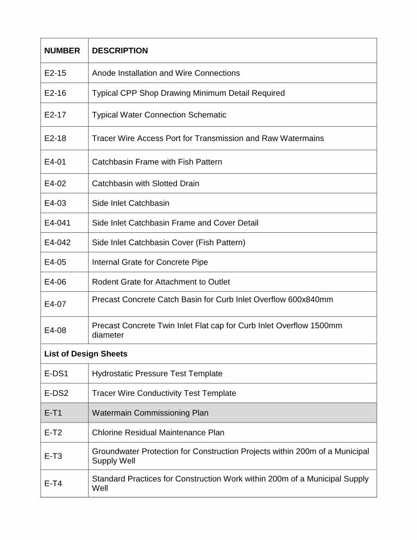
NUMBER DESCRIPTION
E2-15 Anode Installation and Wire Connections
E2-16 Typical CPP Shop Drawing Minimum Detail Required
E2-17 Typical Water Connection Schematic
E2-18 Tracer Wire Access Port for Transmission and Raw Watermains
E4-01 Catchbasin Frame with Fish Pattern
E4-02 Catchbasin with Slotted Drain
E4-03 Side Inlet Catchbasin
E4-041 Side Inlet Catchbasin Frame and Cover Detail
E4-042 Side Inlet Catchbasin Cover (Fish Pattern)
E4-05 Internal Grate for Concrete Pipe
E4-06 Rodent Grate for Attachment to Outlet
E4-07 Precast Concrete Catch Basin for Curb Inlet Overflow 600x840mm
E4-08 Precast Concrete Twin Inlet Flat cap for Curb Inlet Overflow 1500mm diameter
List of Design Sheets
E-DS1 Hydrostatic Pressure Test Template
E-DS2 Tracer Wire Conductivity Test Template
E-T1 Watermain Commissioning Plan
E-T2 Chlorine Residual Maintenance Plan
E-T3 Groundwater Protection for Construction Projects within 200m of a Municipal Supply Well
E-T4 Standard Practices for Construction Work within 200m of a Municipal Supply Well
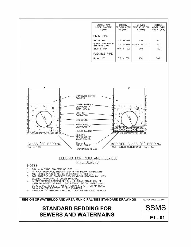
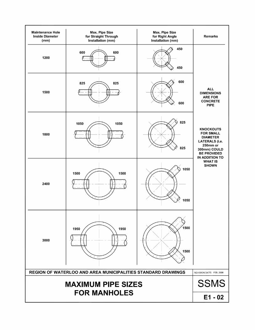
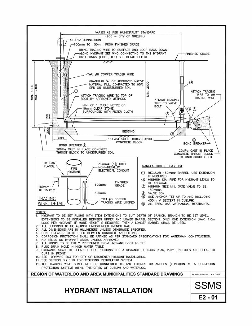
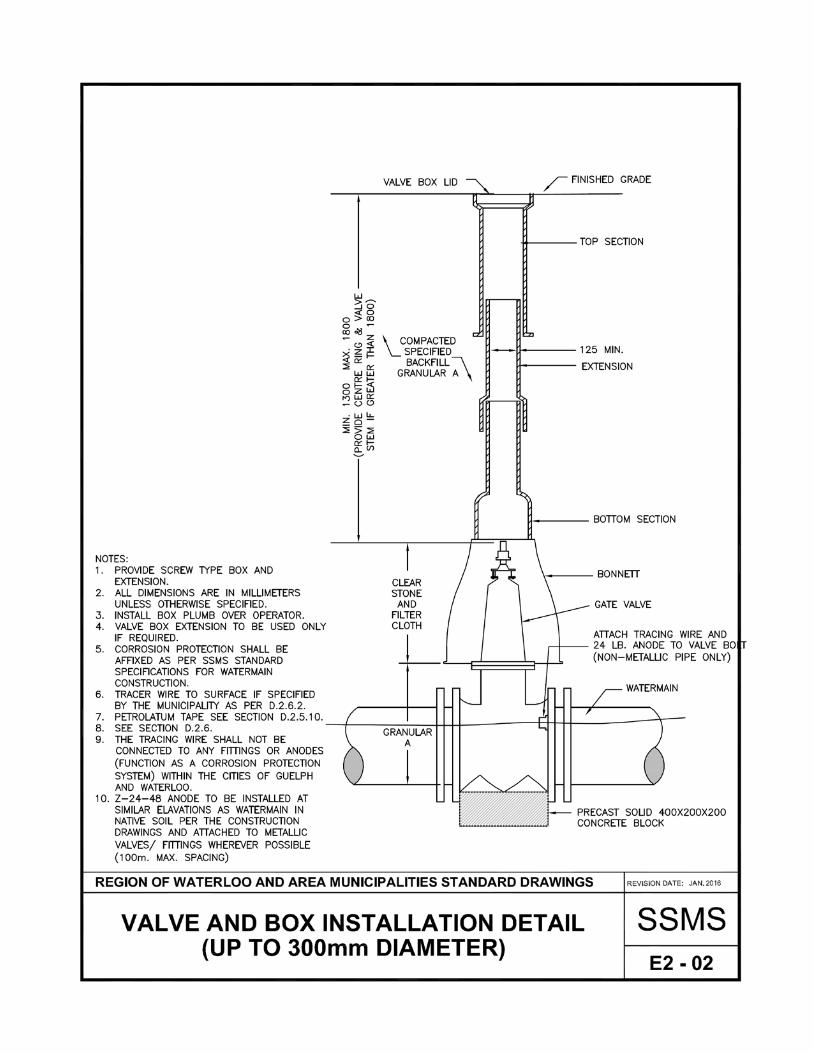
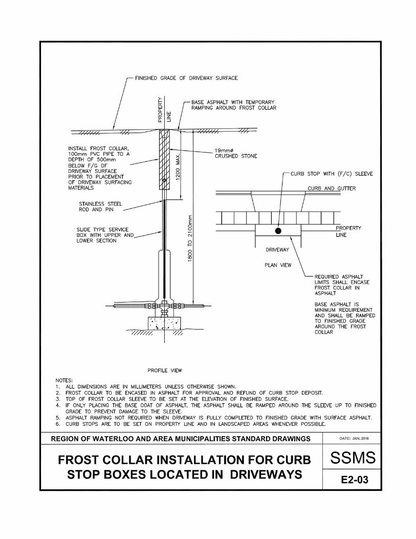
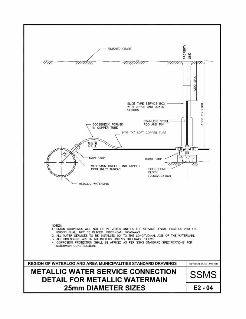
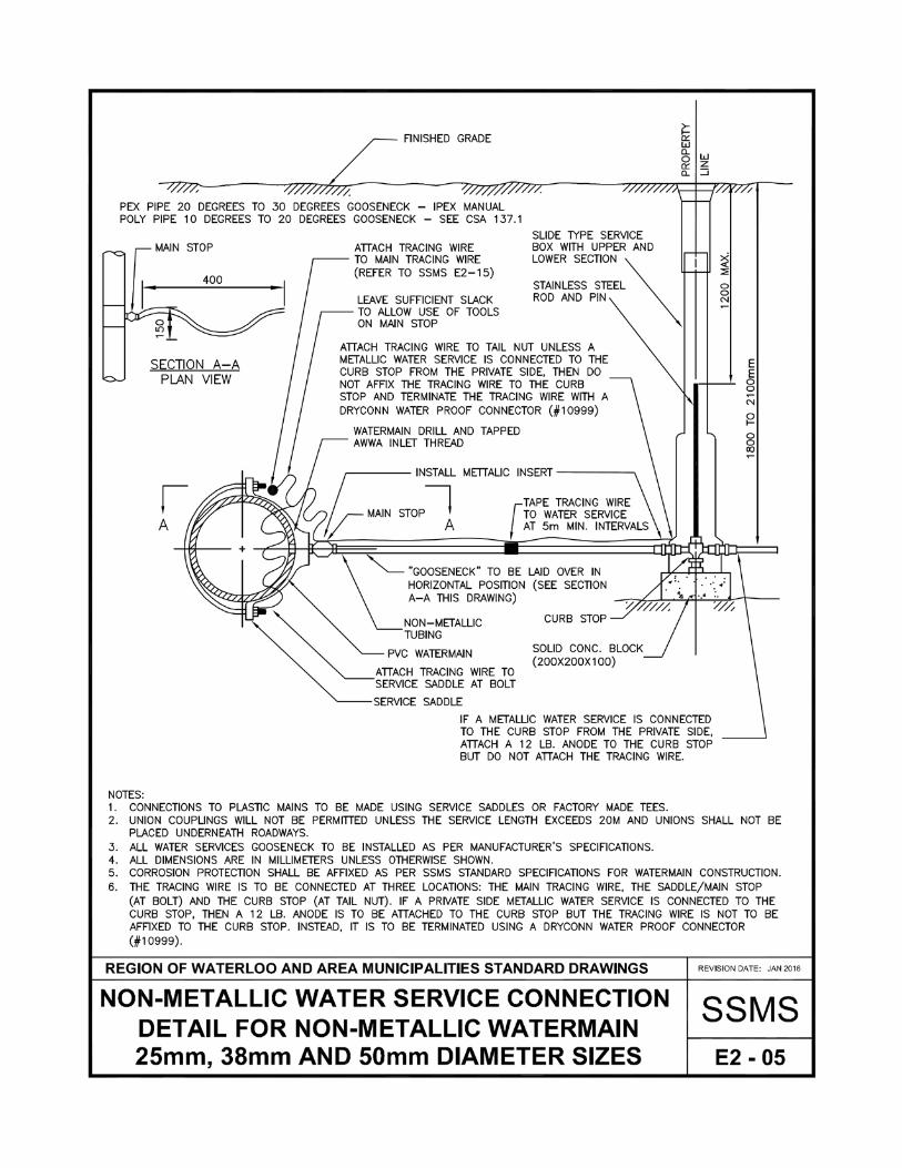
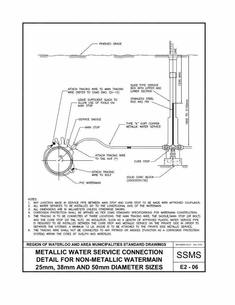
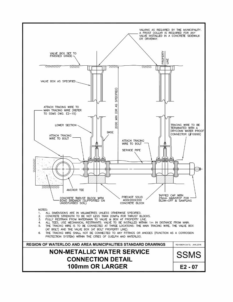
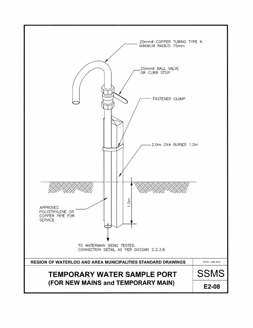
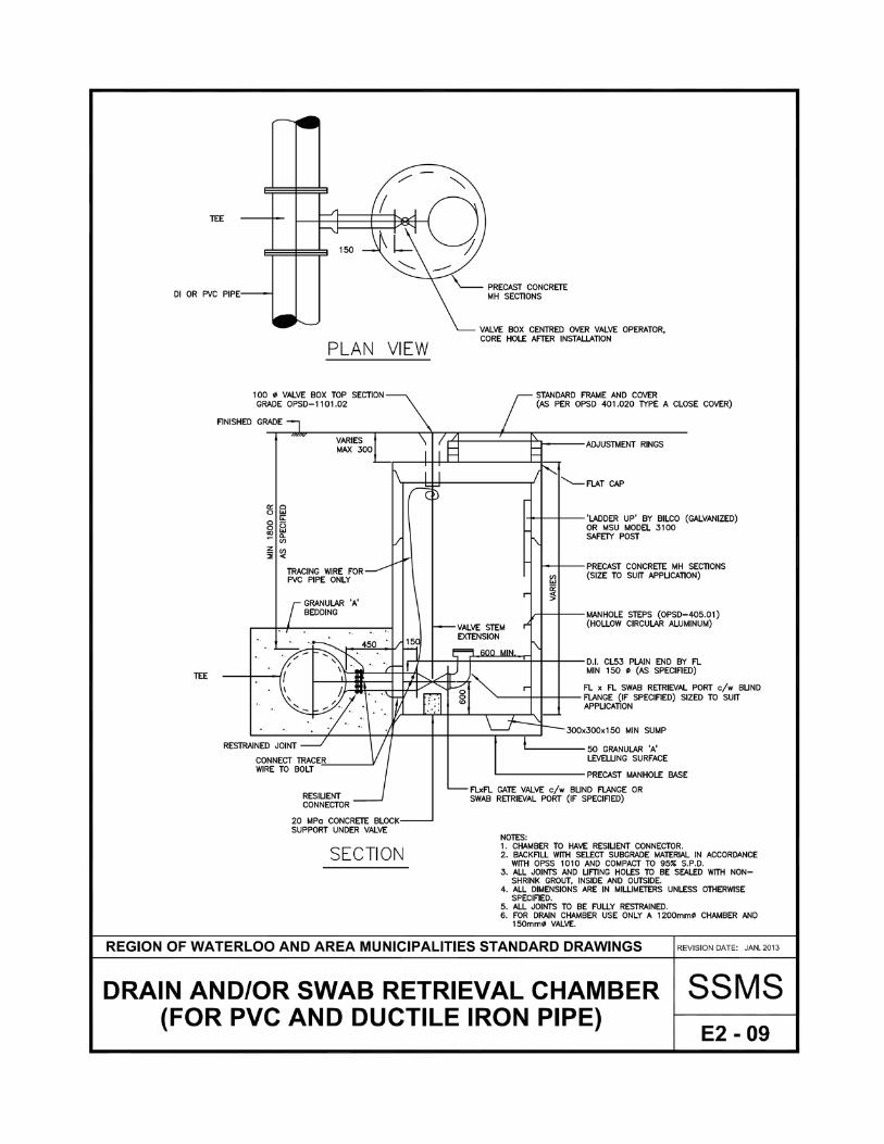
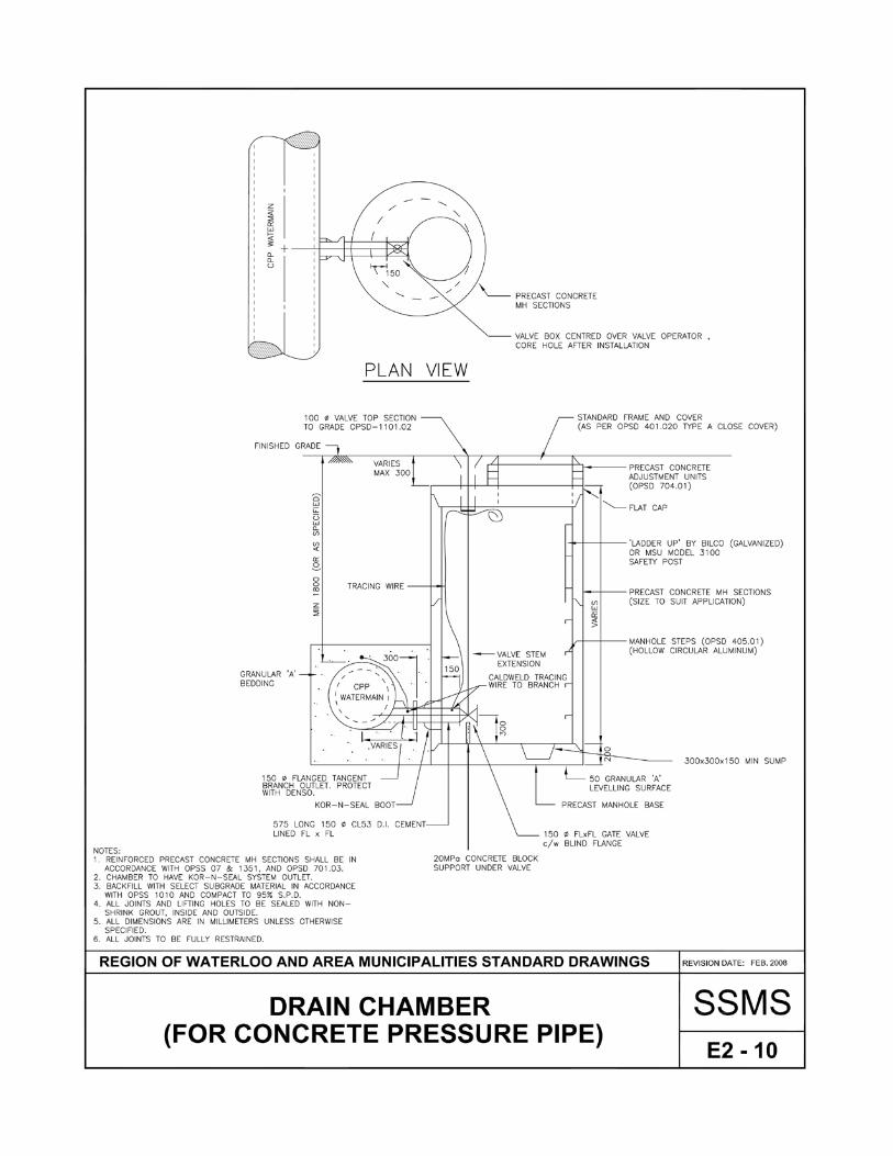
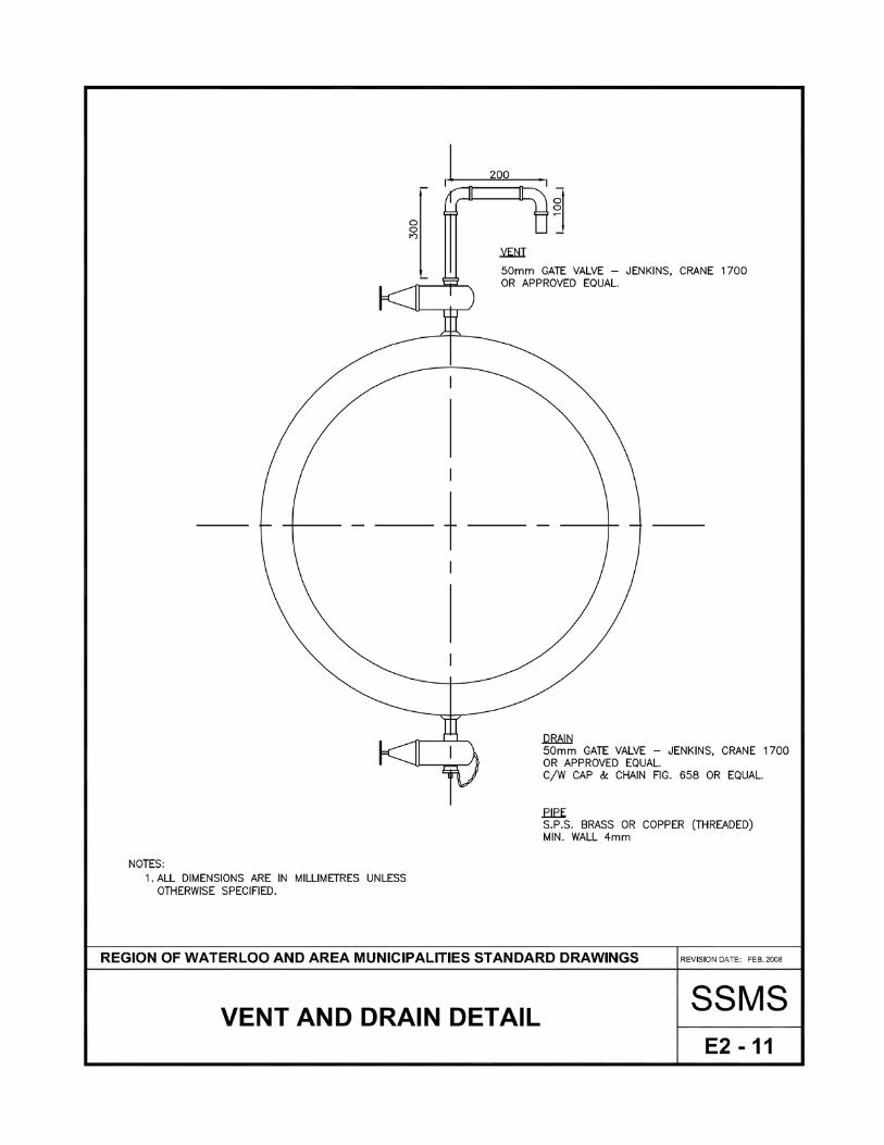
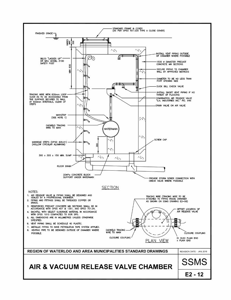
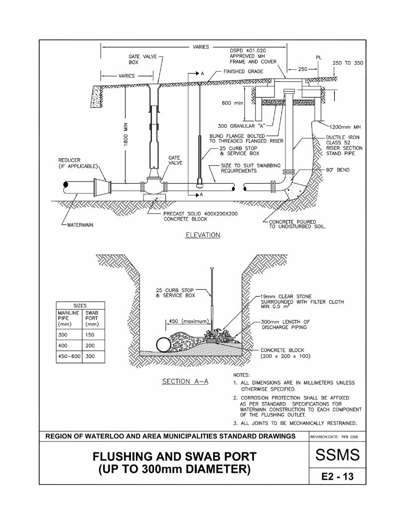
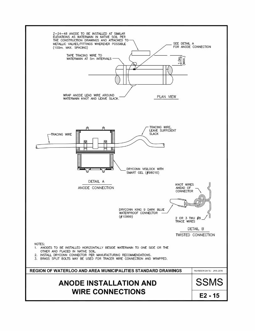
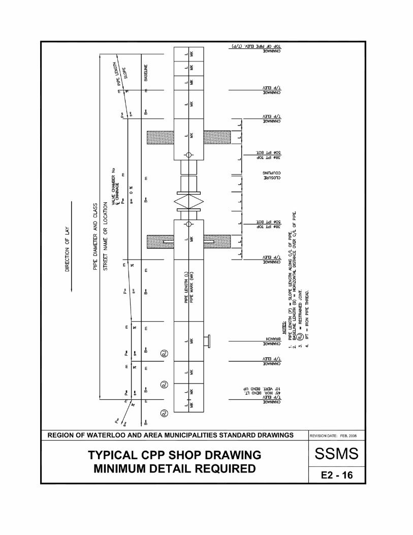
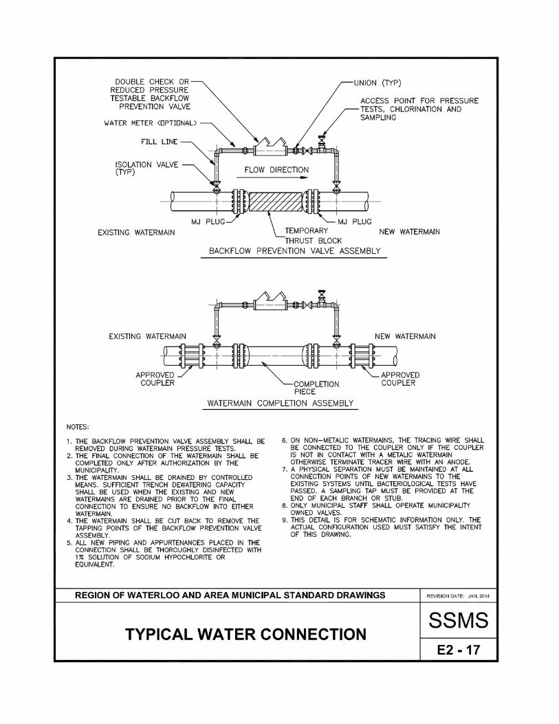
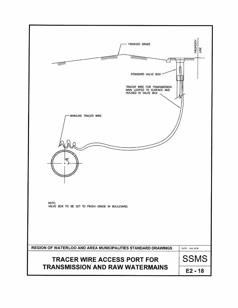
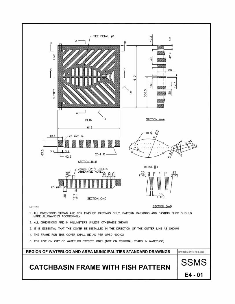
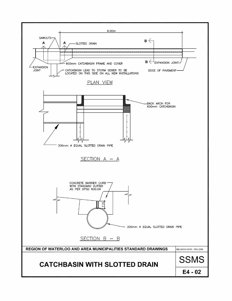
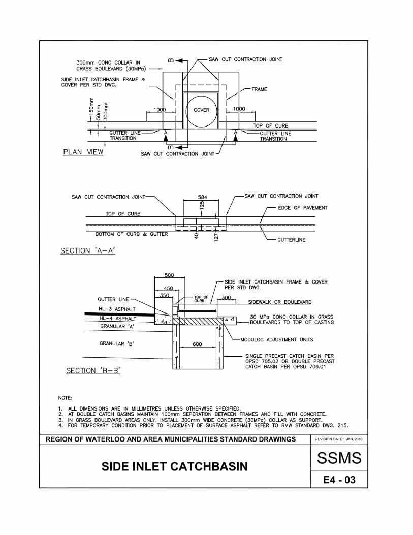
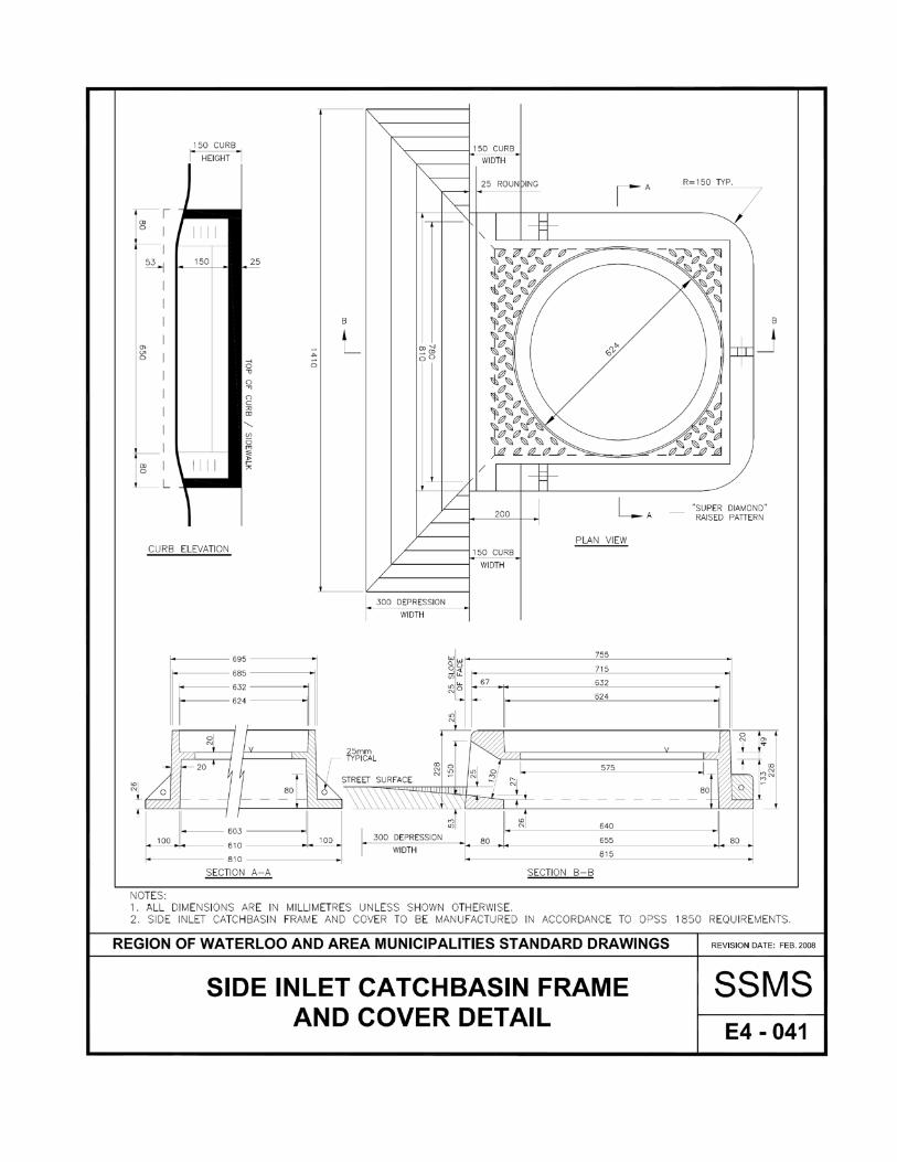
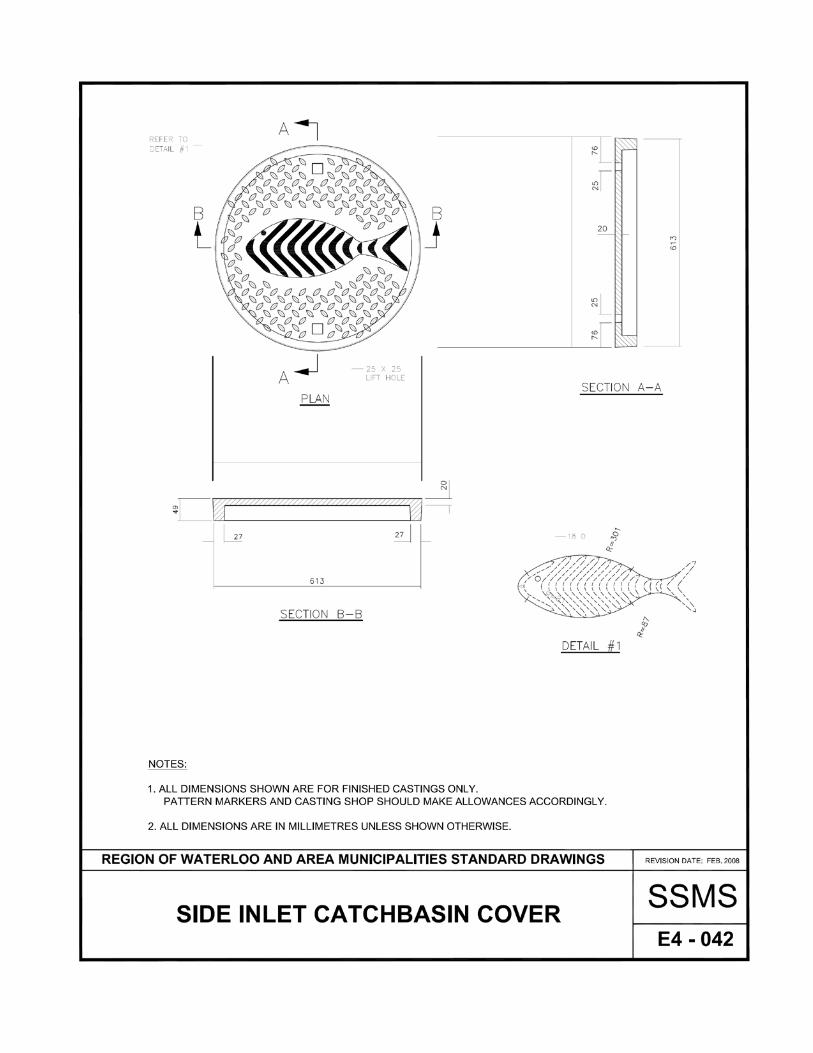
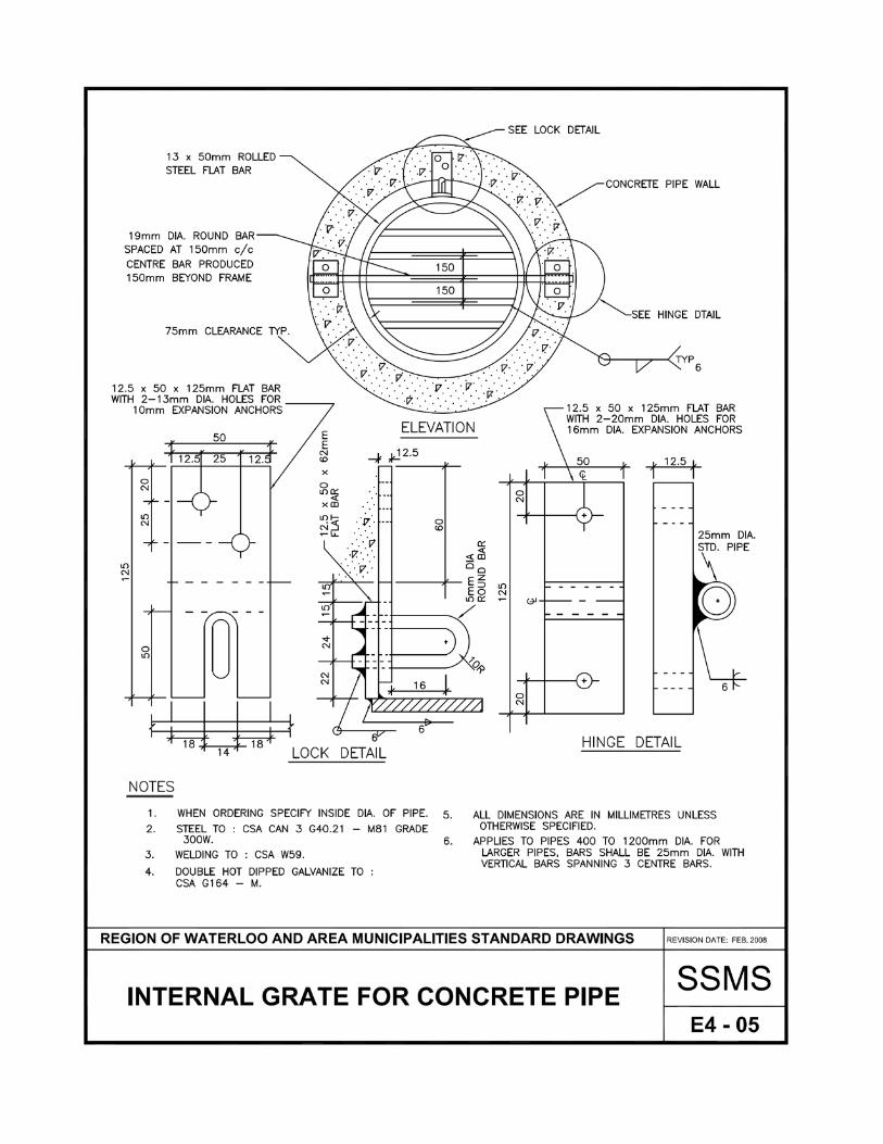
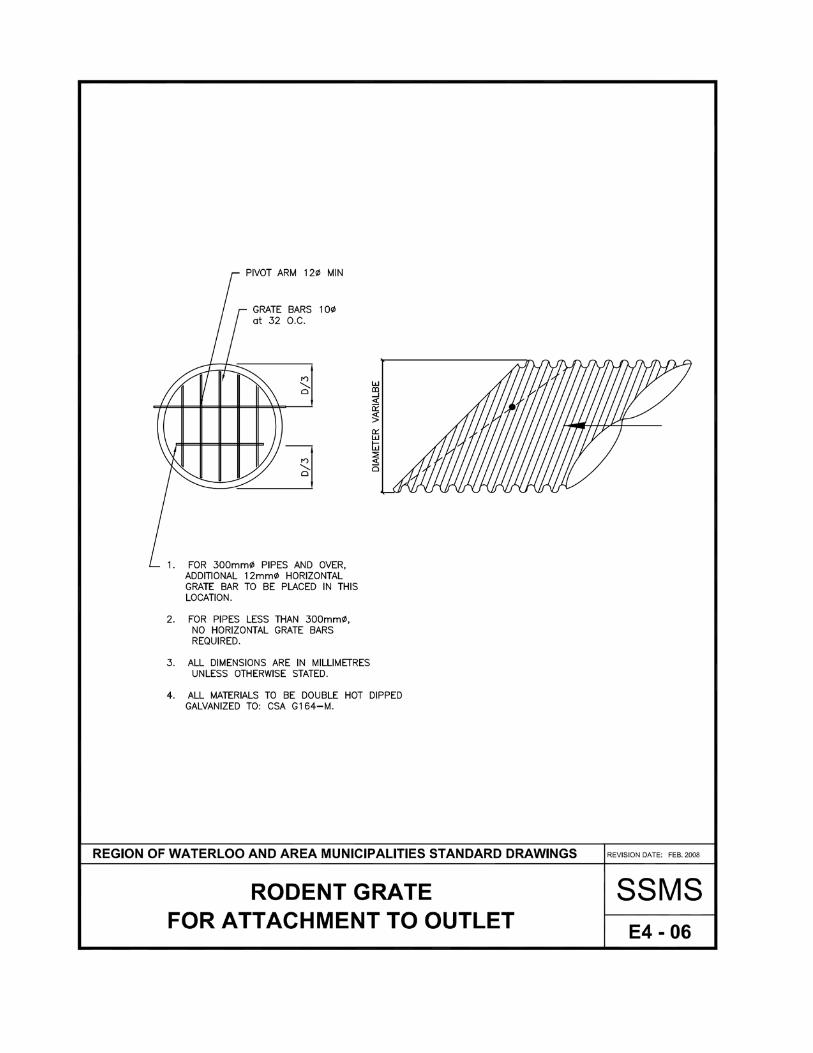
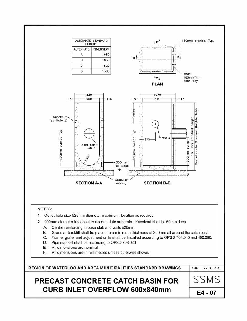
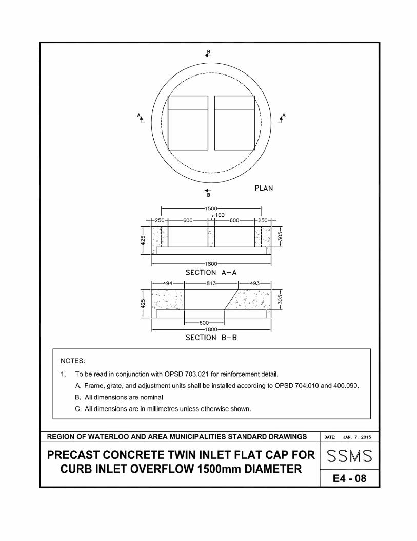
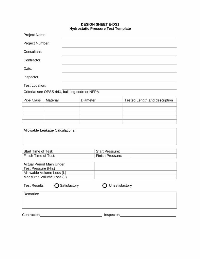
DESIGN SHEET E-DS1 Hydrostatic Pressure Test Template
Project Name:
Project Number:
Consultant:
Contractor:
Date:
Inspector:
Test Location:
Criteria: see OPSS 441, building code or NFPA Pipe Class Material Diameter Tested Length and description Allowable Leakage Calculations: Start Time of Test: Start Pressure: Finish Time of Test: Finish Pressure: Actual Period Main Under Test Pressure (Hrs)
Allowable Volume Loss (L) Measured Volume Loss (L) Test Results: Satisfactory Unsatisfactory Remarks:
Contractor: _______________________________ Inspector: ____________________________
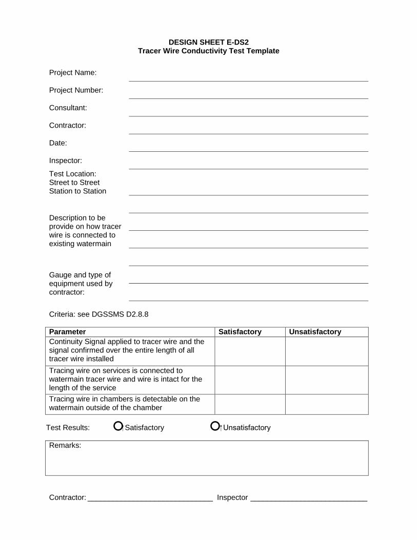
DESIGN SHEET E-DS2
Tracer Wire Conductivity Test Template Project Name:
Project Number:
Consultant:
Contractor:
Date:
Inspector:
Test Location: Street to Street Station to Station
Description to be provide on how tracer wire is connected to existing watermain
Gauge and type of equipment used by contractor:
Criteria: see DGSSMS D2.8.8 Parameter Satisfactory Unsatisfactory Continuity Signal applied to tracer wire and the signal confirmed over the entire length of all tracer wire installed
Tracing wire on services is connected to watermain tracer wire and wire is intact for the length of the service
Tracing wire in chambers is detectable on the watermain outside of the chamber
Test Results: Satisfactory Unsatisfactory Remarks: Contractor: ______________________________ Inspector ____________________________
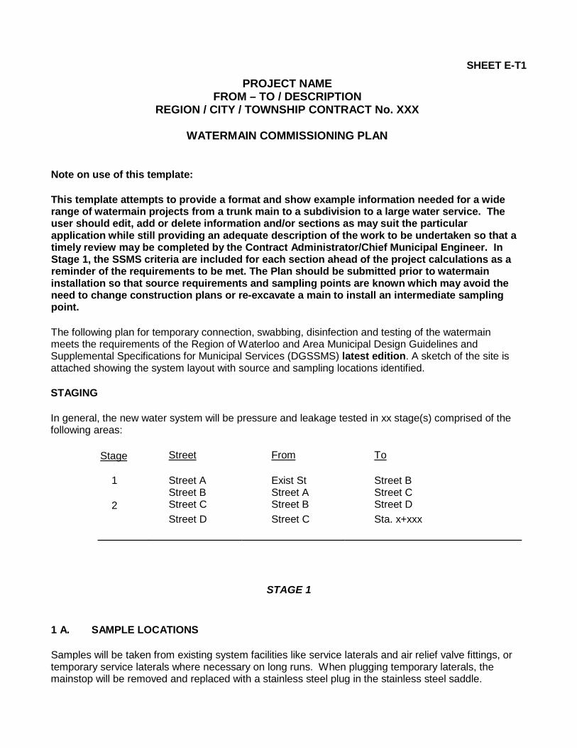
SHEET E-T1
PROJECT NAME FROM – TO / DESCRIPTION
REGION / CITY / TOWNSHIP CONTRACT No. XXX
WATERMAIN COMMISSIONING PLAN
Note on use of this template: This template attempts to provide a format and show example information needed for a wide range of watermain projects from a trunk main to a subdivision to a large water service. The user should edit, add or delete information and/or sections as may suit the particular application while still providing an adequate description of the work to be undertaken so that a timely review may be completed by the Contract Administrator/Chief Municipal Engineer. In Stage 1, the SSMS criteria are included for each section ahead of the project calculations as a reminder of the requirements to be met. The Plan should be submitted prior to watermain installation so that source requirements and sampling points are known which may avoid the need to change construction plans or re-excavate a main to install an intermediate sampling point. The following plan for temporary connection, swabbing, disinfection and testing of the watermain meets the requirements of the Region of Waterloo and Area Municipal Design Guidelines and Supplemental Specifications for Municipal Services (DGSSMS) latest edition. A sketch of the site is attached showing the system layout with source and sampling locations identified. STAGING In general, the new water system will be pressure and leakage tested in xx stage(s) comprised of the following areas:
Stage Street From To
1
2
Street A Street B Street C
Exist St Street A Street B
Street B Street C Street D
Street D Street C Sta. x+xxx
STAGE 1
1 A. SAMPLE LOCATIONS Samples will be taken from existing system facilities like service laterals and air relief valve fittings, or temporary service laterals where necessary on long runs. When plugging temporary laterals, the mainstop will be removed and replaced with a stainless steel plug in the stainless steel saddle.
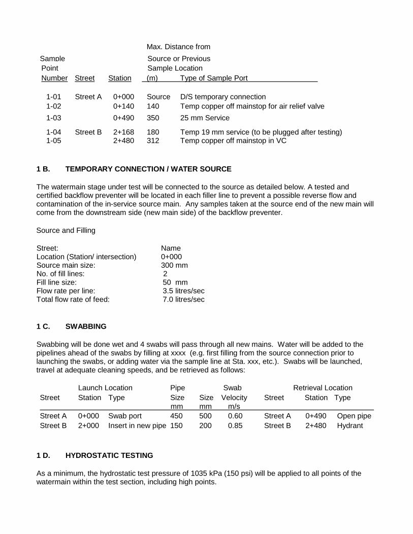
Max. Distance from Sample Source or Previous
Point Sample Location Number Street Station (m) Type of Sample Port
1-01 Street A 0+000 Source D/S temporary connection 1-02 0+140 140 Temp copper off mainstop for air relief valve 1-03 0+490 350 25 mm Service
1-04 1-05
Street B
2+168 2+480
180 312
Temp 19 mm service (to be plugged after testing) Temp copper off mainstop in VC
1 B. TEMPORARY CONNECTION / WATER SOURCE The watermain stage under test will be connected to the source as detailed below. A tested and certified backflow preventer will be located in each filler line to prevent a possible reverse flow and contamination of the in-service source main. Any samples taken at the source end of the new main will come from the downstream side (new main side) of the backflow preventer. Source and Filling Street: Name Location (Station/ intersection) 0+000 Source main size: 300 mm No. of fill lines: 2 Fill line size: 50 mm Flow rate per line: 3.5 litres/sec Total flow rate of feed: 7.0 litres/sec 1 C. SWABBING Swabbing will be done wet and 4 swabs will pass through all new mains. Water will be added to the pipelines ahead of the swabs by filling at xxxx (e.g. first filling from the source connection prior to launching the swabs, or adding water via the sample line at Sta. xxx, etc.). Swabs will be launched, travel at adequate cleaning speeds, and be retrieved as follows: Launch Location Pipe Swab Retrieval Location Street Station Type Size Size Velocity Street Station Type mm mm m/s Street A 0+000 Swab port 450 500 0.60 Street A 0+490 Open pipe Street B 2+000 Insert in new pipe 150 200 0.85 Street B 2+480 Hydrant
1 D. HYDROSTATIC TESTING As a minimum, the hydrostatic test pressure of 1035 kPa (150 psi) will be applied to all points of the watermain within the test section, including high points.
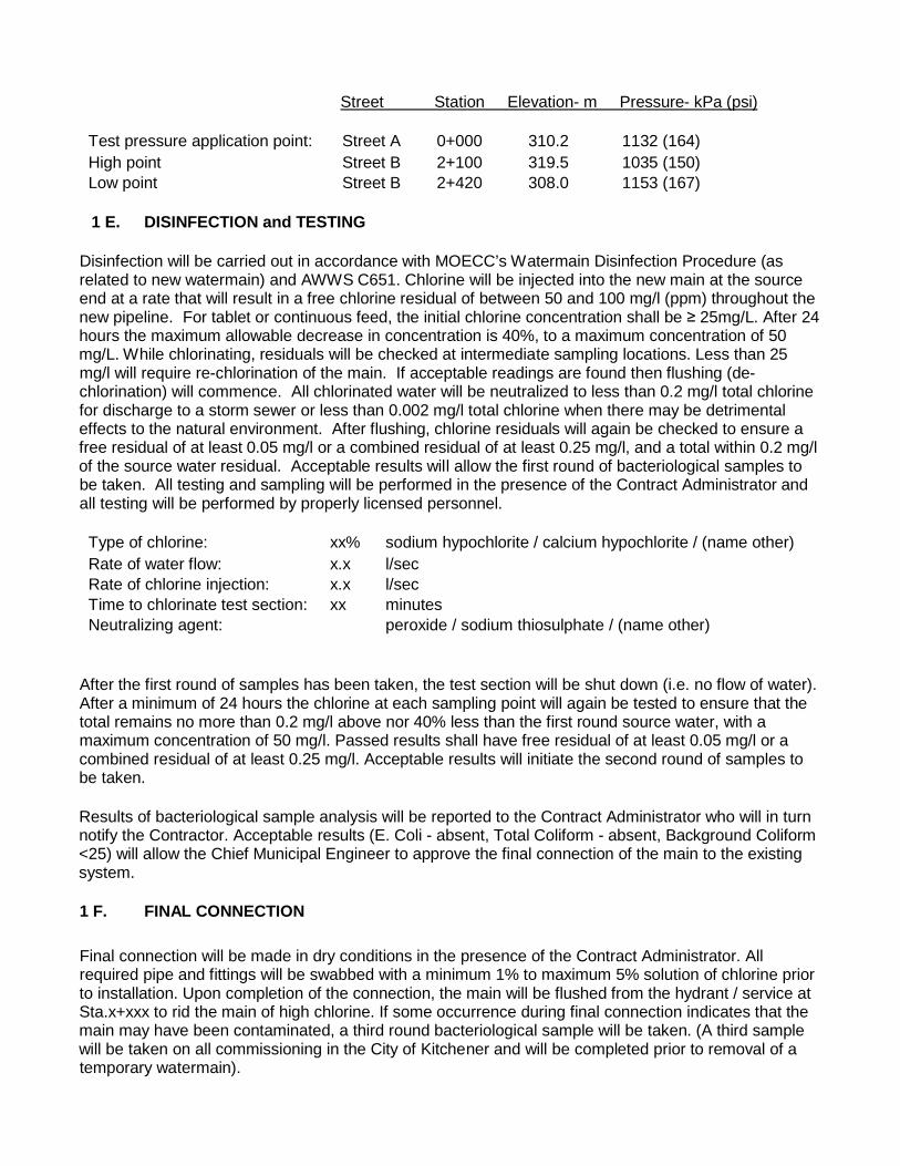
Street Station Elevation- m Pressure- kPa (psi) Test pressure application point: Street A 0+000 310.2 1132 (164) High point Street B 2+100 319.5 1035 (150) Low point Street B 2+420 308.0 1153 (167)
1 E. DISINFECTION and TESTING
Disinfection will be carried out in accordance with MOECC’s Watermain Disinfection Procedure (as related to new watermain) and AWWS C651. Chlorine will be injected into the new main at the source end at a rate that will result in a free chlorine residual of between 50 and 100 mg/l (ppm) throughout the new pipeline. For tablet or continuous feed, the initial chlorine concentration shall be ≥ 25mg/L. After 24 hours the maximum allowable decrease in concentration is 40%, to a maximum concentration of 50 mg/L. While chlorinating, residuals will be checked at intermediate sampling locations. Less than 25 mg/l will require re-chlorination of the main. If acceptable readings are found then flushing (de-chlorination) will commence. All chlorinated water will be neutralized to less than 0.2 mg/l total chlorine for discharge to a storm sewer or less than 0.002 mg/l total chlorine when there may be detrimental effects to the natural environment. After flushing, chlorine residuals will again be checked to ensure a free residual of at least 0.05 mg/l or a combined residual of at least 0.25 mg/l, and a total within 0.2 mg/l of the source water residual. Acceptable results will allow the first round of bacteriological samples to be taken. All testing and sampling will be performed in the presence of the Contract Administrator and all testing will be performed by properly licensed personnel. Type of chlorine: xx% sodium hypochlorite / calcium hypochlorite / (name other) Rate of water flow: x.x l/sec Rate of chlorine injection: x.x l/sec Time to chlorinate test section: xx minutes Neutralizing agent: peroxide / sodium thiosulphate / (name other)
After the first round of samples has been taken, the test section will be shut down (i.e. no flow of water). After a minimum of 24 hours the chlorine at each sampling point will again be tested to ensure that the total remains no more than 0.2 mg/l above nor 40% less than the first round source water, with a maximum concentration of 50 mg/l. Passed results shall have free residual of at least 0.05 mg/l or a combined residual of at least 0.25 mg/l. Acceptable results will initiate the second round of samples to be taken. Results of bacteriological sample analysis will be reported to the Contract Administrator who will in turn notify the Contractor. Acceptable results (E. Coli - absent, Total Coliform - absent, Background Coliform <25) will allow the Chief Municipal Engineer to approve the final connection of the main to the existing system. 1 F. FINAL CONNECTION Final connection will be made in dry conditions in the presence of the Contract Administrator. All required pipe and fittings will be swabbed with a minimum 1% to maximum 5% solution of chlorine prior to installation. Upon completion of the connection, the main will be flushed from the hydrant / service at Sta.x+xxx to rid the main of high chlorine. If some occurrence during final connection indicates that the main may have been contaminated, a third round bacteriological sample will be taken. (A third sample will be taken on all commissioning in the City of Kitchener and will be completed prior to removal of a temporary watermain).
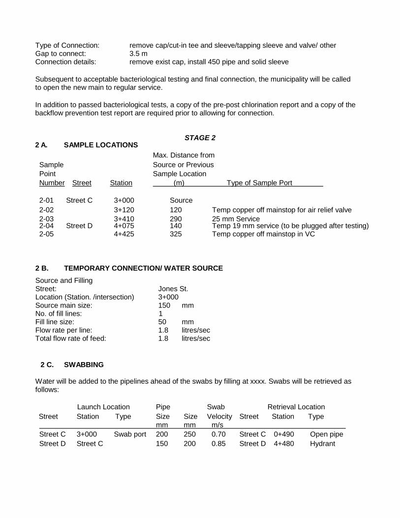
Type of Connection: remove cap/cut-in tee and sleeve/tapping sleeve and valve/ other Gap to connect: 3.5 m Connection details: remove exist cap, install 450 pipe and solid sleeve Subsequent to acceptable bacteriological testing and final connection, the municipality will be called to open the new main to regular service. In addition to passed bacteriological tests, a copy of the pre-post chlorination report and a copy of the backflow prevention test report are required prior to allowing for connection.
STAGE 2
2 A. SAMPLE LOCATIONS Max. Distance from Sample Source or Previous Point Sample Location Number Street Station (m) Type of Sample Port
2-01 Street C 3+000 Source 2-02 3+120 120 Temp copper off mainstop for air relief valve 2-03 3+410 290 25 mm Service 2-04 2-05
Street D 4+075 4+425
140 325
Temp 19 mm service (to be plugged after testing) Temp copper off mainstop in VC
2 B. TEMPORARY CONNECTION/ WATER SOURCE
Source and Filling Street: Jones St. Location (Station. /intersection) 3+000 Source main size: 150 mm No. of fill lines: 1 Fill line size: 50 mm Flow rate per line: 1.8 litres/sec Total flow rate of feed: 1.8 litres/sec
2 C. SWABBING Water will be added to the pipelines ahead of the swabs by filling at xxxx. Swabs will be retrieved as follows: Launch Location Pipe Swab Retrieval Location Street Station Type Size Size Velocity Street Station Type
mm mm m/s Street C 3+000 Swab port 200 250 0.70 Street C 0+490 Open pipe Street D Street C 150 200 0.85 Street D 4+480 Hydrant
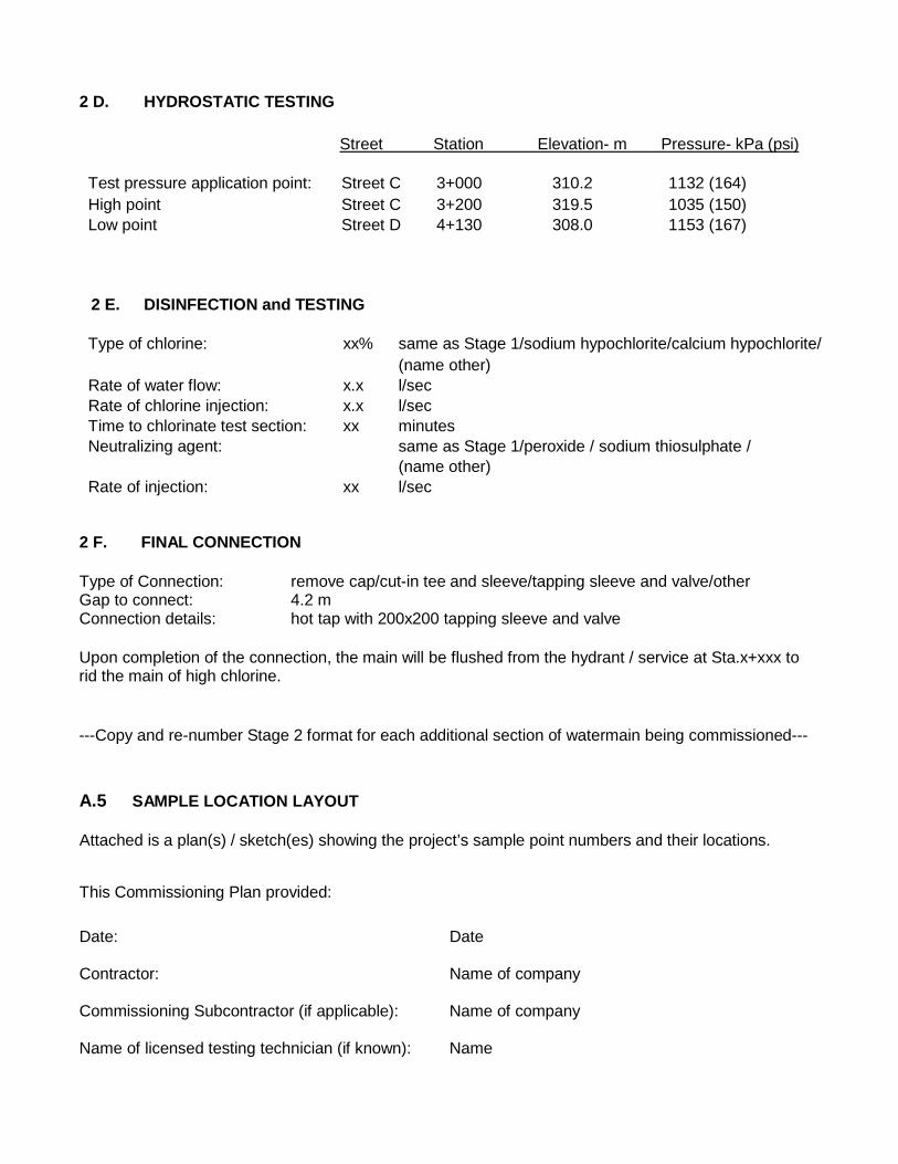
2 D. HYDROSTATIC TESTING
Street Station Elevation- m Pressure- kPa (psi) Test pressure application point: Street C 3+000 310.2 1132 (164) High point Street C 3+200 319.5 1035 (150) Low point Street D 4+130 308.0 1153 (167)
2 E. DISINFECTION and TESTING Type of chlorine: xx% same as Stage 1/sodium hypochlorite/calcium hypochlorite/ (name other) Rate of water flow: x.x l/sec Rate of chlorine injection: x.x l/sec Time to chlorinate test section: xx minutes Neutralizing agent: same as Stage 1/peroxide / sodium thiosulphate / (name other) Rate of injection: xx l/sec
2 F. FINAL CONNECTION Type of Connection: remove cap/cut-in tee and sleeve/tapping sleeve and valve/other Gap to connect: 4.2 m Connection details: hot tap with 200x200 tapping sleeve and valve Upon completion of the connection, the main will be flushed from the hydrant / service at Sta.x+xxx to rid the main of high chlorine. ---Copy and re-number Stage 2 format for each additional section of watermain being commissioned--- A.5 SAMPLE LOCATION LAYOUT Attached is a plan(s) / sketch(es) showing the project’s sample point numbers and their locations. This Commissioning Plan provided: Date: Date Contractor: Name of company
Commissioning Subcontractor (if applicable): Name of company
Name of licensed testing technician (if known): Name
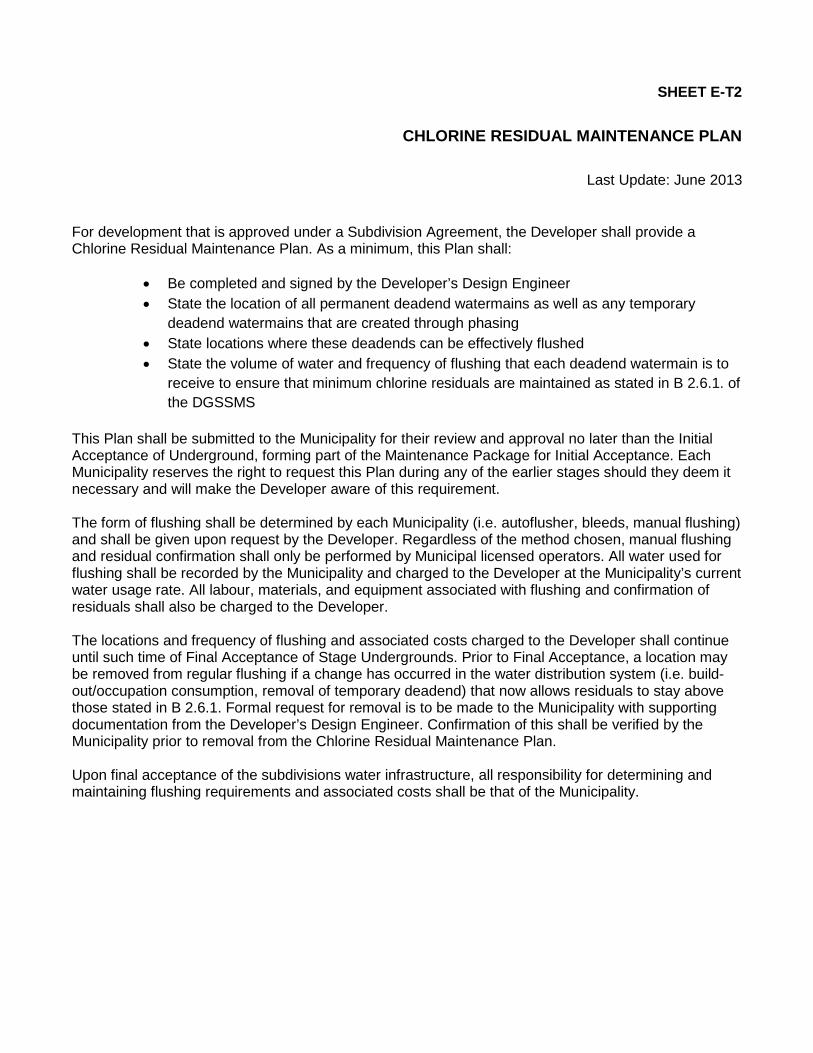
SHEET E-T2
CHLORINE RESIDUAL MAINTENANCE PLAN
Last Update: June 2013 For development that is approved under a Subdivision Agreement, the Developer shall provide a Chlorine Residual Maintenance Plan. As a minimum, this Plan shall:
• Be completed and signed by the Developer’s Design Engineer • State the location of all permanent deadend watermains as well as any temporary
deadend watermains that are created through phasing • State locations where these deadends can be effectively flushed • State the volume of water and frequency of flushing that each deadend watermain is to
receive to ensure that minimum chlorine residuals are maintained as stated in B 2.6.1. of the DGSSMS
This Plan shall be submitted to the Municipality for their review and approval no later than the Initial Acceptance of Underground, forming part of the Maintenance Package for Initial Acceptance. Each Municipality reserves the right to request this Plan during any of the earlier stages should they deem it necessary and will make the Developer aware of this requirement. The form of flushing shall be determined by each Municipality (i.e. autoflusher, bleeds, manual flushing) and shall be given upon request by the Developer. Regardless of the method chosen, manual flushing and residual confirmation shall only be performed by Municipal licensed operators. All water used for flushing shall be recorded by the Municipality and charged to the Developer at the Municipality’s current water usage rate. All labour, materials, and equipment associated with flushing and confirmation of residuals shall also be charged to the Developer. The locations and frequency of flushing and associated costs charged to the Developer shall continue until such time of Final Acceptance of Stage Undergrounds. Prior to Final Acceptance, a location may be removed from regular flushing if a change has occurred in the water distribution system (i.e. build-out/occupation consumption, removal of temporary deadend) that now allows residuals to stay above those stated in B 2.6.1. Formal request for removal is to be made to the Municipality with supporting documentation from the Developer’s Design Engineer. Confirmation of this shall be verified by the Municipality prior to removal from the Chlorine Residual Maintenance Plan. Upon final acceptance of the subdivisions water infrastructure, all responsibility for determining and maintaining flushing requirements and associated costs shall be that of the Municipality.

SHEET E-T3 FOR MUNICIPAL PROJECT MANAGERS: GROUNDWATER PROTECTION FOR CONSTRUCTION PROJECTS WITHIN 200 M OF A MUNICIPAL SUPPLY WELL WATER SERVICES REQUIREMENTS
Last Updated: December 2017 1.0 INTRODUCTION
PURPOSE
The purpose of this document is to ensure that enhanced spill contingency plans and enhanced groundwater protection practices are in place during any construction work carried out close to (within 200 m) of Region of Waterloo municipal supply wells. Construction work includes utilization of heavy equipment, paving, dewatering, pile-driving, borehole drilling, stockpiling of construction-related supplies, subsurface excavation, and related activities. This document is intended for design or construction Project Managers working at the Region of Waterloo or the cities and townships in the Region of Waterloo. These requirements should also be provided to Engineering Consultants working on applicable municipal projects. BACKGROUND
The Region of Waterloo operates approximately 120 municipal supply wells, which provide about 80% of the Region’s municipal drinking water. Enhanced spill/leak prevention measures are required close to municipal supply wells in order to protect the quality of the drinking water sources. Measures to avoid disturbing the filtration capacity of the ground near supply wells are also required. In certain circumstances, for extra protection Water Services will modify the operation of production wells when there is nearby construction. This requires communication protocols between Water Services and the construction Project Managers. The requirements of this document are in addition to regulatory requirements, including those dictated by the Ontario Environmental Protection Act, the Ontario Water Resources Act, the Region of Waterloo Source Protection Plan, The Regional Official Plan (Section 8), and municipal By-Laws.
This document outlines measures that would normally be imposed on construction projects within 200 m of a production well. However, recognizing the unique factors of each project and site, the construction Project Manager may negotiate a modified program with Water Services staff, if required. The Manager, Hydrogeology & Source Water (HSW) section of Water Services is the primary contact regarding this guideline.
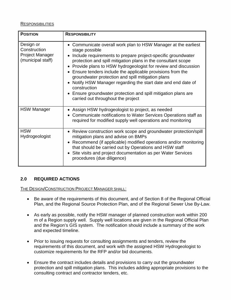
RESPONSIBILITIES
POSITION RESPONSIBILITY
Design or Construction Project Manager (municipal staff)
• Communicate overall work plan to HSW Manager at the earliest stage possible
• Include requirements to prepare project-specific groundwater protection and spill mitigation plans in the consultant scope
• Provide plans to HSW hydrogeologist for review and discussion • Ensure tenders include the applicable provisions from the
groundwater protection and spill mitigation plans • Notify HSW Manager regarding the start date and end date of
construction • Ensure groundwater protection and spill mitigation plans are
carried out throughout the project
HSW Manager • Assign HSW hydrogeologist to project, as needed • Communicate notifications to Water Services Operations staff as
required for modified supply well operations and monitoring
HSW Hydrogeologist
• Review construction work scope and groundwater protection/spill mitigation plans and advise on BMPs
• Recommend (if applicable) modified operations and/or monitoring that should be carried out by Operations and HSW staff
• Site visits and project documentation as per Water Services procedures (due diligence)
2.0 REQUIRED ACTIONS
THE DESIGN/CONSTRUCTION PROJECT MANAGER SHALL:
• Be aware of the requirements of this document, and of Section 8 of the Regional Official Plan, and the Regional Source Protection Plan, and of the Regional Sewer Use By-Law.
• As early as possible, notify the HSW manager of planned construction work within 200 m of a Region supply well. Supply well locations are given in the Regional Official Plan and the Region’s GIS system. The notification should include a summary of the work and expected timeline.
• Prior to issuing requests for consulting assignments and tenders, review the
requirements of this document, and work with the assigned HSW Hydrogeologist to customize requirements for the RFP and/or bid documents.
• Ensure the contract includes details and provisions to carry out the groundwater
protection and spill mitigation plans. This includes adding appropriate provisions to the consulting contract and contractor tenders, etc.
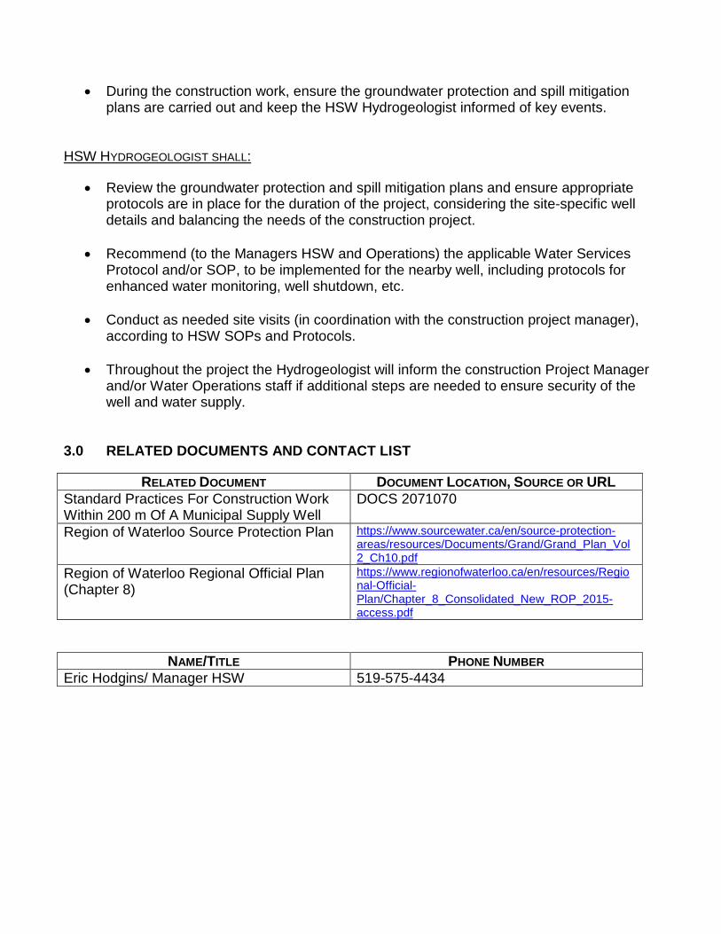
• During the construction work, ensure the groundwater protection and spill mitigation
plans are carried out and keep the HSW Hydrogeologist informed of key events.
HSW HYDROGEOLOGIST SHALL:
• Review the groundwater protection and spill mitigation plans and ensure appropriate protocols are in place for the duration of the project, considering the site-specific well details and balancing the needs of the construction project.
• Recommend (to the Managers HSW and Operations) the applicable Water Services
Protocol and/or SOP, to be implemented for the nearby well, including protocols for enhanced water monitoring, well shutdown, etc.
• Conduct as needed site visits (in coordination with the construction project manager), according to HSW SOPs and Protocols.
• Throughout the project the Hydrogeologist will inform the construction Project Manager and/or Water Operations staff if additional steps are needed to ensure security of the well and water supply.
3.0 RELATED DOCUMENTS AND CONTACT LIST
RELATED DOCUMENT DOCUMENT LOCATION, SOURCE OR URL Standard Practices For Construction Work Within 200 m Of A Municipal Supply Well
DOCS 2071070
Region of Waterloo Source Protection Plan https://www.sourcewater.ca/en/source-protection-areas/resources/Documents/Grand/Grand_Plan_Vol2_Ch10.pdf
Region of Waterloo Regional Official Plan (Chapter 8)
https://www.regionofwaterloo.ca/en/resources/Regional-Official-Plan/Chapter_8_Consolidated_New_ROP_2015-access.pdf
NAME/TITLE PHONE NUMBER Eric Hodgins/ Manager HSW 519-575-4434
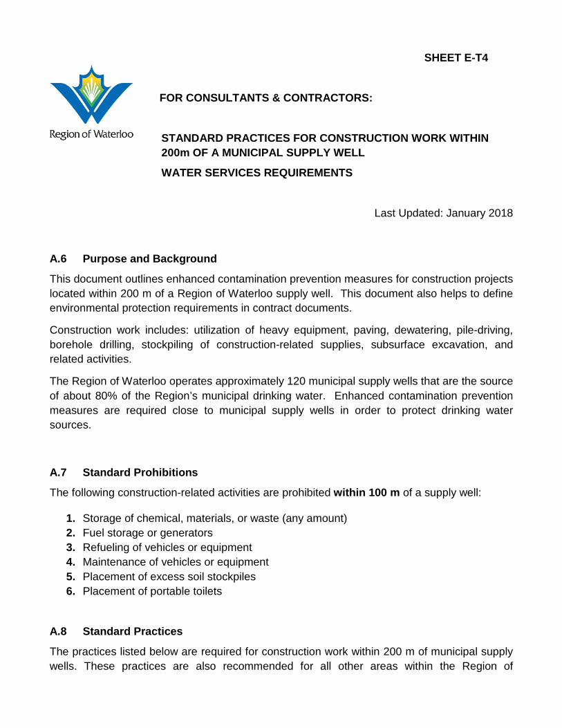
SHEET E-T4
FOR CONSULTANTS & CONTRACTORS:
STANDARD PRACTICES FOR CONSTRUCTION WORK WITHIN 200m OF A MUNICIPAL SUPPLY WELL
WATER SERVICES REQUIREMENTS
Last Updated: January 2018
A.6 Purpose and Background
This document outlines enhanced contamination prevention measures for construction projects located within 200 m of a Region of Waterloo supply well. This document also helps to define environmental protection requirements in contract documents.
Construction work includes: utilization of heavy equipment, paving, dewatering, pile-driving, borehole drilling, stockpiling of construction-related supplies, subsurface excavation, and related activities.
The Region of Waterloo operates approximately 120 municipal supply wells that are the source of about 80% of the Region’s municipal drinking water. Enhanced contamination prevention measures are required close to municipal supply wells in order to protect drinking water sources.
A.7 Standard Prohibitions
The following construction-related activities are prohibited within 100 m of a supply well:
1. Storage of chemical, materials, or waste (any amount) 2. Fuel storage or generators 3. Refueling of vehicles or equipment 4. Maintenance of vehicles or equipment 5. Placement of excess soil stockpiles 6. Placement of portable toilets
A.8 Standard Practices
The practices listed below are required for construction work within 200 m of municipal supply wells. These practices are also recommended for all other areas within the Region of
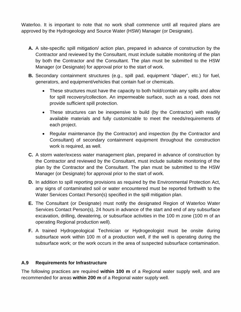
Waterloo. It is important to note that no work shall commence until all required plans are approved by the Hydrogeology and Source Water (HSW) Manager (or Designate).
A. A site-specific spill mitigation/ action plan, prepared in advance of construction by the Contractor and reviewed by the Consultant, must include suitable monitoring of the plan by both the Contractor and the Consultant. The plan must be submitted to the HSW Manager (or Designate) for approval prior to the start of work.
B. Secondary containment structures (e.g., spill pad, equipment “diaper”, etc.) for fuel, generators, and equipment/vehicles that contain fuel or chemicals.
• These structures must have the capacity to both hold/contain any spills and allow for spill recovery/collection. An impermeable surface, such as a road, does not provide sufficient spill protection.
• These structures can be inexpensive to build (by the Contractor) with readily available materials and fully customizable to meet the needs/requirements of each project.
• Regular maintenance (by the Contractor) and inspection (by the Contractor and Consultant) of secondary containment equipment throughout the construction work is required, as well.
C. A storm water/excess water management plan, prepared in advance of construction by the Contractor and reviewed by the Consultant, must include suitable monitoring of the plan by the Contractor and the Consultant. The plan must be submitted to the HSW Manager (or Designate) for approval prior to the start of work.
D. In addition to spill reporting provisions as required by the Environmental Protection Act, any signs of contaminated soil or water encountered must be reported forthwith to the Water Services Contact Person(s) specified in the spill mitigation plan.
E. The Consultant (or Designate) must notify the designated Region of Waterloo Water Services Contact Person(s), 24 hours in advance of the start and end of any subsurface excavation, drilling, dewatering, or subsurface activities in the 100 m zone (100 m of an operating Regional production well).
F. A trained Hydrogeological Technician or Hydrogeologist must be onsite during subsurface work within 100 m of a production well, if the well is operating during the subsurface work; or the work occurs in the area of suspected subsurface contamination.
A.9 Requirements for Infrastructure
The following practices are required within 100 m of a Regional water supply well, and are recommended for areas within 200 m of a Regional water supply well.
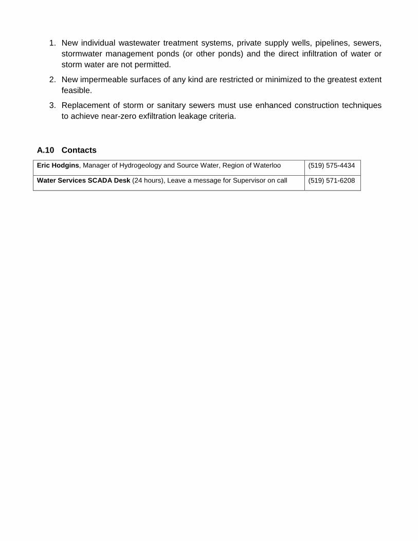
1. New individual wastewater treatment systems, private supply wells, pipelines, sewers, stormwater management ponds (or other ponds) and the direct infiltration of water or storm water are not permitted.
2. New impermeable surfaces of any kind are restricted or minimized to the greatest extent feasible.
3. Replacement of storm or sanitary sewers must use enhanced construction techniques to achieve near-zero exfiltration leakage criteria.
A.10 Contacts
Eric Hodgins, Manager of Hydrogeology and Source Water, Region of Waterloo (519) 575-4434
Water Services SCADA Desk (24 hours), Leave a message for Supervisor on call (519) 571-6208
Region of Waterloo and Area Municipalities
Design guidelines and Supplemental Specifications
For Municipal Services
Part F
Special Product Approval with Conditions
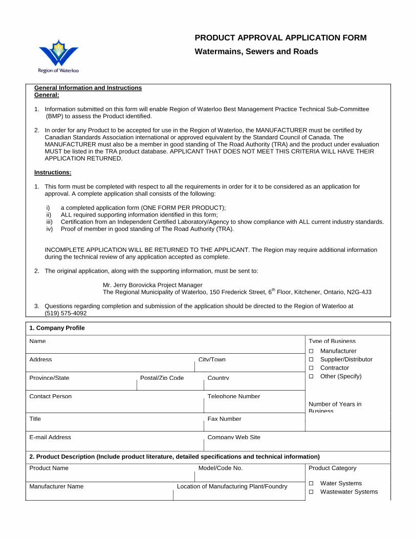
General Information and Instructions General: 1. Information submitted on this form will enable Region of Waterloo Best Management Practice Technical Sub-Committee
(BMP) to assess the Product identified. 2. In order for any Product to be accepted for use in the Region of Waterloo, the MANUFACTURER must be certified by
Canadian Standards Association international or approved equivalent by the Standard Council of Canada. The MANUFACTURER must also be a member in good standing of The Road Authority (TRA) and the product under evaluation MUST be listed in the TRA product database. APPLICANT THAT DOES NOT MEET THIS CRITERIA WILL HAVE THEIR APPLICATION RETURNED.
Instructions: 1. This form must be completed with respect to all the requirements in order for it to be considered as an application for
approval. A complete application shall consists of the following:
i) a completed application form (ONE FORM PER PRODUCT); ii) ALL required supporting information identified in this form; iii) Certification from an Independent Certified Laboratory/Agency to show compliance with ALL current industry standards. iv) Proof of member in good standing of The Road Authority (TRA).
INCOMPLETE APPLICATION WILL BE RETURNED TO THE APPLICANT. The Region may require additional information
during the technical review of any application accepted as complete. 2. The original application, along with the supporting information, must be sent to: Mr. Jerry Borovicka Project Manager The Regional Municipality of Waterloo, 150 Frederick Street, 6th Floor, Kitchener, Ontario, N2G-4J3 3. Questions regarding completion and submission of the application should be directed to the Region of Waterloo at
(519) 575-4092
1. Company Profile
Name Type of Business Manufacturer Supplier/Distributor Contractor Other (Specify)
Address City/Town
Province/State Postal/Zip Code Country
Contact Person Telephone Number Number of Years in
Business Title Fax Number
E-mail Address Company Web Site
2. Product Description (Include product literature, detailed specifications and technical information)
Product Name Model/Code No. Product Category
Water Systems Wastewater Systems
Manufacturer Name Location of Manufacturing Plant/Foundry
PRODUCT APPROVAL APPLICATION FORM Watermains, Sewers and Roads
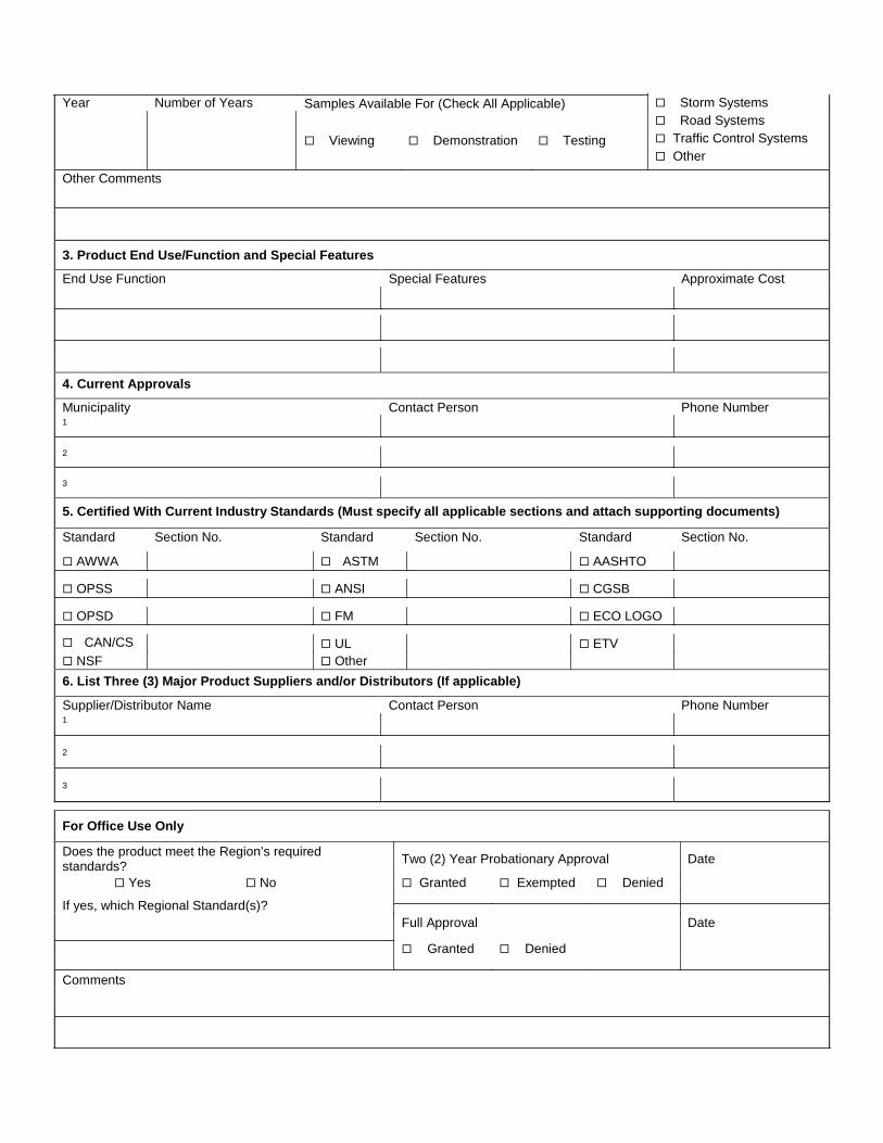
Year
Number of Years
Samples Available For (Check All Applicable) Storm Systems Road Systems Traffic Control Systems Other
Viewing Demonstration Testing
Other Comments
3. Product End Use/Function and Special Features
End Use Function Special Features Approximate Cost
4. Current Approvals
Municipality Contact Person Phone Number 1 2 3
5. Certified With Current Industry Standards (Must specify all applicable sections and attach supporting documents)
Standard Section No. Standard Section No. Standard Section No. AWWA ASTM AASHTO OPSS ANSI CGSB OPSD FM ECO LOGO CAN/CS
UL ETV
NSF Other
6. List Three (3) Major Product Suppliers and/or Distributors (If applicable)
Supplier/Distributor Name Contact Person Phone Number 1 2 3
For Office Use Only
Does the product meet the Region’s required standards? Two (2) Year Probationary Approval Date
Yes No Granted Exempted Denied If yes, which Regional Standard(s)?
Full Approval Date
Granted Denied
Comments