Embed Size (px)
Citation preview
Holland, February 2005.
This document was originally written by Lodewijk Cornelissen together with Arend Schram in the Dutch language. It is a full report including pictures and a drawing about building a wood-epoxy rudder for a Vega. Because there are not too many members on this forum who can read Dutch, Rob Kloosterman, Steve Birch and I made an English translation. I would like to thank everybody for their help and for sharing their knowledge. Regards, Jan van Craaikamp.
How to build your own Vega-rudder When do you need to replace your rudder? That is difficult question. In my particular case it was clear, I had cracks and openings along and under the stainless steel rudder shaft. This happened because the polyester came apart from the stainless steel shaft. The original polyester rudder consists of two parts in which the rudder shaft with side supports (tangs) is laminated. The edges on the inner side are shaped by 3 - 4 cm of polyester paste to glue together the two parts. Moreover, in the inside a lot of polyester is used to glue together the stainless steel supports and the thin part (appr. 2 cm thick) of the rudder blade which is almost solid polyester. The hollow spaces above, between and under the supports are filled with PU foam. If cracks appear, water can penetrate which will be absorbed by the foam. If this water freezes it will expand and split the rudder blade. Unfortunately you cannot see through the rudder blade. The force I needed to split the old rudder showed me that Vega rudders are stronger than expected and will not just fall apart. HOWEVER... from the outside you can never see the real condition of the blade. Once you have cracks in your rudder it is just a matter time, depending on the climate, before your rudder will need to be checked. My ship was imported from Sweden and had apparently met the real winter weather there. Maybe I could have done some extra years with my old rudder but I did not want to take the risk as I sail on both coastal and tidal waters. Lets get going. For the new rudder I chose to use wood and epoxy for the manufacture. This is because I am more familiar with wood and epoxy than with polyester. I could have drawn a mould of the old rudder and built it the same way as the original one but you need a lot of extras like a pressure box to keep everything in shape. When you inject the foam, it will start expanding and create enormous forces on the blade halves. If you build a solid epoxy rudder it will be too heavy and will wear out the rudder shoe bearing. A wood-epoxy rudder also has its’ disadvantages. In fact the core will be of plywood has to be made impermeable with an epoxy coating.

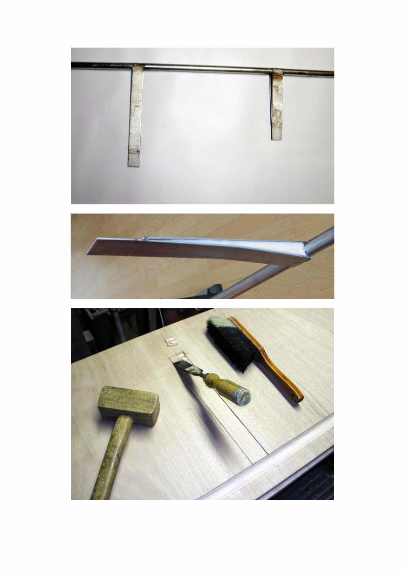
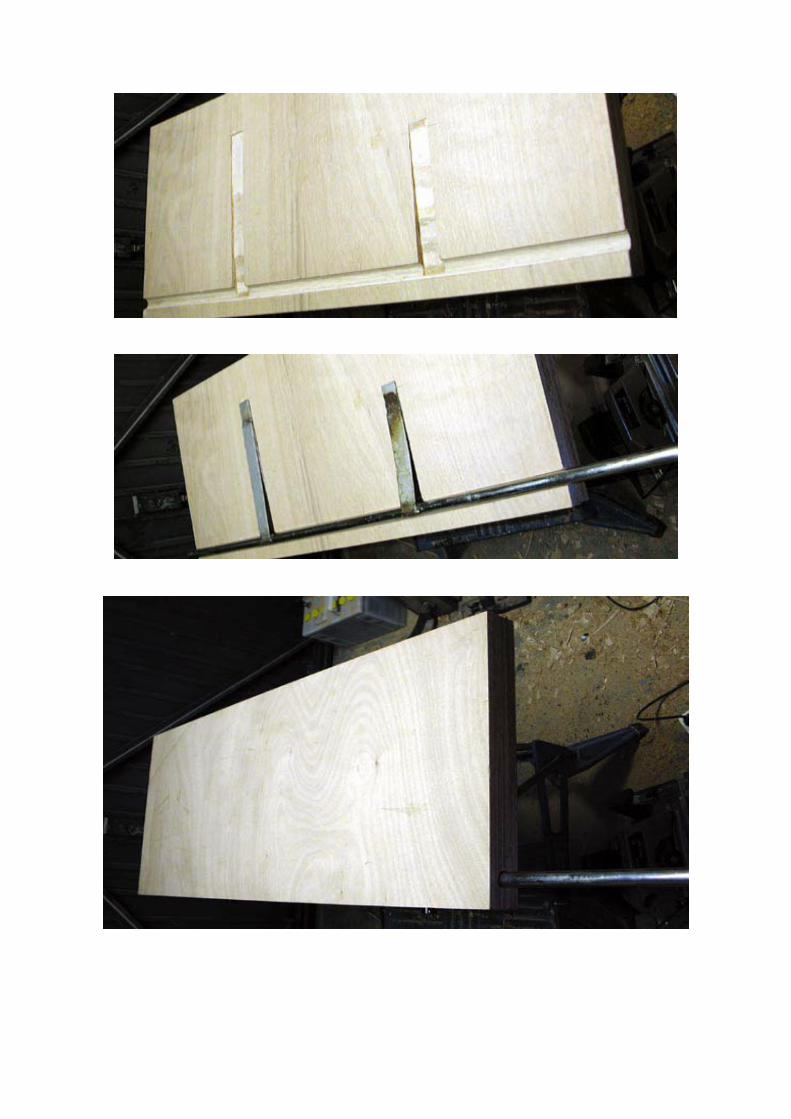
Consider epoxy as a kind of paint used to protect wood against the ingress of water. The epoxy layer is thinner than the original polyester gelcoat. Being an extension of the keel, the rudder base is more vulnerable than a shorter free rudder. That is the reason why I have paid extra attention to the laminate protection applied to the new rudder, as you will see later in this article. The correct measurement (measure twice, cut once !) Check in advance the measurements of your existing rudder with my drawing and note the possible differences. See appendix :Roerblad tek.pdf To split the old rudder blade TIP: Immediately purchase a professional mouth cover and goggles. Do not use the simple throwaway things. The dust is very thin and will get through the cheaper filters. Cover the workshop from ceiling to floor with sheets or work outside (check the air humidity and temperature are within limits). Make a deep cut with an angle grinder around the outside of the polyester blade as deeply as possible into the thin leading edge around the rudder shaft. Avoid damage to the rudder shaft as much as possible. Make some small wooden wedges and hammer them into the cut that you made in the polyester. The edges will break open. After that you can use a chisel, crowbar or heavy screwdrivers to get deeper in the material to break it open. This is a job for two pairs of hands. With some force the parts will break open without damaging the rudder shaft or supports (tangs). Remove the rudder shaft and use, if possible, an undamaged half side of the rudder blade for measurement checks. TIP: Check the rudder shaft, particularly where welded, and ensure it is straight and strong. TIP: If you are going to glue the two wooden halves together you should make sure that you glue the upper sides from the same sheet together. This ensures the structure and grain of the wood is identical and the thickness of the layers on the outside will be the same since they come from the same sheet. You will now end up with a rectangular blade, identical on both sides, before the shaping and laminating begins. Wood You will need two 50 cm x 120 cm x 30 mm sheets made from marine grade plywood. First of all cut out the shape of the rudder shaft. With a circular saw - saw blade width of 3 mm – make a ' half circle ' cut according to the drawing and description to take the rudder shaft and tangs. See APPENDIX: Roerkoninguitsp.pdf TIP: Make the outer parts approx. 1 cm extra wood (flesh) along the rudder shaft. You can remove the extra wood after gluing the parts together as it is possible that you won’t glue the two parts together in the exact position. Adjust the saw according to indications with the support slide on e.g.. 25 mm (not on 17 mm!). Use the 15 cm space of upper side of the rudder blade to check the saw adjustment. This part will be cut off at a later stage. Once you have made the cut in the first piece correctly carry on and do the cut, in mirror image, in the opposite piece of plywood. Keep the depth fixed and adjust the slide on the interior cuts. First you finish the cuts until the width is enough then you start to make deeper cuts to the middle until you have the proper shape of the rudder shaft according to the drawing.

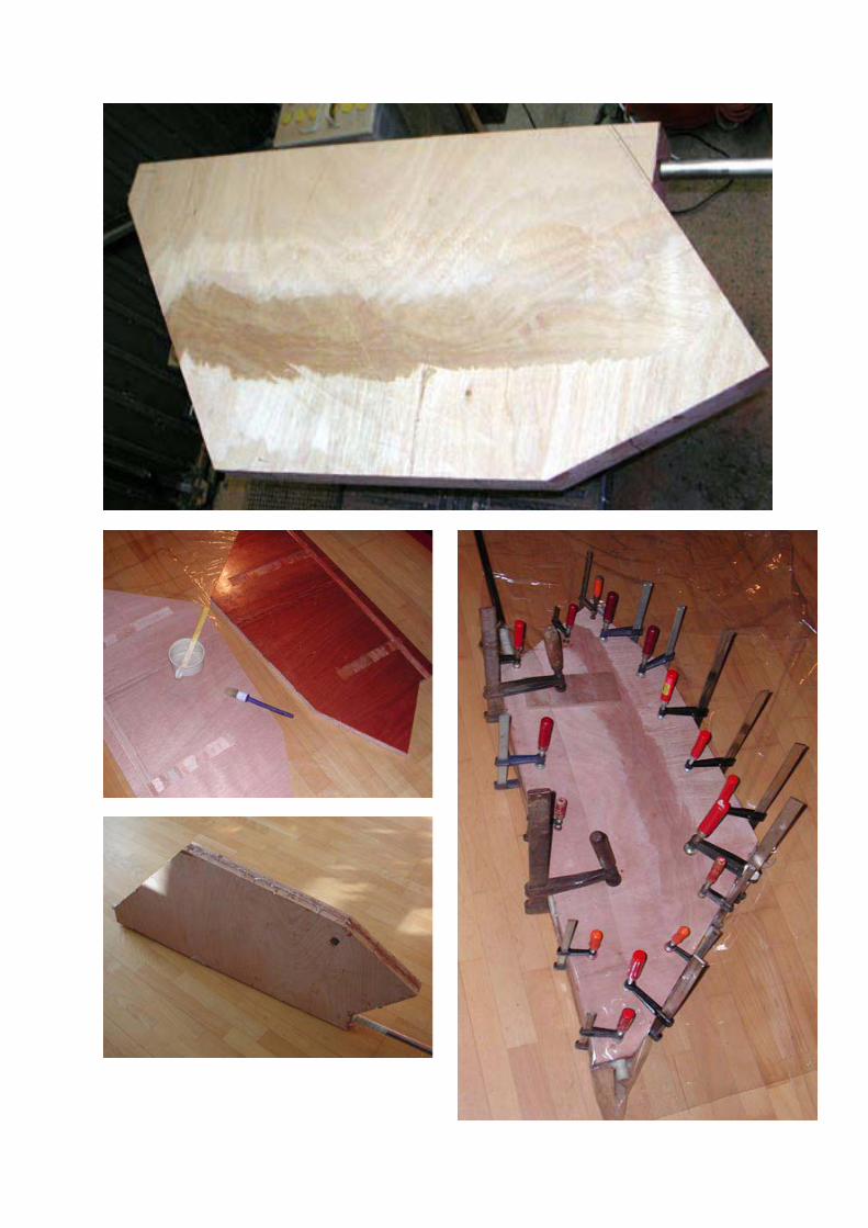
Polish with sanding paper 60 (using a broomstick as support) clear the space enough for the rudder shaft to fit. The space must be wider to allow the epoxy-filler to fill the open spaces later on. Therefore do not make it too narrow! Place the rudder shaft in the space. The shaft should stick out of the wood 37mm (not 35mm but 37 to leave 2 mm space for the epoxy layer). Mark the supports on the blade and make corresponding spaces with a chisel. Make both parts to fit each other. This must be a good fit of course and without tension. Mark the two halves across the seam in a way that you can glue them together in the exact position. Remove the shaft and draw the exact shape of the blade on the wood less 2 mm for the epoxy layer. Shape the blade with a handsaw and circle saw. Save the small pieces of plywood. You will need them now! Fill the gap between the supports (tangs) Clear the stainless steel rudder shaft and support (tangs) of old foam and polyester remnants. Roughen the stainless steel thoroughly. Saw the multiplex wedges to fit as fillers for the inner space of the supports. Glue them with epoxy paste in the support. This will stabilize the supports. Read and understand “Working with epoxy”. Fit the rudder shaft between the two parts again. If needed transfer the rounding of the supports, if happening, to the two blades until they fit. Centre the rudder shaft by means of the hole with a wooden dowel pin by putting through a long straight iron bar. Working with epoxy Make sure all parts, stainless steel or wood, are dust-free. The stainless steel to be glued must really be free of old polyester parts and roughen with coarse emery paper or similar to ensure adequate adhesion. De-grease all parts with epoxy solvent and don’t touch the parts afterwards. Oil from your hands, even a minute amount, hampers glueing. This counts also when adding the epoxy-layers later on. Mix the epoxy carefully according to the prescribed proportions. A wrong mixture is almost useless. Weighing is easy with a kitchen weighing scale, even better if digital. Of course the part which is not to be epoxied should be covered with tape. Joining the rudder parts The insides of the two parts must be prepared with epoxy. This is a thin liquid to close the porous wood. Sand, clean and de-grease. Cut a piece of glasscloth, 12 cm wide for extra re-inforcement between the parts at the thin 8mm trailing edge. Coat the ruddershaft, support (tangs), inside of the two parts of the rudder, the notches with a generous amount of epoxy paste. Also coat the other parts in epoxy (500). Better too much than too little. Superfluous paste will be squeezed out. Apply glasscloth and fit the parts into and on each other. After checking the centreing of the ruddershaft, fix both parts with padded G-Clamps or similar. Remark:To glue the innerparts of the blade properly it is sometimes necessary to keep them together with screws. You should pre-drill to the diameter of the thread of the screw at the screw side so as to obtain enough drawing force onto the other half of the rudder. I did not use the screws. After the epoxy has set you must remove the screws. If you use a plane, electric or otherwise, in case you hit one of the screws whilst planning, it will be ruined. As I have chosen to glue the both “round” sides of the plywood, I have assumed that sufficient force will be transferred from the sides to the middle (a sheet of plywood is never 100% flat) Next day, after removing the glueing clamps, you will see something recognizable. Saw off the long side at 17 mm off the side of the ruddershaft.

Shaping the rudderblade The rudder blade tapers, according to my measurements, in one direction from 60mm to 8 mm. After deducting the thickness of the epoxy it will be from approximately 58mm to 6 mm. We have to plane now, from the thin to the wide side. Use an electric plane till approx 90% of desired thickness has been obtained. To get a smooth surface, plane crosswise. The planed layers show exactly how far you are by equal width and whether or not running parallel. They automatically show “heightlines”. Now use your sharp manual Stanley plane. With that you can feel what you do compared to an electric plane. The “heightlines” run now maximum parallel and maximum equal width. Finish with a sander. Sanding sides and rounding bows. You now hold, with pride, your new Vega rudder after nearly 8 hours of labour and toil. Note that the rock hard epoxy layers of the wood will blunt your plane in no time at all. Layering the epoxy Sanded, dust and greasefree, coat the outside until impregnated. Sand, dust and greasefree again and so on. Hang it between two trestles, one side in the epoxy, cover with glasscloth and roll until all the air has disappeared, the cloth must be saturated completely so there are now white spots showing. Note well: Afterwards past with epoxy to build up the thickness again. Fold back the other side of the cloth, apply epoxy and roll the cloth from the top. Roll well at the edges. Crosscut ends tapering from 60mm to 8mm are being held square and sharp to stimulate the loosening water. This is in contrary to the original old blade which ends sharp (progress in techniques). The rudderblade is loosening water; the swirlings meet each other well behind the rudderblade. Cut excess cloth at one side less than blade thickness. And fold around the edge. The other side is then folded over completely. Next layers of glasscloth are applied with reverse folding. By doing this bit extra reinforcement is built at the crosscut ends. The bottom of the rudder, an extention of the keel, is less vulnerable if the Vega grounds. PLEASE NOTE: The so called “envelope covering” with glasscloth in v-form by folding both edges over each other) is only possible from the ruddershaft side because of the “5 edges form” of the Vega rudder. If done the other way around it will become a mess since the cloth will collapse. Moreover, the 8 mm edge is so thin that the cloth will become loose and will stand proud. I have applied an extra 20cm wide strip around the backside edge (thus the edge is 10cm wide) and brought into the edge by cutting in. With a little bit of craftsmanship and care you can shape the cloth around the ruddershaft connection. TIP: Rounding of the cloth or sharp thin edges can be overcome during the drying process. After some 2 or 3 hours the pressed cloth stays fixed. By applying tight stretched plastic clingfilm it can be handled without sticky hands or becoming loose. After complete hardening the clingfilm may be removed without problems. This way also epoxy-filler can be formed easily, e.g. as a collar around the ruddershaft I used the 160 grams cloth in 3 layers from the ruddershaf-side and one strip from the thin side. It is possible to use 2 layers of 260grams/m2 instead. Afterwards two extra epoxy-layers and filler. Not much filler is used, apart from the crosscut ends where it is generously used. Because of this vulnerability has decreased. (The bottom of the rudder now has 3mm of reinforced epoxy) but also due to the sanding a sharp corner has been obtained. For maximum closing off little filler collars are applied.

It now remains to apply the final coating. A 2 component “armoured varnish” or 1 component. (Primocon of International). I have had a bad experience with the two component armoured varnish. After applying with a mohair-roller, according to the supplier’s advise, it resulted in an “orangeskin” finish to say the least. Nevertheless with light sanding, applying 4 layers and sand the last layer until polished the finish was acceptable. A good alternative and easier to apply is the 1 component varnish by International called “Primacon”. With an anti-fouling of your choice the Vega is complete again. Removing the rudder (whilst ashore) In advance: Remove the tiller. Loosen the nut with a spanner from the holder and remove the steel tapered pin: looking to the rear, from left to right. Remove the holder. This may be surprisingly tight if it has not been removed lately. When the ship is hanging in the slings: remove the two stainless steel bolts from the bronze heel. Attention, because the rudder weighs a total of 25 kgs so ensure it is supported when it comes loose. Remove the heel and take care of the tufnol bearing in the heel. Hoist the ship further, take off the rudder, after which the ship can be set in its’ cradle or supports. This should take about 15 minutes. Do you have a creaking rudder? Polish the ruddershaft as well as the rudder shoe axle with fine (320) waterproof sandpaper then use polishing paper (800 grade or higher). Clean the rudder king as well as the wood of the tiller. Check the bronze heel for irregularities. Clean the rudder tube with a copper 12mm waterpipe in which a 3mm hole is drilled at the top. Attach to the pipe a polishing cloth made of wire-wool. Originally the shaft ran water lubricated in a copper tube. Decalcify if needed especially the bottom-side with vinegar or other decalcifying product. Clean the tube thoroughly a few times. If you have you used oil or grease in the past as a remedy against a creacking rudder then you have only removed the symptom and not the cause. The grease or oil you have used falls mostly in your ship, because at the top of the tube a seal is located. Now you have the chance to de-grease it all and decalcify. You will now have a smooth and quiet steering ship again for years to come. After approximately 10 years, decalcify again. Re-fitting the rudder With the Ship ashore. The new rudder may be mounted after the cockpit sole has been removed. The laminated rudder hole ends about 12 cm under the bronze bearing in the cockpit floor. The tube is extended by a plastic hose in which just under the cockpitfloor a seal is placed to avoid water reaching both tube and ruddershaft. When removing the rudder the seal usually remains in place but could be pressed out. (grease in advance with vaseoline) In most case the seal has not been been replaced, but the springs could be worn out. This is a good moment to replace them. Place the new ring (37x25x7) in the plastic hosemouth and take care it sits upright. The ring is kept in place by the hose. Also you may remove the hose clamp and hose from the tube making replacing the ring easier. In the hoists: A man onboard in the cockpit to lead the ruddershaft carefully through the seal. Take care that the heel, bolts and nut with spanner are kept close at hand. Hoist ship further

and coordinate inserting the rudder. Mount the heel and bearingplate and the ship is ready to be launched into the water. When the shaft comes well through the ring, mounting takes maximum 10 minutes. In the water the tiller can be assembled in reversed order. What do you need? Several handtools, electric plane, hand plane, band sand-machine, circular saw, professional dustmask, latex gloves. 2 x High performance (Marine) plywood, dimensions 500mm x 1200mm, thick 30mm. Epoxyproducts (Poly service): 2 x 1 lt. M.P. cleaner 1 set 300 gr. PP injecteer 500 gr. PP hardner 355 1 kg PP THV 500 epoxy 2 x 200gr. PP glue 700 paste epoxy 100 gr glass bubbles filler for thickening PP 700 to a filler. 5 metres glasscloth in 160 or 280 gr/m2 750 ml. Armoured coat varnish or equivalent 500 ml. PP thinner Various painting materials, sandpaper 60,.80 and 120. Cost of material approx. £170 For comparison: To have a new rudder made by Modus Marine it will cost you, depending of the type: £700 - £900 Expected number of working hours: 50 Other information: Article "Delamineren rudder blade" of Arend Schram in Vegabulletin 96 and the article "de roerendokter" Waterkampioen 19-2000. On http://www.illem.nl/kwartton/roer2.html you find also wood/epoxy-rudder description. Appendices: PDF photograph report: “Your turn?” PDF drawing rudder booklet VEGA 2506 PDF drawing ruddershaft notch Breukelen, February 2004 Lodewijk Cornelissen V 2506, i.s.m. Arend Schram V 1443


5,5
3,5
2,5
119,5
7,0
15,5
55,5
28,5
25,2
41
47,5
1,7
41,8
1,7
26,5
58,5
25
104
5,9
5,9
4,9
3,2
2,8
1,0
0,8
1,6
2,7
4,0
5,3
0,8
1,7
2,8
4,0
5,2
6,0
1,5
1,6 = gemeten bladdikte 1,7 = berekende bladdikte
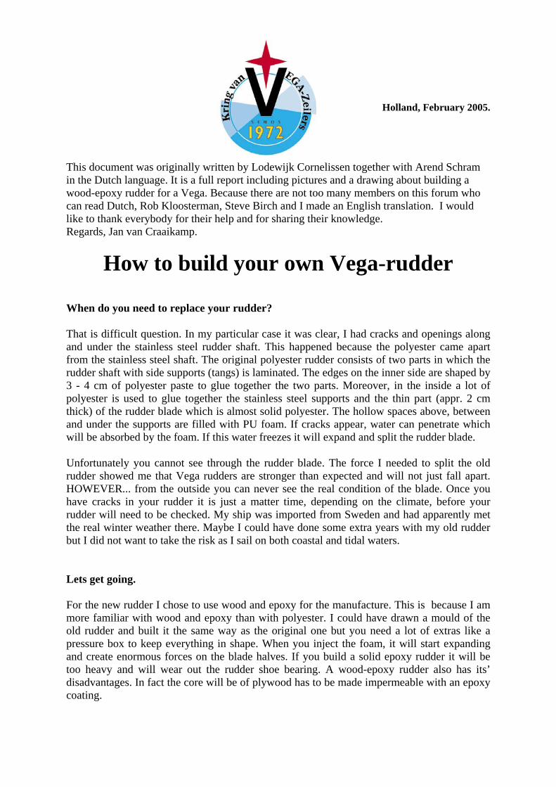
Houtenbladmaat minus 2 mm rondom i.v.m. verdikking epoxy-afwerkingPolyesterroer compleet 22,5 kgRVS roerkoning 8,9 kgHout-epoxyroer compleet 17,5 kg
Roerblad VEGA 2506Maten in cm24-12-03
4
23,5
33,5
4
4090
Maten controleren met uw eigen originele roerbladLodewijk Cornelissen V 2506